IDE User’s Guide 1 ©1989-2018 Lauterbach GmbH IDE User’s Guide TRACE32 Online Help TRACE32 Directory TRACE32 Index TRACE32 Documents ...................................................................................................................... IDE User Interface ......................................................................................................................... IDE User's Guide ........................................................................................................................ 1 History ...................................................................................................................................... 5 Structure and Contents of the Documentation .................................................................... 5 Online Documentation 5 In-Circuit Debugger TRACE32-ICD 7 In-Circuit Emulator TRACE32-ICE 8 Fully Integrated RISC Emulator TRACE32-FIRE 10 Program Start .......................................................................................................................... 12 In-Circuit Debugger TRACE32-ICD 12 In-Circuit Emulator TRACE32-ICE 12 Fully Integrated RISC Emulator TRACE32-FIRE 13 Program End ............................................................................................................................ 14 Screen Display ......................................................................................................................... 15 Concept 15 Graphical User Interface 15 MDI User Interface 16 MWI User Interface 17 Main Menu Bar 18 Accelerators 18 Main Toolbar 19 Work Area 19 Message Line 20 Error Messages 20 General Messages 20 Additional Information on Cursor Position 20 Softkeys 21 State Line 22 Basic 22 Task 24 SMP Systems 24 Advanced 25

Welcome message from author
This document is posted to help you gain knowledge. Please leave a comment to let me know what you think about it! Share it to your friends and learn new things together.
Transcript

IDE User’s Guide
TRACE32 Online Help
TRACE32 Directory
TRACE32 Index
TRACE32 Documents ......................................................................................................................
IDE User Interface .........................................................................................................................
IDE User's Guide ........................................................................................................................ 1
History ...................................................................................................................................... 5
Structure and Contents of the Documentation .................................................................... 5
Online Documentation 5
In-Circuit Debugger TRACE32-ICD 7
In-Circuit Emulator TRACE32-ICE 8
Fully Integrated RISC Emulator TRACE32-FIRE 10
Program Start .......................................................................................................................... 12
In-Circuit Debugger TRACE32-ICD 12
In-Circuit Emulator TRACE32-ICE 12
Fully Integrated RISC Emulator TRACE32-FIRE 13
Program End ............................................................................................................................ 14
Screen Display ......................................................................................................................... 15
Concept 15
Graphical User Interface 15
MDI User Interface 16
MWI User Interface 17
Main Menu Bar 18
Accelerators 18
Main Toolbar 19
Work Area 19
Message Line 20
Error Messages 20
General Messages 20
Additional Information on Cursor Position 20
Softkeys 21
State Line 22
Basic 22
Task 24
SMP Systems 24
Advanced 25
IDE User’s Guide 1 ©1989-2018 Lauterbach GmbH

Show/Hide State Line 25
Window Pages 26
Colors 27
How the TRACE32 PowerView GUI Assists You in Scripting 28
Commands ............................................................................................................................... 30
Command Structure 30
Long Form and Short Form of Commands and Functions 31
Entering Commands 32
Command Line 32
Device Selection 33
Command History 34
Command and Function Parameters 35
Parameter Types 37
Operators 41
Arithmetic Rules and Operator Precedence 43
Parentheses and Braces 44
Parameter History 44
File Names 45
Path Prefixes 46
General Command Parameter Parser - Behavior in the Different Radix Modes .............. 47
Parser Changes in Version V2.00 and Higher 47
A. Object of Description 47
B. Support of C Language Expressions 49
C. Radix Mode Support 50
D. Incompatibilities in RADIX.Classic Mode 51
Operands 52
Operand Format Examples (Literals) 53
Operand Transition Table 54
Operators 55
Operator Formats 56
Operator Transition Table 58
Window System ....................................................................................................................... 59
Windows 59
Window Captions - What Makes Them Special in TRACE32 60
Local Buttons 60
Local Popup Menus 61
Slider Controls 62
Window Operations 63
Basic Operations 63
Old Position, Bookmarks, and Current Selection 63
Getting Information 64
Changing Data or Setups 64
IDE User’s Guide 2 ©1989-2018 Lauterbach GmbH

Window Manager Menu 65
Window Position and Name 68
Freezing a Window 68
Erasing a Window 68
Window Scroll Bars 68
Printing Window Contents 69
Saving Window Contents 69
Special Window Options 71
Text-based Functions 72
Selection Service 72
Message Windows .................................................................................................................. 73
Window Tracking ..................................................................................................................... 74
File and Folder Operations ..................................................................................................... 76
File Contents ............................................................................................................................ 77
Encrypt/Execute Encrypted Files .......................................................................................... 78
Host Commands ...................................................................................................................... 79
Printer Operations ................................................................................................................... 80
System Setup and Configuration ........................................................................................... 82
Command Logging .................................................................................................................. 83
Dialog Programming ............................................................................................................... 84
Dialog Syntax and File Types 84
Comments in Dialogs 86
Dialog Commands 87
Control Your Custom Dialogs 87
Control Behavior of Individual Dialog Elements on Custom Dialogs 87
Interact with the File System 87
Display Message Boxes of the Operating System 87
Dialog Elements 88
Return Values and Labels 90
PRACTICE Macros inside Dialog Definitions 91
HELP System ........................................................................................................................... 92
Ways to Get Help 92
Context-Sensitive Help 93
Structure of the Help System 94
Configure the Help System 95
Recommendations for Choosing a PDF Viewer 96
Bookmarks for Help Topics 97
Create Help Bookmarks 97
Store and Load Help Bookmarks Manually 98
Store and Load Help Bookmarks Automatically 98
IDE User’s Guide 3 ©1989-2018 Lauterbach GmbH

Troubleshooting the Help System 99
Change the Installation Path of the PDF Files 100
Winhelp Compatibility 100
Previous Releases - HELP System ........................................................................................ 101
Previous Releases - HELP Installation and Setup 101
Previous Releases - Configuring an Alternate PDF Viewer 101
Previous Releases - HELP Installation Problems 105
InterCom ................................................................................................................................... 107
Version Management and Licensing ..................................................................................... 108
Editing ...................................................................................................................................... 109
Icons ......................................................................................................................................... 110
Built-in Icons and Icon Library 111
Inserting a Placeholder for User-Defined Icons 112
Drawing Icons 113
Interface ................................................................................................................................... 115
Shortcuts .................................................................................................................................. 116
IDE User’s Guide 4 ©1989-2018 Lauterbach GmbH

IDE User’s Guide
Version 22-Mar-2018
History
16-Mar-18 The new camel casing of the INTERCOM commands is now InterCom.
14-Jun-17 Updated section “Shortcuts” with information on the Pause / Break key.
Structure and Contents of the Documentation
This chapter describes the structure of the TRACE32 documentation - printed as well as online.
Since the development of the TRACE32 software is always in progress, the online version of the manuals will always be more up to date than the printed version. The first pages of the printed documentation contain the issue date.
The release history in the online documentation always lists the latest changes in the TRACE32 software. When you get a new version of the TRACE32 software, please always check the Release history first.
Online Documentation
The most recent version of the TRACE32 documentation is available online.
There are several ways to get access to the documentation:
1. If the TRACE32 software is already running, you can use the Help command in the main menu bar.
2. On the TRACE32 software DVD and in your TRACE32 system path, you can find a directory \PDF. This directory contains the complete TRACE32 documentation in PDF format.
Open directory.pdf to get the table of contents for the complete TRACE32 documentation.
Documentation on how to use the online help can be found in chapter Help System.
IDE User’s Guide 5 ©1989-2018 Lauterbach GmbH

The documentation is automatically filtered by your currently used hardware configuration. The filter automatically reduces the whole documentation to the part that is relevant for you. If you want to change the filter, take a look at the command HELP.FILTER.
When using the RTOS/multi task functionality, you have to enable the RTOS documentation:
HELP.FILTER.ADD rtos* Enable all available RTOS documentation
HELP.FILTER.ADD rtoslinux Enable only the documentation for Linux RTOS Debugger
IDE User’s Guide 6 ©1989-2018 Lauterbach GmbH

In-Circuit Debugger TRACE32-ICD
TRACE32-ICD includes all debuggers based on an on-chip debug interface (e.g. JTAG, BMD, OCDS …) as well as ROM monitor solutions. Lauterbach also provides a trace extension for most debuggers (TRACE32-ICT).
TRACE32-ICD comes with a tutorial that should make you familiar with important features of TRACE32-ICD. See “Training Simulator and Demo Software” (demo.pdf).
For more information on the features of TRACE32-ICD, refer to the following parts of the online help:
• “TRACE32 Installation Guide” (installation.pdf)
This part is the general installation guide for all TRACE32 development tools.
• “ICD In-Circuit Debugger”
This part provides all CPU specific information for your TRACE32-ICD, chiefly how to set up the debugger for your target. Here you will also find all extra features that are supported for your CPU.
• “General Reference Guide” (general_ref_<x>.pdf)
This part provides an alphabetical list of all debugger commands. All commands that are not available for TRACE32-ICD are marked with:
- (E) - TRACE32-ICE only
- (F) - TRACE32-FIRE only
• “IDE User’s Guide” (ide_user.pdf)
All TRACE32 development tools share the common user interface TRACE32 PowerView. This part describes the basic functions of the user interface (command structure, online help, editing and managing files, printer operations, etc.)
• “IDE Reference Guide” (ide_ref.pdf)
This part provides an alphabetical list of all TRACE32 PowerView commands.
• “PRACTICE Script Language User’s Guide” (practice_user.pdf)
The TRACE32 script language PRACTICE is mainly used to perform automatic setups, to automate test sequences or to store the system settings for later recall. This part describes the basic structure and features of PRACTICE.
• “PRACTICE Script Language Reference Guide” (practice_ref.pdf)
This part provides an alphabetical list of all PRACTICE commands.
• “ICD Extensions”
Refer to this part if you want to use the TPU debugger or the PCP debugger.
• “RTOS Debuggers” (rtos_<x>.pdf)
Refer to this part if you want to use the TRACE32 RTOS Debugger.
• “3rd-Party Tool Integrations” (int_<x>.pdf)
Refer to this part, if you want to run TRACE32-ICD from a 3rd-party user interface.
IDE User’s Guide 7 ©1989-2018 Lauterbach GmbH

In-Circuit Emulator TRACE32-ICE
TRACE32-ICE comes with 4 binders which provide documentation support for all its capabilities.
TRACE32-ICE is divided into two major functional units: the Emulator and the Analyzer.
• The emulator-part of TRACE32-ICE is responsible for carrying out debugging functions, for managing breakpoints, for displaying memory and high-level-language structures and for code coverage …
• The analyzer-part of TRACE32-ICE is responsible for displaying and managing the trace buffer, for programming the analyzer trigger unit to perform selective tracing and to carry out complex trigger sequences, for statistic functions and performance analyses …
The following list will give you an idea of the contents of each manual.
“ICE User’s Guide” (ice_user.pdf)
This parts makes you familiar with the concept and the main features of the emulator-part of TRACE32-ICE.
“ICE Targets” This part provides all CPU specific information for your TRACE32-ICE, chiefly how to set up TRACE32-ICE for your target. Here you will also find all extra features that are supported for your CPU.
“General Reference Guide”
This part provides an alphabetical list of all commands for the emulator-part of TRACE32-ICE. All commands that are not available for TRACE32-ICE are marked with (B) - TRACE32-ICD only or (F) - TRACE32-FIRE only.
“ICE/FIRE Analyzer User’s Guide” (analyzer_user.pdf)
This part makes you familiar with the concept and the main features of the analyzer-part of TRACE32-ICE.
“ICE/FIRE Analyzer Trig-ger Unit Programming Guide” (analyzer_prog.pdf)
This part makes you familiar with the concept of the trigger programming language. It contains examples for trigger programs and alphabetical lists of all actions and input events.
“IDE User’s Guide” (ide_user.pdf)
All TRACE32 development tools share the common user interface TRACE32-PowerView. This part describes the basic functions of the user interface (command structure, online help, editing and managing files, printer operations etc.).
“IDE Reference Guide” (ide_ref.pdf)
This part provides an alphabetical list of all operating system commands.
“PRACTICE Script Lan-guage User’s Guide” (practice_user.pdf)
The TRACE32 script language PRACTICE is mainly used to perform automatic setups, to automate test sequences or to store the system settings for later recall. This part describes the basic structure and features of PRACTICE.
IDE User’s Guide 8 ©1989-2018 Lauterbach GmbH

“PRACTICE Script Lan-guage Reference Guide” (practice_ref.pdf)
This part provides an alphabetical list of all PRACTICE commands.
“ICD Extensions” Refer to this part, if you want to use the TPU debugger.
“RTOS Debuggers” Refer to this part if you want to use the TRACE32 RTOS Debugger.
“Tools Integration” Refer to this part, if you want to run TRACE32-ICE from a 3rd-party user interface.
“TRACE32 Installation Guide” (installation.pdf)
This part is the general Installation Guide for all TRACE32 development tools.
“ICE Port Analyzer User’s Guide” (port_user.pdf)
Your TRACE32-ICE can be enhanced by a port analyzer to trace additional CPU lines. A description of the Port Analyzer and its features is provided in the “ICE Port Analyzer User’s Guide” (port_user.pdf)
“Timing Analyzer” The Timing Analyzer provides timing and state analysis, a pattern generator and a serial line tester. A description of the Timing Analyzer and its features is provided in the “Timing Analyzer User’s Guide” (time_user.pdf), the “Timing Analyzer Reference Guide” (time_ref.pdf) and the “Timing Analyzer Trigger Unit Programming Guide” (time_prog.pdf)
IDE User’s Guide 9 ©1989-2018 Lauterbach GmbH

Fully Integrated RISC Emulator TRACE32-FIRE
TRACE32-FIRE comes with 4 binders which provide documentation support for all its capabilities.
The following list will give you an idea of the contents of each manual.
“FIRE User’s Guide” (fire_user.pdf)
This parts makes you familiar with the concept and the main features of TRACE32-FIRE.
“FIRE Targets” This part provides all CPU specific information for your TRACE32-FIRE, chiefly how to set up TRACE32-FIRE for your target. Here you will also find all extra features that are supported for your CPU.
“General Reference Guide”
This part provides an alphabetical list of all commands for debugging and trace with TRACE32-FIRE. All commands that are not available for TRACE32-FIRE are marked with (B) - TRACE32-ICD only or (E) -TRACE32-ICE only.
“ICE/FIRE Analyzer Trig-ger Unit Programming Guide” (analyzer_prog.pdf)
This part makes you familiar with the concept of the trigger programming language. It contains examples for trigger programs and alphabetical lists of all actions and input events.
“IDE User’s Guide” (ide_user.pdf)
All TRACE32 development tools share the common user interface TRACE32-PowerView. This part describes the basic functions of the user interface (command structure, online help, editing and managing files, printer operations etc.)
“IDE Reference Guide” (ide_ref.pdf)
This part provides an alphabetical list of all operating system commands.
“PRACTICE Script Lan-guage User’s Guide” (practice_user.pdf)
The TRACE32 script language PRACTICE is mainly used to perform automatic setups, to automate test sequences or to store the system settings for later recall. This part describes the basic structure and features of PRACTICE.
“PRACTICE Script Lan-guage Reference Guide” (practice_ref.pdf)
This part provides an alphabetical list of all PRACTICE commands.
“ICD Externsions” Refer to this part, if you want to use the TPU debugger and PCP debugger.
“RTOS Debuggers” Refer to this part if you want to use the TRACE32 RTOS Debugger.
’Tools Integration’ Refer to this part, if you want to run TRACE32-FIRE from a 3rd-party user interface.
IDE User’s Guide 10 ©1989-2018 Lauterbach GmbH

“TRACE32 Installation Guide” (installation.pdf)
This part is the general Installation Guide for all TRACE32 development tools.
“FIRE Port Analyzer User´s Guide” (fireport_user.pdf)
Your TRACE32-FIRE can be enhanced by a port analyzer to trace additional CPU lines. A description of the Port Analyzer and its features is provided in the “FIRE Port Analyzer User´s Guide” (fireport_user.pdf).
IDE User’s Guide 11 ©1989-2018 Lauterbach GmbH

Program Start
After installing the driver program to the appropriate host system, the executable can be started.
The TRACE32 system has to be powered up. If this is not the case, the error message "NO CARRIER …", "LINK ERROR …" or "TRACE32 not responding" will appear.
If all environment variables are installed correctly, the driver program can be invoked from any sub-directory or drive.
In-Circuit Debugger TRACE32-ICD
In-Circuit Emulator TRACE32-ICE
t32m<cpu>.exe Windows version for TRACE32-ICD.
TRACE32-ICD system software is running on PC.
t32win.exe(former t32w95.exe)
Windows version for TRACE32-ICD with PODBUS Ethernet Controller (not for PowerTrace/PowerDebugEthernet/PowerDebugUsb/PowerNexus).
TRACE32-ICD system software is downloaded to the PODBUS Ethernet Controller and runs there.
t32m<cpu> Workstation version for TRACE32-ICD.
TRACE32-ICD system software is running on workstation.
t32cde Workstation version for TRACE32-ICD with PODBUS Ethernet Controller (not for PowerTrace/PowerDebugEthernet/PowerDebugUsb/PowerNexus).
TRACE32-ICD system software is downloaded to the PODBUS Ethernet Controller and runs there.
t32win.exe(former t32w95.exe)
Windows version for TRACE32-ICE.
TRACE32-ICE system software is downloaded to the System Controller Unit and runs there.
t32cde Workstation version of TRACE32-ICE.
TRACE32-ICE system software is downloaded to the System Controller Unit runs and there.
IDE User’s Guide 12 ©1989-2018 Lauterbach GmbH

Fully Integrated RISC Emulator TRACE32-FIRE
t32m<cpu>.exe Windows version for TRACE32-FIRE.
TRACE32-FIRE system software is running on PC.
t32win.exe(former t32w95.exe)
Windows version for TRACE32-FIRE with PODBUS Ethernet Controller.
TRACE32-FIRE system software is downloaded to the PODBUS Ethernet Controller and runs there.
t32m<cpu> Workstation version for TRACE32-ICD.
TRACE32-ICD system software is running on workstation.
t32cde Workstation version of TRACE32-FIRE with PODBUS Ethernet Controller.
TRACE32-FIRE system software is downloaded to the PODBUS Ethernet Controller and runs there.
IDE User’s Guide 13 ©1989-2018 Lauterbach GmbH

Program End
Getting back to the operating system command level is possible by using the command QUIT or by choosing File menu > Exit.
The QUIT command quits the driver program and resets the TRACE32 system. When the driver program is restarted, a complete boot sequence will be executed.
If for any reason the host crashes, the TRACE32 system should be switched off for a few seconds.
ABORT Abort driver program
QUIT Return to operating system
::QUIT
NOTE: If your TRACE32 development tool is connected to the target, it is important to use the proper power on/power off sequence. For detailed information refer to the Targets Guides for your CPU.
IDE User’s Guide 14 ©1989-2018 Lauterbach GmbH

Screen Display
Concept
The TRACE32 user interface is based on an extremely fast, character oriented window system. Up to 128 different windows can be composed for display, each can contain up to 250 * 250 characters. Window type, size and status can be defined very flexibly by the user. Each window is assigned to one task, which is sequentially executed to update the window information.
Windows may be frozen to prevent them from being updated.
An array of windows is called a “PAGE”. Several pages can be defined in this manner, with each page representing a part of the user’s work area. Multiple pages cause no performance degradation, as only the visible windows are updated.c:\t32\bin\windows64\config_fdi.t32
Graphical User Interface
The graphical user interface of TRACE32, called TRACE32 PowerView, supports 2 different window modes:
• MDI (multiple document interface): All sub-windows are placed inside the TRACE32 main window.
• MWI (multiple window interface): The TRACE32 main window and the sub-windows are placed freely on the desktop.
On MS Windows systems, the MWI window mode is split into 2 sub-modes:
• FDI (floating document interface): same as MWI, taskbar shows only one icon for all windows, minimizing the main window will also minimize the sub-windows.
• MTI (multiple top-level window interface): taskbar shows an icon for the main window and each sub-window, minimizing the main window does not minimize the sub-windows.
These modes can be set in the SCREEN= section of the configuration file (config.t32). Depending on the version of TRACE32, not all window modes are supported:
Windows Linux/Motif
Linux/Qt
SunOS/Solaris
HP-UX OS X/Motif
OS X/ Qt
MDI + - + - - - +
MWI + + + + + + +
IDE User’s Guide 15 ©1989-2018 Lauterbach GmbH

MDI User Interface
After starting TRACE32, the main window of the debugger is displayed.
For more information, click the blue GUI terms.
A Local popup menu
Main menu bar Main toolbar
Local buttons
Command line
Message line
Softkeys
Work areawith windows
State line
A
IDE User’s Guide 16 ©1989-2018 Lauterbach GmbH

MWI User Interface
After starting TRACE32, the main window of the debugger is displayed.
For more information, click the blue GUI terms.
A Local popup menu
Main menu bar Main toolbar
Command line
Message line
Softkeys
State line
Local buttons
A
IDE User’s Guide 17 ©1989-2018 Lauterbach GmbH

Main Menu Bar[Back to Top]
The main menu bar provides all important commands for each functional unit of the TRACE32 development tool. You can add user-defined menus to the main menu bar by using the MENU commands.
PRACTICE script for the above example:
Accelerators
Accelerators allow you to execute commands with a single keystroke. Usually the function keys are used for this purpose. Accelerators can be changed by using the MENU commands.
PRACTICE script for the above example:
MENU.AddMenu Allows you to quickly add one menu for temporary usage.Default name of the temporary menu is User.
MENU.ReProgram Allows you to embed a menu definition in a PRACTICE script (*.cmm) or create a *.men file for a menu definition.
; menu User with two menu optionsMENU.AddMenu "Mapper Settings" "MAP.List"MENU.AddMenu "Free and Used Memory" "MAP.state"
; the example shows how to include an accelerator in a temporary menuMENU.AddMenu "Mapper Settings, ALT+F10" "Map.List"
IDE User’s Guide 18 ©1989-2018 Lauterbach GmbH

Main Toolbar[Back to Top]
The main toolbar provides buttons for the most important TRACE32 commands. You can add user-defined buttons with tooltips to the main toolbar by using the MENU commands.
PRACTICE script for the above example:
Work Area[Back to Top]
The work area is used as the general input and output area. For more detailed information, see Windows.
In addition to working with windows in the work area, you can place windows on user-defined pages. This is useful if you need to open lots of windows and want to group them. For more information, see Pages.
MENU.AddTool Add a temporary button to the main toolbar, i.e. the button is available only for the current TRACE32 session
TOOLBAR Toggle main toolbar
MENU.Program Editor to write a program that customizes the TRACE32 menu
MENU.ReProgram Menu programming
MENU.RESet Restore default menu and configuration of main toolbar
; the example shows how to add a temporary button to the main toolbar ; <tooltip> <button_letters,color> <command> MENU.AddTool "Mapper Settings" "ML,B" "MAP.List"
IDE User’s Guide 19 ©1989-2018 Lauterbach GmbH

Message Line[Back to Top]
The message line displays error and general messages, information on cursor position, etc. The message line is located below the command line.
Error Messages
Error messages are displayed by a special attribute (e.g. red or blinking). The error message is erased automatically. If an input error was made, an arrow will point to the mistake on the command line.
General Messages
When entering configuration commands, the current state is displayed during the command input. Some command outputs are also displayed in the message line.
Additional Information on Cursor Position
If the left mouse button is pressed down while the cursor is positioned within a window, additional information in regard to the current context will be displayed. In the example below the variable flags is selected in the Data.List window.
The softkeys will no longer correspond to the entered data! If the error message is still unclear, the appropriate page in the on-line manual will be displayed, when using the «help» key.
E::MAP.mapper mode : SLOW blocksize SRAM: 4K DRAM: 16K
E::flag = {1, 1, 0, 0, 1, 1, 1, 1, 1, 0, 0, 1, 1, 0, 0, 0, 0, 1}
IDE User’s Guide 20 ©1989-2018 Lauterbach GmbH

Softkeys[Back to Top]
The softkey structure represents a hierarchical selection menu. Each softkey can be activated by clicking the left mouse button.
Softkeys with pointed brackets (e.g., «<file>, <range>, <address>») are placeholders for parameters which have to be entered in the command line.
In the case of softkeys with square brackets ([ or ]) the command is executed immediately after being selected without a written entry to the command line.
Softkeys written completely in lower case characters represent command hierarchy branching which does not alter the command line (e.g., emulation).
Softkeys written in upper case and mixed case represent command words which can also be entered via the keyboard. You can enter either the entire word, or just the upper case letters. Upper and lower case characters are not differentiated.
By means of the «other» softkey additional menu selections located in the same hierarchical level can be started. By «previous» you can return to the former level in the menu hierarchy. The commands for those softkeys which have been shadowed in on the display are inaccessible at this time.
Data Command
emulate Command path
[Step] Direct command
<address> Parameter
Previous menu
other Next menu
previous
IDE User’s Guide 21 ©1989-2018 Lauterbach GmbH
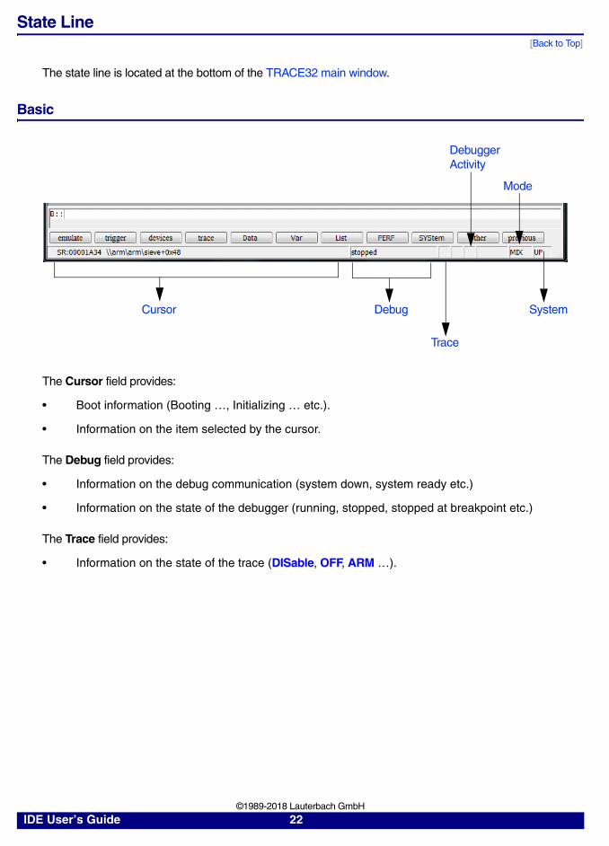
State Line[Back to Top]
The state line is located at the bottom of the TRACE32 main window.
Basic
The Cursor field provides:
• Boot information (Booting …, Initializing … etc.).
• Information on the item selected by the cursor.
The Debug field provides:
• Information on the debug communication (system down, system ready etc.)
• Information on the state of the debugger (running, stopped, stopped at breakpoint etc.)
The Trace field provides:
• Information on the state of the trace (DISable, OFF, ARM …).
Cursor Debug
Trace
System
Debugger Activity
Mode
IDE User’s Guide 22 ©1989-2018 Lauterbach GmbH

The state of the trace can be changed by using the Trace pull-down.
The Debugger Activity field provides information on the target activity of the debugger, for example:
• A red S indicates that the debugger shortly interrupts the program execution to realize a debugger feature, e.g. intrusive breakpoints.
• RUN in green indicates that TRACE32 has started an algorithm on the target to realize a debugger feature, e.g. target-controlled FLASH programming.
The Mode field indicates the debug mode. The debug mode defines how source code information is displayed (assembler code ASM or programming language code HLL or a mixture of both MIX) and how single stepping is performed (assembler line-wise or programming language line-wise).
The debug mode can be changed by using the Mode pull-down.
The System field indicates Up if the communication between the debugger and the processor/core is established and nothing is otherwise.
The communication between the debugger and the processor/core can be established and ended by the System pull-down.
IDE User’s Guide 23 ©1989-2018 Lauterbach GmbH

Task[Back to Top]
The name of the current task is displayed in the Task field after the TRACE32 OS-awareness was activated, see [A]. In a hypervisor environment, the machine name precedes the task name, and the three colons ::: serve as the separator between machine name and task name, see [B].
Selecting another task from the Task pull-down allows to switch the task context (mainly Register.view window and Frame.view window).
• A check mark is used to mark the task for which the task context is displayed.
• A asterisk is used to mark the currently active task.
This feature is not supported for all operating systems.
SMP Systems[Back to Top]
The Cores field shows the currently selected core [A].
• TRACE32 PowerView visualizes all system information from the perspective of the selected core if not specified otherwise.
The Cores pull-down allows to change the selected core.
A
B
A
IDE User’s Guide 24 ©1989-2018 Lauterbach GmbH

Advanced[Back to Top]
The Target field indicates an active target reset or a locked JTAG interface (command: SYStem.LOCK ON).
If “Integrated Run & Stop Mode Debugging via JTAG” is used TRACE32 indicates that a debug agent is running in the Monitor field. For details refer to “RTOS Debugger for Linux - Run Mode” (rtos_linux_run.pdf).
Show/Hide State Line[Back to Top]
STATUSBAR ON Show state line.
STATUSBAR OFF Hide state line.
Target
Monitor
IDE User’s Guide 25 ©1989-2018 Lauterbach GmbH

Window Pages
Window pages in TRACE32 are similar to workspaces in other applications. In TRACE32, you can open windows on different pages, but only the windows on the selected page are visible. Windows located on the other pages are temporarily hidden.
You can create a new page and switch between pages by right-clicking anywhere on the TRACE32 main toolbar. By default, TRACE32 auto-increments the names of new pages P001, P002, etc. But you can also create new pages with user-defined names.
The WinPAGE.List window serves as the table of contents for your pages. You should always open the WinPAGE.List window with the WinResist pre-command to keep the table of contents visible on all pages.
Example:
WinResist.WinPAGE.List ;keep the table of contents visible on all pages
WinPAGE.Create ;new page with auto-incremented page name
;open these windows on the new pageData.ListVar.Frame /Locals /CallerVar.Watch %SpotLight flags ast WinPAGE.Create ANALYZE ;create a new page named ANALYZEWinPAGE.Create EDIT ;create a new page named EDIT
Right-click the toolbar to create a new page or switch to another page.
P000
P001
ANALYZE
Default page P000
New page P001
New pages with user-defined names: ANALYZE and EDIT
Currently selected page
EDIT
IDE User’s Guide 26 ©1989-2018 Lauterbach GmbH

Colors
WinPAGE.select Select page
WinPAGE.Create Create page with a user-defined name
WinPAGE.Delete Delete page
WinPAGE.List List pages
WinPAGE.REName Rename page
WinPAGE.RESet Reset window system
SETUP.COLOR Change colors
sYmbol.List.ColorDef List keyword colors
sYmbol.ColorDef Modify keyword colors
CmdPOS Toolbar and/or background color for multicore debugging (TRACE32 is in MWI window mode)
FramePOS Toolbar and/or background color for multicore debugging (TRACE32 is in MDI window mode)
CORE.SHOWACTIVE Show active cores in an SMP system. Each core has its own color.
SETUP.COLORCORE Enable coloring for core-specific info in SMP systems
<trace>.STATistic.COLOR Assign colors to function for colored graphics
GROUP.COLOR Define color for group indicator
SETUP.DRV Send command to Windows screen driver to change the color of an element, e.g. the background color of the TRACE32 windows.To get the ID of a TRACE32 element whose color you want to change, run SETUP.COLOR.
IDE User’s Guide 27 ©1989-2018 Lauterbach GmbH

How the TRACE32 PowerView GUI Assists You in Scripting
The TRACE32 PowerView GUI is designed to assist you in writing PRACTICE scripts (*.cmm), with which processes can be automated in TRACE32:
1. The GUI controls in TRACE32 windows are labeled such that they reveal the command syntax for use in a PRACTICE script. See (A) below.
2. The commands shown in window captions can be modified and re-used with one mouse-click. See (B) below.
(A) Writing Scripts based on the Text Labels of the TRACE32 PowerView GUI
Let’s assume you are writing a PRACTICE script and require the configuration settings from a window, such as the ITM.state window. A window can contain all sorts of GUI controls: radio options, check boxes, drop-down lists, input boxes, and so on. To write a script that takes all of these GUI controls into account, follow these two simple rules:
1. Type the GUI labels into your script file.
2. Omit the GUI labels that are all lowercase (here: itm, trace, commands)
Resulting command syntax for use in a PRACTICE script:
Solution 2 is the recommended solution in terms of typing effort and source code maintainability - for you and your colleagues.
Solution 3 is very useful for frequently-used commands when you are working with the TRACE32 command line.
Solution 1 Solution 2 Solution 3
ITM.ONITM.DataTrace DataPCITM.PCSampler OFFITM.TImeMode ExternalITM.CyclePrescaler 1/1ITM.TimeStampMode ALLITM.TraceID 16.ITM.TracePriority 2.
itm.onitm.datatrace datapcitm.pcsampler offitm.timemode externalitm.cycleprescaler 1/1itm.timestampmode allitm.traceid 16.itm.tracepriority 2.
itm.onitm.dt dpcitm.pcs offitm.tim eitm.cp 1/1itm.tsm allitm.tid 16.itm.tp 2.
TRACE32 does not accept: ITM.itm.ON
TRACE32 accepts these 2 solutions: ITM.ONitm.on
IDE User’s Guide 28 ©1989-2018 Lauterbach GmbH

(B) Modifying and Re-using Commands Shown In Window Captions
Commands shown in window captions can easily be modified. This is a TRACE32 feature which is very useful if you want to add, remove, or change the options or parameters of a command. This feature is also useful when you are writing a PRACTICE script (*.cmm) and require a command that is already displayed in a window caption; there is no need to re-type the command.
If you want to reproduce the step-by-step procedure below, use this source code:
To modify / re-use commands shown in window captions:
1. As a Windows user, right-click the window caption. As a Linux user, click the top left icon, and then select Command Line.
Vertical lines are shown in the window caption [A].
The command is inserted into the TRACE32 command line [B].
You can now modify the command string in the command line. You can also select and copy the command in the TRACE32 command line and paste the command into a PRACTICE script file.
2. To execute the (modified) command again, click OK.
3. To deselect the window caption without executing the command again, press the Esc key.
;set a test pattern to the virtual memory of TRACE32Data.Set VM:0--0x4f %Byte 1 0 0 0
Data.dump VM:0x0 ;open the Data.dump window
;visualize the contents of the TRACE32 virtual memory as a graphData.DRAWFFT %Decimal.Byte VM:0++0x4f 2.0 512.
A
B
IDE User’s Guide 29 ©1989-2018 Lauterbach GmbH

Commands
• “Command Structure”
• “Long Form and Short Form of Commands and Functions”
• “Entering Commands”
• “Command History”
• “Command and Function Parameters”
• For information about tab completion for commands, see “Shortcuts”, page 116.
Command Structure
Most commands consist of a command word, parameters, and options. The command word consists of several tokens, which are separated by a dot. Commands are combined into command groups whereby the first token of the command designates the command group. The other tokens define subcommands.
Commands can be preceded by a pre-command. Examples of pre-commands are ChDir (for changing the directory), WinPrint, or WinExt. Window pre-commands are used to modify the behavior of the window for a command.WinPrint generates a hardcopy or a file from a command.
WinExt allows you to detach a window, e.g. SYStem.state, from the TRACE32 main window.
You can detach the window - even if TRACE32 is in MDI window mode.WinExt.SYStem.state
Device Command SubcommandB:: Data. dump
ListPrintViewSetLOAD. Ubrof
IeeeSAVE. BINary
. .Break. direct
Set.
::B::WinPrint.Data.dump 0x1000 /Byte
optionparameter
sub-commandcommand
pre-commanddevice prompt
IDE User’s Guide 30 ©1989-2018 Lauterbach GmbH

Long Form and Short Form of Commands and Functions
Commands and functions have a long form and an equivalent short form. The two forms can be used in the TRACE32 command line and in PRACTICE scripts (*.cmm). In addition, the two forms are not case sensitive.
Short forms are a time saver when you are working with the TRACE32 command line. In PRACTICE scripts, the use of short forms is not recommended because short forms tend to make scripts difficult to maintain later on - for you and your colleagues.
Example of the two forms:
UPPER CASE letters in the TRACE32 application and documentation are just visual cues to indicate the short forms of commands. You can see the UPPER CASE letters of the short forms in the following places:
• On the softkeys below the TRACE32 command line
• In the TRACE32 windows, for example, in the SYStem.state window
• In the online help (For example, choose Help menu > Tree to open the command tree.)
To retrieve the long form of an unfamiliar short form (e.g. for sys.d):
1. Choose Help menu > Index.
2. Type the short form in the Find Index box, and then press Enter.
Long form SYStem.state
Short forms SYS or just sys• You can use short forms in UPPER CASE or lower case.• You can omit words in all lower-case letters, e.g. state
macpuomd(-) u Short forms:
Long form: SYStem.MemAccess CPUShort form: sys.ma cpu
IDE User’s Guide 31 ©1989-2018 Lauterbach GmbH

Entering Commands
The long and short forms of TRACE32 commands are not case sensitive.
For example: Var.Watch can be abbreviated to v.w or to v.watch or to V.WATCH or to var.w
Command Line[Back to Top]
All line-oriented commands are entered to the TRACE32 command line. The command line will automatically come into focus when an alphanumeric character is entered (except Editor windows or fields). All line oriented commands are not executed until confirmed by «return» or «[ok]».
The syntax is checked immediately after every key stroke.
NOTE: You can copy and paste up to 300 commands (i.e. 300 lines including comments) into the command line. TRACE32 executes them like a PRACTICE script (*.cmm).
::devices HELP os windows practice EDIT
::B::emulate Data Var trigger devices Analyzer
B::Data.[ok] dump View Print List Set
B::Data.List[ok] <range> <address> options
B::Data.List 0x1000[ok] options
[ok] Mark Track
B::Data.List /MarkPC
TOrder SOrder MarkPC
OS level
Device level
Command
Sub-command
Parameter
Option
;set a test pattern to the virtual memory of TRACE32Data.Set VM:0--0x4f %Byte 1 0 0 0
Data.dump VM:0x0 ;open the Data.dump window
;visualize the contents of the TRACE32 virtual memory as a graphData.DRAWFFT %Decimal.Byte VM:0++0x4f 2.0 512.
IDE User’s Guide 32 ©1989-2018 Lauterbach GmbH

Device Selection
Each TRACE32 system has an identifier ending with two colons. The currently selected device is displayed by the prompt of the command line. System identifiers can be entered prior to each command. When a new device selector is entered prior to a command, the device selector is only valid for this specific command. The permanent selection of a device is done by entering the identifier without any command word. The TRACE32 operating system level can be accessed by entering two colons. Operating system commands can be executed from any device without using a device identifier.
::B:: ; select ICD Debugger
::E:: ; select In-Circuit Emulator TRACE32-ICE
::F:: ; select RISC Emulator TRACE32-FIRE
B::E::Data.dump 0x100 ; A TRACE32-ICE window is generated out; of the ICD debugger environment
B::QUIT ; The QUIT command is a part of the; operating system and therefore, it is; recognized for all devices
CmdPOS Controls the position of TRACE32 in MWI window mode
FramePOS Controls the position of TRACE32 in MDI window mode
IDE User’s Guide 33 ©1989-2018 Lauterbach GmbH

Command History
By using «up» or «down», with the cursor in the command line, you can get back the former executed commands to the command line. By entering a keyword before using «up», it is possible to search for lines containing this word.
With the command HISTory.type the command history is displayed. Clicking with the mouse will copy one line to the command line.
HISTory.eXecute Execute command history
HISTory.SAVE Store command history log
HISTory.Set History settings
HISTory.SIZE Define command history log size
HISTory.type Display command history log
IDE User’s Guide 34 ©1989-2018 Lauterbach GmbH

Command and Function Parameters
Parameters are required for an exact definition of the operation.Every parameter is separated from the next by spaces or a comma..
Omitting parameters is only possible, if commas are used to separate parameters. Additionally existing spaces are simply ignored.
Spaces are not allowed within parameters!White spaces before or after operators are interpreted as separators of consecutive expressions
; parameter separation by spaceFramePOS 10. 10. 80. 50. TOP WHITE
; parameter separation by commaFramePOS 10.,10.,80.,50.,TOP,WHITE
FramePOS 10.,10.,80.,50.,TOP,WHITE
FramePOS 10.,10., , , ,WHITE
FramePOS 10.,10.,,,,WHITE
Wrong: Correct:
0y 1000 0y1000
0x1000 *0x3 0x1000*0x3
(0x1000+0x3 )*0x3 (0x1000+0x3)*0x3
IDE User’s Guide 35 ©1989-2018 Lauterbach GmbH

TRACE32 supports the following syntax for the command parameters.
If SETUP.RADIX. is entered at the command line, the currently used RADIX mode is displayed in the message line.
Classic Number base is hex.
Decimal Number base is decimal, C-like operators are used.
Hex (default) Number base is hex, C-like operators are used.
B::SETUP.RADIX.
IDE User’s Guide 36 ©1989-2018 Lauterbach GmbH

Parameter Types
Numerical values are limited to 64-bit values, strings are limited to 4095 characters. Depending on the particular command or function, the following parameters are valid:
Parameter Type Example RADIX.Classic
AddressSee also Address range below.
UD:0x1000D:0x1000
or UD:1000or D:1000
ASCII value 'A'
Binary mask or bit mask 0yX111XXX or 0X111XXX!
Binary value 0y10y00y100010001
or 1!or 0!or 0100010001!
Boolean <operand1><compare_operator><operand2>or any function returning a boolean expression, such as the functions TRUE() and FOUND().
Decimal value 1. 123445.
Floating point number 1.31.3e+340.123
Hex mask 0xFX0xff1cxxxx
or 0FXor 0ff1cxxxx
Hex value 0x00xd3440x12340xEEEE
or 0or 0d344or 1234or 0EEEE
Range 0x10..0x2010.--30. 0x10--0xed'A'--'Z'
or 10--0ed
IDE User’s Guide 37 ©1989-2018 Lauterbach GmbH

String(with quotation marks)
String(without quotation marks)
"customer name""abc""def" - string literal value: abc"def
Strings without quotation marks are only used in PRACTICE functions for parameters such as:HLL expressions• Var.FVALUE(ast.left->x)Keywords• TASK.STRUCT(queue)• WINdow.POSition(WinTOP,LEFT)
The notation format with quotation marks is accepted for this kind of function parameters as well.
Time range 10us--2ms10us..20msUnits of measurement: • s (seconds)• ms (milliseconds)• us (microseconds)• ns (nanoseconds)
Time value 10s or 10.s are equivalent.23.24ms75.0nsUnits of measurement: • s (seconds)• ms (milliseconds)• us (microseconds)• ns (nanoseconds)
Parameter Type Example RADIX.Classic
IDE User’s Guide 38 ©1989-2018 Lauterbach GmbH

Address Range
An address range consists of a start address, an operator, and an end address. The following operators between the start and end address are permissible: two dots (..) or two dashes (--) or two plus signs (++). If the radix mode is set to SETUP.RADIX.Classic, then only two dashes and two plus signs can be used.
Example 1:
Example 2: All four Data.SAVE.Binary commands save 0x30 bytes beginning from D:0x4040
NOTE: The address range always includes the last byte too.
;Address range Data.List SP:0x0..0xFFF;Address range Data.List SP:0x0--0xFFF
;RADIX.Classic: in RADIX classic you can leave out the "0x" Data.List SP:0--0FFF
;Address range -- Data.SAVE.Binary file1.bin D:0x4040--0x406F;Address range .. Data.SAVE.Binary file2.bin D:0x4040..0x406F
;Offset ++ Data.SAVE.Binary file3.bin D:0x4040++0x2F;Range computed with offset Data.SAVE.Binary file4.bin D:0x4040--(0x4040+0x2F)
Parameter Type Example RADIX.Classic
Symbol mainSIEVE\MCC\sieve
Symbol with special chars `nestxf1::~nestxf1`\`ops::operator<<=`
Line numbers \100\MCC\100\module\100\\program\"C:\folder\helloworld.c"\100
IDE User’s Guide 39 ©1989-2018 Lauterbach GmbH

Filename MS-DOS TESTTEST.CMMA:\FOLDER\TEST.CMMobjs\abc.absNOTE: 'C:TEST.C' is not valid name !
Filename UNIX/OS-9 objs/abs.abs../src/abc.def~/proj/src/main.c~~~~/demo/analyzer/perf.ts
Filename VMS [.objs]abs.abs[-.src]abc.defDISK$DISK2:[t32.font]abc.d;4
Filename special (for 3rd-party tool integration e.g. Eclipse)
\\program\"C:\folder\helloworld.c"\"/home/myuser/examples/demo1.cpp"
Function Register(PC)FOUND()OS.ENV(HOME)
The HLL debugger commands (all commands beginning with Var.) have their own syntax, which is identical to the syntax of the used high level language.
Parameter Type Example RADIX.Classic
IDE User’s Guide 40 ©1989-2018 Lauterbach GmbH

Operators
White spaces before or after operators are interpreted as separators of consecutive expressions.Values can be linked by operators.
Type Example RADIX.Classic
Brackets (main+1)*20
Range (with borders) 0x1000..0x1fff0x1000--0x1fffteststart--testend(-1000.)--(-50.)'a'--'f''a'..'f'
or 1000--1FFF
Range (with offset) 0x1000++0x33teststart++0xff
or 1000++33or teststart++0FF
Negation -1-0x1-0y10000
or -1or -10000!
Binary NOT ~2e~0x2e
or N#2e
Logical NOT !(i<20.)
!('a'--'z'||'A'--'Z'||0x20||0x9||'0'--'9')
!0x10
or N:(i<20.)
or N:('a'--'z':O:'A'--'Z' :O:20:O:9:O:'0'--'9')
or N:10
Shift left 0x10<<2.result: 0x40
0x10<<0x2result: 0x40
0x1000--0x1fff<<0x4result: 0x1000--0x1FFF0
"abc"<<3.result: "abcccc"
"-"<<10.result: "-----------"
or 10<<2
or 1000--1fff<<4
IDE User’s Guide 41 ©1989-2018 Lauterbach GmbH

Shift right "abc">>3.result: "aaaabc"
0x10>>2.result: 0x04
0x1000--(0x1ffff>>0x2)result: 0x1000--0x7fff
0x1000--0x1fff>>0x10result: 0xff0--0x1fef
or 10>>2.
or 1000--1ffff>>2.
Multiplication 1000.*0x2e1000.*0y10
or 1000.*2eor 1000.*10!
Division 1000./0x2e1000./0y10
or 1000./2eor 1000./10!
Addition
Concatenation
0x1000+0x03sieve+0x33
"abc"+"def"or "abc" "def"result: "abcdef"
or 1000+3or sieve+33
Subtraction 0x1000-0x341000.-0x34
or 1000-34or 1000.-34
Comparisons sieve>0x1000sieve<0x1000sieve==0x1000sieve!=0x1000sieve>=0x1000sieve<=0x1000
Data.Byte(my_char)==( 'a'--'z'||'0'||'1')result: TRUE() when value is a lower alphabet character or a binary digit character “0“ or “1”
Register(PC)!=(P:0x1000|| sYmbol.RANGE(func2)|| P:0x20..P:0x2ff)
result: TRUE() when the actual program counter register value is not covered from the address ranges.
or sieve<>1000or sieve=>1000or sieve=<1000
Binary AND mask&0x1000 or mask#A#1000
Binary XOR mask^0x1000 or mask#X#1000
Type Example RADIX.Classic
IDE User’s Guide 42 ©1989-2018 Lauterbach GmbH

Arithmetic Rules and Operator Precedence
The arithmetic hierarchy is similar to that found in most other programming languages, whereby a difference is made between boolean and arithmetic operators of logical relations. Expressions of the same priority are evaluated from left to right.
Binary OR mask|0x1000 or mask#O#1000
Binary Complement ~mask or N#mask
Logical AND flag0&&flag1(r(D0)>d.l(i))&&(d.b(x)<=0x0f)
or flag0:A:flag1or (r(D0)>d.l(i)):A:(d.b(x)<=0f)
Logical XOR flag0^^flag1 or flag0:X:flag1
Logical OR flag0||flag1'a'--'z'||'0'--'9'||0x20||9.
or flag0:O:flag1or 'a'--'z':O:'0'--'9':O:20:O:9
Logical NOT !FOUND() or N:found
Precedence Operands Meaning
1. ( ) { } Brackets (highest priority)
2. -- ++ .. Ranges
3. + - ~ ! N# N: Signs, Binary NOT, Logic NOT
4. << >> Shift operations
5. * / % Multiplication, Division, Modulo
6. + - + Addition, Subtraction, Concatenation
7. == != >= ... Comparisons
8. & #A# Binary AND
9. ^ #X# Binary XOR
10. | #O# Binary OR
11. && :A: Logical AND
12. ^^ :X: Logical XOR
13. || :O: Logical OR
Type Example RADIX.Classic
IDE User’s Guide 43 ©1989-2018 Lauterbach GmbH

Parentheses and Braces
The braces '{' and '}' have the same mathematical function as the parentheses '(' and ')', except that the braces additionally convert a variable expression into a constant expression.
Parameter History
For most parameters (e.g. addresses, file names) the previous parameter entered may be recalled by using the appropriate softkey. Only one entry is stored for each parameter type.
E::Data.dump Register(pc) ; The Data.dump window displays a hex dump; of the memory range indicated by the PC.; Whenever the PC changes the; corresponding memory range is displayed.
E::Data.dump {Register(pc)} ; The Data.dump window displays a hex dump; of the memory range indicated by the PC.; Since the current contents of the PC is ; converted to a constant expression, the ; same memory range is displayed all the ; time, even when the PC changes.
IDE User’s Guide 44 ©1989-2018 Lauterbach GmbH

File Names
TRACE32-PowerView supports the input of file names as follows:
• File names can be entered without extensions (.xyz). The valid extension is added automatically (see SETUP.EXTension).
• File names can be marked with wildcard characters (* or ?). In this case, a file selection or folder picker dialog opens, from which the correct file can be selected. See screenshot below.
• The file type filter can be set to automatically show the desired file types, for example c, cmm, txt, etc.
In the example below, the file type filter is set to c files, i.e. the other files are temporarily hidden in the file selection dialog.
For MS-DOS/Windows applications, only one working directory is supported. To access a file on another drive, the full path name must be used. Prepending the ChDir command before the command causes the new directory to become the current working directory.
Data.LOAD *.abs
DO \practice\* ; execute a PRACTICE script file from; another directory, ; keep current working directory
ChDir.DO \practice\* ; execute a script file from another; directory and make this directory to the; current working directory
EDIT a?.c
DIR *.obj
;inside a PRACTICE script file only, no macro replacement in command line&practice_dir=OS.PresentPracticeDirectory()CD &practice_dir
File type filter
IDE User’s Guide 45 ©1989-2018 Lauterbach GmbH

Path Prefixes
Tildes and periods can be used as path prefixes. There are five special path prefixes:
Example:
Linux Windows Function
./ .\ Current working directory
../ ..\ Parent directory
~/ ~\ Home directory of the user (from $HOME)
~~/ ~~\ System directory of TRACE32. Default: c:\t32 on MS Windows
~~~/ ~~~\ Temporary directory for TRACE32
~~~~/ ~~~~\ Directory where the currently executed PRACTICE script is located
;step through this PRACTICE script file (*.cmm) in the PSTEP windowPSTEP ~~/demo/arm/compiler/arm/arm9.cmm
NOTE: • In the command line, please use the path prefixes instead of the func-tions, e.g. CD ~~~~/ instead of OS.PresentPracticeDirectory().
• TRACE32 can handle forward slashes / on all operating systems.
IDE User’s Guide 46 ©1989-2018 Lauterbach GmbH

General Command Parameter Parser - Behavior in the Different Radix Modes
Parser Changes in Version V2.00 and Higher
A. Object of Description
The general parameter parser for commands is the TRACE32 parser which is used for command line input, the batch language PRACTICE, the analyzer programming language, the peripheral description language and the menu programming. The parser version V2.X was introduced May 1999.
Only the command group “Var” which handles HLL debugging does not use the TRACE32 parser. For HLL debugging a special programming language aware parser is used. This allows the user to enter HLL expression like the following example:
Different HLL parsers are implemented (e.g. for C, C++, JAVA, Ada, ...).
This description is not intended for these kind of special HLL parsers.
Examples of using the general TRACE32 parameter parser:
Command line:
Var.view *((long*)p_firstelement->next))
Break.Set sieve /Alpha
Data.List P:0x1ACE
Data.dump P:0x10--0x200
DUMP mcc.abs 0xC00
; sets alpha breakpoint at function begin; of sieve; opens source list window at address; program 0x1ACE; opens data dump window from address 0x10; to 0x200; displays file dump with file offset; of 0xC00
IDE User’s Guide 47 ©1989-2018 Lauterbach GmbH

PRACTICE script files:
Analyzer programming files:
; check whether program stopped at correct address (0x1000)IF r(PC)!=0x1000(
PRINT "Program stopped at address: " r(PC); loads program counter with address of symbol startaddress; and restart programRegister.Set PC startaddressGo
)ENDDO
TIMECOUNTER delay_counter 100ns--2ms ; defines counter time window
ADDRESS AlphaBreak func1--y.end(func3) ; defines address event from; start address of func1 to end; address of function func3
IDE User’s Guide 48 ©1989-2018 Lauterbach GmbH

B. Support of C Language Expressions
Parser version V2.00 and higher supports a command parameter syntax that is similar to C language expressions.
Please be aware, it isn’t a full C expression implementation, which is only available for the command group “Var” (e.g. Var.view *(&flags+20)).
Restrictions:
1. Not implemented:
sizeof(), (typename), assignment operator (=,+=,-=,*=,/=,%=,>>=,<<=, &=,|=,^=),array[], pointer->element, structure.element, *p_value, &flags[20], (a==2)?1:2e.g. a += b+3;
2. Different meaning:
++ (prefix and postfix; e.g. i++) will be used for range offset input e.g. 1234.++1000.,
-- (prefix and postfix; e.g. i--) will be used for range offset input e.g. 100ns--200ns,
Symbol names will be interpreted always as &symbolname (start address of symbol) and not as name or value for the complete symbol.
Example:
The character & is used to mark PRACTICE macros (e.g. &cpu="MPC860")
3. Extensions:
logical XOR (^^), data type boolean, bit constants, bit masks, hex masks, ranges,addresses, address ranges, times, time ranges can use.. to define a range (e.g. 123..456)
Break.Set flags /Write ; Sets a write breakpoint to the; start address of the variable flags
Var.Break.Set flags /Write ; Sets a write breakpoint to the; complete address range used for; the variable flags
E::Break.ListAddress C
C:00008233 W \\taskc\Global\FLAGS
E::Break.ListAddress C
C:00008233--00008245 W \\taskc\Global\FLAGS
IDE User’s Guide 49 ©1989-2018 Lauterbach GmbH

C. Radix Mode Support
Parser version V2.00 and higher supports radix (number base) switching.
Depending on the selected radix the written values are interpreted in a different way.
E.g. 123 could be meant as 123 decimal or 123 hexadecimal depending on the used radix mode.
RADIX Modes
The radix mode (number base) is specified by this option. Numbers without type prefix like “0X” or “0Y” respectively postfix “.” are interpreted in the selected number base.
If RADIX. is entered in the command line, the currently used RADIX mode is displayed in the state line.
To use PRACTICE and analyser programming files written in old-fashioned format please insert the command RADIX.Classic in the first line of the start up PRACTICE script.
’d’: decimal value - ’h’: hexadecimal value.
RADIX Radix mode
Classic number base is hex - all input formats for operands and operators permitted
Decimal number base is decimal - old-fashioned operators and operands arelocked
Hex number base is hex - old-fashioned operators and operands are locked - default
E::RADIX.radixmode: Hex
Written Value Interpreted Value in Radix Mode
Classic Decimal Hex
1000 1000h==4096d 1000d==1000d 1000h==4096d
P:1234 P:1234h==P:4660d P:1234d==P:1234d P:1234h==P:4660d
1000. 1000d 1000d 1000d
1234. 1234d 1234d 1234d
IDE User’s Guide 50 ©1989-2018 Lauterbach GmbH

D. Incompatibilities in RADIX.Classic Mode
This section describes incompatibilities between radix mode Classic of the parser version 2 and higher compared to older versions. The parser version V2.X was introduced May 1999.
1. Now bit- and hex masks which start with 0x (e.g. 0xx10) will always be interpreted as a hex constant (only one ’x’ in value - e.g. 0x23) or hex mask (more than one ’x’ - e.g. 0x2x4). The result will be a different and wrong constant value or an error message compared to versions <= V1.90.
2. Now symbol names which begin with the prefix character ’.’ will generate an error message. This could be avoided if:
- the whole symbol name is put into quotation marks (e.g ’.start’)
- the automatic symbol prefix is set to ’.’ with the command sYmbol.PREFIX . Then the symbol name has to be entered without prefix (e.g. start).
Written Value Interpreted Value New Syntax for V2.00 and later
<=V1.90 >=V2.00
0xx13 (see 1.) xx13 x13 0Xxx13
0xxxx1100! (see 1.) xxxx1100! syntax error 0Yxxxx1100
0x23af (see 1.) x23af 23af !! 0Xx23af
0x23x56x (see 1.) x23x56x 23x56x !! 0Xx23x56x
.symbolname(symbol names with . as prefix, see 2.))
.symbolname syntax error ‘.symbolname‘or symbolname andsYmbol.PREFIX .
NOTE: In consequence existing PRACTICE files and especially analyser trigger programs written in old-fashioned syntax will not run correctly or will generate an error messages.Please refer to the Operand transition table.
IDE User’s Guide 51 ©1989-2018 Lauterbach GmbH

Operands
Examples for operands:
Restriction:
Not all operand formats could be used in all radix modes. Please refer to the Operand Format Table.
Break.Set sieve /Alpha
Data.List P:0x1AF
Data.dump P:0x10--0x1ff
; sets alpha breakpoint at function begin of; sieve; opens source list window at program address; 0x1AF; opens a data dump window from address 0x10; to 0x1ff
IDE User’s Guide 52 ©1989-2018 Lauterbach GmbH

Operand Format Examples (Literals)
Operand Meaning Radix mode
Classic Decimal Hex
0y1010 binary constant X X X
1010! binary constant X
0x12af hex constant X X X
1234 hex constant X X
1234 decimal constant X
1000. decimal constant X X X
1.2 float constant X X X
0y10xx10 bitmask constant X X X
10xx10! bitmask constant X
0x12axfx hexmask constant X X X
12axfx hexmask constant X
'a' ASCII constant X X X
"abcdef" string constant X X X
"abc""def" string constant with escape sequence for using stringdelimiter inside string literals
string value: abc”def
X X X
`main` backticks for HLL symbols X X X
1000--2000 numeric range constant X X X
1000..2000 numeric range constant X X X
P:0x1af address constant (hex) X X X
P:1234 address constant (hex) X X
P:1234 address constant (decimal) X
P:1234. address constant (decimal) X X X
P:0x1000--0x1fff address range constant X X X
P:0x1000..0x1fff address range constant X X X
123ms time constant X X X
123ns--4.25s time range constant X X X
123ns..4.25s time range constant X X X
IDE User’s Guide 53 ©1989-2018 Lauterbach GmbH

Operand Transition Table
Please use the table below for converting the old-fashioned data type format into the new-fashioned formats.
Old-fashioned New-fashioned Meaning
<= V1.90 >= V2.00
1010! 0y1010 bit constant
12af 0x12af hex constant
10xx10! 0y10xx10 bitmask constant
12axfx 0x12axfx hexmask constant
IDE User’s Guide 54 ©1989-2018 Lauterbach GmbH

Operators
Examples for the use of operators:
Command line:
PRACTICE script files:
Analyzer programming files:
Not all operators could be used in all radix modes. Please refer the Operand Format Table.
Data.dump P:0x10++(Register(D0)%4) ; open data dump window from; address 0x10 to offset value; in register D0 modulo 4
IF Register(PC)!=0x1000 ; check whether program; stopped at the correct; address
DATA.BYTE ascii ’a’--’z’||’A’--’Z’ ; define data event with the; alphabet as valid values
ADDRESS AlphaBreak !(fct1--y.end(fct3)) ; define an address event over; the whole 4 giga address; space without the address; range from start address of; func1 to end address of; func3
IDE User’s Guide 55 ©1989-2018 Lauterbach GmbH

Operator Formats
Operator Meaning Radix mode
Classic Decimal Hex
! logical NOT X X X
&& logical AND X X X
^^ logical XOR X X X
|| logical OR X X X
N: logical NOT X
:A: logical AND X
:X: logical XOR X
:O: logical OR X
~ binary NOT X X X
& binary AND X X X
^ binary XOR X X X
| binary OR X X X
N# binary NOT X
#A# binary AND X
#X# binary XOR X
#O# binary OR X
- negation or minus X X X
+ plus X X X
* multiplication X X X
/ division X X X
% modulo (reminder) X X X
<< shift left X X X
>> shift right X X X
IDE User’s Guide 56 ©1989-2018 Lauterbach GmbH

Operator Meaning Radix mode
Classic Decimal Hex
< smaller than X X X
> greater than X X X
<= smaller or equal than X X X
=< smaller or equal than X
>= bigger or equal than X X X
=> bigger or equal than X
== equal to X X X
<> not equal X
>< not equal X
!= not equal X X X
() {} parenthesis X X X
-- range with borders X X X
.. range with borders X X X
++ range with offset X X X
IDE User’s Guide 57 ©1989-2018 Lauterbach GmbH

Operator Transition Table
Please use the following table to convert old-fashioned operators into the new format.
Old-fashioned New-fashioned Meaning
N# ~ bitwise negation
#A# & bitwise and
#X# ^ bitwise xor
#O# | bitwise or
N: ! logical negation
:A: && logical and
:X: ^^ logical xor
:O: || logical or
<> != not equal comparator
>< != not equal comparator
=< <= smaller or equal comparator
=> >= bigger or equal comparator
not available % modulo (remainder)
IDE User’s Guide 58 ©1989-2018 Lauterbach GmbH

Window System
Windows[Back to Top]
All outputs of the TRACE32 system are displayed in windows. Usually, all windows display current data, because they are updated periodically.
Windows can be closed by the esc key. This allows to temporarily display some information and quickly close the window again.
TRACE32 windows typically consist of some or all of the following components:
A Window manager menu: Clicking the icon lets you open the window manager menu.
B Window caption: It displays the TRACE32 command that was used to open the window.
C Local buttons of a window.
D Scale area: The scale areas [D] and [H] indicate the position of the displayed section in regard to the whole data area.
E Slider control (top).
F Data area: It contains the actual values or information.
G Slider control (bottom).
H Scale area: Refer to [D].
E
C
B
F
D
G
H
A
IDE User’s Guide 59 ©1989-2018 Lauterbach GmbH

Window Captions - What Makes Them Special in TRACE32[Back to Top]
The command you have used to open a window is shown as the window caption. The parameters and options are also included in the window caption.
In addition, you can easily modify the window caption with a simple mouse-click. For more information, refer to “Modifying and Re-using Commands Shown In Window Captions”.
Example: This script allows you to reproduce the above Data.DRAWFFT window:
Local Buttons[Back to Top]
Many TRACE32 windows have built-in local buttons [A]. In addition, you can extend TRACE32 windows with user-defined local buttons [B].
For an example of how to program your own local buttons in TRACE32 windows, see the BUTTONS command.
;set a test pattern to the virtual memory of TRACE32Data.Set AVM:0--0x4f %Byte 1 0 0 0
Data.dump AVM:0x0 ;open the Data.dump window
;visualize the contents of the TRACE32 virtual memory as a graphData.DRAWFFT %Decimal.Byte AVM:0++0x4f 2.0 512.
A B
IDE User’s Guide 60 ©1989-2018 Lauterbach GmbH

Local Popup Menus[Back to Top]
You can extend the built-in local popup menus of TRACE32 windows with your own local popup menus and menu items, as shown in this example of a List.auto window:
There are two ways to add your own menu items to popup menus in TRACE32 windows:
• You can assign your own menu items to the command short form of a TRACE32 window, e.g. to the command short form L. for the List.auto window. As a result, your own menu items are only visible in the List.auto window, but not in the List.Mix nor the List.Asm window nor any other window.For information about command short forms, see “Long Form and Short Form of Commands and Functions”, page 31.
• You can assign your own menu items to the built-in popup menus Program Address and Variable. As a result, your own menu items are visible in all TRACE32 windows that have these popup menus, such as the following windows: List.auto, List.Mix, List.Asm, Data.dump, Var.Watch, etc.
For examples of how to programmatically extend a TRACE32 window with your own menu items, refer to the menu programming command MENU.
A Built-in local popup menu named Program Address.
B User-defined local popup menu.
C User-defined menu items.
B C
A
IDE User’s Guide 61 ©1989-2018 Lauterbach GmbH

Slider Controls
Most windows that output data have slider controls. By dragging the slider controls, you can:
1. Open and close legends, e.g. the color legends of charts in ProfileChart windows, see [A].
2. Resize the scale area, see [B].
3. Display new columns after modifying a command on the fly. In example [C], the Data.List command is modified by adding ISTAT. To display the new columns, drag the slider control to the right.
For information about how to modify a command displayed in a window caption, see “Modifying and Re-using Commands Shown In Window Captions”.
Open and closethe color legend.
C
A
FB
IDE User’s Guide 62 ©1989-2018 Lauterbach GmbH

Window Operations
Basic Operations
All basic operations (e.g. move window, iconize window) are fully compatible with the host operating system.
Old Position, Bookmarks, and Current Selection
You can place visible bookmarks and one hidden bookmark in TRACE32 windows that output data, e.g. in Trace.List or List windows. Using bookmarks, you can navigate between bookmarked locations.
To place visible bookmarks in a window:
1. Choose View menu > e.g. Trace List to open a Trace.List window.
2. Right-click where you want to place a visible bookmark, and then select Toggle Bookmark.
- Scroll somewhere else within the same window, and then place another bookmark.
3. To view the bookmark list, choose View menu > Bookmarks.
Tips: To go to a bookmark location, you have the following options:
• Double-click a bookmark in the BookMark.List window. A new window opens, displaying the bookmark location.
• Open a new window with the Track option, for example:
Visible bookmarks View menu > Bookmarks opens the Bookmark.List window. The steps below describe how to place visible bookmarks. For more information about visible bookmarks and the difference between the bookmark colors yellow and green, see BookMark.
Hidden bookmark Recall Position returns to the position you have previously saved with Store Position. The steps below describe how to place a hidden bookmark.
Current Selection Goto Selection returns you to the currently selected position or last active view (in case the selection is no longer active).
BookMark.List ;alternatively use the TRACE32 command line to open ;the BookMark.List window
Trace.List /Track
BookMark.List ;now click the bookmark you want in the BookMark.List ;window to jump to that bookmark location in the ;Trace.List /Track window
IDE User’s Guide 63 ©1989-2018 Lauterbach GmbH

To place a hidden bookmark in a window:
1. Choose View menu > Trace to open a Trace.List window.
2. Click where you want to place the hidden bookmark.
3. Choose Edit menu > Store Position.
- Scroll somewhere else within the same window.
4. To return to the last stored position, choose Edit menu > Recall Position.
Getting Information
If the left mouse button is held down, additional information will be displayed concerning the field addressed by the cursor position.
Changing Data or Setups
A double click to a field with the left mouse key will invoke a change command such as «Data.Set» or «Register.Set».
E::Var.View \\iar196\iar196\flags\\iar196\iar196\flags = (1, 1, 1, 0, 1, 1, 0, 1, 1, 0, 1, 0, 0, 1,
E::\\iar196\iar196\flags[3]=0
Cursor position
E::Data.dumpaddress 0 1 2 3 0123
SD:00002764 0000 0000 ....SD:00002768 0000 0000 ....SD:0000276C 0000 0000 ....SD:00002770 0000 0000 ....SD:00002774 .... Cursor positionSD:00002778 0101 0001 ....SD:0000277C 0100 0100 ....SD:00002780 0001 0100 ....SD:00002784 0001 0000 ....
E::Data.Set SD:0x2774 %WORD %UP Command generated by mouse click
0101 0101
IDE User’s Guide 64 ©1989-2018 Lauterbach GmbH

Window Manager Menu
The windows in TRACE32 provide a window manager menu with special commands. For a short description of the these commands, see below.
• Windows GUI: To access the window manager menu, click the icon in the top left corner of a window:
• Motif GUI: To access the window manager menu, right-click the window manager button. The window manager button is located on the right upper or right lower corner of a Motif window.
IDE User’s Guide 65 ©1989-2018 Lauterbach GmbH

Short Descriptions of the Special Commands in the Window Manager Menu
Next Jump to next window.
Command Line Inserts the window caption (= command) in the command line.• On a Windows GUI, right-click the window caption.• On a Motif GUI, click the window manager button, and then select
Command line.You can now modify and run the command again or re-use it in a PRACTICE script (*.cmm).See also “Window Captions - What makes them special in TRACE32”.
Reset Position Returns to the position specified in the window caption.Examples of window captions:B::Data.dump (0x100) => Returns to address 0x100B::Data.List func9 => Returns to symbol func9B::Trace.List -000212. => Returns to record -000212.
Freeze Freezes the window contents. Executing the function again will change back to a cyclic update of the window.
Freeze Parameter tbd.
Small, Medium, Large Font
Changes the size of the font for the window. Switching to Large Font is very useful in presentations before large audiences.See also WinSmall, WinMid, WinLarge.
Transparent Makes the window transparent (only available for MWI interface of Windows 2000 and later). These kind of external windows will allow windows in the background to shimmer through.See also WinTrans.
PrintPrint All
The result of Print or Print All depends on the output medium you have selected in the PRinTer dialog:1. Choose File menu > Printer Settings to open the PRinTer dialog.2. Select the output medium you want: printer, ClipBoard, FILE, or Area.
Depending on your selection, the window contents can now a) be sent to the printer or b) copied to the clipboard or c) saved to file or d) printed to an AREA window.
• Print prints only the visible window contents to the selected output medium
• Print all behaves within a TRACE32 window as if you scroll to the top of the terminal buffer and choose Print, then scroll down one visible terminal page and do the next Print, and so on.
NOTE: To process huge amounts of data, e.g. from a List.auto window, we recommend that you redirect the output to a file instead. See PRinTer.FILE example.See also PRinTer and PRinTer.select.
IDE User’s Guide 66 ©1989-2018 Lauterbach GmbH

To Clipboard To Clipboard copies the visible window contents as text to the clipboard.See also PRinTer.
To Clipboard all To Clipboard All behaves within a TRACE32 window as if you scroll to the top of the terminal buffer and choose To Clipboard, then scroll down one visible terminal page and do the next To Clipboard, and so on.
NOTE: To process huge amounts of data, e.g. from a List.auto window, we recommend that you redirect the output to a file instead. See PRinTer.FILE example.See also PRinTer.
Window Screen-shot to File
Captures a screenshot of the active window and opens the Save Window Screenshot dialog. Enter file name and select file type (PNG, GIF etc.)See also SCreenShot.
Window Screen-shot to Clipboard
Copies a screenshot of the visible part of the window to the clipboard.
Store Command Saves the window caption (= command) as a PRACTICE script (*.cmm). The position, size, and name of the window as well as column widths are also included in the script. See also STOre.
IDE User’s Guide 67 ©1989-2018 Lauterbach GmbH

Window Position and Name
The size and position of a window generated by a command can be predefined by the command WinPOS. A name can be specified for this window. This command in mainly used in PRACTICE scripts (*.cmm), which were generated by the STOre command.
Freezing a Window
A window is frozen by choosing the Freeze command of the window manager menu. A frozen window is no longer updated with the current state. Therefore, it can no longer be scrolled, because the required data are missing. The pre-command WinFreeze will generate a frozen window from the command line.
Erasing a Window
Windows are deleted like any other window on the host. All windows can be deleted without loss of data, e.g. when using the editor. The command WinCLEAR without parameters deletes all windows on the current window page. All window pages are deleted by the WinPAGE.RESet command.
Window Scroll Bars
In the case of most windows with a finite size, the relationship between the displayed section and the entire size of the window is represented in the scroll bars located at the borders of the window. Infinite windows, like a hex dump, have no moving scroll bar.
AutoSTOre Store settings automatically
STOre Generate a script that allows to reproduce the current setting or settings
ClipSTOre Store settings to the clipboard
WinPOS Define position, size, and name of the next window
WinOverlay Pile up windows on top of each other
; <x> <y> <w> <h> <win_name>WinPOS 5.0 5.0 58. 8. , , , TEXT1TYPE ~~~\test.txt /LineNumbers
WinCLEAR Erase all windows on one page or a named window
WinPAGE.RESet Erase all pages
IDE User’s Guide 68 ©1989-2018 Lauterbach GmbH

Printing Window Contents
To print a hardcopy of the active window, select the Print command from the window manager menu. Larger areas can be printed by adding the pre-command WinPrint.
Printers must be configured in the config file (default config.t32). The installation of printers is described in the INSTALLATION GUIDE.
Saving Window Contents[Example]
The PRinTer commands can be used to redirect and save window contents to a file. The output file can either contain one printout or combine multiple printouts in one file. The output format of the file can be either a plain ASCII format for postprocessing or POSTSCRIPT for use in document processing tools.
WinPrint.<command> Print one window (full printer size) to file
WinPRT Make hardcopy of existing window
PRinTer.HardCopy Print all windows on screen
PRinTer.select Select type of printer
PRinTer.ClipBoard Re-route printer output to clipboard in specified format
PRinTer.Area Re-route printer output to AREA window in specified format
PRinTer.OPEN Open file and re-route multiple printer outputs to this file
PRinTer.FILE Define file for single printer output and select output format for file
PRinTer.CLOSE Close file after multiple printer outputs
WinPrint Print one window (full size) to file
PRinTer.EXPORT Export CSV-formatted printer output to file
IDE User’s Guide 69 ©1989-2018 Lauterbach GmbH

Example: The contents of the Register.view window are saved to file, which is then opened in the TYPE window. The path prefix ~~~ expands to the temporary directory of TRACE32.
Register.view ;optional step: open the windowPRinTer.FILE ~~~\test.txt ;create and open a file for writingWinPrint.Register.view ;print the window contents to fileTYPE ~~~\test.txt /LineNumbers ;open the file in the TYPE window
Save window contentsto file
IDE User’s Guide 70 ©1989-2018 Lauterbach GmbH

Special Window Options
Windows with some special behavior can be created by the following commands:
Examples:
WinBack Generates a window on background
WinDuplicate Duplicates window
WinExt Generates an external separate window (MWI like)
WinFreeze Generates a frozen window
WinLarge Generate window with large font
WinMid Generate window with regular font
WinOverlay Pile up windows on top of each other
WinPAGE Window pages
WinPAGE.Create Create page
WinPAGE.Delete Delete page
WinPAGE.List List pages
WinPAGE.select Select page
WinResist Generates a window which cannot be erased by WinCLEAR
WinRESIZE New size for window
WinSmall Generate window with small font
WinTABS Define TABs
WinTOP Bring window to top
WinTrans Generate transparent window
WinBack.AREA error
WinFreeze.Data.dump 0x1000
WinResist.PEDIT test
IDE User’s Guide 71 ©1989-2018 Lauterbach GmbH

Text-based Functions
The text-based functions are available in all windows. They allow searching for text and control the display excerpt of the window.
The Find function can be accessed from the Edit menu window (Windows) or from the window manager menu (Motif). This example shows that you can search for text in a peripherals file (PER.view window).
Selection Service
The selection service allows 'drag and drop' and 'cut and paste' features between applications. Drag and drop is started by pressing the left mouse button on a selection and then moving the mouse. Cut and Paste can be done either with the Copy command in the window manager menu or by using the Edit menu or the appropriate accelerator key (i.e. ^C on Windows).
WinFIND Search for a text string in a window
WinPAN Scroll window
IDE User’s Guide 72 ©1989-2018 Lauterbach GmbH
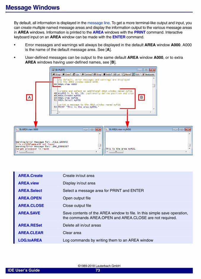
Message Windows
By default, all information is displayed in the message line. To get a more terminal-like output and input, you can create multiple named message areas and display the information output to the various message areas in AREA windows. Information is printed to the AREA windows with the PRINT command. Interactive keyboard input on an AREA window can be made with the ENTER command.
• Error messages and warnings will always be displayed in the default AREA window A000. A000 is the name of the default message area. See [A].
• User-defined messages can be output to the same default AREA window A000, or to extra AREA windows having user-defined names, see [B].
AREA.Create Create in/out area
AREA.view Display in/out area
AREA.Select Select a message area for PRINT and ENTER
AREA.OPEN Open output file
AREA.CLOSE Close output file
AREA.SAVE Save contents of the AREA window to file. In this simple save operation, the commands AREA.OPEN and AREA.CLOSE are not required.
AREA.RESet Delete all in/out areas
AREA.CLEAR Clear area
LOG.toAREA Log commands by writing them to an AREA window
A B
IDE User’s Guide 73 ©1989-2018 Lauterbach GmbH

Window Tracking
Windows may be coupled by a global reference indicator, generated either by the mouse position within a window or by the result of a search or go-to operation. The global reference indicator can be one of the following:
• The line number for text windows, see example 1.
• The address, see example 2.
• Or the absolute time, see example 3.
• Trace record numbers.
Window tracking is possible between different types of windows, like source text, analyzer listings or timing diagrams. Every window which is set to track mode by the option /Track will follow the global reference indicator.
Some windows are temporarily set to tracking when search functions are executed (e.g. the analyzer list window during a find operation).
Example 1 - Tracking in two text windows using the mouse: The cursor position of the mouse pointer [A] can be tracked in the other window [B], provided path and file name are identical in both windows.
Example 2 - Tracking by going to an address:
B Tracking pointer
A The Data.GOTO command is used to go to the address of func2b.
B In the List.auto window, the corresponding position is highlighted because of the use of the Track option.
A
B
B
A
IDE User’s Guide 74 ©1989-2018 Lauterbach GmbH

Example 3 - Tracking based on absolute time: After recording trace data, the same data is displayed in three different Trace.* windows. Each Trace.* window is opened with the Track option.
A By clicking inside the Trace.PROfileChart.sYmbol window, a fine blue graticule marks the cursor position. A tooltip displays more information about the selected position, including the absolute time, here 5.588s.
B A the same time, a fine blue vertical line highlights the corresponding position in the Trace.Chart.sYmbol window thanks to the Track option.
C The corresponding record is also highlighted in the Trace.List window, again thanks to the Track option.
A
B
C
IDE User’s Guide 75 ©1989-2018 Lauterbach GmbH

File and Folder Operations
TRACE32 provides standard operating system commands for fast execution of file and folder operations. The commands are implemented in the TRACE32 software, they don’t execute operating system commands on the host.
For information about wildcard characters and path prefixes supported with the file and folder handling commands, see “File Names”, page 45 and “Path Prefixes”, page 46.
ChDir Change directory
ComPare Compare files
COPY Copy file
DEL Delete file
DIR List subdirectories and files
DUMP Display binary file
EDIT Edit text file in the TRACE32 editor
FIND Find in text or binary file
LS Display directory
MKDIR Create directory
MV Rename file
PACK Compress file (with LZW algorithm)
PATCH Modify binary file
PATH Define search path
PEDIT <file> Open <file> with the PRACTICE script editor
PWD Change directory
REN Rename file
RM Delete file
RMDIR Delete directory
SETUP.EDITEXT Define an external editor
TAR Pack files into an archive without compression
TYPE Display text file
UNARchive Extract files from Linux and Microsoft libraries
UNPACK Expand packed file (with LZW algorithm)
UNZIP Expand GZIP archive file (with DEFLATE algorithm)
ZIP Compress files to GZIP archive (with DEFLATE algorithm)
IDE User’s Guide 76 ©1989-2018 Lauterbach GmbH

File Contents
TRACE32 provides a number of commands for writing data from TRACE32 to file and reading data from files. The following list is a selection of commands:
CLOSE Close file
Data.WRITESTRING Write string from target memory to PRACTICE file
OPEN Open data file
READ Read data from file
Var.EXPORT Export variables in CSV format to file
Var.WRITE Write variables to file
WinPrint Print window
WRITE Write data to file
WRITEB Write binary data to file
APPEND Append data to file
IDE User’s Guide 77 ©1989-2018 Lauterbach GmbH

Encrypt/Execute Encrypted Files
You can encrypt PRACTICE script files (*.cmm) and PER files (*.per) in TRACE32 with user-defined keys. This encryption is useful if you do not want other people to view your source code in human readable form.
Other users can execute any encrypted file (*.cmm or *.per) in TRACE32, provided the encrypted file is unlocked with the same key you have defined for this file.
PRACTICE script files (*.cmm):
PER files (peripheral register definition file, *.per):
Text and binary files:
NOTE: With the correct key, an encrypted file can be executed in TRACE32, but the source code itself remains encrypted.
ENCRYPTDO Encrypt a PRACTICE script file.
DODECRYPT Execute the encrypted PRACTICE script file.NOTE: The PRACTICE script source code itself remains encrypted, i.e. it is not human readable.
ENCRYPTPER Encrypt a PER file.
PER.viewDECRYPT Execute and view the encrypted PER file in a PER window. NOTE: The PER file source code itself remains encrypted, i.e. it is not human readable.
ENCRYPT Encrypt a text or binary file.
DECRYPT Decrypt the text or binary file. The text is displayed in human readable form again.
IDE User’s Guide 78 ©1989-2018 Lauterbach GmbH

Host Commands
Operations of the host system may be executed directly on the command line of TRACE32.
In this example, the TRACE32 commands and functions are formatted in bold. The host command is formatted in regular font.
OS.screen Execute host command
OS.Area Call host operating system with output in a TRACE32 AREA window
OS.Command Execute host command
OS.Window Call host operating system with output in a TRACE32 window
OS.Hidden Call host operating system without output
;list all PRACTICE script files (*.cmm) in the TRACE32 ~~/demo/arm/;folder and all subfolders
LOCAL &files
&files=OS.FILE.ABSPATH(~~/demo/arm/)+"*.cmm"
OS.Window dir /s &files
IDE User’s Guide 79 ©1989-2018 Lauterbach GmbH

Printer Operations
You can send every window or the complete screen from TRACE32 to:
• The default printer
• The clipboard
• A file
• The default AREA window A000
For each output medium, you can define the format, e.g. font, font size, ASCII, enhanced ASCII, XML, or a more complex format, like POSTSCRIPT or WORDSTAR. When printing to file, you can specify path and file name or browse for an existing file.
You have the following options to send information from TRACE32 to a printer or save TRACE32 windows to file:
• Choose File menu > Window Screenshot to File to capture the TRACE32 main window and all other TRACE32 windows displayed within the TRACE32 main window [A].
• Click the top left icon in any window to open the window manager menu [B].
- The Print option prints just the visible contents of the active window [C].
- The Print all option prints more than the visible contents of the active window [D].
• Use the TRACE32 command line and PRACTICE scripts (*.cmm); commands for printing and saving TRACE32 windows to file are listed in the table below.
• Extra commands are provided for saving the code coverage database and the instruction statistics database to XML files.
PRinTer.select Select printer type and output style
PRinTer.FILE Define file for single printer output and select output format for file (ASCII, CSC, XML, etc.)
PRinTer.OPEN Open file and re-route multiple printer outputs to this file
PRinTer.CLOSE Close file after multiple printer outputs
A
B
CD
IDE User’s Guide 80 ©1989-2018 Lauterbach GmbH

Examples:
PRinTer.EXPORT Export CSV-formatted printer output to file
PRinTer.HardCopy Print all windows on screen
PRinter.SIZE Define layout
PRinter.OFFSET Define left and top border
WinPRT <windowname> Prints just the visible contents of the active window
WinPrint.<command> The WinPrint pre-command prints more than the visible contents of the active window
ISTATistic.EXPORT Export instruction statistics to an XML file
COVerage.EXPORT Export code coverage information to an XML file
; example for print operationPRinTer.select IBM ; select IBM printerPRinter.SIZE 80. 65. ; select lines and columnsPRinter.OFFSET 5. 5. ; select borderWinPrint.Data.dump 0x0--0xfff ; print window
; example for copy to file operationPRinTer.FILE test.lst ; open file for printingWinPrint.Data.dump 0x0--0xfff ; print Data.dump window to filePRinTer.select IBM ; switch back to line printer
; example for generating a POSTSCRIPT filePRinTer.FILE test.ps PSPS12 ; open file for printing and select ; POSTSCRIPT, Portrait, ; Helvetica, 12cpiWinPrint.Data.dump 0x0--0xfff ; print Data.dump window to file
IDE User’s Guide 81 ©1989-2018 Lauterbach GmbH

System Setup and Configuration
Many system configuration options are set with the SETUP command. For more information refer to the “IDE Reference Guide” (ide_ref.pdf) and the manual of the devices (Emulator, Analyzer).
SETUP.ASCIITEXT Configure ASCII text display
SETUP.BAKfile Set backup file mode
SETUP.CClear Erase caches
SETUP.COLOR Configure colors
SETUP.DEVNAME Set logical device name
SETUP.DRV Send command to driver
SETUP.EXTension Set default file name extensions
SETUP.HOLDDIR Configure working directory
SETUP.ICONS Display icons in popup menus
SETUP.QUITDO Define quit PRACTICE file
SETUP.ReDraw Update whole screen
SETUP.RESTARTDO Define restart PRACTICE file
SETUP.SOUND Set sound generator mode
SETUP.STATistic Cache and memory usage
SETUP.TabSize Configure tab width
SETUP.TIMEFORM Select scientific time format
SETUP.URATE Limit window update rate
SETUP.WARNSTOP Configure PRACTICE stops
ZERO Set time reference
IDE User’s Guide 82 ©1989-2018 Lauterbach GmbH

Command Logging
Command inputs can be logged. The logging of the command input generates a file which has the structure of a PRACTICE script (*.cmm). This program can be edited and started with the DO command. The command log includes all commands entered in the command line and all mouse commands. Every operation on TRACE32 can be referred to a single-line command. The mouse click to a screen-based button will be stored as a single line command. Command inputs which lead to a syntax error are not logged.
To generate a command log, the log file must be opened first. Then all executed commands are written to this file. There is no limitation by an internal buffer size. The file can be viewed in a window, while it is being filled. By closing the file the logging process is terminated. Only one file may be opened at the same time. The logging may be interrupted temporarily by an OFF and ON sub-command.
LOG.OPEN Generate command LOG file and start logging.
LOG.CLOSE Terminate logging and close command log file.
LOG.type Show contents of the command LOG file
LOG.ON Resume logging
LOG.OFF Pause logging
LOG.toAREA Log commands by writing them to an AREA window
LOG.OPEN...
LOG.OFF...
LOG.ON...LOG.CLOSE
; opens file 't32.log'; commands are logged
; switch off log function; commands are not logged
; switch on log function; commands are logged; close file and terminate log function
IDE User’s Guide 83 ©1989-2018 Lauterbach GmbH

Dialog Programming
The DIALOG command group and its dialog elements, such as buttons and edit boxes, are used to create and display custom dialog boxes. They are normally used to increase the flexibility of PRACTICE script files by providing user selectable actions or requesting information from the user, e.g. actual firmware file name for the flash process.
In this section:
• Dialog Syntax and File Types
• Comments in Dialogs
• Dialog Commands - an Overview
• Dialog Elements - an Overview
• Return Values and Labels
• PRACTICE Macros in Dialog Programming
For information about built-in and user-defined icons, see “Built-in Icons and Icon Library”, page 111.
Dialog Syntax and File Types
The syntax of a dialog definition is line oriented. Blanks and empty lines can be inserted to structure and indent the dialog definition. Single and multi-line programs can be assigned to dialog elements.
Single-line scripts are enclosed in straight quotation marks "..."; multi-line scripts are enclosed in parentheses (...).
The opening parenthesis of a multi-line script must immediately follow after a dialog element. If an empty line is erroneously inserted after a dialog element, the TRACE32 message bar displays the error message nesting block open missing. This error message is displayed when you try to execute the defective dialog.
NOTE: Examples of dialog definitions reside in the directories:• ~~/demo/practice/dialogs
and• ~~/demo/analyzer/trigger
Single-line script Multi-line script
BUTTON "Click Me" "Data.List" BUTTON "Click Me" ( Data.List Register.view )
IDE User’s Guide 84 ©1989-2018 Lauterbach GmbH

There are two file types where you can store custom dialogs. The syntax slightly varies depending on the file type you have chosen:
1. Embedded in PRACTICE script files with the extension *.cmm. The dialog definition is placed in parentheses after the DIALOG command. See Example 1.
2. In extra files with the extension .dlg. They are called by the DIALOG.view command. See Example 2.
Example 1 - The dialog is embedded in a PRACTICE script file with the extension *.cmm:
Example 2 - The dialog is in an extra file with the extension .dlg:
LOCAL &file ;declare PRACTICE macro DIALOG.view ;start the dialog definition ( POS 1. 1. 15.myLabel: EDIT "" "" POSX 1. 6. BUTTON "[:edit]File" "DIALOG.SetFileW myLabel ~~~\*.cmm" POSY 1. DEFBUTTON "OK" "CONTinue" )STOP ;wait for the user's response to the dialog&file=DIALOG.STRing(myLabel) ;get return value of EDIT box by labelDIALOG.END
OPEN #1 &file /CreateWRITE #1 "Begin of file"CLOSE #1ENDDO
PRACTICE script file (*.cmm)
LOCAL &file
DIALOG.view dialog.dlg
STOP&file=DIALOG.STRing(LAB)DIALOG.END
OPEN #1 &file /CreateWRITE #1 "Begin of file"CLOSE #1ENDDO
Contents of dialog.dlg
POS 1. 1. 10.LAB: EDIT "" ""
POS 11. 1. 5.BUTTON "File"(
DIALOG.SetFileW LAB *.cmm)POS 1. 3. 5.DEFBUTTON "OK" "CONTinue"
IDE User’s Guide 85 ©1989-2018 Lauterbach GmbH

Comments in Dialogs
Comment lines start with a semicolon and must be placed in separate lines.
If a comment is erroneously placed in the same line as a dialog element, the TRACE32 message bar displays the error message no more arguments expected. This error message is displayed when you try to execute the defective dialog.
Correct comment position Wrong comment position
DIALOG.view( ;your comment ICON ":objects" ;your comment TEXT "Hello World!")
DIALOG.view( ICON ":objects" ;your comment TEXT "Hello World!" ;your comment)
IDE User’s Guide 86 ©1989-2018 Lauterbach GmbH

Dialog Commands
Using the DIALOG command group you can (a) control your custom dialogs, (b) control the behavior of an individual dialog element on a custom dialog, (c) interact with the file system of the operating system (OS), and (d) display OS message boxes.
Control Your Custom Dialogs
Control Behavior of Individual Dialog Elements on Custom Dialogs
Interact with the File System
Display Message Boxes of the Operating System
DIALOG.AREA Adds an output AREA to a custom dialog
DIALOG.END Close the dialog window
DIALOG.Program Editor to write a custom dialog.
DIALOG.ReProgram Dialog programming
DIALOG.SELect Programmatically focus on this dialog
DIALOG.view Show dialog window
DIALOG.Disable Disable dialog elements
DIALOG.Enable Enable dialog elements
DIALOG.EXecute Execute a dialog button
DIALOG.Set Set the value of a dialog element
DIALOG.DIR Display a folder picker dialog and pass the return value of the selected folder to your PRACTICE script (*.cmm).
DIALOG.File Open an OS file dialog and pass the name of the selected file to your PRACTICE script (*.cmm).
DIALOG.SetDIR Browse for folder. The selected folder an be displayed in the EDIT box of your custom dialog.
DIALOG.SetFile Open an OS file dialog and pass the name of the selected file to a custom dialog. The selected file can be displayed in the EDIT box of your custom dialog.
DIALOG.MESSAGE Create dialog box with an information icon (OK button only)
DIALOG.OK Create dialog box with an exclamation mark (OK button only)
DIALOG.YESNO Create dialog box with YES and NO buttons
IDE User’s Guide 87 ©1989-2018 Lauterbach GmbH

Dialog Elements
Dialog elements allow you to place edit boxes, buttons, drop-down lists, etc. on your custom dialogs. TRACE32 provides the following dialog elements for programming custom dialogs:
BAR Define a progress bar
BOX ["<text>"] Define a decorative border
BUTTON "<text>" [<command>] Define a button
CHECKBOX "<text>" [<command>] Define a check box
CHOOSEBOX "<text>" [<command>] Define a choose box
CLOSE [<command>] Catch window close
COMBOBOX "<list_items>" [<command>] Define a combo box
DEFBUTTON "<text>" [<command>] Define the default button
DEFCOMBOBOX "<list_items>" [<command>] Define a combo box
DEFEDIT "<initial_text>" [<command>] Define an edit control
DEFHOTCOMBOBOX "<list_items>" [<command>]
Define a default hot combo box
DEFHOTEDIT "<initial_text>" [<command>] Define a hot edit control
DEFMEDIT "<initial_text>" [<command>] Define a default multiline edit control
DLISTBOX "<list_items>" [<command>] Define a default list box
DYNAMIC "<initial_text>" [<command>] Define a dynamic, single-line area
DYNCOMBOBOX "<list_items>" [<command>] Define a dynamic combo box
DYNDEFCOMBOBOX "<list_items>" [<command>]
Define a default dynamic combo box
DYNDEFHOTCOMBOBOX "<list_items>" [<command>]
Define a dynamic default hot combo box
DYNHOTCOMBOBOX "<list_items>" [<command>]
Define a dynamic hot combo box
DYNLTEXT "<initial_text>" [<command>] Define a dynamic single-line text area in bold and large font size
DYNPULLDOWN "<list_items>" [<command>] Define a dynamic pull-down list
DYNTEXT "<initial_text>" [<command>] Define a dynamic, single-line text area in regular font size
EDIT "<initial_text>" [<command>] Define an edit control
HEADER "<text>" Define window header
HELP Define a help icon
HOTEDIT "<initial_text>" [<command>] Define a hot edit control
IDE User’s Guide 88 ©1989-2018 Lauterbach GmbH

HOTCOMBOBOX "<list_items>" [<command>] Define a hot combo box
ICON "<built_in_icon_name>" | "<user_defined_icon>"
New icon in top left corner of dialog
INFOTEXT "<msg_text>" [<formatting>] Define a multiline info text box on a dialog
LINE "<text>" Define a decorative line
LISTBOX "<list_items>" [<command>] Define a list box
LTEXT "<text>" Static, single-line text area in bold and large font size
MEDIT "<initial_text>" [<command>] Define a multiline edit control
MLISTBOX "<list_items>" [<command>] Define a multiline list box
NAME "<text>" Define an internal dialog name
POS <x> <y> <width> <height> Define position and size
POSX <inc> <width> <height> Define position and size on the x-axis
POSY <inc> <width> <height> Define position and size on the y-axis
PULLDOWN "<list_items>" [<command>] Define a static pull-down list
SPACE Define space
STATIC "<built_in_icon_name>" | "<user_defined_icon>"
Place an icon in a dialog
TEXT "<text>" Define a text item
TEXTBUTTON "<text>" [<command>] Define a flat button with text only
TREEBUTTON "" [<command>] Define a +/- toggle button
UPDATE ["<command_string>"] [<command>] Executes commands periodically
VLINE "" Define a decorative vertical line
IDE User’s Guide 89 ©1989-2018 Lauterbach GmbH

Return Values and Labels
Dialog elements, such as an EDIT box or a LISTBOX, can have a user-defined label in front of the command. Labels must start in the first column and are always followed by a colon. Together with the DIALOG.STRing() or DIALOG.STRing2() function, a label can be used to access the return value of a dialog element.
The return values of built-in dialog boxes, e.g. the DIALOG.YESNO message box or the DIALOG.DIR folder picker dialog, can be accessed with the ENTRY command. Here is an example of a simple “yesno” input:
LOCAL &retVal ;declare a PRACTICE macro
DIALOG.view ;start the dialog definition( POS 1.5 0.75 30.myLAB: EDIT "x" ""
POSX 1. 5. DEFBUTTON "OK" "CONTinue")STOP ;wait for the user's response to the dialog
&retVal=DIALOG.STRing(myLAB) ;get return value by label
DIALOG.ENDDIALOG.MESSAGE "The EDIT box contains the address &retVal"
LOCAL &result ;declare a PRACTICE macro
DIALOG.YESNO "Program FLASH Memory ?"ENTRY &result ;get return value of DIALOG.YESNO
IF !&result ENDDOELSE( ;your code...)
&retVal=DIALOG.STRing(<label>)
&retVal
ENTRY &<practice_macro>
IDE User’s Guide 90 ©1989-2018 Lauterbach GmbH

PRACTICE Macros inside Dialog Definitions
Two PRACTICE macros, highlighted in blue, are used in the following dialog definition. For activating PRACTICE macro expansion inside a DIALOG definition, the following prerequisites have to be fulfilled:
1. “(&” must be used - instead of just “(“
2. “(&” must begin in the first column of the line
ENTRY &flashno &default_flash_firmware_fileLOCAL &file &header_text&header_text="program dialog for "+FORMAT.Decimal(1,&flashno)&header_text="&header_text"+". flash"
DIALOG.view(&
HEADER "&header_text"POS 1. 1. 30.
LAB: EDIT "&default_flash_firmware_file" ""POS 31. 1. 5.BUTTON "File"(
DIALOG.SetFile LAB *.bin)POS 1. 3. 5.DEFBUTTON "OK" "CONTinue"
)STOP&file=DIALOG.STRing(LAB)PRINT "selected firmware file: &file"PRINT "for flash:"+FORMAT.Decimal(1,&flashno)DIALOG.ENDENDDO
IDE User’s Guide 91 ©1989-2018 Lauterbach GmbH

HELP System
In this section:
• Ways to Get Help
• Context-Sensitive Help
• Structure of the Help System
• Configure the Help System
• Recommendations for Choosing a PDF Viewer
• Bookmarks for Help Topics
• Troubleshooting the Help System
• Change the Installation Path of the PDF Files
Ways to Get Help
There are several methods to get help information:
• Help menu in the menu bar
• Context-sensitive help
• HELP via the TRACE32 command line
• The following HELP commands are available:
HELP.Bookmark Bookmark PDF files
HELP.checkUPDATE Enable the automatic help update via internet
HELP.command Command related support
HELP.FILTER Filtering all documents with the used hardware and RTOS
HELP.Find Full-text search across all help documents
HELP.Index Search within indexed terms, commands, functions
HELP.PDF Open PDF file in a PDF viewer
HELP.PICK Context-sensitive help
HELP.PRinT Print PDF files
HELP.Topics Display help content list
HELP.TREE Display command tree
IDE User’s Guide 92 ©1989-2018 Lauterbach GmbH

Context-Sensitive Help
You can call up the HELP window via the help key. On Windows, the help key is F1. The HELP window then displays information about the current context, with the current context being determined by the cursor position.
• To get context-sensitive help on a window or dialog, click the window or dialog, and then press F1.
• To get context-sensitive help for a command, type the command at the TRACE32 command line, append an empty space, and then press F1.
• To get context-sensitive help on an individual item such as a button, check box, or menu item, click the context help button on the toolbar (HELP.PICK).
• If an error occurs, a short error help message will be displayed. Press F1 to access the complete error help message in the error.pdf.
tbd.
F1
IDE User’s Guide 93 ©1989-2018 Lauterbach GmbH

Structure of the Help System
The TRACE32 help system is divided in two parts:
• The HELP window is used to navigate through the help files and to search for any topic.
• An external PDF viewer displays the selected topics.
New TRACE32 Releases [Software Releases 02/2016 and higher]
Your favorite PDF viewer: It takes only a few mouse-clicks to configure the TRACE32 help system to relay context-sensitive help calls to your favorite PDF viewer.
For a step-by-step procedure, see “Configure the Help System”, page 95.
Previous TRACE32 Releases
Alternate PDF viewers: TRACE32 relays context-sensitive help calls to a batch file, which then calls the desired topic in the PDF file. The script is a *.bat file under Windows, or an*.sh file under Linux and MacOS.
Acrobat Reader: TRACE32 communicates with the TRACE32 plug-in to jump directly to the desired topic in the PDF file.
TRACE32 Your favorite PDF Viewer
HELP window
SETUP.PDFViewer
TRACE32
HELP window
Alternate PDF Viewer
TRACE32
HELP window
Acrobat Reader
TRACE32 plug-in
IDE User’s Guide 94 ©1989-2018 Lauterbach GmbH

Configure the Help System[Recommendations] [Software Releases 02/2016 and higher]
This section describes how to proceed after you have successfully installed the TRACE32 software and the help system.
Upon completion of the installation:
• Each TRACE32 executable (t32m<architecture>.exe) provides the HELP window.
• The file help.t32, which has to be in the system path (e.g. c:\t32), enables all help functions in TRACE32, like context-sensitive help and full-text search. When TRACE32 is started, the file help.t32 is loaded. If not, you receive an error message, saying that the help.t32 file cannot be loaded.
• The PDF help files are in the subfolder pdf of the TRACE32 system path (e.g. c:\t32\pdf). This path can be changed in the config file.
Your next step:
• Configure the TRACE32 help system with a few mouse-clicks to display the PDF help files in your favorite PDF viewer; see step-by-step procedure below.
To configure the TRACE32 help system:
1. Choose Help menu > Setup PDF Viewer, or at the TRACE32 command line, type: SETUP.PDFViewer
The SETUP.PDFViewer dialog window opens.
2. Do one of the following:
- Click DETect if you want to use your default PDF viewer.The remaining input boxes are populated with the pre-configured command line parameters for the selected PDF viewer.
- Click browse if you want to user a PDF viewer other than the default, e.g. a portable PDF viewer.
IDE User’s Guide 95 ©1989-2018 Lauterbach GmbH

Then click preset to populate the remaining input boxes with the pre-configured command line parameters for the selected PDF viewer.
3. Click test to verify that the selected PDF viewer can be started from within TRACE32.
4. Click the remaining three test buttons to verify that your selected PDF viewer passes the following basic tests:
- The PDF viewer opens our test document on page 1.
- The PDF viewer jumps to a named destination on another page in the same test document.
- The PDF viewer prints our test document or opens the Print dialog.
5. If the selected PDF viewer has passed all tests, click Ok.
6. Optional test - online help call via the TRACE32 command line:
- Type the following command at the TRACE32 command line: List.Mix
- Add a space, and then press F1. Result: TRACE32 help system displays the description of the List.Mix command in your favorite PDF viewer.
Recommendations for Choosing a PDF Viewer
1. You should choose a PDF viewer for use with the TRACE32 help system that provides the following features:
- Tabbed document view for files opened via the command line.
- Command line argument for passing file names to the PDF viewer (e.g. debugger_arm.pdf).
- Command line argument for passing named destinations to the PDF viewer (e.g. line IDs).
- One and the same PDF viewer instance allows an unlimited number of context-sensitive jumps to named destinations within one and the same PDF file instance.
- A Back button that allows you to re-trace your navigation steps across PDF documents, and not just the navigation steps within the same PDF document.
- A PDF viewer that is quick to start.
2. Install the latest version of the PDF viewer, in which you want to display the files of the TRACE32 help system.
NOTE: You do not need to re-start TRACE32 because your settings take immediate effect.
IDE User’s Guide 96 ©1989-2018 Lauterbach GmbH

Bookmarks for Help Topics
In this section:
• Create Help Bookmarks
• Store and Load Help Bookmarks Manually
• Store and Load Help Bookmarks Automatically
Create Help Bookmarks
• Right-click any topic in the HELP window, and then select Toggle Bookmark.
- A green rectangle indicates the bookmarked help topic.
- The help bookmark itself is added to the Bookmark tab of the HELP window.
NOTE: Unsaved help bookmarks are only available during the current TRACE32 session.
If you want to re-use your help bookmarks in future sessions, remember to store your help bookmarks. See “Store and Load Help Bookmarks Automatically”, page 98.
IDE User’s Guide 97 ©1989-2018 Lauterbach GmbH

Store and Load Help Bookmarks Manually
Use the steps described below if you want to transfer your bookmarks from one computer to another computer.
To store help bookmarks:
1. On the Bookmark tab of the HELP window, click Store.
2. Enter a file name, and then click Save.The bookmarks displayed on the Bookmarks tab are saved as a PRACTICE script (*.cmm).
To load help bookmarks:
1. On the Bookmark tab of the HELP window, click Load.
2. Browse for the PRACTICE script (*.cmm) containing the bookmarks.
3. Click Open to load the help bookmarks into the Bookmark tab.
Store and Load Help Bookmarks Automatically
1. Close TRACE32.
2. Add the AutoSTOre command to your PRACTICE start-up script (*.cmm):
If the AutoSTOre command is already used in your start-up script, then add just the keyword HELP as shown in the example below.
3. Restart TRACE32.
The help bookmarks you create are now automatically stored when you close TRACE32. In addition, the bookmarks are automatically loaded back into the Bookmark tab of the HELP window when you start TRACE32 again.
This script line returns the path and file name where TRACE32 auto-stores your help bookmarks:
NOTE: Unsaved help bookmarks are only available during the current TRACE32 session.
AutoSTOre , HELP
AutoSTOre , HISTORY HELP
PRINT VERSION.ENVironment(AUTOSTORE)
IDE User’s Guide 98 ©1989-2018 Lauterbach GmbH

Troubleshooting the Help System[Software Releases 02/2016 and higher]
Loads only old Online Help
Verify if the file help.t32 is in the TRACE32 system path (by default c:\t32), and if you have rights to read this file.
Warning: Online help outdated, please upgrade via http://www.lauterbach.com/manual.html
Situation: The TRACE32 message line displays this warning message:
Cause: The TRACE32 help system is at least 2 software releases older than the TRACE32 executable (t32m<architecture>.exe).
Remedy:
1. Open the VERSION.ENVironment window, and then make a note of the paths shown in the lines SYS: and HELP:
2. Close TRACE32.
3. Download the zipped help system of the most recent TRACE32 software release from www.lauterbach.com/manual.html
4. Unzip the downloaded file.
5. Copy the pdf files to the HELP: folder.
6. Copy the help.t32 file to the SYS: folder, i.e. the TRACE32 system directory.
7. Restart TRACE32. The TRACE32 help system is now up to date again.
IDE User’s Guide 99 ©1989-2018 Lauterbach GmbH

Change the Installation Path of the PDF Files
The PDF files of the TRACE32 help system are installed to the TRACE32 system path, subfolder pdf. But sometimes it may be necessary to change this path - for example, if you want different TRACE32 installations to share the same HELP= path.
There are two possibilities to change the installation path for the PDF files:
1. Add it to the configuration file in the OS= part:
2. Set the environment variable “T32HELP” to the pdf installation path.
Winhelp Compatibility
To provide backward compatibility, the main Winhelp functions will still work.
On unix, additionally the environment variable “HHHOME” has to be set to the directory for hyperhelp (used for displaying the online manual).
Winhelp Files:
OS=SYS=c:\t32 ; system directory for TRACE32TMP=c:\tmp ; temporary directory for TRACE32HELP=c:\t32\pdf ; help directory for TRACE32 (default: c:\t32\pdf)
NOTE: The help directory for the PDF files can be a local folder or a network folder, e.g. g:\trace32-help-files\pdf
The file help.t32 must reside in the system directory. A network folder is not supported.
man.t32 Online manual (error messages)
man.* Online manual (WINDOWS help)
manhh.* Online manual (UNIX hyperhelp)
IDE User’s Guide 100 ©1989-2018 Lauterbach GmbH

Previous Releases - HELP System
Previous Releases - HELP Installation and Setup[up to Software Release 09/2015]
The installation of the help system is normally done by the software installation program, but here the complete online help installation is described if any problem occurred:
1. The HELP window is included in the TRACE32 executable (t32*.exe).
2. TRACE32 help loads the file help.t32, which has to be in the system path, e.g. C:\T32\Only this file enables all help functions in TRACE32, like context-sensitive help and full-text search.
3. Acrobat Reader should be installed on the computer, and to use the TRACE32 plug-in, the version has to be 4.0 or higher.
4. Acrobat loads the TRACE32 plug-in (trace32.api) which has to be in the “plug_ins” directory. If the plug-in is loaded correctly, you can find the menu entry About TRACE32 in the Help menu.
5. The PDF help files are in the TRACE32 system path in the subfolder “pdf”, e.g. “C:\T32\pdf”. This path can be changed in the config file.
6. On Unix you have to do manually:
The environment variable “ACROBAT_PATH” has to be set to the path where acroread is installed, Use the setenv command or add it to your .profile - file.
Copy the TRACE32 plug-in to the Acrobat plug_ins folder
Previous Releases - Configuring an Alternate PDF Viewer[only Software Releases 09/2014, 02/2015, and 09/2015]
By default, the help system of TRACE32 uses Adobe Reader as PDF viewer. But, as of the release in November 2014, the help system of TRACE32 supports any PDF viewer that can handle file names and named destinations.
Please consult the help of the PDF viewer you want to use about how to pass file name and named destination as command line arguments to that PDF viewer; for some examples, see below.
The following step-by-step procedure assumes that you have installed TRACE32 in the default system directory c:\t32 on Windows, or $HOME/t32 on Linux.
>setenv ACROBAT_PATH=/opt/Acrobat5
>cp cdrom/bin/suns/trace32.api /opt/Acrobat5/Reader/sparcsol/plug_ins/
IDE User’s Guide 101 ©1989-2018 Lauterbach GmbH

To configure an alternate PDF viewer for the help system of TRACE32:
1. Close TRACE32.
2. Create an OS environment variable called T32PDFVIEWER
3. Assign the following value to the variable:
- For Windows users: c:\t32\_pdfviewer.batThe resulting entry in the Windows Environment Variables dialog looks as follows:
- For Linux and Mac users: $HOME/t32/_pdfviewer.shThe resulting entry in the Linux $HOME/.profile file looks as follows:
4. To make the new OS environment variable and its value available to TRACE32, log out of your Windows or Linux session, and then log in again.
5. In the TRACE32 system directory, create the file _pdfviewer.bat or _pdfviewer.sh
6. For Linux users: Make sure that you have execute permission for the script file, e.g.chmod +x _pdfviewer.sh
7. Enter a script which calls the PDF viewer you want to use and passes file names and named destinations as arguments from TRACE32 to your PDF viewer:
- Examples for Windows users
- Example for Linux users
8. Start TRACE32.
9. To test the alternate online help call, type the following command at the TRACE32 command line:List.Mix
10. Add a space, and then press F1. Result: TRACE32 help system displays the description of the List.Mix command in your favorite PDF viewer.
Previous Releases - Examples for Windows and Linux Users[only Software Releases 09/2014, 02/2015, and 09/2015]
The argument %1 or ${1} in the script examples below takes the pdf file names, the argument %3 or ${3} takes the named destinations within a pdf file.
export T32PDFVIEWER=$HOME/t32/_pdfviewer.sh
IDE User’s Guide 102 ©1989-2018 Lauterbach GmbH

Examples for Windows Users
PDF-XChange Viewer:
SumatraPDF:
The caret sign ^ serves as a line continuation character in Windows batch files (*.bat). White space characters after ^ are NOT permissible.
Foxit Reader:
Adobe Acrobat X Pro:
Example for Linux Users
evince (as of version 3.x; earlier versions do not support the -n option):
evince or xpdf or Firefox: This Linux shell script displays the pdf of the TRACE32 help system in the first available pdf viewer:
@echo offset reader="C:\Program Files\Tracker Software\PDF Viewer\PDFXCview.exe"start "Launch PDF" %reader% /A nameddest=%3 %1
@echo offstart "Launch PDF" "C:\T32\bin\SumatraPDF.exe" ^ %1 ^ -nameddest %3 ^ -reuse-instance
@echo offset reader="C:\Program Files (x86)\Foxit Software\Foxit Reader\Foxit Reader.exe"start "Launch PDF" %reader% /A "nameddest=%3" %1
@echo offstart acrobat.exe /n /A "nameddest=%3" %1
#!/bin/bash/usr/bin/evince ${1} -n ${3} &
#!/bin/bash evince "${1}" -n ${3} || \xpdf -remote t32xpdf -raise "${1}" +${3} || \firefox file:///${1}#nameddest=${3} &
IDE User’s Guide 103 ©1989-2018 Lauterbach GmbH

The backslash \ serves as a line continuation character in Linux shell scripts (*.sh).
IDE User’s Guide 104 ©1989-2018 Lauterbach GmbH

Previous Releases - HELP Installation Problems[up to Software Release 09/2015]
Some common installation problems are described here.
Loads only old Online Help
Verify if help.t32 is in TRACE32 system path (by default c:\t32), and if you have rights to read this file.
Alternate Call for Adobe Reader [only Software Releases 09/2014, 02/2015, and 09/2015]
By default, the trace32.api file relays the call for a particular help topic from TRACE32 to Adobe Reader. However, if you encounter problems after updating your Adobe Reader version, you can bypass the trace32.api file with the code shown below. For a step-by-step procedure, see “Previous Releases - Configuring an Alternate PDF Viewer”, page 101.
Adobe Reader:
Acrobat does not start automatic
Reinstall Acrobat Reader, verify if everybody can write to Acrobat subfolder “plug_ins” – if not, copy “trace32.api” manually to this folder
Acrobat opens File, but does not jump to the right Chapter
Verify if there is a Acrobat menu entry “Help->About plug-ins->About Trace 32” – if not copy “trace32.api” to Acrobat subfolder “plug_ins”
Warning “Communication with Acrobat Reader failed” always when using the Help
Copy “trace32.api” to Acrobat subfolder “plug_ins”
Warning “Communication with Acrobat Reader failed” only at first Acrobat Startup
Acrobat starts too slow.
Good trick to improve Acrobat startup time is to delete never needed plug_ins:
rename folder “plug_ins” to “plug_ins_bak”
then create empty “plug_ins” folder and copy there only “trace32.api” and other really needed plug_ins
@echo offstart acrord32.exe /n /A "nameddest=%3" "%1"
IDE User’s Guide 105 ©1989-2018 Lauterbach GmbH

Warning “Please install Acrobat Reader to see pdf help files!”
This message is displayed if the Acrobat installation could not be found on windows systems. Download the Acrobat Reader software from www.adobe.com and install it.
If you installed Acrobat already and this message is displayed anyway, check if one of the following registry entries exist (execute regedit.exe):
• HKEY_LOCAL_MACHINE: SOFTWARE\\ Microsoft\\ Windows\\ CurrentVersion\\ App Paths\\ Acrobat.exe
• HKEY_LOCAL_MACHINE: SOFTWARE\\ Microsoft\\ Windows\\ CurrentVersion\\ App Paths\\ AcroRd32.exe
If none of these keys exist, remove your current installation and install it again. You can also start Acrobat manually before using the online help and ignore the error message.
If you have the rights and if you are skilled to change registry entries, you can add it manually. But you have to be sure what you are doing - changing registry entries can affect the whole behavior of the Windows system!
Add the key “AcroRd32.exe” as shown below, change the Acrobat installation where it is installed on your system.
Warning “Error occurred while trying to start Acrobat Reader!”
Check the registry entries as described above - check if the (Standard) entry is really the correct installation path
Warning “Acrobat Reader could not be started” (Unix only)
Check if environment variable “ACROBAT_PATH” is set correctly to the Acrobat installation path.
IDE User’s Guide 106 ©1989-2018 Lauterbach GmbH

InterCom
The InterCom system allows the exchange of data between different TRACE32 systems. The exchange can be based on TCP/IP or, if not possible, through files on a network drive. The destination system is defined by an InterCom name. This name is either the name and port number of a UDP port used by this TRACE32 system or a file name. Using TCP/IP for communication is preferred. This requires an entry in the 'config.t32' file of any participating TRACE32 system:
The following example uses TCP/IP for the cross tracking:
When multiple (PODBUS) systems are connected to ONE system controller, it is possible to select the different systems with an extended intercom address:
IC=NETASSISTPORT=20001
...
NOTE: If multiple TRACE32 systems are used on one host, the port numbers must differ!
emulator 1 emulator 2
Analyzer.XTrack ste:20002 Analyzer.XTrack ste:20001
debugger 1 (100) debugger 2 (010)
SYnch.Connect ste:20000.010 SYnch.Connect ste:20000.100
InterCom.Evaluate Evaluates InterCom
InterCom.execute Remote execute command line
InterCom.PING Test the InterCom system
InterCom.PipeCLOSE Close named pipe
InterCom.PipeOPEN Open named pipe
InterCom.PipeREAD Read from named pipe
InterCom.PipeWRITE Write to named pipe
TargetSystem.state Show overview of multicore system
IDE User’s Guide 107 ©1989-2018 Lauterbach GmbH

Version Management and Licensing
The VERSION.view window provides information about the TRACE32 software version and licenses as well as TRACE32 hardware and environment information.
1. To open the VERSION.view window, choose Help menu > About TRACE32.
2. For details, click the more buttons.
For more information on finding serial numbers, see ”Serial Numbers” (updates.pdf).
For more information on using license numbers, see ”The LICENSE Command” (updates.pdf).
The following commands are described in the ”IDE Reference Guide” (ide_ref.pdf).
VERSION.HARDWARE Displays the version of the used debug hardware
VERSION.SOFTWARE Displays detailed information about the used TRACE32 software
VERSION.view Displays window with version info
LICENSE.state Displays the currently used maintenance contract
LICENSE.List Displays all license information
LICENSE.UPDATE Updates the maintenance contract inside a debug cable
IDE User’s Guide 108 ©1989-2018 Lauterbach GmbH

Editing
The TRACE32 editor is primarily used to generate short files. The editor can handle multiple files in separate windows. Access to the same file is possible through multiple windows.
EDIT config.t32 ; edit one file
EDIT *.c ; edit one file with previous select; menu
EDIT test.txtEDIT test.txt
; open file and edit; make new window for the same file
EDIT.CLOSE Close a text file
EDIT.List List editor files
EDIT.LOAD Load text files
EDIT.OPEN Open a text file for editing
EDIT.QUIT Discard modifications
EDIT.SAVE Store a text file
IDE User’s Guide 109 ©1989-2018 Lauterbach GmbH

Icons
TRACE32 allows you to customize the user interface and add icons to your customized user interface. This chapter informs you about the supported icon types, tells you where you can add icons, and describes step-by-step how you can create your own icons.
TRACE32 supports two icon types:
• Built-in icons
• User-defined icons
Both icon types can be added to the following dialog, menu, and toolbar elements:
Icon-capable elements can be used in the following TRACE32 file types:
• PRACTICE script files (*.cmm)
• Menu files (*.men)
• Dialog files (*.dlg)
Which Icon Type Do You Need for Your Project?
You can choose built-in icons from the icon library. For more information, see “Built-in Icons and Icon Library”, page 111.
You can create your own, user-defined icons with the TRACE32 bitmap editor. For step-by-step instructions, see “Inserting a Placeholder for User-Defined Icons”, page 112.
BUTTON Define a button
DEFBUTTON Define the default button
DYNAMIC Define a dynamic, single-line area
ICON Define an icon for the top left corner of a dialog
MENUITEM Define an item in a menu, popup menu or a local button
STATIC Define a non-dynamic area in a dialog
TOOLITEM Define a button in the toolbar
BITMAPEDIT <file> Open the bitmap editor
IDE User’s Guide 110 ©1989-2018 Lauterbach GmbH

Built-in Icons and Icon Library
TRACE32 provides a number of built-in icons. You can easily include these built-in icons in icon-capable dialog, menu, and toolbar elements. Using the TRACE32 icon library, you can:
• Get an overview of all available icons
• Get the built-in name of each icon
To display the TRACE32 icon library:
1. Choose Misc menu > Tools > Display internal icon library.
2. Click any icon.The built-in icon name is displayed in the Icon name field.
3. Observe this syntax for built-in icons: "[:<built_in_icon_name>]<your_text>"
To try this script, simply copy it to a test.cmm file, and then run it in TRACE32 (See “How to...”).
DO "~~/demo/menu/internal_icons.cmm"
DIALOG.view(; Assigns the icon to BUTTON BUTTON "[:var]Any text" "Var.View")STOP DIALOG.END
IDE User’s Guide 111 ©1989-2018 Lauterbach GmbH

Inserting a Placeholder for User-Defined Icons
Icon-capable dialog, menu, and toolbar elements require an icon placeholder in the form of two square brackets [].
To insert an icon placeholder for a user-defined icon:
1. In TRACE32, open the file where you want to add an icon, e.g.:
2. Observe this syntax for the icon placeholder: "[]<your_text>"
Examples:
3. Click Save.
Next: “Drawing Icons”, page 113.
PEDIT ~~/demo/practice/dialogs/dialog_edit.cmm ;PRACTICE script file ;orMENU.Program ~~/demo/menu/demo.men ;menu file ;orDIALOG.Program <your_file>.dlg ;dialog file
;DIALOG element (*.dlg or *.cmm file)BUTTON "Cancel" "GOTO cancel"BUTTON "[]Cancel" "GOTO cancel"
;MENU element (*.men file)MENUITEM "Edit .c File..." "EDIT *.c"MENUITEM "[]Edit .c File..." "EDIT *.c"
IDE User’s Guide 112 ©1989-2018 Lauterbach GmbH

Drawing Icons
After inserting the icon placeholders (see previous section), you can open the file in the BITMAPEDIT window and draw an icon on the canvas.
To draw an icon:
1. Open your file in two TRACE32 editor windows.
- The first editor window contains the source code of your project.
- The second editor window, i.e. the BITMATEDIT window, provides the icon drawing tools.
Example:
A Opens the Preview Icon window.
B Bitmap format (For more information, see the BITMAPEDIT command.)
C Assign a color to a mouse button by clicking a color in the palette with that mouse button.
D The source code of an icon is inserted between the corresponding icon placeholder [] while you are drawing the icon.
E Up and down arrow buttons let you navigate from one icon or icon placeholder to the next.
PEDIT ~~/demo/practice/dialogs/dialog_edit.cmm ;1. editorBITMAPEDIT ~~/demo/practice/dialogs/dialog_edit.cmm ;2. editor ;orMENU.Program ~~/demo/menu/demo.men ;1. editorBITMAPEDIT ~~/demo/menu/demo.men ;2. editor ;orDIALOG.Program <file>.dlg ;1. editorBITMAPEDIT <file>.dlg ;2. editor
A A
E
C
B
D
A
IDE User’s Guide 113 ©1989-2018 Lauterbach GmbH

The same file should now be open in two TRACE32 editor windows.
2. In the BITMAPEDIT window, under Bitmap, click the up and down arrow to navigate to the icon placeholder you want [E].
3. From the color palette, choose the colors you want, and draw an icon.
4. When done, click Save.
5. Click in the window of the first editor: the PEDIT window or the MENU.Program window or the DIALOG.Program window. You are prompted to reload the file.
6. Click Yes to reload.
You are now ready to execute the file to view the finished icon.
• In the PEDIT window, click DO.
• In the MENU.Program window, click Compile.
• In the DIALOG.Program window, click Comp+Show.
IDE User’s Guide 114 ©1989-2018 Lauterbach GmbH

Interface
For more information about the configuration of the interface, see ”TRACE32 Installation Guide” (installation.pdf). Commands are described in the ”IDE Reference Guide” (ide_ref.pdf).
IFCONFIG.state Interface configuration
IFCONFIG.TEST Test interface function and speed
IFCONFIG.PROfile Display operation profiles
IDE User’s Guide 115 ©1989-2018 Lauterbach GmbH

Shortcuts
ALT+ Spacebar
Opens the window manager menu of the active window.
• Available for the TRACE32 window modes FDI and MTI.
• If the TRACE32 window mode is MDI, then the ALT+spacebar shortcut works only for windows preceded by the WinExt pre-command, e.g. WinExt.Register.view or WinExt.List
Alt+F4
• Closes the TRACE32 main window if no WinExt.<window> is selected.
• Closes the active WinExt.<window>. See also esc key.
Ctrl+F
Opens the Find dialog. TRACE32 searches in the active window.
Ctrl+F4
Closes the active window (i.e. windows without the WinExt. pre-command). See also esc key.
Ctrl+F6
Selects the next window (i.e. windows without the WinExt. pre-command).
Ctrl+S
Saves a file, e.g. a *.cmm file in the PRACTICE script editor PEDIT.
Ctrl+Z
Undo (in the PRACTICE script editor).
Ctrl+D and Ctrl+E
Ctrl+D disables the selected breakpoint.
Ctrl+E enables the selected breakpoint.
esc
Closes the active window - regardless of whether the active window is preceded by the WinExt. pre-command or not.
IDE User’s Guide 116 ©1989-2018 Lauterbach GmbH

F1
• To get context-sensitive help on a window or dialog, click the window or dialog, and then press F1.
• To get context-sensitive help for a command, type the command at the command line, append an empty space, and then press F1.
Shift+Tab
Navigate back through the softkeys of a command group:
1. At the command line, type for example: Data.LOAD.
2. Press Shift+Tab to navigate back through the softkeys.
(Alternatively, click .)
Tab and Tab Completion for Commands
(A) Navigate forward through the softkeys of a command group:
1. At the command line, type for example: Data.
2. Press Tab repeatedly to navigate forward through the softkeys.
(Alternatively, click .)
(B) Access the list of PRACTICE functions:
1. At the command line, type: PRINT or Data.Print
2. Type the first few letters of the PRACTICE function you want, e.g. ad
3. Press Tab repeatedly to cycle through the list of matching PRACTICE functions.
F2 Single step
F3 Step over function call or subroutines
F4 Step Diverge Path: Leave loops, go till something new happens.
F5 Go return / Go to the last instruction
F6 Go up / return to the caller function
F7 Go / Start real-time execution
F8 Break / Stop real-time execution
F9 Toggle between the debug modes HLL and MIX
Up and down arrow keys
Go up / down in the command line history.
IDE User’s Guide 117 ©1989-2018 Lauterbach GmbH

(C) Cycle through the list of symbols:
1. At the command line, type for example: List.Mix
2. Press Tab repeatedly to cycle through the list of recently used symbols.
- Type the first few letters of the symbol you want.
- Press Tab repeatedly to cycle through the list of matching symbols.
(D) Complete a command:
• At the command line, type for example symb and then press Tab. TRACE32 completes symb to the command sYmbol
(E) Display suggestions for completing a command:
1. At the command line, type for example tr and then press Tab. TRACE32 suggests TrBus | TrOnchip | Trace | TRANSlation
2. Press Tab repeatedly to cycle through the list of matching commands.
Pause / Break
Moves the insertion point from any TRACE32 window back to the TRACE32 command line.
IDE User’s Guide 118 ©1989-2018 Lauterbach GmbH
Related Documents


