ADVANCED MANUAL ID-51A ID-51E VHF/UHF TRANSCEIVER TROUBLESHOOTING 15 REPEATER AND DUPLEX OPERATIONS 14 PRIORITY WATCH 13 SCAN OPERATION 12 MEMORY OPERATION 11 VOICE MEMORY FUNCTION 10 GPS OPERATION 9 D-STAR OPERATION <ADVANCED> 8 D-STAR OPERATION <BASIC> 7 D-STAR INTRODUCTION 6 BC RADIO OPERATION 5 BASIC OPERATION 4 BATTERY CHARGING 3 PANEL DESCRIPTION 2 USING A MICROSD CARD 1 ACCESSORY ATTACHMENT 16 MENU SCREEN 17 OTHER FUNCTIONS 18 OPTIONS 19 SPECIFICATIONS INDEX INTRODUCTION To update the repeater list, click here! Instructions for advanced operations and additional details are described in this manual. See the Basic manual to begin D-STAR, especially for new users. INDEX FOR MENU ITEMS

Welcome message from author
This document is posted to help you gain knowledge. Please leave a comment to let me know what you think about it! Share it to your friends and learn new things together.
Transcript
ADVANCED MANUAL
ID-51A
ID-51E
VHF/UHF TRANSCEIVER
TROUBLESHOOTING
15 REPEATER AND DUPLEX OPERATIONS
14 PRIORITY WATCH
13 SCAN OPERATION
12 MEMORY OPERATION
11 VOICE MEMORY FUNCTION
10 GPS OPERATION
9 D-STAR OPERATION <ADVANCED>
8 D-STAR OPERATION <BASIC>
7 D-STAR INTRODUCTION
6 BC RADIO OPERATION
5 BASIC OPERATION
4 BATTERY CHARGING
3 PANEL DESCRIPTION
2 USING A MICROSD CARD
1 ACCESSORY ATTACHMENT
16 MENU SCREEN
17 OTHER FUNCTIONS
18 OPTIONS
19 SPECIFICATIONS
INDEX
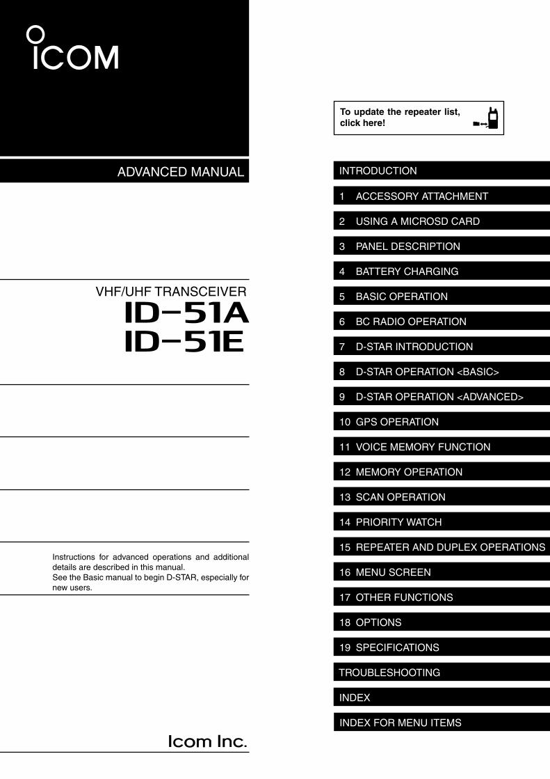
INTRODUCTION
To update the repeater list,
click here!
Instructions for advanced operations and additional details are described in this manual.See the Basic manual to begin D-STAR, especially for new users.
INDEX FOR MENU ITEMS
i
INTRODUCTION
Icom, Icom Inc. and the Icom logo are registered trademarks of Icom Incorporated (Japan) in Japan, the United States, the United Kingdom, Germany, France, Spain, Russia, Australia, New Zealand, and/or other countries.Adobe, Acrobat, and Reader are either registered trademarks or trademarks of Adobe Systems Incorporated in the United States and/or other countries.All other products or brands are registered trademarks or trademarks of their respective holders.
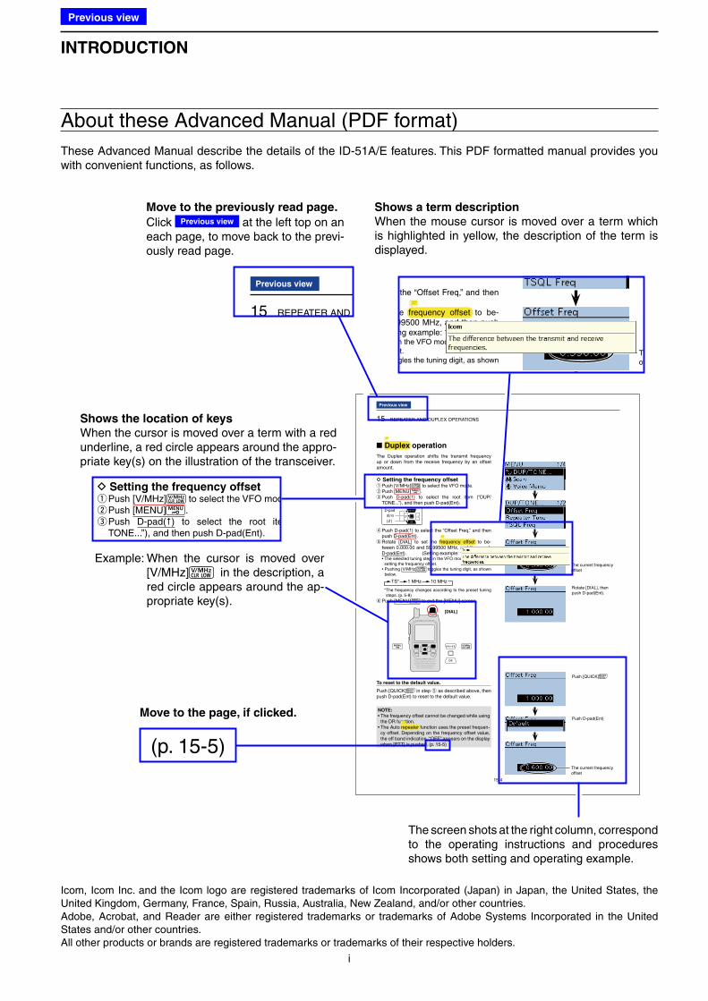
About these Advanced Manual (PDF format)
These Advanced Manual describe the details of the ID-51A/E features. This PDF formatted manual provides you with convenient functions, as follows.
15 REPEATER AND DUPLEX OPERATIONS
15-4
Duplex operation
The Duplex operation shifts the transmit frequency up or down from the receive frequency by an offset amount.
D Setting the frequency offset qPush [V/MHz] to select the VFO mode. wPush [MENU] . e Push D-pad(�) to select the root item (“DUP/TONE...”), and then push D-pad(Ent).
D-pad
( )
(Ent)
r Push D-pad(�) to select the “Offset Freq,” and then push D-pad(Ent). t Rotate [DIAL] to set the frequency offset to be-tween 0.000.00 and 59.99500 MHz, and then push D-pad(Ent). (Setting example: 1.000.00 MHz)
• The selected tuning step in the VFO mode is used when setting the frequency offset.
• Pushing [V/MHz] toggles the tuning digit, as shown below.
TS* 1 MHz 10 MHz
* The frequency changes according to the preset tuning steps. (p. 5-8)
y Push [MENU] to exit the [MENU] screen.
To reset to the default value.
Push [QUICK] in step t as described above, then push D-pad(Ent) to reset to the default value.
The current frequency offset
Rotate [DIAL], then push D-pad(Ent).
Push [QUICK]
Push D-pad(Ent)
[DIAL]
The current frequency offset
NOTE:
• The frequency offset cannot be changed while using the DR function.
• -cy offset. Depending on the frequency offset value, the off band indication, “OFF,” appears on the display when [PTT] is pushed. (p. 15-5)
Previous view
The Auto repeater function uses the preset frequen
Example: When the cursor is moved over [V/MHz] in the description, a red circle appears around the ap-propriate key(s).
(p. 15-5)
Move to the page, if clicked.
The screen shots at the right column, correspond to the operating instructions and procedures shows both setting and operating example.
select the “Offset Freq,” and then
the frequency offset to be-59.99500 MHz, and then push
(Setting example: 1.000.00 MHz)step in the VFO mode is used when
setting the frequency offset.toggles the tuning digit, as shown
The current frequency offset
Shows a term description
When the mouse cursor is moved over a term which is highlighted in yellow, the description of the term is displayed.
15 REPEATER AND DUPLEX OPERA
Previous view
Move to the previously read page.
Click Previous view at the left top on an each page, to move back to the previ-ously read page.
Shows the location of keys
When the cursor is moved over a term with a red underline, a red circle appears around the appro-priate key(s) on the illustration of the transceiver.
D Setting the frequency offset qPush [V/MHz] to select the VFO mode wPush [MENU] . e Push D-pad(�) to select the root item TONE...”), and then push D-pad(Ent).
Previous view
ii
INTRODUCTION
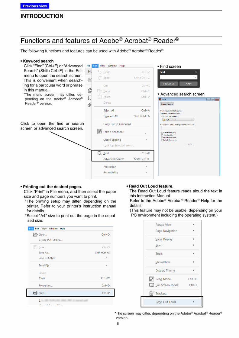
Functions and features of Adobe® Acrobat® Reader®
The following functions and features can be used with Adobe® Acrobat® Reader®.
• Keyword search
Click “Find” (Ctrl+F) or “Advanced Search” (Shift+Ctrl+F) in the Edit menu to open the search screen.
This is convenient when search-ing for a particular word or phrase in this manual.
* The menu screen may differ, de-pending on the Adobe® Acrobat®
Reader® version.
• Find screen
• Advanced search screen
Click to open the find or search screen or advanced search screen.
• Printing out the desired pages.
Click “Print” in File menu, and then select the paper size and page numbers you want to print.
* The printing setup may differ, depending on the printer. Refer to your printer’s instruction manual for details.
* Select "A4" size to print out the page in the equal-ized size.
• Read Out Loud feature.
The Read Out Loud feature reads aloud the text in this Instruction Manual.
Refer to the Adobe® Acrobat® Reader® Help for the details.
( This feature may not be usable, depending on your PC environment including the operating system.)
* The screen may differ, depending on the Adobe® Acrobat® Reader® version.
Previous view
1-1
Section 1 ACCESSORY ATTACHMENT
■ Antenna .............................................................................. 1-2
■ Battery pack ....................................................................... 1-2
■ Belt clip ............................................................................... 1-3
■ Hand strap .......................................................................... 1-3
Previous view
1 ACCESSORY ATTACHMENT
1-2
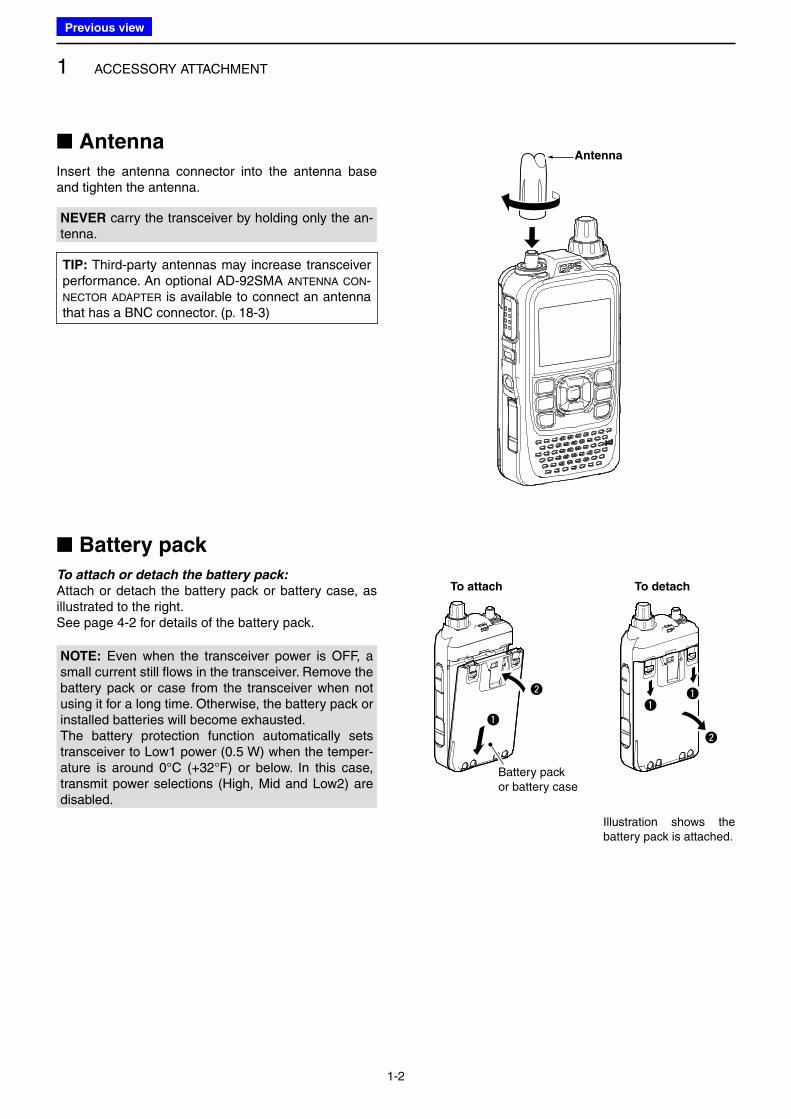
■ Antenna
Insert the antenna connector into the antenna base and tighten the antenna.
■ Battery pack
To attach or detach the battery pack:
Attach or detach the battery pack or battery case, as illustrated to the right.See page 4-2 for details of the battery pack.
To attach To detach
q
w qq
w
Antenna
Battery pack or battery case
Illustration shows the battery pack is attached.
NOTE: Even when the transceiver power is OFF, a small current still flows in the transceiver. Remove the battery pack or case from the transceiver when not using it for a long time. Otherwise, the battery pack or installed batteries will become exhausted.The battery protection function automatically sets transceiver to Low1 power (0.5 W) when the temper-ature is around 0°C (+32°F) or below. In this case, transmit power selections (High, Mid and Low2) are disabled.
TIP: Third-party antennas may increase transceiver performance. An optional AD-92SMA ANTENNA CON-
NECTOR ADAPTER is available to connect an antenna that has a BNC connector. (p. 18-3)
NEVER carry the transceiver by holding only the an-tenna.
Previous view
1 ACCESSORY ATTACHMENT
1-3
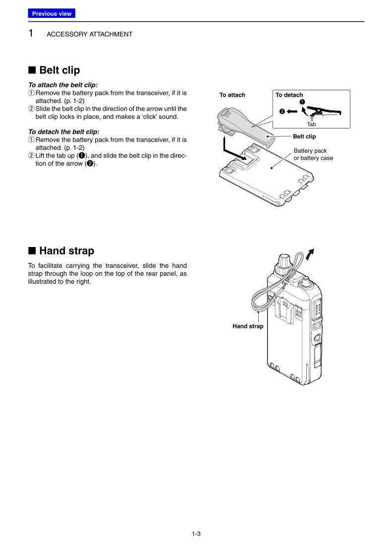
■ Belt clip
To attach the belt clip:
q Remove the battery pack from the transceiver, if it is attached. (p. 1-2) w Slide the belt clip in the direction of the arrow until the belt clip locks in place, and makes a ‘click’ sound.
To detach the belt clip:
q Remove the battery pack from the transceiver, if it is attached. (p. 1-2) w Lift the tab up (q), and slide the belt clip in the direc-tion of the arrow (w).
■ Hand strap
To facilitate carrying the transceiver, slide the hand strap through the loop on the top of the rear panel, as illustrated to the right.
Hand strap
q
w
Tab
Belt clip
To attach To detach
Battery pack or battery case
Previous view
2-1
Section 2 USING A microSD CARD
■ About the microSD card ..................................................... 2-2
■ Saving data onto the microSD card .................................... 2-2
■ Inserting the microSD card ................................................. 2-3
D Formatting the microSD card ......................................... 2-4
■ Removing the microSD card ............................................... 2-5
■ Saving data onto a microSD card ....................................... 2-6
■ Saving with a different file name ......................................... 2-8
■ Loading the saved data files that are on the microSD card.. 2-10
■ Backing up the data stored on the microSD card onto a PC .. 2-12
D About the microSD card’s folder ................................... 2-12
D Making a backup file on your PC .................................. 2-13
■ Importing or Exporting a CSV format file .......................... 2-14
D Importing ...................................................................... 2-14
D Exporting ...................................................................... 2-15
Previous view
2 USING A microSD CARD
2-2
■ About the microSD card
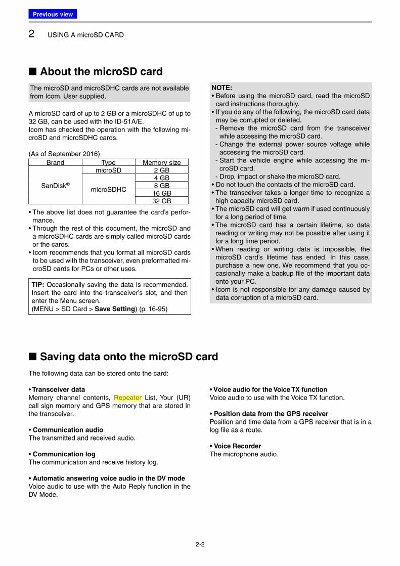
The microSD and microSDHC cards are not available from Icom. User supplied.
A microSD card of up to 2 GB or a microSDHC of up to 32 GB, can be used with the ID-51A/E.Icom has checked the operation with the following mi-croSD and microSDHC cards.
(As of September 2016)
Brand Type Memory size
SanDisk®
microSD 2 GB
microSDHC
4 GB8 GB16 GB32 GB
• The above list does not guarantee the card’s perfor-mance.
• Through the rest of this document, the microSD and a microSDHC cards are simply called microSD cards or the cards.
• Icom recommends that you format all microSD cards to be used with the transceiver, even preformatted mi-croSD cards for PCs or other uses.
The following data can be stored onto the card:
• Transceiver data
Memory channel contents, Repeater List, Your (UR) call sign memory and GPS memory that are stored in the transceiver.
• Communication audio
The transmitted and received audio.
• Communication log
The communication and receive history log.
• Automatic answering voice audio in the DV mode
Voice audio to use with the Auto Reply function in the DV Mode.
• Voice audio for the Voice TX function
Voice audio to use with the Voice TX function.
• Position data from the GPS receiver
Position and time data from a GPS receiver that is in a log file as a route.
• Voice Recorder
The microphone audio.
■ Saving data onto the microSD card
NOTE:
• Before using the microSD card, read the microSD card instructions thoroughly.
• If you do any of the following, the microSD card data may be corrupted or deleted.
- Remove the microSD card from the transceiver while accessing the microSD card.
- Change the external power source voltage while accessing the microSD card.
- Start the vehicle engine while accessing the mi-croSD card.
- Drop, impact or shake the microSD card.• Do not touch the contacts of the microSD card.• The transceiver takes a longer time to recognize a
high capacity microSD card.• The microSD card will get warm if used continuously
for a long period of time.• The microSD card has a certain lifetime, so data
reading or writing may not be possible after using it for a long time period.
• When reading or writing data is impossible, the microSD card’s lifetime has ended. In this case, purchase a new one. We recommend that you oc-casionally make a backup file of the important data onto your PC.
• Icom is not responsible for any damage caused by data corruption of a microSD card.
TIP: Occasionally saving the data is recommended. Insert the card into the transceiver’s slot, and then enter the Menu screen.(MENU > SD Card > Save Setting) (p. 16-95)
Previous view
Icom
ハイライト表示
Radio systems that receive incoming signals and retransmit them to extend the communication area. Normally put on geographically high locations for VHF/UHF radios.
2 USING A microSD CARD
2-3
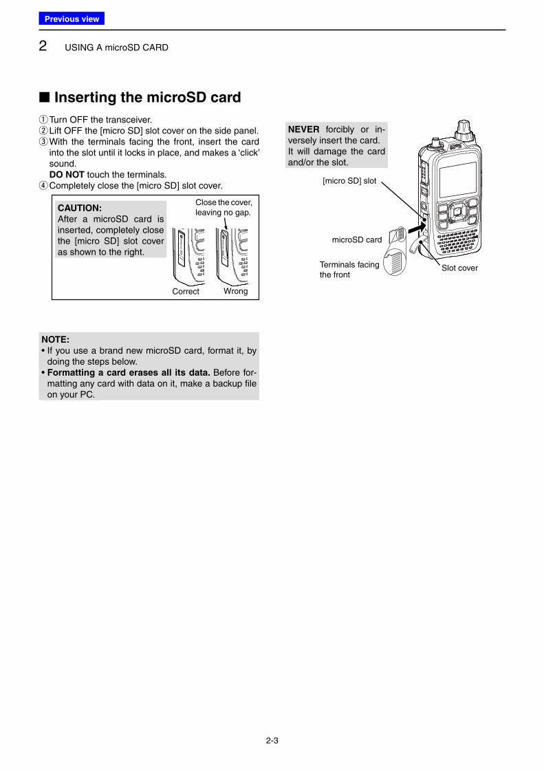
qTurn OFF the transceiver. w Lift OFF the [micro SD] slot cover on the side panel. e With the terminals facing the front, insert the card into the slot until it locks in place, and makes a ‘click’ sound.
DO NOT touch the terminals. rCompletely close the [micro SD] slot cover.
CAUTION:
After a microSD card is inserted, completely close the [micro SD] slot cover as shown to the right.
WrongCorrect
Close the cover, leaving no gap.
Terminals facing the front
microSD card
[micro SD] slot
■ Inserting the microSD card
Slot cover
NEVER forcibly or in-versely insert the card.It will damage the card and/or the slot.
NOTE:
• If you use a brand new microSD card, format it, by doing the steps below.
• Formatting a card erases all its data. Before for-matting any card with data on it, make a backup file on your PC.
Previous view
2 USING A microSD CARD
2-4
■ Inserting the microSD card (Continued)
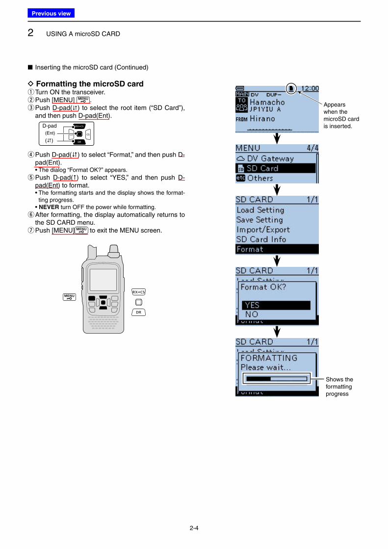
D Formatting the microSD card qTurn ON the transceiver. wPush [MENU] . e Push D-pad() to select the root item (“SD Card”), and then push D-pad(Ent).
D-pad
(�)
(Ent)
r Push D-pad() to select “Format,” and then push D-pad(Ent).
• The dialog “Format OK?” appears.
t Push D-pad() to select “YES,” and then push D-pad(Ent) to format.
• The formatting starts and the display shows the format-ting progress.
• NEVER turn OFF the power while formatting.
y After formatting, the display automatically returns to the SD CARD menu. u Push [MENU] to exit the MENU screen.
Appears when the microSD card is inserted.
Shows the formatting progress
Previous view
2 USING A microSD CARD
2-5
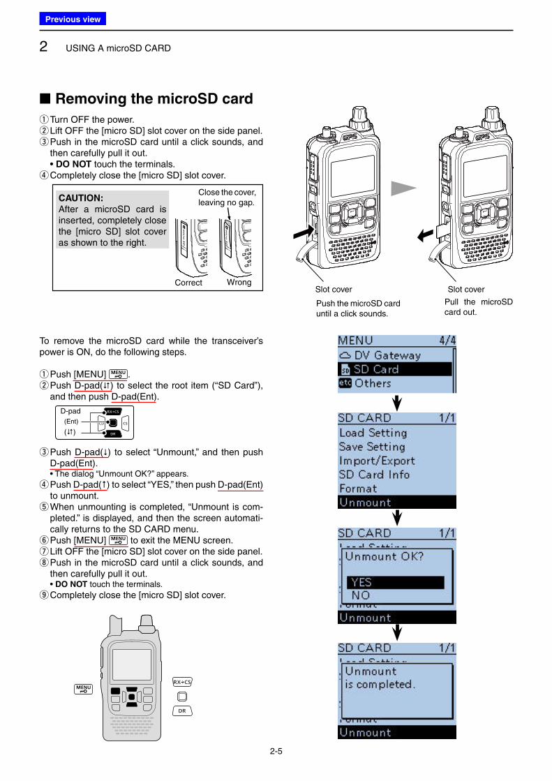
■ Removing the microSD card
qTurn OFF the power. w Lift OFF the [micro SD] slot cover on the side panel. e Push in the microSD card until a click sounds, and then carefully pull it out.
• DO NOT touch the terminals. rCompletely close the [micro SD] slot cover.
CAUTION:
After a microSD card is inserted, completely close the [micro SD] slot cover as shown to the right.
WrongCorrect
Close the cover, leaving no gap.
To remove the microSD card while the transceiver’s power is ON, do the following steps.
qPush [MENU] . w Push D-pad() to select the root item (“SD Card”), and then push D-pad(Ent).
D-pad
(�)
(Ent)
e Push D-pad() to select “Unmount,” and then push D-pad(Ent).
• The dialog “Unmount OK?” appears.
r Push D-pad() to select “YES,” then push D-pad(Ent) to unmount. t When unmounting is completed, “Unmount is com-pleted.” is displayed, and then the screen automati-cally returns to the SD CARD menu. y Push [MENU] to exit the MENU screen. u Lift OFF the [micro SD] slot cover on the side panel. i Push in the microSD card until a click sounds, and then carefully pull it out.
• DO NOT touch the terminals.
oCompletely close the [micro SD] slot cover.
Slot cover Slot cover
Push the microSD card until a click sounds.
Pull the microSD card out.
Previous view
2 USING A microSD CARD
2-6
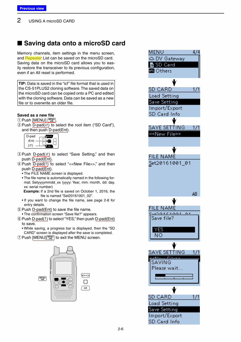
Memory channels, item settings in the menu screen, and Repeater List can be saved on the microSD card.Saving data on the microSD card allows you to eas-ily restore the transceiver to its previous configuration, even if an All reset is performed.
TIP: Data is saved in the “icf” file format that is used in the CS-51PLUS2 cloning software. The saved data on the microSD card can be copied onto a PC and edited with the cloning software. Data can be saved as a new file or to overwrite an older file.
Saved as a new file
qPush [MENU] . w Push D-pad() to select the root item (“SD Card”), and then push D-pad(Ent).
D-pad
(�)
(Ent)
e Push D-pad() to select “Save Setting,” and then push D-pad(Ent). r Push D-pad() to select “<<New File>>,” and then push D-pad(Ent).
• The FILE NAME screen is displayed. • The file name is automatically named in the following for-
mat; Setyyyymmdd_xx (yyyy: Year, mm: month, dd: day, xx: serial number)Example: If a 2nd file is saved on October 1, 2016, the
file is named “Set20161001_02”. • If you want to change the file name, see page 2-8 for
entry details.
tPush D-pad(Ent) to save the file name. • The confirmation screen “Save file?” appears.
y Push D-pad() to select “YES,” then push D-pad(Ent) to save.
• While saving, a progress bar is displayed, then the “SD CARD” screen is displayed after the save is completed.
u Push [MENU] to exit the MENU screen.
■ Saving data onto a microSD card
Previous view
Icom
ハイライト表示
Radio systems that receive incoming signals and retransmit them to extend the communication area. Normally put on geographically high locations for VHF/UHF radios.
2 USING A microSD CARD
2-7
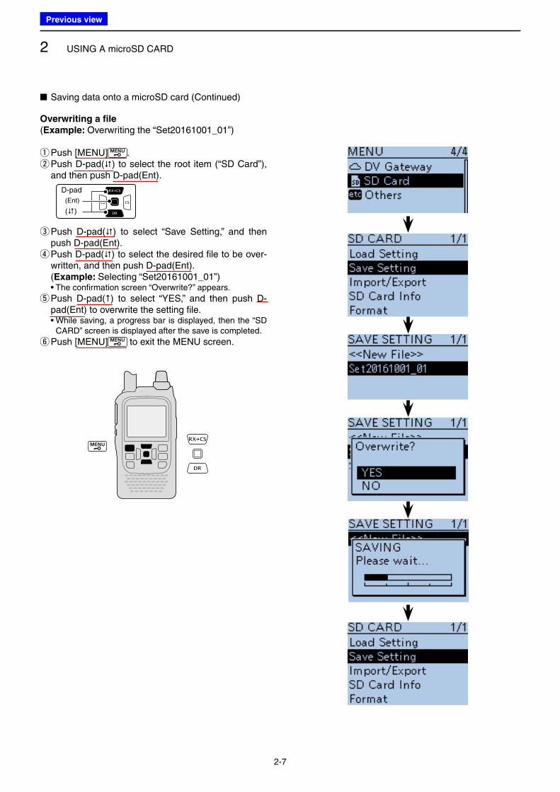
■ Saving data onto a microSD card (Continued)
Overwriting a file
(Example: Overwriting the “Set20161001_01”)
qPush [MENU] . w Push D-pad() to select the root item (“SD Card”), and then push D-pad(Ent).
D-pad
(�)
(Ent)
e Push D-pad() to select “Save Setting,” and then push D-pad(Ent). r Push D-pad() to select the desired file to be over-written, and then push D-pad(Ent).
(Example: Selecting “Set20161001_01”) • The confirmation screen “Overwrite?” appears.
t Push D-pad() to select “YES,” and then push D-pad(Ent) to overwrite the setting file.
• While saving, a progress bar is displayed, then the “SD CARD” screen is displayed after the save is completed.
y Push [MENU] to exit the MENU screen.
Previous view
2 USING A microSD CARD
2-8
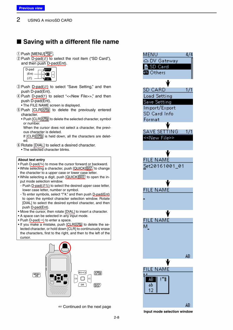
qPush [MENU] . w Push D-pad() to select the root item (“SD Card”), and then push D-pad(Ent).
D-pad
(�)
(Ent)
e Push D-pad() to select “Save Setting,” and then push D-pad(Ent). r Push D-pad() to select “<<New File>>,” and then push D-pad(Ent).
• The FILE NAME screen is displayed.
t Push [CLR] to delete the previously entered character.
• Push [CLR] to delete the selected character, symbol or number. When the cursor does not select a character, the previ-ous character is deleted. If [CLR] is held down, all the characters are delet-ed.
yRotate [DIAL] to select a desired character. • The selected character blinks.
■ Saving with a different file name
Input mode selection window
About text entry
• Push D-pad() to move the cursor forward or backward.• While selecting a character, push [QUICK] to change
the character to a upper case or lower case letter.• While selecting a digit, push [QUICK] to open the in-
put mode selection window. - Push D-pad() to select the desired upper case letter,
lower case letter, number or symbol. - To enter symbols, select “!”#,” and then push D-pad(Ent)
to open the symbol character selection window. Rotate [DIAL] to select the desired symbol character, and then push D-pad(Ent).
• Move the cursor, then rotate [DIAL] to insert a character.• A space can be selected in any input mode.• Push D-pad() to enter a space.• If you make a mistake, push [CLR] to delete the se-
lected character, or hold down [CLR] to continuously erase the characters, first to the right, and then to the left of the cursor.
☞ Continued on the next page
Previous view
2 USING A microSD CARD
2-9
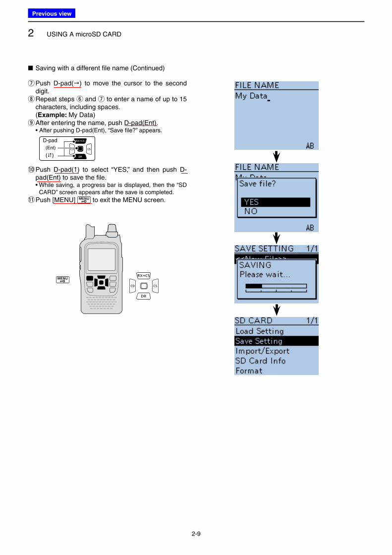
■ Saving with a different file name (Continued)
u Push D-pad() to move the cursor to the second digit. i Repeat steps y and u to enter a name of up to 15 characters, including spaces.
(Example: My Data) oAfter entering the name, push D-pad(Ent).
• After pushing D-pad(Ent), “Save file?” appears.
D-pad
(�)
(Ent)
!0 Push D-pad() to select “YES,” and then push D-pad(Ent) to save the file.
• While saving, a progress bar is displayed, then the “SD CARD” screen appears after the save is completed.
!1 Push [MENU] to exit the MENU screen.
Previous view
2 USING A microSD CARD
2-10
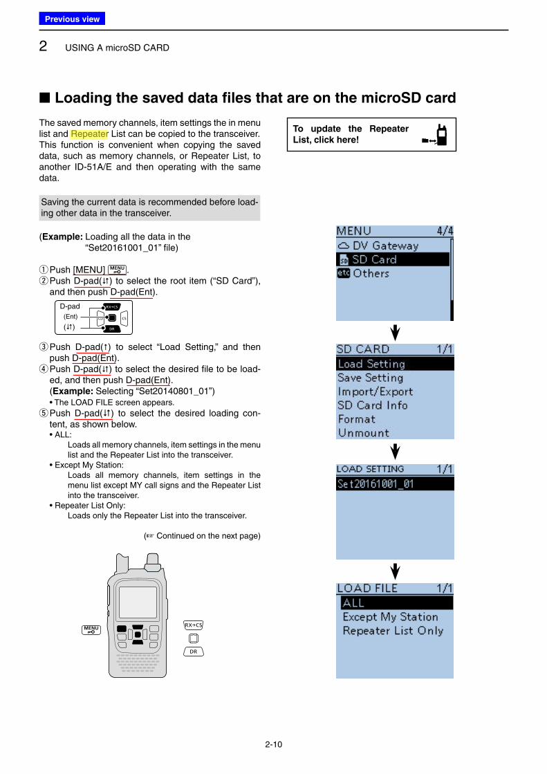
■ Loading the saved data files that are on the microSD card
The saved memory channels, item settings the in menu list and Repeater List can be copied to the transceiver.This function is convenient when copying the saved data, such as memory channels, or Repeater List, to another ID-51A/E and then operating with the same data.
Saving the current data is recommended before load-ing other data in the transceiver.
(Example: Loading all the data in the “Set20161001_01” file)
qPush [MENU] . w Push D-pad() to select the root item (“SD Card”), and then push D-pad(Ent).
D-pad
(�)
(Ent)
e Push D-pad() to select “Load Setting,” and then push D-pad(Ent). r Push D-pad() to select the desired file to be load-ed, and then push D-pad(Ent).
(Example: Selecting “Set20140801_01”) • The LOAD FILE screen appears.
t Push D-pad() to select the desired loading con-tent, as shown below.
• ALL: Loads all memory channels, item settings in the menu
list and the Repeater List into the transceiver. • Except My Station: Loads all memory channels, item settings in the
menu list except MY call signs and the Repeater List into the transceiver.
• Repeater List Only: Loads only the Repeater List into the transceiver.
(☞ Continued on the next page)
To update the Repeater
List, click here!
Previous view
Icom
ハイライト表示
Radio systems that receive incoming signals and retransmit them to extend the communication area. Normally put on geographically high locations for VHF/UHF radios.
2 USING A microSD CARD
2-11
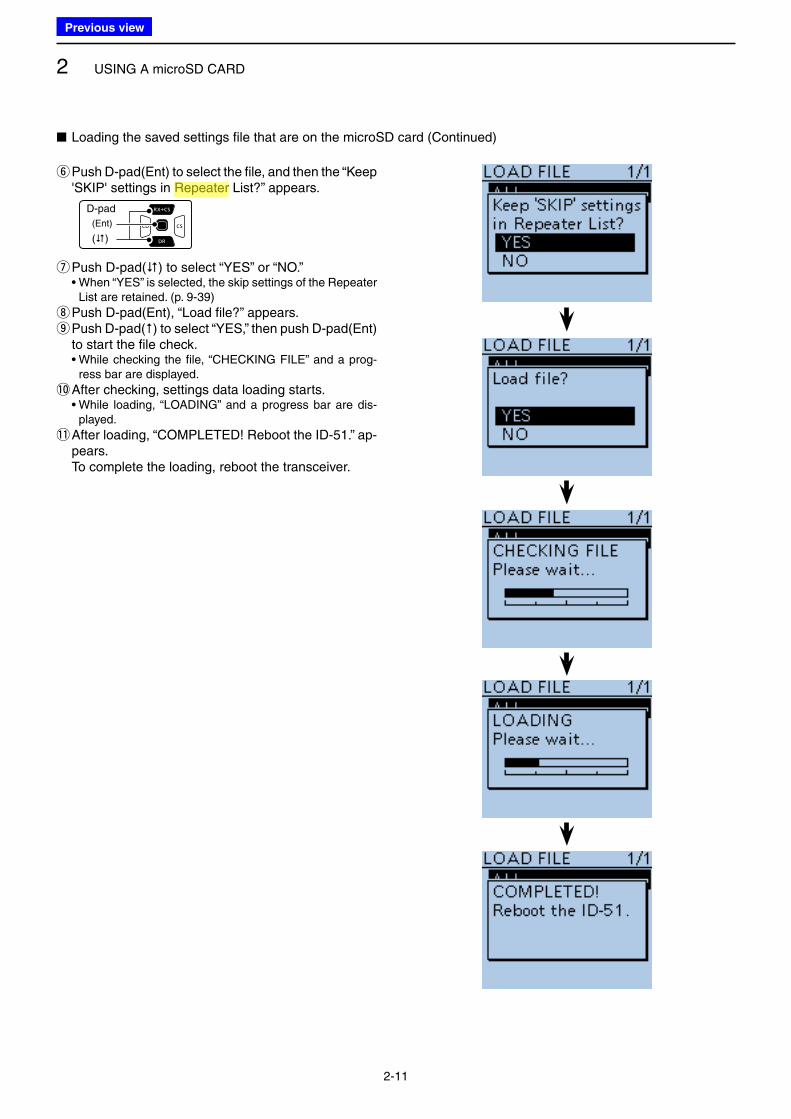
■ Loading the saved settings file that are on the microSD card (Continued)
y Push D-pad(Ent) to select the file, and then the “Keep 'SKIP' settings in Repeater List?” appears.
D-pad
(�)
(Ent)
uPush D-pad() to select “YES” or “NO.” • When “YES” is selected, the skip settings of the Repeater
List are retained. (p. 9-39)
iPush D-pad(Ent), “Load file?” appears. o Push D-pad() to select “YES,” then push D-pad(Ent) to start the file check.
• While checking the file, “CHECKING FILE” and a prog-ress bar are displayed.
!0 After checking, settings data loading starts. • While loading, “LOADING” and a progress bar are dis-
played.
!1 After loading, “COMPLETED! Reboot the ID-51.” ap-pears.
To complete the loading, reboot the transceiver.
Previous view
Icom
ハイライト表示
Radio systems that receive incoming signals and retransmit them to extend the communication area. Normally put on geographically high locations for VHF/UHF radios.
2 USING A microSD CARD
2-12
■ Backing up the data stored on the microSD card onto a PC
A backup file allows easy restoring even if the data on the microSD card is accidentally deleted.
Depending on your PC, a memory card reader (user supplied) may be required to read the microSD card.
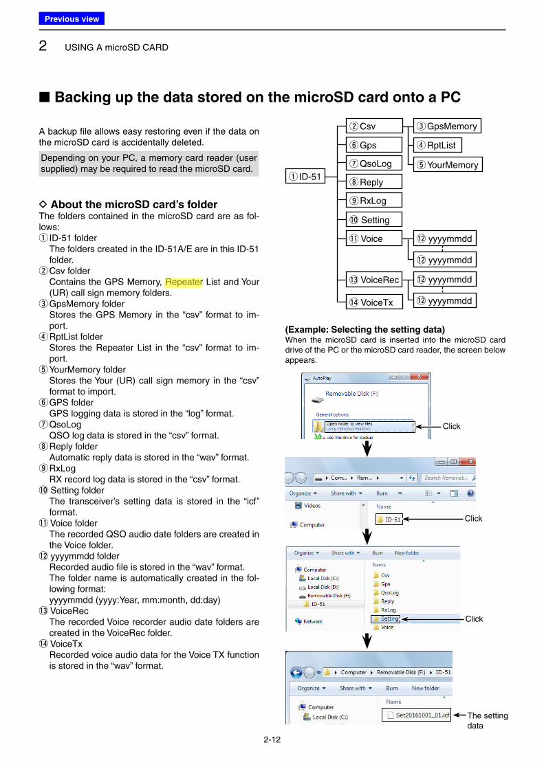
D About the microSD card’s folderThe folders contained in the microSD card are as fol-lows:
q ID-51 folder The folders created in the ID-51A/E are in this ID-51
folder. wCsv folder
Contains the GPS Memory, Repeater List and Your (UR) call sign memory folders. eGpsMemory folder
Stores the GPS Memory in the “csv” format to im-port. rRptList folder
Stores the Repeater List in the “csv” format to im-port. tYourMemory folder
Stores the Your (UR) call sign memory in the “csv” format to import. yGPS folder
GPS logging data is stored in the “log” format. uQsoLog
QSO log data is stored in the “csv” format. iReply folder
Automatic reply data is stored in the “wav” format. oRxLog
RX record log data is stored in the “csv” format.!0 Setting folder The transceiver’s setting data is stored in the “icf”
format.!1 Voice folder The recorded QSO audio date folders are created in
the Voice folder.!2 yyyymmdd folder Recorded audio file is stored in the “wav” format. The folder name is automatically created in the fol-
lowing format: yyyymmdd (yyyy:Year, mm:month, dd:day)!3 VoiceRec The recorded Voice recorder audio date folders are
created in the VoiceRec folder.!4 VoiceTx Recorded voice audio data for the Voice TX function
is stored in the “wav” format.
Click
Click
The setting data
Click
(Example: Selecting the setting data)When the microSD card is inserted into the microSD card drive of the PC or the microSD card reader, the screen below appears.
q ID-51
yGps
iReply
!0 Setting
!1 Voice !2 yyyymmdd
!2 yyyymmdd
uQsoLog
oRxLog
!3 VoiceRec
!4 VoiceTx
wCsv eGpsMemory
rRptList
tYourMemory
!2 yyyymmdd
!2 yyyymmdd
Previous view
Icom
ハイライト表示
Radio systems that receive incoming signals and retransmit them to extend the communication area. Normally put on geographically high locations for VHF/UHF radios.
2 USING A microSD CARD
2-13
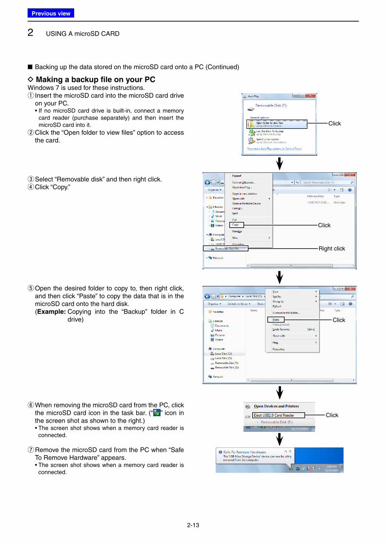
■ Backing up the data stored on the microSD card onto a PC (Continued)
D Making a backup file on your PCWindows 7 is used for these instructions.
q Insert the microSD card into the microSD card drive on your PC.
• If no microSD card drive is built-in, connect a memory card reader (purchase separately) and then insert the microSD card into it.
w Click the “Open folder to view files” option to access the card.
eSelect “Removable disk” and then right click. rClick “Copy.”
t Open the desired folder to copy to, then right click, and then click “Paste” to copy the data that is in the microSD card onto the hard disk.
(Example: Copying into the “Backup” folder in C drive)
y When removing the microSD card from the PC, click the microSD card icon in the task bar. (“ ” icon in the screen shot as shown to the right.)
• The screen shot shows when a memory card reader is connected.
u Remove the microSD card from the PC when “Safe To Remove Hardware” appears.
• The screen shot shows when a memory card reader is connected.
Right click
Click
Click
Click
Click
Previous view
2 USING A microSD CARD
2-14
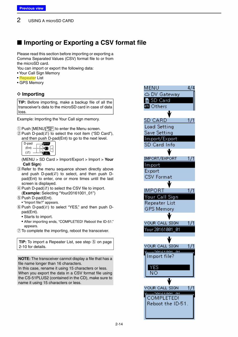
■ Importing or Exporting a CSV format file
Please read this section before importing or exporting a Comma Separated Values (CSV) format file to or from the microSD card.You can import or export the following data:• Your Call Sign Memory• Repeater List• GPS Memory
D Importing
TIP: Before importing, make a backup file of all the transceiver’s data to the microSD card in case of data loss.
Example: Importing the Your Call sign memory.
q Push [MENU] to enter the Menu screen. w Push D-pad() to select the root item (“SD Card”), and then push D-pad(Ent) to go to the next level.
D-pad
(�)
(Ent)
( MENU > SD Card > Import/Export > Import > Your
Call Sign) e Refer to the menu sequence shown directly above and push D-pad() to select, and then push D-pad(Ent) to enter, one or more times until the last screen is displayed. rPush D-pad() to select the CSV file to import.
(Example: Selecting “Your20161001_01”) t Push D-pad(Ent).
• “Import file?” appears.
y Push D-pad() to select “YES,” and then push D-pad(Ent).
• Starts to import. • After importing ends, “COMPLETED! Reboot the ID-51.”
appears.
uTo complete the importing, reboot the transceiver.
NOTE: The transceiver cannot display a file that has a file name longer than 16 characters.In this case, rename it using 15 characters or less.When you export the data in a CSV format file using the CS-51PLUS2 (contained in the CD), make sure to name it using 15 characters or less.
TIP: To import a Repeater List, see step t on page 2-10 for details.
Previous view
Icom
ハイライト表示
Radio systems that receive incoming signals and retransmit them to extend the communication area. Normally put on geographically high locations for VHF/UHF radios.
2 USING A microSD CARD
2-15
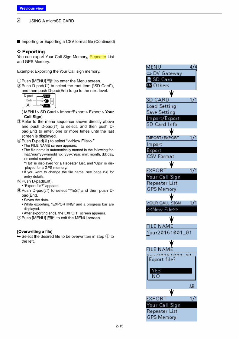
D ExportingYou can export Your Call Sign Memory, Repeater List and GPS Memory.
Example: Exporting the Your Call sign memory.
q Push [MENU] to enter the Menu screen. w Push D-pad() to select the root item (“SD Card”), and then push D-pad(Ent) to go to the next level.
D-pad
(�)
(Ent)
( MENU > SD Card > Import/Export > Export > Your
Call Sign) e Refer to the menu sequence shown directly above and push D-pad() to select, and then push D-pad(Ent) to enter, one or more times until the last screen is displayed. r Push D-pad() to select “<<New File>>.”
• The FILE NAME screen appears. • The file name is automatically named in the following for-
mat; Your*yyyymmdd_xx (yyyy: Year, mm: month, dd: day, xx: serial number)
* “Rpt” is displayed for a Repeater List, and “Gps” is dis-played for a GPS memory.
• If you want to change the file name, see page 2-8 for entry details.
t Push D-pad(Ent). • “Export file?” appears.
y Push D-pad() to select “YES,” and then push D-pad(Ent).
• Saves the data. • While exporting, “EXPORTING” and a progress bar are
displayed. • After exporting ends, the EXPORT screen appears.
uPush [MENU] to exit the MENU screen.
[Overwriting a file]
➥ Select the desired file to be overwritten in step e to the left.
■ Importing or Exporting a CSV format file (Continued)
Previous view
Icom
ハイライト表示
Radio systems that receive incoming signals and retransmit them to extend the communication area. Normally put on geographically high locations for VHF/UHF radios.

3-1
Section 3 PANEL DESCRIPTION
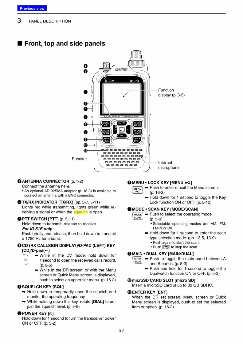
■ Front, top and side panels .................................................. 3-2
■ Function display .................................................................. 3-5
Previous view
3 PANEL DESCRIPTION
3-2
q ANTENNA CONNECTOR (p. 1-2) Connect the antenna here. • An optional AD-92SMA adapter (p. 18-3) is available to
connect an antenna with a BNC connector.
w TX/RX INDICATOR [TX/RX] (pp. 5-7, 5-11) Lights red while transmitting, lights green while re-
ceiving a signal or when the squelch is open.
e PTT SWITCH [PTT] (p. 5-11) Hold down to transmit, release to receive. For ID-51E only
Push briefly and release, then hold down to transmit a 1750 Hz tone burst.
r CD (RX CALLSIGN DISPLAY)/D-PAD (LEFT) KEY
[CD]/D-pad()
➥ While in the DV mode, hold down for 1 second to open the received calls record. (p. 9-5)
➥ While in the DR screen, or with the Menu screen or Quick Menu screen is displayed, push to select an upper tier menu. (p. 16-2)
t SQUELCH KEY [SQL]
➥ Hold down to temporarily open the squelch and monitor the operating frequency.
➥ While holding down this key, rotate [DIAL] to ad-just the squelch level. (p. 5-8)
y POWER KEY [ ]
Hold down for 1 second to turn the transceiver power ON or OFF. (p. 5-2)
u MENU • LOCK KEY [MENU ]
➥ Push to enter or exit the Menu screen. (p. 16-2)
➥ Hold down for 1 second to toggle the Key Lock function ON or OFF. (p. 5-12)
i MODE • SCAN KEY [MODE•SCAN]
➥ Push to select the operating mode. (p. 5-9)• Selectable operating modes are AM, FM,
FM-N or DV.
➥ Hold down for 1 second to enter the scan type selection mode. (pp. 13-5, 13-9)• Push again to start the scan. • Push to stop the scan.
o MAIN • DUAL KEY [MAIN•DUAL]
➥ Push to toggle the main band between A and B bands. (p. 5-3)
➥ Push and hold for 1 second to toggle the Dualwatch function ON or OFF. (p. 5-3)
!0 microSD CARD SLOT [micro SD]
Insert a microSD card of up to 32 GB SDHC.
!1 ENTER KEY [ENT]
When the DR set screen, Menu screen or Quick Menu screen is displayed, push to set the selected item or option. (p. 16-2)
■ Front, top and side panels
Speaker
Function display (p. 3-5)
Internal microphone
q
w
e
r
t
y
u
i
o
!0
!1
Previous view
Icom
ハイライト表示
A function that mutes the audio output for certain signal levels.
3 PANEL DESCRIPTION
3-3
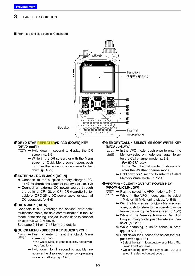
!2 DR (D-STAR REPEATER)/D-PAD (DOWN) KEY
[DR]/D-pad()
➥ Hold down 1 second to display the DR screen. (p. 8-3)
➥ While in the DR screen, or with the Menu screen or Quick Menu screen open, push to move the value or option selector bar down. (p. 16-2)
!3 EXTERNAL DC IN JACK [DC IN]
➥ Connects to the supplied battery charger (BC-167S) to charge the attached battery pack. (p. 4-3)
➥ Connect an external DC power source through the optional CP-12L or CP-19R cigarette lighter cable or OPC-254L DC power cable for external DC operation. (p. 4-6)
!4 DATA JACK [DATA]
Connects to a PC through the optional data com-munication cable, for data communication in the DV mode, or for cloning. The jack is also used to connect an external GPS receiver.
See page 9-14 or 17-17 for more details.
!5 QUICK MENU • SPEECH KEY [QUICK SPCH]
➥ Push to enter or exit the Quick Menu screen. (p. 5-6)• The Quick Menu is used to quickly select vari-
ous functions.
➥ Hold down for 1 second to audibly an-nounce the displayed frequency, operating mode or call sign. (p. 17-6)
!6 MEMORY/CALL • SELECT MEMORY WRITE KEY
[M/CALL•S.MW]
➥ In the VFO mode, push once to enter the Memory selection mode, push again to en-ter the Call channel mode. (p. 8-3)For ID-51A only
In the Call channel mode, push once to enter the Weather channel mode.
➥ Hold down for 1 second to enter the Select Memory Write mode. (p. 12-4)
!7 VFO/MHz • CLEAR • OUTPUT POWER KEY
[VFO/MHz•CLR•LOW]
➥ Push to select the VFO mode. (p. 5-10)➥ While in the VFO mode, push to select
1 MHz or 10 MHz tuning steps. (p. 5-8)➥ With the Menu screen or Quick Menu screen
open, push to return to the operating mode before displaying the Menu screen. (p. 16-2)
➥ While in the Memory Name or Call Sign Programming mode, push to delete a char-acter. (p. 12-11)
➥ While scanning, push to cancel a scan. (pp. 13-5, 13-9)
➥ Hold down for 1 second to select the out-put power. (p. 5-11)• Select the transmit output power of High, Mid,
Low2, Low1 or S-low.• While holding down this key, rotate [DIAL] to
select the desired output power.
■ Front, top and side panels (Continued)
Speaker
Function display (p. 3-5)
Internal microphone
!2!3
!4!5!6
!7
Previous view
Icom
ハイライト表示
Radio systems that receive incoming signals and retransmit them to extend the communication area. Normally put on geographically high locations for VHF/UHF radios.
3 PANEL DESCRIPTION
3-4
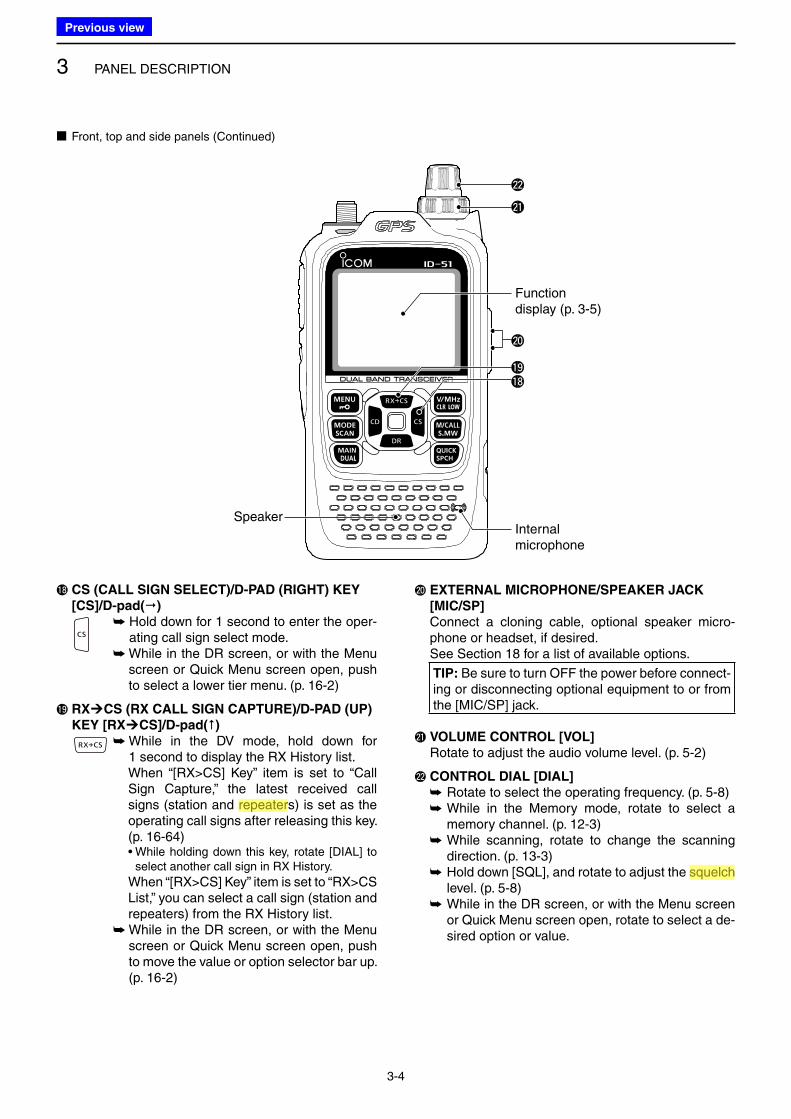
!8 CS (CALL SIGN SELECT)/D-PAD (RIGHT) KEY
[CS]/D-pad()
➥ Hold down for 1 second to enter the oper-ating call sign select mode.
➥ While in the DR screen, or with the Menu screen or Quick Menu screen open, push to select a lower tier menu. (p. 16-2)
!9 RXÚCS (RX CALL SIGN CAPTURE)/D-PAD (UP)
KEY [RXÚCS]/D-pad()
➥ While in the DV mode, hold down for 1 second to display the RX History list.When “[RX>CS] Key” item is set to “Call Sign Capture,” the latest received call signs (station and repeaters) is set as the operating call signs after releasing this key. (p. 16-64)• While holding down this key, rotate [DIAL] to
select another call sign in RX History.
When “[RX>CS] Key” item is set to “RX>CS List,” you can select a call sign (station and repeaters) from the RX History list.
➥ While in the DR screen, or with the Menu screen or Quick Menu screen open, push to move the value or option selector bar up. (p. 16-2)
@0 EXTERNAL MICROPHONE/SPEAKER JACK
[MIC/SP]
Connect a cloning cable, optional speaker micro-phone or headset, if desired.
See Section 18 for a list of available options.
TIP: Be sure to turn OFF the power before connect-ing or disconnecting optional equipment to or from the [MIC/SP] jack.
@1 VOLUME CONTROL [VOL]
Rotate to adjust the audio volume level. (p. 5-2)
@2 CONTROL DIAL [DIAL]
➥ Rotate to select the operating frequency. (p. 5-8) ➥ While in the Memory mode, rotate to select a memory channel. (p. 12-3)
➥ While scanning, rotate to change the scanning direction. (p. 13-3)
➥ Hold down [SQL], and rotate to adjust the squelch level. (p. 5-8)
➥ While in the DR screen, or with the Menu screen or Quick Menu screen open, rotate to select a de-sired option or value.
■ Front, top and side panels (Continued)
Speaker
Function display (p. 3-5)
Internal microphone
!8!9
@0
@1
@2
Previous view
Icom
ハイライト表示
Radio systems that receive incoming signals and retransmit them to extend the communication area. Normally put on geographically high locations for VHF/UHF radios.
Icom
ハイライト表示
A function that mutes the audio output for certain signal levels.
3 PANEL DESCRIPTION
3-5
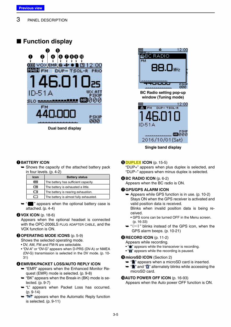
q BATTERY ICON
➥ Shows the capacity of the attached battery pack in four levels. (p. 4-2)
Icon Battery status
The battery has sufficient capacity.
The battery is exhausted a little.
The battery is nearing exhaustion.
The battery is almost fully exhausted.
➥ “
点滅
” appears when the optional battery case is attached. (p. 4-4)
w VOX ICON (p. 18-6) Appears when the optional headset is connected
with the OPC-2006LS PLUG ADAPTER CABLE, and the VOX function is ON.
e OPERATING MODE ICONS (p. 5-9) Shows the selected operating mode. • DV, AM, FM and FM-N are selectable. • “DV-A” or “DV-G” appears when D-PRS (DV-A) or NMEA
(DV-G) transmission is selected in the DV mode. (p. 10-31)
r EMR/BK/PACKET LOSS/AUTO REPLY ICON
➥ “EMR” appears when the Enhanced Monitor Re-quest (EMR) mode is selected. (p. 9-8)
➥ “BK” appears when the Break-in (BK) mode is se-lected. (p. 9-7)
➥ “L” appears when Packet Loss has occurred. (p. 9-14)
➥ “ ” appears when the Automatic Reply function is selected. (p. 9-11)
t DUPLEX ICON (p. 15-5) “DUP+” appears when plus duplex is selected, and
“DUP–” appears when minus duplex is selected.
y BC RADIO ICON (p. 6-2) Appears when the BC radio is ON.
u GPS/GPS ALARM ICON
➥ Appears while GPS function is in use. (p. 10-2) Stays ON when the GPS receiver is activated and
valid position data is received. Blinks when invalid position data is being re-
ceived. • GPS icons can be turned OFF in the Menu screen.
(p. 16-33)
➥ “ S” blinks instead of the GPS icon, when the GPS alarm beeps. (p. 10-21)
i RECORD ICON (p. 11-2) Appears while recording. • “ ” appears while the transceiver is recording. • “ ” appears while the recording is paused.
o microSD ICON (Section 2) ➥ “ ” appears when a microSD card is inserted. ➥ “ ” and “ ” alternately blinks while accessing the microSD card.
!0AUTO POWER OFF ICON (p. 16-93) Appears when the Auto power OFF function is ON.
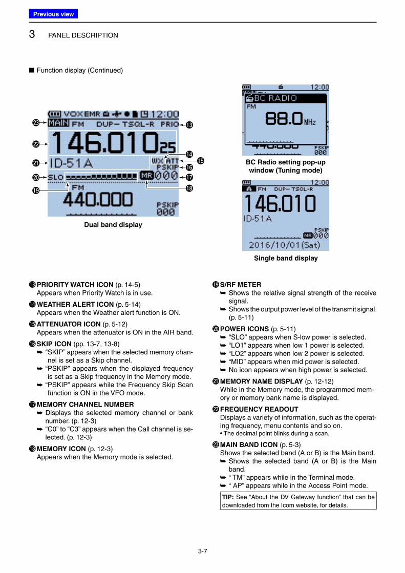
■ Function display
Single band display
BC Radio setting pop-up
window (Tuning mode)
Dual band display
q w r y uio !0
te
Previous view
Icom
ハイライト表示
An operating mode in which the transmit and receive frequencies are separated by an offset amount.
3 PANEL DESCRIPTION
3-6
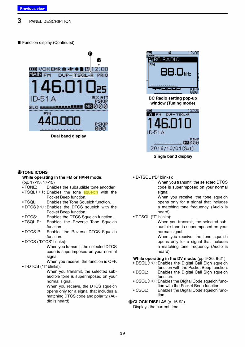
!1 TONE ICONS
While operating in the FM or FM-N mode: (pp. 17-13, 17-15)• TONE: Enables the subaudible tone encoder.• TSQLS: Enables the tone squelch with the
Pocket Beep function.• TSQL: Enables the Tone Squelch function.• DTCSS: Enables the DTCS squelch with the
Pocket Beep function.• DTCS: Enables the DTCS Squelch function.• TSQL-R: Enables the Reverse Tone Squelch
function.• DTCS-R: Enables the Reverse DTCS Squelch
function.• DTCS (“DTCS” blinks): When you transmit, the selected DTCS
code is superimposed on your normal signal.
When you receive, the function is OFF.• T-DTCS (“T” blinks): When you transmit, the selected sub-
audible tone is superimposed on your normal signal.
When you receive, the DTCS squelch opens only for a signal that includes a matching DTCS code and polarity. (Au-dio is heard)
• D-TSQL (“D” blinks): When you transmit, the selected DTCS
code is superimposed on your normal signal.
When you receive, the tone squelch opens only for a signal that includes a matching tone frequency. (Audio is heard)
• T-TSQL (“T” blinks): When you transmit, the selected sub-
audible tone is superimposed on your normal signal.
When you receive, the tone squelch opens only for a signal that includes a matching tone frequency. (Audio is heard)
While operating in the DV mode: (pp. 9-20, 9-21)• DSQLS: Enables the Digital Call Sign squelch
function with the Pocket Beep function.• DSQL: Enables the Digital Call Sign squelch
function.• CSQLS: Enables the Digital Code squelch func-
tion with the Pocket Beep function.• CSQL: Enables the Digital Code squelch func-
tion.
!2 CLOCK DISPLAY (p. 16-92) Displays the current time.
■ Function display (Continued)
Dual band display
Single band display
BC Radio setting pop-up
window (Tuning mode)
!2
!1
Previous view
Icom
ハイライト表示
A function that mutes the audio output for certain signal levels.
3 PANEL DESCRIPTION
3-7
■ Function display (Continued)
Dual band display
Single band display
BC Radio setting pop-up
window (Tuning mode)
!3 PRIORITY WATCH ICON (p. 14-5) Appears when Priority Watch is in use.
!4 WEATHER ALERT ICON (p. 5-14) Appears when the Weather alert function is ON.
!5 ATTENUATOR ICON (p. 5-12) Appears when the attenuator is ON in the AIR band.
!6 SKIP ICON (pp. 13-7, 13-8) ➥ “ SKIP” appears when the selected memory chan-
nel is set as a Skip channel. ➥ “ PSKIP” appears when the displayed frequency
is set as a Skip frequency in the Memory mode. ➥ “ PSKIP” appears while the Frequency Skip Scan
function is ON in the VFO mode.
!7 MEMORY CHANNEL NUMBER
➥ Displays the selected memory channel or bank number. (p. 12-3)
➥ “C0” to “C3” appears when the Call channel is se-lected. (p. 12-3)
!8 MEMORY ICON (p. 12-3) Appears when the Memory mode is selected.
!9 S/RF METER
➥ Shows the relative signal strength of the receive signal.
➥ Shows the output power level of the transmit signal. (p. 5-11)
@0 POWER ICONS (p. 5-11) ➥ “ SLO” appears when S-low power is selected. ➥ “ LO1” appears when low 1 power is selected. ➥ “ LO2” appears when low 2 power is selected. ➥ “ MID” appears when mid power is selected. ➥ No icon appears when high power is selected.
@1 MEMORY NAME DISPLAY (p. 12-12) While in the Memory mode, the programmed mem-
ory or memory bank name is displayed.
@2 FREQUENCY READOUT
Displays a variety of information, such as the operat-ing frequency, menu contents and so on.
• The decimal point blinks during a scan.
@3 MAIN BAND ICON (p. 5-3) Shows the selected band (A or B) is the Main band.
➥ Shows the selected band (A or B) is the Main band.
➥ “ TM” appears while in the Terminal mode. ➥ “ AP” appears while in the Access Point mode.
TIP: See “About the DV Gateway function” that can be
downloaded from the Icom website, for details.
!3
!5!6
!7
!8!9
@0
@1
@2
@3
!4
Previous view
4-1
Section 4 BATTERY CHARGING
■ Battery information ............................................................. 4-2
D Battery life ...................................................................... 4-2
D Battery icon ................................................................... 4-2
■ Charging through the [DC IN] jack ...................................... 4-3
D Battery icon .................................................................... 4-3
D Charging note ................................................................. 4-3
■ Optional battery case ......................................................... 4-4
D Battery life ...................................................................... 4-4
D About the battery replacement ....................................... 4-4
■ Charging with the optional desktop charger ....................... 4-5
D Charging note ................................................................. 4-5
■ External DC power operation ............................................. 4-6
D Operating note ................................................................ 4-6
Previous view
4 BATTERY CHARGING
4-2
■ Battery information
D Battery lifeThe approximate battery life (operating time) as shown to the right is calculated under the following assump-tions:• Power save setting: Auto (Short)• Duty cycle: TX : RX : Stand-by = 1 : 1: 8 (based on
operating style)
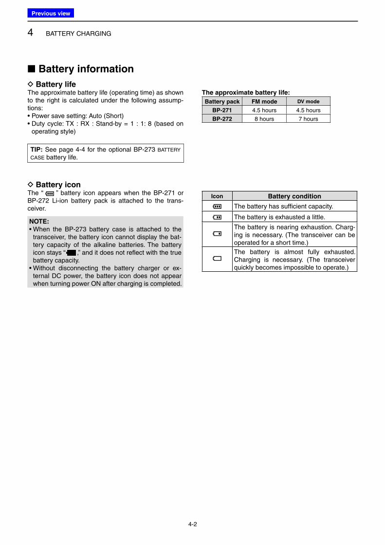
The approximate battery life:
Battery pack FM mode DV mode
BP-271 4.5 hours 4.5 hours
BP-272 8 hours 7 hours
Icon Battery condition
The battery has sufficient capacity.
The battery is exhausted a little.
The battery is nearing exhaustion. Charg-ing is necessary. (The transceiver can be operated for a short time.)
The battery is almost fully exhausted. Charging is necessary. (The transceiver quickly becomes impossible to operate.)
D Battery iconThe “ ” battery icon appears when the BP-271 or BP-272 Li-ion battery pack is attached to the trans-ceiver.
TIP: See page 4-4 for the optional BP-273 BATTERY
CASE battery life.
NOTE:
• When the BP-273 battery case is attached to the transceiver, the battery icon cannot display the bat-tery capacity of the alkaline batteries. The battery icon stays “
点滅
,” and it does not reflect with the true battery capacity.
• Without disconnecting the battery charger or ex-ternal DC power, the battery icon does not appear when turning power ON after charging is completed.
Previous view
4 BATTERY CHARGING
4-3
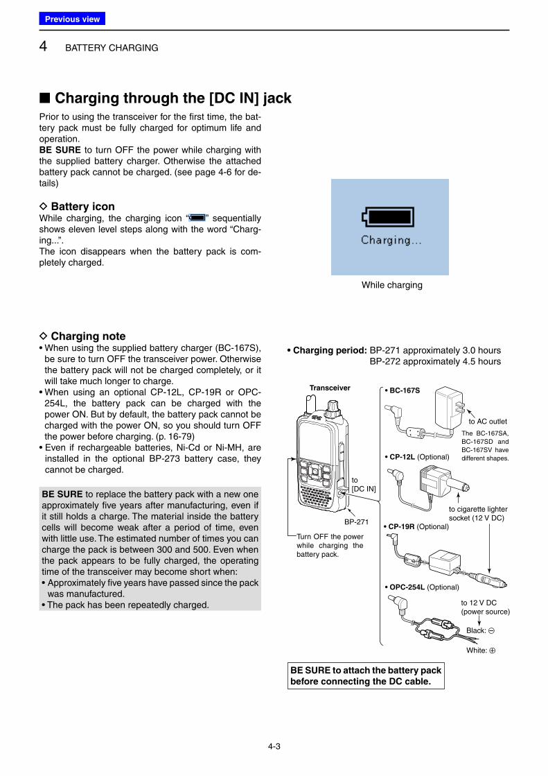
Prior to using the transceiver for the first time, the bat-tery pack must be fully charged for optimum life and operation.BE SURE to turn OFF the power while charging with the supplied battery charger. Otherwise the attached battery pack cannot be charged. (see page 4-6 for de-tails)
D Battery iconWhile charging, the charging icon “ ” sequentially shows eleven level steps along with the word “Charg-ing...”.The icon disappears when the battery pack is com-pletely charged.
• BC-167S
• CP-12L (Optional)
• OPC-254L (Optional)
to AC outlet
to cigarette lightersocket (12 V DC)
to 12 V DC(power source)
White: +
Black: _
Transceiver
to [DC IN]
Turn OFF the power while charging the battery pack.
The BC-167SA,
BC-167SD and
BC-167SV have
different shapes.
BP-271• CP-19R (Optional)
While charging
D Charging note• When using the supplied battery charger (BC-167S),
be sure to turn OFF the transceiver power. Otherwise the battery pack will not be charged completely, or it will take much longer to charge.
• When using an optional CP-12L, CP-19R or OPC-254L, the battery pack can be charged with the power ON. But by default, the battery pack cannot be charged with the power ON, so you should turn OFF the power before charging. (p. 16-79)
• Even if rechargeable batteries, Ni-Cd or Ni-MH, are installed in the optional BP-273 battery case, they cannot be charged.
• Charging period: BP-271 approximately 3.0 hours BP-272 approximately 4.5 hours
BE SURE to attach the battery pack
before connecting the DC cable.
■ Charging through the [DC IN] jack
BE SURE to replace the battery pack with a new one approximately five years after manufacturing, even if it still holds a charge. The material inside the battery cells will become weak after a period of time, even with little use. The estimated number of times you can charge the pack is between 300 and 500. Even when the pack appears to be fully charged, the operating time of the transceiver may become short when:• Approximately five years have passed since the pack
was manufactured.• The pack has been repeatedly charged.
Previous view
4 BATTERY CHARGING
4-4
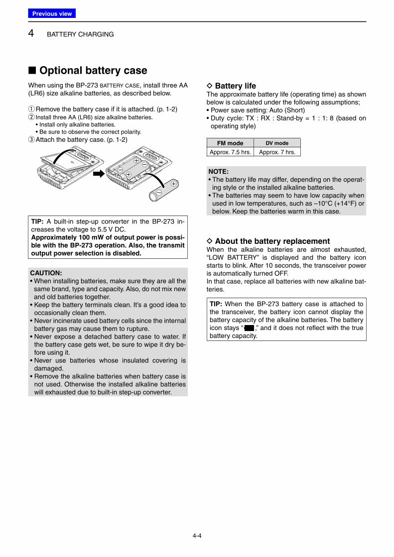
■ Optional battery case
When using the BP-273 BATTERY CASE, install three AA (LR6) size alkaline batteries, as described below.
q Remove the battery case if it is attached. (p. 1-2) w Install three AA (LR6) size alkaline batteries.
• Install only alkaline batteries. • Be sure to observe the correct polarity.
e Attach the battery case. (p. 1-2)
D Battery lifeThe approximate battery life (operating time) as shown below is calculated under the following assumptions;• Power save setting: Auto (Short)• Duty cycle: TX : RX : Stand-by = 1 : 1: 8 (based on
operating style)
FM mode DV mode
Approx. 7.5 hrs. Approx. 7 hrs.
D About the battery replacementWhen the alkaline batteries are almost exhausted, “LOW BATTERY” is displayed and the battery icon starts to blink. After 10 seconds, the transceiver power is automatically turned OFF.In that case, replace all batteries with new alkaline bat-teries.
CAUTION:
• When installing batteries, make sure they are all the same brand, type and capacity. Also, do not mix new and old batteries together.
• Keep the battery terminals clean. It’s a good idea to occasionally clean them.
• Never incinerate used battery cells since the internal battery gas may cause them to rupture.
• Never expose a detached battery case to water. If the battery case gets wet, be sure to wipe it dry be-fore using it.
• Never use batteries whose insulated covering is damaged.
• Remove the alkaline batteries when battery case is not used. Otherwise the installed alkaline batteries will exhausted due to built-in step-up converter.
TIP: A built-in step-up converter in the BP-273 in-creases the voltage to 5.5 V DC.Approximately 100 mW of output power is possi-
ble with the BP-273 operation. Also, the transmit
output power selection is disabled.
TIP: When the BP-273 battery case is attached to the transceiver, the battery icon cannot display the battery capacity of the alkaline batteries. The battery icon stays “
点滅
,” and it does not reflect with the true battery capacity.
NOTE:
• The battery life may differ, depending on the operat-ing style or the installed alkaline batteries.
• The batteries may seem to have low capacity when used in low temperatures, such as –10°C (+14°F) or below. Keep the batteries warm in this case.
Previous view
4 BATTERY CHARGING
4-5
Guide rail
TabsNOTE: If the charging indicator blinks orange for 10 seconds or more with the battery pack installed in the transceiver, try charging the BP-271 alone. You can also try regular charging the BP-271 attached to the transceiver.
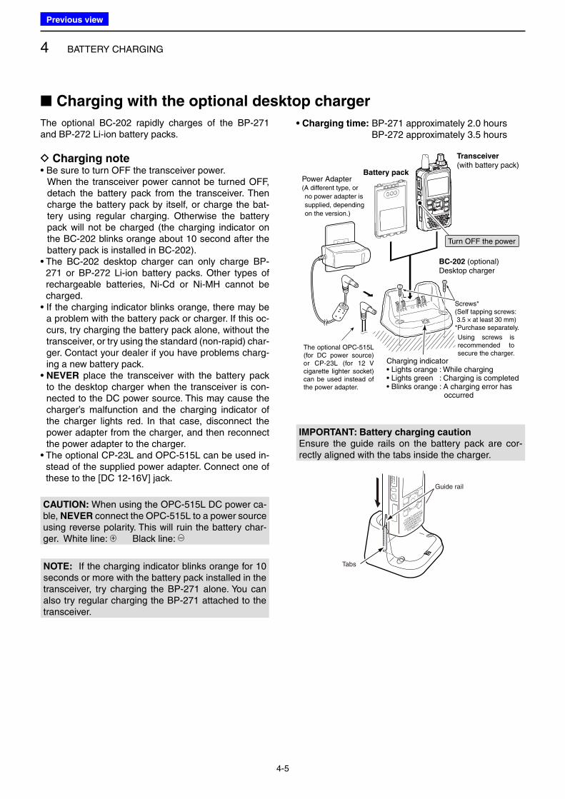
The optional BC-202 rapidly charges of the BP-271 and BP-272 Li-ion battery packs.
D Charging note• Be sure to turn OFF the transceiver power. When the transceiver power cannot be turned OFF,
detach the battery pack from the transceiver. Then charge the battery pack by itself, or charge the bat-tery using regular charging. Otherwise the battery pack will not be charged (the charging indicator on the BC-202 blinks orange about 10 second after the battery pack is installed in BC-202).
• The BC-202 desktop charger can only charge BP-271 or BP-272 Li-ion battery packs. Other types of rechargeable batteries, Ni-Cd or Ni-MH cannot be charged.
• If the charging indicator blinks orange, there may be a problem with the battery pack or charger. If this oc-curs, try charging the battery pack alone, without the transceiver, or try using the standard (non-rapid) char-ger. Contact your dealer if you have problems charg-ing a new battery pack.
• NEVER place the transceiver with the battery pack to the desktop charger when the transceiver is con-nected to the DC power source. This may cause the charger’s malfunction and the charging indicator of the charger lights red. In that case, disconnect the power adapter from the charger, and then reconnect the power adapter to the charger.
• The optional CP-23L and OPC-515L can be used in-stead of the supplied power adapter. Connect one of these to the [DC 12-16V] jack.
Transceiver
(with battery pack)
Turn OFF the power
Battery pack
BC-202 (optional)Desktop charger
Charging indicator• Lights orange : While charging• Lights green : Charging is completed• Blinks orange : A charging error has occurred
Power Adapter(A different type, or
no power adapter is
supplied, depending
on the version.)
Screws*(Self tapping screws:3.5 × at least 30 mm)
*Purchase separately.
Using screws is recommended to secure the charger.
The optional OPC-515L (for DC power source) or CP-23L (for 12 V cigarette lighter socket) can be used instead of the power adapter.
• Charging time: BP-271 approximately 2.0 hours BP-272 approximately 3.5 hours
IMPORTANT: Battery charging caution
Ensure the guide rails on the battery pack are cor-rectly aligned with the tabs inside the charger.
■ Charging with the optional desktop charger
CAUTION: When using the OPC-515L DC power ca-ble, NEVER connect the OPC-515L to a power source using reverse polarity. This will ruin the battery char-ger. White line: + Black line: –
Previous view
4 BATTERY CHARGING
4-6
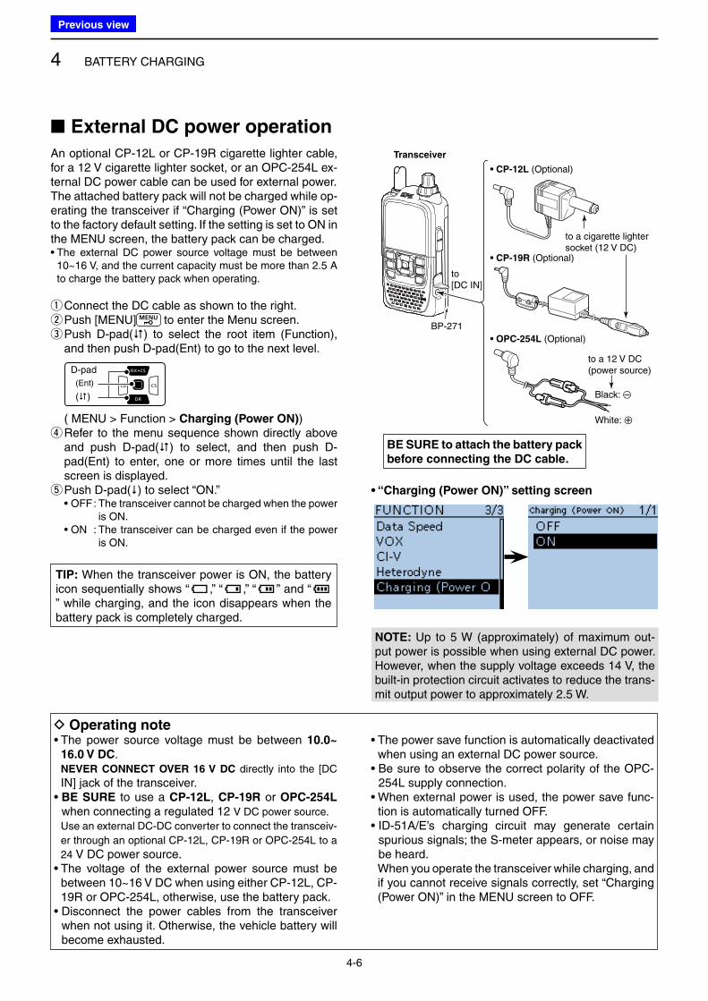
■ External DC power operation
An optional CP-12L or CP-19R cigarette lighter cable, for a 12 V cigarette lighter socket, or an OPC-254L ex-ternal DC power cable can be used for external power.The attached battery pack will not be charged while op-erating the transceiver if “Charging (Power ON)” is set to the factory default setting. If the setting is set to ON in the MENU screen, the battery pack can be charged.• The external DC power source voltage must be between
10~16 V, and the current capacity must be more than 2.5 A to charge the battery pack when operating.
q Connect the DC cable as shown to the right. w Push [MENU] to enter the Menu screen. e Push D-pad() to select the root item (Function), and then push D-pad(Ent) to go to the next level.
D-pad
(�)
(Ent)
( MENU > Function > Charging (Power ON)) r Refer to the menu sequence shown directly above and push D-pad() to select, and then push D-pad(Ent) to enter, one or more times until the last screen is displayed. tPush D-pad() to select “ON.”
• OFF : The transceiver cannot be charged when the power is ON.
• ON : The transceiver can be charged even if the power is ON.
NOTE: Up to 5 W (approximately) of maximum out-put power is possible when using external DC power. However, when the supply voltage exceeds 14 V, the built-in protection circuit activates to reduce the trans-mit output power to approximately 2.5 W.
BP-271
• CP-12L (Optional)
• CP-19R (Optional)
• OPC-254L (Optional)
to a cigarette lightersocket (12 V DC)
to a 12 V DC(power source)
White: +
Black: _
to [DC IN]
Transceiver
D Operating note• The power source voltage must be between 10.0~
16.0 V DC. NEVER CONNECT OVER 16 V DC directly into the [DC
IN] jack of the transceiver.• BE SURE to use a CP-12L, CP-19R or OPC-254L
when connecting a regulated 12 V DC power source.
Use an external DC-DC converter to connect the transceiv-
er through an optional CP-12L, CP-19R or OPC-254L to a
24 V DC power source.• The voltage of the external power source must be
between 10~16 V DC when using either CP-12L, CP-19R or OPC-254L, otherwise, use the battery pack.
• Disconnect the power cables from the transceiver when not using it. Otherwise, the vehicle battery will become exhausted.
• The power save function is automatically deactivated when using an external DC power source.
• Be sure to observe the correct polarity of the OPC-254L supply connection.
• When external power is used, the power save func-tion is automatically turned OFF.
• ID-51A/E’s charging circuit may generate certain spurious signals; the S-meter appears, or noise may be heard.
When you operate the transceiver while charging, and if you cannot receive signals correctly, set “Charging (Power ON)” in the MENU screen to OFF.
BE SURE to attach the battery pack
before connecting the DC cable.
• “Charging (Power ON)” setting screen
TIP: When the transceiver power is ON, the battery icon sequentially shows “ ,” “ ,” “ ” and “” while charging, and the icon disappears when the battery pack is completely charged.
Previous view
5-1
Section 5 BASIC OPERATION
■ Power ON ........................................................................... 5-2
■ Adjusting the audio level ..................................................... 5-2
■ Dualwatch operation ........................................................... 5-3
D MAIN band selection ...................................................... 5-3
D Single watch operation ................................................... 5-3
D Audio mute during Dualwatch operation ......................... 5-4
D Setting the volume for Dualwatch ................................... 5-5
■ Selecting the operating band .............................................. 5-6
■ Selecting a tuning step ....................................................... 5-7
D Tuning step selection ...................................................... 5-7
■ Setting a frequency ............................................................ 5-8
■ Setting the squelch level ..................................................... 5-8
■ Selecting the operating mode ............................................. 5-9
■ Monitor function .................................................................. 5-9
■ Selecting the Mode ........................................................... 5-10
D VFO mode .................................................................... 5-10
D Memory/Call channel/Weather channel mode ............. 5-10
D DR (D-STAR Repeater) function .................................. 5-10
■ Transmitting ...................................................................... 5-11
D About transmit power levels.......................................... 5-11
■ Key Lock function ............................................................. 5-12
■ ATT (AIR) function ............................................................ 5-12
■ Band Scope function ........................................................ 5-13
D Sweep operation .......................................................... 5-13
■ Weather channel operation
(USA version transceivers only) ....................................... 5-14
D Weather channel selection ........................................... 5-14
D Weather alert function .................................................. 5-14
Previous view
5 BASIC OPERATION
5-2
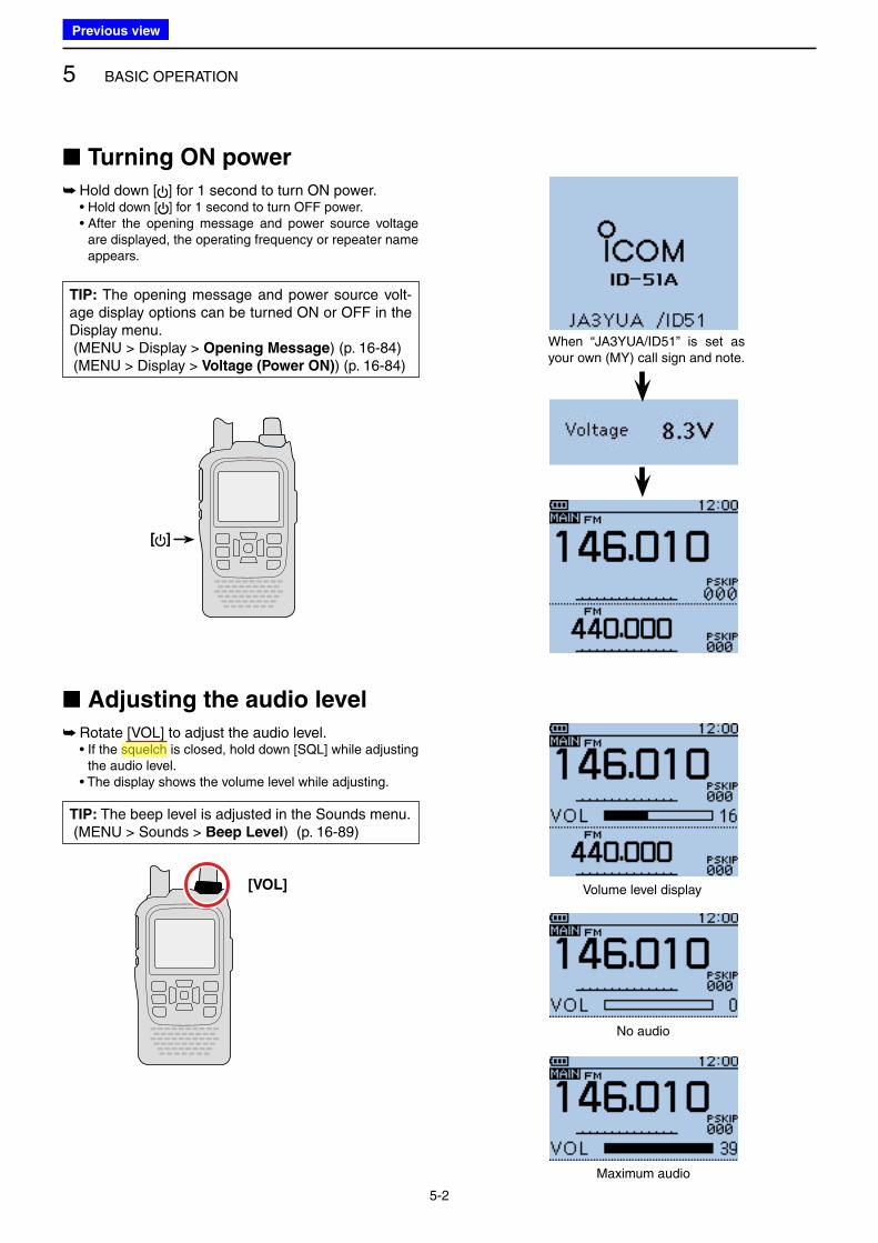
■ Turning ON power
➥ Hold down [ ] for 1 second to turn ON power. • Hold down [ ] for 1 second to turn OFF power. • After the opening message and power source voltage
are displayed, the operating frequency or repeater name appears.
■ Adjusting the audio level
➥ Rotate [VOL] to adjust the audio level. • If the squelch is closed, hold down [SQL] while adjusting
the audio level. • The display shows the volume level while adjusting.
Volume level display
No audio
Maximum audio
When “JA3YUA/ID51” is set as your own (MY) call sign and note.
[VOL]
[ ]
TIP: The opening message and power source volt-age display options can be turned ON or OFF in the Display menu. (MENU > Display > Opening Message) (p. 16-84) (MENU > Display > Voltage (Power ON)) (p. 16-84)
TIP: The beep level is adjusted in the Sounds menu. (MENU > Sounds > Beep Level) (p. 16-89)
Previous view
Icom
ハイライト表示
A function that mutes the audio output for certain signal levels.
5 BASIC OPERATION
5-3
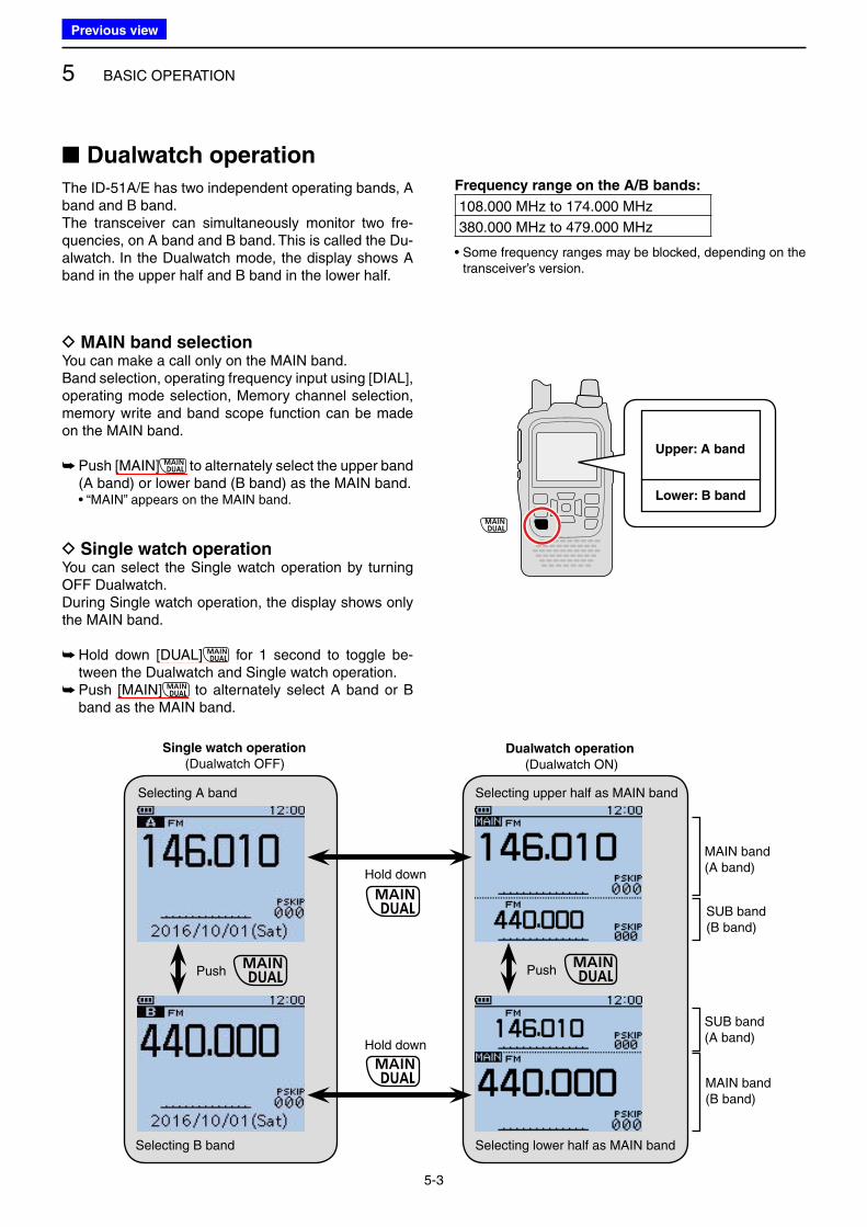
■ Dualwatch operation
The ID-51A/E has two independent operating bands, A band and B band.The transceiver can simultaneously monitor two fre-quencies, on A band and B band. This is called the Du-alwatch. In the Dualwatch mode, the display shows A band in the upper half and B band in the lower half.
Single watch operation
(Dualwatch OFF)Dualwatch operation
(Dualwatch ON)
Selecting B band
Selecting A band
Push
Hold down
Hold down
Selecting lower half as MAIN band
Selecting upper half as MAIN band
MAIN band(A band)
SUB band(B band)
SUB band(A band)
MAIN band(B band)
Frequency range on the A/B bands:
108.000 MHz to 174.000 MHz
380.000 MHz to 479.000 MHz
• Some frequency ranges may be blocked, depending on the transceiver’s version.
Upper: A band
Lower: B band
D MAIN band selectionYou can make a call only on the MAIN band.Band selection, operating frequency input using [DIAL], operating mode selection, Memory channel selection, memory write and band scope function can be made on the MAIN band.
➥ Push [MAIN] to alternately select the upper band (A band) or lower band (B band) as the MAIN band.
• “MAIN” appears on the MAIN band.
D Single watch operationYou can select the Single watch operation by turning OFF Dualwatch.During Single watch operation, the display shows only the MAIN band.
➥ Hold down [DUAL] for 1 second to toggle be-tween the Dualwatch and Single watch operation. ➥ Push [MAIN] to alternately select A band or B band as the MAIN band.
Push
Previous view
5 BASIC OPERATION
5-4
■ Dualwatch operation (Continued)
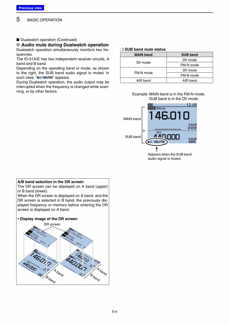
D Audio mute during Dualwatch operationDualwatch operation simultaneously monitors two fre-quencies.The ID-51A/E has two independent receiver circuits, A band and B band.Depending on the operating band or mode, as shown to the right, the SUB band audio signal is muted. In such case, “ ” appears.During Dualwatch operation, the audio output may be interrupted when the frequency is changed while scan-ning, or by other factors.
❍ SUB band mute status
MAIN band SUB band
DV modeDV mode
FM-N mode
FM-N modeDV mode
FM-N mode
AIR band AIR band
A/B band selection in the DR screen
The DR screen can be displayed on A band (upper) or B band (lower).When the DR screen is displayed on A band, and the DR screen is selected in B band, the previously dis-played frequency or memory before entering the DR screen is displayed on A band.
• Display image of the DR screen
DR screen
A bandB band
A bandB band
Appears when the SUB band audio signal is muted.
MAIN band
SUB band
Example: MAIN band is in the FM-N mode. SUB band is in the DV mode.
Previous view
5 BASIC OPERATION
5-5
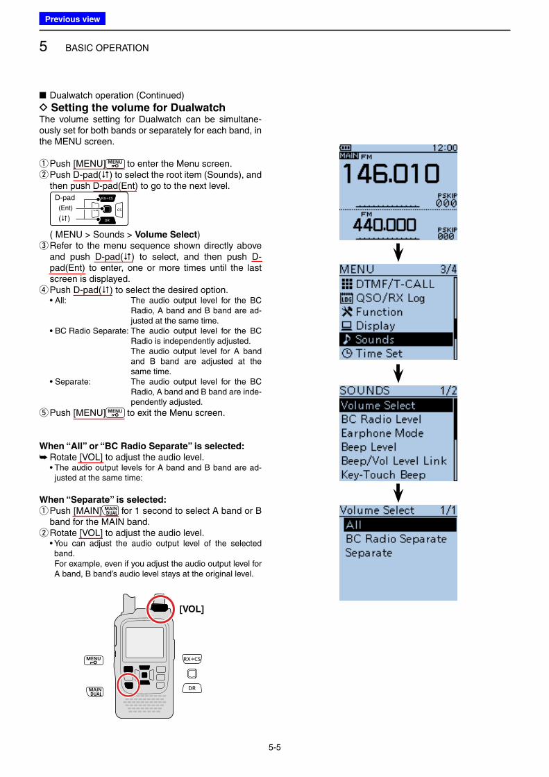
When “All” or “BC Radio Separate” is selected:
➥ Rotate [VOL] to adjust the audio level. • The audio output levels for A band and B band are ad-
justed at the same time:
When “Separate” is selected:
q Push [MAIN] for 1 second to select A band or B band for the MAIN band. w Rotate [VOL] to adjust the audio level.
• You can adjust the audio output level of the selected band.
For example, even if you adjust the audio output level for A band, B band’s audio level stays at the original level.
■ Dualwatch operation (Continued)
D Setting the volume for DualwatchThe volume setting for Dualwatch can be simultane-ously set for both bands or separately for each band, in the MENU screen.
q Push [MENU] to enter the Menu screen. w Push D-pad() to select the root item (Sounds), and then push D-pad(Ent) to go to the next level.
D-pad
(�)
(Ent)
( MENU > Sounds > Volume Select) e Refer to the menu sequence shown directly above and push D-pad() to select, and then push D-pad(Ent) to enter, one or more times until the last screen is displayed. r Push D-pad() to select the desired option.
• All: The audio output level for the BC Radio, A band and B band are ad-justed at the same time.
• BC Radio Separate: The audio output level for the BC Radio is independently adjusted.
The audio output level for A band and B band are adjusted at the same time.
• Separate: The audio output level for the BC Radio, A band and B band are inde-pendently adjusted.
t Push [MENU] to exit the Menu screen.
[VOL]
Previous view
5 BASIC OPERATION
5-6
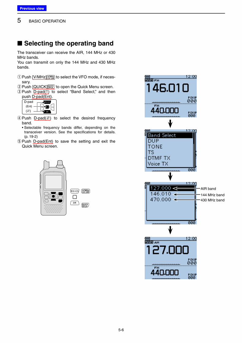
■ Selecting the operating band
The transceiver can receive the AIR, 144 MHz or 430 MHz bands.You can transmit on only the 144 MHz and 430 MHz bands.
q Push [V/MHz] to select the VFO mode, if neces-sary. w Push [QUICK] to open the Quick Menu screen. e Push D-pad() to select “Band Select,” and then push D-pad(Ent).
D-pad
(�)
(Ent)
r Push D-pad() to select the desired frequency band.
• Selectable frequency bands differ, depending on the transceiver version. See the specifications for details. (p. 19-2)
t Push D-pad(Ent) to save the setting and exit the Quick Menu screen.
AIR band
144 MHz band
430 MHz band
Previous view
5 BASIC OPERATION
5-7
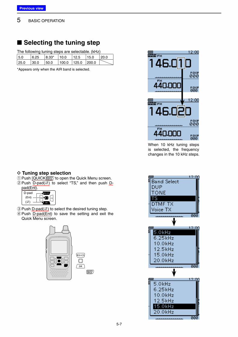
■ Selecting the tuning step
The following tuning steps are selectable. (kHz)
5.0 6.25 8.33* 10.0 12.5 15.0 20.0
25.0 30.0 50.0 100.0 125.0 200.0
*Appears only when the AIR band is selected.
D Tuning step selection q Push [QUICK] to open the Quick Menu screen. w Push D-pad() to select “TS,” and then push D-pad(Ent).
D-pad
(�)
(Ent)
e Push D-pad() to select the desired tuning step. r Push D-pad(Ent) to save the setting and exit the Quick Menu screen.
When 10 kHz tuning steps is selected, the frequency changes in the 10 kHz steps.
Previous view
5 BASIC OPERATION
5-8
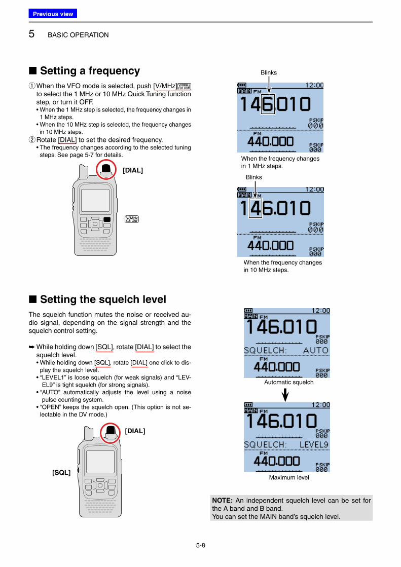
■ Setting the squelch level
The squelch function mutes the noise or received au-dio signal, depending on the signal strength and the squelch control setting.
➥ While holding down [SQL], rotate [DIAL] to select the squelch level.
• While holding down [SQL], rotate [DIAL] one click to dis-play the squelch level.
• “ LEVEL1” is loose squelch (for weak signals) and “LEV-EL9” is tight squelch (for strong signals).
• “ AUTO” automatically adjusts the level using a noise pulse counting system.
• “OPEN” keeps the squelch open. (This option is not se-lectable in the DV mode.)
Automatic squelch
Maximum level
■ Setting a frequency
q When the VFO mode is selected, push [V/MHz] to select the 1 MHz or 10 MHz Quick Tuning function step, or turn it OFF.
• When the 1 MHz step is selected, the frequency changes in 1 MHz steps.
• When the 10 MHz step is selected, the frequency changes in 10 MHz steps.
wRotate [DIAL] to set the desired frequency. • The frequency changes according to the selected tuning
steps. See page 5-7 for details.
[DIAL]
Blinks
Blinks
When the frequency changes in 1 MHz steps.
When the frequency changes in 10 MHz steps.
[DIAL]
[SQL]
NOTE: An independent squelch level can be set for the A band and B band.You can set the MAIN band’s squelch level.
Previous view
5 BASIC OPERATION
5-9
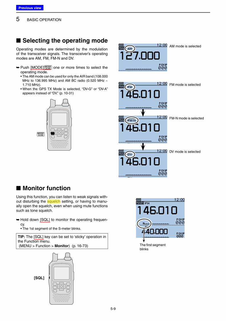
■ Monitor function
Using this function, you can listen to weak signals with-out disturbing the squelch setting, or having to manu-ally open the squelch, even when using mute functions such as tone squelch.
➥ Hold down [SQL] to monitor the operating frequen-cy.
• The 1st segment of the S-meter blinks.
The first segment blinks
■ Selecting the operating mode
Operating modes are determined by the modulation of the transceiver signals. The transceiver’s operating modes are AM, FM, FM-N and DV.
➥ Push [MODE] one or more times to select the operating mode.
• The AM mode can be used for only the AIR band (108.000 MHz to 136.995 MHz) and AM BC radio (0.520 MHz ~ 1.710 MHz).
• When the GPS TX Mode is selected, “DV-G” or “DV-A” appears instead of “DV.” (p. 10-31)
FM mode is selected
FM-N mode is selected
DV mode is selected
AM mode is selected
[SQL]
TIP: The [SQL] key can be set to ‘sticky’ operation in the Function menu. (MENU > Function > Monitor) (p. 16-73)
Previous view
Icom
ハイライト表示
A function that mutes the audio output for certain signal levels.
5 BASIC OPERATION
5-10
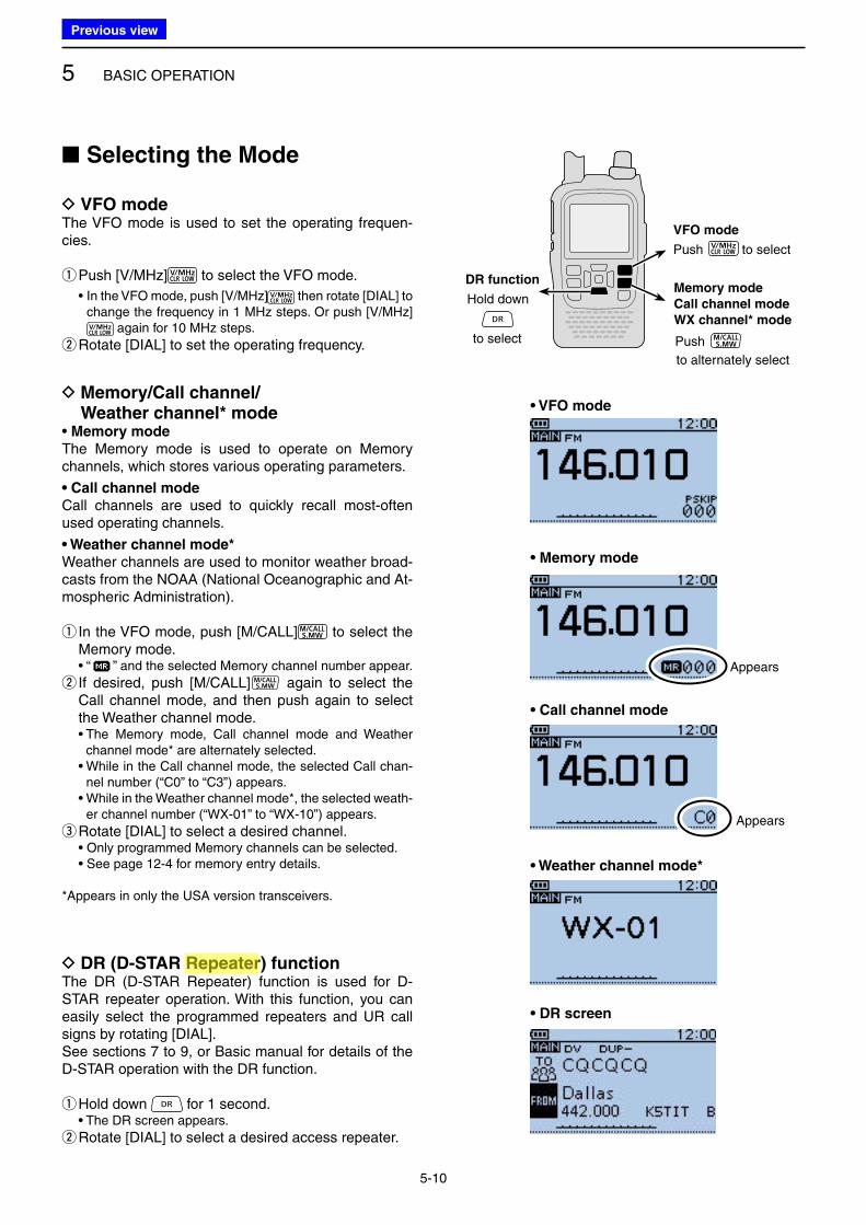
D VFO modeThe VFO mode is used to set the operating frequen-cies.
qPush [V/MHz] to select the VFO mode.
• In the VFO mode, push [V/MHz] then rotate [DIAL] to change the frequency in 1 MHz steps. Or push [V/MHz]
again for 10 MHz steps.
wRotate [DIAL] to set the operating frequency.
• VFO mode D Memory/Call channel/ Weather channel* mode
• Memory mode
The Memory mode is used to operate on Memory channels, which stores various operating parameters.
• Call channel mode
Call channels are used to quickly recall most-often used operating channels.
• Weather channel mode*
Weather channels are used to monitor weather broad-casts from the NOAA (National Oceanographic and At-mospheric Administration).
q In the VFO mode, push [M/CALL] to select the Memory mode.
• “ ” and the selected Memory channel number appear.
w If desired, push [M/CALL] again to select the Call channel mode, and then push again to select the Weather channel mode.
• The Memory mode, Call channel mode and Weather channel mode* are alternately selected.
• While in the Call channel mode, the selected Call chan-nel number (“C0” to “C3”) appears.
• While in the Weather channel mode*, the selected weath-er channel number (“WX-01” to “WX-10”) appears.
eRotate [DIAL] to select a desired channel. • Only programmed Memory channels can be selected. • See page 12-4 for memory entry details.
*Appears in only the USA version transceivers.
• Memory mode
Appears
• Call channel mode
D DR (D-STAR Repeater) functionThe DR (D-STAR Repeater) function is used for D-STAR repeater operation. With this function, you can easily select the programmed repeaters and UR call signs by rotating [DIAL].See sections 7 to 9, or Basic manual for details of the D-STAR operation with the DR function.
q Hold down for 1 second. • The DR screen appears.
wRotate [DIAL] to select a desired access repeater.
• DR screen
■ Selecting the Mode
• Weather channel mode*
Appears
Hold downMemory mode
Call channel mode
WX channel* mode
DR function
Push
VFO mode
to select
to select Push
to alternately select
Previous view
Icom
ハイライト表示
Radio systems that receive incoming signals and retransmit them to extend the communication area. Normally put on geographically high locations for VHF/UHF radios.
5 BASIC OPERATION
5-11
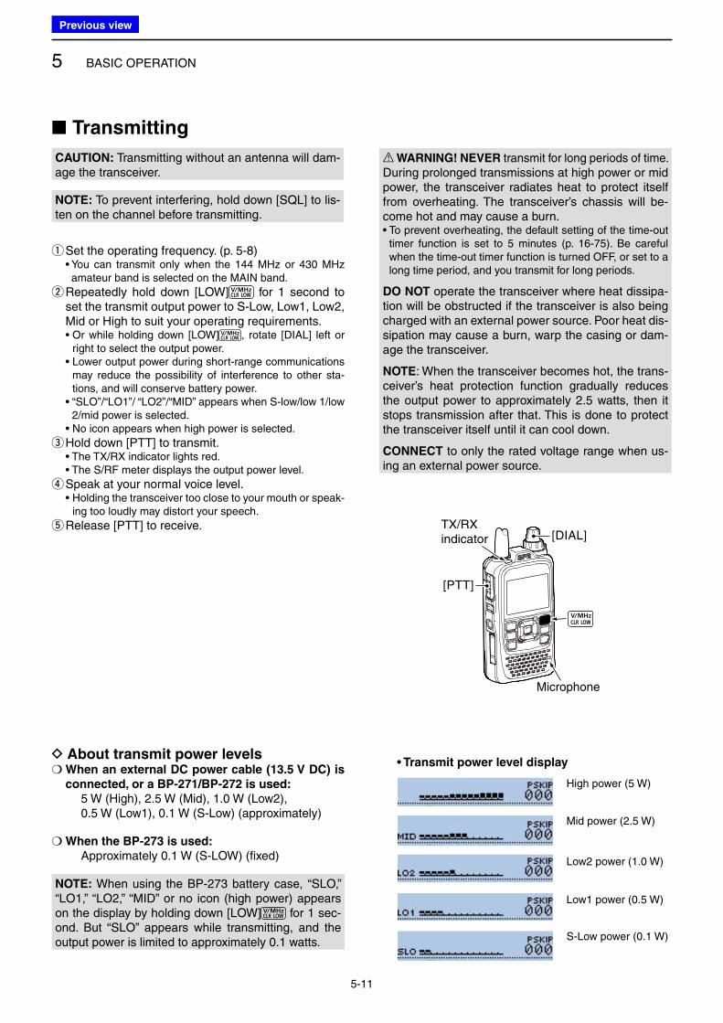
■ Transmitting
CAUTION: Transmitting without an antenna will dam-age the transceiver.
NOTE: To prevent interfering, hold down [SQL] to lis-ten on the channel before transmitting.
q Set the operating frequency. (p. 5-8) • You can transmit only when the 144 MHz or 430 MHz
amateur band is selected on the MAIN band.
w Repeatedly hold down [LOW] for 1 second to set the transmit output power to S-Low, Low1, Low2, Mid or High to suit your operating requirements.
• Or while holding down [LOW] , rotate [DIAL] left or right to select the output power.
• Lower output power during short-range communications may reduce the possibility of interference to other sta-tions, and will conserve battery power.
• “SLO”/“LO1”/ “LO2”/“MID” appears when S-low/low 1/low 2/mid power is selected.
• No icon appears when high power is selected.
e Hold down [PTT] to transmit. • The TX/RX indicator lights red. • The S/RF meter displays the output power level.
r Speak at your normal voice level. • Holding the transceiver too close to your mouth or speak-
ing too loudly may distort your speech.
t Release [PTT] to receive.
D About transmit power levels❍ When an external DC power cable (13.5 V DC) is
connected, or a BP-271/BP-272 is used:
5 W (High), 2.5 W (Mid), 1.0 W (Low2), 0.5 W (Low1), 0.1 W (S-Low) (approximately)
❍ When the BP-273 is used:
Approximately 0.1 W (S-LOW) (fixed)
High power (5 W)
Mid power (2.5 W)
Low2 power (1.0 W)
S-Low power (0.1 W)
R WARNING! NEVER transmit for long periods of time.During prolonged transmissions at high power or mid power, the transceiver radiates heat to protect itself from overheating. The transceiver’s chassis will be-come hot and may cause a burn.• To prevent overheating, the default setting of the time-out
timer function is set to 5 minutes (p. 16-75). Be careful when the time-out timer function is turned OFF, or set to a long time period, and you transmit for long periods.
DO NOT operate the transceiver where heat dissipa-tion will be obstructed if the transceiver is also being charged with an external power source. Poor heat dis-sipation may cause a burn, warp the casing or dam-age the transceiver.
NOTE: When the transceiver becomes hot, the trans-ceiver’s heat protection function gradually reduces the output power to approximately 2.5 watts, then it stops transmission after that. This is done to protect the transceiver itself until it can cool down.
CONNECT to only the rated voltage range when us-ing an external power source.
[DIAL]
[PTT]
TX/RXindicator
Microphone
Low1 power (0.5 W)
• Transmit power level display
NOTE: When using the BP-273 battery case, “SLO,” “LO1,” “LO2,” “MID” or no icon (high power) appears on the display by holding down [LOW] for 1 sec-ond. But “SLO” appears while transmitting, and the output power is limited to approximately 0.1 watts.
Previous view
5 BASIC OPERATION
5-12
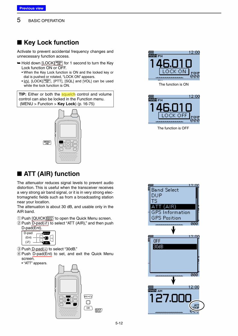
■ Key Lock function
Activate to prevent accidental frequency changes and unnecessary function access.
➥ Hold down [LOCK] for 1 second to turn the Key Lock function ON or OFF.
• When the Key Lock function is ON and the locked key or dial is pushed or rotated, “LOCK ON” appears.
• [ ], [LOCK] , [PTT], [SQL] and [VOL] can be used while the lock function is ON. The function is ON
The function is OFF
■ ATT (AIR) function
The attenuator reduces signal levels to prevent audio distortion. This is useful when the transceiver receives a very strong air band signal, or it is in very strong elec-tromagnetic fields such as from a broadcasting station near your location.The attenuation is about 30 dB, and usable only in the AIR band.
q Push [QUICK] to open the Quick Menu screen. w Push D-pad() to select “ATT (AIR),” and then push D-pad(Ent).
D-pad
(�)
(Ent)
e Push D-pad() to select “30dB.” r Push D-pad(Ent) to set, and exit the Quick Menu screen.
• “ATT” appears.
TIP: Either or both the squelch control and volume control can also be locked in the Function menu. (MENU > Function > Key Lock) (p. 16-75)
Previous view
Icom
ハイライト表示
A function that mutes the audio output for certain signal levels.
5 BASIC OPERATION
5-13
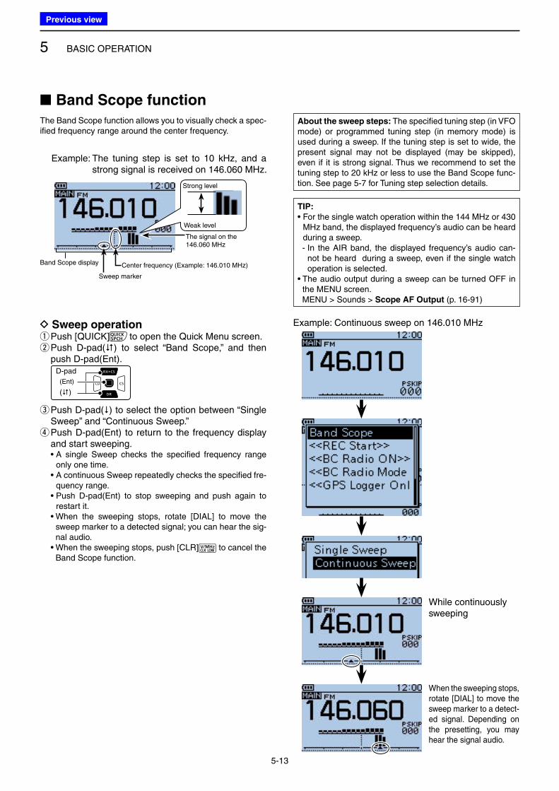
■ Band Scope function
The Band Scope function allows you to visually check a spec-ified frequency range around the center frequency.
Band Scope display
Sweep marker
Strong level
Weak level
The signal on the 146.060 MHz
D Sweep operation q Push [QUICK] to open the Quick Menu screen. w Push D-pad() to select “Band Scope,” and then push D-pad(Ent).
D-pad
(�)
(Ent)
e Push D-pad() to select the option between “Single Sweep” and “Continuous Sweep.” r Push D-pad(Ent) to return to the frequency display and start sweeping.
• A single Sweep checks the specified frequency range only one time.
• A continuous Sweep repeatedly checks the specified fre-quency range.
• Push D-pad(Ent) to stop sweeping and push again to restart it.
• When the sweeping stops, rotate [DIAL] to move the sweep marker to a detected signal; you can hear the sig-nal audio.
• When the sweeping stops, push [CLR] to cancel the Band Scope function.
Center frequency (Example: 146.010 MHz)
Example: The tuning step is set to 10 kHz, and a strong signal is received on 146.060 MHz.
Example: Continuous sweep on 146.010 MHz
While continuously sweeping
When the sweeping stops, rotate [DIAL] to move the sweep marker to a detect-ed signal. Depending on the presetting, you may hear the signal audio.
About the sweep steps: The specified tuning step (in VFO mode) or programmed tuning step (in memory mode) is used during a sweep. If the tuning step is set to wide, the present signal may not be displayed (may be skipped), even if it is strong signal. Thus we recommend to set the tuning step to 20 kHz or less to use the Band Scope func-tion. See page 5-7 for Tuning step selection details.
TIP:
• For the single watch operation within the 144 MHz or 430 MHz band, the displayed frequency’s audio can be heard during a sweep.
- In the AIR band, the displayed frequency’s audio can-not be heard during a sweep, even if the single watch operation is selected.
• The audio output during a sweep can be turned OFF in the MENU screen.
MENU > Sounds > Scope AF Output (p. 16-91)
Previous view
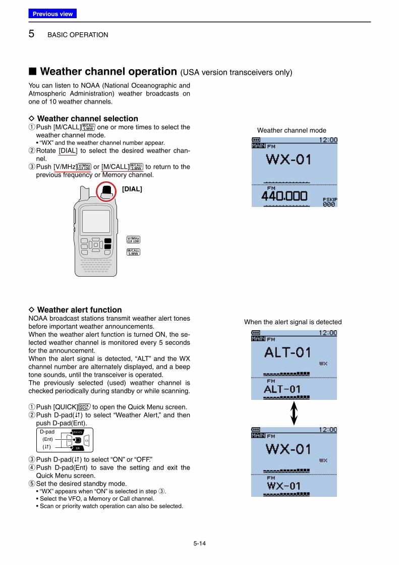
5 BASIC OPERATION
5-14
You can listen to NOAA (National Oceanographic and Atmospheric Administration) weather broadcasts on one of 10 weather channels.
D Weather channel selection q Push [M/CALL] one or more times to select the weather channel mode.
• “WX” and the weather channel number appear.
w Rotate [DIAL] to select the desired weather chan-nel. e Push [V/MHz] or [M/CALL] to return to the previous frequency or Memory channel.
■ Weather channel operation (USA version transceivers only)
D Weather alert functionNOAA broadcast stations transmit weather alert tones before important weather announcements.When the weather alert function is turned ON, the se-lected weather channel is monitored every 5 seconds for the announcement.When the alert signal is detected, “ALT” and the WX channel number are alternately displayed, and a beep tone sounds, until the transceiver is operated.The previously selected (used) weather channel is checked periodically during standby or while scanning.
q Push [QUICK] to open the Quick Menu screen. w Push D-pad() to select “Weather Alert,” and then push D-pad(Ent).
D-pad
(�)
(Ent)
e Push D-pad() to select “ON” or “OFF.” r Push D-pad(Ent) to save the setting and exit the Quick Menu screen. tSet the desired standby mode.
• “WX” appears when “ON” is selected in step e. • Select the VFO, a Memory or Call channel. • Scan or priority watch operation can also be selected.
[DIAL]
Weather channel mode
When the alert signal is detected
Previous view
6-1
Section 6 BC RADIO OPERATION
■ Basic operation ................................................................... 6-2
D Description ..................................................................... 6-2
D Turning ON the BC Radio ............................................... 6-2
D Listening to the BC Radio while monitoring
two ham bands ............................................................... 6-3
D Selecting the BC radio mode .......................................... 6-3
D Selecting the bank in the Memory bank mode ................. 6-4
D Selecting the AM/FM radio mode ................................... 6-5
D Searching for a BC Radio signal .................................... 6-5
D Using the Attenuator function ......................................... 6-6
D Setting the squelch level ................................................. 6-7
D Using the Monitor function .............................................. 6-7
D Setting a tuning step (AM Only) ..................................... 6-8
■ Adding or editing a BC Radio memory ............................... 6-9
D Using the BC Radio Memory .......................................... 6-9
D Add a BC Radio memory ............................................... 6-9
D Deleting a BC Radio memory ....................................... 6-12
D Editing a BC radio memory .......................................... 6-13
D Rearranging the display order of the
BC Radio memory ........................................................ 6-14
■ Skip setting for the BC radio memory ............................... 6-15
■ Using the BC Radio Mode ................................................ 6-16
■ BC Radio settings ............................................................. 6-17
D FM Antenna .................................................................. 6-17
D Power Save (BC Radio) ................................................ 6-17
D Auto Mute ..................................................................... 6-18
D Volume Select .............................................................. 6-19
D BC Radio Level ............................................................. 6-20
Previous view
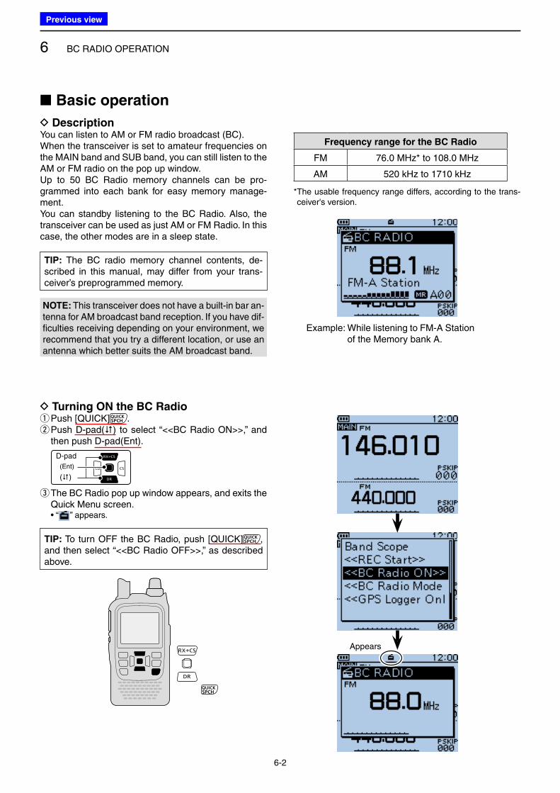
6 BC RADIO OPERATION
6-2
■ Basic operation
D DescriptionYou can listen to AM or FM radio broadcast (BC).When the transceiver is set to amateur frequencies on the MAIN band and SUB band, you can still listen to the AM or FM radio on the pop up window.Up to 50 BC Radio memory channels can be pro-grammed into each bank for easy memory manage-ment.You can standby listening to the BC Radio. Also, the transceiver can be used as just AM or FM Radio. In this case, the other modes are in a sleep state.
Frequency range for the BC Radio
FM 76.0 MHz* to 108.0 MHz
AM 520 kHz to 1710 kHz
* The usable frequency range differs, according to the trans-ceiver's version.
D Turning ON the BC Radio qPush [QUICK] . w Push D-pad() to select “<<BC Radio ON>>,” and then push D-pad(Ent).
D-pad
(�)
(Ent)
e The BC Radio pop up window appears, and exits the Quick Menu screen.
• “ ” appears.
Example: While listening to FM-A Station of the Memory bank A.
Appears
NOTE: This transceiver does not have a built-in bar an-tenna for AM broadcast band reception. If you have dif-ficulties receiving depending on your environment, we recommend that you try a different location, or use an antenna which better suits the AM broadcast band.
TIP: The BC radio memory channel contents, de-scribed in this manual, may differ from your trans-ceiver’s preprogrammed memory.
TIP: To turn OFF the BC Radio, push [QUICK] , and then select “<<BC Radio OFF>>,” as described above.
Previous view
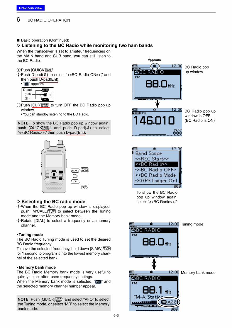
6 BC RADIO OPERATION
6-3
When the transceiver is set to amateur frequencies on the MAIN band and SUB band, you can still listen to the BC Radio.
qPush [QUICK] . w Push D-pad() to select “<<BC Radio ON>>,” and then push D-pad(Ent).
• “ ” appears.
D-pad
(�)
(Ent)
e Push [CLR] to turn OFF the BC Radio pop up window.
• You can standby listening to the BC Radio.
D Selecting the BC radio mode q When the BC Radio pop up window is displayed, push [M/CALL] to select between the Tuning mode and the Memory bank mode. w Rotate [DIAL] to select a frequency or a memory channel.
• Tuning mode
The BC Radio Tuning mode is used to set the desired BC Radio frequency.To save the selected frequency, hold down [S.MW] for 1 second to program it into the lowest memory chan-nel of the selected bank.
• Memory bank mode
The BC Radio Memory bank mode is very useful to quickly select often-used frequency settings.When the Memory bank mode is selected, “ ” and the selected memory channel number appear.
■ Basic operation (Continued)
D Listening to the BC Radio while monitoring two ham bands
Appears
BC Radio pop up window
BC Radio pop up window is OFF(BC Radio is ON)
Tuning mode
Memory bank mode
To show the BC Radio pop up window again, select “<<BC Radio>>.”
NOTE: To show the BC Radio pop up window again, push [QUICK] , and push D-pad() to select “<<BC Radio>>,” then push D-pad(Ent).
NOTE: Push [QUICK] , and select “VFO” to select the Tuning mode, or select “MR” to select the Memory bank mode.
Previous view
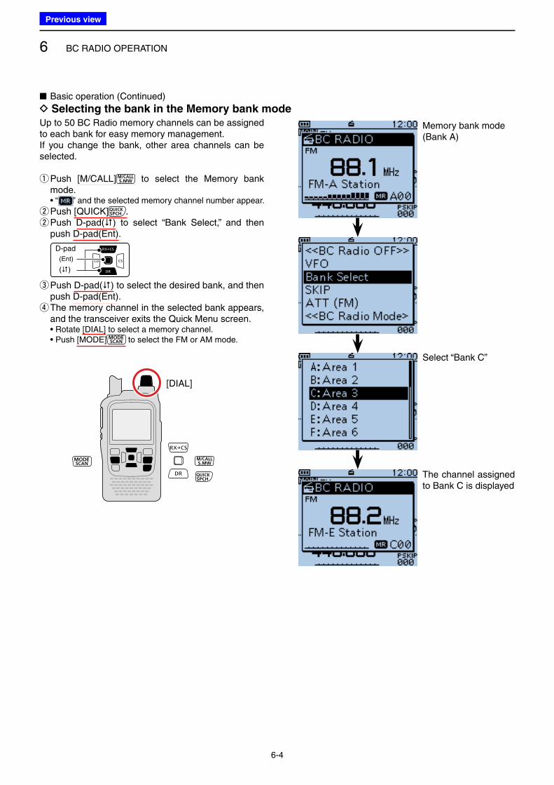
6 BC RADIO OPERATION
6-4
Up to 50 BC Radio memory channels can be assigned to each bank for easy memory management.If you change the bank, other area channels can be selected.
q Push [M/CALL] to select the Memory bank mode.
• “ ” and the selected memory channel number appear.
w Push [QUICK] . w Push D-pad() to select “Bank Select,” and then push D-pad(Ent).
D-pad
(�)
(Ent)
e Push D-pad() to select the desired bank, and then push D-pad(Ent). r The memory channel in the selected bank appears, and the transceiver exits the Quick Menu screen.
• Rotate [DIAL] to select a memory channel. • Push [MODE] to select the FM or AM mode.
■ Basic operation (Continued)
D Selecting the bank in the Memory bank mode
[DIAL]
Memory bank mode (Bank A)
Select “Bank C”
The channel assigned to Bank C is displayed
Previous view
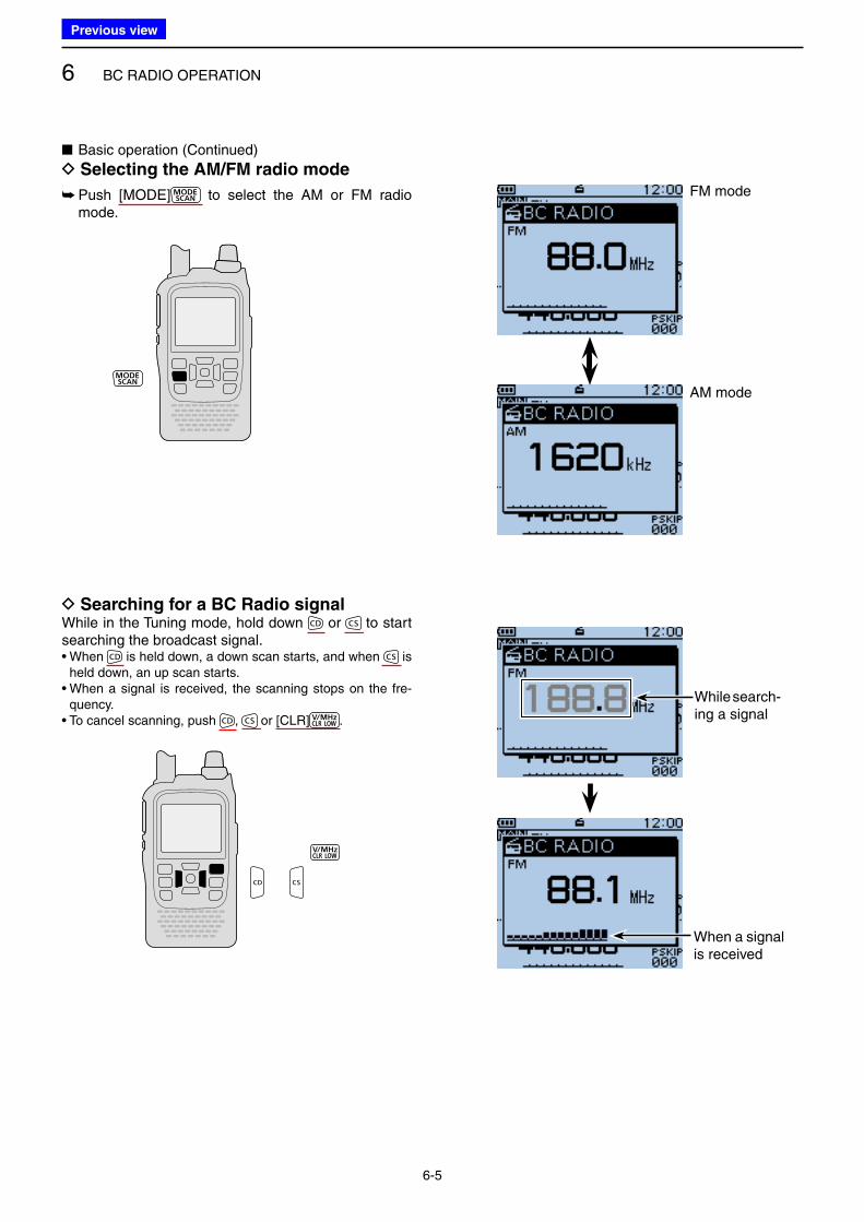
6 BC RADIO OPERATION
6-5
➥ Push [MODE] to select the AM or FM radio mode.
■ Basic operation (Continued)
D Selecting the AM/FM radio mode
D Searching for a BC Radio signalWhile in the Tuning mode, hold down or to start searching the broadcast signal.• When is held down, a down scan starts, and when is
held down, an up scan starts.• When a signal is received, the scanning stops on the fre-
quency.• To cancel scanning, push , or [CLR] .
FM mode
AM mode
While search-ing a signal
When a signal is received
Previous view
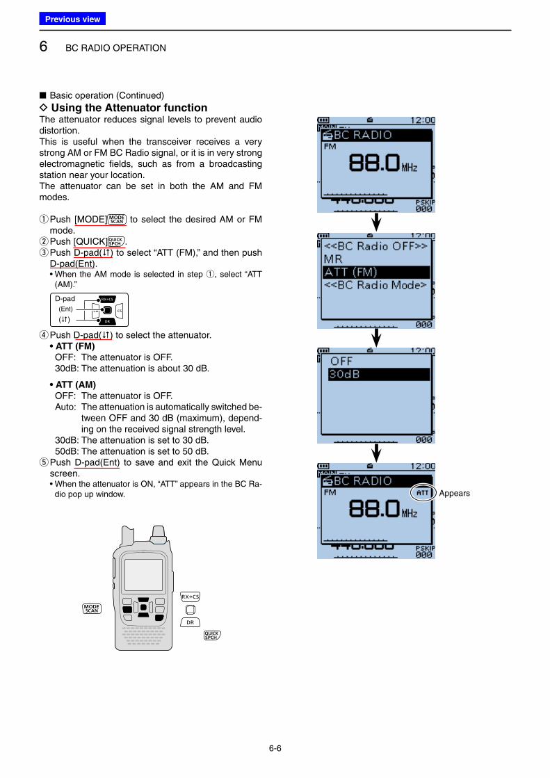
6 BC RADIO OPERATION
6-6
■ Basic operation (Continued)
D Using the Attenuator functionThe attenuator reduces signal levels to prevent audio distortion.This is useful when the transceiver receives a very strong AM or FM BC Radio signal, or it is in very strong electromagnetic fields, such as from a broadcasting station near your location.The attenuator can be set in both the AM and FM modes.
q Push [MODE] to select the desired AM or FM mode. wPush [QUICK] . e Push D-pad() to select “ATT (FM),” and then push D-pad(Ent).
• When the AM mode is selected in step q, select “ATT (AM).”
D-pad
(�)
(Ent)
r Push D-pad() to select the attenuator. • ATT (FM)
OFF: The attenuator is OFF. 30dB: The attenuation is about 30 dB.
• ATT (AM)
OFF: The attenuator is OFF. Auto: The attenuation is automatically switched be-
tween OFF and 30 dB (maximum), depend-ing on the received signal strength level.
30dB: The attenuation is set to 30 dB. 50dB: The attenuation is set to 50 dB.
t Push D-pad(Ent) to save and exit the Quick Menu screen.
• When the attenuator is ON, “ATT” appears in the BC Ra-dio pop up window. Appears
Previous view
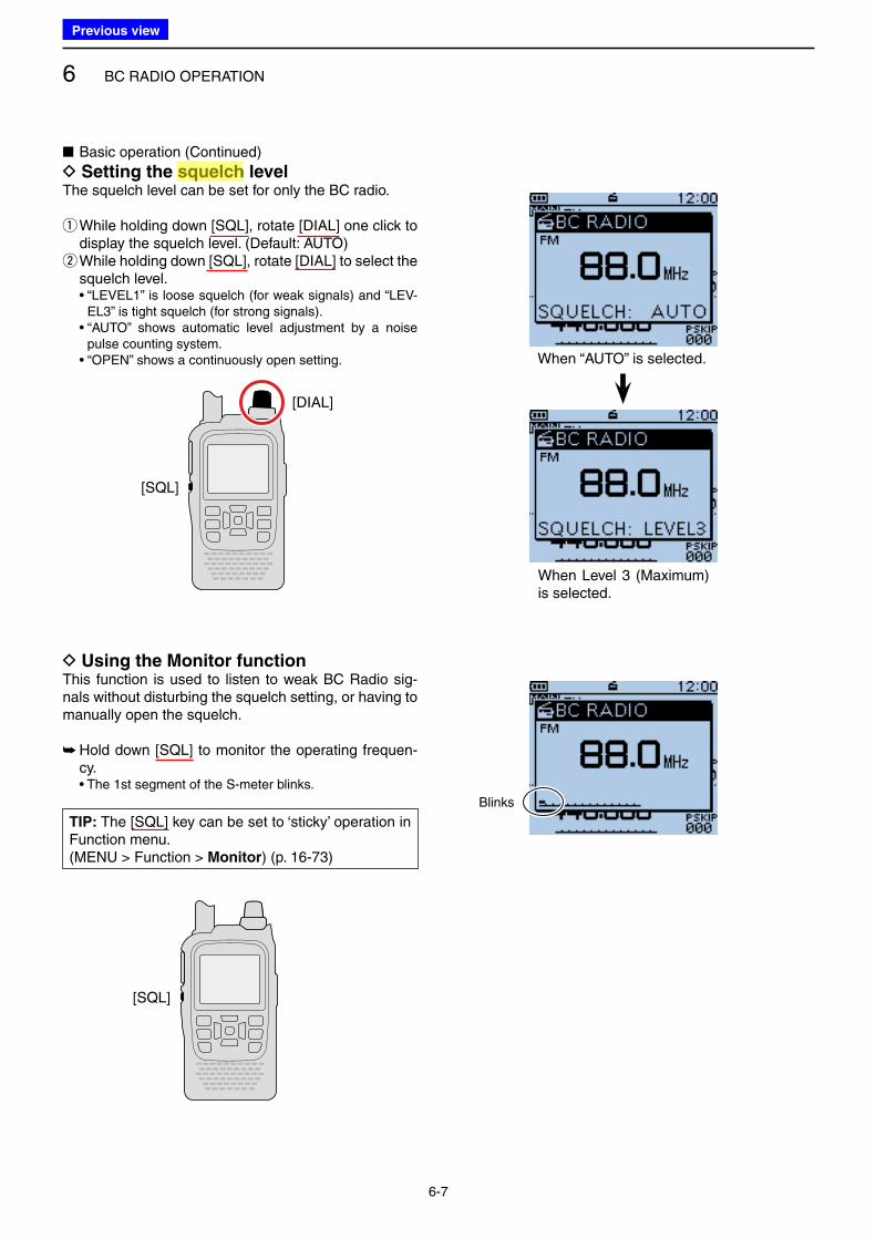
6 BC RADIO OPERATION
6-7
■ Basic operation (Continued)
D Setting the squelch levelThe squelch level can be set for only the BC radio.
q While holding down [SQL], rotate [DIAL] one click to display the squelch level. (Default: AUTO) w While holding down [SQL], rotate [DIAL] to select the squelch level.
• “LEVEL1” is loose squelch (for weak signals) and “LEV-EL3” is tight squelch (for strong signals).
• “AUTO” shows automatic level adjustment by a noise pulse counting system.
• “OPEN” shows a continuously open setting.
[DIAL]
[SQL]
D Using the Monitor functionThis function is used to listen to weak BC Radio sig-nals without disturbing the squelch setting, or having to manually open the squelch.
➥ Hold down [SQL] to monitor the operating frequen-cy.
• The 1st segment of the S-meter blinks.
[SQL]
When “AUTO” is selected.
When Level 3 (Maximum) is selected.
Blinks
TIP: The [SQL] key can be set to ‘sticky’ operation in Function menu.(MENU > Function > Monitor) (p. 16-73)
Previous view
Icom
ハイライト表示
A function that mutes the audio output for certain signal levels.
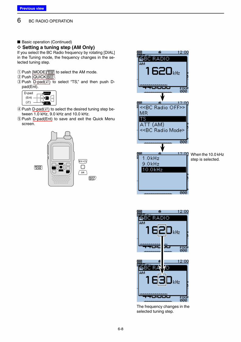
6 BC RADIO OPERATION
6-8
■ Basic operation (Continued)
D Setting a tuning step (AM Only)If you select the BC Radio frequency by rotating [DIAL] in the Tuning mode, the frequency changes in the se-lected tuning step.
q Push [MODE] to select the AM mode. wPush [QUICK] . e Push D-pad() to select “TS,” and then push D-pad(Ent).
D-pad
(�)
(Ent)
r Push D-pad() to select the desired tuning step be-tween 1.0 kHz, 9.0 kHz and 10.0 kHz. t Push D-pad(Ent) to save and exit the Quick Menu screen.
When the 10.0 kHz step is selected.
The frequency changes in the selected tuning step.
Previous view
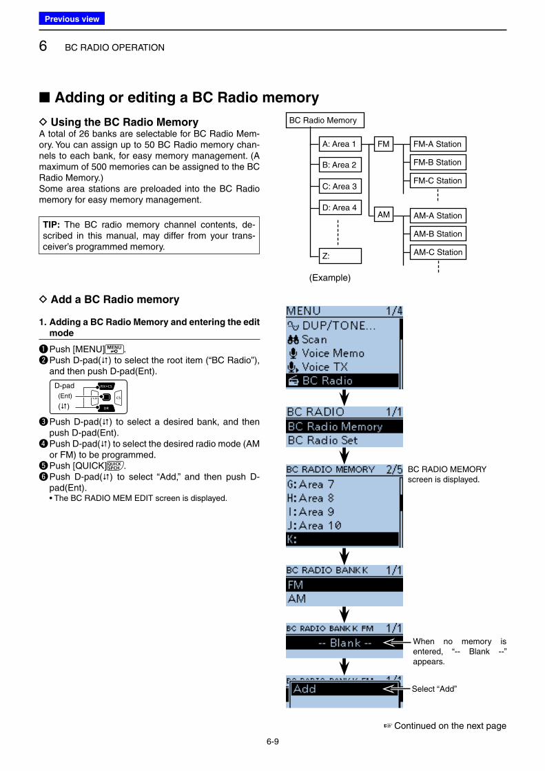
6 BC RADIO OPERATION
6-9
D Add a BC Radio memory
1. Adding a BC Radio Memory and entering the edit
mode
q Push [MENU] . w Push D-pad() to select the root item (“BC Radio”),
and then push D-pad(Ent).
D-pad
(�)
(Ent)
e Push D-pad() to select a desired bank, and then push D-pad(Ent).
r Push D-pad() to select the desired radio mode (AM or FM) to be programmed.
t Push [QUICK] .y Push D-pad() to select “Add,” and then push D-
pad(Ent). • The BC RADIO MEM EDIT screen is displayed.
BC RADIO MEMORY screen is displayed.
■ Adding or editing a BC Radio memory
☞ Continued on the next page
BC Radio Memory
A: Area 1
C: Area 3
B: Area 2
D: Area 4
Z:
FM
AM
FM-A Station
FM-B Station
FM-C Station
AM-A Station
AM-B Station
AM-C Station
D Using the BC Radio MemoryA total of 26 banks are selectable for BC Radio Mem-ory. You can assign up to 50 BC Radio memory chan-nels to each bank, for easy memory management. (A maximum of 500 memories can be assigned to the BC Radio Memory.)Some area stations are preloaded into the BC Radio memory for easy memory management.
Select “Add”
When no memory is entered, “-- Blank --” appears.
(Example)
TIP: The BC radio memory channel contents, de-scribed in this manual, may differ from your trans-ceiver’s programmed memory.
Previous view
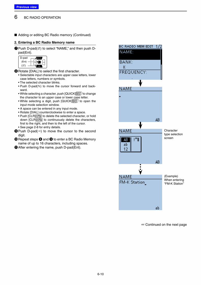
6 BC RADIO OPERATION
6-10
2. Entering a BC Radio Memory name
u Push D-pad() to select “NAME,” and then push D-pad(Ent).
D-pad
(�)
(Ent)
i Rotate [DIAL] to select the first character. • Selectable input characters are upper case letters, lower
case letters, numbers or symbols. • The selected character blinks. • Push D-pad() to move the cursor forward and back-
ward. • While selecting a character, push [QUICK] to change
the character to an upper case or lower case letter. • While selecting a digit, push [QUICK] to open the
input mode selection window. • A space can be entered in any input mode. • Rotate [DIAL] counterclockwise to enter a space. • Push [CLR] to delete the selected character, or hold
down [CLR] to continuously delete the characters, first to the right, and then to the left of the cursor.
• See page 2-8 for entry details.
o Push D-pad() to move the cursor to the second digit.
!0 Repeat steps i and o to enter a BC Radio Memory name of up to 16 characters, including spaces.
!1 After entering the name, push D-pad(Ent).
Character type selection screen
(Example)When entering “FM-K Station”
☞ Continued on the next page
■ Adding or editing BC Radio memory (Continued)
Previous view
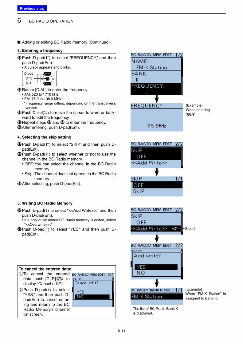
6 BC RADIO OPERATION
6-11
3. Entering a frequency
!2 Push D-pad() to select “FREQUENCY,” and then push D-pad(Ent).
• A cursor appears and blinks.
D-pad
(�)
(Ent)
!3 Rotate [DIAL] to enter the frequency. • AM: 520 to 1710 kHz • FM: 76.0 to 108.0 MHz* * Frequency range differs, depending on the transceiver’s
version.
!4 Push D-pad() to move the cursor forward or back-ward to edit the frequency.
!5 Repeat steps !3 and !4 to enter the frequency.!6 After entering, push D-pad(Ent).
4. Selecting the skip setting
!7 Push D-pad() to select “SKIP,” and then push D-pad(Ent).
!8 Push D-pad() to select whether or not to use the channel in the BC Radio memory.
• OFF: You can select the channel in the BC Radio memory.
• Skip: The channel does not appear in the BC Radio memory.
!9 After selecting, push D-pad(Ent).
5. Writing BC Radio Memory
@0 Push D-pad() to select “<<Add Write>>,” and then push D-pad(Ent).
• If a previously added BC Radio memory is edited, select “<<Overwrite>>.”
@1 Push D-pad() to select “YES,” and then push D-pad(Ent).
To cancel the entered data:
q To cancel the entered data, push [CLR] to display “Cancel edit?.”
w Push D-pad() to select “YES,” and then push D-pad(Ent) to cancel enter-ing and return to the BC Radio Memory’s channel list screen.
(Example)When entering “88.9”
(Example)When “FM-K Station” is assigned to Bank K.
Select
■ Adding or editing BC Radio memory (Continued)
The list of BC Radio Bank K is displayed.
Previous view
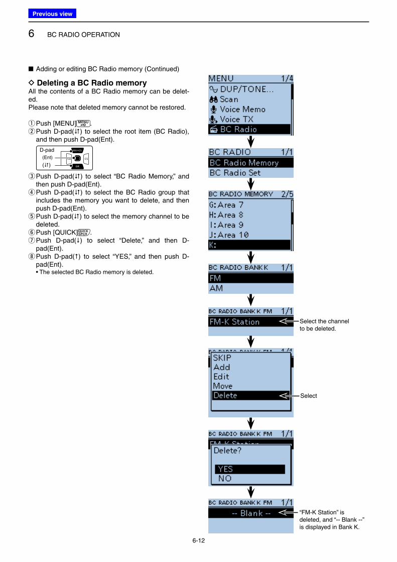
6 BC RADIO OPERATION
6-12
D Deleting a BC Radio memoryAll the contents of a BC Radio memory can be delet-ed.Please note that deleted memory cannot be restored.
qPush [MENU] . w Push D-pad() to select the root item (BC Radio), and then push D-pad(Ent).
D-pad
(�)
(Ent)
e Push D-pad() to select “BC Radio Memory,” and then push D-pad(Ent). r Push D-pad() to select the BC Radio group that includes the memory you want to delete, and then push D-pad(Ent). t Push D-pad() to select the memory channel to be deleted. y Push [QUICK] . u Push D-pad() to select “Delete,” and then D-pad(Ent). i Push D-pad() to select “YES,” and then push D-pad(Ent).
• The selected BC Radio memory is deleted.
■ Adding or editing BC Radio memory (Continued)
Select the channel to be deleted.
Select
“FM-K Station” is deleted, and “-- Blank --” is displayed in Bank K.
Previous view
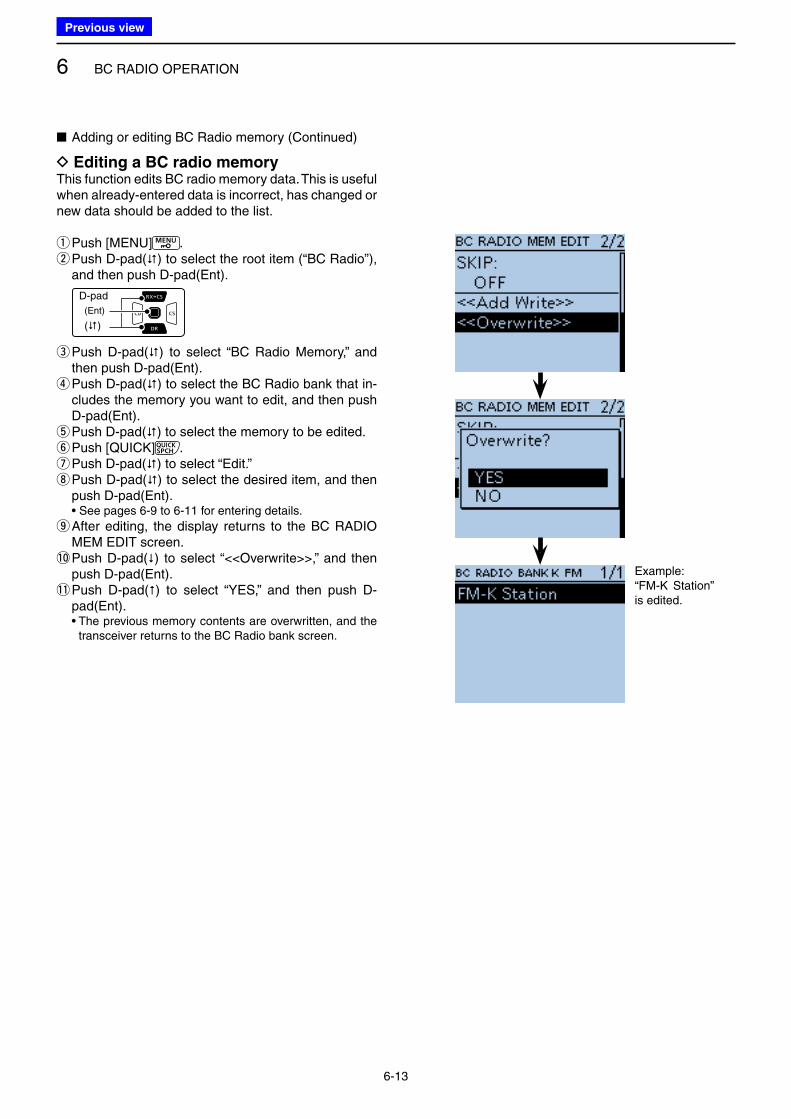
6 BC RADIO OPERATION
6-13
D Editing a BC radio memoryThis function edits BC radio memory data. This is useful when already-entered data is incorrect, has changed or new data should be added to the list.
qPush [MENU] . w Push D-pad() to select the root item (“BC Radio”), and then push D-pad(Ent).
D-pad
(�)
(Ent)
e Push D-pad() to select “BC Radio Memory,” and then push D-pad(Ent). r Push D-pad() to select the BC Radio bank that in-cludes the memory you want to edit, and then push D-pad(Ent). t Push D-pad() to select the memory to be edited. yPush [QUICK] . u Push D-pad() to select “Edit.” i Push D-pad() to select the desired item, and then push D-pad(Ent).
• See pages 6-9 to 6-11 for entering details.
o After editing, the display returns to the BC RADIO MEM EDIT screen.
!0 Push D-pad() to select “<<Overwrite>>,” and then push D-pad(Ent).
!1 Push D-pad() to select “YES,” and then push D-pad(Ent).
• The previous memory contents are overwritten, and the transceiver returns to the BC Radio bank screen.
Example:“FM-K Station” is edited.
■ Adding or editing BC Radio memory (Continued)
Previous view
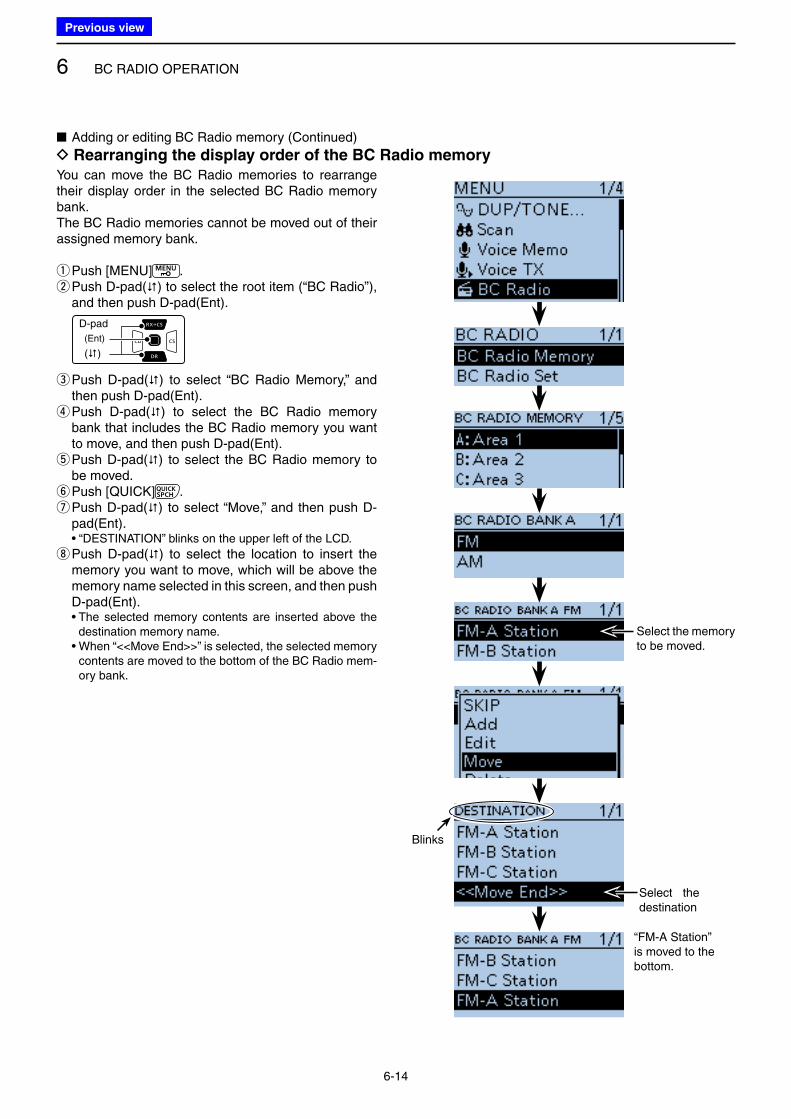
6 BC RADIO OPERATION
6-14
You can move the BC Radio memories to rearrange their display order in the selected BC Radio memory bank.The BC Radio memories cannot be moved out of their assigned memory bank.
qPush [MENU] . w Push D-pad() to select the root item (“BC Radio”), and then push D-pad(Ent).
D-pad
(�)
(Ent)
e Push D-pad() to select “BC Radio Memory,” and then push D-pad(Ent). r Push D-pad() to select the BC Radio memory bank that includes the BC Radio memory you want to move, and then push D-pad(Ent). t Push D-pad() to select the BC Radio memory to be moved. yPush [QUICK] . u Push D-pad() to select “Move,” and then push D-pad(Ent).
• “DESTINATION” blinks on the upper left of the LCD.
i Push D-pad() to select the location to insert the memory you want to move, which will be above the memory name selected in this screen, and then push D-pad(Ent).
• The selected memory contents are inserted above the destination memory name.
• When “<<Move End>>” is selected, the selected memory contents are moved to the bottom of the BC Radio mem-ory bank.
■ Adding or editing BC Radio memory (Continued)
D Rearranging the display order of the BC Radio memory
Select the memory to be moved.
Blinks
Select the destination
“FM-A Station” is moved to the bottom.
Previous view
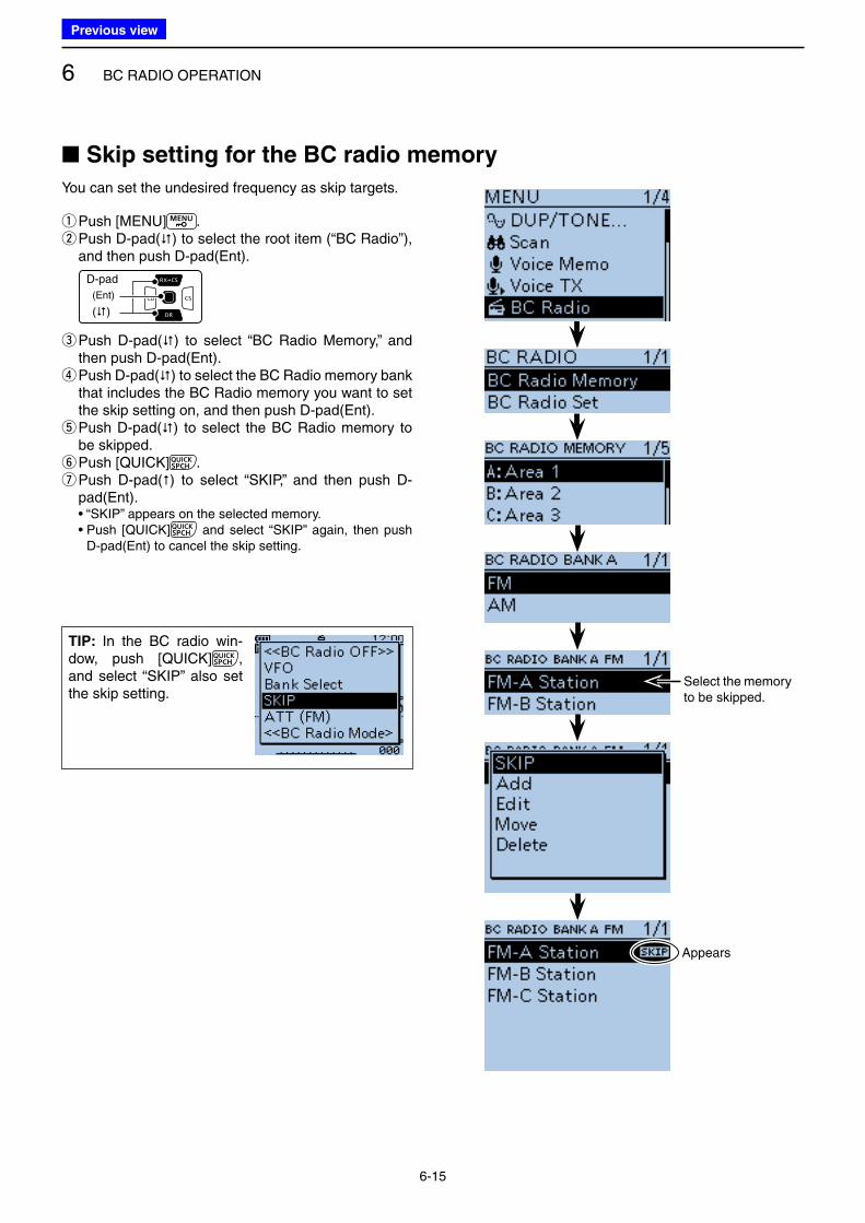
6 BC RADIO OPERATION
6-15
You can set the undesired frequency as skip targets.
qPush [MENU] . w Push D-pad() to select the root item (“BC Radio”), and then push D-pad(Ent).
D-pad
(�)
(Ent)
e Push D-pad() to select “BC Radio Memory,” and then push D-pad(Ent). r Push D-pad() to select the BC Radio memory bank that includes the BC Radio memory you want to set the skip setting on, and then push D-pad(Ent). t Push D-pad() to select the BC Radio memory to be skipped. yPush [QUICK] . u Push D-pad() to select “SKIP,” and then push D-pad(Ent).
• “SKIP” appears on the selected memory. • Push [QUICK] and select “SKIP” again, then push
D-pad(Ent) to cancel the skip setting.
■ Skip setting for the BC radio memory
TIP: In the BC radio win-dow, push [QUICK] , and select “SKIP” also set the skip setting.
Select the memory to be skipped.
Appears
Previous view
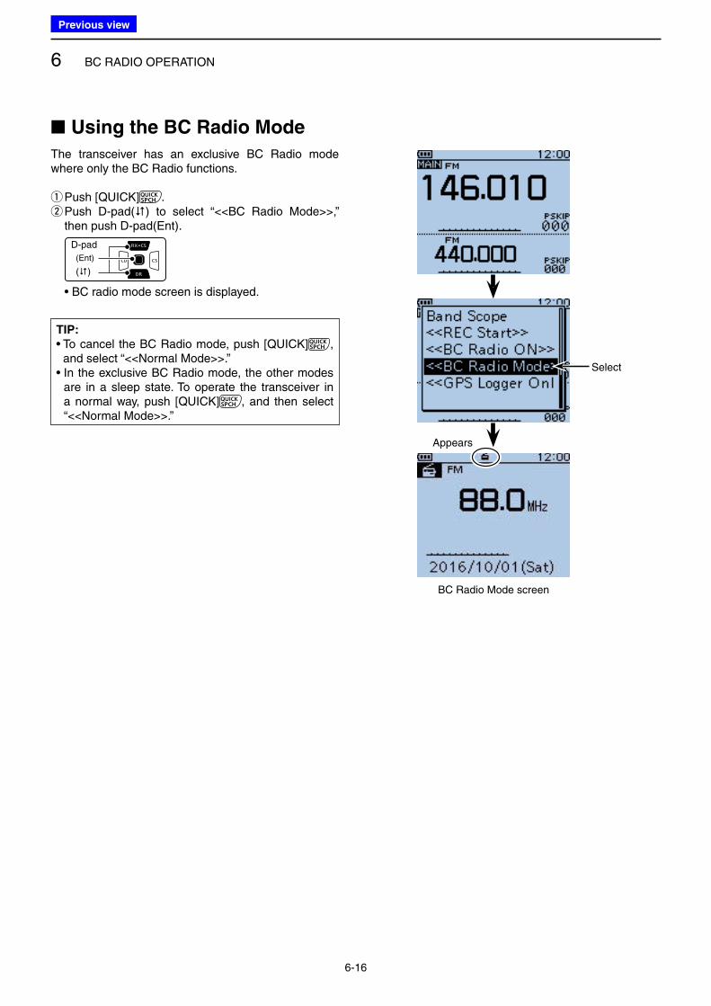
6 BC RADIO OPERATION
6-16
■ Using the BC Radio Mode
The transceiver has an exclusive BC Radio mode where only the BC Radio functions.
qPush [QUICK] . w Push D-pad() to select “<<BC Radio Mode>>,” then push D-pad(Ent).
D-pad
(�)
(Ent)
• BC radio mode screen is displayed.
Appears
Select
BC Radio Mode screen
TIP:
• To cancel the BC Radio mode, push [QUICK] , and select “<<Normal Mode>>.”
• In the exclusive BC Radio mode, the other modes are in a sleep state. To operate the transceiver in a normal way, push [QUICK] , and then select “<<Normal Mode>>.”
Previous view
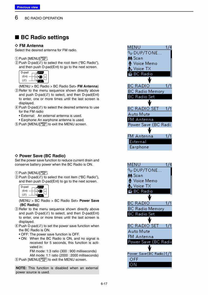
6 BC RADIO OPERATION
6-17
■ BC Radio settings
D FM AntennaSelect the desired antenna for FM radio.
qPush [MENU] . w Push D-pad() to select the root item (“BC Radio”), and then push D-pad(Ent) to go to the next screen.
D-pad
(�)
(Ent)
(MENU > BC Radio > BC Radio Set> FM Antenna) e Refer to the menu sequence shown directly above and push D-pad() to select, and then D-pad(Ent) to enter, one or more times until the last screen is displayed. r Push D-pad() to select the desired antenna to use for the FM radio
• External: An external antenna is used. • Earphone: An earphone antenna is used.
tPush [MENU] to exit the MENU screen.
D Power Save (BC Radio)Set the power save function to reduce current drain and conserve battery power when the BC Radio is ON.
qPush [MENU] . w Push D-pad() to select the root item (“BC Radio”), and then push D-pad(Ent) to go to the next screen.
D-pad
(�)
(Ent)
( MENU > BC Radio > BC Radio Set> Power Save
(BC Radio)) e Refer to the menu sequence shown directly above and push D-pad() to select, and then D-pad(Ent) to enter, one or more times until the last screen is displayed. r Push D-pad() to set the power save function when the BC Radio is ON.
• OFF: The power save function is OFF. • ON: When the BC Radio is ON, and no signal is
received for 5 seconds, this function is acti-vated in:
FM mode: 1:3 ratio (300 : 900 milliseconds) AM mode: 1:1 ratio (2000 : 2000 milliseconds)
tPush [MENU] to exit the MENU screen.
NOTE: This function is disabled when an external power source is used.
Previous view
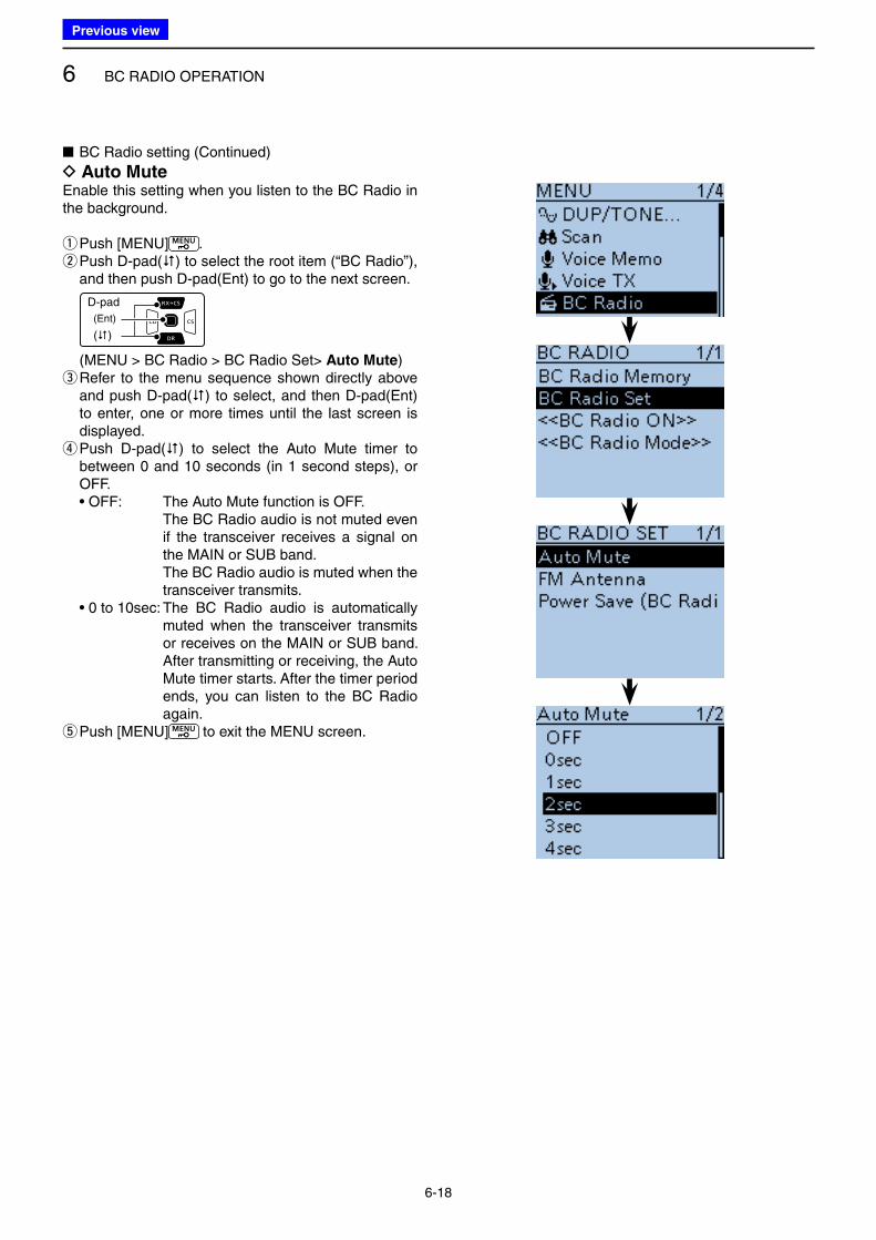
6 BC RADIO OPERATION
6-18
■ BC Radio setting (Continued)
D Auto MuteEnable this setting when you listen to the BC Radio in the background.
qPush [MENU] . w Push D-pad() to select the root item (“BC Radio”), and then push D-pad(Ent) to go to the next screen.
D-pad
(�)
(Ent)
(MENU > BC Radio > BC Radio Set> Auto Mute) e Refer to the menu sequence shown directly above and push D-pad() to select, and then D-pad(Ent) to enter, one or more times until the last screen is displayed. r Push D-pad() to select the Auto Mute timer to between 0 and 10 seconds (in 1 second steps), or OFF.
• OFF: The Auto Mute function is OFF. The BC Radio audio is not muted even
if the transceiver receives a signal on the MAIN or SUB band.
The BC Radio audio is muted when the transceiver transmits.
• 0 to 10sec: The BC Radio audio is automatically muted when the transceiver transmits or receives on the MAIN or SUB band. After transmitting or receiving, the Auto Mute timer starts. After the timer period ends, you can listen to the BC Radio again.
tPush [MENU] to exit the MENU screen.
Previous view
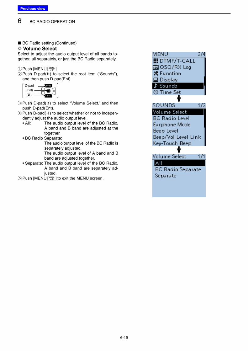
6 BC RADIO OPERATION
6-19
■ BC Radio setting (Continued)
D Volume SelectSelect to adjust the audio output level of all bands to-gether, all separately, or just the BC Radio separately.
qPush [MENU] . w Push D-pad() to select the root item (“Sounds”), and then push D-pad(Ent).
D-pad
(�)
(Ent)
e Push D-pad() to select “Volume Select,” and then push D-pad(Ent). r Push D-pad() to select whether or not to indepen-dently adjust the audio output level.
• All: The audio output level of the BC Radio, A band and B band are adjusted at the together.
• BC Radio Separate: The audio output level of the BC Radio is
separately adjusted. The audio output level of A band and B
band are adjusted together. • Separate: The audio output level of the BC Radio,
A band and B band are separately ad-justed.
tPush [MENU] to exit the MENU screen.
Previous view
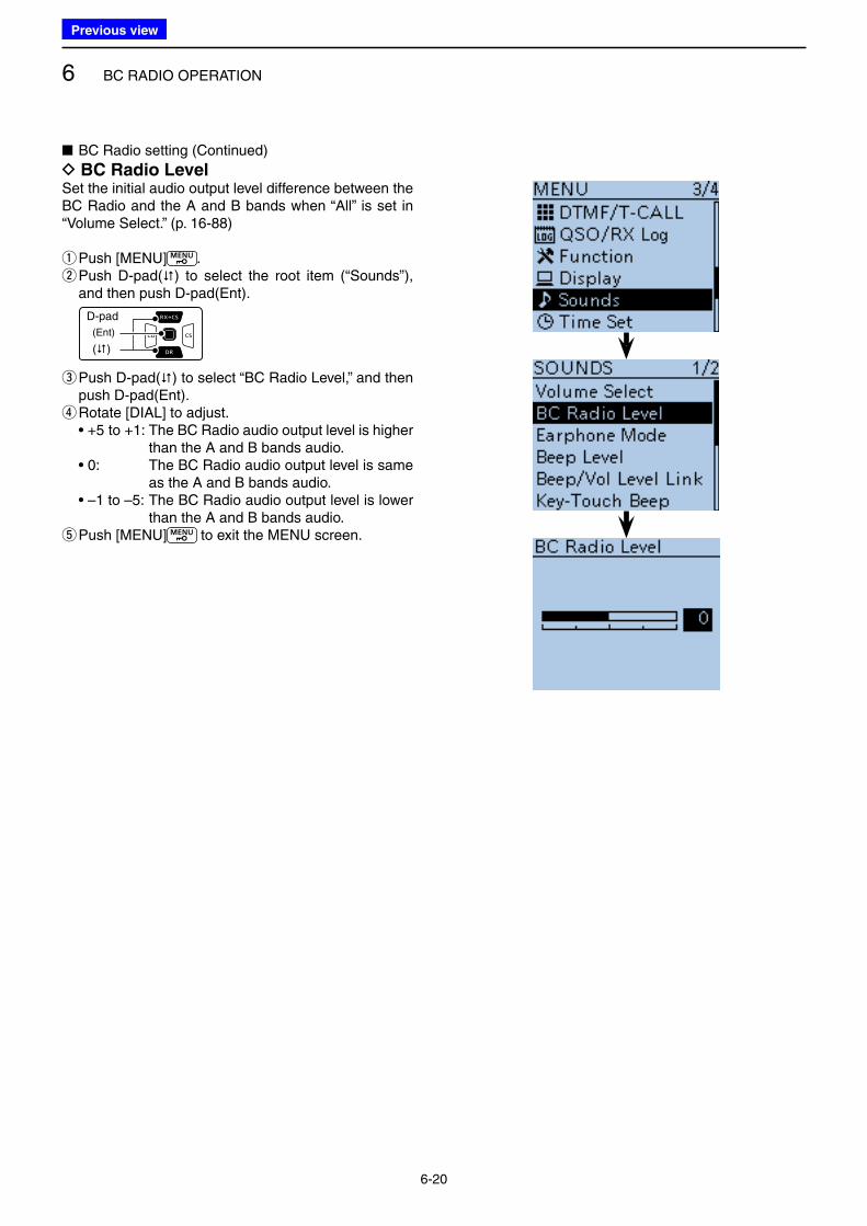
6 BC RADIO OPERATION
6-20
■ BC Radio setting (Continued)
D BC Radio LevelSet the initial audio output level difference between the BC Radio and the A and B bands when “All” is set in “Volume Select.” (p. 16-88)
qPush [MENU] . w Push D-pad() to select the root item (“Sounds”), and then push D-pad(Ent).
D-pad
(�)
(Ent)
e Push D-pad() to select “BC Radio Level,” and then push D-pad(Ent). r Rotate [DIAL] to adjust.
• +5 to +1: The BC Radio audio output level is higher than the A and B bands audio.
• 0: The BC Radio audio output level is same as the A and B bands audio.
• –1 to –5: The BC Radio audio output level is lower than the A and B bands audio.
tPush [MENU] to exit the MENU screen.
Previous view
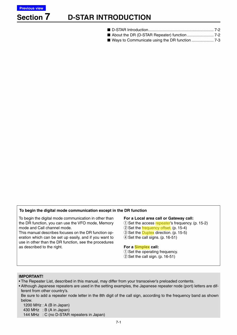
7-1
Section 7 D-STAR INTRODUCTION
IMPORTANT!
• The Repeater List, described in this manual, may differ from your transceiver’s preloaded contents.• Although Japanese repeaters are used in the setting examples, the Japanese repeater node (port) letters are dif-
ferent from other country’s. Be sure to add a repeater node letter in the 8th digit of the call sign, according to the frequency band as shown
below. 1200 MHz : A (B in Japan) 430 MHz : B (A in Japan) 144 MHz : C (no D-STAR repeaters in Japan)
■ D-STAR Introduction ........................................................... 7-2
■ About the DR (D-STAR Repeater) function ........................ 7-2
■ Ways to Communicate using the DR function .................... 7-3
To begin the digital mode communication in other than the DR function, you can use the VFO mode, Memory mode and Call channel mode.This manual describes focuses on the DR function op-eration which can be set up easily, and if you want to use in other than the DR function, see the procedures as described to the right.
For a Local area call or Gateway call:
q Set the access repeater’s frequency. (p. 15-2) wSet the frequency offset. (p. 15-4) eSet the Duplex direction. (p. 15-5) rSet the call signs. (p. 16-51)
For a Simplex call:
q Set the operating frequency. wSet the call sign. (p. 16-51)
To begin the digital mode communication except in the DR function
Previous view
Icom
ハイライト表示
An operating mode in which the transmit and receive frequencies are the same.
Icom
ハイライト表示
The difference between the transmit and receive frequencies.
Icom
ハイライト表示
Radio systems that receive incoming signals and retransmit them to extend the communication area. Normally put on geographically high locations for VHF/UHF radios.
Icom
ハイライト表示
An operating mode in which the transmit and receive frequencies are separated by an offset amount.
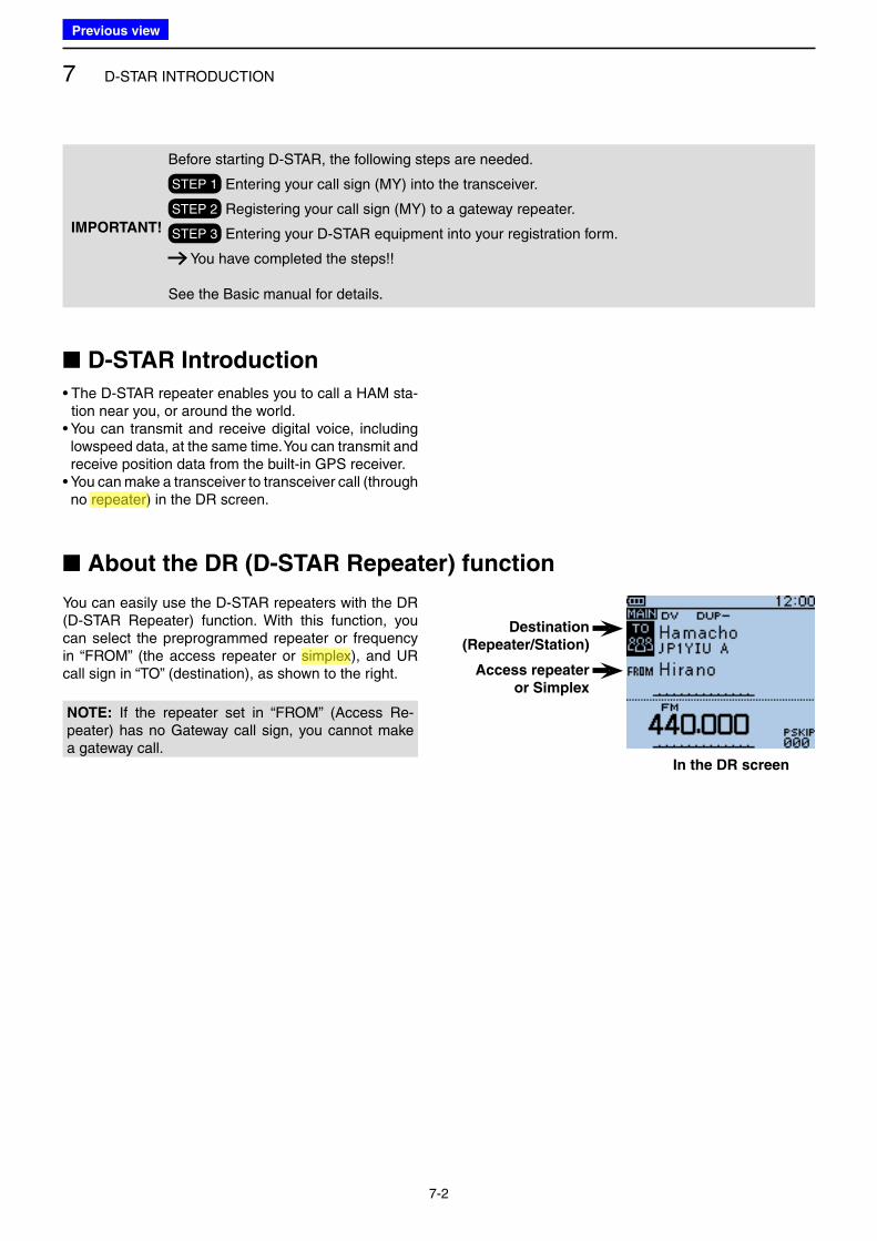
7 D-STAR INTRODUCTION
7-2
■ D-STAR Introduction
• The D-STAR repeater enables you to call a HAM sta-tion near you, or around the world.
• You can transmit and receive digital voice, including lowspeed data, at the same time. You can transmit and receive position data from the built-in GPS receiver.
• You can make a transceiver to transceiver call (through no repeater) in the DR screen.
■ About the DR (D-STAR Repeater) function
You can easily use the D-STAR repeaters with the DR (D-STAR Repeater) function. With this function, you can select the preprogrammed repeater or frequency in “FROM” (the access repeater or simplex), and UR call sign in “TO” (destination), as shown to the right.
Destination
(Repeater/Station)
Access repeater
or Simplex
In the DR screen
IMPORTANT!
Before starting D-STAR, the following steps are needed.
STEP 1 Entering your call sign (MY) into the transceiver.
STEP 2 Registering your call sign (MY) to a gateway repeater.
STEP 3 Entering your D-STAR equipment into your registration form.
You have completed the steps!!
See the Basic manual for details.
NOTE: If the repeater set in “FROM” (Access Re-peater) has no Gateway call sign, you cannot make a gateway call.
Previous view
Icom
ハイライト表示
Radio systems that receive incoming signals and retransmit them to extend the communication area. Normally put on geographically high locations for VHF/UHF radios.
Icom
ハイライト表示
An operating mode in which the transmit and receive frequencies are the same.
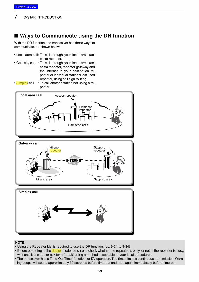
7 D-STAR INTRODUCTION
7-3
With the DR function, the transceiver has three ways to communicate, as shown below.
• Local area call : To call through your local area (ac-cess) repeater.
• Gateway call : To call through your local area (ac-cess) repeater, repeater gateway and the internet to your destination re-peater or individual station’s last used repeater, using call sign routing.
• Simplex call : To call another station not using a re-peater.
NOTE:
• Using the Repeater List is required to use the DR function. (pp. 9-24 to 9-34)• Before operating in the duplex mode, be sure to check whether the repeater is busy, or not. If the repeater is busy,
wait until it is clear, or ask for a “break” using a method acceptable to your local procedures.• The transceiver has a Time-Out Timer function for DV operation. The timer limits a continuous transmission. Warn-
ing beeps will sound approximately 30 seconds before time-out and then again immediately before time-out.
INTERNET
Access repeaterLocal area call
Gateway call
Simplex call
Hamachorepeater
Hamacho area
Hirano area Sapporo area
Hiranorepeater
Sappororepeater
■ Ways to Communicate using the DR function
Previous view
Icom
ハイライト表示
An operating mode in which the transmit and receive frequencies are the same.
Icom
ハイライト表示
Radio systems that receive incoming signals and retransmit them to extend the communication area. Normally put on geographically high locations for VHF/UHF radios.
Icom
ハイライト表示
An operating mode in which the transmit and receive frequencies are separated by an offset amount.
8-1
Section 8 D-STAR OPERATION <BASIC>
■ Setting “FROM” (Access repeater) ..................................... 8-2
D Using the preloaded Repeater List ................................. 8-3
D Using the DR scan ......................................................... 8-4
D Using the Repeater Search function .............................. 8-5
D Using the TX History ...................................................... 8-7
■ Setting “TO” (Destination) ................................................... 8-8
D Using “Local CQ” (Local Area call) ................................. 8-9
D Using “Gateway CQ” (Gateway call) ............................. 8-10
D Using “Your Call Sign” ................................................... 8-11
D Using RX History .......................................................... 8-12
D Using TX History .......................................................... 8-13
D Directly inputting (UR) .................................................. 8-14
D Directly inputting (RPT) ................................................ 8-15
■ Reflector operation ........................................................... 8-16
D What is the reflector? ................................................... 8-16
D Linking to a reflector ..................................................... 8-17
D Using a reflector ........................................................... 8-18
D Unlinking a reflector ...................................................... 8-19
D Reflector Echo Testing .................................................. 8-19
D Requesting repeater information .................................. 8-20
■ Updating the Repeater List ............................................... 8-21
IMPORTANT!
• The Repeater List described in this manual may differ from your transceiver’s Repeater List contents.• Although Japanese repeaters are used in the setting examples, the Japanese repeater node (port) letters are dif-
ferent from other country’s. Be sure to add a repeater node letter as the 8th digit in the call sign field, according to the repeater frequency
band, as shown below. 1200 MHz: A (B in Japan) 430 MHz: B (A in Japan) 144 MHz: C (no D-STAR repeaters in Japan)
Previous view
Icom
ハイライト表示
Radio systems that receive incoming signals and retransmit them to extend the communication area. Normally put on geographically high locations for VHF/UHF radios.
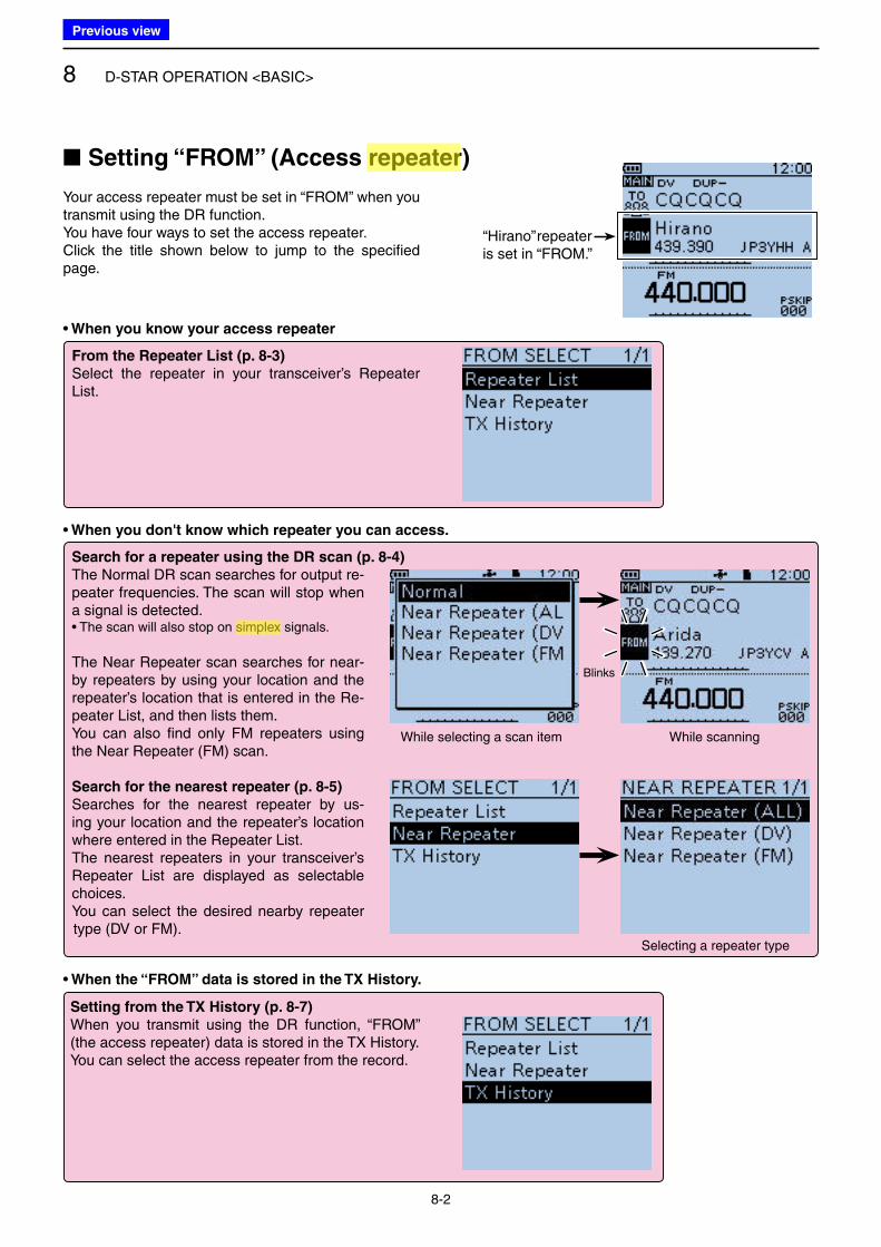
8 D-STAR OPERATION <BASIC>
8-2
• When you know your access repeater
From the Repeater List (p. 8-3)
Select the repeater in your transceiver’s Repeater List.
• When you don't know which repeater you can access.
• When the “FROM” data is stored in the TX History.
Setting from the TX History (p. 8-7)
When you transmit using the DR function, “FROM” (the access repeater) data is stored in the TX History.You can select the access repeater from the record.
Search for a repeater using the DR scan (p. 8-4)
The Normal DR scan searches for output re-peater frequencies. The scan will stop when a signal is detected.• The scan will also stop on simplex signals.
The Near Repeater scan searches for near-by repeaters by using your location and the repeater’s location that is entered in the Re-peater List, and then lists them.You can also find only FM repeaters using the Near Repeater (FM) scan.
Search for the nearest repeater (p. 8-5)
Searches for the nearest repeater by us-ing your location and the repeater’s location where entered in the Repeater List.The nearest repeaters in your transceiver’s Repeater List are displayed as selectable choices. You can select the desired nearby repeater type (DV or FM).
Your access repeater must be set in “FROM” when you transmit using the DR function.You have four ways to set the access repeater.Click the title shown below to jump to the specified page.
■ Setting “FROM” (Access repeater)
“Hirano” repeater is set in “FROM.”
Blinks
While selecting a scan item While scanning
Selecting a repeater type
Previous view
Icom
ハイライト表示
An operating mode in which the transmit and receive frequencies are the same.
Icom
ハイライト表示
Radio systems that receive incoming signals and retransmit them to extend the communication area. Normally put on geographically high locations for VHF/UHF radios.
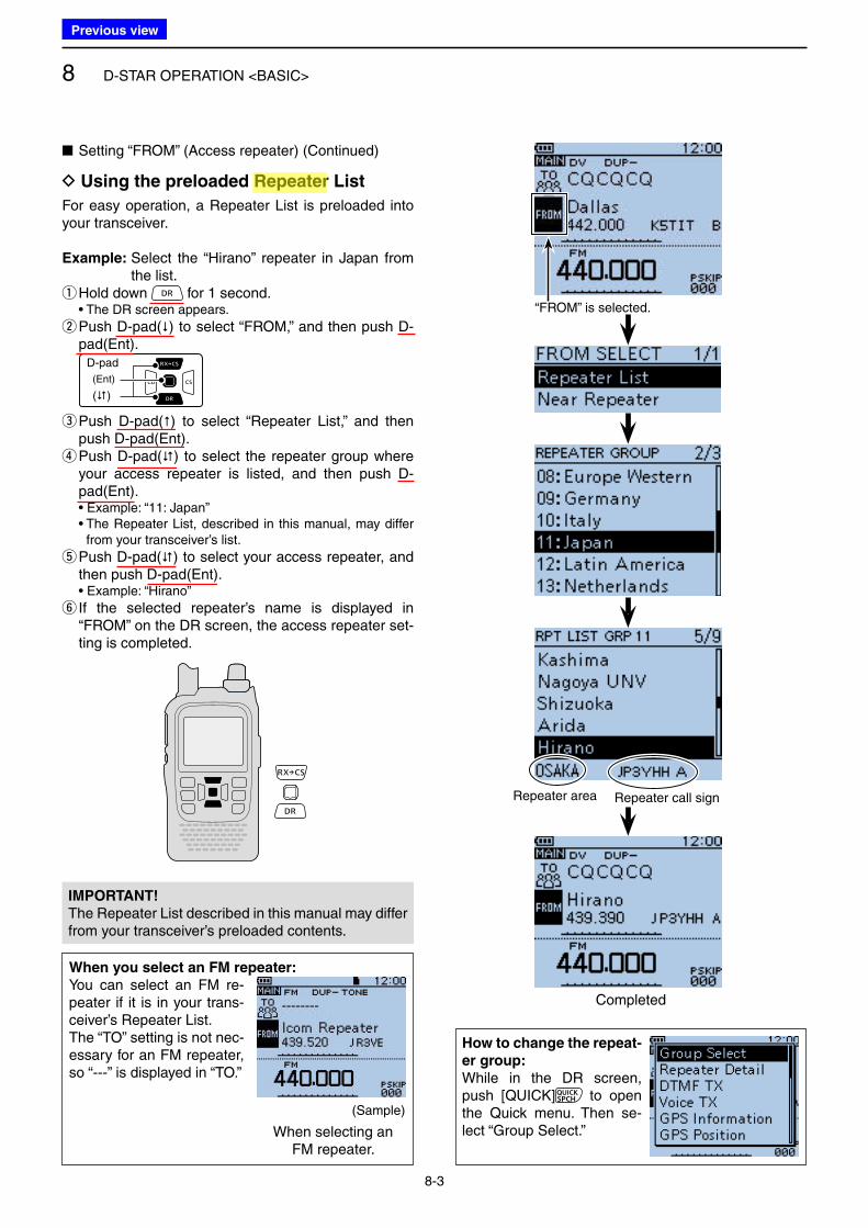
8 D-STAR OPERATION <BASIC>
8-3
For easy operation, a Repeater List is preloaded into your transceiver.
Example: Select the “Hirano” repeater in Japan from the list.
qHold down for 1 second. • The DR screen appears.
w Push D-pad() to select “FROM,” and then push D-pad(Ent).
D-pad
(�)
(Ent)
e Push D-pad() to select “Repeater List,” and then push D-pad(Ent). r Push D-pad() to select the repeater group where your access repeater is listed, and then push D-pad(Ent).
• Example: “11: Japan” • The Repeater List, described in this manual, may differ
from your transceiver’s list.
t Push D-pad() to select your access repeater, and then push D-pad(Ent).
• Example: “Hirano”
y If the selected repeater’s name is displayed in “FROM” on the DR screen, the access repeater set-ting is completed.
■ Setting “FROM” (Access repeater) (Continued)
D Using the preloaded Repeater List
“FROM” is selected.
Repeater area Repeater call sign
Completed
How to change the repeat-
er group:
While in the DR screen, push [QUICK] to open the Quick menu. Then se-lect “Group Select.”
IMPORTANT!
The Repeater List described in this manual may differ from your transceiver’s preloaded contents.
When you select an FM repeater:
You can select an FM re-peater if it is in your trans-ceiver’s Repeater List.The “TO” setting is not nec-essary for an FM repeater, so “---” is displayed in “TO.”
(Sample)
When selecting an FM repeater.
Previous view
Icom
ハイライト表示
Radio systems that receive incoming signals and retransmit them to extend the communication area. Normally put on geographically high locations for VHF/UHF radios.
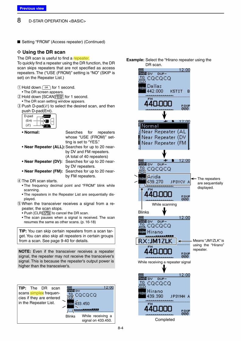
8 D-STAR OPERATION <BASIC>
8-4
The DR scan is useful to find a repeater.To quickly find a repeater using the DR function, the DR scan skips repeaters that are not specified as access repeaters. The (“USE (FROM)” setting is “NO” (SKIP is set) on the Repeater List.)
qHold down for 1 second. • The DR screen appears.
w Hold down [SCAN] for 1 second. • The DR scan setting window appears.
e Push D-pad() to select the desired scan, and then push D-pad(Ent).
D-pad
(�)
(Ent)
• Normal: Searches for repeaters whose “USE (FROM)” set-ting is set to “YES.”
• Near Repeater (ALL): Searches for up to 20 near-by DV and FM repeaters.
(A total of 40 repeaters) • Near Repeater (DV): Searches for up to 20 near-
by DV repeaters. • Near Repeater (FM): Searches for up to 20 near-
by FM repeaters. r The DR scan starts.
• The frequency decimal point and “FROM” blink while scanning.
• The repeaters in the Repeater List are sequentially dis-played.
t When the transceiver receives a signal from a re-peater, the scan stops.
• Push [CLR] to cancel the DR scan. • The scan pauses when a signal is received. The scan
resumes the same as other scans. (p. 16-18)
While receiving a repeater signal
Means “JM1ZLK” is using the “Hirano” repeater.
While scanning
TIP: The DR scan scans simplex frequen-cies if they are entered in the Repeater List.
Example: Select the “Hirano repeater using the DR scan.
NOTE: Even if the transceiver receives a repeater signal, the repeater may not receive the transceiver’s signal. This is because the repeater’s output power is higher than the transceiver’s.
Blinks
Completed
The repeaters are sequentially displayed.
■ Setting “FROM” (Access repeater) (Continued)
D Using the DR scan
While receiving a signal on 433.450.
Blinks
TIP: You can skip certain repeaters from a scan tar-get. You can also skip all repeaters in certain groups from a scan. See page 9-40 for details.
Previous view
Icom
ハイライト表示
Radio systems that receive incoming signals and retransmit them to extend the communication area. Normally put on geographically high locations for VHF/UHF radios.
Icom
ハイライト表示
An operating mode in which the transmit and receive frequencies are the same.
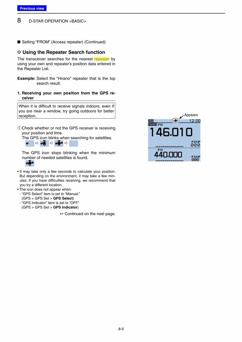
8 D-STAR OPERATION <BASIC>
8-5
☞ Continued on the next page.
The transceiver searches for the nearest repeater by using your own and repeater’s position data entered in the Repeater List.
Example: Select the “Hirano” repeater that is the top search result.
1. Receiving your own position from the GPS re-
ceiver
When it is difficult to receive signals indoors, even if you are near a window, try going outdoors for better reception.
q Check whether or not the GPS receiver is receiving your position and time.
The GPS icon blinks when searching for satellites.
➪ ➪ ➪
The GPS icon stops blinking when the minimum number of needed satellites is found.
• It may take only a few seconds to calculate your position. But depending on the environment, it may take a few min-utes. If you have difficulties receiving, we recommend that you try a different location.
• The icon does not appear when:- “GPS Select” item is set to “Manual.” (GPS > GPS Set > GPS Select)- “GPS Indicator” item is set to “OFF.” (GPS > GPS Set > GPS Indicator)
Appears
■ Setting “FROM” (Access repeater) (Continued)
D Using the Repeater Search function
Previous view
Icom
ハイライト表示
Radio systems that receive incoming signals and retransmit them to extend the communication area. Normally put on geographically high locations for VHF/UHF radios.
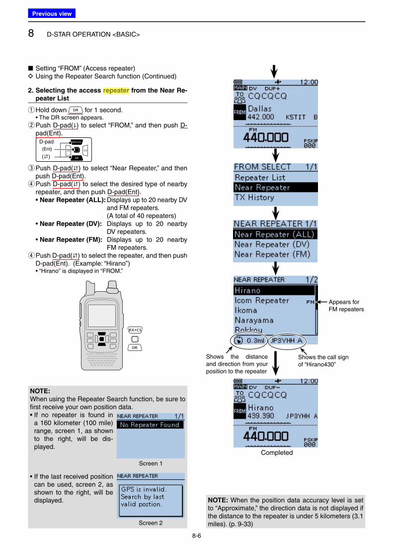
8 D-STAR OPERATION <BASIC>
8-6
2. Selecting the access repeater from the Near Re-
peater List
qHold down for 1 second. • The DR screen appears.
w Push D-pad() to select “FROM,” and then push D-pad(Ent).
D-pad
(�)
(Ent)
e Push D-pad() to select “Near Repeater,” and then push D-pad(Ent). r Push D-pad() to select the desired type of nearby repeater, and then push D-pad(Ent).
• Near Repeater (ALL): Displays up to 20 nearby DV and FM repeaters.
(A total of 40 repeaters) • Near Repeater (DV): Displays up to 20 nearby
DV repeaters. • Near Repeater (FM): Displays up to 20 nearby
FM repeaters. r Push D-pad() to select the repeater, and then push D-pad(Ent). (Example: “Hirano”)
• “Hirano” is displayed in “FROM.”
NOTE: When the position data accuracy level is set to “Approximate,” the direction data is not displayed if the distance to the repeater is under 5 kilometers (3.1 miles). (p. 9-33)
Completed
Shows the distance and direction from your position to the repeater
Shows the call sign of “Hirano430”
NOTE:
When using the Repeater Search function, be sure to first receive your own position data.• If no repeater is found in
a 160 kilometer (100 mile) range, screen 1, as shown to the right, will be dis-played.
• If the last received position can be used, screen 2, as shown to the right, will be displayed.
Screen 1
Screen 2
■ Setting “FROM” (Access repeater) D Using the Repeater Search function (Continued)
Appears for FM repeaters
Previous view
Icom
ハイライト表示
Radio systems that receive incoming signals and retransmit them to extend the communication area. Normally put on geographically high locations for VHF/UHF radios.
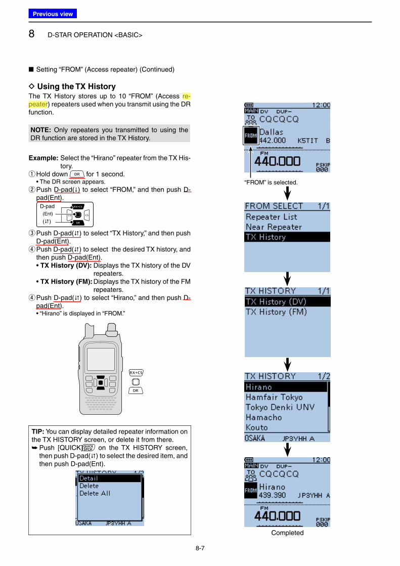
8 D-STAR OPERATION <BASIC>
8-7
The TX History stores up to 10 “FROM” (Access re-peater) repeaters used when you transmit using the DR function.
NOTE: Only repeaters you transmitted to using the DR function are stored in the TX History.
Example: Select the “Hirano” repeater from the TX His-tory.
qHold down for 1 second. • The DR screen appears.
w Push D-pad() to select “FROM,” and then push D-pad(Ent).
D-pad
(�)
(Ent)
e Push D-pad() to select “TX History,” and then push D-pad(Ent). r Push D-pad() to select the desired TX history, and then push D-pad(Ent).
• TX History (DV): Displays the TX history of the DV repeaters.
• TX History (FM): Displays the TX history of the FM repeaters.
r Push D-pad() to select “Hirano,” and then push D-pad(Ent).
• “Hirano” is displayed in “FROM.”
“FROM” is selected.
Completed
■ Setting “FROM” (Access repeater) (Continued)
D Using the TX History
TIP: You can display detailed repeater information on the TX HISTORY screen, or delete it from there.
➥ Push [QUICK] on the TX HISTORY screen, then push D-pad() to select the desired item, and then push D-pad(Ent).
Previous view
Icom
ハイライト表示
Radio systems that receive incoming signals and retransmit them to extend the communication area. Normally put on geographically high locations for VHF/UHF radios.
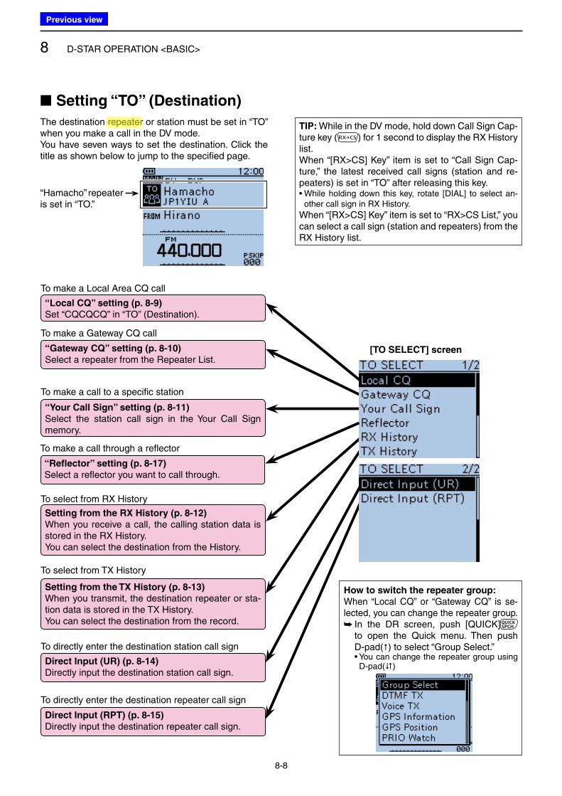
8 D-STAR OPERATION <BASIC>
8-8
To make a Local Area CQ call
“Local CQ” setting (p. 8-9)
Set “CQCQCQ” in “TO” (Destination).
To make a Gateway CQ call
“Gateway CQ” setting (p. 8-10)
Select a repeater from the Repeater List.
To make a call to a specific station
“Your Call Sign” setting (p. 8-11)
Select the station call sign in the Your Call Sign memory.
To select from RX History
Setting from the RX History (p. 8-12)
When you receive a call, the calling station data is stored in the RX History.You can select the destination from the History.
To select from TX History
Setting from the TX History (p. 8-13)
When you transmit, the destination repeater or sta-tion data is stored in the TX History.You can select the destination from the record.
To directly enter the destination station call sign
Direct Input (UR) (p. 8-14)
Directly input the destination station call sign.
To directly enter the destination repeater call sign
Direct Input (RPT) (p. 8-15)
Directly input the destination repeater call sign.
■ Setting “TO” (Destination)
The destination repeater or station must be set in “TO” when you make a call in the DV mode.You have seven ways to set the destination. Click the title as shown below to jump to the specified page.
How to switch the repeater group:
When “Local CQ” or “Gateway CQ” is se-lected, you can change the repeater group.
➥ In the DR screen, push [QUICK] to open the Quick menu. Then push D-pad() to select “Group Select.”
• You can change the repeater group using D-pad()
[TO SELECT] screen
“Hamacho” repeater is set in “TO.”
To make a call through a reflector
“Reflector” setting (p. 8-17)
Select a reflector you want to call through.
TIP: While in the DV mode, hold down Call Sign Cap-ture key ( ) for 1 second to display the RX History list.When “[RX>CS] Key” item is set to “Call Sign Cap-ture,” the latest received call signs (station and re-peaters) is set in “TO” after releasing this key.• While holding down this key, rotate [DIAL] to select an-
other call sign in RX History.
When “[RX>CS] Key” item is set to “RX>CS List,” you can select a call sign (station and repeaters) from the RX History list.
Previous view
Icom
ハイライト表示
Radio systems that receive incoming signals and retransmit them to extend the communication area. Normally put on geographically high locations for VHF/UHF radios.
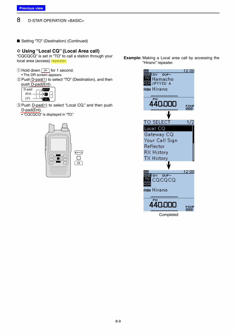
8 D-STAR OPERATION <BASIC>
8-9
■ Setting “TO” (Destination) (Continued)
D Using “Local CQ” (Local Area call)“CQCQCQ” is set in “TO” to call a station through your local area (access) repeater.
qHold down for 1 second. • The DR screen appears.
w Push D-pad() to select “TO” (Destination), and then push D-pad(Ent).
D-pad
(�)
(Ent)
e Push D-pad() to select “Local CQ,” and then push D-pad(Ent).
• “CQCQCQ” is displayed in “TO.”
Example: Making a Local area call by accessing the “Hirano” repeater.
Completed
Previous view
Icom
ハイライト表示
Radio systems that receive incoming signals and retransmit them to extend the communication area. Normally put on geographically high locations for VHF/UHF radios.
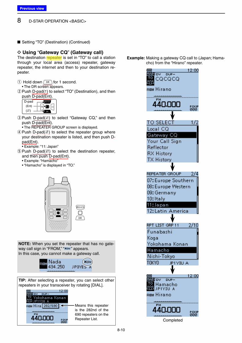
8 D-STAR OPERATION <BASIC>
8-10
■ Setting “TO” (Destination) (Continued)
D Using “Gateway CQ” (Gateway call)The destination repeater is set in “TO” to call a station through your local area (access) repeater, gateway repeater, the internet and then to your destination re-peater.
q Hold down for 1 second. • The DR screen appears.
w Push D-pad() to select “TO” (Destination), and then push D-pad(Ent).
D-pad
(�)
(Ent)
e Push D-pad() to select “Gateway CQ,” and then push D-pad(Ent).
• The REPEATER GROUP screen is displayed.
r Push D-pad() to select the repeater group where your destination repeater is listed, and then push D-pad(Ent).
• Example: “11: Japan”
t Push D-pad() to select the destination repeater, and then push D-pad(Ent).
• Example: “Hamacho” • “Hamacho” is displayed in “TO.”
Example: Making a gateway CQ call to (Japan; Hama-cho) from the “Hirano” repeater.
Completed
TIP: After selecting a repeater, you can select other repeaters in your transceiver by rotating [DIAL].
Means this repeater is the 282nd of the 690 repeaters on the Repeater List.
NOTE: When you set the repeater that has no gate-way call sign in “FROM,” “ ” appears.In this case, you cannot make a gateway call.
Previous view
Icom
ハイライト表示
Radio systems that receive incoming signals and retransmit them to extend the communication area. Normally put on geographically high locations for VHF/UHF radios.
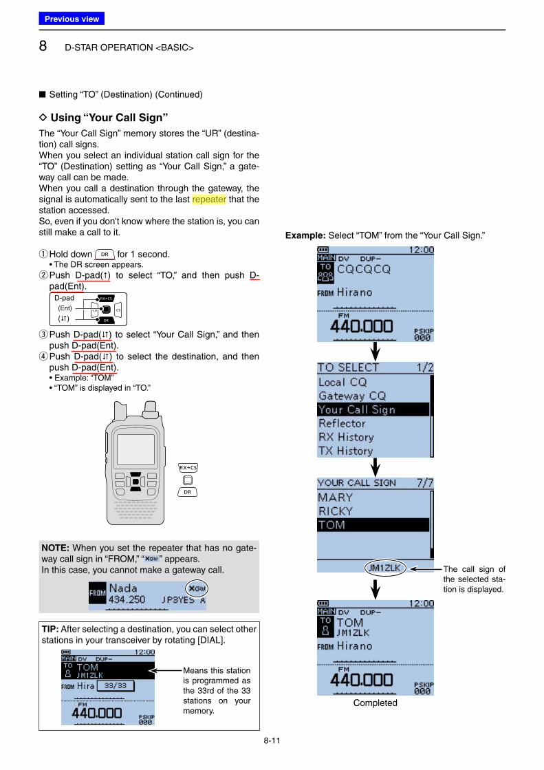
8 D-STAR OPERATION <BASIC>
8-11
■ Setting “TO” (Destination) (Continued)
D Using “Your Call Sign”
The “Your Call Sign” memory stores the “UR” (destina-tion) call signs.When you select an individual station call sign for the “TO” (Destination) setting as “Your Call Sign,” a gate-way call can be made.When you call a destination through the gateway, the signal is automatically sent to the last repeater that the station accessed. So, even if you don't know where the station is, you can still make a call to it.
qHold down for 1 second. • The DR screen appears.
w Push D-pad() to select “TO,” and then push D-pad(Ent).
D-pad
(�)
(Ent)
e Push D-pad() to select “Your Call Sign,” and then push D-pad(Ent). r Push D-pad() to select the destination, and then push D-pad(Ent).
• Example: “TOM” • “TOM” is displayed in “TO.”
TIP: After selecting a destination, you can select other stations in your transceiver by rotating [DIAL].
Example: Select “TOM” from the “Your Call Sign.”
The call sign of the selected sta-tion is displayed.
Completed
Means this station is programmed as the 33rd of the 33 stations on your memory.
NOTE: When you set the repeater that has no gate-way call sign in “FROM,” “ ” appears.In this case, you cannot make a gateway call.
Previous view
Icom
ハイライト表示
Radio systems that receive incoming signals and retransmit them to extend the communication area. Normally put on geographically high locations for VHF/UHF radios.
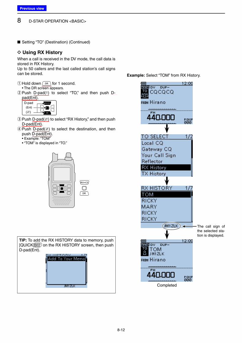
8 D-STAR OPERATION <BASIC>
8-12
When a call is received in the DV mode, the call data is stored in RX History.Up to 50 callers and the last called station’s call signs can be stored.
qHold down for 1 second. • The DR screen appears.
w Push D-pad() to select “TO,” and then push D-pad(Ent).
D-pad
(�)
(Ent)
e Push D-pad() to select “RX History,” and then push D-pad(Ent). r Push D-pad() to select the destination, and then push D-pad(Ent).
• Example: “TOM” • “TOM” is displayed in “TO.”
■ Setting “TO” (Destination) (Continued)
D Using RX History
Example: Select “TOM” from RX History.
Completed
The call sign of the selected sta-tion is displayed.
TIP: To add the RX HISTORY data to memory, push [QUICK] on the RX HISTORY screen, then push D-pad(Ent).
Previous view
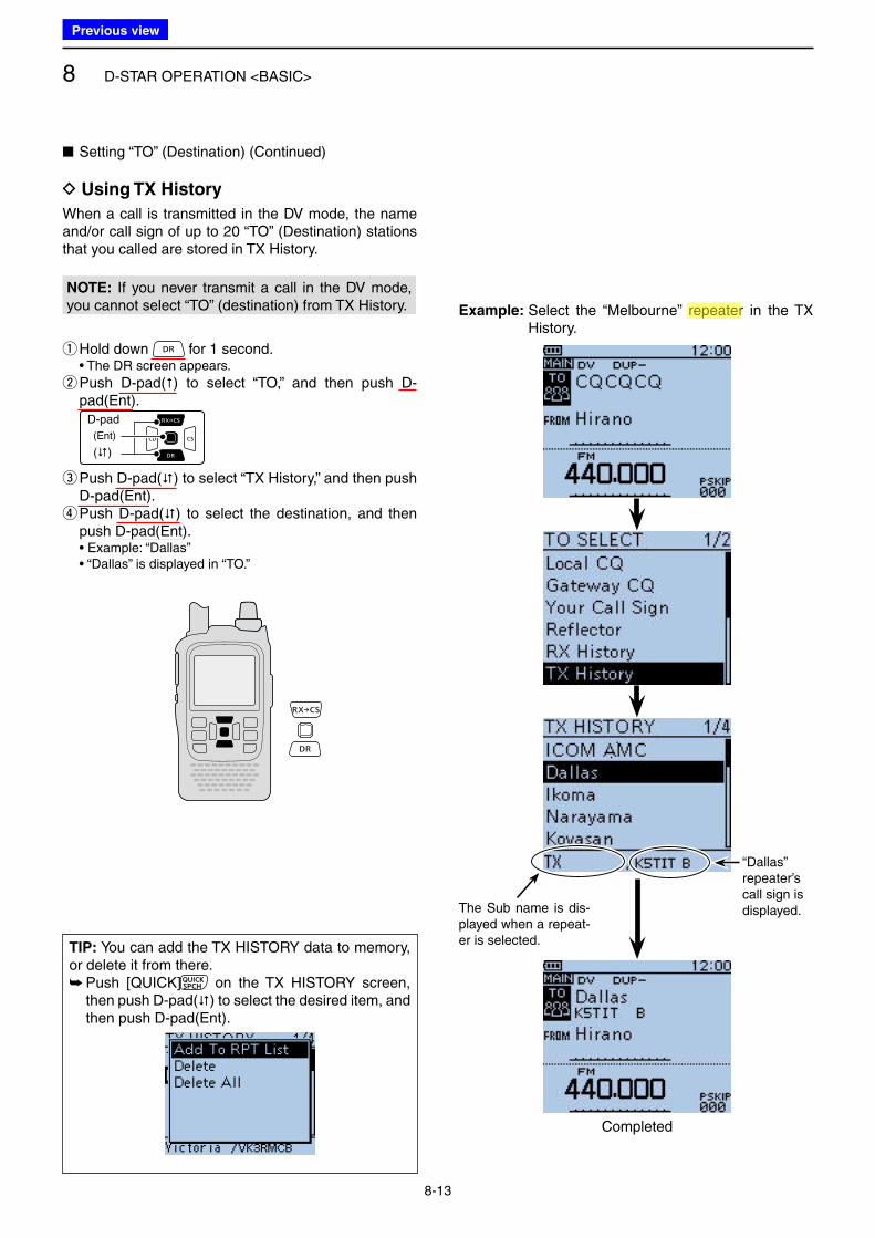
8 D-STAR OPERATION <BASIC>
8-13
When a call is transmitted in the DV mode, the name and/or call sign of up to 20 “TO” (Destination) stations that you called are stored in TX History.
NOTE: If you never transmit a call in the DV mode, you cannot select “TO” (destination) from TX History.
qHold down for 1 second. • The DR screen appears.
w Push D-pad() to select “TO,” and then push D-pad(Ent).
D-pad
(�)
(Ent)
e Push D-pad() to select “TX History,” and then push D-pad(Ent). r Push D-pad() to select the destination, and then push D-pad(Ent).
• Example: “Dallas” • “Dallas” is displayed in “TO.”
■ Setting “TO” (Destination) (Continued)
D Using TX History
Example: Select the “Melbourne” repeater in the TX History.
Completed
“Dallas” repeater’s call sign is displayed.The Sub name is dis-
played when a repeat-er is selected.
TIP: You can add the TX HISTORY data to memory, or delete it from there.
➥ Push [QUICK] on the TX HISTORY screen, then push D-pad() to select the desired item, and then push D-pad(Ent).
Previous view
Icom
ハイライト表示
Radio systems that receive incoming signals and retransmit them to extend the communication area. Normally put on geographically high locations for VHF/UHF radios.
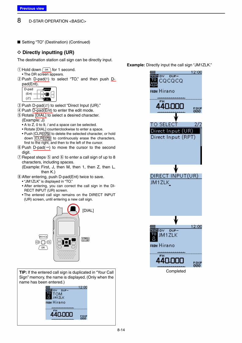
8 D-STAR OPERATION <BASIC>
8-14
The destination station call sign can be directly input.
qHold down for 1 second. • The DR screen appears.
w Push D-pad() to select “TO,” and then push D-pad(Ent).
D-pad
(�)
(Ent)
e Push D-pad() to select “Direct Input (UR).” r Push D-pad(Ent) to enter the edit mode. t Rotate [DIAL] to select a desired character. (Example: J)
• A to Z, 0 to 9, / and a space can be selected. • Rotate [DIAL] counterclockwise to enter a space. • Push [CLR] to delete the selected character, or hold
down [CLR] to continuously erase the characters, first to the right, and then to the left of the cursor.
y Push D-pad() to move the cursor to the second digit. u Repeat steps t and y to enter a call sign of up to 8 characters, including spaces.
(Example: First, J, then M, then 1, then Z, then L, then K.)
iAfter entering, push D-pad(Ent) twice to save. • “JM1ZLK” is displayed in “TO.” • After entering, you can correct the call sign in the DI-
RECT INPUT (UR) screen. • The entered call sign remains on the DIRECT INPUT
(UR) screen, until entering a new call sign.
■ Setting “TO” (Destination) (Continued)
D Directly inputting (UR)
Example: Directly input the call sign “JM1ZLK.”
TIP: If the entered call sign is duplicated in “Your Call Sign” memory, the name is displayed. (Only when the name has been entered.)
Completed
[DIAL]
Previous view
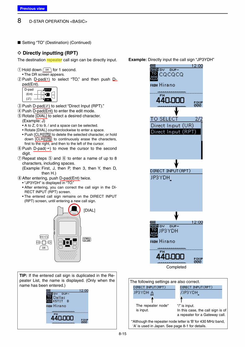
8 D-STAR OPERATION <BASIC>
8-15
The destination repeater call sign can be directly input.
qHold down for 1 second. • The DR screen appears.
w Push D-pad() to select “TO,” and then push D-pad(Ent).
D-pad
(�)
(Ent)
e Push D-pad() to select “Direct Input (RPT).” r Push D-pad(Ent) to enter the edit mode. t Rotate [DIAL] to select a desired character. (Example: J)
• A to Z, 0 to 9, / and a space can be selected. • Rotate [DIAL] counterclockwise to enter a space. • Push [CLR] to delete the selected character, or hold
down [CLR] to continuously erase the characters, first to the right, and then to the left of the cursor.
y Push D-pad() to move the cursor to the second digit. u Repeat steps t and y to enter a name of up to 8 characters, including spaces.
(Example: First, J, then P, then 3, then Y, then D, then H.)
iAfter entering, push D-pad(Ent) twice. • “JP3YDH” is displayed in “TO.” • After entering, you can correct the call sign in the DI-
RECT INPUT (RPT) screen. • The entered call sign remains on the DIRECT INPUT
(RPT) screen, until entering a new call sign.
The following settings are also correct.
The repeater node* is input.
“/” is input.In this case, the call sign is of a repeater for a Gateway call.
* Although the repeater node letter is ‘B’ for 430 MHz band, ‘A’ is used in Japan. See page 8-1 for details.
TIP: If the entered call sign is duplicated in the Re-peater List, the name is displayed. (Only when the name has been entered.)
Example: Directly input the call sign “JP3YDH”
■ Setting “TO” (Destination) (Continued)
D Directly inputting (RPT)
Completed
[DIAL]
Previous view
Icom
ハイライト表示
Radio systems that receive incoming signals and retransmit them to extend the communication area. Normally put on geographically high locations for VHF/UHF radios.
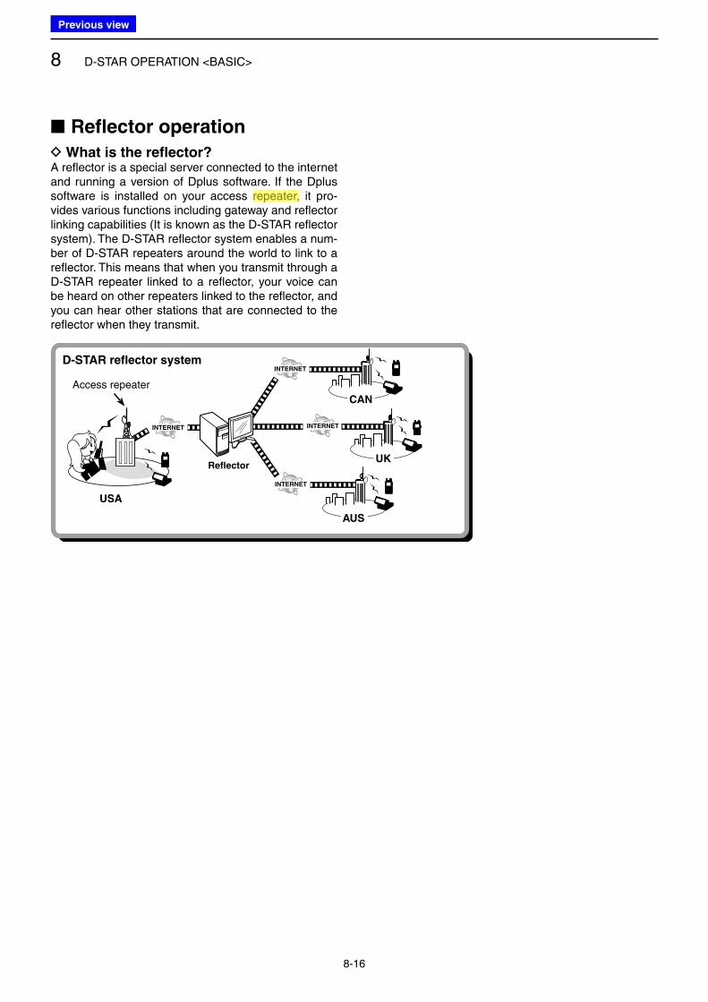
8 D-STAR OPERATION <BASIC>
8-16
D What is the reflector?A reflector is a special server connected to the internet and running a version of Dplus software. If the Dplus software is installed on your access repeater, it pro-vides various functions including gateway and reflector linking capabilities (It is known as the D-STAR reflector system). The D-STAR reflector system enables a num-ber of D-STAR repeaters around the world to link to a reflector. This means that when you transmit through a D-STAR repeater linked to a reflector, your voice can be heard on other repeaters linked to the reflector, and you can hear other stations that are connected to the reflector when they transmit.
Reflector
INTERNET
INTERNET
INTERNET
INTERNET
Access repeater
CAN
UK
AUS
USA
D-STAR reflector system
■ Reflector operation
Previous view
Icom
ハイライト表示
Radio systems that receive incoming signals and retransmit them to extend the communication area. Normally put on geographically high locations for VHF/UHF radios.
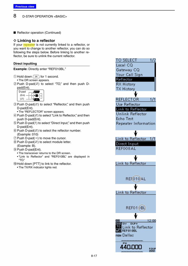
8 D-STAR OPERATION <BASIC>
8-17
■ Reflector operation (Continued)
D Linking to a reflectorIf your repeater is not currently linked to a reflector, or you want to change to another reflector, you can do so following the steps below. Before linking to another re-flector, be sure to unlink the current reflector.
Direct inputting
Example: Directly enter “REF010BL.”
q Hold down for 1 second. • The DR screen appears.
w Push D-pad() to select “TO,” and then push D-pad(Ent).
D-pad
(�)
(Ent)
e Push D-pad() to select “Reflector,” and then push D-pad(Ent).
• The “REFLECTOR” screen appears.
r Push D-pad() to select “Link to Reflector,” and then push D-pad(Ent). t Push D-pad() to select “Direct Input,” and then push D-pad(Ent). y Push D-pad() to select the reflector number.
(Example: 010) u Push D-pad() to move the cursor. i Push D-pad() to select module letter.
(Example: B). oPush D-pad(Ent).
• The transceiver returns to the DR screen. • “Link to Reflector” and “REF010BL” are displayed in
“TO.”
!0 Hold down [PTT] to link to the reflector. • The TX/RX indicator lights red.
Previous view
Icom
ハイライト表示
Radio systems that receive incoming signals and retransmit them to extend the communication area. Normally put on geographically high locations for VHF/UHF radios.
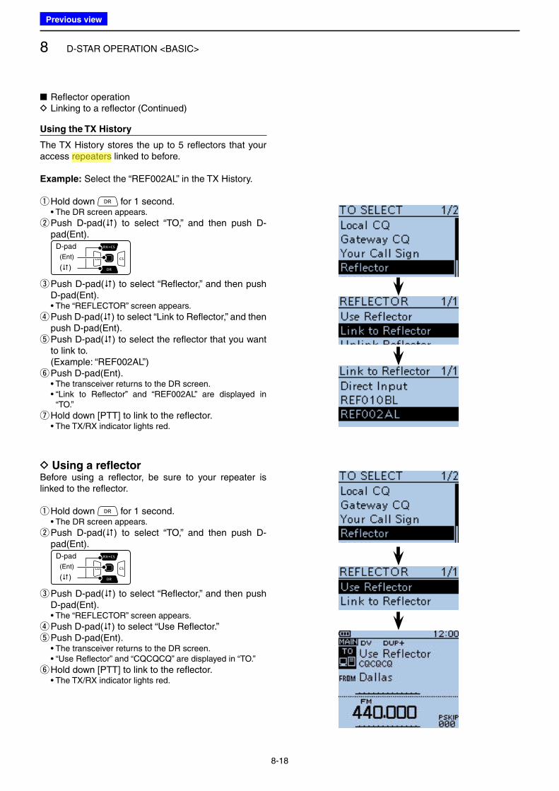
8 D-STAR OPERATION <BASIC>
8-18
Using the TX History
The TX History stores the up to 5 reflectors that your access repeaters linked to before.
Example: Select the “REF002AL” in the TX History.
q Hold down for 1 second. • The DR screen appears.
w Push D-pad() to select “TO,” and then push D-pad(Ent).
D-pad
(�)
(Ent)
e Push D-pad() to select “Reflector,” and then push D-pad(Ent).
• The “REFLECTOR” screen appears.
r Push D-pad() to select “Link to Reflector,” and then push D-pad(Ent). t Push D-pad() to select the reflector that you want to link to.
(Example: “REF002AL”) yPush D-pad(Ent).
• The transceiver returns to the DR screen. • “Link to Reflector” and “REF002AL” are displayed in
“TO.”
u Hold down [PTT] to link to the reflector. • The TX/RX indicator lights red.
■ Reflector operation D Linking to a reflector (Continued)
D Using a reflectorBefore using a reflector, be sure to your repeater is linked to the reflector.
q Hold down for 1 second. • The DR screen appears.
w Push D-pad() to select “TO,” and then push D-pad(Ent).
D-pad
(�)
(Ent)
e Push D-pad() to select “Reflector,” and then push D-pad(Ent).
• The “REFLECTOR” screen appears.
r Push D-pad() to select “Use Reflector.” tPush D-pad(Ent).
• The transceiver returns to the DR screen. • “Use Reflector” and “CQCQCQ” are displayed in “TO.”
y Hold down [PTT] to link to the reflector. • The TX/RX indicator lights red.
Previous view
Icom
ハイライト表示
Radio systems that receive incoming signals and retransmit them to extend the communication area. Normally put on geographically high locations for VHF/UHF radios.
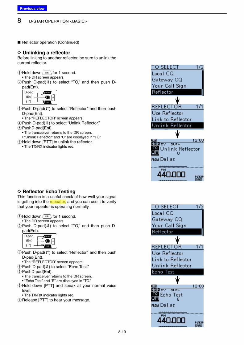
8 D-STAR OPERATION <BASIC>
8-19
■ Reflector operation (Continued)
D Unlinking a reflectorBefore linking to another reflector, be sure to unlink the current reflector.
q Hold down for 1 second. • The DR screen appears.
w Push D-pad() to select “TO,” and then push D-pad(Ent).
D-pad
(�)
(Ent)
e Push D-pad() to select “Reflector,” and then push D-pad(Ent).
• The “REFLECTOR” screen appears.
r Push D-pad() to select “Unlink Reflector.” t PushD-pad(Ent).
• The transceiver returns to the DR screen. • “Unlink Reflector” and “U” are displayed in “TO.”
y Hold down [PTT] to unlink the reflector. • The TX/RX indicator lights red.
D Reflector Echo TestingThis function is a useful check of how well your signal is getting into the repeater, and you can use it to verify that your repeater is operating normally.
q Hold down for 1 second. • The DR screen appears.
w Push D-pad() to select “TO,” and then push D-pad(Ent).
D-pad
(�)
(Ent)
e Push D-pad() to select “Reflector,” and then push D-pad(Ent).
• The “REFLECTOR” screen appears.
r Push D-pad() to select “Echo Test.” t PushD-pad(Ent).
• The transceiver returns to the DR screen. • “Echo Test” and “E” are displayed in “TO.”
y Hold down [PTT] and speak at your normal voice level.
• The TX/RX indicator lights red.
u Release [PTT] to hear your message.
Previous view
Icom
ハイライト表示
Radio systems that receive incoming signals and retransmit them to extend the communication area. Normally put on geographically high locations for VHF/UHF radios.
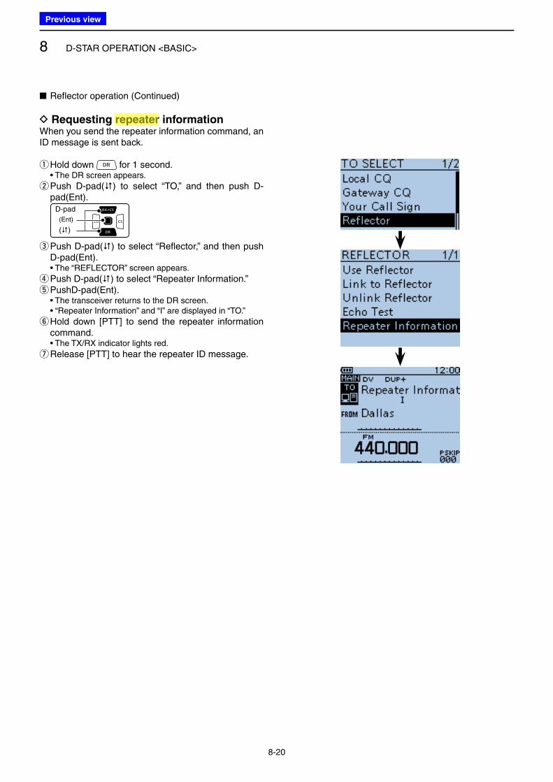
8 D-STAR OPERATION <BASIC>
8-20
■ Reflector operation (Continued)
D Requesting repeater informationWhen you send the repeater information command, an ID message is sent back.
q Hold down for 1 second. • The DR screen appears.
w Push D-pad() to select “TO,” and then push D-pad(Ent).
D-pad
(�)
(Ent)
e Push D-pad() to select “Reflector,” and then push D-pad(Ent).
• The “REFLECTOR” screen appears.
r Push D-pad() to select “Repeater Information.” t PushD-pad(Ent).
• The transceiver returns to the DR screen. • “Repeater Information” and “I” are displayed in “TO.”
y Hold down [PTT] to send the repeater information command.
• The TX/RX indicator lights red.
u Release [PTT] to hear the repeater ID message.
Previous view
Icom
ハイライト表示
Radio systems that receive incoming signals and retransmit them to extend the communication area. Normally put on geographically high locations for VHF/UHF radios.
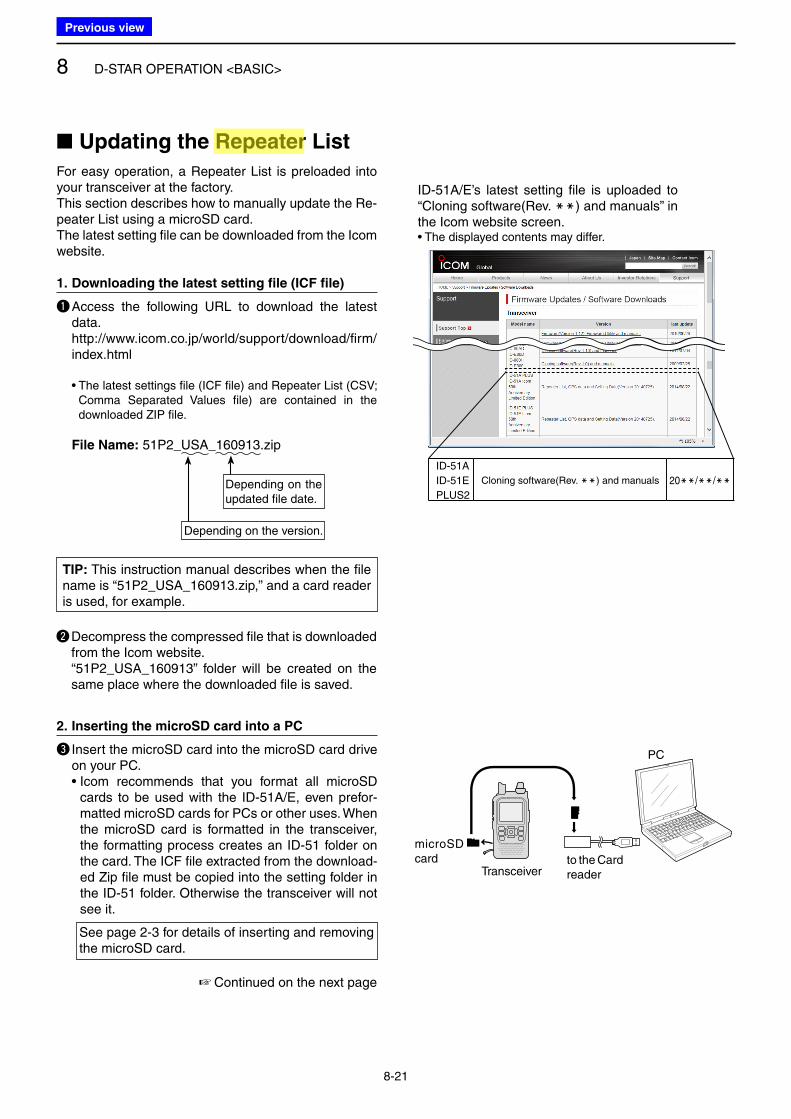
8 D-STAR OPERATION <BASIC>
8-21
■ Updating the Repeater List
For easy operation, a Repeater List is preloaded into your transceiver at the factory.This section describes how to manually update the Re-peater List using a microSD card.The latest setting file can be downloaded from the Icom website.
1. Downloading the latest setting file (ICF file)
q Access the following URL to download the latest data.
http://www.icom.co.jp/world/support/download/firm/index.html
• The latest settings file (ICF file) and Repeater List (CSV; Comma Separated Values file) are contained in the downloaded ZIP file.
File Name: 51P2_USA_160913.zip
Depending on the updated file date.
Depending on the version.
☞ Continued on the next page
microSD card
Transceiverto the Card reader
PC
ID-51A/E’s latest setting file is uploaded to “Cloning software(Rev. MM) and manuals” in the Icom website screen.• The displayed contents may differ.
TIP: This instruction manual describes when the file name is “51P2_USA_160913.zip,” and a card reader is used, for example.
w Decompress the compressed file that is downloaded from the Icom website.
“51P2_USA_160913” folder will be created on the same place where the downloaded file is saved.
2. Inserting the microSD card into a PC
e Insert the microSD card into the microSD card drive on your PC.
• Icom recommends that you format all microSD cards to be used with the ID-51A/E, even prefor-matted microSD cards for PCs or other uses. When the microSD card is formatted in the transceiver, the formatting process creates an ID-51 folder on the card. The ICF file extracted from the download-ed Zip file must be copied into the setting folder in the ID-51 folder. Otherwise the transceiver will not see it.
See page 2-3 for details of inserting and removing the microSD card.
ID-51A
ID-51E
PLUS2
Cloning software(Rev. MM) and manuals 20MM/MM/MM
Previous view
Icom
ハイライト表示
Radio systems that receive incoming signals and retransmit them to extend the communication area. Normally put on geographically high locations for VHF/UHF radios.
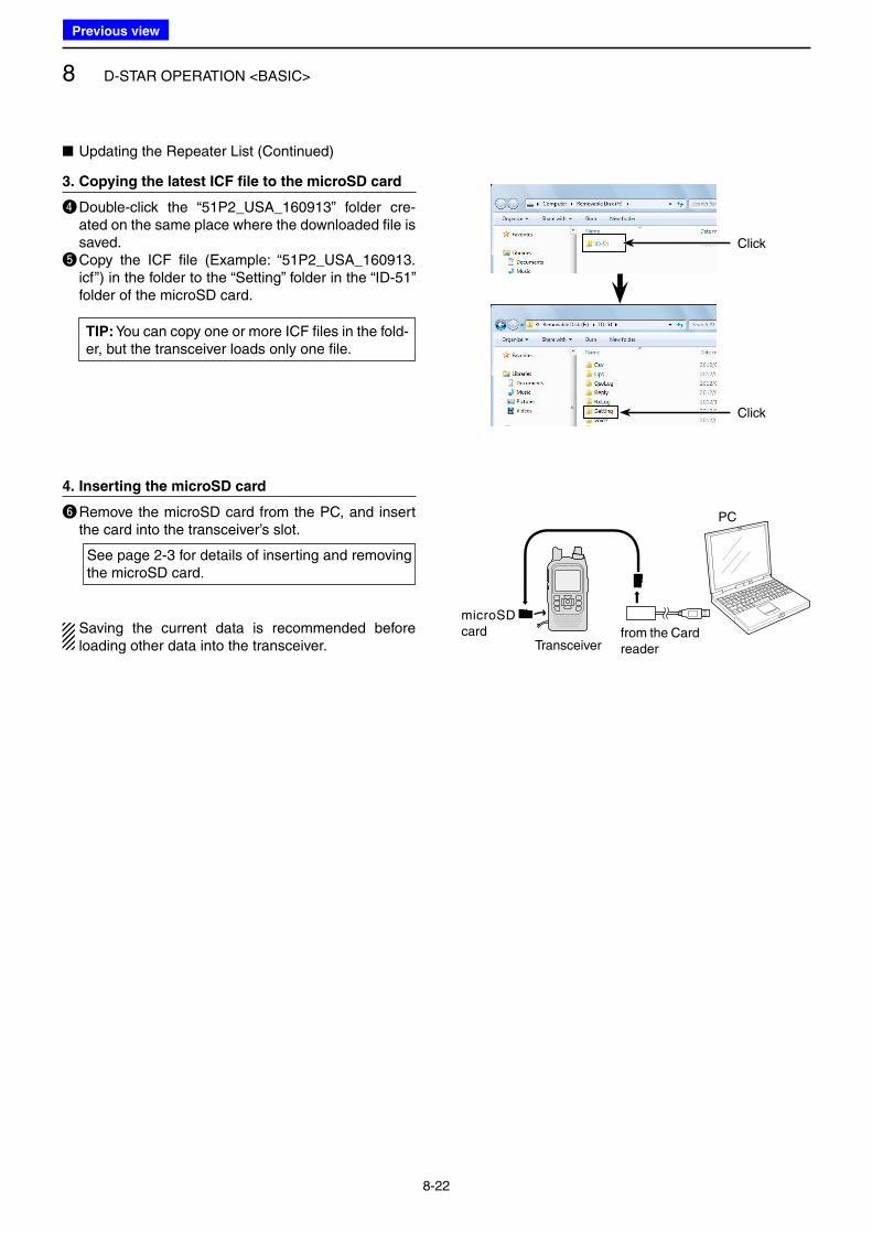
8 D-STAR OPERATION <BASIC>
8-22
■ Updating the Repeater List (Continued)
3. Copying the latest ICF file to the microSD card
r Double-click the “51P2_USA_160913” folder cre-ated on the same place where the downloaded file is saved.
t Copy the ICF file (Example: “51P2_USA_160913.icf”) in the folder to the “Setting” folder in the “ID-51” folder of the microSD card.
TIP: You can copy one or more ICF files in the fold-er, but the transceiver loads only one file.
Click
Click
microSD card
Transceiverfrom the Card reader
PC
4. Inserting the microSD card
y Remove the microSD card from the PC, and insert the card into the transceiver’s slot.
See page 2-3 for details of inserting and removing the microSD card.
Saving the current data is recommended before loading other data into the transceiver.
Previous view
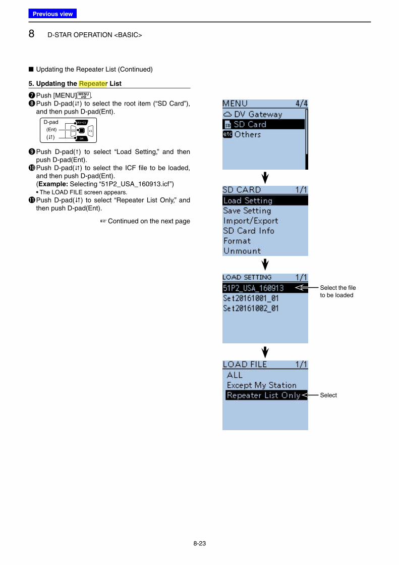
8 D-STAR OPERATION <BASIC>
8-23
☞ Continued on the next page
Select the file to be loaded
Select
5. Updating the Repeater List
u Push [MENU] .i Push D-pad() to select the root item (“SD Card”),
and then push D-pad(Ent).
D-pad
(�)
(Ent)
o Push D-pad() to select “Load Setting,” and then push D-pad(Ent).
!0 Push D-pad() to select the ICF file to be loaded, and then push D-pad(Ent).
(Example: Selecting “51P2_USA_160913.icf”) • The LOAD FILE screen appears.
!1 Push D-pad() to select “Repeater List Only,” and then push D-pad(Ent).
■ Updating the Repeater List (Continued)
Previous view
Icom
ハイライト表示
Radio systems that receive incoming signals and retransmit them to extend the communication area. Normally put on geographically high locations for VHF/UHF radios.
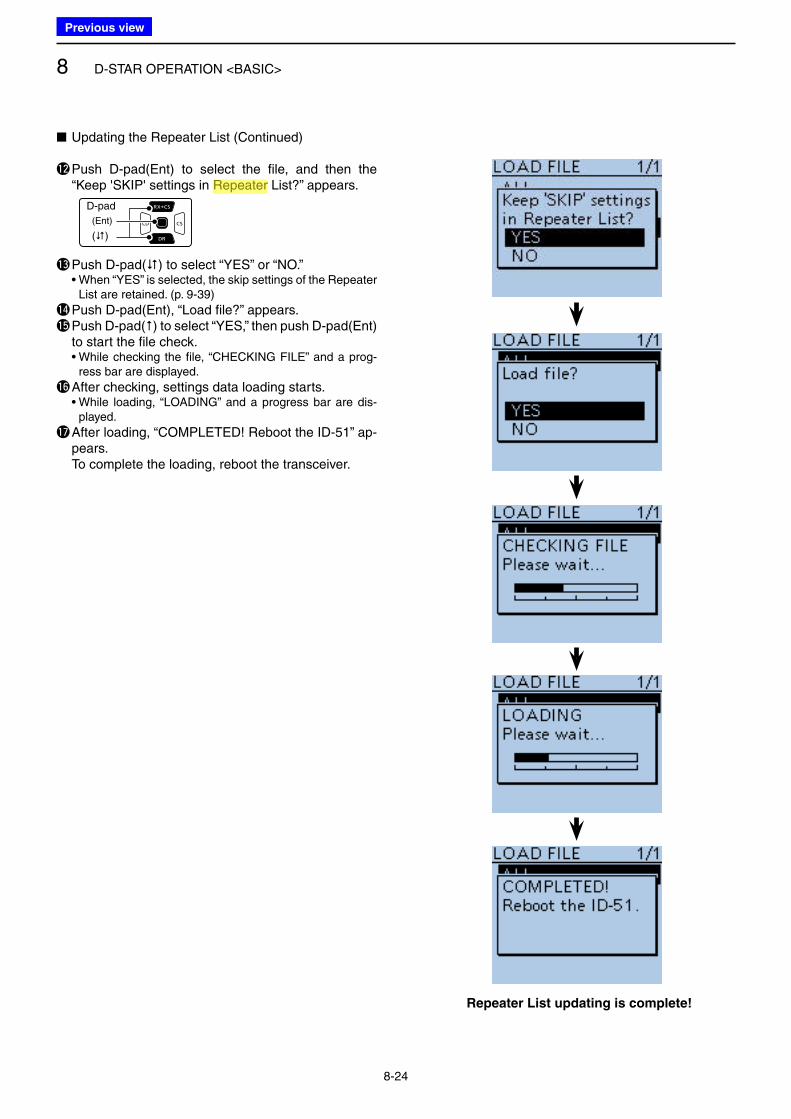
8 D-STAR OPERATION <BASIC>
8-24
Repeater List updating is complete!
■ Updating the Repeater List (Continued)
!2 Push D-pad(Ent) to select the file, and then the “Keep 'SKIP' settings in Repeater List?” appears.
D-pad
(�)
(Ent)
!3 Push D-pad() to select “YES” or “NO.” • When “YES” is selected, the skip settings of the Repeater
List are retained. (p. 9-39)
!4 Push D-pad(Ent), “Load file?” appears.!5 Push D-pad() to select “YES,” then push D-pad(Ent)
to start the file check. • While checking the file, “CHECKING FILE” and a prog-
ress bar are displayed.
!6 After checking, settings data loading starts. • While loading, “LOADING” and a progress bar are dis-
played.
!7 After loading, “COMPLETED! Reboot the ID-51” ap-pears.
To complete the loading, reboot the transceiver.
Previous view
Icom
ハイライト表示
Radio systems that receive incoming signals and retransmit them to extend the communication area. Normally put on geographically high locations for VHF/UHF radios.
9-1
Section 9 D-STAR OPERATION <ADVANCED>
■ Message operation ............................................................. 9-2
D Entering a TX message .................................................. 9-2
D Transmitting a message ................................................. 9-3
D Deleting a TX message .................................................. 9-4
■ Viewing received call signs ................................................. 9-5
D Viewing the RX History screen ....................................... 9-5
■ Using the BK function ......................................................... 9-7
■ Using the EMR communication function............................. 9-8
D Adjusting the EMR AF level ............................................ 9-9
■ Display type setting ............................................................ 9-9
■ Automatic DV detection .................................................... 9-10
■ Automatic Reply function .................................................. 9-11
D Recording an Auto Reply voice announcement ........... 9-12
D Playing back the recorded voice audio ......................... 9-12
D Auto Position Reply function ......................................... 9-13
■ Data communication ......................................................... 9-14
D Connection ................................................................... 9-14
D Data communication application setting ....................... 9-14
D Data communication operation ..................................... 9-14
D DV fast data mode ........................................................ 9-15
■ Speech function ................................................................ 9-16
D Announcing the received call sign ................................ 9-16
D To announce the RX>CS call sign ................................ 9-17
D Selecting the Speech Language .................................. 9-18
D Phonetic Code setting for the Speech alphabet character .. 9-18
D Speech speed selection ............................................... 9-19
D Speech level selection .................................................. 9-19
■ Digital squelch functions ................................................... 9-20
D The digital call sign squelch setting .............................. 9-20
D Pocket beep function with the digital call sign squelch ....... 9-20
D Setting the digital code squelch .................................... 9-21
D Pocket beep function with the digital code squelch ....... 9-21
■ Viewing the call signs ....................................................... 9-22
■ Repeater List .................................................................... 9-23
D Repeater List contents ................................................. 9-23
■ Entering information into Repeater List ............................ 9-24
D Required items for the communication cases ............... 9-24
D New repeater entry ....................................................... 9-25
■ Editing a Repeater List ..................................................... 9-35
■ Deleting a Repeater List ................................................... 9-36
■ Rearranging the repeater display order ............................ 9-37
■ Adding Repeater information using RX History ................ 9-38
■ Skip settings for the DR scan ........................................... 9-39
D Individual skip setting ................................................... 9-39
D Group skip setting ........................................................ 9-40
■ Entering the repeater group name ................................... 9-41
■ Repeater detail screen ..................................................... 9-42
■ Entering the Your (destination) call sign ........................... 9-43
■ Deleting Your (destination) call sign .................................. 9-45
■ Rearranging the display order of Your (destination) call sign . 9-46
■ About the Repeater List default values ............................. 9-47
D Opening the default Repeater List ................................ 9-47
■ Is your setting correct? ..................................................... 9-48
IMPORTANT!
• The Repeater List described in this manual may differ from your trans-ceiver’s preloaded contents.
• Although Japanese repeaters are used in the setting examples, the Japanese repeater node (port) let-ters are different from other coun-try’s.
Be sure to add a repeater node letter as the 8th digit in the call sign field after a repeater call sign, according to the repeater frequency band, as shown below.
1200 MHz: A (B in Japan) 430 MHz: B (A in Japan) 144 MHz: C (no D-STAR repeat-
ers in Japan)
Previous view
Icom
ハイライト表示
Radio systems that receive incoming signals and retransmit them to extend the communication area. Normally put on geographically high locations for VHF/UHF radios.
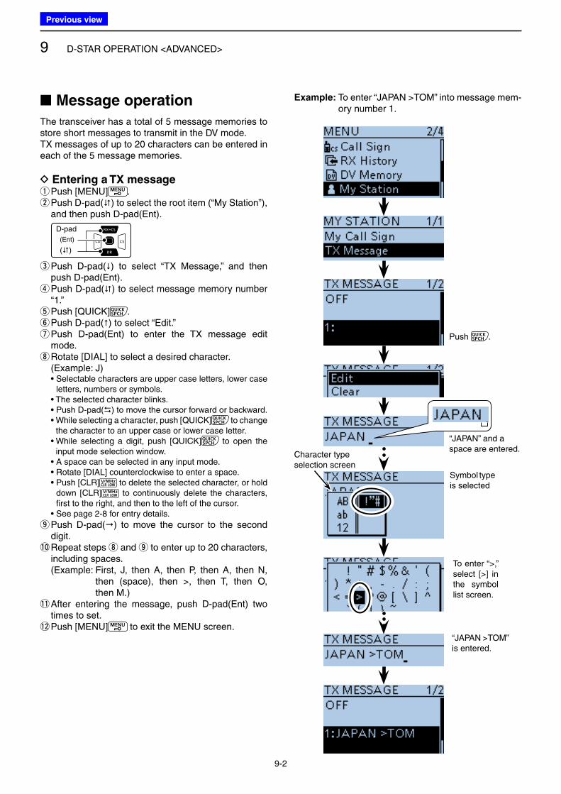
9 D-STAR OPERATION <ADVANCED>
9-2
■ Message operation
The transceiver has a total of 5 message memories to store short messages to transmit in the DV mode.TX messages of up to 20 characters can be entered in each of the 5 message memories.
D Entering a TX message qPush [MENU] . w Push D-pad() to select the root item (“My Station”), and then push D-pad(Ent).
D-pad
(�)
(Ent)
e Push D-pad() to select “TX Message,” and then push D-pad(Ent). r Push D-pad() to select message memory number “1.” tPush [QUICK] . yPush D-pad() to select “Edit.” u Push D-pad(Ent) to enter the TX message edit mode. i Rotate [DIAL] to select a desired character.
(Example: J) • Selectable characters are upper case letters, lower case
letters, numbers or symbols. • The selected character blinks. • Push D-pad() to move the cursor forward or backward. • While selecting a character, push [QUICK] to change
the character to an upper case or lower case letter. • While selecting a digit, push [QUICK] to open the
input mode selection window. • A space can be selected in any input mode. • Rotate [DIAL] counterclockwise to enter a space. • Push [CLR] to delete the selected character, or hold
down [CLR] to continuously delete the characters, first to the right, and then to the left of the cursor.
• See page 2-8 for entry details.
o Push D-pad() to move the cursor to the second digit.
!0 Repeat steps i and o to enter up to 20 characters, including spaces.
(Example: First, J, then A, then P, then A, then N, then (space), then >, then T, then O, then M.)
!1 After entering the message, push D-pad(Ent) two times to set.
!2 Push [MENU] to exit the MENU screen.
“JAPAN” and a space are entered.
Symbol type is selected
To enter “>,” select [>] in the symbol list screen.
“JAPAN >TOM” is entered.
Character type selection screen
Example: To enter “JAPAN >TOM” into message mem-ory number 1.
Push .
Previous view
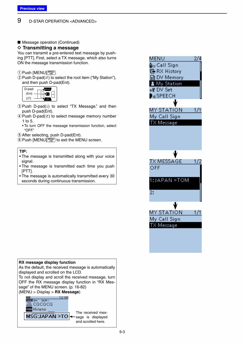
9 D-STAR OPERATION <ADVANCED>
9-3
■ Message operation (Continued)
D Transmitting a messageYou can transmit a pre-entered text message by push-ing [PTT]. First, select a TX message, which also turns ON the message transmission function.
qPush [MENU] . w Push D-pad() to select the root item (“My Station”), and then push D-pad(Ent).
D-pad
(�)
(Ent)
e Push D-pad() to select “TX Message,” and then push D-pad(Ent). r Push D-pad() to select message memory number 1 to 5.
• To turn OFF the message transmission function, select “OFF.”
t After selecting, push D-pad(Ent). yPush [MENU] to exit the MENU screen.
RX message display function
As the default, the received message is automatically displayed and scrolled on the LCD.To not display and scroll the received message, turn OFF the RX message display function in “RX Mes-sage” of the MENU screen. (p. 16-82)(MENU > Display > RX Message)
The received mes-sage is displayed and scrolled here.
TIP:
• The message is transmitted along with your voice signal.
• The message is transmitted each time you push [PTT].
• The message is automatically transmitted every 30 seconds during continuous transmission.
Previous view
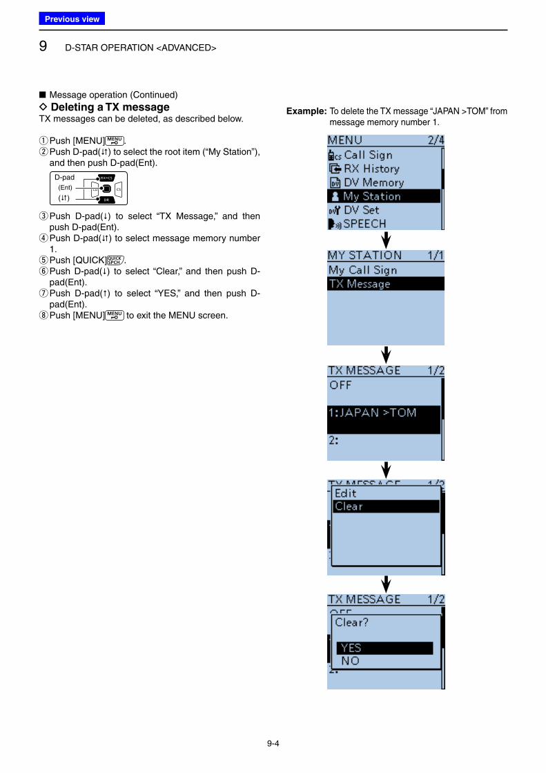
9 D-STAR OPERATION <ADVANCED>
9-4
■ Message operation (Continued)
D Deleting a TX messageTX messages can be deleted, as described below.
qPush [MENU] . w Push D-pad() to select the root item (“My Station”), and then push D-pad(Ent).
D-pad
(�)
(Ent)
e Push D-pad() to select “TX Message,” and then push D-pad(Ent). r Push D-pad() to select message memory number 1. tPush [QUICK] . y Push D-pad() to select “Clear,” and then push D-pad(Ent). u Push D-pad() to select “YES,” and then push D-pad(Ent). iPush [MENU] to exit the MENU screen.
Example: To delete the TX message “JAPAN >TOM” from message memory number 1.
Previous view
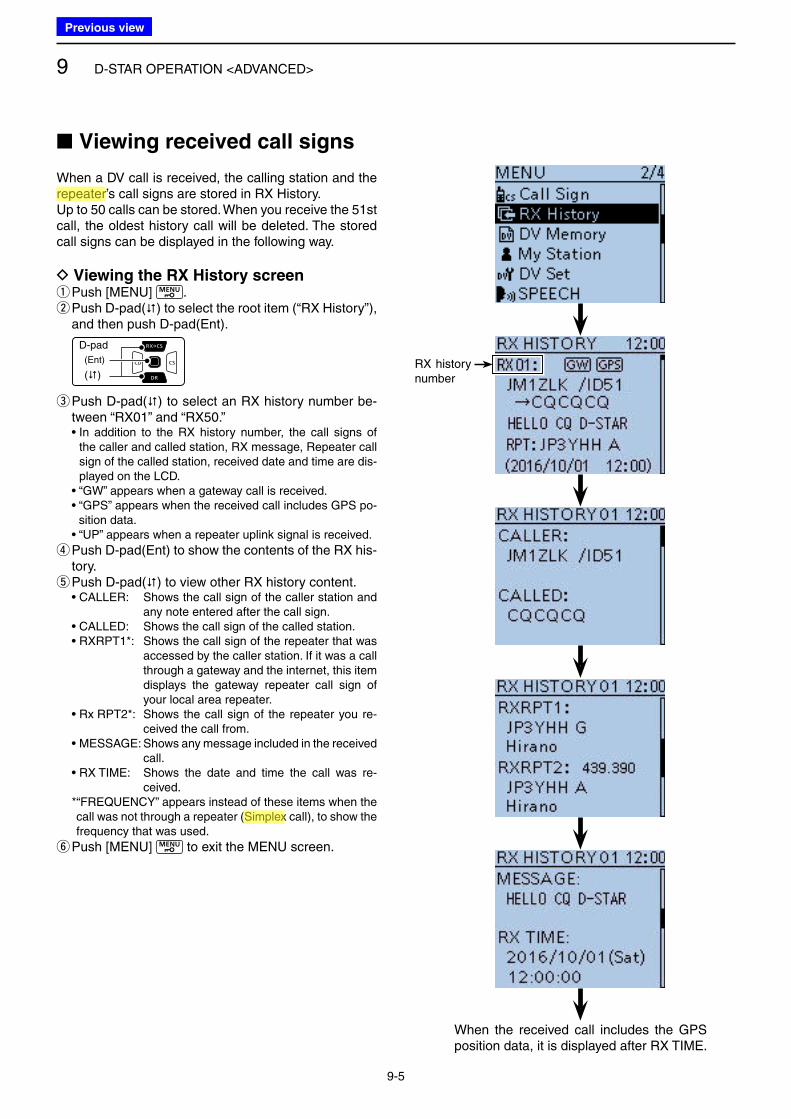
9 D-STAR OPERATION <ADVANCED>
9-5
When a DV call is received, the calling station and the repeater’s call signs are stored in RX History.Up to 50 calls can be stored. When you receive the 51st call, the oldest history call will be deleted. The stored call signs can be displayed in the following way.
D Viewing the RX History screen qPush [MENU] . w Push D-pad() to select the root item (“RX History”), and then push D-pad(Ent).
D-pad
(�)
(Ent)
e Push D-pad() to select an RX history number be-tween “RX01” and “RX50.”
• In addition to the RX history number, the call signs of the caller and called station, RX message, Repeater call sign of the called station, received date and time are dis-played on the LCD.
• “GW” appears when a gateway call is received. • “GPS” appears when the received call includes GPS po-
sition data. • “UP” appears when a repeater uplink signal is received.
r Push D-pad(Ent) to show the contents of the RX his-tory. t Push D-pad() to view other RX history content.
• CALLER: Shows the call sign of the caller station and any note entered after the call sign.
• CALLED: Shows the call sign of the called station. • RXRPT1*: Shows the call sign of the repeater that was
accessed by the caller station. If it was a call through a gateway and the internet, this item displays the gateway repeater call sign of your local area repeater.
• Rx RPT2*: Shows the call sign of the repeater you re-ceived the call from.
• MESSAGE: Shows any message included in the received call.
• RX TIME: Shows the date and time the call was re-ceived.
* “FREQUENCY” appears instead of these items when the call was not through a repeater (Simplex call), to show the frequency that was used.
yPush [MENU] to exit the MENU screen.
■ Viewing received call signs
When the received call includes the GPS position data, it is displayed after RX TIME.
RX history number
Previous view
Icom
ハイライト表示
Radio systems that receive incoming signals and retransmit them to extend the communication area. Normally put on geographically high locations for VHF/UHF radios.
Icom
ハイライト表示
An operating mode in which the transmit and receive frequencies are the same.
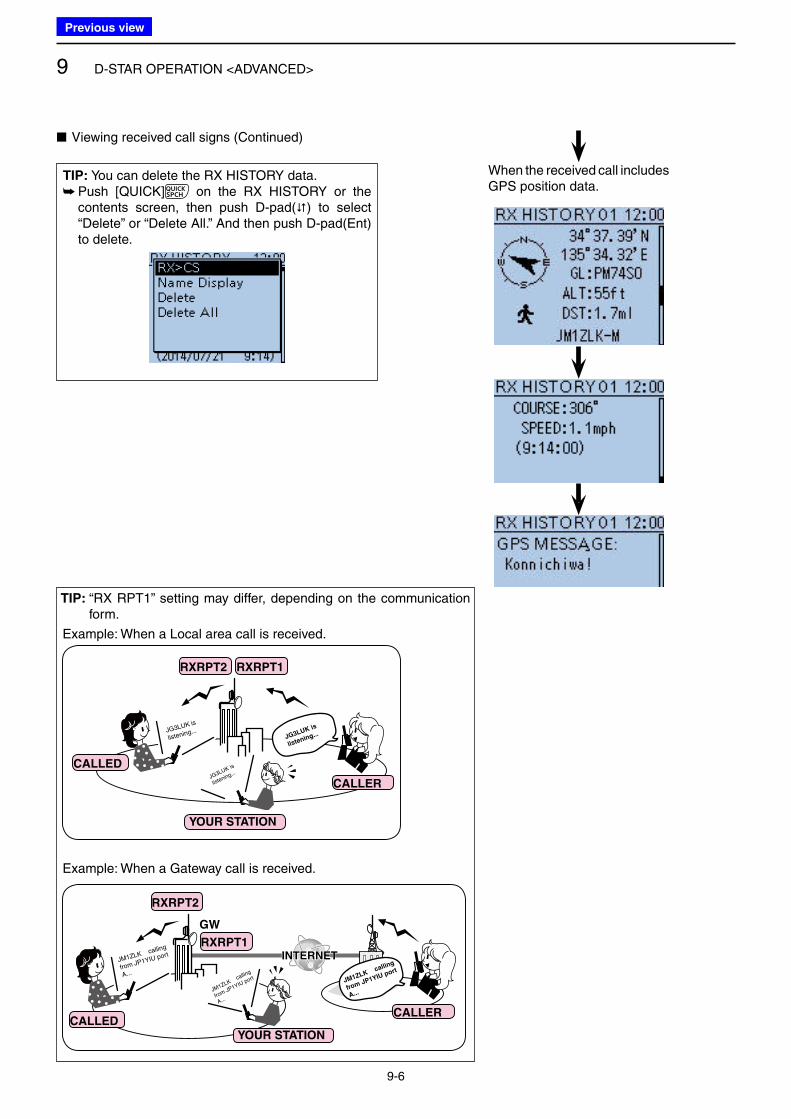
9 D-STAR OPERATION <ADVANCED>
9-6
■ Viewing received call signs (Continued)
When the received call includes GPS position data.
TIP: You can delete the RX HISTORY data. ➥ Push [QUICK] on the RX HISTORY or the contents screen, then push D-pad() to select “Delete” or “Delete All.” And then push D-pad(Ent) to delete.
TIP: “RX RPT1” setting may differ, depending on the communication form.
JG3LUK is
listening...
JG3LUK is
listening...
JG3LUK is
listening...
CALLER
YOUR STATION
RXRPT1RXRPT2
CALLED
JM1ZLK calling
from JP1YIU port
A...
JM1ZLK calling
from JP1YIU port
A...
JM1ZLK calling
from JP1YIU port
A...
INTERNETINTERNET
CALLED
RXRPT2
RXRPT1
CALLER
YOUR STATION
GW
Example: When a Gateway call is received.
Example: When a Local area call is received.
Previous view
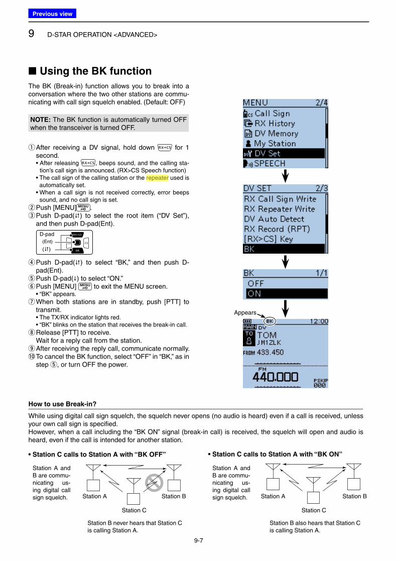
9 D-STAR OPERATION <ADVANCED>
9-7
■ Using the BK function
The BK (Break-in) function allows you to break into a conversation where the two other stations are commu-nicating with call sign squelch enabled. (Default: OFF)
NOTE: The BK function is automatically turned OFF when the transceiver is turned OFF.
q After receiving a DV signal, hold down for 1 second.
• After releasing , beeps sound, and the calling sta-tion’s call sign is announced. (RX>CS Speech function)
• The call sign of the calling station or the repeater used is automatically set.
• When a call sign is not received correctly, error beeps sound, and no call sign is set.
wPush [MENU] . e Push D-pad() to select the root item (“DV Set”), and then push D-pad(Ent).
D-pad
(�)
(Ent)
r Push D-pad() to select “BK,” and then push D-pad(Ent). t Push D-pad() to select “ON.” yPush [MENU] to exit the MENU screen.
• “BK” appears.
u When both stations are in standby, push [PTT] to transmit.
• The TX/RX indicator lights red. • “BK” blinks on the station that receives the break-in call.
iRelease [PTT] to receive. Wait for a reply call from the station.
o After receiving the reply call, communicate normally. !0 To cancel the BK function, select “OFF” in “BK,” as in
step t, or turn OFF the power.
How to use Break-in?
While using digital call sign squelch, the squelch never opens (no audio is heard) even if a call is received, unless your own call sign is specified. However, when a call including the “BK ON” signal (break-in call) is received, the squelch will open and audio is heard, even if the call is intended for another station.
Station B never hears that Station C is calling Station A.
• Station C calls to Station A with “BK OFF”
Station A and B are commu-nicating us-ing digital call sign squelch.
Station B also hears that Station C is calling Station A.
• Station C calls to Station A with “BK ON”
Station A and B are commu-nicating us-ing digital call sign squelch.Station A Station B
Station C
Station A Station B
Station C
Appears
Previous view
Icom
ハイライト表示
Radio systems that receive incoming signals and retransmit them to extend the communication area. Normally put on geographically high locations for VHF/UHF radios.
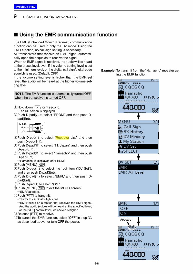
9 D-STAR OPERATION <ADVANCED>
9-8
The EMR (Enhanced Monitor Request) communication function can be used in only the DV mode. Using the EMR function, no call sign setting is necessary. All transceivers that receive an EMR signal automati-cally open their squelch to receive the signal.When an EMR signal is received, the audio will be heard at the preset level, even if the volume setting level is set to the minimum level, or the digital call sign/digital code squelch is used. (Default: OFF)If the volume setting level is higher than the EMR set level, the audio will be heard at the higher volume set-ting level.
NOTE: The EMR function is automatically turned OFF when the transceiver is turned OFF.
qHold down for 1 second. • The DR screen is displayed.
w Push D-pad() to select “FROM,” and then push D-pad(Ent).
D-pad
(�)
(Ent)
e Push D-pad() to select “Repeater List,” and then push D-pad(Ent). r Push D-pad() to select “11: Japan,” and then push D-pad(Ent). t Push D-pad() to select “Hamacho,” and then push D-pad(Ent).
• “Hamacho” is displayed on “FROM”.
yPush [MENU] . u Push D-pad() to select the root item (“DV Set”), and then push D-pad(Ent). i Push D-pad() to select “EMR,” and then push D-pad(Ent). o Push D-pad() to select “ON.”
!0 Push [MENU] to exit the MENU screen. • “EMR” appears.
!1 Push [PTT] to transmit. • The TX/RX indicator lights red. • “EMR” blinks on a station that receives the EMR signal.
And the audio (voice) will be heard at the specified level, or the [VOL] control level, whichever is higher.
!2 Release [PTT] to receive.!3 To cancel the EMR function, select “OFF” in step o,
as described above, or turn OFF the power.Appears
Example: To transmit from the “Hamacho” repeater us-ing the EMR function
■ Using the EMR communication function
Previous view
Icom
ハイライト表示
Radio systems that receive incoming signals and retransmit them to extend the communication area. Normally put on geographically high locations for VHF/UHF radios.
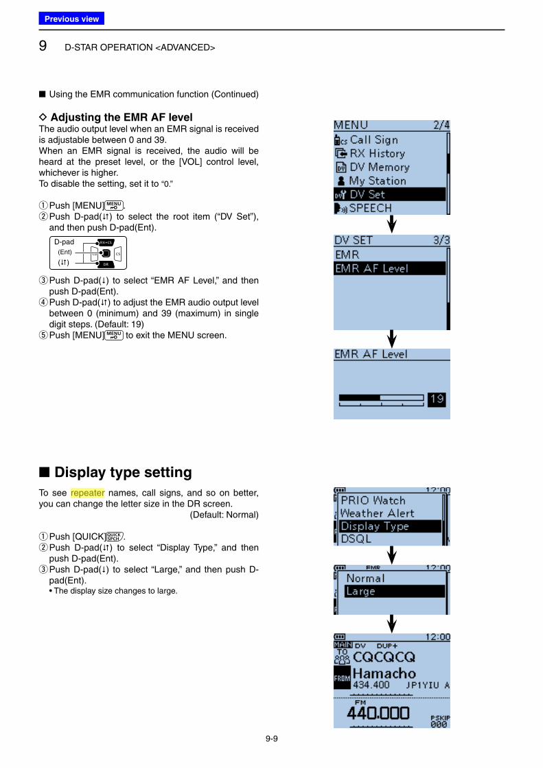
9 D-STAR OPERATION <ADVANCED>
9-9
■ Using the EMR communication function (Continued)
D Adjusting the EMR AF levelThe audio output level when an EMR signal is received is adjustable between 0 and 39.When an EMR signal is received, the audio will be heard at the preset level, or the [VOL] control level, whichever is higher.To disable the setting, set it to “0.”
qPush [MENU] . w Push D-pad() to select the root item (“DV Set”), and then push D-pad(Ent).
D-pad
(�)
(Ent)
e Push D-pad() to select “EMR AF Level,” and then push D-pad(Ent). r Push D-pad() to adjust the EMR audio output level between 0 (minimum) and 39 (maximum) in single digit steps. (Default: 19) tPush [MENU] to exit the MENU screen.
■ Display type setting
To see repeater names, call signs, and so on better, you can change the letter size in the DR screen.
(Default: Normal)
qPush [QUICK] . w Push D-pad() to select “Display Type,” and then push D-pad(Ent). e Push D-pad() to select “Large,” and then push D-pad(Ent).
• The display size changes to large.
Previous view
Icom
ハイライト表示
Radio systems that receive incoming signals and retransmit them to extend the communication area. Normally put on geographically high locations for VHF/UHF radios.
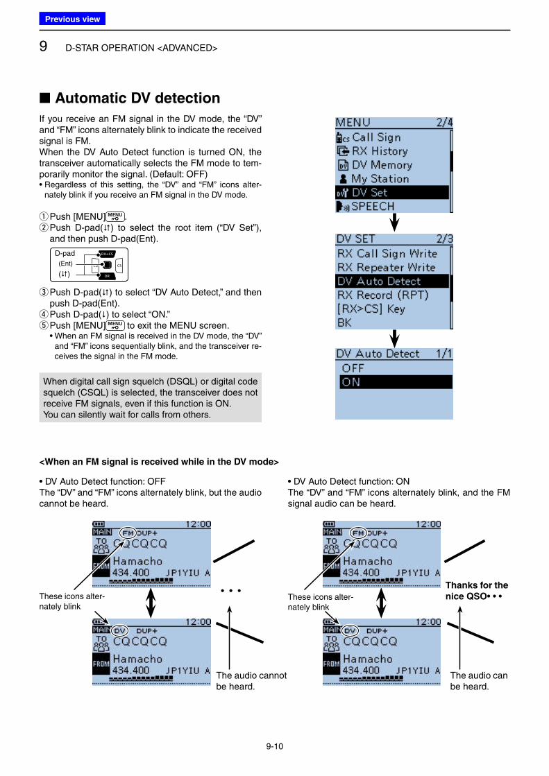
9 D-STAR OPERATION <ADVANCED>
9-10
■ Automatic DV detection
If you receive an FM signal in the DV mode, the “DV” and “FM” icons alternately blink to indicate the received signal is FM.When the DV Auto Detect function is turned ON, the transceiver automatically selects the FM mode to tem-porarily monitor the signal. (Default: OFF)• Regardless of this setting, the “DV” and “FM” icons alter-
nately blink if you receive an FM signal in the DV mode.
qPush [MENU] . w Push D-pad() to select the root item (“DV Set”), and then push D-pad(Ent).
D-pad
(�)
(Ent)
e Push D-pad() to select “DV Auto Detect,” and then push D-pad(Ent). r Push D-pad() to select “ON.” tPush [MENU] to exit the MENU screen.
• When an FM signal is received in the DV mode, the “DV” and “FM” icons sequentially blink, and the transceiver re-ceives the signal in the FM mode.
When digital call sign squelch (DSQL) or digital code squelch (CSQL) is selected, the transceiver does not receive FM signals, even if this function is ON.You can silently wait for calls from others.
These icons alter-nately blink
• • •
<When an FM signal is received while in the DV mode>
• DV Auto Detect function: OFFThe “DV” and “FM” icons alternately blink, but the audio cannot be heard.
The audio cannot be heard.
Thanks for the
nice QSO• • •
• DV Auto Detect function: ONThe “DV” and “FM” icons alternately blink, and the FM signal audio can be heard.
The audio can be heard.
These icons alter-nately blink
Previous view
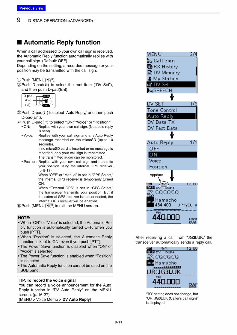
9 D-STAR OPERATION <ADVANCED>
9-11
■ Automatic Reply function
When a call addressed to your own call sign is received, the Automatic Reply function automatically replies with your call sign. (Default: OFF)Depending on the setting, a recorded message or your position may be transmitted with the call sign.
qPush [MENU] . w Push D-pad() to select the root item (“DV Set”), and then push D-pad(Ent).
D-pad
(�)
(Ent)
e Push D-pad() to select “Auto Reply,” and then push D-pad(Ent). r Push D-pad() to select “ON,” “Voice” or “Position.”
• ON: Replies with your own call sign. (No audio reply is sent)
• Voice: Replies with your call sign and any Auto Reply message recorded on the microSD (up to 10 seconds).
If no microSD card is inserted or no message is recorded, only your call sign is transmitted.
The transmitted audio can be monitored. • Position: Replies with your own call sign and transmits
your position using the internal GPS receiver. (p. 9-13)
When “OFF” or “Manual” is set in “GPS Select,” the internal GPS receiver is temporarily turned ON.
When “External GPS” is set in “GPS Select,” the transceiver transmits your position. But if the external GPS receiver is not connected, the internal GPS receiver will be enabled.
tPush [MENU] to exit the MENU screen.
TIP: To record the voice signal
You can record a voice announcement for the Auto Reply function in “DV Auto Reply” on the MENU screen. (p. 16-27)(MENU > Voice Memo > DV Auto Reply)
Appears
After receiving a call from “JG3LUK,” the transceiver automatically sends a reply call.
“TO” setting does not change, but “UR: JG3LUK (Caller’s call sign)” is displayed.
NOTE: • When “ON” or “Voice” is selected, the Automatic Re-
ply function is automatically turned OFF, when you push [PTT].
• When “Position” is selected, the Automatic Reply function is kept to ON, even if you push [PTT].
• The Power Save function is disabled when “ON” or “Voice” is selected.
• The Power Save function is enabled when “Position” is selected.
• The Automatic Reply function cannot be used on the SUB band.
Previous view
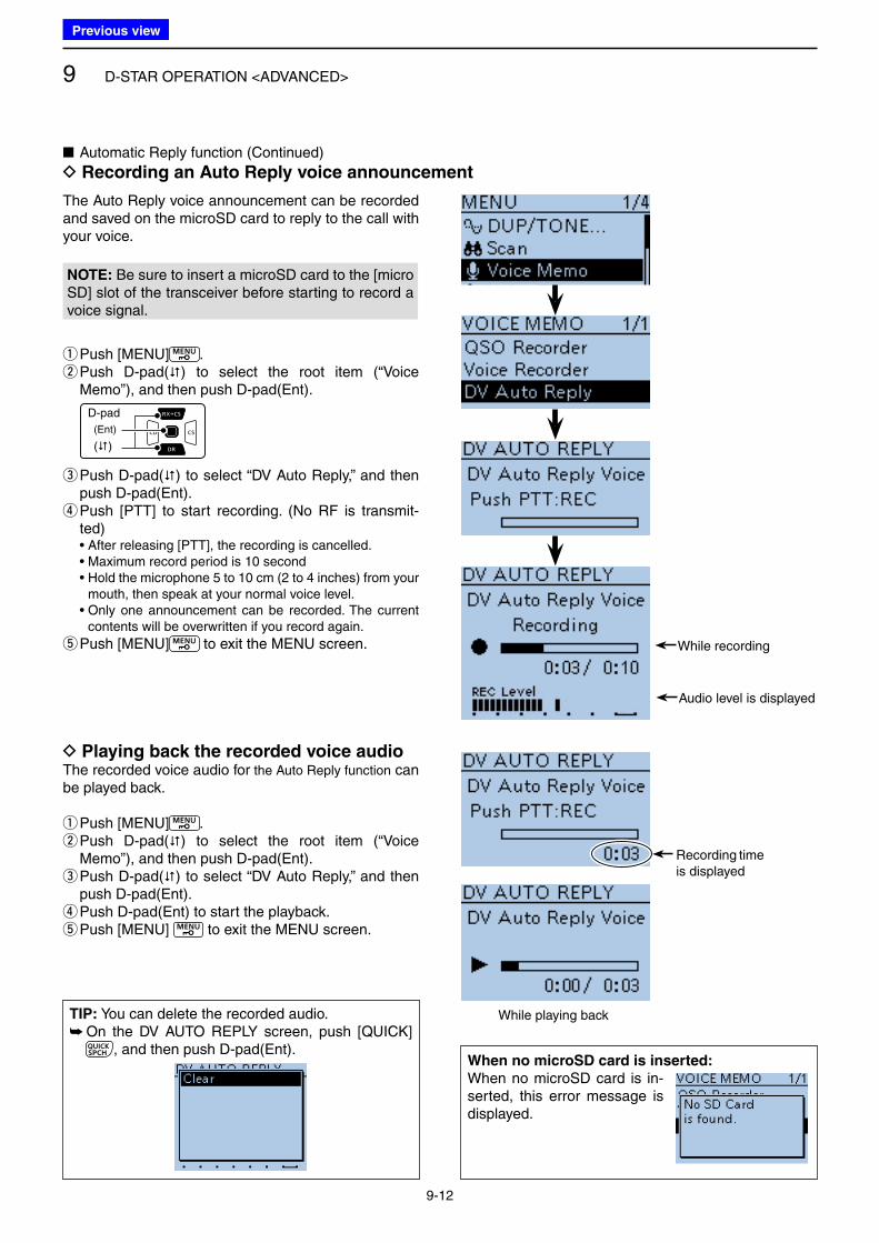
9 D-STAR OPERATION <ADVANCED>
9-12
The Auto Reply voice announcement can be recorded and saved on the microSD card to reply to the call with your voice.
NOTE: Be sure to insert a microSD card to the [micro SD] slot of the transceiver before starting to record a voice signal.
qPush [MENU] . w Push D-pad() to select the root item (“Voice Memo”), and then push D-pad(Ent).
D-pad
(�)
(Ent)
e Push D-pad() to select “DV Auto Reply,” and then push D-pad(Ent). r Push [PTT] to start recording. (No RF is transmit-ted)
• After releasing [PTT], the recording is cancelled. • Maximum record period is 10 second • Hold the microphone 5 to 10 cm (2 to 4 inches) from your
mouth, then speak at your normal voice level. • Only one announcement can be recorded. The current
contents will be overwritten if you record again.
tPush [MENU] to exit the MENU screen.
D Playing back the recorded voice audioThe recorded voice audio for the Auto Reply function can be played back.
qPush [MENU] . w Push D-pad() to select the root item (“Voice Memo”), and then push D-pad(Ent). e Push D-pad() to select “DV Auto Reply,” and then push D-pad(Ent). r Push D-pad(Ent) to start the playback. tPush [MENU] to exit the MENU screen.
TIP: You can delete the recorded audio. ➥ On the DV AUTO REPLY screen, push [QUICK]
, and then push D-pad(Ent).When no microSD card is inserted:
When no microSD card is in-serted, this error message is displayed.
■ Automatic Reply function (Continued)
D Recording an Auto Reply voice announcement
Recording time is displayed
While playing back
While recording
Audio level is displayed
Previous view
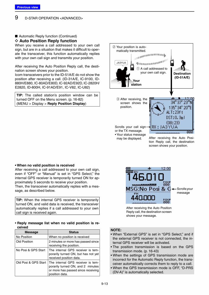
9 D-STAR OPERATION <ADVANCED>
9-13
■ Automatic Reply function (Continued)
D Auto Position Reply functionWhen you receive a call addressed to your own call sign, but are in a situation that makes it difficult to oper-ate the transceiver, this function automatically replies with your own call sign and transmits your position.
After receiving the Auto Position Reply call, the desti-nation screen shows your position.Icom transceivers prior to the ID-51A/E do not show the position after receiving a call. (ID-31A/E, IC-9100, ID-880H/E880, IC-80AD/E80D, IC-92AD/E92D, IC-2820H/E2820, ID-800H, IC-91AD/E91, IC-V82, IC-U82)
w Your position is auto-matically transmitted.
q A call addressed to your own call sign.
Your
station
Destination
(ID-51A/E)
e After receiving, the screen shows the position.
Scrolls your call sign or the TX message.• Your status message may be displayed. After receiving the Auto Posi-
tion Reply call, the destination screen shows your position.
• When no valid position is received
After receiving a call addressed to your own call sign, even if “OFF” or “Manual” is set in “GPS Select,” the internal GPS receiver is temporarily turned ON for ap-proximately 5 seconds to receive your position.Then, the transceiver automatically replies with a mes-sage, as described below.
TIP: When the internal GPS receiver is temporarily turned ON, and valid data is received, the transceiver automatically replies if a call addressed to your own call sign is received again.
• Reply message list when no valid position is re-
ceived
Message Status
No Position When no position is received
Old Position 2 minutes or more has passed since receiving the position.
No Posi & GPS Start The internal GPS receiver is tem-porarily turned ON, but has not yet received position data.
Old Posi & GPS Start The internal GPS receiver is tem-porarily turned ON, and 2 minutes or more has passed since receiving position data.
NOTE:
• When “External GPS” is set in “GPS Select,” and if the external GPS receiver is not connected, the in-ternal GPS receiver will be activated.
• The position transmission is based on the GPS transmission mode. (p. 16-43)
• When the settings of GPS transmission mode are incorrect for the Automatic Reply function, the trans-ceiver automatically corrects them to reply to a call.
• When the GPS transmission mode is OFF, “D-PRS (DV-A)” is automatically selected.
Scrolls your message
After receiving the Auto Position Reply call, the destination screen shows your message.
TIP: The called station’s position window can be turned OFF on the Menu screen. (p. 16-82)(MENU > Display > Reply Position Display)
Previous view
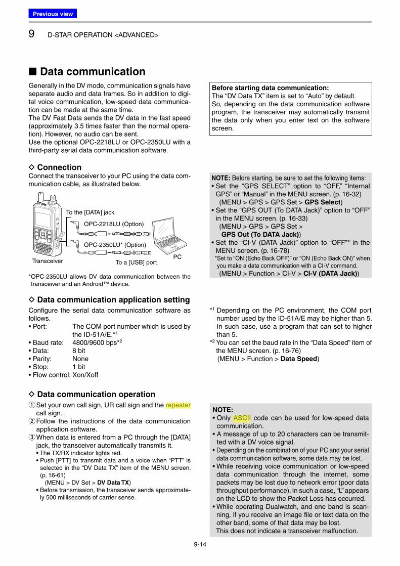
9 D-STAR OPERATION <ADVANCED>
9-14
■ Data communicationGenerally in the DV mode, communication signals have separate audio and data frames. So in addition to digi-tal voice communication, low-speed data communica-tion can be made at the same time.The DV Fast Data sends the DV data in the fast speed (approximately 3.5 times faster than the normal opera-tion). However, no audio can be sent.Use the optional OPC-2218LU or OPC-2350LU with a third-party serial data communication software.
NOTE: • Only ASCII code can be used for low-speed data
communication.• A message of up to 20 characters can be transmit-
ted with a DV voice signal.• Depending on the combination of your PC and your serial
data communication software, some data may be lost.• While receiving voice communication or low-speed
data communication through the internet, some packets may be lost due to network error (poor data throughput performance). In such a case, “L” appears on the LCD to show the Packet Loss has occurred.
• While operating Dualwatch, and one band is scan-ning, if you receive an image file or text data on the other band, some of that data may be lost.
This does not indicate a transceiver malfunction.
q Set your own call sign, UR call sign and the repeater call sign. w Follow the instructions of the data communication application software. e When data is entered from a PC through the [DATA] jack, the transceiver automatically transmits it.
• The TX/RX indicator lights red. • Push [PTT] to transmit data and a voice when “PTT” is
selected in the “DV Data TX” item of the MENU screen. (p. 16-61)
(MENU > DV Set > DV Data TX) • Before transmission, the transceiver sends approximate-
ly 500 milliseconds of carrier sense.
Configure the serial data communication software as follows.• Port: The COM port number which is used by
the ID-51A/E.*1
• Baud rate: 4800/9600 bps*2
• Data: 8 bit • Parity: None• Stop: 1 bit• Flow control: Xon/Xoff
*1 Depending on the PC environment, the COM port number used by the ID-51A/E may be higher than 5. In such case, use a program that can set to higher than 5.
*2 You can set the baud rate in the “Data Speed” item of the MENU screen. (p. 16-76)
(MENU > Function > Data Speed)
D ConnectionConnect the transceiver to your PC using the data com-munication cable, as illustrated below.
To the [DATA] jack
OPC-2218LU (Option)
OPC-2350LU* (Option)
To a [USB] portPC
Transceiver
* OPC-2350LU allows DV data communication between the transceiver and an Android™ device.
D Data communication application setting
D Data communication operation
Before starting data communication:
The “DV Data TX” item is set to “Auto” by default.So, depending on the data communication software program, the transceiver may automatically transmit the data only when you enter text on the software screen.
NOTE: Before starting, be sure to set the following items:• Set the “GPS SELECT” option to “OFF,” “Internal
GPS” or “Manual” in the MENU screen. (p. 16-32) (MENU > GPS > GPS Set > GPS Select)• Set the “GPS OUT (To DATA Jack)” option to “OFF”
in the MENU screen. (p. 16-33) ( MENU > GPS > GPS Set >
GPS Out (To DATA Jack))• Set the “CI-V (DATA Jack)” option to “OFF”* in the
MENU screen. (p. 16-78) * Set to “ON (Echo Back OFF)” or “ON (Echo Back ON)” when
you make a data communication with a CI-V command.
(MENU > Function > CI-V > CI-V (DATA Jack))
Previous view
Icom
ハイライト表示
Radio systems that receive incoming signals and retransmit them to extend the communication area. Normally put on geographically high locations for VHF/UHF radios.
Icom
ハイライト表示
Acronym for the American Standard Code for Information Interchange. Pronounced ask-ee, ASCII is a code for representing English characters as numbers, with each letter assigned a number from 0 to 127.
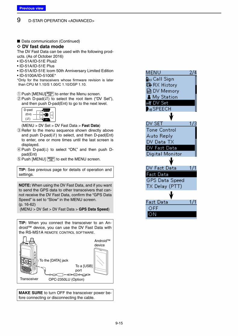
9 D-STAR OPERATION <ADVANCED>
9-15
■ Data communication (Continued)
D DV fast data modeThe DV Fast Data can be used with the following prod-ucts. (As of October 2016)• ID-51A/ID-51E Plus2• ID-51A/ID-51E Plus• ID-51A/ID-51E Icom 50th Anniversary Limited Edition• ID-5100A/ID-5100E** Only for the transceivers whose firmware revision is later than CPU M 1.10/S 1.00/C 1.10/DSP 1.10.
qPush [MENU] to enter the Menu screen. w Push D-pad() to select the root item (“DV Set”), and then push D-pad(Ent) to go to the next level.
D-pad
(�)
(Ent)
( MENU > DV Set > DV Fast Data > Fast Data) e Refer to the menu sequence shown directly above and push D-pad() to select, and then D-pad(Ent) to enter, one or more times until the last screen is displayed. r Push D-pad() to select “ON,” and then push D-pad(Ent) tPush [MENU] to exit the MENU screen.
NOTE: When using the DV Fast Data, and if you want to send the GPS data to other transceivers that can-not receive the DV Fast Data, confirm the “GPS Data Speed” is set to “Slow” in the MENU screen.(p. 16-62) (MENU > DV Set > DV Fast Data > GPS Data Speed)
TIP: When you connect the transceiver to an An-droid™ device, you can use the DV Fast Data with the RS-MS1A REMOTE CONTROL SOFTWARE.
To the [DATA] jack
OPC-2350LU (Option)
To a [USB]port
Android™device
Transceiver
MAKE SURE to turn OFF the transceiver power be-fore connecting or disconnecting the cable.
TIP: See previous page for details of operation and settings.
Previous view
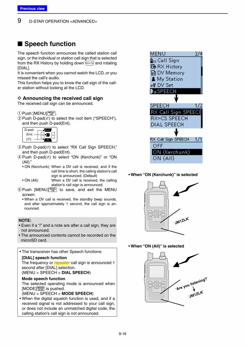
9 D-STAR OPERATION <ADVANCED>
9-16
■ Speech function
The speech function announces the called station call sign, or the individual or station call sign that is selected from the RX History by holding down and rotating [DIAL].It is convenient when you cannot watch the LCD, or you missed the call’s audio.This function helps you to know the call sign of the call-er station without looking at the LCD.
D Announcing the received call signThe received call sign can be announced.
qPush [MENU] . w Push D-pad() to select the root item (“SPEECH”), and then push D-pad(Ent).
D-pad
(�)
(Ent)
e Push D-pad() to select “RX Call Sign SPEECH,” and then push D-pad(Ent). r Push D-pad() to select “ON (Kerchunk)” or “ON (All).”
• ON (Kerchunk): When a DV call is received, and if the call time is short, the calling station’s call sign is announced. (Default)
• ON (All): When a DV call is received, the calling station’s call sign is announced.
t Push [MENU] to save, and exit the MENU screen.
• When a DV call is received, the standby beep sounds, and after approximately 1 second, the call sign is an-nounced.
• The transceiver has other Speech functions:
[DIAL] speech function
The frequency or repeater call sign is announced 1 second after [DIAL] selection.
(MENU > SPEECH > DIAL SPEECH)
Mode speech function
The selected operating mode is announced when [MODE] is pushed.
(MENU > SPEECH > MODE SPEECH)• When the digital squelch function is used, and if a
received signal is not addressed to your call sign, or does not include an unmatched digital code, the calling station’s call sign is not announced.
‘JM1ZLK’
‘JM1ZLK’‘Are you listening?’
• When “ON (Kerchunk)” is selected
• When “ON (All)” is selected
NOTE:
• Even if a “/” and a note are after a call sign, they are not announced.
• The announced contents cannot be recorded on the microSD card.
Previous view
Icom
ハイライト表示
Radio systems that receive incoming signals and retransmit them to extend the communication area. Normally put on geographically high locations for VHF/UHF radios.
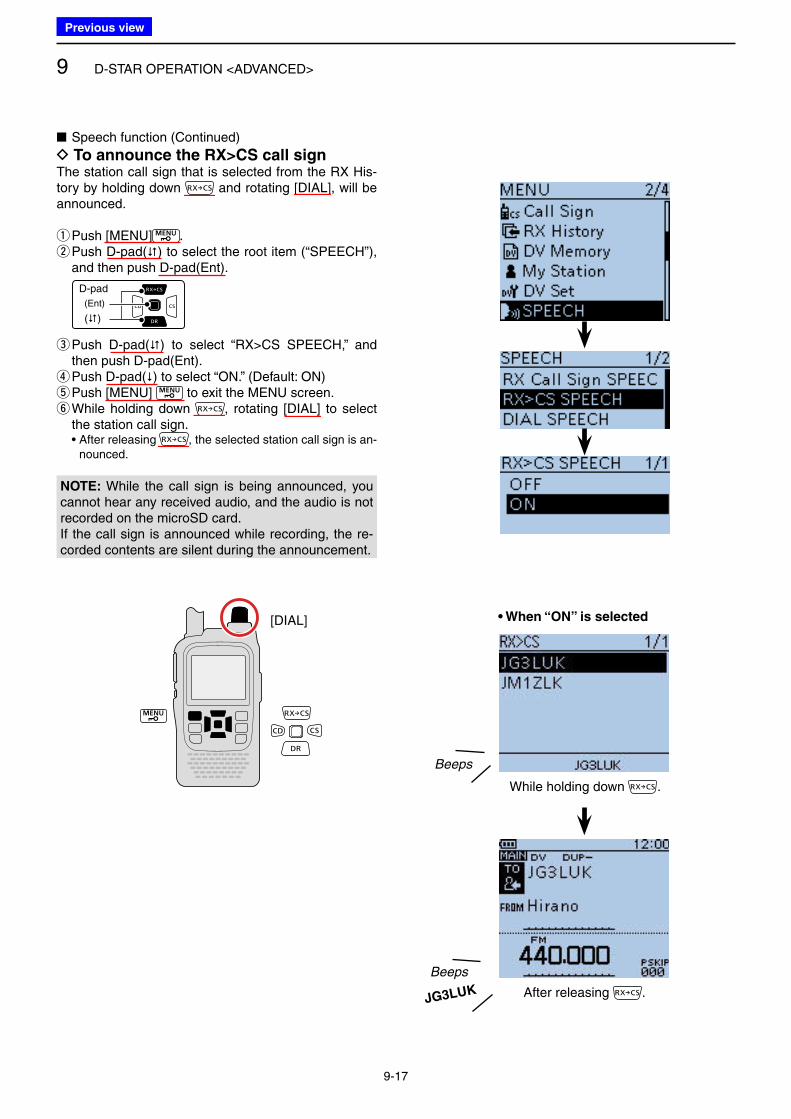
9 D-STAR OPERATION <ADVANCED>
9-17
■ Speech function (Continued)
D To announce the RX>CS call signThe station call sign that is selected from the RX His-tory by holding down and rotating [DIAL], will be announced.
qPush [MENU] . w Push D-pad() to select the root item (“SPEECH”), and then push D-pad(Ent).
D-pad
(�)
(Ent)
e Push D-pad() to select “RX>CS SPEECH,” and then push D-pad(Ent). r Push D-pad() to select “ON.” (Default: ON) tPush [MENU] to exit the MENU screen. y While holding down , rotating [DIAL] to select the station call sign.
• After releasing , the selected station call sign is an-nounced.
• When “ON” is selected
Beeps
While holding down .
Beeps
After releasing .JG3LUK
[DIAL]
NOTE: While the call sign is being announced, you cannot hear any received audio, and the audio is not recorded on the microSD card.If the call sign is announced while recording, the re-corded contents are silent during the announcement.
Previous view
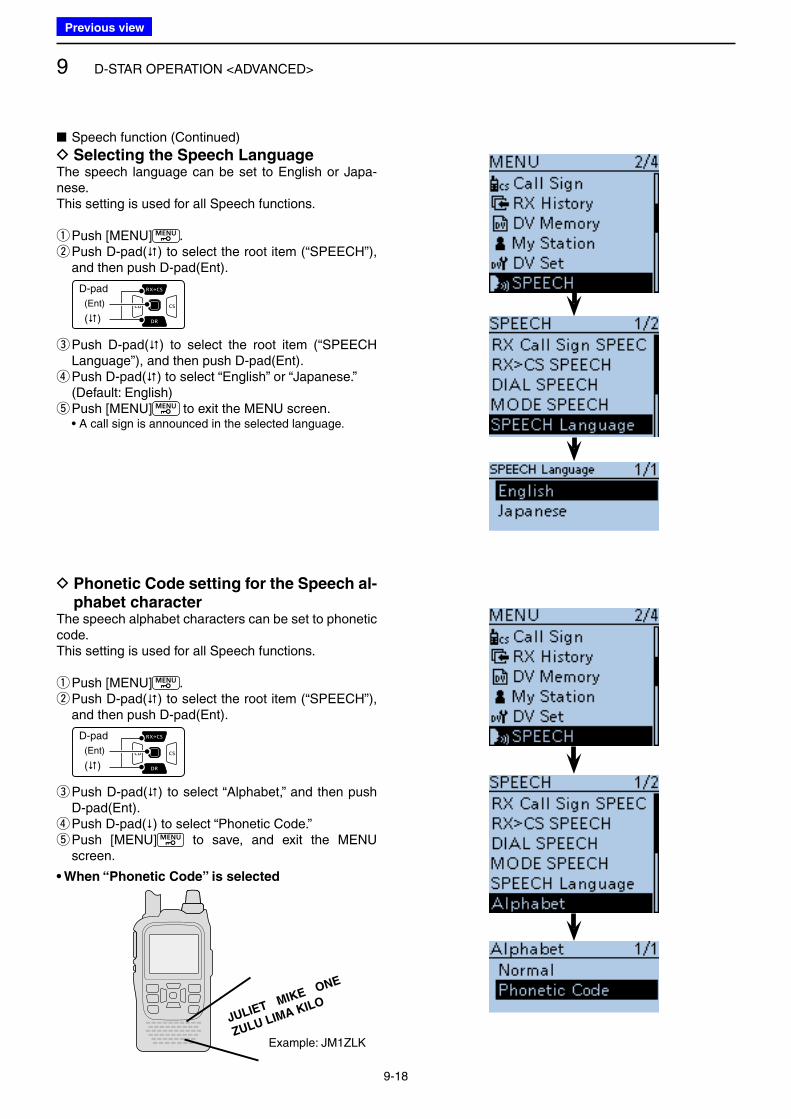
9 D-STAR OPERATION <ADVANCED>
9-18
■ Speech function (Continued)
D Selecting the Speech LanguageThe speech language can be set to English or Japa-nese.This setting is used for all Speech functions.
qPush [MENU] . w Push D-pad() to select the root item (“SPEECH”), and then push D-pad(Ent).
D-pad
(�)
(Ent)
e Push D-pad() to select the root item (“SPEECH Language”), and then push D-pad(Ent). r Push D-pad() to select “English” or “Japanese.”
(Default: English) tPush [MENU] to exit the MENU screen.
• A call sign is announced in the selected language.
D Phonetic Code setting for the Speech al-phabet character
The speech alphabet characters can be set to phonetic code.This setting is used for all Speech functions.
qPush [MENU] . w Push D-pad() to select the root item (“SPEECH”), and then push D-pad(Ent).
D-pad
(�)
(Ent)
e Push D-pad() to select “Alphabet,” and then push D-pad(Ent). r Push D-pad() to select “Phonetic Code.” t Push [MENU] to save, and exit the MENU screen.
JULIET MIKE ONE
ZULU LIMA KILO
Example: JM1ZLK
• When “Phonetic Code” is selected
Previous view
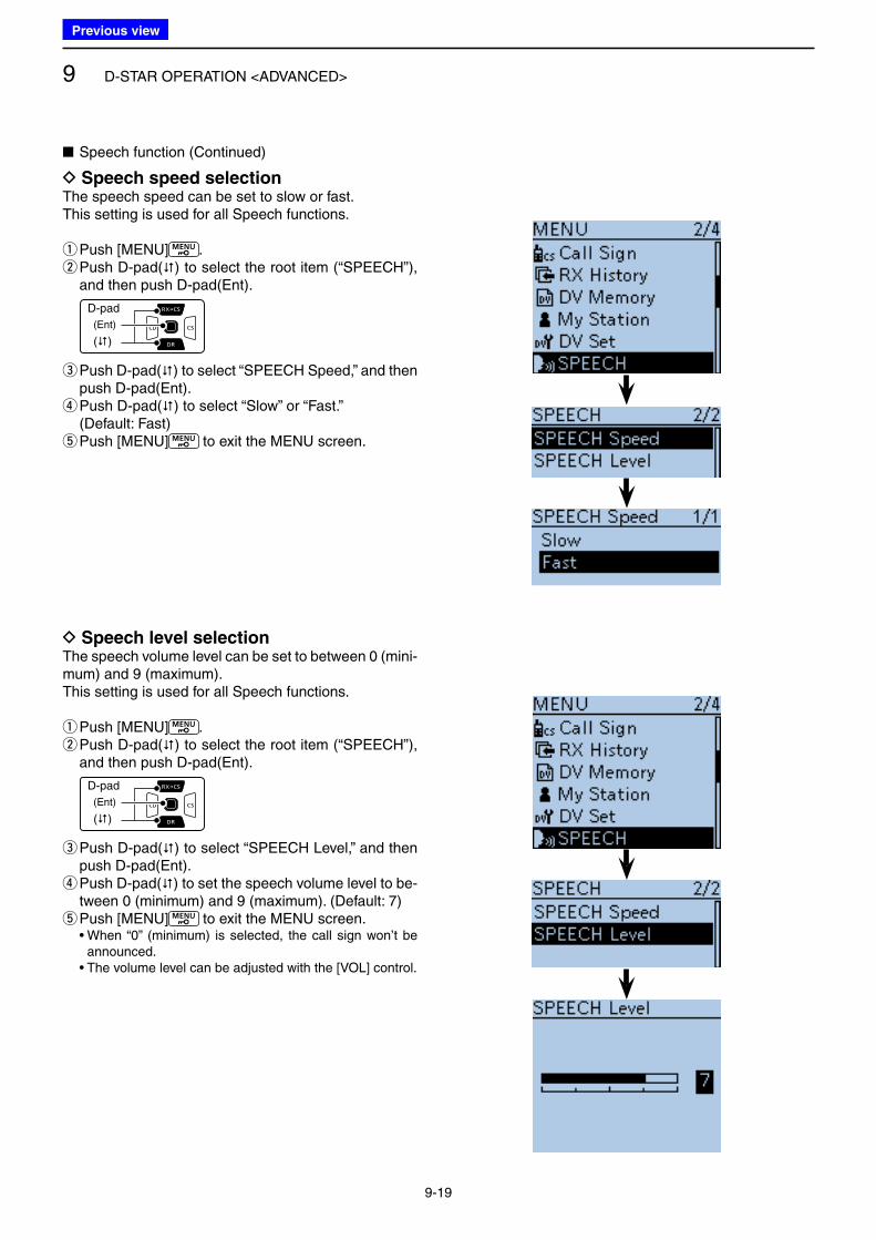
9 D-STAR OPERATION <ADVANCED>
9-19
D Speech speed selectionThe speech speed can be set to slow or fast. This setting is used for all Speech functions.
qPush [MENU] . w Push D-pad() to select the root item (“SPEECH”), and then push D-pad(Ent).
D-pad
(�)
(Ent)
e Push D-pad() to select “SPEECH Speed,” and then push D-pad(Ent). r Push D-pad() to select “Slow” or “Fast.”
(Default: Fast) tPush [MENU] to exit the MENU screen.
■ Speech function (Continued)
D Speech level selectionThe speech volume level can be set to between 0 (mini-mum) and 9 (maximum).This setting is used for all Speech functions.
qPush [MENU] . w Push D-pad() to select the root item (“SPEECH”), and then push D-pad(Ent).
D-pad
(�)
(Ent)
e Push D-pad() to select “SPEECH Level,” and then push D-pad(Ent). r Push D-pad() to set the speech volume level to be-tween 0 (minimum) and 9 (maximum). (Default: 7) tPush [MENU] to exit the MENU screen.
• When “0” (minimum) is selected, the call sign won’t be announced.
• The volume level can be adjusted with the [VOL] control.
Previous view
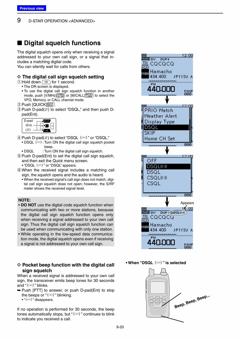
9 D-STAR OPERATION <ADVANCED>
9-20
■ Digital squelch functions
The digital squelch opens only when receiving a signal addressed to your own call sign, or a signal that in-cludes a matching digital code.You can silently wait for calls from others.
D The digital call sign squelch setting qHold down for 1 second.
• The DR screen is displayed. • To use the digital call sign squelch function in another
mode, push [V/MHz] or [M/CALL] to select the VFO, Memory, or CALL channel mode.
wPush [QUICK] . e Push D-pad() to select “DSQL,” and then push D-pad(Ent).
D-pad
(�)
(Ent)
r Push D-pad() to select “DSQL S” or “DSQL.” • DSQL S : Turn ON the digital call sign squelch pocket
beep. • DSQL : Turn ON the digital call sign squelch.
t Push D-pad(Ent) to set the digital call sign squelch, and then exit the Quick menu screen.
• “DSQL S” or “DSQL” appears.
y When the received signal includes a matching call sign, the squelch opens and the audio is heard.
• When the received signal’s call sign does not match, digi-tal call sign squelch does not open; however, the S/RF meter shows the received signal level.
D Pocket beep function with the digital call sign squelch
When a received signal is addressed to your own call sign, the transceiver emits beep tones for 30 seconds and “S” blinks.
➥ Push [PTT] to answer, or push D-pad(Ent) to stop the beeps or “S” blinking.
• “S” disappears.
If no operation is performed for 30 seconds, the beep tones automatically stops, but “S” continues to blink to indicate you received a call.
Beep, Beep, Beep...
• When “DSQL S” is selected
AppearsNOTE:
• DO NOT use the digital code squelch function when communicating with two or more stations, because the digital call sign squelch function opens only when receiving a signal addressed to your own call sign. Thus the digital call sign squelch function can be used when communicating with only one station.
• While operating in the low-speed data communica-tion mode, the digital squelch opens even if receiving a signal is not addressed to your own call sign.
Previous view
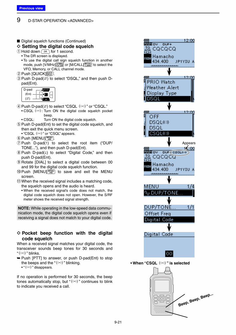
9 D-STAR OPERATION <ADVANCED>
9-21
■ Digital squelch functions (Continued)
D Setting the digital code squelch qHold down for 1 second.
• The DR screen is displayed. • To use the digital call sign squelch function in another
mode, push [V/MHz] or [M/CALL] to select the VFO, Memory, or CALL channel mode.
wPush [QUICK] . e Push D-pad() to select “DSQL,” and then push D-pad(Ent).
D-pad
(�)
(Ent)
r Push D-pad() to select “CSQL S” or “CSQL.” • CSQL S: Turn ON the digital code squelch pocket
beep. • CSQL: Turn ON the digital code squelch.
t Push D-pad(Ent) to set the digital code squelch, and then exit the quick menu screen.
• “CSQL S” or “CSQL” appears.
yPush [MENU] . u Push D-pad() to select the root item (“DUP/TONE...”), and then push D-pad(Ent). i Push D-pad() to select “Digital Code,” and then push D-pad(Ent). o Rotate [DIAL] to select a digital code between 00 and 99 for the digital code squelch function.
!0 Push [MENU] to save and exit the MENU screen.
!1 When the received signal includes a matching code, the squelch opens and the audio is heard.
• When the received signal’s code does not match, the digital code squelch does not open. However, the S/RF meter shows the received signal strength.
D Pocket beep function with the digital code squelch
When a received signal matches your digital code, the transceiver sounds beep tones for 30 seconds and “S” blinks.
➥ Push [PTT] to answer, or push D-pad(Ent) to stop the beeps and the “S” blinking.
• “S” disappears.
If no operation is performed for 30 seconds, the beep tones automatically stop, but “S” continues to blink to indicate you received a call.
Appears
Beep, Beep, Beep...
• When “CSQL S” is selected
NOTE: While operating in the low-speed data commu-nication mode, the digital code squelch opens even if receiving a signal does not match to your digital code.
Previous view
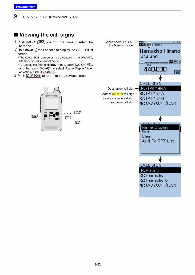
9 D-STAR OPERATION <ADVANCED>
9-22
■ Viewing the call signs
q Push [MODE] one or more times to select the DV mode. w Hold down for 1 second to display the CALL SIGN screen.
• The CALL SIGN screen can be displayed in the DR, VFO, Memory or Call channel mode.
• To select the name display mode, push [QUICK] , and then push D-pad() to select “Name Display.” After selecting, push D-pad(Ent).
e Push [CLR] to return to the previous screen.
Destination call sign
Access repeater call sign
Gateway repeater call sign
Your own call sign
While operating D-STAR in the Memory mode.
Previous view
Icom
ハイライト表示
Radio systems that receive incoming signals and retransmit them to extend the communication area. Normally put on geographically high locations for VHF/UHF radios.
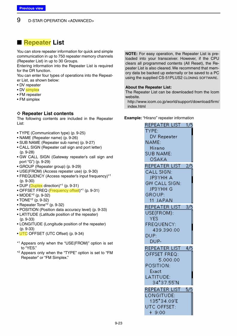
9 D-STAR OPERATION <ADVANCED>
9-23
■ Repeater List
You can store repeater information for quick and simple communication in up to 750 repeater memory channels (Repeater List) in up to 30 Groups.Entering information into the Repeater List is required for the DR function.You can enter four types of operations into the Repeat-er List, as shown below:• DV repeater• DV simplex• FM repeater• FM simplex
D Repeater List contentsThe following contents are included in the Repeater List:
• TYPE (Communication type) (p. 9-25)• NAME (Repeater name) (p. 9-26)• SUB NAME (Repeater sub name) (p. 9-27)• CALL SIGN (Repeater call sign and port letter) (p. 9-28)• GW CALL SIGN (Gateway repeater’s call sign and
port “G”) (p. 9-29)• GROUP (Repeater group) (p. 9-29)• USE(FROM) (Access repeater use) (p. 9-30)• FREQUENCY (Access repeater’s input frequency)*1
(p. 9-30)• DUP (Duplex direction)*1 (p. 9-31)• OFFSET FREQ (Frequency offset)*1 (p. 9-31)• MODE*2 (p. 9-32)• TONE*2 (p. 9-32)• Repeater Tone*2 (p. 9-32)• POSITION (Position data accuracy level) (p. 9-33)• LATITUDE (Latitude position of the repeater) (p. 9-33)• LONGITUDE (Longitude position of the repeater) (p. 9-33)• UTC OFFSET (UTC Offset) (p. 9-34)
*1 Appears only when the “USE(FROM)” option is set to “YES.”
*2 Appears only when the “TYPE” option is set to “FM Repeater” or “FM Simplex.”
Example: “Hirano” repeater information
NOTE: For easy operation, the Repeater List is pre-loaded into your transceiver. However, if the CPU clears all programmed contents (All Reset), the Re-peater List is also cleared. We recommend that mem-ory data be backed up externally or be saved to a PC using the supplied CS-51PLUS2 CLONING SOFTWARE.
About the Repeater List:
The Repeater List can be downloaded from the Icom website. http://www.icom.co.jp/world/support/download/firm/
index.html
Previous view
Icom
ハイライト表示
An operating mode in which the transmit and receive frequencies are the same.
Icom
ハイライト表示
The difference between the transmit and receive frequencies.
Icom
ハイライト表示
Radio systems that receive incoming signals and retransmit them to extend the communication area. Normally put on geographically high locations for VHF/UHF radios.
Icom
ハイライト表示
An operating mode in which the transmit and receive frequencies are separated by an offset amount.
Icom
ハイライト表示
(Universal Time Coordinated) An astronomical time based on the Greenwich meridian (zero degrees longitude).
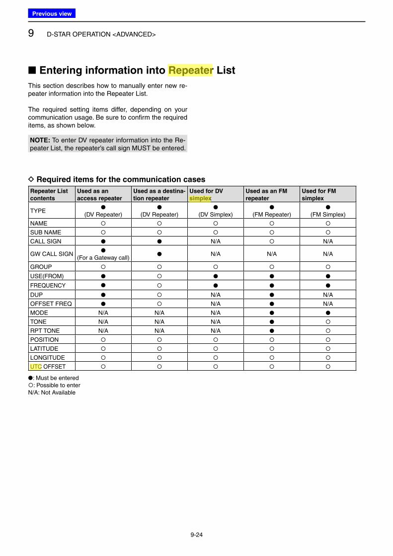
9 D-STAR OPERATION <ADVANCED>
9-24
This section describes how to manually enter new re-peater information into the Repeater List.
The required setting items differ, depending on your communication usage. Be sure to confirm the required items, as shown below.
D Required items for the communication cases
Repeater List
contents
Used as an
access repeater
Used as a destina-
tion repeater
Used for DV
simplex
Used as an FM
repeater
Used for FM
simplex
TYPE●
(DV Repeater)●
(DV Repeater)●
(DV Simplex)●
(FM Repeater)●
(FM Simplex)
NAME
SUB NAME
CALL SIGN ● ● N/A N/A
GW CALL SIGN●
(For a Gateway call) ● N/A N/A N/A
GROUP
USE(FROM) ● ● ● ●
FREQUENCY ● ● ● ●
DUP ● N/A ● N/A
OFFSET FREQ ● N/A ● N/A
MODE N/A N/A N/A ● ●
TONE N/A N/A N/A ●
RPT TONE N/A N/A N/A ●
POSITION
LATITUDE
LONGITUDE
UTC OFFSET
●: Must be entered: Possible to enterN/A: Not Available
■ Entering information into Repeater List
NOTE: To enter DV repeater information into the Re-peater List, the repeater’s call sign MUST be entered.
Previous view
Icom
ハイライト表示
An operating mode in which the transmit and receive frequencies are the same.
Icom
ハイライト表示
Radio systems that receive incoming signals and retransmit them to extend the communication area. Normally put on geographically high locations for VHF/UHF radios.
Icom
ハイライト表示
(Universal Time Coordinated) An astronomical time based on the Greenwich meridian (zero degrees longitude).
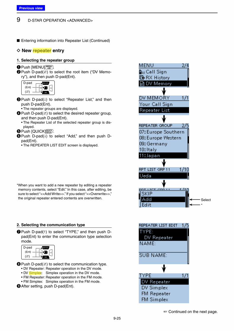
9 D-STAR OPERATION <ADVANCED>
9-25
■ Entering information into Repeater List (Continued)
D New repeater entry
1. Selecting the repeater group
q Push [MENU] .w Push D-pad() to select the root item (“DV Memo-
ry”), and then push D-pad(Ent).
D-pad
(�)
(Ent)
e Push D-pad() to select “Repeater List,” and then push D-pad(Ent).
• The repeater groups are displayed.
r Push D-pad() to select the desired repeater group, and then push D-pad(Ent).
• The Repeater List of the selected repeater group is dis-played.
t Push [QUICK] .y Push D-pad() to select “Add,” and then push D-
pad(Ent). • The REPEATER LIST EDIT screen is displayed.
☞ Continued on the next page.
* When you want to add a new repeater by editing a repeater memory contents, select “Edit.” In this case, after editing, be sure to select “<<Add Write>>.” If you select “<<Overwrite>>,” the original repeater entered contents are overwritten. Select
*
2. Selecting the communication type
u Push D-pad() to select “TYPE,” and then push D-pad(Ent) to enter the communication type selection mode.
D-pad
(�)
(Ent)
i Push D-pad() to select the communication type. • DV Repeater: Repeater operation in the DV mode. • DV Simplex: Simplex operation in the DV mode. • FM Repeater: Repeater operation in the FM mode. • FM Simplex: Simplex operation in the FM mode.
o After setting, push D-pad(Ent).
Previous view
Icom
ハイライト表示
An operating mode in which the transmit and receive frequencies are the same.
Icom
ハイライト表示
Radio systems that receive incoming signals and retransmit them to extend the communication area. Normally put on geographically high locations for VHF/UHF radios.
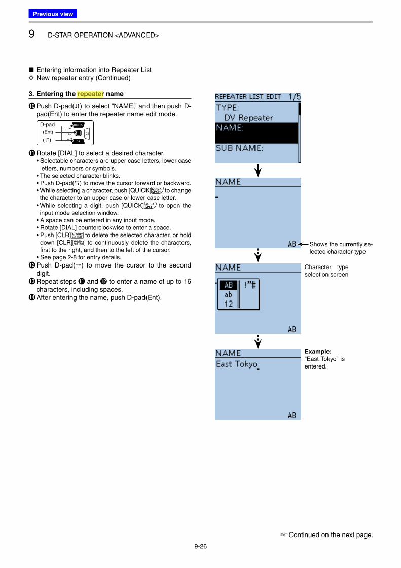
9 D-STAR OPERATION <ADVANCED>
9-26
■ Entering information into Repeater List D New repeater entry (Continued)
3. Entering the repeater name
!0 Push D-pad() to select “NAME,” and then push D-pad(Ent) to enter the repeater name edit mode.
D-pad
(�)
(Ent)
!1 Rotate [DIAL] to select a desired character. • Selectable characters are upper case letters, lower case
letters, numbers or symbols. • The selected character blinks. • Push D-pad() to move the cursor forward or backward. • While selecting a character, push [QUICK] to change
the character to an upper case or lower case letter. • While selecting a digit, push [QUICK] to open the
input mode selection window. • A space can be entered in any input mode. • Rotate [DIAL] counterclockwise to enter a space. • Push [CLR] to delete the selected character, or hold
down [CLR] to continuously delete the characters, first to the right, and then to the left of the cursor.
• See page 2-8 for entry details.
!2 Push D-pad() to move the cursor to the second digit.
!3 Repeat steps !1 and !2 to enter a name of up to 16 characters, including spaces.
!4 After entering the name, push D-pad(Ent).
Character type selection screen
Example:
“East Tokyo” is entered.
☞ Continued on the next page.
Shows the currently se-lected character type
Previous view
Icom
ハイライト表示
Radio systems that receive incoming signals and retransmit them to extend the communication area. Normally put on geographically high locations for VHF/UHF radios.
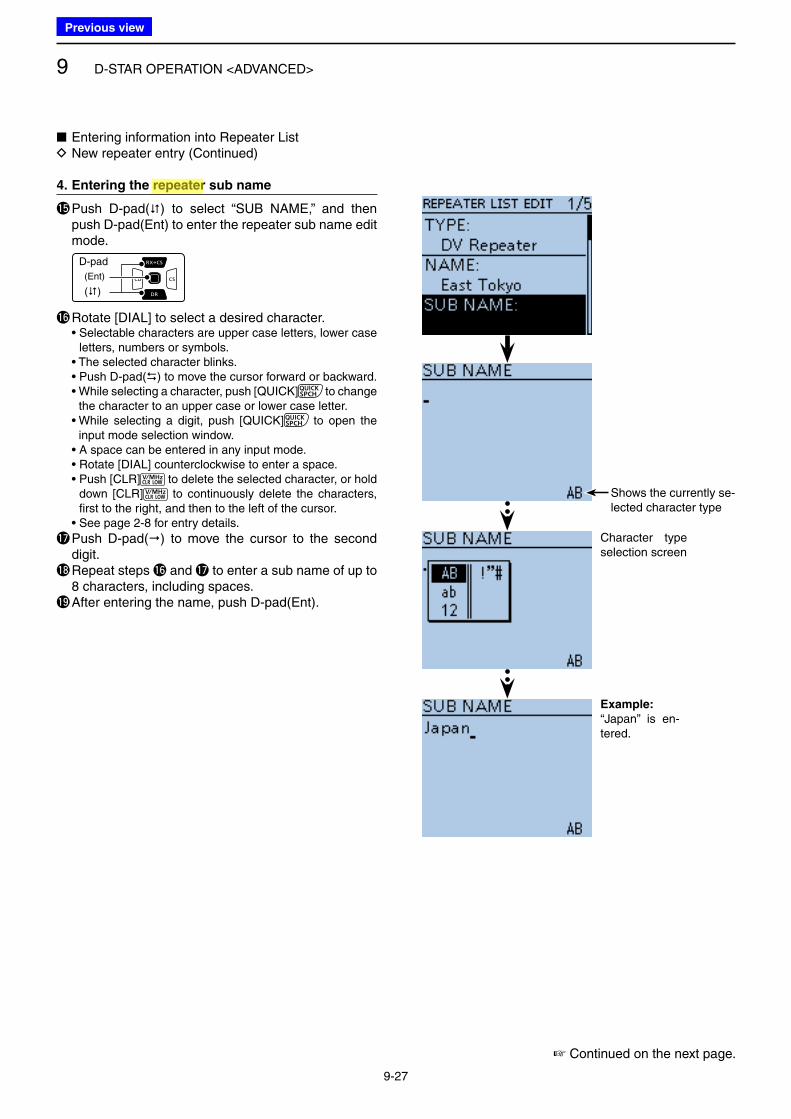
9 D-STAR OPERATION <ADVANCED>
9-27
■ Entering information into Repeater List D New repeater entry (Continued)
4. Entering the repeater sub name
!5 Push D-pad() to select “SUB NAME,” and then push D-pad(Ent) to enter the repeater sub name edit mode.
D-pad
(�)
(Ent)
!6 Rotate [DIAL] to select a desired character. • Selectable characters are upper case letters, lower case
letters, numbers or symbols. • The selected character blinks. • Push D-pad() to move the cursor forward or backward. • While selecting a character, push [QUICK] to change
the character to an upper case or lower case letter. • While selecting a digit, push [QUICK] to open the
input mode selection window. • A space can be entered in any input mode. • Rotate [DIAL] counterclockwise to enter a space. • Push [CLR] to delete the selected character, or hold
down [CLR] to continuously delete the characters, first to the right, and then to the left of the cursor.
• See page 2-8 for entry details.
!7 Push D-pad() to move the cursor to the second digit.
!8 Repeat steps !6 and !7 to enter a sub name of up to 8 characters, including spaces.
!9 After entering the name, push D-pad(Ent).
Character type selection screen
Example:
“Japan” is en-tered.
☞ Continued on the next page.
Shows the currently se-lected character type
Previous view
Icom
ハイライト表示
Radio systems that receive incoming signals and retransmit them to extend the communication area. Normally put on geographically high locations for VHF/UHF radios.
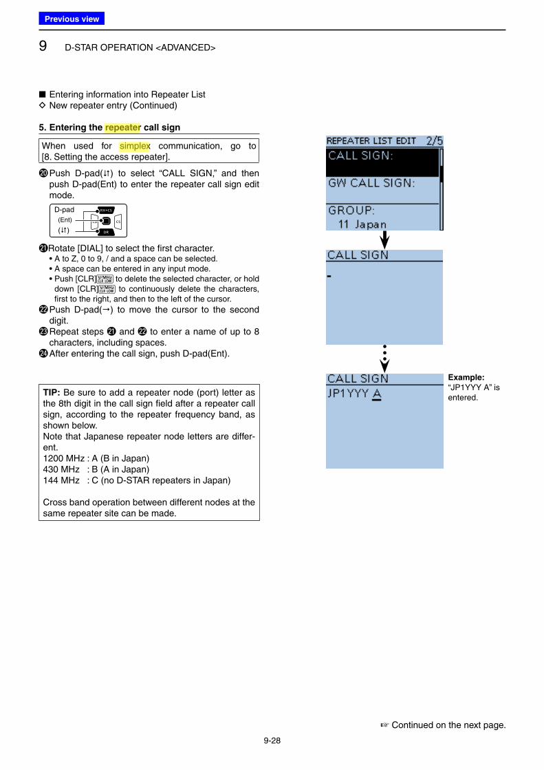
9 D-STAR OPERATION <ADVANCED>
9-28
■ Entering information into Repeater List D New repeater entry (Continued)
5. Entering the repeater call sign
When used for simplex communication, go to [8. Setting the access repeater].
@0 Push D-pad() to select “CALL SIGN,” and then push D-pad(Ent) to enter the repeater call sign edit mode.
D-pad
(�)
(Ent)
@1 Rotate [DIAL] to select the first character. • A to Z, 0 to 9, / and a space can be selected. • A space can be entered in any input mode. • Push [CLR] to delete the selected character, or hold
down [CLR] to continuously delete the characters, first to the right, and then to the left of the cursor.
@2 Push D-pad() to move the cursor to the second digit.
@3 Repeat steps @1 and @2 to enter a name of up to 8 characters, including spaces.
@4 After entering the call sign, push D-pad(Ent).
Example:
“JP1YYY A” is entered.
☞ Continued on the next page.
TIP: Be sure to add a repeater node (port) letter as the 8th digit in the call sign field after a repeater call sign, according to the repeater frequency band, as shown below.Note that Japanese repeater node letters are differ-ent.1200 MHz : A (B in Japan)430 MHz : B (A in Japan)144 MHz : C (no D-STAR repeaters in Japan)
Cross band operation between different nodes at the same repeater site can be made.
Previous view
Icom
ハイライト表示
Radio systems that receive incoming signals and retransmit them to extend the communication area. Normally put on geographically high locations for VHF/UHF radios.
Icom
ハイライト表示
An operating mode in which the transmit and receive frequencies are the same.
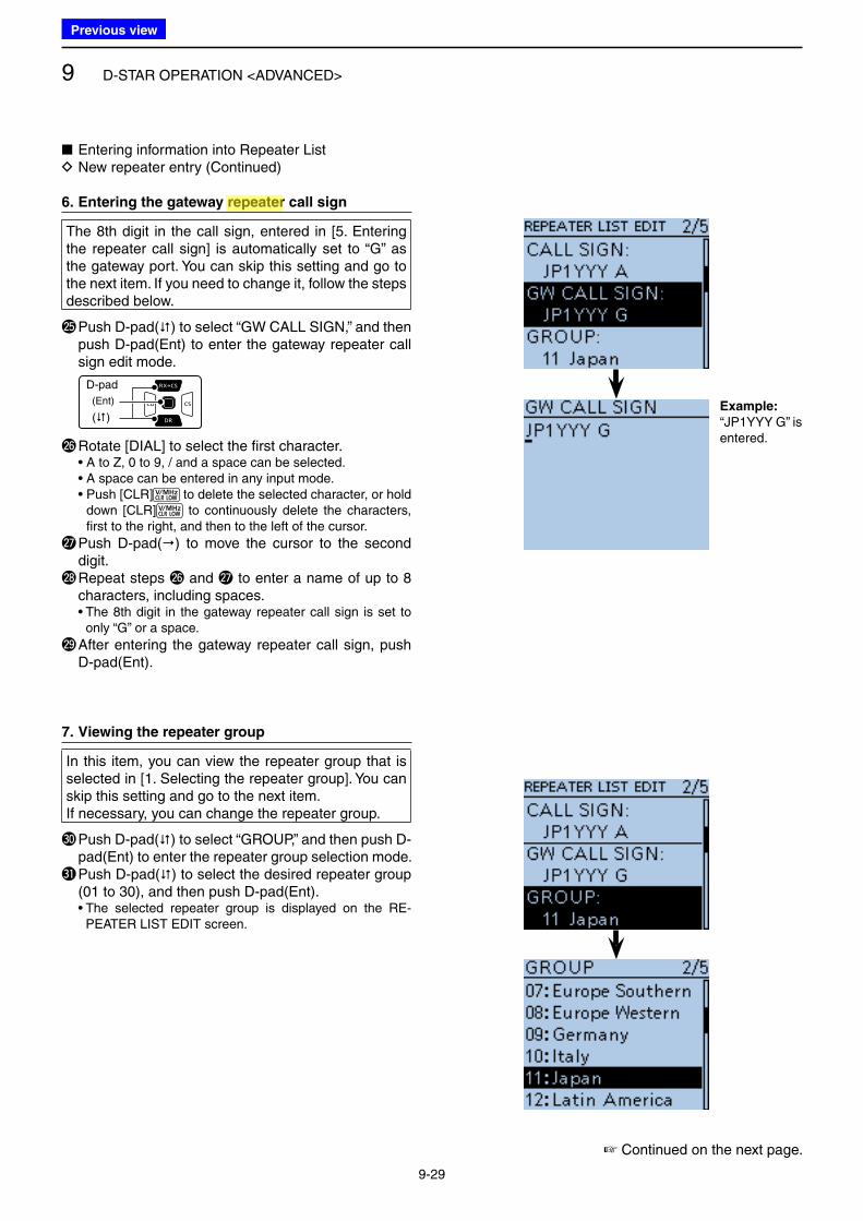
9 D-STAR OPERATION <ADVANCED>
9-29
■ Entering information into Repeater List D New repeater entry (Continued)
6. Entering the gateway repeater call sign
The 8th digit in the call sign, entered in [5. Entering the repeater call sign] is automatically set to “G” as the gateway port. You can skip this setting and go to the next item. If you need to change it, follow the steps described below.
@5 Push D-pad() to select “GW CALL SIGN,” and then push D-pad(Ent) to enter the gateway repeater call sign edit mode.
D-pad
(�)
(Ent)
@6 Rotate [DIAL] to select the first character. • A to Z, 0 to 9, / and a space can be selected. • A space can be entered in any input mode. • Push [CLR] to delete the selected character, or hold
down [CLR] to continuously delete the characters, first to the right, and then to the left of the cursor.
@7 Push D-pad() to move the cursor to the second digit.
@8 Repeat steps @6 and @7 to enter a name of up to 8 characters, including spaces.
• The 8th digit in the gateway repeater call sign is set to only “G” or a space.
@9 After entering the gateway repeater call sign, push D-pad(Ent).
7. Viewing the repeater group
In this item, you can view the repeater group that is selected in [1. Selecting the repeater group]. You can skip this setting and go to the next item.If necessary, you can change the repeater group.
#0 Push D-pad() to select “GROUP,” and then push D-pad(Ent) to enter the repeater group selection mode.
#1 Push D-pad() to select the desired repeater group (01 to 30), and then push D-pad(Ent).
• The selected repeater group is displayed on the RE-PEATER LIST EDIT screen.
☞ Continued on the next page.
Example:
“JP1YYY G” is entered.
Previous view
Icom
ハイライト表示
Radio systems that receive incoming signals and retransmit them to extend the communication area. Normally put on geographically high locations for VHF/UHF radios.
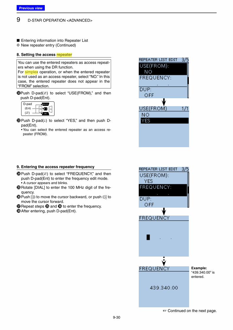
9 D-STAR OPERATION <ADVANCED>
9-30
■ Entering information into Repeater List D New repeater entry (Continued)
8. Setting the access repeater
You can use the entered repeaters as access repeat-ers when using the DR function.For simplex operation, or when the entered repeater is not used as an access repeater, select “NO.” In this case, the entered repeater does not appear in the “FROM” selection.
#2 Push D-pad() to select “USE(FROM),” and then push D-pad(Ent).
D-pad
(�)
(Ent)
#3 Push D-pad() to select “YES,” and then push D-pad(Ent).
• You can select the entered repeater as an access re-peater (FROM).
9. Entering the access repeater frequency
#4 Push D-pad() to select “FREQUENCY,” and then push D-pad(Ent) to enter the frequency edit mode.
• A cursor appears and blinks.
#5 Rotate [DIAL] to enter the 100 MHz digit of the fre-quency.
#6 Push to move the cursor backward, or push to move the cursor forward.
#7 Repeat steps #5 and #6 to enter the frequency.#8 After entering, push D-pad(Ent).
Example:
“439.340.00” is entered.
☞ Continued on the next page.
Previous view
Icom
ハイライト表示
Radio systems that receive incoming signals and retransmit them to extend the communication area. Normally put on geographically high locations for VHF/UHF radios.
Icom
ハイライト表示
An operating mode in which the transmit and receive frequencies are the same.
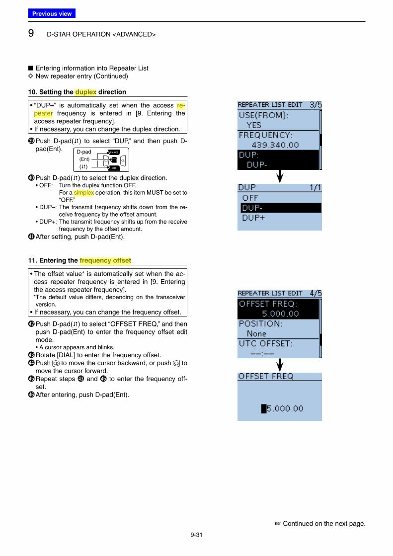
9 D-STAR OPERATION <ADVANCED>
9-31
■ Entering information into Repeater List D New repeater entry (Continued)
10. Setting the duplex direction
• “DUP–” is automatically set when the access re-peater frequency is entered in [9. Entering the access repeater frequency].
• If necessary, you can change the duplex direction.
#9 Push D-pad() to select “DUP,” and then push D-pad(Ent). D-pad
(�)
(Ent)
$0 Push D-pad() to select the duplex direction. • OFF: Turn the duplex function OFF. For a simplex operation, this item MUST be set to
“OFF.” • DUP–: The transmit frequency shifts down from the re-
ceive frequency by the offset amount. • DUP+: The transmit frequency shifts up from the receive
frequency by the offset amount.
$1 After setting, push D-pad(Ent).
11. Entering the frequency offset
• The offset value* is automatically set when the ac-cess repeater frequency is entered in [9. Entering the access repeater frequency].
* The default value differs, depending on the transceiver version.
• If necessary, you can change the frequency offset.
$2 Push D-pad() to select “OFFSET FREQ,” and then push D-pad(Ent) to enter the frequency offset edit mode.
• A cursor appears and blinks.
$3 Rotate [DIAL] to enter the frequency offset.$4 Push to move the cursor backward, or push to
move the cursor forward.$5 Repeat steps $3 and $5 to enter the frequency off-
set.$6 After entering, push D-pad(Ent).
☞ Continued on the next page.
Previous view
Icom
ハイライト表示
An operating mode in which the transmit and receive frequencies are separated by an offset amount.
Icom
ハイライト表示
Radio systems that receive incoming signals and retransmit them to extend the communication area. Normally put on geographically high locations for VHF/UHF radios.
Icom
ハイライト表示
An operating mode in which the transmit and receive frequencies are the same.
Icom
ハイライト表示
The difference between the transmit and receive frequencies.
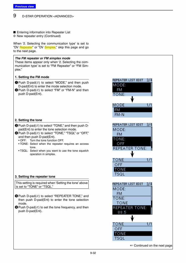
9 D-STAR OPERATION <ADVANCED>
9-32
The FM repeater or FM simplex mode
These items appear only when ‘2. Selecting the com-munication type’ is set to “FM Repeater” or “FM Sim-plex.”
1. Setting the FM mode
q Push D-pad() to select “MODE,” and then push D-pad(Ent) to enter the mode selection mode.
w Push D-pad() to select “FM” or “FM-N” and then push D-pad(Ent).
2. Setting the tone
e Push D-pad() to select “TONE,” and then push D-pad(Ent) to enter the tone selection mode.
r Push D-pad() to select “TONE,” “TSQL” or “OFF,” and then push D-pad(Ent).
• OFF: Turn the tone function OFF. • TONE: Select when the repeater requires an access
tone. • TSQL: Select when you want to use the tone squelch
operation in simplex.
3. Setting the repeater tone
This setting is required when ‘Setting the tone’ above is set to “TONE” or “TSQL.”
t Push D-pad() to select “REPEATER TONE,” and then push D-pad(Ent) to enter the tone selection mode.
y Push D-pad() to set the tone frequency, and then push D-pad(Ent).
■ Entering information into Repeater List D New repeater entry (Continued)
When ‘2. Selecting the communication type’ is set to “DV Repeater” or “DV Simplex,” skip this page and go to the next page.
☞ Continued on the next page.
Previous view
Icom
ハイライト表示
Radio systems that receive incoming signals and retransmit them to extend the communication area. Normally put on geographically high locations for VHF/UHF radios.
Icom
ハイライト表示
An operating mode in which the transmit and receive frequencies are the same.
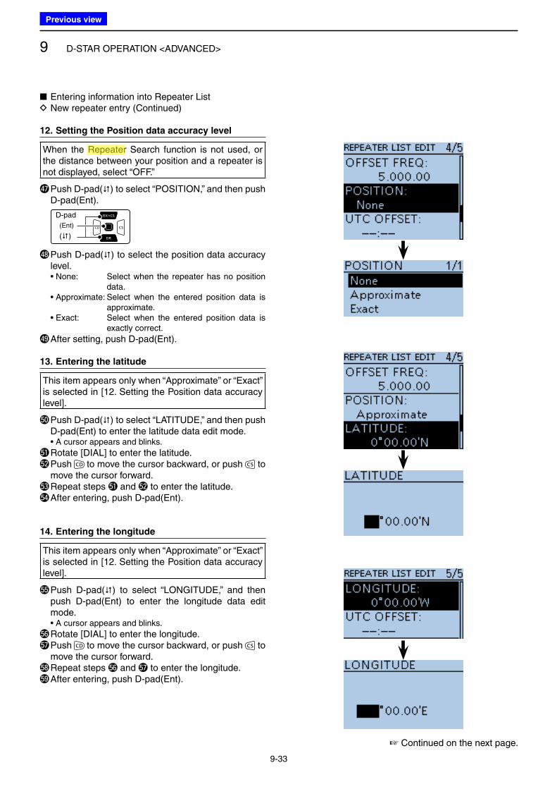
9 D-STAR OPERATION <ADVANCED>
9-33
■ Entering information into Repeater List D New repeater entry (Continued)
12. Setting the Position data accuracy level
When the Repeater Search function is not used, or the distance between your position and a repeater is not displayed, select “OFF.”
$7 Push D-pad() to select “POSITION,” and then push D-pad(Ent).
D-pad
(�)
(Ent)
$8 Push D-pad() to select the position data accuracy level.
• None: Select when the repeater has no position data.
• Approximate: Select when the entered position data is approximate.
• Exact: Select when the entered position data is exactly correct.
$9 After setting, push D-pad(Ent).
13. Entering the latitude
This item appears only when “Approximate” or “Exact” is selected in [12. Setting the Position data accuracy level].
%0 Push D-pad() to select “LATITUDE,” and then push D-pad(Ent) to enter the latitude data edit mode.
• A cursor appears and blinks.
%1 Rotate [DIAL] to enter the latitude.%2 Push to move the cursor backward, or push to
move the cursor forward.%3 Repeat steps %1 and %2 to enter the latitude.%4 After entering, push D-pad(Ent).
14. Entering the longitude
This item appears only when “Approximate” or “Exact” is selected in [12. Setting the Position data accuracy level].
%5 Push D-pad() to select “LONGITUDE,” and then push D-pad(Ent) to enter the longitude data edit mode.
• A cursor appears and blinks.
%6 Rotate [DIAL] to enter the longitude.%7 Push to move the cursor backward, or push to
move the cursor forward.%8 Repeat steps %6 and %7 to enter the longitude.%9 After entering, push D-pad(Ent).
☞ Continued on the next page.
Previous view
Icom
ハイライト表示
Radio systems that receive incoming signals and retransmit them to extend the communication area. Normally put on geographically high locations for VHF/UHF radios.
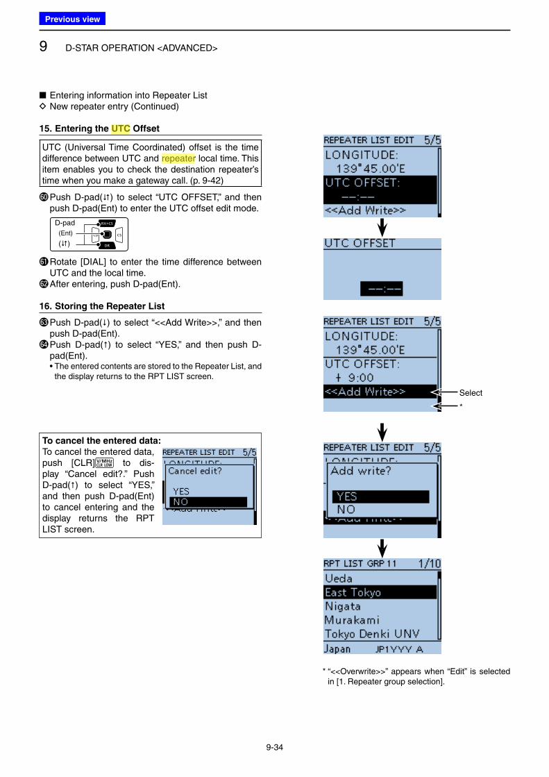
9 D-STAR OPERATION <ADVANCED>
9-34
■ Entering information into Repeater List D New repeater entry (Continued)
15. Entering the UTC Offset
UTC (Universal Time Coordinated) offset is the time difference between UTC and repeater local time. This item enables you to check the destination repeater’s time when you make a gateway call. (p. 9-42)
^0 Push D-pad() to select “UTC OFFSET,” and then push D-pad(Ent) to enter the UTC offset edit mode.
D-pad
(�)
(Ent)
^1 Rotate [DIAL] to enter the time difference between UTC and the local time.
^2 After entering, push D-pad(Ent).
16. Storing the Repeater List
^3 Push D-pad() to select “<<Add Write>>,” and then push D-pad(Ent).
^4 Push D-pad() to select “YES,” and then push D-pad(Ent).
• The entered contents are stored to the Repeater List, and the display returns to the RPT LIST screen.
To cancel the entered data:
To cancel the entered data, push [CLR] to dis-play “Cancel edit?.” Push D-pad() to select “YES,” and then push D-pad(Ent) to cancel entering and the display returns the RPT LIST screen.
* “<<Overwrite>>” appears when “Edit” is selected in [1. Repeater group selection].
Select
*
Previous view
Icom
ハイライト表示
(Universal Time Coordinated) An astronomical time based on the Greenwich meridian (zero degrees longitude).
Icom
ハイライト表示
Radio systems that receive incoming signals and retransmit them to extend the communication area. Normally put on geographically high locations for VHF/UHF radios.
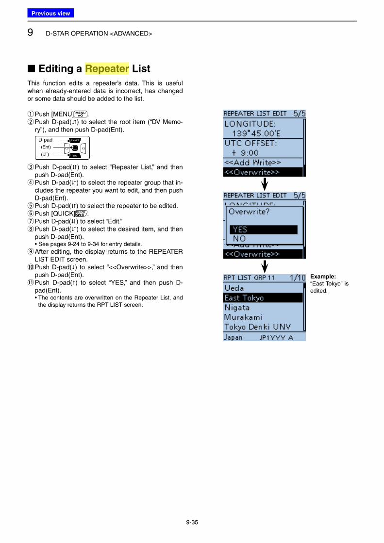
9 D-STAR OPERATION <ADVANCED>
9-35
■ Editing a Repeater List
This function edits a repeater’s data. This is useful when already-entered data is incorrect, has changed or some data should be added to the list.
qPush [MENU] . w Push D-pad() to select the root item (“DV Memo-ry”), and then push D-pad(Ent).
D-pad
(�)
(Ent)
e Push D-pad() to select “Repeater List,” and then push D-pad(Ent). r Push D-pad() to select the repeater group that in-cludes the repeater you want to edit, and then push D-pad(Ent). t Push D-pad() to select the repeater to be edited. yPush [QUICK] . u Push D-pad() to select “Edit.” i Push D-pad() to select the desired item, and then push D-pad(Ent).
• See pages 9-24 to 9-34 for entry details.
o After editing, the display returns to the REPEATER LIST EDIT screen.
!0 Push D-pad() to select “<<Overwrite>>,” and then push D-pad(Ent).
!1 Push D-pad() to select “YES,” and then push D-pad(Ent).
• The contents are overwritten on the Repeater List, and the display returns the RPT LIST screen.
Example:
“East Tokyo” is edited.
Previous view
Icom
ハイライト表示
Radio systems that receive incoming signals and retransmit them to extend the communication area. Normally put on geographically high locations for VHF/UHF radios.
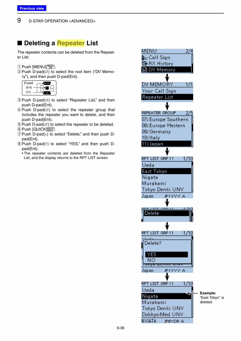
9 D-STAR OPERATION <ADVANCED>
9-36
■ Deleting a Repeater List
The repeater contents can be deleted from the Repeat-er List.
qPush [MENU] . w Push D-pad() to select the root item (“DV Memo-ry”), and then push D-pad(Ent).
D-pad
(�)
(Ent)
e Push D-pad() to select “Repeater List,” and then push D-pad(Ent). r Push D-pad() to select the repeater group that includes the repeater you want to delete, and then push D-pad(Ent). t Push D-pad() to select the repeater to be deleted. yPush [QUICK] . u Push D-pad() to select “Delete,” and then push D-pad(Ent). i Push D-pad() to select “YES,” and then push D-pad(Ent).
• The repeater contents are deleted from the Repeater List, and the display returns to the RPT LIST screen.
Example:
“East Tokyo” is deleted.
Previous view
Icom
ハイライト表示
Radio systems that receive incoming signals and retransmit them to extend the communication area. Normally put on geographically high locations for VHF/UHF radios.
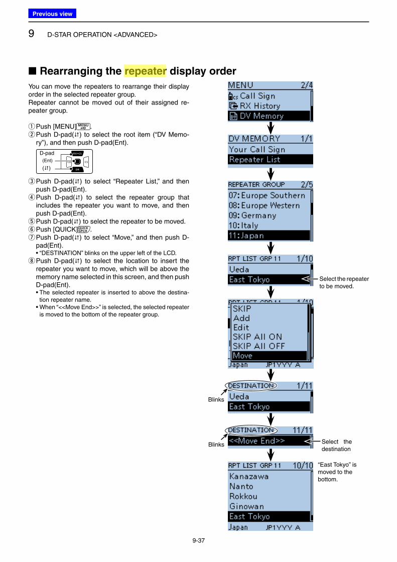
9 D-STAR OPERATION <ADVANCED>
9-37
You can move the repeaters to rearrange their display order in the selected repeater group.Repeater cannot be moved out of their assigned re-peater group.
qPush [MENU] . w Push D-pad() to select the root item (“DV Memo-ry”), and then push D-pad(Ent).
D-pad
(�)
(Ent)
e Push D-pad() to select “Repeater List,” and then push D-pad(Ent). r Push D-pad() to select the repeater group that includes the repeater you want to move, and then push D-pad(Ent). t Push D-pad() to select the repeater to be moved. yPush [QUICK] . u Push D-pad() to select “Move,” and then push D-pad(Ent).
• “DESTINATION” blinks on the upper left of the LCD.
i Push D-pad() to select the location to insert the repeater you want to move, which will be above the memory name selected in this screen, and then push D-pad(Ent).
• The selected repeater is inserted to above the destina-tion repeater name.
• When “<<Move End>>” is selected, the selected repeater is moved to the bottom of the repeater group.
■ Rearranging the repeater display order
Select the repeater to be moved.
Blinks
Blinks Select the destination
“East Tokyo” ismoved to the bottom.
Previous view
Icom
ハイライト表示
Radio systems that receive incoming signals and retransmit them to extend the communication area. Normally put on geographically high locations for VHF/UHF radios.
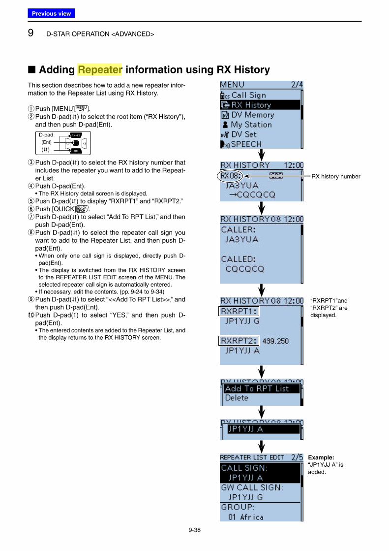
9 D-STAR OPERATION <ADVANCED>
9-38
This section describes how to add a new repeater infor-mation to the Repeater List using RX History.
qPush [MENU] . w Push D-pad() to select the root item (“RX History”), and then push D-pad(Ent).
D-pad
(�)
(Ent)
e Push D-pad() to select the RX history number that includes the repeater you want to add to the Repeat-er List. rPush D-pad(Ent).
• The RX History detail screen is displayed.
t Push D-pad() to display “RXRPT1” and “RXRPT2.” yPush [QUICK] . u Push D-pad() to select “Add To RPT List,” and then push D-pad(Ent). i Push D-pad() to select the repeater call sign you want to add to the Repeater List, and then push D-pad(Ent).
• When only one call sign is displayed, directly push D-pad(Ent).
• The display is switched from the RX HISTORY screen to the REPEATER LIST EDIT screen of the MENU. The selected repeater call sign is automatically entered.
• If necessary, edit the contents. (pp. 9-24 to 9-34)
o Push D-pad() to select “<<Add To RPT List>>,” and then push D-pad(Ent).
!0 Push D-pad() to select “YES,” and then push D-pad(Ent).
• The entered contents are added to the Repeater List, and the display returns to the RX HISTORY screen.
■ Adding Repeater information using RX History
Example:
“JP1YJJ A” is added.
RX history number
“RXRPT1” and “RXRPT2” are displayed.
Previous view
Icom
ハイライト表示
Radio systems that receive incoming signals and retransmit them to extend the communication area. Normally put on geographically high locations for VHF/UHF radios.
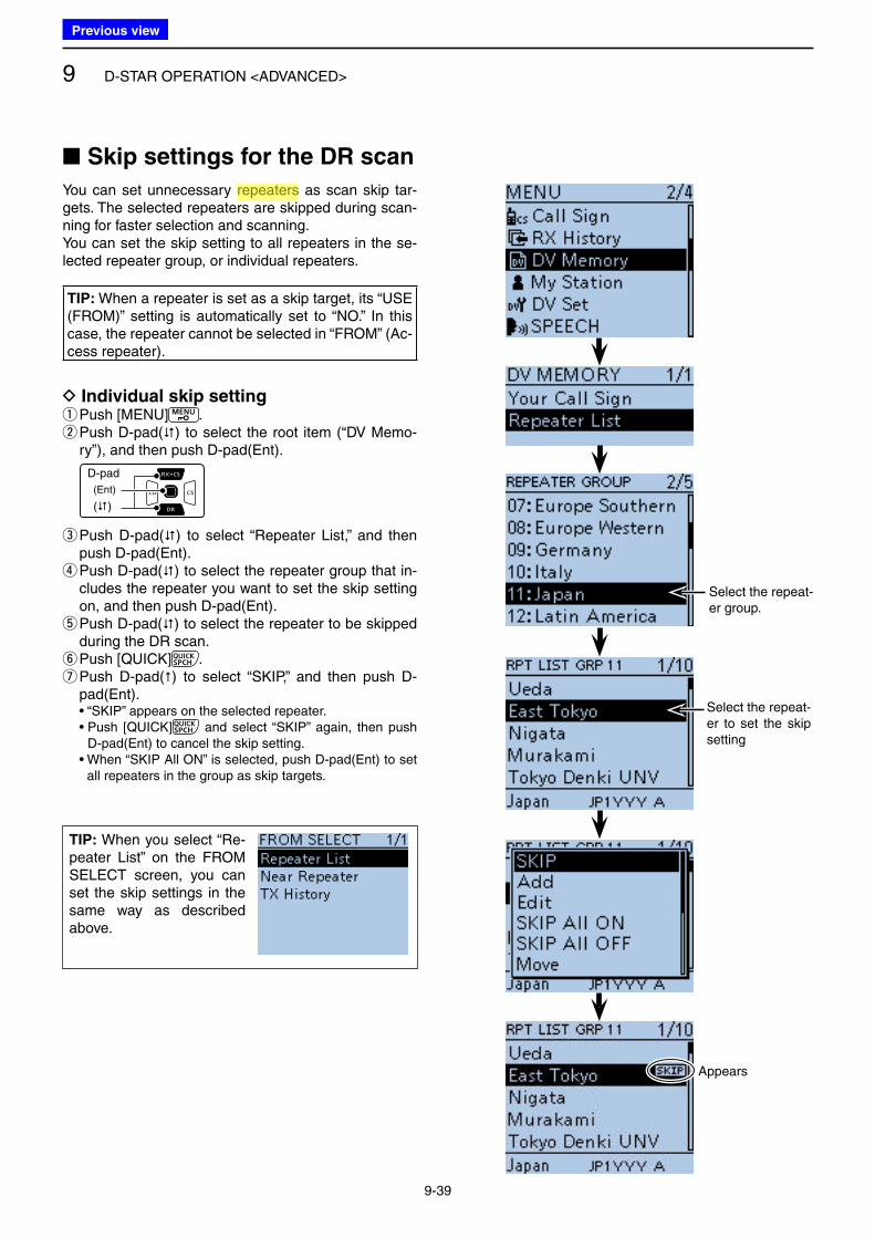
9 D-STAR OPERATION <ADVANCED>
9-39
You can set unnecessary repeaters as scan skip tar-gets. The selected repeaters are skipped during scan-ning for faster selection and scanning.You can set the skip setting to all repeaters in the se-lected repeater group, or individual repeaters.
TIP: When a repeater is set as a skip target, its “USE (FROM)” setting is automatically set to “NO.” In this case, the repeater cannot be selected in “FROM” (Ac-cess repeater).
D Individual skip setting qPush [MENU] . w Push D-pad() to select the root item (“DV Memo-ry”), and then push D-pad(Ent).
D-pad
(�)
(Ent)
e Push D-pad() to select “Repeater List,” and then push D-pad(Ent). r Push D-pad() to select the repeater group that in-cludes the repeater you want to set the skip setting on, and then push D-pad(Ent). t Push D-pad() to select the repeater to be skipped during the DR scan. yPush [QUICK] . u Push D-pad() to select “SKIP,” and then push D-pad(Ent).
• “SKIP” appears on the selected repeater. • Push [QUICK] and select “SKIP” again, then push
D-pad(Ent) to cancel the skip setting. • When “SKIP All ON” is selected, push D-pad(Ent) to set
all repeaters in the group as skip targets.
■ Skip settings for the DR scan
TIP: When you select “Re-peater List” on the FROM SELECT screen, you can set the skip settings in the same way as described above.
Select the repeat-er to set the skip setting
Appears
Select the repeat-er group.
Previous view
Icom
ハイライト表示
Radio systems that receive incoming signals and retransmit them to extend the communication area. Normally put on geographically high locations for VHF/UHF radios.
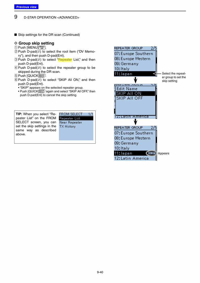
9 D-STAR OPERATION <ADVANCED>
9-40
■ Skip settings for the DR scan (Continued)
D Group skip setting qPush [MENU] . w Push D-pad() to select the root item (“DV Memo-ry”), and then push D-pad(Ent). e Push D-pad() to select “Repeater List,” and then push D-pad(Ent). r Push D-pad() to select the repeater group to be skipped during the DR scan. tPush [QUICK] . y Push D-pad() to select “SKIP All ON,” and then push D-pad(Ent).
• “SKIP” appears on the selected repeater group. • Push [QUICK] again and select “SKIP All OFF,” then
push D-pad(Ent) to cancel the skip setting.
Select the repeat-er group to set the skip setting
Appears
TIP: When you select “Re-peater List” on the FROM SELECT screen, you can set the skip settings in the same way as described above.
Previous view
Icom
ハイライト表示
Radio systems that receive incoming signals and retransmit them to extend the communication area. Normally put on geographically high locations for VHF/UHF radios.
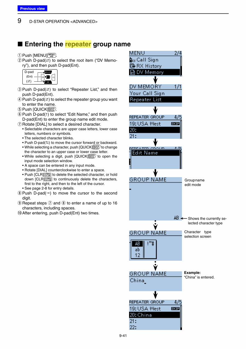
9 D-STAR OPERATION <ADVANCED>
9-41
■ Entering the repeater group name
qPush [MENU] . w Push D-pad() to select the root item (“DV Memo-ry”), and then push D-pad(Ent).
D-pad
(�)
(Ent)
e Push D-pad() to select “Repeater List,” and then push D-pad(Ent). r Push D-pad() to select the repeater group you want to enter the name. tPush [QUICK] . y Push D-pad() to select “Edit Name,” and then push D-pad(Ent) to enter the group name edit mode. u Rotate [DIAL] to select a desired character.
• Selectable characters are upper case letters, lower case letters, numbers or symbols.
• The selected character blinks. • Push D-pad() to move the cursor forward or backward. • While selecting a character, push [QUICK] to change
the character to an upper case or lower case letter. • While selecting a digit, push [QUICK] to open the
input mode selection window. • A space can be entered in any input mode. • Rotate [DIAL] counterclockwise to enter a space. • Push [CLR] to delete the selected character, or hold
down [CLR] to continuously delete the characters, first to the right, and then to the left of the cursor.
• See page 2-8 for entry details.
i Push D-pad() to move the cursor to the second digit. o Repeat steps u and i to enter a name of up to 16 characters, including spaces.
!0 After entering, push D-pad(Ent) two times.
Character type selection screen
Group name edit mode
Example:
“China” is entered.
Shows the currently se-lected character type
Previous view
Icom
ハイライト表示
Radio systems that receive incoming signals and retransmit them to extend the communication area. Normally put on geographically high locations for VHF/UHF radios.
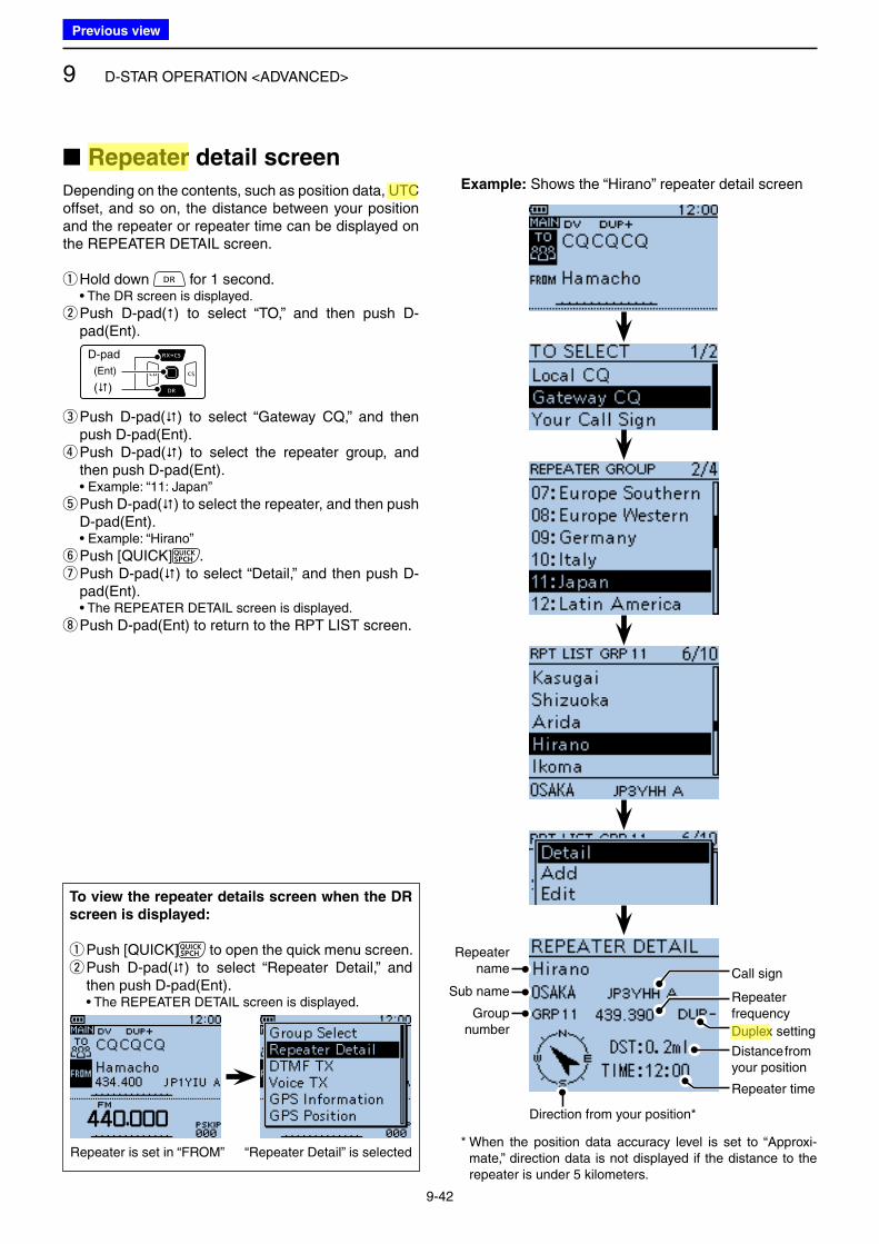
9 D-STAR OPERATION <ADVANCED>
9-42
■ Repeater detail screen
Depending on the contents, such as position data, UTC offset, and so on, the distance between your position and the repeater or repeater time can be displayed on the REPEATER DETAIL screen.
qHold down for 1 second. • The DR screen is displayed.
w Push D-pad() to select “TO,” and then push D-pad(Ent).
D-pad
(�)
(Ent)
e Push D-pad() to select “Gateway CQ,” and then push D-pad(Ent). r Push D-pad() to select the repeater group, and then push D-pad(Ent).
• Example: “11: Japan”
t Push D-pad() to select the repeater, and then push D-pad(Ent).
• Example: “Hirano”
yPush [QUICK] . u Push D-pad() to select “Detail,” and then push D-pad(Ent).
• The REPEATER DETAIL screen is displayed.
iPush D-pad(Ent) to return to the RPT LIST screen.
To view the repeater details screen when the DR
screen is displayed:
q Push [QUICK] to open the quick menu screen. w Push D-pad() to select “Repeater Detail,” and then push D-pad(Ent).
• The REPEATER DETAIL screen is displayed.
Repeater is set in “FROM” “Repeater Detail” is selected* When the position data accuracy level is set to “Approxi-
mate,” direction data is not displayed if the distance to the repeater is under 5 kilometers.
Example: Shows the “Hirano” repeater detail screen
Repeater name
Sub name
Groupnumber
Call sign
Duplex setting
Repeater time
Repeaterfrequency
Distance from your position
Direction from your position*
Previous view
Icom
ハイライト表示
Radio systems that receive incoming signals and retransmit them to extend the communication area. Normally put on geographically high locations for VHF/UHF radios.
Icom
ハイライト表示
An operating mode in which the transmit and receive frequencies are separated by an offset amount.
Icom
ハイライト表示
(Universal Time Coordinated) An astronomical time based on the Greenwich meridian (zero degrees longitude).
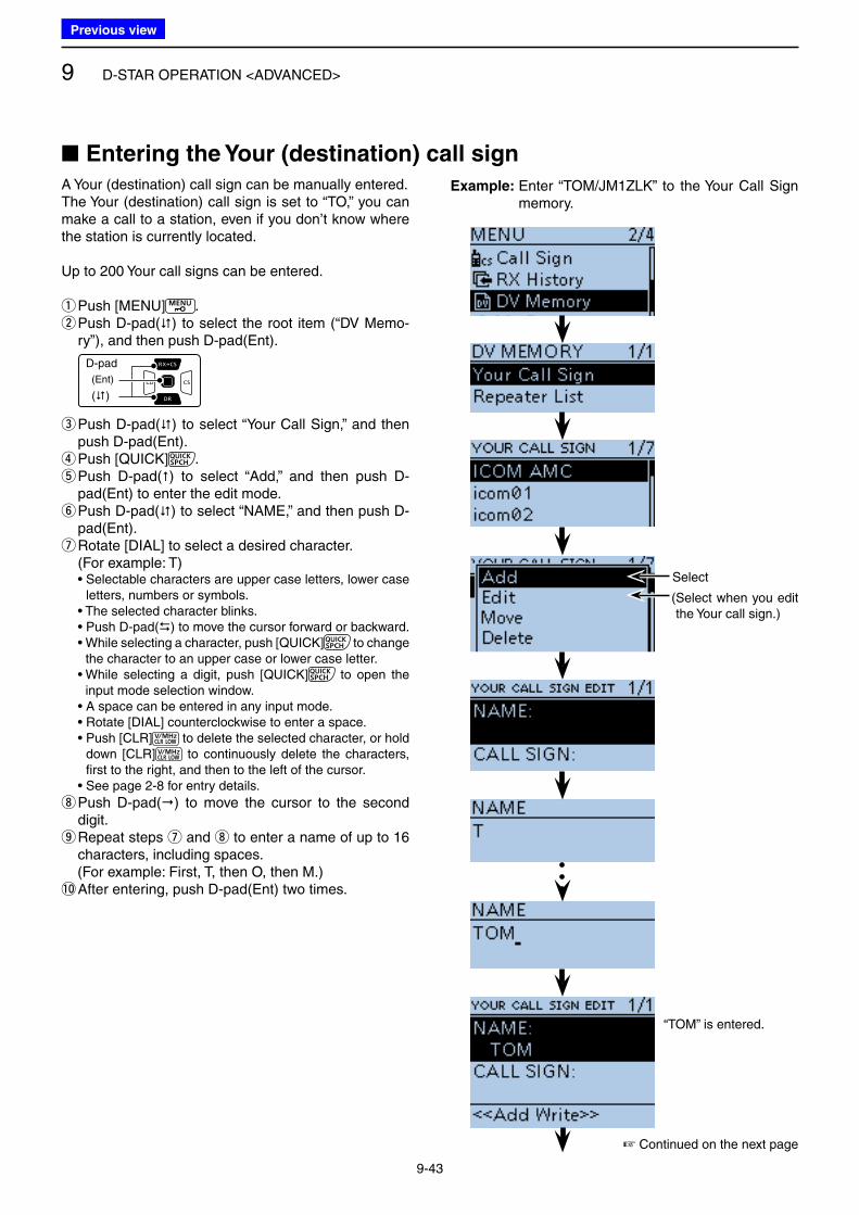
9 D-STAR OPERATION <ADVANCED>
9-43
A Your (destination) call sign can be manually entered.The Your (destination) call sign is set to “TO,” you can make a call to a station, even if you don’t know where the station is currently located.
Up to 200 Your call signs can be entered.
qPush [MENU] . w Push D-pad() to select the root item (“DV Memo-ry”), and then push D-pad(Ent).
D-pad
(�)
(Ent)
e Push D-pad() to select “Your Call Sign,” and then push D-pad(Ent). rPush [QUICK] . t Push D-pad() to select “Add,” and then push D-pad(Ent) to enter the edit mode. y Push D-pad() to select “NAME,” and then push D-pad(Ent). u Rotate [DIAL] to select a desired character.
(For example: T) • Selectable characters are upper case letters, lower case
letters, numbers or symbols. • The selected character blinks. • Push D-pad() to move the cursor forward or backward. • While selecting a character, push [QUICK] to change
the character to an upper case or lower case letter. • While selecting a digit, push [QUICK] to open the
input mode selection window. • A space can be entered in any input mode. • Rotate [DIAL] counterclockwise to enter a space. • Push [CLR] to delete the selected character, or hold
down [CLR] to continuously delete the characters, first to the right, and then to the left of the cursor.
• See page 2-8 for entry details.
i Push D-pad() to move the cursor to the second digit. o Repeat steps u and i to enter a name of up to 16 characters, including spaces.
(For example: First, T, then O, then M.)!0 After entering, push D-pad(Ent) two times.
■ Entering the Your (destination) call sign
☞ Continued on the next page
Example: Enter “TOM/JM1ZLK” to the Your Call Sign memory.
Select
( Select when you edit the Your call sign.)
“TOM” is entered.
Previous view
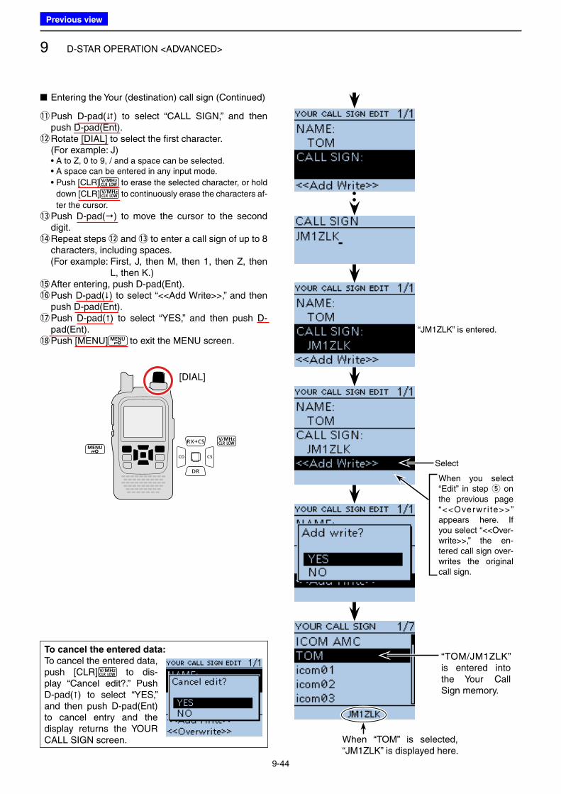
9 D-STAR OPERATION <ADVANCED>
9-44
!1 Push D-pad() to select “CALL SIGN,” and then push D-pad(Ent).
!2 Rotate [DIAL] to select the first character. (For example: J) • A to Z, 0 to 9, / and a space can be selected. • A space can be entered in any input mode.
• Push [CLR] to erase the selected character, or hold
down [CLR] to continuously erase the characters af-
ter the cursor.
!3 Push D-pad() to move the cursor to the second digit.
!4 Repeat steps !2 and !3 to enter a call sign of up to 8 characters, including spaces.
(For example: First, J, then M, then 1, then Z, then L, then K.)
!5 After entering, push D-pad(Ent).!6 Push D-pad() to select “<<Add Write>>,” and then
push D-pad(Ent).!7 Push D-pad() to select “YES,” and then push D-
pad(Ent).!8 Push [MENU] to exit the MENU screen.
[DIAL]
To cancel the entered data:
To cancel the entered data, push [CLR] to dis-play “Cancel edit?.” Push D-pad() to select “YES,” and then push D-pad(Ent) to cancel entry and the display returns the YOUR CALL SIGN screen.
“JM1ZLK” is entered.
Select
When you select “Edit” in step t on the previous page “<<Overwr i te>>” appears here. If you select “<<Over-write>>,” the en-tered call sign over-writes the original call sign.
“TOM/JM1ZLK” is entered into the Your Call Sign memory.
When “TOM” is selected, “JM1ZLK” is displayed here.
■ Entering the Your (destination) call sign (Continued)
Previous view
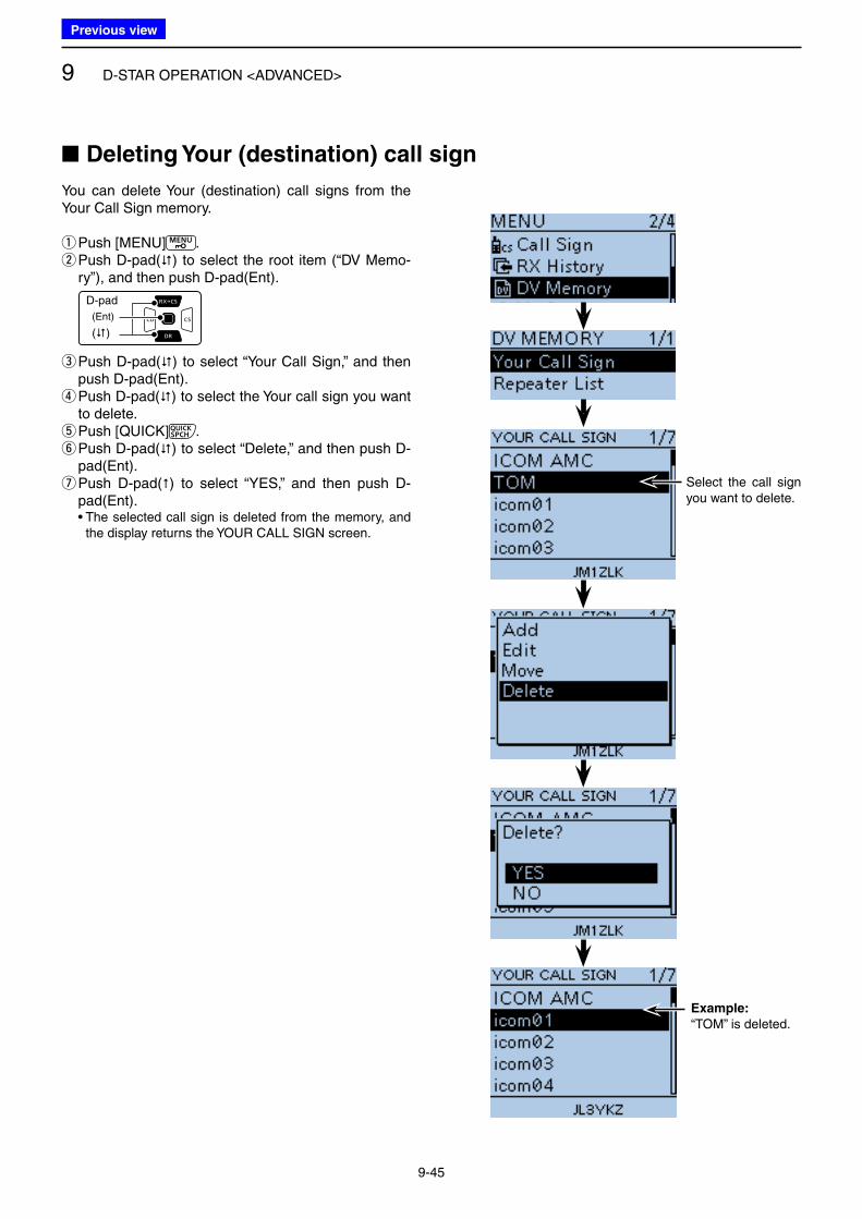
9 D-STAR OPERATION <ADVANCED>
9-45
You can delete Your (destination) call signs from the Your Call Sign memory.
qPush [MENU] . w Push D-pad() to select the root item (“DV Memo-ry”), and then push D-pad(Ent).
D-pad
(�)
(Ent)
e Push D-pad() to select “Your Call Sign,” and then push D-pad(Ent). r Push D-pad() to select the Your call sign you want to delete. tPush [QUICK] . y Push D-pad() to select “Delete,” and then push D-pad(Ent). u Push D-pad() to select “YES,” and then push D-pad(Ent).
• The selected call sign is deleted from the memory, and the display returns the YOUR CALL SIGN screen.
■ Deleting Your (destination) call sign
Select the call sign you want to delete.
Example:
“TOM” is deleted.
Previous view
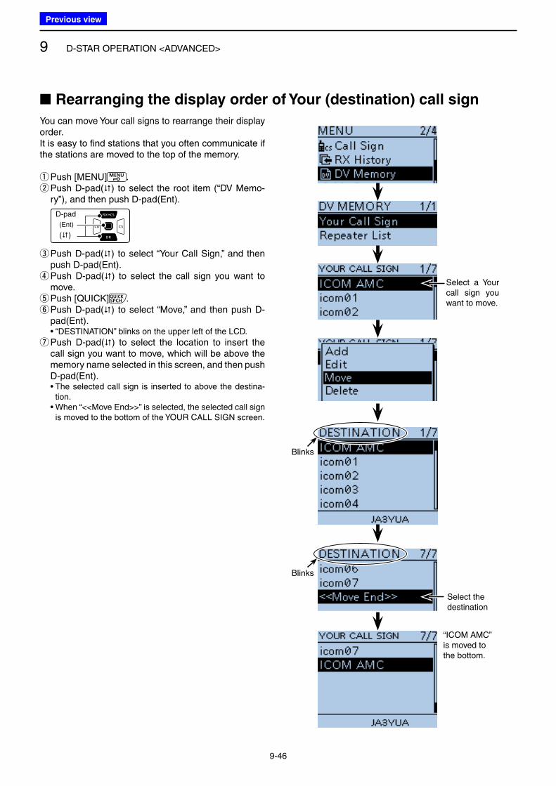
9 D-STAR OPERATION <ADVANCED>
9-46
You can move Your call signs to rearrange their display order.It is easy to find stations that you often communicate if the stations are moved to the top of the memory.
qPush [MENU] . w Push D-pad() to select the root item (“DV Memo-ry”), and then push D-pad(Ent).
D-pad
(�)
(Ent)
e Push D-pad() to select “Your Call Sign,” and then push D-pad(Ent). r Push D-pad() to select the call sign you want to move. tPush [QUICK] . y Push D-pad() to select “Move,” and then push D-pad(Ent).
• “DESTINATION” blinks on the upper left of the LCD.
u Push D-pad() to select the location to insert the call sign you want to move, which will be above the memory name selected in this screen, and then push D-pad(Ent).
• The selected call sign is inserted to above the destina-tion.
• When “<<Move End>>” is selected, the selected call sign is moved to the bottom of the YOUR CALL SIGN screen.
■ Rearranging the display order of Your (destination) call sign
Select a Your call sign you want to move.
Blinks
Blinks
Select the destination
“ICOM AMC” is moved to the bottom.
Previous view
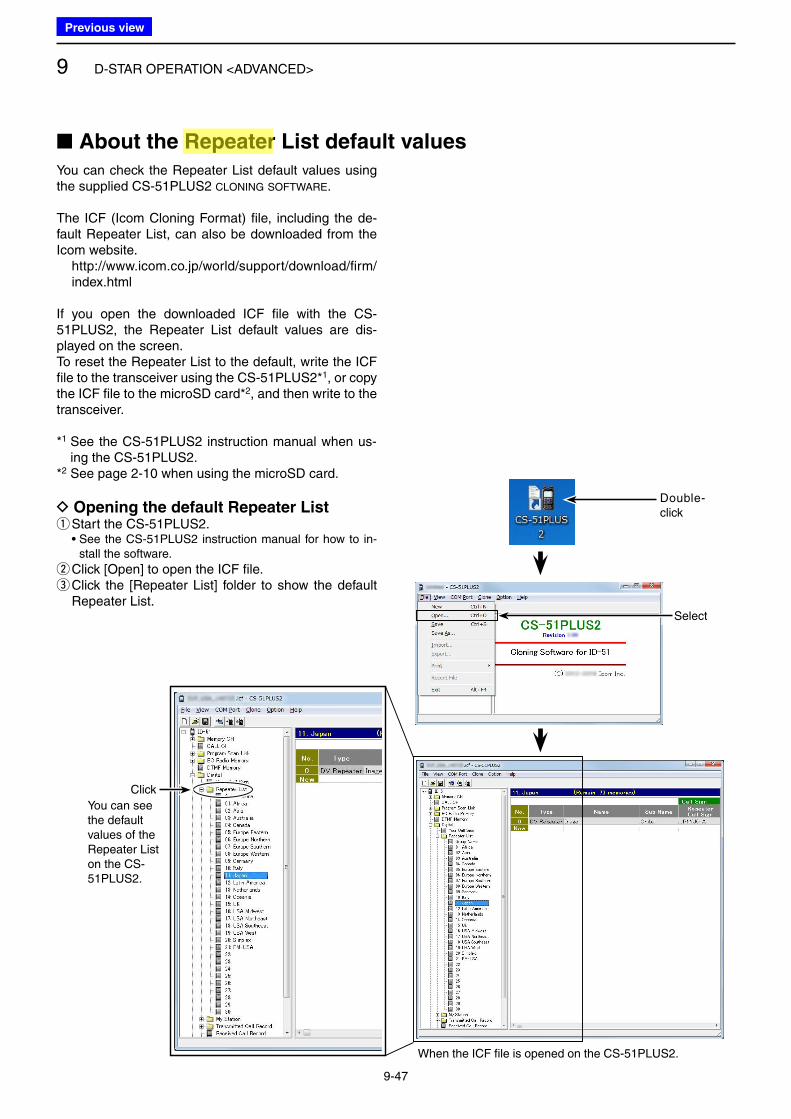
9 D-STAR OPERATION <ADVANCED>
9-47
You can check the Repeater List default values using the supplied CS-51PLUS2 CLONING SOFTWARE.
The ICF (Icom Cloning Format) file, including the de-fault Repeater List, can also be downloaded from the Icom website. http://www.icom.co.jp/world/support/download/firm/
index.html
If you open the downloaded ICF file with the CS-51PLUS2, the Repeater List default values are dis-played on the screen.To reset the Repeater List to the default, write the ICF file to the transceiver using the CS-51PLUS2*1, or copy the ICF file to the microSD card*2, and then write to the transceiver.
*1 See the CS-51PLUS2 instruction manual when us-ing the CS-51PLUS2.
*2 See page 2-10 when using the microSD card.
D Opening the default Repeater List qStart the CS-51PLUS2.
• See the CS-51PLUS2 instruction manual for how to in-stall the software.
w Click [Open] to open the ICF file. e Click the [Repeater List] folder to show the default Repeater List.
■ About the Repeater List default values
When the ICF file is opened on the CS-51PLUS2.
Select
Double-click
Click
You can see the default values of the Repeater List on the CS-51PLUS2.
Previous view
Icom
ハイライト表示
Radio systems that receive incoming signals and retransmit them to extend the communication area. Normally put on geographically high locations for VHF/UHF radios.
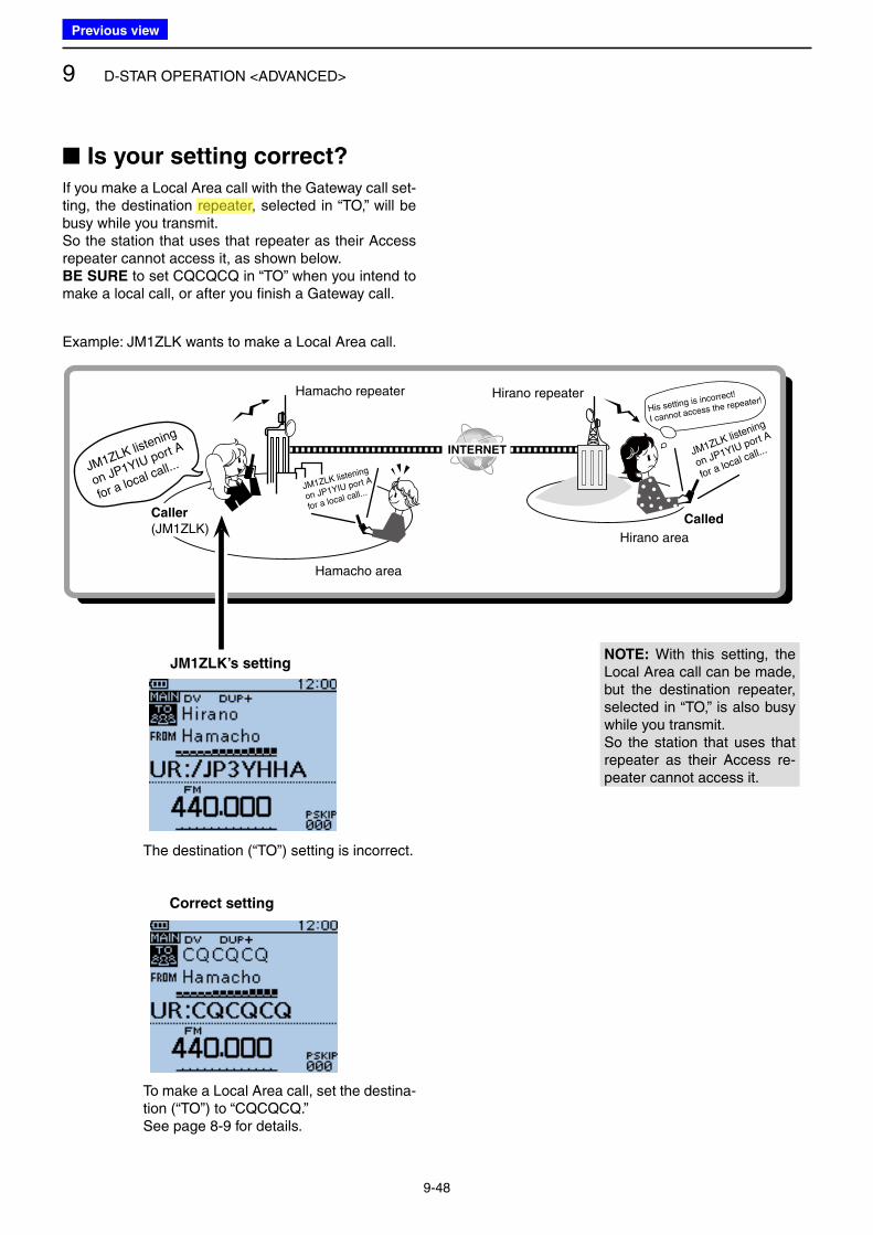
9 D-STAR OPERATION <ADVANCED>
9-48
If you make a Local Area call with the Gateway call set-ting, the destination repeater, selected in “TO,” will be busy while you transmit.So the station that uses that repeater as their Access repeater cannot access it, as shown below.BE SURE to set CQCQCQ in “TO” when you intend to make a local call, or after you finish a Gateway call.
■ Is your setting correct?
JM1ZLK listening
on JP1YIU port A
for a local call...JM1ZLK listening
on JP1YIU port A
for a local call...
JM1ZLK listening
on JP1YIU port A
for a local call...
His setting is incorrect!
I cannot access the repeater!
Example: JM1ZLK wants to make a Local Area call.
Hamacho repeater
Hamacho area
Hirano repeater
Hirano area
CalledCaller
(JM1ZLK)
JM1ZLK’s setting
The destination (“TO”) setting is incorrect.
Correct setting
To make a Local Area call, set the destina-tion (“TO”) to “CQCQCQ.”See page 8-9 for details.
NOTE: With this setting, the Local Area call can be made, but the destination repeater, selected in “TO,” is also busy while you transmit.So the station that uses that repeater as their Access re-peater cannot access it.
Previous view
Icom
ハイライト表示
Radio systems that receive incoming signals and retransmit them to extend the communication area. Normally put on geographically high locations for VHF/UHF radios.
10-1
Section 10 GPS OPERATION
■ GPS operation .................................................................. 10-2
D Receiving GPS data ..................................................... 10-2
■ Checking GPS Position .................................................... 10-3
D Displaying Position Data ............................................... 10-3
D Caller’s TX format ......................................................... 10-5
D Displayed items ............................................................ 10-6
D TX format: D-PRS Position (Mobile) ............................. 10-7
D TX format: D-PRS Position (Base) ............................... 10-7
D TX format: D-PRS Object .............................................. 10-8
D TX format: D-PRS Item ................................................. 10-8
D TX format: D-PRS Weather ........................................... 10-9
D TX mode: NMEA ........................................................... 10-9
D Changing the GPS memory/alarm channel ................. 10-10
D Changing the Grid Locator ......................................... 10-10
D Changing the Compass Direction ............................... 10-10
D Saving your own or received position data ................. 10-11
■ Checking GPS Information (Sky view screen) ................ 10-12
■ GPS memory operation .................................................. 10-13
D GPS Memory ............................................................. 10-13
D Add a GPS memory ................................................... 10-13
D Entering the GPS group name ................................... 10-18
D Deleting GPS data ...................................................... 10-19
D Rearranging the display order of the GPS memory ... 10-20
D Setting the GPS alarm................................................ 10-21
■ Transmitting GPS data (D-PRS and NMEA) ................... 10-23
D Type of position data .................................................. 10-23
■ Transmitting D-PRS (DV-A) data .................................... 10-24
D D-PRS ........................................................................ 10-24
D Operating D-PRS (DV-A) ............................................ 10-24
D Setting D-PRS (DV-A) ................................................. 10-25
D Displaying your position using a mapping program .... 10-29
■ Transmitting NMEA (DV-G) data ..................................... 10-31
D Setting the GPS data sentence .................................. 10-31
D Entering a GPS message ........................................... 10-32
■ GPS Auto transmission .................................................. 10-33
D Setting the GPS automatic transmission .................... 10-33
■ GPS Logger function ...................................................... 10-34
D GPS Logger operating outline .................................... 10-34
D Setting the GPS Logger function ................................ 10-34
D Setting the GPS record interval .................................. 10-35
D Setting the GPS record sentence ............................... 10-35
D Viewing the route on a PC Map .................................. 10-36
D Using <<GPS Logger Only>> mode ........................... 10-38
Previous view
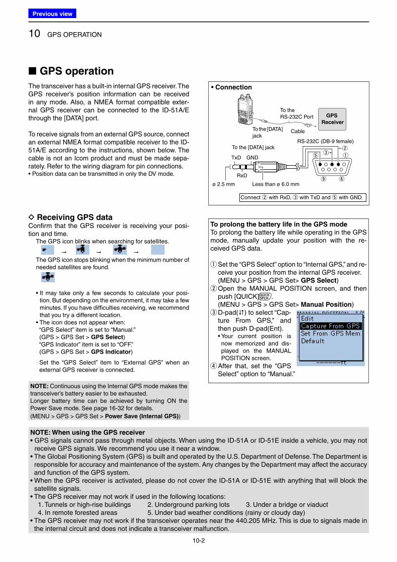
10 GPS OPERATION
10-2
■ GPS operation
The transceiver has a built-in internal GPS receiver. The GPS receiver’s position information can be received in any mode. Also, a NMEA format compatible exter-nal GPS receiver can be connected to the ID-51A/E through the [DATA] port.
To receive signals from an external GPS source, connect an external NMEA format compatible receiver to the ID-51A/E according to the instructions, shown below. The cable is not an Icom product and must be made sepa-rately. Refer to the wiring diagram for pin connections.• Position data can be transmitted in only the DV mode.
To prolong the battery life in the GPS mode
To prolong the battery life while operating in the GPS mode, manually update your position with the re-ceived GPS data.
q Set the “GPS Select” option to “Internal GPS,” and re-ceive your position from the internal GPS receiver.
( MENU > GPS > GPS Set> GPS Select) w Open the MANUAL POSITION screen, and then push [QUICK] .
( MENU > GPS > GPS Set> Manual Position) e D-pad() to select “Cap-ture From GPS,” and then push D-pad(Ent).
• Your current position is now memorized and dis-played on the MANUAL POSITION screen.
r After that, set the “GPS Select” option to “Manual.”
D Receiving GPS dataConfirm that the GPS receiver is receiving your posi-tion and time. The GPS icon blinks when searching for satellites.
The GPS icon stops blinking when the minimum number of
needed satellites are found.
• It may take only a few seconds to calculate your posi-tion. But depending on the environment, it may take a few minutes. If you have difficulties receiving, we recommend that you try a different location.
• The icon does not appear when: “GPS Select” item is set to “Manual.” (GPS > GPS Set > GPS Select) “GPS Indicator” item is set to “OFF.” (GPS > GPS Set > GPS Indicator)
Set the “GPS Select” item to “External GPS” when an external GPS receiver is connected.
GPS
Receiver
To the RS-232C Port
To the [DATA] jack
Cable
Less than ø 6.0 mm
• Connection
RS-232C (DB-9 female)To the [DATA] jack
RxD
TxD GND
ø 2.5 mm
t
o y
ew
q
Connect w with RxD, e with TxD and t with GND.
NOTE: When using the GPS receiver
• GPS signals cannot pass through metal objects. When using the ID-51A or ID-51E inside a vehicle, you may not receive GPS signals. We recommend you use it near a window.
• The Global Positioning System (GPS) is built and operated by the U.S. Department of Defense. The Department is responsible for accuracy and maintenance of the system. Any changes by the Department may affect the accuracy and function of the GPS system.
• When the GPS receiver is activated, please do not cover the ID-51A or ID-51E with anything that will block the satellite signals.
• The GPS receiver may not work if used in the following locations: 1. Tunnels or high-rise buildings 2. Underground parking lots 3. Under a bridge or viaduct 4. In remote forested areas 5. Under bad weather conditions (rainy or cloudy day)• The GPS receiver may not work if the transceiver operates near the 440.205 MHz. This is due to signals made in
the internal circuit and does not indicate a transceiver malfunction.
NOTE: Continuous using the Internal GPS mode makes the transceiver’s battery easier to be exhausted.Longer battery time can be achieved by turning ON the Power Save mode. See page 16-32 for details.
(MENU > GPS > GPS Set > Power Save (Internal GPS))
Previous view
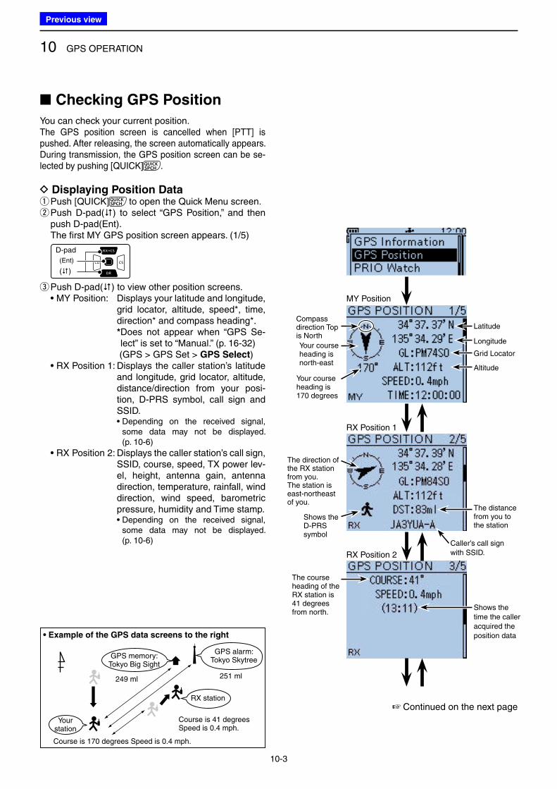
10 GPS OPERATION
10-3
■ Checking GPS Position
You can check your current position.The GPS position screen is cancelled when [PTT] is pushed. After releasing, the screen automatically appears.During transmission, the GPS position screen can be se-lected by pushing [QUICK] .
D Displaying Position Data qPush [QUICK] to open the Quick Menu screen. w Push D-pad() to select “GPS Position,” and then push D-pad(Ent).
The first MY GPS position screen appears. (1/5)
D-pad
(�)
(Ent)
e Push D-pad() to view other position screens. • MY Position: Displays your latitude and longitude,
grid locator, altitude, speed*, time, direction* and compass heading*.
* Does not appear when “GPS Se-lect” is set to “Manual.” (p. 16-32)
(GPS > GPS Set > GPS Select) • RX Position 1: Displays the caller station’s latitude
and longitude, grid locator, altitude, distance/direction from your posi-tion, D-PRS symbol, call sign and SSID.
• Depending on the received signal, some data may not be displayed. (p. 10-6)
• RX Position 2: Displays the caller station’s call sign, SSID, course, speed, TX power lev-el, height, antenna gain, antenna direction, temperature, rainfall, wind direction, wind speed, barometric pressure, humidity and Time stamp.
• Depending on the received signal, some data may not be displayed. (p. 10-6)
Yourstation
GPS memory:Tokyo Big Sight
GPS alarm:Tokyo Skytree
Course is 170 degrees Speed is 0.4 mph.
251 ml249 ml
Course is 41 degreesSpeed is 0.4 mph.
• Example of the GPS data screens to the right
RX station
MY Position
LatitudeCompass direction Top is North
Your course heading is north-east
Longitude
Grid Locator
Your course heading is 170 degrees
RX Position 1
RX Position 2
The direction of the RX station from you.The station is east-northeast of you.
The distance from you to the station
Altitude
The course heading of the RX station is 41 degrees from north.
Caller’s call sign with SSID.
Shows the D-PRS symbol
Shows the time the caller acquired the position data
☞ Continued on the next page
Previous view
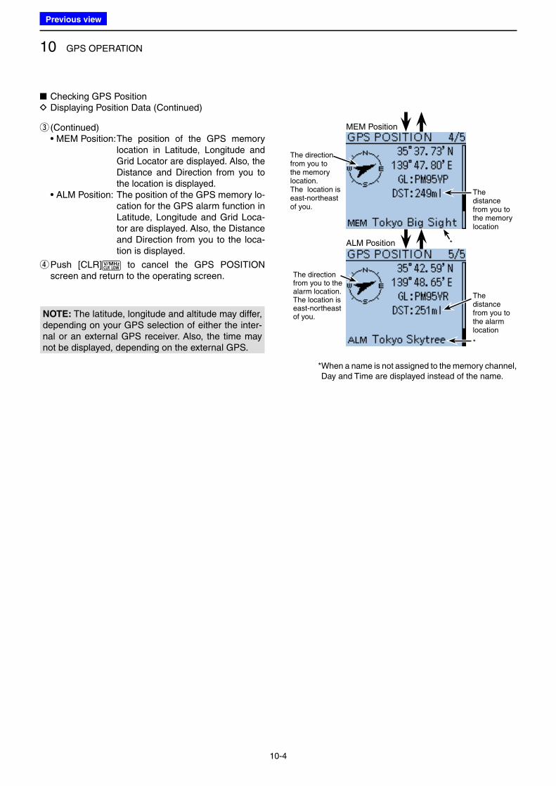
10 GPS OPERATION
10-4
MEM Position
The direction from you to the memory location.The location is east-northeast of you.
* When a name is not assigned to the memory channel, Day and Time are displayed instead of the name.
The distance from you to the memory location
*
*
The direction from you to the alarm location. The location is east-northeast of you.
ALM Position
The distance from you to the alarm location
e (Continued) • MEM Position: The position of the GPS memory
location in Latitude, Longitude and Grid Locator are displayed. Also, the Distance and Direction from you to the location is displayed.
• ALM Position: The position of the GPS memory lo-cation for the GPS alarm function in Latitude, Longitude and Grid Loca-tor are displayed. Also, the Distance and Direction from you to the loca-tion is displayed.
r Push [CLR] to cancel the GPS POSITION screen and return to the operating screen.
NOTE: The latitude, longitude and altitude may differ, depending on your GPS selection of either the inter-nal or an external GPS receiver. Also, the time may not be displayed, depending on the external GPS.
■ Checking GPS Position D Displaying Position Data (Continued)
Previous view
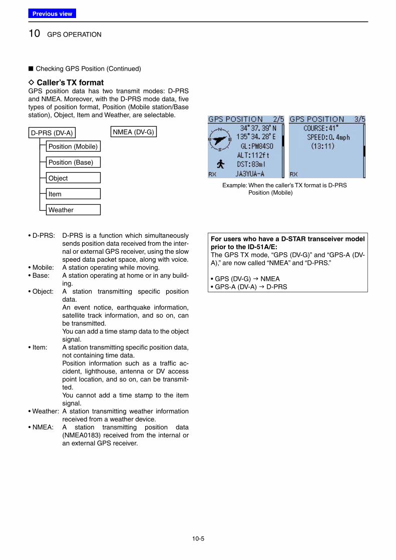
10 GPS OPERATION
10-5
■ Checking GPS Position (Continued)
D Caller’s TX formatGPS position data has two transmit modes: D-PRS and NMEA. Moreover, with the D-PRS mode data, five types of position format, Position (Mobile station/Base station), Object, Item and Weather, are selectable.
NMEA (DV-G)D-PRS (DV-A)
Position (Mobile)
Item
Position (Base)
Object
Weather
• D-PRS: D-PRS is a function which simultaneously sends position data received from the inter-nal or external GPS receiver, using the slow speed data packet space, along with voice.
• Mobile: A station operating while moving.• Base: A station operating at home or in any build-
ing.• Object: A station transmitting specific position
data. An event notice, earthquake information,
satellite track information, and so on, can be transmitted.
You can add a time stamp data to the object signal.
• Item: A station transmitting specific position data, not containing time data.
Position information such as a traffic ac-cident, lighthouse, antenna or DV access point location, and so on, can be transmit-ted.
You cannot add a time stamp to the item signal.
• Weather: A station transmitting weather information received from a weather device.
• NMEA: A station transmitting position data (NMEA0183) received from the internal or an external GPS receiver.
Example: When the caller’s TX format is D-PRS Position (Mobile)
For users who have a D-STAR transceiver model
prior to the ID-51A/E:
The GPS TX mode, “GPS (DV-G)” and “GPS-A (DV-A),” are now called “NMEA” and “D-PRS.”
• GPS (DV-G) NMEA• GPS-A (DV-A) D-PRS
Previous view
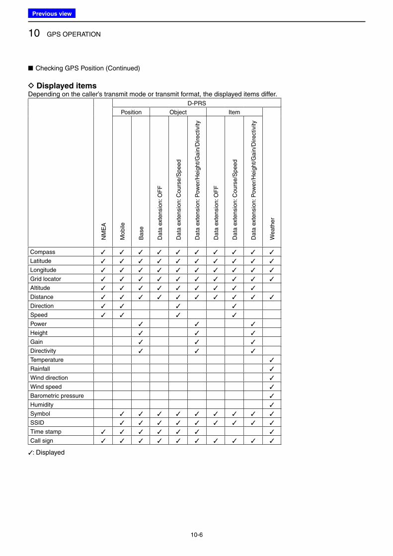
10 GPS OPERATION
10-6
■ Checking GPS Position (Continued)
D Displayed itemsDepending on the caller’s transmit mode or transmit format, the displayed items differ.
D-PRS
Position Object Item
NM
EA
Mob
ile
Base
Data
ext
en
sio
n: O
FF
Data
ext
en
sio
n: C
ou
rse
/Sp
ee
d
Data
ext
en
sio
n: P
ow
er/
He
igh
t/G
ain
/Dire
ctiv
ity
Data
ext
en
sio
n: O
FF
Data
ext
en
sio
n: C
ou
rse
/Sp
ee
d
Data
ext
en
sio
n: P
ow
er/
He
igh
t/G
ain
/Dire
ctiv
ity
We
ath
er
Compass ✓ ✓ ✓ ✓ ✓ ✓ ✓ ✓ ✓ ✓
Latitude ✓ ✓ ✓ ✓ ✓ ✓ ✓ ✓ ✓ ✓
Longitude ✓ ✓ ✓ ✓ ✓ ✓ ✓ ✓ ✓ ✓
Grid locator ✓ ✓ ✓ ✓ ✓ ✓ ✓ ✓ ✓ ✓
Altitude ✓ ✓ ✓ ✓ ✓ ✓ ✓ ✓ ✓
Distance ✓ ✓ ✓ ✓ ✓ ✓ ✓ ✓ ✓ ✓
Direction ✓ ✓ ✓ ✓
Speed ✓ ✓ ✓ ✓
Power ✓ ✓ ✓
Height ✓ ✓ ✓
Gain ✓ ✓ ✓
Directivity ✓ ✓ ✓
Temperature ✓
Rainfall ✓
Wind direction ✓
Wind speed ✓
Barometric pressure ✓
Humidity ✓
Symbol ✓ ✓ ✓ ✓ ✓ ✓ ✓ ✓ ✓
SSID ✓ ✓ ✓ ✓ ✓ ✓ ✓ ✓ ✓
Time stamp ✓ ✓ ✓ ✓ ✓ ✓ ✓
Call sign ✓ ✓ ✓ ✓ ✓ ✓ ✓ ✓ ✓ ✓
✓: Displayed
Previous view
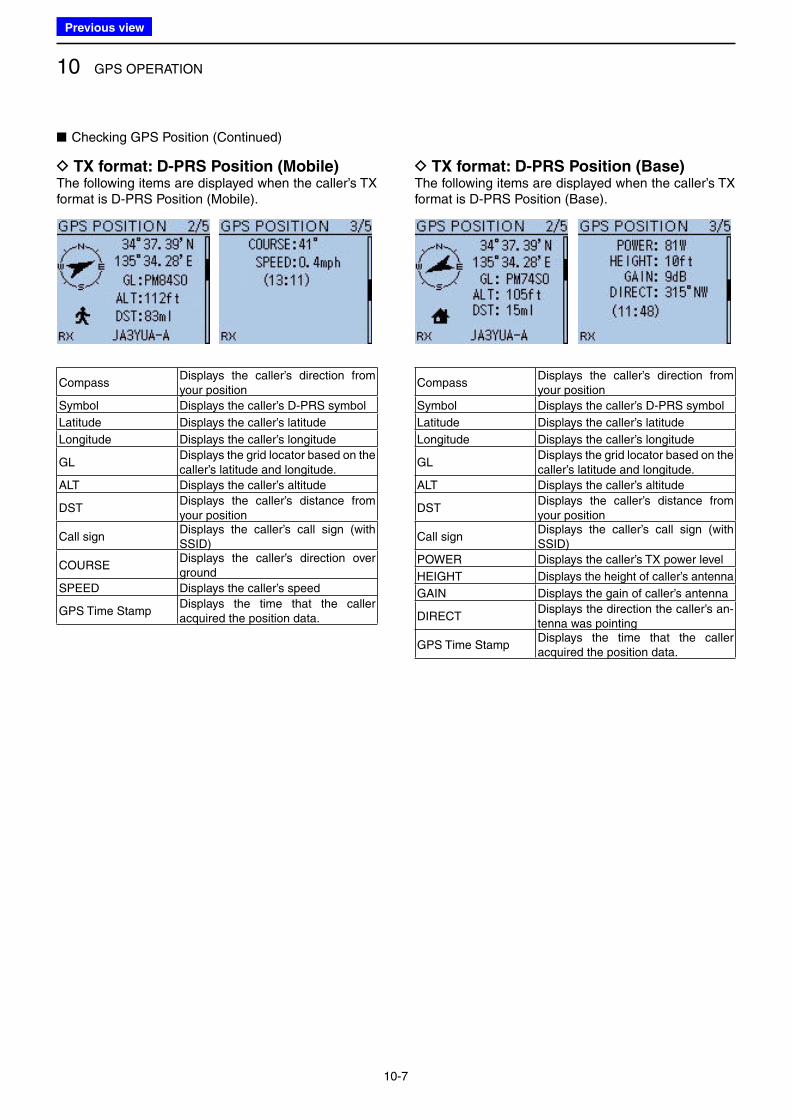
10 GPS OPERATION
10-7
■ Checking GPS Position (Continued)
D TX format: D-PRS Position (Mobile)The following items are displayed when the caller’s TX format is D-PRS Position (Mobile).
CompassDisplays the caller’s direction from your position
Symbol Displays the caller’s D-PRS symbol
Latitude Displays the caller’s latitude
Longitude Displays the caller’s longitude
GLDisplays the grid locator based on the caller’s latitude and longitude.
ALT Displays the caller’s altitude
DSTDisplays the caller’s distance from your position
Call signDisplays the caller’s call sign (with SSID)
COURSEDisplays the caller’s direction over ground
SPEED Displays the caller’s speed
GPS Time StampDisplays the time that the caller acquired the position data.
D TX format: D-PRS Position (Base)The following items are displayed when the caller’s TX format is D-PRS Position (Base).
CompassDisplays the caller’s direction from your position
Symbol Displays the caller’s D-PRS symbol
Latitude Displays the caller’s latitude
Longitude Displays the caller’s longitude
GLDisplays the grid locator based on the caller’s latitude and longitude.
ALT Displays the caller’s altitude
DSTDisplays the caller’s distance from your position
Call signDisplays the caller’s call sign (with SSID)
POWER Displays the caller’s TX power level
HEIGHT Displays the height of caller’s antenna
GAIN Displays the gain of caller’s antenna
DIRECTDisplays the direction the caller’s an-tenna was pointing
GPS Time StampDisplays the time that the caller acquired the position data.
Previous view
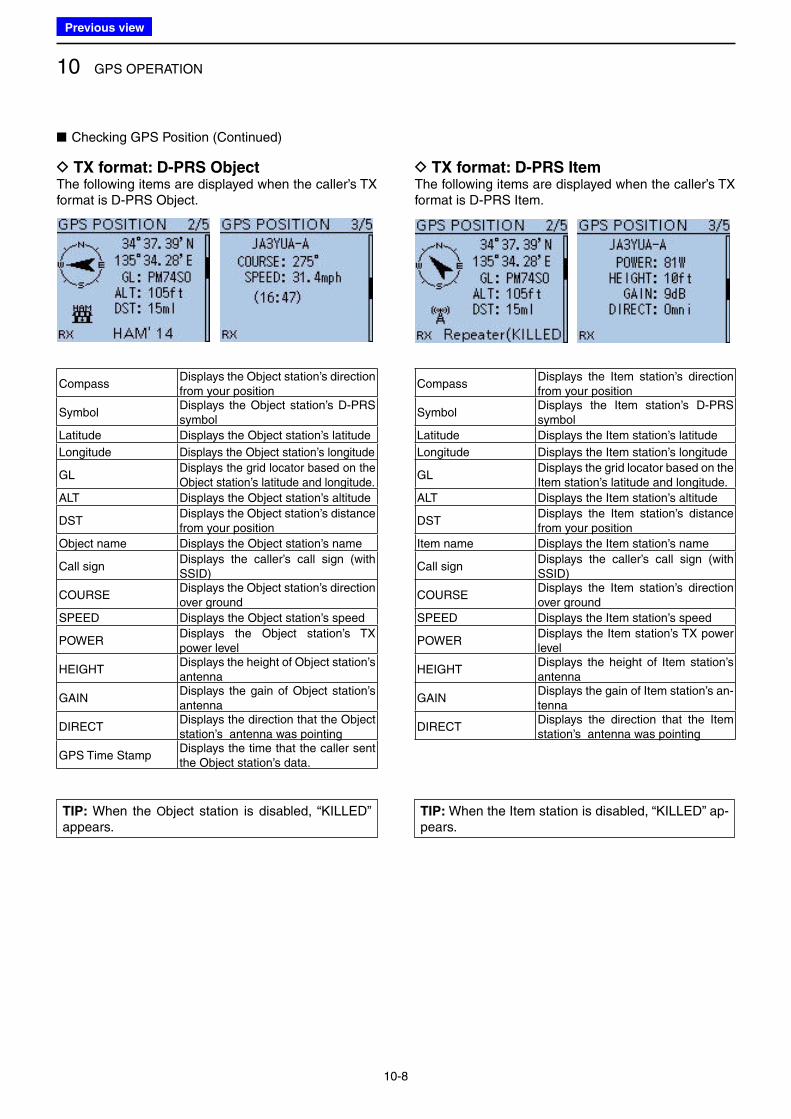
10 GPS OPERATION
10-8
■ Checking GPS Position (Continued)
D TX format: D-PRS ObjectThe following items are displayed when the caller’s TX format is D-PRS Object.
CompassDisplays the Object station’s direction from your position
SymbolDisplays the Object station’s D-PRS symbol
Latitude Displays the Object station’s latitude
Longitude Displays the Object station’s longitude
GLDisplays the grid locator based on the Object station’s latitude and longitude.
ALT Displays the Object station’s altitude
DSTDisplays the Object station’s distance from your position
Object name Displays the Object station’s name
Call signDisplays the caller’s call sign (with SSID)
COURSEDisplays the Object station’s direction over ground
SPEED Displays the Object station’s speed
POWERDisplays the Object station’s TX power level
HEIGHTDisplays the height of Object station’s antenna
GAINDisplays the gain of Object station’s antenna
DIRECTDisplays the direction that the Object station’s antenna was pointing
GPS Time StampDisplays the time that the caller sent the Object station’s data.
D TX format: D-PRS ItemThe following items are displayed when the caller’s TX format is D-PRS Item.
CompassDisplays the Item station’s direction from your position
SymbolDisplays the Item station’s D-PRS symbol
Latitude Displays the Item station’s latitude
Longitude Displays the Item station’s longitude
GLDisplays the grid locator based on the Item station’s latitude and longitude.
ALT Displays the Item station’s altitude
DSTDisplays the Item station’s distance from your position
Item name Displays the Item station’s name
Call signDisplays the caller’s call sign (with SSID)
COURSEDisplays the Item station’s direction over ground
SPEED Displays the Item station’s speed
POWERDisplays the Item station’s TX power level
HEIGHTDisplays the height of Item station’s antenna
GAINDisplays the gain of Item station’s an-tenna
DIRECTDisplays the direction that the Item station’s antenna was pointing
TIP: When the Object station is disabled, “KILLED” appears.
TIP: When the Item station is disabled, “KILLED” ap-pears.
Previous view
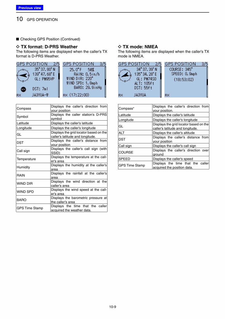
10 GPS OPERATION
10-9
■ Checking GPS Position (Continued)
D TX format: D-PRS WeatherThe following items are displayed when the caller’s TX format is D-PRS Weather.
CompassDisplays the caller’s direction from your position
SymbolDisplays the caller station’s D-PRS symbol
Latitude Displays the caller’s latitude
Longitude Displays the caller’s longitude
GLDisplays the grid locator based on the caller’s latitude and longitude.
DSTDisplays the caller’s distance from your position
Call signDisplays the caller’s call sign (with SSID)
TemperatureDisplays the temperature at the call-er’s area
HumidityDisplays the humidity at the caller’s area
RAINDisplays the rainfall at the caller’s area
WIND DIRDisplays the wind direction at the caller’s area
WIND SPDDisplays the wind speed at the call-er’s area
BARODisplays the barometric pressure at the caller’s area
GPS Time StampDisplays the time that the caller acquired the weather data.
D TX mode: NMEAThe following items are displayed when the caller’s TX mode is NMEA.
Compass*Displays the caller’s direction from your position.
Latitude Displays the caller’s latitude
Longitude Displays the caller’s longitude
GLDisplays the grid locator based on the caller’s latitude and longitude.
ALT Displays the caller’s altitude
DSTDisplays the caller’s distance from your position
Call sign Displays the caller’s call sign
COURSEDisplays the caller’s direction over ground
SPEED Displays the caller’s speed
GPS Time StampDisplays the time that the caller acquired the position data.
Previous view
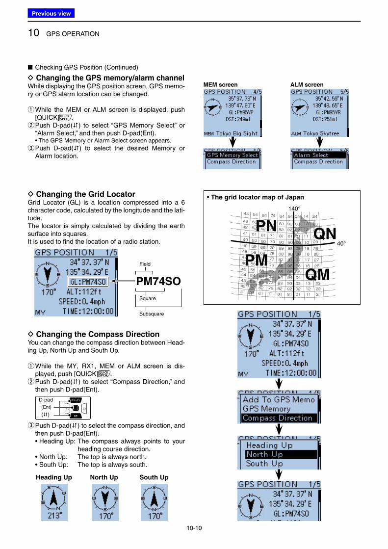
10 GPS OPERATION
10-10
00
09
08
07
06
0504
030201
19
18
17
16
1514
131211
29
28
27
26
2524
232221
10 20
01 11 21
221202
231303
241404
90
999897
96
9594
939291
91
92
93
94
80
898887
86
8584
838281
81
82
83
84
70
797877
76
7574
737271
71
72
73
74
60
696867
66
6564
636261
61
62
63
64
50
595857
56
5554
535251
51
52
53
54
40
494847
46
4544
434241
41
42
43
44140°
40°
PN
PM
QN
QM
• The grid locator map of Japan D Changing the Grid LocatorGrid Locator (GL) is a location compressed into a 6 character code, calculated by the longitude and the lati-tude. The locator is simply calculated by dividing the earth surface into squares.It is used to find the location of a radio station.
Square
Subsquare
Field
PM74SO
D Changing the Compass DirectionYou can change the compass direction between Head-ing Up, North Up and South Up.
q While the MY, RX1, MEM or ALM screen is dis-played, push [QUICK] . w Push D-pad() to select “Compass Direction,” and then push D-pad(Ent).
D-pad
(�)
(Ent)
e Push D-pad() to select the compass direction, and then push D-pad(Ent).
• Heading Up: The compass always points to your heading course direction.
• North Up: The top is always north. • South Up: The top is always south.
Heading Up North Up South Up
D Changing the GPS memory/alarm channelWhile displaying the GPS position screen, GPS memo-ry or GPS alarm location can be changed.
q While the MEM or ALM screen is displayed, push [QUICK] . w Push D-pad() to select “GPS Memory Select” or “Alarm Select,” and then push D-pad(Ent).
• The GPS Memory or Alarm Select screen appears.
e Push D-pad() to select the desired Memory or Alarm location.
■ Checking GPS Position (Continued)
MEM screen ALM screen
Previous view
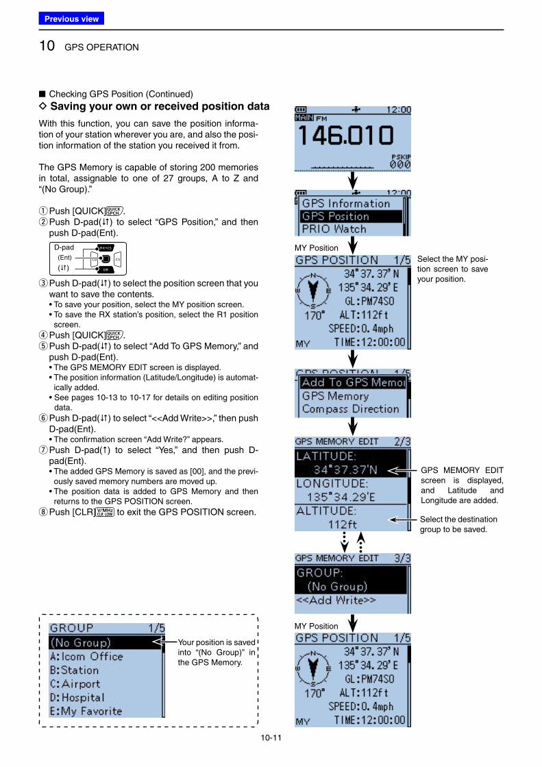
10 GPS OPERATION
10-11
With this function, you can save the position informa-tion of your station wherever you are, and also the posi-tion information of the station you received it from.
The GPS Memory is capable of storing 200 memories in total, assignable to one of 27 groups, A to Z and “(No Group).”
qPush [QUICK] . w Push D-pad() to select “GPS Position,” and then push D-pad(Ent).
D-pad
(�)
(Ent)
e Push D-pad() to select the position screen that you want to save the contents.
• To save your position, select the MY position screen. • To save the RX station’s position, select the R1 position
screen.
rPush [QUICK] . t Push D-pad() to select “Add To GPS Memory,” and push D-pad(Ent).
• The GPS MEMORY EDIT screen is displayed. • The position information (Latitude/Longitude) is automat-
ically added. • See pages 10-13 to 10-17 for details on editing position
data.
y Push D-pad() to select “<<Add Write>>,” then push D-pad(Ent).
• The confirmation screen “Add Write?” appears.
u Push D-pad() to select “Yes,” and then push D-pad(Ent).
• The added GPS Memory is saved as [00], and the previ-ously saved memory numbers are moved up.
• The position data is added to GPS Memory and then returns to the GPS POSITION screen.
i Push [CLR] to exit the GPS POSITION screen.
Your position is saved into “(No Group)” in the GPS Memory.
Select the MY posi-tion screen to save your position.
MY Position
■ Checking GPS Position (Continued)
D Saving your own or received position data
GPS MEMORY EDIT screen is displayed, and Latitude and Longitude are added.
MY Position
Select the destination group to be saved.
Previous view
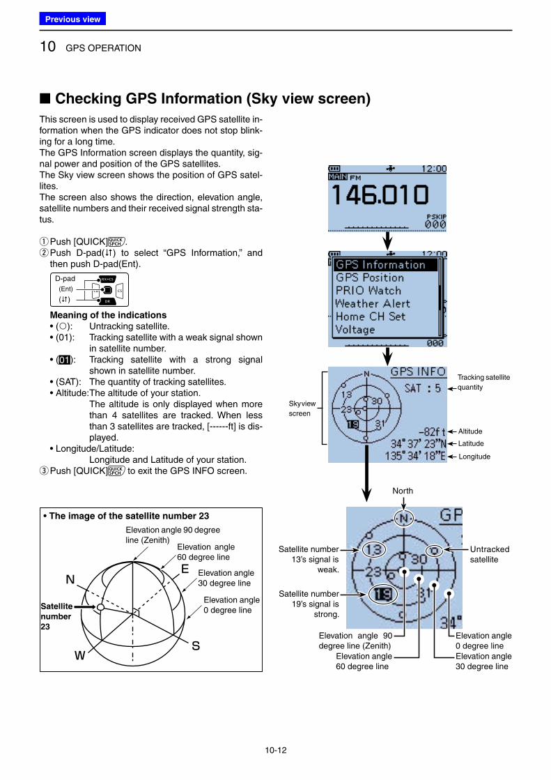
10 GPS OPERATION
10-12
This screen is used to display received GPS satellite in-formation when the GPS indicator does not stop blink-ing for a long time.The GPS Information screen displays the quantity, sig-nal power and position of the GPS satellites. The Sky view screen shows the position of GPS satel-lites. The screen also shows the direction, elevation angle, satellite numbers and their received signal strength sta-tus.
qPush [QUICK] . w Push D-pad() to select “GPS Information,” and then push D-pad(Ent).
D-pad
(�)
(Ent)
Meaning of the indications
• (): Untracking satellite. • (01): Tracking satellite with a weak signal shown
in satellite number. • (01): Tracking satellite with a strong signal
shown in satellite number. • (SAT): The quantity of tracking satellites. • Altitude: The altitude of your station. The altitude is only displayed when more
than 4 satellites are tracked. When less than 3 satellites are tracked, [------ft] is dis-played.
• Longitude/Latitude: Longitude and Latitude of your station.
e Push [QUICK] to exit the GPS INFO screen.
N
W
E
S
Elevation angle 30 degree line
Elevation angle 60 degree line
Elevation angle 90 degree line (Zenith)
• The image of the satellite number 23
■ Checking GPS Information (Sky view screen)
Elevation angle 0 degree line
Sky view
screen
Latitude
Tracking satellite
quantity
Altitude
Longitude
Untracked satellite
Satellite number 19’s signal is
strong.
Satellite number 13’s signal is
weak.
Elevation angle 0 degree lineElevation angle 30 degree line
Elevation angle 60 degree line
Elevation angle 90 degree line (Zenith)
North
Satellite
number
23
Previous view
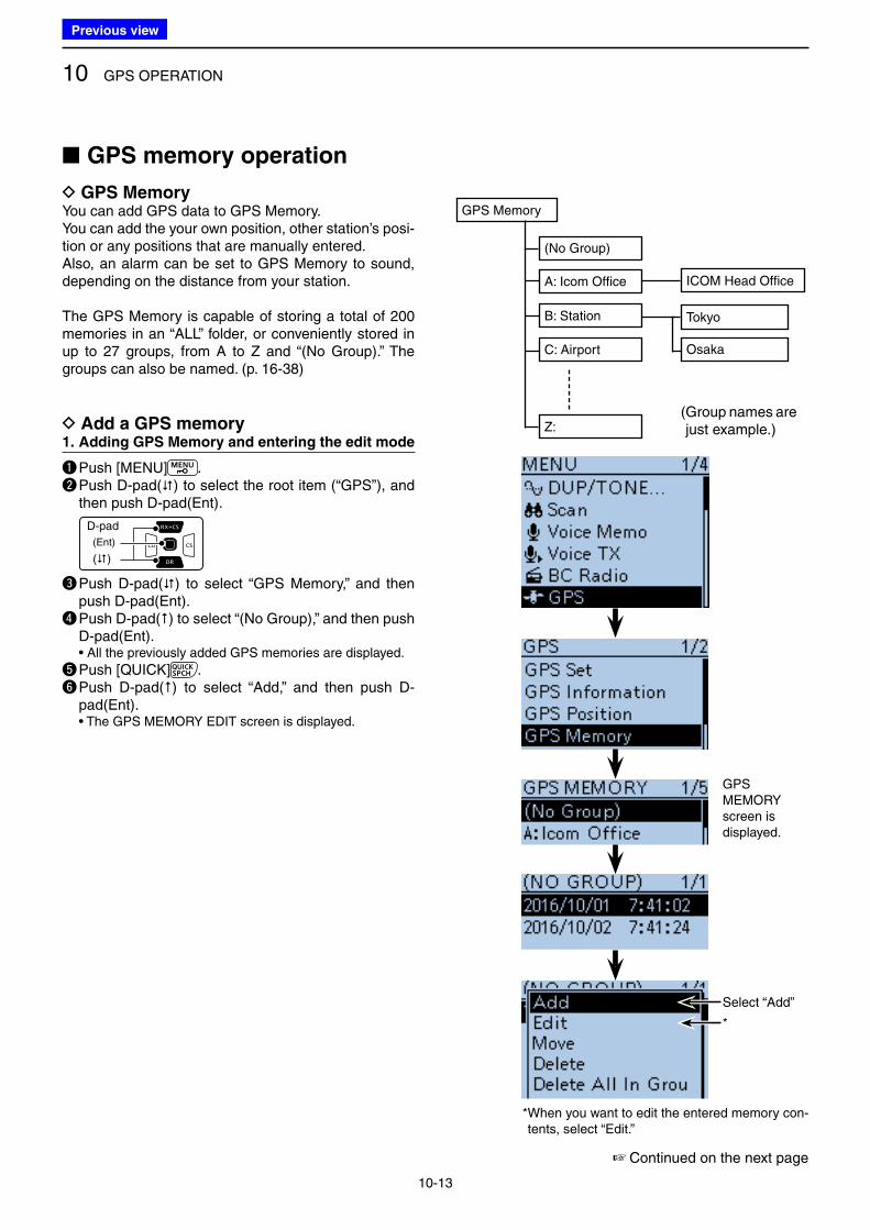
10 GPS OPERATION
10-13
D GPS MemoryYou can add GPS data to GPS Memory. You can add the your own position, other station’s posi-tion or any positions that are manually entered.Also, an alarm can be set to GPS Memory to sound, depending on the distance from your station.
The GPS Memory is capable of storing a total of 200 memories in an “ALL” folder, or conveniently stored in up to 27 groups, from A to Z and “(No Group).” The groups can also be named. (p. 16-38)
D Add a GPS memory1. Adding GPS Memory and entering the edit mode
q Push [MENU] . w Push D-pad() to select the root item (“GPS”), and
then push D-pad(Ent).
D-pad
(�)
(Ent)
e Push D-pad() to select “GPS Memory,” and then push D-pad(Ent).
r Push D-pad() to select “(No Group),” and then push D-pad(Ent).
• All the previously added GPS memories are displayed.
t Push [QUICK] .y Push D-pad() to select “Add,” and then push D-
pad(Ent). • The GPS MEMORY EDIT screen is displayed.
GPS MEMORY screen is displayed.
■ GPS memory operation
☞ Continued on the next page
GPS Memory
(No Group)
B: Station
A: Icom Office
C: Airport
Z:
ICOM Head Office
Tokyo
Osaka
Select “Add”
*
* When you want to edit the entered memory con-tents, select “Edit.”
( Group names are just example.)
Previous view
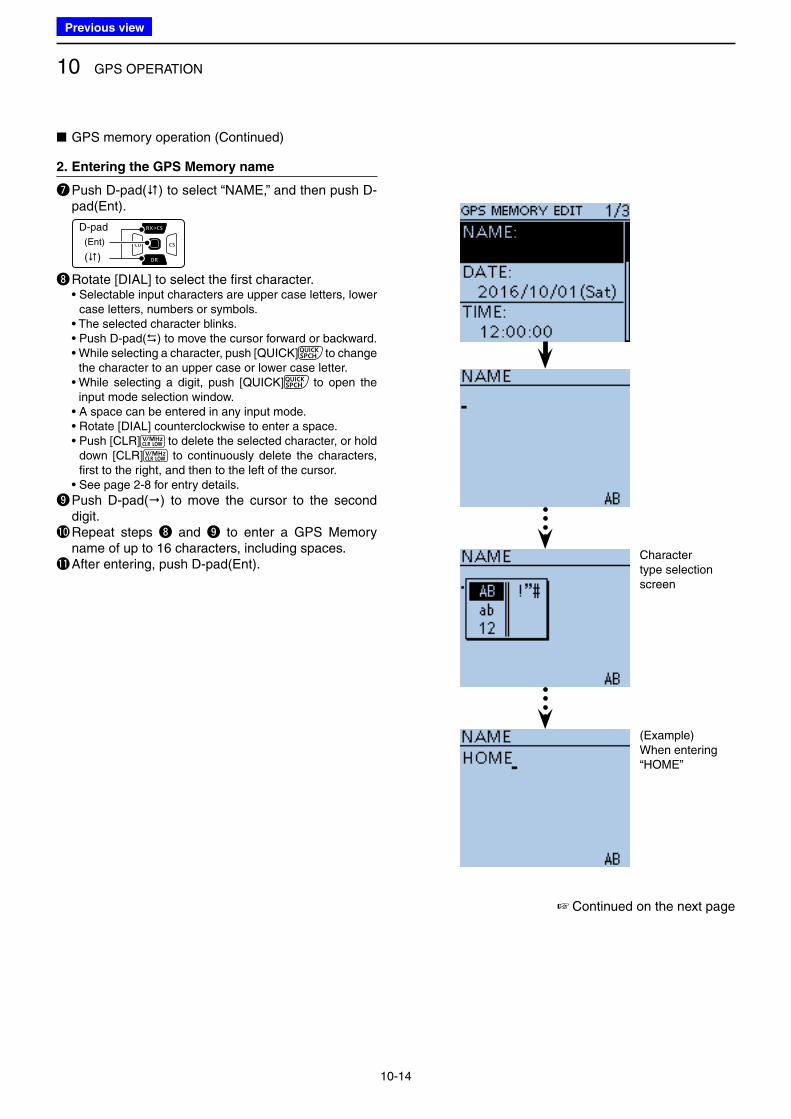
10 GPS OPERATION
10-14
2. Entering the GPS Memory name
u Push D-pad() to select “NAME,” and then push D-pad(Ent).
D-pad
(�)
(Ent)
i Rotate [DIAL] to select the first character. • Selectable input characters are upper case letters, lower
case letters, numbers or symbols. • The selected character blinks. • Push D-pad() to move the cursor forward or backward. • While selecting a character, push [QUICK] to change
the character to an upper case or lower case letter. • While selecting a digit, push [QUICK] to open the
input mode selection window. • A space can be entered in any input mode. • Rotate [DIAL] counterclockwise to enter a space. • Push [CLR] to delete the selected character, or hold
down [CLR] to continuously delete the characters, first to the right, and then to the left of the cursor.
• See page 2-8 for entry details.
o Push D-pad() to move the cursor to the second digit.
!0 Repeat steps i and o to enter a GPS Memory name of up to 16 characters, including spaces.
!1 After entering, push D-pad(Ent).Character type selection screen
(Example)When entering “HOME”
☞ Continued on the next page
■ GPS memory operation (Continued)
Previous view
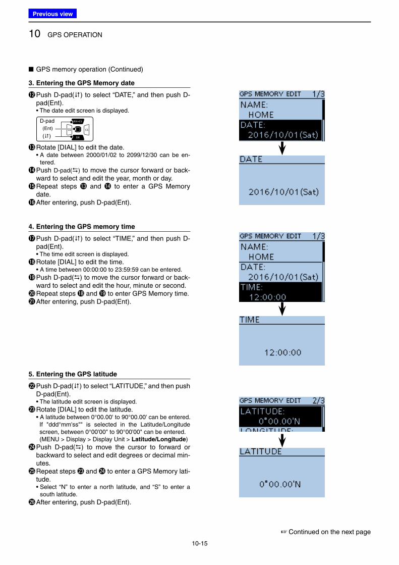
10 GPS OPERATION
10-15
3. Entering the GPS Memory date
!2 Push D-pad() to select “DATE,” and then push D-pad(Ent).
• The date edit screen is displayed.
D-pad
(�)
(Ent)
!3 Rotate [DIAL] to edit the date. • A date between 2000/01/02 to 2099/12/30 can be en-
tered.
!4 Push D-pad() to move the cursor forward or back-ward to select and edit the year, month or day.
!5 Repeat steps !3 and !4 to enter a GPS Memory date.
!6 After entering, push D-pad(Ent).
4. Entering the GPS memory time
!7 Push D-pad() to select “TIME,” and then push D-pad(Ent).
• The time edit screen is displayed.
!8 Rotate [DIAL] to edit the time. • A time between 00:00:00 to 23:59:59 can be entered.
!9 Push D-pad() to move the cursor forward or back-ward to select and edit the hour, minute or second.
@0 Repeat steps !8 and !9 to enter GPS Memory time.@1 After entering, push D-pad(Ent).
5. Entering the GPS latitude
@2 Push D-pad() to select “LATITUDE,” and then push D-pad(Ent).
• The latitude edit screen is displayed.
@3 Rotate [DIAL] to edit the latitude. • A latitude between 0°00.00' to 90°00.00' can be entered. If "ddd°mm'ss"" is selected in the Latitude/Longitude
screen, between 0°00'00" to 90°00'00" can be entered. (MENU > Display > Display Unit > Latitude/Longitude)
@4 Push D-pad() to move the cursor to forward or backward to select and edit degrees or decimal min-utes.
@5 Repeat steps @3 and @4 to enter a GPS Memory lati-tude.
• Select “N” to enter a north latitude, and “S” to enter a south latitude.
@6 After entering, push D-pad(Ent).
■ GPS memory operation (Continued)
☞ Continued on the next page
Previous view
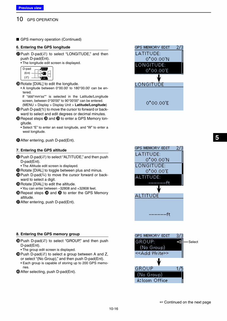
10 GPS OPERATION
10-16
5
6. Entering the GPS longitude
@7 Push D-pad() to select “LONGITUDE,” and then push D-pad(Ent).
• The longitude edit screen is displayed.
D-pad
(�)
(Ent)
@8 Rotate [DIAL] to edit the longitude. • A longitude between 0°00.00' to 180°00.00' can be en-
tered. If "ddd°mm'ss"" is selected in the Latitude/Longitude
screen, between 0°00'00" to 90°00'00" can be entered. (MENU > Display > Display Unit > Latitude/Longitude)
@9 Push D-pad() to move the cursor to forward or back-ward to select and edit degrees or decimal minutes.
#0 Repeat steps @8 and @9 to enter a GPS Memory lon-gitude.
• Select “E” to enter an east longitude, and “W” to enter a west longitude.
#1 After entering, push D-pad(Ent).
7. Entering the GPS altitude
#2 Push D-pad() to select “ALTITUDE,” and then push D-pad(Ent).
• The Altitude edit screen is displayed.
#3 Rotate [DIAL] to toggle between plus and minus.#4 Push D-pad() to move the cursor forward or back-
ward to select a digit.#5 Rotate [DIAL] to edit the altitude. • You can enter between –32808 and +32808 feet.
#6 Repeat steps #4 and #5 to enter the GPS Memory altitude.
#7 After entering, push D-pad(Ent).
8. Entering the GPS memory group
#8 Push D-pad() to select “GROUP,” and then push D-pad(Ent).
• The group edit screen is displayed.
#9 Push D-pad() to select a group between A and Z, or select “(No Group),” and then push D-pad(Ent).
• Each group is capable of storing up to 200 GPS memo-ries.
$0 After selecting, push D-pad(Ent).
■ GPS memory operation (Continued)
Select
☞ Continued on the next page
Previous view
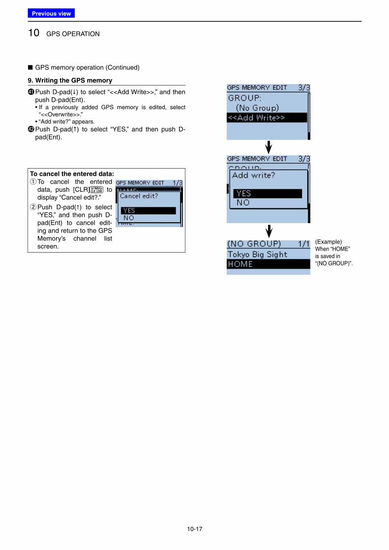
10 GPS OPERATION
10-17
■ GPS memory operation (Continued)
9. Writing the GPS memory
$1 Push D-pad() to select “<<Add Write>>,” and then push D-pad(Ent).
• If a previously added GPS memory is edited, select “<<Overwrite>>.”
• “Add write?” appears.
$2 Push D-pad() to select “YES,” and then push D-pad(Ent).
To cancel the entered data:
q To cancel the entered data, push [CLR] to display “Cancel edit?.”
w Push D-pad() to select “YES,” and then push D-pad(Ent) to cancel edit-ing and return to the GPS Memory’s channel list screen.
(Example) When “HOME” is saved in “(NO GROUP)”.
Previous view
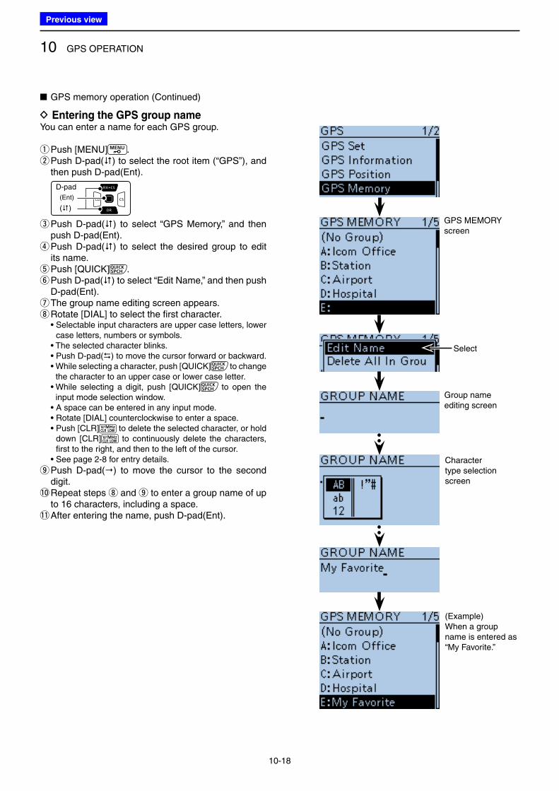
10 GPS OPERATION
10-18
D Entering the GPS group nameYou can enter a name for each GPS group.
qPush [MENU] . w Push D-pad() to select the root item (“GPS”), and then push D-pad(Ent).
D-pad
(�)
(Ent)
e Push D-pad() to select “GPS Memory,” and then push D-pad(Ent). r Push D-pad() to select the desired group to edit its name. tPush [QUICK] . y Push D-pad() to select “Edit Name,” and then push D-pad(Ent). uThe group name editing screen appears. iRotate [DIAL] to select the first character.
• Selectable input characters are upper case letters, lower case letters, numbers or symbols.
• The selected character blinks. • Push D-pad() to move the cursor forward or backward. • While selecting a character, push [QUICK] to change
the character to an upper case or lower case letter. • While selecting a digit, push [QUICK] to open the
input mode selection window. • A space can be entered in any input mode. • Rotate [DIAL] counterclockwise to enter a space. • Push [CLR] to delete the selected character, or hold
down [CLR] to continuously delete the characters, first to the right, and then to the left of the cursor.
• See page 2-8 for entry details.
o Push D-pad() to move the cursor to the second digit.
!0 Repeat steps i and o to enter a group name of up to 16 characters, including a space.
!1 After entering the name, push D-pad(Ent).
GPS MEMORY screen
■ GPS memory operation (Continued)
Select
Group name editing screen
Character type selection screen
(Example) When a group name is entered as “My Favorite.”
Previous view
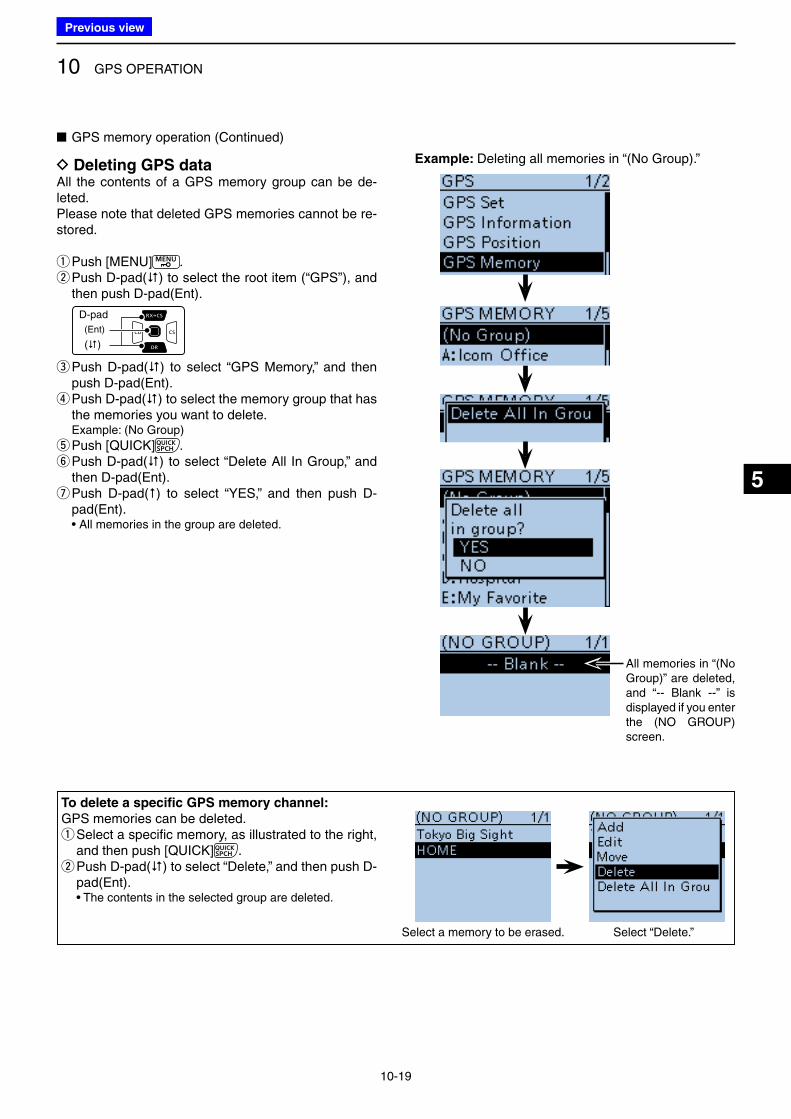
10 GPS OPERATION
10-19
5
D Deleting GPS dataAll the contents of a GPS memory group can be de-leted.Please note that deleted GPS memories cannot be re-stored.
qPush [MENU] . w Push D-pad() to select the root item (“GPS”), and then push D-pad(Ent).
D-pad
(�)
(Ent)
e Push D-pad() to select “GPS Memory,” and then push D-pad(Ent). r Push D-pad() to select the memory group that has the memories you want to delete.
Example: (No Group)
t Push [QUICK] . y Push D-pad() to select “Delete All In Group,” and then D-pad(Ent). u Push D-pad() to select “YES,” and then push D-pad(Ent).
• All memories in the group are deleted.
To delete a specific GPS memory channel:
GPS memories can be deleted. q Select a specific memory, as illustrated to the right, and then push [QUICK] . w Push D-pad() to select “Delete,” and then push D-pad(Ent).
• The contents in the selected group are deleted.
All memories in “(No Group)” are deleted, and “-- Blank --” is displayed if you enter the (NO GROUP) screen.
■ GPS memory operation (Continued)
Example: Deleting all memories in “(No Group).”
Select a memory to be erased. Select “Delete.”
Previous view
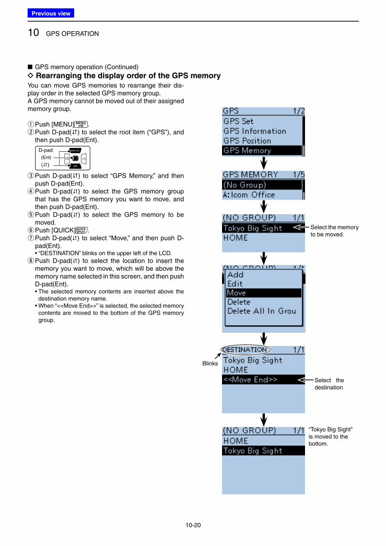
10 GPS OPERATION
10-20
You can move GPS memories to rearrange their dis-play order in the selected GPS memory group.A GPS memory cannot be moved out of their assigned memory group.
qPush [MENU] . w Push D-pad() to select the root item (“GPS”), and then push D-pad(Ent).
D-pad
(�)
(Ent)
e Push D-pad() to select “GPS Memory,” and then push D-pad(Ent). r Push D-pad() to select the GPS memory group that has the GPS memory you want to move, and then push D-pad(Ent). t Push D-pad() to select the GPS memory to be moved. yPush [QUICK] . u Push D-pad() to select “Move,” and then push D-pad(Ent).
• “DESTINATION” blinks on the upper left of the LCD.
i Push D-pad() to select the location to insert the memory you want to move, which will be above the memory name selected in this screen, and then push D-pad(Ent).
• The selected memory contents are inserted above the destination memory name.
• When “<<Move End>>” is selected, the selected memory contents are moved to the bottom of the GPS memory group.
“Tokyo Big Sight” is moved to the bottom.
Select the memory to be moved.
Blinks
Select the destination
■ GPS memory operation (Continued)
D Rearranging the display order of the GPS memory
Previous view
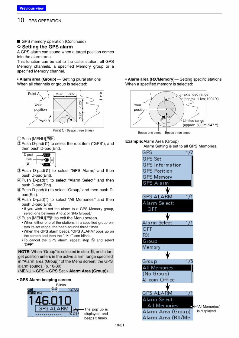
10 GPS OPERATION
10-21
0.25’ 0.25’
0.2
5’
0.2
5’
N
Your position
Your position
Extended range (approx. 1 km; 1094 Y)
Limited range (approx. 500 m; 547 Y)
Beeps one times Beeps three times
• Alarm area (Group) — Setting plural stationsWhen all channels or group is selected:
• Alarm area (RX/Memory)— Setting specific stationsWhen a specified memory is selected:
Point A
Point B
Point C (Beeps three times)
• GPS Alarm beeping screen
■ GPS memory operation (Continued)
D Setting the GPS alarmA GPS alarm can sound when a target position comes into the alarm area.This function can be set to the caller station, all GPS Memory channels, a specified Memory group or a specified Memory channel.
qPush [MENU] . w Push D-pad() to select the root item (“GPS”), and then push D-pad(Ent).
D-pad
(�)
(Ent)
e Push D-pad() to select “GPS Alarm,” and then push D-pad(Ent). r Push D-pad() to select “Alarm Select,” and then push D-pad(Ent). t Push D-pad() to select “Group,” and then push D-pad(Ent). y Push D-pad() to select “All Memories,” and then push D-pad(Ent).
• If you wish to set the alarm to a GPS Memory group, select one between A to Z or “(No Group).”
u Push [MENU] to exit the Menu screen. • When either one of the stations in a specified group en-
ters its set range, the beep sounds three times. • When the GPS alarm beeps, “GPS ALARM” pops up on
the screen and then the “S” icon blinks. • To cancel the GPS alarm, repeat step t and select
“OFF.”
Example: Alarm Area (Group) Alarm Setting is set to all GPS Memories.
“All Memories” is displayed.The pop up is
displayed and beeps 3 times.
Blinks
NOTE: When “Group” is selected in step t, and a tar-get position enters in the active alarm range specified in “Alarm area (Group)” of the Menu screen, the GPS alarm sounds. (p. 16-39)(MENU > GPS > GPS Set > Alarm Area (Group))
Previous view
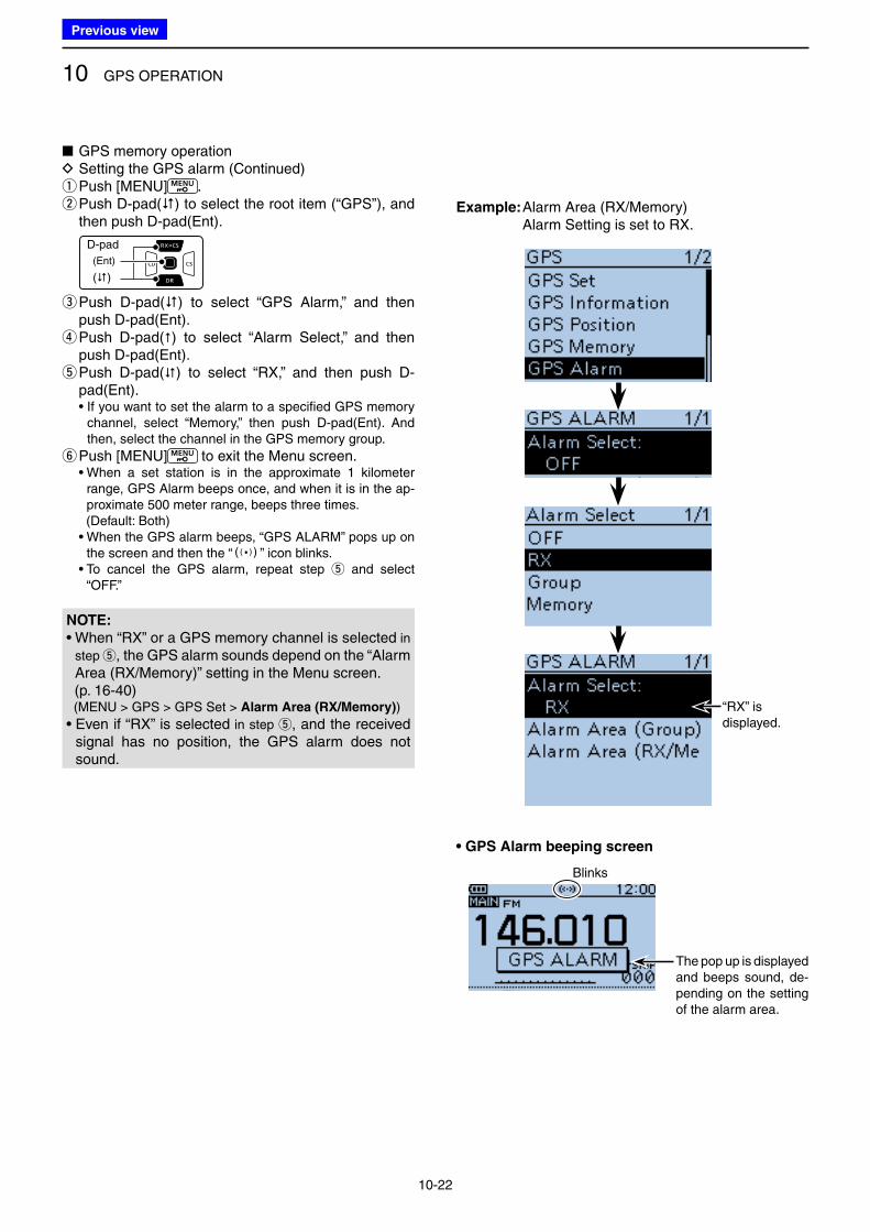
10 GPS OPERATION
10-22
■ GPS memory operation D Setting the GPS alarm (Continued) qPush [MENU] . w Push D-pad() to select the root item (“GPS”), and then push D-pad(Ent).
D-pad
(�)
(Ent)
e Push D-pad() to select “GPS Alarm,” and then push D-pad(Ent). r Push D-pad() to select “Alarm Select,” and then push D-pad(Ent). t Push D-pad() to select “RX,” and then push D-pad(Ent).
• If you want to set the alarm to a specified GPS memory channel, select “Memory,” then push D-pad(Ent). And then, select the channel in the GPS memory group.
y Push [MENU] to exit the Menu screen. • When a set station is in the approximate 1 kilometer
range, GPS Alarm beeps once, and when it is in the ap-proximate 500 meter range, beeps three times.
(Default: Both) • When the GPS alarm beeps, “GPS ALARM” pops up on
the screen and then the “S” icon blinks. • To cancel the GPS alarm, repeat step t and select
“OFF.”
Example: Alarm Area (RX/Memory) Alarm Setting is set to RX.
• GPS Alarm beeping screen
The pop up is displayed and beeps sound, de-pending on the setting of the alarm area.
Blinks
“RX” is displayed.
NOTE:
• When “RX” or a GPS memory channel is selected in
step t, the GPS alarm sounds depend on the “Alarm Area (RX/Memory)” setting in the Menu screen.
(p. 16-40) (MENU > GPS > GPS Set > Alarm Area (RX/Memory))
• Even if “RX” is selected in step t, and the received signal has no position, the GPS alarm does not sound.
Previous view
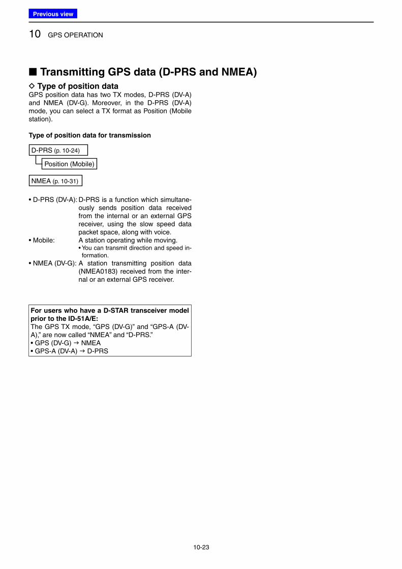
10 GPS OPERATION
10-23
D Type of position dataGPS position data has two TX modes, D-PRS (DV-A) and NMEA (DV-G). Moreover, in the D-PRS (DV-A) mode, you can select a TX format as Position (Mobile station).
Type of position data for transmission
NMEA (p. 10-31)
D-PRS (p. 10-24)
Position (Mobile)
• D-PRS (DV-A): D-PRS is a function which simultane-ously sends position data received from the internal or an external GPS receiver, using the slow speed data packet space, along with voice.
• Mobile: A station operating while moving. • You can transmit direction and speed in-
formation.
• NMEA (DV-G): A station transmitting position data (NMEA0183) received from the inter-nal or an external GPS receiver.
For users who have a D-STAR transceiver model
prior to the ID-51A/E:
The GPS TX mode, “GPS (DV-G)” and “GPS-A (DV-A),” are now called “NMEA” and “D-PRS.”• GPS (DV-G) NMEA• GPS-A (DV-A) D-PRS
■ Transmitting GPS data (D-PRS and NMEA)
Previous view
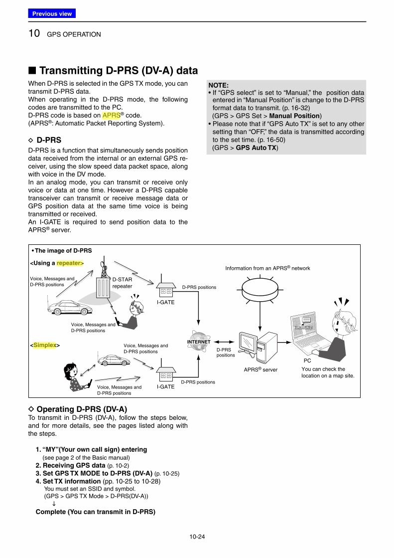
10 GPS OPERATION
10-24
When D-PRS is selected in the GPS TX mode, you can transmit D-PRS data.When operating in the D-PRS mode, the following codes are transmitted to the PC.D-PRS code is based on APRS® code.(APRS®: Automatic Packet Reporting System).
D D-PRS
D-PRS is a function that simultaneously sends position data received from the internal or an external GPS re-ceiver, using the slow speed data packet space, along with voice in the DV mode.In an analog mode, you can transmit or receive only voice or data at one time. However a D-PRS capable transceiver can transmit or receive message data or GPS position data at the same time voice is being transmitted or received.An I-GATE is required to send position data to the APRS® server.
D Operating D-PRS (DV-A)To transmit in D-PRS (DV-A), follow the steps below, and for more details, see the pages listed along with the steps.
1. “MY”(Your own call sign) entering
(see page 2 of the Basic manual)
2. Receiving GPS data (p. 10-2)
3. Set GPS TX MODE to D-PRS (DV-A) (p. 10-25)
4. Set TX information (pp. 10-25 to 10-28) You must set an SSID and symbol. ( GPS > GPS TX Mode > D-PRS(DV-A))
Complete (You can transmit in D-PRS)
NOTE: • If “GPS select” is set to “Manual,” the position data
entered in “Manual Position” is change to the D-PRS format data to transmit. (p. 16-32)
(GPS > GPS Set > Manual Position)• Please note that if “GPS Auto TX” is set to any other
setting than “OFF,” the data is transmitted according to the set time. (p. 16-50)
(GPS > GPS Auto TX)
I-GATE
I-GATE
JA3YUA-Z
APRS® server
PC
You can check the
location on a map site.
D-STAR
repeater
Information from an APRS® network
Voice, Messages and
D-PRS positions
Voice, Messages and
D-PRS positions
Voice, Messages and
D-PRS positions
Voice, Messages and
D-PRS positions
D-PRS positions
D-PRS positions
D-PRSpositions
<Using a repeater>
<Simplex>
• The image of D-PRS
■ Transmitting D-PRS (DV-A) data
Previous view
Icom
ハイライト表示
An operating mode in which the transmit and receive frequencies are the same.
Icom
ハイライト表示
Radio systems that receive incoming signals and retransmit them to extend the communication area. Normally put on geographically high locations for VHF/UHF radios.
Icom
ハイライト表示
(Automatic Packet Reporting System) APRS is a two-way tactical real-time digital communications system between all assets in a network sharing information about everything going on in the local area.
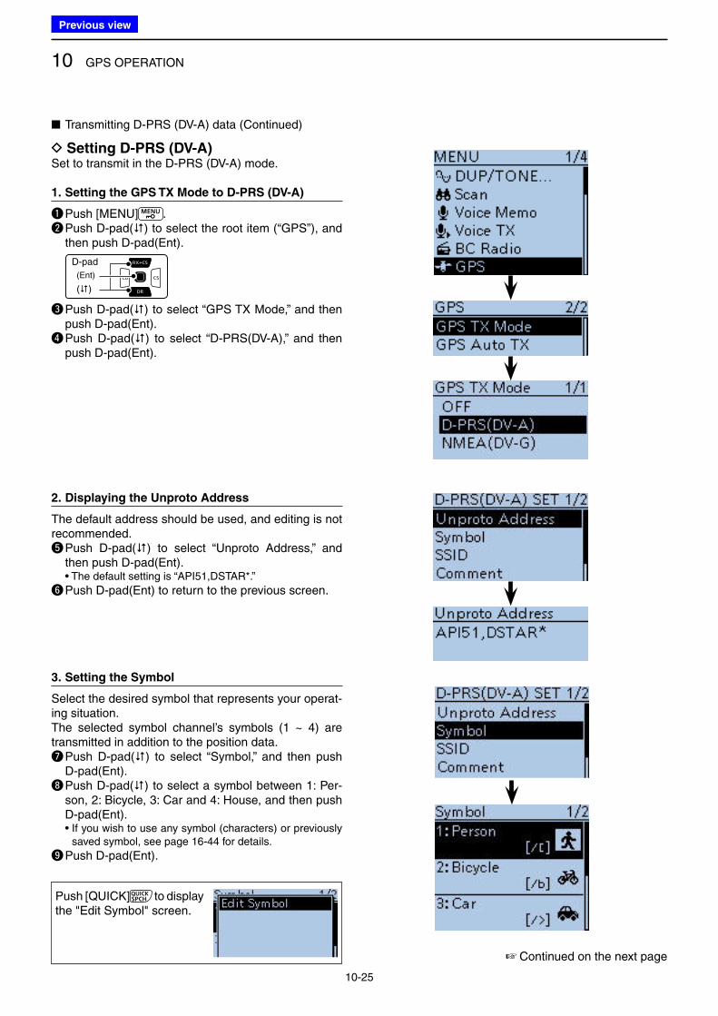
10 GPS OPERATION
10-25
D Setting D-PRS (DV-A)Set to transmit in the D-PRS (DV-A) mode.
1. Setting the GPS TX Mode to D-PRS (DV-A)
q Push [MENU] . w Push D-pad() to select the root item (“GPS”), and
then push D-pad(Ent).
D-pad
(�)
(Ent)
e Push D-pad() to select “GPS TX Mode,” and then push D-pad(Ent).
r Push D-pad() to select “D-PRS(DV-A),” and then push D-pad(Ent).
2. Displaying the Unproto Address
The default address should be used, and editing is not recommended.t Push D-pad() to select “Unproto Address,” and
then push D-pad(Ent). • The default setting is “API51,DSTAR*.”
y Push D-pad(Ent) to return to the previous screen.
3. Setting the Symbol
Select the desired symbol that represents your operat-ing situation.The selected symbol channel’s symbols (1 ~ 4) are transmitted in addition to the position data.u Push D-pad() to select “Symbol,” and then push
D-pad(Ent).i Push D-pad() to select a symbol between 1: Per-
son, 2: Bicycle, 3: Car and 4: House, and then push D-pad(Ent).
• If you wish to use any symbol (characters) or previously saved symbol, see page 16-44 for details.
o Push D-pad(Ent).
■ Transmitting D-PRS (DV-A) data (Continued)
Push [QUICK] to display the "Edit Symbol" screen.
☞ Continued on the next page
Previous view
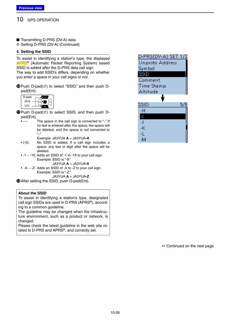
10 GPS OPERATION
10-26
4. Setting the SSID
To assist in identifying a station’s type, the displayed APRS® (Automatic Packet Reporting System) based SSID is added after the D-PRS data call sign.The way to add SSID’s differs, depending on whether you enter a space in your call signs or not.
!0 Push D-pad() to select “SSID,” and then push D-pad(Ent).
D-pad
(�)
(Ent)
!1 Push D-pad() to select SSID, and then push D-pad(Ent).
• ---: The space in the call sign is converted to “-.” If no text is entered after the space, the space will be deleted, and the space is not converted to “-.”
Example: JA3YUA A > JA3YUA-A
• (-0): No SSID is added. If a call sign includes a space, any text or digit after the space will be deleted.
• -1 ~ -15: Adds an SSID of -1 to -15 to your call sign. Example: SSID is “-9.” JA3YUA A > JA3YUA-9
• -A ~ -Z: Adds an SSID of -A to -Z to your call sign. Example: SSID is “-Z.” JA3YUA A > JA3YUA-Z
!2 After setting the SSID, push D-pad(Ent).
About the SSID
To assist in identifying a station’s type, designated call sign SSIDs are used in D-PRS (APRS®), accord-ing to a common guideline.The guideline may be changed when the infrastruc-ture environment, such as a product or network, is changed.Please check the latest guideline in the web site re-lated to D-PRS and APRS®, and correctly set.
■ Transmitting D-PRS (DV-A) data D Setting D-PRS (DV-A) (Continued)
☞ Continued on the next page
Previous view
Icom
ハイライト表示
(Automatic Packet Reporting System) APRS is a two-way tactical real-time digital communications system between all assets in a network sharing information about everything going on in the local area.
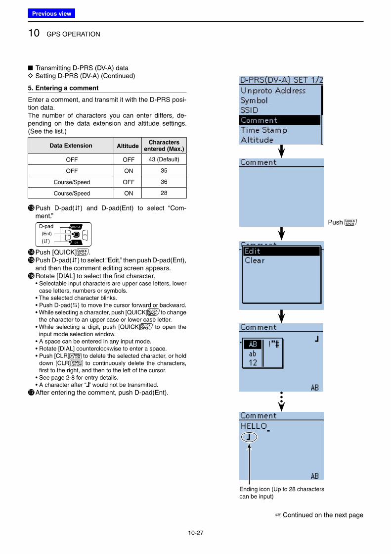
10 GPS OPERATION
10-27
5. Entering a comment
Enter a comment, and transmit it with the D-PRS posi-tion data.The number of characters you can enter differs, de-pending on the data extension and altitude settings. (See the list.)
Data Extension AltitudeCharacters
entered (Max.)
OFF OFF 43 (Default)
OFF ON 35
Course/Speed OFF 36
Course/Speed ON 28
!3 Push D-pad() and D-pad(Ent) to select “Com-ment.”
D-pad
(�)
(Ent)
!4 Push [QUICK] .!5 Push D-pad() to select “Edit,” then push D-pad(Ent),
and then the comment editing screen appears.!6 Rotate [DIAL] to select the first character. • Selectable input characters are upper case letters, lower
case letters, numbers or symbols. • The selected character blinks. • Push D-pad() to move the cursor forward or backward. • While selecting a character, push [QUICK] to change
the character to an upper case or lower case letter. • While selecting a digit, push [QUICK] to open the
input mode selection window. • A space can be entered in any input mode. • Rotate [DIAL] counterclockwise to enter a space. • Push [CLR] to delete the selected character, or hold
down [CLR] to continuously delete the characters, first to the right, and then to the left of the cursor.
• See page 2-8 for entry details. • A character after “ ” would not be transmitted.
!7 After entering the comment, push D-pad(Ent).
■ Transmitting D-PRS (DV-A) data D Setting D-PRS (DV-A) (Continued)
Ending icon (Up to 28 characters can be input)
☞ Continued on the next page
Push
Previous view
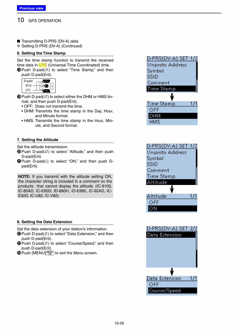
10 GPS OPERATION
10-28
6. Setting the Time Stamp
Set the time stamp function to transmit the received time data in UTC (Universal Time Coordinated) time.!8 Push D-pad() to select “Time Stamp,” and then
push D-pad(Ent).
D-pad
(�)
(Ent)
!9 Push D-pad() to select either the DHM or HMS for-mat, and then push D-pad(Ent).
• OFF: Does not transmit the time. • DHM: Transmits the time stamp in the Day, Hour,
and Minute format. • HMS: Transmits the time stamp in the Hour, Min-
ute, and Second format.
7. Setting the Altitude
Set the altitude transmission.@0 Push D-pad() to select “Altitude,” and then push
D-pad(Ent)@1 Push D-pad() to select “ON,” and then push D-
pad(Ent).
NOTE: If you transmit with the altitude setting ON, the character string is included in a comment on the products that cannot display the altitude. (IC-9100, IC-80AD, IC-E80D, ID-880H, ID-E880, IC-92AD, IC-E92D, IC-U82, IC-V82)
8. Setting the Data Extension
Set the data extension of your station’s information.@2 Push D-pad() to select “Data Extension,” and then
push D-pad(Ent).@3 Push D-pad() to select “Course/Speed,” and then
push D-pad(Ent).@4 Push [MENU] to exit the Menu screen.
■ Transmitting D-PRS (DV-A) data D Setting D-PRS (DV-A) (Continued)
Previous view
Icom
ハイライト表示
(Universal Time Coordinated) An astronomical time based on the Greenwich meridian (zero degrees longitude).
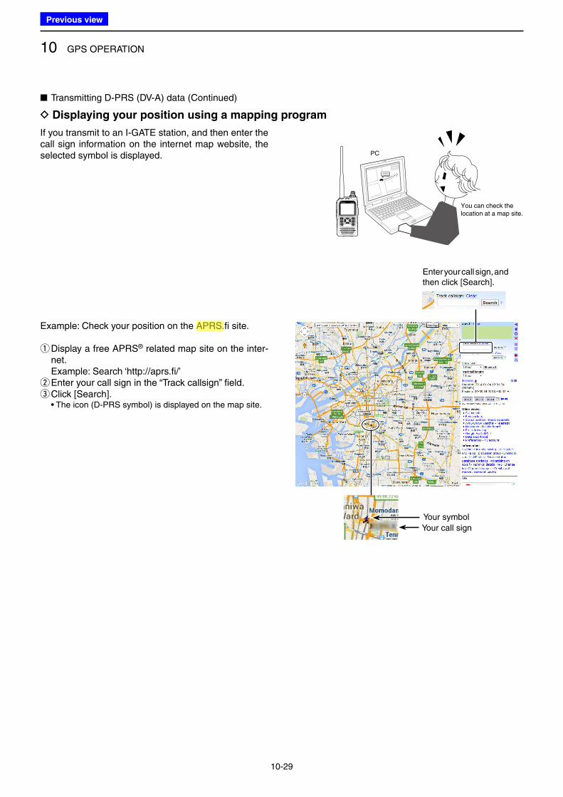
10 GPS OPERATION
10-29
D Displaying your position using a mapping program
If you transmit to an I-GATE station, and then enter the call sign information on the internet map website, the selected symbol is displayed.
■ Transmitting D-PRS (DV-A) data (Continued)
Example: Check your position on the APRS.fi site.
q Display a free APRS® related map site on the inter-net.
Example: Search ‘http://aprs.fi/’ wEnter your call sign in the “Track callsign” field. eClick [Search].
• The icon (D-PRS symbol) is displayed on the map site.
You can check the location at a map site.
PC
Your symbol
Your call sign
Enter your call sign, and then click [Search].
Previous view
Icom
ハイライト表示
(Automatic Packet Reporting System) APRS is a two-way tactical real-time digital communications system between all assets in a network sharing information about everything going on in the local area.
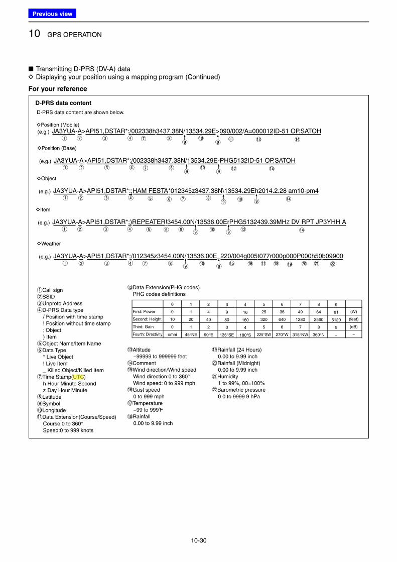
10 GPS OPERATION
10-30
■ Transmitting D-PRS (DV-A) data D Displaying your position using a mapping program (Continued)
D-PRS data content
D-PRS data content are shown below.
DPosition (Mobile)
(e.g.)
(e.g.)
DPosition (Base)
(e.g.)
DObject
(e.g.)
DItem
(e.g.)
DWeather
q w e ro
iuo
!1 !3 !4!0
!0
JA3YUA-A>API51,DSTAR*:/002338h3437.38N/13534.29E>090/002/A=000012ID-51 OP.SATOH
q w e ro
i
i
u
u
u
o!2
!2
!4!0
JA3YUA-A>API51,DSTAR*:/002338h3437.38N/13534.29E-PHG5132ID-51 OP.SATOH
q w e royt
o!4
JA3YUA-A>API51,DSTAR*:;HAM FESTA*012345z3437.38N\13534.29Eh2014.2.28 am10-pm4
!0iq w e royt
o !4
JA3YUA-A>API51,DSTAR*:)REPEATER!3454.00N/13536.00ErPHG5132439.39MHz DV RPT JP3YHH A
!5 !6 !7 !8 !9 @0 @1 @2!0iq w e roo
JA3YUA-A>API51,DSTAR*:/012345z3454.00N/13536.00E_220/004g005t077r000p000P000h50b09900
qCall sign
wSSID
eUnproto Address
rD-PRS Data type
/ Position with time stamp
! Position without time stamp
; Object
) Item
tObject Name/Item Name
yData Type
* Live Object
! Live Item
_ Killed Object/Killed Item
uTime Stamp(UTC)
h Hour Minute Second
z Day Hour Minute
iLatitude
oSymbol
!0Longitude
!1Data Extension(Course/Speed)
Course:0 to 360°
Speed:0 to 999 knots
!2Data Extension(PHG codes) PHG codes definitions
!3Altitude
−99999 to 999999 feet
!4Comment
!5Wind direction/Wind speed
Wind direction:0 to 360°
Wind speed: 0 to 999 mph
!6Gust speed
0 to 999 mph
!7Temperature
−99 to 999ƒ
!8Rainfall
0.00 to 9.99 inch
!9Rainfall (24 Hours)
0.00 to 9.99 inch
@0Rainfall (Midnight)
0.00 to 9.99 inch
@1Humidity
1 to 99%, 00=100%
@2Barometric pressure
0.0 to 9999.9 hPa
First: Power
Second: Height
Third: Gain
Fourth: Directivity
0
0
10
0
omni
2
4
40
2
90°E
3
9
80
3
135°SE
4
16
160
4
180°S
5
25
320
5
225°SW
6
36
640
6
270°W
7
49
1280
7
315°NW
8
64
2560
8
360°N
9
81
5120
9
−
(W)
(feet)
(dB)
−
1
1
20
1
45°NE
For your reference
Previous view
Icom
ハイライト表示
(Universal Time Coordinated) An astronomical time based on the Greenwich meridian (zero degrees longitude).
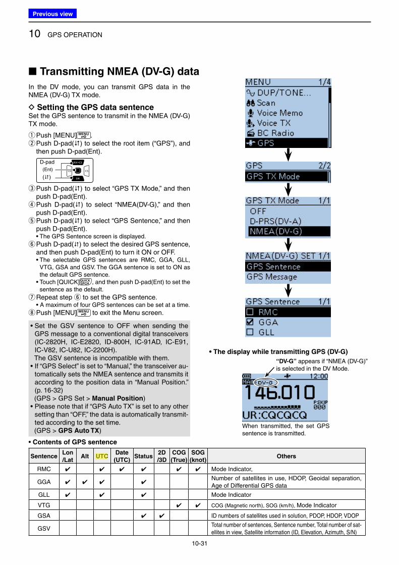
10 GPS OPERATION
10-31
In the DV mode, you can transmit GPS data in the NMEA (DV-G) TX mode.
D Setting the GPS data sentenceSet the GPS sentence to transmit in the NMEA (DV-G) TX mode.
qPush [MENU] . w Push D-pad() to select the root item (“GPS”), and then push D-pad(Ent).
D-pad
(�)
(Ent)
e Push D-pad() to select “GPS TX Mode,” and then push D-pad(Ent). r Push D-pad() to select “NMEA(DV-G),” and then push D-pad(Ent). t Push D-pad() to select “GPS Sentence,” and then push D-pad(Ent).
• The GPS Sentence screen is displayed.
y Push D-pad() to select the desired GPS sentence, and then push D-pad(Ent) to turn it ON or OFF.
• The selectable GPS sentences are RMC, GGA, GLL, VTG, GSA and GSV. The GGA sentence is set to ON as the default GPS sentence.
• Touch [QUICK] , and then push D-pad(Ent) to set the sentence as the default.
uRepeat step y to set the GPS sentence. • A maximum of four GPS sentences can be set at a time.
i Push [MENU] to exit the Menu screen.
SentenceLon
/LatAlt UTC
Date
(UTC)Status
2D
/3D
COG
(True)
SOG
(knot)Others
RMC ✔ ✔ ✔ ✔ ✔ ✔ Mode Indicator,
GGA ✔ ✔ ✔ ✔Number of satellites in use, HDOP, Geoidal separation, Age of Differential GPS data
GLL ✔ ✔ ✔ Mode Indicator
VTG ✔ ✔ COG (Magnetic north), SOG (km/h), Mode Indicator
GSA ✔ ✔ ID numbers of satellites used in solution, PDOP, HDOP, VDOP
GSVTotal number of sentences, Sentence number, Total number of sat-ellites in view, Satellite information (ID, Elevation, Azimuth, S/N)
• Contents of GPS sentence
■ Transmitting NMEA (DV-G) data
• Set the GSV sentence to OFF when sending the GPS message to a conventional digital transceivers (IC-2820H, IC-E2820, ID-800H, IC-91AD, IC-E91, IC-V82, IC-U82, IC-2200H).
The GSV sentence is incompatible with them.• If “GPS Select” is set to “Manual,” the transceiver au-
tomatically sets the NMEA sentence and transmits it according to the position data in “Manual Position.” (p. 16-32)
(GPS > GPS Set > Manual Position)• Please note that if “GPS Auto TX” is set to any other
setting than “OFF,” the data is automatically transmit-ted according to the set time.
(GPS > GPS Auto TX)
• The display while transmitting GPS (DV-G)
When transmitted, the set GPS sentence is transmitted.
“DV-G” appears if “NMEA (DV-G)” is selected in the DV Mode.
Previous view
Icom
ハイライト表示
(Universal Time Coordinated) An astronomical time based on the Greenwich meridian (zero degrees longitude).
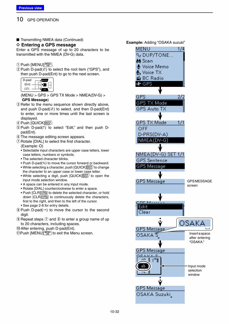
10 GPS OPERATION
10-32
■ Transmitting NMEA data (Continued)
D Entering a GPS messageEnter a GPS message of up to 20 characters to be transmitted with the NMEA (DV-G) data.
qPush [MENU] . w Push D-pad() to select the root item (“GPS”), and then push D-pad(Ent) to go to the next screen.
D-pad
(�)
(Ent)
( MENU > GPS > GPS TX Mode > NMEA(DV-G) > GPS Message)
e Refer to the menu sequence shown directly above, and push D-pad() to select, and then D-pad(Ent) to enter, one or more times until the last screen is displayed. rPush [QUICK] . t Push D-pad() to select “Edit,” and then push D-pad(Ent). yThe message editing screen appears. uRotate [DIAL] to select the first character.
(Example: O) • Selectable input characters are upper case letters, lower
case letters, numbers or symbols. • The selected character blinks. • Push D-pad() to move the cursor forward or backward. • While selecting a character, push [QUICK] to change
the character to an upper case or lower case letter. • While selecting a digit, push [QUICK] to open the
input mode selection window. • A space can be entered in any input mode. • Rotate [DIAL] counterclockwise to enter a space. • Push [CLR] to delete the selected character, or hold
down [CLR] to continuously delete the characters, first to the right, and then to the left of the cursor.
• See page 2-8 for entry details.
i Push D-pad() to move the cursor to the second digit. o Repeat steps u and i to enter a group name of up to 20 characters, including spaces.
!0 After entering, push D-pad(Ent).!1 Push [MENU] to exit the Menu screen.
GPS MESSAGE screen
Input modeselectionwindow
Example: Adding “OSAKA suzuki”
Insert a space after entering “OSAKA.”
Previous view
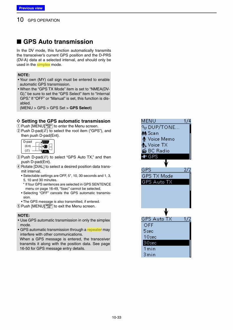
10 GPS OPERATION
10-33
In the DV mode, this function automatically transmits the transceiver’s current GPS position and the D-PRS (DV-A) data at a selected interval, and should only be used in the simplex mode.
NOTE:
• Your own (MY) call sign must be entered to enable automatic GPS transmission.
• When the “GPS TX Mode” item is set to “NMEA(DV-G),” be sure to set the “GPS Select” item to “Internal GPS.” If “OFF” or “Manual” is set, this function is dis-abled.
(MENU > GPS > GPS Set > GPS Select)
D Setting the GPS automatic transmission qPush [MENU] to enter the Menu screen. w Push D-pad() to select the root item (“GPS”), and then push D-pad(Ent).
D-pad
(�)
(Ent)
e Push D-pad() to select “GPS Auto TX,” and then push D-pad(Ent). r Rotate [DIAL] to select a desired position data trans-mit interval.
• Selectable settings are OFF, 5*, 10, 30 seconds and 1, 3, 5, 10 and 30 minutes.
* If four GPS sentences are selected in GPS SENTENCE menu on page 16-49, “5sec” cannot be selected.
• Selecting “OFF” cancels the GPS automatic transmis-sion.
• The GPS message is also transmitted, if entered.
tPush [MENU] to exit the Menu screen.
■ GPS Auto transmission
NOTE:
• Use GPS automatic transmission in only the simplex mode.
• GPS automatic transmission through a repeater may interfere with other communications.
When a GPS message is entered, the transceiver transmits it along with the position data. See page 16-50 for GPS message entry details.
Previous view
Icom
ハイライト表示
An operating mode in which the transmit and receive frequencies are the same.
Icom
ハイライト表示
Radio systems that receive incoming signals and retransmit them to extend the communication area. Normally put on geographically high locations for VHF/UHF radios.
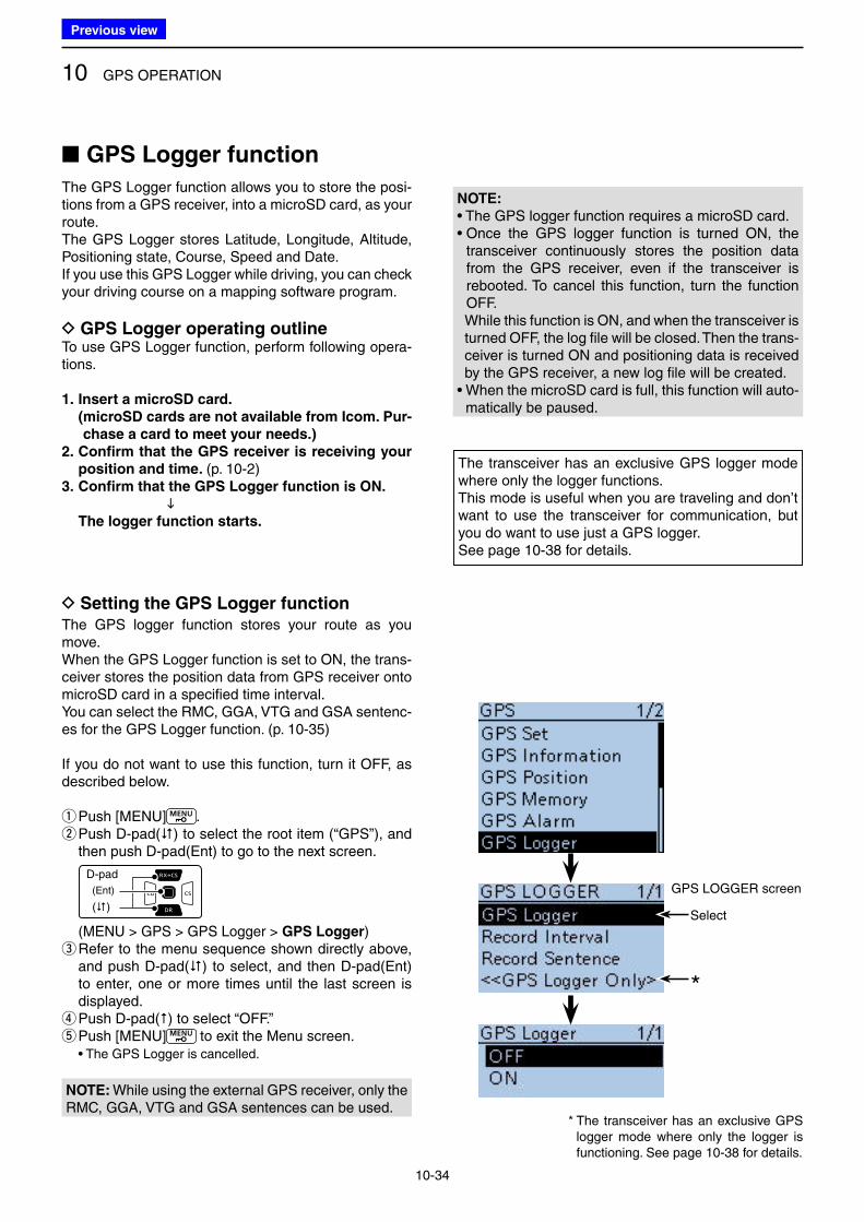
10 GPS OPERATION
10-34
■ GPS Logger function
The GPS Logger function allows you to store the posi-tions from a GPS receiver, into a microSD card, as your route.The GPS Logger stores Latitude, Longitude, Altitude, Positioning state, Course, Speed and Date.If you use this GPS Logger while driving, you can check your driving course on a mapping software program.
D GPS Logger operating outlineTo use GPS Logger function, perform following opera-tions.
1. Insert a microSD card.
( microSD cards are not available from Icom. Pur-
chase a card to meet your needs.)
2. Confirm that the GPS receiver is receiving your
position and time. (p. 10-2)3. Confirm that the GPS Logger function is ON.
The logger function starts.
NOTE:
• The GPS logger function requires a microSD card.• Once the GPS logger function is turned ON, the
transceiver continuously stores the position data from the GPS receiver, even if the transceiver is rebooted. To cancel this function, turn the function OFF.
While this function is ON, and when the transceiver is turned OFF, the log file will be closed. Then the trans-ceiver is turned ON and positioning data is received by the GPS receiver, a new log file will be created.
• When the microSD card is full, this function will auto-matically be paused.
The transceiver has an exclusive GPS logger mode where only the logger functions.This mode is useful when you are traveling and don’t want to use the transceiver for communication, but you do want to use just a GPS logger.See page 10-38 for details.
The GPS logger function stores your route as you move.When the GPS Logger function is set to ON, the trans-ceiver stores the position data from GPS receiver onto microSD card in a specified time interval. You can select the RMC, GGA, VTG and GSA sentenc-es for the GPS Logger function. (p. 10-35)
If you do not want to use this function, turn it OFF, as described below.
qPush [MENU] . w Push D-pad() to select the root item (“GPS”), and then push D-pad(Ent) to go to the next screen.
D-pad
(�)
(Ent)
(MENU > GPS > GPS Logger > GPS Logger) e Refer to the menu sequence shown directly above, and push D-pad() to select, and then D-pad(Ent) to enter, one or more times until the last screen is displayed. rPush D-pad() to select “OFF.” t Push [MENU] to exit the Menu screen.
• The GPS Logger is cancelled.
GPS LOGGER screen
* The transceiver has an exclusive GPS logger mode where only the logger is functioning. See page 10-38 for details.
Select
*
D Setting the GPS Logger function
NOTE: While using the external GPS receiver, only the RMC, GGA, VTG and GSA sentences can be used.
Previous view
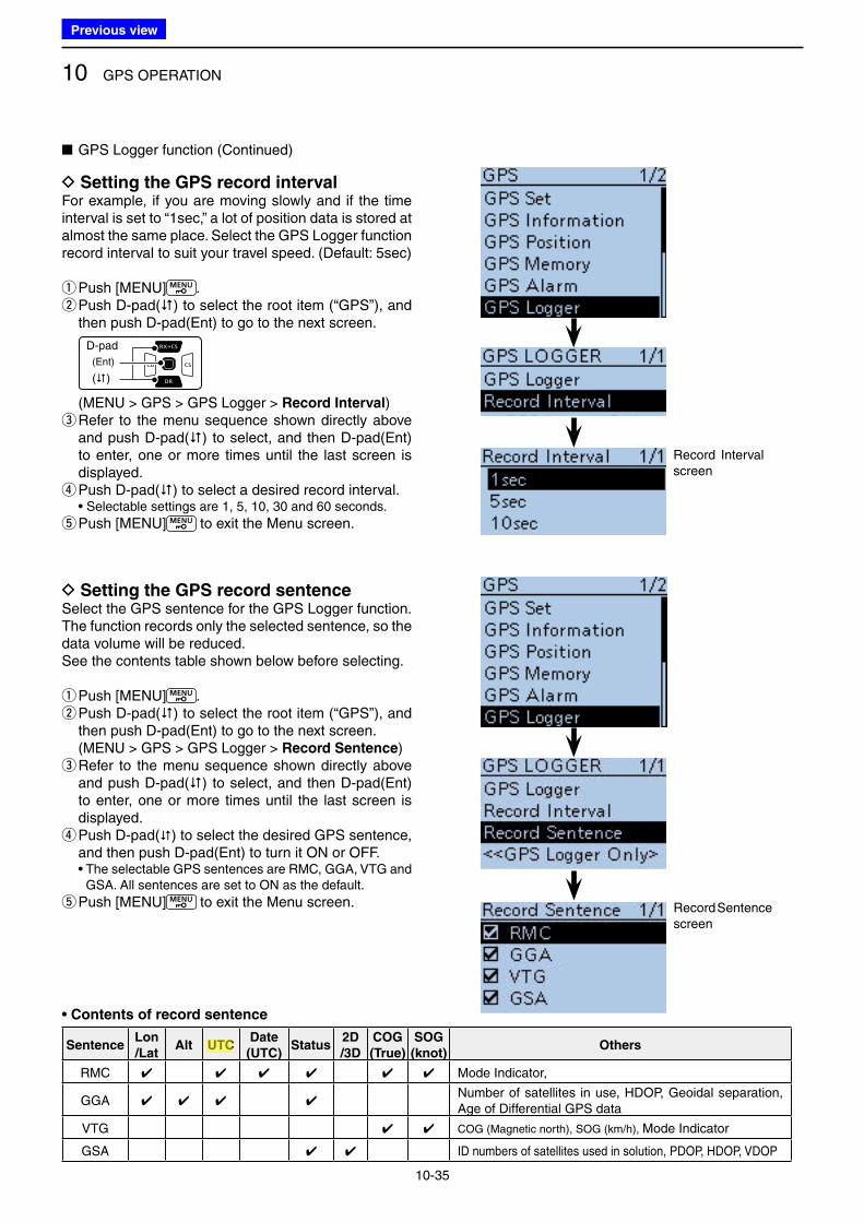
10 GPS OPERATION
10-35
D Setting the GPS record intervalFor example, if you are moving slowly and if the time interval is set to “1sec,” a lot of position data is stored at almost the same place. Select the GPS Logger function record interval to suit your travel speed. (Default: 5sec)
qPush [MENU] . w Push D-pad() to select the root item (“GPS”), and then push D-pad(Ent) to go to the next screen.
D-pad
(�)
(Ent)
(MENU > GPS > GPS Logger > Record Interval) e Refer to the menu sequence shown directly above and push D-pad() to select, and then D-pad(Ent) to enter, one or more times until the last screen is displayed. r Push D-pad() to select a desired record interval.
• Selectable settings are 1, 5, 10, 30 and 60 seconds.
t Push [MENU] to exit the Menu screen.
Record Interval screen
■ GPS Logger function (Continued)
D Setting the GPS record sentenceSelect the GPS sentence for the GPS Logger function.The function records only the selected sentence, so the data volume will be reduced.See the contents table shown below before selecting.
qPush [MENU] . w Push D-pad() to select the root item (“GPS”), and then push D-pad(Ent) to go to the next screen.
(MENU > GPS > GPS Logger > Record Sentence) e Refer to the menu sequence shown directly above and push D-pad() to select, and then D-pad(Ent) to enter, one or more times until the last screen is displayed. r Push D-pad() to select the desired GPS sentence, and then push D-pad(Ent) to turn it ON or OFF.
• The selectable GPS sentences are RMC, GGA, VTG and GSA. All sentences are set to ON as the default.
t Push [MENU] to exit the Menu screen. Record Sentence screen
SentenceLon
/LatAlt UTC
Date
(UTC)Status
2D
/3D
COG
(True)
SOG
(knot)Others
RMC ✔ ✔ ✔ ✔ ✔ ✔ Mode Indicator,
GGA ✔ ✔ ✔ ✔Number of satellites in use, HDOP, Geoidal separation, Age of Differential GPS data
VTG ✔ ✔ COG (Magnetic north), SOG (km/h), Mode Indicator
GSA ✔ ✔ ID numbers of satellites used in solution, PDOP, HDOP, VDOP
• Contents of record sentence
Previous view
Icom
ハイライト表示
(Universal Time Coordinated) An astronomical time based on the Greenwich meridian (zero degrees longitude).
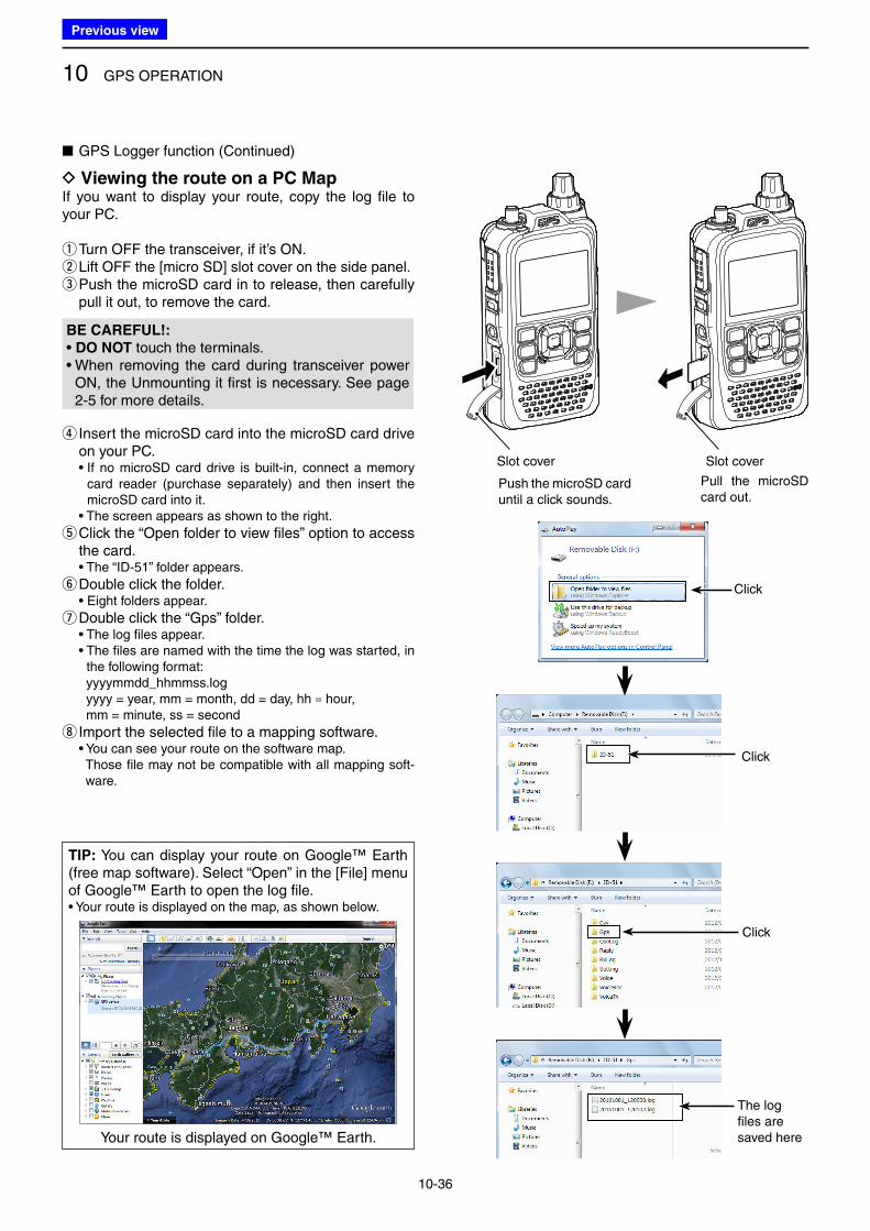
10 GPS OPERATION
10-36
D Viewing the route on a PC MapIf you want to display your route, copy the log file to your PC.
qTurn OFF the transceiver, if it’s ON. w Lift OFF the [micro SD] slot cover on the side panel. e Push the microSD card in to release, then carefully pull it out, to remove the card.
BE CAREFUL!:
• DO NOT touch the terminals.• When removing the card during transceiver power
ON, the Unmounting it first is necessary. See page 2-5 for more details.
r Insert the microSD card into the microSD card drive on your PC.
• If no microSD card drive is built-in, connect a memory card reader (purchase separately) and then insert the microSD card into it.
• The screen appears as shown to the right.
t Click the “Open folder to view files” option to access the card.
• The “ID-51” folder appears.
yDouble click the folder. • Eight folders appear.
uDouble click the “Gps” folder. • The log files appear. • The files are named with the time the log was started, in
the following format: yyyymmdd_hhmmss.log yyyy = year, mm = month, dd = day, hh = hour, mm = minute, ss = second
i Import the selected file to a mapping software. • You can see your route on the software map. Those file may not be compatible with all mapping soft-
ware.
Click
Click
Click
The log files are saved here
■ GPS Logger function (Continued)
Slot cover Slot cover
Push the microSD card until a click sounds.
Pull the microSD card out.
TIP: You can display your route on Google™ Earth (free map software). Select “Open” in the [File] menu of Google™ Earth to open the log file.• Your route is displayed on the map, as shown below.
Your route is displayed on Google™ Earth.
Previous view
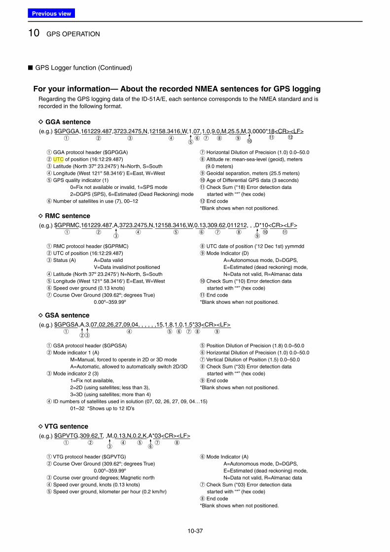
10 GPS OPERATION
10-37
q GGA protocol header ($GPGGA)
w UTC of position (16:12:29.487)
e Latitude (North 37º 23.2475′) N=North, S=South
r Longitude (West 121º 58.3416′) E=East, W=West
t GPS quality indicator (1)
0=Fix not available or invalid, 1=SPS mode
2=DGPS (SPS), 6=Estimated (Dead Reckoning) mode
y Number of satellites in use (7), 00–12
u Horizontal Dilution of Precision (1.0) 0.0–50.0
i Altitude re: mean-sea-level (geoid), meters
(9.0 meters)
o Geoidal separation, meters (25.5 meters)
!0 Age of Differential GPS data (3 seconds)
!1 Check Sum (*18) Error detection data
started with “*” (hex code)
!2 End code
*Blank shows when not positioned.
q w e r y i
For your information— About the recorded NMEA sentences for GPS logging
u o !1 !2t !0
D GGA sentence
(e.g.) $GPGGA,161229.487,3723.2475,N,12158.3416,W,1,07,1.0,9.0,M,25.5,M,3,0000*18<CR><LF>
q RMC protocol header ($GPRMC)
w UTC of position (16:12:29.487)
e Status (A) A=Data valid
V=Data invalid/not positioned
r Latitude (North 37º 23.2475′) N=North, S=South
t Longitude (West 121º 58.3416′) E=East, W=West
y Speed over ground (0.13 knots)
u Course Over Ground (309.62º; degrees True)
0.00º–359.99º
i UTC date of position (’12 Dec 1st) yymmdd
o Mode Indicator (D)
A=Autonomous mode, D=DGPS,
E=Estimated (dead reckoning) mode,
N=Data not valid, R=Almanac data
!0 Check Sum (*10) Error detection data
started with “*” (hex code)
!1 End code
*Blank shows when not positioned.
y Mode Indicator (A)
A=Autonomous mode, D=DGPS,
E=Estimated (dead reckoning) mode,
N=Data not valid, R=Almanac data
u Check Sum (*03) Error detection data
started with “*” (hex code)
i End code
*Blank shows when not positioned.
q w r t y iu !0 !1e o
D RMC sentence
(e.g.) $GPRMC,161229.487,A,3723.2475,N,12158.3416,W,0.13,309.62,011212, , ,D*10<CR><LF>
q VTG protocol header ($GPVTG)
w Course Over Ground (309.62º; degrees True)
0.00º–359.99º
e Course over ground degrees; Magnetic north
r Speed over ground, knots (0.13 knots)
t Speed over ground, kilometer per hour (0.2 km/hr)
q w
D VTG sentence
(e.g.) $GPVTG,309.62,T, ,M,0.13,N,0.2,K,A*03<CR><LF>
q GSA protocol header ($GPGSA)
w Mode indicator 1 (A)
M=Manual, forced to operate in 2D or 3D mode
A=Automatic, allowed to automatically switch 2D/3D
e Mode indicator 2 (3)
1=Fix not available,
2=2D (using satellites; less than 3),
3=3D (using satellites; more than 4)
r ID numbers of satellites used in solution (07, 02, 26, 27, 09, 04…15)
01–32 *Shows up to 12 ID’s
t Position Dilution of Precision (1.8) 0.0–50.0
y Horizontal Dilution of Precision (1.0) 0.0–50.0
u Vertical Dilution of Position (1.5) 0.0–50.0
i Check Sum (*33) Error detection data
started with “*” (hex code)
o End code
*Blank shows when not positioned.
q r t y u i owe
D GSA sentence
(e.g.) $GPGSA,A,3,07,02,26,27,09,04, , , , , ,15,1.8,1.0,1.5*33<CR><LF>
u ir tye
Regarding the GPS logging data of the ID-51A/E, each sentence corresponds to the NMEA standard and is recorded in the following format.
■ GPS Logger function (Continued)
Previous view
Icom
ハイライト表示
(Universal Time Coordinated) An astronomical time based on the Greenwich meridian (zero degrees longitude).
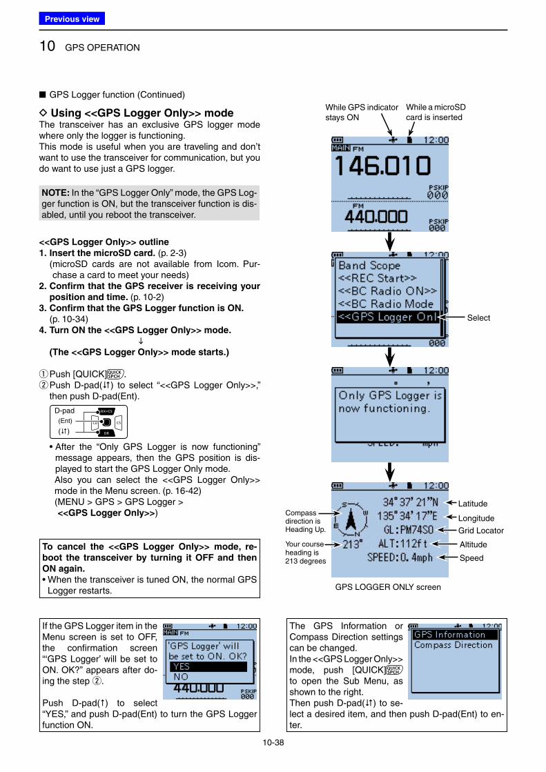
10 GPS OPERATION
10-38
D Using <<GPS Logger Only>> modeThe transceiver has an exclusive GPS logger mode where only the logger is functioning.This mode is useful when you are traveling and don’t want to use the transceiver for communication, but you do want to use just a GPS logger.
NOTE: In the “GPS Logger Only” mode, the GPS Log-ger function is ON, but the transceiver function is dis-abled, until you reboot the transceiver.
<<GPS Logger Only>> outline
1. Insert the microSD card. (p. 2-3) ( microSD cards are not available from Icom. Pur-
chase a card to meet your needs)2. Confirm that the GPS receiver is receiving your
position and time. (p. 10-2)3. Confirm that the GPS Logger function is ON.
(p. 10-34)4. Turn ON the <<GPS Logger Only>> mode.
(The <<GPS Logger Only>> mode starts.)
qPush [QUICK] . w Push D-pad() to select “<<GPS Logger Only>>,” then push D-pad(Ent).
D-pad
(�)
(Ent)
• After the “Only GPS Logger is now functioning” message appears, then the GPS position is dis-played to start the GPS Logger Only mode.
Also you can select the <<GPS Logger Only>> mode in the Menu screen. (p. 16-42)
( MENU > GPS > GPS Logger > <<GPS Logger Only>>)
To cancel the <<GPS Logger Only>> mode, re-
boot the transceiver by turning it OFF and then
ON again.
• When the transceiver is tuned ON, the normal GPS Logger restarts.
If the GPS Logger item in the Menu screen is set to OFF, the confirmation screen “‘GPS Logger’ will be set to ON. OK?” appears after do-ing the step w.
Push D-pad() to select “YES,” and push D-pad(Ent) to turn the GPS Logger function ON.
The GPS Information or Compass Direction settings can be changed.In the <<GPS Logger Only>> mode, push [QUICK] to open the Sub Menu, as shown to the right.Then push D-pad() to se-lect a desired item, and then push D-pad(Ent) to en-ter.
GPS LOGGER ONLY screen
■ GPS Logger function (Continued)
While a microSD card is inserted
While GPS indicator stays ON
Select
Speed
Altitude
Latitude
Longitude
Grid Locator
Your course heading is 213 degrees
Compass direction is Heading Up.
Previous view
11-1
Section 11 VOICE MEMORY FUNCTION
■ Recording a QSO audio ................................................... 11-2
D To start recording ......................................................... 11-2
D To stop recording .......................................................... 11-3
■ Playing back the recorded audio ...................................... 11-4
■ Operations while playing back .......................................... 11-5
D Fast-forward while playing ............................................ 11-5
D Rewind while playing .................................................... 11-5
D Pause while playing ...................................................... 11-5
D Playing the previously file ............................................. 11-5
D Playing the next file ...................................................... 11-5
D Pause at the beginning of the previously file
(Fast forward the file) .................................................... 11-5
D Pause at the beginning of the next file
(Rewind the file) ........................................................... 11-5
■ VOICE PLAYER screen’s description ............................... 11-6
■ Changing the skip time ..................................................... 11-7
■ Deleting the recorded contents (audio) ............................ 11-8
■ Deleting the folder ............................................................ 11-9
■ Changing the recording mode ........................................ 11-10
■ Continue to record even if no signals are received ......... 11-11
■ Record the transmit and receive audio into
the same file ................................................................... 11-12
■ Start to record when the [PTT] switch is pushed ................. 11-13
■ Viewing the file information ............................................. 11-14
■ Viewing the folder information ........................................ 11-15
■ Voice Recorder function ................................................. 11-16
D To start recording ....................................................... 11-16
D Playing back the recorded audio ................................ 11-17
D Erasing the recorded audio contents .......................... 11-18
D MIC Gain setting ......................................................... 11-19
D Changing the skip time ............................................... 11-20
D Viewing the file information ........................................ 11-21
■ Viewing the microSD card’s free space and
recordable time ............................................................... 11-22
■ Playing back the voice memory data on a PC ................. 11-23
Previous view
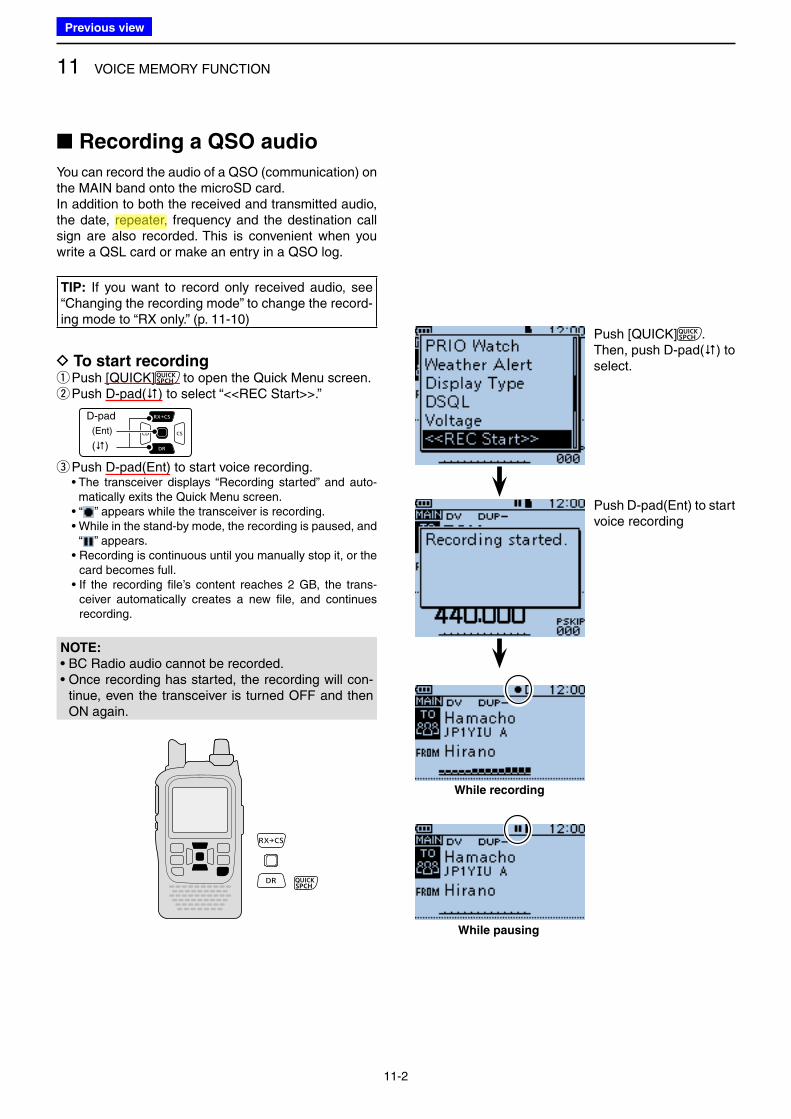
11 VOICE MEMORY FUNCTION
11-2
■ Recording a QSO audio
You can record the audio of a QSO (communication) on the MAIN band onto the microSD card.In addition to both the received and transmitted audio, the date, repeater, frequency and the destination call sign are also recorded. This is convenient when you write a QSL card or make an entry in a QSO log.
TIP: If you want to record only received audio, see “Changing the recording mode” to change the record-ing mode to “RX only.” (p. 11-10)
D To start recording q Push [QUICK] to open the Quick Menu screen. w Push D-pad() to select “<<REC Start>>.”
D-pad
(�)
(Ent)
e Push D-pad(Ent) to start voice recording. • The transceiver displays “Recording started” and auto-
matically exits the Quick Menu screen. • “ ” appears while the transceiver is recording. • While in the stand-by mode, the recording is paused, and
“ ” appears. • Recording is continuous until you manually stop it, or the
card becomes full. • If the recording file’s content reaches 2 GB, the trans-
ceiver automatically creates a new file, and continues recording.
While recording
While pausing
Push [QUICK] .Then, push D-pad() to select.
Push D-pad(Ent) to start voice recording
NOTE:
• BC Radio audio cannot be recorded.• Once recording has started, the recording will con-
tinue, even the transceiver is turned OFF and then ON again.
Previous view
Icom
ハイライト表示
Radio systems that receive incoming signals and retransmit them to extend the communication area. Normally put on geographically high locations for VHF/UHF radios.
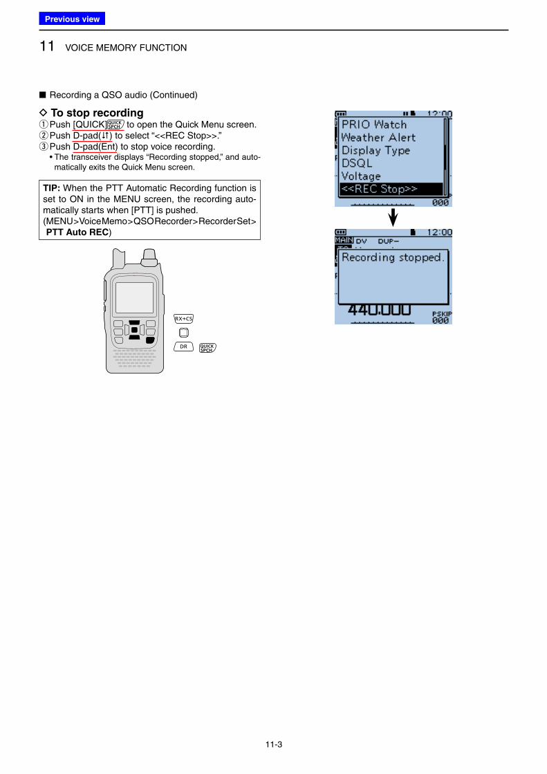
11 VOICE MEMORY FUNCTION
11-3
■ Recording a QSO audio (Continued)
D To stop recording q Push [QUICK] to open the Quick Menu screen. w Push D-pad() to select “<<REC Stop>>.” e Push D-pad(Ent) to stop voice recording.
• The transceiver displays “Recording stopped,” and auto-matically exits the Quick Menu screen.
TIP: When the PTT Automatic Recording function is set to ON in the MENU screen, the recording auto-matically starts when [PTT] is pushed.( MENU > Voice Memo > QSO Recorder > Recorder Set > PTT Auto REC)
Previous view
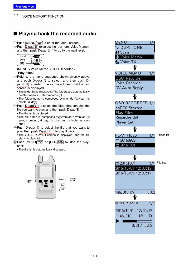
11 VOICE MEMORY FUNCTION
11-4
■ Playing back the recorded audio
q Push [MENU] to enter the Menu screen. w Push D-pad() to select the root item (Voice Memo), and then push D-pad(Ent) to go to the next level.
D-pad
(�)
(Ent)
( MENU > Voice Memo > QSO Recorder > Play Files)
e Refer to the menu sequence shown directly above and push D-pad() to select, and then push D-pad(Ent) to enter, one or more times until the last screen is displayed.
• The folder list is displayed. (The folders are automatically created when you start recording.)
• The folder name is composed yyyymmdd (y: year, m: month, d: day.)
r Push D-pad() to select the folder that contains the file you want to play, and then push D-pad(Ent).
• The file list is displayed. • The file name is composed yyyy/mm/dd hh:mm:ss (y:
year, m: month, d: day, hh: hour, mm: minute, ss: sec-ond.)
t Push D-pad() to select the file that you want to play, then push D-pad(Ent) to play it back.
• The VOICE PLAYER screen is displayed, and the file starts to playback.
y Push [MENU] or [CLR] to stop the play-back.
• The file list is automatically displayed.
Folder list
File list
Previous view
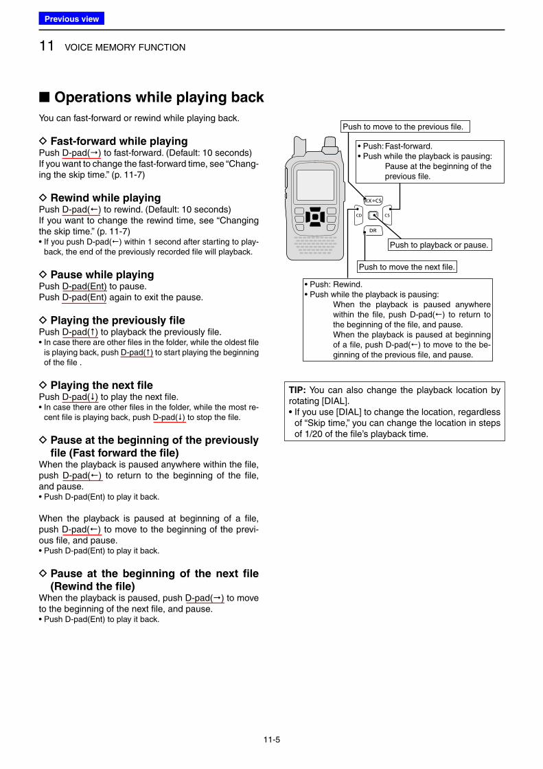
11 VOICE MEMORY FUNCTION
11-5
You can fast-forward or rewind while playing back.
D Fast-forward while playingPush D-pad() to fast-forward. (Default: 10 seconds)If you want to change the fast-forward time, see “Chang-ing the skip time.” (p. 11-7)
D Rewind while playingPush D-pad() to rewind. (Default: 10 seconds)If you want to change the rewind time, see “Changing the skip time.” (p. 11-7)• If you push D-pad() within 1 second after starting to play-
back, the end of the previously recorded file will playback.
D Pause while playingPush D-pad(Ent) to pause.Push D-pad(Ent) again to exit the pause.
D Playing the previously filePush D-pad() to playback the previously file.• In case there are other files in the folder, while the oldest file
is playing back, push D-pad() to start playing the beginning of the file .
D Playing the next filePush D-pad() to play the next file.• In case there are other files in the folder, while the most re-
cent file is playing back, push D-pad() to stop the file.
D Pause at the beginning of the previously file (Fast forward the file)
When the playback is paused anywhere within the file, push D-pad() to return to the beginning of the file, and pause.• Push D-pad(Ent) to play it back.
When the playback is paused at beginning of a file, push D-pad() to move to the beginning of the previ-ous file, and pause.• Push D-pad(Ent) to play it back.
D Pause at the beginning of the next file (Rewind the file)
When the playback is paused, push D-pad() to move to the beginning of the next file, and pause.• Push D-pad(Ent) to play it back.
TIP: You can also change the playback location by rotating [DIAL].• If you use [DIAL] to change the location, regardless
of “Skip time,” you can change the location in steps of 1/20 of the file’s playback time.
Push to move to the previous file.
• Push: Fast-forward.• Push while the playback is pausing: Pause at the beginning of the
previous file.
• Push: Rewind.• Push while the playback is pausing: When the playback is paused anywhere
within the file, push D-pad() to return to the beginning of the file, and pause.
When the playback is paused at beginning of a file, push D-pad() to move to the be-ginning of the previous file, and pause.
Push to playback or pause.
Push to move the next file.
■ Operations while playing back
Previous view
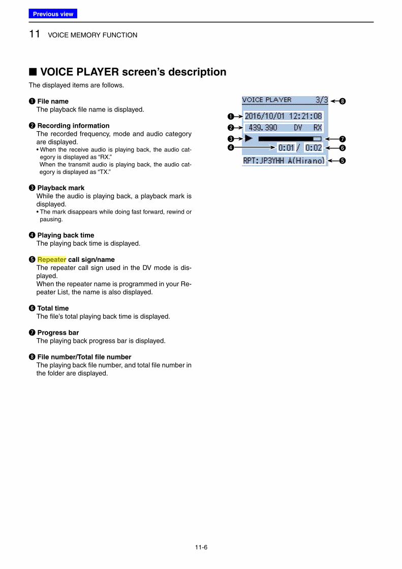
11 VOICE MEMORY FUNCTION
11-6
The displayed items are follows.
q File name
The playback file name is displayed.
w Recording information
The recorded frequency, mode and audio category are displayed.
• When the receive audio is playing back, the audio cat-egory is displayed as “RX.”
When the transmit audio is playing back, the audio cat-egory is displayed as “TX.”
e Playback mark
While the audio is playing back, a playback mark is displayed.
• The mark disappears while doing fast forward, rewind or pausing.
r Playing back time
The playing back time is displayed.
t Repeater call sign/name
The repeater call sign used in the DV mode is dis-played.
When the repeater name is programmed in your Re-peater List, the name is also displayed.
y Total time
The file’s total playing back time is displayed.
u Progress bar
The playing back progress bar is displayed.
i File number/Total file number
The playing back file number, and total file number in the folder are displayed.
■ VOICE PLAYER screen’s description
q
w
e u
i
yr
t
Previous view
Icom
ハイライト表示
Radio systems that receive incoming signals and retransmit them to extend the communication area. Normally put on geographically high locations for VHF/UHF radios.
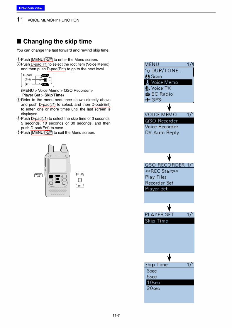
11 VOICE MEMORY FUNCTION
11-7
■ Changing the skip time
You can change the fast forward and rewind skip time.
qPush [MENU] to enter the Menu screen. w Push D-pad() to select the root item (Voice Memo), and then push D-pad(Ent) to go to the next level.
D-pad
(�)
(Ent)
( MENU > Voice Memo > QSO Recorder > Player Set > Skip Time)
e Refer to the menu sequence shown directly above and push D-pad() to select, and then D-pad(Ent) to enter, one or more times until the last screen is displayed. r Push D-pad() to select the skip time of 3 seconds, 5 seconds, 10 seconds or 30 seconds, and then push D-pad(Ent) to save. t Push [MENU] to exit the Menu screen.
Previous view
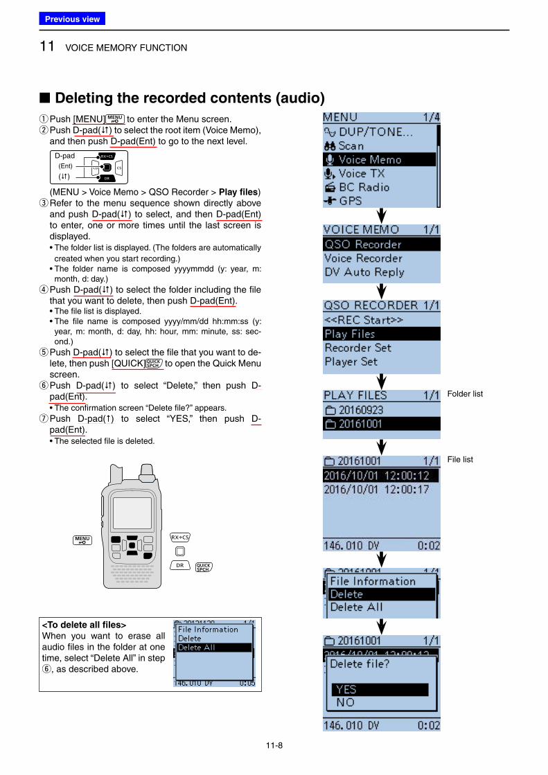
11 VOICE MEMORY FUNCTION
11-8
qPush [MENU] to enter the Menu screen. w Push D-pad() to select the root item (Voice Memo), and then push D-pad(Ent) to go to the next level.
D-pad
(�)
(Ent)
( MENU > Voice Memo > QSO Recorder > Play files) e Refer to the menu sequence shown directly above and push D-pad() to select, and then D-pad(Ent) to enter, one or more times until the last screen is displayed.
• The folder list is displayed. (The folders are automatically
created when you start recording.) • The folder name is composed yyyymmdd (y: year, m:
month, d: day.)
r Push D-pad() to select the folder including the file that you want to delete, then push D-pad(Ent).
• The file list is displayed. • The file name is composed yyyy/mm/dd hh:mm:ss (y:
year, m: month, d: day, hh: hour, mm: minute, ss: sec-ond.)
t Push D-pad() to select the file that you want to de-lete, then push [QUICK] to open the Quick Menu screen. y Push D-pad() to select “Delete,” then push D-pad(Ent).
• The confirmation screen “Delete file?” appears.
u Push D-pad() to select “YES,” then push D-pad(Ent).
• The selected file is deleted.
<To delete all files>
When you want to erase all audio files in the folder at one time, select “Delete All” in step y, as described above.
■ Deleting the recorded contents (audio)
Folder list
File list
Previous view
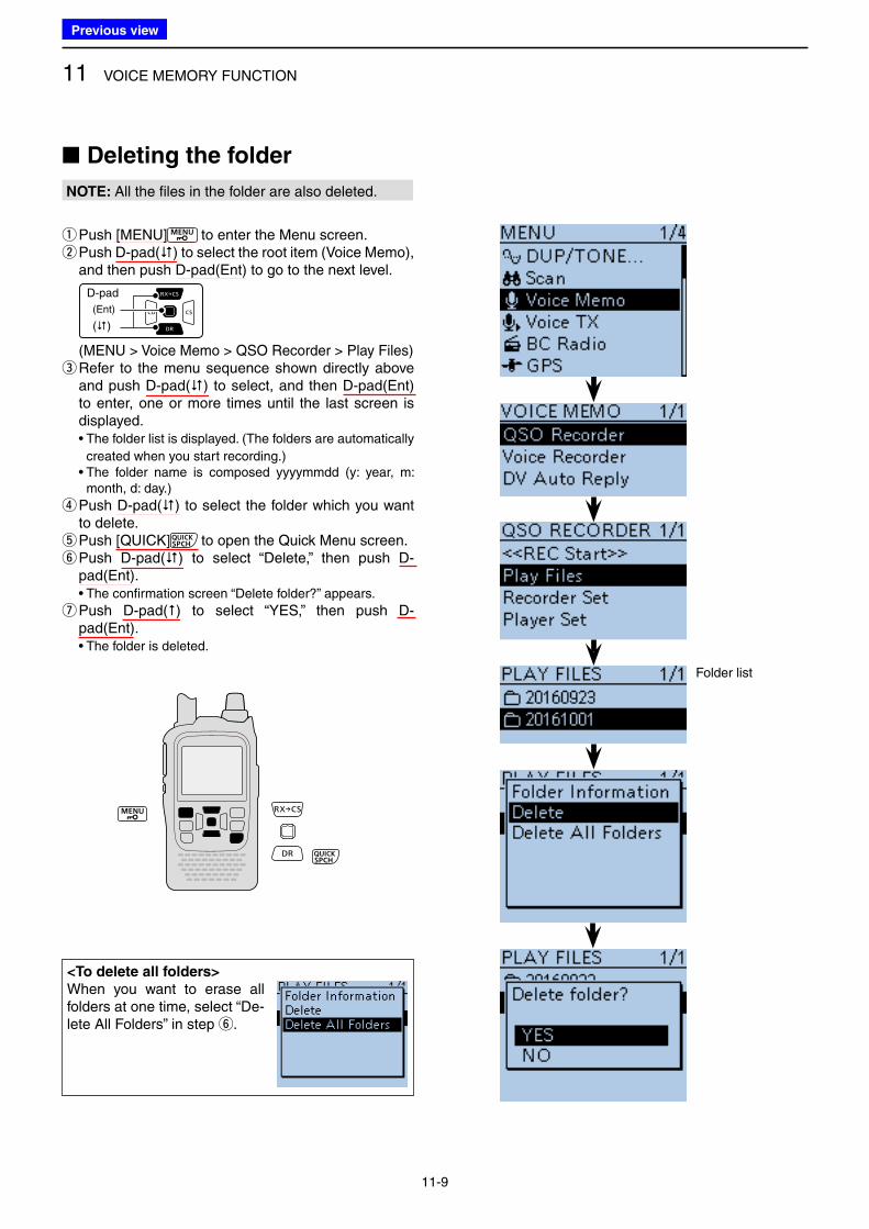
11 VOICE MEMORY FUNCTION
11-9
■ Deleting the folder
NOTE: All the files in the folder are also deleted.
qPush [MENU] to enter the Menu screen. w Push D-pad() to select the root item (Voice Memo), and then push D-pad(Ent) to go to the next level.
D-pad
(�)
(Ent)
( MENU > Voice Memo > QSO Recorder > Play Files) e Refer to the menu sequence shown directly above and push D-pad() to select, and then D-pad(Ent) to enter, one or more times until the last screen is displayed.
• The folder list is displayed. (The folders are automatically
created when you start recording.) • The folder name is composed yyyymmdd (y: year, m:
month, d: day.)
r Push D-pad() to select the folder which you want to delete. t Push [QUICK] to open the Quick Menu screen. y Push D-pad() to select “Delete,” then push D-pad(Ent).
• The confirmation screen “Delete folder?” appears.
u Push D-pad() to select “YES,” then push D-pad(Ent).
• The folder is deleted.
<To delete all folders>
When you want to erase all folders at one time, select “De-lete All Folders” in step y.
Folder list
Previous view
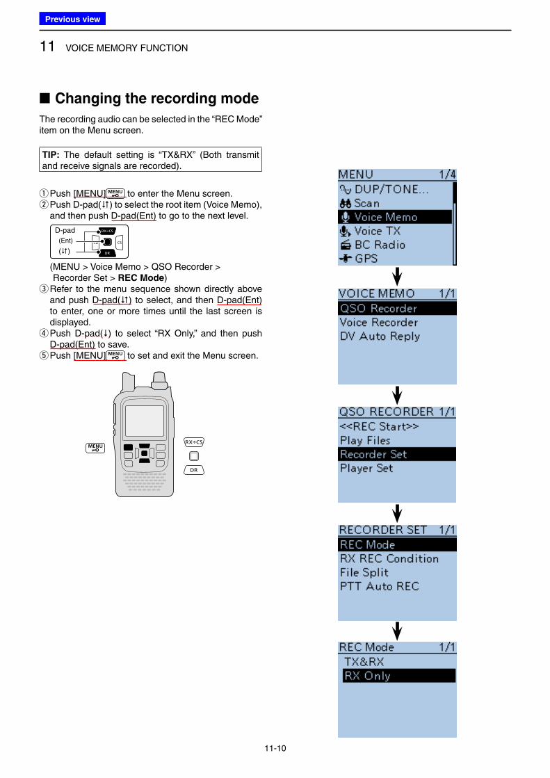
11 VOICE MEMORY FUNCTION
11-10
■ Changing the recording mode
The recording audio can be selected in the “REC Mode” item on the Menu screen.
TIP: The default setting is “TX&RX” (Both transmit and receive signals are recorded).
qPush [MENU] to enter the Menu screen. w Push D-pad() to select the root item (Voice Memo), and then push D-pad(Ent) to go to the next level.
D-pad
(�)
(Ent)
( MENU > Voice Memo > QSO Recorder > Recorder Set > REC Mode)
e Refer to the menu sequence shown directly above and push D-pad() to select, and then D-pad(Ent) to enter, one or more times until the last screen is displayed. r Push D-pad() to select “RX Only,” and then push D-pad(Ent) to save. t Push [MENU] to set and exit the Menu screen.
Previous view
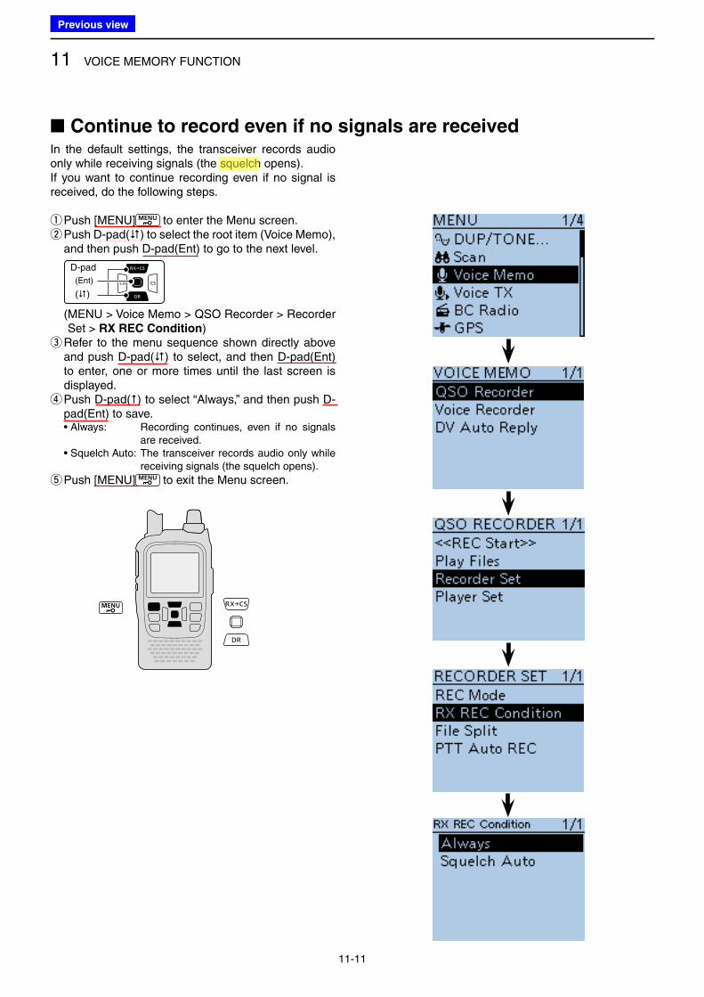
11 VOICE MEMORY FUNCTION
11-11
In the default settings, the transceiver records audio only while receiving signals (the squelch opens).If you want to continue recording even if no signal is received, do the following steps.
qPush [MENU] to enter the Menu screen. w Push D-pad() to select the root item (Voice Memo), and then push D-pad(Ent) to go to the next level.
D-pad
(�)
(Ent)
( MENU > Voice Memo > QSO Recorder > Recorder Set > RX REC Condition)
e Refer to the menu sequence shown directly above and push D-pad() to select, and then D-pad(Ent) to enter, one or more times until the last screen is displayed. r Push D-pad() to select “Always,” and then push D-pad(Ent) to save.
• Always: Recording continues, even if no signals are received.
• Squelch Auto: The transceiver records audio only while receiving signals (the squelch opens).
t Push [MENU] to exit the Menu screen.
■ Continue to record even if no signals are received
Previous view
Icom
ハイライト表示
A function that mutes the audio output for certain signal levels.
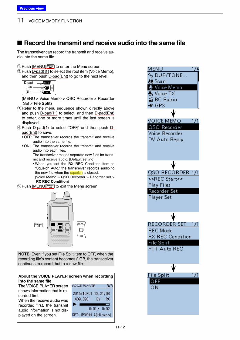
11 VOICE MEMORY FUNCTION
11-12
The transceiver can record the transmit and receive au-dio into the same file.
qPush [MENU] to enter the Menu screen. w Push D-pad() to select the root item (Voice Memo), and then push D-pad(Ent) to go to the next level.
D-pad
(�)
(Ent)
( MENU > Voice Memo > QSO Recorder > Recorder Set > File Split)
e Refer to the menu sequence shown directly above and push D-pad() to select, and then D-pad(Ent) to enter, one or more times until the last screen is displayed. r Push D-pad() to select “OFF,” and then push D-pad(Ent) to save.
• OFF: The transceiver records the transmit and receive audio into the same file.
• ON: The transceiver records the transmit and receive audio into each files.
The transceiver makes separate new files for trans-mit and receive audio. (Default setting)
• When you set the RX REC Condition item to “Squelch Auto,” the transceiver records audio to the new file when the squelch is closed.
( Voice Memo > QSO Recorder > Recorder set > RX REC Condition)
t Push [MENU] to exit the Menu screen.
NOTE: Even if you set File Split item to OFF, when the recording file’s content becomes 2 GB, the transceiver continues to record, but to a new file.
■ Record the transmit and receive audio into the same file
About the VOICE PLAYER screen when recording
into the same file
The VOICE PLAYER screen shows information that is re-corded first.When the receive audio was recorded first, the transmit audio information is not dis-played on the screen.
Previous view
Icom
ハイライト表示
A function that mutes the audio output for certain signal levels.
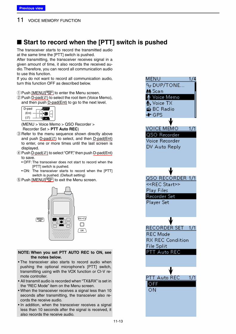
11 VOICE MEMORY FUNCTION
11-13
The transceiver starts to record the transmitted audio at the same time the [PTT] switch is pushed.After transmitting, the transceiver receives signal in a given amount of time, it also records the received au-dio. Therefore, you can record all communication audio to use this function.If you do not want to record all communication audio, turn this function OFF as described below.
qPush [MENU] to enter the Menu screen. w Push D-pad() to select the root item (Voice Memo), and then push D-pad(Ent) to go to the next level.
D-pad
(�)
(Ent)
( MENU > Voice Memo > QSO Recorder > Recorder Set > PTT Auto REC)
e Refer to the menu sequence shown directly above and push D-pad() to select, and then D-pad(Ent) to enter, one or more times until the last screen is displayed. r Push D-pad() to select “OFF,” then push D-pad(Ent) to save.
• OFF: The transceiver does not start to record when the [PTT] switch is pushed.
• ON: The transceiver starts to record when the [PTT] switch is pushed. (Default setting)
t Push [MENU] to exit the Menu screen.
NOTE: When you set PTT AUTO REC to ON, see
the notes below.
• The transceiver also starts to record audio when pushing the optional microphone’s [PTT] switch, transmitting using with the VOX function or CI-V re-mote controller.
• All transmit audio is recorded when “TX&RX” is set in the “REC Mode” item on the Menu screen.
• When the transceiver receives a signal less than 10 seconds after transmitting, the transceiver also re-cords the receive audio.
• In addition, when the transceiver receives a signal less than 10 seconds after the signal is received, it also records the receive audio.
■ Start to record when the [PTT] switch is pushed
Previous view
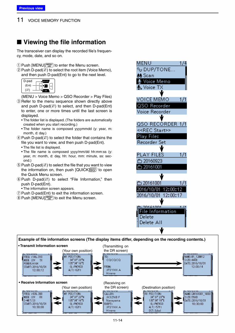
11 VOICE MEMORY FUNCTION
11-14
■ Viewing the file information
The transceiver can display the recorded file’s frequen-cy, mode, date, and so on.
qPush [MENU] to enter the Menu screen. w Push D-pad() to select the root item (Voice Memo), and then push D-pad(Ent) to go to the next level.
D-pad
(�)
(Ent)
( MENU > Voice Memo > QSO Recorder > Play Files) e Refer to the menu sequence shown directly above and push D-pad() to select, and then D-pad(Ent) to enter, one or more times until the last screen is displayed.
• The folder list is displayed. (The folders are automatically created when you start recording.)
• The folder name is composed yyyymmdd (y: year, m: month, d: day.)
r Push D-pad() to select the folder that contains the file you want to view, and then push D-pad(Ent).
• The file list is displayed. • The file name is composed yyyy/mm/dd hh:mm:ss (y:
year, m: month, d: day, hh: hour, mm: minute, ss: sec-ond.)
t Push D-pad() to select the file that you want to view the information on, then push [QUICK] to open the Quick Menu screen. y Push D-pad() to select “File Information,” then push D-pad(Ent).
• The information screen appears.
u Push D-pad(Ent) to exit the information screen. i Push [MENU] to exit the Menu screen.
• Receive Information screen ( Receiving on the DR screen)
Example of file information screens (The display items differ, depending on the recording contents.)
• Transmit Information screen
(Your own position)
( Transmitting on the DR screen)
(Your own position) (Destination position)
Previous view
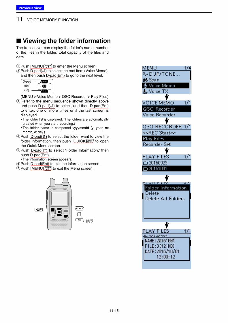
11 VOICE MEMORY FUNCTION
11-15
The transceiver can display the folder’s name, number of the files in the folder, total capacity of the files and date.
qPush [MENU] to enter the Menu screen. w Push D-pad() to select the root item (Voice Memo), and then push D-pad(Ent) to go to the next level.
D-pad
(�)
(Ent)
( MENU > Voice Memo > QSO Recorder > Play Files) e Refer to the menu sequence shown directly above and push D-pad() to select, and then D-pad(Ent) to enter, one or more times until the last screen is displayed.
• The folder list is displayed. (The folders are automatically created when you start recording.)
• The folder name is composed yyyymmdd (y: year, m: month, d: day.)
r Push D-pad() to select the folder want to view the folder information, then push [QUICK] to open the Quick Menu screen. t Push D-pad() to select “Folder Information,” then push D-pad(Ent).
• The information screen appears.
y Push D-pad(Ent) to exit the information screen. u Push [MENU] to exit the Menu screen.
■ Viewing the folder information
Previous view
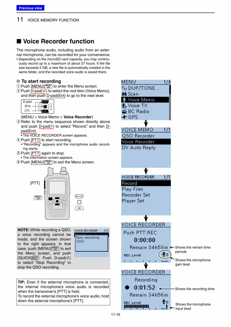
11 VOICE MEMORY FUNCTION
11-16
■ Voice Recorder function
The microphone audio, including audio from an exter-nal microphone, can be recorded for your convenience.• Depending on the microSD card capacity, you may continu-
ously record up to a maximum of about 37 hours. If the file size exceeds 2 GB, a new file is automatically created in the same folder, and the recorded voice audio is saved there.
D To start recording qPush [MENU] to enter the Menu screen. w Push D-pad() to select the root item (Voice Memo), and then push D-pad(Ent) to go to the next level.
D-pad
(�)
(Ent)
( MENU > Voice Memo > Voice Recorder) e Refer to the menu sequence shown directly above and push D-pad() to select “Record,” and then D-pad(Ent).
• The VOICE RECORDER screen appears.
r Push [PTT] to start recording. • “Recording” appears and the microphone audio record-
ing starts.
t Push [PTT] again to stop. • The information screen appears.
y Push [MENU] to exit the Menu screen.
NOTE: While recording a QSO, a voice recording cannot be made, and the screen shown to the right appears. In that case, push [MENU] to exit the Menu screen, and push [QUICK] . Push D-pad() to select “Stop Recording” to stop the QSO recording.
[PTT]
Shows the microphone gain level
Shows the remain time periods
Shows the recording time
Shows the microphone input level
TIP: Even if the external microphone is connected, the internal microphone’s voice audio is recorded when the transceiver’s [PTT] is held.To record the external microphone’s voice audio, hold down the external microphone’s [PTT].
Previous view
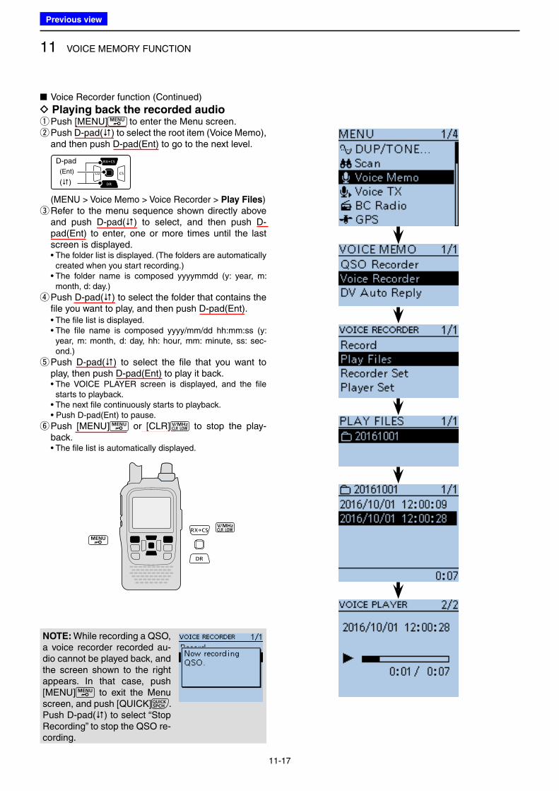
11 VOICE MEMORY FUNCTION
11-17
■ Voice Recorder function (Continued)
D Playing back the recorded audio q Push [MENU] to enter the Menu screen. w Push D-pad() to select the root item (Voice Memo), and then push D-pad(Ent) to go to the next level.
D-pad
(�)
(Ent)
( MENU > Voice Memo > Voice Recorder > Play Files) e Refer to the menu sequence shown directly above and push D-pad() to select, and then push D-pad(Ent) to enter, one or more times until the last screen is displayed.
• The folder list is displayed. (The folders are automatically created when you start recording.)
• The folder name is composed yyyymmdd (y: year, m: month, d: day.)
r Push D-pad() to select the folder that contains the file you want to play, and then push D-pad(Ent).
• The file list is displayed. • The file name is composed yyyy/mm/dd hh:mm:ss (y:
year, m: month, d: day, hh: hour, mm: minute, ss: sec-ond.)
t Push D-pad() to select the file that you want to play, then push D-pad(Ent) to play it back.
• The VOICE PLAYER screen is displayed, and the file starts to playback.
• The next file continuously starts to playback. • Push D-pad(Ent) to pause.
y Push [MENU] or [CLR] to stop the play-back.
• The file list is automatically displayed.
NOTE: While recording a QSO, a voice recorder recorded au-dio cannot be played back, and the screen shown to the right appears. In that case, push [MENU] to exit the Menu screen, and push [QUICK] . Push D-pad() to select “Stop Recording” to stop the QSO re-cording.
Previous view
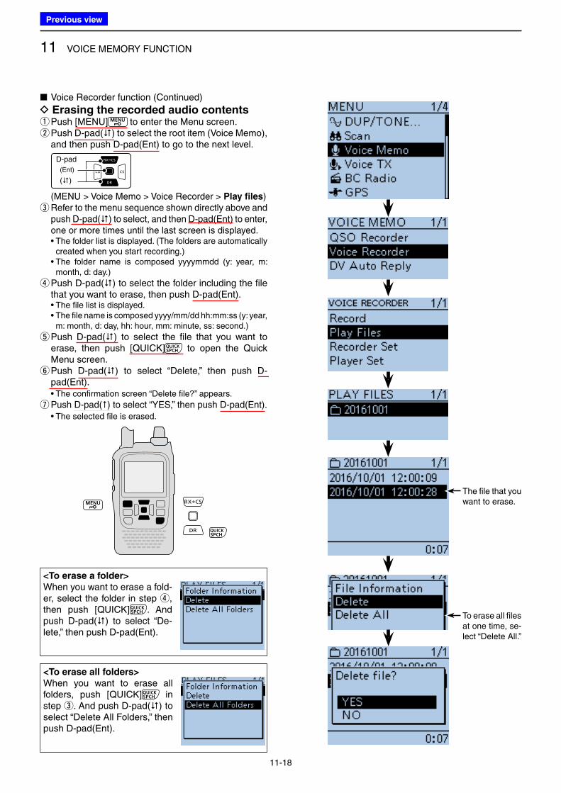
11 VOICE MEMORY FUNCTION
11-18
■ Voice Recorder function (Continued)
D Erasing the recorded audio contents qPush [MENU] to enter the Menu screen. w Push D-pad() to select the root item (Voice Memo), and then push D-pad(Ent) to go to the next level.
D-pad
(�)
(Ent)
( MENU > Voice Memo > Voice Recorder > Play files) e Refer to the menu sequence shown directly above and push D-pad() to select, and then D-pad(Ent) to enter, one or more times until the last screen is displayed.
• The folder list is displayed. (The folders are automatically created when you start recording.)
• The folder name is composed yyyymmdd (y: year, m: month, d: day.)
r Push D-pad() to select the folder including the file that you want to erase, then push D-pad(Ent).
• The file list is displayed. • The file name is composed yyyy/mm/dd hh:mm:ss (y: year,
m: month, d: day, hh: hour, mm: minute, ss: second.)
t Push D-pad() to select the file that you want to erase, then push [QUICK] to open the Quick Menu screen. y Push D-pad() to select “Delete,” then push D-pad(Ent).
• The confirmation screen “Delete file?” appears.
u Push D-pad() to select “YES,” then push D-pad(Ent). • The selected file is erased.
The file that you want to erase.
To erase all files at one time, se-lect “Delete All.”
<To erase all folders>
When you want to erase all folders, push [QUICK] in step e. And push D-pad() to select “Delete All Folders,” then push D-pad(Ent).
<To erase a folder>
When you want to erase a fold-er, select the folder in step r, then push [QUICK] . And push D-pad() to select “De-lete,” then push D-pad(Ent).
Previous view
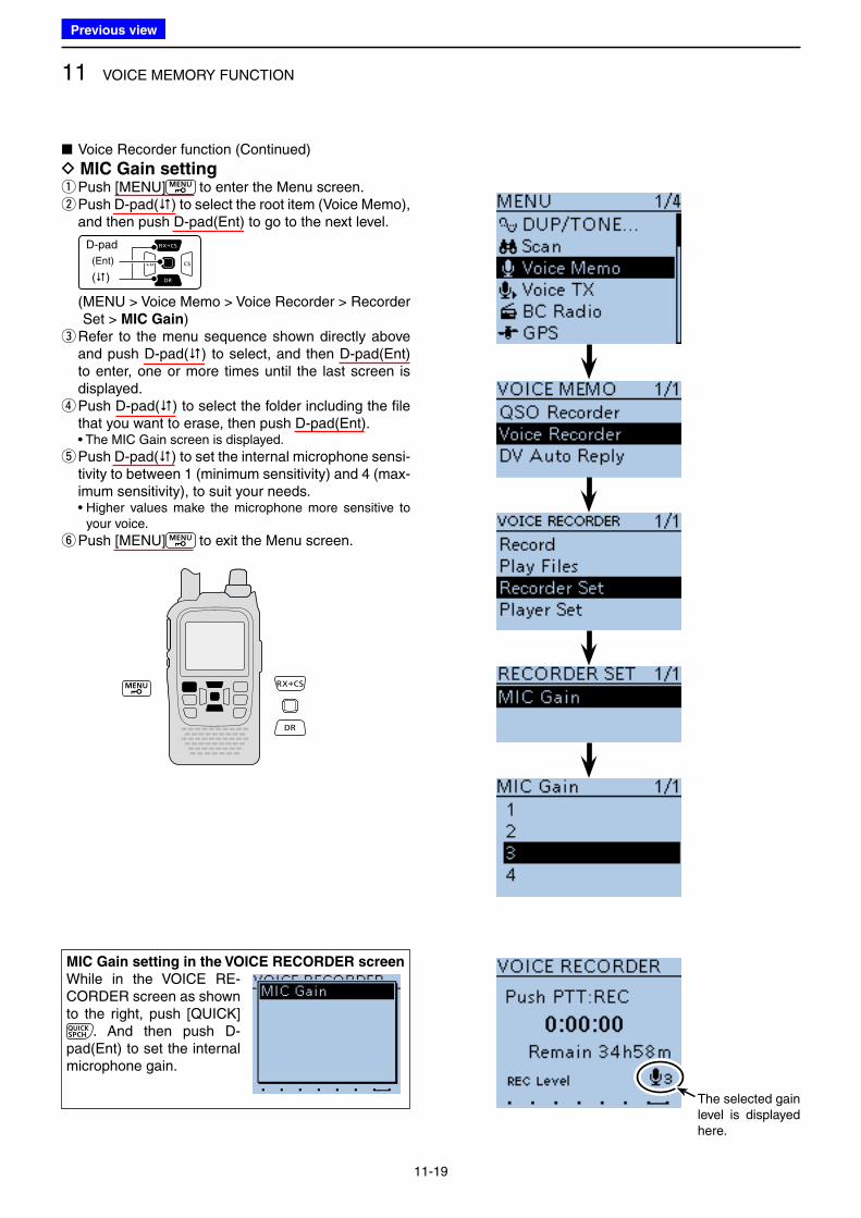
11 VOICE MEMORY FUNCTION
11-19
■ Voice Recorder function (Continued)
D MIC Gain setting qPush [MENU] to enter the Menu screen. w Push D-pad() to select the root item (Voice Memo), and then push D-pad(Ent) to go to the next level.
D-pad
(�)
(Ent)
( MENU > Voice Memo > Voice Recorder > Recorder Set > MIC Gain)
e Refer to the menu sequence shown directly above and push D-pad() to select, and then D-pad(Ent) to enter, one or more times until the last screen is displayed. r Push D-pad() to select the folder including the file that you want to erase, then push D-pad(Ent).
• The MIC Gain screen is displayed.
t Push D-pad() to set the internal microphone sensi-tivity to between 1 (minimum sensitivity) and 4 (max-imum sensitivity), to suit your needs.
• Higher values make the microphone more sensitive to your voice.
y Push [MENU] to exit the Menu screen.
The selected gain level is displayed here.
MIC Gain setting in the VOICE RECORDER screen
While in the VOICE RE-CORDER screen as shown to the right, push [QUICK]
. And then push D-pad(Ent) to set the internal microphone gain.
Previous view
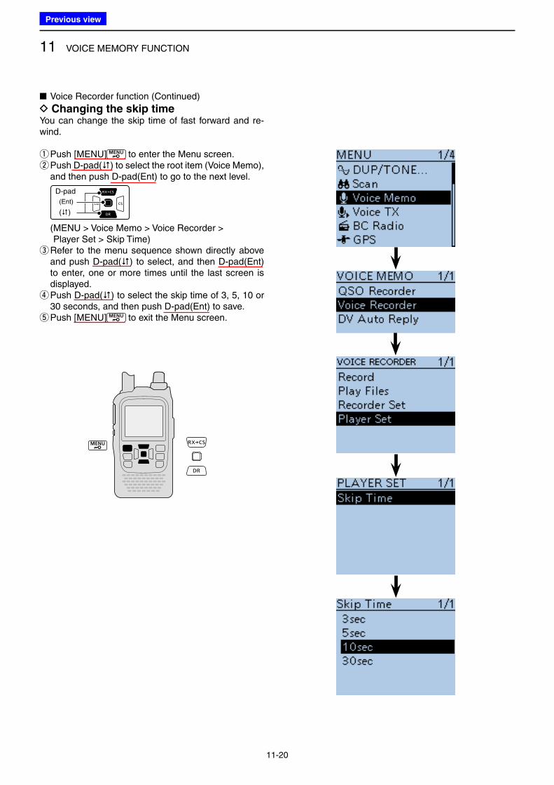
11 VOICE MEMORY FUNCTION
11-20
■ Voice Recorder function (Continued)
D Changing the skip timeYou can change the skip time of fast forward and re-wind.
qPush [MENU] to enter the Menu screen. w Push D-pad() to select the root item (Voice Memo), and then push D-pad(Ent) to go to the next level.
D-pad
(�)
(Ent)
( MENU > Voice Memo > Voice Recorder > Player Set > Skip Time)
e Refer to the menu sequence shown directly above and push D-pad() to select, and then D-pad(Ent) to enter, one or more times until the last screen is displayed. r Push D-pad() to select the skip time of 3, 5, 10 or 30 seconds, and then push D-pad(Ent) to save. t Push [MENU] to exit the Menu screen.
Previous view
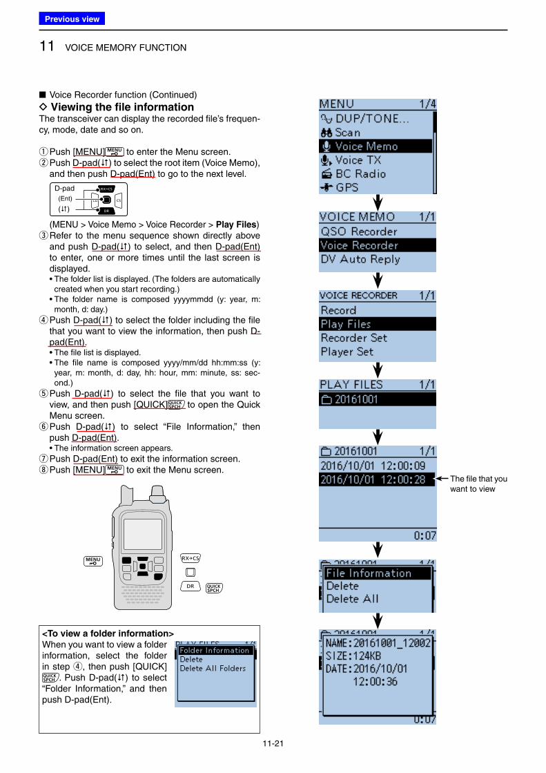
11 VOICE MEMORY FUNCTION
11-21
■ Voice Recorder function (Continued)
D Viewing the file informationThe transceiver can display the recorded file’s frequen-cy, mode, date and so on.
qPush [MENU] to enter the Menu screen. w Push D-pad() to select the root item (Voice Memo), and then push D-pad(Ent) to go to the next level.
D-pad
(�)
(Ent)
( MENU > Voice Memo > Voice Recorder > Play Files) e Refer to the menu sequence shown directly above and push D-pad() to select, and then D-pad(Ent) to enter, one or more times until the last screen is displayed.
• The folder list is displayed. (The folders are automatically created when you start recording.)
• The folder name is composed yyyymmdd (y: year, m: month, d: day.)
r Push D-pad() to select the folder including the file that you want to view the information, then push D-pad(Ent).
• The file list is displayed. • The file name is composed yyyy/mm/dd hh:mm:ss (y:
year, m: month, d: day, hh: hour, mm: minute, ss: sec-ond.)
t Push D-pad() to select the file that you want to view, and then push [QUICK] to open the Quick Menu screen. y Push D-pad() to select “File Information,” then push D-pad(Ent).
• The information screen appears.
u Push D-pad(Ent) to exit the information screen. i Push [MENU] to exit the Menu screen.
<To view a folder information>
When you want to view a folder information, select the folder in step r, then push [QUICK]
. Push D-pad() to select “Folder Information,” and then push D-pad(Ent).
The file that you want to view
Previous view
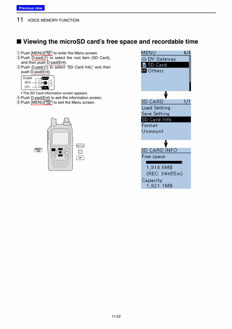
11 VOICE MEMORY FUNCTION
11-22
qPush [MENU] to enter the Menu screen. w Push D-pad() to select the root item (SD Card), and then push D-pad(Ent). e Push D-pad() to select “SD Card Info,” and then push D-pad(Ent).
D-pad
(�)
(Ent)
• The SD Card information screen appears.
rPush D-pad(Ent) to exit the information screen. t Push [MENU] to exit the Menu screen.
■ Viewing the microSD card’s free space and recordable time
Previous view
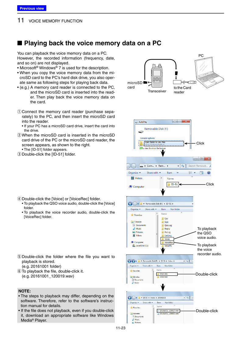
11 VOICE MEMORY FUNCTION
11-23
You can playback the voice memory data on a PC.However, the recorded information (frequency, date, and so on) are not displayed.• Microsoft® Windows® 7 is used for the description.• When you copy the voice memory data from the mi-
croSD card to the PC’s hard disk drive, you also oper-ate same as following steps for playing back data.
• (e.g.) A memory card reader is connected to the PC, and the microSD card is inserted into the read-er. Then play back the voice memory data on the card.
q Connect the memory card reader (purchase sepa-rately) to the PC, and then insert the microSD card into the reader.
• If your PC has a microSD card drive, insert the card into the drive.
w When the microSD card is inserted in the microSD card drive of the PC or the microSD card reader, the screen appears, as shown to the right.
• The [ID-51] folder appears.
e Double-click the [ID-51] folder.
Double-click
Double-click
NOTE:
• The steps to playback may differ, depending on the software. Therefore, refer to the software’s instruc-tion manual for details.
• If the file does not playback, even if you double-click it, download an appropriate software like Windows Media® Player.
■ Playing back the voice memory data on a PC
microSD card
Transceiverto the Card reader
PC
r Double-click the [Voice] or [VoiceRec] folder. • To playback the QSO voice audio, double-click the [Voice]
folder. • To playback the voice recorder audio, double-click the
[VoiceRec] folder.
t Double-click the folder where the file you want to playback is stored.
(e.g. 20161001 folder) y To playback the file, double-click it.
(e.g. 20161001_120019.wav)
Click
Click
To playback the QSO voice audio.
To playback the voice recorder audio.
Previous view
12-1
Section 12 MEMORY OPERATION
■ General description .......................................................... 12-2
D Memory channel contents ............................................ 12-2
■ Selecting a Memory channel ............................................ 12-3
■ Selecting a call channel .................................................... 12-3
■ Entering a Memory channel ............................................. 12-4
■ Copying memory and Call channel contents .................... 12-5
D Memory or Call channelVFO..................................... 12-5
D Memory or Call channelAnother memory or
Call channel .................................................................. 12-6
■ Setting a Memory bank .................................................... 12-7
D Assigning a memory channel to a memory bank ......... 12-7
D Directly entering into a memory bank ........................... 12-8
■ Selecting a Memory bank ................................................. 12-9
■ Entering a memory/bank/scan name.............................. 12-10
D Entering a memory name, bank name or scan name .. 12-10
■ Selecting a memory name display ................................. 12-12
■ Clearing a Memory contents .......................................... 12-13
Previous view
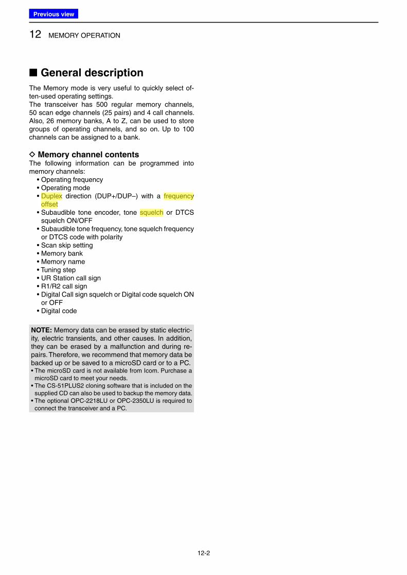
12 MEMORY OPERATION
12-2
■ General description
The Memory mode is very useful to quickly select of-ten-used operating settings.The transceiver has 500 regular memory channels, 50 scan edge channels (25 pairs) and 4 call channels. Also, 26 memory banks, A to Z, can be used to store groups of operating channels, and so on. Up to 100 channels can be assigned to a bank.
D Memory channel contentsThe following information can be programmed into memory channels: • Operating frequency • Operating mode • Duplex direction (DUP+/DUP–) with a frequency
offset • Subaudible tone encoder, tone squelch or DTCS
squelch ON/OFF • Subaudible tone frequency, tone squelch frequency
or DTCS code with polarity • Scan skip setting • Memory bank • Memory name • Tuning step • UR Station call sign • R1/R2 call sign • Digital Call sign squelch or Digital code squelch ON
or OFF • Digital code
NOTE: Memory data can be erased by static electric-ity, electric transients, and other causes. In addition, they can be erased by a malfunction and during re-pairs. Therefore, we recommend that memory data be backed up or be saved to a microSD card or to a PC.• The microSD card is not available from Icom. Purchase a
microSD card to meet your needs.• The CS-51PLUS2 cloning software that is included on the
supplied CD can also be used to backup the memory data.• The optional OPC-2218LU or OPC-2350LU is required to
connect the transceiver and a PC.
Previous view
Icom
ハイライト表示
The difference between the transmit and receive frequencies.
Icom
ハイライト表示
An operating mode in which the transmit and receive frequencies are separated by an offset amount.
Icom
ハイライト表示
A function that mutes the audio output for certain signal levels.
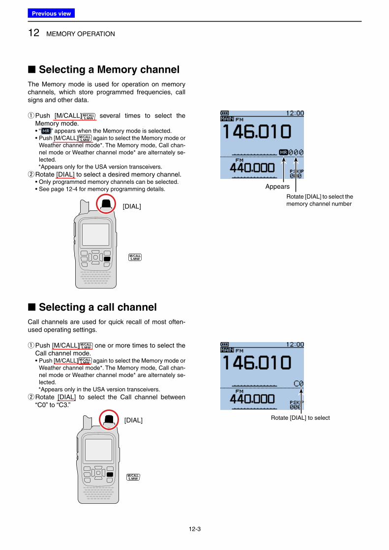
12 MEMORY OPERATION
12-3
■ Selecting a Memory channel
The Memory mode is used for operation on memory channels, which store programmed frequencies, call signs and other data.
q Push [M/CALL] several times to select the Memory mode.
• “ ” appears when the Memory mode is selected. • Push [M/CALL] again to select the Memory mode or
Weather channel mode*. The Memory mode, Call chan-nel mode or Weather channel mode* are alternately se-lected.
*Appears only for the USA version transceivers.
wRotate [DIAL] to select a desired memory channel. • Only programmed memory channels can be selected. • See page 12-4 for memory programming details.
[DIAL]
■ Selecting a call channel
Call channels are used for quick recall of most often-used operating settings.
q Push [M/CALL] one or more times to select the Call channel mode.
• Push [M/CALL] again to select the Memory mode or Weather channel mode*. The Memory mode, Call chan-nel mode or Weather channel mode* are alternately se-lected.
*Appears only in the USA version transceivers.
w Rotate [DIAL] to select the Call channel between “C0” to “C3.”
[DIAL]
Appears
Rotate [DIAL] to select the memory channel number
Rotate [DIAL] to select
Previous view
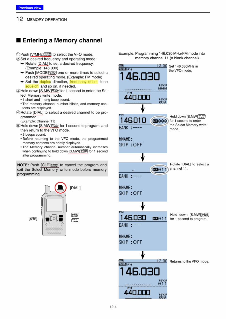
12 MEMORY OPERATION
12-4
■ Entering a Memory channel
qPush [V/MHz] to select the VFO mode. wSet a desired frequency and operating mode:
➥ Rotate [DIAL] to set a desired frequency. (Example: 146.030)
➥ Push [MODE] one or more times to select a desired operating mode. (Example: FM mode)
➥ Set the duplex direction, frequency offset, tone squelch, and so on, if needed.
e Hold down [S.MW] for 1 second to enter the Se-lect Memory write mode.
• 1 short and 1 long beep sound. • The memory channel number blinks, and memory con-
tents are displayed.
r Rotate [DIAL] to select a desired channel to be pro-grammed.
(Example: Channel 11)
t Hold down [S.MW] for 1 second to program, and then return to the VFO mode.
• 3 beeps sound. • Before returning to the VFO mode, the programmed
memory contents are briefly displayed. • The Memory channel number automatically increases
when continuing to hold down [S.MW] for 1 second after programming.
[DIAL]
Set 146.030MHz in the VFO mode.
Hold down [S.MW] for 1 second to enter the Select Memory write mode.
Rotate [DIAL] to select a channel 11.
Hold down [S.MW] for 1 second to program.
Returns to the VFO mode.
Example: Programming 146.030 MHz/FM mode into memory channel 11 (a blank channel).
NOTE: Push [CLR] to cancel the program and exit the Select Memory write mode before memory programming.
Previous view
Icom
ハイライト表示
The difference between the transmit and receive frequencies.
Icom
ハイライト表示
An operating mode in which the transmit and receive frequencies are separated by an offset amount.
Icom
ハイライト表示
A function that mutes the audio output for certain signal levels.
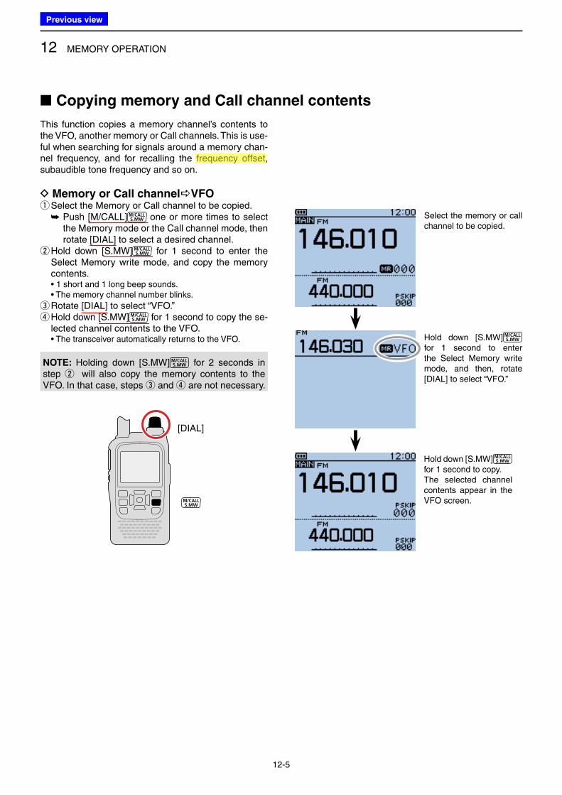
12 MEMORY OPERATION
12-5
■ Copying memory and Call channel contents
This function copies a memory channel’s contents to the VFO, another memory or Call channels. This is use-ful when searching for signals around a memory chan-nel frequency, and for recalling the frequency offset, subaudible tone frequency and so on.
D Memory or Call channelVFO qSelect the Memory or Call channel to be copied.
➥ Push [M/CALL] one or more times to select the Memory mode or the Call channel mode, then rotate [DIAL] to select a desired channel.
w Hold down [S.MW] for 1 second to enter the Select Memory write mode, and copy the memory contents.
• 1 short and 1 long beep sounds. • The memory channel number blinks.
eRotate [DIAL] to select “VFO.” r Hold down [S.MW] for 1 second to copy the se-lected channel contents to the VFO.
• The transceiver automatically returns to the VFO.
[DIAL]
Select the memory or call channel to be copied.
Hold down [S.MW] for 1 second to enter the Select Memory write mode, and then, rotate [DIAL] to select “VFO.”
Hold down [S.MW] for 1 second to copy.The selected channel contents appear in the VFO screen.
NOTE: Holding down [S.MW] for 2 seconds in step w will also copy the memory contents to the VFO. In that case, steps e and r are not necessary.
Previous view
Icom
ハイライト表示
The difference between the transmit and receive frequencies.
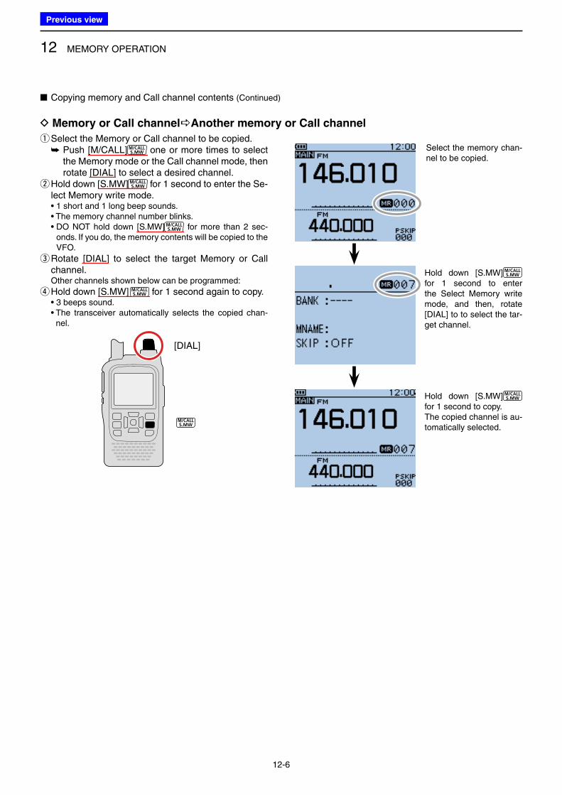
12 MEMORY OPERATION
12-6
qSelect the Memory or Call channel to be copied. ➥ Push [M/CALL] one or more times to select the Memory mode or the Call channel mode, then rotate [DIAL] to select a desired channel.
w Hold down [S.MW] for 1 second to enter the Se-lect Memory write mode.
• 1 short and 1 long beep sounds. • The memory channel number blinks. • DO NOT hold down [S.MW] for more than 2 sec-
onds. If you do, the memory contents will be copied to the VFO.
e Rotate [DIAL] to select the target Memory or Call channel.
Other channels shown below can be programmed:
r Hold down [S.MW] for 1 second again to copy. • 3 beeps sound. • The transceiver automatically selects the copied chan-
nel.
■ Copying memory and Call channel contents (Continued)
[DIAL]
Select the memory chan-nel to be copied.
Hold down [S.MW] for 1 second to enter the Select Memory write mode, and then, rotate [DIAL] to to select the tar-get channel.
Hold down [S.MW] for 1 second to copy.The copied channel is au-tomatically selected.
D Memory or Call channelAnother memory or Call channel
Previous view
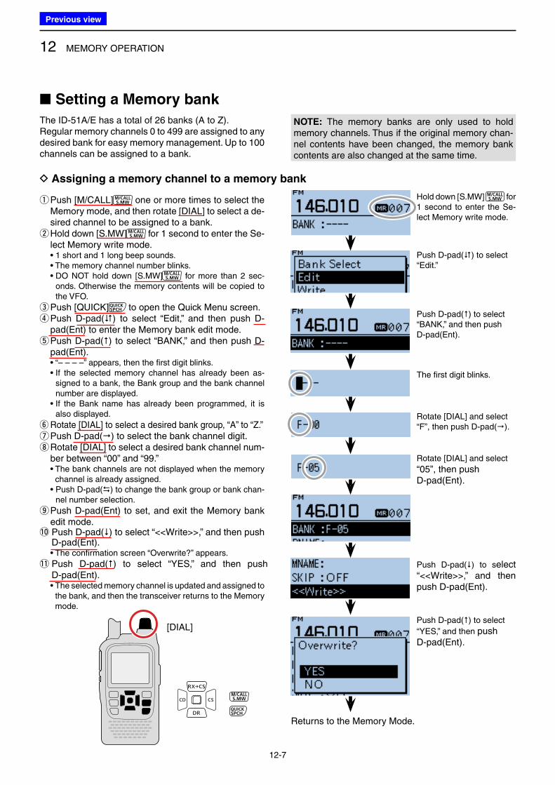
12 MEMORY OPERATION
12-7
q Push [M/CALL] one or more times to select the Memory mode, and then rotate [DIAL] to select a de-sired channel to be assigned to a bank. w Hold down [S.MW] for 1 second to enter the Se-lect Memory write mode.
• 1 short and 1 long beep sounds. • The memory channel number blinks. • DO NOT hold down [S.MW] for more than 2 sec-
onds. Otherwise the memory contents will be copied to the VFO.
e Push [QUICK] to open the Quick Menu screen. r Push D-pad() to select “Edit,” and then push D-pad(Ent) to enter the Memory bank edit mode. t Push D-pad() to select “BANK,” and then push D-pad(Ent).
• “– – – –” appears, then the first digit blinks. • If the selected memory channel has already been as-
signed to a bank, the Bank group and the bank channel number are displayed.
• If the Bank name has already been programmed, it is also displayed.
y Rotate [DIAL] to select a desired bank group, “A” to “Z.” uPush D-pad() to select the bank channel digit. i Rotate [DIAL] to select a desired bank channel num-ber between “00” and “99.”
• The bank channels are not displayed when the memory channel is already assigned.
• Push D-pad() to change the bank group or bank chan-nel number selection.
o Push D-pad(Ent) to set, and exit the Memory bank edit mode.
!0 Push D-pad() to select “<<Write>>,” and then push D-pad(Ent).
• The confirmation screen “Overwrite?” appears.
!1 Push D-pad() to select “YES,” and then push D-pad(Ent).
• The selected memory channel is updated and assigned to the bank, and then the transceiver returns to the Memory mode.
■ Setting a Memory bank
The ID-51A/E has a total of 26 banks (A to Z).Regular memory channels 0 to 499 are assigned to any desired bank for easy memory management. Up to 100 channels can be assigned to a bank.
Hold down [S.MW] for 1 second to enter the Se-lect Memory write mode.
Push D-pad() to select “Edit.”
Push D-pad() to select “BANK,” and then push D-pad(Ent).
The first digit blinks.
Rotate [DIAL] and select “F”, then push D-pad().
Rotate [DIAL] and select
“05”, then push D-pad(Ent).
Push D-pad() to select
“YES,” and then push D-pad(Ent).
Returns to the Memory Mode.
Push D-pad() to select “<<Write>>,” and then push D-pad(Ent).
[DIAL]
D Assigning a memory channel to a memory bank
NOTE: The memory banks are only used to hold memory channels. Thus if the original memory chan-nel contents have been changed, the memory bank contents are also changed at the same time.
Previous view
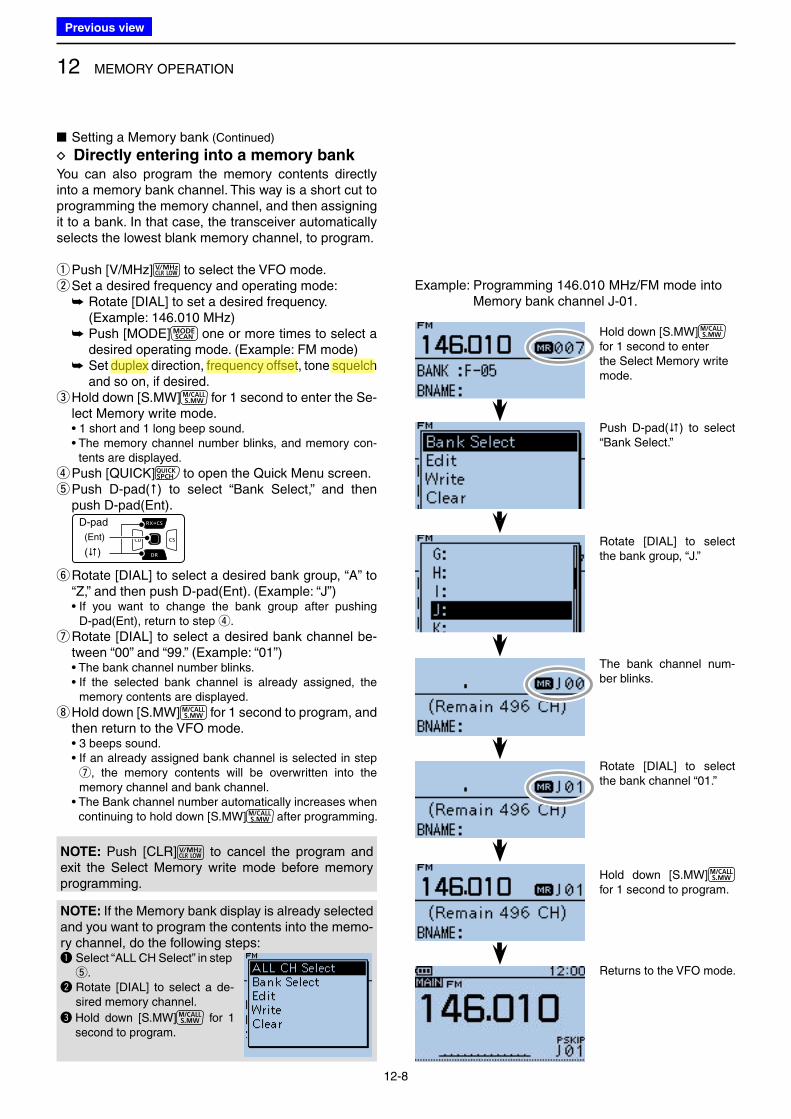
12 MEMORY OPERATION
12-8
You can also program the memory contents directly into a memory bank channel. This way is a short cut to programming the memory channel, and then assigning it to a bank. In that case, the transceiver automatically selects the lowest blank memory channel, to program.
qPush [V/MHz] to select the VFO mode. wSet a desired frequency and operating mode:
➥ Rotate [DIAL] to set a desired frequency. (Example: 146.010 MHz)
➥ Push [MODE] one or more times to select a desired operating mode. (Example: FM mode)
➥ Set duplex direction, frequency offset, tone squelch and so on, if desired.
e Hold down [S.MW] for 1 second to enter the Se-lect Memory write mode.
• 1 short and 1 long beep sound. • The memory channel number blinks, and memory con-
tents are displayed.
r Push [QUICK] to open the Quick Menu screen. t Push D-pad() to select “Bank Select,” and then push D-pad(Ent).
D-pad
(�)
(Ent)
y Rotate [DIAL] to select a desired bank group, “A” to “Z,” and then push D-pad(Ent). (Example: “J”)
• If you want to change the bank group after pushing D-pad(Ent), return to step r.
u Rotate [DIAL] to select a desired bank channel be-tween “00” and “99.” (Example: “01”)
• The bank channel number blinks. • If the selected bank channel is already assigned, the
memory contents are displayed.
i Hold down [S.MW] for 1 second to program, and then return to the VFO mode.
• 3 beeps sound. • If an already assigned bank channel is selected in step
u, the memory contents will be overwritten into the memory channel and bank channel.
• The Bank channel number automatically increases when continuing to hold down [S.MW] after programming.
■ Setting a Memory bank (Continued)
D Directly entering into a memory bank
Hold down [S.MW] for 1 second to enter the Select Memory write mode.
Push D-pad() to select “Bank Select.”
Rotate [DIAL] to select the bank group, “J.”
The bank channel num-ber blinks.
Rotate [DIAL] to select the bank channel “01.”
Hold down [S.MW] for 1 second to program.
Returns to the VFO mode.
Example: Programming 146.010 MHz/FM mode into Memory bank channel J-01.
NOTE: If the Memory bank display is already selected and you want to program the contents into the memo-ry channel, do the following steps:q Select “ALL CH Select” in step
t.w Rotate [DIAL] to select a de-
sired memory channel.
e Hold down [S.MW] for 1 second to program.
NOTE: Push [CLR] to cancel the program and exit the Select Memory write mode before memory programming.
Previous view
Icom
ハイライト表示
The difference between the transmit and receive frequencies.
Icom
ハイライト表示
An operating mode in which the transmit and receive frequencies are separated by an offset amount.
Icom
ハイライト表示
A function that mutes the audio output for certain signal levels.
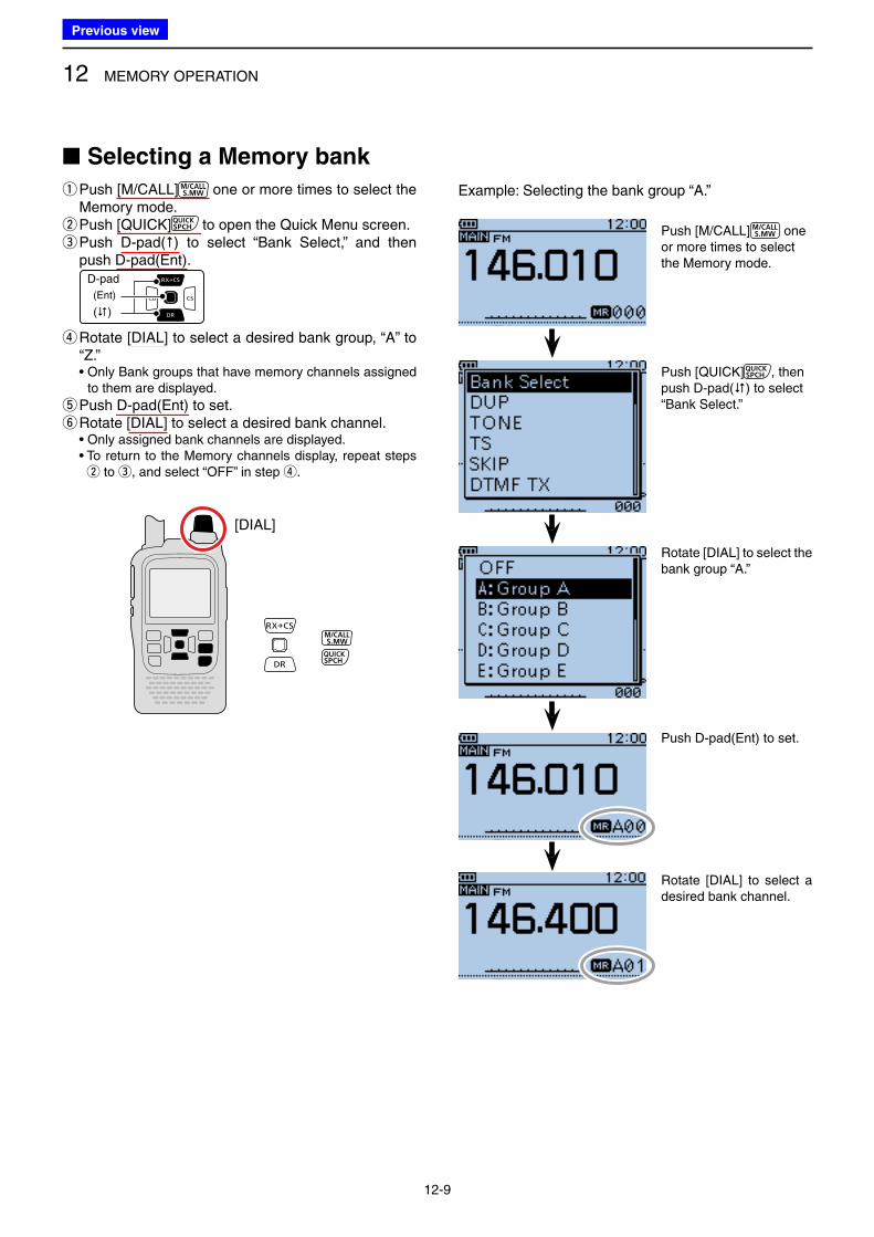
12 MEMORY OPERATION
12-9
■ Selecting a Memory bank
q Push [M/CALL] one or more times to select the Memory mode. w Push [QUICK] to open the Quick Menu screen. e Push D-pad() to select “Bank Select,” and then push D-pad(Ent).
D-pad
(�)
(Ent)
r Rotate [DIAL] to select a desired bank group, “A” to “Z.”
• Only Bank groups that have memory channels assigned to them are displayed.
tPush D-pad(Ent) to set. yRotate [DIAL] to select a desired bank channel.
• Only assigned bank channels are displayed. • To return to the Memory channels display, repeat steps
w to e, and select “OFF” in step r.
[DIAL]
Push [M/CALL] one or more times to select the Memory mode.
Push [QUICK] , then push D-pad() to select “Bank Select.”
Rotate [DIAL] to select the bank group “A.”
Push D-pad(Ent) to set.
Rotate [DIAL] to select a desired bank channel.
Example: Selecting the bank group “A.”
Previous view
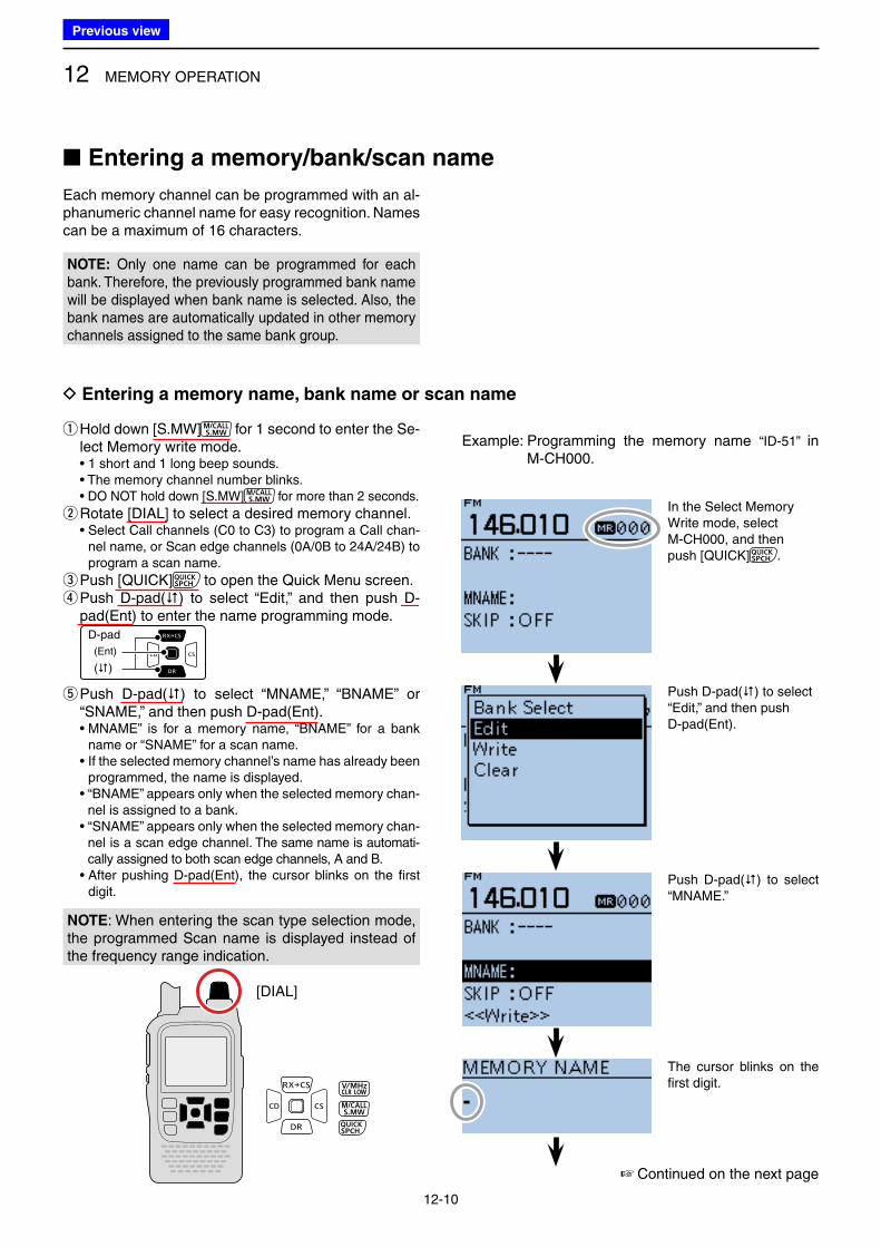
12 MEMORY OPERATION
12-10
■ Entering a memory/bank/scan name
q Hold down [S.MW] for 1 second to enter the Se-lect Memory write mode.
• 1 short and 1 long beep sounds. • The memory channel number blinks. • DO NOT hold down [S.MW] for more than 2 seconds.
wRotate [DIAL] to select a desired memory channel. • Select Call channels (C0 to C3) to program a Call chan-
nel name, or Scan edge channels (0A/0B to 24A/24B) to program a scan name.
e Push [QUICK] to open the Quick Menu screen. r Push D-pad() to select “Edit,” and then push D-pad(Ent) to enter the name programming mode.
D-pad
(�)
(Ent)
t Push D-pad() to select “MNAME,” “BNAME” or “SNAME,” and then push D-pad(Ent).
• MNAME” is for a memory name, “BNAME” for a bank name or “SNAME” for a scan name.
• If the selected memory channel’s name has already been programmed, the name is displayed.
• “BNAME” appears only when the selected memory chan-nel is assigned to a bank.
• “SNAME” appears only when the selected memory chan-nel is a scan edge channel. The same name is automati-cally assigned to both scan edge channels, A and B.
• After pushing D-pad(Ent), the cursor blinks on the first digit.
[DIAL]
In the Select Memory Write mode, select M-CH000, and then push [QUICK] .
Push D-pad() to select “Edit,” and then push D-pad(Ent).
Push D-pad() to select “MNAME.”
The cursor blinks on the first digit.
Example: Programming the memory name “ID-51” in M-CH000.
Each memory channel can be programmed with an al-phanumeric channel name for easy recognition. Names can be a maximum of 16 characters.
D Entering a memory name, bank name or scan name
☞ Continued on the next page
NOTE: Only one name can be programmed for each bank. Therefore, the previously programmed bank name will be displayed when bank name is selected. Also, the bank names are automatically updated in other memory channels assigned to the same bank group.
NOTE: When entering the scan type selection mode, the programmed Scan name is displayed instead of the frequency range indication.
Previous view
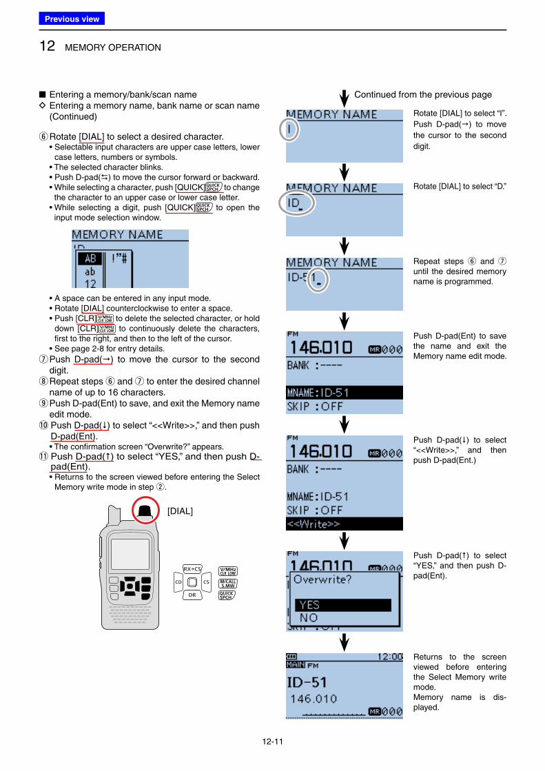
12 MEMORY OPERATION
12-11
yRotate [DIAL] to select a desired character. • Selectable input characters are upper case letters, lower
case letters, numbers or symbols. • The selected character blinks. • Push D-pad() to move the cursor forward or backward. • While selecting a character, push [QUICK] to change
the character to an upper case or lower case letter. • While selecting a digit, push [QUICK] to open the
input mode selection window.
• A space can be entered in any input mode. • Rotate [DIAL] counterclockwise to enter a space. • Push [CLR] to delete the selected character, or hold
down [CLR] to continuously delete the characters, first to the right, and then to the left of the cursor.
• See page 2-8 for entry details.
u Push D-pad() to move the cursor to the second digit. i Repeat steps y and u to enter the desired channel name of up to 16 characters. o Push D-pad(Ent) to save, and exit the Memory name edit mode.
!0 Push D-pad() to select “<<Write>>,” and then push D-pad(Ent).
• The confirmation screen “Overwrite?” appears.!1 Push D-pad() to select “YES,” and then push D-
pad(Ent). • Returns to the screen viewed before entering the Select
Memory write mode in step w.
Continued from the previous page
Rotate [DIAL] to select “I”.
Push D-pad() to move
the cursor to the second
digit.
Rotate [DIAL] to select “D.”
Repeat steps y and u until the desired memory name is programmed.
Push D-pad(Ent) to save the name and exit the Memory name edit mode.
Push D-pad() to select “<<Write>>,” and then push D-pad(Ent.)
Push D-pad() to select “YES,” and then push D-pad(Ent).
Returns to the screen viewed before entering the Select Memory write mode.Memory name is dis-played.
■ Entering a memory/bank/scan name D Entering a memory name, bank name or scan name (Continued)
[DIAL]
Previous view
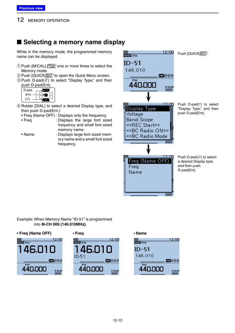
12 MEMORY OPERATION
12-12
■ Selecting a memory name display
While in the memory mode, the programmed memory name can be displayed.
q Push [M/CALL] one or more times to select the Memory mode. w Push [QUICK] to open the Quick Menu screen. e Push D-pad() to select “Display Type,” and then push D-pad(Ent).
D-pad
(�)
(Ent)
r Rotate [DIAL] to select a desired Display type, and then push D-pad(Ent.)
• Freq (Name OFF) : Displays only the frequency. • Freq : Displays the large font sized
frequency and small font sized memory name.
• Name : Displays large font sized mem-ory name and a small font sized frequency.
• Freq (Name OFF) • Freq • Name
Example: When Memory Name “ID-51” is programmed
into M-CH 000 (146.010MHz).
Push [QUICK] .
Push D-pad() to select a desired Display type, and then push D-pad(Ent).
Push D-pad() to select “Display Type,” and then push D-pad(Ent).
Previous view
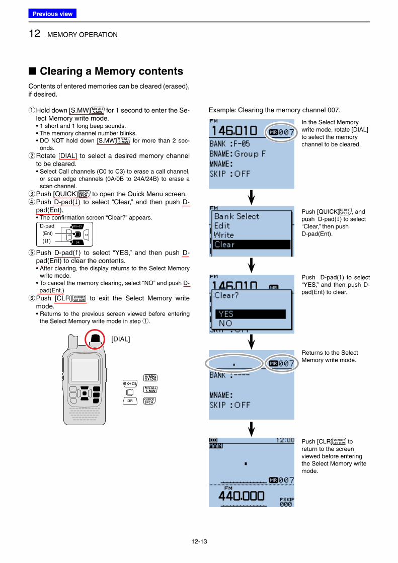
12 MEMORY OPERATION
12-13
■ Clearing a Memory contents
Contents of entered memories can be cleared (erased), if desired.
q Hold down [S.MW] for 1 second to enter the Se-lect Memory write mode.
• 1 short and 1 long beep sounds. • The memory channel number blinks. • DO NOT hold down [S.MW] for more than 2 sec-
onds.
w Rotate [DIAL] to select a desired memory channel to be cleared.
• Select Call channels (C0 to C3) to erase a call channel, or scan edge channels (0A/0B to 24A/24B) to erase a scan channel.
e Push [QUICK] to open the Quick Menu screen. r Push D-pad() to select “Clear,” and then push D-pad(Ent).
• The confirmation screen “Clear?” appears.
D-pad
(�)
(Ent)
t Push D-pad() to select “YES,” and then push D-pad(Ent) to clear the contents.
• After clearing, the display returns to the Select Memory write mode.
• To cancel the memory clearing, select “NO” and push D-pad(Ent.)
y Push [CLR] to exit the Select Memory write mode.
• Returns to the previous screen viewed before entering the Select Memory write mode in step q.
[DIAL]
Example: Clearing the memory channel 007.
In the Select Memory write mode, rotate [DIAL] to select the memory channel to be cleared.
Push [QUICK] , and push D-pad() to select “Clear,” then push D-pad(Ent).
Push D-pad() to select “YES,” and then push D-pad(Ent) to clear.
Returns to the Select Memory write mode.
Push [CLR] to return to the screen viewed before entering the Select Memory write mode.
Previous view
13-1
Section 13 SCAN OPERATION
■ Scan ................................................................................. 13-2
D About the scan function ................................................ 13-2
D VFO scan ..................................................................... 13-2
D Memory scan ................................................................ 13-2
D Memory bank scan ....................................................... 13-2
D Scanning direction ........................................................ 13-3
D Squelch setting for a scan ............................................ 13-3
D Tuning step for a VFO scan .......................................... 13-3
D Skip function ................................................................. 13-3
D Temporarily Skip timer .................................................. 13-3
D Receive mode for a scan .............................................. 13-3
D When a signal is received ............................................ 13-4
D Scan name ................................................................... 13-4
D Scan Stop Beep function .............................................. 13-4
D Scan function during Dualwatch operation ................... 13-4
■ VFO scan ......................................................................... 13-5
D VFO mode scan ........................................................... 13-5
■ Setting and clearing the skip frequencies ......................... 13-7
D Setting the skip frequencies ......................................... 13-7
D Clearing the skip setting ............................................... 13-8
■ Memory scan .................................................................... 13-9
D Memory (skip) scan ...................................................... 13-9
D Memory bank scan ..................................................... 13-10
■ Setting the skip channel ................................................. 13-12
■ Setting the temporary skip function ................................ 13-13
Previous view
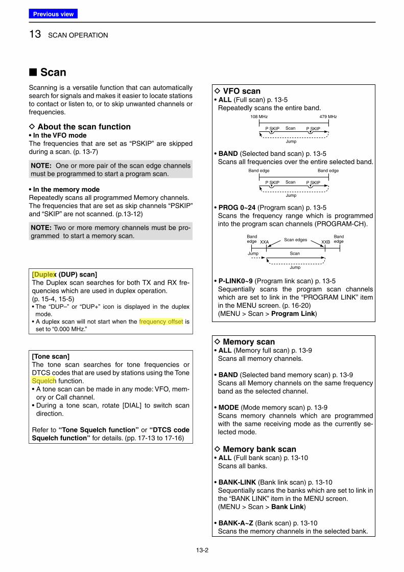
13 SCAN OPERATION
13-2
■ Scan
Scanning is a versatile function that can automatically search for signals and makes it easier to locate stations to contact or listen to, or to skip unwanted channels or frequencies.
D VFO scan• ALL (Full scan) p. 13-5 Repeatedly scans the entire band.
108 MHz 479 MHz
Scan
Jump
P SKIPP SKIP
• BAND (Selected band scan) p. 13-5 Scans all frequencies over the entire selected band.
Band edge Band edge
Scan
Jump
P SKIPP SKIP
• PROG 0~24 (Program scan) p. 13-5 Scans the frequency range which is programmed
into the program scan channels (PROGRAM-CH).
Bandedge XXA XXB
BandedgeScan edges
Scan
Jump
Jump
• P-LINK0~9 (Program link scan) p. 13-5 Sequentially scans the program scan channels
which are set to link in the “PROGRAM LINK” item in the MENU screen. (p. 16-20)
(MENU > Scan > Program Link)
D Memory scan• ALL (Memory full scan) p. 13-9 Scans all memory channels.
• BAND (Selected band memory scan) p. 13-9 Scans all Memory channels on the same frequency
band as the selected channel.
• MODE (Mode memory scan) p. 13-9 Scans memory channels which are programmed
with the same receiving mode as the currently se-lected mode.
D Memory bank scan• ALL (Full bank scan) p. 13-10 Scans all banks.
• BANK-LINK (Bank link scan) p. 13-10 Sequentially scans the banks which are set to link in
the “BANK LINK” item in the MENU screen. (MENU > Scan > Bank Link)
• BANK-A~Z (Bank scan) p. 13-10 Scans the memory channels in the selected bank.
[Duplex (DUP) scan]
The Duplex scan searches for both TX and RX fre-quencies which are used in duplex operation.(p. 15-4, 15-5)• The “DUP–” or “DUP+” icon is displayed in the duplex
mode.• A duplex scan will not start when the frequency offset is
set to “0.000 MHz.”
[Tone scan]
The tone scan searches for tone frequencies or DTCS codes that are used by stations using the Tone Squelch function.• A tone scan can be made in any mode: VFO, mem-
ory or Call channel.• During a tone scan, rotate [DIAL] to switch scan
direction.
Refer to “Tone Squelch function” or “DTCS code
Squelch function” for details. (pp. 17-13 to 17-16)
NOTE: Two or more memory channels must be pro-grammed to start a memory scan.
• In the memory mode
Repeatedly scans all programmed Memory channels.The frequencies that are set as skip channels “PSKIP” and “SKIP” are not scanned. (p.13-12)
NOTE: One or more pair of the scan edge channels must be programmed to start a program scan.
D About the scan function• In the VFO mode
The frequencies that are set as “PSKIP” are skipped during a scan. (p. 13-7)
Previous view
Icom
ハイライト表示
The difference between the transmit and receive frequencies.
Icom
ハイライト表示
An operating mode in which the transmit and receive frequencies are separated by an offset amount.
Icom
ハイライト表示
A function that mutes the audio output for certain signal levels.
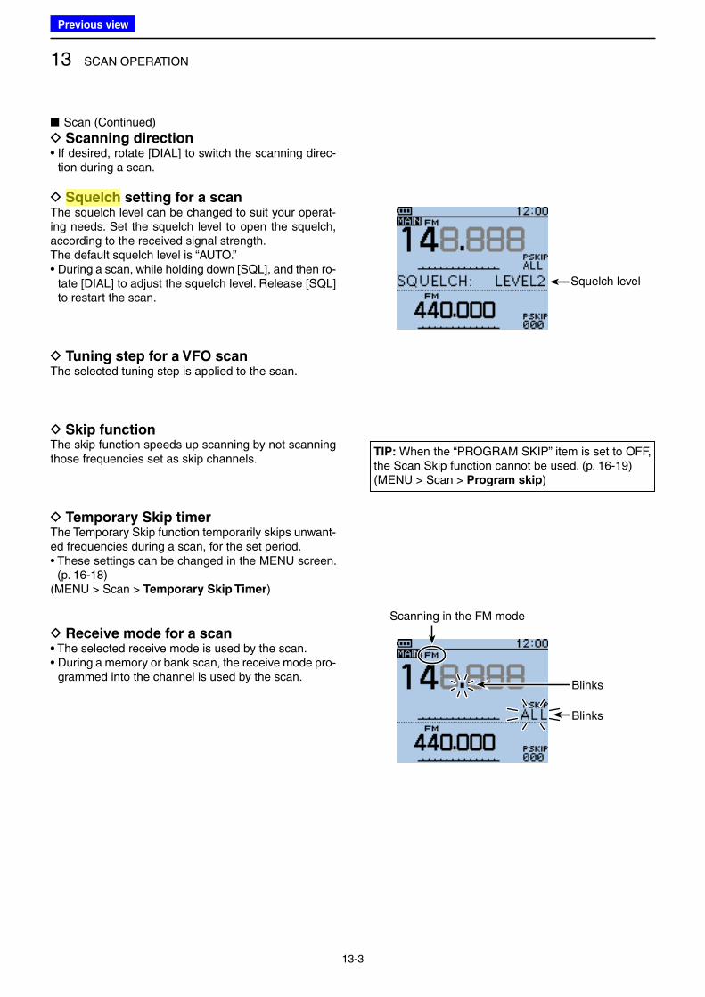
13 SCAN OPERATION
13-3
■ Scan (Continued)
D Scanning direction• If desired, rotate [DIAL] to switch the scanning direc-
tion during a scan.
D Squelch setting for a scanThe squelch level can be changed to suit your operat-ing needs. Set the squelch level to open the squelch, according to the received signal strength. The default squelch level is “AUTO.”• During a scan, while holding down [SQL], and then ro-
tate [DIAL] to adjust the squelch level. Release [SQL] to restart the scan.
D Tuning step for a VFO scanThe selected tuning step is applied to the scan.
D Skip functionThe skip function speeds up scanning by not scanning those frequencies set as skip channels.
D Temporary Skip timerThe Temporary Skip function temporarily skips unwant-ed frequencies during a scan, for the set period.• These settings can be changed in the MENU screen.
(p. 16-18)(MENU > Scan > Temporary Skip Timer)
D Receive mode for a scan• The selected receive mode is used by the scan.• During a memory or bank scan, the receive mode pro-
grammed into the channel is used by the scan.
TIP: When the “PROGRAM SKIP” item is set to OFF, the Scan Skip function cannot be used. (p. 16-19)(MENU > Scan > Program skip)
Squelch level
Scanning in the FM mode
Blinks
Blinks
Previous view
Icom
ハイライト表示
A function that mutes the audio output for certain signal levels.
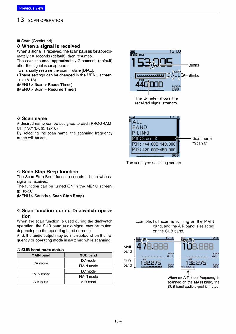
13 SCAN OPERATION
13-4
■ Scan (Continued)
D When a signal is receivedWhen a signal is received, the scan pauses for approxi-mately 10 seconds (default), then resumes.The scan resumes approximately 2 seconds (default) after the signal is disappears.To manually resume the scan, rotate [DIAL].• These settings can be changed in the MENU screen.
(p. 16-18)(MENU > Scan > Pause Timer)(MENU > Scan > Resume Timer)
D Scan nameA desired name can be assigned to each PROGRAM-CH (**A/**B). (p. 12-10)By selecting the scan name, the scanning frequency range will be set.
D Scan Stop Beep functionThe Scan Stop Beep function sounds a beep when a signal is received.The function can be turned ON in the MENU screen. (p. 16-90)(MENU > Sounds > Scan Stop Beep)
D Scan function during Dualwatch opera-tion
When the scan function is used during the dualwatch operation, the SUB band audio signal may be muted, depending on the operating band or mode.And, the audio output may be interrupted when the fre-quency or operating mode is switched while scanning.
❍ SUB band mute status
MAIN band SUB band
DV modeDV mode
FM-N mode
FM-N modeDV mode
FM-N mode
AIR band AIR band
Scan name“Scan 0”
The scan type selecting screen.
The S-meter shows the received signal strength.
Blinks
Blinks
MAIN band
SUB band
Example: Full scan is running on the MAIN band, and the AIR band is selected on the SUB band.
When an AIR band frequency is scanned on the MAIN band, the SUB band audio signal is muted.
Previous view
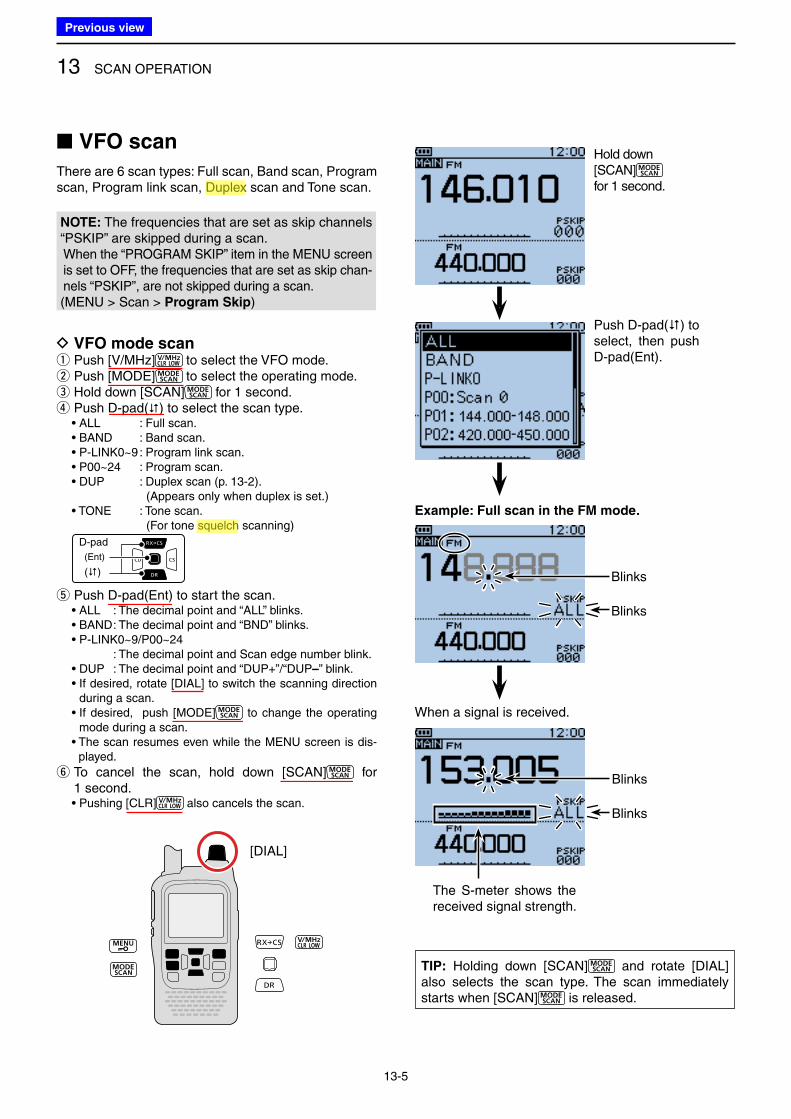
13 SCAN OPERATION
13-5
■ VFO scan
There are 6 scan types: Full scan, Band scan, Program scan, Program link scan, Duplex scan and Tone scan.
NOTE: The frequencies that are set as skip channels “PSKIP” are skipped during a scan. When the “PROGRAM SKIP” item in the MENU screen is set to OFF, the frequencies that are set as skip chan-nels “PSKIP”, are not skipped during a scan.(MENU > Scan > Program Skip)
D VFO mode scan q Push [V/MHz] to select the VFO mode. w Push [MODE] to select the operating mode. e Hold down [SCAN] for 1 second. r Push D-pad() to select the scan type.
• ALL : Full scan. • BAND : Band scan. • P-LINK0~9 : Program link scan. • P00~24 : Program scan. • DUP : Duplex scan (p. 13-2). ( Appears only when duplex is set.) • TONE : Tone scan. (For tone squelch scanning)
D-pad
(�)
(Ent)
t Push D-pad(Ent) to start the scan. • ALL : The decimal point and “ALL” blinks. • BAND : The decimal point and “BND” blinks. • P-LINK0~9/P00~24 : The decimal point and Scan edge number blink. • DUP : The decimal point and “DUP+”/“DUP–” blink. • If desired, rotate [DIAL] to switch the scanning direction
during a scan. • If desired, push [MODE] to change the operating
mode during a scan. • The scan resumes even while the MENU screen is dis-
played.
y To cancel the scan, hold down [SCAN] for 1 second.
• Pushing [CLR] also cancels the scan.
TIP: Holding down [SCAN] and rotate [DIAL] also selects the scan type. The scan immediately starts when [SCAN] is released.
Hold down [SCAN] for 1 second.
Example: Full scan in the FM mode.
When a signal is received.
[DIAL]
Blinks
Blinks
The S-meter shows the received signal strength.
Blinks
Blinks
Push D-pad() to select, then push D-pad(Ent).
Previous view
Icom
ハイライト表示
An operating mode in which the transmit and receive frequencies are separated by an offset amount.
Icom
ハイライト表示
A function that mutes the audio output for certain signal levels.
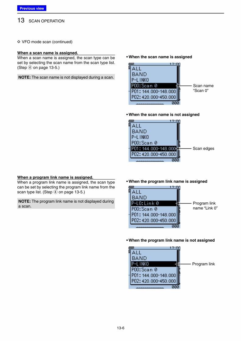
13 SCAN OPERATION
13-6
When a scan name is assigned.
When a scan name is assigned, the scan type can be set by selecting the scan name from the scan type list. (Step r on page 13-5.)
• When the scan name is assigned
• When the program link name is assigned
• When the scan name is not assigned
• When the program link name is not assigned
D VFO mode scan (continued)
Scan name“Scan 0”
When a program link name is assigned.
When a program link name is assigned, the scan type can be set by selecting the program link name from the scan type list. (Step r on page 13-5.)
Scan edges
Program link
Program link name “Link 0”
NOTE: The scan name is not displayed during a scan.
NOTE: The program link name is not displayed during a scan.
Previous view
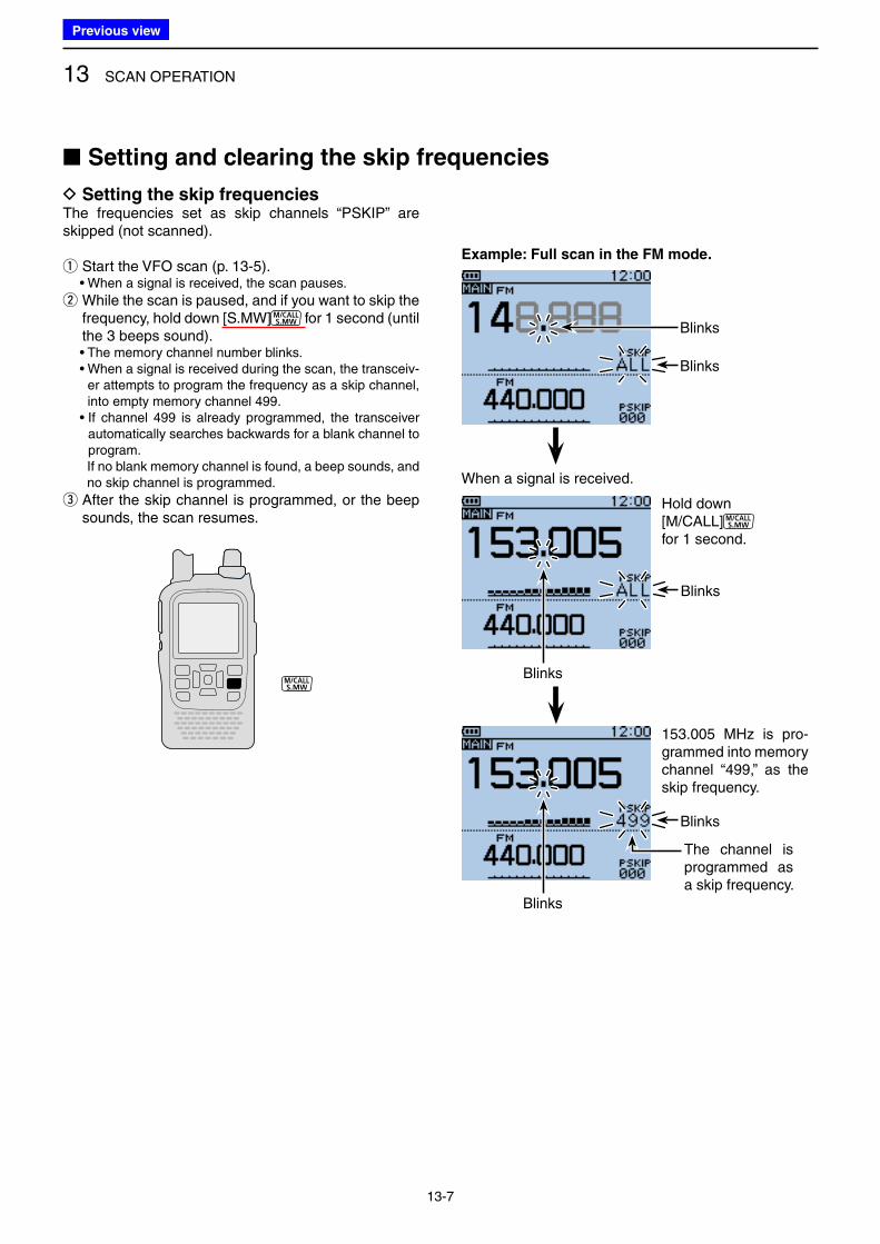
13 SCAN OPERATION
13-7
The channel is programmed as a skip frequency.
Hold down [M/CALL] for 1 second.
153.005 MHz is pro-grammed into memory channel “499,” as the skip frequency.
D Setting the skip frequencies The frequencies set as skip channels “PSKIP” are skipped (not scanned).
q Start the VFO scan (p. 13-5). • When a signal is received, the scan pauses.
w While the scan is paused, and if you want to skip the frequency, hold down [S.MW] for 1 second (until the 3 beeps sound).
• The memory channel number blinks. • When a signal is received during the scan, the transceiv-
er attempts to program the frequency as a skip channel, into empty memory channel 499.
• If channel 499 is already programmed, the transceiver automatically searches backwards for a blank channel to program.
If no blank memory channel is found, a beep sounds, and no skip channel is programmed.
e After the skip channel is programmed, or the beep sounds, the scan resumes.
■ Setting and clearing the skip frequencies
Example: Full scan in the FM mode.
When a signal is received.
Blinks
Blinks
Blinks
Blinks
Blinks
Blinks
Previous view
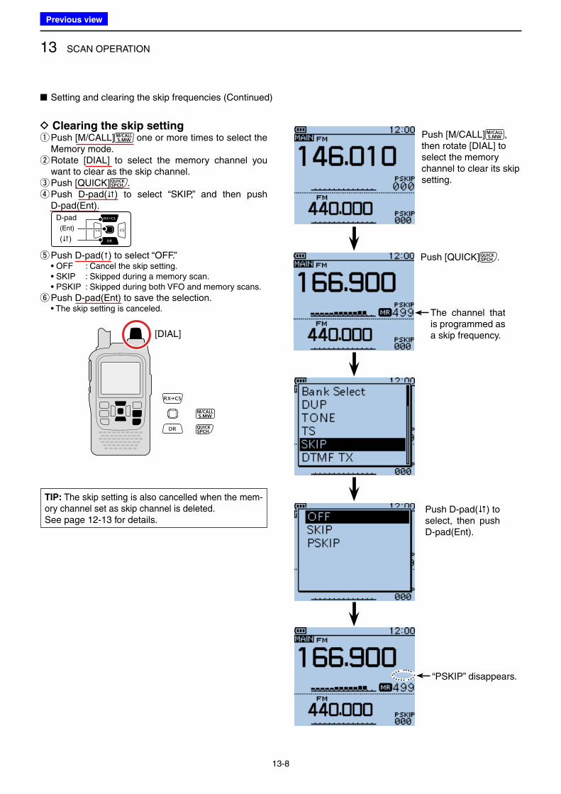
13 SCAN OPERATION
13-8
■ Setting and clearing the skip frequencies (Continued)
D Clearing the skip setting q Push [M/CALL] one or more times to select the Memory mode. w Rotate [DIAL] to select the memory channel you want to clear as the skip channel. ePush [QUICK] . r Push D-pad() to select “SKIP,” and then push D-pad(Ent).
D-pad
(�)
(Ent)
t Push D-pad() to select “OFF.” • OFF : Cancel the skip setting. • SKIP : Skipped during a memory scan. • PSKIP : Skipped during both VFO and memory scans.
y Push D-pad(Ent) to save the selection. • The skip setting is canceled. The channel that
is programmed as a skip frequency.
Push [M/CALL] , then rotate [DIAL] to select the memory channel to clear its skip setting.
Push [QUICK] .
TIP: The skip setting is also cancelled when the mem-ory channel set as skip channel is deleted.See page 12-13 for details.
[DIAL]
“PSKIP” disappears.
Push D-pad() to select, then push D-pad(Ent).
Previous view
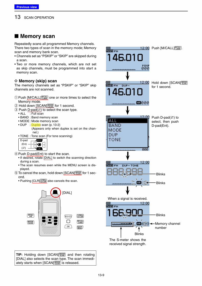
13 SCAN OPERATION
13-9
■ Memory scan
Repeatedly scans all programmed Memory channels.There two types of scan in the memory mode; Memory scan and memory bank scan.• Channels set as “PSKIP” or “SKIP” are skipped during
a scan.• Two or more memory channels, which are not set
as skip channels, must be programmed into start a memory scan.
D Memory (skip) scan The memory channels set as “PSKIP” or “SKIP” skip channels are not scanned.
q Push [M/CALL] one or more times to select the Memory mode. w Hold down [SCAN] for 1 second. e Push D-pad() to select the scan type.
• ALL : Full scan • BAND : Band memory scan • MODE : Mode memory scan • DUP : Duplex scan (p. 13-2) ( Appears only when duplex is set on the chan-
nel.) • TONE : Tone scan (For tone scanning)
D-pad
(�)
(Ent)
r Push D-pad(Ent) to start the scan. • If desired, rotate [DIAL] to switch the scanning direction
during a scan. • The scan resumes even while the MENU screen is dis-
played.
t To cancel the scan, hold down [SCAN] for 1 sec-ond.
• Pushing [CLR] also cancels the scan.
TIP: Holding down [SCAN] and then rotating [DIAL] also selects the scan type. The scan immedi-ately starts when [SCAN] is released.
Hold down [SCAN] for 1 second.
When a signal is received.
Memory channelnumber
[DIAL]
Push [M/CALL] .
Blinks
Blinks
Blinks
Blinks
The S-meter shows the received signal strength.
Push D-pad() to select, then push D-pad(Ent).
Previous view
Icom
ハイライト表示
An operating mode in which the transmit and receive frequencies are separated by an offset amount.
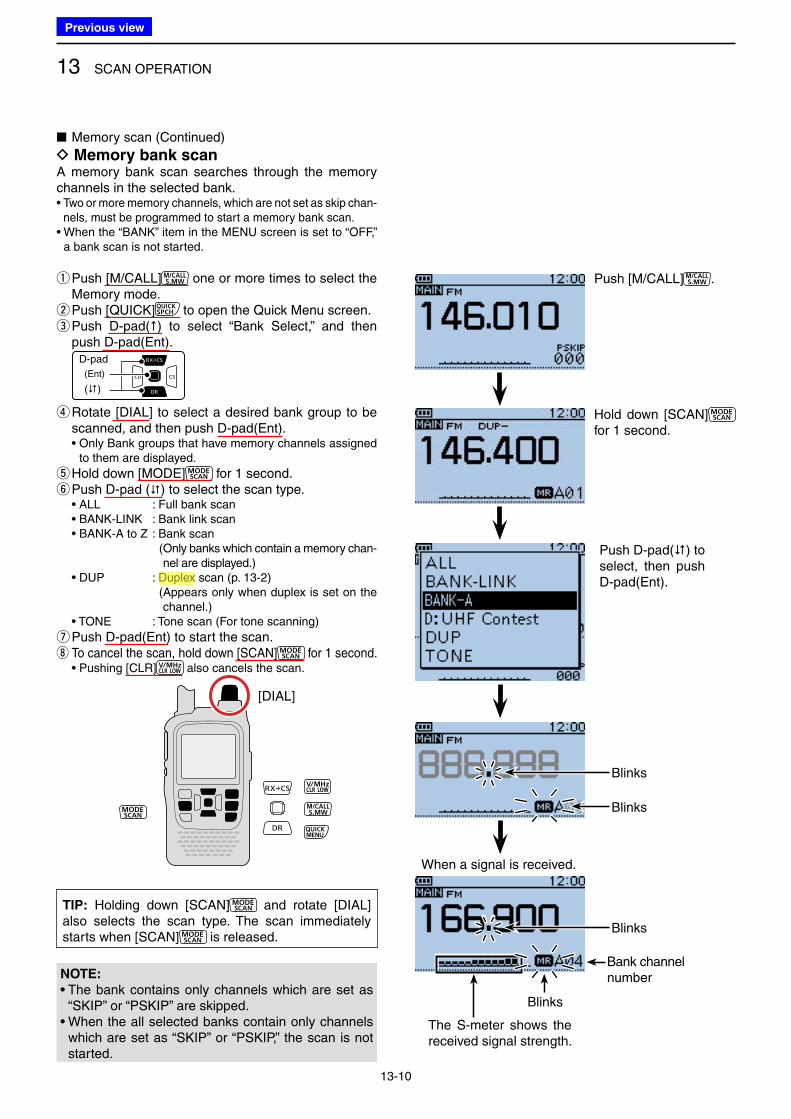
13 SCAN OPERATION
13-10
■ Memory scan (Continued)
D Memory bank scan A memory bank scan searches through the memory channels in the selected bank.• Two or more memory channels, which are not set as skip chan-
nels, must be programmed to start a memory bank scan.• When the “BANK” item in the MENU screen is set to “OFF,”
a bank scan is not started.
q Push [M/CALL] one or more times to select the Memory mode. w Push [QUICK] to open the Quick Menu screen. e Push D-pad() to select “Bank Select,” and then push D-pad(Ent).
D-pad
(�)
(Ent)
r Rotate [DIAL] to select a desired bank group to be scanned, and then push D-pad(Ent).
• Only Bank groups that have memory channels assigned to them are displayed.
t Hold down [MODE] for 1 second. yPush D-pad () to select the scan type.
• ALL : Full bank scan • BANK-LINK : Bank link scan • BANK-A to Z : Bank scan ( Only banks which contain a memory chan-
nel are displayed.) • DUP : Duplex scan (p. 13-2) ( Appears only when duplex is set on the
channel.) • TONE : Tone scan (For tone scanning)
u Push D-pad(Ent) to start the scan. i To cancel the scan, hold down [SCAN] for 1 second.
• Pushing [CLR] also cancels the scan.
NOTE:
• The bank contains only channels which are set as “SKIP” or “PSKIP” are skipped.
• When the all selected banks contain only channels which are set as “SKIP” or “PSKIP,” the scan is not started.
When a signal is received.
Hold down [SCAN] for 1 second.
Push [M/CALL] .
Blinks
Blinks
Bank channelnumber
Blinks
Blinks
The S-meter shows the received signal strength.
Push D-pad() to select, then push D-pad(Ent).
TIP: Holding down [SCAN] and rotate [DIAL] also selects the scan type. The scan immediately starts when [SCAN] is released.
[DIAL]
Previous view
Icom
ハイライト表示
An operating mode in which the transmit and receive frequencies are separated by an offset amount.
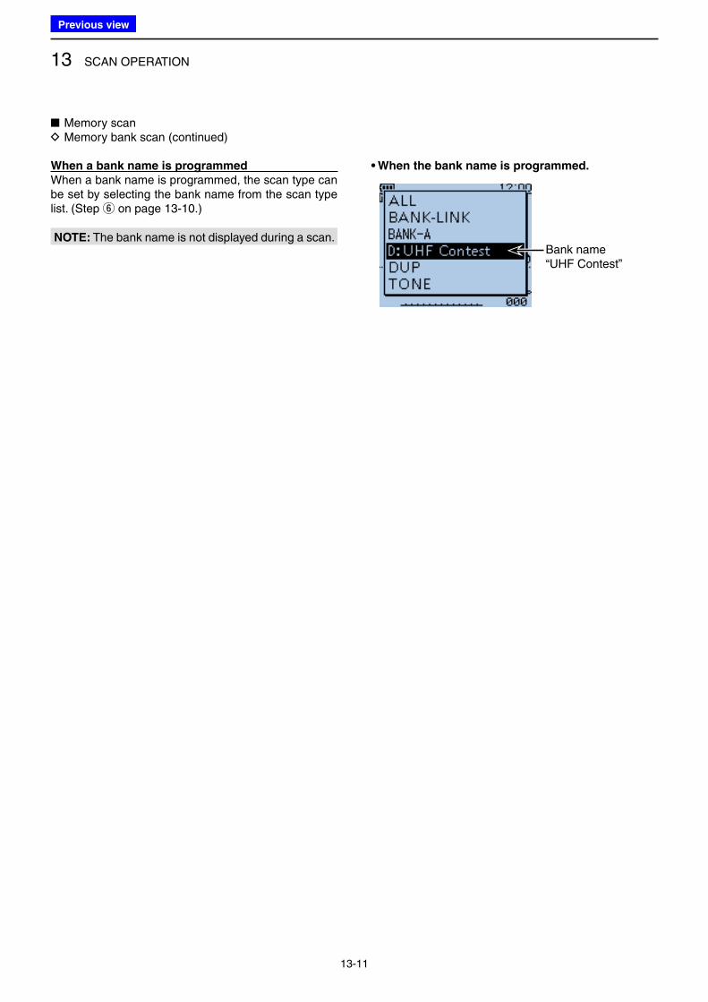
13 SCAN OPERATION
13-11
When a bank name is programmed
When a bank name is programmed, the scan type can be set by selecting the bank name from the scan type list. (Step y on page 13-10.)
• When the bank name is programmed.
Bank name“UHF Contest”
■ Memory scan D Memory bank scan (continued)
NOTE: The bank name is not displayed during a scan.
Previous view
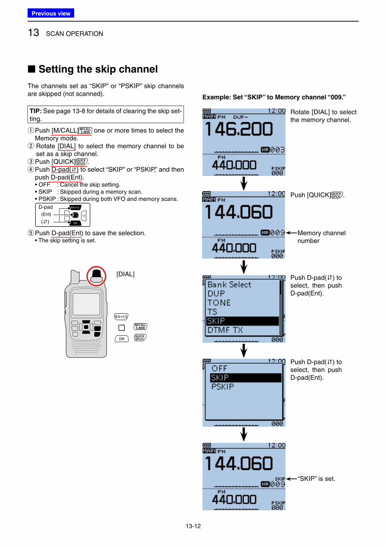
13 SCAN OPERATION
13-12
Example: Set “SKIP” to Memory channel “009.”
Memory channelnumber
Rotate [DIAL] to select the memory channel.
Push [QUICK] .
“SKIP” is set.
The channels set as “SKIP” or “PSKIP” skip channels are skipped (not scanned).
TIP: See page 13-8 for details of clearing the skip set-ting.
q Push [M/CALL] one or more times to select the Memory mode. w Rotate [DIAL] to select the memory channel to be set as a skip channel.
ePush [QUICK] . r Push D-pad() to select “SKIP” or “PSKIP,” and then push D-pad(Ent).
• OFF : Cancel the skip setting. • SKIP : Skipped during a memory scan. • PSKIP : Skipped during both VFO and memory scans.
D-pad
(�)
(Ent)
t Push D-pad(Ent) to save the selection. • The skip setting is set.
[DIAL]
■ Setting the skip channel
Push D-pad() to select, then push D-pad(Ent).
Push D-pad() to select, then push D-pad(Ent).
Previous view
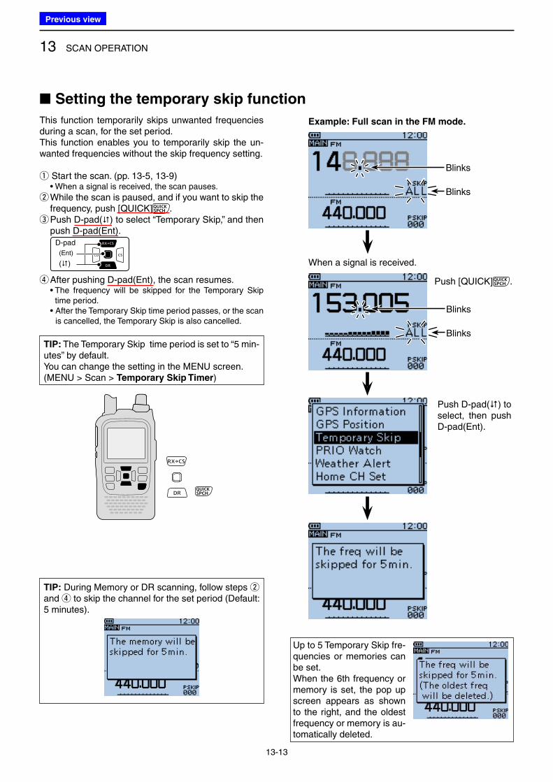
13 SCAN OPERATION
13-13
This function temporarily skips unwanted frequencies during a scan, for the set period.This function enables you to temporarily skip the un-wanted frequencies without the skip frequency setting.
q Start the scan. (pp. 13-5, 13-9) • When a signal is received, the scan pauses.
w While the scan is paused, and if you want to skip the frequency, push [QUICK] . e Push D-pad() to select “Temporary Skip,” and then push D-pad(Ent).
D-pad
(�)
(Ent)
r After pushing D-pad(Ent), the scan resumes. • The frequency will be skipped for the Temporary Skip
time period. • After the Temporary Skip time period passes, or the scan
is cancelled, the Temporary Skip is also cancelled.
■ Setting the temporary skip function
Example: Full scan in the FM mode.
When a signal is received.
Blinks
Blinks
Blinks
Blinks
Push [QUICK] .
Push D-pad() to select, then push D-pad(Ent).
TIP: During Memory or DR scanning, follow steps w and r to skip the channel for the set period (Default: 5 minutes).
Up to 5 Temporary Skip fre-quencies or memories can be set.When the 6th frequency or memory is set, the pop up screen appears as shown to the right, and the oldest frequency or memory is au-tomatically deleted.
TIP: The Temporary Skip time period is set to “5 min-utes” by default.You can change the setting in the MENU screen.(MENU > Scan > Temporary Skip Timer)
Previous view
14-1
Section 14 PRIORITY WATCH
■ Priority watch .................................................................... 14-2
D VFO frequency and a priority channel .......................... 14-2
D VFO frequency and a Memory/Bank scan ................... 14-2
D VFO scan and a priority channel .................................. 14-2
D VFO scan and a Memory/Bank scan ............................. 14-2
D A frequency in “FROM” on the DR screen and
a priority channel .......................................................... 14-3
D DR scan and a priority channel ..................................... 14-3
■ VFO frequency and a priority channel .............................. 14-4
■ VFO frequency and a Memory/Bank scan ....................... 14-6
■ VFO scan and a priority channel ...................................... 14-8
■ VFO scan and Memory/Bank scan ................................. 14-10
■ A frequency in “FROM” on the DR screen and
a priority channel ............................................................ 14-13
■ DR scan and a priority channel ...................................... 14-16
Previous view
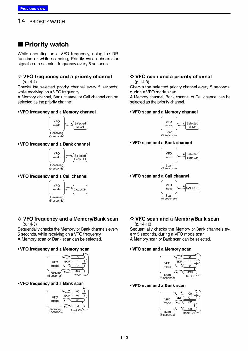
14 PRIORITY WATCH
14-2
■ Priority watch
While operating on a VFO frequency, using the DR function or while scanning, Priority watch checks for signals on a selected frequency every 5 seconds.
D VFO frequency and a priority channel (p. 14-4)Checks the selected priority channel every 5 seconds, while receiving on a VFO frequency.A Memory channel, Bank channel or Call channel can be selected as the priority channel.
• VFO frequency and a Memory channel
Receiving(5 seconds)
VFOmode
SelectedM-CH
• VFO frequency and a Bank channel
SelectedBank CH
Receiving(5 seconds)
VFOmode
• VFO frequency and a Call channel
CALL-CH
Receiving(5 seconds)
VFOmode
D VFO frequency and a Memory/Bank scan (p. 14-6)Sequentially checks the Memory or Bank channels every 5 seconds, while receiving on a VFO frequency.A Memory scan or Bank scan can be selected.
• VFO frequency and a Memory scan
SKIP
0
1
2
499M-CH
Receiving(5 seconds)
VFOmode
• VFO frequency and a Bank scan
SKIP
00
01
02
99
Bank CHReceiving(5 seconds)
VFOmode
D VFO scan and a Memory/Bank scan (p. 14-10)Sequentially checks the Memory or Bank channels ev-ery 5 seconds, during a VFO mode scan.A Memory scan or Bank scan can be selected.
• VFO scan and a Memory scan
SKIP
0
1
2
499
M-CHScan(5 seconds)
VFOmode
• VFO scan and a Bank scan
SKIP
00
01
02
99
Bank CHScan(5 seconds)
VFOmode
D VFO scan and a priority channel (p. 14-8)Checks the selected priority channel every 5 seconds, during a VFO mode scan.A Memory channel, Bank channel or Call channel can be selected as the priority channel.
• VFO scan and a Memory channel
VFOmode
SelectedM-CH
Scan(5 seconds)
• VFO scan and a Bank channel
Scan(5 seconds)
VFOmode
SelectedBank CH
• VFO scan and a Call channel
Scan(5 seconds)
VFOmode CALL-CH
Previous view
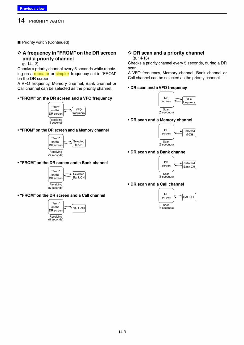
14 PRIORITY WATCH
14-3
D A frequency in “FROM” on the DR screen and a priority channel
(p. 14-13)Checks a priority channel every 5 seconds while receiv-ing on a repeater or simplex frequency set in “FROM” on the DR screen.A VFO frequency, Memory channel, Bank channel or Call channel can be selected as the priority channel.
• “FROM” on the DR screen and a VFO frequency
Receiving(5 seconds)
“From”on the
DR screen
VFOfrequency
• “FROM” on the DR screen and a Memory channel
Receiving(5 seconds)
“From”on the
DR screen
SelectedM-CH
• “FROM” on the DR screen and a Bank channel
Receiving(5 seconds)
“From”on the
DR screen
SelectedBank CH
• “FROM” on the DR screen and a Call channel
Receiving(5 seconds)
“From”on the
DR screenCALL-CH
D DR scan and a priority channel (p. 14-16)Checks a priority channel every 5 seconds, during a DR scan.A VFO frequency, Memory channel, Bank channel or Call channel can be selected as the priority channel.
• DR scan and a VFO frequency
Scan(5 seconds)
DRscreen
VFOfrequency
• DR scan and a Memory channel
Scan(5 seconds)
DRscreen
SelectedM-CH
• DR scan and a Bank channel
Scan(5 seconds)
DRscreen
SelectedBank CH
• DR scan and a Call channel
Scan(5 seconds)
DRscreen CALL-CH
■ Priority watch (Continued)
Previous view
Icom
ハイライト表示
An operating mode in which the transmit and receive frequencies are the same.
Icom
ハイライト表示
Radio systems that receive incoming signals and retransmit them to extend the communication area. Normally put on geographically high locations for VHF/UHF radios.
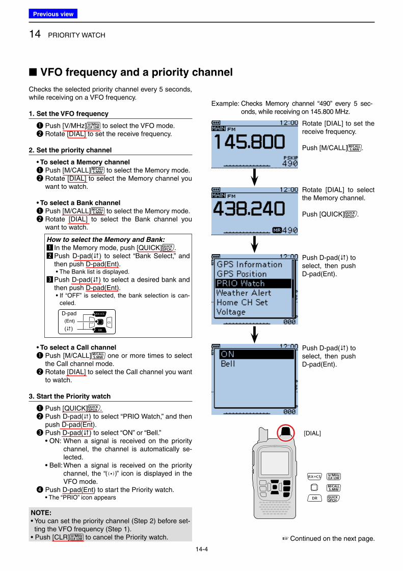
14 PRIORITY WATCH
14-4
Checks the selected priority channel every 5 seconds, while receiving on a VFO frequency.
1. Set the VFO frequency
q Push [V/MHz] to select the VFO mode. w Rotate [DIAL] to set the receive frequency.
2. Set the priority channel
• To select a Memory channel
q Push [M/CALL] to select the Memory mode. w Rotate [DIAL] to select the Memory channel you
want to watch. • To select a Bank channel
q Push [M/CALL] to select the Memory mode. w Rotate [DIAL] to select the Bank channel you
want to watch.
How to select the Memory and Bank:
z In the Memory mode, push [QUICK] .x Push D-pad() to select “Bank Select,” and
then push D-pad(Ent). • The Bank list is displayed.
c Push D-pad() to select a desired bank and then push D-pad(Ent).
• If “OFF” is selected, the bank selection is can-celed.
D-pad
(�)
(Ent)
• To select a Call channel
q Push [M/CALL] one or more times to select the Call channel mode.
w Rotate [DIAL] to select the Call channel you want to watch.
3. Start the Priority watch
q Push [QUICK] . w Push D-pad() to select “PRIO Watch,” and then
push D-pad(Ent). e Push D-pad() to select “ON” or “Bell.” • ON: When a signal is received on the priority
channel, the channel is automatically se-lected.
• Bell: When a signal is received on the priority channel, the “ ” icon is displayed in the VFO mode.
r Push D-pad(Ent) to start the Priority watch. • The “PRIO” icon appears
■ VFO frequency and a priority channel
[DIAL]
Example: Checks Memory channel “490” every 5 sec-onds, while receiving on 145.800 MHz.
☞ Continued on the next page.
Rotate [DIAL] to set the receive frequency.
Push [M/CALL] .
Rotate [DIAL] to select the Memory channel.
Push [QUICK] .
Push D-pad() to select, then push D-pad(Ent).
Push D-pad() to select, then push D-pad(Ent).
NOTE:
• You can set the priority channel (Step 2) before set-ting the VFO frequency (Step 1).
• Push [CLR] to cancel the Priority watch.
Previous view
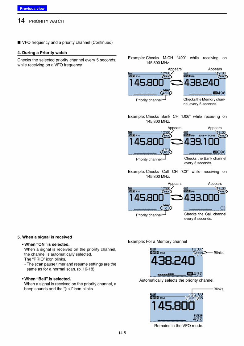
14 PRIORITY WATCH
14-5
Blinks
Automatically selects the priority channel.
Remains in the VFO mode.
4. During a Priority watch
Checks the selected priority channel every 5 seconds, while receiving on a VFO frequency.
5. When a signal is received
• When “ON” is selected.
When a signal is received on the priority channel, the channel is automatically selected.
The “PRIO” icon blinks. - The scan pause timer and resume settings are the
same as for a normal scan. (p. 16-18)
• When “Bell” is selected.
When a signal is received on the priority channel, a beep sounds and the “ ” icon blinks.
Example: Checks M-CH “490” while receiving on 145.800 MHz.
Example: Checks Bank CH “D06” while receiving on 145.800 MHz.
Example: Checks Call CH “C3” while receiving on 145.800 MHz.
Example: For a Memory channel
Appears
Checks the Memory chan-nel every 5 seconds.
■ VFO frequency and a priority channel (Continued)
Appears
Appears Appears
Appears Appears
Priority channel
Priority channel
Priority channel
Blinks
Checks the Bank channel every 5 seconds.
Checks the Call channel every 5 seconds.
Previous view
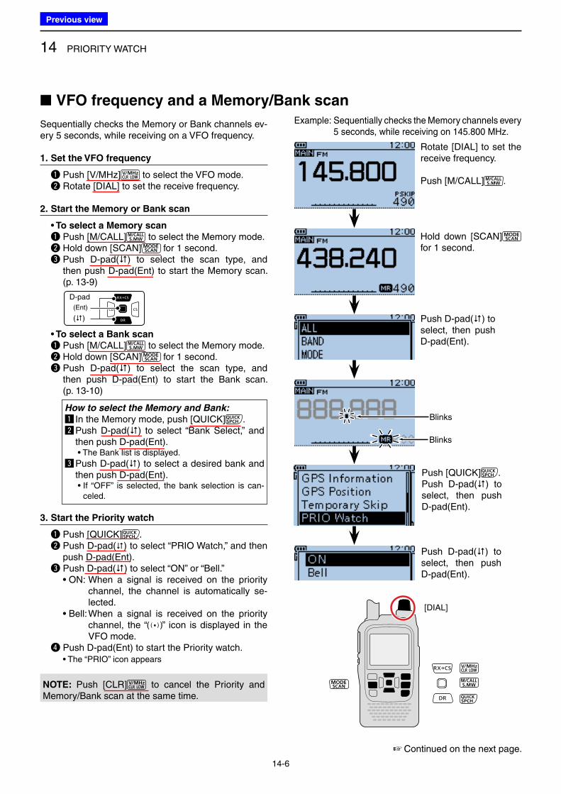
14 PRIORITY WATCH
14-6
Sequentially checks the Memory or Bank channels ev-ery 5 seconds, while receiving on a VFO frequency.
1. Set the VFO frequency
q Push [V/MHz] to select the VFO mode. w Rotate [DIAL] to set the receive frequency.
2. Start the Memory or Bank scan
• To select a Memory scan
q Push [M/CALL] to select the Memory mode. w Hold down [SCAN] for 1 second. e Push D-pad() to select the scan type, and
then push D-pad(Ent) to start the Memory scan. (p. 13-9)
D-pad
(�)
(Ent)
• To select a Bank scan
q Push [M/CALL] to select the Memory mode. w Hold down [SCAN] for 1 second. e Push D-pad() to select the scan type, and
then push D-pad(Ent) to start the Bank scan. (p. 13-10)
How to select the Memory and Bank:
z In the Memory mode, push [QUICK] .x Push D-pad() to select “Bank Select,” and
then push D-pad(Ent). • The Bank list is displayed.
c Push D-pad() to select a desired bank and then push D-pad(Ent).
• If “OFF” is selected, the bank selection is can-celed.
3. Start the Priority watch
q Push [QUICK] . w Push D-pad() to select “PRIO Watch,” and then
push D-pad(Ent). e Push D-pad() to select “ON” or “Bell.” • ON: When a signal is received on the priority
channel, the channel is automatically se-lected.
• Bell: When a signal is received on the priority channel, the “ ” icon is displayed in the VFO mode.
r Push D-pad(Ent) to start the Priority watch. • The “PRIO” icon appears
■ VFO frequency and a Memory/Bank scan
Example: Sequentially checks the Memory channels every 5 seconds, while receiving on 145.800 MHz.
[DIAL]
☞ Continued on the next page.
Rotate [DIAL] to set the receive frequency.
Push [M/CALL] .
Hold down [SCAN] for 1 second.
Push D-pad() to select, then push D-pad(Ent).
Push [QUICK] .Push D-pad() to select, then push D-pad(Ent).
Blinks
Blinks
Push D-pad() to select, then push D-pad(Ent).
NOTE: Push [CLR] to cancel the Priority and Memory/Bank scan at the same time.
Previous view
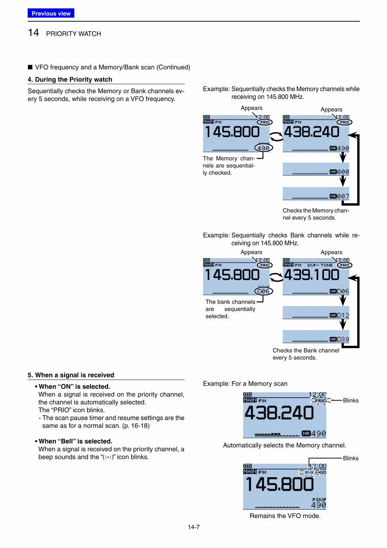
14 PRIORITY WATCH
14-7
4. During the Priority watch
Sequentially checks the Memory or Bank channels ev-ery 5 seconds, while receiving on a VFO frequency.
5. When a signal is received
• When “ON” is selected.
When a signal is received on the priority channel, the channel is automatically selected.
The “PRIO” icon blinks. - The scan pause timer and resume settings are the
same as for a normal scan. (p. 16-18)
• When “Bell” is selected.
When a signal is received on the priority channel, a beep sounds and the “ ” icon blinks.
Example: Sequentially checks the Memory channels while receiving on 145.800 MHz.
Example: Sequentially checks Bank channels while re-ceiving on 145.800 MHz.
■ VFO frequency and a Memory/Bank scan (Continued)
Appears
Checks the Memory chan-nel every 5 seconds.
The Memory chan-nels are sequential-ly checked.
Checks the Bank channel every 5 seconds.
The bank channels are sequentially selected.
Appears
Automatically selects the Memory channel.
Remains the VFO mode.
Example: For a Memory scan
Blinks
Blinks
Appears
Appears
Previous view
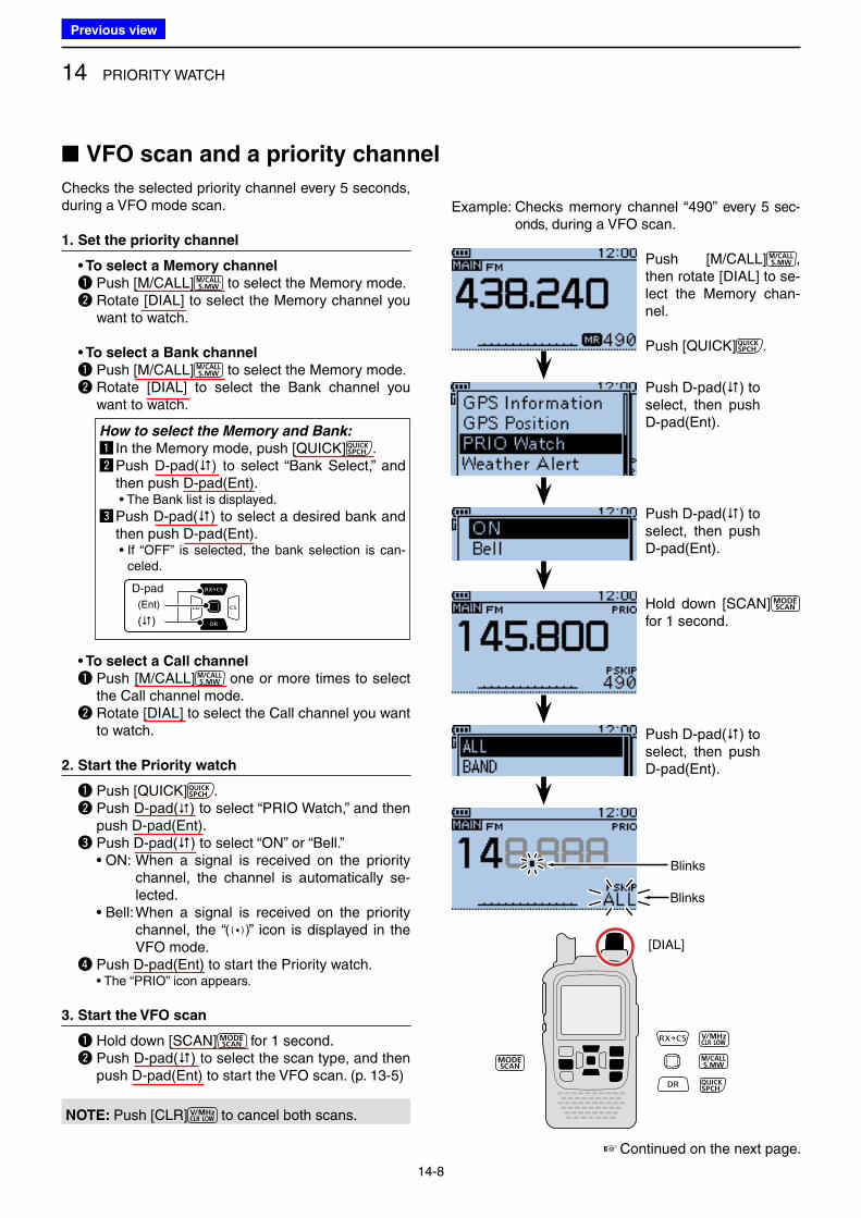
14 PRIORITY WATCH
14-8
Checks the selected priority channel every 5 seconds, during a VFO mode scan.
1. Set the priority channel
• To select a Memory channel
q Push [M/CALL] to select the Memory mode. w Rotate [DIAL] to select the Memory channel you
want to watch. • To select a Bank channel
q Push [M/CALL] to select the Memory mode. w Rotate [DIAL] to select the Bank channel you
want to watch.
How to select the Memory and Bank:
z In the Memory mode, push [QUICK] .x Push D-pad() to select “Bank Select,” and
then push D-pad(Ent). • The Bank list is displayed.
c Push D-pad() to select a desired bank and then push D-pad(Ent).
• If “OFF” is selected, the bank selection is can-celed.
D-pad
(�)
(Ent)
• To select a Call channel
q Push [M/CALL] one or more times to select the Call channel mode.
w Rotate [DIAL] to select the Call channel you want to watch.
2. Start the Priority watch
q Push [QUICK] . w Push D-pad() to select “PRIO Watch,” and then
push D-pad(Ent). e Push D-pad() to select “ON” or “Bell.” • ON: When a signal is received on the priority
channel, the channel is automatically se-lected.
• Bell: When a signal is received on the priority channel, the “ ” icon is displayed in the VFO mode.
r Push D-pad(Ent) to start the Priority watch. • The “PRIO” icon appears.
3. Start the VFO scan
q Hold down [SCAN] for 1 second. w Push D-pad() to select the scan type, and then
push D-pad(Ent) to start the VFO scan. (p. 13-5)
■ VFO scan and a priority channel
Example: Checks memory channel “490” every 5 sec-onds, during a VFO scan.
☞ Continued on the next page.
Push [M/CALL] , then rotate [DIAL] to se-lect the Memory chan-nel.
Push [QUICK] .
Push D-pad() to select, then push D-pad(Ent).
Push D-pad() to select, then push D-pad(Ent).
Hold down [SCAN] for 1 second.
Push D-pad() to select, then push D-pad(Ent).
Blinks
Blinks
[DIAL]
NOTE: Push [CLR] to cancel both scans.
Previous view
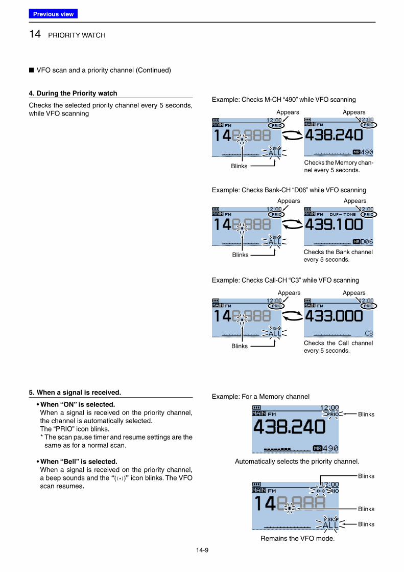
14 PRIORITY WATCH
14-9
5. When a signal is received.
• When “ON” is selected.
When a signal is received on the priority channel, the channel is automatically selected.
The “PRIO” icon blinks. * The scan pause timer and resume settings are the
same as for a normal scan.
• When “Bell” is selected.
When a signal is received on the priority channel, a beep sounds and the “ ” icon blinks. The VFO scan resumes.
Blinks
■ VFO scan and a priority channel (Continued)
Checks the Bank channel every 5 seconds.
4. During the Priority watch
Checks the selected priority channel every 5 seconds, while VFO scanning Appears Appears
Checks the Memory chan-nel every 5 seconds.
Example: Checks M-CH “490” while VFO scanning
Example: Checks Bank-CH “D06” while VFO scanning
Appears Appears
Blinks
Example: Checks Call-CH “C3” while VFO scanning
Appears Appears
BlinksChecks the Call channel every 5 seconds.
Automatically selects the priority channel.
Remains the VFO mode.
Example: For a Memory channel
Blinks
Blinks
Blinks
Blinks
Previous view
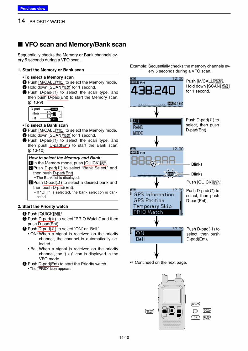
14 PRIORITY WATCH
14-10
■ VFO scan and Memory/Bank scan
Blinks
Example: Sequentially checks the memory channels ev-ery 5 seconds during a VFO scan.
Sequentially checks the Memory or Bank channels ev-ery 5 seconds during a VFO scan.
1. Start the Memory or Bank scan
• To select a Memory scan
q Push [M/CALL] to select the Memory mode. w Hold down [SCAN] for 1 second. e Push D-pad() to select the scan type, and
then push D-pad(Ent) to start the Memory scan. (p. 13-9)
D-pad
(�)
(Ent)
• To select a Bank scan
q Push [M/CALL] to select the Memory mode. w Hold down [SCAN] for 1 second. e Push D-pad() to select the scan type, and
then push D-pad(Ent) to start the Bank scan. (p.13-10)
How to select the Memory and Bank:
z In the Memory mode, push [QUICK] .x Push D-pad() to select “Bank Select,” and
then push D-pad(Ent). • The Bank list is displayed.
c Push D-pad() to select a desired bank and then push D-pad(Ent).
• If “OFF” is selected, the bank selection is can-celed.
2. Start the Priority watch
q Push [QUICK] . w Push D-pad() to select “PRIO Watch,” and then
push D-pad(Ent). e Push D-pad() to select “ON” or “Bell.” • ON: When a signal is received on the priority
channel, the channel is automatically se-lected.
• Bell: When a signal is received on the priority channel, the “ ” icon is displayed in the VFO mode.
r Push D-pad(Ent) to start the Priority watch. • The “PRIO” icon appears
☞ Continued on the next page.
Push [M/CALL] .Hold down [SCAN] for 1 second.
Push D-pad() to select, then push D-pad(Ent).
Blinks
Push [QUICK] .
Push D-pad() to select, then push D-pad(Ent).
Push D-pad() to select, then push D-pad(Ent).
Previous view
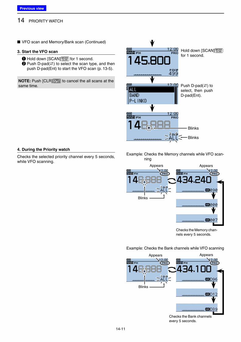
14 PRIORITY WATCH
14-11
■ VFO scan and Memory/Bank scan (Continued)
3. Start the VFO scan
q Hold down [SCAN] for 1 second. w Push D-pad() to select the scan type, and then
push D-pad(Ent) to start the VFO scan (p. 13-5).
4. During the Priority watch
Checks the selected priority channel every 5 seconds, while VFO scanning.
Hold down [SCAN] for 1 second.
Push D-pad() to select, then push D-pad(Ent).
Blinks
Blinks
Example: Checks the Memory channels while VFO scan-ning
Example: Checks the Bank channels while VFO scanning
Blinks
Appears
Checks the Memory chan-nels every 5 seconds.
Blinks
Appears
Checks the Bank channels every 5 seconds.
Appears
Appears
NOTE: Push [CLR] to cancel the all scans at the same time.
Previous view
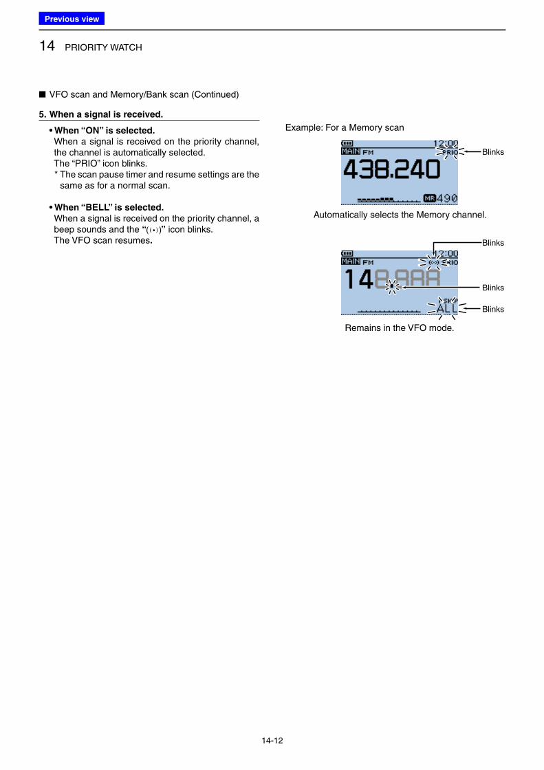
14 PRIORITY WATCH
14-12
■ VFO scan and Memory/Bank scan (Continued)
5. When a signal is received.
• When “ON” is selected.
When a signal is received on the priority channel, the channel is automatically selected.
The “PRIO” icon blinks. * The scan pause timer and resume settings are the
same as for a normal scan.
• When “BELL” is selected.
When a signal is received on the priority channel, a beep sounds and the “ ” icon blinks.
The VFO scan resumes.
Automatically selects the Memory channel.
Remains in the VFO mode.
Example: For a Memory scan
Blinks
Blinks
Blinks
Blinks
Previous view
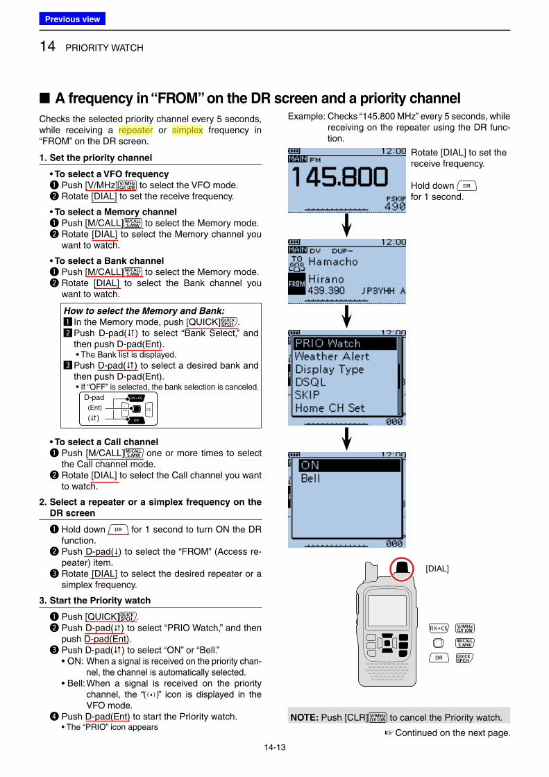
14 PRIORITY WATCH
14-13
■ A frequency in “FROM” on the DR screen and a priority channel
[DIAL]
Example: Checks “145.800 MHz” every 5 seconds, while receiving on the repeater using the DR func-tion.
Checks the selected priority channel every 5 seconds, while receiving a repeater or simplex frequency in “FROM” on the DR screen.
1. Set the priority channel
• To select a VFO frequency
q Push [V/MHz] to select the VFO mode. w Rotate [DIAL] to set the receive frequency.
• To select a Memory channel
q Push [M/CALL] to select the Memory mode. w Rotate [DIAL] to select the Memory channel you
want to watch.
• To select a Bank channel
q Push [M/CALL] to select the Memory mode. w Rotate [DIAL] to select the Bank channel you
want to watch.
How to select the Memory and Bank:
z In the Memory mode, push [QUICK] .x Push D-pad() to select “Bank Select,” and
then push D-pad(Ent). • The Bank list is displayed.
c Push D-pad() to select a desired bank and then push D-pad(Ent).
• If “OFF” is selected, the bank selection is canceled.D-pad
(�)
(Ent)
• To select a Call channel
q Push [M/CALL] one or more times to select the Call channel mode.
w Rotate [DIAL] to select the Call channel you want to watch.
2. Select a repeater or a simplex frequency on the
DR screen
q Hold down for 1 second to turn ON the DR function.
w Push D-pad() to select the “FROM” (Access re-peater) item.
e Rotate [DIAL] to select the desired repeater or a simplex frequency.
3. Start the Priority watch
q Push [QUICK] . w Push D-pad() to select “PRIO Watch,” and then
push D-pad(Ent). e Push D-pad() to select “ON” or “Bell.” • ON: When a signal is received on the priority chan-
nel, the channel is automatically selected. • Bell: When a signal is received on the priority
channel, the “ ” icon is displayed in the VFO mode.
r Push D-pad(Ent) to start the Priority watch. • The “PRIO” icon appears
NOTE: Push [CLR] to cancel the Priority watch.
☞ Continued on the next page.
Rotate [DIAL] to set the receive frequency.
Hold down for 1 second.
Previous view
Icom
ハイライト表示
An operating mode in which the transmit and receive frequencies are the same.
Icom
ハイライト表示
Radio systems that receive incoming signals and retransmit them to extend the communication area. Normally put on geographically high locations for VHF/UHF radios.
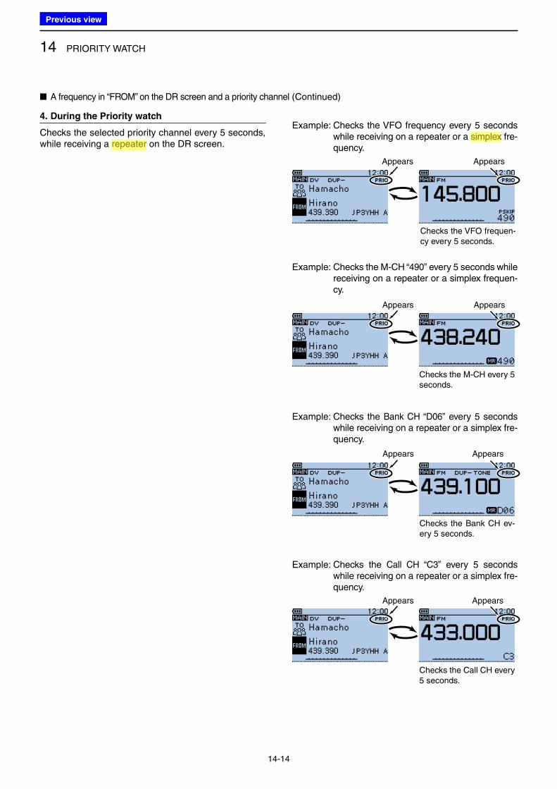
14 PRIORITY WATCH
14-14
■ A frequency in “FROM” on the DR screen and a priority channel (Continued)
4. During the Priority watch
Checks the selected priority channel every 5 seconds, while receiving a repeater on the DR screen.
Example: Checks the VFO frequency every 5 seconds while receiving on a repeater or a simplex fre-quency.
Appears Appears
Checks the VFO frequen-cy every 5 seconds.
Example: Checks the M-CH “490” every 5 seconds while receiving on a repeater or a simplex frequen-cy.
Appears Appears
Checks the M-CH every 5 seconds.
Example: Checks the Bank CH “D06” every 5 seconds while receiving on a repeater or a simplex fre-quency.
Appears Appears
Checks the Bank CH ev-ery 5 seconds.
Example: Checks the Call CH “C3” every 5 seconds while receiving on a repeater or a simplex fre-quency.
Appears Appears
Checks the Call CH every 5 seconds.
Previous view
Icom
ハイライト表示
An operating mode in which the transmit and receive frequencies are the same.
Icom
ハイライト表示
Radio systems that receive incoming signals and retransmit them to extend the communication area. Normally put on geographically high locations for VHF/UHF radios.
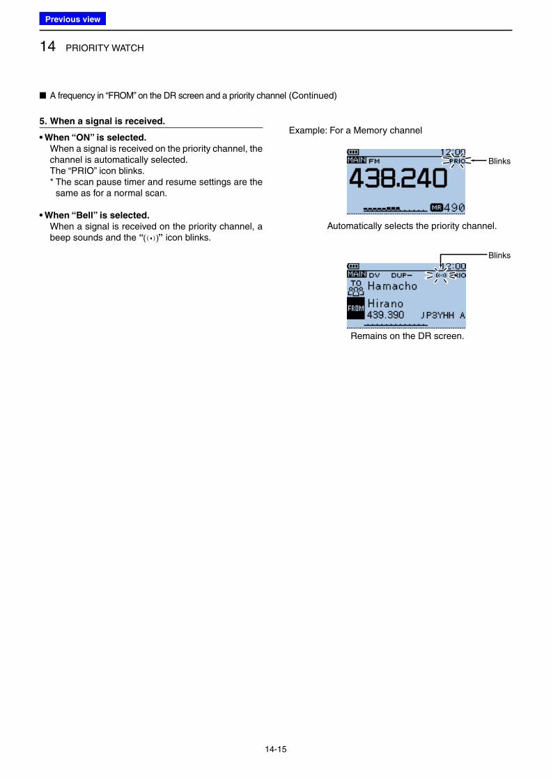
14 PRIORITY WATCH
14-15
5. When a signal is received.
• When “ON” is selected.
When a signal is received on the priority channel, the channel is automatically selected.
The “PRIO” icon blinks. * The scan pause timer and resume settings are the
same as for a normal scan.
• When “Bell” is selected.
When a signal is received on the priority channel, a beep sounds and the “ ” icon blinks.
Automatically selects the priority channel.
Remains on the DR screen.
Example: For a Memory channel
Blinks
Blinks
■ A frequency in “FROM” on the DR screen and a priority channel (Continued)
Previous view
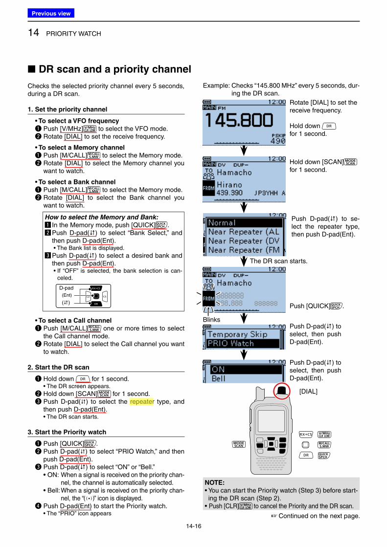
14 PRIORITY WATCH
14-16
■ DR scan and a priority channel
The DR scan starts.
Blinks
[DIAL]
Example: Checks “145.800 MHz” every 5 seconds, dur-ing the DR scan.
Checks the selected priority channel every 5 seconds, during a DR scan.
1. Set the priority channel
• To select a VFO frequency
q Push [V/MHz] to select the VFO mode. w Rotate [DIAL] to set the receive frequency.
• To select a Memory channel
q Push [M/CALL] to select the Memory mode. w Rotate [DIAL] to select the Memory channel you
want to watch.
• To select a Bank channel
q Push [M/CALL] to select the Memory mode. w Rotate [DIAL] to select the Bank channel you
want to watch.
How to select the Memory and Bank:
z In the Memory mode, push [QUICK] .x Push D-pad() to select “Bank Select,” and
then push D-pad(Ent). • The Bank list is displayed.
c Push D-pad() to select a desired bank and then push D-pad(Ent).
• If “OFF” is selected, the bank selection is can-celed.
D-pad
(�)
(Ent)
• To select a Call channel
q Push [M/CALL] one or more times to select the Call channel mode.
w Rotate [DIAL] to select the Call channel you want to watch.
2. Start the DR scan
q Hold down for 1 second. • The DR screen appears.
w Hold down [SCAN] for 1 second. e Push D-pad() to select the repeater type, and
then push D-pad(Ent). • The DR scan starts.
3. Start the Priority watch
q Push [QUICK] . w Push D-pad() to select “PRIO Watch,” and then
push D-pad(Ent). e Push D-pad() to select “ON” or “Bell.” • ON: When a signal is received on the priority chan-
nel, the channel is automatically selected. • Bell: When a signal is received on the priority chan-
nel, the “ ” icon is displayed. r Push D-pad(Ent) to start the Priority watch. • The “PRIO” icon appears
NOTE:
• You can start the Priority watch (Step 3) before start-ing the DR scan (Step 2).
• Push [CLR] to cancel the Priority and the DR scan.
☞ Continued on the next page.
Rotate [DIAL] to set the receive frequency.
Hold down for 1 second.
Hold down [SCAN] for 1 second.
Push [QUICK] .
Push D-pad() to select, then push D-pad(Ent).
Push D-pad() to se-lect the repeater type, then push D-pad(Ent).
Push D-pad() to select, then push D-pad(Ent).
Previous view
Icom
ハイライト表示
Radio systems that receive incoming signals and retransmit them to extend the communication area. Normally put on geographically high locations for VHF/UHF radios.

14 PRIORITY WATCH
14-17
■ DR scan and a priority channel (Continued)
Blinks
4. During the Priority watch
Checks the selected priority channel every 5 seconds, during a DR scan.
Example: Checks the VFO frequency during the DR scan.
Appears Appears
Checks the VFO frequen-cy every 5 seconds.
Example: Checks the M-CH “490” during the DR scan.
Blinks
Appears Appears
Checks the M-CH “490” every 5 seconds.
Example: Checks the Bank CH “D06” during the DR scan.
Blinks
Appears Appears
Checks the Bank CH “D06” every 5 seconds.
Example: Checks the Call CH “C3” during the DR scan.
Blinks
Appears Appears
Checks the Call CH “C3” every 5 seconds.
Previous view
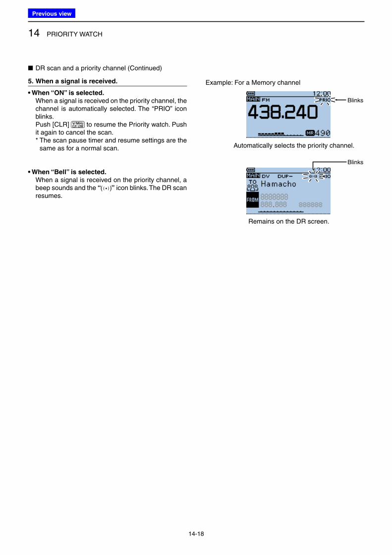
14 PRIORITY WATCH
14-18
5. When a signal is received.
• When “ON” is selected.
When a signal is received on the priority channel, the channel is automatically selected. The “PRIO” icon blinks.
Push [CLR] to resume the Priority watch. Push it again to cancel the scan.
* The scan pause timer and resume settings are the same as for a normal scan.
• When “Bell” is selected.
When a signal is received on the priority channel, a beep sounds and the “ ” icon blinks. The DR scan resumes.
■ DR scan and a priority channel (Continued)
Automatically selects the priority channel.
Remains on the DR screen.
Example: For a Memory channel
Blinks
Blinks
Previous view
15-1
Section 15 REPEATER AND DUPLEX OPERATIONS
■ FM Repeater operation..................................................... 15-2
D Checking the repeater input signal ............................... 15-3
■ Duplex operation .............................................................. 15-4
D Setting the frequency offset .......................................... 15-4
D Setting the duplex direction .......................................... 15-5
D Duplex operation .......................................................... 15-5
■ Off band indication ........................................................... 15-5
■ Auto repeater function ...................................................... 15-6
D Auto repeater setting .................................................... 15-6
D Frequency range and offset direction ........................... 15-6
■ 1750 Hz tone .................................................................... 15-7
Previous view
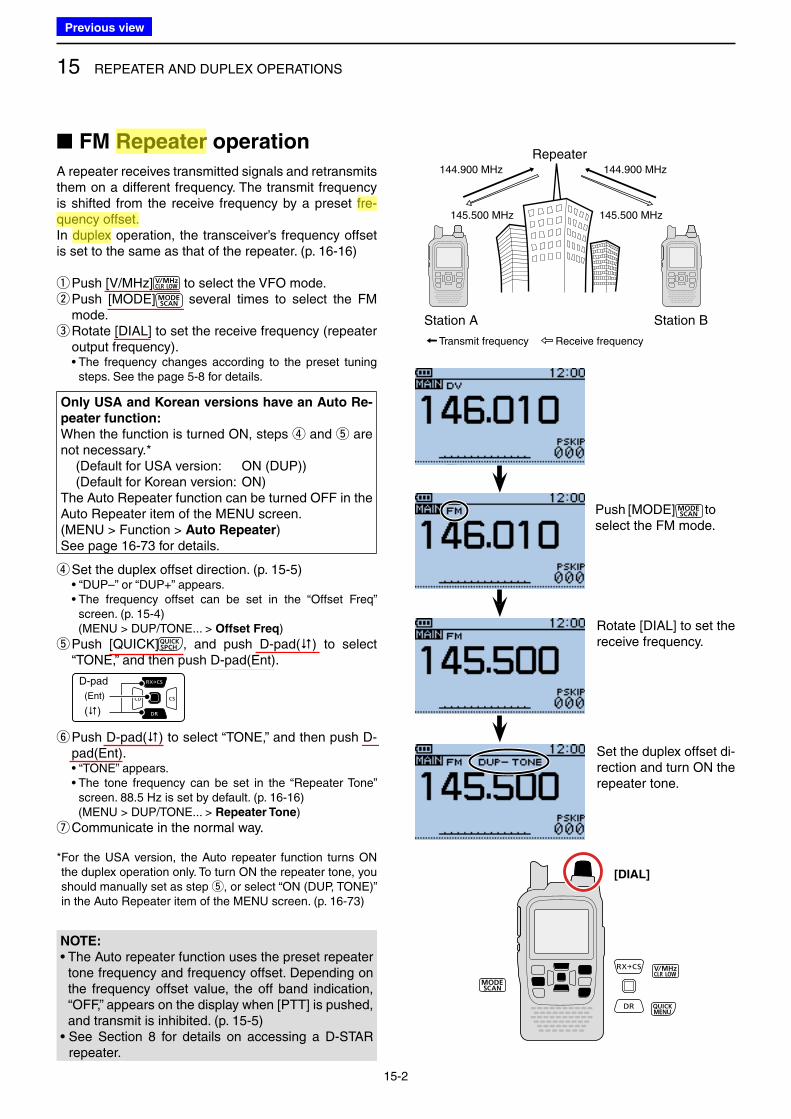
15 REPEATER AND DUPLEX OPERATIONS
15-2
■ FM Repeater operation
A repeater receives transmitted signals and retransmits them on a different frequency. The transmit frequency is shifted from the receive frequency by a preset fre-quency offset.In duplex operation, the transceiver’s frequency offset is set to the same as that of the repeater. (p. 16-16)
qPush [V/MHz] to select the VFO mode. w Push [MODE] several times to select the FM mode. e Rotate [DIAL] to set the receive frequency (repeater output frequency).
• The frequency changes according to the preset tuning steps. See the page 5-8 for details.
Only USA and Korean versions have an Auto Re-
peater function:
When the function is turned ON, steps r and t are not necessary.* (Default for USA version: ON (DUP)) (Default for Korean version: ON) The Auto Repeater function can be turned OFF in the Auto Repeater item of the MENU screen.(MENU > Function > Auto Repeater)See page 16-73 for details.
r Set the duplex offset direction. (p. 15-5) • “DUP–” or “DUP+” appears. • The frequency offset can be set in the “Offset Freq”
screen. (p. 15-4) (MENU > DUP/TONE... > Offset Freq)
t Push [QUICK] , and push D-pad() to select “TONE,” and then push D-pad(Ent).
D-pad
(�)
(Ent)
y Push D-pad() to select “TONE,” and then push D-pad(Ent).
• “TONE” appears. • The tone frequency can be set in the “Repeater Tone”
screen. 88.5 Hz is set by default. (p. 16-16) (MENU > DUP/TONE... > Repeater Tone)
uCommunicate in the normal way.
* For the USA version, the Auto repeater function turns ON the duplex operation only. To turn ON the repeater tone, you should manually set as step t, or select “ON (DUP, TONE)” in the Auto Repeater item of the MENU screen. (p. 16-73)
Station A Station B
Repeater
145.500 MHz
144.900 MHz 144.900 MHz
145.500 MHz
Transmit frequency Receive frequency
[DIAL]
NOTE:
• The Auto repeater function uses the preset repeater tone frequency and frequency offset. Depending on the frequency offset value, the off band indication, “OFF,” appears on the display when [PTT] is pushed, and transmit is inhibited. (p. 15-5)
• See Section 8 for details on accessing a D-STAR repeater.
Push [MODE] to select the FM mode.
Rotate [DIAL] to set the receive frequency.
Set the duplex offset di-rection and turn ON the repeater tone.
Previous view
Icom
ハイライト表示
The difference between the transmit and receive frequencies.
Icom
ハイライト表示
Radio systems that receive incoming signals and retransmit them to extend the communication area. Normally put on geographically high locations for VHF/UHF radios.
Icom
ハイライト表示
An operating mode in which the transmit and receive frequencies are separated by an offset amount.
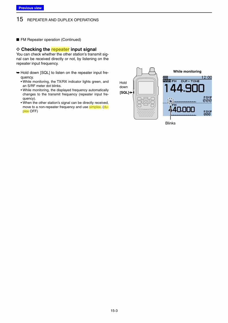
15 REPEATER AND DUPLEX OPERATIONS
15-3
■ FM Repeater operation (Continued)
D Checking the repeater input signalYou can check whether the other station’s transmit sig-nal can be received directly or not, by listening on the repeater input frequency.
➥ Hold down [SQL] to listen on the repeater input fre-quency.
• While monitoring, the TX/RX indicator lights green, and an S/RF meter dot blinks.
• While monitoring, the displayed frequency automatically changes to the transmit frequency (repeater input fre-quency).
• When the other station’s signal can be directly received, move to a non-repeater frequency and use simplex. (du-plex OFF)
While monitoring
Holddown
[SQL]
Blinks
Previous view
Icom
ハイライト表示
An operating mode in which the transmit and receive frequencies are the same.
Icom
ハイライト表示
Radio systems that receive incoming signals and retransmit them to extend the communication area. Normally put on geographically high locations for VHF/UHF radios.
Icom
ハイライト表示
An operating mode in which the transmit and receive frequencies are separated by an offset amount.
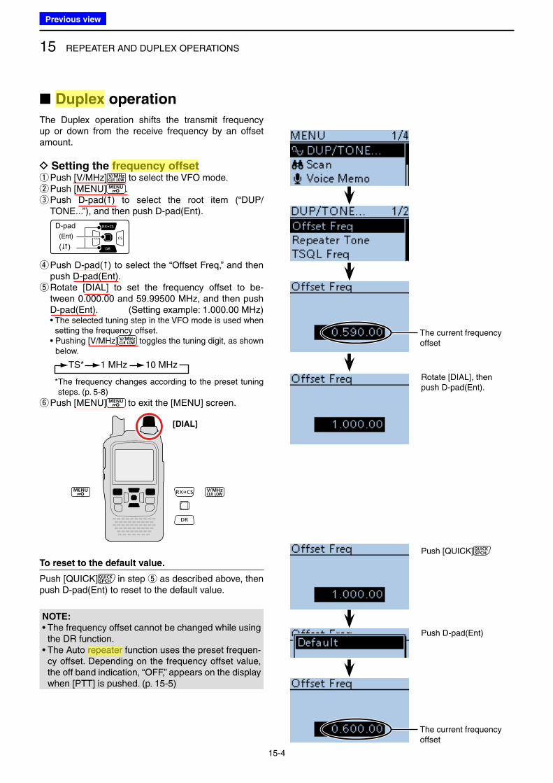
15 REPEATER AND DUPLEX OPERATIONS
15-4
■ Duplex operation
The Duplex operation shifts the transmit frequency up or down from the receive frequency by an offset amount.
D Setting the frequency offset qPush [V/MHz] to select the VFO mode. wPush [MENU] . e Push D-pad() to select the root item (“DUP/TONE...”), and then push D-pad(Ent).
D-pad
(�)
(Ent)
r Push D-pad() to select the “Offset Freq,” and then push D-pad(Ent). t Rotate [DIAL] to set the frequency offset to be-tween 0.000.00 and 59.99500 MHz, and then push D-pad(Ent). (Setting example: 1.000.00 MHz)
• The selected tuning step in the VFO mode is used when setting the frequency offset.
• Pushing [V/MHz] toggles the tuning digit, as shown below.
TS* 1 MHz 10 MHz
* The frequency changes according to the preset tuning steps. (p. 5-8)
y Push [MENU] to exit the [MENU] screen.
To reset to the default value.
Push [QUICK] in step t as described above, then push D-pad(Ent) to reset to the default value.
The current frequency offset
Rotate [DIAL], then push D-pad(Ent).
Push [QUICK]
Push D-pad(Ent)
[DIAL]
The current frequency offset
NOTE:
• The frequency offset cannot be changed while using the DR function.
• The Auto repeater function uses the preset frequen-cy offset. Depending on the frequency offset value, the off band indication, “OFF,” appears on the display when [PTT] is pushed. (p. 15-5)
Previous view
Icom
ハイライト表示
The difference between the transmit and receive frequencies.
Icom
ハイライト表示
An operating mode in which the transmit and receive frequencies are separated by an offset amount.
Icom
ハイライト表示
Radio systems that receive incoming signals and retransmit them to extend the communication area. Normally put on geographically high locations for VHF/UHF radios.
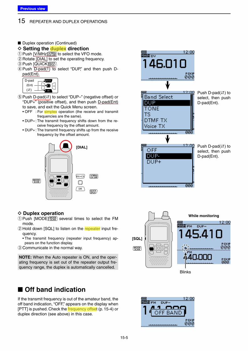
15 REPEATER AND DUPLEX OPERATIONS
15-5
■ Duplex operation (Continued)
D Setting the duplex direction qPush [V/MHz] to select the VFO mode. w Rotate [DIAL] to set the operating frequency. ePush [QUICK] . r Push D-pad() to select “DUP,” and then push D-pad(Ent).
D-pad
(�)
(Ent)
t Push D-pad() to select “DUP–” (negative offset) or “DUP+” (positive offset), and then push D-pad(Ent) to save, and exit the Quick Menu screen.
• OFF : For simplex operation (the receive and transmit frequencies are the same).
• DUP– : The transmit frequency shifts down from the re-ceive frequency by the offset amount.
• DUP+ : The transmit frequency shifts up from the receive frequency by the offset amount.
[DIAL]
■ Off band indication
If the transmit frequency is out of the amateur band, the off band indication, “OFF,” appears on the display when [PTT] is pushed. Check the frequency offset (p. 15-4) or duplex direction (see above) in this case.
Push D-pad() to select, then push D-pad(Ent).
Push D-pad() to select, then push D-pad(Ent).
D Duplex operation q Push [MODE] several times to select the FM mode. w Hold down [SQL] to listen on the repeater input fre-quency.
• The transmit frequency (repeater input frequency) ap-pears on the function display.
eCommunicate in the normal way.
While monitoring
[SQL]
Blinks
NOTE: When the Auto repeater is ON, and the oper-ating frequency is set out of the repeater output fre-quency range, the duplex is automatically cancelled.
Previous view
Icom
ハイライト表示
An operating mode in which the transmit and receive frequencies are the same.
Icom
ハイライト表示
The difference between the transmit and receive frequencies.
Icom
ハイライト表示
Radio systems that receive incoming signals and retransmit them to extend the communication area. Normally put on geographically high locations for VHF/UHF radios.
Icom
ハイライト表示
An operating mode in which the transmit and receive frequencies are separated by an offset amount.
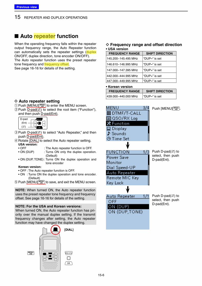
15 REPEATER AND DUPLEX OPERATIONS
15-6
■ Auto repeater function
When the operating frequency falls within the repeater output frequency range, the Auto Repeater function can automatically sets the repeater settings (duplex ON/OFF, duplex direction, tone encoder ON/OFF).The Auto repeater function uses the preset repeater tone frequency and frequency offset. See page 16-16 for details of the setting.
Push [MENU] .
Push D-pad() to select, then push D-pad(Ent).
Push D-pad() to select, then push D-pad(Ent).
D Frequency range and offset direction• USA version
FREQUENCY RANGE SHIFT DIRECTION
145.200~145.495 MHz “DUP–” is set
146.610~146.995 MHz “DUP–” is set
147.000~147.395 MHz “DUP+” is set
442.000~444.995 MHz “DUP+” is set
447.000~449.995 MHz “DUP–” is set
• Korean version
FREQUENCY RANGE SHIFT DIRECTION
439.000~440.000 MHz “DUP–” is set
D Auto repeater setting qPush [MENU] to enter the MENU screen. w Push D-pad() to select the root item (“Function”), and then push D-pad(Ent).
D-pad
(�)
(Ent)
e Push D-pad() to select “Auto Repeater,” and then push D-pad(Ent). r Rotate [DIAL] to select the Auto repeater setting.
USA version:
• OFF : The Auto repeater function is OFF. • ON (DUP) : Turns ON only the duplex operation.
(Default) • ON (DUP, TONE) : Turns ON the duplex operation and
tone encoder Korean version:
• OFF : The Auto repeater function is OFF. • ON : Turns ON the duplex operation and tone encoder.
(Default)
t Push [MENU] to save, and exit the MENU screen.
[DIAL]
NOTE: When turned ON, the Auto repeater function uses the preset repeater tone frequency and frequency offset. See page 16-16 for details of the setting.
NOTE: For the USA and Korean versions:
When turned ON, the Auto repeater function has pri-ority over the manual duplex setting. If the transmit frequency changes after setting, the Auto repeater function may have changed the duplex setting.
Previous view
Icom
ハイライト表示
The difference between the transmit and receive frequencies.
Icom
ハイライト表示
Radio systems that receive incoming signals and retransmit them to extend the communication area. Normally put on geographically high locations for VHF/UHF radios.
Icom
ハイライト表示
An operating mode in which the transmit and receive frequencies are separated by an offset amount.
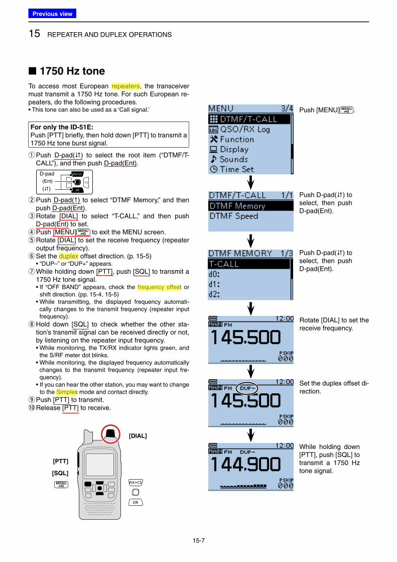
15 REPEATER AND DUPLEX OPERATIONS
15-7
■ 1750 Hz tone
To access most European repeaters, the transceiver must transmit a 1750 Hz tone. For such European re-peaters, do the following procedures.• This tone can also be used as a ‘Call signal.’
For only the ID-51E:
Push [PTT] briefly, then hold down [PTT] to transmit a 1750 Hz tone burst signal.
q Push D-pad() to select the root item (“DTMF/T-CALL”), and then push D-pad(Ent).
D-pad
(�)
(Ent)
w Push D-pad() to select “DTMF Memory,” and then push D-pad(Ent). e Rotate [DIAL] to select “T-CALL,” and then push D-pad(Ent) to set. r Push [MENU] to exit the MENU screen. t Rotate [DIAL] to set the receive frequency (repeater output frequency). y Set the duplex offset direction. (p. 15-5)
• “DUP–” or “DUP+” appears.
u While holding down [PTT], push [SQL] to transmit a 1750 Hz tone signal.
• If “OFF BAND” appears, check the frequency offset or shift direction. (pp. 15-4, 15-5)
• While transmitting, the displayed frequency automati-cally changes to the transmit frequency (repeater input frequency).
i Hold down [SQL] to check whether the other sta-tion’s transmit signal can be received directly or not, by listening on the repeater input frequency.
• While monitoring, the TX/RX indicator lights green, and the S/RF meter dot blinks.
• While monitoring, the displayed frequency automatically changes to the transmit frequency (repeater input fre-quency).
• If you can hear the other station, you may want to change to the Simplex mode and contact directly.
oPush [PTT] to transmit.!0 Release [PTT] to receive.
[PTT]
[SQL]
Push [MENU] .
Push D-pad() to select, then push D-pad(Ent).
Push D-pad() to select, then push D-pad(Ent).
[DIAL]
Rotate [DIAL] to set the receive frequency.
Set the duplex offset di-rection.
While holding down [PTT], push [SQL] to transmit a 1750 Hz tone signal.
Previous view
Icom
ハイライト表示
Radio systems that receive incoming signals and retransmit them to extend the communication area. Normally put on geographically high locations for VHF/UHF radios.
Icom
ハイライト表示
An operating mode in which the transmit and receive frequencies are separated by an offset amount.
Icom
ハイライト表示
The difference between the transmit and receive frequencies.
Icom
ハイライト表示
An operating mode in which the transmit and receive frequencies are the same.
16-1
Section 16 MENU SCREEN
■ Menu item selection.......................................................... 16-2
D Entering the Menu screen ............................................ 16-3
■ Menu items and Default settings ...................................... 16-4
■ DUP/TONE items ........................................................... 16-16
■ Scan items ...................................................................... 16-18
■ Voice Memo items .......................................................... 16-22
■ Voice TX items ................................................................ 16-28
■ Broadcast (BC) Radio items ........................................... 16-30
■ GPS items ...................................................................... 16-32
■ Call sign items ................................................................ 16-51
■ RX History items ............................................................. 16-53
■ DV Memory items ........................................................... 16-56
■ My Station items ............................................................. 16-59
■ DV Set items ................................................................... 16-60
■ SPEECH items ............................................................... 16-66
■ DTMF/T-CALL items ....................................................... 16-68
■ QSO/RX Log items ......................................................... 16-69
■ Function items ................................................................ 16-72
■ Display items .................................................................. 16-80
■ Sounds items .................................................................. 16-88
■ Time set items ................................................................ 16-92
■ DV Gateway items .......................................................... 16-94
■ SD Card items ................................................................ 16-95
■ Others items ................................................................... 16-97
Previous view
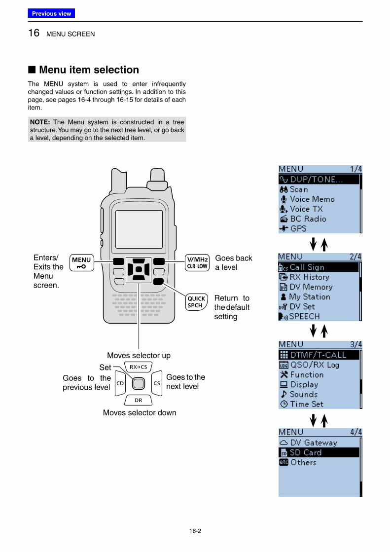
16 MENU SCREEN
16-2
■ Menu item selection
The MENU system is used to enter infrequently changed values or function settings. In addition to this page, see pages 16-4 through 16-15 for details of each item.
Enters/Exits the Menu screen.
Goes back a level
Return to the default setting
Moves selector up
Moves selector down
Goes to the previous level
Goes to the next level
Set
NOTE: The Menu system is constructed in a tree structure. You may go to the next tree level, or go back a level, depending on the selected item.
Previous view
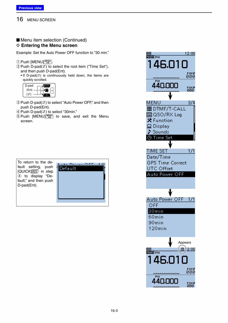
16 MENU SCREEN
16-3
Example: Set the Auto Power OFF function to “30 min.”
qPush [MENU] . w Push D-pad() to select the root item (“Time Set”), and then push D-pad(Ent).
• If D-pad() is continuously held down, the items are quickly scrolled.
D-pad
(�)
(Ent)
e Push D-pad() to select “Auto Power OFF,” and then push D-pad(Ent). r Push D-pad() to select “30min.” t Push [MENU] to save, and exit the Menu screen.
■ Menu item selection (Continued) D Entering the Menu screen
To return to the de-fault setting, push [QUICK] in step r to display “De-fault,” and then push D-pad(Ent).
Appears
Previous view
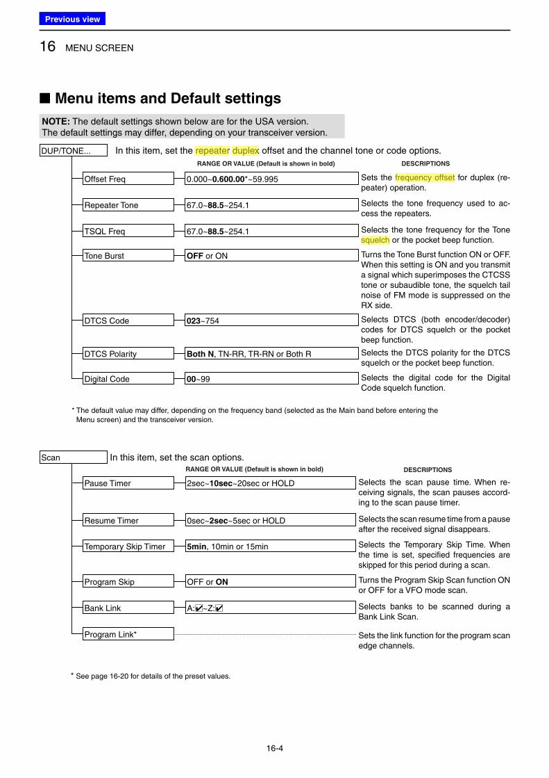
16 MENU SCREEN
16-4
■ Menu items and Default settings
DUP/TONE...
Offset Freq
Repeater Tone
TSQL Freq
Tone Burst
DTCS Code
DTCS Polarity
Digital Code
0.000~0.600.00*~59.995
In this item, set the repeater duplex offset and the channel tone or code options.
67.0~88.5~254.1
67.0~88.5~254.1
RANGE OR VALUE (Default is shown in bold)
OFF or ON
023~754
Both N, TN-RR, TR-RN or Both R
00~99
DESCRIPTIONS
NOTE: The default settings shown below are for the USA version.The default settings may differ, depending on your transceiver version.
Sets the frequency offset for duplex (re-peater) operation.
Selects the tone frequency used to ac-cess the repeaters.
Selects the DTCS polarity for the DTCS squelch or the pocket beep function.
Selects the digital code for the Digital Code squelch function.
Selects the tone frequency for the Tone squelch or the pocket beep function.
Turns the Tone Burst function ON or OFF. When this setting is ON and you transmit a signal which superimposes the CTCSS tone or subaudible tone, the squelch tail noise of FM mode is suppressed on the RX side.
Selects DTCS (both encoder/decoder) codes for DTCS squelch or the pocket beep function.
In this item, set the scan options.Scan
Pause Timer
Resume Timer
Program Skip
Bank Link
Program Link*
2sec~10sec~20sec or HOLD
0sec~2sec~5sec or HOLD
OFF or ON
A:□✔~Z:□✔
* See page 16-20 for details of the preset values.
RANGE OR VALUE (Default is shown in bold) DESCRIPTIONS
Selects the scan pause time. When re-ceiving signals, the scan pauses accord-ing to the scan pause timer.
Selects the scan resume time from a pause after the received signal disappears.
Turns the Program Skip Scan function ON or OFF for a VFO mode scan.
Selects banks to be scanned during a Bank Link Scan.
Sets the link function for the program scan edge channels.
Temporary Skip Timer 5min, 10min or 15min Selects the Temporary Skip Time. When the time is set, specified frequencies are skipped for this period during a scan.
* The default value may differ, depending on the frequency band (selected as the Main band before entering the Menu screen) and the transceiver version.
Previous view
Icom
ハイライト表示
The difference between the transmit and receive frequencies.
Icom
ハイライト表示
Radio systems that receive incoming signals and retransmit them to extend the communication area. Normally put on geographically high locations for VHF/UHF radios.
Icom
ハイライト表示
An operating mode in which the transmit and receive frequencies are separated by an offset amount.
Icom
ハイライト表示
A function that mutes the audio output for certain signal levels.
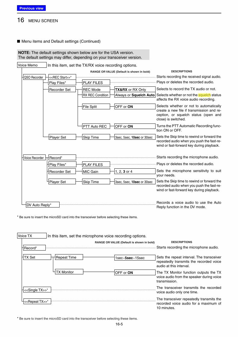
16 MENU SCREEN
16-5
NOTE: The default settings shown below are for the USA version.The default settings may differ, depending on your transceiver version.
■ Menu items and Default settings (Continued)
QSO Recorder <<REC Start>>*
Play Files*
Recorder Set
Player Set
PLAY FILES
REC Mode
RX REC Condition
File Split
PTT Auto REC
Skip Time
In this item, set the TX/RX voice recording options.
TX&RX or RX Only
Always or Squelch Auto
OFF or ON
OFF or ON
3sec, 5sec, 10sec or 30sec
DV Auto Reply*
Voice Memo
DESCRIPTIONSRANGE OR VALUE (Default is shown in bold)
Selects whether or not the squelch status affects the RX voice audio recording.
Turns the PTT Automatic Recording func-tion ON or OFF.
Sets the Skip time to rewind or forward the recorded audio when you push the fast-re-wind or fast-forward key during playback.
Selects whether or not to automatically create a new file if transmission and re-ception, or squelch status (open and close) is switched.
Selects to record the TX audio or not.
Plays or deletes the recorded audio.
Starts recording the received signal audio.
Records a voice audio to use the Auto Reply function in the DV mode.
Voice Recorder Record*
Play Files* PLAY FILES
1, 2, 3 or 4 Sets the microphone sensitivity to suit your needs.
Plays or deletes the recorded audio.
Starts recording the microphone audio.
Player Set Skip Time 3sec, 5sec, 10sec or 30sec Sets the Skip time to rewind or forward the recorded audio when you push the fast-re-wind or fast-forward key during playback.
* Be sure to insert the microSD card into the transceiver before selecting these items.
Record*
TX Set Repeat Time
In this item, set the microphone voice recording options.
1sec~5sec~15sec
OFF or ON
Voice TX
DESCRIPTIONSRANGE OR VALUE (Default is shown in bold)
The TX Monitor function outputs the TX voice audio from the speaker during voice transmission.
Sets the repeat interval. The transceiver repeatedly transmits the recorded voice audio at this interval.
Starts recording the microphone audio.
<<Single TX>>*
<<Repeat TX>>*
TX Monitor
Recorder Set MIC Gain
The transceiver transmits the recorded voice audio only one time.
The transceiver repeatedly transmits the recorded voice audio for a maximum of 10 minutes.
* Be sure to insert the microSD card into the transceiver before selecting these items.
Previous view
Icom
ハイライト表示
A function that mutes the audio output for certain signal levels.
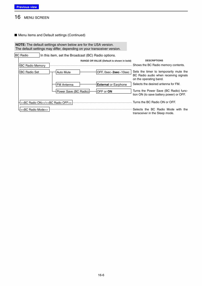
16 MENU SCREEN
16-6
NOTE: The default settings shown below are for the USA version.The default settings may differ, depending on your transceiver version.
■ Menu items and Default settings (Continued)
BC Radio Memory
BC Radio Set Auto Mute
In this item, set the Broadcast (BC) Radio options.
OFF, 0sec~2sec~10sec
OFF or ON
BC Radio
DESCRIPTIONSRANGE OR VALUE (Default is shown in bold)
Turns the Power Save (BC Radio) func-tion ON (to save battery power) or OFF.
Sets the timer to temporarily mute the BC Radio audio when receiving signals on the operating band.
Shows the BC Radio memory contents.
<<BC Radio ON>>/<<BC Radio OFF>>
<<BC Radio Mode>>
Power Save (BC Radio)
Turns the BC Radio ON or OFF.
Selects the BC Radio Mode with the transceiver in the Sleep mode.
FM Antenna External or Earphone Selects the desired antenna for FM.
Previous view
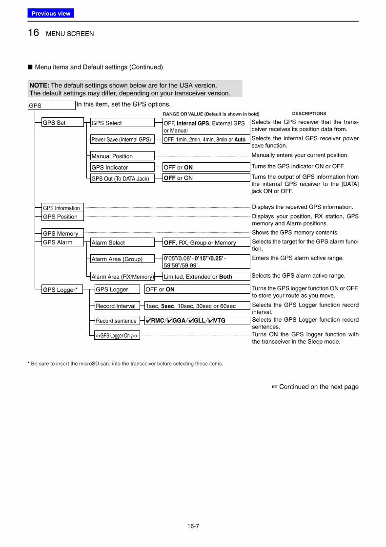
16 MENU SCREEN
16-7
NOTE: The default settings shown below are for the USA version.The default settings may differ, depending on your transceiver version.
■ Menu items and Default settings (Continued)
GPS
GPS Set
GPS Out (To DATA Jack)
In this item, set the GPS options.
OFF or ON
GPS Indicator
GPS Select
Manual Position
OFF or ON
OFF, Internal GPS, External GPS or Manual
Power Save (Internal GPS) OFF, 1min, 2min, 4min, 8min or Auto
DESCRIPTIONSRANGE OR VALUE (Default is shown in bold)
Selects the GPS receiver that the trans-ceiver receives its position data from.
Selects the internal GPS receiver power save function.
Manually enters your current position.
Turns the GPS indicator ON or OFF.
Turns the output of GPS information from the internal GPS receiver to the [DATA] jack ON or OFF.
GPS Logger
Record Interval
Record sentence
1sec, 5sec, 10sec, 30sec or 60sec
□✔RMC/□✔GGA/□✔GLL/□✔VTG
OFF or ON
GPS Memory
GPS Information Displays the received GPS information.
GPS Position Displays your position, RX station, GPS memory and Alarm positions.
Shows the GPS memory contents.
Turns the GPS logger function ON or OFF, to store your route as you move.
Selects the GPS Logger function record interval.
Selects the GPS Logger function record sentences.
<<GPS Logger Only>> Turns ON the GPS logger function with the transceiver in the Sleep mode.
GPS Logger*
GPS Alarm
Alarm Area (RX/Memory)
Alarm Select
Limited, Extended or Both
OFF, RX, Group or Memory
Alarm Area (Group) 0’05”/0.08’~0’15”/0.25’~ 59’59”/59.99’
Selects the target for the GPS alarm func-tion.
Enters the GPS alarm active range.
Selects the GPS alarm active range.
* Be sure to insert the microSD card into the transceiver before selecting these items.
☞ Continued on the next page
Previous view
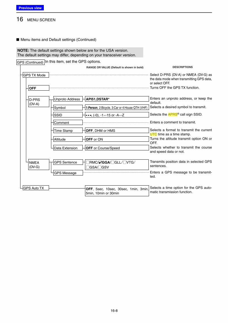
16 MENU SCREEN
16-8
■ Menu items and Default settings (Continued)
NOTE: The default settings shown below are for the USA version.The default settings may differ, depending on your transceiver version.
GPS Auto TX OFF, 5sec, 10sec, 30sec, 1min, 3min, 5min, 10min or 30min
Selects a time option for the GPS auto-matic transmission function.
GPS (Continued) In this item, set the GPS options.
DESCRIPTIONSRANGE OR VALUE (Default is shown in bold)
OFF
Select D-PRS (DV-A) or NMEA (DV-G) as the data mode when transmitting GPS data, or select OFF.
GPS Sentence
GPS Message
□RMC/□✔GGA/□GLL/□VTG/□GSA/□GSV
Transmits position data in selected GPS sentences.
Enters a GPS message to be transmit-ted.
Turns OFF the GPS TX function.
Enters an unproto address, or keep the default.
Unproto Address
Selects whether to transmit the course and speed data or not.
Data Extension OFF or Course/Speed
Selects a format to transmit the current UTC time as a time stamp.
Time Stamp OFF, DHM or HMS
Turns the altitude transmit option ON or OFF.
Altitude OFF or ON
Selects a desired symbol to transmit.Symbol 1:Person, 2:Bicycle, 3:Car or 4:House QTH (VHF)
Selects the APRS® call sign SSID. SSID - - -, (-0), -1~-15 or -A~-Z
API51,DSTAR*D-PRS(DV-A)
Enters a comment to transmit.Comment
NMEA(DV-G)
GPS TX Mode
Previous view
Icom
ハイライト表示
(Universal Time Coordinated) An astronomical time based on the Greenwich meridian (zero degrees longitude).
Icom
ハイライト表示
(Automatic Packet Reporting System) APRS is a two-way tactical real-time digital communications system between all assets in a network sharing information about everything going on in the local area.
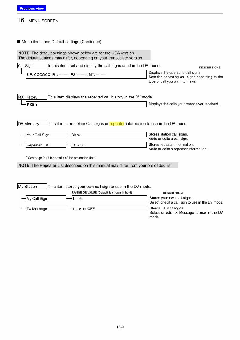
16 MENU SCREEN
16-9
NOTE: The default settings shown below are for the USA version.The default settings may differ, depending on your transceiver version.
■ Menu items and Default settings (Continued)
In this item, set and display the call signs used in the DV mode.
This item displays the received call history in the DV mode.
UR: CQCQCQ, R1: --------, R2: --------, MY: --------
RX01:
This item stores Your Call signs or repeater information to use in the DV mode.
Your Call Sign
Repeater List* 01: ~ 30:
Blank
Call Sign
RX History
DV Memory
NOTE: The Repeater List described on this manual may differ from your preloaded list.
DESCRIPTIONS
DESCRIPTIONS
Displays the operating call signs.Sets the operating call signs according to the type of call you want to make.
Displays the calls your transceiver received.
Stores station call signs.Adds or edits a call sign.
Stores repeater information.Adds or edits a repeater information.
* See page 9-47 for details of the preloaded data.
This item stores your own call sign to use in the DV mode.
My Call Sign 1: ~ 6:
TX Message 1: ~ 5: or OFF
My Station
RANGE OR VALUE (Default is shown in bold)
Stores your own call signs.Select or edit a call sign to use in the DV mode.
Stores TX Messages.Select or edit TX Message to use in the DV mode.
Previous view
Icom
ハイライト表示
Radio systems that receive incoming signals and retransmit them to extend the communication area. Normally put on geographically high locations for VHF/UHF radios.
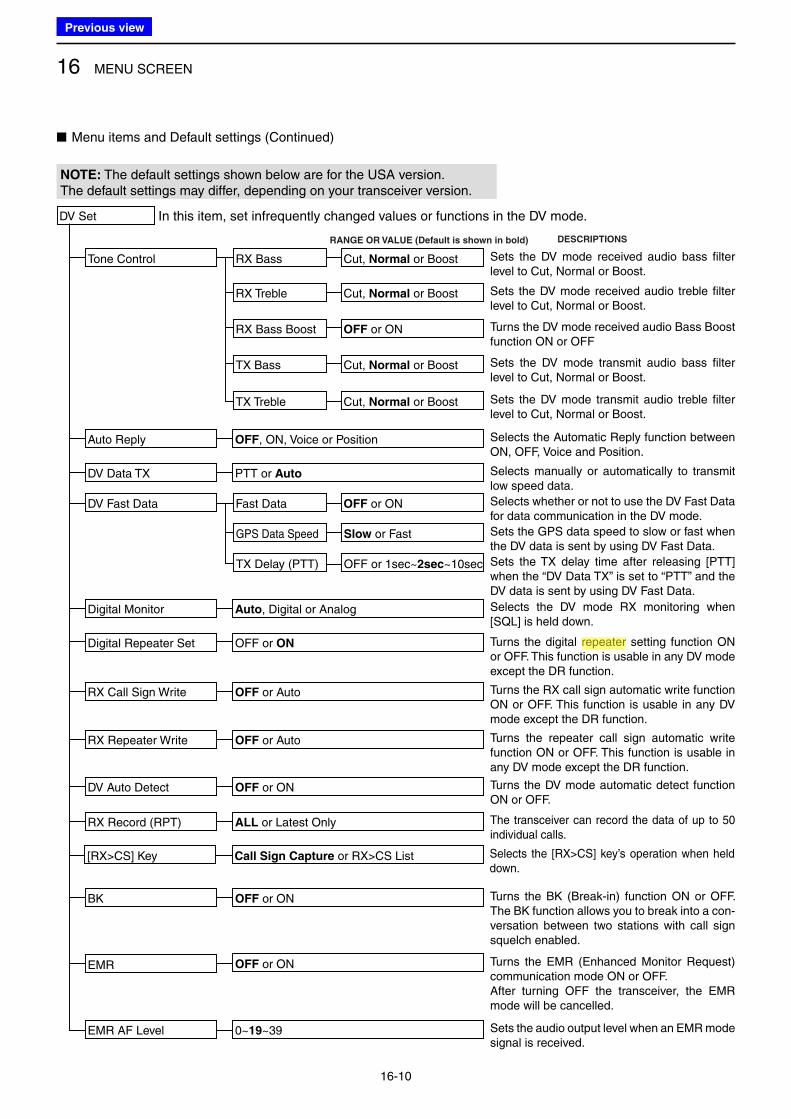
16 MENU SCREEN
16-10
NOTE: The default settings shown below are for the USA version.The default settings may differ, depending on your transceiver version.
■ Menu items and Default settings (Continued)
DV Set
Tone Control RX Bass
RX Treble
RX Bass Boost
TX Bass
TX Treble
Cut, Normal or Boost
In this item, set infrequently changed values or functions in the DV mode.
Cut, Normal or Boost
OFF or ON
Cut, Normal or Boost
Cut, Normal or Boost
DESCRIPTIONSRANGE OR VALUE (Default is shown in bold)
Sets the DV mode received audio bass filter level to Cut, Normal or Boost.
Sets the DV mode received audio treble filter level to Cut, Normal or Boost.
Turns the DV mode received audio Bass Boost function ON or OFF
Sets the DV mode transmit audio bass filter level to Cut, Normal or Boost.
Sets the DV mode transmit audio treble filter level to Cut, Normal or Boost.
Auto Reply
DV Data TX
OFF, ON, Voice or Position
PTT or Auto
Selects the Automatic Reply function between ON, OFF, Voice and Position.
Selects manually or automatically to transmit low speed data.
Selects whether or not to use the DV Fast Data for data communication in the DV mode.
Sets the GPS data speed to slow or fast when the DV data is sent by using DV Fast Data.
Sets the TX delay time after releasing [PTT] when the “DV Data TX” is set to “PTT” and the DV data is sent by using DV Fast Data.
Digital Monitor
Digital Repeater Set
RX Record (RPT)
RX Call Sign Write
RX Repeater Write
DV Auto Detect
Auto, Digital or Analog
OFF or ON
ALL or Latest Only
OFF or Auto
OFF or Auto
OFF or ON
Selects the DV mode RX monitoring when [SQL] is held down.
Turns the digital repeater setting function ON or OFF. This function is usable in any DV mode except the DR function.
Turns the RX call sign automatic write function ON or OFF. This function is usable in any DV mode except the DR function.
Turns the repeater call sign automatic write function ON or OFF. This function is usable in any DV mode except the DR function.
Turns the DV mode automatic detect function ON or OFF.
The transceiver can record the data of up to 50 individual calls.
BK OFF or ON Turns the BK (Break-in) function ON or OFF. The BK function allows you to break into a con-versation between two stations with call sign squelch enabled.
Turns the EMR (Enhanced Monitor Request) communication mode ON or OFF.After turning OFF the transceiver, the EMR mode will be cancelled.
Sets the audio output level when an EMR mode signal is received.
EMR
EMR AF Level
OFF or ON
0~19~39
Fast Data
GPS Data Speed
TX Delay (PTT)
OFF or ON
Slow or Fast
OFF or 1sec~2sec~10sec
DV Fast Data
[RX>CS] Key Call Sign Capture or RX>CS List Selects the [RX>CS] key’s operation when held down.
Previous view
Icom
ハイライト表示
Radio systems that receive incoming signals and retransmit them to extend the communication area. Normally put on geographically high locations for VHF/UHF radios.
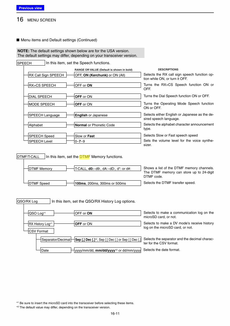
16 MENU SCREEN
16-11
NOTE: The default settings shown below are for the USA version.The default settings may differ, depending on your transceiver version.
■ Menu items and Default settings (Continued)
SPEECH
RX Call Sign SPEECH
RX>CS SPEECH
SPEECH Language
Alphabet
SPEECH Speed
SPEECH Level
OFF, ON (Kerchunk) or ON (All)
In this item, set the Speech functions.
OFF or ON
English or Japanese
Normal or Phonetic Code
Slow or Fast
0~7~9
DESCRIPTIONSRANGE OR VALUE (Default is shown in bold)
Selects the RX call sign speech function op-tion while ON, or turn it OFF.
Turns the RX>CS Speech function ON or OFF.
Selects either English or Japanese as the de-sired speech language.
Selects the alphabet character announcement type.
Selects Slow or Fast speech speed
Sets the volume level for the voice synthe-sizer.
DTMF/T-CALL
DTMF Memory
DTMF Speed
T-CALL, d0:~d9:, dA:~dD:, d*: or d#:
In this item, set the DTMF Memory functions.
100ms, 200ms, 300ms or 500ms
Shows a list of the DTMF memory channels.The DTMF memory can store up to 24-digit DTMF code.
Selects the DTMF transfer speed.
DIAL SPEECH OFF or ON Turns the Dial Speech function ON or OFF.
MODE SPEECH OFF or ON Turns the Operating Mode Speech function ON or OFF.
QSO/RX Log
QSO Log*1
CSV Format
OFF or ON
In this item, set the QSO/RX History Log options.
Selects to make a communication log on the microSD card, or not.
RX History Log*1 OFF or ON Selects to make a DV mode's receive history log on the microSD card, or not.
Date yyyy/mm/dd, mm/dd/yyyy*2 or dd/mm/yyyy Selects the date format.
Separator/Decimal Sep [,] Dec [.]*2, Sep [;] Dec [.] or Sep [;] Dec [,] Selects the separator and the decimal charac-ter for the CSV format.
*1 Be sure to insert the microSD card into the transceiver before selecting these items.
*2 The default value may differ, depending on the transceiver version.
Previous view
Icom
ハイライト表示
(Dual Tone Multi-Frequency (touch tone)) Used to transmit and receive numeric information such as phone numbers, PIN, remote radio control commands, and for other signaling purposes.
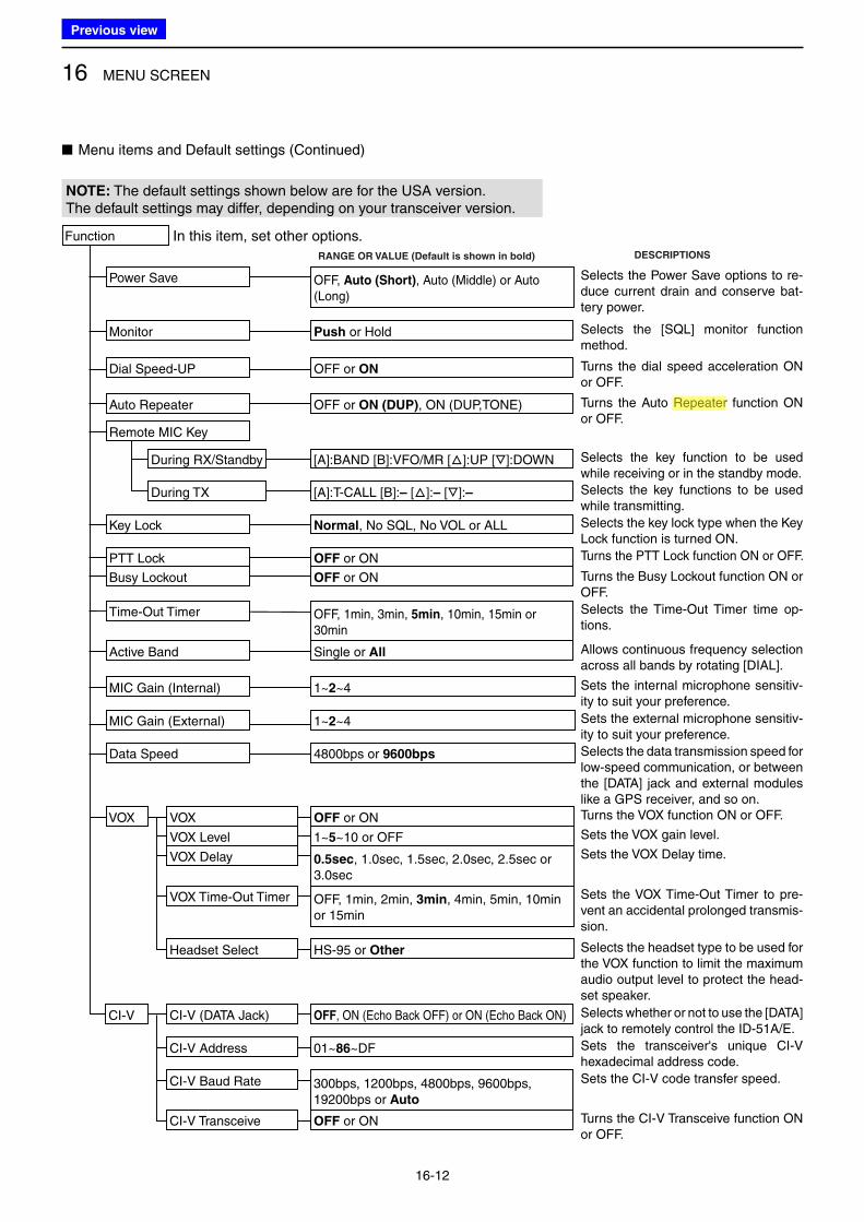
16 MENU SCREEN
16-12
■ Menu items and Default settings (Continued)
NOTE: The default settings shown below are for the USA version.The default settings may differ, depending on your transceiver version.
Function
Power Save
PTT Lock
Monitor
Busy Lockout
Dial Speed-UP
Time-Out Timer
Auto Repeater
Key Lock
OFF, Auto (Short), Auto (Middle) or Auto (Long)
OFF or ON
In this item, set other options.
Push or Hold
OFF or ON
OFF or ON
OFF, 1min, 3min, 5min, 10min, 15min or 30min
OFF or ON (DUP), ON (DUP,TONE)
Normal, No SQL, No VOL or ALL
DESCRIPTIONSRANGE OR VALUE (Default is shown in bold)
Selects the Power Save options to re-duce current drain and conserve bat-tery power.
Selects the [SQL] monitor function method.
Turns the Auto Repeater function ON or OFF.
Turns the dial speed acceleration ON or OFF.
Selects the key lock type when the Key Lock function is turned ON.
Turns the PTT Lock function ON or OFF.
Turns the Busy Lockout function ON or OFF.
Selects the Time-Out Timer time op-tions.
VOX VOX
VOX Level
VOX Delay
Headset Select
OFF or ON
1~5~10 or OFF
0.5sec, 1.0sec, 1.5sec, 2.0sec, 2.5sec or 3.0sec
HS-95 or Other
VOX Time-Out Timer OFF, 1min, 2min, 3min, 4min, 5min, 10min or 15min
MIC Gain (Internal)
MIC Gain (External)
Data Speed
1~2~4
1~2~4
4800bps or 9600bps
Sets the internal microphone sensitiv-ity to suit your preference.
Sets the external microphone sensitiv-ity to suit your preference.
Selects the data transmission speed for low-speed communication, or between the [DATA] jack and external modules like a GPS receiver, and so on.Turns the VOX function ON or OFF.
Sets the VOX gain level.
Sets the VOX Delay time.
Sets the VOX Time-Out Timer to pre-vent an accidental prolonged transmis-sion.
Selects the headset type to be used for the VOX function to limit the maximum audio output level to protect the head-set speaker.
Active Band Single or All Allows continuous frequency selection across all bands by rotating [DIAL].
Remote MIC Key
During RX/Standby
During TX
[A]:BAND [B]:VFO/MR [J]:UP [K]:DOWN
[A]:T-CALL [B]:– [J]:– [K]:–
Selects the key function to be used while receiving or in the standby mode.
Selects the key functions to be used while transmitting.
CI-V CI-V (DATA Jack)
CI-V Address
CI-V Baud Rate
CI-V Transceive
OFF, ON (Echo Back OFF) or ON (Echo Back ON)
01~86~DF
300bps, 1200bps, 4800bps, 9600bps, 19200bps or Auto
OFF or ON
Selects whether or not to use the [DATA] jack to remotely control the ID-51A/E.
Sets the transceiver's unique CI-V hexadecimal address code.
Sets the CI-V code transfer speed.
Turns the CI-V Transceive function ON or OFF.
Previous view
Icom
ハイライト表示
Radio systems that receive incoming signals and retransmit them to extend the communication area. Normally put on geographically high locations for VHF/UHF radios.
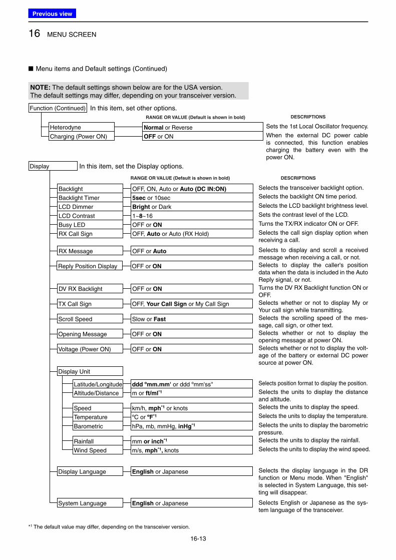
16 MENU SCREEN
16-13
Selects the transceiver backlight option.
Selects the backlight ON time period.
Selects the LCD backlight brightness level.
Sets the contrast level of the LCD.
Turns the TX/RX indicator ON or OFF.
Display
Backlight
LCD Dimmer
LCD Contrast
Busy LED
OFF, ON, Auto or Auto (DC IN:ON)
In this item, set the Display options.
Bright or Dark
1~8~16
OFF or ON
Backlight Timer 5sec or 10sec
DESCRIPTIONSRANGE OR VALUE (Default is shown in bold)
RX Call Sign OFF, Auto or Auto (RX Hold) Selects the call sign display option when receiving a call.
TX Call Sign
Scroll Speed
Opening Message
Voltage (Power ON)
OFF, Your Call Sign or My Call Sign
Slow or Fast
OFF or ON
OFF or ON
DV RX Backlight
RX Message
OFF or ON
OFF or Auto Selects to display and scroll a received message when receiving a call, or not.
Turns the DV RX Backlight function ON or OFF.
Selects whether or not to display My or Your call sign while transmitting.
Selects the scrolling speed of the mes-sage, call sign, or other text.
Selects whether or not to display the opening message at power ON.
Selects whether or not to display the volt-age of the battery or external DC power source at power ON.
System Language English or Japanese Selects English or Japanese as the sys-tem language of the transceiver.
Display Language English or Japanese Selects the display language in the DR function or Menu mode. When "English" is selected in System Language, this set-ting will disappear.
Reply Position Display OFF or ON Selects to display the caller's position data when the data is included in the Auto Reply signal, or not.
■ Menu items and Default settings (Continued)
NOTE: The default settings shown below are for the USA version.The default settings may differ, depending on your transceiver version.
Function (Continued)
Heterodyne Normal or Reverse
In this item, set other options.DESCRIPTIONSRANGE OR VALUE (Default is shown in bold)
Sets the 1st Local Oscillator frequency.
Charging (Power ON) OFF or ON When the external DC power cable is connected, this function enables charging the battery even with the power ON.
Display Unit
Selects position format to display the position.
Selects the units to display the distance and altitude.
Selects the units to display the speed.
Selects the units to display the temperature.
Selects the units to display the barometric pressure.
Selects the units to display the rainfall.
Selects the units to display the wind speed.
Latitude/Longitude
Altitude/Distance
Speed
Temperature
Barometric
Rainfall
Wind Speed
ddd ºmm.mm' or ddd ºmm'ss''
m or ft/ml*1
km/h, mph*1 or knots
ºC or ºF*1
hPa, mb, mmHg, inHg*1
mm or inch*1
m/s, mph*1, knots
*1 The default value may differ, depending on the transceiver version.
Previous view
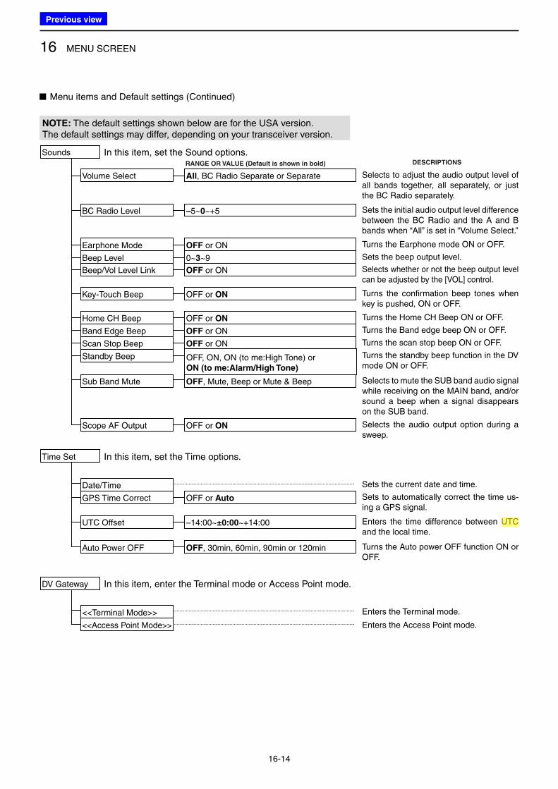
16 MENU SCREEN
16-14
■ Menu items and Default settings (Continued)
NOTE: The default settings shown below are for the USA version.The default settings may differ, depending on your transceiver version.
Sets the beep output level.
Selects whether or not the beep output level can be adjusted by the [VOL] control.
Turns the confirmation beep tones when key is pushed, ON or OFF.
Turns the scan stop beep ON or OFF.
Turns the standby beep function in the DV mode ON or OFF.
Selects the audio output option during a sweep.
Sets to automatically correct the time us-ing a GPS signal.
Sets the current date and time.
Enters the time difference between UTC and the local time.
Turns the Auto power OFF function ON or OFF.
Sounds
Beep Level
Beep/Vol Level Link
Key-Touch Beep
Scan Stop Beep
Scope AF Output
Standby Beep
0~3~9
In this item, set the Sound options.
OFF or ON
OFF or ON
OFF or ON
OFF or ON
OFF, ON, ON (to me:High Tone) or ON (to me:Alarm/High Tone)
Time Set
Date/Time
GPS Time Correct
UTC Offset
Auto Power OFF
In this item, set the Time options.
OFF or Auto
–14:00~±0:00~+14:00
OFF, 30min, 60min, 90min or 120min
DESCRIPTIONSRANGE OR VALUE (Default is shown in bold)
Selects to mute the SUB band audio signal while receiving on the MAIN band, and/or sound a beep when a signal disappears on the SUB band.
Sub Band Mute OFF, Mute, Beep or Mute & Beep
Turns the Home CH Beep ON or OFF.Home CH Beep OFF or ON
Turns the Band edge beep ON or OFF.Band Edge Beep OFF or ON
Selects to adjust the audio output level of all bands together, all separately, or just the BC Radio separately.
Volume Select All, BC Radio Separate or Separate
Sets the initial audio output level difference between the BC Radio and the A and B bands when “All” is set in “Volume Select.”
BC Radio Level –5~0~+5
Turns the Earphone mode ON or OFF.Earphone Mode OFF or ON
Enters the Terminal mode.
DV Gateway
<<Terminal Mode>>
<<Access Point Mode>>
In this item, enter the Terminal mode or Access Point mode.
Enters the Access Point mode.
Previous view
Icom
ハイライト表示
(Universal Time Coordinated) An astronomical time based on the Greenwich meridian (zero degrees longitude).
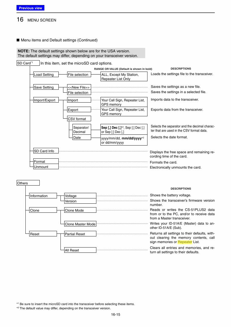
16 MENU SCREEN
16-15
NOTE: The default settings shown below are for the USA version.The default settings may differ, depending on your transceiver version.
■ Menu items and Default settings (Continued)
Others
Clone Clone Mode
Clone Master Mode
DESCRIPTIONS
Reads or writes the CS-51PLUS2 data from or to the PC, and/or to receive data from a Master transceiver.
Writes your ID-51A/E (Master) data to an-other ID-51A/E (Sub).
Information Voltage
Version
Shows the battery voltage.
Shows the transceiver’s firmware version number.
Reset Partial Reset
All Reset
Returns all settings to their defaults, with-out clearing the memory contents, call sign memories or Repeater List.
Clears all entries and memories, and re-turn all settings to their defaults.
SD Card*1
Load Setting
Save Setting
Import/Export
File selection
<<New File>>
File selection
Import
ALL, Except My Station, Repeater List Only
Your Call Sign, Repeater List,GPS memory
Your Call Sign, Repeater List,GPS memory
In this item, set the microSD card options.
DESCRIPTIONSRANGE OR VALUE (Default is shown in bold)
Loads the settings file to the transceiver.
Imports data to the transceiver.
Exports data from the transceiver.
Saves the settings as a new file.
Saves the settings in a selected file.
Format
SD Card Info
Unmount Electronically unmounts the card.
Formats the card.
Displays the free space and remaining re-cording time of the card.
CSV format
Selects the separator and the decimal charac-ter that are used in the CSV format data.
Selects the date format.
Separator/Decimal
Date
Sep [,] Dec [.]*2, Sep [;] Dec [.]or Sep [;] Dec [,]
yyyy/mm/dd, mm/dd/yyyy*2 or dd/mm/yyyy
Export
*1 Be sure to insert the microSD card into the transceiver before selecting these items.
*2 The default value may differ, depending on the transceiver version.
Previous view
Icom
ハイライト表示
Radio systems that receive incoming signals and retransmit them to extend the communication area. Normally put on geographically high locations for VHF/UHF radios.
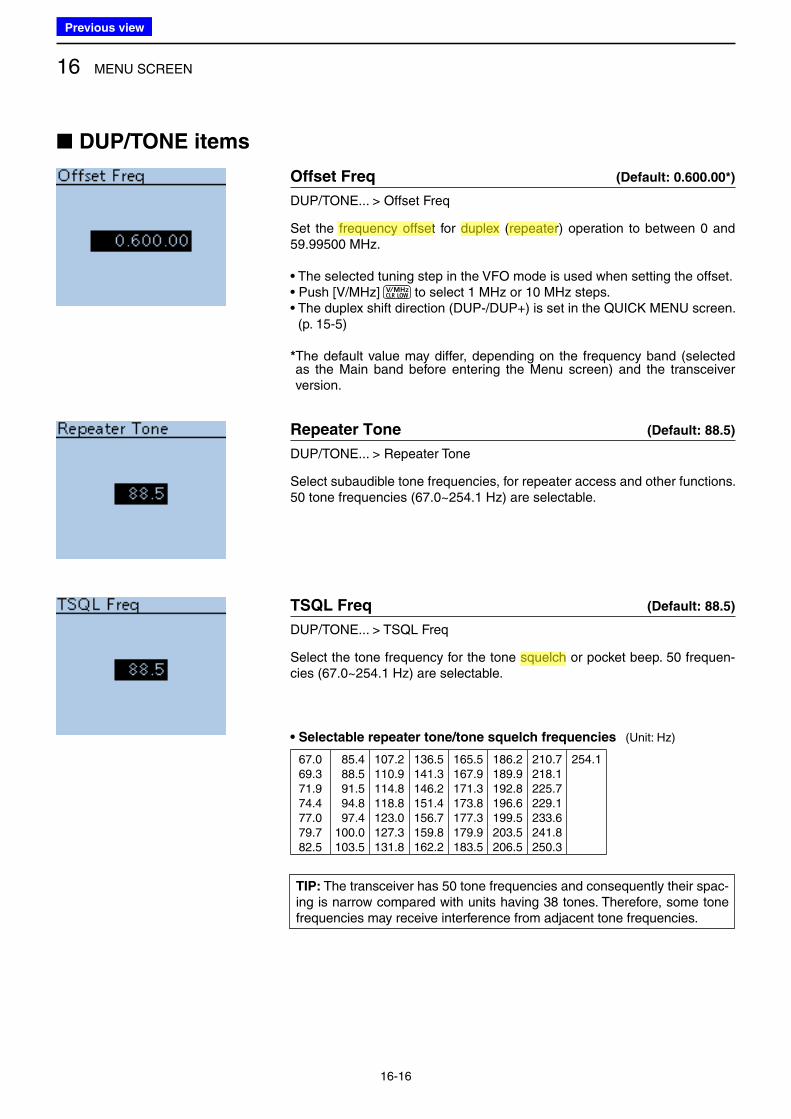
16 MENU SCREEN
16-16
■ DUP/TONE items
Offset Freq (Default: 0.600.00*)
DUP/TONE... > Offset Freq
Set the frequency offset for duplex (repeater) operation to between 0 and 59.99500 MHz.
• The selected tuning step in the VFO mode is used when setting the offset.• Push [V/MHz] to select 1 MHz or 10 MHz steps.• The duplex shift direction (DUP-/DUP+) is set in the QUICK MENU screen.
(p. 15-5)
* The default value may differ, depending on the frequency band (selected as the Main band before entering the Menu screen) and the transceiver version.
Repeater Tone (Default: 88.5)
DUP/TONE... > Repeater Tone
Select subaudible tone frequencies, for repeater access and other functions. 50 tone frequencies (67.0~254.1 Hz) are selectable.
TSQL Freq (Default: 88.5)
DUP/TONE... > TSQL Freq
Select the tone frequency for the tone squelch or pocket beep. 50 frequen-cies (67.0~254.1 Hz) are selectable.
• Selectable repeater tone/tone squelch frequencies (Unit: Hz)
67.069.371.974.477.079.782.5
085.4088.5091.5094.8097.4100.0103.5
107.2110.9114.8118.8123.0127.3131.8
136.5141.3146.2151.4156.7159.8162.2
165.5167.9171.3173.8177.3179.9183.5
186.2189.9192.8196.6199.5203.5206.5
210.7218.1225.7229.1233.6241.8250.3
254.1
TIP: The transceiver has 50 tone frequencies and consequently their spac-ing is narrow compared with units having 38 tones. Therefore, some tone frequencies may receive interference from adjacent tone frequencies.
Previous view
Icom
ハイライト表示
The difference between the transmit and receive frequencies.
Icom
ハイライト表示
Radio systems that receive incoming signals and retransmit them to extend the communication area. Normally put on geographically high locations for VHF/UHF radios.
Icom
ハイライト表示
An operating mode in which the transmit and receive frequencies are separated by an offset amount.
Icom
ハイライト表示
A function that mutes the audio output for certain signal levels.
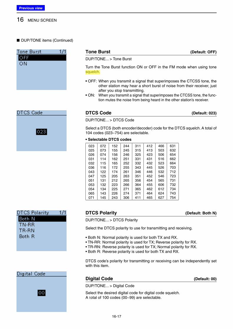
16 MENU SCREEN
16-17
Tone Burst (Default: OFF)
DUP/TONE... > Tone Burst
Turn the Tone Burst function ON or OFF in the FM mode when using tone squelch.
• OFF: When you transmit a signal that superimposes the CTCSS tone, the other station may hear a short burst of noise from their receiver, just after you stop transmitting.
• ON: When you transmit a signal that superimposes the CTCSS tone, the func-tion mutes the noise from being heard in the other station’s receiver.
DTCS Code (Default: 023)
DUP/TONE... > DTCS Code
Select a DTCS (both encoder/decoder) code for the DTCS squelch. A total of 104 codes (023~754) are selectable.
• Selectable DTCS codes
023025026031032036043047051053054065071
072073074114115116122125131132134143145
152155156162165172174205212223225226243
244245246251252255261263265266271274306
311315325331332343346351356364365371411
412413423431432445446452454455462464465
466503506516523526532546565606612624627
631632654662664703712723731732734743754
DTCS Polarity (Default: Both N)
DUP/TONE... > DTCS Polarity
Select the DTCS polarity to use for transmitting and receiving.
• Both N: Normal polarity is used for both TX and RX.• TN-RR: Normal polarity is used for TX; Reverse polarity for RX.• TR-RN: Reverse polarity is used for TX; Normal polarity for RX.• Both R: Reverse polarity is used for both TX and RX.
DTCS code’s polarity for transmitting or receiving can be independently set with this item.
Digital Code (Default: 00)
DUP/TONE... > Digital Code
Select the desired digital code for digital code squelch.A total of 100 codes (00~99) are selectable.
■ DUP/TONE items (Continued)
Previous view
Icom
ハイライト表示
A function that mutes the audio output for certain signal levels.
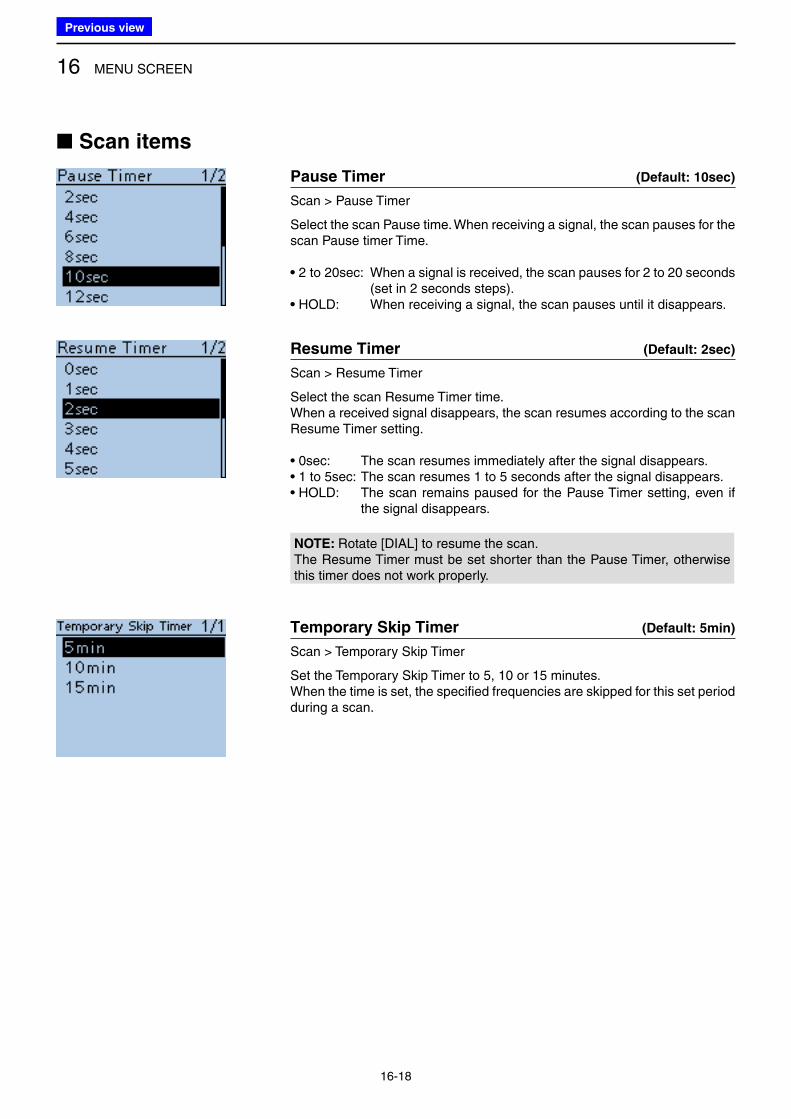
16 MENU SCREEN
16-18
■ Scan items
Pause Timer (Default: 10sec)
Scan > Pause Timer
Select the scan Pause time. When receiving a signal, the scan pauses for the scan Pause timer Time.
• 2 to 20sec: When a signal is received, the scan pauses for 2 to 20 seconds (set in 2 seconds steps).
• HOLD: When receiving a signal, the scan pauses until it disappears.
Resume Timer (Default: 2sec)
Scan > Resume Timer
Select the scan Resume Timer time.When a received signal disappears, the scan resumes according to the scan Resume Timer setting.
• 0sec: The scan resumes immediately after the signal disappears.• 1 to 5sec: The scan resumes 1 to 5 seconds after the signal disappears.• HOLD: The scan remains paused for the Pause Timer setting, even if
the signal disappears.
NOTE: Rotate [DIAL] to resume the scan.The Resume Timer must be set shorter than the Pause Timer, otherwise this timer does not work properly.
Temporary Skip Timer (Default: 5min)
Scan > Temporary Skip Timer
Set the Temporary Skip Timer to 5, 10 or 15 minutes.When the time is set, the specified frequencies are skipped for this set period during a scan.
Previous view
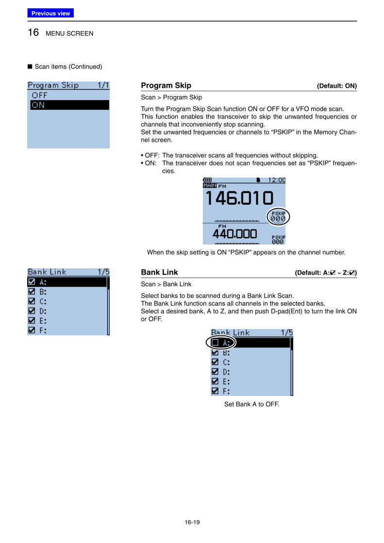
16 MENU SCREEN
16-19
Program Skip (Default: ON)
Scan > Program Skip
Turn the Program Skip Scan function ON or OFF for a VFO mode scan.This function enables the transceiver to skip the unwanted frequencies or channels that inconveniently stop scanning.Set the unwanted frequencies or channels to “PSKIP” in the Memory Chan-nel screen.
• OFF: The transceiver scans all frequencies without skipping.• ON: The transceiver does not scan frequencies set as “PSKIP” frequen-
cies.
When the skip setting is ON “PSKIP” appears on the channel number.
Bank Link (Default: A:✔ ~ Z:✔)
Scan > Bank Link
Select banks to be scanned during a Bank Link Scan.The Bank Link function scans all channels in the selected banks.Select a desired bank, A to Z, and then push D-pad(Ent) to turn the link ON or OFF.
Set Bank A to OFF.
■ Scan items (Continued)
Previous view
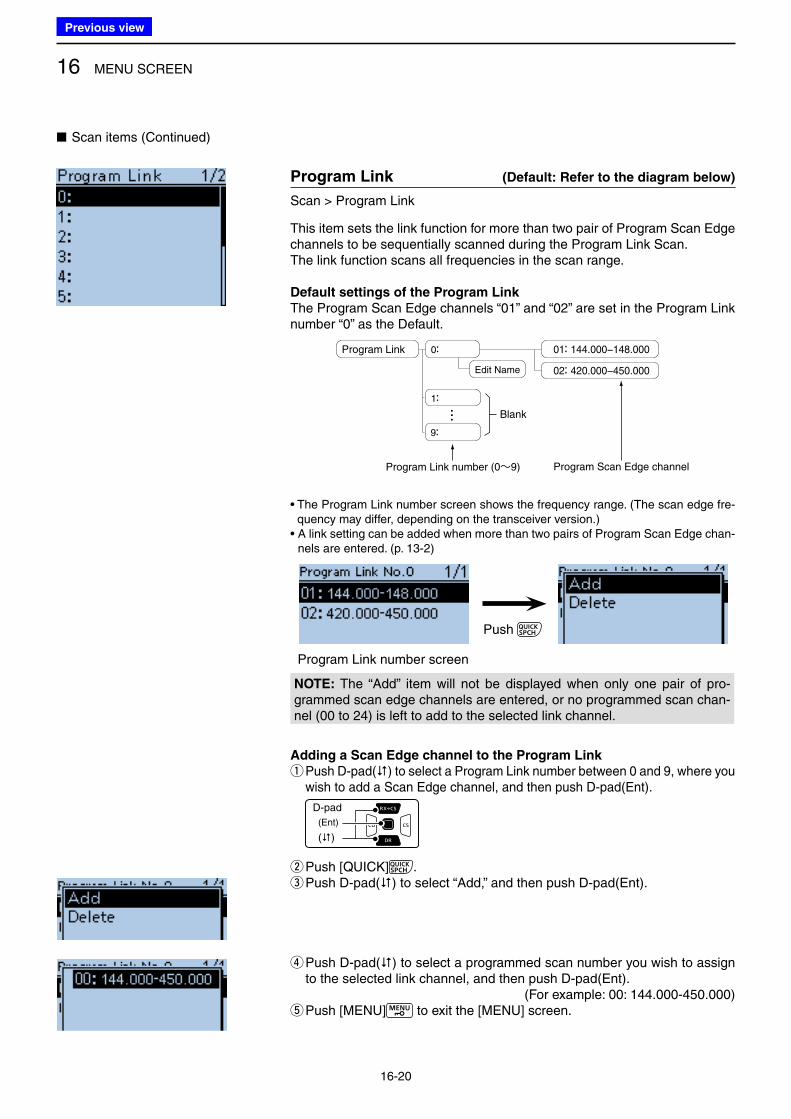
16 MENU SCREEN
16-20
■ Scan items (Continued)
Program Link (Default: Refer to the diagram below)
Scan > Program Link
This item sets the link function for more than two pair of Program Scan Edge channels to be sequentially scanned during the Program Link Scan.The link function scans all frequencies in the scan range.
Default settings of the Program Link
The Program Scan Edge channels “01” and “02” are set in the Program Link number “0” as the Default.
...Program Link 0:
1:
9:
Edit Name
01: 144.000−148.000
Program Link number (0~9)
Blank
Program Scan Edge channel
02: 420.000−450.000
• The Program Link number screen shows the frequency range. (The scan edge fre-quency may differ, depending on the transceiver version.)
• A link setting can be added when more than two pairs of Program Scan Edge chan-nels are entered. (p. 13-2)
Push
Program Link number screen
NOTE: The “Add” item will not be displayed when only one pair of pro-grammed scan edge channels are entered, or no programmed scan chan-nel (00 to 24) is left to add to the selected link channel.
Adding a Scan Edge channel to the Program Link
q Push D-pad() to select a Program Link number between 0 and 9, where you wish to add a Scan Edge channel, and then push D-pad(Ent).
D-pad
(�)
(Ent)
wPush [QUICK] . e Push D-pad() to select “Add,” and then push D-pad(Ent).
r Push D-pad() to select a programmed scan number you wish to assign to the selected link channel, and then push D-pad(Ent).
(For example: 00: 144.000-450.000) tPush [MENU] to exit the [MENU] screen.
Previous view
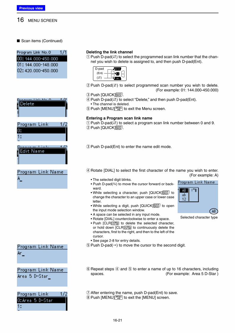
16 MENU SCREEN
16-21
Deleting the link channel
q Push D-pad() to select the programmed scan link number that the chan-nel you wish to delete is assigned to, and then push D-pad(Ent).
w Push D-pad() to select programmed scan number you wish to delete. (For example: 01: 144.000-450.000) ePush [QUICK] . rPush D-pad() to select “Delete,” and then push D-pad(Ent).• The channel is deleted.
tPush [MENU] to exit the Menu screen.
Entering a Program scan link name
q Push D-pad() to select a program scan link number between 0 and 9. wPush [QUICK] .
ePush D-pad(Ent) to enter the name edit mode.
r Rotate [DIAL] to select the first character of the name you wish to enter. (For example: A)
• The selected digit blinks. • Push D-pad() to move the cursor forward or back-
ward. • While selecting a character, push [QUICK] to
change the character to an upper case or lower case letter.
• While selecting a digit, push [QUICK] to open the input mode selection window.
• A space can be selected in any input mode. • Rotate [DIAL] counterclockwise to enter a space. • Push [CLR] to delete the selected character,
or hold down [CLR] to continuously delete the characters, first to the right, and then to the left of the cursor.
• See page 2-8 for entry details.
t Push D-pad() to move the cursor to the second digit.
y Repeat steps r and t to enter a name of up to 16 characters, including spaces. (For example: Area 5 D-Star )
uAfter entering the name, push D-pad(Ent) to save. iPush [MENU] to exit the [MENU] screen.
D-pad
(�)
(Ent)
■ Scan items (Continued)
Selected character type
Previous view
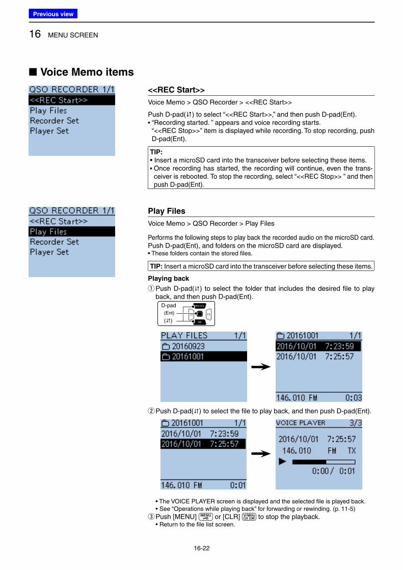
16 MENU SCREEN
16-22
■ Voice Memo items
<<REC Start>>
Voice Memo > QSO Recorder > <<REC Start>>
Push D-pad() to select “<<REC Start>>,” and then push D-pad(Ent).• “Recording started. ” appears and voice recording starts.
“<<REC Stop>>” item is displayed while recording. To stop recording, push D-pad(Ent).
TIP:
• Insert a microSD card into the transceiver before selecting these items.• Once recording has started, the recording will continue, even the trans-
ceiver is rebooted. To stop the recording, select “<<REC Stop>> ” and then push D-pad(Ent).
Play Files
Voice Memo > QSO Recorder > Play Files
Performs the following steps to play back the recorded audio on the microSD card.Push D-pad(Ent), and folders on the microSD card are displayed.• These folders contain the stored files.
TIP: Insert a microSD card into the transceiver before selecting these items.
Playing back
q Push D-pad() to select the folder that includes the desired file to play back, and then push D-pad(Ent).
D-pad
(�)
(Ent)
w Push D-pad() to select the file to play back, and then push D-pad(Ent).
• The VOICE PLAYER screen is displayed and the selected file is played back.• See “Operations while playing back” for forwarding or rewinding. (p. 11-5)
ePush [MENU] or [CLR] to stop the playback.• Return to the file list screen.
Previous view
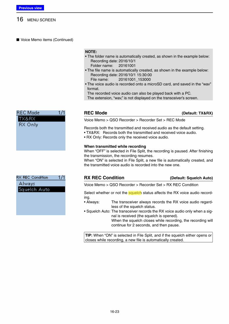
16 MENU SCREEN
16-23
NOTE:
• The folder name is automatically created, as shown in the example below:Recording date: 2016/10/1Folder name: 20161001
• The file name is automatically created, as shown in the example below:Recording date: 2016/10/1 15:30:00File name: 20161001_153000
• The voice audio is recorded onto a microSD card, and saved in the “wav” format. The recorded voice audio can also be played back with a PC. The extension, “wav,” is not displayed on the transceiver’s screen.
REC Mode (Default: TX&RX)
Voice Memo > QSO Recorder > Recorder Set > REC Mode
Records both the transmitted and received audio as the default setting.• TX&RX: Records both the transmitted and received voice audio.• RX Only: Records only the received voice audio.
When transmitted while recording
When “OFF” is selected in File Split, the recording is paused. After finishing the transmission, the recording resumes.When “ON” is selected in File Split, a new file is automatically created, and the transmitted voice audio is recorded into the new one.
RX REC Condition (Default: Squelch Auto)
Voice Memo > QSO Recorder > Recorder Set > RX REC Condition
Select whether or not the squelch status affects the RX voice audio record-ing.• Always: The transceiver always records the RX voice audio regard-
less of the squelch status. • Squelch Auto: The transceiver records the RX voice audio only when a sig-
nal is received (the squelch is opened). When the squelch closes while recording, the recording will
continue for 2 seconds, and then pause.
TIP: When “ON” is selected in File Split, and if the squelch either opens or closes while recording, a new file is automatically created.
■ Voice Memo items (Continued)
Previous view
Icom
ハイライト表示
A function that mutes the audio output for certain signal levels.
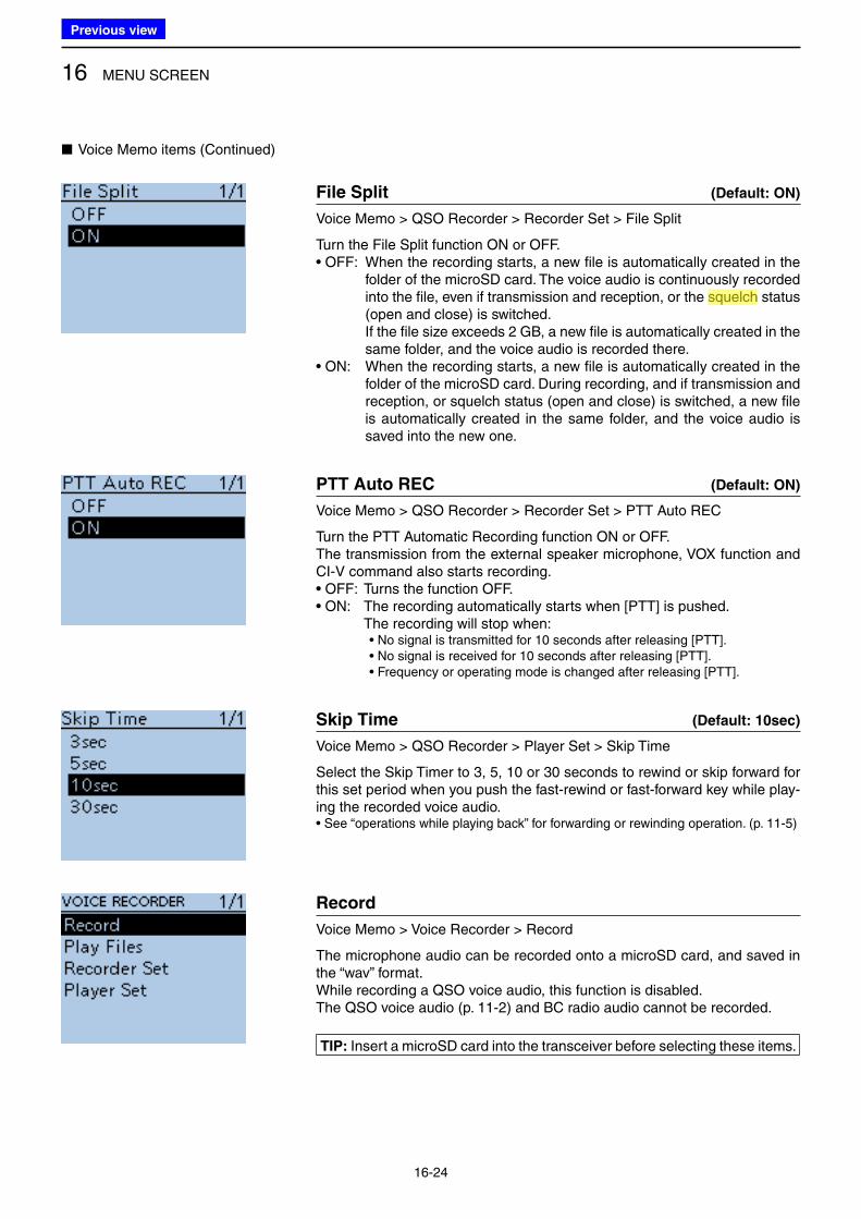
16 MENU SCREEN
16-24
File Split (Default: ON)
Voice Memo > QSO Recorder > Recorder Set > File Split
Turn the File Split function ON or OFF.• OFF: When the recording starts, a new file is automatically created in the
folder of the microSD card. The voice audio is continuously recorded into the file, even if transmission and reception, or the squelch status (open and close) is switched.
If the file size exceeds 2 GB, a new file is automatically created in the same folder, and the voice audio is recorded there.
• ON: When the recording starts, a new file is automatically created in the folder of the microSD card. During recording, and if transmission and reception, or squelch status (open and close) is switched, a new file is automatically created in the same folder, and the voice audio is saved into the new one.
PTT Auto REC (Default: ON)
Voice Memo > QSO Recorder > Recorder Set > PTT Auto REC
Turn the PTT Automatic Recording function ON or OFF. The transmission from the external speaker microphone, VOX function and CI-V command also starts recording.• OFF: Turns the function OFF.• ON: The recording automatically starts when [PTT] is pushed. The recording will stop when:
• No signal is transmitted for 10 seconds after releasing [PTT].• No signal is received for 10 seconds after releasing [PTT]. • Frequency or operating mode is changed after releasing [PTT].
Skip Time (Default: 10sec)
Voice Memo > QSO Recorder > Player Set > Skip Time
Select the Skip Timer to 3, 5, 10 or 30 seconds to rewind or skip forward for this set period when you push the fast-rewind or fast-forward key while play-ing the recorded voice audio.• See “operations while playing back” for forwarding or rewinding operation. (p. 11-5)
Record
Voice Memo > Voice Recorder > Record
The microphone audio can be recorded onto a microSD card, and saved in the “wav” format.While recording a QSO voice audio, this function is disabled.The QSO voice audio (p. 11-2) and BC radio audio cannot be recorded.
TIP: Insert a microSD card into the transceiver before selecting these items.
■ Voice Memo items (Continued)
Previous view
Icom
ハイライト表示
A function that mutes the audio output for certain signal levels.
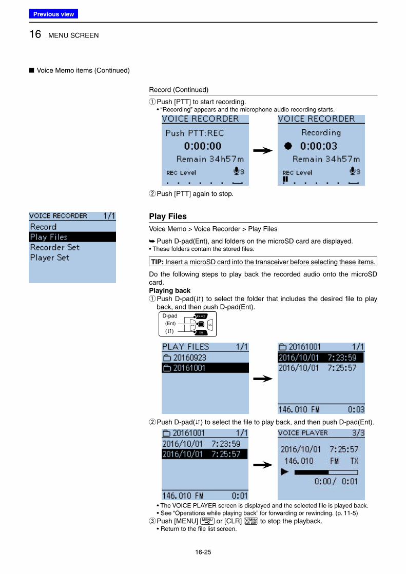
16 MENU SCREEN
16-25
■ Voice Memo items (Continued)
Record (Continued)
qPush [PTT] to start recording. • “Recording” appears and the microphone audio recording starts.
wPush [PTT] again to stop.
Play Files
Voice Memo > Voice Recorder > Play Files
➥ Push D-pad(Ent), and folders on the microSD card are displayed.• These folders contain the stored files.
TIP: Insert a microSD card into the transceiver before selecting these items.
Do the following steps to play back the recorded audio onto the microSD card.Playing back
q Push D-pad() to select the folder that includes the desired file to play back, and then push D-pad(Ent).
D-pad
(�)
(Ent)
w Push D-pad() to select the file to play back, and then push D-pad(Ent).
• The VOICE PLAYER screen is displayed and the selected file is played back.• See “Operations while playing back” for forwarding or rewinding. (p. 11-5)
ePush [MENU] or [CLR] to stop the playback.• Return to the file list screen.
Previous view
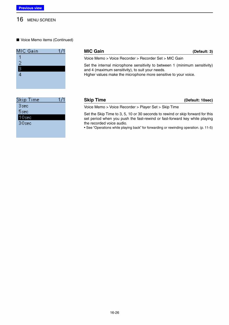
16 MENU SCREEN
16-26
■ Voice Memo items (Continued)
MIC Gain (Default: 3)
Voice Memo > Voice Recorder > Recorder Set > MIC Gain
Set the internal microphone sensitivity to between 1 (minimum sensitivity) and 4 (maximum sensitivity), to suit your needs.Higher values make the microphone more sensitive to your voice.
Skip Time (Default: 10sec)
Voice Memo > Voice Recorder > Player Set > Skip Time
Set the Skip Time to 3, 5, 10 or 30 seconds to rewind or skip forward for this set period when you push the fast-rewind or fast-forward key while playing the recorded voice audio.• See “Operations while playing back” for forwarding or rewinding operation. (p. 11-5)
Previous view
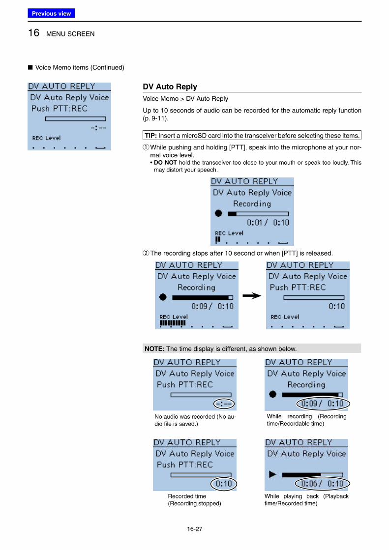
16 MENU SCREEN
16-27
DV Auto Reply
Voice Memo > DV Auto Reply
Up to 10 seconds of audio can be recorded for the automatic reply function (p. 9-11).
TIP: Insert a microSD card into the transceiver before selecting these items.
q While pushing and holding [PTT], speak into the microphone at your nor-mal voice level.• DO NOT hold the transceiver too close to your mouth or speak too loudly. This
may distort your speech.
w The recording stops after 10 second or when [PTT] is released.
NOTE: The time display is different, as shown below.
No audio was recorded (No au-dio file is saved.)
While recording (Recording time/Recordable time)
Recorded time(Recording stopped)
While playing back (Playback time/Recorded time)
■ Voice Memo items (Continued)
Previous view
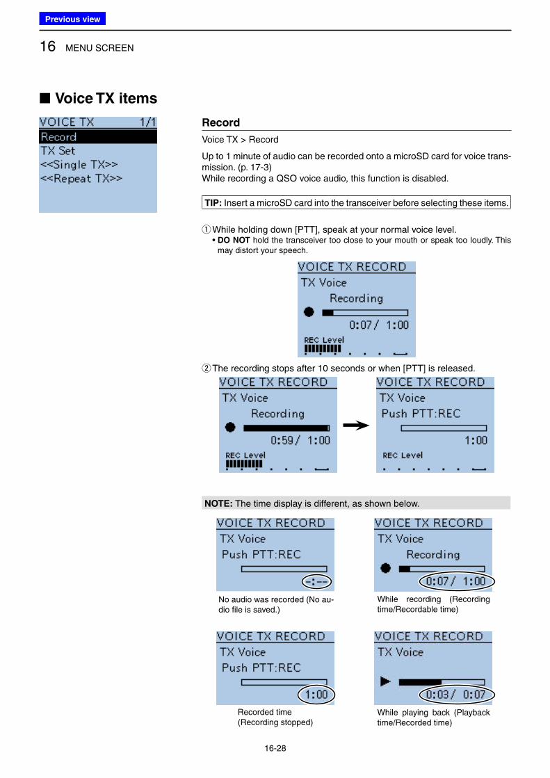
16 MENU SCREEN
16-28
■ Voice TX items
Record
Voice TX > Record
Up to 1 minute of audio can be recorded onto a microSD card for voice trans-mission. (p. 17-3)While recording a QSO voice audio, this function is disabled.
TIP: Insert a microSD card into the transceiver before selecting these items.
q While holding down [PTT], speak at your normal voice level.• DO NOT hold the transceiver too close to your mouth or speak too loudly. This
may distort your speech.
w The recording stops after 10 seconds or when [PTT] is released.
NOTE: The time display is different, as shown below.
No audio was recorded (No au-dio file is saved.)
While recording (Recording time/Recordable time)
Recorded time(Recording stopped)
While playing back (Playback time/Recorded time)
Previous view
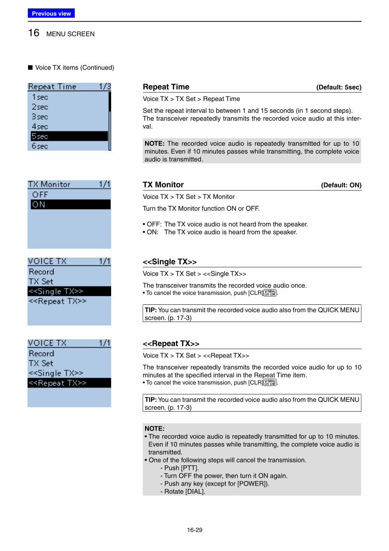
16 MENU SCREEN
16-29
■ Voice TX items (Continued)
Repeat Time (Default: 5sec)
Voice TX > TX Set > Repeat Time
Set the repeat interval to between 1 and 15 seconds (in 1 second steps).The transceiver repeatedly transmits the recorded voice audio at this inter-val.
NOTE: The recorded voice audio is repeatedly transmitted for up to 10 minutes. Even if 10 minutes passes while transmitting, the complete voice audio is transmitted.
TX Monitor (Default: ON)
Voice TX > TX Set > TX Monitor
Turn the TX Monitor function ON or OFF.
• OFF: The TX voice audio is not heard from the speaker. • ON: The TX voice audio is heard from the speaker.
<<Single TX>>
Voice TX > TX Set > <<Single TX>>
The transceiver transmits the recorded voice audio once.• To cancel the voice transmission, push [CLR] .
TIP: You can transmit the recorded voice audio also from the QUICK MENU screen. (p. 17-3)
<<Repeat TX>>
Voice TX > TX Set > <<Repeat TX>>
The transceiver repeatedly transmits the recorded voice audio for up to 10 minutes at the specified interval in the Repeat Time item.• To cancel the voice transmission, push [CLR] .
TIP: You can transmit the recorded voice audio also from the QUICK MENU screen. (p. 17-3)
NOTE:
• The recorded voice audio is repeatedly transmitted for up to 10 minutes. Even if 10 minutes passes while transmitting, the complete voice audio is transmitted.
• One of the following steps will cancel the transmission. - Push [PTT]. - Turn OFF the power, then turn it ON again. - Push any key (except for [POWER]). - Rotate [DIAL].
Previous view
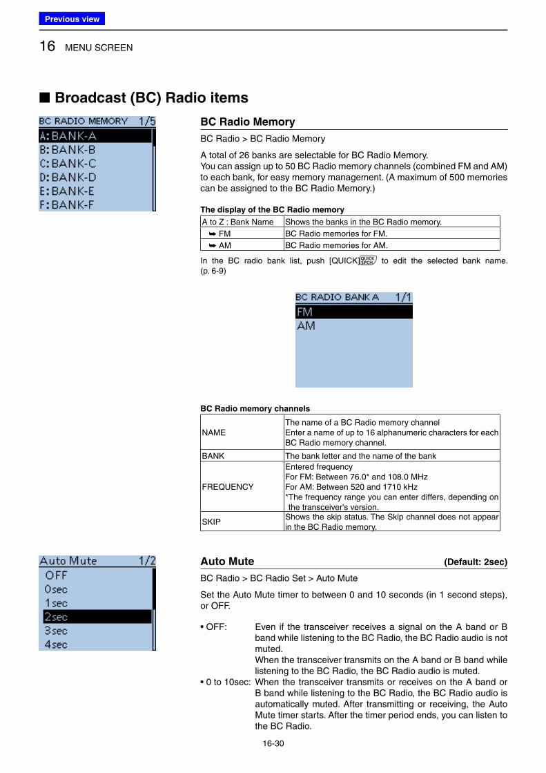
16 MENU SCREEN
16-30
■ Broadcast (BC) Radio items
BC Radio Memory
BC Radio > BC Radio Memory
A total of 26 banks are selectable for BC Radio Memory.You can assign up to 50 BC Radio memory channels (combined FM and AM) to each bank, for easy memory management. (A maximum of 500 memories can be assigned to the BC Radio Memory.)
The display of the BC Radio memory
A to Z : Bank Name Shows the banks in the BC Radio memory.
➥ FM BC Radio memories for FM.
➥ AM BC Radio memories for AM.
In the BC radio bank list, push [QUICK] to edit the selected bank name. (p. 6-9)
BC Radio memory channels
NAMEThe name of a BC Radio memory channelEnter a name of up to 16 alphanumeric characters for each BC Radio memory channel.
BANK The bank letter and the name of the bank
FREQUENCY
Entered frequencyFor FM: Between 76.0* and 108.0 MHzFor AM: Between 520 and 1710 kHz* The frequency range you can enter differs, depending on the transceiver's version.
SKIPShows the skip status. The Skip channel does not appear in the BC Radio memory.
Auto Mute (Default: 2sec)
BC Radio > BC Radio Set > Auto Mute
Set the Auto Mute timer to between 0 and 10 seconds (in 1 second steps), or OFF.
• OFF: Even if the transceiver receives a signal on the A band or B band while listening to the BC Radio, the BC Radio audio is not muted.
When the transceiver transmits on the A band or B band while listening to the BC Radio, the BC Radio audio is muted.
• 0 to 10sec: When the transceiver transmits or receives on the A band or B band while listening to the BC Radio, the BC Radio audio is automatically muted. After transmitting or receiving, the Auto Mute timer starts. After the timer period ends, you can listen to the BC Radio.
Previous view
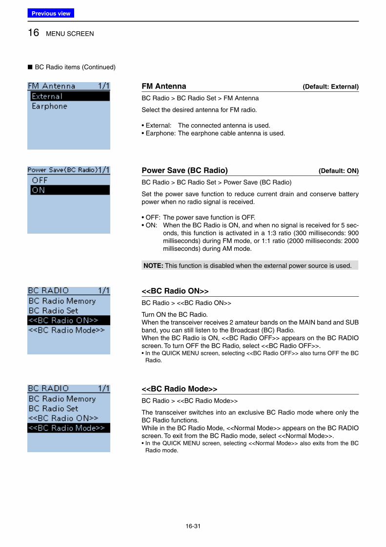
16 MENU SCREEN
16-31
FM Antenna (Default: External)
BC Radio > BC Radio Set > FM Antenna
Select the desired antenna for FM radio.
• External: The connected antenna is used.• Earphone: The earphone cable antenna is used.
Power Save (BC Radio) (Default: ON)
BC Radio > BC Radio Set > Power Save (BC Radio)
Set the power save function to reduce current drain and conserve battery power when no radio signal is received.
• OFF: The power save function is OFF. • ON: When the BC Radio is ON, and when no signal is received for 5 sec-
onds, this function is activated in a 1:3 ratio (300 milliseconds: 900 milliseconds) during FM mode, or 1:1 ratio (2000 milliseconds: 2000 milliseconds) during AM mode.
NOTE: This function is disabled when the external power source is used.
<<BC Radio ON>>
BC Radio > <<BC Radio ON>>
Turn ON the BC Radio.When the transceiver receives 2 amateur bands on the MAIN band and SUB band, you can still listen to the Broadcast (BC) Radio.When the BC Radio is ON, <<BC Radio OFF>> appears on the BC RADIO screen. To turn OFF the BC Radio, select <<BC Radio OFF>>.• In the QUICK MENU screen, selecting <<BC Radio OFF>> also turns OFF the BC
Radio.
<<BC Radio Mode>>
BC Radio > <<BC Radio Mode>>
The transceiver switches into an exclusive BC Radio mode where only the BC Radio functions.While in the BC Radio Mode, <<Normal Mode>> appears on the BC RADIO screen. To exit from the BC Radio mode, select <<Normal Mode>>.• In the QUICK MENU screen, selecting <<Normal Mode>> also exits from the BC
Radio mode.
■ BC Radio items (Continued)
Previous view
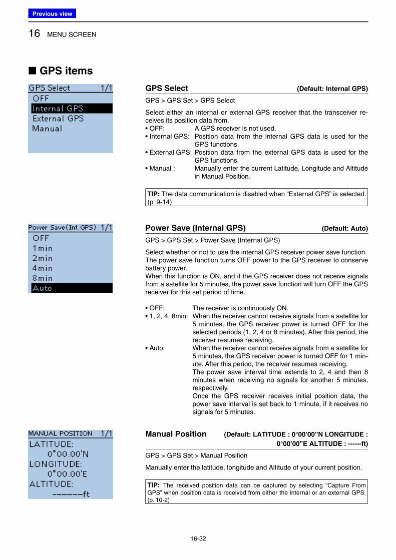
16 MENU SCREEN
16-32
■ GPS items
GPS Select (Default: Internal GPS)
GPS > GPS Set > GPS Select
Select either an internal or external GPS receiver that the transceiver re-ceives its position data from.• OFF: A GPS receiver is not used. • Internal GPS: Position data from the internal GPS data is used for the
GPS functions.• External GPS: Position data from the external GPS data is used for the
GPS functions. • Manual : Manually enter the current Latitude, Longitude and Altitude
in Manual Position.
TIP: The data communication is disabled when “External GPS” is selected.(p. 9-14)
Power Save (Internal GPS) (Default: Auto)
GPS > GPS Set > Power Save (Internal GPS)
Select whether or not to use the internal GPS receiver power save function.The power save function turns OFF power to the GPS receiver to conserve battery power.When this function is ON, and if the GPS receiver does not receive signals from a satellite for 5 minutes, the power save function will turn OFF the GPS receiver for this set period of time.
• OFF: The receiver is continuously ON.• 1, 2, 4, 8min: When the receiver cannot receive signals from a satellite for
5 minutes, the GPS receiver power is turned OFF for the selected periods (1, 2, 4 or 8 minutes). After this period, the receiver resumes receiving.
• Auto: When the receiver cannot receive signals from a satellite for 5 minutes, the GPS receiver power is turned OFF for 1 min-ute. After this period, the receiver resumes receiving.
The power save interval time extends to 2, 4 and then 8 minutes when receiving no signals for another 5 minutes, respectively.
Once the GPS receiver receives initial position data, the power save interval is set back to 1 minute, if it receives no signals for 5 minutes.
Manual Position (Default: LATITUDE : 0°00’00”N LONGITUDE :
0°00’00”E ALTITUDE : ------ft)
GPS > GPS Set > Manual Position
Manually enter the latitude, longitude and Altitude of your current position.
TIP: The received position data can be captured by selecting “Capture From GPS” when position data is received from either the internal or an external GPS. (p. 10-2)
Previous view
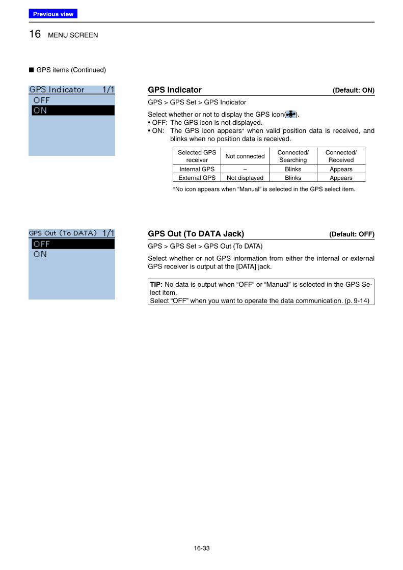
16 MENU SCREEN
16-33
GPS Indicator (Default: ON)
GPS > GPS Set > GPS Indicator
Select whether or not to display the GPS icon( ).• OFF: The GPS icon is not displayed. • ON: The GPS icon appears* when valid position data is received, and
blinks when no position data is received.
Selected GPS receiver
Not connectedConnected/Searching
Connected/ Received
Internal GPS – Blinks Appears
External GPS Not displayed Blinks Appears
*No icon appears when “Manual” is selected in the GPS select item.
GPS Out (To DATA Jack) (Default: OFF)
GPS > GPS Set > GPS Out (To DATA)
Select whether or not GPS information from either the internal or external GPS receiver is output at the [DATA] jack.
TIP: No data is output when “OFF” or “Manual” is selected in the GPS Se-lect item.Select “OFF” when you want to operate the data communication. (p. 9-14)
■ GPS items (Continued)
Previous view
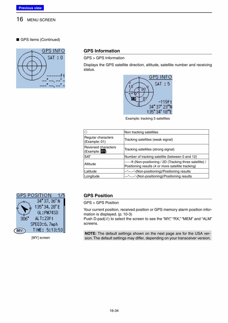
16 MENU SCREEN
16-34
■ GPS items (Continued)
GPS Information
GPS > GPS Information
Displays the GPS satellite direction, altitude, satellite number and receiving status.
Example: tracking 5 satellites
Non tracking satellites
Regular characters (Example: 01)
Tracking satellites (weak signal)
Reversed characters (Example: 01 )
Tracking satellites (strong signal)
SAT Number of tracking satellite (between 0 and 12)
Altitude------ft (Non-positioning / 2D (Tracking three satellite) /Positioning results (4 or more satellite tracking)
Latitude --°--.--'-(Non-positioning)/Positioning results
Longitude ---°--.--'-(Non-positioning)/Positioning results
GPS Position
GPS > GPS Position
Your current position, received position or GPS memory alarm position infor-mation is displayed. (p. 10-3)Push D-pad() to select the screen to see the “MY,” “RX,” “MEM” and “ALM” screens.
NOTE: The default settings shown on the next page are for the USA ver-sion. The default settings may differ, depending on your transceiver version.[MY] screen
Previous view
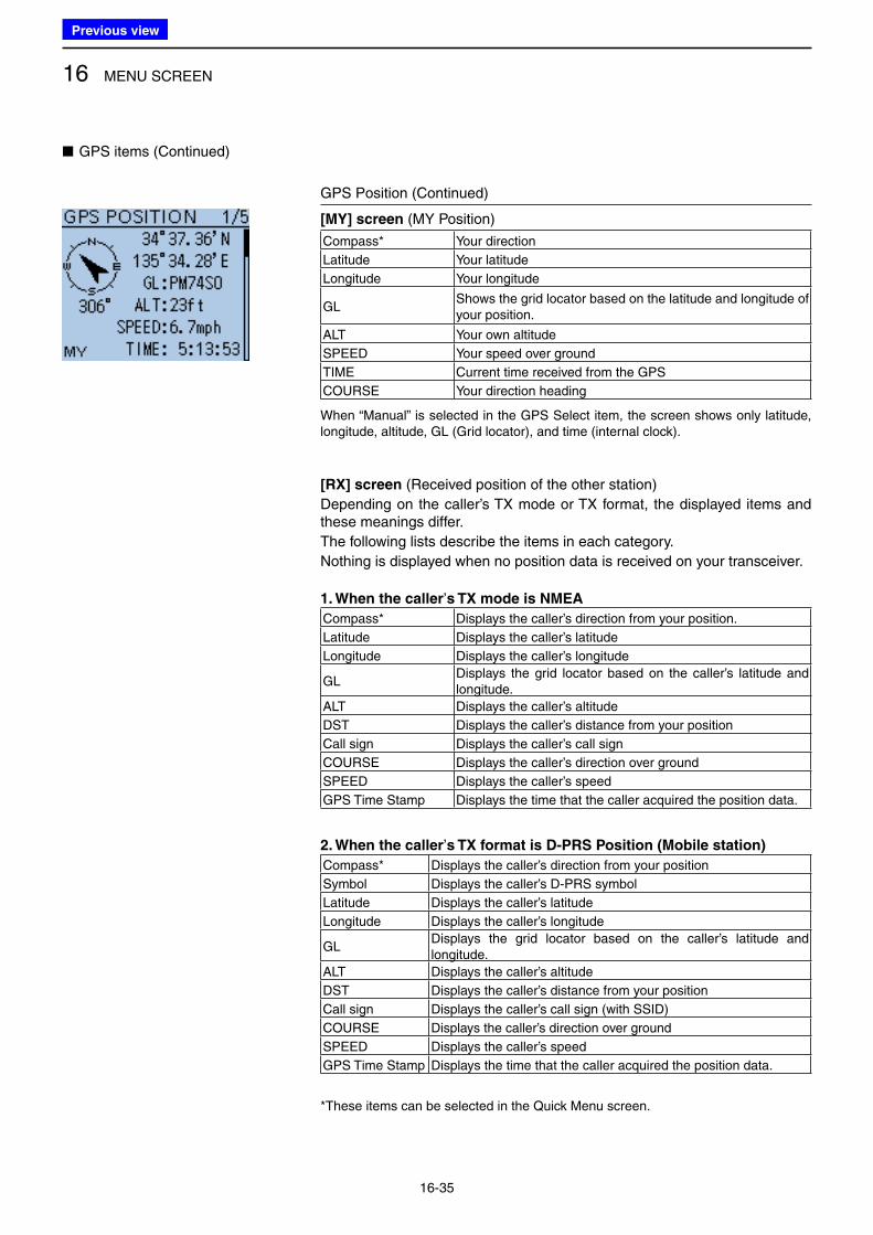
16 MENU SCREEN
16-35
■ GPS items (Continued)
GPS Position (Continued)
[MY] screen (MY Position)
Compass* Your direction
Latitude Your latitude
Longitude Your longitude
GLShows the grid locator based on the latitude and longitude of your position.
ALT Your own altitude
SPEED Your speed over ground
TIME Current time received from the GPS
COURSE Your direction heading
When “Manual” is selected in the GPS Select item, the screen shows only latitude, longitude, altitude, GL (Grid locator), and time (internal clock).
[RX] screen (Received position of the other station)
Depending on the caller’s TX mode or TX format, the displayed items and these meanings differ.
The following lists describe the items in each category.
Nothing is displayed when no position data is received on your transceiver.
1. When the caller’s TX mode is NMEA
Compass* Displays the caller’s direction from your position.
Latitude Displays the caller’s latitude
Longitude Displays the caller’s longitude
GLDisplays the grid locator based on the caller’s latitude and longitude.
ALT Displays the caller’s altitude
DST Displays the caller’s distance from your position
Call sign Displays the caller’s call sign
COURSE Displays the caller’s direction over ground
SPEED Displays the caller’s speed
GPS Time Stamp Displays the time that the caller acquired the position data.
2. When the caller’s TX format is D-PRS Position (Mobile station)
Compass* Displays the caller’s direction from your position
Symbol Displays the caller’s D-PRS symbol
Latitude Displays the caller’s latitude
Longitude Displays the caller’s longitude
GLDisplays the grid locator based on the caller’s latitude and longitude.
ALT Displays the caller’s altitude
DST Displays the caller’s distance from your position
Call sign Displays the caller’s call sign (with SSID)
COURSE Displays the caller’s direction over ground
SPEED Displays the caller’s speed
GPS Time Stamp Displays the time that the caller acquired the position data.
*These items can be selected in the Quick Menu screen.
Previous view
16 MENU SCREEN
16-36
GPS Position (Continued)
3. When the caller’s TX format is D-PRS Position (Base station)
Compass* Displays the caller’s direction from your position
Symbol Displays the caller’s D-PRS symbol
Latitude Displays the caller’s latitude
Longitude Displays the caller’s longitude
GLDisplays the grid locator based on the caller’s latitude and longitude.
ALT Displays the caller’s altitude
DST Displays the caller’s distance from your position
Call sign Displays the caller’s call sign (with SSID)
POWER Displays the caller’s TX power level
HEIGHT Displays the height of caller’s antenna
GAIN Displays the gain of caller’s antenna
DIRECT Displays the direction of caller’s antenna was pointing
GPS Time Stamp Displays the time that the caller acquired the position data.
4. When the caller’s TX format is D-PRS Object/Item
Compass* Displays the Object/Item station’s direction from your position
Symbol Displays the Object/Item station’s D-PRS symbol
Latitude Displays the Object/Item station’s latitude
Longitude Displays the Object/Item station’s longitude
GLDisplays the grid locator based on the Object/Item station’s latitude and longitude.
ALT Displays the Object/Item station’s altitude
DST Displays the Object/Item station’s distance from your position
Object/Item name Displays the Object/Item station’s name
Call sign Displays the caller’s call sign (with SSID)
COURSE Displays the Object/Item station’s direction over ground
SPEED Displays the Object/Item station’s speed
POWER Displays the Object/Item station’s TX power level
HEIGHT Displays the height of Object/Item station’s antenna
GAIN Displays the gain of Object/Item station’s antenna
DIRECTDisplays the direction that the Object/Item station’s antenna was pointing
GPS Time Stamp Displays the time that the caller sent the Object station’s data.
When the object or item station is disabled, “KILLED” appears.
*These items can be selected in the Quick Menu screen.
■ GPS items (Continued)
Previous view
16 MENU SCREEN
16-37
GPS Position (Continued)
5. When the caller’s TX format is D-PRS Weather
Compass* Displays the caller’s direction from your position
Symbol Displays the caller station’s D-PRS symbol
Latitude Displays the caller’s latitude
Longitude Displays the caller’s longitude
GLDisplays the grid locator based on the caller’s latitude and longitude
DST Displays the caller’s distance from your position
Call sign Displays the caller’s call sign (with SSID)
Temperature Displays the temperature at the caller station’s area
Humidity Displays the humidity at the caller station’s area
RAIN Displays the rainfall at the caller station’s area
WIND DIR Displays the wind direction at the caller station’s area
WIND SPD Displays the wind speed at the caller station’s area
BARO Displays the barometric pressure at the caller station’s area
GPS Time Stamp Displays the time that the caller acquired the weather data.
[MEM] screen (GPS memory alarm position)
Compass*Displays GPS Memory channel’s direction from your posi-tion
Latitude Displays GPS Memory channel’s latitude
Longitude Displays GPS Memory channel’s longitude
GLDisplays the grid locator based on the latitude and longitude of GPS Memory channel’s.
DST Displays GPS Memory channel’s distance from your position
GPS memory name* Displays the selected GPS memory name
[ALM] screen (GPS alarm position)
Compass* Displays GPS Alarm area’s direction from your position
Latitude Displays GPS Alarm area’s latitude
Longitude Displays GPS Alarm area’s longitude
GLDisplays the grid locator based on the latitude and longitude of GPS Alarm area’s.
DST Displays GPS Alarm area’s distance from your position
GPS Alarm*Displays “RX,” GPS memory group name or GPS memory name specified for the GPS alarm function.
*These items can be selected in the Quick Menu screen.
■ GPS items (Continued)
Previous view
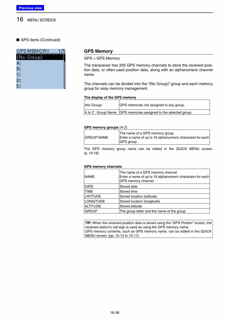
16 MENU SCREEN
16-38
■ GPS items (Continued)
GPS Memory
GPS > GPS Memory
The transceiver has 200 GPS memory channels to store the received posi-tion data, or often-used position data, along with an alphanumeric channel name.
The channels can be divided into the “(No Group)” group and each memory group for easy memory management.
The display of the GPS memory
(No Group) GPS memories not assigned to any group.
A to Z : Group Name GPS memories assigned to the selected group.
GPS memory groups (A-Z)
GROUP NAMEThe name of a GPS memory groupEnter a name of up to 16 alphanumeric characters for each GPS group.
The GPS memory group name can be edited in the QUICK MENU screen. (p. 10-18)
GPS memory channels
NAMEThe name of a GPS memory channelEnter a name of up to 16 alphanumeric characters for each GPS memory channel.
DATE Stored date
TIME Stored time
LATITUDE Stored location (latitude)
LONGITUDE Stored location (longitude)
ALTITUDE Stored altitude
GROUP The group letter and the name of the group
TIP: When the received position data is stored using the “GPS Positon” screen, the received station’s call sign is used as using the GPS memory name.GPS memory contents, such as GPS memory name, can be edited in the QUICK MENU screen. (pp. 10-13 to 10-17)
Previous view
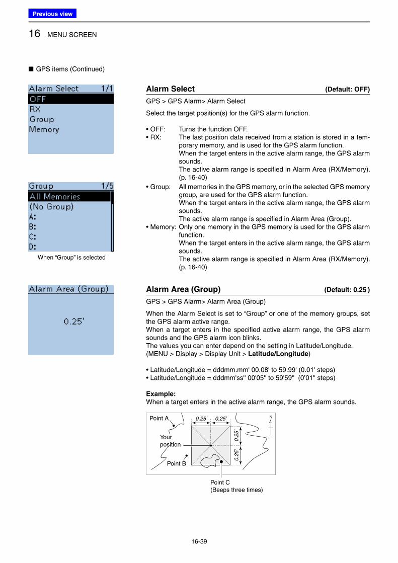
16 MENU SCREEN
16-39
■ GPS items (Continued)
Alarm Select (Default: OFF)
GPS > GPS Alarm> Alarm Select
Select the target position(s) for the GPS alarm function.
• OFF: Turns the function OFF.• RX: The last position data received from a station is stored in a tem-
porary memory, and is used for the GPS alarm function. When the target enters in the active alarm range, the GPS alarm
sounds. The active alarm range is specified in Alarm Area (RX/Memory).
(p. 16-40)
• Group: All memories in the GPS memory, or in the selected GPS memory group, are used for the GPS alarm function.
When the target enters in the active alarm range, the GPS alarm sounds.
The active alarm range is specified in Alarm Area (Group).• Memory: Only one memory in the GPS memory is used for the GPS alarm
function. When the target enters in the active alarm range, the GPS alarm
sounds. The active alarm range is specified in Alarm Area (RX/Memory).
(p. 16-40)
Alarm Area (Group) (Default: 0.25')
GPS > GPS Alarm> Alarm Area (Group)
When the Alarm Select is set to “Group” or one of the memory groups, set the GPS alarm active range.When a target enters in the specified active alarm range, the GPS alarm sounds and the GPS alarm icon blinks.The values you can enter depend on the setting in Latitude/Longitude.(MENU > Display > Display Unit > Latitude/Longitude)
• Latitude/Longitude = dddmm.mm' 00.08' to 59.99' (0.01' steps)• Latitude/Longitude = dddmm'ss'' 00'05'' to 59'59'' (0’01" steps)
Example:
When a target enters in the active alarm range, the GPS alarm sounds.
0.25’ 0.25’
0.2
5’
0.2
5’
N
Your position
Point A
Point B
Point C(Beeps three times)
When “Group” is selected
Previous view
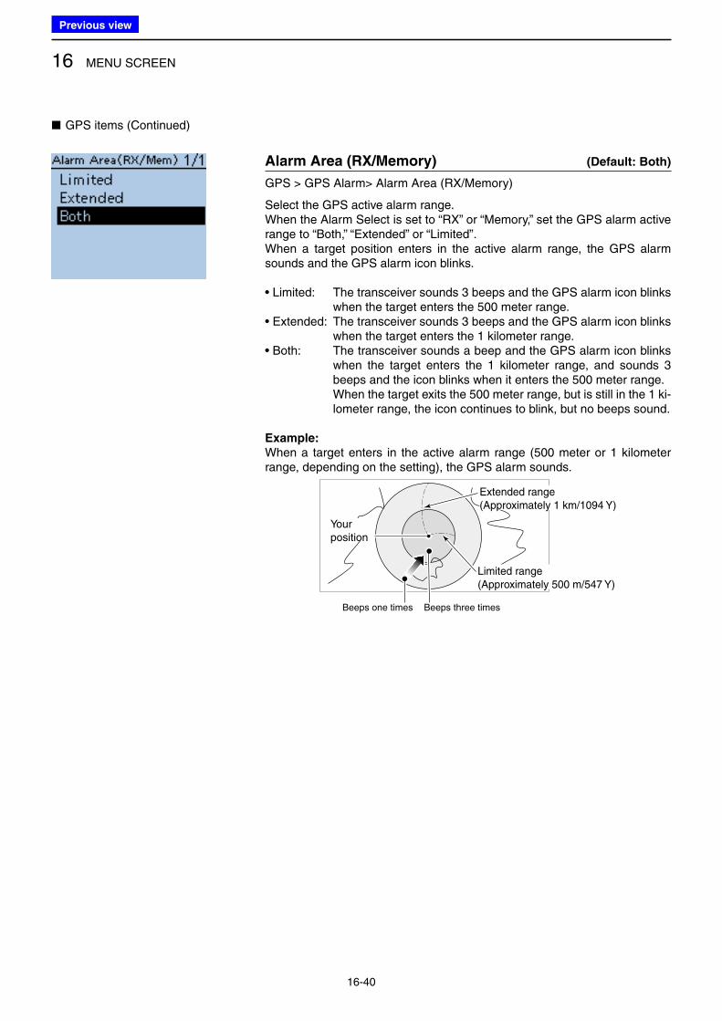
16 MENU SCREEN
16-40
■ GPS items (Continued)
Alarm Area (RX/Memory) (Default: Both)
GPS > GPS Alarm> Alarm Area (RX/Memory)
Select the GPS active alarm range.When the Alarm Select is set to “RX” or “Memory,” set the GPS alarm active range to “Both,” “Extended” or “Limited”.When a target position enters in the active alarm range, the GPS alarm sounds and the GPS alarm icon blinks.
• Limited: The transceiver sounds 3 beeps and the GPS alarm icon blinks when the target enters the 500 meter range.
• Extended: The transceiver sounds 3 beeps and the GPS alarm icon blinks when the target enters the 1 kilometer range.
• Both: The transceiver sounds a beep and the GPS alarm icon blinks when the target enters the 1 kilometer range, and sounds 3 beeps and the icon blinks when it enters the 500 meter range.
When the target exits the 500 meter range, but is still in the 1 ki-lometer range, the icon continues to blink, but no beeps sound.
Example:
When a target enters in the active alarm range (500 meter or 1 kilometer range, depending on the setting), the GPS alarm sounds.
Your position
Extended range (Approximately 1 km/1094 Y)
Limited range (Approximately 500 m/547 Y)
Beeps one times Beeps three times
Previous view
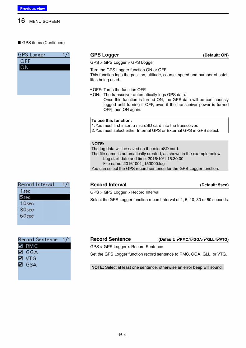
16 MENU SCREEN
16-41
■ GPS items (Continued)
GPS Logger (Default: ON)
GPS > GPS Logger > GPS Logger
Turn the GPS Logger function ON or OFF.This function logs the position, altitude, course, speed and number of satel-lites being used.
• OFF: Turns the function OFF. • ON: The transceiver automatically logs GPS data. Once this function is turned ON, the GPS data will be continuously
logged until turning it OFF, even if the transceiver power is turned OFF, then ON again.
To use this function:
1. You must first insert a microSD card into the transceiver.2. You must select either Internal GPS or External GPS in GPS select.
NOTE:
The log data will be saved on the microSD card.The file name is automatically created, as shown in the example below:
Log start date and time: 2016/10/1 15:30:00File name: 20161001_153000.log
You can select the GPS record sentence for the GPS Logger function.
Record Interval (Default: 5sec)
GPS > GPS Logger > Record Interval
Select the GPS Logger function record interval of 1, 5, 10, 30 or 60 seconds.
Record Sentence (Default: □✔RMC/□✔GGA/□✔GLL/□✔VTG)
GPS > GPS Logger > Record Sentence
Set the GPS Logger function record sentence to RMC, GGA, GLL, or VTG.
NOTE: Select at least one sentence, otherwise an error beep will sound.
Previous view
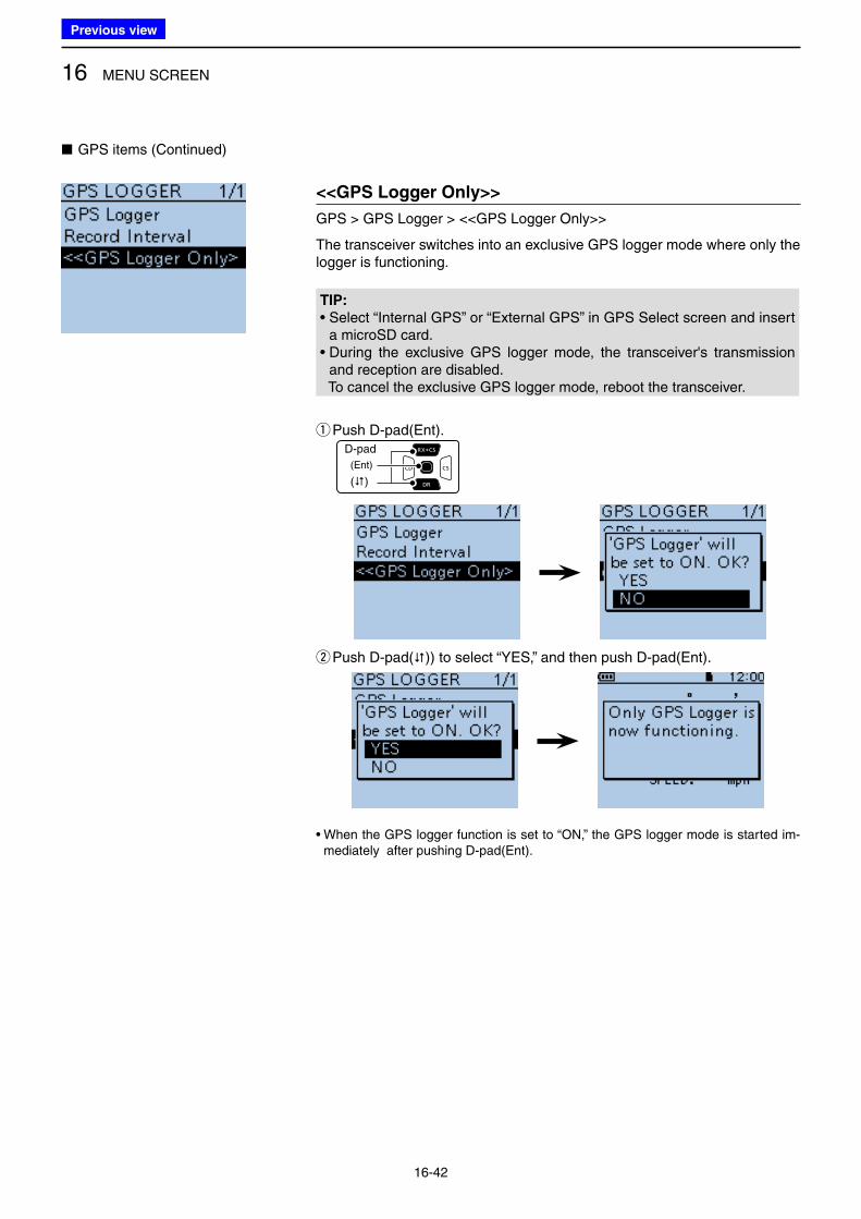
16 MENU SCREEN
16-42
■ GPS items (Continued)
<<GPS Logger Only>>
GPS > GPS Logger > <<GPS Logger Only>>
The transceiver switches into an exclusive GPS logger mode where only the logger is functioning.
TIP:
• Select “Internal GPS” or “External GPS” in GPS Select screen and insert a microSD card.
• During the exclusive GPS logger mode, the transceiver's transmission and reception are disabled.
To cancel the exclusive GPS logger mode, reboot the transceiver.
q Push D-pad(Ent).D-pad
(�)
(Ent)
w Push D-pad()) to select “YES,” and then push D-pad(Ent).
• When the GPS logger function is set to “ON,” the GPS logger mode is started im-mediately after pushing D-pad(Ent).
Previous view
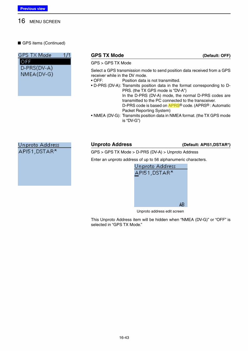
16 MENU SCREEN
16-43
■ GPS items (Continued)
GPS TX Mode (Default: OFF)
GPS > GPS TX Mode
Select a GPS transmission mode to send position data received from a GPS receiver while in the DV mode.• OFF: Position data is not transmitted. • D-PRS (DV-A): Transmits position data in the format corresponding to D-
PRS. (the TX GPS mode is “DV-A”) In the D-PRS (DV-A) mode, the normal D-PRS codes are
transmitted to the PC connected to the transceiver. D-PRS code is based on APRS® code. (APRS® : Automatic
Packet Reporting System) • NMEA (DV-G): Transmits position data in NMEA format. (the TX GPS mode
is “DV-G”)
Unproto Address (Default: API51,DSTAR*)
GPS > GPS TX Mode > D-PRS (DV-A) > Unproto Address
Enter an unproto address of up to 56 alphanumeric characters.
Unproto address edit screen
This Unproto Address item will be hidden when “NMEA (DV-G)” or “OFF” is selected in “GPS TX Mode.”
Previous view
Icom
ハイライト表示
(Automatic Packet Reporting System) APRS is a two-way tactical real-time digital communications system between all assets in a network sharing information about everything going on in the local area.
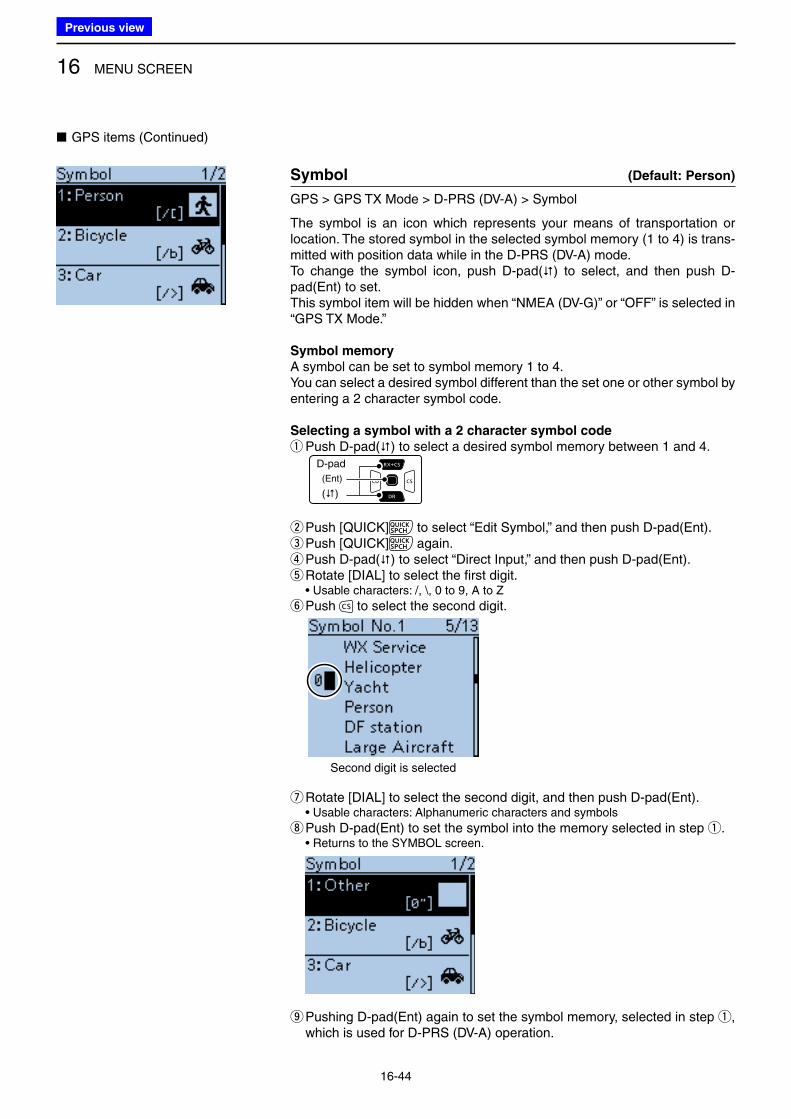
16 MENU SCREEN
16-44
■ GPS items (Continued)
Symbol (Default: Person)
GPS > GPS TX Mode > D-PRS (DV-A) > Symbol
The symbol is an icon which represents your means of transportation or location. The stored symbol in the selected symbol memory (1 to 4) is trans-mitted with position data while in the D-PRS (DV-A) mode. To change the symbol icon, push D-pad() to select, and then push D-pad(Ent) to set. This symbol item will be hidden when “NMEA (DV-G)” or “OFF” is selected in “GPS TX Mode.”
Symbol memory
A symbol can be set to symbol memory 1 to 4.You can select a desired symbol different than the set one or other symbol by entering a 2 character symbol code.
Selecting a symbol with a 2 character symbol code
q Push D-pad() to select a desired symbol memory between 1 and 4.D-pad
(�)
(Ent)
w Push [QUICK] to select “Edit Symbol,” and then push D-pad(Ent). ePush [QUICK] again. r Push D-pad() to select “Direct Input,” and then push D-pad(Ent). tRotate [DIAL] to select the first digit.• Usable characters: /, \, 0 to 9, A to Z
yPush to select the second digit.
Second digit is selected
u Rotate [DIAL] to select the second digit, and then push D-pad(Ent).• Usable characters: Alphanumeric characters and symbols
i Push D-pad(Ent) to set the symbol into the memory selected in step q.• Returns to the SYMBOL screen.
o Pushing D-pad(Ent) again to set the symbol memory, selected in step q, which is used for D-PRS (DV-A) operation.
Previous view
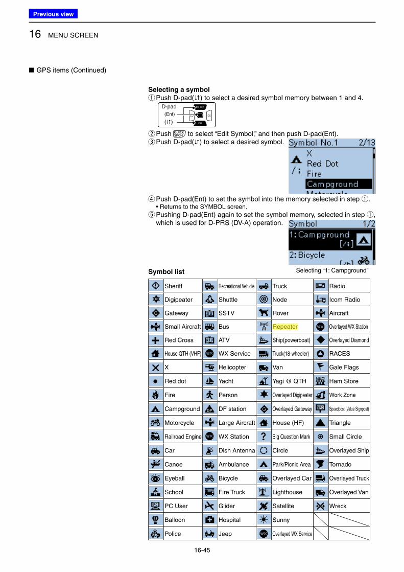
16 MENU SCREEN
16-45
■ GPS items (Continued)
Selecting a symbol
q Push D-pad() to select a desired symbol memory between 1 and 4.D-pad
(�)
(Ent)
w Push to select “Edit Symbol,” and then push D-pad(Ent). e Push D-pad() to select a desired symbol.
r Push D-pad(Ent) to set the symbol into the memory selected in step q.• Returns to the SYMBOL screen.
t Pushing D-pad(Ent) again to set the symbol memory, selected in step q, which is used for D-PRS (DV-A) operation.
Symbol list
Sheriff Recreational Vehicle Truck Radio
Digipeater Shuttle Node Icom Radio
Gateway SSTV Rover Aircraft
Small Aircraft Bus Repeater Overlayed WX Station
Red Cross ATV Ship(powerboat) Overlayed Diamond
House QTH (VHF) WX Service Truck(18-wheeler) RACES
X Helicopter Van Gale Flags
Red dot Yacht Yagi @ QTH Ham Store
Fire Person Overlayed Digipeater Work Zone
Campground DF station Overlayed Gateway Speedpost (Value Signpost)
Motorcycle Large Aircraft House (HF) Triangle
Railroad Engine WX Station Big Question Mark Small Circle
Car Dish Antenna Circle Overlayed Ship
Canoe Ambulance Park/Picnic Area Tornado
Eyeball Bicycle Overlayed Car Overlayed Truck
School Fire Truck Lighthouse Overlayed Van
PC User Glider Satellite Wreck
Balloon Hospital Sunny
Police Jeep Overlayed WX Service
Selecting “1: Campground”
Previous view
Icom
ハイライト表示
Radio systems that receive incoming signals and retransmit them to extend the communication area. Normally put on geographically high locations for VHF/UHF radios.
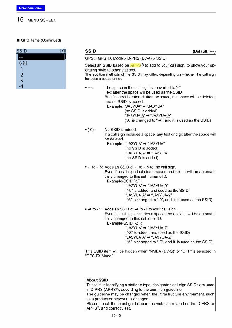
16 MENU SCREEN
16-46
■ GPS items (Continued)
SSID (Default: - - -)
GPS > GPS TX Mode > D-PRS (DV-A) > SSID
Select an SSID based on APRS® to add to your call sign, to show your op-erating style to other stations.The addition methods of the SSID may differ, depending on whether the call sign includes a space or not.
• - - -: The space in the call sign is converted to “-.” Text after the space will be used as the SSID. But if no text is entered after the space, the space will be deleted,
and no SSID is added. Example: “JA3YUA” ➡ “JA3YUA” (no SSID is added) “JA3YUA A” ➡ “JA3YUA-A” (“A” is changed to “-A”, and it is used as the SSID)
• (-0): No SSID is added. If a call sign includes a space, any text or digit after the space will
be deleted. Example: “JA3YUA” ➡ “JA3YUA” (no SSID is added) “JA3YUA A” ➡ “JA3YUA” (no SSID is added)
• -1 to -15: Adds an SSID of -1 to -15 to the call sign. Even if a call sign includes a space and text, it will be automati-
cally changed to this set numeric ID. Example(SSID [-9]): “JA3YUA” ➡ “JA3YUA-9” (“-9” is added, and used as the SSID) “JA3YUA A” ➡ “JA3YUA-9” (“A” is changed to “-9”, and it is used as the SSID)
• -A to -Z: Adds an SSID of -A to -Z to your call sign. Even if a call sign includes a space and a text, it will be automati-
cally changed to this set letter ID. Example(SSID [-Z]): “JA3YUA” ➡ “JA3YUA-Z” (“-Z” is added, and used as the SSID) “JA3YUA A” ➡ “JA3YUA-Z” (“A” is changed to “-Z”, and it is used as the SSID)
This SSID item will be hidden when “NMEA (DV-G)” or “OFF” is selected in “GPS TX Mode.”
About SSID
To assist in identifying a station’s type, designated call sign SSIDs are used in D-PRS (APRS®), according to the common guideline.The guideline may be changed when the infrastructure environment, such as a product or network, is changed.Please check the latest guideline in the web site related on the D-PRS or APRS®, and correctly set.
Previous view
Icom
ハイライト表示
(Automatic Packet Reporting System) APRS is a two-way tactical real-time digital communications system between all assets in a network sharing information about everything going on in the local area.
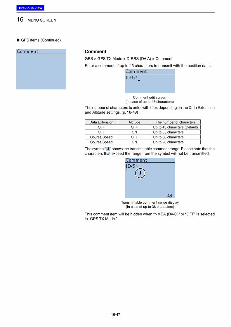
16 MENU SCREEN
16-47
■ GPS items (Continued)
Comment
GPS > GPS TX Mode > D-PRS (DV-A) > Comment
Enter a comment of up to 43 characters to transmit with the position data.
Comment edit screen(In case of up to 43 characters)
The number of characters to enter will differ, depending on the Data Extension and Altitude settings. (p. 16-48)
Data Extension Altitude The number of characters
OFF OFF Up to 43 characters (Default)
OFF ON Up to 35 characters
Course/Speed OFF Up to 36 characters
Course/Speed ON Up to 28 characters
The symbol “ ” shows the transmittable comment range. Please note that the characters that exceed the range from the symbol will not be transmitted.
Transmittable comment range display (In case of up to 36 characters)
This comment item will be hidden when “NMEA (DV-G)” or “OFF” is selected in “GPS TX Mode.”
Previous view
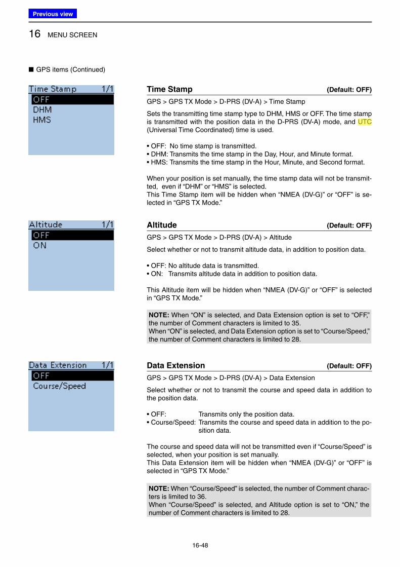
16 MENU SCREEN
16-48
■ GPS items (Continued)
Time Stamp (Default: OFF)
GPS > GPS TX Mode > D-PRS (DV-A) > Time Stamp
Sets the transmitting time stamp type to DHM, HMS or OFF. The time stamp is transmitted with the position data in the D-PRS (DV-A) mode, and UTC (Universal Time Coordinated) time is used.
• OFF: No time stamp is transmitted. • DHM: Transmits the time stamp in the Day, Hour, and Minute format. • HMS: Transmits the time stamp in the Hour, Minute, and Second format.
When your position is set manually, the time stamp data will not be transmit-ted, even if “DHM” or “HMS” is selected.This Time Stamp item will be hidden when “NMEA (DV-G)” or “OFF” is se-lected in “GPS TX Mode.”
Altitude (Default: OFF)
GPS > GPS TX Mode > D-PRS (DV-A) > Altitude
Select whether or not to transmit altitude data, in addition to position data.
• OFF: No altitude data is transmitted. • ON: Transmits altitude data in addition to position data.
This Altitude item will be hidden when “NMEA (DV-G)” or “OFF” is selected in “GPS TX Mode.”
NOTE: When “ON” is selected, and Data Extension option is set to “OFF,” the number of Comment characters is limited to 35.When “ON” is selected, and Data Extension option is set to “Course/Speed,” the number of Comment characters is limited to 28.
Data Extension (Default: OFF)
GPS > GPS TX Mode > D-PRS (DV-A) > Data Extension
Select whether or not to transmit the course and speed data in addition to the position data.
• OFF: Transmits only the position data. • Course/Speed: Transmits the course and speed data in addition to the po-
sition data.
The course and speed data will not be transmitted even if “Course/Speed” is selected, when your position is set manually.This Data Extension item will be hidden when “NMEA (DV-G)” or “OFF” is selected in “GPS TX Mode.”
NOTE: When “Course/Speed” is selected, the number of Comment charac-ters is limited to 36.When “Course/Speed” is selected, and Altitude option is set to “ON,” the number of Comment characters is limited to 28.
Previous view
Icom
ハイライト表示
(Universal Time Coordinated) An astronomical time based on the Greenwich meridian (zero degrees longitude).
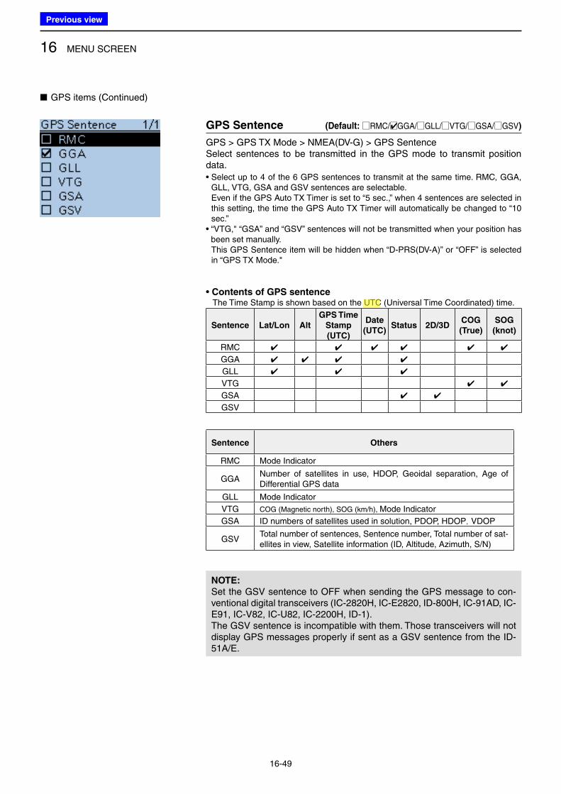
16 MENU SCREEN
16-49
■ GPS items (Continued)
GPS Sentence (Default: □RMC/□✔GGA/□GLL/□VTG/□GSA/□GSV)
GPS > GPS TX Mode > NMEA(DV-G) > GPS Sentence Select sentences to be transmitted in the GPS mode to transmit position data.• Select up to 4 of the 6 GPS sentences to transmit at the same time. RMC, GGA,
GLL, VTG, GSA and GSV sentences are selectable.Even if the GPS Auto TX Timer is set to “5 sec.,” when 4 sentences are selected in this setting, the time the GPS Auto TX Timer will automatically be changed to “10 sec.”
• “VTG," “GSA” and “GSV” sentences will not be transmitted when your position has been set manually. This GPS Sentence item will be hidden when “D-PRS(DV-A)” or “OFF” is selected in “GPS TX Mode."
• Contents of GPS sentence The Time Stamp is shown based on the UTC (Universal Time Coordinated) time.
Sentence Lat/Lon Alt
GPS Time
Stamp
(UTC)
Date
(UTC)Status 2D/3D
COG
(True)
SOG
(knot)
RMC ✔ ✔ ✔ ✔ ✔ ✔
GGA ✔ ✔ ✔ ✔
GLL ✔ ✔ ✔
VTG ✔ ✔
GSA ✔ ✔
GSV
Sentence Others
RMC Mode Indicator
GGANumber of satellites in use, HDOP, Geoidal separation, Age of Differential GPS data
GLL Mode Indicator
VTG COG (Magnetic north), SOG (km/h), Mode Indicator
GSA ID numbers of satellites used in solution, PDOP, HDOP, VDOP
GSVTotal number of sentences, Sentence number, Total number of sat-ellites in view, Satellite information (ID, Altitude, Azimuth, S/N)
NOTE:
Set the GSV sentence to OFF when sending the GPS message to con-ventional digital transceivers (IC-2820H, IC-E2820, ID-800H, IC-91AD, IC-E91, IC-V82, IC-U82, IC-2200H, ID-1).The GSV sentence is incompatible with them. Those transceivers will not display GPS messages properly if sent as a GSV sentence from the ID-51A/E.
Previous view
Icom
ハイライト表示
(Universal Time Coordinated) An astronomical time based on the Greenwich meridian (zero degrees longitude).
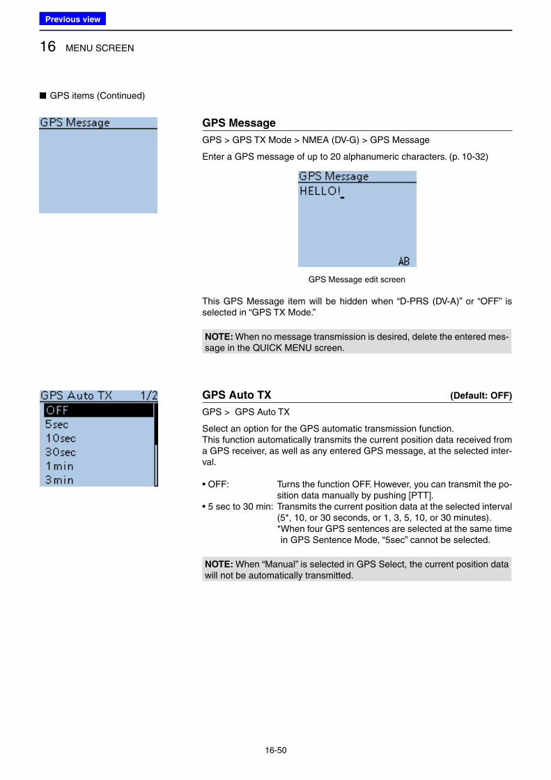
16 MENU SCREEN
16-50
■ GPS items (Continued)
GPS Message
GPS > GPS TX Mode > NMEA (DV-G) > GPS Message
Enter a GPS message of up to 20 alphanumeric characters. (p. 10-32)
GPS Message edit screen
This GPS Message item will be hidden when “D-PRS (DV-A)” or “OFF” is selected in “GPS TX Mode.”
NOTE: When no message transmission is desired, delete the entered mes-sage in the QUICK MENU screen.
GPS Auto TX (Default: OFF)
GPS > GPS Auto TX
Select an option for the GPS automatic transmission function.This function automatically transmits the current position data received from a GPS receiver, as well as any entered GPS message, at the selected inter-val.
• OFF: Turns the function OFF. However, you can transmit the po-sition data manually by pushing [PTT].
• 5 sec to 30 min: Transmits the current position data at the selected interval (5*, 10, or 30 seconds, or 1, 3, 5, 10, or 30 minutes).
* When four GPS sentences are selected at the same time in GPS Sentence Mode, “5sec” cannot be selected.
NOTE: When “Manual” is selected in GPS Select, the current position data will not be automatically transmitted.
Previous view
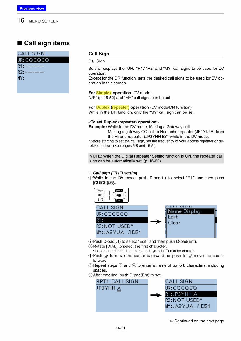
16 MENU SCREEN
16-51
■ Call sign items
Call Sign
Call Sign
Sets or displays the “UR,” “R1,” “R2” and “MY” call signs to be used for DV operation.Except for the DR function, sets the desired call signs to be used for DV op-eration in this screen.
For Simplex operation (DV mode)“UR” (p. 16-52) and “MY” call signs can be set.
For Duplex (repeater) operation (DV mode/DR function)While in the DR function, only the “MY” call sign can be set.
<To set Duplex (repeater) operation>
Example : While in the DV mode, Making a Gateway call Making a gateway CQ call to Hamacho repeater (JP1YIU B) from
the Hirano repeater (JP3YHH B)*, while in the DV mode.* Before starting to set the call sign, set the frequency of your access repeater or du-plex direction. (See pages 5-8 and 15-5.)
NOTE: When the Digital Repeater Setting function is ON, the repeater call sign can be automatically set. (p. 16-63)
1. Call sign (“R1”) setting
q While in the DV mode, push D-pad() to select “R1,” and then push [QUICK] .
D-pad
(�)
(Ent)
wPush D-pad() to select “Edit,” and then push D-pad(Ent). eRotate [DIAL] to select the first character.
• Letters, numbers, characters, and symbol (“/”) can be entered.
r Push to move the cursor backward, or push to move the cursor forward. t Repeat steps e and r to enter a name of up to 8 characters, including spaces. yAfter entering, push D-pad(Ent) to set.
☞ Continued on the next page
Previous view
Icom
ハイライト表示
An operating mode in which the transmit and receive frequencies are the same.
Icom
ハイライト表示
Radio systems that receive incoming signals and retransmit them to extend the communication area. Normally put on geographically high locations for VHF/UHF radios.
Icom
ハイライト表示
An operating mode in which the transmit and receive frequencies are separated by an offset amount.
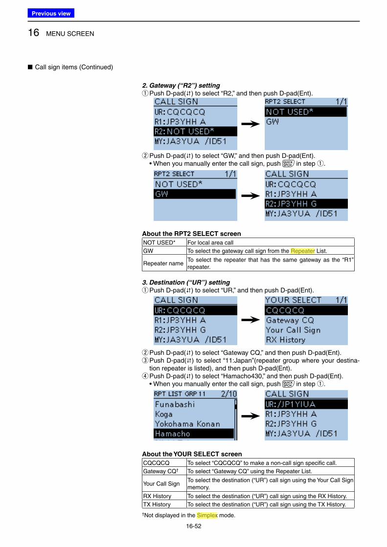
16 MENU SCREEN
16-52
2. Gateway (“R2”) setting
q Push D-pad() to select “R2,” and then push D-pad(Ent).
wPush D-pad() to select “GW,” and then push D-pad(Ent).• When you manually enter the call sign, push in step q.
About the RPT2 SELECT screen
NOT USED* For local area call
GW To select the gateway call sign from the Repeater List.
Repeater nameTo select the repeater that has the same gateway as the “R1” repeater.
3. Destination (“UR”) setting
q Push D-pad() to select “UR,” and then push D-pad(Ent).
wPush D-pad() to select “Gateway CQ,” and then push D-pad(Ent). e Push D-pad() to select “11:Japan”(repeater group where your destina-tion repeater is listed), and then push D-pad(Ent). rPush D-pad() to select “Hamacho430,” and then push D-pad(Ent).• When you manually enter the call sign, push in step q.
About the YOUR SELECT screen
CQCQCQ To select “CQCQCQ” to make a non-call sign specific call.
Gateway CQ† To select “Gateway CQ” using the Repeater List.
Your Call SignTo select the destination (“UR”) call sign using the Your Call Sign memory.
RX History To select the destination (“UR”) call sign using the RX History.
TX History To select the destination (“UR”) call sign using the TX History.
†Not displayed in the Simplex mode.
■ Call sign items (Continued)
Previous view
Icom
ハイライト表示
An operating mode in which the transmit and receive frequencies are the same.
Icom
ハイライト表示
Radio systems that receive incoming signals and retransmit them to extend the communication area. Normally put on geographically high locations for VHF/UHF radios.
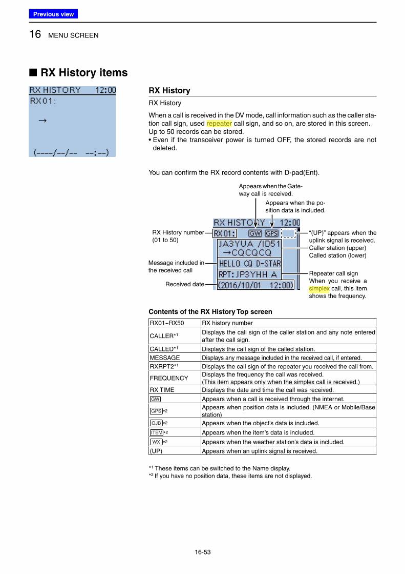
16 MENU SCREEN
16-53
■ RX History items
RX History
RX History
When a call is received in the DV mode, call information such as the caller sta-tion call sign, used repeater call sign, and so on, are stored in this screen.Up to 50 records can be stored.• Even if the transceiver power is turned OFF, the stored records are not
deleted.
You can confirm the RX record contents with D-pad(Ent).
RX History number (01 to 50)
Message included in the received call
Received date
Caller station (upper)Called station (lower)
Repeater call signWhen you receive a simplex call, this item shows the frequency.
Appears when the Gate-way call is received.
Appears when the po-sition data is included.
“(UP)” appears when the uplink signal is received.
Contents of the RX History Top screen
RX01~RX50 RX history number
CALLER*1 Displays the call sign of the caller station and any note entered after the call sign.
CALLED*1 Displays the call sign of the called station.
MESSAGE Displays any message included in the received call, if entered.
RXRPT2*1 Displays the call sign of the repeater you received the call from.
FREQUENCYDisplays the frequency the call was received.( This item appears only when the simplex call is received.)
RX TIME Displays the date and time the call was received.
GW Appears when a call is received through the internet.
GPS *2Appears when position data is included. (NMEA or Mobile/Base station)
OJB *2 Appears when the object’s data is included.
ITEM *2 Appears when the item’s data is included.
WX *2 Appears when the weather station’s data is included.
(UP) Appears when an uplink signal is received.
*1 These items can be switched to the Name display.*2 If you have no position data, these items are not displayed.
Previous view
Icom
ハイライト表示
An operating mode in which the transmit and receive frequencies are the same.
Icom
ハイライト表示
Radio systems that receive incoming signals and retransmit them to extend the communication area. Normally put on geographically high locations for VHF/UHF radios.
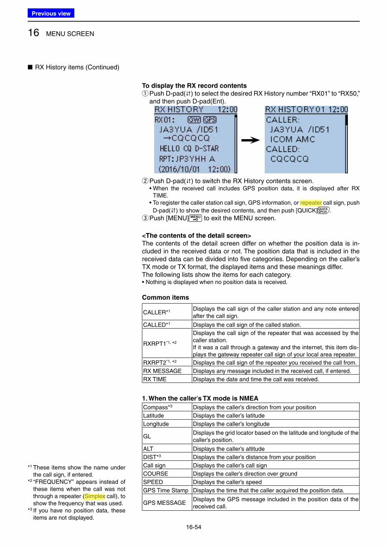
16 MENU SCREEN
16-54
To display the RX record contents
q Push D-pad() to select the desired RX History number “RX01” to “RX50,” and then push D-pad(Ent).
wPush D-pad() to switch the RX History contents screen.• When the received call includes GPS position data, it is displayed after RX
TIME.• To register the caller station call sign, GPS information, or repeater call sign, push
D-pad() to show the desired contents, and then push [QUICK] .
ePush [MENU] to exit the MENU screen.
<The contents of the detail screen>
The contents of the detail screen differ on whether the position data is in-cluded in the received data or not. The position data that is included in the received data can be divided into five categories. Depending on the caller’s TX mode or TX format, the displayed items and these meanings differ.The following lists show the items for each category.• Nothing is displayed when no position data is received.
Common items
CALLER*1 Displays the call sign of the caller station and any note entered after the call sign.
CALLED*1 Displays the call sign of the called station.
RXRPT1*1, *2
Displays the call sign of the repeater that was accessed by the caller station. If it was a call through a gateway and the internet, this item dis-plays the gateway repeater call sign of your local area repeater.
RXRPT2*1, *2 Displays the call sign of the repeater you received the call from.
RX MESSAGE Displays any message included in the received call, if entered.
RX TIME Displays the date and time the call was received.
1. When the caller’s TX mode is NMEA
Compass*3 Displays the caller’s direction from your position
Latitude Displays the caller’s latitude
Longitude Displays the caller’s longitude
GLDisplays the grid locator based on the latitude and longitude of the caller’s position.
ALT Displays the caller’s altitude
DIST*3 Displays the caller’s distance from your position
Call sign Displays the caller’s call sign
COURSE Displays the caller’s direction over ground
SPEED Displays the caller’s speed
GPS Time Stamp Displays the time that the caller acquired the position data.
GPS MESSAGEDisplays the GPS message included in the position data of the received call.
■ RX History items (Continued)
*1 These items show the name under the call sign, if entered.
*2 “FREQUENCY” appears instead of these items when the call was not through a repeater (Simplex call), to show the frequency that was used.
*3 If you have no position data, these items are not displayed.
Previous view
Icom
ハイライト表示
An operating mode in which the transmit and receive frequencies are the same.
Icom
ハイライト表示
Radio systems that receive incoming signals and retransmit them to extend the communication area. Normally put on geographically high locations for VHF/UHF radios.
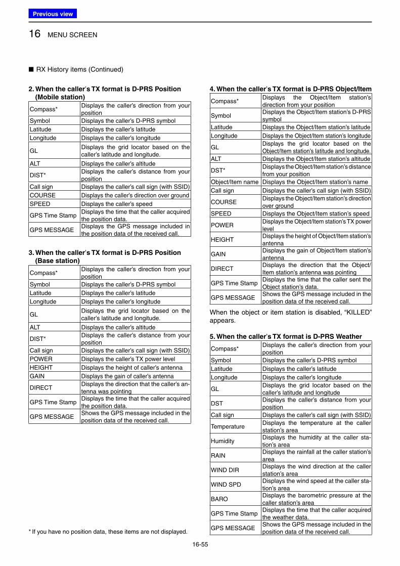
16 MENU SCREEN
16-55
■ RX History items (Continued)
2. When the caller’s TX format is D-PRS Position
(Mobile station)
Compass*Displays the caller’s direction from your position
Symbol Displays the caller’s D-PRS symbol
Latitude Displays the caller’s latitude
Longitude Displays the caller’s longitude
GLDisplays the grid locator based on the caller’s latitude and longitude.
ALT Displays the caller’s altitude
DIST*Displays the caller’s distance from your position
Call sign Displays the caller’s call sign (with SSID)
COURSE Displays the caller’s direction over ground
SPEED Displays the caller’s speed
GPS Time StampDisplays the time that the caller acquired the position data.
GPS MESSAGEDisplays the GPS message included in the position data of the received call.
3. When the caller’s TX format is D-PRS Position
(Base station)
Compass*Displays the caller’s direction from your position
Symbol Displays the caller’s D-PRS symbol
Latitude Displays the caller’s latitude
Longitude Displays the caller’s longitude
GLDisplays the grid locator based on the caller’s latitude and longitude.
ALT Displays the caller’s altitude
DIST*Displays the caller’s distance from your position
Call sign Displays the caller’s call sign (with SSID)
POWER Displays the caller’s TX power level
HEIGHT Displays the height of caller’s antenna
GAIN Displays the gain of caller’s antenna
DIRECTDisplays the direction that the caller’s an-tenna was pointing
GPS Time StampDisplays the time that the caller acquired the position data.
GPS MESSAGEShows the GPS message included in the position data of the received call.
4. When the caller’s TX format is D-PRS Object/Item
Compass*Displays the Object/Item station’s direction from your position
SymbolDisplays the Object/Item station’s D-PRS symbol
Latitude Displays the Object/Item station’s latitude
Longitude Displays the Object/Item station’s longitude
GLDisplays the grid locator based on the Object/Item station’s latitude and longitude.
ALT Displays the Object/Item station’s altitude
DST*Displays the Object/Item station’s distance from your position
Object/Item name Displays the Object/Item station’s name
Call sign Displays the caller’s call sign (with SSID)
COURSEDisplays the Object/Item station’s direction over ground
SPEED Displays the Object/Item station’s speed
POWERDisplays the Object/Item station’s TX power level
HEIGHTDisplays the height of Object/Item station’s antenna
GAINDisplays the gain of Object/Item station’s antenna
DIRECTDisplays the direction that the Object/Item station’s antenna was pointing
GPS Time StampDisplays the time that the caller sent the Object station’s data.
GPS MESSAGEShows the GPS message included in the position data of the received call.
When the object or item station is disabled, “KILLED” appears.
5. When the caller’s TX format is D-PRS Weather
Compass*Displays the caller’s direction from your position
Symbol Displays the caller’s D-PRS symbol
Latitude Displays the caller’s latitude
Longitude Displays the caller’s longitude
GLDisplays the grid locator based on the caller’s latitude and longitude
DSTDisplays the caller’s distance from your position
Call sign Displays the caller’s call sign (with SSID)
TemperatureDisplays the temperature at the caller station’s area
HumidityDisplays the humidity at the caller sta-tion’s area
RAINDisplays the rainfall at the caller station’s area
WIND DIRDisplays the wind direction at the caller station’s area
WIND SPDDisplays the wind speed at the caller sta-tion’s area
BARODisplays the barometric pressure at the caller station’s area
GPS Time StampDisplays the time that the caller acquired the weather data.
GPS MESSAGEShows the GPS message included in the position data of the received call.* If you have no position data, these items are not displayed.
Previous view
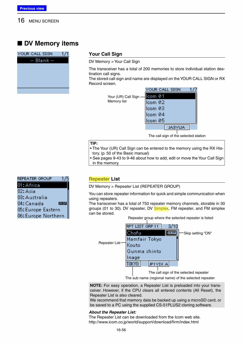
16 MENU SCREEN
16-56
■ DV Memory items
Your Call Sign
DV Memory > Your Call Sign
The transceiver has a total of 200 memories to store individual station des-tination call signs.The stored call sign and name are displayed on the YOUR CALL SIGN or RX Record screen.
Your (UR) Call Sign Memory list
The call sign of the selected station
TIP:
• The Your (UR) Call Sign can be entered to the memory using the RX His-tory. (p. 50 of the Ba sic manual)
• See pages 9-43 to 9-46 about how to add, edit or move the Your Call Sign in the memory.
Repeater List
DV Memory > Repeater List (REPEATER GROUP)
You can store repeater information for quick and simple communication when using repeaters.The transceiver has a total of 750 repeater memory channels, storable in 30 groups (01 to 30). DV repeater, DV Simplex, FM repeater, and FM simplex can be stored.
Repeater List
The sub name (regional name) of the selected repeater
Repeater group where the selected repeater is listed
The call sign of the selected repeater
Skip setting “ON”
NOTE: For easy operation, a Repeater List is preloaded into your trans-ceiver. However, if the CPU clears all entered contents (All Reset), the Repeater List is also cleared. We recommend that memory data be backed up using a microSD card, or be saved to a PC using the supplied CS-51PLUS2 cloning software.
About the Repeater List:
The Repeater List can be downloaded from the Icom web site.http://www.icom.co.jp/world/support/download/firm/index.html
Previous view
Icom
ハイライト表示
Radio systems that receive incoming signals and retransmit them to extend the communication area. Normally put on geographically high locations for VHF/UHF radios.
Icom
ハイライト表示
An operating mode in which the transmit and receive frequencies are the same.
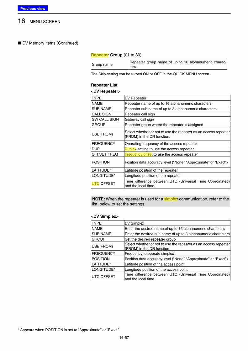
16 MENU SCREEN
16-57
Repeater Group (01 to 30)
Group nameRepeater group name of up to 16 alphanumeric charac-ters
The Skip setting can be turned ON or OFF in the QUICK MENU screen.
Repeater List
<DV Repeater>
TYPE DV Repeater
NAME Repeater name of up to 16 alphanumeric characters
SUB NAME Repeater sub name of up to 8 alphanumeric characters
CALL SIGN Repeater call sign
GW CALL SIGN Gateway call sign
GROUP Repeater group where the repeater is assigned
USE(FROM)Select whether or not to use the repeater as an access repeater (FROM) in the DR function.
FREQUENCY Operating frequency of the access repeater
DUP Duplex setting to use the access repeater
OFFSET FREQ Frequency offset to use the access repeater
POSITION Position data accuracy level (“None,” “Approximate” or “Exact”)
LATITUDE* Latitude position of the repeater
LONGITUDE* Longitude position of the repeater
UTC OFFSETTime difference between UTC (Universal Time Coordinated) and the local time
NOTE: When the repeater is used for a simplex communication, refer to the list below to set the settings.
<DV Simplex>
TYPE DV Simplex
NAME Enter the desired name of up to 16 alphanumeric characters
SUB NAME Enter the desired sub name of up to 8 alphanumeric characters
GROUP Set the desired repeater group
USE(FROM)Select whether or not to use the repeater as an access repeater (FROM) in the DR function
FREQUENCY Frequency to operate simplex
POSITION Position data accuracy level (“None,” “Approximate” or “Exact”)
LATITUDE* Latitude position of the access point
LONGITUDE* Longitude position of the access point
UTC OFFSETTime difference between UTC (Universal Time Coordinated) and the local time
■ DV Memory items (Continued)
* Appears when POSITION is set to “Approximate” or “Exact.”
Previous view
Icom
ハイライト表示
The difference between the transmit and receive frequencies.
Icom
ハイライト表示
Radio systems that receive incoming signals and retransmit them to extend the communication area. Normally put on geographically high locations for VHF/UHF radios.
Icom
ハイライト表示
An operating mode in which the transmit and receive frequencies are separated by an offset amount.
Icom
ハイライト表示
(Universal Time Coordinated) An astronomical time based on the Greenwich meridian (zero degrees longitude).
Icom
ハイライト表示
An operating mode in which the transmit and receive frequencies are the same.
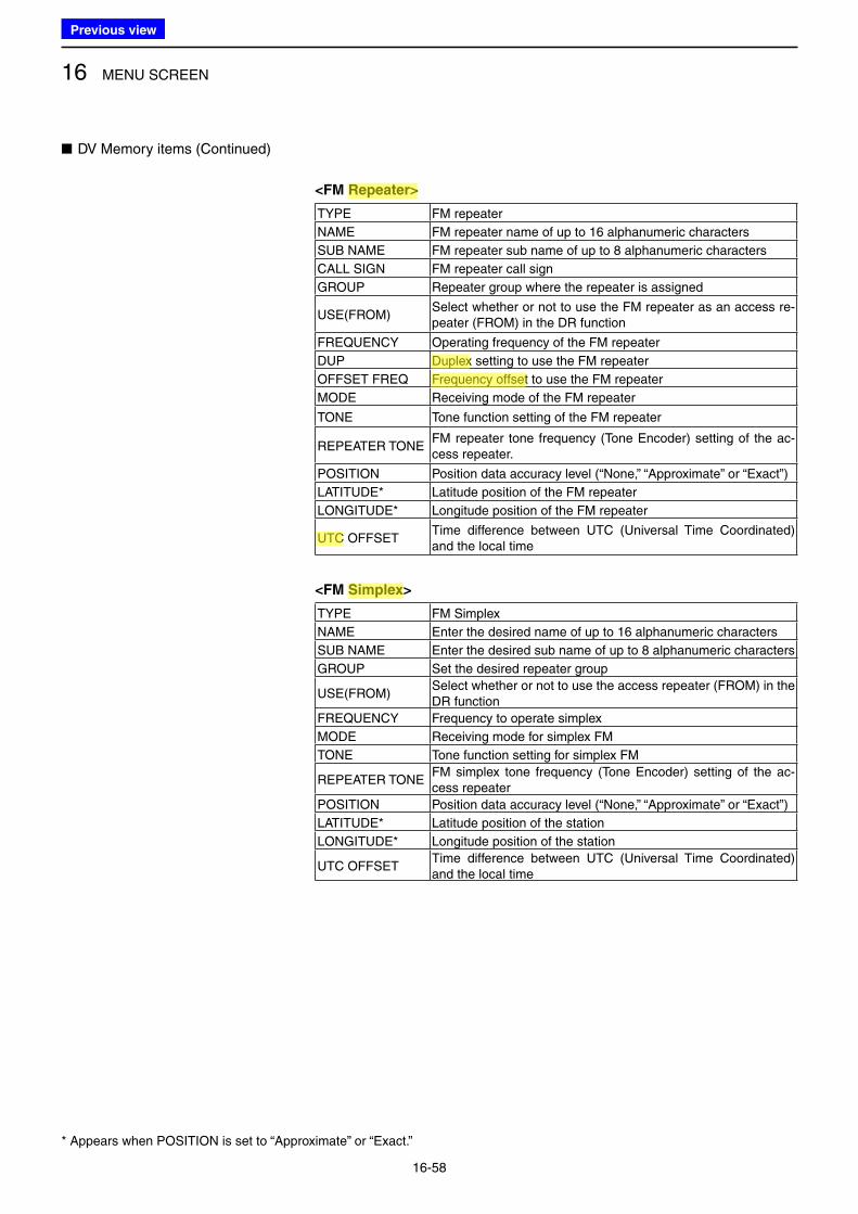
16 MENU SCREEN
16-58
<FM Repeater>
TYPE FM repeater
NAME FM repeater name of up to 16 alphanumeric characters
SUB NAME FM repeater sub name of up to 8 alphanumeric characters
CALL SIGN FM repeater call sign
GROUP Repeater group where the repeater is assigned
USE(FROM)Select whether or not to use the FM repeater as an access re-peater (FROM) in the DR function
FREQUENCY Operating frequency of the FM repeater
DUP Duplex setting to use the FM repeater
OFFSET FREQ Frequency offset to use the FM repeater
MODE Receiving mode of the FM repeater
TONE Tone function setting of the FM repeater
REPEATER TONEFM repeater tone frequency (Tone Encoder) setting of the ac-cess repeater.
POSITION Position data accuracy level (“None,” “Approximate” or “Exact”)
LATITUDE* Latitude position of the FM repeater
LONGITUDE* Longitude position of the FM repeater
UTC OFFSETTime difference between UTC (Universal Time Coordinated) and the local time
<FM Simplex>
TYPE FM Simplex
NAME Enter the desired name of up to 16 alphanumeric characters
SUB NAME Enter the desired sub name of up to 8 alphanumeric characters
GROUP Set the desired repeater group
USE(FROM)Select whether or not to use the access repeater (FROM) in the DR function
FREQUENCY Frequency to operate simplex
MODE Receiving mode for simplex FM
TONE Tone function setting for simplex FM
REPEATER TONEFM simplex tone frequency (Tone Encoder) setting of the ac-cess repeater
POSITION Position data accuracy level (“None,” “Approximate” or “Exact”)
LATITUDE* Latitude position of the station
LONGITUDE* Longitude position of the station
UTC OFFSETTime difference between UTC (Universal Time Coordinated) and the local time
■ DV Memory items (Continued)
* Appears when POSITION is set to “Approximate” or “Exact.”
Previous view
Icom
ハイライト表示
An operating mode in which the transmit and receive frequencies are the same.
Icom
ハイライト表示
The difference between the transmit and receive frequencies.
Icom
ハイライト表示
Radio systems that receive incoming signals and retransmit them to extend the communication area. Normally put on geographically high locations for VHF/UHF radios.
Icom
ハイライト表示
An operating mode in which the transmit and receive frequencies are separated by an offset amount.
Icom
ハイライト表示
(Universal Time Coordinated) An astronomical time based on the Greenwich meridian (zero degrees longitude).
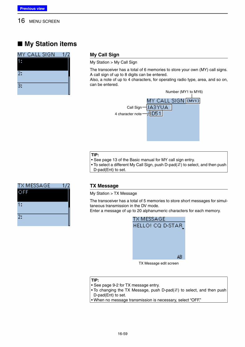
16 MENU SCREEN
16-59
■ My Station items
My Call Sign
My Station > My Call Sign
The transceiver has a total of 6 memories to store your own (MY) call signs.A call sign of up to 8 digits can be entered.Also, a note of up to 4 characters, for operating radio type, area, and so on, can be entered.
Call Sign
4 character note
Number (MY1 to MY6)
TIP:
• See page 13 of the Ba sic manual for MY call sign entry.• To select a different My Call Sign, push D-pad() to select, and then push
D-pad(Ent) to set.
TX Message
My Station > TX Message
The transceiver has a total of 5 memories to store short messages for simul-taneous transmission in the DV mode.Enter a message of up to 20 alphanumeric characters for each memory.
TX Message edit screen
TIP:
• See page 9-2 for TX message entry.• To changing the TX Message, push D-pad() to select, and then push
D-pad(Ent) to set.• When no message transmission is necessary, select “OFF.”
Previous view
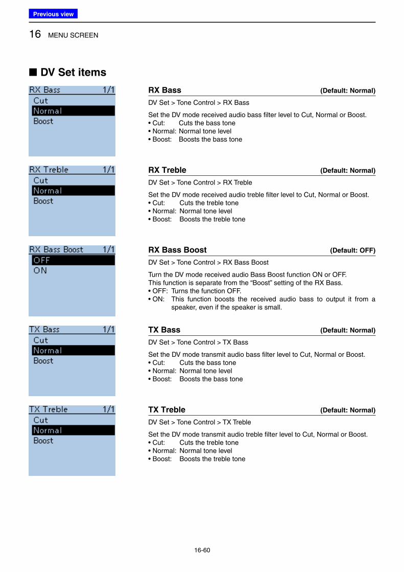
16 MENU SCREEN
16-60
■ DV Set items
RX Bass (Default: Normal)
DV Set > Tone Control > RX Bass
Set the DV mode received audio bass filter level to Cut, Normal or Boost.• Cut: Cuts the bass tone • Normal: Normal tone level• Boost: Boosts the bass tone
RX Treble (Default: Normal)
DV Set > Tone Control > RX Treble
Set the DV mode received audio treble filter level to Cut, Normal or Boost.• Cut: Cuts the treble tone • Normal: Normal tone level• Boost: Boosts the treble tone
RX Bass Boost (Default: OFF)
DV Set > Tone Control > RX Bass Boost
Turn the DV mode received audio Bass Boost function ON or OFF.This function is separate from the “Boost” setting of the RX Bass.• OFF: Turns the function OFF. • ON: This function boosts the received audio bass to output it from a
speaker, even if the speaker is small.
TX Bass (Default: Normal)
DV Set > Tone Control > TX Bass
Set the DV mode transmit audio bass filter level to Cut, Normal or Boost.• Cut: Cuts the bass tone • Normal: Normal tone level• Boost: Boosts the bass tone
TX Treble (Default: Normal)
DV Set > Tone Control > TX Treble
Set the DV mode transmit audio treble filter level to Cut, Normal or Boost.• Cut: Cuts the treble tone• Normal: Normal tone level• Boost: Boosts the treble tone
Previous view
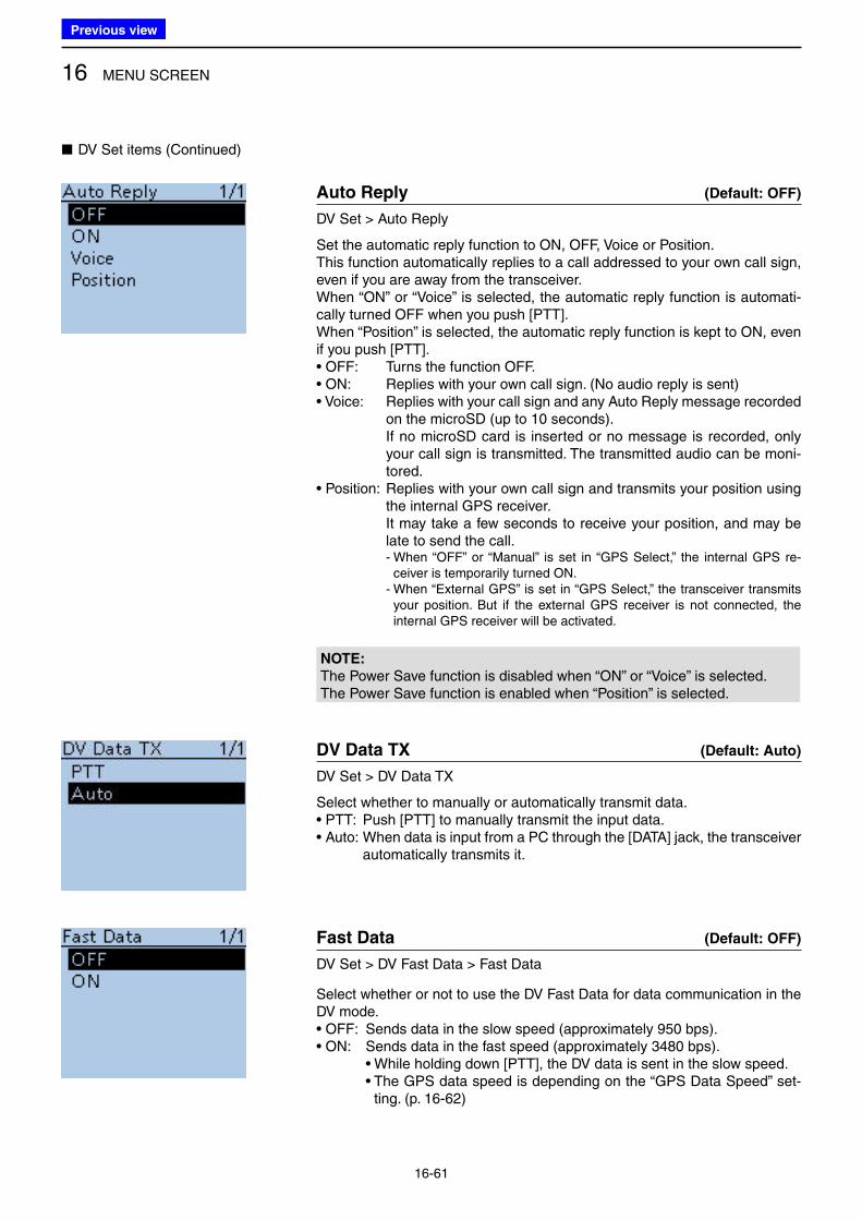
16 MENU SCREEN
16-61
■ DV Set items (Continued)
Auto Reply (Default: OFF)
DV Set > Auto Reply
Set the automatic reply function to ON, OFF, Voice or Position.This function automatically replies to a call addressed to your own call sign, even if you are away from the transceiver.When “ON” or “Voice” is selected, the automatic reply function is automati-cally turned OFF when you push [PTT].When “Position” is selected, the automatic reply function is kept to ON, even if you push [PTT].• OFF: Turns the function OFF.• ON: Replies with your own call sign. (No audio reply is sent)• Voice: Replies with your call sign and any Auto Reply message recorded
on the microSD (up to 10 seconds). If no microSD card is inserted or no message is recorded, only
your call sign is transmitted. The transmitted audio can be moni-tored.
• Position: Replies with your own call sign and transmits your position using the internal GPS receiver.
It may take a few seconds to receive your position, and may be late to send the call.
- When “OFF” or “Manual” is set in “GPS Select,” the internal GPS re-ceiver is temporarily turned ON.
- When “External GPS” is set in “GPS Select,” the transceiver transmits your position. But if the external GPS receiver is not connected, the internal GPS receiver will be activated.
NOTE:
The Power Save function is disabled when “ON” or “Voice” is selected.The Power Save function is enabled when “Position” is selected.
DV Data TX (Default: Auto)
DV Set > DV Data TX
Select whether to manually or automatically transmit data.• PTT: Push [PTT] to manually transmit the input data. • Auto: When data is input from a PC through the [DATA] jack, the transceiver
automatically transmits it.
Fast Data (Default: OFF)
DV Set > DV Fast Data > Fast Data
Select whether or not to use the DV Fast Data for data communication in the DV mode.• OFF: Sends data in the slow speed (approximately 950 bps).• ON: Sends data in the fast speed (approximately 3480 bps). • While holding down [PTT], the DV data is sent in the slow speed. • The GPS data speed is depending on the “GPS Data Speed” set-
ting. (p. 16-62)
Previous view
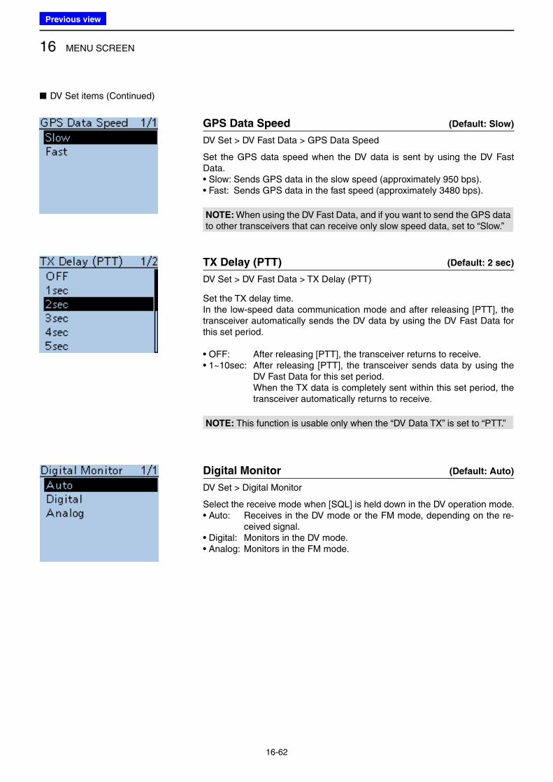
16 MENU SCREEN
16-62
■ DV Set items (Continued)
GPS Data Speed (Default: Slow)
DV Set > DV Fast Data > GPS Data Speed
Set the GPS data speed when the DV data is sent by using the DV Fast Data.• Slow: Sends GPS data in the slow speed (approximately 950 bps).• Fast: Sends GPS data in the fast speed (approximately 3480 bps).
NOTE: When using the DV Fast Data, and if you want to send the GPS data to other transceivers that can receive only slow speed data, set to “Slow.”
TX Delay (PTT) (Default: 2 sec)
DV Set > DV Fast Data > TX Delay (PTT)
Set the TX delay time.In the low-speed data communication mode and after releasing [PTT], the transceiver automatically sends the DV data by using the DV Fast Data for this set period.
• OFF: After releasing [PTT], the transceiver returns to receive.• 1~10sec: After releasing [PTT], the transceiver sends data by using the
DV Fast Data for this set period. When the TX data is completely sent within this set period, the
transceiver automatically returns to receive.
NOTE: This function is usable only when the “DV Data TX” is set to “PTT.”
Digital Monitor (Default: Auto)
DV Set > Digital Monitor
Select the receive mode when [SQL] is held down in the DV operation mode.• Auto: Receives in the DV mode or the FM mode, depending on the re-
ceived signal. • Digital: Monitors in the DV mode.• Analog: Monitors in the FM mode.
Previous view

16 MENU SCREEN
16-63
Digital Repeater Set (Default: ON)
DV Set > Digital Repeater Set
Turn the digital repeater setting function ON or OFF.In any DV mode except for the DR function, and when accessing a repeater that has a call sign that is different than the transceiver’s setting, this function reads the repeater’s signal and automatically sets the repeater call sign into R1 and R2.• OFF: Turns the function OFF. • ON: Automatically sets the repeater call sign.
RX Call Sign Write (Default: OFF)
DV Set > RX Call Sign Write
Set the RX call sign automatic write function to Auto or OFF.When receiving a call addressed to your own call sign in any DV mode ex-cept for the DR function, this function automatically sets the caller station call sign into “UR.”• OFF: Turns the function OFF.• Auto: Automatically sets the call sign of the caller station into “UR.”
RX Repeater Write (Default: OFF)
DV Set > RX Repeater Write
Set the repeater call sign automatic write function to Auto or OFF.When receiving a call addressed to your own call sign through a repeater in any DV mode except for the DR function, this function automatically sets the call sign of the repeater into “R1” or “R2.”• OFF: Turns the function OFF. • Auto: Automatically sets the call sign of the repeater into “R1” and/or “R2.”
DV Auto Detect (Default: OFF)
DV Set > DV Auto Detect
Turn the DV mode automatic detect function ON or OFF.If you receive a non-digital signal during DV mode operation, this function automatically switches to the FM mode.• OFF: Turns the function OFF. The operating mode is fixed to the DV mode. • ON: Automatically selects the FM mode for temporary operation.
■ DV Set items (Continued)
Previous view
Icom
ハイライト表示
Radio systems that receive incoming signals and retransmit them to extend the communication area. Normally put on geographically high locations for VHF/UHF radios.
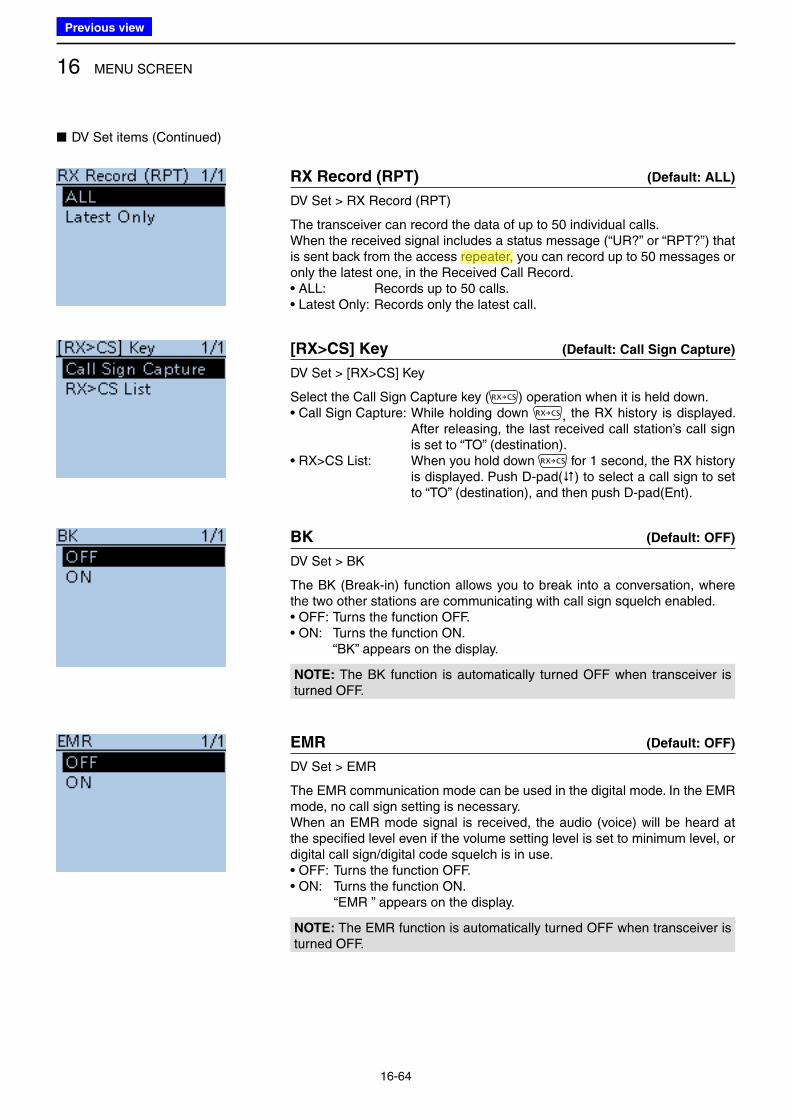
16 MENU SCREEN
16-64
■ DV Set items (Continued)
RX Record (RPT) (Default: ALL)
DV Set > RX Record (RPT)
The transceiver can record the data of up to 50 individual calls.When the received signal includes a status message (“UR?” or “RPT?”) that is sent back from the access repeater, you can record up to 50 messages or only the latest one, in the Received Call Record.• ALL: Records up to 50 calls.• Latest Only: Records only the latest call.
[RX>CS] Key (Default: Call Sign Capture)
DV Set > [RX>CS] Key
Select the Call Sign Capture key ( ) operation when it is held down.• Call Sign Capture: While holding down , the RX history is displayed.
After releasing, the last received call station’s call sign is set to “TO” (destination).
• RX>CS List: When you hold down for 1 second, the RX history is displayed. Push D-pad() to select a call sign to set to “TO” (destination), and then push D-pad(Ent).
BK (Default: OFF)
DV Set > BK
The BK (Break-in) function allows you to break into a conversation, where the two other stations are communicating with call sign squelch enabled.• OFF: Turns the function OFF.• ON: Turns the function ON. “BK” appears on the display.
NOTE: The BK function is automatically turned OFF when transceiver is turned OFF.
EMR (Default: OFF)
DV Set > EMR
The EMR communication mode can be used in the digital mode. In the EMR mode, no call sign setting is necessary. When an EMR mode signal is received, the audio (voice) will be heard at the specified level even if the volume setting level is set to minimum level, or digital call sign/digital code squelch is in use.• OFF: Turns the function OFF.• ON: Turns the function ON. “EMR ” appears on the display.
NOTE: The EMR function is automatically turned OFF when transceiver is turned OFF.
Previous view
Icom
ハイライト表示
Radio systems that receive incoming signals and retransmit them to extend the communication area. Normally put on geographically high locations for VHF/UHF radios.
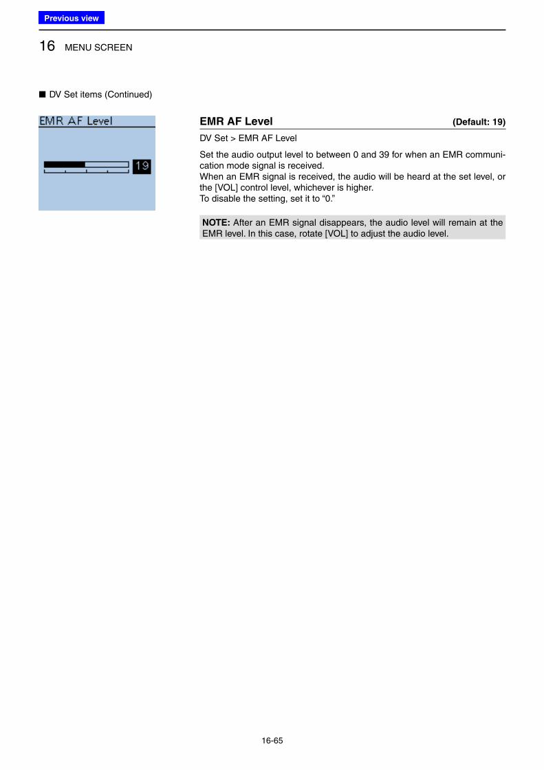
16 MENU SCREEN
16-65
■ DV Set items (Continued)
EMR AF Level (Default: 19)
DV Set > EMR AF Level
Set the audio output level to between 0 and 39 for when an EMR communi-cation mode signal is received.When an EMR signal is received, the audio will be heard at the set level, or the [VOL] control level, whichever is higher.To disable the setting, set it to “0.”
NOTE: After an EMR signal disappears, the audio level will remain at the EMR level. In this case, rotate [VOL] to adjust the audio level.
Previous view
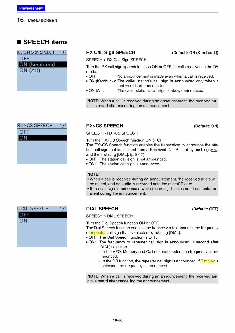
16 MENU SCREEN
16-66
■ SPEECH items
RX Call Sign SPEECH (Default: ON (Kerchunk))
SPEECH > RX Call Sign SPEECH
Turn the RX call sign speech function ON or OFF for calls received in the DV mode.• OFF: No announcement is made even when a call is received. • ON (Kerchunk): The caller station’s call sign is announced only when it
makes a short transmission.• ON (All): The caller station’s call sign is always announced.
NOTE: When a call is received during an announcement, the received au-dio is heard after cancelling the announcement.
RX>CS SPEECH (Default: ON)
SPEECH > RX>CS SPEECH
Turn the RX>CS Speech function ON or OFF.The RX>CS Speech function enables the transceiver to announce the sta-tion call sign that is selected from a Received Call Record by pushing and then rotating [DIAL]. (p. 9-17)• OFF: The station call sign is not announced.• ON: The station call sign is announced.
NOTE:
• When a call is received during an announcement, the received audio will be muted, and no audio is recorded onto the microSD card.
• If the call sign is announced while recording, the recorded contents are silent during the announcement.
DIAL SPEECH (Default: OFF)
SPEECH > DIAL SPEECH
Turn the Dial Speech function ON or OFF.The Dial Speech function enables the transceiver to announce the frequency or repeater call sign that is selected by rotating [DIAL].• OFF: The Dial Speech function is OFF. • ON: The frequency or repeater call sign is announced, 1 second after
[DIAL] selection. - In the VFO, Memory and Call channel modes, the frequency is an-
nounced. - In the DR function, the repeater call sign is announced. If Simplex is
selected, the frequency is announced.
NOTE: When a call is received during an announcement, the received au-dio is heard after cancelling the announcement.
Previous view
Icom
ハイライト表示
Radio systems that receive incoming signals and retransmit them to extend the communication area. Normally put on geographically high locations for VHF/UHF radios.
Icom
ハイライト表示
An operating mode in which the transmit and receive frequencies are the same.
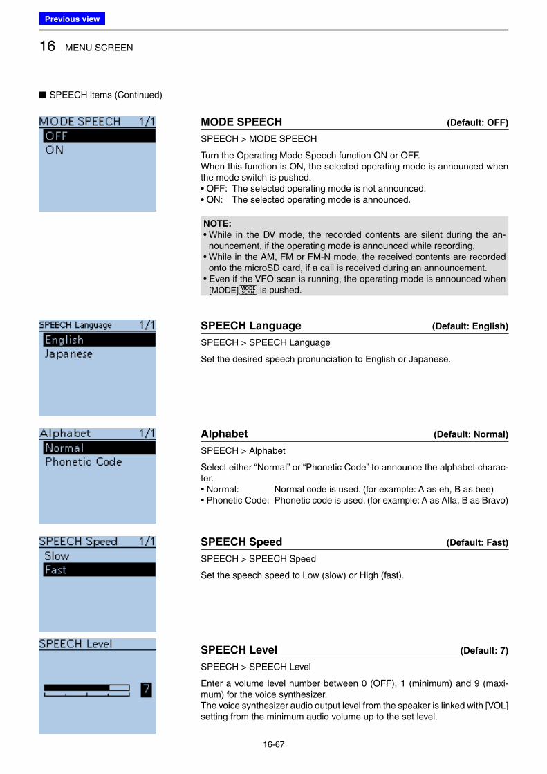
16 MENU SCREEN
16-67
MODE SPEECH (Default: OFF)
SPEECH > MODE SPEECH
Turn the Operating Mode Speech function ON or OFF.When this function is ON, the selected operating mode is announced when the mode switch is pushed.• OFF: The selected operating mode is not announced.• ON: The selected operating mode is announced.
NOTE:
• While in the DV mode, the recorded contents are silent during the an-nouncement, if the operating mode is announced while recording,
• While in the AM, FM or FM-N mode, the received contents are recorded onto the microSD card, if a call is received during an announcement.
• Even if the VFO scan is running, the operating mode is announced when [MODE] is pushed.
SPEECH Language (Default: English)
SPEECH > SPEECH Language
Set the desired speech pronunciation to English or Japanese.
Alphabet (Default: Normal)
SPEECH > Alphabet
Select either “Normal” or “Phonetic Code” to announce the alphabet charac-ter.• Normal: Normal code is used. (for example: A as eh, B as bee) • Phonetic Code: Phonetic code is used. (for example: A as Alfa, B as Bravo)
SPEECH Speed (Default: Fast)
SPEECH > SPEECH Speed
Set the speech speed to Low (slow) or High (fast).
SPEECH Level (Default: 7)
SPEECH > SPEECH Level
Enter a volume level number between 0 (OFF), 1 (minimum) and 9 (maxi-mum) for the voice synthesizer.The voice synthesizer audio output level from the speaker is linked with [VOL] setting from the minimum audio volume up to the set level.
■ SPEECH items (Continued)
Previous view
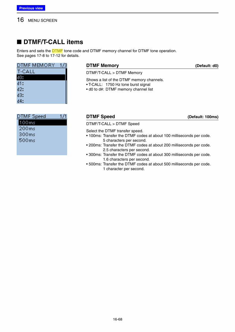
16 MENU SCREEN
16-68
■ DTMF/T-CALL items
Enters and sets the DTMF tone code and DTMF memory channel for DTMF tone operation.See pages 17-8 to 17-12 for details.
DTMF Memory (Default: d0)
DTMF/T-CALL > DTMF Memory
Shows a list of the DTMF memory channels. • T-CALL: 1750 Hz tone burst signal• d0 to d#: DTMF memory channel list
DTMF Speed (Default: 100ms)
DTMF/T-CALL > DTMF Speed
Select the DTMF transfer speed.• 100ms: Transfer the DTMF codes at about 100 milliseconds per code. 5 characters per second.• 200ms: Transfer the DTMF codes at about 200 milliseconds per code. 2.5 characters per second.• 300ms: Transfer the DTMF codes at about 300 milliseconds per code. 1.6 characters per second.• 500ms: Transfer the DTMF codes at about 500 milliseconds per code. 1 character per second.
Previous view
Icom
ハイライト表示
(Dual Tone Multi-Frequency (touch tone)) Used to transmit and receive numeric information such as phone numbers, PIN, remote radio control commands, and for other signaling purposes.
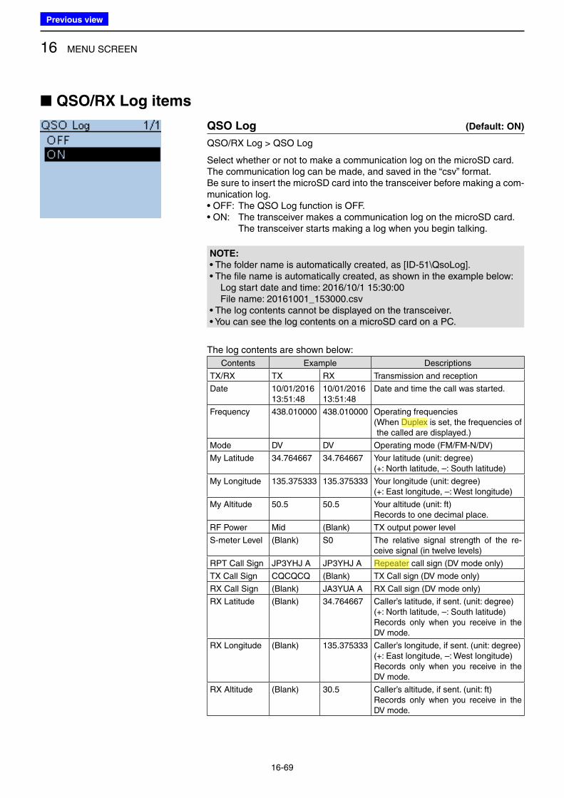
16 MENU SCREEN
16-69
■ QSO/RX Log items
QSO Log (Default: ON)
QSO/RX Log > QSO Log
Select whether or not to make a communication log on the microSD card.The communication log can be made, and saved in the “csv” format. Be sure to insert the microSD card into the transceiver before making a com-munication log.• OFF: The QSO Log function is OFF. • ON: The transceiver makes a communication log on the microSD card. The transceiver starts making a log when you begin talking.
NOTE:
• The folder name is automatically created, as [ID-51\QsoLog].• The file name is automatically created, as shown in the example below: Log start date and time: 2016/10/1 15:30:00 File name: 20161001_153000.csv• The log contents cannot be displayed on the transceiver.• You can see the log contents on a microSD card on a PC.
The log contents are shown below:
Contents Example Descriptions
TX/RX TX RX Transmission and reception
Date 10/01/201613:51:48
10/01/201613:51:48
Date and time the call was started.
Frequency 438.010000 438.010000 Operating frequencies( When Duplex is set, the frequencies of the called are displayed.)
Mode DV DV Operating mode (FM/FM-N/DV)
My Latitude 34.764667 34.764667 Your latitude (unit: degree)(+: North latitude, –: South latitude)
My Longitude 135.375333 135.375333 Your longitude (unit: degree)(+: East longitude, –: West longitude)
My Altitude 50.5 50.5 Your altitude (unit: ft)Records to one decimal place.
RF Power Mid (Blank) TX output power level
S-meter Level (Blank) S0 The relative signal strength of the re-ceive signal (in twelve levels)
RPT Call Sign JP3YHJ A JP3YHJ A Repeater call sign (DV mode only)
TX Call Sign CQCQCQ (Blank) TX Call sign (DV mode only)
RX Call Sign (Blank) JA3YUA A RX Call sign (DV mode only)
RX Latitude (Blank) 34.764667 Caller’s latitude, if sent. (unit: degree)(+: North latitude, –: South latitude)Records only when you receive in the DV mode.
RX Longitude (Blank) 135.375333 Caller’s longitude, if sent. (unit: degree)(+: East longitude, –: West longitude)Records only when you receive in the DV mode.
RX Altitude (Blank) 30.5 Caller’s altitude, if sent. (unit: ft)Records only when you receive in the DV mode.
Previous view
Icom
ハイライト表示
An operating mode in which the transmit and receive frequencies are separated by an offset amount.
Icom
ハイライト表示
Radio systems that receive incoming signals and retransmit them to extend the communication area. Normally put on geographically high locations for VHF/UHF radios.
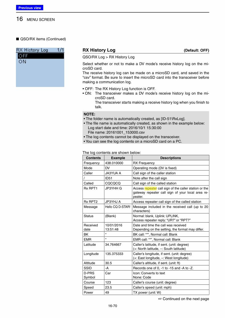
16 MENU SCREEN
16-70
■ QSO/RX items (Continued)
RX History Log (Default: OFF)
QSO/RX Log > RX History Log
Select whether or not to make a DV mode’s receive history log on the mi-croSD card. The receive history log can be made on a microSD card, and saved in the “csv” format. Be sure to insert the microSD card into the transceiver before making a communication log.
• OFF: The RX History Log function is OFF.• ON: The transceiver makes a DV mode’s receive history log on the mi-
croSD card. The transceiver starts making a receive history log when you finish to
talk.
NOTE:
• The folder name is automatically created, as [ID-51\RxLog].• The file name is automatically created, as shown in the example below: Log start date and time: 2016/10/1 15:30:00 File name: 20161001_153000.csv• The log contents cannot be displayed on the transceiver.• You can see the log contents on a microSD card on a PC.
The log contents are shown below:
Contents Example Descriptions
Frequency 438.010000 RX Frequency
Mode DV Operating mode (DV is fixed)
Caller JA3YUA A Call sign of the caller station
/ ID51 Note after the call sign
Called CQCQCQ Call sign of the called station
Rx RPT1 JP3YHH G Access repeater call sign of the caller station or the gateway repeater call sign of your local area re-peater.
Rx RPT2 JP3YHJ A Access repeater call sign of the called station
Message Hello CQ D-STAR! Message included in the received call (up to 20 characters)
Status (Blank) Normal: blank, Uplink: UPLINK, Access repeater reply: “UR?” or “RPT?”
Receiveddate
10/01/201613:51:48
Date and time the call was receivedDepending on the setting, the format may differ.
BK * BK call: “*”, Normal call: Blank
EMR * EMR call: “*”, Normal call: Blank
Latitude 34.764667 Caller’s latitude, if sent. (unit: degree)(+: North latitude, –: South latitude)
Longitude 135.375333 Caller’s longitude, if sent. (unit: degree)(+: East longitude, –: West longitude)
Altitude 30.5 Caller’s altitude, if sent. (unit: ft)
SSID -A Records one of 0, -1 to -15 and -A to -Z.
D-PRSSymbol
Car Icon: Converts to textNone: Code
Course 123 Caller’s course (unit: degree)
Speed 23.5 Caller’s speed (unit: mph)
Power 49 TX power (unit: W)
☞ Continued on the next page
Previous view
Icom
ハイライト表示
Radio systems that receive incoming signals and retransmit them to extend the communication area. Normally put on geographically high locations for VHF/UHF radios.
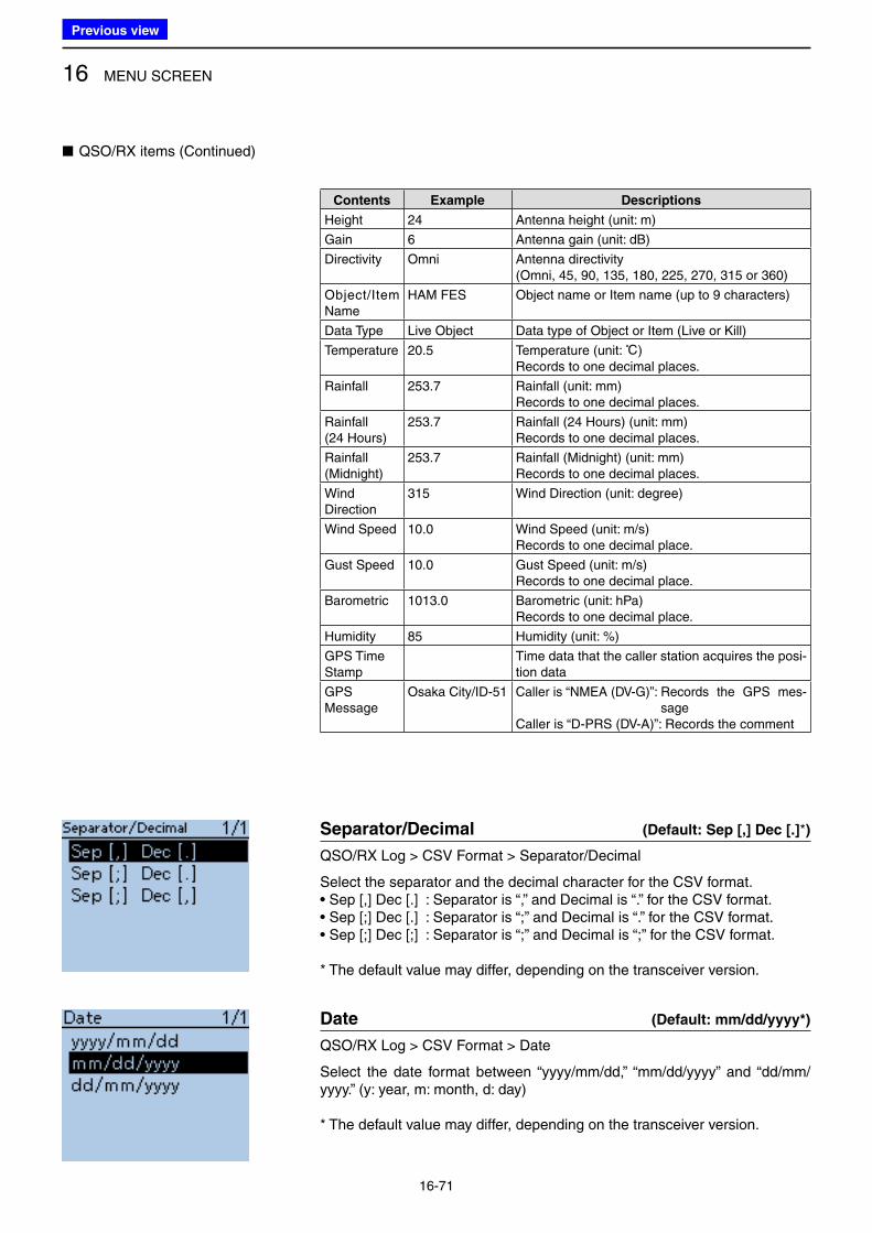
16 MENU SCREEN
16-71
■ QSO/RX items (Continued)
Separator/Decimal (Default: Sep [,] Dec [.]*)
QSO/RX Log > CSV Format > Separator/Decimal
Select the separator and the decimal character for the CSV format.• Sep [,] Dec [.] : Separator is “,” and Decimal is “.” for the CSV format.• Sep [;] Dec [.] : Separator is “;” and Decimal is “.” for the CSV format.• Sep [;] Dec [;] : Separator is “;” and Decimal is “;” for the CSV format.
* The default value may differ, depending on the transceiver version.
Date (Default: mm/dd/yyyy*)
QSO/RX Log > CSV Format > Date
Select the date format between “yyyy/mm/dd,” “mm/dd/yyyy” and “dd/mm/yyyy.” (y: year, m: month, d: day)
* The default value may differ, depending on the transceiver version.
Contents Example Descriptions
Height 24 Antenna height (unit: m)
Gain 6 Antenna gain (unit: dB)
Directivity Omni Antenna directivity(Omni, 45, 90, 135, 180, 225, 270, 315 or 360)
Object/Item Name
HAM FES Object name or Item name (up to 9 characters)
Data Type Live Object Data type of Object or Item (Live or Kill)
Temperature 20.5 Temperature (unit: ç)Records to one decimal places.
Rainfall 253.7 Rainfall (unit: mm)Records to one decimal places.
Rainfall(24 Hours)
253.7 Rainfall (24 Hours) (unit: mm) Records to one decimal places.
Rainfall(Midnight)
253.7 Rainfall (Midnight) (unit: mm) Records to one decimal places.
WindDirection
315 Wind Direction (unit: degree)
Wind Speed 10.0 Wind Speed (unit: m/s) Records to one decimal place.
Gust Speed 10.0 Gust Speed (unit: m/s) Records to one decimal place.
Barometric 1013.0 Barometric (unit: hPa) Records to one decimal place.
Humidity 85 Humidity (unit: %)
GPS Time Stamp
Time data that the caller station acquires the posi-tion data
GPSMessage
Osaka City/ID-51 Caller is “NMEA (DV-G)”: Records the GPS mes-sage
Caller is “D-PRS (DV-A)”: Records the comment
Previous view
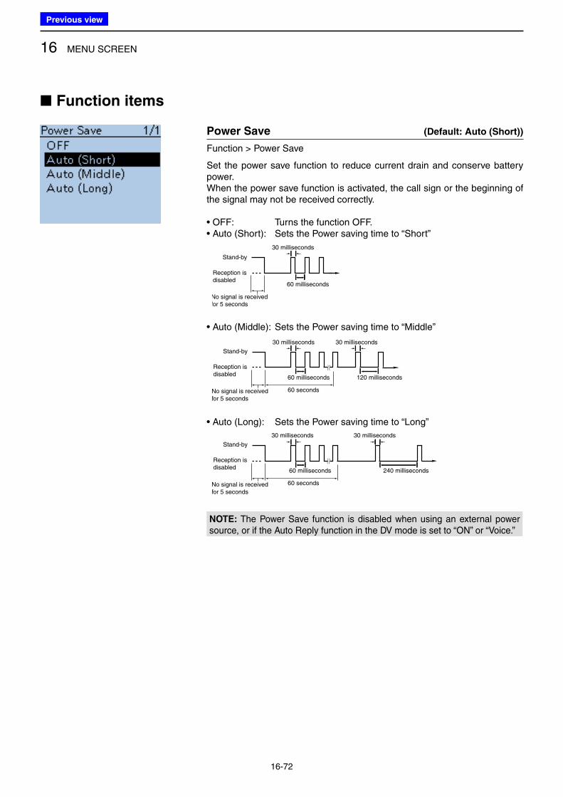
16 MENU SCREEN
16-72
■ Function items
Power Save (Default: Auto (Short))
Function > Power Save
Set the power save function to reduce current drain and conserve battery power.When the power save function is activated, the call sign or the beginning of the signal may not be received correctly.
• OFF: Turns the function OFF. • Auto (Short): Sets the Power saving time to “Short”
30 milliseconds
60 milliseconds
No signal is receivedfor 5 seconds
Stand-by
オート(短)
オート(中)
FM/FM-N
DV
Reception is disabled
~ ~ ~ ~
FM/FM-N
DV
~ ~ ~ ~
~ ~
オート(長)
FM/FM-N
DV
~ ~ ~ ~ ~ ~ ~ ~
~ ~• Auto (Middle): Sets the Power saving time to “Middle”
オート(短)
オート(中)
FM/FM-N
DV
~ ~ ~ ~
FM/FM-N
DV
~ ~ ~ ~
~ ~
オート(長)
FM/FM-N
DV
~ ~ ~ ~ ~ ~ ~ ~
~ ~
No signal is receivedfor 5 seconds
Stand-by
Reception is disabled
60 milliseconds
60 seconds
30 milliseconds
120 milliseconds
30 milliseconds
• Auto (Long): Sets the Power saving time to “Long”
オート(短)
オート(中)
FM/FM-N
DV
~ ~ ~ ~
FM/FM-N
DV~ ~ ~ ~
~ ~
オート(長)
FM/FM-N
DV
~ ~ ~ ~ ~ ~ ~ ~
~ ~
No signal is receivedfor 5 seconds
Stand-by
Reception is disabled
60 milliseconds 240 milliseconds
60 seconds
30 milliseconds 30 milliseconds
NOTE: The Power Save function is disabled when using an external power source, or if the Auto Reply function in the DV mode is set to “ON” or “Voice.”
Previous view
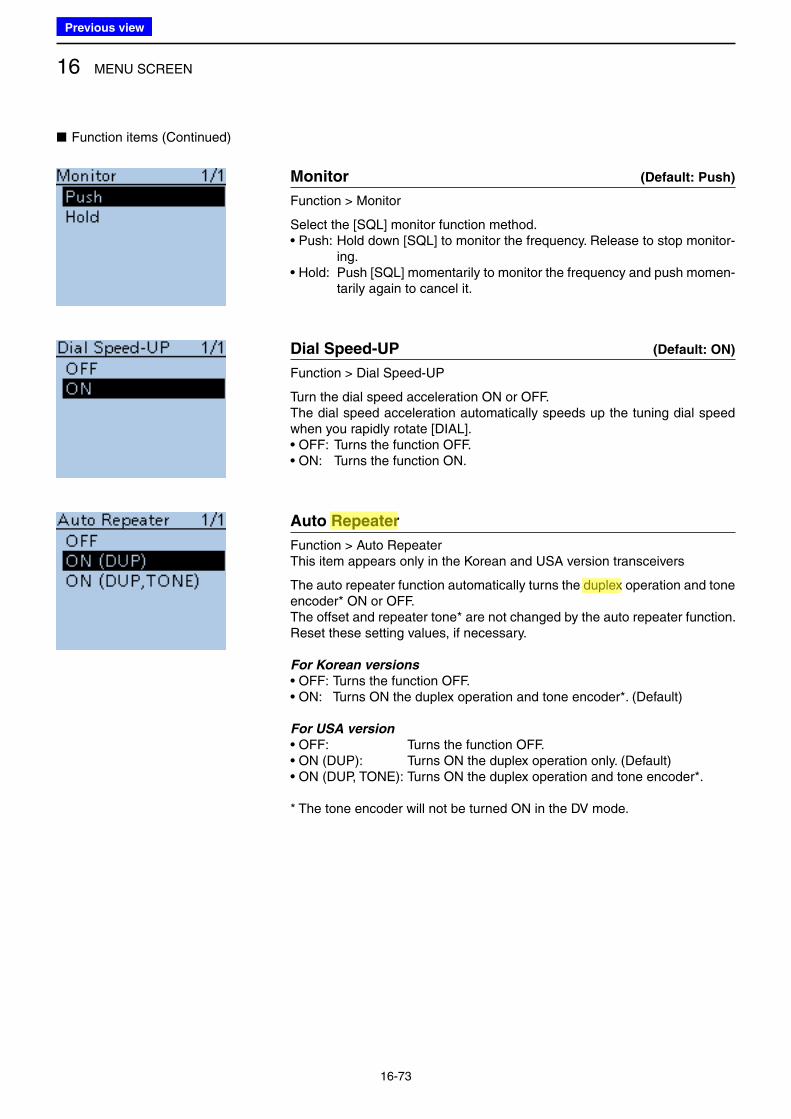
16 MENU SCREEN
16-73
■ Function items (Continued)
Monitor (Default: Push)
Function > Monitor
Select the [SQL] monitor function method.• Push: Hold down [SQL] to monitor the frequency. Release to stop monitor-
ing. • Hold: Push [SQL] momentarily to monitor the frequency and push momen-
tarily again to cancel it.
Dial Speed-UP (Default: ON)
Function > Dial Speed-UP
Turn the dial speed acceleration ON or OFF.The dial speed acceleration automatically speeds up the tuning dial speed when you rapidly rotate [DIAL].• OFF: Turns the function OFF.• ON: Turns the function ON.
Auto Repeater
Function > Auto Repeater This item appears only in the Korean and USA version transceivers
The auto repeater function automatically turns the duplex operation and tone encoder* ON or OFF.The offset and repeater tone* are not changed by the auto repeater function. Reset these setting values, if necessary.
For Korean versions
• OFF: Turns the function OFF. • ON: Turns ON the duplex operation and tone encoder*. (Default)
For USA version
• OFF: Turns the function OFF.• ON (DUP): Turns ON the duplex operation only. (Default)• ON (DUP, TONE): Turns ON the duplex operation and tone encoder*.
* The tone encoder will not be turned ON in the DV mode.
Previous view
Icom
ハイライト表示
Radio systems that receive incoming signals and retransmit them to extend the communication area. Normally put on geographically high locations for VHF/UHF radios.
Icom
ハイライト表示
An operating mode in which the transmit and receive frequencies are separated by an offset amount.
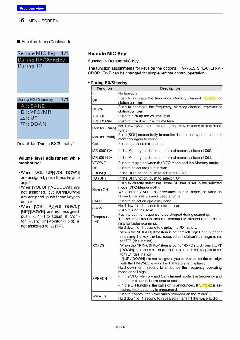
16 MENU SCREEN
16-74
Remote MIC Key
Function > Remote MIC Key
The function assignments for keys on the optional HM-75LS SPEAKER-MI-CROPHONE can be changed for simple remote control operation.
• During RX/Standby:
Function Description
--- No function
UPPush to increase the frequency, Memory channel, repeater or station call sign.
DOWNPush to decrease the frequency, Memory channel, repeater or station call sign.
VOL UP Push to turn up the volume level.
VOL DOWN Push to turn down the volume level.
Monitor (Push)Hold down [SQL] to monitor the frequency. Release to stop moni-toring.
Monitor (Hold)Push [SQL] momentarily to monitor the frequency and push mo-mentarily again to cancel it.
CALL Push to select a call channel.
MR (000 CH) In the Memory mode, push to select memory channel 000.
MR (001 CH) In the Memory mode, push to select memory channel 001.
VFO/MR Push to toggle between the VFO mode and the Memory mode.
DR Push to select the DR function.
FROM (DR) In the DR function, push to select “FROM.”
TO (DR) In the DR function, push to select “TO.”
Home CH
Push to directly select the Home CH that is set to the selected mode (VFO/Memory/DR).While in the CALL CH or weather channel mode, or when no Home CH is set, an error beep sounds.
BAND Push to select an operating band.
SCANHold down for 1 second to start a scan.Push to stop the scan.
Temporary Skip
Push to set the frequency to be skipped during scanning.The selected frequencies are temporarily skipped during scan-ning for faster scanning.
RX>CS
Hold down for 1 second to display the RX history.- When the “[RX>CS] Key” item is set to “Call Sign Capture,” after
releasing the key, the last received call station’s call sign is set to “TO” (destination).
- When the “[RX>CS] Key” item is set to “RX>CS List,” push [UP]/[DOWN] to select a call sign, and then push this key again to set to “TO” (destination).
- If [UP]/[DOWN] are not assigned, you cannot select the call sign with the HM-75LS, even if the RX history is displayed.
SPEECH
Hold down for 1 second to announce the frequency, operating mode or call sign.- In the VFO, Memory and Call channel mode, the frequency and
the operating mode are announced.- In the DR function, the call sign is announced. If Simplex is se-
lected, the frequency is announced.
Voice TXPush to transmit the voice audio recorded on the microSD.Hold down for 1 second to repeatedly transmit the voice audio.
■ Function items (Continued)
Volume level adjustment while
monitoring:
• When [VOL UP]/[VOL DOWN] are assigned, push these keys to adjust.
• When [VOL UP]/[VOL DOWN] are not assigned, but [UP]/[DOWN] are assigned, push these keys to adjust.
• When [VOL UP]/[VOL DOWN]/[UP]/[DOWN] are not assigned, push []/[] to adjust, if [Moni-tor (Push)] or [Monitor (Hold)] is not assigned to []/[].
Default for “During RX/Standby”
Previous view
Icom
ハイライト表示
Radio systems that receive incoming signals and retransmit them to extend the communication area. Normally put on geographically high locations for VHF/UHF radios.
Icom
ハイライト表示
An operating mode in which the transmit and receive frequencies are the same.
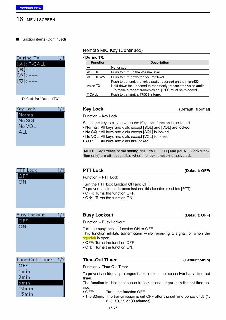
16 MENU SCREEN
16-75
■ Function items (Continued)
Remote MIC Key (Continued)
• During TX:
Function Description
--- No function
VOL UP Push to turn up the volume level.
VOL DOWN Push to turn down the volume level.
Voice TXPush to transmit the voice audio recorded on the microSD.Hold down for 1 second to repeatedly transmit the voice audio.- To make a repeat transmission, [PTT] must be released.
T-CALL Push to transmit a 1750 Hz tone.
Key Lock (Default: Normal)
Function > Key Lock
Select the key lock type when the Key Lock function is activated.• Normal: All keys and dials except [SQL] and [VOL] are locked. • No SQL: All keys and dials except [SQL] is locked. • No VOL: All keys and dials except [VOL] is locked.• ALL: All keys and dials are locked.
NOTE: Regardless of the setting, the [PWR], [PTT] and [MENU] (lock func-tion only) are still accessible when the lock function is activated.
PTT Lock (Default: OFF)
Function > PTT Lock
Turn the PTT lock function ON and OFF.To prevent accidental transmissions, this function disables [PTT].• OFF: Turns the function OFF. • ON: Turns the function ON.
Busy Lockout (Default: OFF)
Function > Busy Lockout
Turn the busy lockout function ON or OFF.This function inhibits transmission while receiving a signal, or when the squelch is open.• OFF: Turns the function OFF.• ON: Turns the function ON.
Time-Out Timer (Default: 5min)
Function > Time-Out Timer
To prevent accidental prolonged transmission, the transceiver has a time-out timer.The function inhibits continuous transmissions longer than the set time pe-riod.• OFF: Turns the function OFF. • 1 to 30min: The transmission is cut OFF after the set time period ends (1,
3, 5, 10, 15 or 30 minutes).
Default for “During TX”
Previous view
Icom
ハイライト表示
A function that mutes the audio output for certain signal levels.
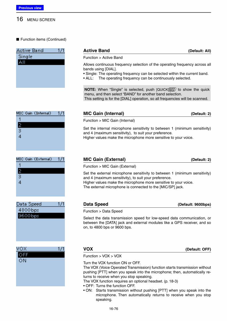
16 MENU SCREEN
16-76
■ Function items (Continued)
Active Band (Default: All)
Function > Active Band
Allows continuous frequency selection of the operating frequency across all bands using [DIAL].• Single: The operating frequency can be selected within the current band.• ALL: The operating frequency can be continuously selected.
NOTE: When “Single” is selected, push [QUICK] to show the quick menu, and then select “BAND” for another band selection.This setting is for the [DIAL] operation, so all frequencies will be scanned.
MIC Gain (Internal) (Default: 2)
Function > MIC Gain (Internal)
Set the internal microphone sensitivity to between 1 (minimum sensitivity) and 4 (maximum sensitivity), to suit your preference.Higher values make the microphone more sensitive to your voice.
MIC Gain (External) (Default: 2)
Function > MIC Gain (External)
Set the external microphone sensitivity to between 1 (minimum sensitivity) and 4 (maximum sensitivity), to suit your preference.Higher values make the microphone more sensitive to your voice.The external microphone is connected to the [MIC/SP] jack.
Data Speed (Default: 9600bps)
Function > Data Speed
Select the data transmission speed for low-speed data communication, or between the [DATA] jack and external modules like a GPS receiver, and so on, to 4800 bps or 9600 bps.
VOX (Default: OFF)
Function > VOX > VOX
Turn the VOX function ON or OFF.The VOX (Voice Operated Transmission) function starts transmission without pushing [PTT] when you speak into the microphone; then, automatically re-turns to receive when you stop speaking.The VOX function requires an optional headset. (p. 18-3)• OFF: Turns the function OFF. • ON: Starts transmission without pushing [PTT] when you speak into the
microphone. Then automatically returns to receive when you stop speaking.
Previous view
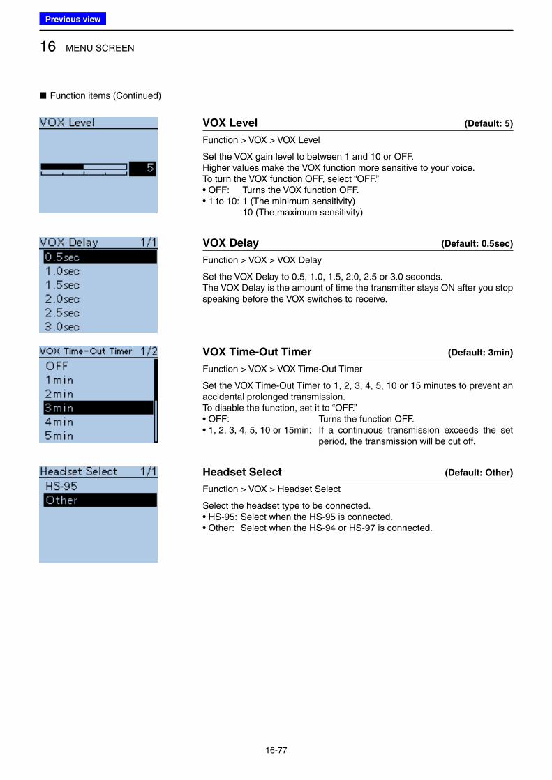
16 MENU SCREEN
16-77
VOX Level (Default: 5)
Function > VOX > VOX Level
Set the VOX gain level to between 1 and 10 or OFF.Higher values make the VOX function more sensitive to your voice.To turn the VOX function OFF, select “OFF.”• OFF: Turns the VOX function OFF. • 1 to 10: 1 (The minimum sensitivity) 10 (The maximum sensitivity)
VOX Delay (Default: 0.5sec)
Function > VOX > VOX Delay
Set the VOX Delay to 0.5, 1.0, 1.5, 2.0, 2.5 or 3.0 seconds.The VOX Delay is the amount of time the transmitter stays ON after you stop speaking before the VOX switches to receive.
VOX Time-Out Timer (Default: 3min)
Function > VOX > VOX Time-Out Timer
Set the VOX Time-Out Timer to 1, 2, 3, 4, 5, 10 or 15 minutes to prevent an accidental prolonged transmission.To disable the function, set it to “OFF.”• OFF: Turns the function OFF. • 1, 2, 3, 4, 5, 10 or 15min: If a continuous transmission exceeds the set
period, the transmission will be cut off.
Headset Select (Default: Other)
Function > VOX > Headset Select
Select the headset type to be connected. • HS-95: Select when the HS-95 is connected. • Other: Select when the HS-94 or HS-97 is connected.
■ Function items (Continued)
Previous view
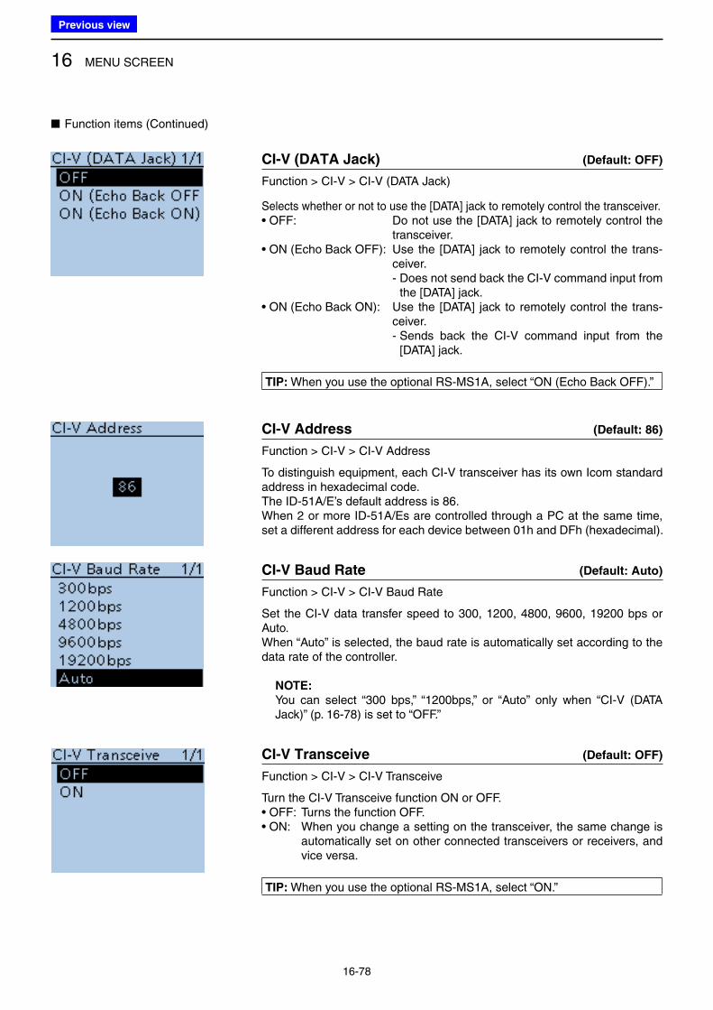
16 MENU SCREEN
16-78
■ Function items (Continued)
CI-V (DATA Jack) (Default: OFF)
Function > CI-V > CI-V (DATA Jack)
Selects whether or not to use the [DATA] jack to remotely control the transceiver.• OFF: Do not use the [DATA] jack to remotely control the
transceiver.• ON (Echo Back OFF): Use the [DATA] jack to remotely control the trans-
ceiver. - Does not send back the CI-V command input from
the [DATA] jack.• ON (Echo Back ON): Use the [DATA] jack to remotely control the trans-
ceiver. - Sends back the CI-V command input from the
[DATA] jack.
TIP: When you use the optional RS-MS1A, select “ON (Echo Back OFF).”
CI-V Address (Default: 86)
Function > CI-V > CI-V Address
To distinguish equipment, each CI-V transceiver has its own Icom standard address in hexadecimal code.The ID-51A/E’s default address is 86.When 2 or more ID-51A/Es are controlled through a PC at the same time, set a different address for each device between 01h and DFh (hexadecimal).
CI-V Baud Rate (Default: Auto)
Function > CI-V > CI-V Baud Rate
Set the CI-V data transfer speed to 300, 1200, 4800, 9600, 19200 bps or Auto.When “Auto” is selected, the baud rate is automatically set according to the data rate of the controller.
NOTE:
You can select “300 bps,” “1200bps,” or “Auto” only when “CI-V (DATA Jack)” (p. 16-78) is set to “OFF.”
CI-V Transceive (Default: OFF)
Function > CI-V > CI-V Transceive
Turn the CI-V Transceive function ON or OFF.• OFF: Turns the function OFF. • ON: When you change a setting on the transceiver, the same change is
automatically set on other connected transceivers or receivers, and vice versa.
TIP: When you use the optional RS-MS1A, select “ON.”
Previous view
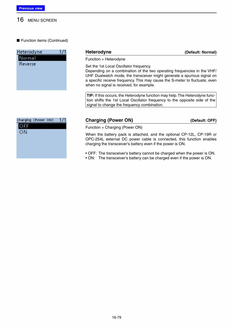
16 MENU SCREEN
16-79
■ Function items (Continued)
Heterodyne (Default: Normal)
Function > Heterodyne
Set the 1st Local Oscillator frequency.Depending on a combination of the two operating frequencies in the VHF/UHF Dualwatch mode, the transceiver might generate a spurious signal on a specific receive frequency. This may cause the S-meter to fluctuate, even when no signal is received, for example.
TIP: If this occurs, the Heterodyne function may help. The Heterodyne func-tion shifts the 1st Local Oscillator frequency to the opposite side of the signal to change the frequency combination.
Charging (Power ON) (Default: OFF)
Function > Charging (Power ON)
When the battery pack is attached, and the optional CP-12L, CP-19R or OPC-254L external DC power cable is connected, this function enables charging the transceiver's battery even if the power is ON.
• OFF: The transceiver's battery cannot be charged when the power is ON.• ON: The transceiver's battery can be charged even if the power is ON.
Previous view
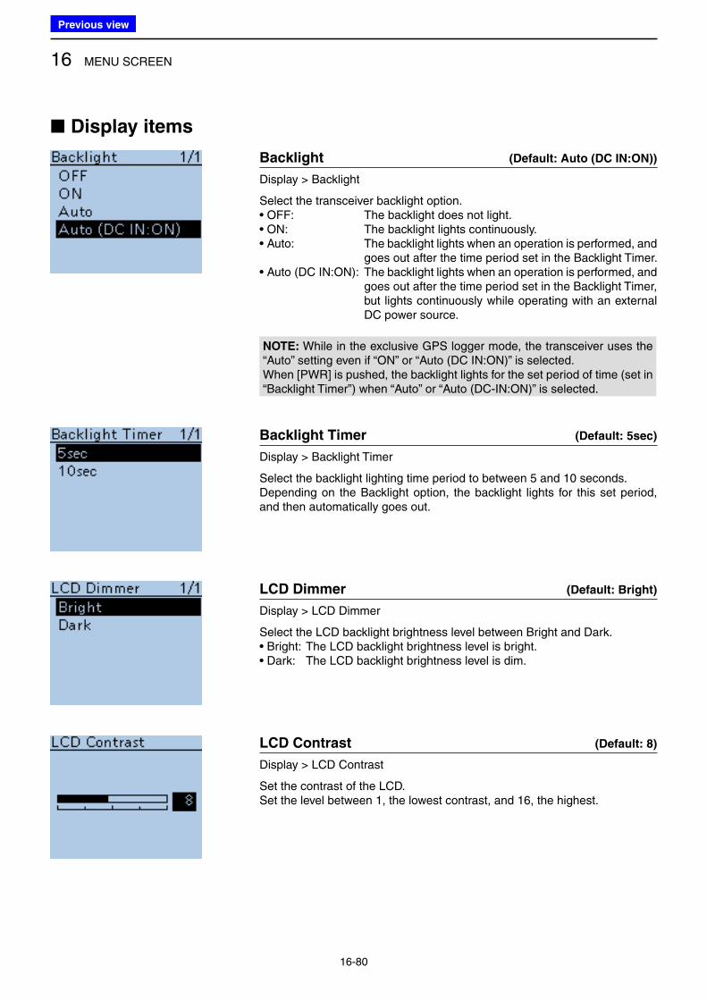
16 MENU SCREEN
16-80
■ Display items
Backlight (Default: Auto (DC IN:ON))
Display > Backlight
Select the transceiver backlight option.• OFF: The backlight does not light. • ON: The backlight lights continuously. • Auto: The backlight lights when an operation is performed, and
goes out after the time period set in the Backlight Timer.• Auto (DC IN:ON): The backlight lights when an operation is performed, and
goes out after the time period set in the Backlight Timer, but lights continuously while operating with an external DC power source.
NOTE: While in the exclusive GPS logger mode, the transceiver uses the “Auto” setting even if “ON” or “Auto (DC IN:ON)” is selected.When [PWR] is pushed, the backlight lights for the set period of time (set in “Backlight Timer”) when “Auto” or “Auto (DC-IN:ON)” is selected.
Backlight Timer (Default: 5sec)
Display > Backlight Timer
Select the backlight lighting time period to between 5 and 10 seconds.Depending on the Backlight option, the backlight lights for this set period, and then automatically goes out.
LCD Dimmer (Default: Bright)
Display > LCD Dimmer
Select the LCD backlight brightness level between Bright and Dark.• Bright: The LCD backlight brightness level is bright.• Dark: The LCD backlight brightness level is dim.
LCD Contrast (Default: 8)
Display > LCD Contrast
Set the contrast of the LCD.Set the level between 1, the lowest contrast, and 16, the highest.
Previous view
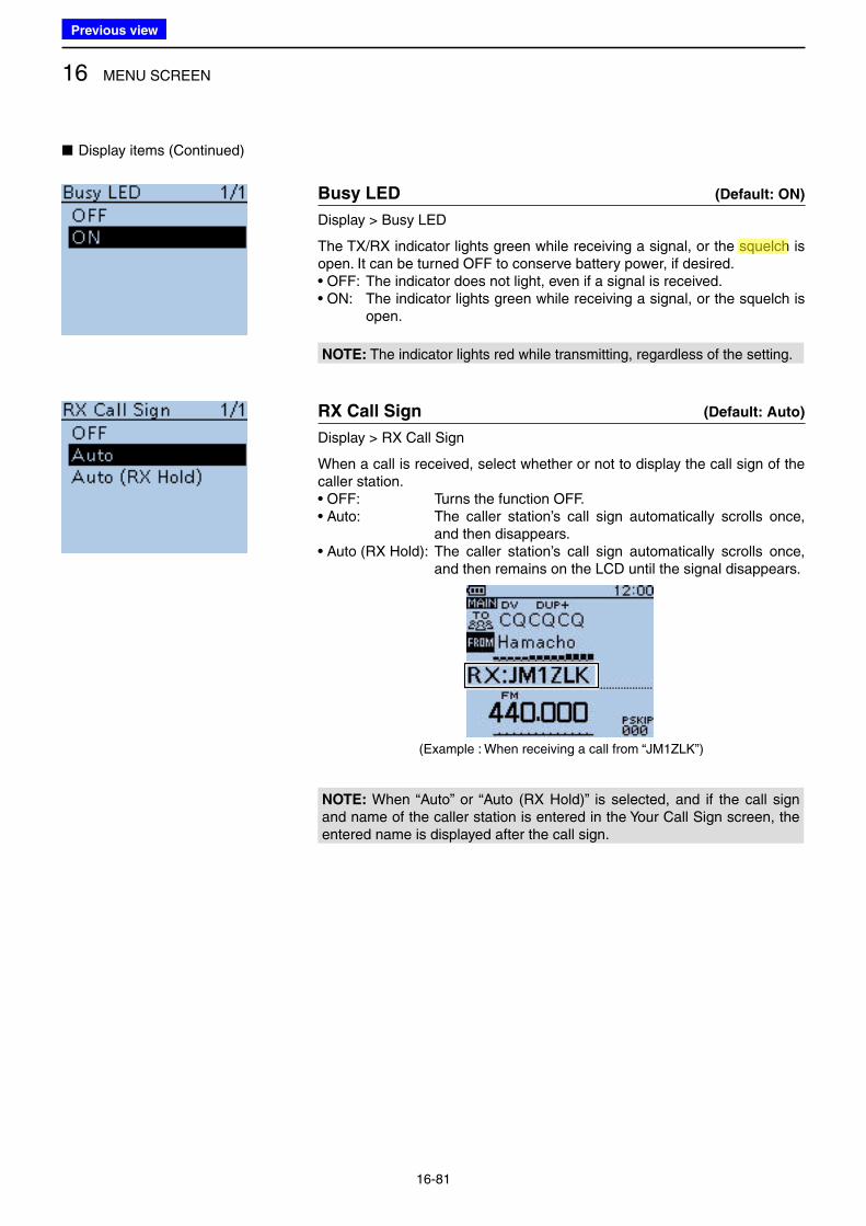
16 MENU SCREEN
16-81
■ Display items (Continued)
Busy LED (Default: ON)
Display > Busy LED
The TX/RX indicator lights green while receiving a signal, or the squelch is open. It can be turned OFF to conserve battery power, if desired.• OFF: The indicator does not light, even if a signal is received. • ON: The indicator lights green while receiving a signal, or the squelch is
open.
NOTE: The indicator lights red while transmitting, regardless of the setting.
RX Call Sign (Default: Auto)
Display > RX Call Sign
When a call is received, select whether or not to display the call sign of the caller station.• OFF: Turns the function OFF. • Auto: The caller station’s call sign automatically scrolls once,
and then disappears.• Auto (RX Hold): The caller station’s call sign automatically scrolls once,
and then remains on the LCD until the signal disappears.
(Example : When receiving a call from “JM1ZLK”)
NOTE: When “Auto” or “Auto (RX Hold)” is selected, and if the call sign and name of the caller station is entered in the Your Call Sign screen, the entered name is displayed after the call sign.
Previous view
Icom
ハイライト表示
A function that mutes the audio output for certain signal levels.
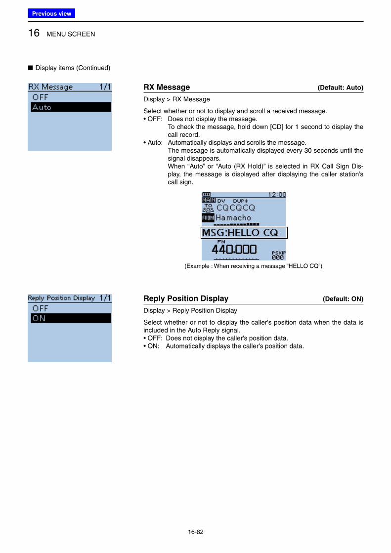
16 MENU SCREEN
16-82
■ Display items (Continued)
RX Message (Default: Auto)
Display > RX Message
Select whether or not to display and scroll a received message.• OFF: Does not display the message. To check the message, hold down [CD] for 1 second to display the
call record. • Auto: Automatically displays and scrolls the message. The message is automatically displayed every 30 seconds until the
signal disappears. When “Auto” or “Auto (RX Hold)” is selected in RX Call Sign Dis-
play, the message is displayed after displaying the caller station’s call sign.
(Example : When receiving a message “HELLO CQ”)
Reply Position Display (Default: ON)
Display > Reply Position Display
Select whether or not to display the caller's position data when the data is included in the Auto Reply signal.• OFF: Does not display the caller's position data.• ON: Automatically displays the caller's position data.
Previous view
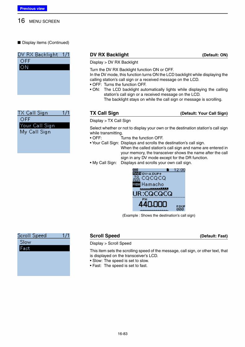
16 MENU SCREEN
16-83
DV RX Backlight (Default: ON)
Display > DV RX Backlight
Turn the DV RX Backlight function ON or OFF.In the DV mode, this function turns ON the LCD backlight while displaying the calling station’s call sign or a received message on the LCD.• OFF: Turns the function OFF. • ON: The LCD backlight automatically lights while displaying the calling
station’s call sign or a received message on the LCD. The backlight stays on while the call sign or message is scrolling.
TX Call Sign (Default: Your Call Sign)
Display > TX Call Sign
Select whether or not to display your own or the destination station's call sign while transmitting.• OFF: Turns the function OFF.• Your Call Sign: Displays and scrolls the destination’s call sign. When the called station’s call sign and name are entered in
your memory, the transceiver shows the name after the call sign in any DV mode except for the DR function.
• My Call Sign: Displays and scrolls your own call sign.
(Example : Shows the destination’s call sign)
Scroll Speed (Default: Fast)
Display > Scroll Speed
This item sets the scrolling speed of the message, call sign, or other text, that is displayed on the transceiver's LCD.• Slow: The speed is set to slow. • Fast: The speed is set to fast.
■ Display items (Continued)
Previous view
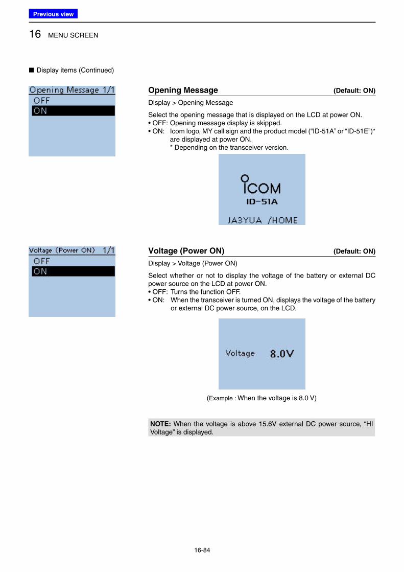
16 MENU SCREEN
16-84
■ Display items (Continued)
Opening Message (Default: ON)
Display > Opening Message
Select the opening message that is displayed on the LCD at power ON.• OFF: Opening message display is skipped. • ON: Icom logo, MY call sign and the product model (“ID-51A” or “ID-51E”)*
are displayed at power ON. * Depending on the transceiver version.
Voltage (Power ON) (Default: ON)
Display > Voltage (Power ON)
Select whether or not to display the voltage of the battery or external DC power source on the LCD at power ON.• OFF: Turns the function OFF. • ON: When the transceiver is turned ON, displays the voltage of the battery
or external DC power source, on the LCD.
NOTE: When the voltage is above 15.6V external DC power source, “HI Voltage” is displayed.
(Example : When the voltage is 8.0 V)
Previous view
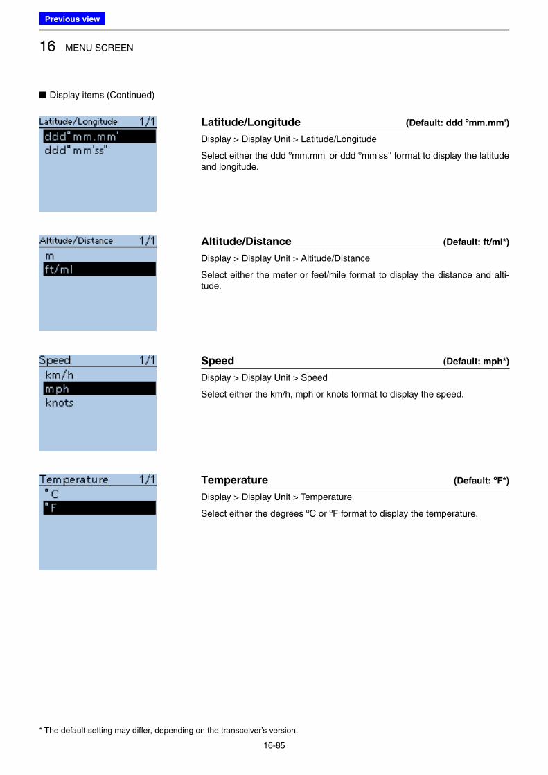
16 MENU SCREEN
16-85
Latitude/Longitude (Default: ddd ºmm.mm')
Display > Display Unit > Latitude/Longitude
Select either the ddd ºmm.mm' or ddd ºmm'ss'' format to display the latitude and longitude.
Altitude/Distance (Default: ft/ml*)
Display > Display Unit > Altitude/Distance
Select either the meter or feet/mile format to display the distance and alti-tude.
Speed (Default: mph*)
Display > Display Unit > Speed
Select either the km/h, mph or knots format to display the speed.
Temperature (Default: ºF*)
Display > Display Unit > Temperature
Select either the degrees ºC or ºF format to display the temperature.
■ Display items (Continued)
* The default setting may differ, depending on the transceiver’s version.
Previous view
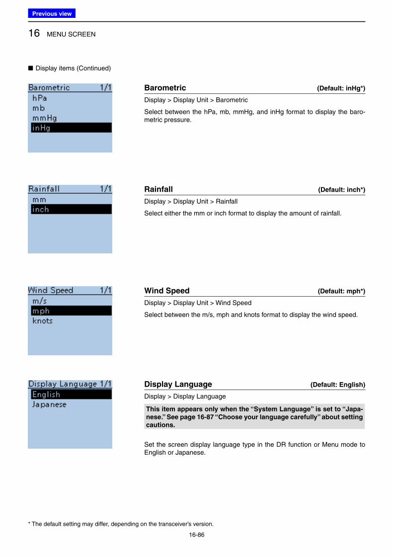
16 MENU SCREEN
16-86
Barometric (Default: inHg*)
Display > Display Unit > Barometric
Select between the hPa, mb, mmHg, and inHg format to display the baro-metric pressure.
Rainfall (Default: inch*)
Display > Display Unit > Rainfall
Select either the mm or inch format to display the amount of rainfall.
Wind Speed (Default: mph*)
Display > Display Unit > Wind Speed
Select between the m/s, mph and knots format to display the wind speed.
Display Language (Default: English)
Display > Display Language
This item appears only when the “System Language” is set to “Japa-
nese.” See page 16-87 “Choose your language carefully” about setting
cautions.
Set the screen display language type in the DR function or Menu mode to English or Japanese.
■ Display items (Continued)
* The default setting may differ, depending on the transceiver’s version.
Previous view
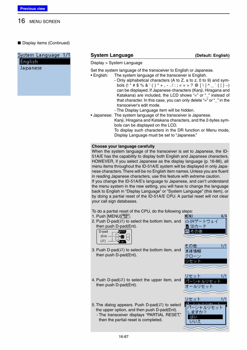
16 MENU SCREEN
16-87
System Language (Default: English)
Display > System Language
Set the system language of the transceiver to English or Japanese.• English: The system language of the transceiver is English. - Only alphabetical characters (A to Z, a to z, 0 to 9) and sym-
bols (! " # $ % & ' ( ) * + , - . / : ; < = > ? @ [ \ ] ^ _ ` { | } ~) can be displayed. If Japanese characters (Kanji, Hiragana and Katakana) are included, the LCD shows “=” or “_” instead of that character. In this case, you can only delete “=” or “_” in the transceiver's edit mode.
- The Display Language item will be hidden.• Japanese: The system language of the transceiver is Japanese. Kanji, Hiragana and Katakana characters, and the 2-bytes sym-
bols can be displayed on the LCD. To display such characters in the DR function or Menu mode,
Display Language must be set to “Japanese.”
■ Display items (Continued)
Choose your language carefully
When the system language of the transceiver is set to Japanese, the ID-51A/E has the capability to display both English and Japanese characters. HOWEVER, if you select Japanese as the display language (p. 16-86), all menu items throughout the ID-51A/E system will be displayed in only Japa-nese characters. There will be no English item names. Unless you are fluent in reading Japanese characters, use this feature with extreme caution. If you change the ID-51A/E’s language to Japanese, and can’t understand the menu system in the new setting, you will have to change the language back to English in “Display Language” or “System Language” (this item), or by doing a partial reset of the ID-51A/E CPU. A partial reset will not clear your call sign databases.
To do a partial reset of the CPU, do the following steps:1. Push [MENU] .2. Push D-pad() to select the bottom item, and
then push D-pad(Ent).D-pad
(�)
(Ent)
3. Push D-pad() to select the bottom item, and then push D-pad(Ent).
4. Push D-pad() to select the upper item, and then push D-pad(Ent).
5. The dialog appears. Push D-pad() to select the upper option, and then push D-pad(Ent).
- The transceiver displays “PARTIAL RESET,” then the partial reset is completed.
Previous view
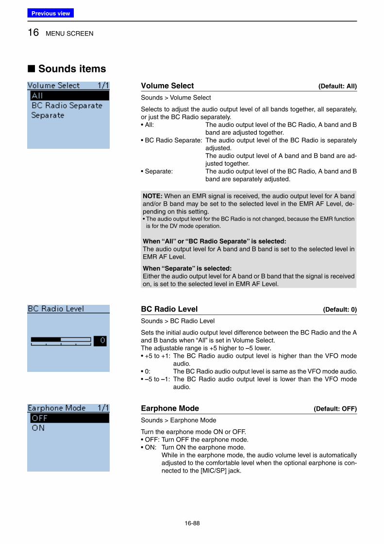
16 MENU SCREEN
16-88
■ Sounds items
Volume Select (Default: All)
Sounds > Volume Select
Selects to adjust the audio output level of all bands together, all separately, or just the BC Radio separately.• All: The audio output level of the BC Radio, A band and B
band are adjusted together.• BC Radio Separate: The audio output level of the BC Radio is separately
adjusted. The audio output level of A band and B band are ad-
justed together.• Separate: The audio output level of the BC Radio, A band and B
band are separately adjusted.
NOTE: When an EMR signal is received, the audio output level for A band and/or B band may be set to the selected level in the EMR AF Level, de-pending on this setting.• The audio output level for the BC Radio is not changed, because the EMR function
is for the DV mode operation.
When “All” or “BC Radio Separate” is selected:
The audio output level for A band and B band is set to the selected level in EMR AF Level.
When “Separate” is selected:
Either the audio output level for A band or B band that the signal is received on, is set to the selected level in EMR AF Level.
BC Radio Level (Default: 0)
Sounds > BC Radio Level
Sets the initial audio output level difference between the BC Radio and the A and B bands when “All” is set in Volume Select.The adjustable range is +5 higher to –5 lower.• +5 to +1: The BC Radio audio output level is higher than the VFO mode
audio.• 0: The BC Radio audio output level is same as the VFO mode audio. • –5 to –1: The BC Radio audio output level is lower than the VFO mode
audio.
Earphone Mode (Default: OFF)
Sounds > Earphone Mode
Turn the earphone mode ON or OFF.• OFF: Turn OFF the earphone mode.• ON: Turn ON the earphone mode. While in the earphone mode, the audio volume level is automatically
adjusted to the comfortable level when the optional earphone is con-nected to the [MIC/SP] jack.
Previous view
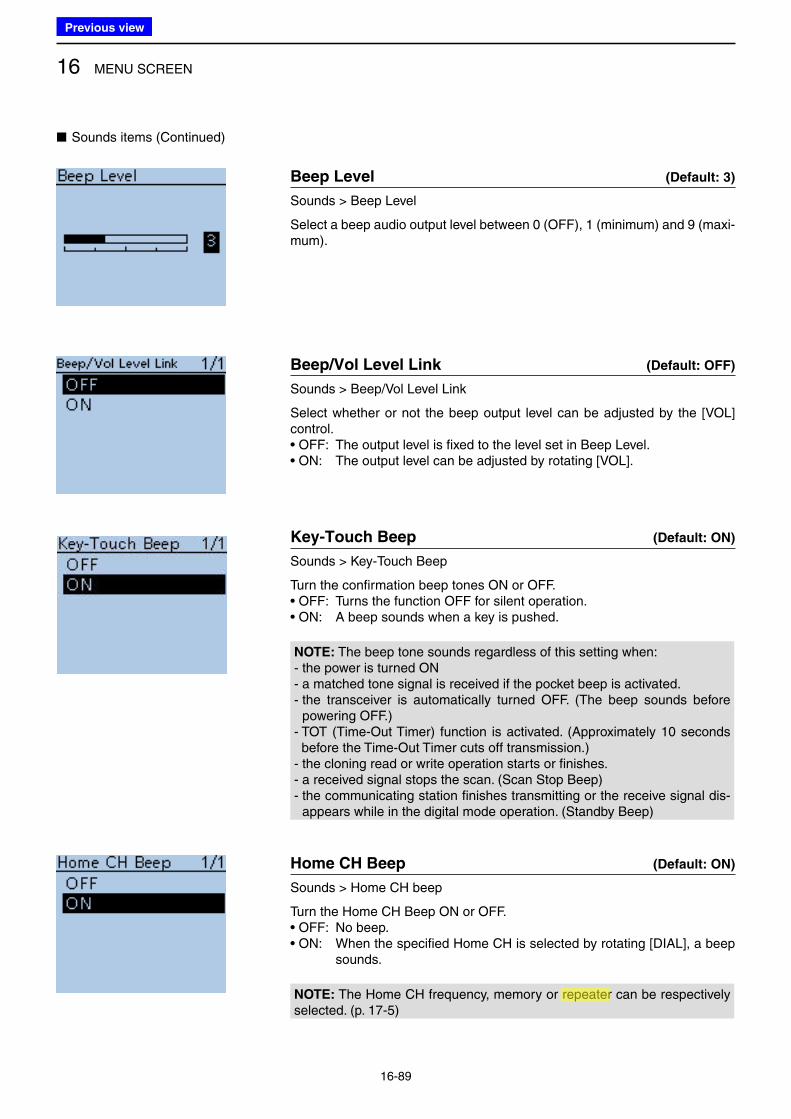
16 MENU SCREEN
16-89
Beep Level (Default: 3)
Sounds > Beep Level
Select a beep audio output level between 0 (OFF), 1 (minimum) and 9 (maxi-mum).
Beep/Vol Level Link (Default: OFF)
Sounds > Beep/Vol Level Link
Select whether or not the beep output level can be adjusted by the [VOL] control.• OFF: The output level is fixed to the level set in Beep Level.• ON: The output level can be adjusted by rotating [VOL].
Key-Touch Beep (Default: ON)
Sounds > Key-Touch Beep
Turn the confirmation beep tones ON or OFF.• OFF: Turns the function OFF for silent operation.• ON: A beep sounds when a key is pushed.
NOTE: The beep tone sounds regardless of this setting when:- the power is turned ON- a matched tone signal is received if the pocket beep is activated.- the transceiver is automatically turned OFF. (The beep sounds before
powering OFF.)- TOT (Time-Out Timer) function is activated. (Approximately 10 seconds
before the Time-Out Timer cuts off transmission.)- the cloning read or write operation starts or finishes.- a received signal stops the scan. (Scan Stop Beep)- the communicating station finishes transmitting or the receive signal dis-
appears while in the digital mode operation. (Standby Beep)
Home CH Beep (Default: ON)
Sounds > Home CH beep
Turn the Home CH Beep ON or OFF.• OFF: No beep.• ON: When the specified Home CH is selected by rotating [DIAL], a beep
sounds.
NOTE: The Home CH frequency, memory or repeater can be respectively selected. (p. 17-5)
■ Sounds items (Continued)
Previous view
Icom
ハイライト表示
Radio systems that receive incoming signals and retransmit them to extend the communication area. Normally put on geographically high locations for VHF/UHF radios.
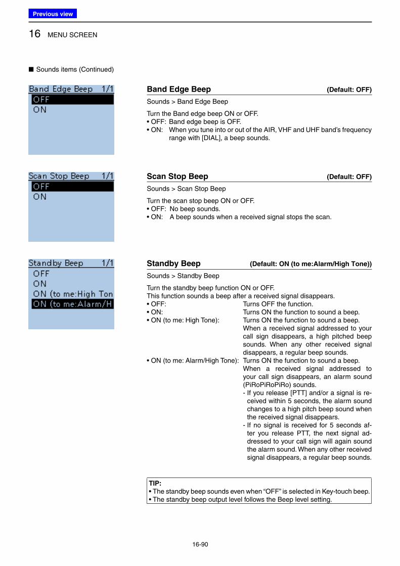
16 MENU SCREEN
16-90
Band Edge Beep (Default: OFF)
Sounds > Band Edge Beep
Turn the Band edge beep ON or OFF.• OFF: Band edge beep is OFF.• ON: When you tune into or out of the AIR, VHF and UHF band’s frequency
range with [DIAL], a beep sounds.
Scan Stop Beep (Default: OFF)
Sounds > Scan Stop Beep
Turn the scan stop beep ON or OFF.• OFF: No beep sounds.• ON: A beep sounds when a received signal stops the scan.
Standby Beep (Default: ON (to me:Alarm/High Tone))
Sounds > Standby Beep
Turn the standby beep function ON or OFF.This function sounds a beep after a received signal disappears.• OFF: Turns OFF the function.• ON: Turns ON the function to sound a beep.• ON (to me: High Tone): Turns ON the function to sound a beep. When a received signal addressed to your
call sign disappears, a high pitched beep sounds. When any other received signal disappears, a regular beep sounds.
• ON (to me: Alarm/High Tone): Turns ON the function to sound a beep. When a received signal addressed to
your call sign disappears, an alarm sound (PiRoPiRoPiRo) sounds.
- If you release [PTT] and/or a signal is re-ceived within 5 seconds, the alarm sound changes to a high pitch beep sound when the received signal disappears.
- If no signal is received for 5 seconds af-ter you release PTT, the next signal ad-dressed to your call sign will again sound the alarm sound. When any other received signal disappears, a regular beep sounds.
TIP:
• The standby beep sounds even when “OFF” is selected in Key-touch beep.• The standby beep output level follows the Beep level setting.
■ Sounds items (Continued)
Previous view
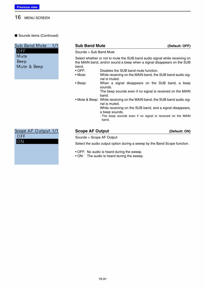
16 MENU SCREEN
16-91
■ Sounds items (Continued)
Sub Band Mute (Default: OFF)
Sounds > Sub Band Mute
Select whether or not to mute the SUB band audio signal while receiving on the MAIN band, and/or sound a beep when a signal disappears on the SUB band.• OFF: Disables the SUB band mute function.• Mute: While receiving on the MAIN band, the SUB band audio sig-
nal is muted.• Beep: When a signal disappears on the SUB band, a beep
sounds. The beep sounds even if no signal is received on the MAIN
band.• Mute & Beep: While receiving on the MAIN band, the SUB band audio sig-
nal is muted. While receiving on the SUB band, and a signal disappears,
a beep sounds. - The beep sounds even if no signal is received on the MAIN
band.
Scope AF Output (Default: ON)
Sounds > Scope AF Output
Select the audio output option during a sweep by the Band Scope function.
• OFF: No audio is heard during the sweep.• ON: The audio is heard during the sweep.
Previous view
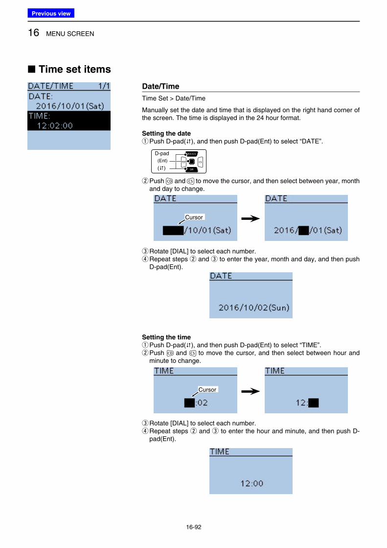
Date/Time
Time Set > Date/Time
Manually set the date and time that is displayed on the right hand corner of the screen. The time is displayed in the 24 hour format.
Setting the date
q Push D-pad(), and then push D-pad(Ent) to select “DATE”.
D-pad
(�)
(Ent)
w Push and to move the cursor, and then select between year, month and day to change.
Cursor
eRotate [DIAL] to select each number. r Repeat steps w and e to enter the year, month and day, and then push D-pad(Ent).
Setting the time
q Push D-pad(), and then push D-pad(Ent) to select “TIME”. w Push and to move the cursor, and then select between hour and minute to change.
Cursor
eRotate [DIAL] to select each number. r Repeat steps w and e to enter the hour and minute, and then push D-pad(Ent).
16 MENU SCREEN
16-92
■ Time set items
Previous view
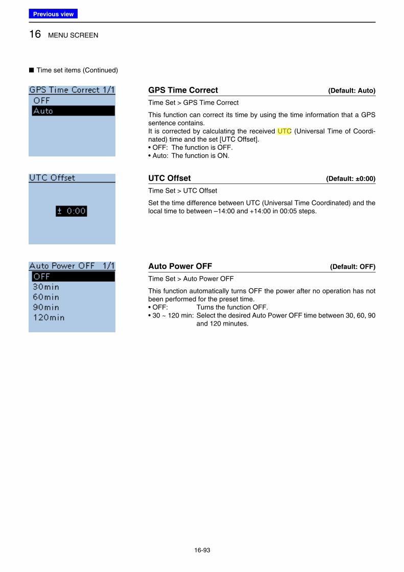
16 MENU SCREEN
16-93
GPS Time Correct (Default: Auto)
Time Set > GPS Time Correct
This function can correct its time by using the time information that a GPS sentence contains.It is corrected by calculating the received UTC (Universal Time of Coordi-nated) time and the set [UTC Offset].• OFF: The function is OFF.• Auto: The function is ON.
UTC Offset (Default: ±0:00)
Time Set > UTC Offset
Set the time difference between UTC (Universal Time Coordinated) and the local time to between –14:00 and +14:00 in 00:05 steps.
Auto Power OFF (Default: OFF)
Time Set > Auto Power OFF
This function automatically turns OFF the power after no operation has not been performed for the preset time.• OFF: Turns the function OFF.• 30 ~ 120 min: Select the desired Auto Power OFF time between 30, 60, 90
and 120 minutes.
■ Time set items (Continued)
Previous view
Icom
ハイライト表示
(Universal Time Coordinated) An astronomical time based on the Greenwich meridian (zero degrees longitude).
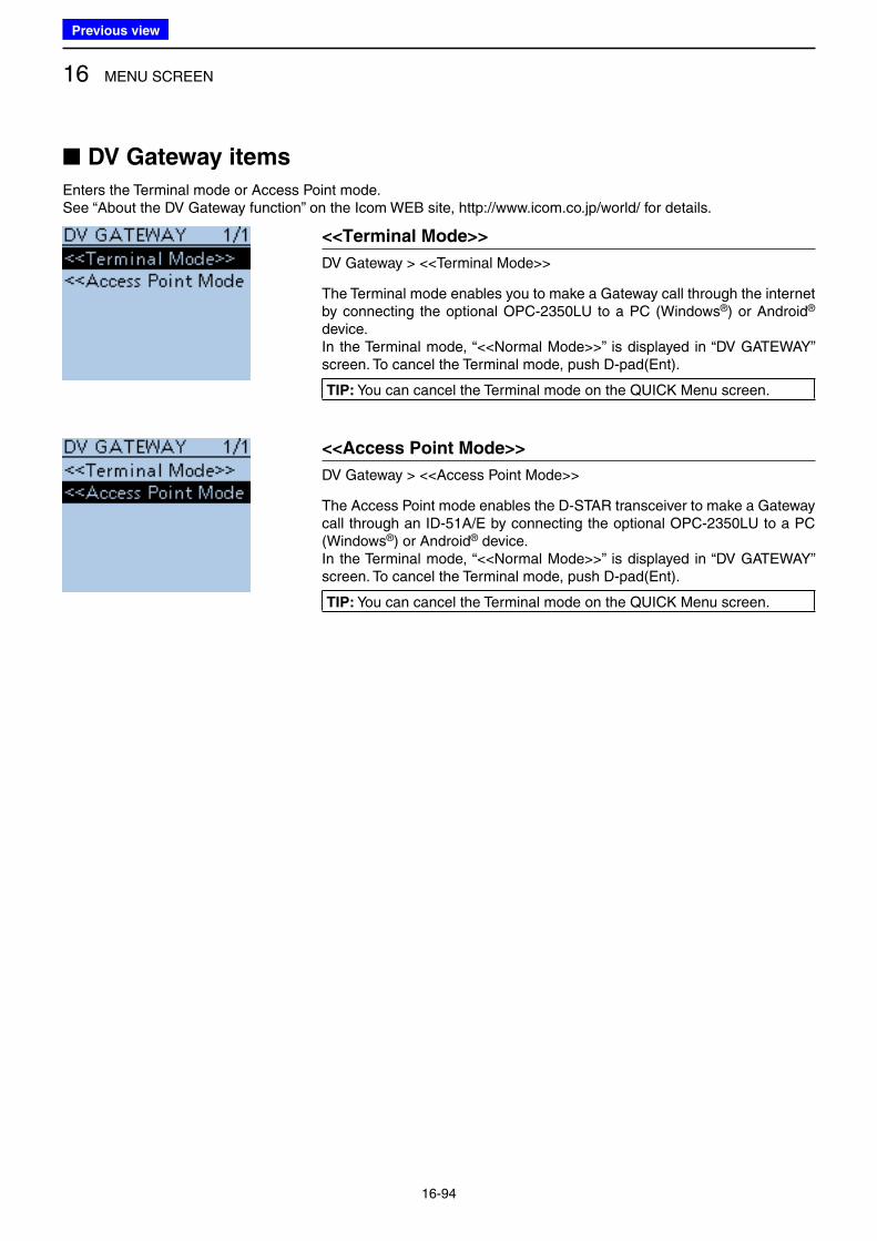
16 MENU SCREEN
16-94
■ DV Gateway items
Enters the Terminal mode or Access Point mode.See “About the DV Gateway function” on the Icom WEB site, http://www.icom.co.jp/world/ for details.
<<Terminal Mode>>
DV Gateway > <<Terminal Mode>>
The Terminal mode enables you to make a Gateway call through the internet by connecting the optional OPC-2350LU to a PC (Windows®) or Android® device.In the Terminal mode, “<<Normal Mode>>” is displayed in “DV GATEWAY” screen. To cancel the Terminal mode, push D-pad(Ent).
TIP: You can cancel the Terminal mode on the QUICK Menu screen.
<<Access Point Mode>>
DV Gateway > <<Access Point Mode>>
The Access Point mode enables the D-STAR transceiver to make a Gateway call through an ID-51A/E by connecting the optional OPC-2350LU to a PC (Windows®) or Android® device.In the Terminal mode, “<<Normal Mode>>” is displayed in “DV GATEWAY” screen. To cancel the Terminal mode, push D-pad(Ent).
TIP: You can cancel the Terminal mode on the QUICK Menu screen.
Previous view
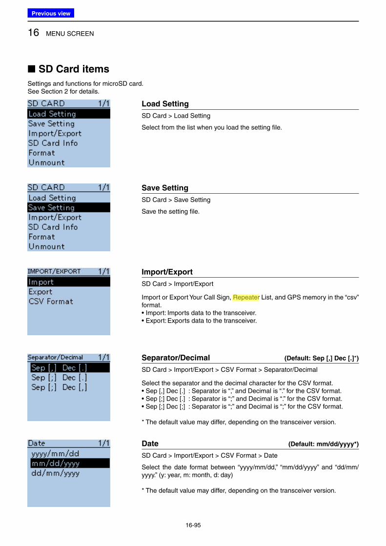
16 MENU SCREEN
16-95
■ SD Card items
Settings and functions for microSD card.See Section 2 for details.
Load Setting
SD Card > Load Setting
Select from the list when you load the setting file.
Save Setting
SD Card > Save Setting
Save the setting file.
Import/Export
SD Card > Import/Export
Import or Export Your Call Sign, Repeater List, and GPS memory in the “csv” format.• Import: Imports data to the transceiver.• Export: Exports data to the transceiver.
Separator/Decimal (Default: Sep [,] Dec [.]*)
SD Card > Import/Export > CSV Format > Separator/Decimal
Select the separator and the decimal character for the CSV format.• Sep [,] Dec [.] : Separator is “,” and Decimal is “.” for the CSV format.• Sep [;] Dec [.] : Separator is “;” and Decimal is “.” for the CSV format.• Sep [;] Dec [;] : Separator is “;” and Decimal is “;” for the CSV format.
* The default value may differ, depending on the transceiver version.
Date (Default: mm/dd/yyyy*)
SD Card > Import/Export > CSV Format > Date
Select the date format between “yyyy/mm/dd,” “mm/dd/yyyy” and “dd/mm/yyyy.” (y: year, m: month, d: day)
* The default value may differ, depending on the transceiver version.
Previous view
Icom
ハイライト表示
Radio systems that receive incoming signals and retransmit them to extend the communication area. Normally put on geographically high locations for VHF/UHF radios.
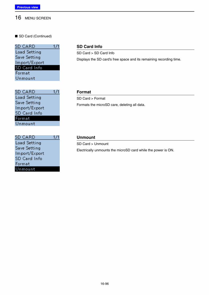
16 MENU SCREEN
16-96
■ SD Card (Continued)
SD Card Info
SD Card > SD Card Info
Displays the SD card’s free space and its remaining recording time.
Format
SD Card > Format
Formats the microSD care, deleting all data.
Unmount
SD Card > Unmount
Electrically unmounts the microSD card while the power is ON.
Previous view
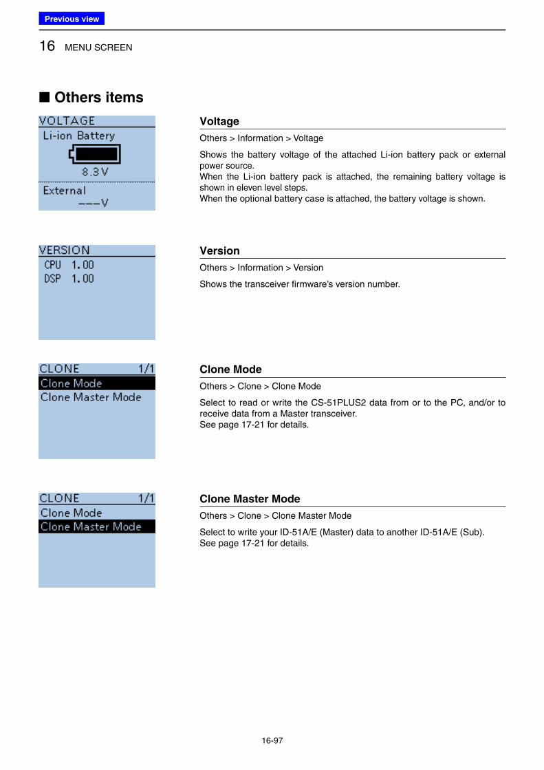
16 MENU SCREEN
16-97
■ Others items
Voltage
Others > Information > Voltage
Shows the battery voltage of the attached Li-ion battery pack or external power source.When the Li-ion battery pack is attached, the remaining battery voltage is shown in eleven level steps.When the optional battery case is attached, the battery voltage is shown.
Version
Others > Information > Version
Shows the transceiver firmware’s version number.
Clone Mode
Others > Clone > Clone Mode
Select to read or write the CS-51PLUS2 data from or to the PC, and/or to receive data from a Master transceiver.See page 17-21 for details.
Clone Master Mode
Others > Clone > Clone Master Mode
Select to write your ID-51A/E (Master) data to another ID-51A/E (Sub).See page 17-21 for details.
Previous view
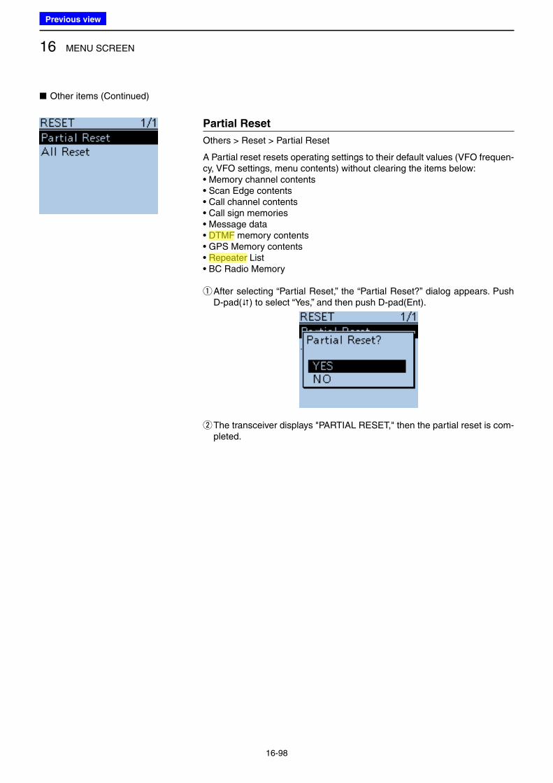
16 MENU SCREEN
16-98
Partial Reset
Others > Reset > Partial Reset
A Partial reset resets operating settings to their default values (VFO frequen-cy, VFO settings, menu contents) without clearing the items below:• Memory channel contents• Scan Edge contents• Call channel contents• Call sign memories• Message data• DTMF memory contents• GPS Memory contents• Repeater List• BC Radio Memory
q After selecting “Partial Reset,” the “Partial Reset?” dialog appears. Push D-pad() to select “Yes,” and then push D-pad(Ent).
w The transceiver displays "PARTIAL RESET," then the partial reset is com-pleted.
■ Other items (Continued)
Previous view
Icom
ハイライト表示
Radio systems that receive incoming signals and retransmit them to extend the communication area. Normally put on geographically high locations for VHF/UHF radios.
Icom
ハイライト表示
(Dual Tone Multi-Frequency (touch tone)) Used to transmit and receive numeric information such as phone numbers, PIN, remote radio control commands, and for other signaling purposes.
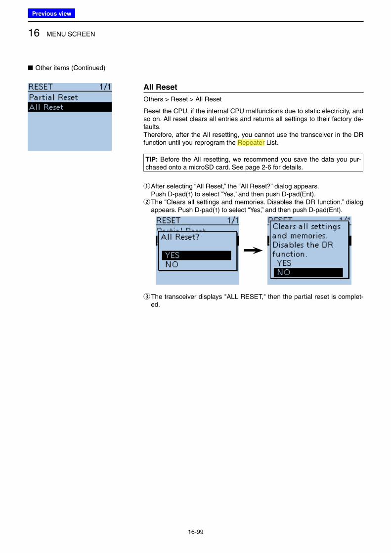
All Reset
Others > Reset > All Reset
Reset the CPU, if the internal CPU malfunctions due to static electricity, and so on. All reset clears all entries and returns all settings to their factory de-faults.Therefore, after the All resetting, you cannot use the transceiver in the DR function until you reprogram the Repeater List.
TIP: Before the All resetting, we recommend you save the data you pur-chased onto a microSD card. See page 2-6 for details.
qAfter selecting “All Reset,” the “All Reset?” dialog appears. Push D-pad() to select “Yes,” and then push D-pad(Ent).
w The “Clears all settings and memories. Disables the DR function.” dialog appears. Push D-pad() to select “Yes,” and then push D-pad(Ent).
e The transceiver displays "ALL RESET," then the partial reset is complet-ed.
16 MENU SCREEN
16-99
■ Other items (Continued)
Previous view
Icom
ハイライト表示
Radio systems that receive incoming signals and retransmit them to extend the communication area. Normally put on geographically high locations for VHF/UHF radios.
17-1
Section 17 OTHER FUNCTIONS
■ Voice TX function .............................................................. 17-2
D Recording ..................................................................... 17-2
D The recorded voice audio playing back ........................ 17-2
D To transmit the recorded voice audio ............................ 17-3
D Repeat Time setting ..................................................... 17-4
D TX Monitor function ...................................................... 17-4
■ Home CH Beep function ................................................... 17-5
D Home CH setting .......................................................... 17-5
D Home CH operation ...................................................... 17-5
■ Speech function ................................................................ 17-6
D [DIAL] speech function setting ...................................... 17-6
D Mode speech function setting ....................................... 17-7
■ Using the DTMF memory ................................................. 17-8
D DTMF code programming ............................................ 17-8
D Monitoring the stored DTMF code ................................ 17-9
D DTMF code transmission ........................................... 17-10
D DTMF code transmission (Direct Input) ...................... 17-11
D Setting DTMF transfer speed ..................................... 17-12
■ Tone squelch operation .................................................. 17-13
D Tone squelch frequency setting and operation ........... 17-13
■ DTCS squelch operation ................................................ 17-15
D DTCS code setting and operation .............................. 17-15
■ Cloning function .............................................................. 17-17
D Transceiver-to-Transceiver cloning using a microSD card .. 17-17
D Cloning from a PC using a microSD card ................... 17-20
D Cloning from a PC using an optional data cable ........ 17-20
D Transceiver-to-Transceiver cloning using a cable ....... 17-21
■ CI-V information ............................................................. 17-22
D CI-V data setting ......................................................... 17-22
D CI-V connection example ........................................... 17-22
D Data format ................................................................. 17-22
D Command table .......................................................... 17-23
Previous view
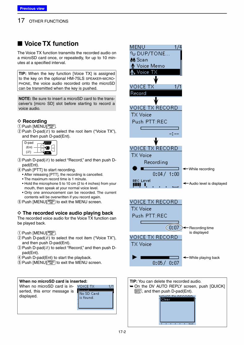
17 OTHER FUNCTIONS
17-2
■ Voice TX function
The Voice TX function transmits the recorded audio on a microSD card once, or repeatedly, for up to 10 min-utes at a specified interval.
TIP: When the key function [Voice TX] is assigned to the key on the optional HM-75LS SPEAKER-MICRO-
PHONE, the voice audio recorded onto the microSD can be transmitted when the key is pushed.
NOTE: Be sure to insert a microSD card to the trans-ceiver’s [micro SD] slot before starting to record a voice audio.
D Recording qPush [MENU] . w Push D-pad() to select the root item (“Voice TX”), and then push D-pad(Ent).
D-pad
(�)
(Ent)
e Push D-pad() to select “Record,” and then push D-pad(Ent). r Push [PTT] to start recording.
• After releasing [PTT], the recording is cancelled. • The maximum record time is 1 minute. • Hold the microphone 5 to 10 cm (2 to 4 inches) from your
mouth, then speak at your normal voice level. • Only one announcement can be recorded. The current
contents will be overwritten if you record again.
tPush [MENU] to exit the MENU screen.
D The recorded voice audio playing backThe recorded voice audio for the Voice TX function can be played back.
qPush [MENU] . w Push D-pad() to select the root item (“Voice TX”), and then push D-pad(Ent). e Push D-pad() to select “Record,” and then push D-pad(Ent). r Push D-pad(Ent) to start the playback. tPush [MENU] to exit the MENU screen.
TIP: You can delete the recorded audio. ➥ On the DV AUTO REPLY screen, push [QUICK]
, and then push D-pad(Ent).
When no microSD card is inserted:
When no microSD card is in-serted, this error message is displayed.
Recording time is displayed
While recording
Audio level is displayed
While playing back
Previous view
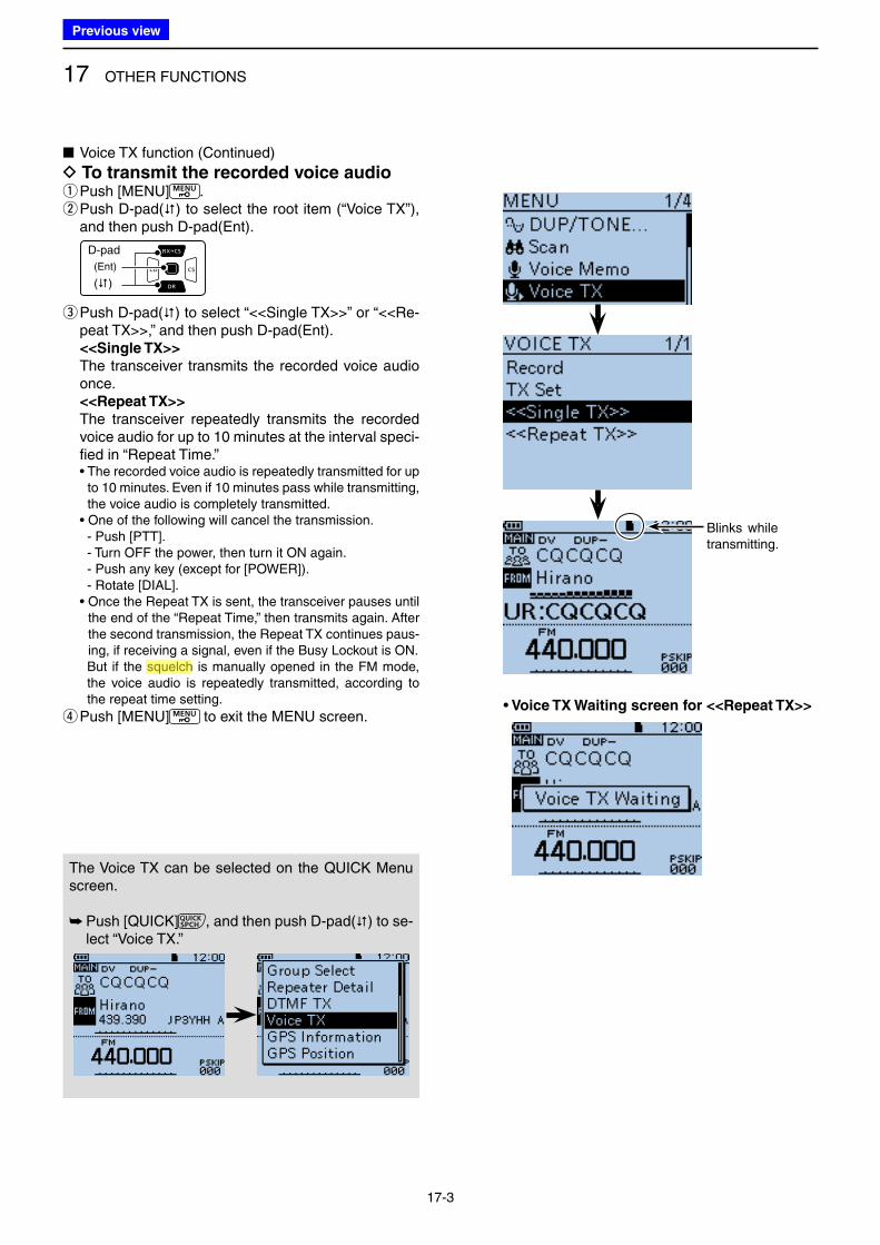
17 OTHER FUNCTIONS
17-3
■ Voice TX function (Continued)
D To transmit the recorded voice audio qPush [MENU] . w Push D-pad() to select the root item (“Voice TX”), and then push D-pad(Ent).
D-pad
(�)
(Ent)
e Push D-pad() to select “<<Single TX>>” or “<<Re-peat TX>>,” and then push D-pad(Ent).
<<Single TX>>
The transceiver transmits the recorded voice audio once.
<<Repeat TX>>
The transceiver repeatedly transmits the recorded voice audio for up to 10 minutes at the interval speci-fied in “Repeat Time.”
• The recorded voice audio is repeatedly transmitted for up to 10 minutes. Even if 10 minutes pass while transmitting, the voice audio is completely transmitted.
• One of the following will cancel the transmission. - Push [PTT]. - Turn OFF the power, then turn it ON again. - Push any key (except for [POWER]). - Rotate [DIAL]. • Once the Repeat TX is sent, the transceiver pauses until
the end of the “Repeat Time,” then transmits again. After the second transmission, the Repeat TX continues paus-ing, if receiving a signal, even if the Busy Lockout is ON.
But if the squelch is manually opened in the FM mode, the voice audio is repeatedly transmitted, according to the repeat time setting.
rPush [MENU] to exit the MENU screen.
Blinks while transmitting.
• Voice TX Waiting screen for <<Repeat TX>>
The Voice TX can be selected on the QUICK Menu screen.
➥ Push [QUICK] , and then push D-pad() to se-lect “Voice TX.”
Previous view
Icom
ハイライト表示
A function that mutes the audio output for certain signal levels.
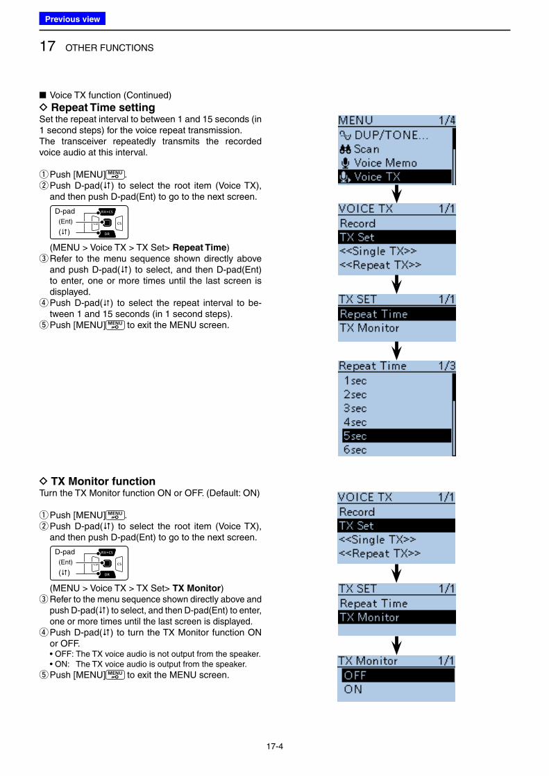
17 OTHER FUNCTIONS
17-4
■ Voice TX function (Continued)
D Repeat Time settingSet the repeat interval to between 1 and 15 seconds (in 1 second steps) for the voice repeat transmission.The transceiver repeatedly transmits the recorded voice audio at this interval.
qPush [MENU] . w Push D-pad() to select the root item (Voice TX), and then push D-pad(Ent) to go to the next screen.
D-pad
(�)
(Ent)
(MENU > Voice TX > TX Set> Repeat Time) e Refer to the menu sequence shown directly above and push D-pad() to select, and then D-pad(Ent) to enter, one or more times until the last screen is displayed. r Push D-pad() to select the repeat interval to be-tween 1 and 15 seconds (in 1 second steps). tPush [MENU] to exit the MENU screen.
D TX Monitor functionTurn the TX Monitor function ON or OFF. (Default: ON)
qPush [MENU] . w Push D-pad() to select the root item (Voice TX), and then push D-pad(Ent) to go to the next screen.
D-pad
(�)
(Ent)
(MENU > Voice TX > TX Set> TX Monitor) e Refer to the menu sequence shown directly above and push D-pad() to select, and then D-pad(Ent) to enter, one or more times until the last screen is displayed. r Push D-pad() to turn the TX Monitor function ON or OFF.
• OFF: The TX voice audio is not output from the speaker. • ON: The TX voice audio is output from the speaker.
tPush [MENU] to exit the MENU screen.
Previous view
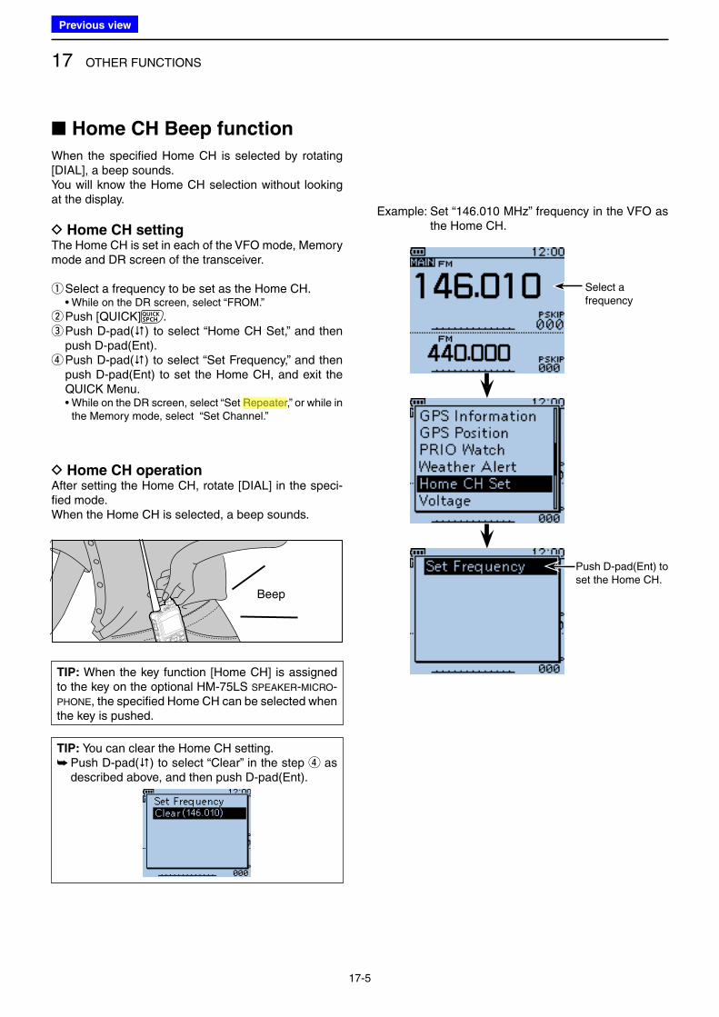
17 OTHER FUNCTIONS
17-5
■ Home CH Beep function
When the specified Home CH is selected by rotating [DIAL], a beep sounds.You will know the Home CH selection without looking at the display.
D Home CH settingThe Home CH is set in each of the VFO mode, Memory mode and DR screen of the transceiver.
qSelect a frequency to be set as the Home CH. • While on the DR screen, select “FROM.”
w Push [QUICK] . e Push D-pad() to select “Home CH Set,” and then push D-pad(Ent). r Push D-pad() to select “Set Frequency,” and then push D-pad(Ent) to set the Home CH, and exit the QUICK Menu.
• While on the DR screen, select “Set Repeater,” or while in the Memory mode, select “Set Channel.”
TIP: You can clear the Home CH setting. ➥ Push D-pad() to select “Clear” in the step r as described above, and then push D-pad(Ent).
Example: Set “146.010 MHz” frequency in the VFO as the Home CH.
Select a frequency
Push D-pad(Ent) to set the Home CH.
D Home CH operationAfter setting the Home CH, rotate [DIAL] in the speci-fied mode.When the Home CH is selected, a beep sounds.
Beep
TIP: When the key function [Home CH] is assigned to the key on the optional HM-75LS SPEAKER-MICRO-
PHONE, the specified Home CH can be selected when the key is pushed.
Previous view
Icom
ハイライト表示
Radio systems that receive incoming signals and retransmit them to extend the communication area. Normally put on geographically high locations for VHF/UHF radios.
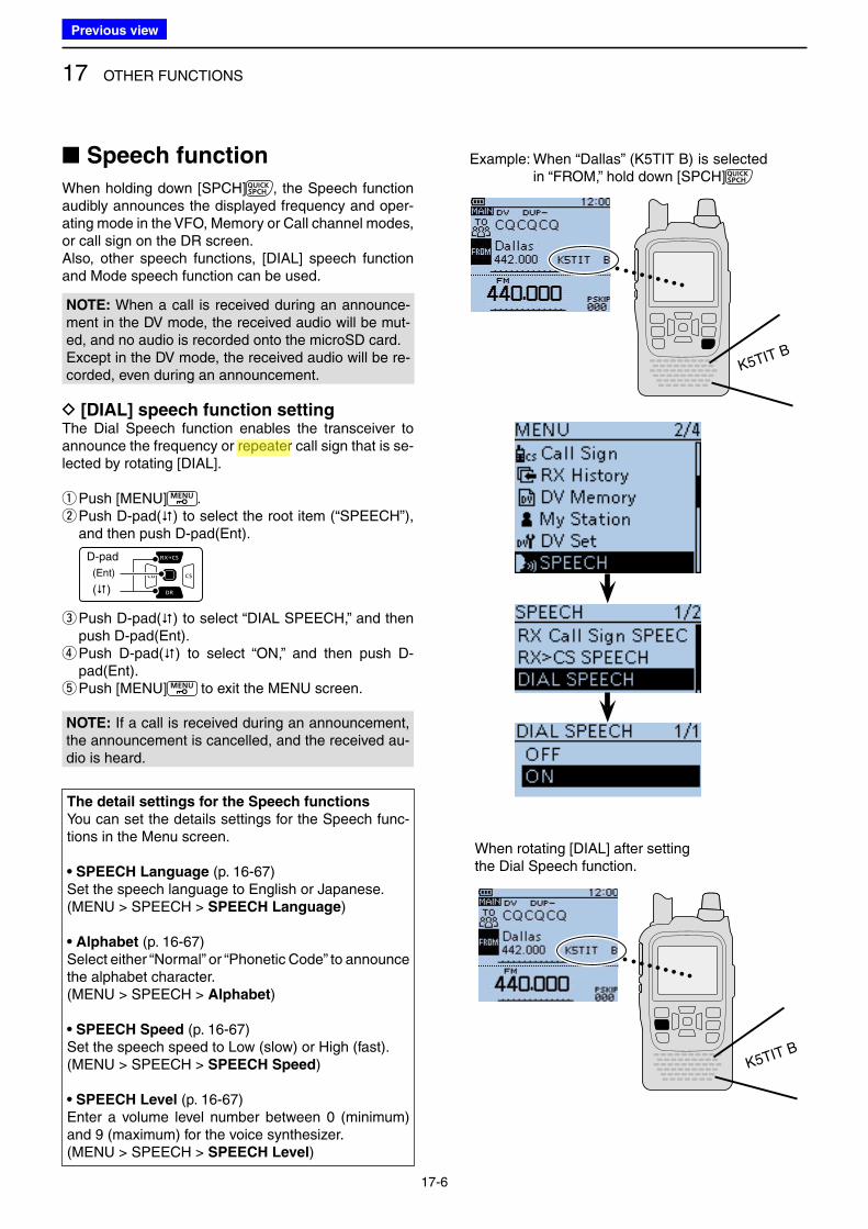
17 OTHER FUNCTIONS
17-6
■ Speech function
When holding down [SPCH] , the Speech function audibly announces the displayed frequency and oper-ating mode in the VFO, Memory or Call channel modes, or call sign on the DR screen.Also, other speech functions, [DIAL] speech function and Mode speech function can be used.
D [DIAL] speech function settingThe Dial Speech function enables the transceiver to announce the frequency or repeater call sign that is se-lected by rotating [DIAL].
qPush [MENU] . w Push D-pad() to select the root item (“SPEECH”), and then push D-pad(Ent).
D-pad
(�)
(Ent)
e Push D-pad() to select “DIAL SPEECH,” and then push D-pad(Ent). r Push D-pad() to select “ON,” and then push D-pad(Ent). tPush [MENU] to exit the MENU screen.
K5TIT B
Example: When “Dallas” (K5TIT B) is selected in “FROM,” hold down [SPCH]
The detail settings for the Speech functions
You can set the details settings for the Speech func-tions in the Menu screen.
• SPEECH Language (p. 16-67)Set the speech language to English or Japanese.(MENU > SPEECH > SPEECH Language)
• Alphabet (p. 16-67)Select either “Normal” or “Phonetic Code” to announce the alphabet character.(MENU > SPEECH > Alphabet)
• SPEECH Speed (p. 16-67)Set the speech speed to Low (slow) or High (fast).(MENU > SPEECH > SPEECH Speed)
• SPEECH Level (p. 16-67)Enter a volume level number between 0 (minimum) and 9 (maximum) for the voice synthesizer.(MENU > SPEECH > SPEECH Level)
When rotating [DIAL] after setting the Dial Speech function.
K5TIT B
NOTE: When a call is received during an announce-ment in the DV mode, the received audio will be mut-ed, and no audio is recorded onto the microSD card.Except in the DV mode, the received audio will be re-corded, even during an announcement.
NOTE: If a call is received during an announcement, the announcement is cancelled, and the received au-dio is heard.
Previous view
Icom
ハイライト表示
Radio systems that receive incoming signals and retransmit them to extend the communication area. Normally put on geographically high locations for VHF/UHF radios.
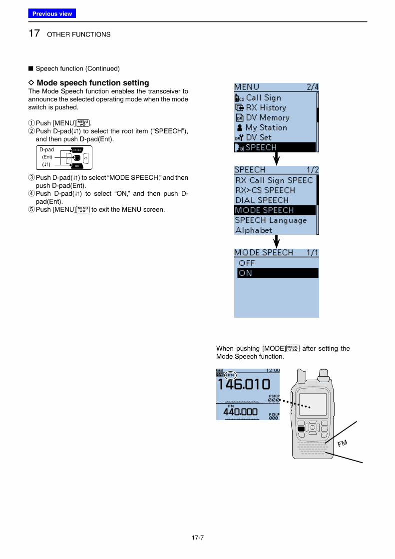
17 OTHER FUNCTIONS
17-7
D Mode speech function settingThe Mode Speech function enables the transceiver to announce the selected operating mode when the mode switch is pushed.
qPush [MENU] . w Push D-pad() to select the root item (“SPEECH”), and then push D-pad(Ent).
D-pad
(�)
(Ent)
e Push D-pad() to select “MODE SPEECH,” and then push D-pad(Ent). r Push D-pad() to select “ON,” and then push D-pad(Ent). tPush [MENU] to exit the MENU screen.
FM
When pushing [MODE] after setting the Mode Speech function.
■ Speech function (Continued)
Previous view
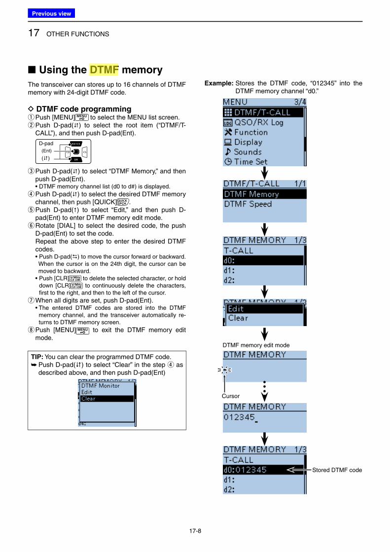
17 OTHER FUNCTIONS
17-8
■ Using the DTMF memory
The transceiver can stores up to 16 channels of DTMF memory with 24-digit DTMF code.
D DTMF code programming qPush [MENU] to select the MENU list screen. w Push D-pad() to select the root item (“DTMF/T-CALL”), and then push D-pad(Ent).
D-pad
(�)
(Ent)
e Push D-pad() to select “DTMF Memory,” and then push D-pad(Ent).
• DTMF memory channel list (d0 to d#) is displayed.
r Push D-pad() to select the desired DTMF memory channel, then push [QUICK] . t Push D-pad() to select “Edit,” and then push D-pad(Ent) to enter DTMF memory edit mode. y Rotate [DIAL] to select the desired code, the push D-pad(Ent) to set the code.
Repeat the above step to enter the desired DTMF codes.
• Push D-pad() to move the cursor forward or backward. When the cursor is on the 24th digit, the cursor can be
moved to backward. • Push [CLR] to delete the selected character, or hold
down [CLR] to continuously delete the characters, first to the right, and then to the left of the cursor.
uWhen all digits are set, push D-pad(Ent). • The entered DTMF codes are stored into the DTMF
memory channel, and the transceiver automatically re-turns to DTMF memory screen.
i Push [MENU] to exit the DTMF memory edit mode.
Example: Stores the DTMF code, “012345” into the DTMF memory channel “d0.”
Stored DTMF code
TIP: You can clear the programmed DTMF code. ➥ Push D-pad() to select “Clear” in the step r as described above, and then push D-pad(Ent)
DTMF memory edit mode
Cursor
Previous view
Icom
ハイライト表示
(Dual Tone Multi-Frequency (touch tone)) Used to transmit and receive numeric information such as phone numbers, PIN, remote radio control commands, and for other signaling purposes.
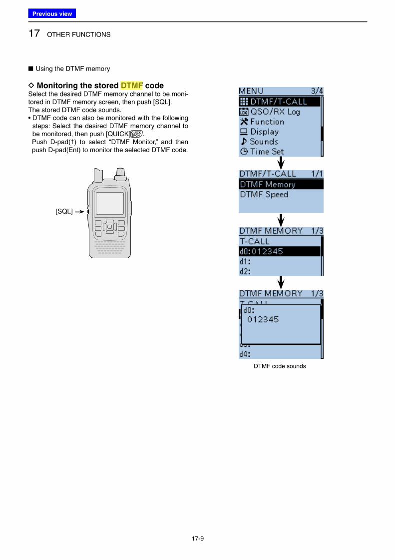
17 OTHER FUNCTIONS
17-9
■ Using the DTMF memory
D Monitoring the stored DTMF codeSelect the desired DTMF memory channel to be moni-tored in DTMF memory screen, then push [SQL].The stored DTMF code sounds.• DTMF code can also be monitored with the following
steps: Select the desired DTMF memory channel to be monitored, then push [QUICK] .
Push D-pad() to select “DTMF Monitor,” and then push D-pad(Ent) to monitor the selected DTMF code.
DTMF code sounds
[SQL]
Previous view
Icom
ハイライト表示
(Dual Tone Multi-Frequency (touch tone)) Used to transmit and receive numeric information such as phone numbers, PIN, remote radio control commands, and for other signaling purposes.
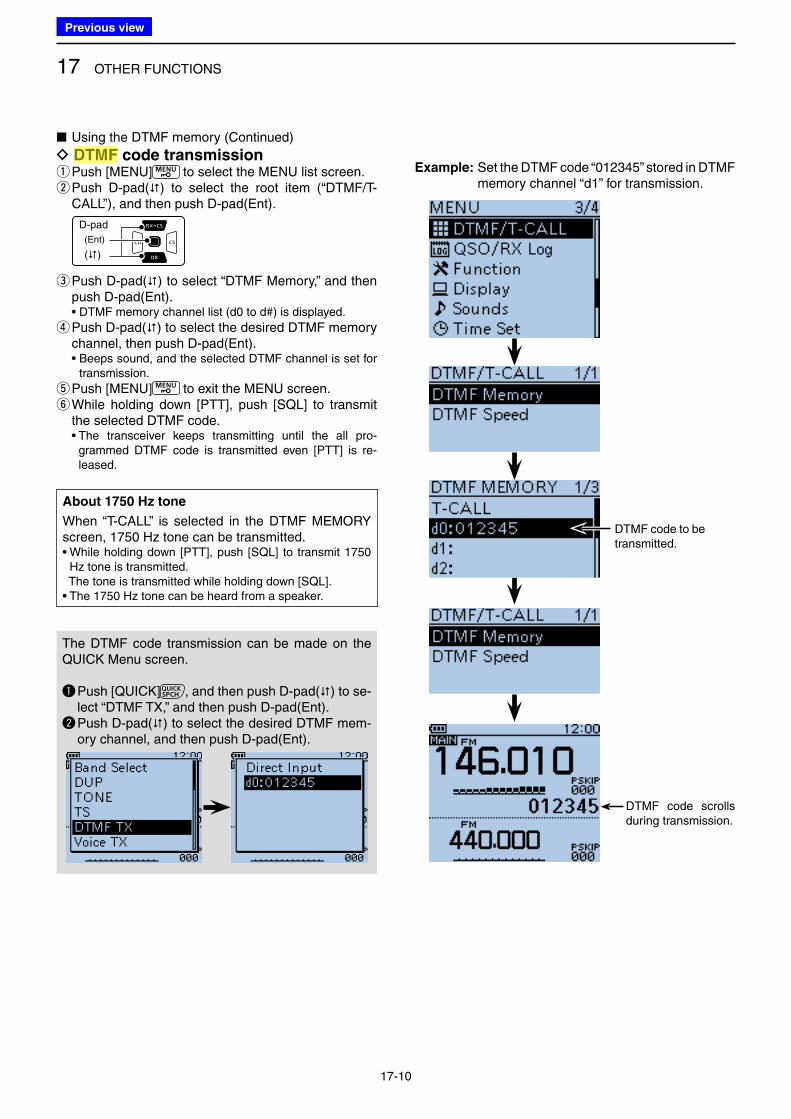
17 OTHER FUNCTIONS
17-10
■ Using the DTMF memory (Continued)
D DTMF code transmission qPush [MENU] to select the MENU list screen. w Push D-pad() to select the root item (“DTMF/T-CALL”), and then push D-pad(Ent).
D-pad
(�)
(Ent)
e Push D-pad() to select “DTMF Memory,” and then push D-pad(Ent).
• DTMF memory channel list (d0 to d#) is displayed.
r Push D-pad() to select the desired DTMF memory channel, then push D-pad(Ent).
• Beeps sound, and the selected DTMF channel is set for transmission.
t Push [MENU] to exit the MENU screen. y While holding down [PTT], push [SQL] to transmit the selected DTMF code.
• The transceiver keeps transmitting until the all pro-grammed DTMF code is transmitted even [PTT] is re-leased.
Example: Set the DTMF code “012345” stored in DTMF memory channel “d1” for transmission.
DTMF code to be transmitted.
DTMF code scrolls during transmission.
About 1750 Hz tone
When “T-CALL” is selected in the DTMF MEMORY screen, 1750 Hz tone can be transmitted.• While holding down [PTT], push [SQL] to transmit 1750
Hz tone is transmitted. The tone is transmitted while holding down [SQL]. • The 1750 Hz tone can be heard from a speaker.
The DTMF code transmission can be made on the QUICK Menu screen.
q Push [QUICK] , and then push D-pad() to se-lect “DTMF TX,” and then push D-pad(Ent).
w Push D-pad() to select the desired DTMF mem-ory channel, and then push D-pad(Ent).
Previous view
Icom
ハイライト表示
(Dual Tone Multi-Frequency (touch tone)) Used to transmit and receive numeric information such as phone numbers, PIN, remote radio control commands, and for other signaling purposes.
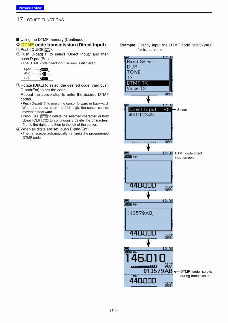
17 OTHER FUNCTIONS
17-11
■ Using the DTMF memory (Continued)
D DTMF code transmission (Direct Input) qPush [QUICK] . w Push D-pad() to select “Direct Input,” and then push D-pad(Ent).
• The DTMF code direct input screen is displayed.
D-pad
(�)
(Ent)
e Rotate [DIAL] to select the desired code, then push D-pad(Ent) to set the code.
Repeat the above step to enter the desired DTMF codes.
• Push D-pad() to move the cursor forward or backward. When the cursor is on the 24th digit, the cursor can be
moved to backward. • Push [CLR] to delete the selected character, or hold
down [CLR] to continuously delete the characters, first to the right, and then to the left of the cursor.
rWhen all digits are set, push D-pad(Ent). • The transceiver automatically transmits the programmed
DTMF code.
Select
DTMF code scrolls during transmission.
DTMF code direct input screen
Example: Directly input the DTMF code “013579AB” for transmission.
Previous view
Icom
ハイライト表示
(Dual Tone Multi-Frequency (touch tone)) Used to transmit and receive numeric information such as phone numbers, PIN, remote radio control commands, and for other signaling purposes.
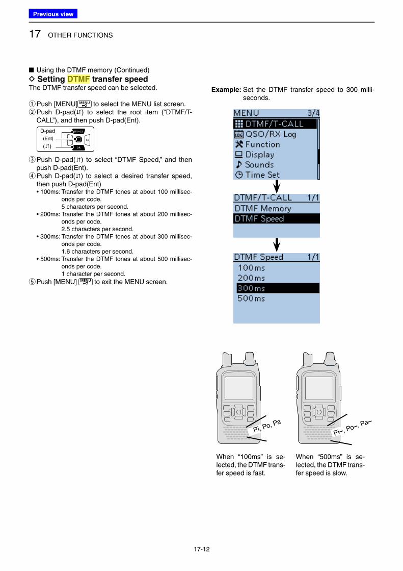
17 OTHER FUNCTIONS
17-12
■ Using the DTMF memory (Continued)
D Setting DTMF transfer speedThe DTMF transfer speed can be selected.
qPush [MENU] to select the MENU list screen. w Push D-pad() to select the root item (“DTMF/T-CALL”), and then push D-pad(Ent).
D-pad
(�)
(Ent)
e Push D-pad() to select “DTMF Speed,” and then push D-pad(Ent). r Push D-pad() to select a desired transfer speed, then push D-pad(Ent)
• 100ms: Transfer the DTMF tones at about 100 millisec-onds per code.
5 characters per second. • 200ms: Transfer the DTMF tones at about 200 millisec-
onds per code. 2.5 characters per second. • 300ms: Transfer the DTMF tones at about 300 millisec-
onds per code. 1.6 characters per second. • 500ms: Transfer the DTMF tones at about 500 millisec-
onds per code. 1 character per second.
t Push [MENU] to exit the MENU screen.
Example: Set the DTMF transfer speed to 300 milli-seconds.
Pi, Po, Pa
Pi–, Po–, Pa–
When “100ms” is se-lected, the DTMF trans-fer speed is fast.
When “500ms” is se-lected, the DTMF trans-fer speed is slow.
Previous view
Icom
ハイライト表示
(Dual Tone Multi-Frequency (touch tone)) Used to transmit and receive numeric information such as phone numbers, PIN, remote radio control commands, and for other signaling purposes.

17 OTHER FUNCTIONS
17-13
■ Tone squelch operation
The tone squelch opens only when you receive a signal containing a matching subaudible tone in the FM or FM narrow mode. You can silently wait for calls from others using the same tone.Also, reversed tone squelch function is ready to mute the squelch when a signal containing a matched sub-audible tone.
D Tone squelch frequency setting and op-eration q Push [V/MHz] once or more times to select the VFO mode. w Push [MODE] once or more times to select the FM or FM-N (FM narrow) mode. e Rotate [DIAL] to select a desired operating frequency. rPush [MENU] to select the MENU list screen. t Push D-pad() to select the root item (“DUP/TONE…”), and then push D-pad(Ent).
D-pad
(�)
(Ent)
y Push D-pad() to select “TSQL Freq,” and then push D-pad(Ent).
• The selected tone squelch frequency is displayed.
u Rotate [DIAL] to select a desired tone squelch fre-quency, then push D-pad(Ent).
(Example: 100.0 Hz) • Select a tone squelch frequency between 67.0 and 254.1
Hz.
Set a desired op-erating frequency.
Select FM or FM-N mode.
☞ Continued to the step i on the next page
TIP: To return to the default tone squelch frequency, push [QUICK] in the step y as described above, and then push D-pad(Ent).
Previous view
Icom
ハイライト表示
A function that mutes the audio output for certain signal levels.
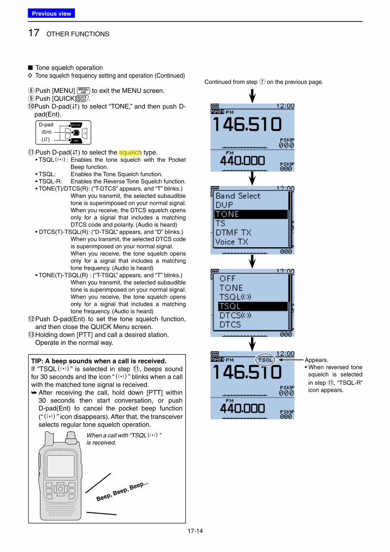
17 OTHER FUNCTIONS
17-14
■ Tone squelch operation D Tone squelch frequency setting and operation (Continued)
iPush [MENU] to exit the MENU screen. oPush [QUICK] .
!0 Push D-pad() to select “TONE,” and then push D-pad(Ent).
D-pad
(�)
(Ent)
!1 Push D-pad() to select the squelch type.• TSQLS: Enables the tone squelch with the Pocket
Beep function.• TSQL: Enables the Tone Squelch function.• TSQL-R: Enables the Reverse Tone Squelch function.• TONE(T)/DTCS(R): (“T-DTCS” appears, and “T” blinks.) When you transmit, the selected subaudible
tone is superimposed on your normal signal. When you receive, the DTCS squelch opens
only for a signal that includes a matching DTCS code and polarity. (Audio is heard)
• DTCS(T)-TSQL(R): (“D-TSQL” appears, and “D” blinks.) When you transmit, the selected DTCS code
is superimposed on your normal signal. When you receive, the tone squelch opens
only for a signal that includes a matching tone frequency. (Audio is heard)
• TONE(T)-TSQL(R) : (“T-TSQL” appears, and “T” blinks.) When you transmit, the selected subaudible
tone is superimposed on your normal signal. When you receive, the tone squelch opens
only for a signal that includes a matching tone frequency. (Audio is heard)
!2 Push D-pad(Ent) to set the tone squelch function, and then close the QUICK Menu screen.
!3 Holding down [PTT] and call a desired station. Operate in the normal way.
Continued from step u on the previous page.
Appears.• When reversed tone
squelch is selected
in step !1, “TSQL-R” icon appears.
TIP: A beep sounds when a call is received.
If “TSQLS” is selected in step !1, beeps sound for 30 seconds and the icon “S” blinks when a call with the matched tone signal is received.
➥ After receiving the call, hold down [PTT] within 30 seconds then start conversation, or push D-pad(Ent) to cancel the pocket beep function
(“S” icon disappears). After that, the transceiver selects regular tone squelch operation.
Beep, Beep, Beep...
When a call with “TSQLS”
is received.
Previous view
Icom
ハイライト表示
A function that mutes the audio output for certain signal levels.
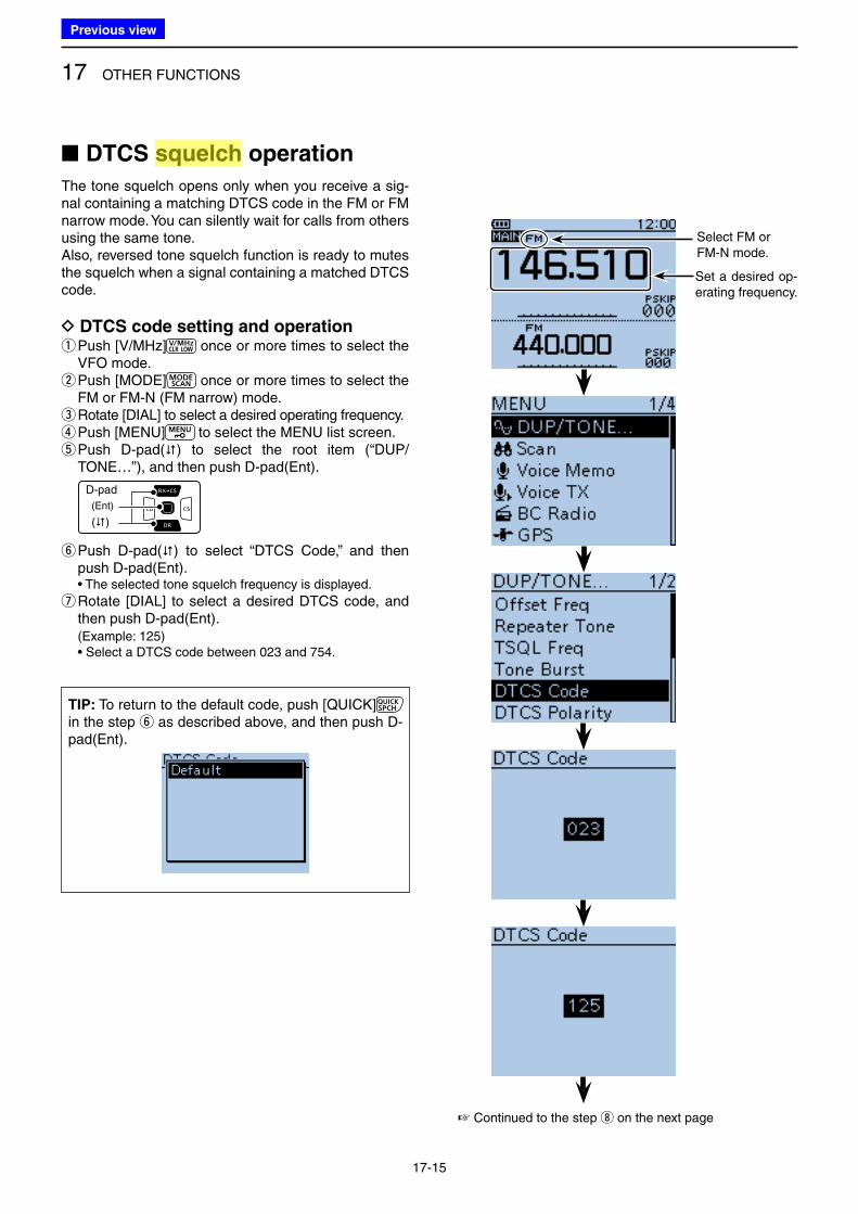
17 OTHER FUNCTIONS
17-15
■ DTCS squelch operation
The tone squelch opens only when you receive a sig-nal containing a matching DTCS code in the FM or FM narrow mode. You can silently wait for calls from others using the same tone.Also, reversed tone squelch function is ready to mutes the squelch when a signal containing a matched DTCS code.
D DTCS code setting and operation q Push [V/MHz] once or more times to select the VFO mode. w Push [MODE] once or more times to select the FM or FM-N (FM narrow) mode. e Rotate [DIAL] to select a desired operating frequency. rPush [MENU] to select the MENU list screen. t Push D-pad() to select the root item (“DUP/TONE…”), and then push D-pad(Ent).
D-pad
(�)
(Ent)
y Push D-pad() to select “DTCS Code,” and then push D-pad(Ent).
• The selected tone squelch frequency is displayed.
u Rotate [DIAL] to select a desired DTCS code, and then push D-pad(Ent).
(Example: 125) • Select a DTCS code between 023 and 754.
TIP: To return to the default code, push [QUICK] in the step y as described above, and then push D-pad(Ent).
Set a desired op-erating frequency.
Select FM or FM-N mode.
☞ Continued to the step i on the next page
Previous view
Icom
ハイライト表示
A function that mutes the audio output for certain signal levels.

17 OTHER FUNCTIONS
17-16
■ Tone squelch operation D DTCS code setting and operation (Continued)
iPush [MENU] to exit the MENU screen. oPush [QUICK] .
!0 Push D-pad() to select “TONE,” and then push D-pad(Ent).
D-pad
(�)
(Ent)
!1 Push D-pad() to select the tone squelch type.• DTCSS: Enables the DTCS squelch with the Pocket
Beep function.• DTCS: Enables the DTCS Squelch function.• DTCS-R: Enables the Reverse DTCS Squelch function.• DTCS(T): (“DTCS” blinks) When you transmit, the selected DTCS code
is superimposed on your normal signal. When you receive, the function is OFF.• TONE(T)/DTCS(R): (“T-DTCS” appears, and “T” blinks.) When you transmit, the selected subaudible
tone is superimposed on your normal signal. When you receive, the DTCS squelch opens
only for a signal that includes a matching DTCS code and polarity. (Audio is heard)
• DTCS(T)-TSQL(R): (“D-TSQL” appears, and “D” blinks.) When you transmit, the selected DTCS code
is superimposed on your normal signal. When you receive, the tone squelch opens
only for a signal that includes a matching tone frequency. (Audio is heard)
!2 Push D-pad(Ent) to set the DTCS squelch function, and then close the QUICK Menu screen.
!3 Holding down [PTT] and call a desired station. • Operate in the normal way.
Continued from step u on the previous page.
Appears.• When reversed tone
squelch is selected
in step !1, “DTCS-R” icon appears.
TIP: Sounds beep when a call is received.
If “DTCSS” is selected in step !1, beeps sound for 30 seconds and the icon “S” blinks when a call with the matched DTCS code signal is received.
➥ After receiving a call, hold down [PTT] within 30 seconds then start conversation, or push D-pad(Ent) to cancel the pocket beep function (“S” icon disappears). After that, the transceiv-er selects regular DTCS squelch operation. If no operation is performed within 30 seconds, beeps stop sounding but the “S” icon blinking remains.
Beep, Beep, Beep...
When a call with “TSQLS”
is received.
Previous view
Icom
ハイライト表示
A function that mutes the audio output for certain signal levels.
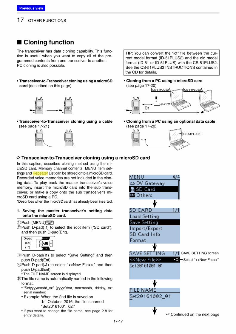
17 OTHER FUNCTIONS
17-17
• Transceiver-to-Transceiver cloning using a microSD
card (described on this page)
• Transceiver-to-Transceiver cloning using a cable
(see page 17-21)
• Cloning from a PC using a microSD card
(see page 17-20)
• Cloning from a PC using an optional data cable
(see page 17-20)
D Transceiver-to-Transceiver cloning using a microSD cardIn this caption, describes cloning method using the mi-croSD card. Memory channel contents, MENU item set-tings and Repeater List can be stored onto a microSD card.Recorded voice memories are not included in the clon-ing data. To play back the master transceiver’s voice memory, insert the microSD card into the sub trans-ceiver, or make a copy onto the sub transceiver’s mi-croSD card using a PC.* Describes when the microSD card has already been inserted.
1. Saving the master transceiver’s setting data
onto the microSD card.
qPush [MENU] . w Push D-pad() to select the root item (“SD card”), and then push D-pad(Ent).
D-pad
(�)
(Ent)
e Push D-pad() to select “Save Setting,” and then push D-pad(Ent). r Push D-pad() to select “<<New File>>,” and then push D-pad(Ent).
• The FILE NAME screen is displayed.
t The file name is automatically named in the following format:
• “Setyyyymmdd_xx” (yyyy:Year, mm:month, dd:day, xx: serial number)
• Example: When the 2nd file is saved on 1st October, 2016, the file is named “Set20161001_02.” • If you want to change the file name, see page 2-8 for
entry details.
■ Cloning function
The transceiver has data cloning capability. This func-tion is useful when you want to copy all of the pro-grammed contents from one transceiver to another.PC cloning is also possible.
☞ Continued on the next page
Select “<<New File>>”
SAVE SETTING screen
Or
CS-51PLUS2CS-51PLUS2
CS-51PLUS2
TIP: You can convert the “icf” file between the cur-rent model format (ID-51PLUS2) and the old model format (ID-51 or ID-51PLUS) with the CS-51PLUS2. See the CS-51PLUS2 INSTRUCTIONS contained in the CD for details.
Previous view
Icom
ハイライト表示
Radio systems that receive incoming signals and retransmit them to extend the communication area. Normally put on geographically high locations for VHF/UHF radios.
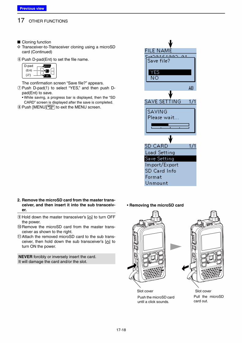
17 OTHER FUNCTIONS
17-18
• Removing the microSD card
■ Cloning function D Transceiver-to-Transceiver cloning using a microSD card (Continued)
yPush D-pad(Ent) to set the file name.
D-pad
(�)
(Ent)
The confirmation screen “Save file?” appears. u Push D-pad() to select “YES,” and then push D-pad(Ent) to save.
• While saving, a progress bar is displayed, then the “SD
CARD” screen is displayed after the save is completed.
i Push [MENU] to exit the MENU screen.
2. Remove the microSD card from the master trans-
ceiver, and then insert it into the sub transceiv-
er.
o Hold down the master transceiver’s [ ] to turn OFF the power.
!0 Remove the microSD card from the master trans-ceiver as shown to the right.
!1 Attach the removed microSD card to the sub trans-ceiver, then hold down the sub transceiver’s [ ] to turn ON the power.
Slot cover Slot cover
Push the microSD card until a click sounds.
Pull the microSD card out.
NEVER forcibly or inversely insert the card.It will damage the card and/or the slot.
Previous view
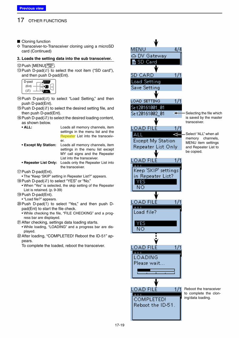
17 OTHER FUNCTIONS
17-19
3. Loads the setting data into the sub transceiver.
!2 Push [MENU] .!3 Push D-pad() to select the root item (“SD card”),
and then push D-pad(Ent).
D-pad
(�)
(Ent)
!4 Push D-pad() to select “Load Setting,” and then push D-pad(Ent).
!5 Push D-pad() to select the desired setting file, and then push D-pad(Ent).
!6 Push D-pad() to select the desired loading content, as shown below.
• ALL: Loads all memory channels, item settings in the menu list and the Repeater List into the transceiv-er.
• Except My Station: Loads all memory channels, item settings in the menu list except MY call signs and the Repeater List into the transceiver.
• Repeater List Only: Loads only the Repeater List into the transceiver.
!7 Push D-pad(Ent). • The “Keep ‘SKIP’ setting in Repeater List?” appears.
!8 Push D-pad() to select “YES” or “No.” • When “Yes” is selected, the skip setting of the Repeater
List is retained. (p. 9-39)
!9 Push D-pad(Ent). • “Load file?” appears.
@0 Push D-pad() to select “Yes,” and then push D-pad(Ent) to start the file check.
• While checking the file, “FILE CHECKING” and a prog-ress bar are displayed.
@1 After checking, settings data loading starts. • While loading, “LOADING” and a progress bar are dis-
played.
@2 After loading, “COMPLETED! Reboot the ID-51” ap-pears.
To complete the loaded, reboot the transceiver.
Reboot the transceiver to complete the clon-ing/data loading.
Selecting the file which is saved by the master transceiver.
Select “ALL” when all memory channels, MENU item settings and Repeater List to be copied.
■ Cloning function D Transceiver-to-Transceiver cloning using a microSD card (Continued)
Previous view
Icom
ハイライト表示
Radio systems that receive incoming signals and retransmit them to extend the communication area. Normally put on geographically high locations for VHF/UHF radios.
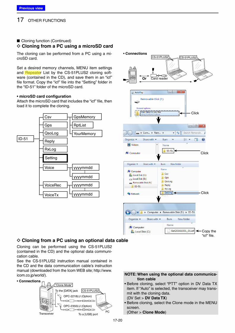
17 OTHER FUNCTIONS
17-20
• Connections
• Connections
■ Cloning function (Continued)
D Cloning from a PC using a microSD card
The cloning can be performed from a PC using a mi-croSD card.
Set a desired memory channels, MENU item settings and Repeater List by the CS-51PLUS2 cloning soft-ware (contained in the CD), and save them in an “icf” file format. Copy the “icf” file into the “Setting” folder in the “ID-51” folder of the microSD card.
• microSD card configuration
Attach the microSD card that includes the “icf” file, then load it to complete the cloning.
D Cloning from a PC using an optional data cable
Cloning can be performed using the CS-51PLUS2 (contained in the CD) and the optional data communi-cation cable.See the CS-51PLUS2 instruction manual contained in the CD and the data communication cable’s instruction manual (downloaded from the Icom WEB site; http://www.icom.co.jp/world/). NOTE: When using the optional data communica-
tion cable
• Before cloning, select “PTT” option in DV Data TX item. If “Auto” is selected, the transceiver may trans-mit with the cloning data.
(DV Set > DV Data TX)• Before cloning, select the Clone mode in the MENU
screen. (Other > Clone Mode)
Click
Click
Card readerOr
CS-51PLUS2 CS-51PLUS2
To the [DATA] jack
OPC-2218LU (Option)
OPC-2350LU (Option)
To a [USB] portPC
Transceiver
"Clone Mode"
CS-51PLUS2
Copy the “icf” file.
Click
ID-51
Gps
Reply
Setting
Voice yyyymmdd
yyyymmdd
QsoLog
RxLog
VoiceRec
VoiceTx
Csv GpsMemory
RptList
YourMemory
yyyymmdd
yyyymmdd
Previous view
Icom
ハイライト表示
Radio systems that receive incoming signals and retransmit them to extend the communication area. Normally put on geographically high locations for VHF/UHF radios.
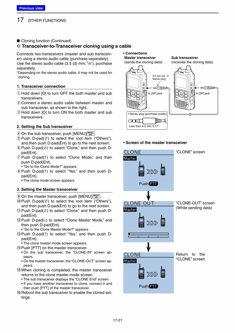
17 OTHER FUNCTIONS
17-21
“CLONE” screen
“CLONE-OUT” screen(While sending data)
Return to the “CLONE” screen
• Connections
Master transceiver
(sends the cloning data)Sub transceiver
(receives the cloning data)
• Screen of the master transceiver
■ Cloning function (Continued)
D Transceiver-to-Transceiver cloning using a cable
Connects two transceivers (master and sub transceiv-er) using a stereo audio cable (purchase separately).Use the stereo audio cable (3.5 (d) mm; 1⁄8″), purchase separately.* Depending on the stereo audio cable, it may not be used for cloning.
1. Transceiver connection
q Hold down [ ] to turn OFF the both master and sub transceivers. w Connect a stereo audio cable between master and sub transceiver, as shown to the right. e Hold down [ ] to turn ON the both master and sub transceivers.
2. Setting the Sub transceiver
rOn the sub transceiver, push [MENU] . t Push D-pad() to select the root item (“Others”), and then push D-pad(Ent) to go to the next screen. y Push D-pad() to select “Clone,” and then push D-pad(Ent). u Push D-pad() to select “Clone Mode,” and then push D-pad(Ent).
• “Go to the Clone Mode?” appears.
i Push D-pad() to select “Yes,” and then push D-pad(Ent).
• The clone mode screen appears.
3. Setting the Master transceiver
o On the master transceiver, push [MENU] .!0 Push D-pad() to select the root item (“Others”),
and then push D-pad(Ent) to go to the next screen.!1 Push D-pad() to select “Clone,” and then push D-
pad(Ent).!2 Push D-pad() to select “Clone Master Mode,” and
then push D-pad(Ent). • “Go to the Clone Master Mode?” appears.
!3 Push D-pad() to select “Yes,” and then push D-pad(Ent).
• The clone master mode screen appears.
!4 Push [PTT] on the master transceiver. • On the sub transceiver, the “CLONE-IN” screen ap-
pears. • On the master transceiver, the “CLONE-OUT” screen ap-
pears.
!5 When cloning is completed, the master transceiver returns to the clone master mode screen.
• The sub transceiver displays the “CLONE End” screen. • If you have another transceiver to clone, connect it and
then push [PTT] of the master transceiver.
!6 Reboot the sub transceiver to enable the cloned set-tings.
to [SP] jack to [SP] jack
3.5 mm (d); 1⁄8″Stereo plug
• Stereo plug (purchase locally)
Less than 4.5 mm; 0.17″
Previous view
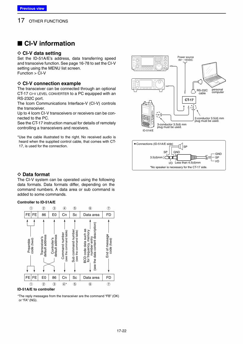
17 OTHER FUNCTIONS
17-22
D Data formatThe CI-V system can be operated using the following data formats. Data formats differ, depending on the command numbers. A data area or sub command is added to some commands.
■ CI-V information
D CI-V data settingSet the ID-51A/E’s address, data transferring speed and transceive function. See page 16-78 to set the CI-V setting using the MENU list screen.Function > CI-V
D CI-V connection exampleThe transceiver can be connected through an optional CT-17 CI-V LEVEL CONVERTER to a PC equipped with an RS-232C port.The Icom Communications Interface-V (CI-V) controls the transceiver.Up to 4 Icom CI-V transceivers or receivers can be con-nected to the PC.See the CT-17 instruction manual for details of remotely controlling a transceivers and receivers.
* Use the cable illustrated to the right. No received audio is heard when the supplied control cable, that comes with CT-17, is used for the connection.
CT-17
Power source9V~15VDC
RS-232Ccable
ID-51A/E
personalcomputer
GND
I/O
SP
SP
GND
SP
I/O
¡Connections (ID-51A/E side)
*No speaker is necessary for the CT-17 side.
3-conductor 3.5(d) mmplug must be used.
2-conductor 3.5(d) mmplug must be used.
3.5(d)mm
Less than 4.5(d)mm
Controller to ID-51A/E
FE FE 86 E0 Cn Sc Data area FD
Pre
am
ble
code (
fixe
d)
Tra
nsceiv
er’s
defa
ult a
ddre
ss
Contr
olle
r’s
defa
ult a
ddre
ss
Com
mand n
um
ber
(see the
com
mand t
able
)
Sub c
om
man
d n
um
be
r(s
ee the
com
mand t
able
)
BC
D c
ode d
ata
such a
sfo
r fr
eq
uency,
mem
ory
nu
mber
entr
y(s
ee th
e d
ata
conte
nt descri
ption)
End
of m
essage
co
de (
fixe
d)
ID-51A/E to controller
q w e r t y u
FE FE E0 86 Cn Sc Data area FD
q w e r* t y u
*The reply messages from the transceiver are the command “FB” (OK)
or “FA” (NG).
Previous view
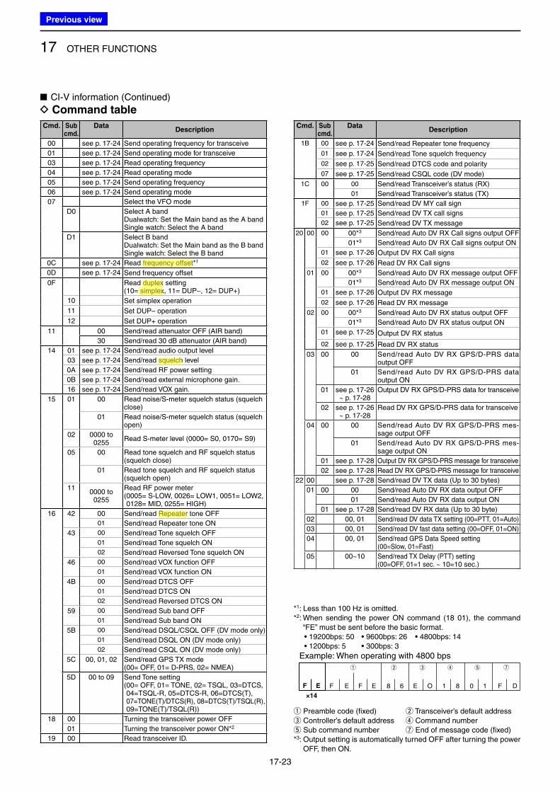
17 OTHER FUNCTIONS
17-23
■ CI-V information (Continued)
D Command table
Cmd. Sub cmd.
DataDescription
00 see p. 17-24 Send operating frequency for transceive
01 see p. 17-24 Send operating mode for transceive
03 see p. 17-24 Read operating frequency
04 see p. 17-24 Read operating mode
05 see p. 17-24 Send operating frequency
06 see p. 17-24 Send operating mode
07 Select the VFO mode
D0 Select A bandDualwatch: Set the Main band as the A bandSingle watch: Select the A band
D1 Select B bandDualwatch: Set the Main band as the B bandSingle watch: Select the B band
0C see p. 17-24 Read frequency offset*1
0D see p. 17-24 Send frequency offset
0F Read duplex setting(10= simplex, 11= DUP–, 12= DUP+)
10 Set simplex operation
11 Set DUP– operation
12 Set DUP+ operation
11 00 Send/read attenuator OFF (AIR band)
30 Send/read 30 dB attenuator (AIR band)
14 01 see p. 17-24 Send/read audio output level
03 see p. 17-24 Send/read squelch level
0A see p. 17-24 Send/read RF power setting
0B see p. 17-24 Send/read external microphone gain.
16 see p. 17-24 Send/read VOX gain.
15 01 00 Read noise/S-meter squelch status (squelch close)
01 Read noise/S-meter squelch status (squelch open)
02 0000 to 0255
Read S-meter level (0000= S0, 0170= S9)
05 00 Read tone squelch and RF squelch status (squelch close)
01 Read tone squelch and RF squelch status (squelch open)
110000 to 0255
Read RF power meter( 0005= S-LOW, 0026= LOW1, 0051= LOW2, 0128= MID, 0255= HIGH)
16 42 00 Send/read Repeater tone OFF
01 Send/read Repeater tone ON
43 00 Send/read Tone squelch OFF
01 Send/read Tone squelch ON
02 Send/read Reversed Tone squelch ON
46 00 Send/read VOX function OFF
01 Send/read VOX function ON
4B 00 Send/read DTCS OFF
01 Send/read DTCS ON
02 Send/read Reversed DTCS ON
59 00 Send/read Sub band OFF
01 Send/read Sub band ON
5B 00 Send/read DSQL/CSQL OFF (DV mode only)
01 Send/read DSQL ON (DV mode only)
02 Send/read CSQL ON (DV mode only)
5C 00, 01, 02 Send/read GPS TX mode(00= OFF, 01= D-PRS, 02= NMEA)
5D 00 to 09 Send Tone setting( 00= OFF, 01= TONE, 02= TSQL, 03=DTCS, 04=TSQL-R, 05=DTCS-R, 06=DTCS(T), 07=TONE(T)/DTCS(R), 08=DTCS(T)/TSQL(R), 09=TONE(T)/TSQL(R))
18 00 Turning the transceiver power OFF
01 Turning the transceiver power ON*2
19 00 Read transceiver ID.
Cmd. Sub cmd.
DataDescription
1B 00 see p. 17-24 Send/read Repeater tone frequency
01 see p. 17-24 Send/read Tone squelch frequency
02 see p. 17-25 Send/read DTCS code and polarity
07 see p. 17-25 Send/read CSQL code (DV mode)
1C 00 00 Send/read Transceiver’s status (RX)
01 Send/read Transceiver’s status (TX)
1F 00 see p. 17-25 Send/read DV MY call sign
01 see p. 17-25 Send/read DV TX call signs
02 see p. 17-25 Send/read DV TX message
20 00 00 00*3 Send/read Auto DV RX Call signs output OFF
01*3 Send/read Auto DV RX Call signs output ON
01 see p. 17-26 Output DV RX Call signs
02 see p. 17-26 Read DV RX Call signs
01 00 00*3 Send/read Auto DV RX message output OFF
01*3 Send/read Auto DV RX message output ON
01 see p. 17-26 Output DV RX message
02 see p. 17-26 Read DV RX message
02 00 00*3 Send/read Auto DV RX status output OFF
01*3 Send/read Auto DV RX status output ON
01 see p. 17-25 Output DV RX status
02 see p. 17-25 Read DV RX status
03 00 00 Send/read Auto DV RX GPS/D-PRS data output OFF
01 Send/read Auto DV RX GPS/D-PRS data output ON
01 see p. 17-26 ~ p. 17-28
Output DV RX GPS/D-PRS data for transceive
02 see p. 17-26 ~ p. 17-28
Read DV RX GPS/D-PRS data for transceive
04 00 00 Send/read Auto DV RX GPS/D-PRS mes-sage output OFF
01 Send/read Auto DV RX GPS/D-PRS mes-sage output ON
01 see p. 17-28 Output DV RX GPS/D-PRS message for transceive
02 see p. 17-28 Read DV RX GPS/D-PRS message for transceive
22 00 see p. 17-28 Send/read DV TX data (Up to 30 bytes)
01 00 00 Send/read Auto DV RX data output OFF
01 Send/read Auto DV RX data output ON
01 see p. 17-28 Send/read DV RX data (Up to 30 byte)
02 00, 01 Send/read DV data TX setting (00=PTT, 01=Auto)
03 00, 01 Send/read DV fast data setting (00=OFF, 01=ON)
04 00, 01 Send/read GPS Data Speed setting(00=Slow, 01=Fast)
05 00~10 Send/read TX Delay (PTT) setting(00=OFF, 01=1 sec. ~ 10=10 sec.)
*1: Less than 100 Hz is omitted.*2: When sending the power ON command (18 01), the command
“FE” must be sent before the basic format. • 19200bps: 50 • 9600bps: 26 • 4800bps: 14 • 1200bps: 5 • 300bps: 3
q w e r t u
FF E
×14
68EFE E 1081O DF
Example: When operating with 4800 bps
q Preamble code (fixed) w Transceiver’s default addresse Controller’s default address r Command numbert Sub command number u End of message code (fixed)*3: Output setting is automatically turned OFF after turning the power
OFF, then ON.
Previous view
Icom
ハイライト表示
The difference between the transmit and receive frequencies.
Icom
ハイライト表示
An operating mode in which the transmit and receive frequencies are the same.
Icom
ハイライト表示
An operating mode in which the transmit and receive frequencies are separated by an offset amount.
Icom
ハイライト表示
A function that mutes the audio output for certain signal levels.
Icom
ハイライト表示
Radio systems that receive incoming signals and retransmit them to extend the communication area. Normally put on geographically high locations for VHF/UHF radios.
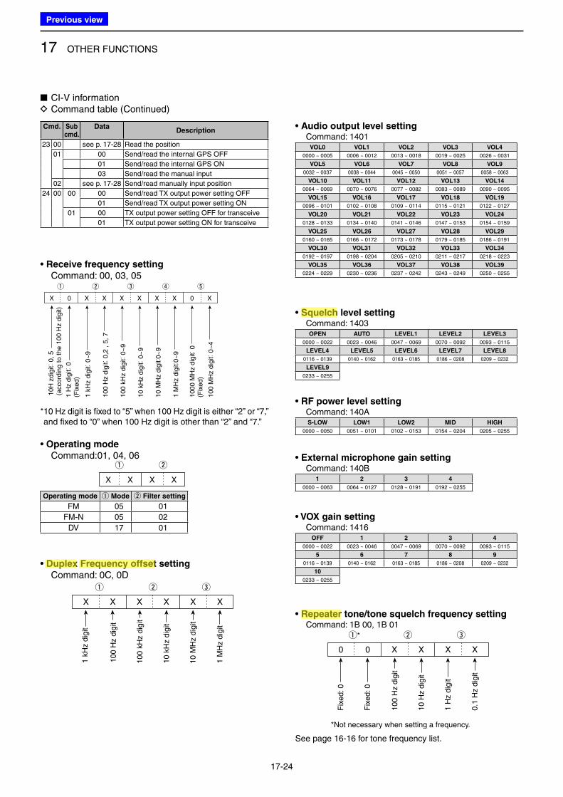
17 OTHER FUNCTIONS
17-24
■ CI-V information D Command table (Continued)
Cmd. Sub cmd.
DataDescription
23 00 see p. 17-28 Read the position
01 00 Send/read the internal GPS OFF
01 Send/read the internal GPS ON
03 Send/read the manual input
02 see p. 17-28 Send/read manually input position
24 00 00 00 Send/read TX output power setting OFF
01 Send/read TX output power setting ON
01 00 TX output power setting OFF for transceive
01 TX output power setting ON for transceive
• Receive frequency setting
Command: 00, 03, 05
* 10 Hz digit is fixed to “5” when 100 Hz digit is either “2” or “7,” and fixed to “0” when 100 Hz digit is other than “2” and “7.”
• Duplex Frequency offset setting
Command: 0C, 0D
• Audio output level setting Command: 1401
• Operating mode
Command:01, 04, 06
Operating mode q Mode w Filter setting
FM 05 01
FM-N 05 02
DV 17 01
q
XX X X
w
VOL0 VOL1 VOL2 VOL3 VOL4
0000 ~ 0005 0006 ~ 0012 0013 ~ 0018 0019 ~ 0025 0026 ~ 0031
VOL5 VOL6 VOL7 VOL8 VOL9
0032 ~ 0037 0038 ~ 0044 0045 ~ 0050 0051 ~ 0057 0058 ~ 0063
VOL10 VOL11 VOL12 VOL13 VOL14
0064 ~ 0069 0070 ~ 0076 0077 ~ 0082 0083 ~ 0089 0090 ~ 0095
VOL15 VOL16 VOL17 VOL18 VOL19
0096 ~ 0101 0102 ~ 0108 0109 ~ 0114 0115 ~ 0121 0122 ~ 0127
VOL20 VOL21 VOL22 VOL23 VOL24
0128 ~ 0133 0134 ~ 0140 0141 ~ 0146 0147 ~ 0153 0154 ~ 0159
VOL25 VOL26 VOL27 VOL28 VOL29
0160 ~ 0165 0166 ~ 0172 0173 ~ 0178 0179 ~ 0185 0186 ~ 0191
VOL30 VOL31 VOL32 VOL33 VOL34
0192 ~ 0197 0198 ~ 0204 0205 ~ 0210 0211 ~ 0217 0218 ~ 0223
VOL35 VOL36 VOL37 VOL38 VOL39
0224 ~ 0229 0230 ~ 0236 0237 ~ 0242 0243 ~ 0249 0250 ~ 0255
q ew
X X X X X X
100 H
z dig
it
100 k
Hz
dig
it
10 k
Hz
dig
it
10 M
Hz
dig
it
1 k
Hz
dig
it
1 M
Hz
dig
it
q
0X X X X
w e
X
r t
XX X0
10H
zdig
it: 0
, 5
(accord
ing t
o t
he 1
00 H
z d
igit)
1 H
z d
igit: 0
(Fix
ed)
1 k
Hz d
igit: 0
~9
100 H
z d
igit: 0
,2 ,
5,
7
100 k
Hz d
igit: 0
~9
10 k
Hz d
igit: 0
~9
10 M
Hz d
igit:
0~
9
1 M
Hz d
igit:
0~
9
1000 M
Hz d
igit: 0
(Fix
ed)
100 M
Hz d
igit: 0
~4
0 0 X X X X
※
固定:0
固定:0
100Hz桁
10Hz桁
1Hz桁
0.1Hz桁
X X X 0
1kHz桁:0~3
100Hz桁:0~9
10Hz桁:0~9
1Hz桁:0
(固定)
• Squelch level setting Command: 1403
• External microphone gain setting Command: 140B
• RF power level setting Command: 140A
OPEN AUTO LEVEL1 LEVEL2 LEVEL3
0000 ~ 0022 0023 ~ 0046 0047 ~ 0069 0070 ~ 0092 0093 ~ 0115
LEVEL4 LEVEL5 LEVEL6 LEVEL7 LEVEL8
0116 ~ 0139 0140 ~ 0162 0163 ~ 0185 0186 ~ 0208 0209 ~ 0232
LEVEL9
0233 ~ 0255
1 2 3 4
0000 ~ 0063 0064 ~ 0127 0128 ~ 0191 0192 ~ 0255
S-LOW LOW1 LOW2 MID HIGH
0000 ~ 0050 0051 ~ 0101 0102 ~ 0153 0154 ~ 0204 0205 ~ 0255
• VOX gain setting Command: 1416
OFF 1 2 3 4
0000 ~ 0022 0023 ~ 0046 0047 ~ 0069 0070 ~ 0092 0093 ~ 0115
5 6 7 8 9
0116 ~ 0139 0140 ~ 0162 0163 ~ 0185 0186 ~ 0208 0209 ~ 0232
10
0233 ~ 0255
• Repeater tone/tone squelch frequency setting Command: 1B 00, 1B 01
q* ew
0 0 X X X X
Fix
ed: 0
Fix
ed: 0
100
Hz d
igit
10 H
z d
igit
1 H
z d
igit
0.1
Hz d
igit
*Not necessary when setting a frequency.
See page 16-16 for tone frequency list.
Previous view
Icom
ハイライト表示
An operating mode in which the transmit and receive frequencies are separated by an offset amount.
Icom
ハイライト表示
The difference between the transmit and receive frequencies.
Icom
ハイライト表示
A function that mutes the audio output for certain signal levels.
Icom
ハイライト表示
Radio systems that receive incoming signals and retransmit them to extend the communication area. Normally put on geographically high locations for VHF/UHF radios.
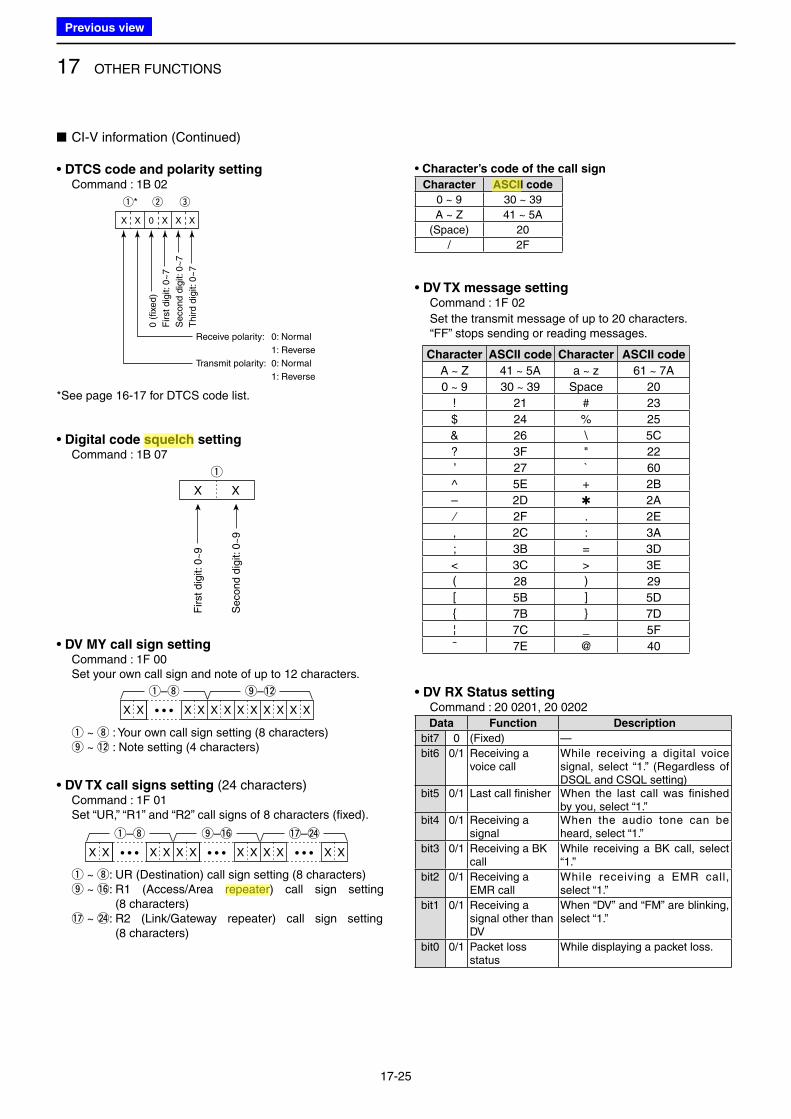
17 OTHER FUNCTIONS
17-25
• DTCS code and polarity setting Command : 1B 02
: : : : : : : :
: :
0 0 X X X X
※
固定:0
固定:0
100Hz桁
10Hz桁
1Hz桁
0.1Hz桁
X X X 0
1kHz桁:0~3
100Hz桁:0~9
10Hz桁:0~9
1Hz桁:0
(固定)
X X 0 X X X
q* w e
0 (
fixe
d)
First d
igit: 0
~7
Se
co
nd
dig
it: 0
~7
Th
ird
dig
it: 0
~7
Receive polarity: 0: Normal
1: Reverse
Transmit polarity: 0: Normal
1: Reverse
*See page 16-17 for DTCS code list.
■ CI-V information (Continued)
• DV TX call signs setting (24 characters) Command : 1F 01 Set “UR,” “R1” and “R2” call signs of 8 characters (fixed).
X X• • •X X X X X X X X X X• • •
!7–@4o–!6q–i
• • •
q ~ i: UR (Destination) call sign setting (8 characters) o ~ !6: R1 (Access/Area repeater) call sign setting
(8 characters) !7 ~ @4: R2 (Link/Gateway repeater) call sign setting
(8 characters)
• Digital code squelch setting Command : 1B 07
X X
q
First dig
it: 0
~9
Second
dig
it: 0
~9
• DV MY call sign setting Command : 1F 00 Set your own call sign and note of up to 12 characters.
X X X X X X X X X X X X
o–!2q–i
• • •
q ~ i : Your own call sign setting (8 characters) o ~ !2 : Note setting (4 characters)
• Character’s code of the call sign
Character ASCII code
0 ~ 9 30 ~ 39
A ~ Z 41 ~ 5A
(Space) 20
/ 2F
• DV TX message setting Command : 1F 02
Set the transmit message of up to 20 characters. “FF” stops sending or reading messages.
Character ASCII code Character ASCII code
A ~ Z 41 ~ 5A a ~ z 61 ~ 7A
0 ~ 9 30 ~ 39 Space 20
! 21 # 23
$ 24 % 25
& 26 \ 5C
? 3F " 22
’ 27 ` 60
^ 5E + 2B
– 2D ✱ 2A
⁄ 2F . 2E
, 2C : 3A
; 3B = 3D
< 3C > 3E
( 28 ) 29
[ 5B ] 5D
{ 7B } 7D
¦ 7C _ 5F
¯ 7E @ 40
• DV RX Status setting Command : 20 0201, 20 0202
Data Function Description
bit7 0 (Fixed) —
bit6 0/1 Receiving a voice call
While receiving a digital voice signal, select “1.” (Regardless of DSQL and CSQL setting)
bit5 0/1 Last call finisher When the last call was finished by you, select “1.”
bit4 0/1 Receiving a signal
When the audio tone can be heard, select “1.”
bit3 0/1 Receiving a BK call
While receiving a BK call, select “1.”
bit2 0/1 Receiving a EMR call
While receiving a EMR call, select “1.”
bit1 0/1 Receiving a signal other than DV
When “DV” and “FM” are blinking, select “1.”
bit0 0/1 Packet loss status
While displaying a packet loss.
Previous view
Icom
ハイライト表示
A function that mutes the audio output for certain signal levels.
Icom
ハイライト表示
Radio systems that receive incoming signals and retransmit them to extend the communication area. Normally put on geographically high locations for VHF/UHF radios.
Icom
ハイライト表示
Acronym for the American Standard Code for Information Interchange. Pronounced ask-ee, ASCII is a code for representing English characters as numbers, with each letter assigned a number from 0 to 127.
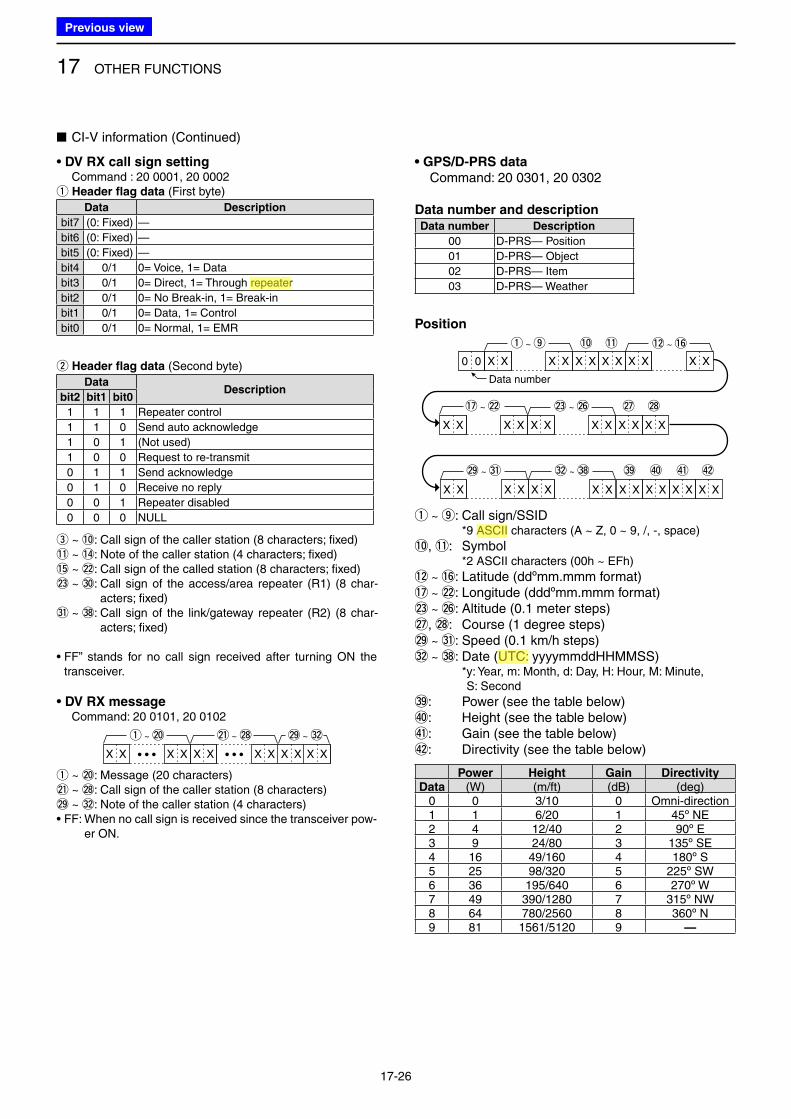
17 OTHER FUNCTIONS
17-26
• DV RX call sign setting Command : 20 0001, 20 0002q Header flag data (First byte)
Data Description
bit7 (0: Fixed) —
bit6 (0: Fixed) —
bit5 (0: Fixed) —
bit4 0/1 0= Voice, 1= Data
bit3 0/1 0= Direct, 1= Through repeater
bit2 0/1 0= No Break-in, 1= Break-in
bit1 0/1 0= Data, 1= Control
bit0 0/1 0= Normal, 1= EMR
w Header flag data (Second byte)
DataDescription
bit2 bit1 bit0
1 1 1 Repeater control
1 1 0 Send auto acknowledge
1 0 1 (Not used)
1 0 0 Request to re-transmit
0 1 1 Send acknowledge
0 1 0 Receive no reply
0 0 1 Repeater disabled
0 0 0 NULL
e ~ !0: Call sign of the caller station (8 characters; fixed)!1 ~ !4: Note of the caller station (4 characters; fixed)!5 ~ @2: Call sign of the called station (8 characters; fixed)@3 ~ #0: Call sign of the access/area repeater (R1) (8 char-
acters; fixed)#1 ~ #8: Call sign of the link/gateway repeater (R2) (8 char-
acters; fixed)
• FF” stands for no call sign received after turning ON the transceiver.
• DV RX message Command: 20 0101, 20 0102
X X X XXX X X
@1 ~ @8 @9 ~ #2
• • •X X• • •X X
q ~ @0
q ~ @0: Message (20 characters)@1 ~ @8: Call sign of the caller station (8 characters)@9 ~ #2: Note of the caller station (4 characters)• FF: When no call sign is received since the transceiver pow-
er ON.
• GPS/D-PRS data
Command: 20 0301, 20 0302
Data number and descriptionData number Description
00 D-PRS— Position
01 D-PRS— Object
02 D-PRS— Item
03 D-PRS— Weather
Position
X X X X X X X X
X X X X
X X X X X X X X
X X X X
X X X X
X X X X
X X X X X X X X
0 0
q ~ o !0 !1
#9 $0 $1 $2
!2 ~ !6
!7 ~ @2 @3 ~ @6 @7 @8
@9 ~ #1 #2 ~ #8
,
Data number
q ~ o: Call sign/SSID *9 ASCII characters (A ~ Z, 0 ~ 9, /, -, space)
!0, !1: Symbol *2 ASCII characters (00h ~ EFh)
!2 ~ !6: Latitude (ddºmm.mmm format)!7 ~ @2: Longitude (dddºmm.mmm format)@3 ~ @6: Altitude (0.1 meter steps)@7, @8: Course (1 degree steps)@9 ~ #1: Speed (0.1 km/h steps)#2 ~ #8: Date (UTC: yyyymmddHHMMSS) * y: Year, m: Month, d: Day, H: Hour, M: Minute,
S: Second
#9: Power (see the table below)$0: Height (see the table below)$1: Gain (see the table below)$2: Directivity (see the table below)
Power Height Gain DirectivityData (W) (m/ft) (dB) (deg)
0 0 3/10 0 Omni-direction1 1 6/20 1 45º NE2 4 12/40 2 90º E3 9 24/80 3 135º SE4 16 49/160 4 180º S5 25 98/320 5 225º SW6 36 195/640 6 270º W7 49 390/1280 7 315º NW8 64 780/2560 8 360º N9 81 1561/5120 9 —
■ CI-V information (Continued)
Previous view
Icom
ハイライト表示
Radio systems that receive incoming signals and retransmit them to extend the communication area. Normally put on geographically high locations for VHF/UHF radios.
Icom
ハイライト表示
Acronym for the American Standard Code for Information Interchange. Pronounced ask-ee, ASCII is a code for representing English characters as numbers, with each letter assigned a number from 0 to 127.
Icom
ハイライト表示
(Universal Time Coordinated) An astronomical time based on the Greenwich meridian (zero degrees longitude).
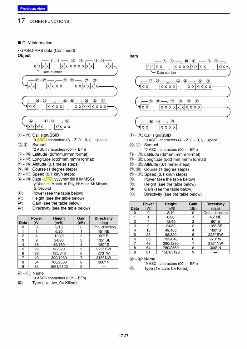
17 OTHER FUNCTIONS
17-27
• GPS/D-PRS data (Continued)Object
,
X X X X X X
X X
X X X X
X X X X X X X X
X X X X
X X X X
X X X X
X X X X X X X X
!0 !1
#9
X X
%2
$0 $1
$2
!2 ~ !6
!7 ~ @2 @3 ~ @6 @7
@9 ~ #1 #2 ~ #8
$3 ~ %1
@8
X X X X0 1
q ~ o
Data number
q ~ o: Call sign/SSID *9 ASCII characters (A ~ Z, 0 ~ 9, /, -, space)
!0, !1: Symbol *2 ASCII characters (00h ~ EFh)
!2 ~ !6: Latitude (ddºmm.mmm format)!7 ~ @2: Longitude (dddºmm.mmm format)@3 ~ @6: Altitude (0.1 meter steps)@7, @8: Course (1 degree steps)@9 ~ #1: Speed (0.1 km/h steps)#2 ~ #8: Date (UTC: yyyymmddHHMMSS) * y: Year, m: Month, d: Day, H: Hour, M: Minute,
S: Second
#9: Power (see the table below)$0: Height (see the table below)$1: Gain (see the table below)$2: Directivity (see the table below)
Power Height Gain DirectivityData (W) (m/ft) (dB) (deg)
0 0 3/10 0 Omni-direction1 1 6/20 1 45º NE2 4 12/40 2 90º E3 9 24/80 3 135º SE4 16 49/160 4 180º S5 25 98/320 5 225º SW6 36 195/640 6 270º W7 49 390/1280 7 315º NW8 64 780/2560 8 360º N9 81 1561/5120 9 —
$3 ~ %1: Name *9 ASCII characters (00h ~ EFh)
%2: Type (1= Live, 0= Killed)
Item
,
X X X X X X X X
X X X X
X X X X X X X X
X X X X
X X X X
X X X X
X X X X
!0 !1
#2
X X
$5
#3 #4 #5
!2 ~ !6
!7 ~ @2 @3 ~ @6 @7
@9 ~ #1
#6 ~ $4
@8
X X X X0 2
q ~ o
Data number
q ~ o: Call sign/SSID *9 ASCII characters (A ~ Z, 0 ~ 9, /, -, space)
!0, !1: Symbol *2 ASCII characters (00h ~ EFh)
!2 ~ !6: Latitude (ddºmm.mmm format)!7 ~ @2: Longitude (dddºmm.mmm format)@3 ~ @6: Altitude (0.1 meter steps)@7, @8: Course (1 degree steps)@9 ~ #1: Speed (0.1 km/h steps)#2: Power (see the table below)#3: Height (see the table below)#4: Gain (see the table below)#5: Directivity (see the table below)
Power Height Gain DirectivityData (W) (m/ft) (dB) (deg)
0 0 3/10 0 Omni-direction1 1 6/20 1 45º NE2 4 12/40 2 90º E3 9 24/80 3 135º SE4 16 49/160 4 180º S5 25 98/320 5 225º SW6 36 195/640 6 270º W7 49 390/1280 7 315º NW8 64 780/2560 8 360º N9 81 1561/5120 9 —
#6 ~ $4: Name *9 ASCII characters (00h ~ EFh)
$5: Type (1= Live, 0= Killed)
■ CI-V information
Previous view
Icom
ハイライト表示
Acronym for the American Standard Code for Information Interchange. Pronounced ask-ee, ASCII is a code for representing English characters as numbers, with each letter assigned a number from 0 to 127.
Icom
ハイライト表示
(Universal Time Coordinated) An astronomical time based on the Greenwich meridian (zero degrees longitude).
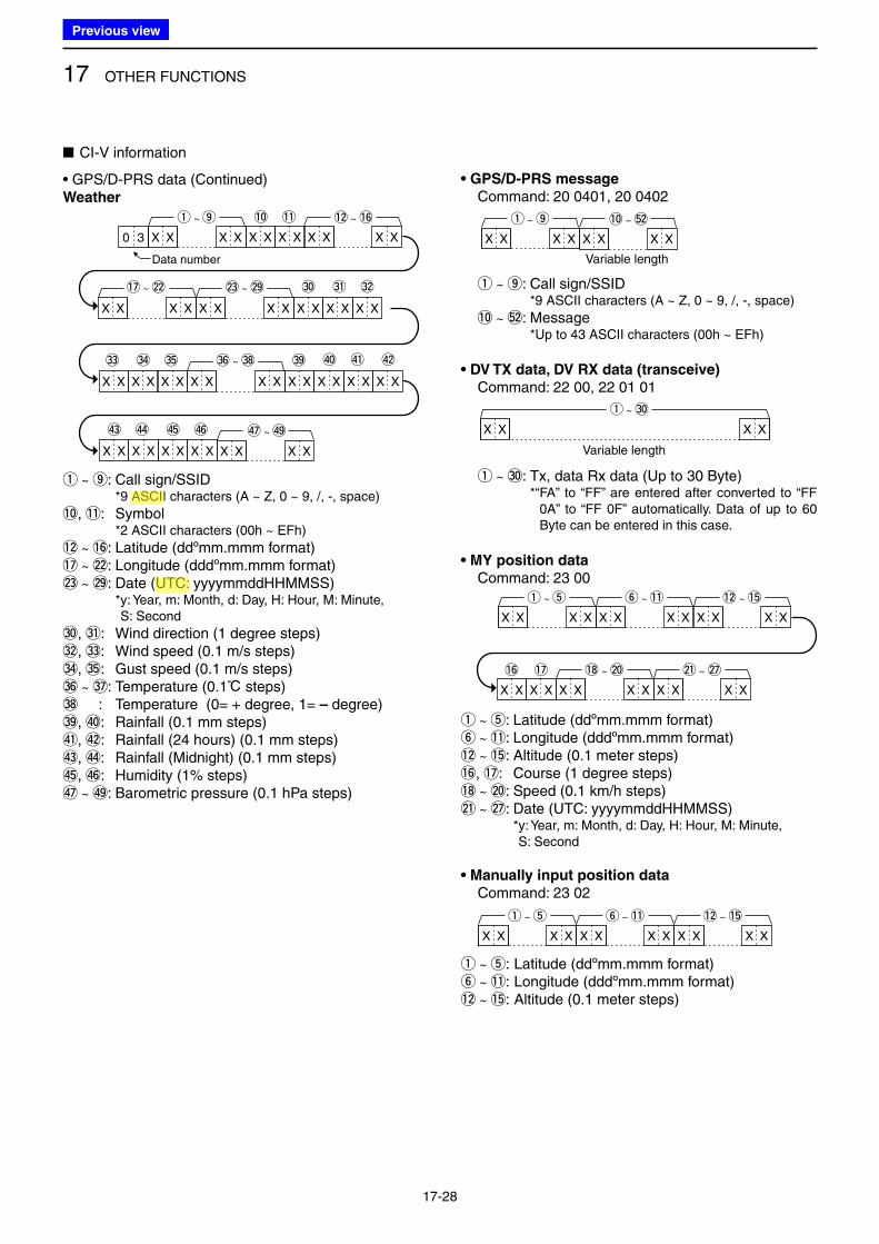
17 OTHER FUNCTIONS
17-28
• GPS/D-PRS data (Continued)Weather
,
X X X X X X
X X
X X X X X X X X
X X X X X X X X
!0 !1
#3
X X X X
#4 #5
#0 #1 #2
X X X X X X X X
#9
X X X X
$3 $4
X X X X
$5
$0 $1 $2
$6
!2 ~ !6
!7 ~ @2 @3 ~ @9
X X X X
#6 ~ #8
X X X X
$7 ~ $9
X X X X0 3
q ~ o
Data number
q ~ o: Call sign/SSID *9 ASCII characters (A ~ Z, 0 ~ 9, /, -, space)
!0, !1: Symbol *2 ASCII characters (00h ~ EFh)
!2 ~ !6: Latitude (ddºmm.mmm format)!7 ~ @2: Longitude (dddºmm.mmm format)@3 ~ @9: Date (UTC: yyyymmddHHMMSS) * y: Year, m: Month, d: Day, H: Hour, M: Minute,
S: Second
#0, #1: Wind direction (1 degree steps)#2, #3: Wind speed (0.1 m/s steps)#4, #5: Gust speed (0.1 m/s steps)#6 ~ #7: Temperature (0.1ç steps)#8 : Temperature (0= + degree, 1= – degree)#9, $0: Rainfall (0.1 mm steps)$1, $2: Rainfall (24 hours) (0.1 mm steps)$3, $4: Rainfall (Midnight) (0.1 mm steps)$5, $6: Humidity (1% steps)$7 ~ $9: Barometric pressure (0.1 hPa steps)
• GPS/D-PRS message
Command: 20 0401, 20 0402
,
Variable length
X X X X
!0 ~ %2
X X X X
q ~ o
q ~ o: Call sign/SSID *9 ASCII characters (A ~ Z, 0 ~ 9, /, -, space)
!0 ~ %2: Message *Up to 43 ASCII characters (00h ~ EFh)
• DV TX data, DV RX data (transceive)
Command: 22 00, 22 01 01
,
Variable length
X X X X
q ~ #0
q ~ #0: Tx, data Rx data (Up to 30 Byte) *“ FA” to “FF” are entered after converted to “FF
0A” to “FF 0F” automatically. Data of up to 60 Byte can be entered in this case.
• MY position data
Command: 23 00
,
X X X X
q ~ t
X X X X
y ~ !1
X X X X
!2 ~ !5
X X X X
!8 ~ @0
X X X X
@1 ~ @7!6
X X
!7
X X
q ~ t: Latitude (ddºmm.mmm format)y ~ !1: Longitude (dddºmm.mmm format)!2 ~ !5: Altitude (0.1 meter steps)!6, !7: Course (1 degree steps)!8 ~ @0: Speed (0.1 km/h steps)@1 ~ @7: Date (UTC: yyyymmddHHMMSS) * y: Year, m: Month, d: Day, H: Hour, M: Minute,
S: Second
• Manually input position data
Command: 23 02
,
X X X X
q ~ t
X X X X
y ~ !1
X X X X
!2 ~ !5
q ~ t: Latitude (ddºmm.mmm format)y ~ !1: Longitude (dddºmm.mmm format)!2 ~ !5: Altitude (0.1 meter steps)
■ CI-V information
Previous view
Icom
ハイライト表示
Acronym for the American Standard Code for Information Interchange. Pronounced ask-ee, ASCII is a code for representing English characters as numbers, with each letter assigned a number from 0 to 127.
Icom
ハイライト表示
(Universal Time Coordinated) An astronomical time based on the Greenwich meridian (zero degrees longitude).
18-1
Section 18 OPTIONS
■ Option list ......................................................................... 18-2
■ Optional HM-75LS REMOTE CONTROL SPEAKER MICROPHONE .. 18-4
D Remote control function setting .................................... 18-4
■ VOX function ..................................................................... 18-5
D Optional unit connection ............................................... 18-5
D Selecting the headset type ........................................... 18-5
D Turning the VOX function ON or OFF ........................... 18-6
D VOX Level setting ......................................................... 18-7
D VOX-related settings ..................................................... 18-8
■ SJ-1 SILICONE JACKET ........................................................ 18-8
■ Using the RS-MS1A ......................................................... 18-9
D Required items ............................................................. 18-9
D Connection ................................................................... 18-9
D Download procedures .................................................. 18-9
Previous view
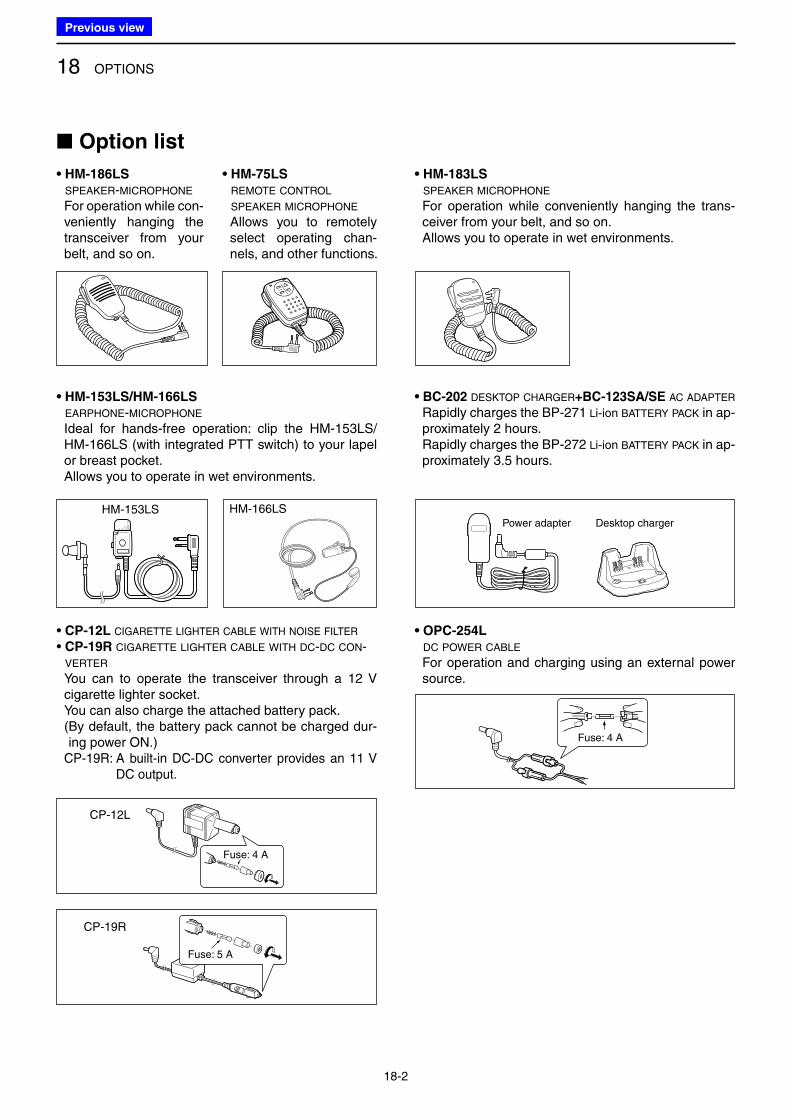
18 OPTIONS
18-2
■ Option list
Desktop chargerPower adapter
Fuse: 4 A
Fuse: 5 A
Fuse: 4 A
• HM-186LS
SPEAKER-MICROPHONE
For operation while con-veniently hanging the transceiver from your belt, and so on.
• HM-75LS
REMOTE CONTROL
SPEAKER MICROPHONE
Allows you to remotely select operating chan-nels, and other functions.
• OPC-254L
DC POWER CABLE
For operation and charging using an external power source.
• HM-153LS/HM-166LS
EARPHONE-MICROPHONE
Ideal for hands-free operation: clip the HM-153LS/HM-166LS (with integrated PTT switch) to your lapel or breast pocket.
Allows you to operate in wet environments.
• BC-202 DESKTOP CHARGER+BC-123SA/SE AC ADAPTER
Rapidly charges the BP-271 Li-ion BATTERY PACK in ap-proximately 2 hours.
Rapidly charges the BP-272 Li-ion BATTERY PACK in ap-proximately 3.5 hours.
• CP-12L CIGARETTE LIGHTER CABLE WITH NOISE FILTER
• CP-19R CIGARETTE LIGHTER CABLE WITH DC-DC CON-
VERTER
You can to operate the transceiver through a 12 V cigarette lighter socket.
You can also charge the attached battery pack. ( By default, the battery pack cannot be charged dur-
ing power ON.) CP-19R: A built-in DC-DC converter provides an 11 V
DC output.
CP-12L
HM-166LSHM-153LS
CP-19R
• HM-183LS
SPEAKER MICROPHONE
For operation while conveniently hanging the trans-ceiver from your belt, and so on.
Allows you to operate in wet environments.
Previous view
18 OPTIONS
18-3
Icom is not responsible for the destruction, damage to, or performance of any Icom or non-Icom equip-ment, if the malfunction is because of:• Force majeure, including, but not limited to, fires,
earthquakes, storms, floods, lightning, other natu-ral disasters, disturbances, riots, war, or radioactive contamination.
• The use of Icom transceivers with any equipment that is not manufactured or approved by Icom.
D BATTERY PACKS/CASE
• BP-271 Li-ion BATTERY PACK
7.4 V 1150 mAh (minimum)/1200 mAh (typical) Battery life: Approximately 4.5 hours* (FM/DV)• BP-272 Li-ion BATTERY PACK
7.4 V 1880 mAh (minimum)/2000 mAh (typical) Battery life: Approximately 8 hours* (FM) Approximately 7 hours* (DV)• BP-273 BATTERY CASE
Battery case for three LR6 (AA) alkaline batteries.
*At High power, TX : RX: Standby = 1:1:8
D CHARGERS
• BC-167SA/SD/SV BATTERY CHARGER
To regular charge the BP-271 or BP-272 Lithium ion battery pack.
Same as the supplied one. (Not supplied with some transceiver versions.)
D SOFTWARE/CABLES
• CS-51PLUS2 CLONING SOFTWARE
Free download software (contained in the CD) Use this software to program settings such as mem-
ory channels and Menu mode contents quickly and easily.
The OPC-2218LU, OPC-2350LU, or microSD card is required.
• RS-MS1A REMOTE CONTROL SOFTWARE
Free download software Allows using the extended D-STAR functions to ex-
change image files or text messages, or display the received D-PRS station data on a map application by an Android™ device.
The OPC-2350LU is required.• RS-MS3W REMOTE CONTROL SOFTWARE
Free download software. Allows using the DV Gateway function. See “About the DV Gateway function” on the Icom
WEB site, http://www.icom.co.jp/world/ for details. The OPC-2350LU is required.• RS-MS3A REMOTE CONTROL SOFTWARE
Free download software. Allows using the DV Gateway function. See “About the DV Gateway function” on the Icom
WEB site, http://www.icom.co.jp/world/ for details. The OPC-2350LU is required.• OPC-2218LU DATA CABLE
Allows DV data communication, or data cloning with CS-51PLUS2 (contained in the CD).
• OPC-2350LU DATA CABLE
Allows DV data communication between the trans-ceiver and an Android™ device, or data cloning with CS-51PLUS2 (contained in the CD).
D OTHER OPTIONS
• HM-75A/HM-153/HM-166/HM-186 MICROPHONES or SP-13 EARPHONE +OPC-2144 PLUG ADAPTER CABLE
HM-75A: Remote control Speaker microphone HM-153: Earphone microphone HM-166: Earphone microphone HM-186: Speaker microphone SP-13: Earphone OPC-2144: Allows you to connect the HM-75A/HM-
153/HM-166/HM-186/SP-13 to the trans-ceiver.
• HS-94/HS-95/HS-97 HEADSET
+OPC-2006LS PLUG ADAPTER CABLE
HS-94: Ear hook type HS-95: Neck & arm type HS-97: Throat microphone OPC-2006LS: Allows you to connect the HS-94/HS-95/
HS-97 to the transceiver. After connect-ing, the VOX function can be used.
• LC-179 CARRYING CASE
Helps protect the transceiver from scratches, and so on.
• SJ-1 SILICONE JACKET
• AD-92SMA ANTENNA CONNECTOR ADAPTER
Allows you to connect an antenna or antenna cable that has a BNC connector.
• CT-17 CI-V LEVEL CONVERTER UNIT
For remote transceiver control using a personal com-puter equipped with an RS-232C port. You can change frequencies, operating mode, memory channels, and so on, using your computer.
• FA-S270C ANTENNA
Same as the supplied one.• MB-127 BELT CLIP
Same as the supplied one.
■ Option list (Continued)
Previous view
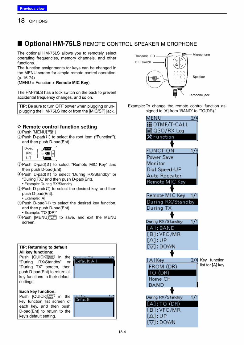
18 OPTIONS
18-4
A
B
Speaker
Earphone jack
PTT switch
OFF ON
LOCK
Transmit LED Microphone
■ Optional HM-75LS REMOTE CONTROL SPEAKER MICROPHONE
The optional HM-75LS allows you to remotely select operating frequencies, memory channels, and other functions.The function assignments for keys can be changed in the MENU screen for simple remote control operation. (p. 16-74)(MENU > Function > Remote MIC Key)
The HM-75LS has a lock switch on the back to prevent accidental frequency changes, and so on.
D Remote control function setting qPush [MENU] . w Push D-pad() to select the root item (“Function”), and then push D-pad(Ent).
D-pad
(�)
(Ent)
e Push D-pad() to select “Remote MIC Key,” and then push D-pad(Ent). r Push D-pad() to select “During RX/Standby” or “During TX,” and then push D-pad(Ent).
• Example: During RX/Standby
t Push D-pad() to select the desired key, and then push D-pad(Ent).
• Example: [A]
y Push D-pad() to select the desired key function, and then push D-pad(Ent).
• Example: “TO (DR)”
u Push [MENU] to save, and exit the MENU screen.
Key function list for [A] key
TIP: Returning to default
All key functions:
Push [QUICK] in the “During RX/Standby” or “During TX” screen, then push D-pad(Ent) to return all key functions to their default settings.
Each key function:
Push [QUICK] in the key function list screen of each key, and then push D-pad(Ent) to return to the key’s default setting.
Example: To change the remote control function as-signed to [A] from “BAND” to “TO(DR).”
TIP: Be sure to turn OFF power when plugging or un-plugging the HM-75LS into or from the [MIC/SP] jack.
Previous view
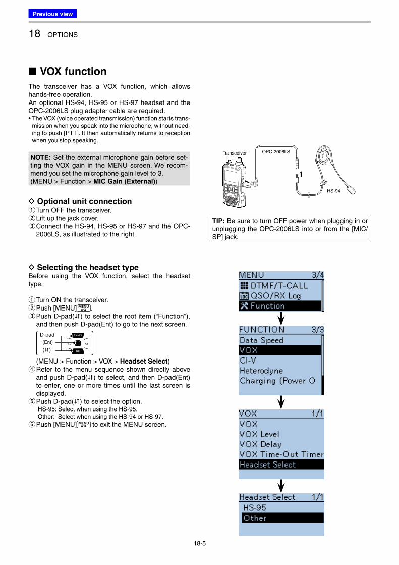
18 OPTIONS
18-5
■ VOX function
The transceiver has a VOX function, which allows hands-free operation.An optional HS-94, HS-95 or HS-97 headset and the OPC-2006LS plug adapter cable are required.• The VOX (voice operated transmission) function starts trans-
mission when you speak into the microphone, without need-ing to push [PTT]. It then automatically returns to reception when you stop speaking.
NOTE: Set the external microphone gain before set-ting the VOX gain in the MENU screen. We recom-mend you set the microphone gain level to 3.(MENU > Function > MIC Gain (External))
D Optional unit connection q Turn OFF the transceiver. w Lift up the jack cover. e Connect the HS-94, HS-95 or HS-97 and the OPC-2006LS, as illustrated to the right.
D Selecting the headset typeBefore using the VOX function, select the headset type.
qTurn ON the transceiver. wPush [MENU] . e Push D-pad() to select the root item (“Function”), and then push D-pad(Ent) to go to the next screen.
D-pad
(�)
(Ent)
(MENU > Function > VOX > Headset Select) r Refer to the menu sequence shown directly above and push D-pad() to select, and then D-pad(Ent) to enter, one or more times until the last screen is displayed. t Push D-pad() to select the option.
HS-95: Select when using the HS-95. Other: Select when using the HS-94 or HS-97.
y Push [MENU] to exit the MENU screen.
OPC-2006LS
HS-94
Transceiver
TIP: Be sure to turn OFF power when plugging in or unplugging the OPC-2006LS into or from the [MIC/SP] jack.
Previous view
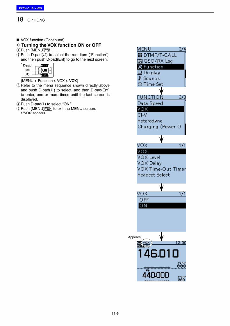
18 OPTIONS
18-6
■ VOX function (Continued)
D Turning the VOX function ON or OFF qPush [MENU] . w Push D-pad() to select the root item (“Function”), and then push D-pad(Ent) to go to the next screen.
D-pad
(�)
(Ent)
(MENU > Function > VOX > VOX) e Refer to the menu sequence shown directly above and push D-pad() to select, and then D-pad(Ent) to enter, one or more times until the last screen is displayed. rPush D-pad() to select “ON.” tPush [MENU] to exit the MENU screen.
• “VOX” appears.
Appears
Previous view
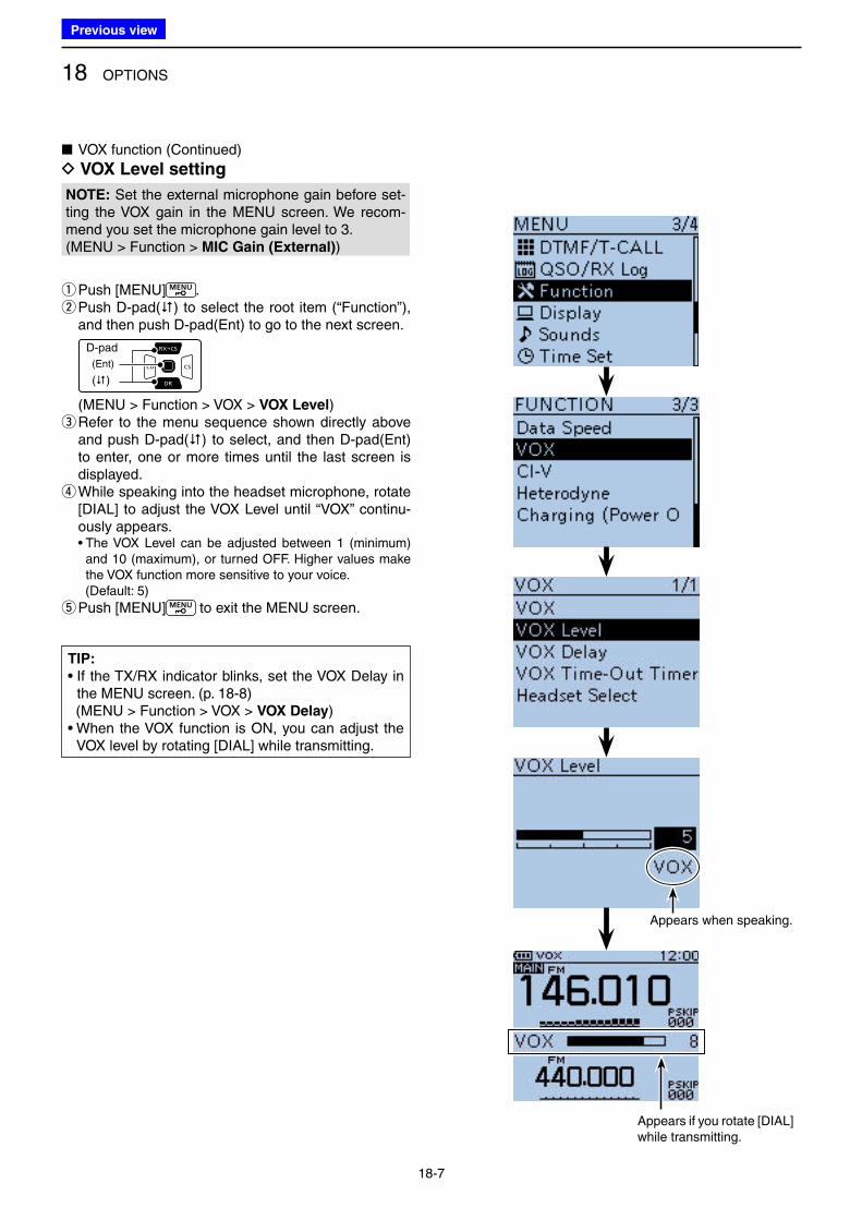
18 OPTIONS
18-7
■ VOX function (Continued)
D VOX Level setting
NOTE: Set the external microphone gain before set-ting the VOX gain in the MENU screen. We recom-mend you set the microphone gain level to 3.(MENU > Function > MIC Gain (External))
qPush [MENU] . w Push D-pad() to select the root item (“Function”), and then push D-pad(Ent) to go to the next screen.
D-pad
(�)
(Ent)
(MENU > Function > VOX > VOX Level) e Refer to the menu sequence shown directly above and push D-pad() to select, and then D-pad(Ent) to enter, one or more times until the last screen is displayed. r While speaking into the headset microphone, rotate [DIAL] to adjust the VOX Level until “VOX” continu-ously appears.
• The VOX Level can be adjusted between 1 (minimum) and 10 (maximum), or turned OFF. Higher values make the VOX function more sensitive to your voice.
(Default: 5)
tPush [MENU] to exit the MENU screen.
Appears if you rotate [DIAL] while transmitting.
Appears when speaking.
TIP:
• If the TX/RX indicator blinks, set the VOX Delay in the MENU screen. (p. 18-8)
(MENU > Function > VOX > VOX Delay)• When the VOX function is ON, you can adjust the
VOX level by rotating [DIAL] while transmitting.
Previous view
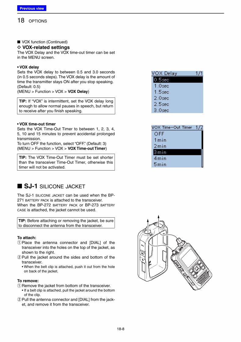
18 OPTIONS
18-8
■ VOX function (Continued)
D VOX-related settingsThe VOX Delay and the VOX time-out timer can be set in the MENU screen.
• VOX delay
Sets the VOX delay to between 0.5 and 3.0 seconds (in 0.5 seconds steps). The VOX delay is the amount of time the transmitter stays ON after you stop speaking.(Default: 0.5)(MENU > Function > VOX > VOX Delay)
■ SJ-1 SILICONE JACKET
The SJ-1 SILICONE JACKET can be used when the BP-271 BATTERY PACK is attached to the transceiver.When the BP-272 BATTERY PACK or BP-273 BATTERY
CASE is attached, the jacket cannot be used.
TIP: Before attaching or removing the jacket, be sure to disconnect the antenna from the transceiver.
To attach:
q Place the antenna connector and [DIAL] of the transceiver into the holes on the top of the jacket, as shown to the right. w Pull the jacket around the sides and bottom of the transceiver.
• When the belt clip is attached, push it out from the hole on back of the jacket.
To remove:
q Remove the jacket from bottom of the transceiver. • If a belt clip is attached, pull the jacket around the bottom
of the clip.
w Pull the antenna connector and [DIAL] from the jack-et, and remove it from the transceiver.
• VOX time-out timer
Sets the VOX Time-Out Timer to between 1, 2, 3, 4, 5, 10 and 15 minutes to prevent accidental prolonged transmission.To turn OFF the function, select “OFF.” (Default: 3)(MENU > Function > VOX > VOX Time-out Timer)
TIP: The VOX Time-Out Timer must be set shorter than the transceiver Time-Out Timer, otherwise this timer will not be activated.
TIP: If “VOX” is intermittent, set the VOX delay long enough to allow normal pauses in speech, but return to receive after you finish speaking.
Previous view
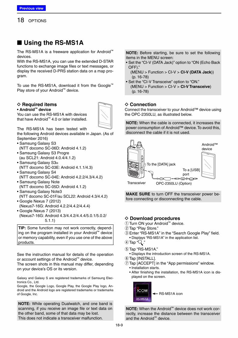
18 OPTIONS
18-9
D Required items• Android™ device
You can use the RS-MS1A with devices that have Android™ 4.0 or later installed.
The RS-MS1A has been tested with the following Android devices available in Japan. (As of September 2016)• Samsung Galaxy S3 (NTT docomo SC-06D: Android 4.1.2)• Samsung Galaxy S3 Progre (au SCL21: Android 4.0.4/4.1.2)• Samsung Galaxy S3α (NTT docomo SC-03E: Android 4.1.1/4.3)• Samsung Galaxy S4 (NTT docomo SC-04E: Android 4.2.2/4.3/4.4.2)• Samsung Galaxy Note (NTT docomo SC-05D: Android 4.1.2)• Samsung Galaxy Note3 (NTT docomo SC-01F/au SCL22: Android 4.3/4.4.2)• Google Nexus 7 (2012) (Nexus7-16G: Android 4.2.2/4.4.2/4.4.4)• Google Nexus 7 (2013) (Nexus7-16G: Android 4.3/4.4.2/4.4.4/5.0.1/5.0.2/
5.1.1)
TIP: Some function may not work correctly, depend-ing on the program installed in your Android™ device or memory capability, even if you use one of the above products.
See the instruction manual for details of the operation or account settings of the Android™ device.The screen shots in this manual may differ, depending on your device’s OS or its version.
Galaxy and Galaxy S are registered trademarks of Samsung Elec-tronics Co., Ltd.Google, the Google Logo, Google Play, the Google Play logo, An-droid and the Android logo are registered trademarks or trademarks of Google, Inc.
D Download procedures qTurn ON your Android™ device. wTap “Play Store.” eEnter “RS-MS1A” in the “Search Google Play” field.
• Displays “RS-MS1A” in the application list.
rTap “ .”
tTap “RS-MS1A.” • Displays the introduction screen of the RS-MS1A.
yTap [INSTALL]. uTap [ACCEPT] in the “App permissions” window.
• Installation starts. • After finishing the installation, the RS-MS1A icon is dis-
played on the screen.
RS-MS1A icon
■ Using the RS-MS1A
The RS-MS1A is a freeware application for Android™ devices.With the RS-MS1A, you can use the extended D-STAR functions to exchange image files or text messages, or display the received D-PRS station data on a map pro-gram.
To use the RS-MS1A, download it from the Google™ Play store of your Android™ device.
D ConnectionConnect the transceiver to your Android™ device using the OPC-2350LU, as illustrated below.
MAKE SURE to turn OFF the transceiver power be-fore connecting or disconnecting the cable.
To the [DATA] jack
OPC-2350LU (Option)
To a [USB]port
Android™device
Transceiver
NOTE: When the Android™ device does not work cor-rectly, increase the distance between the transceiver and the Android™ device.
NOTE: Before starting, be sure to set the following items in the MENU screen:• Set the “CI-V (DATA Jack)” option to “ON (Echo Back
OFF).” ( MENU > Function > CI-V > CI-V (DATA Jack))
(p. 16-78)• Set the “CI-V Transceive” option to “ON.” ( MENU > Function > CI-V > CI-V Transceive)
(p. 16-78)
Android®端末NOTE: When the cable is connected, it increases the power consumption of Android™ device. To avoid this, disconnect the cable if it is not used.
NOTE: While operating Dualwatch, and one band is scanning, if you receive an image file or text data on the other band, some of that data may be lost.This does not indicate a transceiver malfunction.
Previous view
19-1
Section 19 SPECIFICATIONS
■ Transceiver ....................................................................... 19-2
D General ......................................................................... 19-2
D Transmitter .................................................................... 19-2
D Receiver ....................................................................... 19-3
■ BC-202 DESKTOP CHARGER ............................................... 19-3
Previous view
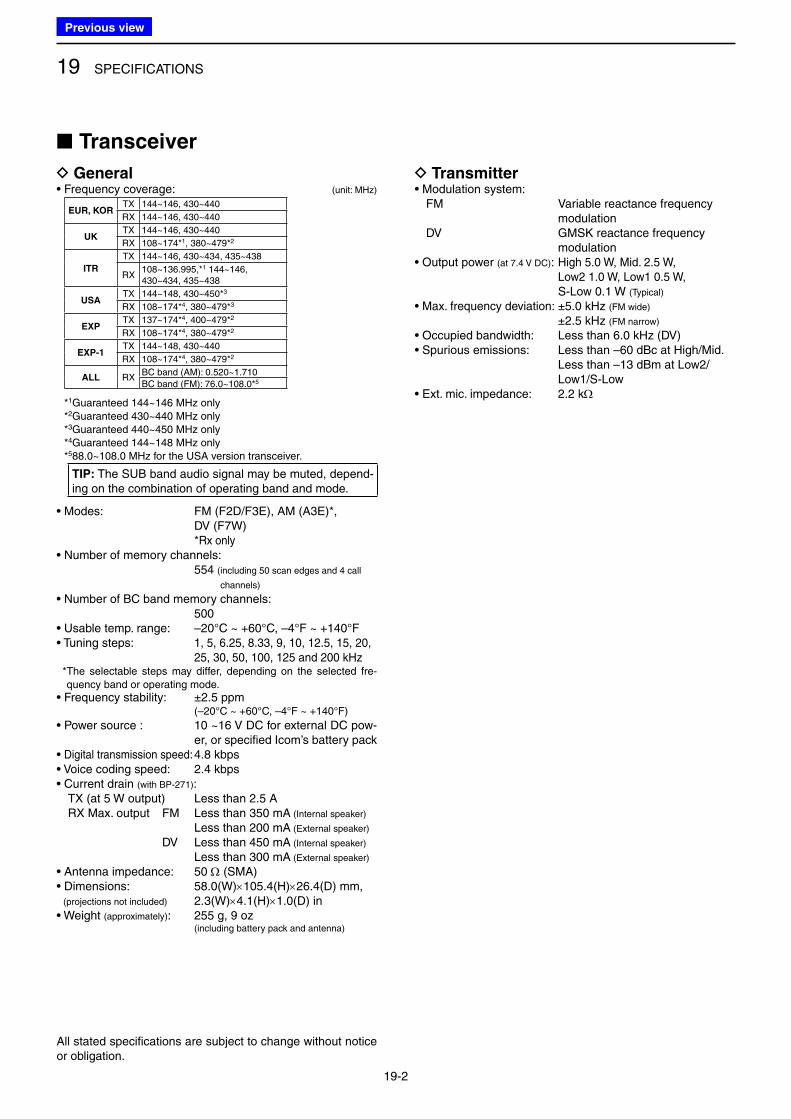
19 SPECIFICATIONS
19-2
■ Transceiver
D General• Frequency coverage: (unit: MHz)
EUR, KORTX 144~146, 430~440
RX 144~146, 430~440
UKTX 144~146, 430~440
RX 108~174*1, 380~479*2
ITR
TX 144~146, 430~434, 435~438
RX108~136.995,*1 144~146,430~434, 435~438
USATX 144~148, 430~450*3
RX 108~174*4, 380~479*3
EXPTX 137~174*4, 400~479*2
RX 108~174*4, 380~479*2
EXP-1TX 144~148, 430~440
RX 108~174*4, 380~479*2
ALL RXBC band (AM): 0.520~1.710
BC band (FM): 76.0~108.0*5
*1Guaranteed 144~146 MHz only*2Guaranteed 430~440 MHz only*3Guaranteed 440~450 MHz only*4Guaranteed 144~148 MHz only*588.0~108.0 MHz for the USA version transceiver.
TIP: The SUB band audio signal may be muted, depend-ing on the combination of operating band and mode.
• Modes: FM (F2D/F3E), AM (A3E)*, DV (F7W) *Rx only
• Number of memory channels: 554 ( including 50 scan edges and 4 call
channels)
• Number of BC band memory channels: 500
• Usable temp. range: –20°C ~ +60°C, –4°F ~ +140°F• Tuning steps: 1, 5, 6.25, 8.33, 9, 10, 12.5, 15, 20,
25, 30, 50, 100, 125 and 200 kHz * The selectable steps may differ, depending on the selected fre-
quency band or operating mode.• Frequency stability: ±2.5 ppm
(–20°C ~ +60°C, –4°F ~ +140°F)
• Power source : 10 ~16 V DC for external DC pow-er, or specified Icom’s battery pack
• Digital transmission speed: 4.8 kbps• Voice coding speed: 2.4 kbps• Current drain (with BP-271): TX (at 5 W output) Less than 2.5 A RX Max. output FM Less than 350 mA (Internal speaker)
Less than 200 mA (External speaker)
DV Less than 450 mA (Internal speaker)
Less than 300 mA (External speaker)
• Antenna impedance: 50 W (SMA)• Dimensions: 58.0(W)×105.4(H)×26.4(D) mm, (projections not included) 2.3(W)×4.1(H)×1.0(D) in• Weight (approximately): 255 g, 9 oz (including battery pack and antenna)
D Transmitter• Modulation system: FM Variable reactance frequency
modulation DV GMSK reactance frequency
modulation• Output power (at 7.4 V DC): High 5.0 W, Mid. 2.5 W,
Low2 1.0 W, Low1 0.5 W, S-Low 0.1 W (Typical)
• Max. frequency deviation: ±5.0 kHz (FM wide) ±2.5 kHz (FM narrow)
• Occupied bandwidth: Less than 6.0 kHz (DV)• Spurious emissions: Less than –60 dBc at High/Mid.
Less than –13 dBm at Low2/Low1/S-Low
• Ext. mic. impedance: 2.2 kW
All stated specifications are subject to change without notice or obligation.
Previous view
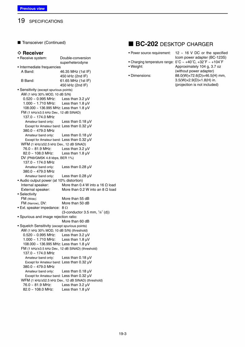
19 SPECIFICATIONS
19-3
■ BC-202 DESKTOP CHARGER
• Power source requirement: 12 ~ 16 V DC or the specified Icom power adapter (BC-123S)
• Charging temperature range: 0˚C ~ +40˚C, +32˚F ~ +104˚F• Weight: Approximately 104 g, 3.7 oz (without power adapter)• Dimensions: 88.0(W)×72.6(D)×46.5(H) mm, 3.5(W)×2.9(D)×1.8(H) in. (projection is not included)
■ Transceiver (Continued)
D Receiver• Receive system: Double-conversion
superheterodyne• Intermediate frequencies A Band: 46.35 MHz (1st IF) 450 kHz (2nd IF) B Band: 61.65 MHz (1st IF) 450 kHz (2nd IF)• Sensitivity (except spurious points)
AM (1 kHz 30% MOD, 10 dB S/N)
0.520 ~ 0.995 MHz: Less than 3.2 µV 1.000 ~ 1.710 MHz: Less than 1.8 µV 108.000 ~ 136.995 MHz: Less than 1.8 µV FM (1 kHz/±3.5 kHz Dev., 12 dB SINAD)
137.0 ~ 174.0 MHz Amateur band only: Less than 0.18 µV Except for Amateur band: Less than 0.32 µV 380.0 ~ 479.0 MHz Amateur band only: Less than 0.18 µV Except for Amateur band: Less than 0.32 µV WFM (1 kHz/±52.5 kHz Dev., 12 dB SINAD)
76.0 ~ 81.9 MHz: Less than 3.2 µV 82.0 ~ 108.0 MHz: Less than 1.8 µV DV (PN9/GMSK 4.8 kbps, BER 1%)
137.0 ~ 174.0 MHz Amateur band only: Less than 0.28 µV 380.0 ~ 479.0 MHz Amateur band only: Less than 0.28 µV• Audio output power (at 10% distortion) Internal speaker: More than 0.4 W into a 16 Ω load External speaker: More than 0.2 W into an 8 Ω load• Selectivity FM (Wide): More than 55 dB FM (Narrow), DV: More than 50 dB• Ext. speaker impedance: 8 W
(3-conductor 3.5 mm, 1⁄8˝ (d))• Spurious and image rejection ratio: More than 60 dB• Squelch Sensitivity (except spurious points)
AM (1 kHz 30% MOD, 10 dB S/N) (threshold)
0.520 ~ 0.995 MHz: Less than 3.2 µV 1.000 ~ 1.710 MHz: Less than 1.8 µV 108.000 ~ 136.995 MHz: Less than 1.8 µV FM (1 kHz/±3.5 kHz Dev., 12 dB SINAD) (threshold)
137.0 ~ 174.0 MHz Amateur band only: Less than 0.18 µV Except for Amateur band: Less than 0.32 µV 380.0 ~ 479.0 MHz Amateur band only: Less than 0.18 µV Except for Amateur band: Less than 0.32 µV WFM (1 kHz/±52.5 kHz Dev., 12 dB SINAD) (threshold)
76.0 ~ 81.9 MHz: Less than 3.2 µV 82.0 ~ 108.0 MHz: Less than 1.8 µV
Previous view
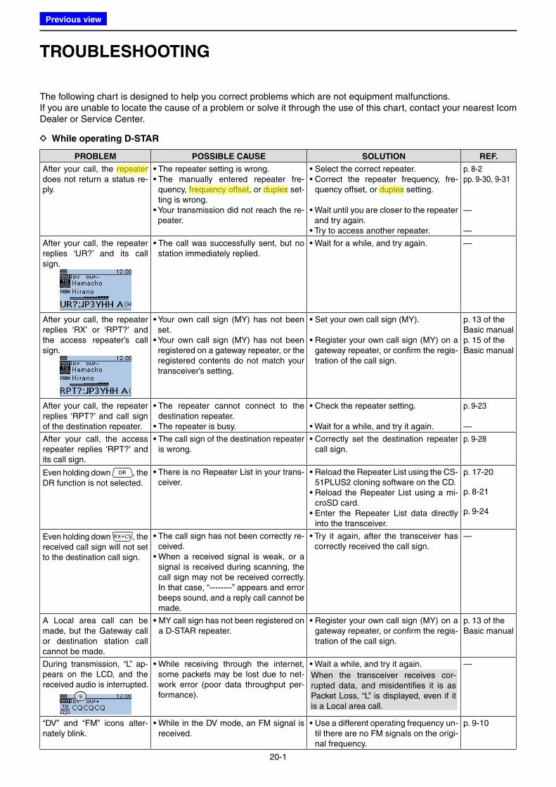
20-1
TROUBLESHOOTING
The following chart is designed to help you correct problems which are not equipment malfunctions.If you are unable to locate the cause of a problem or solve it through the use of this chart, contact your nearest Icom Dealer or Service Center.
D While operating D-STAR
PROBLEM POSSIBLE CAUSE SOLUTION REF.
After your call, the repeater does not return a status re-ply.
• The repeater setting is wrong.• The manually entered repeater fre-
quency, frequency offset, or duplex set-ting is wrong.
• Your transmission did not reach the re-peater.
• Select the correct repeater.• Correct the repeater frequency, fre-
quency offset, or duplex setting.
• Wait until you are closer to the repeater and try again.
• Try to access another repeater.
p. 8-2pp. 9-30, 9-31
—
—
After your call, the repeater replies ‘UR?’ and its call sign.
• The call was successfully sent, but no station immediately replied.
• Wait for a while, and try again. —
After your call, the repeater replies ‘RX’ or ‘RPT?’ and the access repeater’s call sign.
• Your own call sign (MY) has not been set.
• Your own call sign (MY) has not been registered on a gateway repeater, or the registered contents do not match your transceiver’s setting.
• Set your own call sign (MY).
• Register your own call sign (MY) on a gateway repeater, or confirm the regis-tration of the call sign.
p. 13 of the Basic manualp. 15 of the Basic manual
After your call, the repeater replies ‘RPT?’ and call sign of the destination repeater.
• The repeater cannot connect to the destination repeater.
• The repeater is busy.
• Check the repeater setting.
• Wait for a while, and try it again.
p. 9-23
—
After your call, the access repeater replies ‘RPT?’ and its call sign.
• The call sign of the destination repeater is wrong.
• Correctly set the destination repeater call sign.
p. 9-28
Even holding down , the DR function is not selected.
• There is no Repeater List in your trans-ceiver.
• Reload the Repeater List using the CS-51PLUS2 cloning software on the CD.
• Reload the Repeater List using a mi-croSD card.
• Enter the Repeater List data directly into the transceiver.
p. 17-20
p. 8-21
p. 9-24
Even holding down , the received call sign will not set to the destination call sign.
• The call sign has not been correctly re-ceived.
• When a received signal is weak, or a signal is received during scanning, the call sign may not be received correctly. In that case, “--------” appears and error beeps sound, and a reply call cannot be made.
• Try it again, after the transceiver has correctly received the call sign.
—
A Local area call can be made, but the Gateway call or destination station call cannot be made.
• MY call sign has not been registered on a D-STAR repeater.
• Register your own call sign (MY) on a gateway repeater, or confirm the regis-tration of the call sign.
p. 13 of the Basic manual
During transmission, “L” ap-pears on the LCD, and the received audio is interrupted.
• While receiving through the internet, some packets may be lost due to net-work error (poor data throughput per-formance).
• Wait a while, and try it again.
When the transceiver receives cor-rupted data, and misidentifies it is as Packet Loss, “L” is displayed, even if it is a Local area call.
—
“DV” and “FM” icons alter-nately blink.
• While in the DV mode, an FM signal is received.
• Use a different operating frequency un-til there are no FM signals on the origi-nal frequency.
p. 9-10
Previous view
Icom
ハイライト表示
The difference between the transmit and receive frequencies.
Icom
ハイライト表示
Radio systems that receive incoming signals and retransmit them to extend the communication area. Normally put on geographically high locations for VHF/UHF radios.
Icom
ハイライト表示
An operating mode in which the transmit and receive frequencies are separated by an offset amount.
Icom
ハイライト表示
An operating mode in which the transmit and receive frequencies are separated by an offset amount.
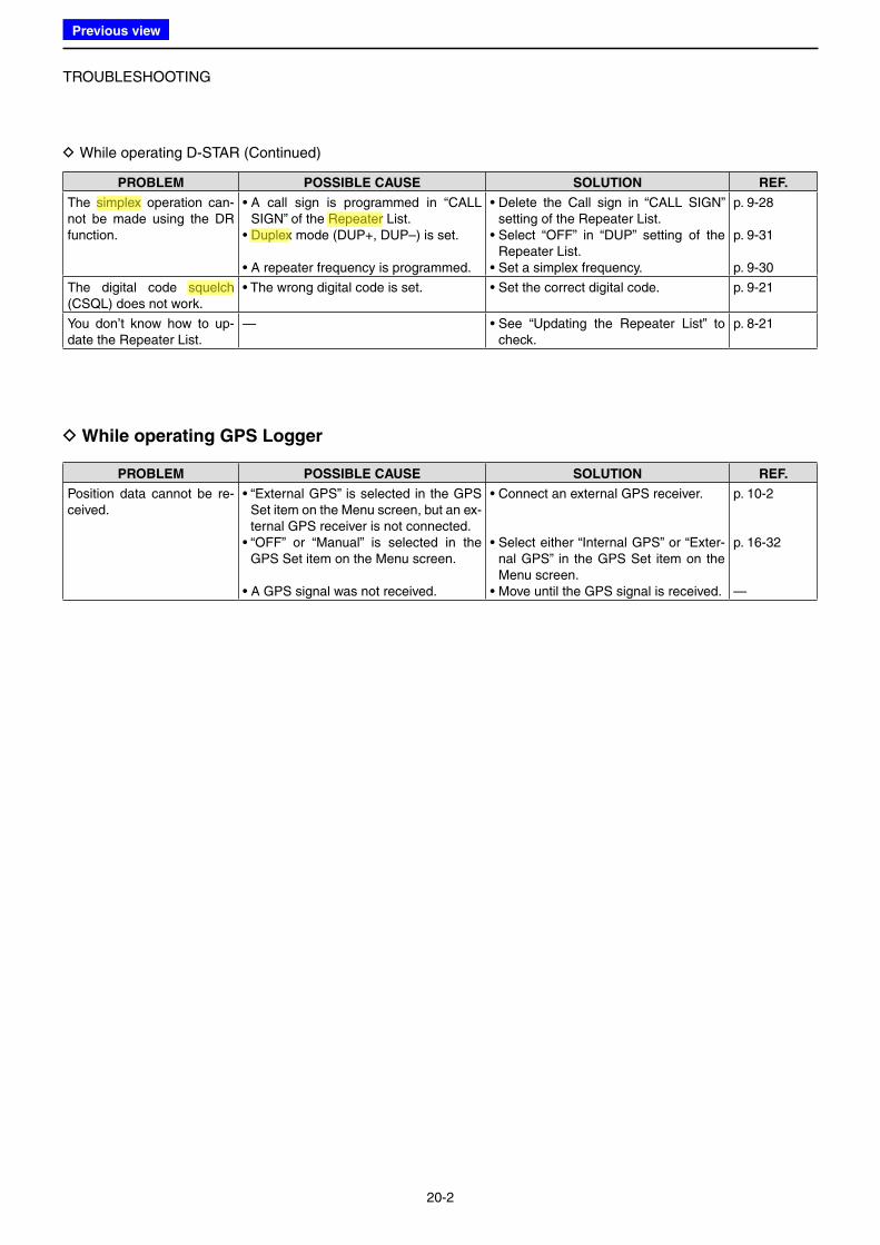
TROUBLESHOOTING
20-2
D While operating GPS Logger
PROBLEM POSSIBLE CAUSE SOLUTION REF.
Position data cannot be re-ceived.
• “External GPS” is selected in the GPS Set item on the Menu screen, but an ex-ternal GPS receiver is not connected.
• “OFF” or “Manual” is selected in the GPS Set item on the Menu screen.
• A GPS signal was not received.
• Connect an external GPS receiver.
• Select either “Internal GPS” or “Exter-nal GPS” in the GPS Set item on the Menu screen.
• Move until the GPS signal is received.
p. 10-2
p. 16-32
—
D While operating D-STAR (Continued)
PROBLEM POSSIBLE CAUSE SOLUTION REF.
The simplex operation can-not be made using the DR function.
• A call sign is programmed in “CALL SIGN” of the Repeater List.
• Duplex mode (DUP+, DUP–) is set.
• A repeater frequency is programmed.
• Delete the Call sign in “CALL SIGN” setting of the Repeater List.
• Select “OFF” in “DUP” setting of the Repeater List.
• Set a simplex frequency.
p. 9-28
p. 9-31
p. 9-30
The digital code squelch (CSQL) does not work.
• The wrong digital code is set. • Set the correct digital code. p. 9-21
You don’t know how to up-date the Repeater List.
— • See “Updating the Repeater List” to check.
p. 8-21
Previous view
Icom
ハイライト表示
An operating mode in which the transmit and receive frequencies are the same.
Icom
ハイライト表示
Radio systems that receive incoming signals and retransmit them to extend the communication area. Normally put on geographically high locations for VHF/UHF radios.
Icom
ハイライト表示
An operating mode in which the transmit and receive frequencies are separated by an offset amount.
Icom
ハイライト表示
A function that mutes the audio output for certain signal levels.
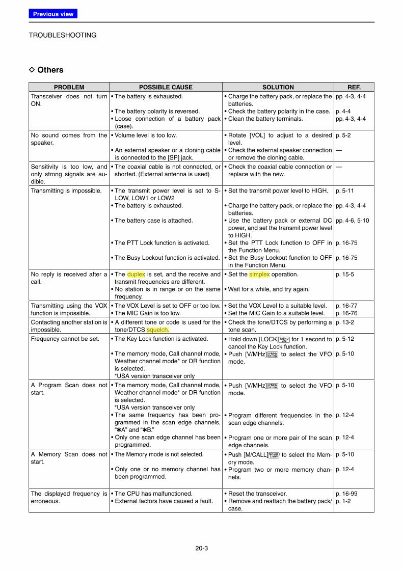
TROUBLESHOOTING
20-3
D Others
PROBLEM POSSIBLE CAUSE SOLUTION REF.
Transceiver does not turn ON.
• The battery is exhausted.
• The battery polarity is reversed.• Loose connection of a battery pack
(case).
• Charge the battery pack, or replace the batteries.
• Check the battery polarity in the case.• Clean the battery terminals.
pp. 4-3, 4-4
p. 4-4pp. 4-3, 4-4
No sound comes from the speaker.
• Volume level is too low.
• An external speaker or a cloning cable is connected to the [SP] jack.
• Rotate [VOL] to adjust to a desired level.
• Check the external speaker connection or remove the cloning cable.
p. 5-2
—
Sensitivity is too low, and only strong signals are au-dible.
• The coaxial cable is not connected, or shorted. (External antenna is used)
• Check the coaxial cable connection or replace with the new.
—
Transmitting is impossible. • The transmit power level is set to S-LOW, LOW1 or LOW2
• The battery is exhausted.
• The battery case is attached.
• The PTT Lock function is activated.
• The Busy Lockout function is activated.
• Set the transmit power level to HIGH.
• Charge the battery pack, or replace the batteries.
• Use the battery pack or external DC power, and set the transmit power level to HIGH.
• Set the PTT Lock function to OFF in the Function Menu.
• Set the Busy Lockout function to OFF in the Function Menu.
p. 5-11
pp. 4-3, 4-4
pp. 4-6, 5-10
p. 16-75
p. 16-75
No reply is received after a call.
• The duplex is set, and the receive and transmit frequencies are different.
• No station is in range or on the same frequency.
• Set the simplex operation.
• Wait for a while, and try again.
p. 15-5
Transmitting using the VOX function is impossible.
• The VOX Level is set to OFF or too low.• The MIC Gain is too low.
• Set the VOX Level to a suitable level.• Set the MIC Gain to a suitable level.
p. 16-77p. 16-76
Contacting another station is impossible.
• A different tone or code is used for the tone/DTCS squelch.
• Check the tone/DTCS by performing a tone scan.
p. 13-2
Frequency cannot be set. • The Key Lock function is activated.
• The memory mode, Call channel mode, Weather channel mode* or DR function is selected.
*USA version transceiver only
• Hold down [LOCK] for 1 second to cancel the Key Lock function.
• Push [V/MHz] to select the VFO mode.
p. 5-12
p. 5-10
A Program Scan does not start.
• The memory mode, Call channel mode, Weather channel mode* or DR function is selected.
*USA version transceiver only• The same frequency has been pro-
grammed in the scan edge channels, “✱A” and “✱B.”
• Only one scan edge channel has been programmed.
• Push [V/MHz] to select the VFO mode.
• Program different frequencies in the scan edge channels.
• Program one or more pair of the scan edge channels.
p. 5-10
p. 12-4
p. 12-4
A Memory Scan does not start.
• The Memory mode is not selected.
• Only one or no memory channel has been programmed.
• Push [M/CALL] to select the Mem-ory mode.
• Program two or more memory chan-nels.
p. 5-10
p. 12-4
The displayed frequency is erroneous.
• The CPU has malfunctioned.• External factors have caused a fault.
• Reset the transceiver.• Remove and reattach the battery pack/
case.
p. 16-99p. 1-2
Previous view
Icom
ハイライト表示
An operating mode in which the transmit and receive frequencies are the same.
Icom
ハイライト表示
An operating mode in which the transmit and receive frequencies are separated by an offset amount.
Icom
ハイライト表示
A function that mutes the audio output for certain signal levels.
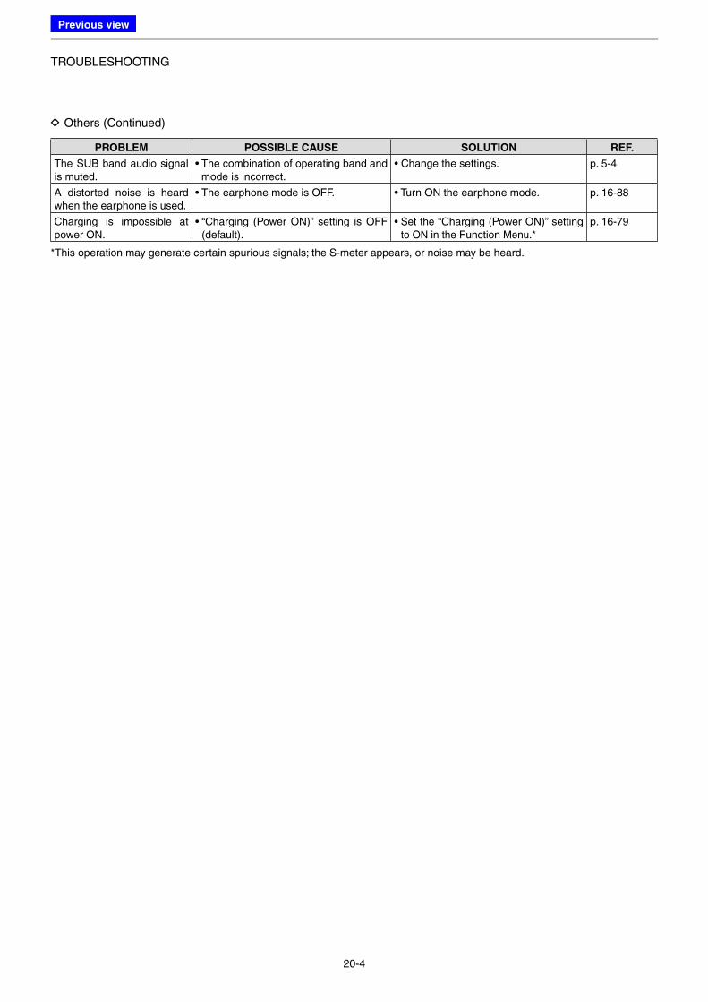
TROUBLESHOOTING
20-4
D Others (Continued)
PROBLEM POSSIBLE CAUSE SOLUTION REF.
The SUB band audio signal is muted.
• The combination of operating band and mode is incorrect.
• Change the settings. p. 5-4
A distorted noise is heard when the earphone is used.
• The earphone mode is OFF. • Turn ON the earphone mode. p. 16-88
Charging is impossible at power ON.
• “Charging (Power ON)” setting is OFF (default).
• Set the “Charging (Power ON)” setting to ON in the Function Menu.*
p. 16-79
*This operation may generate certain spurious signals; the S-meter appears, or noise may be heard.
Previous view
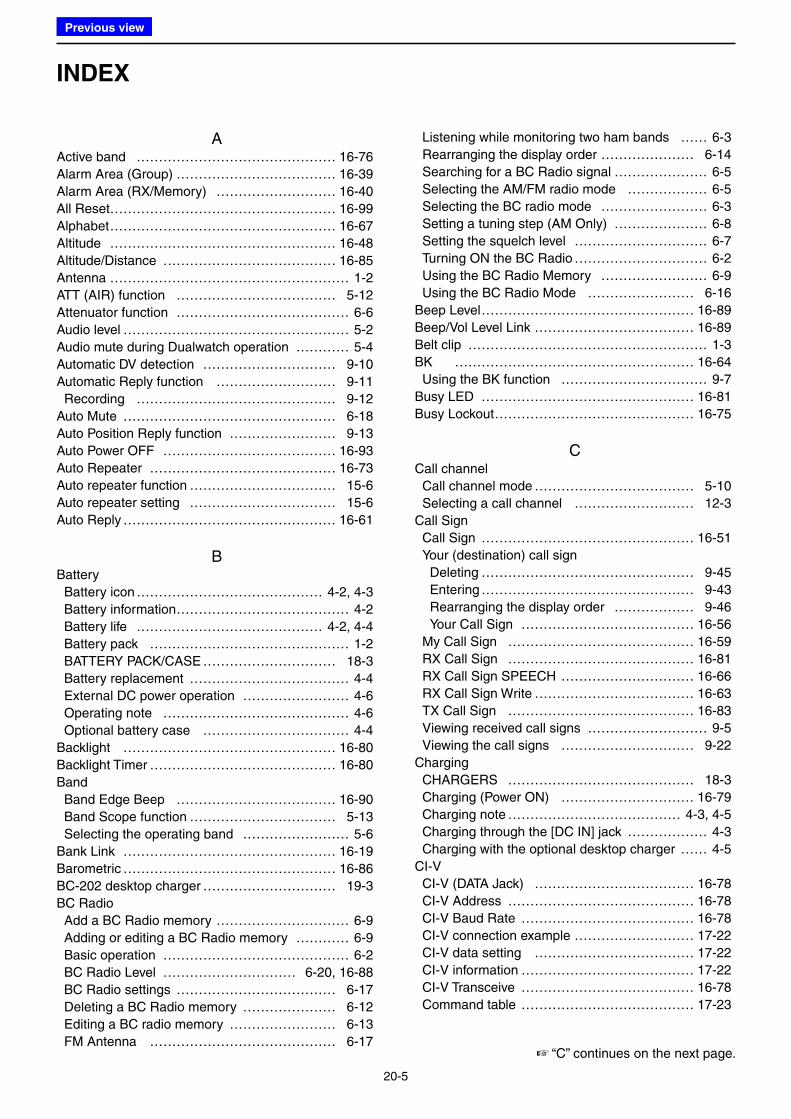
20-5
INDEX
AActive band ……………………………………… 16-76
Alarm Area (Group) ……………………………… 16-39
Alarm Area (RX/Memory) ……………………… 16-40
All Reset…………………………………………… 16-99
Alphabet …………………………………………… 16-67
Altitude …………………………………………… 16-48
Altitude/Distance ………………………………… 16-85
Antenna ……………………………………………… 1-2
ATT (AIR) function ……………………………… 5-12
Attenuator function ………………………………… 6-6
Audio level …………………………………………… 5-2
Audio mute during Dualwatch operation ………… 5-4
Automatic DV detection ………………………… 9-10
Automatic Reply function ……………………… 9-11
Recording ……………………………………… 9-12
Auto Mute ………………………………………… 6-18
Auto Position Reply function …………………… 9-13
Auto Power OFF ………………………………… 16-93
Auto Repeater …………………………………… 16-73
Auto repeater function …………………………… 15-6
Auto repeater setting …………………………… 15-6
Auto Reply ………………………………………… 16-61
BBattery
Battery icon …………………………………… 4-2, 4-3
Battery information ………………………………… 4-2
Battery life …………………………………… 4-2, 4-4
Battery pack ……………………………………… 1-2
BATTERY PACK/CASE ………………………… 18-3
Battery replacement ……………………………… 4-4
External DC power operation …………………… 4-6
Operating note …………………………………… 4-6
Optional battery case …………………………… 4-4
Backlight ………………………………………… 16-80
Backlight Timer …………………………………… 16-80
Band
Band Edge Beep ……………………………… 16-90
Band Scope function …………………………… 5-13
Selecting the operating band …………………… 5-6
Bank Link ………………………………………… 16-19
Barometric ………………………………………… 16-86
BC-202 desktop charger ………………………… 19-3
BC Radio
Add a BC Radio memory ………………………… 6-9
Adding or editing a BC Radio memory ………… 6-9
Basic operation …………………………………… 6-2
BC Radio Level ………………………… 6-20, 16-88
BC Radio settings ……………………………… 6-17
Deleting a BC Radio memory ………………… 6-12
Editing a BC radio memory …………………… 6-13
FM Antenna …………………………………… 6-17
Listening while monitoring two ham bands …… 6-3
Rearranging the display order ………………… 6-14
Searching for a BC Radio signal ………………… 6-5
Selecting the AM/FM radio mode ……………… 6-5
Selecting the BC radio mode …………………… 6-3
Setting a tuning step (AM Only) ………………… 6-8
Setting the squelch level ………………………… 6-7
Turning ON the BC Radio ………………………… 6-2
Using the BC Radio Memory …………………… 6-9
Using the BC Radio Mode …………………… 6-16
Beep Level ………………………………………… 16-89
Beep/Vol Level Link ……………………………… 16-89
Belt clip ……………………………………………… 1-3
BK ……………………………………………… 16-64
Using the BK function …………………………… 9-7
Busy LED ………………………………………… 16-81
Busy Lockout ……………………………………… 16-75
CCall channel
Call channel mode ……………………………… 5-10
Selecting a call channel ……………………… 12-3
Call Sign
Call Sign ………………………………………… 16-51
Your (destination) call sign
Deleting ………………………………………… 9-45
Entering ………………………………………… 9-43
Rearranging the display order ……………… 9-46
Your Call Sign ………………………………… 16-56
My Call Sign …………………………………… 16-59
RX Call Sign …………………………………… 16-81
RX Call Sign SPEECH ………………………… 16-66
RX Call Sign Write ……………………………… 16-63
TX Call Sign …………………………………… 16-83
Viewing received call signs ……………………… 9-5
Viewing the call signs ………………………… 9-22
Charging
CHARGERS …………………………………… 18-3
Charging (Power ON) ………………………… 16-79
Charging note ………………………………… 4-3, 4-5
Charging through the [DC IN] jack ……………… 4-3
Charging with the optional desktop charger …… 4-5
CI-V
CI-V (DATA Jack) ……………………………… 16-78
CI-V Address …………………………………… 16-78
CI-V Baud Rate ………………………………… 16-78
CI-V connection example ……………………… 17-22
CI-V data setting ……………………………… 17-22
CI-V information ………………………………… 17-22
CI-V Transceive ………………………………… 16-78
Command table ………………………………… 17-23
☞ “C” continues on the next page.
Previous view
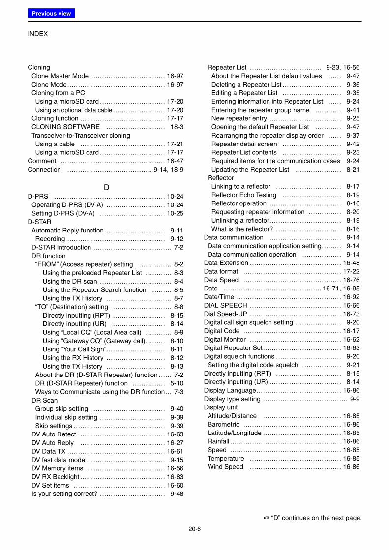
INDEX
20-6
Cloning
Clone Master Mode …………………………… 16-97
Clone Mode ……………………………………… 16-97
Cloning from a PC
Using a microSD card ………………………… 17-20
Using an optional data cable …………………… 17-20
Cloning function ………………………………… 17-17
CLONING SOFTWARE ……………………… 18-3
Transceiver-to-Transceiver cloning
Using a cable ………………………………… 17-21
Using a microSD card ………………………… 17-17
Comment ………………………………………… 16-47
Connection ………………………………… 9-14, 18-9
DD-PRS …………………………………………… 10-24
Operating D-PRS (DV-A) ……………………… 10-24
Setting D-PRS (DV-A) ………………………… 10-25
D-STAR
Automatic Reply function ……………………… 9-11
Recording ……………………………………… 9-12
D-STAR Introduction ……………………………… 7-2
DR function
“FROM” (Access repeater) setting …………… 8-2
Using the preloaded Repeater List ………… 8-3
Using the DR scan …………………………… 8-4
Using the Repeater Search function ……… 8-5
Using the TX History ………………………… 8-7
“TO” (Destination) setting ……………………… 8-8
Directly inputting (RPT) …………………… 8-15
Directly inputting (UR) …………………… 8-14
Using “Local CQ” (Local Area call) ………… 8-9
Using “Gateway CQ” (Gateway call) ……… 8-10
Using “Your Call Sign” ……………………… 8-11
Using the RX History ……………………… 8-12
Using the TX History ……………………… 8-13
About the DR (D-STAR Repeater) function …… 7-2
DR (D-STAR Repeater) function …………… 5-10
Ways to Communicate using the DR function … 7-3
DR Scan
Group skip setting …………………………… 9-40
Individual skip setting ………………………… 9-39
Skip settings …………………………………… 9-39
DV Auto Detect ………………………………… 16-63
DV Auto Reply ………………………………… 16-27
DV Data TX ……………………………………… 16-61
DV fast data mode ……………………………… 9-15
DV Memory items ……………………………… 16-56
DV RX Backlight ………………………………… 16-83
DV Set items …………………………………… 16-60
Is your setting correct? ………………………… 9-48
Repeater List …………………………… 9-23, 16-56
About the Repeater List default values …… 9-47
Deleting a Repeater List ……………………… 9-36
Editing a Repeater List ……………………… 9-35
Entering information into Repeater List …… 9-24
Entering the repeater group name ………… 9-41
New repeater entry …………………………… 9-25
Opening the default Repeater List ………… 9-47
Rearranging the repeater display order …… 9-37
Repeater detail screen ……………………… 9-42
Repeater List contents ……………………… 9-23
Required items for the communication cases 9-24
Updating the Repeater List ………………… 8-21
Reflector
Linking to a reflector ………………………… 8-17
Reflector Echo Testing ……………………… 8-19
Reflector operation …………………………… 8-16
Requesting repeater information …………… 8-20
Unlinking a reflector …………………………… 8-19
What is the reflector? ………………………… 8-16
Data communication …………………………… 9-14
Data communication application setting ……… 9-14
Data communication operation ……………… 9-14
Data Extension …………………………………… 16-48
Data format ……………………………………… 17-22
Data Speed ……………………………………… 16-76
Date ……………………………………… 16-71, 16-95
Date/Time ………………………………………… 16-92
DIAL SPEECH …………………………………… 16-66
Dial Speed-UP …………………………………… 16-73
Digital call sign squelch setting ………………… 9-20
Digital Code ……………………………………… 16-17
Digital Monitor …………………………………… 16-62
Digital Repeater Set ……………………………… 16-63
Digital squelch functions ………………………… 9-20
Setting the digital code squelch ……………… 9-21
Directly inputting (RPT) ………………………… 8-15
Directly inputting (UR) …………………………… 8-14
Display Language ………………………………… 16-86
Display type setting ………………………………… 9-9
Display unit
Altitude/Distance ……………………………… 16-85
Barometric ……………………………………… 16-86
Latitude/Longitude ……………………………… 16-85
Rainfall …………………………………………… 16-86
Speed …………………………………………… 16-85
Temperature …………………………………… 16-85
Wind Speed …………………………………… 16-86
☞ “D” continues on the next page.
Previous view
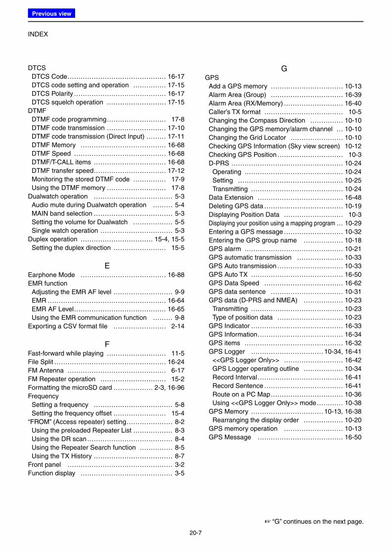
INDEX
20-7
DTCS
DTCS Code ……………………………………… 16-17
DTCS code setting and operation …………… 17-15
DTCS Polarity …………………………………… 16-17
DTCS squelch operation ……………………… 17-15
DTMF
DTMF code programming ……………………… 17-8
DTMF code transmission ……………………… 17-10
DTMF code transmission (Direct Input) ……… 17-11
DTMF Memory ………………………………… 16-68
DTMF Speed …………………………………… 16-68
DTMF/T-CALL items …………………………… 16-68
DTMF transfer speed …………………………… 17-12
Monitoring the stored DTMF code …………… 17-9
Using the DTMF memory ……………………… 17-8
Dualwatch operation ……………………………… 5-3
Audio mute during Dualwatch operation ……… 5-4
MAIN band selection ……………………………… 5-3
Setting the volume for Dualwatch ……………… 5-5
Single watch operation …………………………… 5-3
Duplex operation …………………………… 15-4, 15-5
Setting the duplex direction …………………… 15-5
EEarphone Mode ………………………………… 16-88
EMR function
Adjusting the EMR AF level ……………………… 9-9
EMR ……………………………………………… 16-64
EMR AF Level …………………………………… 16-65
Using the EMR communication function ……… 9-8
Exporting a CSV format file …………………… 2-14
FFast-forward while playing ……………………… 11-5
File Split …………………………………………… 16-24
FM Antenna ……………………………………… 6-17
FM Repeater operation ………………………… 15-2
Formatting the microSD card ……………… 2-3, 16-96
Frequency
Setting a frequency ……………………………… 5-8
Setting the frequency offset …………………… 15-4
“FROM” (Access repeater) setting ………………… 8-2
Using the preloaded Repeater List ……………… 8-3
Using the DR scan ………………………………… 8-4
Using the Repeater Search function …………… 8-5
Using the TX History ……………………………… 8-7
Front panel ………………………………………… 3-2
Function display …………………………………… 3-5
GGPS
Add a GPS memory …………………………… 10-13
Alarm Area (Group) …………………………… 16-39
Alarm Area (RX/Memory) ……………………… 16-40
Caller’s TX format ……………………………… 10-5
Changing the Compass Direction …………… 10-10
Changing the GPS memory/alarm channel … 10-10
Changing the Grid Locator …………………… 10-10
Checking GPS Information (Sky view screen) 10-12
Checking GPS Position ………………………… 10-3
D-PRS …………………………………………… 10-24
Operating ……………………………………… 10-24
Setting ………………………………………… 10-25
Transmitting …………………………………… 10-24
Data Extension ………………………………… 16-48
Deleting GPS data ……………………………… 10-19
Displaying Position Data ……………………… 10-3
Displaying your position using a mapping program … 10-29
Entering a GPS message ……………………… 10-32
Entering the GPS group name ……………… 10-18
GPS alarm ……………………………………… 10-21
GPS automatic transmission ………………… 10-33
GPS Auto transmission ………………………… 10-33
GPS Auto TX …………………………………… 16-50
GPS Data Speed ……………………………… 16-62
GPS data sentence …………………………… 10-31
GPS data (D-PRS and NMEA) ……………… 10-23
Transmitting …………………………………… 10-23
Type of position data ………………………… 10-23
GPS Indicator …………………………………… 16-33
GPS Information ………………………………… 16-34
GPS items ……………………………………… 16-32
GPS Logger …………………………… 10-34, 16-41
<<GPS Logger Only>> ……………………… 16-42
GPS Logger operating outline ……………… 10-34
Record Interval ………………………………… 16-41
Record Sentence ……………………………… 16-41
Route on a PC Map …………………………… 10-36
Using <<GPS Logger Only>> mode ………… 10-38
GPS Memory …………………………… 10-13, 16-38
Rearranging the display order ……………… 10-20
GPS memory operation ……………………… 10-13
GPS Message ………………………………… 16-50
☞ “G” continues on the next page.
Previous view
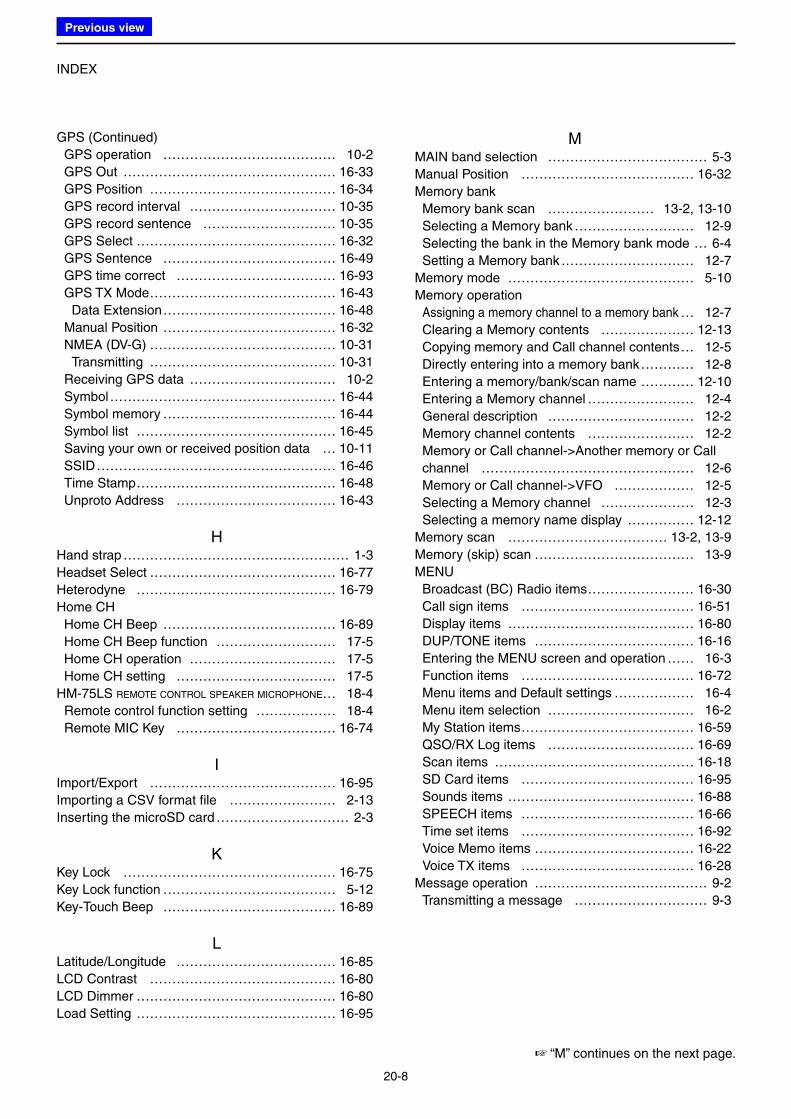
INDEX
20-8
GPS (Continued)
GPS operation ………………………………… 10-2
GPS Out ………………………………………… 16-33
GPS Position …………………………………… 16-34
GPS record interval …………………………… 10-35
GPS record sentence ………………………… 10-35
GPS Select ……………………………………… 16-32
GPS Sentence ………………………………… 16-49
GPS time correct ……………………………… 16-93
GPS TX Mode …………………………………… 16-43
Data Extension ………………………………… 16-48
Manual Position ………………………………… 16-32
NMEA (DV-G) …………………………………… 10-31
Transmitting …………………………………… 10-31
Receiving GPS data …………………………… 10-2
Symbol …………………………………………… 16-44
Symbol memory ………………………………… 16-44
Symbol list ……………………………………… 16-45
Saving your own or received position data … 10-11
SSID ……………………………………………… 16-46
Time Stamp ……………………………………… 16-48
Unproto Address ……………………………… 16-43
HHand strap …………………………………………… 1-3
Headset Select …………………………………… 16-77
Heterodyne ……………………………………… 16-79
Home CH
Home CH Beep ………………………………… 16-89
Home CH Beep function ……………………… 17-5
Home CH operation …………………………… 17-5
Home CH setting ……………………………… 17-5
HM-75LS REMOTE CONTROL SPEAKER MICROPHONE … 18-4
Remote control function setting ……………… 18-4
Remote MIC Key ……………………………… 16-74
IImport/Export …………………………………… 16-95
Importing a CSV format file …………………… 2-13
Inserting the microSD card ………………………… 2-3
KKey Lock ………………………………………… 16-75
Key Lock function ………………………………… 5-12
Key-Touch Beep ………………………………… 16-89
LLatitude/Longitude ……………………………… 16-85
LCD Contrast …………………………………… 16-80
LCD Dimmer ……………………………………… 16-80
Load Setting ……………………………………… 16-95
MMAIN band selection ……………………………… 5-3
Manual Position ………………………………… 16-32
Memory bank
Memory bank scan …………………… 13-2, 13-10
Selecting a Memory bank ……………………… 12-9
Selecting the bank in the Memory bank mode … 6-4
Setting a Memory bank ………………………… 12-7
Memory mode …………………………………… 5-10
Memory operation
Assigning a memory channel to a memory bank … 12-7
Clearing a Memory contents ………………… 12-13
Copying memory and Call channel contents … 12-5
Directly entering into a memory bank ………… 12-8
Entering a memory/bank/scan name ………… 12-10
Entering a Memory channel …………………… 12-4
General description …………………………… 12-2
Memory channel contents …………………… 12-2
Memory or Call channel->Another memory or Call
channel ………………………………………… 12-6
Memory or Call channel->VFO ……………… 12-5
Selecting a Memory channel ………………… 12-3
Selecting a memory name display …………… 12-12
Memory scan ……………………………… 13-2, 13-9
Memory (skip) scan ……………………………… 13-9
MENU
Broadcast (BC) Radio items …………………… 16-30
Call sign items ………………………………… 16-51
Display items …………………………………… 16-80
DUP/TONE items ……………………………… 16-16
Entering the MENU screen and operation …… 16-3
Function items ………………………………… 16-72
Menu items and Default settings ……………… 16-4
Menu item selection …………………………… 16-2
My Station items ………………………………… 16-59
QSO/RX Log items …………………………… 16-69
Scan items ……………………………………… 16-18
SD Card items ………………………………… 16-95
Sounds items …………………………………… 16-88
SPEECH items ………………………………… 16-66
Time set items ………………………………… 16-92
Voice Memo items ……………………………… 16-22
Voice TX items ………………………………… 16-28
Message operation ………………………………… 9-2
Transmitting a message ………………………… 9-3
☞ “M” continues on the next page.
Previous view
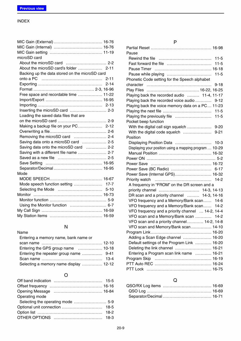
INDEX
20-9
MIC Gain (External) ……………………………… 16-76
MIC Gain (Internal) ……………………………… 16-76
MIC Gain setting ………………………………… 11-19
microSD card
About the microSD card ………………………… 2-2
About the microSD card’s folder ……………… 2-11
Backing up the data stored on the microSD card
onto a PC ……………………………………… 2-11
Exporting ………………………………………… 2-14
Format ……………………………………… 2-3, 16-96
Free space and recordable time ……………… 11-22
Import/Export …………………………………… 16-95
Importing ………………………………………… 2-13
Inserting the microSD card ……………………… 2-3
Loading the saved data files that are
on the microSD card ……………………………… 2-9
Making a backup file on your PC ……………… 2-12
Overwriting a file…………………………………… 2-6
Removing the microSD card …………………… 2-4
Saving data onto a microSD card ……………… 2-5
Saving data onto the microSD card …………… 2-2
Saving with a different file name ………………… 2-7
Saved as a new file ……………………………… 2-5
Save Setting …………………………………… 16-95
Separator/Decimal ……………………………… 16-95
Mode
MODE SPEECH ………………………………… 16-67
Mode speech function setting ………………… 17-7
Selecting the Mode …………………………… 5-10
Monitor …………………………………………… 16-73
Monitor function …………………………………… 5-9
Using the Monitor function ……………………… 6-7
My Call Sign ……………………………………… 16-59
My Station items ………………………………… 16-59
NName
Entering a memory name, bank name or
scan name ……………………………………… 12-10
Entering the GPS group name ……………… 10-18
Entering the repeater group name …………… 9-41
Scan name ……………………………………… 13-4
Selecting a memory name display …………… 12-12
OOff band indication ……………………………… 15-5
Offset frequency ………………………………… 16-16
Opening Message ……………………………… 16-84
Operating mode
Selecting the operating mode …………………… 5-9
Optional unit connection ………………………… 18-5
Option list ………………………………………… 18-2
OTHER OPTIONS ……………………………… 18-3
PPartial Reset ……………………………………… 16-98
Pause
Rewind the file ………………………………… 11-5
Fast forward the file …………………………… 11-5
Pause Timer …………………………………… 16-18
Pause while playing …………………………… 11-5
Phonetic Code setting for the Speech alphabet
character ………………………………………… 9-18
Play Files ………………………………… 16-22, 16-25
Playing back the recorded audio ……… 11-4, 11-17
Playing back the recorded voice audio ………… 9-12
Playing back the voice memory data on a PC … 11-23
Playing the next file ……………………………… 11-5
Playing the previously file ……………………… 11-5
Pocket beep function
With the digital call sign squelch ……………… 9-20
With the digital code squelch ………………… 9-21
Position
Displaying Position Data ……………………… 10-3
Displaying your position using a mapping program … 10-29
Manual Position ………………………………… 16-32
Power ON …………………………………………… 5-2
Power Save ……………………………………… 16-72
Power Save (BC Radio) ………………………… 6-17
Power Save (Internal GPS) ……………………… 16-32
Priority watch …………………………………… 14-2
A frequency in “FROM” on the DR screen and a
priority channel ………………………… 14-3, 14-13
DR scan and a priority channel ……… 14-3, 14-16
VFO frequency and a Memory/Bank scan …… 14-6
VFO frequency and a Memory/Bank scan …… 14-2
VFO frequency and a priority channel … 14-2, 14-4
VFO scan and a Memory/Bank scan ………… 14-2
VFO scan and a priority channel ………… 14-2, 14-8
VFO scan and Memory/Bank scan …………… 14-10
Program Link ……………………………………… 16-20
Adding a Scan Edge channel ………………… 16-20
Default settings of the Program Link ………… 16-20
Deleting the link channel ……………………… 16-21
Entering a Program scan link name ………… 16-21
Program Skip …………………………………… 16-19
PTT Auto REC …………………………………… 16-24
PTT Lock ………………………………………… 16-75
QQSO/RX Log items ……………………………… 16-69
QSO Log ………………………………………… 16-69
Separator/Decimal ……………………………… 16-71
Previous view
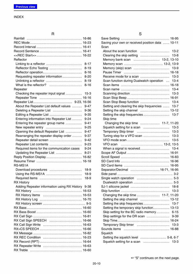
INDEX
20-10
RRainfall …………………………………………… 16-86
REC Mode ………………………………………… 16-23
Record Interval …………………………………… 16-41
Record Sentence ………………………………… 16-41
<<REC Start>> …………………………………… 16-22
Reflector
Linking to a reflector …………………………… 8-17
Reflector Echo Testing ………………………… 8-19
Reflector operation……………………………… 8-16
Requesting repeater information ……………… 8-20
Unlinking a reflector …………………………… 8-19
What is the reflector? ………………………… 8-16
Repeater
Checking the repeater input signal …………… 15-3
Repeater Tone ………………………………… 16-16
Repeater List ……………………………… 9-23, 16-56
About the Repeater List default values ……… 9-47
Deleting a Repeater List ……………………… 9-36
Editing a Repeater List ………………………… 9-35
Entering information into Repeater List ……… 9-24
Entering the repeater group name …………… 9-41
New repeater entry …………………………… 9-25
Opening the default Repeater List …………… 9-47
Rearranging the repeater display order ……… 9-37
Repeater detail screen ………………………… 9-42
Repeater List contents ………………………… 9-23
Required items for the communication cases 9-24
Updating the Repeater List …………………… 8-21
Reply Position Display …………………………… 16-82
Resume Timer …………………………………… 16-18
RS-MS1A
Download procedures ………………………… 18-9
Using the RS-MS1A …………………………… 18-9
Required items ………………………………… 18-9
RX History
Adding Repeater information using RX History 9-38
RX History ……………………………………… 16-53
RX History items ……………………………… 16-53
RX History Log ………………………………… 16-70
RX History screen ………………………………… 9-5
RX Bass …………………………………………… 16-60
RX Bass Boost …………………………………… 16-60
RX Call Sign ……………………………………… 16-81
RX Call Sign SPEECH ………………………… 16-66
RX Call Sign Write ……………………………… 16-63
RX>CS SPEECH ………………………………… 16-66
RX Message ……………………………………… 16-82
RX REC Condition ……………………………… 16-23
RX Record (RPT) ………………………………… 16-64
RX Repeater Write ……………………………… 16-63
RX Treble ………………………………………… 16-60
SSave Setting ……………………………………… 16-95
Saving your own or received position data …… 10-11
Scan
About the scan function ……………………… 13-2
Clearing the skip setting ……………………… 13-8
Memory bank scan …………………… 13-2, 13-10
Memory scan ……………………………… 13-2, 13-9
Memory (skip) scan …………………………… 13-9
Pause Timer …………………………………… 16-18
Receive mode for a scan ……………………… 13-3
Scan function during Dualwatch operation … 13-4
Scan items ……………………………………… 16-18
Scan name ……………………………………… 13-4
Scanning direction ……………………………… 13-3
Scan Stop Beep ………………………………… 16-91
Scan Stop Beep function ……………………… 13-4
Setting and clearing the skip frequencies …… 13-7
Setting the skip channel ……………………… 13-12
Setting the skip frequencies …………………… 13-7
Skip time
Changing the skip time ……………… 11-7, 11-20
Squelch setting for a scan …………………… 13-3
Temporary Skip timer ………………………… 13-3
Tuning step for a VFO scan …………………… 13-3
VFO mode scan ………………………………… 13-5
VFO scan ………………………………… 13-2, 13-5
When a signal is received ……………………… 13-4
Scope AF Output ………………………………… 16-91
Scroll Speed ……………………………………… 16-83
SD Card Info ……………………………………… 16-96
SD Card items …………………………………… 16-95
Separator/Decimal ……………………… 16-71, 16-95
Side panel …………………………………………… 3-2
Single watch operation …………………………… 5-3
Dualwatch operation ……………………………… 5-3
SJ-1 silicone jacket ……………………………… 18-8
Skip function ……………………………………… 13-3
Changing the skip time ………………… 11-7, 11-20
Setting the skip channel ……………………… 13-12
Setting the skip frequencies …………………… 13-7
Setting the temporary skip function …………… 13-13
Skip setting for the BC radio memory ………… 6-15
Skip settings for the DR scan ………………… 9-39
Skip Time ………………………………………… 16-24
Temporary Skip timer ………………………… 13-3
Sounds items …………………………………… 16-88
Squelch
Setting the squelch level …………………… 5-8, 6-7
Squelch setting for a scan …………………… 13-3
☞ “S” continues on the next page.
Previous view
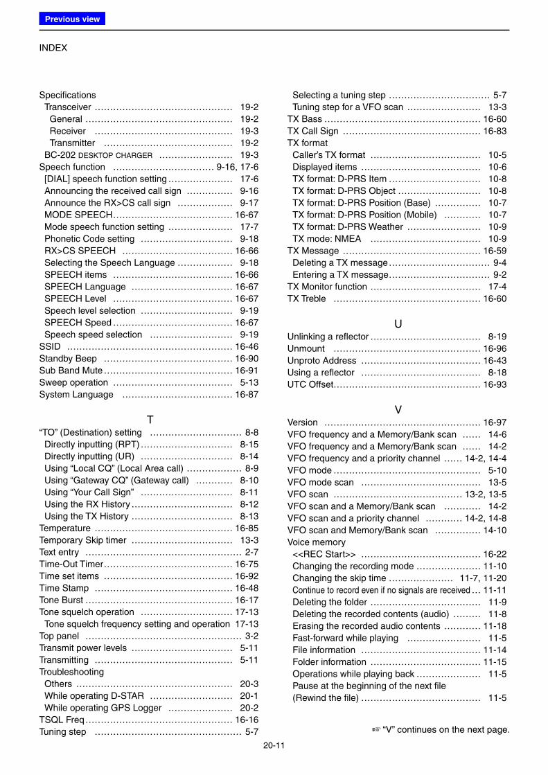
INDEX
20-11
Specifications
Transceiver ……………………………………… 19-2
General ………………………………………… 19-2
Receiver ……………………………………… 19-3
Transmitter …………………………………… 19-2
BC-202 DESKTOP CHARGER …………………… 19-3
Speech function …………………………… 9-16, 17-6
[DIAL] speech function setting ………………… 17-6
Announcing the received call sign …………… 9-16
Announce the RX>CS call sign ……………… 9-17
MODE SPEECH ………………………………… 16-67
Mode speech function setting ………………… 17-7
Phonetic Code setting ………………………… 9-18
RX>CS SPEECH ……………………………… 16-66
Selecting the Speech Language ……………… 9-18
SPEECH items ………………………………… 16-66
SPEECH Language …………………………… 16-67
SPEECH Level ………………………………… 16-67
Speech level selection ………………………… 9-19
SPEECH Speed ………………………………… 16-67
Speech speed selection ……………………… 9-19
SSID ……………………………………………… 16-46
Standby Beep …………………………………… 16-90
Sub Band Mute …………………………………… 16-91
Sweep operation ………………………………… 5-13
System Language ……………………………… 16-87
T“TO” (Destination) setting ………………………… 8-8
Directly inputting (RPT) ………………………… 8-15
Directly inputting (UR) ………………………… 8-14
Using “Local CQ” (Local Area call) ……………… 8-9
Using “Gateway CQ” (Gateway call) ………… 8-10
Using “Your Call Sign” ………………………… 8-11
Using the RX History …………………………… 8-12
Using the TX History …………………………… 8-13
Temperature ……………………………………… 16-85
Temporary Skip timer …………………………… 13-3
Text entry …………………………………………… 2-7
Time-Out Timer …………………………………… 16-75
Time set items …………………………………… 16-92
Time Stamp ……………………………………… 16-48
Tone Burst ………………………………………… 16-17
Tone squelch operation ………………………… 17-13
Tone squelch frequency setting and operation 17-13
Top panel …………………………………………… 3-2
Transmit power levels …………………………… 5-11
Transmitting ……………………………………… 5-11
Troubleshooting
Others …………………………………………… 20-3
While operating D-STAR ……………………… 20-1
While operating GPS Logger ………………… 20-2
TSQL Freq ………………………………………… 16-16
Tuning step ………………………………………… 5-7
Selecting a tuning step …………………………… 5-7
Tuning step for a VFO scan …………………… 13-3
TX Bass …………………………………………… 16-60
TX Call Sign ……………………………………… 16-83
TX format
Caller’s TX format ……………………………… 10-5
Displayed items ………………………………… 10-6
TX format: D-PRS Item ………………………… 10-8
TX format: D-PRS Object ……………………… 10-8
TX format: D-PRS Position (Base) …………… 10-7
TX format: D-PRS Position (Mobile) ………… 10-7
TX format: D-PRS Weather …………………… 10-9
TX mode: NMEA ……………………………… 10-9
TX Message ……………………………………… 16-59
Deleting a TX message …………………………… 9-4
Entering a TX message …………………………… 9-2
TX Monitor function ……………………………… 17-4
TX Treble ………………………………………… 16-60
UUnlinking a reflector ……………………………… 8-19
Unmount ………………………………………… 16-96
Unproto Address ………………………………… 16-43
Using a reflector ………………………………… 8-18
UTC Offset………………………………………… 16-93
VVersion …………………………………………… 16-97
VFO frequency and a Memory/Bank scan …… 14-6
VFO frequency and a Memory/Bank scan …… 14-2
VFO frequency and a priority channel …… 14-2, 14-4
VFO mode ………………………………………… 5-10
VFO mode scan ………………………………… 13-5
VFO scan …………………………………… 13-2, 13-5
VFO scan and a Memory/Bank scan ………… 14-2
VFO scan and a priority channel ………… 14-2, 14-8
VFO scan and Memory/Bank scan …………… 14-10
Voice memory
<<REC Start>> ………………………………… 16-22
Changing the recording mode ………………… 11-10
Changing the skip time ………………… 11-7, 11-20
Continue to record even if no signals are received … 11-11
Deleting the folder ……………………………… 11-9
Deleting the recorded contents (audio) ……… 11-8
Erasing the recorded audio contents ………… 11-18
Fast-forward while playing …………………… 11-5
File information ………………………………… 11-14
Folder information ……………………………… 11-15
Operations while playing back ………………… 11-5
Pause at the beginning of the next file
(Rewind the file) ………………………………… 11-5
☞ “V” continues on the next page.
Previous view
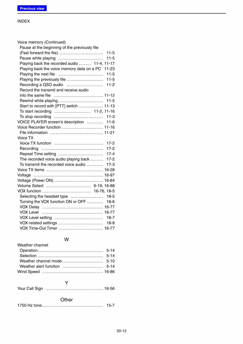
INDEX
20-12
Voice memory (Continued)
Pause at the beginning of the previously file
(Fast forward the file) …………………………… 11-5
Pause while playing …………………………… 11-5
Playing back the recorded audio ……… 11-4, 11-17
Playing back the voice memory data on a PC 11-23
Playing the next file …………………………… 11-5
Playing the previously file ……………………… 11-5
Recording a QSO audio ……………………… 11-2
Record the transmit and receive audio
into the same file ……………………………… 11-12
Rewind while playing …………………………… 11-5
Start to record with [PTT] switch ……………… 11-13
To start recording ……………………… 11-2, 11-16
To stop recording ……………………………… 11-3
VOICE PLAYER screen’s description ………… 11-6
Voice Recorder function ………………………… 11-16
File information ………………………………… 11-21
Voice TX
Voice TX function ……………………………… 17-2
Recording ……………………………………… 17-2
Repeat Time setting …………………………… 17-4
The recorded voice audio playing back ……… 17-2
To transmit the recorded voice audio ………… 17-3
Voice TX items …………………………………… 16-28
Voltage …………………………………………… 16-97
Voltage (Power ON) ……………………………… 16-84
Volume Select …………………………… 6-19, 16-88
VOX function ……………………………… 16-76, 18-5
Selecting the headset type …………………… 18-5
Turning the VOX function ON or OFF ………… 18-6
VOX Delay ……………………………………… 16-77
VOX Level ……………………………………… 16-77
VOX Level setting ……………………………… 18-7
VOX-related settings …………………………… 18-8
VOX Time-Out Timer …………………………… 16-77
WWeather channel
Operation ………………………………………… 5-14
Selection ………………………………………… 5-14
Weather channel mode ………………………… 5-10
Weather alert function ………………………… 5-14
Wind Speed ……………………………………… 16-86
YYour Call Sign …………………………………… 16-56
Other1750 Hz tone ……………………………………… 15-7
Previous view
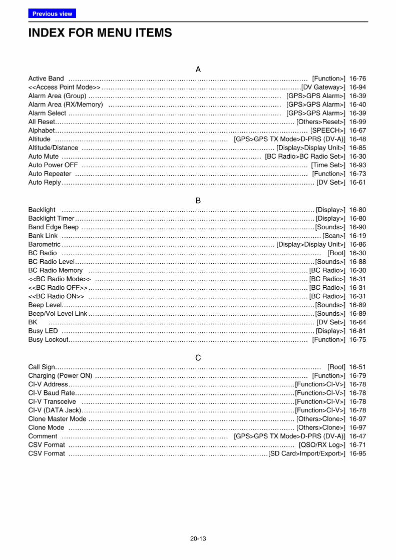
INDEX FOR MENU ITEMS
20-13
AActive Band ……………………………………………………………………………………………… [Function>] 16-76
<<Access Point Mode>> ………………………………………………………………………………[DV Gateway>] 16-94
Alarm Area (Group) …………………………………………………………………………… [GPS>GPS Alarm>] 16-39
Alarm Area (RX/Memory) …………………………………………………………………… [GPS>GPS Alarm>] 16-40
Alarm Select …………………………………………………………………………………… [GPS>GPS Alarm>] 16-39
All Reset……………………………………………………………………………………………… [Others>Reset>] 16-99
Alphabet …………………………………………………………………………………………………… [SPEECH>] 16-67
Altitude …………………………………………………………………… [GPS>GPS TX Mode>D-PRS (DV-A)] 16-48
Altitude/Distance …………………………………………………………………………… [Display>Display Unit>] 16-85
Auto Mute ……………………………………………………………………………… [BC Radio>BC Radio Set>] 16-30
Auto Power OFF ………………………………………………………………………………………… [Time Set>] 16-93
Auto Repeater …………………………………………………………………………………………… [Function>] 16-73
Auto Reply …………………………………………………………………………………………………… [DV Set>] 16-61
BBacklight …………………………………………………………………………………………………… [Display>] 16-80
Backlight Timer ……………………………………………………………………………………………… [Display>] 16-80
Band Edge Beep ……………………………………………………………………………………………[Sounds>] 16-90
Bank Link ……………………………………………………………………………………………………… [Scan>] 16-19
Barometric …………………………………………………………………………………… [Display>Display Unit>] 16-86
BC Radio ……………………………………………………………………………………………………… [Root] 16-30
BC Radio Level ………………………………………………………………………………………………[Sounds>] 16-88
BC Radio Memory ……………………………………………………………………………………… [BC Radio>] 16-30
<<BC Radio Mode>> …………………………………………………………………………………… [BC Radio>] 16-31
<<BC Radio OFF>> ……………………………………………………………………………………… [BC Radio>] 16-31
<<BC Radio ON>> ……………………………………………………………………………………… [BC Radio>] 16-31
Beep Level……………………………………………………………………………………………………[Sounds>] 16-89
Beep/Vol Level Link …………………………………………………………………………………………[Sounds>] 16-89
BK ………………………………………………………………………………………………………… [DV Set>] 16-64
Busy LED …………………………………………………………………………………………………… [Display>] 16-81
Busy Lockout……………………………………………………………………………………………… [Function>] 16-75
CCall Sign………………………………………………………………………………………………………… [Root] 16-51
Charging (Power ON) …………………………………………………………………………………… [Function>] 16-79
CI-V Address …………………………………………………………………………………………[Function>CI-V>] 16-78
CI-V Baud Rate………………………………………………………………………………………[Function>CI-V>] 16-78
CI-V Transceive ……………………………………………………………………………………[Function>CI-V>] 16-78
CI-V (DATA Jack) ……………………………………………………………………………………[Function>CI-V>] 16-78
Clone Master Mode ………………………………………………………………………………… [Others>Clone>] 16-97
Clone Mode ………………………………………………………………………………………… [Others>Clone>] 16-97
Comment ………………………………………………………………… [GPS>GPS TX Mode>D-PRS (DV-A)] 16-47
CSV Format ………………………………………………………………………………………… [QSO/RX Log>] 16-71
CSV Format ………………………………………………………………………………[SD Card>Import/Export>] 16-95
Previous view
INDEX FOR MENU ITEMS
20-14
DDate ………………………………………………………………………………… [QSO/RX Log>CSV Format>] 16-71
Date ……………………………………………………………………… [SD Card>Import/Export/CSV Format>] 16-95
Data Extension …………………………………………………………… [GPS>GPS TX Mode>D-PRS (DV-A)] 16-48
Data Speed ……………………………………………………………………………………………… [Function>] 16-76
Date/Time ………………………………………………………………………………………………… [Time Set>] 16-92
DIAL SPEECH …………………………………………………………………………………………… [SPEECH>] 16-66
Dial Speed-UP …………………………………………………………………………………………… [Function>] 16-73
Digital Code …………………………………………………………………………………………… [DUP/TONE>] 16-17
Digital Monitor ……………………………………………………………………………………………… [DV Set>] 16-62
Digital Repeater Set ………………………………………………………………………………………… [DV Set>] 16-63
Display ………………………………………………………………………………………………………… [Root] 16-80
Display Language…………………………………………………………………………………………… [Display>] 16-86
Display Unit ………………………………………………………………………………………………… [Display>] 16-85
DTCS Code …………………………………………………………………………………………… [DUP/TONE>] 16-17
DTCS Polarity ………………………………………………………………………………………… [DUP/TONE>] 16-17
DTMF Memory …………………………………………………………………………………… [DTMF/T-CALL>] 16-68
DTMF Speed ……………………………………………………………………………………… [DTMF/T-CALL>] 16-68
DTMF/T-CALL ………………………………………………………………………………………………… [Root] 16-68
DUP/TONE...…………………………………………………………………………………………………… [Root] 16-16
During RX/Standby ………………………………………………………………… [Function>Remote MIC Key>] 16-74
During TX …………………………………………………………………………… [Function>Remote MIC Key>] 16-75
DV Auto Detect ……………………………………………………………………………………………… [DV Set>] 16-63
DV Auto Reply ……………………………………………………………………………………… [Voice Memo>] 16-27
DV Data TX ………………………………………………………………………………………………… [DV Set>] 16-61
DV Fast Data………………………………………………………………………………………………… [DV Set>] 16-61
DV Gateway …………………………………………………………………………………………………… [Root] 16-94
DV Memory …………………………………………………………………………………………………… [Root] 16-56
DV RX Backlight …………………………………………………………………………………………… [Display>] 16-83
DV Set ………………………………………………………………………………………………………… [Root] 16-60
D-PRS (DV-A) ……………………………………………………………………………… [GPS>GPS TX Mode>] 16-43
EEarphone Mode ……………………………………………………………………………………………[Sounds>] 16-88
Export ………………………………………………………………………………………[SD Card>Import/Export>] 16-95
EMR ………………………………………………………………………………………………………… [DV Set>] 16-64
EMR AF Level ……………………………………………………………………………………………… [DV Set>] 16-65
FFast Data ………………………………………………………………………………… [DV Set>DV Fast Data>] 16-61
File Split …………………………………………………………… [Voice Memo>QSO Recorder>Recorder Set>] 16-24
FM Antenna …………………………………………………………………………… [BC Radio>BC Radio Set>] 16-31
Format …………………………………………………………………………………………………… [SD Card>] 16-96
Function ………………………………………………………………………………………………………… [Root] 16-72
Previous view
INDEX FOR MENU ITEMS
20-15
GGPS …………………………………………………………………………………………………………… [Root] 16-32
GPS Alarm……………………………………………………………………………………………………… [GPS>] 16-39
GPS Auto TX…………………………………………………………………………………………………… [GPS>] 16-50
GPS Data Speed ………………………………………………………………………… [DV Set>DV Fast Data>] 16-62
GPS Indicator …………………………………………………………………………………… [GPS>GPS Set>] 16-33
GPS Information ……………………………………………………………………………………………… [GPS>] 16-34
GPS Logger …………………………………………………………………………………………………… [GPS>] 16-41
GPS Logger …………………………………………………………………………………… [GPS>GPS Logger>] 16-41
<<GPS Logger Only>> ……………………………………………………………………… [GPS>GPS Logger>] 16-42
GPS Memory…………………………………………………………………………………………………… [GPS>] 16-38
GPS Message ………………………………………………………………[GPS>GPS TX Mode>NMEA (DV-G)] 16-50
GPS Out (to DATA jack) ………………………………………………………………………… [GPS>GPS Set>] 16-33
GPS Position …………………………………………………………………………………………………… [GPS>] 16-34
GPS Select ……………………………………………………………………………………… [GPS>GPS Set>] 16-32
GPS Sentence ………………………………………………………………[GPS>GPS TX Mode>NMEA (DV-G)] 16-49
GPS Set ………………………………………………………………………………………………………… [GPS>] 16-32
GPS Time Correct ……………………………………………………………………………………… [Time Set>] 16-93
GPS TX Mode ………………………………………………………………………………………………… [GPS>] 16-43
HHeadset Select …………………………………………………………………………………… [Function>VOX>] 16-77
Heterodyne ……………………………………………………………………………………………… [Function>] 16-79
Home CH Beep………………………………………………………………………………………………[Sounds>] 16-89
IImport ………………………………………………………………………………………[SD Card>Import/Export>] 16-95
Import/Export……………………………………………………………………………………………… [SD Card>] 16-95
Information…………………………………………………………………………………………………… [Others>] 16-97
KKey Lock ………………………………………………………………………………………………… [Function>] 16-75
Key-Touch Beep ……………………………………………………………………………………………[Sounds>] 16-89
LLatitude/Longitude ………………………………………………………………………… [Display>Display Unit>] 16-85
LCD Contrast ……………………………………………………………………………………………… [Display>] 16-80
LCD Dimmer ………………………………………………………………………………………………… [Display>] 16-80
Load Setting ……………………………………………………………………………………………… [SD Card>] 16-95
MManual Position ………………………………………………………………………………… [GPS>GPS Set>] 16-32
MIC Gain (External) ……………………………………………………………………………………… [Function>] 16-76
MIC Gain (Internal) ……………………………………………………………………………………… [Function>] 16-76
MODE SPEECH ………………………………………………………………………………………… [SPEECH>] 16-67
Monitor …………………………………………………………………………………………………… [Function>] 16-73
My Call Sign …………………………………………………………………………………………… [My Station>] 16-59
My Station ……………………………………………………………………………………………………… [Root] 16-59
Previous view
INDEX FOR MENU ITEMS
20-16
N<<New File>> …………………………………………………………………………… [SD Card>Save Setting>] 16-95
NMEA (DV-G) ……………………………………………………………………………… [GPS>GPS TX Mode>] 16-49
OOffset Freq……………………………………………………………………………………………… [DUP/TONE>] 16-16
Opening Message ………………………………………………………………………………………… [Display>] 16-84
Others…………………………………………………………………………………………………………… [Root] 16-97
PPartial Reset ………………………………………………………………………………………… [Others>Reset>] 16-98
Pause Timer …………………………………………………………………………………………………… [Scan>] 16-18
Play Files ………………………………………………………………………… [Voice Memo>QSO Recorder>] 16-22
Play Files ………………………………………………………………………… [Voice Memo>Voice Recorder>] 16-25
Player Set ………………………………………………………………………… [Voice Memo>QSO Recorder>] 16-24
Player Set ………………………………………………………………………… [Voice Memo>Voice Recorder>] 16-26
Power Save ……………………………………………………………………………………………… [Function>] 16-72
Power Save (BC Radio) ……………………………………………………………… [BC Radio>BC Radio Set>] 16-31
Power Save (Internal GPS) …………………………………………………………………… [GPS>GPS Set>] 16-32
Program Link …………………………………………………………………………………………………… [Scan>] 16-20
Program Skip ………………………………………………………………………………………………… [Scan>] 16-19
PTT Auto REC …………………………………………………… [Voice Memo>QSO Recorder>Recorder Set>] 16-24
PTT Lock ………………………………………………………………………………………………… [Function>] 16-75
QQSO Log …………………………………………………………………………………………… [QSO/RX Log>] 16-69
QSO Recorder ……………………………………………………………………………………… [Voice Memo>] 16-22
QSO/RX Log …………………………………………………………………………………………………… [Root] 16-69
RRainfall ……………………………………………………………………………………… [Display>Display Unit>] 16-86
REC Mode ………………………………………………………… [Voice Memo>QSO Recorder>Recorder Set>] 16-23
<<REC Start>> …………………………………………………………………… [Voice Memo>QSO Recorder>] 16-22
Record …………………………………………………………………………… [Voice Memo>Voice Recorder>] 16-24
Record …………………………………………………………………………………………………… [Voice TX>] 16-28
Record Interval ………………………………………………………………………………… [GPS>GPS Logger>] 16-41
Recorder Set ……………………………………………………………………… [Voice Memo>QSO Recorder>] 16-23
Recorder Set ……………………………………………………………………… [Voice Memo>Voice Recorder>] 16-26
Record Sentence ……………………………………………………………………………… [GPS>GPS Logger>] 16-41
Remote MIC Key ………………………………………………………………………………………… [Function>] 16-74
Repeat Time …………………………………………………………………………………… [Voice TX>TX Set>] 16-29
<<Repeat TX>> ………………………………………………………………………………………… [Voice TX>] 16-29
Repeater List …………………………………………………………………………………………… [DV Memory>] 16-56
Repeater Tone ………………………………………………………………………………………… [DUP/TONE>] 16-16
Reply Position Display ……………………………………………………………………………………… [Display>] 16-82
Reset ………………………………………………………………………………………………………… [Others>] 16-98
Resume Timer ………………………………………………………………………………………………… [Scan>] 16-18
RX Bass …………………………………………………………………………………… [DV Set>Tone Control>] 16-60
RX Bass Boost …………………………………………………………………………… [DV Set>Tone Control>] 16-60
Previous view
INDEX FOR MENU ITEMS
20-17
RX Call Sign ………………………………………………………………………………………………… [Display>] 16-81
RX Call Sign SPEECH ………………………………………………………………………………… [SPEECH>] 16-66
RX Call Sign Write ………………………………………………………………………………………… [DV Set>] 16-63
RX History ……………………………………………………………………………………………………… [Root] 16-53
RX History Log ……………………………………………………………………………………… [QSO/RX Log>] 16-70
RX Message ………………………………………………………………………………………………… [Display>] 16-82
RX REC Condition ……………………………………………… [Voice Memo>QSO Recorder>Recorder Set>] 16-23
RX Record (RPT) …………………………………………………………………………………………… [DV Set>] 16-64
RX Repeater Write ………………………………………………………………………………………… [DV Set>] 16-63
RX Treble ………………………………………………………………………………… [DV Set>Tone Control>] 16-60
RX>CS SPEECH ………………………………………………………………………………………… [SPEECH>] 16-66
[RX>CS] Key ………………………………………………………………………………………………… [DV Set>] 16-64
SSave Setting ……………………………………………………………………………………………… [SD Card>] 16-95
Scan …………………………………………………………………………………………………………… [Root] 16-18
Scan Stop Beep ……………………………………………………………………………………………[Sounds>] 16-90
Scope AF Output ……………………………………………………………………………………………[Sounds>] 16-91
Scroll Speed ………………………………………………………………………………………………… [Display>] 16-83
SD Card ………………………………………………………………………………………………………… [Root] 16-95
SD Card Info ……………………………………………………………………………………………… [SD Card>] 16-96
Separator/Decimal ………………………………………………………………… [QSO/RX Log>CSV Format>] 16-71
Separator/Decimal ……………………………………………………… [SD Card>Import/Export/CSV Format>] 16-95
<<Single TX>> …………………………………………………………………………………………… [Voice TX>] 16-29
Skip Time …………………………………………………………… [Voice Memo>QSO Recorder>Player Set>] 16-24
Sound …………………………………………………………………………………………………………… [Root] 16-88
SPEECH ……………………………………………………………………………………………………… [Root] 16-66
SPEECH Language ……………………………………………………………………………………… [SPEECH>] 16-67
SPEECH Level …………………………………………………………………………………………… [SPEECH>] 16-67
SPEECH Speed ………………………………………………………………………………………… [SPEECH>] 16-67
Speed ………………………………………………………………………………………… [Display>Display Unit>] 16-85
SSID ……………………………………………………………………… [GPS>GPS TX Mode>D-PRS (DV-A)] 16-46
Standby Beep ………………………………………………………………………………………………[Sounds>] 16-90
Sub Band Mute ………………………………………………………………………………………………[Sounds>] 16-91
System Language ………………………………………………………………………………………… [Display>] 16-87
TTemperature ………………………………………………………………………………… [Display>Display Unit>] 16-85
Temporary Skip Timer ………………………………………………………………………………………… [Scan>] 16-18
<<Terminal Mode>> ……………………………………………………………………………………[DV Gateway>] 16-94
Time Set………………………………………………………………………………………………………… [Root] 16-92
Time Stamp ……………………………………………………………… [GPS>GPS TX Mode>D-PRS (DV-A)] 16-48
Time-Out Timer …………………………………………………………………………………………… [Function>] 16-75
Tone Burst ……………………………………………………………………………………………… [DUP/TONE>] 16-17
Tone Control ………………………………………………………………………………………………… [DV Set>] 16-60
TSQL Freq ……………………………………………………………………………………………… [DUP/TONE>] 16-16
TX Bass …………………………………………………………………………………… [DV Set>Tone Control>] 16-60
TX Call Sign ………………………………………………………………………………………………… [Display>] 16-83
TX Delay (PTT) …………………………………………………………………………… [DV Set>DV Fast Data>] 16-62
TX Message …………………………………………………………………………………………… [My Station>] 16-59
TX Monitor ……………………………………………………………………………………… [Voice TX>TX Set>] 16-29
TX Set …………………………………………………………………………………………………… [Voice TX>] 16-29
TX Treble ………………………………………………………………………………… [DV Set>Tone Control>] 16-60
Previous view
INDEX FOR MENU ITEMS
20-18
UUnmount ………………………………………………………………………………………………… [SD Card>] 16-96
Unproto Address ………………………………………………………… [GPS>GPS TX Mode>D-PRS (DV-A)] 16-43
UTC Offset………………………………………………………………………………………………… [Time Set>] 16-93
VVersion ……………………………………………………………………………………… [Others>Information>] 16-97
Voice Memo …………………………………………………………………………………………………… [Root] 16-22
Voice Recorder ……………………………………………………………………………………… [Voice Memo>] 16-24
Voice TX ……………………………………………………………………………………………………… [Root] 16-28
Voltage ……………………………………………………………………………………… [Others>Information>] 16-97
Voltage (Power ON) ………………………………………………………………………………………… [Display>] 16-84
Volume Select ………………………………………………………………………………………………[Sounds>] 16-88
VOX ……………………………………………………………………………………………………… [Function>] 16-76
VOX ……………………………………………………………………………………………… [Function>VOX>] 16-76
VOX Delay ………………………………………………………………………………………… [Function>VOX>] 16-77
VOX Level ………………………………………………………………………………………… [Function>VOX>] 16-77
VOX Time-Out Timer …………………………………………………………………………… [Function>VOX>] 16-77
WWind Speed ………………………………………………………………………………… [Display>Display Unit>] 16-86
YYour Call Sign ………………………………………………………………………………………… [DV Memory>] 16-56
Previous view
1-1-32 Kamiminami, Hirano-ku, Osaka 547-0003, JapanA-7331-3EX© 2016 Icom Inc.
Related Documents