bringing technology to life

Welcome message from author
This document is posted to help you gain knowledge. Please leave a comment to let me know what you think about it! Share it to your friends and learn new things together.
Transcript
bringing technology to life
1725 North Salisbury Blvd. · PO Box 2828 · Salisbury, Maryland 21802
800.780.2169 · 410.860.5100 · Fax 410.860.1949
[email protected] · www.lorch.com
lo
rc
h m
icr
ow
av
e r
F &
mic
ro
wa
ve
Pr
od
uc
ts
1725 N. Salisbury Blvd. · PO Box 2828 · Salisbury, MD 21802 Phone 800.780.2169, 410.860.5100 · Fax 410.860.1949
www.lorch.com · [email protected] 3
For four decades, Lorch Microwave has continuously supplied RF and Microwave components and systems to the leading military, industrial, and commercial manufacturers worldwide. This history is based on the fundamental principle that we supply solutions for the changing needs of our customers. Through continuous investment in engineering and manufacturing capabilities, Lorch is able to respond to our customer’s unique custom requirements as though we are supplying “standard off-the-shelf product.”
Lorch Microwave is committed to providing our customers with technically advanced, high quality products at competitive prices. As such, all productsoffered by Lorch Microwave are subject to the same rigorous design, manufac-turing and inspection criteria. Manufacturing, testing and inspection facilities are located in our modern 37,000 square foot factory in Salisbury, Maryland.The company is MIL qualified and conforms to the principals set forth inISO-9001 and ISO-14001. Regardless of application, the processes and proce-dures followed at Lorch help ensure that all products are fully compliant to all specifications and will perform as designed right out of the box.
The products described in this catalog have resulted from a combination of 40 years of design experience as well as the utilization of the latest computer aided design technology and manufacturing techniques. Further, Lorch’s research and development activities are constantly evaluating new materials, plating techniques, and manufacturing processes to ensure that the company offers the highest performing components available today.
Lorch Microwave’s designs are developed for ease of manufacturing and flex-ibility as a prime consideration. This, coupled with adequate inventories of raw materials and inventories of raw materials and in-house control of all critical process from design through manufacturing and testing yields deliveries that are quoted in weeks rather than months.
At Lorch Microwave, we believe that putting our trademark on the product is our commitment to you of quality, service and satisfaction. We understand that our product includes not just the component or system purchase, but rather, the entire purchasing experience. You have our commitment that Lorch willcontinue our tradition of unparalleled service to the microwave industry.

1725 N. Salisbury Blvd. · PO Box 2828 · Salisbury, MD 21802 Phone 800.780.2169, 410.860.5100 · Fax 410.860.1949 www.lorch.com · [email protected]
Part numbers are assigned at time of order. If youhave generated a part number, give the name of the component and the frequency range as stated in the catalog. If special options or non-standard features are desired, they should be fully described and a unique part number will be assigned. Special modificationsfor unusual applications, custom components andadaptation of existing parts can be designed anddeveloped by our engineering department. A qualified staff of experienced sales and design engineers isavailable to assist you in specifying components for your special requirements.
Ordering AddressLorch MicrowavePO Box 2828Salisbury, MD 21802
Ordering: 800-780-2169Phone: 410-860-5100Fax: 410-860-1949
Our CAGE code is 29971
Orders may be placed through our local salesrepresentative in your area or directly with the factory. Final determination of price, terms, conditions, andacceptance of orders, however, may be made only by our staff in Salisbury, Maryland.
Payment OptionsLorch Microwave offers many convenient payment methods, including: Open Account (subject to creditapproval), Mastercard/Visa, and Letters of Credit.Please specify payment method at time of order.
DeliveryIf a carrier is not specified at the time of order, shipment will be made via UPS Ground or UPS Air dependingon distance from the factory. For rush service, we will ship by air freight, air express, or others, as requested. Firm delivery dates are given at time of quotation. Lorch Microwave maintains complete inventory so that many items may be delivered within 24 hours when quoted by the factory.
Packing and PackagingPacking and Packaging is normally supplied to “Best Commercial” standards. Packaging to military require-ments, including Bar Coding is available on request.
WarrantyProducts manufactured by Lorch Microwave are warran-tied against defective materials and workmanship for a period of one year from the date of shipment. Lorch Microwave’s obligation for any defect shall be limited to the repair of the defective part. Lorch Microwave assumes no liability if defects result from improper use, operation above rated capacities, repairs not made by us, or misapplication of equipment. No other warranty is expressed or implied. Lorch Microwave neither makes nor authorizes any other person to make any otherwarranty concerning its products. Lorch Microwave is not liable for consequential damages. Warranty returns must first be authorized by our sales office prior to return and must be returned pre-paid.
Terms and ConditionsPlease visit our website at www.lorch.com/terms fora complete listing.

1725 N. Salisbury Blvd. · PO Box 2828 · Salisbury, MD 21802 Phone 800.780.2169, 410.860.5100 · Fax 410.860.1949
www.lorch.com · [email protected] 5
General Company Information
3 Company Introduction
4 Ordering Information
5 Contents
Filter Products
6 General Filter Information
7-8 Filter Circuit Topology
9 Environmental Capabilities
Cavity Filters
10-11 General Information
12-13 Specifying Cavity Filters
14-16 Cavity Outline Drawings
17 Waveguide General
Discrete Components
18 General Information
19 Specifying Bandpass Filters
20 Specifying Lowpass Filters
21 Specifying Highpass Filters
22-26 Outline Drawings
Ceramic Filters
27 General Information
28 Specifying Ceramic Filters
29 Ceramic Outline Drawings
30 Z-Pack Series™
Integrated Assemblies 31-35
Tunable Filters
36-37 Tunable Bandpass Filters
38 Tunable Bandreject Filters
39 Digital Tunable Filters
Tubular Filters
40 General Information
41 Specifying Bandpass Filters
42 Specifying Lowpass Filters
43-44 Tubular Filter Dimensions
RF Products
45 Phase Comparators
46 Manual Phase Shifters
47 Digital Phase Shifters
48 Voltage Controlled Phase Shifters
49 Voltage Controlled Attenuators
50 Broad Band Mixers

1725 N. Salisbury Blvd. · PO Box 2828 · Salisbury, MD 21802 Phone 800.780.2169, 410.860.5100 · Fax 410.860.1949 www.lorch.com · [email protected]
In many cases it is important to know more about the passband of a filter around the transition region between the passband and the stopband. The information provided serves as a design aid where passband flatness is an important criteria.
The dissipative losses are greater at the bandedges than at center frequency. The passband of the filter becomes rounded at the bandedges. Since both the dissipative loss and the reflective losses are present in each filter, the ripple becomes superimposed on the rounded passband created by the dissipa-tive losses. Because of this it is more useful to specify a relative bandwidth as shown than the equi-ripple bandwidth.
The relationship between center frequency insertion loss and the +/- 5 degree phase linearity bandwidth is shown. This bandwidth is defined as the maximum deviation from a best-fit line drawn between two points on either side of the passband.
The relationship between center frequency insertion loss and the 1.5:1 VSWR bandwidth is also given. The VSWR corresponds to a 14 dB Return Loss in a 50 Ohm system.
Example:A 4 pole filter with a 3 dB bandwidth of 60 MHz and3.5 dB insertion loss:
0.5 dB bandwidth is .64 x 60 = 38.4 MHz1.0 dB bandwidth is .77 x 60 = 46.2 MHz+/- 5° phase bandwidth is .62 x 60 = 37.2 MHz1.5:1 VSWR bandwidth is .85 x 60 = 51 MHz
Note: When out-of-band attenuation is not specified, a 3 dB bandwidth tolerance of -0 / + 10% nominal will be used.
The (%) tolerance on bandwidth will be inversely proportional to an actual decrease in bandwidth (MHz) vs. frequency. If a maximum bandwidth is required, please specify.
3.0 dB Relative BW
1.0 dB Relative BW
0.5 dB Relative BW
0 dB Relative BW
Insertion Loss Ripple
N = 4 - 10
N = 3
N = 2
4.5
4.0
3.5
3.0
2.5
2.0
1.5
1.0
0.50.2 0.3 0.4 0.5 0.6 0.7 0.8 0.9 1.0
0.5 dB Relative Bandwidth
Inse
rtio
n Lo
ss (d
B)
Fractional Bandwidth
N = 4 - 10
N = 3
N = 2
4.5
4.0
3.5
3.0
2.5
2.0
1.5
1.0
0.50.2 0.3 0.4 0.5 0.6 0.7 0.8 0.9 1.0
Inse
rtio
n Lo
ss (d
B)
Fractional Bandwidth
1.0 dB Relative Bandwidth
N = 4 - 10
N = 3
N = 2
4.5
4.0
3.5
3.0
2.5
2.0
1.5
1.0
0.50.1 0.2 0.3 0.4 0.5 0.6 0.7 0.8 0.9
Inse
rtio
n Lo
ss (d
B)
Fractional Bandwidth
± 5° Relative Phase Bandwidth
1.5:1 VSWR Bandwidth p4
4.5
4.0
3.5
3.0
2.5
2.0
1.5
1.0
0.50.5 0.6 0.7 0.8 0.9 1.0 1.1 1.2 1.3
N = 6 - 10
N = 5
N = 4
N = 3
N = 2
Inse
rtio
n Lo
ss (d
B)
Fractional Bandwidth
1.5:1 VSWR Bandwidth

1725 N. Salisbury Blvd. · PO Box 2828 · Salisbury, MD 21802 Phone 800.780.2169, 410.860.5100 · Fax 410.860.1949
www.lorch.com · [email protected] 7
Modern filter synthesis allows the placement of transmission zeroes by the designer. Lorch Microwave incorporates the use of the latest software to design our filters to each unique application. Filters may be designed with asymmetrical responses to most efficiently attenuate low side or high side signals. Symmetrical responses are used where both lower and upper attenuations are important. Lorch Microwave utilizes elliptic or pole-placed functions where finite zeros are required. The schematics and response curves below show just a few of the filter networks used.
Lowpass FilterThis is the simplest form of a ladder network. The lowpass filter response extends from D.C. to a specified cutoff frequency. The passband insertion loss is mea-sured at .90 times the 3 dB cutoff. Stopband response may extend to 100 times the cutoff frequency.
< I
ncre
asin
g A
tten
uatio
n
Increasing Frequency >
Highpass Filter p,4
< I
ncre
asin
g A
tten
uatio
n
Increasing Frequency >
Hipass FilterThis is the inverse of the lowpass circuit shown. Thehighpass filter is specified with a 3 dB cutoff as well asan upper passband limit. Because of parasitic elementsinherent in the design, the passband cannot extendto infinite frequencies. Responses are available to 20 times the specified cutoff frequency.
Lowpass/Highpass Filter
< I
ncre
asin
g A
tten
uatio
n
Increasing Frequency >
< I
ncre
asin
g A
tten
uatio
n
Increasing Frequency >
Direct Scaled Bandpass Filter
Lowpass/Highpass FilterThis is a cascade of the lowpass and highpass circuits shown above. This configuration is generally used for bandwidths of an octave or greater. The response maybe tailored to meet the upper and lower stopbandrequirements as needed.
Direct Scaled Bandpass FiltersThis is the classical “resonant ladder” used in widebandapplications. The circuit is obtained by a lowpass tobandpass transform. Its advantages are geometricsymmetry and a small spread of element values whenused in circuit transforms.
1725 N. Salisbury Blvd. · PO Box 2828 · Salisbury, MD 21802 Phone 800.780.2169, 410.860.5100 · Fax 410.860.1949 www.lorch.com · [email protected]
Nodal Circuit Bandpass Filter
< I
ncre
asin
g A
tten
uatio
n
Increasing Frequency >
< I
ncre
asin
g A
tten
uatio
n
Increasing Frequency >
< I
ncre
asin
g A
tten
uatio
n
Increasing Frequency >
< I
ncre
asin
g A
tten
uatio
n
Increasing Frequency >
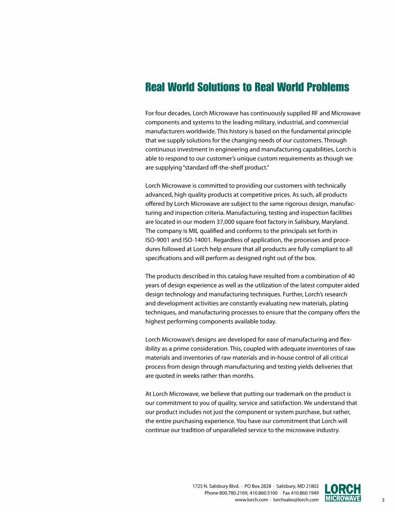
Nodal Circuit Bandpass FiltersThe capacitively coupled nodal circuitprovides an excellent configuration fornarrowband use. The highside responsemay be sharpened by the use of a varietyof transforming networks.
Mesh Circuit Bandpass Filter
Mesh Circuit Bandpass FilterThis is the “dual” of the nodal circuit shown.It provides a steeper high side response due to the greater number of zeroes at infinity. This circuit may also use a variety of transforming networks to provide symmetry to the response.
Elliptic Filter
Elliptic FilterThe Elliptic filter (also known as a Cauer response) provides the steepest out of band attenuation of any filter response. This is achieved by adding anti-resonance, or notch sections to the filter. These responses areavailable in Lowpass, Highpass, Bandpassand Bandstop.
Pole Placed Filter
Pole Placed FilterUnlike the Elliptic filter where the finiteattenuation poles are determined by the mathematical function, the Pole Placed filter allows the designer to specify where these points fall. This design is useful where there are specific single frequencies to remove.

1725 N. Salisbury Blvd. · PO Box 2828 · Salisbury, MD 21802 Phone 800.780.2169, 410.860.5100 · Fax 410.860.1949
www.lorch.com · [email protected] 9
The standard environmentalconditions are listed throughoutthe catalog in the correspondingsection for each product series.
Most products offered by LorchMicrowave may be designed to meet any of the extended environmental specifications shown in the following table. Conditions not listed may alsobe acceptable. Lorch Microwave has the capability to test our products in accordance with these or similar environmental test methods. Please contact the sales department foryour specific requirements.
Rating or Test
Temperature Operating, °C
Temperature Storage, °C
Gross Leak
Fine Leak
Moisture Resistance (Humidity)
Thermal Shock
Mechanical Shock
Random Vibration
Vibration High Frequency
Solderability
Terminal Strength and Fatigue
Altitude
Salt Spray
Solvent Resistance
Solder Heat
MIL-STD-202FMethod/Conditions
-55 °C, +85 °C
-55 °C, +125 °C
Method 112
Method 112
Method 106
Method 107
Method 213
Method 214
Method 204
Method 208
Method 211
Method 105
Method 101
Method 215
Method 210
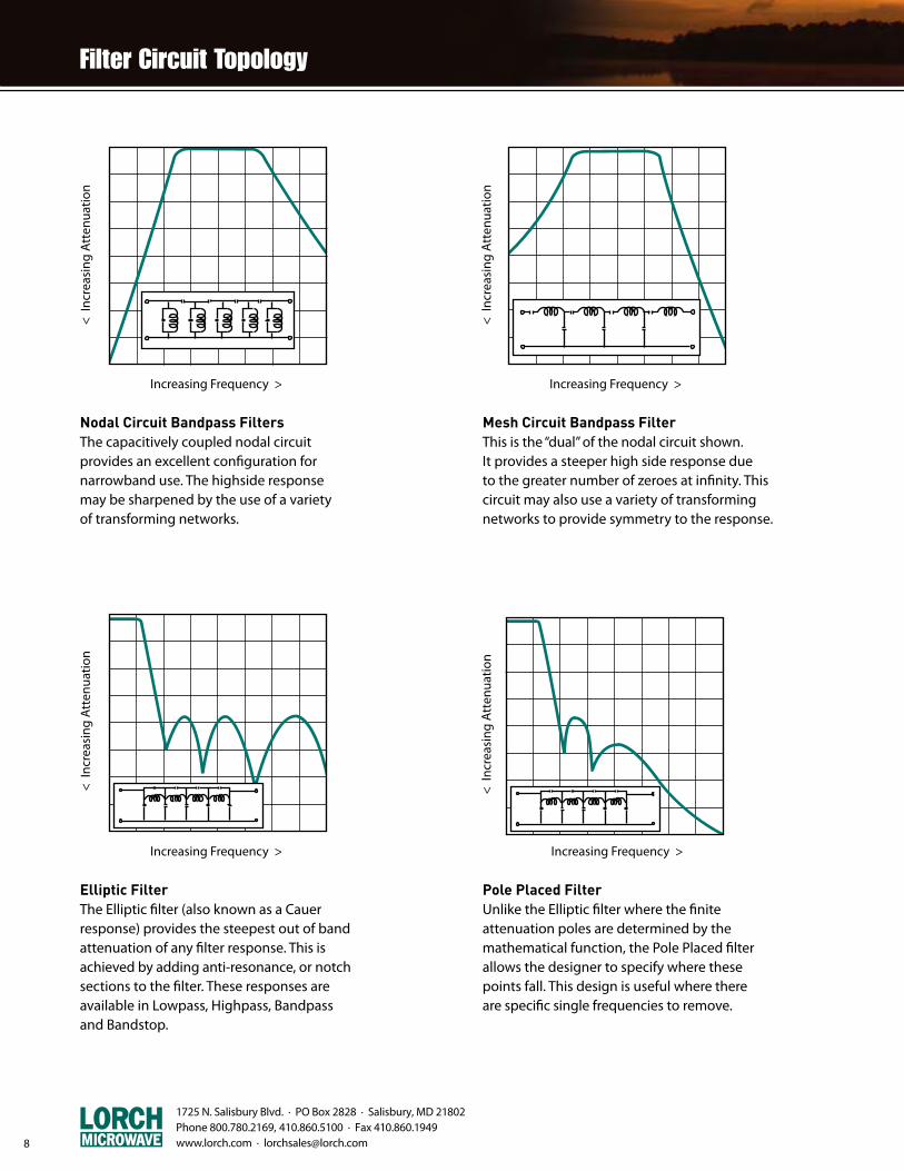
z 30 MHz to 40 GHz
z 3 dB Bandwidths from <0.5 to >66%
z High “Q”, Low Loss
z High Power
z Computer-Aided Designs
z Helical, Combline, Interdigital
z Waveguide
z 12 Stock Series
Lorch Microwave's cavity filter designs are available in the frequency range of 30 MHz to 40 GHz and with bandwidth options from less than 0.5% to over 66%. Cavity filters offer the user very low insertion loss, steep skirt selectivity, and narrower bandwidths than discrete component filters. Cavity filter performance is based on parts selection and physical layout of the helical coils, resonators, as well as the shape and size of the cavity housing. Lorch Microwave offers the user 12 unique stock designs to satisfy the majority of ap-plications. At lower frequencies a helical coil is used to excite the electromagnetic field, while a 1/8 to 1/4 wave capacitively loaded design is used at higher frequencies. A cylindrical waveguide design is used to achieve narrow bandwidths and high power operation.
Each filter is custom designed to your exact specificationso that you will receive the optimum performance at the lowest cost. Filter performance is easily predicted using our proprietary software, while CAD files are generated for our CNC machine and fabrication center. At Lorch Microwave, even complex designs and working drawings can be gener-ated in a matter of a few hours…not weeks.
Standard cavity filters generally are designed using alumi-num as the base metal. As most raw metals are inherently lossy, filter housings are silver plated for improved electrical characteristics and current flow. Brass, copper, aluminum or bi-metal resonators are used to minimize frequency drift over temperature.
1725 N. Salisbury Blvd. · PO Box 2828 · Salisbury, MD 21802 Phone 800.780.2169, 410.860.5100 · Fax 410.860.1949 www.lorch.com · [email protected]
1725 N. Salisbury Blvd. · PO Box 2828 · Salisbury, MD 21802 Phone 800.780.2169, 410.860.5100 · Fax 410.860.1949
www.lorch.com · [email protected] 11
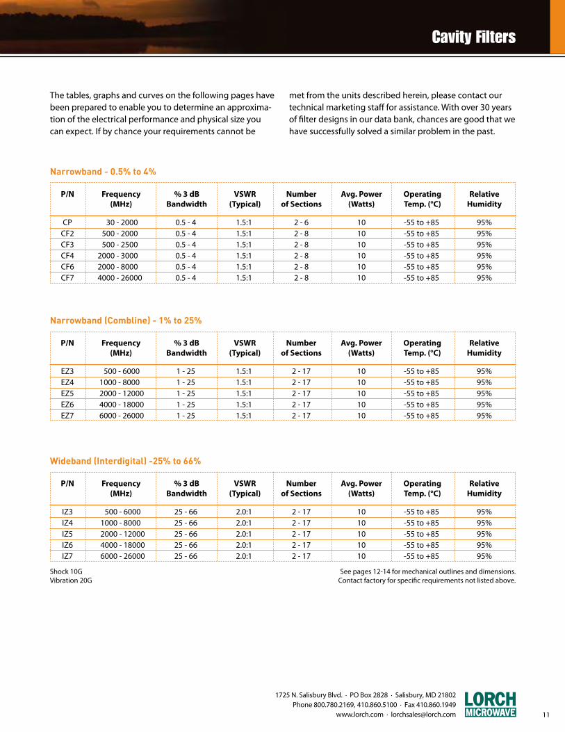
The tables, graphs and curves on the following pages have been prepared to enable you to determine an approxima-tion of the electrical performance and physical size you can expect. If by chance your requirements cannot be
met from the units described herein, please contact our technical marketing staff for assistance. With over 30 years of filter designs in our data bank, chances are good that we have successfully solved a similar problem in the past.
Narrowband - 0.5% to 4%
CP 30 - 2000 0.5 - 4 1.5:1 2 - 6 10 -55 to +85 95% CF2 500 - 2000 0.5 - 4 1.5:1 2 - 8 10 -55 to +85 95% CF3 500 - 2500 0.5 - 4 1.5:1 2 - 8 10 -55 to +85 95% CF4 2000 - 3000 0.5 - 4 1.5:1 2 - 8 10 -55 to +85 95% CF6 2000 - 8000 0.5 - 4 1.5:1 2 - 8 10 -55 to +85 95% CF7 4000 - 26000 0.5 - 4 1.5:1 2 - 8 10 -55 to +85 95%
P/N Frequency % 3 dB VSWR Number Avg. Power Operating Relative (MHz) Bandwidth (Typical) of Sections (Watts) Temp. (°C) Humidity
See pages 12-14 for mechanical outlines and dimensions. Contact factory for specific requirements not listed above.
Shock 10GVibration 20G
Narrowband (Combline) - 1% to 25%
EZ3 500 - 6000 1 - 25 1.5:1 2 - 17 10 -55 to +85 95% EZ4 1000 - 8000 1 - 25 1.5:1 2 - 17 10 -55 to +85 95% EZ5 2000 - 12000 1 - 25 1.5:1 2 - 17 10 -55 to +85 95% EZ6 4000 - 18000 1 - 25 1.5:1 2 - 17 10 -55 to +85 95% EZ7 6000 - 26000 1 - 25 1.5:1 2 - 17 10 -55 to +85 95%
P/N Frequency % 3 dB VSWR Number Avg. Power Operating Relative (MHz) Bandwidth (Typical) of Sections (Watts) Temp. (°C) Humidity
Wideband (Interdigital) -25% to 66%
IZ3 500 - 6000 25 - 66 2.0:1 2 - 17 10 -55 to +85 95% IZ4 1000 - 8000 25 - 66 2.0:1 2 - 17 10 -55 to +85 95% IZ5 2000 - 12000 25 - 66 2.0:1 2 - 17 10 -55 to +85 95% IZ6 4000 - 18000 25 - 66 2.0:1 2 - 17 10 -55 to +85 95% IZ7 6000 - 26000 25 - 66 2.0:1 2 - 17 10 -55 to +85 95%
P/N Frequency % 3 dB VSWR Number Avg. Power Operating Relative (MHz) Bandwidth (Typical) of Sections (Watts) Temp. (°C) Humidity

12
1725 N. Salisbury Blvd. · PO Box 2828 · Salisbury, MD 21802 Phone 800.780.2169, 410.860.5100 · Fax 410.860.1949 www.lorch.com · [email protected]
Cavity Filter Part Number Description
4 CF2 - 1200 / A15 - S / SM 1 2 3 4 5 6
1. Number of Sections
2. Series and Package Size
3. Center Frequency, MHz
4. Bandwidth and Code (3 dB BW Standard)
5. Input Connector
6. Output Connector (if different from input)
Connector TypeBNC Female (1)BNC Male (1)Blind MateN Female (1)N Male (1)RF Pin (2)SMA FemaleSMA MaleSMA RemovableSpecialTNC Female (1)TNC Male (1)
DesignatorBBMBPNNMPSSMSRXTTM
CONNECTORS
Calculating Number of SectionsThe following curves show the stopband frequenciesnormalized to the 3 dB bandwidth for filters with 2 to 13sections. A ratio of stopband frequency to 3 dB bandwidthis used.
The curve on the next page shows a slightly asymmetric frequency response resulting from the circuit used. Other schematics may be utilized to yield different attenuation characteristics (i.e. steeper on the high frequency side ofthe passband and shallower on the low side).
Example:A CF-Series filter has a center frequency of 1000 MHz and a3 dB bandwidth of 10 MHz. A stopband attenuation of 60 dB is required at 980 MHz and 1030 MHz.
The percentage bandwidth is 1%, calculated as follows:
For the first stopband requirement: Number of 3 dBbandwidths from center frequency =
From the CP/CF series attenuation curve, we find that aminimum of 7 sections are required.
The second stopband requirement is: Number of 3 dBbandwidths from center frequency =
From the CP/CF series attenuation curve, we find that 5sections minimum are required.
The greater number of sections must always be used to insure full specification compliance; therefore, a 7 section should be used.
3 dB BW (MHz) x 100 =
Fo (MHz) 10
x 100 = 1%1000
(1000 - 980) = 2.0
10
(1030 - 1000) = 3.0
10
(1) Requires Minimum Cross Section of 0.88”
(2) Requires SMA Removable Connectors at
High Frequencies
Bandwidth3 dB1 dBequi-ripplespecial
Designator/(blank)/A/R/X

1725 N. Salisbury Blvd. · PO Box 2828 · Salisbury, MD 21802 Phone 800.780.2169, 410.860.5100 · Fax 410.860.1949
www.lorch.com · [email protected] 13
Insertion Loss CalculationKnowing the number of sections, center frequency and bandwidth of the filter, insertion loss may be calculated using the following formula:
Example: 5CF2-915/25-N
1. Percentage BW = 25 / 915 x 100 = 2.7%
2. Q from CF series curves = 2.9
3. Number of Sections = 5
4.
Example: 9EZ6-8725/1375-S
1. Percentage BW = 1375/8725 x 100 = 15.8%
2. Q from EZ series curves = 1.1
3. Number of Sections = 9
4.
Loss = N - 1.5
+ 0.2 Q x %3dB BW
Loss = 5 - 1.5
+ 0.2 2.9 x 2.7
Loss = 9 - 1.5
+ 0.2 = 0.63 dB 1.1 x 15.8
-4 -3 -2 -1 1 2 3 4
0
10
20
30
40
50
60
70
3dB Ref BW
N = 3
N = 4
N = 3
N = 4
N = 5
N = 7
N = 2N = 2
N = 5
N = 7
CP and CF Series Attenuation Characteristics
Att
enua
tion
dB
Number of 3 dB BandwidthsFrom Center Frequency
5
4
3
2
1
0.5
0.30.1 0.5 1.0 5.0 10.0 30.0
CF2
CF3
CPCF7
CF7
CF4 CF6
“Q”-CF, CP Series, Narrowband Cavities
3.0
2.0
1.0
0.60.5 1.0 2.0 3.0 5.0 10.0 20.0 30.0
EZ3
EZ4
EZ5EZ6
EZ7
“Q”-EZ, IZ Series, Wideband Cavities
0
10
20
30
40
50
60
70-4 -3 -2 -1 1 2 3 4
3dB Ref BW
N = 3
N = 5
N = 7
N = 11
N = 13
N = 9 N = 9
N = 13
N = 11
N = 7
N = 3
N = 5
EZ and IZ Series Attenuation Characteristics
Att
enua
tion
dB
Center Frequency (GHz)
Att
enua
tion
dB
Center Frequency (GHz)
Att
enua
tion
dB
Number of 3 dB BandwidthsFrom Center Frequency
1725 N. Salisbury Blvd. · PO Box 2828 · Salisbury, MD 21802 Phone 800.780.2169, 410.860.5100 · Fax 410.860.1949 www.lorch.com · [email protected] 14
1.13(28.7).75 (19.1)
H
L
.13 (3.3)
.19 (4.8)
.13 (3.3)
.160 (4.1) Dia. 4 places
.38 (9.7)
.06 (1.5)
1.0(25.4)
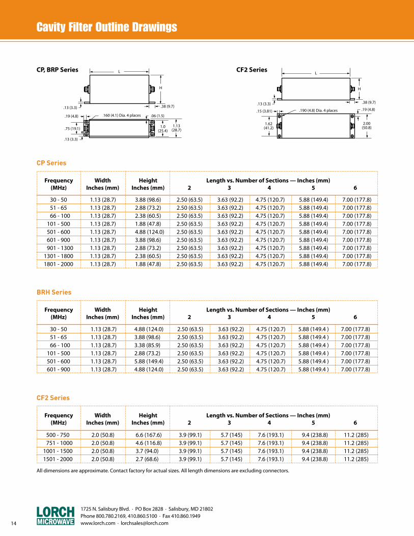
CP, BRP Series
1.62(41.2)
H
L
.13 (3.3)
.15 (3.81) .190 (4.8) Dia. 4 places
.38 (9.7)
.19 (4.8)
2.00(50.8)
CF2 Series
CP Series
30 - 50 1.13 (28.7) 3.88 (98.6) 2.50 (63.5) 3.63 (92.2) 4.75 (120.7) 5.88 (149.4) 7.00 (177.8) 51 - 65 1.13 (28.7) 2.88 (73.2) 2.50 (63.5) 3.63 (92.2) 4.75 (120.7) 5.88 (149.4) 7.00 (177.8) 66 - 100 1.13 (28.7) 2.38 (60.5) 2.50 (63.5) 3.63 (92.2) 4.75 (120.7) 5.88 (149.4) 7.00 (177.8) 101 - 500 1.13 (28.7) 1.88 (47.8) 2.50 (63.5) 3.63 (92.2) 4.75 (120.7) 5.88 (149.4) 7.00 (177.8) 501 - 600 1.13 (28.7) 4.88 (124.0) 2.50 (63.5) 3.63 (92.2) 4.75 (120.7) 5.88 (149.4) 7.00 (177.8) 601 - 900 1.13 (28.7) 3.88 (98.6) 2.50 (63.5) 3.63 (92.2) 4.75 (120.7) 5.88 (149.4) 7.00 (177.8) 901 - 1300 1.13 (28.7) 2.88 (73.2) 2.50 (63.5) 3.63 (92.2) 4.75 (120.7) 5.88 (149.4) 7.00 (177.8) 1301 - 1800 1.13 (28.7) 2.38 (60.5) 2.50 (63.5) 3.63 (92.2) 4.75 (120.7) 5.88 (149.4) 7.00 (177.8) 1801 - 2000 1.13 (28.7) 1.88 (47.8) 2.50 (63.5) 3.63 (92.2) 4.75 (120.7) 5.88 (149.4) 7.00 (177.8)
Frequency Width Height Length vs. Number of Sections — Inches (mm) (MHz) Inches (mm) Inches (mm) 2 3 4 5 6
BRH Series
30 - 50 1.13 (28.7) 4.88 (124.0) 2.50 (63.5) 3.63 (92.2) 4.75 (120.7) 5.88 (149.4 ) 7.00 (177.8) 51 - 65 1.13 (28.7) 3.88 (98.6) 2.50 (63.5) 3.63 (92.2) 4.75 (120.7) 5.88 (149.4 ) 7.00 (177.8) 66 - 100 1.13 (28.7) 3.38 (85.9) 2.50 (63.5) 3.63 (92.2) 4.75 (120.7) 5.88 (149.4 ) 7.00 (177.8) 101 - 500 1.13 (28.7) 2.88 (73.2) 2.50 (63.5) 3.63 (92.2) 4.75 (120.7) 5.88 (149.4 ) 7.00 (177.8) 501 - 600 1.13 (28.7) 5.88 (149.4) 2.50 (63.5) 3.63 (92.2) 4.75 (120.7) 5.88 (149.4 ) 7.00 (177.8) 601 - 900 1.13 (28.7) 4.88 (124.0) 2.50 (63.5) 3.63 (92.2) 4.75 (120.7) 5.88 (149.4 ) 7.00 (177.8)
Frequency Width Height Length vs. Number of Sections — Inches (mm) (MHz) Inches (mm) Inches (mm) 2 3 4 5 6
All dimensions are approximate. Contact factory for actual sizes. All length dimensions are excluding connectors.
500 - 750 2.0 (50.8) 6.6 (167.6) 3.9 (99.1) 5.7 (145) 7.6 (193.1) 9.4 (238.8) 11.2 (285) 751 - 1000 2.0 (50.8) 4.6 (116.8) 3.9 (99.1) 5.7 (145) 7.6 (193.1) 9.4 (238.8) 11.2 (285) 1001 - 1500 2.0 (50.8) 3.7 (94.0) 3.9 (99.1) 5.7 (145) 7.6 (193.1) 9.4 (238.8) 11.2 (285) 1501 - 2000 2.0 (50.8) 2.7 (68.6) 3.9 (99.1) 5.7 (145) 7.6 (193.1) 9.4 (238.8) 11.2 (285)
CF2 Series
Frequency Width Height Length vs. Number of Sections — Inches (mm) (MHz) Inches (mm) Inches (mm) 2 3 4 5 6
1725 N. Salisbury Blvd. · PO Box 2828 · Salisbury, MD 21802 Phone 800.780.2169, 410.860.5100 · Fax 410.860.1949
www.lorch.com · [email protected] 15
H
1.37(34.8)
L
.13 (3.3)
.15 (3.8) .160 (4.1) Dia. 4 places
.38 (9.7)
.19 (4.8)
1.75(44.5)
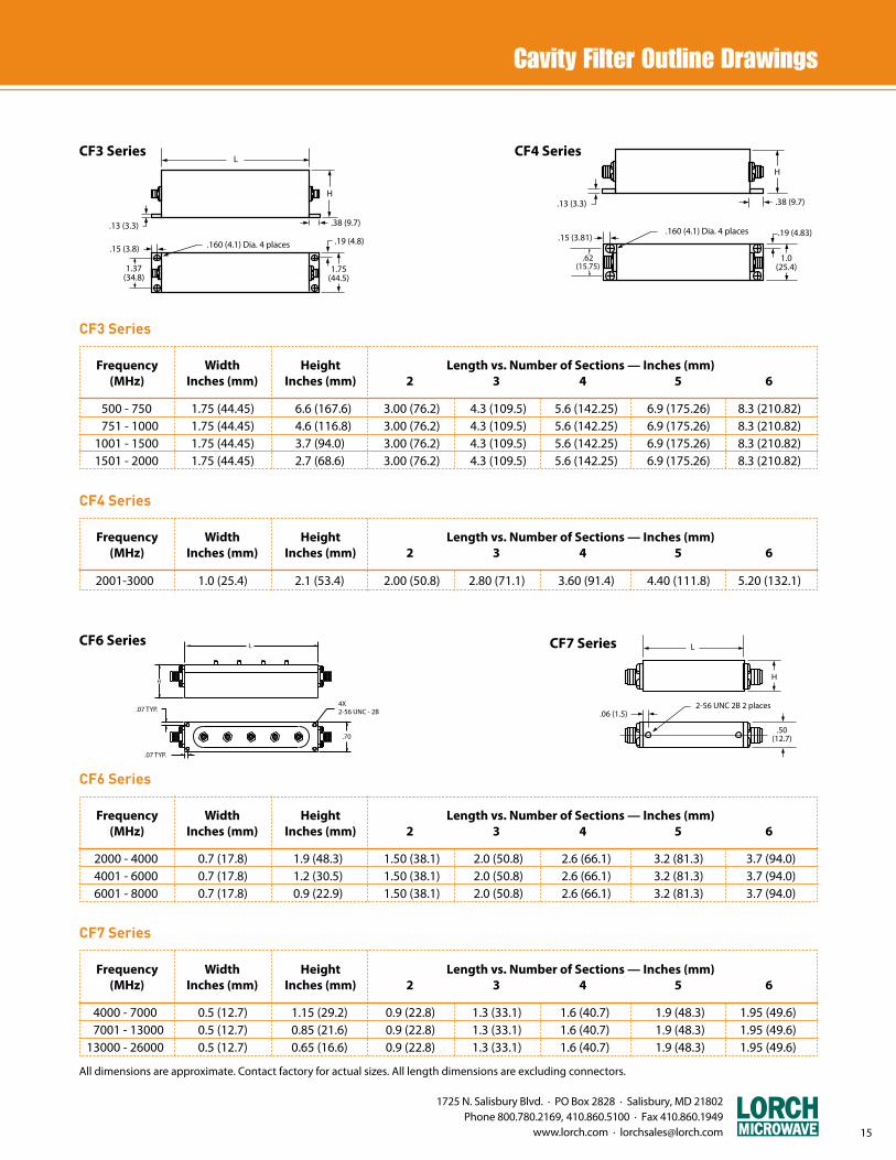
CF3 Series CF4 Series
p19, CF4 Series
.62(15.75)
H
.13 (3.3)
.15 (3.81).160 (4.1) Dia. 4 places
.38 (9.7)
.19 (4.83)
1.0(25.4)
L
H
.07 TYP.
.07 TYP.
.70
4X2-56 UNC - 2B
H
L
.06 (1.5)2-56 UNC 2B 2 places
.50(12.7)
CF6 Series CF7 Series
All dimensions are approximate. Contact factory for actual sizes. All length dimensions are excluding connectors.
500 - 750 1.75 (44.45) 6.6 (167.6) 3.00 (76.2) 4.3 (109.5) 5.6 (142.25) 6.9 (175.26) 8.3 (210.82) 751 - 1000 1.75 (44.45) 4.6 (116.8) 3.00 (76.2) 4.3 (109.5) 5.6 (142.25) 6.9 (175.26) 8.3 (210.82) 1001 - 1500 1.75 (44.45) 3.7 (94.0) 3.00 (76.2) 4.3 (109.5) 5.6 (142.25) 6.9 (175.26) 8.3 (210.82) 1501 - 2000 1.75 (44.45) 2.7 (68.6) 3.00 (76.2) 4.3 (109.5) 5.6 (142.25) 6.9 (175.26) 8.3 (210.82)
CF3 Series
Frequency Width Height Length vs. Number of Sections — Inches (mm) (MHz) Inches (mm) Inches (mm) 2 3 4 5 6
2001-3000 1.0 (25.4) 2.1 (53.4) 2.00 (50.8) 2.80 (71.1) 3.60 (91.4) 4.40 (111.8) 5.20 (132.1)
CF4 Series
Frequency Width Height Length vs. Number of Sections — Inches (mm) (MHz) Inches (mm) Inches (mm) 2 3 4 5 6
4000 - 7000 0.5 (12.7) 1.15 (29.2) 0.9 (22.8) 1.3 (33.1) 1.6 (40.7) 1.9 (48.3) 1.95 (49.6) 7001 - 13000 0.5 (12.7) 0.85 (21.6) 0.9 (22.8) 1.3 (33.1) 1.6 (40.7) 1.9 (48.3) 1.95 (49.6) 13000 - 26000 0.5 (12.7) 0.65 (16.6) 0.9 (22.8) 1.3 (33.1) 1.6 (40.7) 1.9 (48.3) 1.95 (49.6)
CF7 Series
Frequency Width Height Length vs. Number of Sections — Inches (mm) (MHz) Inches (mm) Inches (mm) 2 3 4 5 6
2000 - 4000 0.7 (17.8) 1.9 (48.3) 1.50 (38.1) 2.0 (50.8) 2.6 (66.1) 3.2 (81.3) 3.7 (94.0) 4001 - 6000 0.7 (17.8) 1.2 (30.5) 1.50 (38.1) 2.0 (50.8) 2.6 (66.1) 3.2 (81.3) 3.7 (94.0) 6001 - 8000 0.7 (17.8) 0.9 (22.9) 1.50 (38.1) 2.0 (50.8) 2.6 (66.1) 3.2 (81.3) 3.7 (94.0)
CF6 Series
Frequency Width Height Length vs. Number of Sections — Inches (mm) (MHz) Inches (mm) Inches (mm) 2 3 4 5 6
1725 N. Salisbury Blvd. · PO Box 2828 · Salisbury, MD 21802 Phone 800.780.2169, 410.860.5100 · Fax 410.860.1949 www.lorch.com · [email protected]
.06 TYP.
.06 TYP.
L
W
H
4X 2-56 UNC - 2B
L
H
.09
W
2X 2-56 UNC - 2B
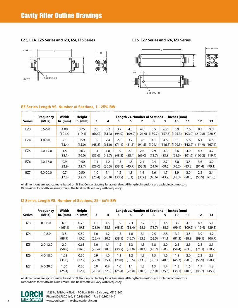
EZ3, EZ4, EZ5 Series and IZ3, IZ4, IZ5 Series EZ6, EZ7 Series and IZ6, IZ7 Series
All dimensions are approximate, based on % BW. Contact factory for actual sizes. All length dimensions are excluding connectors.Dimensions for width are a maximum. The final width will vary with frequency.
EZ Series Length VS. Number of Sections, 1 - 25% BW
EZ3 0.5-6.0 4.00 0.75 2.6 3.2 3.7 4.3 4.8 5.5 6.2 6.9 7.6 8.3 9.0 (101.6) (19.1) (66.0) (81.3) (94.0) (109.2) (121.9) (139.7) (157.5) (175.3) (193.0) (210.8) (228.6)
EZ4 1.0-8.0 2.1 0.59 1.9 2.4 2.8 3.2 3.6 4.1 4.6 5.1 5.6 6.1 6.6 (53.4) (15.0) (48.8) (61.0) (71.1) (81.3) (91.5) (104.1) (116.8) (129.5) (142.2) (154.9) (167.6)
EZ5 2.0-12.0 1.5 0.63 1.4 1.8 1.9 2.3 2.6 2.9 3.3 3.6 4.0 4.3 4.7 (38.1) (16.0) (35.6) (45.7) (48.8) (58.4) (66.0) (73.7) (83.8) (91.5) (101.6) (109.2) (119.4)
EZ6 4.0-18.0 0.9 0.50 1.1 1.2 1.5 1.8 2.1 2.4 2.7 3.0 3.3 3.6 3.9 (22.9) (12.7) (28.0) (30.5) (38.1) (45.7) (53.3) (61.0) (68.6) (76.2) (83.8) (91.4) (99.1)
EZ7 6.0-20.0 0.7 0.50 1.0 1.1 1.2 1.3 1.4 1.6 1.7 1.9 2.0 2.2 2.4 (17.8) (12.7) (25.4) (28.0) (30.5) (33) (35.6) (40.6) (43.2) (48.3) (50.8) (55.9) (61.0)
Frequency Width Height Length vs. Number of Sections — Inches (mm) Series (MHz) In. (mm) In. (mm) 3 4 5 6 7 8 9 10 11 12 13
All dimensions are approximate, based on % BW. Contact factory for actual sizes. All length dimensions are excluding connectors.Dimensions for width are a maximum. The final width will vary with frequency.
IZ Series Length VS. Number of Sections, 25 - 66% BW
IZ3 0.5-6.0 6.5 0.75 1.1 1.5 1.9 2.3 2.7 3.1 3.5 3.9 4.3 4.7 5.1 (165.1) (19.1) (28.0) (38.1) (48.3) (58.4) (68.6) (78.7) (88.9) (99.1) (109.2) (119.4) (129.5)
IZ4 1.0-8.0 3.5 0.59 1.0 1.2 1.5 1.8 2.1 2.5 2.8 3.2 3.5 3.9 4.2 (88.9) (15.0) (25.4) (30.5) (38.1) (45.7) (53.3) (63.5) (71.1) (81.3) (88.9) (99.1) (106.7)
IZ5 2.0-12.0 2.0 0.63 1.0 1.1 1.2 1.3 1.5 1.8 2.0 2.3 2.5 2.8 3.1 (50.8) (16.0) (25.4) (28.0) (30.5) (33.0) (38.1) (45.7) (50.8) (58.4) (63.5) (71.1) (78.7)
IZ6 4.0-18.0 1.25 0.50 0.9 1.0 1.1 1.2 1.3 1.5 1.6 1.8 2.0 2.2 2.3 (31.8) (12.7) (22.9) (25.4) (28.0) (30.5) (33.0) (38.1) (40.6) (45.7) (50.8) (55.9) (58.4)
IZ7 6.0-20.0 1.00 0.50 0.8 0.9 1.0 1.1 1.2 1.3 1.4 1.5 1.6 1.7 1.8 (25.4) (12.7) (20.3) (22.9) (25.4) (28.0) (30.5) (33.0) (35.6) (38.1) (40.6) (43.2) (45.7)
Frequency Width Height Length vs. Number of Sections — Inches (mm) Series (MHz) In. (mm) In. (mm) 3 4 5 6 7 8 9 10 11 12 13

Waveguide Part Number Description
4 WR62 - 12950 / R175 - C / CK 1 2 3 4 5 6
1. Number of Sections
2. Waveguide Size
3. Center Frequency, MHz
4. Bandwidth and Code
5. Input Connector
6. Output Connector
Connector TypeCover FlangeChoke FlangeSMA FemaleSMA MaleSMA RemovableK FemaleK MaleSpecial
DesignatorCCKSSMSRKKMX
CONNECTORS
Most standard connectors and flanges are available.
Bandwidth3 dB1 dBequi-ripplespecial
Designator/(blank)/A/R/X
Lorch Microwave offers a complete line of waveguide filters, that cover the frequency range of 2-40 GHz. Lorch offers waveguide filters as single components or in a diplexedconfiguration. Typical applications for radio communications.
17
1725 N. Salisbury Blvd. · PO Box 2828 · Salisbury, MD 21802 Phone 800.780.2169, 410.860.5100 · Fax 410.860.1949
www.lorch.com · [email protected]
z Frequency Range 2 - 40 GHz
z 2 thru 8 Sections
z W/G Flange or Connectorized
z Stand Alone Filters or Diplexed
Frequency Range 4 - 40 GHz 2 - 40 GHz Bandwidth 0.5 - 5% Contact Factory Number of Sections 2 - 8 2 - 13 Typical VSWR 1.5:1 <1.3:1 Power Handling 1 watt avg >100 watts
Waveguide Filter Electrical Performance
Parameter Standard Special
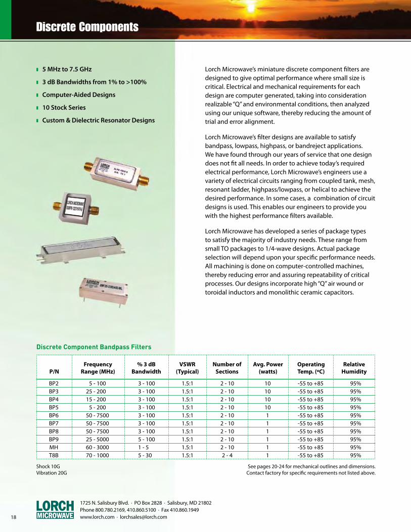
z 5 MHz to 7.5 GHz
z 3 dB Bandwidths from 1% to >100%
z Computer-Aided Designs
z 10 Stock Series
z Custom & Dielectric Resonator Designs
18
1725 N. Salisbury Blvd. · PO Box 2828 · Salisbury, MD 21802 Phone 800.780.2169, 410.860.5100 · Fax 410.860.1949 www.lorch.com · [email protected]
Lorch Microwave’s miniature discrete component filters are designed to give optimal performance where small size is critical. Electrical and mechanical requirements for each design are computer generated, taking into consideration realizable “Q” and environmental conditions, then analyzed using our unique software, thereby reducing the amount of trial and error alignment.
Lorch Microwave’s filter designs are available to satisfy bandpass, lowpass, highpass, or bandreject applications. We have found through our years of service that one design does not fit all needs. In order to achieve today’s required electrical performance, Lorch Microwave’s engineers use a variety of electrical circuits ranging from coupled tank, mesh, resonant ladder, highpass/lowpass, or helical to achieve the desired performance. In some cases, a combination of circuit designs is used. This enables our engineers to provide you with the highest performance filters available.
Lorch Microwave has developed a series of package types to satisfy the majority of industry needs. These range from small TO packages to 1/4-wave designs. Actual package selection will depend upon your specific performance needs. All machining is done on computer-controlled machines, thereby reducing error and assuring repeatability of critical processes. Our designs incorporate high “Q” air wound or toroidal inductors and monolithic ceramic capacitors.
See pages 20-24 for mechanical outlines and dimensions. Contact factory for specific requirements not listed above.
Shock 10GVibration 20G
Discrete Component Bandpass Filters
BP2 5 - 100 3 - 100 1.5:1 2 - 10 10 -55 to +85 95% BP3 25 - 200 3 - 100 1.5:1 2 - 10 10 -55 to +85 95% BP4 15 - 200 3 - 100 1.5:1 2 - 10 10 -55 to +85 95% BP5 5 - 200 3 - 100 1.5:1 2 - 10 10 -55 to +85 95% BP6 50 - 7500 3 - 100 1.5:1 2 - 10 1 -55 to +85 95% BP7 50 - 7500 3 - 100 1.5:1 2 - 10 1 -55 to +85 95% BP8 50 - 7500 3 - 100 1.5:1 2 - 10 1 -55 to +85 95% BP9 25 - 5000 5 - 100 1.5:1 2 - 10 1 -55 to +85 95% MH 60 - 3000 1 - 5 1.5:1 2 - 10 1 -55 to +85 95% T8B 70 - 1000 5 - 30 1.5:1 2 - 4 1 -55 to +85 95%
Frequency % 3 dB VSWR Number of Avg. Power Operating Relative P/N Range (MHz) Bandwidth (Typical) Sections (watts) Temp. (ºC) Humidity
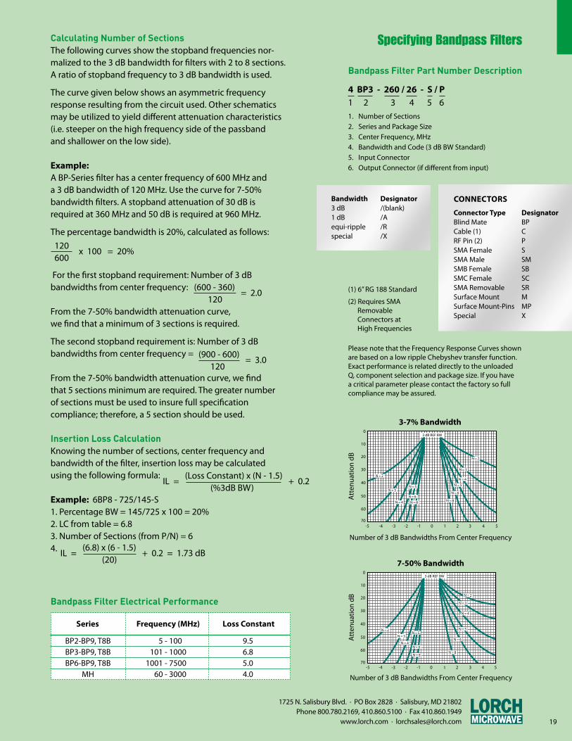
Calculating Number of SectionsThe following curves show the stopband frequencies nor-malized to the 3 dB bandwidth for filters with 2 to 8 sections. A ratio of stopband frequency to 3 dB bandwidth is used.
The curve given below shows an asymmetric frequency response resulting from the circuit used. Other schematics may be utilized to yield different attenuation characteristics (i.e. steeper on the high frequency side of the passbandand shallower on the low side).
Example:A BP-Series filter has a center frequency of 600 MHz anda 3 dB bandwidth of 120 MHz. Use the curve for 7-50%bandwidth filters. A stopband attenuation of 30 dB isrequired at 360 MHz and 50 dB is required at 960 MHz.
The percentage bandwidth is 20%, calculated as follows:
For the first stopband requirement: Number of 3 dBbandwidths from center frequency:
From the 7-50% bandwidth attenuation curve,we find that a minimum of 3 sections is required.
The second stopband requirement is: Number of 3 dBbandwidths from center frequency =
From the 7-50% bandwidth attenuation curve, we findthat 5 sections minimum are required. The greater numberof sections must be used to insure full specificationcompliance; therefore, a 5 section should be used.
Insertion Loss CalculationKnowing the number of sections, center frequency and bandwidth of the filter, insertion loss may be calculatedusing the following formula:
Example: 6BP8 - 725/145-S1. Percentage BW = 145/725 x 100 = 20%2. LC from table = 6.83. Number of Sections (from P/N) = 64.
Bandpass Filter Part Number Description
4 BP3 - 260 / 26 - S / P 1 2 3 4 5 61. Number of Sections2. Series and Package Size3. Center Frequency, MHz4. Bandwidth and Code (3 dB BW Standard)5. Input Connector6. Output Connector (if different from input)
Connector TypeBlind MateCable (1)RF Pin (2)SMA FemaleSMA MaleSMB FemaleSMC FemaleSMA RemovableSurface MountSurface Mount-PinsSpecial
DesignatorBPCPSSMSBSCSRMMPX
CONNECTORS
(1) 6” RG 188 Standard
(2) Requires SMA Removable Connectors at High Frequencies
Please note that the Frequency Response Curves shown are based on a low ripple Chebyshev transfer function. Exact performance is related directly to the unloaded Q, component selection and package size. If you have a critical parameter please contact the factory so full compliance may be assured.
0
10
20
30
40
50
60
70-3-4 -2 -1 0 1 2 3 4 5-5
N = 2
N = 3N = 5
N = 6N = 6
N = 5
N = 4
N = 3
N = 2
3 dB REF BW
N = 8 N = 8N = 4
Att
enua
tion
dB
Number of 3 dB Bandwidths From Center Frequency
3-7% Bandwidth
N = 2
N = 3
N = 6
-3-4 -2 -1 0 1 2 3 4 5-570
0
10
20
30
40
50
60
3 dB REF BW
N = 4
N = 5
N = 2
N = 3
N = 4
N = 5
N = 6
N = 8N = 8
Att
enua
tion
dB
Number of 3 dB Bandwidths From Center Frequency
7-50% Bandwidth
19
(600 - 360) = 2.0
120
(900 - 600) = 3.0
120
IL = (Loss Constant) x (N - 1.5)
+ 0.2 (%3dB BW)
IL = (6.8) x (6 - 1.5)
+ 0.2 = 1.73 dB (20)
BP2-BP9, T8B 5 - 100 9.5 BP3-BP9, T8B 101 - 1000 6.8 BP6-BP9, T8B 1001 - 7500 5.0 MH 60 - 3000 4.0
Bandpass Filter Electrical Performance
Series Frequency (MHz) Loss Constant
Bandwidth3 dB1 dBequi-ripplespecial
Designator/(blank)/A/R/X
1725 N. Salisbury Blvd. · PO Box 2828 · Salisbury, MD 21802 Phone 800.780.2169, 410.860.5100 · Fax 410.860.1949
www.lorch.com · [email protected]
120 x 100 = 20%
600
(1) Requires Minimum Cross Section of 0.88”
(2) Requires SMA Removable Connectors at High Frequencies
See pages 20-24 for mechanical outlines and dimensions. Contact factory for specific requirements not listed above.
Shock 10GVibration 20G
Discrete Component Lowpass Filters
LP2 1 - 100 1.5:1 2 - 10 10 -55 to +85 95% LP3 2.5 - 150 1.5:1 2 - 10 10 -55 to +85 95% LP4 10 - 200 1.5:1 2 - 10 10 -55 to +85 95% LP5 0.1 - 10 1.5:1 2 - 10 10 -55 to +85 95% LP6 10 - 6000 1.5:1 2 - 10 1 -55 to +85 95% LP7 10 - 6000 1.5:1 2 - 10 1 -55 to +85 95% LP8 10 - 6000 1.5:1 2 - 10 1 -55 to +85 95% LP9 10 - 6000 1.5:1 2 - 8 1 -55 to +85 95% T8L 70 - 1000 1.5:1 2 - 4 1 -55 to +85 95%
Frequency VSWR Number of Avg. Power Operating Relative P/N Range (MHz) (Typical) Sections (watts) Temp. (ºC) Humidity
20
1725 N. Salisbury Blvd. · PO Box 2828 · Salisbury, MD 21802 Phone 800.780.2169, 410.860.5100 · Fax 410.860.1949 www.lorch.com · [email protected]
Connector TypeBlind MateCable (1)RF Pin (2)SMA FemaleSMA MaleSMB FemaleSMC FemaleSMA RemovableSurface MountSurface Mount-PinsSpecial
DesignatorBPCPSSMSBSCSRMMPX
CONNECTORS
(1) 6” RG 188 Standard
(2) Requires SMA Removable Connectors at High Frequencies
Bandwidth3 dB1 dBequi-ripplespecial
Designator/(blank)/A/R/X
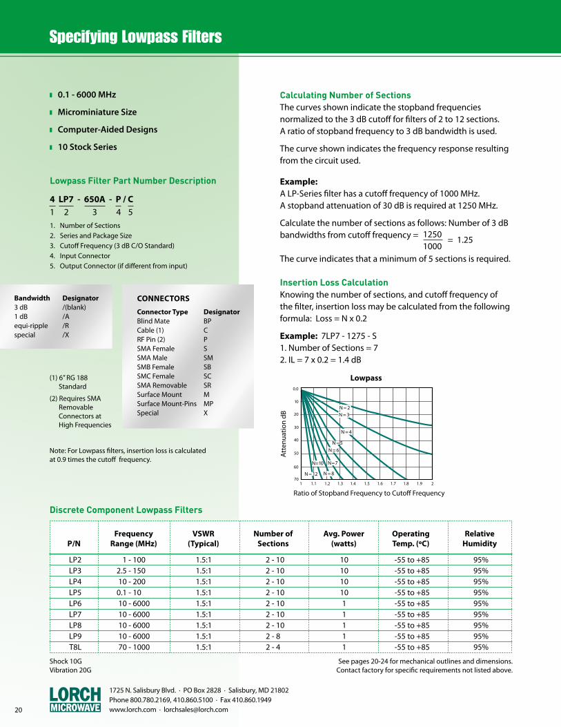
Calculating Number of SectionsThe curves shown indicate the stopband frequenciesnormalized to the 3 dB cutoff for filters of 2 to 12 sections.A ratio of stopband frequency to 3 dB bandwidth is used.
The curve shown indicates the frequency response resulting from the circuit used.
Example:A LP-Series filter has a cutoff frequency of 1000 MHz.A stopband attenuation of 30 dB is required at 1250 MHz.
Calculate the number of sections as follows: Number of 3 dB bandwidths from cutoff frequency =
The curve indicates that a minimum of 5 sections is required.
Insertion Loss CalculationKnowing the number of sections, and cutoff frequency of the filter, insertion loss may be calculated from the following formula: Loss = N x 0.2
Example: 7LP7 - 1275 - S1. Number of Sections = 72. IL = 7 x 0.2 = 1.4 dB
0.0
10
20
30
40
50
60
701.1 1.21 1.3 1.4 1.5 1.6 1.7 1.8 1.9 2
N = 2N = 3
N = 4
N = 5N = 6
N = 7
N = 8
N = 10
N = 12
Att
enua
tion
dB
Ratio of Stopband Frequency to Cutoff Frequency
Lowpass
z 0.1 - 6000 MHz
z Microminiature Size
z Computer-Aided Designs
z 10 Stock Series
Lowpass Filter Part Number Description
4 LP7 - 650A - P / C 1 2 3 4 51. Number of Sections2. Series and Package Size3. Cutoff Frequency (3 dB C/O Standard)4. Input Connector5. Output Connector (if different from input)
1250 = 1.25
1000
Note: For Lowpass filters, insertion loss is calculated at 0.9 times the cutoff frequency.
Connector TypeBlind MateCable (1)RF Pin (2)SMA FemaleSMA MaleSMB FemaleSMC FemaleSMA RemovableSurface MountSurface Mount-PinsSpecial
DesignatorBPCPSSMSBSCSRMMPX
CONNECTORS
(1) 6” RG 188 Standard
(2) Requires SMA Removable Connectors at High Frequencies
Bandwidth3 dB1 dBequi-ripplespecial
Designator/(blank)/A/R/X
z 0.1 - 4000 MHz
z Broad Passband Range
z Computer-Aided Designs
z 9 Stock Series
Highpass Filter Part Number Description
3 HPD - 2000 - SR / SRM 1 2 3 4 51. Number of Sections2. Series and Package Size3. Cutoff Frequency (3 dB BW Standard)4. Input Connector5. Output Connector (if different from input)
Note: For Highpass filters, insertion loss is calculated at 1.1 times the cutoff frequency.
* Note: This is an approximation and may vary depending on transfer function and/or packaging. If a specific require-ment is desired please check with the factory.
See pages 20-24 for mechanical outlines and dimensions. Contact factory for specific requirements not listed above.Shock 10GVibration 20G
Discrete Component Highpass Filters
HP2 0.1 - 200 2 - 6 3-5 x Fc 1.5:1 10 -55 to +85 95% HP3 3 - 500 2 - 6 3-5 x Fc 1.5:1 10 -55 to +85 95% HP4 50 - 1000 2 - 6 3-5 x Fc 1.5:1 10 -55 to +85 95% HP5 0.1 - 200 2 - 6 3-5 x Fc 1.5:1 10 -55 to +85 95% HPD 550 - 4000 2 - 6 3-5 x Fc 1.5:1 1 -55 to +85 95% HP6 300 - 1000 2 - 6 3-5 x Fc 1.5:1 1 -55 to +85 95% HP7 500 - 1000 2 - 6 3-5 x Fc 1.5:1 1 -55 to +85 95% HP8 10 - 500 2 - 6 3-5 x Fc 1.5:1 1 -55 to +85 95% HP9 100 - 1000 2 - 6 3-5 x Fc 1.5:1 1 -55 to +85 95%
Frequency Number of Upper VSWR Avg. Power Operating Relative P/N Range (MHz) Sections Bandpass Limit* (Typical) (watts) Temp. (ºC) Humidity
21
1725 N. Salisbury Blvd. · PO Box 2828 · Salisbury, MD 21802 Phone 800.780.2169, 410.860.5100 · Fax 410.860.1949
www.lorch.com · [email protected]
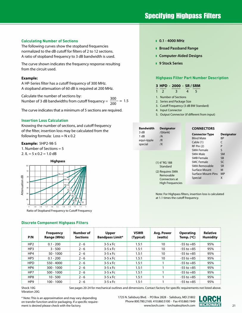
Calculating Number of SectionsThe following curves show the stopband frequenciesnormalized to the dB cutoff for filters of 2 to 12 sections.A ratio of stopband frequency to 3 dB bandwidth is used.
The curve shown indicates the frequency response resulting from the circuit used.
Example:A HP-Series filter has a cutoff frequency of 300 MHz.A stopband attenuation of 60 dB is required at 200 MHz.
Calculate the number of sections by:Number of 3 dB bandwidths from cutoff frequency =
The curve indicates that a minimum of 5 sections are required.
Insertion Loss CalculationKnowing the number of sections, and cutoff frequencyof the filter, insertion loss may be calculated from thefollowing formula: Loss = N x 0.2
Example: 5HP2-98-S1. Number of Sections = 52. IL = 5 x 0.2 = 1.0 dB
0.0
10
20
30
40
50
60
701.9 1.82 1.7 1.6 1.5 1.4 1.3 1.2 1.1 1
N = 2
N = 3
N = 4
N = 5
N = 6N = 7
N = 8N = 10
N = 12
Att
enua
tion
dB
Ratio of Stopband Frequency to Cutoff Frequency
Highpass
300 = 1.5
200
1725 N. Salisbury Blvd. · PO Box 2828 · Salisbury, MD 21802 Phone 800.780.2169, 410.860.5100 · Fax 410.860.1949 www.lorch.com · [email protected] 22
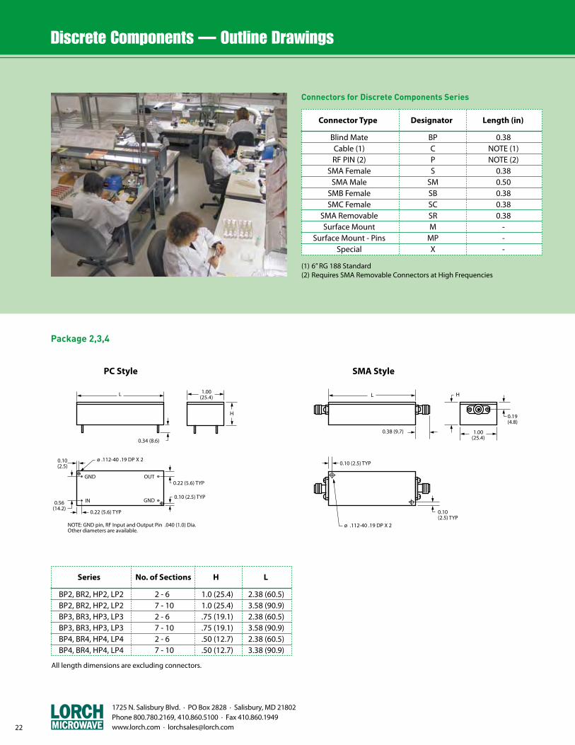
Package 2,3,4
(1) 6” RG 188 Standard(2) Requires SMA Removable Connectors at High Frequencies
Connectors for Discrete Components Series
Blind Mate BP 0.38 Cable (1) C NOTE (1) RF PIN (2) P NOTE (2) SMA Female S 0.38 SMA Male SM 0.50 SMB Female SB 0.38 SMC Female SC 0.38 SMA Removable SR 0.38 Surface Mount M - Surface Mount - Pins MP - Special X -
Connector Type Designator Length (in)
All length dimensions are excluding connectors.
BP2, BR2, HP2, LP2 2 - 6 1.0 (25.4) 2.38 (60.5) BP2, BR2, HP2, LP2 7 - 10 1.0 (25.4) 3.58 (90.9) BP3, BR3, HP3, LP3 2 - 6 .75 (19.1) 2.38 (60.5) BP3, BR3, HP3, LP3 7 - 10 .75 (19.1) 3.58 (90.9) BP4, BR4, HP4, LP4 2 - 6 .50 (12.7) 2.38 (60.5) BP4, BR4, HP4, LP4 7 - 10 .50 (12.7) 3.38 (90.9)
Series No. of Sections H L
PC Style
L
0.34 (8.6)
1.00(25.4)
H
ø .112-40 .19 DP X 20.10(2.5)
0.56(14.2)
0.22 (5.6) TYP
0.10 (2.5) TYP
0.22 (5.6) TYPGND
IN
OUT
GND
NOTE: GND pin, RF Input and Output Pin .040 (1.0) Dia.Other diameters are available.
1.00(25.4)
H
0.19(4.8)
L
0.38 (9.7)
0.10 (2.5) TYP
0.10(2.5) TYP
ø .112-40 .19 DP X 2
SMA Style
L
0.34 (8.6)
1.00(25.4)
H
ø .112-40 .19 DP X 20.10(2.5)
0.56(14.2)
0.22 (5.6) TYP
0.10 (2.5) TYP
0.22 (5.6) TYPGND
IN
OUT
GND
NOTE: GND pin, RF Input and Output Pin .040 (1.0) Dia.Other diameters are available.
1.00(25.4)
H
0.19(4.8)
L
0.38 (9.7)
0.10 (2.5) TYP
0.10(2.5) TYP
ø .112-40 .19 DP X 2
1725 N. Salisbury Blvd. · PO Box 2828 · Salisbury, MD 21802 Phone 800.780.2169, 410.860.5100 · Fax 410.860.1949
www.lorch.com · [email protected] 23
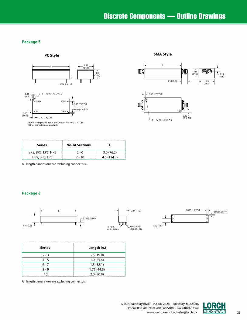
Package 5
0.12 (3.0) MIN
0.06 (1.5) TYP0.075 (1.9) TYP
L
0.31 (7.9)
0.22 (5.6)
0.44 (11.2)
GND PINS.036 (.9) Dia
RF PINS.017 (.5) Dia
0.12 (3.0) MIN
0.06 (1.5) TYP0.075 (1.9) TYP
L
0.31 (7.9)
0.22 (5.6)
0.44 (11.2)
GND PINS.036 (.9) Dia
RF PINS.017 (.5) DiaPackage 6
L
0.34 (8.6)
1.25(31.8)
1.0(25.4)
ø .112-40 .19 DP X 20.10(2.5)
0.65(16.5)
0.30 (7.6) TYP
0.10 (2.5) TYP
0.30 (7.6) TYPGND
IN
OUT
GND
NOTE: GND pin, RF Input and Output Pin .040 (1.0) Dia.Other diameters are available.
1.25(31.8)
1.0(25.4) 0.19
(4.8)
L
0.38 (9.7)
0.10 (2.5) TYP
0.10(2.5) TYP
ø .112-40 .19 DP X 2
PC Style SMA Style
L
0.34 (8.6)
1.25(31.8)
1.0(25.4)
ø .112-40 .19 DP X 20.10(2.5)
0.65(16.5)
0.30 (7.6) TYP
0.10 (2.5) TYP
0.30 (7.6) TYPGND
IN
OUT
GND
NOTE: GND pin, RF Input and Output Pin .040 (1.0) Dia.Other diameters are available.
1.25(31.8)
1.0(25.4) 0.19
(4.8)
L
0.38 (9.7)
0.10 (2.5) TYP
0.10(2.5) TYP
ø .112-40 .19 DP X 2
All length dimensions are excluding connectors.
BP5, BR5, LP5, HP5 2 - 6 3.0 (76.2) BP5, BR5, LP5 7 - 10 4.5 (114.3)
Series No. of Sections L
All length dimensions are excluding connectors.
2 - 3 .75 (19.0) 4 - 5 1.0 (25.4) 6 - 7 1.5 (38.1) 8 - 9 1.75 (44.5) 10 2.0 (50.8)
Series Length in.)
1725 N. Salisbury Blvd. · PO Box 2828 · Salisbury, MD 21802 Phone 800.780.2169, 410.860.5100 · Fax 410.860.1949 www.lorch.com · [email protected] 24
0.38(9.7)
GND PINS.036 (.9) Dia
RF PINS.017 (.5) Dia
0.12(3.0) MIN
0.06(1.5) TYP
0.075 (1.9) TYP
L
0.38(9.7)
0.19(4.8)
0.19(4.8)
0.38(9.7)
SMA ConnectorX 2
0.38(9.7)
ø .060-80 .13 DP X 4
0.06 (1.5) TYP
0.06 (1.5) TYP
C L
L
C L
0.110 (2.8) TYP0.05 (1.3) TYP
0.02 (.5) TYP
0.38(9.7)
0.10 (2.5) TYP
L
0.38(9.7)
0.10(2.5) TYP
ø 0.017 PinX 2
C L
0.38(9.7)
ø .060-80 X .10 DP X 40.06(1.5)
0.38(9.7)
0.19(4.8)
C L
L
0.38(9.7)
0.18 (4.7)
C L
0.38(9.7)
0.38(9.7)
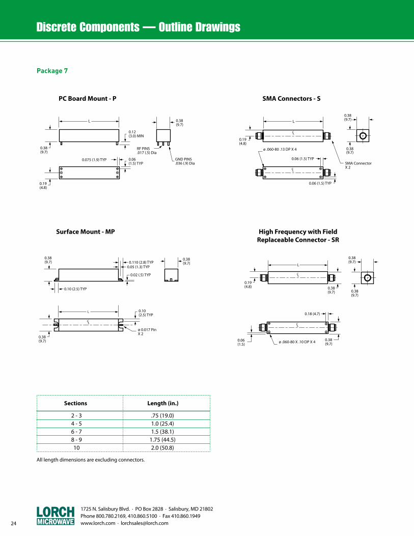
Package 7
PC Board Mount - P SMA Connectors - S
0.38(9.7)
GND PINS.036 (.9) Dia
RF PINS.017 (.5) Dia
0.12(3.0) MIN
0.06(1.5) TYP
0.075 (1.9) TYP
L
0.38(9.7)
0.19(4.8)
0.19(4.8)
0.38(9.7)
SMA ConnectorX 2
0.38(9.7)
ø .060-80 .13 DP X 4
0.06 (1.5) TYP
0.06 (1.5) TYP
C L
L
C L
0.110 (2.8) TYP0.05 (1.3) TYP
0.02 (.5) TYP
0.38(9.7)
0.10 (2.5) TYP
L
0.38(9.7)
0.10(2.5) TYP
ø 0.017 PinX 2
C L
0.38(9.7)
ø .060-80 X .10 DP X 40.06(1.5)
0.38(9.7)
0.19(4.8)
C L
L
0.38(9.7)
0.18 (4.7)
C L
0.38(9.7)
0.38(9.7)
Surface Mount - MP High Frequency with FieldReplaceable Connector - SR
0.38(9.7)
GND PINS.036 (.9) Dia
RF PINS.017 (.5) Dia
0.12(3.0) MIN
0.06(1.5) TYP
0.075 (1.9) TYP
L
0.38(9.7)
0.19(4.8)
0.19(4.8)
0.38(9.7)
SMA ConnectorX 2
0.38(9.7)
ø .060-80 .13 DP X 4
0.06 (1.5) TYP
0.06 (1.5) TYP
C L
L
C L
0.110 (2.8) TYP0.05 (1.3) TYP
0.02 (.5) TYP
0.38(9.7)
0.10 (2.5) TYP
L
0.38(9.7)
0.10(2.5) TYP
ø 0.017 PinX 2
C L
0.38(9.7)
ø .060-80 X .10 DP X 40.06(1.5)
0.38(9.7)
0.19(4.8)
C L
L
0.38(9.7)
0.18 (4.7)
C L
0.38(9.7)
0.38(9.7)
0.38(9.7)
GND PINS.036 (.9) Dia
RF PINS.017 (.5) Dia
0.12(3.0) MIN
0.06(1.5) TYP
0.075 (1.9) TYP
L
0.38(9.7)
0.19(4.8)
0.19(4.8)
0.38(9.7)
SMA ConnectorX 2
0.38(9.7)
ø .060-80 .13 DP X 4
0.06 (1.5) TYP
0.06 (1.5) TYP
C L
L
C L
0.110 (2.8) TYP0.05 (1.3) TYP
0.02 (.5) TYP
0.38(9.7)
0.10 (2.5) TYP
L
0.38(9.7)
0.10(2.5) TYP
ø 0.017 PinX 2
C L
0.38(9.7)
ø .060-80 X .10 DP X 40.06(1.5)
0.38(9.7)
0.19(4.8)
C L
L
0.38(9.7)
0.18 (4.7)
C L
0.38(9.7)
0.38(9.7)
All length dimensions are excluding connectors.
2 - 3 .75 (19.0) 4 - 5 1.0 (25.4) 6 - 7 1.5 (38.1) 8 - 9 1.75 (44.5) 10 2.0 (50.8)
Sections Length (in.)

1725 N. Salisbury Blvd. · PO Box 2828 · Salisbury, MD 21802 Phone 800.780.2169, 410.860.5100 · Fax 410.860.1949
www.lorch.com · [email protected] 25
PC Board Mount - P SMA Connectors - S
0.12(3.0) MIN
0.06(1.5) TYP
0.075 (1.9) TYP
L
0.40(10.2)
0.25(6.4)
0.50(12.7)
GND PINS.036 (.9) Dia
RF PINS.017 (.5) Dia
0.25(6.4)
SMA ConnectorX 2
0.40(10.2)ø .060-80 X .13 DP X 4
0.06 (1.5) TYP
0.06 (1.5) TYP
L
C L
C L
0.110 (2.8) TYP0.05 (1.3) TYP
0.02 (.5) TYP
0.40(10.2)
0.10 (2.5) TYP
L
0.50(12.7)
0.10 (2.5) TYP
ø 0.017 PinX 2
C L
0.40(10.2)
0.50(12.7)
0.50(12.7)
Surface Mount - MP
p23. Series T8B, T8L
OUT
GND
IN
GND
0.447(11.35)
ø 0.60(15.2)
ø 0.017 (0.4)/0.020 (0.5)TYP
0.447 (11.35)
0.35(8.8)
0.12(3.1)
Series T8B, T8L
Package 8
0.12(3.0) MIN
0.06(1.5) TYP
0.075 (1.9) TYP
L
0.40(10.2)
0.25(6.4)
0.50(12.7)
GND PINS.036 (.9) Dia
RF PINS.017 (.5) Dia
0.25(6.4)
SMA ConnectorX 2
0.40(10.2)ø .060-80 X .13 DP X 4
0.06 (1.5) TYP
0.06 (1.5) TYP
L
C L
C L
0.110 (2.8) TYP0.05 (1.3) TYP
0.02 (.5) TYP
0.40(10.2)
0.10 (2.5) TYP
L
0.50(12.7)
0.10 (2.5) TYP
ø 0.017 PinX 2
C L
0.40(10.2)
0.50(12.7)
0.50(12.7)
All length dimensions are excluding connectors.
2 - 3 .75 (19.0) 4 - 5 1.0 (25.4) 6 - 7 1.5 (38.1) 8 - 9 1.75 (44.5) 10 2.0 (50.8)
Sections Length (in.)
1725 N. Salisbury Blvd. · PO Box 2828 · Salisbury, MD 21802 Phone 800.780.2169, 410.860.5100 · Fax 410.860.1949 www.lorch.com · [email protected]
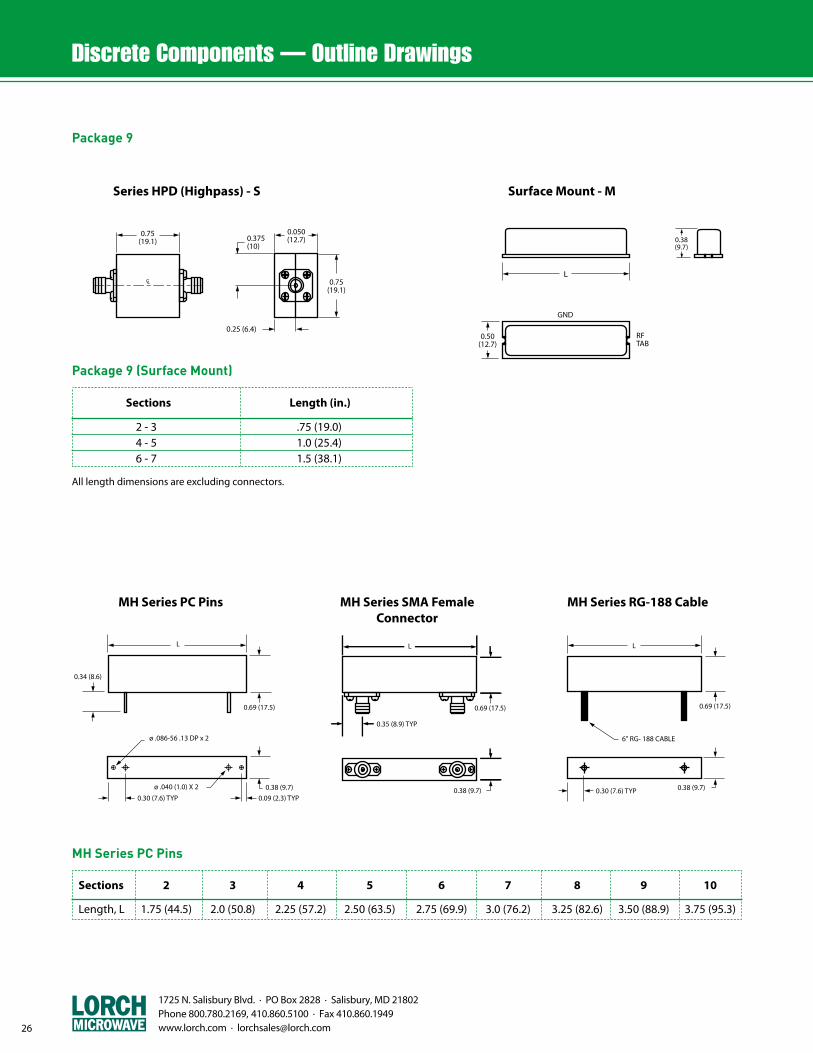
Package 9
Series HPD (Highpass) - S Surface Mount - M
0.050(12.7)
p23. Series HPD (Highpass)
0.25 (6.4)
0.75(19.1) 0.375
(10)
0.75(19.1)
CL
GND
RFTAB
0.38(9.7)
0.50(12.7)
L
p23. MH Series PC Pins
L
0.34 (8.6)
0.69 (17.5)
ø .086-56 .13 DP x 2
0.30 (7.6) TYP0.38 (9.7)
0.09 (2.3) TYP
ø .040 (1.0) X 2
p23. MH series SMA female Connectors
L
0.69 (17.5)
0.35 (8.9) TYP
0.38 (9.7)
p23. MH series RG - 188 Cable
0.30 (7.6) TYP 0.38 (9.7)
L
0.69 (17.5)
6" RG- 188 CABLE
MH Series PC Pins MH Series SMA Female Connector
MH Series RG-188 Cable
Sections 2 3 4 5 6 7 8 9 10
Length, L 1.75 (44.5) 2.0 (50.8) 2.25 (57.2) 2.50 (63.5) 2.75 (69.9) 3.0 (76.2) 3.25 (82.6) 3.50 (88.9) 3.75 (95.3)
MH Series PC Pins
Package 9 (Surface Mount)
All length dimensions are excluding connectors.
2 - 3 .75 (19.0) 4 - 5 1.0 (25.4) 6 - 7 1.5 (38.1)
Sections Length (in.)
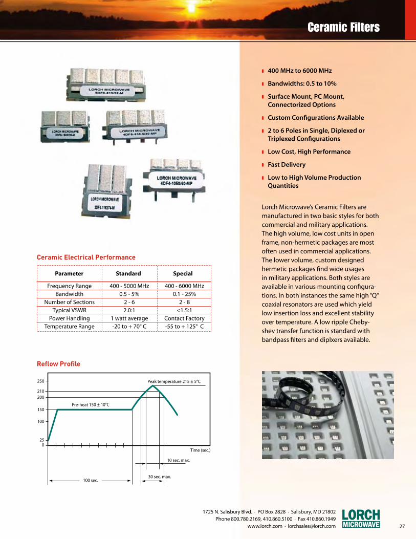
z 400 MHz to 6000 MHz
z Bandwidths: 0.5 to 10%
z Surface Mount, PC Mount, Connectorized Options
z Custom Configurations Available
z 2 to 6 Poles in Single, Diplexed or Triplexed Configurations
z Low Cost, High Performance
z Fast Delivery
z Low to High Volume Production Quantities
Lorch Microwave’s Ceramic Filters are manufactured in two basic styles for both commercial and military applications. The high volume, low cost units in open frame, non-hermetic packages are most often used in commercial applications. The lower volume, custom designed hermetic packages find wide usages in military applications. Both styles are available in various mounting configura-tions. In both instances the same high “Q” coaxial resonators are used which yield low insertion loss and excellent stability over temperature. A low ripple Cheby-shev transfer function is standard with bandpass filters and diplxers available.
Ceramic Filters, info chart
Peak temperature 215 ± 5°C
Pre-heat 150 ± 10°C
250
210200
150
100
250
100 sec.30 sec. max.
10 sec. max.
Time (sec.)
Reflow Profile
1725 N. Salisbury Blvd. · PO Box 2828 · Salisbury, MD 21802 Phone 800.780.2169, 410.860.5100 · Fax 410.860.1949
www.lorch.com · [email protected] 27
Ceramic Electrical Performance
Frequency Range 400 - 5000 MHz 400 - 6000 MHz Bandwidth 0.5 - 5% 0.1 - 25% Number of Sections 2 - 6 2 - 8 Typical VSWR 2.0:1 <1.5:1 Power Handling 1 watt average Contact Factory Temperature Range -20 to + 70° C -55 to + 125° C
Parameter Standard Special
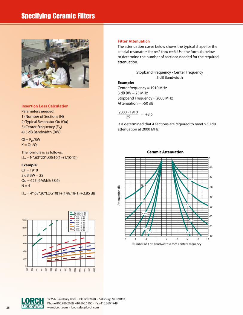
Filter AttenuationThe attenuation curve below shows the typical shape for the coaxial resonators for n=2 thru n=6. Use the formula below to determine the number of sections needed for the required attenuation.
Stopband Frequency - Center Frequency3 dB Bandwidth
Example:Center frequency = 1910 MHz3 dB BW = 25 MHzStopband Frequency = 2000 MHzAttenuation = >50 dB
It is determined that 4 sections are required to meet >50 dB attenuation at 2000 MHz
2000 - 1910 = +3.6 25
Ceramic Q chart
1200
1000
800
600
400
200
0
400
100060
0
800
200
1200
1400
1600
1800
2000
2200
2400
2600
2800
3000
12 mm / Er 3812 mm / Er 85
6 mm / Er 856 mm / Er 38
4 mm / Er 854 mm / Er 38
3 mm / Er 853 mm / Er 38
2 mm / Er 852 mm / Er 38
Insertion Loss CalculationParameters needed:1) Number of Sections (N)2) Typical Resonator Qu (Qu)3) Center Frequency (Fo)4) 3 dB Bandwidth (BW)
Ql = Fo/BWK = Qu/Ql
The formula is as follows:l.L. = N*.63*20*LOG10(1+(1/(K-1)))
Example:CF = 19103 dB BW = 25Qu = 625 (6MM/Er38.6)N = 4
l.L. = 4*.63*20*LOG10(1+(1/(8.18-1)))-2.85 dB
CeramicAttennation Characteristics
-4 -3 -2 -1 0 +1 +2 +3 +4-80
-70
-60
-50
-40
-30
-20
-10
0
N = 2
N = 3
N = 4
N = 5
N = 6
N = 2
N = 3
N = 4
N = 5
N = 6
Att
enua
tion
dB
Number of 3 dB Bandwidths From Center Frequency
Ceramic Attenuation
1725 N. Salisbury Blvd. · PO Box 2828 · Salisbury, MD 21802 Phone 800.780.2169, 410.860.5100 · Fax 410.860.1949 www.lorch.com · [email protected]

1725 N. Salisbury Blvd. · PO Box 2828 · Salisbury, MD 21802 Phone 800.780.2169, 410.860.5100 · Fax 410.860.1949
www.lorch.com · [email protected] 29
Ceramic "MP" Series Sections (2+3)
H
AW2
0.080 TYP(2.0) 0.080 TYP
(2.0)
L “MP”
W1
C L
.11
Ceramic “MP” Series (Sections 2 + 3) Ceramic “MP” Series (Sections 4, 5 + 6)
Ceramic "MP Series Sections (4,5+6)
HB
AW2
0.080 TYP(2.0) 0.080 TYP
(2.0)
L “MP”
W1
.11
Note:The tables shown for the “MP” series may be used as an approximation in determining the dimensions for the “M” series. The exact dimensions for the “M” series can be determined by using the “Lorch Filter Select Plus” (LFSP) filter selection program on the Lorch Microwave website.
Ceramic “M” Series (Sections 4, 5 + 6)
L “M”
0.050 (1.27) TYP
0.175 (4.44) TYP
IndicatesCopper
0.150 (3.81)TYP
0.050 (1.27) TYP
0.015 (0.38) TYP
0.050 (1.27) TYP
R 0.026X 10
W
H
W2
W4
Ceramic “M” Series (Sections 2 + 3)
L “M”
0.050 (1.27) TYP
0.175 (4.44) TYP
0.050 (1.27) TYP
R 0.026X 8
W
W2
L2
IndicatesCopper
0.015 (0.38) TYPH
W4
0.050 (1.27) TYP
0.150 (3.81)TYP
*W1= Frequency Dependent; *W2= .250 over 1.1 GHz, .500 under 1.1 GHz
Ceramic Electrical Performance
Profile Width 1 Width 2 Height Length vs. No. of Sections, Inches (mm) Inches (mm) Inches (mm) Inches (mm) 2 3 A
12 mm .51 (12.5) .96 (24.4) 1.44 (36.6) .24 6 & 7 mm *See Notes *See Notes .28 (7.1) .56 (14.2) .84 (21.3) .14 4 mm .19 (4.8) .32 (8) 0.48 (12.2) .08
Profile Width 1 Width 2 Height Length vs. No. of Sections, Inches (mm) Inches (mm) Inches (mm) Inches (mm) 4 5 6 A B
12 mm .51 (12.5) 1.92 (48.8) 2.40 (61) 2.88 (73.1) .24 .28 6 & 7mm *See Notes *See Notes .28 (7.1) 1.12 (28.4) 1.49 (37.8) 1.68 (42.7) .14 .28 4 mm .19 (4.8) 0.64 (16.2) 0.80 (20.3) 0.96 (24.3) .08 .20
Notes:L = Number of resonators x size of resonators H = Size of resonators (height) + .03 TYPW = Length of resonators (approx.) length is determined by frequency

1725 N. Salisbury Blvd. · PO Box 2828 · Salisbury, MD 21802 Phone 800.780.2169, 410.860.5100 · Fax 410.860.1949 www.lorch.com · [email protected]
z 30 - 5000 MHz
z Leaded Surface Mount Package
z Low Profile
z Ceramic/Discrete Technology
z 2–8 Sections
z 3 dB Bandwidth (BPF) 2-100%
z Average Power 1 Watt
z Temperature Range -55 to +85°C
z Bandpass, Lowpass, Highpass & Band Reject Models Available
z Transfer Functions: ■ Chebyshev ■ Bessel ■ Elliptical ■ Gaussian
Lorch Microwave Z-Pack Series™ of leaded surface mount filters provide the designer with an alternative to traditional axial leads and “gull wing” RF Pin configurations. In addition to ease of installation the Z-Pack Series™ filters exhibit extremely good impedance matching characteristics and very good isolation.
The Z-Pack Series™ filters cover the frequency range of 30 MHz to 5000 MHz and is available in bandpass, lowpass, high-pass and band reject models with various transfer functions. Several package configurations are available with low profile (.25" height), a primary feature. Package sizes have beenchosen to accept discrete filter or ceramic technology design and are primarily used in performance based military orcommercial applications.
DFM Series Packages
Length (L) vs. Number of Sections
DFM4 1.0 L = 2-3 Sections 1.5 L = 4-6 Sections 2.0 L = 7-8 Sections
DFM6 1.0 L = 2 Sections 1.75 L = 3-4 Sections 2.25 L = 5-6 Sections
Notes:• RF Pins are 0.015 diameter• Grounding tabs on side of unit optional• Tab thickness - 0.020 std.
MF Series Packages
Length (L) vs. Number of Sections
MF Series 1.0 L = 2-4 Sections 1.5 L = 4-6 Sections 2.0 L = 7-8 Sections
Series Height (H) Width (W)
DFM45 .25 .50 DFM47 .25 .75 DFM65 .38 .50 DFM67 .38 .75
Series Height (H) Width (W)
MF25 .25 .50 MF27 .25 .75 MF35 .38 .50 MF37 .38 .75

Integrated products are available for a wide variety of applica-tions including RF preselection and LO selection for converters, harmonic rejection and signal leveling in multi-band transmit-ters and general purpose multi-band signal separation func-tions. The frequency range for switched filters is as low as 10 MHz and as high as 20 GHz.
The utilization of multiple switch and filter technologies can be combined to address a wide range of requirements and to provide optimized electrical, mechanical and cost performance for each application. To achieve critical filter performance re-quirements, Lorch will use combline or interdigital structures for high-Q and lumped element structures for moderate-Q depend-ing on size constraints. Lumped element filters are ideal where small packages are required.
With innovative filter technology and custom packaging, switched filters are an ideal integrated microwave component for the design engineer looking to minimize size and weight. By integrating both filter and switch components we can achieve small size and eliminate transitions between circuit elements. This allows a more optimum impedance match between components and provides passband insertion loss, flatness and VSWR close to that of individual components in a module. The elimination of interfaces and the use of internal channelization allow optimum rejection and isolation.
Multi-channel switched filter designs are available with profiles as low as 0.3 inches. Additional functions can be incor-porated into switch banks. Power dividers or coupled output ports, separate switch inputs and/or outputs, isolators, BIT functions, amplifiers, and attenuators all can be integrated into single package configurations, with a minimal increase in size.
VHF Switch BankLumped element filters are combined with two SP3T MMIC switches in an integrated aluminum package to provide a custom 3-channel switched filter. The switch bank covers the VHF frequency range. The bank utilizes a +5V power sup-ply and two TTL control lines for switch-ing. The filter bandwidths are 1.5 dB with stop bands of 45, 50, and 60 dB. This unit has been designed to meet stringentmilitary environment of -55 to +85 degree operating temperature.
1227 MHz BANDPASS
1575 MHz BANDPASS
RX FILTER
TX FILTER TX
RX
OPTIONAL FILTERING
dc
280-348 MHz
349-407 MHz
408-494 MHz
RF INPUT SP3T SP3T
LOGIC DCDC AND CONTROL
INPUTCIRCUIT
RF OUTPUT
DC VOLTAGE
Performance
Insertion Loss 5.0 dB max. VSWR 1.5:1 40 dBc Rejection 50 dBc 60 dBc Switching Speed 250 nS DC Power +5V @ 40 mA Operating Temp. -55 to +85°C
31
1725 N. Salisbury Blvd. · PO Box 2828 · Salisbury, MD 21802 Phone 800.780.2169, 410.860.5100 · Fax 410.860.1949
www.lorch.com · [email protected]
1725 N. Salisbury Blvd. · PO Box 2828 · Salisbury, MD 21802 Phone 800.780.2169, 410.860.5100 · Fax 410.860.1949 www.lorch.com · [email protected]
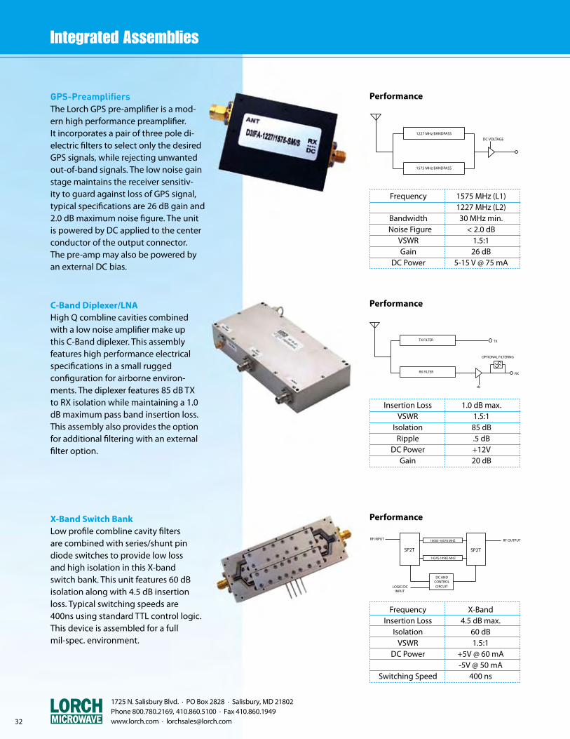
GPS-PreamplifiersThe Lorch GPS pre-amplifier is a mod-ern high performance preamplifier.It incorporates a pair of three pole di-electric filters to select only the desired GPS signals, while rejecting unwanted out-of-band signals. The low noise gain stage maintains the receiver sensitiv-ity to guard against loss of GPS signal, typical specifications are 26 dB gain and 2.0 dB maximum noise figure. The unit is powered by DC applied to the center conductor of the output connector.The pre-amp may also be powered by an external DC bias.
Performance
1227 MHz BANDPASS
1575 MHz BANDPASS
RX FILTER
TX FILTER TX
RX
OPTIONAL FILTERING
dc
280-348 MHz
349-407 MHz
408-494 MHz
RF INPUT SP3T SP3T
LOGIC DCDC AND CONTROL
INPUTCIRCUIT
RF OUTPUT
DC VOLTAGE
Frequency 1575 MHz (L1) 1227 MHz (L2) Bandwidth 30 MHz min. Noise Figure < 2.0 dB VSWR 1.5:1 Gain 26 dB DC Power 5-15 V @ 75 mA
C-Band Diplexer/LNAHigh Q combline cavities combinedwith a low noise amplifier make upthis C-Band diplexer. This assemblyfeatures high performance electrical specifications in a small ruggedconfiguration for airborne environ-ments. The diplexer features 85 dB TXto RX isolation while maintaining a 1.0 dB maximum pass band insertion loss. This assembly also provides the option for additional filtering with an external filter option.
X-Band Switch BankLow profile combline cavity filtersare combined with series/shunt pin diode switches to provide low lossand high isolation in this X-bandswitch bank. This unit features 60 dB isolation along with 4.5 dB insertionloss. Typical switching speeds are400ns using standard TTL control logic.This device is assembled for a fullmil-spec. environment.
1227 MHz BANDPASS
1575 MHz BANDPASS
RX FILTER
TX FILTER TX
RX
OPTIONAL FILTERING
dc
280-348 MHz
349-407 MHz
408-494 MHz
RF INPUT SP3T SP3T
LOGIC DCDC AND CONTROL
INPUTCIRCUIT
RF OUTPUT
DC VOLTAGE
Performance
Insertion Loss 1.0 dB max. VSWR 1.5:1 Isolation 85 dB Ripple .5 dB DC Power +12V Gain 20 dB
SP2TSP2T
LOGIC/DCINPUT
RF INPUT
14245-14965 MHZ
CONTROLCIRCUIT
DC AND
10055-10570 MHZ RF OUTPUT
Performance
Frequency X-Band Insertion Loss 4.5 dB max. Isolation 60 dB VSWR 1.5:1 DC Power +5V @ 60 mA -5V @ 50 mA Switching Speed 400 ns

33
1725 N. Salisbury Blvd. · PO Box 2828 · Salisbury, MD 21802 Phone 800.780.2169, 410.860.5100 · Fax 410.860.1949
www.lorch.com · [email protected]
6-Channel Switched FilterHigh-Q lumped element filters are com-bined with MMIC switches to provide low loss narrow band filter selectivity. The RF band is split into 6 narrow, over-lapping channels. Filter components are selected to provide a minimum frequen-cy drift over an operating temperature of -55 to +85 °C. This unit features a phase noise specification of -148 dBc/Hz at four different offset frequencies. DC control for this device is provided thrua nine pin D-sub connector.
Low Profile Switch BankFour channel switch filter bank utilizing modern switch technology in a .30 tall package. The low profile switch bank features four bandpass filters in a pack-age that is 1.6 x 1.6 x .3 tall. The bank contains four bandpass filters that have a common center frequency and four independent bandwidths. The insertion loss is amplitude matched to provide constant amplitude. The filters feature 80 dB stopbands with symmetrical skirt attenuation. The mechanical configura-tion is designed to meet Mil-Std-202 environmental conditions.
5-Channel Switched Filter The Lorch Microwave five channel switch filter bank features mixed filter technology combined with high perfor-mance pin diode switches. The bankfeatures one high Q lumped element filter and four combline cavities. The control circuitry features a 3 to 8 decod-er that provides standard 3 bit TTL logic and utilizes a single +5 V power supply.
SP4T SP4T
DC ANDCONTROLCIRCUITLOGIC/DC
INPUT
RF OUTPUTRF INPUT
CIRCUITCONTROLDC AND
INPUTLOGIC/DC
RF INPUT
SP2TRF OUTPUT
SP2TBY-PASS
SP6TSP6T
LOGIC/DCINPUT
DC ANDCONTROLCIRCUIT
RF OUTPUTRF INPUT
LOGIC/DCINPUT
CIRCUITCONTROLDC AND
SP2TSP2T
RF INPUT RF OUTPUT
100-1700 MHZ
1500-2500 MHZ
2300-3500 MHZ
3300-5675 MHZ
5500-7500 MHZ
6000-9500 MHZ
1688-1712 MHZ
1655-1745 MHZ
1630-1770 MHZ
1550-1850 MHZ
1675-1725 MHZ
2016-2225 MHZ
2225-3436 MHZ
CIRCUITCONTROLDC AND
INPUTLOGIC/DC
RF INPUT SP5T
RF OUTPUT
SP5T
LPF
CIRCUITCONTROLDC AND
INPUTLOGIC/DC
RF INPUT SP3T RF OUTPUTSP3T
3420-3820 MHZ
5130-5730 MHZ
6840-7640 MHZ
8550-9550 MHZ
10260-11460 MHZ
60.85-62.15 MHZ
64.85-66.15 MHZ
68.85-70.15 MHZ
SP2TSP2T
INPUTLOGIC/DC
RF INPUT
CIRCUITCONTROLDC AND
2937.5-3042.5 MHZ RF OUTPUT
SP2TSP2T
INPUTLOGIC/DC
RF INPUT
1610-1790 MHZ
CIRCUITCONTROLDC AND
1655-1745 MHZ RF OUTPUT
2750-3250 MHZ
Performance
Performance
Performance
Insertion Loss 8.0 dB max. 1 dB BW 6.8 MHz VSWR 1.7:1 Rejection 60 dBc Operating Temp. -55 to +85 ºC Phase Noise -148 dBc/Hz
Insertion Loss 8.0 dB max. Amplitude Match 1.0 dB Rejection 80 dBc VSWR 1.4:1 Control 2 bit TTL Power Supply +5V @ 50 mA Package 1.6 x 1.6 x .3
Insertion Loss 6.0 dB max. VSWR 2.0:1 Rejection 60 dBc Control 3 bit TTL Amplitude Var. +/- 1 dB Switching Speed 1 us
1725 N. Salisbury Blvd. · PO Box 2828 · Salisbury, MD 21802 Phone 800.780.2169, 410.860.5100 · Fax 410.860.1949 www.lorch.com · [email protected]
SP4T SP4T
DC ANDCONTROLCIRCUITLOGIC/DC
INPUT
RF OUTPUTRF INPUT
CIRCUITCONTROLDC AND
INPUTLOGIC/DC
RF INPUT
SP2TRF OUTPUT
SP2TBY-PASS
SP6TSP6T
LOGIC/DCINPUT
DC ANDCONTROLCIRCUIT
RF OUTPUTRF INPUT
LOGIC/DCINPUT
CIRCUITCONTROLDC AND
SP2TSP2T
RF INPUT RF OUTPUT
100-1700 MHZ
1500-2500 MHZ
2300-3500 MHZ
3300-5675 MHZ
5500-7500 MHZ
6000-9500 MHZ
1688-1712 MHZ
1655-1745 MHZ
1630-1770 MHZ
1550-1850 MHZ
1675-1725 MHZ
2016-2225 MHZ
2225-3436 MHZ
Performance
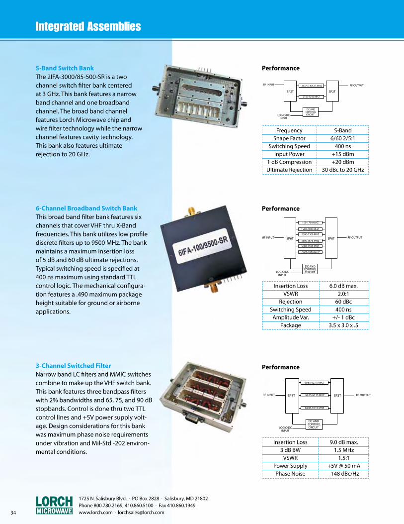
Insertion Loss 6.0 dB max. VSWR 2.0:1 Rejection 60 dBc Switching Speed 400 ns Amplitude Var. +/- 1 dBc Package 3.5 x 3.0 x .5
S-Band Switch BankThe 2IFA-3000/85-500-SR is a two channel switch filter bank centeredat 3 GHz. This bank features a narrow band channel and one broadbandchannel. The broad band channelfeatures Lorch Microwave chip andwire filter technology while the narrow channel features cavity technology.This bank also features ultimaterejection to 20 GHz.
6-Channel Broadband Switch BankThis broad band filter bank features six channels that cover VHF thru X-Band frequencies. This bank utilizes low profile discrete filters up to 9500 MHz. The bank maintains a maximum insertion loss of 5 dB and 60 dB ultimate rejections. Typical switching speed is specified at 400 ns maximum using standard TTL control logic. The mechanical configura-tion features a .490 maximum package height suitable for ground or airborne applications.
3-Channel Switched FilterNarrow band LC filters and MMIC switches combine to make up the VHF switch bank. This bank features three bandpass filters with 2% bandwidths and 65, 75, and 90 dB stopbands. Control is done thru two TTL control lines and +5V power supply volt-age. Design considerations for this bank was maximum phase noise requirements under vibration and Mil-Std -202 environ-mental conditions.
CIRCUITCONTROLDC AND
INPUTLOGIC/DC
RF INPUT SP5T
RF OUTPUT
SP5T
LPF
CIRCUITCONTROLDC AND
INPUTLOGIC/DC
RF INPUT SP3T RF OUTPUTSP3T
3420-3820 MHZ
5130-5730 MHZ
6840-7640 MHZ
8550-9550 MHZ
10260-11460 MHZ
60.85-62.15 MHZ
64.85-66.15 MHZ
68.85-70.15 MHZ
SP2TSP2T
INPUTLOGIC/DC
RF INPUT
CIRCUITCONTROLDC AND
2937.5-3042.5 MHZ RF OUTPUT
SP2TSP2T
INPUTLOGIC/DC
RF INPUT
1610-1790 MHZ
CIRCUITCONTROLDC AND
1655-1745 MHZ RF OUTPUT
2750-3250 MHZ
Performance
Insertion Loss 9.0 dB max. 3 dB BW 1.5 MHz VSWR 1.5:1 Power Supply +5V @ 50 mA Phase Noise -148 dBc/Hz
Performance
CIRCUITCONTROLDC AND
INPUTLOGIC/DC
RF INPUT SP5T
RF OUTPUT
SP5T
LPF
CIRCUITCONTROLDC AND
INPUTLOGIC/DC
RF INPUT SP3T RF OUTPUTSP3T
3420-3820 MHZ
5130-5730 MHZ
6840-7640 MHZ
8550-9550 MHZ
10260-11460 MHZ
60.85-62.15 MHZ
64.85-66.15 MHZ
68.85-70.15 MHZ
SP2TSP2T
INPUTLOGIC/DC
RF INPUT
CIRCUITCONTROLDC AND
2937.5-3042.5 MHZ RF OUTPUT
SP2TSP2T
INPUTLOGIC/DC
RF INPUT
1610-1790 MHZ
CIRCUITCONTROLDC AND
1655-1745 MHZ RF OUTPUT
2750-3250 MHZ
Frequency S-Band Shape Factor 6/60 2/5:1 Switching Speed 400 ns Input Power +15 dBm 1 dB Compression +20 dBm Ultimate Rejection 30 dBc to 20 GHz
34

1725 N. Salisbury Blvd. · PO Box 2828 · Salisbury, MD 21802 Phone 800.780.2169, 410.860.5100 · Fax 410.860.1949
www.lorch.com · [email protected]
Switch Bank / By-PassThe two channel switch bank features a bandpass filter and by-pass channel. The by-pass channel is designed into the device as part of the RF board. This provides a wider bandwidth and lower insertion loss. The bandpass is designed as an LC filter and potted to provide maximum performance under Mil-Std-202 vibration profiles. The bank provides a single voltage supply and low current consumption to support modern design techniques.
2-Channel Switch BankThe 2IFA-2016/2436 is a two channel high isolation switch filter bank. This unit features 80 dB stopbands, 6.5 dB maximum insertion loss and 2.0:1 VSWR. The control and voltage lines feature decoupling to reduce RF pick-up. The switching speed is specified as 100 ns maximum and this includes the delay thru the filters. The mechanical housing includes RF pins for surface mounting and .300 tall maximum height to fit low profile cards.
Miniature 2-Channel Switch BankSmall size, low profile and high end performance are featured in this two channel switch filter bank. The bandpass filters are centered at 1700 MHz with bandwidths of 150 and 300 MHz. The operating temperature is -54 to +95°C. The filters are temperature compensated to meet the extreme operating condi-tions. Switching speeds are specified as 100 ns maximum. The total package size is 1.5L x 1.0W x .4T excluding RF pins for the input and output.
SP4T SP4T
DC ANDCONTROLCIRCUITLOGIC/DC
INPUT
RF OUTPUTRF INPUT
CIRCUITCONTROLDC AND
INPUTLOGIC/DC
RF INPUT
SP2TRF OUTPUT
SP2TBY-PASS
SP6TSP6T
LOGIC/DCINPUT
DC ANDCONTROLCIRCUIT
RF OUTPUTRF INPUT
LOGIC/DCINPUT
CIRCUITCONTROLDC AND
SP2TSP2T
RF INPUT RF OUTPUT
100-1700 MHZ
1500-2500 MHZ
2300-3500 MHZ
3300-5675 MHZ
5500-7500 MHZ
6000-9500 MHZ
1688-1712 MHZ
1655-1745 MHZ
1630-1770 MHZ
1550-1850 MHZ
1675-1725 MHZ
2016-2225 MHZ
2225-3436 MHZ
Performance
Insertion Loss 6.5 dB max. Rejection 80 dBc VSWR 1.7:1 Switching Speed 100 ns Power Supply +5V @ 50 mA Package 3.25 x 1.25 x .3
Performance
Insertion Loss 7.0 dB max. Rejection 60 dBc Control TTL Operating Temp. 0 to +70 ºC
SP4T SP4T
DC ANDCONTROLCIRCUITLOGIC/DC
INPUT
RF OUTPUTRF INPUT
CIRCUITCONTROLDC AND
INPUTLOGIC/DC
RF INPUT
SP2TRF OUTPUT
SP2TBY-PASS
SP6TSP6T
LOGIC/DCINPUT
DC ANDCONTROLCIRCUIT
RF OUTPUTRF INPUT
LOGIC/DCINPUT
CIRCUITCONTROLDC AND
SP2TSP2T
RF INPUT RF OUTPUT
100-1700 MHZ
1500-2500 MHZ
2300-3500 MHZ
3300-5675 MHZ
5500-7500 MHZ
6000-9500 MHZ
1688-1712 MHZ
1655-1745 MHZ
1630-1770 MHZ
1550-1850 MHZ
1675-1725 MHZ
2016-2225 MHZ
2225-3436 MHZ
Performance
Frequency 1700 MHz Ripple .4 dB Input Power +10 dBm Operating Temp. -54 to +95 ºC Group Delay Var. 4 ns Package 1.5 x 1.0 x .4
CIRCUITCONTROLDC AND
INPUTLOGIC/DC
RF INPUT SP5T
RF OUTPUT
SP5T
LPF
CIRCUITCONTROLDC AND
INPUTLOGIC/DC
RF INPUT SP3T RF OUTPUTSP3T
3420-3820 MHZ
5130-5730 MHZ
6840-7640 MHZ
8550-9550 MHZ
10260-11460 MHZ
60.85-62.15 MHZ
64.85-66.15 MHZ
68.85-70.15 MHZ
SP2TSP2T
INPUTLOGIC/DC
RF INPUT
CIRCUITCONTROLDC AND
2937.5-3042.5 MHZ RF OUTPUT
SP2TSP2T
INPUTLOGIC/DC
RF INPUT
1610-1790 MHZ
CIRCUITCONTROLDC AND
1655-1745 MHZ RF OUTPUT
2750-3250 MHZ
35

z 24 MHz to 3000 MHz
z Direct Readout
z Octave Tuning
z High Power
z Digital and Manual Tuning Available
z Diplexer Configuration
z Ruggedized Applications
Lorch Microwave's tunable filter products are designed to provide high performance in a single package. While typically used in test and measurement applications, these products can also be ruggedized for mobile and remote applications.
Lorch Microwave offers several standard Bandpass and Bandreject Tuners covering the frequency range of 24 MHz to 3000 MHz in octave bands. Cellular and PCS units cover less than full octaves, however they feature greater dial resolution. All standard units offer direct frequency read-out, high power, and narrow bandwidth.
Lorch Microwave's standard products may be customized to meet specific requirements; including Digitally Controlled, Diplexed, and Ruggedized options. Contact the factory for your specific requirements.
An additional feature of Lorch Microwave's Tunable Filter Product Line is the ability to ship standard bandpass and bandreject filters overnight from stock.
3-Section Tunable Bandpass
5-Section Tunable Bandpass
3.25
H
WL
3 SECTION TUNABLE BANDPASS
0.98
TUNABLEBANDPASS
FILTER
36
1725 N. Salisbury Blvd. · PO Box 2828 · Salisbury, MD 21802 Phone 800.780.2169, 410.860.5100 · Fax 410.860.1949 www.lorch.com · [email protected]
Connector TypeBNC Female FN Female SMA - FemaleTNC - Female
DesignatorBFNST
CONNECTORS
Tunable Filter Part Number Description
5 TF - 200 / 400 - 5 S1 2 3 4 5
1. Number of Sections
2. Series (TF)
3. Frequency Range, MHz
4. Percent Bandwidth 3 dB (3 dB BW Standard)
5. Connectors
Bandwidth3 dBspecial
Designator/(blank)/X
6.50
W
H
L
5 SECTION TUNABLE BANDPASS
0.98
TUNABLEBANDPASS
FILTER
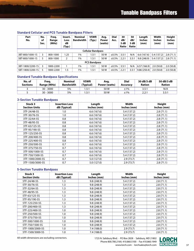
1725 N. Salisbury Blvd. · PO Box 2828 · Salisbury, MD 21802 Phone 800.780.2169, 410.860.5100 · Fax 410.860.1949
www.lorch.com · [email protected]
Stock 3 Insertion Loss Length Width Height Section Units dB (Typical) Inches (mm) Inches (mm) Inches (mm) 5TF-24/48-5S 1.3 9.8 (248.9) 5.4 (137.2) 2.8 (71.1) 5TF-30/76-5S 1.3 9.8 (248.9) 5.4 (137.2) 2.8 (71.1) 5TF-32/64-5S 1.3 9.8 (248.9) 5.4 (137.2) 2.8 (71.1) 5TF-48/95-5S 1.3 9.8 (248.9) 5.4 (137.2) 2.8 (71.1) 5TF-63/125-5S 1.3 9.8 (248.9) 5.4 (137.2) 2.8 (71.1) 5TF-95/190-5S 1.3 9.8 (248.9) 5.4 (137.2) 2.8 (71.1) 5TF-125/250-5S 1.3 9.8 (248.9) 5.4 (137.2) 2.8 (71.1) 5TF-200/400-5S 1.3 9.8 (248.9) 5.4 (137.2) 2.8 (71.1) 5TF-225/400-5S 1.0 9.8 (248.9) 5.4 (137.2) 2.8 (71.1) 5TF-250/500-5S 1.0 9.8 (248.9) 5.4 (137.2) 2.8 (71.1) 5TF-375/750-5S 1.0 9.8 (248.9) 5.4 (137.2) 2.8 (71.1) 5TF-500/1000-5S 1.0 9.8 (248.9) 5.4 (137.2) 2.8 (71.1) 5TF-750/1500-5S 1.0 9.8 (248.9) 5.4 (137.2) 2.8 (71.1) 5TF-1000/2000-5S 1.0 7.4 (188.0) 2.9 (73.7) 2.8 (71.1) 5TF-1500/3000-5S 1.0 7.4 (188.0) 2.9 (73.7) 2.8 (71.1)
37
Standard Cellular and PCS Tunable Bandpass Filters
5-Section Tunable Bandpass
All width dimensions are excluding connectors.
Part No. Freq. Insert. Nominal VSWR Avg. Dial 30 50 Length Width Height No. of Range Loss Bandwidth (Typ.) Power Acc. dB/ dB/ Inches Inches Inches Sec. (MHz) dB (watts) 3 dB 3 dB (mm) (mm) (mm) (Typ.) Ratio Ratio
Cellular Bandpass 3BT-800/1000-1S 3 800-1000 1.25 1% 1.5:1 50 W ±0.5% 3.5:1 N/A 6.6 (167.6) 5.4 (137.2) 2.8 (71.1) 5BT-800/1000-1S 5 800-1000 2 1% 1.5:1 50 W ±0.5% 2.2:1 3.5:1 9.8 (248.9) 5.4 (137.2) 2.8 (71.1)
PCS Bandpass 3BT-1800/2200-1S 3 1800-2200 1 1% 1.5:1 50 W ±0.5% 3.5:1 N/A 6.57 (166.9) 2.0 (50.8) 2.0 (50.8) 5BT-1800/2200-1S 5 1800-2200 1.5 1% 1.5:1 50 W ±0.5% 2.2:1 3.5:1 9.86 (250.4) 2.0 (50.8) 2.0 (50.8)
Standard Tunable Bandpass Specifications No. of Freq. Nominal VSWR Avg. Dial 30 dB/3 dB 50 dB/3 dB Sections Range (MHz) Bandwidth (Typical) Power (watts) Accuracy Ration Ration
3 30 - 3000 5% 1.5:1 50 W ±1% 3.5:1 N/A 5 30 - 3000 5% 1.5:1 50 W ±1% 2.2:1 3.5:1
3-Section Tunable Bandpass Stock 3 Insertion Loss Length Width Height Section Units dB (Typical) Inches (mm) Inches (mm) Inches (mm)
3TF-24/48-5S 1.0 6.6 (167.6) 5.4 (137.2) 2.8 (71.1) 3TF-30/76-5S 1.0 6.6 (167.6) 5.4 (137.2) 2.8 (71.1) 3TF-32/64-5S 0.8 6.6 (167.6) 5.4 (137.2) 2.8 (71.1) 3TF-48/95-5S 0.8 6.6 (167.6) 5.4 (137.2) 2.8 (71.1) 3TF-63/125-5S 0.8 6.6 (167.6) 5.4 (137.2) 2.8 (71.1) 3TF-95/190-5S 0.8 6.6 (167.6) 5.4 (137.2) 2.8 (71.1) 3TF-125/250-5S 0.8 6.6 (167.6) 5.4 (137.2) 2.8 (71.1) 3TF-200/400-5S 0.8 6.6 (167.6) 5.4 (137.2) 2.8 (71.1) 3TF-225/400-5S 0.8 6.6 (167.6) 5.4 (137.2) 2.8 (71.1) 3TF-250/500-5S 0.7 6.6 (167.6) 5.4 (137.2) 2.8 (71.1) 3TF-375/750-5S 0.7 6.6 (167.6) 5.4 (137.2) 2.8 (71.1) 3TF-500/1000-5S 0.7 6.6 (167.6) 5.4 (137.2) 2.8 (71.1) 3TF-750/1500-5S 0.7 6.6 (167.6) 5.4 (137.2) 2.8 (71.1) 3TF-1000/2000-5S 0.7 5.0 (127.0) 2.9 (73.7) 2.8 (71.1) 3TF-1500/3000-5S 0.7 5.0 (127.0) 2.9 (73.7) 2.8 (71.1)
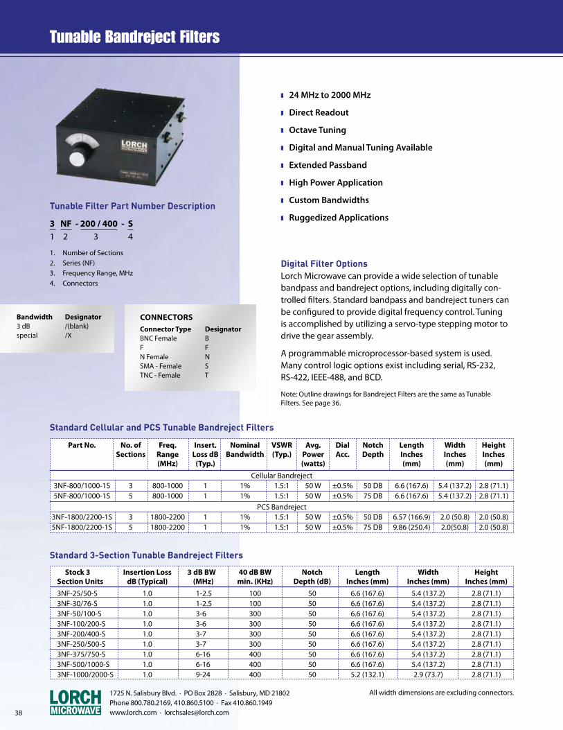
Digital Filter OptionsLorch Microwave can provide a wide selection of tunable bandpass and bandreject options, including digitally con-trolled filters. Standard bandpass and bandreject tuners can be configured to provide digital frequency control. Tuning is accomplished by utilizing a servo-type stepping motor to drive the gear assembly.
A programmable microprocessor-based system is used. Many control logic options exist including serial, RS-232, RS-422, IEEE-488, and BCD.
Note: Outline drawings for Bandreject Filters are the same as Tunable Filters. See page 36.
Standard 3-Section Tunable Bandreject Filters
All width dimensions are excluding connectors.
38
1725 N. Salisbury Blvd. · PO Box 2828 · Salisbury, MD 21802 Phone 800.780.2169, 410.860.5100 · Fax 410.860.1949 www.lorch.com · [email protected]
z 24 MHz to 2000 MHz
z Direct Readout
z Octave Tuning
z Digital and Manual Tuning Available
z Extended Passband
z High Power Application
z Custom Bandwidths
z Ruggedized Applications
Connector TypeBNC Female FN Female SMA - FemaleTNC - Female
DesignatorBFNST
CONNECTORS
Tunable Filter Part Number Description
3 NF - 200 / 400 - S 1 2 3 4
1. Number of Sections2. Series (NF)3. Frequency Range, MHz4. Connectors
Bandwidth3 dBspecial
Designator/(blank)/X
Standard Cellular and PCS Tunable Bandreject Filters
Part No. No. of Freq. Insert. Nominal VSWR Avg. Dial Notch Length Width Height Sections Range Loss dB Bandwidth (Typ.) Power Acc. Depth Inches Inches Inches (MHz) (Typ.) (watts) (mm) (mm) (mm)
Cellular Bandreject 3NF-800/1000-1S 3 800-1000 1 1% 1.5:1 50 W ±0.5% 50 DB 6.6 (167.6) 5.4 (137.2) 2.8 (71.1) 5NF-800/1000-1S 5 800-1000 1 1% 1.5:1 50 W ±0.5% 75 DB 6.6 (167.6) 5.4 (137.2) 2.8 (71.1) PCS Bandreject 3NF-1800/2200-1S 3 1800-2200 1 1% 1.5:1 50 W ±0.5% 50 DB 6.57 (166.9) 2.0 (50.8) 2.0 (50.8) 5NF-1800/2200-1S 5 1800-2200 1 1% 1.5:1 50 W ±0.5% 75 DB 9.86 (250.4) 2.0(50.8) 2.0 (50.8)
Stock 3 Insertion Loss 3 dB BW 40 dB BW Notch Length Width Height Section Units dB (Typical) (MHz) min. (KHz) Depth (dB) Inches (mm) Inches (mm) Inches (mm)
3NF-25/50-S 1.0 1-2.5 100 50 6.6 (167.6) 5.4 (137.2) 2.8 (71.1) 3NF-30/76-S 1.0 1-2.5 100 50 6.6 (167.6) 5.4 (137.2) 2.8 (71.1) 3NF-50/100-S 1.0 3-6 300 50 6.6 (167.6) 5.4 (137.2) 2.8 (71.1) 3NF-100/200-S 1.0 3-6 300 50 6.6 (167.6) 5.4 (137.2) 2.8 (71.1) 3NF-200/400-S 1.0 3-7 300 50 6.6 (167.6) 5.4 (137.2) 2.8 (71.1) 3NF-250/500-S 1.0 3-7 300 50 6.6 (167.6) 5.4 (137.2) 2.8 (71.1) 3NF-375/750-S 1.0 6-16 400 50 6.6 (167.6) 5.4 (137.2) 2.8 (71.1) 3NF-500/1000-S 1.0 6-16 400 50 6.6 (167.6) 5.4 (137.2) 2.8 (71.1) 3NF-1000/2000-S 1.0 9-24 400 50 5.2 (132.1) 2.9 (73.7) 2.8 (71.1)
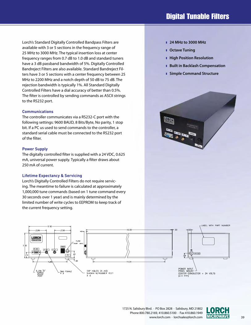
39
1725 N. Salisbury Blvd. · PO Box 2828 · Salisbury, MD 21802 Phone 800.780.2169, 410.860.5100 · Fax 410.860.1949
www.lorch.com · [email protected]
z 24 MHz to 3000 MHz
z Octave Tuning
z High Position Resolution
z Built in Backlash Compensation
z Simple Command Structure
Lorch’s Standard Digitally Controlled Bandpass Filters are available with 3 or 5 sections in the frequency range of 25 MHz to 3000 MHz. The typical insertion loss at center frequency ranges from 0.7 dB to 1.0 dB and standard tuners have a 3 dB passband bandwidth of 5%. Digitally Controlled Bandreject Filters are also available. Standard Bandreject Fil-ters have 3 or 5 sections with a center frequency between 25 MHz to 2200 MHz and a notch depth of 50 dB to 75 dB. The rejection bandwidth is typically 1%. All Standard Digitally Controlled Filters have a dial accuracy of better than 0.5%. The filter is controlled by sending commands as ASCII strings to the RS232 port.
CommunicationsThe controller communicates via a RS232-C port with the following settings: 9600 BAUD, 8 Bits/Byte, No parity, 1 stop bit. If a PC us used to send commands to the controller, a standard serial cable must be connected to the RS232 port of the filter.
Power SupplyThe digitally controlled filter is supplied with a 24 VDC, 0.625 mA, universal power supply. Typically a filter draws about 250 mA of current.
Lifetime Expectancy & ServicingLorch’s Digitally Controlled Filters do not require servic-ing. The meantime to failure is calculated at approximately 1,000,000 tune commands (based on 1 tune command every 30 seconds over 1 year) and is mainly determined by the limited number of write cycles to EEPROM to keep track of the current frequency setting.
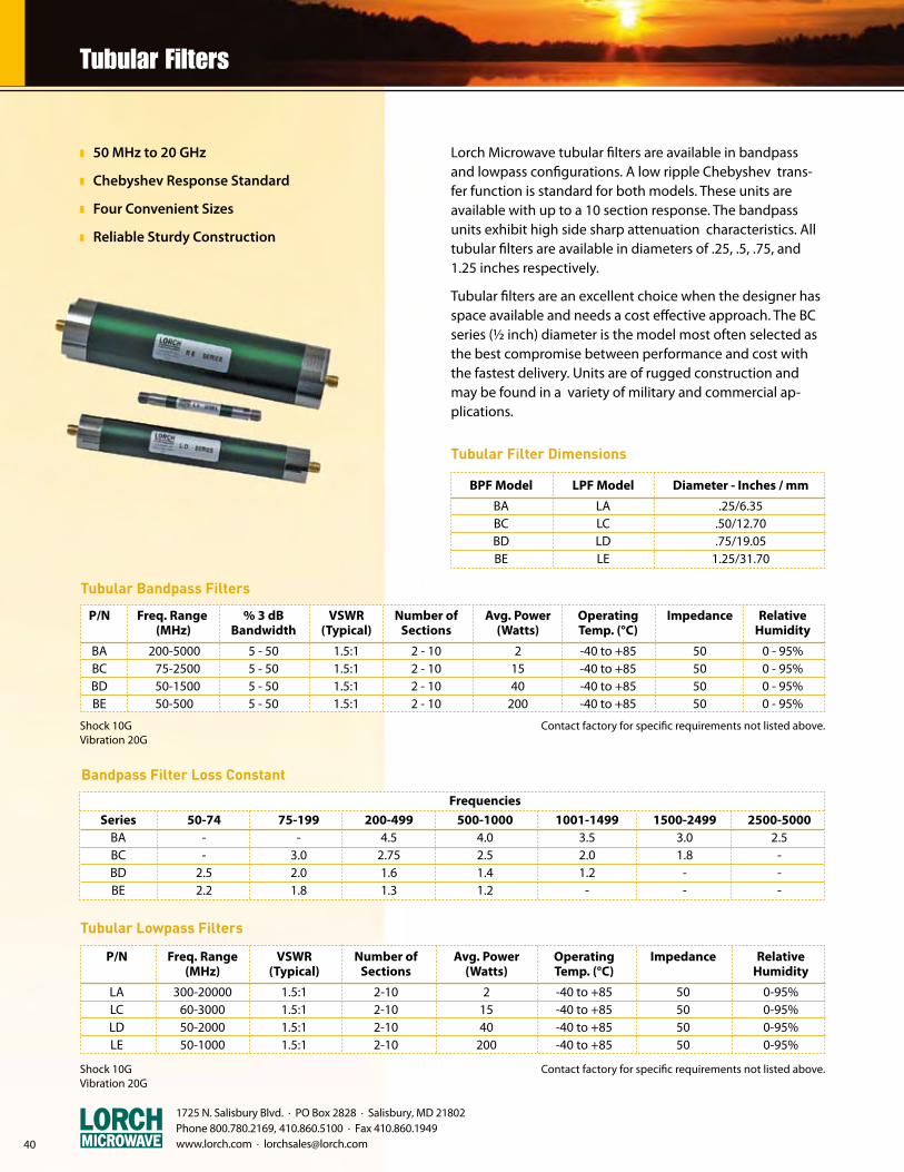
1725 N. Salisbury Blvd. · PO Box 2828 · Salisbury, MD 21802 Phone 800.780.2169, 410.860.5100 · Fax 410.860.1949 www.lorch.com · [email protected]
z 50 MHz to 20 GHz
z Chebyshev Response Standard
z Four Convenient Sizes
z Reliable Sturdy Construction
Lorch Microwave tubular filters are available in bandpass and lowpass configurations. A low ripple Chebyshev trans-fer function is standard for both models. These units are available with up to a 10 section response. The bandpass units exhibit high side sharp attenuation characteristics. All tubular filters are available in diameters of .25, .5, .75, and 1.25 inches respectively.
Tubular filters are an excellent choice when the designer has space available and needs a cost effective approach. The BC series (½ inch) diameter is the model most often selected as the best compromise between performance and cost with the fastest delivery. Units are of rugged construction and may be found in a variety of military and commercial ap-plications.
Tubular Filter Dimensions
BPF Model LPF Model Diameter - Inches / mm
BA LA .25/6.35 BC LC .50/12.70 BD LD .75/19.05 BE LE 1.25/31.70
Tubular Bandpass Filters
Contact factory for specific requirements not listed above.Shock 10GVibration 20G
P/N Freq. Range % 3 dB VSWR Number of Avg. Power Operating Impedance Relative (MHz) Bandwidth (Typical) Sections (Watts) Temp. (°C) Humidity
BA 200-5000 5 - 50 1.5:1 2 - 10 2 -40 to +85 50 0 - 95% BC 75-2500 5 - 50 1.5:1 2 - 10 15 -40 to +85 50 0 - 95% BD 50-1500 5 - 50 1.5:1 2 - 10 40 -40 to +85 50 0 - 95% BE 50-500 5 - 50 1.5:1 2 - 10 200 -40 to +85 50 0 - 95%
Bandpass Filter Loss Constant
Frequencies
Series 50-74 75-199 200-499 500-1000 1001-1499 1500-2499 2500-5000 BA - - 4.5 4.0 3.5 3.0 2.5 BC - 3.0 2.75 2.5 2.0 1.8 - BD 2.5 2.0 1.6 1.4 1.2 - - BE 2.2 1.8 1.3 1.2 - - -
Tubular Lowpass Filters
Contact factory for specific requirements not listed above.Shock 10GVibration 20G
P/N Freq. Range VSWR Number of Avg. Power Operating Impedance Relative (MHz) (Typical) Sections (Watts) Temp. (°C) Humidity
LA 300-20000 1.5:1 2-10 2 -40 to +85 50 0-95% LC 60-3000 1.5:1 2-10 15 -40 to +85 50 0-95% LD 50-2000 1.5:1 2-10 40 -40 to +85 50 0-95% LE 50-1000 1.5:1 2-10 200 -40 to +85 50 0-95%
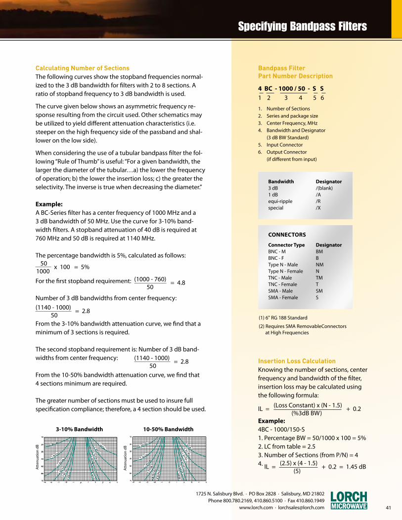
41
1725 N. Salisbury Blvd. · PO Box 2828 · Salisbury, MD 21802 Phone 800.780.2169, 410.860.5100 · Fax 410.860.1949
www.lorch.com · [email protected]
Bandpass Filter Part Number Description
4 BC - 1000 / 50 - S S 1 2 3 4 5 6
1. Number of Sections2. Series and package size3. Center Frequency, MHz4. Bandwidth and Designator (3 dB BW Standard)5. Input Connector6. Output Connector (if different from input)
Calculating Number of SectionsThe following curves show the stopband frequencies normal-ized to the 3 dB bandwidth for filters with 2 to 8 sections. A ratio of stopband frequency to 3 dB bandwidth is used.
The curve given below shows an asymmetric frequency re-sponse resulting from the circuit used. Other schematics may be utilized to yield different attenuation characteristics (i.e. steeper on the high frequency side of the passband and shal-lower on the low side).
When considering the use of a tubular bandpass filter the fol-lowing “Rule of Thumb” is useful: “For a given bandwidth, the larger the diameter of the tubular…a) the lower the frequency of operation; b) the lower the insertion loss; c) the greater the selectivity. The inverse is true when decreasing the diameter.”
Example:A BC-Series filter has a center frequency of 1000 MHz and a 3 dB bandwidth of 50 MHz. Use the curve for 3-10% band-width filters. A stopband attenuation of 40 dB is required at 760 MHz and 50 dB is required at 1140 MHz.
The percentage bandwidth is 5%, calculated as follows:
For the first stopband requirement:
Number of 3 dB bandwidths from center frequency:
From the 3-10% bandwidth attenuation curve, we find that a minimum of 3 sections is required.
The second stopband requirement is: Number of 3 dB band-widths from center frequency:
From the 10-50% bandwidth attenuation curve, we find that 4 sections minimum are required.
The greater number of sections must be used to insure full specification compliance; therefore, a 4 section should be used.
Insertion Loss CalculationKnowing the number of sections, center frequency and bandwidth of the filter, insertion loss may be calculated using the following formula:
Example:4BC - 1000/150-S1. Percentage BW = 50/1000 x 100 = 5%2. LC from table = 2.53. Number of Sections (from P/N) = 44.
IL = (Loss Constant) x (N - 1.5) + 0.2 (%3dB BW)
IL = (2.5) x (4 - 1.5) + 0.2 = 1.45 dB (5)
50 x 100 = 5%1000
(1000 - 760) = 4.8 50
(1140 - 1000) = 2.8 50
(1140 - 1000) = 2.8 50
(1) 6" RG 188 Standard
(2) Requires SMA RemovableConnectors at High Frequencies
Bandwidth3 dB1 dBequi-ripplespecial
Designator/(blank)/A/R/X
Connector TypeBNC - MBNC - FType N - MaleType N - FemaleTNC - MaleTNC - FemaleSMA - MaleSMA - Female
CONNECTORS
DesignatorBMBNMNTMTSMS
Att
enua
tion
dB
3-10% Bandwidth 10-50% Bandwidth
Att
enua
tion
dB
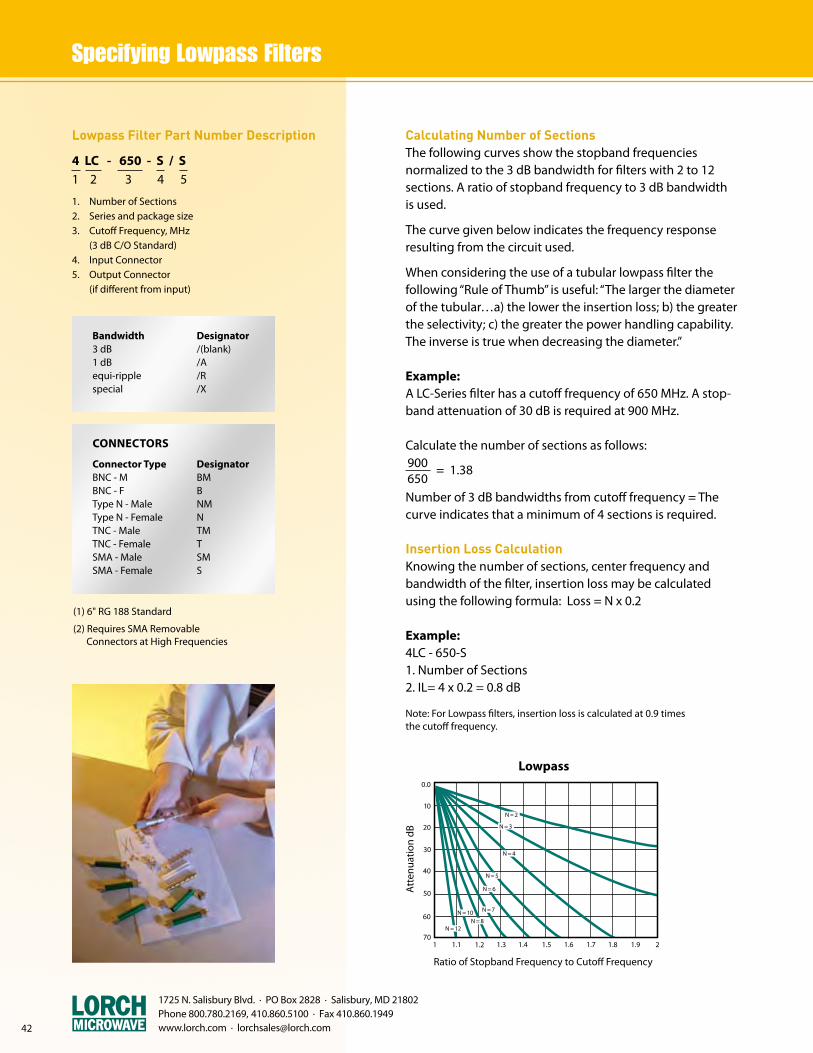
Lowpass Filter Part Number Description
4 LC - 650 - S / S 1 2 3 4 5
1. Number of Sections2. Series and package size3. Cutoff Frequency, MHz (3 dB C/O Standard)4. Input Connector5. Output Connector (if different from input)
(1) 6" RG 188 Standard
(2) Requires SMA Removable Connectors at High Frequencies
Bandwidth3 dB1 dBequi-ripplespecial
Designator/(blank)/A/R/X
Connector TypeBNC - MBNC - FType N - MaleType N - FemaleTNC - MaleTNC - FemaleSMA - MaleSMA - Female
DesignatorBMBNMNTMTSMS
1725 N. Salisbury Blvd. · PO Box 2828 · Salisbury, MD 21802 Phone 800.780.2169, 410.860.5100 · Fax 410.860.1949 www.lorch.com · [email protected]
Calculating Number of SectionsThe following curves show the stopband frequencies normalized to the 3 dB bandwidth for filters with 2 to 12 sections. A ratio of stopband frequency to 3 dB bandwidth is used.
The curve given below indicates the frequency response resulting from the circuit used.
When considering the use of a tubular lowpass filter the following “Rule of Thumb” is useful: “The larger the diameter of the tubular…a) the lower the insertion loss; b) the greater the selectivity; c) the greater the power handling capability. The inverse is true when decreasing the diameter.”
Example:A LC-Series filter has a cutoff frequency of 650 MHz. A stop-band attenuation of 30 dB is required at 900 MHz.
Calculate the number of sections as follows:
Number of 3 dB bandwidths from cutoff frequency = The curve indicates that a minimum of 4 sections is required.
Insertion Loss CalculationKnowing the number of sections, center frequency and bandwidth of the filter, insertion loss may be calculated using the following formula: Loss = N x 0.2
Example:4LC - 650-S1. Number of Sections2. IL= 4 x 0.2 = 0.8 dB
Note: For Lowpass filters, insertion loss is calculated at 0.9 times the cutoff frequency.
900 = 1.38650
0.0
10
20
30
40
50
60
701.1 1.21 1.3 1.4 1.5 1.6 1.7 1.8 1.9 2
N = 2
N = 3
N = 4
N = 5
N = 6
N = 7
N = 8N = 10
N = 12
Att
enua
tion
dB
Ratio of Stopband Frequency to Cutoff Frequency
Lowpass
CONNECTORS

1725 N. Salisbury Blvd. · PO Box 2828 · Salisbury, MD 21802 Phone 800.780.2169, 410.860.5100 · Fax 410.860.1949
www.lorch.com · [email protected] 43
The length of a tubular filter is determined by adding the connector dimensions from the table below. The filter length is obtained from the Length vs. Frequency tables.
Example:A 5-section bandpass filter Model BC with a center fre-quency of 300 MHz and with SMA connectors has a filter dimension of 3.4 inches and a connector dimension of 0.8 inches. The total length is 5.0 inches.
NR- Not recommended for PC mount. Contact factory with specific requirements. Standard connector dimensions are in inches, please use 25.4 to convert to metric.
Connector Dimensions (inches)
Connector Style Connector Cod .25 Diameter .50 Diameter .75 Diameter 1.25 Diameter Figure
"N" Female N NR* 1.28 1.4 1.7 - "N" Male NM NR* 1.23 1.31 1.65 - BNC Female B NR* 1.0 1.35 1.42 - BNC Male BM NR* .93 1.45 1.35 - TNC Female T NR* 1.0 1.35 1.42 - TNC Male TM NR* .93 1.45 1.35 - SMA Female (standard) S .6 .8 .8 .8 1 SMA Male (standard SM .73 .85 .85 .85 1 SMA Male (right angle square) EP .55 .65 .65 .65 2
BA - Filter Length vs. Frequency (MHz)
No. of 200- 300- 400- 1000- 3000- 4000- Sections 300 400 1000 3000 4000 5000 2 1.10 1.00 .90 .80 .70 .50 3 2.00 1.90 1.40 1.20 1.00 .70 4 2.90 2.80 1.90 1.70 1.30 .90 5 3.80 3.60 2.40 2.10 1.60 1.10 6 4.70 4.40 2.90 2.50 1.90 1.30 7 5.60 5.20 3.40 2.90 2.20 1.60 8 6.50 6.00 3.90 3.30 2.50 1.90
BC - Filter Length vs. Frequency (MHz)
No. of 75-130 130-180 180-350 350-700 700-2500 Sections 2 2.00 1.60 1.30 1.10 .90 3 3.15 2.60 2.00 1.65 1.40 4 4.30 3.60 2.70 2.20 1.95 5 5.45 4.55 3.40 2.70 2.45 6 6.60 5.55 4.10 3.25 3.00 7 7.75 6.55 4.80 3.80 3.50 8 8.90 7.55 5.50 4.35 4.00 9 - 8.55 6.20 4.90 4.55 10 - 9.50 6.90 5.40 5.00
BD - Filter Length vs. Frequency (MHz)
No. of 50-140 140-230 230-500 500-1500 Sections 2 2.00 1.50 1.30 1.10 3 3.00 2.25 1.85 1.60 4 3.95 3.00 2.40 2.10 5 4.90 3.75 2.95 2.60 6 5.90 4.50 3.50 3.10 7 6.85 5.25 4.10 3.60 8 7.80 6.00 4.60 4.10 9 8.80 6.75 5.15 4.60 10 - 7.50 5.70 5.10
BE - Filter Length vs. Frequency (MHz)
No. of 50-80 80-200 200-400 400-500 Sections 2 2.80 2.40 2.00 1.60 3 3.80 3.20 2.80 2.30 4 4.80 4.00 3.60 3.00 5 6.00 5.20 4.40 3.80 6 7.20 5.60 5.20 4.60 7 8.40 6.40 6.00 5.40 8 9.60 7.20 6.80 6.20 9 - 8.60 7.60 7.00 10 - - 8.50 7.80
All dimensions are approximate. Contact factory for actual sizes. All length dimensions are excluding connectors.

42
1725 N. Salisbury Blvd. · PO Box 2828 · Salisbury, MD 21802 Phone 800.780.2169, 410.860.5100 · Fax 410.860.1949 www.lorch.com · [email protected]
LA - Filter Length vs. Frequency (MHz)
* Contact factory for exact size at higher frequencies.
LD - Filter Length vs. Frequency (MHz)
No. of 50- 100- 200- 400- 600- 1000- Sections 100 200 400 600 1000 2000
2 2.20 2.00 1.20 1.00 .90 .80 3 3.50 3.15 2.00 1.60 1.35 1.25 4 4.75 4.30 2.70 2.15 1.80 1.65 5 6.00 5.40 3.40 2.70 2.25 2.00 6 7.30 6.50 4.10 3.25 2.70 2.45 7 8.60 7.65 4.90 3.85 3.15 2.85 8 - 8.75 5.55 4.40 3.60 3.30 9 - - 6.40 5.00 4.00 3.70 10 - - 7.00 5.50 4.50 4.10
No. of 300- 600- 1000- 1300- 1700- 2300- 3000- 5000- Sections 600 1000 1300 1700 2300 3000 5000 20000
2 .65 .55 .40 .50 .45 .40 .40 3 1.00 .90 .70 .85 .75 .70 .75 4 1.45 1.25 1.00 1.20 1.10 1.00 1.50 5 1.90 1.65 1.30 1.55 1.40 1.30 1.40 6 2.30 2.00 1.60 1.95 1.70 1.55 1.75 * 7 2.75 2.40 1.90 2.30 2.00 1.85 2.10 8 3.20 2.75 2.20 2.65 2.35 2.15 2.45 9 3.65 3.10 2.50 3.00 2.70 2.45 2.80 10 4.10 3.50 2.80 3.35 3.00 2.75 3.10
LC - Filter Length vs. Frequency (MHz) LE - Filter Length vs. Frequency (MHz)
No. of 50-80 80-200 200-600 600-1000 Sections
2 2.40 2.00 1.30 1.00 3 3.55 2.85 2.00 1.55 4 4.75 3.70 2.60 2.00 5 6.00 4.55 3.25 2.60 6 7.15 5.40 3.90 3.10 7 8.35 6.25 4.55 3.65 8 9.50 7.10 5.20 4.20 9 - 7.95 5.85 4.70 10 - 8.80 6.50 5.20
All dimensions are approximate. Contact factory for actual sizes. All length dimensions are excluding connectors.
No. of 60- 90- 150- 200- 400- 800- Sections 90 150 200 400 800 3000
2 2.10 1.80 1.55 1.10 .75 .65 3 3.15 2.80 2.45 1.80 1.20 1.10 4 4.20 3.85 3.40 2.55 1.70 1.50 5 5.60 4.85 4.30 3.25 2.15 1.95 6 6.90 5.90 5.20 3.95 2.60 2.40 7 8.30 6.95 6.15 4.70 3.00 2.80 8 9.60 7.95 7.00 5.40 3.50 3.25 9 10.88 8.95 8.00 6.10 3.95 3.70 10 - - 8.90 6.80 4.40 4.10
1725 N. Salisbury Blvd. · PO Box 2828 · Salisbury, MD 21802 Phone 800.780.2169, 410.860.5100 · Fax 410.860.1949 www.lorch.com · [email protected]
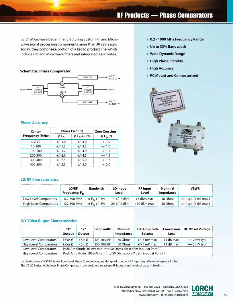
1725 N. Salisbury Blvd. · PO Box 2828 · Salisbury, MD 21802 Phone 800.780.2169, 410.860.5100 · Fax 410.860.1949
www.lorch.com · [email protected] 45
z 0.2 - 1000 MHz Frequency Range
z Up to 33% Bandwidth
z Wide Dynamic Range
z High Phase Stability
z High Accuracy
z PC Mount and Connectorized
Lorch Microwave began manufacturing custom RF and Micro-wave signal processing components more than 30 years ago. Today, they comprise a portion of a broad product line which includes RF and Microwave filters and Integrated Assemblies.
LO IN RF IN
X OUT
Y OUT
(KCOS Ø)
(KSIN Ø)
MIXER
MIXER
90POWERDIVIDER
O 0POWERDIVIDER
O
DIPLEXER
DIPLEXER
1
0
-10 90 180 270 360
= X Output
= Y Output
INPUT PHASE ANGLE vs OUTPUT VOLTAGE
SCHEMATIC, PHASE COMPARATOR
Schematic, Phase Comparator
Phase Accuracy
Center Phase Error (º) Zero Crossing Frequency (MHz) @ Fo @ Fo +/-5% @ Fo (º)
0.2-10 +/- 1.0 +/- 3.0 +/- 1.0 10-100 +/- 1.5 +/- 3.5 +/- 1.0 100-200 +/- 1.7 +/- 4.0 +/- 1.5 200-300 +/- 2.0 +/- 4.5 +/- 1.5 300-400 +/- 2.5 +/- 5.0 +/- 1.7 400-500 +/- 2.5 +/- 5.0 +/- 2.0
LO/RF Characteristics
LO/RF Bandwith LO Input RF Input Nominal VSWR Frequency, Fo Level Level Impedance
Low-Level Comparators 0.2-500 MHz @ Fo +/- 5% +13 +/- 2 dBm +3 dBm max. 50 Ohms 1.4:1 typ. (1.6:1 max.)
High-Level Comparators 0.2-500 MHz @ Fo +/- 5% +20 +/- 2 dBm +10 dBm max. 50 Ohms 1.4:1 typ. (1.6:1 max.)
X/Y Video Output Characteristics
"X" "Y" Bandwidth Nominal X/Y Amplitude Conversion DC Offset Voltage Output Output Impedance Balance Loss
Low-Level Comparators k Cos Ø k Sin Ø DC-10% RF 50 Ohms +/- 5 mV max. 11 dB max. +/- 2 mV typ. High-Level Comparators k Cos Ø k Sin Ø DC-10% RF 50 Ohms +/- 5 mV max. 11 dB max. +/- 2 mV typ. Low-Level Comparators Peak Amplitude: 85 mV min. into 50 Ohms, for 0 dBm input at Port RF High-Level Comparators Peak Amplitude: 190 mV min. into 50 Ohms, for +7 dBm input at Port RF
Lorch Microwave’s CP-13 Series, Low-Level Phase Comparators, are designed to accept RF input signal levels of up to +3 dBm.The CP-20 Series, High-Level Phase Comparators, are designed to accept RF input signal levels of up to + 10 dBm.

z 10 - 1000 MHz Frequency Range
z 10% Standard Bandwidth
z 0-90°, 0-180° and 0-360° Phase Shift Ranges
z Multi-Turn, Infinite Resolution
z Low Loss, High Phase Stability
z PC Mount and Connectorized
1725 N. Salisbury Blvd. · PO Box 2828 · Salisbury, MD 21802 Phone 800.780.2169, 410.860.5100 · Fax 410.860.1949 www.lorch.com · [email protected]
1.8
1.5
1.2
0 17 34
0
0
120
180
17 34
60
0
0
0
0
Inse
rtio
n Lo
ss
Relative Rotation (turns)
Typical Insertion Loss vs. Relative Rotation
1.8
1.5
1.2
0 17 34
0
0
120
180
17 34
60
0
0
0
0
Typical Phase Shift vs. Relative RotationPh
ase
Shift
Relative Rotation (turns)
Typical Performance Specifications
Frequency Usable Phase Shift Insertion Loss VSWR (MHz) Bandwidth (%) @Fo (°)
10-250 10 0-90 1.3 1.6:1 10-250 10 0-180 1.7 1.6:1 250-500 10 0-90 1.4 1.6:1 250-500 10 0-180 1.8 1.8:1
Notes:1) Nominal impedance is 50 Ohms.2) All units rated at 0.5 Watts average, 2 Watts peak.

1725 N. Salisbury Blvd. · PO Box 2828 · Salisbury, MD 21802 Phone 800.780.2169, 410.860.5100 · Fax 410.860.1949
www.lorch.com · [email protected] 47
z 1 - 1000 MHz Frequency Range
z Up to a Full Octave Bandwidth
z 0-360° Phase Shift
z Integral TTL Driver
z 1-8 Bit Control
z Accuracy to 1/2 Least Significant Bit
z Time Shifter or Frequency Independence
Characteristics
Parameter Type 1 Type 2
Phase Shift Independence of Proportional to Frequency Frequency
Group Delay Constant with Proportional to Frequency Phase Shift
Typical Performance Specifications
Notes:1) DC power supply requirements: +5VDC @ 20 mA, -5VDC @ 20 mA; RF input power: +16 dBm max.; Switching time: 100 ns max.2) Please specify bit sequence, if other than standards
Part Number Type #Bits Center Bandwidth VSWR Typ. Insertion Loss Phase Error/Bit Frequency (MHz) (MHz) (dB) Typ. (º) Typ.
DP-1-6-70-10-75 1 6 70 10 1.6:1 8 +/- 1.5 DP-1-6-305-30-75 1 6 305 30 1.6:1 8 +/- 2 DP-1-8-80-8-77 1 8 80 8 1.6:1 9 +/- 2 DP-1-8-370-5-77 1 8 370 5 1.6:1 9 +/- 2 DP-2-4-295-10-73 2 4 295 10 1.6:1 5.5 +/- 1.5 DP-2-6-255-30-75 2 6 255 30 1.6:1 7 +/- 1.5 DP-2-8-350-3-77 2 8 350 3 1.8:1 9 +/- 2 DP-2-8-860-80-77 2 8 860 80 2.0:1 9.5 +/- 3.5
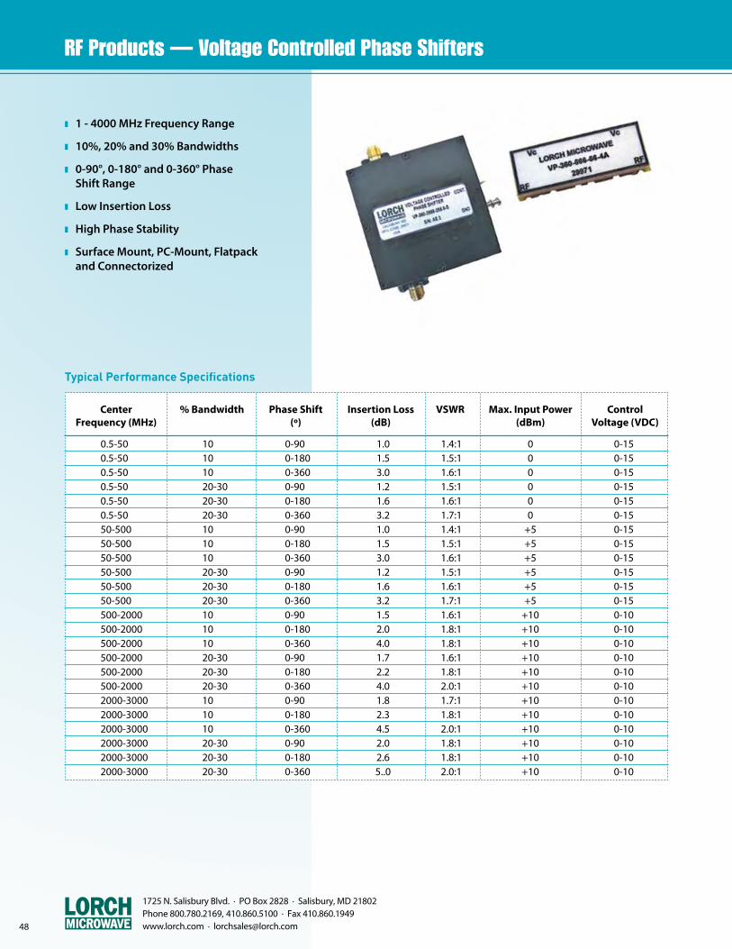
1725 N. Salisbury Blvd. · PO Box 2828 · Salisbury, MD 21802 Phone 800.780.2169, 410.860.5100 · Fax 410.860.1949 www.lorch.com · [email protected]
z 1 - 4000 MHz Frequency Range
z 10%, 20% and 30% Bandwidths
z 0-90°, 0-180° and 0-360° Phase Shift Range
z Low Insertion Loss
z High Phase Stability
z Surface Mount, PC-Mount, Flatpack and Connectorized
Typical Performance Specifications
Center % Bandwidth Phase Shift Insertion Loss VSWR Max. Input Power Control Frequency (MHz) (º) (dB) (dBm) Voltage (VDC)
0.5-50 10 0-90 1.0 1.4:1 0 0-15 0.5-50 10 0-180 1.5 1.5:1 0 0-15 0.5-50 10 0-360 3.0 1.6:1 0 0-15 0.5-50 20-30 0-90 1.2 1.5:1 0 0-15 0.5-50 20-30 0-180 1.6 1.6:1 0 0-15 0.5-50 20-30 0-360 3.2 1.7:1 0 0-15 50-500 10 0-90 1.0 1.4:1 +5 0-15 50-500 10 0-180 1.5 1.5:1 +5 0-15 50-500 10 0-360 3.0 1.6:1 +5 0-15 50-500 20-30 0-90 1.2 1.5:1 +5 0-15 50-500 20-30 0-180 1.6 1.6:1 +5 0-15 50-500 20-30 0-360 3.2 1.7:1 +5 0-15 500-2000 10 0-90 1.5 1.6:1 +10 0-10 500-2000 10 0-180 2.0 1.8:1 +10 0-10 500-2000 10 0-360 4.0 1.8:1 +10 0-10 500-2000 20-30 0-90 1.7 1.6:1 +10 0-10 500-2000 20-30 0-180 2.2 1.8:1 +10 0-10 500-2000 20-30 0-360 4.0 2.0:1 +10 0-10 2000-3000 10 0-90 1.8 1.7:1 +10 0-10 2000-3000 10 0-180 2.3 1.8:1 +10 0-10 2000-3000 10 0-360 4.5 2.0:1 +10 0-10 2000-3000 20-30 0-90 2.0 1.8:1 +10 0-10 2000-3000 20-30 0-180 2.6 1.8:1 +10 0-10 2000-3000 20-30 0-360 5..0 2.0:1 +10 0-10
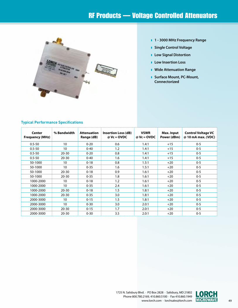
1725 N. Salisbury Blvd. · PO Box 2828 · Salisbury, MD 21802 Phone 800.780.2169, 410.860.5100 · Fax 410.860.1949
www.lorch.com · [email protected] 49
z 1 - 3000 MHz Frequency Range
z Single Control Voltage
z Low Signal Distortion
z Low Insertion Loss
z Wide Attenuation Range
z Surface Mount, PC-Mount, Connectorized
Typical Performance Specifications
Center % Bandwidth Attenuation Insertion Loss (dB) VSWR Max. Input Control Voltage VC Frequency (MHz) Range (dB) @ Vc = OVDC @ Vc = OVDC Power (dBm) @ 10 mA max. (VDC)
0.5-50 10 0-20 0.6 1.4:1 +15 0-5 0.5-50 10 0-40 1.2 1.4:1 +15 0-5 0.5-50 20-30 0-20 0.8 1.4:1 +15 0-5 0.5-50 20-30 0-40 1.6 1.4:1 +15 0-5 50-1000 10 0-18 0.8 1.5:1 +20 0-5 50-1000 10 0-35 1.6 1.5:1 +20 0-5 50-1000 20-30 0-18 0.9 1.6:1 +20 0-5 50-1000 20-30 0-35 1.8 1.6:1 +20 0-5 1000-2000 10 0-18 1.2 1.6:1 +20 0-5 1000-2000 10 0-35 2.4 1.6:1 +20 0-5 1000-2000 20-30 0-18 1.5 1.8:1 +20 0-5 1000-2000 20-30 0-35 3.0 1.8:1 +20 0-5 2000-3000 10 0-15 1.5 1.8:1 +20 0-5 2000-3000 10 0-30 3.0 2.0:1 +20 0-5 2000-3000 20-30 0-15 1.7 2.0:1 +20 0-5 2000-3000 20-30 0-30 3.5 2.0:1 +20 0-5
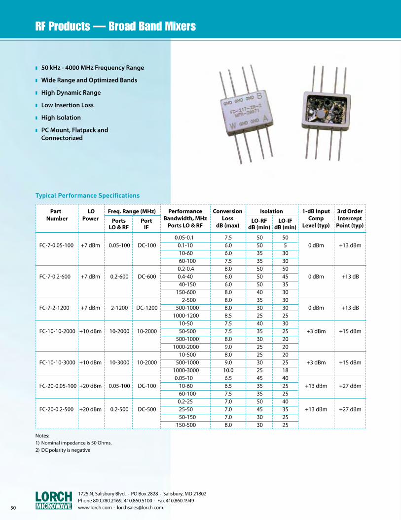
1725 N. Salisbury Blvd. · PO Box 2828 · Salisbury, MD 21802 Phone 800.780.2169, 410.860.5100 · Fax 410.860.1949 www.lorch.com · [email protected]
z 50 kHz - 4000 MHz Frequency Range
z Wide Range and Optimized Bands
z High Dynamic Range
z Low Insertion Loss
z High Isolation
z PC Mount, Flatpack and Connectorized
Typical Performance Specifications
Part LO Freq. Range (MHz) Isolation Number Power
0.05-0.1 7.5 50 50 FC-7-0.05-100 +7 dBm 0.05-100 DC-100 0.1-10 6.0 50 5 0 dBm +13 dBm 10-60 6.0 35 30 60-100 7.5 35 30 0.2-0.4 8.0 50 50 FC-7-0.2-600 +7 dBm 0.2-600 DC-600 0.4-40 6.0 50 45 0 dBm +13 dB 40-150 6.0 50 35 150-600 8.0 40 30 2-500 8.0 35 30 FC-7-2-1200 +7 dBm 2-1200 DC-1200 500-1000 8.0 30 30 0 dBm +13 dB 1000-1200 8.5 25 25 10-50 7.5 40 30 FC-10-10-2000 +10 dBm 10-2000 10-2000 50-500 7.5 35 25 +3 dBm +15 dBm 500-1000 8.0 30 20 1000-2000 9.0 25 20 10-500 8.0 25 20 FC-10-10-3000 +10 dBm 10-3000 10-2000 500-1000 9.0 30 25 +3 dBm +15 dBm 1000-3000 10.0 25 18 0.05-10 6.5 45 40 FC-20-0.05-100 +20 dBm 0.05-100 DC-100 10-60 6.5 35 25 +13 dBm +27 dBm 60-100 7.5 35 25 0.2-25 7.0 50 40 FC-20-0.2-500 +20 dBm 0.2-500 DC-500 25-50 7.0 45 35 +13 dBm +27 dBm 50-150 7.0 30 25 150-500 8.0 30 25
PerformanceBandwidth, MHz
Ports LO & RF
ConversionLoss
dB (max)
1-dB Input Comp
Level (typ)
3rd OrderIntercept
Point (typ)Ports
LO & RFPort
IFLO-RF
dB (min)LO-IF
dB (min)
Notes:1) Nominal impedance is 50 Ohms.2) DC polarity is negative

bringing technology to life
1725 North Salisbury Blvd. · PO Box 2828 · Salisbury, Maryland 21802
800.780.2169 · 410.860.5100 · Fax 410.860.1949
[email protected] · www.lorch.com
lo
rc
h m
icr
ow
av
e r
F &
mic
ro
wa
ve
Pr
od
uc
ts
Related Documents