ONLINE HELP ICR890 High-end CCD Camera System Camera System for Reading 1-D and 2-D Codes with Superb Image Quality suitable for OCR and Video Coding Applications

Welcome message from author
This document is posted to help you gain knowledge. Please leave a comment to let me know what you think about it! Share it to your friends and learn new things together.
Transcript
ICR890
Online HelpO N L I N E H E L P
ICR890High-end CCD Camera System
Camera System for Reading 1-D and 2-D Codes with SuperbImage Quality suitable for OCR and Video Coding Applications

Online Help
ICR890
2 © SICK AG · Division Auto Ident · Germany · All rights reserved 8012178/0000/2008-01-28
Software Versions
Copyright
Copyright © 2007
SICK AG Waldkirch
Auto Ident, Werk Reute
Nimburger Strasse 11
79276 Reute
Germany
Trademark
Windows 2000TM, XPTM, VistaTM and Internet ExplorerTM are registered trademarks or trade-marks of the Microsoft Corporation in the USA and other countries.
AcrobatTM ReaderTM is a trademark of Adobe Systems Incorporated.
Delivery version of the online help
The latest version of this online help for the SOPAS-ET device description is available as a PDF at www.sick.com.
Software/Tool Function Version
Device description ICR890
Device specific software module for configuration software SOPAS-ET
V 2.10
SOPAS-ET Configuration software V 2.14
Online Help
ICR890
Contents
8012178/0000/2008-01-28 © SICK AG · Division Auto Ident · Germany · All rights reserved 3
Table of contents1 Notes on this document................................................................................................... 52 ICR890................................................................................................................................ 7
2.1 Parameter.......................................................................................................... 72.1.1 Reading Configuration.................................................................................. 7
2.1.1.1 Object Trigger Control .............................................................................. 92.1.1.2 Focus Control .........................................................................................10
2.1.1.2.1Limits ..................................................................................................122.1.1.2.2MLG Settings......................................................................................12
2.1.1.3 Illumination Control................................................................................122.1.2 Position........................................................................................................132.1.3 Increment ....................................................................................................152.1.4 Image Output ..............................................................................................152.1.5 1D Code.......................................................................................................16
2.1.5.1 Codabar ..................................................................................................172.1.5.2 Code 39 ..................................................................................................182.1.5.3 UPC / EAN...............................................................................................192.1.5.4 2/5 Interleaved ......................................................................................202.1.5.5 Code 93 ..................................................................................................212.1.5.6 Code 128................................................................................................22
2.1.6 2D Code.......................................................................................................232.1.6.1 Data Matrix .............................................................................................232.1.6.2 PDF 417..................................................................................................25
2.1.7 Data Processing..........................................................................................262.1.7.1 Output Control ........................................................................................272.1.7.2 Evaluation Conditions ............................................................................282.1.7.3 Filter/Sorter for Output Formatter ........................................................312.1.7.4 Output Format ........................................................................................32
2.1.8 Network / Interfaces / IOs .........................................................................332.1.8.1 Serial .......................................................................................................342.1.8.2 Ethernet ..................................................................................................342.1.8.3 GBit Ethernet ..........................................................................................35
2.1.8.3.1GBit FTP..............................................................................................362.1.8.4 CAN .........................................................................................................362.1.8.5 Digital inputs ..........................................................................................372.1.8.6 Digital Outputs........................................................................................37
2.2 Service .............................................................................................................382.2.1 Operating Data............................................................................................38
2.2.1.1 Illumination.............................................................................................392.2.2 System Status.............................................................................................39
2.3 Analysis ............................................................................................................402.3.1 Event Monitor..............................................................................................402.3.2 Image Viewer ..............................................................................................40

Online Help
ICR890
4 © SICK AG · Division Auto Ident · Germany · All rights reserved 8012178/0000/2008-01-28
Contents
Online Help Chapter 1
ICR890
Notes on this document
8012178/0000/2008-01-28 © SICK AG · Division Auto Ident · Germany · All rights reserved 5
1 Notes on this document
Purpose This document provides instructions for technical staff on the configuration of the high-end CCD camera system ICR890 with the SOPAS-ET software.
This document provides information on all the parameters required for ICR890 system op-eration.
Target group The target group of this document is persons entrusted with the following activities:
Tab. 1-1: Target group
Depth of information This document contains all the information required for on-site configuration of the ICR890 system. The factory configuration (default setting) of the high-end CCD camera system is designed for use as a stand-alone device.
Information on mounting, installation, maintenance and troubleshooting are listed in the operating instructions of the ICR890 system (document no. 8011325).
Important Further information on the design of the ICR890 system as well as the barcode technology is available from SICK AG, Auto Ident division.
Online at www.sick.com.
Used symbols To provide easier access some information in this document is emphasised as follows:
Reference Blue underlined font shows a reference to more detailed information.
Activities Target group
Startup and configuration Trained staff, e.g. technicians or engineers
Hint
This symbol refers to special features.
Note
This symbol refers to additional settings in the configuration software SOPAS-ET.
Important
This symbol refers to additional technical documents.

Chapter 1 Online Help
ICR890
6 © SICK AG · Division Auto Ident · Germany · All rights reserved 8012178/0000/2008-01-28
Notes on this document
Online Help Chapter 2
ICR890
ICR890
8012178/0000/2008-01-28 © SICK AG · Division Auto Ident · Germany · All rights reserved 7
2 ICR890
2.1 Parameter
2.1.1 Reading Configuration
Codelabel properties The reading parameters and properties of the barcode are set with the parameters of the Codelabel properties group.
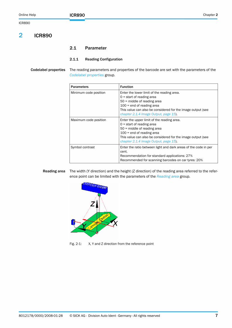
Reading area The width (Y direction) and the height (Z direction) of the reading area referred to the refer-ence point can be limited with the parameters of the Reading area group.
Fig. 2-1: X, Y and Z direction from the reference point
Parameters Function
Minimum code position Enter the lower limit of the reading area.0 = start of reading area50 = middle of reading area100 = end of reading areaThis value can also be considered for the image output (see chapter 2.1.4 Image Output, page 15).
Maximum code position Enter the upper limit of the reading area.0 = start of reading area50 = middle of reading area100 = end of reading areaThis value can also be considered for the image output (see chapter 2.1.4 Image Output, page 15).
Symbol contrast Enter the ratio between light and dark areas of the code in per cent.Recommendation for standard applications: 27%Recommended for scanning barcodes on car tyres: 20%
Chapter 2 Online Help
ICR890
8 © SICK AG · Division Auto Ident · Germany · All rights reserved 8012178/0000/2008-01-28
ICR890
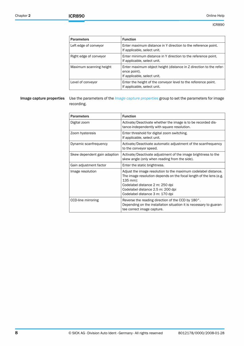
Image capture properties Use the parameters of the Image capture properties group to set the parameters for image recording.
Parameters Function
Left edge of conveyor Enter maximum distance in Y direction to the reference point.If applicable, select unit.
Right edge of conveyor Enter minimum distance in Y direction to the reference point.If applicable, select unit.
Maximum scanning height Enter maximum object height (distance in Z direction to the refer-ence point).If applicable, select unit.
Level of conveyor Enter the height of the conveyor level to the reference point.If applicable, select unit.
Parameters Function
Digital zoom Activate/Deactivate whether the image is to be recorded dis-tance-independently with square resolution.
Zoom hysteresis Enter threshold for digital zoom switching.If applicable, select unit.
Dynamic scanfrequency Activate/Deactivate automatic adjustment of the scanfrequency to the conveyor speed.
Skew dependent gain adaption Activate/Deactivate adjustment of the image brightness to the skew angle (only when reading from the side).
Gain adjustment factor Enter the static brightness.
Image resolution Adjust the image resolution to the maximum codelabel distance.The image resolution depends on the focal length of the lens (e.g. 135 mm):Codelabel distance 2 m: 250 dpiCodelabel distance 2.5 m: 200 dpiCodelabel distance 3 m: 170 dpi
CCD-line mirroring Reverse the reading direction of the CCD by 180°.Depending on the installation situation it is necessary to guaran-tee correct image capture.
Online Help Chapter 2
ICR890
ICR890
8012178/0000/2008-01-28 © SICK AG · Division Auto Ident · Germany · All rights reserved 9
2.1.1.1 Object Trigger Control
Start/Stop ofobject trigger
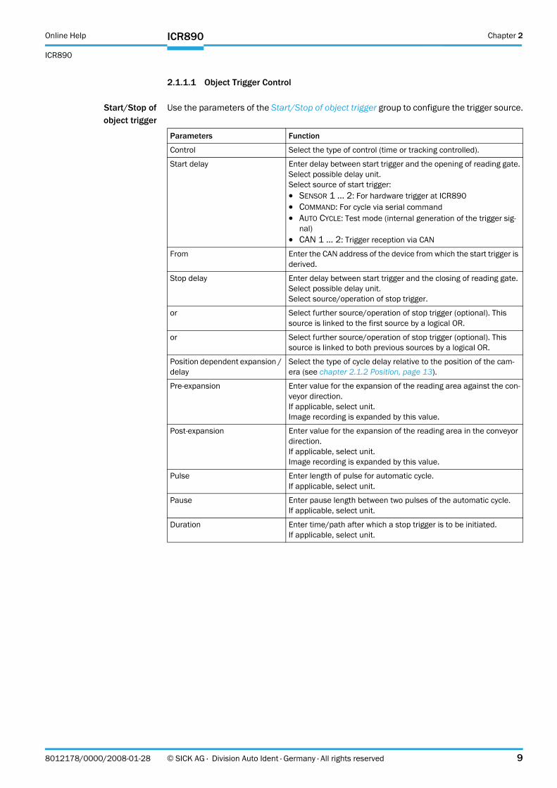
Use the parameters of the Start/Stop of object trigger group to configure the trigger source.
Parameters Function
Control Select the type of control (time or tracking controlled).
Start delay Enter delay between start trigger and the opening of reading gate.Select possible delay unit.Select source of start trigger:! SENSOR 1 ... 2: For hardware trigger at ICR890! COMMAND: For cycle via serial command! AUTO CYCLE: Test mode (internal generation of the trigger sig-
nal)! CAN 1 ... 2: Trigger reception via CAN
From Enter the CAN address of the device from which the start trigger is derived.
Stop delay Enter delay between start trigger and the closing of reading gate.Select possible delay unit.Select source/operation of stop trigger.
or Select further source/operation of stop trigger (optional). This source is linked to the first source by a logical OR.
or Select further source/operation of stop trigger (optional). This source is linked to both previous sources by a logical OR.
Position dependent expansion / delay
Select the type of cycle delay relative to the position of the cam-era (see chapter 2.1.2 Position, page 13).
Pre-expansion Enter value for the expansion of the reading area against the con-veyor direction.If applicable, select unit.Image recording is expanded by this value.
Post-expansion Enter value for the expansion of the reading area in the conveyor direction.If applicable, select unit.Image recording is expanded by this value.
Pulse Enter length of pulse for automatic cycle.If applicable, select unit.
Pause Enter pause length between two pulses of the automatic cycle.If applicable, select unit.
Duration Enter time/path after which a stop trigger is to be initiated.If applicable, select unit.
Chapter 2 Online Help
ICR890
10 © SICK AG · Division Auto Ident · Germany · All rights reserved 8012178/0000/2008-01-28
ICR890
2.1.1.2 Focus Control
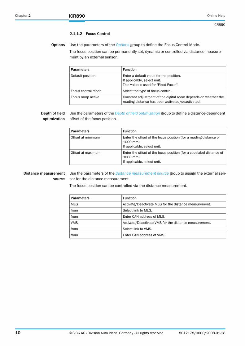
Options Use the parameters of the Options group to define the Focus Control Mode.
The focus position can be permanently set, dynamic or controlled via distance measure-ment by an external sensor.
Depth of fieldoptimization
Use the parameters of the Depth of field optimization group to define a distance-dependent offset of the focus position.
Distance measurementsource
Use the parameters of the Distance measurement source group to assign the external sen-sor for the distance measurement.
The focus position can be controlled via the distance measurement.
Parameters Function
Default position Enter a default value for the position.If applicable, select unit.This value is used for "Fixed Focus".
Focus control mode Select the type of focus control.
Focus ramp active Constant adjustment of the digital zoom depends on whether the reading distance has been activated/deactivated.
Parameters Function
Offset at minimum Enter the offset of the focus position (for a reading distance of 1000 mm).If applicable, select unit.
Offset at maximum Enter the offset of the focus position (for a codelabel distance of 3000 mm).If applicable, select unit.
Parameters Function
MLG Activate/Deactivate MLG for the distance measurement.
from Select link to MLG.
from Enter CAN address of MLG.
VMS Activate/Deactivate VMS for the distance measurement.
from Select link to VMS.
from Enter CAN address of VMS.
Online Help Chapter 2
ICR890
ICR890
8012178/0000/2008-01-28 © SICK AG · Division Auto Ident · Germany · All rights reserved 11
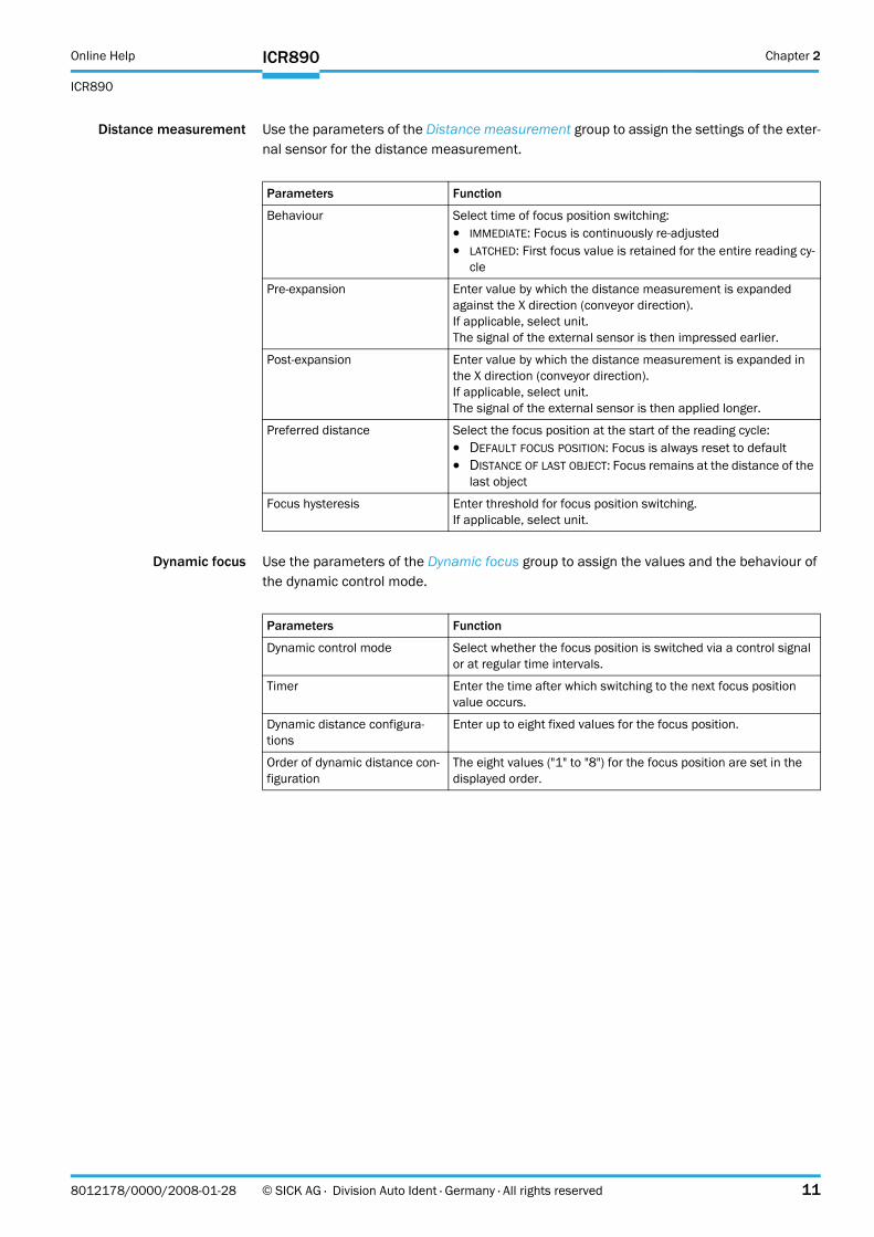
Distance measurement Use the parameters of the Distance measurement group to assign the settings of the exter-nal sensor for the distance measurement.
Dynamic focus Use the parameters of the Dynamic focus group to assign the values and the behaviour of the dynamic control mode.
Parameters Function
Behaviour Select time of focus position switching:! IMMEDIATE: Focus is continuously re-adjusted! LATCHED: First focus value is retained for the entire reading cy-
cle
Pre-expansion Enter value by which the distance measurement is expanded against the X direction (conveyor direction).If applicable, select unit.The signal of the external sensor is then impressed earlier.
Post-expansion Enter value by which the distance measurement is expanded in the X direction (conveyor direction).If applicable, select unit.The signal of the external sensor is then applied longer.
Preferred distance Select the focus position at the start of the reading cycle:! DEFAULT FOCUS POSITION: Focus is always reset to default! DISTANCE OF LAST OBJECT: Focus remains at the distance of the
last object
Focus hysteresis Enter threshold for focus position switching.If applicable, select unit.
Parameters Function
Dynamic control mode Select whether the focus position is switched via a control signal or at regular time intervals.
Timer Enter the time after which switching to the next focus position value occurs.
Dynamic distance configura-tions
Enter up to eight fixed values for the focus position.
Order of dynamic distance con-figuration
The eight values ("1" to "8") for the focus position are set in the displayed order.
Chapter 2 Online Help
ICR890
12 © SICK AG · Division Auto Ident · Germany · All rights reserved 8012178/0000/2008-01-28
ICR890
2.1.1.2.1Limits
Focus control limits Use the parameters of the Focus control limits group to activate/deactivate the focus con-trol limits deviating from the reading area.
Limits referred toconveyor belt
Use the parameters of the Limits referred to conveyor belt group to assign the focus control limits deviating from the reading area.
2.1.1.2.2MLG Settings
General Use the parameters of the General group to configure, amongst other things, the position and the properties of the external distance measurement.
2.1.1.3 Illumination Control
Illumination mode Use the parameters of the Illumination mode group to define the conditions for illumination control.
Parameters Function
Limits referred to conveyor belt Activate/Deactivate relative focus control limits.
Parameters Function
Right edge of conveyor Enter minimum distance in Y direction to the reference point.If applicable, select unit.
Left edge of conveyor Enter maximum distance in Y direction to the reference point.If applicable, select unit.
Level of conveyor Enter the height of the conveyor level to the reference point.If applicable, select unit.
Maximum scanning height Enter maximum height (distance in Z direction to the reference point).If applicable, select unit.
Parameters Function
Distance between beams Enter distance between the beams of the MLG.
Number of beams Enter number of beams of the MLG.
X-position of MLG Enter distance of MLG to the reference point in X direction (con-veyor direction).
Z-position of MLG Enter height of the first MLG light beam to the reference point in Z direction (height).
Parameters Function
Lamp on Select condition for switching on the illumination.
Lamp off Select condition for switching off the illumination.
Lamp timeout active Activate/Deactivate automatic illumination switch-off.
Timeout Enter the time after which the illumination is automatically switched off.
Online Help Chapter 2
ICR890
ICR890
8012178/0000/2008-01-28 © SICK AG · Division Auto Ident · Germany · All rights reserved 13
2.1.2 Position
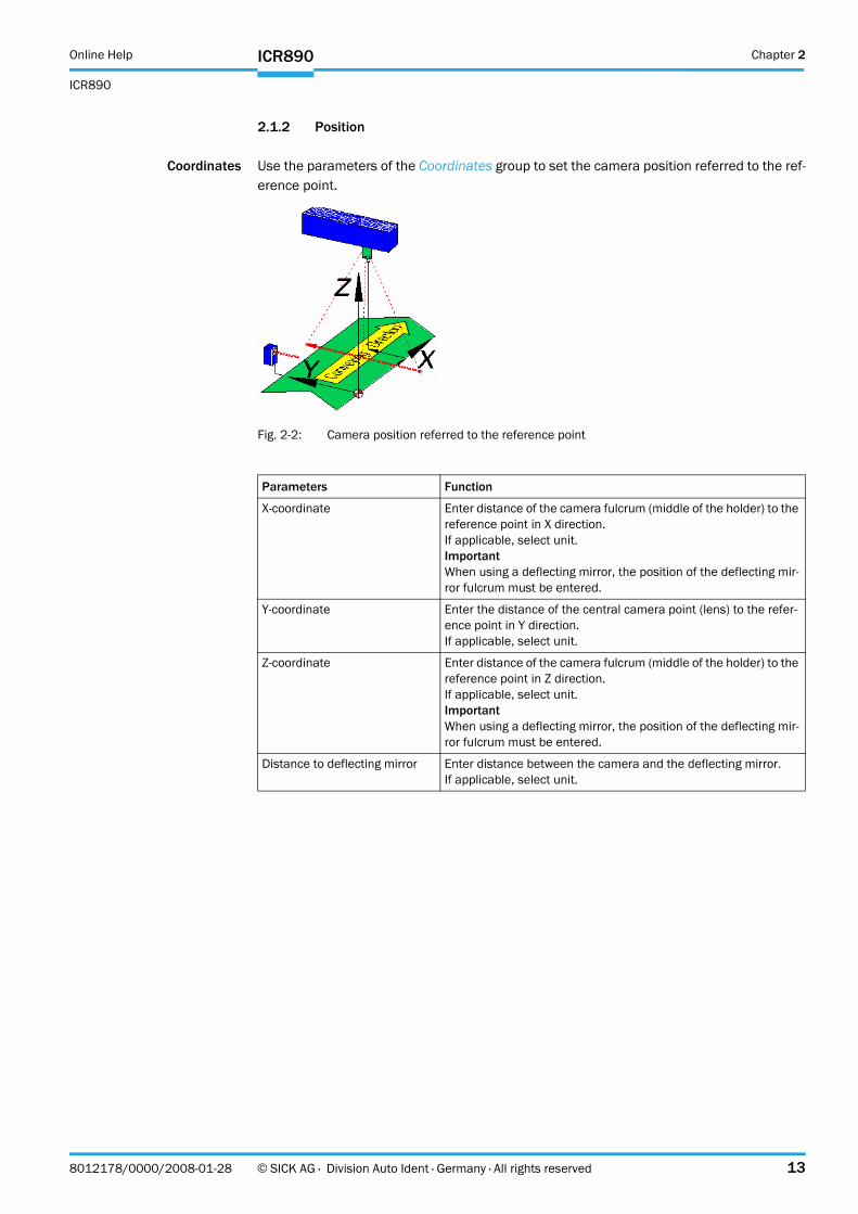
Coordinates Use the parameters of the Coordinates group to set the camera position referred to the ref-erence point.
Fig. 2-2: Camera position referred to the reference point
Parameters Function
X-coordinate Enter distance of the camera fulcrum (middle of the holder) to the reference point in X direction.If applicable, select unit.ImportantWhen using a deflecting mirror, the position of the deflecting mir-ror fulcrum must be entered.
Y-coordinate Enter the distance of the central camera point (lens) to the refer-ence point in Y direction.If applicable, select unit.
Z-coordinate Enter distance of the camera fulcrum (middle of the holder) to the reference point in Z direction.If applicable, select unit.ImportantWhen using a deflecting mirror, the position of the deflecting mir-ror fulcrum must be entered.
Distance to deflecting mirror Enter distance between the camera and the deflecting mirror.If applicable, select unit.
Chapter 2 Online Help
ICR890
14 © SICK AG · Division Auto Ident · Germany · All rights reserved 8012178/0000/2008-01-28
ICR890
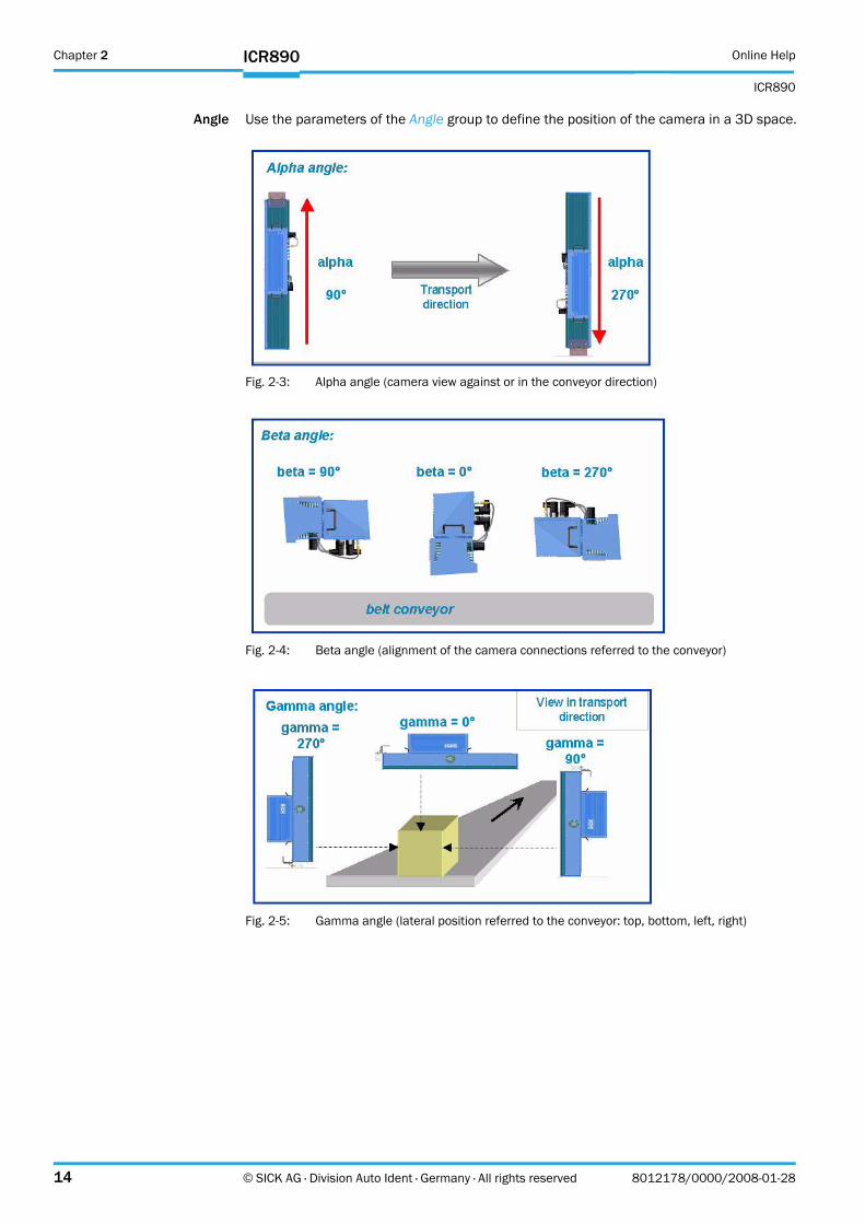
Angle Use the parameters of the Angle group to define the position of the camera in a 3D space.
Fig. 2-3: Alpha angle (camera view against or in the conveyor direction)
Fig. 2-4: Beta angle (alignment of the camera connections referred to the conveyor)
Fig. 2-5: Gamma angle (lateral position referred to the conveyor: top, bottom, left, right)
Online Help Chapter 2
ICR890
ICR890
8012178/0000/2008-01-28 © SICK AG · Division Auto Ident · Germany · All rights reserved 15
2.1.3 Increment
An external incremental encoder can be connected to determine the actual conveyor speed.
The conveyor speed results from the number of impulses and the resolution of the external incremental encoder. Alternatively, a fixed speed can be selected.
Increment The increment source and the resolution/speed are configured via the parameters of the Increment group.
2.1.4 Image Output
Condition Use the parameters of the Condition group to define the conditions for the image output.
Parameters Function
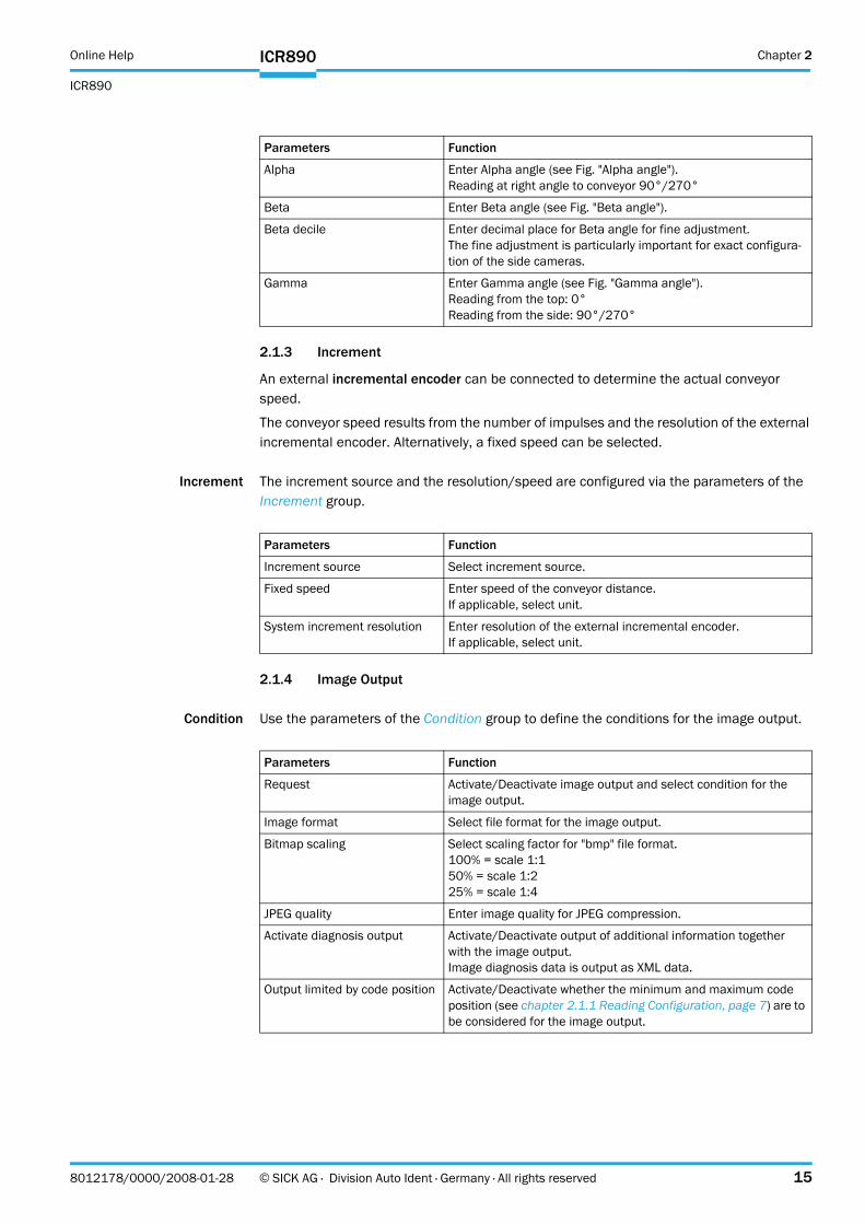
Alpha Enter Alpha angle (see Fig. "Alpha angle").Reading at right angle to conveyor 90°/270°
Beta Enter Beta angle (see Fig. "Beta angle").
Beta decile Enter decimal place for Beta angle for fine adjustment.The fine adjustment is particularly important for exact configura-tion of the side cameras.
Gamma Enter Gamma angle (see Fig. "Gamma angle").Reading from the top: 0°Reading from the side: 90°/270°
Parameters Function
Increment source Select increment source.
Fixed speed Enter speed of the conveyor distance.If applicable, select unit.
System increment resolution Enter resolution of the external incremental encoder.If applicable, select unit.
Parameters Function
Request Activate/Deactivate image output and select condition for the image output.
Image format Select file format for the image output.
Bitmap scaling Select scaling factor for "bmp" file format.100% = scale 1:150% = scale 1:225% = scale 1:4
JPEG quality Enter image quality for JPEG compression.
Activate diagnosis output Activate/Deactivate output of additional information together with the image output.Image diagnosis data is output as XML data.
Output limited by code position Activate/Deactivate whether the minimum and maximum code position (see chapter 2.1.1 Reading Configuration, page 7) are to be considered for the image output.
Chapter 2 Online Help
ICR890
16 © SICK AG · Division Auto Ident · Germany · All rights reserved 8012178/0000/2008-01-28
ICR890
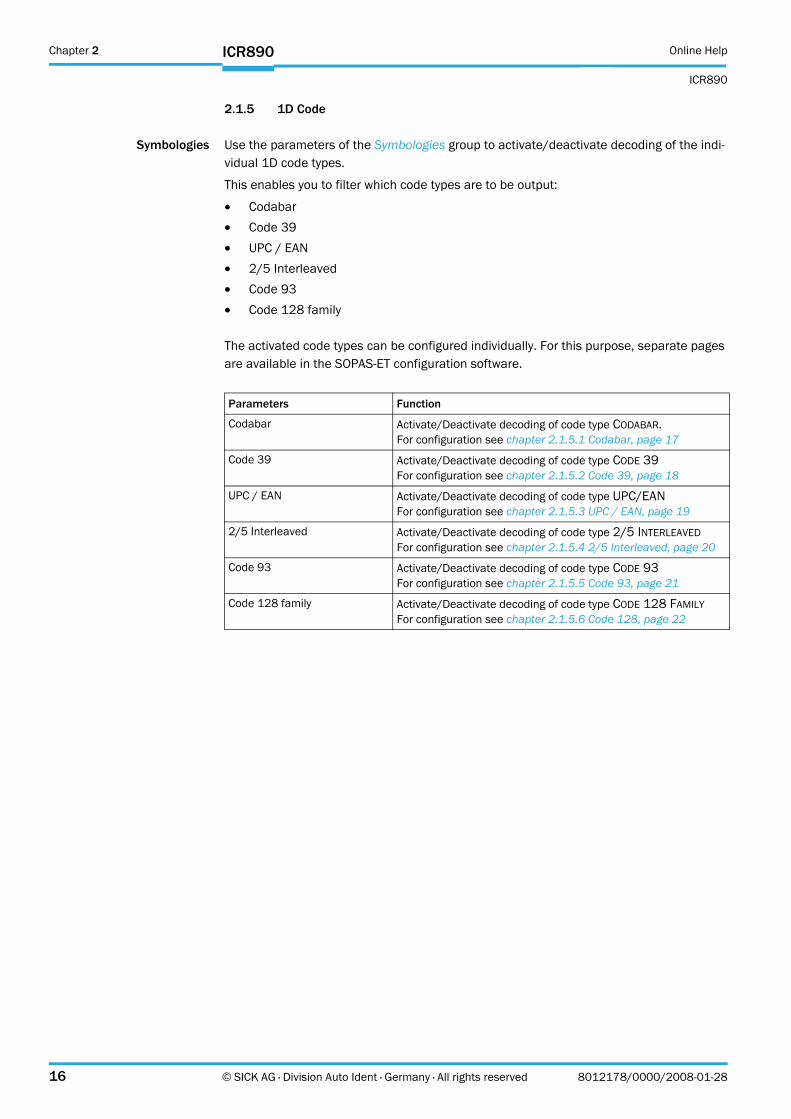
2.1.5 1D Code
Symbologies Use the parameters of the Symbologies group to activate/deactivate decoding of the indi-vidual 1D code types.
This enables you to filter which code types are to be output:
! Codabar! Code 39! UPC / EAN! 2/5 Interleaved! Code 93! Code 128 family
The activated code types can be configured individually. For this purpose, separate pages are available in the SOPAS-ET configuration software.
Parameters Function
Codabar Activate/Deactivate decoding of code type CODABAR.For configuration see chapter 2.1.5.1 Codabar, page 17
Code 39 Activate/Deactivate decoding of code type CODE 39For configuration see chapter 2.1.5.2 Code 39, page 18
UPC / EAN Activate/Deactivate decoding of code type UPC/EANFor configuration see chapter 2.1.5.3 UPC / EAN, page 19
2/5 Interleaved Activate/Deactivate decoding of code type 2/5 INTERLEAVEDFor configuration see chapter 2.1.5.4 2/5 Interleaved, page 20
Code 93 Activate/Deactivate decoding of code type CODE 93For configuration see chapter 2.1.5.5 Code 93, page 21
Code 128 family Activate/Deactivate decoding of code type CODE 128 FAMILYFor configuration see chapter 2.1.5.6 Code 128, page 22
Online Help Chapter 2
ICR890
ICR890
8012178/0000/2008-01-28 © SICK AG · Division Auto Ident · Germany · All rights reserved 17
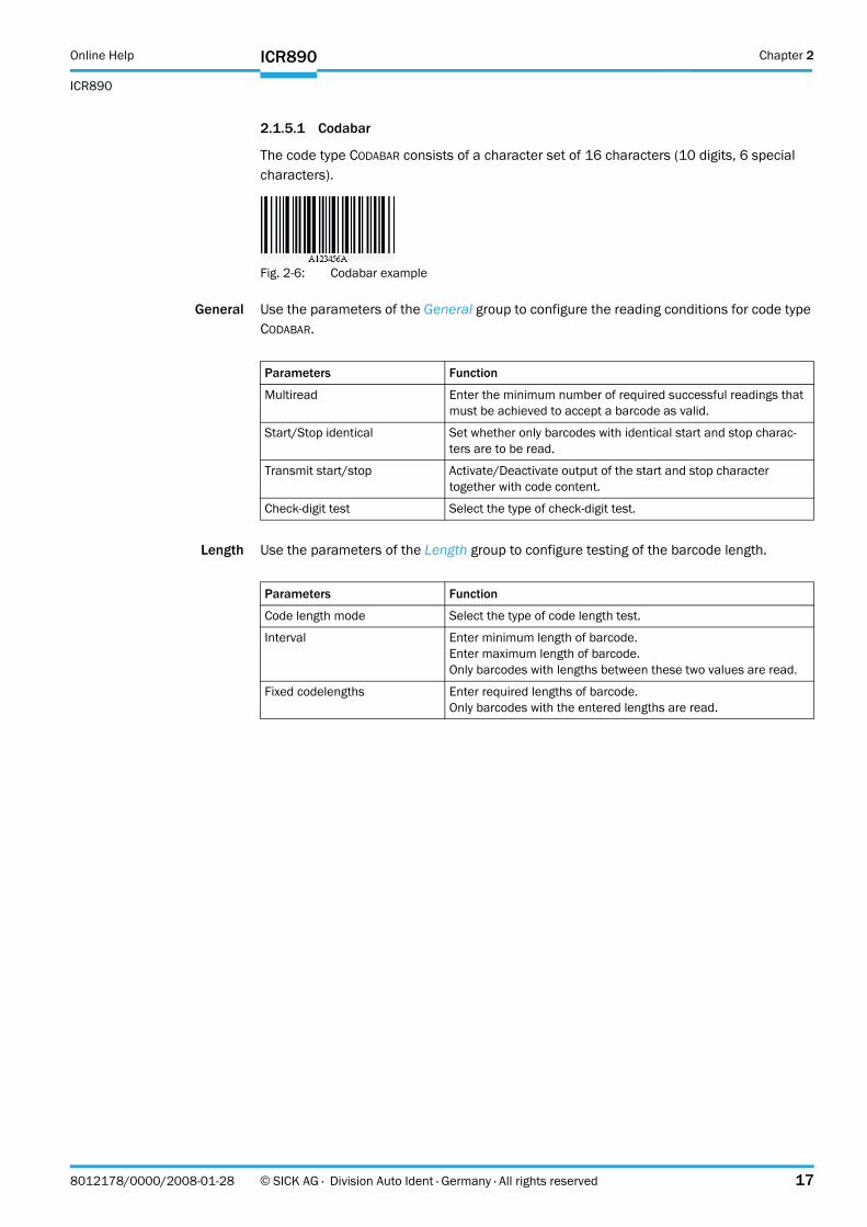
2.1.5.1 Codabar
The code type CODABAR consists of a character set of 16 characters (10 digits, 6 special characters).
Fig. 2-6: Codabar example
General Use the parameters of the General group to configure the reading conditions for code type CODABAR.
Length Use the parameters of the Length group to configure testing of the barcode length.
Parameters Function
Multiread Enter the minimum number of required successful readings that must be achieved to accept a barcode as valid.
Start/Stop identical Set whether only barcodes with identical start and stop charac-ters are to be read.
Transmit start/stop Activate/Deactivate output of the start and stop character together with code content.
Check-digit test Select the type of check-digit test.
Parameters Function
Code length mode Select the type of code length test.
Interval Enter minimum length of barcode.Enter maximum length of barcode.Only barcodes with lengths between these two values are read.
Fixed codelengths Enter required lengths of barcode.Only barcodes with the entered lengths are read.
Chapter 2 Online Help
ICR890
18 © SICK AG · Division Auto Ident · Germany · All rights reserved 8012178/0000/2008-01-28
ICR890
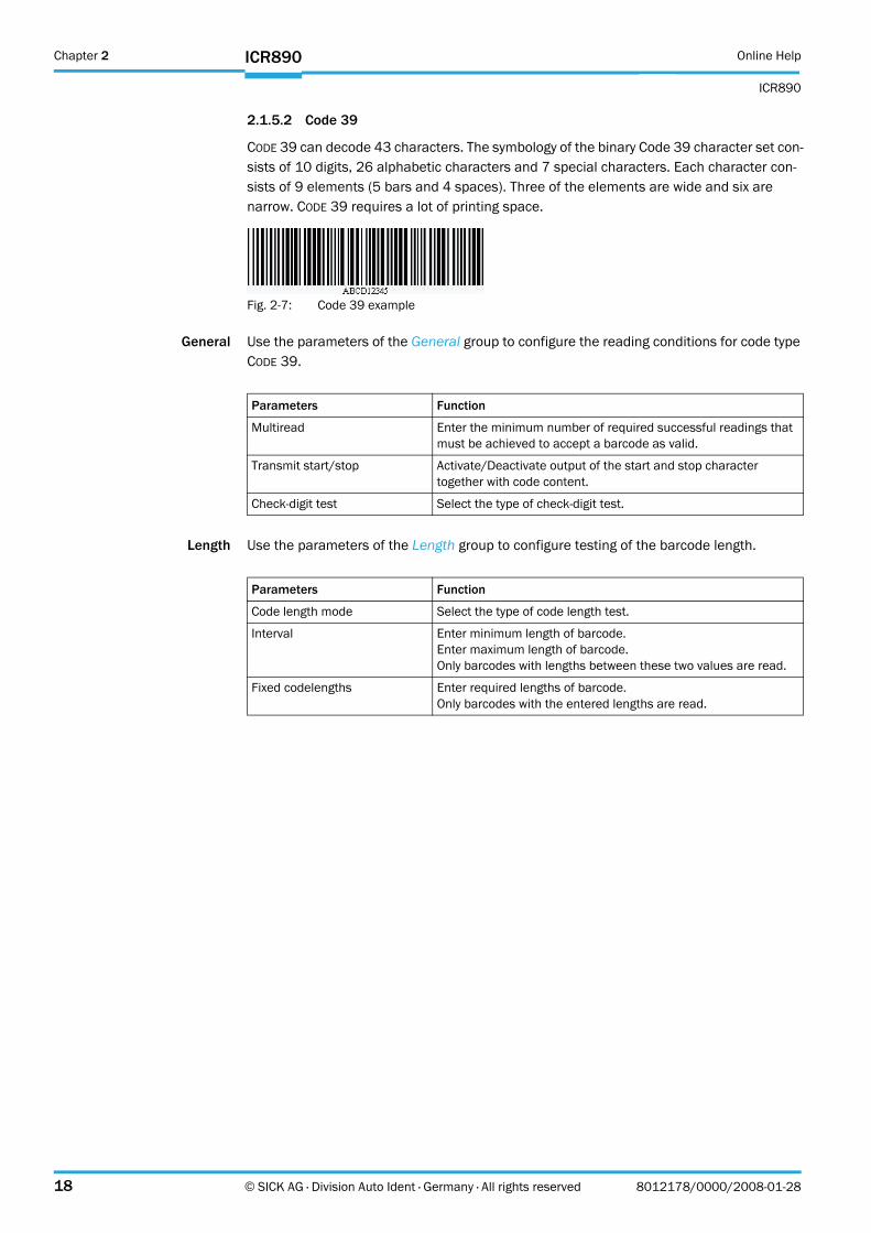
2.1.5.2 Code 39
CODE 39 can decode 43 characters. The symbology of the binary Code 39 character set con-sists of 10 digits, 26 alphabetic characters and 7 special characters. Each character con-sists of 9 elements (5 bars and 4 spaces). Three of the elements are wide and six are narrow. CODE 39 requires a lot of printing space.
Fig. 2-7: Code 39 example
General Use the parameters of the General group to configure the reading conditions for code type CODE 39.
Length Use the parameters of the Length group to configure testing of the barcode length.
Parameters Function
Multiread Enter the minimum number of required successful readings that must be achieved to accept a barcode as valid.
Transmit start/stop Activate/Deactivate output of the start and stop character together with code content.
Check-digit test Select the type of check-digit test.
Parameters Function
Code length mode Select the type of code length test.
Interval Enter minimum length of barcode.Enter maximum length of barcode.Only barcodes with lengths between these two values are read.
Fixed codelengths Enter required lengths of barcode.Only barcodes with the entered lengths are read.
Online Help Chapter 2
ICR890
ICR890
8012178/0000/2008-01-28 © SICK AG · Division Auto Ident · Germany · All rights reserved 19
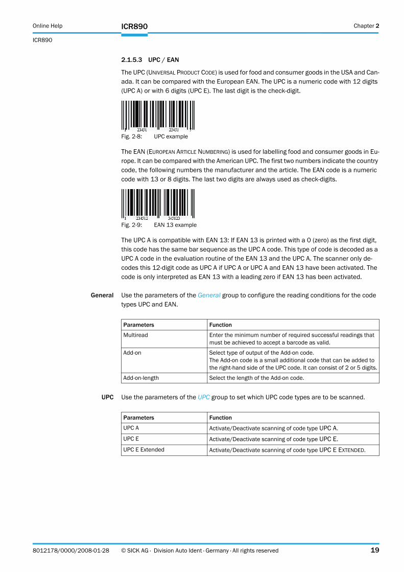
2.1.5.3 UPC / EAN
The UPC (UNIVERSAL PRODUCT CODE) is used for food and consumer goods in the USA and Can-ada. It can be compared with the European EAN. The UPC is a numeric code with 12 digits (UPC A) or with 6 digits (UPC E). The last digit is the check-digit.
Fig. 2-8: UPC example
The EAN (EUROPEAN ARTICLE NUMBERING) is used for labelling food and consumer goods in Eu-rope. It can be compared with the American UPC. The first two numbers indicate the country code, the following numbers the manufacturer and the article. The EAN code is a numeric code with 13 or 8 digits. The last two digits are always used as check-digits.
Fig. 2-9: EAN 13 example
The UPC A is compatible with EAN 13: If EAN 13 is printed with a 0 (zero) as the first digit, this code has the same bar sequence as the UPC A code. This type of code is decoded as a UPC A code in the evaluation routine of the EAN 13 and the UPC A. The scanner only de-codes this 12-digit code as UPC A if UPC A or UPC A and EAN 13 have been activated. The code is only interpreted as EAN 13 with a leading zero if EAN 13 has been activated.
General Use the parameters of the General group to configure the reading conditions for the code types UPC and EAN.
UPC Use the parameters of the UPC group to set which UPC code types are to be scanned.
Parameters Function
Multiread Enter the minimum number of required successful readings that must be achieved to accept a barcode as valid.
Add-on Select type of output of the Add-on code.The Add-on code is a small additional code that can be added to the right-hand side of the UPC code. It can consist of 2 or 5 digits.
Add-on-length Select the length of the Add-on code.
Parameters Function
UPC A Activate/Deactivate scanning of code type UPC A.
UPC E Activate/Deactivate scanning of code type UPC E.
UPC E Extended Activate/Deactivate scanning of code type UPC E EXTENDED.
Chapter 2 Online Help
ICR890
20 © SICK AG · Division Auto Ident · Germany · All rights reserved 8012178/0000/2008-01-28
ICR890
EAN Use the parameters of the EAN group to set which EAN code types are to be scanned.
2.1.5.4 2/5 Interleaved
The 2/5 INTERLEAVED (also called ITF) is a very common code type for coding numeric infor-mation. The main fields of application are in the industrial sector. The 2/5 INTERLEAVED is a binary code which encodes digits from 0-9.
Fig. 2-10: 2/5 Interleaved example
General Use the parameters of the General group to configure the reading conditions for the code type 2/5 INTERLEAVED.
Length Use the parameters of the Length group to configure testing of the barcode length.
Parameters Function
EAN 8 Activate/Deactivate scanning of code type EAN 8.
EAN 13 Activate/Deactivate scanning of code type EAN 13.
Parameters Function
Multiread #1 Enter the minimum number of required successful readings that must be achieved to accept a barcode as valid.
Check-digit test #1 Select the type of check-digit test for the first code length.
Check-digit test #2 Select the type of check-digit test for the second code length.
Check-digit test #3 Select the type of check-digit test for the third code length.
Check-digit test #4 Select the type of check-digit test for the fourth code length.
Check-digit test #5 Select the type of check-digit test for the fifth code length.
Parameters Function
Code length mode Select the type of code length test.
Interval Enter minimum length of barcode.Enter maximum length of barcode.Only barcodes with lengths between these two values are read.
Fixed codelengths Enter required lengths of barcode.Only barcodes with the entered lengths are read.Use the parameters of the General group to define the type of check-digit test.
Online Help Chapter 2
ICR890
ICR890
8012178/0000/2008-01-28 © SICK AG · Division Auto Ident · Germany · All rights reserved 21
2.1.5.5 Code 93
CODE 93 is an alphanumeric code comparable with CODE 39 (see chapter 2.1.5.2 Code 39, page 18). However, Code 93 requires less space. The same character set (10 digits, 26 characters and 7 special characters) can be encoded. The code is multiple-valued (valency 4).
Fig. 2-11: Code 93 example
General Use the parameters of the General group to configure the reading conditions for the code type CODE 93.
Length Use the parameters of the Length group to configure testing of the barcode length.
Parameters Function
Multiread Enter the minimum number of required successful readings that must be achieved to accept a barcode as valid.
Parameters Function
Code length mode Select the type of code length test.
Interval Enter minimum length of barcode.Enter maximum length of barcode.Only barcodes with lengths between these two values are read.
Fixed codelengths Enter required lengths of barcode.Only barcodes with the entered lengths are read.
Chapter 2 Online Help
ICR890
22 © SICK AG · Division Auto Ident · Germany · All rights reserved 8012178/0000/2008-01-28
ICR890
2.1.5.6 Code 128
CODE 128 is an alphanumeric code that can indicate the complete ASCII character set with three character sets (set A, B and C). A check-digit test is always available.
! Character set A includes digits, uppercase letters and special characters.! Character set B includes digits, uppercase and lowercase letters.! Character set C only includes digits, but with a double density.
It is possible to start with one of these sets and to switch to another character set within the code. CODE 128 is multiple-valued code (valency 4).
Fig. 2-12: Code 128 example
General Use the parameters of the General group to configure the reading conditions for the code family CODE 128.
Length Use the parameters of the Length group to configure testing of the barcode length.
EAN 128 Use the parameters of the EAN 128 group to assign the function characters FC1. These function characters identify the code as code type EAN 128. They can be at the beginning or in the middle of the code.
Fig. 2-13: EAN 128 example
Parameters Function
Code 128 Activate/Deactivate scanning of code type CODE 128.
EAN 128 Activate/Deactivate scanning of code type EAN 128.
Multiread Enter the minimum number of required successful readings that must be achieved to accept a barcode as valid.
Parameters Function
Code length mode Select the type of code length test.
Interval Enter minimum length of barcode.Enter maximum length of barcode.Only barcodes with lengths between these two values are read.
Fixed codelengths Enter required lengths of barcode.Only barcodes with the entered lengths are read.
Parameters Function
FC1 value on first position Enter FC1 values that have to be positioned at the beginning of codes that are to be read.
FC1 value within code Enter FC1 values that have to be positioned in the middle of codes that are to be read.
Online Help Chapter 2
ICR890
ICR890
8012178/0000/2008-01-28 © SICK AG · Division Auto Ident · Germany · All rights reserved 23
2.1.6 2D Code
Symbologies Use the parameters of the Symbologies group to activate/deactivate decoding of the indi-vidual 2D code types.
This enables you to filter which code types are to be output:
! Data Matrix! PDF 417
The activated code types can be configured individually. For this purpose, separate pages are available in the SOPAS-ET configuration software.
2.1.6.1 Data Matrix
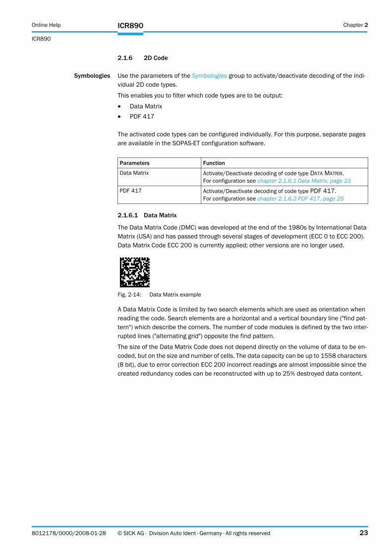
The Data Matrix Code (DMC) was developed at the end of the 1980s by International Data Matrix (USA) and has passed through several stages of development (ECC 0 to ECC 200). Data Matrix Code ECC 200 is currently applied; other versions are no longer used.
Fig. 2-14: Data Matrix example
A Data Matrix Code is limited by two search elements which are used as orientation when reading the code. Search elements are a horizontal and a vertical boundary line ("find pat-tern") which describe the corners. The number of code modules is defined by the two inter-rupted lines ("alternating grid") opposite the find pattern.
The size of the Data Matrix Code does not depend directly on the volume of data to be en-coded, but on the size and number of cells. The data capacity can be up to 1558 characters (8 bit), due to error correction ECC 200 incorrect readings are almost impossible since the created redundancy codes can be reconstructed with up to 25% destroyed data content.
Parameters Function
Data Matrix Activate/Deactivate decoding of code type DATA MATRIX.For configuration see chapter 2.1.6.1 Data Matrix, page 23
PDF 417 Activate/Deactivate decoding of code type PDF 417.For configuration see chapter 2.1.6.2 PDF 417, page 25
Chapter 2 Online Help
ICR890
24 © SICK AG · Division Auto Ident · Germany · All rights reserved 8012178/0000/2008-01-28
ICR890
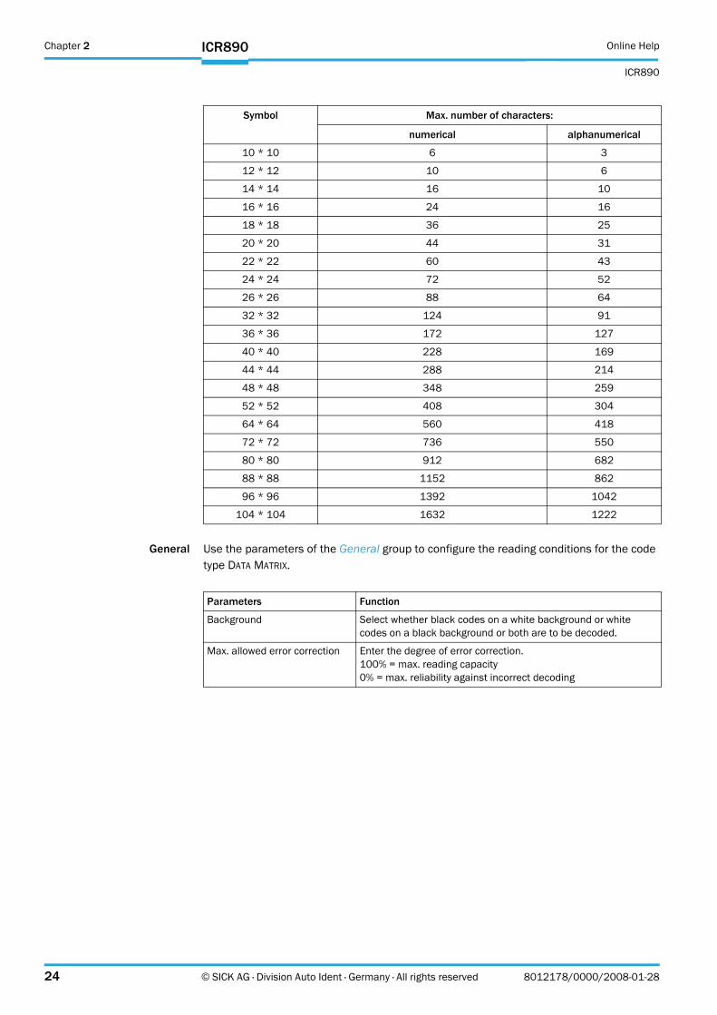
General Use the parameters of the General group to configure the reading conditions for the code type DATA MATRIX.
Symbol Max. number of characters:
numerical alphanumerical
10 * 10 6 3
12 * 12 10 6
14 * 14 16 10
16 * 16 24 16
18 * 18 36 25
20 * 20 44 31
22 * 22 60 43
24 * 24 72 52
26 * 26 88 64
32 * 32 124 91
36 * 36 172 127
40 * 40 228 169
44 * 44 288 214
48 * 48 348 259
52 * 52 408 304
64 * 64 560 418
72 * 72 736 550
80 * 80 912 682
88 * 88 1152 862
96 * 96 1392 1042
104 * 104 1632 1222
Parameters Function
Background Select whether black codes on a white background or white codes on a black background or both are to be decoded.
Max. allowed error correction Enter the degree of error correction.100% = max. reading capacity0% = max. reliability against incorrect decoding
Online Help Chapter 2
ICR890
ICR890
8012178/0000/2008-01-28 © SICK AG · Division Auto Ident · Germany · All rights reserved 25
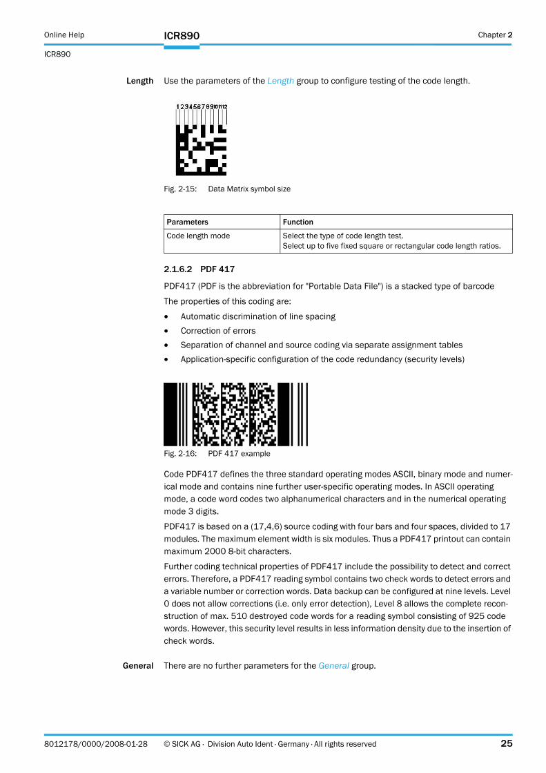
Length Use the parameters of the Length group to configure testing of the code length.
Fig. 2-15: Data Matrix symbol size
2.1.6.2 PDF 417
PDF417 (PDF is the abbreviation for "Portable Data File") is a stacked type of barcode
The properties of this coding are:
! Automatic discrimination of line spacing! Correction of errors! Separation of channel and source coding via separate assignment tables! Application-specific configuration of the code redundancy (security levels)
Fig. 2-16: PDF 417 example
Code PDF417 defines the three standard operating modes ASCII, binary mode and numer-ical mode and contains nine further user-specific operating modes. In ASCII operating mode, a code word codes two alphanumerical characters and in the numerical operating mode 3 digits.
PDF417 is based on a (17,4,6) source coding with four bars and four spaces, divided to 17 modules. The maximum element width is six modules. Thus a PDF417 printout can contain maximum 2000 8-bit characters.
Further coding technical properties of PDF417 include the possibility to detect and correct errors. Therefore, a PDF417 reading symbol contains two check words to detect errors and a variable number or correction words. Data backup can be configured at nine levels. Level 0 does not allow corrections (i.e. only error detection), Level 8 allows the complete recon-struction of max. 510 destroyed code words for a reading symbol consisting of 925 code words. However, this security level results in less information density due to the insertion of check words.
General There are no further parameters for the General group.
Parameters Function
Code length mode Select the type of code length test.Select up to five fixed square or rectangular code length ratios.
Chapter 2 Online Help
ICR890
26 © SICK AG · Division Auto Ident · Germany · All rights reserved 8012178/0000/2008-01-28
ICR890
2.1.7 Data Processing
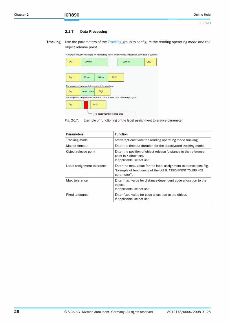
Tracking Use the parameters of the Tracking group to configure the reading operating mode and the object release point.
Fig. 2-17: Example of functioning of the label assignment tolerance parameter
Parameters Function
Tracking mode Activate/Deactivate the reading operating mode tracking.
Master timeout Enter the timeout duration for the deactivated tracking mode.
Object release point Enter the position of object release (distance to the reference point in X direction).If applicable, select unit.
Label assignment tolerance Enter the max. value for the label assignment tolerance (see Fig. "Example of functioning of the LABEL ASSIGNMENT TOLERANCE parameter").
Max. tolerance Enter max. value for distance-dependent code allocation to the object.If applicable, select unit.
Fixed tolerance Enter fixed value for code allocation to the object.If applicable, select unit.
Online Help Chapter 2
ICR890
ICR890
8012178/0000/2008-01-28 © SICK AG · Division Auto Ident · Germany · All rights reserved 27
2.1.7.1 Output Control
Output control Use the parameters of the Output control group to configure the output of the read code contents.
Parameters Function
Control Select the type of control (time or tracking controlled).
Data transmission point Select output time of the read code contents.
Related to Select the reference edge for the activated tracking mode (see chapter 2.1.7 Data Processing, page 26).ImportantFor data transmission related to the object front edge, the maxi-mum object length must be added to the standard data transmis-sion point (object rear edge).
at X-position Enter the X position (distance to the reference point) at which the read code contents are to be output for activated tracking mode (see chapter 2.1.7 Data Processing, page 26).If applicable, select unit.
Time Enter the time period after which the read code contents are to be output for activated tracking mode (see chapter 2.1.7 Data Processing, page 26).
Data transmission point If the tracking mode has been deactivated (see chapter 2.1.7 Data Processing, page 26), the read code content is output with "Good Read".
Delay Enter the delay for the data transmission point for deactivated tracking mode (see chapter 2.1.7 Data Processing, page 26).If applicable, select unit.
Timeout Enter delay for the transmission of the reading data.If applicable, select unit.
Chapter 2 Online Help
ICR890
28 © SICK AG · Division Auto Ident · Germany · All rights reserved 8012178/0000/2008-01-28
ICR890
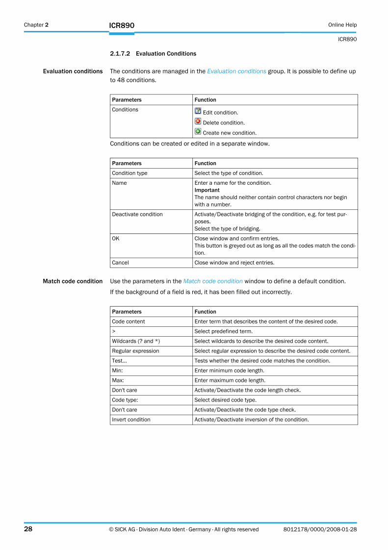
2.1.7.2 Evaluation Conditions
Evaluation conditions The conditions are managed in the Evaluation conditions group. It is possible to define up to 48 conditions.
Conditions can be created or edited in a separate window.
Match code condition Use the parameters in the Match code condition window to define a default condition.
If the background of a field is red, it has been filled out incorrectly.
Parameters Function
Conditions Edit condition.
Delete condition.
Create new condition.
Parameters Function
Condition type Select the type of condition.
Name Enter a name for the condition.ImportantThe name should neither contain control characters nor begin with a number.
Deactivate condition Activate/Deactivate bridging of the condition, e.g. for test pur-poses.Select the type of bridging.
OK Close window and confirm entries.This button is greyed out as long as all the codes match the condi-tion.
Cancel Close window and reject entries.
Parameters Function
Code content Enter term that describes the content of the desired code.
> Select predefined term.
Wildcards (? and *) Select wildcards to describe the desired code content.
Regular expression Select regular expression to describe the desired code content.
Test... Tests whether the desired code matches the condition.
Min: Enter minimum code length.
Max: Enter maximum code length.
Don't care Activate/Deactivate the code length check.
Code type: Select desired code type.
Don't care Activate/Deactivate the code type check.
Invert condition Activate/Deactivate inversion of the condition.
Online Help Chapter 2
ICR890
ICR890
8012178/0000/2008-01-28 © SICK AG · Division Auto Ident · Germany · All rights reserved 29
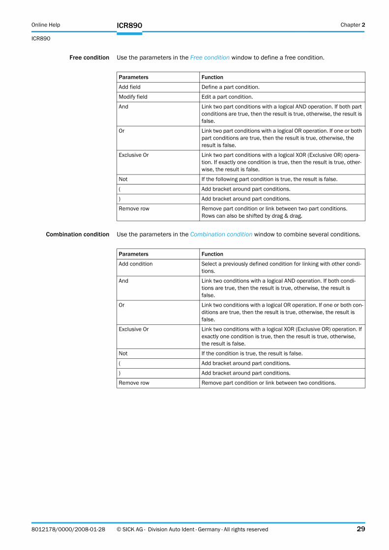
Free condition Use the parameters in the Free condition window to define a free condition.
Combination condition Use the parameters in the Combination condition window to combine several conditions.
Parameters Function
Add field Define a part condition.
Modify field Edit a part condition.
And Link two part conditions with a logical AND operation. If both part conditions are true, then the result is true, otherwise, the result is false.
Or Link two part conditions with a logical OR operation. If one or both part conditions are true, then the result is true, otherwise, the result is false.
Exclusive Or Link two part conditions with a logical XOR (Exclusive OR) opera-tion. If exactly one condition is true, then the result is true, other-wise, the result is false.
Not If the following part condition is true, the result is false.
( Add bracket around part conditions.
) Add bracket around part conditions.
Remove row Remove part condition or link between two part conditions.Rows can also be shifted by drag & drag.
Parameters Function
Add condition Select a previously defined condition for linking with other condi-tions.
And Link two conditions with a logical AND operation. If both condi-tions are true, then the result is true, otherwise, the result is false.
Or Link two conditions with a logical OR operation. If one or both con-ditions are true, then the result is true, otherwise, the result is false.
Exclusive Or Link two conditions with a logical XOR (Exclusive OR) operation. If exactly one condition is true, then the result is true, otherwise, the result is false.
Not If the condition is true, the result is false.
( Add bracket around part conditions.
) Add bracket around part conditions.
Remove row Remove part condition or link between two conditions.
Chapter 2 Online Help
ICR890
30 © SICK AG · Division Auto Ident · Germany · All rights reserved 8012178/0000/2008-01-28
ICR890
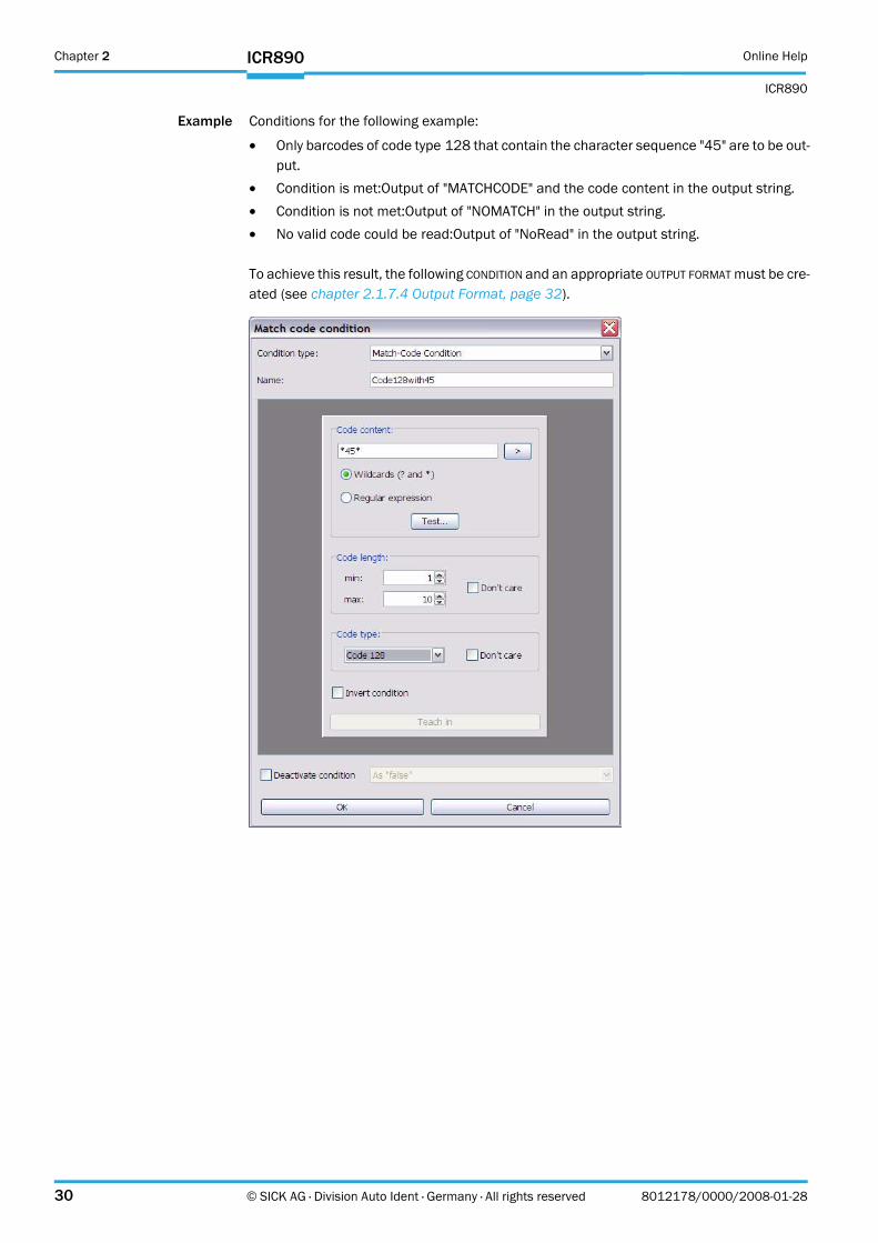
Example Conditions for the following example:
! Only barcodes of code type 128 that contain the character sequence "45" are to be out-put.
! Condition is met:Output of "MATCHCODE" and the code content in the output string.! Condition is not met:Output of "NOMATCH" in the output string.! No valid code could be read:Output of "NoRead" in the output string.
To achieve this result, the following CONDITION and an appropriate OUTPUT FORMAT must be cre-ated (see chapter 2.1.7.4 Output Format, page 32).
Online Help Chapter 2
ICR890
ICR890
8012178/0000/2008-01-28 © SICK AG · Division Auto Ident · Germany · All rights reserved 31
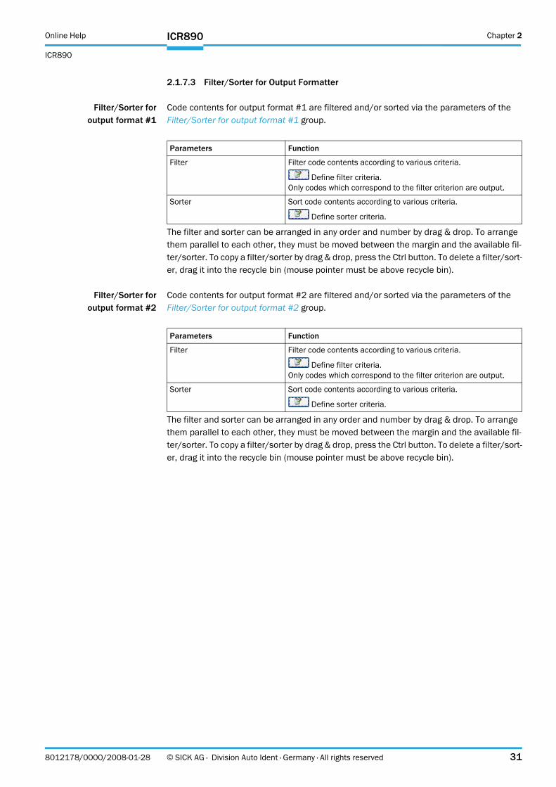
2.1.7.3 Filter/Sorter for Output Formatter
Filter/Sorter foroutput format #1
Code contents for output format #1 are filtered and/or sorted via the parameters of the Filter/Sorter for output format #1 group.
The filter and sorter can be arranged in any order and number by drag & drop. To arrange them parallel to each other, they must be moved between the margin and the available fil-ter/sorter. To copy a filter/sorter by drag & drop, press the Ctrl button. To delete a filter/sort-er, drag it into the recycle bin (mouse pointer must be above recycle bin).
Filter/Sorter foroutput format #2
Code contents for output format #2 are filtered and/or sorted via the parameters of the Filter/Sorter for output format #2 group.
The filter and sorter can be arranged in any order and number by drag & drop. To arrange them parallel to each other, they must be moved between the margin and the available fil-ter/sorter. To copy a filter/sorter by drag & drop, press the Ctrl button. To delete a filter/sort-er, drag it into the recycle bin (mouse pointer must be above recycle bin).
Parameters Function
Filter Filter code contents according to various criteria.
Define filter criteria.Only codes which correspond to the filter criterion are output.
Sorter Sort code contents according to various criteria.
Define sorter criteria.
Parameters Function
Filter Filter code contents according to various criteria.
Define filter criteria.Only codes which correspond to the filter criterion are output.
Sorter Sort code contents according to various criteria.
Define sorter criteria.

Chapter 2 Online Help
ICR890
32 © SICK AG · Division Auto Ident · Germany · All rights reserved 8012178/0000/2008-01-28
ICR890
2.1.7.4 Output Format
Output format #1 The reading results (decoded codes) are output by definable data interfaces. For this, two different output formats (telegrams) can be defined. The format can also depend on condi-tions.
Use the parameters of the Output format #1 group to define the first format of the reading results.
The created output format can be marked and copied into a text editor for saving. To copy it back, right mouse click on the Output format #1 window and select the command "PASTE FROM EXTERN...".
Output format #2 The reading results (decoded codes) are output by definable data interfaces. For this, two different output formats (telegrams) can be defined. The format can also depend on condi-tions.
Use the parameters of the Output format #2 group to define the second format of the read-ing results.
The created output format can be marked and copied into a text editor for saving. To copy it back, right mouse click on the Output format #2 window and select the command "PASTE FROM EXTERN...".
Parameters Function
Output format #1 Enter output format of the reading results. Open input field. Close input field. Select condition.
Right mouse click: Insert new condition, data field or special char-acter.Click on the bottom row of the data field: Select attribute charac-teristics.
Accept Confirm entries.
Parameters Function
Output format #2 Enter output format of the reading results. Open input field. Close input field. Select condition.
Right mouse click: Insert new condition, data field or special char-acter.Click on the bottom row of the data field: Select attribute charac-teristics.
Accept Confirm entries.
Online Help Chapter 2
ICR890
ICR890
8012178/0000/2008-01-28 © SICK AG · Division Auto Ident · Germany · All rights reserved 33
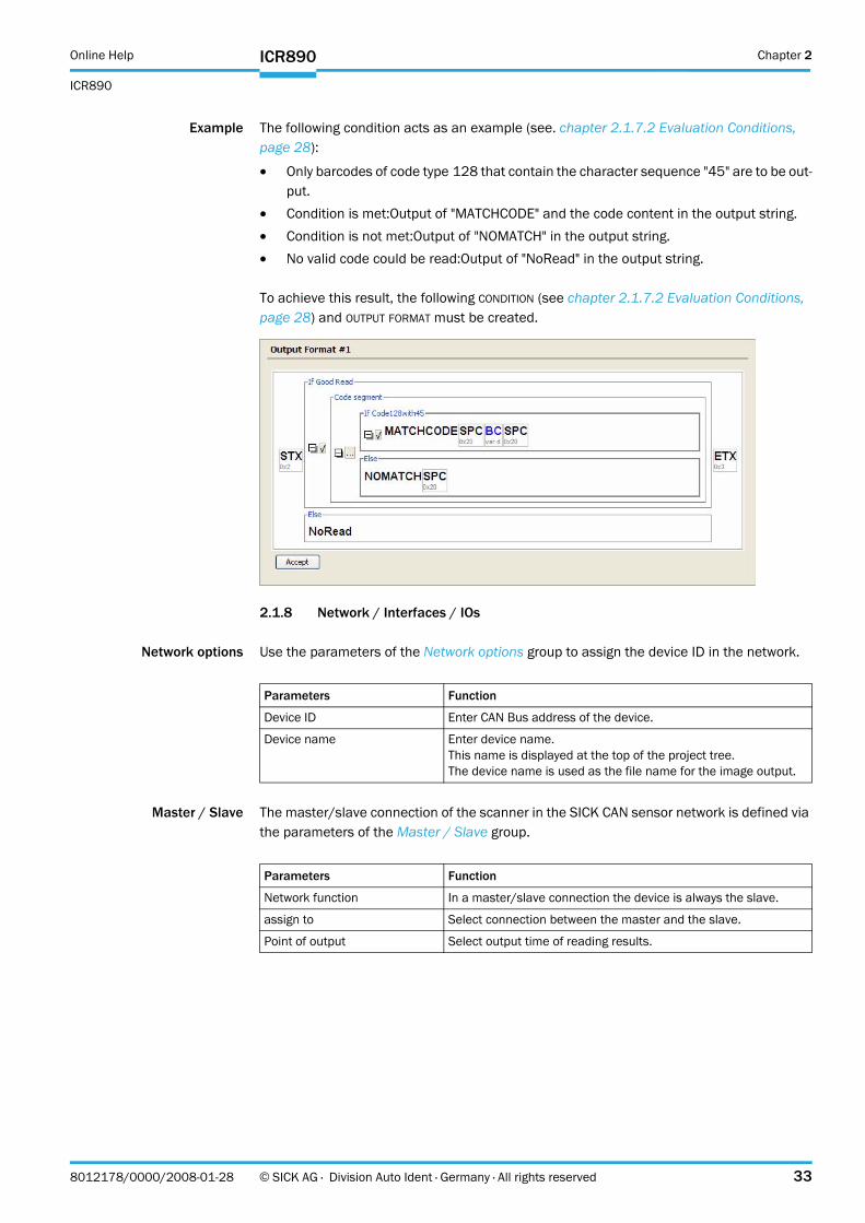
Example The following condition acts as an example (see. chapter 2.1.7.2 Evaluation Conditions, page 28):
! Only barcodes of code type 128 that contain the character sequence "45" are to be out-put.
! Condition is met:Output of "MATCHCODE" and the code content in the output string.! Condition is not met:Output of "NOMATCH" in the output string.! No valid code could be read:Output of "NoRead" in the output string.
To achieve this result, the following CONDITION (see chapter 2.1.7.2 Evaluation Conditions, page 28) and OUTPUT FORMAT must be created.
2.1.8 Network / Interfaces / IOs
Network options Use the parameters of the Network options group to assign the device ID in the network.
Master / Slave The master/slave connection of the scanner in the SICK CAN sensor network is defined via the parameters of the Master / Slave group.
Parameters Function
Device ID Enter CAN Bus address of the device.
Device name Enter device name.This name is displayed at the top of the project tree.The device name is used as the file name for the image output.
Parameters Function
Network function In a master/slave connection the device is always the slave.
assign to Select connection between the master and the slave.
Point of output Select output time of reading results.
Chapter 2 Online Help
ICR890
34 © SICK AG · Division Auto Ident · Germany · All rights reserved 8012178/0000/2008-01-28
ICR890
2.1.8.1 Serial
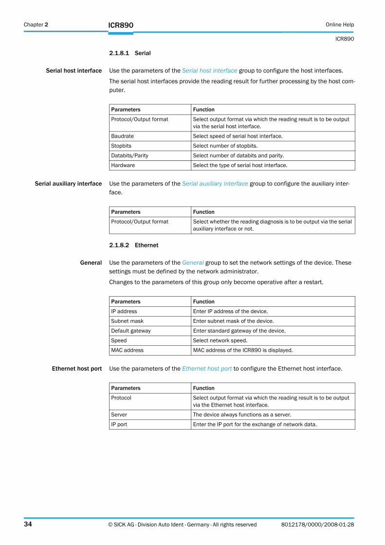
Serial host interface Use the parameters of the Serial host interface group to configure the host interfaces.
The serial host interfaces provide the reading result for further processing by the host com-puter.
Serial auxiliary interface Use the parameters of the Serial auxiliary interface group to configure the auxiliary inter-face.
2.1.8.2 Ethernet
General Use the parameters of the General group to set the network settings of the device. These settings must be defined by the network administrator.
Changes to the parameters of this group only become operative after a restart.
Ethernet host port Use the parameters of the Ethernet host port to configure the Ethernet host interface.
Parameters Function
Protocol/Output format Select output format via which the reading result is to be output via the serial host interface.
Baudrate Select speed of serial host interface.
Stopbits Select number of stopbits.
Databits/Parity Select number of databits and parity.
Hardware Select the type of serial host interface.
Parameters Function
Protocol/Output format Select whether the reading diagnosis is to be output via the serial auxiliary interface or not.
Parameters Function
IP address Enter IP address of the device.
Subnet mask Enter subnet mask of the device.
Default gateway Enter standard gateway of the device.
Speed Select network speed.
MAC address MAC address of the ICR890 is displayed.
Parameters Function
Protocol Select output format via which the reading result is to be output via the Ethernet host interface.
Server The device always functions as a server.
IP port Enter the IP port for the exchange of network data.
Online Help Chapter 2
ICR890
ICR890
8012178/0000/2008-01-28 © SICK AG · Division Auto Ident · Germany · All rights reserved 35
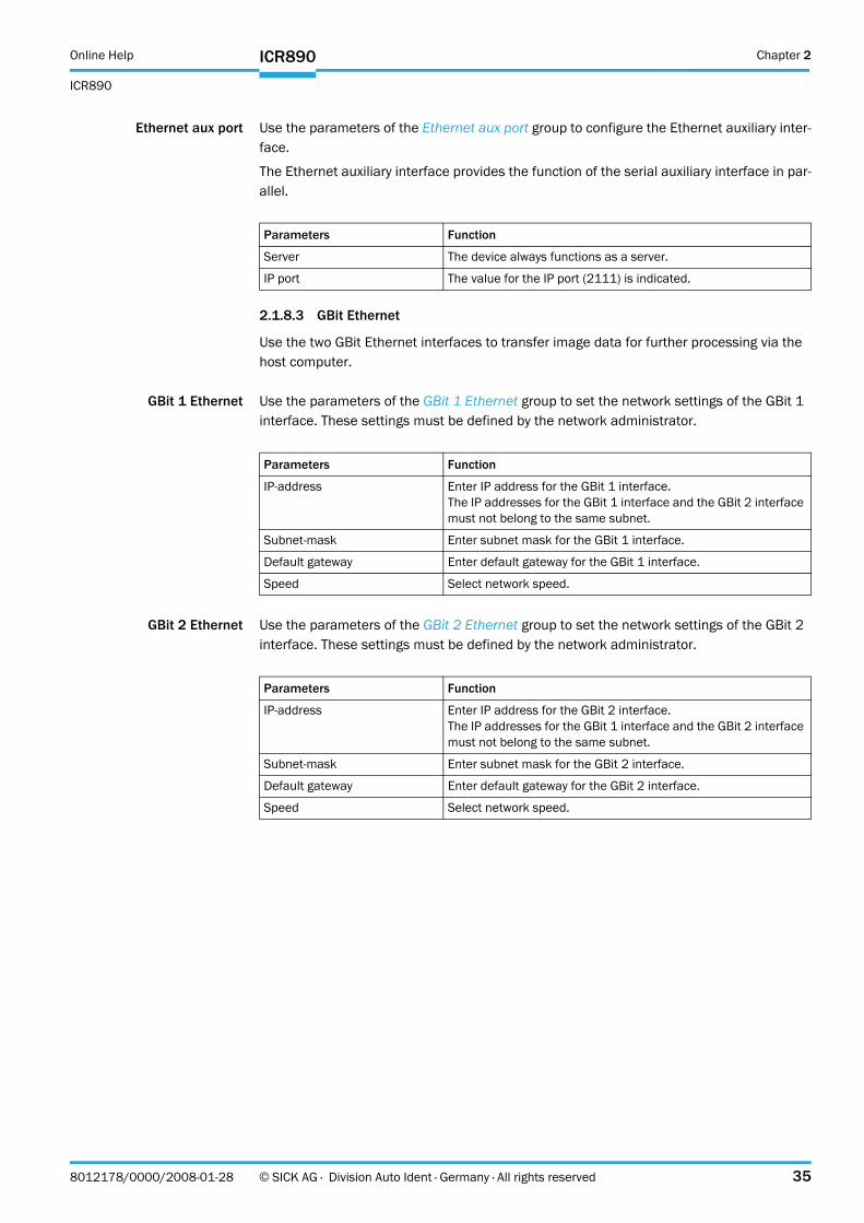
Ethernet aux port Use the parameters of the Ethernet aux port group to configure the Ethernet auxiliary inter-face.
The Ethernet auxiliary interface provides the function of the serial auxiliary interface in par-allel.
2.1.8.3 GBit Ethernet
Use the two GBit Ethernet interfaces to transfer image data for further processing via the host computer.
GBit 1 Ethernet Use the parameters of the GBit 1 Ethernet group to set the network settings of the GBit 1 interface. These settings must be defined by the network administrator.
GBit 2 Ethernet Use the parameters of the GBit 2 Ethernet group to set the network settings of the GBit 2 interface. These settings must be defined by the network administrator.
Parameters Function
Server The device always functions as a server.
IP port The value for the IP port (2111) is indicated.
Parameters Function
IP-address Enter IP address for the GBit 1 interface.The IP addresses for the GBit 1 interface and the GBit 2 interface must not belong to the same subnet.
Subnet-mask Enter subnet mask for the GBit 1 interface.
Default gateway Enter default gateway for the GBit 1 interface.
Speed Select network speed.
Parameters Function
IP-address Enter IP address for the GBit 2 interface.The IP addresses for the GBit 1 interface and the GBit 2 interface must not belong to the same subnet.
Subnet-mask Enter subnet mask for the GBit 2 interface.
Default gateway Enter default gateway for the GBit 2 interface.
Speed Select network speed.
Chapter 2 Online Help
ICR890
36 © SICK AG · Division Auto Ident · Germany · All rights reserved 8012178/0000/2008-01-28
ICR890
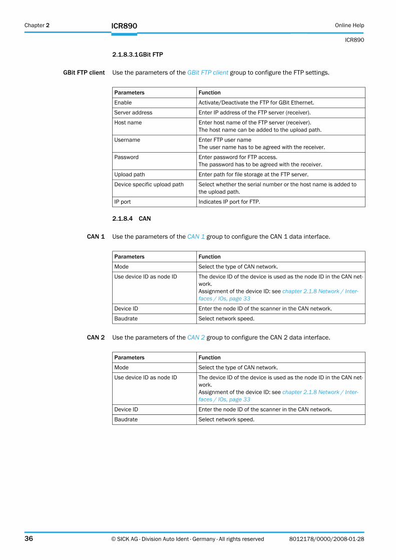
2.1.8.3.1GBit FTP
GBit FTP client Use the parameters of the GBit FTP client group to configure the FTP settings.
2.1.8.4 CAN
CAN 1 Use the parameters of the CAN 1 group to configure the CAN 1 data interface.
CAN 2 Use the parameters of the CAN 2 group to configure the CAN 2 data interface.
Parameters Function
Enable Activate/Deactivate the FTP for GBit Ethernet.
Server address Enter IP address of the FTP server (receiver).
Host name Enter host name of the FTP server (receiver).The host name can be added to the upload path.
Username Enter FTP user nameThe user name has to be agreed with the receiver.
Password Enter password for FTP access.The password has to be agreed with the receiver.
Upload path Enter path for file storage at the FTP server.
Device specific upload path Select whether the serial number or the host name is added to the upload path.
IP port Indicates IP port for FTP.
Parameters Function
Mode Select the type of CAN network.
Use device ID as node ID The device ID of the device is used as the node ID in the CAN net-work.Assignment of the device ID: see chapter 2.1.8 Network / Inter-faces / IOs, page 33
Device ID Enter the node ID of the scanner in the CAN network.
Baudrate Select network speed.
Online Help Chapter 2
ICR890
ICR890
8012178/0000/2008-01-28 © SICK AG · Division Auto Ident · Germany · All rights reserved 37
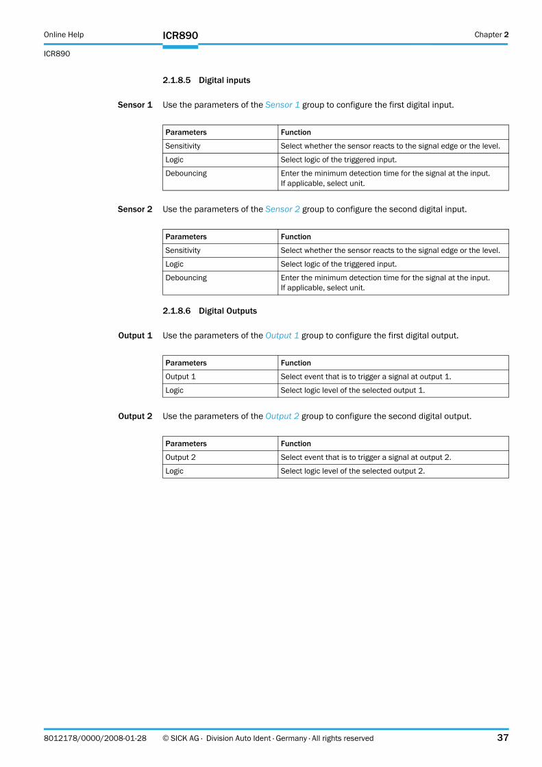
2.1.8.5 Digital inputs
Sensor 1 Use the parameters of the Sensor 1 group to configure the first digital input.
Sensor 2 Use the parameters of the Sensor 2 group to configure the second digital input.
2.1.8.6 Digital Outputs
Output 1 Use the parameters of the Output 1 group to configure the first digital output.
Output 2 Use the parameters of the Output 2 group to configure the second digital output.
Parameters Function
Sensitivity Select whether the sensor reacts to the signal edge or the level.
Logic Select logic of the triggered input.
Debouncing Enter the minimum detection time for the signal at the input.If applicable, select unit.
Parameters Function
Sensitivity Select whether the sensor reacts to the signal edge or the level.
Logic Select logic of the triggered input.
Debouncing Enter the minimum detection time for the signal at the input.If applicable, select unit.
Parameters Function
Output 1 Select event that is to trigger a signal at output 1.
Logic Select logic level of the selected output 1.
Parameters Function
Output 2 Select event that is to trigger a signal at output 2.
Logic Select logic level of the selected output 2.

Chapter 2 Online Help
ICR890
38 © SICK AG · Division Auto Ident · Germany · All rights reserved 8012178/0000/2008-01-28
ICR890
2.2 Service
2.2.1 Operating Data
Device information The identification data of the device is indicated via the parameters of the Device informa-tion group. This data is important for service work.
Operating Data Information about previous device operation is indicated via the parameters of the Operating Data group.
Service information Information about service and maintenance is indicated via the parameters of the Service information group.
Parameters Function
Manufacturer Indicates the manufacturer of the scanner.
Device type Indicates the device type of the scanner.
Software version Indicates the version of the installed firmware.
Order number Indicates the order number of the scanner.
Serial number Indicates the serial number of the scanner.
Parameters Function
Power-on counter Indicates how often the device has been activated.
Operating hours Indicates the total number of device operating hours.
Daily operating hours Indicates the device operating time since the last activation.
Max. temperature image proc-essor
Indicates the maximum temperature achieved by the image proc-essor.
Current temperature image processor
Indicates the current temperature at the image processor.
Max. temperature digital board Indicates the maximum temperature achieved by the digital board.
Current temperature digital board
Indicates the current temperature at the digital board.
Max. temperature CCD board Indicates the maximum temperature achieved by the CCD board.
Current temperature CCD board Indicates the current temperature at the CCD board.
Parameters Function
Last username Indicates the last logged-in user.
Last parameterization Indicates the date of the last parameterisation.
Last maintenance Enter date of the last maintenance
Next maintenance Enter date of the next maintenance.

Online Help Chapter 2
ICR890
ICR890
8012178/0000/2008-01-28 © SICK AG · Division Auto Ident · Germany · All rights reserved 39
2.2.1.1 Illumination
Device information The identification data of the illumination is indicated via the parameters of the Device in-formation group. This data is important for service work.
Operating dataillumination
Information about previous illumination operation is indicated via the parameters of the Operating data illumination group.
2.2.2 System Status
System information The parameters of the System information group indicate system messages.
Parameters Function
Device type The device type of the illumination is indicated.
Software version The version of the installed firmware is indicated.
Order number The order number of the illumination is indicated.
Serial number The serial number of the illumination is indicated.
Parameters Function
Power-on counter Indicates how often the illumination has been activated.
Operating hours Indicates the total number of illumination operating hours.
Fan rotation speed Indicates the fan speed.
Supply voltage Indicates the current supply voltage.
Parameters Function
Type Indicates the type of message.
First occurrence Indicates the time of first occurrence.
Latest occurrence Indicates the time of latest occurrence.
Number Indicates the message number.
Description Indicates the message text.
Info Indicates further information concerning the message.
Status Indicates the message status.
Counter Indicates the number of message occurrences.
Chapter 2 Online Help
ICR890
40 © SICK AG · Division Auto Ident · Germany · All rights reserved 8012178/0000/2008-01-28
ICR890
2.3 Analysis
2.3.1 Event Monitor
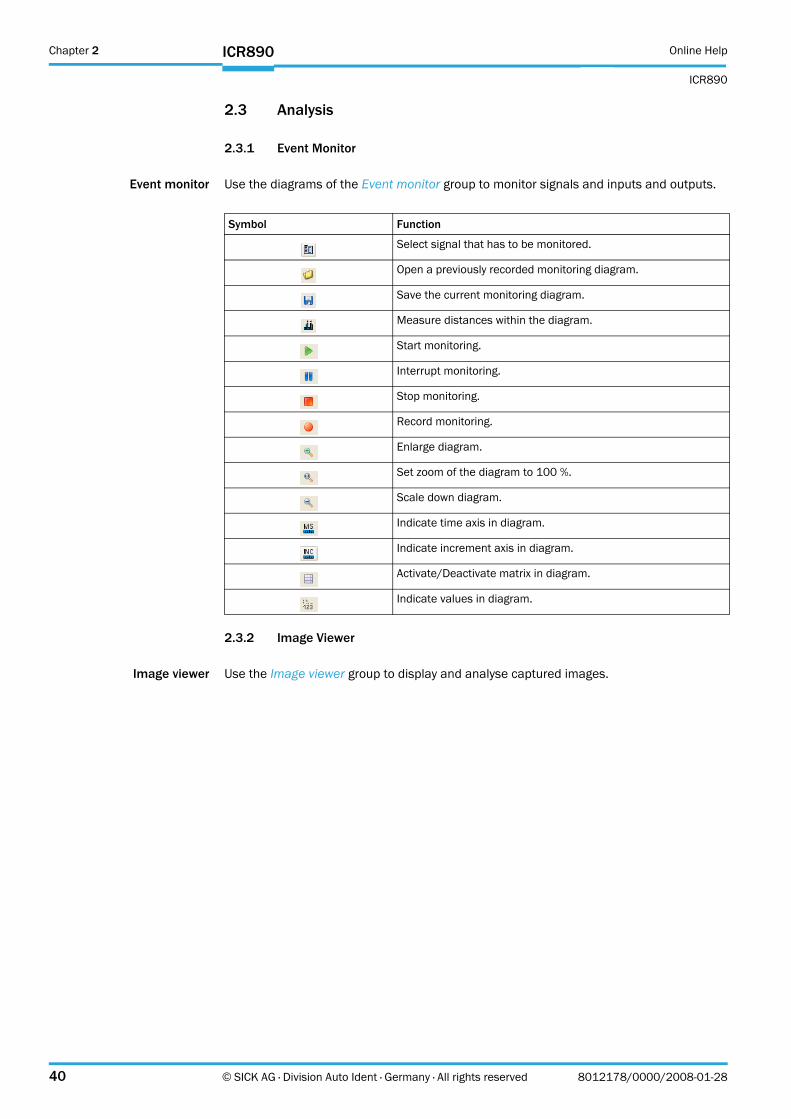
Event monitor Use the diagrams of the Event monitor group to monitor signals and inputs and outputs.
2.3.2 Image Viewer
Image viewer Use the Image viewer group to display and analyse captured images.
Symbol Function
Select signal that has to be monitored.
Open a previously recorded monitoring diagram.
Save the current monitoring diagram.
Measure distances within the diagram.
Start monitoring.
Interrupt monitoring.
Stop monitoring.
Record monitoring.
Enlarge diagram.
Set zoom of the diagram to 100 %.
Scale down diagram.
Indicate time axis in diagram.
Indicate increment axis in diagram.
Activate/Deactivate matrix in diagram.
Indicate values in diagram.

Online Help
ICR890
8012178/0000/2008-01-28 © SICK AG · Division Auto Ident · Germany · All rights reserved 41
Chapter 2 Online Help
ICR890
42 © SICK AG · Division Auto Ident · Germany · All rights reserved 8012178/0000/2008-01-28
ICR890
SICK AG | Waldkirch | Germany | www.sick.com
8012
178/
2008
-01-
28 · D
WF
<PM
6.5/
FM7.
0/PD
F>/V
D
Australia
Belgium/Luxembourg
Brasil
Ceská Republika
E-Mail [email protected]
China
Danmark
E-Mail [email protected]
Deutschland
España
France
Great Britain
India
Italia
Japan
Nederlands
Norge
Österreich
Polska
Republic of Korea
Republika Slowenija
România
Russia
E-Mail denis.kesaev@sick-
Schweiz
Singapore
Suomi
Sverige
Taiwan
Türkiye
USA/Canada/México
www.sick.com
Related Documents