PART I ICND1 COPYRIGHTED MATERIAL

Welcome message from author
This document is posted to help you gain knowledge. Please leave a comment to let me know what you think about it! Share it to your friends and learn new things together.
Transcript

Part
IICND1
COPYRIG
HTED M
ATERIAL

789704c01.indd 31-01-2008 01:34 PM
Chapter
1Internetworking
The followINg ICND1 exam TopICs are CovereD IN ThIs ChapTer:
11 Operation of IP Data Networks
1■ Recognize the purpose and functions of various network
devices such as Routers, Switches, Bridges and Hubs.
1■ Select the components required to meet a given network
specification.
1■ Identify common applications and their impact on the
network.
1■ Describe the purpose and basic operation of the protocols in
the OSI and TCP/IP models.
789704c01.indd 31-01-2008 01:34 PM
Welcome to the exciting world of internetworking. This first chapter will serve as an internetworking review by focusing on how to connect networks together using Cisco routers and
switches, and I’ve written it with the assumption that you have some simple basic network-ing knowledge. The emphasis of this review will be on the Cisco CCENT and/or CCNA Routing and Switching (CCNA R/S) objectives you’ll need a solid grasp on in order to suc-ceed in getting your certifications.
Let’s start by defining exactly what an internetwork is: You create an internetwork when you connect two or more networks via a router and configure a logical network addressing scheme with a protocol such as IP or IPv6.
We’ll also dissect the Open Systems Interconnection (OSI) model, and I’ll describe each part of it to you in detail because you really need complete, reliable knowledge of it. Understanding the OSI model is key for the solid foundation you’ll need to build upon with the more advanced Cisco networking knowledge gained as you become increasingly skilled.
The OSI model has seven hierarchical layers that were developed to enable different networks to communicate reliably between disparate systems. Since this book is centering upon all things CCNA, it’s crucial for you to understand the OSI model as Cisco sees it, so that’s how I’ll be presenting the seven layers to you.
After you finish reading this chapter, you’ll encounter review questions and written labs. These are given to you to really lock the information from this chapter into your memory. So don’t skip them!
To find up-to-the-minute updates for this chapter, please see www.lammle.com/forum or the book’s web page at www.sybex.com.
Internetworking BasicsBefore exploring internetworking models and the OSI model’s specifications, you need to grasp the big picture and the answer to this burning question: Why is it so important to learn Cisco internetworking anyway?
Networks and networking have grown exponentially over the past 20 years, and under-standably so. They’ve had to evolve at light speed just to keep up with huge increases in basic, mission-critical user needs, (e.g. simple sharing data and printers), as well as greater burdens like multimedia remote presentations and conferencing. Unless everyone who needs

Internetworking Basics 5
789704c01.indd 31-01-2008 01:34 PM
to share network resources is located in the same office space—an increasingly uncommon situation—the challenge is to connect relevant networks so all users can share the wealth of whatever services and resources are required.
Figure 1.1 shows a basic local area network (LAN) that’s connected using a hub, which is basically just an antiquated device that connects wires together. Keep in mind that a simple network like this would be considered one collision domain and one broadcast domain. No worries if you have no idea what I mean by that because coming up soon, I’m going to talk about collision and broadcast domains enough to make you dream about them!
f I gu r e 1.1 A very basic network
SallyBob HEY SALLY?
Hub
Okay, things really can’t get much simpler than this. And yes, though you can still find this configuration in some home networks, even many of those as well as the smallest busi-ness networks are more complicated today. As we move through this book, I’ll just keep building upon this tiny network a bit at a time until we arrive at some really nice, robust and current network designs—the types that will help you get your certification and a job!
But as I said, we’ll get there one step at a time, so let’s get back to the network shown in Figure 1.1 with this scenario: Bob wants to send Sally a file, and to complete that goal in this kind of network, he’ll simply broadcast that he’s looking for her, which is basically just shouting out over the network. Think of it like this, Bob walking out of his house and yell-ing down a street called Chaos Court in order to contact Sally. This might work if Bob and Sally were the only ones living there, but not so much if it’s crammed with homes and all the others living there are always hollering up and down the street to their neighbors just like Bob. Nope, Chaos Court would absolutely live up to its name, with all those residents going off whenever they felt like it—and believe it or not, our networks actually still work this way to a degree! So, given a choice, would you stay in Chaos, or would you pull up stakes and move on over to a nice new modern community called Broadway Lanes, which offers plenty of amenities and room for your home plus future additions all on nice, wide streets that can easily handle all present and future traffic? Good choice… so did Sally, who now lives a much quieter life, getting letters (packets) from Bob instead of a headache!
The scenario I just described brings me to the basic point of what this book and the Cisco certification objectives are really all about. My goal of showing you how to create efficient networks and segment them correctly in order to minimize all the chaotic yelling and screaming going on in them is a universal theme throughout my CCENT and CCNA series books. It’s just inevitable that you’ll have to break up a large network into a bunch

6 Chapter 1 u Internetworking
789704c01.indd 31-01-2008 01:34 PM
of smaller ones at some point to match a network’s equally inevitable growth, and as that expansion occurs, user response time simultaneously dwindles to a frustrating crawl. But if you master the vital technology and skills I have in store for you in this series, you’ll be well equipped to rescue your network and its users by creating an efficient new network neighborhood to give them key amenities like the bandwidth they need to meet their evolving demands.
And this is no joke; most of us think of growth as good—and it can be—but as many of us experience daily when commuting to work, school, etc., it can also mean your LAN’s traffic congestion can reach critical mass and grind to a complete halt! Again, the solu-tion to this problem begins with breaking up a massive network into a number of smaller ones—something called network segmentation. This concept is a lot like planning a new community or modernizing an existing one. More streets are added, complete with new intersections and traffic signals, plus post offices with official maps documenting all those street names and directions on how to get to each are built. You’ll need to effect new laws to keep order to it all and provide a police station to protect this nice new neighborhood as well. In a networking neighborhood environment, all of this is carried out using devices like routers, switches, and bridges.
So let’s take a look at our new neighborhood now, because the word has gotten out; many more hosts have moved into it, so it’s time to upgrade that new high-capacity infrastructure that we promised to handle the increase in population. Figure 1.2 shows a network that’s been segmented with a switch, making each network segment that connects to the switch its own separate collision domain. Doing this results in a lot less yelling!
f I gu r e 1. 2 A switch can break up collision domains.
SallyBobJohnHEY JOHN!
Hub Switch
S1
This is a great start, but I really want you to make note of the fact that this network is still one, single broadcast domain, meaning that we’ve really only decreased our scream-ing and yelling, not eliminated it. For example, if there’s some sort of vital announcement that everyone in our neighborhood needs to hear about, it will definitely still get loud! You can see that the hub used in Figure 1.2 just extended the one collision domain from the switch port. The result is that John received the data from Bob but, happily, Sally did not. This is good because Bob intended to talk with John directly, and if he had needed to send a broadcast instead, everyone, including Sally, would have received it, possibly caus-ing unnecessary congestion.
Internetworking Basics 7
789704c01.indd 31-01-2008 01:34 PM
Here’s a list of some of the things that commonly cause LAN traffic congestion:
1u Too many hosts in a collision or broadcast domain
1u Broadcast storms
1u Too much multicast traffic
1u Low bandwidth
1u Adding hubs for connectivity to the network
1u A bunch of ARP broadcasts
Take another look at Figure 1.2 and make sure you see that I extended the main hub from Figure 1.1 to a switch in Figure 1.2. I did that because hubs don’t segment a network; they just connect network segments. Basically, it’s an inexpensive way to connect a couple of PCs, and again, that’s great for home use and troubleshooting, but that’s about it!
As our planned community starts to grow, we’ll need to add more streets with traffic control, and even some basic security. We’ll achieve this by adding routers because these con-venient devices are used to connect networks and route packets of data from one network to another. Cisco became the de facto standard for routers because of its unparalleled selection of high-quality router products and fantastic service. So never forget that by default, routers are basically employed to efficiently break up a broadcast domain—the set of all devices on a net-work segment, which are allowed to “hear” all broadcasts sent out on that specific segment.
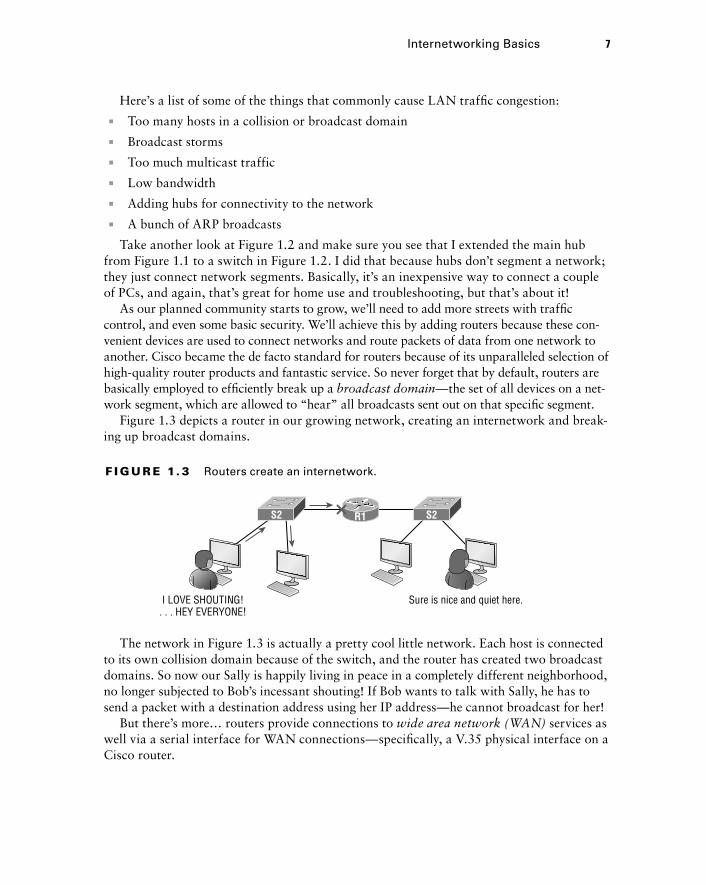
Figure 1.3 depicts a router in our growing network, creating an internetwork and break-ing up broadcast domains.
f I gu r e 1. 3 Routers create an internetwork.
I LOVE SHOUTING!. . . HEY EVERYONE!
Sure is nice and quiet here.
S2 S2R1
The network in Figure 1.3 is actually a pretty cool little network. Each host is connected to its own collision domain because of the switch, and the router has created two broadcast domains. So now our Sally is happily living in peace in a completely different neighborhood, no longer subjected to Bob’s incessant shouting! If Bob wants to talk with Sally, he has to send a packet with a destination address using her IP address—he cannot broadcast for her!
But there’s more… routers provide connections to wide area network (WAN) services as well via a serial interface for WAN connections—specifically, a V.35 physical interface on a Cisco router.

8 Chapter 1 u Internetworking
789704c01.indd 31-01-2008 01:34 PM
Let me make sure you understand why breaking up a broadcast domain is so important. When a host or server sends a network broadcast, every device on the network must read and process that broadcast—unless you have a router. When the router’s interface receives this broadcast, it can respond by basically saying, “Thanks, but no thanks,” and discard the broadcast without forwarding it on to other networks. Even though routers are known for breaking up broadcast domains by default, it’s important to remember that they break up collision domains as well.
There are two advantages to using routers in your network:
1u They don’t forward broadcasts by default.
1u They can filter the network based on layer 3, Network layer, information such as an IP address.
Here are four ways a router functions in your network:
1u Packet switching
1u Packet filtering
1u Internetwork communication
1u Path selection
I’ll tell you all about the various layers later in this chapter, but for now, it’s helpful to think of routers as layer 3 switches. Unlike plain-vanilla layer 2 switches, which forward or filter frames, routers (layer 3 switches) use logical addressing and provide an important capacity called packet switching. Routers can also provide packet filtering via access lists, and when routers connect two or more networks together and use logical addressing (IP or IPv6), you then have an internetwork. Finally, routers use a routing table, which is essen-tially a map of the internetwork, to make best path selections for getting data to its proper destination and properly forward packets to remote networks.
Conversely, we don’t use layer 2 switches to create internetworks because they don’t break up broadcast domains by default. Instead, they’re employed to add functionality to a network LAN. The main purpose of these switches is to make a LAN work better—to optimize its performance—providing more bandwidth for the LAN’s users. Also, these switches don’t for-ward packets to other networks like routers do. Instead, they only “switch” frames from one port to another within the switched network. And don’t worry, even though you’re probably thinking, “Wait—what are frames and packets?” I promise to completely fill you in later in this chapter. For now, think of a packet as a package containing data.
Okay, so by default, switches break up collision domains, but what are these things? Collision domain is an Ethernet term used to describe a network scenario in which one device sends a packet out on a network segment and every other device on that same seg-ment is forced to pay attention no matter what. This isn’t very efficient because if a differ-ent device tries to transmit at the same time, a collision will occur, requiring both devices to retransmit, one at a time—not good! This happens a lot in a hub environment, where each host segment connects to a hub that represents only one collision domain and a single broadcast domain. By contrast, each and every port on a switch represents its own collision domain, allowing network traffic to flow much more smoothly.
Internetworking Basics 9
789704c01.indd 31-01-2008 01:34 PM
Switches create separate collision domains within a single broadcast domain. Routers provide a separate broadcast domain for each interface. Don’t let this ever confuse you!
The term bridging was introduced before routers and switches were implemented, so it’s pretty common to hear people referring to switches as bridges. That’s because bridges and switches basically do the same thing—break up collision domains on a LAN. Note to self that you cannot buy a physical bridge these days, only LAN switches, which use bridging technologies. This does mean that you’ll still hear Cisco and others refer to LAN switches as multiport bridges now and then.
But does it mean that a switch is just a multiple-port bridge with more brainpower? Well, pretty much, only there are still some key differences. Switches do provide a bridging function, but they do that with greatly enhanced management ability and features. Plus, most bridges had only 2 or 4 ports, which is severely limiting. Of course, it was possible to get your hands on a bridge with up to 16 ports, but that’s nothing compared to the hun-dreds of ports available on some switches!
You would use a bridge in a network to reduce collisions within broadcast domains and to increase the number of collision domains in your network. Doing this provides more bandwidth for users. And never forget that using hubs in your Ethernet network can contribute to congestion. As always, plan your network design carefully!
Figure 1.4 shows how a network would look with all these internetwork devices in place. Remember, a router doesn’t just break up broadcast domains for every LAN interface, it breaks up collision domains too.
Looking at Figure 1.4, did you notice that the router has the center stage position and connects each physical network together? I’m stuck with using this layout because of the ancient bridges and hubs involved. I really hope you don’t run across a network like this, but it’s still really important to understand the strategic ideas that this figure represents!
See that bridge up at the top of our internetwork shown in Figure 1.4? It’s there to connect the hubs to a router. The bridge breaks up collision domains, but all the hosts connected to both hubs are still crammed into the same broadcast domain. That bridge also created only three collision domains, one for each port, which means that each device connected to a hub is in the same collision domain as every other device connected to that same hub. This is really lame and to be avoided if possible, but it’s still better than having one collision domain for all hosts! So don’t do this at home; it’s a great museum piece and a wonderful example of what not to do, but this inefficient design would be terrible for use in today’s networks! It does show us how far we’ve come though, and again, the foundational concepts it illustrates are really important for you to get.

10 Chapter 1 u Internetworking
789704c01.indd 31-01-2008 01:34 PM
f I gu r e 1. 4 Internetworking devices
Hub
WAN ServicesISPSwitch
Bridge
Router
And I want you to notice something else: The three interconnected hubs at the bottom of the figure also connect to the router. This setup creates one collision domain and one broadcast domain and makes that bridged network, with its two collision domains, look majorly better by contrast!
Don’t misunderstand… bridges/switches are used to segment networks, but they will not isolate broadcast or multicast packets.
The best network connected to the router is the LAN switched network on the left. Why? Because each port on that switch breaks up collision domains. But it’s not all good—all devices are still in the same broadcast domain. Do you remember why this can be really bad? Because all devices must listen to all broadcasts transmitted, that’s why! And if your broadcast domains are too large, the users have less bandwidth and are required to process more broadcasts. Network response time eventually will slow to a level that could cause riots and strikes, so it’s important to keep your broadcast domains small in the vast major-ity of networks today.
Once there are only switches in our example network, things really change a lot! Figure 1.5 demonstrates a network you’ll typically stumble upon today.

Internetworking Basics 11
789704c01.indd 31-01-2008 01:34 PM
Here I’ve placed the LAN switches at the center of this network world, with the routers connecting the logical networks. If I went ahead and implemented this design, I’ve created something called virtual LANs, or VLANs, which are used when you logically break up broadcast domains in a layer 2, switched network. It’s really important to understand that even in a switched network environment, you still need a router to provide communication between VLANs. Don’t forget that!
f I gu r e 1.5 Switched networks creating an internetwork
Router
Router
Still, clearly the best network design is the one that’s perfectly configured to meet the business requirements of the specific company or client it serves, and it’s usually one in which LAN switches exist in harmony with routers strategically placed in the network. It’s my hope that this book will help you understand the basics of routers and switches so you can make solid, informed decisions on a case-by-case basis and be able to achieve that goal! But I digress…
So let’s go back to Figure 1.4 now for a minute and really scrutinize it because I want to ask you this question: How many collision domains and broadcast domains are really there in this internetwork? I hope you answered nine collision domains and three broad-cast domains! The broadcast domains are definitely the easiest to spot because only routers break up broadcast domains by default, and since there are three interface connections, that gives you three broadcast domains. But do you see the nine collision domains? Just in case that’s a no, I’ll explain. The all-hub network at the bottom is one collision domain; the bridge network on top equals three collision domains. Add in the switch network of five collision domains—one for each switch port—and you get a total of nine!
While we’re at this, in Figure 1.5, each port on the switch is a separate collision domain, and each VLAN would be a separate broadcast domain. So how many collision domains do you see here? I’m counting 12—remember that connections between the switches are con-sidered a collision domain! Since the figure doesn’t show any VLAN information, we can assume the default of one broadcast domain is in place.
12 Chapter 1 u Internetworking
789704c01.indd 31-01-2008 01:34 PM
should I replace my existing 10/100 mbps switches?
Let’s say you’re a network administrator at a large company. The boss comes to you and says that he got your requisition to buy a bunch of new switches but he’s really freaking out about the price tag! Should you push it—do you really need to go this far?
If you can, absolutely! Make your case and go for it because the newest switches add really huge capacity to a network that older 10/100 Mbps switches just can’t touch. And yes, five-year-old switches are considered pretty Pleistocene these days. But in real-ity, most of us just don’t have an unlimited budget to buy all new gigabit switches and 10/100 Mbps switches can still create a nice network—if you design and implement that network correctly! Still, plan and budget accordingly because you’ll have to replace those 10/100 switches eventually.
Another good question: Do you really need 1 Gbps or better switch ports for all your users, servers, and other devices? Yes, you absolutely need new higher-end switches! This is because servers and hosts are no longer the bottlenecks of our internetworks, our routers and switches are—especially legacy ones. We now need gigabit on the desktop and on every router interface; 10 Gbps would be better, and go even higher if you can afford it.
So, go ahead. Put that requisition for all new switches. You’ll be a hero before long!
Okay, so now that you’ve gotten a pretty thorough introduction to internetworking and the various devices that populate an internetwork, it’s time to head into exploring the inter-networking models.
Internetworking ModelsFirst a little history: When networks first came into being, computers could typically communicate only with computers from the same manufacturer. For example, companies ran either a complete DECnet solution or an IBM solution, never both together. In the late 1970s, the Open Systems Interconnection (OSI) reference model was created by the International Organization for Standardization (ISO) to break through this barrier.
The OSI model was meant to help vendors create interoperable network devices and software in the form of protocols so that different vendor networks could work in peace-able accord with each other. Like world peace, it’ll probably never happen completely, but it’s still a great goal!
Anyway the OSI model is the primary architectural model for networks. It describes how data and network information are communicated from an application on one computer
Internetworking Models 13
789704c01.indd 31-01-2008 01:34 PM
through the network media to an application on another computer. The OSI reference model breaks this approach into layers.
Coming up, I’ll explain the layered approach to you plus how we can use it to help us troubleshoot our internetworks.
Goodness! ISO, OSI, and soon you’ll hear about IOS! Just remember that the ISO created the OSI and that Cisco created the Internetworking Operating System (IOS), which is what this book is all-so-about.
The Layered ApproachUnderstand that a reference model is a conceptual blueprint of how communications should take place. It addresses all the processes required for effective communication and divides them into logical groupings called layers. When a communication system is designed in this manner, it’s known as a hierarchical or layered architecture.
Think of it like this: You and some friends want to start a company. One of the first things you’ll do is sort out every task that must be done and decide who will do what. You would move on to determine the order in which you would like everything to be done with careful consideration of how all your specific operations relate to each other. You would then organize everything into departments (e.g., sales, inventory, and shipping), with each department dealing with its specific responsibilities and keeping its own staff busy enough to focus on their own particular area of the enterprise.
In this scenario, departments are a metaphor for the layers in a communication system. For things to run smoothly, the staff of each department has to trust in and rely heavily upon those in the others to do their jobs well. During planning sessions, you would take notes, recording the entire process to guide later discussions and clarify standards of operation, thereby creating your business blueprint—your own reference model.
And once your business is launched, your department heads, each armed with the part of the blueprint relevant to their own department, will develop practical ways to implement their distinct tasks. These practical methods, or protocols, will then be compiled into a standard operating procedures manual and followed closely because each procedure will have been included for different reasons, delimiting their various degrees of importance and implemen-tation. All of this will become vital if you form a partnership or acquire another company because then it will be really important that the new company’s business model is compatible with yours!
Models happen to be really important to software developers too. They often use a refer-ence model to understand computer communication processes so they can determine which functions should be accomplished on a given layer. This means that if someone is creating a protocol for a certain layer, they only need to be concerned with their target layer’s function. Software that maps to another layers’ protocols and is specifically designed to be deployed there will handle additional functions. The technical term for this idea is binding. The com-munication processes that are related to each other are bound, or grouped together, at a particular layer.
14 Chapter 1 u Internetworking
789704c01.indd 31-01-2008 01:34 PM
Advantages of Reference ModelsThe OSI model is hierarchical, and there are many advantages that can be applied to any layered model, but as I said, the OSI model’s primary purpose is to allow different vendors’ networks to interoperate.
Here’s a list of some of the more important benefits for using the OSI layered model:
1u It divides the network communication process into smaller and simpler components, facilitating component development, design, and troubleshooting.
1u It allows multiple-vendor development through the standardization of network components.
1u It encourages industry standardization by clearly defining what functions occur at each layer of the model.
1u It allows various types of network hardware and software to communicate.
1u It prevents changes in one layer from affecting other layers to expedite development.
The OSI Reference ModelOne of best gifts the OSI specifications gives us is paving the way for the data transfer between disparate hosts running different operating systems, like Unix hosts, Windows machines, Macs, smartphones, and so on.
And remember, the OSI is a logical model, not a physical one. It’s essentially a set of guide-lines that developers can use to create and implement applications to run on a network. It also provides a framework for creating and implementing networking standards, devices, and inter-networking schemes.
The OSI has seven different layers, divided into two groups. The top three layers define how the applications within the end stations will communicate with each other as well as with users. The bottom four layers define how data is transmitted end to end.
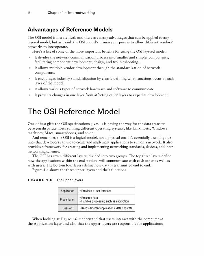
Figure 1.6 shows the three upper layers and their functions.
f I gu r e 1.6 The upper layers
Presentation
Application
Session
• Provides a user interface
• Presents data• Handles processing such as encryption
• Keeps different applications’ data separate
When looking at Figure 1.6, understand that users interact with the computer at the Application layer and also that the upper layers are responsible for applications

The OSI Reference Model 15
789704c01.indd 31-01-2008 01:34 PM
communicating between hosts. None of the upper layers knows anything about network-ing or network addresses because that’s the responsibility of the four bottom layers.
In Figure 1.7, which shows the four lower layers and their functions, you can see that it’s these four bottom layers that define how data is transferred through physical media like wire, cable, fiber optics, switches, and routers. These bottom layers also determine how to rebuild a data stream from a transmitting host to a destination host’s application.
f I gu r e 1.7 The lower layers
Transport
Network
• Provides reliable or unreliable delivery• Performs error correction before retransmit
Data Link• Combines packets into bytes and bytes into frames• Provides access to media using MAC address• Performs error detection not correction
Physical • Moves bits between devices• Specifies voltage, wire speed, and pinout of cables
• Provides logical addressing, which routers use for path determination
The following network devices operate at all seven layers of the OSI model:
1u Network management stations (NMSs)
1u Web and application servers
1u Gateways (not default gateways)
1u Servers
1u Network hosts
Basically, the ISO is pretty much the Emily Post of the network protocol world. Just as Ms. Post wrote the book setting the standards—or protocols—for human social interac-tion, the ISO developed the OSI reference model as the precedent and guide for an open network protocol set. Defining the etiquette of communication models, it remains the most popular means of comparison for protocol suites today.
The OSI reference model has the following seven layers:
1u Application layer (layer 7)
1u Presentation layer (layer 6)
1u Session layer (layer 5)
1u Transport layer (layer 4)
1u Network layer (layer 3)
1u Data Link layer (layer 2)
1u Physical layer (layer 1)

16 Chapter 1 u Internetworking
789704c01.indd 31-01-2008 01:34 PM
Some people like to use a mnemonic to remember the seven layers, such as All People Seem To Need Data Processing. Figure 1.8 shows a summary of the functions defined at each layer of the OSI model.
f I gu r e 1. 8 OSI layer functions
Application • File, print, message, database, and application services
Presentation • Data encryption, compression, and translation services
Session • Dialog control
Transport • End-to-end connection
Network • Routing
Data Link • Framing
Physical • Physical topology
I’ve separated the 7-layer model into three different functions: the upper layers, the middle layers and the bottom layers. The upper layers communicate with the user interface and appli-cation, the middle layers do reliable communication and routing to a remote network, and the bottom layers communicate to the local network.
With this in hand, you’re now ready to explore each layer’s function in detail!
The Application LayerThe Application layer of the OSI model marks the spot where users actually communi-cate to the computer and comes into play only when it’s clear that access to the network will be needed soon. Take the case of Internet Explorer (IE). You could actually uninstall every trace of networking components like TCP/IP, the NIC card, and so on and still use IE to view a local HTML document. But things would get ugly if you tried to do things like view a remote HTML document that must be retrieved because IE and other browsers act on these types of requests by attempting to access the Application layer. So basically, the Application layer is working as the interface between the actual application program and the next layer down by providing ways for the application to send information down through the protocol stack. This isn’t actually part of the layered structure, because browsers don’t live in the Application layer, but they interface with it as well as the rel-evant protocols when asked to access remote resources.
Identifying and confirming the communication partner’s availability and verifying the required resources to permit the specified type of communication to take place also occurs at the Application layer. This is important because, like the lion’s share of browser functions, computer applications sometimes need more than desktop resources. It’s more typical than you would think for the communicating components of several network

The OSI Reference Model 17
789704c01.indd 31-01-2008 01:34 PM
applications to come together to carry out a requested function. Here are a few good examples of these kinds of events:
1u File transfers
1u Email
1u Enabling remote access
1u Network management activities
1u Client/server processes
1u Information location
Many network applications provide services for communication over enterprise net-works, but for present and future internetworking, the need is fast developing to reach beyond the limits of current physical networking.
The Application layer works as the interface between actual application programs. This means end-user programs like Microsoft Word don’t reside at the Application layer, they interface with the Application layer protocols. Later, in Chapter 3, “TCP/IP,” I’ll talk in detail about a few important programs that actually reside at the Application layer, like Telnet, FTP and TFTP.
The Presentation LayerThe Presentation layer gets its name from its purpose: It presents data to the Application layer and is responsible for data translation and code formatting. Think of it as the OSI model’s translator, providing coding and conversion services. One very effective way of ensuring a successful data transfer is to convert the data into a standard format before transmission. Computers are configured to receive this generically formatted data and then reformat it back into its native state to read it. An example of this type of translation service occurs when translating old Extended Binary Coded Decimal Interchange Code (EBCDIC) data to ASCII, the American Standard Code for Information Interchange (often pronounced “askee”). So just remember that by providing translation services, the Presentation layer ensures that data transferred from the Application layer of one system can be read by the Application layer of another one.
With this in mind, it follows that the OSI would include protocols that define how standard data should be formatted, so key functions like data compression, decompres-sion, encryption, and decryption are also associated with this layer. Some Presentation layer standards are involved in multimedia operations as well.
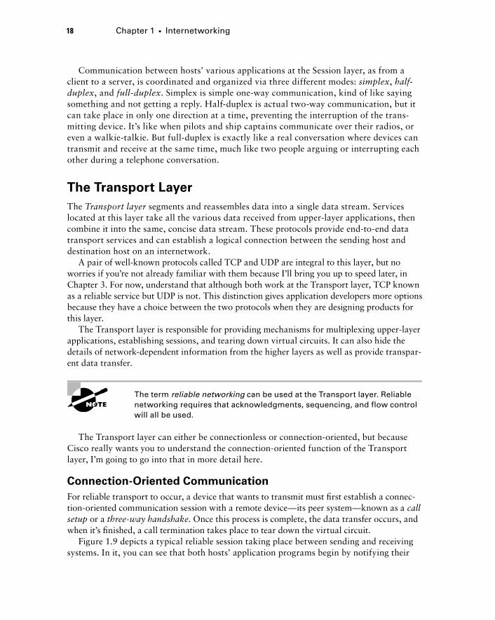
The Session LayerThe Session layer is responsible for setting up, managing, and dismantling sessions between Presentation layer entities and keeping user data separate. Dialog control between devices also occurs at this layer.
18 Chapter 1 u Internetworking
789704c01.indd 31-01-2008 01:34 PM
Communication between hosts’ various applications at the Session layer, as from a client to a server, is coordinated and organized via three different modes: simplex, half-duplex, and full-duplex. Simplex is simple one-way communication, kind of like saying something and not getting a reply. Half-duplex is actual two-way communication, but it can take place in only one direction at a time, preventing the interruption of the trans-mitting device. It’s like when pilots and ship captains communicate over their radios, or even a walkie-talkie. But full-duplex is exactly like a real conversation where devices can transmit and receive at the same time, much like two people arguing or interrupting each other during a telephone conversation.
The Transport LayerThe Transport layer segments and reassembles data into a single data stream. Services located at this layer take all the various data received from upper-layer applications, then combine it into the same, concise data stream. These protocols provide end-to-end data transport services and can establish a logical connection between the sending host and destination host on an internetwork.
A pair of well-known protocols called TCP and UDP are integral to this layer, but no worries if you’re not already familiar with them because I’ll bring you up to speed later, in Chapter 3. For now, understand that although both work at the Transport layer, TCP known as a reliable service but UDP is not. This distinction gives application developers more options because they have a choice between the two protocols when they are designing products for this layer.
The Transport layer is responsible for providing mechanisms for multiplexing upper-layer applications, establishing sessions, and tearing down virtual circuits. It can also hide the details of network-dependent information from the higher layers as well as provide transpar-ent data transfer.
The term reliable networking can be used at the Transport layer. Reliable networking requires that acknowledgments, sequencing, and flow control will all be used.
The Transport layer can either be connectionless or connection-oriented, but because Cisco really wants you to understand the connection-oriented function of the Transport layer, I’m going to go into that in more detail here.
Connection-Oriented CommunicationFor reliable transport to occur, a device that wants to transmit must first establish a connec-tion-oriented communication session with a remote device—its peer system—known as a call setup or a three-way handshake. Once this process is complete, the data transfer occurs, and when it’s finished, a call termination takes place to tear down the virtual circuit.
Figure 1.9 depicts a typical reliable session taking place between sending and receiving systems. In it, you can see that both hosts’ application programs begin by notifying their
The OSI Reference Model 19
789704c01.indd 31-01-2008 01:34 PM
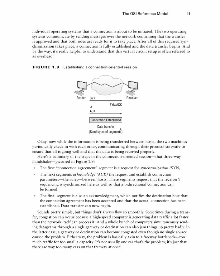
individual operating systems that a connection is about to be initiated. The two operating systems communicate by sending messages over the network confirming that the transfer is approved and that both sides are ready for it to take place. After all of this required syn-chronization takes place, a connection is fully established and the data transfer begins. And by the way, it’s really helpful to understand that this virtual circuit setup is often referred to as overhead!
f I gu r e 1. 9 Establishing a connection-oriented session
Sender SYN Receiver
SYN/ACK
ACK
Connection Established
Data transfer(Send bytes of segments)
Okay, now while the information is being transferred between hosts, the two machines periodically check in with each other, communicating through their protocol software to ensure that all is going well and that the data is being received properly.
Here’s a summary of the steps in the connection-oriented session—that three-way handshake—pictured in Figure 1.9:
1u The first “connection agreement” segment is a request for synchronization (SYN).
1u The next segments acknowledge (ACK) the request and establish connection parameters—the rules—between hosts. These segments request that the receiver’s sequencing is synchronized here as well so that a bidirectional connection can be formed.
1u The final segment is also an acknowledgment, which notifies the destination host that the connection agreement has been accepted and that the actual connection has been established. Data transfer can now begin.
Sounds pretty simple, but things don’t always flow so smoothly. Sometimes during a trans-fer, congestion can occur because a high-speed computer is generating data traffic a lot faster than the network itself can process it! And a whole bunch of computers simultaneously send-ing datagrams through a single gateway or destination can also jam things up pretty badly. In the latter case, a gateway or destination can become congested even though no single source caused the problem. Either way, the problem is basically akin to a freeway bottleneck—too much traffic for too small a capacity. It’s not usually one car that’s the problem; it’s just that there are way too many cars on that freeway at once!

20 Chapter 1 u Internetworking
789704c01.indd 31-01-2008 01:34 PM
But what actually happens when a machine receives a flood of datagrams too quickly for it to process? It stores them in a memory section called a buffer. Sounds great; it’s just that this buffering action can solve the problem only if the datagrams are part of a small burst. If the datagram deluge continues, eventually exhausting the device’s memory, its flood capacity will be exceeded and it will dump any and all additional datagrams it receives just like an inundated overflowing bucket!
Flow ControlSince floods and losing data can both be tragic, we have a fail-safe solution in place known as flow control. Its job is to ensure data integrity at the Transport layer by allowing applications to request reliable data transport between systems. Flow control prevents a sending host on one side of the connection from overflowing the buffers in the receiving host. Reliable data transport employs a connection-oriented communications session between systems, and the protocols involved ensure that the following will be achieved:
1u The segments delivered are acknowledged back to the sender upon their reception.
1u Any segments not acknowledged are retransmitted.
1u Segments are sequenced back into their proper order upon arrival at their destination.
1u A manageable data flow is maintained in order to avoid congestion, overloading, or worse, data loss.
The purpose of flow control is to provide a way for the receiving device to control the amount of data sent by the sender.
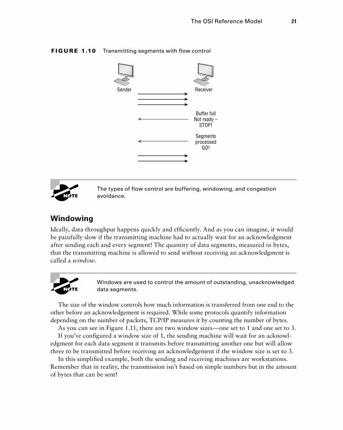
Because of the transport function, network flood control systems really work well. Instead of dumping and losing data, the Transport layer can issue a “not ready” indicator to the sender, or potential source of the flood. This mechanism works kind of like a stop-light, signaling the sending device to stop transmitting segment traffic to its overwhelmed peer. After the peer receiver processes the segments already in its memory reservoir—its buffer—it sends out a “ready” transport indicator. When the machine waiting to transmit the rest of its datagrams receives this “go” indicator, it resumes its transmission. The pro-cess is pictured in Figure 1.10.
In a reliable, connection-oriented data transfer, datagrams are delivered to the receiving host hopefully in the same sequence they’re transmitted. A failure will occur if any data segments are lost, duplicated, or damaged along the way—a problem solved by having the receiving host acknowledge that it has received each and every data segment.
A service is considered connection-oriented if it has the following characteristics:
1u A virtual circuit, or “three-way handshake” is set up.
1u It uses sequencing.
1u It uses acknowledgments.
1u It uses flow control.
The OSI Reference Model 21
789704c01.indd 31-01-2008 01:34 PM
f I gu r e 1.10 Transmitting segments with flow control
Sender Receiver
Buffer fullNot ready –
STOP!
Segmentsprocessed
GO!
The types of flow control are buffering, windowing, and congestion avoidance.
WindowingIdeally, data throughput happens quickly and efficiently. And as you can imagine, it would be painfully slow if the transmitting machine had to actually wait for an acknowledgment after sending each and every segment! The quantity of data segments, measured in bytes, that the transmitting machine is allowed to send without receiving an acknowledgment is called a window.
Windows are used to control the amount of outstanding, unacknowledged data segments.
The size of the window controls how much information is transferred from one end to the other before an acknowledgement is required. While some protocols quantify information depending on the number of packets, TCP/IP measures it by counting the number of bytes.
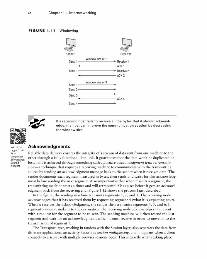
As you can see in Figure 1.11, there are two window sizes—one set to 1 and one set to 3.If you’ve configured a window size of 1, the sending machine will wait for an acknowl-
edgment for each data segment it transmits before transmitting another one but will allow three to be transmitted before receiving an acknowledgement if the window size is set to 3.
In this simplified example, both the sending and receiving machines are workstations. Remember that in reality, the transmission isn’t based on simple numbers but in the amount of bytes that can be sent!
22 Chapter 1 u Internetworking
789704c01.indd 31-01-2008 01:34 PM
f I gu r e 1.11 Windowing
Sender
Window size of 1
Window size of 3
Receiver
Send 1 Receive 1ACK 1
Send 1 Receive 2ACK 2
Send 1Send 2
Send 3ACK 4
Send 4
If a receiving host fails to receive all the bytes that it should acknowl-edge, the host can improve the communication session by decreasing the window size.
AcknowledgmentsReliable data delivery ensures the integrity of a stream of data sent from one machine to the other through a fully functional data link. It guarantees that the data won’t be duplicated or lost. This is achieved through something called positive acknowledgment with retransmis-sion—a technique that requires a receiving machine to communicate with the transmitting source by sending an acknowledgment message back to the sender when it receives data. The sender documents each segment measured in bytes, then sends and waits for this acknowledg-ment before sending the next segment. Also important is that when it sends a segment, the transmitting machine starts a timer and will retransmit if it expires before it gets an acknowl-edgment back from the receiving end. Figure 1.12 shows the process I just described.
In the figure, the sending machine transmits segments 1, 2, and 3. The receiving node acknowledges that it has received them by requesting segment 4 (what it is expecting next). When it receives the acknowledgment, the sender then transmits segments 4, 5, and 6. If segment 5 doesn’t make it to the destination, the receiving node acknowledges that event with a request for the segment to be re-sent. The sending machine will then resend the lost segment and wait for an acknowledgment, which it must receive in order to move on to the transmission of segment 7.
The Transport layer, working in tandem with the Session layer, also separates the data from different applications, an activity known as session multiplexing, and it happens when a client connects to a server with multiple browser sessions open. This is exactly what’s taking place
Visit ccna .gg/ch1/b for a companion MicroNugget from CBT Nuggets.

The OSI Reference Model 23
789704c01.indd 31-01-2008 01:34 PM
when you go someplace online like Amazon and click multiple links, opening them simulta-neously to get information when comparison shopping. The client data from each browser session must be separate when the server application receives it, which is pretty slick techno-logically speaking, and it’s the Transport layer to the rescue for that juggling act!
f I gu r e 1.12 Transport layer reliable delivery
Sender Receiver
Send 1
1
Send 3Send 2
ACK 4Send 4Send 5Send 6
ACK 5
Connection lost!
ACK 7Send 5
2 3 4 5 6 1 2 3 4 5 6
The Network LayerThe Network layer, or layer 3, manages device addressing, tracks the location of devices on the network, and determines the best way to move data. This means that it’s up to the Network layer to transport traffic between devices that aren’t locally attached. Routers, which are layer 3 devices, are specified at this layer and provide the routing services within an internetwork.
Here’s how that works: first, when a packet is received on a router interface, the desti-nation IP address is checked. If the packet isn’t destined for that particular router, it will look up the destination network address in the routing table. Once the router chooses an exit interface, the packet will be sent to that interface to be framed and sent out on the local network. If the router can’t find an entry for the packet’s destination network in the routing table, the router drops the packet.
Data and route update packets are the two types of packets used at the Network layer:
Data packets These are used to transport user data through the internetwork. Protocols used to support data traffic are called routed protocols, and IP and IPv6 are key examples. I’ll cover IP addressing in Chapter 3, “TCP/IP,” and Chapter 4, “Easy Subnetting,” and I’ll cover IPv6 in Chapter 14, “Internet Protocol Version 6 (IPV6)”.
24 Chapter 1 u Internetworking
789704c01.indd 31-01-2008 01:34 PM
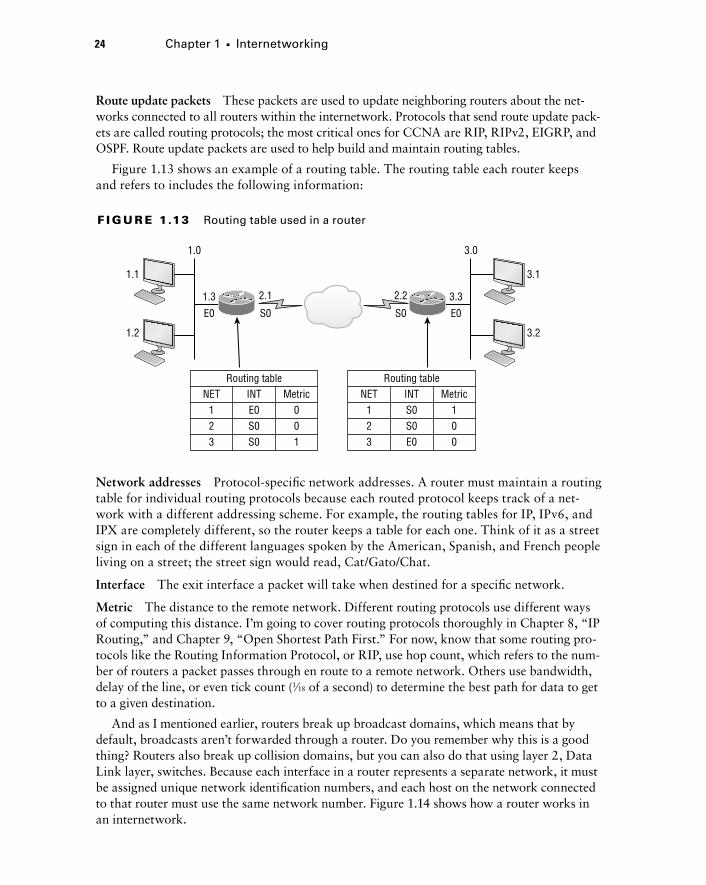
Route update packets These packets are used to update neighboring routers about the net-works connected to all routers within the internetwork. Protocols that send route update pack-ets are called routing protocols; the most critical ones for CCNA are RIP, RIPv2, EIGRP, and OSPF. Route update packets are used to help build and maintain routing tables.
Figure 1.13 shows an example of a routing table. The routing table each router keeps and refers to includes the following information:
f I gu r e 1.13 Routing table used in a router
1.0 3.0
1.3
E0
2.1
S0
NET
2.2
S0
3.3
E0
1.1
1.2
3.1
3.2
123
INTRouting table
E0S0S0
Metric001
NET123
INTRouting table
S0S0E0
Metric100
Network addresses Protocol-specific network addresses. A router must maintain a routing table for individual routing protocols because each routed protocol keeps track of a net-work with a different addressing scheme. For example, the routing tables for IP, IPv6, and IPX are completely different, so the router keeps a table for each one. Think of it as a street sign in each of the different languages spoken by the American, Spanish, and French people living on a street; the street sign would read, Cat/Gato/Chat.
Interface The exit interface a packet will take when destined for a specific network.
Metric The distance to the remote network. Different routing protocols use different ways of computing this distance. I’m going to cover routing protocols thoroughly in Chapter 8, “IP Routing,” and Chapter 9, “Open Shortest Path First.” For now, know that some routing pro-tocols like the Routing Information Protocol, or RIP, use hop count, which refers to the num-ber of routers a packet passes through en route to a remote network. Others use bandwidth, delay of the line, or even tick count (1⁄18 of a second) to determine the best path for data to get to a given destination.
And as I mentioned earlier, routers break up broadcast domains, which means that by default, broadcasts aren’t forwarded through a router. Do you remember why this is a good thing? Routers also break up collision domains, but you can also do that using layer 2, Data Link layer, switches. Because each interface in a router represents a separate network, it must be assigned unique network identification numbers, and each host on the network connected to that router must use the same network number. Figure 1.14 shows how a router works in an internetwork.
The OSI Reference Model 25
789704c01.indd 31-01-2008 01:34 PM
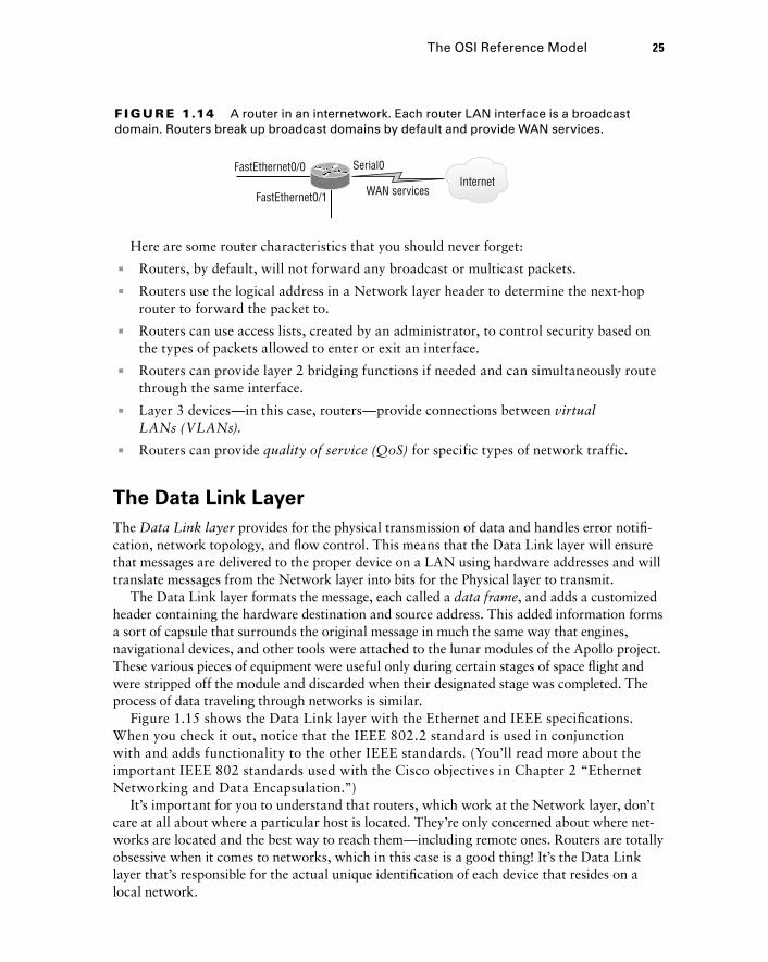
f I gu r e 1.14 A router in an internetwork. Each router LAN interface is a broadcast domain. Routers break up broadcast domains by default and provide WAN services.
WAN servicesInternet
FastEthernet0/0
FastEthernet0/1
Serial0
Here are some router characteristics that you should never forget:
1u Routers, by default, will not forward any broadcast or multicast packets.
1u Routers use the logical address in a Network layer header to determine the next-hop router to forward the packet to.
1u Routers can use access lists, created by an administrator, to control security based on the types of packets allowed to enter or exit an interface.
1u Routers can provide layer 2 bridging functions if needed and can simultaneously route through the same interface.
1u Layer 3 devices—in this case, routers—provide connections between virtual LANs (VLANs).
1u Routers can provide quality of service (QoS) for specific types of network traffic.
The Data Link LayerThe Data Link layer provides for the physical transmission of data and handles error notifi-cation, network topology, and flow control. This means that the Data Link layer will ensure that messages are delivered to the proper device on a LAN using hardware addresses and will translate messages from the Network layer into bits for the Physical layer to transmit.
The Data Link layer formats the message, each called a data frame, and adds a customized header containing the hardware destination and source address. This added information forms a sort of capsule that surrounds the original message in much the same way that engines, navigational devices, and other tools were attached to the lunar modules of the Apollo project. These various pieces of equipment were useful only during certain stages of space flight and were stripped off the module and discarded when their designated stage was completed. The process of data traveling through networks is similar.
Figure 1.15 shows the Data Link layer with the Ethernet and IEEE specifications. When you check it out, notice that the IEEE 802.2 standard is used in conjunction with and adds functionality to the other IEEE standards. (You’ll read more about the important IEEE 802 standards used with the Cisco objectives in Chapter 2 “Ethernet Networking and Data Encapsulation.”)
It’s important for you to understand that routers, which work at the Network layer, don’t care at all about where a particular host is located. They’re only concerned about where net-works are located and the best way to reach them—including remote ones. Routers are totally obsessive when it comes to networks, which in this case is a good thing! It’s the Data Link layer that’s responsible for the actual unique identification of each device that resides on a local network.

26 Chapter 1 u Internetworking
789704c01.indd 31-01-2008 01:34 PM
f I gu r e 1.15 Data Link layer
Media Access Control (MAC)
802.11 802.3 802.2
Logical Link Control (LLC)
For a host to send packets to individual hosts on a local network as well as transmit packets between routers, the Data Link layer uses hardware addressing. Each time a packet is sent between routers, it’s framed with control information at the Data Link layer, but that information is stripped off at the receiving router and only the original packet is left completely intact. This framing of the packet continues for each hop until the packet is finally delivered to the correct receiving host. It’s really important to understand that the packet itself is never altered along the route; it’s only encapsulated with the type of control information required for it to be properly passed on to the different media types.
The IEEE Ethernet Data Link layer has two sublayers:
Media Access Control (MAC) Defines how packets are placed on the media. Contention media access is “first come/first served” access where everyone shares the same band-width—hence the name. Physical addressing is defined here as well as logical topologies. What’s a logical topology? It’s the signal path through a physical topology. Line discipline, error notification (but not correction), the ordered delivery of frames, and optional flow control can also be used at this sublayer.
Logical Link Control (LLC) Responsible for identifying Network layer protocols and then encapsulating them. An LLC header tells the Data Link layer what to do with a packet once a frame is received. It works like this: a host receives a frame and looks in the LLC header to find out where the packet is destined—for instance, the IP protocol at the Network layer. The LLC can also provide flow control and sequencing of control bits.
The switches and bridges I talked about near the beginning of the chapter both work at the Data Link layer and filter the network using hardware (MAC) addresses. I’ll talk about these next.
As data is encoded with control information at each layer of the OSI model, the data is named with something called a Protocol Data Unit (PDU). At the Transport layer the PDU is called a Segment, Network layer is Packet, Data Link is Frame, and Physical layer is Bits. This method of naming the data at each layer is covered thoroughly in Chapter 2.

The OSI Reference Model 27
789704c01.indd 31-01-2008 01:34 PM
Switches and Bridges at the Data Link LayerLayer 2 switching is considered hardware-based bridging because it uses specialized hard-ware called an application-specific integrated circuit (ASIC). ASICs can run up to high gigabit speeds with very low latency rates.
Latency is the time measured from when a frame enters a port to when it exits a port.
Bridges and switches read each frame as it passes through the network. The layer 2 device then puts the source hardware address in a filter table and keeps track of which port the frame was received on. This information (logged in the bridge’s or switch’s filter table) is what helps the machine determine the location of the specific sending device. Figure 1.16 shows a switch in an internetwork and how John is sending packets to the Internet and Sally doesn’t hear his frames because she is in a different collision domain. The destination frame goes directly to the default gateway router, and Sally doesn’t see John’s traffic, much to her relief.
f I gu r e 1.16 A switch in an internetwork
2 3
Mac Address—TableF0/1: 00c0.1234.2211F0/2: 00c0.1234.2212F0/3: 00c0.1234.2213F0/4: 00c0.1234.2214
1 4
The real estate business is all about location, location, location, and it’s the same way for both layer 2 and layer 3 devices. Though both need to be able to negotiate the network, it’s crucial to remember that they’re concerned with very different parts of it. Primarily, layer 3 machines (such as routers) need to locate specific networks, whereas layer 2 machines (switches and bridges) need to eventually locate specific devices. So, networks are to routers as individual devices are to switches and bridges. And routing tables that “map” the internetwork are for routers, as filter tables that “map” individual devices are for switches and bridges.
After a filter table is built on the layer 2 device, it will forward frames only to the segment where the destination hardware address is located. If the destination device is on the same seg-ment as the frame, the layer 2 device will block the frame from going to any other segments. If the destination is on a different segment, the frame can be transmitted only to that segment. This is called transparent bridging.

28 Chapter 1 u Internetworking
789704c01.indd 31-01-2008 01:34 PM
When a switch interface receives a frame with a destination hardware address that isn’t found in the device’s filter table, it will forward the frame to all connected segments. If the unknown device that was sent the “mystery frame” replies to this forwarding action, the switch updates its filter table regarding that device’s location. But in the event the destina-tion address of the transmitting frame is a broadcast address, the switch will forward all broadcasts to every connected segment by default.
All devices that the broadcast is forwarded to are considered to be in the same broadcast domain. This can be a problem because layer 2 devices propagate layer 2 broadcast storms that can seriously choke performance, and the only way to stop a broadcast storm from propagating through an internetwork is with a layer 3 device—a router!
The biggest benefit of using switches instead of hubs in your internetwork is that each switch port is actually its own collision domain. Remember that a hub creates one large collision domain, which is not a good thing! But even armed with a switch, you still don’t get to just break up broadcast domains by default because neither switches nor bridges will do that. They’ll simply forward all broadcasts instead.
Another benefit of LAN switching over hub-centered implementations is that each device on every segment plugged into a switch can transmit simultaneously. Well, at least they can as long as there’s only one host on each port and there isn’t a hub plugged into a switch port! As you might have guessed, this is because hubs allow only one device per network segment to communicate at a time.
The Physical LayerFinally arriving at the bottom, we find that the Physical layer does two things: it sends bits and receives bits. Bits come only in values of 1 or 0—a Morse code with numerical values. The Physical layer communicates directly with the various types of actual communication media. Different kinds of media represent these bit values in different ways. Some use audio tones, while others employ state transitions—changes in voltage from high to low and low to high. Specific protocols are needed for each type of media to describe the proper bit patterns to be used, how data is encoded into media signals, and the various qualities of the physical media’s attachment interface.
The Physical layer specifies the electrical, mechanical, procedural, and functional requirements for activating, maintaining, and deactivating a physical link between end systems. This layer is also where you identify the interface between the data terminal equipment (DTE) and the data communication equipment (DCE). (Some old phone-company employees still call DCE “data circuit-terminating equipment.”) The DCE is usually located at the service provider, while the DTE is the attached device. The services available to the DTE are most often accessed via a modem or channel service unit/data service unit (CSU/DSU).
The Physical layer’s connectors and different physical topologies are defined by the OSI as standards, allowing disparate systems to communicate. The Cisco exam objectives are interested only in the IEEE Ethernet standards.
Summary 29
789704c01.indd 31-01-2008 01:34 PM
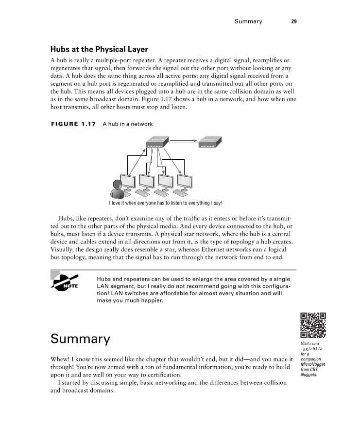
Hubs at the Physical LayerA hub is really a multiple-port repeater. A repeater receives a digital signal, reamplifies or regenerates that signal, then forwards the signal out the other port without looking at any data. A hub does the same thing across all active ports: any digital signal received from a segment on a hub port is regenerated or reamplified and transmitted out all other ports on the hub. This means all devices plugged into a hub are in the same collision domain as well as in the same broadcast domain. Figure 1.17 shows a hub in a network, and how when one host transmits, all other hosts must stop and listen.
f I gu r e 1.17 A hub in a network
I love it when everyone has to listen to everything I say!
Hubs, like repeaters, don’t examine any of the traffic as it enters or before it’s transmit-ted out to the other parts of the physical media. And every device connected to the hub, or hubs, must listen if a device transmits. A physical star network, where the hub is a central device and cables extend in all directions out from it, is the type of topology a hub creates. Visually, the design really does resemble a star, whereas Ethernet networks run a logical bus topology, meaning that the signal has to run through the network from end to end.
Hubs and repeaters can be used to enlarge the area covered by a single LAN segment, but I really do not recommend going with this configura-tion! LAN switches are affordable for almost every situation and will make you much happier.
SummaryWhew! I know this seemed like the chapter that wouldn’t end, but it did—and you made it through! You’re now armed with a ton of fundamental information; you’re ready to build upon it and are well on your way to certification.
I started by discussing simple, basic networking and the differences between collision and broadcast domains.
Visit ccna .gg/ch1/a for a companion MicroNugget from CBT Nuggets.

30 Chapter 1 u Internetworking
789704c01.indd 31-01-2008 01:34 PM
I then discussed the OSI model—the seven-layer model used to help application developers design applications that can run on any type of system or network. Each layer has its special jobs and select responsibilities within the model to ensure that solid, effective communications do, in fact, occur. I provided you with complete details of each layer and discussed how Cisco views the specifications of the OSI model.
In addition, each layer in the OSI model specifies different types of devices, and I described the different devices used at each layer.
Remember that hubs are Physical layer devices and repeat the digital signal to all segments except the one from which it was received. Switches segment the network using hardware addresses and break up collision domains. Routers break up broadcast domains as well as collision domains and use logical addressing to send packets through an internetwork.
Exam Essentials
Identify the possible causes of LAN traffic congestion. Too many hosts in a broadcast domain, broadcast storms, multicasting, and low bandwidth are all possible causes of LAN traffic congestion.
Describe the difference between a collision domain and a broadcast domain. Collision domain is an Ethernet term used to describe a network collection of devices in which one particular device sends a packet on a network segment, forcing every other device on that same segment to pay attention to it. With a broadcast domain, a set of all devices on a net-work hear all broadcasts sent on all segments.
Differentiate a MAC address and an IP address and describe how and when each address type is used in a network. A MAC address is a hexadecimal number identifying the phys-ical connection of a host. MAC addresses are said to operate on layer 2 of the OSI model. IP addresses, which can be expressed in binary or decimal format, are logical identifiers that are said to be on layer 3 of the OSI model. Hosts on the same physical segment locate one another with MAC addresses, while IP addresses are used when they reside on differ-ent LAN segments or subnets.
Understand the difference between a hub, a bridge, a switch, and a router. A hub creates one collision domain and one broadcast domain. A bridge breaks up collision domains but creates one large broadcast domain. They use hardware addresses to filter the network. Switches are really just multiple-port bridges with more intelligence; they break up collision domains but creates one large broadcast domain by default. Bridges and switches use hardware addresses to filter the network. Routers break up broadcast domains (and collision domains) and use logical addressing to filter the network.
Identify the functions and advantages of routers. Routers perform packet switching, filter-ing, and path selection, and they facilitate internetwork communication. One advantage of routers is that they reduce broadcast traffic.

Exam Essentials 31
789704c01.indd 31-01-2008 01:34 PM
Differentiate connection-oriented and connectionless network services and describe how each is handled during network communications. Connection-oriented services use acknowledgments and flow control to create a reliable session. More overhead is used than in a connectionless network service. Connectionless services are used to send data with no acknowledgments or flow control. This is considered unreliable.
Define the OSI layers, understand the function of each, and describe how devices and net-working protocols can be mapped to each layer. You must remember the seven layers of the OSI model and what function each layer provides. The Application, Presentation, and Session layers are upper layers and are responsible for communicating from a user inter-face to an application. The Transport layer provides segmentation, sequencing, and virtual circuits. The Network layer provides logical network addressing and routing through an internetwork. The Data Link layer provides framing and placing of data on the network medium. The Physical layer is responsible for taking 1s and 0s and encoding them into a digital signal for transmission on the network segment.
32 Chapter 1 u Internetworking
789704c01.indd 31-01-2008 01:34 PM
Written LabsIn this section, you’ll complete the following labs to make sure you’ve got the information and concepts contained within them fully dialed in:
Lab 1.1: OSI Questions
Lab 1.2: Defining the OSI Layers and Devices
Lab 1.3: Identifying Collision and Broadcast Domains
The answers to these labs can be found in Appendix A, “Answers to Written Labs.”
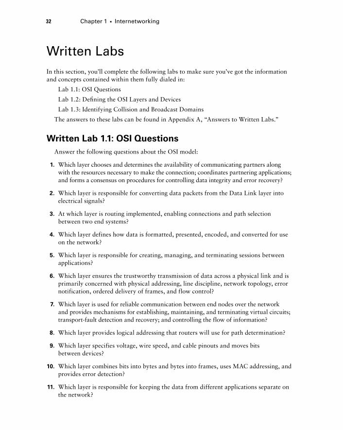
Written Lab 1.1: OSI QuestionsAnswer the following questions about the OSI model:
1. Which layer chooses and determines the availability of communicating partners along with the resources necessary to make the connection; coordinates partnering applications; and forms a consensus on procedures for controlling data integrity and error recovery?
2. Which layer is responsible for converting data packets from the Data Link layer into electrical signals?
3. At which layer is routing implemented, enabling connections and path selection between two end systems?
4. Which layer defines how data is formatted, presented, encoded, and converted for use on the network?
5. Which layer is responsible for creating, managing, and terminating sessions between applications?
6. Which layer ensures the trustworthy transmission of data across a physical link and is primarily concerned with physical addressing, line discipline, network topology, error notification, ordered delivery of frames, and flow control?
7. Which layer is used for reliable communication between end nodes over the network and provides mechanisms for establishing, maintaining, and terminating virtual circuits; transport-fault detection and recovery; and controlling the flow of information?
8. Which layer provides logical addressing that routers will use for path determination?
9. Which layer specifies voltage, wire speed, and cable pinouts and moves bits between devices?
10. Which layer combines bits into bytes and bytes into frames, uses MAC addressing, and provides error detection?
11. Which layer is responsible for keeping the data from different applications separate on the network?

Written Labs 33
789704c01.indd 31-01-2008 01:34 PM
12. Which layer is represented by frames?
13. Which layer is represented by segments?
14. Which layer is represented by packets?
15. Which layer is represented by bits?
16. Put the following in order of encapsulation:
Packets
Frames
Bits
Segments
17. Which layer segments and reassembles data into a data stream?
18. Which layer provides the physical transmission of the data and handles error notifica-tion, network topology, and flow control?
19. Which layer manages logical device addressing, tracks the location of devices on the internetwork, and determines the best way to move data?
20. What is the bit length and expression form of a MAC address?
Written Lab 1.2: Defining the OSI Layers and DevicesFill in the blanks with the appropriate layer of the OSI or hub, switch, or router device.
Description Device or OSI Layer
This device sends and receives information about the Network layer.
This layer creates a virtual circuit before transmitting between two end stations.
This device uses hardware addresses to filter a network.
Ethernet is defined at these layers.
This layer supports flow control, sequencing, and acknowledgments.
This device can measure the distance to a remote network.
Logical addressing is used at this layer.
Hardware addresses are defined at this layer.

34 Chapter 1 u Internetworking
789704c01.indd 31-01-2008 01:34 PM
Description Device or OSI Layer
This device creates one big collision domain and one large broadcast domain.
This device creates many smaller collision domains, but the network is still one large broadcast domain.
This device can never run full-duplex.
This device breaks up collision domains and broadcast domains.
Written Lab 1.3: Identifying Collision and Broadcast Domains 1. In the following exhibit, identify the number of collision domains and broadcast
domains in each specified device. Each device is represented by a letter:
A. Hub
B. Bridge
C. Switch
D. Router
A B
Hub SwitchC
S1
Bridge
D
Router

Review Questions 35
789704c01.indd 31-01-2008 01:34 PM
Review Questions
The following questions are designed to test your understanding of this chapter’s material. For more information on how to get additional ques-tions, please see this book’s introduction.
The answers to these questions can be found in Appendix B, “Answers to Chapter Review Questions.”
1. Which of the following statements is/are true with regard to the device shown below? (Choose all that apply.)
A. It includes one collision domain and one broadcast domain
B. It includes one collision domain and 10 broadcast domains
C. It includes 10 collision domains and one broadcast domain
D. It includes one collision domain and 10 broadcast domains
E. It includes 10 collision domains and 10 broadcast domains
2. With respect to the OSI model, which of the following are correct statements about PDUs?
A. A segment contains IP addresses.
B. A packet contains IP addresses.
C. A segment contains MAC addresses.
D. A packet contains MAC addresses.
3. You are the Cisco administrator for your company. A new branch office is opening and you are selecting the necessary hardware to support the network. There will be two groups of computers, each organized by department. The Sales group computers will be assigned IP addresses ranging from 192.168.1.2 to 192.168.1.50. The Accounting group will be assigned IP addresses ranging from 10.0.0.2 to 10.0.0.50. What type of device should you select to connect the two groups of computers so that data commu-nication can occur?
A. Hub
B. Switch
C. Router
D. Bridge

36 Chapter 1 u Internetworking
789704c01.indd 31-01-2008 01:34 PM
4. The most effective way to mitigate congestion on a LAN would be to__________________?
A. Upgrade the network cards
B. Change the cabling to CAT 6
C. Replace the hubs with switches
D. Upgrade the CPUs in the routers
5. In the work area below draw a line from the OSI model layer to its PDU.
Transport Bits
Data Link Segment
Physical Packet
Network Frame
Layer Description
6. In the diagram below what procedure is shown?
Sender SYN Receiver
SYN/ACK
ACK
Connection Established
Data transfer(Send bytes of segments)
A. flow control
B. windowing
C. TCP handshake
D. reliable delivery

Review Questions 37
789704c01.indd 31-01-2008 01:34 PM
7. You need to provide network connectivity to 150 client computers that will reside in the same sub network, and each client computer must be allocated dedicated band-width. Which device should you use to accomplish the task?
A. Hub
B. Switch
C. Router
D. Bridge
8. In the work area below, drag the OSI model layer on the left to its description on the right.
left list:
Layer
Transport
Physical
Data Link
Network
right list:
Description
Framing
End-to-end connection
Routing
Conversion to bits
9. What feature of TCP is illustrated below?
Sender Receiver
Send 1
1
Send 3Send 2
ACK 2Send 4Send 5Send 6
ACK 5
Connection lost!
ACK 7Send 5
2 3 4 5 6 1 2 3 4 5 6
A. flow control
B. UDP handshake
C. TCP handshake
D. reliable delivery

38 Chapter 1 u Internetworking
789704c01.indd 31-01-2008 01:34 PM
10. Which of the following is an example of a routed protocol?
A. EIGRP
B. IP
C. OSPF
D. BGP
11. Which of the following is NOT a function carried out on the Application layer of the OSI model?
A. email
B. data translation and code formatting
C. file transfers
D. client/server processes
12. Which of the following layers of the OSI model was later subdivided into two layers?
A. Presentation
B. Transport
C. Data Link
D. Physical
13. What feature of TCP is illustrated below?
Sender Receiver
Send 1
Send 3Send 2
ACK 4Send 4
A. flow control
B. windowing
C. TCP handshake
D. reliable delivery

Review Questions 39
789704c01.indd 31-01-2008 01:34 PM
14. An example of a device that operates on the physical layer is a ____________.
A. Hub
B. Switch
C. Router
D. Bridge
15. Which of the following is NOT a benefit of using a reference model?
A. divides the network communication process into smaller and simpler components
B. encourages industry standardization
C. enforces consistency across vendors
D. allows various types of network hardware and software to communicate
16. Which of the following statements is not true with regard to routers?
A. They forward broadcasts by default
B. They can filter the network based on Network layer information
C. They perform path selection
D. They perform packet switching
17. Switches break up _______________ domains and routers break up _____________ domains.
A. broadcast, broadcast
B. collision, collision
C. collision, broadcast
D. broadcast, collision
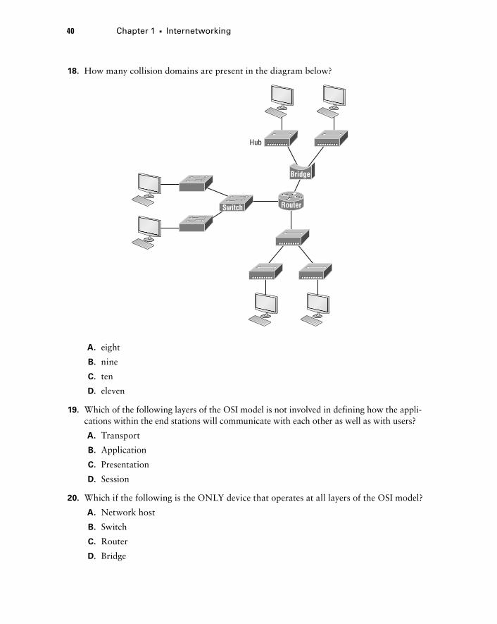
40 Chapter 1 u Internetworking
789704c01.indd 31-01-2008 01:34 PM
18. How many collision domains are present in the diagram below?
Hub
Switch
Bridge
Router
A. eight
B. nine
C. ten
D. eleven
19. Which of the following layers of the OSI model is not involved in defining how the appli-cations within the end stations will communicate with each other as well as with users?
A. Transport
B. Application
C. Presentation
D. Session
20. Which if the following is the ONLY device that operates at all layers of the OSI model?
A. Network host
B. Switch
C. Router
D. Bridge
Related Documents