Welcome message from author
This document is posted to help you gain knowledge. Please leave a comment to let me know what you think about it! Share it to your friends and learn new things together.
Transcript


Construction of coaching stockConstruction of coaching stock
Shell or the skeleton partShell or the skeleton part
Furnishing or the provisions of amenitiesFurnishing or the provisions of amenities
Bogie (Trolley), the running gearBogie (Trolley), the running gear

BogieBogie

BOGIE (TROLLEY)BOGIE (TROLLEY)
What ?What ?
Why?Why?

Main Units of a BogieMain Units of a Bogie
1.1. Bogie FrameBogie Frame
2.2. Wheel and Axle Wheel and Axle
3.3. Bearing ArrangementBearing Arrangement
4.4. Bogie Frame – Axle Joint Bogie Frame – Axle Joint
5.5. BolsterBolster
6.6. Primary Suspension Primary Suspension
7.7. Secondary Suspension Secondary Suspension
8.8. Bogie – Body JointBogie – Body Joint
9.9. Brake SystemBrake System

Version of Coaching BogieVersion of Coaching Bogie
IRS Bogie IRS Bogie SCHLIEREN Bogie (ICF Laminated Bogie) SCHLIEREN Bogie (ICF Laminated Bogie) MAN-HAL Bogie (BEML Bogie) MAN-HAL Bogie (BEML Bogie) ICF All Coiled Bogie ICF All Coiled Bogie IR-20 Bogie IR-20 Bogie Fiat Bogie (Similar to IR-20 Bogie)Fiat Bogie (Similar to IR-20 Bogie)

IRS BogieIRS Bogie

IRS BogieIRS Bogie
Developed / Built by:Developed / Built by: British MakeBritish Make
Introduction to Railway :Introduction to Railway : Since 1930 – 31 Since 1930 – 31
Status:Status: Productions abolished and use Productions abolished and use discontinued on Mail / express service.discontinued on Mail / express service.

SCHLIEREN Bogie SCHLIEREN Bogie (ICF Laminated Bogie)(ICF Laminated Bogie)

SCHLIEREN Bogie (ICF Laminated Bogie)
Developed / Built by:
M/S Swiss Car and
Elevator manufacturing corporation Ltd,
Schlieren, Zurich
Introduction to Railway : Since 1951
Status: Productions abolished and use discontinued on Mail / express
service.

MAN-HAL Bogie MAN-HAL Bogie (BEML Bogie)(BEML Bogie)

Developed / Built by:
M/S HAL Banglore
in collaboration with
M/S MAN Nurnberg (West Germany)
Introduction to Railway : Since 1958-59
Status: Productions abolished and use discontinued on Mail / express
service having speed more than 105 KMPH.
MAN-HAL Bogie (BEML Bogie)

ICF All Coiled BogieICF All Coiled Bogie

Developed / Built by: ICF & RCF
Introduction to Railway : Since 1965
Status: Productions continue by ICF & RCF.
ICF All Coiled Bogie

Fiat Bogie Fiat Bogie (Similar to IR-20 Bogie)(Similar to IR-20 Bogie)

Developed / Built by: RCF
Introduction to Railway : Since 1998
Status: Used in few coaches and production abolished due to introduction of
FIAT bogie.
IR-20 Bogie

Developed / Built by: 24 Coaches imported from Switzer land in 2000- 01.
Introduction to Railway : Since 2001
Status: Productions started in RCF.
FIAT Bogie

ICF BOGIE (Top View)
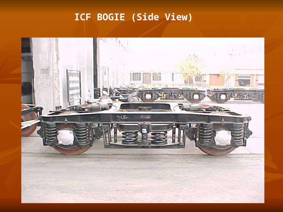
ICF BOGIE (Side View)
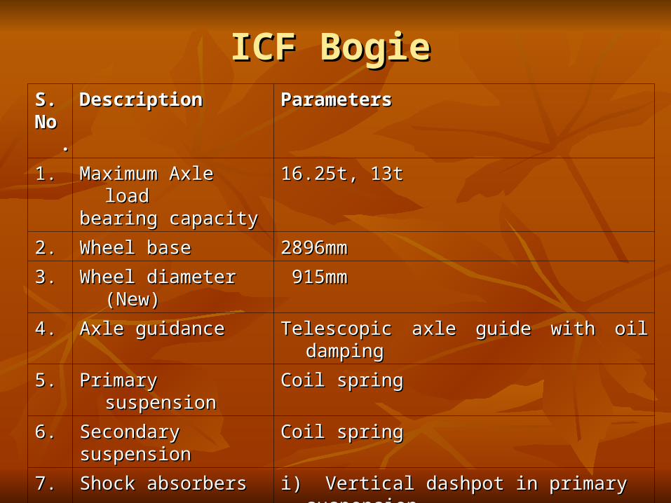
ICF BogieICF BogieS. S. No.No.
DescriptionDescription ParametersParameters
1.1. Maximum Axle loadMaximum Axle loadbearing capacitybearing capacity
16.25t, 13t16.25t, 13t
2.2. Wheel baseWheel base 2896mm2896mm
3.3. Wheel diameter (New)Wheel diameter (New) 915mm915mm
4.4. Axle guidanceAxle guidance Telescopic axle guide with oil dampingTelescopic axle guide with oil damping
5.5. Primary suspensionPrimary suspension Coil springCoil spring
6.6. SecondarySecondarysuspensionsuspension
Coil springCoil spring
7.7. Shock absorbersShock absorbers i) Vertical dashpot in primary suspension.i) Vertical dashpot in primary suspension.ii) Hydraulic double acting vertical shock ii) Hydraulic double acting vertical shock
absorber in secondary suspension.absorber in secondary suspension.
8.8. Transfer of coachTransfer of coachbody weightbody weight
Through bogie side bearer pitched atThrough bogie side bearer pitched at1600mm.1600mm.

ICF BogieICF Bogie
Manufactured by ICF/RCF Manufactured by ICF/RCF
Helical coil springs are used in both the Helical coil springs are used in both the primary and the secondary stages. primary and the secondary stages.
The axle guide device provides viscous The axle guide device provides viscous damping across primary springs while damping across primary springs while hydraulic dampers are provided across the hydraulic dampers are provided across the secondary stage. secondary stage.

Rigid axle box guide arrangement Rigid axle box guide arrangement eliminates any longitudinal or transverse eliminates any longitudinal or transverse relative movement between the axles relative movement between the axles and the bogie frame.and the bogie frame.
These guides are fitted with guide caps These guides are fitted with guide caps having nine holes of diameter 5 mm having nine holes of diameter 5 mm equidistant through which oil in the lower equidistant through which oil in the lower spring seat passes under pressure spring seat passes under pressure during dynamic oscillation of coach and during dynamic oscillation of coach and provide necessary damping to primary provide necessary damping to primary suspension to enhance better riding suspension to enhance better riding quality of coach. quality of coach.
ICF BogieICF Bogie

ICF BogieICF Bogie Isolation of vibration is effected by rubber Isolation of vibration is effected by rubber
pads in primary and secondary pads in primary and secondary suspension.suspension.
The wheel sets are provided with self-The wheel sets are provided with self-aligning spherical roller bearings mounted aligning spherical roller bearings mounted in cast steel axle box housings. in cast steel axle box housings.

ICF BogieICF Bogie
AIR VENT SCREWSAIR VENT SCREWS
-- On the bogie side frames, directly On the bogie side frames, directly above the dash-pots, tapped holes above the dash-pots, tapped holes are are provided for replenishing oil in the dash provided for replenishing oil in the dash pots. Special screws with copper pots. Special screws with copper asbestos washers are screwed on asbestos washers are screwed on the the tapped hole to make it air tight. tapped hole to make it air tight.

ICF BogieICF Bogie
The quantity of oil required to achieve The quantity of oil required to achieve 40 40 mmmm oil level above the guide cap in oil level above the guide cap in modified arrangement is approximately modified arrangement is approximately 1.6 1.6 litersliters and in unmodified arrangement is and in unmodified arrangement is approximately approximately 1.4 liters1.4 liters. As it is not . As it is not possible in open line to distinguish between possible in open line to distinguish between modified and unmodified arrangements, modified and unmodified arrangements, 40 40 mmmm oil level is standardised for both. oil level is standardised for both.

ICF BogieICF Bogie
Side-bearers consist of lubricated metal Side-bearers consist of lubricated metal slides immersed in oil baths. slides immersed in oil baths.
The ends of the bogie bolsters rest on The ends of the bogie bolsters rest on the bolster helical springs placed over the bolster helical springs placed over the lower spring beam suspended from the lower spring beam suspended from the bogie frame by the inclined swing the bogie frame by the inclined swing links at an angle 7 degree. links at an angle 7 degree.

ICF BogieICF Bogie
SILENT BLOCKSILENT BLOCK
-- This is a synthetic rubber bush fitted in This is a synthetic rubber bush fitted in anchor link and center pivot of ICF anchor link and center pivot of ICF
bogies to transmit force without shock bogies to transmit force without shock and and reduce noise.reduce noise.

ICF BogieICF Bogie
The two anchor links diagonally positioned are The two anchor links diagonally positioned are provided with silent block bushes. The links provided with silent block bushes. The links prevent any relative movement between the prevent any relative movement between the bogie frame and coach body.bogie frame and coach body.

ICFICF
CENTRE PIVOT ARRANGEMENTCENTRE PIVOT ARRANGEMENT
The centre pivot pin joins the body with the bogie and The centre pivot pin joins the body with the bogie and transmits the tractive and braking forces on the transmits the tractive and braking forces on the bogies. It does not transmit any vertical load. It is bogies. It does not transmit any vertical load. It is equipped with rubber silent block bushes which tend equipped with rubber silent block bushes which tend to centralise the bogies with respect to the body and, to centralise the bogies with respect to the body and, to some extent, control and damp the angular to some extent, control and damp the angular oscillations of the bogies. oscillations of the bogies.
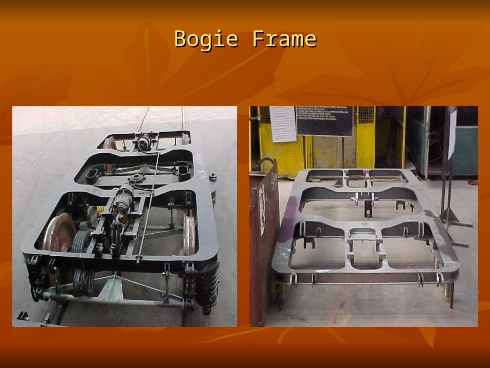
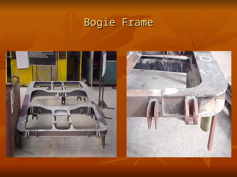
Bogie FrameBogie Frame

Bogie FrameBogie Frame
All welded light weight construction. All welded light weight construction.
Bogie FrameBogie Frame


Suggested BSS bracket and Suggested BSS bracket and axle guide alignment gaugesaxle guide alignment gauges
13t bogies13t bogies 16.25t bogies16.25t bogies
Longitudinal gauge for BSS Longitudinal gauge for BSS bracketsbrackets
140014001.0 mm1.0 mm ( (7007000.50.5 mmmm from longitudinal from longitudinal center-line)center-line)
150015001.0 mm (7501.0 mm (7500.5 0.5 mmmm from longitudinal from longitudinal center-line)center-line)
Transverse gauge for BSS Transverse gauge for BSS bracketsbrackets
2159 2159 1.0 mm1.0 mm 2159 2159 1.0 mm 1.0 mm
Diagonal gauge for BSS Diagonal gauge for BSS bracketsbrackets
2573 2573 1.0 mm1.0 mm 2629 2629 1.0 mm 1.0 mm
Longitudinal gauge for axle Longitudinal gauge for axle guideguide
5705701.0 mm1.0 mm (equidistant (equidistant from center-line of axle)from center-line of axle)
570 570 1.0 mm 1.0 mm (equidistant (equidistant from center-line of axle)from center-line of axle)
Transverse gauge for axle Transverse gauge for axle guideguide
215921591.0 mm1.0 mm 215921591.0 mm1.0 mm
Diagonal gauge for axle guideDiagonal gauge for axle guide 361236121.0 mm1.0 mm 361236121.0 mm1.0 mm
Distance between BSS bracket Distance between BSS bracket and adjacent axle guideand adjacent axle guide
4634631.0 mm1.0 mm 4134131.0 mm1.0 mm
Longitudinal gauge for Longitudinal gauge for suspension strapsuspension strap
8708701.0 mm1.0 mm (equidistant (equidistant from center-line of axle)from center-line of axle)
8708701.0mm1.0mm (equidistant (equidistant from center-line of the axle)from center-line of the axle)

Wheel & AxleWheel & Axle

Axle Box HousingAxle Box Housing

Roller BearingRoller Bearing
Wheel & AxleWheel & Axle
Axles are located on the bogie by Axles are located on the bogie by telescopic dash pot and axle guide telescopic dash pot and axle guide assemblies. assemblies.

Axle Box SpringAxle Box Spring

Dashpots and Axle Guide AssemblesDashpots and Axle Guide Assembles
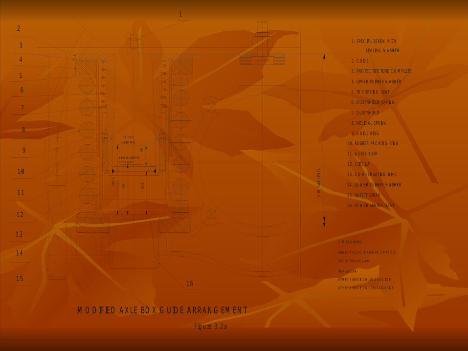
Fig ure 3.2a
UN DER TARE
A SSEM BLIN G
142.
5
104
SEALING WASHER
2. G UIDE
3. PRO TEC TIVE TUBE C O M PLETE
4. UPPER RUBBER WASHER
5. TO P SPRING SEAT
6. DUST SHIELD SPRING
7. DUST SHIELD
8. HELIC AL SPRING
9. G UIDE RING
10. RUBBER PAC KING RING
11. G UIDE BUSH
12. C IRC LIP
13. C O M PENSATING RING
14. LO WER RUBBER WASHER
15. SAFETY STRAP
16. LO WER SPRING SEAT
1
2
3
4
5
6
7
8
9
10
11
12
13
14
1516
1. SPEC IAL SEREW WITH
PO WER C AR-
EXC EPT PO WER C ARS
686 FO R ALL AC & NO N-AC C O AC HES
X TO RAIL LEVEL-
X TO
RA
IL L
EVEL
O IL LEVEL BEFO RE
O IL LEVEL
670 FO R BO G IE O N LUG G AG E SIDE
672 FO R BO G IE O N G ENERATO R SIDE
92.5
40
M O DIFIED AXLE BO X G UIDE ARRANG EM ENT
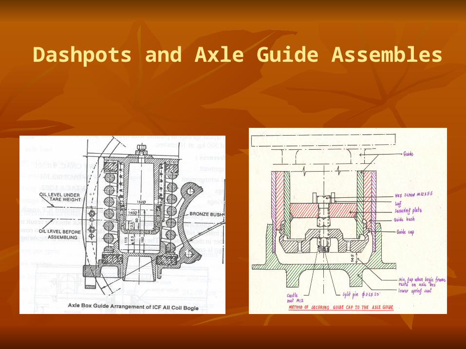
Dashpots and Axle Guide Assembles

Dashpots and Axle Guide Assembles
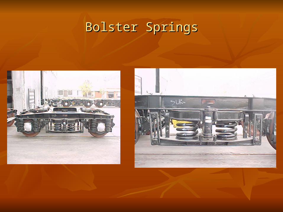
Bolster SpringsBolster Springs
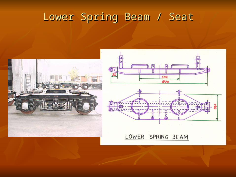
Lower Spring Beam / SeatLower Spring Beam / Seat

Drawing code of springs for ICF BG coaches(Reference RDSO Amendment slip no. 5 of September 2001 to STR WD-01-HLs- 94 (Rev.1 May 95)
Type of springType of spring Type of bogiesType of bogies ICF Drg. NoICF Drg. No Drg. Code Drg. Code No.No.
Axle boxAxle box All Non AC ICF typeAll Non AC ICF type F-0-1-006F-0-1-006 A01A01
All AC ICF type All AC ICF type WTAC-0-1-202WTAC-0-1-202 A03A03
Power car Power car WLRRM2-0-1-202WLRRM2-0-1-202 A04A04
Double deckerDouble decker DD-0-1-001DD-0-1-001 A06A06
High capacity Power CarHigh capacity Power Car WLRRM8-0-1-802WLRRM8-0-1-802 A09A09
High capacity parcel vanHigh capacity parcel van RDSO /SK-98017RDSO /SK-98017 A10A10
Bolster Bolster All Non AC ICF typeAll Non AC ICF type F-0-5-002F-0-5-002 B01B01
All AC ICF type All AC ICF type WTAC-0-5-202WTAC-0-5-202 B03B03
Power car Power car WLRRM2-0-5-202WLRRM2-0-5-202 B04B04
Double deckerDouble decker DD-0-5-003DD-0-5-003 B06B06
Bolster Bolster
High capacity Power carHigh capacity Power car WLRRM8-0-5-802 WLRRM8-0-5-802 B11B11
B13B13
High capacity Parcel vanHigh capacity Parcel van RDSO /SK-98018RDSO /SK-98018B15B15
B16B16

Load deflection testing and grouping of Axle box spring (B.G Main line coaches)
CodeCode Wire Wire diadia
Free Free heightheight
Test Test LoadLoad
Acceptable Acceptable height under height under
test loadtest load
Groups as per loaded spring height Groups as per loaded spring height
AA BB CC
YellowYellow Oxford Oxford Blue*Blue*
GreenGreen
A01A01 33.533.5 360360 20002000 279-295279-295 279-284279-284 285-289285-289 290-295290-295
A03A03 33.533.5 375375 28002800 264-282264-282 264-269264-269 270-275270-275 276-282276-282
A04A04 3535 372372 30003000 265-282265-282 265-270265-270 271-276271-276 277-282277-282
A06A06 3636 337337 24002400 269-284269-284 269-273269-273 274-279274-279 280-284280-284
A09A09 3737 360360 30003000 277-293277-293 277-282277-282 283-288283-288 289-293289-293
A10A10 3939 315315 18001800 276-289276-289 276-279276-279 280-284280-284 285-289285-289
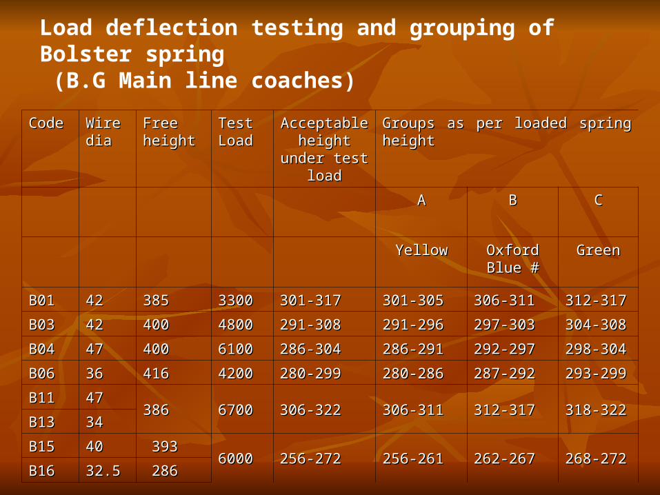
Load deflection testing and grouping of Bolster spring (B.G Main line coaches)
CodeCode Wire Wire diadia
Free Free heightheight
Test Test LoadLoad
Acceptable Acceptable height under height under
test loadtest load
Groups as per loaded spring heightGroups as per loaded spring height
AA BB CC
YellowYellow Oxford Blue Oxford Blue ##
GreenGreen
B01B01 4242 385385 33003300 301-317301-317 301-305301-305 306-311306-311 312-317312-317
B03B03 4242 400400 48004800 291-308291-308 291-296291-296 297-303297-303 304-308304-308
B04B04 4747 400400 61006100 286-304286-304 286-291286-291 292-297292-297 298-304298-304
B06B06 3636 416416 42004200 280-299280-299 280-286280-286 287-292287-292 293-299293-299
B11B11 4747386386 67006700 306-322306-322 306-311306-311 312-317312-317 318-322318-322
B13B13 3434
B15B15 4040 39339360006000 256-272256-272 256-261256-261 262-267262-267 268-272268-272
B16B16 32.532.5 286 286
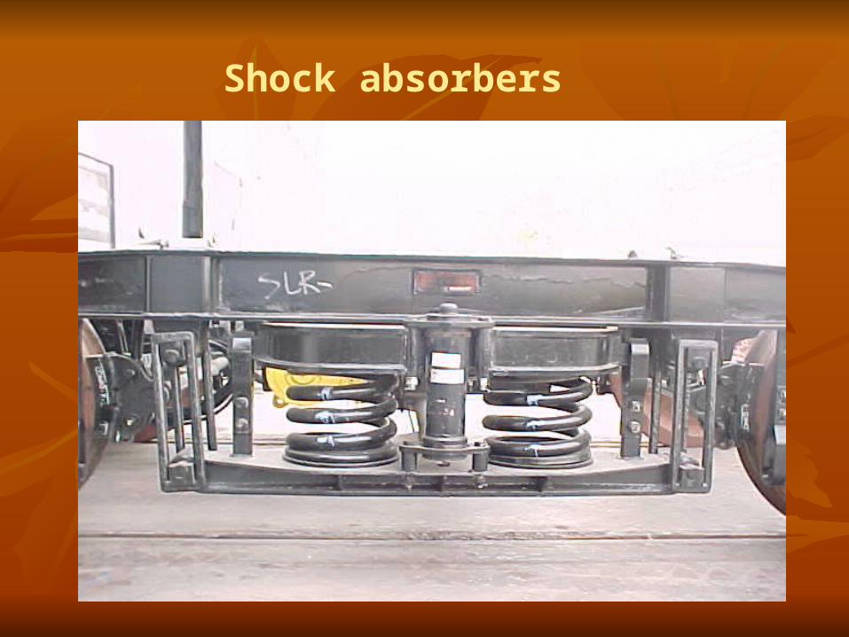
Shock absorbers
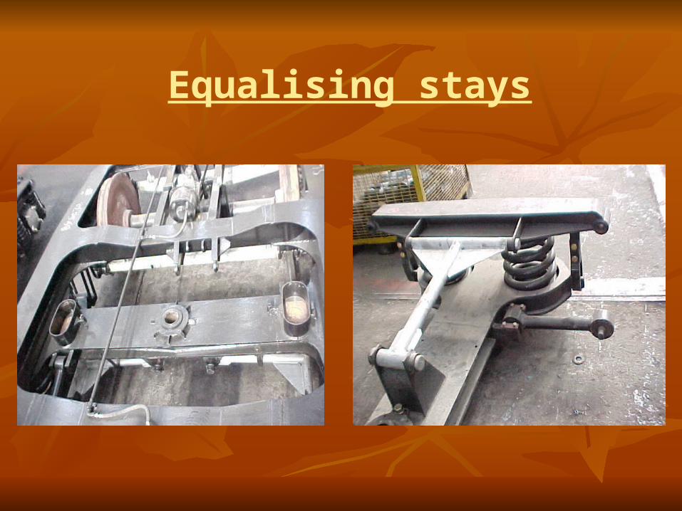
Equalising stays

Provided on bogies between the lower Provided on bogies between the lower spring plank and the bolster spring plank and the bolster
To prevent lateral thrust on the bolster To prevent lateral thrust on the bolster springs which have not been designed to springs which have not been designed to take the lateral forces. take the lateral forces.
Pin connections at both ends to swivel Pin connections at both ends to swivel freely.freely.
Equalising stays
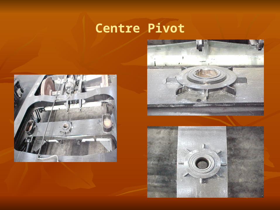
Centre Pivot

Centre Pivot

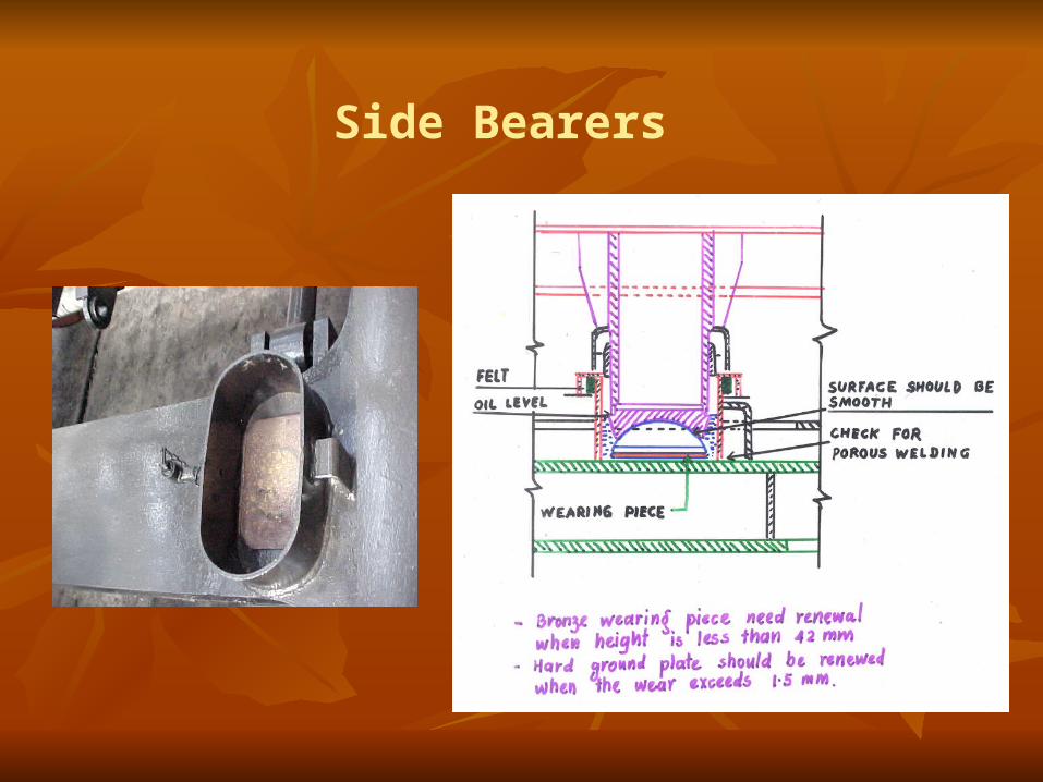
Side Bearers

Consists of a machined steel wearing plate Consists of a machined steel wearing plate immersed in an oil bath immersed in an oil bath
Floating bronze-wearing piece with a Floating bronze-wearing piece with a spherical top surface kept in itspherical top surface kept in it
The coach body rests on the top spherical The coach body rests on the top spherical surface of these bronze-wearing pieces surface of these bronze-wearing pieces through the corresponding attachments on through the corresponding attachments on the bottom of the body-bolster. the bottom of the body-bolster.
Side Bearer
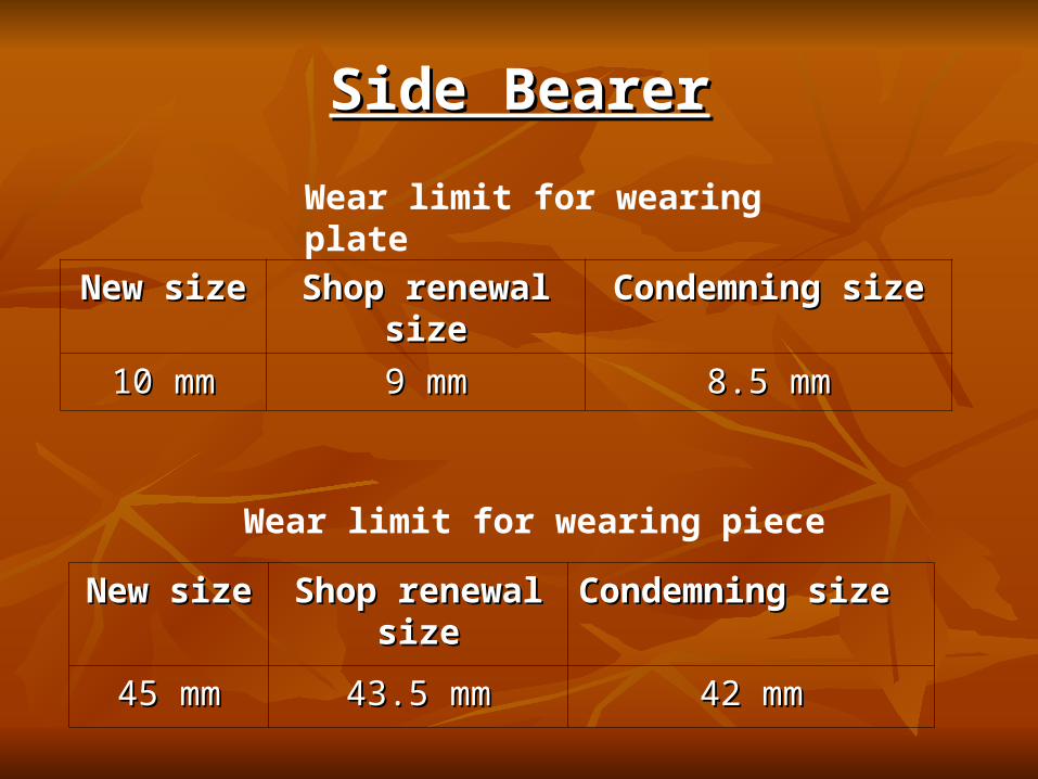
Side BearerSide Bearer
Wear limit for wearing plate
New sizeNew size Shop renewal Shop renewal sizesize
Condemning sizeCondemning size
10 mm10 mm 9 mm9 mm 8.5 mm8.5 mm
Wear limit for wearing piece
New sizeNew size Shop renewal Shop renewal sizesize
Condemning sizeCondemning size
45 mm45 mm 43.5 mm43.5 mm 42 mm42 mm
Side Bearers
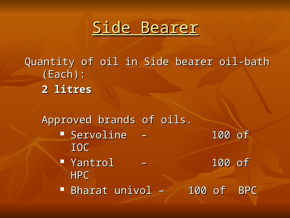
Side BearerSide Bearer
Quantity of oil in Side bearer oil-bath Quantity of oil in Side bearer oil-bath (Each): (Each):
2 litres2 litres
Approved brands of oils.Approved brands of oils. Servoline Servoline – – 100 of IOC100 of IOC Yantrol Yantrol – – 100 of HPC100 of HPC Bharat univol – Bharat univol – 100 of BPC100 of BPC

Anchor Links

Anchor linksAnchor links
Pin connection to the Bolster sides and Pin connection to the Bolster sides and the Bogie Transoms.the Bogie Transoms.
Can swivel universally to permit the Can swivel universally to permit the bolster to rise and fall and sway side bolster to rise and fall and sway side wards. wards.
One anchor link is provided on each side One anchor link is provided on each side of the bolster diagonally across. of the bolster diagonally across.
Fitted with silent block bushesFitted with silent block bushes

Anchor linkAnchor link
To hold in position longitudinally the To hold in position longitudinally the floating bogie bolster floating bogie bolster
To design to take the tractive and braking To design to take the tractive and braking forces. forces.

ANCHOR LINK WITH SILENT BLOCKFigure 3.5
Anchor linkAnchor link

Hanger and Hanger Blocks

Axle Box safety Strap

Hanger Pin Safety Stopper

Brake Shoe headBrake Shoe head
In order to fit the brake block snugly in the brake In order to fit the brake block snugly in the brake head to avoid any movement between them.head to avoid any movement between them.
To avoid excessive wear at the ends of the brake To avoid excessive wear at the ends of the brake head.head.

Brake shoe key
• In order to fit the brake block snugly in the brake head to avoid any movement between them.

Safety wire rope
• The old arrangement of safety straps is reported to be falling in service due to ballast hitting.
• To improve the safety of brake beam falling on the track safety wire rope introduced.

Brake block hanger
• To avoid brake block climbing over the wheel in case of fully worn out wheels.

Standardization of equalizing stay
• The old equalizing stay had a pin dia of 25 mm. The longer pin is found to be bending in service resulting in removal difficulties.
• In the standardized equalizing stay the dia of pin has been increased to 31 mm.

Pin for brake lever hanger
• To avoid slipping of nylon bush in the lever hanger a washer is welded.
• Castle nut with split pin introduced.

Improved brake beam
• The old brake beam does not cater to the load requirement of air braked coaches and it also bends under extra loads.

Single piece brake block hanger
• Single piece design will avoid misalignment of brake block with respect to wheel tread.
Revised side buffer casing
• To avoid cracks developing from the bolt holes in the U/frame headstock.
• Horizontal pitch for bolt holes has been increased from 254 mm to 349 mm.
• Vertical pitch for bolt holes has been increased from 127 mm to 170 mm.

Provision of locking arrangement for guide cap
• To avoid falling of guide cap due to breakage of spring clip.

Rubber stopper axle box crown bolt
• To prevent the breakage of axle box crown hexagonal bolt assembly in service.
• The hexagonal head bolt is prevented from hitting directly. Instead the rubber stopper will be hitting the crown.

Weld joint of bogie side frame with head stock
• The side frame head stock joint below guide in the old design was undesirable as the joint leads to misalignment of guides.
• Shifted to headstock beyond brake hanger brackets.

Slack adjuster articulation
• To provide freedom of rotation in horizontal plane an additional pin joint has been provided.
• Freedom of rotation in vertical plane is also ensured at the floating lever end.
• This arrangement is expected to minimize the incidence of slack adjuster spring breakages.

Workshop ActivitiesWorkshop Activities
1.1. Coach liftingCoach lifting2.2. Bogie cleaningBogie cleaning3.3. Bogie dismantlingBogie dismantling4.4. Component cleaningComponent cleaning5.5. Attention to componentsAttention to components6.6. Repair of componentsRepair of components7.7. Bogie assemblyBogie assembly8.8. Load testing and adjustmentLoad testing and adjustment9.9. Lowering of coachLowering of coach10.10. Final adjustmentFinal adjustment

Workshop Maintenance of Workshop Maintenance of ICF Bogie- Flow diagramICF Bogie- Flow diagram

L.S. BEAM
RAIL LEVEL
BO G IE FRAM E
PART- I
D E
M
G
F
BO G IE BO LSTER
A
B
C
SUSPENSIO N DIAG RAM M ATIC ARRANG EM ENT
BO G IE BO LSTER
RAIL LEVEL
FIG URE 1.4a
BO DY BO LSTER
BO G IE FRAM E SIDE BEARER
PART- II
J
NI
L
2
NO TE - P1. Dim e nsio ns E & J sha ll b e m a inta ine d with re q uire d num b e r o f c o m p e nsa ting ring s o f sta nd a rd thic kne ss o f 4 m m .P2. Axle b o x sp ring s : WTAC -0-1-202P Bo lste r sp ring s : WTAC -0-5-202
H
K
2
FO R SELF G ENERATING AC C O AC HES (IC F DRAWING NO . IC F/SK -9-0-126)P 2

L.S. BEAM
RAIL LEVEL
BO G IE FRAM E
PART- I
G#
Z
F
BO G IE BO LSTER
B
X
A
2896 (WHEEL BASE)
SUSPENSIO N DIAG RAM M ATIC ARRANG EM ENT
FO R NO N AC C O AC HES (RC F DRAWING NO . C C 90019)P
NO TE - P1. Dim e nsio ns A & B m a rke d sho uld b e e nsure d le ss tha n d im e nsio ns C & D m a rke d re sp e c tive ly.P2. # C R to d ra wingNo .-C C 01140 to b e p ro vid e d .P3. * C R to d ra wing No . - C C 05251 to b e p ro vid e d .P4. 'F' the va ria tio n in a ll the fo ur b o g ie c o rne rhe ig hts m ust b e le ss tha n o r e q ua l to 10 m m .P5. Dra wing No . SG 90002, SZ90004, SE90011, LB90002 a re sup e rse d e d b y th isd ra wing .P6. The he ig ht o f Axle b o x sp ring a nd b o lste r sp ring in ta re & g ro ss c o nd itio ns is fo r re fe re nc e o nly.P7. The re q uire m e nt o f C R'sa s sho wn in the c o lum ns fo r p rim a ry & 30 m m in se c o nd a ry susp e nsio n.P8. O nly b lue b e nd sp ring s b o th in p rim a ry a nd se c o nd a rysta g e a re to b e use d in p o sta l va n c o a c h.
FIG URE 1 .4c
RAIL LEVEL
BO G IE FRAM E
BO DY BO LSTER
BO G IE BO LSTER
PART- II
SIDE BEARER
Y
H
We ig ht o f e a c h b o g ie = 5.9tPUnsp rung m a ss/b o g ie = 3.2 tPBo lste rwe ig ht = 0.4 tPC .R. =C o m p e nsa ting ring
C
D%
%c 915

Type of Type of coachcoach
Tare Tare weight of weight of
coachcoach
Normal Normal pay loadpay load
Total Total pay loadpay load
Bogie frame Bogie frame bolster bolster
clearanceclearance
Body bogie Body bogie clearanceclearance
Crown clearanceCrown clearance
ACAC In tonnesIn tonnes In tonnesIn tonnes In In tonnestonnes
B dimensionB dimension C DimensionC Dimension A DimensionA Dimension
TareTare GrossGross TareTare GrossGross TareTare GrossGross
ACCW ACCW (EOG)(EOG)
44.844.8 3.683.68 3.683.68 404055 505055 707033 606033 282833 202033
ACCW ACCW (SG)(SG)
49.149.1 3.683.68 3.683.68 404055 505055 707033 606033 303033 222233
ACCN ACCN (EOG)(EOG)
48.348.3 5.125.12 5.125.12 404055 545455 707033 565633 343433 222233
ACCN ACCN (SG)(SG)
52.5352.53 5.125.12 5.125.12 404055 535355 707033 575733 353533 232333
ACCZ ACCZ (EOG)(EOG)
43.143.1 5.365.36 5.365.36 404055 545455 707033 565633 323233 202033
Check List

Type Type of of
coachcoach
Tare Tare weight weight
of of coachcoach
Normal Normal pay pay loadload
Total Total pay pay loadload
Test load per Test load per bogiebogie
Bogie frame Bogie frame bolster bolster
clearanceclearance
Body bogie Body bogie clearanceclearance
Crown Crown clearanceclearance
ACAC In In tonnestonnes
In In tonnestonnes
In In tonntonneses
Under Under tare tare
Under Under GrossGross
B dimensionB dimension C DimensionC Dimension A DimensionA Dimension
In In tonnes tonnes
In In tonnestonnes
TareTare GrossGross TareTare GrossGross TareTare GrossGross
ACCZ ACCZ (SG)(SG)
46.8346.83 5.845.84 5.845.84 17.2217.22 20.1420.14 404055 565655 707033 545433 353533 222233
FACZ FACZ (EOG)(EOG)
42.642.6 3.683.68 3.683.68 15.1015.10 16.9416.94 404055 505055 707033 606033 272733 191933
RA RA (NON (NON AC)AC)
41.341.3 1.201.20 1.201.20 14.4514.45 14.0514.05 404055 444455 707033 666633 202033 171733
VPVP(HIGH (HIGH
CAPACCAPACITY)ITY)
3232 2323 2323 9.89.8 21.321.3 404055 818155 707033 292933 363633 111133
IRQ IRQ ACCN ACCN (SG) (SG)
41.341.3 5.125.12 5.125.12 19.4519.45 22.0122.01 404055 545455 707033 565633 353533 232333
RA ACRA AC 46.6946.69 1.201.20 1.201.20 17.1417.14 17.1417.14 404055 434355 707033 676733 222233 191933
Check List

Type Type of of
coachcoach
Tare Tare weighweigh
t of t of coachcoach
NormNormal pay al pay loadload
Over Over loadload
Total Total pay pay loadload
Test load per Test load per bogiebogie
Bogie frame Bogie frame bolster bolster
clearanceclearance
Body bogie Body bogie clearanceclearance
Crown Crown clearanceclearance
ACAC In In tonnetonne
ss
In In tonnetonne
ss
In In tonnetonne
ss
In In tonnetonne
ss
Under Under tare tare
Under Under GrossGross
B dimensionB dimension C DimensionC Dimension A DimensionA Dimension
In In tonnetonnes s
In In tonnetonne
ss
TareTare GrossGross TareTare GrossGross TarTaree
GrossGross
GSGS 36.9936.99 5.855.85 100%100% 11.7011.70 12.612.6 18.4518.45 404055 747433 707033 363633 474733
202033
SOCSOC 37.0037.00 7.027.02 100%100% 14.0414.04 12.612.6 19.6219.62 404055 818155 707033 292933 505033
181833
SCNSCN 38.0338.03 5.765.76 -- 5.765.76 13.1213.12 16.0016.00 404055 575755 707033 535333 313133
171733
Check List

Type Type of of
coachcoach
Tare Tare weight weight
of of coachcoach
NormaNormal pay l pay loadload
Over Over loadload
Total Total pay pay loadload
Test load per Test load per bogiebogie
Bogie Bogie frame frame bolster bolster
clearanceclearance
Body bogie Body bogie clearanceclearance
Crown Crown clearanceclearance
ACAC In In tonnestonnes
In In tonnestonnes
In In tonnestonnes
In In tonnestonnes
Under Under tare tare
Under Under GrossGross
B B dimensiondimension
C C DimensionDimension
A A DimensionDimension
In In tonnes tonnes
In In tonnestonnes
TaTarere
GrosGrosss
TareTare GrosGrosss
TareTare GrosGrosss
SLRSLR 37.1037.10 10.6010.60 2.62.6 13.2013.20 12.6512.65 19.2519.25 404055
797955
707033
313133
505033
202033
VPVP 32.0032.00 18.0018.00 -- 18.0018.00 10.3010.30 19.3019.30 404055
777755
707033
333333
393933
111133
IRQ IRQ SCNSCN
37.237.2 5.765.76 -- 5.765.76 12.712.7 15.5815.58 404055
575755
707033
535333
303033
171733
Postal Postal VanVan
36.536.5 3.03.0 -- 3.03.0 12.3512.35 13.8513.85 404055
494955
707033
616133
222233
151533
Check List

Cause – Buffer height lowCause – Buffer height low
Wear on wheel tread . Wear on wheel tread . Wear on wearing piece and wearing plate of the Wear on wearing piece and wearing plate of the
side bearers . side bearers . Wear on hanger , hanger block and pin of the Wear on hanger , hanger block and pin of the
secondary suspension . secondary suspension . Loss in free heights of primary and secondary Loss in free heights of primary and secondary
coil springs . coil springs . Load deflection characteristics of the primary and Load deflection characteristics of the primary and
secondary springs not being within the secondary springs not being within the prescribed limit . prescribed limit .
Related Documents