iCAM7100S SERIES HARDWARE GUIDE ADVANCED MULTIFACTOR BIOMETRIC IRIS READER • Fully automatic dual iris capture • Simple non-intrusive, non-contact user interface • Integrated megapixel face camera with LED flash • ISO/ANSI compliant iris and face images • 4.3” color touch screen LCD • Integrated contactless smart card reader [optional] • Surface mount plate included; Recess mounting kit [optional] VERSION 1.1 Packing List Required Equipment (not included) Power Source • 12-24 VDC +/- 10% / Minimum 24W (12VDC @ 2AMPS) (Measured at iCAM unit) • Uninterruptable Power Supply (strongly recommended) Network • Ethernet Wiring CAT5e Ethernet Cabling (or better) • Ethernet Switch Software • Software required depending on Application (See www.irisid.com for details) What’s in the Box • iCAM7 series • Hardware Guide • L wrench iCAM7 series Hardware Guide L wrench iCAM7101S-B (Black Color) iCAM7111S-H1T (Titanium Color) FACE CAMERA DUAL IRIS 4.3” LCD CONTACTLESS CARD READER ISO/ANSI COMPLIANT EASY INSTALLATION iCAM7101S-B / iCAM7101S-T iCAM7111S-H1B / iCAM7111S-H1T

Welcome message from author
This document is posted to help you gain knowledge. Please leave a comment to let me know what you think about it! Share it to your friends and learn new things together.
Transcript

iCAM7100S SERIES HARDWARE GUIDEA D V A N C E D M U LT I F A C T O R B I O M E T R I C I R I S R E A D E R
• Fully automatic dual iris capture• Simple non-intrusive, non-contact user interface• Integrated megapixel face camera with LED flash• ISO/ANSI compliant iris and face images• 4.3” color touch screen LCD• Integrated contactless smart card reader [optional]• Surface mount plate included; Recess mounting kit [optional]
VERSION 1.1
Packing List
Required Equipment (not included) Power Source • 12-24 VDC +/- 10% / Minimum 24W (12VDC @ 2AMPS) (Measured at iCAM unit)
• Uninterruptable Power Supply (strongly recommended)
Network • Ethernet Wiring CAT5e Ethernet Cabling (or better)
• Ethernet Switch
Software • Software required depending on Application (See www.irisid.com for details)
What’s in the Box • iCAM7 series
• Hardware Guide
• L wrench
iCAM7 series Hardware Guide L wrench
iCAM7101S-B (Black Color)
iCAM7111S-H1T (Titanium Color)
FACE CAMERADUAL IRIS 4.3” LCD
CONTACTLESSCARD READER
ISO/ANSICOMPLIANT
EASYINSTALLATION
iCAM7101S-B / iCAM7101S-TiCAM7111S-H1B / iCAM7111S-H1T
2
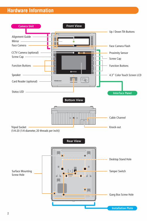
Front View
Bottom View
Rear View
Hardware Information
Mirror
Up / Down Tilt Buttons
Face Camera Flash
Proximity Sensor
4.3” Color Touch Screen LCD
Cable Channel
Knock-out
Function Buttons
Screw Cap
Face Camera
Alignment Guide
Card Reader (optional)
Speaker
Status LED
Tripod Socket(1/4-20 (1/4 diameter, 20 threads per inch))
Surface MountingScrew Hole
Gang Box Screw Hole
Screw Cap
Function Buttons
Tamper Switch
Desktop Stand Hole
Installation Plate
Camera Unit
Interface Panel
CCTV Camera (optional)

3
Hardware Information
Inside
Input / OutputConnections
External GPIO
Relay Output
RS232 / RS485 /RS422 Serial
WiegandOutput / Input
TamperSwitch
Wiring LegendGuide
Installation Plate Screw
RTC Battery
Power LED
Power Connection
Power On/Off Switch
Ethernet Connection /USB 2.0 (Bottom)
Factory Default Button
External Speaker Jack
4
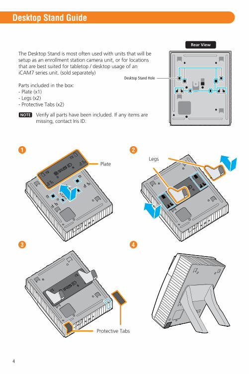
Desktop Stand Guide
Protective Tabs
1 2
3 4
The Desktop Stand is most often used with units that will be setup as an enrollment station camera unit, or for locations that are best suited for tabletop / desktop usage of an iCAM7 series unit. (sold separately)
Parts included in the box:- Plate (x1)- Legs (x2)- Protective Tabs (x2)
Rear View
Desktop Stand Hole
NOTE Verify all parts have been included. If any items are missing, contact Iris ID.
PlateLegs
5
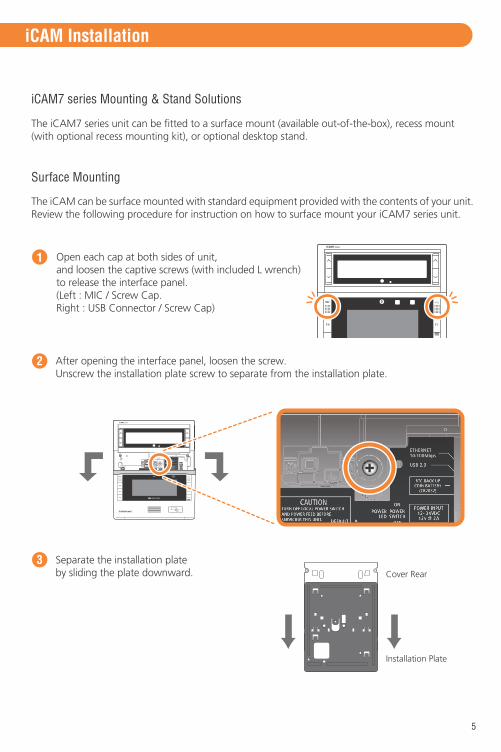
1 Open each cap at both sides of unit, and loosen the captive screws (with included L wrench)to release the interface panel.(Left : MIC / Screw Cap. Right : USB Connector / Screw Cap)
2
iCAM7 series Mounting & Stand Solutions
iCAM Installation
The iCAM7 series unit can be fitted to a surface mount (available out-of-the-box), recess mount (with optional recess mounting kit), or optional desktop stand.
Surface Mounting
After opening the interface panel, loosen the screw.Unscrew the installation plate screw to separate from the installation plate.
Separate the installation plateby sliding the plate downward.
3Cover Rear
Installation Plate
The iCAM can be surface mounted with standard equipment provided with the contents of your unit. Review the following procedure for instruction on how to surface mount your iCAM7 series unit.

6
Slide the iCAM7 series into the installation plate and fasten the installation plate with a screw.
OR
5
Place the installation plate on the desired wall and screw into wall. Feed any needed wiring through the installation plate hole (i.e.: Power, Ethernet, etc).Attach the installation plate to the wall surface using the appropriate fastener (recommended #10 screws) and anchors for the wall material. Another option is to mount and fasten the installation plate to a previously installed electrical gang box.
4
Installation Plate
Surface Mount
Gang Box Mount
Hole Marking
Installation Plate

Turn on power source and switch the power switch of the iCAM7 series unit to the ON position.
8
After wiring the unit and switching it to the ON position, close the interface panel and fasten the screws. (with screw caps placed back into closed position).
9
Remove protective film from RTC battery.6
Before wiring unit, confirm the power is in the off position. Route and connect the Power and Ethernet wires to iCAM7 series.
7
NOTE
OFF
ON
Power on
Power SupplyConnector
EthernetCable
If connecting any other wiring such as Wiegand, GPI/O to the iCAM, review the following section “Wire Connection Details” before closing interface panel and fastening screws.
7
OFF
ON
OFF
ON
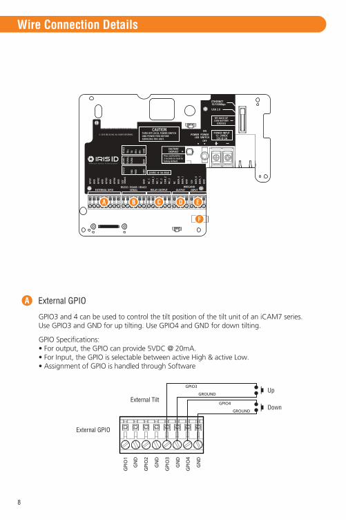
External GPIOA
Wire Connection Details
8
A B C D
F
E
GPIO Specifications:• For output, the GPIO can provide 5VDC @ 20mA.• For Input, the GPIO is selectable between active High & active Low.• Assignment of GPIO is handled through Software
GPIO3 and 4 can be used to control the tilt position of the tilt unit of an iCAM7 series. Use GPIO3 and GND for up tilting. Use GPIO4 and GND for down tilting.
External GPIO
External Tilt
GPI
O1
GN
D
GPI
O2
GN
D
GPI
O3
GN
D
GPI
O4
GN
D
GPIO3
GROUND
GPIO4
GROUND
Up
Down
9
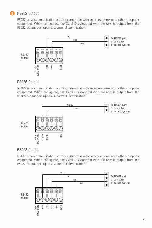
B RS232 Output
RS232Output
To RS232 portof computeror access system
TXD
RXD
GND
RS232 serial communication port for connection with an access panel or to other computerequipment. When configured, the Card ID associated with the user is output from the RS232 output port upon a successful identification.
12V
DC
(Max
0.3
A)
12V
DC
(Max
0.3
A)
12V
DC
(Max
0.3
A)
TXD
RX
D
GN
D
RS485 Output
RS485Output
To RS485 portof computeror access system
TX/RX+
TX/RX-
RS485 serial communication port for connection with an access panel or to other computerequipment. When configured, the Card ID associated with the user is output from the RS485 output port upon a successful identification.
TX/R
X+
TX/R
X-
GN
D
RS422 Output
RS422Output
To RS422portof computeror access system
TX+
TX-
RX+
RX-
RS422 serial communication port for connection with an access panel or to other computerequipment. When configured, the Card ID associated with the user is output from the RS422 output port upon a successful identification.
TX+
TX-
RX
+
RX
-
GN
D

IMPORTANT: ONLY KNOWLEDGEABLE PROFESSIONAL INSTALLERS SHOULD BE USED TO INSTALL ALL ELECTRONIC ENTRY/EXIT LOCKING DEVICES. DIRECT CONNECTION OF ELECTRONIC ENTRY/EXIT LOCKING DEVICES SHOULDN’T BE MADE FROM THE RELAY OUTPUTS ON THE ICAM. IT IS THE RESPONSIBILITY OF THE INSTALLER TO ASSURE THAT THE INSTALLATION IS PERFORMED IN ACCORDANCE WITH ALL COUNTRY/STATE/ LOCAL FIRE AND SAFETY REGULATIONS AND THAT ANY 3RD PARTY PRODUCTS USED WILL NOT CREATE A HAZARD.
10
C Relay Output
Relay Output
Two independent dry contact relays. The purpose and the duration of the relays are defined by the controlling software. Typically, Relay_1 (NC_1, COM_1, NO_1) is triggered upon user acceptance (access granted). The diagram shows Relay_1 connected to indicators which changes from Red to Green for an accepted user. Relay_2 (NC_2, COM_2, NO_2) is typically used to indicate iCAM tamper. In this diagram the relay is activated when the iCAM tamper switch is triggered. The maximum electrical rating for the relay is 3A at 24VDC.
RED
LIGHTPOWERSUPPLY
ALARMSYSTEM24 HOUR
ZONE
GREEN
NC
_1
CO
M_1
NO
_1
NC
_2
CO
M_2
NO
_2
Wiegand Output
Wiegand Specifications: • Wiegand output uses 3 wire interface (Data0, Data1, and Ground), • Maximum wire length from iCAM to Access Control Panel is 500feet (152m).
D
ACCESSCONTROL
PANEL
GROUND
DATA_1
DATA_0
Wiegand Output Card ReaderInterface
The Wiegand Output from the iCAM7 series camera unit can be used with 3rd party devices capable of receiving Wiegand data. This Wiegand output emulates a typical Access Control Card Reader. Configuration of this output is provided through software. See the associated image for general wiring of Wiegand Output to an Access Control Panel.
NC
DA
TA_0
DA
TA_1
GN
D

11
E Wiegand Input
Wiegand Intput
12VDCDATA_0
DATA_1
GROUND
ExternalProx Card
Reader
Wiegand input is available on the iCAM for connection from 3rd party proximity card readers. This connection can provide 12VDC and a maximum 300mA current to a proximity card reader.
12V
DC
(Max
0.3
A)
DA
TA_0
DA
TA_1
GN
D
External Speaker OutF
To amplified speakerLeft signal
Ground
Right signal3.5mm
Allows for connection of an external amplified speaker. This port provides mono or stereo (single channel) audio of voice prompts and other unit sounds. Both the internal and external speakers can operate concurrently.
To amplified speakerMono
Stereo
Signal
Ground
3.5mm

12
iCAM Configuration
The iCAM 7 Series camera contains a configuration interface called the iCAM Configuration. This configuration interface allows the installer to setup the iCAM’s IP Address, IrisServer connection, and other configuration options.
From a PC with an internet browser connected to the network (that the iCAM7 series unit is connected to), type the IP address of the iCAM. For example, if the IP address of an iCAM is 192.168.5.100 (default IP), you would access the configuration web interface by typing http://192.168.5.100 from an internet browser.
To login, the User ID required when prompted is iCAM7000. The Password is iris7000. The system is case sensitive when entering in your login credentials.
Once you have connected to the iCAM Configuration Interface - settings, information, and options become available to further configure your system. Additional documentation for setup and configuration can be found at:
http://www.irisid.com/productdocumentation
How to access the iCAM Configuration interface

13
How to Operate
• Orange turns to green when user is at correct distance.
• Visual indication is amplified with friendly audio prompts.
• Right and left irides are acquired.
• A face picture can also be captured.
• iCAM activates when user approaches or when card is presented.
• Picture capture range is 11~15 inches (28-38cm) away.• Self or auto/set height adjustment.
• Placing dot over the bridge of nose, easily helps alignment.
Green dot = In range Orange dot = Out of range
(28-38cm)
Tilt up +35 DegreesRead distance 14inches
Tilt down -25 DegreesRead distance 14inches away
11~15”
The on-unit up/down tilt buttons can be used to adjustthe tilt angle; or an external mounted switch can be wired to control up/down tilt via GPI.

14
Reset IP Address and Login Credentials • Unit Power is ON• Press and Hold the Factory Default Button for more than 3 seconds.• Unit will beep when the default process has started.• The iCAM IP Address will be reset to 192.168.5.100, The Username to iCAM7000, and the password to iris7000.
Reset all settings and reload software • Power Unit OFF• Press and Hold the Factory Default Button (FDB)• While still holding the FDB, Turn ON the unit power• Keep the FDB held in for at least 10 seconds.• Stop holding the FDB • Do not turn off the power to the unit or remove the network connection for at least 10 minutes (the unit will reboot several times on its own during the software reload process).• When complete the iCAM will have reloaded the software and reset IP Addresses and log-in creditenials to the defaults.
Restoring The Unit to Factory Default
The Factory Default Button can be used to restore the settings of the iCAM 7 Series to factory default. This button is located inside of the unit next to the power switch (see image), and can be used in two different ways:
Factory Default Button
Factory Default Button Function Procedure

15
Memo
Serial Number: Unit IP Address: Installation Date:
Option 3 Iris Server IP:
Option 3 Security ID:
Note:
General Information
Technical Support
Printed in Korea
Additional information and technical assistance is available on the Iris ID Systemssupport web site at www.irisid.com. Click on Support & Service then Technical Support.
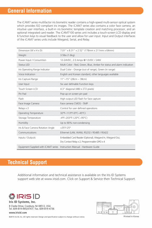
7.01” x 8.31” x 2.52” (178mm x 211mm x 64mm)Dimension (W x H x D)
3.5lbs (1.6kg)Weight
12-24VDC, 2.0 Amps @ 12VDC / 24WPower Input / Consumtion
Multi Color - Red, Green, Blue, Amber for status and alarm indicationStatus LED
Dual Color - Orange (out of range), Green (in range)Iris Operating Range Indicator
English and Korean standard, other languages availableVoice Indication
11”~15” (28cm ~ 38cm)Iris Capture Range
Six user definable Function keysUser Input
4.3” diagonal (480 x 272 pixels)Touch Screen LCD
Pop-up on screen pin padPin Pad
High output LED flash for face captureFlash
Face camera CMOS - 5MPFace Image Camera
32°F~113°F (0°C~45°C)Operating Temperature
-4°F~203°F (-20°C~95°C)Storage Temperature
Up to 90% non-condensingHumidity
Control for user defined operationsRelays x 2
Iris & Face Camera Rotation Angle
Communications
Inputs / Outputs
Equipment Supplied with iCAM7 series
+35°/-25°
Ethernet (LAN, WAN), RS232 / RS485 / RS422
Embedded Card Reader (Optional), Wiegand In, Wiegand Out,
Dry Contact Relay x 2, Programmable GPIO x 4
Instruction Manual - Hardware Guide
The iCAM7 series multifactor iris biometric reader contains a high-speed multi-sensor optical system which provides ISO compliant iris images. The iCAM7 series also contains a color face camera, an intuitive user interface, a built-in iris biometric template creation and matching processor, and an optional integrated card reader. The iCAM7100 series unit includes a touch-screen LCD display and 6 function keys to visual feedback to the user and allow for user input. Input and Output interfaces of the iCAM7 series units include Wiegand, Serial, and Relay.
Iris ID Systems, Inc.
www.irisid.com
8 Clarke Drive, Cranbury, NJ 08512, USATel. 609-819-IRIS(4747) Fax. 609-819-4736
©2015 Iris ID, Inc. All rights reserved. Design and specification subject to change without notice.
Related Documents