Geometrix ™ Articulated Ceiling Planes Metal Ceiling Panels

Welcome message from author
This document is posted to help you gain knowledge. Please leave a comment to let me know what you think about it! Share it to your friends and learn new things together.
Transcript

Geometrix™
Articulated Ceiling
Planes
Metal Ceiling Panels

3-D
An entirely new perspective
on metal ceilings

Form

GEOMETRIX™ Metal Ceiling Panels
enable you to add new
3-dimensional form to:
Retail and hospitality locations
Office lobbies and conference rooms
Health care environments
Entertainment and gaming venues
Education environments
Transportation hubs

1
Geometrix™
System 2 IntroductionInformation 3 System Overview
4 System Components
Design 8 Design ToolsInformation 10 Design Concepts
Architectural 18Specifications
Metal Ceiling Panels
GEOMETRIX™
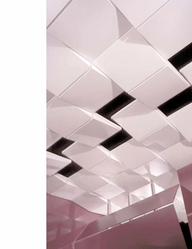
Metal Ceiling PanelsGEOMETRIX™ Metal Ceiling Panels are 3-dimensional, lightweight aluminum panels thatlend unique perspective and unexpected dimension to ceiling space. Offered in a variety ofdesigns and in varying depths, the panels install easily into 9/16� narrow-profile and 15/16�
standard suspension systems.
2
Panels
The 2� x 2� GEOMETRIX Metal Ceiling Panels are
offered in four panel designs and in varying
panel depths. The profiles can be combined
to create 3-D patterns or used randomly for
dimensional variety. The lay-in panels are
available in two standard colors: Flat White and
Silver Satin. Custom colors are available on
request (no minimum required). The panels
are offered in solid metal or in a choice of five
perforated patterns.
Suspension Systems
The lightweight, lay-in panels install into nar-
row-profile and standard suspension systems
and allow full ceiling accessibility.
Perimeter Details
Optional COMPÄSSO™ Edge Trim may be added
for a more finished appearance at exposed
edges. (See IC400 in the USG Specialty Ceilings
binder for more information.)
Lighting and Utility Access
GEOMETRIX Metal Ceiling Panels can be specified
with custom-sized and custom-positioned
pre-engineered utility circles to allow for easy
integration of lighting and utilities.
Acoustical Performance
Perforated GEOMETRIX Metal Ceiling Panels come
standard with USG’s ACOUSTIBOND™ factory-applied
backer for enhanced sound performance.

System OverviewGEOMETRIX
Metal CeilingPanels
3
GEOMETRIX Metal Ceiling Panels are offered in four panel profiles: flat, wedge-shapedand wedge-shaped inside corners and outside corners. The flat panels come in a choice of four depths: 5/16�, 1-1/4�, 2-1/4� and 3-1/4�. The wedge-shaped panelscome in a choice of three depths: 1-1/4�, 2-1/4� and 3-1/4�.
Product Materials Panels:Aluminum. GEOMETRIX panels meet ASTM E84 Class A requirements for Surface Burning Characteristics.Information Suspension system:All DONN® Brand 9/16� CENTRICITEE,™ FINELINE® and 15/16� DX® profiles
Edge trim system: Painted cold rolled steel
Finishes GEOMETRIX panels are available in solid metal or in a choice of five perforated patterns (C375, D250, D375, C062 and C062A).A black ACOUSTIBOND backer is included standard with all perforated panels unless otherwise specified.The ACOUSTIBOND backer is also available in white. (See page 6 for more details.)
Colors Standard colors: Flat White and Silver Satin. Custom colors are available on request.
Size and Weight Panels: 2� x 2�Weight (for 3� deep flat panel): 0.75 lbs./sf.
Assembly View from Above
hanger wire
USG DONN Brand Suspension System 2' cross tee
USG DONN BrandSuspension System4' cross tee USG DONN Brand
Suspension Systemmain tee
COMPÄSSO trim(optional)
GEOMETRIX wedge panel

4
System ComponentsGEOMETRIX
Metal CeilingPanels
Panel Options Shapes GEOMETRIX Metal Ceiling Panels can be used in conjunction with standard acoustical panels, or any other 2� x 2�lay-in panels from USG Interiors, to create an unlimited range of truly one-of-a-kind dimensional treatments.
Use the following selector key to specify panels for your GEOMETRIX ceiling designs.
5/16� GEOMETRIX Flat = GF-0Panel Depth
1-1/4� GEOMETRIX Flat = GF-1 GEOMETRIX Wedge = GW-1Panel Depth
GEOMETRIX Outside Wedge Corner = GOC-1 GEOMETRIX Inside Wedge Corner = GIC-1
2-1/4� GEOMETRIX Flat = GF-2 GEOMETRIX Wedge = GW-2Panel Depth
5/16"
11/4" 11/4"5/16"
21/4" 21/4"5/16"
11/4"5/16"11/4"5/16"

5
Panel Options 2-1/4� GEOMETRIX Outside Wedge Corner = GOC-2 GEOMETRIX Inside Wedge Corner = GIC-2Panel Depth
3-1/4� GEOMETRIX Flat = GF-3 GEOMETRIX Wedge = GW-3Panel Depth
GEOMETRIX Outside Wedge Corner = GOC-3 GEOMETRIX Inside Wedge Corner = GIC-3
31/4" 31/4"5/16"
Colors Flat White and Silver Satin. Custom colors are available on request (no minimum order required).
Integrated Lighting GEOMETRIX Metal Ceiling flat and wedge panels can be specified with custom-sized and custom-positioned and Utilities pre-engineered utility circles for easy integration of lighting and utilities.
Utility Circle in Solid Panel Utility Circle in Perforated Panel
Y
X
hole diameter
side B
side D
side A
side C
Y
X
side B
side D
side A
side Chole diameter
21/4"5/16"21/4"5/16"
31/4"5/16"31/4"5/16"

6
System ComponentsGEOMETRIX
Metal Ceiling Panels
Panel Options Solid or Perforated GEOMETRIX panels are available in solid metal or in a choice of five perforated patterns (shown below at 50% size).
Pattern No. C375 Pattern No. D250 Pattern No. D375Round—3/8� perforations Square—1/4� perforations Square—3/8� perforations1.125� o.c., 9% open area .75� o.c., 11% open area 1.125� o.c., 11% open area
Pattern No. C062 Pattern No. C062ARound—1/16� perforations Round—1/16� perforations.351� o.c., 3% open area .176� o.c., 8% open area
Acoustical Perforated GEOMETRIX Metal Ceiling Panels come standard with a black, factory-applied USG ACOUSTIBONDPerformance backer for enhanced sound performance. The ACOUSTIBOND backer is included on all perforated panels unless
otherwise specified. The ACOUSTIBOND backer is also available in white.
Standard (with black ACOUSTIBOND Backer) Optional (without ACOUSTIBOND Backer)

Suspension The lightweight, durable GEOMETRIX Metal Ceiling Panels install quickly and easily into narrow-profile (9/16�) Systems CENTRICITEE (DXT), FINELINE DXF, FINELINE 1/8 (DXFF) suspension systems, as well as standard (15/16�)
suspension systems.
Edge Details GEOMETRIX Panels with GEOMETRIX Panels with 9/16� GEOMETRIX Panels with 9/16� GEOMETRIX Panels with 9/16�15/16� DONN Brand DX DONN Brand CENTRICITEE (DXT) FINELINE (DXF) Suspension FINELINE (DXFF) SuspensionSuspension Suspension
COMPÄSSO™ Optional edge trim in 2-1/4�, 4�, 6� or 8� heights may be added for a more finished appearance.Edge Trim
DX or DXT Profile DXF or DXFF Profile
Perimeter Non-Wall or “Floating” DX or DXT Profile DXF or DXFF ProfileDetails Condition
Wall DX or DXT Profile DXF or DXFF ProfileCondition
7
GEOMETRIX panel GEOMETRIX panel
DX or DXT tee DX or DXT tee
24" o.c. standard
DXF or DXFF tee
M7 or M9 wall molding
DX or DXT tee DX or DXT tee
24" o.c. standard
GEOMETRIX panel GEOMETRIX panel
DXF or DXFF tee
GEOMETRIX panel GEOMETRIX panel
DX or DXT teeDX or DXT tee
24" o.c. standard
COMPASSO edge trim
DXF or DXFF tee

8
Design Tools
GEOMETRIX Metal Ceiling Panels can be designed using three interactive design tools:the GEOMETRIX Online Designer, GEOMETRIX CAD Blocks or the USG Design Wizard.
GEOMETRIX GEOMETRIX DXF Blocks offer designers a simple, time saving means for creating GEOMETRIX Metal Ceiling PanelCAD Blocks designs in most CAD systems. The DXF blocks, which can be downloaded for free from the Online Tools section
of the USG web site (www.usg.com), are compatible with nearly all CAD systems.
Flat GF-1 GW-2 GW-3 GF-0
Wedge GW-1 GW-2 GW-3
Outside Corner GOC-1 GOC-2 GOC-3
Inside Corner GIC-1 GIC-2 GIC-3
GEOMETRIX This interactive design tool, available in the Online Tools section of the USG web site (www.usg.com), enables Online Designer architects and designers to intuitively define, create and view multiple GEOMETRIX Metal Ceiling Panel designs.
Users simply define the dimensions of a desired ceiling space and then drop-and-drag GEOMETRIX ceiling panelsinto 2� x 2� suspension system modules, which are automatically created within the defined space. Panels canbe removed or reconfigured at will—and it’s all done on the Internet in real time. Selected designs can bedownloaded and seamlessly integrated with AutoCAD and other CAD design software.
O1 2
O 1 O 2 O 3
O 0
0 1
O 0
0 2
O 0
0 3
O 1
1 1
O 2
2 2
O 3
3 3
3
GEOMETRIX
Metal Ceiling Panels

9
GEOMETRIX OnlineDesigner
USG Design The USG Design Wizard is an intuitive, interactive software tool that enables specifiers to quickly generate 3-D Wizard designs featuring GEOMETRIX Metal Ceiling Panels, as well as a wide range of other acoustical and specialty ceiling
systems from USG Interiors. The Design Wizard integrates seamlessly with AutoCAD Release 2000, 2000i, 2002and ADT 3.0 to allow designers to view full-color 3-D designs and create specifications.
The USG Design Wizard can be downloaded for free from the USG web site (www.usg.com). The download is recommended for high-speed connections only. To request the Design Wizard on CD, register online or contactUSG’s Sample and Literature department by calling 888.874-2450 or e-mailing [email protected] USG DesignWizard Help Desk can be contacted by calling 877.919.0546, or by e-mailing [email protected].

Design Concepts
10
Basketweave PerspectivePattern
GEOMETRIX Metal Ceiling Panels can be configured in a wide range of patterns andrandom designs. The illustrations in this section show some basic design concepts. Of course, these are just a few ideas. You’re only limited by your imagination.
GEOMETRIX
Metal Ceiling Panels
Reference Point
Reference Point
Reflected Ceiling PlanUsing GEOMETRIXCAD Blocks

11
Coffered PerspectivePattern
Reference Point
Reference Point
Reflected Ceiling PlanUsing GEOMETRIXCAD Blocks

GEOMETRIX
Metal Ceiling Panels
Design Concepts
12
Sawtooth PerspectivePattern
Reference Point
Reference Point
Reflected Ceiling PlanUsing GEOMETRIXCAD Blocks

Alternating PerspectiveSawtoothPattern
13
Reference Point
Reference Point
Reflected Ceiling PlanUsing GEOMETRIXCAD Blocks

GEOMETRIX
Metal Ceiling Panels
Design Concepts
14
Checkerboard PerspectivePattern
Reference Point
Reference Point
Reflected Ceiling PlanUsing GEOMETRIXCAD Blocks

15
Pinwheel PerspectivePattern
Reference Point
Reference Point
Reflected Ceiling PlanUsing GEOMETRIXCAD Blocks

GEOMETRIX
Metal Ceiling Panels
Design Concepts
16
Undulating PerspectivePattern
Reference Point
Reference Point
Reflected Ceiling PlanUsing GEOMETRIXCAD Blocks

17
Random Perspective
Reference Point
Reference Point
Reflected Ceiling PlanUsing GEOMETRIXCAD Blocks

18
Part 1: 1.1 A. Drawings and general provisions of the Contract, including General and Supplementary Conditions and General Related Documents Division 1 Specification Sections, apply to this Section.
1.2 A. This Section includes aluminum acoustical metal pans and exposed direct-hung suspension systems for ceilings.Summary B. Related Sections include the following:
1. Division 9 – Section 09250 – Gypsum Board2. Division 9 – Section 09511 – Acoustical Panel Ceilings3. Division 15 Sections – Mechanical4. Division 16 Sections – Electrical
C. Products furnished, but not installed under this Section.
1.3 A. AC:Articulation Class.Definitions B. NRC: Noise Reduction Coefficient.
C. Recycled Content: Average percentage based on weight of component materials. Material recovered or divertedfrom the solid waste stream, either during the manufacturing process (pre-consumer) or after consumer use(post-consumer).
1.4 A. Product Data: For each type of product indicated.Submittals B. Coordinate Drawings: Reflected ceiling plans drawn to scale and coordinating penetrations and ceiling-mounted
items. Show the following:1. Ceiling suspension members.2. Method of attaching hangers to building structure.3. Ceiling-mounted items including lighting fixtures, diffusers, grilles, speakers, sprinklers, access panels, and special
moldings.C. Samples for Verification: For each component indicated and for each exposed finish required, prepared on Samples
of size indicated below.1. Metal Pan: Manufacturer standard samples of each type, finish, color, pattern, and texture. Show pan edge profile.2. Exposed Suspension System Members, Moldings, and Trim: Set of 12 inch long Samples of each type, finish, and color.
D. Product Test Reports: Based on evaluation of comprehensive tests performed by a qualified testing agency, for each acoustical panel ceiling and suspension system.
1. UL Acoustical Compliance: For acoustical performance, each carton of material must carry Underwriter’sLaboratory certification for AC (if applicable), CAC and NRC.
2. UL Suspension System Load Compliance: Manufacturer must certify that the metal suspension system is ULClassified to be load compliant per ASTM C635. For load compliance, each carton of main tees must carryUnderwriter’s Laboratory certification for load compliance.
E. Research/Evaluation Reports: For each acoustical panel ceiling and components.F. Maintenance Data: For finishes to include in maintenance manuals.
1.5 A. Source Limitations for Acoustical Metal Pan Ceilings: Obtain each set of acoustical metal pans and exposed Quality Assurance suspension systems from one source with resources to provide products of consistent quality in appearance,
physical properties, and performance.B. Fire-Test-Response Characteristics: Provide acoustical metal pan ceilings with surface-burning characteristics
complying with ASTM E 1264 for Class A materials as determined by testing identical products per ASTM E 84 by UL or another testing and inspecting agency acceptable to authorities having jurisdiction.
C. Seismic Standard: Provide acoustical metal pan ceilings designed and installed to withstand the effects of earth-quake motions according to the following:
1. Standard for Ceiling Suspension Systems Requiring Seismic Restraint: Comply with ASTM E 580.2. CISCA’s Recommendations for Acoustical Ceilings: Comply with CISCA’s “Recommendations for Direct-Hung
Acoustical Tile and Lay-in Panel Ceilings—Seismic Zones 0-2.”
GEOMETRIX
Metal Ceiling Panels
Architectural SpecificationsSection 09514—Acoustical Metal Pan Ceilings

3. CISCA’s Guidelines for Systems Requiring Seismic Restraint: Comply with CISCA’s “Guidelines for Seismic Restraintof Direct-Hung Suspended Ceiling Assemblies—Seismic Zones 3 & 4.”
4. UBC Standard 25-2, “Metal Suspension Systems for Acoustical Tile and for Lay-in Panel Ceilings.”D. Pre-installation Conference: Conduct conference at Project site to comply with requirements in Division 1 Section
“Project Management and Coordination.”
1.6 A. Deliver acoustical metal pans, suspension system components, and accessories to Project site in original,Delivery, Storage, unopened packages and store them in a fully enclosed, conditioned space where they will be protected againstand Handling
damage from moisture, humidity, temperature extremes, direct sunlight, surface contamination, and other causes.
1.7 A. Environmental Limitations: Do not install acoustical metal pan ceilings until spaces are enclosed and weather-Project Conditions proof, wet work in spaces is complete and dry, work above ceilings is complete, and ambient temperature and
humidity conditions are maintained at the levels indicated for Project when occupied for its intended use.1. Pressurized Plenums: Operate ventilation system for not less than 48 hours before beginning acoustical panel
ceiling installation.
1.8 A. Coordinate layout and installation of acoustical metal pans and suspension system with other construction thatCoordination penetrates ceilings or is supported by them, including light fixtures, HVAC equipment, fire-suppression system,
and partition assemblies.
1.9 A. Furnish extra materials described below that match products installed and that are packaged with protective Extra Materials covering for storage and identified with labels describing contents.
1. Acoustical Metal Pans: Full-size units equal to 2.0 percent of quantity installed.2. Suspension System Components: Quantity of each exposed component equal to 2.0 percent of quantity installed.3. Hold-Down Clips: Equal to 2.0 percent of amount installed.
Part 2: 2.1 A. In other Part 2 articles where titles below introduce lists, the following requirements apply for product selection:Products Manufacturers 1. Products: Subject to compliance with requirements, provide one of the products specified.
2. Manufacturers: Subject to compliance with requirements, provide products by the manufacturers specified.
2.2 A. Acoustical Metal Pan Standard: Provide manufacturer’s standard acoustical metal pans of configuration Acoustical Metal indicated that comply with ASTM E 1264 classifications as designated by types, acoustical ratings, and light Ceiling Pans
reflectance, unless otherwise indicated.1. Mounting Method for Measuring NRC:Type E-400; plenum mounting in which face of test specimen is
15-3/4 inches away from test surface per ASTM E 795.B. Sheet Metal Characteristics: For metal fabrications exposed to view in the completed Work, provide materials with
smooth, flat surfaces without blemishes. Do not use materials with exposed pitting, seam marks, roller marks,roughness, stains, or discolorations.
1. Aluminum Sheet: Roll-formed aluminum sheet, complying with ASTM B 209; alloy and temper recommended byaluminum producer and finisher for type of use and finish indicated.
C. Pan Fabrication: Manufacturer’s standard units of size, profile, and edge treatment indicated, formed from metalindicated and finished to comply with requirements indicated.
1. Lay-in Pans: Formed to set in exposed suspension grid.(Delete the following paragraph if non-perforated panels are used or sound-absorbing layer is not required.)
D. Sound-Absorbent Fabric Layer: Provide fabric layer, sized to fit concealed surface of pan, and consisting of [black],[white], nonwoven, nonflammable, sound-absorbent material with surface-burning characteristics for flame-spread index of 25 or less and smoke-developed index of 50 or less, as determined by testing per ASTM E 84.
1. Bond fabric layer to panels in the factory with manufacturer’s standard nonflammable adhesive.
19

2.3 A. Products:Aluminum Metal USG Interiors, Inc., [GEOMETRIX].Pans for Acoustical
B. Classification: Units complying with ASTM E 1264 for [Type VII, perforated aluminum facing (pan) with mineral-Metal Pan Ceilingor glass-fiber-base backing] [Type XX, other types described as perforated aluminum facing (pan) units] AMPC-[#][Type XX, other types described as nonperforated aluminum facing (pan) units] <Insert Type XX description>.
1. Pattern: [Perforation Pattern C375], [Perforation Pattern D250], [Perforation Pattern D375], [Perforation Pattern C062],[Perforation Pattern C062A].
C. Pan Type: Lay-in pan.D. Pan Thickness: Not less than 0.020� minimum.E. Pan Edge Detail: [5/16� Reveal] [1-1/4� Reveal] [2-1/4� Reveal] [3-1/4� Reveal].F. Pan Profile Detail: [Flat] [Wedge] [Inside Wedge Corner] [Outside Wedge Corner].G. Pan Size: 24 by 24 inches.H. Pan Face Finish: Painted to match color indicated by product designation.I. Recycled Content: Not less than 90%.
2.4 A. Metal Suspension System Standard: Provide manufacturer’s standard direct-hung metal suspension systemsMetal Suspension of types, structural classifications, and finishes indicated that comply with applicable requirements in ASTM C 635.Systems
B. Finishes and Colors, General: Comply with NAAMM’s “Metal Finishes Manual for Architectural and Metal Products”for recommendations for applying and designating finishes. Provide manufacturer’s standard factory-applied finishfor type of system indicated.
C. Attachment Devices: Size for five times the design load indicated in ASTM C 635,Table 1, “Direct Hung,” unlessotherwise indicated.
1. Anchors in Concrete:Anchors of type and material indicated below, with holes or loops for attaching hangers of type indicated and with capability to sustain, without failure, a load equal to five times that imposed by ceilingconstruction, as determined by testing per ASTM E 488 or ASTM E 1512 as applicable, conducted by a qualifiedtesting and inspecting agency.a. Type: Postinstalled expansion anchors.b. Type: Postinstalled adhesive anchors.c. Corrosion Protection: Carbon-steel components zinc plated to comply with ASTM B 633, Class Fe/Zn 5 (0.005 mm)
for Class SC 1 service condition.d. Corrosion Protection: Stainless-steel components complying with ASTM F 593 and ASTM F 594, Group 1
alloy 304 or 316 for bolts; alloy 304 or 316 for anchor.e. Corrosion Protection: Components fabricated from nickel-copper-alloy rods complying with ASTM B 164 for
UNS No. N04400 alloy.2. Power-Actuated Fasteners in Concrete: Fastener system of type suitable for application indicated, fabricated
from corrosion-resistant materials, with clips or other accessory devices for attaching hangers of type indicated,and with capability to sustain, without failure, a load equal to 10 times that imposed by ceiling construction, asdetermined by testing per ASTM E 1190, conducted by a qualified testing and inspecting agency.
D. Wire Hangers, Braces, and Ties: Provide wires complying with the following requirements:1. Zinc-Coated Carbon-Steel Wire:ASTM A 641/A 641M, Class 1 zinc coating, soft temper.2. Nickel-Copper-Alloy Wire:ASTM B 164, nickel-copper-alloy UNS No. N04400.3. Size: Select wire diameter so its stress at three times hanger design load (ASTM C 635,Table 1, “Direct Hung”)
will be less than yield stress of wire, but provide not less than [0.106-inch] [0.135-inch] diameter wire.E. [Hanger Rods] [Flat Hangers]: Mild steel, zinc coated or protected with rust-inhibitive paint.
GEOMETRIX
Metal Ceiling Panels
Architectural Specifications
20

F. Angle Hangers:Angles with legs not less than 7/8 inch wide; formed with 0.04-inch thick, galvanized steel sheetcomplying with ASTM A 653/A 653M, G90 coating designation; with bolted connections and 5/16-inch diameter bolts.
G. Seismic Struts: Manufacturer’s standard compression struts designed to accommodate seismic forces.H. Seismic Clips: Manufacturer’s standard seismic clips designed and spaced to secure acoustical panels in-place.I. Hold-Down Clips:Where indicated, provide manufacturer’s standard hold-down clips spaced 24 inches o.c.
on all cross tees.J. Exposed Metal Edge Moldings and Trim: Provide exposed members as indicated or required [to comply with
seismic requirements of authorities having jurisdiction,] to conceal edges of and penetrations through ceiling, toconceal edges of pans and runners, for fixture trim and adapters, for fascia at changes in ceiling height, and forother conditions; of metal and finish matching acoustical metal pan ceiling units, unless otherwise indicated.
1. For Circular Penetrations of Ceiling: Fabricate edge moldings to diameter required to fit penetration exactly.
2.5 A. Products:Metal Suspension 1. USG Interiors, Inc., DONN [DX] [DXT] [DXF] [DXFF] suspension system.System for
B. Wide-Face, Capped, Double-Web, Steel Suspension System: Main and cross runners roll formed from cold-rolled Acoustical steel sheet, prepainted, electrolytically zinc coated, or hot-dip galvanized according to ASTM A 653/A 653M, not Metal Pan Ceiling
less than G30 coating designation, with prefinished 15/16-inch wide metal caps on flanges.1. Structural Classification: [Intermediate] [Heavy]-duty system.2. End Condition of Cross Runners: Override (stepped) type.3. Face Design: Flat, flush.4. Cap Material: [Steel] [Aluminum] cold-rolled sheet.5. Cap Finish: [Painted white] [Painted in color as selected from manufacturer’s full range] [Painted to match color of
acoustical unit] [Plated with metallic finish, as selected from manufacturer’s full range].C. Narrow-Face, Capped, Double-Web, Steel Suspension System: Main and cross runners roll formed from cold-rolled
steel sheet, prepainted, electrolytically zinc coated, or hot-dip galvanized according to ASTM A 653/653M, not lessthan G30 coating designation, with prefinished 9/16-inch wide metal caps on flanges.
1. Structural Classification: [Intermediate] [Heavy]-duty system.2. End Condition of Cross Runners: Override (stepped) type.3. Face Design: Flat, flush.4. Cap Material: [Steel] cold-rolled sheet.5. Cap Finish: [Painted white] [Painted in color as selected from manufacturer’s full range] [Painted to match color
of acoustical unit] [Plated with metallic finish, as selected from manufacturer’s full range].D. Narrow-Face, Uncapped, Double-Web, Steel Suspension System: Main and cross runners roll formed from cold-
rolled steel sheet, prepainted, electrolytically zinc coated, or hot-dip galvanized, to produce structural memberswith 9/16-inch wide faces.
1. Structural Classification: [Intermediate] [Heavy]-duty system.2. Face Design: [With 1/8-inch wide, slotted, box-shaped flange] [With 1/4-inch wide, slotted, box-shaped flange].3. Face Finish: Painted [white] [in color as selected from manufacturer’s full range] [to match color indicated by
manufacturer’s designation] [to match color of acoustical unit].4. Reveal Finish: Painted [white] [black].
21

2.6 A. Manufacturers:Metal Edge 1. USG Interiors, Inc.Moldings and Trim
B. Roll-Formed Sheet-Metal Edge Moldings and Trim:Type and profile indicated or, if not indicated, manufacturer’sstandard moldings for edges and penetrations that fit acoustical panel edge details and suspension systems indi-cated; formed from sheet metal of same material, finish, and color as that used for exposed flanges of suspensionsystem runners.
1. For lay-in panels with reveal edge details, provide stepped edge molding that forms reveal of same depth and width as that formed between edge of panel and flange at exposed suspension member.
2. For circular penetrations of ceiling, provide edge moldings fabricated to diameter required to fit penetration exactly.3. For narrow-face suspension systems, provide suspension system and manufacturer’s standard edge moldings
that match width and configuration of exposed runners.C. COMPÄSSO Suspension System Trim:
1. COMPÄSSO Trim: [2-1/4 inch] [4 inch] [6 inch] [8 inch] wide face, 9/16 inch horizontal legs with hems formed for attachment to the COMPÄSSO mounting clip; commercial quality cold-rolled 24-gauge steel, factory finished in[baked polyester enamel paint finish], [color], painted [on exposed face] [all around – 360°].
2. Splice plate: Steel in finish to match trim pans; formed for snap-fit into [2-1/4 inch] [4 inch] [6 inch] [8 inch] pan ends.3. Attachment clips: Hot-dipped steel in [galvanized finish] [finish to match pans] formed for snap-fit into [2-1/4 inch]
[4 inch] [6 inch] [8 inch] pan attached to DONN [DX] [DXT] [DXF] [DXFF] suspension system members.4. 90° Corner Trim Pieces: To match COMPÄSSO trim.
2.7 A. Products:Acoustical 1. Acoustical Sealant for Exposed and Concealed Joints:Sealant
a. United States Gypsum Co.; SHEETROCK Acoustical Sealant.2. Acoustical Sealant for Concealed Joints:
a. Tremco, Inc.; Tremco Acoustical Sealant.B. Acoustical Sealant for Exposed and Concealed Joints: Manufacturer’s standard nonsag, paintable, nonstaining
latex sealant complying with ASTM C 834 and effective in reducing airborne sound transmission through perimeterjoints and openings in building construction as demonstrated by testing representative assemblies according toASTM E 90.
C. Acoustical Sealant for Concealed Joints: Manufacturer’s standard nondrying, nonhardening, nonskinning, non-staining, gunnable, synthetic-rubber sealant recommended for sealing interior concealed joints to reduce airbornesound transmission.
2.8 A. Comply with NAAMM’s “Metal Finishes Manual for Architectural and Metal Products” for recommendationsFinishes, for applying and designating finishes.General
B. Appearance of Finished Work: Variations in appearance of abutting or adjacent pieces are acceptable if they arewithin one-half of the range of approved Samples. Noticeable variations in the same piece are not acceptable.Variations in appearance of other components are acceptable if they are within the range of approved Samples and are assembled or installed to minimize contrast.
2.9 A. Finish designations prefixed by AA comply with the system established by the Aluminum Association for Aluminum designating aluminum finishes.Finishes
B. Color-Coated Finish: Manufacturer’s standard baked paint complying with coating manufacturer’s written instructionsfor surface preparation, pretreatment, application, baking, and minimum dry film thickness.
GEOMETRIX
Metal Ceiling Panels
Architectural Specifications
22

Part 3: 3.1 A. Examine substrates, areas, and conditions, including structural framing to which acoustical panel ceilings attachExecution Examination or abut, with Installer present, for compliance with requirements specified in this and other Sections that affect
ceiling installation and anchorage and with requirements for installation tolerances and other conditions affectingperformance of acoustical panel ceilings.
B. Proceed with installation only after unsatisfactory conditions have been corrected.
3.2 A. Measure each ceiling area and establish layout of acoustical panels to balance border widths at opposite Preparation edges of each ceiling.Avoid using less-than-half-width panels at borders, and comply with layout shown on
reflected ceiling plans.
3.3 A. General: Install acoustical panel ceilings to comply with ASTM C 636 and seismic requirements indicated, perInstallation, manufacturer’s written instructions and CISCA’s “Ceiling Systems Handbook.”General
B. Suspend ceiling hangers from building’s structural members and as follows:1. Install hangers plumb and free from contact with insulation or other objects within ceiling plenum that are not part
of supporting structure or of ceiling suspension system.2. Splay hangers only where required to miss obstructions; offset resulting horizontal forces by bracing, countersplaying,
or other equally effective means.3. Splay hangers only where required and, if permitted with fire-resistance-rated ceilings, to miss obstructions; offset
resulting horizontal forces by bracing, countersplaying, or other equally effective means.4. Where width of ducts and other construction within ceiling plenum produces hanger spacings that interfere with
location of hangers at spacings required to support standard suspension system members, install supplemental suspension members and hangers in form of trapezes or equivalent devices. Size supplemental suspension members and hangers to support ceiling loads within performance limits established by referencedstandards and publications.
5. Secure wire hangers to ceiling suspension members and to supports above with a minimum of three tight turns.Connect hangers directly either to structures or to inserts, eye screws, or other devices that are secure and appro-priate for substrate and that will not deteriorate or otherwise fail due to age, corrosion, or elevated temperatures.
6. Secure flat, angle, channel, and rod hangers to structure, including intermediate framing members, by attaching to inserts, eye screws, or other devices that are secure and appropriate for both structure to which hangers areattached and type of hanger involved. Install hangers in a manner that will not cause them to deteriorate or fail dueto age, corrosion, or elevated temperatures.
7. Do not support ceilings directly from permanent metal forms or floor deck. Fasten hangers to cast-in-place hangerinserts, postinstalled mechanical or adhesive anchors, or power-actuated fasteners that extend through forms intoconcrete.
8. Do not attach hangers to steel deck tabs.9. Do not attach hangers to steel roof deck.Attach hangers to structural members.
10. Space hangers not more than 48 inches o.c. along each member supported directly from hangers, unless otherwise indicated; provide hangers not more than 8 inches from ends of each member.
C. Secure bracing wires to ceiling suspension members and to supports with a minimum of four tight turns. Suspendbracing from building’s structural members as required for hangers, without attaching to permanent metal forms,steel deck, or steel deck tabs. Fasten bracing wires into concrete with cast-in-place or postinstalled anchors.
23

D. Install edge moldings and trim of type indicated at perimeter of acoustical ceiling area and where necessary to conceal edges of acoustical panels.
1. Apply acoustical sealant in a continuous ribbon concealed on back of vertical legs of moldings before they areinstalled.
2. Screw attach moldings to substrate at intervals not more than 16 inches o.c. and not more than 3 inches fromends, leveling with ceiling suspension system to a tolerance of 1/8 inch in 12 feet Miter corners accurately andconnect securely.
3. Do not use exposed fasteners, including pop rivets, on moldings and trim.E. Install suspension system runners so they are square and securely interlocked with one another. Remove and
replace dented, bent, or kinked members.F. Cut acoustical metal pan units for accurate fit at borders and at interruptions and penetrations by other work
through ceilings. Stiffen edges of cut units as required to eliminate evidence of buckling or variations in flatnessexceeding referenced standards for stretcher-leveled metal sheet.
G. Install acoustical metal pans in coordination with suspension system and exposed moldings and trim.1. For lay-in reveal-edge pans on suspension system runners, install pans with bottom of reveal in firm contact with
top surface of runner flanges.2. For lay-in reveal-edge pans on suspension system members with box-shaped flanges, install pans with reveal
surfaces in firm contact with suspension system surfaces and panel faces flush with bottom face of runners.3. Align joints in adjacent courses to form uniform, straight joints parallel to room axis in both directions, unless
otherwise indicated.4. Install directionally patterned or textured metal pans in directions indicated.5. Install sound-absorbent fabric layers in perforated metal pans.
3.4 A. Clean exposed surfaces of acoustical metal pan ceilings, including trim and edge moldings after removing Cleaning strippable, temporary protective covering, if any. Comply with manufacturer’s written instructions for stripping
of temporary protective covering, cleaning, and touchup of minor finish damage. Remove and replace ceiling components that cannot be successfully cleaned and repaired to permanently eliminate evidence of damage,including dented and bent units.
24
GEOMETRIX
Metal Ceiling Panels
Architectural Specifications


Manufactured by USG Interiors, Inc.125 South Franklin StreetChicago, IL 60606
IC437/5-02 © 2002, USG Interiors, Inc.Printed in U.S.A.
Technical Service
800 USG.4YOU
Web Site
www.usg.comSamples/Literature
888 874.2450
Samples/Literature E-mail
[email protected]/Literature/Fax
888 874.2348
Customer Service
800 950.3839
NoteAll products described heremay not be available in all geographic markets. Consultyour local sales office or representative for information.TrademarksThe following trademarks usedherein are owned by USGInteriors, Inc.: CENTRICITEE, DONN,DX, FINELINE, GEOMETRIX, USG.PatentsPatents pending
NoticeWe shall not be liable for incidental and consequential damages, directly or indirectlysustained, nor for any losscaused by application of thesegoods not in accordance withcurrent printed instructions orfor other than the intendeduse. Our liability is expresslylimited to replacement ofdefective goods. Any claimshall be deemed waived unlessmade in writing to us withinthirty (30) days from date itwas or reasonably should havebeen discovered.
Safety First!Follow good safety and industrialhygiene practices duringhandling and installing of allproducts and systems. Takenecessary precautions andwear the appropriate personalprotective equipment asneeded. Read material safetydata sheets and relatedliterature on products beforespecification and/or installation.
Related Documents