preliminary preliminary iC-HG EVAL HG21M HIGH-SPEED MODULE FOR SMD VCSEL ARRAYS Rev A1, Page 1/3 ORDERING INFORMATION Type Package Options Order Designation iC-HG HG21M (DIL28) - iC-HG iCSY HG21M Figure 1: HG21M Package (DIL28) PIN CONFIGURATION Figure 2: Top view / Dimensions in mm No Name Function 1 GND Ground, Analog Ground 2 GND Ground, Analog Ground 3 GND Ground, Analog Ground 4 GND Ground, Analog Ground 5 nc not connected 6 nc not connected 7 nc not connected 8 nc not connected 9 nc not connected 10 nc not connected 11 nc not connected 12 nc not connected 13 RCI36 Current Control Voltage 36 14 POTVDD Potentiometer 12 36 VDD No Name Function 15 POTVDD Potentiometer 12 36 VDD 16 RCI12 Current Control Voltage 12 17 POTGND Potentiometer 12 36 GND 18 POTGND Potentiometer 12 36 GND 19 EN46 Input Channel 4 + 6 20 EN35 Input Channel 3 + 5 21 EN2 Input Channel 2 22 EN1 Input Channel 1 23 ELVDS TTL/LVDS Input Selector 24 NER Error Monitor Output 25 VDD Supply Voltage 26 LDA Anode Laser Diode 27 LDA Anode Laser Diode 28 LDA Anode Laser Diode Copyright © 2015 iC-Haus http://www.ichaus.com

Welcome message from author
This document is posted to help you gain knowledge. Please leave a comment to let me know what you think about it! Share it to your friends and learn new things together.
Transcript

preliminary preliminary iC-HG EVAL HG21MHIGH-SPEED MODULE FOR SMD VCSEL ARRAYS
Rev A1, Page 1/3
ORDERING INFORMATION
Type Package Options Order Designation
iC-HG HG21M
(DIL28)
- iC-HG iCSY HG21M
Figure 1: HG21M Package (DIL28)
PIN CONFIGURATION
Figure 2: Top view / Dimensions in mm
No Name Function
1 GND Ground, Analog Ground
2 GND Ground, Analog Ground
3 GND Ground, Analog Ground
4 GND Ground, Analog Ground
5 nc not connected
6 nc not connected
7 nc not connected
8 nc not connected
9 nc not connected
10 nc not connected
11 nc not connected
12 nc not connected
13 RCI36 Current Control Voltage 36
14 POTVDD Potentiometer 12 36 VDD
No Name Function
15 POTVDD Potentiometer 12 36 VDD
16 RCI12 Current Control Voltage 12
17 POTGND Potentiometer 12 36 GND
18 POTGND Potentiometer 12 36 GND
19 EN46 Input Channel 4 + 6
20 EN35 Input Channel 3 + 5
21 EN2 Input Channel 2
22 EN1 Input Channel 1
23 ELVDS TTL/LVDS Input Selector
24 NER Error Monitor Output
25 VDD Supply Voltage
26 LDA Anode Laser Diode
27 LDA Anode Laser Diode
28 LDA Anode Laser Diode
Copyright © 2015 iC-Haus http://www.ichaus.com

preliminary preliminary iC-HG EVAL HG21MHIGH-SPEED MODULE FOR SMD VCSEL ARRAYS
Rev A1, Page 2/3
SMD POSITIONS
Figure 3: SMD Positions
NOTE: Module must be baked (min. 24 h at 100 °C)
before exposing to high temperature processes (e.g.
reflow soldering) to avoid delamination, PCB/VIA dam-
ages, and popcorning.
The PCB has a very low thermal resistance that makes
manual soldering of SMT devices difficult.
Figure 4: Details of the VCSEL pad
ABSOLUTE MAXIMUM RATINGS
Item Symbol Parameter Conditions Unit
No. Min. Typ. Max.
TG1 Ta Operating Ambient Temperature Range -20 85 °C
TG2 Ts Storage Temperature Range -20 85 °C
preliminary preliminary iC-HG EVAL HG21MHIGH-SPEED MODULE FOR SMD VCSEL ARRAYS
Rev A1, Page 3/3
SCHEMATICS
J19
1kΩ
RPOT3612
X
X
Components marked with 'X'are not assembled
X
2
J16
J111
J110
22
J128
CVDD11μF
1
2
J1
1
2100nFCVDD21
2
J1
2
100ΩREN36
1
2
100nF
CLAS7_8
1
2
J15
RPOT12
1kΩ1
LDK3 23
13LDK4
LDK5 11
9LDK6
22NER
EPADSUB
18VDD
CLAS1_6
100nF
7 CI6
19 ELVDS
21 EN1
20 EN2
EN317
EN416
EN515
EN614
GND4
27LDK1
LDK2 25
28
26AGND2
24AGND3
AGND4 12
10AGND5
AGND6 8
CI11
CI22
3 CI3
5 CI4
6 CI5
18
J119
J120
iC-HGU1
AGND1
RSHRT30Ω
1
2
J117
J1
21
J112
0ΩRSHRT2
1
2
XD1
A
C
J115
J1
1
2
J18
J17
J113
RSHRT1
0Ω12
REN12100Ω
27
J114
1kΩPOT36 C
L
R
J124
J125
J126
J1
2100ΩRCI36
1
2
J123
RJ116
RCI12100Ω
1
J13
J14
POT121kΩ
CL
RCVPOT4.7μF
1
2
J11
J1
/TTLLVDS
MONITORPWR & TEMP
&
&
&
&
&
&
U1iC-HG
100nF
CLAS1_6
J1
1kΩ
RPOT12
REN36100Ω
CLAS7_8
100nFCVDD2100nF
J1
J1
1μFCVDD1
J1
J1
J1
J1
J1
RPOT36
1kΩ4.7μF
RCVPOT
J1
J1
J1
1kΩPOT12
J1
100ΩRCI12 RCI36
100Ω
J1
J1
J1
J1
J1
J1
POT361kΩ
J1
0Ω
RSHRT1
100ΩREN12
J1
J1
D1X
J1
J1
J1
RSHRT20Ω
0ΩRSHRT3
J1
J1
J1
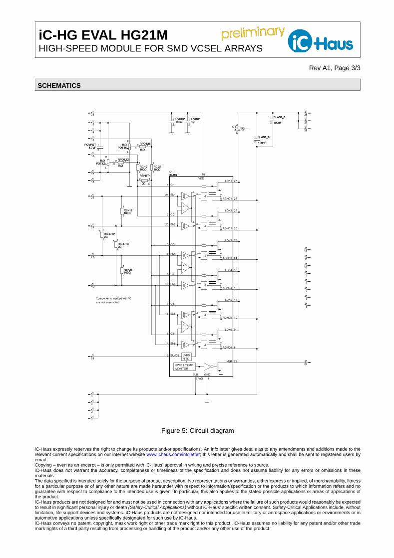
Figure 5: Circuit diagram
iC-Haus expressly reserves the right to change its products and/or specifications. An info letter gives details as to any amendments and additions made to therelevant current specifications on our internet website www.ichaus.com/infoletter; this letter is generated automatically and shall be sent to registered users byemail.Copying – even as an excerpt – is only permitted with iC-Haus’ approval in writing and precise reference to source.iC-Haus does not warrant the accuracy, completeness or timeliness of the specification and does not assume liability for any errors or omissions in thesematerials.The data specified is intended solely for the purpose of product description. No representations or warranties, either express or implied, of merchantability, fitnessfor a particular purpose or of any other nature are made hereunder with respect to information/specification or the products to which information refers and noguarantee with respect to compliance to the intended use is given. In particular, this also applies to the stated possible applications or areas of applications ofthe product.iC-Haus products are not designed for and must not be used in connection with any applications where the failure of such products would reasonably be expectedto result in significant personal injury or death (Safety-Critical Applications) without iC-Haus’ specific written consent. Safety-Critical Applications include, withoutlimitation, life support devices and systems. iC-Haus products are not designed nor intended for use in military or aerospace applications or environments or inautomotive applications unless specifically designated for such use by iC-Haus.iC-Haus conveys no patent, copyright, mask work right or other trade mark right to this product. iC-Haus assumes no liability for any patent and/or other trademark rights of a third party resulting from processing or handling of the product and/or any other use of the product.
Related Documents