1 2006/4/12 1 Chapter 7 Plasma Basics 2006/4/12 2 Objectives • List at least three IC processes using plasma • Name three impor tant collisions in plasma • Descr ibe mean free path • Explain how plasma enhance etch and CVD processes • Name two high density plasma sources

Welcome message from author
This document is posted to help you gain knowledge. Please leave a comment to let me know what you think about it! Share it to your friends and learn new things together.
Transcript

8/6/2019 IC Ch07-Plasma Basics
http://slidepdf.com/reader/full/ic-ch07-plasma-basics 1/45
1
2006/4/12 1
Chapter 7
Plasma Basics
2006/4/12 2
Objectives
• List at least three IC processes using plasma
• Name three important collisions in plasma
• Describe mean free path
• Explain how plasma enhance etch and CVD
processes
• Name two high density plasma sources

8/6/2019 IC Ch07-Plasma Basics
http://slidepdf.com/reader/full/ic-ch07-plasma-basics 2/45
2
2006/4/12 3
Topics of Discussion
• What is plasma?
• Why use plasma?
• Ion bombardment
• Application of plasma process
2006/4/12 4
Applications of Plasma
• CVD
•
Etch• PVD
• Ion Implantation
• Photoresist strip
• Process chamber dry clean
8/6/2019 IC Ch07-Plasma Basics
http://slidepdf.com/reader/full/ic-ch07-plasma-basics 3/45
3
2006/4/12 5
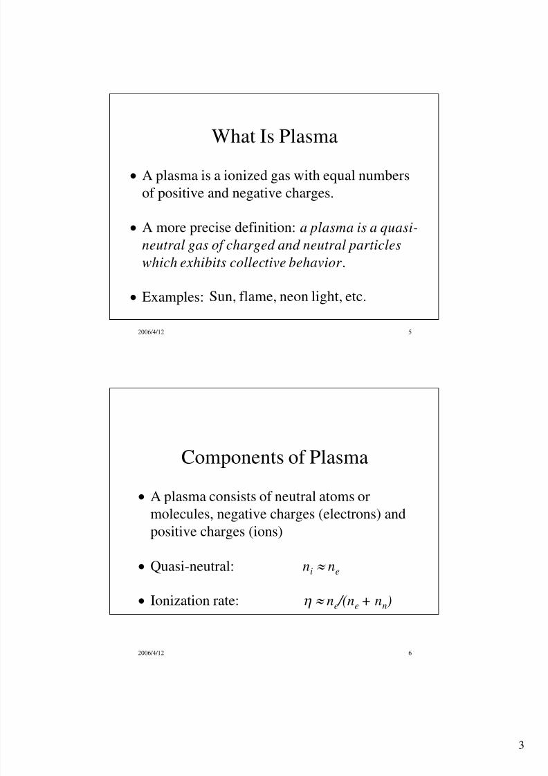
What Is Plasma
A plasma is a ionized gas with equal numbers
of positive and negative charges.
A more precise definition: a plasma is a quasi-
neutral gas of charged and neutral particles
which exhibits collective behavior .
Examples: Sun, flame, neon light, etc.
2006/4/12 6
Components of Plasma
A plasma consists of neutral atoms or
molecules, negative charges (electrons) and
positive charges (ions)
Quasi-neutral: ni ne
Ionization rate: ne /(ne + nn)

8/6/2019 IC Ch07-Plasma Basics
http://slidepdf.com/reader/full/ic-ch07-plasma-basics 4/45

8/6/2019 IC Ch07-Plasma Basics
http://slidepdf.com/reader/full/ic-ch07-plasma-basics 5/45
5
2006/4/12 9
Parallel Plate Plasma System
Plasma
RF power
Dark spaces orsheathlayers
Electrodes
To Vacuum Pump
2006/4/12 10
Generation of a Plasma
• External power is needed
• Radio frequency (RF) power is the mostcommonly used power source with which avarying electric field is established
• Electrons and ions are continually generated andlost by collisions and recombination
• A plasma is stabilized when generation rate of electrons is equal to loss rate of electrons
• Vacuum system is required to generate a stable RFplasma

8/6/2019 IC Ch07-Plasma Basics
http://slidepdf.com/reader/full/ic-ch07-plasma-basics 6/45
6
2006/4/12 11
Ionization Process
e + A A+ + 2 e
Ionization collisions generate electrons and ions
It sustains a stable plasma
• Electron collides with neutral atom or molecule
• Knock out one of orbital electron
2006/4/12 12
Illustration of Ionization
Free
Electron
Free
Electrons
Orbital
Electron
Nucleus Nucleus

8/6/2019 IC Ch07-Plasma Basics
http://slidepdf.com/reader/full/ic-ch07-plasma-basics 7/45
7
2006/4/12 13
Excitation and Relaxation
e + A A* + e where A* is excited state
A* A + h (Photons) light emission
Different atoms or molecules have difference
frequencies, that is why different gases have
different glow colors.
The change of the glow colors is used for etch
and chamber clean process endpoint.
2006/4/12 14
Excitation Collision
Impact
electron
Grounded
electron
Excited
electron
NucleusNucleus
Impact
electron

8/6/2019 IC Ch07-Plasma Basics
http://slidepdf.com/reader/full/ic-ch07-plasma-basics 8/45
8
2006/4/12 15
Relaxation
Ground State
h
h
h: Planck Constant
: Frequency of Light
Excited State
2006/4/12 16
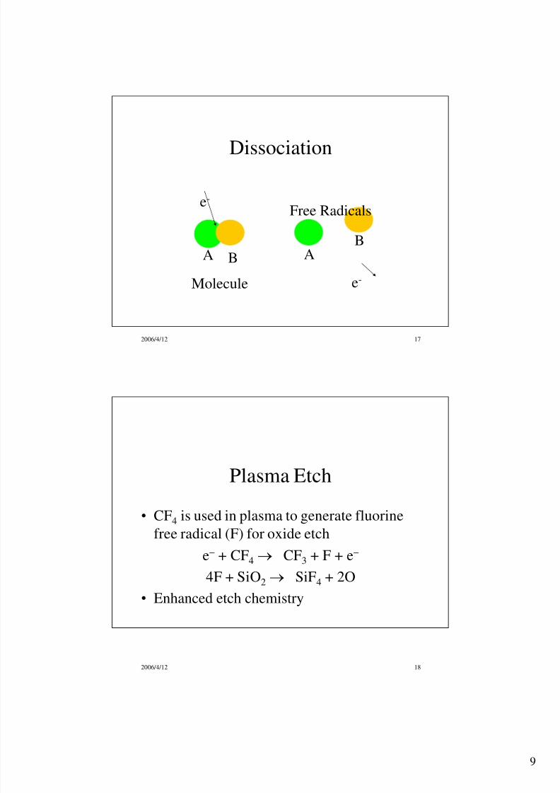
Dissociation
• Electron collides with a molecule, it can
break the chemical bond and generate free
radicals:
e + AB A + B + e
• Free radicals have at least one unpaired
electron and are very chemically reactive.
• Increasing chemical reaction rate
• Very important for both etch and CVD.
8/6/2019 IC Ch07-Plasma Basics
http://slidepdf.com/reader/full/ic-ch07-plasma-basics 9/45
9
2006/4/12 17
Dissociation
A B
e-
B
e-
A
Molecule
Free Radicals
2006/4/12 18
Plasma Etch
• CF4 is used in plasma to generate fluorine
free radical (F) for oxide etch
e + CF4 CF3 + F + e
4F + SiO2 SiF4 + 2O
• Enhanced etch chemistry

8/6/2019 IC Ch07-Plasma Basics
http://slidepdf.com/reader/full/ic-ch07-plasma-basics 10/45
10
2006/4/12 19
Plasma Enhanced CVD
• PECVD with SiH4 and NO2 (laughing gas)
e + SiH4 SiH2 + 2H + e
e + N2O N2 + O + e
SiH2 + 3O SiO2 + H2O
• Plasma enhanced chemical reaction• PECVD can achieve high deposition rate at
relatively lower temperature
2006/4/12 20
Q & A
• Why are dissociation not important in the
aluminum and copper PVD processes?
• Aluminum and copper sputtering processes
only use argon. Argon is a noble gas, which
exist in the form of atoms instead of
molecules. Thus there is no dissociation
process in argon plasma

8/6/2019 IC Ch07-Plasma Basics
http://slidepdf.com/reader/full/ic-ch07-plasma-basics 11/45
11
2006/4/12 21
Q & A
• Is there any dissociation collision in PVD
processes?
• Yes. In TiN deposition process, both Ar and
N2 are used. In plasma, N2 is dissociated to
generate free radical N, which reacts withTi target to from TiN on the surface. Ar+
ions sputter TiN molecules from the surface
and deposit them on wafer surface.
2006/4/12 22
Table 7.1 Silane Dissociation
Collisions Byproducts Energy of Formation
e-
+ SiH4 SiH2 + H2 + e-
2.2 eV
SiH3 + H + e-
4.0 eV
Si + 2 H2 + e-
4.2 eV
SiH + H2 + H + e-
5.7 eV
SiH2*
+ 2H + e-
8.9 eV
Si*
+ 2H2 + e-
9.5 eV
SiH2+
+ H2 + 2 e-
11.9 eV
SiH3+
+ H + 2 e-
12.32 eV
Si+
+ 2H2 + 2 e-
13.6 eV
SiH+
+ H2 + H + 2 e-
15.3 eV
8/6/2019 IC Ch07-Plasma Basics
http://slidepdf.com/reader/full/ic-ch07-plasma-basics 12/45
12
2006/4/12 23
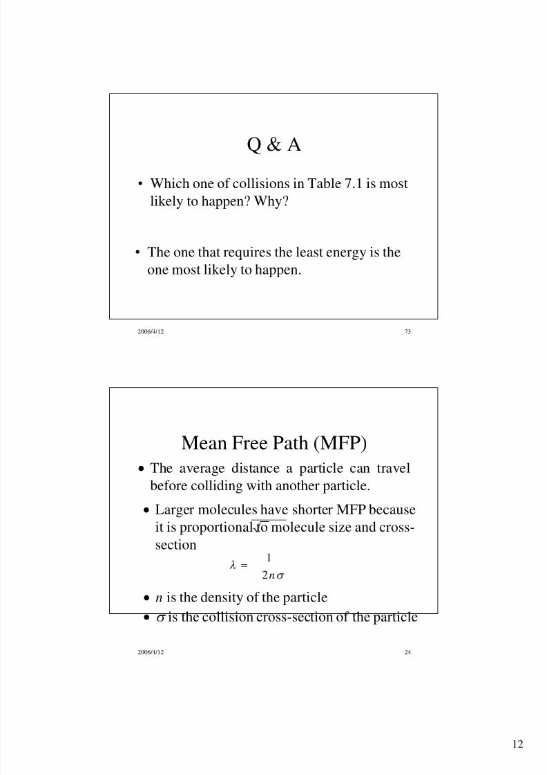
Q & A
• Which one of collisions in Table 7.1 is most
likely to happen? Why?
• The one that requires the least energy is the
one most likely to happen.
2006/4/12 24
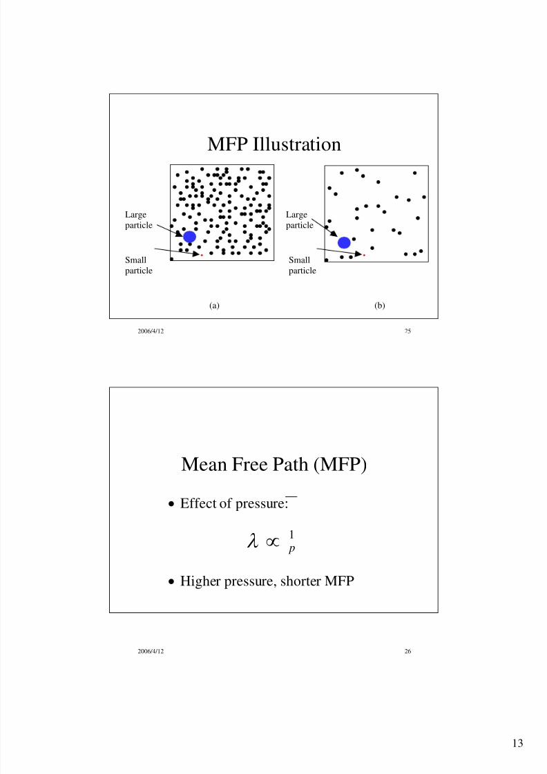
Mean Free Path (MFP)
The average distance a particle can travel
before colliding with another particle.
n2
1
n is the density of the particle
is the collision cross-section of the particle
Larger molecules have shorter MFP because
it is proportional to molecule size and cross-
section
8/6/2019 IC Ch07-Plasma Basics
http://slidepdf.com/reader/full/ic-ch07-plasma-basics 13/45
13
2006/4/12 25
MFP Illustration
Large
particle
Small
particle
Large
particle
Small
particle
(a) (b)
2006/4/12 26
Mean Free Path (MFP)
Effect of pressure:
Higher pressure, shorter MFP
1 p

8/6/2019 IC Ch07-Plasma Basics
http://slidepdf.com/reader/full/ic-ch07-plasma-basics 14/45
14
2006/4/12 27
Q & A• Why does one need a vacuum chamber to
generate a stable plasma?
• At atmospheric pressure (760 Torr), MFP of an
electron is very short. Electrons are hard to get
enough energy to ionize gases molecules.
• Extremely strong electric field can create
plasma in the form of arcing (lightening)
instead of steady state glow discharge.
2006/4/12 28
Movement of Charged Particle
Electron is much lighter than ion
me << mi
me:m Hydrogen =1:1836 Electric forces on electrons and ions are the same
F = qE
Electron has much higher acceleration
a = F/m

8/6/2019 IC Ch07-Plasma Basics
http://slidepdf.com/reader/full/ic-ch07-plasma-basics 15/45
15
2006/4/12 29
Movement of Charged Particle
RF electric field varies quickly, electrons are
accelerated very quickly while ions react slowly
Ions have more collisions due to their larger
cross-section that further slowing them down
Electrons move much faster than ions in plasma
2006/4/12 30
Thermal Velocity
Electron thermal velocity, 1eV = 11594 K
v = (kT e /me)1/2
RF plasma, T e is about 2 eV
ve 5.93107 cm/sec = 1.33107 mph
(equivalent to airplane’s speed)

8/6/2019 IC Ch07-Plasma Basics
http://slidepdf.com/reader/full/ic-ch07-plasma-basics 16/45
16
2006/4/12 31
Magnetic Force and Gyro-motion
Magnetic force on a charged particle:
F = qvB
Magnetic force is always perpendicular to the
particle velocity
Charged particle will spiral around themagnetic field line.
Gyro-motion.
2006/4/12 32
Gyro-motion
Trajectory of charged particleMagnetic Field Line

8/6/2019 IC Ch07-Plasma Basics
http://slidepdf.com/reader/full/ic-ch07-plasma-basics 17/45
17
2006/4/12 33
Gyrofrequency• Charged particle in gyro motion in magnetic field
m
qB
Gyro radius
• Gyroradius of charged particle in a magneticfield, , can be expressed as:
= v /
2006/4/12 34
Energy, E
f ( E )
2 - 3 eV
Electrons with
enough energy
for ionization
Boltzmann Distribution

8/6/2019 IC Ch07-Plasma Basics
http://slidepdf.com/reader/full/ic-ch07-plasma-basics 18/45
18
2006/4/12 35
Ion Bombardment
Electrons reach electrodes and chamber wall first
Electrodes charged negatively, repel electrons
and attract ions.
The sheath potential accelerates ions towards the
electrode and causes ion bombardment.
Ion bombardment is very important for etch,sputtering and PECVD processes.
2006/4/12 36
Sheath Potential
+-+-+-+-+-+-
+
+-+-+-+-+-+-
+
+-+-+-+-+-+-
+
+-+-+-+-+-+-
+
+-+-+-+-+-+-
+
+-+-+-+-+-+-
+
+-+-+-+-+-+-
+
+-+-+-+-+-+-
+
+-+-+-+-+-+
+
+
+-+-+-+-+
+
+
+-+-+-+
+
+
+
+
+-+-+
+
+
+
+
+-+
+
+
+
+
+
+
+
+
+
+
Sheath RegionV p
V f
x
Dark space
Bulk plasma
Sheath Potential
E l e c t r o d e
8/6/2019 IC Ch07-Plasma Basics
http://slidepdf.com/reader/full/ic-ch07-plasma-basics 19/45
19
2006/4/12 37
Ion Bombardment
Anything close to plasma gets ion bombardment
Mainly determined by RF power
Pressure also can affect bombardment
2006/4/12 38
Applications of Ion bombardment
Help to achieve anisotropic etch profile
Damaging mechanism
Blocking mechanism
Argon sputtering
Dielectric etch for gap fill
Metal deposition
Help control film stress in PECVD processes
Heavier bombardment, more compressive film
8/6/2019 IC Ch07-Plasma Basics
http://slidepdf.com/reader/full/ic-ch07-plasma-basics 20/45
20
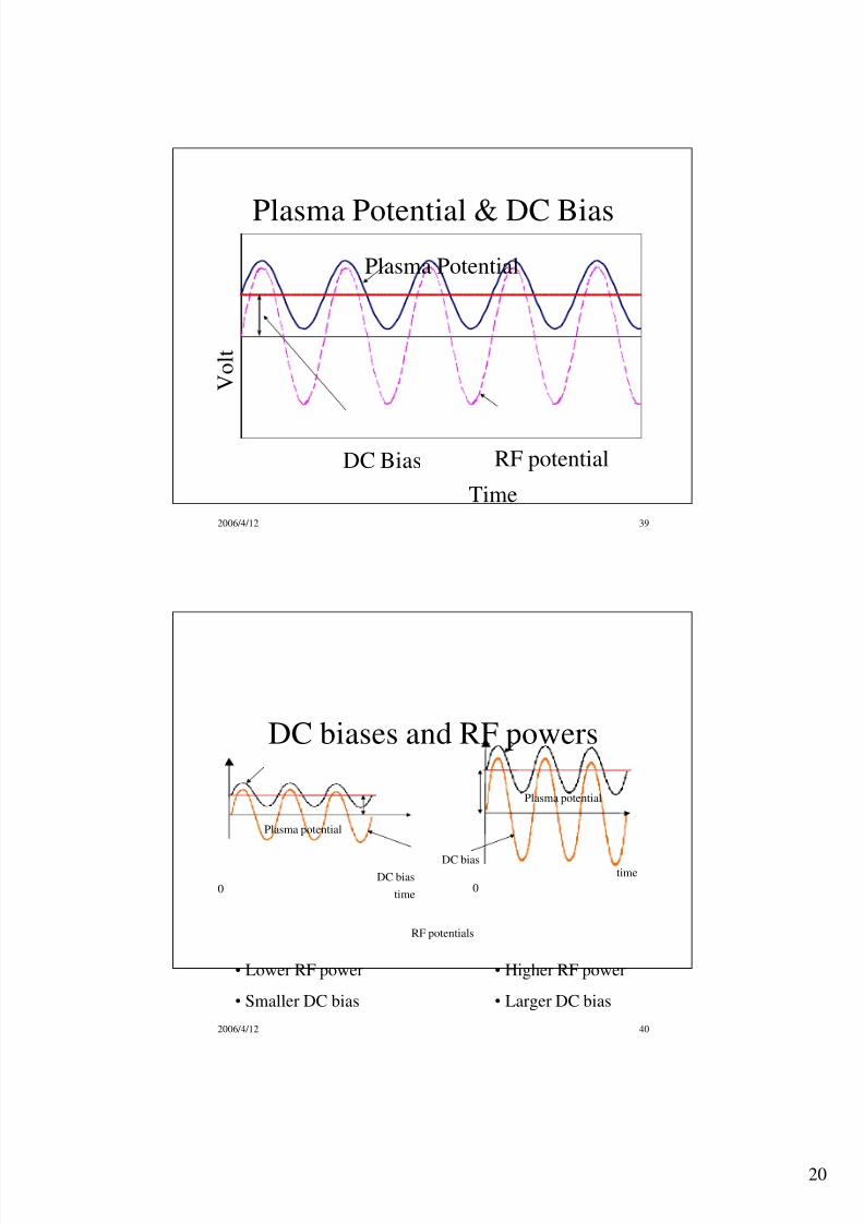
2006/4/12 39
Plasma Potential & DC Bias
Time
V o l t
DC Bias RF potential
Plasma Potential
2006/4/12 40
DC biases and RF powers
0time
Plasma potential
0
time
Plasma potential
DC bias
RF potentials
DC bias
• Lower RF power
• Smaller DC bias
• Higher RF power
• Larger DC bias

8/6/2019 IC Ch07-Plasma Basics
http://slidepdf.com/reader/full/ic-ch07-plasma-basics 21/45
21
2006/4/12 41
Ion Bombardment
•Ion energy
•Ion flux (density)
•Both controlled by RF power
2006/4/12 42
Ion Bombardment Control
• Increasing RF power, DC bias increases, ion
density also increases.
• Both ion density and ion bombardment energy
are controlled by RF power.
• RF power is the most important knob controlling
ion bombardment
• RF power also used to control film stress for
PECVD processes
8/6/2019 IC Ch07-Plasma Basics
http://slidepdf.com/reader/full/ic-ch07-plasma-basics 22/45
22
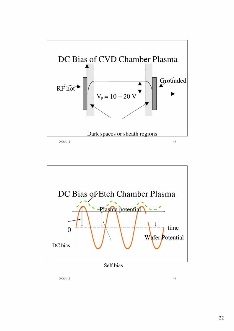
2006/4/12 43
DC Bias of CVD Chamber Plasma
Vp = 10 20 V
RF hot
Grounded
Dark spaces or sheath regions
2006/4/12 44
DC Bias of Etch Chamber Plasma
DC bias
0time
Wafer Potential
Plasma potential
Self bias

8/6/2019 IC Ch07-Plasma Basics
http://slidepdf.com/reader/full/ic-ch07-plasma-basics 23/45
23
2006/4/12 45
DC Bias of Etch Chamber Plasma
V 2
A2
A1
V 1 /V 2 =( A2 /A1)
V 1
= 200 to 1000 V
4
DC bias V1
2006/4/12 46
Question and Answer
• If the electrode area ratio is 1:3, what is the
difference between the DC bias and the self-
bias compare with the DC bias?
• The DC bias is V 1 , the self-bias is V 1 V 2 ,
therefore, the difference is
[V 1 (V 1 V 2)]/ V 1 = V 2 / V 1 = ( A1 / A2)4 = (1/3)4 = 1/81 = 1.23%

8/6/2019 IC Ch07-Plasma Basics
http://slidepdf.com/reader/full/ic-ch07-plasma-basics 24/45
24
2006/4/12 47
Q and A• Can we insert a fine metal probe into the
plasma to measure the plasma potential V 2?
• Yes, we can. However, it is not very accurate
because of sheath potential near probe surface
• Measurement results are determined by thetheoretical models of the sheath potential,
which have not been fully developed, yet.
2006/4/12 48
Ion Bombardment and Electrode Size
• Smaller electrode has more energetic ion
bombardment due to self-bias
• Etch chambers usually place wafer onsmaller electrode

8/6/2019 IC Ch07-Plasma Basics
http://slidepdf.com/reader/full/ic-ch07-plasma-basics 25/45
25
2006/4/12 49
Advantages of Using Plasma
• Plasma processes in IC fabrication: – PECVD
• CVD chamber dry clean
– Plasma Etch
– PVD
– Ion implantation
2006/4/12 50
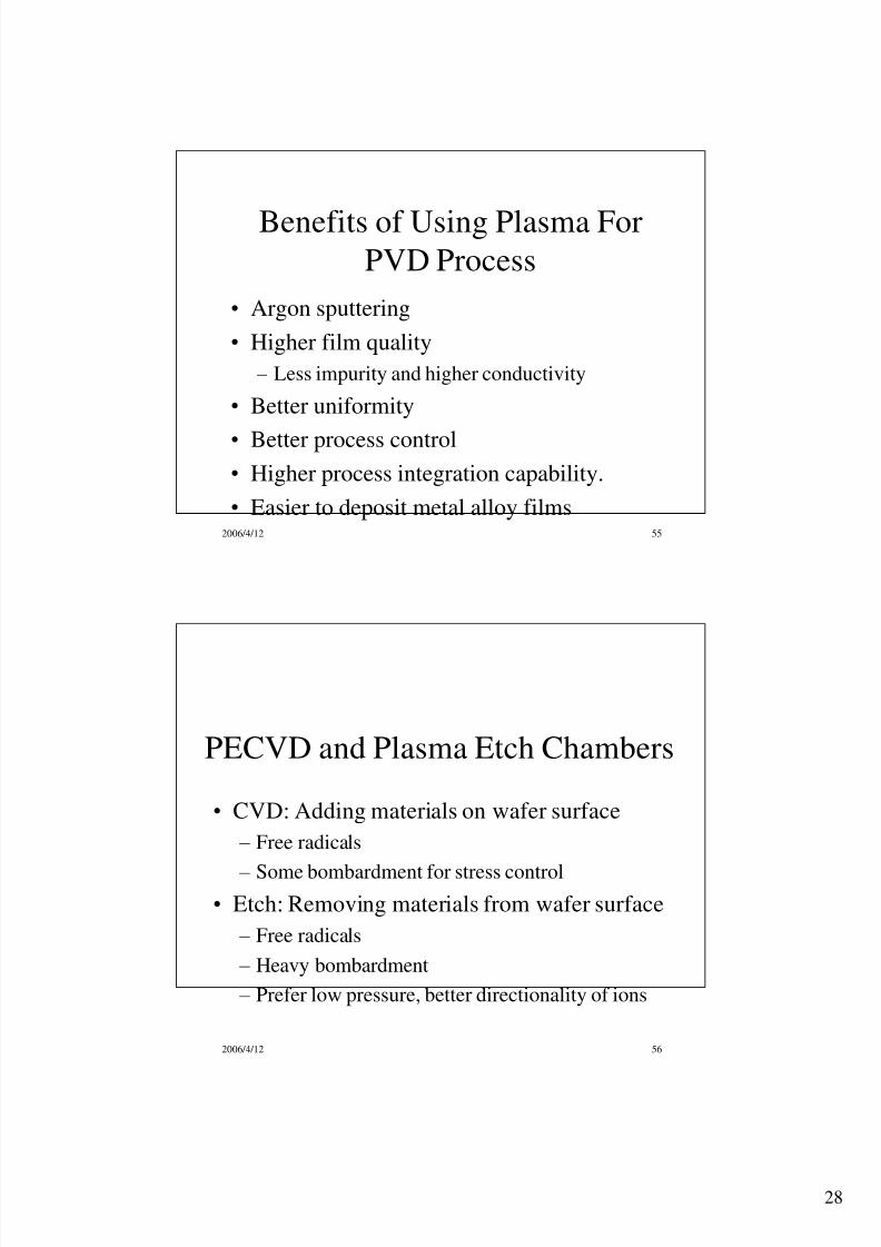
Benefits of Using Plasma in
CVD Process
• High deposition rate at relatively lowertemperature.
• Independent film stress control
• Chamber dry clean
• Gap fill capability

8/6/2019 IC Ch07-Plasma Basics
http://slidepdf.com/reader/full/ic-ch07-plasma-basics 26/45
26
2006/4/12 51
Comparison of PECVD and LPCVD
Processes LPCVD (150 mm) PECVD (150 mm)
Chemical reaction SiH4+ O 2 SiO2 + … SiH4+ N2O SiO2 + …
Process parameters p =3 Torr, T=400 C p=3 Torr, T=400 C and
RF=180 W
Deposition rate 100 to 200 Å/min 8000 Å/min
Process systems Batch system Single-wafer system
Wafer to wafer uniformity Difficult to control Easier to control
2006/4/12 52
Gap Fill by HDP-CVD
• Simultaneously deposition and sputtering
• Tapering the gap opening
• Fill gap between metal lines bottom up

8/6/2019 IC Ch07-Plasma Basics
http://slidepdf.com/reader/full/ic-ch07-plasma-basics 27/45
27
2006/4/12 53
HDP CVD Void-free Gap Fill
0.25 m, A/R 4:1
2006/4/12 54
Benefits of Using Plasma For
Etch Process
• High etch rate
• Anisotropic etch profile
• Optical endpoint
• Less chemical usage and disposal
8/6/2019 IC Ch07-Plasma Basics
http://slidepdf.com/reader/full/ic-ch07-plasma-basics 28/45

8/6/2019 IC Ch07-Plasma Basics
http://slidepdf.com/reader/full/ic-ch07-plasma-basics 29/45
29
2006/4/12 57
PECVD Chambers
• Ion bombardment control film stress
• Wafer is placed grounded electrode
• Both RF hot and grounded electrodes have
about the same area
•
It has very little self-bias• The ion bombardment energy is about 10 to
20 eV, mainly determined by the RF power
2006/4/12 58
Schematic of a PECVD Chamber
PlasmaChuck
RF
Wafer

8/6/2019 IC Ch07-Plasma Basics
http://slidepdf.com/reader/full/ic-ch07-plasma-basics 30/45
30
2006/4/12 59
Plasma Etch Chambers
• Ion bombardment
– Physically dislodge
– break chemical bonds
• Wafer on smaller electrode
• Self-bias
• Ion bombardment energy
– on wafer (RF hot electrode): 200 to 1000 eV
– on lid (ground electrode): 10 to 20 eV.
2006/4/12 60
Plasma Etch Chambers
• Heat generation by heavy ion bombardment
• Need control temperature to protect masking PR
• Water-cool wafer chuck (pedestal, cathode)
• Lower pressure not good to transfer heat from
wafer to chuck
• Helium backside cooling required
• Clamp ring or electrostatic chuck (E-chuck) to
hold wafer
8/6/2019 IC Ch07-Plasma Basics
http://slidepdf.com/reader/full/ic-ch07-plasma-basics 31/45
31
2006/4/12 61
Plasma Etch Chambers
• Etch prefer lower pressure
– longer MFP, more ion energy and less scattering
• Low pressure, long MFP, less ionization
collision
– hard to generate and sustain plasma
• Magnets are used to force electron spin and
travel longer distance to increase collisions
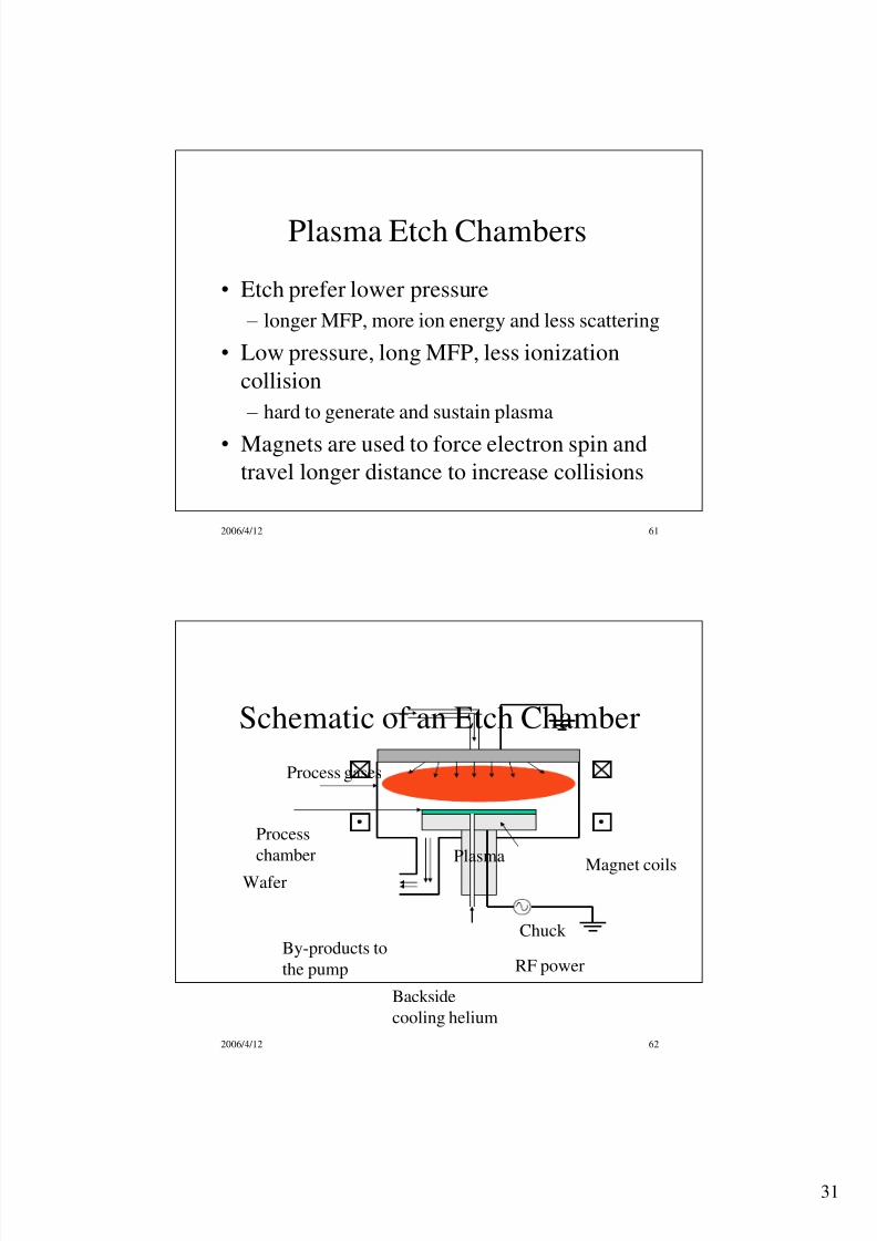
2006/4/12 62
Schematic of an Etch Chamber
Process gases
Plasma
Process
chamber
By-products to
the pump
Chuck
RF power
Backside
cooling helium
Magnet coilsWafer
8/6/2019 IC Ch07-Plasma Basics
http://slidepdf.com/reader/full/ic-ch07-plasma-basics 32/45
32
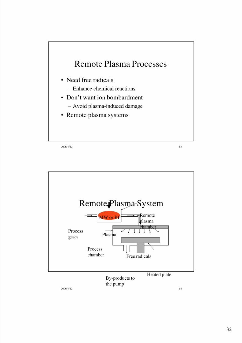
2006/4/12 63
Remote Plasma Processes
• Need free radicals
– Enhance chemical reactions
• Don’t want ion bombardment
– Avoid plasma-induced damage
• Remote plasma systems
2006/4/12 64
Process
gases Plasma
MW or RF
Process
chamber
By-products to
the pump
Remote
plasma
chamber
Free radicals
Heated plate
Remote Plasma System

8/6/2019 IC Ch07-Plasma Basics
http://slidepdf.com/reader/full/ic-ch07-plasma-basics 33/45
33
2006/4/12 65
Photoresist Strip
• Remove photoresist right after etch
• O2 and H2O chemistry
• Can be integrated with etch system
• In-situ etch and PR strip
• Improve both throughput and yield
2006/4/12 66
Photoresist Strip Process
H2O, O2 Plasma
OO H
Microwave
Process chamber
H2O, CO2, …
To the pump
Remote plasma
chamber
OO OH HWafer with
photoresist
Heated plate

8/6/2019 IC Ch07-Plasma Basics
http://slidepdf.com/reader/full/ic-ch07-plasma-basics 34/45
34
2006/4/12 67
Remote Plasma Etch
• Applications: isotropic etch processes:
– LOCOS or STI nitride strip
– wineglass contact hole etch
• Can be integrated with plasma etch system
– improve throughput
• Part of efforts to replace wet process
2006/4/12 68
NF3 Plasma
F FF
F N2N2
F
Microwave
Process
chamber
N2, SiF4, …
To pump
Remote plasma
chamber
Heated plate
Remote Plasma Etch System
Wafer
8/6/2019 IC Ch07-Plasma Basics
http://slidepdf.com/reader/full/ic-ch07-plasma-basics 35/45
35
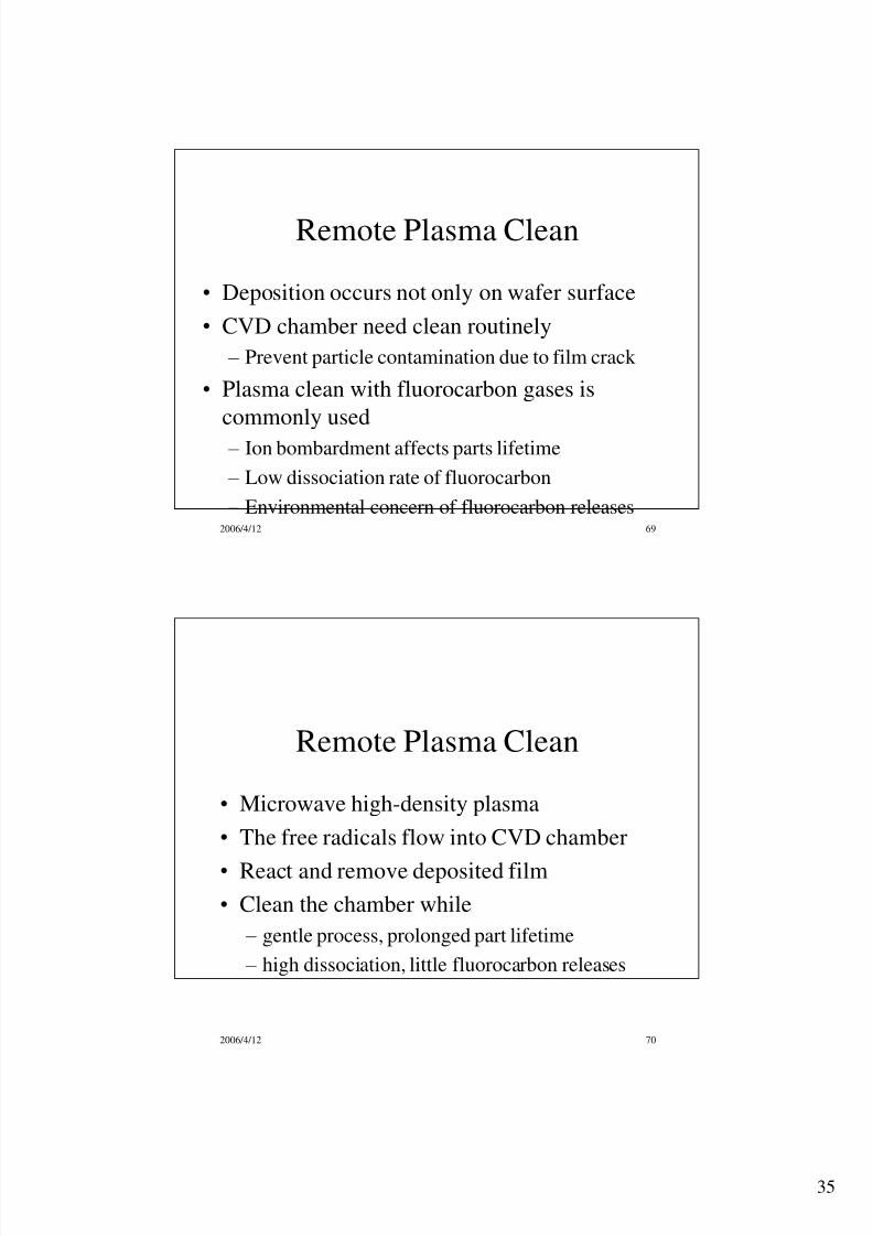
2006/4/12 69
Remote Plasma Clean
• Deposition occurs not only on wafer surface
• CVD chamber need clean routinely
– Prevent particle contamination due to film crack
• Plasma clean with fluorocarbon gases is
commonly used
– Ion bombardment affects parts lifetime
– Low dissociation rate of fluorocarbon
– Environmental concern of fluorocarbon releases
2006/4/12 70
Remote Plasma Clean
• Microwave high-density plasma
• The free radicals flow into CVD chamber
• React and remove deposited film
• Clean the chamber while
– gentle process, prolonged part lifetime
– high dissociation, little fluorocarbon releases

8/6/2019 IC Ch07-Plasma Basics
http://slidepdf.com/reader/full/ic-ch07-plasma-basics 36/45
36
2006/4/12 71
NF3 Plasma
FF
FF N2N2
F
Microwave
CVD
chamber
N2, SiF4, …
To pump
Remote plasma
chamber
Heated plate
Remote Plasma Clean System
2006/4/12 72
Remote Plasma CVD (RPCVD)
• Epitaxial Si-Ge for high-speed BiCMOS
• Still in R&D
• Gate dielectric: SiO2, SiON, and Si3N4
• High- dielectrics: HfO2, TiO2, and Ta2O5
• PMD barrier nitride
– LPCVD: budget limitations
– PECVD: plasma induced damage

8/6/2019 IC Ch07-Plasma Basics
http://slidepdf.com/reader/full/ic-ch07-plasma-basics 37/45
37
2006/4/12 73
High-density Plasma
• High-density at low pressure are desired
• Lower pressure, longer MFP, less ion
scattering, which enhance etch profile control.
• Higher density, more ions and free radicals
– Enhance chemical reaction
– Increase ion bombardment
• For CVD processes, HDP in-situ, simultaneous
dep/etch/dep enhance gap fill
2006/4/12 74
Limitation of Parallel Plate
Plasma Source
• Capacitively coupled plasma source
• Can not generate high-density plasma
• Hard to generate plasma even with magnets atlow pressure, about a few mTorr.
– electron MFP too long, no enough ionization
collisions.
8/6/2019 IC Ch07-Plasma Basics
http://slidepdf.com/reader/full/ic-ch07-plasma-basics 38/45
38
2006/4/12 75
Limitation of Parallel PlatePlasma Source
• Cannot independently control ion flux and ion
energy
• Both are directly related to RF power
• Better process control requires a plasma source
that capable to independently control both of
them
2006/4/12 76
ICP and ECR
• Most commonly used in IC industry
• Inductively coupled plasma, ICP
– also called transformer coupled plasma, or TCP
• Electron cyclotron resonance, ECR,
• Low press at few mTorr
• Independently control ion flux and ion energy

8/6/2019 IC Ch07-Plasma Basics
http://slidepdf.com/reader/full/ic-ch07-plasma-basics 39/45
39
2006/4/12 77
Inductively Coupled Plasma (ICP)
• RF current flows in the coils generates a
changing electric field via inductive coupling
• The angular electric field accelerates electrons
in angular direction.
• Electrons to travel a long distance without
collision with the chamber wall or electrode.
• Ionization collisions generate high-density
plasma at low pressure
2006/4/12 78
Inductively Coupled Plasma (ICP)
• Bias RF power controls the ion energy
• Source RF power controls the ion flux
• Helium backside cooling system with E-chuck controls wafer temperature

8/6/2019 IC Ch07-Plasma Basics
http://slidepdf.com/reader/full/ic-ch07-plasma-basics 40/45
40
2006/4/12 79
Illustration of Inductive Coupling
RF current in coil
RF magnetic field
Induced electric field
2006/4/12 80
Schematic of ICP Chamber
Helium
Bias RF
Wafer
E-chuck
Plasma
Inductive coilsSource RF
Chamber body
Ceramic cover

8/6/2019 IC Ch07-Plasma Basics
http://slidepdf.com/reader/full/ic-ch07-plasma-basics 41/45
41
2006/4/12 81
Application of ICP
• Dielectric CVD
• All patterned etch processes, particularly for
high aspect-ration structure
• Sputtering clean prior to metal deposition
•
Metal plasma PVD• Plasma immersion ion implantation
2006/4/12 82
ECR
• Gyro-frequency or cyclotron frequency:
• Determined by magnetic field
mqB

8/6/2019 IC Ch07-Plasma Basics
http://slidepdf.com/reader/full/ic-ch07-plasma-basics 42/45
42
2006/4/12 83
ECR
• Electron cyclotron resonance when MW = e
• Electrons get energy from MW
• Energetic electrons collide with other atoms
or molecules
•
Ionization collisions generate more electrons• Electrons are spiraling around the field line
• Many collisions even at very low pressure
2006/4/12 84
Illustration of ECR
Electron trajectory
B
M i c r o w a v e P o w e r
8/6/2019 IC Ch07-Plasma Basics
http://slidepdf.com/reader/full/ic-ch07-plasma-basics 43/45
43
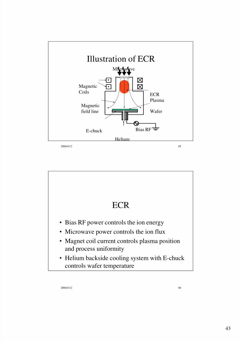
2006/4/12 85
Helium
Bias RF
Magnetic
field line
Microwave
Magnetic
CoilsECR
Plasma
Wafer
E-chuck
Illustration of ECR
2006/4/12 86
ECR
• Bias RF power controls the ion energy
• Microwave power controls the ion flux
• Magnet coil current controls plasma positionand process uniformity
• Helium backside cooling system with E-chuck
controls wafer temperature

8/6/2019 IC Ch07-Plasma Basics
http://slidepdf.com/reader/full/ic-ch07-plasma-basics 44/45
44
2006/4/12 87
Application of ECR
• Dielectric CVD
• All patterned etch processes
• Plasma immersion ion implantation
2006/4/12 88
Summary
• Plasma is ionized gas with n –
= n+
• Plasma consist of n, e, and i
• Ionization, excitation-relaxation, dissociation
• Ion bombardment help increase etch rate and
achieve anisotropic etch
• Light emission can be used for etch end point
• MFP and its relationship with pressure
• Ions from plasma always bombard electrodes
8/6/2019 IC Ch07-Plasma Basics
http://slidepdf.com/reader/full/ic-ch07-plasma-basics 45/45
2006/4/12 89
Summary
• Increasing RF power increases both ion flux
and ion energy in capacitive coupled plasmas
• Low frequency RF power gives ions more
energy, causes heavier ion bombardment
• The etch processes need much more ion
bombardment than the PECVD
• Low pressure, high density plasma are desired
• ICP and ECR are two HDP systems used in IC
fabrication
Related Documents