Redbooks Front cover IBM z14 Configuration Setup Octavian Lascu Franco Pinto Bill White Peter Hoyle Jannie Houlbjerg Kazuhiro Nakajima Nelson Oliveira Martin Söllig

Welcome message from author
This document is posted to help you gain knowledge. Please leave a comment to let me know what you think about it! Share it to your friends and learn new things together.
Transcript

Redbooks
Front cover
IBM z14Configuration Setup
Octavian Lascu
Franco Pinto
Bill White
Peter Hoyle
Jannie Houlbjerg
Kazuhiro Nakajima
Nelson Oliveira
Martin Söllig


International Technical Support Organization
IBM z14 Configuration Setup
September 2017
SG24-8460-00

© Copyright International Business Machines Corporation 2017. All rights reserved.Note to U.S. Government Users Restricted Rights -- Use, duplication or disclosure restricted by GSA ADP ScheduleContract with IBM Corp.
First Edition (September 2017)
This edition applies to IBM z14 and IBM Z Hardware Management Console Version 2.14.0 (Driver Level 32).
Note: Before using this information and the product it supports, read the information in “Notices” on page ix.
Important: At time of publication, this book is based on a pre-GA version of a product. For the most up-to-date information regarding this product, consult the product documentation or subsequent updates of this book.
Contents
Notices . . . . . . . . . . . . . . . . . . . . . . . . . . . . . . . . . . . . . . . . . . . . . . . . . . . . . . . . . . . . . . . . . ixTrademarks . . . . . . . . . . . . . . . . . . . . . . . . . . . . . . . . . . . . . . . . . . . . . . . . . . . . . . . . . . . . . . .x
Preface . . . . . . . . . . . . . . . . . . . . . . . . . . . . . . . . . . . . . . . . . . . . . . . . . . . . . . . . . . . . . . . . . xiAuthors. . . . . . . . . . . . . . . . . . . . . . . . . . . . . . . . . . . . . . . . . . . . . . . . . . . . . . . . . . . . . . . . . . xiNow you can become a published author, too! . . . . . . . . . . . . . . . . . . . . . . . . . . . . . . . . . . . xiiComments welcome. . . . . . . . . . . . . . . . . . . . . . . . . . . . . . . . . . . . . . . . . . . . . . . . . . . . . . . xiiiStay connected to IBM Redbooks . . . . . . . . . . . . . . . . . . . . . . . . . . . . . . . . . . . . . . . . . . . . xiii
Chapter 1. Introduction. . . . . . . . . . . . . . . . . . . . . . . . . . . . . . . . . . . . . . . . . . . . . . . . . . . . 11.1 High-level goal . . . . . . . . . . . . . . . . . . . . . . . . . . . . . . . . . . . . . . . . . . . . . . . . . . . . . . . . 21.2 Scope . . . . . . . . . . . . . . . . . . . . . . . . . . . . . . . . . . . . . . . . . . . . . . . . . . . . . . . . . . . . . . . 21.3 Tools . . . . . . . . . . . . . . . . . . . . . . . . . . . . . . . . . . . . . . . . . . . . . . . . . . . . . . . . . . . . . . . . 4
Chapter 2. Planning considerations . . . . . . . . . . . . . . . . . . . . . . . . . . . . . . . . . . . . . . . . . 52.1 Scenarios . . . . . . . . . . . . . . . . . . . . . . . . . . . . . . . . . . . . . . . . . . . . . . . . . . . . . . . . . . . . 7
2.1.1 Scenario 1: Upgrading an existing IBM Z server to a z14. . . . . . . . . . . . . . . . . . . . 72.1.2 Scenario 2: Installing a new z14 server . . . . . . . . . . . . . . . . . . . . . . . . . . . . . . . . . 72.1.3 Differences in planning for the two scenarios . . . . . . . . . . . . . . . . . . . . . . . . . . . . . 7
2.2 Tools . . . . . . . . . . . . . . . . . . . . . . . . . . . . . . . . . . . . . . . . . . . . . . . . . . . . . . . . . . . . . . . . 82.3 IBM Resource Link . . . . . . . . . . . . . . . . . . . . . . . . . . . . . . . . . . . . . . . . . . . . . . . . . . . . . 82.4 Hardware Configuration Definition tool . . . . . . . . . . . . . . . . . . . . . . . . . . . . . . . . . . . . . . 9
2.4.1 Hardware Configuration Manager . . . . . . . . . . . . . . . . . . . . . . . . . . . . . . . . . . . . . . 92.5 CHPID Mapping Tool . . . . . . . . . . . . . . . . . . . . . . . . . . . . . . . . . . . . . . . . . . . . . . . . . . . 9
2.5.1 HCD and the CMT . . . . . . . . . . . . . . . . . . . . . . . . . . . . . . . . . . . . . . . . . . . . . . . . 102.6 Other tools. . . . . . . . . . . . . . . . . . . . . . . . . . . . . . . . . . . . . . . . . . . . . . . . . . . . . . . . . . . 10
2.6.1 Input/output configuration program . . . . . . . . . . . . . . . . . . . . . . . . . . . . . . . . . . . . 112.6.2 Worldwide Port Name Prediction Tool . . . . . . . . . . . . . . . . . . . . . . . . . . . . . . . . . 112.6.3 Coupling Facility Structure Sizer (CFSizer). . . . . . . . . . . . . . . . . . . . . . . . . . . . . . 112.6.4 Power Estimation Tool . . . . . . . . . . . . . . . . . . . . . . . . . . . . . . . . . . . . . . . . . . . . . 122.6.5 SMC Applicability Tool . . . . . . . . . . . . . . . . . . . . . . . . . . . . . . . . . . . . . . . . . . . . . 122.6.6 zBNA Tool . . . . . . . . . . . . . . . . . . . . . . . . . . . . . . . . . . . . . . . . . . . . . . . . . . . . . . . 12
2.7 Hardware Management Console/Support Element setup. . . . . . . . . . . . . . . . . . . . . . . 122.7.1 Defining the HMC Activation Profiles . . . . . . . . . . . . . . . . . . . . . . . . . . . . . . . . . . 122.7.2 Cryptographic configuration . . . . . . . . . . . . . . . . . . . . . . . . . . . . . . . . . . . . . . . . . 142.7.3 Defining the LPAR Group Control . . . . . . . . . . . . . . . . . . . . . . . . . . . . . . . . . . . . . 142.7.4 Defining the Console (HMC part) . . . . . . . . . . . . . . . . . . . . . . . . . . . . . . . . . . . . . 142.7.5 Support Element settings . . . . . . . . . . . . . . . . . . . . . . . . . . . . . . . . . . . . . . . . . . . 152.7.6 Setting up Server Time Protocol . . . . . . . . . . . . . . . . . . . . . . . . . . . . . . . . . . . . . . 15
2.8 Activities centered on the IODF . . . . . . . . . . . . . . . . . . . . . . . . . . . . . . . . . . . . . . . . . . 162.8.1 Logical channel subsystems . . . . . . . . . . . . . . . . . . . . . . . . . . . . . . . . . . . . . . . . . 162.8.2 Defining partitions . . . . . . . . . . . . . . . . . . . . . . . . . . . . . . . . . . . . . . . . . . . . . . . . . 172.8.3 Defining Storage I/O - FICON and FCP . . . . . . . . . . . . . . . . . . . . . . . . . . . . . . . . 192.8.4 Defining the IBM zHyperLink Express. . . . . . . . . . . . . . . . . . . . . . . . . . . . . . . . . . 202.8.5 Defining Network. . . . . . . . . . . . . . . . . . . . . . . . . . . . . . . . . . . . . . . . . . . . . . . . . . 202.8.6 Defining the console (OSA-ICC) . . . . . . . . . . . . . . . . . . . . . . . . . . . . . . . . . . . . . . 252.8.7 Defining coupling and timing only links . . . . . . . . . . . . . . . . . . . . . . . . . . . . . . . . . 262.8.8 Planning considerations for zEDC . . . . . . . . . . . . . . . . . . . . . . . . . . . . . . . . . . . . 27
© Copyright IBM Corp. 2017. All rights reserved. iii
Chapter 3. Preparing for a new z14 . . . . . . . . . . . . . . . . . . . . . . . . . . . . . . . . . . . . . . . . . 293.1 Hardware features. . . . . . . . . . . . . . . . . . . . . . . . . . . . . . . . . . . . . . . . . . . . . . . . . . . . . 303.2 Upgrading an existing z13 to a z14 and maintaining your existing serial number (Frame
roll MES). . . . . . . . . . . . . . . . . . . . . . . . . . . . . . . . . . . . . . . . . . . . . . . . . . . . . . . . . . . . 313.2.1 Scenario overview. . . . . . . . . . . . . . . . . . . . . . . . . . . . . . . . . . . . . . . . . . . . . . . . . 313.2.2 Creating the work IODF from the current 2964 production IODF . . . . . . . . . . . . . 323.2.3 Repeating the 2964 processor to be replaced . . . . . . . . . . . . . . . . . . . . . . . . . . . 333.2.4 Coupling Link information messages . . . . . . . . . . . . . . . . . . . . . . . . . . . . . . . . . . 343.2.5 Deleting any unsupported items in the repeated 2964 . . . . . . . . . . . . . . . . . . . . . 343.2.6 Changing the 2964 to a 3906 and deleting the 2964 . . . . . . . . . . . . . . . . . . . . . . 353.2.7 Deleting the 2964 processor definition . . . . . . . . . . . . . . . . . . . . . . . . . . . . . . . . . 363.2.8 Reconnecting the CF channel paths that were not migrated . . . . . . . . . . . . . . . . 37
3.3 Saving and restoring OSA configuration data . . . . . . . . . . . . . . . . . . . . . . . . . . . . . . . . 373.3.1 Using OSA/SF to save and restore OSE OAT configuration data . . . . . . . . . . . . 373.3.2 Export and import OSA-ICC configuration data with OSA Advanced Facilities . . 383.3.3 Using OSA Advanced Facilities to set OSA parameters. . . . . . . . . . . . . . . . . . . . 38
3.4 Installing a new z14 into an existing environment . . . . . . . . . . . . . . . . . . . . . . . . . . . . . 383.4.1 Scenario overview. . . . . . . . . . . . . . . . . . . . . . . . . . . . . . . . . . . . . . . . . . . . . . . . . 383.4.2 Creating a work IODF from the current production IODF . . . . . . . . . . . . . . . . . . . 393.4.3 Adding the new 3906 processor . . . . . . . . . . . . . . . . . . . . . . . . . . . . . . . . . . . . . . 40
3.5 Saving and restoring any OSA configuration data . . . . . . . . . . . . . . . . . . . . . . . . . . . . 423.5.1 Using OSA/SF to save and restore OSE OAT configuration data . . . . . . . . . . . . 433.5.2 Export and import OSA-ICC configuration data with OSA Advanced Facilities . . 433.5.3 Using OSA Advanced Facilities to set OSA parameters. . . . . . . . . . . . . . . . . . . . 43
3.6 Additional steps and processes . . . . . . . . . . . . . . . . . . . . . . . . . . . . . . . . . . . . . . . . . . 43
Chapter 4. Mapping CHIDs to CHPIDs using the CMT. . . . . . . . . . . . . . . . . . . . . . . . . . 454.1 Validating the 3906 work IODF . . . . . . . . . . . . . . . . . . . . . . . . . . . . . . . . . . . . . . . . . . . 464.2 Creating the IOCP for the CHPID Mapping Tool. . . . . . . . . . . . . . . . . . . . . . . . . . . . . . 474.3 Assigning CHIDs to CHPIDs using the CMT. . . . . . . . . . . . . . . . . . . . . . . . . . . . . . . . . 504.4 Importing the CFReport file into the CHPID Mapping Tool . . . . . . . . . . . . . . . . . . . . . . 514.5 Importing the 3906 IOCP file into the CHPID Mapping Tool . . . . . . . . . . . . . . . . . . . . . 544.6 Resolving CHPIDs with CHID conflicts . . . . . . . . . . . . . . . . . . . . . . . . . . . . . . . . . . . . . 604.7 Hardware resolution . . . . . . . . . . . . . . . . . . . . . . . . . . . . . . . . . . . . . . . . . . . . . . . . . . . 61
4.7.1 Reset Incompatible (Hardware - I/O) Entries . . . . . . . . . . . . . . . . . . . . . . . . . . . . 614.7.2 Reset “Error: No hardware found” Entries. . . . . . . . . . . . . . . . . . . . . . . . . . . . . . . 644.7.3 Reset “Select at least one adapter type”. . . . . . . . . . . . . . . . . . . . . . . . . . . . . . . . 654.7.4 Reset “Required hardware for type IOCP_type not available” . . . . . . . . . . . . . . . 664.7.5 Reset “CHID_1 moved to new channel ID: CHID_2” . . . . . . . . . . . . . . . . . . . . . . 66
4.8 Manual mapping to resolve CIB CHPIDs . . . . . . . . . . . . . . . . . . . . . . . . . . . . . . . . . . . 674.9 Processing Automatic Mapping then CU Priority . . . . . . . . . . . . . . . . . . . . . . . . . . . . . 684.10 CHPIDs not connected to control units . . . . . . . . . . . . . . . . . . . . . . . . . . . . . . . . . . . . 724.11 Creating CHPID Mapping Tool reports . . . . . . . . . . . . . . . . . . . . . . . . . . . . . . . . . . . . 72
4.11.1 CHPID Report . . . . . . . . . . . . . . . . . . . . . . . . . . . . . . . . . . . . . . . . . . . . . . . . . . . 744.11.2 CHPID to Port Report, sorted by location . . . . . . . . . . . . . . . . . . . . . . . . . . . . . . 784.11.3 CHPID to CU Report . . . . . . . . . . . . . . . . . . . . . . . . . . . . . . . . . . . . . . . . . . . . . . 79
4.12 Creating an updated IOCP . . . . . . . . . . . . . . . . . . . . . . . . . . . . . . . . . . . . . . . . . . . . . 804.13 HCD: Updating the 3906 work IODF with CHIDs . . . . . . . . . . . . . . . . . . . . . . . . . . . . 814.14 Additional steps and processes . . . . . . . . . . . . . . . . . . . . . . . . . . . . . . . . . . . . . . . . . 84
Chapter 5. Production IODF and setting up the CPC. . . . . . . . . . . . . . . . . . . . . . . . . . . 855.1 Building the 3906 production IODF . . . . . . . . . . . . . . . . . . . . . . . . . . . . . . . . . . . . . . . . 865.2 Writing the IOCP to the 2964 processor using HCD . . . . . . . . . . . . . . . . . . . . . . . . . . . 895.3 Creating a Reset Profile on the 3906 Support Element . . . . . . . . . . . . . . . . . . . . . . . . 96
iv IBM z14 Configuration Setup
5.3.1 Background activities that have occurred . . . . . . . . . . . . . . . . . . . . . . . . . . . . . . . 965.3.2 Building the Reset Profile and pointing to required IOCDS. . . . . . . . . . . . . . . . . . 965.3.3 Setting up and verifying the Reset Profile . . . . . . . . . . . . . . . . . . . . . . . . . . . . . . . 99
5.4 Creating an Image Profile on the 3906 Support Element . . . . . . . . . . . . . . . . . . . . . . 1015.4.1 Image Profile: General page . . . . . . . . . . . . . . . . . . . . . . . . . . . . . . . . . . . . . . . . 1015.4.2 Image Profile: Processor page . . . . . . . . . . . . . . . . . . . . . . . . . . . . . . . . . . . . . . 1025.4.3 Image Profile: Security page. . . . . . . . . . . . . . . . . . . . . . . . . . . . . . . . . . . . . . . . 1035.4.4 Image Profile: Storage page . . . . . . . . . . . . . . . . . . . . . . . . . . . . . . . . . . . . . . . . 1045.4.5 Image Profile: Options page . . . . . . . . . . . . . . . . . . . . . . . . . . . . . . . . . . . . . . . . 1055.4.6 Image Profile: Load page . . . . . . . . . . . . . . . . . . . . . . . . . . . . . . . . . . . . . . . . . . 1065.4.7 Image Profile: Crypto page . . . . . . . . . . . . . . . . . . . . . . . . . . . . . . . . . . . . . . . . . 1075.4.8 Image Profile: Time Offset . . . . . . . . . . . . . . . . . . . . . . . . . . . . . . . . . . . . . . . . . 1085.4.9 Image Profile: Saving . . . . . . . . . . . . . . . . . . . . . . . . . . . . . . . . . . . . . . . . . . . . . 109
5.5 Performing a Power-On Reset of the 3906 . . . . . . . . . . . . . . . . . . . . . . . . . . . . . . . . . 1095.5.1 Coupling Facility Links . . . . . . . . . . . . . . . . . . . . . . . . . . . . . . . . . . . . . . . . . . . . 1095.5.2 Server Time Protocol configuration. . . . . . . . . . . . . . . . . . . . . . . . . . . . . . . . . . . 113
5.6 Building and verifying Load (IPL) profiles . . . . . . . . . . . . . . . . . . . . . . . . . . . . . . . . . . 1195.7 Building and verifying LOADxx Members in SYS#.IPLPARM. . . . . . . . . . . . . . . . . . . 1225.8 Communicating information about the new z14 . . . . . . . . . . . . . . . . . . . . . . . . . . . . . 123
Chapter 6. Configuring network features . . . . . . . . . . . . . . . . . . . . . . . . . . . . . . . . . . . 1256.1 Preparation for defining and customizing OSA-Express . . . . . . . . . . . . . . . . . . . . . . . 1266.2 Define OSA Express to your IO configuration. . . . . . . . . . . . . . . . . . . . . . . . . . . . . . . 126
6.2.1 Choosing the OSA-Express CHPID type . . . . . . . . . . . . . . . . . . . . . . . . . . . . . . 1266.2.2 Defining the OSA-Express to IO configuration . . . . . . . . . . . . . . . . . . . . . . . . . . 1276.2.3 Confirm your OSA-Express IO definition. . . . . . . . . . . . . . . . . . . . . . . . . . . . . . . 127
6.3 Customizing OSA-Express using OSA Advanced facilities. . . . . . . . . . . . . . . . . . . . . 1296.3.1 Configuring OAT and SNA LLC2 timer for OSE channel . . . . . . . . . . . . . . . . . . 1306.3.2 Setting OSA parameters using OSA Advanced Facilities . . . . . . . . . . . . . . . . . . 1396.3.3 Confirm your OSA customization . . . . . . . . . . . . . . . . . . . . . . . . . . . . . . . . . . . . 141
6.4 Shared Memory Communications (SMC-R and SMC-D) . . . . . . . . . . . . . . . . . . . . . . 1416.5 Channel-To-Channel connection . . . . . . . . . . . . . . . . . . . . . . . . . . . . . . . . . . . . . . . . 141
6.5.1 FICON CTC: Preparing. . . . . . . . . . . . . . . . . . . . . . . . . . . . . . . . . . . . . . . . . . . . 1416.5.2 FICON CTC: Implementation . . . . . . . . . . . . . . . . . . . . . . . . . . . . . . . . . . . . . . . 1426.5.3 FICON CTC: Management . . . . . . . . . . . . . . . . . . . . . . . . . . . . . . . . . . . . . . . . . 143
Chapter 7. Defining console communication . . . . . . . . . . . . . . . . . . . . . . . . . . . . . . . . 1477.1 Preparing console definition . . . . . . . . . . . . . . . . . . . . . . . . . . . . . . . . . . . . . . . . . . . . 1487.2 Defining the OSA-ICC . . . . . . . . . . . . . . . . . . . . . . . . . . . . . . . . . . . . . . . . . . . . . . . . . 1487.3 Defining OSA-ICC configuration using OSA Advanced facilities (new configuration) . 149
7.3.1 Saving and restoring OSA-ICC configuration . . . . . . . . . . . . . . . . . . . . . . . . . . . 1547.4 Verifying the OSA-ICC definition. . . . . . . . . . . . . . . . . . . . . . . . . . . . . . . . . . . . . . . . . 159
7.4.1 z/OS commands . . . . . . . . . . . . . . . . . . . . . . . . . . . . . . . . . . . . . . . . . . . . . . . . . 1597.4.2 OSA-ICC console initial window . . . . . . . . . . . . . . . . . . . . . . . . . . . . . . . . . . . . . 161
Chapter 8. Preparing for Sysplex and configuring Server Time Protocol . . . . . . . . . 1638.1 Preparing for Parallel Sysplex. . . . . . . . . . . . . . . . . . . . . . . . . . . . . . . . . . . . . . . . . . . 1648.2 Preparing for non-sysplex system time synchronization . . . . . . . . . . . . . . . . . . . . . . . 1648.3 Server Time Protocol overview . . . . . . . . . . . . . . . . . . . . . . . . . . . . . . . . . . . . . . . . . . 164
8.3.1 Using external time source . . . . . . . . . . . . . . . . . . . . . . . . . . . . . . . . . . . . . . . . . 1658.4 Configuring the HMC as an NTP server . . . . . . . . . . . . . . . . . . . . . . . . . . . . . . . . . . . 166
8.4.1 Configuring HMC time source and NTP server . . . . . . . . . . . . . . . . . . . . . . . . . 1678.4.2 NTP Broadband Authentication (optional). . . . . . . . . . . . . . . . . . . . . . . . . . . . . . 171
8.5 What is new in HMC V2.14.0 (Manage System Time task) . . . . . . . . . . . . . . . . . . . . 177
Contents v

8.5.1 Set CTN member restriction menu . . . . . . . . . . . . . . . . . . . . . . . . . . . . . . . . . . . 1798.6 Single server STP-only CTN . . . . . . . . . . . . . . . . . . . . . . . . . . . . . . . . . . . . . . . . . . . . 180
8.6.1 Configuring a new STP-only CTN. . . . . . . . . . . . . . . . . . . . . . . . . . . . . . . . . . . . 1818.6.2 Verify new CTN configuration . . . . . . . . . . . . . . . . . . . . . . . . . . . . . . . . . . . . . . . 1878.6.3 Configure External Time Source. . . . . . . . . . . . . . . . . . . . . . . . . . . . . . . . . . . . . 1888.6.4 Verify the ETS configuration . . . . . . . . . . . . . . . . . . . . . . . . . . . . . . . . . . . . . . . . 191
8.7 Adding the z14 server to an existing CTN. . . . . . . . . . . . . . . . . . . . . . . . . . . . . . . . . . 1928.7.1 HMC operations to add the CPC to the CTN . . . . . . . . . . . . . . . . . . . . . . . . . . . 1938.7.2 Verify that the system is added to the CTN. . . . . . . . . . . . . . . . . . . . . . . . . . . . . 195
8.8 Assign an STP role to the CPC. . . . . . . . . . . . . . . . . . . . . . . . . . . . . . . . . . . . . . . . . . 1968.8.1 HMC operations to assign or modify STP Role. . . . . . . . . . . . . . . . . . . . . . . . . . 1968.8.2 Verify assigned server roles . . . . . . . . . . . . . . . . . . . . . . . . . . . . . . . . . . . . . . . . 200
Chapter 9. Defining Coupling Facility links . . . . . . . . . . . . . . . . . . . . . . . . . . . . . . . . . 2039.1 Coupling connectivity options on z14 . . . . . . . . . . . . . . . . . . . . . . . . . . . . . . . . . . . . . 204
9.1.1 Coupling connectivity for Parallel Sysplex on z14. . . . . . . . . . . . . . . . . . . . . . . . 2049.1.2 Internal coupling . . . . . . . . . . . . . . . . . . . . . . . . . . . . . . . . . . . . . . . . . . . . . . . . . 2059.1.3 InfiniBand features . . . . . . . . . . . . . . . . . . . . . . . . . . . . . . . . . . . . . . . . . . . . . . . 2059.1.4 Integrated Coupling Adapter Short Reach (ICA SR). . . . . . . . . . . . . . . . . . . . . . 2059.1.5 Coupling Express Long Range (CE LR) . . . . . . . . . . . . . . . . . . . . . . . . . . . . . . . 2069.1.6 Preparing to define coupling facility links . . . . . . . . . . . . . . . . . . . . . . . . . . . . . . 206
9.2 Coupling Express Long Range . . . . . . . . . . . . . . . . . . . . . . . . . . . . . . . . . . . . . . . . . . 2079.2.1 CE LR: Implementation. . . . . . . . . . . . . . . . . . . . . . . . . . . . . . . . . . . . . . . . . . . . 2079.2.2 CE LR: Managing the configuration . . . . . . . . . . . . . . . . . . . . . . . . . . . . . . . . . . 212
9.3 Integrated Coupling Adapter Short Range . . . . . . . . . . . . . . . . . . . . . . . . . . . . . . . . . 2149.3.1 ICA SR: Implementation . . . . . . . . . . . . . . . . . . . . . . . . . . . . . . . . . . . . . . . . . . . 2149.3.2 ICA SR: Managing the configuration. . . . . . . . . . . . . . . . . . . . . . . . . . . . . . . . . . 219
9.4 Defining an STP timing-only link by using ICA SR . . . . . . . . . . . . . . . . . . . . . . . . . . . 2219.4.1 STP timing only: Implementation . . . . . . . . . . . . . . . . . . . . . . . . . . . . . . . . . . . . 2219.4.2 STP timing-only links: Managing the configuration . . . . . . . . . . . . . . . . . . . . . . . 223
9.5 CF LPAR setup and CFCC Level 22. . . . . . . . . . . . . . . . . . . . . . . . . . . . . . . . . . . . . . 2249.5.1 Coupling Facility Level 22 . . . . . . . . . . . . . . . . . . . . . . . . . . . . . . . . . . . . . . . . . . 224
Chapter 10. Specialized features . . . . . . . . . . . . . . . . . . . . . . . . . . . . . . . . . . . . . . . . . . 22710.1 Crypto Express6S . . . . . . . . . . . . . . . . . . . . . . . . . . . . . . . . . . . . . . . . . . . . . . . . . . . 228
10.1.1 Crypto Express6S overview . . . . . . . . . . . . . . . . . . . . . . . . . . . . . . . . . . . . . . . 22810.1.2 Planning for Crypto Express6S configuration . . . . . . . . . . . . . . . . . . . . . . . . . . 23010.1.3 Configuring Crypto Express6S . . . . . . . . . . . . . . . . . . . . . . . . . . . . . . . . . . . . . 23210.1.4 Handling cryptographic coprocessors by using ICSF . . . . . . . . . . . . . . . . . . . . 251
10.2 zEnterprise Data Compression . . . . . . . . . . . . . . . . . . . . . . . . . . . . . . . . . . . . . . . . . 25810.2.1 zEDC overview . . . . . . . . . . . . . . . . . . . . . . . . . . . . . . . . . . . . . . . . . . . . . . . . . 25810.2.2 Planning for zEDC configuration. . . . . . . . . . . . . . . . . . . . . . . . . . . . . . . . . . . . 25810.2.3 Configuring zEDC . . . . . . . . . . . . . . . . . . . . . . . . . . . . . . . . . . . . . . . . . . . . . . . 25810.2.4 Handling zEDC . . . . . . . . . . . . . . . . . . . . . . . . . . . . . . . . . . . . . . . . . . . . . . . . . 258
10.3 Virtual Flash Memory . . . . . . . . . . . . . . . . . . . . . . . . . . . . . . . . . . . . . . . . . . . . . . . . 26110.3.1 VFM overview . . . . . . . . . . . . . . . . . . . . . . . . . . . . . . . . . . . . . . . . . . . . . . . . . . 26110.3.2 Planning for VFM configuration. . . . . . . . . . . . . . . . . . . . . . . . . . . . . . . . . . . . . 26110.3.3 Configuring VFM . . . . . . . . . . . . . . . . . . . . . . . . . . . . . . . . . . . . . . . . . . . . . . . . 26110.3.4 VFM management . . . . . . . . . . . . . . . . . . . . . . . . . . . . . . . . . . . . . . . . . . . . . . 263
10.4 Shared Memory Communications over RDMA (SMC-R) . . . . . . . . . . . . . . . . . . . . . 27110.4.1 SMC-R overview . . . . . . . . . . . . . . . . . . . . . . . . . . . . . . . . . . . . . . . . . . . . . . . . 27210.4.2 Planning for SMC-R configuration. . . . . . . . . . . . . . . . . . . . . . . . . . . . . . . . . . . 27210.4.3 Configuring SMC-R. . . . . . . . . . . . . . . . . . . . . . . . . . . . . . . . . . . . . . . . . . . . . . 272
vi IBM z14 Configuration Setup
10.4.4 SMC-R Management . . . . . . . . . . . . . . . . . . . . . . . . . . . . . . . . . . . . . . . . . . . . 27310.5 Shared Memory Communications - Direct Memory Access . . . . . . . . . . . . . . . . . . . 275
10.5.1 SMC-D overview . . . . . . . . . . . . . . . . . . . . . . . . . . . . . . . . . . . . . . . . . . . . . . . . 27510.5.2 Planning for SMC-D configuration. . . . . . . . . . . . . . . . . . . . . . . . . . . . . . . . . . . 27510.5.3 Configuring SMC-D. . . . . . . . . . . . . . . . . . . . . . . . . . . . . . . . . . . . . . . . . . . . . . 27510.5.4 SMC-D management . . . . . . . . . . . . . . . . . . . . . . . . . . . . . . . . . . . . . . . . . . . . 275
10.6 IBM zHyperlink Express . . . . . . . . . . . . . . . . . . . . . . . . . . . . . . . . . . . . . . . . . . . . . . 27610.6.1 IBM zHyperlink Express overview. . . . . . . . . . . . . . . . . . . . . . . . . . . . . . . . . . . 27610.6.2 Planning for zHyperlink Express configuration . . . . . . . . . . . . . . . . . . . . . . . . . 27710.6.3 Configuring zHyperlink Express . . . . . . . . . . . . . . . . . . . . . . . . . . . . . . . . . . . . 277
Chapter 11. Adding LPARs and OSCONFIGs . . . . . . . . . . . . . . . . . . . . . . . . . . . . . . . . 28311.1 Defining more I/O using HCD . . . . . . . . . . . . . . . . . . . . . . . . . . . . . . . . . . . . . . . . . . 28411.2 OSCONFIGs and Logical Partition definitions . . . . . . . . . . . . . . . . . . . . . . . . . . . . . 284
11.2.1 Defining an additional OSCONFIG . . . . . . . . . . . . . . . . . . . . . . . . . . . . . . . . . . 28411.2.2 Defining additional OS LPARs in a CSS. . . . . . . . . . . . . . . . . . . . . . . . . . . . . . 286
Chapter 12. Adding storage devices . . . . . . . . . . . . . . . . . . . . . . . . . . . . . . . . . . . . . . . 28912.1 Defining more I/O using HCD . . . . . . . . . . . . . . . . . . . . . . . . . . . . . . . . . . . . . . . . . . 290
12.1.1 Defining FICON Switches (Directors, SANs, SAN Switches) . . . . . . . . . . . . . . 29012.2 FICON CHPIDs, Switches, and DASD control units . . . . . . . . . . . . . . . . . . . . . . . . . 292
12.2.1 Defining FICON CHPIDs and connecting them to a FICON Switch . . . . . . . . . 29212.2.2 Defining FICON CHPIDs for direct connect to a 2107 Control Unit . . . . . . . . . 29412.2.3 Defining FICON CHPIDs for switched connect to a 2107 Control Unit . . . . . . . 29612.2.4 Defining 3390B devices to an OSCONFIG and EDT/Esoteric . . . . . . . . . . . . . 301
Chapter 13. Adding network devices . . . . . . . . . . . . . . . . . . . . . . . . . . . . . . . . . . . . . . 30713.1 Defining more I/O using HCD . . . . . . . . . . . . . . . . . . . . . . . . . . . . . . . . . . . . . . . . . . 30813.2 OSA CHPID definitions . . . . . . . . . . . . . . . . . . . . . . . . . . . . . . . . . . . . . . . . . . . . . . . 308
13.2.1 Defining OSC CHPIDs . . . . . . . . . . . . . . . . . . . . . . . . . . . . . . . . . . . . . . . . . . . 30813.2.2 Defining OSC CHPID connections to an OSC Control Unit . . . . . . . . . . . . . . . 31013.2.3 Defining 3270-X devices to an OSCONFIG . . . . . . . . . . . . . . . . . . . . . . . . . . . 31413.2.4 Defining 3270-X devices to NIP within an OSCONFIG. . . . . . . . . . . . . . . . . . . 31713.2.5 Defining OSD CHPIDs . . . . . . . . . . . . . . . . . . . . . . . . . . . . . . . . . . . . . . . . . . . 32113.2.6 Defining OSD CHPID connections to an OSA Control Unit . . . . . . . . . . . . . . . 32413.2.7 Defining OSA and OSAD devices to an OSCONFIG . . . . . . . . . . . . . . . . . . . . 32813.2.8 Defining OSE CHPIDs . . . . . . . . . . . . . . . . . . . . . . . . . . . . . . . . . . . . . . . . . . . 33213.2.9 Defining OSE CHPID connections to an OSA Control Unit . . . . . . . . . . . . . . . 33513.2.10 Defining OSA and OSAD devices to an OSCONFIG . . . . . . . . . . . . . . . . . . . 33913.2.11 Defining OSM CHPIDs . . . . . . . . . . . . . . . . . . . . . . . . . . . . . . . . . . . . . . . . . . 34313.2.12 Defining OSM CHPID connections to an OSM Control Unit . . . . . . . . . . . . . . 34513.2.13 Defining OSA-M devices to an OSCONFIG . . . . . . . . . . . . . . . . . . . . . . . . . . 349
13.3 IQD CHPIDs for HiperSockets . . . . . . . . . . . . . . . . . . . . . . . . . . . . . . . . . . . . . . . . . 35213.3.1 Defining IQD CHPIDs . . . . . . . . . . . . . . . . . . . . . . . . . . . . . . . . . . . . . . . . . . . . 35213.3.2 Defining IQD CHPID connections to an IQD Control Unit. . . . . . . . . . . . . . . . . 35513.3.3 Defining IQD devices to an OSCONFIG . . . . . . . . . . . . . . . . . . . . . . . . . . . . . . 359
Chapter 14. Adding coupling connectivity . . . . . . . . . . . . . . . . . . . . . . . . . . . . . . . . . . 36314.1 Defining more I/O using HCD . . . . . . . . . . . . . . . . . . . . . . . . . . . . . . . . . . . . . . . . . . 36414.2 Coupling Facility LPARs, CS5, CL5, and ICP CHPIDs . . . . . . . . . . . . . . . . . . . . . . . 364
14.2.1 Defining Coupling Facility LPARs in a CSS . . . . . . . . . . . . . . . . . . . . . . . . . . . 36414.2.2 Defining CS5 CHPIDs. . . . . . . . . . . . . . . . . . . . . . . . . . . . . . . . . . . . . . . . . . . . 36514.2.3 Defining a Coupling Facility link with CS5 CHPIDs. . . . . . . . . . . . . . . . . . . . . . 36914.2.4 Defining CL5 CHPIDs . . . . . . . . . . . . . . . . . . . . . . . . . . . . . . . . . . . . . . . . . . . . 372
Contents vii
14.2.5 Defining a Coupling Facility link with CL5 CHPIDs . . . . . . . . . . . . . . . . . . . . . . 37514.2.6 Defining ICP CHPIDs . . . . . . . . . . . . . . . . . . . . . . . . . . . . . . . . . . . . . . . . . . . . 37814.2.7 Defining a Coupling Facility link with ICP CHPIDs . . . . . . . . . . . . . . . . . . . . . . 382
Chapter 15. Adding PCIe devices . . . . . . . . . . . . . . . . . . . . . . . . . . . . . . . . . . . . . . . . . 38715.1 Defining more I/O using HCD . . . . . . . . . . . . . . . . . . . . . . . . . . . . . . . . . . . . . . . . . . 38815.2 PCIe feature definitions. . . . . . . . . . . . . . . . . . . . . . . . . . . . . . . . . . . . . . . . . . . . . . . 388
15.2.1 Defining an ISM PCIe function . . . . . . . . . . . . . . . . . . . . . . . . . . . . . . . . . . . . . 38815.2.2 Defining a RoCE-2 PCIe function . . . . . . . . . . . . . . . . . . . . . . . . . . . . . . . . . . . 39115.2.3 Defining a zEDC EXPRESS PCIe function. . . . . . . . . . . . . . . . . . . . . . . . . . . . 39515.2.4 Defining a zHyperLink PCIe function . . . . . . . . . . . . . . . . . . . . . . . . . . . . . . . . 398
Appendix A. Additional material . . . . . . . . . . . . . . . . . . . . . . . . . . . . . . . . . . . . . . . . . . 403Locating the web material . . . . . . . . . . . . . . . . . . . . . . . . . . . . . . . . . . . . . . . . . . . . . . . . . 403Using the web material. . . . . . . . . . . . . . . . . . . . . . . . . . . . . . . . . . . . . . . . . . . . . . . . . . . . 403
Downloading and extracting the web material . . . . . . . . . . . . . . . . . . . . . . . . . . . . . . . 403
Related publications . . . . . . . . . . . . . . . . . . . . . . . . . . . . . . . . . . . . . . . . . . . . . . . . . . . . 405IBM Redbooks . . . . . . . . . . . . . . . . . . . . . . . . . . . . . . . . . . . . . . . . . . . . . . . . . . . . . . . . . . 405Online resources . . . . . . . . . . . . . . . . . . . . . . . . . . . . . . . . . . . . . . . . . . . . . . . . . . . . . . . . 405Help from IBM . . . . . . . . . . . . . . . . . . . . . . . . . . . . . . . . . . . . . . . . . . . . . . . . . . . . . . . . . . 406
Index . . . . . . . . . . . . . . . . . . . . . . . . . . . . . . . . . . . . . . . . . . . . . . . . . . . . . . . . . . . . . . . . . 407
viii IBM z14 Configuration Setup

Notices
This information was developed for products and services offered in the US. This material might be available from IBM in other languages. However, you may be required to own a copy of the product or product version in that language in order to access it.
IBM may not offer the products, services, or features discussed in this document in other countries. Consult your local IBM representative for information on the products and services currently available in your area. Any reference to an IBM product, program, or service is not intended to state or imply that only that IBM product, program, or service may be used. Any functionally equivalent product, program, or service that does not infringe any IBM intellectual property right may be used instead. However, it is the user’s responsibility to evaluate and verify the operation of any non-IBM product, program, or service.
IBM may have patents or pending patent applications covering subject matter described in this document. The furnishing of this document does not grant you any license to these patents. You can send license inquiries, in writing, to:IBM Director of Licensing, IBM Corporation, North Castle Drive, MD-NC119, Armonk, NY 10504-1785, US
INTERNATIONAL BUSINESS MACHINES CORPORATION PROVIDES THIS PUBLICATION “AS IS” WITHOUT WARRANTY OF ANY KIND, EITHER EXPRESS OR IMPLIED, INCLUDING, BUT NOT LIMITED TO, THE IMPLIED WARRANTIES OF NON-INFRINGEMENT, MERCHANTABILITY OR FITNESS FOR A PARTICULAR PURPOSE. Some jurisdictions do not allow disclaimer of express or implied warranties in certain transactions, therefore, this statement may not apply to you.
This information could include technical inaccuracies or typographical errors. Changes are periodically made to the information herein; these changes will be incorporated in new editions of the publication. IBM may make improvements and/or changes in the product(s) and/or the program(s) described in this publication at any time without notice.
Any references in this information to non-IBM websites are provided for convenience only and do not in any manner serve as an endorsement of those websites. The materials at those websites are not part of the materials for this IBM product and use of those websites is at your own risk.
IBM may use or distribute any of the information you provide in any way it believes appropriate without incurring any obligation to you.
The performance data and client examples cited are presented for illustrative purposes only. Actual performance results may vary depending on specific configurations and operating conditions.
Information concerning non-IBM products was obtained from the suppliers of those products, their published announcements or other publicly available sources. IBM has not tested those products and cannot confirm the accuracy of performance, compatibility or any other claims related to non-IBM products. Questions on the capabilities of non-IBM products should be addressed to the suppliers of those products.
Statements regarding IBM’s future direction or intent are subject to change or withdrawal without notice, and represent goals and objectives only.
This information contains examples of data and reports used in daily business operations. To illustrate them as completely as possible, the examples include the names of individuals, companies, brands, and products. All of these names are fictitious and any similarity to actual people or business enterprises is entirely coincidental.
COPYRIGHT LICENSE:
This information contains sample application programs in source language, which illustrate programming techniques on various operating platforms. You may copy, modify, and distribute these sample programs in any form without payment to IBM, for the purposes of developing, using, marketing or distributing application programs conforming to the application programming interface for the operating platform for which the sample programs are written. These examples have not been thoroughly tested under all conditions. IBM, therefore, cannot guarantee or imply reliability, serviceability, or function of these programs. The sample programs are provided “AS IS”, without warranty of any kind. IBM shall not be liable for any damages arising out of your use of the sample programs.
© Copyright IBM Corp. 2017. All rights reserved. ix

Trademarks
IBM, the IBM logo, and ibm.com are trademarks or registered trademarks of International Business Machines Corporation, registered in many jurisdictions worldwide. Other product and service names might be trademarks of IBM or other companies. A current list of IBM trademarks is available on the web at “Copyright and trademark information” at http://www.ibm.com/legal/copytrade.shtml
The following terms are trademarks or registered trademarks of International Business Machines Corporation, and might also be trademarks or registered trademarks in other countries.
DB2®FICON®GDPS®HiperSockets™HyperSwap®IBM®IBM z®IBM z Systems®IBM z13®IMS™
MVS™Parallel Sysplex®PR/SM™Redbooks®Redbooks (logo) ®Resource Link®RMF™System z10®System z9®VTAM®
WebSphere®z Systems®z/OS®z/VM®z/VSE®z10™z13®z13s™z9®zEnterprise®
The following terms are trademarks of other companies:
Linux is a trademark of Linus Torvalds in the United States, other countries, or both.
Java, and all Java-based trademarks and logos are trademarks or registered trademarks of Oracle and/or its affiliates.
Other company, product, or service names may be trademarks or service marks of others.
x IBM z14 Configuration Setup
Preface
This IBM® Redbooks® publication helps you install, configure, and maintain the IBM z14. The z14 offers new functions that require a comprehensive understanding of the available configuration options. This book presents configuration setup scenarios, and describes implementation examples in detail.
This publication is intended for systems engineers, hardware planners, and anyone who needs to understand IBM Z configuration and implementation. Readers should be generally familiar with current IBM Z technology and terminology. For more information about the functions of the z14, see IBM z14 Technical Introduction, SG24-8450 and IBM z14 Technical Guide, SG24-8451.
Authors
This book was produced by a team of specialists from around the world working at the International Technical Support Organization, Poughkeepsie Center.
Octavian Lascu is a Senior IT Consultant for IBM Romania with over 25 years of experience. He specializes in designing, implementing, and supporting complex IT infrastructure environments (systems, storage, and networking), including high availability and disaster recovery solutions and high-performance computing deployments. He has developed materials for and taught workshops for technical audiences around the world for the past 17 years. He has written several IBM publications.
Franco Pinto is a Client Technical Specialist in IBM Switzerland. He has over 20 years of experience in the mainframe and IBM z/OS® fields. His areas of expertise include IBM Z technical pre-sales covering mainframe sizing and installation planning, and providing support on existing and new IBM Z functions.
Bill White is an IBM Redbooks Project Leader and Senior Networking and Connectivity Specialist at IBM Redbooks, Poughkeepsie Center.
Peter Hoyle works for IBM Australia as an IBM Z configuration and solution designer. He has more than 38 years of experience in the IT industry, including 18 years in IBM mainframe configuration management and design. He has worked at IBM since 1999. His areas of expertise include HCM and HCD, IBM Z hardware and connectivity, implementing configuration solutions, and creating diagrams and documentation. He has been a co-author of several IBM Z I/O configuration publications, from the IBM System z9® to the IBM z14.
Jannie Houlbjerg is a Systems Programmer working at JN Data in Denmark. She has 20 years of experience in the IBM Z field. Her areas of expertise include IBM Z hardware, IBM Parallel Sysplex®, Performance and High Availability, and IBM GDPS®.
Kazuhiro Nakajima is a Senior IT Specialist in IBM Japan. He has over 27 years career in IBM Japan and over 15 years of experience in technical sales and supporting IBM Z clients. His areas of expertise include IBM Z hardware, z/OS, and IBM Z connectivity. He has also co-authored the IBM zEnterprise® EC12 Configuration Setup and IBM z13® Configuration Setup.
© Copyright IBM Corp. 2017. All rights reserved. xi

Nelson Oliveira is a Product Services Consultant and Expert in SITS with IBM in Brazil. He has 26 years of experience in the field of mainframe technology. His areas of expertise include z/OS, JES2, Parallel Sysplex, High availability, GDPS, and IBM Z platform.
Martin Söllig is a Consultant IT Specialist in Germany. He has 27 years of experience working in the IBM Z field. He holds a degree in Mathematics from University of Hamburg. His areas of expertise include z/OS and IBM Z hardware, specifically in Parallel Sysplex and GDPS environments, and also in cryptography on IBM Z.
The authors in Poughkeepsie. From left to right: Peter, Jannie, Chris, Franco, Bill, Martin, Nelson, and Kazu (photo courtesy of Ann Lund)
Thanks to the following people for their contributions to this project:
Robert HaimowitzInternational Technical Support Organization, Poughkeepsie Center
Dale RiedyIBM Poughkeepsie
Now you can become a published author, too!
Here’s an opportunity to spotlight your skills, grow your career, and become a published author—all at the same time! Join an ITSO residency project and help write a book in your area of expertise, while honing your experience using leading-edge technologies. Your efforts will help to increase product acceptance and customer satisfaction, as you expand your network of technical contacts and relationships. Residencies run from two to six weeks in length, and you can participate either in person or as a remote resident working from your home base.
xii IBM z14 Configuration Setup

Find out more about the residency program, browse the residency index, and apply online at:
ibm.com/redbooks/residencies.html
Comments welcome
Your comments are important to us!
We want our books to be as helpful as possible. Send us your comments about this book or other IBM Redbooks publications in one of the following ways:
� Use the online Contact us review Redbooks form found at:
ibm.com/redbooks
� Send your comments in an email to:
� Mail your comments to:
IBM Corporation, International Technical Support OrganizationDept. HYTD Mail Station P0992455 South RoadPoughkeepsie, NY 12601-5400
Stay connected to IBM Redbooks
� Find us on Facebook:
http://www.facebook.com/IBMRedbooks
� Follow us on Twitter:
http://twitter.com/ibmredbooks
� Look for us on LinkedIn:
http://www.linkedin.com/groups?home=&gid=2130806
� Explore new Redbooks publications, residencies, and workshops with the IBM Redbooks weekly newsletter:
https://www.redbooks.ibm.com/Redbooks.nsf/subscribe?OpenForm
� Stay current on recent Redbooks publications with RSS Feeds:
http://www.redbooks.ibm.com/rss.html
Preface xiii

xiv IBM z14 Configuration Setup

Chapter 1. Introduction
This chapter describes the high-level goal of this book. This book is based on scenarios that the team has devised based on experience and best practices. The scenarios implementation is described in subsequent chapters along with the tools that help implement the configurations that are described.
This chapter includes the following sections:
� High-level goal� Scope� Tools
1
© Copyright IBM Corp. 2017. All rights reserved. 1
1.1 High-level goal
The goal of this book is to help you plan for and complete the configuration tasks for a successful installation of an IBM z14 server. The book covers the planning and preparation tasks needed from when a z14 is delivered and physically installed up to the point when an LPAR is ready to be activated.
The book is based on two scenarios, and describes the planning considerations and configuration examples in detail from both a Hardware Management Console (HMC)/Support Element (SE) and input/output definition file (IODF) point of view.
1.2 Scope
Before you perform the planning and preparation tasks that this book covers, a number of activities must be completed beforehand:
� Customer’s Configuration Design: Together with your team, IBM will provide design and configuration information for the installation of the z14 system you plan to purchase.
� IBM Order to Manufacturing: Your IBM representative will order the agreed configuration. IBM will make available for download the machine configuration as a Configuration Report File (CFR). The CFR file can be obtained from the IBM Resource Link website (authentication is required, use your IBM ID) using a Configuration Control Number (CCN) (provided by your IBM representative).
� Physical installation: With support from IBM, the new order or the upgrade to a z14 server will be physically installed.
� HMC/TKE installation: With support from IBM, the HMCs and the (optional) Trusted Key Entry (TKE) workstations will be installed and, if necessary, contents such as user profiles and API settings will be migrated (in a replacement of HMCs and TKEs).
2 IBM z14 Configuration Setup
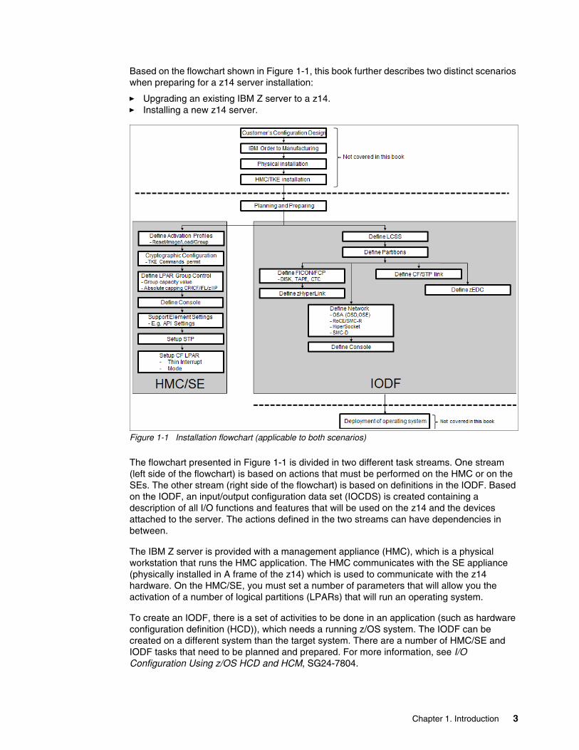
Based on the flowchart shown in Figure 1-1, this book further describes two distinct scenarios when preparing for a z14 server installation:
� Upgrading an existing IBM Z server to a z14.� Installing a new z14 server.
Figure 1-1 Installation flowchart (applicable to both scenarios)
The flowchart presented in Figure 1-1 is divided in two different task streams. One stream (left side of the flowchart) is based on actions that must be performed on the HMC or on the SEs. The other stream (right side of the flowchart) is based on definitions in the IODF. Based on the IODF, an input/output configuration data set (IOCDS) is created containing a description of all I/O functions and features that will be used on the z14 and the devices attached to the server. The actions defined in the two streams can have dependencies in between.
The IBM Z server is provided with a management appliance (HMC), which is a physical workstation that runs the HMC application. The HMC communicates with the SE appliance (physically installed in A frame of the z14) which is used to communicate with the z14 hardware. On the HMC/SE, you must set a number of parameters that will allow you the activation of a number of logical partitions (LPARs) that will run an operating system.
To create an IODF, there is a set of activities to be done in an application (such as hardware configuration definition (HCD)), which needs a running z/OS system. The IODF can be created on a different system than the target system. There are a number of HMC/SE and IODF tasks that need to be planned and prepared. For more information, see I/O Configuration Using z/OS HCD and HCM, SG24-7804.
Chapter 1. Introduction 3
This book covers what is needed from a HMC/SE and IODF perspective from the time when the z14 is delivered and physically installed up to the point when an LPAR is ready to be activated. The flowchart is intended to act as a checklist rather than a step-by-step procedure. Nevertheless, the steps in this book should provide enough information for you to replicate the approach in your environment.
For more information about how to deploy an operating system (z/OS in this case), see Mainframe from Scratch: Hardware Configuration and z/OS Build, SG24-8329.
1.3 Tools
Several tools are provided by IBM that help you to achieve a successful z14 server installation. These tools are covered in 2.2, “Tools” on page 8.
Whenever possible, throughout the book, checklists are provided that help you go through the steps required to complete a specified task.
In addition to the tools and checklists provided in this document, it is important that the planning and configuration steps are aligned with other technical departments within your organization such as storage and network administration, as well as with the capacity (workload) planning and cryptographic/security teams.
4 IBM z14 Configuration Setup

Chapter 2. Planning considerations
This chapter describes two scenarios for planning and configuration of an IBM z14 server. Whenever possible, worksheets that support the planning tasks described in this chapter are provided. Throughout this book, we provide various definition examples using hardware configuration definition (HCD) as the preferred method for configuration. Other tools, such as Hardware Configuration Manager (HCM) and ICP/IOCP are mentioned for reference only.
This chapter also provides a short overview of tools that IBM provides to help with the complexity of configuring a z14, and information about where to obtain the tools and their intended use.
This chapter highlights what should be considered when planning for creating the configurations (as described in 1.2, “Scope” on page 2):
� Activities centered on the HMC / SE:
– Defining Activation Profiles:
• Reset
• Image
• Load
• Group
– Cryptographic Configuration:
• TKE Commands permit
– Defining LPAR Group Control:
• Group capacity value
• Absolute capping CP/ICF/IFL/zIIP
– Defining Console
– Support Element Settings (for example, API settings)
– Setting up Server Time Protocol (STP)
2
© Copyright IBM Corp. 2017. All rights reserved. 5

� Activities centered on IODF:
– Defining the LCSS
– Defining Partitions
– Defining Storage:
• Defining IBM FICON®: Access to storage devices for devices using the FICON Protocol
• Defining FCP: Access to storage devices for devices using the Fibre Channel Protocol
• Defining CTC
– Defining zHyperLink Express
– Defining Network:
• OSA-Express OSD, OSE
• OSA-Express RoCE / SMC-R
• IBM HiperSockets™
• SMC-D
– Defining the Console
– Defining CF / STP links
– Defining zEDC
This chapter includes the following sections:
� Scenarios� Tools� IBM Resource Link� Hardware Configuration Definition tool� CHPID Mapping Tool� Other tools� Hardware Management Console/Support Element setup� Activities centered on the IODF
6 IBM z14 Configuration Setup
2.1 Scenarios
Throughout this book, we use two distinct scenarios by which we explain the tasks and procedures involved to successfully install and configure a z14 server.
2.1.1 Scenario 1: Upgrading an existing IBM Z server to a z14
This scenario assumes that an existing IBM Z environment where the existing IBM Z server is upgraded by using a miscellaneous equipment specifications (MES) to a z14. The scenario includes a planned outage period for the time of the physical upgrade of the machine. The software environments that are supported by this machine will not be available during this period. The serial number of the machine will remain the same after the upgrade.
2.1.2 Scenario 2: Installing a new z14 server
This scenario assumes that a new z14 is installed in an existing mainframe environment. The z14 machine will be physically installed along with an existing IBM Z machine. After the installation of the z14 has been successfully completed and the system has been handed over by the IBM service representative, the software environment on the machine to be replaced must be stopped and recabling actions must be performed.
When recabling is complete, postinstallation activities must be performed and the software environment can be brought back online on the new system (z14). An outage has still to be planned for this scenario, and a new serial number must be considered, so software keys for the new system must be available.
2.1.3 Differences in planning for the two scenarios
In the first scenario, the physical platform identity to be configured remains the same. No hardware configuration files must be physically migrated to another platform. The machine serial number remains the same after the upgrade, so no changes to the software licenses are required.
In the second scenario, the physical platform to be configured changes. Hardware configuration files must be prepared on the existing machine, and must be migrated (moved) to the new z14 server together with the attached cabling. The serial number changes with the activation of the z14 machine, which means that planning and preparing for software license changes must be considered.
In both scenarios, we assume that bringing up the existing features and functions has highest priority. Adding new features and functions (new functionality) acquired with the system upgrade or installed in the new z14 have a lower priority. The elapsed time of the planned outage can vary significantly, depending on the approach chosen in either scenario.
Chapter 2. Planning considerations 7
In both scenarios some information must be obtained before starting the process of changing to or installing the new z14:
� The new processor ID: The processor ID is used to assign a unique name to identify the processor in the HCD. See HCD Users Guide. SC34-2669 for details.
� The CFReport file: The CFReport file is downloadable from IBM Resource Link® by entering the Configuration Control Number (CCN). The CCN is provided by your IBM representative.
� The system serial number: If a new z14 will be installed, a new serial number is provided by your IBM representative.
2.2 Tools
IBM provides several tools to help with the complexity of configuring an IBM Z server. This section summarizes the various tools available for the IBM Z platform, and briefly outlines their benefits for the planning process.
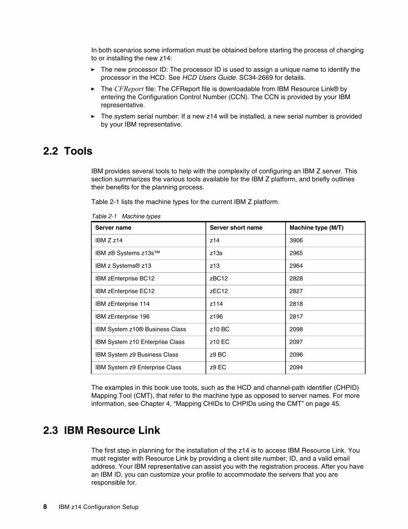
Table 2-1 lists the machine types for the current IBM Z platform.
Table 2-1 Machine types
The examples in this book use tools, such as the HCD and channel-path identifier (CHPID) Mapping Tool (CMT), that refer to the machine type as opposed to server names. For more information, see Chapter 4, “Mapping CHIDs to CHPIDs using the CMT” on page 45.
2.3 IBM Resource Link
The first step in planning for the installation of the z14 is to access IBM Resource Link. You must register with Resource Link by providing a client site number, ID, and a valid email address. Your IBM representative can assist you with the registration process. After you have an IBM ID, you can customize your profile to accommodate the servers that you are responsible for.
Server name Server short name Machine type (M/T)
IBM Z z14 z14 3906
IBM z® Systems z13s™ z13s 2965
IBM z Systems® z13 z13 2964
IBM zEnterprise BC12 zBC12 2828
IBM zEnterprise EC12 zEC12 2827
IBM zEnterprise 114 z114 2818
IBM zEnterprise 196 z196 2817
IBM System z10® Business Class z10 BC 2098
IBM System z10 Enterprise Class z10 EC 2097
IBM System z9 Business Class z9 BC 2096
IBM System z9 Enterprise Class z9 EC 2094
8 IBM z14 Configuration Setup

On the Resource Link website, you have access to various resources and tools that are designed to help the installation process. A number of tools are available to simplify the installation process of a z14 server. Even if you have worked with most of these tools before, be sure to check for the latest versions that are relevant to z14.
The Education and Library tabs on the website displays information about the IBM Z family and some online tutorials. Under the Tools tab, you can download the latest version of the most frequently used tools and obtain system and configuration information.
2.4 Hardware Configuration Definition tool
HCD is an application that runs on z/OS and IBM z/VM® that supplies an interactive dialog to generate the input/output definition file (IODF) and the input/output configuration data set (IOCDS). Generally, use HCD or HCM to generate the I/O configuration, rather than writing your own IOCP statements. HCD performs validation as you enter the data, thus minimizing the risk of errors. This book provides examples for using HCD, with some examples using HCM (see 2.4.1, “Hardware Configuration Manager” on page 9).
New hardware (z14) requires program temporary fixes (PTFs) to enable definition support in HCD.
Get the most current information about HCD at the Hardware Configuration page.
When defining devices in HCD, the hardware features can be selected according to the physical setup of the devices attached to the z14. Detailed forms and charts that describe the current environment facilitate the planning process.
2.4.1 Hardware Configuration Manager
HCM provides a graphical user interface to HCD and the associated IODF. HCM runs on a workstation and can also define and store more information about the physical hardware to which the IODF is defined.
HCM does not replace HCD. It is used with HCD and the associated IODF. However, HCM can be used in a stand-alone mode after an IODF is built and the configuration files (IODF##.HCM or IODF##.HCR) are created on your HCM workstation.
Get the most updated information about HCM at the Hardware Configuration page.
2.5 CHPID Mapping Tool
The CMT provides a mechanism to map physical channel IDs (PCHIDs) to CHPIDs as required on a z14. The CMT is optional but is preferred to manually mapping the PCHIDs to CHPIDs. Using the CMT provides the best availability recommendations for a particular configuration.
Chapter 2. Planning considerations 9

Two files are needed to obtain an IODF file containing the correct PCHID numbers by using CMT:
� A production IODF file without PCHID numbers. For information about how to obtain this file, see Chapter 4, “Mapping CHIDs to CHPIDs using the CMT” on page 45.
� The CFReport file reflecting the physical configuration of the ordered z14 server, obtained from the Resource Link website. The CCN is generated by your IBM Client Representative when building the order for your configuration.
2.5.1 HCD and the CMT
The HCD process flow for a new z14 installation is shown in Figure 2-1.
Figure 2-1 CMT: I/O configuration definition flow for a new installation
Part of the actions described in Figure 2-1 might also be valid for an upgrade, depending on the hardware configuration of the upgraded machine.
To download the CMT, log in to the Resource Link site with a registered Resource Link ID.
For more information, see the CHPID Mapping Tool Users Guide, GC28-6825. For a detailed description on how to use the CMT, see Chapter 4, “Mapping CHIDs to CHPIDs using the CMT” on page 45.
2.6 Other tools
The tools that are described in this section are not referenced in this book. However, they can help speed up the process of planning and configuring for specific topics outside of this book.
Hardware Configuration Dialog
IODFNo PCHIDs
IOCP DeckNo PCHIDs
IOCP Deckw ith
PCHIDs
IODF w ithPCHIDs
H/W Config File
(CCN)
Reports
CHPID Mapping Tool
4. Run CHPID Mapping Tool.Produce an IOCP deckwith PCHIDs assigned.
1. Create IODF without PCHIDs.
2. Create Validated Work IODF.
3. Create IOCP deck.Build IOCP input data set.
5. Import IOCP deck with PCHIDsinto IODF.
6. Create a production IODF.Build production I/O definition file.
10 IBM z14 Configuration Setup
2.6.1 Input/output configuration program
ICP IOCP Version 5 Release 4.0 or later is required for a z14 server. You can define the z14 configuration by using only IOCP. However, HCD is suggested because of its verification and validation capabilities. By using ICP IOCP, it is possible to write an IOCDS in preparation for a CPC upgrade.
For more information about the changes and requirements for ICP IOCP, see IBM Z Input/Output Configuration Program User's Guide for ICP IOCP, SB10-7172.
2.6.2 Worldwide Port Name Prediction Tool
The worldwide port name (WWPN) Tool for IBM Z Fibre Channel Protocol (FCP) Channels helps prepare configuration files that are required or generated by the IBM Z platform when FCP Channels are installed. In particular, this tool helps during the installation of new systems and system upgrades.
One of the most important configuration parameters are WWPNs, which uniquely identify physical or virtual Fibre Channel ports. They are typically used in Fibre Channel Storage Area Network (SAN) switches to assign the corresponding ports to zones of a SAN. They are used in storage subsystems to grant access from these ports to specific storage devices that are identified by logical unit numbers (LUNs).
The capability of the WWPN Prediction Tool is extended to calculate and show WWPNs for both virtual and physical ports before system installation.
The WWPN Prediction Tool is available for download from IBM Resource Link and is applicable to all FICON channels defined as CHPID type FCP (for communication with SCSI devices) on z14. You can access the tool at this web page using your IBMid.
WWPN PersistenceThe FCP WWPNs are determined based on the I/O serial number of the CPC, the IOCDS configuration details (for NPIV WWPNs), and the PCHID values (for physical WWPNs). With the introduction of the z13, WWPN Persistence configuration option has been introduced. When FC #0099 (WWPN Persistence) is ordered as part of a new or upgraded configuration for a z14, the I/O serial number part of the WWPN for the new z14 is the same serial number as for the source machine configuration.
For more information, see the Techdocs website.
2.6.3 Coupling Facility Structure Sizer (CFSizer)
Moving to a new z14 means migrating to a higher CFCC level (CFCC level 22). If your existing CF data structures are adequately sized, and you want to know how much these structures might need to grow to accommodate the same workload at the new CFCC level, you can use the current structure sizes to calculate the new sizes. The CFSizer Tool helps you evaluate the sizing of the CF structures.
Use the CFSizer tool to plan the amount of storage that must be allocated for coupling facility partitions more accurately. You can access the tool from the CFSizer page.
Chapter 2. Planning considerations 11
2.6.4 Power Estimation Tool
The Power Estimation Tool is a web-based tool that allows you to estimate the power consumption for your IBM Z server. The tool also estimates the machine’s weight.
See the IBM Resource Link to access the tool.
2.6.5 SMC Applicability Tool
A tool called Shared Memory Communications (SMC) Applicability Tool (SMCAT) has been created that helps customers to determine the value of SMC-R and SMC-D in their environment with minimal effort and minimal impact.
SMCAT is integrated within the TCP/IP stack and gathers new statistics that are used to project SMC applicability and benefits for the current system. For more information, see the Shared Memory Communications Reference Information website.
2.6.6 zBNA Tool
zBNA is a PC-based productivity tool designed to provide a means of estimating the elapsed time for batch jobs solely based on the differences in CPU speeds for a base processor and a target processor, the number of engines on each system, and system capacities. Data sharing is not considered. zBNA provides powerful, graphic demonstration of the z/OS batch window.
The zBNA Tool also provides the capability to project the benefits of deploying the zEDC Express feature.
The zBNA tool and its Users Guide can be downloaded from the IBM z Systems Batch Network Analyzer (zBNA) Tool website.
2.7 Hardware Management Console/Support Element setup
This section introduces the configuration and management tools and procedures available on the Hardware Management Console (HMC) and the Support Element (SE).
2.7.1 Defining the HMC Activation Profiles
Activation profiles must be customized by using the HMC. Activation profiles are required for central processor complex (CPC) and CPC image activation. They are used to tailor the operation of a CPC and are stored in the SE associated with the CPC. There are four types of activation profiles:
� Reset: A reset profile is used to activate a CPC and its images.
� Image: An image profile is used to activate an image of a CPC previously activated.
� Load: A load profile is used to load a previously activated image with a control program or operating system.
� Group: A group profile is used to define the group capacity value for all logical partitions belonging to that group.
12 IBM z14 Configuration Setup
Default profiles of each of these types are provided. The Activate task activates the CPC or CPC image. Initially, the Default profile is selected. You can specify an activation profile other than the Default. This feature provides you with the capability to have multiple profiles, for example one for every IOCDS file managed by the CPC.
Reset ProfileEvery CPC in the processor cluster needs a reset profile to determine the mode in which the CPC Licensed Internal Code will be loaded and how much main storage will be used. Using the reset profile, you must provide the order in which the LPARs will be activated during power-on reset (POR). The maximum number of Reset profiles allowed for each CPC is 26.
For more information about how to define a Reset Profile, see 5.3, “Creating a Reset Profile on the 3906 Support Element” on page 96.
Image ProfileSelect the appropriate RESET profile and within the profile, select the appropriate IOCDS. The list of LPARs defined in the IOCDS will be displayed. Parameters must be set for each LPAR before it can be activated and IPLed. The parameters for each LPAR define these settings:
� General: The mode of operation and its identifier� Processor: The number of logical CPs, zIIPs, and the weight assigned to the processor� Security: The security options for this LPAR� Storage: Memory and Virtual Flash Memory assigned to this LPAR� Options: The I/O priority and defined capacity options� Load: The load parameters necessary to IPL this LPAR� Crypto: The Crypto express parameters (also see 2.7.2, “Cryptographic configuration” on
page 14)
For more information about how to define an Image Profile, see 5.4, “Creating an Image Profile on the 3906 Support Element” on page 101.
Load profileA Load profile is needed to define the channel address of the device from which the operating system will be loaded. Depending on the Support Element model and machine type, the maximum number of Load profiles that are allowed for each CPC is 64 - 255.
Group profileA Group profile defines the group capacity value that can be customized in determining the allocation and management of processor resources assigned to the logical partition in a group.
Note: To help you gathering the necessary input, a worksheet is provided with this book. See Appendix A, “Additional material” on page 403 for information about downloading the worksheet associated with this material.
Chapter 2. Planning considerations 13
2.7.2 Cryptographic configuration
The activation profile that you use to activate a logical partition prepares it for running software products that use the Crypto Express feature. Using the feature’s cryptographic facilities and functions requires customizing the logical partition’s activation profile to accomplish these tasks:
� Install the CP Assist for Cryptographic Facility (CPACF) DES/TDES Enablement feature if you are planning to use ICSF.
� Give it access to at least one Crypto Express feature. This goal is accomplished by selecting from the Usage Domain Index and the Cryptographic Candidate list.
� Load it with an operating system, such as z/OS, that supports using cryptographic functions.
For more information about the cryptographic feature, see 10.1, “Crypto Express6S” on page 228.
2.7.3 Defining the LPAR Group Control
The following are methods that can be used to limit the processor capacity usage for a group of LPARs and help you control software cost:
� Group Capacity is capping the processor consumption to the value of the four hour rolling average (4HRA) for a group of LPARs.
� LPAR group absolute capping value is independent of the 4H rolling average consumption and limits the amount of physical processor capacity that is consumed by a group of LPARs
Both methods (group capacity and LPAR group absolute capping) can be used concurrently and in combination with LPAR capping.
Consider reevaluating the parameters in a scenario where the values must be migrated from a previous generation CPC to a z14 so they fit to the new CPC.
A good overview of the capping technologies and 4HRA Optimization can be found in the Capping Technologies and 4HRA Optimization document.
2.7.4 Defining the Console (HMC part)
The OSA-ICC function of the OSA-Express 1000Base-T feature supports TN3270 enhancements (TN3270E) and non-SNA distributed function terminal (DFT) 3270 emulation. Planning for an IBM z14 OSA-ICC implementation requires input from a number of disciplines within a customer organization:
� IBM Z server I/O subsystem configuration� Operating system configuration� OSA-Express feature configuration� Ethernet LAN configuration� Client TN3270E configuration
Tip: Capacity management using capping technologies is an ongoing process that must be monitored and adjusted over time. Temporary or permanent capacity changes also must be considered when using capping technologies.
14 IBM z14 Configuration Setup

The OSA-Express feature configuration requires configuration tasks to be performed on the HMC using the OSA Advanced Facilities task. Collect information for the following parameters before starting the configuration activities:
� OSA-ICC server: Name, Host IP address, TCP port number, Gateway IP address, the netmask, the network type, and the MTU size
� OSA-ICC session definitions: Channel subsystem, the MIF (LPAR) ID, Device number, LU-name, clients’ IP address, clients’ DHDTO/RSP/RTO
For an upgrade of an existing IBM Z server to a z14, these definitions can be exported from the source machine using on-board HMC facilities and imported back again after the upgrade is complete.
See Chapter 7, “Defining console communication” on page 147 for details about the definitions. Also, see the OSA-Express Integrated Console Controller Implementation Guide, SG24-6364, for implementation details.
2.7.5 Support Element settings
The SEs supplied with the z14 are two appliances based on 1U x86 servers. Both units are installed at the top of the A frame. One is a primary SE and the other is the alternate SE.
Generally, the SE settings are considered part of the physical installation of the z14 server and therefore not presented in this book. For a new z14 server, a new range of TCP/IP addresses must be provided by the customer to the system services representative (SSR) who performs the physical installation. As an extra measure of security, provisioning of a separate LAN segment for the management functions is preferred. During an upgrade from an older IBM Z server to a z14, the current settings on the SEs should be backed up for migration purposes.
In addition to the standard SE configuration, there could be also other parameters that should be backed up, such as the API Settings. These parameters can be accessed through the Customize API Settings task on the SE.
2.7.6 Setting up Server Time Protocol
STP provides the means by which the time of day (TOD) clocks in various systems can be synchronized by using messages transported over coupling links. STP operates along with the TOD-clock steering facility, providing a new timing mode, timing states, external interrupts, and machine check conditions.
The HMC provides the user interface to manage an STP-only Coordinated Timing Network (CTN).
Consider the following items when setting up an HMC for STP:
� A CTN ID (must be unique for all IBM Z servers that will be part of the CTN).
� To synchronize IBM Z servers to an External Time Source (ETS), then a network Time Protocol (NTP) server information (and network connectivity using NTP/NTPS protocol with optional pulse per second (PPS)) must be provided.
� The time zone offset, Daylight Saving Time offset, and leap second offset.
Note: Consider defining multiple sessions per LPAR to allow access for a number of users at the same time.
Chapter 2. Planning considerations 15

� Optional, the HMC can be configured as an NTP server.
� For the IBM Z servers that are part of a CTN, STP roles must be planned (Preferred, Backup, and Current Time Servers as well as Arbiter).
� As part of a migration, changing the Current Time Server must be done before migration to the new platform (z14).
For details, see Chapter 8, “Preparing for Sysplex and configuring Server Time Protocol” on page 163For detailed information about planning, implementing, and managing an STP environment, see Server Time Protocol Planning Guide, SG24-7280, Server Time Protocol Planning Guide, SG24-7280 and Server Time Protocol Recovery Guide, SG24-7380.
2.8 Activities centered on the IODF
This section describes the information (I/O configuration) in the IODF.
2.8.1 Logical channel subsystems
An IBM Z processor manages I/O resources (logical partitions, channel paths, control units, I/O devices) by housing them in multiple logical channel subsystems. Each logical channel subsystem (LCSS) can have up to 256 channel paths. The z14 supports up to 6 LCSSs.
A spanned channel path is one that can be used by partitions in more than one logical channel subsystem. You must use the same CHPID value across all logical channel subsystems sharing a spanned channel. However, logical channel subsystems that do not share a spanned channel can use that CHPID for other channels.
For more information, see z/OS Hardware Configuration Definition Planning, GA32-0907.
Planning should consider multiple logical channel subsystems, which allow you to logically partition your physical channel resources to accommodate large-scale enterprise workload connectivity and high-bandwidth demands. Each LCSS can have up to 256 CHPIDs. On the z14, you can define up to six LCSSs. Each LCSS can support up to 15 logical partitions (LPARs) except for LCSS 5, which can support up to 10 LPARs for a total of 85 LPARs per z14 server.
Additionally, LCSSs provide for multiple subchannel sets for expanding the number of I/O devices managed in each CSS. The z14 supports up to four subchannel sets per LCSS.
Not all device types are eligible for nonzero subchannel sets. Subchannel set 0 (SS0) can be used for any type of device. Additional subchannel sets (for example: subchannel set 1 (SS1)) can only be used for certain classes of devices, such as parallel access volume alias devices.
For more information, see IBM z14 Technical Guide, SG24-8451.Use multiple subchannel sets to move devices of eligible device types to additional subchannel sets, then define more physical devices to SS0.
Note: The z14 supports STP stratum level 4. This feature avoids the additional complexity and expense of system reconfiguration. All systems that might become exposed to this situation should have this change installed. Stratum level 4 should only be used during a migration, and for a short period.
16 IBM z14 Configuration Setup

2.8.2 Defining partitions
The IBM Processor Resource/System Manager (PR/SM™) feature allows a single CPC to run multiple operating systems in LPAR mode. Each operating system has its own logical partition, which is a separate set of system resources that includes these items:
� A portion of storage (memory).� One or more central and specialty processors. The processors can be dedicated or
shared.
Only LPAR mode (not basic mode) is supported on IBM Z servers.
Profile data can be exported on the older server and imported on the z14. If the LPAR data has been imported from an older server, consider the LPAR sizing before the LPAR migration to the z14.For additional information, see the Support Element Operations Guide at IBM Knowledge Center.
For more information about how to define LPARs in IODF, see Chapter 3, “Preparing for a new z14” on page 29.
Planning considerations for Virtual Flash MemoryIBM Virtual Flash Memory (VFM - Feature Code #0604) is the replacement for the Flash Express features (FC #0402 and FC #0403).
IBM VFM minimum software requirements are:
� z/OS V2.3.� z/OS V2.2.� z/OS V2.1.� z/OS V1.13 with PTFs, the z/OS V1.13 RSM Enablement Offering web deliverable
installed, and an extended support contract for IBM Software Support Services. The web deliverable is available at the z/OS downloads page.
VFM (FC #0604) is available in 1.5 TB increments, each feature providing for 1.5 TB (1536 GB) of memory. Up to four VFM features can be ordered, resulting in a total of 6 TB of virtual flash memory. Both the ‘plan ahead memory option’ and the ‘flexible memory option’ must consider VFM requirements.
With the introduction of VFM, there are no changes to existing operating system interface for handling the storage-class memory (SCM). OS handles VFM the same way as the Flash Express. The allocation of VFM storage is done during LPAR activation because the LPAR hypervisor manages the partition memory.
Both the initial and maximum amounts of VFM are specified in the LPAR image profile. VFM can be added or deleted to/from operating systems by using existing SCM commands after the LPAR has been activated. VFM allocation and definition for all partitions can be displayed on the Storage Information window on the HMC and using SCM commands in z/OS.
Note: The VFM values for Initial and Maximum allocations cannot be dynamically changed. One or more partitions must be activated (or reactivated) for VFM allocation changes to take effect.
Chapter 2. Planning considerations 17

At partition activation time, over-commitment of VFM storage is supported. To allow for LPARs to concurrently allocate more VFM than their initial value, the Maximum value for VFM storage on the LPAR image profile can be set to the maximum of physically available VFM storage for each LPAR. This setting allows more storage to be added to partitions subject to the amount that is not assigned to other partitions. This concern is shown in 10.3.3, “Configuring VFM” on page 261.
If the total amount of VFM allocated to all active partitions is equal to the LICCC value, but the sum of active partition maximums is larger than the installed amount, customer might be able to concurrently add VFM and increase allocations without reactivating partitions. This feature can be illustrated in the following examples.
Non-disruptive migrationThe following is an example of a non-disruptive migration:
� A z14 CPC has one VFM feature installed, LICCC = 1.5 TB.
� LPAR A has 1.0 TB assigned, max = 1.5 TB.
� LPAR B has 0.5 TB assigned, max = 1.5 TB.
� Now LPAR B must be altered to have 1.0 TB assigned. This change is not possible within the constraints of installed VFM.
� Another 1.5 TB VFM feature is purchased and installed concurrently. Now up to 1.0 TB can be added concurrently to LPAR B without reactivating the LPAR.
Figure 2-2 shows the non-disruptive migration example.
Figure 2-2 Non-disruptive VFM migration example
Disruptive migrationThe following is an example of a disruptive migration:
� A z14 CPC has one VFM feature installed, LICCC = 1.5 TB.
� LPAR A has 1.0 TB assigned, max = 1.5 TB.
� LPAR B has 0.5 TB assigned, max = 1.5 TB.
INIT
MAX
INIT
MAX
LPAR A LPAR B
VFM installed
1,5 TB
1,0 TB
0,5 TB
After :
added
2,0 TB
2,5 TB
3,0 TB
INIT
MAX
INIT
MAX
LPAR A LPAR B
VFM installed 1,5 TB
1,0 TB
0,5 TB
Before :
18 IBM z14 Configuration Setup

� Now LPAR A must be altered to have up to 2 TB. This change falls outside the range of maximum installed VFM.
� Another 1.5 TB VFM feature is purchased and installed concurrently. Now LPAR A must be reactivated with the new maximum VFM value of at least 2 TB and less than or equal to 3.0 TB.
Figure 2-3 shows the disruptive migration example.
Figure 2-3 Disruptive VFM migration example
For details of how to configure VFM, see 10.3, “Virtual Flash Memory” on page 261.
2.8.3 Defining Storage I/O - FICON and FCP
FICON Express16S+, FICON Express 16S and FICON Express8S features provide connectivity to storage devices by using Fibre Connection (FICON) or Fibre Channel Protocol (FCP). FICON Express16S+ and FICON Express 16S features support auto negotiation for the link data rate: 4 Gbps, 8 Gbps, and 16 Gbps. FICON Express8S supports auto negotiation for the link data rate at 2 Gbps, 4 Gbps, and 8 Gbps.
FICON Express16S+, FICON Express16S, and FICON Express8S support High Performance FICON for z IBM z Systems (zHPF). zHPF is an extension to the FICON architecture that provides performance improvement for single-track and multi-track operations.
On a new build z14 server, only the FICON Express16S+ feature can be ordered. The FICON Express16S and FICON Express8S features can be carried forward when upgrading from an older IBM Z server.
INIT
MAX
INIT
MAX
LPAR A LPAR B
VFM installed
1,5 TB
1,0 TB
0,5 TB
After :
2,0 TB
2,5 TB
3,0 TB
INIT
MAX
INIT
MAX
LPAR A LPAR B
VFM installed 1,5 TB
1,0 TB
0,5 TB
Before :
Note: On a FICON Express16S+ feature, both ports must be configured either as channel type FC or FCP. A mixed configuration is not allowed.
Chapter 2. Planning considerations 19

For detailed information about how to configure a FICON Express16S+ feature, see Chapter 12, “Adding storage devices” on page 289.
2.8.4 Defining the IBM zHyperLink Express
For detailed information about defining zHyperLink Express, see 10.6, “IBM zHyperlink Express” on page 276.
2.8.5 Defining Network
This section provides planning considerations for deploying the network-related features:
� OSA features
� Shared Memory Communications (SMC-R and SMC-D) features:
– SMC - RDMA over Converged Ethernet (RoCE) Express features (SMC-R)
– SMC - Direct Memory Access over Internal Shared Memory (SMC-D)
� HiperSockets
Open Systems Adapter (OSA)The OSA Express features are installed in an IBM Z server I/O drawer. The features are available as different types and support several networking protocols. Depending on the types of OSAs installed in the z14, the CPC supports attachment with the following characteristics:
� Copper-based Ethernet (10, 100 and 1000 Mbps)� Fiber-based Gigabit Ethernet (GbE), Short Wave (SX), and Long Wave (LX) � Fiber-based 10-Gigabit Ethernet Short Reach (SR) and Long Reach (LR)
Based on the intended use, the operating modes must be defined with channel type and device address. For configuration details, see Chapter 6, “Configuring network features” on page 125 and the OSA-Express Implementation Guide, SG24-5948.
IBM z14 will be the last z Systems and IBM Z high-end server to support FICON Express8Sa: z14 will be the last z Systems and IBM Z high-end server to support FICON Express8S (#0409 and #0410) channels. Enterprises should begin migrating from FICON Express8S channels to FICON Express16S+ channels (#0427 and #0428). FICON Express8S will not be supported on future high-end IBM Z servers as carry forward on an upgrade.
a. The statements from IBM regarding its plans, directions, and intent are subject to change or withdrawal without notice at IBM’s sole discretion. Information regarding potential future products is intended to outline our general product direction and it should not be relied on in making a purchasing decision.
IBM intends to deliver IMS™ exploitation of IBM z14 and DS8880 zHyperLink WRITE operationsa: zHyperLink Express is a direct connect short distance IBM Z I/O adapter designed to work with a FICON or High-Performance FICON SAN infrastructure.
a. IBM’s statements regarding its plans, directions, and intent are subject to change or withdrawal without notice at IBM’s sole discretion. Information regarding potential future products is intended to outline our general product direction and it should not be relied on in making a purchasing decision.
20 IBM z14 Configuration Setup
Starting with Driver Level 22 (HMC 2.13.0) installed on z13, HMC has been enhanced to take advantage of the Open Systems Adapter/Support Facility (OSA/SF) function for the OSA-Express6S, OSA-Express5S, and OSA-Express4S features. Either OSA/SF on the HMC or the OSA/SF in the operating system component can be used for the OSA-Express4S features. For the OSA-Express6S and OSA-Express5S features, OSA/SF on the HMC is required. The OSA/SF is used primarily for these purposes:
� Manage all OSA ports.
� Configure all OSA non-QDIO ports.
� Configure local MAC addresses.
� Display registered IPv4 addresses (in use and not in use). It is supported on IBM Z platform for QDIO ports.
� Display registered IPv4 or IPv6 Virtual MAC and VLAN ID associated with all OSA Ethernet features configured as QDIO Layer 2.
� Provide status information about an OSA port and its shared or exclusive use state.
See 6.3, “Customizing OSA-Express using OSA Advanced facilities” on page 129 for details about the use of OSA/SF on the HMC.
Shared Memory Communications - RDMAThe 10GbE RoCE Express (FC #0411) and 10GbE RoCE Express2 (FC #0412) features are designed to help reduce CPU consumption for applications that use the TCP/IP stack without requiring application changes. Using the RoCE Express features also helps to reduce network latency using the SMC-R protocol in z/OS V2.1 or later. For more information, see RFC 7609. SMC-R is transparent to applications and can be used for LPAR-to-LPAR communications on a single CPC or for server-to-server communications across multiple IBM Z CPCs.
Deployment of the RoCE Express features is supported in either point-to-point configuration or switched configurations. When planning to deploy RoCE Express features in a switched configuration, the switches must support the following requirements:
� Global Pause function frame (as described in the IEEE 802.3x standard) should be enabled
� Priority Flow Control (PFC) disabled
� No firewalls, no routing
IBM provides the SMC Applicability Tool (SMCAT) that helps determine the potential gains of using SMC-R in an environment (see 2.6.5, “SMC Applicability Tool” on page 12).
With z14, the new 10GbE RoCE Express2 feature is available. This feature provides increased virtualization (sharing) capabilities. For more information, see IBM z14 Technical Guide, SG24-8451.
OSA-Express6S 1000BASE-T adaptersa: OSA-Express6S 1000BASE-T adapters (#0426) will be the last generation of OSA 1000BASE-T adapters to support connections operating at 100 Mbps link speed. Future OSA-Express 1000BASE-T adapter generations will support operation only at 1000 Mbps (1 Gb/s) link speed.
a. IBM’s statements regarding its plans, directions, and intent are subject to change or withdrawal without notice at IBM’s sole discretion. Information regarding potential future products is intended to outline our general product direction and it should not be relied on in making a purchasing decision.
Chapter 2. Planning considerations 21
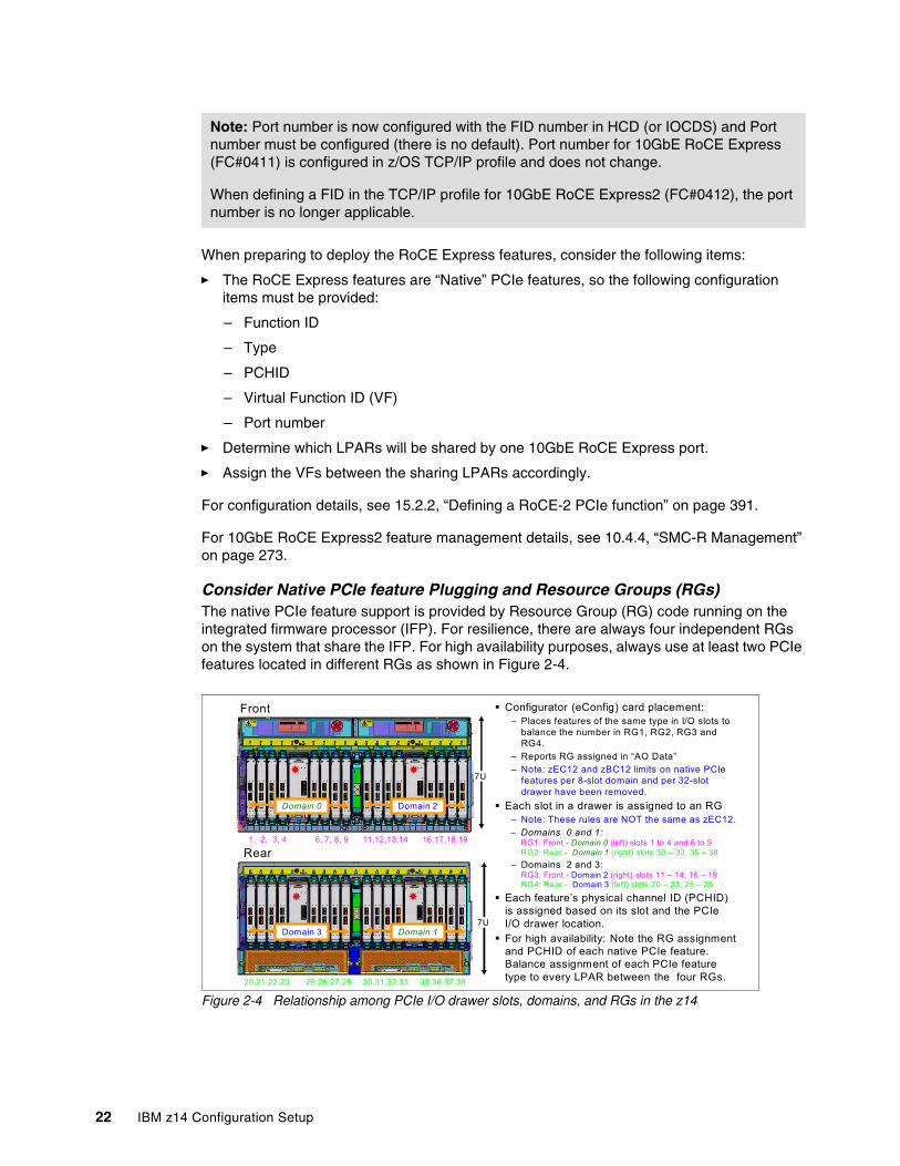
When preparing to deploy the RoCE Express features, consider the following items:
� The RoCE Express features are “Native” PCIe features, so the following configuration items must be provided:
– Function ID
– Type
– PCHID
– Virtual Function ID (VF)
– Port number
� Determine which LPARs will be shared by one 10GbE RoCE Express port.
� Assign the VFs between the sharing LPARs accordingly.
For configuration details, see 15.2.2, “Defining a RoCE-2 PCIe function” on page 391.
For 10GbE RoCE Express2 feature management details, see 10.4.4, “SMC-R Management” on page 273.
Consider Native PCIe feature Plugging and Resource Groups (RGs)The native PCIe feature support is provided by Resource Group (RG) code running on the integrated firmware processor (IFP). For resilience, there are always four independent RGs on the system that share the IFP. For high availability purposes, always use at least two PCIe features located in different RGs as shown in Figure 2-4.
Figure 2-4 Relationship among PCIe I/O drawer slots, domains, and RGs in the z14
Note: Port number is now configured with the FID number in HCD (or IOCDS) and Port number must be configured (there is no default). Port number for 10GbE RoCE Express (FC#0411) is configured in z/OS TCP/IP profile and does not change.
When defining a FID in the TCP/IP profile for 10GbE RoCE Express2 (FC#0412), the port number is no longer applicable.
Configurator (eConfig) card placement: – Places features of the same type in I/O slots to
balance the number in RG1, RG2, RG3 and RG4.
– Reports RG assigned in “AO Data”– Note: zEC12 and zBC12 limits on native PCIe
features per 8-slot domain and per 32-slot drawer have been removed.
Each slot in a drawer is assigned to an RG– Note: These rules are NOT the same as zEC12.– Domains 0 and 1:
RG1: Front - Domain 0 (left) slots 1 to 4 and 6 to 9RG2: Rear - Domain 1 (right) slots 30 – 33, 35 – 38
– Domains 2 and 3:RG3: Front - Domain 2 (right) slots 11 – 14, 16 – 19RG4: Rear - Domain 3 (left) slots 20 – 23, 25 – 28
Each feature’s physical channel ID (PCHID) is assigned based on its slot and the PCIe I/O drawer location.
For high availability: Note the RG assignment and PCHID of each native PCIe feature. Balance assignment of each PCIe feature type to every LPAR between the four RGs.
Front
7U
Domain 0 Domain 2
1, 2, 3, 4 6, 7, 8, 9 11,12,13,14 16,17,18,19
7U
Rear
Domain 3 Domain 1
20,21,22,23 25,26,27,28 30,31,32,33 35,36,37,38
22 IBM z14 Configuration Setup

Shared Memory Communications - Direct Memory Access (SMC-D)With the z13 (Driver 27) and z13s servers, IBM introduced SMC-D. SMC-D uses Internal Shared Memory (ISM) virtual PCIe adapter to provide direct memory access communications between LPARs inside the same IBM Z CPC.
SMC-D maintains the socket-API transparency aspect of SMC-R so that applications that use TCP/IP communications can benefit immediately without requiring any application software or IP topology changes. SMC-D completes the overall Shared Memory Communications solution, providing synergy with SMC-R. Both protocols use shared memory architectural concepts, eliminating TCP/IP processing in the data path, yet preserving TCP/IP Qualities of Service for connection management purposes.
From a planning standpoint, SMC-D is similar to SMC-R, so the same planning considerations apply. The objective is to provide consistent operations and management tasks for both SMC-D and SMC-R. SMC-D uses a new virtual PCI adapter called Internal Shared Memory (ISM). The ISM Interfaces are associated with IP interfaces (for example HiperSockets or OSA, ISM interfaces do not exist without an IP interface).
ISM interfaces are not defined in software. Instead, ISM interfaces are dynamically defined and created, and automatically started and stopped. You do not need to operate (Start or Stop) the ISM interfaces. Unlike RoCE, ISM FIDs (PFIDs) are not defined in software. Instead, they are auto-discovered based on their PNet ID.
Before implementing SMC-R or SMC-D, check your environment for the following items:
� Run the SMCAT to evaluate applicability and potential value. For information about the SMCAT, see the IBM z/OS SMC Applicability Test (SMC-AT) document.
See 2.6.5, “SMC Applicability Tool” on page 12 in this chapter for more information.
� Review and adjust as needed the available real memory and fixed memory usage limits (z/OS and CS). SMC requires fixed memory. You might need to review the limits and provision additional real memory for z/OS.
� Review IP topology, VLAN usage considerations, and IPSec.
� Review changes to messages, monitoring information, and diagnostic tools. There are numerous updates to these items:
– Messages (IBM VTAM® and TCP stack)
– Netstat (status, monitoring, and display information)
– CS diagnostic tools (VIT, Packet trace, CTRACE, and IPCS formatted memory dumps)
For more information about SMC-R planning and security considerations, see the SMC-R tab on the Shared Memory Communications Reference Information page.
For more information about SMC-D planning and security considerations, see the SMC-D tab on the Shared Memory Communications Reference Information page.
For more information about how to define SMC-D, see 15.2.1, “Defining an ISM PCIe function” on page 388.
For an overview of how to manage an SMC-D connection, see 10.5.4, “SMC-D management” on page 275.
Chapter 2. Planning considerations 23
HiperSocketsHiperSockets provides the fastest TCP/IP communications between z/OS, z/VM, IBM z/VSE®, and Linux logical partitions within a z14 CPC, that act like internal “virtual” local area networks. This is achieved by using the Licensed Internal Code (LIC) and supporting device drivers in the operating systems. HiperSockets establishes a network with higher availability, security, simplicity, performance, and cost effectiveness than can be achieved by using an external IP network.
The HiperSockets function is based on the OSA-Express queued direct input/output (QDIO) protocol and hence HiperSockets is called internal QDIO (iQDIO). The LIC emulates the link control layer of an OSA-Express QDIO interface, and uses no physical cabling or external networking connections. Data access is performed at memory speeds, bypassing external network delays and provides users high-speed logical LANs with minimal system and network overhead.
HiperSockets can be defined as Multiple Image Facility (MIF)-shared in a CSS and as spanned channels across multiple CSSs. A HiperSockets CHPID can be seen as an internal LAN to the server. The level of sharing is determined by the logical partitions you want to grant access to that LAN.
HiperSockets is supported by the following operating systems:
� All in-service z/OS releases� All in-service z/VM releases� All in service z/VSE releases� Linux on z Systems
On a z14, HiperSockets supports the following functions:
� HiperSockets Broadcast
Supported across HiperSockets on Internet Protocol Version 4 (IPv4) for applications. Applications that use the broadcast function can propagate the broadcast frames to all TCP/IP applications that are using HiperSockets. This support is applicable in Linux, z/OS, and z/VM environments.
� VLAN support
Virtual local area networks (VLANs) are supported by Linux on z Systems and z/OS V1R8 or later for HiperSockets. VLANs can reduce overhead by allowing networks to be organized by traffic patterns rather than physical location. This enhancement allows traffic flow on a VLAN connection both over HiperSockets and between HiperSockets and OSA-Express Ethernet features.
� IPv6 support on HiperSockets
� HiperSockets Network Concentrator
Traffic between HiperSockets and OSA-Express can be transparently bridged by using the HiperSockets Network Concentrator. This configuration eliminates intervening network routing overhead, resulting in increasing performance and a simplified network configuration. This improvement is achieved by configuring a connector Linux system that has HiperSockets and OSA-Express connections defined to it.
� HiperSockets Layer 2 support
HiperSockets supports two transport modes on the z14 Layer 2 (Link Layer) and Layer 3 (Network and IP Layer).
24 IBM z14 Configuration Setup
As with Layer 3 functions, HiperSockets Layer 2 devices can be configured as primary or secondary connectors or multicast routers. These configurations enable high performance and highly available Link Layer switches between the HiperSockets network and an external Ethernet.
� HiperSockets multiple write facility
HiperSockets performance has been increased by allowing streaming of bulk data over a HiperSockets link between logical partitions. Multiple writes with fewer I/O interrupts reduce processor usage of both the sending and receiving logical partitions, and is supported in z/OS.
� HiperSockets Completion Queue
The HiperSockets Completion Queue function is designed to allow HiperSockets to transfer data synchronously if possible, and asynchronously if necessary. This function combines ultra-low latency with more tolerance for traffic peaks.
With the asynchronous support, during high volume situations, data can be temporarily held until the receiver has buffers available in its inbound queue. This function provides end-to-end performance improvement for LPAR to LPAR communication.
� HiperSockets Virtual Switch Bridge Support
The z/VM virtual switch is enhanced to transparently bridge a guest virtual machine network connection on a HiperSockets LAN segment. z/VM 6.2 or later, TCP/IP, and Performance Toolkit APARs are required for this support. This bridge allows a single HiperSockets guest virtual machine network connection to also directly communicate with the following devices:
– Other guest virtual machines on the virtual switch
– External network hosts through the virtual switch OSA UPLINK port
� zIIP-Assisted HiperSockets for large messages
In z/OS, HiperSockets has been enhanced for zIIP exploitation. Specifically, the z/OS Communications Server allows the HiperSockets Multiple Write Facility processing for large outbound messages that originate from z/OS to be run on a zIIP.
z/OS application workloads that are based on XML, HTTP, SOAP, Java, and traditional file transfer can benefit from zIIP enablement by lowering general-purpose processor usage.
When the workload is eligible, the HiperSockets device driver layer processing (write command) is redirected to a zIIP, which unblocks the sending application.
For more information about the technical details of each function, see IBM Z Connectivity Handbook, SG24-5444.
2.8.6 Defining the console (OSA-ICC)
The OSA-ICC function of the OSA-Express 1000Base-T feature supports TN3270 enhancements (TN3270E) and non-SNA DFT 3270 emulation. Planning for an IBM Z z14 OSA-ICC implementation requires input from a number of disciplines within a customer organization:
� IBM Z server I/O subsystem configuration� Operating system configuration� OSA-Express feature configuration� Ethernet LAN configuration� Client TN3270E configuration
Chapter 2. Planning considerations 25
In HCD, the OSA-Express feature must be defined to operate as an Integrated Console Controller (ICC). Configuration requirements are as follows:
� IBM Z server I/O subsystem configuration: The same basic rules for adding a OSA-ICC adapter apply as to any other new device.
� Operating system configuration: To have a Nucleus Initialization Program (NIP) console available, make sure that the correct device number is defined in the HCD Operating system Work with consoles dialog.
During an upgrade from an existing IBM Z server to a z14, the same definitions can be used for the new machine as on the source configuration.
See the OSA-Express Integrated Console Controller Implementation Guide, SG24-6364, for implementation details.
The following planning topics must be considered:
� Reserve at least one OSA-Express 1000Base-T port to be defined as channel type OSC� Define 3270-X Devices in HCD to act as system consoles� The use of OSA/Advanced facilities to configure the sessions
For more information about how to configure non-SNA consoles, see Chapter 7, “Defining console communication” on page 147.
2.8.7 Defining coupling and timing only links
Support for Parallel Sysplex includes the Coupling Facility Control Code and coupling links. A new Coupling connectivity in support of Parallel Sysplex environments is provided on the z14 by the following feature:
� Coupling Express Long Reach (CE LR). The feature (FC #0433) has two ports coupling link connectivity for a distance up to 10 km (6.2 miles).
� Integrated Coupling Adapter (ICA SR), FC #0172.
� HCA3-O, 12x InfiniBand (FC #0171).
� HCA3-O LR, 1x InfiniBand (FC #0170).
� Internal Coupling (ICs) channels operate at memory speed.
For more information, see IBM Z Connectivity Handbook, SG24-5444.
All coupling link types can be used to carry STP messages.
Planning considerationsThe relationship between one or more CF link connections between CPCs must be configured in HCD to enable the exchange of CF link signals. HCD generates the Control Unit (CU) and device definitions automatically, provided the CPCs are known within the same IODF file and the AID or PCHIDs are not reserved by other definitions.
Depending on the hardware configured on the CPC (InfiniBand, or Coupling over PCIe), a different channel type must be defined.
Note: The CE LR is a two-port card that occupies one PCIe I/O drawer slot. Therefore, an IBM Z z13, z13s and z14 server configured as a stand-alone Coupling Facility (CF) must have at least one PCIe I/O drawer.
26 IBM z14 Configuration Setup
As described in this section, depending on the type of the CF link hardware, CF links operate up to a set distance. Physical placement of the CPCs and / or CFs must be considered to avoid exceeding the maximum distance supported by the CF link. For the HCA3-O LR, 1x InfiniBand coupling link and the Coupling Express Long Reach links dense wavelength division multiplexing (DWDM) technology can be used to extend the maximum length of the CF links.
See the IBM Resource Link website for a list of qualified devices.
STP signals can be exchanged between two CPCs without any CF LPARs involved. If physical coupling links are established between two CPCs, HCD allows the configuration of STP links (timing-only links).
For detailed information, see z/OS HCD User’s Guide, SC34-2669, and Chapter 8, “Preparing for Sysplex and configuring Server Time Protocol” on page 163.
2.8.8 Planning considerations for zEDC
This section provides planning considerations for installing the zEDC Express feature in a z14.
The zEDC Express feature is a hardware feature that allows for data compression and decompression. It is a PCIe native feature that allows for high-performance, low-latency compression that reduces processor use. The hardware device is a standard computer expansion card that is installed into the PCIe I/O drawer.
Be sure to install a minimum of two zEDC Express features, one per Resource Group (RG). For the best data throughput and availability, two features per RG, for a total of four features, must be installed. Additionally, for the full zEDC benefit, zEDC should be active on all systems that might access or share compressed format data sets. This configuration eliminates instances where software inflation would be used when zEDC is not available.
A detailed description about the zEDC Express feature can be found in Reduce Storage Occupancy and Increase Operations Efficiency with IBM zEnterprise Data Compression, SG24-8259.
IBM z14 will be the last z Systems and IBM Z server to support HCA3-O and HCA3-O LR adaptersa: z14 will be last z Systems and IBM Z server to support HCA3-O fanout for 12x IFB (#0171) and HCA3-O LR fanout for 1x IFB (#0170). As announced previously, z13s is the last mid-range z Systems server to support these adapters. Enterprises should begin migrating from HCA3-O and HCA3-O LR adapters to ICA SR and Coupling Express Long Reach (CE LR) adapters on z14, z13, and z13s.
For high-speed short-range coupling connectivity, enterprises should migrate to the Integrated Coupling Adapter (ICA-SR). For long-range coupling connectivity, enterprises should migrate to the new Coupling Express LR coupling adapter. For long-range coupling connectivity requiring a DWDM, enterprises will need to determine their wanted DWDM vendor’s plan to qualify the planned replacement long-range coupling link.
a. IBM’s statements regarding its plans, directions, and intent are subject to change or withdrawal without notice at IBM’s sole discretion. Information regarding potential future products is intended to outline our general product direction and it should not be relied on in making a purchasing decision.
Chapter 2. Planning considerations 27

In this section, a short summary about planning consideration of the zEDC Express feature is given. Several tasks must be done to use zEDC features:
1. Planning the installation:
– Consider the number and sharing of one or more zEDC Express features.
– Update the IFAPRDxx PARMLIB member in z/OS 2.1.
– Plan for IPLs before activating the prized software feature for the first time.
2. z/OS: Verifying the prerequisites:
– Look up the IBM.Function.zEDC fixcat for proper PTFs.
3. z/OS: Enabling the Priced Software Feature.
4. HCD: Defining the PCIe features:
– For details, see Chapter 10, “Specialized features” on page 227.
5. Managing the zEDC Express PCIe features:
– See 10.2.4, “Handling zEDC” on page 258.
28 IBM z14 Configuration Setup
Chapter 3. Preparing for a new z14
This chapter describes two scenarios when preparing for a z14 server installation:
� Upgrading an existing IBM Z server (zEC12, zBC12, z13 or z13s) to a z14 server and maintaining your existing serial number.
� Installing a new z14 zServer into an existing environment.
Our examples only show upgrading from an existing z13 or installing a new z14. An upgrade includes frames (Z and A), drawers (CPC and PCIe I/O), and new I/O features.
Because a wide variety of environments exists, the results that are achieved in your environment might differ from those that are described here.
This chapter includes the following sections:
� Hardware features
� Upgrading an existing z13 to a z14 and maintaining your existing serial number (Frame roll MES)
� Scenario overview
� HCD: Migrating the existing 2964 IODF
� Saving and restoring OSA configuration data
� Installing a new z14 into an existing environment
� Scenario overview
� HCD: Creating a 3906 IODF
� Saving and restoring any OSA configuration data
� Additional steps and processes
3
© Copyright IBM Corp. 2017. All rights reserved. 29
3.1 Hardware features
This section lists the channel (CHPID) types and hardware features for a z14.
CHPID types that are new for 3906:
� CL5
Hardware features that are new or available for order with a 3906:
� FC #0427 - FICON Express16S+ LX� FC #0428 - FICON Express16S+ SX� FC #0422 - OSA-Express6S GbE LX� FC #0423 - OSA-Express6S GbE SX� FC #0424 - OSA-Express6S 10 GbE LR� FC #0425 - OSA-Express6S 10 GbE SR� FC #0426 - OSA-Express6S 1000BASE-T Ethernet� FC #0412 - RoCE Express2 10 GbE� FC #0893 - Crypto Express6S� FC #0433 - Coupling Express LR� FC #0431 - zHyperLink Express� FC #0604 - Virtual Flash Memory (VFM)� FC #0170 - HCA3-O 1x LR IFB� FC #0171 - HCA3-O 12x IFB� FC #0172 - Integrated Coupling Adapter SR� FC #0901 - Regional Crypto Enablement (RCE)
CHPID types that are migrated (carry forward):
� FC and FCP� OSC, OSD, OSM, and OSX� CIB, CS5, and ICP� IQD
Hardware features that can be migrated to the 3906:
� FC #0418 - FICON Express16S LX� FC #0419 - FICON Express16S SX� FC #0409 - FICON Express8S LX� FC #0410 - FICON Express8S SX� FC #0413 - OSA-Express5S GbE LX� FC #0414 - OSA-Express5S GbE SX� FC #0415 - OSA-Express5S 10 GbE LR� FC #0416 - OSA-Express5S 10 GbE SR� FC #0417 - OSA-Express5S 1000BASE-T Ethernet� FC #0408 - OSA-Express4S 1000BASE-T Ethernet� FC #0411 - RoCE Express 10 Gbe SR� FC #0420 - zEDC Express� FC #0890 - Crypto Express5S� FC #0170 - HCA3-O 1x LR IFB� FC #0171 - HCA3-O 12x IFB� FC #0172 - Integrated Coupling Adapter SR� FC #0901 - Regional Crypto Enablement (RCE)
CHPID types not migrated (no carry forward):
� OSN
30 IBM z14 Configuration Setup
Hardware features that cannot be ordered nor carried forward for an upgrade to 3906:
� FC #3325 - FICON Express8 LX� FC #3326 - FICON Express8 SX� FC #0865 - Crypto Express4S� FC #0403 - Flash Express� FC #0402 - Flash Express� IBM zAware Firmware� STP Mixed CTN
3.2 Upgrading an existing z13 to a z14 and maintaining your existing serial number (Frame roll MES)
This section describes the steps to upgrade an existing IBM Z server already defined in your IODF (zEC12, zBC12, z13, or z13s) to a z14 server and maintaining system serial number.
3.2.1 Scenario overview
This scenario describes the configuration steps to upgrade an existing 2964 (z13) CPC to a 3906 (z14) CPC. Key factors are as follows:
� Hardware configuration definition (HCD) requires a new CPC (processor) ID for the 3906.
� Keep the same CPC name for the 3906 (this is optional, the CPC name can be changed).
� The 3906 processor channels connect to the same switch ports and access the same control unit interfaces.
� The control unit interfaces connect to the same switch ports.
� The starting IODF is the current 2964 production input/output definition file (IODF).
� The target IODF is a new 3906 work IODF.
� HCD actions:
– Migrate updated IOCP statements.
– Build production IODF.
– Remote write IODF to input/output configuration data set (IOCDS).
� The HMC actions:
– Build the Reset Profile and point to required IOCDS.
– Build/verify the Image Profiles.
– Build/verify the Load Profiles.
– Perform a power-on reset.
The example uses a 2964-N96 with a Processor ID of DRACO with six CSSs (CSS ID=0 to CSS ID=5). This system is replaced with a 3906-M03 with a Processor ID of CETUS and six CSSes.
The CPC name DRACO and serial number are not changed.
Chapter 3. Preparing for a new z14 31
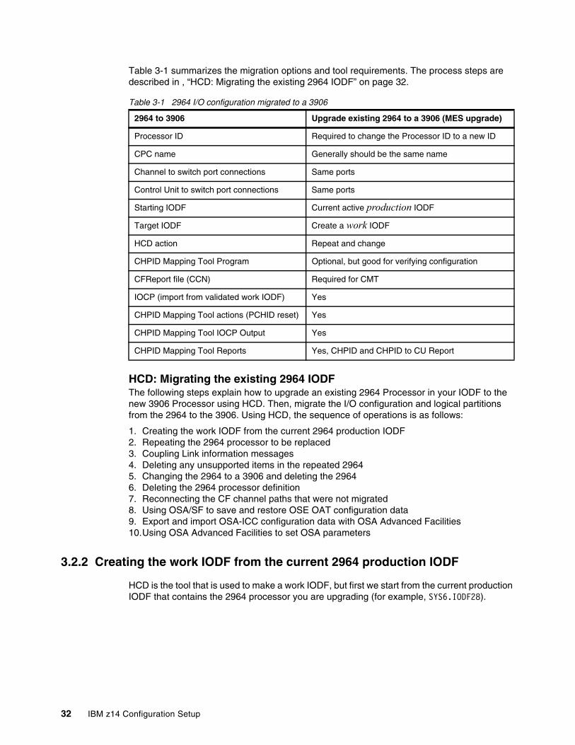
Table 3-1 summarizes the migration options and tool requirements. The process steps are described in , “HCD: Migrating the existing 2964 IODF” on page 32.
Table 3-1 2964 I/O configuration migrated to a 3906
HCD: Migrating the existing 2964 IODFThe following steps explain how to upgrade an existing 2964 Processor in your IODF to the new 3906 Processor using HCD. Then, migrate the I/O configuration and logical partitions from the 2964 to the 3906. Using HCD, the sequence of operations is as follows:
1. Creating the work IODF from the current 2964 production IODF2. Repeating the 2964 processor to be replaced3. Coupling Link information messages4. Deleting any unsupported items in the repeated 29645. Changing the 2964 to a 3906 and deleting the 29646. Deleting the 2964 processor definition7. Reconnecting the CF channel paths that were not migrated8. Using OSA/SF to save and restore OSE OAT configuration data9. Export and import OSA-ICC configuration data with OSA Advanced Facilities10.Using OSA Advanced Facilities to set OSA parameters
3.2.2 Creating the work IODF from the current 2964 production IODF
HCD is the tool that is used to make a work IODF, but first we start from the current production IODF that contains the 2964 processor you are upgrading (for example, SYS6.IODF28).
2964 to 3906 Upgrade existing 2964 to a 3906 (MES upgrade)
Processor ID Required to change the Processor ID to a new ID
CPC name Generally should be the same name
Channel to switch port connections Same ports
Control Unit to switch port connections Same ports
Starting IODF Current active production IODF
Target IODF Create a work IODF
HCD action Repeat and change
CHPID Mapping Tool Program Optional, but good for verifying configuration
CFReport file (CCN) Required for CMT
IOCP (import from validated work IODF) Yes
CHPID Mapping Tool actions (PCHID reset) Yes
CHPID Mapping Tool IOCP Output Yes
CHPID Mapping Tool Reports Yes, CHPID and CHPID to CU Report
32 IBM z14 Configuration Setup
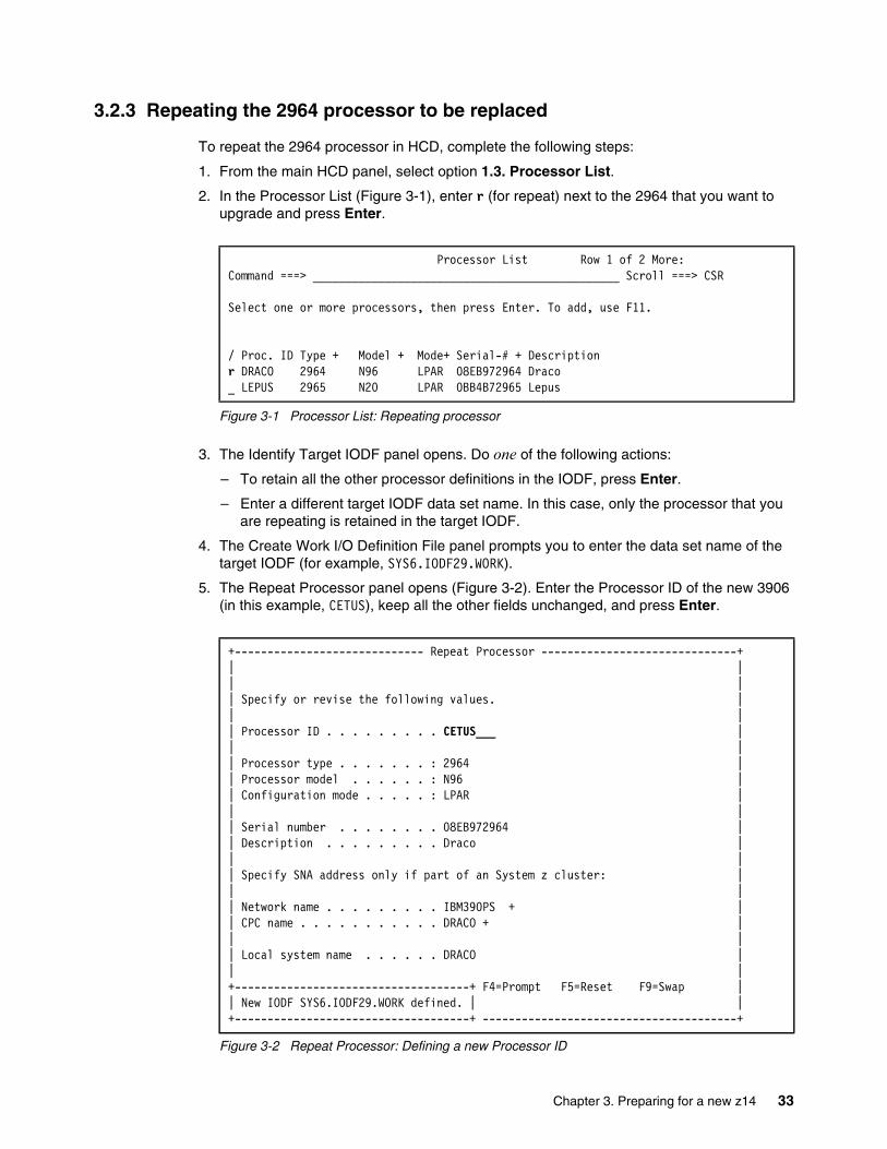
3.2.3 Repeating the 2964 processor to be replaced
To repeat the 2964 processor in HCD, complete the following steps:
1. From the main HCD panel, select option 1.3. Processor List.
2. In the Processor List (Figure 3-1), enter r (for repeat) next to the 2964 that you want to upgrade and press Enter.
Figure 3-1 Processor List: Repeating processor
3. The Identify Target IODF panel opens. Do one of the following actions:
– To retain all the other processor definitions in the IODF, press Enter.
– Enter a different target IODF data set name. In this case, only the processor that you are repeating is retained in the target IODF.
4. The Create Work I/O Definition File panel prompts you to enter the data set name of the target IODF (for example, SYS6.IODF29.WORK).
5. The Repeat Processor panel opens (Figure 3-2). Enter the Processor ID of the new 3906 (in this example, CETUS), keep all the other fields unchanged, and press Enter.
Figure 3-2 Repeat Processor: Defining a new Processor ID
Processor List Row 1 of 2 More: Command ===> _______________________________________________ Scroll ===> CSR Select one or more processors, then press Enter. To add, use F11. / Proc. ID Type + Model + Mode+ Serial-# + Description r DRACO 2964 N96 LPAR 08EB972964 Draco _ LEPUS 2965 N20 LPAR 0BB4B72965 Lepus
+----------------------------- Repeat Processor ------------------------------+| || || Specify or revise the following values. || || Processor ID . . . . . . . . . CETUS___ || || Processor type . . . . . . . : 2964 || Processor model . . . . . . : N96 || Configuration mode . . . . . : LPAR || || Serial number . . . . . . . . 08EB972964 || Description . . . . . . . . . Draco || || Specify SNA address only if part of an System z cluster: || || Network name . . . . . . . . . IBM390PS + || CPC name . . . . . . . . . . . DRACO + || || Local system name . . . . . . DRACO || |+------------------------------------+ F4=Prompt F5=Reset F9=Swap || New IODF SYS6.IODF29.WORK defined. | |+------------------------------------+ ---------------------------------------+
Chapter 3. Preparing for a new z14 33

3.2.4 Coupling Link information messages
You might receive severity messages (E, I, or W). As shown in Figure 3-3, CBDG441I, severity I messages are displayed in the example because the CF Link CHPIDs were not copied to the 3906 definition.
Figure 3-3 Message List: Showing CBDG441I
To resolve this issue, complete the following steps:
1. Scroll until you reach the end of the messages and see the CBDG271I requested action on object DRACO successfully processed message.
2. Press PF3 or PF12 to continue. As shown in Figure 3-4, there is an extra 2964 processor named CETUS.
Figure 3-4 Processor List: Repeated processor
3.2.5 Deleting any unsupported items in the repeated 2964
If you are upgrading a processor that contains any CHPID types of OSN, then these must be deleted from the IODF before changing the processor type to 3906.
+------------------------------- Message List --------------------------------+| Save Query Help || -------------------------------------------------------------------------- || Row 1 of 37 || Command ===> ___________________________________________ Scroll ===> CSR || || Messages are sorted by severity. Select one or more, then press Enter. || || / Sev Msg. ID Message Text || _ I CBDG441I The coupling facility connection between channel path || # 0.F4 of processor DRACO and channel path 0.F5 of || # processor DRACO is not copied. || _ I CBDG441I The coupling facility connection between channel path || # 0.F5 of processor DRACO and channel path 0.F4 of || # processor DRACO is not copied. || _ I CBDG441I The coupling facility connection between channel path || # 0.F6 of processor DRACO and channel path 0.F7 of || # processor LEPUS is not copied. || _ I CBDG441I The coupling facility connection between channel path || # 0.F7 of processor DRACO and channel path 0.F6 of || # processor LEPUS is not copied. || _ I CBDG271I Requested action on object DRACO successfully processed. || ***************************** Bottom of data ******************************
Processor List Row 1 of 3 More: Command ===> _______________________________________________ Scroll ===> CSR Select one or more processors, then press Enter. To add, use F11. / Proc. ID Type + Model + Mode+ Serial-# + Description _ CETUS 2964 N96 LPAR 08EB972964 Draco _ DRACO 2964 N96 LPAR 08EB972964 Draco _ LEPUS 2965 N20 LPAR 0BB4B72965 Lepus
34 IBM z14 Configuration Setup

3.2.6 Changing the 2964 to a 3906 and deleting the 2964
You can either keep the original copy of the 2964 (DRACO) or delete it from the IODF. In this example, keep it in the IODF for a few more steps.
To change the 2964 to a 3906, complete the following steps:
1. Enter c (for change) next to CETUS to change the 2964 to a 3906 and press Enter. The Change Process Definition panel opens (Figure 3-5).
2. Make the following updates and press Enter:
– Update Processor type to 3906.
– Update Processor model to M03.
– Update the 2964 part of the Serial number to 3906 (that is, 08EB732964 to 08EB973906).
– Update Description to CETUS.
– Update Local system name to CETUS.
Figure 3-5 Processors: Change Processor Definition
Note: Because we will be using HCD to write an IOCDS to this 2964 in preparation for an upgrade, we need to leave the Network name and CPC name set to IBM390PS and DRACO. These settings will need to be updated in the IODF after the 2964 has been upgraded to a 3906.
+------------------------ Change Processor Definition ------------------------+| || || Specify or revise the following values. || || Processor ID . . . . . . . . : CETUS || Support level: || 2964 support, ISM, RCE || Processor type . . . . . . . . 3906 + || Processor model . . . . . . . M03 + || Configuration mode . . . . . . LPAR + || || Serial number . . . . . . . . 08EB973906 + || Description . . . . . . . . . CETUS || || Specify SNA address only if part of an System z cluster: || || Network name . . . . . . . . . IBM390PS + || CPC name . . . . . . . . . . . DRACO + || || Local system name . . . . . . CETUS || F1=Help F2=Split F3=Exit F4=Prompt F5=Reset F9=Swap || F12=Cancel |+-----------------------------------------------------------------------------+
Chapter 3. Preparing for a new z14 35

3. The Update Channel Path Identifiers panel opens (Figure 3-6). No changes are made in this example.
Figure 3-6 Processors: Update Channel Path Identifiers
4. Press Enter for each Channel Subsystem ID.
5. The repeated 2964 processor is successfully changed to a 3906-M03 as shown in Figure 3-7.
Figure 3-7 Processor List: Changed processor
3.2.7 Deleting the 2964 processor definition
Now that the 2964 was repeated and changed to a 3906, the original 2964 definition (DRACO) must be deleted so that the required CF Links can be restored.
+--------------------- Update Channel Path Identifiers ----------------------+| Row 1 of 100 || Command ===> __________________________________________ Scroll ===> CSR || || Specify any changes to the channel path identifiers in the list below. || || Processor ID . . . . : CETUS CETUS || Channel Subsystem ID : 0 || || CHPID Type Side Until CHPID New CHPID + || 00 IQD __ 00 || 10 FCP __ 10 || 11 FCP __ 11 || 12 FCP __ 12 || 13 FCP __ 13 || 14 FC __ 14 || 15 FC __ 15 || 16 FC __ 16 || 17 FC __ 17 || 1C FC __ 1C || 1D FC __ 1D || F1=Help F2=Split F3=Exit F4=Prompt F5=Reset || F7=Backward F8=Forward F9=Swap F12=Cancel |+----------------------------------------------------------------------------+
Processor List Row 1 of 3 More: Command ===> _______________________________________________ Scroll ===> CSR Select one or more processors, then press Enter. To add, use F11. / Proc. ID Type + Model + Mode+ Serial-# + Description _ CETUS 3906 M03 LPAR 08EB973906 CETUS _ DRACO 2964 N96 LPAR 08EB972964 Draco _ LEPUS 2965 N20 LPAR 0BB4B72965 Lepus
36 IBM z14 Configuration Setup

To delete the 2964 processor definition, complete the following steps:
1. Enter d (for delete) next to the DRACO processor in the Processor List (Figure 3-8).
Figure 3-8 Processor List: Deleting processor
2. Press Enter to confirm the deletion of the processor (Figure 3-9).
Figure 3-9 Processor List: Processor deleted
3.2.8 Reconnecting the CF channel paths that were not migrated
Manually redefine the CF Links that you want from the CETUS (previously DRACO) processor to any other processor, along with any Internal Coupling Facility links that you want. To help in this effort, you can get a CF connection report from the previous production IODF containing the 2964. Alternatively, you can make a note of all CBDG441I error messages that you received in 3.2.7, “Deleting the 2964 processor definition” on page 36.
3.3 Saving and restoring OSA configuration data
The three processes for Open Systems Adapter (OSA) cards that you might need to use when upgrading or replacing your processor are described here.
3.3.1 Using OSA/SF to save and restore OSE OAT configuration data
See 7.3.1, “Saving and restoring OSA-ICC configuration” on page 154 for details of how to save and restore any OSA configuration data such the OSA Address Table (OAT).
Processor List Row 1 of 3 More: Command ===> _______________________________________________ Scroll ===> CSR Select one or more processors, then press Enter. To add, use F11. / Proc. ID Type + Model + Mode+ Serial-# + Description _ CETUS 3906 M03 LPAR 08EB973906 CETUS d DRACO 2964 N96 LPAR 08EB972964 Draco _ LEPUS 2965 N20 LPAR 0BB4B72965 Lepus
Processor List Row 1 of 2 More: Command ===> _______________________________________________ Scroll ===> CSR Select one or more processors, then press Enter. To add, use F11. / Proc. ID Type + Model + Mode+ Serial-# + Description _ CETUS 3906 M03 LPAR 08EB973906 CETUS _ LEPUS 2965 N20 LPAR 0BB4B72965 Lepus
Chapter 3. Preparing for a new z14 37
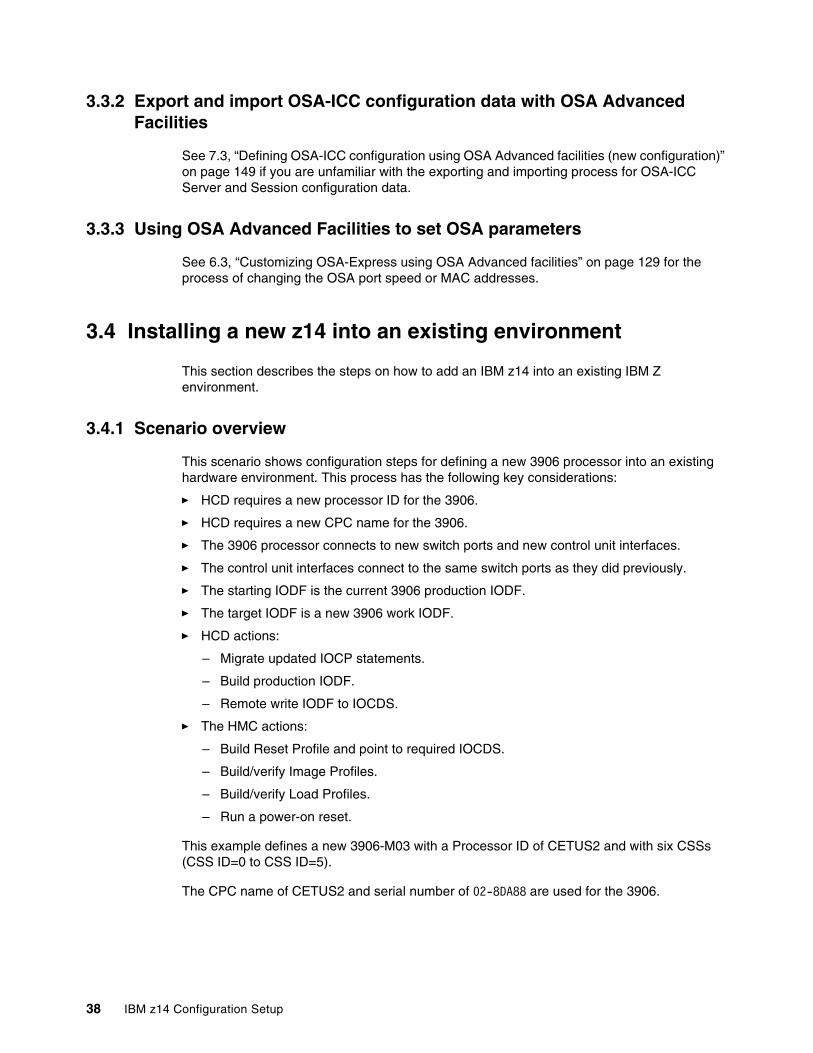
3.3.2 Export and import OSA-ICC configuration data with OSA Advanced Facilities
See 7.3, “Defining OSA-ICC configuration using OSA Advanced facilities (new configuration)” on page 149 if you are unfamiliar with the exporting and importing process for OSA-ICC Server and Session configuration data.
3.3.3 Using OSA Advanced Facilities to set OSA parameters
See 6.3, “Customizing OSA-Express using OSA Advanced facilities” on page 129 for the process of changing the OSA port speed or MAC addresses.
3.4 Installing a new z14 into an existing environment
This section describes the steps on how to add an IBM z14 into an existing IBM Z environment.
3.4.1 Scenario overview
This scenario shows configuration steps for defining a new 3906 processor into an existing hardware environment. This process has the following key considerations:
� HCD requires a new processor ID for the 3906.
� HCD requires a new CPC name for the 3906.
� The 3906 processor connects to new switch ports and new control unit interfaces.
� The control unit interfaces connect to the same switch ports as they did previously.
� The starting IODF is the current 3906 production IODF.
� The target IODF is a new 3906 work IODF.
� HCD actions:
– Migrate updated IOCP statements.
– Build production IODF.
– Remote write IODF to IOCDS.
� The HMC actions:
– Build Reset Profile and point to required IOCDS.
– Build/verify Image Profiles.
– Build/verify Load Profiles.
– Run a power-on reset.
This example defines a new 3906-M03 with a Processor ID of CETUS2 and with six CSSs (CSS ID=0 to CSS ID=5).
The CPC name of CETUS2 and serial number of 02-8DA88 are used for the 3906.
38 IBM z14 Configuration Setup
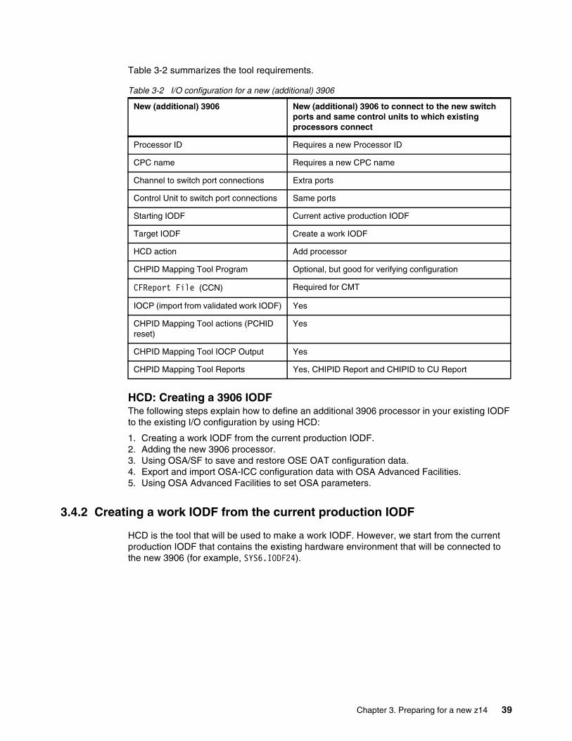
Table 3-2 summarizes the tool requirements.
Table 3-2 I/O configuration for a new (additional) 3906
HCD: Creating a 3906 IODFThe following steps explain how to define an additional 3906 processor in your existing IODF to the existing I/O configuration by using HCD:
1. Creating a work IODF from the current production IODF.2. Adding the new 3906 processor.3. Using OSA/SF to save and restore OSE OAT configuration data.4. Export and import OSA-ICC configuration data with OSA Advanced Facilities.5. Using OSA Advanced Facilities to set OSA parameters.
3.4.2 Creating a work IODF from the current production IODF
HCD is the tool that will be used to make a work IODF. However, we start from the current production IODF that contains the existing hardware environment that will be connected to the new 3906 (for example, SYS6.IODF24).
New (additional) 3906 New (additional) 3906 to connect to the new switch ports and same control units to which existing processors connect
Processor ID Requires a new Processor ID
CPC name Requires a new CPC name
Channel to switch port connections Extra ports
Control Unit to switch port connections Same ports
Starting IODF Current active production IODF
Target IODF Create a work IODF
HCD action Add processor
CHPID Mapping Tool Program Optional, but good for verifying configuration
CFReport File (CCN) Required for CMT
IOCP (import from validated work IODF) Yes
CHPID Mapping Tool actions (PCHID reset)
Yes
CHPID Mapping Tool IOCP Output Yes
CHPID Mapping Tool Reports Yes, CHIPID Report and CHIPID to CU Report
Chapter 3. Preparing for a new z14 39

3.4.3 Adding the new 3906 processor
To add the new 3906 processor, complete the following steps:
1. From the HCD main menu, select option 1.3, Processor List.
2. In the Processor List (Figure 3-10), press PF11, or enter add on the command line to add a processor and press Enter.
Figure 3-10 Processor List: Adding a processor
The Add Processor panel opens (Figure 3-11).
Figure 3-11 Add Processor: Data fields to be updated
3. Specify the appropriate values. For example, specify these values, shown in Figure 3-12 on page 41:
Processor ID CETUS2Processor type 3906Processor model M03Number of channel subsystems (Keep this blank for now)Serial number 08DA883906
Processor List Row 1 of 3 More: Command ===> add____________________________________________ Scroll ===> CSR Select one or more processors, then press Enter. To add, use F11. / Proc. ID Type + Model + Mode+ Serial-# + Description _ CETUS 3906 M03 LPAR 0EE0F73906 Cetus _ DRACO 2964 N96 LPAR 08EB972964 Draco _ LEPUS 2965 N20 LPAR 0BB4B72965 Lepus ******************************* Bottom of data *****************************
+------------------------------- Add Processor -------------------------------+| || || Specify or revise the following values. || || Processor ID . . . . . . . . . . ________ || Processor type . . . . . . . . . ________ + || Processor model . . . . . . . . ________ + || Configuration mode . . . . . . . LPAR + || Number of channel subsystems . . _ + || || Serial number . . . . . . . . . __________ || Description . . . . . . . . . . ________________________________ || || Specify SNA address only if part of a System z cluster: || || Network name . . . . . . . . . . ________ + || CPC name . . . . . . . . . . . . ________ + || || Local system name . . . . . . . ________ || F1=Help F2=Split F3=Exit F4=Prompt F5=Reset F9=Swap || F12=Cancel |+-----------------------------------------------------------------------------+
40 IBM z14 Configuration Setup
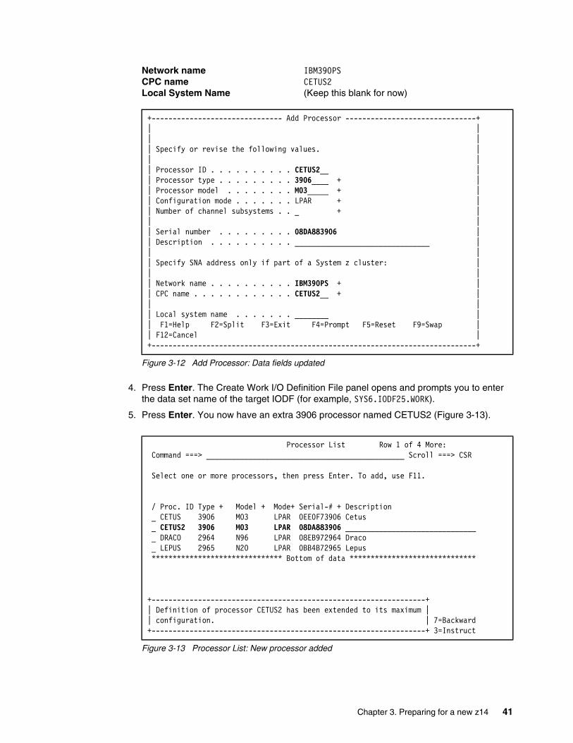
Network name IBM390PSCPC name CETUS2Local System Name (Keep this blank for now)
Figure 3-12 Add Processor: Data fields updated
4. Press Enter. The Create Work I/O Definition File panel opens and prompts you to enter the data set name of the target IODF (for example, SYS6.IODF25.WORK).
5. Press Enter. You now have an extra 3906 processor named CETUS2 (Figure 3-13).
Figure 3-13 Processor List: New processor added
+------------------------------- Add Processor -------------------------------+| || || Specify or revise the following values. || || Processor ID . . . . . . . . . . CETUS2__ || Processor type . . . . . . . . . 3906____ + || Processor model . . . . . . . . M03_____ + || Configuration mode . . . . . . . LPAR + || Number of channel subsystems . . _ + || || Serial number . . . . . . . . . 08DA883906 || Description . . . . . . . . . . ________________________________ || || Specify SNA address only if part of a System z cluster: || || Network name . . . . . . . . . . IBM390PS + || CPC name . . . . . . . . . . . . CETUS2__ + || || Local system name . . . . . . . ________ || F1=Help F2=Split F3=Exit F4=Prompt F5=Reset F9=Swap || F12=Cancel |+-----------------------------------------------------------------------------+
Processor List Row 1 of 4 More: Command ===> _______________________________________________ Scroll ===> CSR Select one or more processors, then press Enter. To add, use F11. / Proc. ID Type + Model + Mode+ Serial-# + Description _ CETUS 3906 M03 LPAR 0EE0F73906 Cetus _ CETUS2 3906 M03 LPAR 08DA883906 _______________________________ _ DRACO 2964 N96 LPAR 08EB972964 Draco _ LEPUS 2965 N20 LPAR 0BB4B72965 Lepus ******************************* Bottom of data ******************************
+-----------------------------------------------------------------+ | Definition of processor CETUS2 has been extended to its maximum | | configuration. | 7=Backward+-----------------------------------------------------------------+ 3=Instruct
Chapter 3. Preparing for a new z14 41
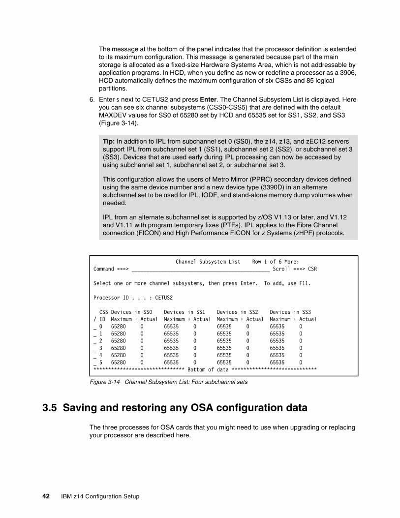
The message at the bottom of the panel indicates that the processor definition is extended to its maximum configuration. This message is generated because part of the main storage is allocated as a fixed-size Hardware Systems Area, which is not addressable by application programs. In HCD, when you define as new or redefine a processor as a 3906, HCD automatically defines the maximum configuration of six CSSs and 85 logical partitions.
6. Enter s next to CETUS2 and press Enter. The Channel Subsystem List is displayed. Here you can see six channel subsystems (CSS0-CSS5) that are defined with the default MAXDEV values for SS0 of 65280 set by HCD and 65535 set for SS1, SS2, and SS3 (Figure 3-14).
Figure 3-14 Channel Subsystem List: Four subchannel sets
3.5 Saving and restoring any OSA configuration data
The three processes for OSA cards that you might need to use when upgrading or replacing your processor are described here.
Tip: In addition to IPL from subchannel set 0 (SS0), the z14, z13, and zEC12 servers support IPL from subchannel set 1 (SS1), subchannel set 2 (SS2), or subchannel set 3 (SS3). Devices that are used early during IPL processing can now be accessed by using subchannel set 1, subchannel set 2, or subchannel set 3.
This configuration allows the users of Metro Mirror (PPRC) secondary devices defined using the same device number and a new device type (3390D) in an alternate subchannel set to be used for IPL, IODF, and stand-alone memory dump volumes when needed.
IPL from an alternate subchannel set is supported by z/OS V1.13 or later, and V1.12 and V1.11 with program temporary fixes (PTFs). IPL applies to the Fibre Channel connection (FICON) and High Performance FICON for z Systems (zHPF) protocols.
Channel Subsystem List Row 1 of 6 More: Command ===> _______________________________________________ Scroll ===> CSR Select one or more channel subsystems, then press Enter. To add, use F11. Processor ID . . . : CETUS2 CSS Devices in SS0 Devices in SS1 Devices in SS2 Devices in SS3 / ID Maximum + Actual Maximum + Actual Maximum + Actual Maximum + Actual_ 0 65280 0 65535 0 65535 0 65535 0 _ 1 65280 0 65535 0 65535 0 65535 0 _ 2 65280 0 65535 0 65535 0 65535 0 _ 3 65280 0 65535 0 65535 0 65535 0 _ 4 65280 0 65535 0 65535 0 65535 0 _ 5 65280 0 65535 0 65535 0 65535 0 ******************************* Bottom of data *****************************
42 IBM z14 Configuration Setup

3.5.1 Using OSA/SF to save and restore OSE OAT configuration data
See 7.3.1, “Saving and restoring OSA-ICC configuration” on page 154 for details about how to save and restore any OSA configuration data such the OAT.
3.5.2 Export and import OSA-ICC configuration data with OSA Advanced Facilities
See 7.3, “Defining OSA-ICC configuration using OSA Advanced facilities (new configuration)” on page 149 if you are unfamiliar with the exporting and importing process for OSA-ICC Server and Session configuration data.
3.5.3 Using OSA Advanced Facilities to set OSA parameters
See 6.3.2, “Setting OSA parameters using OSA Advanced Facilities” on page 139 for the process of changing the OSA port speed or MAC addresses.
3.6 Additional steps and processes
Proceed to Chapter 4, “Mapping CHIDs to CHPIDs using the CMT” on page 45 when you are ready to map the PCHIDs from the z14 CFR file to the CHPIDs in your exported IODF.
To define the I/O configuration for your system, proceed to Chapter 5, “Production IODF and setting up the CPC” on page 85.
Chapter 3. Preparing for a new z14 43

44 IBM z14 Configuration Setup
Chapter 4. Mapping CHIDs to CHPIDs using the CMT
This chapter describes a detailed scenario for using the CHPID Mapping Tool (CMT).
This chapter includes the following sections:
� Validating the 3906 work IODF� Creating the IOCP for the CHPID Mapping Tool� Assigning CHIDs to CHPIDs using the CMT� Importing the CFReport file into the CHPID Mapping Tool� Importing the 3906 IOCP file into the CHPID Mapping Tool� Resolving CHPIDs with CHID conflicts� Hardware resolution� Manual mapping to resolve CIB CHPIDs� Processing Automatic Mapping then CU Priority� CHPIDs not connected to control units� Creating CHPID Mapping Tool reports� Creating an updated IOCP� HCD: Updating the 3906 work IODF with CHIDs� Additional steps and processes
4
© Copyright IBM Corp. 2017. All rights reserved. 45
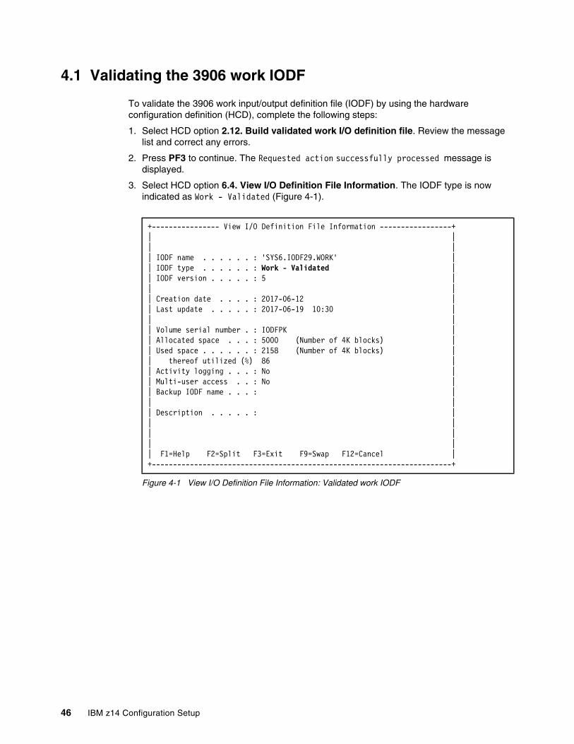
4.1 Validating the 3906 work IODF
To validate the 3906 work input/output definition file (IODF) by using the hardware configuration definition (HCD), complete the following steps:
1. Select HCD option 2.12. Build validated work I/O definition file. Review the message list and correct any errors.
2. Press PF3 to continue. The Requested action successfully processed message is displayed.
3. Select HCD option 6.4. View I/O Definition File Information. The IODF type is now indicated as Work - Validated (Figure 4-1).
Figure 4-1 View I/O Definition File Information: Validated work IODF
+---------------- View I/O Definition File Information -----------------+| || || IODF name . . . . . . : 'SYS6.IODF29.WORK' || IODF type . . . . . . : Work - Validated || IODF version . . . . . : 5 || || Creation date . . . . : 2017-06-12 || Last update . . . . . : 2017-06-19 10:30 || || Volume serial number . : IODFPK || Allocated space . . . : 5000 (Number of 4K blocks) || Used space . . . . . . : 2158 (Number of 4K blocks) || thereof utilized (%) 86 || Activity logging . . . : No || Multi-user access . . : No || Backup IODF name . . . : || || Description . . . . . : || || || || F1=Help F2=Split F3=Exit F9=Swap F12=Cancel |+-----------------------------------------------------------------------+
46 IBM z14 Configuration Setup
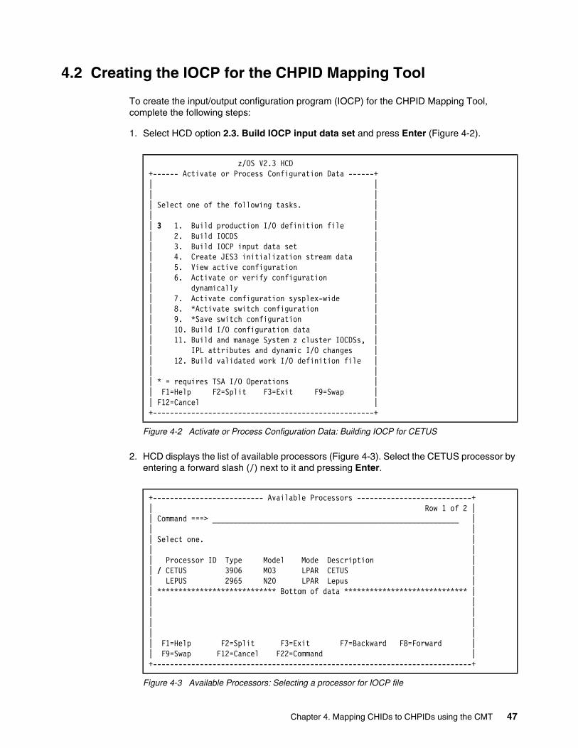
4.2 Creating the IOCP for the CHPID Mapping Tool
To create the input/output configuration program (IOCP) for the CHPID Mapping Tool, complete the following steps:
1. Select HCD option 2.3. Build IOCP input data set and press Enter (Figure 4-2).
Figure 4-2 Activate or Process Configuration Data: Building IOCP for CETUS
2. HCD displays the list of available processors (Figure 4-3). Select the CETUS processor by entering a forward slash (/) next to it and pressing Enter.
Figure 4-3 Available Processors: Selecting a processor for IOCP file
z/OS V2.3 HCD +------ Activate or Process Configuration Data ------+| || || Select one of the following tasks. || || 3 1. Build production I/O definition file || 2. Build IOCDS || 3. Build IOCP input data set || 4. Create JES3 initialization stream data || 5. View active configuration || 6. Activate or verify configuration || dynamically || 7. Activate configuration sysplex-wide || 8. *Activate switch configuration || 9. *Save switch configuration || 10. Build I/O configuration data || 11. Build and manage System z cluster IOCDSs, || IPL attributes and dynamic I/O changes || 12. Build validated work I/O definition file || || * = requires TSA I/O Operations || F1=Help F2=Split F3=Exit F9=Swap || F12=Cancel |+----------------------------------------------------+
+-------------------------- Available Processors ---------------------------+| Row 1 of 2 || Command ===> __________________________________________________________ || || Select one. || || Processor ID Type Model Mode Description || / CETUS 3906 M03 LPAR CETUS || LEPUS 2965 N20 LPAR Lepus || **************************** Bottom of data ***************************** || || || || || F1=Help F2=Split F3=Exit F7=Backward F8=Forward || F9=Swap F12=Cancel F22=Command |+---------------------------------------------------------------------------+
Chapter 4. Mapping CHIDs to CHPIDs using the CMT 47

3. HCD displays a panel on which you enter information about the IOCP input data set to be created (Figure 4-4). Complete the following fields:
– Title1: IODF29– IOCP input data set: 'SYS6.IODF29.IOCPIN.CETUS'– Input to Stand-alone IOCP: Yes– Job statement information: Complete this information for your installation.
Figure 4-4 Build IOCP Input Data Set: Data fields to be updated
4. Press Enter. HCD submits a batch job to create the data set.
+------------------------- Build IOCP Input Data Set -------------------------+| || || Specify or revise the following values. || || IODF name . . . . . . . . . : 'SYS6.IODF29.WORK' || Processor ID . . . . . . . : CETUS || Title1 . IODF29 || Title2 : SYS6.IODF29.WORK - 2017-06-19 10:30 || || IOCP input data set || 'SYS6.IODF29.IOCPIN.CETUS' || Input to Stand-alone IOCP? Yes (Yes or No) || || Job statement information || //WIOCP JOB (ACCOUNT),'NAME',MSGCLASS=T || //* || //* || //* || //* || //* || || F1=Help F2=Split F3=Exit F5=Reset F9=Swap F12=Cancel |+-----------------------------------------------------------------------------+
48 IBM z14 Configuration Setup
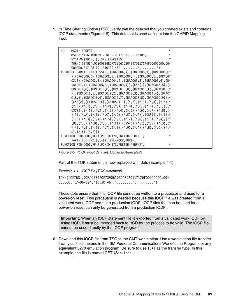
5. In Time Sharing Option (TSO), verify that the data set that you created exists and contains IOCP statements (Figure 4-5). This data set is used as input into the CHPID Mapping Tool.
Figure 4-5 IOCP input data set: Contents (truncated)
Part of the TOK statement is now replaced with dots (Example 4-1).
Example 4-1 IOCP file (TOK statement)
TOK=('CETUS',00800224E0F73906103045970117170F00000000,00*000000,'17-06-19','10:30:45','........','........')
These dots ensure that this IOCP file cannot be written to a processor and used for a power-on reset. This precaution is needed because this IOCP file was created from a validated work IODF and not a production IODF. IOCP files that can be used for a power-on reset can only be generated from a production IODF.
6. Download this IOCP file from TSO to the CMT workstation. Use a workstation file transfer facility such as the one in the IBM Personal Communications Workstation Program, or any equivalent 3270 emulation program. Be sure to use TEXT as the transfer type. In this example, the file is named CETUSin.iocp.
ID MSG1='IODF29', * MSG2='SYS6.IODF29.WORK - 2017-06-19 10:30', * SYSTEM=(3906,1),LSYSTEM=CETUS, * TOK=('CETUS',00800224E0F73906103045970117170F00000000,00* 000000,'17-06-19','10:30:45','........','........') RESOURCE PARTITION=((CSS(0),(DRACO0A,A),(DRACO0B,B),(DRACO0C,C* ),(DRACO0D,D),(DRACO0E,E),(DRACO0F,F),(DRACO01,1),(DRACO* 02,2),(DRACO03,3),(DRACO04,4),(DRACO05,5),(DRACO06,6),(D* RACO07,7),(DRACO08,8),(DRACO09,9)),(CSS(1),(DRACO1A,A),(* DRACO1B,B),(DRACO1C,C),(DRACO1D,D),(DRACO1E,E),(DRACO1F,* F),(DRACO11,1),(DRACO12,2),(DRACO13,3),(DRACO14,4),(DRAC* O15,5),(DRACO16,6),(DRACO17,7),(DRACO18,8),(DRACO19,9)),* (CSS(2),(CETUS2F,F),(CETUS21,1),(*,2),(*,3),(*,4),(*,5),* (*,6),(*,7),(*,8),(*,9),(*,A),(*,B),(*,C),(*,D),(*,E)),(* CSS(3),(*,1),(*,2),(*,3),(*,4),(*,5),(*,6),(*,7),(*,8),(* *,9),(*,A),(*,B),(*,C),(*,D),(*,E),(*,F)),(CSS(4),(*,1),* (*,2),(*,3),(*,4),(*,5),(*,6),(*,7),(*,8),(*,9),(*,A),(** ,B),(*,C),(*,D),(*,E),(*,F)),(CSS(5),(*,1),(*,2),(*,3),(* *,4),(*,5),(*,6),(*,7),(*,8),(*,9),(*,A),(*,B),(*,C),(*,* D),(*,E),(*,F))) FUNCTION FID=0000,VF=1,PCHID=17C,PNETID=PERFNET, * PART=((CETUS21),(=)),TYPE=ROC2,PORT=1 FUNCTION FID=0001,VF=2,PCHID=17C,PNETID=PERFNET, *
Important: When an IOCP statement file is exported from a validated work IODF by using HCD, it must be imported back to HCD for the process to be valid. The IOCP file cannot be used directly by the IOCP program.
Chapter 4. Mapping CHIDs to CHPIDs using the CMT 49

4.3 Assigning CHIDs to CHPIDs using the CMT
The following steps use the IOCP statements from HCD steps and the 3906 order process (CFReport). Use the CHPID Mapping Tool to assign CHIDs to each of the CHPIDs for the 3906.
For this process, the CHPID Mapping Tool (CMT) must be downloaded. For more information about downloading and installing the CMT, see 2.5, “CHPID Mapping Tool” on page 9. If CMT is already installed, verify that the latest updates are installed.
The version of CHPID Mapping Tool that is used for the following captures is 6.19. Check for the latest version on IBM Resource Link.
For more information, see the CHPID Mapping Tool User’s Guide, GC28-6947.
Use the CHPID Mapping Tool to complete the following steps:
1. Import the CFReport file into the CMT.
2. Import the IOCP file into the CMT.
3. Resolve CHPIDs with a CHID conflict.
4. Process the hardware resolution.
5. Manually resolve the CIB or CS5 CHPIDs.
6. Set the priority for single-path control units and other control units that override the CHPID Mapping Tool default priorities and Automatic Mapping.
7. Resolve the CHPIDs that are not connected to control units.
8. Create the CHPID Mapping Tool reports.
9. Create an updated IOCP statements file for transfer back into the IODF file.
50 IBM z14 Configuration Setup

4.4 Importing the CFReport file into the CHPID Mapping Tool
To import the CFReport file into the CHPID Mapping Tool, complete the following steps:
1. Start the CMT on your workstation.
2. CMT asks for a project name and location of the CMT work files. We used CETUS_upg as the project name. (Figure 4-6).
Figure 4-6 Creating a CHPID Mapping Tool Project
3. Next, specify the CFReport and IOCP input file panel is displayed. For this step, we only input the CFReport file for now
Attention: To import the CFReport File into the CHPID Mapping Tool, a Customer Number must be contained in the CFReport File.
Chapter 4. Mapping CHIDs to CHPIDs using the CMT 51
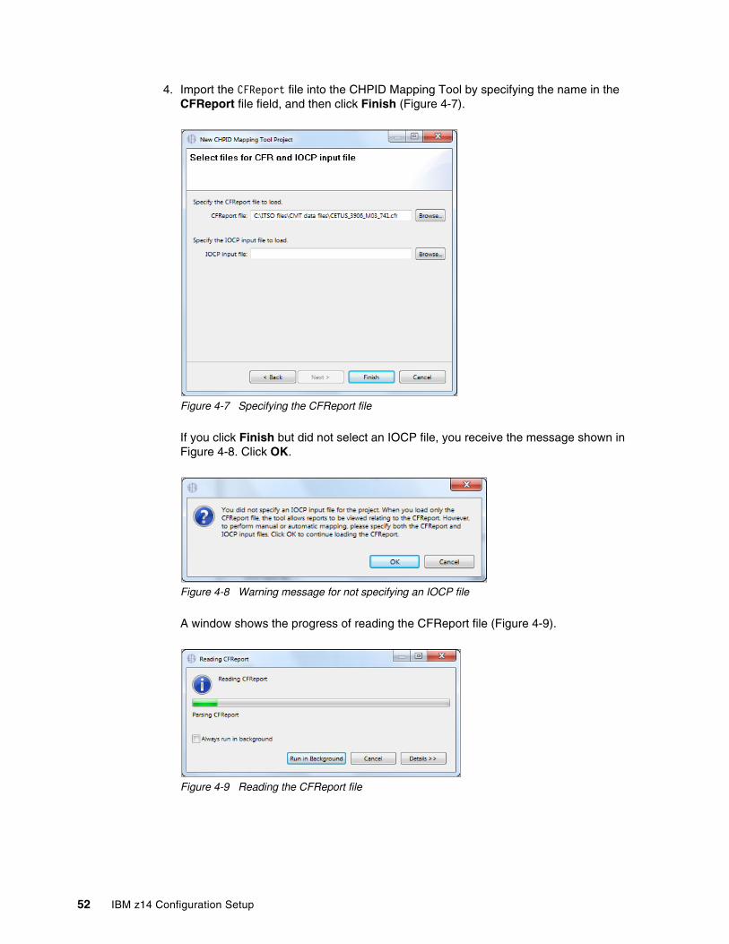
4. Import the CFReport file into the CHPID Mapping Tool by specifying the name in the CFReport file field, and then click Finish (Figure 4-7).
Figure 4-7 Specifying the CFReport file
If you click Finish but did not select an IOCP file, you receive the message shown in Figure 4-8. Click OK.
Figure 4-8 Warning message for not specifying an IOCP file
A window shows the progress of reading the CFReport file (Figure 4-9).
Figure 4-9 Reading the CFReport file
52 IBM z14 Configuration Setup
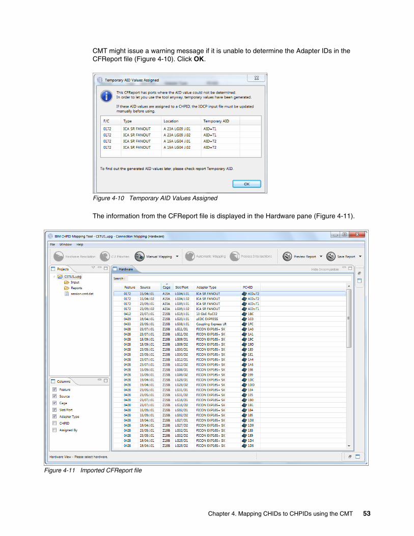
CMT might issue a warning message if it is unable to determine the Adapter IDs in the CFReport file (Figure 4-10). Click OK.
Figure 4-10 Temporary AID Values Assigned
The information from the CFReport file is displayed in the Hardware pane (Figure 4-11).
Figure 4-11 Imported CFReport file
Chapter 4. Mapping CHIDs to CHPIDs using the CMT 53

4.5 Importing the 3906 IOCP file into the CHPID Mapping Tool
To import the validated 3906 IOCP file into the CHPID Mapping Tool, complete the following steps:
1. Right-click anywhere in the Projects window and select Import IOCP input file (Figure 4-12).
Figure 4-12 Importing the IOCP file
2. Select the IOCP file on your workstation to import into the CHPID Mapping Tool and click Finish (Figure 4-13).
Figure 4-13 Specifying the IOCP file for import
54 IBM z14 Configuration Setup
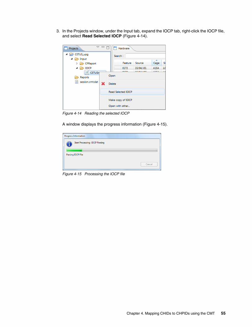
3. In the Projects window, under the Input tab, expand the IOCP tab, right-click the IOCP file, and select Read Selected IOCP (Figure 4-14).
Figure 4-14 Reading the selected IOCP
A window displays the progress information (Figure 4-15).
Figure 4-15 Processing the IOCP file
Chapter 4. Mapping CHIDs to CHPIDs using the CMT 55
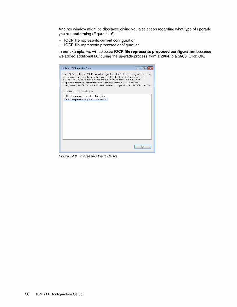
Another window might be displayed giving you a selection regarding what type of upgrade you are performing (Figure 4-16):
– IOCP file represents current configuration– IOCP file represents proposed configuration
In our example, we will selected IOCP file represents proposed configuration because we added additional I/O during the upgrade process from a 2964 to a 3906. Click OK.
Figure 4-16 Processing the IOCP file
56 IBM z14 Configuration Setup
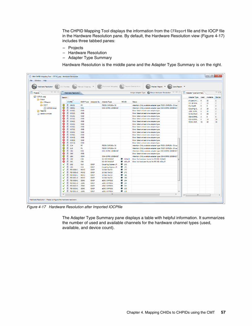
The CHPID Mapping Tool displays the information from the CFReport file and the IOCP file in the Hardware Resolution pane. By default, the Hardware Resolution view (Figure 4-17) includes three tabbed panes:
– Projects– Hardware Resolution– Adapter Type Summary
Hardware Resolution is the middle pane and the Adapter Type Summary is on the right.
Figure 4-17 Hardware Resolution after Imported IOCPfile
The Adapter Type Summary pane displays a table with helpful information. It summarizes the number of used and available channels for the hardware channel types (used, available, and device count).
Chapter 4. Mapping CHIDs to CHPIDs using the CMT 57
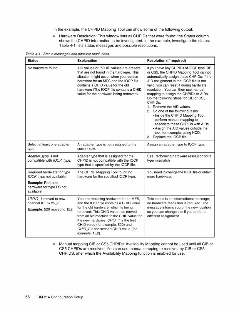
In the example, the CHPID Mapping Tool can show some of the following output:
� Hardware Resolution: This window lists all CHPIDs that were found; the Status column shows the CHPID information to be investigated. In the example, investigate the status; Table 4-1 lists status messages and possible resolutions.
Table 4-1 Status messages and possible resolutions
� Manual mapping CIB or CS5 CHPIDs: Availability Mapping cannot be used until all CIB or CS5 CHPIDs are resolved. You can use manual mapping to resolve any CIB or CS5 CHPIDS, after which the Availability Mapping function is enabled for use.
Status Explanation Resolution (if required)
No hardware found AID values or PCHID values are present that are not found in the hardware. This situation might occur when you replace hardware for an MES and the IOCP file contains a CHID value for the old hardware (The IOCP file contains a CHID value for the hardware being removed).
If you have any CHPIDs of IOCP type CIB or CS5, the CHPID Mapping Tool cannot automatically assign these CHPIDs. If the AID assignment in the IOCP file is not valid, you can reset it during hardware resolution. You can then use manual mapping to assign the CHPIDs to AIDs. Do the following steps for CIB or CS5 CHPIDs:1. Remove the AID values.2. Do one of the following tasks:
- Inside the CHPID Mapping Tool, perform manual mapping to associate these CHPIDs with AIDs.
- Assign the AID values outside the tool, for example, using HCD.
3. Replace the IOCP file.
Select at least one adapter type.
An adapter type is not assigned to the current row.
Assign an adapter type to IOCP type.
Adapter_type is not compatible with IOCP_type.
Adapter type that is assigned for the CHPID is not compatible with the IOCP type that is specified by the IOCP file.
See Performing hardware resolution for a type mismatch
Required hardware for type IOCP_type not available.
Example: Required hardware for type FC not available.
The CHPID Mapping Tool found no hardware for the specified IOCP type.
You need to change the IOCP file or obtain more hardware.
CHID_1 moved to new channel ID: CHID_2
Example: 520 moved to 1E2
You are replacing hardware for an MES, and the IOCP file contains a CHID value for the old hardware, which is being removed. This CHID value has moved from an old machine to the CHID value for the new hardware. CHID_1 is the first CHID value (for example, 520) and CHID_2 is the second CHID value (for example, 1E2).
This status is an informational message; no hardware resolution is required. The message informs you of the new location so you can change this if you prefer a different assignment.
58 IBM z14 Configuration Setup
� Process the CU Priorities and Automatic Mapping:
– Reset CHPIDs assigned by Automatic Mapping: Selecting this option resets all CHPIDs that were processed by prior availability runs in this session.
By default, this option is selected.
– Reset CHPIDs assigned by Manual Mapping: Selecting this option resets CHPIDs that were assigned a CHID in the Manual window. If this option is not selected (it has no check mark), then availability CHIDs for these CHPIDs are not reset.
By default, this option is not selected.
– Reset CHPIDs assigned by IOCP (Potential re-cabling): If some of the CHPIDs are assigned in the IOCP Input file, selecting this option resets the CHPIDs. Selecting this option might require recabling after availability assignments.
Generally, select this option.
– Reset CHPIDs assigned by CMT for config files: The CFReport indicates that you are doing an MES/upgrade, and you have channels or CHPIDs (or both) that might have configuration files that are currently associated with them. The MES/upgrade might move some of those channel cards.
Regardless of whether the channels are moving or not, the CHPID Mapping Tool either assigns CHIDs to the logical CHPID definitions to keep the CHPID definition associated with its current configuration file, or moves the definition to the new location where the channel is moving.
If you reset the CHPID Mapping Tool assignments, back up the configuration file data before the MES, and restore that data to the new location (the CHID where the affected CHPIDs are assigned) before you use the CHPIDs.
By default, this option is not selected.
If no options are selected, availability works only on CHPIDs that do not have CHIDs assigned.
To give the CHPID Mapping Tool the most choices when you use the availability option, select Reset CHPIDs assigned by IOCP.
However, if you select Reset CHPIDs assigned by Automatic Mapping, review the intersects from availability processing carefully to ensure that preserving the prior CHPID-to-CHID relationship does not cause unacceptable availability.
Attention: If you run Reset CHPIDs assigned by IOCP, it resets any previously mapped CHPID assignments and can result in recabling of the server.
Chapter 4. Mapping CHIDs to CHPIDs using the CMT 59
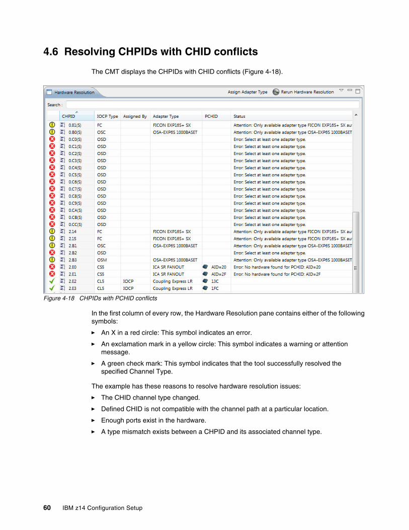
4.6 Resolving CHPIDs with CHID conflicts
The CMT displays the CHPIDs with CHID conflicts (Figure 4-18).
Figure 4-18 CHPIDs with PCHID conflicts
In the first column of every row, the Hardware Resolution pane contains either of the following symbols:
� An X in a red circle: This symbol indicates an error.
� An exclamation mark in a yellow circle: This symbol indicates a warning or attention message.
� A green check mark: This symbol indicates that the tool successfully resolved the specified Channel Type.
The example has these reasons to resolve hardware resolution issues:
� The CHID channel type changed.
� Defined CHID is not compatible with the channel path at a particular location.
� Enough ports exist in the hardware.
� A type mismatch exists between a CHPID and its associated channel type.
60 IBM z14 Configuration Setup
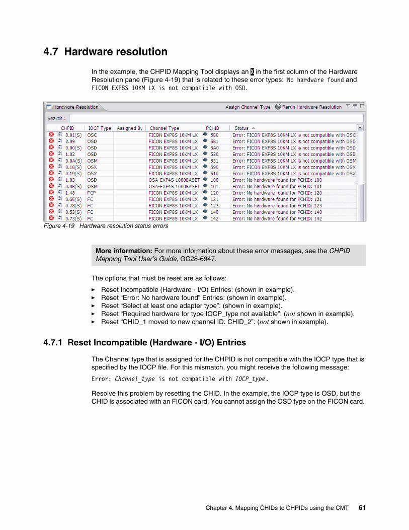
4.7 Hardware resolution
In the example, the CHPID Mapping Tool displays an X in the first column of the Hardware Resolution pane (Figure 4-19) that is related to these error types: No hardware found and FICON EXP8S 10KM LX is not compatible with OSD.
Figure 4-19 Hardware resolution status errors
The options that must be reset are as follows:
� Reset Incompatible (Hardware - I/O) Entries: (shown in example).� Reset “Error: No hardware found” Entries: (shown in example).� Reset “Select at least one adapter type”: (shown in example).� Reset “Required hardware for type IOCP_type not available”: (not shown in example).� Reset “CHID_1 moved to new channel ID: CHID_2”: (not shown in example).
4.7.1 Reset Incompatible (Hardware - I/O) Entries
The Channel type that is assigned for the CHPID is not compatible with the IOCP type that is specified by the IOCP file. For this mismatch, you might receive the following message:
Error: Channel_type is not compatible with IOCP_type.
Resolve this problem by resetting the CHID. In the example, the IOCP type is OSD, but the CHID is associated with an FICON card. You cannot assign the OSD type on the FICON card.
More information: For more information about these error messages, see the CHPID Mapping Tool User’s Guide, GC28-6947.
Chapter 4. Mapping CHIDs to CHPIDs using the CMT 61
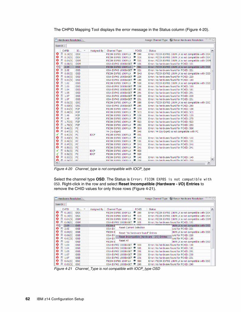
The CHPID Mapping Tool displays the error message in the Status column (Figure 4-20).
Figure 4-20 Channel_type is not compatible with IOCP_type
Select the channel type OSD. The Status is Error: FICON EXP8S is not compatible with OSD. Right-click in the row and select Reset Incompatible (Hardware - I/O) Entries to remove the CHID values for only those rows (Figure 4-21).
Figure 4-21 Channel_Type is not compatible with IOCP_type OSD
62 IBM z14 Configuration Setup
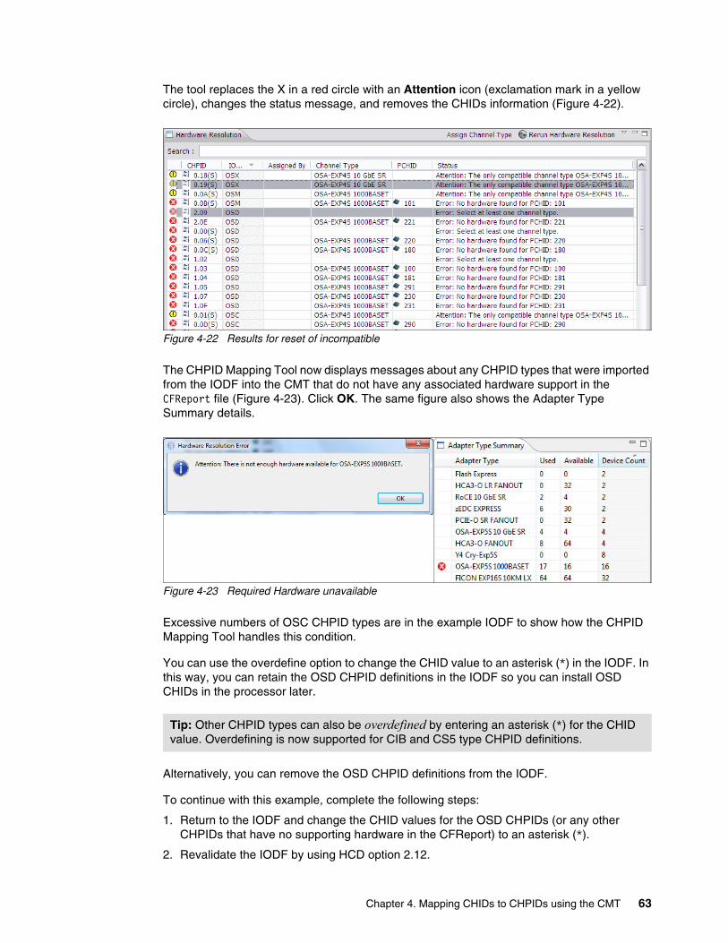
The tool replaces the X in a red circle with an Attention icon (exclamation mark in a yellow circle), changes the status message, and removes the CHIDs information (Figure 4-22).
Figure 4-22 Results for reset of incompatible
The CHPID Mapping Tool now displays messages about any CHPID types that were imported from the IODF into the CMT that do not have any associated hardware support in the CFReport file (Figure 4-23). Click OK. The same figure also shows the Adapter Type Summary details.
Figure 4-23 Required Hardware unavailable
Excessive numbers of OSC CHPID types are in the example IODF to show how the CHPID Mapping Tool handles this condition.
You can use the overdefine option to change the CHID value to an asterisk (*) in the IODF. In this way, you can retain the OSD CHPID definitions in the IODF so you can install OSD CHIDs in the processor later.
Alternatively, you can remove the OSD CHPID definitions from the IODF.
To continue with this example, complete the following steps:
1. Return to the IODF and change the CHID values for the OSD CHPIDs (or any other CHPIDs that have no supporting hardware in the CFReport) to an asterisk (*).
2. Revalidate the IODF by using HCD option 2.12.
Tip: Other CHPID types can also be overdefined by entering an asterisk (*) for the CHID value. Overdefining is now supported for CIB and CS5 type CHPID definitions.
Chapter 4. Mapping CHIDs to CHPIDs using the CMT 63
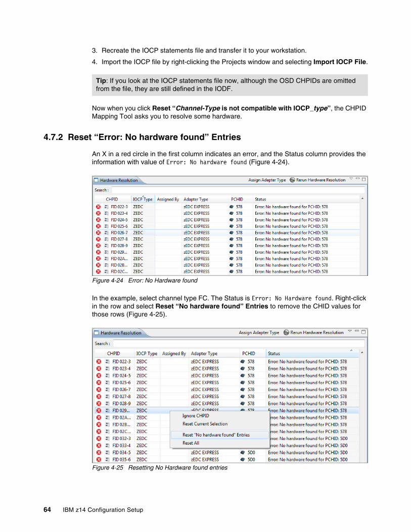
3. Recreate the IOCP statements file and transfer it to your workstation.
4. Import the IOCP file by right-clicking the Projects window and selecting Import IOCP File.
Now when you click Reset “Channel-Type is not compatible with IOCP_type”, the CHPID Mapping Tool asks you to resolve some hardware.
4.7.2 Reset “Error: No hardware found” Entries
An X in a red circle in the first column indicates an error, and the Status column provides the information with value of Error: No hardware found (Figure 4-24).
Figure 4-24 Error: No Hardware found
In the example, select channel type FC. The Status is Error: No Hardware found. Right-click in the row and select Reset “No hardware found” Entries to remove the CHID values for those rows (Figure 4-25).
Figure 4-25 Resetting No Hardware found entries
Tip: If you look at the IOCP statements file now, although the OSD CHPIDs are omitted from the file, they are still defined in the IODF.
64 IBM z14 Configuration Setup
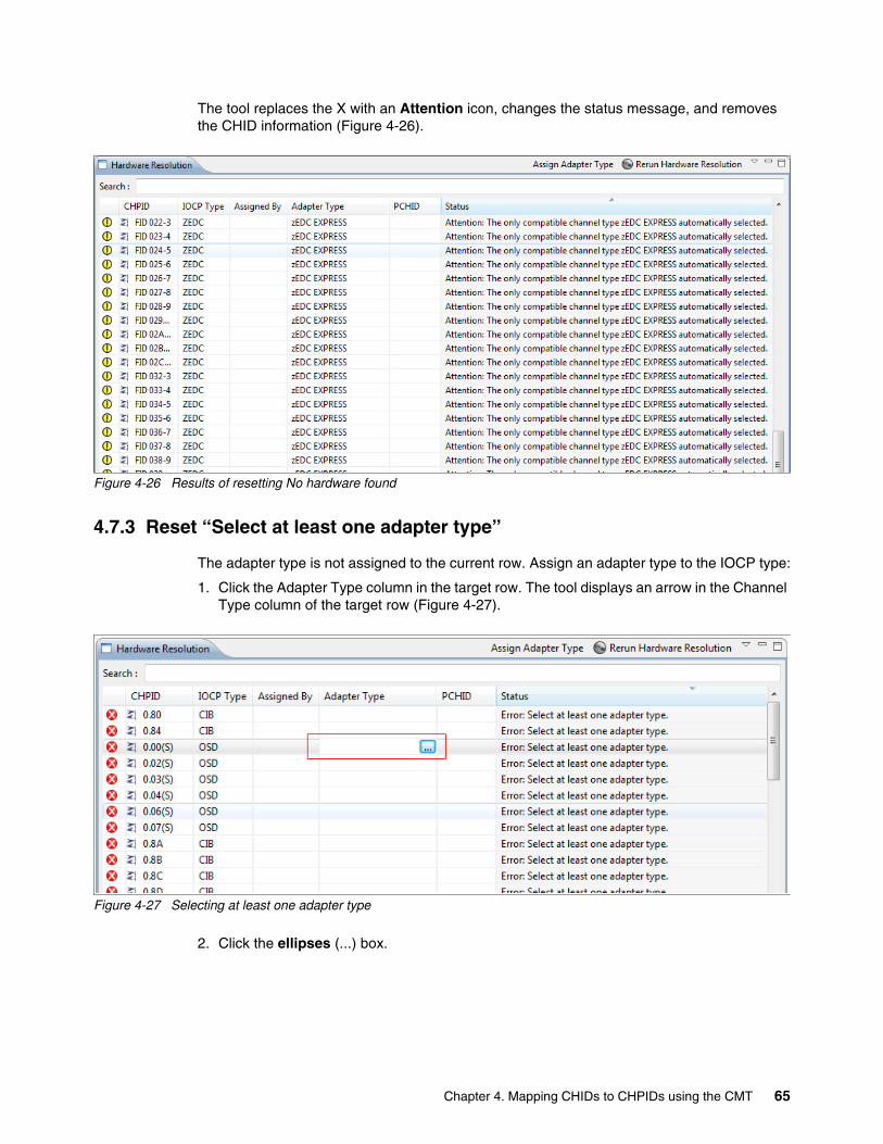
The tool replaces the X with an Attention icon, changes the status message, and removes the CHID information (Figure 4-26).
Figure 4-26 Results of resetting No hardware found
4.7.3 Reset “Select at least one adapter type”
The adapter type is not assigned to the current row. Assign an adapter type to the IOCP type:
1. Click the Adapter Type column in the target row. The tool displays an arrow in the Channel Type column of the target row (Figure 4-27).
Figure 4-27 Selecting at least one adapter type
2. Click the ellipses (...) box.
Chapter 4. Mapping CHIDs to CHPIDs using the CMT 65

3. The tool displays a list of available and compatible card types for the CHPID as shown in Figure 4-28. Select an adapter type and click OK.
4. In the Adapter Type Summary tab, observe that the Used and Available totals change.
Figure 4-28 Adapter Type Selection
4.7.4 Reset “Required hardware for type IOCP_type not available”
The CHPID Mapping Tool found no hardware for the specified IOCP type, as in this example:
Required hardware for type CS5 not available.
You must change IOCP file or obtain more hardware.
4.7.5 Reset “CHID_1 moved to new channel ID: CHID_2”
When moving from old hardware to new hardware, for example during a miscellaneous equipment specification (MES), the CHID value assigned to a feature can change. This message indicates that the IOCP file contains a CHID value for the old machine that is being removed. The CHID value is changed from the old machine to the CHID value for the new machine.
For example, CHID_1 is the first CHID value representing the old hardware (for example, 1B0) and CHID_2 is the new value representing the new hardware (for example, 533). In essence, the feature is present in both the old and new hardware, but its location (CHID) has changed.
This status is an informational message. No hardware resolution is required. The message informs you of the new location so you can change it if you prefer a different assignment.
After you assign all Adapter Types, the Manual Mapping button becomes available.
66 IBM z14 Configuration Setup

4.8 Manual mapping to resolve CIB CHPIDs
In some situations, the Automatic Mapping option is not available. You cannot use automatic mapping until all CIB or CS5 CHPIDs are resolved. You can use manual mapping to resolve this task.
To resolve the CIB or CS5 CHPIDs, assign the available CHPIDs:
1. Click Manual Mapping (Figure 4-29).
Figure 4-29 Manual Mapping
2. Ensure that the tool is set to display Manual Mapping in the Hardware -> I/O format (Figure 4-30).
Figure 4-30 Manual Mapping of Hardware -> I/O
3. Click every row that has type ICA SR in the Channel Type column. The tool displays all the available CHPIDs with IOCP type (Figure 4-31).
Figure 4-31 Adapter Type of HCA3 and associated CHPID assigned
4. Select one or more empty check boxes in the I/O Config pane to assign the CHPID. In the Hardware pane, the CHPID number is inserted in the CHPID column. Iin the Assigned By column, the value of Manual is inserted.
Chapter 4. Mapping CHIDs to CHPIDs using the CMT 67

5. If you select more than one CHPID for an ICS SR adapter type, you see the Multiple --> value (Figure 4-32) inserted in the CHPID and Assigned By columns.
Figure 4-32 Adapter Type of HCA3 and associated multiple CHPID assigned
The Automatic Mapping button becomes available after you assign all the CHPIDs of IOCP type CIB or CS5.
4.9 Processing Automatic Mapping then CU Priority
If you are importing an IOCP statements file from a 2964 that had CU Priority values defined, review the CU Priority values first. The CHPID Mapping Tool can then perform the availability functions appropriately for a 3906.
You must assign priorities if you want to make some control units more important (in the CMT processing order) than others, or have two (or more) control units that you want the CMT to process at the same time.
68 IBM z14 Configuration Setup
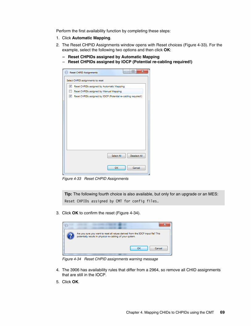
Perform the first availability function by completing these steps:
1. Click Automatic Mapping.
2. The Reset CHPID Assignments window opens with Reset choices (Figure 4-33). For the example, select the following two options and then click OK:
– Reset CHPIDs assigned by Automatic Mapping – Reset CHPIDs assigned by IOCP (Potential re-cabling required!)
Figure 4-33 Reset CHPID Assignments
3. Click OK to confirm the reset (Figure 4-34).
Figure 4-34 Reset CHPID assignments warning message
4. The 3906 has availability rules that differ from a 2964, so remove all CHID assignments that are still in the IOCP.
5. Click OK.
Tip: The following fourth choice is also available, but only for an upgrade or an MES:
Reset CHPIDs assigned by CMT for config files.
Chapter 4. Mapping CHIDs to CHPIDs using the CMT 69

6. After the CHPID Mapping Tool resets the CHPIDs, it displays the result of the process (Figure 4-35). Click OK.
Figure 4-35 Availability ran successfully with no errors message
7. Click OK (Figure 4-36).
Figure 4-36 Process Intersections run successfully message
The possible intersects are as follows:
C Two or more assigned channels use the same channel card.
S More than half the assigned channels use the same InfiniBand or STI link.
M All assigned channels are supported by the same MBA group.
B More than half the assigned channels are supported by the same MBA Group.
D Assigned channels are on the same daughter card.
Tip: Intersect messages inform you of a potential availability problem detected by the CMT. However, they do not necessarily indicate an error. It is your responsibility to evaluate whether the condition must be corrected.
70 IBM z14 Configuration Setup
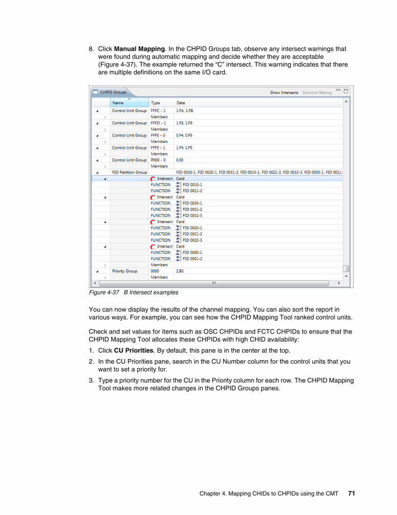
8. Click Manual Mapping. In the CHPID Groups tab, observe any intersect warnings that were found during automatic mapping and decide whether they are acceptable (Figure 4-37). The example returned the “C” intersect. This warning indicates that there are multiple definitions on the same I/O card.
Figure 4-37 B Intersect examples
You can now display the results of the channel mapping. You can also sort the report in various ways. For example, you can see how the CHPID Mapping Tool ranked control units.
Check and set values for items such as OSC CHPIDs and FCTC CHPIDs to ensure that the CHPID Mapping Tool allocates these CHPIDs with high CHID availability:
1. Click CU Priorities. By default, this pane is in the center at the top.
2. In the CU Priorities pane, search in the CU Number column for the control units that you want to set a priority for.
3. Type a priority number for the CU in the Priority column for each row. The CHPID Mapping Tool makes more related changes in the CHPID Groups panes.
Chapter 4. Mapping CHIDs to CHPIDs using the CMT 71
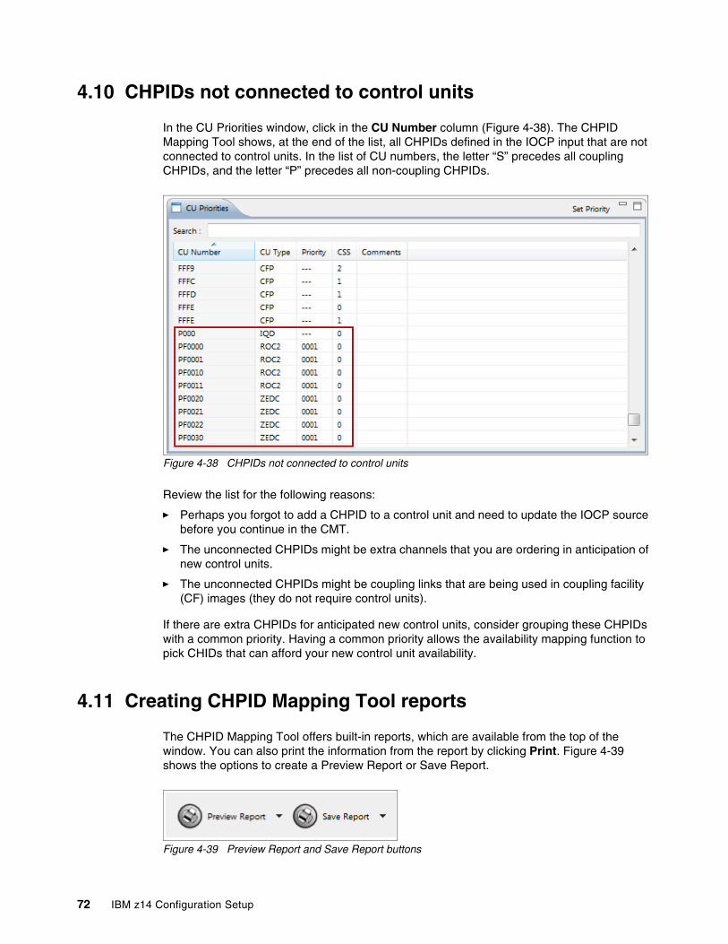
4.10 CHPIDs not connected to control units
In the CU Priorities window, click in the CU Number column (Figure 4-38). The CHPID Mapping Tool shows, at the end of the list, all CHPIDs defined in the IOCP input that are not connected to control units. In the list of CU numbers, the letter “S” precedes all coupling CHPIDs, and the letter “P” precedes all non-coupling CHPIDs.
Figure 4-38 CHPIDs not connected to control units
Review the list for the following reasons:
� Perhaps you forgot to add a CHPID to a control unit and need to update the IOCP source before you continue in the CMT.
� The unconnected CHPIDs might be extra channels that you are ordering in anticipation of new control units.
� The unconnected CHPIDs might be coupling links that are being used in coupling facility (CF) images (they do not require control units).
If there are extra CHPIDs for anticipated new control units, consider grouping these CHPIDs with a common priority. Having a common priority allows the availability mapping function to pick CHIDs that can afford your new control unit availability.
4.11 Creating CHPID Mapping Tool reports
The CHPID Mapping Tool offers built-in reports, which are available from the top of the window. You can also print the information from the report by clicking Print. Figure 4-39 shows the options to create a Preview Report or Save Report.
Figure 4-39 Preview Report and Save Report buttons
72 IBM z14 Configuration Setup

Click Preview Report or Save Report to display choices (a list of types of reports). The choices are the same except that Save Report lists an extra selection (Figure 4-40).
Figure 4-40 Preview Report and Save Report menus
For simplicity, only three reports are described in this example:
� The CHPID Report � The Port Report, sorted by location� The CHPID to Control Unit Report
However, all built-in reports are printed in the same way.
The person who installs the I/O cables during system installation needs one of these reports. The Port Report, sorted by location, is preferable. The installer can use this report to help with labeling the cables. The labels must include the CHID or cage/slot/port information before system delivery.
Chapter 4. Mapping CHIDs to CHPIDs using the CMT 73

4.11.1 CHPID Report
To create the CHPID report, complete the following steps:
1. Click Preview Report → CHPID Report (Figure 4-41).
Figure 4-41 Preview report: CHPID Report
74 IBM z14 Configuration Setup
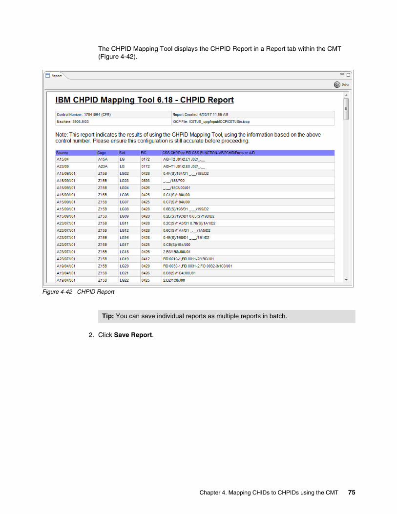
The CHPID Mapping Tool displays the CHPID Report in a Report tab within the CMT (Figure 4-42).
Figure 4-42 CHPID Report
2. Click Save Report.
Tip: You can save individual reports as multiple reports in batch.
Chapter 4. Mapping CHIDs to CHPIDs using the CMT 75

In the example, when you click CHPID Report, an option window opens (Figure 4-43). Specify a file name and an external path (location) of where to save the file. If you want to save the report in HTML, select HTML. The tool selects PDF by default. The window is similar for all type of reports. Click Finish.
Figure 4-43 Save CHPID Report
76 IBM z14 Configuration Setup
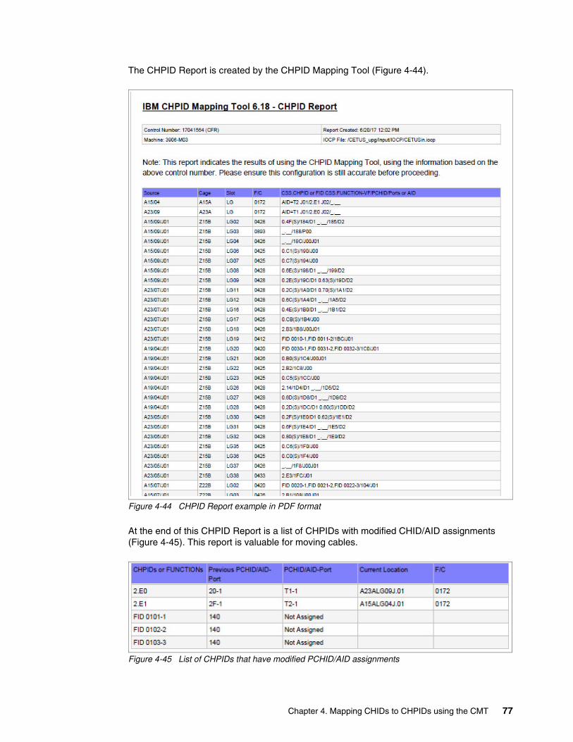
The CHPID Report is created by the CHPID Mapping Tool (Figure 4-44).
Figure 4-44 CHPID Report example in PDF format
At the end of this CHPID Report is a list of CHPIDs with modified CHID/AID assignments (Figure 4-45). This report is valuable for moving cables.
Figure 4-45 List of CHPIDs that have modified PCHID/AID assignments
Chapter 4. Mapping CHIDs to CHPIDs using the CMT 77
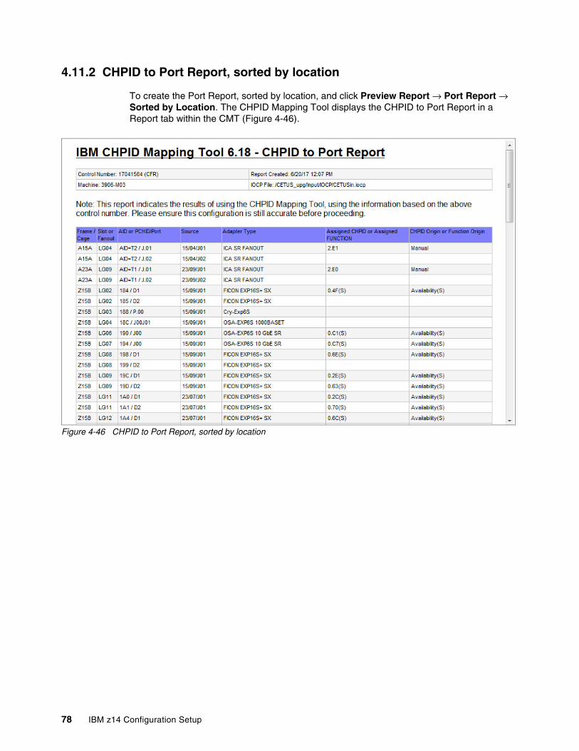
4.11.2 CHPID to Port Report, sorted by location
To create the Port Report, sorted by location, and click Preview Report → Port Report → Sorted by Location. The CHPID Mapping Tool displays the CHPID to Port Report in a Report tab within the CMT (Figure 4-46).
Figure 4-46 CHPID to Port Report, sorted by location
78 IBM z14 Configuration Setup
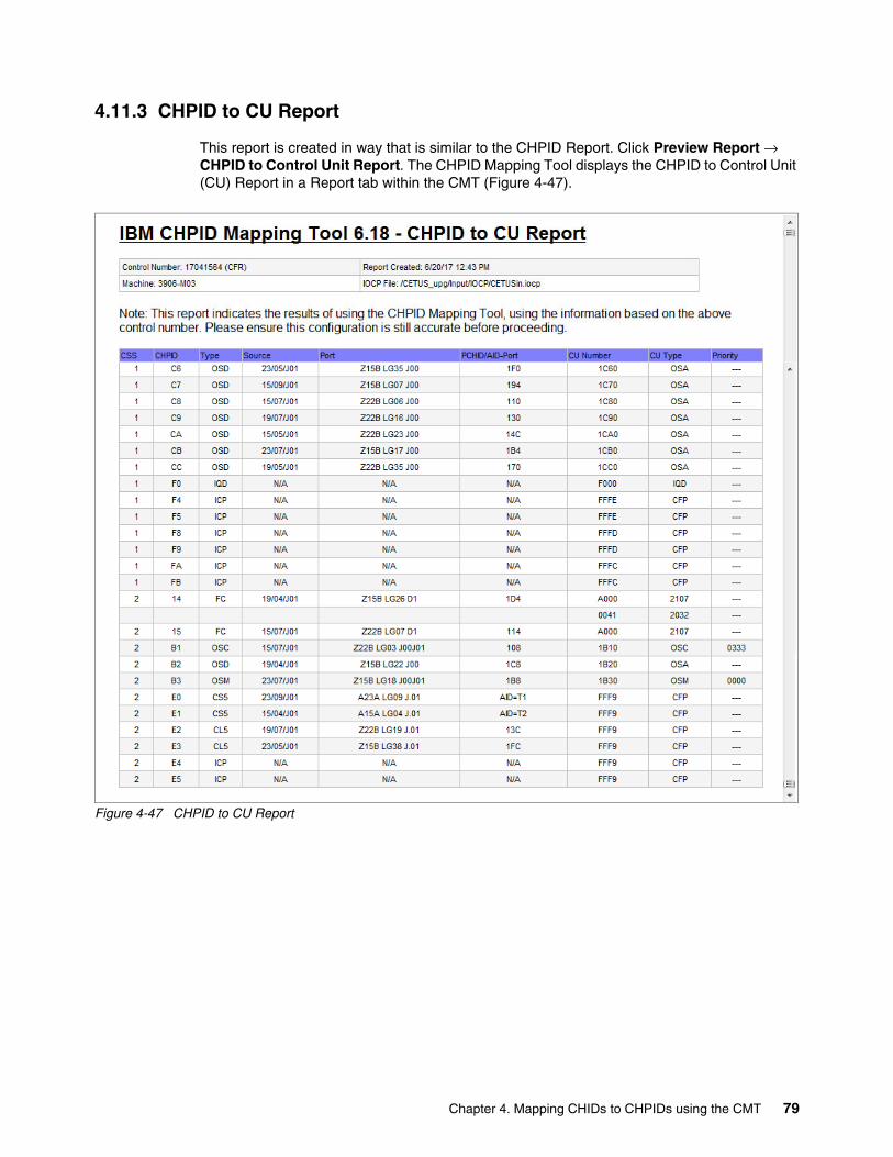
4.11.3 CHPID to CU Report
This report is created in way that is similar to the CHPID Report. Click Preview Report → CHPID to Control Unit Report. The CHPID Mapping Tool displays the CHPID to Control Unit (CU) Report in a Report tab within the CMT (Figure 4-47).
Figure 4-47 CHPID to CU Report
Chapter 4. Mapping CHIDs to CHPIDs using the CMT 79
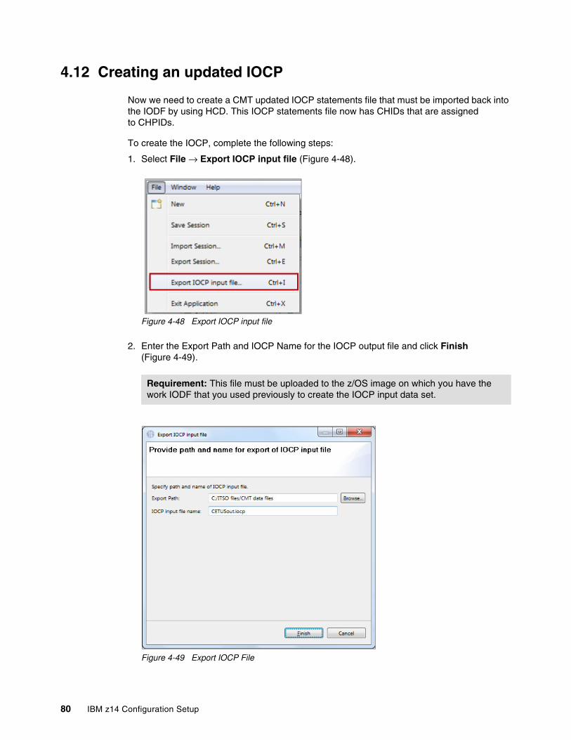
4.12 Creating an updated IOCP
Now we need to create a CMT updated IOCP statements file that must be imported back into the IODF by using HCD. This IOCP statements file now has CHIDs that are assigned to CHPIDs.
To create the IOCP, complete the following steps:
1. Select File → Export IOCP input file (Figure 4-48).
Figure 4-48 Export IOCP input file
2. Enter the Export Path and IOCP Name for the IOCP output file and click Finish (Figure 4-49).
Figure 4-49 Export IOCP File
Requirement: This file must be uploaded to the z/OS image on which you have the work IODF that you used previously to create the IOCP input data set.
80 IBM z14 Configuration Setup

3. Select File → Save Session (Figure 4-50).
Figure 4-50 Save session
You might want to save your project before exiting the CMT application.
4.13 HCD: Updating the 3906 work IODF with CHIDs
After you map the CHIDs to CHPIDs by using the CHPID Mapping Tool, transfer this information back into HCD. In our example we call the host file name ‘SYS6.IODF29.IOCPOUT.CETUS’.
To update the IODF with the CHIDs, complete these steps:
1. Upload the IOCP file that was created by the CMT (CETUSout.iocp, in the example) to the z/OS image. Use a file transfer facility, such as the one in IBM Personal Communications or an equivalent FTP program. Be sure to use TEXT as the transfer type and allocate the z/OS file with RECFM=F or FB and LRECL=80.
In the updated IOCP statements file, notice that the CMT keeps a reference to the CCN. Also, note the CU Priority values added for the OSC control units.
Example 4-2 Updated IOCP statements file: With CMT statements
CNTLUNIT CUNUMBR=FFFC,PATH=((CSS(2),E1,E0,E3,E2,E5,E4)), * UNIT=CFP IODEVICE ADDRESS=(FFA5,007),CUNUMBR=(FFFC),UNIT=CFP IODEVICE ADDRESS=(FFBD,007),CUNUMBR=(FFFC),UNIT=CFP IODEVICE ADDRESS=(FFC4,008),CUNUMBR=(FFFC),UNIT=CFP IODEVICE ADDRESS=(FFCC,008),CUNUMBR=(FFFC),UNIT=CFP IODEVICE ADDRESS=(FFD4,008),CUNUMBR=(FFFC),UNIT=CFP IODEVICE ADDRESS=(FFDC,008),CUNUMBR=(FFFC),UNIT=CFP *CMT* VERSION=000 *CMT* CCN=21751417(CFR from ResourceLink) *CMT* 1B30.2=0000,PF0050.0=0001,PF0051.0=0001,PF0040.0=0001,PF0030.0=0001 *CMT* PF0041.0=0001,PF0020.0=0001,PF0031.0=0001,PF0010.0=0001,PF0021.0=0001 *CMT* PF0032.0=0001,PF0000.0=0001,PF0011.0=0001,PF0022.0=0001,PF0001.0=0001 *CMT* PF0101.0=0001,PF0201.0=0001,PF0102.0=0001,PF0202.0=0001,PF0103.0=0001 *CMT* PF0203.0=0001 ******************************** Bottom of Data ********************************
Remember: Control unit priorities are stored in the IOCP output file that is created by CMT. This file is migrated back into HCD. HCD maintains these priorities and outputs them when it creates another IOCP deck. They are in the form of commented lines at the end of the IOCP deck (Example 4-2).
Chapter 4. Mapping CHIDs to CHPIDs using the CMT 81

2. From the HCD main panel, enter the work IODF name used. Select option 5. Migrate configuration data (Figure 4-51).
Figure 4-51 Hardware Configuration: Migrate configuration data
3. From the Migrate Configuration Data panel (Figure 4-52), select option 1. Migrate IOCP/OS data and press Enter.
Figure 4-52 Migrate Configuration Data: Migrate IOCP/OS data.
z/OS V2.3 HCD Command ===> ________________________________________________________________ Hardware Configuration Select one of the following. 5 0. Edit profile options and policies 1. Define, modify, or view configuration data 2. Activate or process configuration data 3. Print or compare configuration data 4. Create or view graphical configuration report 5. Migrate configuration data 6. Maintain I/O definition files 7. Query supported hardware and installed UIMs 8. Getting started with this dialog 9. What's new in this release For options 1 to 5, specify the name of the IODF to be used. I/O definition file . . . 'SYS6.IODF29.WORK' +
+----------- Migrate Configuration Data ------------+| || || Select one of the following tasks. || || 1_ 1. Migrate IOCP/OS data || 2. *Migrate switch configuration data || || * = requires TSA I/O Operations || || F1=Help F2=Split F3=Exit F9=Swap || F12=Cancel |+---------------------------------------------------+
82 IBM z14 Configuration Setup

4. The Migrate IOCP Data panel opens (Figure 4-53). Complete the following fields and then press Enter:
Processor ID Use the same ID used to create the IOCP input deck.
OS configuration ID This configuration is the OS configuration that is associated with the processor.
IOCP only input data set This data set is the one specified when the CETUSout.iocp file was uploaded to z/OS.
Processing mode Select option 2 to save the results of the migration. However, before using option 2, try to migrate by using option 1 to validate the operation.
Migrate options Select option 3 for PCHIDS. Only the PCHIDs are migrated into the work IODF.
Figure 4-53 Migrate IOCP / MVSCP / HCPRIO Data: Data fields to be updated
+-------------------- Migrate IOCP / MVSCP / HCPRIO Data ---------------------+| || || Specify or revise the following values. || || Processor ID . . . . . . . . . . . . CETUS___ + CSS ID . . . . . . _ + || OS configuration ID . . . . . . . . ITSOTEST + || || Combined IOCP/MVSCP input data set . _____________________________________ || IOCP only input data set . . . . . . 'SYS6.IODF29.IOCPOUT.CETUS' || MVSCP only or HCPRIO input data set _____________________________________ || Associated with processor ________ + || partition ________ + || Processing mode . . . . . . . . . . 2 1. Validate || 2. Save || || Migrate options . . . . . . . . . . 3 1. Complete || 2. Incremental || 3. PCHIDs || MACLIB used . . . . . . . 'SYS1.MACLIB' || Volume serial number . . . ______ + (if not cataloged) || || F1=Help F2=Split F3=Exit F4=Prompt F9=Swap F12=Cancel |+-----------------------------------------------------------------------------+
Chapter 4. Mapping CHIDs to CHPIDs using the CMT 83
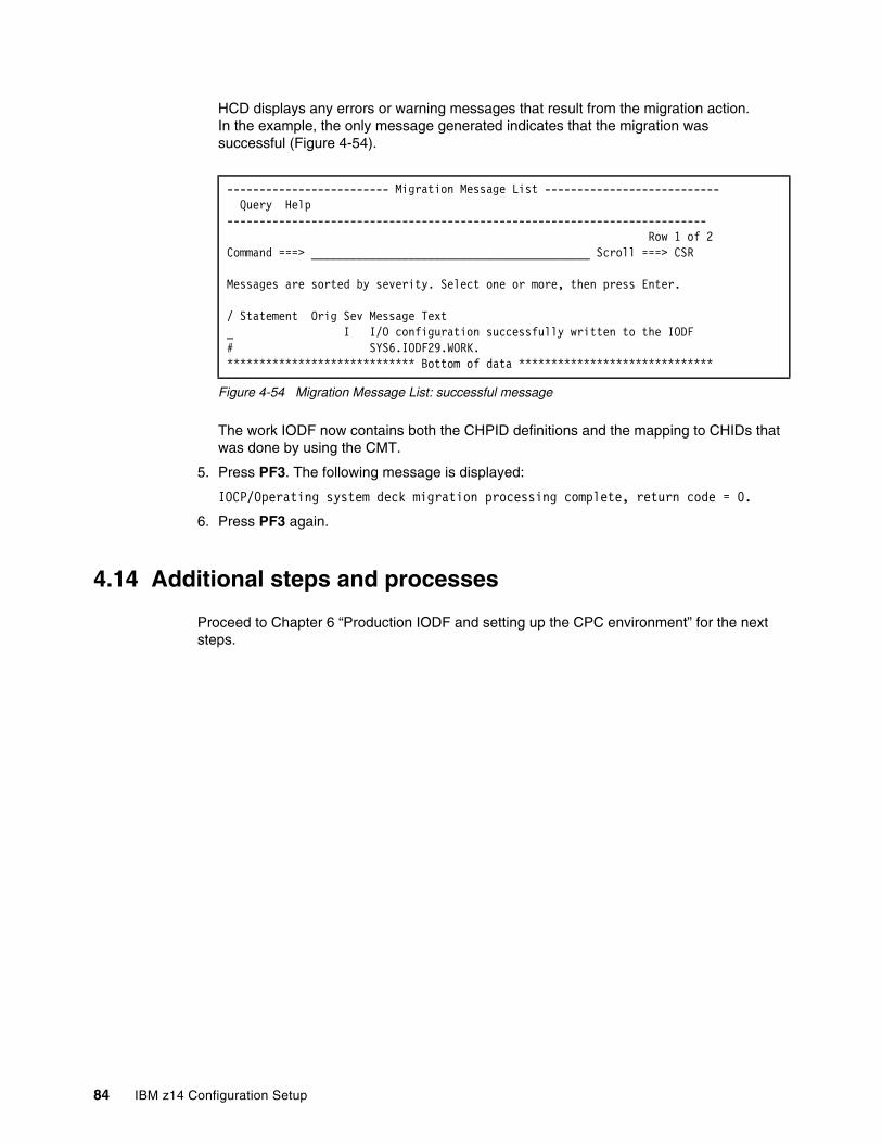
HCD displays any errors or warning messages that result from the migration action. In the example, the only message generated indicates that the migration was successful (Figure 4-54).
Figure 4-54 Migration Message List: successful message
The work IODF now contains both the CHPID definitions and the mapping to CHIDs that was done by using the CMT.
5. Press PF3. The following message is displayed:
IOCP/Operating system deck migration processing complete, return code = 0.
6. Press PF3 again.
4.14 Additional steps and processes
Proceed to Chapter 6 “Production IODF and setting up the CPC environment” for the next steps.
------------------------- Migration Message List --------------------------- Query Help -------------------------------------------------------------------------- Row 1 of 2 Command ===> ___________________________________________ Scroll ===> CSR Messages are sorted by severity. Select one or more, then press Enter. / Statement Orig Sev Message Text _ I I/O configuration successfully written to the IODF # SYS6.IODF29.WORK. ***************************** Bottom of data ******************************
84 IBM z14 Configuration Setup

Chapter 5. Production IODF and setting up the CPC
This chapter describes the following tasks:
� Building the 3906 production IODF� Writing the IOCP to the 2964 processor using HCD� Creating a Reset Profile on the 3906 Support Element� Creating an Image Profile on the 3906 Support Element� Performing a Power-On Reset of the 3906� Building and verifying Load (IPL) profiles� Building and verifying LOADxx Members in SYS#.IPLPARM� Communicating information about the new z14
5
© Copyright IBM Corp. 2017. All rights reserved. 85
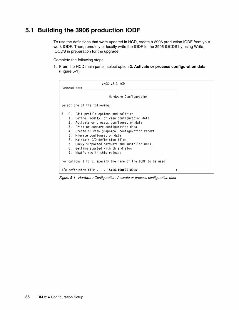
5.1 Building the 3906 production IODF
To use the definitions that were updated in HCD, create a 3906 production IODF from your work IODF. Then, remotely or locally write the IODF to the 3906 IOCDS by using Write IOCDS in preparation for the upgrade.
Complete the following steps:
1. From the HCD main panel, select option 2. Activate or process configuration data (Figure 5-1).
Figure 5-1 Hardware Configuration: Activate or process configuration data
z/OS V2.3 HCD Command ===> _____________________________________________________ Hardware Configuration Select one of the following. 2 0. Edit profile options and policies 1. Define, modify, or view configuration data 2. Activate or process configuration data 3. Print or compare configuration data 4. Create or view graphical configuration report 5. Migrate configuration data 6. Maintain I/O definition files 7. Query supported hardware and installed UIMs 8. Getting started with this dialog 9. What's new in this release For options 1 to 5, specify the name of the IODF to be used. I/O definition file . . . 'SYS6.IODF29.WORK' +
86 IBM z14 Configuration Setup

2. The Activate or Process Configuration Data panel is displayed (Figure 5-2). Select option 1. Build production I/O definition file and press Enter.
Figure 5-2 Activate or Process Configuration Data: Build production IODF
+------ Activate or Process Configuration Data ------+| || || Select one of the following tasks. || || 1_ 1. Build production I/O definition file || 2. Build IOCDS || 3. Build IOCP input data set || 4. Create JES3 initialization stream data || 5. View active configuration || 6. Activate or verify configuration || dynamically || 7. Activate configuration sysplex-wide || 8. *Activate switch configuration || 9. *Save switch configuration || 10. Build I/O configuration data || 11. Build and manage System z cluster IOCDSs, || IPL attributes and dynamic I/O changes || 12. Build validated work I/O definition file || || * = requires TSA I/O Operations || F1=Help F2=Split F3=Exit F9=Swap || F12=Cancel |+----------------------------------------------------+
Chapter 5. Production IODF and setting up the CPC 87
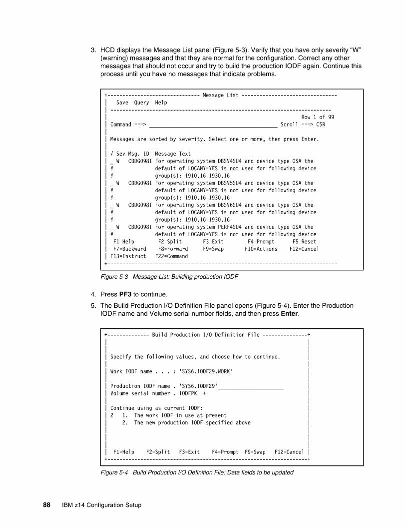
3. HCD displays the Message List panel (Figure 5-3). Verify that you have only severity “W” (warning) messages and that they are normal for the configuration. Correct any other messages that should not occur and try to build the production IODF again. Continue this process until you have no messages that indicate problems.
Figure 5-3 Message List: Building production IODF
4. Press PF3 to continue.
5. The Build Production I/O Definition File panel opens (Figure 5-4). Enter the Production IODF name and Volume serial number fields, and then press Enter.
Figure 5-4 Build Production I/O Definition File: Data fields to be updated
+------------------------------- Message List --------------------------------| Save Query Help | -------------------------------------------------------------------------- | Row 1 of 99 | Command ===> ___________________________________________ Scroll ===> CSR | | Messages are sorted by severity. Select one or more, then press Enter. | | / Sev Msg. ID Message Text | _ W CBDG098I For operating system DBSV4SU4 and device type OSA the | # default of LOCANY=YES is not used for following device | # group(s): 1910,16 1930,16 | _ W CBDG098I For operating system DBSV5SU4 and device type OSA the | # default of LOCANY=YES is not used for following device | # group(s): 1910,16 1930,16 | _ W CBDG098I For operating system DBSV6SU4 and device type OSA the | # default of LOCANY=YES is not used for following device | # group(s): 1910,16 1930,16 | _ W CBDG098I For operating system PERF4SU4 and device type OSA the | # default of LOCANY=YES is not used for following device | F1=Help F2=Split F3=Exit F4=Prompt F5=Reset | F7=Backward F8=Forward F9=Swap F10=Actions F12=Cancel | F13=Instruct F22=Command +-----------------------------------------------------------------------------
+-------------- Build Production I/O Definition File ---------------+| || || Specify the following values, and choose how to continue. || || Work IODF name . . . : 'SYS6.IODF29.WORK' || || Production IODF name . 'SYS6.IODF29'______________________ || Volume serial number . IODFPK + || || Continue using as current IODF: || 2 1. The work IODF in use at present || 2. The new production IODF specified above || || || || F1=Help F2=Split F3=Exit F4=Prompt F9=Swap F12=Cancel |+-------------------------------------------------------------------+
88 IBM z14 Configuration Setup
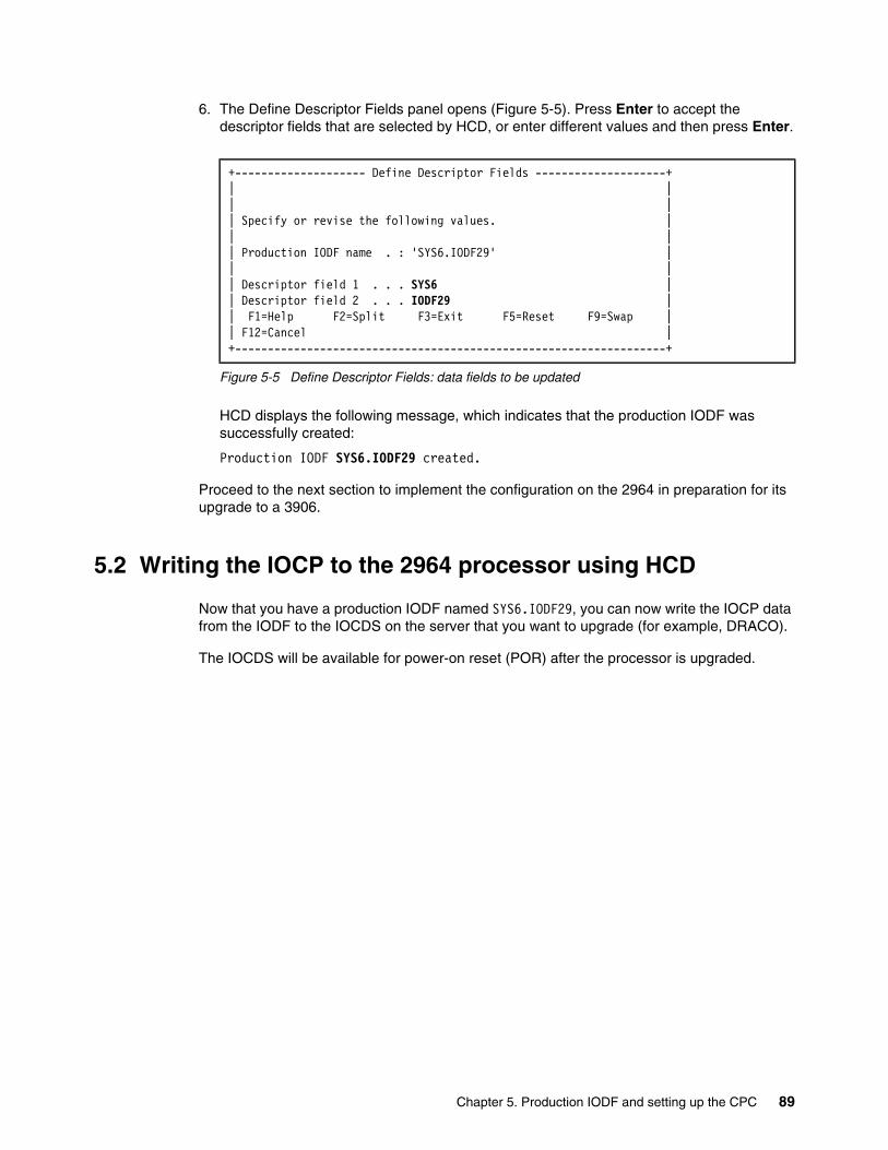
6. The Define Descriptor Fields panel opens (Figure 5-5). Press Enter to accept the descriptor fields that are selected by HCD, or enter different values and then press Enter.
Figure 5-5 Define Descriptor Fields: data fields to be updated
HCD displays the following message, which indicates that the production IODF was successfully created:
Production IODF SYS6.IODF29 created.
Proceed to the next section to implement the configuration on the 2964 in preparation for its upgrade to a 3906.
5.2 Writing the IOCP to the 2964 processor using HCD
Now that you have a production IODF named SYS6.IODF29, you can now write the IOCP data from the IODF to the IOCDS on the server that you want to upgrade (for example, DRACO).
The IOCDS will be available for power-on reset (POR) after the processor is upgraded.
+-------------------- Define Descriptor Fields --------------------+| || || Specify or revise the following values. || || Production IODF name . : 'SYS6.IODF29' || || Descriptor field 1 . . . SYS6 || Descriptor field 2 . . . IODF29 || F1=Help F2=Split F3=Exit F5=Reset F9=Swap || F12=Cancel |+------------------------------------------------------------------+
Chapter 5. Production IODF and setting up the CPC 89
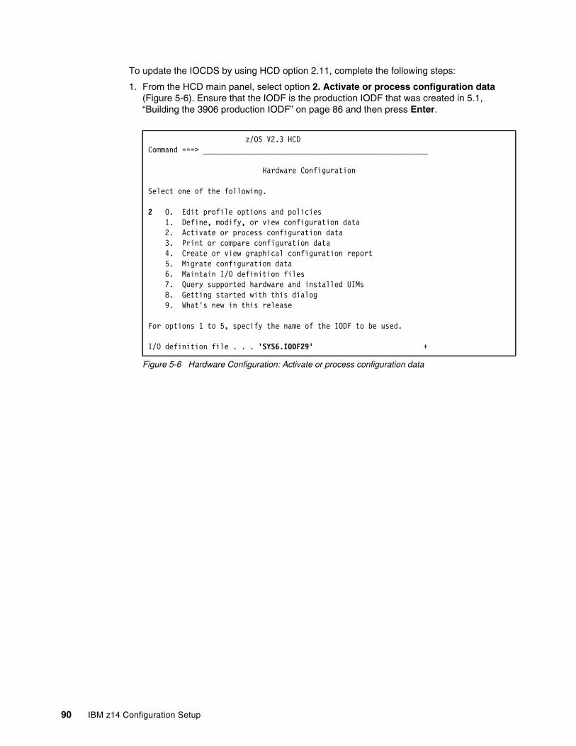
To update the IOCDS by using HCD option 2.11, complete the following steps:
1. From the HCD main panel, select option 2. Activate or process configuration data (Figure 5-6). Ensure that the IODF is the production IODF that was created in 5.1, “Building the 3906 production IODF” on page 86 and then press Enter.
Figure 5-6 Hardware Configuration: Activate or process configuration data
z/OS V2.3 HCD Command ===> _____________________________________________________ Hardware Configuration Select one of the following. 2 0. Edit profile options and policies 1. Define, modify, or view configuration data 2. Activate or process configuration data 3. Print or compare configuration data 4. Create or view graphical configuration report 5. Migrate configuration data 6. Maintain I/O definition files 7. Query supported hardware and installed UIMs 8. Getting started with this dialog 9. What's new in this release For options 1 to 5, specify the name of the IODF to be used. I/O definition file . . . 'SYS6.IODF29' +
90 IBM z14 Configuration Setup

2. The Activate or Process Configuration Data panel opens (Figure 5-7). Select option 11. Build and manage System z cluster IOCDSs, IPL attributes and dynamic I/O changes, and press Enter.
Figure 5-7 Activate or Process Configuration data: Build and manage System z cluster IOCDSs, IPL attributes and dynamic I/O changes
This example assumes that you have connectivity to the 2964 that is being upgraded over the HMC local area network to write an IOCDS.
If the server being upgraded is not accessible from the HMC LAN, create a IOCP file from HCD, then use the stand-alone IOCP process to update the IOCDS.
You can create an IOCP file by using the same process that you used to create an IOCP file for the CMT.
+------ Activate or Process Configuration Data ------+| || || Select one of the following tasks. || || 11 1. Build production I/O definition file || 2. Build IOCDS || 3. Build IOCP input data set || 4. Create JES3 initialization stream data || 5. View active configuration || 6. Activate or verify configuration || dynamically || 7. Activate configuration sysplex-wide || 8. *Activate switch configuration || 9. *Save switch configuration || 10. Build I/O configuration data || 11. Build and manage System z cluster IOCDSs, || IPL attributes and dynamic I/O changes || 12. Build validated work I/O definition file || || * = requires TSA I/O Operations || F1=Help F2=Split F3=Exit F9=Swap || F12=Cancel |+----------------------------------------------------+
Tip: The Support Element can now read an IOCP file that has been written to a USB flash memory drive.
Chapter 5. Production IODF and setting up the CPC 91
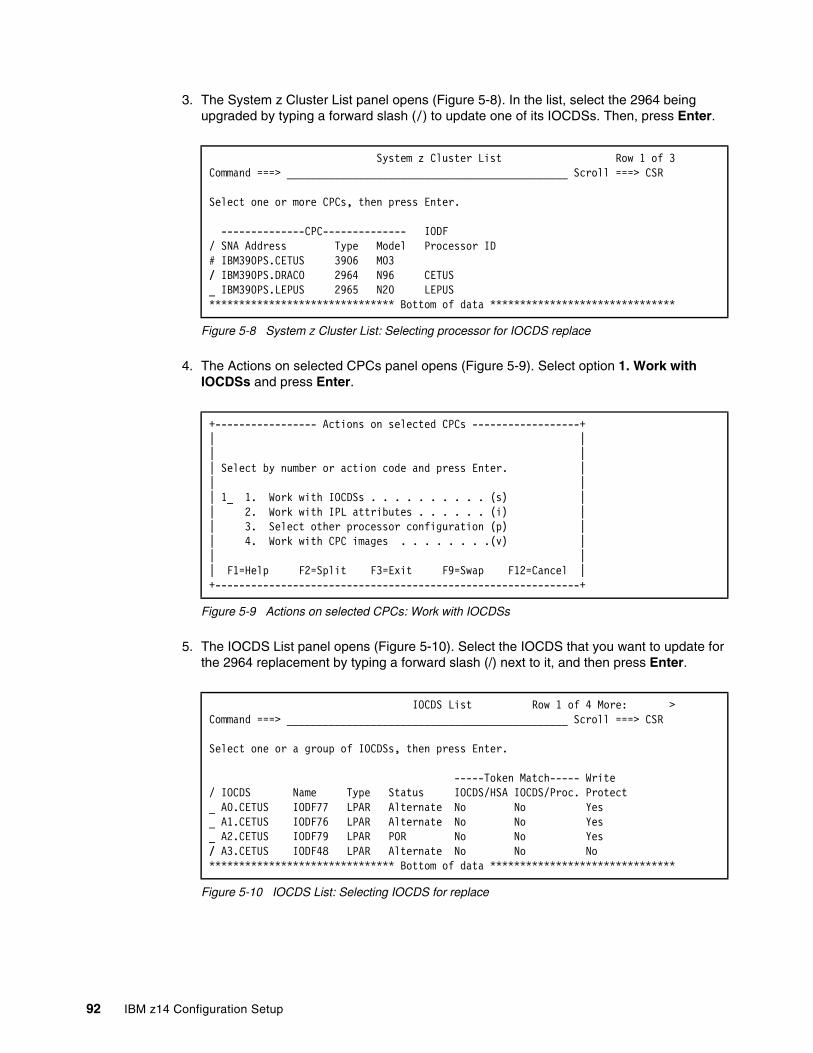
3. The System z Cluster List panel opens (Figure 5-8). In the list, select the 2964 being upgraded by typing a forward slash (/) to update one of its IOCDSs. Then, press Enter.
Figure 5-8 System z Cluster List: Selecting processor for IOCDS replace
4. The Actions on selected CPCs panel opens (Figure 5-9). Select option 1. Work with IOCDSs and press Enter.
Figure 5-9 Actions on selected CPCs: Work with IOCDSs
5. The IOCDS List panel opens (Figure 5-10). Select the IOCDS that you want to update for the 2964 replacement by typing a forward slash (/) next to it, and then press Enter.
Figure 5-10 IOCDS List: Selecting IOCDS for replace
System z Cluster List Row 1 of 3Command ===> _______________________________________________ Scroll ===> CSR Select one or more CPCs, then press Enter. --------------CPC-------------- IODF / SNA Address Type Model Processor ID # IBM390PS.CETUS 3906 M03 / IBM390PS.DRACO 2964 N96 CETUS _ IBM390PS.LEPUS 2965 N20 LEPUS ******************************* Bottom of data *******************************
+----------------- Actions on selected CPCs ------------------+| || || Select by number or action code and press Enter. || || 1_ 1. Work with IOCDSs . . . . . . . . . . (s) || 2. Work with IPL attributes . . . . . . (i) || 3. Select other processor configuration (p) || 4. Work with CPC images . . . . . . . .(v) || || F1=Help F2=Split F3=Exit F9=Swap F12=Cancel |+-------------------------------------------------------------+
IOCDS List Row 1 of 4 More: >Command ===> _______________________________________________ Scroll ===> CSR Select one or a group of IOCDSs, then press Enter. -----Token Match----- Write / IOCDS Name Type Status IOCDS/HSA IOCDS/Proc. Protect _ A0.CETUS IODF77 LPAR Alternate No No Yes _ A1.CETUS IODF76 LPAR Alternate No No Yes _ A2.CETUS IODF79 LPAR POR No No Yes / A3.CETUS IODF48 LPAR Alternate No No No ******************************* Bottom of data *******************************
92 IBM z14 Configuration Setup

6. The Actions on selected IOCDSs panel opens (Figure 5-11). Select option 1. Update IOCDS and press Enter.
Figure 5-11 Actions on selected IOCDSs: Update IOCDS
7. The Build IOCDSs panel opens (Figure 5-12). Verify that all the information is correct. Complete the Title1 field, set Write IOCDS in preparation of upgrade to Yes, and press Enter.
Figure 5-12 Build IOCDSs: Verifying IODF
+---------------- Actions on selected IOCDSs -----------------+| || || Select by number or action code and press Enter. || || 1_ 1. Update IOCDS . . . . . . . . . . . . (u) || 2. Switch IOCDS . . . . . . . . . . . . (s) || 3. Enable write protection . . . . . . (e) || 4. Disable write protection . . . . . . (w) || || || F1=Help F2=Split F3=Exit F9=Swap F12=Cancel |+-------------------------------------------------------------+
+------------------------------- Build IOCDSs --------------------------------+| Row 1 of 1 || Command ===> ___________________________________________ Scroll ===> CSR || || Specify or revise the following values. || || IODF name . . . . . . . . . : 'SYS6.IODF29' || || Title1 . IODF29__________________________________________________________ || Title2 : SYS6.IODF29 - 2017-06-21 11:48 || || Write IOCDS in || IOCDS Switch IOCDS preparation of upgrade || A3.CETUS No Yes || ***************************** Bottom of data ****************************** || || || F1=Help F2=Split F3=Exit F5=Reset F7=Backward || F8=Forward F9=Swap F12=Cancel F22=Command |+-----------------------------------------------------------------------------+
Tip: Specifying Yes in the Write IOCDS in preparation of upgrade field is required only when you replace or upgrade the existing hardware and want to write the IOCDS for a 3906 from the existing hardware. The Yes value permits the writing of an IOCDS that contains information that the current hardware does not recognize.
Chapter 5. Production IODF and setting up the CPC 93
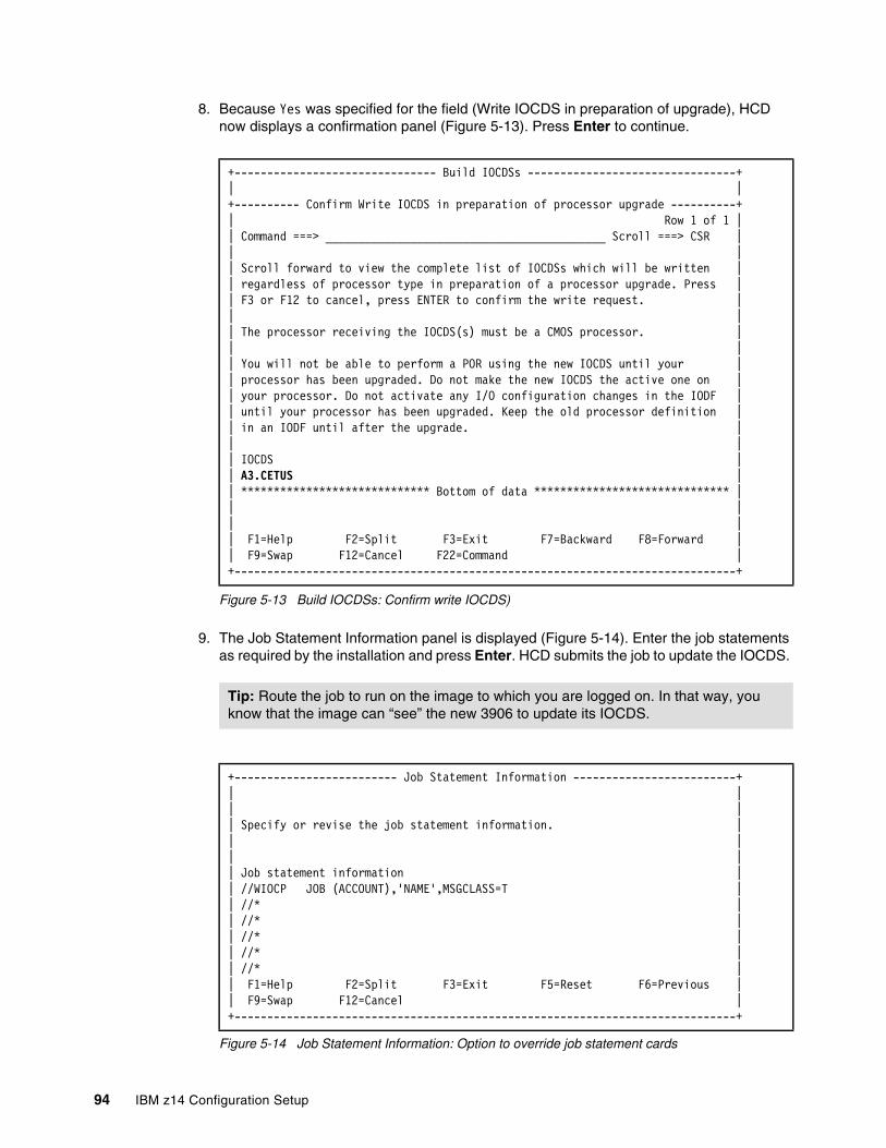
8. Because Yes was specified for the field (Write IOCDS in preparation of upgrade), HCD now displays a confirmation panel (Figure 5-13). Press Enter to continue.
Figure 5-13 Build IOCDSs: Confirm write IOCDS)
9. The Job Statement Information panel is displayed (Figure 5-14). Enter the job statements as required by the installation and press Enter. HCD submits the job to update the IOCDS.
Figure 5-14 Job Statement Information: Option to override job statement cards
+------------------------------- Build IOCDSs --------------------------------+| |+---------- Confirm Write IOCDS in preparation of processor upgrade ----------+| Row 1 of 1 || Command ===> ___________________________________________ Scroll ===> CSR || || Scroll forward to view the complete list of IOCDSs which will be written || regardless of processor type in preparation of a processor upgrade. Press || F3 or F12 to cancel, press ENTER to confirm the write request. || || The processor receiving the IOCDS(s) must be a CMOS processor. || || You will not be able to perform a POR using the new IOCDS until your || processor has been upgraded. Do not make the new IOCDS the active one on || your processor. Do not activate any I/O configuration changes in the IODF || until your processor has been upgraded. Keep the old processor definition || in an IODF until after the upgrade. || || IOCDS || A3.CETUS || ***************************** Bottom of data ****************************** || || || F1=Help F2=Split F3=Exit F7=Backward F8=Forward || F9=Swap F12=Cancel F22=Command |+-----------------------------------------------------------------------------+
Tip: Route the job to run on the image to which you are logged on. In that way, you know that the image can “see” the new 3906 to update its IOCDS.
+------------------------- Job Statement Information -------------------------+| || || Specify or revise the job statement information. || || || Job statement information || //WIOCP JOB (ACCOUNT),'NAME',MSGCLASS=T || //* || //* || //* || //* || //* || F1=Help F2=Split F3=Exit F5=Reset F6=Previous || F9=Swap F12=Cancel |+-----------------------------------------------------------------------------+
94 IBM z14 Configuration Setup
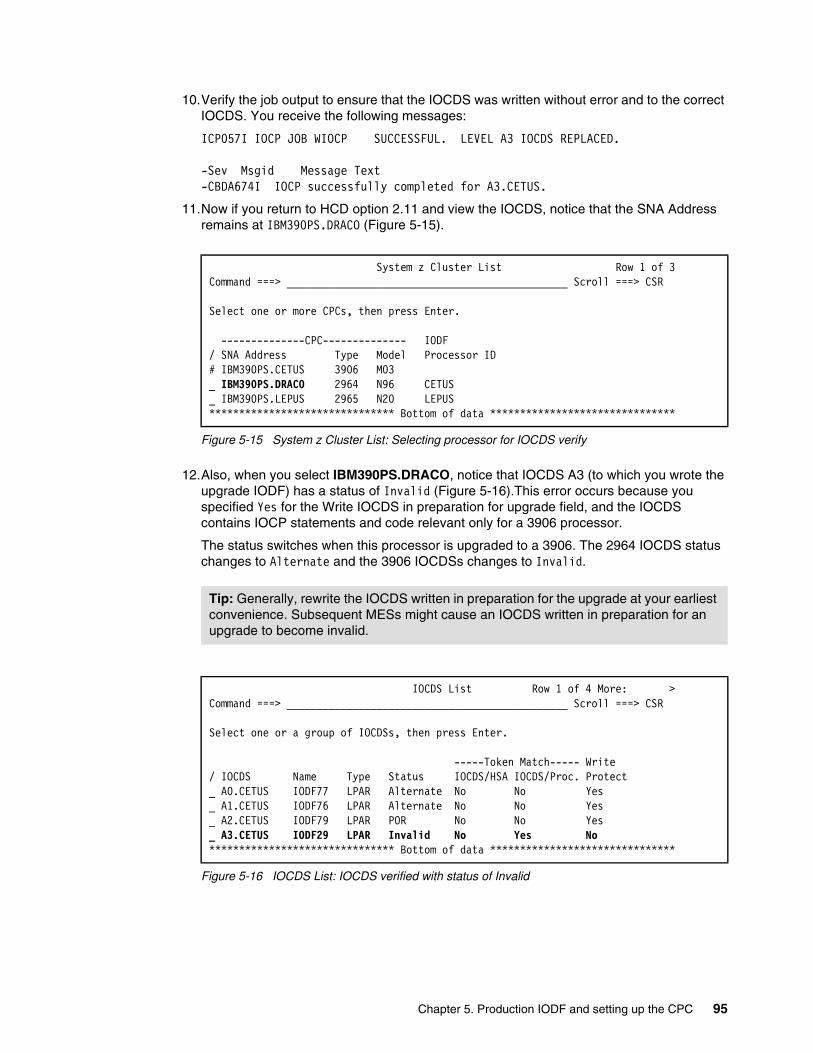
10.Verify the job output to ensure that the IOCDS was written without error and to the correct IOCDS. You receive the following messages:
ICP057I IOCP JOB WIOCP SUCCESSFUL. LEVEL A3 IOCDS REPLACED.
-Sev Msgid Message Text -CBDA674I IOCP successfully completed for A3.CETUS.
11.Now if you return to HCD option 2.11 and view the IOCDS, notice that the SNA Address remains at IBM390PS.DRACO (Figure 5-15).
Figure 5-15 System z Cluster List: Selecting processor for IOCDS verify
12.Also, when you select IBM390PS.DRACO, notice that IOCDS A3 (to which you wrote the upgrade IODF) has a status of Invalid (Figure 5-16).This error occurs because you specified Yes for the Write IOCDS in preparation for upgrade field, and the IOCDS contains IOCP statements and code relevant only for a 3906 processor.
The status switches when this processor is upgraded to a 3906. The 2964 IOCDS status changes to Alternate and the 3906 IOCDSs changes to Invalid.
Figure 5-16 IOCDS List: IOCDS verified with status of Invalid
System z Cluster List Row 1 of 3Command ===> _______________________________________________ Scroll ===> CSR Select one or more CPCs, then press Enter. --------------CPC-------------- IODF / SNA Address Type Model Processor ID # IBM390PS.CETUS 3906 M03 _ IBM390PS.DRACO 2964 N96 CETUS _ IBM390PS.LEPUS 2965 N20 LEPUS ******************************* Bottom of data *******************************
Tip: Generally, rewrite the IOCDS written in preparation for the upgrade at your earliest convenience. Subsequent MESs might cause an IOCDS written in preparation for an upgrade to become invalid.
IOCDS List Row 1 of 4 More: >Command ===> _______________________________________________ Scroll ===> CSR Select one or a group of IOCDSs, then press Enter. -----Token Match----- Write / IOCDS Name Type Status IOCDS/HSA IOCDS/Proc. Protect _ A0.CETUS IODF77 LPAR Alternate No No Yes _ A1.CETUS IODF76 LPAR Alternate No No Yes _ A2.CETUS IODF79 LPAR POR No No Yes _ A3.CETUS IODF29 LPAR Invalid No Yes No ******************************* Bottom of data *******************************
Chapter 5. Production IODF and setting up the CPC 95
5.3 Creating a Reset Profile on the 3906 Support ElementTo build and activate your Reset Profile using the HMC, complete the steps in this section.
5.3.1 Background activities that have occurred
The following activities must have occurred before you create a Reset Profile:
� The 2964 processor has been upgraded to a 3906-M03.
� A new HMC has been installed with the correct driver level to support the 3906, and it is connected to the customer HMC network.
� The upgraded 3906 (CETUS) has been defined to the new HMC.
� The 2964, now upgraded to a 3906, has been Power on Reset with the Diagnostic (DEFAULT) IOCDS.
� The 3906 has had a new IOCP written to its IOCDS from the IODF (IODF05) using HCD Option 2.11.
� The 3906 is now ready to be customized with specific customer definitions.
5.3.2 Building the Reset Profile and pointing to required IOCDS
Now that the IOCP file is written to an IOCDS, build a Reset (power-on reset) Profile to point to that IOCDS. This Reset Profile is used to power-on reset the new 3906 after it is upgraded and handed over from the IBM System Service Representative.
To build the profile, complete the following steps:
1. Log on using SYSPROG authority to the HMC workstation supplied with the 3906, or use a remote web browser and select the new 3906.
2. Under Systems Management, click Systems Management to expand the list.
3. Under Systems Management, click the radio button next to the system to select it (in this example, CETUS).
96 IBM z14 Configuration Setup
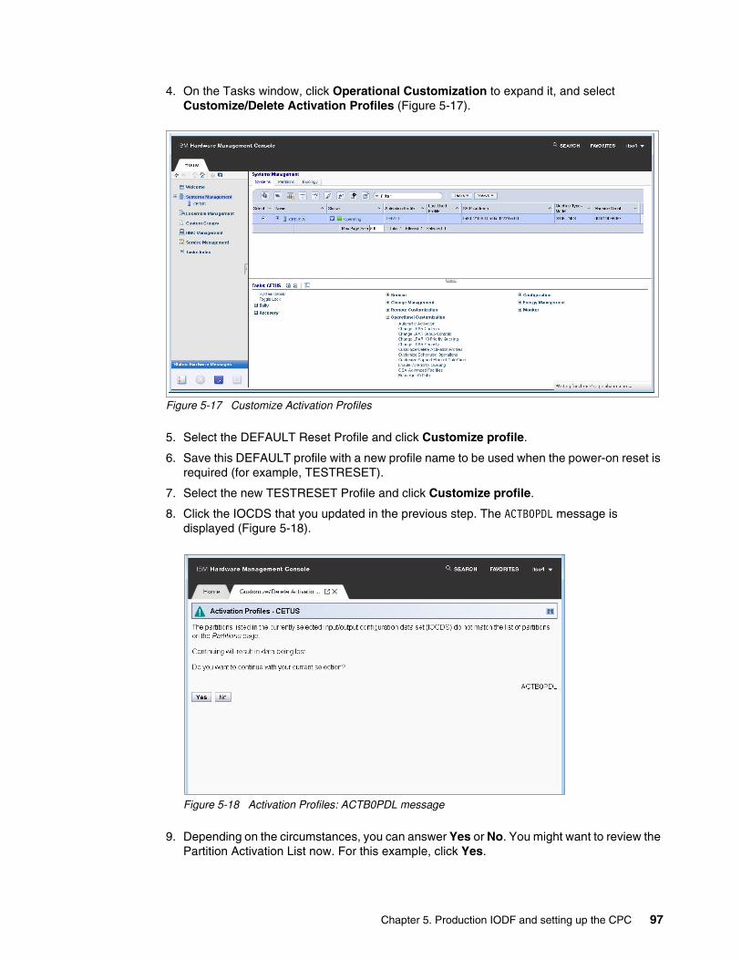
4. On the Tasks window, click Operational Customization to expand it, and select Customize/Delete Activation Profiles (Figure 5-17).
Figure 5-17 Customize Activation Profiles
5. Select the DEFAULT Reset Profile and click Customize profile.
6. Save this DEFAULT profile with a new profile name to be used when the power-on reset is required (for example, TESTRESET).
7. Select the new TESTRESET Profile and click Customize profile.
8. Click the IOCDS that you updated in the previous step. The ACTB0PDL message is displayed (Figure 5-18).
Figure 5-18 Activation Profiles: ACTB0PDL message
9. Depending on the circumstances, you can answer Yes or No. You might want to review the Partition Activation List now. For this example, click Yes.
Chapter 5. Production IODF and setting up the CPC 97
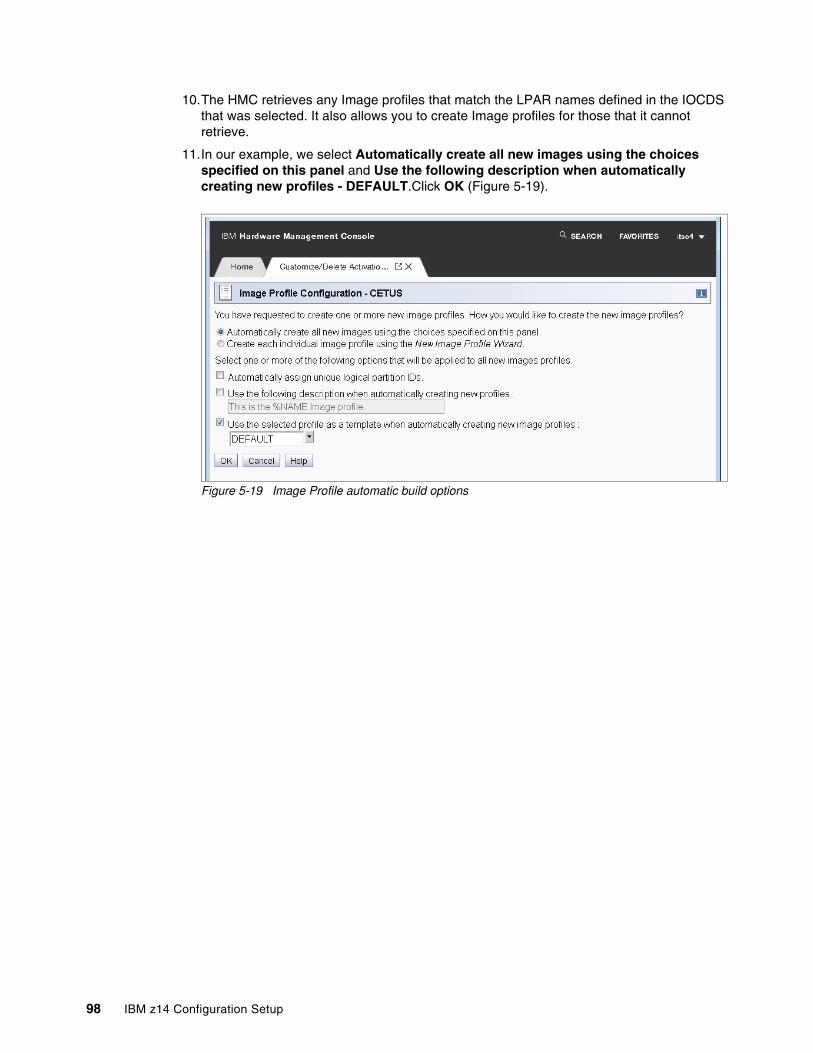
10.The HMC retrieves any Image profiles that match the LPAR names defined in the IOCDS that was selected. It also allows you to create Image profiles for those that it cannot retrieve.
11.In our example, we select Automatically create all new images using the choices specified on this panel and Use the following description when automatically creating new profiles - DEFAULT.Click OK (Figure 5-19).
Figure 5-19 Image Profile automatic build options
98 IBM z14 Configuration Setup

12.Note the list of LPARs that were retrieved and built based on the LPARs that were defined in the selected IOCDS. Click Save (Figure 5-20).
Figure 5-20 Reset and Image profile list: Selecting IOCDS
For planning information, see Chapter 2, “Planning considerations” on page 5.
5.3.3 Setting up and verifying the Reset Profile
To set up and verify the Reset Profile, complete these steps:
1. Click Partitions to display the list of partitions (LPARs) in the partition activation list.
This display lists all of the partitions that were retrieved by the automatic build for Reset Profile TESTRESET. The partition list also determines all the Image profiles that would be activated if the CPC was Power on Reset (POR).
Here you can tailor which Image profiles are displayed and activated, and also the order of activation and the order in which they are displayed in the Reset profile.
Typing over or removing the number in the Order field determines how you want the Partitions in the Reset Profile to behave. That is, they are removed or the order changed.
Chapter 5. Production IODF and setting up the CPC 99

2. After you make your determinations, click Save (Figure 5-21).
Figure 5-21 Reset and Image profile list: Updating the partition list
3. If you have any Coupling Facility partitions defined, HMC asks if you want to change the partition activation order, as it is preferential but not essential that CF LPARs are activated before z/OS LPARs. Click Yes or No (Figure 5-22).
Figure 5-22 Reset and Image profile list: Coupling Facility LPAR verification
100 IBM z14 Configuration Setup
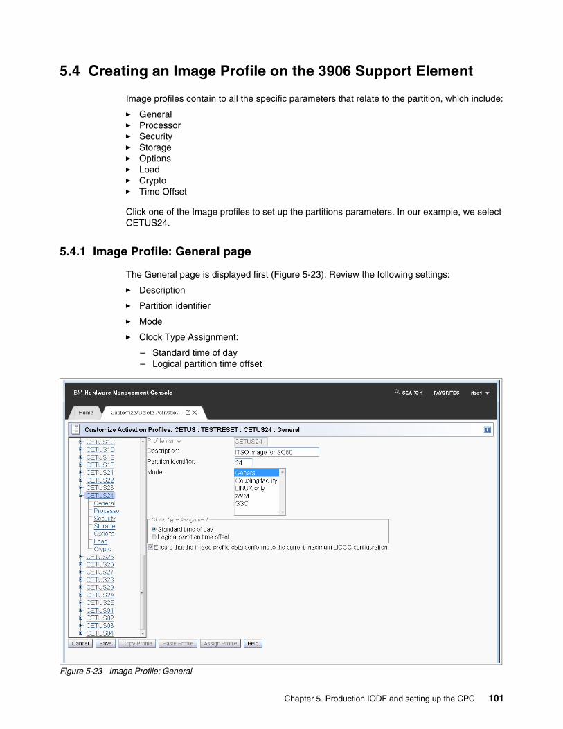
5.4 Creating an Image Profile on the 3906 Support Element
Image profiles contain to all the specific parameters that relate to the partition, which include:
� General� Processor� Security� Storage� Options� Load� Crypto� Time Offset
Click one of the Image profiles to set up the partitions parameters. In our example, we select CETUS24.
5.4.1 Image Profile: General page
The General page is displayed first (Figure 5-23). Review the following settings:
� Description
� Partition identifier
� Mode
� Clock Type Assignment:
– Standard time of day– Logical partition time offset
Figure 5-23 Image Profile: General
Chapter 5. Production IODF and setting up the CPC 101
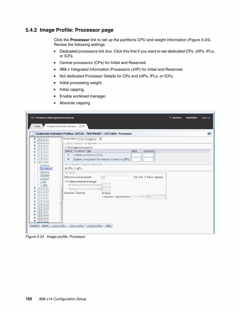
5.4.2 Image Profile: Processor page
Click the Processor link to set up the partitions CPU and weight information (Figure 5-24). Review the following settings:
� Dedicated processors tick box: Click this first if you want to set dedicated CPs, zIIPs, IFLs, or ICFs.
� Central processors (CPs) for Initial and Reserved.
� IBM z Integrated Information Processors (zIIP) for Initial and Reserved.
� Not dedicated Processor Details for CPs and zIIPs, IFLs, or ICFs.
� Initial processing weight.
� Initial capping.
� Enable workload manager.
� Absolute capping.
Figure 5-24 Image profile: Processor
102 IBM z14 Configuration Setup
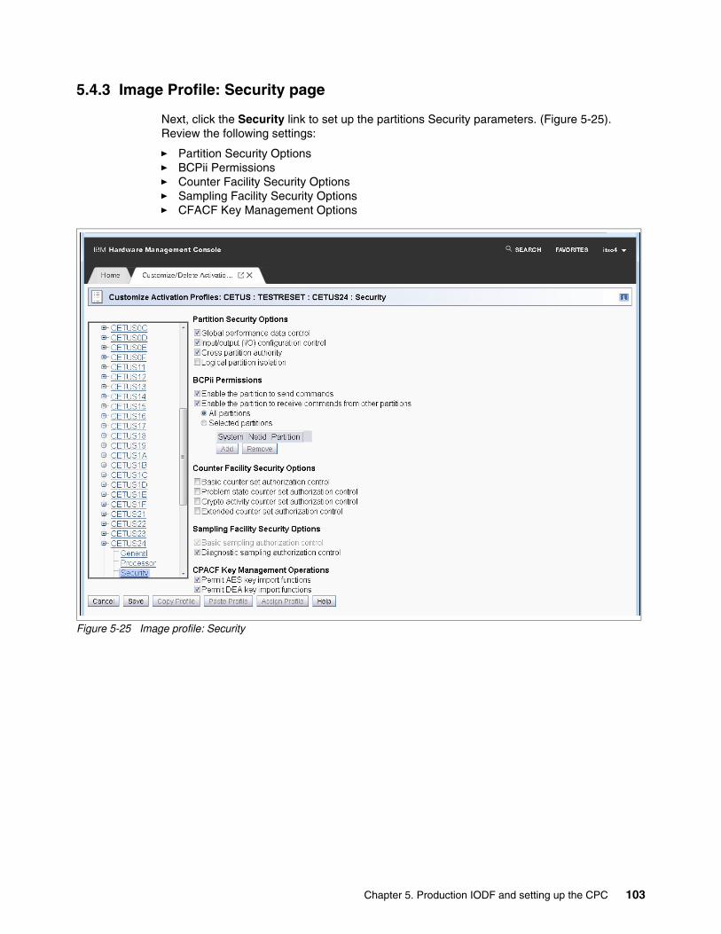
5.4.3 Image Profile: Security page
Next, click the Security link to set up the partitions Security parameters. (Figure 5-25). Review the following settings:
� Partition Security Options� BCPii Permissions� Counter Facility Security Options� Sampling Facility Security Options� CFACF Key Management Options
Figure 5-25 Image profile: Security
Chapter 5. Production IODF and setting up the CPC 103

5.4.4 Image Profile: Storage page
Click the Storage link to set up the partitions Initial and Reserved storage and Virtual Flash Memory initial and Maximum values (Figure 5-26). Review the following settings:
� Central Storage Amount, Initial and Reserved� Virtual Flash memory Initial and Maximum
Figure 5-26 Image profile: Storage
104 IBM z14 Configuration Setup

5.4.5 Image Profile: Options page
Click the Options link to set up the partitions Defined capacity (Figure 5-27). Review the following settings:
� Minimum input/output (I/O) priority� Maximum input/output (I/O) priority� Defined capacity� CP management cluster name
Figure 5-27 Image profile: Options
Chapter 5. Production IODF and setting up the CPC 105

5.4.6 Image Profile: Load page
Click the Load link if you want to set up any automatic load (IPL) parameters when the partition is activated by using a Power-on Reset, or Image profile activation. If you prefer not to IPL a z/OS system into a partition during a Power-on Reset or Image profile activation, then Load Profiles can be set up and activated and used when required. This concern is mentioned in the following section (Figure 5-28). Review the following settings:
� Load during activation check box, which determines whether the options in this panel are used
� Load type
� Load address
� Time-out value
Figure 5-28 Image profile: Load
106 IBM z14 Configuration Setup
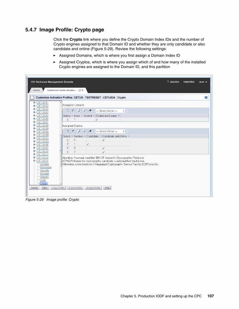
5.4.7 Image Profile: Crypto page
Click the Crypto link where you define the Crypto Domain Index IDs and the number of Crypto engines assigned to that Domain ID and whether they are only candidate or also candidate and online (Figure 5-29). Review the following settings:
� Assigned Domains, which is where you first assign a Domain Index ID
� Assigned Cryptos, which is where you assign which of and how many of the installed Crypto engines are assigned to the Domain ID, and this partition
Figure 5-29 Image profile: Crypto
Chapter 5. Production IODF and setting up the CPC 107
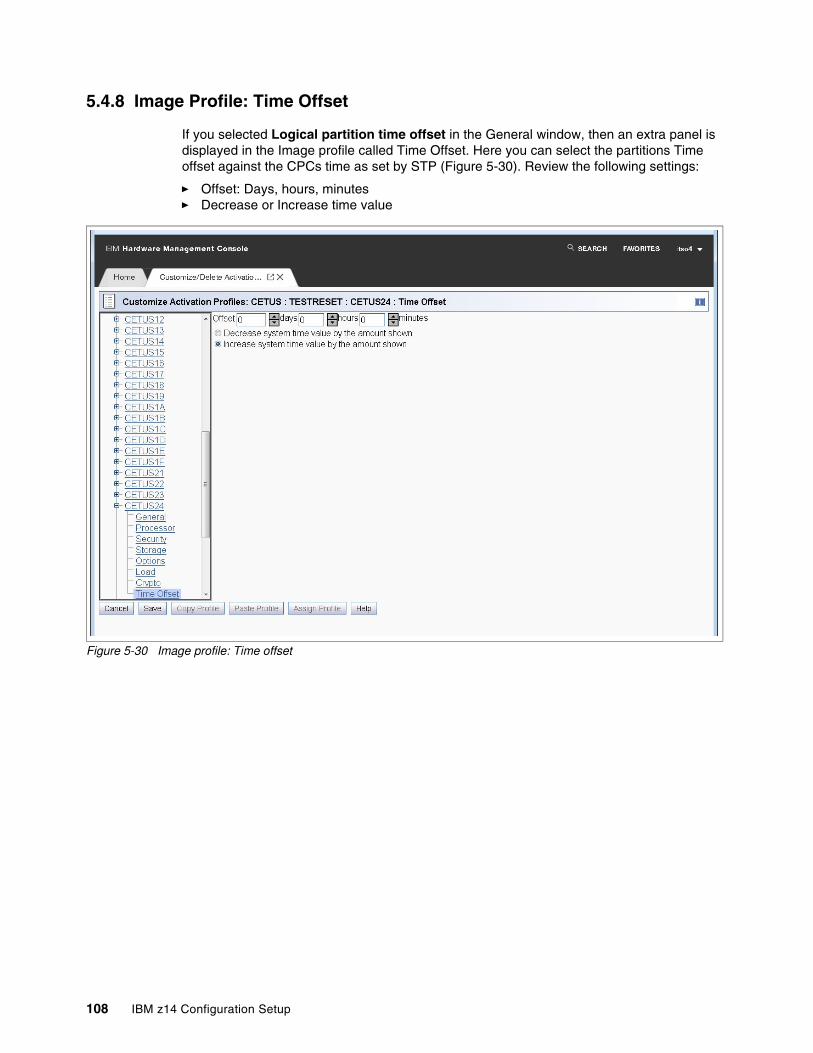
5.4.8 Image Profile: Time Offset
If you selected Logical partition time offset in the General window, then an extra panel is displayed in the Image profile called Time Offset. Here you can select the partitions Time offset against the CPCs time as set by STP (Figure 5-30). Review the following settings:
� Offset: Days, hours, minutes� Decrease or Increase time value
Figure 5-30 Image profile: Time offset
108 IBM z14 Configuration Setup
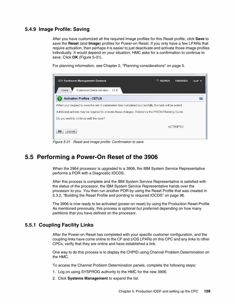
5.4.9 Image Profile: Saving
After you have customized all the required Image profiles for this Reset profile, click Save to save the Reset (and Image) profiles for Power-on Reset. If you only have a few LPARs that require activation, then perhaps it is easier to just deactivate and activate those Image profiles individually. It would depend on your situation. HMC asks for a confirmation to continue to save. Click OK (Figure 5-31).
For planning information, see Chapter 2, “Planning considerations” on page 5.
Figure 5-31 Reset and Image profile: Confirmation to save
5.5 Performing a Power-On Reset of the 3906
When the 2964 processor is upgraded to a 3906, the IBM System Service Representative performs a POR with a Diagnostic IOCDS.
After this process is complete and the IBM System Service Representative is satisfied with the status of the processor, the IBM System Service Representative hands over the processor to you. You then run another POR by using the Reset Profile that was created in 5.3.2, “Building the Reset Profile and pointing to required IOCDS” on page 96.
The 3906 is now ready to be activated (power-on reset) by using the Production Reset Profile As mentioned previously, this process is optional but preferred depending on how many partitions that you have defined on the processor.
5.5.1 Coupling Facility Links
After the Power-on Reset has completed with your specific customer configuration, and the coupling links have come online to the CF and z/OS LPARs on this CPC and any links to other CPCs, verify that they are online and have established a link.
One way to do this process is to display the CHPID using Channel Problem Determination on the HMC.
To access the Channel Problem Determination panels, complete the following steps:
1. Log on using SYSPROG authority to the HMC for the new 3906.
2. Click Systems Management to expand the list.
Chapter 5. Production IODF and setting up the CPC 109
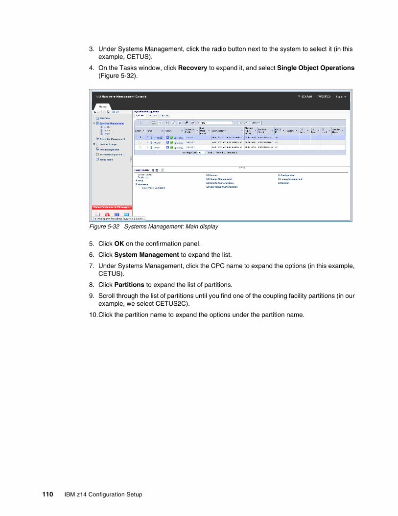
3. Under Systems Management, click the radio button next to the system to select it (in this example, CETUS).
4. On the Tasks window, click Recovery to expand it, and select Single Object Operations (Figure 5-32).
Figure 5-32 Systems Management: Main display
5. Click OK on the confirmation panel.
6. Click System Management to expand the list.
7. Under Systems Management, click the CPC name to expand the options (in this example, CETUS).
8. Click Partitions to expand the list of partitions.
9. Scroll through the list of partitions until you find one of the coupling facility partitions (in our example, we select CETUS2C).
10.Click the partition name to expand the options under the partition name.
110 IBM z14 Configuration Setup
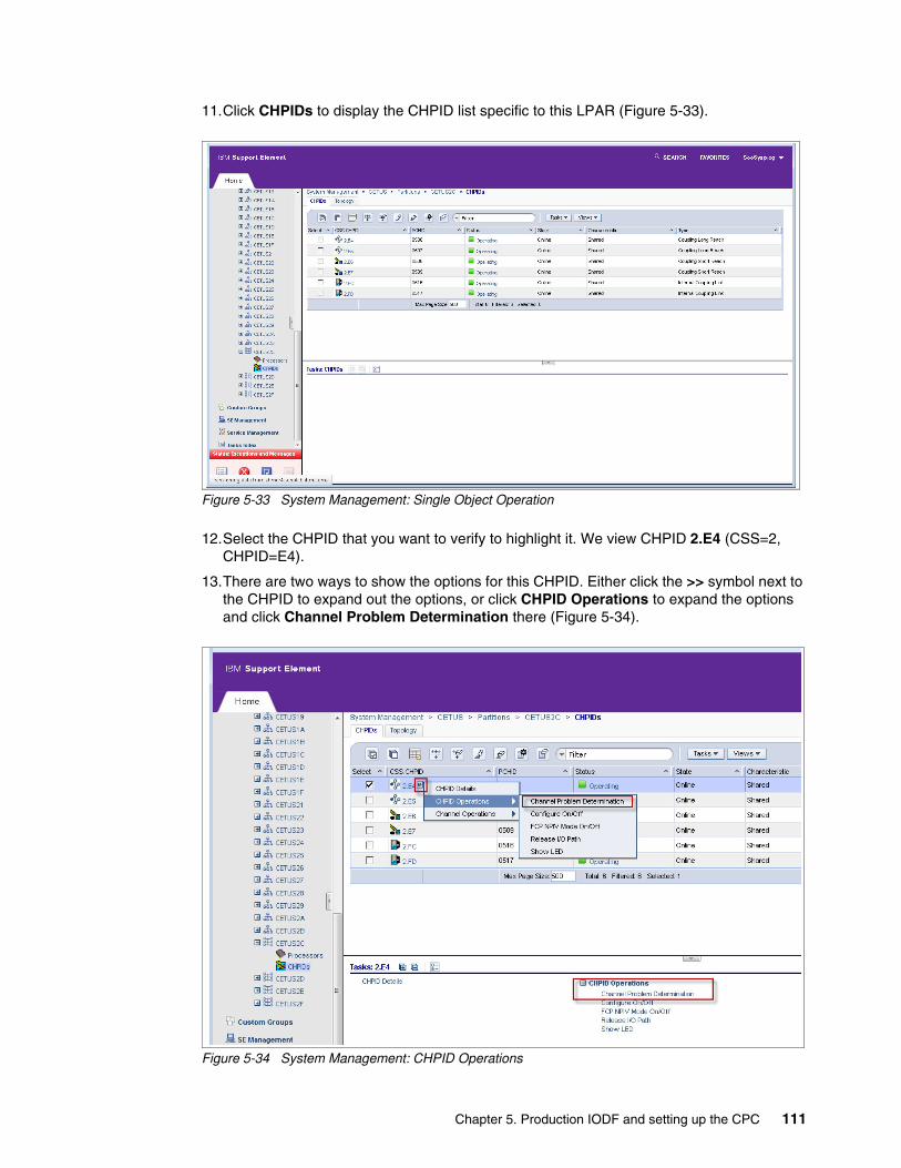
11.Click CHPIDs to display the CHPID list specific to this LPAR (Figure 5-33).
Figure 5-33 System Management: Single Object Operation
12.Select the CHPID that you want to verify to highlight it. We view CHPID 2.E4 (CSS=2, CHPID=E4).
13.There are two ways to show the options for this CHPID. Either click the >> symbol next to the CHPID to expand out the options, or click CHPID Operations to expand the options and click Channel Problem Determination there (Figure 5-34).
Figure 5-34 System Management: CHPID Operations
Chapter 5. Production IODF and setting up the CPC 111
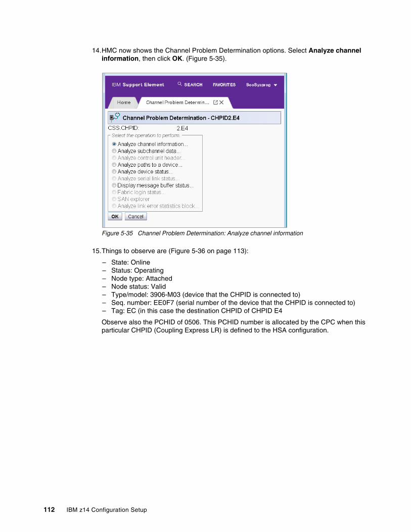
14.HMC now shows the Channel Problem Determination options. Select Analyze channel information, then click OK. (Figure 5-35).
Figure 5-35 Channel Problem Determination: Analyze channel information
15.Things to observe are (Figure 5-36 on page 113):
– State: Online – Status: Operating – Node type: Attached– Node status: Valid– Type/model: 3906-M03 (device that the CHPID is connected to)– Seq. number: EE0F7 (serial number of the device that the CHPID is connected to)– Tag: EC (in this case the destination CHPID of CHPID E4
Observe also the PCHID of 0506. This PCHID number is allocated by the CPC when this particular CHPID (Coupling Express LR) is defined to the HSA configuration.
112 IBM z14 Configuration Setup
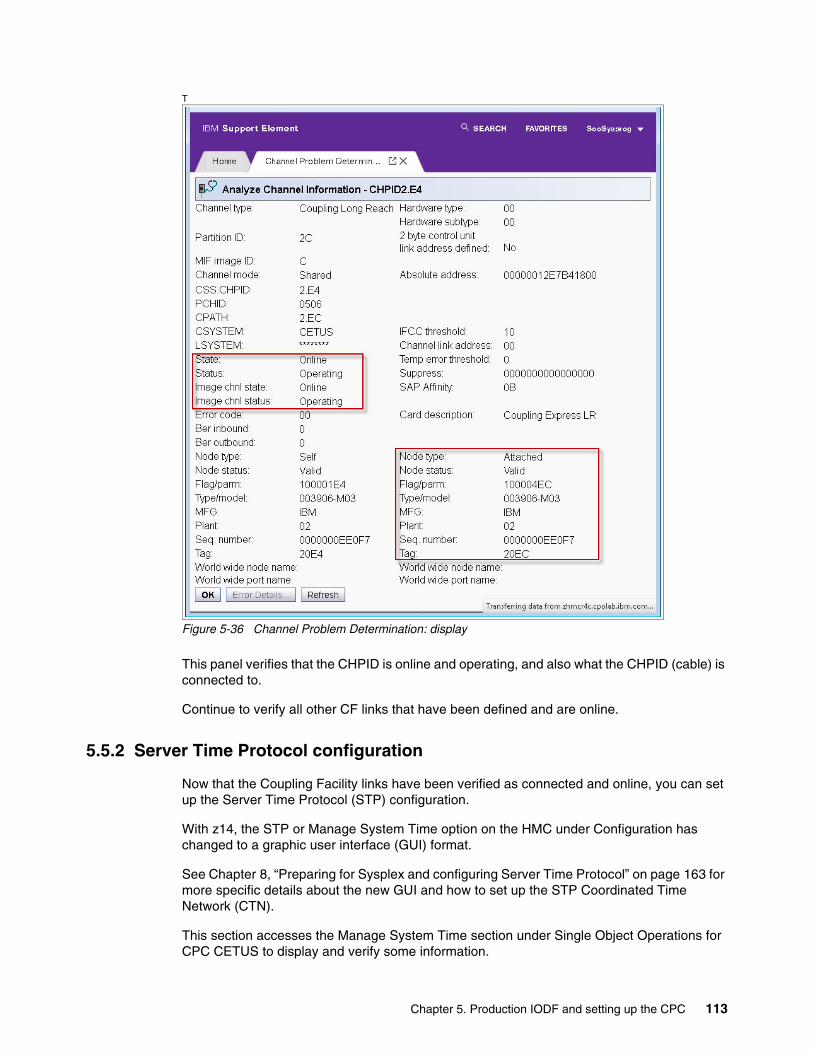
T
Figure 5-36 Channel Problem Determination: display
This panel verifies that the CHPID is online and operating, and also what the CHPID (cable) is connected to.
Continue to verify all other CF links that have been defined and are online.
5.5.2 Server Time Protocol configuration
Now that the Coupling Facility links have been verified as connected and online, you can set up the Server Time Protocol (STP) configuration.
With z14, the STP or Manage System Time option on the HMC under Configuration has changed to a graphic user interface (GUI) format.
See Chapter 8, “Preparing for Sysplex and configuring Server Time Protocol” on page 163 for more specific details about the new GUI and how to set up the STP Coordinated Time Network (CTN).
This section accesses the Manage System Time section under Single Object Operations for CPC CETUS to display and verify some information.
Chapter 5. Production IODF and setting up the CPC 113

To access the Manage System Time panels under Single Object Operations, complete the following steps:
1. Log on using SYSPROG authority to the HMC for the new 3906.
2. Click Systems Management to expand the list.
3. Under Systems Management, click the radio button next to the system to select it (in this example, CETUS).
4. On the Tasks panel, click Recovery to expand it, and select Single Object Operations (Figure 5-37).
Figure 5-37 Systems Management: Main display
5. Click System Management to expand the list.
6. Under Systems Management, click the CPC name to expand the options (in this example, CETUS).
7. Click Configuration to expand the items under the configuration category.
114 IBM z14 Configuration Setup

8. Click System (Sysplex) Time (Figure 5-38).
Figure 5-38 Single Object Operations: System (Sysplex) Time
9. Click Yes for the Attention window warning you that any action in the following windows might affect the current LPARs that are Operating.
10.Click the ETS Configuration tab to check whether there are any External Time Source (ETS) definitions (Figure 5-39).
Figure 5-39 System (Sysplex) Time: ETS Configuration
Figure 5-39 shows None has been selected for any ETS.
Chapter 5. Production IODF and setting up the CPC 115
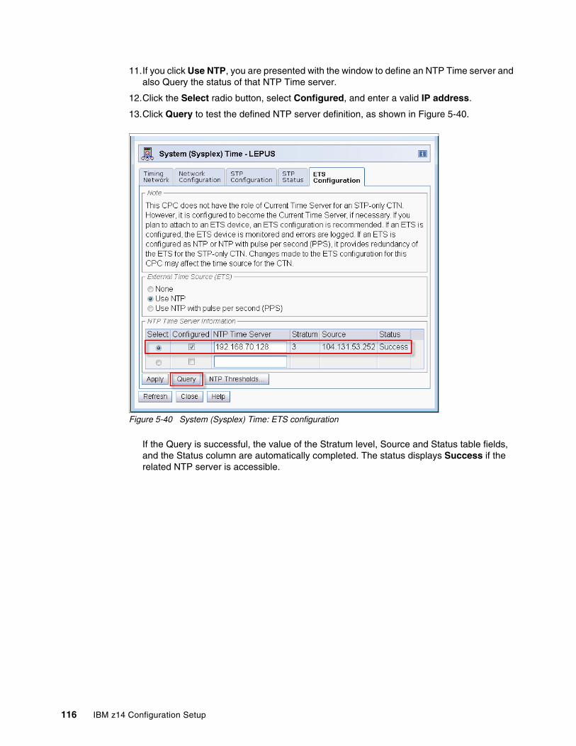
11.If you click Use NTP, you are presented with the window to define an NTP Time server and also Query the status of that NTP Time server.
12.Click the Select radio button, select Configured, and enter a valid IP address.
13.Click Query to test the defined NTP server definition, as shown in Figure 5-40.
Figure 5-40 System (Sysplex) Time: ETS configuration
If the Query is successful, the value of the Stratum level, Source and Status table fields, and the Status column are automatically completed. The status displays Success if the related NTP server is accessible.
116 IBM z14 Configuration Setup
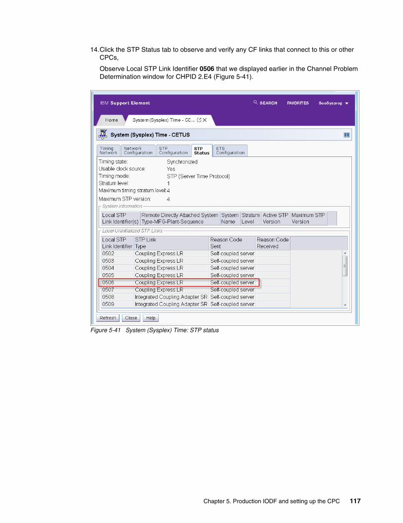
14.Click the STP Status tab to observe and verify any CF links that connect to this or other CPCs,
Observe Local STP Link Identifier 0506 that we displayed earlier in the Channel Problem Determination window for CHPID 2.E4 (Figure 5-41).
Figure 5-41 System (Sysplex) Time: STP status
Chapter 5. Production IODF and setting up the CPC 117
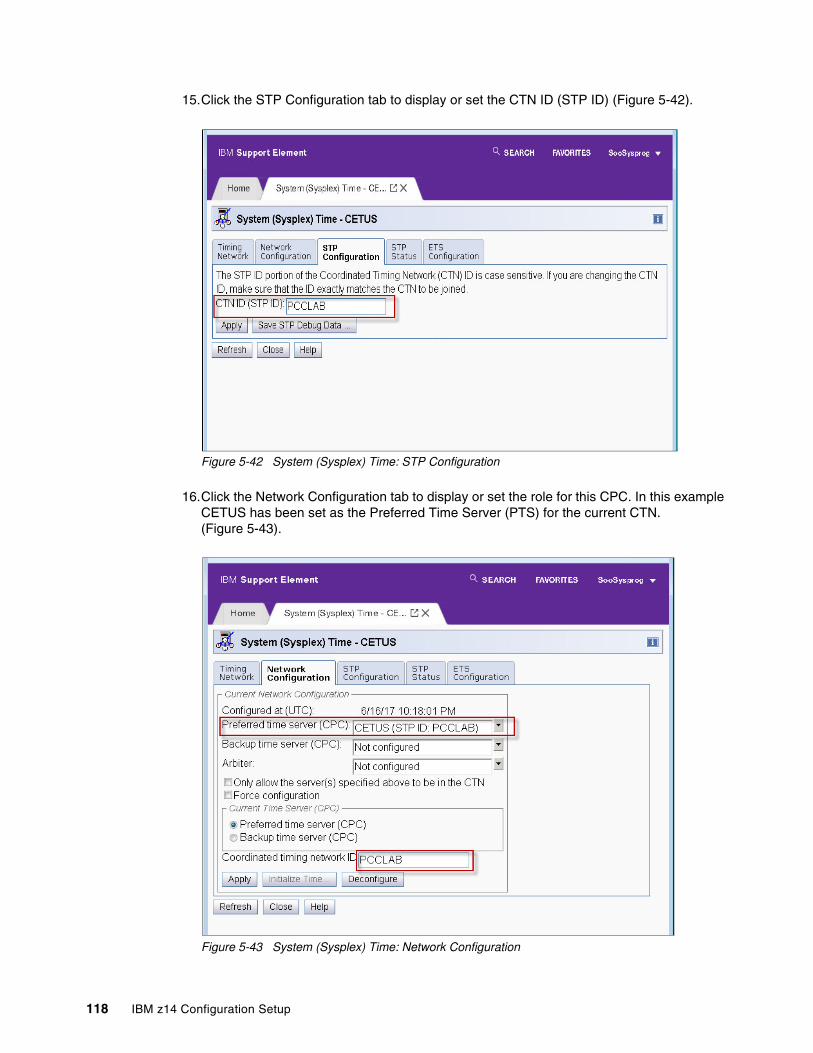
15.Click the STP Configuration tab to display or set the CTN ID (STP ID) (Figure 5-42).
Figure 5-42 System (Sysplex) Time: STP Configuration
16.Click the Network Configuration tab to display or set the role for this CPC. In this example CETUS has been set as the Preferred Time Server (PTS) for the current CTN. (Figure 5-43).
Figure 5-43 System (Sysplex) Time: Network Configuration
118 IBM z14 Configuration Setup
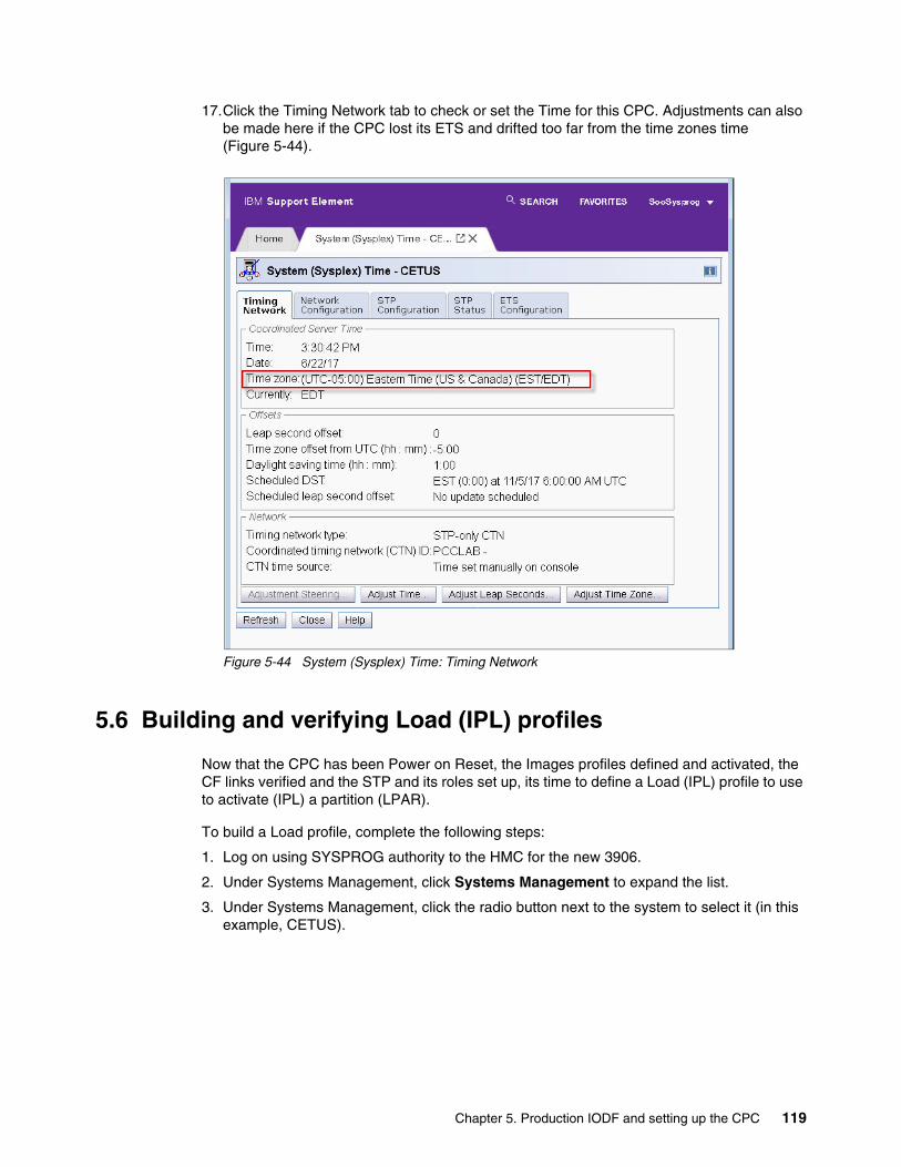
17.Click the Timing Network tab to check or set the Time for this CPC. Adjustments can also be made here if the CPC lost its ETS and drifted too far from the time zones time (Figure 5-44).
Figure 5-44 System (Sysplex) Time: Timing Network
5.6 Building and verifying Load (IPL) profiles
Now that the CPC has been Power on Reset, the Images profiles defined and activated, the CF links verified and the STP and its roles set up, its time to define a Load (IPL) profile to use to activate (IPL) a partition (LPAR).
To build a Load profile, complete the following steps:
1. Log on using SYSPROG authority to the HMC for the new 3906.
2. Under Systems Management, click Systems Management to expand the list.
3. Under Systems Management, click the radio button next to the system to select it (in this example, CETUS).
Chapter 5. Production IODF and setting up the CPC 119

4. On the Tasks panel, click Operational Customization to expand it, and select Customize/Delete Activation Profiles (Figure 5-45).
Figure 5-45 Systems Management: Main display
5. Select the DEFAULTLOAD Load Profile and click Customize profile.
6. Enter the required parameters that are specific to your installation to perform an IPL:
– Profile name: Type your preferred profile name over DEFAULTLOAD
– Description: Enter your preferred description
– Load type: Normal
– Load address: The device address of the IPL volume (9D31)
– Load parameter: 944301M1
• 9443 = the device address of the IODF volume
• 01 = the suffix of the LOADxx member in SYS#.IPLPARM on device 9443
• M = automatic IPL
• 1 = SYS1.NUCLEUS
120 IBM z14 Configuration Setup

Figure 5-46 shows an example.
Figure 5-46 Customize Load Profiles: Load
Chapter 5. Production IODF and setting up the CPC 121
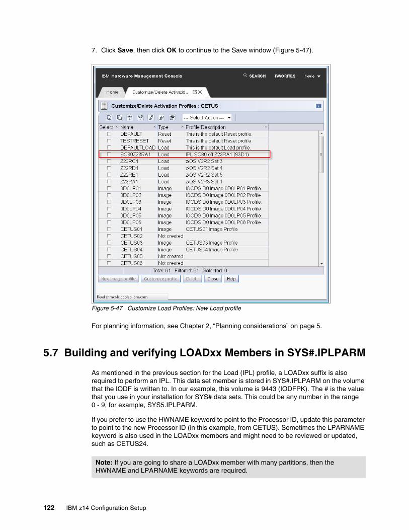
7. Click Save, then click OK to continue to the Save window (Figure 5-47).
Figure 5-47 Customize Load Profiles: New Load profile
For planning information, see Chapter 2, “Planning considerations” on page 5.
5.7 Building and verifying LOADxx Members in SYS#.IPLPARM
As mentioned in the previous section for the Load (IPL) profile, a LOADxx suffix is also required to perform an IPL. This data set member is stored in SYS#.IPLPARM on the volume that the IODF is written to. In our example, this volume is 9443 (IODFPK). The # is the value that you use in your installation for SYS# data sets. This could be any number in the range 0 - 9, for example, SYS5.IPLPARM.
If you prefer to use the HWNAME keyword to point to the Processor ID, update this parameter to point to the new Processor ID (in this example, from CETUS). Sometimes the LPARNAME keyword is also used in the LOADxx members and might need to be reviewed or updated, such as CETUS24.
Note: If you are going to share a LOADxx member with many partitions, then the HWNAME and LPARNAME keywords are required.
122 IBM z14 Configuration Setup
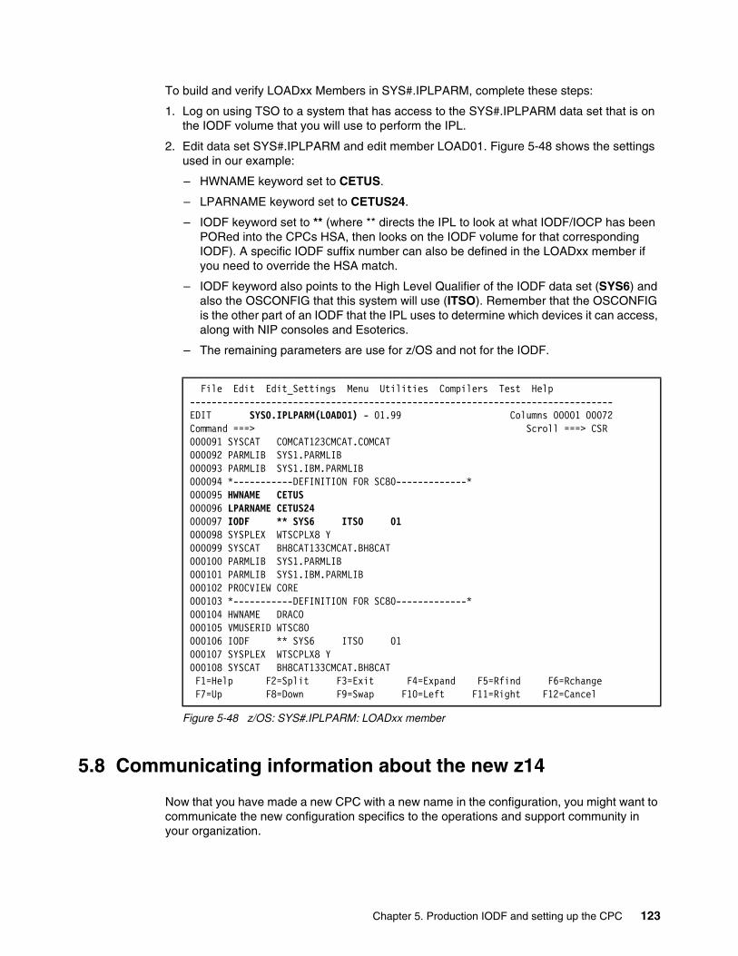
To build and verify LOADxx Members in SYS#.IPLPARM, complete these steps:
1. Log on using TSO to a system that has access to the SYS#.IPLPARM data set that is on the IODF volume that you will use to perform the IPL.
2. Edit data set SYS#.IPLPARM and edit member LOAD01. Figure 5-48 shows the settings used in our example:
– HWNAME keyword set to CETUS.
– LPARNAME keyword set to CETUS24.
– IODF keyword set to ** (where ** directs the IPL to look at what IODF/IOCP has been PORed into the CPCs HSA, then looks on the IODF volume for that corresponding IODF). A specific IODF suffix number can also be defined in the LOADxx member if you need to override the HSA match.
– IODF keyword also points to the High Level Qualifier of the IODF data set (SYS6) and also the OSCONFIG that this system will use (ITSO). Remember that the OSCONFIG is the other part of an IODF that the IPL uses to determine which devices it can access, along with NIP consoles and Esoterics.
– The remaining parameters are use for z/OS and not for the IODF.
Figure 5-48 z/OS: SYS#.IPLPARM: LOADxx member
5.8 Communicating information about the new z14
Now that you have made a new CPC with a new name in the configuration, you might want to communicate the new configuration specifics to the operations and support community in your organization.
File Edit Edit_Settings Menu Utilities Compilers Test Help ------------------------------------------------------------------------------EDIT SYS0.IPLPARM(LOAD01) - 01.99 Columns 00001 00072Command ===> Scroll ===> CSR 000091 SYSCAT COMCAT123CMCAT.COMCAT 000092 PARMLIB SYS1.PARMLIB 000093 PARMLIB SYS1.IBM.PARMLIB 000094 *-----------DEFINITION FOR SC80-------------* 000095 HWNAME CETUS 000096 LPARNAME CETUS24 000097 IODF ** SYS6 ITSO 01 000098 SYSPLEX WTSCPLX8 Y 000099 SYSCAT BH8CAT133CMCAT.BH8CAT 000100 PARMLIB SYS1.PARMLIB 000101 PARMLIB SYS1.IBM.PARMLIB 000102 PROCVIEW CORE 000103 *-----------DEFINITION FOR SC80-------------* 000104 HWNAME DRACO 000105 VMUSERID WTSC80 000106 IODF ** SYS6 ITSO 01 000107 SYSPLEX WTSCPLX8 Y 000108 SYSCAT BH8CAT133CMCAT.BH8CAT F1=Help F2=Split F3=Exit F4=Expand F5=Rfind F6=Rchange F7=Up F8=Down F9=Swap F10=Left F11=Right F12=Cancel
Chapter 5. Production IODF and setting up the CPC 123

124 IBM z14 Configuration Setup
Chapter 6. Configuring network features
This chapter explains how to configure network to your z14. It includes the following topics:
� Preparation for defining and customizing OSA-Express� Define OSA Express to your IO configuration� Customizing OSA-Express using OSA Advanced facilities� Shared Memory Communications (SMC-R and SMC-D)� Channel-To-Channel connection
6
© Copyright IBM Corp. 2017. All rights reserved. 125
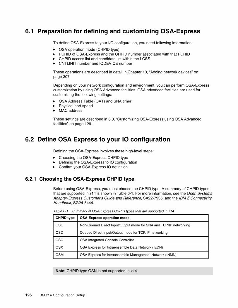
6.1 Preparation for defining and customizing OSA-Express
To define OSA-Express to your I/O configuration, you need following information:
� OSA operation mode (CHPID type)� PCHID of OSA-Express and the CHPID number associated with that PCHID� CHPID access list and candidate list within the LCSS� CNTLINIT number and IODEVICE number
These operations are described in detail in Chapter 13, “Adding network devices” on page 307.
Depending on your network configuration and environment, you can perform OSA-Express customization by using OSA Advanced facilities. OSA advanced facilities are used for customizing the following settings:
� OSA Address Table (OAT) and SNA timer� Physical port speed� MAC address
These settings are described in 6.3, “Customizing OSA-Express using OSA Advanced facilities” on page 129.
6.2 Define OSA Express to your IO configuration
Defining the OSA-Express involves these high-level steps:
� Choosing the OSA-Express CHPID type� Defining the OSA-Express to IO configuration� Confirm your OSA-Express IO definition
6.2.1 Choosing the OSA-Express CHPID type
Before using OSA-Express, you must choose the CHPID type. A summary of CHPID types that are supported in z14 is shown in Table 6-1. For more information, see the Open Systems Adapter-Express Customer's Guide and Reference, SA22-7935, and the IBM Z Connectivity Handbook, SG24-5444.
Table 6-1 Summary of OSA-Express CHPID types that are supported in z14
CHPID type OSA-Express operation mode
OSE Non-Queued Direct Input/Output mode for SNA and TCP/IP networking
OSD Queued Direct Input/Output mode for TCP/IP networking
OSC OSA Integrated Console Controller
OSX OSA Express for Intraensemble Data Network (IEDN)
OSM OSA Express for Intraensemble Management Network (INMN)
Note: CHPID type OSN is not supported in z14.
126 IBM z14 Configuration Setup
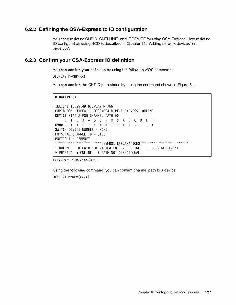
6.2.2 Defining the OSA-Express to IO configuration
You need to define CHPID, CNTLUNIT, and IODEVICE for using OSA-Express. How to define IO configuration using HCD is described in Chapter 13, “Adding network devices” on page 307.
6.2.3 Confirm your OSA-Express IO definition
You can confirm your definition by using the following z/OS command:
DISPLAY M=CHP(xx)
You can confirm the CHPID path status by using the command shown in Figure 6-1.
Figure 6-1 OSD D M=CHP
Using the following command, you can confirm channel path to a device:
DISPLAY M=DEV(xxxx)
D M=CHP(00)
IEE174I 15.29.49 DISPLAY M 755 CHPID 00: TYPE=11, DESC=OSA DIRECT EXPRESS, ONLINE DEVICE STATUS FOR CHANNEL PATH 00 0 1 2 3 4 5 6 7 8 9 A B C D E F 0800 + + + + + + + + + + + + . . . + SWITCH DEVICE NUMBER = NONE PHYSICAL CHANNEL ID = 0100 PNETID 1 = PERFNET ************************ SYMBOL EXPLANATIONS ************************ + ONLINE @ PATH NOT VALIDATED - OFFLINE . DOES NOT EXIST * PHYSICALLY ONLINE $ PATH NOT OPERATIONAL
Chapter 6. Configuring network features 127
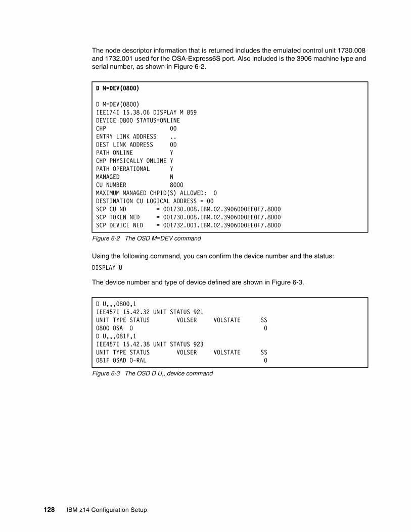
The node descriptor information that is returned includes the emulated control unit 1730.008 and 1732.001 used for the OSA-Express6S port. Also included is the 3906 machine type and serial number, as shown in Figure 6-2.
Figure 6-2 The OSD M=DEV command
Using the following command, you can confirm the device number and the status:
DISPLAY U
The device number and type of device defined are shown in Figure 6-3.
Figure 6-3 The OSD D U,,,device command
D M=DEV(0800)
D M=DEV(0800) IEE174I 15.38.06 DISPLAY M 859 DEVICE 0800 STATUS=ONLINE CHP 00 ENTRY LINK ADDRESS .. DEST LINK ADDRESS 0D PATH ONLINE Y CHP PHYSICALLY ONLINE Y PATH OPERATIONAL Y MANAGED N CU NUMBER 8000 MAXIMUM MANAGED CHPID(S) ALLOWED: 0 DESTINATION CU LOGICAL ADDRESS = 00 SCP CU ND = 001730.008.IBM.02.3906000EE0F7.8000 SCP TOKEN NED = 001730.008.IBM.02.3906000EE0F7.8000 SCP DEVICE NED = 001732.001.IBM.02.3906000EE0F7.8000
D U,,,0800,1 IEE457I 15.42.32 UNIT STATUS 921 UNIT TYPE STATUS VOLSER VOLSTATE SS 0800 OSA O 0 D U,,,081F,1 IEE457I 15.42.38 UNIT STATUS 923 UNIT TYPE STATUS VOLSER VOLSTATE SS 081F OSAD O-RAL 0
128 IBM z14 Configuration Setup
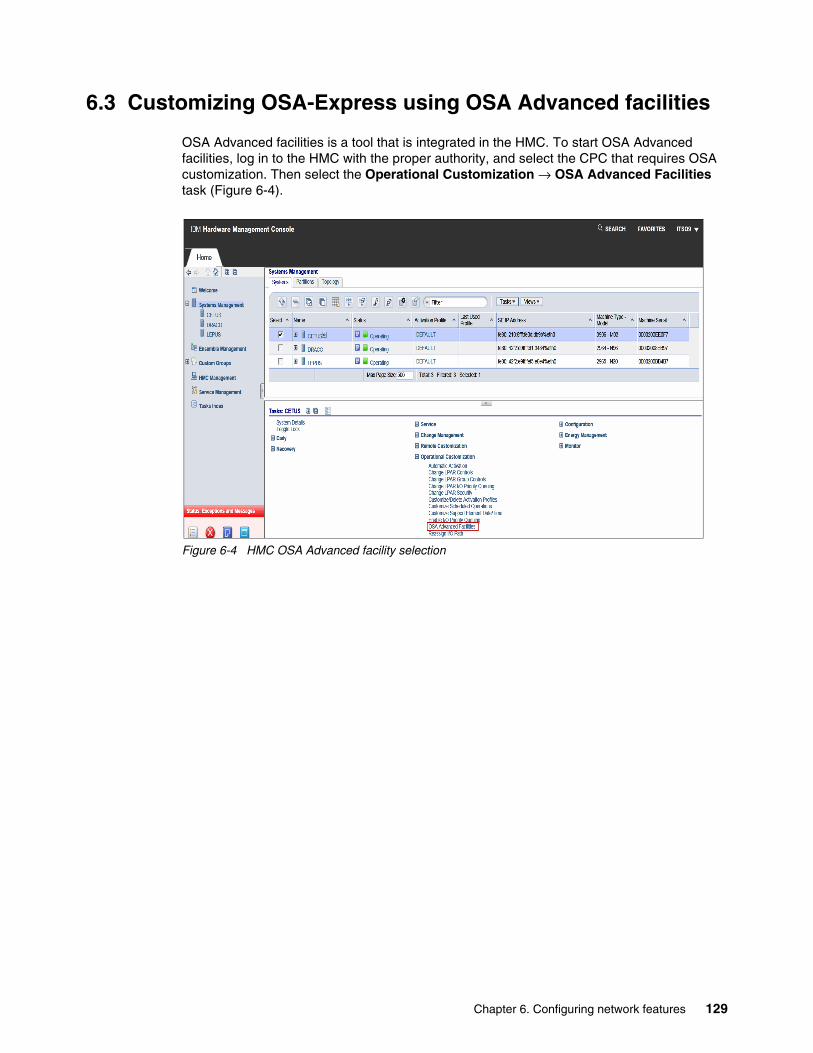
6.3 Customizing OSA-Express using OSA Advanced facilities
OSA Advanced facilities is a tool that is integrated in the HMC. To start OSA Advanced facilities, log in to the HMC with the proper authority, and select the CPC that requires OSA customization. Then select the Operational Customization → OSA Advanced Facilities task (Figure 6-4).
Figure 6-4 HMC OSA Advanced facility selection
Chapter 6. Configuring network features 129
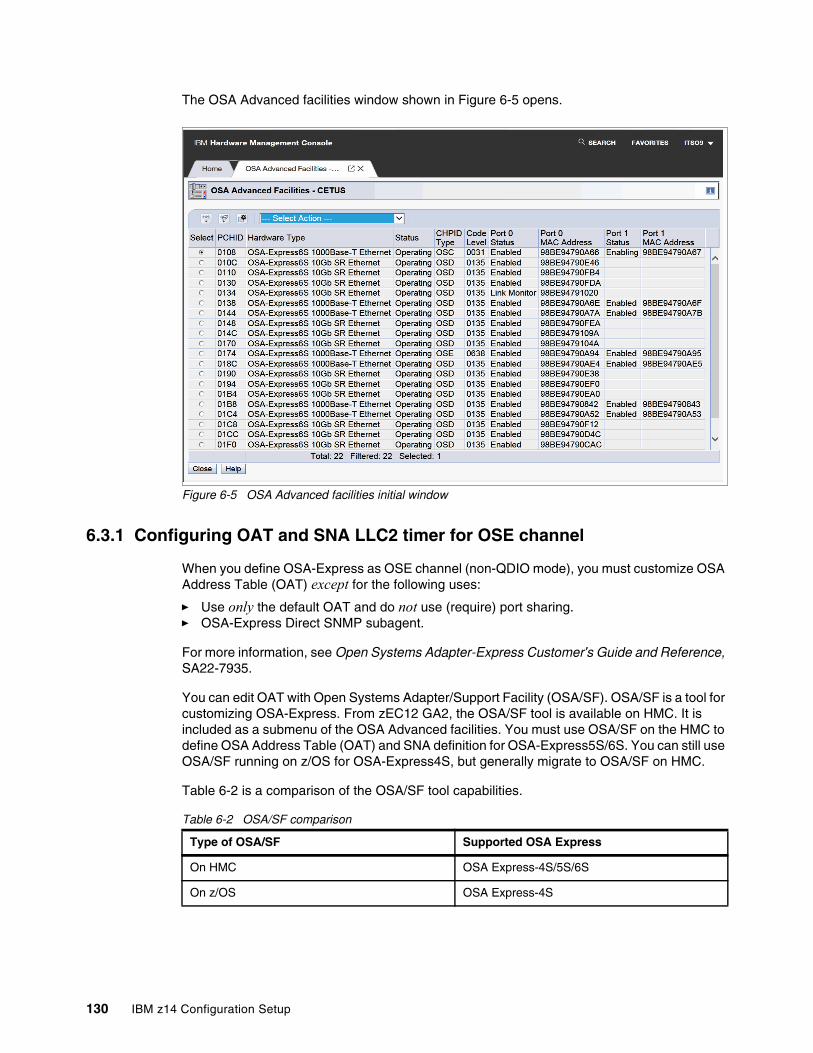
The OSA Advanced facilities window shown in Figure 6-5 opens.
Figure 6-5 OSA Advanced facilities initial window
6.3.1 Configuring OAT and SNA LLC2 timer for OSE channel
When you define OSA-Express as OSE channel (non-QDIO mode), you must customize OSA Address Table (OAT) except for the following uses:
� Use only the default OAT and do not use (require) port sharing.� OSA-Express Direct SNMP subagent.
For more information, see Open Systems Adapter-Express Customer's Guide and Reference, SA22-7935.
You can edit OAT with Open Systems Adapter/Support Facility (OSA/SF). OSA/SF is a tool for customizing OSA-Express. From zEC12 GA2, the OSA/SF tool is available on HMC. It is included as a submenu of the OSA Advanced facilities. You must use OSA/SF on the HMC to define OSA Address Table (OAT) and SNA definition for OSA-Express5S/6S. You can still use OSA/SF running on z/OS for OSA-Express4S, but generally migrate to OSA/SF on HMC.
Table 6-2 is a comparison of the OSA/SF tool capabilities.
Table 6-2 OSA/SF comparison
Type of OSA/SF Supported OSA Express
On HMC OSA Express-4S/5S/6S
On z/OS OSA Express-4S
130 IBM z14 Configuration Setup

For other CHPID types, OSA/SF is not required. If you need to change the port speed or the Media Access Control (MAC) address, you can configure it from the OSA Advanced Facility. The OSA CHPID type and OSA/SF requirements are listed in Table 6-3.
Table 6-3 OSA/SF and OSA CHPID reference
When you use SNA network using OSE channel and need to change SNA timer (SNA LLC2 parameter), you must customize the parameters in OSA/Advanced facilities. For more information, see Open Systems Adapter-Express Customer's Guide and Reference, SA22-7935.
If you are upgrading from zEC12 or z13 to z14, and your configuration uses the OSA Express-4S/5S 1000Base-T feature, your OSE configuration is automatically migrated. After this process is complete, check the configuration in OSA/SF on the HMC.
Customizing OAT and SNA timer
OSA CHPID type OSA/SF
OSE Required
OSD Not required
OSC Not supported
OSX Not supported
OSM Not supported
Note: OSN channel is not supported on z14.
Note: Before you customize OAT and SNA timer with OSA/AF on the HMC, see Open Systems Adapter/Support Facility on the Hardware Management Console, SC14-7580. You can download it from IBM Resource Link.
Chapter 6. Configuring network features 131

To customize OAT and SNA time for OSE channel, complete the following steps:
1. Start OSA Advanced facilities.
2. The OSA Advanced Facilities window opens (Figure 6-6). Select the OSE channel PCHID you want to customize. In this example, we selected PCHID 0174. Then select Card specific advanced facilities from the Select Action menu, as shown in Figure 6-6.
Figure 6-6 Entering OSA/SF on the HMC
3. The Advanced Facilities window opens (Figure 6-7). To edit OAT and SNA timer entries, select Panel configuration options and click OK.
Figure 6-7 OSA/SF on the HMC window configuration options
132 IBM z14 Configuration Setup

4. The Panel Configuration Options window opens (Figure 6-8). You can define these items:
Edit OAT entries By selecting this option, you can edit the OAT and SNA definition. An OAT entry defines the data path between an OSA feature port and an LPAR image.
Edit SNA timers By selecting this option, you can enter SNA timer values.
Figure 6-8 OSA/SF on the HMC: Configuration file options
5. Choose Edit OAT entries, and the Edit OSA Address Table (OAT) Entries window opens as shown in Figure 6-9.
Figure 6-9 OSA/SF on HMC: Edit OSA Address Table (OAT) Entries window
Chapter 6. Configuring network features 133
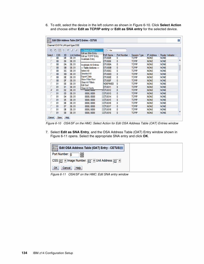
6. To edit, select the device in the left column as shown in Figure 6-10. Click Select Action and choose either Edit as TCP/IP entry or Edit as SNA entry for the selected device.
Figure 6-10 OSA/SF on the HMC: Select Action for Edit OSA Address Table (OAT) Entries window
7. Select Edit as SNA Entry, and the OSA Address Table (OAT) Entry window shown in Figure 6-11 opens. Select the appropriate SNA entry and click OK.
Figure 6-11 OSA/SF on the HMC: Edit SNA entry window
134 IBM z14 Configuration Setup
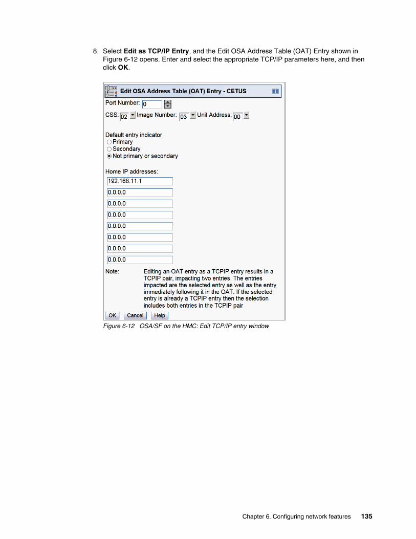
8. Select Edit as TCP/IP Entry, and the Edit OSA Address Table (OAT) Entry shown in Figure 6-12 opens. Enter and select the appropriate TCP/IP parameters here, and then click OK.
Figure 6-12 OSA/SF on the HMC: Edit TCP/IP entry window
Chapter 6. Configuring network features 135
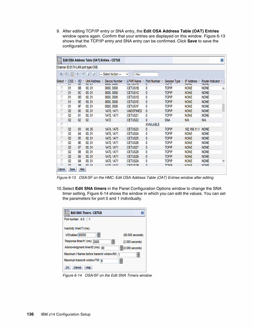
9. After editing TCP/IP entry or SNA entry, the Edit OSA Address Table (OAT) Entries window opens again. Confirm that your entries are displayed on this window. Figure 6-13 shows that the TCP/IP entry and SNA entry can be confirmed. Click Save to save the configuration.
Figure 6-13 OSA/SF on the HMC: Edit OSA Address Table (OAT) Entries window after editing
10.Select Edit SNA timers in the Panel Configuration Options window to change the SNA timer setting. Figure 6-14 shows the window in which you can edit the values. You can set the parameters for port 0 and 1 individually.
Figure 6-14 OSA/SF on the Edit SNA Timers window
136 IBM z14 Configuration Setup
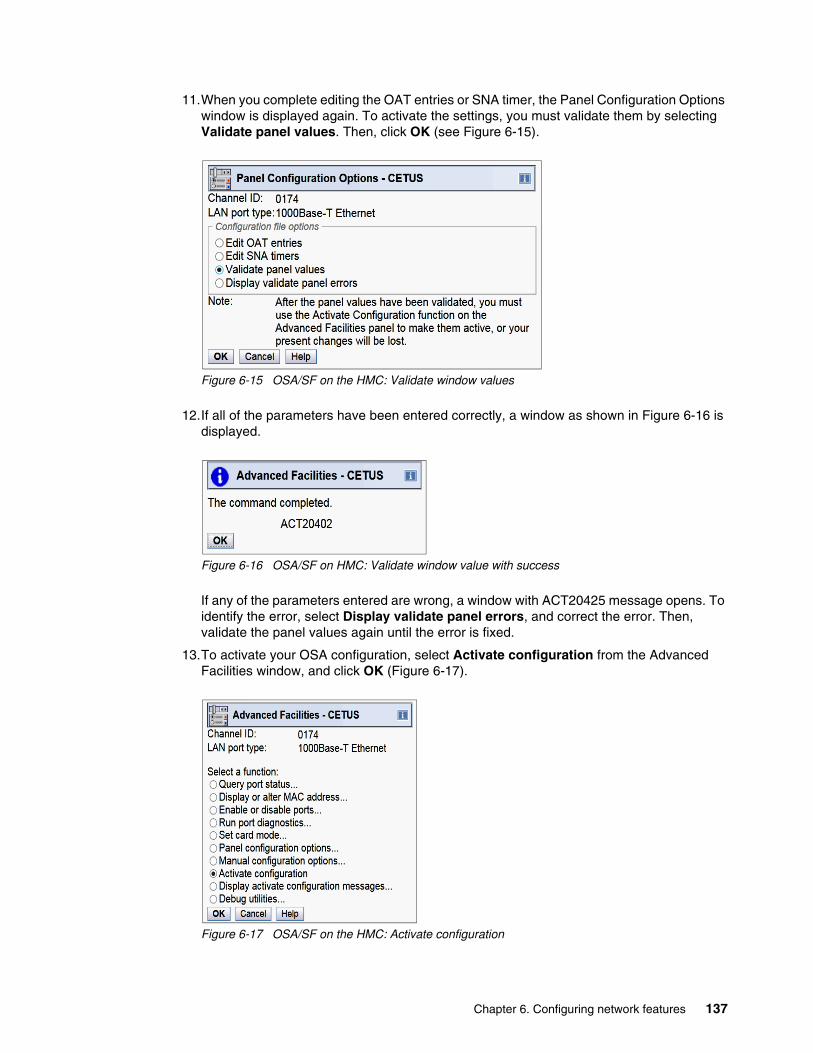
11.When you complete editing the OAT entries or SNA timer, the Panel Configuration Options window is displayed again. To activate the settings, you must validate them by selecting Validate panel values. Then, click OK (see Figure 6-15).
Figure 6-15 OSA/SF on the HMC: Validate window values
12.If all of the parameters have been entered correctly, a window as shown in Figure 6-16 is displayed.
Figure 6-16 OSA/SF on HMC: Validate window value with success
If any of the parameters entered are wrong, a window with ACT20425 message opens. To identify the error, select Display validate panel errors, and correct the error. Then, validate the panel values again until the error is fixed.
13.To activate your OSA configuration, select Activate configuration from the Advanced Facilities window, and click OK (Figure 6-17).
Figure 6-17 OSA/SF on the HMC: Activate configuration
Chapter 6. Configuring network features 137
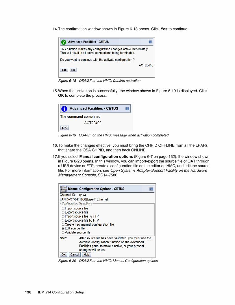
14.The confirmation window shown in Figure 6-18 opens. Click Yes to continue.
Figure 6-18 OSA/SF on the HMC: Confirm activation
15.When the activation is successfully, the window shown in Figure 6-19 is displayed. Click OK to complete the process.
Figure 6-19 OSA/SF on the HMC: message when activation completed
16.To make the changes effective, you must bring the CHPID OFFLINE from all the LPARs that share the OSA CHPID, and then back ONLINE.
17.If you select Manual configuration options (Figure 6-7 on page 132), the window shown in Figure 6-20 opens. In this window, you can import/export the source file of OAT through a USB device or FTP, create a configuration file on the editor on HMC, and edit the source file. For more information, see Open Systems Adapter/Support Facility on the Hardware Management Console, SC14-7580.
Figure 6-20 OSA/SF on the HMC: Manual Configuration options
138 IBM z14 Configuration Setup
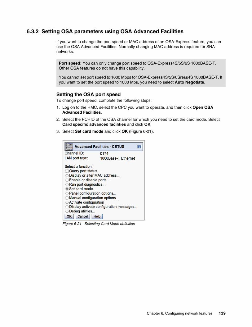
6.3.2 Setting OSA parameters using OSA Advanced Facilities
If you want to change the port speed or MAC address of an OSA-Express feature, you can use the OSA Advanced Facilities. Normally changing MAC address is required for SNA networks.
Setting the OSA port speedTo change port speed, complete the following steps:
1. Log on to the HMC, select the CPC you want to operate, and then click Open OSA Advanced Facilities.
2. Select the PCHID of the OSA channel for which you need to set the card mode. Select Card specific advanced facilities and click OK.
3. Select Set card mode and click OK (Figure 6-21).
Figure 6-21 Selecting Card Mode definition
Port speed: You can only change port speed to OSA-Express4S/5S/6S 1000BASE-T. Other OSA features do not have this capability.
You cannot set port speed to 1000 Mbps for OSA-Express4S/5S/6Sress4S 1000BASE-T. If you want to set the port speed to 1000 Mbs, you need to select Auto Negotiate.
Chapter 6. Configuring network features 139

4. The Set Card Mode or Speed window opens (Figure 6-22). Select the correct port speed from the Speed/Mode list. You can set the speed of port 0 and 1 individually. Click OK.
Figure 6-22 Set card mode or speed
5. To make the changes effective, you must configure CHPID OFFLINE and ONLINE from every LPAR where this CHPID is defined.
Changing OSA MAC addressTo change the MAC address, complete the following steps:
1. Log on to the HMC, then open OSA Advanced Facilities, and select the PCHID you want to customize.
2. The Advanced Facilities window opens (Figure 6-23). Select Display or alter MAC address and then click OK.
Figure 6-23 Display or alter MAC address
140 IBM z14 Configuration Setup
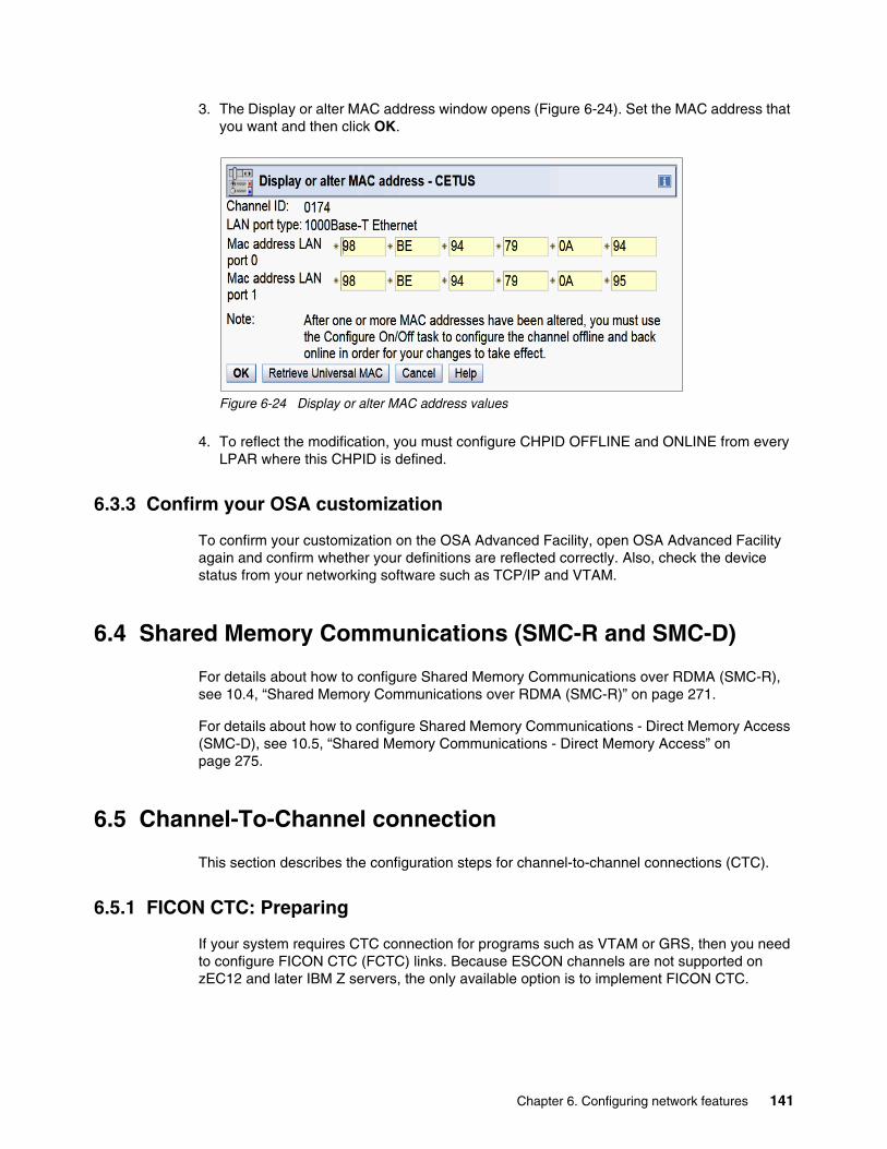
3. The Display or alter MAC address window opens (Figure 6-24). Set the MAC address that you want and then click OK.
Figure 6-24 Display or alter MAC address values
4. To reflect the modification, you must configure CHPID OFFLINE and ONLINE from every LPAR where this CHPID is defined.
6.3.3 Confirm your OSA customization
To confirm your customization on the OSA Advanced Facility, open OSA Advanced Facility again and confirm whether your definitions are reflected correctly. Also, check the device status from your networking software such as TCP/IP and VTAM.
6.4 Shared Memory Communications (SMC-R and SMC-D)
For details about how to configure Shared Memory Communications over RDMA (SMC-R), see 10.4, “Shared Memory Communications over RDMA (SMC-R)” on page 271.
For details about how to configure Shared Memory Communications - Direct Memory Access (SMC-D), see 10.5, “Shared Memory Communications - Direct Memory Access” on page 275.
6.5 Channel-To-Channel connection
This section describes the configuration steps for channel-to-channel connections (CTC).
6.5.1 FICON CTC: Preparing
If your system requires CTC connection for programs such as VTAM or GRS, then you need to configure FICON CTC (FCTC) links. Because ESCON channels are not supported on zEC12 and later IBM Z servers, the only available option is to implement FICON CTC.
Chapter 6. Configuring network features 141
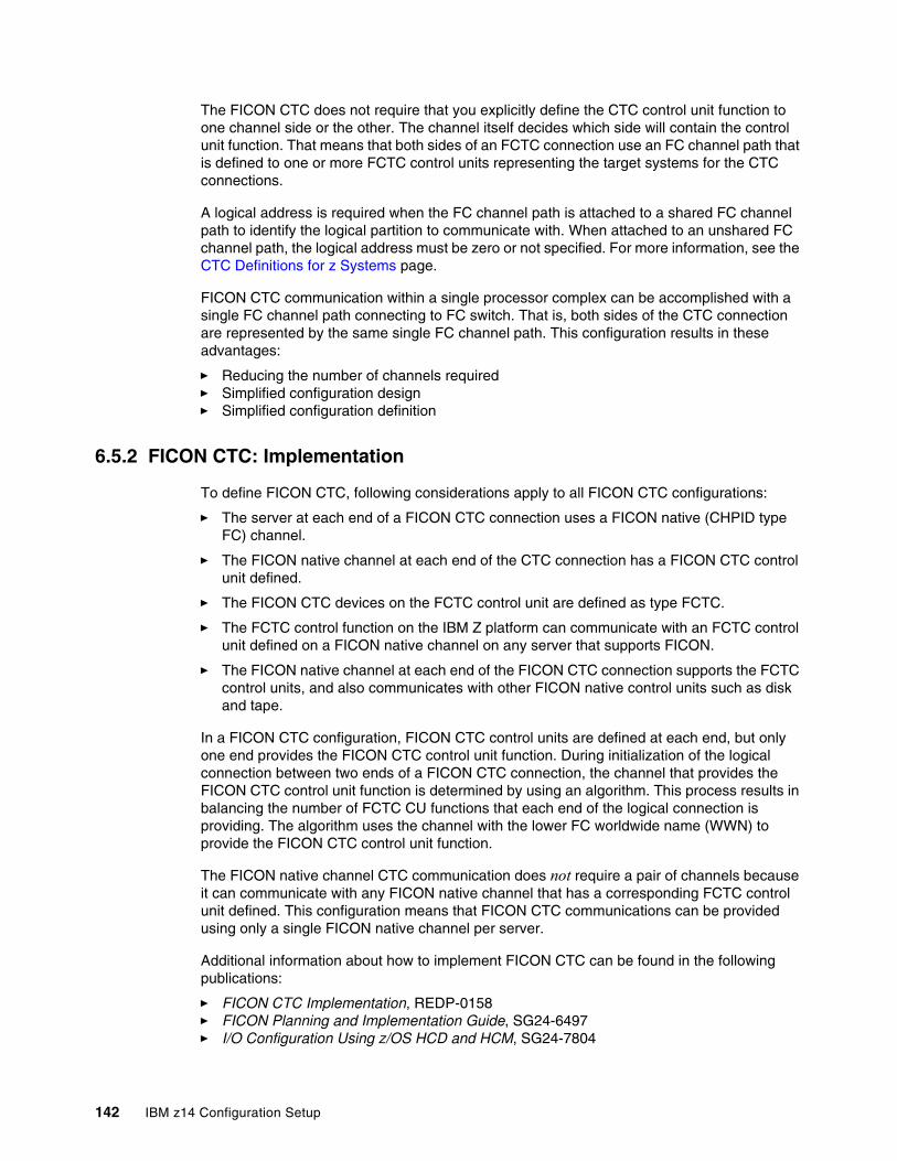
The FICON CTC does not require that you explicitly define the CTC control unit function to one channel side or the other. The channel itself decides which side will contain the control unit function. That means that both sides of an FCTC connection use an FC channel path that is defined to one or more FCTC control units representing the target systems for the CTC connections.
A logical address is required when the FC channel path is attached to a shared FC channel path to identify the logical partition to communicate with. When attached to an unshared FC channel path, the logical address must be zero or not specified. For more information, see the CTC Definitions for z Systems page.
FICON CTC communication within a single processor complex can be accomplished with a single FC channel path connecting to FC switch. That is, both sides of the CTC connection are represented by the same single FC channel path. This configuration results in these advantages:
� Reducing the number of channels required� Simplified configuration design� Simplified configuration definition
6.5.2 FICON CTC: Implementation
To define FICON CTC, following considerations apply to all FICON CTC configurations:
� The server at each end of a FICON CTC connection uses a FICON native (CHPID type FC) channel.
� The FICON native channel at each end of the CTC connection has a FICON CTC control unit defined.
� The FICON CTC devices on the FCTC control unit are defined as type FCTC.
� The FCTC control function on the IBM Z platform can communicate with an FCTC control unit defined on a FICON native channel on any server that supports FICON.
� The FICON native channel at each end of the FICON CTC connection supports the FCTC control units, and also communicates with other FICON native control units such as disk and tape.
In a FICON CTC configuration, FICON CTC control units are defined at each end, but only one end provides the FICON CTC control unit function. During initialization of the logical connection between two ends of a FICON CTC connection, the channel that provides the FICON CTC control unit function is determined by using an algorithm. This process results in balancing the number of FCTC CU functions that each end of the logical connection is providing. The algorithm uses the channel with the lower FC worldwide name (WWN) to provide the FICON CTC control unit function.
The FICON native channel CTC communication does not require a pair of channels because it can communicate with any FICON native channel that has a corresponding FCTC control unit defined. This configuration means that FICON CTC communications can be provided using only a single FICON native channel per server.
Additional information about how to implement FICON CTC can be found in the following publications:
� FICON CTC Implementation, REDP-0158� FICON Planning and Implementation Guide, SG24-6497� I/O Configuration Using z/OS HCD and HCM, SG24-7804
142 IBM z14 Configuration Setup

6.5.3 FICON CTC: Management
After activating the new FICON CTC configuration and all cables have been connected, verify whether the CHPIDs are online and operating by using either z/OS or the Support Element (SE) windows:
� Checking status by using z/OS commands. If you are interested in checking the status of CHPIDs 34 and 35, issue D M=CHP(34) and D M=CHP(35) commands as shown in Figure 6-25.
Figure 6-25 DISPLAY FCTC on system SC81
D M=CHP(34) IEE174I 13.52.39 DISPLAY M 575 CHPID 34: TYPE=1A, DESC=FICON POINT TO POINT, ONLINE DEVICE STATUS FOR CHANNEL PATH 34 NO DEVICES ARE ACCESSIBLE THROUGH THIS CHANNEL PATH SWITCH DEVICE NUMBER = NONE ATTACHED ND = 003906.M03.IBM.02.0000000EE0F7 PHYSICAL CHANNEL ID = 0168 FACILITIES SUPPORTED = ZHPF ************************ SYMBOL EXPLANATIONS ************************+ ONLINE @ PATH NOT VALIDATED - OFFLINE . DOES NOT EXIST * PHYSICALLY ONLINE $ PATH NOT OPERATIONAL
D M=CHP(35) IEE174I 13.52.43 DISPLAY M 577 CHPID 35: TYPE=1A, DESC=FICON POINT TO POINT, ONLINE DEVICE STATUS FOR CHANNEL PATH 35 NO DEVICES ARE ACCESSIBLE THROUGH THIS CHANNEL PATH SWITCH DEVICE NUMBER = NONE ATTACHED ND = 003906.M03.IBM.02.0000000EE0F7 PHYSICAL CHANNEL ID = 0169 FACILITIES SUPPORTED = ZHPF ************************ SYMBOL EXPLANATIONS ************************+ ONLINE @ PATH NOT VALIDATED - OFFLINE . DOES NOT EXIST * PHYSICALLY ONLINE $ PATH NOT OPERATIONAL
Chapter 6. Configuring network features 143

� Checking status by using SE windows:
– From the HMC, select the CEC (under Systems Management) where the CHPID/PCHID you would like to verify is and click Single Object Operations (under the Recovery task options).
– On the Support Element, select the same CEC and click Channels. Look for the PCHID you are interested in checking the status of. The result is shown in Figure 6-26.
Figure 6-26 Using the SE to verify channel FCTC using the CEC view
To get more details about the PCHID, click the PCHID to open the details window shown in Figure 6-27.
Figure 6-27 FCTC PCHID details
144 IBM z14 Configuration Setup
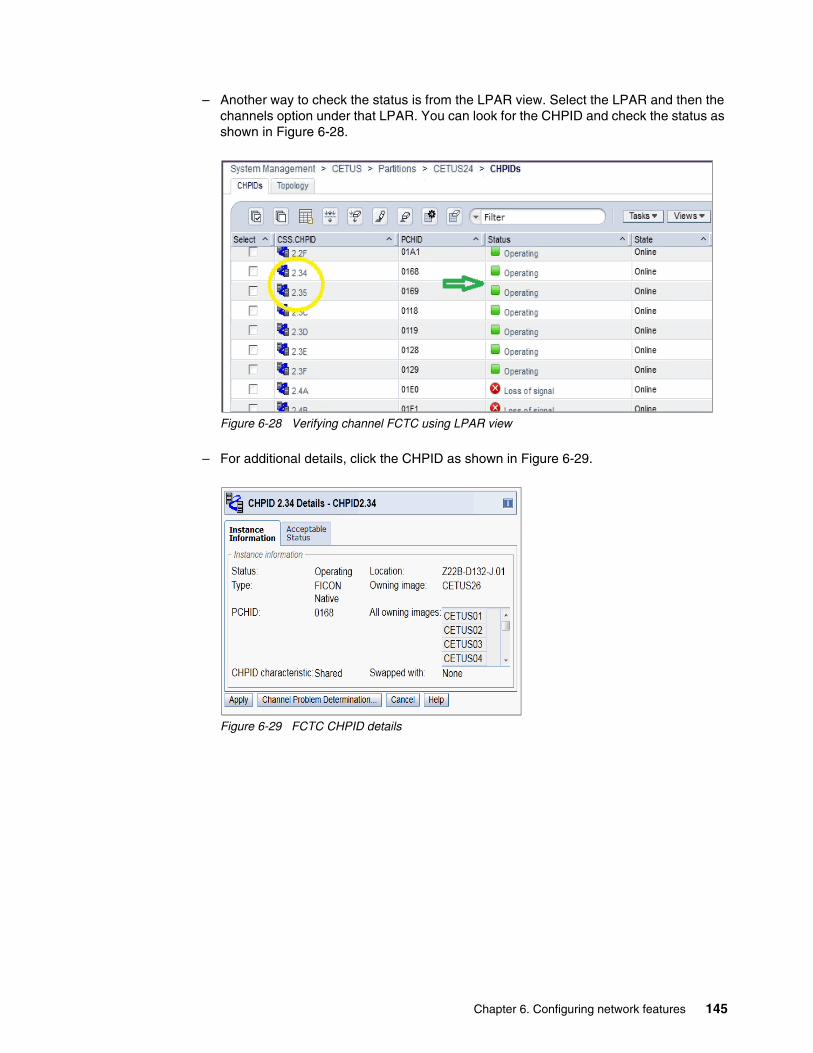
– Another way to check the status is from the LPAR view. Select the LPAR and then the channels option under that LPAR. You can look for the CHPID and check the status as shown in Figure 6-28.
Figure 6-28 Verifying channel FCTC using LPAR view
– For additional details, click the CHPID as shown in Figure 6-29.
Figure 6-29 FCTC CHPID details
Chapter 6. Configuring network features 145

146 IBM z14 Configuration Setup

Chapter 7. Defining console communication
This chapter describes the following topics:
� Preparing console definition� Defining the OSA-ICC� Defining OSA-ICC configuration using OSA Advanced facilities (new configuration)� Verifying the OSA-ICC definition
7
© Copyright IBM Corp. 2017. All rights reserved. 147

7.1 Preparing console definition
A non-SNA console is a console that is required for IPL, z/OS system operation, and management. You must define at least one non-SNA console to your z/OS system. To define the non-SNA console, use the OSA-Express Integrated Console Controller (OSA-ICC) function. For more information, see z Systems Open Systems Adapter Integrated Console Controller User's Guide, SC27-9003. The following steps are required:
1. Define the OSC CHPID and the CNTLUNIT.2. Define the 3270-X IODEVICE.3. Configure OSA-ICC using the OSA Advanced facilities.4. Export / import OSA-ICC configuration (optional).5. Activate OSA-ICC configuration using the OSA Advanced facilities.6. Setup Personal Communications.
You must configure OSA-ICC when you upgrade to z14 from an older Z server or when installing a new z14. For an upgrade from z13 or zEC12, the OSA-ICC configuration is automatically upgraded to z14.
7.2 Defining the OSA-ICC
Before you perform OSA-ICC configuration, you need to define the OSC CHPID, CNTLUNIT, and 3270-X IODEVICE to the I/O configuration. Defining OSC channel by using HCD is described in Chapter 13, “Adding network devices” on page 307, and Chapter 11, “Adding LPARs and OSCONFIGs” on page 283.
Note: OSC channel can be defined only for OSA-Express4s/5s/6s 1000Base-T cards.
148 IBM z14 Configuration Setup

7.3 Defining OSA-ICC configuration using OSA Advanced facilities (new configuration)
When installing a new z14, you must configure OSA-ICC from scratch. To define a new OSA-ICC configuration, complete the following steps:
1. Log on to the HMC, select the CPC and open OSA Advanced facilities.
2. Select the OSC PCHID to be used for the new OSA-ICC configuration, and select Card specific advanced facilities (Figure 7-1).
Figure 7-1 Card Specific Advanced facilities
3. Select Panel configuration options and click OK (Figure 7-2).
Figure 7-2 Panel Configuration Options
Chapter 7. Defining console communication 149

4. The Panel Configuration Options window opens (Figure 7-3). Define session configuration and server configuration in this window, and validate those values. In this example, we define the server configuration first. Next, we define the session configuration. To edit the server configuration, select Edit server configuration and click OK.
Figure 7-3 Edit Server Configuration
5. The Edit Server Configuration panel opens. Enter the necessary values on this panel. Figure 7-4 shows our sample configuration. Click OK to save.
Figure 7-4 Edit Server Configuration Panel
6. The command is completed (ACT20402) window opens. Click OK to return to the Panel Configuration Options window.
150 IBM z14 Configuration Setup

7. Next, define the session configuration. Select Edit sessions configuration and click OK. The window shown in Figure 7-5 opens.
Figure 7-5 Edit Session Configuration
8. The Edit Sessions Configuration window opens (Figure 7-6). To configure a new session, select a number from the Session Index column and click Change.
Figure 7-6 Edit Sessions Configuration
Chapter 7. Defining console communication 151
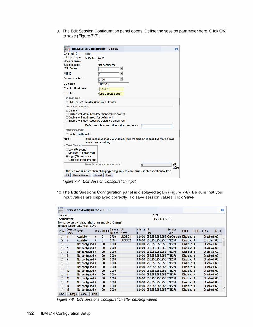
9. The Edit Session Configuration panel opens. Define the session parameter here. Click OK to save (Figure 7-7).
Figure 7-7 Edit Session Configuration input
10.The Edit Sessions Configuration panel is displayed again (Figure 7-8). Be sure that your input values are displayed correctly. To save session values, click Save.
Figure 7-8 Edit Sessions Configuration after defining values
152 IBM z14 Configuration Setup

11.The command completed (ACT20402) window opens. Click OK.
12.The Panel Configuration Options window opens again (Figure 7-9). Now you can validate the values. Select Validate panel values and click OK.
Figure 7-9 Display validate panel errors
13.If configuration data is correct, the command completed (ACT20402) window opens.
If an error is encountered, a window similar to Figure 7-10 opens. You can confirm the error by selecting Display validate panel errors on Panel Configuration Options (Figure 7-9). Correct the error, and select again the Validate panel values to re-check.
Figure 7-10 Panel Configuration Options error found
Chapter 7. Defining console communication 153
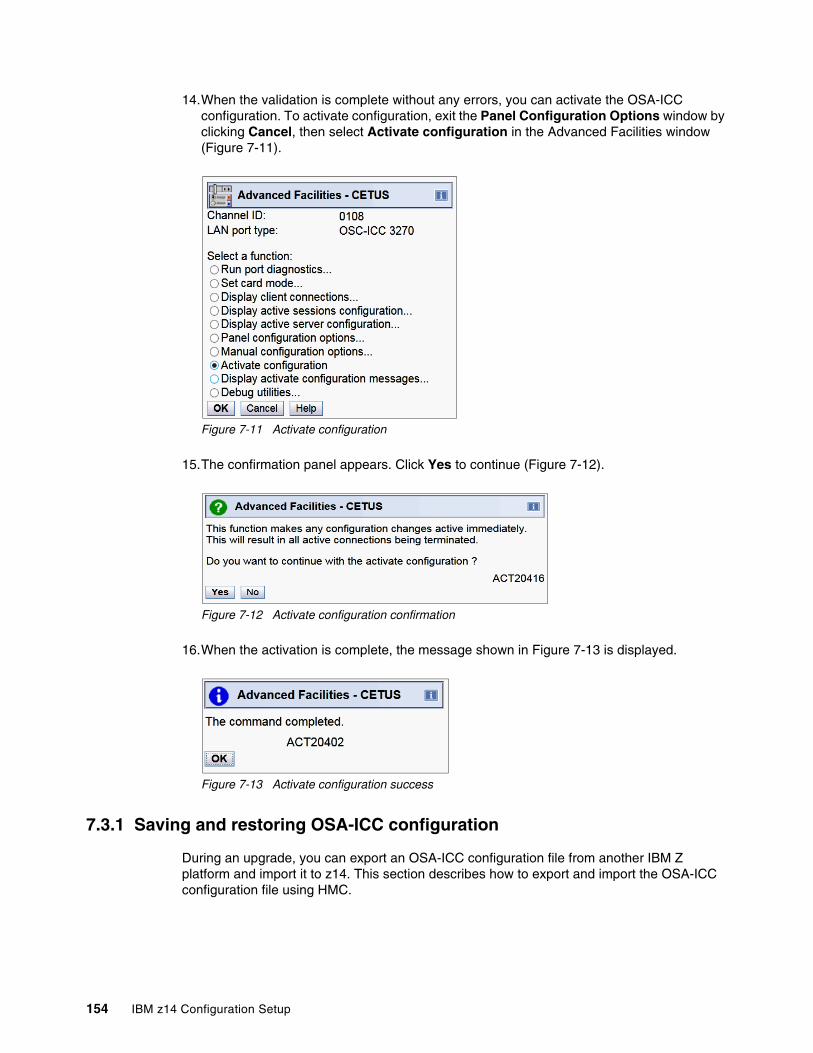
14.When the validation is complete without any errors, you can activate the OSA-ICC configuration. To activate configuration, exit the Panel Configuration Options window by clicking Cancel, then select Activate configuration in the Advanced Facilities window (Figure 7-11).
Figure 7-11 Activate configuration
15.The confirmation panel appears. Click Yes to continue (Figure 7-12).
Figure 7-12 Activate configuration confirmation
16.When the activation is complete, the message shown in Figure 7-13 is displayed.
Figure 7-13 Activate configuration success
7.3.1 Saving and restoring OSA-ICC configuration
During an upgrade, you can export an OSA-ICC configuration file from another IBM Z platform and import it to z14. This section describes how to export and import the OSA-ICC configuration file using HMC.
154 IBM z14 Configuration Setup

Exporting OSA-ICC configuration file using OSA Advanced FacilitiesIn this example, we export the OSA-ICC configuration file from a z13 server and import the file to the (new) z14 with a USB flash drive. You can also import/export the configuration file by using FTP.
To export the OSA-ICC configuration file, follow these steps:
1. Before you export a source file, prepare the USB flash drive that is supported by the HMC, and insert it into the USB port of the HMC. When the flash drive is recognized by the HMC, the window shown in Figure 7-14 is displayed.
Figure 7-14 Removable media inserted
2. Log on to the HMC, select the CPC you want to operate, and open the OSA Advanced facility.
3. Select the OSC CHPID to export the OSA-ICC configuration file. Next, select Card specific advanced facilities. Select Manual configuration options and click OK (Figure 7-15).
Figure 7-15 Manual configuration options
Chapter 7. Defining console communication 155
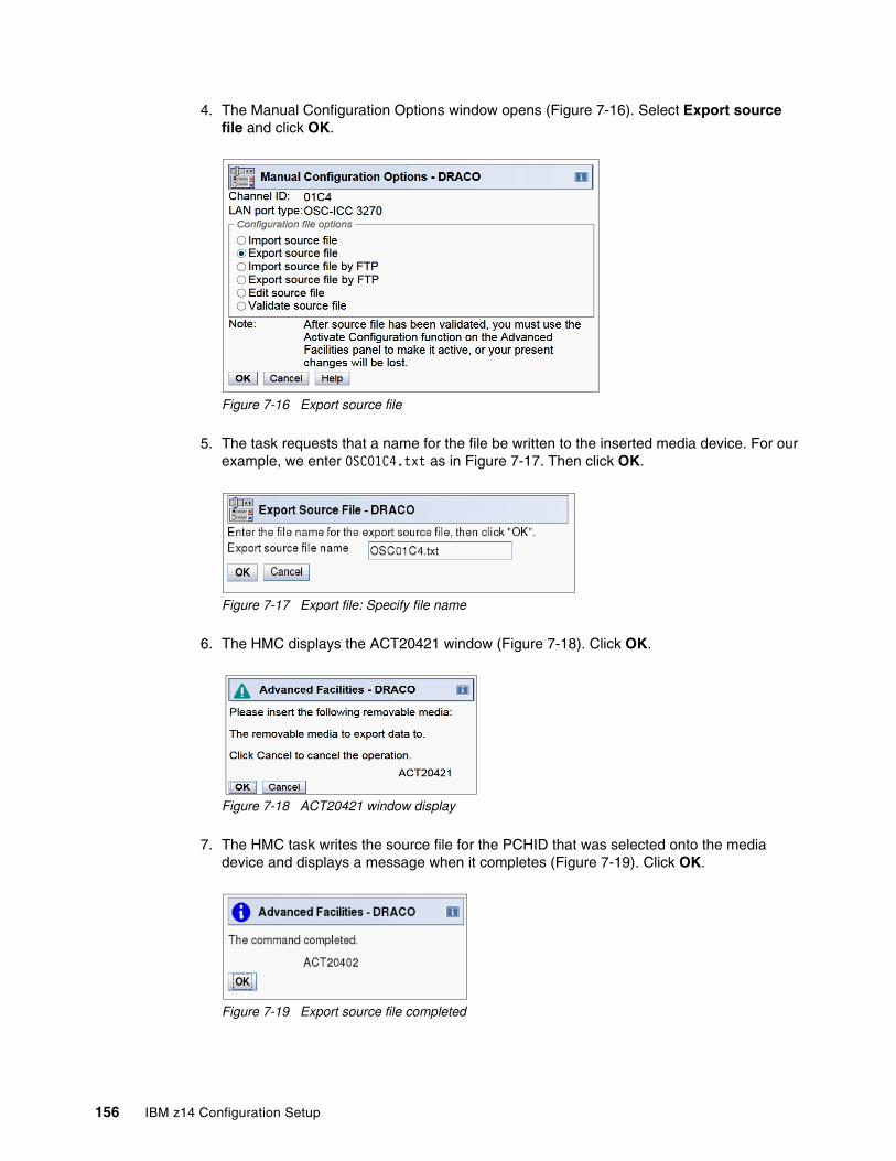
4. The Manual Configuration Options window opens (Figure 7-16). Select Export source file and click OK.
Figure 7-16 Export source file
5. The task requests that a name for the file be written to the inserted media device. For our example, we enter OSC01C4.txt as in Figure 7-17. Then click OK.
Figure 7-17 Export file: Specify file name
6. The HMC displays the ACT20421 window (Figure 7-18). Click OK.
Figure 7-18 ACT20421 window display
7. The HMC task writes the source file for the PCHID that was selected onto the media device and displays a message when it completes (Figure 7-19). Click OK.
Figure 7-19 Export source file completed
156 IBM z14 Configuration Setup
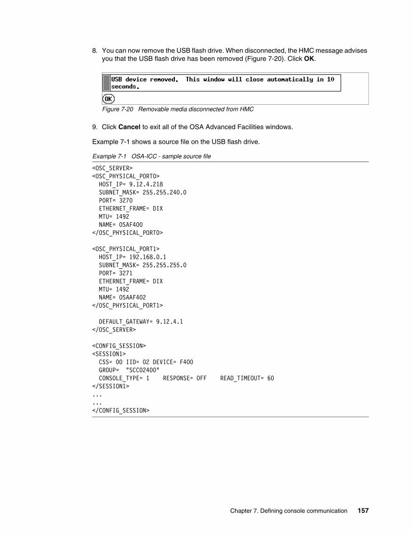
8. You can now remove the USB flash drive. When disconnected, the HMC message advises you that the USB flash drive has been removed (Figure 7-20). Click OK.
Figure 7-20 Removable media disconnected from HMC
9. Click Cancel to exit all of the OSA Advanced Facilities windows.
Example 7-1 shows a source file on the USB flash drive.
Example 7-1 OSA-ICC - sample source file
<OSC_SERVER><OSC_PHYSICAL_PORT0> HOST_IP= 9.12.4.218 SUBNET_MASK= 255.255.240.0 PORT= 3270 ETHERNET_FRAME= DIX MTU= 1492 NAME= OSAF400</OSC_PHYSICAL_PORT0>
<OSC_PHYSICAL_PORT1> HOST_IP= 192.168.0.1 SUBNET_MASK= 255.255.255.0 PORT= 3271 ETHERNET_FRAME= DIX MTU= 1492 NAME= OSAAF402</OSC_PHYSICAL_PORT1>
DEFAULT_GATEWAY= 9.12.4.1</OSC_SERVER>
<CONFIG_SESSION><SESSION1> CSS= 00 IID= 02 DEVICE= F400 GROUP= "SCC02400" CONSOLE_TYPE= 1 RESPONSE= OFF READ_TIMEOUT= 60</SESSION1>......</CONFIG_SESSION>
Chapter 7. Defining console communication 157
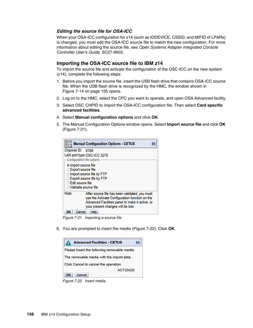
Editing the source file for OSA-ICCWhen your OSA-ICC configuration for z14 (such as IODEVICE, CSSID, and MIFID of LPARs) is changed, you must edit the OSA-ICC source file to match the new configuration. For more information about editing the source file, see Open Systems Adapter Integrated Console Controller User's Guide, SC27-9003.
Importing the OSA-ICC source file to IBM z14To import the source file and activate the configuration of the OSC-ICC on the new system (z14), complete the following steps:
1. Before you import the source file, insert the USB flash drive that contains OSA-ICC source file. When the USB flash drive is recognized by the HMC, the window shown in Figure 7-14 on page 155 opens.
2. Log on to the HMC, select the CPC you want to operate, and open OSA Advanced facility.
3. Select OSC CHPID to import the OSA-ICC configuration file. Then select Card specific advanced facilities.
4. Select Manual configuration options and click OK.
5. The Manual Configuration Options window opens. Select Import source file and click OK (Figure 7-21).
Figure 7-21 Importing a source file
6. You are prompted to insert the media (Figure 7-22). Click OK.
Figure 7-22 Insert media
158 IBM z14 Configuration Setup
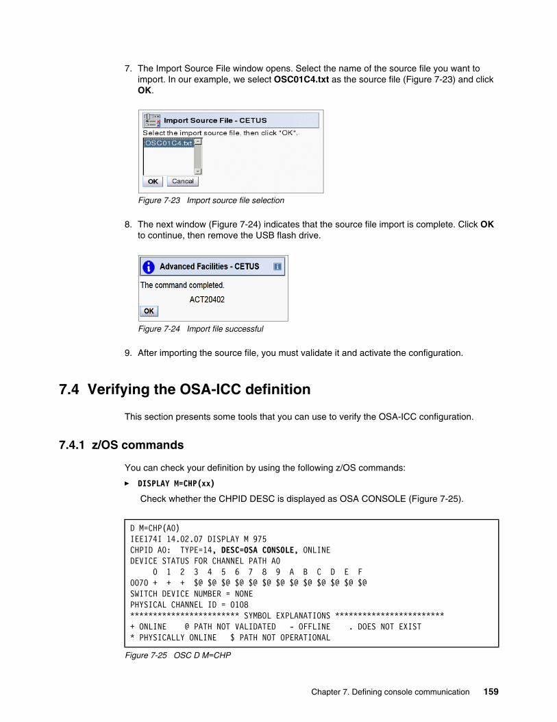
7. The Import Source File window opens. Select the name of the source file you want to import. In our example, we select OSC01C4.txt as the source file (Figure 7-23) and click OK.
Figure 7-23 Import source file selection
8. The next window (Figure 7-24) indicates that the source file import is complete. Click OK to continue, then remove the USB flash drive.
Figure 7-24 Import file successful
9. After importing the source file, you must validate it and activate the configuration.
7.4 Verifying the OSA-ICC definition
This section presents some tools that you can use to verify the OSA-ICC configuration.
7.4.1 z/OS commands
You can check your definition by using the following z/OS commands:
� DISPLAY M=CHP(xx)
Check whether the CHPID DESC is displayed as OSA CONSOLE (Figure 7-25).
Figure 7-25 OSC D M=CHP
D M=CHP(A0) IEE174I 14.02.07 DISPLAY M 975 CHPID A0: TYPE=14, DESC=OSA CONSOLE, ONLINE DEVICE STATUS FOR CHANNEL PATH A0 0 1 2 3 4 5 6 7 8 9 A B C D E F 0070 + + + $@ $@ $@ $@ $@ $@ $@ $@ $@ $@ $@ $@ $@ SWITCH DEVICE NUMBER = NONE PHYSICAL CHANNEL ID = 0108 ************************ SYMBOL EXPLANATIONS ************************ + ONLINE @ PATH NOT VALIDATED - OFFLINE . DOES NOT EXIST * PHYSICALLY ONLINE $ PATH NOT OPERATIONAL
Chapter 7. Defining console communication 159
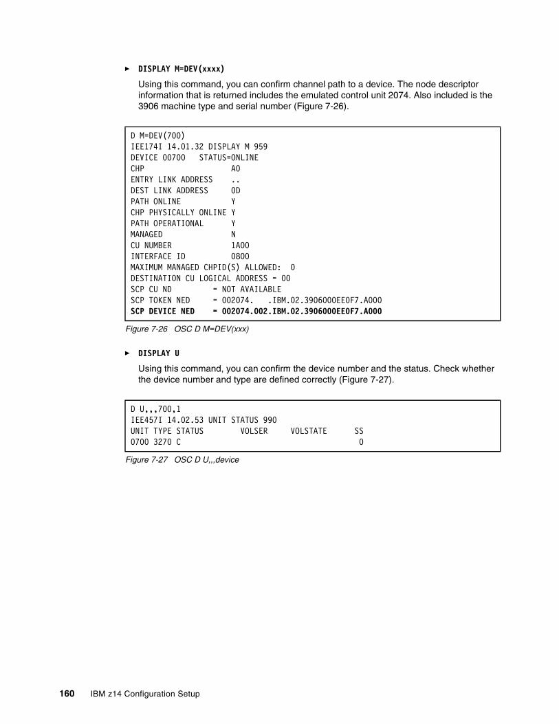
� DISPLAY M=DEV(xxxx)
Using this command, you can confirm channel path to a device. The node descriptor information that is returned includes the emulated control unit 2074. Also included is the 3906 machine type and serial number (Figure 7-26).
Figure 7-26 OSC D M=DEV(xxx)
� DISPLAY U
Using this command, you can confirm the device number and the status. Check whether the device number and type are defined correctly (Figure 7-27).
Figure 7-27 OSC D U,,,device
D M=DEV(700) IEE174I 14.01.32 DISPLAY M 959 DEVICE 00700 STATUS=ONLINE CHP A0 ENTRY LINK ADDRESS .. DEST LINK ADDRESS 0D PATH ONLINE Y CHP PHYSICALLY ONLINE Y PATH OPERATIONAL Y MANAGED N CU NUMBER 1A00 INTERFACE ID 0800 MAXIMUM MANAGED CHPID(S) ALLOWED: 0 DESTINATION CU LOGICAL ADDRESS = 00 SCP CU ND = NOT AVAILABLE SCP TOKEN NED = 002074. .IBM.02.3906000EE0F7.A000 SCP DEVICE NED = 002074.002.IBM.02.3906000EE0F7.A000
D U,,,700,1 IEE457I 14.02.53 UNIT STATUS 990 UNIT TYPE STATUS VOLSER VOLSTATE SS 0700 3270 C 0
160 IBM z14 Configuration Setup

7.4.2 OSA-ICC console initial window
When you have completed setting up the IBM Personal Communications, you will see the OSA-ICC initial window as shown in Figure 7-28. Check whether the OSA-ICC definitions are reflected correctly.
If you do not see the initial window, check your definition in the OSA-ICC or IBM Personal Communications session setup.
Figure 7-28 OSA-ICC initial window
** OSC Index 03 connected to cetusic2 via IP Addr 9.76.56.78:1025 ** ** LT Index=08 CSSID=02 MIFID=04 CU=0 UA=02 LUName=SYSLAB ** ** Type=3906-M03 Mfg=IBM SN=0000000EE0F7 CHPID=A0 Status=Active **
192.168.11.1:51426
Chapter 7. Defining console communication 161

162 IBM z14 Configuration Setup
Chapter 8. Preparing for Sysplex and configuring Server Time Protocol
This chapter describes the preparation tasks for IBM Parallel Sysplex and how to configure time synchronization with Server Time Protocol (STP).
This chapter includes the following topics:
� Preparing for Parallel Sysplex� Preparing for non-sysplex system time synchronization� Server Time Protocol overview� Configuring the HMC as an NTP server� What is new in HMC V2.14.0 (Manage System Time task)� Single server STP-only CTN� Adding the z14 server to an existing CTN� Assign an STP role to the CPC
8
© Copyright IBM Corp. 2017. All rights reserved. 163
8.1 Preparing for Parallel Sysplex
If your z14 is a member of a Parallel Sysplex or if you create a new Parallel Sysplex involving the IBM z14, time synchronization among CPCs is required. For time synchronization, you must use the Server Time Protocol feature (FC #1021). In addition to the time synchronization, the following tasks are required in preparation for Sysplex:
1. Defining CF (coupling) links.2. Defining FICON CTC connections (optional).3. Defining the CF LPAR.4. Defining the CF LPAR on image profile in HMC.5. Configuring STP.
Defining CF (coupling) links is described in Chapter 9, “Defining Coupling Facility links” on page 203. Defining the image profile is described in 5.4, “Creating an Image Profile on the 3906 Support Element” on page 101.
8.2 Preparing for non-sysplex system time synchronization
If your z14 is not part of a Parallel Sysplex but you want to synchronize the time among multiple CPCs, you need the STP function and STP-only (timing) links. These configuration steps are required:
1. Defining STP-only (timing) links.2. Configuring STP.
Defining STP-only (timing) links is described in 9.4, “Defining an STP timing-only link by using ICA SR” on page 221.
This chapter describes how to set up STP on a z14 server.
8.3 Server Time Protocol overview
STP provides time synchronization among multiple CPCs in a Coordinated Timing Network (CTN). CTN is a collection of servers that are synchronized to a time value called Coordinated Server Time (CST). STP function (feature) is implemented in the Licensed Internal Code (LIC) as a chargeable feature. You must order STP enablement feature code #1021 to use STP.
For more information about STP concepts and planning information, see the Server Time Protocol Planning Guide, SG24-7280.
164 IBM z14 Configuration Setup
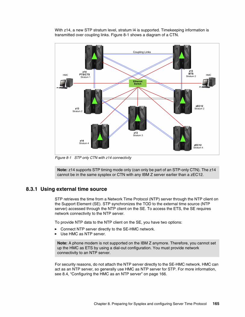
With z14, a new STP stratum level, stratum l4 is supported. Timekeeping information is transmitted over coupling links. Figure 8-1 shows a diagram of a CTN.
Figure 8-1 STP only CTN with z14 connectivity
8.3.1 Using external time source
STP retrieves the time from a Network Time Protocol (NTP) server through the NTP client on the Support Element (SE). STP synchronizes the TOD to the external time source (NTP server) accessed through the NTP client on the SE. To access the ETS, the SE requires network connectivity to the NTP server.
To provide NTP data to the NTP client on the SE, you have two options:
� Connect NTP server directly to the SE-HMC network.� Use HMC as NTP server.
For security reasons, do not attach the NTP server directly to the SE-HMC network. HMC can act as an NTP server, so generally use HMC as NTP server for STP. For more information, see 8.4, “Configuring the HMC as an NTP server” on page 166.
Note: z14 supports STP timing mode only (can only be part of an STP-only CTN). The z14 cannot be in the same sysplex or CTN with any IBM Z server earlier than a zEC12.
zEC12Stratum 4
z14Stratum 4
Coupling Links
z13BTS
Stratum 2
z14PTS/CTS
Stratum 1
z13Stratum 3
HMCHMC
zEC12Stratum 2z13
Stratum 2
Ethernet Switch
Note: A phone modem is not supported on the IBM Z anymore. Therefore, you cannot set up the HMC as ETS by using a dial-out configuration. You must provide network connectivity to an NTP server.
Chapter 8. Preparing for Sysplex and configuring Server Time Protocol 165
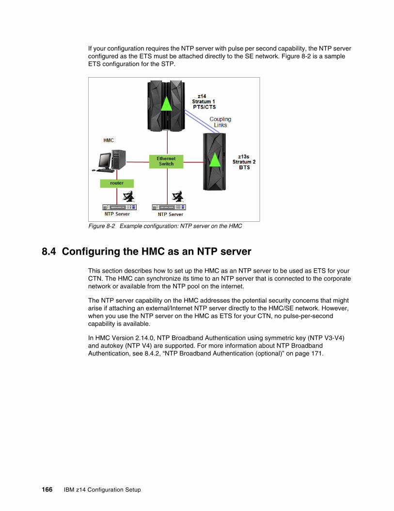
If your configuration requires the NTP server with pulse per second capability, the NTP server configured as the ETS must be attached directly to the SE network. Figure 8-2 is a sample ETS configuration for the STP.
Figure 8-2 Example configuration: NTP server on the HMC
8.4 Configuring the HMC as an NTP server
This section describes how to set up the HMC as an NTP server to be used as ETS for your CTN. The HMC can synchronize its time to an NTP server that is connected to the corporate network or available from the NTP pool on the internet.
The NTP server capability on the HMC addresses the potential security concerns that might arise if attaching an external/Internet NTP server directly to the HMC/SE network. However, when you use the NTP server on the HMC as ETS for your CTN, no pulse-per-second capability is available.
In HMC Version 2.14.0, NTP Broadband Authentication using symmetric key (NTP V3-V4) and autokey (NTP V4) are supported. For more information about NTP Broadband Authentication, see 8.4.2, “NTP Broadband Authentication (optional)” on page 171.
166 IBM z14 Configuration Setup
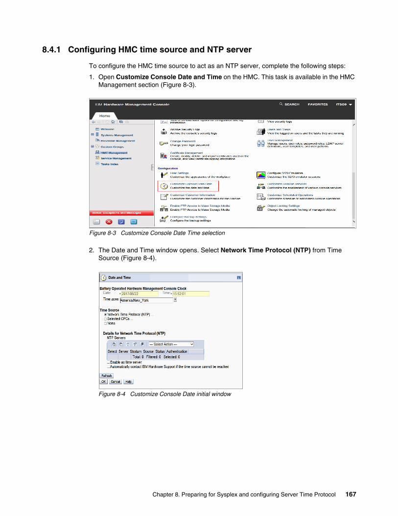
8.4.1 Configuring HMC time source and NTP server
To configure the HMC time source to act as an NTP server, complete the following steps:
1. Open Customize Console Date and Time on the HMC. This task is available in the HMC Management section (Figure 8-3).
Figure 8-3 Customize Console Date Time selection
2. The Date and Time window opens. Select Network Time Protocol (NTP) from Time Source (Figure 8-4).
Figure 8-4 Customize Console Date initial window
Chapter 8. Preparing for Sysplex and configuring Server Time Protocol 167

3. Select Add Server from the Select Action list (Figure 8-5).
Figure 8-5 Customize Console Date - Time Add Server
4. The Add Network Time Server window opens. In this window, you can set the values in the following fields:
– Enter the time server host name or IP address: This mandatory field is the IP address or host name of NTP server. For the example configuration, 1.pool.ntp.org is the NTP server.
– Authentication Selection: You can define this field if you want to use NTP Broadband Authentication Support function. If you do not use NTP Broadband Authentication Support function, select None.
Click OK when finished (Figure 8-6).
Figure 8-6 Add Network Time Server
Tip: Using a host name requires you to customize and enable Domain Name Services on the HMC. To complete this task, click Customize Network Setting → Name services in the Hardware Management Console Setting Work Area.
168 IBM z14 Configuration Setup
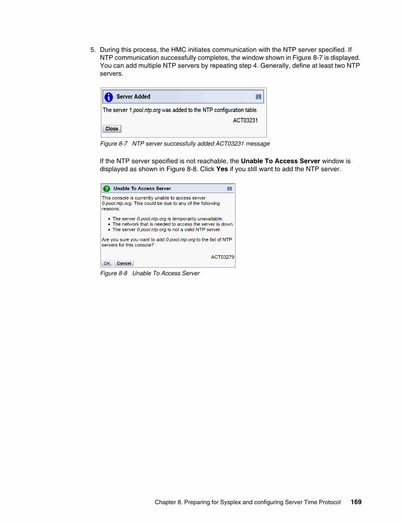
5. During this process, the HMC initiates communication with the NTP server specified. If NTP communication successfully completes, the window shown in Figure 8-7 is displayed. You can add multiple NTP servers by repeating step 4. Generally, define at least two NTP servers.
Figure 8-7 NTP server successfully added ACT03231 message
If the NTP server specified is not reachable, the Unable To Access Server window is displayed as shown in Figure 8-8. Click Yes if you still want to add the NTP server.
Figure 8-8 Unable To Access Server
Chapter 8. Preparing for Sysplex and configuring Server Time Protocol 169
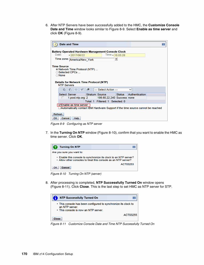
6. After NTP Servers have been successfully added to the HMC, the Customize Console Date and Time window looks similar to Figure 8-9. Select Enable as time server and click OK (Figure 8-9).
Figure 8-9 Configuring as NTP server
7. In the Turning On NTP window (Figure 8-10), confirm that you want to enable the HMC as time server. Click OK.
Figure 8-10 Turning On NTP (server)
8. After processing is completed, NTP Successfully Turned On window opens (Figure 8-11). Click Close. This is the last step to set HMC as NTP server for STP.
Figure 8-11 Customize Console Date and Time NTP Successfully Turned On
170 IBM z14 Configuration Setup
8.4.2 NTP Broadband Authentication (optional)
HMC supports NTP Broadband Authentication. Configure the (optional) NTP Authentication if your HMC requires it. NTP server authentication provides an increased level of security in the following situations:
� When using a proxy to access outside network
NTP requests are User Datagram Protocol (UDP) socket packets, so they cannot pass through the proxy. The proxy must be configured as an NTP server to get to target servers on the internet.
� Using firewall
NTP requests can pass through the firewall. If you use firewall to access an outside NTP server, use the HMC authentication to ensure untampered time stamps.
Two authentication methods are supported for NTP:
� Symmetric key (NTP V3-V4) authentication
Symmetric key encryption uses the same key for both encryption and decryption. When the HMC is acting as the client, the symmetric key index that is specified on each NTP server definition must be present in the key file. The specified key index, key type, and the key string must align with the specified key information of the target server. Likewise, if the HMC is acting as a server, the client specified key information must match the same key index on the server. Symmetric key supports Network Address Translation (NAT).
� Autokey (NTP V4) authentication
Autokey uses public key cryptography. The key generation for the HMC NTP is done by clicking Generate Local Host Key on the Autokey Configuration window. Clicking this button issues the ntp-keygen command, which generates the specific key and certificate for this system. Autokey authentication is not available with a NAT firewall.
Consideration: If more than one NTP server is defined, you cannot specify which server is the primary server. The NTP service on the HMC takes any defined NTP server and tries to contact it. If it succeeds, that server is used as the time source until either the server in question is no longer available or the console is rebooted. If it cannot communicate with that server, it tries another in the list.
The check box on the Configure NTP Setting window is used only for actions in the Select Action list, and not for setting a primary or preferred NTP server.
Chapter 8. Preparing for Sysplex and configuring Server Time Protocol 171
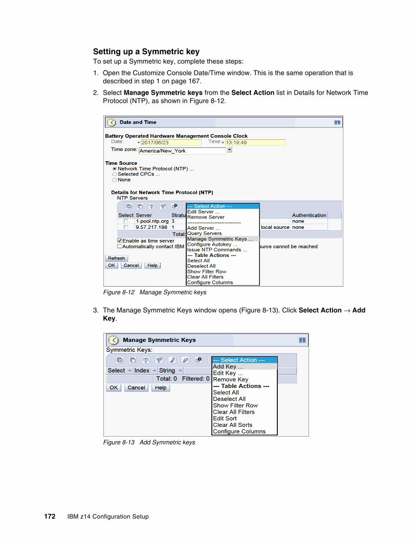
Setting up a Symmetric keyTo set up a Symmetric key, complete these steps:
1. Open the Customize Console Date/Time window. This is the same operation that is described in step 1 on page 167.
2. Select Manage Symmetric keys from the Select Action list in Details for Network Time Protocol (NTP), as shown in Figure 8-12.
Figure 8-12 Manage Symmetric keys
3. The Manage Symmetric Keys window opens (Figure 8-13). Click Select Action → Add Key.
Figure 8-13 Add Symmetric keys
172 IBM z14 Configuration Setup

4. The Add Symmetric Key Data window opens (Figure 8-14). The following data must be entered:
Key index A numeric value in the range 1 - 65534.
Key string The key string can be up to 40 characters long. If the string is 40 characters long, the characters must be hexadecimal ASCII characters (0-9, a-f). If the string is fewer than 40 characters long, the characters can be any printable ASCII character.
Figure 8-14 Add Symmetric key data
5. The Enter Symmetric Key window opens. Click Close to add the Symmetric Key (Figure 8-15).
Figure 8-15 Enter Symmetric Key successfully added
6. The key is displayed in the Manage Symmetric Keys window (Figure 8-16). You can enter additional key data in this window by repeating the previous steps. Click OK to proceed if no more keys are needed.
Figure 8-16 Symmetric key list
7. The completion window opens (Figure 8-17). Click Close to return to the Configure NTP Settings window.
Figure 8-17 Completed message for symmetric key configuration
Chapter 8. Preparing for Sysplex and configuring Server Time Protocol 173
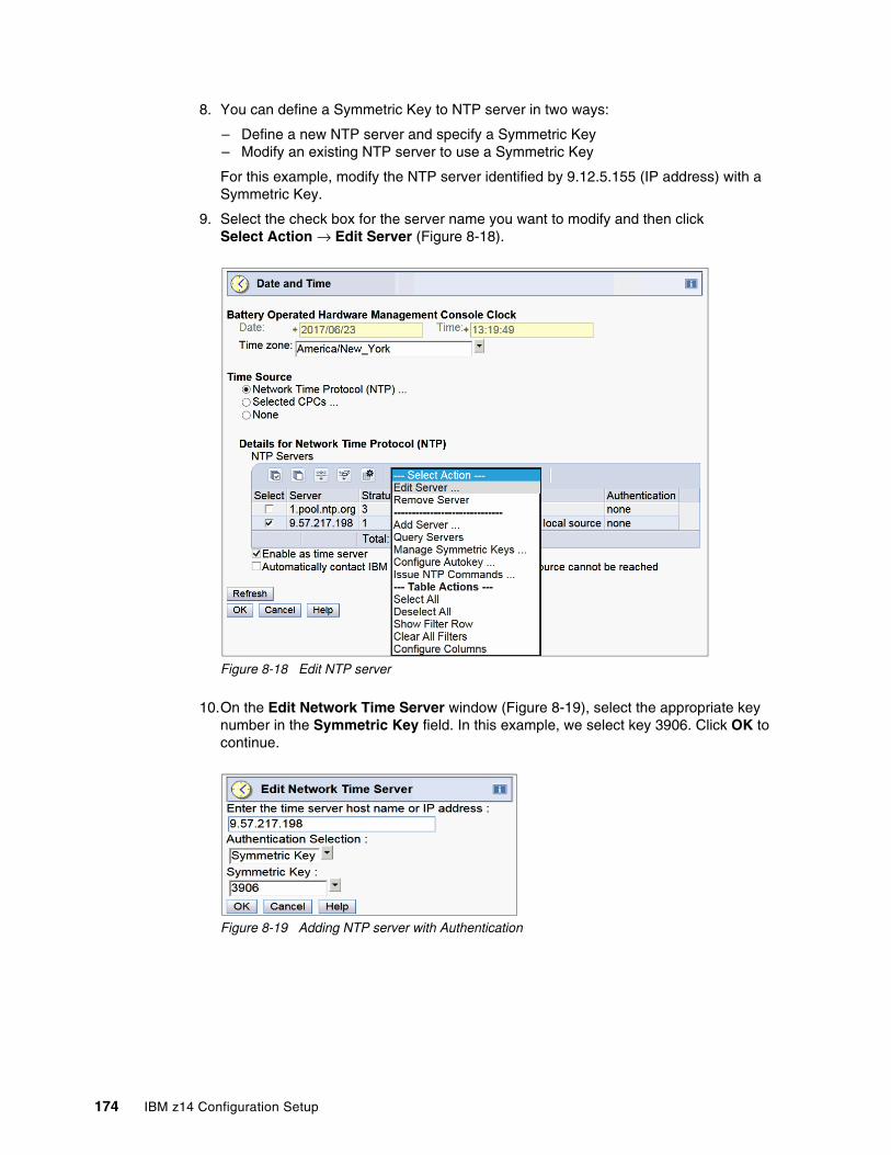
8. You can define a Symmetric Key to NTP server in two ways:
– Define a new NTP server and specify a Symmetric Key– Modify an existing NTP server to use a Symmetric Key
For this example, modify the NTP server identified by 9.12.5.155 (IP address) with a Symmetric Key.
9. Select the check box for the server name you want to modify and then click Select Action → Edit Server (Figure 8-18).
Figure 8-18 Edit NTP server
10.On the Edit Network Time Server window (Figure 8-19), select the appropriate key number in the Symmetric Key field. In this example, we select key 3906. Click OK to continue.
Figure 8-19 Adding NTP server with Authentication
174 IBM z14 Configuration Setup
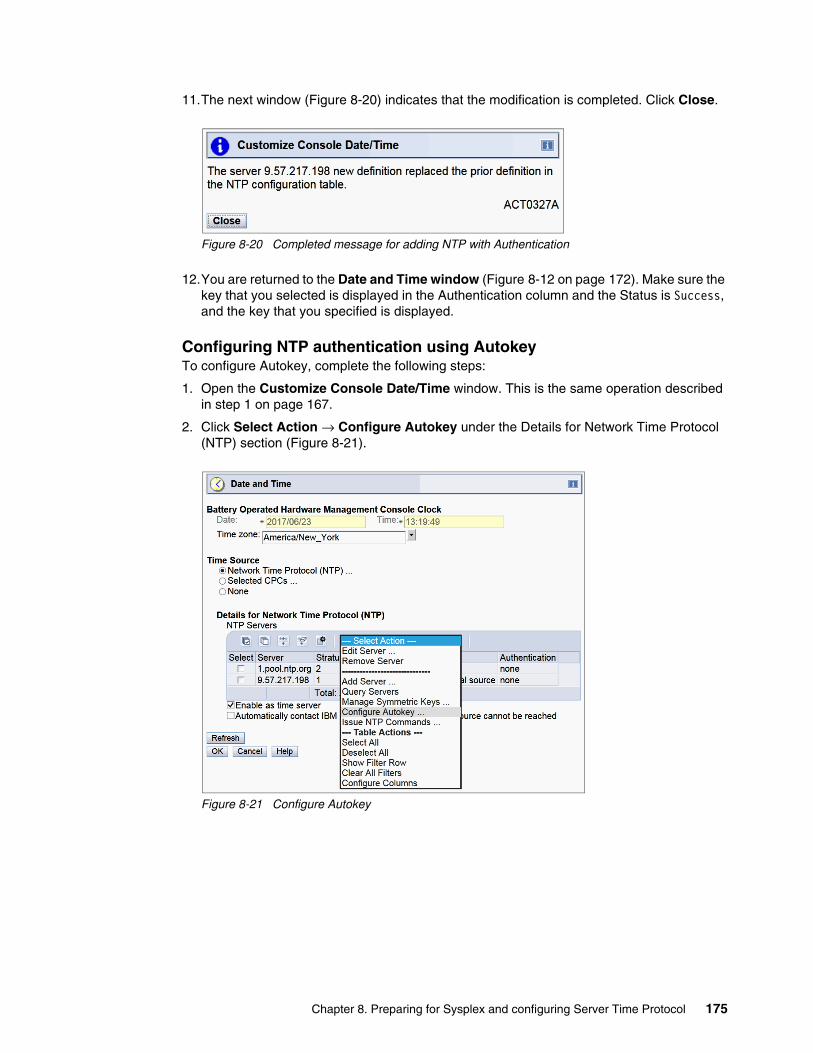
11.The next window (Figure 8-20) indicates that the modification is completed. Click Close.
Figure 8-20 Completed message for adding NTP with Authentication
12.You are returned to the Date and Time window (Figure 8-12 on page 172). Make sure the key that you selected is displayed in the Authentication column and the Status is Success, and the key that you specified is displayed.
Configuring NTP authentication using AutokeyTo configure Autokey, complete the following steps:
1. Open the Customize Console Date/Time window. This is the same operation described in step 1 on page 167.
2. Click Select Action → Configure Autokey under the Details for Network Time Protocol (NTP) section (Figure 8-21).
Figure 8-21 Configure Autokey
Chapter 8. Preparing for Sysplex and configuring Server Time Protocol 175
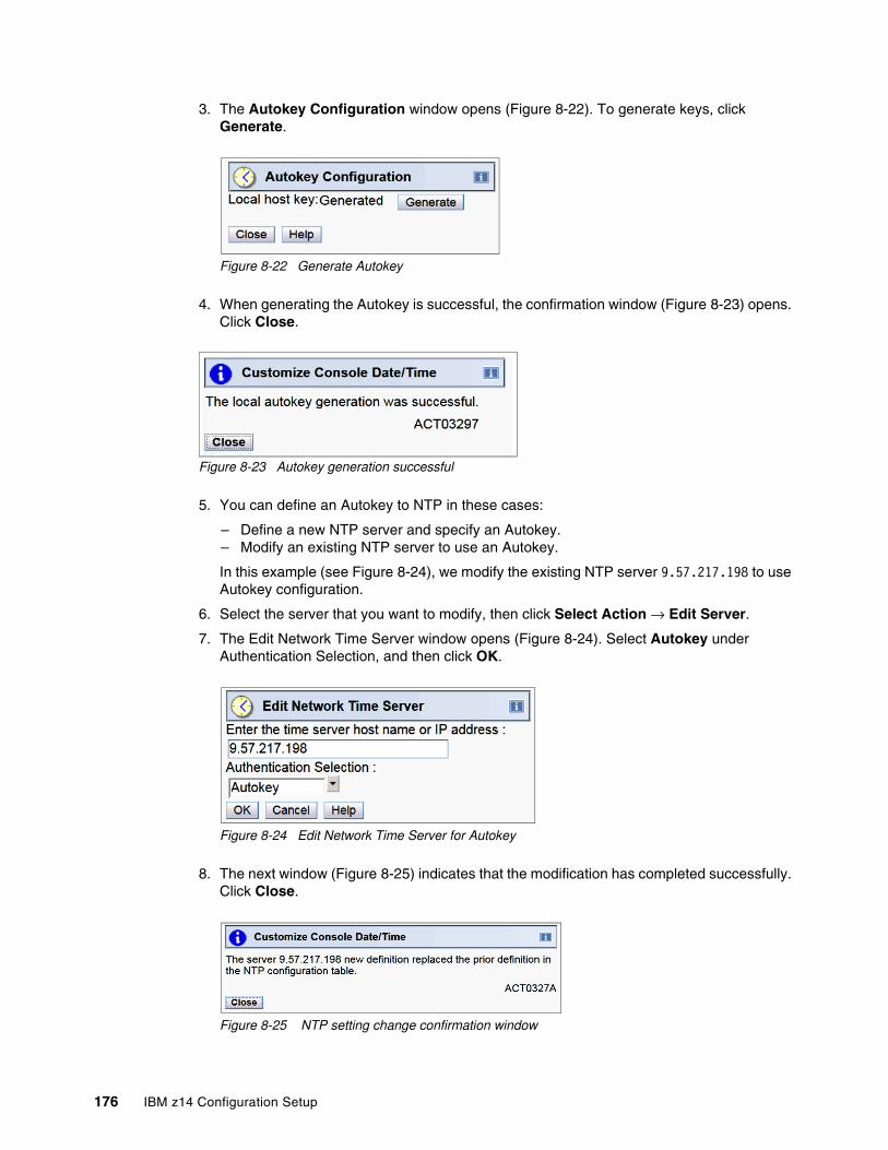
3. The Autokey Configuration window opens (Figure 8-22). To generate keys, click Generate.
Figure 8-22 Generate Autokey
4. When generating the Autokey is successful, the confirmation window (Figure 8-23) opens. Click Close.
Figure 8-23 Autokey generation successful
5. You can define an Autokey to NTP in these cases:
– Define a new NTP server and specify an Autokey.– Modify an existing NTP server to use an Autokey.
In this example (see Figure 8-24), we modify the existing NTP server 9.57.217.198 to use Autokey configuration.
6. Select the server that you want to modify, then click Select Action → Edit Server.
7. The Edit Network Time Server window opens (Figure 8-24). Select Autokey under Authentication Selection, and then click OK.
Figure 8-24 Edit Network Time Server for Autokey
8. The next window (Figure 8-25) indicates that the modification has completed successfully. Click Close.
Figure 8-25 NTP setting change confirmation window
176 IBM z14 Configuration Setup
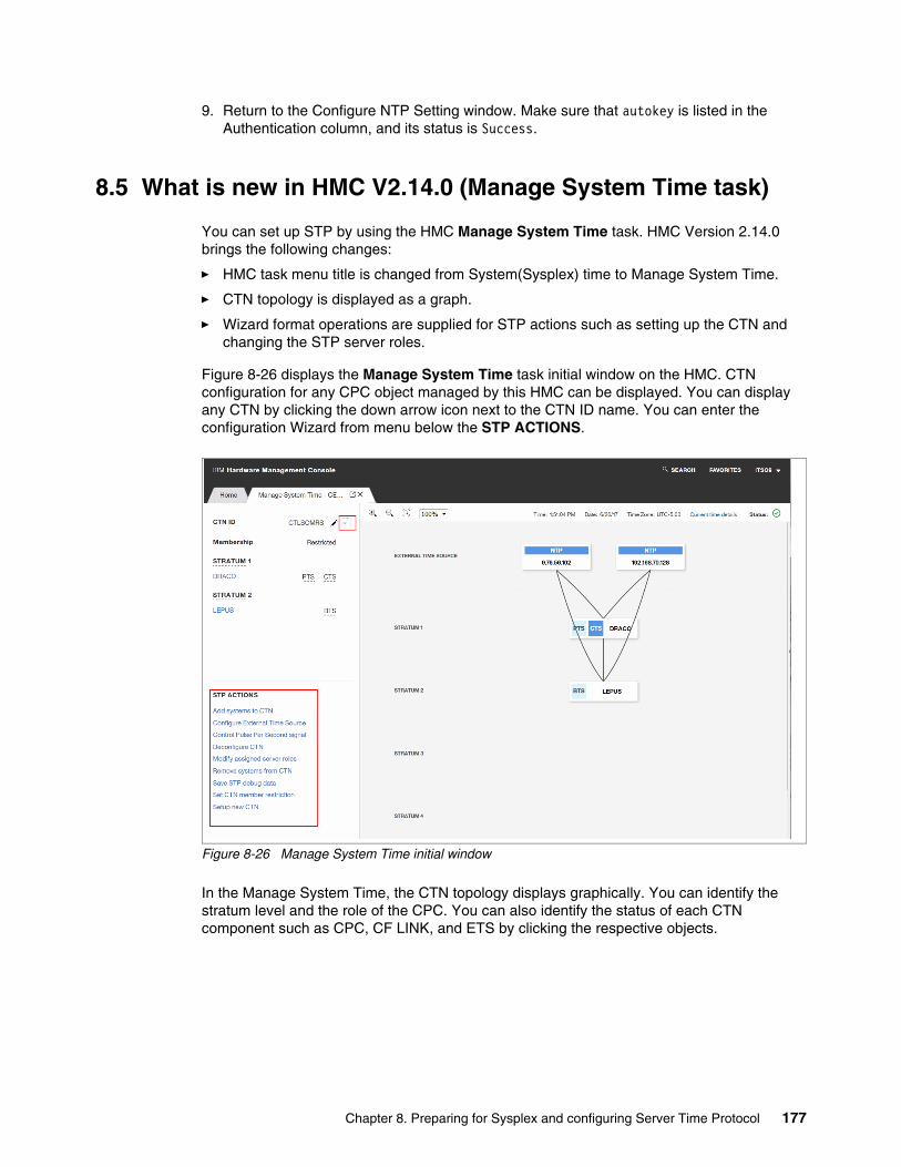
9. Return to the Configure NTP Setting window. Make sure that autokey is listed in the Authentication column, and its status is Success.
8.5 What is new in HMC V2.14.0 (Manage System Time task)
You can set up STP by using the HMC Manage System Time task. HMC Version 2.14.0 brings the following changes:
� HMC task menu title is changed from System(Sysplex) time to Manage System Time.
� CTN topology is displayed as a graph.
� Wizard format operations are supplied for STP actions such as setting up the CTN and changing the STP server roles.
Figure 8-26 displays the Manage System Time task initial window on the HMC. CTN configuration for any CPC object managed by this HMC can be displayed. You can display any CTN by clicking the down arrow icon next to the CTN ID name. You can enter the configuration Wizard from menu below the STP ACTIONS.
Figure 8-26 Manage System Time initial window
In the Manage System Time, the CTN topology displays graphically. You can identify the stratum level and the role of the CPC. You can also identify the status of each CTN component such as CPC, CF LINK, and ETS by clicking the respective objects.
Chapter 8. Preparing for Sysplex and configuring Server Time Protocol 177
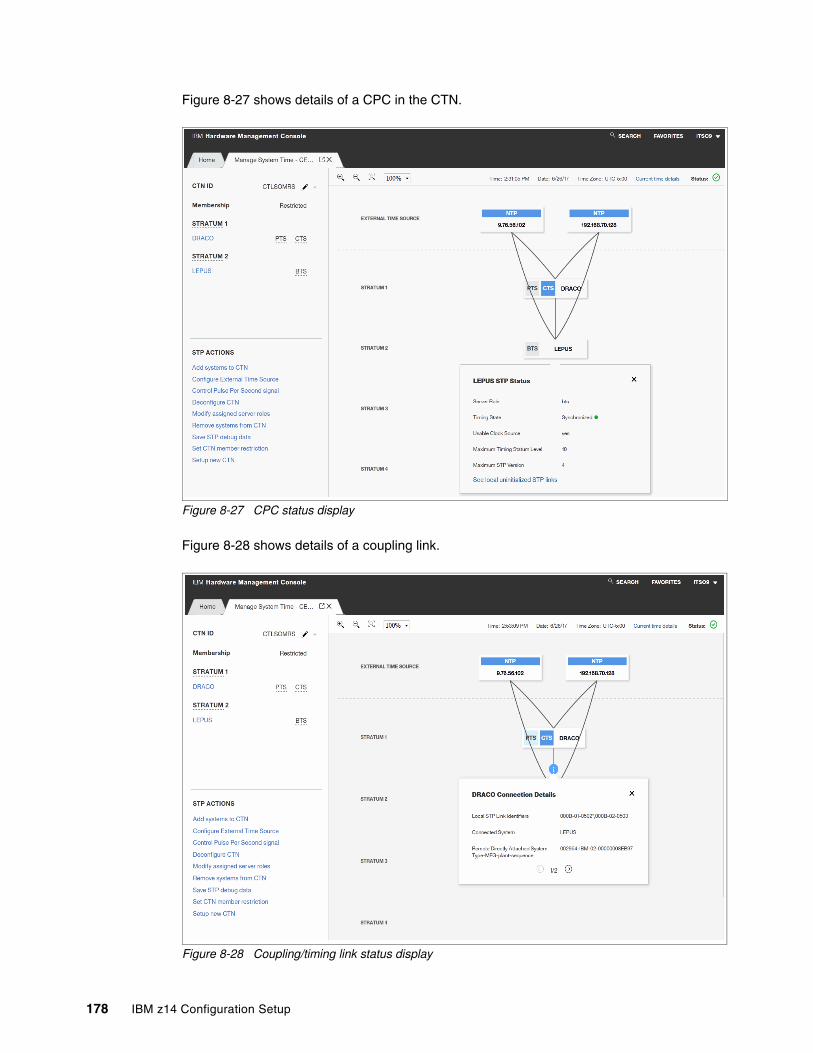
Figure 8-27 shows details of a CPC in the CTN.
Figure 8-27 CPC status display
Figure 8-28 shows details of a coupling link.
Figure 8-28 Coupling/timing link status display
178 IBM z14 Configuration Setup
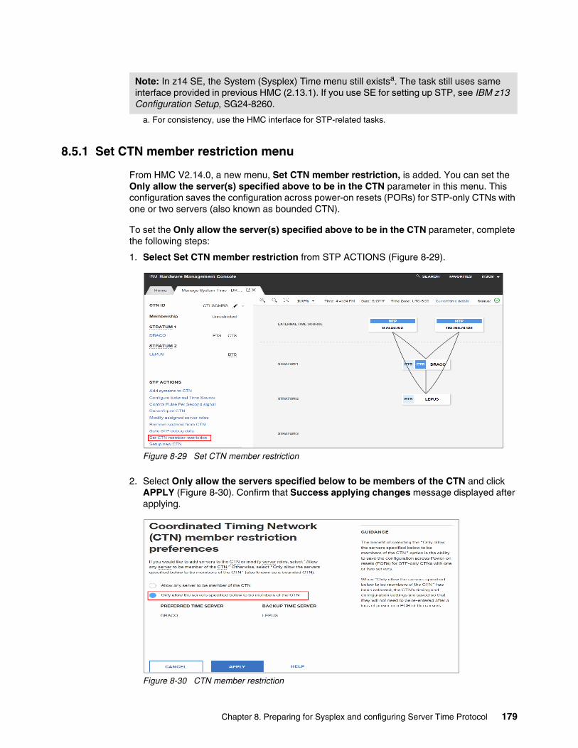
8.5.1 Set CTN member restriction menu
From HMC V2.14.0, a new menu, Set CTN member restriction, is added. You can set the Only allow the server(s) specified above to be in the CTN parameter in this menu. This configuration saves the configuration across power-on resets (PORs) for STP-only CTNs with one or two servers (also known as bounded CTN).
To set the Only allow the server(s) specified above to be in the CTN parameter, complete the following steps:
1. Select Set CTN member restriction from STP ACTIONS (Figure 8-29).
Figure 8-29 Set CTN member restriction
2. Select Only allow the servers specified below to be members of the CTN and click APPLY (Figure 8-30). Confirm that Success applying changes message displayed after applying.
Figure 8-30 CTN member restriction
Note: In z14 SE, the System (Sysplex) Time menu still existsa. The task still uses same interface provided in previous HMC (2.13.1). If you use SE for setting up STP, see IBM z13 Configuration Setup, SG24-8260.
a. For consistency, use the HMC interface for STP-related tasks.
Chapter 8. Preparing for Sysplex and configuring Server Time Protocol 179
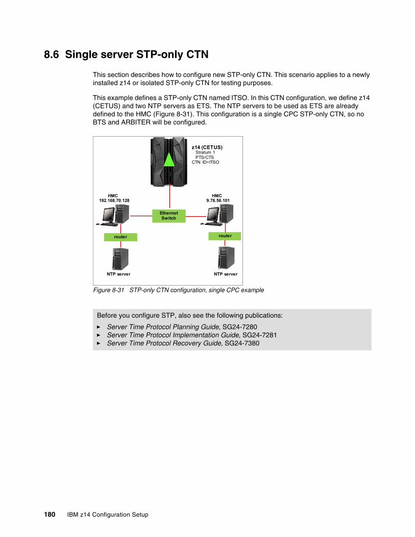
8.6 Single server STP-only CTN
This section describes how to configure new STP-only CTN. This scenario applies to a newly installed z14 or isolated STP-only CTN for testing purposes.
This example defines a STP-only CTN named ITSO. In this CTN configuration, we define z14 (CETUS) and two NTP servers as ETS. The NTP servers to be used as ETS are already defined to the HMC (Figure 8-31). This configuration is a single CPC STP-only CTN, so no BTS and ARBITER will be configured.
Figure 8-31 STP-only CTN configuration, single CPC example
Before you configure STP, also see the following publications:
� Server Time Protocol Planning Guide, SG24-7280� Server Time Protocol Implementation Guide, SG24-7281� Server Time Protocol Recovery Guide, SG24-7380
z14 (CETUS)Stratum 1PTS/CTS
CTN ID=ITSO
HMC192.168.70.128
Ethernet Switch
routerrouter
NTP server NTP server
HMC9.76.56.101
180 IBM z14 Configuration Setup

8.6.1 Configuring a new STP-only CTN
To configure new STP-only CTN, select the Setup new CTN menu from STP ACTIONS list in the Manage System Time task. To set up new STP-only CTN, complete these steps:
1. In the HMC, select the CPC to configure STP and Manage System Time, under the Configuration task (Figure 8-32).
Figure 8-32 Manage System Time CPC selection
2. The Manage system Time window opens. If you already defined CPC object which configured CTN, the CTN configuration is displayed graphically. To define new CTN, select Setup new CTN from STP ACTIONS (Figure 8-33).
Figure 8-33 Setup new CTN
Chapter 8. Preparing for Sysplex and configuring Server Time Protocol 181
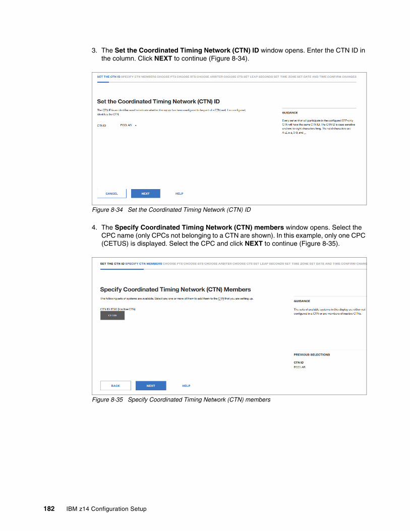
3. The Set the Coordinated Timing Network (CTN) ID window opens. Enter the CTN ID in the column. Click NEXT to continue (Figure 8-34).
Figure 8-34 Set the Coordinated Timing Network (CTN) ID
4. The Specify Coordinated Timing Network (CTN) members window opens. Select the CPC name (only CPCs not belonging to a CTN are shown). In this example, only one CPC (CETUS) is displayed. Select the CPC and click NEXT to continue (Figure 8-35).
Figure 8-35 Specify Coordinated Timing Network (CTN) members
182 IBM z14 Configuration Setup

5. The Choose Preferred Time Server window opens. Select the CPC name for PTS (Figure 8-36).
Figure 8-36 Manage System Time: Choose Preferred Time Server
6. The Choose Current Time Server window opens. We select CETUS for CTS. Click NEXT to continue (Figure 8-37).
Figure 8-37 Choose Current Time Server
Note: Because CETUS is the only CPC (server) in the CTN, the CHOOSE BTS and CHOOSE ARBITER steps are not available.
Chapter 8. Preparing for Sysplex and configuring Server Time Protocol 183

7. The Adjust leap second offset window opens. Define the applicable value here, then click NEXT to continue (Figure 8-38).
Figure 8-38 Adjust leap second offset
8. The Set time zone window opens. Specify the following two parameters:
– Adjust time zone offset– Clock adjustment for Daylight Saving Time
Select the appropriate items from the list. These parameters are used when initializing time for the CTS that is defined in the next step. We define Eastern Time for the Time Zone offset and Automatically adjust for the Daylight Saving Time. Click NEXT to continue (Figure 8-39).
Figure 8-39 Set time zone
184 IBM z14 Configuration Setup
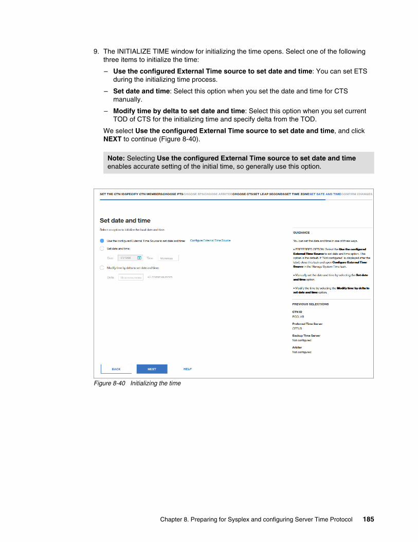
9. The INITIALIZE TIME window for initializing the time opens. Select one of the following three items to initialize the time:
– Use the configured External Time source to set date and time: You can set ETS during the initializing time process.
– Set date and time: Select this option when you set the date and time for CTS manually.
– Modify time by delta to set date and time: Select this option when you set current TOD of CTS for the initializing time and specify delta from the TOD.
We select Use the configured External Time source to set date and time, and click NEXT to continue (Figure 8-40).
Figure 8-40 Initializing the time
Note: Selecting Use the configured External Time source to set date and time enables accurate setting of the initial time, so generally use this option.
Chapter 8. Preparing for Sysplex and configuring Server Time Protocol 185
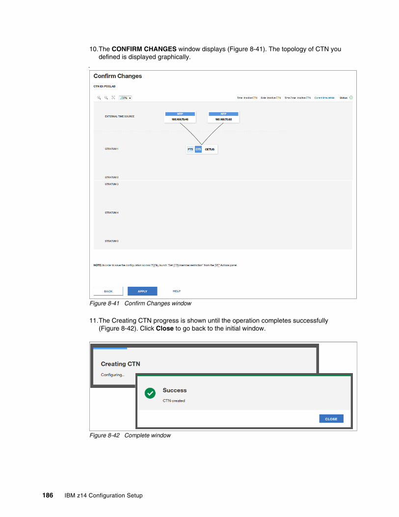
10.The CONFIRM CHANGES window displays (Figure 8-41). The topology of CTN you defined is displayed graphically.
Figure 8-41 Confirm Changes window
11.The Creating CTN progress is shown until the operation completes successfully (Figure 8-42). Click Close to go back to the initial window.
Figure 8-42 Complete window
186 IBM z14 Configuration Setup

8.6.2 Verify new CTN configuration
When the new CTN configuration is complete, the Manage System Time initial window is displayed. Check that the following items are defined properly on this window (Figure 8-43):
– Status– CTN ID – Time / Date / Time zone– Stratum Level– STP Role
Figure 8-43 New CTN
You can also check the status of STP by using the z/OS D ETR command (Figure 8-44).
Figure 8-44 z/OS D ETR command
D ETR IEA386I 08.12.13 TIMING STATUS 508 SYNCHRONIZATION MODE = STP THIS SERVER IS A STRATUM 1 CTN ID = PCCLAB THE STRATUM 1 NODE ID = 003906.M03.IBM.02.0000000EE0F7 THIS IS THE PREFERRED TIME SERVER THIS STP NETWORK HAS NO BACKUP TIME SERVER THIS STP NETWORK HAS NO SERVER TO ACT AS ARBITER
Chapter 8. Preparing for Sysplex and configuring Server Time Protocol 187
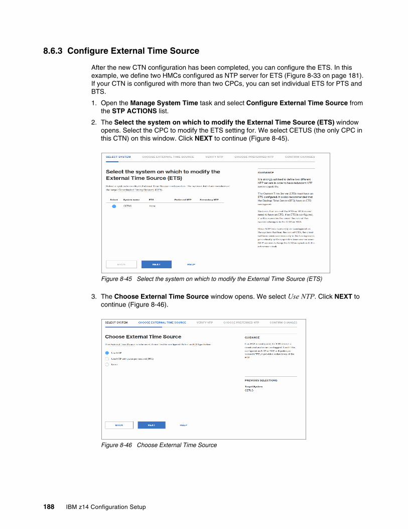
8.6.3 Configure External Time Source
After the new CTN configuration has been completed, you can configure the ETS. In this example, we define two HMCs configured as NTP server for ETS (Figure 8-33 on page 181). If your CTN is configured with more than two CPCs, you can set individual ETS for PTS and BTS.
1. Open the Manage System Time task and select Configure External Time Source from the STP ACTIONS list.
2. The Select the system on which to modify the External Time Source (ETS) window opens. Select the CPC to modify the ETS setting for. We select CETUS (the only CPC in this CTN) on this window. Click NEXT to continue (Figure 8-45).
Figure 8-45 Select the system on which to modify the External Time Source (ETS)
3. The Choose External Time Source window opens. We select Use NTP. Click NEXT to continue (Figure 8-46).
Figure 8-46 Choose External Time Source
188 IBM z14 Configuration Setup

4. The Verify Network Time Protocol server(s) window opens. You can define up to two NTP servers by specifying either the IP address or the host name (IP label) of the NTP server by clicking the pencil icon. After adding IP address or host name, turn on the Enabled switch icon. Then click TEST CONNECTIVITY to ensure the NTP server is reachable. The Check the Connection status row displays No errors. Click NEXT to continue (Figure 8-47).
Figure 8-47 Verify Network Time Protocol servers
If you need to set NTP thresholds, click Set NTP Thresholds and specify the parameter. You can set the NTP Stratum level threshold and the Source ID time threshold (Figure 8-48).
Figure 8-48 Set NTP Thresholds (optional)
Chapter 8. Preparing for Sysplex and configuring Server Time Protocol 189

5. The Choose the preferred NTP server window opens. Select one of the NTP servers to be the preferred server. In our example, we select 192.168.70.128 as the preferred NTP server. Click NEXT to continue (Figure 8-49).
Figure 8-49 Choose the preferred NTP server
6. The Confirm External Time Source configuration window opens. Verify and click APPLY to complete the definition (Figure 8-50).
Figure 8-50 Confirm External Time Source configuration
190 IBM z14 Configuration Setup
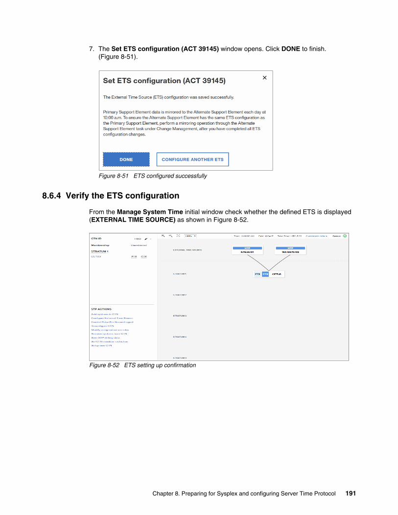
7. The Set ETS configuration (ACT 39145) window opens. Click DONE to finish. (Figure 8-51).
Figure 8-51 ETS configured successfully
8.6.4 Verify the ETS configuration
From the Manage System Time initial window check whether the defined ETS is displayed (EXTERNAL TIME SOURCE) as shown in Figure 8-52.
Figure 8-52 ETS setting up confirmation
Chapter 8. Preparing for Sysplex and configuring Server Time Protocol 191

8.7 Adding the z14 server to an existing CTN
This section describes the procedure used to add a z14 CPC to an existing CTN. In the diagram shown in Figure 8-53, we add a z14 (CETUS) to the existing CTN with the ID CTLSOMRS. The CETUS CPC is planned to be connected through coupling links to a Stratum 2 CPC named LEPUS, but at the moment, it is not connected to any CPCs. When added to the CTN, CETUS becomes the Stratum 0 (unsynchronized).
Figure 8-53 Scenario to add a z14 CPC to an existing CTN
DRACO (z13)Stratum 1
PTS / CTSCTNID=CTLSOMRS
HMC192.168.70.128
Ethernet Switch
router
NTP server
LEPUS (z13s)Stratum 2
BTSCTNID=CTLSOMRS
CETUS (z14)Stratum 0
CTNID=CTLSOMRS
CF Link
192 IBM z14 Configuration Setup
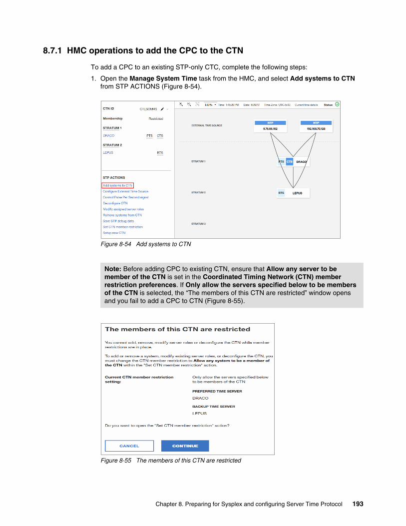
8.7.1 HMC operations to add the CPC to the CTN
To add a CPC to an existing STP-only CTC, complete the following steps:
1. Open the Manage System Time task from the HMC, and select Add systems to CTN from STP ACTIONS (Figure 8-54).
Figure 8-54 Add systems to CTN
Figure 8-55 The members of this CTN are restricted
Note: Before adding CPC to existing CTN, ensure that Allow any server to be member of the CTN is set in the Coordinated Timing Network (CTN) member restriction preferences. If Only allow the servers specified below to be members of the CTN is selected, the “The members of this CTN are restricted” window opens and you fail to add a CPC to CTN (Figure 8-55).
Chapter 8. Preparing for Sysplex and configuring Server Time Protocol 193
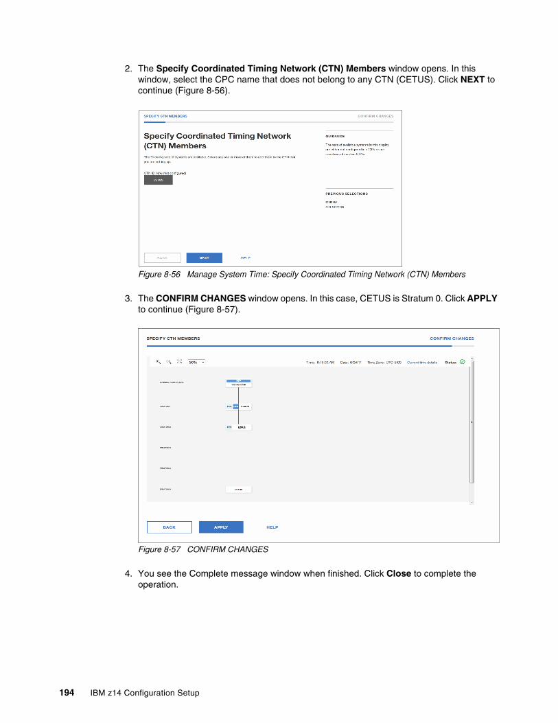
2. The Specify Coordinated Timing Network (CTN) Members window opens. In this window, select the CPC name that does not belong to any CTN (CETUS). Click NEXT to continue (Figure 8-56).
Figure 8-56 Manage System Time: Specify Coordinated Timing Network (CTN) Members
3. The CONFIRM CHANGES window opens. In this case, CETUS is Stratum 0. Click APPLY to continue (Figure 8-57).
Figure 8-57 CONFIRM CHANGES
4. You see the Complete message window when finished. Click Close to complete the operation.
194 IBM z14 Configuration Setup
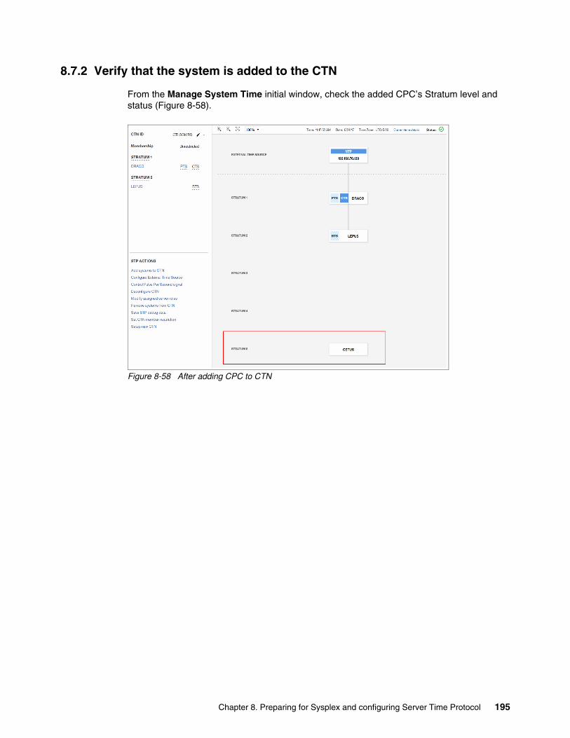
8.7.2 Verify that the system is added to the CTN
From the Manage System Time initial window, check the added CPC’s Stratum level and status (Figure 8-58).
Figure 8-58 After adding CPC to CTN
Chapter 8. Preparing for Sysplex and configuring Server Time Protocol 195
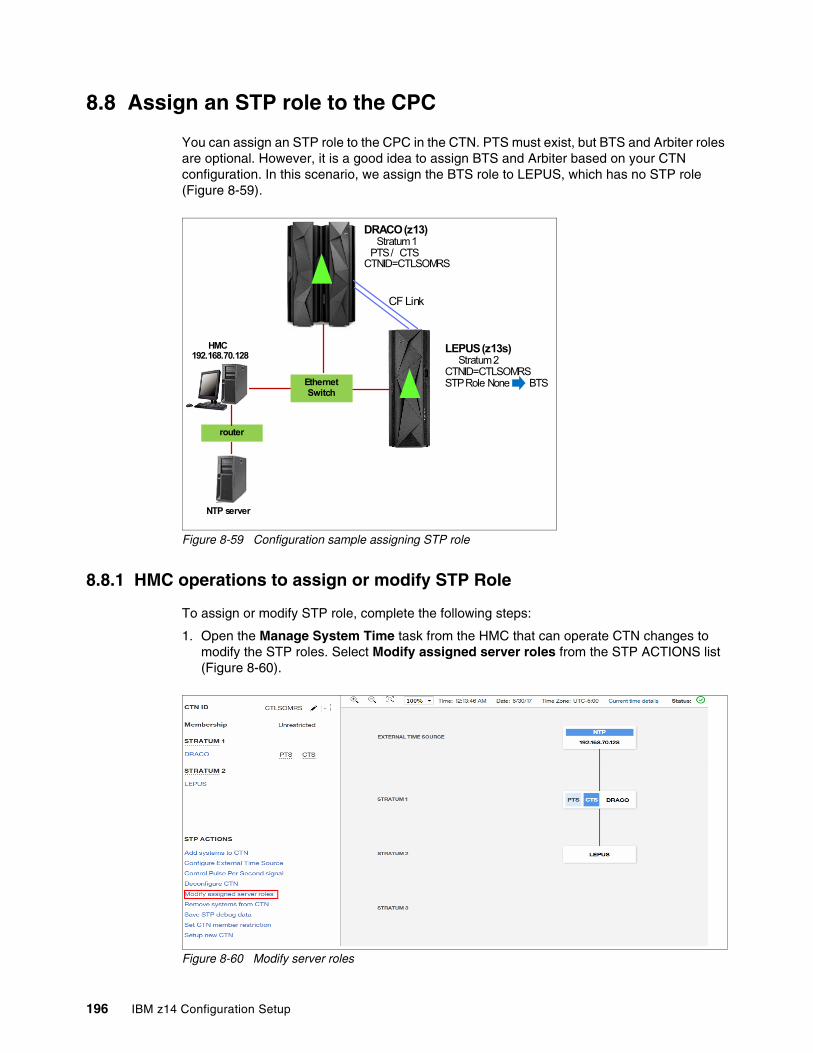
8.8 Assign an STP role to the CPC
You can assign an STP role to the CPC in the CTN. PTS must exist, but BTS and Arbiter roles are optional. However, it is a good idea to assign BTS and Arbiter based on your CTN configuration. In this scenario, we assign the BTS role to LEPUS, which has no STP role (Figure 8-59).
Figure 8-59 Configuration sample assigning STP role
8.8.1 HMC operations to assign or modify STP Role
To assign or modify STP role, complete the following steps:
1. Open the Manage System Time task from the HMC that can operate CTN changes to modify the STP roles. Select Modify assigned server roles from the STP ACTIONS list (Figure 8-60).
Figure 8-60 Modify server roles
DRACO (z13)Stratum 1
PTS / CTSCTNID=CTLSOMRS
HMC192.168.70.128
Ethernet Switch
router
NTP server
LEPUS (z13s)Stratum 2
CTNID=CTLSOMRSSTP Role None BTS
CF Link
196 IBM z14 Configuration Setup

2. The Choose Preferred Time Server window opens. Select the CPC name for the PTS. In this example, we do not change the PTS, so DRACO remains selected (Figure 8-61).
Figure 8-61 Choose Preferred Time Server
3. The Choose Backup Time Server window opens. In the window, select the CPC name to use for BTS. In this example, we choose LEPUS for BTS. Click NEXT to continue (Figure 8-62).
Figure 8-62 Choose Backup Time Server
Chapter 8. Preparing for Sysplex and configuring Server Time Protocol 197

4. The Choose Arbiter window opens. Because this is a diad (two CPC configuration), we cannot define Arbiter, so select Do not configure an Arbiter. Click NEXT to continue (Figure 8-63).
Figure 8-63 Choose Arbiter
5. The Choose Current Time Server window opens. Select the CPC name to act as the CTS. Click NEXT to continue (Figure 8-64).
Figure 8-64 Choose Current Time Server
198 IBM z14 Configuration Setup
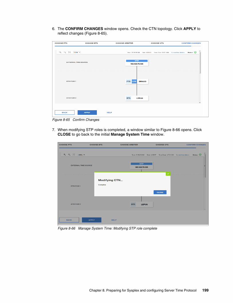
6. The CONFIRM CHANGES window opens. Check the CTN topology. Click APPLY to reflect changes (Figure 8-65).
Figure 8-65 Confirm Changes
7. When modifying STP roles is completed, a window similar to Figure 8-66 opens. Click CLOSE to go back to the initial Manage System Time window.
Figure 8-66 Manage System Time: Modifying STP role complete
Chapter 8. Preparing for Sysplex and configuring Server Time Protocol 199
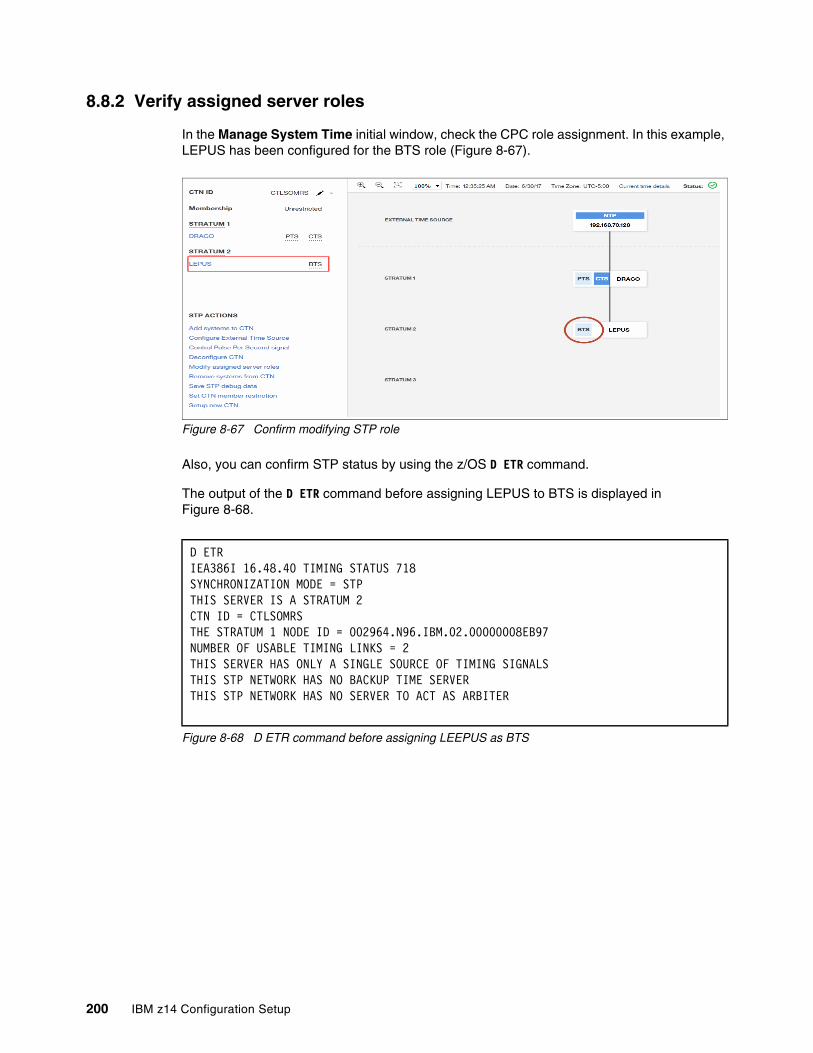
8.8.2 Verify assigned server roles
In the Manage System Time initial window, check the CPC role assignment. In this example, LEPUS has been configured for the BTS role (Figure 8-67).
Figure 8-67 Confirm modifying STP role
Also, you can confirm STP status by using the z/OS D ETR command.
The output of the D ETR command before assigning LEPUS to BTS is displayed in Figure 8-68.
Figure 8-68 D ETR command before assigning LEEPUS as BTS
D ETRIEA386I 16.48.40 TIMING STATUS 718SYNCHRONIZATION MODE = STPTHIS SERVER IS A STRATUM 2CTN ID = CTLSOMRSTHE STRATUM 1 NODE ID = 002964.N96.IBM.02.00000008EB97NUMBER OF USABLE TIMING LINKS = 2THIS SERVER HAS ONLY A SINGLE SOURCE OF TIMING SIGNALSTHIS STP NETWORK HAS NO BACKUP TIME SERVERTHIS STP NETWORK HAS NO SERVER TO ACT AS ARBITER
200 IBM z14 Configuration Setup
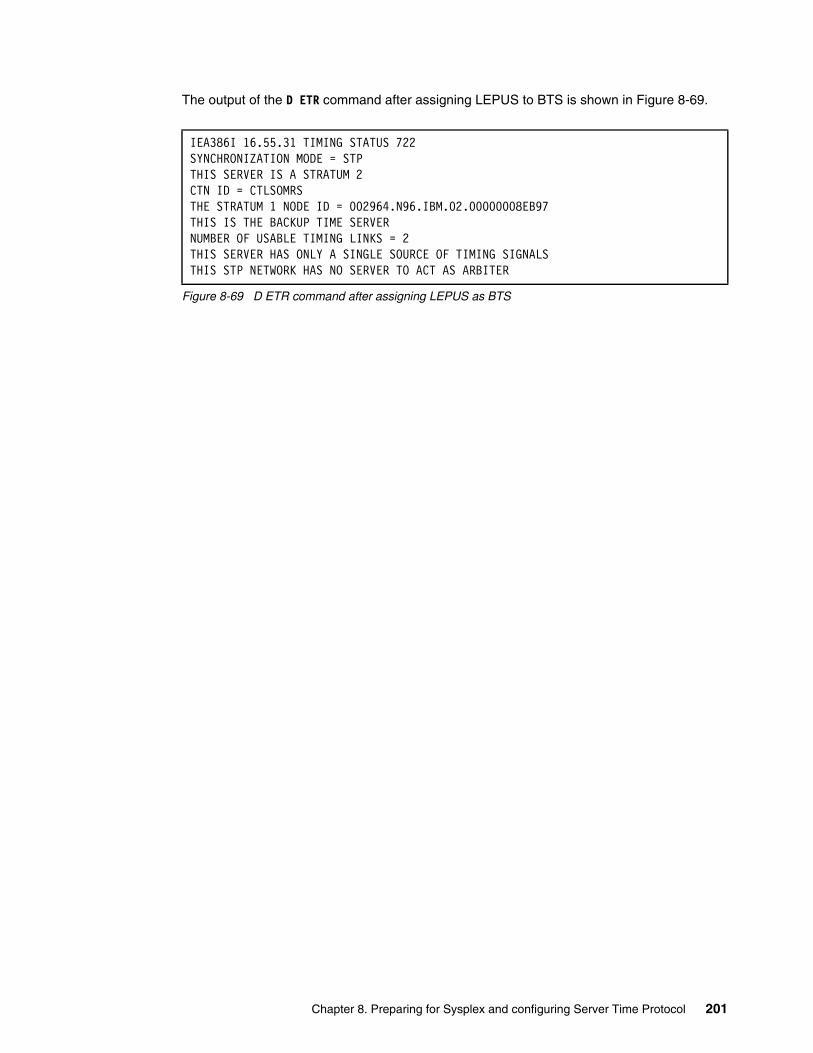
The output of the D ETR command after assigning LEPUS to BTS is shown in Figure 8-69.
Figure 8-69 D ETR command after assigning LEPUS as BTS
IEA386I 16.55.31 TIMING STATUS 722SYNCHRONIZATION MODE = STPTHIS SERVER IS A STRATUM 2CTN ID = CTLSOMRSTHE STRATUM 1 NODE ID = 002964.N96.IBM.02.00000008EB97THIS IS THE BACKUP TIME SERVERNUMBER OF USABLE TIMING LINKS = 2THIS SERVER HAS ONLY A SINGLE SOURCE OF TIMING SIGNALSTHIS STP NETWORK HAS NO SERVER TO ACT AS ARBITER
Chapter 8. Preparing for Sysplex and configuring Server Time Protocol 201

202 IBM z14 Configuration Setup

Chapter 9. Defining Coupling Facility links
This chapter describes the coupling connectivity options available on z14. Coupling links support Parallel Sysplex and STP. It introduces the new adapter and channel type for long-distance coupling, the Coupling Express Long Reach (CE LR).
This chapter includes the following sections:
� Coupling connectivity options on z14� Coupling Express Long Range� Integrated Coupling Adapter Short Range� Defining an STP timing-only link by using ICA SR� CF LPAR setup and CFCC Level 22
9
© Copyright IBM Corp. 2017. All rights reserved. 203
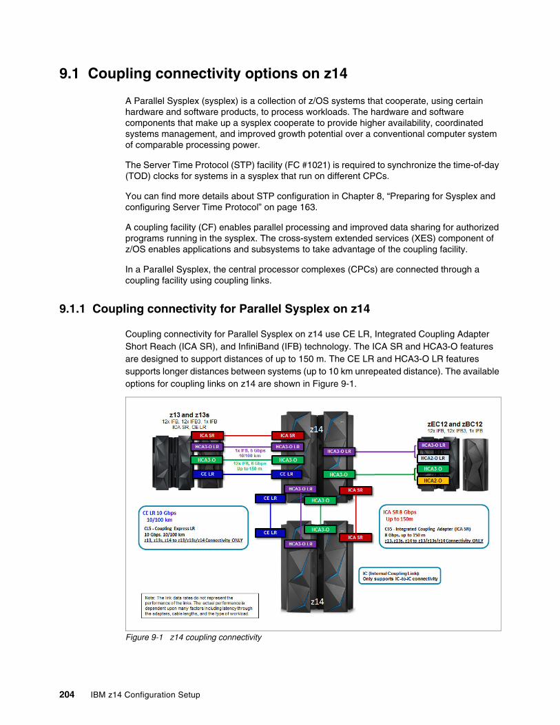
9.1 Coupling connectivity options on z14
A Parallel Sysplex (sysplex) is a collection of z/OS systems that cooperate, using certain hardware and software products, to process workloads. The hardware and software components that make up a sysplex cooperate to provide higher availability, coordinated systems management, and improved growth potential over a conventional computer system of comparable processing power.
The Server Time Protocol (STP) facility (FC #1021) is required to synchronize the time-of-day (TOD) clocks for systems in a sysplex that run on different CPCs.
You can find more details about STP configuration in Chapter 8, “Preparing for Sysplex and configuring Server Time Protocol” on page 163.
A coupling facility (CF) enables parallel processing and improved data sharing for authorized programs running in the sysplex. The cross-system extended services (XES) component of z/OS enables applications and subsystems to take advantage of the coupling facility.
In a Parallel Sysplex, the central processor complexes (CPCs) are connected through a coupling facility using coupling links.
9.1.1 Coupling connectivity for Parallel Sysplex on z14
Coupling connectivity for Parallel Sysplex on z14 use CE LR, Integrated Coupling Adapter Short Reach (ICA SR), and InfiniBand (IFB) technology. The ICA SR and HCA3-O features are designed to support distances of up to 150 m. The CE LR and HCA3-O LR features supports longer distances between systems (up to 10 km unrepeated distance). The available options for coupling links on z14 are shown in Figure 9-1.
Figure 9-1 z14 coupling connectivity
204 IBM z14 Configuration Setup

9.1.2 Internal coupling
Internal coupling (IC) links are used for internal communication between LPARs on the same system running coupling facilities (CF) and z/OS images. The connection is emulated in Licensed Internal Code (LIC) and provides for fast and secure memory-to-memory communications between LPARs within a single system. No physical cabling is required.
9.1.3 InfiniBand features
IFB has these features:
� Host Channel Adapter 3 - Optical Long Reach (HCA3-O LR)
HCA3-O LR is a fanout card, based on InfiniBand protocol that supports 1x InfiniBand (1xIFB). The HCA3-O LR fanout for 1x InfiniBand (1x IFB) provides four ports and optional additional subchannels for extended-distance solutions.
The HCA3-O LR 1x InfiniBand supports up to 16 channel path IDs (CHPIDs) per feature. The CHPID type is CIB and up to 32 subchannels (devices) are supported. The HCA3-O LR supports a link data rate of up to 5 Gbps1.
InfiniBand (HCA3-O LR) coupling link supports unrepeated distances of up to 10 km (6.2 miles) using 9 µm single mode fiber optic cables and up to 100 km (62 miles) using IBM Z qualified Dense Wavelength Division Multiplexer (DWDM) equipment. Connectivity to HCA2-O LR is supported.
� Host Channel Adapter 3 - Optical (HCA3-O)
HCA3-O is a fanout card, based on InfiniBand protocol that supports 12x InfiniBand (12x IFB). The HCA3-O fanout for 12x InfiniBand (12x IFB) provides two ports.
The 12x InfiniBand coupling link supports a link speed of up to 6 GBps1.
InfiniBand (HCA3-O) coupling links (12x IFB) support distances up to 150 meters (492 feet) when using industry standard OM3 50 µm fiber optic cables. HCA3-O to HCA2-O connection is supported.
9.1.4 Integrated Coupling Adapter Short Reach (ICA SR)
The ICA SR, first introduced with the IBM z13, is a two-port fanout that is used for short distance coupling connectivity and uses the coupling channel type CS5. The ICA SR uses PCIe Gen3 technology, with x16 lanes that are bifurcated into x8 lanes for coupling.
The ICA SR supports cable length of up to 150 m and supports a link data rate of 8 Gbps1. It also supports up to four CHPIDs per port and seven subchannels (devices) per CHPID. The coupling links can be defined as shared between images within a CSS. They can also be spanned across multiple CSSs in an IBM Z CPC.
IBM z14 will be the last IBM Z server to support HCA3-O and HCA3-O LR adapters: z14 will be last IBM Z server to support HCA3-O fanout for 12x IFB (#0171) and HCA3-O LR fanout for 1x IFB (#0170). As announced previously, z13s is the last midrange IBM Z server to support these adapters (see Hardware Announcement 117-044).
1 The link data rates do not represent the performance of the links. The actual performance depends on many factors that include latency through the adapters, cable lengths, and the type of workload.
Chapter 9. Defining Coupling Facility links 205
9.1.5 Coupling Express Long Range (CE LR)
The CE LR is a two-port PCIe native adapter that is used for long-distance coupling connectivity and uses a new coupling channel type: CL5. The CE LR feature uses PCIe Gen3 technology and is hosted in a PCIe I/O drawer. CE LR is not supported in a switched environment (point-to-point links only).
The feature supports communication at unrepeated distances up to 10 km (6.2 miles) using 9µm single mode fiber optic cables and repeated distances up to 100 km (62 miles) using IBM Z qualified DWDM vendor equipment. It supports up to four CHPIDs per port and 32 subchannels (devices) per CHPID. CE LR supports a link data rate of up to 10 Gbps2. The coupling links can be defined as shared between images within a CSS or spanned across multiple CSSs in an IBM Z CPC.
9.1.6 Preparing to define coupling facility links
As a good point to start your preparation for implementing any kind of coupling link is an accurate and current documentation that clearly illustrates all connections that are needed to the new/upgraded CPC.
When installing coupling links, ensure that you have ordered enough ports to provide your configuration with physical feature redundancy. Your sysplex should be configured for the highest possible availability.
Sysplex failure independence is a function of a z/OS to CF relationship. For example, all connectors to a structure on a stand-alone CF are failure independent. However, with an ICF, all connections from z/OS images on the same footprint are failure-dependent.
For more information, see Coupling Facility Configuration Options, ZSW01971, which can be found at the Parallel Sysplex white paper page.
Evaluate whether you have in the current configuration any channel features that are not supported on the z14. The configuration should be reviewed for any channel types that cannot be carried forward nor connected to the z14 server.
As per the earlier Statement for Direction (see 9.1.1, “Coupling connectivity for Parallel Sysplex on z14” on page 204) IBM z14 server will be the last IBM Z server to support InfiniBand coupling connectivity. Therefore, the introduction of the new/upgraded z14 CPC is the correct moment to plan and execute a migration from InfiniBand coupling links using the new CE LR and the ICA SR.
Another important point to be considered is to ensure that all processors that it will be connected by using coupling links follow the N-2 rule. Only N, N-1, and N-2 generation servers can coexist in the same sysplex or CTN. The z14 can connect only to zEC12 and zBC12, z13 and z13s, and z14.
If coupling links are to be connected cross sites through DWDM, it is necessary to verify whether the DWDM equipment to be used supports the respective couplink link technology and is qualified for Server Time Protocol.
2 The link data rates do not represent the performance of the links. The actual performance depends on many factors that include latency through the adapters, cable lengths, and the type of workload.
Note: Do NOT use DWDM equipment that has not been qualified to transport STP information.
206 IBM z14 Configuration Setup
IBM does not provide channel cables as features on the z14. Therefore, a complete analysis must be made of the I/O connectors used on existing systems being upgraded to z14 to ensure that the appropriate fiber cabling is installed.
An equivalent study should be part of your preparation to install a new z14 so that you have all cabling delivered to the data center before installation date.
All required cables for the z14 should be identified and placed on order. Labeling of all cables it is required for the installation. At a minimum, the labels should identify the PCHID number.
If you have already received the configuration and PCHID reports from IBM, define your coupling links to fit your planned configuration to your new/upgraded CPC.
9.2 Coupling Express Long Range
This section describes implementation of couplink links using the Coupling Express Long reach feature.
9.2.1 CE LR: Implementation
A new CHPID type (CL5) is introduced with the z14. It uses PCIe Gen3 technology and is hosted in a PCIe I/O drawer.
The definition of this CFlink is an example that it is part of the activity Define CF/STP link shown in Figure 1-1 on page 3.
Note: Deactivate any coupling link on other connected systems before an upgrade, or you might experience configuration errors.
Chapter 9. Defining Coupling Facility links 207
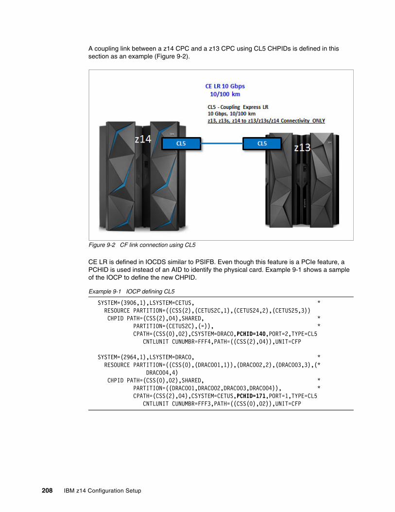
A coupling link between a z14 CPC and a z13 CPC using CL5 CHPIDs is defined in this section as an example (Figure 9-2).
Figure 9-2 CF link connection using CL5
CE LR is defined in IOCDS similar to PSIFB. Even though this feature is a PCIe feature, a PCHID is used instead of an AID to identify the physical card. Example 9-1 shows a sample of the IOCP to define the new CHPID.
Example 9-1 IOCP defining CL5
SYSTEM=(3906,1),LSYSTEM=CETUS, * RESOURCE PARTITION=((CSS(2),(CETUS2C,1),(CETUS24,2),(CETUS25,3)) CHPID PATH=(CSS(2),04),SHARED, * PARTITION=(CETUS2C),(=)), * CPATH=(CSS(0),02),CSYSTEM=DRACO,PCHID=140,PORT=2,TYPE=CL5 CNTLUNIT CUNUMBR=FFF4,PATH=((CSS(2),04)),UNIT=CFP
SYSTEM=(2964,1),LSYSTEM=DRACO, * RESOURCE PARTITION=((CSS(0),(DRACO01,1)),(DRACO02,2),(DRACO03,3),(* DRACO04,4) CHPID PATH=(CSS(0),02),SHARED, * PARTITION=((DRACO01,DRACO02,DRACO03,DRACO04)), * CPATH=(CSS(2),04),CSYSTEM=CETUS,PCHID=171,PORT=1,TYPE=CL5 CNTLUNIT CUNUMBR=FFF3,PATH=((CSS(0),02)),UNIT=CFP
208 IBM z14 Configuration Setup

The following sequence of steps shows how to define the coupling link connection between a z14 and a z13 using CL5 CHPIDs by using HCD:
1. From the main HCD panel, select option 1.3. Processor List. Enter s (work with attached channel paths) next to the first CPC (CETUS 3906) that you want to use to define the CL5 CHPID and press Enter.
2. From the Channel Subsystem List, Enter s (work with attached channel paths) next to the CSSID that you want to use. In our example, we use CSSID=2. Press Enter.
3. In the Channel Path List panel, press PF11 to add a channel.
4. In the Add Channel Path panel (Figure 9-3), add these settings for the instance: CHPID 04, type CL5, mode SHR, PCHID 140. Then, press Enter.
Figure 9-3 Adding CHPID CL5 on z14
5. In the Specify Coupling Pchid/Port Attribute panel (Figure 9-4), type for instance: port 2 and press Enter.
Figure 9-4 Specify port for CL5 on z14
Chapter 9. Defining Coupling Facility links 209
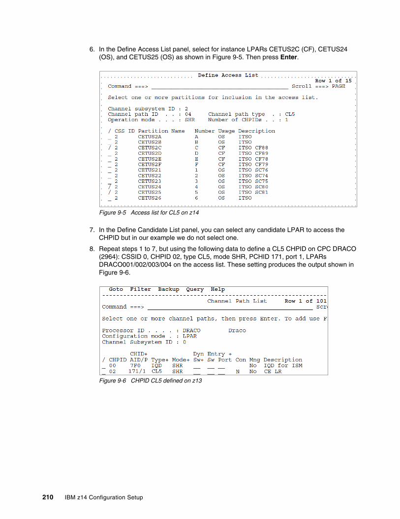
6. In the Define Access List panel, select for instance LPARs CETUS2C (CF), CETUS24 (OS), and CETUS25 (OS) as shown in Figure 9-5. Then press Enter.
Figure 9-5 Access list for CL5 on z14
7. In the Define Candidate List panel, you can select any candidate LPAR to access the CHPID but in our example we do not select one.
8. Repeat steps 1 to 7, but using the following data to define a CL5 CHPID on CPC DRACO (2964): CSSID 0, CHPID 02, type CL5, mode SHR, PCHID 171, port 1, LPARs DRACO001/002/003/004 on the access list. These setting produces the output shown in Figure 9-6.
Figure 9-6 CHPID CL5 defined on z13
210 IBM z14 Configuration Setup

9. To connect the CFlinks, enter the following values in the Connect to CF Channel Path panel (Figure 9-7) and press Enter:
– Destination processor ID: DRACO– Destination channel subsystem ID: 0– Destination channel path ID: 02.
Figure 9-7 Connecting CL5 CF links
10.After accepting or overriding the Control Unit and Device numbers for both processors, HCD returns to the CF Channel Path Connectivity List panel (Figure 9-8) where you can see that the CFlinks are now connected.
Figure 9-8 CL5 CF links connected
Chapter 9. Defining Coupling Facility links 211
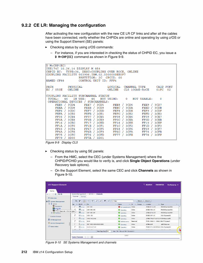
9.2.2 CE LR: Managing the configuration
After activating the new configuration with the new CE LR CF links and after all the cables have been connected, verify whether the CHPIDs are online and operating by using z/OS or using the Support Element (SE) panels:
� Checking status by using z/OS commands:
– For instance, if you are interested in checking the status of CHPID EC, you issue a D M=CHP(EC) command as shown in Figure 9-9.
Figure 9-9 Display CL5
� Checking status by using SE panels:
– From the HMC, select the CEC (under Systems Management) where the CHPID/PCHID you would like to verify is, and click Single Object Operations (under Recovery task options).
– On the Support Element, select the same CEC and click Channels as shown in Figure 9-10.
Figure 9-10 SE Systems Management and channels
212 IBM z14 Configuration Setup
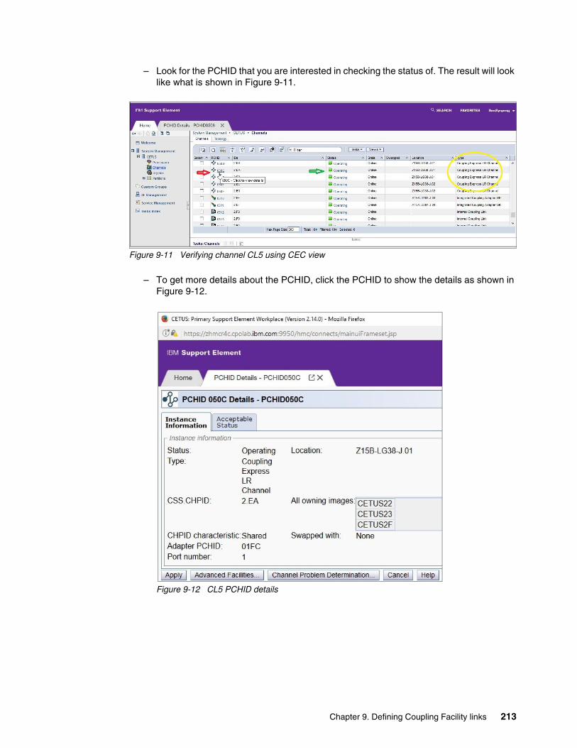
– Look for the PCHID that you are interested in checking the status of. The result will look like what is shown in Figure 9-11.
Figure 9-11 Verifying channel CL5 using CEC view
– To get more details about the PCHID, click the PCHID to show the details as shown in Figure 9-12.
Figure 9-12 CL5 PCHID details
Chapter 9. Defining Coupling Facility links 213
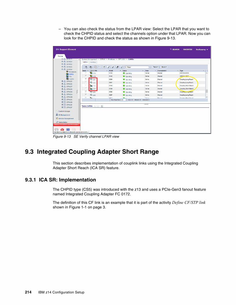
– You can also check the status from the LPAR view: Select the LPAR that you want to check the CHPID status and select the channels option under that LPAR. Now you can look for the CHPID and check the status as shown in Figure 9-13.
Figure 9-13 SE Verify channel LPAR view
9.3 Integrated Coupling Adapter Short Range
This section describes implementation of couplink links using the Integrated Coupling Adapter Short Reach (ICA SR) feature.
9.3.1 ICA SR: Implementation
The CHPID type (CS5) was introduced with the z13 and uses a PCIe-Gen3 fanout feature named Integrated Coupling Adapter FC 0172.
The definition of this CF link is an example that it is part of the activity Define CF/STP link shown in Figure 1-1 on page 3.
214 IBM z14 Configuration Setup
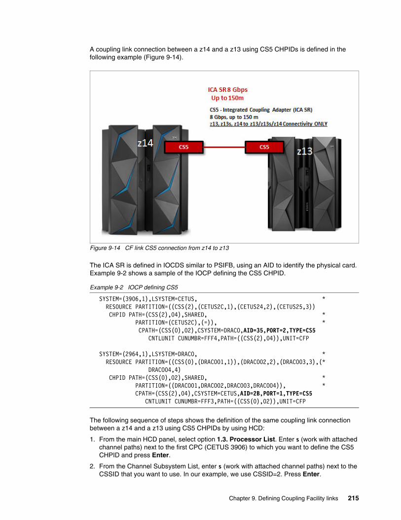
A coupling link connection between a z14 and a z13 using CS5 CHPIDs is defined in the following example (Figure 9-14).
Figure 9-14 CF link CS5 connection from z14 to z13
The ICA SR is defined in IOCDS similar to PSIFB, using an AID to identify the physical card. Example 9-2 shows a sample of the IOCP defining the CS5 CHPID.
Example 9-2 IOCP defining CS5
SYSTEM=(3906,1),LSYSTEM=CETUS, * RESOURCE PARTITION=((CSS(2),(CETUS2C,1),(CETUS24,2),(CETUS25,3)) CHPID PATH=(CSS(2),04),SHARED, * PARTITION=(CETUS2C),(=)), * CPATH=(CSS(0),02),CSYSTEM=DRACO,AID=35,PORT=2,TYPE=CS5 CNTLUNIT CUNUMBR=FFF4,PATH=((CSS(2),04)),UNIT=CFP
SYSTEM=(2964,1),LSYSTEM=DRACO, * RESOURCE PARTITION=((CSS(0),(DRACO01,1)),(DRACO02,2),(DRACO03,3),(* DRACO04,4) CHPID PATH=(CSS(0),02),SHARED, * PARTITION=((DRACO01,DRACO02,DRACO03,DRACO04)), * CPATH=(CSS(2),04),CSYSTEM=CETUS,AID=2B,PORT=1,TYPE=CS5 CNTLUNIT CUNUMBR=FFF3,PATH=((CSS(0),02)),UNIT=CFP
The following sequence of steps shows the definition of the same coupling link connection between a z14 and a z13 using CS5 CHPIDs by using HCD:
1. From the main HCD panel, select option 1.3. Processor List. Enter s (work with attached channel paths) next to the first CPC (CETUS 3906) to which you want to define the CS5 CHPID and press Enter.
2. From the Channel Subsystem List, enter s (work with attached channel paths) next to the CSSID that you want to use. In our example, we use CSSID=2. Press Enter.
Chapter 9. Defining Coupling Facility links 215
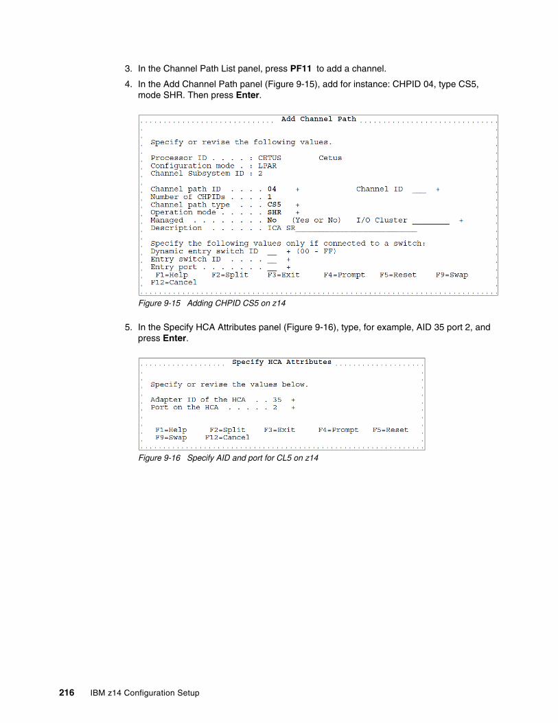
3. In the Channel Path List panel, press PF11 to add a channel.
4. In the Add Channel Path panel (Figure 9-15), add for instance: CHPID 04, type CS5, mode SHR. Then press Enter.
Figure 9-15 Adding CHPID CS5 on z14
5. In the Specify HCA Attributes panel (Figure 9-16), type, for example, AID 35 port 2, and press Enter.
Figure 9-16 Specify AID and port for CL5 on z14
216 IBM z14 Configuration Setup
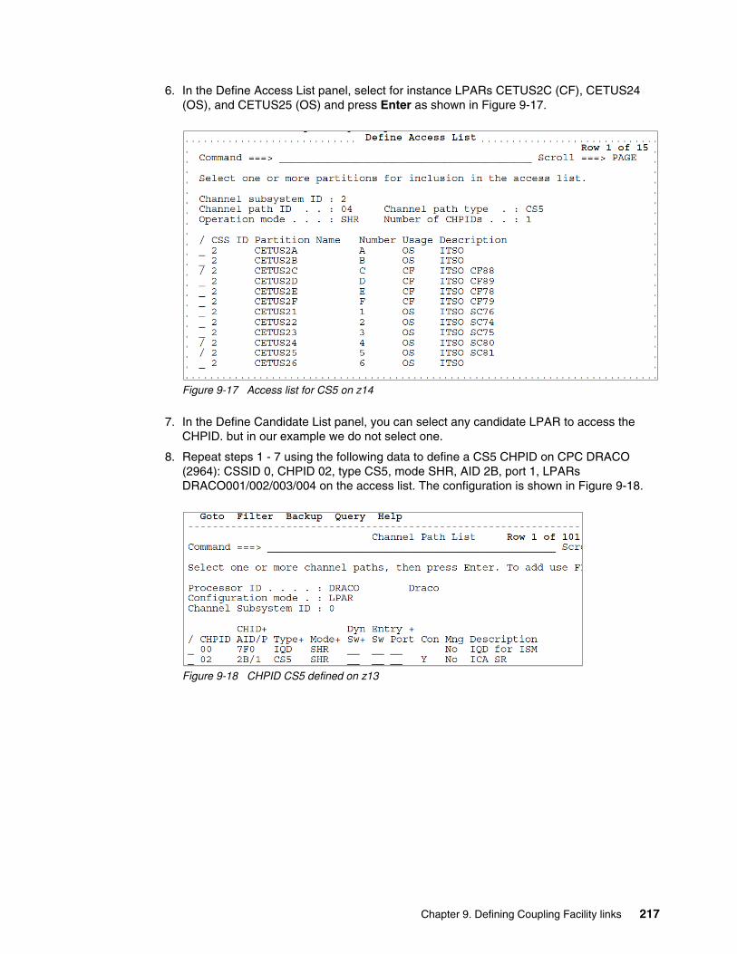
6. In the Define Access List panel, select for instance LPARs CETUS2C (CF), CETUS24 (OS), and CETUS25 (OS) and press Enter as shown in Figure 9-17.
Figure 9-17 Access list for CS5 on z14
7. In the Define Candidate List panel, you can select any candidate LPAR to access the CHPID. but in our example we do not select one.
8. Repeat steps 1 - 7 using the following data to define a CS5 CHPID on CPC DRACO (2964): CSSID 0, CHPID 02, type CS5, mode SHR, AID 2B, port 1, LPARs DRACO001/002/003/004 on the access list. The configuration is shown in Figure 9-18.
Figure 9-18 CHPID CS5 defined on z13
Chapter 9. Defining Coupling Facility links 217
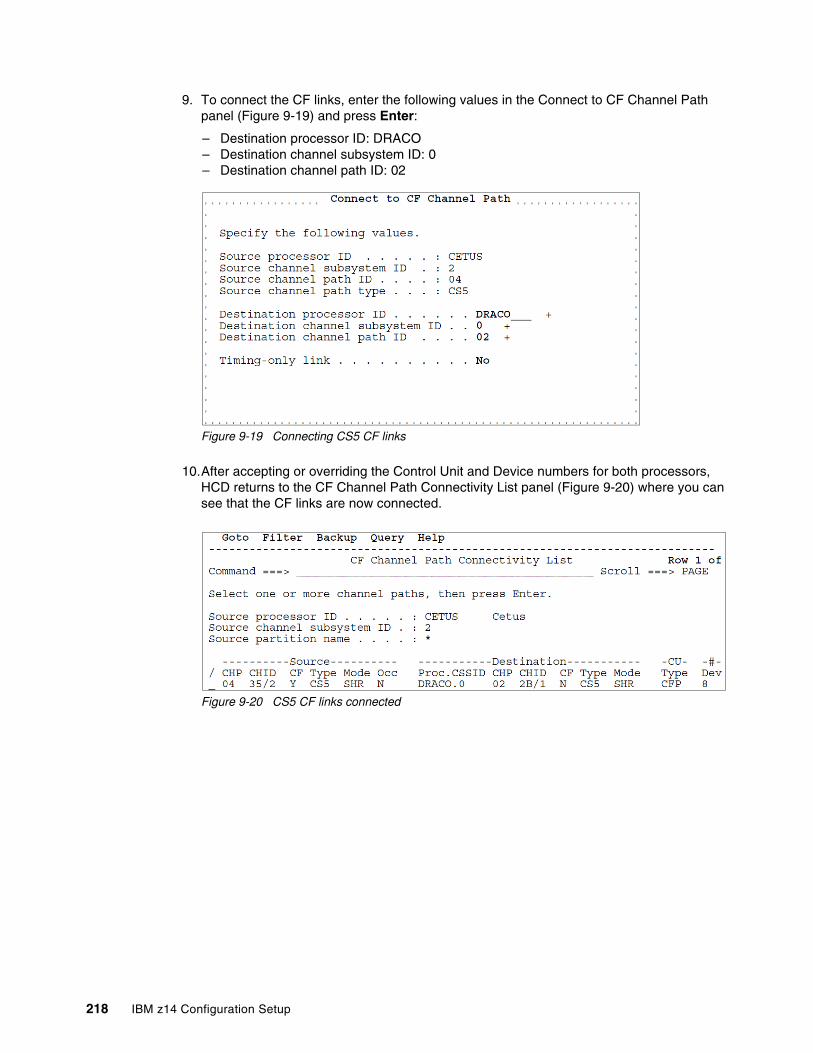
9. To connect the CF links, enter the following values in the Connect to CF Channel Path panel (Figure 9-19) and press Enter:
– Destination processor ID: DRACO– Destination channel subsystem ID: 0– Destination channel path ID: 02
Figure 9-19 Connecting CS5 CF links
10.After accepting or overriding the Control Unit and Device numbers for both processors, HCD returns to the CF Channel Path Connectivity List panel (Figure 9-20) where you can see that the CF links are now connected.
Figure 9-20 CS5 CF links connected
218 IBM z14 Configuration Setup
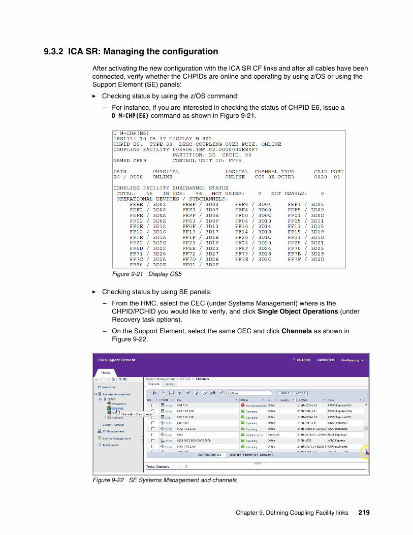
9.3.2 ICA SR: Managing the configuration
After activating the new configuration with the ICA SR CF links and after all cables have been connected, verify whether the CHPIDs are online and operating by using z/OS or using the Support Element (SE) panels:
� Checking status by using the z/OS command:
– For instance, if you are interested in checking the status of CHPID E6, issue a D M=CHP(E6) command as shown in Figure 9-21.
Figure 9-21 Display CS5
� Checking status by using SE panels:
– From the HMC, select the CEC (under Systems Management) where is the CHPID/PCHID you would like to verify, and click Single Object Operations (under Recovery task options).
– On the Support Element, select the same CEC and click Channels as shown in Figure 9-22.
Figure 9-22 SE Systems Management and channels
Chapter 9. Defining Coupling Facility links 219
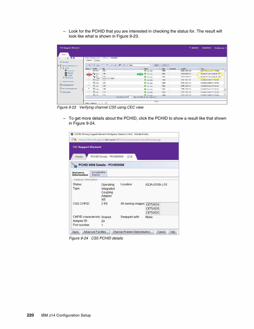
– Look for the PCHID that you are interested in checking the status for. The result will look like what is shown in Figure 9-23.
Figure 9-23 Verifying channel CS5 using CEC view
– To get more details about the PCHID, click the PCHID to show a result like that shown in Figure 9-24.
Figure 9-24 CS5 PCHID details
220 IBM z14 Configuration Setup

– Another option is to check the status from the LPAR view: Select the LPAR that you are interested in checking the CHPID status for, and select the Channels option under that LPAR. Now you can look for the CHPID and check the status as shown in Figure 9-25.
Figure 9-25 SE Verify channel LPAR view
9.4 Defining an STP timing-only link by using ICA SR
This section describes how to configure timing-links (for STP messages) over ICA SR connectivity.
9.4.1 STP timing only: Implementation
In this topic, a CHPID type (CS5) connection is used to show an example of STP timing-only link definition.
The definition of the STP timing-only link is part of the Define CF/STP link activity that is shown in Figure 1-1 on page 3.
Chapter 9. Defining Coupling Facility links 221
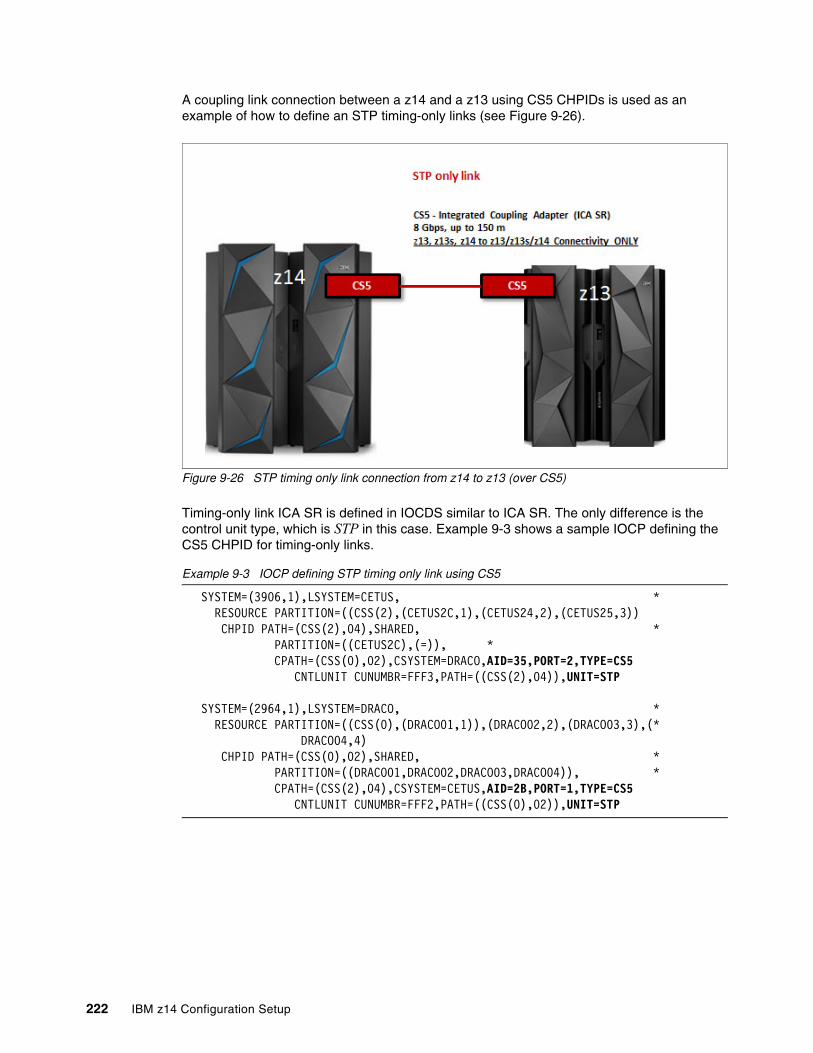
A coupling link connection between a z14 and a z13 using CS5 CHPIDs is used as an example of how to define an STP timing-only links (see Figure 9-26).
Figure 9-26 STP timing only link connection from z14 to z13 (over CS5)
Timing-only link ICA SR is defined in IOCDS similar to ICA SR. The only difference is the control unit type, which is STP in this case. Example 9-3 shows a sample IOCP defining the CS5 CHPID for timing-only links.
Example 9-3 IOCP defining STP timing only link using CS5
SYSTEM=(3906,1),LSYSTEM=CETUS, * RESOURCE PARTITION=((CSS(2),(CETUS2C,1),(CETUS24,2),(CETUS25,3)) CHPID PATH=(CSS(2),04),SHARED, * PARTITION=((CETUS2C),(=)), * CPATH=(CSS(0),02),CSYSTEM=DRACO,AID=35,PORT=2,TYPE=CS5 CNTLUNIT CUNUMBR=FFF3,PATH=((CSS(2),04)),UNIT=STP
SYSTEM=(2964,1),LSYSTEM=DRACO, * RESOURCE PARTITION=((CSS(0),(DRACO01,1)),(DRACO02,2),(DRACO03,3),(* DRACO04,4) CHPID PATH=(CSS(0),02),SHARED, * PARTITION=((DRACO01,DRACO02,DRACO03,DRACO04)), * CPATH=(CSS(2),04),CSYSTEM=CETUS,AID=2B,PORT=1,TYPE=CS5 CNTLUNIT CUNUMBR=FFF2,PATH=((CSS(0),02)),UNIT=STP
222 IBM z14 Configuration Setup

The sequence of steps to define the STP timing only link connection between a z14 and a z13 using CS5 CHPIDs by using HCD is the same as for defining the CFlinks to a connection using CS5 CHPIDs. Complete steps 1 - 8, described starting on step 1 on page 215, should be done:
� On the CF links connection step (step 9 on page 218), after including the data related to the CPC DRACO side of the connection, type YES on the Timing-only link option of the Connect to CF Channel Path panel (Figure 9-27) and press Enter.
Figure 9-27 STP timing only link from z14 to z13 by using CS5
� After accepting or overriding the Control Unit and Device numbers for both processors, HCD returns to the CF Channel Path Connectivity List panel (Figure 9-28). You can see that the STP timing only links are now connected.
Figure 9-28 STP Timing only links connected
9.4.2 STP timing-only links: Managing the configuration
After activating the new configuration with the ICA SR links defined as STP timing-only links and after all cables have been connected, verify whether the CHPIDs are online and operating by using z/OS or using the SE panels.
The same process that you have used for ICA SR links should be followed to check the status (online and operating) of the CS5 CHPIDs that were defined to work as STP timing-only links.
Complete the steps described in 9.3.2, “ICA SR: Managing the configuration” on page 219 using the respective CHPID/PCHID of the links you are interested in checking the status.
Chapter 9. Defining Coupling Facility links 223
9.5 CF LPAR setup and CFCC Level 22
The intention of this topic is only to remind you about some configuration aspects related to a Coupling Facility LPAR, such as THIN INTERRUPT, MODE, memory considerations due to the new CF Level, and the changes in CFCC Level 22.
As previously mentioned in the installation flow chart (Figure 1-1 on page 3), the following aspects must be considered for the activity Setup CF LPAR:
� THIN INTERRUPT
Using this enhancement can potentially improve the responsiveness of shared ICFs or CPs running CFCC in a test or development environment.
However, production environments should generally use dedicated ICFs or dedicated CPs.
� MODE
The default setting for a 3906 Coupling Facility Partition is Volatile. Ensure that plans are in place to set this setting to Non-volatile if required.
� Memory considerations
Memory planning must take into consideration the CFCC memory and structure size increases associated with a new level of the Coupling Facility Control Code (CFCC).
LPARS running the CFCC code might have increased storage requirements:
– CF Level 21 (or earlier) to CF Level 22– CFSizer Tool
Additionally, as in prior CF Levels, ensure that the CF LPAR has at least 512 MB storage for CFCC code.
9.5.1 Coupling Facility Level 22
The new CFCC Level 22 introduces changes/improvements in the following areas:
� Coupling Facility processor scalability
Coupling Facility work management and dispatcher changes to allow improved efficiency as additional processors are added to scale up the capacity of a CF image:
– Non-prioritized (FIFO-based) work queues
– Master/subordinate system-managed duplexing protocol Processor scalability for CF images with five or more dedicated processors
– Exploitation of improved z14 instruction set
– These changes automatically apply to all CF images on z14
� XCF/XES List Notification Enhancements:
– CF list structures support three notification mechanisms to inform exploiters about the status of shared objects in the CF: List. This information is used by many exploiters including XCF Signaling; Key-range (used predominantly by IBM WebSphere® MQ shared queues), and Sublist notification (used predominantly by IMS shared queues).
224 IBM z14 Configuration Setup

– CF exploiters have requested the following three enhancements to these existing notification mechanisms:
• Immediate/delayed round-robin notification for list and key-range notifications (requested by WebSphere MQ)
• Aggressive list and key-range notifications (requested by WebSphere MQ)
• List full/not-full notifications (requested by XCF Signaling)
Chapter 9. Defining Coupling Facility links 225

226 IBM z14 Configuration Setup
Chapter 10. Specialized features
This chapter covers the configuration of all specialized features available for IBM z14. It discusses the implementation of the following items:
� Crypto Express6S� zEnterprise Data Compression� Virtual Flash Memory� Shared Memory Communications over RDMA (SMC-R)� Shared Memory Communications - Direct Memory Access� IBM zHyperlink Express
10
© Copyright IBM Corp. 2017. All rights reserved. 227
10.1 Crypto Express6S
This section provides information about the configuration of the Crypto Express6S feature on an IBM z14. It covers cryptographic domains, configuration rules, and what to consider when you are planning for nondisruptive installation of cryptographic features.
The chapter includes the steps for defining and configuring the Crypto Express6S feature to a logical partition.
This section includes the following topics:
� Crypto Express6S overview� Planning for Crypto Express6S configuration� Configuring Crypto Express6S� Handling cryptographic coprocessors by using ICSF
10.1.1 Crypto Express6S overview
In a z14 server, two generations of cryptographic coprocessors1 are supported:
� Crypto Express5S, Feature Code #0890, carry forward only (MES from z13)� Crypto Express6S, Feature Code #0893
This section describes the Crypto Express6S feature, new with z14. For Crypto Express5S feature configuration (not changed from previous server generation (z13)), see IBM z13 Configuration Setup, SG24-8260.
With z14, each cryptographic coprocessor has 85 physical sets of registers or queue registers. This amount corresponds to the maximum number of LPARs running on a z14, which is also 85. Each of these 85 sets belongs to a domain as follows:
� A cryptographic domain index, in the range of 0 - 84, is allocated to a logical partition by the definition of the partition in its image profile. The same domain must also be allocated to the ICSF instance running in the logical partition that uses the Options data set.
� Each ICSF instance accesses only the Master Keys or queue registers corresponding to the domain number specified in the logical partition image profile at the Support Element and in its Options data set. Each ICSF instance sees a logical cryptographic coprocessor that consists of the physical cryptographic engine and the unique set of registers (the domain) allocated to this logical partition.
The installation of the CP Assist for Cryptographic Functions (CPACF) DES/TDES enablement, Feature Code #3863, is prerequisite for the Crypto Express6S feature. This feature enables these functions:
� For data privacy and confidentially: Data Encryption Standard (DES) includes single-length key DES, double-length key DES, and triple-length key DES (also known as triple DES), and Advanced Encryption Standard (AES) for 128-bit, 192-bit, and 256-bit keys.
� For data integrity: Secure Hash Algorithm-1 (SHA-1) 160-bit, and SHA-2 for 224-, 256-, 384-, and 512-bit support. SHA-3 for 224-, 256-, 384-, and 512-bit support, and SHAKE for 128-, and 256-bit support. SHA-1, SHA-2 and SHA3 are included enabled on all IBM z14s, and do not require the no-charge enablement feature #3863.
1 Regional Crypto Enablement is also supported, like on z13, but this topic is not covered here.
228 IBM z14 Configuration Setup
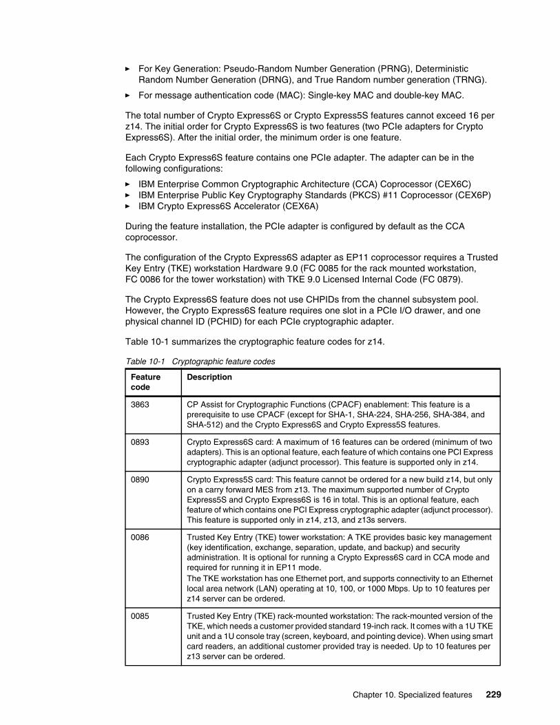
� For Key Generation: Pseudo-Random Number Generation (PRNG), Deterministic Random Number Generation (DRNG), and True Random number generation (TRNG).
� For message authentication code (MAC): Single-key MAC and double-key MAC.
The total number of Crypto Express6S or Crypto Express5S features cannot exceed 16 per z14. The initial order for Crypto Express6S is two features (two PCIe adapters for Crypto Express6S). After the initial order, the minimum order is one feature.
Each Crypto Express6S feature contains one PCIe adapter. The adapter can be in the following configurations:
� IBM Enterprise Common Cryptographic Architecture (CCA) Coprocessor (CEX6C) � IBM Enterprise Public Key Cryptography Standards (PKCS) #11 Coprocessor (CEX6P)� IBM Crypto Express6S Accelerator (CEX6A)
During the feature installation, the PCIe adapter is configured by default as the CCA coprocessor.
The configuration of the Crypto Express6S adapter as EP11 coprocessor requires a Trusted Key Entry (TKE) workstation Hardware 9.0 (FC 0085 for the rack mounted workstation, FC 0086 for the tower workstation) with TKE 9.0 Licensed Internal Code (FC 0879).
The Crypto Express6S feature does not use CHPIDs from the channel subsystem pool. However, the Crypto Express6S feature requires one slot in a PCIe I/O drawer, and one physical channel ID (PCHID) for each PCIe cryptographic adapter.
Table 10-1 summarizes the cryptographic feature codes for z14.
Table 10-1 Cryptographic feature codes
Feature code
Description
3863 CP Assist for Cryptographic Functions (CPACF) enablement: This feature is a prerequisite to use CPACF (except for SHA-1, SHA-224, SHA-256, SHA-384, and SHA-512) and the Crypto Express6S and Crypto Express5S features.
0893 Crypto Express6S card: A maximum of 16 features can be ordered (minimum of two adapters). This is an optional feature, each feature of which contains one PCI Express cryptographic adapter (adjunct processor). This feature is supported only in z14.
0890 Crypto Express5S card: This feature cannot be ordered for a new build z14, but only on a carry forward MES from z13. The maximum supported number of Crypto Express5S and Crypto Express6S is 16 in total. This is an optional feature, each feature of which contains one PCI Express cryptographic adapter (adjunct processor). This feature is supported only in z14, z13, and z13s servers.
0086 Trusted Key Entry (TKE) tower workstation: A TKE provides basic key management (key identification, exchange, separation, update, and backup) and security administration. It is optional for running a Crypto Express6S card in CCA mode and required for running it in EP11 mode. The TKE workstation has one Ethernet port, and supports connectivity to an Ethernet local area network (LAN) operating at 10, 100, or 1000 Mbps. Up to 10 features per z14 server can be ordered.
0085 Trusted Key Entry (TKE) rack-mounted workstation: The rack-mounted version of the TKE, which needs a customer provided standard 19-inch rack. It comes with a 1U TKE unit and a 1U console tray (screen, keyboard, and pointing device). When using smart card readers, an additional customer provided tray is needed. Up to 10 features per z13 server can be ordered.
Chapter 10. Specialized features 229
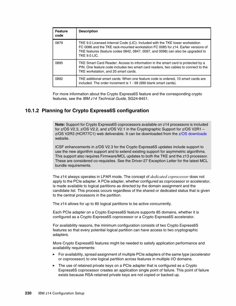
For more information about the Crypto Express6S feature and the corresponding crypto features, see the IBM z14 Technical Guide, SG24-8451.
10.1.2 Planning for Crypto Express6S configuration
The z14 always operates in LPAR mode. The concept of dedicated coprocessor does not apply to the PCIe adapter. A PCIe adapter, whether configured as coprocessor or accelerator, is made available to logical partitions as directed by the domain assignment and the candidate list. This process occurs regardless of the shared or dedicated status that is given to the central processors in the partition.
The z14 allows for up to 85 logical partitions to be active concurrently.
Each PCIe adapter on a Crypto Express6S feature supports 85 domains, whether it is configured as a Crypto Express6S coprocessor or a Crypto Express6S accelerator.
For availability reasons, the minimum configuration consists of two Crypto Express6S features so that every potential logical partition can have access to two cryptographic adapters.
More Crypto Express6S features might be needed to satisfy application performance and availability requirements:
� For availability, spread assignment of multiple PCIe adapters of the same type (accelerator or coprocessor) to one logical partition across features in multiple I/O domains.
� The use of retained private keys on a PCIe adapter that is configured as a Crypto Express6S coprocessor creates an application single point of failure. This point of failure exists because RSA-retained private keys are not copied or backed up.
0879 TKE 9.0 Licensed Internal Code (LIC): Included with the TKE tower workstation FC 0086 and the TKE rack-mounted workstation FC 0085 for z14. Earlier versions of TKE features (feature codes 0842, 0847, 0097, and 0098) can also be upgraded to TKE 9.0 LIC.
0895 TKE Smart Card Reader: Access to information in the smart card is protected by a PIN. One feature code includes two smart card readers, two cables to connect to the TKE workstation, and 20 smart cards.
0892 TKE additional smart cards: When one feature code is ordered, 10 smart cards are included. The order increment is 1 - 99 (990 blank smart cards).
Feature code
Description
Note: Support for Crypto Express6S coprocessors available on z14 processors is included for z/OS V2.3, z/OS V2.2, and z/OS V2.1 in the Cryptographic Support for z/OS V2R1 – z/OS V2R3 (HCR77C1) web deliverable. It can be downloaded from the z/OS downloads website.
ICSF enhancements in z/OS V2.3 for the Crypto Express6S updates include support to use the new algorithm support and to extend existing support for asymmetric algorithms. This support also requires Firmware/MCL updates to both the TKE and the z13 processor. These are considered co-requisites. See the Driver-27 Exception Letter for the latest MCL bundle requirements.
230 IBM z14 Configuration Setup
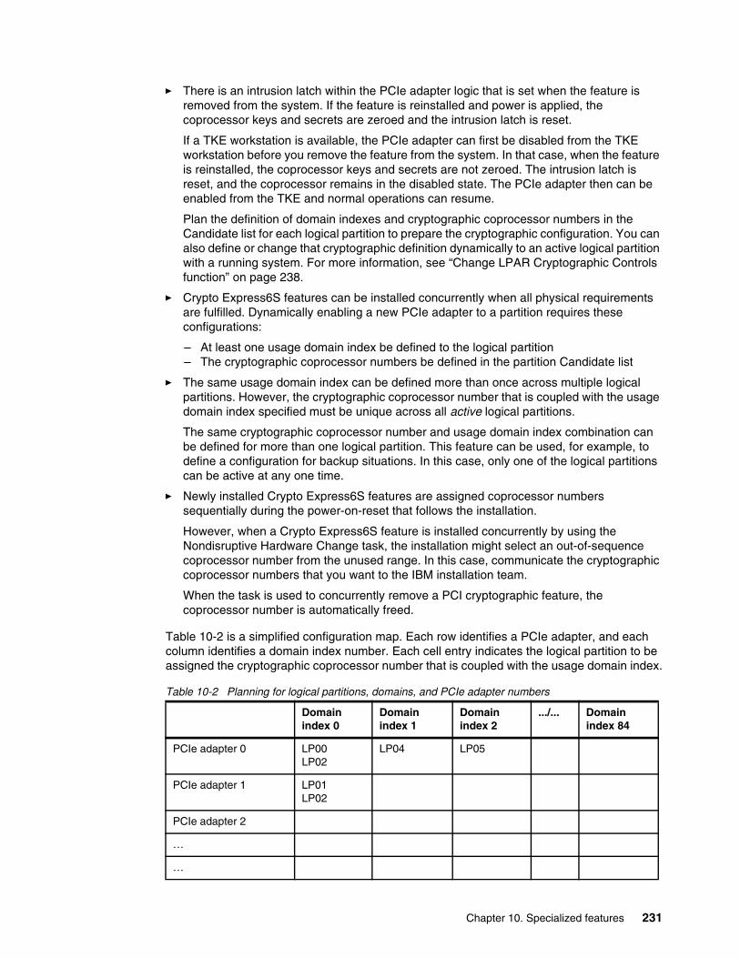
� There is an intrusion latch within the PCIe adapter logic that is set when the feature is removed from the system. If the feature is reinstalled and power is applied, the coprocessor keys and secrets are zeroed and the intrusion latch is reset.
If a TKE workstation is available, the PCIe adapter can first be disabled from the TKE workstation before you remove the feature from the system. In that case, when the feature is reinstalled, the coprocessor keys and secrets are not zeroed. The intrusion latch is reset, and the coprocessor remains in the disabled state. The PCIe adapter then can be enabled from the TKE and normal operations can resume.
Plan the definition of domain indexes and cryptographic coprocessor numbers in the Candidate list for each logical partition to prepare the cryptographic configuration. You can also define or change that cryptographic definition dynamically to an active logical partition with a running system. For more information, see “Change LPAR Cryptographic Controls function” on page 238.
� Crypto Express6S features can be installed concurrently when all physical requirements are fulfilled. Dynamically enabling a new PCIe adapter to a partition requires these configurations:
– At least one usage domain index be defined to the logical partition– The cryptographic coprocessor numbers be defined in the partition Candidate list
� The same usage domain index can be defined more than once across multiple logical partitions. However, the cryptographic coprocessor number that is coupled with the usage domain index specified must be unique across all active logical partitions.
The same cryptographic coprocessor number and usage domain index combination can be defined for more than one logical partition. This feature can be used, for example, to define a configuration for backup situations. In this case, only one of the logical partitions can be active at any one time.
� Newly installed Crypto Express6S features are assigned coprocessor numbers sequentially during the power-on-reset that follows the installation.
However, when a Crypto Express6S feature is installed concurrently by using the Nondisruptive Hardware Change task, the installation might select an out-of-sequence coprocessor number from the unused range. In this case, communicate the cryptographic coprocessor numbers that you want to the IBM installation team.
When the task is used to concurrently remove a PCI cryptographic feature, the coprocessor number is automatically freed.
Table 10-2 is a simplified configuration map. Each row identifies a PCIe adapter, and each column identifies a domain index number. Each cell entry indicates the logical partition to be assigned the cryptographic coprocessor number that is coupled with the usage domain index.
Table 10-2 Planning for logical partitions, domains, and PCIe adapter numbers
Domain index 0
Domain index 1
Domain index 2
.../... Domain index 84
PCIe adapter 0 LP00LP02
LP04 LP05
PCIe adapter 1 LP01LP02
PCIe adapter 2
…
…
Chapter 10. Specialized features 231
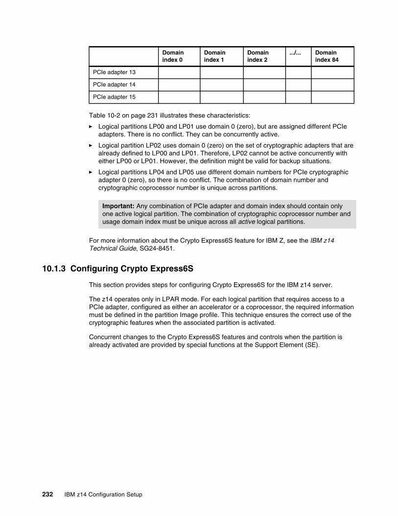
Table 10-2 on page 231 illustrates these characteristics:
� Logical partitions LP00 and LP01 use domain 0 (zero), but are assigned different PCIe adapters. There is no conflict. They can be concurrently active.
� Logical partition LP02 uses domain 0 (zero) on the set of cryptographic adapters that are already defined to LP00 and LP01. Therefore, LP02 cannot be active concurrently with either LP00 or LP01. However, the definition might be valid for backup situations.
� Logical partitions LP04 and LP05 use different domain numbers for PCIe cryptographic adapter 0 (zero), so there is no conflict. The combination of domain number and cryptographic coprocessor number is unique across partitions.
For more information about the Crypto Express6S feature for IBM Z, see the IBM z14 Technical Guide, SG24-8451.
10.1.3 Configuring Crypto Express6S
This section provides steps for configuring Crypto Express6S for the IBM z14 server.
The z14 operates only in LPAR mode. For each logical partition that requires access to a PCIe adapter, configured as either an accelerator or a coprocessor, the required information must be defined in the partition Image profile. This technique ensures the correct use of the cryptographic features when the associated partition is activated.
Concurrent changes to the Crypto Express6S features and controls when the partition is already activated are provided by special functions at the Support Element (SE).
PCIe adapter 13
PCIe adapter 14
PCIe adapter 15
Important: Any combination of PCIe adapter and domain index should contain only one active logical partition. The combination of cryptographic coprocessor number and usage domain index must be unique across all active logical partitions.
Domain index 0
Domain index 1
Domain index 2
.../... Domain index 84
232 IBM z14 Configuration Setup
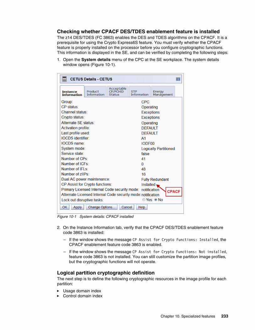
Checking whether CPACF DES/TDES enablement feature is installedThe z14 DES/TDES (FC 3863) enables the DES and TDES algorithms on the CPACF. It is a prerequisite for using the Crypto Express6S feature. You must verify whether the CPACF feature is properly installed on the processor before you configure cryptographic functions. This information is displayed in the SE, and can be verified by completing the following steps:
1. Open the System details menu of the CPC at the SE workplace. The system details window opens (Figure 10-1).
Figure 10-1 System details: CPACF installed
2. On the Instance Information tab, verify that the CPACF DES/TDES enablement feature code 3863 is installed:
– If the window shows the message CP Assist for Crypto Functions: Installed, the CPACF enablement feature code 3863 is enabled.
– If the window shows the message CP Assist for Crypto Functions: Not installed, feature code 3863 is not installed. You can still customize the partition image profiles, but the cryptographic functions will not operate.
Logical partition cryptographic definitionThe next step is to define the following cryptographic resources in the image profile for each partition:
� Usage domain index� Control domain index
Chapter 10. Specialized features 233

� PCI Cryptographic Coprocessor Candidate List� PCI Cryptographic Coprocessor Online List
This task is accomplished by using the Customize/Delete Activation Profile task, which is in the Operational Customization Group, either from the HMC or from the SE. Modify the cryptographic initial definition from the Crypto option in the image profile, as shown in Figure 10-2. After this definition is modified, any change to the image profile requires a DEACTIVATE and ACTIVATE of the logical partition for the change to take effect. Therefore, this kind of cryptographic definition is disruptive to a running system.
Figure 10-2 Customize Image Profiles: Crypto
The cryptographic resource definitions have the following meanings:
� Control Domain
Identifies the cryptographic coprocessor domains that can be administered from this logical partition if it is being set up as the TCP/IP host for the TKE.
If you are setting up the host TCP/IP in this logical partition to communicate with the TKE, the partition is used as a path to other domains’ Master Keys. Indicate all the control domains that you want to access (including this partition’s own control domain) from this partition.
Tip: Operational changes can be made by using the Change LPAR Cryptographic Controls task from the Support Element, which reflects the cryptographic definitions in the image profile for the partition. With this function, you can dynamically add and remove the cryptographic feature without stopping a running operating system. More information about using this function is in “Change LPAR Cryptographic Controls function” on page 238.
234 IBM z14 Configuration Setup
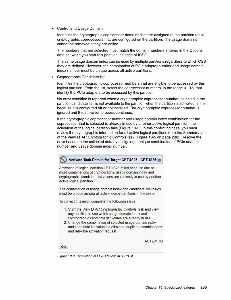
� Control and Usage Domain
Identifies the cryptographic coprocessor domains that are assigned to the partition for all cryptographic coprocessors that are configured on the partition. The usage domains cannot be removed if they are online.
The numbers that are selected must match the domain numbers entered in the Options data set when you start this partition instance of ICSF.
The same usage domain index can be used by multiple partitions regardless to which CSS they are defined. However, the combination of PCIe adapter number and usage domain index number must be unique across all active partitions.
� Cryptographic Candidate list
Identifies the cryptographic coprocessor numbers that are eligible to be accessed by this logical partition. From the list, select the coprocessor numbers, in the range 0 - 15, that identify the PCIe adapters to be accessed by this partition.
No error condition is reported when a cryptographic coprocessor number, selected in the partition candidate list, is not available to the partition when the partition is activated, either because it is configured off or not installed. The cryptographic coprocessor number is ignored and the activation process continues.
If the cryptographic coprocessor number and usage domain index combination for the coprocessor that is selected is already in use by another active logical partition, the activation of the logical partition fails (Figure 10-3). In this conflicting case, you must review the cryptographic information for all active logical partitions from the Summary tab of the View LPAR Cryptographic Controls task (Figure 10-5 on page 238). Resolve the error based on the collected data by assigning a unique combination of PCIe adapter number and usage domain index number.
Figure 10-3 Activation of LPAR failed: ACTZ01DD
Chapter 10. Specialized features 235

� Cryptographic Online list
Identifies the cryptographic coprocessor numbers that are automatically brought online during logical partition activation. The numbers that are selected in the online list must also be part of the candidate list.
After the next partition activation, installed PCI Cryptographic Coprocessors that are in the partition’s PCI Cryptographic Coprocessor Candidate list but not on the PCI Cryptographic Coprocessor Online list are in a configured off state (Standby). They can later be configured online to the partition by selecting Configure On/Off from the SE. For more information, see “Configuring a Crypto Express6S online or offline on a logical partition” on page 248.
When the partition is activated, no error condition is reported if a cryptographic coprocessor number selected in the partition’s online list is not installed. The cryptographic coprocessor is ignored and the activation process continues.
When a cryptographic coprocessor number selected in the partition’s online list was previously configured to an off state to the partition, it is automatically configured back to an on state when the partition is activated. The cryptographic online list is always selected from the image profile for each logical partition.
Cryptographic configuration using the Support ElementFrom the SE, you can do these tasks:
� Display PCI Cryptographic Configuration.
� Display LPAR cryptographic controls (domain index and candidate/online lists for currently activate partitions).
� Reconfigure the coprocessor from/to accelerator.
� Configure a cryptographic coprocessor and accelerator on/off to a logical partition.
� Change LPAR cryptographic controls to a logical partition.
These tasks require you to work from the SE. To get to the appropriate SE task, log on to the SE directly, or click Single Object Operations from the HMC.
Cryptographic managementAfter you select the CPCs, click Cryptographic Management in the Configuration section.
Figure 10-4 on page 237 shows the Cryptographic Management window. Use this window to obtain the installed cryptographic configuration (the association of the cryptographic number and the card serial number):
� View installed cryptographic features, with status and assigned PCHID and coprocessor numbers. Each PCI-X adapter is assigned to a coprocessor number, in the range 0 - 15, as part of the configuration process. The assignment is made when the feature is installed.
� View coprocessor numbers that are still assigned to removed cryptographic features.
� Initiate the release of coprocessor numbers. Remove the relationship only when a Crypto Express6S feature is permanently removed from the CPC.
The release option removes the relationship between a PCI cryptographic feature serial number and the assigned coprocessor numbers. Removing the relationship frees the coprocessor numbers, making them available to be assigned to a new feature serial number.
236 IBM z14 Configuration Setup
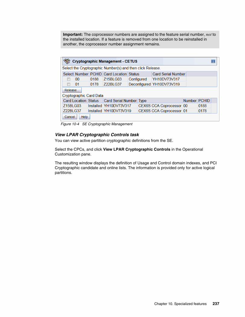
Figure 10-4 SE Cryptographic Management
View LPAR Cryptographic Controls taskYou can view active partition cryptographic definitions from the SE.
Select the CPCs, and click View LPAR Cryptographic Controls in the Operational Customization pane.
The resulting window displays the definition of Usage and Control domain indexes, and PCI Cryptographic candidate and online lists. The information is provided only for active logical partitions.
Important: The coprocessor numbers are assigned to the feature serial number, not to the installed location. If a feature is removed from one location to be reinstalled in another, the coprocessor number assignment remains.
Chapter 10. Specialized features 237
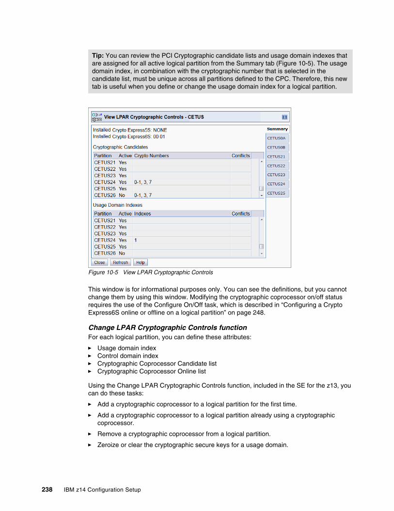
Figure 10-5 View LPAR Cryptographic Controls
This window is for informational purposes only. You can see the definitions, but you cannot change them by using this window. Modifying the cryptographic coprocessor on/off status requires the use of the Configure On/Off task, which is described in “Configuring a Crypto Express6S online or offline on a logical partition” on page 248.
Change LPAR Cryptographic Controls functionFor each logical partition, you can define these attributes:
� Usage domain index� Control domain index� Cryptographic Coprocessor Candidate list� Cryptographic Coprocessor Online list
Using the Change LPAR Cryptographic Controls function, included in the SE for the z13, you can do these tasks:
� Add a cryptographic coprocessor to a logical partition for the first time.
� Add a cryptographic coprocessor to a logical partition already using a cryptographic coprocessor.
� Remove a cryptographic coprocessor from a logical partition.
� Zeroize or clear the cryptographic secure keys for a usage domain.
Tip: You can review the PCI Cryptographic candidate lists and usage domain indexes that are assigned for all active logical partition from the Summary tab (Figure 10-5). The usage domain index, in combination with the cryptographic number that is selected in the candidate list, must be unique across all partitions defined to the CPC. Therefore, this new tab is useful when you define or change the usage domain index for a logical partition.
238 IBM z14 Configuration Setup
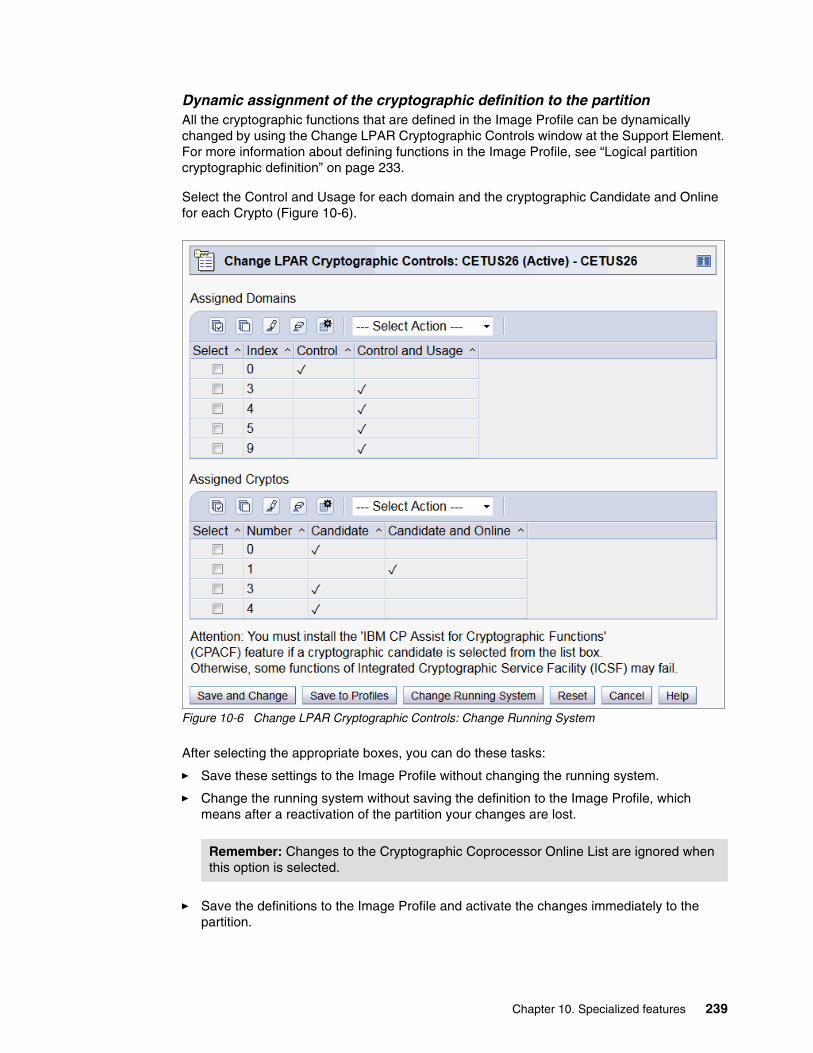
Dynamic assignment of the cryptographic definition to the partitionAll the cryptographic functions that are defined in the Image Profile can be dynamically changed by using the Change LPAR Cryptographic Controls window at the Support Element. For more information about defining functions in the Image Profile, see “Logical partition cryptographic definition” on page 233.
Select the Control and Usage for each domain and the cryptographic Candidate and Online for each Crypto (Figure 10-6).
Figure 10-6 Change LPAR Cryptographic Controls: Change Running System
After selecting the appropriate boxes, you can do these tasks:
� Save these settings to the Image Profile without changing the running system.
� Change the running system without saving the definition to the Image Profile, which means after a reactivation of the partition your changes are lost.
� Save the definitions to the Image Profile and activate the changes immediately to the partition.
Remember: Changes to the Cryptographic Coprocessor Online List are ignored when this option is selected.
Chapter 10. Specialized features 239
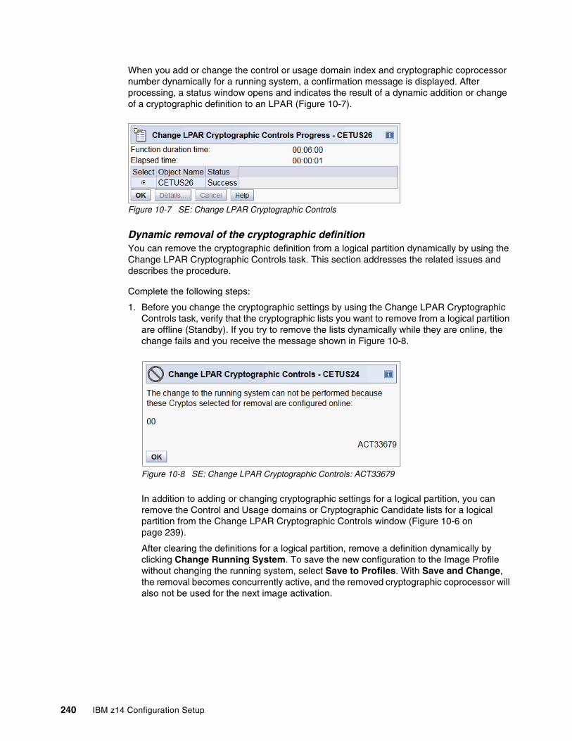
When you add or change the control or usage domain index and cryptographic coprocessor number dynamically for a running system, a confirmation message is displayed. After processing, a status window opens and indicates the result of a dynamic addition or change of a cryptographic definition to an LPAR (Figure 10-7).
Figure 10-7 SE: Change LPAR Cryptographic Controls
Dynamic removal of the cryptographic definitionYou can remove the cryptographic definition from a logical partition dynamically by using the Change LPAR Cryptographic Controls task. This section addresses the related issues and describes the procedure.
Complete the following steps:
1. Before you change the cryptographic settings by using the Change LPAR Cryptographic Controls task, verify that the cryptographic lists you want to remove from a logical partition are offline (Standby). If you try to remove the lists dynamically while they are online, the change fails and you receive the message shown in Figure 10-8.
Figure 10-8 SE: Change LPAR Cryptographic Controls: ACT33679
In addition to adding or changing cryptographic settings for a logical partition, you can remove the Control and Usage domains or Cryptographic Candidate lists for a logical partition from the Change LPAR Cryptographic Controls window (Figure 10-6 on page 239).
After clearing the definitions for a logical partition, remove a definition dynamically by clicking Change Running System. To save the new configuration to the Image Profile without changing the running system, select Save to Profiles. With Save and Change, the removal becomes concurrently active, and the removed cryptographic coprocessor will also not be used for the next image activation.
240 IBM z14 Configuration Setup

2. When you remove the only definition of the cryptographic lists, the zeroize window opens (Figure 10-9).
Figure 10-9 SE: Change LPAR Cryptographic Controls Zeroize
3. In the confirmation window (Figure 10-10), click OK to dynamically change the cryptographic settings. After processing, a status window indicates the result of the dynamic change of cryptographic definition to an LPAR.
Figure 10-10 SE: Change LPAR Cryptographic Controls: ACT33680
Reconfiguration of the PCIe Adapter typeEach PCIe Crypto Express6S feature can be configured either as a coprocessor or as an accelerator. Each Crypto Express6S feature can be set in these configurations:
� IBM Enterprise Common Cryptographic Architecture (CCA) Coprocessor (CEX6C)� IBM Enterprise Public Key Cryptography Standards #11 (PKCS) Coprocessor (CEX6P)� IBM Crypto Express6S Accelerator (CEX6A)
Consideration: Because you cannot see all cryptographic information, including the usage domains for other logical partitions, clear the zeroize selection by using the Change LPAR Cryptographic Controls task. For more information about zeroize, see “Reconfiguration of the PCIe Adapter type” on page 241.
Chapter 10. Specialized features 241
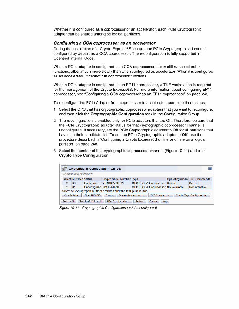
Whether it is configured as a coprocessor or an accelerator, each PCIe Cryptographic adapter can be shared among 85 logical partitions.
Configuring a CCA coprocessor as an acceleratorDuring the installation of a Crypto Express6S feature, the PCIe Cryptographic adapter is configured by default as a CCA coprocessor. The reconfiguration is fully supported in Licensed Internal Code.
When a PCIe adapter is configured as a CCA coprocessor, it can still run accelerator functions, albeit much more slowly than when configured as accelerator. When it is configured as an accelerator, it cannot run coprocessor functions.
When a PCIe adapter is configured as an EP11 coprocessor, a TKE workstation is required for the management of the Crypto Express6S. For more information about configuring EP11 coprocessor, see “Configuring a CCA coprocessor as an EP11 coprocessor” on page 245.
To reconfigure the PCIe Adapter from coprocessor to accelerator, complete these steps:
1. Select the CPC that has cryptographic coprocessor adapters that you want to reconfigure, and then click the Cryptographic Configuration task in the Configuration Group.
2. The reconfiguration is enabled only for PCIe adapters that are Off. Therefore, be sure that the PCIe Cryptographic adapter status for that cryptographic coprocessor channel is unconfigured. If necessary, set the PCIe Cryptographic adapter to Off for all partitions that have it in their candidate list. To set the PCIe Cryptographic adapter to Off, use the procedure described in “Configuring a Crypto Express6S online or offline on a logical partition” on page 248.
3. Select the number of the cryptographic coprocessor channel (Figure 10-11) and click Crypto Type Configuration.
Figure 10-11 Cryptographic Configuration task (unconfigured)
242 IBM z14 Configuration Setup
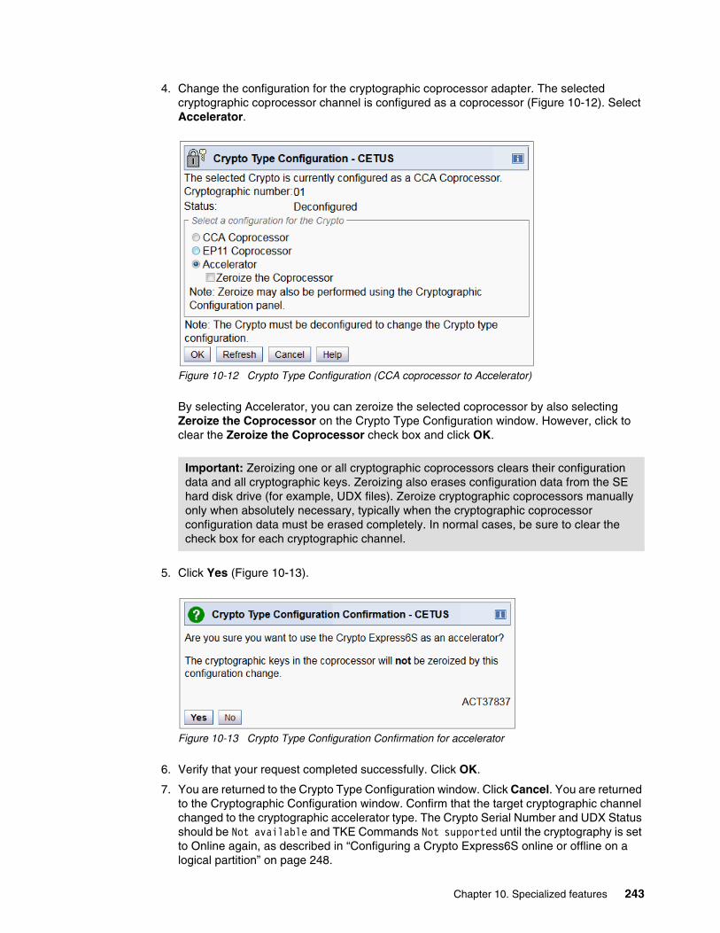
4. Change the configuration for the cryptographic coprocessor adapter. The selected cryptographic coprocessor channel is configured as a coprocessor (Figure 10-12). Select Accelerator.
Figure 10-12 Crypto Type Configuration (CCA coprocessor to Accelerator)
By selecting Accelerator, you can zeroize the selected coprocessor by also selecting Zeroize the Coprocessor on the Crypto Type Configuration window. However, click to clear the Zeroize the Coprocessor check box and click OK.
5. Click Yes (Figure 10-13).
Figure 10-13 Crypto Type Configuration Confirmation for accelerator
6. Verify that your request completed successfully. Click OK.
7. You are returned to the Crypto Type Configuration window. Click Cancel. You are returned to the Cryptographic Configuration window. Confirm that the target cryptographic channel changed to the cryptographic accelerator type. The Crypto Serial Number and UDX Status should be Not available and TKE Commands Not supported until the cryptography is set to Online again, as described in “Configuring a Crypto Express6S online or offline on a logical partition” on page 248.
Important: Zeroizing one or all cryptographic coprocessors clears their configuration data and all cryptographic keys. Zeroizing also erases configuration data from the SE hard disk drive (for example, UDX files). Zeroize cryptographic coprocessors manually only when absolutely necessary, typically when the cryptographic coprocessor configuration data must be erased completely. In normal cases, be sure to clear the check box for each cryptographic channel.
Chapter 10. Specialized features 243

After you perform this task and go back to the Cryptographic Configuration window, the information in Figure 10-14 is displayed.
Figure 10-14 Cryptographic Configuration (Accelerator online)
8. Click View Details for detailed information (Figure 10-15).
Figure 10-15 Cryptographic Details (Accelerator)
Note: UDX support is not available for Crypto Express6S defined as an EP11 coprocessor.
244 IBM z14 Configuration Setup
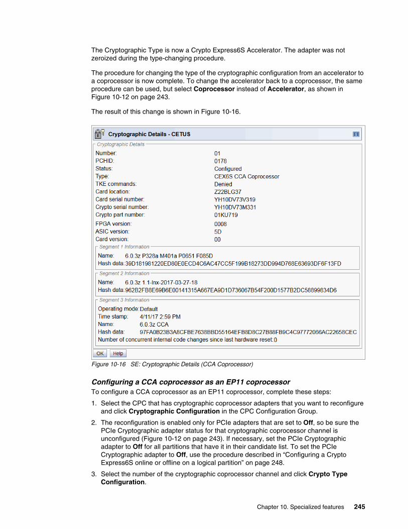
The Cryptographic Type is now a Crypto Express6S Accelerator. The adapter was not zeroized during the type-changing procedure.
The procedure for changing the type of the cryptographic configuration from an accelerator to a coprocessor is now complete. To change the accelerator back to a coprocessor, the same procedure can be used, but select Coprocessor instead of Accelerator, as shown in Figure 10-12 on page 243.
The result of this change is shown in Figure 10-16.
Figure 10-16 SE: Cryptographic Details (CCA Coprocessor)
Configuring a CCA coprocessor as an EP11 coprocessorTo configure a CCA coprocessor as an EP11 coprocessor, complete these steps:
1. Select the CPC that has cryptographic coprocessor adapters that you want to reconfigure and click Cryptographic Configuration in the CPC Configuration Group.
2. The reconfiguration is enabled only for PCIe adapters that are set to Off, so be sure the PCIe Cryptographic adapter status for that cryptographic coprocessor channel is unconfigured (Figure 10-12 on page 243). If necessary, set the PCIe Cryptographic adapter to Off for all partitions that have it in their candidate list. To set the PCIe Cryptographic adapter to Off, use the procedure described in “Configuring a Crypto Express6S online or offline on a logical partition” on page 248.
3. Select the number of the cryptographic coprocessor channel and click Crypto Type Configuration.
Chapter 10. Specialized features 245
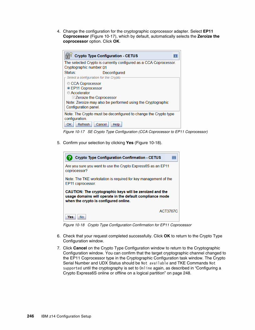
4. Change the configuration for the cryptographic coprocessor adapter. Select EP11 Coprocessor (Figure 10-17), which by default, automatically selects the Zeroize the coprocessor option. Click OK.
Figure 10-17 SE Crypto Type Configuration (CCA Coprocessor to EP11 Coprocessor)
5. Confirm your selection by clicking Yes (Figure 10-18).
Figure 10-18 Crypto Type Configuration Confirmation for EP11 Coprocessor
6. Check that your request completed successfully. Click OK to return to the Crypto Type Configuration window.
7. Click Cancel on the Crypto Type Configuration window to return to the Cryptographic Configuration window. You can confirm that the target cryptographic channel changed to the EP11 Coprocessor type in the Cryptographic Configuration task window. The Crypto Serial Number and UDX Status should be Not available and TKE Commands Not supported until the cryptography is set to Online again, as described in “Configuring a Crypto Express6S online or offline on a logical partition” on page 248.
246 IBM z14 Configuration Setup
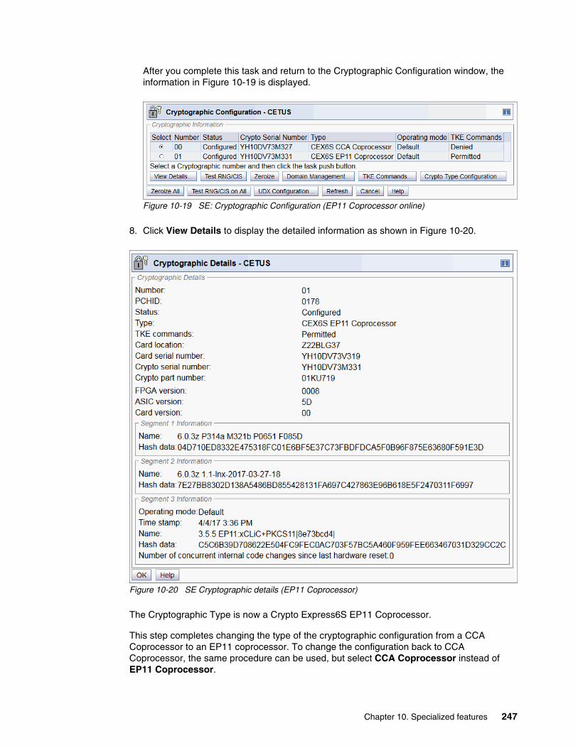
After you complete this task and return to the Cryptographic Configuration window, the information in Figure 10-19 is displayed.
Figure 10-19 SE: Cryptographic Configuration (EP11 Coprocessor online)
8. Click View Details to display the detailed information as shown in Figure 10-20.
Figure 10-20 SE Cryptographic details (EP11 Coprocessor)
The Cryptographic Type is now a Crypto Express6S EP11 Coprocessor.
This step completes changing the type of the cryptographic configuration from a CCA Coprocessor to an EP11 coprocessor. To change the configuration back to CCA Coprocessor, the same procedure can be used, but select CCA Coprocessor instead of EP11 Coprocessor.
Chapter 10. Specialized features 247
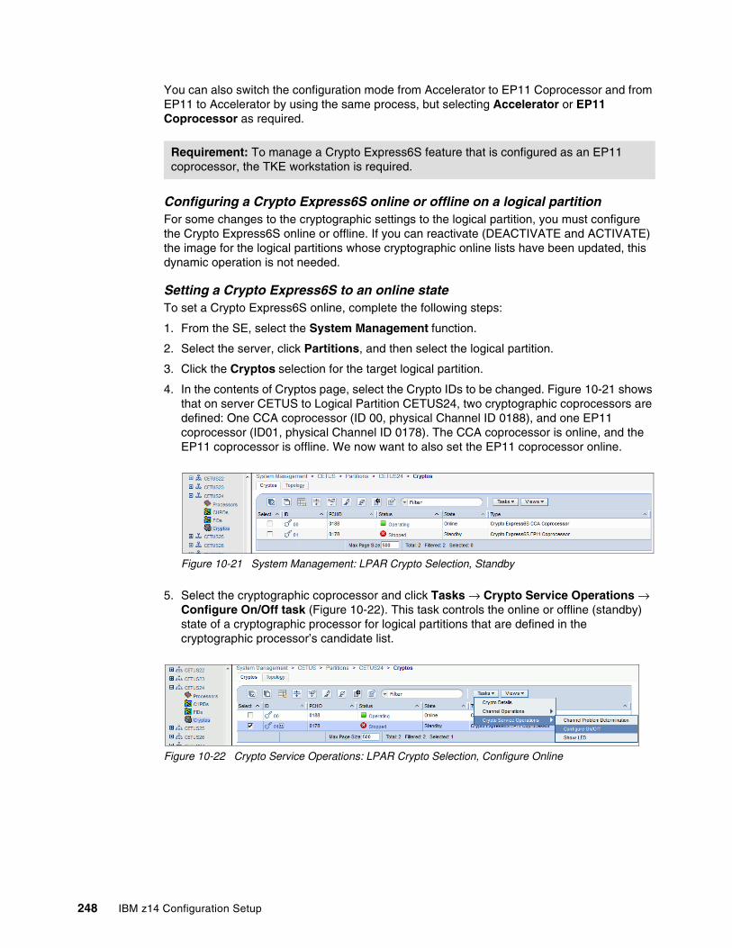
You can also switch the configuration mode from Accelerator to EP11 Coprocessor and from EP11 to Accelerator by using the same process, but selecting Accelerator or EP11 Coprocessor as required.
Configuring a Crypto Express6S online or offline on a logical partitionFor some changes to the cryptographic settings to the logical partition, you must configure the Crypto Express6S online or offline. If you can reactivate (DEACTIVATE and ACTIVATE) the image for the logical partitions whose cryptographic online lists have been updated, this dynamic operation is not needed.
Setting a Crypto Express6S to an online stateTo set a Crypto Express6S online, complete the following steps:
1. From the SE, select the System Management function.
2. Select the server, click Partitions, and then select the logical partition.
3. Click the Cryptos selection for the target logical partition.
4. In the contents of Cryptos page, select the Crypto IDs to be changed. Figure 10-21 shows that on server CETUS to Logical Partition CETUS24, two cryptographic coprocessors are defined: One CCA coprocessor (ID 00, physical Channel ID 0188), and one EP11 coprocessor (ID01, physical Channel ID 0178). The CCA coprocessor is online, and the EP11 coprocessor is offline. We now want to also set the EP11 coprocessor online.
Figure 10-21 System Management: LPAR Crypto Selection, Standby
5. Select the cryptographic coprocessor and click Tasks → Crypto Service Operations → Configure On/Off task (Figure 10-22). This task controls the online or offline (standby) state of a cryptographic processor for logical partitions that are defined in the cryptographic processor’s candidate list.
Figure 10-22 Crypto Service Operations: LPAR Crypto Selection, Configure Online
Requirement: To manage a Crypto Express6S feature that is configured as an EP11 coprocessor, the TKE workstation is required.
248 IBM z14 Configuration Setup

6. Select the cryptographic coprocessor channel number that you want, and then click Select Action → Toggle to switch from Standby to Online (Figure 10-23). If you want multiple cryptographic channels at the same time, select Toggle All On.
Figure 10-23 Config On/Off (Standby)
7. After confirming that your requested cryptographic coprocessor channel is set to the wanted state of Online, click OK (Figure 10-24).
Figure 10-24 Configure On/Off (Standby to Online)
8. Confirm that your request is completed (Figure 10-25). Click OK.
Figure 10-25 Configure On/Off (Standby to Online) completed
9. After you verify that the current state of the channels has changed to Online, click Cancel to return.
Chapter 10. Specialized features 249
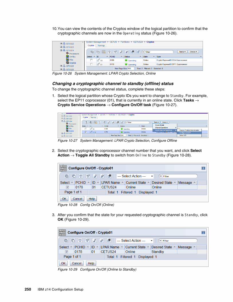
10.You can view the contents of the Cryptos window of the logical partition to confirm that the cryptographic channels are now in the Operating status (Figure 10-26).
Figure 10-26 System Management: LPAR Crypto Selection, Online
Changing a cryptographic channel to standby (offline) statusTo change the cryptographic channel status, complete these steps:
1. Select the logical partition whose Crypto IDs you want to change to Standby. For example, select the EP11 coprocessor (01), that is currently in an online state. Click Tasks → Crypto Service Operations → Configure On/Off task (Figure 10-27).
Figure 10-27 System Management: LPAR Crypto Selection, Configure Offline
2. Select the cryptographic coprocessor channel number that you want, and click Select Action → Toggle All Standby to switch from Online to Standby (Figure 10-28).
Figure 10-28 Config On/Off (Online)
3. After you confirm that the state for your requested cryptographic channel is Standby, click OK (Figure 10-29).
Figure 10-29 Configure On/Off (Online to Standby)
250 IBM z14 Configuration Setup

4. Because taking a cryptographic coprocessor offline can be disruptive to your application, a confirmation is required. The task must be confirmed by keying in the user password (Figure 10-30).
Figure 10-30 Configure On/Off (Online to Standby): Confirmation
5. Confirm that your request is completed (Figure 10-31). Click OK.
Figure 10-31 Config On/Off (Online to Standby) completed
10.1.4 Handling cryptographic coprocessors by using ICSF
Integrated cryptographic service facility (ICSF) provides an Interactive System Productivity Facility (ISPF) Coprocessor Management panel where you can display or change the status (Active or Deactivate) of cryptographic coprocessors. This action only affects the coprocessor status of ICSF, and has no effect on the Online/Standby hardware status that is displayed on the z14 Support Element.
It is not the purpose of this section to show how to create, load, and manage keys in the cryptographic adapters. For that information, see the ICSF literature. This section only shows how to activate and deactivate a cryptographic coprocessor, and how to display the hardware status.
Chapter 10. Specialized features 251

From the ICSF main panel (Figure 10-32), select option 1 to open the ICSF Coprocessor Management panel.
Figure 10-32 Integrated Cryptographic Support Facility main panel
Cryptographic coprocessors that are currently configured on the partition are listed in the ICSF Coprocessor Management panel (Figure 10-33).
Figure 10-33 ICSF Coprocessor Management
HCR77C0 -------------- Integrated Cryptographic Service Facility -------------OPTION ===> System Name: SC80 Crypto Domain: 1 Enter the number of the desired option. 1 COPROCESSOR MGMT - Management of Cryptographic Coprocessors 2 KDS MANAGEMENT - Master key set or change, KDS Processing 3 OPSTAT - Installation options 4 ADMINCNTL - Administrative Control Functions 5 UTILITY - ICSF Utilities 6 PPINIT - Pass Phrase Master Key/KDS Initialization 7 TKE - TKE PKA Direct Key Load 8 KGUP - Key Generator Utility processes 9 UDX MGMT - Management of User Defined Extensions Licensed Materials - Property of IBM 5650-ZOS Copyright IBM Corp. 1989, 2016. US Government Users Restricted Rights - Use, duplication or disclosure restricted by GSA ADP Schedule Contract with IBM Corp. Press ENTER to go to the selected option. Press END to exit to the previous menu.
------------------------- ICSF Coprocessor Management -------- Row 1 to 2 of 2 COMMAND ===> SCROLL ===> PAGE Select the cryptographic features to be processed and press ENTER. Action characters are: A, D, E, K, R, S and V. See the help panel for details. CRYPTO SERIAL FEATURE NUMBER STATUS AES DES ECC RSA P11 ------- -------- -------------------- --- --- --- --- --- . 5C00 DV73M327 Master key incorrect I U I U . 5P01 DV73M331 Active I ******************************* Bottom of data ********************************
252 IBM z14 Configuration Setup

When a coprocessor is configured offline to the logical partition from the SE (standby status), it is shown as Offline in the ICSF Coprocessor Management panel (Figure 10-34).
Figure 10-34 ICSF Coprocessor Management (Candidate only - Standby)
A cryptographic coprocessor becomes visible to ICSF Coprocessor Management when the coprocessor number is part of the partition candidate list and the coprocessor is first brought online to the partition in either of these ways:
� At the time the partition is activated, if the coprocessor is installed and the coprocessor number is part of the partition Online list.
� When the coprocessor is first configured online to the partition by using the Config On/Off task from the SE Workplace.
In the list (Figure 10-35), enter A or D to switch a coprocessor status to Active or Deactivated.
Figure 10-35 ICSF Coprocessor Management (Online)
------------------------- ICSF Coprocessor Management -------- Row 1 to 2 of 2 COMMAND ===> SCROLL ===> PAGE Select the cryptographic features to be processed and press ENTER. Action characters are: A, D, E, K, R, S and V. See the help panel for details. CRYPTO SERIAL FEATURE NUMBER STATUS AES DES ECC RSA P11 ------- -------- -------------------- --- --- --- --- --- . 5C00 DV73M327 Master key incorrect I U I U . 5P01 DV73M331 Offline ******************************* Bottom of data ********************************
------------------------- ICSF Coprocessor Management -------- Row 1 to 2 of 2 COMMAND ===> SCROLL ===> PAGE Select the cryptographic features to be processed and press ENTER. Action characters are: A, D, E, K, R, S and V. See the help panel for details. CRYPTO SERIAL FEATURE NUMBER STATUS AES DES ECC RSA P11 ------- -------- -------------------- --- --- --- --- --- . 5C00 DV73M327 Master key incorrect I U I U d 5P01 DV73M331 Active I ******************************* Bottom of data ********************************
Chapter 10. Specialized features 253
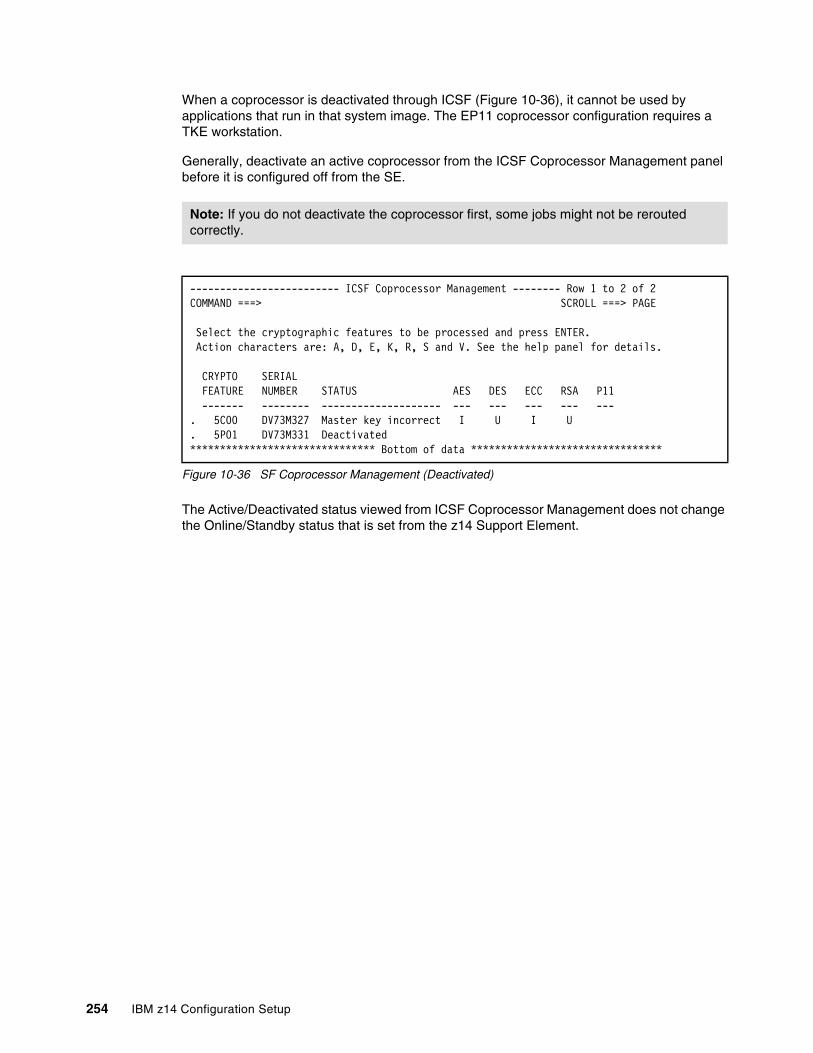
When a coprocessor is deactivated through ICSF (Figure 10-36), it cannot be used by applications that run in that system image. The EP11 coprocessor configuration requires a TKE workstation.
Generally, deactivate an active coprocessor from the ICSF Coprocessor Management panel before it is configured off from the SE.
Figure 10-36 SF Coprocessor Management (Deactivated)
The Active/Deactivated status viewed from ICSF Coprocessor Management does not change the Online/Standby status that is set from the z14 Support Element.
Note: If you do not deactivate the coprocessor first, some jobs might not be rerouted correctly.
------------------------- ICSF Coprocessor Management -------- Row 1 to 2 of 2 COMMAND ===> SCROLL ===> PAGE Select the cryptographic features to be processed and press ENTER. Action characters are: A, D, E, K, R, S and V. See the help panel for details. CRYPTO SERIAL FEATURE NUMBER STATUS AES DES ECC RSA P11 ------- -------- -------------------- --- --- --- --- --- . 5C00 DV73M327 Master key incorrect I U I U . 5P01 DV73M331 Deactivated ******************************* Bottom of data ********************************
254 IBM z14 Configuration Setup

Figure 10-37 shows ICSF Coprocessor Hardware Status panel.
Figure 10-37 ICSF Coprocessor Hardware Status
---------------------- ICSF - Coprocessor Hardware Status ---------------------COMMAND ===> SCROLL ===> CRYPTO DOMAIN: 1 REGISTER STATUS COPROCESSOR 5C00 More: + Crypto Serial Number : DV73M327 Status : MASTER KEY INCORRECT AES Master Key New Master Key register : EMPTY Verification pattern : Old Master Key register : EMPTY Verification pattern : Current Master Key register : EMPTY Verification pattern : DES Master Key New Master Key register : PART FULL Verification pattern : 150DABC954E60E9E Hash pattern : E729EFEC3DC43C33 : 5A1875E620DE9C53 Old Master Key register : EMPTY Verification pattern : Hash pattern : : Current Master Key register : EMPTY Verification pattern : Hash pattern : : ECC Master Key New Master Key register : EMPTY Verification pattern : Old Master Key register : EMPTY Verification pattern : Current Master Key register : EMPTY Verification pattern : RSA Master Key New Master Key register : EMPTY Verification pattern : : Old Master Key register : EMPTY Verification pattern : : Current Master Key register : EMPTY Verification pattern : :
Press ENTER to refresh the hardware status display.
Chapter 10. Specialized features 255
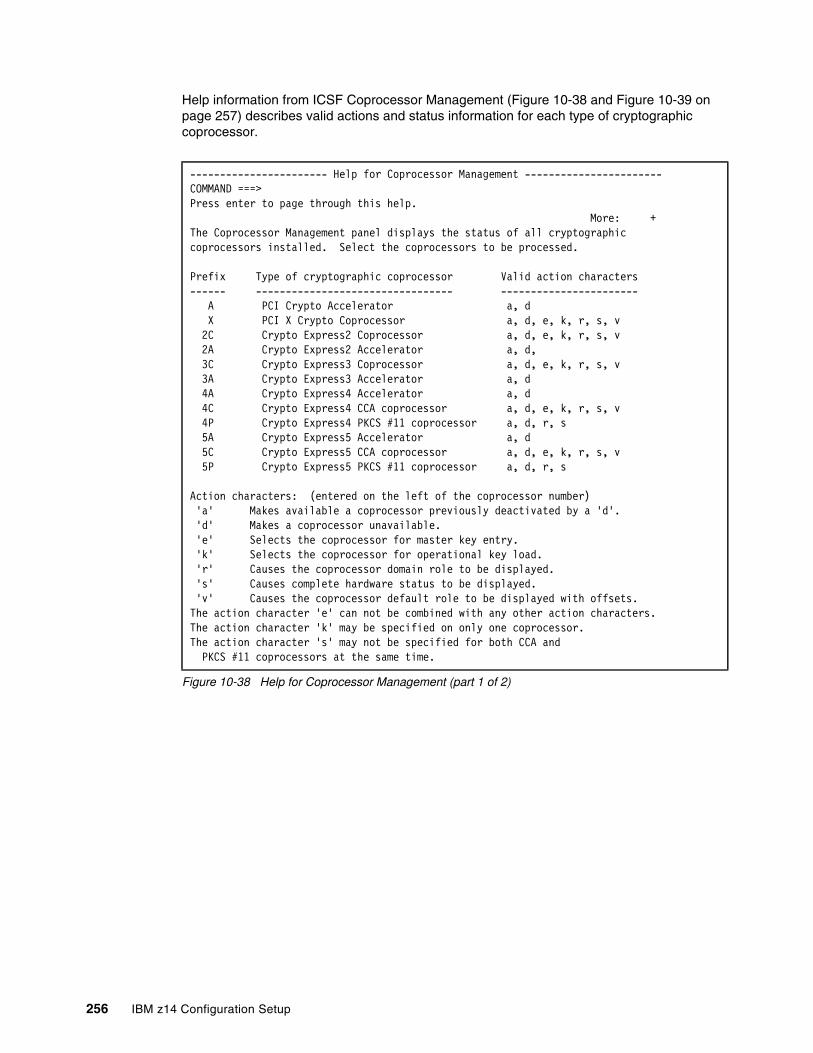
Help information from ICSF Coprocessor Management (Figure 10-38 and Figure 10-39 on page 257) describes valid actions and status information for each type of cryptographic coprocessor.
Figure 10-38 Help for Coprocessor Management (part 1 of 2)
----------------------- Help for Coprocessor Management -----------------------COMMAND ===> Press enter to page through this help. More: + The Coprocessor Management panel displays the status of all cryptographic coprocessors installed. Select the coprocessors to be processed. Prefix Type of cryptographic coprocessor Valid action characters ------ --------------------------------- ----------------------- A PCI Crypto Accelerator a, d X PCI X Crypto Coprocessor a, d, e, k, r, s, v 2C Crypto Express2 Coprocessor a, d, e, k, r, s, v 2A Crypto Express2 Accelerator a, d, 3C Crypto Express3 Coprocessor a, d, e, k, r, s, v 3A Crypto Express3 Accelerator a, d 4A Crypto Express4 Accelerator a, d 4C Crypto Express4 CCA coprocessor a, d, e, k, r, s, v 4P Crypto Express4 PKCS #11 coprocessor a, d, r, s 5A Crypto Express5 Accelerator a, d 5C Crypto Express5 CCA coprocessor a, d, e, k, r, s, v 5P Crypto Express5 PKCS #11 coprocessor a, d, r, s Action characters: (entered on the left of the coprocessor number) 'a' Makes available a coprocessor previously deactivated by a 'd'. 'd' Makes a coprocessor unavailable. 'e' Selects the coprocessor for master key entry. 'k' Selects the coprocessor for operational key load. 'r' Causes the coprocessor domain role to be displayed. 's' Causes complete hardware status to be displayed. 'v' Causes the coprocessor default role to be displayed with offsets. The action character 'e' can not be combined with any other action characters. The action character 'k' may be specified on only one coprocessor. The action character 's' may not be specified for both CCA and PKCS #11 coprocessors at the same time.
256 IBM z14 Configuration Setup

Figure 10-39 Help for Coprocessor Management (part 2 of 2)
Status: - Active: The feature is available for work. - Offline: The feature is installed but not available to ICSF. - Deactivated: The feature has been deactivated (see action characters) - Busy: The feature is temporarily busy. - Hardware error: The feature has been stopped. - Disabled by TKE: The feature has removed from service by a TKE workstation. - Master key incorrect: At least one master key is incorrect. - Being reconfigured: An error has been detected and being checked by the configuration task - Initializing stage 1: The feature has been detected by the configuration task. No status is available. - Initializing stage 2: The feature is being reset by the configuration task. No status is available. - Initializing stage 3: The feature is being readied by configuration task. No status is available. - Unknown response: The feature has returned a return/reason code combination that ICSF does not recognize. - Hung User on Feature: The feature is not responding. One or more users hold the feature latch. If this problem persists please take a dump and contact IBM service. You will need to recycle ICSF to reclaim use of the feature. - Bad feature response: An unexpected response was received from a feature. - Retry limit reached: Initialization of the feature failed. - Unknown feature type: A feature has a type that is not recognized by ICSF. - Unknown feature type: A feature has a type that is not recognized by ICSF. - Repeat failures: A feature has experienced repeated failures and recovered. The feature is made inactive and will require manual intervention to cause ICSF to attempt to use it again. Cryptographic Coprocessor Master Key State: A: Master key Verification Pattern matches the Key Store (CKDS, PKDS, or TKDS) and the master key is available for use C: Master key Verification Pattern matches the Key Store, but the master key is not available for use E: Master key Verification Pattern mismatch for Key Store or, for P11, no TKDS was specified in the options data set I: The Master key Verification Pattern in the Key Store is not set, so the contents of the Master key are Ignored U: Master key is not initialized -: Not supported : Not applicable F3 = END HELP
Chapter 10. Specialized features 257

10.2 zEnterprise Data Compression
This section provides information about the configuration of the zEnterprise Data Compression (zEDC) feature on an IBM z14. It covers the following topics:
� zEDC overview� Planning for zEDC configuration� Configuring zEDC� Handling zEDC
10.2.1 zEDC overview
The IBM zEDC Express is an optional feature available with the zEC12, zBC12, z13, z13s, and z14. It is designed to provide hardware-based acceleration for data compression and decompression.
The zEDC Express feature is a native PCIe I/O card that can be installed in the PCIe I/O drawer, up to two zEDC Express features per drawer domain. Between one and eight features can be installed on the system. There is one PCIe adapter/compression coprocessor per feature, and a zEDC Express feature can be shared by up to 15 LPARs.
For more information about the zEDC feature, see the IBM z14 Technical Guide, SG24-8451, and Reduce Storage Occupancy and Increase Operations Efficiency with IBM zEnterprise Data Compression, SG24-8259.
10.2.2 Planning for zEDC configuration
For details about planning, see 2.8.8, “Planning considerations for zEDC” on page 27.
10.2.3 Configuring zEDC
For information about configuring a zEDC card using HCD, see 15.2.3, “Defining a zEDC EXPRESS PCIe function” on page 395.
10.2.4 Handling zEDC
This section briefly describes how to handle the zEDC Express feature.
To verify that the IFAPRDxx member in your SYS1.PARMLIB concatenation is updated with the zEDC contents, use the D IQP command.
Example 10-1 shows the output of the D IQP command that shows the status of the software feature.
Example 10-1 Feature enablement
D IQP IQP066I 11.03.08 DISPLAY IQP 661 zEDC Information
Note: Schedule an IPL for every LPAR that you want zEDC active on. For more information, see Reduce Storage Occupancy and Increase Operations Efficiency with IBM zEnterprise Data Compression, SG24-8259.
258 IBM z14 Configuration Setup
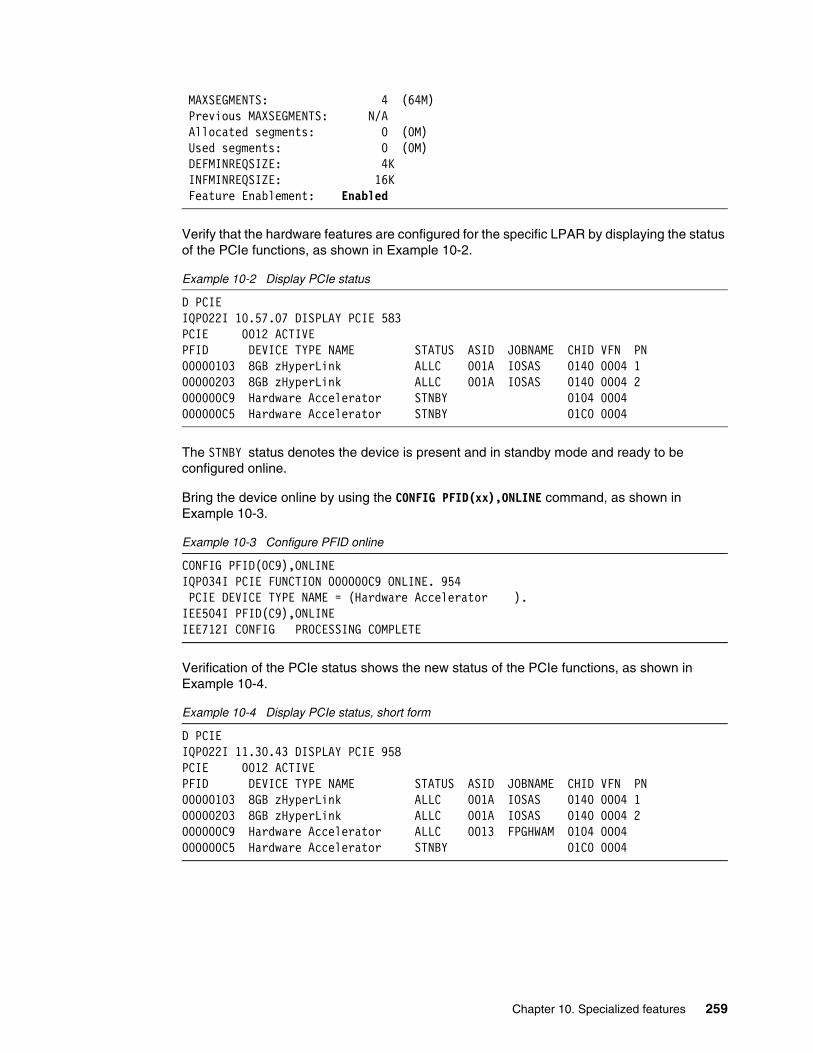
MAXSEGMENTS: 4 (64M) Previous MAXSEGMENTS: N/A Allocated segments: 0 (0M) Used segments: 0 (0M) DEFMINREQSIZE: 4K INFMINREQSIZE: 16K Feature Enablement: Enabled
Verify that the hardware features are configured for the specific LPAR by displaying the status of the PCIe functions, as shown in Example 10-2.
Example 10-2 Display PCIe status
D PCIE IQP022I 10.57.07 DISPLAY PCIE 583 PCIE 0012 ACTIVE PFID DEVICE TYPE NAME STATUS ASID JOBNAME CHID VFN PN00000103 8GB zHyperLink ALLC 001A IOSAS 0140 0004 1 00000203 8GB zHyperLink ALLC 001A IOSAS 0140 0004 2 000000C9 Hardware Accelerator STNBY 0104 0004 000000C5 Hardware Accelerator STNBY 01C0 0004
The STNBY status denotes the device is present and in standby mode and ready to be configured online.
Bring the device online by using the CONFIG PFID(xx),ONLINE command, as shown in Example 10-3.
Example 10-3 Configure PFID online
CONFIG PFID(0C9),ONLINE IQP034I PCIE FUNCTION 000000C9 ONLINE. 954 PCIE DEVICE TYPE NAME = (Hardware Accelerator ).IEE504I PFID(C9),ONLINE IEE712I CONFIG PROCESSING COMPLETE
Verification of the PCIe status shows the new status of the PCIe functions, as shown in Example 10-4.
Example 10-4 Display PCIe status, short form
D PCIE IQP022I 11.30.43 DISPLAY PCIE 958 PCIE 0012 ACTIVE PFID DEVICE TYPE NAME STATUS ASID JOBNAME CHID VFN PN00000103 8GB zHyperLink ALLC 001A IOSAS 0140 0004 1 00000203 8GB zHyperLink ALLC 001A IOSAS 0140 0004 2 000000C9 Hardware Accelerator ALLC 0013 FPGHWAM 0104 0004 000000C5 Hardware Accelerator STNBY 01C0 0004
Chapter 10. Specialized features 259
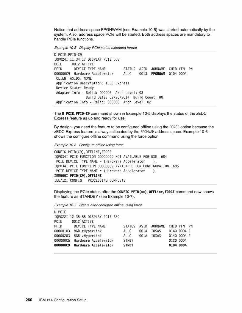
Notice that address space FPGHWAM (see Example 10-5) was started automatically by the system. Also, address space PCIe will be started. Both address spaces are mandatory to handle PCIe functions.
Example 10-5 Display PCIe status extended format
D PCIE,PFID=C9 IQP024I 11.34.17 DISPLAY PCIE 008 PCIE 0012 ACTIVE PFID DEVICE TYPE NAME STATUS ASID JOBNAME CHID VFN PN000000C9 Hardware Accelerator ALLC 0013 FPGHWAM 0104 0004 CLIENT ASIDS: NONE Application Description: zEDC Express Device State: Ready Adapter Info - Relid: 00000B Arch Level: 03 Build Date: 02/26/2014 Build Count: 00 Application Info - Relid: 000000 Arch Level: 02
The D PCIE,PFID=C9 command shown in Example 10-5 displays the status of the zEDC Express feature as up and ready for use.
By design, you need the feature to be configured offline using the FORCE option because the zEDC Express feature is always allocated by the FPGHWAM address space. Example 10-6 shows the configure offline command using the force option.
Example 10-6 Configure offline using force
CONFIG PFID(C9),OFFLINE,FORCE IQP034I PCIE FUNCTION 000000C9 NOT AVAILABLE FOR USE. 684 PCIE DEVICE TYPE NAME = (Hardware Accelerator ). IQP034I PCIE FUNCTION 000000C9 AVAILABLE FOR CONFIGURATION. 685 PCIE DEVICE TYPE NAME = (Hardware Accelerator ). IEE505I PFID(C9),OFFLINE IEE712I CONFIG PROCESSING COMPLETE
Displaying the PCIe status after the CONFIG PFID(xx),OFFLine,FORCE command now shows the feature as STANDBY (see Example 10-7).
Example 10-7 Status after configure offline using force
D PCIE IQP022I 12.35.55 DISPLAY PCIE 689 PCIE 0012 ACTIVE PFID DEVICE TYPE NAME STATUS ASID JOBNAME CHID VFN PN00000103 8GB zHyperLink ALLC 001A IOSAS 0140 0004 1 00000203 8GB zHyperLink ALLC 001A IOSAS 0140 0004 2 000000C5 Hardware Accelerator STNBY 01C0 0004 000000C9 Hardware Accelerator STNBY 0104 0004
260 IBM z14 Configuration Setup

10.3 Virtual Flash Memory
This section provides information about the configuration of the Virtual Flash Memory (VFM) feature on an IBM z14. It covers the following topics:
� VFM overview� Planning for VFM configuration� Configuring VFM� VFM management
10.3.1 VFM overview
IBM VFM is the replacement for the Flash Express features that were available on the IBM zEC12 and IBM z13. VFM is offering up to 6.0 TB of virtual flash memory in 1.5 TB increments. No application changes are required to change from IBM Flash Express to VFM.
IBM Virtual Flash Memory is designed to help improve availability and handling of paging workload spikes when running z/OS V2.1, V2.2, or V2.3, or on z/OS V1.13. With this support, z/OS is designed to help improve system availability and responsiveness by using VFM across transitional workload events such as market openings, and diagnostic data collection. z/OS is also designed to help improve processor performance by supporting middleware exploitation of pageable large (1 MB) pages.
Using VFM can help availability by reducing latency from paging delays that can occur at the start of the workday or during other transitional periods. It is also designed to help eliminate delays that can occur when collecting diagnostic data during failures. VFM can also be used in coupling facility images to provide extended capacity and availability for workloads making use of IBM WebSphere MQ Shared Queues structures.
vFM can help organizations meet their most demanding service level agreements and compete more effectively. VFM is designed to be easy to configure, and to provide rapid time to value.
For more information about the VFM feature, see the IBM z14 Technical Guide, SG24-8451.
10.3.2 Planning for VFM configuration
For planning considerations, see “Planning considerations for Virtual Flash Memory” on page 17.
10.3.3 Configuring VFM
The Assignment of VFM storage to LPARs is exclusively done with the definitions in the image activation profiles.
Note: Unlike the Flash Express cards, the allocation of VFM storage to LPARs cannot be altered to an activated LPAR. So the Manage Flash Allocation selection on the HMC is not supported for z14.
Chapter 10. Specialized features 261

Be aware of these considerations when you allocate Flash Express storage to a partition:
� When an allocation is first defined, you must set the initial and maximum allocation in 16 GB increments.
� An SCM allocation is put online to the z/OS image that is assigned to the partition at IPL time unless the z/OS image is configured not to do so.
� z/OS allows more memory to be configured online, up to the maximum GB defined in this window, or up the maximum VFM available and not used by other LPARs.
� Minimum amounts are allocated from the available pool, so they cannot be overallocated.
� Maximum amounts can be overallocated up to the VFM LICCC value of the z14.
� Maximum amounts must be greater than or equal to the initial amounts.
To allocate VFM storage to a partition, select the LPAR on the HMC and click Operational Customization → Customize/Delete Activation Profiles. Then, select the image profile and click Customize profile. The Initial and the Maximum values for the VFM are specified on the Storage tab. This configuration is shown in (Figure 10-40).
Figure 10-40 Flash Allocation in Image Profile
In this example, the initial value is set to 32 GB, and the maximum value is set to 64 GB. Note that the z14 has two VFM features installed, which allows a maximum of 3072 GB allocated to the LPAR.
These definitions will not change the settings of a running LPAR. They will only be used at the activation of the LPAR. A newly activated LPAR comes up with the specified amount of initial memory VFM storage online.
262 IBM z14 Configuration Setup

If in the image activation profile of an LPAR an amount of initial VFM storage greater than the available amount of deallocated VFM storage on the z14 is specified, the activation of this LPAR fails with message ACTZ01EB, as illustrated in Figure 10-41.
Figure 10-41 Insufficient VFM available, ACTZ01EB
10.3.4 VFM management
On the memory allocation of a z14 is shown on the SE in the Storage Information window. To view it, click the server and select Operational Customization → Storage Information. Then, the Base System Storage Allocation window is displayed, as shown in Figure 10-42.
Figure 10-42 Storage Information: Base System Storage Allocation
The z14 server in our examples (CETUS) has 3072 GB installed, of which 256 GB are allocated to activated LPARs.
Note: For a Coupling Facility LPAR, it is also possible to define an initial value and a higher maximum value for VFM in the image profile. However, it does not make sense to set the maximum value higher than the initial value because the CFCC does not support any command to set any reserved memory online.
Chapter 10. Specialized features 263
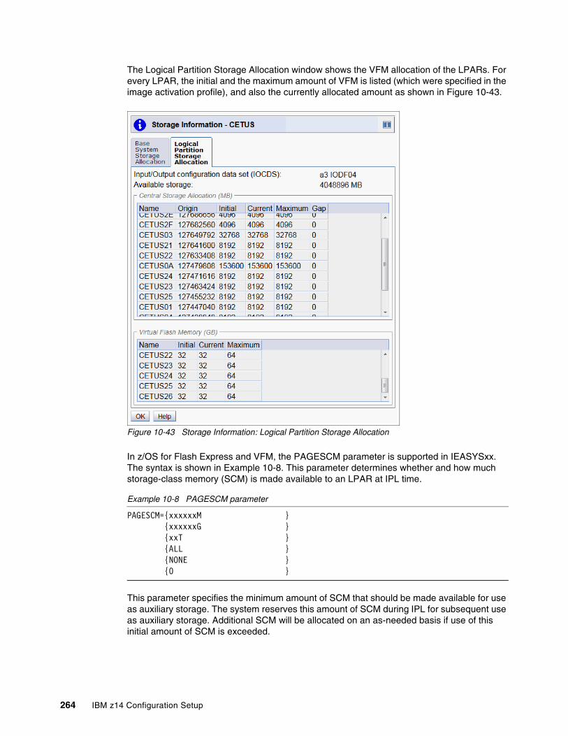
The Logical Partition Storage Allocation window shows the VFM allocation of the LPARs. For every LPAR, the initial and the maximum amount of VFM is listed (which were specified in the image activation profile), and also the currently allocated amount as shown in Figure 10-43.
Figure 10-43 Storage Information: Logical Partition Storage Allocation
In z/OS for Flash Express and VFM, the PAGESCM parameter is supported in IEASYSxx. The syntax is shown in Example 10-8. This parameter determines whether and how much storage-class memory (SCM) is made available to an LPAR at IPL time.
Example 10-8 PAGESCM parameter
PAGESCM={xxxxxxM } {xxxxxxG } {xxT } {ALL } {NONE } {0 }
This parameter specifies the minimum amount of SCM that should be made available for use as auxiliary storage. The system reserves this amount of SCM during IPL for subsequent use as auxiliary storage. Additional SCM will be allocated on an as-needed basis if use of this initial amount of SCM is exceeded.
264 IBM z14 Configuration Setup

You can specify the following value ranges for the PAGESCM parameter to reserve SCM for paging at IPL:
xxxxxxM Specifies the amount of SCM to reserve for paging at IPL, in megabytes. This value can be 1 - 6 decimal digits.
xxxxxxG Specifies the amount of SCM to reserve for paging at IPL, in gigabytes. This value can be 1 - 6 decimal digits.
xxT Specifies the amount of SCM to reserve for paging at IPL, in terabytes. This value can be 1 - 2 decimal digits. The maximum amount of SCM supported for paging is 16 TB.
ALL Reserves all SCM for paging at IPL.
NONE SCM is not used for paging. This parameter remains in effect until the next IPL.
0 | 0M | 0G | 0T Indicates that no SCM will be reserved for paging at IPL. Instead, SCM is allocated as needed, based on paging demand.
Default value ALL
Associated parmlib member: None
The CONFIG SCM command is used to configure SCM storage online or offline to an LPAR (Example 10-9).
Example 10-9 CONFIG SCM
CONFIG SCM(ddddddddM|G|T),ONLINE|ONCONFIG SCM(ddddddddM|G|T),OFFLINE|OFFCONFIG SCMscm_ranges,OFFLINE|OFF
The system reconfigures SCM, both logically and physically. To bring SCM online, an amount must be specified. To take SCM offline, a range of starting and ending addresses of the SCM blocks must be specified.
The command has the following values:
ddddddddM|G|T The amount of SCM to be reconfigured. Specify up to eight decimal digits followed by a multiplier (M=megabytes, G=gigabytes, or T=terabytes) for this amount. Check your processor configuration for the supported SCM increment sizes. The value for dddddddd must be a multiple of the SCM increment size (usually 2, 4, or 8), and cannot exceed 16T.
Instead of specifying a decimal amount, you can alternatively specify a hexadecimal amount, with or without a multiplier, in the following format:
X'xxxxxx'
For example:
X'123456789A00000'
X'123'M
You can use underscore characters in any hexadecimal specification for additional clarity. Underscore characters in the specification are ignored during processing.
Chapter 10. Specialized features 265
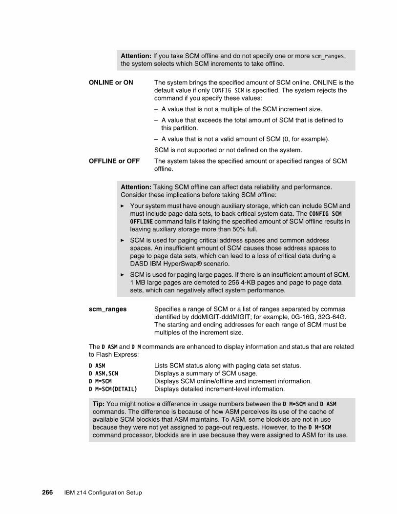
ONLINE or ON The system brings the specified amount of SCM online. ONLINE is the default value if only CONFIG SCM is specified. The system rejects the command if you specify these values:
– A value that is not a multiple of the SCM increment size.
– A value that exceeds the total amount of SCM that is defined to this partition.
– A value that is not a valid amount of SCM (0, for example).
SCM is not supported or not defined on the system.
OFFLINE or OFF The system takes the specified amount or specified ranges of SCM offline.
scm_ranges Specifies a range of SCM or a list of ranges separated by commas identified by dddM|G|T-dddM|G|T; for example, 0G-16G, 32G-64G. The starting and ending addresses for each range of SCM must be multiples of the increment size.
The D ASM and D M commands are enhanced to display information and status that are related to Flash Express:
D ASM Lists SCM status along with paging data set status.D ASM,SCM Displays a summary of SCM usage.D M=SCM Displays SCM online/offline and increment information.D M=SCM(DETAIL) Displays detailed increment-level information.
Attention: If you take SCM offline and do not specify one or more scm_ranges, the system selects which SCM increments to take offline.
Attention: Taking SCM offline can affect data reliability and performance. Consider these implications before taking SCM offline:
� Your system must have enough auxiliary storage, which can include SCM and must include page data sets, to back critical system data. The CONFIG SCM OFFLINE command fails if taking the specified amount of SCM offline results in leaving auxiliary storage more than 50% full.
� SCM is used for paging critical address spaces and common address spaces. An insufficient amount of SCM causes those address spaces to page to page data sets, which can lead to a loss of critical data during a DASD IBM HyperSwap® scenario.
� SCM is used for paging large pages. If there is an insufficient amount of SCM, 1 MB large pages are demoted to 256 4-KB pages and page to page data sets, which can negatively affect system performance.
Tip: You might notice a difference in usage numbers between the D M=SCM and D ASM commands. The difference is because of how ASM perceives its use of the cache of available SCM blockids that ASM maintains. To ASM, some blockids are not in use because they were not yet assigned to page-out requests. However, to the D M=SCM command processor, blockids are in use because they were assigned to ASM for its use.
266 IBM z14 Configuration Setup

VFM storage can also be used by coupling facility LPARs running CFCC Level 22 on z14, just like Flash Express storage could be used by coupling facility LPARs running CFCC Level 19 (on zEC12) or CFCC Level 20 or 21 (on zEC13). Systems without this support cannot connect to or rebuild a structure using SCM storage.
In 10.3.3, “Configuring VFM” on page 261 we allocated an initial VFM storage of 32 GB to the LPAR CETUS24, and a maximum VFM storage of 64 GB. See Figure 10-40 on page 262. Now, from CETUS24 running the z/OS image SC80, we issue the IBM MVS™ D IPLINFO,PAGESCM command. Example 10-10 shows the results.
Example 10-10 D IPLINFO,PAGESCM
D IPLINFO,PAGESCM IEE255I SYSTEM PARAMETER 'PAGESCM': NOT_SPECIFIED
Because no PAGESCM parameter is specified, the default value of ALL is used (reserves all SCM for paging at IPL time). If a VFM storage allocation is defined for the LPAR and PAGESCM=ALL is specified (or kept at the default), then at IPL time, the initial amount of VFM storage specified is used automatically by z/OS for paging. Likewise, if a specific amount is specified, this amount is made available for paging.
From SC80, run the enhanced D ASM and D M commands to display Flash Express SCM-related information and status. The result for each command is shown in Example 10-11.
Example 10-11 Display commands
D ASM IEE200I 17.39.48 DISPLAY ASM 023TYPE FULL STAT DEV DATASET NAMEPLPA 56% OK 9916 PAGE.SC80.PLPACOMMON 0% OK 9916 PAGE.SC80.COMMONLOCAL 0% OK 9916 PAGE.SC80.LOCAL1LOCAL 0% OK 803D PAGE.SC80.LOCAL2SCM 0% OK N/A N/APAGEDEL COMMAND IS NOT ACTIVE
D ASM,SCM IEE207I 17.41.33 DISPLAY ASM 025 STATUS FULL SIZE USED IN-ERROR IN-USE 0% 8,388,608 20,055 0
D M=SCM IEE174I 17.42.10 DISPLAY M 027STORAGE-CLASS MEMORY STATUS64G DEFINEDONLINE0G-32G32G OFFLINE-AVAILABLE0% IN USESCM INCREMENT SIZE IS 16G
D M=SCM(DETAIL) IEE174I 17.43.46 DISPLAY M 029 STORAGE-CLASS MEMORY STATUS - INCREMENT DETAIL 64G DEFINED ADDRESS IN USE STATUS
Chapter 10. Specialized features 267
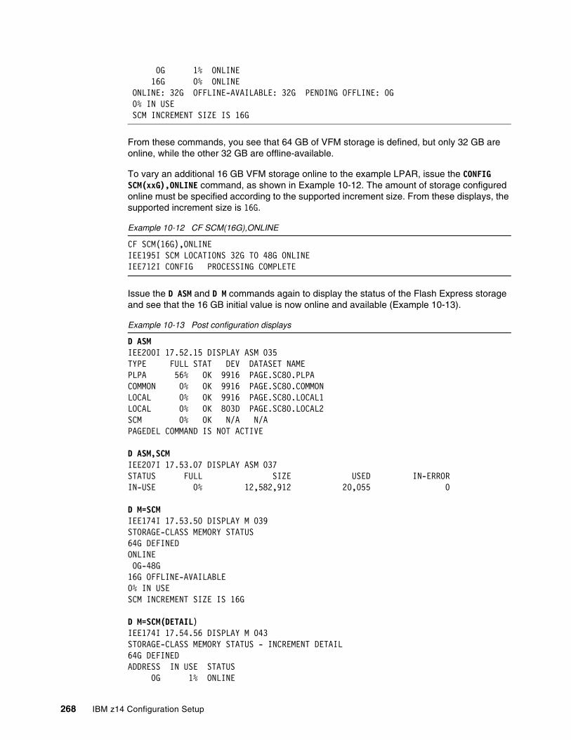
0G 1% ONLINE 16G 0% ONLINE ONLINE: 32G OFFLINE-AVAILABLE: 32G PENDING OFFLINE: 0G 0% IN USE SCM INCREMENT SIZE IS 16G
From these commands, you see that 64 GB of VFM storage is defined, but only 32 GB are online, while the other 32 GB are offline-available.
To vary an additional 16 GB VFM storage online to the example LPAR, issue the CONFIG SCM(xxG),ONLINE command, as shown in Example 10-12. The amount of storage configured online must be specified according to the supported increment size. From these displays, the supported increment size is 16G.
Example 10-12 CF SCM(16G),ONLINE
CF SCM(16G),ONLINE IEE195I SCM LOCATIONS 32G TO 48G ONLINEIEE712I CONFIG PROCESSING COMPLETE
Issue the D ASM and D M commands again to display the status of the Flash Express storage and see that the 16 GB initial value is now online and available (Example 10-13).
Example 10-13 Post configuration displays
D ASM IEE200I 17.52.15 DISPLAY ASM 035TYPE FULL STAT DEV DATASET NAMEPLPA 56% OK 9916 PAGE.SC80.PLPACOMMON 0% OK 9916 PAGE.SC80.COMMONLOCAL 0% OK 9916 PAGE.SC80.LOCAL1LOCAL 0% OK 803D PAGE.SC80.LOCAL2SCM 0% OK N/A N/APAGEDEL COMMAND IS NOT ACTIVE
D ASM,SCM IEE207I 17.53.07 DISPLAY ASM 037STATUS FULL SIZE USED IN-ERRORIN-USE 0% 12,582,912 20,055 0
D M=SCM IEE174I 17.53.50 DISPLAY M 039STORAGE-CLASS MEMORY STATUS64G DEFINEDONLINE0G-48G16G OFFLINE-AVAILABLE0% IN USESCM INCREMENT SIZE IS 16G
D M=SCM(DETAIL) IEE174I 17.54.56 DISPLAY M 043STORAGE-CLASS MEMORY STATUS - INCREMENT DETAIL64G DEFINEDADDRESS IN USE STATUS 0G 1% ONLINE
268 IBM z14 Configuration Setup
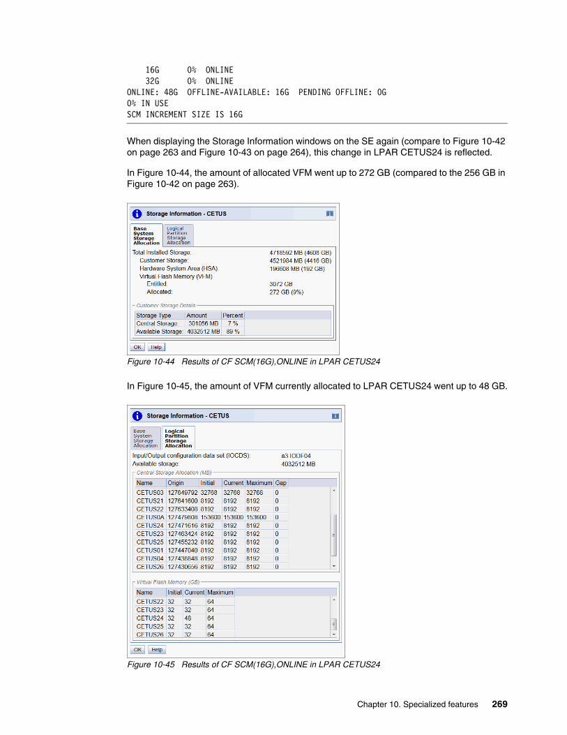
16G 0% ONLINE 32G 0% ONLINEONLINE: 48G OFFLINE-AVAILABLE: 16G PENDING OFFLINE: 0G0% IN USESCM INCREMENT SIZE IS 16G
When displaying the Storage Information windows on the SE again (compare to Figure 10-42 on page 263 and Figure 10-43 on page 264), this change in LPAR CETUS24 is reflected.
In Figure 10-44, the amount of allocated VFM went up to 272 GB (compared to the 256 GB in Figure 10-42 on page 263).
Figure 10-44 Results of CF SCM(16G),ONLINE in LPAR CETUS24
In Figure 10-45, the amount of VFM currently allocated to LPAR CETUS24 went up to 48 GB.
Figure 10-45 Results of CF SCM(16G),ONLINE in LPAR CETUS24
Chapter 10. Specialized features 269
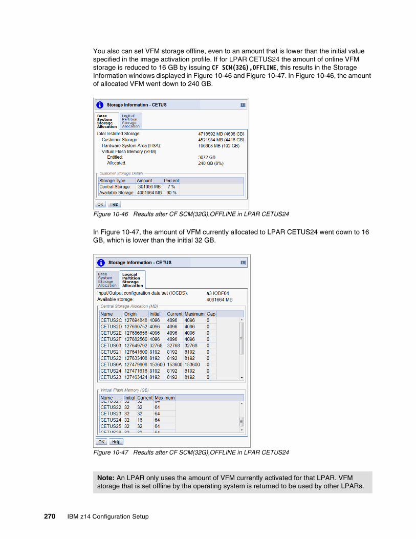
You also can set VFM storage offline, even to an amount that is lower than the initial value specified in the image activation profile. If for LPAR CETUS24 the amount of online VFM storage is reduced to 16 GB by issuing CF SCM(32G),OFFLINE, this results in the Storage Information windows displayed in Figure 10-46 and Figure 10-47. In Figure 10-46, the amount of allocated VFM went down to 240 GB.
Figure 10-46 Results after CF SCM(32G),OFFLINE in LPAR CETUS24
In Figure 10-47, the amount of VFM currently allocated to LPAR CETUS24 went down to 16 GB, which is lower than the initial 32 GB.
Figure 10-47 Results after CF SCM(32G),OFFLINE in LPAR CETUS24
Note: An LPAR only uses the amount of VFM currently activated for that LPAR. VFM storage that is set offline by the operating system is returned to be used by other LPARs.
270 IBM z14 Configuration Setup
The allocation of VFM storage to a coupling facility LPAR is done in the same way as for z/OS LPARs and is described in 10.3.3, “Configuring VFM” on page 261. The amount of SCM allocated to a coupling facility LPAR can be displayed in the Operating System Messages window at the HMC.
For example, LPAR CETUS2C, which has allocated 16 GB of initial VFM storage has a message that shows the amount of SCM available, as shown in Example 10-14.
Example 10-14 CFCC messages with SCM
CF0280I CFCC Release 22.00, Service Level 00.24 Built on 06/02/2017 at 09:14:00 Code Load Features: Facility Operational Level: 22
CF0011I Coupling Facility is active with: 2 CPs 6 CF Receiver Channels 6 CF Sender Channels 3607 MB of allocatable storage 16384 MB of Total SCM storage
The CF must know the algorithm of how the structure is used by the application. Currently, this algorithm is defined only for IBM MQ shared queues. To use this function, assign flash memory to your coupling facilities according to the procedure described in the following section and update your structure definitions in your CFRM policy with the new parameter SCMMAXSIZE and SCMALGORITHM. For more information, see z/OS MVS Setting Up a Sysplex, SA23-1399.
IBM MQ for z/OS Version 7 or later allows the migration of IBM MQ shared queue objects to flash memory when structure utilization exceeds the defined threshold. The IBM MQ objects are fetched back to real CF Storage when requested. This process provides an overflow capability for IBM MQ shared queues to handle workload peaks.
IBM RMF™ provides measurement data and reporting capabilities for VFM and Flash Express. The support enhances RMF Postprocessor and Monitor III reports with various new CF SCM statistics.
Coupling Facility SCM statistics are provided in these reports:
� RMF Postprocessor Coupling Facility Activity (CF) report� RMF Monitor III Coupling Facility Overview (CFOVER) report� RMF Monitor III Coupling Facility Activity (CFACT) report
10.4 Shared Memory Communications over RDMA (SMC-R)
This section provides information about the configuration of the Shared Memory Communications over RDMA (SMC-R) using the 10GbE RoCE Express2 feature on an IBM z14. It covers the following topics:
� SMC-R overview� Planning for SMC-R configuration� Configuring SMC-R� SMC-R Management
Chapter 10. Specialized features 271
10.4.1 SMC-R overview
SMC-R uses existing IBM Z and industry standard communications technology:
� RDMA, which is based on queue pair (QP) technology that also uses an InfiniBand transport service type that is called reliable connected QPs (RC-QPs), which provide these features:
– Represent SMC Links in a logical point-to-point connection.
– Transport data over unique RDMA network interface cards (RNICs) that are logically bound together to form Link Groups. Link Groups are used for high availability and load balancing needs.
Ports in the IBM Z 10GbE RoCE Express feature (also referred to as RNICs) are used as the physical transport layer for RDMA.
� Single root I/O virtualization (SR-IOV) is a Peripheral Component Interconnect Express (PCIe) standard that define extensions to PCIe specifications. SR-IOV enables sharing of 10GbE RoCE Express ports between LPARs in the IBM z13, IBM z13s, and IBM z14.
For more information about the 10GbE RoCE Express2 feature and about SMC-R, see the IBM z14 Technical Guide, SG24-8451, and IBM z/OS V2R2 Communications Server TCP/IP Implementation Volume 1, SG24-8360.
10.4.2 Planning for SMC-R configuration
For an overview of planning considerations, see “Shared Memory Communications - RDMA” on page 21.
10.4.3 Configuring SMC-R
The 10GbE RoCE Express and 10GbE RoCE Express2 features are native PCIe features, so the HCD and IOCP definition rule differ from a non-PCIe card such as OSA Express. Here are the rules:
� PCIe Function Identifier (FID) must be defined in HCD or HCM to create IOCP input:
– FID is a hexadecimal value (three heximal digits, range 000 - FFF), which specifies the PCIe function.
– It cannot be assigned to a channel subsystem, so that any LPAR can be defined to a function.
– It has a PARTITION parameter that dedicates it to one LPAR or allows reconfiguration among a group of LPARs. A function cannot be defined as shared.
– In z/OS system commands, PCIe FID is represented as PFID.
� If the intended PCIe hardware supports multiple partitions, it has a decimal Virtual Function Identifier (VF=) in the range 1 - n, where n is the maximum number of partitions that the PCIe feature supports.
� Other parameters that are specific to the PCIe feature. For example, the 10GbE RoCE Express requires a Physical Network Identifier (PNETID=), and the new 10GbE RoCE Express2 feature supports a port identifier (PORT=).
272 IBM z14 Configuration Setup
� For function mapping to hardware, assign a Physical Channel Identifier (PCHID=) to identify the hardware feature in a specific PCIe I/O drawer and the slot to be used for the defined function. The following methods can be used:
– Manually, by using the configurator (eCONFIG) PCHID report.– Using the CHPID Mapping tool and the eConfig Configuration Report File (CFR) input.
For information about configuring an SMC-R connection using HCD, see 15.2.2, “Defining a RoCE-2 PCIe function” on page 391.
10.4.4 SMC-R Management
This section introduces the z/OS commands related to the RoCE Express PCIe feature and show the responses on our test system.
DISPLAY PCIEYou can use the DISPLAY PCIE command to display these items:
� All registered device drivers (with assigned printable names).� All available or in-use PCIe functions and their associated device types.� Information about a specific PCIe device with a list of the client address spaces using the
device.
Example 10-15 is an example of the D PCIE command. You can confirm the FID and VFID that you have defined. FID is represented as PFID (PCIE function identifiers).
Example 10-15 Example of D PCIE command
D PCIE IQP022I 09.29.59 DISPLAY PCIE 698 PCIE 0012 ACTIVE PFID DEVICE TYPE NAME STATUS ASID JOBNAME CHID VFN PN000000C9 Hardware Accelerator ALLC 0013 FPGHWAM 0104 0004 000000C5 Hardware Accelerator ALLC 0013 FPGHWAM 01C0 0004 00000103 8GB zHyperLink ALLC 001A IOSAS 0140 0004 1 00000203 8GB zHyperLink ALLC 001A IOSAS 0140 0004 2 000000A5 RoCE Express2 CNFG 017C 0002 1 000000A9 RoCE Express2 STNBY 017C 0004 2 000000A3 RoCE Express2 CNFG 01BC 0002 1 000000A7 RoCE Express2 STNBY 01BC 0004 2
Example 10-16 is an example of the D PCIE,PFID=pfid command. After you define the new PCIe function, enter this command and confirm that its status is ACTIVE.
Example 10-16 Example of D PCIE,PFID=pfid command
D PCIE,PFID=A5 IQP024I 09.35.22 DISPLAY PCIE 752 PCIE 0012 ACTIVE
Note: Unlike CHPIDs, multiple functions can be mapped to the same PCHID. This is conceptually similar to mapping multiple InfiniBand coupling CHPIDs to the same adapter and port.
Chapter 10. Specialized features 273
PFID DEVICE TYPE NAME STATUS ASID JOBNAME CHID VFN PN000000A5 RoCE Express2 CNFG 017C 0002 1 CLIENT ASIDS: NONE
Example 10-17 is example of the D PCIE,DD command. You can confirm the details of the device drives that are installed in the system.
Example 10-17 Example of D PCIE,DD command
D PCIE,DD IQP023I 09.35.54 DISPLAY PCIE 769PCIE 0012 ACTIVE DEV TYPE DEVICE TYPE NAME 1014044B Hardware Accelerator 10140613 8GB zHyperLink 15B36750 10GbE RoCE 15B31003 10GbE RoCE 15B31004 10GbE RoCE Express 15B31016 RoCE Express2 15B31014 40GbE RoCE Express2 101404ED ISM
The CONFIG commandYou can use the CONFIG command to bring the PCIE function ID (PFID) online or offline.
Example 10-18 is an example of CONFIG PFID(x),ONLINE command.
Example 10-18 Example of CF PFID(x),ONLINE command
CONFIG PFID(A5),ONLINE IEE504I PFID(A5),ONLINE IEE712I CONFIG PROCESSING COMPLETE
Example 10-19 is an example of CONFIG PFID(x),OFFLINE command.
Example 10-19 Example of CF PFID(x),OFFLINE command
CONFIG PFID(A5),OFFLINE IQP034I PCIE FUNCTION 000000A5 OFFLINE. 806 PCIE DEVICE TYPE NAME = (RoCE Express2 ).IEE505I PFID(A5),OFFLINE IEE712I CONFIG PROCESSING COMPLETE
For more details about how to manage a RoCE Express feature, see IBM z/OS V2R2 Communications Server TCP/IP Implementation Volume 1: Base Functions, Connectivity, and Routing, SG24-8360.
274 IBM z14 Configuration Setup

10.5 Shared Memory Communications - Direct Memory Access
This section provides information about the configuration of the Shared Memory Communiction - Direct Memory Access (SMC-D) connections on an IBM z14. It covers the following topics:
� SMC-D overview� Planning for SMC-D configuration� Configuring SMC-D� SMC-D management
10.5.1 SMC-D overview
SMC-D is a protocol that allows TCP socket applications to transparently use Internal Shared Memory (ISM). ISM is a virtual channel similar to IQD for HiperSockets. A virtual adapter is created in each z/OS LPAR and by using the SMC protocol, the memory is logically shared. The virtual network is provided by firmware.
SMC-R requires a TCP/IP connection and preserves the entire network infrastructure. SMC-D is also a “hybrid” solution. It uses a TCP connection to establish the SMC-D connection. The TCP path can be either through an OSA-Express port or through HiperSockets connection. A TCP option (called SMCD) controls switching from TCP to “out of band” SMC-D. The SMC-D information is exchanged within the TCP data stream. Socket application data is exchanged through ISM (write operations). The TCP connection remains established to control the SMC-D connection.
For more information about SMC-D, see the IBM z14 Technical Guide, SG24-8451, and IBM z/OS V2R2 Communications Server TCP/IP Implementation Volume 1, SG24-8360.
10.5.2 Planning for SMC-D configuration
For an overview of planning considerations for SMC-D, see “Shared Memory Communications - Direct Memory Access (SMC-D)” on page 23.
10.5.3 Configuring SMC-D
For information about configuring an SMC-D connection using HCD, see 15.2.1, “Defining an ISM PCIe function” on page 388.
10.5.4 SMC-D management
From an operational standpoint, SMC-D is similar to SMC-R. However, SMC-D uses direct memory access (DMA) instead of an RDMA, and uses a virtual PCI adapter that is called ISM rather than an RNIC. The ISM interfaces are associated with IP interfaces (for example, HiperSockets or OSA-Express) and are dynamically created, automatically started and stopped, and are auto-discovered.
SMC-D over ISM does not use QP technology like SMC-R. Therefore, links and Link Groups based on QPs (or other hardware constructs) are not applicable to ISM. SMC-D protocol has a design concept of a “logical point-to-point connection” called an SMC-D link.
Chapter 10. Specialized features 275

Internal Shared Memory technologyISM is a virtual PCI network adapter that enables direct access to shared virtual memory, providing highly optimized network communications for operating systems within the same IBM Z platform.
Virtual memory is managed by each z/OS (similar to SMC-R logically shared memory) following the existing IBM Z PCIe I/O translation architecture.
For more information about management of SMC-D, see IBM z/OS V2R2 Communications Server TCP/IP Implementation Volume 1: Base Functions, Connectivity, and Routing, SG24-8360.
10.6 IBM zHyperlink Express
This section provides information about the configuration of the zHyperlink Express feature on an IBM z14. It covers the following topics:
� IBM zHyperlink Express overview� Planning for zHyperlink Express configuration� Configuring zHyperlink Express� Managing zHyperlink Express
10.6.1 IBM zHyperlink Express overview
IBM zHyperLink Express is a new, short distance, IBM Z I/O channel designed for up to 10x lower latency than High Performance FICON. zHyperLink is intended to speed Db2 for z/OS transaction processing and improve active log throughput. This feature is in the PCIe I/O drawer and is a two-port adapter used for short distance, direct connectivity between a z14 and a DS8880. It uses PCIe Gen3 technology, with x16 lanes that are bifurcated into x8 lanes for storage connectivity.
The zHyperLink Express is designed to drive distances up to 150 meters and support a link data rate of 8 GigaBytes per second (GBps). A zHyperlink port is fully sharable between all partitions because 127 virtual functions/PFIDs per link are supported.
IBM zHyperLink dramatically reduces the latency of DASD I/Os by interconnecting the z14 CPC directly to the I/O Bay of the DS8880. This feature improves the application response time without application changes. zHyperLink is fast enough to run I/Os synchronously, so that the CPU can just wait for the data, which results in these advantages:
� No Undispatch of the running task� No CPU Queueing Delays to resume it� No host CPU cache disruption� Very small I/O service time
The zHyperLInk Express adapter takes one slot on z14 PCIe I/O drawer, and each adapter has a single PCHID with two ports. Up to 16 zHyperLink Express adapters can be installed in one z14 server, thus having up to 32 links.
Note: The SMC-D information in the netstat command displays is related to ISM link information (not Link Groups).
276 IBM z14 Configuration Setup
FICON connectivity to each storage system is still required to be used for these purposes:
� For initialization of the zHyperlink connection� For I/Os that are not eligible for zHyperlink� For failback when a zHyperlink request fails (for example, cache miss, busy condition)
For more information about the zHyperlink feature, see the IBM z14 Technical Guide, SG24-8451, and IBM Z Connectivity Handbook, SG24-5444.
10.6.2 Planning for zHyperlink Express configuration
For planning considerations, see 2.8.4, “Defining the IBM zHyperLink Express” on page 20.
10.6.3 Configuring zHyperlink Express
Like the 10GbE RoCE Express and the 10GbE RoCE Express2 features, the zHyperlink Express card is a native PCIe I/O feature, so the HCD and IOCP definition rules for native PCIe cards also apply, as stated in “Configuring SMC-R” on page 272.
zHyperLink ports are defined as PCI functions in the I/O configuration, where the PCHID represents the card and the port number represents the port. Each zHyperlink can be shared by up to 127 virtual functions. Generally, define four PFIDs per zHyperLink port per LPAR so that up to four simultaneous operations can be active on a link at a time (more will cause link busy type conditions). Also, eight FICON CHPIDs can still be defined per Logical Control Unit (LCU) because zHyperLink does not reduce that number.
The association between zHyperLinks and storage systems is automatically discovered, so no I/O configuration definition is required. The z14 firmware discovers the storage subsystem during link initialization, and z/OS associates the zHyperlinks with the devices at IPL or vary online time.
For information about configuring a zHyperling Express card using HCD, see 15.2.4, “Defining a zHyperLink PCIe function” on page 398.
Chapter 10. Specialized features 277

Managing zHyperlink ExpressTo enable IBM DB2® to use zHyperlinks, the DB2 zParm form zHyperlink must be enabled, as shown in Figure 10-48.
Figure 10-48 DB2 zParm: zHyperlink
The acceptable values for the DB2 zHyperlink Scope are:
ENABLE DB2 requests the zHyperlink protocol for all eligible I/O requests
DISBALE DB2 does not use the zHyperlink for any I/O requests
DATABASE DB2 requests the zHyperlink protocol for only database synchronous read I/Os
LOG DB2 requests the zHyperlink protocol for only log write I/Os
Note that at GA time, zHyperlink is only used by synchronous DB2 database reads, provided with APAR PI77461 for DB2 V12.
To enable z/OS for zHyperlink read I/Os, the ZHYPERLINK OPER=READ statement must be added to the IECIOSxx parmlib member, as shown in Example 10-20.
Example 10-20 IECIOSxx parmlib enabled for zHyperlink read I/Os
VIEW USER.PLXA.PARMLIB(IECIOSRF) - 01.02 Columns 00001 00072 Command ===> Scroll ===> HALF ****** ***************************** Top of Data ****************************** 000240 CTRACE(CTIIOSST) 000250 STORAGE IOSBLKS=31 000260 HYPERPAV=XPAV 000270 MIDAW=YES 000280 ZHPF=YES 000300 ZHYPERLINK OPER=READ ****** **************************** Bottom of Data ****************************
278 IBM z14 Configuration Setup

This process can also be done dynamically by entering the SETIOS ZHYPERLINK,OPER=READ console command. The corresponding display command is DISPLAY IOS,ZHYPERLINK, as shown in Example 10-21.
Example 10-21 DISPLAY IOS,ZHYPERLINK
-D IOS,ZHYPERLINK IOS634I 13.30.55 IOS SYSTEM OPTION 190 ZHYPERLINK IS ENABLED FOR READ OPERATIONS
The DISPLAY PCIE command can be used to display the available PCIe function IDs for zHyperlink, as shown in Example 10-22.
Example 10-22 DISPLAY PCIE
-D PCIE IQP022I 13.38.28 DISPLAY PCIE 208 PCIE 0012 ACTIVE PFID DEVICE TYPE NAME STATUS ASID JOBNAME CHID VFN PN 0000123A 8GB zHyperLink ALLC 001A IOSAS 0184 0014 1 0000123B 8GB zHyperLink ALLC 001A IOSAS 0184 0015 1 0000123C 8GB zHyperLink ALLC 001A IOSAS 01C0 0012 2 0000123D 8GB zHyperLink ALLC 001A IOSAS 01C0 0013 2 00001208 8GB zHyperLink ALLC 001A IOSAS 0184 0012 2 00001209 8GB zHyperLink ALLC 001A IOSAS 0184 0013 2 0000120A 8GB zHyperLink ALLC 001A IOSAS 0184 0014 2 0000120B 8GB zHyperLink ALLC 001A IOSAS 0184 0015 2 0000120C 8GB zHyperLink ALLC 001A IOSAS 01C0 0012 1 0000120D 8GB zHyperLink ALLC 001A IOSAS 01C0 0013 1 0000120E 8GB zHyperLink ALLC 001A IOSAS 01C0 0014 1 0000120F 8GB zHyperLink ALLC 001A IOSAS 01C0 0015 1 0000123E 8GB zHyperLink ALLC 001A IOSAS 01C0 0014 2 0000123F 8GB zHyperLink ALLC 001A IOSAS 01C0 0015 2
Example 10-23 shows the DISPLAY PCIE=pfid command to display a specific zHyperlink PCIe function ID.
Example 10-23 DiSPLAY PCIE=pfid
-D PCIE,PFID=123A IQP024I 13.45.40 DISPLAY PCIE 274 PCIE 0012 ACTIVE PFID DEVICE TYPE NAME STATUS ASID JOBNAME CHID VFN PN 0000123A 8GB zHyperLink ALLC 001A IOSAS 0184 0014 1 CLIENT ASIDS: NONE CU WWNN: 5005076308FFD00A CU Link Id: 0280 S/W State: Allocated Port State: Operational CU Node Descriptor: 002107.985.IBM.75.0000000GYF81
Chapter 10. Specialized features 279

The results of issuing the DISPLAY M=CU(cun) command against a control unit enabled for zHyperlink are shown in Example 10-24.
Example 10-24 DISPLAY M=CU(cun)
-D M=CU(7002) IEE174I 14.04.24 DISPLAY M 393 CONTROL UNIT 7002 CHP 30 31 32 33 ENTRY LINK ADDRESS .. .. .. .. DEST LINK ADDRESS 0D 0D 0D 0D CHP PHYSICALLY ONLINE Y Y Y Y PATH VALIDATED Y Y Y Y MANAGED N N N N ZHPF - CHPID Y Y Y Y ZHPF - CU INTERFACE Y Y Y Y INTERFACE ID 0135 0003 0005 0201 MAXIMUM MANAGED CHPID(S) ALLOWED = 0 DESTINATION CU LOGICAL ADDRESS = 50 CU ND = 002107.985.IBM.75.0000000GYF81.0135 CU NED = 002107.985.IBM.75.0000000GYF81.5000 TOKEN NED = 002107.900.IBM.75.0000000GYF81.5000 WWNN = 5005076308FFD00A FUNCTIONS ENABLED = ZHPF, ZHYPERLINK(R), XPAV XPAV CU PEERS = 7002, 7202 DEFINED DEVICES 07000-0700F DEFINED PAV ALIASES 17020-1702F ZHYPERLINKS PFID PCHID Port LinkId S/W St Port St 00001230 013C 02 0081 Alloc Oper 00001231 013C 02 0081 Alloc Oper 00001232 013C 02 0081 Alloc Oper 00001233 013C 02 0081 Alloc Oper 00001234 0178 01 0180 Alloc Oper 00001235 0178 01 0180 Alloc Oper 00001236 0178 01 0180 Alloc Oper 00001237 0178 01 0180 Alloc Oper 00001238 0184 01 0280 Alloc Oper 00001239 0184 01 0280 Alloc Oper 0000123A 0184 01 0280 Alloc Oper 0000123B 0184 01 0280 Alloc Oper 0000123C 01C0 02 0381 Alloc Oper 0000123D 01C0 02 0381 Alloc Oper 0000123E 01C0 02 0381 Alloc Oper 0000123F 01C0 02 0381 Alloc Oper
The results for the DISPLAY M=DEV(devno) command against a device enabled for zHyperlink are shown in Example 10-25.
Example 10-25 DISPLAY M=DEV(devno)
-D M=DEV(7000) IEE174I 13.59.00 DISPLAY M 333 DEVICE 07000 STATUS=ONLINE
280 IBM z14 Configuration Setup
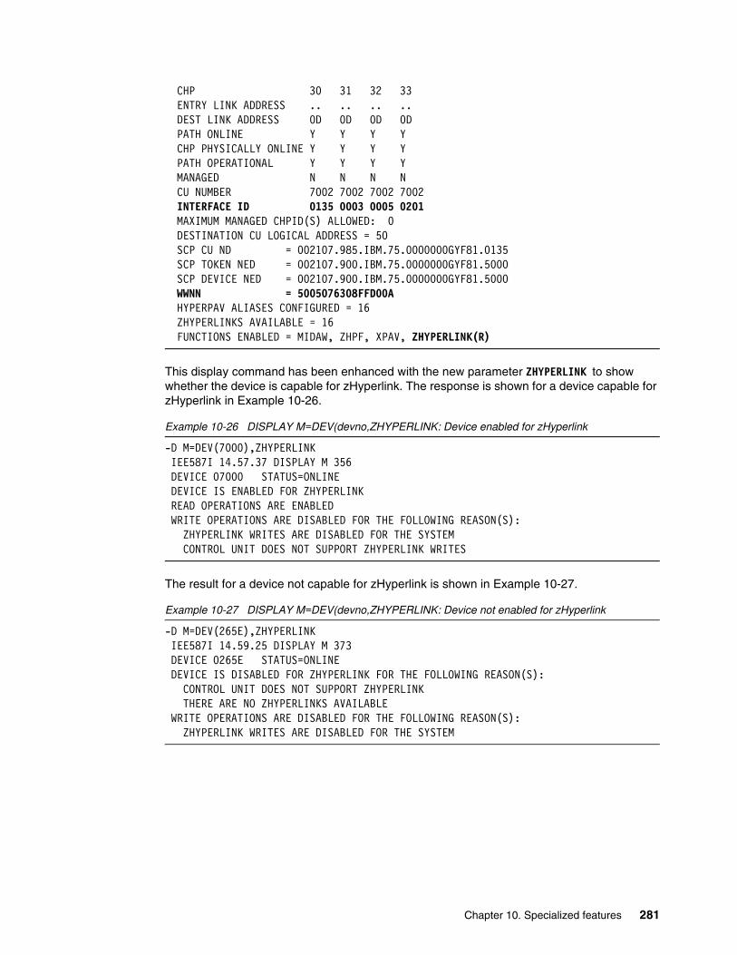
CHP 30 31 32 33 ENTRY LINK ADDRESS .. .. .. .. DEST LINK ADDRESS 0D 0D 0D 0D PATH ONLINE Y Y Y Y CHP PHYSICALLY ONLINE Y Y Y Y PATH OPERATIONAL Y Y Y Y MANAGED N N N N CU NUMBER 7002 7002 7002 7002 INTERFACE ID 0135 0003 0005 0201 MAXIMUM MANAGED CHPID(S) ALLOWED: 0 DESTINATION CU LOGICAL ADDRESS = 50 SCP CU ND = 002107.985.IBM.75.0000000GYF81.0135 SCP TOKEN NED = 002107.900.IBM.75.0000000GYF81.5000 SCP DEVICE NED = 002107.900.IBM.75.0000000GYF81.5000 WWNN = 5005076308FFD00A HYPERPAV ALIASES CONFIGURED = 16 ZHYPERLINKS AVAILABLE = 16 FUNCTIONS ENABLED = MIDAW, ZHPF, XPAV, ZHYPERLINK(R)
This display command has been enhanced with the new parameter ZHYPERLINK to show whether the device is capable for zHyperlink. The response is shown for a device capable for zHyperlink in Example 10-26.
Example 10-26 DISPLAY M=DEV(devno,ZHYPERLINK: Device enabled for zHyperlink
-D M=DEV(7000),ZHYPERLINK IEE587I 14.57.37 DISPLAY M 356 DEVICE 07000 STATUS=ONLINE DEVICE IS ENABLED FOR ZHYPERLINK READ OPERATIONS ARE ENABLED WRITE OPERATIONS ARE DISABLED FOR THE FOLLOWING REASON(S): ZHYPERLINK WRITES ARE DISABLED FOR THE SYSTEM CONTROL UNIT DOES NOT SUPPORT ZHYPERLINK WRITES
The result for a device not capable for zHyperlink is shown in Example 10-27.
Example 10-27 DISPLAY M=DEV(devno,ZHYPERLINK: Device not enabled for zHyperlink
-D M=DEV(265E),ZHYPERLINK IEE587I 14.59.25 DISPLAY M 373 DEVICE 0265E STATUS=ONLINE DEVICE IS DISABLED FOR ZHYPERLINK FOR THE FOLLOWING REASON(S): CONTROL UNIT DOES NOT SUPPORT ZHYPERLINK THERE ARE NO ZHYPERLINKS AVAILABLE WRITE OPERATIONS ARE DISABLED FOR THE FOLLOWING REASON(S): ZHYPERLINK WRITES ARE DISABLED FOR THE SYSTEM
Chapter 10. Specialized features 281

282 IBM z14 Configuration Setup
Chapter 11. Adding LPARs and OSCONFIGs
This chapter describes the steps for adding Logical Partitions and Operating System Configurations to your IODF. It includes a list of these potential configuration items and a short description on how to do each of them using HCD.
This book shows only the definition process. If you want a deeper understanding of how to use HCD and FICON, see these resources:
� I/O Configuration Using z/OS HCD and HCM, SG24-7804� FICON Planning and Implementation Guide, SG24-6497
This chapter includes the following sections:
� Defining more I/O using HCD� OSCONFIGs and Logical Partition definitions
11
Note: Not all of the following configuration items are necessarily required for your installation. In addition, the examples presented are not exhaustive.
© Copyright IBM Corp. 2017. All rights reserved. 283
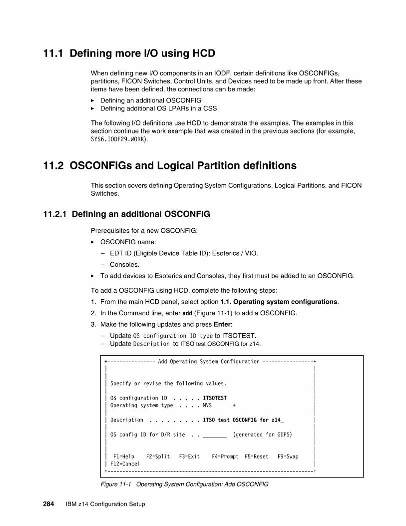
11.1 Defining more I/O using HCD
When defining new I/O components in an IODF, certain definitions like OSCONFIGs, partitions, FICON Switches, Control Units, and Devices need to be made up front. After these items have been defined, the connections can be made:
� Defining an additional OSCONFIG� Defining additional OS LPARs in a CSS
The following I/O definitions use HCD to demonstrate the examples. The examples in this section continue the work example that was created in the previous sections (for example, SYS6.IODF29.WORK).
11.2 OSCONFIGs and Logical Partition definitions
This section covers defining Operating System Configurations, Logical Partitions, and FICON Switches.
11.2.1 Defining an additional OSCONFIG
Prerequisites for a new OSCONFIG:
� OSCONFIG name:
– EDT ID (Eligible Device Table ID): Esoterics / VIO.
– Consoles.
� To add devices to Esoterics and Consoles, they first must be added to an OSCONFIG.
To add a OSCONFIG using HCD, complete the following steps:
1. From the main HCD panel, select option 1.1. Operating system configurations.
2. In the Command line, enter add (Figure 11-1) to add a OSCONFIG.
3. Make the following updates and press Enter:
– Update OS configuration ID type to ITSOTEST.– Update Description to ITSO test OSCONFIG for z14.
Figure 11-1 Operating System Configuration: Add OSCONFIG
+---------------- Add Operating System Configuration -----------------+| || || Specify or revise the following values. || || OS configuration ID . . . . . ITSOTEST || Operating system type . . . . MVS + || || Description . . . . . . . . . ITSO test OSCONFIG for z14_ || || OS config ID for D/R site . . ________ (generated for GDPS) || || || F1=Help F2=Split F3=Exit F4=Prompt F5=Reset F9=Swap || F12=Cancel |+---------------------------------------------------------------------+
284 IBM z14 Configuration Setup
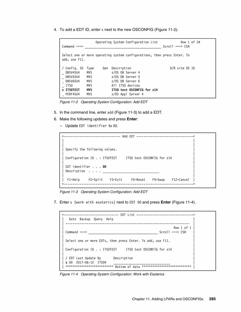
4. To add a EDT ID, enter s next to the new OSCONFIG (Figure 11-2).
Figure 11-2 Operating System Configuration: Add EDT
5. In the command line, enter add (Figure 11-3) to add a EDT.
6. Make the following updates and press Enter:
– Update EDT identifier to 00.
Figure 11-3 Operating System Configuration: Add EDT
7. Enter s (work with esoterics) next to EDT 00 and press Enter (Figure 11-4).
Figure 11-4 Operating System Configuration: Work with Esoterics
Operating System Configuration List Row 1 of 34Command ===> ___________________________________________ Scroll ===> CSR Select one or more operating system configurations, then press Enter. To add, use F11. / Config. ID Type Gen Description D/R site OS ID _ DBSV4SU4 MVS z/OS DB Server 4 _ DBSV5SU4 MVS z/OS DB Server 5 _ DBSV6SU4 MVS z/OS DB Server 6 _ ITSO MVS All ITSO devices s ITSOTEST MVS ITSO test OSCONFIG for z14 _ PERF4SU4 MVS z/OS Appl Server 4
+-------------------------------- Add EDT --------------------------------+| || || Specify the following values. || || Configuration ID . : ITSOTEST ITSO test OSCONFIG for z14 || || EDT identifier . . . 00 || Description . . . . ________________________________ || || F1=Help F2=Split F3=Exit F5=Reset F9=Swap F12=Cancel |+-------------------------------------------------------------------------+
+------------------------------- EDT List --------------------------------+| Goto Backup Query Help || ---------------------------------------------------------------------- || Row 1 of 1 || Command ===> _______________________________________ Scroll ===> CSR || || Select one or more EDTs, then press Enter. To add, use F11. || || Configuration ID . : ITSOTEST ITSO test OSCONFIG for z14 || || / EDT Last Update By Description || s 00 2017-06-12 ITSO4 ________________________________ || *************************** Bottom of data **************************** |
Chapter 11. Adding LPARs and OSCONFIGs 285

8. In the command line, enter add (Figure 11-5) to add an Esoteric.
9. Make the following updates and press Enter:
– Update Esoteric name to ITSOESO1.
– Update VIO eligible to Yes (if you with to make this Esoteric VIO eligible). This is normally used for an Esoteric called VIO.
– Update Token to 1.
Figure 11-5 Operating System Configuration: Add Esoteric
10.After you add devices to the OSCONFIG ITSOTEST in the following examples, you will then be able to add those device definitions to an Esoteric or Console if applicable.
11.2.2 Defining additional OS LPARs in a CSS
The following are considerations for a new (unreserved) partition:
� Partition name.� Number.� Usage.� Description.� To add CHPIDs to a partition, they first must be defined to the processor.� Renaming an existing partition is a two-step process. First, it needs to be redefined as
reserved (Partition name = *). Then the IODF must be activated on the processor, redefined to the new name, and then the IODF activated on the processor.
To change a reserved partition to an active partition in a CSS, complete the following steps:
1. From the main HCD panel, select option 1.3. Processors.
2. Type s next to the processor that you want to add a partition to, and press Enter.
3. Type p next to the CSS ID that you want to add a partition to, and press Enter.
4. Type c next to the Reserved Partition that you want to unreserve (we will use ID 1 for this example), and press Enter.
+----------------------------- Esoteric List -----------------------------+| Goto Filter Backup Query Help || - +--------------------- Add Esoteric ---------------------+ --------- || | | || C | | ==> CSR || | Specify the following values. | || S | | 11. || | Esoteric name . . . ITSOESO1 | || C | VIO eligible . . . . No (Yes or No) | || E | Token . . . . . . . 1___ | || | | || / | | || * | F1=Help F2=Split F3=Exit F5=Reset F9=Swap | ********** || | F12=Cancel | || +--------------------------------------------------------+ || |
286 IBM z14 Configuration Setup
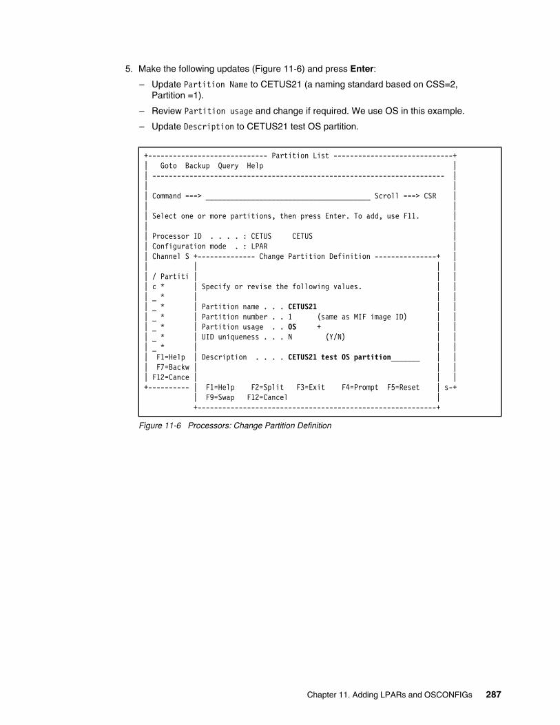
5. Make the following updates (Figure 11-6) and press Enter:
– Update Partition Name to CETUS21 (a naming standard based on CSS=2, Partition =1).
– Review Partition usage and change if required. We use OS in this example.
– Update Description to CETUS21 test OS partition.
Figure 11-6 Processors: Change Partition Definition
+----------------------------- Partition List -----------------------------+| Goto Backup Query Help || ----------------------------------------------------------------------- || || Command ===> ________________________________________ Scroll ===> CSR || || Select one or more partitions, then press Enter. To add, use F11. || || Processor ID . . . . : CETUS CETUS || Configuration mode . : LPAR || Channel S +-------------- Change Partition Definition ---------------+ || | | || / Partiti | | || c * | Specify or revise the following values. | || _ * | | || _ * | Partition name . . . CETUS21 | || _ * | Partition number . . 1 (same as MIF image ID) | || _ * | Partition usage . . OS + | || _ * | UID uniqueness . . . N (Y/N) | || _ * | | || F1=Help | Description . . . . CETUS21 test OS partition_______ | || F7=Backw | | || F12=Cance | | |+---------- | F1=Help F2=Split F3=Exit F4=Prompt F5=Reset | s-+ | F9=Swap F12=Cancel | +----------------------------------------------------------+
Chapter 11. Adding LPARs and OSCONFIGs 287

288 IBM z14 Configuration Setup

Chapter 12. Adding storage devices
This chapter describes how to define FICON switches and FICON Channel path IDs (CHPIDs), and connect them to a DASD Control Unit. It includes a list of these potential configuration items and a short description on how to do each of them using HCD.
This chapter shows only the definition process. If you want a deeper understanding of how to use HCD and FICON, see these resources:
� I/O Configuration Using z/OS HCD and HCM, SG24-7804� FICON Planning and Implementation Guide, SG24-6497
This chapter includes the following sections:
� Defining more I/O using HCD� FICON CHPIDs, Switches, and DASD control units
12
Note: Not all of the following configuration items are necessarily required for your installation. In addition, the examples presented are not exhaustive.
© Copyright IBM Corp. 2017. All rights reserved. 289
12.1 Defining more I/O using HCD
When defining new I/O components in an IODF, certain definitions like OSCONFIGs, partitions, FICON Switches, Control Units, and Devices need to be made up front. After these items have been defined, the connections can be made:
� Defining FICON Switches (Directors, SANs, SAN Switches)� Defining FICON CHPIDs and connecting them to a FICON Switch� Defining FICON CHPIDs for direct connect to a 2107 Control Unit� Defining FICON CHPIDs for switched connect to a 2107 Control Unit� Defining 3390B devices to an OSCONFIG and EDT/Esoteric
The following I/O definitions use HCD to demonstrate the examples. The examples continue using the example created in the previous sections (for example, SYS6.IODF29.WORK).
12.1.1 Defining FICON Switches (Directors, SANs, SAN Switches)
The following are considerations for a new FICON Switch:
� Switch ID� Switch type� Serial number (optional)� Description (optional)� Switch address� Installed port range� Switch CU number� Switch device number
To add a FICON Switch using HCD, complete the following steps:
1. From the main HCD panel, select option 1.2. Switches.
2. In the command line, enter add (Figure 12-1 on page 291) to add a Switch.
3. Make the following updates and press Enter:
– Update Switch ID to 41.– Update Switch type to 2032.– Update Description to ITSO test SAN definition.– Update Switch address to 41.– Update Installed port range to 00 and FE.– Update Switch CU number to 0041.– Update Switch device number to 0041.
290 IBM z14 Configuration Setup
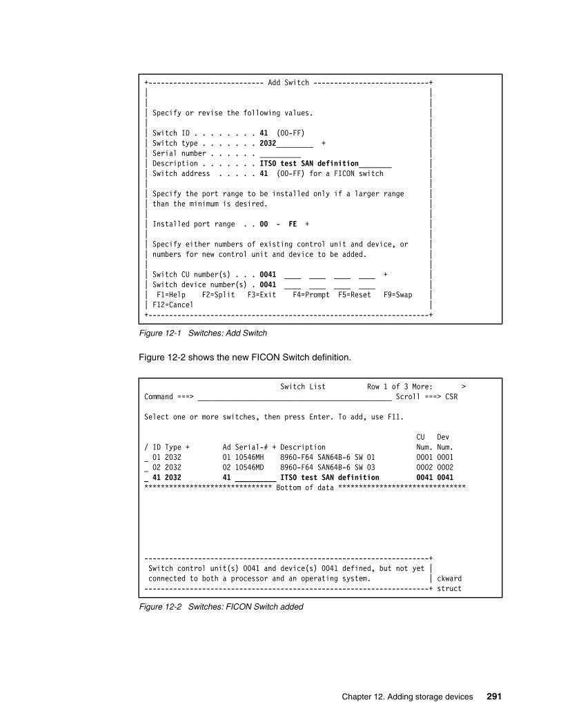
Figure 12-1 Switches: Add Switch
Figure 12-2 shows the new FICON Switch definition.
Figure 12-2 Switches: FICON Switch added
+---------------------------- Add Switch ----------------------------+| || || Specify or revise the following values. || || Switch ID . . . . . . . . 41 (00-FF) || Switch type . . . . . . . 2032_________ + || Serial number . . . . . . __________ || Description . . . . . . . ITSO test SAN definition________ || Switch address . . . . . 41 (00-FF) for a FICON switch || || Specify the port range to be installed only if a larger range || than the minimum is desired. || || Installed port range . . 00 - FE + || || Specify either numbers of existing control unit and device, or || numbers for new control unit and device to be added. || || Switch CU number(s) . . . 0041 ____ ____ ____ ____ + || Switch device number(s) . 0041 ____ ____ ____ ____ || F1=Help F2=Split F3=Exit F4=Prompt F5=Reset F9=Swap || F12=Cancel |+--------------------------------------------------------------------+
Switch List Row 1 of 3 More: >Command ===> _______________________________________________ Scroll ===> CSR Select one or more switches, then press Enter. To add, use F11. CU Dev / ID Type + Ad Serial-# + Description Num. Num. _ 01 2032 01 10546MH 8960-F64 SAN64B-6 SW 01 0001 0001 _ 02 2032 02 10546MD 8960-F64 SAN64B-6 SW 03 0002 0002 _ 41 2032 41 __________ ITSO test SAN definition 0041 0041 ******************************* Bottom of data ******************************* ---------------------------------------------------------------------+ Switch control unit(s) 0041 and device(s) 0041 defined, but not yet | connected to both a processor and an operating system. | ckward ---------------------------------------------------------------------+ struct
Chapter 12. Adding storage devices 291
12.2 FICON CHPIDs, Switches, and DASD control units
This section covers defining FICON CHPIDs, and then connecting them to FICON switches and to a DASD control unit.
12.2.1 Defining FICON CHPIDs and connecting them to a FICON Switch
The following are considerations for a new FICON CHPID:
� Channel path ID (CHPID).
� Channel ID (CHID).
� Channel path type.
� Operational mode.
� Description.
� Dynamic entry switch ID.
� Entry switch ID.
� Entry port.
� Partition access list.
� For performance and redundancy, how many CHPIDs are required to connect to the FICON Switch, and subsequently to one or more Control Units.
� For performance and redundancy, how many I/O cards of that feature are installed in the processor and to what PCIe ports and on which CPC drawer do the I/O cards connect to (See the PCHID/CHID report for a list of installed hardware).
� After a CHPID is defined, it can then be added to a predefined partition in that CSS.
� After a CHPID is defined, it can then be connected to a FICON Switch.
� After a CHPID is defined, it can then be connected to a Control Unit (covered in a later step).
To define a new FICON CHPID, connect to a FICON Switch, and provide access to a partition, complete these steps:
1. From the main HCD panel, select option 1.3. Processors.
2. Enter s next to the Processor that you want to add a CHPID to, and press Enter.
3. Enter s next to the CSS ID that you want to add a CHPID to, and press Enter.
4. In the command line, enter add (Figure 12-3 on page 293) to add a CHPID.
5. Make the following updates and press Enter:
– Update Channel path ID to 14.– Update Channel ID to 114.– Update Channel path type to FC.– Update Operational mode to SHR.– Update Description to whatever description that you want.– Update Dynamic entry switch ID to 41.– Update Entry switch ID to 41 (optional but preferred).– Update Entry port to 10 (optional but preferred).
292 IBM z14 Configuration Setup

Figure 12-3 Processors: Add Channel Path
HCD now prompts you to select which partition the CHPID should have Access to.
6. Type forward slash ‘/’ next to the partition you want (Figure 12-4), and press Enter.
Figure 12-4 Processors: Define Access List
Because we only have one partition defined in this CSS, we do not see the Define Candidate List panel, even though we have defined the CHPID as SHR.
+---------------------------- Add Channel Path -----------------------------+| || || Specify or revise the following values. || || Processor ID . . . . : CETUS CETUS || Configuration mode . : LPAR || Channel Subsystem ID : 2 || || Channel path ID . . . . 14 + Channel ID 114 + || Number of CHPIDs . . . . 1 || Channel path type . . . FC + || Operation mode . . . . . SHR + || Managed . . . . . . . . No (Yes or No) I/O Cluster ________ + || Description . . . . . . FC#0428 16Gb FICON Exp16S+ SX || || Specify the following values only if connected to a switch: || Dynamic entry switch ID 41 + (00 - FF) || Entry switch ID . . . . 41 + || Entry port . . . . . . . 10 + || F1=Help F2=Split F3=Exit F4=Prompt F5=Reset F9=Swap || F12=Cancel |+---------------------------------------------------------------------------+
+--------------------------- Define Access List ----------------------------+| Row 1 of 1 || Command ===> _________________________________________ Scroll ===> CSR || || Select one or more partitions for inclusion in the access list. || || Channel subsystem ID : 2 || Channel path ID . . : 14 Channel path type . : FC || Operation mode . . . : SHR Number of CHPIDs . . : 1 || || / CSS ID Partition Name Number Usage Description || / 2 CETUS21 1 OS CETUS21 test OS partition || **************************** Bottom of data ***************************** || || || || F1=Help F2=Split F3=Exit F5=Reset F6=Previous || F7=Backward F8=Forward F9=Swap F12=Cancel |+---------------------------------------------------------------------------+
Chapter 12. Adding storage devices 293

HCD now returns back to the Channel Path List showing you the CHPID that was just defined (Figure 12-5).
Figure 12-5 Processors: Channel Path List
12.2.2 Defining FICON CHPIDs for direct connect to a 2107 Control Unit
The following are considerations for a new FICON CHPID:
� Channel path ID (CHPID).
� Channel ID (CHID).
� Channel path type.
� Operational mode.
� Description.
� Partition access list.
� For performance and redundancy, how many CHPIDs are required to connect to the FICON Switch and then to one or more Control Units.
� For performance and redundancy, how many I/O cards of that feature are installed in the processor and to what PCIe ports on what CPC drawer do the I/O cards connect to (see the PCHID/CHID report for a list of installed hardware).
� After a CHPID is defined, it can then be added to a predefined partition in that CSS.
� The CHPID can then be connected to a Control Unit (covered in a later step).
To define a new FICON CHPID that connects directly to a Control Unit and provides access to a partition, complete these steps:
1. From the main HCD panel, select option 1.3. Processors.
2. Enter s next to the processor that you want to add a CHPID to, and press Enter.
3. Enter s next to the CSS ID that you want to add a CHPID to, and press Enter.
4. In the command line, enter add to add a CHPID.
Channel Path List Row 1 of 1 More: Command ===> _______________________________________________ Scroll ===> CSR Select one or more channel paths, then press Enter. To add use F11. Processor ID . . . . : CETUS CETUS Configuration mode . : LPAR Channel Subsystem ID : 2 CHID+ Dyn Entry + / CHPID AID/P Type+ Mode+ Sw+ Sw Port Con Mng Description _ 14 114 FC SHR 41 41 10 No FC#0428 16Gb FICON Exp16S+ SX ******************************* Bottom of data *****************************
Note: For FC#0428 FICON Express16S+, defining both FC and FCP CHPID types on the same I/O card is not supported. HCD issues the following warning message during a Validate or Build Production for an IODF:
W CBDA963I Chpid type mix detected on processor CETUS for channels: 0.95,,, 0.63
294 IBM z14 Configuration Setup

5. Make the following updates (Figure 12-6) and press Enter:
– Update Channel path ID to 15.– Update Channel ID to 115.– Update Channel path type to FC.– Update Operational mode to SHR.– Update Description to the description that you want.
Figure 12-6 Processors: Add Channel Path
6. Type forward slash ‘/’ next to the partition that you want CHPID to have access to (Figure 12-7), and press Enter.
Figure 12-7 Processors: Define Access List
+---------------------------- Add Channel Path -----------------------------+| || || Specify or revise the following values. || || Processor ID . . . . : CETUS CETUS || Configuration mode . : LPAR || Channel Subsystem ID : 2 || || Channel path ID . . . . 15 + Channel ID 115 + || Number of CHPIDs . . . . 1 || Channel path type . . . FC_ + || Operation mode . . . . . SHR + || Managed . . . . . . . . No (Yes or No) I/O Cluster ________ + || Description . . . . . . FC#0428 16Gb FICON Exp16S+ SX___ || || Specify the following values only if connected to a switch: || Dynamic entry switch ID __ + (00 - FF) || Entry switch ID . . . . __ + || Entry port . . . . . . . __ + || F1=Help F2=Split F3=Exit F4=Prompt F5=Reset F9=Swap || F12=Cancel |+---------------------------------------------------------------------------+
+--------------------------- Define Access List ----------------------------+| Row 1 of 1 || Command ===> _________________________________________ Scroll ===> CSR || || Select one or more partitions for inclusion in the access list. || || Channel subsystem ID : 2 || Channel path ID . . : 15 Channel path type . : FC || Operation mode . . . : SHR Number of CHPIDs . . : 1 || || / CSS ID Partition Name Number Usage Description || / 2 CETUS21 1 OS CETUS21 test OS partition || **************************** Bottom of data ***************************** || || || || F1=Help F2=Split F3=Exit F5=Reset F6=Previous || F7=Backward F8=Forward F9=Swap F12=Cancel |+---------------------------------------------------------------------------+
Chapter 12. Adding storage devices 295
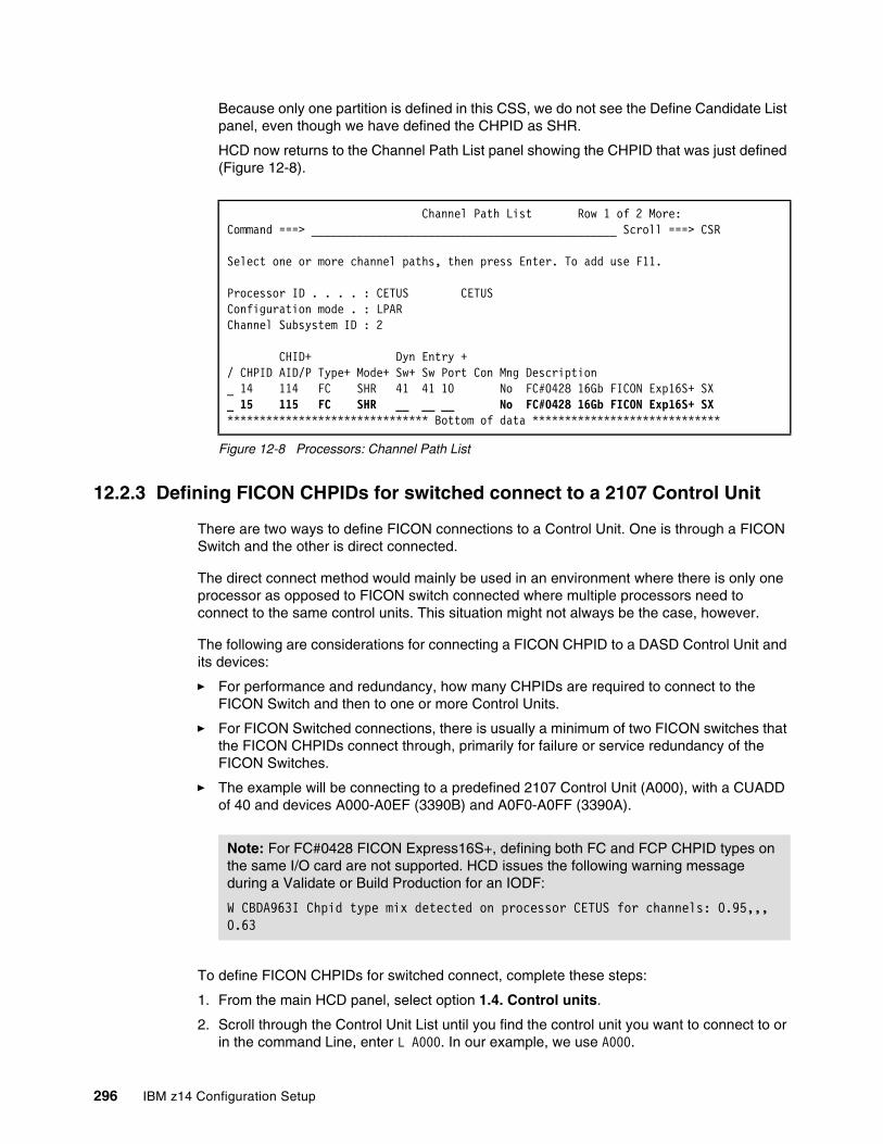
Because only one partition is defined in this CSS, we do not see the Define Candidate List panel, even though we have defined the CHPID as SHR.
HCD now returns to the Channel Path List panel showing the CHPID that was just defined (Figure 12-8).
Figure 12-8 Processors: Channel Path List
12.2.3 Defining FICON CHPIDs for switched connect to a 2107 Control Unit
There are two ways to define FICON connections to a Control Unit. One is through a FICON Switch and the other is direct connected.
The direct connect method would mainly be used in an environment where there is only one processor as opposed to FICON switch connected where multiple processors need to connect to the same control units. This situation might not always be the case, however.
The following are considerations for connecting a FICON CHPID to a DASD Control Unit and its devices:
� For performance and redundancy, how many CHPIDs are required to connect to the FICON Switch and then to one or more Control Units.
� For FICON Switched connections, there is usually a minimum of two FICON switches that the FICON CHPIDs connect through, primarily for failure or service redundancy of the FICON Switches.
� The example will be connecting to a predefined 2107 Control Unit (A000), with a CUADD of 40 and devices A000-A0EF (3390B) and A0F0-A0FF (3390A).
To define FICON CHPIDs for switched connect, complete these steps:
1. From the main HCD panel, select option 1.4. Control units.
2. Scroll through the Control Unit List until you find the control unit you want to connect to or in the command Line, enter L A000. In our example, we use A000.
Channel Path List Row 1 of 2 More: Command ===> _______________________________________________ Scroll ===> CSR Select one or more channel paths, then press Enter. To add use F11. Processor ID . . . . : CETUS CETUS Configuration mode . : LPAR Channel Subsystem ID : 2 CHID+ Dyn Entry + / CHPID AID/P Type+ Mode+ Sw+ Sw Port Con Mng Description _ 14 114 FC SHR 41 41 10 No FC#0428 16Gb FICON Exp16S+ SX _ 15 115 FC SHR __ __ __ No FC#0428 16Gb FICON Exp16S+ SX ******************************* Bottom of data *****************************
Note: For FC#0428 FICON Express16S+, defining both FC and FCP CHPID types on the same I/O card are not supported. HCD issues the following warning message during a Validate or Build Production for an IODF:
W CBDA963I Chpid type mix detected on processor CETUS for channels: 0.95,,, 0.63
296 IBM z14 Configuration Setup

3. Enter c next to the Control Unit definition, and press Enter.
4. Make the following updates for a FICON switch connection (Figure 12-9), and press Enter:
– Update Connected to switches to 41. Switch 41 is the switch ID we defined in the previous example.
– Update Ports to 11. Port 11 is the FICON switch port that the Control Unit will connect to (also known as the Destination Link Address (DLA) of the FICON CHPID).
Figure 12-9 Control units: Change Control Unit Definition
HCD now shows the Select Processor / CU panel. This panel is where the connection is now made between the FICON CHPID (14) and the Control Unit FICON Switch Port (11) through the FICON switch (41).
5. Enter c next to the Processor.CSS that contains the partition that we want to have access to the control unit and also has access to the CHPID that we want to connect to the control unit. In our example, we use CETUS.2, then press Enter.
+----------------- Change Control Unit Definition ------------------+| || || Specify or revise the following values. || || Control unit number . . . . A000 + || || Control unit type . . . . . 2107 + || || Serial number . . . . . . . __________ + || Description . . . . . . . . DS8886 - SU2 - SSID=A000 || || Connected to switches . . . 41 __ __ __ __ __ __ __ + || Ports . . . . . . . . . . . 11 __ __ __ __ __ __ __ + || || Define more than eight ports . . 2 1. Yes || 2. No || || F1=Help F2=Split F3=Exit F4=Prompt F5=Reset F9=Swap || F12=Cancel |+-------------------------------------------------------------------+
Chapter 12. Adding storage devices 297
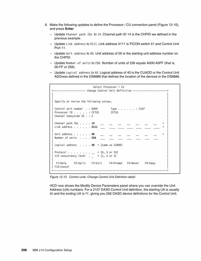
6. Make the following updates to define the Processor / CU connection panel (Figure 12-10), and press Enter:
– Update Channel path IDs to 14. Channel path ID 14 is the CHPID we defined in the previous example.
– Update Link address to 4111. Link address 4111 is FICON switch 41 and Control Unit Port 11.
– Update Unit address to 00. Unit address of 00 is the starting unit address number on the CHPID.
– Update Number of units to 256. Number of units of 256 equals A000-A0FF (that is, 00-FF or 256).
– Update Logical address to 40. Logical address of 40 is the CUADD or the Control Unit ADDress defined in the DS8886 that defines the location of the devices in the DS8886.
Figure 12-10 Control units: Change Control Unit Definition detail
HCD now shows the Modify Device Parameters panel where you can override the Unit Address (UA) numbers. For a 2107 DASD Control Unit definition, the starting UA is usually 00 and the ending UA is FF, giving you 256 DASD device definitions for the Control Unit.
Select Processor / CU +---------------------- Change Control Unit Definition -----------------------+| || || Specify or revise the following values. || || Control unit number . : A000 Type . . . . . . : 2107 || Processor ID . . . . . : CETUS CETUS || Channel Subsystem ID . : 2 || || Channel path IDs . . . . 14 __ __ __ __ __ __ __ + || Link address . . . . . . 4111 ___ ____ ____ ____ ____ ____ ____ + || || Unit address . . . . . . 00 __ __ __ __ __ __ __ + || Number of units . . . . 256 ___ ___ ___ ___ ___ ___ ___ || || Logical address . . . . 40 + (same as CUADD) || || Protocol . . . . . . . . __ + (D, S or S4) || I/O concurrency level . _ + (1, 2 or 3) || || F1=Help F2=Split F3=Exit F4=Prompt F5=Reset F9=Swap || F12=Cancel |+-----------------------------------------------------------------------------+
298 IBM z14 Configuration Setup
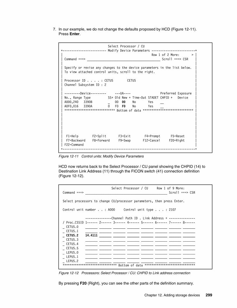
7. In our example, we do not change the defaults proposed by HCD (Figure 12-11). Press Enter.
Figure 12-11 Control units: Modify Device Parameters
HCD now returns back to the Select Processor / CU panel showing the CHPID (14) to Destination Link Address (11) through the FICON switch (41) connection definition (Figure 12-12).
Figure 12-12 Processors: Select Processor / CU: CHPID to Link address connection
By pressing F20 (Right), you can see the other parts of the definition summary.
Select Processor / CU +------------------------- Modify Device Parameters -------------------------+| Row 1 of 2 More: > || Command ===> __________________________________________ Scroll ===> CSR || || Specify or revise any changes to the device parameters in the list below. || To view attached control units, scroll to the right. || || Processor ID . . . . : CETUS CETUS || Channel Subsystem ID : 2 || || ---------Device--------- ---UA---- Preferred Exposure || No., Range Type SS+ Old New + Time-Out STADET CHPID + Device || A000,240 3390B _ 00 00 No Yes __ || A0F0,016 3390A 0 F0 F0 No Yes __ || ***************************** Bottom of data ***************************** || || || || || || F1=Help F2=Split F3=Exit F4=Prompt F5=Reset || F7=Backward F8=Forward F9=Swap F12=Cancel F20=Right || F22=Command |+----------------------------------------------------------------------------+
Select Processor / CU Row 1 of 9 More: Command ===> _______________________________________________ Scroll ===> CSR Select processors to change CU/processor parameters, then press Enter. Control unit number . . : A000 Control unit type . . . : 2107 ---------------Channel Path ID . Link Address + --------------- / Proc.CSSID 1------ 2------ 3------ 4------ 5------ 6------ 7------ 8------ _ CETUS.0 _______ _______ _______ _______ _______ _______ _______ _______ _ CETUS.1 _______ _______ _______ _______ _______ _______ _______ _______ _ CETUS.2 14.4111 _______ _______ _______ _______ _______ _______ _______ _ CETUS.3 _______ _______ _______ _______ _______ _______ _______ _______ _ CETUS.4 _______ _______ _______ _______ _______ _______ _______ _______ _ CETUS.5 _______ _______ _______ _______ _______ _______ _______ _______ _ LEPUS.0 _______ _______ _______ _______ _______ _______ _______ _______ _ LEPUS.1 _______ _______ _______ _______ _______ _______ _______ _______ _ LEPUS.2 _______ _______ _______ _______ _______ _______ _______ _______ ******************************* Bottom of data *****************************
Chapter 12. Adding storage devices 299
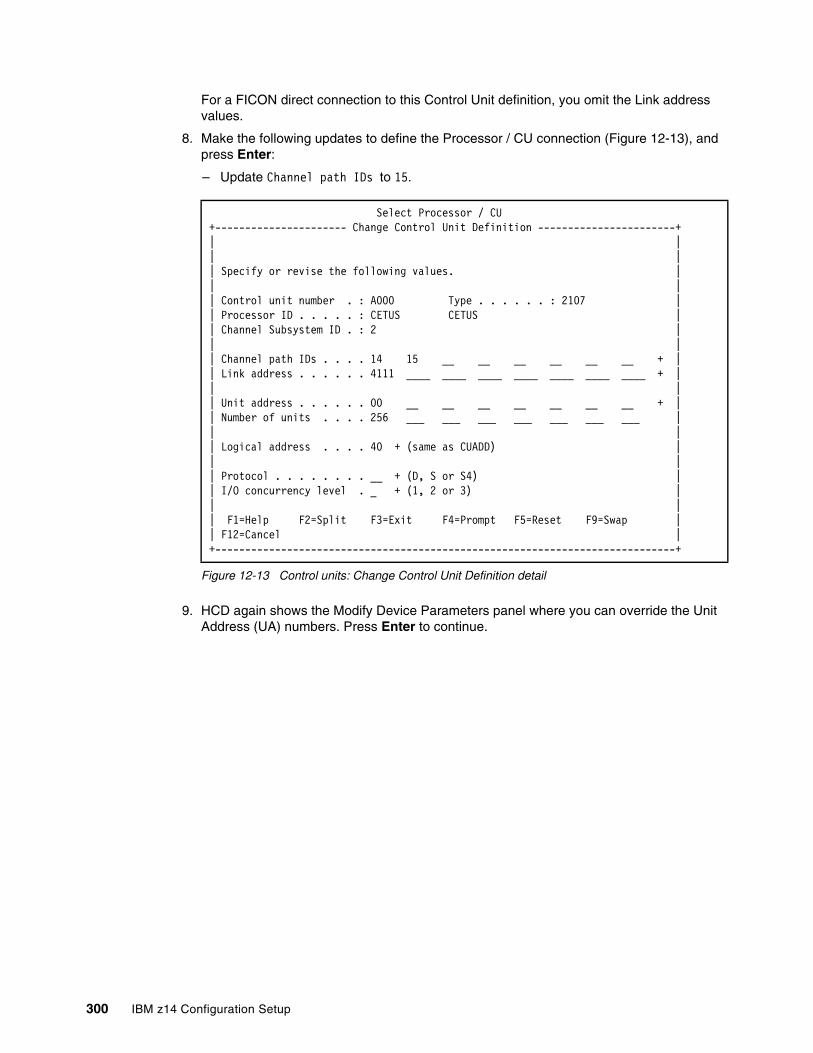
For a FICON direct connection to this Control Unit definition, you omit the Link address values.
8. Make the following updates to define the Processor / CU connection (Figure 12-13), and press Enter:
– Update Channel path IDs to 15.
Figure 12-13 Control units: Change Control Unit Definition detail
9. HCD again shows the Modify Device Parameters panel where you can override the Unit Address (UA) numbers. Press Enter to continue.
Select Processor / CU +---------------------- Change Control Unit Definition -----------------------+| || || Specify or revise the following values. || || Control unit number . : A000 Type . . . . . . : 2107 || Processor ID . . . . . : CETUS CETUS || Channel Subsystem ID . : 2 || || Channel path IDs . . . . 14 15 __ __ __ __ __ __ + || Link address . . . . . . 4111 ____ ____ ____ ____ ____ ____ ____ + || || Unit address . . . . . . 00 __ __ __ __ __ __ __ + || Number of units . . . . 256 ___ ___ ___ ___ ___ ___ ___ || || Logical address . . . . 40 + (same as CUADD) || || Protocol . . . . . . . . __ + (D, S or S4) || I/O concurrency level . _ + (1, 2 or 3) || || F1=Help F2=Split F3=Exit F4=Prompt F5=Reset F9=Swap || F12=Cancel |+-----------------------------------------------------------------------------+
300 IBM z14 Configuration Setup
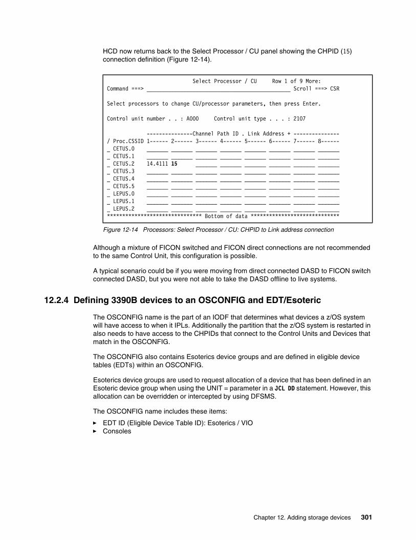
HCD now returns back to the Select Processor / CU panel showing the CHPID (15) connection definition (Figure 12-14).
Figure 12-14 Processors: Select Processor / CU: CHPID to Link address connection
Although a mixture of FICON switched and FICON direct connections are not recommended to the same Control Unit, this configuration is possible.
A typical scenario could be if you were moving from direct connected DASD to FICON switch connected DASD, but you were not able to take the DASD offline to live systems.
12.2.4 Defining 3390B devices to an OSCONFIG and EDT/Esoteric
The OSCONFIG name is the part of an IODF that determines what devices a z/OS system will have access to when it IPLs. Additionally the partition that the z/OS system is restarted in also needs to have access to the CHPIDs that connect to the Control Units and Devices that match in the OSCONFIG.
The OSCONFIG also contains Esoterics device groups and are defined in eligible device tables (EDTs) within an OSCONFIG.
Esoterics device groups are used to request allocation of a device that has been defined in an Esoteric device group when using the UNIT = parameter in a JCL DD statement. However, this allocation can be overridden or intercepted by using DFSMS.
The OSCONFIG name includes these items:
� EDT ID (Eligible Device Table ID): Esoterics / VIO� Consoles
Select Processor / CU Row 1 of 9 More: Command ===> _______________________________________________ Scroll ===> CSR Select processors to change CU/processor parameters, then press Enter. Control unit number . . : A000 Control unit type . . . : 2107 ---------------Channel Path ID . Link Address + ---------------/ Proc.CSSID 1------ 2------ 3------ 4------ 5------ 6------ 7------ 8------_ CETUS.0 _______ _______ _______ _______ _______ _______ _______ ________ CETUS.1 _______ _______ _______ _______ _______ _______ _______ ________ CETUS.2 14.4111 15 _______ _______ _______ _______ _______ ________ CETUS.3 _______ _______ _______ _______ _______ _______ _______ ________ CETUS.4 _______ _______ _______ _______ _______ _______ _______ ________ CETUS.5 _______ _______ _______ _______ _______ _______ _______ ________ LEPUS.0 _______ _______ _______ _______ _______ _______ _______ ________ LEPUS.1 _______ _______ _______ _______ _______ _______ _______ ________ LEPUS.2 _______ _______ _______ _______ _______ _______ _______ _______******************************* Bottom of data *****************************
Chapter 12. Adding storage devices 301

The following are considerations for adding devices to an OSCONFIG and Esoteric:
� Adding a device to an OSCONFIG does not necessarily mean that the z/OS system will have access to that device.
� Does the device need to be added to an Esoteric device group. Mostly this is installation-specific.
� The example will be adding the predefined 2107 devices A000-A0EF (3390B) and A0F0-A0FF (3390A).
To define 3390B devices to an OSCONFIG and EDT/Esoteric, complete these steps:
1. From the main HCD panel, select option 1.5. I/O Devices.
2. Scroll through the I/O Device List until you find the device number you want to add to the OSCONFIG or in the command line enter L A000. In our example, we use A000.
3. Enter c next to one or more Device numbers, and press Enter.
HCD displays the Change Device Definition panel where you can modify the Control Unit that the devices are attached to (Figure 12-15). Press Enter.
Figure 12-15 I/O Devices: Change Device Definition
HCD now displays the Device / Processor Definition panel where you can modify some of the Device parameters relating to SubChannel Set (SS), Unit Address (UA), and the Explicit Device Candidate List.
+------------------------- Change Device Definition --------------------------+| || || Specify or revise the following values. || || Device number . . . . . . . : A000 (0000 - FFFF) || Number of devices . . . . . : 240 || Device type . . . . . . . . : 3390B || || Serial number . . . . . . . . __________ + || Description . . . . . . . . . ________________________________ || || Volume serial number . . . . . ______ + (for DASD) || || PPRC usage . . . . . . . . . . _ + (for DASD) || || Connected to CUs . A000 ____ ____ ____ ____ ____ ____ ____ + || || ENTER to continue. || || F1=Help F2=Split F3=Exit F4=Prompt F5=Reset F9=Swap || F12=Cancel |+-----------------------------------------------------------------------------+
302 IBM z14 Configuration Setup

4. Enter c next to the Proc.CCSID item if you want to modify any of these parameters (Figure 12-16) or press Enter to accept the defaults.
Figure 12-16 I/O Devices: Device / Processor Definition continued
5. Next is the HCD panel where you Define Devices to the Operating System Configuration. Scroll through the list of OSCONFIG definitions until you find the OSCONFIG you want to add to the Devices to or in the command line, enter L ITSOTEST. In our example, we use ITSOTEST.
6. Enter s next to the OSCONFIG, and press Enter.
HCD displays the Device Parameters and Features applicable to that particular device type. In our example, we are adding 3390B and 3390A devices to ITSOTEST.
+---------------------- Device / Processor Definition -----------------------+| Row 1 of 1 || Command ===> __________________________________________ Scroll ===> CSR || || Select processors to change device/processor definitions, then press || Enter. || || Device number . . : A000 Number of devices . : 240 || Device type . . . : 3390B || || Preferred Device Candidate List || / Proc.CSSID SS+ UA+ Time-Out STADET CHPID + Explicit Null || c CETUS.2 _ 00 No Yes __ No ___ || ***************************** Bottom of data ***************************** || || || F1=Help F2=Split F3=Exit F4=Prompt F5=Reset || F6=Previous F7=Backward F8=Forward F9=Swap F12=Cancel || F22=Command |+----------------------------------------------------------------------------+
Chapter 12. Adding storage devices 303
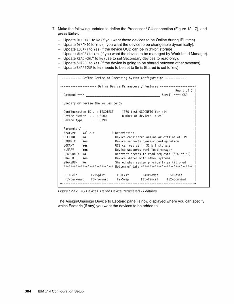
7. Make the following updates to define the Processor / CU connection (Figure 12-17), and press Enter:
– Update OFFLINE to No (if you want these devices to be Online during IPL time).– Update DYNAMIC to Yes (if you want the device to be changeable dynamically).– Update LOCANY to Yes (if the device UCB can be in 31-bit storage).– Update WLMPAV to Yes (if you want the device to be managed by Work Load Manager).– Update READ-ONLY to No (use to set Secondary devices to read only).– Update SHARED to Yes (if the device is going to be shared between other systems).– Update SHAREDUP to No (needs to be set to No is Shared is set to Yes).
Figure 12-17 I/O Devices: Define Device Parameters / Features
The Assign/Unassign Device to Esoteric panel is now displayed where you can specify which Esoteric (if any) you want the devices to be added to.
+----------- Define Device to Operating System Configuration -----------+ | | +-------------------- Define Device Parameters / Features --------------------+| Row 1 of 7 || Command ===> ___________________________________________ Scroll ===> CSR || || Specify or revise the values below. || || Configuration ID . : ITSOTEST ITSO test OSCONFIG for z14 || Device number . . : A000 Number of devices : 240 || Device type . . . : 3390B || || Parameter/ || Feature Value + R Description || OFFLINE No Device considered online or offline at IPL || DYNAMIC Yes Device supports dynamic configuration || LOCANY Yes UCB can reside in 31 bit storage || WLMPAV Yes Device supports work load manager || READ-ONLY No Restrict access to read requests (SEC or NO) || SHARED Yes Device shared with other systems || SHAREDUP No Shared when system physically partitioned || ***************************** Bottom of data ****************************** || || F1=Help F2=Split F3=Exit F4=Prompt F5=Reset || F7=Backward F8=Forward F9=Swap F12=Cancel F22=Command |+-----------------------------------------------------------------------------+
304 IBM z14 Configuration Setup
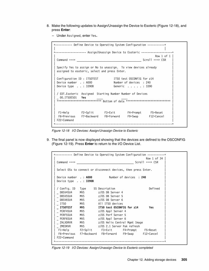
8. Make the following updates to Assign/Unassign the Device to Esoteric (Figure 12-18), and press Enter:
– Under Assigned, enter Yes.
Figure 12-18 I/O Devices: Assign/Unassign Device to Esoteric
9. The final panel is now displayed showing that the devices are defined to the OSCONFIG (Figure 12-19). Press Enter to return to the I/O Device List.
Figure 12-19 I/O Devices: Assign/Unassign Device to Esoteric completed
+----------- Define Device to Operating System Configuration -----------+ | | +-------------------- Assign/Unassign Device to Esoteric --------------------+| Row 1 of 1 || Command ===> __________________________________________ Scroll ===> CSR || || Specify Yes to assign or No to unassign. To view devices already || assigned to esoteric, select and press Enter. || || Configuration ID : ITSOTEST ITSO test OSCONFIG for z14 || Device number . : A000 Number of devices : 240 || Device type . . : 3390B Generic . . . . . : 3390 || || / EDT.Esoteric Assigned Starting Number Number of Devices || _ 00.ITSOESO1 Yes ____ ____ || ***************************** Bottom of data ***************************** || || || F1=Help F2=Split F3=Exit F4=Prompt F5=Reset || F6=Previous F7=Backward F8=Forward F9=Swap F12=Cancel || F22=Command |+----------------------------------------------------------------------------+
+----------- Define Device to Operating System Configuration -----------+| Row 1 of 34 || Command ===> _____________________________________ Scroll ===> CSR || || Select OSs to connect or disconnect devices, then press Enter. || || Device number . : A000 Number of devices : 240 || Device type . . : 3390B || || / Config. ID Type SS Description Defined || _ DBSV4SU4 MVS z/OS DB Server 4 || _ DBSV5SU4 MVS z/OS DB Server 5 || _ DBSV6SU4 MVS z/OS DB Server 6 || _ ITSO MVS All ITSO devices || _ ITSOTEST MVS ITSO test OSCONFIG for z14 Yes || _ PERF4SU4 MVS z/OS Appl Server 4 || _ PERF5SU4 MVS z/OS Perf Server 5 || _ PERF6SU4 MVS z/OS Appl Server 6 || _ ZHLXDRVR MVS z/OS Helix Central Mgmt Image || _ ZMEDRVR MVS z/OS 2.1 Server Pak refresh || F1=Help F2=Split F3=Exit F4=Prompt F5=Reset || F6=Previous F7=Backward F8=Forward F9=Swap F12=Cancel || F22=Command |+-----------------------------------------------------------------------+
Chapter 12. Adding storage devices 305

The same steps can now be performed for the remaining devices A0F0-A0FF (3390A) for this example.
306 IBM z14 Configuration Setup
Chapter 13. Adding network devices
This chapter describes steps on how to define OSC, OSD, OSE, OSM, and IQD CHPIDs; Control Units; and devices.
Here is a list of these potential configuration items and a short description on how to do each of them using HCD.
This chapter includes the following sections:
� Defining more I/O using HCD� OSA CHPID definitions� IQD CHPIDs for HiperSockets
13
Note: Not all of the following configuration items are necessarily required for your installation. In addition, the examples presented are not exhaustive.
© Copyright IBM Corp. 2017. All rights reserved. 307

13.1 Defining more I/O using HCD
When defining new I/O components in an IODF, certain definitions like OSCONFIGs, partitions, FICON Switches, Control Units, and Devices need to be made up front. After these items have been defined, then the connections can be made:
� Defining OSC CHPIDs� Defining OSC CHPID connections to an OSC Control Unit� Defining 3270-X devices to an OSCONFIG� Defining 3270-X devices to NIP within an OSCONFIG� Defining OSD CHPIDs� Defining OSD CHPID connections to an OSA Control Unit� Defining OSA and OSAD devices to an OSCONFIG� Defining OSE CHPIDs� Defining OSE CHPID connections to an OSA Control Unit� Defining OSA and OSAD devices to an OSCONFIG� Defining OSM CHPIDs� Defining OSM CHPID connections to an OSM Control Unit� Defining OSA-M devices to an OSCONFIG� Defining IQD CHPIDs� Defining IQD CHPID connections to an IQD Control Unit� Defining IQD devices to an OSCONFIG
The following I/O definitions use HCD to demonstrate the examples. The examples continue with the work example created in the previous sections (for example, SYS6.IODF29.WORK).
13.2 OSA CHPID definitions
This section covers defining OSC, OSD, OSE, and OSM CHPIDs and their control units and devices.
13.2.1 Defining OSC CHPIDs
When defining an OSD or OSE connection, first you need to determine which type of OSA card you need for your configuration. OSC connections use the copper-based OSA Express6S 1000BASE-T card:
� Optical based cards:
– OSA Express6S GbE SX or LX
– OSA Express6S 10 Gb SR or LR
� Copper-based cards:
– OSA Express6S 1000BASE-T
The following are considerations for a new OSC CHPID:
� Channel path ID (CHPID)� Channel ID (CHID)� Channel path type� Operational mode� Description� Partition access list
308 IBM z14 Configuration Setup

� For performance and redundancy, how many I/O cards of that feature are installed in the processor and to what PCIe ports on what CPC drawer that the I/O cards connect to (see the PCHID/CHID report for a list of installed hardware)
To define a new OSC CHPID, and provide access to a partition, complete these steps:
1. From the main HCD panel, select option 1.3. Processors.
2. Enter s next to the Processor that you want to add a CHPID to, and press Enter.
3. Enter s next to the CSS ID that you want to add a CHPID to, and press Enter.
4. In the command line, enter add (Figure 13-1), to add a CHPID.
5. Make the following updates and press Enter:
– Update Channel path ID to B1.’Update Channel ID to 1B8.– Update Channel path type to OSC.– Update Operational mode to SHR.– Update Description to the description that you want.
Figure 13-1 Processors: Add Channel Path, OSC
+---------------------------- Add Channel Path -----------------------------+| || || Specify or revise the following values. || || Processor ID . . . . : CETUS CETUS || Configuration mode . : LPAR || Channel Subsystem ID : 2 || || Channel path ID . . . . B1 + Channel ID 1B8 + || Number of CHPIDs . . . . 1 || Channel path type . . . OSC + || Operation mode . . . . . SHR + || Managed . . . . . . . . No (Yes or No) I/O Cluster + || Description . . . . . . FC#0426 OSA Express6S 1000BASE-T || || Specify the following values only if connected to a switch: || Dynamic entry switch ID __ + (00 - FF) || Entry switch ID . . . . __ + || Entry port . . . . . . . __ + || F1=Help F2=Split F3=Exit F4=Prompt F5=Reset F9=Swap || F12=Cancel |+---------------------------------------------------------------------------+
Chapter 13. Adding network devices 309
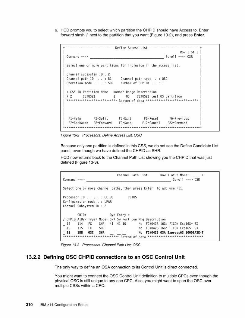
6. HCD prompts you to select which partition the CHPID should have Access to. Enter forward slash ‘/’ next to the partition that you want (Figure 13-2), and press Enter.
Figure 13-2 Processors: Define Access List, OSC
Because only one partition is defined in this CSS, we do not see the Define Candidate List panel, even though we have defined the CHPID as SHR.
HCD now returns back to the Channel Path List showing you the CHPID that was just defined (Figure 13-3).
Figure 13-3 Processors: Channel Path List, OSC
13.2.2 Defining OSC CHPID connections to an OSC Control Unit
The only way to define an OSA connection to its Control Unit is direct connected.
You might want to connect the OSC Control Unit definition to multiple CPCs even though the physical OSC is still unique to any one CPC. Also, you might want to span the OSC over multiple CSSs within a CPC.
+--------------------------- Define Access List ----------------------------+| Row 1 of 1 || Command ===> _________________________________________ Scroll ===> CSR || || Select one or more partitions for inclusion in the access list. || || Channel subsystem ID : 2 || Channel path ID . . : B1 Channel path type . : OSC || Operation mode . . . : SHR Number of CHPIDs . . : 1 || || / CSS ID Partition Name Number Usage Description || / 2 CETUS21 1 OS CETUS21 test OS partition || **************************** Bottom of data ***************************** || || || || F1=Help F2=Split F3=Exit F5=Reset F6=Previous || F7=Backward F8=Forward F9=Swap F12=Cancel F22=Command |+---------------------------------------------------------------------------+
Channel Path List Row 1 of 3 More: >Command ===> _______________________________________________ Scroll ===> CSR Select one or more channel paths, then press Enter. To add use F11. Processor ID . . . . : CETUS CETUS Configuration mode . : LPAR Channel Subsystem ID : 2 CHID+ Dyn Entry + / CHPID AID/P Type+ Mode+ Sw+ Sw Port Con Mng Description _ 14 114 FC SHR 41 41 10 No FC#0428 16Gb FICON Exp16S+ SX _ 15 115 FC SHR __ __ __ No FC#0428 16Gb FICON Exp16S+ SX _ B1 1B8 OSC SHR __ __ __ No FC#0426 OSA Express6S 1000BASE-T******************************* Bottom of data *******************************
310 IBM z14 Configuration Setup
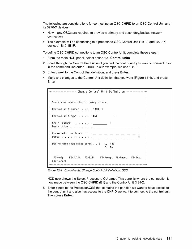
The following are considerations for connecting an OSC CHPID to an OSC Control Unit and its 3270-X devices:
� How many OSCs are required to provide a primary and secondary/backup network connection.
� The example will be connecting to a predefined OSC Control Unit (1B10) and 3270-X devices 1B10-1B1F.
To define OSC CHPID connections to an OSC Control Unit, complete these steps:
1. From the main HCD panel, select option 1.4. Control units.
2. Scroll through the Control Unit List until you find the control unit you want to connect to or in the command line enter L 1B10. In our example, we use 1B10.
3. Enter c next to the Control Unit definition, and press Enter.
4. Make any changes to the Control Unit definition that you want (Figure 13-4), and press Enter.
Figure 13-4 Control units: Change Control Unit Definition, OSC
HCD now shows the Select Processor / CU panel. This panel is where the connection is now made between the OSC CHPID (B1) and the Control Unit (1B10).
5. Enter c next to the Processor.CSS that contains the partition we want to have access to the control unit and also has access to the CHPID we want to connect to the control unit. Then press Enter.
+---------------- Change Control Unit Definition ------------+| || || Specify or revise the following values. || || Control unit number . . . . 1B10 + || || Control unit type . . . . . OSC + || || Serial number . . . . . . . __________ + || Description . . . . . . . . ________________________________ || || Connected to switches . . . __ __ __ __ __ __ __ __ + || Ports . . . . . . . . . . . __ __ __ __ __ __ __ __ + || || Define more than eight ports . . 2 1. Yes || 2. No || || || F1=Help F2=Split F3=Exit F4=Prompt F5=Reset F9=Swap || F12=Cancel |+-------------------------------------------------------------------+
Chapter 13. Adding network devices 311

6. Make the following updates to define the Processor / CU connection (Figure 13-5), and press Enter:
– Update Channel path IDs to B1. Channel path ID B1 is the CHPID we defined in the previous example.
Figure 13-5 Control units: Change Control Unit Definition detail, OSC
7. HCD now shows the Modify Device Parameters panel where you can override the Unit Address (UA) numbers. For most OSA definitions, the Unit address starts at 00.
Select Processor / CU +---------------------- Change Control Unit Definition -----------------------+| || || Specify or revise the following values. || || Control unit number . : 1B10 Type . . . . . . : OSC || Processor ID . . . . . : CETUS CETUS || Channel Subsystem ID . : 2 || || Channel path IDs . . . . B1 __ __ __ __ __ __ __ + || Link address . . . . . . ____ ____ ____ ____ ____ ____ ____ ____ + || || Unit address . . . . . . 00 __ __ __ __ __ __ __ + || Number of units . . . . 254 ___ ___ ___ ___ ___ ___ ___ || || Logical address . . . . __ + (same as CUADD) || || Protocol . . . . . . . . __ + (D, S or S4) || I/O concurrency level . _ + (1, 2 or 3) || || F1=Help F2=Split F3=Exit F4=Prompt F5=Reset F9=Swap || F12=Cancel |+-----------------------------------------------------------------------------+
312 IBM z14 Configuration Setup
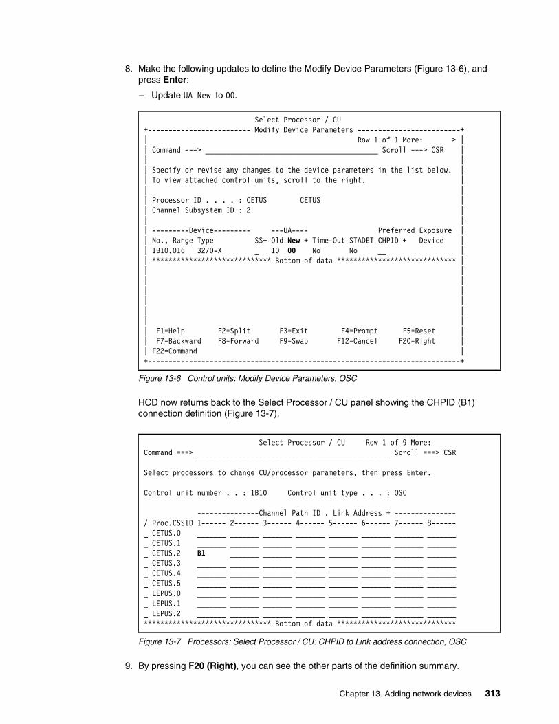
8. Make the following updates to define the Modify Device Parameters (Figure 13-6), and press Enter:
– Update UA New to 00.
Figure 13-6 Control units: Modify Device Parameters, OSC
HCD now returns back to the Select Processor / CU panel showing the CHPID (B1) connection definition (Figure 13-7).
Figure 13-7 Processors: Select Processor / CU: CHPID to Link address connection, OSC
9. By pressing F20 (Right), you can see the other parts of the definition summary.
Select Processor / CU +------------------------- Modify Device Parameters -------------------------+| Row 1 of 1 More: > || Command ===> __________________________________________ Scroll ===> CSR || || Specify or revise any changes to the device parameters in the list below. || To view attached control units, scroll to the right. || || Processor ID . . . . : CETUS CETUS || Channel Subsystem ID : 2 || || ---------Device--------- ---UA---- Preferred Exposure || No., Range Type SS+ Old New + Time-Out STADET CHPID + Device || 1B10,016 3270-X _ 10 00 No No __ || ***************************** Bottom of data ***************************** || || || || || || || F1=Help F2=Split F3=Exit F4=Prompt F5=Reset || F7=Backward F8=Forward F9=Swap F12=Cancel F20=Right || F22=Command |+----------------------------------------------------------------------------+
Select Processor / CU Row 1 of 9 More: Command ===> _______________________________________________ Scroll ===> CSR Select processors to change CU/processor parameters, then press Enter. Control unit number . . : 1B10 Control unit type . . . : OSC ---------------Channel Path ID . Link Address + ---------------/ Proc.CSSID 1------ 2------ 3------ 4------ 5------ 6------ 7------ 8------_ CETUS.0 _______ _______ _______ _______ _______ _______ _______ ________ CETUS.1 _______ _______ _______ _______ _______ _______ _______ ________ CETUS.2 B1 _______ _______ _______ _______ _______ _______ ________ CETUS.3 _______ _______ _______ _______ _______ _______ _______ ________ CETUS.4 _______ _______ _______ _______ _______ _______ _______ ________ CETUS.5 _______ _______ _______ _______ _______ _______ _______ ________ LEPUS.0 _______ _______ _______ _______ _______ _______ _______ ________ LEPUS.1 _______ _______ _______ _______ _______ _______ _______ ________ LEPUS.2 _______ _______ _______ _______ _______ _______ _______ _______******************************* Bottom of data *****************************
Chapter 13. Adding network devices 313
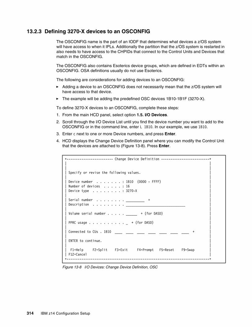
13.2.3 Defining 3270-X devices to an OSCONFIG
The OSCONFIG name is the part of an IODF that determines what devices a z/OS system will have access to when it IPLs. Additionally the partition that the z/OS system is restarted in also needs to have access to the CHPIDs that connect to the Control Units and Devices that match in the OSCONFIG.
The OSCONFIG also contains Esoterics device groups, which are defined in EDTs within an OSCONFIG. OSA definitions usually do not use Esoterics.
The following are considerations for adding devices to an OSCONFIG:
� Adding a device to an OSCONFIG does not necessarily mean that the z/OS system will have access to that device.
� The example will be adding the predefined OSC devices 1B10-1B1F (3270-X).
To define 3270-X devices to an OSCONFIG, complete these steps:
1. From the main HCD panel, select option 1.5. I/O Devices.
2. Scroll through the I/O Device List until you find the device number you want to add to the OSCONFIG or in the command line, enter L 1B10. In our example, we use 1B10.
3. Enter c next to one or more Device numbers, and press Enter.
4. HCD displays the Change Device Definition panel where you can modify the Control Unit that the devices are attached to (Figure 13-8). Press Enter.
Figure 13-8 I/O Devices: Change Device Definition, OSC
+------------------------- Change Device Definition --------------------------+| || || Specify or revise the following values. || || Device number . . . . . . . : 1B10 (0000 - FFFF) || Number of devices . . . . . : 16 || Device type . . . . . . . . : 3270-X || || Serial number . . . . . . . . __________ + || Description . . . . . . . . . ________________________________ || || Volume serial number . . . . . ______ + (for DASD) || || PPRC usage . . . . . . . . . . _ + (for DASD) || || Connected to CUs . 1B10 ____ ____ ____ ____ ____ ____ ____ + || || ENTER to continue. || || F1=Help F2=Split F3=Exit F4=Prompt F5=Reset F9=Swap || F12=Cancel |+-----------------------------------------------------------------------------+
314 IBM z14 Configuration Setup
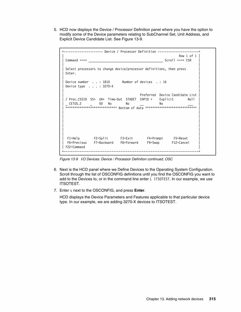
5. HCD now displays the Device / Processor Definition panel where you have the option to modify some of the Device parameters relating to SubChannel Set, Unit Address, and Explicit Device Candidate List. See Figure 13-9.
Figure 13-9 I/O Devices: Device / Processor Definition continued, OSC
6. Next is the HCD panel where we Define Devices to the Operating System Configuration. Scroll through the list of OSCONFIG definitions until you find the OSCONFIG you want to add to the Devices to, or in the command line enter L ITSOTEST. In our example, we use ITSOTEST.
7. Enter s next to the OSCONFIG, and press Enter.
HCD displays the Device Parameters and Features applicable to that particular device type. In our example, we are adding 3270-X devices to ITSOTEST.
+---------------------- Device / Processor Definition -----------------------+| Row 1 of 1 || Command ===> __________________________________________ Scroll ===> CSR || || Select processors to change device/processor definitions, then press || Enter. || || Device number . . : 1B10 Number of devices . : 16 || Device type . . . : 3270-X || || Preferred Device Candidate List || / Proc.CSSID SS+ UA+ Time-Out STADET CHPID + Explicit Null || _ CETUS.2 _ 00 No No __ No ___ || ***************************** Bottom of data ***************************** || || || || || || || F1=Help F2=Split F3=Exit F4=Prompt F5=Reset || F6=Previous F7=Backward F8=Forward F9=Swap F12=Cancel || F22=Command |+----------------------------------------------------------------------------+
Chapter 13. Adding network devices 315
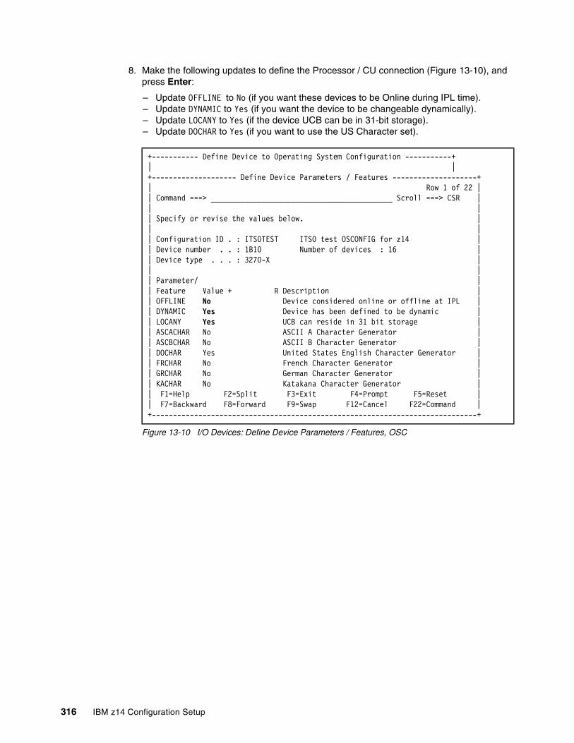
8. Make the following updates to define the Processor / CU connection (Figure 13-10), and press Enter:
– Update OFFLINE to No (if you want these devices to be Online during IPL time).– Update DYNAMIC to Yes (if you want the device to be changeable dynamically).– Update LOCANY to Yes (if the device UCB can be in 31-bit storage).– Update DOCHAR to Yes (if you want to use the US Character set).
Figure 13-10 I/O Devices: Define Device Parameters / Features, OSC
+----------- Define Device to Operating System Configuration -----------+ | | +-------------------- Define Device Parameters / Features --------------------+| Row 1 of 22 || Command ===> ___________________________________________ Scroll ===> CSR || || Specify or revise the values below. || || Configuration ID . : ITSOTEST ITSO test OSCONFIG for z14 || Device number . . : 1B10 Number of devices : 16 || Device type . . . : 3270-X || || Parameter/ || Feature Value + R Description || OFFLINE No Device considered online or offline at IPL || DYNAMIC Yes Device has been defined to be dynamic || LOCANY Yes UCB can reside in 31 bit storage || ASCACHAR No ASCII A Character Generator || ASCBCHAR No ASCII B Character Generator || DOCHAR Yes United States English Character Generator || FRCHAR No French Character Generator || GRCHAR No German Character Generator || KACHAR No Katakana Character Generator || F1=Help F2=Split F3=Exit F4=Prompt F5=Reset || F7=Backward F8=Forward F9=Swap F12=Cancel F22=Command |+-----------------------------------------------------------------------------+
316 IBM z14 Configuration Setup
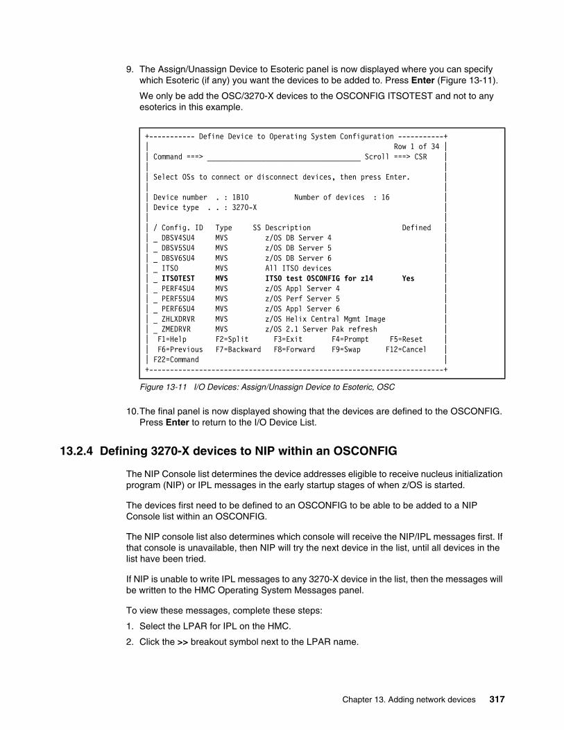
9. The Assign/Unassign Device to Esoteric panel is now displayed where you can specify which Esoteric (if any) you want the devices to be added to. Press Enter (Figure 13-11).
We only be add the OSC/3270-X devices to the OSCONFIG ITSOTEST and not to any esoterics in this example.
Figure 13-11 I/O Devices: Assign/Unassign Device to Esoteric, OSC
10.The final panel is now displayed showing that the devices are defined to the OSCONFIG. Press Enter to return to the I/O Device List.
13.2.4 Defining 3270-X devices to NIP within an OSCONFIG
The NIP Console list determines the device addresses eligible to receive nucleus initialization program (NIP) or IPL messages in the early startup stages of when z/OS is started.
The devices first need to be defined to an OSCONFIG to be able to be added to a NIP Console list within an OSCONFIG.
The NIP console list also determines which console will receive the NIP/IPL messages first. If that console is unavailable, then NIP will try the next device in the list, until all devices in the list have been tried.
If NIP is unable to write IPL messages to any 3270-X device in the list, then the messages will be written to the HMC Operating System Messages panel.
To view these messages, complete these steps:
1. Select the LPAR for IPL on the HMC.
2. Click the >> breakout symbol next to the LPAR name.
+----------- Define Device to Operating System Configuration -----------+| Row 1 of 34 || Command ===> _____________________________________ Scroll ===> CSR || || Select OSs to connect or disconnect devices, then press Enter. || || Device number . : 1B10 Number of devices : 16 || Device type . . : 3270-X || || / Config. ID Type SS Description Defined || _ DBSV4SU4 MVS z/OS DB Server 4 || _ DBSV5SU4 MVS z/OS DB Server 5 || _ DBSV6SU4 MVS z/OS DB Server 6 || _ ITSO MVS All ITSO devices || _ ITSOTEST MVS ITSO test OSCONFIG for z14 Yes || _ PERF4SU4 MVS z/OS Appl Server 4 || _ PERF5SU4 MVS z/OS Perf Server 5 || _ PERF6SU4 MVS z/OS Appl Server 6 || _ ZHLXDRVR MVS z/OS Helix Central Mgmt Image || _ ZMEDRVR MVS z/OS 2.1 Server Pak refresh || F1=Help F2=Split F3=Exit F4=Prompt F5=Reset || F6=Previous F7=Backward F8=Forward F9=Swap F12=Cancel || F22=Command |+-----------------------------------------------------------------------+
Chapter 13. Adding network devices 317
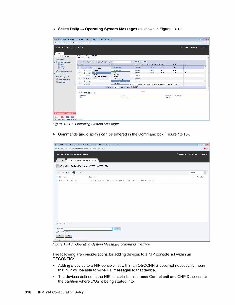
3. Select Daily → Operating System Messages as shown in Figure 13-12.
Figure 13-12 Operating System Messages
4. Commands and displays can be entered in the Command box (Figure 13-13).
Figure 13-13 Operating System Messages command interface
The following are considerations for adding devices to a NIP console list within an OSCONFIG:
� Adding a device to a NIP console list within an OSCONFIG does not necessarily mean that NIP will be able to write IPL messages to that device.
� The devices defined in the NIP console list also need Control unit and CHPID access to the partition where z/OS is being started into.
318 IBM z14 Configuration Setup
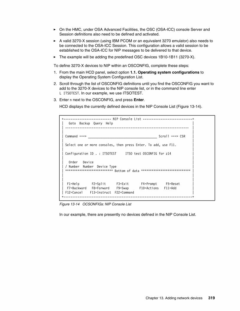
� On the HMC, under OSA Advanced Facilities, the OSC (OSA-ICC) console Server and Session definitions also need to be defined and activated.
� A valid 3270-X session (using IBM PCOM or an equivalent 3270 emulator) also needs to be connected to the OSA-ICC Session. This configuration allows a valid session to be established to the OSA-ICC for NIP messages to be delivered to that device.
� The example will be adding the predefined OSC devices 1B10-1B11 (3270-X).
To define 3270-X devices to NIP within an OSCONFIG, complete these steps:
1. From the main HCD panel, select option 1.1. Operating system configurations to display the Operating System Configuration List.
2. Scroll through the list of OSCONFIG definitions until you find the OSCONFIG you want to add to the 3270-X devices to the NIP console list, or in the command line enter L ITSOTEST. In our example, we use ITSOTEST.
3. Enter n next to the OSCONFIG, and press Enter.
HCD displays the currently defined devices in the NIP Console List (Figure 13-14).
Figure 13-14 OCSONFIGs: NIP Console List
In our example, there are presently no devices defined in the NIP Console List.
+--------------------------- NIP Console List ----------------------------+| Goto Backup Query Help || ---------------------------------------------------------------------- || || Command ===> _______________________________________ Scroll ===> CSR || || Select one or more consoles, then press Enter. To add, use F11. || || Configuration ID . : ITSOTEST ITSO test OSCONFIG for z14 || || Order Device || / Number Number Device Type || *************************** Bottom of data **************************** || || || F1=Help F2=Split F3=Exit F4=Prompt F5=Reset || F7=Backward F8=Forward F9=Swap F10=Actions F11=Add || F12=Cancel F13=Instruct F22=Command |+-------------------------------------------------------------------------+
Chapter 13. Adding network devices 319
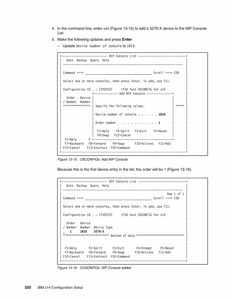
4. In the command line, enter add (Figure 13-15) to add a 3270-X device to the NIP Console List.
5. Make the following updates and press Enter:
– Update Device number of console to 1B10.
Figure 13-15 OSCONFIGs: Add NIP Console
Because this is the first device entry in the list, the order will be 1 (Figure 13-16).
Figure 13-16 OCSONFIGs: NIP Console added
+--------------------------- NIP Console List ----------------------------+| Goto Backup Query Help || ---------------------------------------------------------------------- || || Command ===> _______________________________________ Scroll ===> CSR || || Select one or more consoles, then press Enter. To add, use F11. || || Configuration ID . : ITSOTEST ITSO test OSCONFIG for z14 || +-------------- Add NIP Console ---------------+ || Order Device | | || / Number Number | | || **************** | Specify the following values. | ***** || | | || | Device number of console . . . . . . 1B10 | || | | || | Order number . . . . . . . . . . . . 1 | || | | || | F1=Help F2=Split F3=Exit F5=Reset | || | F9=Swap F12=Cancel | || F1=Help F +----------------------------------------------+ || F7=Backward F8=Forward F9=Swap F10=Actions F11=Add || F12=Cancel F13=Instruct F22=Command |+-------------------------------------------------------------------------+
+--------------------------- NIP Console List ----------------------------+| Goto Backup Query Help || ---------------------------------------------------------------------- || Row 1 of 1 || Command ===> _______________________________________ Scroll ===> CSR || || Select one or more consoles, then press Enter. To add, use F11. || || Configuration ID . : ITSOTEST ITSO test OSCONFIG for z14 || || Order Device || / Number Number Device Type || _ 1 1B10 3270-X || *************************** Bottom of data **************************** || || || F1=Help F2=Split F3=Exit F4=Prompt F5=Reset || F7=Backward F8=Forward F9=Swap F10=Actions F11=Add || F12=Cancel F13=Instruct F22=Command |+-------------------------------------------------------------------------+
320 IBM z14 Configuration Setup

6. Add device 1B11 to the NIP Console List (Figure 13-17).
Figure 13-17 OCSONFIGs: extra NIP Console added
13.2.5 Defining OSD CHPIDs
When defining an OSD or OSE connection, first you need to determine which type of OSA card you need for your configuration. For OSD and ODE connections, they can use either optical or copper-based cards. It depends on the type and speed of network you want to connect your OSAs to:
� Optical based cards:
– OSA Express6S GbE SX or LX
– OSA Express6S 10 Gb SR or LR
� Copper-based cards:
– OSA Express6S 1000BASE-T
The following are considerations for a new OSD CHPID:
� Channel path ID (CHPID)� Channel ID (CHID)� Channel path type� Operational mode� Description� Partition access list� For performance and redundancy, how many I/O cards of that feature are installed in the
processor and to what PCIe ports on what CPC drawer do the I/O cards connect to (see the PCHID/CHID report for a list of installed hardware)
To define a new OSD CHPID, and provide access to a partition, complete these steps:
1. From the main HCD panel, select option 1.3. Processors.
2. Enter s next to the Processor that you want to add a CHPID to, and press Enter.
3. Enter s next to the CSS ID that you want to add a CHPID to, and press Enter.
+--------------------------- NIP Console List ----------------------------+| Goto Backup Query Help || ---------------------------------------------------------------------- || Row 1 of 2 || Command ===> _______________________________________ Scroll ===> CSR || || Select one or more consoles, then press Enter. To add, use F11. || || Configuration ID . : ITSOTEST ITSO test OSCONFIG for z14 || || Order Device || / Number Number Device Type || _ 1 1B10 3270-X || _ 2 1B11 3270-X || *************************** Bottom of data **************************** || || || F1=Help F2=Split F3=Exit F4=Prompt F5=Reset || F7=Backward F8=Forward F9=Swap F10=Actions F11=Add || F12=Cancel F13=Instruct F22=Command |+-------------------------------------------------------------------------+
Chapter 13. Adding network devices 321

4. In the command line, enter add (Figure 13-18) to add a CHPID.
5. Make the following updates and press Enter:
– Update Channel path ID to B2.– Update Channel ID to 1C4.– Update Channel path type to OSD.– Update Operational mode to SHR.– Update Description to the description that you want.
Figure 13-18 Processors: Add Channel Path, OSD
6. HCD now prompts you to specify whether the Allow more than 160 TCP/IP stacks. The default is No, which we will use for our example.
7. Leave the default option for 160 TCP/IP stacks to No for our example (Figure 13-19), and press Enter.
Figure 13-19 Processors: Allow for more than 160 TCP/IP stacks, OSD
8. Next, HCD now prompts you to Add or Modify any Physical Network IDs. We will not be using any Physical Network ID definitions for the OSD definition in this example.
+---------------------------- Add Channel Path -----------------------------+| || || Specify or revise the following values. || || Processor ID . . . . : CETUS CETUS || Configuration mode . : LPAR || Channel Subsystem ID : 2 || || Channel path ID . . . . B2 + Channel ID 1C4 + || Number of CHPIDs . . . . 1 || Channel path type . . . OSD + || Operation mode . . . . . SHR + || Managed . . . . . . . . No (Yes or No) I/O Cluster ________ + || Description . . . . . . FC#0425 OSA Express6S 10GbE SR || || Specify the following values only if connected to a switch: || Dynamic entry switch ID __ + (00 - FF) || Entry switch ID . . . . __ + || Entry port . . . . . . . __ + || F1=Help F2=Split F3=Exit F4=Prompt F5=Reset F9=Swap || F12=Cancel |+---------------------------------------------------------------------------+
+----------- Allow for more than 160 TCP/IP stacks -----------+| || || Specify Yes to allow more than 160 TCP/IP stacks, || otherwise specify No. Specifying Yes will cause priority || queuing to be disabled. || || Will greater than 160 TCP/IP stacks || be required for this channel? . . . No || F1=Help F2=Split F3=Exit F5=Reset F9=Swap || F12=Cancel |+-------------------------------------------------------------+
322 IBM z14 Configuration Setup

9. Leave the default option for Physical Network IDs to blank fields (Figure 13-20), and press Enter.
Figure 13-20 Processors: Add/Modify Physical Network IDs, OSD
10.HCD will now prompt you to select which partition the CHPID should have Access to. Enter forward slash ‘/’ next to the partition that you want (Figure 13-21), and press Enter.
Figure 13-21 Processors: Define Access List, OSD
Because we only have one partition defined in this CSS, we do not see the Define Candidate List panel, even though we have defined the CHPID as SHR.
+--------------------- Add/Modify Physical Network IDs ---------------------+| || || If the Channel ID (CHID) is associated to one or more physical networks, || specify each physical network ID corresponding to each applicable || physical port. || || Physical network ID 1 . . ________________ || Physical network ID 2 . . ________________ || Physical network ID 3 . . ________________ || Physical network ID 4 . . ________________ || || || || F1=Help F2=Split F3=Exit F5=Reset F9=Swap F12=Cancel |+---------------------------------------------------------------------------+
+--------------------------- Define Access List ----------------------------+| Row 1 of 1 || Command ===> _________________________________________ Scroll ===> CSR || || Select one or more partitions for inclusion in the access list. || || Channel subsystem ID : 2 || Channel path ID . . : B2 Channel path type . : OSD || Operation mode . . . : SHR Number of CHPIDs . . : 1 || || / CSS ID Partition Name Number Usage Description || / 2 CETUS21 1 OS CETUS21 test OS partition || **************************** Bottom of data ***************************** || || || || F1=Help F2=Split F3=Exit F5=Reset F6=Previous || F7=Backward F8=Forward F9=Swap F12=Cancel F22=Command |+---------------------------------------------------------------------------+
Chapter 13. Adding network devices 323
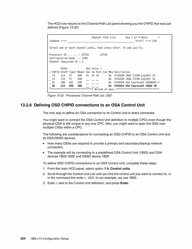
The HCD now returns to the Channel Path List panel showing you the CHPID that was just defined (Figure 13-22).
Figure 13-22 Processors: Channel Path List, OSD
13.2.6 Defining OSD CHPID connections to an OSA Control Unit
The only way to define an OSA connection to its Control Unit is direct connected.
You might want to connect the OSA Control Unit definition to multiple CPCs even though the physical OSA is still unique to any one CPC. Also, you might want to span the OSA over multiple CSSs within a CPC.
The following are considerations for connecting an OSD CHPID to an OSA Control Unit and its OSA/OSAD devices:
� How many OSAs are required to provide a primary and secondary/backup network connection.
� The example will be connecting to a predefined OSA Control Unit (1B20) and OSA devices 1B20-1B2E and OSAD device 1B2F.
To define OSD CHPID connections to an OSA Control Unit, complete these steps:
1. From the main HCD panel, select option 1.4. Control units.
2. Scroll through the Control Unit List until you find the control unit you want to connect to, or in the command line enter L 1B20. In our example, we use 1B20.
3. Enter c next to the Control Unit definition, and press Enter.
Channel Path List Row 1 of 4 More: >Command ===> _______________________________________________ Scroll ===> CSR Select one or more channel paths, then press Enter. To add use F11. Processor ID . . . . : CETUS CETUS Configuration mode . : LPAR Channel Subsystem ID : 2 CHID+ Dyn Entry + / CHPID AID/P Type+ Mode+ Sw+ Sw Port Con Mng Description _ 14 114 FC SHR 41 41 10 No FC#0428 16Gb FICON Exp16S+ SX _ 15 115 FC SHR __ __ __ No FC#0428 16Gb FICON Exp16S+ SX _ B1 1B8 OSC SHR __ __ __ No FC#0426 OSA Express6S 1000BASE-T_ B2 1C4 OSD SHR __ __ __ No FC#0425 OSA Express6S 10GbE SR ******************************* Bottom of data *******************************
324 IBM z14 Configuration Setup
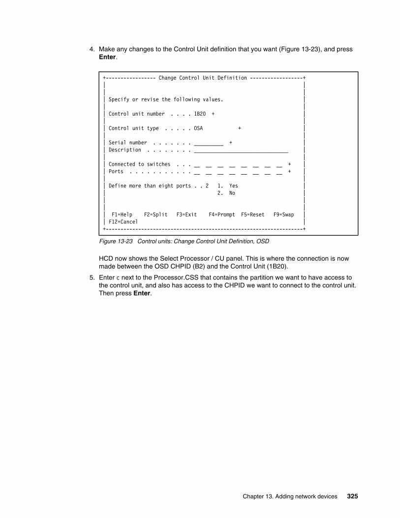
4. Make any changes to the Control Unit definition that you want (Figure 13-23), and press Enter.
Figure 13-23 Control units: Change Control Unit Definition, OSD
HCD now shows the Select Processor / CU panel. This is where the connection is now made between the OSD CHPID (B2) and the Control Unit (1B20).
5. Enter c next to the Processor.CSS that contains the partition we want to have access to the control unit, and also has access to the CHPID we want to connect to the control unit. Then press Enter.
+----------------- Change Control Unit Definition ------------------+| || || Specify or revise the following values. || || Control unit number . . . . 1B20 + || || Control unit type . . . . . OSA + || || Serial number . . . . . . . __________ + || Description . . . . . . . . ________________________________ || || Connected to switches . . . __ __ __ __ __ __ __ __ + || Ports . . . . . . . . . . . __ __ __ __ __ __ __ __ + || || Define more than eight ports . . 2 1. Yes || 2. No || || || F1=Help F2=Split F3=Exit F4=Prompt F5=Reset F9=Swap || F12=Cancel |+-------------------------------------------------------------------+
Chapter 13. Adding network devices 325
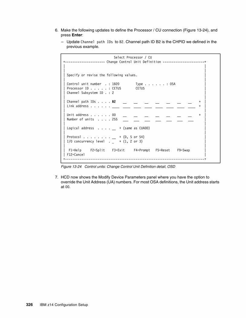
6. Make the following updates to define the Processor / CU connection (Figure 13-24), and press Enter:
– Update Channel path IDs to B2. Channel path ID B2 is the CHPID we defined in the previous example.
Figure 13-24 Control units: Change Control Unit Definition detail, OSD
7. HCD now shows the Modify Device Parameters panel where you have the option to override the Unit Address (UA) numbers. For most OSA definitions, the Unit address starts at 00.
Select Processor / CU +---------------------- Change Control Unit Definition -----------------------+| || || Specify or revise the following values. || || Control unit number . : 1B20 Type . . . . . . : OSA || Processor ID . . . . . : CETUS CETUS || Channel Subsystem ID . : 2 || || Channel path IDs . . . . B2 __ __ __ __ __ __ __ + || Link address . . . . . . ____ ____ ____ ____ ____ ____ ____ ____ + || || Unit address . . . . . . 00 __ __ __ __ __ __ __ + || Number of units . . . . 255 ___ ___ ___ ___ ___ ___ ___ || || Logical address . . . . __ + (same as CUADD) || || Protocol . . . . . . . . __ + (D, S or S4) || I/O concurrency level . _ + (1, 2 or 3) || || F1=Help F2=Split F3=Exit F4=Prompt F5=Reset F9=Swap || F12=Cancel |+-----------------------------------------------------------------------------+
326 IBM z14 Configuration Setup

8. Make the following updates to define the Modify Device Parameters (Figure 13-25), and press Enter:
– Update UA New to 00 for the OSA device type– Update UA New to FE for the OSAD device type
Figure 13-25 Control units: Modify Device Parameters, OSD
HCD now returns back to the Select Processor / CU panel showing the CHPID (B2) connection definition (Figure 13-26).
Figure 13-26 Processors: Select Processor / CU: CHPID to Link address connection, OSD
Select Processor / CU +------------------------- Modify Device Parameters -------------------------+| Row 1 of 2 More: > || Command ===> __________________________________________ Scroll ===> CSR || || Specify or revise any changes to the device parameters in the list below. || To view attached control units, scroll to the right. || || Processor ID . . . . : CETUS CETUS || Channel Subsystem ID : 2 || || ---------Device--------- ---UA---- Preferred Exposure || No., Range Type SS+ Old New + Time-Out STADET CHPID + Device || 1B20,015 OSA _ 20 00 No No __ || 1B2F,001 OSAD _ 2F FE No No __ || ***************************** Bottom of data ***************************** || || || || || || F1=Help F2=Split F3=Exit F4=Prompt F5=Reset || F7=Backward F8=Forward F9=Swap F12=Cancel F20=Right || F22=Command |+----------------------------------------------------------------------------+
Select Processor / CU Row 1 of 9 More: Command ===> _______________________________________________ Scroll ===> CSR Select processors to change CU/processor parameters, then press Enter. Control unit number . . : 1B20 Control unit type . . . : OSA ---------------Channel Path ID . Link Address + ---------------/ Proc.CSSID 1------ 2------ 3------ 4------ 5------ 6------ 7------ 8------_ CETUS.0 _______ _______ _______ _______ _______ _______ _______ ________ CETUS.1 _______ _______ _______ _______ _______ _______ _______ ________ CETUS.2 B2 _______ _______ _______ _______ _______ _______ ________ CETUS.3 _______ _______ _______ _______ _______ _______ _______ ________ CETUS.4 _______ _______ _______ _______ _______ _______ _______ ________ CETUS.5 _______ _______ _______ _______ _______ _______ _______ ________ LEPUS.0 _______ _______ _______ _______ _______ _______ _______ ________ LEPUS.1 _______ _______ _______ _______ _______ _______ _______ ________ LEPUS.2 _______ _______ _______ _______ _______ _______ _______ _______******************************* Bottom of data *****************************
Chapter 13. Adding network devices 327

Press F20 (Right) to see the other parts of the definition summary.
13.2.7 Defining OSA and OSAD devices to an OSCONFIG
The OSCONFIG name is the part of an IODF that determines what devices a z/OS system will have access to when it IPLs. Additionally, the partition that the z/OS system is started in also needs to have access to the CHPIDs that connect to the Control Units and Devices that match in the OSCONFIG.
The OSCONFIG also contains Esoterics device groups, which are defined in EDTs within an OSCONFIG. OSA definitions usually do not use Esoterics.
The following are considerations for adding devices to an OSCONFIG:
� Adding a device to an OSCONFIG does not necessarily mean that the z/OS system will have access to that device.
� The example will be adding the predefined OSA devices 1B20-1B2F (OSA/OSAD).
To define OSA and OSAD devices to an OSCONFIG, complete these steps:
1. From the main HCD panel, select option 1.5. I/O Devices.
2. Scroll through the I/O Device List until you find the device number that you want to add to the OSCONFIG, or in the command line enter L 1B20. In our example, we use 1B20.
Because OSA and OSAD are two different device types, they need to be added separately to the OSCONFIG.
3. Enter c next to one or more Device numbers, and press Enter.
4. HCD displays the Change Device Definition panel where you have the option to modify the Control Unit that the devices are attached to (Figure 13-27). Press Enter.
Figure 13-27 I/O Devices: Change Device Definition, OSD
+------------------------- Change Device Definition --------------------------+| || || Specify or revise the following values. || || Device number . . . . . . . : 1B20 (0000 - FFFF) || Number of devices . . . . . : 15 || Device type . . . . . . . . : OSA || || Serial number . . . . . . . . __________ + || Description . . . . . . . . . ________________________________ || || Volume serial number . . . . . ______ + (for DASD) || || PPRC usage . . . . . . . . . . _ + (for DASD) || || Connected to CUs . 1B20 ____ ____ ____ ____ ____ ____ ____ + || || ENTER to continue. || || F1=Help F2=Split F3=Exit F4=Prompt F5=Reset F9=Swap || F12=Cancel |+-----------------------------------------------------------------------------+
328 IBM z14 Configuration Setup

5. HCD now displays the Device / Processor Definition panel where you have the option to modify some of the Device parameters relating to SubChannel Set, Unit Address, and Explicit Device Candidate List. Type c next to the Proc.CCSID item if you want to modify any of these parameters (Figure 13-28) or press Enter to accept the defaults.
Figure 13-28 I/O Devices: Device / Processor Definition continued, OSD
6. Next is the HCD panel where we Define Devices to the Operating System Configuration. Scroll through the list of OSCONFIG definitions until you find the OSCONFIG you want to add to the Devices to, or in the command line enter L ITSOTEST. In our example, we use ITSOTEST.
7. Enter s next to the OSCONFIG, and press Enter.
HCD displays the Device Parameters and Features applicable to that particular device type. In our example, we are adding OSA devices to ITSOTEST.
+---------------------- Device / Processor Definition -----------------------+| Row 1 of 1 || Command ===> __________________________________________ Scroll ===> CSR || || Select processors to change device/processor definitions, then press || Enter. || || Device number . . : 1B20 Number of devices . : 15 || Device type . . . : OSA || || Preferred Device Candidate List || / Proc.CSSID SS+ UA+ Time-Out STADET CHPID + Explicit Null || _ CETUS.2 _ 00 No No __ No ___ || ***************************** Bottom of data ***************************** || || || || || || || F1=Help F2=Split F3=Exit F4=Prompt F5=Reset || F6=Previous F7=Backward F8=Forward F9=Swap F12=Cancel || F22=Command |+----------------------------------------------------------------------------+
Chapter 13. Adding network devices 329

8. Make the following updates to define the Processor / CU connection (Figure 13-29), and press Enter:
– Update OFFLINE to No (if you want these devices to be Online during IPL time).– Update DYNAMIC to Yes (if you want the device to be changeable dynamically).– Update LOCANY to Yes (if the device UCB can be in 31-bit storage).
Figure 13-29 I/O Devices: Define Device Parameters / Features, OSD
+----------- Define Device to Operating System Configuration -----------+ | | +-------------------- Define Device Parameters / Features --------------------+| Row 1 of 3 || Command ===> ___________________________________________ Scroll ===> CSR || || Specify or revise the values below. || || Configuration ID . : ITSOTEST ITSO test OSCONFIG for z14 || Device number . . : 1B20 Number of devices : 15 || Device type . . . : OSA || || Parameter/ || Feature Value + R Description || OFFLINE No Device considered online or offline at IPL || DYNAMIC Yes Device has been defined to be dynamic || LOCANY Yes UCB can reside in 31 bit storage || ***************************** Bottom of data ****************************** || || || || || || F1=Help F2=Split F3=Exit F4=Prompt F5=Reset || F7=Backward F8=Forward F9=Swap F12=Cancel F22=Command |+-----------------------------------------------------------------------------+
330 IBM z14 Configuration Setup

9. The Assign/Unassign Device to Esoteric panel is now displayed where you can specify which Esoteric (if any) you want the devices to be added to. We will only be adding the OSA/OSAD devices to the OSCONFIG ITSOTEST and not to any esoterics in this example (Figure 13-30). Press Enter.
Figure 13-30 I/O Devices: Assign/Unassign Device to Esoteric, OSD
10.The final panel is now displayed showing that the devices are defined to the OSCONFIG. Press Enter to return to the I/O Device List.
+----------- Define Device to Operating System Configuration -----------+| Row 1 of 34 || Command ===> _____________________________________ Scroll ===> CSR || || Select OSs to connect or disconnect devices, then press Enter. || || Device number . : 1B20 Number of devices : 15 || Device type . . : OSA || || / Config. ID Type SS Description Defined || _ DBSV4SU4 MVS z/OS DB Server 4 || _ DBSV5SU4 MVS z/OS DB Server 5 || _ DBSV6SU4 MVS z/OS DB Server 6 || _ ITSO MVS All ITSO devices || _ ITSOTEST MVS ITSO test OSCONFIG for z14 Yes || _ PERF4SU4 MVS z/OS Appl Server 4 || _ PERF5SU4 MVS z/OS Perf Server 5 || _ PERF6SU4 MVS z/OS Appl Server 6 || _ ZHLXDRVR MVS z/OS Helix Central Mgmt Image || _ ZMEDRVR MVS z/OS 2.1 Server Pak refresh || F1=Help F2=Split F3=Exit F4=Prompt F5=Reset || F6=Previous F7=Backward F8=Forward F9=Swap F12=Cancel || F22=Command |+-----------------------------------------------------------------------+
Chapter 13. Adding network devices 331
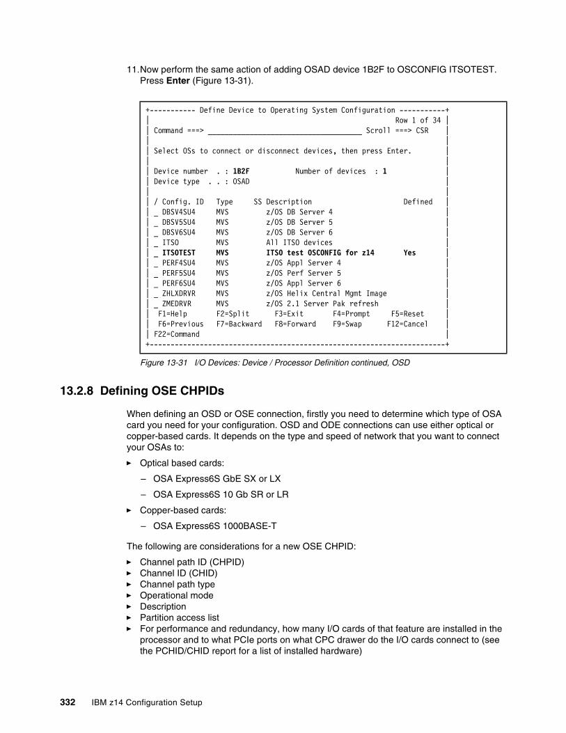
11.Now perform the same action of adding OSAD device 1B2F to OSCONFIG ITSOTEST. Press Enter (Figure 13-31).
Figure 13-31 I/O Devices: Device / Processor Definition continued, OSD
13.2.8 Defining OSE CHPIDs
When defining an OSD or OSE connection, firstly you need to determine which type of OSA card you need for your configuration. OSD and ODE connections can use either optical or copper-based cards. It depends on the type and speed of network that you want to connect your OSAs to:
� Optical based cards:
– OSA Express6S GbE SX or LX
– OSA Express6S 10 Gb SR or LR
� Copper-based cards:
– OSA Express6S 1000BASE-T
The following are considerations for a new OSE CHPID:
� Channel path ID (CHPID)� Channel ID (CHID)� Channel path type� Operational mode� Description� Partition access list� For performance and redundancy, how many I/O cards of that feature are installed in the
processor and to what PCIe ports on what CPC drawer do the I/O cards connect to (see the PCHID/CHID report for a list of installed hardware)
+----------- Define Device to Operating System Configuration -----------+| Row 1 of 34 || Command ===> _____________________________________ Scroll ===> CSR || || Select OSs to connect or disconnect devices, then press Enter. || || Device number . : 1B2F Number of devices : 1 || Device type . . : OSAD || || / Config. ID Type SS Description Defined || _ DBSV4SU4 MVS z/OS DB Server 4 || _ DBSV5SU4 MVS z/OS DB Server 5 || _ DBSV6SU4 MVS z/OS DB Server 6 || _ ITSO MVS All ITSO devices || _ ITSOTEST MVS ITSO test OSCONFIG for z14 Yes || _ PERF4SU4 MVS z/OS Appl Server 4 || _ PERF5SU4 MVS z/OS Perf Server 5 || _ PERF6SU4 MVS z/OS Appl Server 6 || _ ZHLXDRVR MVS z/OS Helix Central Mgmt Image || _ ZMEDRVR MVS z/OS 2.1 Server Pak refresh || F1=Help F2=Split F3=Exit F4=Prompt F5=Reset || F6=Previous F7=Backward F8=Forward F9=Swap F12=Cancel || F22=Command |+-----------------------------------------------------------------------+
332 IBM z14 Configuration Setup
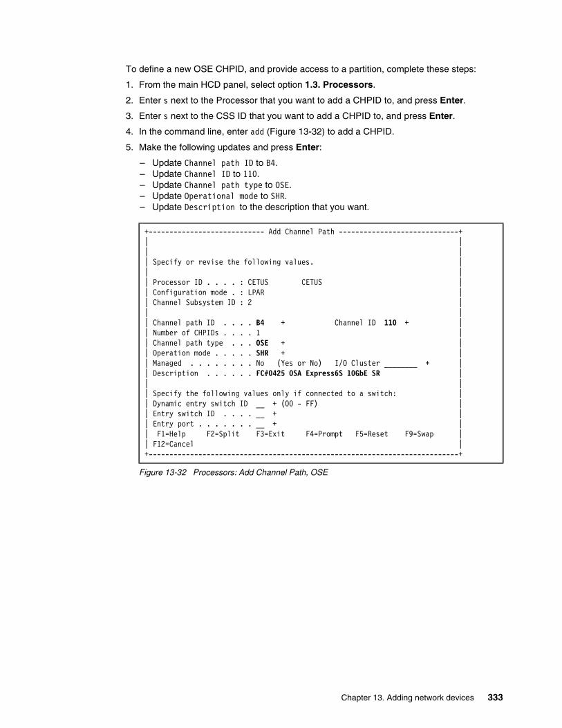
To define a new OSE CHPID, and provide access to a partition, complete these steps:
1. From the main HCD panel, select option 1.3. Processors.
2. Enter s next to the Processor that you want to add a CHPID to, and press Enter.
3. Enter s next to the CSS ID that you want to add a CHPID to, and press Enter.
4. In the command line, enter add (Figure 13-32) to add a CHPID.
5. Make the following updates and press Enter:
– Update Channel path ID to B4.– Update Channel ID to 110.– Update Channel path type to OSE.– Update Operational mode to SHR.– Update Description to the description that you want.
Figure 13-32 Processors: Add Channel Path, OSE
+---------------------------- Add Channel Path -----------------------------+| || || Specify or revise the following values. || || Processor ID . . . . : CETUS CETUS || Configuration mode . : LPAR || Channel Subsystem ID : 2 || || Channel path ID . . . . B4 + Channel ID 110 + || Number of CHPIDs . . . . 1 || Channel path type . . . OSE + || Operation mode . . . . . SHR + || Managed . . . . . . . . No (Yes or No) I/O Cluster ________ + || Description . . . . . . FC#0425 OSA Express6S 10GbE SR || || Specify the following values only if connected to a switch: || Dynamic entry switch ID __ + (00 - FF) || Entry switch ID . . . . __ + || Entry port . . . . . . . __ + || F1=Help F2=Split F3=Exit F4=Prompt F5=Reset F9=Swap || F12=Cancel |+---------------------------------------------------------------------------+
Chapter 13. Adding network devices 333
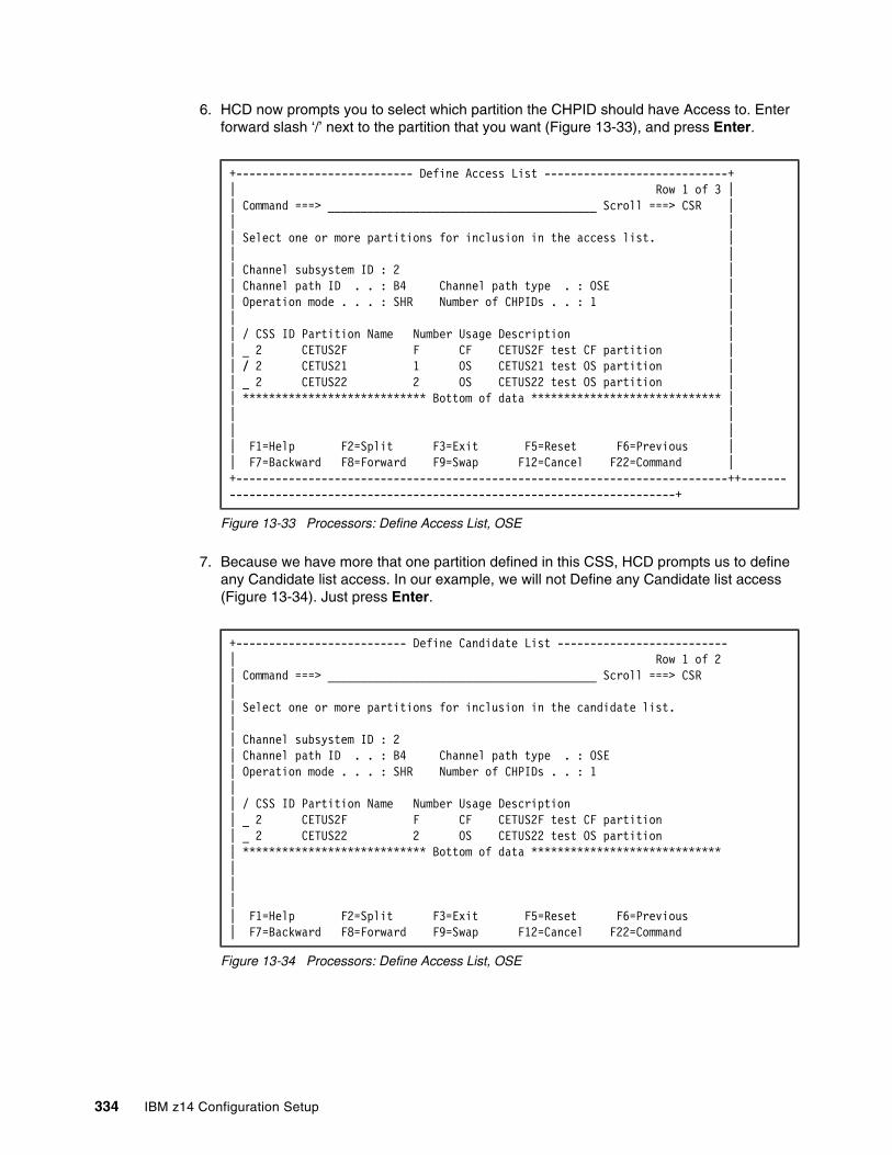
6. HCD now prompts you to select which partition the CHPID should have Access to. Enter forward slash ‘/’ next to the partition that you want (Figure 13-33), and press Enter.
Figure 13-33 Processors: Define Access List, OSE
7. Because we have more that one partition defined in this CSS, HCD prompts us to define any Candidate list access. In our example, we will not Define any Candidate list access (Figure 13-34). Just press Enter.
Figure 13-34 Processors: Define Access List, OSE
+--------------------------- Define Access List ----------------------------+| Row 1 of 3 || Command ===> _________________________________________ Scroll ===> CSR || || Select one or more partitions for inclusion in the access list. || || Channel subsystem ID : 2 || Channel path ID . . : B4 Channel path type . : OSE || Operation mode . . . : SHR Number of CHPIDs . . : 1 || || / CSS ID Partition Name Number Usage Description || _ 2 CETUS2F F CF CETUS2F test CF partition || / 2 CETUS21 1 OS CETUS21 test OS partition || _ 2 CETUS22 2 OS CETUS22 test OS partition || **************************** Bottom of data ***************************** || || || F1=Help F2=Split F3=Exit F5=Reset F6=Previous || F7=Backward F8=Forward F9=Swap F12=Cancel F22=Command |+---------------------------------------------------------------------------++---------------------------------------------------------------------------+
+-------------------------- Define Candidate List --------------------------| Row 1 of 2 | Command ===> _________________________________________ Scroll ===> CSR | | Select one or more partitions for inclusion in the candidate list. | | Channel subsystem ID : 2 | Channel path ID . . : B4 Channel path type . : OSE | Operation mode . . . : SHR Number of CHPIDs . . : 1 | | / CSS ID Partition Name Number Usage Description | _ 2 CETUS2F F CF CETUS2F test CF partition | _ 2 CETUS22 2 OS CETUS22 test OS partition | **************************** Bottom of data ***************************** | | | | F1=Help F2=Split F3=Exit F5=Reset F6=Previous | F7=Backward F8=Forward F9=Swap F12=Cancel F22=Command
334 IBM z14 Configuration Setup
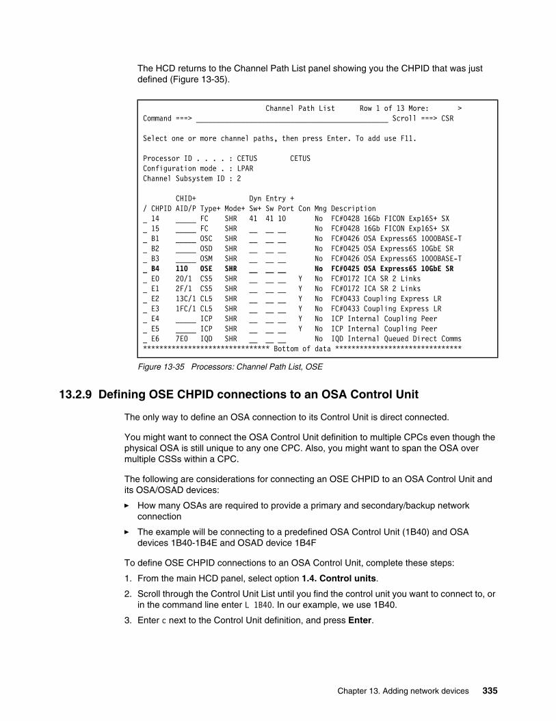
The HCD returns to the Channel Path List panel showing you the CHPID that was just defined (Figure 13-35).
Figure 13-35 Processors: Channel Path List, OSE
13.2.9 Defining OSE CHPID connections to an OSA Control Unit
The only way to define an OSA connection to its Control Unit is direct connected.
You might want to connect the OSA Control Unit definition to multiple CPCs even though the physical OSA is still unique to any one CPC. Also, you might want to span the OSA over multiple CSSs within a CPC.
The following are considerations for connecting an OSE CHPID to an OSA Control Unit and its OSA/OSAD devices:
� How many OSAs are required to provide a primary and secondary/backup network connection
� The example will be connecting to a predefined OSA Control Unit (1B40) and OSA devices 1B40-1B4E and OSAD device 1B4F
To define OSE CHPID connections to an OSA Control Unit, complete these steps:
1. From the main HCD panel, select option 1.4. Control units.
2. Scroll through the Control Unit List until you find the control unit you want to connect to, or in the command line enter L 1B40. In our example, we use 1B40.
3. Enter c next to the Control Unit definition, and press Enter.
Channel Path List Row 1 of 13 More: >Command ===> _______________________________________________ Scroll ===> CSR Select one or more channel paths, then press Enter. To add use F11. Processor ID . . . . : CETUS CETUS Configuration mode . : LPAR Channel Subsystem ID : 2 CHID+ Dyn Entry + / CHPID AID/P Type+ Mode+ Sw+ Sw Port Con Mng Description _ 14 _____ FC SHR 41 41 10 No FC#0428 16Gb FICON Exp16S+ SX _ 15 _____ FC SHR __ __ __ No FC#0428 16Gb FICON Exp16S+ SX _ B1 _____ OSC SHR __ __ __ No FC#0426 OSA Express6S 1000BASE-T_ B2 _____ OSD SHR __ __ __ No FC#0425 OSA Express6S 10GbE SR _ B3 _____ OSM SHR __ __ __ No FC#0426 OSA Express6S 1000BASE-T_ B4 110 OSE SHR __ __ __ No FC#0425 OSA Express6S 10GbE SR _ E0 20/1 CS5 SHR __ __ __ Y No FC#0172 ICA SR 2 Links _ E1 2F/1 CS5 SHR __ __ __ Y No FC#0172 ICA SR 2 Links _ E2 13C/1 CL5 SHR __ __ __ Y No FC#0433 Coupling Express LR _ E3 1FC/1 CL5 SHR __ __ __ Y No FC#0433 Coupling Express LR _ E4 _____ ICP SHR __ __ __ Y No ICP Internal Coupling Peer _ E5 _____ ICP SHR __ __ __ Y No ICP Internal Coupling Peer _ E6 7E0 IQD SHR __ __ __ No IQD Internal Queued Direct Comms******************************* Bottom of data *******************************
Chapter 13. Adding network devices 335

4. Make any changes to the Control Unit definition that you want (Figure 13-36), and press Enter.
Figure 13-36 Control units: Change Control Unit Definition, OSE
5. HCD now shows the Select Processor / CU panel, which is where the connection is now made between the OSE CHPID (B4) and the Control Unit (1B40). Enter c next to the Processor.CSS that contains the partition we want to have access to the control unit and also has access to the CHPID we want to connect to the control unit. Then press Enter.
+----------------- Change Control Unit Definition ------------------+| || || Specify or revise the following values. || || Control unit number . . . . 1B40 + || || Control unit type . . . . . OSA + || || Serial number . . . . . . . __________ + || Description . . . . . . . . ________________________________ || || Connected to switches . . . __ __ __ __ __ __ __ __ + || Ports . . . . . . . . . . . __ __ __ __ __ __ __ __ + || || Define more than eight ports . . 2 1. Yes || 2. No || || || || || F1=Help F2=Split F3=Exit F4=Prompt F5=Reset F9=Swap || F12=Cancel |+-------------------------------------------------------------------+
336 IBM z14 Configuration Setup
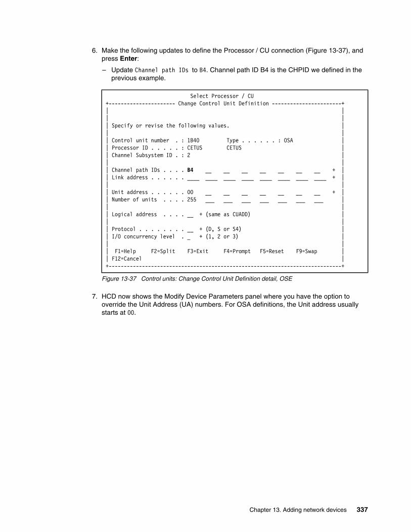
6. Make the following updates to define the Processor / CU connection (Figure 13-37), and press Enter:
– Update Channel path IDs to B4. Channel path ID B4 is the CHPID we defined in the previous example.
Figure 13-37 Control units: Change Control Unit Definition detail, OSE
7. HCD now shows the Modify Device Parameters panel where you have the option to override the Unit Address (UA) numbers. For OSA definitions, the Unit address usually starts at 00.
Select Processor / CU +---------------------- Change Control Unit Definition -----------------------+| || || Specify or revise the following values. || || Control unit number . : 1B40 Type . . . . . . : OSA || Processor ID . . . . . : CETUS CETUS || Channel Subsystem ID . : 2 || || Channel path IDs . . . . B4 __ __ __ __ __ __ __ + || Link address . . . . . . ____ ____ ____ ____ ____ ____ ____ ____ + || || Unit address . . . . . . 00 __ __ __ __ __ __ __ + || Number of units . . . . 255 ___ ___ ___ ___ ___ ___ ___ || || Logical address . . . . __ + (same as CUADD) || || Protocol . . . . . . . . __ + (D, S or S4) || I/O concurrency level . _ + (1, 2 or 3) || || F1=Help F2=Split F3=Exit F4=Prompt F5=Reset F9=Swap || F12=Cancel |+-----------------------------------------------------------------------------+
Chapter 13. Adding network devices 337
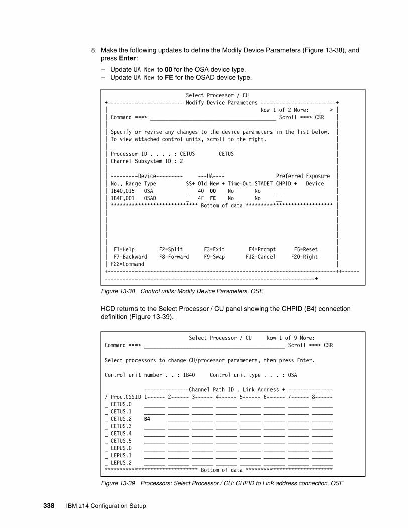
8. Make the following updates to define the Modify Device Parameters (Figure 13-38), and press Enter:
– Update UA New to 00 for the OSA device type.– Update UA New to FE for the OSAD device type.
Figure 13-38 Control units: Modify Device Parameters, OSE
HCD returns to the Select Processor / CU panel showing the CHPID (B4) connection definition (Figure 13-39).
Figure 13-39 Processors: Select Processor / CU: CHPID to Link address connection, OSE
Select Processor / CU +------------------------- Modify Device Parameters -------------------------+| Row 1 of 2 More: > || Command ===> __________________________________________ Scroll ===> CSR || || Specify or revise any changes to the device parameters in the list below. || To view attached control units, scroll to the right. || || Processor ID . . . . : CETUS CETUS || Channel Subsystem ID : 2 || || ---------Device--------- ---UA---- Preferred Exposure || No., Range Type SS+ Old New + Time-Out STADET CHPID + Device || 1B40,015 OSA _ 40 00 No No __ || 1B4F,001 OSAD _ 4F FE No No __ || ***************************** Bottom of data ***************************** || || || || || || F1=Help F2=Split F3=Exit F4=Prompt F5=Reset || F7=Backward F8=Forward F9=Swap F12=Cancel F20=Right || F22=Command |+----------------------------------------------------------------------------++----------------------------------------------------------------------------+
Select Processor / CU Row 1 of 9 More: Command ===> _______________________________________________ Scroll ===> CSR Select processors to change CU/processor parameters, then press Enter. Control unit number . . : 1B40 Control unit type . . . : OSA ---------------Channel Path ID . Link Address + ---------------/ Proc.CSSID 1------ 2------ 3------ 4------ 5------ 6------ 7------ 8------_ CETUS.0 _______ _______ _______ _______ _______ _______ _______ ________ CETUS.1 _______ _______ _______ _______ _______ _______ _______ ________ CETUS.2 B4 _______ _______ _______ _______ _______ _______ ________ CETUS.3 _______ _______ _______ _______ _______ _______ _______ ________ CETUS.4 _______ _______ _______ _______ _______ _______ _______ ________ CETUS.5 _______ _______ _______ _______ _______ _______ _______ ________ LEPUS.0 _______ _______ _______ _______ _______ _______ _______ ________ LEPUS.1 _______ _______ _______ _______ _______ _______ _______ ________ LEPUS.2 _______ _______ _______ _______ _______ _______ _______ _______******************************* Bottom of data *****************************
338 IBM z14 Configuration Setup

9. By pressing F20 (Right), you can see the other parts of the definition summary.
13.2.10 Defining OSA and OSAD devices to an OSCONFIG
The OSCONFIG name is the part of an IODF that determines what devices a z/OS system will have access to when it IPLs. Additionally the partition that the z/OS system is started in also needs to have access to the CHPIDs that connect to the Control Units and Devices that match in the OSCONFIG.
The OSCONFIG also contains Esoterics device groups, which are defined in EDTs within an OSCONFIG. OSA definitions usually do not use Esoterics.
The following are considerations for adding devices to an OSCONFIG:
� Adding a device to an OSCONFIG does not necessarily mean that the z/OS system will have access to that device.
� The example will be adding the predefined OSA devices 1B40-1B4F (OSA/OSAD).
To define OSA and OSAD devices to an OSCONFIG, complete these steps:
1. From the main HCD panel, select option 1.5. I/O Devices.
2. Scroll through the I/O Device List until you find the device number you want to add to the OSCONFIG, or in the command line enter L 1B40. In our example, we use 1B40.
Because OSA and OSAD are two different device types, they will need to be added separately to the OSCONFIG.
3. Enter c next to the Device numbers, and press Enter.
4. HCD displays the Change Device Definition panel where you have the option to modify the Control Unit that the devices are attached to (Figure 13-40). Press Enter.
Figure 13-40 I/O Devices: Change Device Definition, OSE
+------------------------- Change Device Definition --------------------------+| || || Specify or revise the following values. || || Device number . . . . . . . : 1B40 (0000 - FFFF) || Number of devices . . . . . : 15 || Device type . . . . . . . . : OSA || || Serial number . . . . . . . . __________ + || Description . . . . . . . . . ________________________________ || || Volume serial number . . . . . ______ + (for DASD) || || PPRC usage . . . . . . . . . . _ + (for DASD) || || Connected to CUs . 1B40 ____ ____ ____ ____ ____ ____ ____ + || || ENTER to continue. || || F1=Help F2=Split F3=Exit F4=Prompt F5=Reset F9=Swap || F12=Cancel |+-----------------------------------------------------------------------------+
Chapter 13. Adding network devices 339
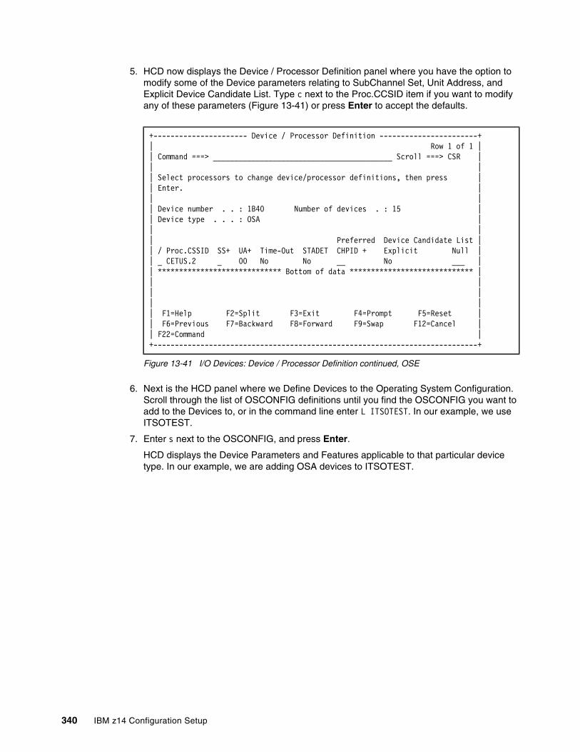
5. HCD now displays the Device / Processor Definition panel where you have the option to modify some of the Device parameters relating to SubChannel Set, Unit Address, and Explicit Device Candidate List. Type c next to the Proc.CCSID item if you want to modify any of these parameters (Figure 13-41) or press Enter to accept the defaults.
Figure 13-41 I/O Devices: Device / Processor Definition continued, OSE
6. Next is the HCD panel where we Define Devices to the Operating System Configuration. Scroll through the list of OSCONFIG definitions until you find the OSCONFIG you want to add to the Devices to, or in the command line enter L ITSOTEST. In our example, we use ITSOTEST.
7. Enter s next to the OSCONFIG, and press Enter.
HCD displays the Device Parameters and Features applicable to that particular device type. In our example, we are adding OSA devices to ITSOTEST.
+---------------------- Device / Processor Definition -----------------------+| Row 1 of 1 || Command ===> __________________________________________ Scroll ===> CSR || || Select processors to change device/processor definitions, then press || Enter. || || Device number . . : 1B40 Number of devices . : 15 || Device type . . . : OSA || || Preferred Device Candidate List || / Proc.CSSID SS+ UA+ Time-Out STADET CHPID + Explicit Null || _ CETUS.2 _ 00 No No __ No ___ || ***************************** Bottom of data ***************************** || || || || F1=Help F2=Split F3=Exit F4=Prompt F5=Reset || F6=Previous F7=Backward F8=Forward F9=Swap F12=Cancel || F22=Command |+----------------------------------------------------------------------------+
340 IBM z14 Configuration Setup
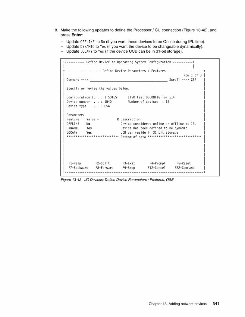
8. Make the following updates to define the Processor / CU connection (Figure 13-42), and press Enter:
– Update OFFLINE to No (if you want these devices to be Online during IPL time).– Update DYNAMIC to Yes (if you want the device to be changeable dynamically).– Update LOCANY to Yes (if the device UCB can be in 31-bit storage).
Figure 13-42 I/O Devices: Define Device Parameters / Features, OSE
+----------- Define Device to Operating System Configuration -----------+ | | +-------------------- Define Device Parameters / Features --------------------+| Row 1 of 3 || Command ===> ___________________________________________ Scroll ===> CSR || || Specify or revise the values below. || || Configuration ID . : ITSOTEST ITSO test OSCONFIG for z14 || Device number . . : 1B40 Number of devices : 15 || Device type . . . : OSA || || Parameter/ || Feature Value + R Description || OFFLINE No Device considered online or offline at IPL || DYNAMIC Yes Device has been defined to be dynamic || LOCANY Yes UCB can reside in 31 bit storage || ***************************** Bottom of data ****************************** || || || || || || F1=Help F2=Split F3=Exit F4=Prompt F5=Reset || F7=Backward F8=Forward F9=Swap F12=Cancel F22=Command |+-----------------------------------------------------------------------------+
Chapter 13. Adding network devices 341
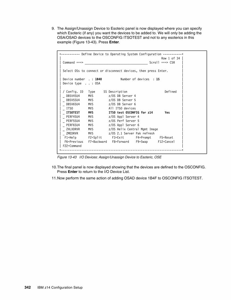
9. The Assign/Unassign Device to Esoteric panel is now displayed where you can specify which Esoteric (if any) you want the devices to be added to. We will only be adding the OSA/OSAD devices to the OSCONFIG ITSOTEST and not to any esoterics in this example (Figure 13-43). Press Enter.
Figure 13-43 I/O Devices: Assign/Unassign Device to Esoteric, OSE
10.The final panel is now displayed showing that the devices are defined to the OSCONFIG. Press Enter to return to the I/O Device List.
11.Now perform the same action of adding OSAD device 1B4F to OSCONFIG ITSOTEST.
+----------- Define Device to Operating System Configuration -----------+| Row 1 of 34 || Command ===> _____________________________________ Scroll ===> CSR || || Select OSs to connect or disconnect devices, then press Enter. || || Device number . : 1B40 Number of devices : 15 || Device type . . : OSA || || / Config. ID Type SS Description Defined || _ DBSV4SU4 MVS z/OS DB Server 4 || _ DBSV5SU4 MVS z/OS DB Server 5 || _ DBSV6SU4 MVS z/OS DB Server 6 || _ ITSO MVS All ITSO devices || _ ITSOTEST MVS ITSO test OSCONFIG for z14 Yes || _ PERF4SU4 MVS z/OS Appl Server 4 || _ PERF5SU4 MVS z/OS Perf Server 5 || _ PERF6SU4 MVS z/OS Appl Server 6 || _ ZHLXDRVR MVS z/OS Helix Central Mgmt Image || _ ZMEDRVR MVS z/OS 2.1 Server Pak refresh || F1=Help F2=Split F3=Exit F4=Prompt F5=Reset || F6=Previous F7=Backward F8=Forward F9=Swap F12=Cancel || F22=Command |+-----------------------------------------------------------------------+
342 IBM z14 Configuration Setup
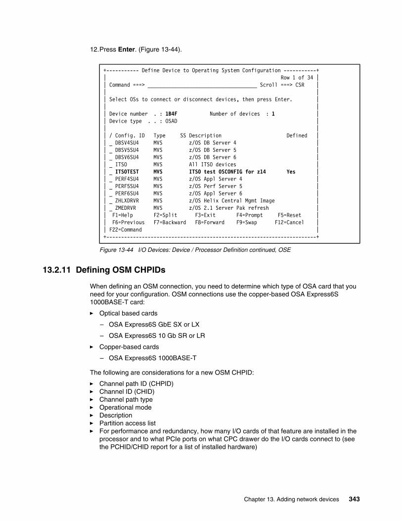
12.Press Enter. (Figure 13-44).
Figure 13-44 I/O Devices: Device / Processor Definition continued, OSE
13.2.11 Defining OSM CHPIDs
When defining an OSM connection, you need to determine which type of OSA card that you need for your configuration. OSM connections use the copper-based OSA Express6S 1000BASE-T card:
� Optical based cards
– OSA Express6S GbE SX or LX
– OSA Express6S 10 Gb SR or LR
� Copper-based cards
– OSA Express6S 1000BASE-T
The following are considerations for a new OSM CHPID:
� Channel path ID (CHPID)� Channel ID (CHID)� Channel path type� Operational mode� Description� Partition access list� For performance and redundancy, how many I/O cards of that feature are installed in the
processor and to what PCIe ports on what CPC drawer do the I/O cards connect to (see the PCHID/CHID report for a list of installed hardware)
+----------- Define Device to Operating System Configuration -----------+| Row 1 of 34 || Command ===> _____________________________________ Scroll ===> CSR || || Select OSs to connect or disconnect devices, then press Enter. || || Device number . : 1B4F Number of devices : 1 || Device type . . : OSAD || || / Config. ID Type SS Description Defined || _ DBSV4SU4 MVS z/OS DB Server 4 || _ DBSV5SU4 MVS z/OS DB Server 5 || _ DBSV6SU4 MVS z/OS DB Server 6 || _ ITSO MVS All ITSO devices || _ ITSOTEST MVS ITSO test OSCONFIG for z14 Yes || _ PERF4SU4 MVS z/OS Appl Server 4 || _ PERF5SU4 MVS z/OS Perf Server 5 || _ PERF6SU4 MVS z/OS Appl Server 6 || _ ZHLXDRVR MVS z/OS Helix Central Mgmt Image || _ ZMEDRVR MVS z/OS 2.1 Server Pak refresh || F1=Help F2=Split F3=Exit F4=Prompt F5=Reset || F6=Previous F7=Backward F8=Forward F9=Swap F12=Cancel || F22=Command |+-----------------------------------------------------------------------+
Chapter 13. Adding network devices 343

To define a new OSM CHPID, and provide access to a partition, complete these steps:
1. From the main HCD panel, select option 1.3. Processors.
2. Enter s next to the Processor that you want to add a CHPID to, and press Enter.
3. Enter s next to the CSS ID that you want to add a CHPID to, and press Enter.
4. In the command line, enter add (Figure 13-45) to add a CHPID.
5. Make the following updates and press Enter:
– Update Channel path ID to B3.– Update Channel ID to 1F8.– Update Channel path type to OSM.– Update Operational mode to SHR.– Update Description to description that you want.
Figure 13-45 Processors: Add Channel Path, OSM
6. HCD now prompts you to specify whether the Allow more than 160 TCP/IP stacks. The default is Yes, which we will use for our example (Figure 13-46). Press Enter.
Figure 13-46 Processors: Allow for more than 160 TCP/IP stacks, OSM
+---------------------------- Add Channel Path -----------------------------+| || || Specify or revise the following values. || || Processor ID . . . . : CETUS CETUS || Configuration mode . : LPAR || Channel Subsystem ID : 2 || || Channel path ID . . . . B3 + Channel ID 1F8 + || Number of CHPIDs . . . . 1 || Channel path type . . . OSM + || Operation mode . . . . . SHR + || Managed . . . . . . . . No (Yes or No) I/O Cluster ________ + || Description . . . . . . FC#0426 OSA Express6S 1000BASE-T || || Specify the following values only if connected to a switch: || Dynamic entry switch ID __ + (00 - FF) || Entry switch ID . . . . __ + || Entry port . . . . . . . __ + || F1=Help F2=Split F3=Exit F4=Prompt F5=Reset F9=Swap || F12=Cancel |+---------------------------------------------------------------------------+
+----------- Allow for more than 160 TCP/IP stacks -----------+| || || Specify Yes to allow more than 160 TCP/IP stacks, || otherwise specify No. Specifying Yes will cause priority || queuing to be disabled. || || Will greater than 160 TCP/IP stacks || be required for this channel? . . . Yes || F1=Help F2=Split F3=Exit F5=Reset F9=Swap || F12=Cancel |+-------------------------------------------------------------+
344 IBM z14 Configuration Setup
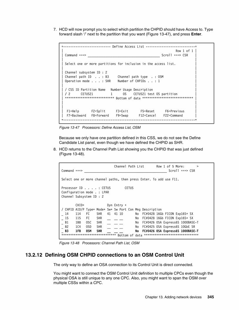
7. HCD will now prompt you to select which partition the CHPID should have Access to. Type forward slash ‘/’ next to the partition that you want (Figure 13-47), and press Enter.
Figure 13-47 Processors: Define Access List, OSM
Because we only have one partition defined in this CSS, we do not see the Define Candidate List panel, even though we have defined the CHPID as SHR.
8. HCD returns to the Channel Path List showing you the CHPID that was just defined (Figure 13-48).
Figure 13-48 Processors: Channel Path List, OSM
13.2.12 Defining OSM CHPID connections to an OSM Control Unit
The only way to define an OSA connection to its Control Unit is direct connected.
You might want to connect the OSM Control Unit definition to multiple CPCs even though the physical OSA is still unique to any one CPC. Also, you might want to span the OSM over multiple CSSs within a CPC.
+--------------------------- Define Access List ----------------------------+| Row 1 of 1 || Command ===> _________________________________________ Scroll ===> CSR || || Select one or more partitions for inclusion in the access list. || || Channel subsystem ID : 2 || Channel path ID . . : B3 Channel path type . : OSM || Operation mode . . . : SHR Number of CHPIDs . . : 1 || || / CSS ID Partition Name Number Usage Description || / 2 CETUS21 1 OS CETUS21 test OS partition || **************************** Bottom of data ***************************** || || || F1=Help F2=Split F3=Exit F5=Reset F6=Previous || F7=Backward F8=Forward F9=Swap F12=Cancel F22=Command |+---------------------------------------------------------------------------+
Channel Path List Row 1 of 5 More: >Command ===> _______________________________________________ Scroll ===> CSR Select one or more channel paths, then press Enter. To add use F11. Processor ID . . . . : CETUS CETUS Configuration mode . : LPAR Channel Subsystem ID : 2 CHID+ Dyn Entry + / CHPID AID/P Type+ Mode+ Sw+ Sw Port Con Mng Description _ 14 114 FC SHR 41 41 10 No FC#0428 16Gb FICON Exp16S+ SX _ 15 115 FC SHR __ __ __ No FC#0428 16Gb FICON Exp16S+ SX _ B1 1B8 OSC SHR __ __ __ No FC#0426 OSA Express6S 1000BASE-T_ B2 1C4 OSD SHR __ __ __ No FC#0425 OSA Express6S 10GbE SR _ B3 1F8 OSM SHR __ __ __ No FC#0426 OSA Express6S 1000BASE-T******************************* Bottom of data *******************************
Chapter 13. Adding network devices 345
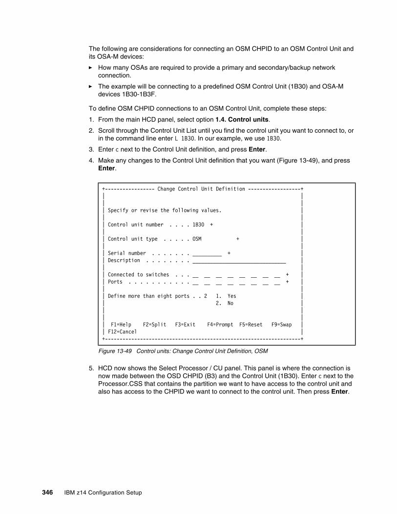
The following are considerations for connecting an OSM CHPID to an OSM Control Unit and its OSA-M devices:
� How many OSAs are required to provide a primary and secondary/backup network connection.
� The example will be connecting to a predefined OSM Control Unit (1B30) and OSA-M devices 1B30-1B3F.
To define OSM CHPID connections to an OSM Control Unit, complete these steps:
1. From the main HCD panel, select option 1.4. Control units.
2. Scroll through the Control Unit List until you find the control unit you want to connect to, or in the command line enter L 1B30. In our example, we use 1B30.
3. Enter c next to the Control Unit definition, and press Enter.
4. Make any changes to the Control Unit definition that you want (Figure 13-49), and press Enter.
Figure 13-49 Control units: Change Control Unit Definition, OSM
5. HCD now shows the Select Processor / CU panel. This panel is where the connection is now made between the OSD CHPID (B3) and the Control Unit (1B30). Enter c next to the Processor.CSS that contains the partition we want to have access to the control unit and also has access to the CHPID we want to connect to the control unit. Then press Enter.
+----------------- Change Control Unit Definition ------------------+| || || Specify or revise the following values. || || Control unit number . . . . 1B30 + || || Control unit type . . . . . OSM + || || Serial number . . . . . . . __________ + || Description . . . . . . . . ________________________________ || || Connected to switches . . . __ __ __ __ __ __ __ __ + || Ports . . . . . . . . . . . __ __ __ __ __ __ __ __ + || || Define more than eight ports . . 2 1. Yes || 2. No || || || F1=Help F2=Split F3=Exit F4=Prompt F5=Reset F9=Swap || F12=Cancel |+-------------------------------------------------------------------+
346 IBM z14 Configuration Setup

6. Make the following updates to define the Processor / CU connection (Figure 13-50), and press Enter:
– Update Channel path IDs to B3. Channel path ID B3 is the CHPID we defined in the previous example.
Figure 13-50 Control units: Change Control Unit Definition detail, OSM
Select Processor / CU +---------------------- Change Control Unit Definition -----------------------+| || || Specify or revise the following values. || || Control unit number . : 1B30 Type . . . . . . : OSM || Processor ID . . . . . : CETUS CETUS || Channel Subsystem ID . : 2 || || Channel path IDs . . . . B3 __ __ __ __ __ __ __ + || Link address . . . . . . ____ ____ ____ ____ ____ ____ ____ ____ + || || Unit address . . . . . . 00 __ __ __ __ __ __ __ + || Number of units . . . . 255 ___ ___ ___ ___ ___ ___ ___ || || Logical address . . . . __ + (same as CUADD) || || Protocol . . . . . . . . __ + (D, S or S4) || I/O concurrency level . _ + (1, 2 or 3) || || F1=Help F2=Split F3=Exit F4=Prompt F5=Reset F9=Swap || F12=Cancel |+-----------------------------------------------------------------------------+
Chapter 13. Adding network devices 347

7. HCD now shows the Modify Device Parameters panel where you have the option to override the UA numbers. For OSA definitions, the Unit address usually starts at 00. Make the following updates to define the Modify Device Parameters (Figure 13-51), and press Enter:
– Update UA New to 00 for the OSA-M device type.
Figure 13-51 Control units: Modify Device Parameters, OSM
HCD returns to the Select Processor / CU panel showing the CHPID (B3) connection definition (Figure 13-52).
Figure 13-52 Processors: Select Processor / CU: CHPID to Link address connection, OSM
8. Press F20 (Right) to see the other parts of the definition summary.
Select Processor / CU +------------------------- Modify Device Parameters -------------------------+| Row 1 of 1 More: > || Command ===> __________________________________________ Scroll ===> CSR || || Specify or revise any changes to the device parameters in the list below. || To view attached control units, scroll to the right. || || Processor ID . . . . : CETUS CETUS || Channel Subsystem ID : 2 || || ---------Device--------- ---UA---- Preferred Exposure || No., Range Type SS+ Old New + Time-Out STADET CHPID + Device || 1B30,016 OSA-M _ 30 00 No No __ || ***************************** Bottom of data ***************************** || || || F1=Help F2=Split F3=Exit F4=Prompt F5=Reset || F7=Backward F8=Forward F9=Swap F12=Cancel F20=Right || F22=Command |+----------------------------------------------------------------------------+
Select Processor / CU Row 1 of 9 More: Command ===> _______________________________________________ Scroll ===> CSR Select processors to change CU/processor parameters, then press Enter. Control unit number . . : 1B30 Control unit type . . . : OSM ---------------Channel Path ID . Link Address + ---------------/ Proc.CSSID 1------ 2------ 3------ 4------ 5------ 6------ 7------ 8------_ CETUS.0 _______ _______ _______ _______ _______ _______ _______ ________ CETUS.1 _______ _______ _______ _______ _______ _______ _______ ________ CETUS.2 B3 _______ _______ _______ _______ _______ _______ ________ CETUS.3 _______ _______ _______ _______ _______ _______ _______ ________ CETUS.4 _______ _______ _______ _______ _______ _______ _______ ________ CETUS.5 _______ _______ _______ _______ _______ _______ _______ ________ LEPUS.0 _______ _______ _______ _______ _______ _______ _______ ________ LEPUS.1 _______ _______ _______ _______ _______ _______ _______ ________ LEPUS.2 _______ _______ _______ _______ _______ _______ _______ _______******************************* Bottom of data *****************************
348 IBM z14 Configuration Setup

13.2.13 Defining OSA-M devices to an OSCONFIG
The OSCONFIG name is the part of an IODF that determines what devices a z/OS system will have access to when it IPLs. Additionally the partition that the z/OS system is started in also needs to have access to the CHPIDs that connect to the Control Units and Devices that match in the OSCONFIG.
The OSCONFIG also contains Esoterics device groups that are defined in EDTs within an OSCONFIG. OSA definitions usually do not use Esoterics.
The following are considerations for adding devices to an OSCONFIG:
� Adding a device to an OSCONFIG does not necessarily mean that the z/OS system will have access to that device.
� The example will be adding the predefined OSA devices 1B30-1B3F (OSA-M).
1. From the main HCD panel, select option 1.5. I/O Devices.
2. Scroll through the I/O Device List until you find the device number you want to add to the OSCONFIG or in the Command Line enter L 1B30. In our example we will use 1B30.
3. Type c next to the Device number(s), and press Enter.
HCD will display the Change Device Definition panel where you have the option to modify the Control Unit that the devices are attached to (Figure 13-53). Press Enter.
Figure 13-53 I/O Devices: Change Device Definition, OSM
HCD now displays the Device / Processor Definition panel where you have the option to modify some of the Device parameters relating to SubChannel Set, Unit Address, and Explicit Device Candidate List.
+------------------------- Change Device Definition --------------------------+| || || Specify or revise the following values. || || Device number . . . . . . . : 1B30 (0000 - FFFF) || Number of devices . . . . . : 16 || Device type . . . . . . . . : OSA-M || || Serial number . . . . . . . . __________ + || Description . . . . . . . . . ________________________________ || || Volume serial number . . . . . ______ + (for DASD) || || PPRC usage . . . . . . . . . . _ + (for DASD) || || Connected to CUs . 1B30 ____ ____ ____ ____ ____ ____ ____ + || || ENTER to continue. || || F1=Help F2=Split F3=Exit F4=Prompt F5=Reset F9=Swap || F12=Cancel |+-----------------------------------------------------------------------------+
Chapter 13. Adding network devices 349
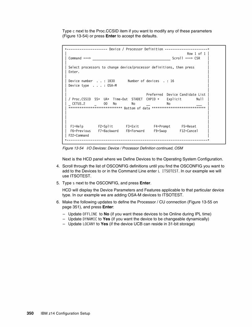
Type c next to the Proc.CCSID item if you want to modify any of these parameters (Figure 13-54) or press Enter to accept the defaults.
Figure 13-54 I/O Devices: Device / Processor Definition continued, OSM
Next is the HCD panel where we Define Devices to the Operating System Configuration.
4. Scroll through the list of OSCONFIG definitions until you find the OSCONFIG you want to add to the Devices to or in the Command Line enter L ITSOTEST. In our example we will use ITSOTEST.
5. Type s next to the OSCONFIG, and press Enter.
HCD will display the Device Parameters and Features applicable to that particular device type. In our example we are adding OSA-M devices to ITSOTEST.
6. Make the following updates to define the Processor / CU connection (Figure 13-55 on page 351), and press Enter:
– Update OFFLINE to No (if you want these devices to be Online during IPL time)– Update DYNAMIC to Yes (if you want the device to be changeable dynamically)– Update LOCANY to Yes (if the device UCB can reside in 31-bit storage)
+---------------------- Device / Processor Definition -----------------------+| Row 1 of 1 || Command ===> __________________________________________ Scroll ===> CSR || || Select processors to change device/processor definitions, then press || Enter. || || Device number . . : 1B30 Number of devices . : 16 || Device type . . . : OSA-M || || Preferred Device Candidate List || / Proc.CSSID SS+ UA+ Time-Out STADET CHPID + Explicit Null || _ CETUS.2 _ 00 No No __ No ___ || ***************************** Bottom of data ***************************** || || || || F1=Help F2=Split F3=Exit F4=Prompt F5=Reset || F6=Previous F7=Backward F8=Forward F9=Swap F12=Cancel || F22=Command |+----------------------------------------------------------------------------+
350 IBM z14 Configuration Setup
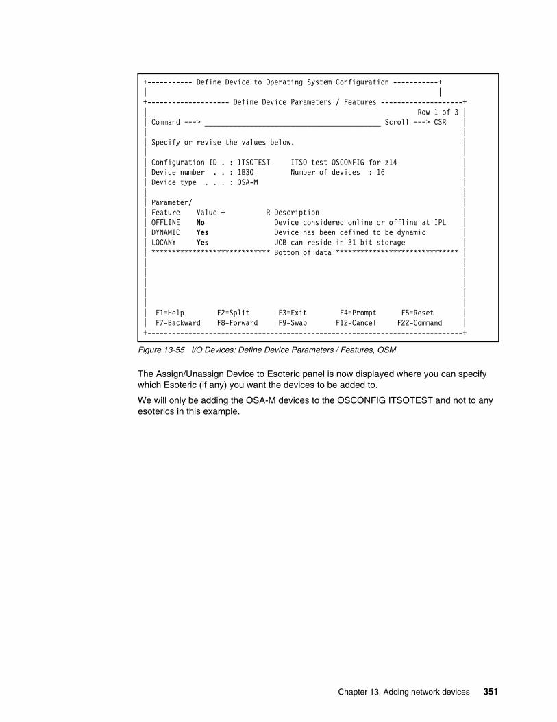
Figure 13-55 I/O Devices: Define Device Parameters / Features, OSM
The Assign/Unassign Device to Esoteric panel is now displayed where you can specify which Esoteric (if any) you want the devices to be added to.
We will only be adding the OSA-M devices to the OSCONFIG ITSOTEST and not to any esoterics in this example.
+----------- Define Device to Operating System Configuration -----------+ | | +-------------------- Define Device Parameters / Features --------------------+| Row 1 of 3 || Command ===> ___________________________________________ Scroll ===> CSR || || Specify or revise the values below. || || Configuration ID . : ITSOTEST ITSO test OSCONFIG for z14 || Device number . . : 1B30 Number of devices : 16 || Device type . . . : OSA-M || || Parameter/ || Feature Value + R Description || OFFLINE No Device considered online or offline at IPL || DYNAMIC Yes Device has been defined to be dynamic || LOCANY Yes UCB can reside in 31 bit storage || ***************************** Bottom of data ****************************** || || || || || || F1=Help F2=Split F3=Exit F4=Prompt F5=Reset || F7=Backward F8=Forward F9=Swap F12=Cancel F22=Command |+-----------------------------------------------------------------------------+
Chapter 13. Adding network devices 351
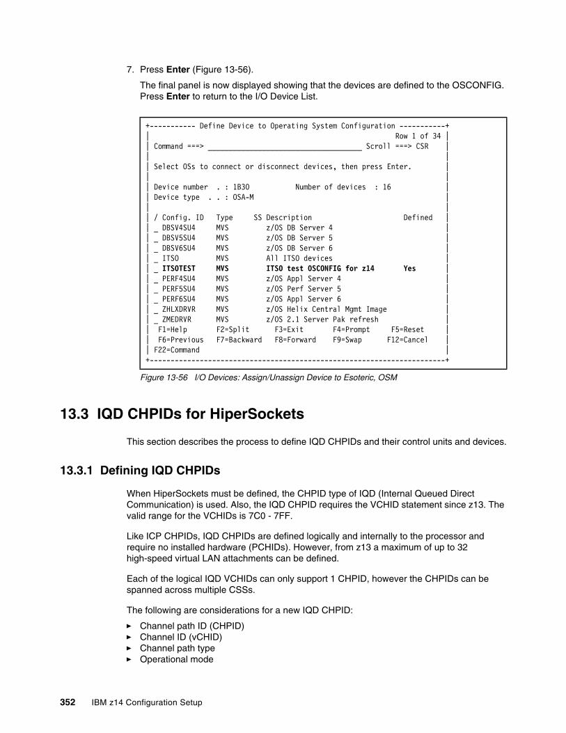
7. Press Enter (Figure 13-56).
The final panel is now displayed showing that the devices are defined to the OSCONFIG. Press Enter to return to the I/O Device List.
Figure 13-56 I/O Devices: Assign/Unassign Device to Esoteric, OSM
13.3 IQD CHPIDs for HiperSockets
This section describes the process to define IQD CHPIDs and their control units and devices.
13.3.1 Defining IQD CHPIDs
When HiperSockets must be defined, the CHPID type of IQD (Internal Queued Direct Communication) is used. Also, the IQD CHPID requires the VCHID statement since z13. The valid range for the VCHIDs is 7C0 - 7FF.
Like ICP CHPIDs, IQD CHPIDs are defined logically and internally to the processor and require no installed hardware (PCHIDs). However, from z13 a maximum of up to 32 high-speed virtual LAN attachments can be defined.
Each of the logical IQD VCHIDs can only support 1 CHPID, however the CHPIDs can be spanned across multiple CSSs.
The following are considerations for a new IQD CHPID:
� Channel path ID (CHPID)� Channel ID (vCHID)� Channel path type� Operational mode
+----------- Define Device to Operating System Configuration -----------+| Row 1 of 34 || Command ===> _____________________________________ Scroll ===> CSR || || Select OSs to connect or disconnect devices, then press Enter. || || Device number . : 1B30 Number of devices : 16 || Device type . . : OSA-M || || / Config. ID Type SS Description Defined || _ DBSV4SU4 MVS z/OS DB Server 4 || _ DBSV5SU4 MVS z/OS DB Server 5 || _ DBSV6SU4 MVS z/OS DB Server 6 || _ ITSO MVS All ITSO devices || _ ITSOTEST MVS ITSO test OSCONFIG for z14 Yes || _ PERF4SU4 MVS z/OS Appl Server 4 || _ PERF5SU4 MVS z/OS Perf Server 5 || _ PERF6SU4 MVS z/OS Appl Server 6 || _ ZHLXDRVR MVS z/OS Helix Central Mgmt Image || _ ZMEDRVR MVS z/OS 2.1 Server Pak refresh || F1=Help F2=Split F3=Exit F4=Prompt F5=Reset || F6=Previous F7=Backward F8=Forward F9=Swap F12=Cancel || F22=Command |+-----------------------------------------------------------------------+
352 IBM z14 Configuration Setup

� Description� Partition access list
To define a new IQD CHPID, and provide access to a partition:
1. From the main HCD panel, select option 1.3. Processors.
2. Type s next to the Processor that you want to add a CHPID to, and press Enter.
3. Type s next to the CSS ID that you want to add a CHPID to, and press Enter.
4. In the Command line, enter add (Figure 13-57), to add a new CHPID.
5. Make the following updates and press Enter:
– Update Channel path ID to E0.– Update Channel ID to 7E0.– Update Channel path type to IQD.– Update Operational mode to SHR.– Update Description to the description that you want.
Figure 13-57 Processors: Add Channel Path, IQD
HCD now prompts you to specify the IQD Channel Parameters, where you set the maximum frame size in KB and what IQD function will be used.
+---------------------------- Add Channel Path -----------------------------+| || || Specify or revise the following values. || || Processor ID . . . . : CETUS CETUS || Configuration mode . : LPAR || Channel Subsystem ID : 2 || || Channel path ID . . . . E6 + Channel ID 7E0 + || Number of CHPIDs . . . . 1 || Channel path type . . . IQD + || Operation mode . . . . . SHR + || Managed . . . . . . . . No (Yes or No) I/O Cluster ________ + || Description . . . . . . IQD Internal Queued Direct Comms || || Specify the following values only if connected to a switch: || Dynamic entry switch ID __ + (00 - FF) || Entry switch ID . . . . __ + || Entry port . . . . . . . __ + || F1=Help F2=Split F3=Exit F4=Prompt F5=Reset F9=Swap || F12=Cancel |+---------------------------------------------------------------------------+
Chapter 13. Adding network devices 353
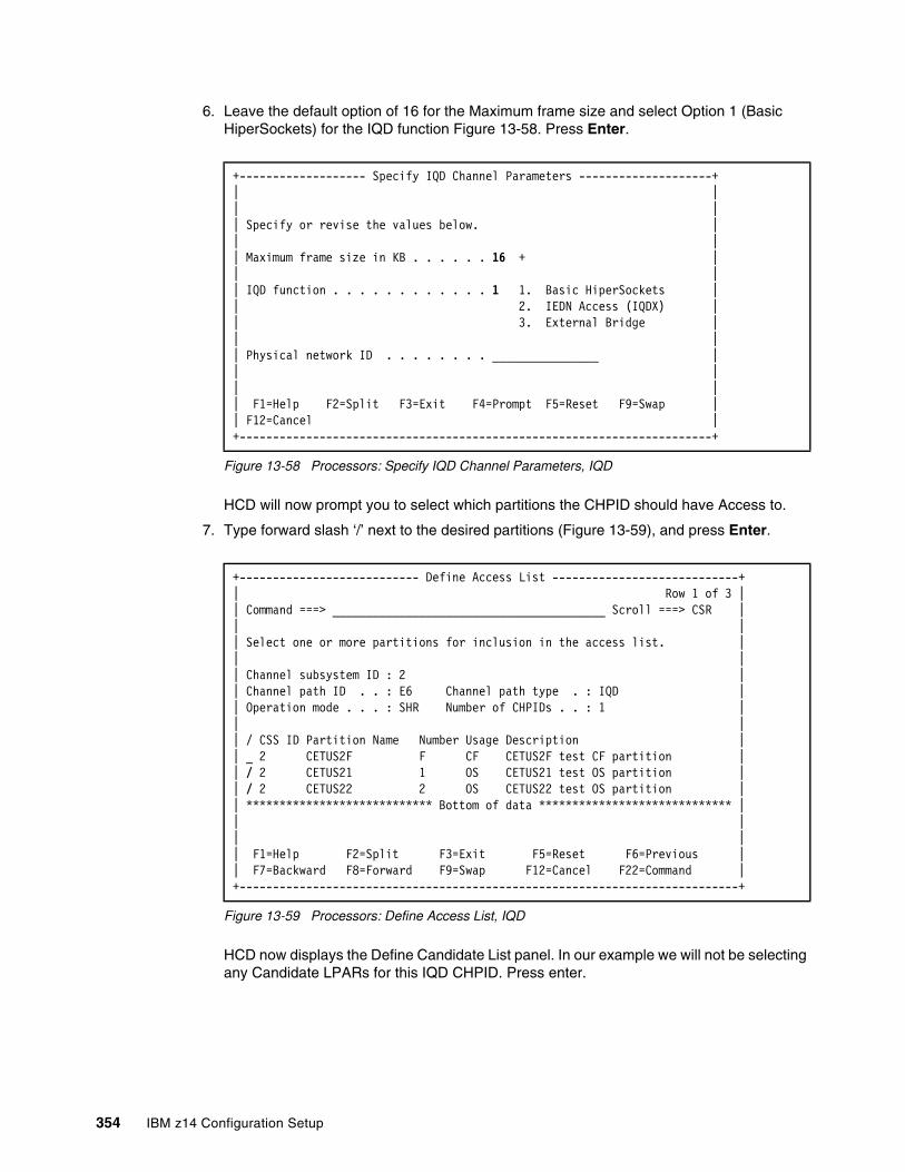
6. Leave the default option of 16 for the Maximum frame size and select Option 1 (Basic HiperSockets) for the IQD function Figure 13-58. Press Enter.
Figure 13-58 Processors: Specify IQD Channel Parameters, IQD
HCD will now prompt you to select which partitions the CHPID should have Access to.
7. Type forward slash ‘/’ next to the desired partitions (Figure 13-59), and press Enter.
Figure 13-59 Processors: Define Access List, IQD
HCD now displays the Define Candidate List panel. In our example we will not be selecting any Candidate LPARs for this IQD CHPID. Press enter.
+------------------- Specify IQD Channel Parameters --------------------+| || || Specify or revise the values below. || || Maximum frame size in KB . . . . . . 16 + || || IQD function . . . . . . . . . . . . 1 1. Basic HiperSockets || 2. IEDN Access (IQDX) || 3. External Bridge || || Physical network ID . . . . . . . . ________________ || || || F1=Help F2=Split F3=Exit F4=Prompt F5=Reset F9=Swap || F12=Cancel |+-----------------------------------------------------------------------+
+--------------------------- Define Access List ----------------------------+| Row 1 of 3 || Command ===> _________________________________________ Scroll ===> CSR || || Select one or more partitions for inclusion in the access list. || || Channel subsystem ID : 2 || Channel path ID . . : E6 Channel path type . : IQD || Operation mode . . . : SHR Number of CHPIDs . . : 1 || || / CSS ID Partition Name Number Usage Description || _ 2 CETUS2F F CF CETUS2F test CF partition || / 2 CETUS21 1 OS CETUS21 test OS partition || / 2 CETUS22 2 OS CETUS22 test OS partition || **************************** Bottom of data ***************************** || || || F1=Help F2=Split F3=Exit F5=Reset F6=Previous || F7=Backward F8=Forward F9=Swap F12=Cancel F22=Command |+---------------------------------------------------------------------------+
354 IBM z14 Configuration Setup
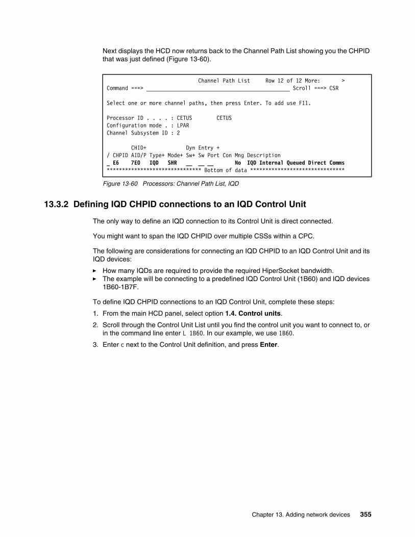
Next displays the HCD now returns back to the Channel Path List showing you the CHPID that was just defined (Figure 13-60).
Figure 13-60 Processors: Channel Path List, IQD
13.3.2 Defining IQD CHPID connections to an IQD Control Unit
The only way to define an IQD connection to its Control Unit is direct connected.
You might want to span the IQD CHPID over multiple CSSs within a CPC.
The following are considerations for connecting an IQD CHPID to an IQD Control Unit and its IQD devices:
� How many IQDs are required to provide the required HiperSocket bandwidth.� The example will be connecting to a predefined IQD Control Unit (1B60) and IQD devices
1B60-1B7F.
To define IQD CHPID connections to an IQD Control Unit, complete these steps:
1. From the main HCD panel, select option 1.4. Control units.
2. Scroll through the Control Unit List until you find the control unit you want to connect to, or in the command line enter L 1B60. In our example, we use 1B60.
3. Enter c next to the Control Unit definition, and press Enter.
Channel Path List Row 12 of 12 More: >Command ===> _______________________________________________ Scroll ===> CSR Select one or more channel paths, then press Enter. To add use F11. Processor ID . . . . : CETUS CETUS Configuration mode . : LPAR Channel Subsystem ID : 2 CHID+ Dyn Entry + / CHPID AID/P Type+ Mode+ Sw+ Sw Port Con Mng Description _ E6 7E0 IQD SHR __ __ __ No IQD Internal Queued Direct Comms******************************* Bottom of data *******************************
Chapter 13. Adding network devices 355

4. Make any changes to the Control Unit definition that you want (Figure 13-61), and press Enter.
Figure 13-61 Control units: Change Control Unit Definition, IQD
5. HCD now shows the Select Processor / CU panel. This panel is where the connection is now made between the IQD CHPID (E6) and the Control Unit (1B60). Enter c next to the Processor.CSS that contains the partition you want to have access to the control unit and also has access to the CHPID you want to connect to the control unit. Then press Enter.
+----------------- Change Control Unit Definition ------------------+| || || Specify or revise the following values. || || Control unit number . . . . 1B60 + || || Control unit type . . . . . IQD + || || Serial number . . . . . . . __________ + || Description . . . . . . . . ________________________________ || || Connected to switches . . . __ __ __ __ __ __ __ __ + || Ports . . . . . . . . . . . __ __ __ __ __ __ __ __ + || || Define more than eight ports . . 2 1. Yes || 2. No || || || || || F1=Help F2=Split F3=Exit F4=Prompt F5=Reset F9=Swap || F12=Cancel |+-------------------------------------------------------------------+
356 IBM z14 Configuration Setup
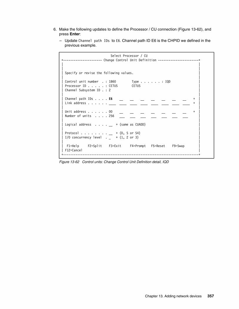
6. Make the following updates to define the Processor / CU connection (Figure 13-62), and press Enter:
– Update Channel path IDs to E6. Channel path ID E6 is the CHPID we defined in the previous example.
Figure 13-62 Control units: Change Control Unit Definition detail, IQD
Select Processor / CU +---------------------- Change Control Unit Definition -----------------------+| || || Specify or revise the following values. || || Control unit number . : 1B60 Type . . . . . . : IQD || Processor ID . . . . . : CETUS CETUS || Channel Subsystem ID . : 2 || || Channel path IDs . . . . E6 __ __ __ __ __ __ __ + || Link address . . . . . . ____ ____ ____ ____ ____ ____ ____ ____ + || || Unit address . . . . . . 00 __ __ __ __ __ __ __ + || Number of units . . . . 256 ___ ___ ___ ___ ___ ___ ___ || || Logical address . . . . __ + (same as CUADD) || || Protocol . . . . . . . . __ + (D, S or S4) || I/O concurrency level . _ + (1, 2 or 3) || || F1=Help F2=Split F3=Exit F4=Prompt F5=Reset F9=Swap || F12=Cancel |+-----------------------------------------------------------------------------+
Chapter 13. Adding network devices 357

7. HCD now shows the Modify Device Parameters panel where you have the option to override the UA numbers. For IQD definitions, the Unit address usually starts at 00. Make the following updates to define the Modify Device Parameters (Figure 13-63), and press Enter:
– Update UA New to 00 for the IQD device type.
Figure 13-63 Control units: Modify Device Parameters, IQD
HCD now returns back to the Select Processor / CU panel showing the CHPID (E6) connection definition (Figure 13-64).
Figure 13-64 Processors: Select Processor / CU: CHPID to Link address connection, IQD
8. Pressing F20 (Right) to see the other parts of the definition summary.
Select Processor / CU +------------------------- Modify Device Parameters -------------------------+| Row 1 of 1 More: > || Command ===> __________________________________________ Scroll ===> CSR || || Specify or revise any changes to the device parameters in the list below. || To view attached control units, scroll to the right. || || Processor ID . . . . : CETUS CETUS || Channel Subsystem ID : 2 || || ---------Device--------- ---UA---- Preferred Exposure || No., Range Type SS+ Old New + Time-Out STADET CHPID + Device || 1B60,032 IQD _ 60 00 No No __ || ***************************** Bottom of data ***************************** || || || F1=Help F2=Split F3=Exit F4=Prompt F5=Reset || F7=Backward F8=Forward F9=Swap F12=Cancel F20=Right || F22=Command |+----------------------------------------------------------------------------+
Select Processor / CU Row 1 of 9 More: Command ===> _______________________________________________ Scroll ===> CSR Select processors to change CU/processor parameters, then press Enter. Control unit number . . : 1B60 Control unit type . . . : IQD ---------------Channel Path ID . Link Address + ---------------/ Proc.CSSID 1------ 2------ 3------ 4------ 5------ 6------ 7------ 8------_ CETUS.0 _______ _______ _______ _______ _______ _______ _______ ________ CETUS.1 _______ _______ _______ _______ _______ _______ _______ ________ CETUS.2 E6 _______ _______ _______ _______ _______ _______ ________ CETUS.3 _______ _______ _______ _______ _______ _______ _______ ________ CETUS.4 _______ _______ _______ _______ _______ _______ _______ ________ CETUS.5 _______ _______ _______ _______ _______ _______ _______ ________ LEPUS.0 _______ _______ _______ _______ _______ _______ _______ ________ LEPUS.1 _______ _______ _______ _______ _______ _______ _______ ________ LEPUS.2 _______ _______ _______ _______ _______ _______ _______ _______******************************* Bottom of data *****************************
358 IBM z14 Configuration Setup
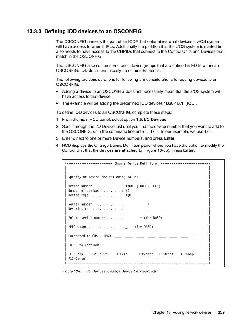
13.3.3 Defining IQD devices to an OSCONFIG
The OSCONFIG name is the part of an IODF that determines what devices a z/OS system will have access to when it IPLs. Additionally the partition that the z/OS system is started in also needs to have access to the CHPIDs that connect to the Control Units and Devices that match in the OSCONFIG.
The OSCONFIG also contains Esoterics device groups that are defined in EDTs within an OSCONFIG. IQD definitions usually do not use Esoterics.
The following are considerations for following are considerations for adding devices to an OSCONFIG:
� Adding a device to an OSCONFIG does not necessarily mean that the z/OS system will have access to that device.
� The example will be adding the predefined IQD devices 1B60-1B7F (IQD).
To define IQD devices to an OSCONFIG, complete these steps:
1. From the main HCD panel, select option 1.5. I/O Devices.
2. Scroll through the I/O Device List until you find the device number that you want to add to the OSCONFIG, or in the command line enter L 1B60. In our example, we use 1B60.
3. Enter c next to one or more Device numbers, and press Enter.
4. HCD displays the Change Device Definition panel where you have the option to modify the Control Unit that the devices are attached to (Figure 13-65). Press Enter.
Figure 13-65 I/O Devices: Change Device Definition, IQD
+------------------------- Change Device Definition --------------------------+| || || Specify or revise the following values. || || Device number . . . . . . . : 1B60 (0000 - FFFF) || Number of devices . . . . . : 32 || Device type . . . . . . . . : IQD || || Serial number . . . . . . . . __________ + || Description . . . . . . . . . ________________________________ || || Volume serial number . . . . . ______ + (for DASD) || || PPRC usage . . . . . . . . . . _ + (for DASD) || || Connected to CUs . 1B60 ____ ____ ____ ____ ____ ____ ____ + || || ENTER to continue. || || F1=Help F2=Split F3=Exit F4=Prompt F5=Reset F9=Swap || F12=Cancel |+-----------------------------------------------------------------------------+
Chapter 13. Adding network devices 359
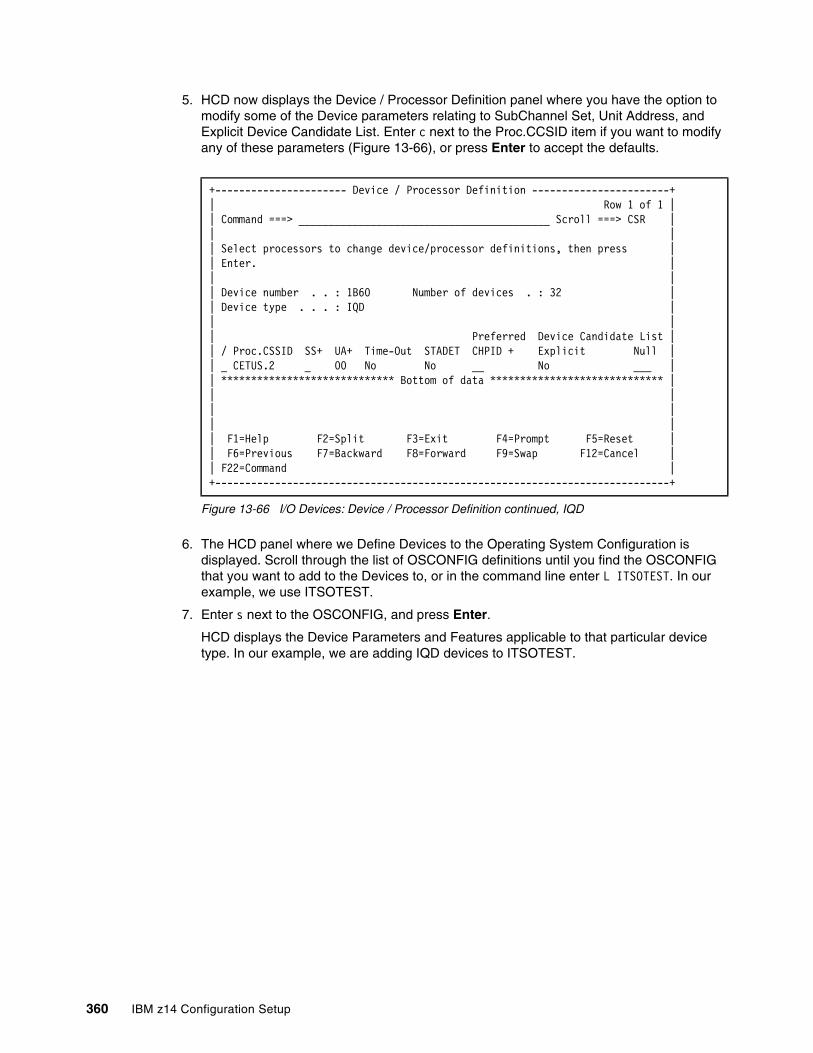
5. HCD now displays the Device / Processor Definition panel where you have the option to modify some of the Device parameters relating to SubChannel Set, Unit Address, and Explicit Device Candidate List. Enter c next to the Proc.CCSID item if you want to modify any of these parameters (Figure 13-66), or press Enter to accept the defaults.
Figure 13-66 I/O Devices: Device / Processor Definition continued, IQD
6. The HCD panel where we Define Devices to the Operating System Configuration is displayed. Scroll through the list of OSCONFIG definitions until you find the OSCONFIG that you want to add to the Devices to, or in the command line enter L ITSOTEST. In our example, we use ITSOTEST.
7. Enter s next to the OSCONFIG, and press Enter.
HCD displays the Device Parameters and Features applicable to that particular device type. In our example, we are adding IQD devices to ITSOTEST.
+---------------------- Device / Processor Definition -----------------------+| Row 1 of 1 || Command ===> __________________________________________ Scroll ===> CSR || || Select processors to change device/processor definitions, then press || Enter. || || Device number . . : 1B60 Number of devices . : 32 || Device type . . . : IQD || || Preferred Device Candidate List || / Proc.CSSID SS+ UA+ Time-Out STADET CHPID + Explicit Null || _ CETUS.2 _ 00 No No __ No ___ || ***************************** Bottom of data ***************************** || || || || F1=Help F2=Split F3=Exit F4=Prompt F5=Reset || F6=Previous F7=Backward F8=Forward F9=Swap F12=Cancel || F22=Command |+----------------------------------------------------------------------------+
360 IBM z14 Configuration Setup

8. Make the following updates to define the Processor / CU connection (Figure 13-67), and press Enter:
– Update OFFLINE to No (if you want these devices to be Online during IPL time).– Update DYNAMIC to Yes (if you want the device to be changeable dynamically).– Update LOCANY to Yes (if the device UCB can be in 31-bit storage).
Figure 13-67 I/O Devices: Define Device Parameters / Features, IQD
+----------- Define Device to Operating System Configuration -----------+ | | +-------------------- Define Device Parameters / Features --------------------+| Row 1 of 3 || Command ===> ___________________________________________ Scroll ===> CSR || || Specify or revise the values below. || || Configuration ID . : ITSOTEST ITSO test OSCONFIG for z14 || Device number . . : 1B60 Number of devices : 32 || Device type . . . : IQD || || Parameter/ || Feature Value + R Description || OFFLINE No Device considered online or offline at IPL || DYNAMIC Yes Device has been defined to be dynamic || LOCANY Yes UCB can reside in 31 bit storage || ***************************** Bottom of data ****************************** || || || F1=Help F2=Split F3=Exit F4=Prompt F5=Reset || F7=Backward F8=Forward F9=Swap F12=Cancel F22=Command |+-----------------------------------------------------------------------------+
Chapter 13. Adding network devices 361
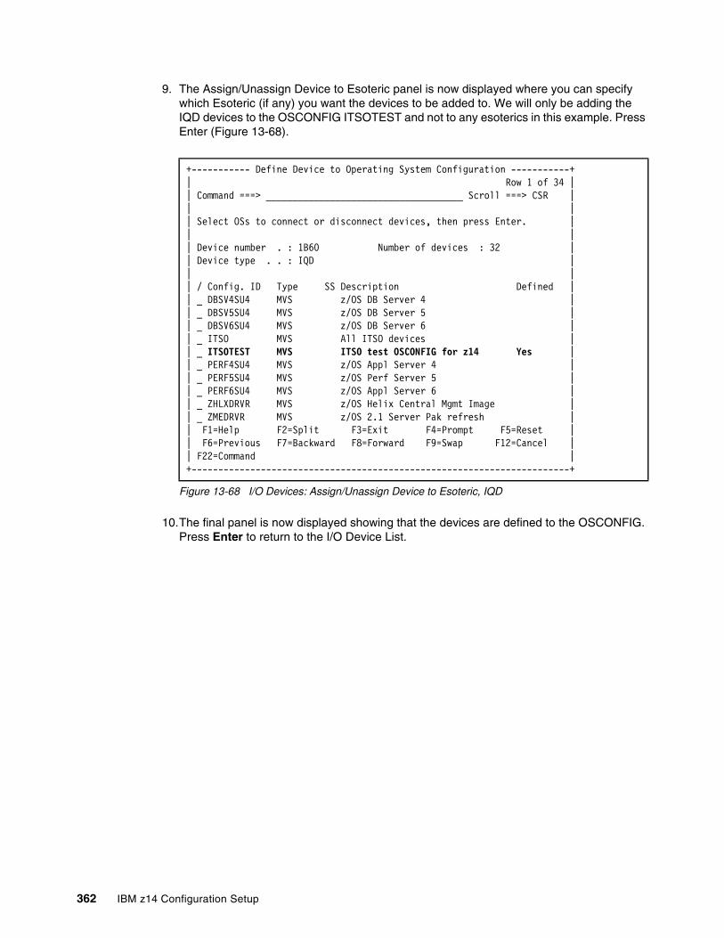
9. The Assign/Unassign Device to Esoteric panel is now displayed where you can specify which Esoteric (if any) you want the devices to be added to. We will only be adding the IQD devices to the OSCONFIG ITSOTEST and not to any esoterics in this example. Press Enter (Figure 13-68).
Figure 13-68 I/O Devices: Assign/Unassign Device to Esoteric, IQD
10.The final panel is now displayed showing that the devices are defined to the OSCONFIG. Press Enter to return to the I/O Device List.
+----------- Define Device to Operating System Configuration -----------+| Row 1 of 34 || Command ===> _____________________________________ Scroll ===> CSR || || Select OSs to connect or disconnect devices, then press Enter. || || Device number . : 1B60 Number of devices : 32 || Device type . . : IQD || || / Config. ID Type SS Description Defined || _ DBSV4SU4 MVS z/OS DB Server 4 || _ DBSV5SU4 MVS z/OS DB Server 5 || _ DBSV6SU4 MVS z/OS DB Server 6 || _ ITSO MVS All ITSO devices || _ ITSOTEST MVS ITSO test OSCONFIG for z14 Yes || _ PERF4SU4 MVS z/OS Appl Server 4 || _ PERF5SU4 MVS z/OS Perf Server 5 || _ PERF6SU4 MVS z/OS Appl Server 6 || _ ZHLXDRVR MVS z/OS Helix Central Mgmt Image || _ ZMEDRVR MVS z/OS 2.1 Server Pak refresh || F1=Help F2=Split F3=Exit F4=Prompt F5=Reset || F6=Previous F7=Backward F8=Forward F9=Swap F12=Cancel || F22=Command |+-----------------------------------------------------------------------+
362 IBM z14 Configuration Setup

Chapter 14. Adding coupling connectivity
This chapter describes the steps to define CS5, CL5, and ICP CHPIDs, and Coupling Facility links between these CHPID types.
It provides a list of these potential configuration items and a short description on how to do each of them using HCD.
This chapter includes the following sections:
� Defining more I/O using HCD� Coupling Facility LPARs, CS5, CL5, and ICP CHPIDs
14
Note: Not all of the following configuration items are necessarily required for your installation. In addition, the examples presented are not exhaustive.
© Copyright IBM Corp. 2017. All rights reserved. 363
14.1 Defining more I/O using HCD
When defining new I/O components in an IODF, certain definitions like OSCONFIGs, partitions, FICON Switches, Control Units, and Devices need to be made up front. After these have been defined, then the connections can be made:
� Defining Coupling Facility LPARs in a CSS� Defining CS5 CHPIDs� Defining a Coupling Facility link with CS5 CHPIDs� Defining CL5 CHPIDs� Defining a Coupling Facility link with CL5 CHPIDs� Defining ICP CHPIDs� Defining a Coupling Facility link with ICP CHPIDs
The following I/O definitions use HCD to demonstrate the examples. The examples in this chapter continue the work example created in the previous chapters (for example, SYS6.IODF29.WORK).
14.2 Coupling Facility LPARs, CS5, CL5, and ICP CHPIDs
This section covers defining Coupling Facility LPARs and the CS5, CL5, and ICP CHPID type definitions.
14.2.1 Defining Coupling Facility LPARs in a CSS
The following are considerations for a new (unreserved) partition:
� Partition name.� Number.� Usage.� Description.� To add CHPIDs to a partition, they first must be defined to the processor.� To rename an existing partition is a two-step process. First, it needs to be redefined as
reserved (Partition name = *) and the IODF activated on the processor. Then the partition must be redefined to the new name and the IODF activated on the processor.
To change a reserved partition to an active partition in a CSS, complete the following steps:
1. From the main HCD panel, select option 1.3. Processors.
2. Enter s next to the Processor that you want to add a partition to, and press Enter.
3. Enter p next to the CSS ID that you want to add a partition to, and press Enter.
4. Enter c next to the Reserved Partition that you want to unreserve (we use ID F for this example), and press Enter.
364 IBM z14 Configuration Setup
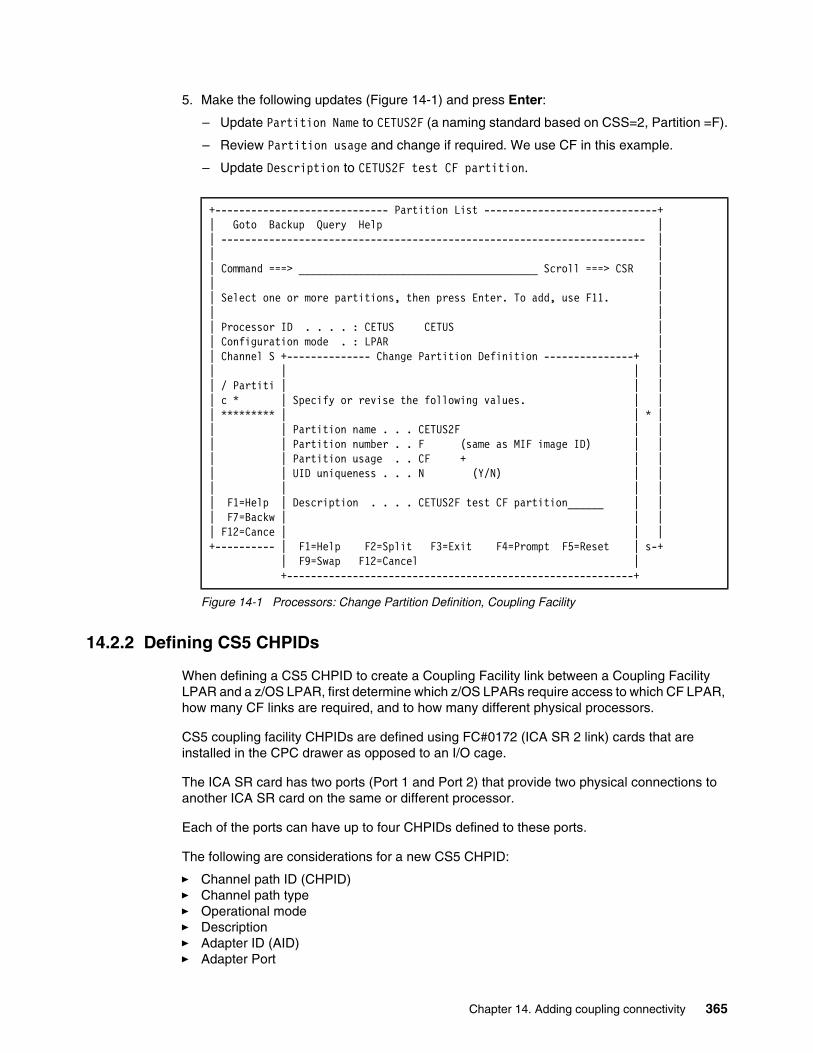
5. Make the following updates (Figure 14-1) and press Enter:
– Update Partition Name to CETUS2F (a naming standard based on CSS=2, Partition =F).
– Review Partition usage and change if required. We use CF in this example.
– Update Description to CETUS2F test CF partition.
Figure 14-1 Processors: Change Partition Definition, Coupling Facility
14.2.2 Defining CS5 CHPIDs
When defining a CS5 CHPID to create a Coupling Facility link between a Coupling Facility LPAR and a z/OS LPAR, first determine which z/OS LPARs require access to which CF LPAR, how many CF links are required, and to how many different physical processors.
CS5 coupling facility CHPIDs are defined using FC#0172 (ICA SR 2 link) cards that are installed in the CPC drawer as opposed to an I/O cage.
The ICA SR card has two ports (Port 1 and Port 2) that provide two physical connections to another ICA SR card on the same or different processor.
Each of the ports can have up to four CHPIDs defined to these ports.
The following are considerations for a new CS5 CHPID:
� Channel path ID (CHPID)� Channel path type� Operational mode� Description� Adapter ID (AID)� Adapter Port
+----------------------------- Partition List -----------------------------+| Goto Backup Query Help || ----------------------------------------------------------------------- || || Command ===> ________________________________________ Scroll ===> CSR || || Select one or more partitions, then press Enter. To add, use F11. || || Processor ID . . . . : CETUS CETUS || Configuration mode . : LPAR || Channel S +-------------- Change Partition Definition ---------------+ || | | || / Partiti | | || c * | Specify or revise the following values. | || ********* | | * || | Partition name . . . CETUS2F | || | Partition number . . F (same as MIF image ID) | || | Partition usage . . CF + | || | UID uniqueness . . . N (Y/N) | || | | || F1=Help | Description . . . . CETUS2F test CF partition______ | || F7=Backw | | || F12=Cance | | |+---------- | F1=Help F2=Split F3=Exit F4=Prompt F5=Reset | s-+ | F9=Swap F12=Cancel | +----------------------------------------------------------+
Chapter 14. Adding coupling connectivity 365
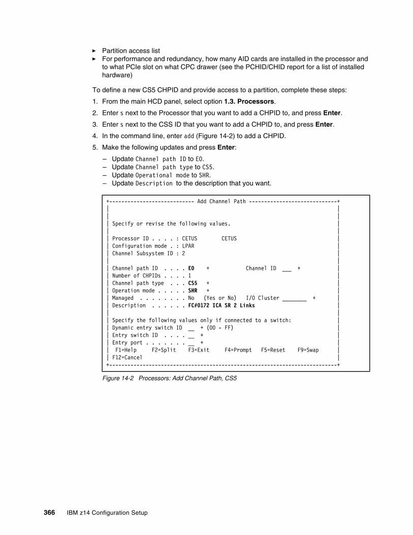
� Partition access list� For performance and redundancy, how many AID cards are installed in the processor and
to what PCIe slot on what CPC drawer (see the PCHID/CHID report for a list of installed hardware)
To define a new CS5 CHPID and provide access to a partition, complete these steps:
1. From the main HCD panel, select option 1.3. Processors.
2. Enter s next to the Processor that you want to add a CHPID to, and press Enter.
3. Enter s next to the CSS ID that you want to add a CHPID to, and press Enter.
4. In the command line, enter add (Figure 14-2) to add a CHPID.
5. Make the following updates and press Enter:
– Update Channel path ID to E0.– Update Channel path type to CS5.– Update Operational mode to SHR.– Update Description to the description that you want.
Figure 14-2 Processors: Add Channel Path, CS5
+---------------------------- Add Channel Path -----------------------------+| || || Specify or revise the following values. || || Processor ID . . . . : CETUS CETUS || Configuration mode . : LPAR || Channel Subsystem ID : 2 || || Channel path ID . . . . E0 + Channel ID ___ + || Number of CHPIDs . . . . 1 || Channel path type . . . CS5 + || Operation mode . . . . . SHR + || Managed . . . . . . . . No (Yes or No) I/O Cluster ________ + || Description . . . . . . FC#0172 ICA SR 2 Links || || Specify the following values only if connected to a switch: || Dynamic entry switch ID __ + (00 - FF) || Entry switch ID . . . . __ + || Entry port . . . . . . . __ + || F1=Help F2=Split F3=Exit F4=Prompt F5=Reset F9=Swap || F12=Cancel |+---------------------------------------------------------------------------+
366 IBM z14 Configuration Setup
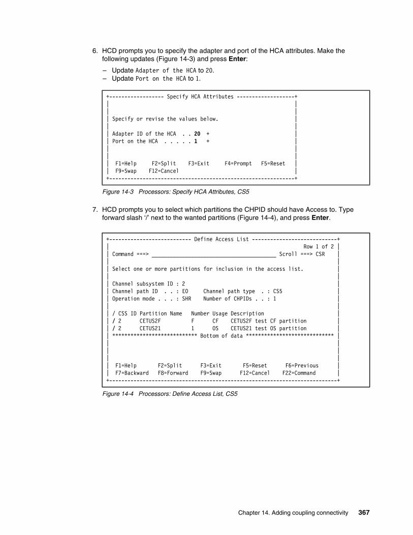
6. HCD prompts you to specify the adapter and port of the HCA attributes. Make the following updates (Figure 14-3) and press Enter:
– Update Adapter of the HCA to 20.– Update Port on the HCA to 1.
Figure 14-3 Processors: Specify HCA Attributes, CS5
7. HCD prompts you to select which partitions the CHPID should have Access to. Type forward slash ‘/’ next to the wanted partitions (Figure 14-4), and press Enter.
Figure 14-4 Processors: Define Access List, CS5
+------------------ Specify HCA Attributes -------------------+| || || Specify or revise the values below. || || Adapter ID of the HCA . . 20 + || Port on the HCA . . . . . 1 + || || || F1=Help F2=Split F3=Exit F4=Prompt F5=Reset || F9=Swap F12=Cancel |+-------------------------------------------------------------+
+--------------------------- Define Access List ----------------------------+| Row 1 of 2 || Command ===> _________________________________________ Scroll ===> CSR || || Select one or more partitions for inclusion in the access list. || || Channel subsystem ID : 2 || Channel path ID . . : E0 Channel path type . : CS5 || Operation mode . . . : SHR Number of CHPIDs . . : 1 || || / CSS ID Partition Name Number Usage Description || / 2 CETUS2F F CF CETUS2F test CF partition || / 2 CETUS21 1 OS CETUS21 test OS partition || **************************** Bottom of data ***************************** || || || || F1=Help F2=Split F3=Exit F5=Reset F6=Previous || F7=Backward F8=Forward F9=Swap F12=Cancel F22=Command |+---------------------------------------------------------------------------+
Chapter 14. Adding coupling connectivity 367
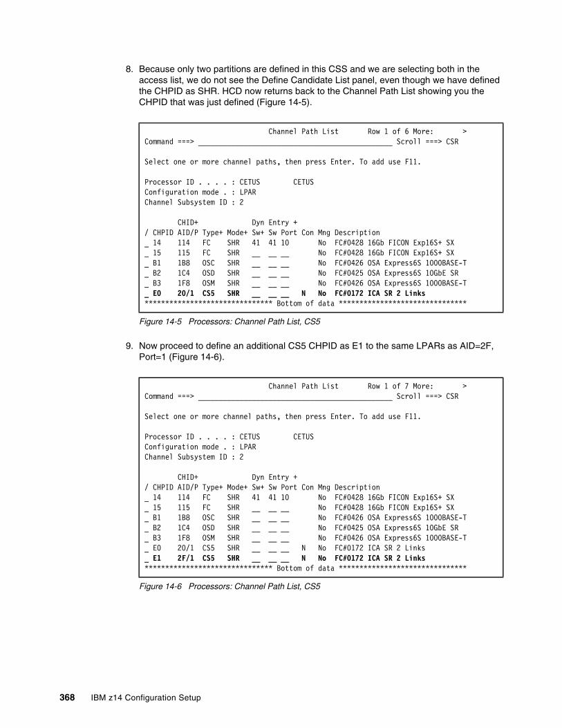
8. Because only two partitions are defined in this CSS and we are selecting both in the access list, we do not see the Define Candidate List panel, even though we have defined the CHPID as SHR. HCD now returns back to the Channel Path List showing you the CHPID that was just defined (Figure 14-5).
Figure 14-5 Processors: Channel Path List, CS5
9. Now proceed to define an additional CS5 CHPID as E1 to the same LPARs as AID=2F, Port=1 (Figure 14-6).
Figure 14-6 Processors: Channel Path List, CS5
Channel Path List Row 1 of 6 More: >Command ===> _______________________________________________ Scroll ===> CSR Select one or more channel paths, then press Enter. To add use F11. Processor ID . . . . : CETUS CETUS Configuration mode . : LPAR Channel Subsystem ID : 2 CHID+ Dyn Entry + / CHPID AID/P Type+ Mode+ Sw+ Sw Port Con Mng Description _ 14 114 FC SHR 41 41 10 No FC#0428 16Gb FICON Exp16S+ SX _ 15 115 FC SHR __ __ __ No FC#0428 16Gb FICON Exp16S+ SX _ B1 1B8 OSC SHR __ __ __ No FC#0426 OSA Express6S 1000BASE-T_ B2 1C4 OSD SHR __ __ __ No FC#0425 OSA Express6S 10GbE SR _ B3 1F8 OSM SHR __ __ __ No FC#0426 OSA Express6S 1000BASE-T_ E0 20/1 CS5 SHR __ __ __ N No FC#0172 ICA SR 2 Links ******************************* Bottom of data *******************************
Channel Path List Row 1 of 7 More: >Command ===> _______________________________________________ Scroll ===> CSR Select one or more channel paths, then press Enter. To add use F11. Processor ID . . . . : CETUS CETUS Configuration mode . : LPAR Channel Subsystem ID : 2 CHID+ Dyn Entry + / CHPID AID/P Type+ Mode+ Sw+ Sw Port Con Mng Description _ 14 114 FC SHR 41 41 10 No FC#0428 16Gb FICON Exp16S+ SX _ 15 115 FC SHR __ __ __ No FC#0428 16Gb FICON Exp16S+ SX _ B1 1B8 OSC SHR __ __ __ No FC#0426 OSA Express6S 1000BASE-T_ B2 1C4 OSD SHR __ __ __ No FC#0425 OSA Express6S 10GbE SR _ B3 1F8 OSM SHR __ __ __ No FC#0426 OSA Express6S 1000BASE-T_ E0 20/1 CS5 SHR __ __ __ N No FC#0172 ICA SR 2 Links _ E1 2F/1 CS5 SHR __ __ __ N No FC#0172 ICA SR 2 Links ******************************* Bottom of data *******************************
368 IBM z14 Configuration Setup
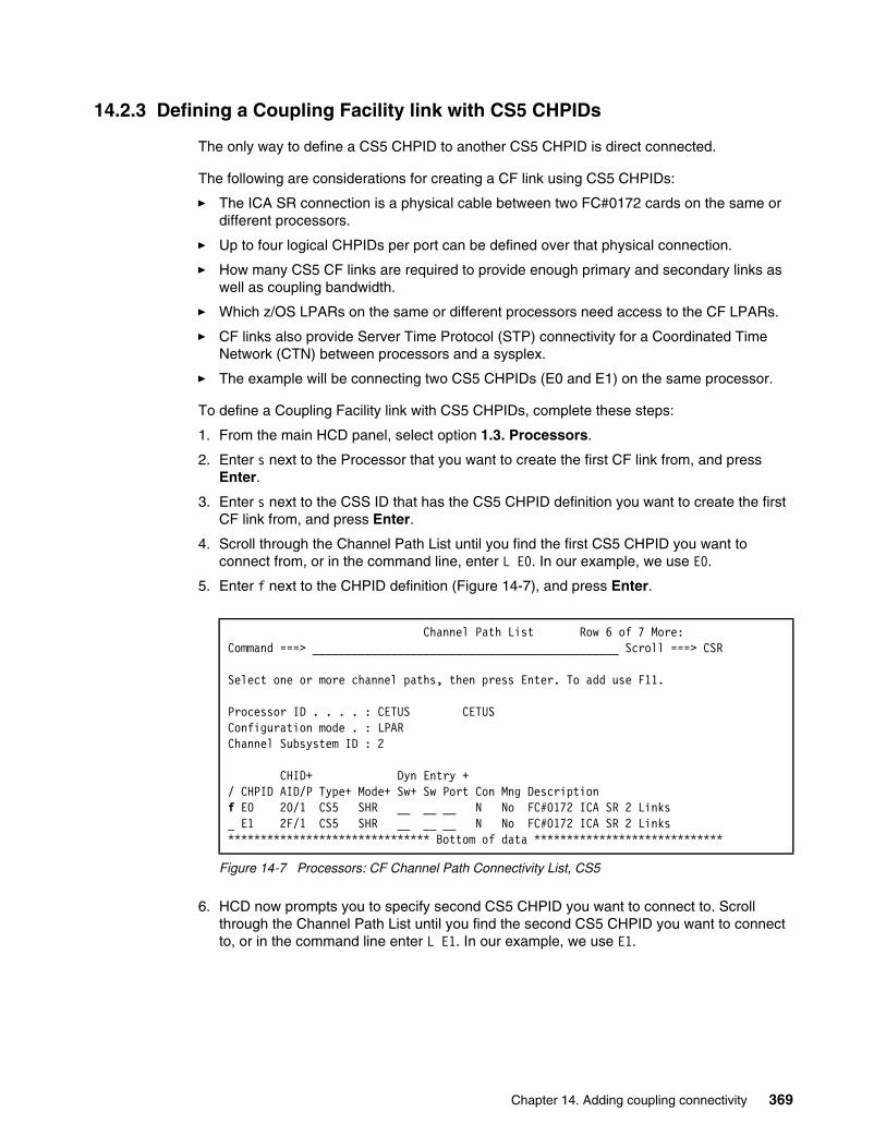
14.2.3 Defining a Coupling Facility link with CS5 CHPIDs
The only way to define a CS5 CHPID to another CS5 CHPID is direct connected.
The following are considerations for creating a CF link using CS5 CHPIDs:
� The ICA SR connection is a physical cable between two FC#0172 cards on the same or different processors.
� Up to four logical CHPIDs per port can be defined over that physical connection.
� How many CS5 CF links are required to provide enough primary and secondary links as well as coupling bandwidth.
� Which z/OS LPARs on the same or different processors need access to the CF LPARs.
� CF links also provide Server Time Protocol (STP) connectivity for a Coordinated Time Network (CTN) between processors and a sysplex.
� The example will be connecting two CS5 CHPIDs (E0 and E1) on the same processor.
To define a Coupling Facility link with CS5 CHPIDs, complete these steps:
1. From the main HCD panel, select option 1.3. Processors.
2. Enter s next to the Processor that you want to create the first CF link from, and press Enter.
3. Enter s next to the CSS ID that has the CS5 CHPID definition you want to create the first CF link from, and press Enter.
4. Scroll through the Channel Path List until you find the first CS5 CHPID you want to connect from, or in the command line, enter L E0. In our example, we use E0.
5. Enter f next to the CHPID definition (Figure 14-7), and press Enter.
Figure 14-7 Processors: CF Channel Path Connectivity List, CS5
6. HCD now prompts you to specify second CS5 CHPID you want to connect to. Scroll through the Channel Path List until you find the second CS5 CHPID you want to connect to, or in the command line enter L E1. In our example, we use E1.
Channel Path List Row 6 of 7 More: Command ===> _______________________________________________ Scroll ===> CSR Select one or more channel paths, then press Enter. To add use F11. Processor ID . . . . : CETUS CETUS Configuration mode . : LPAR Channel Subsystem ID : 2 CHID+ Dyn Entry + / CHPID AID/P Type+ Mode+ Sw+ Sw Port Con Mng Description f E0 20/1 CS5 SHR __ __ __ N No FC#0172 ICA SR 2 Links _ E1 2F/1 CS5 SHR __ __ __ N No FC#0172 ICA SR 2 Links ******************************* Bottom of data *****************************
Chapter 14. Adding coupling connectivity 369

7. Enter p next to the CHPID definition, (Figure 14-8) and press Enter.
Figure 14-8 Processors: CF Channel Path Connectivity List, CS5
8. HCD prompts you to specify which CF channel path to connect to. Make the following updates (Figure 14-9) and press Enter:
– Update Destination processor ID to CETUS.– Update Destination channel subsystem ID to 2.– Update Destination channel path ID to E0.
Figure 14-9 Processors: Connect to CF Channel Path, CS5
CF Channel Path Connectivity List Row 1 of 2Command ===> ____________________________________________ Scroll ===> CSR Select one or more channel paths, then press Enter. Source processor ID . . . . . : CETUS CETUS Source channel subsystem ID . : 2 Source partition name . . . . : * ----------Source---------- -----------Destination----------- -CU- -#- / CHP CHID CF Type Mode Occ Proc.CSSID CHP CHID CF Type Mode Type Dev _ E0 20/1 Y CS5 SHR N p E1 2F/1 Y CS5 SHR N ******************************* Bottom of data *******************************
+---------------- Connect to CF Channel Path -----------------+| || || Specify the following values. || || Source processor ID . . . . . : CETUS || Source channel subsystem ID . : 2 || Source channel path ID . . . . : E1 || Source channel path type . . . : CS5 || || Destination processor ID . . . . . . CETUS + || Destination channel subsystem ID . . 2 + || Destination channel path ID . . . . E0 + || || Timing-only link . . . . . . . . . . No || || || F1=Help F2=Split F3=Exit F4=Prompt F5=Reset || F9=Swap F12=Cancel |+-------------------------------------------------------------+
370 IBM z14 Configuration Setup

9. HCD checks available Control Unit numbers and Device addresses starting at FFFF and working backwards to provide suggestions. These suggestions can be overridden or accepted. We accept the suggestions for the second CS5 CHPID (Figure 14-10) and press Enter.
Figure 14-10 Processors: Add CF Control Unit and Devices, CS5
10.HCD provides suggested Control Unit numbers and Device addresses for the first CS5 CHPID (Figure 14-11). Observe that the Control unit number is the same and that eight devices were allocated. Press Enter.
Figure 14-11 Processors: Add CF Control Unit and Devices, CS5
+----------------- Add CF Control Unit and Devices ------------------+| || || Confirm or revise the CF control unit number and device numbers || for the CF control unit and devices to be defined. || || Processor ID . . . . . . . : CETUS || Channel subsystem ID . . . : 2 || Channel path ID . . . . . : E1 Operation mode . . : SHR || Channel path type . . . . : CS5 || || Control unit number . . . . FFF9 + || || Device number . . . . . . . FFA4 || Number of devices . . . . . 8 || || || F1=Help F2=Split F3=Exit F4=Prompt F5=Reset || F6=Previous F9=Swap F12=Cancel |+--------------------------------------------------------------------+
+----------------- Add CF Control Unit and Devices ------------------+| || || Confirm or revise the CF control unit number and device numbers || for the CF control unit and devices to be defined. || || Processor ID . . . . . . . : CETUS || Channel subsystem ID . . . : 2 || Channel path ID . . . . . : E0 Operation mode . . : SHR || Channel path type . . . . : CS5 || || Control unit number . . . . FFF9 + || || Device number . . . . . . . FF9C || Number of devices . . . . . 8 || || || F1=Help F2=Split F3=Exit F4=Prompt F5=Reset || F6=Previous F9=Swap F12=Cancel |+--------------------------------------------------------------------+
Chapter 14. Adding coupling connectivity 371

HCD provides a summary of the Source and Destination CF Connectivity List (Figure 14-12).
Figure 14-12 Processors: Add CF Channel Path Connectivity List, CS5
14.2.4 Defining CL5 CHPIDs
When defining a CL5 CHPID to create a Coupling Facility link between a Coupling Facility LPAR and a z/OS LPAR, determine which z/OS LPARs require access to which CF LPAR, how many CF links are required and to how many different physical processors.
CL5 coupling facility CHPIDs are defined using FC#0433 (Coupling Express LR) cards which are installed in the CPC drawer as opposed to an I/O cage.
The Coupling Express LR card has two ports (Port 1 and Port 2) which provide two physical connections between another Coupling Express LR card on the same or different processor.
Each of the ports can have up to four CHPIDs defined.
The following are considerations for a new CL5 CHPID:
� Channel path ID (CHPID)� Channel ID (CHID)� Channel path type� Operational mode� Description� Partition access list� For performance and redundancy, how many CL5 cards are installed in the processor and
to what PCIe slot on what CPC drawer (see the PCHID/CHID report for a list of installed hardware)
To define a new CL5 CHPID and provide access to a partition, complete these steps:
1. From the main HCD panel, select option 1.3. Processors.
2. Enter s next to the Processor that you want to add a CHPID to, and press Enter.
3. Enter s next to the CSS ID that you want to add a CHPID to, and press Enter.
CF Channel Path Connectivity List Row 1 of Command ===> ____________________________________________ Scroll ===> CSR Select one or more channel paths, then press Enter. Source processor ID . . . . . : CETUS CETUS Source channel subsystem ID . : 2 Source partition name . . . . : * ----------Source---------- -----------Destination----------- -CU- -#- / CHP CHID CF Type Mode Occ Proc.CSSID CHP CHID CF Type Mode Type Dev _ E0 20/1 Y CS5 SHR N CETUS.2 E1 2F/1 Y CS5 SHR CFP 8 _ E1 2F/1 Y CS5 SHR N CETUS.2 E0 20/1 Y CS5 SHR CFP 8 ******************************* Bottom of data ******************************
372 IBM z14 Configuration Setup

4. In the command line, enter add (Figure 14-13) to add a CHPID.
5. Make the following updates and press Enter:
– Update Channel path ID to E2.– Update Channel ID to 13C.– Update Channel path type to CL5.– Update Operational mode to SHR.– Update Description to the description that you want.
Figure 14-13 Processors: Add Channel Path, CL5
6. HCD prompts you to specify the coupling PCHID/Port attributes. Make the following updates (Figure 14-14) and press Enter:
– Update Coupling Port to 1.
Figure 14-14 Processors: Specify Coupling Pchid/Port Attributes, CL5
+---------------------------- Add Channel Path -----------------------------+| || || Specify or revise the following values. || || Processor ID . . . . : CETUS CETUS || Configuration mode . : LPAR || Channel Subsystem ID : 2 || || Channel path ID . . . . E2 + Channel ID 13C + || Number of CHPIDs . . . . 1 || Channel path type . . . CL5 + || Operation mode . . . . . SHR + || Managed . . . . . . . . No (Yes or No) I/O Cluster ________ + || Description . . . . . . FC#0433 Coupling Express LR_____ || || Specify the following values only if connected to a switch: || Dynamic entry switch ID __ + (00 - FF) || Entry switch ID . . . . __ + || Entry port . . . . . . . __ + || F1=Help F2=Split F3=Exit F4=Prompt F5=Reset F9=Swap || F12=Cancel |+---------------------------------------------------------------------------+
+----------- Specify Coupling Pchid/Port Attribute -----------+| || || Specify or revise the values below. || || Physical channel ID . . . 13C || Coupling port . . . . . . 1 + || || || F1=Help F2=Split F3=Exit F4=Prompt F5=Reset || F9=Swap F12=Cancel |+-------------------------------------------------------------+
Chapter 14. Adding coupling connectivity 373
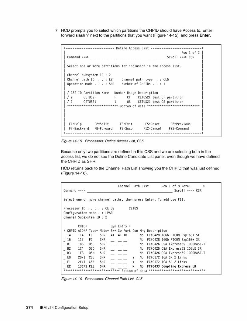
7. HCD prompts you to select which partitions the CHPID should have Access to. Enter forward slash ‘/’ next to the partitions that you want (Figure 14-15), and press Enter.
Figure 14-15 Processors: Define Access List, CL5
Because only two partitions are defined in this CSS and we are selecting both in the access list, we do not see the Define Candidate List panel, even though we have defined the CHPID as SHR.
HCD returns back to the Channel Path List showing you the CHPID that was just defined (Figure 14-16).
Figure 14-16 Processors: Channel Path List, CL5
+--------------------------- Define Access List ----------------------------+| Row 1 of 2 || Command ===> _________________________________________ Scroll ===> CSR || || Select one or more partitions for inclusion in the access list. || || Channel subsystem ID : 2 || Channel path ID . . : E2 Channel path type . : CL5 || Operation mode . . . : SHR Number of CHPIDs . . : 1 || || / CSS ID Partition Name Number Usage Description || / 2 CETUS2F F CF CETUS2F test CF partition || / 2 CETUS21 1 OS CETUS21 test OS partition || **************************** Bottom of data ***************************** || || || || F1=Help F2=Split F3=Exit F5=Reset F6=Previous || F7=Backward F8=Forward F9=Swap F12=Cancel F22=Command |+---------------------------------------------------------------------------+
Channel Path List Row 1 of 8 More: >Command ===> _______________________________________________ Scroll ===> CSR Select one or more channel paths, then press Enter. To add use F11. Processor ID . . . . : CETUS CETUS Configuration mode . : LPAR Channel Subsystem ID : 2 CHID+ Dyn Entry + / CHPID AID/P Type+ Mode+ Sw+ Sw Port Con Mng Description _ 14 114 FC SHR 41 41 10 No FC#0428 16Gb FICON Exp16S+ SX _ 15 115 FC SHR __ __ __ No FC#0428 16Gb FICON Exp16S+ SX _ B1 1B8 OSC SHR __ __ __ No FC#0426 OSA Express6S 1000BASE-T_ B2 1C4 OSD SHR __ __ __ No FC#0425 OSA Express6S 10GbE SR _ B3 1F8 OSM SHR __ __ __ No FC#0426 OSA Express6S 1000BASE-T_ E0 20/1 CS5 SHR __ __ __ Y No FC#0172 ICA SR 2 Links _ E1 2F/1 CS5 SHR __ __ __ Y No FC#0172 ICA SR 2 Links _ E2 13C/1 CL5 SHR __ __ __ N No FC#0433 Coupling Express LR ******************************* Bottom of data *******************************
374 IBM z14 Configuration Setup

8. Now define an additional CL5 CHPID as E3 to the same LPARs as CHID=1FC, Port=1 (Figure 14-17).
Figure 14-17 Processors: Channel Path List, CL5
14.2.5 Defining a Coupling Facility link with CL5 CHPIDs
The only way to define a CL5 CHPID to another CL5 CHPID is direct connected.
The following are considerations for creating a CF link using CL5 CHPIDs:
� The Coupling Express LR connection is a physical cable between two FC#0433 cards on the same or different processors.
� Up to four logical CHPIDs per port can be defined over that physical connection.
� How many CL5 CF links are required to provide enough primary and secondary links as well as coupling bandwidth.
� Which z/OS LPARs on the same or different processors need access to the CF LPARs.
� CF links also provide STP connectivity for a CTN between processors and a sysplex.
� The example will be connecting two CL5 CHPIDs (E2 and E3) on the same processor.
To define a Coupling Facility link with CL5 CHPIDs, complete these steps:
1. From the main HCD panel, select option 1.3. Processors.
2. Enter s next to the Processor that you want to create the first CF link from, and press Enter.
3. Enter s next to the CSS ID that has the CL5 CHPID definition you want to create the first CF link from, and press Enter.
4. Scroll through the Channel Path List until you find the first CS5 CHPID you want to connect from, or in the command line, enter L E2. In our example, we use E2.
Channel Path List Row 1 of 9 More: >Command ===> _______________________________________________ Scroll ===> CSR Select one or more channel paths, then press Enter. To add use F11. Processor ID . . . . : CETUS CETUS Configuration mode . : LPAR Channel Subsystem ID : 2 CHID+ Dyn Entry + / CHPID AID/P Type+ Mode+ Sw+ Sw Port Con Mng Description _ 14 114 FC SHR 41 41 10 No FC#0428 16Gb FICON Exp16S+ SX _ 15 115 FC SHR __ __ __ No FC#0428 16Gb FICON Exp16S+ SX _ B1 1B8 OSC SHR __ __ __ No FC#0426 OSA Express6S 1000BASE-T_ B2 1C4 OSD SHR __ __ __ No FC#0425 OSA Express6S 10GbE SR _ B3 1F8 OSM SHR __ __ __ No FC#0426 OSA Express6S 1000BASE-T_ E0 20/1 CS5 SHR __ __ __ Y No FC#0172 ICA SR 2 Links _ E1 2F/1 CS5 SHR __ __ __ Y No FC#0172 ICA SR 2 Links _ E2 13C/1 CL5 SHR __ __ __ N No FC#0433 Coupling Express LR _ E3 1FC/1 CL5 SHR __ __ __ N No FC#0433 Coupling Express LR ******************************* Bottom of data *******************************
Chapter 14. Adding coupling connectivity 375
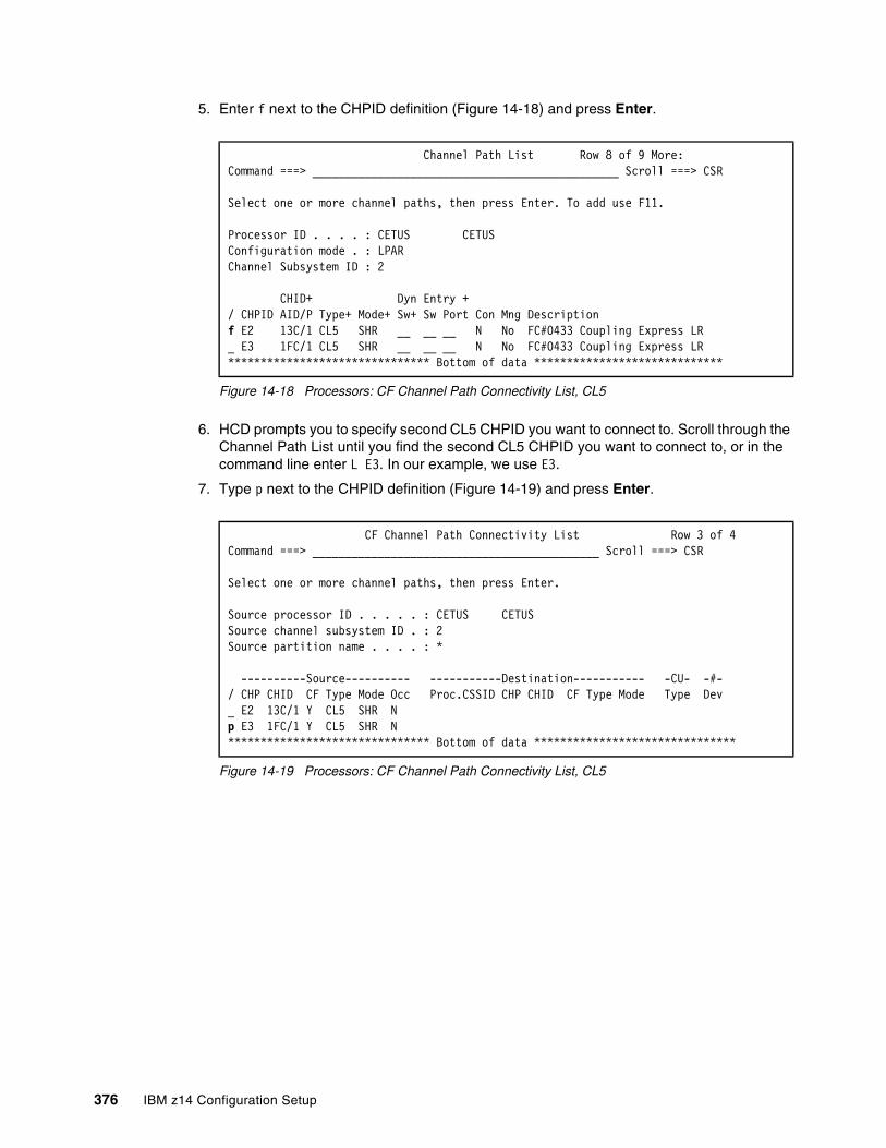
5. Enter f next to the CHPID definition (Figure 14-18) and press Enter.
Figure 14-18 Processors: CF Channel Path Connectivity List, CL5
6. HCD prompts you to specify second CL5 CHPID you want to connect to. Scroll through the Channel Path List until you find the second CL5 CHPID you want to connect to, or in the command line enter L E3. In our example, we use E3.
7. Type p next to the CHPID definition (Figure 14-19) and press Enter.
Figure 14-19 Processors: CF Channel Path Connectivity List, CL5
Channel Path List Row 8 of 9 More: Command ===> _______________________________________________ Scroll ===> CSR Select one or more channel paths, then press Enter. To add use F11. Processor ID . . . . : CETUS CETUS Configuration mode . : LPAR Channel Subsystem ID : 2 CHID+ Dyn Entry + / CHPID AID/P Type+ Mode+ Sw+ Sw Port Con Mng Description f E2 13C/1 CL5 SHR __ __ __ N No FC#0433 Coupling Express LR _ E3 1FC/1 CL5 SHR __ __ __ N No FC#0433 Coupling Express LR ******************************* Bottom of data *****************************
CF Channel Path Connectivity List Row 3 of 4Command ===> ____________________________________________ Scroll ===> CSR Select one or more channel paths, then press Enter. Source processor ID . . . . . : CETUS CETUS Source channel subsystem ID . : 2 Source partition name . . . . : * ----------Source---------- -----------Destination----------- -CU- -#- / CHP CHID CF Type Mode Occ Proc.CSSID CHP CHID CF Type Mode Type Dev _ E2 13C/1 Y CL5 SHR N p E3 1FC/1 Y CL5 SHR N ******************************* Bottom of data *******************************
376 IBM z14 Configuration Setup
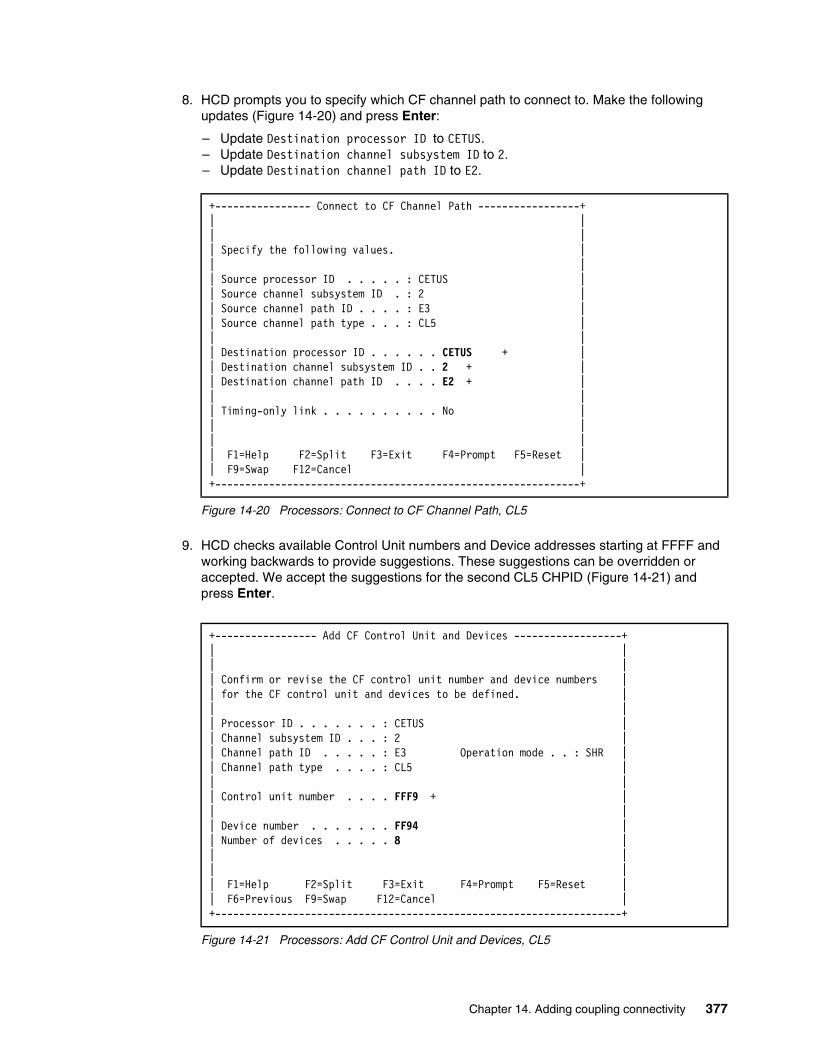
8. HCD prompts you to specify which CF channel path to connect to. Make the following updates (Figure 14-20) and press Enter:
– Update Destination processor ID to CETUS.– Update Destination channel subsystem ID to 2.– Update Destination channel path ID to E2.
Figure 14-20 Processors: Connect to CF Channel Path, CL5
9. HCD checks available Control Unit numbers and Device addresses starting at FFFF and working backwards to provide suggestions. These suggestions can be overridden or accepted. We accept the suggestions for the second CL5 CHPID (Figure 14-21) and press Enter.
Figure 14-21 Processors: Add CF Control Unit and Devices, CL5
+---------------- Connect to CF Channel Path -----------------+| || || Specify the following values. || || Source processor ID . . . . . : CETUS || Source channel subsystem ID . : 2 || Source channel path ID . . . . : E3 || Source channel path type . . . : CL5 || || Destination processor ID . . . . . . CETUS + || Destination channel subsystem ID . . 2 + || Destination channel path ID . . . . E2 + || || Timing-only link . . . . . . . . . . No || || || F1=Help F2=Split F3=Exit F4=Prompt F5=Reset || F9=Swap F12=Cancel |+-------------------------------------------------------------+
+----------------- Add CF Control Unit and Devices ------------------+| || || Confirm or revise the CF control unit number and device numbers || for the CF control unit and devices to be defined. || || Processor ID . . . . . . . : CETUS || Channel subsystem ID . . . : 2 || Channel path ID . . . . . : E3 Operation mode . . : SHR || Channel path type . . . . : CL5 || || Control unit number . . . . FFF9 + || || Device number . . . . . . . FF94 || Number of devices . . . . . 8 || || || F1=Help F2=Split F3=Exit F4=Prompt F5=Reset || F6=Previous F9=Swap F12=Cancel |+--------------------------------------------------------------------+
Chapter 14. Adding coupling connectivity 377
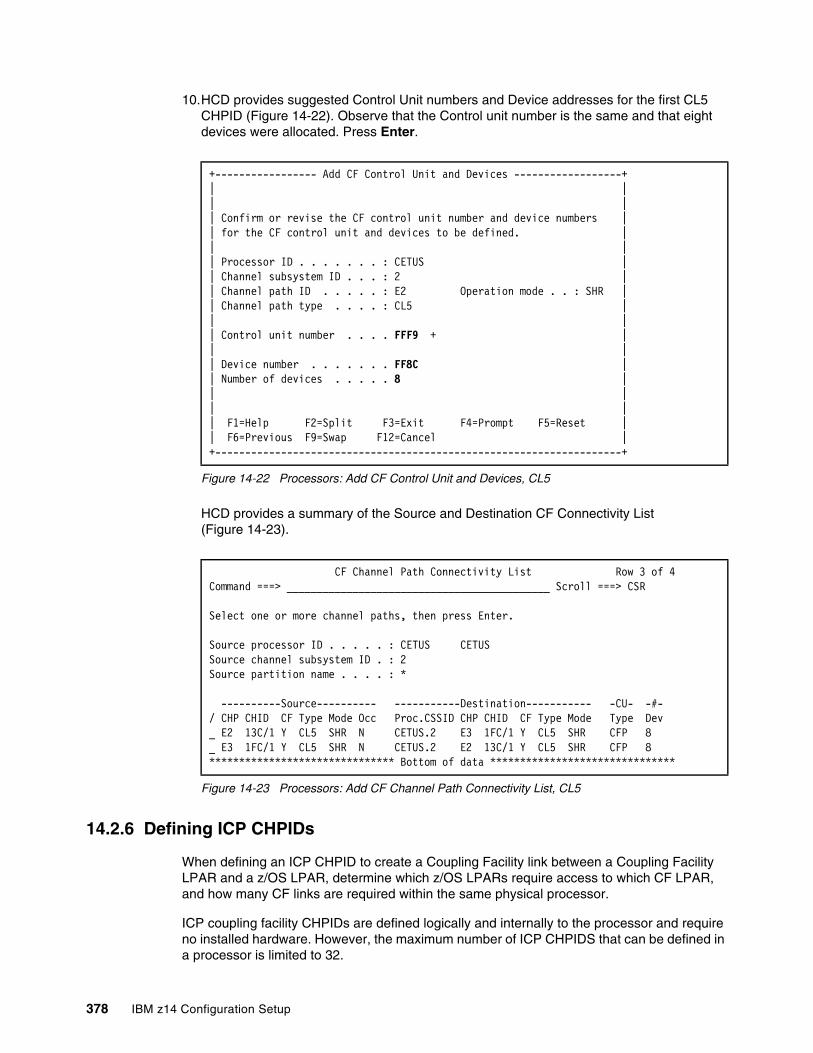
10.HCD provides suggested Control Unit numbers and Device addresses for the first CL5 CHPID (Figure 14-22). Observe that the Control unit number is the same and that eight devices were allocated. Press Enter.
Figure 14-22 Processors: Add CF Control Unit and Devices, CL5
HCD provides a summary of the Source and Destination CF Connectivity List (Figure 14-23).
Figure 14-23 Processors: Add CF Channel Path Connectivity List, CL5
14.2.6 Defining ICP CHPIDs
When defining an ICP CHPID to create a Coupling Facility link between a Coupling Facility LPAR and a z/OS LPAR, determine which z/OS LPARs require access to which CF LPAR, and how many CF links are required within the same physical processor.
ICP coupling facility CHPIDs are defined logically and internally to the processor and require no installed hardware. However, the maximum number of ICP CHPIDS that can be defined in a processor is limited to 32.
+----------------- Add CF Control Unit and Devices ------------------+| || || Confirm or revise the CF control unit number and device numbers || for the CF control unit and devices to be defined. || || Processor ID . . . . . . . : CETUS || Channel subsystem ID . . . : 2 || Channel path ID . . . . . : E2 Operation mode . . : SHR || Channel path type . . . . : CL5 || || Control unit number . . . . FFF9 + || || Device number . . . . . . . FF8C || Number of devices . . . . . 8 || || || F1=Help F2=Split F3=Exit F4=Prompt F5=Reset || F6=Previous F9=Swap F12=Cancel |+--------------------------------------------------------------------+
CF Channel Path Connectivity List Row 3 of 4Command ===> ____________________________________________ Scroll ===> CSR Select one or more channel paths, then press Enter. Source processor ID . . . . . : CETUS CETUS Source channel subsystem ID . : 2 Source partition name . . . . : * ----------Source---------- -----------Destination----------- -CU- -#- / CHP CHID CF Type Mode Occ Proc.CSSID CHP CHID CF Type Mode Type Dev _ E2 13C/1 Y CL5 SHR N CETUS.2 E3 1FC/1 Y CL5 SHR CFP 8 _ E3 1FC/1 Y CL5 SHR N CETUS.2 E2 13C/1 Y CL5 SHR CFP 8 ******************************* Bottom of data *******************************
378 IBM z14 Configuration Setup
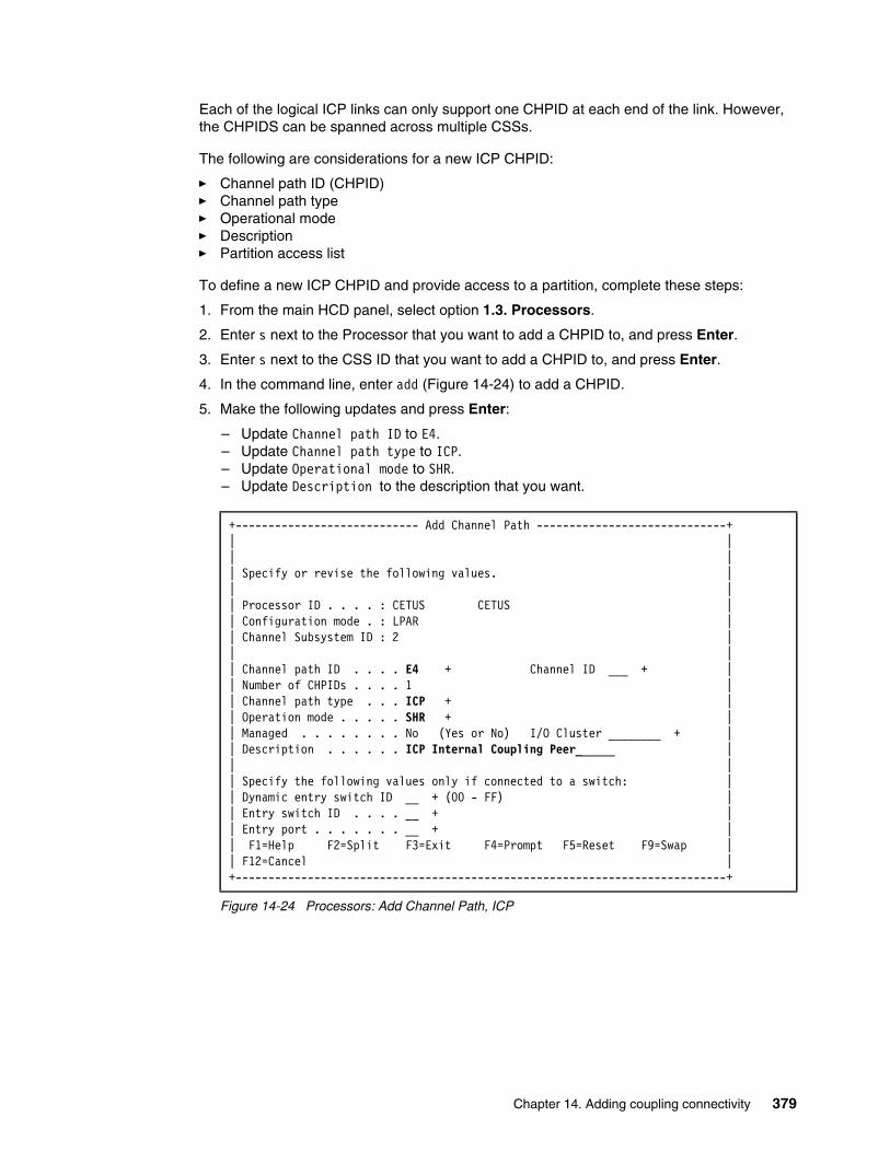
Each of the logical ICP links can only support one CHPID at each end of the link. However, the CHPIDS can be spanned across multiple CSSs.
The following are considerations for a new ICP CHPID:
� Channel path ID (CHPID)� Channel path type� Operational mode� Description� Partition access list
To define a new ICP CHPID and provide access to a partition, complete these steps:
1. From the main HCD panel, select option 1.3. Processors.
2. Enter s next to the Processor that you want to add a CHPID to, and press Enter.
3. Enter s next to the CSS ID that you want to add a CHPID to, and press Enter.
4. In the command line, enter add (Figure 14-24) to add a CHPID.
5. Make the following updates and press Enter:
– Update Channel path ID to E4.– Update Channel path type to ICP.– Update Operational mode to SHR.– Update Description to the description that you want.
Figure 14-24 Processors: Add Channel Path, ICP
+---------------------------- Add Channel Path -----------------------------+| || || Specify or revise the following values. || || Processor ID . . . . : CETUS CETUS || Configuration mode . : LPAR || Channel Subsystem ID : 2 || || Channel path ID . . . . E4 + Channel ID ___ + || Number of CHPIDs . . . . 1 || Channel path type . . . ICP + || Operation mode . . . . . SHR + || Managed . . . . . . . . No (Yes or No) I/O Cluster ________ + || Description . . . . . . ICP Internal Coupling Peer______ || || Specify the following values only if connected to a switch: || Dynamic entry switch ID __ + (00 - FF) || Entry switch ID . . . . __ + || Entry port . . . . . . . __ + || F1=Help F2=Split F3=Exit F4=Prompt F5=Reset F9=Swap || F12=Cancel |+---------------------------------------------------------------------------+
Chapter 14. Adding coupling connectivity 379
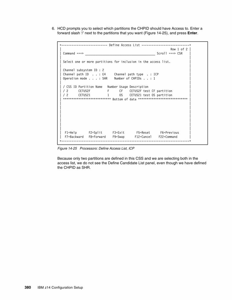
6. HCD prompts you to select which partitions the CHPID should have Access to. Enter a forward slash ‘/’ next to the partitions that you want (Figure 14-25), and press Enter.
Figure 14-25 Processors: Define Access List, ICP
Because only two partitions are defined in this CSS and we are selecting both in the access list, we do not see the Define Candidate List panel, even though we have defined the CHPID as SHR.
+--------------------------- Define Access List ----------------------------+| Row 1 of 2 || Command ===> _________________________________________ Scroll ===> CSR || || Select one or more partitions for inclusion in the access list. || || Channel subsystem ID : 2 || Channel path ID . . : E4 Channel path type . : ICP || Operation mode . . . : SHR Number of CHPIDs . . : 1 || || / CSS ID Partition Name Number Usage Description || / 2 CETUS2F F CF CETUS2F test CF partition || / 2 CETUS21 1 OS CETUS21 test OS partition || **************************** Bottom of data ***************************** || || || || || || || || F1=Help F2=Split F3=Exit F5=Reset F6=Previous || F7=Backward F8=Forward F9=Swap F12=Cancel F22=Command |+---------------------------------------------------------------------------+
380 IBM z14 Configuration Setup
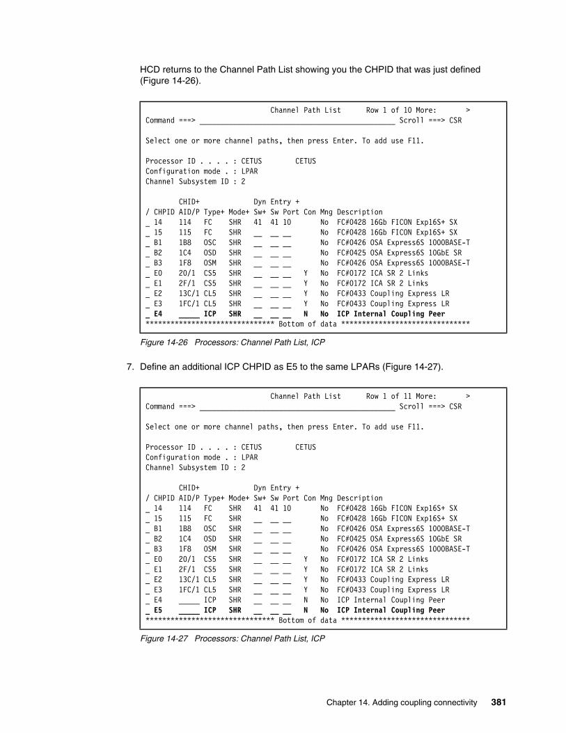
HCD returns to the Channel Path List showing you the CHPID that was just defined (Figure 14-26).
Figure 14-26 Processors: Channel Path List, ICP
7. Define an additional ICP CHPID as E5 to the same LPARs (Figure 14-27).
Figure 14-27 Processors: Channel Path List, ICP
Channel Path List Row 1 of 10 More: >Command ===> _______________________________________________ Scroll ===> CSR Select one or more channel paths, then press Enter. To add use F11. Processor ID . . . . : CETUS CETUS Configuration mode . : LPAR Channel Subsystem ID : 2 CHID+ Dyn Entry + / CHPID AID/P Type+ Mode+ Sw+ Sw Port Con Mng Description _ 14 114 FC SHR 41 41 10 No FC#0428 16Gb FICON Exp16S+ SX _ 15 115 FC SHR __ __ __ No FC#0428 16Gb FICON Exp16S+ SX _ B1 1B8 OSC SHR __ __ __ No FC#0426 OSA Express6S 1000BASE-T_ B2 1C4 OSD SHR __ __ __ No FC#0425 OSA Express6S 10GbE SR _ B3 1F8 OSM SHR __ __ __ No FC#0426 OSA Express6S 1000BASE-T_ E0 20/1 CS5 SHR __ __ __ Y No FC#0172 ICA SR 2 Links _ E1 2F/1 CS5 SHR __ __ __ Y No FC#0172 ICA SR 2 Links _ E2 13C/1 CL5 SHR __ __ __ Y No FC#0433 Coupling Express LR _ E3 1FC/1 CL5 SHR __ __ __ Y No FC#0433 Coupling Express LR _ E4 _____ ICP SHR __ __ __ N No ICP Internal Coupling Peer ******************************* Bottom of data *******************************
Channel Path List Row 1 of 11 More: >Command ===> _______________________________________________ Scroll ===> CSR Select one or more channel paths, then press Enter. To add use F11. Processor ID . . . . : CETUS CETUS Configuration mode . : LPAR Channel Subsystem ID : 2 CHID+ Dyn Entry + / CHPID AID/P Type+ Mode+ Sw+ Sw Port Con Mng Description _ 14 114 FC SHR 41 41 10 No FC#0428 16Gb FICON Exp16S+ SX _ 15 115 FC SHR __ __ __ No FC#0428 16Gb FICON Exp16S+ SX _ B1 1B8 OSC SHR __ __ __ No FC#0426 OSA Express6S 1000BASE-T_ B2 1C4 OSD SHR __ __ __ No FC#0425 OSA Express6S 10GbE SR _ B3 1F8 OSM SHR __ __ __ No FC#0426 OSA Express6S 1000BASE-T_ E0 20/1 CS5 SHR __ __ __ Y No FC#0172 ICA SR 2 Links _ E1 2F/1 CS5 SHR __ __ __ Y No FC#0172 ICA SR 2 Links _ E2 13C/1 CL5 SHR __ __ __ Y No FC#0433 Coupling Express LR _ E3 1FC/1 CL5 SHR __ __ __ Y No FC#0433 Coupling Express LR _ E4 _____ ICP SHR __ __ __ N No ICP Internal Coupling Peer _ E5 _____ ICP SHR __ __ __ N No ICP Internal Coupling Peer ******************************* Bottom of data *******************************
Chapter 14. Adding coupling connectivity 381
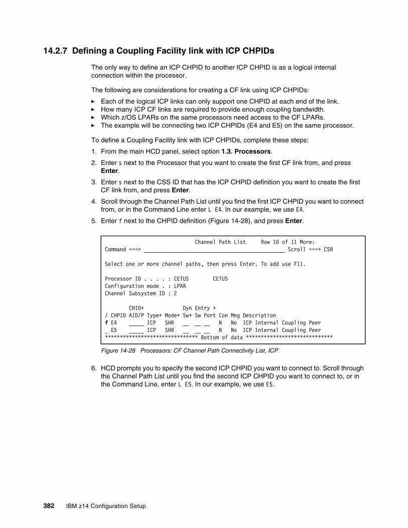
14.2.7 Defining a Coupling Facility link with ICP CHPIDs
The only way to define an ICP CHPID to another ICP CHPID is as a logical internal connection within the processor.
The following are considerations for creating a CF link using ICP CHPIDs:
� Each of the logical ICP links can only support one CHPID at each end of the link.� How many ICP CF links are required to provide enough coupling bandwidth.� Which z/OS LPARs on the same processors need access to the CF LPARs.� The example will be connecting two ICP CHPIDs (E4 and E5) on the same processor.
To define a Coupling Facility link with ICP CHPIDs, complete these steps:
1. From the main HCD panel, select option 1.3. Processors.
2. Enter s next to the Processor that you want to create the first CF link from, and press Enter.
3. Enter s next to the CSS ID that has the ICP CHPID definition you want to create the first CF link from, and press Enter.
4. Scroll through the Channel Path List until you find the first ICP CHPID you want to connect from, or in the Command Line enter L E4. In our example, we use E4.
5. Enter f next to the CHPID definition (Figure 14-28), and press Enter.
Figure 14-28 Processors: CF Channel Path Connectivity List, ICP
6. HCD prompts you to specify the second ICP CHPID you want to connect to. Scroll through the Channel Path List until you find the second ICP CHPID you want to connect to, or in the Command Line, enter L E5. In our example, we use E5.
Channel Path List Row 10 of 11 More: Command ===> _______________________________________________ Scroll ===> CSR Select one or more channel paths, then press Enter. To add use F11. Processor ID . . . . : CETUS CETUS Configuration mode . : LPAR Channel Subsystem ID : 2 CHID+ Dyn Entry + / CHPID AID/P Type+ Mode+ Sw+ Sw Port Con Mng Description f E4 _____ ICP SHR __ __ __ N No ICP Internal Coupling Peer _ E5 _____ ICP SHR __ __ __ N No ICP Internal Coupling Peer ******************************* Bottom of data *****************************
382 IBM z14 Configuration Setup

7. Type p next to the CHPID definition (Figure 14-29) and press Enter.
Figure 14-29 Processors: CF Channel Path Connectivity List, ICP
8. HCD prompts you to specify which CF channel path to connect to. Make the following updates (Figure 14-30) and press Enter:
– Update Destination processor ID to CETUS.– Update Destination channel subsystem ID to 2.– Update Destination channel path ID to E4.
Figure 14-30 Processors: Connect to CF Channel Path, ICP
CF Channel Path Connectivity List Row 5 of 6Command ===> ____________________________________________ Scroll ===> CSR Select one or more channel paths, then press Enter. Source processor ID . . . . . : CETUS CETUS Source channel subsystem ID . : 2 Source partition name . . . . : * ----------Source---------- -----------Destination----------- -CU- -#- / CHP CHID CF Type Mode Occ Proc.CSSID CHP CHID CF Type Mode Type Dev _ E4 Y ICP SHR N p E5 Y ICP SHR N ******************************* Bottom of data *******************************
+---------------- Connect to CF Channel Path -----------------+| || || Specify the following values. || || Source processor ID . . . . . : CETUS || Source channel subsystem ID . : 2 || Source channel path ID . . . . : E5 || Source channel path type . . . : ICP || || Destination processor ID . . . . . . CETUS + || Destination channel subsystem ID . . 2 + || Destination channel path ID . . . . E4 + || || Timing-only link . . . . . . . . . . No || || || F1=Help F2=Split F3=Exit F4=Prompt F5=Reset || F9=Swap F12=Cancel |+-------------------------------------------------------------+
Chapter 14. Adding coupling connectivity 383

9. HCD checks available Control Unit numbers and Device addresses starting at FFFF and working backwards to provide suggestions. These suggestions can be overridden or accepted. We accept the suggestions for the second ICP CHPID (Figure 14-31) and press Enter.
Figure 14-31 Processors: Add CF Control Unit and Devices, ICP
10.HCD provides suggested Control Unit numbers and Device addresses for the first ICP CHPID (Figure 14-32). Observe that the Control unit number is the same and that seven devices were allocated. Press Enter.
Figure 14-32 Processors: Add CF Control Unit and Devices, ICP
+----------------- Add CF Control Unit and Devices ------------------+| || || Confirm or revise the CF control unit number and device numbers || for the CF control unit and devices to be defined. || || Processor ID . . . . . . . : CETUS || Channel subsystem ID . . . : 2 || Channel path ID . . . . . : E5 Operation mode . . : SHR || Channel path type . . . . : ICP || || Control unit number . . . . FFF9 + || || Device number . . . . . . . FF85 || Number of devices . . . . . 7 || || || F1=Help F2=Split F3=Exit F4=Prompt F5=Reset || F6=Previous F9=Swap F12=Cancel |+--------------------------------------------------------------------+
+----------------- Add CF Control Unit and Devices ------------------+| || || Confirm or revise the CF control unit number and device numbers || for the CF control unit and devices to be defined. || || Processor ID . . . . . . . : CETUS || Channel subsystem ID . . . : 2 || Channel path ID . . . . . : E4 Operation mode . . : SHR || Channel path type . . . . : ICP || || Control unit number . . . . FFF9 + || || Device number . . . . . . . FF7E || Number of devices . . . . . 7 || || || F1=Help F2=Split F3=Exit F4=Prompt F5=Reset || F6=Previous F9=Swap F12=Cancel |+--------------------------------------------------------------------+
384 IBM z14 Configuration Setup

HCD provides a summary of the Source and Destination CF Connectivity List (Figure 14-33).
Figure 14-33 Processors: Add CF Channel Path Connectivity List, ICP
CF Channel Path Connectivity List Row 5 of 6Command ===> ____________________________________________ Scroll ===> CSR Select one or more channel paths, then press Enter. Source processor ID . . . . . : CETUS CETUS Source channel subsystem ID . : 2 Source partition name . . . . : * ----------Source---------- -----------Destination----------- -CU- -#- / CHP CHID CF Type Mode Occ Proc.CSSID CHP CHID CF Type Mode Type Dev _ E4 Y ICP SHR N CETUS.2 E5 Y ICP SHR CFP 7 _ E5 Y ICP SHR N CETUS.2 E4 Y ICP SHR CFP 7 ******************************* Bottom of data *******************************
Chapter 14. Adding coupling connectivity 385

386 IBM z14 Configuration Setup

Chapter 15. Adding PCIe devices
This chapter describes the steps to define ISM, RoCE-2, zEDC, and zHyperLink PCIe functions, features, and devices.
It includes a list of these potential configuration items and a short description on how to do each of them using HCD.
This chapter includes the following sections:
� Defining more I/O using HCD� PCIe feature definitions
15
Note: Not all of the following configuration items are necessarily required for your installation. In addition, the examples presented are not exhaustive.
© Copyright IBM Corp. 2017. All rights reserved. 387
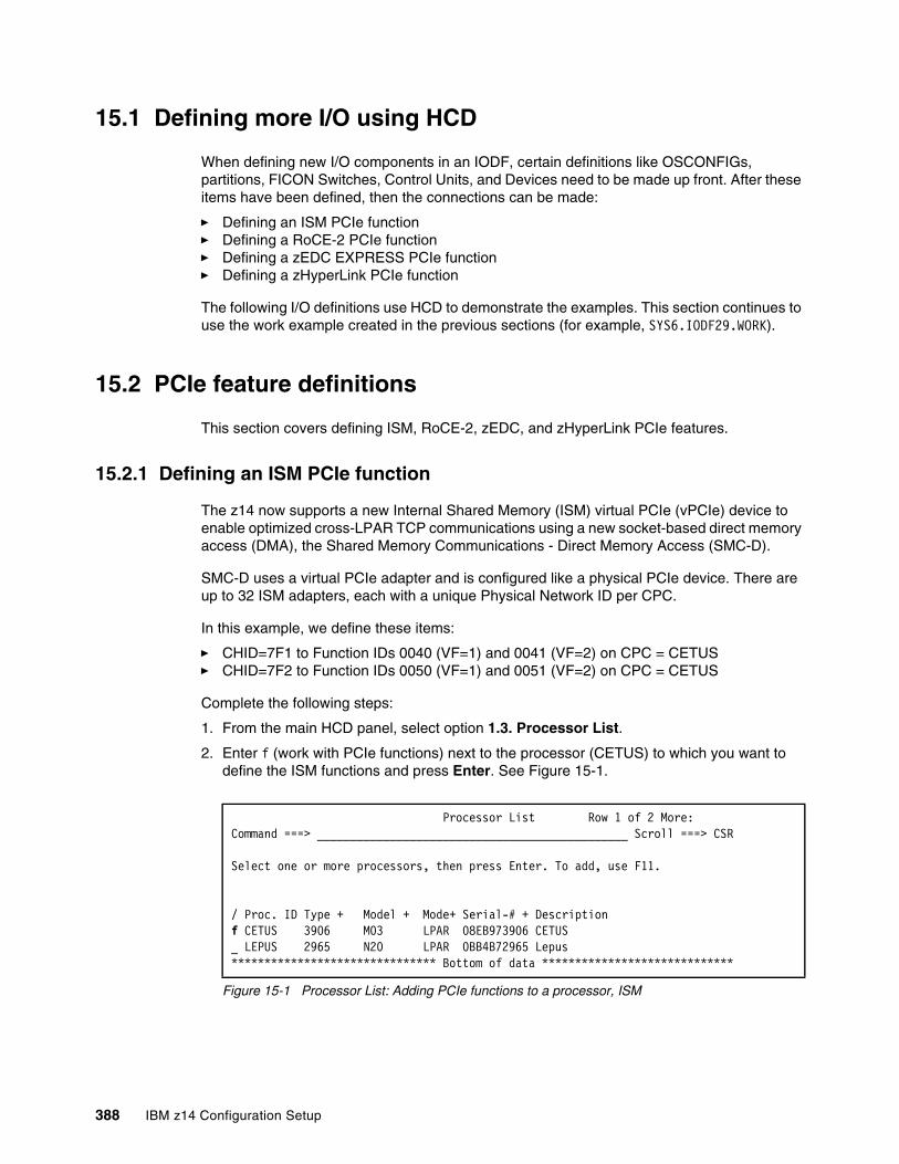
15.1 Defining more I/O using HCD
When defining new I/O components in an IODF, certain definitions like OSCONFIGs, partitions, FICON Switches, Control Units, and Devices need to be made up front. After these items have been defined, then the connections can be made:
� Defining an ISM PCIe function� Defining a RoCE-2 PCIe function� Defining a zEDC EXPRESS PCIe function� Defining a zHyperLink PCIe function
The following I/O definitions use HCD to demonstrate the examples. This section continues to use the work example created in the previous sections (for example, SYS6.IODF29.WORK).
15.2 PCIe feature definitions
This section covers defining ISM, RoCE-2, zEDC, and zHyperLink PCIe features.
15.2.1 Defining an ISM PCIe function
The z14 now supports a new Internal Shared Memory (ISM) virtual PCIe (vPCIe) device to enable optimized cross-LPAR TCP communications using a new socket-based direct memory access (DMA), the Shared Memory Communications - Direct Memory Access (SMC-D).
SMC-D uses a virtual PCIe adapter and is configured like a physical PCIe device. There are up to 32 ISM adapters, each with a unique Physical Network ID per CPC.
In this example, we define these items:
� CHID=7F1 to Function IDs 0040 (VF=1) and 0041 (VF=2) on CPC = CETUS� CHID=7F2 to Function IDs 0050 (VF=1) and 0051 (VF=2) on CPC = CETUS
Complete the following steps:
1. From the main HCD panel, select option 1.3. Processor List.
2. Enter f (work with PCIe functions) next to the processor (CETUS) to which you want to define the ISM functions and press Enter. See Figure 15-1.
Figure 15-1 Processor List: Adding PCIe functions to a processor, ISM
Processor List Row 1 of 2 More: Command ===> _______________________________________________ Scroll ===> CSR Select one or more processors, then press Enter. To add, use F11. / Proc. ID Type + Model + Mode+ Serial-# + Description f CETUS 3906 M03 LPAR 08EB973906 CETUS _ LEPUS 2965 N20 LPAR 0BB4B72965 Lepus ******************************* Bottom of data *****************************
388 IBM z14 Configuration Setup
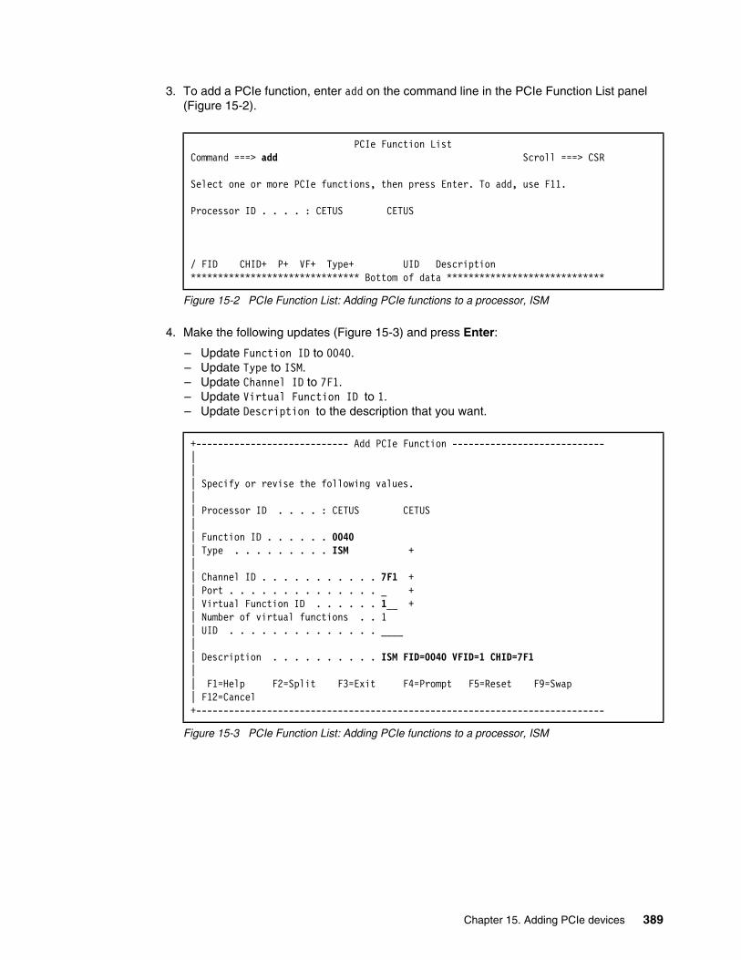
3. To add a PCIe function, enter add on the command line in the PCIe Function List panel (Figure 15-2).
Figure 15-2 PCIe Function List: Adding PCIe functions to a processor, ISM
4. Make the following updates (Figure 15-3) and press Enter:
– Update Function ID to 0040.– Update Type to ISM.– Update Channel ID to 7F1.– Update Virtual Function ID to 1.– Update Description to the description that you want.
Figure 15-3 PCIe Function List: Adding PCIe functions to a processor, ISM
PCIe Function List Command ===> add Scroll ===> CSR Select one or more PCIe functions, then press Enter. To add, use F11. Processor ID . . . . : CETUS CETUS / FID CHID+ P+ VF+ Type+ UID Description ******************************* Bottom of data *****************************
+---------------------------- Add PCIe Function ----------------------------| | | Specify or revise the following values. | | Processor ID . . . . : CETUS CETUS | | Function ID . . . . . . 0040 | Type . . . . . . . . . ISM + | | Channel ID . . . . . . . . . . . 7F1 + | Port . . . . . . . . . . . . . . _ + | Virtual Function ID . . . . . . 1__ + | Number of virtual functions . . 1 | UID . . . . . . . . . . . . . . ____ | | Description . . . . . . . . . . ISM FID=0040 VFID=1 CHID=7F1 | | F1=Help F2=Split F3=Exit F4=Prompt F5=Reset F9=Swap | F12=Cancel +---------------------------------------------------------------------------
Chapter 15. Adding PCIe devices 389
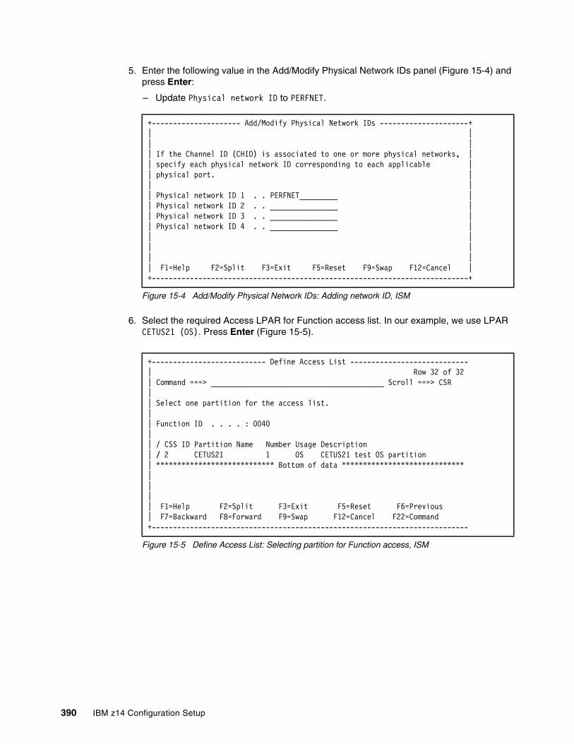
5. Enter the following value in the Add/Modify Physical Network IDs panel (Figure 15-4) and press Enter:
– Update Physical network ID to PERFNET.
Figure 15-4 Add/Modify Physical Network IDs: Adding network ID, ISM
6. Select the required Access LPAR for Function access list. In our example, we use LPAR CETUS21 (OS). Press Enter (Figure 15-5).
Figure 15-5 Define Access List: Selecting partition for Function access, ISM
+--------------------- Add/Modify Physical Network IDs ---------------------+| || || If the Channel ID (CHID) is associated to one or more physical networks, || specify each physical network ID corresponding to each applicable || physical port. || || Physical network ID 1 . . PERFNET_________ || Physical network ID 2 . . ________________ || Physical network ID 3 . . ________________ || Physical network ID 4 . . ________________ || || || || F1=Help F2=Split F3=Exit F5=Reset F9=Swap F12=Cancel |+---------------------------------------------------------------------------+
+--------------------------- Define Access List ----------------------------| Row 32 of 32 | Command ===> _________________________________________ Scroll ===> CSR | | Select one partition for the access list. | | Function ID . . . . : 0040 | | / CSS ID Partition Name Number Usage Description | / 2 CETUS21 1 OS CETUS21 test OS partition | **************************** Bottom of data ***************************** | | | | F1=Help F2=Split F3=Exit F5=Reset F6=Previous | F7=Backward F8=Forward F9=Swap F12=Cancel F22=Command +---------------------------------------------------------------------------
390 IBM z14 Configuration Setup

7. Select any Candidate LPARs for Function access list. In our example, we do not select any candidate LPARs. Press Enter.
HCD returns to the PCIe Function List panel where you can see the Function now defined (Figure 15-6).
Figure 15-6 PCIe Function List: Function now created, ISM
8. Now define the other Function IDs according to the example so far (Figure 15-7).
Figure 15-7 PCIe Function List: All Functions now created, ISM
15.2.2 Defining a RoCE-2 PCIe function
RDMA over Converged Ethernet (RoCE) uses a new PCIe hardware card for the z14 and is named 10GbE RoCE Express (FC#0412).
To use RoCE hardware functions, the Function IDs, Virtual Function IDs, and Physical Network IDs must be defined in HCD to the PCHID that is assigned to the RoCE hardware cards installed in the processor.
Similar to defining a channel-path identifier (CHPID) to a physical channel ID (PCHID) for FICON and OSA type channels, Function IDs and Virtual Function IDs are assigned RoCE PCHIDs.
PCIe Function List Row 10 of 10 More: Command ===> _______________________________________________ Scroll ===> CSR Select one or more PCIe functions, then press Enter. To add, use F11. Processor ID . . . . : CETUS CETUS / FID CHID+ P+ VF+ Type+ UID Description _ 0040 7F1 _ 1 ISM ____ ISM FID=0040 VFID=1 CHID=7F1 ******************************* Bottom of data *****************************
PCIe Function List Row 10 of 13 More: Command ===> _______________________________________________ Scroll ===> CSR Select one or more PCIe functions, then press Enter. To add, use F11. Processor ID . . . . : CETUS CETUS / FID CHID+ P+ VF+ Type+ UID Description _ 0040 7F1 _ 1 ISM ____ ISM FID=0040 VFID=1 CHID=7F1 _ 0041 7F1 _ 2 ISM ____ ISM FID=0041 VFID=2 CHID=7F1 _ 0050 7F2 _ 1 ISM ____ ISM FID=0050 VFID=1 CHID=7F2 _ 0051 7F2 _ 2 ISM ____ ISM FID=0051 VFID=2 CHID=7F2 ******************************* Bottom of data *****************************
Chapter 15. Adding PCIe devices 391

First, for information about the PCHID and Resource Group (RG), see the PCHID report for the processor (Example 15-1).
Example 15-1 PCHID Report: RoCE information from PCHID report
Machine: 3906-M03 SN1 - - - - - - - - - - - - - - - - - - - - - - - - - - - - - - - - - - - - - - - Source Drwr Slot F/C PCHID/Ports or AID Comment
A19/LG05/J01 Z22B 38 0412 17C/D1D2 RG2 A23/LG07/J01 Z15B 19 0412 1BC/D1D2 RG3 - - - - - - - - - - - - - - - - - - - - - - - - - - - - - - - - - - - - - - - Legend:
Source Book Slot/Fanout Slot/Jack RG3 Resource Group 3 RG2 Resource Group 2 0412 10GbE RoCE Express
In this example, we define these items:
� PCHID=17C to Function IDs 0000 (VF=1) and 0001 (VF=2) on CPC = CETUS to Physical Network ID 1 = PERFNET
� PCHID=1BC to Function IDs 0010 (VF=1) and 0011 (VF=2) on CPC = CETUS to Physical Network ID 1 = PERFNET
Complete the following steps:
1. From the main HCD panel, select option 1.3. Processor List.
2. Enter f (work with PCIe functions) next to the processor (CETUS) to which you want to define the RoCE-2 functions and press Enter. See Figure 15-8.
Figure 15-8 Processor List: Adding PCIe functions to a processor, RoCE-2
Processor List Row 1 of 2 More: Command ===> _______________________________________________ Scroll ===> CSR Select one or more processors, then press Enter. To add, use F11. / Proc. ID Type + Model + Mode+ Serial-# + Description f CETUS 3906 M03 LPAR 08EB973906 CETUS _ LEPUS 2965 N20 LPAR 0BB4B72965 Lepus ******************************* Bottom of data *****************************
392 IBM z14 Configuration Setup

3. To add a PCIe function, enter add on the command line in the PCIe Function List panel (Figure 15-9).
Figure 15-9 PCIe Function List: adding PCIe functions to a processor, RoCE-2
4. Make the following updates (Figure 15-10) and press Enter:
– Update Function ID to 0000.– Update Type to ROCE-2.– Update Channel ID to 17C.– Update Port to 1.– Update Virtual Function ID to 1.– Update Description to the description that you want.
Figure 15-10 PCIe Function List: Adding PCIe functions to a processor, RoCE-2
PCIe Function List Command ===> add Scroll ===> CSR Select one or more PCIe functions, then press Enter. To add, use F11. Processor ID . . . . : CETUS CETUS / FID CHID+ P+ VF+ Type+ UID Description ******************************* Bottom of data *****************************
+---------------------------- Add PCIe Function ----------------------------+| || || Specify or revise the following values. || || Processor ID . . . . : CETUS CETUS || || Function ID . . . . . . 0000 || Type . . . . . . . . . ROCE-2 + || || Channel ID . . . . . . . . . . . 17C + || Port . . . . . . . . . . . . . . 1 + || Virtual Function ID . . . . . . 1__ + || Number of virtual functions . . 1 || UID . . . . . . . . . . . . . . ____ || || Description . . . . . . . . . . RoCE-2 FID=0000 VFID=1 CHID=17C || || F1=Help F2=Split F3=Exit F4=Prompt F5=Reset F9=Swap || F12=Cancel |+---------------------------------------------------------------------------+
Chapter 15. Adding PCIe devices 393

5. Enter the following value in the Add/Modify Physical Network IDs panel (Figure 15-11) and press Enter:
– Update Physical network ID to PERFNET.
Figure 15-11 Add/Modify Physical Network IDs: Adding network ID, RoCE-2
6. Select the required Access LPAR for Function access list. In our example, we use LPAR CETUS21 (OS). Press Enter. See Figure 15-12.
Figure 15-12 Define Access List: Selecting partition for Function access, RoCE-2
+--------------------- Add/Modify Physical Network IDs ---------------------+| || || If the Channel ID (CHID) is associated to one or more physical networks, || specify each physical network ID corresponding to each applicable || physical port. || || Physical network ID 1 . . PERFNET_________ || Physical network ID 2 . . ________________ || Physical network ID 3 . . ________________ || Physical network ID 4 . . ________________ || || || || F1=Help F2=Split F3=Exit F5=Reset F9=Swap F12=Cancel |+---------------------------------------------------------------------------+
+--------------------------- Define Access List ----------------------------+| Row 32 of 32 || Command ===> _________________________________________ Scroll ===> CSR || || Select one partition for the access list. || || Function ID . . . . : 000 || || / CSS ID Partition Name Number Usage Description || / 2 CETUS21 1 OS CETUS21 test OS partition || **************************** Bottom of data ***************************** || || || || F1=Help F2=Split F3=Exit F5=Reset F6=Previous || F7=Backward F8=Forward F9=Swap F12=Cancel F22=Command |+---------------------------------------------------------------------------+
394 IBM z14 Configuration Setup
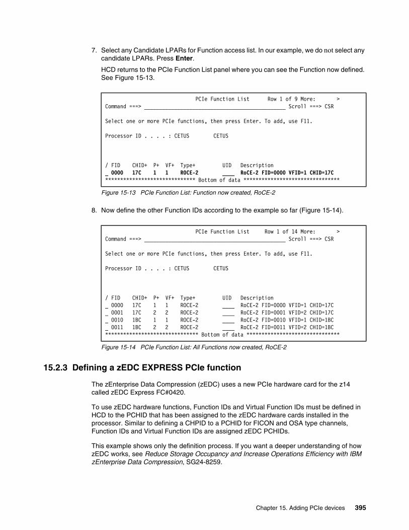
7. Select any Candidate LPARs for Function access list. In our example, we do not select any candidate LPARs. Press Enter.
HCD returns to the PCIe Function List panel where you can see the Function now defined. See Figure 15-13.
Figure 15-13 PCIe Function List: Function now created, RoCE-2
8. Now define the other Function IDs according to the example so far (Figure 15-14).
Figure 15-14 PCIe Function List: All Functions now created, RoCE-2
15.2.3 Defining a zEDC EXPRESS PCIe function
The zEnterprise Data Compression (zEDC) uses a new PCIe hardware card for the z14 called zEDC Express FC#0420.
To use zEDC hardware functions, Function IDs and Virtual Function IDs must be defined in HCD to the PCHID that has been assigned to the zEDC hardware cards installed in the processor. Similar to defining a CHPID to a PCHID for FICON and OSA type channels, Function IDs and Virtual Function IDs are assigned zEDC PCHIDs.
This example shows only the definition process. If you want a deeper understanding of how zEDC works, see Reduce Storage Occupancy and Increase Operations Efficiency with IBM zEnterprise Data Compression, SG24-8259.
PCIe Function List Row 1 of 9 More: > Command ===> _______________________________________________ Scroll ===> CSR Select one or more PCIe functions, then press Enter. To add, use F11. Processor ID . . . . : CETUS CETUS / FID CHID+ P+ VF+ Type+ UID Description _ 0000 17C 1 1 ROCE-2 ____ RoCE-2 FID=0000 VFID=1 CHID=17C ****************************** Bottom of data ********************************
PCIe Function List Row 1 of 14 More: >Command ===> _______________________________________________ Scroll ===> CSR Select one or more PCIe functions, then press Enter. To add, use F11. Processor ID . . . . : CETUS CETUS / FID CHID+ P+ VF+ Type+ UID Description _ 0000 17C 1 1 ROCE-2 ____ RoCE-2 FID=0000 VFID=1 CHID=17C _ 0001 17C 2 2 ROCE-2 ____ RoCE-2 FID=0001 VFID=2 CHID=17C _ 0010 1BC 1 1 ROCE-2 ____ RoCE-2 FID=0010 VFID=1 CHID=1BC _ 0011 1BC 2 2 ROCE-2 ____ RoCE-2 FID=0011 VFID=2 CHID=1BC ******************************* Bottom of data *******************************
Chapter 15. Adding PCIe devices 395
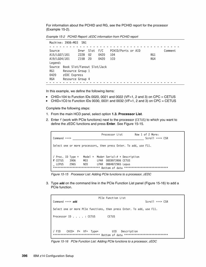
For information about the PCHID and RG, see the PCHID report for the processor (Example 15-2).
Example 15-2 PCHID Report: zEDC information from PCHID report
Machine: 3906-M03 SN1 - - - - - - - - - - - - - - - - - - - - - - - - - - - - - - - - - - - - - - - Source Drwr Slot F/C PCHID/Ports or AID Comment
A15/LG07/J01 Z22B 02 0420 104 RG1 A19/LG04/J01 Z15B 20 0420 1C0 RG4 Legend:
Source Book Slot/Fanout Slot/Jack RG1 Resource Group 1 0420 zEDC Express RG4 Resource Group 4- - - - - - - - - - - - - - - - - - - - - - - - - - - - - - - - - - - - - - -
In this example, we define the following items:
� CHID=104 to Function IDs 0020, 0021 and 0022 (VF=1, 2 and 3) on CPC = CETUS� CHID=1C0 to Function IDs 0030, 0031 and 0032 (VF=1, 2 and 3) on CPC = CETUS
Complete the following steps:
1. From the main HCD panel, select option 1.3. Processor List.
2. Enter f (work with PCIe functions) next to the processor (CETUS) to which you want to define the zEDC functions and press Enter. See Figure 15-15.
Figure 15-15 Processor List: Adding PCIe functions to a processor, zEDC
3. Type add on the command line in the PCIe Function List panel (Figure 15-16) to add a PCIe function.
Figure 15-16 PCIe Function List: Adding PCIe functions to a processor, zEDC
Processor List Row 1 of 2 More: Command ===> _______________________________________________ Scroll ===> CSR Select one or more processors, then press Enter. To add, use F11. / Proc. ID Type + Model + Mode+ Serial-# + Description f CETUS 3906 M03 LPAR 08EB973906 CETUS _ LEPUS 2965 N20 LPAR 0BB4B72965 Lepus ******************************* Bottom of data *****************************
PCIe Function List Command ===> add Scroll ===> CSR Select one or more PCIe functions, then press Enter. To add, use F11. Processor ID . . . . : CETUS CETUS / FID CHID+ P+ VF+ Type+ UID Description ******************************* Bottom of data *****************************
396 IBM z14 Configuration Setup
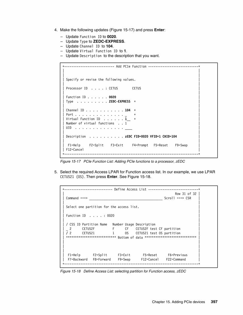
4. Make the following updates (Figure 15-17) and press Enter:
– Update Function ID to 0020.– Update Type to ZEDC-EXPRESS.– Update Channel ID to 104.– Update Virtual Function ID to 1.– Update Description to the description that you want.
Figure 15-17 PCIe Function List: Adding PCIe functions to a processor, zEDC
5. Select the required Access LPAR for Function access list. In our example, we use LPAR CETUS21 (OS). Then press Enter. See Figure 15-18.
Figure 15-18 Define Access List: selecting partition for Function access, zEDC
+---------------------------- Add PCIe Function ----------------------------+| || || Specify or revise the following values. || || Processor ID . . . . : CETUS CETUS || || Function ID . . . . . . 0020 || Type . . . . . . . . . ZEDC-EXPRESS + || || Channel ID . . . . . . . . . . . 104 + || Port . . . . . . . . . . . . . . _ + || Virtual Function ID . . . . . . 1__ + || Number of virtual functions . . 1 || UID . . . . . . . . . . . . . . ____ || || Description . . . . . . . . . . zEDC FID=0020 VFID=1 CHID=104 || || F1=Help F2=Split F3=Exit F4=Prompt F5=Reset F9=Swap || F12=Cancel |+---------------------------------------------------------------------------+
+--------------------------- Define Access List ----------------------------+| Row 31 of 32 || Command ===> _________________________________________ Scroll ===> CSR || || Select one partition for the access list. || || Function ID . . . . : 0020 || || / CSS ID Partition Name Number Usage Description || _ 2 CETUS2F F CF CETUS2F test CF partition || / 2 CETUS21 1 OS CETUS21 test OS partition || **************************** Bottom of data ***************************** || || || || F1=Help F2=Split F3=Exit F5=Reset F6=Previous || F7=Backward F8=Forward F9=Swap F12=Cancel F22=Command |+---------------------------------------------------------------------------+
Chapter 15. Adding PCIe devices 397
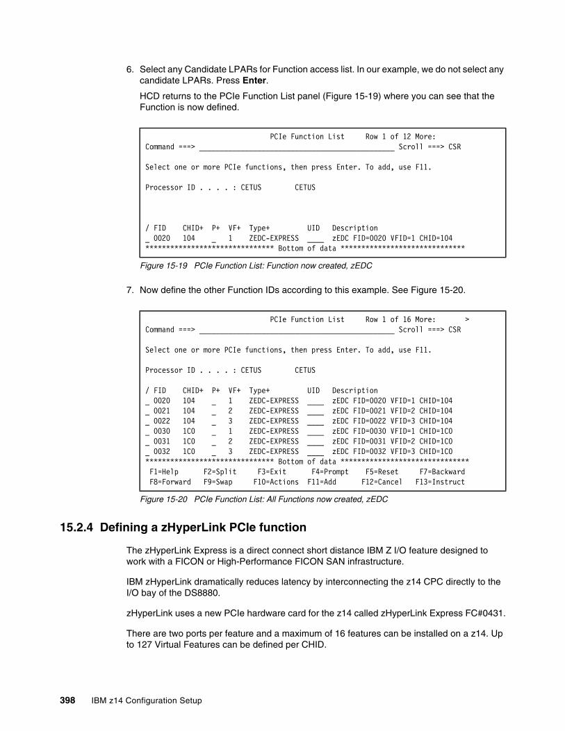
6. Select any Candidate LPARs for Function access list. In our example, we do not select any candidate LPARs. Press Enter.
HCD returns to the PCIe Function List panel (Figure 15-19) where you can see that the Function is now defined.
Figure 15-19 PCIe Function List: Function now created, zEDC
7. Now define the other Function IDs according to this example. See Figure 15-20.
Figure 15-20 PCIe Function List: All Functions now created, zEDC
15.2.4 Defining a zHyperLink PCIe function
The zHyperLink Express is a direct connect short distance IBM Z I/O feature designed to work with a FICON or High-Performance FICON SAN infrastructure.
IBM zHyperLink dramatically reduces latency by interconnecting the z14 CPC directly to the I/O bay of the DS8880.
zHyperLink uses a new PCIe hardware card for the z14 called zHyperLink Express FC#0431.
There are two ports per feature and a maximum of 16 features can be installed on a z14. Up to 127 Virtual Features can be defined per CHID.
PCIe Function List Row 1 of 12 More: Command ===> _______________________________________________ Scroll ===> CSR Select one or more PCIe functions, then press Enter. To add, use F11. Processor ID . . . . : CETUS CETUS / FID CHID+ P+ VF+ Type+ UID Description _ 0020 104 _ 1 ZEDC-EXPRESS ____ zEDC FID=0020 VFID=1 CHID=104 ******************************* Bottom of data ******************************
PCIe Function List Row 1 of 16 More: >Command ===> _______________________________________________ Scroll ===> CSR Select one or more PCIe functions, then press Enter. To add, use F11. Processor ID . . . . : CETUS CETUS
/ FID CHID+ P+ VF+ Type+ UID Description _ 0020 104 _ 1 ZEDC-EXPRESS ____ zEDC FID=0020 VFID=1 CHID=104 _ 0021 104 _ 2 ZEDC-EXPRESS ____ zEDC FID=0021 VFID=2 CHID=104 _ 0022 104 _ 3 ZEDC-EXPRESS ____ zEDC FID=0022 VFID=3 CHID=104 _ 0030 1C0 _ 1 ZEDC-EXPRESS ____ zEDC FID=0030 VFID=1 CHID=1C0 _ 0031 1C0 _ 2 ZEDC-EXPRESS ____ zEDC FID=0031 VFID=2 CHID=1C0 _ 0032 1C0 _ 3 ZEDC-EXPRESS ____ zEDC FID=0032 VFID=3 CHID=1C0 ******************************* Bottom of data ******************************* F1=Help F2=Split F3=Exit F4=Prompt F5=Reset F7=Backward F8=Forward F9=Swap F10=Actions F11=Add F12=Cancel F13=Instruct
398 IBM z14 Configuration Setup
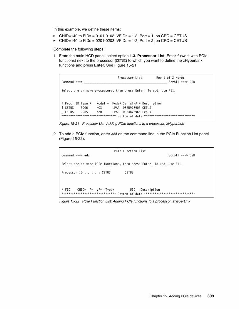
In this example, we define these items:
� CHID=140 to FIDs = 0101-0103, VFIDs = 1-3, Port = 1, on CPC = CETUS� CHID=140 to FIDs = 0201-0203, VFIDs = 1-3, Port = 2, on CPC = CETUS
Complete the following steps:
1. From the main HCD panel, select option 1.3. Processor List. Enter f (work with PCIe functions) next to the processor (CETUS) to which you want to define the zHyperLink functions and press Enter. See Figure 15-21.
Figure 15-21 Processor List: Adding PCIe functions to a processor, zHyperLink
2. To add a PCIe function, enter add on the command line in the PCIe Function List panel (Figure 15-22).
Figure 15-22 PCIe Function List: Adding PCIe functions to a processor, zHyperLink
Processor List Row 1 of 2 More: Command ===> _______________________________________________ Scroll ===> CSR Select one or more processors, then press Enter. To add, use F11. / Proc. ID Type + Model + Mode+ Serial-# + Description f CETUS 3906 M03 LPAR 08EB973906 CETUS _ LEPUS 2965 N20 LPAR 0BB4B72965 Lepus ******************************* Bottom of data *****************************
PCIe Function List Command ===> add Scroll ===> CSR Select one or more PCIe functions, then press Enter. To add, use F11. Processor ID . . . . : CETUS CETUS / FID CHID+ P+ VF+ Type+ UID Description ******************************* Bottom of data *****************************
Chapter 15. Adding PCIe devices 399
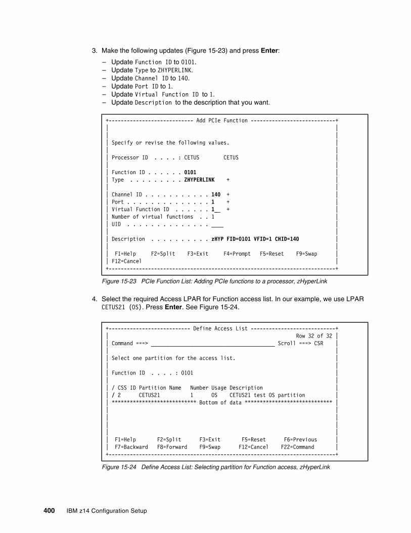
3. Make the following updates (Figure 15-23) and press Enter:
– Update Function ID to 0101.– Update Type to ZHYPERLINK.– Update Channel ID to 140.– Update Port ID to 1.– Update Virtual Function ID to 1.– Update Description to the description that you want.
Figure 15-23 PCIe Function List: Adding PCIe functions to a processor, zHyperLink
4. Select the required Access LPAR for Function access list. In our example, we use LPAR CETUS21 (OS). Press Enter. See Figure 15-24.
Figure 15-24 Define Access List: Selecting partition for Function access, zHyperLink
+---------------------------- Add PCIe Function ----------------------------+| || || Specify or revise the following values. || || Processor ID . . . . : CETUS CETUS || || Function ID . . . . . . 0101 || Type . . . . . . . . . ZHYPERLINK + || || Channel ID . . . . . . . . . . . 140 + || Port . . . . . . . . . . . . . . 1 + || Virtual Function ID . . . . . . 1__ + || Number of virtual functions . . 1 || UID . . . . . . . . . . . . . . ____ || || Description . . . . . . . . . . zHYP FID=0101 VFID=1 CHID=140 || || F1=Help F2=Split F3=Exit F4=Prompt F5=Reset F9=Swap || F12=Cancel |+---------------------------------------------------------------------------+
+--------------------------- Define Access List ----------------------------+| Row 32 of 32 || Command ===> _________________________________________ Scroll ===> CSR || || Select one partition for the access list. || || Function ID . . . . : 0101 || || / CSS ID Partition Name Number Usage Description || / 2 CETUS21 1 OS CETUS21 test OS partition || **************************** Bottom of data ***************************** || || || || || F1=Help F2=Split F3=Exit F5=Reset F6=Previous || F7=Backward F8=Forward F9=Swap F12=Cancel F22=Command |+---------------------------------------------------------------------------+
400 IBM z14 Configuration Setup
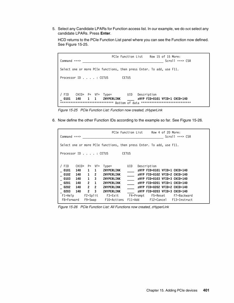
5. Select any Candidate LPARs for Function access list. In our example, we do not select any candidate LPARs. Press Enter.
HCD returns to the PCIe Function List panel where you can see the Function now defined. See Figure 15-25.
Figure 15-25 PCIe Function List: Function now created, zHyperLink
6. Now define the other Function IDs according to the example so far. See Figure 15-26.
Figure 15-26 PCIe Function List: All Functions now created, zHyperLink
PCIe Function List Row 15 of 15 More: Command ===> _______________________________________________ Scroll ===> CSR Select one or more PCIe functions, then press Enter. To add, use F11. Processor ID . . . . : CETUS CETUS / FID CHID+ P+ VF+ Type+ UID Description _ 0101 140 1 1 ZHYPERLINK ____ zHYP FID=0101 VFID=1 CHID=140 ******************************* Bottom of data *****************************
PCIe Function List Row 4 of 20 More: Command ===> _______________________________________________ Scroll ===> CSR Select one or more PCIe functions, then press Enter. To add, use F11. Processor ID . . . . : CETUS CETUS
/ FID CHID+ P+ VF+ Type+ UID Description _ 0101 140 1 1 ZHYPERLINK ____ zHYP FID=0101 VFID=1 CHID=140 _ 0102 140 1 2 ZHYPERLINK ____ zHYP FID=0102 VFID=2 CHID=140 _ 0103 140 1 3 ZHYPERLINK ____ zHYP FID=0103 VFID=3 CHID=140 _ 0201 140 2 1 ZHYPERLINK ____ zHYP FID=0201 VFID=1 CHID=140 _ 0202 140 2 2 ZHYPERLINK ____ zHYP FID=0202 VFID=2 CHID=140 _ 0203 140 2 3 ZHYPERLINK ____ zHYP FID=0203 VFID=3 CHID=140 F1=Help F2=Split F3=Exit F4=Prompt F5=Reset F7=Backward F8=Forward F9=Swap F10=Actions F11=Add F12=Cancel F13=Instruct
Chapter 15. Adding PCIe devices 401

402 IBM z14 Configuration Setup

Appendix A. Additional material
This book refers to additional material that can be downloaded from the Internet as described in the following sections.
Locating the web material
The web material associated with this book is available in softcopy on the Internet from the IBM Redbooks web server:
ftp://www.redbooks.ibm.com/redbooks/SG248460
Alternatively, you can go to the IBM Redbooks website:
ibm.com/redbooks
Search for SG248460, select the title, and then click Additional materials to open the directory that corresponds with the IBM Redbooks form number, SG248460.
Using the web material
The additional web material that accompanies this book includes the following file:
File name Description8460_DH2_Image_worksheet.xlsx Worksheet for gathering setup information
Downloading and extracting the web material
Create a subdirectory (folder) on your workstation, and extract the contents of the web material .zip file into this folder.
A
© Copyright IBM Corp. 2017. All rights reserved. 403

404 IBM z14 Configuration Setup

Related publications
The publications listed in this section are considered particularly suitable for a more detailed discussion of the topics covered in this book.
IBM Redbooks
The following IBM Redbooks publications provide additional information about the topic in this document. Note that some publications referenced in this list might be available in softcopy only.
� FICON CTC Implementation, REDP-0158
� FICON Planning and Implementation Guide, SG24-6497
� IBM Z Connectivity Handbook, SG24-5444
� IBM z/OS V2R2 Communications Server TCP/IP Implementation Volume 1: Base Functions, Connectivity, and Routing, SG24-8360
� IBM z13 Configuration Setup, SG24-8260
� IBM z14 Technical Guide, SG24-8451
� IBM z14 Technical Introduction, SG24-8450
� I/O Configuration Using z/OS HCD and HCM, SG24-7804
� Mainframe from Scratch: Hardware Configuration and z/OS Build, SG24-8329
� OSA-Express Implementation Guide, SG24-5948
� OSA-Express Integrated Console Controller Implementation Guide, SG24-6364
� Reduce Storage Occupancy and Increase Operations Efficiency with IBM zEnterprise Data Compression, SG24-8259
� Server Time Protocol Implementation Guide, SG24-7281
� Server Time Protocol Planning Guide, SG24-7280
� Server Time Protocol Recovery Guide, SG24-7380
You can search for, view, download or order these documents and other Redbooks, Redpapers, Web Docs, draft and additional materials, at the following website:
ibm.com/redbooks
Online resources
These websites are also relevant as further information sources:
� Capping Technologies and 4HRA Optimization document
ftp://public.dhe.ibm.com/eserver/zseries/zos/wlm/Capping_Technologies_and_4HRA_Optimization_2016.pdf
� CFSizer tool
https://www.ibm.com/systems/support/z/cfsizer/
© Copyright IBM Corp. 2017. All rights reserved. 405

� CTC Definitions for z Systems
http://www.vm.ibm.com/devpages/altmarka/ctc.html
� Hardware Configuration (HCD and HCM)
https://www.ibm.com/systems/z/os/zos/features/hcm/
� IBM Knowledge Center
https://www.ibm.com/support/knowledgecenter
� IBM Resource Link
https://www.ibm.com/servers/resourcelink/svc03100.nsf?OpenDatabase
� IBM z Systems Batch Network Analyzer (zBNA) Tool website
http://www.ibm.com/support/techdocs/atsmastr.nsf/WebIndex/PRS5132
� IBM z/OS SMC Applicability Tool (SMC-AT) document
ftp://public.dhe.ibm.com/software/os/systemz/pdf/SMC_Applicability_Tool_Overview_03-10-16.pdf
� IBM’s Shared Memory Communications over RDMA (SMC-R) Protocol, RFC 7609
https://tools.ietf.org/html/rfc7609
� Parallel Sysplex white paper page
https://www.ibm.com/systems/z/advantages/pso/whitepaper.html
� Shared Memory Communications Reference Information website
https://www.ibm.com/software/network/commserver/SMC/
� Techdocs website
https://www.ibm.com/support/techdocs/atsmastr.nsf/WebIndex/PRS3659
� WWPN Prediction Tool
https://www.ibm.com/servers/resourcelink/hom03010.nsf/pages/wwpnMain?OpenDocument&pathID=
� z/OS downloads page
https://www.ibm.com/systems/z/os/zos/tools/downloads/index.html
Help from IBM
IBM Support and downloads
ibm.com/support
IBM Global Services
ibm.com/services
406 IBM z14 Configuration Setup

Index
Aactivation profile 97, 110, 114, 120Add Network Time Server 168Automatic Mapping 68available processor 47
Bbrowser window 75–76, 78–79
CCFReport 50
file 32, 51, 63order file 54
Channel Subsystem 32, 42CHPID assignment 69CHPID Mapping Tool 8, 49
Action 32assignment 59default priority 50display 72IOCP file 54IOCP Output 32report 32, 71report name 79statement 81workstation 51
CHPID report 73–74CHPID type 30CHPIDs 32CIB type
CHPID definition 63CMT see CHPID Mapping Toolconfiguration data 86configure NTP
client 192setting 168
control unit (CU) 50priority 81Report 73, 79
CPC IDSCZP301 31
Create Work I/O Definition File panel 33Cryptographic 229cryptographic
configuration overview 258definition 233Feature codes 229reconfiguration of adapter 241
CSS 38CSSID 31CU Priority 68, 72CU report 79
© Copyright IBM Corp. 2017. All rights reserved.
Ddata set 47descriptor field 89Diagnostic IOCDS 109
Eerror message 37External Time Source (ETS) 166
FFCTC CHPIDs 71FICON channel 19
HHCD
Repeat Processor 33HCD display 47HCPRIO Data 83HiperSockets
Network Traffic Analyzer 25HMC LAN 91
IIBM service representative 109image profile 38, 98–99, 101, 113Import IOCP File 54input file 59input/output (I/O) 284, 290, 308, 364, 388Input/Output Configuration Data Set (IOCDS) 92input/output configuration program (IOCP) 32Internal Coupling Channels 26intersect messages 70intersects 70IOCDS panel 93IOCP data panel 83IOCP deck (ID) 81IOCP file 47IOCP input
data 48deck 83file 63
IOCP output file 81IOCP program 49IOCP statement 68
file 49IOCP/OS data 82iocpout.txt file 81, 83
Jjob statement information 48, 94
407
LLicensed Internal Code (LIC) 164Load Profile 38logical partition (LPAR) 32, 228
Mmessage authentication code (MAC) 229Message List 34Miscellaneous Equipment Specification (MES) 59
NNTP Broadband Authentication 166NTP server 166
OOperational Customization 97, 110, 114, 120OS configuration 83OSA-ICC CHPID 71OSD CHPID 63
Pphone modem 165port connection 32Port Report 73power-on reset (POR) 49, 109Preview Report 73Process Configuration Data 47, 87processing mode 83processor definition 33Processor ID
use 83Processor List 33, 284–287, 290–305, 309–317, 319–362, 364–385, 388, 392, 396, 399
processor SCZP901 37, 285processor model 40processor SCZP102 47processor type 284–287, 290, 292, 295, 297–298, 304–305, 309, 316, 322, 327, 330, 333, 338, 341, 344, 348, 350, 353, 358, 361, 365–367, 370, 373, 377, 379, 383, 389–390, 393–394, 400production I/O definition file 87production IODF 32
RRedbooks website 405
Contact us xiiiReset CHPIDs 59Reset CHPIDs assigned by Automatic Mapping 59Reset CHPIDs assigned by CMT for config files 59Reset CHPIDs assigned by IOCP 59Reset CHPIDs assigned by Manual Mapping 59Reset Profile 38, 96
SS/390 microprocessor
IOCDSs 91
S/390 Microprocessor ClusterList panel 92
Save Report 73serial number 38Server Time Protocol (STP) 26SOURCE column 74Stand-Alone IOCP 48Support Element (SE) 91SYS6.IODF 59 284, 290, 308, 364, 388
Ttarget IODF 32
data 33TOK statement 49Tools
Hardware Configuration Manager (HCM) 9transfer type 49Trusted Key Entry (TKE) 231
Uunconnected CHPIDs 72Update IOCDS 93
Wwork IODF 32, 46, 86
name 82
Zz/OS image 81zEnterprise 258
408 IBM z14 Configuration Setup

ISB
N 0738442720
SG
24-8460-00
(0.5” spine)0.475”<
->0.873”
250 <->
459 pages
IBM z14 Configuration Setup


ibm.com/redbooks
Printed in U.S.A.
Back cover
ISBN 0738442720
SG24-8460-00
®
Related Documents