IBM TotalStorage DS4400 Fibre Channel Storage Server Installation and Support Guide GC26-7731-00

Welcome message from author
This document is posted to help you gain knowledge. Please leave a comment to let me know what you think about it! Share it to your friends and learn new things together.
Transcript

IBM TotalStorage DS4400
Fibre Channel Storage Server
Installation and Support Guide
GC26-7731-00
���

IBM TotalStorage DS4400
Fibre Channel Storage Server
Installation and Support Guide
GC26-7731-00
���

Note
Before using this information and the product it supports, be sure to read the general information under “Notices” on page
57.
First Edition (January 2005)
© Copyright International Business Machines Corporation 2005. All rights reserved.
US Government Users Restricted Rights – Use, duplication or disclosure restricted by GSA ADP Schedule Contract
with IBM Corp.

Contents
Figures . . . . . . . . . . . . . . . v
Tables . . . . . . . . . . . . . . . vii
Safety . . . . . . . . . . . . . . . ix
About this book . . . . . . . . . . . xv
FAStT product renaming . . . . . . . . . . xv
Who should read this document . . . . . . . xv
How this book is organized . . . . . . . . . xvi
Notices and statements in this book . . . . . . xvi
DS4000 installation process overview . . . . . xvi
DS4000 Storage Server publications . . . . . . xvii
DS4500 storage server library . . . . . . . xvii
DS4400 storage server library . . . . . . . xix
DS4300 storage server library . . . . . . . xx
DS4100 storage server library . . . . . . . xxi
DS4000 Storage Manager Version 9 publications xxii
Other DS4000 and DS4000-related documents xxiii
Getting information, help and service . . . . . xxiv
Before you call . . . . . . . . . . . xxiv
Using the documentation . . . . . . . . xxv
Web sites . . . . . . . . . . . . . . xxv
How to send your comments . . . . . . . . xxvi
Chapter 1. Introduction and installation 1
Inventory checklist . . . . . . . . . . . . 2
DS4400 Storage Server components . . . . . . . 3
Product updates . . . . . . . . . . . . . 5
Operating specifications . . . . . . . . . . 7
Preparing for installation . . . . . . . . . . 8
Handling static-sensitive devices . . . . . . . . 8
Installing the DS4400 Storage Server in a rack cabinet 9
Installing additional hardware . . . . . . . . 9
Installing hardware for host-agent (in-band)
management . . . . . . . . . . . . . 10
Installing hardware for direct (out-of-band)
management . . . . . . . . . . . . . 11
Installing hardware for cluster servers . . . . 11
Installing storage expansion enclosures in a rack
cabinet . . . . . . . . . . . . . . . . 13
Chapter 2. Connecting the DS4400
Storage Server . . . . . . . . . . . 15
DS4400 Storage Server mini-hub interface
connections . . . . . . . . . . . . . . 15
DS4400 Storage Server interface ports . . . . . . 15
Host interface ports . . . . . . . . . . . 16
Drive interface ports . . . . . . . . . . 16
Intermixing storage expansion enclosure
models . . . . . . . . . . . . . . 17
Ethernet interface ports . . . . . . . . . 21
Installing SFP modules . . . . . . . . . . 21
Removing SFP modules . . . . . . . . . . 23
Handling fiber-optic cables . . . . . . . . . 24
Using LC-LC Fibre Channel cables . . . . . . 25
Connecting an LC-LC cable to an SFP module . . 25
Removing an LC-LC Fibre Channel cable . . . 28
Using LC-SC Fibre Channel cable adapters . . . . 28
Connecting an LC-SC cable to a device . . . . 29
Removing an LC-LC cable from an LC-SC cable
adapter . . . . . . . . . . . . . . . 31
DS4400 Storage Server and storage expansion
enclosure cabling overview . . . . . . . . . 32
Configuring the drive loops . . . . . . . . . 32
Connecting a redundant drive loop to the DS4400
Storage Server . . . . . . . . . . . . . 35
Connecting hosts directly to the DS4400 Storage
Server . . . . . . . . . . . . . . . . 37
Connecting hosts using external devices . . . . . 38
Setting the Link Rate Interface switch . . . . . 41
Setting data transfer rates on host-side mini hubs 42
Setting data transfer rates on drive-side mini
hubs . . . . . . . . . . . . . . . . 42
Connecting Ethernet cables . . . . . . . . . 42
Chapter 3. Starting the DS4400 Storage
Server . . . . . . . . . . . . . . . 43
Power cabling . . . . . . . . . . . . . 43
Turning on the power . . . . . . . . . . . 45
Turning off the power . . . . . . . . . . . 46
Turning on the DS4400 Storage Server alarm . . . 47
DS4400 Storage Server indicator lights . . . . . 48
Installing the DS4000 Storage Manager client . . . 51
Firmware updates . . . . . . . . . . . . 52
Best practices guidelines . . . . . . . . . . 52
Appendix. Accessibility . . . . . . . 55
Notices . . . . . . . . . . . . . . 57
Trademarks . . . . . . . . . . . . . . 57
Important notes . . . . . . . . . . . . . 58
Electronic emission notices . . . . . . . . . 59
Federal Communications Commission (FCC)
statement . . . . . . . . . . . . . . 59
Industry Canada Class A emission compliance
statement . . . . . . . . . . . . . . 59
Australia and New Zealand Class A statement . 59
United Kingdom telecommunications safety
requirement . . . . . . . . . . . . . 59
European Union EMC Directive conformance
statement . . . . . . . . . . . . . . 59
Taiwan electrical emission statement . . . . . 60
Japanese Voluntary Control Council for
Interference (VCCI) statement . . . . . . . 60
Power cords . . . . . . . . . . . . . . 60
Glossary . . . . . . . . . . . . . . 63
63
© Copyright IBM Corp. 2005 iii

Index . . . . . . . . . . . . . . . 73
iv IBM TotalStorage DS4400 Fibre Channel Storage Server: Installation and Support Guide

Figures
1. Installation process flow by current
publications . . . . . . . . . . . . xvii
2. IBM DS4400 Fibre Channel Storage Server 2
3. IBM DS4400 Fibre Channel Storage Server -
front view . . . . . . . . . . . . . 4
4. IBM DS4400 Fibre Channel Storage Server -
back view . . . . . . . . . . . . . 5
5. Host agent (in-band) managed storage
subsystems . . . . . . . . . . . . . 10
6. Direct (out-of-band) managed storage
subsystems . . . . . . . . . . . . . 11
7. Installing host adapters in storage subsystems
on a Fibre Channel network . . . . . . . 12
8. DS4400 mini-hub interface connections 15
9. DS4400 Storage Server interface ports . . . . 16
10. Host mini-hub ports . . . . . . . . . 16
11. Drive mini-hub ports . . . . . . . . . 17
12. Ethernet ports . . . . . . . . . . . . 21
13. Small Form-Factor Pluggable (SFP) Module 22
14. Installing an SFP module in a mini hub 23
15. Unlocking the SFP module latch - plastic
variety . . . . . . . . . . . . . . 24
16. Unlocking the SFP module latch - wire variety 24
17. LC-LC Fibre Channel cable . . . . . . . 25
18. Removing fiber-optic cable protective caps 26
19. Inserting an LC-LC Fibre Channel cable into
an SFP module . . . . . . . . . . . 27
20. Inserting an LC-LC Fibre Channel cable into
an installed SFP module . . . . . . . . 27
21. LC-LC Fibre Channel Cable lever and latches 28
22. Removing the LC-LC Fibre Channel cable 28
23. LC-SC Fibre Channel cable . . . . . . . 29
24. Removing the LC-SC cable adapter protective
caps . . . . . . . . . . . . . . . 30
25. Connecting an LC-LC cable into the LC-SC
cable adapter . . . . . . . . . . . . 30
26. LC-LS Fibre Channel Cable lever and latches 31
27. Removing the LC-LC Fibre Channel cable from
an LC-SC Fibre Channel cable adapter . . . 31
28. Redundant drive loop cabling overview 32
29. Connecting two storage expansion enclosures
into drive loop A . . . . . . . . . . 33
30. Storage expansion enclosure environmental
services module (ESM) board in and out ports . 33
31. Connecting two storage expansion enclosures
into redundant drive loop B . . . . . . . 34
32. Connecting additional storage expansion
enclosures to drive loops A and B . . . . . 34
33. Connecting a second redundant storage
expansion enclosure group (loops C and D) . . 35
34. Connecting drive loop A to the DS4400 Storage
Server . . . . . . . . . . . . . . 36
35. Connecting redundant drive loops to the
DS4400 Storage Server . . . . . . . . . 36
36. Connecting two redundant storage expansion
enclosure groups . . . . . . . . . . . 37
37. Connecting hosts directly to the controller 38
38. Using two Fibre Channel switches to connect a
host . . . . . . . . . . . . . . . 39
39. Using four Fibre Channel switches to connect
multiple hosts . . . . . . . . . . . . 40
40. Adding hosts using cascading switches 40
41. Mini-hub Link Rate Interface switch and Speed
indicator light . . . . . . . . . . . . 41
42. Ethernet port locations . . . . . . . . . 42
43. Connecting the power cords . . . . . . . 43
44. Redundant AC power connections to
controllers and storage expansion enclosures . 45
45. DS4400 Storage Server alarm switch . . . . 48
46. RAID controller indicator lights . . . . . . 48
47. DS4400 Storage Server indicator lights . . . 49
48. DS4400 Storage Server indicator lights . . . 49
49. Battery indicator lights . . . . . . . . . 50
50. Power supply and fan and communications
module indicator lights . . . . . . . . 50
51. Mini-hub indicator lights . . . . . . . . 51
© Copyright IBM Corp. 2005 v

vi IBM TotalStorage DS4400 Fibre Channel Storage Server: Installation and Support Guide

Tables
1. Mapping of FAStT names to DS4000 Series
names . . . . . . . . . . . . . . xv
2. TotalStorage DS4500 Fibre Channel Storage
Server document titles by user tasks . . . xviii
3. TotalStorage DS4400 Fibre Channel Storage
Server document titles by user tasks . . . . xix
4. TotalStorage DS4300 Fibre Channel Storage
Server document titles by user tasks . . . . xx
5. TotalStorage DS4100 SATA Storage Server
document titles by user tasks . . . . . . xxi
6. TotalStorage DS4000 Storage Manager Version
9 titles by user tasks . . . . . . . . . xxii
7. TotalStorage DS4000 and DS4000–related
document titles by user tasks . . . . . . xxiii
8. IBM DS4400 Fibre Channel Storage Server
operating specifications . . . . . . . . . 7
9. Possible combinations of FAStT EXP500 and
DS4000 EXP700 storage expansion enclosures
per drive loop . . . . . . . . . . . . 18
10. Mini-hub indicator lights . . . . . . . . 51
11. DS4000 Storage Manager alternate keyboard
operations . . . . . . . . . . . . . 55
© Copyright IBM Corp. 2005 vii

viii IBM TotalStorage DS4400 Fibre Channel Storage Server: Installation and Support Guide
Safety
Before installing this product, read the Safety Information.
Antes de instalar este produto, leia as Informações de Segurança.
Pred instalací tohoto produktu si prectete prírucku bezpecnostních instrukcí.
Læs sikkerhedsforskrifterne, før du installerer dette produkt.
Lees voordat u dit product installeert eerst de veiligheidsvoorschriften.
Ennen kuin asennat tämän tuotteen, lue turvaohjeet kohdasta Safety Information.
Avant d’installer ce produit, lisez les consignes de sécurité.
Vor der Installation dieses Produkts die Sicherheitshinweise lesen.
Prima di installare questo prodotto, leggere le Informazioni sulla Sicurezza
Les sikkerhetsinformasjonen (Safety Information) før du installerer dette produktet.
Antes de instalar este produto, leia as Informações sobre Segurança.
© Copyright IBM Corp. 2005 ix

Antes de instalar este producto lea la información de seguridad.
Läs säkerhetsinformationen innan du installerar den här produkten.
Statement 1:
DANGER
Electrical current from power, telephone, and communication cables is
hazardous.
To avoid a shock hazard:
v Do not connect or disconnect any cables or perform installation,
maintenance, or reconfiguration of this product during an electrical storm.
v Connect all power cords to a properly wired and grounded electrical outlet.
v Connect to properly wired outlets any equipment that will be attached to
this product.
v When possible, use one hand only to connect or disconnect signal cables.
v Never turn on any equipment when there is evidence of fire, water, or
structural damage.
v Disconnect the attached power cords, telecommunications systems,
networks, and modems before you open the device covers, unless
instructed otherwise in the installation and configuration procedures.
v Connect and disconnect cables as described in the following table when
installing, moving, or opening covers on this product or attached devices.
To Connect: To Disconnect:
1. Turn everything OFF.
2. First, attach all cables to devices.
3. Attach signal cables to connectors.
4. Attach power cords to outlet.
5. Turn device ON.
1. Turn everything OFF.
2. First, remove power cords from outlet.
3. Remove signal cables from connectors.
4. Remove all cables from devices.
x IBM TotalStorage DS4400 Fibre Channel Storage Server: Installation and Support Guide
Statement 2:
CAUTION:
When replacing the lithium battery, use only IBM Part Number 33F8354 or an
equivalent type battery recommended by the manufacturer. If your system has a
module containing a lithium battery, replace it only with the same module type
made by the same manufacturer. The battery contains lithium and can explode if
not properly used, handled, or disposed of.
Do not:
v Throw or immerse into water
v Heat to more than 100°C (212°F)
v Repair or disassemble
Dispose of the battery as required by local ordinances or regulations.
Statement 3:
CAUTION:
When laser products (such as CD-ROMs, DVD drives, fiber optic devices, or
transmitters) are installed, note the following:
v Do not remove the covers. Removing the covers of the laser product could
result in exposure to hazardous laser radiation. There are no serviceable parts
inside the device.
v Use of controls or adjustments or performance of procedures other than those
specified herein might result in hazardous radiation exposure.
DANGER
Some laser products contain an embedded Class 3A or Class 3B laser diode.
Note the following.
Laser radiation when open. Do not stare into the beam, do not view directly
with optical instruments, and avoid direct exposure to the beam.
Class 1 Laser statement
Class 1 Laser ProductLaser Klasse 1Laser Klass 1Luokan 1 LaserlaiteAppareil A Laser de Classe 1`
Safety xi

Statement 4:
≥ 18 kg (39.7 lb) ≥ 32 kg (70.5 lb) ≥ 55 kg (121.2 lb)
CAUTION:
Use safe practices when lifting.
Statement 5:
CAUTION:
The power control button on the device and the power switch on the power
supply do not turn off the electrical current supplied to the device. The device
also might have more than one power cord. To remove all electrical current from
the device, ensure that all power cords are disconnected from the power source.
1
2
xii IBM TotalStorage DS4400 Fibre Channel Storage Server: Installation and Support Guide
Statement 8:
CAUTION:
Never remove the cover on a power supply or any part that has the following
label atteched.
Hazardous voltage, current, and energy levels are present inside any component
that has this label attached. There are no serviceable parts inside these
components. If you suspect a problem with one of these parts, contact a service
technician.
Safety xiii

xiv IBM TotalStorage DS4400 Fibre Channel Storage Server: Installation and Support Guide

About this book
This book provides instructions for setting up, installing, and connecting your
IBM®
TotalStorage™
DS4400 Fibre Channel Storage Server. This installation guide is
intended for system operators and service technicians who have extensive
knowledge of Fibre Channel and network technology.
FAStT product renaming
IBM is in the process of renaming some FAStT family products. Table 1 identifies
each new DS4000 product name with its corresponding FAStT product name. Note
that this change of product name only indicates no change in functionality or
warranty. All products listed below with new names are functionally-equivalent
and fully-interoperable. Each DS4000 product retains full IBM service as outlined
in service contracts issued for analogous FAStT products.
Table 1. Mapping of FAStT names to DS4000 Series names
Current FAStT Product Name New DS4000 Product Name
IBM TotalStorage FAStT Storage Server IBM TotalStorage DS4000
FAStT DS4000
FAStT Family DS4000 Mid-range Disk System
FAStT Storage Manager vX.Y (for example
v9.10)
DS4000 Storage Manager vX.Y (for example
v9.10)
FAStT100 DS4100
FAStT600 DS4300
FAStT600 with Turbo Feature DS4300 Turbo
FAStT700 DS4400
FAStT900 DS4500
EXP700 DS4000 EXP700
EXP710 DS4000 EXP710
EXP100 DS4000 EXP100
FAStT FlashCopy FlashCopy for DS4000
FAStT VolumeCopy VolumeCopy for DS4000
FAStT Remote Mirror (RM) Enhanced Remote Mirroring for DS4000
FAStT Synchronous Mirroring Metro Mirroring for DS4000
Global Copy for DS4000(New Feature = Asynchronous Mirroring
without Consistency Group)
Global Mirroring for DS4000(New Feature = Asynchronous Mirroring
with Consistency Group)
Who should read this document
This document is intended for system operators and service technicians who have
extensive knowledge of fibre channel and network technology.
© Copyright IBM Corp. 2005 xv
How this book is organized
Chapter 1, “Introduction and installation,” on page 1 introduces the IBM DS4400
Fibre Channel Storage Server and contains set up instructions. This chapter also
includes an overview of the IBM DS4400 Fibre Channel Storage Server features and
components.
Chapter 2, “Connecting the DS4400 Storage Server,” on page 15 provides
information about the components that connect the DS4400 Storage Server to the
Fibre Channel network and instructions for connecting the DS4400 Storage Server
to other Fibre Channel devices.
Chapter 3, “Starting the DS4400 Storage Server,” on page 43 provides information
about connecting the power cords, turning the power on and off, checking the
indicator lights, and installing the IBM Storage Manager software.
“Accessibility,” on page 55 provides information about DS4000 Storage Manager
accessibility features.
“Notices” on page 57 provides product notices.
Notices and statements in this book
The caution and danger statements used in this book also appear in the
multilingual Safety Information book provided with your IBM DS4400 Fibre Channel
Storage Server. Each caution and danger statement is numbered for easy reference
to the corresponding statements in the safety book.
The following types of notices and statements are used in this book:
v Note: These notices provide important tips, guidance, or advice.
v Important: These notices provide information or advice that might help you
avoid inconvenient or problem situations.
v Attention: These notices indicate possible damage to programs, devices, or data.
An attention notice is placed just before the instruction or situation in which
damage could occur.
v Caution: These statements indicate situations that can be potentially hazardous
to you. A caution statement is placed just before the description of a potentially
hazardous procedure step or situation.
v Danger: These statements indicate situations that can be potentially lethal or
extremely hazardous to you. A danger statement is placed just before the
description of a potentially lethal or extremely hazardous procedure step or
situation.
DS4000 installation process overview
Attention: For the latest product information, go to the following Web site:
www.ibm.com/servers/storage/support/disk/
The following flow chart gives an overview of the DS4000 hardware and the
DS4000 Storage Manager software installation process. Lined arrows in the flow
chart indicate consecutive steps in the hardware and software installation process.
Labeled arrows indicate which current documents provide detailed information
about those steps.
xvi IBM TotalStorage DS4400 Fibre Channel Storage Server: Installation and Support Guide

Install Process Documentation
Plan installation Connect Power andStart Server
DS4000 Storage ServerInstallation Guide
Complete SM SWInstallation
Configure StorageHardware
Online Help
Configure StorageSubsystems on Host
Verify Serveroperation w/ LEDs
Prepare forInstallation ofSM Software
Install and VerifySM SW on Host and
Workstation
* FC Planning andIntegration: User's Guide
and Svc Info
DS4000 Storage ManagerConcepts Guide
DS4000 Storage Exp EnclsInstall and User's Guides
DS4000 Fibre ChannelStorage Server
Installation Guides
Fibre Channel CablingInstructions
DS4000 and HBA Installand User's Guides
DS4000 Storage SvrInstallation Guide
DS4000 RAID ControllerEnclosure Unit Install
and User's Guide
Copy ServicesUser's Guide
DS4000 Storage Manager
DS4000 StorageManager Installation
and SupportOS Guides
DS4000 HardwareMaintenance Manual
DS4000 ProblemDetermination Guide
Out-of-Band In-Band
Make FC Connections
SET Link Speed(1GB or 2GB)
Install StorageServer/RAID ControllerEnclosure(s) in Rack
Install NetworkHardware; Prep areNetwork Connection
Install StorageExpansion Enclosure(s)
DetermineManagement
Method
* For pSeries/POWER server and pSeries/POWER-supported HBA use only sj0
01046
DS4000 Storage Server publications
The following tables present an overview of the DS4500, DS4400, DS4300 Fibre
Channel, and DS4100 SATA Storage Server product libraries, as well as other
related documents. Each table lists documents that are included in the libraries and
what common tasks they address.
You can access the documents listed in these tables at one of the following Web
sites:
www.ibm.com/servers/storage/support/disk/
www.ibm.com/shop/publications/order/
DS4500 storage server library
Table 2 on page xviii associates each document in the DS4500 (previously
FAStT900) storage server library with its related common user tasks.
Figure 1. Installation process flow by current publications
About this book xvii

Table 2. TotalStorage DS4500 Fibre Channel Storage Server document titles by user tasks
Title User Tasks
Planning Hardware
Installation
Software
Installation
Configuration Operation and
Administration
Diagnosis and
Maintenance
IBM TotalStorage
DS4500 Installation
and Support Guide,
GC26-7727
U U U
IBM TotalStorage
DS4500 Fibre
Channel Cabling
Instructions,
GC26-7729
U U
IBM TotalStorage
DS4500 Storage
Server User’s Guide,
GC26-7726
U U U
IBM TotalStorage
DS4500 Rack
Mounting
Instructions,
GC26-7728
U U
xviii IBM TotalStorage DS4400 Fibre Channel Storage Server: Installation and Support Guide

DS4400 storage server library
Table 3 associates each document in the DS4400 (previously FAStT700) storage
server library with its related common user tasks.
Table 3. TotalStorage DS4400 Fibre Channel Storage Server document titles by user tasks
Title User Tasks
Planning Hardware
Installation
Software
Installation
Configuration Operation and
Administration
Diagnosis and
Maintenance
IBM DS4400 Fibre
Channel Storage
Server User’s Guide,
GC26-7730
U U U U U
IBM DS4400 Fibre
Channel Storage
Server Installation
and Support Guide,
GC26-7731
U U U U
IBM DS4400 Fibre
Channel Cabling
Instructions,
GC26-7732
U U
About this book xix

DS4300 storage server library
Table 4 associates each document in the DS4300 (previously FAStT600) storage
server library with its related common user tasks.
Table 4. TotalStorage DS4300 Fibre Channel Storage Server document titles by user tasks
Title User Tasks
Planning Hardware
Installation
Software
Installation
Configuration Operation and
Administration
Diagnosis and
Maintenance
IBM TotalStorage
DS4300 Fibre
Channel Storage
Server Installation
and User’s Guide,
GC26-7722
U U U
IBM TotalStorage
DS4300 Rack
Mounting
Instructions,
GC26-7724
U U
IBM TotalStorage
DS4300 Fibre
Channel Cabling
Instructions,
GC26-7725
U U
IBM TotalStorage
DS4300 SCU Base
Upgrade Kit,
GC26-7740
U U
IBM TotalStorage
DS4300 SCU Turbo
Upgrade Kit,
GC26-7741
U U
IBM TotalStorage
DS4300 Turbo Models
6LU/6LX Upgrade
Kit, GC26-7723
U U
xx IBM TotalStorage DS4400 Fibre Channel Storage Server: Installation and Support Guide

DS4100 storage server library
Table 5 associates each document in the DS4100 (previously FAStT100) storage
server library with its related common user tasks.
Table 5. TotalStorage DS4100 SATA Storage Server document titles by user tasks
Title User Tasks
Planning Hardware
Installation
Software
Installation
Configuration Operation and
Administration
Diagnosis and
Maintenance
IBM TotalStorage
DS4100 Installation,
User’s and
Maintenance Guide,
GC26-7733
U U U U U
IBM TotalStorage
DS4100 Cabling
Guide, 24P8973
U
About this book xxi
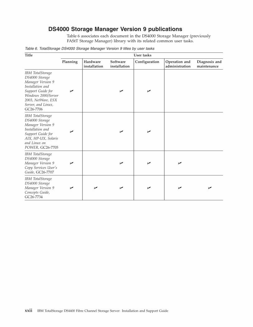
DS4000 Storage Manager Version 9 publications
Table 6 associates each document in the DS4000 Storage Manager (previously
FAStT Storage Manager) library with its related common user tasks.
Table 6. TotalStorage DS4000 Storage Manager Version 9 titles by user tasks
Title User tasks
Planning Hardware
installation
Software
installation
Configuration Operation and
administration
Diagnosis and
maintenance
IBM TotalStorage
DS4000 Storage
Manager Version 9
Installation and
Support Guide for
Windows 2000/Server
2003, NetWare, ESX
Server, and Linux,
GC26-7706
U U U
IBM TotalStorage
DS4000 Storage
Manager Version 9
Installation and
Support Guide for
AIX, HP-UX, Solaris
and Linux on
POWER, GC26-7705
U U U
IBM TotalStorage
DS4000 Storage
Manager Version 9
Copy Services User’s
Guide, GC26-7707
U U U U
IBM TotalStorage
DS4000 Storage
Manager Version 9
Concepts Guide,
GC26-7734
U U U U U U
xxii IBM TotalStorage DS4400 Fibre Channel Storage Server: Installation and Support Guide

Other DS4000 and DS4000-related documents
Table 7 associates each of the following documents with its related common user
tasks.
Table 7. TotalStorage DS4000 and DS4000–related document titles by user tasks
Title User Tasks
Planning Hardware
Installation
Software
Installation
Configuration Operation and
Administration
Diagnosis and
Maintenance
IBM Safety
Information,
P48P9741
U
IBM TotalStorage
DS4000 Quick Start
Guide, GC26-7738
U U
IBM TotalStorage
DS4000 Hardware
Maintenance
Manual,GC26-7702
U
IBM TotalStorage
DS4000 Problem
Determination Guide,
GC26-7703
U
IBM Fibre Channel
Planning and
Integration: User’s
Guide and Service
Information,
SC23-4329
U U U U
IBM TotalStorage
DS4000 FC2-133
Host Bus Adapter
Installation and
User’s Guide,
GC26-7736
U U
IBM TotalStorage
DS4000 FC2-133
Dual Port Host Bus
Adapter Installation
and User’s Guide,
GC26-7737
U U
IBM TotalStorage
DS4000 Fibre
Channel and Serial
ATA Intermix
Premium Feature
Installation Overview
GC26-7713
U U U U
Fibre Channel
Solutions - IBM
DS4000 EXP500
Installation and
User’s Guide,
59p5637
U U U U U
About this book xxiii

Table 7. TotalStorage DS4000 and DS4000–related document titles by user tasks (continued)
Title User Tasks
Planning Hardware
Installation
Software
Installation
Configuration Operation and
Administration
Diagnosis and
Maintenance
IBM TotalStorage
DS4000 EXP700 and
EXP710 Storage
Expansion Enclosures
Installation, User’s,
and Maintenance
Guide, GC26-7735
U U U U U
IBM TotalStorage
DS4000 Hard Drive
and Storage
Expansion Enclosures
Installation and
Migration Guide,
GC26-7704
U U
IBM DS4000
Management Suite
Java User’s Guide,
32P0081
U U
IBM Netfinity® Fibre
Channel Cabling
Instructions, 19K0906
U
IBM Fibre Channel
SAN Configuration
Setup Guide, 25P2509
U U U U
Getting information, help and service
If you need help, service, or technical assistance or just want more information
about IBM products, you will find a wide variety of sources available from IBM to
assist you. This section contains information about where to go for additional
information about IBM and IBM products, and what to do if you experience a
problem with your system.
Before you call
Before you call, take these steps to try to solve the problem yourself:
v Check all cables to make sure that they are connected.
v Check the power switches to make sure that the system is turned on.
v Use the troubleshooting information in your system documentation, and use the
diagnostic tools that come with your system.
v Check for technical information, hints, tips, and new device drivers at the IBM
support Web site pages that are listed in this section.
v Use an IBM discussion forum on the IBM Web site to ask questions.
You can solve many problems without outside assistance by following the
troubleshooting procedures that IBM provides in the DS4000 Storage Manager
online help or in the documents that are provided with your system and software.
The information that comes with your system also describes the diagnostic tests
that you can perform. Most servers, operating systems, and programs come with
xxiv IBM TotalStorage DS4400 Fibre Channel Storage Server: Installation and Support Guide

information that contains troubleshooting procedures and explanations of error
messages and error codes. If you suspect a software problem, see the information
for the operating system or program.
Using the documentation
Information about your IBM system and preinstalled software, if any, is available
in the documents that come with your system. This includes printed books, online
documents, readme files, and help files. See the troubleshooting information in
your system documentation for instructions for using the diagnostic programs. The
troubleshooting information or the diagnostic programs might tell you that you
need additional or updated device drivers or other software.
Web sites
The most up-to-date information about DS4000 storage servers and DS4000 Storage
Manager, including documentation and the most recent software, firmware, and
NVSRAM downloads, can be found at the following Web sites.
DS4000 Fibre Channel storage servers
Find the latest information about IBM TotalStorage disk storage systems,
including all of the DS4000 storage servers:
http://www.ibm.com/servers/storage/disk/index.html
IBM TotalStorage products
Find information about all IBM TotalStorage products:
www.storage.ibm.com/
TotalStorage DS4000 interoperability matrix
Find the latest information about operating system and HBA support,
clustering support, storage area network (SAN) fabric support, and DS4000
Storage Manager feature support:
www.ibm.com/servers/storage/support/disk/
DS4000 Storage Manager readme files
Find the latest readme files for DS4000 Storage Manager:
www.ibm.com/servers/storage/support/disk/
Click the link for your DS4000 storage server. When the page opens, click
the Download tab. Click the link for Current recommended Firmware and
Storage Manager. In the tables, find the Storage Manager listing for your
operating system and click the v9.1x link in the Current Version column.
Storage Area Network (SAN) support
Find information about using SAN switches, including links to user guides
and other documents:
www.ibm.com/servers/storage/support/san/index.html
DS4000 technical support
Find DS4000 downloads, hints and tips, documentation, parts information,
HBA and Fibre Channel support:
http://www.ibm.com/servers/storage/support/disk/
About this book xxv
Premium feature activation
Enable a premium feature on a DS4000 storage server by using the online
tool:
www.storage.ibm.com/pfeatures.html
IBM publications center
Find IBM publications:
www.ibm.com/shop/publications/order/
How to send your comments
Your feedback is important to help us provide the highest quality information. If
you have any comments about this document, you can submit them in one of the
following ways:
v E-mail
Submit your comments electronically to:
Be sure to include the name and order number of the document and, if
applicable, the specific location of the text you are commenting on, such as a
page number or table number.
v Mail
Fill out the Readers’ Comments form (RCF) at the back of this document and
return it by mail or give it to an IBM representative. If the RCF has been
removed, you can address your comments to:
International Business Machines Corporation
Information Development
Department GZW
9000 South Rita Road
Tucson Arizona 85744-0001
U.S.A.
xxvi IBM TotalStorage DS4400 Fibre Channel Storage Server: Installation and Support Guide

Chapter 1. Introduction and installation
Thank you for purchasing an IBM TotalStorage DS4000 series product. IBM DS4000
series solutions are designed to support the large and growing data storage
requirements of business-critical applications. These scalable DS4000 series
solutions provide data access and protection to meet existing enterprise storage
requirements and future needs.
Fibre Channel is a technology similar to a high-speed network that connects large
amounts of disk storage to a server or cluster of servers. Fibre Channel technology
helps increase performance, scalability, availability, and the distance that attached
storage subsystems can be from network servers. The IBM DS4400 Fibre Channel
Storage Server (machine type 1742, models 1RU and 1RX) supports Fibre Channel
disk drives to maximize performance and redundancy.
Fibre Channel technology supports applications that require large amounts of disk
storage shared by two or more servers. With Fibre Channel, higher throughput
rates over longer distances (up to 10 km) are possible than with small computer
system interface (SCSI) or Serial Storage Architecture (SSA) technology.
The IBM DS4400 Fibre Channel Storage Server (referred to throughout this book as
DS4400 Storage Server) is a high-performance unit that provides dual, redundant
RAID controllers with Fibre Channel interfaces to both the host and drive loops.
The DS4400 Storage Server has redundant cooling, redundant power, and battery
backup of the controller cache.
Designed to provide maximum host and drive-side redundancy, the DS4400
Storage Server supports direct attachment of up to four hosts containing two host
adapters each. Using external Fibre Channel switches in conjunction with the
DS4400 Storage Server, you can attach up to 256 hosts with two adapters each to a
DS4400 Storage Server using controller firmware version 06.xx.xx.xx or higher.
The DS4400 Storage Server functions with at least one external fibre channel or
SATA storage expansion enclosure containing fibre channel hard drives. The
DS4400 Storage Server supports a maximum of 224 hard drives when using
DS4000 EXP700, DS4000 EXP710, or DS4000 EXP100 storage expansion enclosures.
If the fibre channel drives are configured using EXP500 storage expansion
enclosures only, a maximum of 220 hard drives are supported.
In order to attach DS4000 EXP100 or EXP710 storage expansion enclosures to a
DS4400 Storage Server, the DS4400 Storage Server controller firmware must be at
version 06.xx.xx.xx or higher. In addition, you must purchase the FC/SATA
Enclosure Intermix premium option to combine EXP100s with EXP700s or EXP710s
in the same DS4400 Storage Server configuration.
This chapter provides descriptions of the primary components of the DS4400
Storage Server and contains setup instructions. The DS4400 Storage Server is used
with rack-mounted storage expansion enclosures. Figure 2 on page 2 shows the
IBM DS4400 Fibre Channel Storage Server.
© Copyright IBM Corp. 2005 1

Inventory checklist
The IBM DS4400 Fibre Channel Storage Server comes with the following hardware:
v Two power cords
v One rack-mounting hardware kit:
– Two rails (right and left)
– Eight black M6 hex-head screws
– Eight clip nuts
– Eight cage nuts
The IBM DS4400 Fibre Channel Storage Server comes with the following software
and documentation:
v A Storage Manger version 9.1 support for Linux CD, a Storage Manger version
9.1 support for Netware CD, and a Storage Manager version 9.1 CD support for
Microsoft Windows 2000 and Windows Server 2003, each including:
– Storage Manager version 9.1 host software for appropriate OS.
– Controller firmware and NVSRAM, storage expansion enclosure ESM
firmware, and supported FC HBA drivers.
– Publications in Adobe Acrobat Portable Document Format (PDF).v Rack mounting assembly kit including:
– Rack Mounting Instructions
– Rack Mounting Template
– White tape dotsv IBM DS4400 Fibre Channel Cabling Instructions
To connect the DS4400 Storage Server to other devices, you might need the
following hardware options, which are purchased separately:
v IBM Small Form-Factor Pluggable (SFP) Module
v IBM LC-LC Fibre Channel Cable
v IBM LC-SC Fibre Channel Cable Adapter
v IBM DS4400 Mini Hub
Figure 2. IBM DS4400 Fibre Channel Storage Server
2 IBM TotalStorage DS4400 Fibre Channel Storage Server: Installation and Support Guide

DS4400 Storage Server components
The DS4400 Storage Server has the following removable components, called
customer replaceable units (CRUs). All CRUs are accessible from the front or back
of the DS4400 Storage Server.
v Bezel (front cover)
v RAID controller (comes with two)
v Battery
v Storage server fan
v Power supply (comes with two)
v Host mini hub (comes with two, four maximum)
v Drive mini hub (comes with two, four maximum)
v Fan and communications module
v Small Form-Factor Pluggable (SFP) module (must be purchased separately)
Attention: The DS4400 controller units are not compatible with the controller
units from FAStT500 or DS4500 Fibre Channel storage servers. DS4500 controller
units normally have the metallic gold latch handle. Do not mix FAStT500 or
DS4500 controller units with IBM DS4400 controller units in the same storage
server units. The DS4400 or FAStT500 controller units are not keyed, while the
DS4500 controller units are keyed to prevent them from being mistakenly inserted
in the non-supported storage server units. Do not force the controller units or the
backplane might be damaged. Before installing new controller units, check that you
have the correct controller unit type, and contact IBM support if you have any
doubts.
Figure 3 on page 4 shows the DS4400 Storage Server front bezel. The bezel is a
removable front cover with holes for viewing status lights and for boosting air
circulation. Figure 3 on page 4 also shows the IBM DS4400 Storage Server without
the front bezel, exposing the following components:
v Storage server fan - A removable unit that contains two cooling fans and
indicator lights.
v Battery - A removable unit that contains the cache battery, battery charger
circuitry, and status indicator lights for the controllers.
v Controllers - Two removable units that each contain one RAID controller with 1
Gb cache memory and status indicator lights.
Removable bezel
Chapter 1. Introduction and installation 3

Storage server fan Controllers
Battery
Figure 3. IBM DS4400 Fibre Channel Storage Server - front view
4 IBM TotalStorage DS4400 Fibre Channel Storage Server: Installation and Support Guide
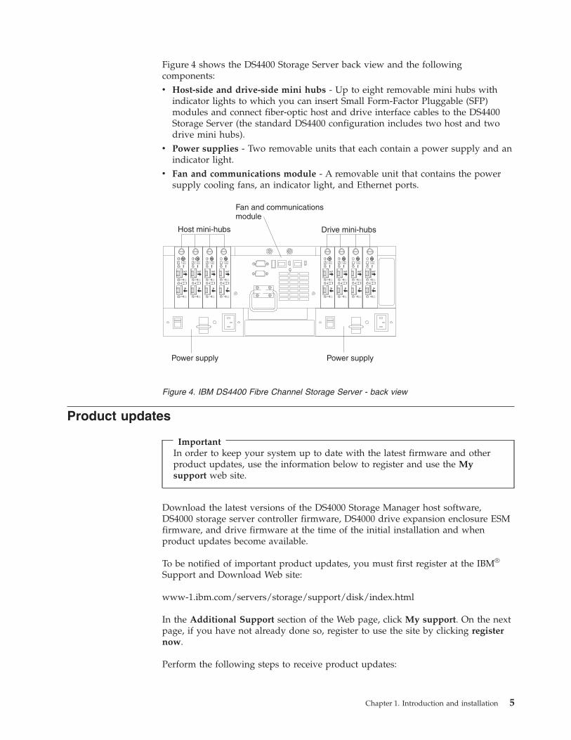
Figure 4 shows the DS4400 Storage Server back view and the following
components:
v Host-side and drive-side mini hubs - Up to eight removable mini hubs with
indicator lights to which you can insert Small Form-Factor Pluggable (SFP)
modules and connect fiber-optic host and drive interface cables to the DS4400
Storage Server (the standard DS4400 configuration includes two host and two
drive mini hubs).
v Power supplies - Two removable units that each contain a power supply and an
indicator light.
v Fan and communications module - A removable unit that contains the power
supply cooling fans, an indicator light, and Ethernet ports.
OUT
IN
!2 Gb/s1 Gb/s
OUT
IN
!2 Gb/s1 Gb/s
OUT
IN
!2 Gb/s1 Gb/s
OUT
IN
!2 Gb/s1 Gb/s
OUT
IN
!2 Gb/s1 Gb/s
OUT
IN
!2 Gb/s1 Gb/s
OUT
IN
!2 Gb/s1 Gb/s
OUT
IN
!2 Gb/s1 Gb/s
Host mini-hubs Drive mini-hubs
Fan and communicationsmodule
Power supply Power supply
Product updates
Important
In order to keep your system up to date with the latest firmware and other
product updates, use the information below to register and use the My
support web site.
Download the latest versions of the DS4000 Storage Manager host software,
DS4000 storage server controller firmware, DS4000 drive expansion enclosure ESM
firmware, and drive firmware at the time of the initial installation and when
product updates become available.
To be notified of important product updates, you must first register at the IBM®
Support and Download Web site:
www-1.ibm.com/servers/storage/support/disk/index.html
In the Additional Support section of the Web page, click My support. On the next
page, if you have not already done so, register to use the site by clicking register
now.
Perform the following steps to receive product updates:
Figure 4. IBM DS4400 Fibre Channel Storage Server - back view
Chapter 1. Introduction and installation 5

1. After you have registered, type your user ID and password to log into the site.
The My support page opens.
2. Click add products. A pull-down menu displays.
3. In the pull-down menu, select Storage. Another pull-down menu displays.
4. In the new pull-down menu, and in the subsequent pull-down menus that
display, select the following topics:
v Computer Storage
v Disk Storage Systems
v TotalStorage DS4000 Midrange Disk Systems & FAStT Stor Srvrs
Note: During this process a check list displays. Do not check any of the items
in the check list until you complete the selections in the pull-down
menus.
5. When you finish selecting the menu topics, place a check in the box for the
machine type of your DS4000 series product, as well as any other attached
DS4000 series product(s) for which you would like to receive information, then
click Add products. The My support page opens again.
6. On the My support page, click the Edit profile tab, then click Subscribe to
email. A pull-down menu displays.
7. In the pull-down menu, select Storage. A check list displays.
8. Place a check in each of the following boxes:
a. Please send these documents by weekly email
b. Downloads and drivers
c. Flashes
and any other topics that you may be interested in, and then click Update.
9. Click Sign out to log out of My Support.
6 IBM TotalStorage DS4400 Fibre Channel Storage Server: Installation and Support Guide

Operating specifications
Table 8 summarizes the operating specifications of the DS4400 Storage Server.
Table 8. IBM DS4400 Fibre Channel Storage Server operating specifications
Size (with front panel and without
mounting rails):
v Depth: 63.5 cm (25 in.)
v Height: 17.45 cm (6.87 in.)
v Width: 48.2 cm (18.97 in.)
Weight:
Typical DS4400 Storage Server fully
configured: 43.99 kg (97 lbs)
Electrical input:
v Sine-wave input (50 to 60 Hz) is
required
v Input voltage:
– Low range:
- Minimum: 90 V ac
- Maximum: 136 V ac
– High range:
- Minimum: 198 V ac
- Maximum: 257 V ac
– Input kilovolt-amperes (kVA)
approximately: 0.214 kVA
Environment:
v Air temperature:
– Altitude: 0 to 914 m (3000 ft):
10° to 35° C (50° to 95° F)
– Altitude: 914 m (3000 ft) to 2133
m (7000 ft): 10° to 32° C (50° to
90° F)
v Humidity:
10% to 80% non-condensing
Acoustical noise emissions values:
For typical system configurations:
v Sound power (idling and
operating): 6.5 bels
v Sound pressure (idling and
operating): 65 dBA
These levels are measured in
controlled acoustical environments
according to ISO 7779 and are
reported in accordance with ISO 9296.
The declared sound power levels
indicate an upper limit, below which
a large portion of machines operate.
Sound pressure levels in your location
might exceed the average 1-meter
values stated because of room
reflections and other nearby noise.
Chapter 1. Introduction and installation 7

Preparing for installation
Use the following procedure to prepare the DS4400 Storage Server for installation
into a rack cabinet.
1. Prepare the site to meet all area, environmental, power, and site requirements.
For more information, see “Operating specifications” on page 7.
2. Move the DS4400 Storage Server and its rack cabinet to the site.
Statement 4:
≥ 18 kg (39.7 lb) ≥ 32 kg (70.5 lb) ≥ 55 kg (121.2 lb)
CAUTION:
Use safe practices when lifting.
3. Remove the DS4400 Storage Server from its shipping container and check the
contents (see “Inventory checklist” on page 2). If any items are missing, contact
your IBM reseller before proceeding.
4. Assemble the tools and equipment you will need for installation. These might
include:
v Power cords (comes with the DS4400 Storage Server)
v Number two Phillips and medium flat-blade screwdrivers
v Antistatic protection (such as a grounding wrist strap)
v Fibre Channel (FC) and Ethernet interface cables and cable straps
v Rack-mounting hardware (comes with the DS4400 Storage Server)
v IBM Storage Manager software to configure the storage subsystems (comes
with the DS4400 Storage Server)
Handling static-sensitive devices
Attention: Static electricity can damage electronic devices and your system. To
avoid damage, keep static-sensitive devices in their static-protective package until
you are ready to install them.
To reduce the possibility of electrostatic discharge, observe the following
precautions:
v Limit your movement. Movement can cause static electricity to build up around
you.
v Handle the device carefully, holding it by its edges or its frame.
v Do not touch solder joints, pins, or exposed printed circuitry.
v Do not leave the device where others can handle and possibly damage the
device.
8 IBM TotalStorage DS4400 Fibre Channel Storage Server: Installation and Support Guide

v While the device is still in its static-protective package, touch it to an unpainted
metal part of the system unit for at least two seconds. (This drains static
electricity from the package and from your body.)
v Remove the device from its package and install it directly into your system unit
without setting it down. If it is necessary to set the device down, place it in its
static-protective package. Do not place the device on your system unit cover or
on a metal table.
v Take additional care when handling devices during cold weather because
heating reduces indoor humidity and increases static electricity.
Installing the DS4400 Storage Server in a rack cabinet
The DS4400 Storage Server comes with a rack-mounting hardware kit for
installation into a rack cabinet. It is easier to lift the DS4400 Storage Server and
install it in a rack cabinet if you remove all CRUs first. A fully loaded DS4400
Storage Server with a storage server fan, battery, fan and communications module,
two RAID controllers, two power supplies, and eight mini hubs installed weighs
43.99 kg (97 lbs). If you remove all the CRUs, you reduce the overall weight.
For detailed instructions about removing the CRUs and installing the DS4400
Storage Server in a rack cabinet, refer to the Rack Mounting Template and Rack
Mounting Instructions that come with the DS4400 Storage Server. If you have not
already done so, read “Preparing for installation” on page 8 before you begin.
Installing additional hardware
You might need to install additional hardware if your Fibre Channel network is
configured for the following:
v Host-agent (in-band) management of storage subsystem
v Direct (out-of-band) management of storage subsystem
v Cluster server environment
Use the information in the following sections to determine the additional hardware
that you need.
Chapter 1. Introduction and installation 9

Installing hardware for host-agent (in-band) management
If you are using the host-agent (in-band) method to manage storage subsystems,
the host-agent software is installed on the host computer. You must install at least
one management station and host computer; then, attach the Ethernet cables from
the host computer to the management station. Figure 5 shows host-agent (in-band)
managed storage subsystems.
Ethernet
Host computer
Controller
Controller
Controller
Controller
Fibre ChannelI/O path
Management station(one or more)
Running thehost-agent software
Running theclient software
Storage subsystems
Managed hub orFibre Channel switch
Host bus adapter
Storage subsystems
You will connect fiber-optic cables to each controller later in the installation
process.
After you install the hardware, if your Fibre Channel network environment is
configured for cluster servers, go to “Installing hardware for cluster servers” on
page 11.
If you are installing storage expansion enclosures in a rack cabinet, go to
“Installing storage expansion enclosures in a rack cabinet” on page 13. Otherwise,
go to Chapter 2, “Connecting the DS4400 Storage Server,” on page 15.
Figure 5. Host agent (in-band) managed storage subsystems
10 IBM TotalStorage DS4400 Fibre Channel Storage Server: Installation and Support Guide

Installing hardware for direct (out-of-band) management
If you are using the direct (out-of-band) method to manage storage subsystems,
use Ethernet connections from a management station to each controller. You must
install at least one management station and then attach Ethernet cables to each
management station and two Ethernet cables per DS4400 Storage Server. Figure 6
shows direct (out-of-band) managed storage subsystems.
Ethernet
Host computer
Fibre ChannelI/O path
Management station(one or more)
Controller
Controller
Controller
Controller
Storage subsystems
Running theclient software
Running theclient software
Host bus adapter
Managed hub orFibre Channel switch
Storage subsystems
You will connect fiber-optic and Ethernet cables to each controller later in the
installation process.
After you install the hardware, if your Fibre Channel network environment is
configured for cluster servers, go to “Installing hardware for cluster servers.”
If you are installing storage expansion enclosures in a rack cabinet, go to
“Installing storage expansion enclosures in a rack cabinet” on page 13. Otherwise,
go to Chapter 2, “Connecting the DS4400 Storage Server,” on page 15.
Installing hardware for cluster servers
If the Fibre Channel network environment into which you are installing the storage
subsystem is configured for cluster servers, you must install two host bus adapters
per cluster node. For complete information about installing host bus adapters, refer
to the IBM TotalStorage DS4000 FC2-133 Dual Port Host Bus Adapter Installation and
User’s Guide.
Figure 7 on page 12 shows Fibre Channel connections using a dual-path
configuration for fully redundant environments.
Figure 6. Direct (out-of-band) managed storage subsystems
Chapter 1. Introduction and installation 11

Note: The interlink is used as the clustering heartbeat path.
Node A
Host adapters
Node A
Host adapters
Node B
Host adapters
Node B
Host adapters
Switch Switch
Storagesubsystemcontrollers
Storagesubsystemcontrollers
Storage subsystem
Storage subsystem
Interlink
Interlink
Fibre Channelconnection(direct)
Fibre Channelconnection(dual path)
Mini-hub1
Mini-hub1
Mini-hub2
Mini-hub2
Before you install the host adapters, note the following about the cluster server
Fibre Channel network environment:
v When using a dual-path configuration, each node has two paths to the storage
server providing greater redundancy protection if a connection problem occurs.
Install two single-channel host adapters in each node.
v Use the correct host adapter device driver. Refer to the IBM Storage Manager
Installation and Support Guide that is appropriate for your operating system and
Figure 7. Installing host adapters in storage subsystems on a Fibre Channel network
12 IBM TotalStorage DS4400 Fibre Channel Storage Server: Installation and Support Guide

refer to the README file for information on supported host adapters and device
drivers. This information is found on the Storage Manager installation CD or at
http://www.ibm.com/pc/support/.
Make sure each host adapter and controller has a unique Fibre Channel ID.
Refer to the documentation provided with your host adapters for installation
requirements and procedures.
After you install the cluster server hardware, continue with “Installing storage
expansion enclosures in a rack cabinet” or go to Chapter 2, “Connecting the
DS4400 Storage Server,” on page 15.
Installing storage expansion enclosures in a rack cabinet
Install the storage expansion enclosures that you are attaching to the DS4400
Storage Server in a rack cabinet. Preparing the storage expansion enclosures for
installation in a rack cabinet might involve any or all of the following tasks:
v Moving the storage expansion enclosures to the installation site
v Unpacking the storage expansion enclosures from their shipping cartons
v Checking the shipping contents
v Removing all customer replaceable units (CRUs)
For detailed instructions on installing the storage expansion enclosures in a rack
cabinet, refer to the documentation that comes with each device. After you install
the storage expansion enclosures, go to Chapter 2, “Connecting the DS4400 Storage
Server,” on page 15.
Chapter 1. Introduction and installation 13

14 IBM TotalStorage DS4400 Fibre Channel Storage Server: Installation and Support Guide
Chapter 2. Connecting the DS4400 Storage Server
This chapter provides information about connecting the DS4400 Storage Server to
other Fibre Channel devices. It contains information about the interface connections
and installing SFP modules and fiber-optic cables. This chapter also provides
detailed information about configuring drive loops and connecting the DS4400
Storage Server to hosts and storage expansion enclosures.
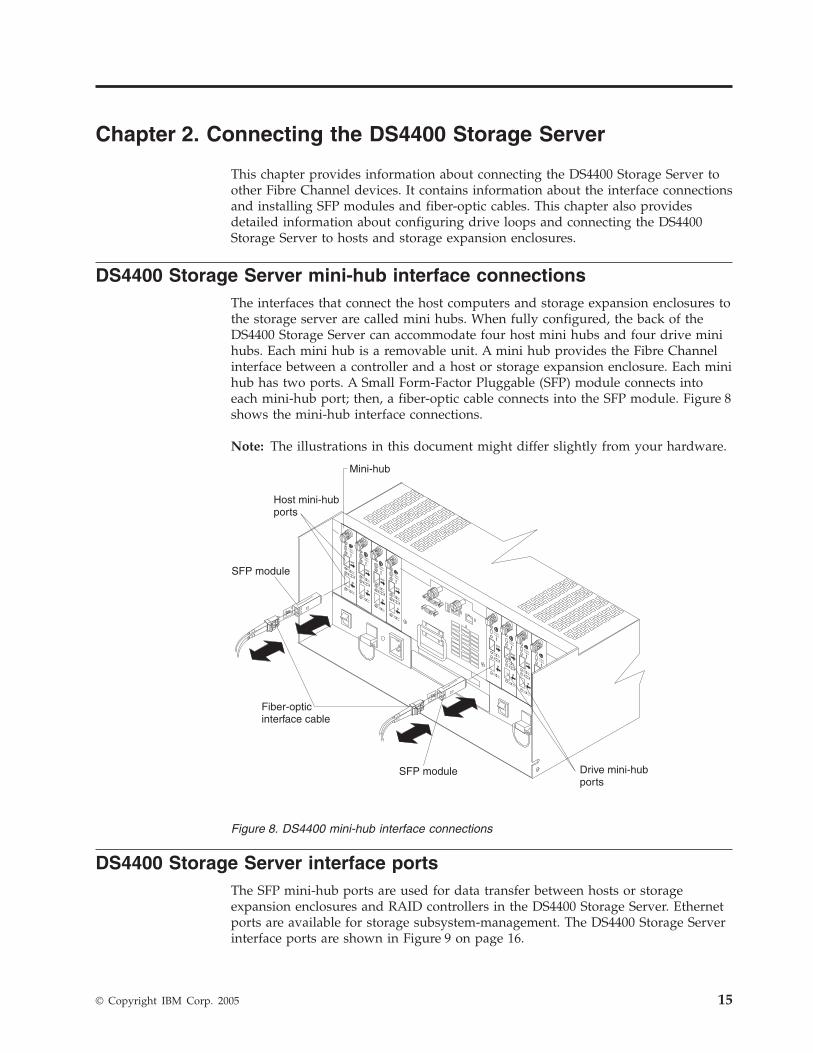
DS4400 Storage Server mini-hub interface connections
The interfaces that connect the host computers and storage expansion enclosures to
the storage server are called mini hubs. When fully configured, the back of the
DS4400 Storage Server can accommodate four host mini hubs and four drive mini
hubs. Each mini hub is a removable unit. A mini hub provides the Fibre Channel
interface between a controller and a host or storage expansion enclosure. Each mini
hub has two ports. A Small Form-Factor Pluggable (SFP) module connects into
each mini-hub port; then, a fiber-optic cable connects into the SFP module. Figure 8
shows the mini-hub interface connections.
Note: The illustrations in this document might differ slightly from your hardware.
OUT
IN
!
2 Gb/s1 Gb/s
OUT
IN
!
2 Gb/s1 Gb/s
OUT
IN
!
2 Gb/s1 Gb/s
OUT
IN
!
2 Gb/s1 Gb/s
OUT
IN
!
2 Gb/s1 Gb/s
OUT
IN
!
2 Gb/s1 Gb/s
OUT
IN
!
2 Gb/s1 Gb/s
OUT
IN
!
2 Gb/s1 Gb/s
Mini-hub
Host mini-hubports
SFP module
SFP module
Fiber-opticinterface cable
Drive mini-hubports
DS4400 Storage Server interface ports
The SFP mini-hub ports are used for data transfer between hosts or storage
expansion enclosures and RAID controllers in the DS4400 Storage Server. Ethernet
ports are available for storage subsystem-management. The DS4400 Storage Server
interface ports are shown in Figure 9 on page 16.
Figure 8. DS4400 mini-hub interface connections
© Copyright IBM Corp. 2005 15
OUT
IN
!2 Gb/s1 Gb/s
OUT
IN
!2 Gb/s1 Gb/s
OUT
IN
!2 Gb/s1 Gb/s
OUT
IN
!2 Gb/s1 Gb/s
OUT
IN
!2 Gb/s1 Gb/s
OUT
IN
!2 Gb/s1 Gb/s
OUT
IN
!2 Gb/s1 Gb/s
OUT
IN
!2 Gb/s1 Gb/s
Hostmini-hubports
Ethernet interface ports
Drivemini-hubports
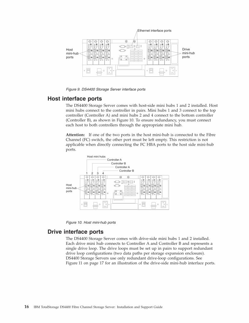
Host interface ports
The DS4400 Storage Server comes with host-side mini hubs 1 and 2 installed. Host
mini hubs connect to the controller in pairs. Mini hubs 1 and 3 connect to the top
controller (Controller A) and mini hubs 2 and 4 connect to the bottom controller
(Controller B), as shown in Figure 10. To ensure redundancy, you must connect
each host to both controllers through the appropriate mini hub.
Attention: If one of the two ports in the host mini-hub is connected to the Fibre
Channel (FC) switch, the other port must be left empty. This restriction is not
applicable when directly connecting the FC HBA ports to the host side mini-hub
ports.
OUT
IN
!2 Gb/s1 Gb/s
OUT
IN
!2 Gb/s1 Gb/s
OUT
IN
!2 Gb/s1 Gb/s
OUT
IN
!2 Gb/s1 Gb/s
OUT
IN
!2 Gb/s1 Gb/s
OUT
IN
!2 Gb/s1 Gb/s
OUT
IN
!2 Gb/s1 Gb/s
OUT
IN
!2 Gb/s1 Gb/s
Host mini hubs
Hostmini-hubports
Controller AController B
Controller AController B
1 2 3 4
Drive interface ports
The DS4400 Storage Server comes with drive-side mini hubs 1 and 2 installed.
Each drive mini hub connects to Controller A and Controller B and represents a
single drive loop. The drive loops must be set up in pairs to support redundant
drive loop configurations (two data paths per storage expansion enclosure).
DS4400 Storage Servers use only redundant drive-loop configurations. See
Figure 11 on page 17 for an illustration of the drive-side mini-hub interface ports.
Figure 9. DS4400 Storage Server interface ports
Figure 10. Host mini-hub ports
16 IBM TotalStorage DS4400 Fibre Channel Storage Server: Installation and Support Guide

The maximum number of storage expansion enclosures that can be connected per
pair of redundant drive loops depends on the IBM DS4000 storage expansion
enclosure models used. The following DS4000 storage expansion enclosure types
are supported by the DS4400 Storage Server:
v FAStT EXP500
v DS4000 EXP700
v DS4000 EXP710
v DS4000 EXP100
If the drives are configured using only DS4000 EXP700, EXP710, or EXP100 storage
expansion enclosures, the DS4400 Storage Server supports a maximum of 224 hard
drives.
If the drives are configured using only FAStT EXP500 storage expansion
enclosures, the DS4400 Storage Server supports a maximum of 220 hard drives.
Attention: In order to attach DS4000 EXP100 or DS4000 EXP710 storage
expansion enclosures to a DS4400 Storage Server, the DS4400 Storage Server
controller firmware must be at version 06.xx.xx.xx or higher. In addition, you must
purchase the FC/SATA Enclosure Intermix premium option to combine DS4000
EXP100s with DS4000 EXP700s or DS4000 EXP710s in the same DS4400 Storage
Server configuration.
For detailed information about how to cable the storage server and storage
expansion enclosures, see the DS4400 Fibre Channel Cabling Instructions that come
with the storage server.
Intermixing storage expansion enclosure models
Storage expansion enclosure models can be mixed in the same redundant drive
loop or the same pair of redundant drive loops. As described in the following
sections, you can intermix FAStT EXP500s and DS4000 EXP700s, and you can also
intermix DS4000 EXP100s, EXP710s, and EXP700s.
You cannot mix DS4000 EXP100s or DS4000 EXP710s with FAStT EXP500s in any
DS4000 storage server configuration. If a DS4000 EXP100 or DS4000 EXP710 is
attached to the DS4400 Storage Server in one drive loop, no FAStT EXP500s can be
present either in the same drive loop or in the other drive loop.
OUT
IN
!2 Gb/s1 Gb/s
OUT
IN
!2 Gb/s1 Gb/s
OUT
IN
!2 Gb/s1 Gb/s
OUT
IN
!2 Gb/s1 Gb/s
OUT
IN
!2 Gb/s1 Gb/s
OUT
IN
!2 Gb/s1 Gb/s
OUT
IN
!2 Gb/s1 Gb/s
OUT
IN
!2 Gb/s1 Gb/s
Drivemini-hubports
Drive loop C and Dfor redundant loop 2
Drive loop A and Bfor redundant loop 1
4 3 2 1
Use one port on eachmini hub to connecta drive loop cable
Leave one port unoccupiedfor future upgrades
Figure 11. Drive mini-hub ports
Chapter 2. Connecting the DS4400 Storage Server 17
Note: This restriction exists because the FAStT EXP500 storage expansion enclosure
operates at 1 Gbps only, while the DS4000 EXP100 and DS4000 EXP710
storage expansion enclosures do not operate at 1 Gbps. The DS4400 Storage
Server does not support mixed drive loop speeds.
Intermixing FAStT EXP500s and DS4000 EXP700s: You can intermix FAStT
EXP500 and DS4000 EXP700 storage expansion enclosure models in the same
redundant pair of drive loops.
Attention: If you are intermixing FAStT EXP500s and DS4000 EXP700s, it is
strongly recommended that you do not cable the FAStT EXP500 and DS4000
EXP700 storage expansion enclosure models in the same redundant drive loop pair.
Instead, you should cable the FAStT EXP500 storage expansion enclosures together
using one pair of redundant drive loops, and you should the DS4000 EXP700
storage expansion enclosures together using the other pair of redundant drive
loops.
Note: You might need to purchase two additional drive mini hubs to implement
this cabling scheme.
If you are intermixing FAStT EXP500s and DS4000 EXP700s, your drive loop
configuration must meet the following requirements:
v The maximum Fibre Channel transfer speed in all of the DS4000 EXP700s must
be set to 1 Gbps because the maximum FC transfer speed of the IBM FAStT
EXP500 storage expansion enclosures is 1 Gbps. Otherwise, a drive channel mini
hub data rate mismatch error will be generated.
v The maximum Fibre Channel transfer speed in all the DS4400 Storage Server
drive-side mini hubs must be set to 1 Gbps.
Attention: If you change the DS4000 EXP700 storage expansion enclosure or
DS4400 Storage Server enclosure link speed setting, you must power-cycle the
storage server. See “Turning off the power” on page 46 and “Turning on the
power” on page 45 for the proper DS4000 configuration power-down and
power-up sequences. For more information, see the IBM TotalStorage DS4000
Hard Drive and Storage Expansion Enclosure Installation and Migration Guide.
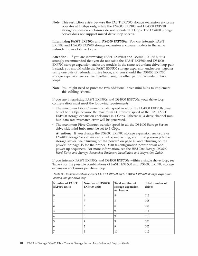
If you intermix FAStT EXP500s and DS4000 EXP700s within a single drive loop, see
Table 9 for the possible combinations of FAStT EXP500 and DS4000 EXP700 storage
expansion enclosures per drive loop.
Table 9. Possible combinations of FAStT EXP500 and DS4000 EXP700 storage expansion
enclosures per drive loop
Number of FAStT
EXP500 units
Number of DS4000
EXP700 units
Total number of
storage expansion
enclosures
Total number of
drives
0 8 8 112
1 7 8 108
2 6 8 104
3 6 9 114
4 5 9 110
5 4 9 106
6 3 9 102
7 3 10 112
18 IBM TotalStorage DS4400 Fibre Channel Storage Server: Installation and Support Guide
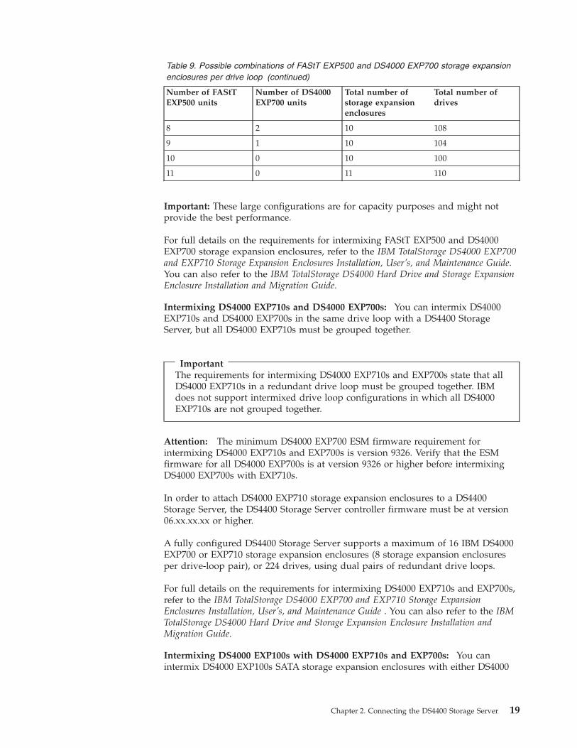
Table 9. Possible combinations of FAStT EXP500 and DS4000 EXP700 storage expansion
enclosures per drive loop (continued)
Number of FAStT
EXP500 units
Number of DS4000
EXP700 units
Total number of
storage expansion
enclosures
Total number of
drives
8 2 10 108
9 1 10 104
10 0 10 100
11 0 11 110
Important: These large configurations are for capacity purposes and might not
provide the best performance.
For full details on the requirements for intermixing FAStT EXP500 and DS4000
EXP700 storage expansion enclosures, refer to the IBM TotalStorage DS4000 EXP700
and EXP710 Storage Expansion Enclosures Installation, User’s, and Maintenance Guide.
You can also refer to the IBM TotalStorage DS4000 Hard Drive and Storage Expansion
Enclosure Installation and Migration Guide.
Intermixing DS4000 EXP710s and DS4000 EXP700s: You can intermix DS4000
EXP710s and DS4000 EXP700s in the same drive loop with a DS4400 Storage
Server, but all DS4000 EXP710s must be grouped together.
Important
The requirements for intermixing DS4000 EXP710s and EXP700s state that all
DS4000 EXP710s in a redundant drive loop must be grouped together. IBM
does not support intermixed drive loop configurations in which all DS4000
EXP710s are not grouped together.
Attention: The minimum DS4000 EXP700 ESM firmware requirement for
intermixing DS4000 EXP710s and EXP700s is version 9326. Verify that the ESM
firmware for all DS4000 EXP700s is at version 9326 or higher before intermixing
DS4000 EXP700s with EXP710s.
In order to attach DS4000 EXP710 storage expansion enclosures to a DS4400
Storage Server, the DS4400 Storage Server controller firmware must be at version
06.xx.xx.xx or higher.
A fully configured DS4400 Storage Server supports a maximum of 16 IBM DS4000
EXP700 or EXP710 storage expansion enclosures (8 storage expansion enclosures
per drive-loop pair), or 224 drives, using dual pairs of redundant drive loops.
For full details on the requirements for intermixing DS4000 EXP710s and EXP700s,
refer to the IBM TotalStorage DS4000 EXP700 and EXP710 Storage Expansion
Enclosures Installation, User’s, and Maintenance Guide . You can also refer to the IBM
TotalStorage DS4000 Hard Drive and Storage Expansion Enclosure Installation and
Migration Guide.
Intermixing DS4000 EXP100s with DS4000 EXP710s and EXP700s: You can
intermix DS4000 EXP100s SATA storage expansion enclosures with either DS4000
Chapter 2. Connecting the DS4400 Storage Server 19

EXP710s, DS4000 EXP700s, or both EXP710s and EXP700s, in the same pair of
redundant drive loops with a DS4400 Storage Server, but all DS4000 EXP710s must
be grouped together.
Important
The requirements for intermixing DS4000 EXP100s with either DS4000
EXP710s, DS4000 EXP700s, or both EXP710s and EXP700s state that you must
group the same enclosure types together.
In order to attach DS4000 EXP100 or EXP710 storage expansion enclosures to a
DS4400 Storage Server, the DS4400 Storage Server controller firmware must be at
version 06.xx.xx.xx or higher. In addition, you must purchase the FC/SATA
Enclosure Intermix premium option to combine EXP100s with EXP700s or EXP710s
in the same DS4400 Storage Server configuration.
For more information on the cabling requirements and best practices for
intermixing EXP100s with EXP700s or EXP710s in the same DS4000 Storage Server
configuration, refer to the IBM TotalStorage DS4000 Fibre Channel and Serial ATA
Intermix Premium Feature Installation Overview that ships with the FC/SATA
Enclosure Intermix premium feature. You can also refer to the IBM TotalStorage
DS4000 Hard Drive and Storage Expansion Enclosure Installation and Migration Guide
Attention: The minimum DS4000 EXP100 ESM firmware requirement for
intermixing DS4000 EXP100s with DS4000 EXP710s or EXP700s is version 9554.
Before intermixing DS4000 EXP100s with DS4000 EXP700s or EXP710s, you must
verify that the ESM firmware for all DS4000 EXP100s is at version 9554 or higher.
As discussed in “Intermixing DS4000 EXP710s and DS4000 EXP700s” on page 19,
you must also verify that the ESM firmware for all DS4000 EXP700s is at version
9326 or higher.
A fully configured DS4400 Storage Server supports a maximum of 16 IBM DS4000
EXP700, EXP710, or EXP100 storage expansion enclosures (8 storage expansion
enclosures per drive-loop pair), or 224 drives, using dual pairs of redundant drive
loops.
20 IBM TotalStorage DS4400 Fibre Channel Storage Server: Installation and Support Guide
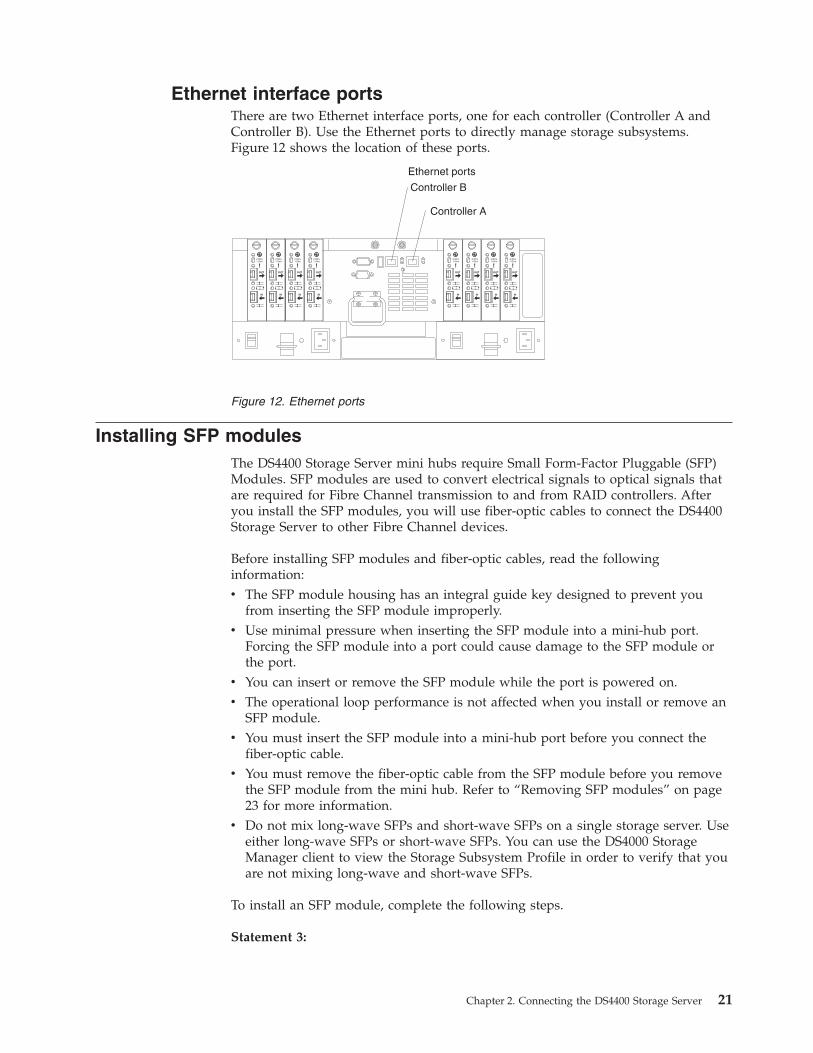
Ethernet interface ports
There are two Ethernet interface ports, one for each controller (Controller A and
Controller B). Use the Ethernet ports to directly manage storage subsystems.
Figure 12 shows the location of these ports.
OUT
IN
!2 Gb/s1 Gb/s
OUT
IN
!2 Gb/s1 Gb/s
OUT
IN
!2 Gb/s1 Gb/s
OUT
IN
!2 Gb/s1 Gb/s
OUT
IN
!2 Gb/s1 Gb/s
OUT
IN
!2 Gb/s1 Gb/s
OUT
IN
!2 Gb/s1 Gb/s
OUT
IN
!2 Gb/s1 Gb/s
Ethernet ports
Controller A
Controller B
Installing SFP modules
The DS4400 Storage Server mini hubs require Small Form-Factor Pluggable (SFP)
Modules. SFP modules are used to convert electrical signals to optical signals that
are required for Fibre Channel transmission to and from RAID controllers. After
you install the SFP modules, you will use fiber-optic cables to connect the DS4400
Storage Server to other Fibre Channel devices.
Before installing SFP modules and fiber-optic cables, read the following
information:
v The SFP module housing has an integral guide key designed to prevent you
from inserting the SFP module improperly.
v Use minimal pressure when inserting the SFP module into a mini-hub port.
Forcing the SFP module into a port could cause damage to the SFP module or
the port.
v You can insert or remove the SFP module while the port is powered on.
v The operational loop performance is not affected when you install or remove an
SFP module.
v You must insert the SFP module into a mini-hub port before you connect the
fiber-optic cable.
v You must remove the fiber-optic cable from the SFP module before you remove
the SFP module from the mini hub. Refer to “Removing SFP modules” on page
23 for more information.
v Do not mix long-wave SFPs and short-wave SFPs on a single storage server. Use
either long-wave SFPs or short-wave SFPs. You can use the DS4000 Storage
Manager client to view the Storage Subsystem Profile in order to verify that you
are not mixing long-wave and short-wave SFPs.
To install an SFP module, complete the following steps.
Statement 3:
Figure 12. Ethernet ports
Chapter 2. Connecting the DS4400 Storage Server 21
CAUTION:
When laser products (such as CD-ROMs, DVD drives, fiber optic devices, or
transmitters) are installed, note the following:
v Do not remove the covers. Removing the covers of the laser product could
result in exposure to hazardous laser radiation. There are no serviceable parts
inside the device.
v Use of controls or adjustments or performance of procedures other than those
specified herein might result in hazardous radiation exposure.
DANGER
Some laser products contain an embedded Class 3A or Class 3B laser diode.
Note the following.
Laser radiation when open. Do not stare into the beam, do not view directly
with optical instruments, and avoid direct exposure to the beam.
Attention: When you handle static-sensitive devices, take precautions to avoid
damage from static electricity. For details about handling static-sensitive devices,
see “Handling static-sensitive devices” on page 8.
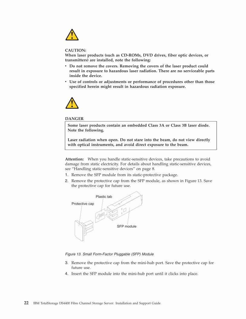
1. Remove the SFP module from its static-protective package.
2. Remove the protective cap from the SFP module, as shown in Figure 13. Save
the protective cap for future use.
Protective cap
Plastic tab
SFP module
3. Remove the protective cap from the mini-hub port. Save the protective cap for
future use.
4. Insert the SFP module into the mini-hub port until it clicks into place.
Figure 13. Small Form-Factor Pluggable (SFP) Module
22 IBM TotalStorage DS4400 Fibre Channel Storage Server: Installation and Support Guide
OUT
IN
!
2 Gb/s1 Gb/s
OUT
IN
!
2 Gb/s1 Gb/s
OUT
IN
!
2 Gb/s1 Gb/s
OUT
IN
!
2 Gb/s1 Gb/s
SFP module
Fiber-opticcable
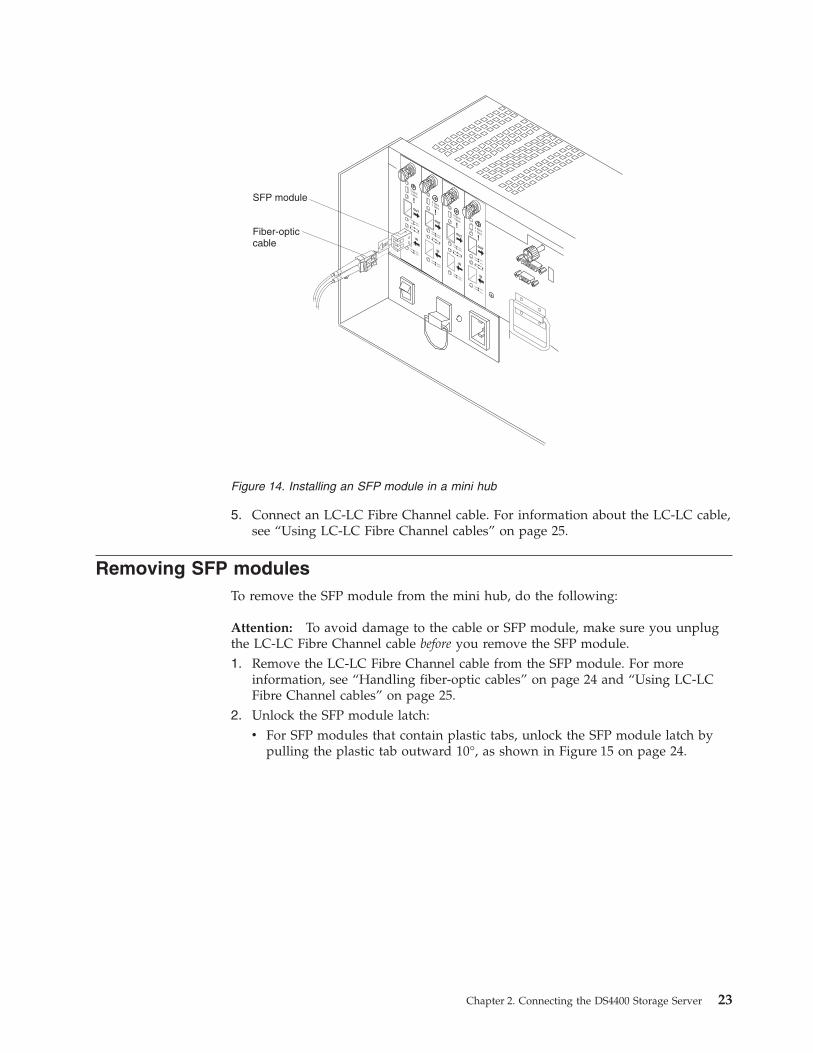
5. Connect an LC-LC Fibre Channel cable. For information about the LC-LC cable,
see “Using LC-LC Fibre Channel cables” on page 25.
Removing SFP modules
To remove the SFP module from the mini hub, do the following:
Attention: To avoid damage to the cable or SFP module, make sure you unplug
the LC-LC Fibre Channel cable before you remove the SFP module.
1. Remove the LC-LC Fibre Channel cable from the SFP module. For more
information, see “Handling fiber-optic cables” on page 24 and “Using LC-LC
Fibre Channel cables” on page 25.
2. Unlock the SFP module latch:
v For SFP modules that contain plastic tabs, unlock the SFP module latch by
pulling the plastic tab outward 10°, as shown in Figure 15 on page 24.
Figure 14. Installing an SFP module in a mini hub
Chapter 2. Connecting the DS4400 Storage Server 23

v For SFP modules that contain wire tabs, unlock the SFP module latch by
pulling the wire latch outward 90°, as shown in Figure 16.
Attention: When you handle static-sensitive devices, take precautions to avoid
damage from static electricity. For details about handling static-sensitive
devices, see “Handling static-sensitive devices” on page 8.
3. With the SFP latch in the unlocked position, slide the SFP module out of the
mini-hub port.
4. Replace the protective cap on the SFP module.
5. Place the SFP module into a static-protective package.
6. Replace the protective cap on the mini-hub port.
Handling fiber-optic cables
Before using fiber-optic cables, read the following precautions.
Attention: To avoid damage to your fiber-optic cables, follow these guidelines:
v Do not route the cable along a folding cable-management arm.
v When attaching to a device on slide rails, leave enough slack in the cable so that
it does not bend to a radius of less than 38 mm (1.5 in.) when extended or
become pinched when retracted.
v Route the cable away from places where it can be snagged by other devices in
the rack.
v Do not overtighten the cable straps or bend the cables to a radius of less than 38
mm (1.5 in.).
v Do not put excess weight on the cable at the connection point. Be sure that the
cable is well supported.
Protective cap
SFP module
10o
Plastic tab
F10ug009
Figure 15. Unlocking the SFP module latch - plastic variety
Protective cap
SFP module90o
Wire tabF
10ug010
Figure 16. Unlocking the SFP module latch - wire variety
24 IBM TotalStorage DS4400 Fibre Channel Storage Server: Installation and Support Guide

Using LC-LC Fibre Channel cables
The LC-LC Fibre Channel cable is a fiber-optic cable that is used to connect into
one of the following devices:
v SFP module installed in a DS4400 Storage Server mini hub
v SFP module installed in an IBM Fibre Channel switch
v Optical interface connector on an IBM DS4000 FC-2 Host Bus Adapter (Part
number 19K1246)
For more information about connecting to these devices, see the documentation
that comes with the device.
Figure 17 shows an LC-LC Fibre Channel cable.
The following sections provide the procedures for properly connecting and
removing an LC-LC Fibre Channel cable.
Note: If you are connecting a DS4400 Storage Server to a EXP500 storage
expansion enclosure or to an IBM DS4000 host adapter, you must also use
an LC-SC Fibre Channel cable adapter. For more information about using
the Fibre Channel cable adapter, see “Using LC-SC Fibre Channel cable
adapters” on page 28.
Connecting an LC-LC cable to an SFP module
To connect an LC-LC Fibre Channel cable to an SFP module, complete the
following steps.
Statement 3:
Figure 17. LC-LC Fibre Channel cable
Chapter 2. Connecting the DS4400 Storage Server 25

CAUTION:
When laser products (such as CD-ROMs, DVD drives, fiber optic devices, or
transmitters) are installed, note the following:
v Do not remove the covers. Removing the covers of the laser product could
result in exposure to hazardous laser radiation. There are no serviceable parts
inside the device.
v Use of controls or adjustments or performance of procedures other than those
specified herein might result in hazardous radiation exposure.
DANGER
Some laser products contain an embedded Class 3A or Class 3B laser diode.
Note the following.
Laser radiation when open. Do not stare into the beam, do not view directly
with optical instruments, and avoid direct exposure to the beam.
1. Read the information in “Handling fiber-optic cables” on page 24.
2. If necessary, remove the protective cap from the SFP module, as shown in
Figure 13 on page 22. Save the protective cap for future use.
3. Remove the two protective caps from one end of the LC-LC cable, as shown in
Figure 18. Save the protective caps for future use.
Protective cap
Fiber-opticcable
4. Carefully insert that same end of the LC-LC cable into an SFP module that is
installed in a DS4400 Storage Server mini hub. The cable connector is keyed to
ensure it is inserted into the SFP module correctly. Holding the connector, push
in the cable until it clicks into place.
Figure 18. Removing fiber-optic cable protective caps
26 IBM TotalStorage DS4400 Fibre Channel Storage Server: Installation and Support Guide

Figure 20 shows an LC-LC Fibre Channel cable connecting into an SFP module
that is installed in a DS4400 Storage Server mini hub.
OUT
IN
!
2 Gb/s1 Gb/s
OUT
IN
!
2 Gb/s1 Gb/s
OUT
IN
!
2 Gb/s1 Gb/s
OUT
IN
!
2 Gb/s1 Gb/s
SFP module
Fiber-opticcable
5. Remove the two protective caps from the other end of the LC-LC cable, as
shown in Figure 18 on page 26. Save the protective caps for future use.
6. Connect the LC-LC Fibre Channel cable to one of the following devices:
v SFP module that is installed in an IBM Fibre Channel switch
v Optical interface connector on an IBM DS4000 FC-2 Host Bus Adapter (Part
Number 19K1246)
v LC-SC Fibre Channel cable adapter (For information about using an LC-SC
cable adapter, see “Using LC-SC Fibre Channel cable adapters” on page 28.)
Figure 19. Inserting an LC-LC Fibre Channel cable into an SFP module
Figure 20. Inserting an LC-LC Fibre Channel cable into an installed SFP module
Chapter 2. Connecting the DS4400 Storage Server 27

For more information about connecting to these devices, see the documentation
that comes with the device.
Removing an LC-LC Fibre Channel cable
To remove an LC-LC Fibre Channel cable, do the following:
Attention: To avoid damaging the LC-LC cable or SFP module, make sure you
press and hold the lever to release the latches before you remove the cable from
the SFP module. Ensure that the levers are in the released position when removing
the cable. When removing the cable from the SFP module, make sure you do not
grasp the SFP module plastic tab.
1. On the end of the LC-LC cable that connects into the SFP module or host bus
adapter, press down and hold the lever to release the latches, as shown in
Figure 21. Carefully pull on the connector to remove the cable from the SFP
module, as shown in Figure 22.
Lever
Latches
2. Replace the protective caps on the cable ends.
3. Replace the protective cap on the SFP module.
Using LC-SC Fibre Channel cable adapters
The LC-SC Fibre Channel Cable Adapter is a fiber-optic cable that is used to
connect the LC connector into one of the following devices that require SC
connectors:
v DS4000 host adapter (Part number 00N6881)
v FAStT EXP500 storage expansion enclosure (Machine type 3560)
Figure 21. LC-LC Fibre Channel Cable lever and latches
Figure 22. Removing the LC-LC Fibre Channel cable
28 IBM TotalStorage DS4400 Fibre Channel Storage Server: Installation and Support Guide

v 1 Gb Fibre Channel switch (Machine type 2109)
v Managed hub (Machine type 3534)
For more information about connecting to these devices, see the documentation
that comes with the device.
Figure 23 shows an LC-SC Fibre Channel cable.
LC connector
SC connector
The following sections provide the procedures for properly connecting and
removing an LC-SC Fibre Channel cable.
Connecting an LC-SC cable to a device
To connect an LC-SC cable to a device, complete the following steps.
Statement 3:
CAUTION:
When laser products (such as CD-ROMs, DVD drives, fiber optic devices, or
transmitters) are installed, note the following:
v Do not remove the covers. Removing the covers of the laser product could
result in exposure to hazardous laser radiation. There are no serviceable parts
inside the device.
v Use of controls or adjustments or performance of procedures other than those
specified herein might result in hazardous radiation exposure.
Figure 23. LC-SC Fibre Channel cable
Chapter 2. Connecting the DS4400 Storage Server 29

DANGER
Some laser products contain an embedded Class 3A or Class 3B laser diode.
Note the following.
Laser radiation when open. Do not stare into the beam, do not view directly
with optical instruments, and avoid direct exposure to the beam.
1. Read the information in “Handling fiber-optic cables” on page 24.
2. Connect an LC-LC cable to an SFP module in the DS4400 Storage Server mini
hub. For instructions, see “Connecting an LC-LC cable to an SFP module” on
page 25.
3. Remove the two protective caps from the LC connector end of the LC-SC cable,
as shown in Figure 24. Save the protective caps for future use.
4. Carefully insert the LC connector end of the cable into the LC connector end of
the LC-SC cable adapter. Push in the connector until it clicks into place.
5. Connect the SC connector end of the LC-SC cable to one of the following
devices:
v Optical interface connector on an IBM DS4000 FC-2 Host Bus Adapter (Part
number 19K1246)
v GBIC installed in a FAStT EXP500 storage expansion enclosure (Machine type
3560)
Figure 24. Removing the LC-SC cable adapter protective caps
Figure 25. Connecting an LC-LC cable into the LC-SC cable adapter
30 IBM TotalStorage DS4400 Fibre Channel Storage Server: Installation and Support Guide
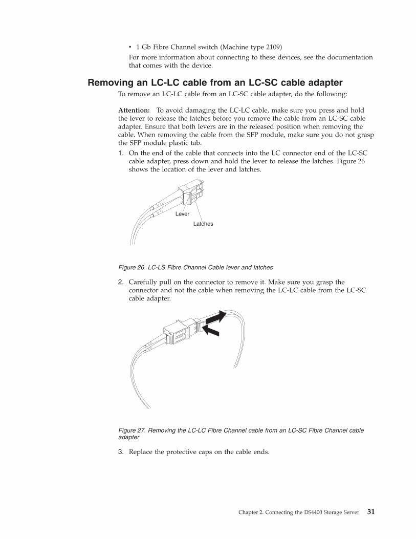
v 1 Gb Fibre Channel switch (Machine type 2109)For more information about connecting to these devices, see the documentation
that comes with the device.
Removing an LC-LC cable from an LC-SC cable adapter
To remove an LC-LC cable from an LC-SC cable adapter, do the following:
Attention: To avoid damaging the LC-LC cable, make sure you press and hold
the lever to release the latches before you remove the cable from an LC-SC cable
adapter. Ensure that both levers are in the released position when removing the
cable. When removing the cable from the SFP module, make sure you do not grasp
the SFP module plastic tab.
1. On the end of the cable that connects into the LC connector end of the LC-SC
cable adapter, press down and hold the lever to release the latches. Figure 26
shows the location of the lever and latches.
Lever
Latches
2. Carefully pull on the connector to remove it. Make sure you grasp the
connector and not the cable when removing the LC-LC cable from the LC-SC
cable adapter.
3. Replace the protective caps on the cable ends.
Figure 26. LC-LS Fibre Channel Cable lever and latches
Figure 27. Removing the LC-LC Fibre Channel cable from an LC-SC Fibre Channel cable
adapter
Chapter 2. Connecting the DS4400 Storage Server 31

DS4400 Storage Server and storage expansion enclosure cabling
overview
The DS4400 Storage Server supports two redundant drive loops. A redundant drive
loop consists of one or more storage expansion enclosures connected to a controller
using two sets of Fibre Channel cables. If one data path fails, the controller uses
the other data path to maintain the connection to the drive group.
Figure 28 shows a storage subsystem containing one storage server and two
redundant drive loops with four storage expansion enclosures each. Each storage
expansion enclosures group uses redundant drive loops to connect to the DS4400
Storage Server. Loop A and loop B make up one redundant pair of drive loops.
Loop C and loop D make up a second redundant pair.
Attention: To prevent loss of storage expansion enclosure redundancy, connect
the storage expansion enclosures as shown in Figure 28.
Note: The illustrations in this document might differ slightly from your hardware.
Storage expansionenclosures group 1
Storage expansion
enclosures group 2
Drive loop A
Drive loop B
Drive loop C
Drive loop D
Storage server
Configuring the drive loops
The procedure and illustrations in this section show an example of how to connect
one storage expansion enclosure group of four storage expansion enclosures into a
redundant drive loop. Instructions for how to connect a second redundant storage
expansion enclosure group of four storage expansion enclosures into a redundant
drive loop are also included in this procedure.
To complete this procedure, you will need two fiber-optic cables per storage
expansion enclosure. Handle and install fiber-optic cables properly to avoid
degraded performance or loss of communications with devices. Do not overtighten
the cable straps or bend the cables to a radius less than 38 mm (1.5 in.).
Figure 28. Redundant drive loop cabling overview
32 IBM TotalStorage DS4400 Fibre Channel Storage Server: Installation and Support Guide

1. Connect the first two storage expansion enclosures to drive loop A, as shown in
Figure 29.
Starting with the first storage expansion enclosuree, connect a fiber-optic cable
from the In port on the left environmental services module (ESM) board to the
Out port on the left ESM board in the second (next) storage expansion
enclosure.
Last storageexpansionenclosure
ESM boards
ESM board
Loop AFibre ChannelcableFirst storage
expansion
enclosure
Storageserver
In Out
For the location of the ports on the storage expansion enclosure ESM board, see
Figure 30.
In InOut Out
Storage expansion enclosure
ESM board
2. Connect the same first two storage expansion enclosures to drive loop B, as
shown in Figure 31 on page 34.
Starting with the first storage expansion enclosure, connect a fiber-optic cable
from the In port on the right ESM board to the Out port on the right ESM
board in the second (next) storage expansion enclosure.
Figure 29. Connecting two storage expansion enclosures into drive loop A
Figure 30. Storage expansion enclosure environmental services module (ESM) board in and
out ports
Chapter 2. Connecting the DS4400 Storage Server 33

ESM board
Loop BFibre Channelcable
In Out
If you want to connect more storage expansion enclosures into drive loops A
and B, continue with Step 3; otherwise, go to “Connecting a redundant drive
loop to the DS4400 Storage Server” on page 35.
3. Connect additional storage expansion enclosures to drive loops A and B, as
shown in Figure 32.
Starting with the second storage expansion enclosure, connect each additional
storage expansion enclosure into drive loops A and B in the same manner.
Leave the In port on the last storage expansion enclosure in the loop and the
Out port on the first storage expansion enclosure unoccupied.
Loop BLoop A
Storage expansion
enclosure group 1
In InOut Out
Storage server
If you want to connect a second storage expansion enclosure group, go to Step
4; otherwise, go to “Connecting a redundant drive loop to the DS4400 Storage
Server” on page 35.
4. Repeat Step 1 on page 33 through Step 3 to connect a second redundant storage
expansion enclosure group. Figure 33 on page 35 shows a second redundant
storage expansion enclosure group (loop C and loop D on storage expansion
enclosure group 2).
Figure 31. Connecting two storage expansion enclosures into redundant drive loop B
Figure 32. Connecting additional storage expansion enclosures to drive loops A and B
34 IBM TotalStorage DS4400 Fibre Channel Storage Server: Installation and Support Guide

Loop B
Loop D
Loop A
Loop C
Storage expansion
enclosure group 1
Storage expansion
enclosure group 2
Storage server
5. Continue with “Connecting a redundant drive loop to the DS4400 Storage
Server.”
Connecting a redundant drive loop to the DS4400 Storage Server
Use the following procedure to connect a redundant drive loop to the DS4400
Storage Server. You will need two fiber-optic cables for each redundant pair of
loops (for example, loop A and loop B) that you are connecting to the DS4400
Storage Server.
1. Connect drive loop A to the DS4400 Storage Server, as shown in Figure 34 on
page 36.
Starting with the last storage expansion enclosure in loop A, connect the In port
on the left ESM board to the Out (upper) port on drive mini hub 4 on the
DS4400 Storage Server.
Leave the Out port on the left ESM board on the first storage expansion
enclosure and the In (lower) connector on drive mini hub 4 unoccupied.
Figure 33. Connecting a second redundant storage expansion enclosure group (loops C and
D)
Chapter 2. Connecting the DS4400 Storage Server 35

Loop A Fibre Channel cables
Out port on drivemini hub 4
2. Connect drive loop B to the DS4400 Storage Server, as shown in Figure 35.
Starting with the first storage expansion enclosure in the loop, connect the Out
port on the right ESM board to the In (lower) port on drive mini hub 3.
Leave the In port on the right ESM board on the last storage expansion
enclosure and the Out (upper) port on drive mini hub 3 unoccupied.
Loop B Fibre Channel cables
In port on drivemini hub 3
Last storage expansion
enclosure
First storage expansion
enclosure
To connect a second redundant storage expansion enclosure group to the
DS4400 Storage Server, continue with Step 3; otherwise, go to “Connecting
hosts directly to the DS4400 Storage Server” on page 37.
3. Connect drive loop C to the DS4400 Storage Server, as shown in Figure 36 on
page 37.
Starting with the first storage expansion enclosure in storage expansion
enclosure group 2, connect the In port on the left ESM board to the Out (upper)
port on drive mini hub 2.
Figure 34. Connecting drive loop A to the DS4400 Storage Server
Figure 35. Connecting redundant drive loops to the DS4400 Storage Server
36 IBM TotalStorage DS4400 Fibre Channel Storage Server: Installation and Support Guide

Leave the Out port on the left ESM board on the last storage expansion
enclosure in storage expansion enclosure group 2 and the In (lower) port on the
drive mini hub 2 unoccupied.
4. Connect drive loop D to the DS4400 Storage Server, as shown in Figure 36.
Starting with the last storage expansion enclosure in storage expansion
enclosure group 2, connect the Out port on the right ESM board to the In
(lower) port on mini hub 1.
Leave the In port on the right ESM board on the first storage expansion
enclosure in storage expansion enclosure group 2 and the Out (upper) port on
drive mini hub 1 unoccupied.
Storage expansion
enclosures group 1
Storage expansion
enclosures group 2
Drive loop A
Drive loop B
Drive loop C
Out
Drive loop D
Storage server
Drive loop AFibre Channelcables
Drive loop CFcables
ibre Channel
Drive loop BFcables
ibre Channel
Drive loop DFcables
ibre Channel
In
Last storage expansion
enclosure
Last storage expansion
enclosure
First storage expansion
enclosure
First storage expansion
enclosure
In InOut Out
Connecting hosts directly to the DS4400 Storage Server
Use this procedure to connect up to four hosts, with two host adapters each,
directly to the DS4400 Storage Server. If you are connecting five or more hosts to
the DS4400 Storage Server, go to “Connecting hosts using external devices” on
page 38.
Before proceeding, make sure that you connect fiber-optic cables to all host
adapters that you are connecting to the DS4400 Storage Server.
Important: Host mini hub 1 and mini hub 3 correspond to Controller A (top) and
mini hub 2 and mini hub 4 correspond to Controller B (bottom). To ensure
redundancy, connect each host to both controllers. You can use either the upper or
lower ports on either mini hub.
Figure 36. Connecting two redundant storage expansion enclosure groups
Chapter 2. Connecting the DS4400 Storage Server 37

The example in the following procedure uses the upper ports for Hosts 1 and 4
and the lower ports for Hosts 2 and 3.
1. Connect the first host (Host 1) to the DS4400 Storage Server, as shown in
Figure 37.
Connect Host Adapter 1 (HA1) from Host 1 to a port on host mini hub 1.
Connect HA2 from Host 1 to mini hub 2.
To connect a second host, continue with Step 2; otherwise, go to “Setting the
Link Rate Interface switch” on page 41.
2. Connect a second host (Host 2) to the DS4400 Storage Server, as shown in
Figure 37.
Attach HA1 from Host 2 to the unoccupied port on mini hub 1. Attach HA2
from Host 2 to the unoccupied port on mini hub 2.
To connect a third host, continue with Step 3; otherwise, go to “Setting the Link
Rate Interface switch” on page 41.
3. Connect a third host (Host 3) to the DS4400 Storage Server, as shown in
Figure 37.
Attach HA1 from Host 3 to mini hub 3. Attach HA2 from Host 3 to mini hub 4.
To connect a fourth host, continue with Step 4; otherwise, go to “Setting the
Link Rate Interface switch” on page 41.
4. Connect a fourth host (Host 4) to the DS4400 Storage Server, as shown in
Figure 37.
Attach HA1 and HA2 from Host 4 to the two unoccupied ports on mini hub 3
and mini hub 4.
OUT
IN
!2 Gb/s1 Gb/s
OUT
IN
!2 Gb/s1 Gb/s
OUT
IN
!2 Gb/s1 Gb/s
OUT
IN
!2 Gb/s1 Gb/s
OUT
IN
!2 Gb/s1 Gb/s
OUT
IN
!2 Gb/s1 Gb/s
OUT
IN
!2 Gb/s1 Gb/s
OUT
IN
!2 Gb/s1 Gb/s
Controller AController B
Controller AController B
1 2 3 4
Host 1 HA2
Host 2 HA1
Host 3 HA1Host 4 HA1
Host 1 HA1
Host 2 HA2
Host 3 HA2Host 4 HA2
5. Go to “Setting the Link Rate Interface switch” on page 41.
Connecting hosts using external devices
Use the information in this section to connect five or more hosts to the DS4400
Storage Server. When you use external Fibre Channel switches, the DS4400 Storage
Server supports up to 64 hosts (128 host adapters, 64 host adapters per controller)
and two host adapters for each host.
Important: Host mini hub 1 and host mini hub 3 correspond to Controller A (top).
Mini hub 2 and mini hub 4 correspond to Controller B (bottom). To ensure
redundancy, connect each host to both controllers. You can use either the upper or
lower connectors on either mini hub.
Figure 37. Connecting hosts directly to the controller
38 IBM TotalStorage DS4400 Fibre Channel Storage Server: Installation and Support Guide

You connect additional hosts to the DS4400 Storage Server by adding host-side
mini hubs and Fibre Channel switches, (one Fibre Channel switch for each mini
hub).
Attention: If one of the two ports in the host mini-hub is connected to the Fibre
Channel (FC) switch, the other port must be left empty. This restriction is not
applicable when directly connecting the FC HBA ports to the host side mini-hub
ports.
Figure 38 shows an example of dual path configuration using Fibre Channel
switches. Host 1 contains two host bus adapters that are connected to host mini
hubs. To configure a host with dual path redundancy, connect the first host bus
adapter (HA1) to SW1 and connect the second host bus adapter (HA2) to SW2.
Then, connect SW1 to host mini hub 1 and SW2 to host mini hub 2.
OUT
IN
!2 Gb/s1 Gb/s
OUT
IN
!2 Gb/s1 Gb/s
OUT
IN
!2 Gb/s1 Gb/s
OUT
IN
!2 Gb/s1 Gb/s
OUT
IN
!2 Gb/s1 Gb/s
OUT
IN
!2 Gb/s1 Gb/s
OUT
IN
!2 Gb/s1 Gb/s
OUT
IN
!2 Gb/s1 Gb/s
1 2 3 4
Controller A
Controller B
Controller A
Controller B
SW1 SW2
Host X
HA1 HA2 HAX HAX
Host 1
Figure 38. Using two Fibre Channel switches to connect a host
Chapter 2. Connecting the DS4400 Storage Server 39

You can directly attach up to four Fibre Channel switches (one per mini hub) to a
DS4400 Storage Server. Figure 39 shows an example of attaching four Fibre
Channel switches.
OUT
IN
!2 Gb/s1 Gb/s
OUT
IN
!2 Gb/s1 Gb/s
OUT
IN
!2 Gb/s1 Gb/s
OUT
IN
!2 Gb/s1 Gb/s
OUT
IN
!2 Gb/s1 Gb/s
OUT
IN
!2 Gb/s1 Gb/s
OUT
IN
!2 Gb/s1 Gb/s
OUT
IN
!2 Gb/s1 Gb/s
1 2 3 4
Host 1 Host XHost X Host X
Method 1Connect a new managedhub to an available porton each hub that youconnected in Step 1.
Method 2Connect a new managedhub to either port on eachremaining host mini-hub.
SW SWSW SW
Most Fibre Channel switches support eight to sixteen hosts. If your configuration
requires more hosts than four Fibre Channel switches can support, you must add
cascading switches, as shown in Figure 40.
OUT
IN
!2 Gb/s1 Gb/s
OUT
IN
!2 Gb/s1 Gb/s
OUT
IN
!2 Gb/s1 Gb/s
OUT
IN
!2 Gb/s1 Gb/s
OUT
IN
!2 Gb/s1 Gb/s
OUT
IN
!2 Gb/s1 Gb/s
OUT
IN
!2 Gb/s1 Gb/s
OUT
IN
!2 Gb/s1 Gb/s
1 2 3 4
Host 1 Host XHost X Host X
SW1 SWXSW2 SWX
Figure 39. Using four Fibre Channel switches to connect multiple hosts
Figure 40. Adding hosts using cascading switches
40 IBM TotalStorage DS4400 Fibre Channel Storage Server: Installation and Support Guide

Setting the Link Rate Interface switch
Each DS4400 Storage Server mini hub has a Link Rate Interface switch that is used
to select the host-side or drive-side mini-hub data transfer rates. The switch
settings are labeled 2 Gb per second and 1 Gb per second. Use a device with a
point such as a small flat-blade screwdriver or ballpoint pen to set the host-side or
drive-side mini-hub Link Rate Interface switch. See Figure 41.
The Speed indicator light is green when the data transfer rate of the Fibre Channel
loop is 2 Gb per second. The Speed indicator light is off when the data transfer
rate is 1 Gb per second. Figure 41 shows the location of the Link Rate switch and
indicator light.
OUT
IN
!2 Gb/s1 Gb/s
Speed indicator light
Link rate interface switch
2 Gb/s1 Gb/s
This illustrationshows the switch
set to 2 Gb/s
Figure 41. Mini-hub Link Rate Interface switch and Speed indicator light
Chapter 2. Connecting the DS4400 Storage Server 41

Setting data transfer rates on host-side mini hubs
To set the Link Rate Interface switch on the host-side mini hubs, complete the
following steps.
Note: Host-side mini-hub ports must be connected to devices that have the same
data transfer rate.
1. Verify the data transfer rate of the devices on the loop or the Fibre Channel
switch port.
2. Set the data transfer rate on the host bus adapter based on the data transfer
rate of the devices on the loop or the Fibre Channel switch port.
3. Set the Link Rate Interface switch to match the data transfer rate of the host
bus adapter.
Setting data transfer rates on drive-side mini hubs
On the drive-side mini hubs, set the Link Rate Interface switch to 2 Gb per second
or 1 Gb per second based on the data transfer rate of the storage expansion
enclosures.
Note: All storage expansion enclosures on the loop and drive-side mini-hub ports
must be connected to devices that have the same data transfer rate.
To set the data transfer rate on drive-side mini hubs, do the following:
1. Verify the data transfer rate of the storage expansion enclosure on the loop.
2. Set the link rate interface switch to match the data rate of the storage expansion
enclosure.
Connecting Ethernet cables
To manage a storage subsystem using the direct (out-of-band) method, connect a
pair of Ethernet cables from the management station to the Ethernet ports for
Controller A or Controller B on the back of the DS4400 Storage Server. For an
illustration of direct (out-of-band) management, see Figure 6 on page 11.
Figure 42 shows the location of the Ethernet ports.
OUT
IN
!2 Gb/s1 Gb/s
OUT
IN
!2 Gb/s1 Gb/s
OUT
IN
!2 Gb/s1 Gb/s
OUT
IN
!2 Gb/s1 Gb/s
OUT
IN
!2 Gb/s1 Gb/s
OUT
IN
!2 Gb/s1 Gb/s
OUT
IN
!2 Gb/s1 Gb/s
OUT
IN
!2 Gb/s1 Gb/s
Ethernet ports
Controller A
Controller B
Figure 42. Ethernet port locations
42 IBM TotalStorage DS4400 Fibre Channel Storage Server: Installation and Support Guide

Chapter 3. Starting the DS4400 Storage Server
After you install the DS4400 Storage Server in a rack cabinet and connect it to the
Fibre Channel Arbitrated Loop, you are ready to complete the installation. This
chapter describes how to connect the power cords, turn on and off the power,
check the indicator lights, and install the Storage Manager software.
Power cabling
The DS4400 uses two standard power cords. You can connect the power cords to a
primary power unit inside the rack cabinet, such as a properly grounded ac
distribution unit, or to an external source, such as a properly grounded electrical
outlet.
The DS4400 storage server does not ship with power cords. Refer to “Power cords”
on page 60 for the list of IBM-approved power cords for your region. The DS4400
storage server ships with two line jumper cords for connecting the DS4400 power
supplies to an IBM-approved rack power distribution unit.
If you have not already done so, attach the power cords by using Figure 43 for the
location of the component parts.
Perform the following to cable the power cords:
1. Connect the power cord to the power supply.
2. Remove the nut that holds the power cable strain-relief clamp, and then
remove the strain-relief clamp.
OUT
IN
!
2 Gb/s1 Gb/s
OUT
IN
!
2 Gb/s1 Gb/s
OUT
IN
!
2 Gb/s1 Gb/s
OUT
IN
!
2 Gb/s1 Gb/s
OUT
IN
!
2 Gb/s1 Gb/s
OUT
IN
!
2 Gb/s1 Gb/s
OUT
IN
!
2 Gb/s1 Gb/s
OUT
IN
!
2 Gb/s1 Gb/s
ac powercord
ac powercord
Power switch
Power switch
Figure 43. Connecting the power cords
© Copyright IBM Corp. 2005 43

3. Wrap the strain-relief clamp around the power cord approximately 20 cm (8 in.)
from the power supply connection end. Leave some slack between the clamp
and the power-supply end of the power cord.
4. Replace the power cable strain-relief clamp, and tighten it securely with the
nut.
5. Plug the power cord into a properly grounded electrical outlet.
Note: To maintain power redundancy, plug the storage server’s right and left
power supplies into two independent external power circuits through ac
distribution units inside a rack cabinet or directly into external
receptacles. Similarly, the right and left power supplies of the DS4000
storage expansion enclosures attached to the DS4400 should be plugged
into the same two independent external power circuits as the DS4400.
It is recommended that you determine the maximum surge current
possible when all devices in the power circuit are started at the same
time. Based on the total number of devices on a power circuit, find the
maximum (worst-case) specification value in order to prevent the circuit
from tripping. When both power supplies are connected and the storage
server is powered on, each power supply unit will handle approximately
one-half of the current load. If there is only one power supply unit, it
will handle all of the current load. To ensure maximum protection
against power loss due to power supply unit failure or a power circuit
tripping, both power supply units must be connected and powered on.
See Table 8 on page 7 for the DS4400 AC power requirements.
See Figure 44 on page 45 for an example of redundant power cabling.
44 IBM TotalStorage DS4400 Fibre Channel Storage Server: Installation and Support Guide
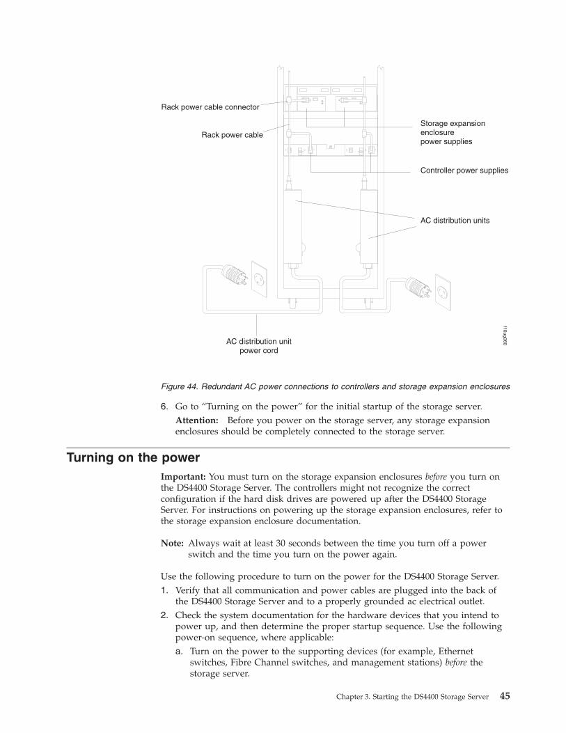
6. Go to “Turning on the power” for the initial startup of the storage server. Attention: Before you power on the storage server, any storage expansion
enclosures should be completely connected to the storage server.
Turning on the power
Important: You must turn on the storage expansion enclosures before you turn on
the DS4400 Storage Server. The controllers might not recognize the correct
configuration if the hard disk drives are powered up after the DS4400 Storage
Server. For instructions on powering up the storage expansion enclosures, refer to
the storage expansion enclosure documentation.
Note: Always wait at least 30 seconds between the time you turn off a power
switch and the time you turn on the power again.
Use the following procedure to turn on the power for the DS4400 Storage Server.
1. Verify that all communication and power cables are plugged into the back of
the DS4400 Storage Server and to a properly grounded ac electrical outlet.
2. Check the system documentation for the hardware devices that you intend to
power up, and then determine the proper startup sequence. Use the following
power-on sequence, where applicable:
a. Turn on the power to the supporting devices (for example, Ethernet
switches, Fibre Channel switches, and management stations) before the
storage server.
AC distribution unitpower cord
Controller power supplies
Storage expansionenclosurepower supplies
Rack power cable connector
Rack power cable
AC distribution units
f10ug060
Figure 44. Redundant AC power connections to controllers and storage expansion enclosures
Chapter 3. Starting the DS4400 Storage Server 45

Attention: If you will be directly managing the storage array, you must set
up the Dynamic Host Configuration Protocol (DHCP) or BOOT-P server
before you turn on the power. Setting up the server allows the controllers to
obtain the corresponding IP address when you turn on the power to the
array module. For more information, see the software installation guide for
your operating system.
b. You must turn on the storage expansion enclosures before the DS4400
Storage Server. The controllers might not recognize the correct configuration
if the drives are powered up after the storage server. For instructions on
powering up the storage expansion enclosures, refer to the storage
expansion enclosure documentation.
c. Turn on the power to the storage server.
d. Restart or turn on the power to the host.
Note: Depending on your operating system, you might not have to restart
the host. For more information, see the software installation guide for
your operating system.3. Turn on power to each device using the power-on sequence as outlined in the
previous step. When turning on power to the DS4400 Storage Server, turn on
both of the power-supply switches on the back of the DS4400 Storage Server.
You must turn on both power-supply switches to take advantage of the
redundant power supplies.
4. Use the storage-management software and the Fault indicator lights to check
the overall status of the DS4400 Storage Server and its components.
Turning off the power
Attention: The DS4400 Storage Server is designed to run continuously, 24 hours a
day. Except in an emergency, never turn off the power even if any DS4400 Storage
Server fault indicator lights are lit. Use the proper troubleshooting or servicing
procedure to correct the fault before turning off the power. This ensures that the
DS4400 Storage Server powers up correctly later.
Statement 5:
CAUTION:
The power control button on the device and the power switch on the power
supply do not turn off the electrical current supplied to the device. The device
also might have more than one power cord. To remove all electrical current from
the device, ensure that all power cords are disconnected from the power source.
1
2
Use the following procedure to turn off power to the DS4400 Storage Server.
46 IBM TotalStorage DS4400 Fibre Channel Storage Server: Installation and Support Guide

1. Make sure that all amber fault indicator lights on the DS4400 Storage Server are
off. If any fault indicator lights are on, use the storage-management software to
determine the status of the system components and correct any problems before
turning off the power.
2. The operating system software might require you to perform other procedures
before you turn off the power. Use the storage-management software to check
the status of the storage server. Correct problems that are reported before you
turn off the power.
3. Prepare the DS4400 Storage Server for shutdown, as follows:
a. Stop all I/O activity to the DS4400 Storage Server and attached storage
expansion enclosures.
Note: If a parity check is in progress, it might take a long time for the drive
indicator lights to stop blinking.
b. Use the operating-system software to disconnect the DS4400 Storage Server
logical drives from the host before the storage server is powered off.
c. Make sure that the fast write cache indicator light on each DS4400 Storage
Server front panel and all drive active indicator lights on each storage
expansion enclosure front panel are off (not blinking).
d. Disconnect the DS4400 Storage Server and storage expansion enclosures
from the hosts.
Attention: To turn off all power to the storage server, you must turn off both
power-supply switches and disconnect both power cords. Use the procedure in
step 4 for the proper shutdown sequence.
4. To turn off the power to each device, use the following shutdown sequence.
Note: You do not need to perform this step if you are servicing only the
DS4400 Storage Server.
a. Turn off power to the host before the storage server. If the host must stay
powered on to support an existing network, refer to the operating system
documentation for information about disconnecting the storage server
logical drives from the host before the storage server is powered off.
b. Turn off power to the storage server before you turn off power to the storage
expansion enclosures. Turn off both power supply switches on the back of
the storage server.
c. Turn off power to other supporting devices (for example, management
stations, Fibre Channel switches, or Ethernet switches).
Turning on the DS4400 Storage Server alarm
The DS4400 Storage Server has an audible alarm. This alarm is controlled by a
switch that is located on the storage server fan. You can enable this alarm by
removing the bezel and setting the switch in the up position, as shown in Figure 45
on page 48.
Chapter 3. Starting the DS4400 Storage Server 47

Alarm switch
DS4400 Storage Server indicator lights
The indicator lights on the front of the DS4400 Storage Server are shown in
Figure 46 through Figure 49 on page 50.
Fault-BAmber light indicatescontroller fault.Normal status: OffProblem status: On
PowerGreen light indicates thatpower is on.Normal status: OnProblem status: Off
HeartbeatGreen light indicates that thecontroller is working.Normal status: On (blinking)Problem status: On
Status(8 lights including the Heartbeat)Green lights indicate controllerstatus.
Controller statusindicator lights
Reset switch
The RAID controller status lights might blink when I/O activity is in progress. If
the Heartbeat light blinks continuously, then the other status lights will glow in
various patterns to show the status or an error condition. The pattern shown
depends on whether the controller is active (online) or passive (offline). For more
information, refer to IBM DS4400 TotalStorage Fibre Channel Storage Server User’s
Guide and the IBM Storage Manager Installation and Support Guide for your operating
system.
Figure 45. DS4400 Storage Server alarm switch
Figure 46. RAID controller indicator lights
48 IBM TotalStorage DS4400 Fibre Channel Storage Server: Installation and Support Guide
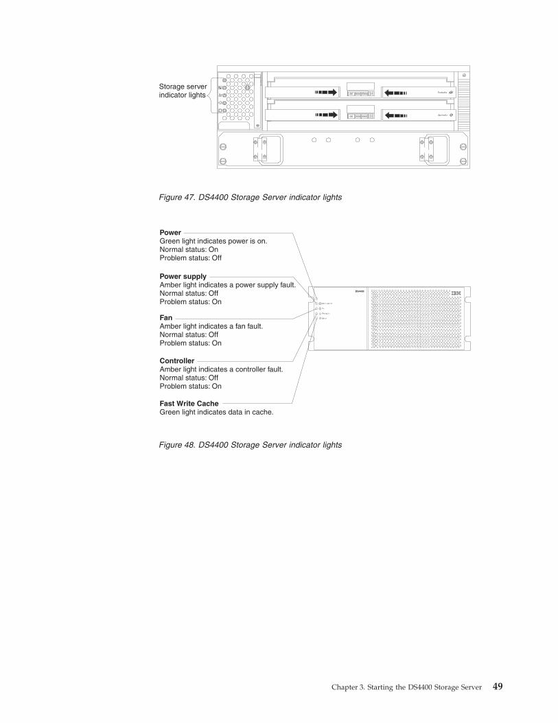
Storage serverindicator lights
DS4400
PowerGreen light indicates power is on.Normal status: OnProblem status: Off
Power supplyAmber light indicates a power supply fault.Normal status: OffProblem status: On
FanAmber light indicates a fan fault.Normal status: OffProblem status: On
ControllerAmber light indicates a controller fault.Normal status: OffProblem status: On
Fast Write CacheGreen light indicates data in cache.
Figure 47. DS4400 Storage Server indicator lights
Figure 48. DS4400 Storage Server indicator lights
Chapter 3. Starting the DS4400 Storage Server 49
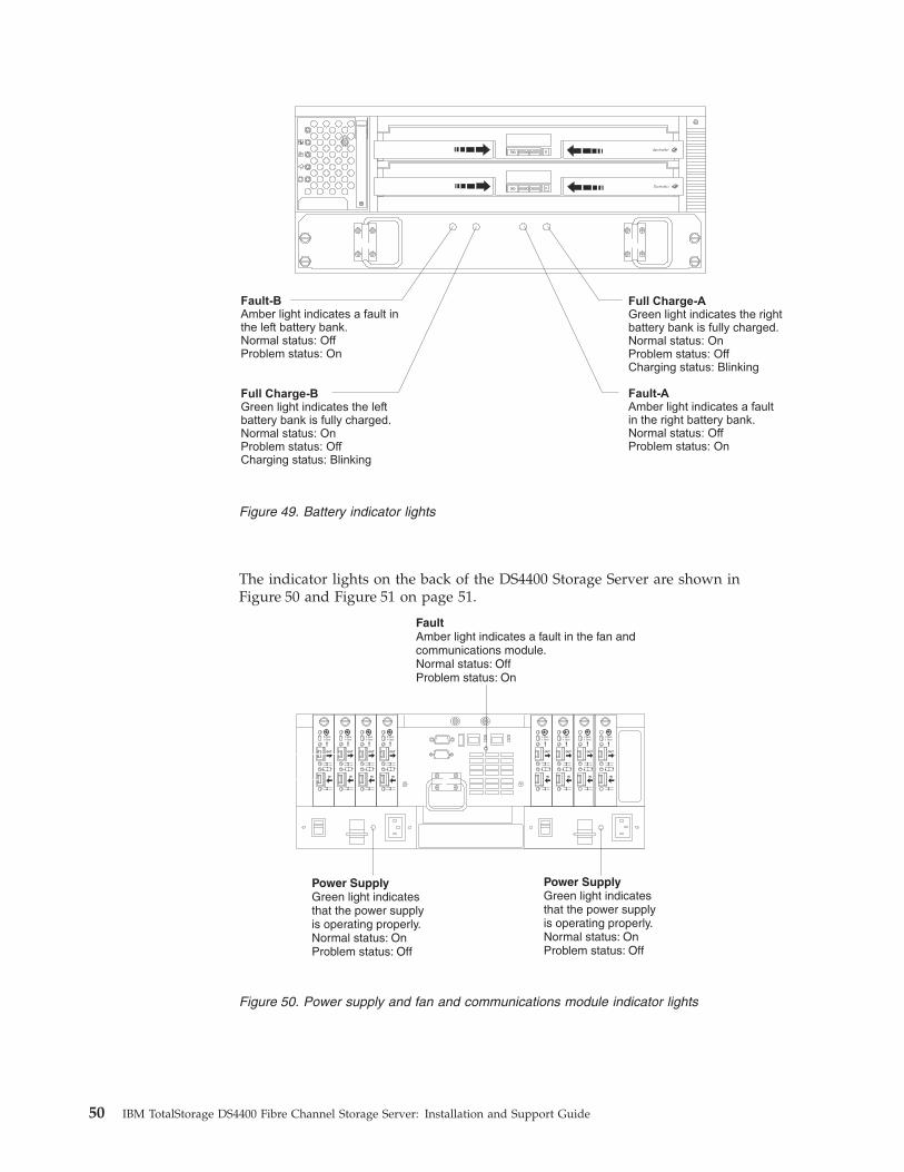
Fault-B
Amber light indicates a fault inthe left battery bank.Normal status: OffProblem status: On
Fault-AAmber light indicates a faultin the right battery bank.Normal status: OffProblem status: On
Full Charge-BGreen light indicates the leftbattery bank is fully charged.Normal status: OnProblem status: OffCharging status: Blinking
Full Charge-AGreen light indicates the rightbattery bank is fully charged.Normal status: OnProblem status: OffCharging status: Blinking
The indicator lights on the back of the DS4400 Storage Server are shown in
Figure 50 and Figure 51 on page 51.
OUT
IN
!2 Gb/s1 Gb/s
OUT
IN
!2 Gb/s1 Gb/s
OUT
IN
!2 Gb/s1 Gb/s
OUT
IN
!2 Gb/s1 Gb/s
OUT
IN
!2 Gb/s1 Gb/s
OUT
IN
!2 Gb/s1 Gb/s
OUT
IN
!2 Gb/s1 Gb/s
OUT
IN
!2 Gb/s1 Gb/s
FaultAmber light indicates a fault in the fan andcommunications module.Normal status: OffProblem status: On
Power SupplyGreen light indicatesthat the power supplyis operating properly.Normal status: OnProblem status: Off
Power SupplyGreen light indicatesthat the power supplyis operating properly.Normal status: OnProblem status: Off
Figure 49. Battery indicator lights
Figure 50. Power supply and fan and communications module indicator lights
50 IBM TotalStorage DS4400 Fibre Channel Storage Server: Installation and Support Guide

OUT
IN
!2 Gb/s1 Gb/s
OUT
IN
!2 Gb/s1 Gb/s
OUT
IN
!2 Gb/s1 Gb/s
OUT
IN
!2 Gb/s1 Gb/s
OUT
IN
!2 Gb/s1 Gb/s
OUT
IN
!2 Gb/s1 Gb/s
OUT
IN
!2 Gb/s1 Gb/s
OUT
IN
!2 Gb/s1 Gb/s
OUT
IN
!2 Gb/s1 Gb/s
OUT
Speed
Bypass(upper port)
Bypass(lower port)
Loop good
Fault
Mini-hub indicatorlights
Link rateinterface switch
Table 10 describes the mini-hub indicator lights.
Table 10. Mini-hub indicator lights
Icon
Indicator
light Color
Normal
operation
Problem
indicator Condition indicated
None Speed Green On for 2 Gb
Off for 1 Gb
None Light on indicates data
transfer rate of 2 Gb per
second. Light off indicates
data transfer rate of 1 Gb
per second.
! Fault Amber Off On There is a fault in the
mini hub.
Bypass Amber Off On The upper mini-hub port
is bypassed.
Loop good Green On Off The drive loop is
operational.
Bypass
(lower port)
Amber Off On The lower mini-hub port
is bypassed.
Installing the DS4000 Storage Manager client
Refer to the IBM TotalStorage DS4000 Storage Manager 9.10 Installation and Support
Guide for the appropriate operating system for instructions on how to install the
Storage Manager software. Use that document and the online help to configure the
logical drives, partitions, and so on for the RAID controllers. Use your operating
system documentation to make the new logical drives accessible to the operating
system. Do not proceed with the configuration set-up until you have completed the
DS4000 Storage Manager installation.
Assemble any additional items in preparation for software installation. These items
might include:
v HBA drivers
v Controller firmware
v IP addresses for RAID controllers (for in-band management only)
Figure 51. Mini-hub indicator lights
Chapter 3. Starting the DS4400 Storage Server 51
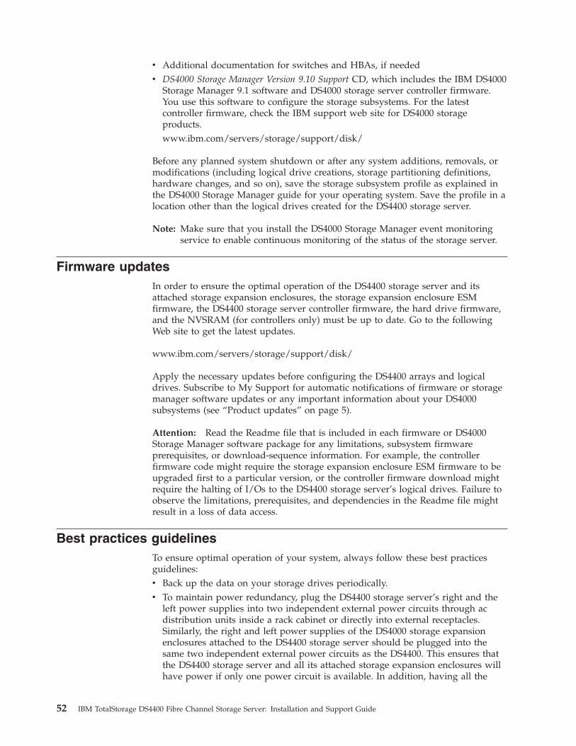
v Additional documentation for switches and HBAs, if needed
v DS4000 Storage Manager Version 9.10 Support CD, which includes the IBM DS4000
Storage Manager 9.1 software and DS4000 storage server controller firmware.
You use this software to configure the storage subsystems. For the latest
controller firmware, check the IBM support web site for DS4000 storage
products.
www.ibm.com/servers/storage/support/disk/
Before any planned system shutdown or after any system additions, removals, or
modifications (including logical drive creations, storage partitioning definitions,
hardware changes, and so on), save the storage subsystem profile as explained in
the DS4000 Storage Manager guide for your operating system. Save the profile in a
location other than the logical drives created for the DS4400 storage server.
Note: Make sure that you install the DS4000 Storage Manager event monitoring
service to enable continuous monitoring of the status of the storage server.
Firmware updates
In order to ensure the optimal operation of the DS4400 storage server and its
attached storage expansion enclosures, the storage expansion enclosure ESM
firmware, the DS4400 storage server controller firmware, the hard drive firmware,
and the NVSRAM (for controllers only) must be up to date. Go to the following
Web site to get the latest updates.
www.ibm.com/servers/storage/support/disk/
Apply the necessary updates before configuring the DS4400 arrays and logical
drives. Subscribe to My Support for automatic notifications of firmware or storage
manager software updates or any important information about your DS4000
subsystems (see “Product updates” on page 5).
Attention: Read the Readme file that is included in each firmware or DS4000
Storage Manager software package for any limitations, subsystem firmware
prerequisites, or download-sequence information. For example, the controller
firmware code might require the storage expansion enclosure ESM firmware to be
upgraded first to a particular version, or the controller firmware download might
require the halting of I/Os to the DS4400 storage server’s logical drives. Failure to
observe the limitations, prerequisites, and dependencies in the Readme file might
result in a loss of data access.
Best practices guidelines
To ensure optimal operation of your system, always follow these best practices
guidelines:
v Back up the data on your storage drives periodically.
v To maintain power redundancy, plug the DS4400 storage server’s right and the
left power supplies into two independent external power circuits through ac
distribution units inside a rack cabinet or directly into external receptacles.
Similarly, the right and left power supplies of the DS4000 storage expansion
enclosures attached to the DS4400 storage server should be plugged into the
same two independent external power circuits as the DS4400. This ensures that
the DS4400 storage server and all its attached storage expansion enclosures will
have power if only one power circuit is available. In addition, having all the
52 IBM TotalStorage DS4400 Fibre Channel Storage Server: Installation and Support Guide
right or all the left power supplies plug into the same power circuit enables the
components in the storage subsystem to power on simultaneously during an
unattended restoration of power.
v Before any planned system shutdown or after any system additions, removals,
or modifications (including logical drive creations, storage partitioning
definitions, hardware changes, and so on), save the storage subsystem profile as
explained in the DS4000 Storage Manager guide for your operating system. Save
the profile in a location other than the logical drives created for the DS4400
storage server.
v Ensure that your system is in an optimal state before you shut it down. Never
turn the power off if any fault light is lit; be sure to resolve any error conditions
before you shut down the system.
v During any maintenance or attended power-up procedure, carefully follow the
sequences listed in “Turning off the power” on page 46 and“Turning on the
power” on page 45 for the proper DS4000 configuration power-down and
power-up sequences. Check that each component of the subsystem is
powered-on in the proper order during this entire power-up procedure to ensure
the controller will be able to optimally access all of your storage subsystems.
v A storage system in an optimal state should recover automatically from an
unexpected shutdown and unattended simultaneous restoration of power to
system components. After power is restored, call IBM support if any of the
following conditions occur:
– The storage subsystem logical drives and arrays are not displayed in the
DS4000 Storage Manager graphical user interface (GUI).
– The storage subsystem logical drives and arrays do not come online.
– The storage subsystem logical drives and arrays seem to be degraded.v Using the DS4000 Storage Manager client, save the DS4000 subsystem
configuration profile to a disk that is not affected every time you make changes
(such as logical drive creation or modification, or storage partitioning changes)
to the DS4000 subsystem configuration.
Chapter 3. Starting the DS4400 Storage Server 53

54 IBM TotalStorage DS4400 Fibre Channel Storage Server: Installation and Support Guide
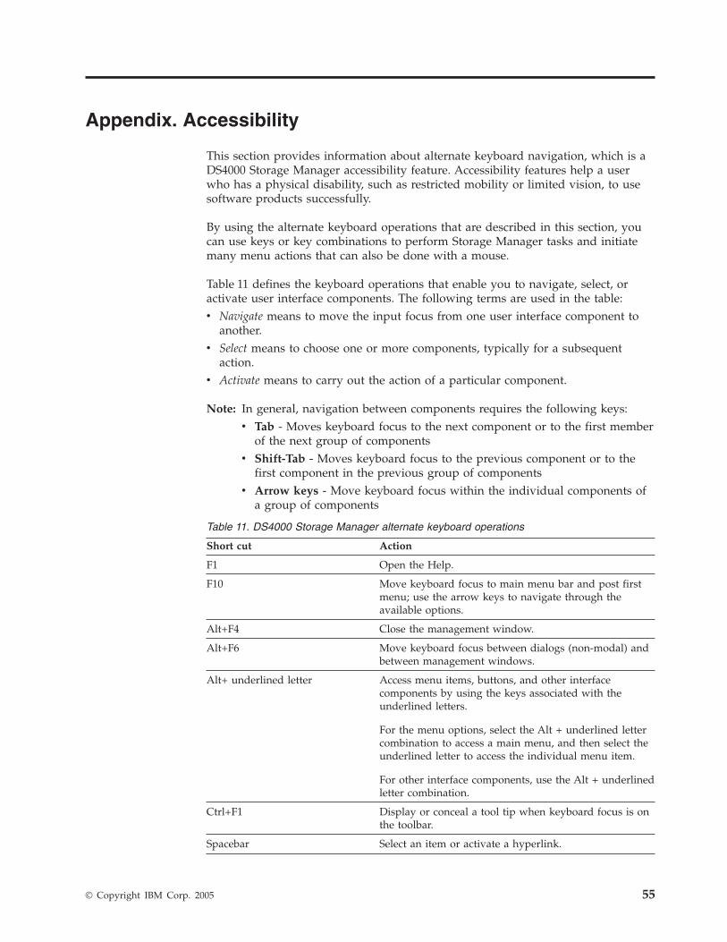
Appendix. Accessibility
This section provides information about alternate keyboard navigation, which is a
DS4000 Storage Manager accessibility feature. Accessibility features help a user
who has a physical disability, such as restricted mobility or limited vision, to use
software products successfully.
By using the alternate keyboard operations that are described in this section, you
can use keys or key combinations to perform Storage Manager tasks and initiate
many menu actions that can also be done with a mouse.
Table 11 defines the keyboard operations that enable you to navigate, select, or
activate user interface components. The following terms are used in the table:
v Navigate means to move the input focus from one user interface component to
another.
v Select means to choose one or more components, typically for a subsequent
action.
v Activate means to carry out the action of a particular component.
Note: In general, navigation between components requires the following keys:
v Tab - Moves keyboard focus to the next component or to the first member
of the next group of components
v Shift-Tab - Moves keyboard focus to the previous component or to the
first component in the previous group of components
v Arrow keys - Move keyboard focus within the individual components of
a group of components
Table 11. DS4000 Storage Manager alternate keyboard operations
Short cut Action
F1 Open the Help.
F10 Move keyboard focus to main menu bar and post first
menu; use the arrow keys to navigate through the
available options.
Alt+F4 Close the management window.
Alt+F6 Move keyboard focus between dialogs (non-modal) and
between management windows.
Alt+ underlined letter Access menu items, buttons, and other interface
components by using the keys associated with the
underlined letters.
For the menu options, select the Alt + underlined letter
combination to access a main menu, and then select the
underlined letter to access the individual menu item.
For other interface components, use the Alt + underlined
letter combination.
Ctrl+F1 Display or conceal a tool tip when keyboard focus is on
the toolbar.
Spacebar Select an item or activate a hyperlink.
© Copyright IBM Corp. 2005 55

Table 11. DS4000 Storage Manager alternate keyboard operations (continued)
Short cut Action
Ctrl+Spacebar
(Contiguous/Non-contiguous)
AMW Logical/Physical View
Select multiple drives in the Physical View.
To select multiple drives, select one drive by pressing
Spacebar, and then press Tab to switch focus to the next
drive you want to select; press Ctrl+Spacebar to select
the drive.
If you press Spacebar alone when multiple drives are
selected then all selections are removed.
Use the Ctrl+Spacebar combination to deselect a drive
when multiple drives are selected.
This behavior is the same for contiguous and
non-contiguous selection of drives.
End, Page Down Move keyboard focus to the last item in the list.
Esc Close the current dialog (does not require keyboard
focus).
Home, Page Up Move keyboard focus to the first item in the list.
Shift+Tab Move keyboard focus through components in the
reverse direction.
Ctrl+Tab Move keyboard focus from a table to the next user
interface component.
Tab Navigate keyboard focus between components or select
a hyperlink.
Down arrow Move keyboard focus down one item in the list.
Left arrow Move keyboard focus to the left.
Right arrow Move keyboard focus to the right.
Up arrow Move keyboard focus up one item in the list.
56 IBM TotalStorage DS4400 Fibre Channel Storage Server: Installation and Support Guide

Notices
This publication was developed for products and services offered in the U.S.A.
IBM may not offer the products, services, or features discussed in this document in
other countries. Consult your local IBM representative for information on the
products and services currently available in your area. Any reference to an IBM
product, program, or service is not intended to state or imply that only that IBM
product, program, or service may be used. Any functionally equivalent product,
program, or service that does not infringe any IBM intellectual property right may
be used instead. However, it is the user’s responsibility to evaluate and verify the
operation of any non-IBM product, program, or service.
IBM may have patents or pending patent applications covering subject matter
described in this document. The furnishing of this document does not give you
any license to these patents. You can send license inquiries, in writing, to:
IBM Director of Licensing
IBM Corporation
North Castle Drive
Armonk, NY 10504-1785
U.S.A.
INTERNATIONAL BUSINESS MACHINES CORPORATION PROVIDES THIS
PUBLICATION “AS IS” WITHOUT WARRANTY OF ANY KIND, EITHER
EXPRESS OR IMPLIED, INCLUDING, BUT NOT LIMITED TO, THE IMPLIED
WARRANTIES OF NON-INFRINGEMENT, MERCHANTABILITY OR FITNESS
FOR A PARTICULAR PURPOSE. Some states do not allow disclaimer of express or
implied warranties in certain transactions, therefore, this statement may not apply
to you.
This information could include technical inaccuracies or typographical errors.
Changes are periodically made to the information herein; these changes will be
incorporated in new editions of the publication. IBM may make improvements
and/or changes in the product(s) and/or the program(s) described in this
publication at any time without notice.
Any references in this publication to non-IBM Web sites are provided for
convenience only and do not in any manner serve as an endorsement of those Web
sites. The materials at those Web sites are not part of the materials for this IBM
product, and use of those Web sites is at your own risk.
IBM may use or distribute any of the information you supply in any way it
believes appropriate without incurring any obligation to you.
Trademarks
The following terms are trademarks of International Business Machines
Corporation in the United States, other countries, or both:
IBM
HelpCenter
© Copyright IBM Corp. 2005 57

e-business logo
xSeries
ServerProven
TotalStorage
Intel, Celeron, MMX, LANDesk, Pentium, Pentium II Xeon, and Pentium III Xeon
are trademarks of Intel Corporation in the United States, other countries, or both.
Microsoft, Windows, and Windows NT are trademarks of Microsoft Corporation in
the United States, other countries, or both.
Linux is a registered trademark of Linus Torvalds.
Other company, product, or service names may be the trademarks or service marks
of others.
Important notes
Processor speeds indicate the internal clock speed of the microprocessor; other
factors also affect application performance.
CD-ROM drive speeds list the variable read rate. Actual speeds vary and are often
less than the maximum possible.
When referring to processor storage, real and virtual storage, or channel volume,
KB stands for approximately 1000 bytes, MB stands for approximately 1000000
bytes, and GB stands for approximately 1000000000 bytes.
When referring to hard disk drive capacity or communications volume, MB stands
for 1 000 000 bytes, and GB stands for 1 000 000 000 bytes. Total user-accessible
capacity may vary depending on operating environments.
Maximum internal hard disk drive capacities assume the replacement of any
standard hard disk drives and population of all hard disk drive bays with the
largest currently supported drives available from IBM.
Maximum memory may require replacement of the standard memory with an
optional memory module.
IBM makes no representation or warranties regarding non-IBM products and
services that are ServerProven®
, including but not limited to the implied warranties
of merchantability and fitness for a particular purpose. These products are offered
and warranted solely by third parties.
Unless otherwise stated, IBM makes no representations or warranties with respect
to non-IBM products. Support (if any) for the non-IBM products is provided by the
third party, not IBM.
Some software may differ from its retail version (if available), and may not include
user manuals or all program functionality.
58 IBM TotalStorage DS4400 Fibre Channel Storage Server: Installation and Support Guide

Electronic emission notices
Federal Communications Commission (FCC) statement
Note: This equipment has been tested and found to comply with the limits for a
Class A digital device, pursuant to Part 15 of the FCC Rules. These limits are
designed to provide reasonable protection against harmful interference when the
equipment is operated in a commercial environment. This equipment generates,
uses, and can radiate radio frequency energy and, if not installed and used in
accordance with the instruction manual, may cause harmful interference to radio
communications. Operation of this equipment in a residential area is likely to cause
harmful interference, in which case the user will be required to correct the
interference at his own expense.
Properly shielded and grounded cables and connectors must be used in order to
meet FCC emission limits. IBM is not responsible for any radio or television
interference caused by using other than recommended cables and connectors or by
unauthorized changes or modifications to this equipment. Unauthorized changes
or modifications could void the user’s authority to operate the equipment.
This device complies with Part 15 of the FCC Rules. Operation is subject to the
following two conditions: (1) this device may not cause harmful interference, and
(2) this device must accept any interference received, including interference that
may cause undesired operation.
Industry Canada Class A emission compliance statement
This Class A digital apparatus complies with Canadian ICES-003.
Avis de conformité à la réglementation d’Industrie Canada
Cet appareil numérique de la classe A est conforme à la norme NMB-003 du
Canada.
Australia and New Zealand Class A statement
Attention: This is a Class A product. In a domestic environment this product may
cause radio interference in which case the user may be required to take adequate
measures.
United Kingdom telecommunications safety requirement
Notice to Customers
This apparatus is approved under approval number NS/G/1234/J/100003 for
indirect connection to public telecommunication systems in the United Kingdom.
European Union EMC Directive conformance statement
This product is in conformity with the protection requirements of EU Council
Directive 89/336/EEC on the approximation of the laws of the Member States
relating to electromagnetic compatibility. IBM cannot accept responsibility for any
failure to satisfy the protection requirements resulting from a nonrecommended
modification of the product, including the fitting of non-IBM option cards.
This product has been tested and found to comply with the limits for Class A
Information Technology Equipment according to CISPR 22/European Standard EN
Notices 59

55022. The Limits for Class A equipment were derived for commercial and
industrial environments to provide reasonable protection against interference with
licensed communication equipment.
Attention: This is a Class A product. In a domestic environment this product
may cause radio interference in which case the user may be required to take
adequate measures.
Taiwan electrical emission statement
Japanese Voluntary Control Council for Interference (VCCI)
statement
Power cords
For your safety, IBM provides a power cord with a grounded attachment plug to
use with this IBM product. To avoid electrical shock, always use the power cord
and plug with a properly grounded outlet.
IBM power cords used in the United States and Canada are listed by Underwriter’s
Laboratories (UL) and certified by the Canadian Standards Association (CSA).
For units intended to be operated at 115 volts: Use a UL-listed and CSA-certified
cord set consisting of a minimum 18 AWG, Type SVT or SJT, three-conductor cord,
a maximum of 15 feet in length and a parallel blade, grounding-type attachment
plug rated 15 amperes, 125 volts.
For units intended to be operated at 230 volts (U.S. use): Use a UL-listed and
CSA-certified cord set consisting of a minimum 18 AWG, Type SVT or SJT,
three-conductor cord, a maximum of 15 feet in length and a tandem blade,
grounding-type attachment plug rated 15 amperes, 250 volts.
60 IBM TotalStorage DS4400 Fibre Channel Storage Server: Installation and Support Guide

For units intended to be operated at 230 volts (outside the U.S.): Use a cord set
with a grounding-type attachment plug. The cord set should have the appropriate
safety approvals for the country in which the equipment will be installed.
IBM power cords for a specific country or region are usually available only in that
country or region.
IBM power cord part
number Used in these countries and regions
13F9940 Argentina, Australia, China (PRC), New Zealand, Papua New
Guinea, Paraguay, Uruguay, Western Samoa
13F9979 Afghanistan, Algeria, Andorra, Angola, Austria, Belgium, Benin,
Bulgaria, Burkina Faso, Burundi, Cameroon, Central African Rep.,
Chad, China (Macau S.A.R.), Czech Republic, Egypt, Finland,
France, French Guiana, Germany, Greece, Guinea, Hungary,
Iceland, Indonesia, Iran, Ivory Coast, Jordan, Lebanon,
Luxembourg, Malagasy, Mali, Martinique, Mauritania, Mauritius,
Monaco, Morocco, Mozambique, Netherlands, New Caledonia,
Niger, Norway, Poland, Portugal, Romania, Senegal, Slovakia,
Spain, Sudan, Sweden, Syria, Togo, Tunisia, Turkey, former USSR,
Vietnam, former Yugoslavia, Zaire, Zimbabwe
13F9997 Denmark
14F0015 Bangladesh, Burma, Pakistan, South Africa, Sri Lanka
14F0033 Antigua, Bahrain, Brunei, Channel Islands, China (Hong Kong
S.A.R.), Cyprus, Dubai, Fiji, Ghana, India, Iraq, Ireland, Kenya,
Kuwait, Malawi, Malaysia, Malta, Nepal, Nigeria, Polynesia,
Qatar, Sierra Leone, Singapore, Tanzania, Uganda, United
Kingdom, Yemen, Zambia
14F0051 Liechtenstein, Switzerland
14F0069 Chile, Ethiopia, Italy, Libya, Somalia
14F0087 Israel
1838574 Thailand
6952301 Bahamas, Barbados, Bermuda, Bolivia, Brazil, Canada, Cayman
Islands, Colombia, Costa Rica, Dominican Republic, Ecuador, El
Salvador, Guatemala, Guyana, Haiti, Honduras, Jamaica, Japan,
Korea (South), Liberia, Mexico, Netherlands Antilles, Nicaragua,
Panama, Peru, Philippines, Saudi Arabia, Suriname, Taiwan,
Trinidad (West Indies), United States of America, Venezuela
Notices 61

62 IBM TotalStorage DS4400 Fibre Channel Storage Server: Installation and Support Guide

Glossary
This glossary provides definitions for the
terminology and abbreviations used in IBM
TotalStorage DS4000 publications.
If you do not find the term you are looking for,
see the IBM Glossary of Computing Terms located at
the following Web site:
www.ibm.com/ibm/terminology
This glossary also includes terms and definitions
from:
v Information Technology Vocabulary by
Subcommittee 1, Joint Technical Committee 1,
of the International Organization for
Standardization and the International
Electrotechnical Commission (ISO/IEC
JTC1/SC1). Definitions are identified by the
symbol (I) after the definition; definitions taken
from draft international standards, committee
drafts, and working papers by ISO/IEC
JTC1/SC1 are identified by the symbol (T) after
the definition, indicating that final agreement
has not yet been reached among the
participating National Bodies of SC1.
v IBM Glossary of Computing Terms. New York:
McGraw-Hill, 1994.
The following cross-reference conventions are
used in this glossary:
See Refers you to (a) a term that is the
expanded form of an abbreviation or
acronym, or (b) a synonym or more
preferred term.
See also
Refers you to a related term.
Abstract Windowing Toolkit (AWT). A Java graphical
user interface (GUI).
accelerated graphics port (AGP). A bus specification
that gives low-cost 3D graphics cards faster access to
main memory on personal computers than the usual
peripheral component interconnect (PCI) bus. AGP
reduces the overall cost of creating high-end graphics
subsystems by using existing system memory.
access volume. A special logical drive that allows the
host-agent to communicate with the controllers in the
storage subsystem.
adapter. A printed circuit assembly that transmits user
data input/output (I/O) between the internal bus of
the host system and the external fibre-channel (FC) link
and vice versa. Also called an I/O adapter, host
adapter, or FC adapter.
advanced technology (AT) bus architecture. A bus
standard for IBM compatibles. It extends the XT bus
architecture to 16 bits and also allows for bus
mastering, although only the first 16 MB of main
memory are available for direct access.
agent. A server program that receives virtual
connections from the network manager (the client
program) in a Simple Network Management
Protocol-Transmission Control Protocol/Internet
Protocol (SNMP-TCP/IP) network-managing
environment.
AGP. See accelerated graphics port.
AL_PA. See arbitrated loop physical address.
arbitrated loop. One of three existing fibre-channel
topologies, in which 2 - 126 ports are interconnected
serially in a single loop circuit. Access to the Fibre
Channel-Arbitrated Loop (FC-AL) is controlled by an
arbitration scheme. The FC-AL topology supports all
classes of service and guarantees in-order delivery of
FC frames when the originator and responder are on
the same FC-AL. The default topology for the disk
array is arbitrated loop. An arbitrated loop is
sometimes referred to as a Stealth Mode.
arbitrated loop physical address (AL_PA). An 8-bit
value that is used to uniquely identify an individual
port within a loop. A loop can have one or more
AL_PAs.
array. A collection of fibre-channel or SATA hard
drives that are logically grouped together. All the
drives in the array are assigned the same RAID level.
An array is sometimes referred to as a ″RAID set.″ See
also redundant array of independent disks (RAID), RAID
level.
asynchronous write mode. In remote mirroring, an
option that allows the primary controller to return a
write I/O request completion to the host server before
data has been successfully written by the secondary
controller. See also synchronous write mode, remote
mirroring, Global Copy,Global Mirroring.
AT. See advanced technology (AT) bus architecture.
ATA. See AT-attached.
© Copyright IBM Corp. 2005 63

AT-attached. Peripheral devices that are compatible
with the original IBM AT computer standard in which
signals on a 40-pin AT-attached (ATA) ribbon cable
followed the timings and constraints of the Industry
Standard Architecture (ISA) system bus on the IBM PC
AT computer. Equivalent to integrated drive electronics
(IDE).
auto-volume transfer/auto-disk transfer (AVT/ADT).
A function that provides automatic failover in case of
controller failure on a storage subsystem.
AVT/ADT. See auto-volume transfer/auto-disk transfer.
AWT. See Abstract Windowing Toolkit.
basic input/output system (BIOS). The personal
computer code that controls basic hardware operations,
such as interactions with diskette drives, hard disk
drives, and the keyboard.
BIOS. See basic input/output system.
BOOTP. See bootstrap protocol.
bootstrap protocol (BOOTP). In Transmission Control
Protocol/Internet Protocol (TCP/IP) networking, an
alternative protocol by which a diskless machine can
obtain its Internet Protocol (IP) address and such
configuration information as IP addresses of various
servers from a BOOTP server.
bridge. A storage area network (SAN) device that
provides physical and transport conversion, such as
fibre channel to small computer system interface (SCSI)
bridge.
bridge group. A bridge and the collection of devices
connected to it.
broadcast. The simultaneous transmission of data to
more than one destination.
cathode ray tube (CRT). A display device in which
controlled electron beams are used to display
alphanumeric or graphical data on an
electroluminescent screen.
client. A computer system or process that requests a
service of another computer system or process that is
typically referred to as a server. Multiple clients can
share access to a common server.
command. A statement used to initiate an action or
start a service. A command consists of the command
name abbreviation, and its parameters and flags if
applicable. A command can be issued by typing it on a
command line or selecting it from a menu.
community string. The name of a community
contained in each Simple Network Management
Protocol (SNMP) message.
concurrent download. A method of downloading and
installing firmware that does not require the user to
stop I/O to the controllers during the process.
CRC. See cyclic redundancy check.
CRT. See cathode ray tube.
CRU. See customer replaceable unit.
customer replaceable unit (CRU). An assembly or
part that a customer can replace in its entirety when
any of its components fail. Contrast with field replaceable
unit (FRU).
cyclic redundancy check (CRC). (1) A redundancy
check in which the check key is generated by a cyclic
algorithm. (2) An error detection technique performed
at both the sending and receiving stations.
dac. See disk array controller.
dar. See disk array router.
DASD. See direct access storage device.
data striping. See striping.
default host group. A logical collection of discovered
host ports, defined host computers, and defined host
groups in the storage-partition topology that fulfill the
following requirements:
v Are not involved in specific logical drive-to-LUN
mappings
v Share access to logical drives with default logical
drive-to-LUN mappings
device type. Identifier used to place devices in the
physical map, such as the switch, hub, or storage.
DHCP. See Dynamic Host Configuration Protocol.
direct access storage device (DASD). A device in
which access time is effectively independent of the
location of the data. Information is entered and
retrieved without reference to previously accessed data.
(For example, a disk drive is a DASD, in contrast with
a tape drive, which stores data as a linear sequence.)
DASDs include both fixed and removable storage
devices.
direct memory access (DMA). The transfer of data
between memory and an input/output (I/O) device
without processor intervention.
disk array controller (dac). A disk array controller
device that represents the two controllers of an array.
See also disk array router.
disk array router (dar). A disk array router that
represents an entire array, including current and
deferred paths to all logical unit numbers (LUNs)
(hdisks on AIX). See also disk array controller.
64 IBM TotalStorage DS4400 Fibre Channel Storage Server: Installation and Support Guide

DMA. See direct memory access.
domain. The most significant byte in the node port
(N_port) identifier for the fibre-channel (FC) device. It
is not used in the fibre channel-small computer system
interface (FC-SCSI) hardware path ID. It is required to
be the same for all SCSI targets logically connected to
an FC adapter.
DRAM. See dynamic random access memory.
Dynamic Host Configuration Protocol (DHCP). A
protocol defined by the Internet Engineering Task Force
that is used for dynamically assigning Internet Protocol
(IP) addresses to computers in a network.
dynamic random access memory (DRAM). A storage
in which the cells require repetitive application of
control signals to retain stored data.
ECC. See error correction coding.
EEPROM. See electrically erasable programmable
read-only memory.
EISA. See Extended Industry Standard Architecture.
electrically erasable programmable read-only memory
(EEPROM). A type of memory chip which can retain
its contents without consistent electrical power. Unlike
the PROM which can be programmed only once, the
EEPROM can be erased electrically. Because it can only
be reprogrammed a limited number of times before it
wears out, it is appropriate for storing small amounts
of data that are changed infrequently.
electrostatic discharge (ESD). The flow of current that
results when objects that have a static charge come into
close enough proximity to discharge.
environmental service module (ESM) canister. A
component in a storage expansion enclosure that
monitors the environmental condition of the
components in that enclosure. Not all storage
subsystems have ESM canisters.
E_port. See expansion port.
error correction coding (ECC). A method for encoding
data so that transmission errors can be detected and
corrected by examining the data on the receiving end.
Most ECCs are characterized by the maximum number
of errors they can detect and correct.
ESD. See electrostatic discharge.
ESM canister. See environmental service module canister.
EXP. See storage expansion enclosure.
expansion port (E_port). A port that connects the
switches for two fabrics.
Extended Industry Standard Architecture (EISA). A
bus standard for IBM compatibles that extends the
Industry Standard Architecture (ISA) bus architecture to
32 bits and allows more than one central processing
unit (CPU) to share the bus. See also Industry Standard
Architecture.
fabric. A Fibre Channel entity which interconnects and
facilitates logins of N_ports attached to it. The fabric is
responsible for routing frames between source and
destination N_ports using address information in the
frame header. A fabric can be as simple as a
point-to-point channel between two N-ports, or as
complex as a frame-routing switch that provides
multiple and redundant internal pathways within the
fabric between F_ports.
fabric port (F_port). In a fabric, an access point for
connecting a user’s N_port. An F_port facilitates
N_port logins to the fabric from nodes connected to the
fabric. An F_port is addressable by the N_port
connected to it. See also fabric.
FAStT MSJ. See FAStT Management Suite Java.
FAStT Management Suite Java (FAStT MSJ). A
diagnostic and configuration utility that can be used on
Linux, Microsoft Windows, and Novell NetWare host
systems. In Linux, it is also used with the QLRemote
agent to define preferred and non-preferred paths for
logical drives.
FC. See fibre channel.
FC-AL. See arbitrated loop.
feature enable identifier. A unique identifier for the
storage subsystem, which is used in the process of
generating a premium feature key. See also premium
feature key.
fibre channel (FC). A set of standards for a serial
input/output (I/O) bus capable of transferring data
between two ports at up to 100 Mbps, with standards
proposals to go to higher speeds. FC supports
point-to-point, arbitrated loop, and switched topologies.
Fibre Channel-Arbitrated Loop (FC-AL). See arbitrated
loop.
Fibre Channel Protocol (FCP) for small computer
system interface (SCSI). A high-level fibre-channel
mapping layer (FC-4) that uses lower-level
fibre-channel (FC-PH) services to transmit SCSI
commands, data, and status information between a
SCSI initiator and a SCSI target across the FC link by
using FC frame and sequence formats.
field replaceable unit (FRU). An assembly that is
replaced in its entirety when any one of its components
fails. In some cases, a field replaceable unit might
contain other field replaceable units. Contrast with
customer replaceable unit (CRU).
Glossary 65

FlashCopy. A premium feature for DS4000 that can
make an instantaneous copy of the data in a volume.
F_port. See fabric port.
FRU. See field replaceable unit.
GBIC. See gigabit interface converter
gigabit interface converter (GBIC). A transceiver that
performs serial, optical-to-electrical, and
electrical-to-optical signal conversions for high-speed
networking. A GBIC can be hot swapped. See also small
form-factor pluggable.
Global Copy. Refers to a remote logical drive mirror
pair that is set up using asynchronous write mode
without the write consistency group option. This is also
referred to as ″Asynchronous Mirroring without
Consistency Group.″ Global Copy does not ensure that
write requests to multiple primary logical drives are
carried out in the same order on the secondary logical
drives as they are on the primary logical drives. If it is
critical that writes to the primary logical drives are
carried out in the same order in the appropriate
secondary logical drives, Global Mirroring should be
used instead of Global Copy. See also asynchronous write
mode, Global Mirroring, remote mirroring, Metro Mirroring.
Global Mirroring. Refers to a remote logical drive
mirror pair that is set up using asynchronous write
mode with the write consistency group option. This is
also referred to as ″Asynchronous Mirroring with
Consistency Group.″ Global Mirroring ensures that
write requests to multiple primary logical drives are
carried out in the same order on the secondary logical
drives as they are on the primary logical drives,
preventing data on the secondary logical drives from
becoming inconsistent with the data on the primary
logical drives. See also asynchronous write mode, Global
Copy, remote mirroring, Metro Mirroring.
graphical user interface (GUI). A type of computer
interface that presents a visual metaphor of a
real-world scene, often of a desktop, by combining
high-resolution graphics, pointing devices, menu bars
and other menus, overlapping windows, icons, and the
object-action relationship.
GUI. See graphical user interface.
HBA. See host bus adapter.
hdisk. An AIX term representing a logical unit
number (LUN) on an array.
host. A system that is directly attached to the storage
subsystem through a fibre-channel input/output (I/O)
path. This system is used to serve data (typically in the
form of files) from the storage subsystem. A system can
be both a storage management station and a host
simultaneously.
host bus adapter (HBA). An interface between the
fibre-channel network and a workstation or server.
host computer. See host.
host group. An entity in the storage partition topology
that defines a logical collection of host computers that
require shared access to one or more logical drives.
host port. Ports that physically reside on the host
adapters and are automatically discovered by the
DS4000 Storage Manager software. To give a host
computer access to a partition, its associated host ports
must be defined.
hot swap. To replace a hardware component without
turning off the system.
hub. In a network, a point at which circuits are either
connected or switched. For example, in a star network,
the hub is the central node; in a star/ring network, it is
the location of wiring concentrators.
IBMSAN driver. The device driver that is used in a
Novell NetWare environment to provide multipath
input/output (I/O) support to the storage controller.
IC. See integrated circuit.
IDE. See integrated drive electronics.
in-band. Transmission of management protocol over
the fibre-channel transport.
Industry Standard Architecture (ISA). Unofficial
name for the bus architecture of the IBM PC/XT
personal computer. This bus design included expansion
slots for plugging in various adapter boards. Early
versions had an 8-bit data path, later expanded to 16
bits. The ″Extended Industry Standard Architecture″
(EISA) further expanded the data path to 32 bits. See
also Extended Industry Standard Architecture.
initial program load (IPL). The initialization
procedure that causes an operating system to
commence operation. Also referred to as a system
restart, system startup, and boot.
integrated circuit (IC). A microelectronic
semiconductor device that consists of many
interconnected transistors and other components. ICs
are constructed on a small rectangle cut from a silicon
crystal or other semiconductor material. The small size
of these circuits allows high speed, low power
dissipation, and reduced manufacturing cost compared
with board-level integration. Also known as a chip.
integrated drive electronics (IDE). A disk drive
interface based on the 16-bit IBM personal computer
Industry Standard Architecture (ISA) in which the
controller electronics reside on the drive itself,
66 IBM TotalStorage DS4400 Fibre Channel Storage Server: Installation and Support Guide

eliminating the need for a separate adapter card. Also
known as an Advanced Technology Attachment
Interface (ATA).
Internet Protocol (IP). A protocol that routes data
through a network or interconnected networks. IP acts
as an intermediary between the higher protocol layers
and the physical network.
Internet Protocol (IP) address. The unique 32-bit
address that specifies the location of each device or
workstation on the Internet. For example, 9.67.97.103 is
an IP address.
interrupt request (IRQ). A type of input found on
many processors that causes the processor to suspend
normal processing temporarily and start running an
interrupt handler routine. Some processors have several
interrupt request inputs that allow different priority
interrupts.
IP. See Internet Protocol.
IPL. See initial program load.
IRQ. See interrupt request.
ISA. See Industry Standard Architecture.
Java Runtime Environment (JRE). A subset of the
Java Development Kit (JDK) for end users and
developers who want to redistribute the Java Runtime
Environment (JRE). The JRE consists of the Java virtual
machine, the Java Core Classes, and supporting files.
JRE. See Java Runtime Environment.
label. A discovered or user entered property value
that is displayed underneath each device in the
Physical and Data Path maps.
LAN. See local area network.
LBA. See logical block address.
local area network (LAN). A computer network
located on a user’s premises within a limited
geographic area.
logical block address (LBA). The address of a logical
block. Logical block addresses are typically used in
hosts’ I/O commands. The SCSI disk command
protocol, for example, uses logical block addresses.
logical partition (LPAR). (1) A subset of a single
system that contains resources (processors, memory,
and input/output devices). A logical partition operates
as an independent system. If hardware requirements
are met, multiple logical partitions can exist within a
system. (2) A fixed-size portion of a logical volume. A
logical partition is the same size as the physical
partitions in its volume group. Unless the logical
volume of which it is a part is mirrored, each logical
partition corresponds to, and its contents are stored on,
a single physical partition. (3) One to three physical
partitions (copies). The number of logical partitions
within a logical volume is variable.
logical unit number (LUN). An identifier used on a
small computer system interface (SCSI) bus to
distinguish among up to eight devices (logical units)
with the same SCSI ID.
loop address. The unique ID of a node in
fibre-channel loop topology sometimes referred to as a
loop ID.
loop group. A collection of storage area network
(SAN) devices that are interconnected serially in a
single loop circuit.
loop port. A node port (N_port) or fabric port (F_port)
that supports arbitrated loop functions associated with
an arbitrated loop topology.
LPAR. See logical partition.
LUN. See logical unit number.
MAC. See medium access control.
management information base (MIB). The
information that is on an agent. It is an abstraction of
configuration and status information.
man pages. In UNIX-based operating systems, online
documentation for operating system commands,
subroutines, system calls, file formats, special files,
stand-alone utilities, and miscellaneous facilities.
Invoked by the man command.
MCA. See micro channel architecture.
media scan. A media scan is a background process
that runs on all logical drives in the storage subsystem
for which it has been enabled, providing error detection
on the drive media. The media scan process scans all
logical drive data to verify that it can be accessed, and
optionally scans the logical drive data also.
medium access control (MAC). In local area networks
(LANs), the sublayer of the data link control layer that
supports medium-dependent functions and uses the
services of the physical layer to provide services to the
logical link control sublayer. The MAC sublayer
includes the method of determining when a device has
access to the transmission medium.
Metro Mirroring. This term is used to refer to a
remote logical drive mirror pair which is set up with
synchronous write mode. See also remote mirroring,
Global Mirroring.
MIB. See management information base.
micro channel architecture (MCA). Hardware that is
used for PS/2 Model 50 computers and above to
Glossary 67

provide better growth potential and performance
characteristics when compared with the original
personal computer design.
Microsoft Cluster Server (MSCS). MSCS, a feature of
Windows NT Server (Enterprise Edition), supports the
connection of two servers into a cluster for higher
availability and easier manageability. MSCS can
automatically detect and recover from server or
application failures. It can also be used to balance
server workload and provide for planned maintenance.
mini hub. An interface card or port device that
receives short-wave fiber channel GBICs or SFPs. These
devices enable redundant fibre channel connections
from the host computers, either directly or through a
fibre channel switch or managed hub, over optical fiber
cables to the DS4000 Storage Server controllers. Each
DS4000 controller is responsible for two mini hubs.
Each mini hub has two ports. Four host ports (two on
each controller) provide a cluster solution without use
of a switch. Two host-side mini hubs are shipped as
standard. See also host port, gigabit interface converter
(GBIC), small form-factor pluggable (SFP).
mirroring. A fault-tolerance technique in which
information on a hard disk is duplicated on additional
hard disks. See also remote mirroring.
model. The model identification that is assigned to a
device by its manufacturer.
MSCS. See Microsoft Cluster Server.
network management station (NMS). In the Simple
Network Management Protocol (SNMP), a station that
runs management application programs that monitor
and control network elements.
NMI. See non-maskable interrupt.
NMS. See network management station.
non-maskable interrupt (NMI). A hardware interrupt
that another service request cannot overrule (mask). An
NMI bypasses and takes priority over interrupt
requests generated by software, the keyboard, and
other such devices and is issued to the microprocessor
only in disastrous circumstances, such as severe
memory errors or impending power failures.
node. A physical device that allows for the
transmission of data within a network.
node port (N_port). A fibre-channel defined hardware
entity that performs data communications over the
fibre-channel link. It is identifiable by a unique
worldwide name. It can act as an originator or a
responder.
nonvolatile storage (NVS). A storage device whose
contents are not lost when power is cut off.
N_port. See node port.
NVS. See nonvolatile storage.
NVSRAM. Nonvolatile storage random access
memory. See nonvolatile storage.
Object Data Manager (ODM). An AIX proprietary
storage mechanism for ASCII stanza files that are
edited as part of configuring a drive into the kernel.
ODM. See Object Data Manager.
out-of-band. Transmission of management protocols
outside of the fibre-channel network, typically over
Ethernet.
partitioning. See storage partition.
parity check. (1) A test to determine whether the
number of ones (or zeros) in an array of binary digits is
odd or even. (2) A mathematical operation on the
numerical representation of the information
communicated between two pieces. For example, if
parity is odd, any character represented by an even
number has a bit added to it, making it odd, and an
information receiver checks that each unit of
information has an odd value.
PCI local bus. See peripheral component interconnect
local bus.
PDF. See portable document format.
performance events. Events related to thresholds set
on storage area network (SAN) performance.
peripheral component interconnect local bus (PCI
local bus). A local bus for PCs, from Intel, that
provides a high-speed data path between the CPU and
up to 10 peripherals (video, disk, network, and so on).
The PCI bus coexists in the PC with the Industry
Standard Architecture (ISA) or Extended Industry
Standard Architecture (EISA) bus. ISA and EISA boards
plug into an IA or EISA slot, while high-speed PCI
controllers plug into a PCI slot. See also Industry
Standard Architecture, Extended Industry Standard
Architecture.
polling delay. The time in seconds between successive
discovery processes during which discovery is inactive.
port. A part of the system unit or remote controller to
which cables for external devices (such as display
stations, terminals, printers, switches, or external
storage units) are attached. The port is an access point
for data entry or exit. A device can contain one or more
ports.
portable document format (PDF). A standard
specified by Adobe Systems, Incorporated, for the
electronic distribution of documents. PDF files are
compact; can be distributed globally by e-mail, the
Web, intranets, or CD-ROM; and can be viewed with
68 IBM TotalStorage DS4400 Fibre Channel Storage Server: Installation and Support Guide
the Acrobat Reader, which is software from Adobe
Systems that can be downloaded at no cost from the
Adobe Systems home page.
premium feature key. A file that the storage
subsystem controller uses to enable an authorized
premium feature. The file contains the feature enable
identifier of the storage subsystem for which the
premium feature is authorized, and data about the
premium feature. See also feature enable identifier.
private loop. A freestanding arbitrated loop with no
fabric attachment. See also arbitrated loop.
program temporary fix (PTF). A temporary solution
or bypass of a problem diagnosed by IBM in a current
unaltered release of the program.
PTF. See program temporary fix.
RAID. See redundant array of independent disks (RAID).
RAID level. An array’s RAID level is a number that
refers to the method used to achieve redundancy and
fault tolerance in the array. See also array, redundant
array of independent disks (RAID).
RAID set. See array.
RAM. See random-access memory.
random-access memory (RAM). A temporary storage
location in which the central processing unit (CPU)
stores and executes its processes. Contrast with DASD.
RDAC. See redundant disk array controller.
read-only memory (ROM). Memory in which stored
data cannot be changed by the user except under
special conditions.
recoverable virtual shared disk (RVSD). A virtual
shared disk on a server node configured to provide
continuous access to data and file systems in a cluster.
redundant array of independent disks (RAID). A
collection of disk drives (array) that appears as a single
volume to the server, which is fault tolerant through an
assigned method of data striping, mirroring, or parity
checking. Each array is assigned a RAID level, which is
a specific number that refers to the method used to
achieve redundancy and fault tolerance. See also array,
parity check, mirroring, RAID level, striping.
redundant disk array controller (RDAC). (1) In
hardware, a redundant set of controllers (either
active/passive or active/active). (2) In software, a layer
that manages the input/output (I/O) through the
active controller during normal operation and
transparently reroutes I/Os to the other controller in
the redundant set if a controller or I/O path fails.
remote mirroring. Online, real-time replication of data
between storage subsystems that are maintained on
separate media. The Enhanced Remote Mirror Option is
a DS4000 premium feature that provides support for
remote mirroring. See also Global Mirroring, Metro
Mirroring.
ROM. See read-only memory.
router. A computer that determines the path of
network traffic flow. The path selection is made from
several paths based on information obtained from
specific protocols, algorithms that attempt to identify
the shortest or best path, and other criteria such as
metrics or protocol-specific destination addresses.
RVSD. See recoverable virtual shared disk.
SAI. See Storage Array Identifier.
SA Identifier. See Storage Array Identifier.
SAN. See storage area network.
SATA. See serial ATA.
scope. Defines a group of controllers by their Internet
Protocol (IP) addresses. A scope must be created and
defined so that dynamic IP addresses can be assigned
to controllers on the network.
SCSI. See small computer system interface.
segmented loop port (SL_port). A port that allows
division of a fibre-channel private loop into multiple
segments. Each segment can pass frames around as an
independent loop and can connect through the fabric to
other segments of the same loop.
sense data. (1) Data sent with a negative response,
indicating the reason for the response. (2) Data
describing an I/O error. Sense data is presented to a
host system in response to a sense request command.
serial ATA. The standard for a high-speed alternative
to small computer system interface (SCSI) hard drives.
The SATA-1 standard is equivalent in performance to a
10 000 RPM SCSI drive.
serial storage architecture (SSA). An interface
specification from IBM in which devices are arranged
in a ring topology. SSA, which is compatible with small
computer system interface (SCSI) devices, allows
full-duplex packet multiplexed serial data transfers at
rates of 20 Mbps in each direction.
server. A functional hardware and software unit that
delivers shared resources to workstation client units on
a computer network.
server/device events. Events that occur on the server
or a designated device that meet criteria that the user
sets.
SFP. See small form-factor pluggable.
Glossary 69

Simple Network Management Protocol (SNMP). In
the Internet suite of protocols, a network management
protocol that is used to monitor routers and attached
networks. SNMP is an application layer protocol.
Information on devices managed is defined and stored
in the application’s Management Information Base
(MIB).
SL_port. See segmented loop port.
SMagent. The DS4000 Storage Manager optional
Java-based host-agent software, which can be used on
Microsoft Windows, Novell NetWare, HP-UX, and
Solaris host systems to manage storage subsystems
through the host fibre-channel connection.
SMclient. The DS4000 Storage Manager client
software, which is a Java-based graphical user interface
(GUI) that is used to configure, manage, and
troubleshoot storage servers and storage expansion
enclosures in a DS4000 storage subsystem. SMclient can
be used on a host system or on a storage management
station.
SMruntime. A Java compiler for the SMclient.
SMutil. The DS4000 Storage Manager utility software
that is used on Microsoft Windows, HP-UX, and Solaris
host systems to register and map new logical drives to
the operating system. In Microsoft Windows, it also
contains a utility to flush the cached data of the
operating system for a particular drive before creating a
FlashCopy.
small computer system interface (SCSI). A standard
hardware interface that enables a variety of peripheral
devices to communicate with one another.
small form-factor pluggable (SFP). An optical
transceiver that is used to convert signals between
optical fiber cables and switches. An SFP is smaller
than a gigabit interface converter (GBIC). See also
gigabit interface converter.
SNMP. See Simple Network Management Protocol and
SNMPv1.
SNMP trap event. (1) (2) An event notification sent by
the SNMP agent that identifies conditions, such as
thresholds, that exceed a predetermined value. See also
Simple Network Management Protocol.
SNMPv1. The original standard for SNMP is now
referred to as SNMPv1, as opposed to SNMPv2, a
revision of SNMP. See also Simple Network Management
Protocol.
SRAM. See static random access memory.
SSA. See serial storage architecture.
static random access memory (SRAM). Random
access memory based on the logic circuit know as
flip-flop. It is called static because it retains a value as
long as power is supplied, unlike dynamic random
access memory (DRAM), which must be regularly
refreshed. It is however, still volatile, meaning that it
can lose its contents when the power is turned off.
storage area network (SAN). A dedicated storage
network tailored to a specific environment, combining
servers, storage products, networking products,
software, and services. See also fabric.
Storage Array Identifier (SAI or SA Identifier). The
Storage Array Identifier is the identification value used
by the DS4000 Storage Manager host software
(SMClient) to uniquely identify each managed storage
server. The DS4000 Storage Manager SMClient program
maintains Storage Array Identifier records of
previously-discovered storage servers in the host
resident file, which allows it to retain discovery
information in a persistent fashion.
storage expansion enclosure (EXP). A feature that can
be connected to a system unit to provide additional
storage and processing capacity.
storage management station. A system that is used to
manage the storage subsystem. A storage management
station does not need to be attached to the storage
subsystem through the fibre-channel input/output
(I/O) path.
storage partition. Storage subsystem logical drives
that are visible to a host computer or are shared among
host computers that are part of a host group.
storage partition topology. In the DS4000 Storage
Manager client, the Topology view of the Mappings
window displays the default host group, the defined
host group, the host computer, and host-port nodes.
The host port, host computer, and host group
topological elements must be defined to grant access to
host computers and host groups using logical
drive-to-LUN mappings.
striping. Splitting data to be written into equal blocks
and writing blocks simultaneously to separate disk
drives. Striping maximizes performance to the disks.
Reading the data back is also scheduled in parallel,
with a block being read concurrently from each disk
then reassembled at the host.
subnet. An interconnected but independent segment
of a network that is identified by its Internet Protocol
(IP) address.
sweep method. A method of sending Simple Network
Management Protocol (SNMP) requests for information
to all the devices on a subnet by sending the request to
every device in the network.
switch. A fibre-channel device that provides full
bandwidth per port and high-speed routing of data by
using link-level addressing.
70 IBM TotalStorage DS4400 Fibre Channel Storage Server: Installation and Support Guide

switch group. A switch and the collection of devices
connected to it that are not in other groups.
switch zoning. See zoning.
synchronous write mode. In remote mirroring, an
option that requires the primary controller to wait for
the acknowledgment of a write operation from the
secondary controller before returning a write I/O
request completion to the host. See also asynchronous
write mode, remote mirroring, Metro Mirroring.
system name. Device name assigned by the vendor’s
third-party software.
TCP. See Transmission Control Protocol.
TCP/IP. See Transmission Control Protocol/Internet
Protocol.
terminate and stay resident program (TSR program).
A program that installs part of itself as an extension of
DOS when it is executed.
topology. The physical or logical arrangement of
devices on a network. The three fibre-channel
topologies are fabric, arbitrated loop, and
point-to-point. The default topology for the disk array
is arbitrated loop.
TL_port. See translated loop port.
transceiver. A device that is used to transmit and
receive data. Transceiver is an abbreviation of
transmitter-receiver.
translated loop port (TL_port). A port that connects to
a private loop and allows connectivity between the
private loop devices and off loop devices (devices not
connected to that particular TL_port).
Transmission Control Protocol (TCP). A
communication protocol used in the Internet and in
any network that follows the Internet Engineering Task
Force (IETF) standards for internetwork protocol. TCP
provides a reliable host-to-host protocol between hosts
in packed-switched communication networks and in
interconnected systems of such networks. It uses the
Internet Protocol (IP) as the underlying protocol.
Transmission Control Protocol/Internet Protocol
(TCP/IP). A set of communication protocols that
provide peer-to-peer connectivity functions for both
local and wide-area networks.
trap. In the Simple Network Management Protocol
(SNMP), a message sent by a managed node (agent
function) to a management station to report an
exception condition.
trap recipient. Receiver of a forwarded Simple
Network Management Protocol (SNMP) trap.
Specifically, a trap receiver is defined by an Internet
Protocol (IP) address and port to which traps are sent.
Presumably, the actual recipient is a software
application running at the IP address and listening to
the port.
TSR program. See terminate and stay resident program.
uninterruptible power supply. A source of power
from a battery that is installed between a computer
system and its power source. The uninterruptible
power supply keeps the system running if a
commercial power failure occurs, until an orderly
shutdown of the system can be performed.
user action events. Actions that the user takes, such as
changes in the storage area network (SAN), changed
settings, and so on.
worldwide port name (WWPN). A unique identifier
for a switch on local and global networks.
worldwide name (WWN). A globally unique 64-bit
identifier assigned to each Fibre Channel port.
WORM. See write-once read-many.
write-once read many (WORM). Any type of storage
medium to which data can be written only a single
time, but can be read from any number of times. After
the data is recorded, it cannot be altered.
WWN. See worldwide name.
zoning. (1) In Fibre Channel environments, the
grouping of multiple ports to form a virtual, private,
storage network. Ports that are members of a zone can
communicate with each other, but are isolated from
ports in other zones. (2) A function that allows
segmentation of nodes by address, name, or physical
port and is provided by fabric switches or hubs.
Glossary 71

72 IBM TotalStorage DS4400 Fibre Channel Storage Server: Installation and Support Guide

Index
Aacoustical noise emissions values of
storage server 7
addressfor e-mail comments xxvi
for reader comment form xxvi
of IBM xxvi
air temperature specifications of storage
server 7
alarm switch, turning on 47
Bbattery indicator lights 50
best practices 52
Ccabling the DS4400 Storage Server
configuring drive loops 32
connecting drive loop 35
connecting hosts directly 37
connecting hosts using external
devices 38
connecting storage expansion
enclosure overview 32
cabling the storage serverconnecting power cables 43
maintaining redundancy 43
Class A electronic emission notice 59
cluster server hardware installation 11
comments about this document, how to
send xxvi
components of DS4400 Storage Serverback view 5
front view 3
Concepts Guide xxii
controller firmwarerequirements for DS4400 52
Copy Services Guide xxii
Ddata transfer rate, setting
drive-side mini hub 42
host-side mini hub 42
dimensions of storage server 7
direct storage subsystem
management 11, 42
documentationDS4000 Storage Manager xxii
related xxiii
Web sites xxv
drive interface ports 16
drive loopcabling for redundancy 32
connecting to DS4400 Storage
Server 35
drive loop, cabling redundant 32
DS4000 Quick Start Guide xxiii
DS4000 Storage Managerrelated documents xxiii
DS4000 Storage Manager 9user tasks xxii
DS4000 Storage Manager clientinstalling 51
DS4000 Storage Manager Installation and
Support Guide for Linux xxii
DS4000 Storage Manager Installation and
Support Guide for Novell
NetWare xxii
DS4000 Storage Manager Installation and
Support Guide for Windows 2000 xxii
DS4000 Storage Manager Installation and
Support Guide for Windows NT xxii
DS4000/FAStT product renaming xv
DS4100 Storage Server library xxi
DS4300 Fibre Channel Storage Server
library xx
DS4400 Storage Serveralarm switch 47
componentsback view 5
front view 3
installing in rack cabinet 9
operating specifications 7
preparing for installation 8
turning power off 46
turning power on 45
DS4400 Storage Server library xix
DS4500 Fibre Channel Storage Server
library xvii
Ee-mail address xxvi
electrical input specifications of storage
server 7
electronic emission Class A notice 59
electrostatic discharge, preventing 8
environmental specifications of storage
server 7
Ethernetconnecting cable 42
port locations 42
Ffan
indicator light 49
fan and communications module
indicator light 50
FAStT/DS4000 product renaming xv
FCC Class A notice 59
feedback about this document, sending to
IBM xxvi
fiber-optic cablehandling 24
LC-LC using 25
fiber-optic cable (continued)LC-SC using 28
Fibre Channelcable
using LC-LC 25
using LC-SC 28
overview 1
firmwarerequirements for DS4400 52
Gglossary 63
Hhardware installation
DS4400 Storage Server 9
for cluster servers 11
for direct (out-of-band)
management 11
for host-agent (in-band)
management 10
storage expansion enclosures 13
hardware installation process
overview xvii
hostconnecting to DS4400 Storage
Server 37
connecting to DS4400 Storage Server
using external device 38
host adapterinstalling for cluster server
support 11
using to connect to hosts 37
host interface ports 16
host-agent storage subsystem
management 10
how to send your comments xxvi
humidity specifications of storage
server 7
IIBM
address xxvi
e-mail address xxvi
IBM Safety Information xxiii
indicator lightsbattery 50
fan and communications module 50
mini hub 51
power supply 50
RAID controller 48
Speed 41
storage server 49
installation planning xvii
installation process overview xvii
interface portdrive 16
© Copyright IBM Corp. 2005 73

interface port (continued)Ethernet
interface ports 21
host 16
inventory checklist 2
LLC-LC Fibre Channel cable
removing 28
LC-SC Fibre Channel cableconnecting 29
removing 31
lights, indicatorbattery 50
fan and communications module 50
mini hub 51
power supply 50
RAID controller 48
storage server 49
Link Rate Interface switchsetting data transfer rate
drive-side 42
host-side 42
Speed indicator light 41
Mmanaging storage subsystems 11
direct method 42
host-agent method 10
mini hubindicator lights 51
interface connections 15
Nnoise emissions values of storage
server 7
notes, important 58
noticeselectronic emission 59
FCC, Class A 59
used in this book xvi
Ooperating specifications 7
Pports
drive interface 16
power cordsconnecting 43
power supply indicator light 50
power-on sequence 45
powering off the storage server 46
powering on the storage server 45
Rrack cabinet
installing DS4400 Storage Server in 9
rack cabinet (continued)installing storage expansion enclosure
in 13
RAID controller indicator lights 48
reader comment form xxvi
redundant drive loop, cabling 32
renaming xv
resourcese-mail address xxvi
Web sites xxv
Ssending your comments to IBM xxvi
SFP modulesimportant information about 21
installing 21
removing 23
shutdown sequence 46, 47
software installation process
overview xvii
specification, operating 7
Speed indicator light 41
starpubs xxvi
startup sequence 45
static-sensitive devices, handling 8
storage area network (SAN)technical support Web site xxv
storage expansion enclosureinstalling in rack cabinet 13
overview 32
turning on before storage server 45
storage expansion enclosurescompatibility 17
intermixing 17
storage server indicator lights 49
storage subsystem managementdirect method 11
direct method using Ethernet
cables 42
Ethernet ports 42
host-agent method 10
switchtechnical support Web site xxv
Ttrademarks 57
turning power off 46
turning power on 45
UUnited States electronic emission Class A
notice 59
United States FCC Class A notice 59
user tasksDS4000 Storage Manager xxii
DS4100 Storage Server xxi
DS4300 Fibre Channel Storage
Server xx
DS4400 Fibre Channel Storage
Server xix
DS4500 Fibre Channel Storage
Server xvii
related documents xxiii
WWeb sites
DS4000 interoperability matrix xxv
DS4000 storage servers xxv
DS4000 technical support xxv
IBM publications center xxvi
IBM TotalStorage products xxv
list xxv
premium feature activation xxvi
readme files xxv
SAN support xxv
switch support xxv
weight specifications of storage server 7
74 IBM TotalStorage DS4400 Fibre Channel Storage Server: Installation and Support Guide
Readers’ Comments — We’d Like to Hear from You
IBM TotalStorage DS4400
Fibre Channel Storage Server
Installation and Support Guide
Publication No. GC26-7731-00
Overall, how satisfied are you with the information in this book?
Very Satisfied Satisfied Neutral Dissatisfied Very
Dissatisfied
Overall satisfaction h h h h h
How satisfied are you that the information in this book is:
Very Satisfied Satisfied Neutral Dissatisfied Very
Dissatisfied
Accurate h h h h h
Complete h h h h h
Easy to find h h h h h
Easy to understand h h h h h
Well organized h h h h h
Applicable to your tasks h h h h h
Please tell us how we can improve this book:
Thank you for your responses. May we contact you? h Yes h No
When you send comments to IBM, you grant IBM a nonexclusive right to use or distribute your comments in any
way it believes appropriate without incurring any obligation to you.
Name
Address
Company or Organization
Phone No.

Readers’ Comments — We’d Like to Hear from You GC26-7731-00
GC26-7731-00
����
Cut or FoldAlong Line
Cut or FoldAlong Line
Fold and Tape Please do not staple Fold and Tape
Fold and Tape Please do not staple Fold and Tape
NO POSTAGENECESSARYIF MAILED IN THEUNITED STATES
BUSINESS REPLY MAIL FIRST-CLASS MAIL PERMIT NO. 40 ARMONK, NEW YORK
POSTAGE WILL BE PAID BY ADDRESSEE
International Business Machines Corporation
Information Development
Dept. GZW
9000 South Rita Road
Tucson, Arizona
U.S.A. 85744-0001
_ _ _ _ _ _ _ _ _ _ _ _ _ _ _ _ _ _ _ _ _ _ _ _ _ _ _ _ _ _ _ _ _ _ _ _ _ _ _ _ _ _ _ _ _ _ _ _ _ _ _ _ _ _ _ _ _ _ _ _ _ _ _ _ _ _ _ _ _ _ _ _ _ _ _ _ _ _ _ _ _ _ _ _ _ _ _ _ _
_ _ _ _ _ _ _ _ _ _ _ _ _ _ _ _ _ _ _ _ _ _ _ _ _ _ _ _ _ _ _ _ _ _ _ _ _ _ _ _ _ _ _ _ _ _ _ _ _ _ _ _ _ _ _ _ _ _ _ _ _ _ _ _ _ _ _ _ _ _ _ _ _ _ _ _ _ _ _ _ _ _ _ _ _ _ _ _ _
__
__
__
__
__
__
__
__
__
__
__
__
__
__
__
__
__
__
__
__
__
__
__
__
__
__
__
__
__
__
__
__
__
__
__
__
__
__
__
__
__
__
__
__
__
__
__
__
__
_


����
Part Number: 25R0410
Printed in USA
GC26-7731-00
(1P)
P/N:
25
R041
0
Related Documents