ibm.com/redbooks Front cover IBM System Storage N series Hardware Guide Roland Tretau Jeff Lin Dirk Peitzmann Steven Pemberton Tom Provost Marco Schwarz Select the right N series hardware for your environment Understand N series unified storage solutions Take storage efficiency to the next level

IBM System Storage N Series Hardware Guide
Oct 27, 2015
Welcome message from author
This document is posted to help you gain knowledge. Please leave a comment to let me know what you think about it! Share it to your friends and learn new things together.
Transcript

ibm.com/redbooks
Front cover
IBM System Storage N series Hardware Guide
Roland TretauJeff Lin
Dirk PeitzmannSteven Pemberton
Tom ProvostMarco Schwarz
Select the right N series hardware for your environment
Understand N series unified storage solutions
Take storage efficiency to the next level


International Technical Support Organization
IBM System Storage N series Hardware Guide
September 2012
SG24-7840-02

© Copyright International Business Machines Corporation 2012. All rights reserved.Note to U.S. Government Users Restricted Rights -- Use, duplication or disclosure restricted by GSA ADP ScheduleContract with IBM Corp.
Third Edition (September 2012)
This edition applies to the IBM System Storage N series portfolio as of June 2012.
Note: Before using this information and the product it supports, read the information in “Notices” on page xi.

Contents
Notices . . . . . . . . . . . . . . . . . . . . . . . . . . . . . . . . . . . . . . . . . . . . . . . . . . . . . . . . . . . . . . . . . xiTrademarks . . . . . . . . . . . . . . . . . . . . . . . . . . . . . . . . . . . . . . . . . . . . . . . . . . . . . . . . . . . . . . xii
Preface . . . . . . . . . . . . . . . . . . . . . . . . . . . . . . . . . . . . . . . . . . . . . . . . . . . . . . . . . . . . . . . . xiiiThe team who wrote this book . . . . . . . . . . . . . . . . . . . . . . . . . . . . . . . . . . . . . . . . . . . . . . . xiiiNow you can become a published author, too! . . . . . . . . . . . . . . . . . . . . . . . . . . . . . . . . . . .xvComments welcome. . . . . . . . . . . . . . . . . . . . . . . . . . . . . . . . . . . . . . . . . . . . . . . . . . . . . . . .xvStay connected to IBM Redbooks . . . . . . . . . . . . . . . . . . . . . . . . . . . . . . . . . . . . . . . . . . . . xvi
Summary of changes . . . . . . . . . . . . . . . . . . . . . . . . . . . . . . . . . . . . . . . . . . . . . . . . . . . . . xviiSeptember 2012, Third Edition . . . . . . . . . . . . . . . . . . . . . . . . . . . . . . . . . . . . . . . . . . . . . . xvii
Part 1. Introduction to N series hardware. . . . . . . . . . . . . . . . . . . . . . . . . . . . . . . . . . . . . . . . . . . . . . . . . . 1
Chapter 1. Introduction to IBM System Storage N series . . . . . . . . . . . . . . . . . . . . . . . . 31.1 Overview . . . . . . . . . . . . . . . . . . . . . . . . . . . . . . . . . . . . . . . . . . . . . . . . . . . . . . . . . . . . . 41.2 IBM System Storage N series hardware . . . . . . . . . . . . . . . . . . . . . . . . . . . . . . . . . . . . . 51.3 Software licensing structure . . . . . . . . . . . . . . . . . . . . . . . . . . . . . . . . . . . . . . . . . . . . . 10
1.3.1 Mid-range and high-end . . . . . . . . . . . . . . . . . . . . . . . . . . . . . . . . . . . . . . . . . . . . 101.3.2 Entry-level . . . . . . . . . . . . . . . . . . . . . . . . . . . . . . . . . . . . . . . . . . . . . . . . . . . . . . . 11
1.4 Data ONTAP 8 supported systems . . . . . . . . . . . . . . . . . . . . . . . . . . . . . . . . . . . . . . . . 12
Chapter 2. Entry-level systems . . . . . . . . . . . . . . . . . . . . . . . . . . . . . . . . . . . . . . . . . . . . 132.1 Overview . . . . . . . . . . . . . . . . . . . . . . . . . . . . . . . . . . . . . . . . . . . . . . . . . . . . . . . . . . . . 142.2 N3220 . . . . . . . . . . . . . . . . . . . . . . . . . . . . . . . . . . . . . . . . . . . . . . . . . . . . . . . . . . . . . . 14
2.2.1 N3220 model 2857-A12 . . . . . . . . . . . . . . . . . . . . . . . . . . . . . . . . . . . . . . . . . . . . 142.2.2 N3220 model 2857-A22 . . . . . . . . . . . . . . . . . . . . . . . . . . . . . . . . . . . . . . . . . . . . 142.2.3 N3220 hardware . . . . . . . . . . . . . . . . . . . . . . . . . . . . . . . . . . . . . . . . . . . . . . . . . . 15
2.3 N3240 . . . . . . . . . . . . . . . . . . . . . . . . . . . . . . . . . . . . . . . . . . . . . . . . . . . . . . . . . . . . . . 162.3.1 N3240 model 2857-A14 . . . . . . . . . . . . . . . . . . . . . . . . . . . . . . . . . . . . . . . . . . . . 162.3.2 N3240 model 2857-A24 . . . . . . . . . . . . . . . . . . . . . . . . . . . . . . . . . . . . . . . . . . . . 162.3.3 N3240 hardware . . . . . . . . . . . . . . . . . . . . . . . . . . . . . . . . . . . . . . . . . . . . . . . . . . 16
2.4 N32x0 common information . . . . . . . . . . . . . . . . . . . . . . . . . . . . . . . . . . . . . . . . . . . . . 182.5 N3400 . . . . . . . . . . . . . . . . . . . . . . . . . . . . . . . . . . . . . . . . . . . . . . . . . . . . . . . . . . . . . . 19
2.5.1 N3400 model 2859-A11 . . . . . . . . . . . . . . . . . . . . . . . . . . . . . . . . . . . . . . . . . . . . 192.5.2 N3400 model 2859-A21 . . . . . . . . . . . . . . . . . . . . . . . . . . . . . . . . . . . . . . . . . . . . 192.5.3 N3400 hardware . . . . . . . . . . . . . . . . . . . . . . . . . . . . . . . . . . . . . . . . . . . . . . . . . . 19
2.6 N3000 technical specifications at a glance . . . . . . . . . . . . . . . . . . . . . . . . . . . . . . . . . . 21
Chapter 3. Mid-range systems . . . . . . . . . . . . . . . . . . . . . . . . . . . . . . . . . . . . . . . . . . . . . 233.1 Overview . . . . . . . . . . . . . . . . . . . . . . . . . . . . . . . . . . . . . . . . . . . . . . . . . . . . . . . . . . . . 24
3.1.1 Common features . . . . . . . . . . . . . . . . . . . . . . . . . . . . . . . . . . . . . . . . . . . . . . . . . 243.1.2 Hardware summary. . . . . . . . . . . . . . . . . . . . . . . . . . . . . . . . . . . . . . . . . . . . . . . . 253.1.3 Functions and features common to all models . . . . . . . . . . . . . . . . . . . . . . . . . . . 25
3.2 Hardware. . . . . . . . . . . . . . . . . . . . . . . . . . . . . . . . . . . . . . . . . . . . . . . . . . . . . . . . . . . . 273.2.1 N6210 and N6240 and N6240 hardware overview . . . . . . . . . . . . . . . . . . . . . . . . 273.2.2 IBM N62x0 MetroCluster / gateway models . . . . . . . . . . . . . . . . . . . . . . . . . . . . . 313.2.3 IBM N62x0 series technical specifications . . . . . . . . . . . . . . . . . . . . . . . . . . . . . . 32
3.3 N62x0 technical specifications at a glance . . . . . . . . . . . . . . . . . . . . . . . . . . . . . . . . . . 33
© Copyright IBM Corp. 2012. All rights reserved. iii

Chapter 4. High-end systems. . . . . . . . . . . . . . . . . . . . . . . . . . . . . . . . . . . . . . . . . . . . . . 354.1 Overview . . . . . . . . . . . . . . . . . . . . . . . . . . . . . . . . . . . . . . . . . . . . . . . . . . . . . . . . . . . . 364.2 Hardware. . . . . . . . . . . . . . . . . . . . . . . . . . . . . . . . . . . . . . . . . . . . . . . . . . . . . . . . . . . . 37
4.2.1 Base components . . . . . . . . . . . . . . . . . . . . . . . . . . . . . . . . . . . . . . . . . . . . . . . . . 374.2.2 IBM N series N7950T slot configuration rules. . . . . . . . . . . . . . . . . . . . . . . . . . . . 404.2.3 N7950T hot-pluggable FRUs . . . . . . . . . . . . . . . . . . . . . . . . . . . . . . . . . . . . . . . . 404.2.4 N7950T cooling architecture . . . . . . . . . . . . . . . . . . . . . . . . . . . . . . . . . . . . . . . . . 414.2.5 System-level diagnostic procedures . . . . . . . . . . . . . . . . . . . . . . . . . . . . . . . . . . . 414.2.6 N7950T supported back-end storage . . . . . . . . . . . . . . . . . . . . . . . . . . . . . . . . . . 414.2.7 MetroCluster, Gateway, and FlexCache . . . . . . . . . . . . . . . . . . . . . . . . . . . . . . . . 414.2.8 N7950T guidelines . . . . . . . . . . . . . . . . . . . . . . . . . . . . . . . . . . . . . . . . . . . . . . . . 424.2.9 N7950T SFP+ modules. . . . . . . . . . . . . . . . . . . . . . . . . . . . . . . . . . . . . . . . . . . . . 43
4.3 N7950T technical specifications at a glance . . . . . . . . . . . . . . . . . . . . . . . . . . . . . . . . . 43
Chapter 5. Expansion units . . . . . . . . . . . . . . . . . . . . . . . . . . . . . . . . . . . . . . . . . . . . . . . 475.1 Shelf technology overview . . . . . . . . . . . . . . . . . . . . . . . . . . . . . . . . . . . . . . . . . . . . . . 485.2 Expansion unit EXN3000 . . . . . . . . . . . . . . . . . . . . . . . . . . . . . . . . . . . . . . . . . . . . . . . 48
5.2.1 Overview . . . . . . . . . . . . . . . . . . . . . . . . . . . . . . . . . . . . . . . . . . . . . . . . . . . . . . . . 485.2.2 Supported EXN3000 drives . . . . . . . . . . . . . . . . . . . . . . . . . . . . . . . . . . . . . . . . . 505.2.3 Environmental and technical specification . . . . . . . . . . . . . . . . . . . . . . . . . . . . . . 50
5.3 Expansion unit EXN3500 . . . . . . . . . . . . . . . . . . . . . . . . . . . . . . . . . . . . . . . . . . . . . . . 505.3.1 Overview . . . . . . . . . . . . . . . . . . . . . . . . . . . . . . . . . . . . . . . . . . . . . . . . . . . . . . . . 515.3.2 Intermix support . . . . . . . . . . . . . . . . . . . . . . . . . . . . . . . . . . . . . . . . . . . . . . . . . . 525.3.3 Supported EXN3500 drives . . . . . . . . . . . . . . . . . . . . . . . . . . . . . . . . . . . . . . . . . 535.3.4 Environmental and technical specification . . . . . . . . . . . . . . . . . . . . . . . . . . . . . . 53
5.4 Expansion unit EXN4000 . . . . . . . . . . . . . . . . . . . . . . . . . . . . . . . . . . . . . . . . . . . . . . . 535.4.1 Supported EXN4000 drives . . . . . . . . . . . . . . . . . . . . . . . . . . . . . . . . . . . . . . . . . 545.4.2 Environmental and technical specification . . . . . . . . . . . . . . . . . . . . . . . . . . . . . . 55
5.5 Self-Encrypting Drive . . . . . . . . . . . . . . . . . . . . . . . . . . . . . . . . . . . . . . . . . . . . . . . . . . 555.5.1 SED at a glance . . . . . . . . . . . . . . . . . . . . . . . . . . . . . . . . . . . . . . . . . . . . . . . . . . 555.5.2 SED overview . . . . . . . . . . . . . . . . . . . . . . . . . . . . . . . . . . . . . . . . . . . . . . . . . . . . 555.5.3 Threats mitigated by self-encryption . . . . . . . . . . . . . . . . . . . . . . . . . . . . . . . . . . . 555.5.4 Effect of self-encryption on Data ONTAP features . . . . . . . . . . . . . . . . . . . . . . . . 565.5.5 Mixing drive types . . . . . . . . . . . . . . . . . . . . . . . . . . . . . . . . . . . . . . . . . . . . . . . . . 565.5.6 managementKey management . . . . . . . . . . . . . . . . . . . . . . . . . . . . . . . . . . . . . . . 56
Chapter 6. Cabling expansions . . . . . . . . . . . . . . . . . . . . . . . . . . . . . . . . . . . . . . . . . . . . 596.1 EXN3000 and EXN3500 disk shelves cabling . . . . . . . . . . . . . . . . . . . . . . . . . . . . . . . 60
6.1.1 Controller-to-shelf connection rules . . . . . . . . . . . . . . . . . . . . . . . . . . . . . . . . . . . 606.1.2 SAS shelf interconnects . . . . . . . . . . . . . . . . . . . . . . . . . . . . . . . . . . . . . . . . . . . . 616.1.3 Top connections . . . . . . . . . . . . . . . . . . . . . . . . . . . . . . . . . . . . . . . . . . . . . . . . . . 636.1.4 Bottom connections . . . . . . . . . . . . . . . . . . . . . . . . . . . . . . . . . . . . . . . . . . . . . . . 646.1.5 Verifying SAS connections . . . . . . . . . . . . . . . . . . . . . . . . . . . . . . . . . . . . . . . . . . 646.1.6 Connecting the optional ACP cables . . . . . . . . . . . . . . . . . . . . . . . . . . . . . . . . . . 65
6.2 EXN4000 disk shelves cabling . . . . . . . . . . . . . . . . . . . . . . . . . . . . . . . . . . . . . . . . . . . 666.2.1 Non-multipath Fibre Channel cabling . . . . . . . . . . . . . . . . . . . . . . . . . . . . . . . . . . 666.2.2 Multipath Fibre Channel cabling . . . . . . . . . . . . . . . . . . . . . . . . . . . . . . . . . . . . . . 67
6.3 Multipath High-Availability cabling. . . . . . . . . . . . . . . . . . . . . . . . . . . . . . . . . . . . . . . . . 68
Chapter 7. Highly Available controller pairs . . . . . . . . . . . . . . . . . . . . . . . . . . . . . . . . . . 697.1 HA pair overview . . . . . . . . . . . . . . . . . . . . . . . . . . . . . . . . . . . . . . . . . . . . . . . . . . . . . . 70
7.1.1 Benefits of HA pairs . . . . . . . . . . . . . . . . . . . . . . . . . . . . . . . . . . . . . . . . . . . . . . . 707.1.2 Characteristics of nodes in an HA pair . . . . . . . . . . . . . . . . . . . . . . . . . . . . . . . . . 717.1.3 Preferred practices for deploying an HA pair . . . . . . . . . . . . . . . . . . . . . . . . . . . . 72
iv IBM System Storage N series Hardware Guide

7.1.4 Comparison of HA pair types . . . . . . . . . . . . . . . . . . . . . . . . . . . . . . . . . . . . . . . . 737.2 HA pair types and requirements . . . . . . . . . . . . . . . . . . . . . . . . . . . . . . . . . . . . . . . . . . 74
7.2.1 Standard HA pairs. . . . . . . . . . . . . . . . . . . . . . . . . . . . . . . . . . . . . . . . . . . . . . . . . 747.2.2 Mirrored HA pairs . . . . . . . . . . . . . . . . . . . . . . . . . . . . . . . . . . . . . . . . . . . . . . . . . 767.2.3 Stretched MetroCluster . . . . . . . . . . . . . . . . . . . . . . . . . . . . . . . . . . . . . . . . . . . . . 777.2.4 Fabric-attached MetroCluster . . . . . . . . . . . . . . . . . . . . . . . . . . . . . . . . . . . . . . . . 78
7.3 Configuring the HA pair . . . . . . . . . . . . . . . . . . . . . . . . . . . . . . . . . . . . . . . . . . . . . . . . . 807.3.1 Configuration variations for standard HA pair configurations . . . . . . . . . . . . . . . . 817.3.2 Preferred practices for HA pair configurations . . . . . . . . . . . . . . . . . . . . . . . . . . . 817.3.3 Enabling licenses on the HA pair configuration. . . . . . . . . . . . . . . . . . . . . . . . . . . 827.3.4 Configuring Interface Groups (VIFs) . . . . . . . . . . . . . . . . . . . . . . . . . . . . . . . . . . . 837.3.5 Configuring interfaces for takeover . . . . . . . . . . . . . . . . . . . . . . . . . . . . . . . . . . . . 837.3.6 Setting options and parameters . . . . . . . . . . . . . . . . . . . . . . . . . . . . . . . . . . . . . . 847.3.7 Testing takeover and giveback . . . . . . . . . . . . . . . . . . . . . . . . . . . . . . . . . . . . . . . 857.3.8 Eliminating single points of failure with HA pair configurations . . . . . . . . . . . . . . . 86
7.4 Managing an HA pair configuration. . . . . . . . . . . . . . . . . . . . . . . . . . . . . . . . . . . . . . . . 877.4.1 Managing an HA pair configuration. . . . . . . . . . . . . . . . . . . . . . . . . . . . . . . . . . . . 887.4.2 Halting a node without takeover . . . . . . . . . . . . . . . . . . . . . . . . . . . . . . . . . . . . . . 887.4.3 Basic HA pair configuration management. . . . . . . . . . . . . . . . . . . . . . . . . . . . . . . 897.4.4 HA pair configuration failover basic operations. . . . . . . . . . . . . . . . . . . . . . . . . . . 987.4.5 Connectivity during failover . . . . . . . . . . . . . . . . . . . . . . . . . . . . . . . . . . . . . . . . . . 98
Chapter 8. MetroCluster . . . . . . . . . . . . . . . . . . . . . . . . . . . . . . . . . . . . . . . . . . . . . . . . . 1018.1 Overview of MetroCluster . . . . . . . . . . . . . . . . . . . . . . . . . . . . . . . . . . . . . . . . . . . . . . 1028.2 Business continuity solutions . . . . . . . . . . . . . . . . . . . . . . . . . . . . . . . . . . . . . . . . . . . 1058.3 Stretch MetroCluster . . . . . . . . . . . . . . . . . . . . . . . . . . . . . . . . . . . . . . . . . . . . . . . . . . 105
8.3.1 Planning Stretch MetroCluster configurations. . . . . . . . . . . . . . . . . . . . . . . . . . . 1068.3.2 Cabling Stretch MetroClusters . . . . . . . . . . . . . . . . . . . . . . . . . . . . . . . . . . . . . . 107
8.4 Fabric Attached MetroCluster . . . . . . . . . . . . . . . . . . . . . . . . . . . . . . . . . . . . . . . . . . . 1088.4.1 Planning Fabric MetroCluster configurations . . . . . . . . . . . . . . . . . . . . . . . . . . . 1098.4.2 Cabling Fabric MetroClusters . . . . . . . . . . . . . . . . . . . . . . . . . . . . . . . . . . . . . . . 111
8.5 Synchronous mirroring with SyncMirror . . . . . . . . . . . . . . . . . . . . . . . . . . . . . . . . . . . 1128.5.1 SyncMirror overview . . . . . . . . . . . . . . . . . . . . . . . . . . . . . . . . . . . . . . . . . . . . . . 1128.5.2 SyncMirror without MetroCluster. . . . . . . . . . . . . . . . . . . . . . . . . . . . . . . . . . . . . 115
8.6 MetroCluster zoning and TI zones . . . . . . . . . . . . . . . . . . . . . . . . . . . . . . . . . . . . . . . 1168.7 Failure scenarios. . . . . . . . . . . . . . . . . . . . . . . . . . . . . . . . . . . . . . . . . . . . . . . . . . . . . 118
8.7.1 MetroCluster host failure . . . . . . . . . . . . . . . . . . . . . . . . . . . . . . . . . . . . . . . . . . . 1198.7.2 N series and expansion unit failure . . . . . . . . . . . . . . . . . . . . . . . . . . . . . . . . . . . 1198.7.3 MetroCluster interconnect failure . . . . . . . . . . . . . . . . . . . . . . . . . . . . . . . . . . . . 1208.7.4 MetroCluster site failure . . . . . . . . . . . . . . . . . . . . . . . . . . . . . . . . . . . . . . . . . . . 1218.7.5 MetroCluster site recovery . . . . . . . . . . . . . . . . . . . . . . . . . . . . . . . . . . . . . . . . . 122
Chapter 9. FibreBridge 6500N . . . . . . . . . . . . . . . . . . . . . . . . . . . . . . . . . . . . . . . . . . . . 1239.1 Description . . . . . . . . . . . . . . . . . . . . . . . . . . . . . . . . . . . . . . . . . . . . . . . . . . . . . . . . . 1249.2 Architecture . . . . . . . . . . . . . . . . . . . . . . . . . . . . . . . . . . . . . . . . . . . . . . . . . . . . . . . . . 1249.3 Administration and management . . . . . . . . . . . . . . . . . . . . . . . . . . . . . . . . . . . . . . . . 127
Chapter 10. Data protection with RAID Double Parity . . . . . . . . . . . . . . . . . . . . . . . . . 12910.1 Background . . . . . . . . . . . . . . . . . . . . . . . . . . . . . . . . . . . . . . . . . . . . . . . . . . . . . . . . 13010.2 Why use RAID-DP . . . . . . . . . . . . . . . . . . . . . . . . . . . . . . . . . . . . . . . . . . . . . . . . . . 131
10.2.1 Single-parity RAID using larger disks . . . . . . . . . . . . . . . . . . . . . . . . . . . . . . . . 13110.2.2 Advantages of RAID-DP data protection. . . . . . . . . . . . . . . . . . . . . . . . . . . . . . 132
10.3 RAID-DP overview . . . . . . . . . . . . . . . . . . . . . . . . . . . . . . . . . . . . . . . . . . . . . . . . . . 13310.3.1 Protection levels with RAID-DP. . . . . . . . . . . . . . . . . . . . . . . . . . . . . . . . . . . . . 133
Contents v

10.3.2 Larger versus smaller RAID groups . . . . . . . . . . . . . . . . . . . . . . . . . . . . . . . . . 13310.4 RAID-DP and double parity . . . . . . . . . . . . . . . . . . . . . . . . . . . . . . . . . . . . . . . . . . . . 134
10.4.1 Internal structure of RAID-DP . . . . . . . . . . . . . . . . . . . . . . . . . . . . . . . . . . . . . . 13410.4.2 RAID 4 horizontal row parity . . . . . . . . . . . . . . . . . . . . . . . . . . . . . . . . . . . . . . . 13510.4.3 Adding RAID-DP double-parity stripes . . . . . . . . . . . . . . . . . . . . . . . . . . . . . . . 13610.4.4 RAID-DP reconstruction . . . . . . . . . . . . . . . . . . . . . . . . . . . . . . . . . . . . . . . . . . 13710.4.5 Protection levels with RAID-DP. . . . . . . . . . . . . . . . . . . . . . . . . . . . . . . . . . . . . 141
10.5 Hot spare disks . . . . . . . . . . . . . . . . . . . . . . . . . . . . . . . . . . . . . . . . . . . . . . . . . . . . . 145
Chapter 11. Core technologies . . . . . . . . . . . . . . . . . . . . . . . . . . . . . . . . . . . . . . . . . . . 14711.1 Write Anywhere File Layout (WALF) . . . . . . . . . . . . . . . . . . . . . . . . . . . . . . . . . . . . . 14811.2 Disk structure . . . . . . . . . . . . . . . . . . . . . . . . . . . . . . . . . . . . . . . . . . . . . . . . . . . . . . 14911.3 NVRAM and system memory . . . . . . . . . . . . . . . . . . . . . . . . . . . . . . . . . . . . . . . . . . 15011.4 Intelligent caching of write requests . . . . . . . . . . . . . . . . . . . . . . . . . . . . . . . . . . . . . 151
11.4.1 Journaling write requests . . . . . . . . . . . . . . . . . . . . . . . . . . . . . . . . . . . . . . . . . 15111.4.2 NVRAM operation . . . . . . . . . . . . . . . . . . . . . . . . . . . . . . . . . . . . . . . . . . . . . . . 152
11.5 N series read caching techniques . . . . . . . . . . . . . . . . . . . . . . . . . . . . . . . . . . . . . . . 15311.5.1 Introduction of read caching . . . . . . . . . . . . . . . . . . . . . . . . . . . . . . . . . . . . . . . 15411.5.2 Read caching in system memory . . . . . . . . . . . . . . . . . . . . . . . . . . . . . . . . . . . 154
Chapter 12. Flash Cache. . . . . . . . . . . . . . . . . . . . . . . . . . . . . . . . . . . . . . . . . . . . . . . . . 15712.1 About Flash Cache . . . . . . . . . . . . . . . . . . . . . . . . . . . . . . . . . . . . . . . . . . . . . . . . . . 15812.2 Flash Cache module . . . . . . . . . . . . . . . . . . . . . . . . . . . . . . . . . . . . . . . . . . . . . . . . . 15812.3 How Flash Cache works . . . . . . . . . . . . . . . . . . . . . . . . . . . . . . . . . . . . . . . . . . . . . . 158
12.3.1 Data ONTAP disk read operation . . . . . . . . . . . . . . . . . . . . . . . . . . . . . . . . . . . 15912.3.2 Data ONTAP clearing space in the system memory for more data . . . . . . . . . 15912.3.3 Saving useful data in Flash Cache . . . . . . . . . . . . . . . . . . . . . . . . . . . . . . . . . . 16012.3.4 Reading data from Flash Cache . . . . . . . . . . . . . . . . . . . . . . . . . . . . . . . . . . . . 161
Chapter 13. Disk sanitization . . . . . . . . . . . . . . . . . . . . . . . . . . . . . . . . . . . . . . . . . . . . . 16313.1 Data ONTAP disk sanitization. . . . . . . . . . . . . . . . . . . . . . . . . . . . . . . . . . . . . . . . . . 16413.2 Data confidentiality . . . . . . . . . . . . . . . . . . . . . . . . . . . . . . . . . . . . . . . . . . . . . . . . . . 164
13.2.1 Background. . . . . . . . . . . . . . . . . . . . . . . . . . . . . . . . . . . . . . . . . . . . . . . . . . . . 16413.2.2 Data erasure and standards compliance . . . . . . . . . . . . . . . . . . . . . . . . . . . . . 16413.2.3 Technology drivers . . . . . . . . . . . . . . . . . . . . . . . . . . . . . . . . . . . . . . . . . . . . . . 16513.2.4 Costs and risks . . . . . . . . . . . . . . . . . . . . . . . . . . . . . . . . . . . . . . . . . . . . . . . . . 165
13.3 Data ONTAP sanitization operation . . . . . . . . . . . . . . . . . . . . . . . . . . . . . . . . . . . . . 16613.4 Disk Sanitization with encrypted disks . . . . . . . . . . . . . . . . . . . . . . . . . . . . . . . . . . . 168
Chapter 14. Designing an N series solution . . . . . . . . . . . . . . . . . . . . . . . . . . . . . . . . . 16914.1 Primary issues that affect planning . . . . . . . . . . . . . . . . . . . . . . . . . . . . . . . . . . . . . . 170
14.1.1 IBM Capacity Magic . . . . . . . . . . . . . . . . . . . . . . . . . . . . . . . . . . . . . . . . . . . . . 17014.1.2 IBM Disk Magic . . . . . . . . . . . . . . . . . . . . . . . . . . . . . . . . . . . . . . . . . . . . . . . . . 170
14.2 Performance and throughput . . . . . . . . . . . . . . . . . . . . . . . . . . . . . . . . . . . . . . . . . . 17014.2.1 Capacity requirements . . . . . . . . . . . . . . . . . . . . . . . . . . . . . . . . . . . . . . . . . . . 17114.2.2 Other effects of Snapshot . . . . . . . . . . . . . . . . . . . . . . . . . . . . . . . . . . . . . . . . . 17614.2.3 Capacity overhead versus performance . . . . . . . . . . . . . . . . . . . . . . . . . . . . . . 17614.2.4 Processor utilization . . . . . . . . . . . . . . . . . . . . . . . . . . . . . . . . . . . . . . . . . . . . . 17714.2.5 Effects of optional features . . . . . . . . . . . . . . . . . . . . . . . . . . . . . . . . . . . . . . . . 17714.2.6 Future expansion . . . . . . . . . . . . . . . . . . . . . . . . . . . . . . . . . . . . . . . . . . . . . . . 17714.2.7 Application considerations . . . . . . . . . . . . . . . . . . . . . . . . . . . . . . . . . . . . . . . . 17814.2.8 Backup servers . . . . . . . . . . . . . . . . . . . . . . . . . . . . . . . . . . . . . . . . . . . . . . . . . 18014.2.9 Backup and recovery . . . . . . . . . . . . . . . . . . . . . . . . . . . . . . . . . . . . . . . . . . . . 18014.2.10 Resiliency to failure . . . . . . . . . . . . . . . . . . . . . . . . . . . . . . . . . . . . . . . . . . . . . 181
vi IBM System Storage N series Hardware Guide

14.3 Summary. . . . . . . . . . . . . . . . . . . . . . . . . . . . . . . . . . . . . . . . . . . . . . . . . . . . . . . . . . 183
Part 2. Installation and administration . . . . . . . . . . . . . . . . . . . . . . . . . . . . . . . . . . . . . . . . . . . . . . . . . . 185
Chapter 15. Preparation and installation . . . . . . . . . . . . . . . . . . . . . . . . . . . . . . . . . . . 18715.1 Installation prerequisites . . . . . . . . . . . . . . . . . . . . . . . . . . . . . . . . . . . . . . . . . . . . . . 188
15.1.1 Pre-installation checklist . . . . . . . . . . . . . . . . . . . . . . . . . . . . . . . . . . . . . . . . . . 18815.1.2 Before arriving on site . . . . . . . . . . . . . . . . . . . . . . . . . . . . . . . . . . . . . . . . . . . . 188
15.2 Configuration worksheet . . . . . . . . . . . . . . . . . . . . . . . . . . . . . . . . . . . . . . . . . . . . . . 18915.3 Initial hardware setup . . . . . . . . . . . . . . . . . . . . . . . . . . . . . . . . . . . . . . . . . . . . . . . . 19215.4 Troubleshooting if the system does not boot . . . . . . . . . . . . . . . . . . . . . . . . . . . . . . 193
Chapter 16. Basic N series administration . . . . . . . . . . . . . . . . . . . . . . . . . . . . . . . . . . 19516.1 Administration methods. . . . . . . . . . . . . . . . . . . . . . . . . . . . . . . . . . . . . . . . . . . . . . . 196
16.1.1 FilerView interface . . . . . . . . . . . . . . . . . . . . . . . . . . . . . . . . . . . . . . . . . . . . . . 19616.1.2 Command-line interface . . . . . . . . . . . . . . . . . . . . . . . . . . . . . . . . . . . . . . . . . . 19616.1.3 N series System Manager. . . . . . . . . . . . . . . . . . . . . . . . . . . . . . . . . . . . . . . . . 19816.1.4 OnCommand. . . . . . . . . . . . . . . . . . . . . . . . . . . . . . . . . . . . . . . . . . . . . . . . . . . 198
16.2 Starting, stopping, and rebooting the storage system. . . . . . . . . . . . . . . . . . . . . . . . 19816.2.1 Starting the IBM System Storage N series storage system . . . . . . . . . . . . . . . 19916.2.2 Stopping the IBM System Storage N series storage system . . . . . . . . . . . . . . 19916.2.3 Rebooting the system . . . . . . . . . . . . . . . . . . . . . . . . . . . . . . . . . . . . . . . . . . . . 204
Part 3. Client hardware integration . . . . . . . . . . . . . . . . . . . . . . . . . . . . . . . . . . . . . . . . . . . . . . . . . . . . . 205
Chapter 17. Host Utilities Kits . . . . . . . . . . . . . . . . . . . . . . . . . . . . . . . . . . . . . . . . . . . . 20717.1 What Host Utilities Kits are . . . . . . . . . . . . . . . . . . . . . . . . . . . . . . . . . . . . . . . . . . . . 20817.2 The components of a Host Utilities Kit . . . . . . . . . . . . . . . . . . . . . . . . . . . . . . . . . . . 208
17.2.1 What is included in the Host Utilities Kit . . . . . . . . . . . . . . . . . . . . . . . . . . . . . . 20817.2.2 Current supported operating environments. . . . . . . . . . . . . . . . . . . . . . . . . . . . 208
17.3 Functions provided by Host Utilities . . . . . . . . . . . . . . . . . . . . . . . . . . . . . . . . . . . . . 20917.3.1 Host configuration . . . . . . . . . . . . . . . . . . . . . . . . . . . . . . . . . . . . . . . . . . . . . . . 20917.3.2 IBM N series controller and LUN configuration . . . . . . . . . . . . . . . . . . . . . . . . . 209
17.4 Windows installation example . . . . . . . . . . . . . . . . . . . . . . . . . . . . . . . . . . . . . . . . . . 20917.4.1 Installing and configuring Host Utilities . . . . . . . . . . . . . . . . . . . . . . . . . . . . . . . 20917.4.2 Preparation . . . . . . . . . . . . . . . . . . . . . . . . . . . . . . . . . . . . . . . . . . . . . . . . . . . . 21017.4.3 Running the Host Utilities installation program . . . . . . . . . . . . . . . . . . . . . . . . . 21317.4.4 Host configuration settings . . . . . . . . . . . . . . . . . . . . . . . . . . . . . . . . . . . . . . . . 21417.4.5 Overview of settings used by the Host Utilities . . . . . . . . . . . . . . . . . . . . . . . . . 215
17.5 Setting up LUNs . . . . . . . . . . . . . . . . . . . . . . . . . . . . . . . . . . . . . . . . . . . . . . . . . . . . 21617.5.1 LUN overview . . . . . . . . . . . . . . . . . . . . . . . . . . . . . . . . . . . . . . . . . . . . . . . . . . 21617.5.2 Initiator group overview. . . . . . . . . . . . . . . . . . . . . . . . . . . . . . . . . . . . . . . . . . . 21617.5.3 About mapping LUNs for Windows clusters . . . . . . . . . . . . . . . . . . . . . . . . . . . 21717.5.4 Adding iSCSI targets. . . . . . . . . . . . . . . . . . . . . . . . . . . . . . . . . . . . . . . . . . . . . 21717.5.5 Accessing LUNs on hosts . . . . . . . . . . . . . . . . . . . . . . . . . . . . . . . . . . . . . . . . . 217
Chapter 18. Boot from SAN . . . . . . . . . . . . . . . . . . . . . . . . . . . . . . . . . . . . . . . . . . . . . . 21918.1 Overview . . . . . . . . . . . . . . . . . . . . . . . . . . . . . . . . . . . . . . . . . . . . . . . . . . . . . . . . . . 22018.2 Configure SAN boot for IBM System x servers . . . . . . . . . . . . . . . . . . . . . . . . . . . . . 221
18.2.1 Configuration limits and preferred configurations . . . . . . . . . . . . . . . . . . . . . . . 22118.2.2 Preferred practices . . . . . . . . . . . . . . . . . . . . . . . . . . . . . . . . . . . . . . . . . . . . . . 22218.2.3 Basics of the boot process . . . . . . . . . . . . . . . . . . . . . . . . . . . . . . . . . . . . . . . . 22418.2.4 Configuring SAN booting before installing Windows or Linux systems. . . . . . . 22518.2.5 Windows 2003 Enterprise SP2 installation . . . . . . . . . . . . . . . . . . . . . . . . . . . . 243
Contents vii

18.2.6 Windows 2008 Enterprise installation . . . . . . . . . . . . . . . . . . . . . . . . . . . . . . . . 24418.2.7 Red Hat Enterprise Linux 5.2 installation . . . . . . . . . . . . . . . . . . . . . . . . . . . . . 250
18.3 Boot from SAN and other protocols . . . . . . . . . . . . . . . . . . . . . . . . . . . . . . . . . . . . . 25218.3.1 Boot from iSCSI SAN . . . . . . . . . . . . . . . . . . . . . . . . . . . . . . . . . . . . . . . . . . . . 25218.3.2 Boot from FCoE . . . . . . . . . . . . . . . . . . . . . . . . . . . . . . . . . . . . . . . . . . . . . . . . 252
Chapter 19. Host multipathing . . . . . . . . . . . . . . . . . . . . . . . . . . . . . . . . . . . . . . . . . . . . 25519.1 Overview . . . . . . . . . . . . . . . . . . . . . . . . . . . . . . . . . . . . . . . . . . . . . . . . . . . . . . . . . . 25619.2 Multipathing software options . . . . . . . . . . . . . . . . . . . . . . . . . . . . . . . . . . . . . . . . . . 257
19.2.1 Third-party multipathing solution. . . . . . . . . . . . . . . . . . . . . . . . . . . . . . . . . . . . 25719.2.2 Native multipathing solution . . . . . . . . . . . . . . . . . . . . . . . . . . . . . . . . . . . . . . . 25819.2.3 Asymmetric Logical Unit Access (ALUA) . . . . . . . . . . . . . . . . . . . . . . . . . . . . . 25819.2.4 Why ALUA? . . . . . . . . . . . . . . . . . . . . . . . . . . . . . . . . . . . . . . . . . . . . . . . . . . . 258
Part 4. Performing upgrades . . . . . . . . . . . . . . . . . . . . . . . . . . . . . . . . . . . . . . . . . . . . . . . . . . . . . . . . . . 261
Chapter 20. Designing for nondisruptive upgrades. . . . . . . . . . . . . . . . . . . . . . . . . . . 26320.1 System NDU . . . . . . . . . . . . . . . . . . . . . . . . . . . . . . . . . . . . . . . . . . . . . . . . . . . . . . . 264
20.1.1 Types of system NDU . . . . . . . . . . . . . . . . . . . . . . . . . . . . . . . . . . . . . . . . . . . . 26420.1.2 Supported Data ONTAP upgrades . . . . . . . . . . . . . . . . . . . . . . . . . . . . . . . . . . 26420.1.3 System NDU hardware requirements . . . . . . . . . . . . . . . . . . . . . . . . . . . . . . . . 26620.1.4 System NDU software requirements. . . . . . . . . . . . . . . . . . . . . . . . . . . . . . . . . 26620.1.5 Prerequisites for a system NDU . . . . . . . . . . . . . . . . . . . . . . . . . . . . . . . . . . . . 26820.1.6 Steps for major version upgrades NDU in NAS and SAN environments . . . . . 26920.1.7 System commands compatibility. . . . . . . . . . . . . . . . . . . . . . . . . . . . . . . . . . . . 270
20.2 Shelf firmware NDU . . . . . . . . . . . . . . . . . . . . . . . . . . . . . . . . . . . . . . . . . . . . . . . . . 27020.2.1 Types of shelf controller module firmware NDUs supported. . . . . . . . . . . . . . . 27020.2.2 Upgrading the shelf firmware . . . . . . . . . . . . . . . . . . . . . . . . . . . . . . . . . . . . . . 27120.2.3 Upgrading the AT-FCX shelf firmware on live systems. . . . . . . . . . . . . . . . . . . 27120.2.4 Upgrading the AT-FCX shelf firmware during system reboot . . . . . . . . . . . . . . 272
20.3 Disk firmware NDU . . . . . . . . . . . . . . . . . . . . . . . . . . . . . . . . . . . . . . . . . . . . . . . . . . 27220.3.1 Overview of disk firmware NDU . . . . . . . . . . . . . . . . . . . . . . . . . . . . . . . . . . . . 27220.3.2 Upgrading the disk firmware non-disruptively . . . . . . . . . . . . . . . . . . . . . . . . . . 273
20.4 ACP firmware NDU . . . . . . . . . . . . . . . . . . . . . . . . . . . . . . . . . . . . . . . . . . . . . . . . . . 27420.4.1 Upgrading ACP firmware non-disruptively . . . . . . . . . . . . . . . . . . . . . . . . . . . . 27420.4.2 Upgrading ACP firmware manually . . . . . . . . . . . . . . . . . . . . . . . . . . . . . . . . . . 274
20.5 RLM firmware NDU . . . . . . . . . . . . . . . . . . . . . . . . . . . . . . . . . . . . . . . . . . . . . . . . . . 275
Chapter 21. Hardware and software upgrades . . . . . . . . . . . . . . . . . . . . . . . . . . . . . . . 27721.1 Hardware upgrades. . . . . . . . . . . . . . . . . . . . . . . . . . . . . . . . . . . . . . . . . . . . . . . . . . 278
21.1.1 Connecting a new disk shelf . . . . . . . . . . . . . . . . . . . . . . . . . . . . . . . . . . . . . . . 27821.1.2 Adding a PCI adapter . . . . . . . . . . . . . . . . . . . . . . . . . . . . . . . . . . . . . . . . . . . . 27821.1.3 Upgrading a storage controller head. . . . . . . . . . . . . . . . . . . . . . . . . . . . . . . . . 279
21.2 Software upgrades . . . . . . . . . . . . . . . . . . . . . . . . . . . . . . . . . . . . . . . . . . . . . . . . . . 27921.2.1 Upgrading to Data ONTAP 7.3 . . . . . . . . . . . . . . . . . . . . . . . . . . . . . . . . . . . . . 28021.2.2 Upgrading to Data ONTAP 8.1 . . . . . . . . . . . . . . . . . . . . . . . . . . . . . . . . . . . . . 281
Part 5. Appendixes . . . . . . . . . . . . . . . . . . . . . . . . . . . . . . . . . . . . . . . . . . . . . . . . . . . . . . . . . . . . . . . . . . 289
Appendix A. Getting started. . . . . . . . . . . . . . . . . . . . . . . . . . . . . . . . . . . . . . . . . . . . . . 291Preinstallation planning . . . . . . . . . . . . . . . . . . . . . . . . . . . . . . . . . . . . . . . . . . . . . . . . . . . 292
Collecting documents . . . . . . . . . . . . . . . . . . . . . . . . . . . . . . . . . . . . . . . . . . . . . . . . . . 292Initial worksheet for setting up the nodes . . . . . . . . . . . . . . . . . . . . . . . . . . . . . . . . . . . 292
Start with the hardware . . . . . . . . . . . . . . . . . . . . . . . . . . . . . . . . . . . . . . . . . . . . . . . . . . . 296
viii IBM System Storage N series Hardware Guide

Power on N series . . . . . . . . . . . . . . . . . . . . . . . . . . . . . . . . . . . . . . . . . . . . . . . . . . . . . . . 297Data ONTAP update . . . . . . . . . . . . . . . . . . . . . . . . . . . . . . . . . . . . . . . . . . . . . . . . . . . . . 301Obtaining the Data ONTAP software from the IBM NAS website . . . . . . . . . . . . . . . . . . . 302Installing Data ONTAP system files . . . . . . . . . . . . . . . . . . . . . . . . . . . . . . . . . . . . . . . . . . 303Downloading Data ONTAP to the storage system . . . . . . . . . . . . . . . . . . . . . . . . . . . . . . . 308Setting up the network using console . . . . . . . . . . . . . . . . . . . . . . . . . . . . . . . . . . . . . . . . 310Changing the IP address . . . . . . . . . . . . . . . . . . . . . . . . . . . . . . . . . . . . . . . . . . . . . . . . . . 311Setting up the DNS . . . . . . . . . . . . . . . . . . . . . . . . . . . . . . . . . . . . . . . . . . . . . . . . . . . . . . 312
Appendix B. Operating environment . . . . . . . . . . . . . . . . . . . . . . . . . . . . . . . . . . . . . . . 315N3000 entry-level systems. . . . . . . . . . . . . . . . . . . . . . . . . . . . . . . . . . . . . . . . . . . . . . . . . 316
N3400 . . . . . . . . . . . . . . . . . . . . . . . . . . . . . . . . . . . . . . . . . . . . . . . . . . . . . . . . . . . . . . 316N3220 . . . . . . . . . . . . . . . . . . . . . . . . . . . . . . . . . . . . . . . . . . . . . . . . . . . . . . . . . . . . . . 317N3240 . . . . . . . . . . . . . . . . . . . . . . . . . . . . . . . . . . . . . . . . . . . . . . . . . . . . . . . . . . . . . . 317
N6000 mid-range systems . . . . . . . . . . . . . . . . . . . . . . . . . . . . . . . . . . . . . . . . . . . . . . . . . 318N6210 . . . . . . . . . . . . . . . . . . . . . . . . . . . . . . . . . . . . . . . . . . . . . . . . . . . . . . . . . . . . . . 318N6240 . . . . . . . . . . . . . . . . . . . . . . . . . . . . . . . . . . . . . . . . . . . . . . . . . . . . . . . . . . . . . . 319N6270 . . . . . . . . . . . . . . . . . . . . . . . . . . . . . . . . . . . . . . . . . . . . . . . . . . . . . . . . . . . . . . 320
N7000 high-end systems . . . . . . . . . . . . . . . . . . . . . . . . . . . . . . . . . . . . . . . . . . . . . . . . . . 320N7950T . . . . . . . . . . . . . . . . . . . . . . . . . . . . . . . . . . . . . . . . . . . . . . . . . . . . . . . . . . . . . 321
N series expansion shelves . . . . . . . . . . . . . . . . . . . . . . . . . . . . . . . . . . . . . . . . . . . . . . . . 321EXN1000. . . . . . . . . . . . . . . . . . . . . . . . . . . . . . . . . . . . . . . . . . . . . . . . . . . . . . . . . . . . 321EXN3000. . . . . . . . . . . . . . . . . . . . . . . . . . . . . . . . . . . . . . . . . . . . . . . . . . . . . . . . . . . . 322EXN3500. . . . . . . . . . . . . . . . . . . . . . . . . . . . . . . . . . . . . . . . . . . . . . . . . . . . . . . . . . . . 322EXN4000. . . . . . . . . . . . . . . . . . . . . . . . . . . . . . . . . . . . . . . . . . . . . . . . . . . . . . . . . . . . 323
Appendix C. Useful resources . . . . . . . . . . . . . . . . . . . . . . . . . . . . . . . . . . . . . . . . . . . . 325N series to NetApp model reference . . . . . . . . . . . . . . . . . . . . . . . . . . . . . . . . . . . . . . . . . 326Interoperability matrix . . . . . . . . . . . . . . . . . . . . . . . . . . . . . . . . . . . . . . . . . . . . . . . . . . . . . 326
Related publications . . . . . . . . . . . . . . . . . . . . . . . . . . . . . . . . . . . . . . . . . . . . . . . . . . . . 327IBM Redbooks . . . . . . . . . . . . . . . . . . . . . . . . . . . . . . . . . . . . . . . . . . . . . . . . . . . . . . . . . . 327Other publications . . . . . . . . . . . . . . . . . . . . . . . . . . . . . . . . . . . . . . . . . . . . . . . . . . . . . . . 328Online resources . . . . . . . . . . . . . . . . . . . . . . . . . . . . . . . . . . . . . . . . . . . . . . . . . . . . . . . . 328Help from IBM . . . . . . . . . . . . . . . . . . . . . . . . . . . . . . . . . . . . . . . . . . . . . . . . . . . . . . . . . . 328
Index . . . . . . . . . . . . . . . . . . . . . . . . . . . . . . . . . . . . . . . . . . . . . . . . . . . . . . . . . . . . . . . . . 329
Contents ix

x IBM System Storage N series Hardware Guide

Notices
This information was developed for products and services offered in the U.S.A.
IBM may not offer the products, services, or features discussed in this document in other countries. Consult your local IBM representative for information on the products and services currently available in your area. Any reference to an IBM product, program, or service is not intended to state or imply that only that IBM product, program, or service may be used. Any functionally equivalent product, program, or service that does not infringe any IBM intellectual property right may be used instead. However, it is the user's responsibility to evaluate and verify the operation of any non-IBM product, program, or service.
IBM may have patents or pending patent applications covering subject matter described in this document. The furnishing of this document does not grant you any license to these patents. You can send license inquiries, in writing, to: IBM Director of Licensing, IBM Corporation, North Castle Drive, Armonk, NY 10504-1785 U.S.A.
The following paragraph does not apply to the United Kingdom or any other country where such provisions are inconsistent with local law: INTERNATIONAL BUSINESS MACHINES CORPORATION PROVIDES THIS PUBLICATION "AS IS" WITHOUT WARRANTY OF ANY KIND, EITHER EXPRESS OR IMPLIED, INCLUDING, BUT NOT LIMITED TO, THE IMPLIED WARRANTIES OF NON-INFRINGEMENT, MERCHANTABILITY OR FITNESS FOR A PARTICULAR PURPOSE. Some states do not allow disclaimer of express or implied warranties in certain transactions, therefore, this statement may not apply to you.
This information could include technical inaccuracies or typographical errors. Changes are periodically made to the information herein; these changes will be incorporated in new editions of the publication. IBM may make improvements and/or changes in the product(s) and/or the program(s) described in this publication at any time without notice.
Any references in this information to non-IBM websites are provided for convenience only and do not in any manner serve as an endorsement of those websites. The materials at those websites are not part of the materials for this IBM product and use of those websites is at your own risk.
IBM may use or distribute any of the information you supply in any way it believes appropriate without incurring any obligation to you.
Any performance data contained herein was determined in a controlled environment. Therefore, the results obtained in other operating environments may vary significantly. Some measurements may have been made on development-level systems and there is no guarantee that these measurements will be the same on generally available systems. Furthermore, some measurements may have been estimated through extrapolation. Actual results may vary. Users of this document should verify the applicable data for their specific environment.
Information concerning non-IBM products was obtained from the suppliers of those products, their published announcements or other publicly available sources. IBM has not tested those products and cannot confirm the accuracy of performance, compatibility or any other claims related to non-IBM products. Questions on the capabilities of non-IBM products should be addressed to the suppliers of those products.
This information contains examples of data and reports used in daily business operations. To illustrate them as completely as possible, the examples include the names of individuals, companies, brands, and products. All of these names are fictitious and any similarity to the names and addresses used by an actual business enterprise is entirely coincidental.
COPYRIGHT LICENSE:
This information contains sample application programs in source language, which illustrate programming techniques on various operating platforms. You may copy, modify, and distribute these sample programs in any form without payment to IBM, for the purposes of developing, using, marketing or distributing application programs conforming to the application programming interface for the operating platform for which the sample programs are written. These examples have not been thoroughly tested under all conditions. IBM, therefore, cannot guarantee or imply reliability, serviceability, or function of these programs.
© Copyright IBM Corp. 2012. All rights reserved. xi

Trademarks
IBM, the IBM logo, and ibm.com are trademarks or registered trademarks of International Business Machines Corporation in the United States, other countries, or both. These and other IBM trademarked terms are marked on their first occurrence in this information with the appropriate symbol (® or ™), indicating US registered or common law trademarks owned by IBM at the time this information was published. Such trademarks may also be registered or common law trademarks in other countries. A current list of IBM trademarks is available on the Web at http://www.ibm.com/legal/copytrade.shtml
The following terms are trademarks of the International Business Machines Corporation in the United States, other countries, or both:
AIX®DB2®DS4000®DS6000™DS8000®Enterprise Storage Server®IBM®
Redbooks®Redpapers™Redbooks (logo) ®System i®System p®System Storage®System x®
System z®Tivoli®XIV®xSeries®z/OS®
The following terms are trademarks of other companies:
Intel Xeon, Intel, Intel logo, Intel Inside logo, and Intel Centrino logo are trademarks or registered trademarks of Intel Corporation or its subsidiaries in the United States and other countries.
Linux is a trademark of Linus Torvalds in the United States, other countries, or both.
Microsoft, Windows NT, Windows, and the Windows logo are trademarks of Microsoft Corporation in the United States, other countries, or both.
Snapshot, SecureAdmin, RAID-DP, FlexShare, FlexCache, WAFL, SyncMirror, SnapVault, SnapRestore, SnapMirror, SnapManager, SnapLock, SnapDrive, NearStore, MultiStore, FlexVol, FlexClone, FilerView, Data ONTAP, NetApp, and the NetApp logo are trademarks or registered trademarks of NetApp, Inc. in the U.S. and other countries.
UNIX is a registered trademark of The Open Group in the United States and other countries.
Other company, product, or service names may be trademarks or service marks of others.
xii IBM System Storage N series Hardware Guide

Preface
This IBM® Redbooks® publication provides a detailed look at the features, benefits, and capabilities of the IBM System Storage® N series hardware offerings.
The IBM System Storage N series systems can help you tackle the challenge of effective data management by using virtualization technology and a unified storage architecture. The N series delivers low- to high-end enterprise storage and data management capabilities with midrange affordability. Built-in serviceability and manageability features help support your efforts to increase reliability; simplify and unify storage infrastructure and maintenance; and deliver exceptional economy.
The IBM System Storage N series systems provide a range of reliable, scalable storage solutions to meet various storage requirements. These capabilities are achieved by using network access protocols such as Network File System (NFS), Common Internet File System (CIFS), HTTP, and iSCSI, and storage area network technologies such as Fibre Channel. Using built-in Redundant Array of Independent Disks (RAID) technologies, all data is protected with options to enhance protection through mirroring, replication, Snapshots, and backup. These storage systems also have simple management interfaces that make installation, administration, and troubleshooting straightforward.
In addition, this book also addresses high-availability solutions including clustering and MetroCluster supporting highest business continuity requirements. MetroCluster is a unique solution that combines array-based clustering with synchronous mirroring to deliver continuous availability.
This is a companion book to IBM System Storage N series Software Guide, SG24-7129. This book can be found at:
http://www.redbooks.ibm.com/abstracts/sg247129.html?Open
The team who wrote this book
This book was produced by a team of specialists from around the world working at the International Technical Support Organization, San Jose Center.
Roland Tretau is an Information Systems professional with over 15 years of experience in the IT industry. He holds Engineering and Business Masters degrees, and is the author of many storage-related IBM Redbooks publications. Roland has a solid background in project management, consulting, operating systems, storage solutions, enterprise search technologies, and data management.
Jeff Lin is a Client Technical Specialist for the IBM Sales & Distribution Group in San Jose, California, USA. He holds degrees in engineering and biochemistry, and has six years of experience in IT consulting and administration. Jeff is an expert in storage solution design, implementation, and virtualization. He has a wide range of practical experience, including Solaris on SPARC, IBM AIX®, IBM System x®, and VMWare ESX.
Dirk Peitzmann is a Leading Technical Sales Professional with IBM Systems Sales in Munich, Germany. Dirk is an experienced professional providing technical pre-sales and post-sales solutions for IBM server and storage systems. His areas of expertise include designing virtualization infrastructures and disk solutions as well as carrying out performance
© Copyright IBM Corp. 2012. All rights reserved. xiii

analysis and the sizing of SAN and NAS solutions. He holds an engineering diploma in Computer Sciences from the University of Applied Science in Isny, Germany, and is an Open Group Master Certified IT Specialist.
Steven Pemberton is a senior storage architect with IBM GTS in Melbourne, Australia. He has broad experience as an IT solution architect, pre-sales specialist, consultant, instructor, and enterprise IT customer. He is a member of the IBM Technical Experts Council for Australia and New Zealand (TEC A/NZ), has multiple industry certifications, and is the co-author of five previous IBM Redbooks.
Tom Provost is a Field Technical Sales Specialist for the IBM Systems and Technology Group in Belgium. Tom has multiple years of experience as an IT professional providing design, implementation, migration, and troubleshooting support for IBM System x, IBM System Storage, storage software, and virtualization. Tom also is the co-author of several other Redbooks and IBM Redpapers™. He joined IBM in 2010.
Marco Schwarz is an IT specialist and team leader for Techline as part of the Techline Global Center of Excellence who lives in Germany. He has multiple years of experience in designing IBM System Storage solutions. His expertise spans all recent technologies in the IBM storage portfolio, including tape, disk, and NAS technologies.
Figure 1 The team, from left: Dirk, Tom, Roland, Marco, Jeff, and Steven
xiv IBM System Storage N series Hardware Guide

Thanks to the following people for their contributions to this project:
Bertrand DufrasneInternational Technical Support Organization, San Jose Center
Thanks to the authors of the previous editions of this book:
Alex OsunaSandro De SantisCarsten LarsenTarik MalufPatrick P. Schill
Now you can become a published author, too!
Here’s an opportunity to spotlight your skills, grow your career, and become a published author—all at the same time! Join an ITSO residency project and help write a book in your area of expertise, while honing your experience using leading-edge technologies. Your efforts will help to increase product acceptance and customer satisfaction, as you expand your network of technical contacts and relationships. Residencies run from two to six weeks in length, and you can participate either in person or as a remote resident working from your home base.
Find out more about the residency program, browse the residency index, and apply online at:
ibm.com/redbooks/residencies.html
Comments welcome
Your comments are important to us!
We want our books to be as helpful as possible. Send us your comments about this book or other IBM Redbooks publications in one of the following ways:
� Use the online Contact us review Redbooks form found at:
ibm.com/redbooks
� Send your comments in an email to:
� Mail your comments to:
IBM Corporation, International Technical Support OrganizationDept. HYTD Mail Station P0992455 South RoadPoughkeepsie, NY 12601-5400
Preface xv

Stay connected to IBM Redbooks
� Find us on Facebook:
http://www.facebook.com/IBMRedbooks
� Follow us on Twitter:
http://twitter.com/ibmredbooks
� Look for us on LinkedIn:
http://www.linkedin.com/groups?home=&gid=2130806
� Explore new Redbooks publications, residencies, and workshops with the IBM Redbooks weekly newsletter:
https://www.redbooks.ibm.com/Redbooks.nsf/subscribe?OpenForm
� Stay current on recent Redbooks publications with RSS Feeds:
http://www.redbooks.ibm.com/rss.html
xvi IBM System Storage N series Hardware Guide

Summary of changes
This section describes the technical changes made in this edition of the book and in previous editions. This edition might also include minor corrections and editorial changes that are not identified.
Summary of Changesfor SG24-7840-02for IBM System Storage N series Hardware Guideas created or updated on September 21, 2012.
September 2012, Third Edition
This revision reflects the addition, deletion, or modification of new and changed information described below.
New information� The N series hardware portfolio has been updated reflecting the June 2012 status quo.� Information and changed in Data ONTAP 8.1 have been included.� High-Availability and MetroCluster information has been updated to including SAS shelf
technology.
Changed information� Hardware information for products no longer available has been removed� Information only valid for Data ONTAP 7.x has been removed or modified to highlight
differences and improvements in the current Data ONTAP 8.1 release.
© Copyright IBM Corp. 2012. All rights reserved. xvii

xviii IBM System Storage N series Hardware Guide

Part 1 Introduction to N series hardware
This part introduces the N series hardware, including the storage controller models, disk expansion shelves, and cabling recommendations.
It also addresses some of the hardware functions, including active/active controller clusters, MetroCluster, NVRAM and cache memory, and RAID-DP protection.
Finally, it provides a high-level guide to designing an N series solution.
This part includes the following chapters:
� Introduction to IBM System Storage N series� Entry-level systems� Mid-range systems� High-end systems� Expansion units� Cabling expansions� Highly Available controller pairs� MetroCluster� FibreBridge 6500N� Data protection with RAID Double Parity� Core technologies� Flash Cache� Disk sanitization� Designing an N series solution
© Copyright IBM Corp. 2012. All rights reserved. 1

2 IBM System Storage N series Hardware Guide

Chapter 1. Introduction to IBM System Storage N series
The IBM System Storage N series offers additional choices to organizations that face the challenges of enterprise data management. The IBM System Storage N series is designed to deliver high-end value with midrange affordability. Built-in enterprise serviceability and manageability features help to support customer efforts to increase reliability, simplify, and unify storage infrastructure and maintenance, and deliver exceptional economy.
This chapter includes the following sections:
� Overview� IBM System Storage N series hardware� Software licensing structure� Data ONTAP 8 supported systems
1
© Copyright IBM Corp. 2012. All rights reserved. 3

1.1 Overview
This section introduces the IBM System Storage N series and describes its hardware features. The IBM System Storage N series provides a range of reliable, scalable storage solutions for a variety of storage requirements. These capabilities are achieved by using network access protocols such as Network File System (NFS), Common Internet File System (CIFS), HTTP, FTP, and iSCSI. They are also achieved by using storage area network technologies such as Fibre Channel and Fibre Channel Over Ethernet (FCoE). built-in Redundant Array of Independent Disks (RAID) technologies, all data is protected, with options to enhance protection through mirroring, replication, Snapshots, and backup. These storage systems also have simple management interfaces that make installation, administration, and troubleshooting straightforward.
The N series unified storage solution supports file and block protocols as shown in Figure 1-1. Further, converged networking is supported for all protocols.
Figure 1-1 Unified storage
This type of flexible storage solution offers many benefits:
� Heterogeneous unified storage solution: Unified access for multiprotocol storage environments.
� Versatile: A single integrated architecture designed to support concurrent block I/O and file servicing over Ethernet and Fibre Channel SAN infrastructures.
� Comprehensive software suite designed to provide robust system management, copy services, and virtualization technologies.
� Ease of changing storage requirements that allows fast, dynamic changes. If additional storage is required, you can expand it quickly and non-disruptively. If existing storage is deployed incorrectly, you can reallocate available storage from one application to another quickly and easily.
4 IBM System Storage N series Hardware Guide

� Maintains availability and productivity during upgrades. If outages are necessary, downtime is kept to a minimum.
� Easily and quickly implement nondisruptive upgrades.
� Create effortless backup and recovery solutions that operate in a common manner across all data access methods.
� Tune the storage environment to a specific application while maintaining its availability and flexibility.
� Change the deployment of storage resources easily, quickly, and non-disruptively. Online storage resource redeployment is possible.
� Achieve robust data protection with support for online backup and recovery.
� Include added value features such as deduplication to optimize space management.
All N series storage systems use a single operating system (Data ONTAP) across the entire platform. They offer advanced function software features that provide one of the industry’s most flexible storage platforms. This functionality includes comprehensive system management, storage management, onboard copy services, virtualization technologies, disaster recovery, and backup solutions.
1.2 IBM System Storage N series hardware
These sections address the N series models available at the time of this writing. Figure 1-2 on page 6 identifies all the N series models released by IBM to date that belong to the N3000, N6000, and N7000 series line.
Chapter 1. Introduction to IBM System Storage N series 5

Figure 1-2 N series hardware portfolio
Features and benefits include:
� Data compression
– Transparent in-line data compression can store more data in less space, reducing the amount of storage you need to purchase and maintain.
– Reduces the time and bandwidth required to replicate data during volume SnapMirror transfers.
� Deduplication
– Runs block-level data deduplication on NearStore data volumes.
– Scans and deduplicates volume data automatically, resulting in fast, efficient space savings with minimal effect on operations.
� Data ONTAP
– Provides full-featured and multiprotocol data management for both block and file serving environments through N series storage operating system.
– Simplifies data management through single architecture and user interface, and reduces costs for SAN and NAS deployment.
� Disk sanitization
– Obliterates data by overwriting disks with specified byte patterns or random data.
– Prevents recovery of current data by any known recovery methods.
IBM® System Storage™ N seriesDelivering value across the datacenter…
Entry level pricing, Enterprise Class Performance
Centralize Storage in Remote & Branch Offices
Attractive feature package included
Easy-to-Use Back-up and Restore Processes
Highly-scalable storage systems designed to meet the needs oflarge enterprise data centers.
Lower acquisition and administrative costs than traditional
large-scale enterprise storage systems
Seamless scalability, mission critical availability, and
superior performance for both SAN and NAS operating
environments
Excellent performance, flexibility, and scalability all ata proven lower overall TCO
N series Unified Storage Architecture provides unmatched simplicity
Highly efficient capacity utilization
Comprehensive set of storage resiliency
features including RAID 6 (RAID-DP™)
N series GatewaysLeverage existing Storage Assets while introducing N series Software. Gateway functionality is achieved by adding a gateway feature code to the N6000 or N7000 appliance.
N3400
136 / 272 TB
N6240600 / 1,800 TB*
N6210240 / 720 TB*
N6270960 / 2,880 TB*
Dual node onlyN7950T
1440 / 4320 TB*
N3220
144 / 374 TB
N3240
144 / 432 TB*
* Max capacity with 3TB HDD
6 IBM System Storage N series Hardware Guide

� FlexCache
– Creates a flexible caching layer within your storage infrastructure that automatically adapts to changing usage patterns to eliminate bottlenecks.
– Improves application response times for large compute farms, speeds data access for remote users, or creates a tiered storage infrastructure that circumvents tedious data management tasks.
� FlexClone
– Provides near-instant creation of LUN and volume clones without requiring additional storage capacity.
– Accelerates test and development, and storage capacity savings.
� FlexShare
– Prioritizes storage resource allocation to highest-value workloads on a heavily loaded system.
– Ensures that best performance is provided to designated high-priority applications.
� FlexVol
– Creates flexibly sized LUNs and volumes across a large pool of disks and one or more RAID groups.
– Enables applications and users to get more space dynamically and non-disruptively without IT staff intervention. Enables more productive use of available storage and helps improve performance.
� Gateway
– Supports attachment to IBM Enterprise Storage Server® (ESS) series, IBM XIV® Storage System, and IBM System Storage DS8000® and DS5000 series. Also supports a broad range of IBM, EMC, Hitachi, Fujitsu, and HP storage subsystems.
� MetroCluster
– Offers an integrated high-availability/disaster-recovery solution for campus and metro-area deployments.
– Ensures high data availability when a site failure occurs.
– Supports Fibre Channel attached storage with SAN Fibre Channel switch; SAS attached storage with Fibre Channel -SAS bridge; and Gateway storage with SAN Fibre Channel switch.
� MultiStore
– Partitions a storage system into multiple virtual storage appliances.
– Enables secure consolidation of multiple domains and controllers.
� NearStore (near-line)
– Increases the maximum number of concurrent data streams (per storage controller).
– Enhances backup, data protection, and disaster preparedness by increasing the number of concurrent data streams between two N series systems.
� OnCommand
– Enables the consolidation and simplification of shared IT storage management by providing common management services, integration, security, and role-based access controls delivering greater flexibility and efficiency.
– Manages multiple N series systems from a single administrative console.
– Speeds deployment and consolidated management of multiple N series systems.
Chapter 1. Introduction to IBM System Storage N series 7

� Flash Cache (Performance Acceleration Module)
– Improves throughput and reduces latency for file services and other random read intensive workloads.
– Offers power savings by consuming less power than adding more disk drives to optimize performance.
� RAID-DP
– Offers double parity bit RAID protection (N series RAID 6 implementation).
– Protects against data loss because of double disk failures and media bit errors that occur during drive rebuild processes.
� SecureAdmin
– Authenticates both the administrative user and the N series system, creating a secure, direct communication link to the N series system.
– Protects administrative logins, passwords, and session commands from cleartext snooping by replacing RSH and Telnet with the strongly encrypted SSH protocol.
� Single Mailbox Recovery for Exchange (SMBR)
– Enables the recovery of a single mailbox from a Microsoft Exchange Information Store.
– Extracts a single mailbox or email directly in minutes with SMBR, compared to hours with traditional methods. This process eliminates the need for staff-intensive, complex, and time-consuming Exchange server and mailbox recovery
� SnapDrive
– Provides host-based data management of N series storage from Microsoft Windows, UNIX, and Linux servers.
– Simplifies host-consistent Snapshot copy creation and automates error-free restores.
� SnapLock
– Write-protects structured application data files within a volume to provide Write Once Read Many (WORM) disk storage.
– Provides storage, which enables compliance with government records retention regulations.
� SnapManager
– Provides host-based data management of N series storage for databases and business applications.
– Simplifies application-consistent Snapshot copies, automates error-free data restores, and enables application-aware disaster recovery.
� SnapMirror
– Enables automatic, incremental data replication between synchronous or asynchronous systems.
– Provides flexible, efficient site-to-site mirroring for disaster recovery and data distribution.
� SnapRestore
– Restores single files, directories, or entire LUNs and volumes rapidly, from any Snapshot backup.
– Enables near-instant recovery of files, databases, and complete volumes.
8 IBM System Storage N series Hardware Guide

� Snapshot
– Makes incremental, data-in-place, point-in-time copies of a LUN or volume with minimal performance effect.
– Enables frequent, nondisruptive, space-efficient, and quickly restorable backups.
� SnapVault
– Exports Snapshot copies to another N series system, providing an incremental block-level backup solution.
– Enables cost-effective, long-term retention of rapidly restorable disk-based backups.
� Storage Encryption
– Provides support for Full Disk Encryption (FDE) drives in N series disk shelf storage and integration with License Key Managers, including IBM Tivoli® Key Lifecycle Manager (TKLM).
� SyncMirror
– Maintains two online copies of data with RAID-DP protection on each side of the mirror.
– Protects against all types of hardware outages, including triple disk failure.
� Gateway
– Reduce data management complexity in heterogeneous storage environments for data protection and retention.
� Software bundles
– Provides flexibility to take advantage of breakthrough capabilities, while maximizing value with a considerable discount.
– Simplifies ordering of combinations of software features: Windows Bundle, Complete Bundle, and Virtual Bundle.
For more information about N series software features, see the companion book IBM System Storage N series Software Guide, SG24-7129. This book can be found at:
http://www.redbooks.ibm.com/abstracts/sg247129.html?Open
Chapter 1. Introduction to IBM System Storage N series 9

All N series systems support the storage efficiency features shown in Figure 1-3.
Figure 1-3 Storage efficiency features
1.3 Software licensing structure
This section provides an overview of the software licensing structure.
1.3.1 Mid-range and high-end
The software structure for mid-range and high-end systems is assembled out of eight major options:
� Data ONTAP Essentials (including one protocol of choice)� Protocols (CIFS, NFS, Fibre Channel, iSCSI)� SnapRestore� SnapMirror� SnapVault� FlexClone� SnapLock� SnapManager Suite
Storage Efficiency features Snapshot™ CopiesPoint-in-time copies that write only changed blocks. No performance penalty.
Virtual Copies (FlexClone®)Near-zero space, instant “virtual”
copies. Only subsequent changes in cloned dataset get stored.
Thin Provisioning (FlexVol®)
Create flexible volumes that appear to be a certain size but are really a much
smaller pool.
RAID-DP® Protection (RAID-6)
Protects against double disk failure with no performance penalty.
DeduplicationRemoves data redundancies in primary and secondary storage.
Saveup to95%
Saveup to46%
Saveup to33%
Saveover80%
Saveover80%
Thin Replication (SnapVault® and SnapMirror®)
Make data copies for disaster recovery and backup using a minimal amount of
space.
Saveup to95%
Data CompressionReduces footprint of primary
and secondary storage.
Saveup to87%
10 IBM System Storage N series Hardware Guide

Figure 1-4 provides an overview of the software structure introduced with the availability of Data ONTAP 8.1.
Figure 1-4 Software structure for mid-range and enterprise systems
To increase the business flow efficiencies, the 7-mode licensing infrastructure was modified to handle features that are free of charge in a more bundled/packaged manner.
You no longer need to add license keys on your system for most features that are distributed at no additional fee. For some platforms, features in a software bundle require only one license key. Other features are enabled when you add certain other software bundle keys.
1.3.2 Entry-level
The entry-level software structure is similar to the mid-range and high-end structures outlined in the previous section. The following changes apply:
� All protocols (CIFS, NFS, Fibre Channel, iSCSI) are included with entry-level systems� Gateway feature is not available� MetroCluster feature is not available
Data ONTAPEssentials
Includes: One Protocol of choice, SnapShots, HTTP, Deduplication, Compression, NearStore, DSM/MPIO, SyncMirror, MultiStore, FlexCache, MetroCluster, High availability, OnCommandLicense Key Details: Only SyncMirror Local, Cluster Failover and Cluster Failover Remote License Keys are required for DOT 8.1, the DSM/MPIO License key must be installed on Server
ProtocolsSold Separately: iSCSI, FCP, CIFS, NFSLicense Key Details: Each Protocol License Key must be installed separately
SnapRestoreIncludes: SnapRestore®
License Key Details: SnapRestore License Key must be installed separately
SnapMirrorIncludes: SnapMirror®
License Key Details: SnapMirror License Key unlocks all product features
FlexCloneIncludes: FlexClone®
License Key Details: FlexClone License Key must be installed separately
SnapVaultIncludes: SnapVault® Primary and SnapVault® Secondary License Key Details: SnapVault Secondary License Key unlocks both Primary and Secondary products
SnapLockSold Separately: SnapLock® Compliance and SnapLock® EnterpriseLicense Key Details: Each product is unlocked by its own Master License Key
SnapManager SuiteIncludes: SnapManagers for Exchange, SQL Server, SharePoint, Oracle, SAP, VMWare Virtual Infrastructure, Hyper-V, and SnapDrives for Windows and UNIXLicense Key Details: SnapManager Exchange License Key unlocks the entire Suite of features
Complete BundleIncludes: All Protocols, Single MailBox Recovery, SnapLock ®, SnapRestore®, SnapMirror®, FlexClone®, SnapVault®, and SnapManager SuiteLicense Key Details: Refer to the individual Product License Key Details
Software Structure 2.0 LicensingPLATFORMS: N62x0 & N7950T
NOTE: For DOT 8.0 and earlier, every feature requires its own License Key to be installed separately
Chapter 1. Introduction to IBM System Storage N series 11

1.4 Data ONTAP 8 supported systems
Figure 1-5 provides an overview of systems that support Data ONTAP 8. The listed systems reflect the N series product portfolio as of June 2011, and some older N series systems that are suitable to run Data ONTAP 8.
Figure 1-5 Supported Data ONTAP 8.x systems
Models Supported by Data ONTAP Versions 8.0 and Higher
IBM 8.0 8.0.1 8.0.2 8.0.3 8.1
N3220 x
N3240 x
N3400 x x x x x
N5300 x x x x x
N5600 x x x x x
N6040 x x x x x
N6060 x x x x x
N6070 x x x x x
N6210 x x x x
N6240 x x x x
N6270 x x x x
N7600 x x x x x
N7700 x x x x x
N7800 x x x x x
N7900 x x x x x
N7950T x x x x
Current Portfolio
12 IBM System Storage N series Hardware Guide

Chapter 2. Entry-level systems
This chapter describes the IBM System Storage N series 3000 systems, which address the entry-level segment.
This chapter includes the following sections:
� Overview� N3220� N3240� N32x0 common information� N3400� N3000 technical specifications at a glance
2
© Copyright IBM Corp. 2012. All rights reserved. 13

2.1 Overview
Figure 2-1 shows the N3000 modular disk storage system. They are designed to provide primary and auxiliary storage for midsize enterprises. N3000 systems offer integrated data access, intelligent management software, data protection capabilities, and expandability to 432 TB of raw capacity in a cost-effective package. Furthermore, N3000 series innovations include internal controller support for Serial-Attached SCSI (SAS) or SATA drives, expandable I/O connectivity, and onboard remote management.
Figure 2-1 N3000 modular disk storage system
IBM System Storage N3220 is available as a single-node (Model A12) and as a dual-node (Model A22) (active-active) base unit.
The IBM System Storage N3240 consists of single-node (Model A14) and dual-node (Model A24) (active-active) base units.
The IBM System Storage N3400 is available as a single-node (Model A11) and as a dual-node (Model A21) (active-active) base unit.
2.2 N3220
This section addresses the N series 3220 models.
2.2.1 N3220 model 2857-A12
N3220 Model A12 is a single-node storage controller. It is designed to provide HTTP, Internet Small Computer System Interface (iSCSI), NFS, CIFS, and Fibre Channel Protocol (FCP) support through optional features. Model A12 is a 2U storage controller that must be mounted in a standard 19-inch rack. Model A12 can be upgraded to a Model A22. However, this is a disruptive upgrade.
2.2.2 N3220 model 2857-A22
N3320 Model A22 is designed to provide identical functions as the single-node Model A12. However, it has a second Processor Control Module (PCM) and the Clustered Failover (CFO) licensed function. Model A22 consists of two PCMs that are designed to provide failover and failback function, helping improve overall availability. Model A22 is a 2U rack-mountable storage controller.
14 IBM System Storage N series Hardware Guide

2.2.3 N3220 hardware
The N3220 hardware has these characteristics:
� Based on the EXN3500 expansion shelf� 24 2.5” SFF SAS disk drives
– Minimum initial order of 12 disk drives� Specifications (single node, 2x for dual node)
– 2U, standard 19-inch rack mount enclosure (single or dual node)– One 1.73 GHz Intel dual-core processor – 6 GB random access ECC memory (NVRAM 768 MB)– Four integrated Gigabit Ethernet RJ45 ports – Two SAS ports– One serial console port and one integrated RLM port– One optional expansion I/O adapter slot on mezzanine card– 10 GbE or 8 Gb FC card provides two ports– Redundant hot-swappable, auto-ranging power supplies and cooling fans
Figure 2-2 shows the front and rear view of the N3220.
Figure 2-2 N3220 front and rear view
Chapter 2. Entry-level systems 15

Figure 2-3 shows the N3220 Single-Controller in chassis
Figure 2-3 N3220 Single-Controller in chassis
2.3 N3240
This section addresses the N series 3240 models.
2.3.1 N3240 model 2857-A14
N3240 Model A14 is designed to provide a single-node storage controller with HTTP, iSCSI, NFS, CIFS, and FCP support through optional features. The N3240 Model A14 is a 4U storage controller that must be mounted in a standard 19-inch rack. Model A14 can be upgraded to a Model A24. However, this is a disruptive upgrade.
2.3.2 N3240 model 2857-A24
N3240 Model A24 is designed to provide identical functions as the single-node Model A14. However, it includes a second PCM and CFO licensed function. Model A24 consists of two PCMs that are designed to provide failover and failback function, helping improve overall availability. Model A24 is a 4U rack-mountable storage controller.
2.3.3 N3240 hardware
� Based on the EXN3000 expansion shelf� 24 SATA disk drives
– Minimum initial order of 12 disk drives� Specifications (single node, 2x for dual node)
– 4U, standard 19-inch rack mount enclosure (single or dual node)– One 1.73 GHz Intel dual-core processor – 6 GB random access ECC memory (NVRAM 768 MB)– Four integrated Gigabit Ethernet RJ45 ports – Two SAS ports– One serial console port and one integrated RLM port– One optional expansion I/O adapter slot on mezzanine card– 10 GbE or 8 Gb FC card provides two ports– Redundant hot-swappable, auto-ranging power supplies and cooling fans
16 IBM System Storage N series Hardware Guide

Figure 2-4 shows the front and rear view of the N3240
Figure 2-4 N3240 front and rear view
Figure 2-5 shows the N3240 Single-Controller in chassis
Figure 2-5 N3240 Single-Controller in chassis
Chapter 2. Entry-level systems 17

Figure 2-6 shows the controller with the 8 Gb FC Mezzanine card option
Figure 2-6 Controller with 8 Gb FC Mezzanine card option
Figure 2-7 shows the controller with the 10 GbE Mezzanine card option
Figure 2-7 Controller with 10 GbE Mezzanine card option
2.4 N32x0 common information
Table 2-1 provides ordering information for N32x0 systems.
Table 2-1 N32x0 configuration
Table 2-2 provides ordering information for N32x0 systems with Mezzanine cards.
Table 2-2 N32x0 controller configuration
Model Form factor HDD PSU Select PCM
N3220-A12, A22 2U chassis 24 SFF SAS 2.5” 2 One or two controllers, each with:� No mezzanine card or� Dual FC mezzanine card or� Dual 10 GE mezzanine card
N3240-A14, A24 4U chassis 24 SATA 3.5” 4
Feature code Configuration
Controller with no Mezzanine Card (blank cover)
2030 Controller with dual-port FC Mezzanine Card (include SFP+)
2031 Controller with dual-port 10 GbE Mezzanine Card (no SFP+)
18 IBM System Storage N series Hardware Guide

Table 2-3 provides information about the maximum number of supported shelves by expansion type.
Table 2-3 N32x0 number of supported shelves
2.5 N3400
This section addresses the N series 3400 models.
2.5.1 N3400 model 2859-A11
The Model A11 is designed to provide a single-node storage controller with iSCSI support, and NFS, CIFS, and FCP support through optional features. The N3400 Model A11 is a 2U storage controller that must be mounted in a standard 19-inch rack.
2.5.2 N3400 model 2859-A21
The Model A21 is designed to provide identical function as the N3400 Model A11. However, it includes a second PCM and the CFO licensed function. The Model A21 also supports a maximum of 136 drives. The Model A21 consists of two PCMs that are designed to provide failover and failback function, helping improve overall availability. The Model A21 is a 2U rack-mountable storage controller.
2.5.3 N3400 hardware
The IBM System Storage N3400 can provide primary and auxiliary storage for the midsize enterprise. It enables the IT department of such an organization to consolidate all of their distributed application-based storage and unstructured data into one unified, easily managed and expandable platform. This configuration increases their effectiveness. N3400 offers integrated block-level and file-level data access, intelligent management software, and data protection capabilities in a cost-effective package. The IBM System Storage N3400 and the other N3000 models provide innovation with internal controller support for SAS or SATA drives, expandable I/O connectivity, and onboard remote management.
The new N3400 series can scale up to 24 TB of internal raw capacity by using 2 TB SATA drives and increase total raw capacity to 408 TB. Using 2 TB SATA drives lowers the maximum spindle count in the system.
N3400 is a 2U box with the capability to host up to 12 drives in the controller enclosure. If more capacity is needed, the N3400 can be attached to external EXN1000, EXN3000, EXN3500 and EXN4000 units with SATA, SAS and FC drives.
Expansion Shelf (Total 114 Spindles)
Number of Shelves Supported
EXN 1000 Up to six shelves (500 GB, 750 GB, and 1 TB SATA disk drives)
ESN 3000 Up to nine shelves (300 GB, 450 GB & 600 GB SAS) or (500 GB, 1 TB, 2 TB and 3 TB SATA disk drives)
EXN 3500 Up to nine shelves (450 GB and 600 GB SAS SFF disk drives)
EXN 4000 Up to six shelves (144 GB, 300 GB, 450 GB, and 600 GB Fibre Channel disk drives)
Chapter 2. Entry-level systems 19

Figure 2-8 shows the front view of the N3400 controller module.
Figure 2-8 Front views of 3400 controller modules
Figure 2-9 shows the back view of the N3400 controller module. In the rear panel both clustered controllers and stand-alone controller options are available.
I
Figure 2-9 Comparison of N3400 configurations
N3400 has one SAS expansion port per controller with one Alternate Control Path (ACP). If you need to attach the EXN3000 shelf to the controller, you can configure the shelf ACP during the setup process. Doing so enables Data ONTAP to manage the EXN3000 on a separate network to increase availability and stability. The ACP is shown in Figure 2-10.
Figure 2-10 N 3400 communication ports
20 IBM System Storage N series Hardware Guide

The N3400 has the following key specifications:
� 2U high
� Up to six external enclosures EXN1000, EXN4000 expansion units
� Up to five external SAS enclosures EXN3000 or EXN3500 expansion units
� High-performance SAS infrastructure
� Single controller or dual controller (for HA)
� Unified storage: iSCSI, NAS, Fibre Channel
� Each controller: Up to 8 gigabit Ethernet ports and two dual 4 Gbps Fibre Channel ports
� Onboard remote platform management
� Internal SAS drive bays
Starting from SAS firmware 0500, you can perform a Non Disruptive Update (NDU) so disk I/Os are not interrupted while the SAS firmware is being updated.
2.6 N3000 technical specifications at a glance
Table 2-4 shows the N3000 technical specifications at a glance.
Table 2-4 Summary of the specifications for the N3000 family.
N3220 N3220 N3240 N3240 N3400 N3400
System model 2857-A12 2857-A22 2857-A14 2857-A24 2859-A11 2859-A21
Height 2U 2U 4U 4U 2U 2U
Weight 50.4 lbs(22.9 kg)
55.4 lbs(25.2 kg)
102 lbs (46.4 kg)
107.1 lbs(48.7 kg)
66 lb. (29.9 kg) with drives
AC Powera 2.7A @100V 1.4A @200V
2.7A @100V 1.76A@200V
4.85A@100V 2.5A @200V
5.52A@100V 2.79A@200V
3.9A @100V 2A @200V
4.6A@100V 2.3A@200V
BTU/hrb 919 @100V 895 @200V
1215 @100V 1157 @200V
1646 @100V 1598 @200V
1861 @100V 1813 @200V
1319 @100V 1288 @200V
1558 @100V 1524@200V
Controller configuration
Single DualActive/Active
Single DualActive/Active
Single DualActive/Active
Processor 1x 64-bit dual-core HT
2x 64-bit dual-core HT
1x 64-bit dual-core HT
2x 64-bit dual-core HT
1x 32-bit dual-core
2x 32-bit dual-core
Memory 6c 12 6d 12 4 8
NVMEM 768 MB 1.5 GB 768 MB 1.5 GB 512 MB 512 MB
Fibre Channel ports 0-28 Gb SFP+
0-4 8 Gb SFP+
0-28 Gb SFP+
0-48 Gb SFP+
44 Gb SFP
24 Gb SFP
Exp Slots 1 mezzanine 2 mezzanine 1 mezzanine 2 mezzanine - -
Ethernet ports 4 GbE RJ450-2 10 GbE
8 GbE RJ450-4 10 GbE
4 GbE RJ450-2 10 GbE
8 GbE RJ450-4 10 GbE
4 GbE RJ45 8 GbE RJ45
SAS Ports 2x6 Gb QSFP
4x6 Gb QSFP
2x6 Gb QSFP
4x6 Gb QSFP
1x3 Gb QSFP
2x3 Gb QSFP
Chapter 2. Entry-level systems 21

For more information about N series 3000 systems, see the following website:
http://www.ibm.com/systems/storage/network/n3000/appliance/index.html
Max Capacity TBe
(7.3.x / 8.0.x / 8.1.x)- / - / 374 - / - / 432 136 136-408f
Number of disk drives
144x (24 internal + 120 external) 136x (12 internal + 124 external)
Max ShelvesEXN3500 / EXN3000 / EXN4000
5 / 5 / 6 4 / 4 / 8
Max Aggregateg
(7.3.x / 8.0.x / 8.1.x)- / - / 60 TB 16-30-30
Max FlexVol Size(7.3.x / 8.0.x / 8.1.x)
- / - / 60 TB 16-30-30
Data ONTAP(minimum release)
8.1 7.3.2, 8.0, 8.1
a. AC Power values shown are based on typical system values with two power supply units.b. Thermal dissipation values shown are based on typical system values.c. NVMEM on N3240 and N3220 uses a portion of the 6 GB of controller memory, resulting in ~5.25 GB memory for
Data ONTAP.d. NVMEM on N3240 and N3220 uses a portion of the 6 GB of controller memory, resulting in ~5.25 GB memory for
Data ONTAP.e. System capacity is calculated using base 10 arithmetic (1TB=1,000,000,000,000 bytes) and is derived based on
the type, size, and number of drives.f. Max capacity shown can be achieved only by using 3 TB drives under Data ONTAP 8.0.2 or later.g. Maximum aggregate size is calculated by using base 2 arithmetic (1 TB = 240 bytes).
N3220 N3220 N3240 N3240 N3400 N3400
22 IBM System Storage N series Hardware Guide

Chapter 3. Mid-range systems
This chapter addresses the IBM System Storage N series 6000 systems, which address the mid-range segment.
This chapter includes the following sections:
� Overview� Hardware� N62x0 technical specifications at a glance
3
© Copyright IBM Corp. 2012. All rights reserved. 23

3.1 Overview
Figure 3-1 shows the N62x0 modular disk storage system. They are designed to have these advantages:
� Increase NAS storage flexibility and expansion capabilities by consolidating block and file data sets onto a single multiprotocol storage platform.
� Provide performance when your applications need it most with high bandwidth, 64-bit architecture, and the latest I/O technologies.
� Maximize storage efficiency and growth and preserve investments in staff expertise and capital equipment with data-in-place upgrades to more powerful IBM System Storage N series.
� Improve your business efficiency by taking advantage of the N6000 series capabilities, which are also available with a Gateway feature. These capabilities reduce data management complexity in heterogeneous storage environments for data protection and retention.
Figure 3-1 Mid-range systems
IBM System Storage N62x0 series systems help you meet your network-attached storage (NAS) needs. They provide high levels of application availability for everything from critical business operations to technical applications. You can also address NAS and storage area network (SAN) as primary and auxiliary storage requirements. In addition, you get outstanding value. These flexible systems offer excellent performance and impressive expandability at a low total cost of ownership.
3.1.1 Common features
The N62x0 modular disk storage system has these common features:
� Simultaneous multiprotocol support for FCoE, FCP, iSCSI, CIFS, NFS, HTTP, and FTP
� File-level and block-level service in a single system
� Support for Fibre Channel, SAS, and SATA disk drives
� Data ONTAP software
� 70 TB maximum volume size
� Broad range of built-in features
� Multiple supported backup methods that include disk-based and host-based backup and tape backup to direct, SAN, and GbE attached tape devices
24 IBM System Storage N series Hardware Guide

3.1.2 Hardware summary
The N62x0 modular disk storage system contains the following hardware:
� Up to 2880 TB raw storage capacity� 4 GB to 32 GB random access memory� 512 MB to 4 GB nonvolatile memory� Integrated Fibre Channel, Ethernet, and SAS ports� Quad-port 4 Gbps adapters (optional)� Up to four Performance Acceleration Modules (Flash Cache)� Diagnostic LED/LCD� Dual redundant hot-plug integrated cooling fans and autoranging power supplies� 19 inch, rack-mountable unit
N6210The IBM System Storage N6210 includes these storage controllers:
� Model C20: An active/active dual-node base unit� Model C10: A single-node base unit
N6240The IBM System Storage N6240 includes these storage controllers:
� Model C21: An active/active dual-node base unit� Model E11: A single-node base unit� Model E21: The coupling of two Model E11s
Exx models contain an I/O expansion module that provides additional PCIe slots. The I/O expansion is not available on Cxx models.
N6270The IBM System Storage N6270 includes these storage controllers:
� Model C22: An active/active dual-node base unit that consists of a single chassis with two controllers and no I/O expansion modules
� Model E12: A single-node base unit that consists of a single chassis with one controller and one I/O expansion module
� Model E22: The coupling of two E12 models
Exx models contain an I/O expansion module that provides additional PCIe slots. The I/O expansion is not available on Cxx models
3.1.3 Functions and features common to all models
This section describes the functions and features that are common to all eight models.
Fibre Channel, SAS, and SATA attachmentAll models include Fibre Channel, SAS, and SATA attachment options for disk expansion units. These options are designed to allow deployment in multiple environments, including data retention, NearStore, disk-to-disk backup scenarios, and high-performance, mission-critical I/O intensive operations
Chapter 3. Mid-range systems 25

The IBM System Storage N series supports these expansion units:
� EXN1000 SATA storage expansion unit � EXN2000 and EXN4000 FC storage expansion units� EXN3000 SAS/SATA expansion unit� EXN3500 SAS expansion unit
At least one storage expansion unit must be attached to the N series system.
All eight models must be mounted in a standard 19-inch rack. None of the eight include storage in the base chassis
Dynamic removal and insertion of the controllerThe N6000 controllers are hot pluggable. You do not have to turn off PSUs to remove a controller in a dual-controller configuration.
PSUs are independent components. One PSU can run an entire system indefinitely. There is no “two-minute rule” if you remove one PSU. PSUs have internal fans for self-cooling only.
RLM design and internal Ethernet switch on the controllerThe Data ONTAP management interface, known as e0M, provides a robust and cost-effective way to segregate management subnets from data subnets without incurring a port penalty. On the N6000 series, the traditional RLM port on the rear of the chassis (now identified by a wrench symbol) connects first to an internal Ethernet switch. This switch provides connectivity to the RLM and e0M interfaces. Because the RLM and e0M each have unique TCP/IP addresses, the switch can discretely route traffic to either interface. You do not need to use a data port to connect to an external Ethernet switch. Set up of VLANs and VIFs is not required and not supported because e0M allows customers to have dedicated management networks without VLANs.
The e0M interface can be thought of as another way to remotely access and manage the storage controller. It is similar to the serial console, RLM, and standard network interfaces. Use the e0M interface for network-based storage controller administration, monitoring activities, and ASUP reporting. The RLM is used when you require its higher level of support features. Host-side application data should connect to the appliance on a separate subnet from the management interfaces
RLM assisted cluster failover (CFO)To decrease the time required for cluster failover to occur when there is an event, the RLM can communicate with the partner node instance of Data ONTAP. This capability was available in other N series models before the N6000 series. However, the internal Ethernet switch makes the configuration much easier and facilitates quicker cluster failover, with some failovers occurring within 15 seconds.
Reliability improvementsThe N6000 series improves reliability as compared to its predecessors. Highlights include the following improvements:
� Fewer cables, eliminating external cables in cluster configurations� Embedded NVRAM eliminates the PCIe connector� There are fewer components, specifically, two fewer power supplies� Improved component de-rating guidelines result in less stress on components
26 IBM System Storage N series Hardware Guide
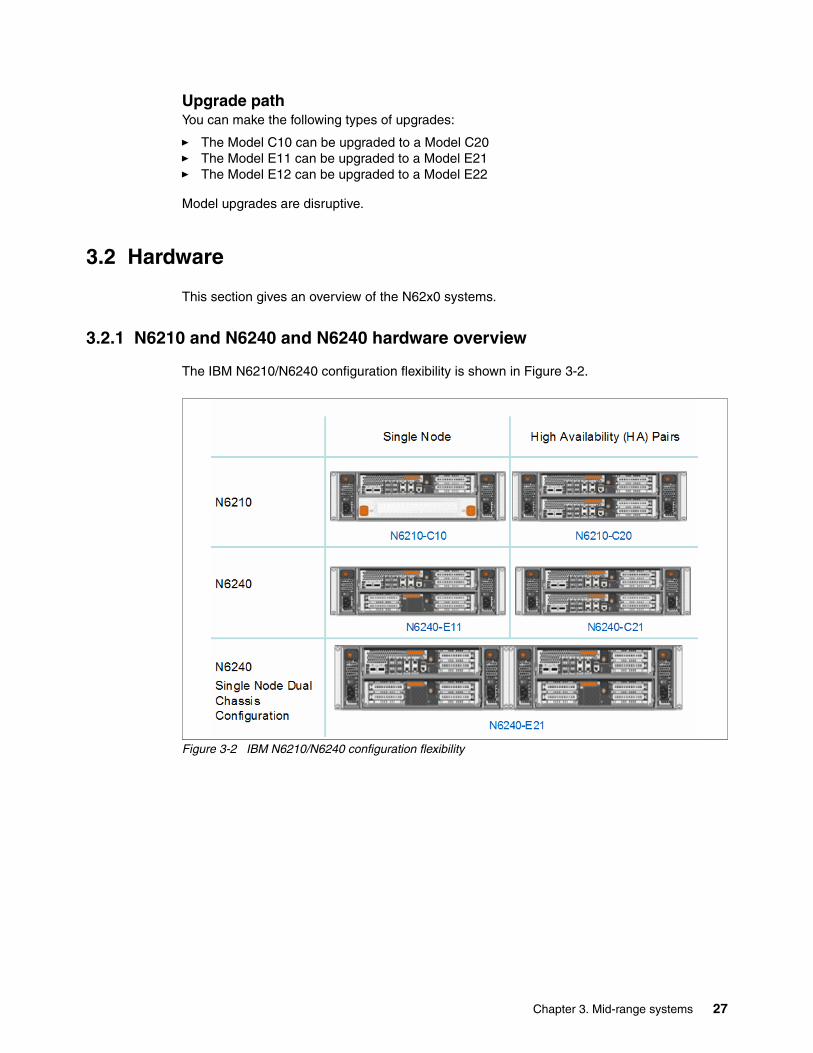
Upgrade pathYou can make the following types of upgrades:
� The Model C10 can be upgraded to a Model C20� The Model E11 can be upgraded to a Model E21� The Model E12 can be upgraded to a Model E22
Model upgrades are disruptive.
3.2 Hardware
This section gives an overview of the N62x0 systems.
3.2.1 N6210 and N6240 and N6240 hardware overview
The IBM N6210/N6240 configuration flexibility is shown in Figure 3-2.
Figure 3-2 IBM N6210/N6240 configuration flexibility
Chapter 3. Mid-range systems 27

Figure 3-3 shows the IBM N6270 configuration flexibility.
Figure 3-3 IBM N6270 configuration flexibility
Figure 3-4 shows the IBM N62x0 slots and interfaces for a Standalone Controller:
� 2 PCIe v2.0 (Gen 2) x 8 slots– Top full height, full length– Bottom full height, ¾ length
� 2 x 6 Gb SAS (0a, 0b)� 2 x HA interconnect (c0a, c0b)� 2 x 4 Gb FCP (0c, 0d)� 2 x GbE (e0a, e0b)� USB port (not currently used)� Management (wrench)
– SP and e0M � Private management
– ACP (wrench w/lock)� Serial console port� I/O expansion module
– 4 x PCIe 8x– Full length, full height slots
Figure 3-4 N62x0 slots and interfaces Standalone Controller
28 IBM System Storage N series Hardware Guide

Figure 3-5 shows the IBM N62x0 Controller I/O module.
Figure 3-5 IBM N62x0 Controller I/O
IBM N62x0 I/O configuration flexibility is shown in Figure 3-6.
Figure 3-6 IBM N62x0 I/O configuration flexibility
Chapter 3. Mid-range systems 29

IBM N62x0 I/O Expansion Module (IOXM) is displayed in Figure 3-7. It has these characteristics:
� Components are not hot swappable:
– Controller will panic if removed
– If inserted into running IBM N6200, IOXM is not recognized until the controller is rebooted
� 4 full-length PCIe v1.0 (Gen 1) x 8 slots
Figure 3-7 IBM N62x0 I/O Expansion Module (IOXM)
Figure 3-8 displays the IBM N62x0 system board layout.
Figure 3-8 IBM N62x0 system board layout
30 IBM System Storage N series Hardware Guide

Figure 3-9 shows the IBM N62x0 USB Flash Module, which has the following features.
� It is the boot device for Data ONTAP and the environment variables� It replaces CompactFlash� It has the same resiliency levels as CompactFlash� 2 GB density is currently used� It is a replaceable FRU
Figure 3-9 IBM N62x0 USB Flash Module
3.2.2 IBM N62x0 MetroCluster / gateway models
This section gives a brief description of the MetroCluster feature. For more information, see Chapter 8, “MetroCluster” on page 101.
Supported MetroCluster N62x0 configurationThe following MetroCluster two-chassis configurations are supported:
� Each chassis single-enclosure stand alone
• IBM N6210 controller with blank. The N6210-C20 with MetroCluster does ship the second chassis, but does not include the VI card any more.
• IBM N6240 controller with IOXM
� Two chassis with single-enclosure HA (twin)
• Supported on IBM N6240 model
� Fabric MetroCluster requires EXN4000 disk shelves or SAS shelves with SAS FibreBridge (EXN3000 and EXN3500)
Gateway Models are supported on both models, but have these requirements:
� A 4 port/4 Gb FC adapter required for IBM Gateway N6240 array attach
� N6210 Gateway is limited to one LUN group from a single array
FCVI card and port clarificationsIn many stretch MetroCluster configurations, the cluster interconnect on the NVRAM cards in each controller is used to provide the path for cluster interconnect traffic. The N60xx and N62xx series offer a new architecture that incorporates a dual-controller design with the cluster interconnect on the backplane.
The N62x0 ports c0a and c0b are the ports you need to connect to establish controller communication. Use them to enable NVRAM mirroring after you set up a dual-chassis HA configuration (that is, N62xx with IOXM). Those ports are not capable of running standard Ethernet or the Cluster-Mode cluster network.
Chapter 3. Mid-range systems 31

“Stretching” the HA-pair (also called the SFO pair) by using the c0x ports is qualified with optical SFPs up to a distance of 30 m. Beyond that distance, you need the FC-VI adapter. When the FC-VI card is present, the c0x ports are disabled.
3.2.3 IBM N62x0 series technical specifications
This section provides more details for the N62x0 systems.
IBM N62x0 series cooling architecture has these characteristics:
� Three fan FRUs per chassis
– Each FRU contains two air movers for a total of six fans
� Same fan FRUs cool both controllers
� Fans speed regulated by service processor
– Processors can force higher fan speed to provide adequate cooling if SP is offline
� Fail-safe architecture
– Separate paths from controller to each fan FRU
� Fan FRU contains EEPROM with fan FRU information
� Both controllers try to set fan speeds
– Final fan speed is the maximum speed requested by either controller
� One failed fan allowed per chassis
– Controller runs indefinitely with single failed fan
– 2-minute shutdown rule applies if the fan FRU is removed
• Data ONTAP initiates the shutdown
� Power supplies (PSUs) cool themselves
– Do not contribute to controller cooling
– System runs indefinitely on one PSU
– No 2-minute shutdown rule for removed PSU
New service processor (SP) enhances manageability and RASM details:
� SP available through Ethernet or serial console
– Shares management wrench port with e0M for Ethernet
• Similar to RLM and e0M on IBM N60x0
– Toggle from serial console into SP with CTRL-G
– Toggle back to serial console with CTRL-D
– Actively manages some hardware
– Fans
– FRU tracking
– Advanced sensor management
� SP is used to create cores, and no NMI button is present
Tip: Always use an FCVI card in any N62xx MetroCluster, regardless if it is a stretched or fabric-attached MetroCluster
32 IBM System Storage N series Hardware Guide

The system-level diagnostics SLDIAG has these features:
� SLDIAG replaces SYSDIAG
– Both run system-level diagnostic procedures
� SLDIAG has these major differences from SYSDIAG:
– SLDIAG runs from maintenance mode
– SYSDIAG booted with a separate binary
� SLDIAG has a CLI interface
� SYSDIAG used menu tables
SLDIAG is used on the IBM N6210 and N6240, and all new platforms going forward.
3.3 N62x0 technical specifications at a glance
Table 3-1 provides the N62x0 specifications at a glance.
Table 3-1 Summary of the specifications for the N62X0 family.
N6210 N6210 N6240 N6240 N6240
System model 2858-C10 2857-C20 2857-C21 2857-E11 2859-AE21
Height 3U 3U 3U 3U 6U
Weight 67.3 lbs(30.5 kg)
79.5 lbs(36.1 kg)
l74.5 lbs(33.8 kg)
74.5 lbs(33.8 kg)
149 lbs(67.6 kg)
AC Powera 3.0A @100V 1.6A @200V
4.6A @100V 2.3A@200V
3.7A@100V 1.9A@200V
3.7A@100V 1.9A@200V
7.4A @100V 3.9A @200V
BTU/hrb 919 @100V 895 @200V
1215 @100V 1157 @200V
1646 @100V 1598 @200V
1861 @100V 1813 @200V
1319 @100V 1288 @200V
Controller configuration
Single DualActive/Active
DualActive/Active
Singlewith IOXM
DualActive/Activewith IOXM
Processor 1x 64-bit dual-core
2x 64-bit dual-core
2x 64-bit quad-core HT
1x 64-bit quad-core
2x 32-bit quad-core
Memory 4 GB 8 GB 16 GB 8 GB 16 GB
NVRAM 512 MBNVMEM
1 GBNVMEM
2 GBNVMEM
1 GBNVMEM
2 GBNVMEM
Fibre Channel ports Two 4 Gb SFP
Four 4 Gb SFP
Four 4 Gb SFP
Two 4 Gb SFP
Four 4 Gb SFP
Exp Slots 2 PCIe 4 PCIe 4 PCIe 2 PCIe 4 PCIe
Ethernet ports 2 GbE RJ45 4 GbE RJ45 4 GbE RJ45 2 GbE RJ45 4 GbE RJ45
SAS Ports 2x6 Gb QSFP
4x6 Gb QSFP
4x6 Gb QSFP
2x6 Gb QSFP
4x6 Gb QSFP
Max Capacity TBc
(7.3.x / 8.0.x / 8.1.x)240/720d/720e 600/1800f/1800g
Chapter 3. Mid-range systems 33

For more information about N series 6000 systems, see the following website:
http://www.ibm.com/systems/storage/network/n6000/appliance/index.html
Number of disk drives
240 600
Max ShelvesEXN3500 / EXN3000 / EXN4000
10/10/17 25/25/42
Max Aggregateh
(7.3.x / 8.0.x / 8.1.x)16 TB/50 TB/75 TB 16 TB/50 TB/90 TB
Max FlexVol Size(7.3.x / 8.0.x / 8.1.x)
16 TB/50 TB/50 TB 16 TB/50 TB/60 TB
Data ONTAP(minimum release)
7.3.5, 8.0.1, 8.1
a. AC Power values shown are based on typical system values with two power supply units.b. Thermal dissipation values shown are based on typical system values.c. System capacity is calculated using base 10 arithmetic (1TB=1,000,000,000,000 bytes), and is
derived based on the type, size, and number of drivesd. Max capacity shown can be achieved only by using 3 TB drives under Data ONTAP 8.0.2 or latere. Max capacity shown can be achieved only by using 3 TB drives under Data ONTAP 8.0.2 or laterf. Max capacity shown can be achieved only by using 3 TB drives under Data ONTAP 8.0.2 or laterg. Max capacity shown can be achieved only by using 3 TB drives under Data ONTAP 8.0.2 or laterh. Maximum aggregate size is calculated using base 2 arithmetic (1TB = 240 bytes).
N6210 N6210 N6240 N6240 N6240
34 IBM System Storage N series Hardware Guide

Chapter 4. High-end systems
This chapter describes the IBM System Storage N series 7000 systems, which address the high-end segment.
This chapter includes the following sections:
� Overview� Hardware� N7950T technical specifications at a glance
4
© Copyright IBM Corp. 2012. All rights reserved. 35

4.1 Overview
Figure 4-1 shows the N7950T Model E22 modular disk storage system. It is designed to provide these advantages:
� High data availability and system-level redundancy
� Support of concurrent block I/O and file serving over Ethernet and Fibre Channel SAN infrastructures
� High throughput and fast response times
� Support of enterprise customers who require network-attached storage (NAS), with Fibre Channel or iSCSI connectivity
� Attachment of Fibre Channel, serial-attached SCSI (SAS), and Serial Advanced Technology Attachment (SATA) disk expansion units
Figure 4-1 N7950T Model E22 modular disk storage system
The IBM System Storage N7950T (2867 Model E22) system is an active/active dual-node base unit. It consists of two cable-coupled chassis with one controller and one I/O expansion module per node. It is designed to provide fast data access, simultaneous multiprotocol support, expandability, upgradability, and low maintenance requirements.
The N7950T can be configured as a gateway and is designed to provide these advantages:
� High data availability and system-level redundancy designed to address the needs of business-critical and mission-critical applications.
� Single, integrated architecture designed to support concurrent block I/O and file serving over Ethernet and Fibre Channel SAN infrastructures.
� High throughput and fast response times for database, email, and technical applications
� Enterprise customer support for unified access requirements for NAS through Fibre Channel or iSCSI.
� Fibre Channel, SAS, and SATA attachment options for disk expansion units designed to allow deployment in multiple environments. These environments include data retention, NearStore, disk-to-disk backup scenarios, and high-performance, mission-critical I/O intensive operations.
The N7950T supports the EXN1000 SATA storage expansion unit, the EXN4000 FC storage expansion units, the EXN3000 SAS/SATA expansion unit, and the EXN3500 SAS expansion unit. At least one storage expansion unit must be attached to the N series system.
The IBM System Storage N series is designed to interoperate with products capable of data transmission in the industry-standard iSCSI, CIFS, FCP, FCoE, and NFS protocols. Supported systems include the IBM System p®, IBM System i® (NFS only), IBM System x, and IBM System z® (NFS only) servers. The N7950T system consists of Model E22 and associated software.
36 IBM System Storage N series Hardware Guide

The N7950T can be configured, by using optional features, to be either a storage controller or gateway. It includes clustered failover (CFO) support (by using the required feature), which provides a failover and failback function to improve overall availability.
N series systems must be mounted in a standard 19-inch rack.
The N7950T includes the following hardware:
� Up to 14320 TB raw storage capacity
� 192 GB random access memory (192 GB of physical memory: Actual memory allocated depends on the Data ONTAP release in use)
� 8 GB nonvolatile memory
� Integrated Fibre Channel, Ethernet, and SAS ports
� Supports Flash Cache 2 Modules maximum of 16 TB
� Diagnostic LED/LCD
� Dual redundant hot-plug integrated cooling fans and auto ranging power supplies
� 19 inch, rack-mountable
4.2 Hardware
This section provides an overview of the N7950T E22 hardware.
4.2.1 Base components
Figure 4-2 shows the IBM N series N7950T base components.
Figure 4-2 IBM N series N7950T base components
Chapter 4. High-end systems 37

Figure 4-3 shows the IBM N series N7950T configuration.
Figure 4-3 IBM N series N7950T configuration
Table 4-1 provides a list of features for the N7950T.
Table 4-1 N7950 Series features
Figure 4-4 shows the IBM N series N7950T Slots and Interfaces Controller Module.
Figure 4-4 IBM N series N7950T Slots and Interfaces Controller Module
The N7950T includes the following features:
� 2 onboard I/O slots (vertical)
– NVRAM8 always goes into slot 2
– Special 8 Gb FC or 6 Gb SAS system board must be in slot 1
– Fibre Channel system board ports can be target or initiator
Ports
FC Target 48
10 GbE 40
GbE 52a
a. Depends on the DOT release
6 Gb SAS 72
FC Initiator 128
Flash Cache maximum 16 GB
38 IBM System Storage N series Hardware Guide

� 4 PCIe v2.0 (Gen 2) x8 slots (horizontal)
– Full length and full height for regular expansion adapters
� 4 x 10 GbE (e0c, e0d, e0e, e0f)
– SFP+ module not interchangeable with other 10 GbE ports
� 4 x 8 Gb FCP (0a, 0b, 0c, 0d)
Figure 4-5 shows the IBM N series N7950T Controller I/O.
Figure 4-5 IBM N series N7950T Controller I/O
Figure 4-6 shows the IBM N series N7950T I/O Expansion Module (IOXM).
Figure 4-6 IBM N series N7950T I/O Expansion Module (IOXM)
The N7950T IOXM has these characteristics:
� All PCIe v2.0 (Gen 2) slots
– Vertical slots have different form factor
� Not hot-swappable:
– Controller will panic if removed
– Hot pluggable, but not recognized until reboot
Chapter 4. High-end systems 39

4.2.2 IBM N series N7950T slot configuration rules
The following configuration rules apply to the N7950.
Vertical I/O slots� Vertical slots use custom form-factor cards
– Look similar to standard PCIe
– Cannot put standard PCIe cards into the vertical I/O slots
� Vertical slot rules
– Slot 1 must have a special Fibre Channel or SAS system board: Feature Code 1079 (Fibre Channel) and Feature Code 1080 (SAS)
– Slot 2 must have NVRAM8
– Slots 11 and 12:
• Can configure with a special FC I/O or SAS I/O card: Feature Code 1079 (FC) and Feature Code 1080 (SAS)
• Can mix FC and SAS system boards in slots 11 and 12
– FC card ports can be set to target or initiator
Horizontal PCIe slots� Support standard PCIe adapters and cards:
– 10 GbE NIC (new quad port 1 GbE PCIe adapter for N7950T FC1028)
– 10 GbE unified target adapter
– 8 Gb Fibre Channel
– Flash Cache
� Storage HBAs:
– Special-purpose FC I/O and SAS I/O cards, and NVRAM8, are NOT used in PCIe slots
4.2.3 N7950T hot-pluggable FRUs
The following items are hot-pluggable:
� Fans
– Two-minute shutdown rule if you remove a fan FRU
� Controllers
– Do not turn off PSUs to remove a controller in dual- controller systems
� PSUs
– One PSU can run the entire system
– There is no two-minute shutdown rule if one PSU removed
� IOXMs are not hot pluggable
– Removing the IOXM forces a system reboot
– System will not recognize a hot-plugged IOXM
40 IBM System Storage N series Hardware Guide

4.2.4 N7950T cooling architecture
The following are details about the N7950T cooling architecture:
� Six fan FRUs per chassis, paired three each for top and bottom bays
– Each fan FRU has two fans
� One failed fan allowed per chassis bay
– Controller can run indefinitely with single failed fan
– Two failed fans in controller bay cause a shutdown
– Two-minute shutdown rule applies if a fan FRU is removed
• Rule enforced on a per-controller basis
4.2.5 System-level diagnostic procedures
The following system-level tools are present in N7950T systems:
� SLDIAG replaces SYSDIAG
– Both run system-level diagnostic procedures
� SLDIAG has these major differences from SYSDIAG:
– SLDIAG runs from maintenance mode
• SYSDIAG booted with a separate binary
– SLDIAG has a CLI interface
• SYSDIAG used menu tables
� SLDIAG used on IBM N series N6200 series and all new platforms going forward
4.2.6 N7950T supported back-end storage
The following back-end storage is supported:
� Shelves and modules
– EXN3500: 2U 24 drive SFF SAS
– EXN3000: 4U 24 drive SAS / SATA
– EXN4000: 4U 14 drive Fibre Channel
– EXN1000: 4U 14 drive SATA
� Any HDDs supported in listed shelves
� New 100 GB SSDs supported in the EXN3000 shelves
4.2.7 MetroCluster, Gateway, and FlexCache
MetroCluster and Gateway configurations have these characteristics:
� Supported MetroCluster two-chassis configuration
� Single-enclosure stand-alone chassis: IBM N series N7950T-E22 controller with IOXM
� Fabric MetroCluster requires EXN4000 shelves
� The N7950T series also functions as a Gateway
Chapter 4. High-end systems 41

� FlexCache uses N7950T chassis
– Controller with IOXM
– Supports dual-enclosure HA configuration
4.2.8 N7950T guidelines
The following list provides useful tips for the N7950T model:
� Get hands-on experience with Data ONTAP 8.1
� Do not attempt to put vertical slot I/O system boards in horizontal expansion slots
� Do not attempt to put expansion cards in vertical I/O slots
� Onboard 10 GbE ports require feature code for SFP+
– Not compatible with other SFP+ for the 2-port 10 GbE NIC (FC 1078)
� Onboard 8 Gb SFP not interchangeable with other SFPs
– 8 Gb SFP+ autoranges 8/4/2 Gbps, does not support 1 Gb/sec
� Pay attention when 6 Gb SAS system board in I/O slot 1
� NVRAM8 and SAS both use QSFP connection
Figure 4-7 explain the use of the SAS Card in I/O Slot 1.
Figure 4-7 Using SAS Card in I/O Slot 1
� NVRAM8 and SAS I/O system boards use the QSFP connector
– Mixing the cables does not cause physical damage, but the cables will not work
– Label your HA and SAS cables when you remove them
42 IBM System Storage N series Hardware Guide

4.2.9 N7950T SFP+ modules
This section provides detailed information about SFP+ modules.
Figure 4-8 shows the 8 Gb SFP+ modules.
Figure 4-8 8 Gb SFP+ modules
Figure 4-9 shows the 10 GbE SFP+ modules.
Figure 4-9 10 GbE SFP+ modules
4.3 N7950T technical specifications at a glance
Table 4-2 provides the N7950T technical specifications.
Table 4-2 Summary of the specifications for the N7950T.
N7950T
System model 2867-E22
Height 12U
Chapter 4. High-end systems 43

Weight 251.4 lbs (114 kg)
AC Powera 13.8A @100V7A @200V
BTU/hrb 4540 @100V4404 @200V
Controller configuration Dual Active/Active with IOXM
Processor 4x 64-bit six core
Memory 192 GB
NVRAM 8 GB
Fibre Channel ports 8 - 328 Gb SFP+c
Exp Slots 24 PCIe
Ethernet ports 4x GbE RJ458x 10 GbE SFP+
SAS ports 0 - 246 Gb QSFPd
Max Capacity TBe
(7.3.x / 8.0.x / 8.1.x)-/4320f/4320g
Number of disk drives 1440
Max ShelvesEXN3500 / EXN3000 / EXN4000
60/60/84
Max Aggregateh
(7.3.x / 8.0.x / 8.1.x)-/100TB/162TB
Max FlexVol Size(7.3.x / 8.0.x / 8.1.x)
-/100TB/100TB
Data ONTAP(minimum release)
8.0.1, 8.1
a. AC Power values shown are based on typical system values with two power supply units.
b. Thermal dissipation values shown are based on typical system values.
c. N7950T embedded Fibre Channel ports and Fibre Channel ports on the vertical FC system boards are considered on-board ports. They can be set as target or initiators and support operation at 2, 4, or 8 Gb speeds. Operation at 1 Gb speeds is not supported.
d. The number of onboard SAS ports differs based on the configuration.
e. System capacity is calculated using base 10 arithmetic (1TB=1,000,000,000,000 bytes) and is derived based on the type, size, and number of drives.
f. Max capacity shown can be achieved only by using 3 TB drives under Data ONTAP 8.0.2 or greater.
g. Max capacity shown can be achieved only by using 3 TB drives under Data ONTAP 8.0.2 or greater.
N7950T
44 IBM System Storage N series Hardware Guide

For more information about N series 7000 systems, see the following website:
http://www.ibm.com/systems/storage/network/n7000/appliance/index.html
h. Maximum aggregate size is calculated using base 2 arithmetic (1TB = 240 bytes).
Chapter 4. High-end systems 45

46 IBM System Storage N series Hardware Guide

Chapter 5. Expansion units
This chapter provides detailed information for the IBM N series expansion units, also called disk shelves.
This chapter includes the following sections:
� Shelf technology overview� Expansion unit EXN3000� Expansion unit EXN3500� Expansion unit EXN4000� Self-Encrypting Drive
5
© Copyright IBM Corp. 2012. All rights reserved. 47
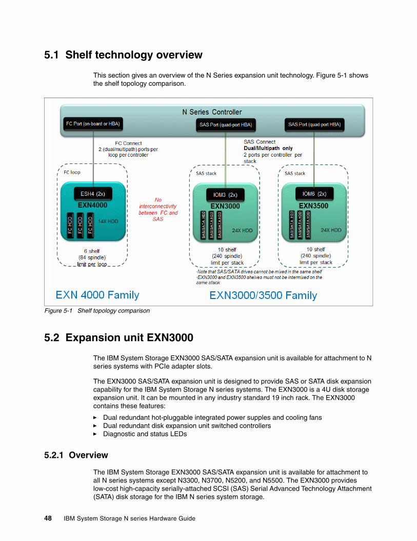
5.1 Shelf technology overview
This section gives an overview of the N Series expansion unit technology. Figure 5-1 shows the shelf topology comparison.
Figure 5-1 Shelf topology comparison
5.2 Expansion unit EXN3000
The IBM System Storage EXN3000 SAS/SATA expansion unit is available for attachment to N series systems with PCIe adapter slots.
The EXN3000 SAS/SATA expansion unit is designed to provide SAS or SATA disk expansion capability for the IBM System Storage N series systems. The EXN3000 is a 4U disk storage expansion unit. It can be mounted in any industry standard 19 inch rack. The EXN3000 contains these features:
� Dual redundant hot-pluggable integrated power supples and cooling fans� Dual redundant disk expansion unit switched controllers� Diagnostic and status LEDs
5.2.1 Overview
The IBM System Storage EXN3000 SAS/SATA expansion unit is available for attachment to all N series systems except N3300, N3700, N5200, and N5500. The EXN3000 provides low-cost high-capacity serially-attached SCSI (SAS) Serial Advanced Technology Attachment (SATA) disk storage for the IBM N series system storage.
48 IBM System Storage N series Hardware Guide

The EXN3000 is a 4U disk storage expansion unit. It can be mounted in any industry standard 19 inch rack. The EXN3000 contains these features:
� Dual redundant hot-pluggable integrated power supplies and cooling fans� Dual redundant disk expansion unit switched controllers� 24 hard disk drive slots
The EXN3000 SAS/SATA expansion unit is shown in Figure 5-2.
Figure 5-2 EXN3000 SAS/SATA
The EXN3000 SAS/SATA expansion unit is shipped with no disk drives unless disk drives are included in the order. In that case, the disk drives are installed in the plant.
The EXN3000 SAS/SATA expansion unit can be shipped with no disk drives installed. Disk drives ordered with the EXN3000 are installed by IBM in the plant before shipping.
Figure 5-3 shows the rear view and the fans.
Figure 5-3 Rear view and the fans.
Requirement: For an initial order of an N series system, at least one of the storage expansion units must be ordered with at least five disk drive features.
Chapter 5. Expansion units 49

5.2.2 Supported EXN3000 drives
Table 5-1 lists the drives that are supported by EXN3000 at the time of writing.
Table 5-1 EXN3000 supported drives
5.2.3 Environmental and technical specification
Table 5-2 shows the environmental and technical specifications.
Table 5-2 EXN3000 environmental specifications
5.3 Expansion unit EXN3500
The EXN3500 is a small form factor (SFF) 2U disk storage expansion unit for mounting in any industry standard 19-inch rack. The EXN3500 provides low-cost, high-capacity SAS disk storage with slots for 24 hard disk drives for the IBM N series system storage family.
The EXN3500 SAS expansion unit is shipped with no disk drives unless they are included in the order. In that case, the disk drives are installed in the plant.
EXN3000 Minimum Data ONTAP RPM Capacity
SAS 7.3.2, 8.0, 8.1 15K 300 GB
7.3.2, 8.0, 8.1 15K 450 GB
7.3.2, 8.0, 8.1 15K 600 GB
8.1 15K 600 GB encrypted
SATA 7.3.2, 8.0, 8.1 7.2K 500 GB
7.3.2, 8.0, 8.1 7.2K 1 TB
7.3.2, 8.0, 8.1 7.2K 2 TB
8.0.2, 8.1 7.2K 3 TB
SSD 8.01 N/A 100 GB
EXN3000
Disk 24
Rack size 4U
Weight Empty: 21.1 lb. (9.6 kg)Without drives: 53.7 lb. (24.4 kg)With drives: 110 lb. (49.9 kg)
Power SAS: 300 GB 6.0A, 450 GB 6.3A, 600 GB 5.7ASATA: 1 TB 4.4A, 2 TB 4.6A, 3 TB 4.6ASSD: 100 GB 1.6A
Thermal (BTU/hr) SAS: 300 GB 2048, 450 GB 2150, 600 GB 1833SATA: 1 TB 1495, 2 TB 1561, 3 TB 1555 SSD: 100 GB 557
50 IBM System Storage N series Hardware Guide

The EXN3500 SAS expansion unit is a 2U SFF disk storage expansion unit that must be mounted in an industry standard 19-inch rack. It can be attached to all N series systems except N3300, N3700, N5200, and N5500. It includes the following features:
� Third-generation SAS product
� Increased density
� 24x2.5” 10k RPM drives in 2 rack U at same capacity points (450 GB, 600 GB) offers double the GB/rack U of the EXN3000
� Increased IOPs/rack U
� Greater bandwidth
� 6 Gb SAS 2.0 offers ~24 Gb (6 Gb x4) combined bandwidth per wide port
� Improved power consumption: Power consumption per GB reduced by approximately 30-50%*
� Only SAS drives are supported in the EXN3500: SATA is not supported
What has not changed:
� Same underlying architecture and FW base as EXN3000
� All existing EXN3000 features/functionality
� Still use the 3 Gb PCIe Quad-Port SAS HBA (already 6 Gb capable) or onboard SAS ports
5.3.1 Overview
The EXN3500 includes the following hardware:
� Dual, redundant, hot-pluggable, integrated power supplies and cooling fans� Dual, redundant, disk expansion unit switched controllers� 24 SFF hard disk drive slots� Diagnostic and status LEDs
Figure 5-4 shows the EXN3500 front view.
Figure 5-4 EXN3500 front view
The EXN3500 SAS expansion unit can be shipped with no disk drives installed. Disk drives ordered with the EXN3500 are installed by IBM in the plant before shipping. Disk drives can be of 450 GB and 600 GB physical capacity, and must be ordered as features of the EXN3500.
Requirement: For an initial order of an N series system, at least one of the storage expansion units must be ordered with at least five disk drive features.
Chapter 5. Expansion units 51

Figure 5-5 shows the rear view of the EXN3500 showing the connectivity and resiliency.
Figure 5-5 EXN3500 rear view
Figure 5-6 shows the IOM differences.
Figure 5-6 IOM differences
5.3.2 Intermix support
The following list shows how EXN3000 and EXN3500 can be combined:
� Intermix of EXN3000 and EXN3500 shelves: EXN3000 and EXN3500 shelves cannot be intermixed on the same stack
� EXN3000 supports only IOM3 modules: Using IOM6 modules in an EXN3000 is not supported
� EXN3500 supports only IOM6 modules: Using IOM3 modules in an EXN3500 is not supported
52 IBM System Storage N series Hardware Guide

5.3.3 Supported EXN3500 drives
Table 5-3 lists the drives that are supported by EXN3500 at the time of writing.
Table 5-3 EXN3500 supported drives
5.3.4 Environmental and technical specification
Table 5-4 shows the environmental and technical specifications.
Table 5-4 EXN3500 environmental specifications
5.4 Expansion unit EXN4000
EXN4000 shelves use ESH4 as the controller module. ESH4 is the third-generation, multiloop speed ESH module. ESH4 can function at 1 Gb, 2 Gb, or 4 Gb loop speed when it works with EXN4000. The ESH4 has LEDs that indicate these conditions:
� Whether the module is functioning normally � Whether there are any problems with the hardware� The loop speed operation of the EXN4000
The EXN4000 has these main advantages:
� Higher bandwidth for heavy sequential workload� Fewer HBAs or slots used to achieve higher bandwidth needs
The EXN4000 FC storage expansion unit runs at 2 Gbps FC when attached to systems that do not have 4 Gbps capability. ENX4000 can also be added to loops with existing EXN2000 loops.
EXN3500 Minimum Data ONTAP RPM Capacity
SAS 7.3.4, 8.0.1, 8.1 10K 450 GB
7.3.4, 8.0.1, 8.1 10K 600 GB
7.3.4, 8.0.1, 8.1 15K 600 GB encrypted
EXN3500
Disk 24
Rack size 2U
Weight Empty: 17.4 lb. (7.9 kg)Without Drives: 34.6 lb. (15.7 kg)With Drives: 49lb. (22.2 kg)
Power SAS: 450 GB 3.05A, 600 GB 3.59A
Thermal (BTU/hr) SAS: 450 GB 1024, 600 GB 1202
Chapter 5. Expansion units 53

Figure 5-7 shows the front view of the EXN4000 expansion unit.
Figure 5-7 EXN4000 expansion unit
Figure 5-8 shows the rear view and the fans.
Figure 5-8 2xESH4 and 2xPSU/fans
Figure 5-9 shows the location of the LEDs
Figure 5-9 Location of LEDs for an ESH4
EXN4000 is the replacement for the EXN2000 Fibre Channel storage expansion unit.
5.4.1 Supported EXN4000 drives
Table 5-5 lists the drives that are supported by EXN4000 at the time of writing.
Table 5-5 EXN3000 supported drives
EXN3000 Minimum Data ONTAP RPM Capacity
Fibre Channel
7.2.5, 7.3, 8.0 15K 300 GB
7.2.5, 7.3, 8.0 15K 450 GB
7.3.2, 8.0 15K 600 GB
54 IBM System Storage N series Hardware Guide

5.4.2 Environmental and technical specification
Table 5-6 shows the environmental and technical specifications.
Table 5-6 EXN4000 environmental specifications
5.5 Self-Encrypting Drive
This section addresses the FDE 600 GB 2.5 HDD drive.
5.5.1 SED at a glance
At the time of writing, only the FDE 600 GB drive was supported:
� Self-Encrypting Drive (SED)
– 600 GB capacity
– 2.5” form factor, 10k rpm, 6 GB SAS
– Encryption enabled through disk drive firmware (same drive as currently shipping with different firmware)
� Available in EXN3500 and EXN3000 expansion shelf and N3220 (internal drives) controller: Only fully populated (24 drives) and N3220 controller
� Requires DOT 8.1 minimum
� Only allowed with HA (dual node) systems
� Provides storage encryption capability (key manager interface)
5.5.2 SED overview
Storage Encryption is the implementation of full disk encryption (FDE) by using self-encrypting drives from third-party vendors such as Seagate and Hitachi. FDE refers to encryption of all blocks in a disk drive, whether by software or hardware. NSE is encryption that operates seamlessly with Data ONTAP features such as storage efficiency. This is possible because the encryption occurs below Data ONTAP as the data is being written to the physical disk.
5.5.3 Threats mitigated by self-encryption
Self-encryption mitigates several threats. The primary threat model it addresses, per the Trusted Computing Group (TCG) specification, is the prevention of unauthorized access to
EXN4000
Disk 14
Rack size 3U
Weight Empty: 50.06 lb. (23 kg)Without Drives: 68 lb. (30.8 kg)With Drives: 77lb. (35 kg)
Power FC: 300 GB 3.29A, 450 GB 3.59A, 600 GB 3.44A
Thermal (BTU/hr) FC: 300 GB 1119, 450 GB 1119, 600 GB 1094
Chapter 5. Expansion units 55

encrypted data at rest on powered-off disk drives. That is, it prevents someone from removing a shelf or drive and mounting them on an unauthorized system. This security minimizes risk of unauthorized access to data if drives are stolen from a facility or compromised during physical movement of the storage array between facilities.
Additionally, Self-encryption prevents unauthorized data access when drives are returned as spares or after drive failure. This security includes cryptographic shredding of data for non-returnable disk (NRD), disk repurposing scenarios, and simplified disposal of the drive through disk destroy commands. These processes render a disk completely unusable. This greatly simplifies the disposal of drives and eliminates the need for costly, time-consuming physical drive shredding.
Remember that all data on the drives is automatically encrypted. If you do not want to track where the most sensitive data is or risk it being outside an encrypted volume, use NSE to ensure that all data is encrypted.
5.5.4 Effect of self-encryption on Data ONTAP features
Self-encryption operates below all Data ONTAP features such as SnapDrive, SnapMirror, and even compression and deduplication. Interoperability with these features should be transparent. SnapVault and SnapMirror are both supported, but in order for data at the destination to be encrypted, the target must be another self-encrypted system.
The use of SnapLock prevents the inclusion of self-encryption. Therefore, simultaneous operation of SnapLock and self-encryption is not possible. This limitation is being evaluated for a future release of Data ONTAP. MetroCluster is not currently supported because of the lack of support for the SAS interface. Support for MetroCluster is currently targeted for a future release of Data ONTAP.
5.5.5 Mixing drive types
In Data ONTAP 8.1, all drives installed within the storage platform must be self-encrypting drives. The mixing of encrypted with unencrypted drives or shelves across a stand-alone platform or high availability (HA) pair is not supported.
5.5.6 managementKey management
This section provides more detailed information about key management.
Overview of KMIPKey Management Interoperability Protocol (KMIP) is an encryption key interoperability standard created by a consortium of security and storage vendors (OASIS). Version 1.0 was ratified in September 2010, and participating vendors have later released compatible products. KMIP seems to have replaced IEEE P1619.3, which was an earlier proposed standard.
With KMIP-compatible tools, organizations can manage their encryption keys from a single point of control. This system improves security, simplifies complexity, and achieves regulation compliance more quickly and easily. It is a huge improvement over the current approach of using many different encryption key management tools for many different business purposes and IT assets.
56 IBM System Storage N series Hardware Guide

Communication with the KMIP serverSelf-encryption uses Secure Sockets Layer (SSL) certificates to establish secure communications with the KMIP server. These certificates need to be in Base64-encoded X.509 PEM format, and can be either self-signed or signed by a certificate authority (CA).
Supported key managersSelf-encryption with Data ONTAP 8.1 supports IBM Tivoli Key Lifecycle Management Version 2 server for key management. Others will follow. Other KMIP-compliant key managers are being evaluated as they come onto the market.
Self-encryption supports up to four key managers simultaneously for high availability of the authentication key. Figure 5-10 shows authentication key use in self-encryption. It demonstrates how the Authentication Key (AK) is used to wrap the Data Encryption Key (DEK) and is backed up to an external key management server.
Figure 5-10 Authentication key use
Tivoli Key Lifecycle ManagerObtaining that central point of control requires more than just an open standard. It also requires a dedicated management solution designed to capitalize on it. IBM Tivoli Key Lifecycle Manager version 2 gives you the power to manage keys centrally at every stage of their lifecycles.
Tivoli Key Lifecycle Manager does key serving transparently for encrypting devices and key management, making it simple to use. Furthermore, it is easy to install and configure. Because it demands no changes to applications and servers, it is a seamless fit for virtually any IT infrastructure.
For these reasons, IBM has led the IT industry in developing and promoting an exciting new security standard: Key Management Interoperability Protocol (KMIP). KMIP is an open standard designed to support the full lifecycle of key management tasks from key creation to key retirement.
Chapter 5. Expansion units 57

IBM Tivoli Key Lifecycle Manager V1.0 supports the following operating systems:
� AIX V5.3, 64-bit, Technology Level 5300-04, and Service Pack 5300-04-02, AIX 6.1 64 bit
� Red Hat Enterprise Linux AS Version 4.0 on x86, 32-bit
� SUSE Linux Enterprise Server Version 9 on x86, 32-bit, and V10 on x86, 32-bit
� Sun Server Solaris 10 (SPARC 64-bit)
� Microsoft Windows Server 2003 R2 (32-bit Intel)
� IBM z/OS® V1 Release 9, or later
For more information about Tivoli Key Lifecycle Manager, see this website:
http://www.ibm.com/software/tivoli/products/key-lifecycle-mgr/
Remember: In Sun Server Solaris, Tivoli Key Lifecycle Manager runs in a 32-bit JVM.
58 IBM System Storage N series Hardware Guide

Chapter 6. Cabling expansions
This chapter addresses the multipath cabling of expansions. The following topics are covered:
� Standard multipath cabling� Multipath HA cabling� Cabling different expansions
This chapter includes the following sections:
� EXN3000 and EXN3500 disk shelves cabling� EXN4000 disk shelves cabling� Multipath High-Availability cabling
6
© Copyright IBM Corp. 2012. All rights reserved. 59

6.1 EXN3000 and EXN3500 disk shelves cabling
This section provides information about cabling the disk shelf SAS connections and the optional ACP connections for a new storage system installation. Cabling the EXN3500 is much alike the EXN3000. As a result, the information provided is applicable for both.
At this time, the maximum distance between controller nodes that are connected to EXN3000 disk shelves is 5 meters. HA pairs with EXN3000 shelves are therefore either local, mirrored, or a stretch MetroCluster depending on the licenses installed for cluster failover.
The EXN3000 shelves are not supported for MetroClusters that span separate sites, nor are they supported for fabric-attached MetroClusters.
The example used throughout is an HA pair with two 4-port SAS-HBA controllers in each N series controller. The configuration includes two SAS stacks, each of which has three SAS shelves.
6.1.1 Controller-to-shelf connection rules
Each controller connects to each stack of disk shelves in the system through the controller SAS ports. These ports can be A, B, C, and D, and can be on a SAS HBA in a physical PCI slot [slot 1-N] or on the base controller.
For quad-port SAS HBAs, the controller-to-shelf connection rules ensure resiliency for the storage system based on the ASIC chip design. Ports A and B are on one ASIC chip, and ports C and D are on a second ASIC chip. Because ports A and C connect to the top shelf and ports B and D connect to the bottom shelf in each stack, the controllers maintain connectivity to the disk shelves if an ASIC chip fails.
Figure 6-1 shows a quad-port SAS HBA with the two ASIC chips and their designated ports.
Figure 6-1 Quad-port SAS HBA with two ASIC chips
Connecting the Quad-port SAS HBAs follows these rules for connecting to SAS shelves:
� HBA port A and port C always connect to the top storage expansion unit in a stack of storage expansion units.
� HBA port B and port D always connect to the bottom storage expansion unit in a stack of storage expansion units.
60 IBM System Storage N series Hardware Guide

Think of the four HBA ports as two units of ports. Port A and port C are the top connection unit, and port B and port D are the bottom connection unit (Figure 6-2). Each unit (A/C and B/D) connects to each of the two ASIC chips on the HBA. If one chip fails, the HBA maintains connectivity to the stack of storage expansion units.
Figure 6-2 Top and bottom cabling for quad-port SAS HBAs
SAS cabling is based on the rule that each controller is connected to the top storage expansion unit and the bottom storage expansion unit in a stack:
� Controller 1 always connects to the top storage expansion unit IOM A and the bottom storage expansion unit IOM B in a stack of storage expansion units
� Controller 2 always connects to the top storage expansion unit IOM B and the bottom storage expansion unit IOM A in a stack of storage expansion units
6.1.2 SAS shelf interconnects
SAS shelf interconnect follows these rules:
� All the disk shelves in a stack are daisy-chained when you have more than one disk shelf in a stack.
� IOM A circle port is connected to the next IOM A square port.
� IOM B circle port is connected to the next IOM B square port.
Chapter 6. Cabling expansions 61

Figure 6-3 shows how the SAS shelves are interconnected for two stacks with three shelves each.
Figure 6-3 SAS shelf interconnect
62 IBM System Storage N series Hardware Guide

6.1.3 Top connections
The top ports of the SAS shelves are connected to the HA pair controllers as shown in Figure 6-4.
Figure 6-4 SAS shelf cable top connections
Chapter 6. Cabling expansions 63

6.1.4 Bottom connections
The bottom ports of the SAS shelves are connected to the HA pair controllers as shown in Figure 6-5.
Figure 6-5 SAS shelf cable bottom connections
Figure 6-5 is a fully redundant example of SAS shelf connectivity. No single cable failure or shelf controller causes any interruption of service.
6.1.5 Verifying SAS connections
After you complete the SAS connections in your storage system using the applicable cabling procedure, verify the SAS connections. Complete the following procedure to verify that the storage expansion unit IOMs have connectivity to the controllers:
1. Enter the following command at the system console:
sasadmin expander_map
Tip: For Active/Active (high availability) configurations, run this command on both nodes.
64 IBM System Storage N series Hardware Guide

2. Review the output and perform the following steps:
– If the output lists all of the IOMs, then the IOMs have connectivity. Return to the cabling procedure for your storage configuration to complete the cabling steps.
– Sometimes IOMs are not shown because the IOM is cabled incorrectly. The incorrectly cabled IOM and all of the IOMs downstream from it are not displayed in the output. Return to the cabling procedure for your storage configuration, review the cabling to correct cabling errors, and verify SAS connectivity again.
6.1.6 Connecting the optional ACP cables
This section provides information about cabling the disk shelf ACP connections for a new storage system installation. This section provides information about cabling the optional disk shelf ACP connections for a new storage system installation. See Figure 6-6 for an example.
These ACP cabling rules apply to all supported storage systems that use SAS storage:
� You must use CAT6 Ethernet cables with RJ-45 connectors for ACP connections.
� If your storage system does not have a dedicated network interface for each controller, you must dedicate one for each controller at system setup. You can use a quad-port Ethernet card.
� All ACP connections to the disk shelf are cabled through the ACP ports, which are designated by a square symbol or a circle symbol.
Figure 6-6 SAS shelf cable ACP connections
Chapter 6. Cabling expansions 65

Enable ACP on the storage system by entering the following command at the console:
options acp.enabled on
Verify that the ACP cabling is correct by entering the following command:
storage show acp
For more information about cabling SAS stacks and ACP to an HA pair, see the IBM System Storage EXN3000 Storage Expansion Unit Hardware and Service Guide found at:
http://www.ibm.com/storage/support/nas
6.2 EXN4000 disk shelves cabling
This section describes the requirements for connecting an expansion unit to N series storage systems and other expansion units. For more information about installing and connecting expansion units in a rack, or connecting an expansion unit to your storage system, see the Installation and Setup Instructions for your storage system.
6.2.1 Non-multipath Fibre Channel cabling
Figure 6-7 shows EXN4000 disk shelves connected to a HA pair with non-multipath cabling. A single Fibre Channel cable or shelf controller failure might cause a takeover situation.
Figure 6-7 EXN4000 dual controller non-multipath
66 IBM System Storage N series Hardware Guide

6.2.2 Multipath Fibre Channel cabling
Figure 6-8 shows four EXN4000 disk shelves in two separate loops connected to a HA pair with redundant multipath cabling. No single Fibre Channel cable or shelf controller failure causes a takeover situation.
Figure 6-8 EXN4000 dual controller with multipath
Attention: Do not mix Fibre Channel and SATA expansion units in the same loop.
Tip: For N series controllers to communicate with an EXN4000 disk shelf, the Fibre Channel ports on the controller or gateway must be set for initiator. Changing behavior of the Fibre Channel ports on the N series system can be performed with the fcadmin command.
Chapter 6. Cabling expansions 67

6.3 Multipath High-Availability cabling
A standard N series clustered storage system has multiple single-points-of-failure on each shelf which can trigger a cluster failover (Example 6-1). Cluster failovers can disrupt access to data and put an increased workload on the surviving cluster node.
Example 6-1 Clustered system with a single connection to disks
N6270A> storage show disk –pPRIMARY PORT SECONDARY PORT SHELF BAY ------- ---- --------- ---- --------- 0a.16 A 1 00a.18 A 1 20a.19 A 1 30a.20 A 1 4
Multipath High-Availability (MPHA) cabling adds redundancy, reducing the number of conditions that can trigger a failover (Example 6-2).
Example 6-2 Clustered system with MPHA connections to disks
N6270A> storage show disk -pPRIMARY PORT SECONDARY PORT SHELF BAY------- ---- --------- ---- ---------0a.16 A 0c.16 B 1 00c.17 B 0a.17 A 1 10c.18 B 0a.18 A 1 20a.19 A 0c.19 B 1 3
With only a single connection to the A channel, a disk ‘loop’ is technically a daisy chain. When any component (fiber cable, shelf cable, shelf controller) in the loop fails, access is lost to all shelves after the break, triggering a cluster failover event.
MPHA cabling creates a true loop by providing a path into the A channel and out of the B channel. Multiple shelves can experience failures without losing communication to the controller. A cluster failover is only triggered when a single shelf experiences failures to both the A and B channels.
68 IBM System Storage N series Hardware Guide

Chapter 7. Highly Available controller pairs
IBM System Storage N series HA pair configuration consists of two nodes that are able to take over and fail over their resources or services to counterpart nodes. This function assumes that all resources can be accessed by each node. This chapter addresses aspects of determining HA pair status, and HA pair management.
In Data ONTAP 8.x, the recovery capability provided by a pair of nodes (storage systems) that is called an HA pair. This pair is configured to serve data for each other if one of the two nodes stops functioning. Previously with Data ONTAP 7G, this function was called an Active/Active configuration.
This chapter includes the following sections:
� HA pair overview� HA pair types and requirements� Configuring the HA pair� Managing an HA pair configuration
7
© Copyright IBM Corp. 2012. All rights reserved. 69

7.1 HA pair overviewAn HA pair is two storage systems (nodes) whose controllers are connected to each other directly. The nodes are connected to each other through an NVRAM adapter, or, in the case of systems with two controllers in a single chassis, through an internal interconnect. This allows one node to serve data on the disks of its failed partner node. Each node continually monitors its partner, mirroring the data for each other’s nonvolatile memory (NVRAM or NVMEM). Figure 7-1 illustrates a standard HA pair configuration.
Figure 7-1 Standard HA pair configuration
In a standard HA pair, Data ONTAP functions so that each node monitors the functioning of its partner through a heartbeat signal sent between the nodes. Data from the NVRAM of one node is mirrored to its partner. Each node can take over the partner's disks or array LUNs if the partner fails. Also, the nodes synchronize time.
7.1.1 Benefits of HA pairsConfiguring storage systems in an HA pair provides the following benefits:
� Fault tolerance: When one node fails or becomes impaired, a takeover occurs and the partner node serves the data of the failed node.
� Nondisruptive software upgrades: When you halt one node and allow takeover, the partner node continues to serve data for the halted node while you upgrade the node you halted.
70 IBM System Storage N series Hardware Guide

� Nondisruptive hardware maintenance: When you halt one node and allow takeover, the partner node continues to serve data for the halted node. You can then replace or repair hardware in the node you halted.
Figure 7-2 shows an HA pair where Controller A has failed and Controller B took over services from the failing node.
Figure 7-2 Failover configuration
7.1.2 Characteristics of nodes in an HA pairTo configure and manage nodes in an HA pair, you need to know the characteristics that all types of HA pairs have in common:
� HA pairs are connected to each other. This connection cen be through an HA interconnect that consists of adapters and cable, or, in systems with two controllers in the same chassis, through an internal interconnect. The nodes use the interconnect to do the following tasks:
– Continually check whether the other node is functioning.
– Mirror log data for each other’s NVRAM.
– Synchronize each other’s time.
� They use two or more disk shelf loops, or third-party storage, in which the following conditions apply:
– Each node manages its own disks or array LUNs.
– Each node in takeover mode manages the disks or array LUNs of its partner. For third-party storage, the partner node takes over read/write access to the array LUNs owned by the failed node until the failed node becomes available again.
its
Chapter 7. Highly Available controller pairs 71

� They own their spare disks, spare array LUNs, or both, and do not share them with the other node.
� They each have mailbox disks or array LUNs on the root volume:
– Two if it is an N series controller system (four if the root volume is mirrored by using the SyncMirror feature).
– One if it is an N series gateway system (two if the root volume is mirrored by using the SyncMirror feature).
� They can be on the same Windows domain, or on separate domains.
7.1.3 Preferred practices for deploying an HA pairTo ensure that your HA pair is robust and operational, you need to be familiar the following guidelines:
� Make sure that the controllers and disk shelves are on separate power supplies or grids so that a single power outage does not affect both components.
� Use VIFs (virtual interfaces) to provide redundancy and improve availability of network communication.
� Maintain consistent configuration between the two nodes. An inconsistent configuration is often the cause of failover problems.
� Make sure that each node has sufficient resources to adequately support the workload of both nodes during takeover mode.
� Use the HA Configuration Checker to help ensure that failovers are successful.
� If your system supports remote management (by using an Remote LAN Management (RLM) or Service Processor), ensure that you configure it properly.
� Higher numbers of traditional volumes and FlexVols on your system can affect takeover and giveback times.
� When adding traditional or FlexVols to an HA pair, consider testing the takeover and giveback times to ensure that they fall within your requirements.
� For systems that use disks, check for and remove any failed disks.
For more information about configuring an HA pair, see the Data ONTAP 8.0 7-Mode High-Availability Configuration Guide found at:
http://www.ibm.com/storage/support/nas
Clarification: Disk ownership is established by Data ONTAP or the administrator, rather than by which disk shelf the disk is attached to.
Tip: The mailbox disks or LUNs are used to do the following tasks:
� Maintain consistency between the pair
� Continually check whether the other node is running or whether it has run a takeover
� Store configuration information that is not specific to any particular node
72 IBM System Storage N series Hardware Guide

7.1.4 Comparison of HA pair typesTable 7-1 identifies the types of N series HA pair configurations (or High Availability pairs) and where each might be applied.
Table 7-1 Configuration types
Certain terms have particular meanings when used to refer to HA pair configuration. The specialized meanings of these terms are as follows:
� An HA pair configuration is a pair of storage systems configured to serve data for each other if one of the two systems becomes impaired. In Data ONTAP documentation and other information resources, HA pair configurations are sometimes also called HA pairs.
� When in an HA pair configuration, systems are often called nodes. One node is sometimes called the local node, and the other node is called the partner node or remote node.
� Controller failover, also called cluster failover (CFO), refers to the technology that enables two storage systems to take over each other’s data. This configuration improves data availability.
� FC direct-attached topologies are topologies in which the hosts are directly attached to the storage system. Direct-attached systems do not use a fabric or Fibre Channel switches.
� FC dual fabric topologies are topologies in which each host is attached to two physically independent fabrics that are connected to storage systems. Each independent fabric can consist of multiple Fibre Channel switches. A fabric that is zoned into two logically independent fabrics is not a dual fabric connection.
� FC single fabric topologies are topologies in which the hosts are attached to the storage systems through a single Fibre Channel fabric. The fabric can consist of multiple Fibre Channel switches.
HA pair configuration type
If A-SIS active
Distance between nodes
Failover possible after loss of entire node (including storage)
Notes
Standard HA pair configuration
No Up to 500 metersa
a. SAS configurations are limited to 5 meters between nodes
No Use this configuration to provide higher availability by protecting against many hardware single points of failure.
Mirrored HA pair configuration
Yes Up to 500 metersa No Use this configuration to add increased data protection to the benefits of a standard HA pair configuration.
Stretch MetroCluster
Yes Up to 500 meters(270 meters if Fibre Channel speed 4 Gbps and 150 meters if Fibre Channel speed is 8 Gbps)
Yes Use this configuration to provide data and hardware duplication to protect against a local disaster.
Fabric-attached MetroCluster
Yes Up to 100 km depending on switch configuration. For gateway systems, up to 30 km.
Yes Use this configuration to provide data and hardware duplication to protect against a larger-scale disaster.
Chapter 7. Highly Available controller pairs 73

� iSCSI direct-attached topologies are topologies in which the hosts are directly attached to the storage controller. Direct-attached systems do not use networks or Ethernet switches.
� iSCSI network-attached topologies are topologies in which the hosts are attached to storage controllers through Ethernet switches. Networks can contain multiple Ethernet switches in any configuration.
� Mirrored HA pair configuration is similar to the standard HA pair configuration, except that there are two copies, or plexes, of the data. This configuration is also called data mirroring.
� Remote storage refers to the storage that is accessible to the local node, but is at the location of the remote node.
� Single storage controller configurations are topologies in which there is only one storage controller is used. Single storage controller configurations have a single point of failure and do not support cfmodes in Fibre Channel SAN configurations.
� Standard HA pair configuration refers to a configuration set up so that one node automatically takes over for its partner when the partner node becomes impaired.
7.2 HA pair types and requirementsThere are four types of HA pairs, each having distinct advantages and requirements:
� Standard HA pairs� Mirrored HA pairs� Stretch MetroClusters� Fabric-attached MetroClusters
Each of these HA pair types is described in further detail in the following sections.
7.2.1 Standard HA pairsIn a standard HA pair, Data ONTAP functions so that each node monitors the functioning of its partner through a heartbeat signal sent between the nodes. Data from the NVRAM of one node is mirrored by its partner. Each node can take over the partner's disks or array LUNs if the partner fails. Also, the nodes synchronize time.
Standard HA pairs have the following characteristics:
� Standard HA pairs provide high availability (HA) by pairing two controllers so that one can serve data for the other in case of controller failure or other unexpected events.
� Data ONTAP functions so that each node monitors the functioning of its partner through a heartbeat signal sent between the nodes.
� Data from the NVRAM of one node is mirrored by its partner. Each node can take over the partner's disks or array LUNs if the partner fails.
Tip: You must follow certain requirements and restrictions when setting up a new HA pair configuration. These restrictions are described in further detail in the following sections.
74 IBM System Storage N series Hardware Guide

Figure 7-3 shows a standard HA pair with native disk shelves without Multipath Storage.
Figure 7-3 Standard HA pair with native disk shelves without Multipath Storage
In the example shown in Figure 7-3, cabling is without redundant paths to disk shelves. If one controller loses access to disk shelves, the partner controller can take over services. Takeover scenarios are addressed later in this chapter.
Setup requirements and restrictions for standard HA pairsThe following requirements and restrictions apply for standard HA pairs:
� Architecture compatibility: Both nodes must have the same system model and be running the same firmware version. See the Data ONTAP Release Notes for the list of supported systems at:
http://www.ibm.com/storage/support/nas
For systems with two controller modules in a single chassis, both nodes of the HA pair configuration are in the same chassis and have internal cluster interconnect.
� Storage capacity: The number of disks must not exceed the maximum configuration capacity. In addition, the total storage attached to each node must not exceed the capacity for a single node.
Clarification: After a failover, the takeover node temporarily serves data from all the storage in the HA pair configuration. When the single-node capacity limit is less than the total HA pair configuration capacity limit, the total disk space in a HA pair configuration can be greater than the single-node capacity limit. The takeover node can temporarily serve more than the single-node capacity would normally allow if it does not own more than the single-node capacity.
Chapter 7. Highly Available controller pairs 75

� Disks and disk shelf compatibility:
– Both Fibre Channel, SAS, and SATA storage are supported in standard HA pair configuration if the two storage types are not mixed on the same loop.
– One node can have only Fibre Channel storage and the partner node can have only SATA storage if needed.
� HA interconnect adapters and cables must be installed unless the system has two controllers in the chassis and an internal interconnect.
� Nodes must be attached to the same network and the network interface cards (NICs) must be configured correctly.
� The same system software, such as Common Internet File System (CIFS), Network File System (NFS), or SyncMirror, must be licensed and enabled on both nodes.
� For an HA pair that uses third-party storage, both nodes in the pair must be able to see the same array LUNs. However, only the node that is the configured owner of a LUN has read and write access to the LUN.
License requirementsThe cf (cluster failover) license must be enabled on both nodes.
7.2.2 Mirrored HA pairsMirrored HA pairs have the following characteristics:
� Mirrored HA pairs provide high availability through failover, just as standard HA pairs do.
� Mirrored HA pairs maintain two complete copies of all mirrored data. These copies are called plexes, and are continually and synchronously updated every time Data ONTAP writes to a mirrored aggregate.
� The plexes can be physically separated to protect against the loss of one set of disks or array LUNs.
� Mirrored HA pairs use SyncMirror.
Setup requirements and restrictions for mirrored HA pairsThe restrictions and requirements for mirrored HA pairs include those for a standard HA pair with these additional requirements for disk pool assignments and cabling:
� You must ensure that your disk pools are configured correctly:
– Disks or array LUNs in the same plex must be from the same pool, with those in the opposite plex from the opposite pool.
– There must be sufficient spares in each pool to account for a disk or array LUN failure.
– Avoid having both plexes of a mirror on the same disk shelf because that would result in a single point of failure.
� If you are using third-party storage, paths to an array LUN must be redundant.
Tip: If a takeover occurs, the takeover node can provide only the functionality for the licenses installed on it. If the takeover node does not have a license that was being used by the partner node to serve data, your HA pair configuration loses functionality at takeover.
Restriction: Mirrored HA pairs do not provide the capability to fail over to the partner node if one node is completely lost. For this capability, use a MetroCluster.
76 IBM System Storage N series Hardware Guide

License requirementsThe following licenses must be enabled on both nodes:
� cf (cluster failover)
� syncmirror_local
7.2.3 Stretched MetroClusterStretch MetroCluster has the following characteristics:
� Stretch MetroClusters provide data mirroring and the additional ability to initiate a failover if an entire site becomes lost or unavailable.
� Stretch MetroClusters provide two complete copies of the specified data volumes or file systems that you indicated as being mirrored volumes or file systems in an HA pair.
� Data volume copies are called plexes, and are continually and synchronously updated every time Data ONTAP writes data to the disks.
� Plexes are physically separated from each other across separate groupings of disks.
� The Stretch MetroCluster nodes can be physically distant from each other (up to 500 meters).
Figure 7-4 shows a simplified Stretch MetroCluster.
Figure 7-4 Simplified Stretch MetroCluster
A Stretch MetroCluster can be cabled to be redundant or non-redundant, and aggregates can be mirrored or unmirrored. Cabling for Stretch MetroCluster basically follows the same rules
Remember: Unlike mirrored HA pairs, MetroClusters provide the capability to force a failover when an entire node (including the controllers and storage) is unavailable.
Chapter 7. Highly Available controller pairs 77

as for a standard HA pair. The main difference is that a Stretch MetroCluster spans over two sites with a maximum distance of up to 500 meters.
A MetroCluster provides the cf forcetakeover -d command, giving a single command to initiate a failover if an entire site becomes lost or unavailable. If a disaster occurs at one of the node locations, your data survives on the other node. In addition, it can be served by that node while you address the issue or rebuild the configuration.
In a site disaster, unmirrored data cannot be retrieved from the failing site. For the surviving site to do a successful takeover, the root volume must be mirrored.
Setup requirements and restrictions for stretched MetroClusterYou must follow certain requirements and restrictions when setting up a new Stretch MetroCluster configuration.
The restrictions and requirements for stretch MetroClusters include those for a standard HA pair and those for a mirrored HA pair. In addition, the following requirements apply:
� Both SATA and Fibre Channel storage is supported on stretch MetroClusters, but both plexes of the same aggregate must use the same type of storage.
For example, you cannot mirror a Fibre Channel aggregate with SATA storage.
� MetroCluster is not supported on the N3300, N3400, and N3600 platforms.
� The following distance limitations dictate the default speed you can set:
– If the distance between the nodes is less than 150m and you have an 8 Gb FC-VI adapter, set the default speed to 8 Gb. If you want to increase the distance to 270 meters or 500 meters, you can set the default speed to 4 Gb or 2 Gb.
– If the distance between nodes is 150 - 270 meters and you have an 8 Gb FC-VI adapter, set the default speed to 4 Gb.
– If the distance between nodes is 270 - 500 meters and you have an 8 Gb FC-VI or 4-Gb FC-VI adapter, set the default speed to 2 Gb.
� If you want to convert the stretch MetroCluster configuration to a fabric-attached MetroCluster configuration, unset the speed of the nodes before conversion. You can unset the speed by using the unsetenv command.
License requirementsThe following licenses must be enabled on both nodes:
� cf (cluster failover)� syncmirror_local� cf_remote
7.2.4 Fabric-attached MetroClusterLike Stretched MetroClusters, Fabric-attached MetroClusters allow you to mirror data between sites and to declare a site disaster, with takeover, if an entire site becomes lost or unavailable.
The main difference from a Stretched MetroCluster is that all connectivity between controllers, disk shelves, and between the sites is carried over IBM/Brocade Fibre Channel switches. These are called the back-end switches.
The back-end switches are configured with two independent and redundant Fibre Channel switch fabrics. Each fabric can have a single or dual inter-switch link (ISL) connection that
78 IBM System Storage N series Hardware Guide

operates at up to 8 Gbps. With a Fabric-attached MetroCluster, the distance between sites can be expanded from 500 meters up to a maximum of 100 km.
Fabric-attached MetroClusters has the following characteristics:
� Fabric-attached MetroClusters contain two complete, separate copies of the data volumes or file systems that you configured as mirrored volumes or file systems in your HA pair.
� The fabric-attached MetroCluster nodes can be physically distant from each other beyond the 500 meter limit of a Stretch MetroCluster.
� Maximum distance between the fabric-attached MetroCluster nodes is up to 100 km, depending on the switch configuration.
� A fabric-attached MetroCluster connects the two controllers nodes and the disk shelves through four SAN switches called the Back-end Switches.
� The Back-end Switches are IBM/Brocade Fibre Channel switches in a dual-fabric configuration for redundancy.
Figure 7-5 shows a simplified Fabric-attached MetroCluster. Use a single disk shelf per Fibre Channel switch port. Up to two shelves are allowed.
Figure 7-5 Simplified Fabric-attached MetroCluster
Setup requirements and restrictions for fabric-attached MetroClustersYou must follow certain requirements and restrictions when setting up a new fabric-attached MetroCluster configuration.
The setup requirements for a fabric-attached MetroCluster include those for standard and mirrored HA pairs, with the following exceptions.
Tip: The back-end Fibre Channel switches can be used for HA node pair and disk shelf pair connectivity only.
Chapter 7. Highly Available controller pairs 79

Node requirementsThe following are the requirements for the nodes:
� The nodes must be one of the following system models configured for mirrored volume use. Each node in the pair must be the same model.
– N5000 series systems, except for the N5500 and N5200 systems.
– N6040, N6060, and N6070 systems
– N7600, N7700, N7800, and N7900
– N6210 and N6240 systems
� Each node requires a 4-Gbps FC-VI (Fibre Channel/Virtual Interface) adapter. The slot position is dependent on the controller model. The FC-VI adapter is also called a VI-MC or VI-MetroCluster adapter.
� The 8-Gbps FC-VI (Fibre Channel/Virtual Interface) adapter is supported only on the following systems:
– N6210 and N6240
License requirementsThe following licenses must be enabled on both nodes:
� cf (cluster failover)� syncmirror_local� cf_remote
7.3 Configuring the HA pairThis section describes how to start a new standard HA pair configuration for the first time. It also describes how to enable licenses, set options, configure networking, test the configuration, and address the modes of HA pair configurations.
The first time you start the HA pair, ensure that the nodes are correctly connected and powered up. Then use the setup program to configure the systems. When the setup program runs on a storage system in an HA pair, it prompts you to answer questions specific for HA pairs.
Tip: For information about supported cards and slot placement, see the appropriate hardware and service guide on the IBM NAS support site.
Consideration: Strict rules apply for how the back-end switches are configured. For more information, see the IBM System Storage N series Brocade 300 and Brocade 5100 Switch Configuration Guide found at:
http://www.ibm.com/storage/support/nas
Strict rules also apply for which firmware versions are supported on the back-end switches. For more information, see the latest IBM System Storage N series and TotalStorage NAS interoperability matrixes found at:
http://www.ibm.com/support/docview.wss?uid=ssg1S7003897
80 IBM System Storage N series Hardware Guide

Consider the following questions about your installation before proceeding through the setup program:
� Do you want to configure VIFs for your network interfaces?
� How do you want to configure your interfaces for takeover?
7.3.1 Configuration variations for standard HA pair configurationsThe following list describes configuration variations that are supported for standard HA pair configurations:
� Asymmetrical configurations: In an asymmetrical standard HA pair configuration, one node has more storage than the other. This configuration is supported if neither node exceeds the maximum capacity limit for the node.
� Active/passive configurations: In this configuration, the passive node has only a root volume. The active node has all the remaining storage and services all data requests during normal operation. The passive node responds to data requests only if it takes over for the active node.
� Shared loops or stacks: If your standard HA pair configuration is using software-based disk ownership, you can share a loop or stack between the two nodes. This is useful for active/passive configurations.
� Multipath storage: Multipath storage for HA pair configurations provides a redundant connection from each node to every disk. It can prevent some types of failovers.
7.3.2 Preferred practices for HA pair configurationsFollow these preferred practices to ensure that HA pair storage systems achieve maximum uptime:
� Make sure that the HA pair storage systems and shelves are on separate power supplies or grids. This configuration prevents a single power outage from affecting both controller units and shelves.
� Use VIFs to provide redundancy and improve the availability of network communication. The virtual interfaces are set up during initial installation or the subsequent initiation of setup.
� Maintain a consistent configuration between HA pair nodes (such as Data ONTAP versions). An inconsistent HA pair storage system configuration is often related to failover problems.
� Test the failover capability periodically (for example, during planned maintenance) to ensure an effective HA pair storage system configuration.
� Follow the documented procedures in the upgrade guide when upgrading HA pair storage systems.
� Make sure that HA pair nodes have sufficient resources to adequately support workload during takeover mode.
� Periodically use the HA pair configurations checker to help ensure that failovers are successful.
Attention: Use VIFs with HA pairs to reduce SPOFs (single points of failure). If you do not want to configure your network for use in an HA pair when you run setup for the first time, you can configure it later. You can do so either by running setup again, or by using the ifconfig command and editing the /etc/rc file manually. However, you must provide at least one local IP address to exit setup.
Chapter 7. Highly Available controller pairs 81

� Make sure that the /etc/rc file is correctly configured as shown in Example 7-1.
Example 7-1 Example of /etc/rc files
/etc/rc on itsotuc1:hostname itsotuc1ifconfig e0 `hostname`-e0 mediatype 100tx-fd netmask 255.255.255.0vif create multi vif1 e3a e3b e3c e3difconfig vif1 `hostname`-vif1 mediatype 100tx-fd netmask 255.255.255.0 partner vif2route add default 10.10.10.1 1routed onsavecoreexportfs -anfs on
/etc/rc on itsotuc2:hostname itsotuc2ifconfig e0 `hostname`-e0 mediatype 100tx-fd netmask 255.255.255.0vif create multi vif2 e3a e3b e3c e3difconfig vif2 `hostname`-vif2 mediatype 100tx-fd netmask 255.255.255.0 partner vif1route add default 10.10.10.1 1routed onsavecoreexportfs -anfs on
7.3.3 Enabling licenses on the HA pair configurationTo enable a license on the HA pair configuration, perform these steps:
1. For each required license, enter the license and code on both node consoles as shown in the Example 7-2.
Example 7-2 Enabling license
license add xxxxxwhere xxxxxis the license code you received for the feature
2. Reboot both nodes by using the reboot command.
3. Enable HA pair capability on each node by entering the cf enable command on the local node console.
4. Verify that HA pair capability is enabled by entering the cf status command on each node console as shown in the Example 7-3.
Example 7-3 Confirming whether a HA pair configuration is enabled
cf statusCluster enabled, nas2 is up
5. Repeat for any other licenses that you need to enable using the license type and code for each licensed product installed on the HA pair configuration.
82 IBM System Storage N series Hardware Guide

7.3.4 Configuring Interface Groups (VIFs)The setup process guides the N series administrator through the configuration of Interface Groups. In the setup wizard, they are called VIFs.
Example 7-4 shows where the VIF is configured in setup. Configure a multimode VIF, which is the default, using all four Ethernet ports of the N series controller.
Example 7-4 Configuring a multimode VIF
Do you want to configure virtual network interfaces? [n]: yNumber of virtual interfaces to configure? [0] 1Name of virtual interface #1 []: vif1Is vif1 a single [s], multi [m] or a lacp [l] virtual interface? [m] mIs vif1 to use IP based [i], MAC based [m], Round-robin based [r] or Port based [p] load balancing? [i] iNumber of links for vif1? [0] 4Name of link #1 for vif1 []: e0aName of link #2 for vif1 []: e0bName of link #3 for vif1 []: e0cName of link #4 for vif1 []: e0dPlease enter the IP address for Network Interface vif1 []: 9.11.218.173Please enter the netmask for Network Interface vif1 [255.0.0.0]:255.0.0.0
The Interface Groups can also be configured by using Data ONTAP FilerView or IBM System Manager for IBM N series.
7.3.5 Configuring interfaces for takeoverDuring setup, you can assign an IP address to a network interface and assign a partner IP address that the interface takes over if a failover occurs. In that case, the IP addresses from the controller that is being taken over can be accessed even if it is down for maintenance.
LAN interfaces can be configured in three ways:
� Shared interfaces� Dedicated interfaces� Standby interfaces
Configuring shared interfaces with setupA shared network interface for both the local controller and the partner. If the partner fails, the network interface assumes the identity of a network interface on the partner. However, it works on behalf of both the live controller and the partner. A network interface performs this role if it has a local IP address and a partner IP address. You can assign these addresses by using the partner option of the ifconfig command.
Example 7-5 shows how to configure the shared interfaces. The IP addresses of the controller that is being taken over is accessible on the local controller port e0b.
Example 7-5 Configuring shared interfaces with setup
Please enter the IP address for Network Interface e0b []: 9.11.218.160Please enter the netmask for Network Interface e0b [255.0.0.0]:255.0.0.0Should interface e0b take over a partner IP address during failover? [n]: yPlease enter the IPv4 address or interface name to be taken over by e0b []: e0b
Chapter 7. Highly Available controller pairs 83

After finishing setup, the system prompts you to reboot to make the new settings effective.
Configuring dedicated interfaces with setupA dedicated network interface for the local controller whether the controller is in takeover mode. A network interface performs this role if it has a local IP address but not a partner IP address. You can assign this role by using the partner option of the ifconfig command.
Example 7-6 shows how to configure a dedicated interface for the N series.
Example 7-6 Configuring a dedicated interface
Please enter the IP address for Network Interface e0b []: 9.11.218.160Please enter the netmask for Network Interface e0b [255.0.0.0]: 255.0.0.0Should interface e0b take over a partner IP address during failover? [n]:n
Configuring standby interfaces with setupIf the partner node fails, the system will activate the partner IP addresses that have been previously assigned as takeover IP address. When the file server is not in takeover mode, the partner IP address is not active. A network interface performs this role if it does not have a local IP address but a partner IP address. You can assign this role by using the partner option of the ifconfig command.
Example 7-7 shows how to configure a standby network interface for the partner. You do not configure any IP addresses for the e0b interface.
Example 7-7 Configuring standby network interface
Please enter the IP address for Network Interface e0b []:Should interface e0b take over a partner IP address during failover? [n]: yPlease enter the IPv4 address or interface name to be taken over by e0b []: e0b
7.3.6 Setting options and parametersSome options must be the same on both nodes in the HA pair configuration. Others can be different, and still others are affected by failover events.
In an HA pair configuration, options can be one of the following types:
� Options that must be the same on both nodes for the HA pair configuration to function correctly.
� Options that might be overwritten on the node that is failing over. These options must be the same on both nodes to avoid losing system state after a failover.
� Options that need to be the same on both nodes so that system behavior does not change during failover.
� Options that can be different on each node.
Attention: If the partner is a VIF, you must use the VIF interface name.
Tip: You can determine whether an option must be the same from the comments that accompany the option value when you enter the option command. If there are no comments, the option can be different on each node.
84 IBM System Storage N series Hardware Guide

Setting matching node optionsBecause certain Data ONTAP options must be the same on both the local and partner node, check them with the options command on each node. Change them as necessary.
Perform these steps to check the options:
1. View and note the values of the options on the local and partner nodes by using the following command on each console:
options
The current option settings for the node are displayed on the console. Output similar to the following is displayed:
autosupport.doit DONTautosupport.enable on
2. Verify that the options with comments in parentheses are set to the same value for both nodes. The comments are as follows:
Value might be overwritten in takeoverSame value required in local+partnerSame value in local+partner recommended
3. Correct any mismatched options by using the following command:
options option_name option_value
For more information about the options, see the na_options man page at:
http://www.ibm.com/storage/support/nas/
Parameters that must be the same on each nodeThe parameters listed in Table 7-2 must be the same so that takeover is smooth and data is transferred between the nodes correctly.
Table 7-2 Parameters that must be the same in both nodes
7.3.7 Testing takeover and givebackAfter you configure all aspects of your HA pair configuration, perform the following steps to verify that it operates as expected:
1. Check the cabling on the HA pair configuration interconnect cables to make sure that they are secure.
2. Verify that you can create and retrieve files on both nodes for each licensed protocol.
3. Enter the following command from the local node console:
cf takeover
Parameter Setting for...
date date, rdate
NDMP (on or off) ndmp (on or off)
route table published route
route enabled routed (on or off)
Time zone time zone
Chapter 7. Highly Available controller pairs 85

The local node takes over the partner node and the following message is displayed:
takeover completed
4. Test communication between the local node and partner node. For example, you can use the fcstat device_map command to ensure that one node can access the other node’s disks.
5. Give back the partner node by entering the following command:
cf giveback
The local node releases the partner node, which reboots and resumes normal operation. The following message is displayed on the console when the process is complete:
giveback completed
6. Proceed as shown in Table 7-3 depending on whether you got the message that giveback was completed successfully.
Table 7-3 Takeover and giveback messages
7.3.8 Eliminating single points of failure with HA pair configurationsTable 7-4 lists the ways that using HA pair configurations help you to avoid single points of failure (SPOFs) in various hardware components.
Table 7-4 Avoiding single points of failure by using HA pair configurations
If takeover and giveback... Then...
Is completed successfully Repeat steps 2 through 5 on the partner node.
Fails Attempt to correct the takeover or giveback failure.
Hardware component
SPOF SPOF eliminated
Non-HA pair
HA pair
IBM System Storage N series storage system
Yes No If a storage system fails, cluster failover automatically fails over to its partner storage system and serves data from the takeover system.
NVRAM Yes No If an NVRAM adapter fails, cluster failover automatically fails over to its partner storage system and serves data from the takeover storage system.
Processor fan Yes No If the processor fan fails, the node gracefully shuts down. Cluster failover automatically fails over to its partner storage system and serves data from the takeover storage system.
Multiple NICs with VIFS (virtual interfaces)
No No If one of the networking links fails, the networking traffic is automatically sent over the remaining networking links on the storage system. No failover is needed in this situation.
If all NICs fail, you can initiate failover to a partner storage system and serve data from the takeover storage system.
Tip: Always use multiple NICs with VIFS to improve networking availability for both single storage systems and HA pair storage systems.
Single NIC Yes No If a NIC fails, you can initiate a failover to its partner storage system and serve data from the takeover storage system.
86 IBM System Storage N series Hardware Guide

7.4 Managing an HA pair configurationThis section describes the considerations and activities related to managing an HA pair configuration.
There are the following ways to manage resources and to perform takeover/giveback from one node to another node:
� Data ONTAP command-line interface (CLI)� Data ONTAP FilerView � IBM System Manager for N series� Operations Manager
FC-AL card Yes No If an FC-AL card for the primary loop fails, the partner node attempts a failover at the time of failure.
If the FC-AL card for the secondary loop fails, the failover capability is disabled. However, both storage systems continue to serve data to their respective applications and users, with no effect or delay.
Disk drive No No If a disk fails, the storage system can reconstruct data from the RAID 4 or RAID DP. No failover is needed in this situation.
Disk shelf (including backplane)
No No A disk shelf is a passive backplane with dual power supplies, dual fans, dual ESH2s, and dual FC-AL loops. It is the most reliable component in a storage system.
Power supply No No Both the storage system and the disk shelf have dual power supplies. If one power supply fails, the second power supply automatically kicks in. No failover is needed in this situation.
Fan (storage system or disk shelf)
No No Both the storage system head and disk shelf have multiple fans. If one fan fails, the second fan automatically provides cooling. No failover is needed in this situation.
Cluster adapter N/A No If a cluster adapter fails, the failover capability is disabled but both storage systems continue to serve data to their respective applications and users.
HA pair configuration interconnect cable
N/A No The cluster adapter supports dual cluster interconnect cables. If one cable fails, the HA pair traffic (heartbeat and NVRAM data) is automatically sent over the second cable with no delay or interruption.
If both cables fail, the failover capability is disabled, but both storage systems continue to serve data to their respective applications and users.
Hardware component
SPOF SPOF eliminated
Non-HA pair
HA pair
Chapter 7. Highly Available controller pairs 87

7.4.1 Managing an HA pair configuration At a high level, the tasks involved in managing an HA pair configuration are:
� Monitoring HA pair configuration status� Viewing information about the HA pair configuration:
– Displaying the partner’s name– Displaying disk information
� Enabling and disabling takeover� Enabling and disabling immediate takeover of a panicked partner� Halting a node without takeover� Performing a takeover
For more information about managing an HA pair configuration, see the IBM System Storage N series Data ONTAP 8.0 7-Mode High-Availability Configuration Guide at:
http://www.ibm.com/storage/support/nas
7.4.2 Halting a node without takeoverYou can halt the node and prevent its partner from taking over. For example, you might need to perform maintenance on both the storage system and its disks. In this case, you might want to avoid an attempt by the partner node to write to those disks.
To do halt a node without takeover, enter the following command:
halt -f
The syntax for the halt command is:
halt [-d] [-t interval] [-f]where:
-d The storage system performs a core dump before halting.
-t interval The storage system halts after the number of minutes specified by interval.
-f Prevents one partner in a clustered storage system pair from taking over the other after the storage system halts.
Example 7-8 shows how an HA pair node is halted by using the halt -f command. You can monitor the entire shutdown process to the LOADER prompt by logging on through the RLM module. Doing so gives you console access even during reboot.
Example 7-8 Halting by using the halt -f command.
itsonas2> cf statusCluster enabled, itsonas1 is up.
itsonas2> cf monitor current time: 09Apr2011 01:49:12 UP 8+23:34:29, partner 'itsonas1', cluster monitor enabled VIA Interconnect is up (link 0 up, link 1 up), takeover capability on-line partner update TAKEOVER_ENABLED (09Apr2011 01:49:12)
itsonas2> halt -f
CIFS local server is shutting down...
CIFS local server has shut down...Sat Apr 9 01:49:21 GMT-7 [itsonas2: kern.shutdown:notice]: System shut down because : "halt".
88 IBM System Storage N series Hardware Guide

Sat Apr 9 01:49:21 GMT-7 [itsonas2: fcp.service.shutdown:info]: FCP service shutdownSat Apr 9 01:49:21 GMT-7 [itsonas2: perf.archive.stop:info]: Performance archiver stopped.Sat Apr 9 01:49:21 GMT-7 [itsonas2: cf.fsm.takeoverOfPartnerDisabled:notice]: Cluster monitor: takeover of itsonas1 disabled (local halt in progress)Sat Apr 9 01:49:28 GMT-7 [itsonas2: cf.fsm.takeoverByPartnerDisabled:notice]: Cluster monitor: takeover of itsonas2 by itsonas1 disabled (partner halted in notakeover mode)
CFE version 3.1.0 based on Broadcom CFE: 1.0.40Copyright (C) 2000,2001,2002,2003 Broadcom Corporation.Portions Copyright (c) 2002-2006 Network Appliance, Inc.
CPU type 0xF29: 2800MHzTotal memory: 0x80000000 bytes (2048MB)
CFE>
The same result can be accomplished by using the command cf disable followed by the halt command.
From the CFE prompt or the boot LOADER prompt, depending on the model, the system can be rebooted by using the boot_ontap command.
7.4.3 Basic HA pair configuration managementThis section demonstrates HA pair configuration management, including forced HA pair takeover and giveback.
Issue the cf takeover command on the node that will remain operating and take over resources of the other node. In the example, take the node itsosj_n2 offline by issuing cf takeover on node itsosj_n1.
Initiating takeover by using the CLIUse the following steps if working from a command line:
1. Check the HA pair status with the cf status command as shown in Example 7-9.
Example 7-9 cf status: Check status
itsonas2> cf statusCluster enabled, itsonas1 is up.
itsonas2>
2. Issue the cf takeover command. Example 7-10 shows the console output during takeover.
Example 7-10 cf takeover command
itsonas2> cf takeovercf: takeover initiated by operatoritsonas2> Sat Apr 9 02:00:22 GMT-7 [itsonas2: cf.misc.operatorTakeover:warning]: Cluster monitor: takeover initiated by operator
Attention: Taking over resources affects the client environment. In particular, Windows users and shares (CIFS services) are affected by this procedure.
Chapter 7. Highly Available controller pairs 89

Sat Apr 9 02:00:22 GMT-7 [itsonas2: cf.fsm.nfo.acceptTakeoverReq:warning]: Negotiated failover: accepting takeover request by partner, reason: operator initiated cf takeover. Asking partner to shutdown gracefully; will takeover in at most 180 seconds.Sat Apr 9 02:00:33 GMT-7 [itsonas2: cf.fsm.firmwareStatus:info]: Cluster monitor: partner rebootingSat Apr 9 02:00:33 GMT-7 [itsonas2: cf.fsm.takeoverByPartnerDisabled:notice]: Cluster monitor: takeover of itsonas2 by itsonas1 disabled (interconnect error)Sat Apr 9 02:00:33 GMT-7 [itsonas2: cf.fsm.nfo.partnerShutdown:warning]: Negotiated failover: partner has shutdownSat Apr 9 02:00:33 GMT-7 [itsonas2: cf.fsm.takeover.nfo:info]: Cluster monitor: takeover attempted after 'cf takeover'. commandSat Apr 9 02:00:33 GMT-7 [itsonas2: cf.fsm.stateTransit:warning]: Cluster monitor: UP --> TAKEOVERSat Apr 9 02:00:33 GMT-7 [itsonas2: cf.fm.takeoverStarted:warning]: Cluster monitor: takeover startedSat Apr 9 02:00:33 GMT-7 [itsonas1/itsonas2: coredump.spare.none:info]: No sparecore disk was found.Sat Apr 9 02:00:34 GMT-7 [itsonas2: nv.partner.disabled:info]: NVRAM takeover: Partner NVRAM was disabled.Replaying takeover WAFL logSat Apr 9 02:00:36 GMT-7 [itsonas1/itsonas2: wafl.takeover.nvram.missing:info]: WAFL takeover: No WAFL nvlog records were found to replay.Sat Apr 9 02:00:36 GMT-7 [itsonas1/itsonas2: wafl.replay.done:info]: WAFL log replay completed, 0 secondsSat Apr 9 02:00:36 GMT-7 [itsonas1/itsonas2: fcp.service.startup:info]: FCP service startupVdisk Snap Table for host:1 is initialized
Sat Apr 9 02:00:40 GMT-7 [itsonas2 (takeover): cf.fm.takeoverComplete:warning]: Cluster monitor: takeover completedSat Apr 9 02:00:40 GMT-7 [itsonas2 (takeover): cf.fm.takeoverDuration:warning]: Cluster monitor: takeover duration time is 7 secondsSat Apr 9 02:00:44 GMT-7 [itsonas1/itsonas2: cmds.sysconf.validDebug:debug]: sysconfig: Validating configuration.Sat Apr 9 02:00:47 GMT-7 [itsonas1/itsonas2: kern.syslogd.restarted:info]: syslogd: Restarted.Sat Apr 9 02:00:52 GMT-7 [itsonas1/itsonas2: asup.smtp.host:info]: Autosupport cannot connect to host mailhost (Unknown mhost) for message: SYSTEM CONFIGURATION WARNINGSat Apr 9 02:00:52 GMT-7 [itsonas1/itsonas2: asup.smtp.unreach:error]: Autosupport mail was not sent because the system cannot reach any of the mail hosts from the autosupport.mailhost option. (SYSTEM CONFIGURATION WARNING)Sat Apr 9 02:01:00 GMT-7 [itsonas2 (takeover): monitor.globalStatus.critical:CRITICAL]: This node has taken over itsonas1.Sat Apr 9 02:01:00 GMT-7 [itsonas1/itsonas2: monitor.volume.nearlyFull:debug]: /vol/mp3_files is nearly full (using or reserving 97% of space and 1% of inodes, using 97% of reserve).Sat Apr 9 02:01:00 GMT-7 [itsonas1/itsonas2: monitor.globalStatus.critical:CRITICAL]: itsonas2 has taken over this node.Sat Apr 9 02:01:03 GMT-7 [itsonas1/itsonas2: nbt.nbns.registrationComplete:info]: NBT: All CIFS name registrations have completed for the partner server.
itsonas2(takeover)>
3. Check the status of the cluster by using the cf status command. Example 7-11 shows that system is in takeover condition, and that the partner controller is waiting for giveback.
Example 7-11 cf status: Verification if takeover completed
itsonas2(takeover)> cf statusitsonas2 has taken over itsonas1.itsonas1 is ready for giveback.
90 IBM System Storage N series Hardware Guide

Takeover due to negotiated failover, reason: operator initiated cf takeover
itsonas2(takeover)>
In the example, the N series itsonas1 rebooted when you ran the cf takeover command. When one N series storage system node is in takeover mode, the partner N series node does not reboot until the cf giveback command is run.
Initiating giveback by using the CLIWhile in takeover mode, the N series administrator is able to move the console context to the controller that has been taken over. This move is accomplished by using the partner command.
Example 7-12 shows how you can run commands from the N series node that is being taken over. Issue the partner command followed by the command you need to run. Another partner command brings the operator back to the takeover N series node. The prompt changes to reflect which N series node has the console.
Example 7-12 Moving context to the controller that is being taken over
itsonas1(takeover)> partnerLogin to partner shell: itsonas2itsonas2/itsonas1> Tue Apr 12 03:14:02 GMT-7 [itsonas1 (takeover): cf.partner.login:notice]: Login to partner shell: itsonas2
itsonas2/itsonas1> vol status Volume State Status Options vol0 online raid_dp, flex rootFlexvolume_copy online raid_dp, flex create_ucode=on, sis convert_ucode=on dedupe online raid_dp, flex create_ucode=on, sis convert_ucode=on testdata online raid_dp, flex create_ucode=on, convert_ucode=onitsonas2/itsonas1> aggr status Aggr State Status Options aggr0 online raid_dp, aggr root
itsonas2/itsonas1> partnerLogoff from partner shell: itsonas2
itsonas1(takeover)>
To give back resources, issue the cf giveback command as shown in Example 7-13.
Example 7-13 cf giveback
itsonas1(takeover)> cf statusitsonas1 has taken over itsonas2.itsonas2 is ready for giveback.Takeover due to negotiated failover, reason: operator initiated cf takeover
itsonas1(takeover)> cf givebackitsonas1(takeover)> Tue Apr 12 03:17:11 GMT-7 [itsonas1 (takeover): kern.cli.cmd:debug]: Command line input: the command is 'cf'. The full command line is 'cf giveback'.Tue Apr 12 03:17:11 GMT-7 [itsonas1 (takeover): cf.misc.operatorGiveback:info]: Cluster monitor: giveback initiated by operatorTue Apr 12 03:17:11 GMT-7 [itsonas1: cf.fm.givebackStarted:warning]: Cluster monitor: giveback started
Chapter 7. Highly Available controller pairs 91

CIFS partner server is shutting down...
CIFS partner server has shut down...Tue Apr 12 03:17:11 GMT-7 [itsonas2/itsonas1: scsitgt.ha.state.changed:debug]: STIO HA State : In Takeover --> Giving Back after 5060 seconds.Tue Apr 12 03:17:11 GMT-7 [itsonas2/itsonas1: fcp.service.shutdown:info]: FCP service shutdownTue Apr 12 03:17:11 GMT-7 [itsonas2/itsonas1: scsitgt.ha.state.changed:debug]: STIO HA State : Giving Back --> Normal after 0 seconds.Tue Apr 12 03:17:15 GMT-7 [itsonas1: cf.rsrc.transitTime:notice]: Top Giveback transit times raid=2963, wafl=974 {giveback_sync=367, sync_clean=316, forget=254, finish=35, vol_refs=2, mark_abort=0, wait_offline=0, wait_create=0, abort_scans=0, drain_msgs=0}, wafl_gb_sync=301, registry_giveback=35, sanown_replay=24, nfsd=14, java=7, ndmpd=6, httpd=1, ifconfig=1Tue Apr 12 03:17:15 GMT-7 [itsonas1: asup.msg.giveback.delayed:info]: giveback AutoSupport delayed 5 minutes (until after the giveback process is complete).Tue Apr 12 03:17:15 GMT-7 [itsonas1: time.daemon.targetNotResponding:error]: Time server '0.north-america.pool.ntp.org' is not responding to time synchronization requests.Tue Apr 12 03:17:15 GMT-7 [itsonas1: cf.fm.givebackComplete:warning]: Cluster monitor: giveback completedTue Apr 12 03:17:15 GMT-7 [itsonas1: cf.fm.givebackDuration:warning]: Cluster monitor: giveback duration time is 4 secondsTue Apr 12 03:17:15 GMT-7 [itsonas1: cf.fsm.stateTransit:warning]: Cluster monitor: TAKEOVER --> UPTue Apr 12 03:17:16 GMT-7 [itsonas1: cf.fsm.takeoverByPartnerDisabled:notice]: Cluster monitor: takeover of itsonas1 by itsonas2 disabled (unsynchronized log)Tue Apr 12 03:17:16 GMT-7 [itsonas1: cf.fm.timeMasterStatus:info]: Acting as cluster time slaveTue Apr 12 03:17:17 GMT-7 [itsonas1: cf.fsm.takeoverOfPartnerDisabled:notice]: Cluster monitor: takeover of itsonas2 disabled (partner booting)Tue Apr 12 03:17:22 GMT-7 [itsonas1: cf.fsm.takeoverOfPartnerDisabled:notice]: Cluster monitor: takeover of itsonas2 disabled (unsynchronized log)Tue Apr 12 03:17:23 GMT-7 [itsonas1: cf.fsm.takeoverByPartnerEnabled:notice]: Cluster monitor: takeover of itsonas1 by itsonas2 enabledTue Apr 12 03:17:24 GMT-7 [itsonas1: cf.fsm.takeoverOfPartnerEnabled:notice]: Cluster monitor: takeover of itsonas2 enabled
itsonas1>
You can check the HA pair status by issuing the cf status command as shown in Example 7-14.
Example 7-14 cf status: Check for successful giveback
itsonas1> cf statusCluster enabled, itsonas2 is up.
itsonas1>
Initiating takeover by using System ManagerData ONTAP FilerView or System Manager can be used for performing takeover/giveback actions from a graphical user interface. The example demonstrates how to perform these tasks by using System Manager.
System Manager is a tool used for managing IBM N series available for no extra fee. System Manager can be downloaded from the IBM NAS support site found at:
http://www.ibm.com/storage/support/nas
92 IBM System Storage N series Hardware Guide

1. As illustrated in Figure 7-6, you can perform the takeover by using System Manager and clicking Active/Active Configuration Takeover.
Figure 7-6 System Manager initiating takeover
Tip: Under normal conditions, you do not need to perform takeover/giveback on an IBM N series system. Usually you need to use it only if a controller needs to be halted or rebooted for maintenance.
Chapter 7. Highly Available controller pairs 93

2. Figure 7-7 shows the Active/Active takeover wizard step 1. Click Next to continue.
Figure 7-7 System Manager initiating takeover step 1
3. Figure 7-8 shows the Active/Active takeover wizard step 2. Click Next to continue.
Figure 7-8 System Manager initiating takeover step 2
94 IBM System Storage N series Hardware Guide

4. Figure 7-9 shows the Active/Active takeover wizard step 3. Click Finish to continue.
Figure 7-9 System Manager initiating takeover step 3
5. Figure 7-10 shows the Active/Active takeover wizard final step where takeover has been run successfully. Click Close to continue.
Figure 7-10 System Manager takeover successful
Chapter 7. Highly Available controller pairs 95

6. Figure 7-11 shows that System Manager now displays the status of the takeover. The only option at this stage to perform giveback.
Figure 7-11 System Manager itsonas2 taken over by itsonas1
Initiating giveback by using System ManagerFigure 7-12 illustrates how to perform the giveback by using System Manager.
Figure 7-12 FilerView: Initiate giveback
96 IBM System Storage N series Hardware Guide

Figure 7-13 shows a successfully completed giveback.
Figure 7-13 System Manager giveback successful
Figure 7-14 shows that System Manager now reports the systems back to normal after a successful giveback.
Figure 7-14 System Manager with systems back to normal
Chapter 7. Highly Available controller pairs 97

7.4.4 HA pair configuration failover basic operationsWhen a failover occurs, the running partner node in the HA pair configuration takes over the functions and disk drives of the failed node. It does so by creating an emulated storage system that runs the following tasks:
� Assumes the identity of the failed node.
� Accesses the disks of the failed node and serves their data to clients.
� The partner node maintains its own identity and its own primary functions, but also handles the added function of the failed node through the emulated node.
7.4.5 Connectivity during failoverBoth front-end and back-end operations are affected during a failover. On the front end are the IP addresses and the host name. On the back end, there is the connectivity and addressing to the disk subsystem. Both the back-end and front-end interfaces must be configured correctly for a successful failover.
Reasons for HA pair configuration failoverThe conditions under which takeovers occur depend on how you configure the HA pair configuration. Takeovers can be initiated when one of the following conditions occurs:
� An HA pair node that is configured for immediate takeover on panic undergoes a software or system failure that leads to a panic.
� A node that is in an HA pair configuration undergoes a system failure (for example, NVRAM failure) and cannot reboot.
� There is a mismatch between the disks that one node can see and the disks that the other node can see.
� One or more network interfaces that are configured to support failover becomes unavailable.
� A node cannot send heartbeat messages to its partner. This situation might happen if the node experienced a hardware failure or software failure that did not result in a panic, but still prevents it from functioning correctly. An example is a failure in the interconnect cable.
� You halt one of the HA pair nodes without using the -f flag. The -f flag applies only to storage systems in an HA pair configuration. If you enter the halt -f command on an N series, its partner does not take over.
� You initiate a takeover manually.
Failover because of disk mismatchCommunication between HA pair nodes is first established through the HA pair configuration interconnect adapters. At this time, the nodes exchange a list of disk shelves that are visible on the A loop and B loop of each node. If the B loop shelf count on its partner is greater than
Remember: When a failover occurs, existing CIFS sessions are terminated. A graceful shutdown of the CIFS sessions is not possible, and some data transfers might be interrupted.
Restriction: If the storage for a node also loses power at the same time, a standard takeover is not possible.
98 IBM System Storage N series Hardware Guide

its local A loop shelf count, the system concludes that it is impaired. It then prompts that node’s partner to initiate a takeover.
Chapter 7. Highly Available controller pairs 99

100 IBM System Storage N series Hardware Guide

Chapter 8. MetroCluster
This chapter address the MetroCluster feature. This integrated, high-availability, business continuance solution allows clustering of two N6000, or N7000 storage controllers at distances up to 100 kilometers.
The primary goal of MetroCluster is to provide mission-critical applications with redundant storage services in case of site-specific disasters. By synchronously mirroring data between two sites, it tolerates site-specific disasters with minimal interruption to applications and no data loss.
The following topics are covered:
� Benefits of using MetroCluster� Synchronous mirroring with SyncMirror� Business continuity with IBM System Storage N series� Implementing MetroCluster� MetroCluster configurations� Prerequisites for MetroCluster usage� SyncMirror setup� Failure scenarios
This chapter includes the following sections:
� Overview of MetroCluster� Business continuity solutions� Stretch MetroCluster� Fabric Attached MetroCluster� Synchronous mirroring with SyncMirror� MetroCluster zoning and TI zones� Failure scenarios
8
© Copyright IBM Corp. 2012. All rights reserved. 101

8.1 Overview of MetroClusterIBM N series MetroCluster, as illustrated in Figure 8-1, is a solution that combines N series local clustering with synchronous mirroring to deliver continuous availability. MetroCluster expands the capabilities of the N series portfolio. It works seamless with your host and storage environment to provide continuous data availability between two sites while eliminating the need to create and maintain complicated failover scripts. You can serve data even if there is a complete site failure.
As a self-contained solution at the N series storage controller level, MetroCluster is able to transparently recover from failures, so business-critical applications continue uninterrupted.
Figure 8-1 MetroCluster
MetroCluster is a fully integrated solution designed to be easy to administer that is built on proven technology. It provides automatic failover to remote data center to achieve these goals:
� Helps protect business continuity in the event of a failure in the primary data center� Helps reduce dependency on IT staff for manual actions� Provides synchronous mirroring up to 100 km
Its data replication capabilities are designed to do these functions:
� Maintain a constantly up-to-date copy of data at a remote data center� Support replication of data from a primary to a remote site to maintain data currency
102 IBM System Storage N series Hardware Guide

MetroCluster software provides an enterprise solution for high availability over wide area networks (WANs). MetroCluster deployments of N series storage systems are used for the following functions:
� Business continuance.
� Disaster recovery.
� Achieving recovery point and recovery time objectives (instant failover). You also have more options regarding recovery point/time objectives in conjunction with other features.
MetroCluster technology is an important component of enterprise data protection strategies. In a failure in one location (the local node or the disks are failing), MetroCluster provides automatic failover to the remaining node. This failover allows access to the data copy (because of SyncMirror) in the second location.
A MetroCluster system is made up of the following components:
� Two N series storage controllers, HA configuration: These provide the nodes for serving the data in case of a failure. N62x0 and N7950T systems are supported in MetroCluster configurations, whereas N3x00 is not supported.
� MetroCluster VI FC HBA: Used for cluster interconnect.
� SyncMirror license: Provides an up-to-date copy of data at the remote site. Data is ready for access after failover without administrator intervention. This license comes with Data ONTAP Essentials.
� MetroCluster/Cluster remote and CFO license: Provides a mechanism to failover (automatically or administrator driven).
� FC switches: Provide storage system connectivity between sites/locations. These are used for fabric MetroClusters only.
� FibreBridges if you are going to use EXN3000 or EXXN3500 SAS Shelves.
� Cables: Multimode fiber optic cables (single-mode cables are not supported).
MetroCluster allows the Active/Active configuration to be spread across data centers up to 100 kilometers apart. During an outage at one data center, the second data center can assume all affected storage operations lost with the original data center.
SyncMirror is required as part of MetroCluster to ensure that an identical copy of the data exists in the second data center. If site A goes down, MetroCluster allows you to rapidly resume operations at a remote site minutes after a disaster. SyncMirror is used in MetroCluster environments to mirror data in two locations, as illustrated in Figure 8-2 on page 104. Aggregate mirroring must be like to like disk types.
Remember: Since the Data ONTAP 7.3 release, the cluster license and SyncMirror license are part of the base software bundle.
Chapter 8. MetroCluster 103

Figure 8-2 Logical view of MetroCluster SyncMirror
Geographical separation of N series nodes is implemented by physically separating controllers and storage, creating two MetroCluster halves. For distances under 500m (campus distances), long cables are used to create Stretch MetroCluster configurations.
For distances more than 500m but less than 100km (metro distances), a fabric is implemented across the two locations, creating a Fabric MetroCluster configuration.
The Cluster_Remote license provides features that enable the administrator to declare a site disaster and initiate a site failover by using a single command. The cf forcetakeover -d command initiates a takeover of the local partner even in the absence of a quorum of partner mailbox disks. This command gives the administrator the ability to declare a site-specific disaster and have one node take over its partner’s identity without a quorum of disks.
Several requirements must be in place to enable takeover in a site disaster:
� Root volumes of both storage systems must be synchronously mirrored.
� Only synchronously mirrored aggregates are available during a site disaster.
Administrator intervention, that is, issuing the forcetakeover command, is required as a safety precaution against a split brain scenario.
Attention: Site-specific disasters are not the same as a normal cluster failover.
104 IBM System Storage N series Hardware Guide
8.2 Business continuity solutions
The N series offers several levels of protection with several different options. MetroCluster is just one of the options offered by the N series. MetroCluster fits into the campus-level distance requirement of business continuity as shown in Figure 8-3.
Figure 8-3 Business continuity with IBM System Storage N series
Table 8-1 addresses the differences between synchronous SnapMirror and MetroCluster with SyncMirror.
Table 8-1 Differences between Sync SnapMirror and MetroCluster SyncMirror
8.3 Stretch MetroCluster
The Stretch MetroCluster configuration uses two storage systems that are connected to provide high availability and data mirroring. You can place these two systems in separate locations. When the distance between the two systems is less than 500 meters, you can implement Stretch MetroCluster. The cabling is direct connected between nodes and shelves. FibreBridges are required when using SAS Shelves (EXN3000 and EXN3500).
Feature Synchronous SnapMirror MetroCluster (SyncMirror)
Network for Replication Fibre Channel or IP Fibre Channel only
Concurrent transfer limited Yes No
Distance limitation Up to 200 KM (depending on latency)
100 KM (Fabric MetroCluster)
Replication between HA pairs Yes No
Deduplication Deduplicated volume and sync volume cannot be in same aggregate
Yes
Use of secondary node for an additional async mirroring
Yes No, async replication occurs from primary plex
Within DataCenter
ClusteredFailover (CFO)
High system protection
MetroCluster (Stretch)Cost effective zero RPO protection
PrimaryData Center
Async SnapMirrorMost cost effective with RPO from 10 min. to 1 day
MetroCluster (Fabric)Cost effective zero RPO protection
Sync SnapMirrorMost robust zero RPO protection
Chapter 8. MetroCluster 105

8.3.1 Planning Stretch MetroCluster configurations
For planning and sizing Stretch MetroCluster environments, keep in mind these considerations:
� Use multipath HA (MPHA) cabling.
� Use FibreBridges in conjunction with SAS Shelves (EXN3000 & EXN3500).
� N62x0 and N7950T systems require FC/VI cards for Fabric MetroClusters.
� Provide enough ports/loops to satisfy performance (plan additional adapters if appropriate).
Stretch MetroCluster controllers connect directly to local shelves and remote shelves. The minimum is four FC ports per controller for a single stack (or loop) configuration. But keep in mind that you mix the pools of the different two controllers in each stack. For more information, see Figure 8-4.
This has a minimal effect on the environment, because in case of disk failures (+ replacement), you must assign this disk manually to the correct controller/pool. Therefore, use disk pools on different stacks.
Figure 8-4 Stretch MetroCluster setup with only one stack per site
� Stretch MetroCluster has no imposed spindle limits, just the platform limit.
� Take care in planning N6210 MetroCluster configurations, because the N6210 has only two FC initiator onboard ports and two PCI expansion slots. Because you use one slot for the FC/VI adapter, you have only one remaining slot for an FC initiator card. Because you need four FC ports, needed for Stretch MetroCluster, two configurations are possible:
– Two onboard FC ports + dual port FC initiator adapter
– Quad port FC initiator HBA (frees up onboard FC ports)
Remember that all slots are in use and the N6210 cannot be upgraded with other adapters.
Requirement: A Stretch MetroCluster solution requires at least four disk shelves.
106 IBM System Storage N series Hardware Guide

� Mixed SATA and FC configurations are allowed if the following requirements are met:
– There is no intermixing of Fibre Channel and SATA shelves on the same loop.
– Mirrored shelves must be of the same type as their parents.
The Stretch MetroCluster heads can have a distance of up to 500 m (@2 Gbps). Greater distances might be available at lower speeds (check with RPQ/SCORE). Qualified distances are up to 500 m. If you have distances greater then 500m, choose Fabric MetroCluster. The following Table (Table 8-2) lists theoretical Stretch MetroCluster distances.
Table 8-2 Theoretical MetroCluster distances in meters
8.3.2 Cabling Stretch MetroClusters
Figure 8-5 shows a Stretch MetroCluster with two EXN4000 FC shelves on each site.
Figure 8-5 Stretch MetroCluster cabling with EXN4000
Data Rate in Gbps OM-2 (50/125um) OM-3 (50/125um) OM-3+
1 500 860 1130
2 300 500 650
4 150 270 350
Remember: The following are the maximum distance supported for Stretch MetroCluster:
� 2 Gbps: 500 meter � 4 Gbps: 270 meter� 8 Gbps: 150 meter
Chapter 8. MetroCluster 107

If you decide to use SAS Shelves (EXN3000 and EXN3500) you must use FibreBridges. Starting with Data ONTAP 8.1, EXN3000 (SAS or SATA) and EXN3500 are supported on Stretch MetroCluster (and Fabric MetroCluster as well) through SAS FC bridge (FibreBridge).
The FibreBridge runs protocol conversion from SAS to FC and enables connectivity between Fibre Channel initiators and SAS storage enclosure devices. This process enables SAS disks to display as LUNs in a MetroCluster fabric. You need a minimum of four FibreBridges (minimum is two per stack) in a MetroCluster environment. A sample is shown in Figure 8-6.
Figure 8-6 Cabling a Stretch MetroCluster with FibreBridges and SAS Shelves
For more information about SAS Bridges, see the “SAS FibreBridges” chapter of the N series Hardware book.
8.4 Fabric Attached MetroCluster
Fabric Attached MetroCluster, sometimes called Fabric MetroCluster, is based on the same concept as Stretch MetroCluster. However, it provides greater distances (up to 100 km) by using SAN Fabrics. Both nodes in a Fabric MetroCluster are connected through four Fibre Channel switches (two fabrics) for high availability and data mirroring. There is no direct connection as with Stretch MetroCluster. The nodes can be placed in different locations. Since Data ONTAP 8.0, Fabric Metro Clusters require dedicated fabrics for internal connectivity (back-end traffic and FC/VI communication). It is not supported to share this infrastructure with other systems.
Minimum of four FibreBridges are required when using SAS Shelves (EXN3000 and EXN3500) in a MetroCluster environment.
108 IBM System Storage N series Hardware Guide

8.4.1 Planning Fabric MetroCluster configurations
When planning and sizing Fabric MetroCluster environments, keep in mind these considerations:
� Use FibreBridges in conjunction with SAS Shelves (EXN3000 & EXN3500).
� Provide enough ports/loops to satisfy performance (plan additional adapters if appropriate).
� Storage must be symmetric (for example, same storage on both sides). For storage that is not symmetric, but is similar, file a RPQ/SCORE.
� Keep in mind that N series native disk shelf disk drives are not supported with MetroClusters.
� Four Brocade/IBM B-Type Fibre Channel Switches are needed. For more information about supported Switches and firmware in Fabric MetroCluster environments, see the Interoperability Matrix at:
http://www-304.ibm.com/support/docview.wss?uid=ssg1S7003897
One pair of FC switches is required at each location. The switches need to be dedicated for the MetroCluster environment, and cannot be shared with other systems. Remember that you might need the following licenses for the Fibre Channel switches:
– Extended distance license (if over 10km)– Full-fabric license– Ports-on-Demand (POD) licenses (for additional ports)
� Infrastructure / connectivity has these options:
– Dark fiber: Direct connections by using long-wave Small Form-factor Pluggable transceiver (SFPs) can be provided by customer. No standard offering is available for these SFPs for large distances (> 30km).
– Leased metro-wide transport services from a service provider: Typically provisioned by dense wavelength division multiplexer/time division multiplexer/optical add drop multiplexer (DWDM/TDM/OADM) devices. Make sure that the device is supported by fabric switch vendor (IBM/Brocade).
– Dedicated bandwidth between sites (mandatory): One inter-switch link (ISL) per fabric, or two ISLs if using the traffic isolation (TI) feature and appropriate zoning. Do not use ISL trunking, because it is not supported,
� Take care in designing fabric MetroCluster infrastructure. Check ISL requirements and keep in mind that cluster interconnect needs good planning and performance.
� Latency considerations: A dedicated fiber link has a round-trip time (RTT) of approximately 1 ms for every 100km (~ 60 miles). Additional nonsignificant latency might be introduced by devices (for example, multiplexers) en route. Generally speaking, as distance between sites increases (assuming 100 km = 1 ms link latency):
– Storage response time increases by the link latency. If storage has a response time of 1.5 ms for local access, the response time increases by 1 ms to 2.5 ms over 100km.
– Applications, in contrast, respond differently to the increase in storage response time. Some application response time increases by greater than the link latency. For example, application A response time with local storage access is 5 ms and over 100km is 6 ms. Application B response time with local storage access is 5 ms, but over 100km is 10ms.
� Take care in planning N6210 MetroCluster configurations, because the N6210 has only two Fibre Channel initiator onboard ports and two PCI expansion slots. Because you use one slot for the FC/VI adapter, you have only one remaining slot for a Fibre Channel
Chapter 8. MetroCluster 109

initiator card. Because of a minimum of four Fibre Channel ports needed for Stretch MetroCluster, two configurations are possible:
– Two onboard Fibre Channel ports + dual port Fibre Channel initiator adapter
– Quad port FC initiator HBA (frees up onboard Fibre Channel ports)
Remember that all slots are in use, and the N6210 cannot be upgraded with other adapters.
� Currently when using SAS Shelves, there is no spindle limit with Fabric MetroCluster and Data ONTAP 8.x. Only the platform spindle limit applies (N62x0 and N7950T) as shown in Table 8-3.
Table 8-3 Maximum number of spindles with DOT 8.x and Fabric MetroCluster
Platform Number of spindles SAS/SATA(requires FibreBridges)
Maximum number of FC disks
N6210 480 480
N6240 600 600
N6270 960 840 (672 with DOT7.3.2 or 7.3.4)
N7950T 1176 840 (672 with DOT7.3.2 or 7.3.4)
Requirement: Fabric MetroClusters need four dedicated FC switches in two fabrics. Each fabric must be dedicated to the traffic for a single MetroCluster. No other devices can be connected to the MetroCluster fabric.
Beginning with Data ONTAP 8.1, MetroCluster supports shared-switches configuration with Brocade 5100 switches. Two MetroCluster configurations can be built with four Brocade 5100 switches. For more information about shared-switches configuration, see the Data ONTAP High Availability Configuration Guide.
Attention: Always see the MetroCluster Interoperability Matrix on the IBM Support site for the latest information about components and compatibility.
110 IBM System Storage N series Hardware Guide
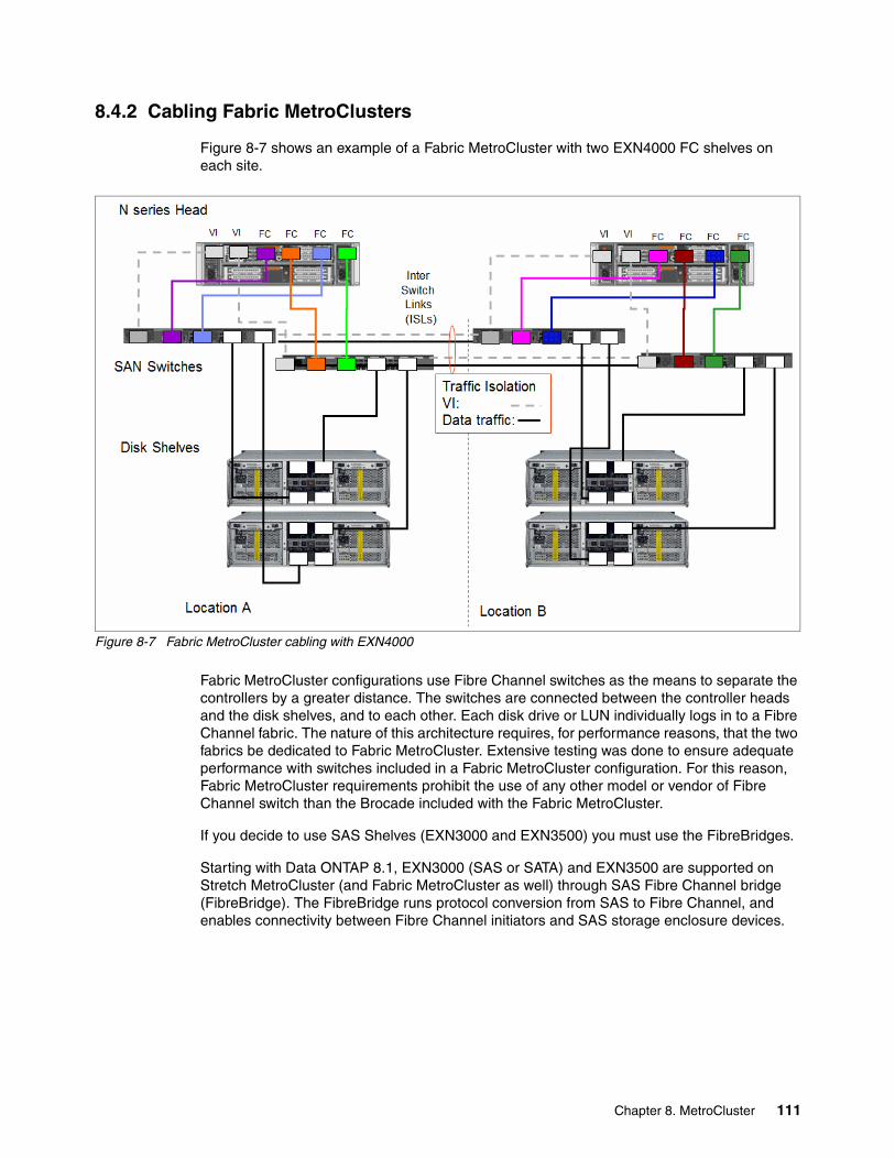
8.4.2 Cabling Fabric MetroClusters
Figure 8-7 shows an example of a Fabric MetroCluster with two EXN4000 FC shelves on each site.
Figure 8-7 Fabric MetroCluster cabling with EXN4000
Fabric MetroCluster configurations use Fibre Channel switches as the means to separate the controllers by a greater distance. The switches are connected between the controller heads and the disk shelves, and to each other. Each disk drive or LUN individually logs in to a Fibre Channel fabric. The nature of this architecture requires, for performance reasons, that the two fabrics be dedicated to Fabric MetroCluster. Extensive testing was done to ensure adequate performance with switches included in a Fabric MetroCluster configuration. For this reason, Fabric MetroCluster requirements prohibit the use of any other model or vendor of Fibre Channel switch than the Brocade included with the Fabric MetroCluster.
If you decide to use SAS Shelves (EXN3000 and EXN3500) you must use the FibreBridges.
Starting with Data ONTAP 8.1, EXN3000 (SAS or SATA) and EXN3500 are supported on Stretch MetroCluster (and Fabric MetroCluster as well) through SAS Fibre Channel bridge (FibreBridge). The FibreBridge runs protocol conversion from SAS to Fibre Channel, and enables connectivity between Fibre Channel initiators and SAS storage enclosure devices.
Chapter 8. MetroCluster 111

This process allows SAS disks to display as LUNs in a MetroCluster fabric. You need at least four FibreBridges (minimum is two per stack) in a MetroCluster environment as shown in Figure 8-8.
Figure 8-8 Cabling a Fabric MetroCluster with FibreBridges and SAS Shelves
For more information about SAS Bridges, see the SAS FibreBridges Chapter in the N series Hardware book.
8.5 Synchronous mirroring with SyncMirrorSyncMirror synchronously mirrors data across the two halves of the MetroCluster configuration by writing data to two plexes:
� The local plex (on the local shelf) actively serving data� The remote plex (on the remote shelf) normally not serving data
On local shelf failure, the remote shelf seamless takes over data-serving operations. Both copies or plexes are updated synchronously on writes, thus ensuring consistency.
8.5.1 SyncMirror overview
The design of IBM System Storage N series and MetroCluster provides data availability even in the event of an outage. Availability is preserved whether it is because of a disk problem, cable break, or host bus adapter (HBA) failure. SyncMirror can instantly access the mirrored data without operator intervention or disruption to client applications.
112 IBM System Storage N series Hardware Guide

Read performance is optimized by performing application reads from both plexes as shown in Figure 8-9.
Figure 8-9 Synchronous mirroring
SyncMirror is used to create aggregate mirrors. When planning for SyncMirror environments, keep in mind the following considerations:
� Aggregate mirrors need to be on the remote site (geographically separated)� In normal mode (no takeover), aggregate mirrors cannot be served out� Aggregate mirrors can exist only between like drive types.
When the SyncMirror license is installed, disks are divided into pools (pool0: local, pool1: remote/mirror). When a mirror is created, Data ONTAP pulls disks from pool0 for the local aggregate and from pool1 for the mirrored aggregate. Verify the correct number of disks in each pool before creating the aggregates. Any of the following commands can be used as shown in Example 8-1.
Example 8-1 Verification of SyncMirror
itsosj_n1>sysconfig -ritsosj_n1>aggr status -ritsosj_n1>vol status -r
To see the volume /plex/raidgroup relationship, use the sysconfig –r command as shown in Example 8-2. Use the aggr mirror command to start mirroring the plexes.
Example 8-2 Viewing the aggregate status
n5500-ctr-tic-1> sysconfig -rAggregate aggr0 (online, raid_dp, mirrored) (block checksums) Plex /aggr0/plex0 (online, normal, active, pool0) RAID group /aggr0/plex0/rg0 (normal)
RAID Disk Device HA SHELF BAY CHAN Pool Type RPM Used (MB/blks) Phys (MB/blks) --------- ------ ------------- ---- ---- ---- ----- -------------- -------------- dparity 0a.16 0a 1 0 FC:A 0 FCAL 15000 136000/278528000 137104/280790184 parity 0a.17 0a 1 1 FC:A 0 FCAL 15000 136000/278528000 137104/280790184 data 0a.18 0a 1 2 FC:A 0 FCAL 15000 136000/278528000 137104/280790184
Plex /aggr0/plex2 (online, normal, active, pool1)
Chapter 8. MetroCluster 113

RAID group /aggr0/plex2/rg0 (normal)
RAID Disk Device HA SHELF BAY CHAN Pool Type RPM Used (MB/blks) Phys (MB/blks) --------- ------ ------------- ---- ---- ---- ----- -------------- -------------- dparity 0c.25 0c 1 9 FC:B 1 FCAL 15000 136000/278528000 137104/280790184 parity 0c.24 0c 1 8 FC:B 1 FCAL 15000 136000/278528000 137104/280790184 data 0c.23 0c 1 7 FC:B 1 FCAL 15000 136000/278528000 137104/280790184
Aggregate aggr1 (online, raid4, mirrored) (block checksums) Plex /aggr1/plex0 (online, normal, active, pool0) RAID group /aggr1/plex0/rg0 (normal)
RAID Disk Device HA SHELF BAY CHAN Pool Type RPM Used (MB/blks) Phys (MB/blks) --------- ------ ------------- ---- ---- ---- ----- -------------- -------------- parity 0a.19 0a 1 3 FC:A 0 FCAL 15000 136000/278528000 137104/280790184 data 0a.21 0a 1 5 FC:A 0 FCAL 15000 136000/278528000 137104/280790184 data 0a.20 0a 1 4 FC:A 0 FCAL 15000 136000/278528000 137104/280790184
Plex /aggr1/plex1 (online, normal, active, pool1) RAID group /aggr1/plex1/rg0 (normal)
RAID Disk Device HA SHELF BAY CHAN Pool Type RPM Used (MB/blks) Phys (MB/blks) --------- ------ ------------- ---- ---- ---- ----- -------------- -------------- parity 0c.26 0c 1 10 FC:B 1 FCAL 15000 272000/557056000 274845/562884296 data 0c.20 0c 1 4 FC:B 1 FCAL 15000 136000/278528000 280104/573653840 data 0c.29 0c 1 13 FC:B 1 FCAL 15000 136000/278528000 280104/573653840
Pool1 spare disks
RAID Disk Device HA SHELF BAY CHAN Pool Type RPM Used (MB/blks) Phys (MB/blks)--------- ------ ------------- ---- ---- ---- ----- -------------- --------------Spare disks for block or zoned checksum traditional volumes or aggregatesspare 0c.28 0c 1 12 FC:B 1 FCAL 15000 272000/557056000 280104/573653840
Pool0 spare disks
RAID Disk Device HA SHELF BAY CHAN Pool Type RPM Used (MB/blks) Phys (MB/blks)--------- ------ ------------- ---- ---- ---- ----- -------------- --------------Spare disks for block or zoned checksum traditional volumes or aggregatesspare 0a.22 0a 1 6 FC:A 0 FCAL 15000 136000/278528000 137104/280790184
Partner disks
RAID Disk Device HA SHELF BAY CHAN Pool Type RPM Used (MB/blks) Phys (MB/blks)--------- ------ ------------- ---- ---- ---- ----- -------------- --------------partner 0a.25 0a 1 9 FC:A 1 FCAL 15000 0/0 137104/280790184partner 0a.27 0a 1 11 FC:A 1 FCAL 15000 0/0 137104/280790184partner 0a.26 0a 1 10 FC:A 1 FCAL 15000 0/0 137104/280790184partner 0c.16 0c 1 0 FC:B 0 FCAL 15000 0/0 137104/280790184partner 0c.21 0c 1 5 FC:B 0 FCAL 15000 0/0 137104/280790184partner 0c.22 0c 1 6 FC:B 0 FCAL 15000 0/0 137104/280790184partner 0a.29 0a 1 13 FC:A 1 FCAL 15000 0/0 137104/280790184partner 0c.17 0c 1 1 FC:B 0 FCAL 15000 0/0 137104/280790184partner 0c.27 0c 1 11 FC:B 0 FCAL 15000 0/0 137104/280790184
114 IBM System Storage N series Hardware Guide

partner 0c.18 0c 1 2 FC:B 0 FCAL 15000 0/0 137104/280790184partner 0a.23 0a 1 7 FC:A 1 FCAL 15000 0/0 137104/280790184partner 0a.28 0a 1 12 FC:A 1 FCAL 15000 0/0 137104/280790184partner 0a.24 0a 1 8 FC:A 1 FCAL 15000 0/0 137104/280790184partner 0c.19 0c 1 3 FC:B 0 FCAL 15000 0/0 274845/562884296
8.5.2 SyncMirror without MetroCluster
SyncMirror local (without MetroCluster) is basically a standard cluster with one or both controllers mirroring their RAID to two separate shelves. However, if you lose a controller and one of its RAID sets (plexes) during failover, the partner does not take over the other RAID set (plex). Therefore, without MetroCluster, all of the same rules apply as for a normal cluster:
� If controller A fails, partner B takes over.
� If loop A (Plex0) on controller A fails, controller A continues operation by running through loop B (Plex1).
� If controller A fails and either loop A or loop B (Plex0/Plex1) fails, you cannot continue.
MetroCluster protects against the following scenario: If controller A fails and its SyncMirrored shelves attached to loop A (Plex0) or loop B (Plex1) fail simultaneously, partner B takes over. Partner B takes over the operation for partner A and its SyncMirrored plex on either loop A (Plex0) or loop B (Plex1). See Figure 8-10.
Figure 8-10 MetroCluster protection
Chapter 8. MetroCluster 115

8.6 MetroCluster zoning and TI zones
Traditional SAN has great flexibility in connecting devices to ports if the ports are configured correctly and any zoning requirements are met. A MetroCluster, however, expects certain devices to be connected to specific ports or ranges of ports. It is therefore critical that cabling is exactly as described in the installation procedures. Also, no switch-specific functions such as trunking or zoning are currently used in a Fabric MetroCluster, making switch management minimal.
The TI zone feature of Brocade/IBM B type switches (FOS 6.0.0b or later) allows you to control the flow of interswitch traffic. You do so by creating a dedicated path for traffic that flows from a specific set of source ports. In a fabric MetroCluster configuration, the traffic isolation feature can be used to dedicate an ISL to high-priority cluster interconnect traffic.
FCVI exchanges need to be isolated because they are high priority traffic that should not be subject to any interruption or congestion caused by storage traffic
Fabric OS v6.0.0b introduces Traffic Isolation Zones, which have these features:
� Can create a dedicated route
� Does not modify the routing table
� Is implemented across the entire data path from a single location
� Does not require a license
� TI Zones are called “zones”, but they are really about FSPF routing
� TI Zones need a standard zoning configuration in effect
� TI Zones display only in the defined zoning configuration (not in effective zoning configuration)
� Create TI Zones by using Domain, Index (D, I) notation
� E_Ports and F_ and FL_Ports must be included for an end-to-end route (initiator - target)
� Ports are only members of a single TI Zone
Without TI Zones, traffic is free to use either ISL, subject to the rules of FSPF (Fibre Channel shortest path first) and DPS (Dynamic Path Selection). See Figure 8-11.
Figure 8-11 Traffic flow without TI Zones
116 IBM System Storage N series Hardware Guide

You can benefit from using two ISLs per fabric (instead of one ISL per fabric) to separate out high-priority cluster interconnect traffic from other traffic. This configuration prevents contention on the back-end fabric, and provides additional bandwidth in some cases. The TI feature is used to enable this separation. The TI feature provides better resiliency and performance.
Traffic isolation is implemented by using a special zone, called a traffic isolation zone (TI zone). A TI zone indicates the set of ports and ISLs to be used for a specific traffic flow. When a TI zone is activated, the fabric attempts to isolate all interswitch traffic that enters from a member of the zone. The traffic is isolated to only those ISLs that have been included in the zone. The fabric also attempts to exclude traffic not in the TI zone from using ISLs within that TI zone.
TI Zones are a new feature of Fabric OS v6.0.0b that have the following restrictions:
� TI Zones exist only in the Defined Zoning Configuration
� TI Zones must be created with Domain, Index notation only
� TI Zones must include both E_Ports and N_Ports to create a complete, dedicated, end-to-end route from Initiator to Target
Each fabric is configured to prohibit probing of the FCVI ports by the Fabric nameserver.
Figure 8-12 shows the dedicated traffic between Domain 1 and Domain 2. Data from system A would stay in the TI Zone “1-2-3-4” and would not pass TI Zone “5-6-7-8”“. So the traffic is routed on 2-3 for system A and 6-7 for system B.
Figure 8-12 TI Zones
Chapter 8. MetroCluster 117

Figure 8-13 shows an example of TI in a Fabric MetroCluster environment. VI traffic (orange) is separated from data/backend traffic (black) by TI zones.
Figure 8-13 TI Zones in MetroCluster environment
8.7 Failure scenarios
The following examples illustrate some possible failure scenarios and the resulting configurations when using MetroCluster.
118 IBM System Storage N series Hardware Guide

8.7.1 MetroCluster host failureIn this scenario, N series N1 (Node 1) has failed. CFO/MetroCluster takes over the services and access to its disks (Figure 8-14). The fabric switches provide the connectivity for the N series N2 and the hosts to continue to access data without interruption.
Figure 8-14 IBM System Storage N series failure
8.7.2 N series and expansion unit failureFigure 8-15 shows the loss of one site, resulting from failure of the controller and shelves at the same time.
Figure 8-15 Controller and expansion unit failure
To continue access, a failover must be performed by the administrator by issuing the cfo -d command. Data access is restored because DC1 mirror was in sync with DC1 primary.
Chapter 8. MetroCluster 119

Through connectivity provided by the fabric switches, all hosts again have access to the required data.
8.7.3 MetroCluster interconnect failureIn this scenario, the fabric switch interconnects have failed (Figure 8-16). Although this is not a critical failure, resolve it promptly before a more critical failure occurs.
Figure 8-16 Interconnect failure
During this period, data access is uninterrupted to all hosts. No automated controller takeover occurs. Both controller heads continue to serve its LUNs/volumes. However, mirroring and failover are disabled, thus reducing data protection. When the interconnect failure is resolved, resyncing of mirrors occurs.
120 IBM System Storage N series Hardware Guide

8.7.4 MetroCluster site failure
In this scenario, a site disaster has occurred and all switches, storage systems, and hosts have been lost (Figure 8-17). To continue data access, a cluster failover must be initiated by using the cfo -d command. Both primaries now exist at data center 2, and hosting of Host1 is also done at data center 2.
Figure 8-17 Site failure
Attention: If the site failure is staggered in nature and the interconnect fails before the rest of the site, data loss might occur. Data loss occurs because processing continues after the interconnect fails. However, typically site failures occur pervasively and at the same time.
Chapter 8. MetroCluster 121

8.7.5 MetroCluster site recovery
After the hosts, switches, and storage systems have been recovered at data center 1, a recovery can be performed. A cf giveback command is issued to resume normal operations (Figure 8-18). Mirrors are resynchronized and primaries and mirrors are reversed to their previous status.
Figure 8-18 MetroCluster recovery
122 IBM System Storage N series Hardware Guide

Chapter 9. FibreBridge 6500N
This chapter contains information about the FC-SAS FibreBridge.
The ATTO FibreBridge 6500N provides an innovative bridging solution between the Fibre Channel and SAS protocols. It is an FC/SAS bridge in EXN3000 (2857-003) and EXN3500 (2857-006) storage expansion units attached to IBM System Storage N series storage systems in a MetroCluster configuration.
The ATTO FibreBridge is a performance tuned intelligent protocol translator that allows upstream initiators connected through Fibre Channel to communicate with downstream targets connected through SAS. It is a high performance bridge that adds 8-Gigabit Fibre Channel connectivity to 6-Gigabit SAS storage devices. ATTO FibreBridge provides a complete highly available connectivity solution for MetroCluster.
This chapter includes the following sections:
� Description� Architecture� Administration and management
9
© Copyright IBM Corp. 2012. All rights reserved. 123

9.1 Description
MetroCluster adds great availability to N series systems but is limited to Fibre Channel drive shelves only. Before 8.1, both SATA and Fibre Channel drive shelves were supported on active-active configuration in stretch MetroCluster configurations. However, both plexes of the same aggregate must use the same type of storage. In a fabric MetroCluster configuration, only Fibre Channel drive shelves had been supported.
Starting with Data ONTAP 8.1, EXN3000 (SAS or SATA) and EXN3500 are supported on Fabric MetroCluster and on Stretch MetroCluster through SAS Fibre Channel bridge (FibreBridge). The FibreBridge (shown in Figure 9-1) runs protocol conversion from SAS to Fibre Channel. It enables connectivity between Fibre Channel initiators and SAS storage enclosure devices so that SAS disks display as LUNs in a MetroCluster fabric.
Figure 9-1 FibreBridge front view
The FibreBridge is only available as part of the MetroCluster solution, and is intended for back-end shelf cabling only.
9.2 Architecture
FibreBridge 6500N bridges are used in MetroCluster systems when SAS disk shelves are used. You can install the bridges by using these methods:
� As part of a new MetroCluster installation� As a hot-add to an existing MetroCluster system with SAS or Fibre Channel disk shelves � As a hot-swap to replace a failed bridge
You can also hot-add a SAS disk shelf to an existing stack of SAS disk shelves.
Table 9-1 Shelf combinations in a FibreBridge stack
Attention: At the time of writing, Data ONTAP 8.1 has these limitations:
� The FibreBridge does not support mixing EXN3000 and EXN3500 in same stack.� FibreBridge configurations currently do not support SSD drives. � The FibreBridge does not support SNMP.
Shelf EXN3000(SAS disks)
EXN3000 (SATA disks)
EXN3500SAS disks
EXN3000 (SAS disks) SAME YES NO
EXN3000 (SATA disks) YES SAME NO
EXN3500 SAS disks NO NO SAME
124 IBM System Storage N series Hardware Guide

The FC-SAS00 FibreBridge product has the following specifications:
� Two 8 Gb/s FC ports (optical SFP+ modules included)� (4x) 6 Gb/s SAS ports (only one SAS port used) � Dual 100/1000 RJ-45 Ethernet ports� Serial port (RS-232)� 1U enclosure� Mountable into a standard 19” rack
Figure 9-2 provides a a view of the bridge ports.
Figure 9-2 FibreBridge ports on rear side
At a minimum, MetroCluster requires four FibreBridges, two per stack, with one stack on either site. Therefore, two FibreBridges (one for redundancy) are required per stack of SAS shelves. Current maximum is 10 SAS shelves per stack of SAS or SATA disks.
A sample cabling diagram is provided in Figure 9-3.
Figure 9-3 FibreBridge stack of SAS shelves
Restriction: Only the SAS port labeled ‘A’ can be used to connect expansion shelves because SAS port B is disabled.
An Ethernet port and a serial port are available for bridge management.
Chapter 9. FibreBridge 6500N 125

The normal platform spindle limits apply to the entire MetroCluster configuration. However, because each controller sees all storage, the platform spindle limit applies to the entire configuration. For example, if the spindle limit for N series N62x0 is n, then despite the two controllers, the spindle limit for a N62x0 fabric MetroCluster configuration remains n.
Figure 9-4 shows an example of an N series Stretch MetroCluster environment. Fibre Channel ports of the N series nodes are connected to the Fibre Channel ports on the FibreBridge (FC1 and FC2). SAS ports of the first and last shelf in a stack are connected to the SAS ports (SAS port A) on the FibreBridge. Each stack has two bridges. MetroCluster uses at least four FibreBridges.
Figure 9-4 Stretch MetroCluster with FibreBridges
126 IBM System Storage N series Hardware Guide

Figure 9-5 shows an example of a Fabric MetroCluster that uses FibreBridges to connect to SAS disk shelves. Each of the two nodes connects through four Fibre Channel links to the SAN fabrics for data traffic plus two additional Fibre Channel links intended for VI traffic. Each of the FibreBridges is connected with one link per bridge to the SAN. The first and last SAS shelves in a stack are each connected through one SAS link to a bridge.
Figure 9-5 Fabric MetroCluster with FibreBridges
N series gateway configurations do not use the FibreBridge. Storage is presented through FCP as LUNs from whatever back-end array the gateway head is front ending.
9.3 Administration and management
The FibreBridge comes with an easy to use, web-based ExpressNAV System Manager, which provides capabilities for remote configuration, management of the bridge, diagnostic capabilities and to update the bridge firmware. The ATTO QuickNAV utility can be used to configure the bridge Ethernet management 1 port. Generally, use the ATTO ExpressNAV System Manager, which requires you to connect the Management 1 (MC 1) port to your network by using an Ethernet cable.
You can use other management interfaces such as a serial port or Telnet to configure and manage a bridge. They can also be used to configure the Ethernet management 1 port, and FTP to update the bridge firmware. If you choose any of these management interfaces, you must meet the applicable requirements.
FC FC FC FC
IOM A IOM B
IOM A IOM B
IOM A IOM B
Expansion Units (SAS)
FC FC FC FC
IOM A IOM B
IOM A IOM B
IOM A IOM B
Management Network (IP)
FC2FC1Et1 SASA FC2FC1Et1 SASA FC2FC1Et1 SASA FC2FC1Et1 SASA
Inter Switch Links (ISLs)
FibreBridge
N seriesHead
SAN Switches
Chapter 9. FibreBridge 6500N 127

Install an ATTO-supported web browser so that you can use the ATTO ExpressNAV GUI. The most effective browsers are Internet Explorer 8 and Mozilla Firefox 3. The ATTO FibreBridge 6500N Installation and Operation Manual contains a list of supported web browsers.
The FibreBridge has the following environmental specifications:
� Power consumption is 55W: 110V, 0.5A / 220V, 0.25A
� Input 85-264 VAC, 1A, 47-63 Hz
� BTU: 205 BTU/hr
� Weight: 8.75lbs
Operating Environment:
� Temperature: 5-40° C at 10,000 feet
� Humidity: 10 - 90%
� Thermal monitoring possible
� Front to rear cooling
Monitoring options of the device includes:
� Event Management System (EMS) messages and Autosupport messages
� Data ONTAP commands such as storage show bridge –v
� FibreBridge commands such as DumpConfiguration
The FibreBridge does not support SNMP in the DOT 8.1 release.
128 IBM System Storage N series Hardware Guide

Chapter 10. Data protection with RAID Double Parity
This chapter provides an overview of RAID Double Parity (RAID-DP) and explains how it dramatically increases the data fault tolerance of various disk failure scenarios. Other key areas covered include cost information, special hardware requirements, creating RAID groups, and converting from RAID 4 to RAID-DP.
This chapter includes a double-disk failure recovery scenario. This scenario illustrates how RAID-DP allows the RAID group to continue serving data and re-create the data on the two failed disks.
This chapter addresses the following topics:
� Why use RAID-DP� RAID-DP overview� Single-Parity versus RAID-DP� RAID-DP reconstruction process� Converting and creating RAID groups from RAID 4 to RAID-DP� Hot spare disks
This chapter includes the following sections:
� Background� Why use RAID-DP� RAID-DP overview� RAID-DP and double parity� Hot spare disks
10
© Copyright IBM Corp. 2012. All rights reserved. 129

10.1 BackgroundIn this chapter, the term volume, when used alone, is defined to mean both traditional volumes and aggregates. Data ONTAP volumes have two distinct versions:
� Traditional volumes� Virtual volumes called FlexVols
FlexVols offer flexible and unparalleled functionality housed in a construct known as an aggregate. For more information about FlexVol and thin provisioning, see N series Thin Provisioning, REDP-47470, at:
http://www.redbooks.ibm.com/abstracts/redp4747.html?Open
Traditional single-parity RAID technology offers protection from a single disk drive failure. If a secondary event occurs during reconstruction, the RAID array might experience data corruption or a volume being lost. The single-parity RAID solution can improve performance, but presents greater risk of data loss. Select the solution carefully selected so that it complies with your organization’s policies and application-specific requirements.
Although disk drive technology has increased capacities and reduced seek time performances, it has not reduced the amount of contrast between decreased reliability. It addition, the technology has actually increased bit error rates. The result is an increase of potential uncorrectable bit errors, and reduced reliability of traditional single parity RAID adequately protecting data. Today traditional RAID is stretching past its limitations.
By increasing the data fault tolerance of various disk failures, and infusing block-level striping, double parity distributions presents RAID data protection called RAID Double Parity. This protection is also called RAID-DP, and is illustrated in Figure 10-1. RAID-DP is available on the entire IBM System Storage N series data storage product line.
Figure 10-1 RAID-DP
© 2005 IBM Corporation35
Address the challenge with RAID Double Parity (RAID-DP)
Survives any 2-disk-failure scenario
Compared to single-parity RAID,RAID-DP has: Better protection (>4,000
MTTDL)
Equal, often better performance
Same capacity overhead(typically 1 parity per 6 data drives
Outperforms any other “double-parity” offering
Combined with SyncMirror (RAID1), N series storage systems are designed to survive failure of any five disks in one disk protection group
P
P DP
Single-parity RAIDprotects against anysingle disk failure
RAID-DP Protects against any two-disk failure
130 IBM System Storage N series Hardware Guide

10.2 Why use RAID-DPAs mentioned earlier, traditional single-parity RAID offers adequate protection against a single event. This event can be either a complete disk failure or a bit error during a read. In either event, data is re-created by using both parity data and data that remains on unaffected disks in the array or volume.
If the event is a read error, re-creating data happens almost instantaneously and the array or volume remains in an online mode. However, if a disk fails, the lost data must be re-created. The array or volume remains in a vulnerable degraded mode until data is reconstructed onto a replacement disk or global hot spare disk. This degraded mode is where traditional single-parity RAID fails to meet the demands of modern disk architectures. In single-parity RAID, the chance of secondary disk failure is increased during rebuild times, increasing the risk of data loss.
Modern disk architectures have continued to evolve, as have other computer-related technologies. Disk drives are orders of magnitude larger than they were when RAID was first introduced. As disk drives have gotten larger, their reliability has not improved, and the bit error likelihood per drive has increased proportionally with larger media. These three factors (larger disks, unimproved reliability, and increased bit errors with larger media) have serious consequences for the ability of single-parity RAID to protect data.
Given that disks are as likely to fail now as when RAID technology was first introduced, RAID is still vital. Integrating RAID-DP when one disk fails, RAID re-creates data from both parities and the remaining disks in the array or volume onto a hot spare disk. But because RAID was introduced, the significant increases in disk size have resulted in much longer reconstruction times for data lost on the failed disk.
It takes much longer to re-create lost data when a 274 GB disk fails than when a 36 GB disk fails (Figure 10-2). In addition, reconstruction times are longer because the larger disk drives in use today tend to be ATA-based. ATA-based drives run more slowly and are less reliable than smaller, SCSI-based drives.
Figure 10-2 Disk size versus reconstruction time
10.2.1 Single-parity RAID using larger disks
The various options to extend the ability of single-parity RAID to protect data as disks continue to get larger are not attractive. The first option is to continue to buy and implement storage using the smallest disk sizes possible so that reconstruction completes quicker. However, this approach is impractical. Capacity density is critical in space-constrained data
Chapter 10. Data protection with RAID Double Parity 131

centers, and smaller disks result in less capacity per square foot. Also, storage vendors are forced to offer products based on what disk manufacturers are supplying, and smaller disks are not readily available, if at all.
The second way to protect data on larger disks with single-parity RAID is slightly more practical, but still not effective for various reasons. Keeping the size of arrays or volumes small, the time to reconstruct is reduced. However, an array or volume built with more disks takes longer to reconstruct data from one failed disk than one built with fewer disks. Smaller arrays and volumes have two costs that cannot be overcome:
1. Additional disks are lost to parity, thus reducing usable capacity and increasing total cost of ownership (TCO).
2. Performance is generally slower with smaller arrays, aggregates, and volumes, affecting business and users.
The most reliable protection offered by single-parity RAID is RAID 1, or mirroring. In RAID 1, the mirroring process replicates an exact copy of all data on an array, aggregate, or volume to a second array or volume. Although RAID 1 mirroring affords maximum fault tolerance from disk failure, the cost of the implementation is severe. RAID 1 requires twice the disk capacity to store the same amount of data.
Using smaller arrays and volumes to improve fault tolerance increases the total cost of ownership of storage because of less usable capacity per dollar spent. RAID 1 mirror with its requirement for double the amount of capacity is the most expensive type of storage solution with the highest total cost of ownership (Figure 10-3).
Figure 10-3 RAID 1 mirror
10.2.2 Advantages of RAID-DP data protection
Given the current landscape with larger disk drives that affect data protection, customers and analysts need a way to affordably improve RAID reliability from storage vendors. To meet this demand, a new type of RAID protection called RAID Double Parity (RAID-DP) has been developed (Figure 10-4).
Figure 10-4 RAID-DP
s
132 IBM System Storage N series Hardware Guide
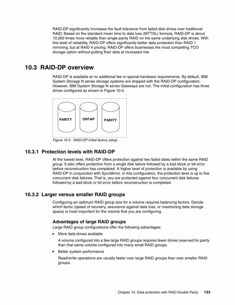
RAID-DP significantly increases the fault tolerance from failed disk drives over traditional RAID. Based on the standard mean time to data loss (MTTDL) formula, RAID-DP is about 10,000 times more reliable than single-parity RAID on the same underlying disk drives. With this level of reliability, RAID-DP offers significantly better data protection than RAID 1 mirroring, but at RAID 4 pricing. RAID-DP offers businesses the most compelling TCO storage option without putting their data at increased risk.
10.3 RAID-DP overviewRAID-DP is available at no additional fee or special hardware requirements. By default, IBM System Storage N series storage systems are shipped with the RAID-DP configuration. However, IBM System Storage N series Gateways are not. The initial configuration has three drives configured as shown in Figure 10-5.
Figure 10-5 RAID-DP Initial factory setup
10.3.1 Protection levels with RAID-DPAt the lowest level, RAID-DP offers protection against two failed disks within the same RAID group. It also offers protection from a single disk failure followed by a bad block or bit error before reconstruction has completed. A higher level of protection is available by using RAID-DP in conjunction with SyncMirror. In this configuration, the protection level is up to five concurrent disk failures. That is, you are protected against four concurrent disk failures followed by a bad block or bit error before reconstruction is completed.
10.3.2 Larger versus smaller RAID groupsConfiguring an optimum RAID group size for a volume requires balancing factors. Decide which factor (speed of recovery, assurance against data loss, or maximizing data storage space) is most important for the volume that you are configuring.
Advantages of large RAID groupsLarge RAID group configurations offer the following advantages:
� More data drives available
A volume configured into a few large RAID groups requires fewer drives reserved for parity than that same volume configured into many small RAID groups.
� Better system performance
Read/write operations are usually faster over large RAID groups than over smaller RAID groups.
ONTAPPARITY PARITY
Chapter 10. Data protection with RAID Double Parity 133

Advantages of small RAID groupsSmall RAID group configurations offer the following advantages:
� Shorter disk reconstruction times
During disk failure within a small RAID group, data reconstruction time is usually shorter than it would be within a large RAID group.
� Decreased risk of data loss because of multiple disk failures
Data loss through double disk failure within a RAID 4 group is less likely than during a triple disk failure within a RAID-DP group.
10.4 RAID-DP and double parityIt is well known that parity generally improves fault tolerance, and that single-parity RAID improves data protection. Given that traditional single-parity RAID has a good track record to date, the concept of double-parity RAID sounds like a better protection scheme. This is borne out in the earlier example using the MTTDL formula. But what exactly is RAID-DP?
At the most basic layer, RAID-DP adds a second parity disk to each RAID group in a volume. A RAID group is an underlying construct on which volumes are built. Each traditional RAID 4 group has data disks and one parity disk, with volumes that contain one or more RAID 4 groups. The parity disk in a RAID 4 volume stores row parity across the disks in a RAID 4 group. The additional RAID-DP parity disk stores diagonal parity across the disks in a RAID-DP group (Figure 10-6). These two parity stripes in RAID-DP provide data protection in the event of two disk failures that occur in the same RAID group.
Figure 10-6 RAID 4 and RAID-DP
10.4.1 Internal structure of RAID-DPWith RAID-DP, the traditional RAID 4 horizontal parity structure is still employed and becomes a subset of the RAID-DP construct. In other words, how RAID 4 works on storage is not modified with RAID-DP. Data is written out in horizontal rows with parity calculated for each row in RAID-DP, which is considered the row component of double parity. If a single disk fails or a read error from a bad block or bit error occurs, the row parity approach of RAID 4 is used to re-create the data. RAID-DP is not engaged. In this case, the diagonal parity component of RAID-DP is a protective envelope around the row parity component.
134 IBM System Storage N series Hardware Guide

10.4.2 RAID 4 horizontal row parityFigure 10-7 illustrates the horizontal row parity approach used in the traditional RAID 4 solution. It is the first step in establishing an understanding of RAID-DP and double parity.
Figure 10-7 RAID 4 horizontal parity
Figure 10-7 represents a traditional RAID 4 group that uses row parity. It consists of four data disks (the first four columns, labeled D) and the single row parity disk (the last column, labeled P). The rows represent the standard 4 KB blocks used by the traditional RAID 4 implementation. The second row is populated with sample data in each 4 KB block. Parity calculated for data in the row is then stored in the corresponding block on the parity disk.
In this case, the way parity is calculated is to add the values in each of the horizontal blocks. That sum is stored as the parity value (3 + 1 + 2 + 3 = 9). In practice, parity is calculated by an exclusive OR (XOR) process, but addition is fairly similar and works as well for the purposes of this example. If you need to reconstruct data from a single failure, the process used to generate parity is reversed. If the first disk fails, RAID 4 re-creates the data value 3 in the first column. It subtracts the values on the remaining disks from what is stored in parity (9 - 3 - 2 - 1 = 3). This example of reconstruction with single-parity RAID shows why data is protected up to, but not beyond, one disk failure event.
Chapter 10. Data protection with RAID Double Parity 135

10.4.3 Adding RAID-DP double-parity stripesFigure 10-8 adds one diagonal parity stripe, denoted by the blue-shaded blocks, and a second parity disk, denoted with a DP in the sixth column. These are added to the existing RAID 4 group from the previous section. Figure 10-8 shows the RAID-DP construct that is a super-set of the underlying RAID 4 horizontal row parity solution.
Figure 10-8 Adding RAID-DP double parity stripes
The diagonal parity stripe was calculated by using the addition approach for this example rather than the XOR used in practice. It was then stored on the second parity disk (1 + 2 + 2 + 7 = 12).Note that the diagonal parity stripe includes an element from row parity as part of its diagonal parity sum. RAID-DP treats all disks in the original RAID 4 construct, including both data and row parity disks, as the same.
Figure 10-9 adds in the rest of the data for each block and creates corresponding row and diagonal parity stripes.
Figure 10-9 Block representation of RAID-DP corresponding with row and diagonal parity
One RAID-DP condition that is apparent from Figure 10-9 is that the diagonal stripes wrap at the edges of the row parity construct.
The following are important conditions for RAID-DP's ability to recover from double disk failures:
� The first condition is that each diagonal parity stripe misses one (and only one) disk, but each diagonal misses a different disk
� The Figure 10-9 illustrates an omitted diagonal parity stripe (white blocks) stored on the second diagonal parity disk.
136 IBM System Storage N series Hardware Guide

Omitting the one diagonal stripe does not affect RAID-DP's ability to recover all data in a double-disk failure as illustrated in reconstruction example.
The same RAID-DP diagonal parity conditions covered in this example are true in real storage deployments. It works even in deployments that involve dozens of disks in a RAID group and millions of rows of data written horizontally across the RAID 4 group. Recovery of larger-size RAID groups works the same, regardless of the number of disks in the RAID group.
RAID-DP, based on proven mathematical theorems, provides the ability to recover all data in the even of a double-disk failure. More information can be found at:
1. One way is using mathematical theorems and proofs. For more information about the mathematical theorems, and proofs used in RAID-DP, see the “Double Disk Failure Correction” document available at the USENIX Organization website:
http://www.usenix.org
2. Go through the double-disk failure and subsequent recovery process presented in 10.4.4, “RAID-DP reconstruction” on page 137.
10.4.4 RAID-DP reconstructionUsing Figure 10-9 on page 136 as the starting point, assume that the RAID group is functioning normally when a double-disk failure occurs. The failure is shown by all data in the first two columns being missing in Figure 10-10.
Figure 10-10 RAID-DP simulation of double disk failure
When engaged after a double-disk failure, RAID-DP first begins looking for a chain to begin reconstruction with. In this case, the first diagonal parity stripe in the chain that it finds is represented by the blue series of diagonal blocks. Remember that when reconstructing data for a single disk failure under RAID 4, no more than one element can be missing or failed. If an additional element is missing, data loss is inevitable.
Chapter 10. Data protection with RAID Double Parity 137

With this in mind, traverse the blue series diagonal blocks in Figure 10-10 on page 137. Notice that only one of the five blue series blocks are missing. With four out of five elements available, RAID-DP has all of the information needed to reconstruct the data in the missing blue series block. Figure 10-11 shows that this data is recovered over to an available hot spare disk.
Figure 10-11 RAID-DP reconstruction simulation diagonal blue block
The data has been re-created from the missing diagonal blue block by using the same arithmetic addressed earlier (12 - 7 - 2 - 2 = 1). Now that the missing blue series diagonal information has been re-created, the recovery process switches from using diagonal parity to using horizontal row parity. Specifically, the top row after the blue block re-creates the missing diagonal block. There is now enough information available to reconstruct the single missing horizontal gray block in column 1, row 1, disk 3 parity (9 - 3 - 2 - 1 = 3). This process is shown in Figure 10-12.
Figure 10-12 RAID-DP reconstruction of first horizontal block
138 IBM System Storage N series Hardware Guide

The algorithm continues determining whether additional diagonal blocks can be re-created. The upper left block is re-created from row parity, and RAID-DP can proceed in re-creating the gray diagonal block in column two, row two. See Figure 10-13.
Figure 10-13 RAID-DP reconstruction simulation of gray block column two
RAID-DP recovers the gray diagonal block in column two, row two. Adequate information is now available for row parity to re-creating the missing horizontal white block (one) in the first column, row two (Figure 10-14).
Figure 10-14 RAID-DP reconstruction simulation of white block column one
Chapter 10. Data protection with RAID Double Parity 139

As noted earlier, the white diagonal stripe is not stored, and no additional diagonal blocks can be re-creating on the existing chain. RAID-DP continues to search for a new chain to start re-creating diagonal blocks. In this example, the procedure determines that it can re-create missing data in the gold stripe, as shown in Figure 10-15.
Figure 10-15 RAID-DP reconstruction simulation of second horizontal block
After RAID-DP re-creates a missing diagonal block, the process again switches to re-creating a missing horizontal block from row parity. When the missing diagonal block in the gold stripe is re-created, enough information is available to re-create the missing horizontal block from row parity, as shown in Figure 10-16.
Figure 10-16 RAID-DP reconstruction simulation of gold horizontal block
140 IBM System Storage N series Hardware Guide

After the missing block in the horizontal row is re-created, reconstruction switches back to diagonal parity to re-creating a missing diagonal block. RAID-DP can continue in the current chain on the red stripe, as shown in Figure 10-17.
Figure 10-17 RAID-DP reconstruction simulation of Red diagonal block
Again, after the recovery of a diagonal block, the process switches back to row parity because it has enough information to re-create data for the one horizontal block. At this point in the double-disk failure scenario, all data has been re-creating with RAID-DP, as shown in Figure 10-18.
Figure 10-18 RAID-DP reconstruction simulation of recovered blocks optimal status
10.4.5 Protection levels with RAID-DPThe RAID-DP reconstruction simulation demonstrated in 10.4.4, “RAID-DP reconstruction” on page 137 illustrates recovery in operation. However, there are other areas of RAID-DP that require further discussion. For example, if a double-disk failure occurs, RAID-DP automatically raises the priority of the reconstruction process so that the recovery completes faster. The time in reconstruction of data blocks generated from two failed disk drives is slightly less than the time to reconstruct data from a single-disk failure.
A second key feature of RAID-DP with double-disk failure is that it is highly likely that one disk failed some time before the second. Therefore, at least some information is already re-created with traditional row parity. RAID-DP automatically adjusts for this occurrence by starting recovery where two elements are missing from the second disk failure.
A higher level of protection is available by using RAID-DP in conjunction with SyncMirror. In this configuration, the protection level is up to five concurrent disk failures. These failures
Chapter 10. Data protection with RAID Double Parity 141

consist of four concurrent disk failures followed by a bad block or bit error before reconstruction is completed.
Creating RAID-DP aggregates and traditional volumesTo create an aggregate or traditional volume with RAID-DP–based RAID groups, select that option in FilerView when provisioning storage. You can also add the –t raid_dp switch to the traditional aggr or vol create command on the command-line interface. The command-line interface syntax is [vol | aggr] create name –t raid_dp X, with X representing the number of disks the traditional volume or aggregate contains. If the type of RAID group is not specified, Data ONTAP automatically uses the default RAID group type. The default RAID group type used, either RAID-DP or RAID4, depends on the platform and disk that are used.
The output shown in Figure 10-19 from the vol status command shows a four-disk RAID-DP RAID group for a traditional volume named test. The second parity disk for diagonal parity is denoted as dparity.
Figure 10-19 Volume status command output of aggregate
Converting existing aggregates and traditional volumes to RAID-DPExisting aggregates and traditional volumes can be easily converted to RAID-DP by using the command [aggr | vol] options name raidtype raid_dp. Figure 10-20 shows the example itso volume as a traditional RAID4 volume.
Figure 10-20 vol status command showing ‘itso” volume as traditional RAID4 volume
142 IBM System Storage N series Hardware Guide

When the command is entered, the aggregate or, as in the following examples, traditional volumes are instantly denoted as RAID-DP. However, all diagonal parity stripes still need to be calculated and stored on the second parity disk. Figure 10-21 shows using the command to convert the volume.
Figure 10-21 “itso” volume conversion from traditional RAID4 to RAID-DP
In these examples, when changing the volume itso, the aggregates within the RAID-DP volume pl_install and TPC change when the command is run. Protection against double disk failure is not available until all diagonal parity stripes are calculated and stored on the diagonal parity disk. Figure 10-22 shows a “reconstruct” status that signifies that diagonal parity creation in process,
Figure 10-22 “itso” volume in reconstruct status during conversion of diagonal parity RAID-DP
Calculating the diagonals as part of a conversion to RAID-DP takes time and affects performance slightly on the storage controller. The amount of time and performance effect for conversions to RAID-DP depends on the storage controller and how busy the storage controller is during the conversion. Generally, run conversions to RAID-DP during off-peak hours to minimize potential performance effect to business or users.
For conversions from RAID4 to RAID-DP, certain conditions are required. Conversions at the aggregate or traditional volume level require an available disk for the second diagonal parity disk for each RAID4 group. The size of the disks used for diagonal parity needs to be at least the size of the original RAID4 row parity disks. In the example, the volume itso is altered from an RAID4 status to RAID-DP.
Chapter 10. Data protection with RAID Double Parity 143

Figure 10-23 shows a completed conversion to RAID-DP volume.
Figure 10-23 “itso” volume completed RAID-DP conversion successfully
Converting existing aggregates and traditional volumes back to RAID4Aggregates and traditional volumes can be converted back to RAID4 with the command [aggr |vol] options name raidtype raid4. Figure 10-24 shows itso as RAID-DP parity.
Figure 10-24 Aggregate status of “itso” as RAID-DP parity
Figure 10-25 shows the conversion of itso back to RAID4. In this case, the conversion is instantaneous because the old RAID4 row parity construct is still in place as a subsystem in RAID-DP.
Figure 10-25 “itso” volume conversion from traditional RAID-DP to RAID4
Figure 10-26 shows the completed process. If a RAID-DP group is converted to RAID4, each RAID group’s second diagonal parity disk is released and put back into the spare disk pool.
Figure 10-26 RAID4 conversion instantaneous completion results
144 IBM System Storage N series Hardware Guide

RAID-DP volume managementFrom a management and operational point of view, RAID-DP aggregates and traditional volumes work exactly like their RAID4 counterparts. The same practices and guidelines work for both RAID4 and RAID-DP. Therefore, little to no changes are required for standard operational procedures used by IBM System Storage N series administrators. The commands you use for management activities on the storage controller are the same regardless of the mix of RAID4 and RAID-DP aggregates or traditional volumes. For instance, to add additional capacity, run the command [aggr | vol] add name X just as you would for a RAID4-based storage.
10.5 Hot spare disks A hot spare disk is a storage system disk that has not been assigned to a RAID group. It does not yet hold data, but is ready for use. In a disk failure within a RAID group, Data ONTAP automatically assigns hot spare disks to RAID groups to replace the failed disks.
Hot spare disks do not have to be in the same disk shelf as other disks of a RAID group to be available to a RAID group (Figure 10-27).
Figure 10-27 RAID-DP protection
During disk failure, the storage system replaces the failed disk with a spare and reconstructs data. If a disk fails, the storage system runs these actions:
1. The storage system replaces the failed disk with a hot spare disk. If RAID-DP is enabled and double-disk failure occurs in the RAID group, the storage system replaces each failed disk with a separate spare disk. Data ONTAP first attempts to use a hot spare disk of the same size as the failed disk. If no disk of the same size is available, Data ONTAP replaces the failed disk with a spare disk of the next available size up.
Tip: You need at least one spare disk available per aggregate, but no more than three. In addition, the available spares need at least one disk for each disk size and disk type installed in your storage system. This configuration allows the storage system to use a disk of the same size and type as a failed disk when reconstructing a failed disk. If a disk fails and a hot spare disk of the same size is not available, the storage system uses a spare disk of the next available size up.
RAID-DP Protection
rg0
rg1
rg2
rg3
Vol_1
hot spare
Data drive
Parity drive
dParity drive
RAID group
Chapter 10. Data protection with RAID Double Parity 145

2. The storage system reconstructs, in the background, the missing data onto the hot spare disks.
3. The storage system logs the activity in the /etc/messages file on the root volume.
With RAID-DP, these processes can be carried out even in the event of simultaneous failure of two disks in a RAID group.
During reconstruction, file service can slow down. After the storage system is finished reconstructing data, replace the failed disks with new hot spare disks as soon as possible. Hot spare disks must always be available in the system.
146 IBM System Storage N series Hardware Guide

Chapter 11. Core technologies
This chapter addresses N series core technologies such as the WAFL file system, disk structures, and NVRAM access methods.
This chapter includes the following sections:
� Write Anywhere File Layout (WALF)� Disk structure� NVRAM and system memory� Intelligent caching of write requests� N series read caching techniques
11
© Copyright IBM Corp. 2012. All rights reserved. 147
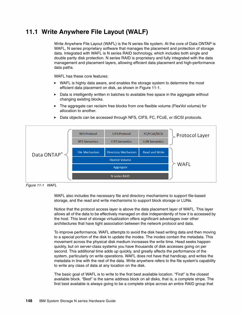
11.1 Write Anywhere File Layout (WALF)
Write Anywhere File Layout (WAFL) is the N series file system. At the core of Data ONTAP is WAFL, N series proprietary software that manages the placement and protection of storage data. Integrated with WAFL is N series RAID technology, which includes both single and double parity disk protection. N series RAID is proprietary and fully integrated with the data management and placement layers, allowing efficient data placement and high-performance data paths.
WAFL has these core features:
� WAFL is highly data aware, and enables the storage system to determine the most efficient data placement on disk, as shown in Figure 11-1.
� Data is intelligently written in batches to available free space in the aggregate without changing existing blocks.
� The aggregate can reclaim free blocks from one flexible volume (FlexVol volume) for allocation to another.
� Data objects can be accessed through NFS, CIFS, FC, FCoE, or iSCSI protocols.
Figure 11-1 WAFL
WAFL also includes the necessary file and directory mechanisms to support file-based storage, and the read and write mechanisms to support block storage or LUNs.
Notice that the protocol access layer is above the data placement layer of WAFL. This layer allows all of the data to be effectively managed on disk independently of how it is accessed by the host. This level of storage virtualization offers significant advantages over other architectures that have tight association between the network protocol and data.
To improve performance, WAFL attempts to avoid the disk head writing data and then moving to a special portion of the disk to update the inodes. The inodes contain the metadata. This movement across the physical disk medium increases the write time. Head seeks happen quickly, but on server-class systems you have thousands of disk accesses going on per second. This additional time adds up quickly, and greatly affects the performance of the system, particularly on write operations. WAFL does not have that handicap, and writes the metadata in line with the rest of the data. Write anywhere refers to the file system’s capability to write any class of data at any location on the disk.
The basic goal of WAFL is to write to the first best available location. “First” is the closest available block. “Best” is the same address block on all disks, that is, a complete stripe. The first best available is always going to be a complete stripe across an entire RAID group that
148 IBM System Storage N series Hardware Guide

uses the least amount of head movement to access. That is arguably the most important criterion for choosing where WAFL is going to locate data on a disk.
Data ONTAP has control over where everything goes on the disks, so it can decide on the optimal location for data and metadata. This fact has significant ramifications for the way Data ONTAP does everything, but particularly in the operation of RAID and the operation of Snapshot technology.
11.2 Disk structure
Closely integrated with N series RAID is the aggregate, which forms a storage pool by concatenating RAID groups. The aggregate controls data placement and space management activities.
The FlexVol volume is logically assigned to an aggregate, but is not statically mapped to it. This dynamic mapping relationship between the aggregate layer and the FlexVol layer is integral to the innovative storage features of Data ONTAP.
An abstract layout is shown in Figure 11-2.
Figure 11-2 Dynamic disk structure
To write new data into a RAID stripe that already contains data (and parity), you must read the parity block. You then calculate a new parity value for the stripe, and write the data block plus the new parity block. This process adds a significant amount of extra work for each block to be written.
The N series reduces this penalty by buffering NVRAM-protected writes in memory, and then writing full RAID stripes plus parity whenever possible. This process makes reading parity data before writing unnecessary, and requires only a single parity calculation for a full stripe of data blocks. WAFL does not overwrite existing blocks when they are modified, and it can write
Chapter 11. Core technologies 149

data and metadata to any location. In other data layouts, modified data blocks are usually overwritten, and metadata is often required to be at fixed locations.
This approach offers much better write performance, even for double-parity RAID (RAID 6). Unlike other RAID 6 implementations, RAID-DP performs so well that it is the default option for N series storage systems. Tests show that random write performance declines only 2% versus the N series RAID 4 implementation. By comparison, another major storage vendor’s RAID 6 random write performance decreases by 33% relative to RAID 5 on the same system. RAID 4 and RAID 5 are both single-parity RAID implementations. RAID 4 uses a designated parity disk. RAID 5 distributes parity information across all disks in a RAID group.
11.3 NVRAM and system memory
Caching technologies provide a way to decouple storage performance from the number of disks in the underlying disk array to substantially improve cost. The N series platform has been a pioneer in the development of innovative read and write caching technologies. The N series storage systems use NVRAM to journal incoming write requests. This configuration allows it to commit write requests to nonvolatile memory and respond back to writing hosts without delay. Caching writes early in the stack allows the N series to optimize writes to disk, even when writing to double-parity RAID. Most other storage vendors cache writes at the device driver level.
The N series uses a multilevel approach to read caching. The first-level read cache is provided by the system buffer cache. Special algorithms decide which data to retain in memory and which data to prefetch to optimize this function. The N series Flash Cache provides an optional second-level cache. It accepts blocks as they are ejected from the buffer cache to create a large, low-latency block pool to satisfy read requests. Flash Cache can reduce your storage costs by 50% or more. It does so by reducing the number of spindles needed for a specific level of performance. Therefore, it allows you to replace high-performance disks with more economical options.
Both buffer cache and Flash Cache benefit from a cache amplification effect that occurs when N series deduplication or FlexClone technologies are used. Behavior can be further tuned and priorities can be set by using N series FlexShare to create different classes of service.
Traditionally, storage performance has been closely tied to spindle count. The primary means of boosting storage performance was to add more or higher performance disks. However, the intelligent use of caching can dramatically improve storage performance for a wide variety of applications.
From the beginning, the N series platform has pioneered innovative approaches to both read and write caching. These approaches allow you to do more with less hardware and at less cost. N series caching technologies can help you in these ways:
� Increases I/O throughput while decreasing I/O latency (the time needed to satisfy an I/O request)
� Decreases storage capital and operating costs for a specific level of performance
� Eliminates much of the manual performance tuning that is necessary in traditional storage environments
150 IBM System Storage N series Hardware Guide

11.4 Intelligent caching of write requests
Caching writes have been used as a means of accelerating write performance since the earliest days of storage. The N series uses a highly optimized approach to write caching that integrates closely with the Data ONTAP operating environment. This approach eliminates the need for the huge and expensive write caches seen on some storage arrays. It enables the N series to achieve exceptional write performance, even with RAID 6 (double-parity RAID).
11.4.1 Journaling write requests
When any storage system receives a write request, it must commit the data to permanent storage before the request can be confirmed to the writer. Otherwise, if the storage system experiences a failure while the data is only in volatile memory, that data would be lost. This data loss can cause the underlying file structures to become corrupted.
Storage system vendors commonly use battery-backed, nonvolatile RAM (NVRAM) to cache writes and accelerate write performance while providing permanence. This process is used because writing to memory is much faster than writing to disk. The N series provides NVRAM in all of its current storage systems. However, the Data ONTAP operating environment uses NVRAM in a much different manner than typical storage arrays.
Every few seconds, Data ONTAP creates a special Snapshot copy called a consistency point, which is a consistent image of the on-disk file system. A consistency point remains unchanged even as new blocks are being written to disk because Data ONTAP does not overwrite existing disk blocks. The NVRAM is used as a journal of the write requests that Data ONTAP has received since creation of the last consistency point. With this approach, if a failure occurs, Data ONTAP reverts to the latest consistency point. It then replays the journal of write requests from NVRAM to bring the system up to date and make sure the data and metadata on disk are current.
This is a much different use of NVRAM than that of traditional storage arrays, which cache writes requests at the disk driver layer. This use offers several advantages:
� Requires less NVRAM. Processing a write request and caching the resulting disk writes generally take much more space in NVRAM than journaling the information required to replay the request. Consider a simple 8 KB NFS write request. Caching the disk blocks that must be written to satisfy the request requires the following memory:
– 8 KB for the data– 8 KB for the inode – For large files, another 8 KB for the indirect block
Data ONTAP merely has to log the 8 KB of data along with about 120 bytes of header information. Therefore, it uses half or a third as much space.
It is common for other vendors to point out that N series storage systems often have far less NVRAM than competing models. This is because N series storage systems actually need less NVRAM to do the same job because of their unique use of NVRAM.
� Decreases the criticality of NVRAM. When NVRAM is used as a cache of unwritten disk blocks, it becomes part of the disk subsystem. A failure can cause significant data corruption. If something goes wrong with the NVRAM in an N series storage system, a few write requests might be lost. However, the on-disk image of the file system remains completely self-consistent.
� Improves response times. Both block-oriented SAN protocols (Fibre Channel protocol, iSCSI, FCoE) and file-oriented NAS storage protocols (CIFS, NFS) require an
Chapter 11. Core technologies 151

acknowledgement from the storage system that a write has been completed. To reply to a write request, a storage system without any NVRAM must run these steps:
a. Update its in-memory data structuresb. Allocate disk space for new datac. Wait for all modified data to reach disk
A storage system with an NVRAM write cache runs the same steps, but copies modified data into NVRAM instead of waiting for disk writes. Data ONTAP can reply to a write request much more quickly because it need update only its in-memory data structures and log the request. It does not have to allocate disk space for new data or copy modified data and metadata to NVRAM.
� Optimizes disk writes. Journaling all write data immediately and acknowledging the client or host not only improve response times, but also gives Data ONTAP more time to schedule and optimize disk writes. Storage systems that cache writes in the disk driver layer must accelerate processing in all the intervening layers to provide a quick response to host or client. This requirement gives them less time to optimize.
For more information about how Data ONTAP benefits from NVRAM, see the following document:
http://www.redbooks.ibm.com/abstracts/redp4086.html?Open
11.4.2 NVRAM operation
No matter how large a write cache is or how it is used, eventually data must be written to disk. Data ONTAP divides its NVRAM into two separate buffers. When one buffer is full, that triggers disk write activity to flush all the cached writes to disk and create a consistency point. Meanwhile, the second buffer continues to collect incoming writes until it is full, and then the process reverts to the first buffer. This approach to caching writes in combination with WAFL is closely integrated with N series RAID 4 and RAID-DP. It allows the N series to schedule writes such that disk write performance is optimized for the underlying RAID array. The combination of N series NVRAM and WAFL in effect turns a set of random writes into sequential writes.
The controller contains a special chunk of RAM called NVRAM. It is nonvolatile because it has a battery. Therefore, if a sudden disaster that interrupts the power supply strikes the system, the data stored in NVRAM is not lost.
After data gets to an N series storage system, it is treated in the same way whether it came through a SAN or NAS connection. As I/O requests come into the system, they first go to RAM. The RAM on an N series system is used as in any other system: It is where Data ONTAP does active processing. As the write requests come in, the operating system also logs them in to NVRAM.
NVRAM is logically divided into two halves so that as one half is emptying out, the incoming requests fill up the other half. As soon as WAFL fills up one half of NVRAM, WAFL forces a consistency point, or CP, to happen. It then writes the contents of that half of NVRAM to the storage media. A fully loaded system does back-to-back CPs, so it is filling and refilling both halves of the NVRAM.
Upon receipt from the host, WAFL logs writes in NVRAM and immediately sends an ACK (acknowledgment) back to the host. At that point from the host’s perspective, the data has been written to storage. But in fact, the data might be temporarily held in NVRAM. The goal of WAFL is to write data in full stripes across the storage media. To write the data, it holds write requests in NVRAM while it chooses the best location for the data. It then does RAID
152 IBM System Storage N series Hardware Guide

calculations, parity calculations, and gathers enough data to write a full stripe across the entire RAID group. A sample client request is displayed in Figure 11-3.
Figure 11-3 High performance NVRAM virtualization
WAFL never holds data longer than 10 seconds before it establishes a CP. At least every 10 seconds, WAFL takes the contents of NVRAM and commits it to disk. As soon as a write request is committed to a block on disk, WAFL clears it from the journal. On a system that is lightly loaded, an administrator can actually see the 10 second CPs happen: Every 10 seconds the lights cascade across the system. Most systems run with a heavier load than that, and CPs happen at smaller intervals depending on the system load.
NVRAM does not cause a performance bottleneck. The response time of RAM and NVRAM is measured in microseconds. Disk response times are always in milliseconds and it takes a few milliseconds for a disk to respond to an I/O. Disks therefore are always the performance bottleneck of any storage system. They are the bottleneck because disks are radically slower than any other component on the system. When a system starts committing back-to-back CPs, the disks are taking writes as fast as they possibly can. That is a platform limit for that system. To improve performance when the platform limit is reached, you can spread the traffic across more heads or upgrade the head to a system with greater capacity. NVRAM can function faster if the disks can keep up.
For more information about technical details of N series RAID-DP, see this document:
http://www.redbooks.ibm.com/abstracts/redp4169.html?Open
11.5 N series read caching techniques
The random read performance of a storage system is dependent on both drive count (total number of drives in the storage system) and drive rotational speed. Unfortunately, adding more drives to boost storage performance also means using more power, more cooling, and more space. With single disk capacity growing much more quickly than performance, many
Chapter 11. Core technologies 153
applications require additional disk spindles to achieve optimum performance even when the additional capacity is not needed.
11.5.1 Introduction of read caching
Read caching is the process of deciding which data to either keep or prefetch into storage system memory to satisfy read requests more rapidly. The N series uses a multilevel approach to read caching to break the link between random read performance and spindle count. This configuration provides you with multiple options to deliver low read latency and high read throughput while minimizing the number of disk spindles you need:
� Read caching in system memory (the system buffer cache) provides the first-level read cache, and is used in all current N series storage systems.
� Flash Cache (PAM II) provides an optional second-level read cache to supplement system memory.
� FlexCache creates a separate caching tier within your storage infrastructure to satisfy read throughput requirements in the most data-intensive environments.
The system buffer cache and Flash Cache increase read performance within a storage system. FlexCache scales read performance beyond the boundaries of any single system’s performance capabilities.
N series deduplication and other storage efficiency technologies eliminate duplicate blocks from disk storage. These functions make sure that valuable cache space is not wasted storing multiple copies of the same data blocks. Both the system buffer cache and Flash Cache benefit from this “cache amplification” effect. The percentage of cache hits increases and average latency improves as more shared blocks are cached. N series FlexShare software can also be used to prioritize some workloads over others and modify caching behavior to meet specific objectives.
11.5.2 Read caching in system memory
There are two distinct aspects to read caching:
� Keeping “valuable” data in system memory� Prefetching data into system memory before it is requested
Deciding which data to keep in system memoryThe simplest means of accelerating read performance is to cache data in system memory after it arrives there. If another request for the same data is received, that request can then be satisfied from memory rather than having to reread it from disk. However, for each block in the system buffer cache, Data ONTAP must determine the potential “value” of the block. The questions that must be addressed for each data block include:
� Is the data likely to be reused?� How long should the data stay in memory?� Will the data change before it can be reused?
Answers to these questions can be determined in large part based on the type of data and how it got into memory in the first place.
� Write data: Write workloads tend not to be read back after writing. They are often already cached locally on the system that ran the write. Therefore, they are generally not good candidates for caching. In addition, recently written data is normally not a high priority for retention in the system buffer cache. The overall write workload can be high enough that
154 IBM System Storage N series Hardware Guide

writes overflow the cache and cause other, more valuable data to be ejected. However, some read-modify-write type workloads benefit from caching recent writes. Examples include stock market simulations and some engineering applications.
� Sequential reads: Sequential reads can often be satisfied by reading a large amount of contiguous data from disk at one time. In addition, as with writes, caching large sequential reads can cause more valuable data to be ejected from system cache. Therefore, it is preferable to read such data from disk and preserve available read cache for data that is more likely to be read again. The N series provides algorithms to recognize sequential read activity and read data ahead, making it unnecessary to retain this type of data in cache with a high priority.
� Metadata: Metadata describes where and how data is stored on disk (name, size, block locations, and so on). Because metadata is needed to access user data, it is normally cached with high priority to avoid the need to read metadata from disk before every read and write.
� Small, random reads: Small, random reads are the most expensive disk operation because they require a higher number of head seeks per kilobyte than sequential reads. Head seeks are a major source of the read latency associated with reading from disk. Therefore, data that is randomly read is a high priority for caching in system memory.
The default caching behavior for the Data ONTAP buffer cache is to prioritize small, random reads and metadata over writes and sequential reads.
Deciding which data to prefetch into system memoryThe N series read ahead algorithms are designed to anticipate what data will be requested and read it into memory before the read request arrives. Because of the importance of effective read ahead algorithms, IBM has done a significant amount of research in this area. Data ONTAP uses an adaptive read history logging system based on “read sets”, which provides much better performance than traditional and fixed read-ahead schemes.
In fact, multiple read sets can support caching for individual files or LUNs, which means that multiple read streams can be prefetched simultaneously. The number of read sets per file or LUN object is related to the frequency of access and the size of the object.
The system adaptively selects an optimized read-ahead size for each read stream based on these historical factors:
� The number of read requests processed in the read stream� The amount of host-requested data in the read stream� A read access style associated with the read stream� Forward and backward reading� Identifying coalesced and fuzzy sequences of arbitrary read access patterns
Cache management is significantly improved by these algorithms, which determine when to run read-ahead operations and how long each read stream's data is retained in cache.
Chapter 11. Core technologies 155

156 IBM System Storage N series Hardware Guide

Chapter 12. Flash Cache
This chapter provides an overview of Flash Cache and all of its components.
This chapter includes the following sections:
� About Flash Cache� Flash Cache module� How Flash Cache works
12
© Copyright IBM Corp. 2012. All rights reserved. 157

12.1 About Flash Cache
Flash Cache (previously called PAM II) is a set of solutions that combine software and hardware within IBM N series storage controllers. It increases system performance without increasing the disk drive count. Flash Cache is implemented as software features in Data ONTAP and PCIe-based modules with either 256 GB, 512 GB, or 1 TB of flash memory per module. The modules are controlled by custom-coded Field Programmable Gate Array processors. Multiple modules can be combined in a single system and are presented as a single unit. This technology allows submillisecond access to data that would previously have been served from disk at averages of 10 milliseconds or more.
12.2 Flash Cache module
The Flash Cache option offers a way to optimize the performance of an N series storage system by improving throughput and latency. It also reduces the number of disk spindles/shelves required, and the power, cooling, and rack space requirements.
A Flash Cache module provides an additional 256 GB, 512 GB, or 1 TB (PAM II) of extended cache for your IBM System Storage N series storage subsystem. The amount depends on the model. Up to eight modules can be installed. Each module must be installed on a PCI express slot, and consumes only an additional 18 W of power per module. Extra rack space and ventilation are not required, making it an environmentally friendly option. Figure 12-1 shows the Flash Cache module.
Figure 12-1 Flash Cache Module
12.3 How Flash Cache works
Flash Cache replaces disk reads with access to an extended cache contained in one or more hardware modules. Your workload is accelerated in direct proportion to the disk reads replaced. The remainder of this document focuses on different workloads and how they are accelerated. It also covers how to choose and configure the best mode of operation, and how to observe Flash Cache at work.
Tip: This solution is suitable for all types of workloads, but provides the greatest benefit from IBM System Storage N series storage subsystems that serve intensive random read transactions.
158 IBM System Storage N series Hardware Guide
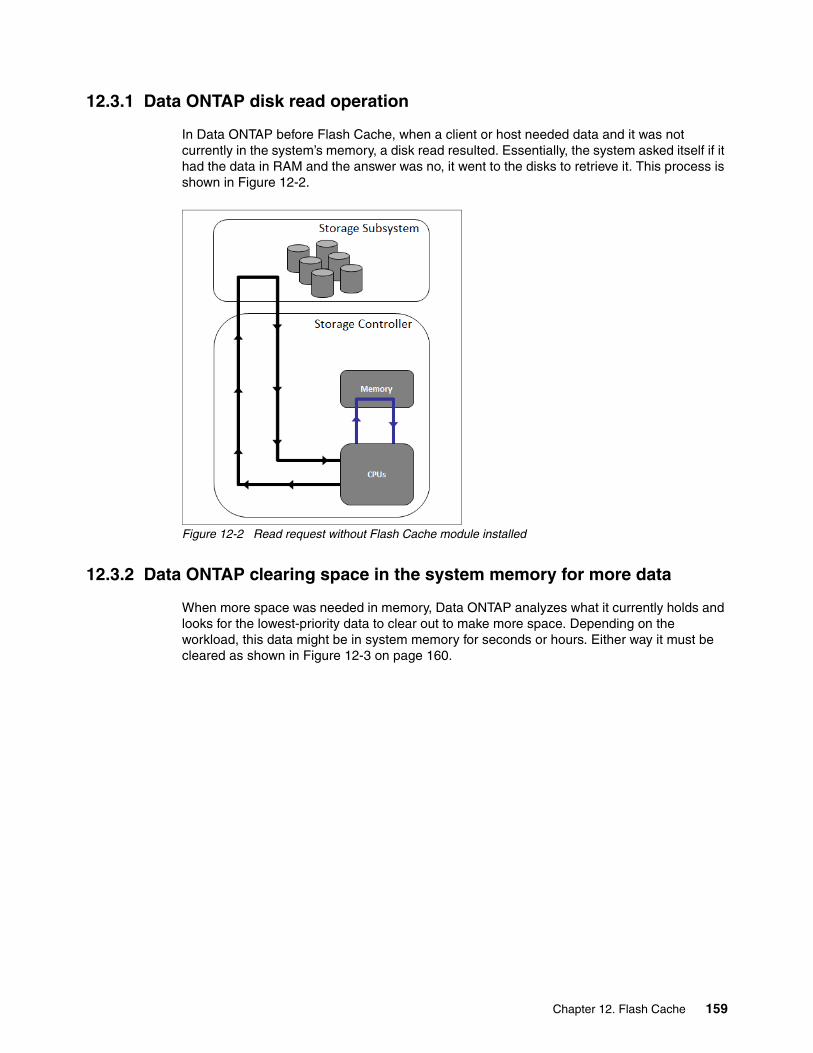
12.3.1 Data ONTAP disk read operation
In Data ONTAP before Flash Cache, when a client or host needed data and it was not currently in the system’s memory, a disk read resulted. Essentially, the system asked itself if it had the data in RAM and the answer was no, it went to the disks to retrieve it. This process is shown in Figure 12-2.
Figure 12-2 Read request without Flash Cache module installed
12.3.2 Data ONTAP clearing space in the system memory for more data
When more space was needed in memory, Data ONTAP analyzes what it currently holds and looks for the lowest-priority data to clear out to make more space. Depending on the workload, this data might be in system memory for seconds or hours. Either way it must be cleared as shown in Figure 12-3 on page 160.
Chapter 12. Flash Cache 159

Figure 12-3 Clearing memory before introducing Flash Cache
12.3.3 Saving useful data in Flash Cache
With the addition of Flash Cache modules, the data that would have previously been cleared is now placed in the module. Data is always read from disk into memory and then stored in the module when it needs to be cleared from system memory (Figure 12-4).
Figure 12-4 Data is stored in Flash Cache
160 IBM System Storage N series Hardware Guide

12.3.4 Reading data from Flash Cache
When the data is stored in the module, Data ONTAP can check to see whether it is there the next time it is needed (Figure 12-5).
Figure 12-5 Read request with Flash Cache module installed
When it is there, access to it is far faster than having to go to disk. This process is how a workload is accelerated (Figure 12-6).
Figure 12-6 Additional storage for WAFL extended cache
Need Space in System Memory?
Read from Disk
Data in Module?
Read from Module
Not in Module?
Chapter 12. Flash Cache 161

162 IBM System Storage N series Hardware Guide

Chapter 13. Disk sanitization
This chapter addresses disk sanitization and the process of physically removing data from a disk. This process involves overwriting patterns on the disk in a manner that precludes the recovery of that data by any known recovery methods.
It also presents the Data ONTAP disk sanitization feature and briefly addresses data confidentiality, technology drivers, costs and risks, and the sanitizing operation.
This chapter includes the following sections:
� Data ONTAP disk sanitization� Data confidentiality� Data ONTAP sanitization operation� Disk Sanitization with encrypted disks
13
© Copyright IBM Corp. 2012. All rights reserved. 163
13.1 Data ONTAP disk sanitizationIBM N series Data ONTAP includes Disk Sanitization with a separately licensable, no-cost solution as a part of every offered system. When enabled, this feature logically deletes all data on one or more physical disk drives. It does so in a manner that precludes recovery of that data by any known recovery methods. The obliteration is accomplished by overwriting the entire disk multiple times with user-defined patterns of data. The disk sanitization feature runs a disk-format operation. This operation uses three successive byte overwrite patterns per cycle and a default six cycles per operation for a total of 18 complete disk overwrite passes.
Disk sanitization can be performed on one or more physical disk drives. You can sanitize or cleanse all disks associated with a complete WAFL volume (and spares). You can also perform subvolume cleansing such as cleansing a qtree, a directory, or a file. For subvolume cleansing, any data that you want to retain must be migrated to another volume before the cleansing process. This volume can be on the same storage or another storage system. After the data migration is complete, sanitization can be performed on all of the drives associated with the initial original volume.
13.2 Data confidentialityIn every industry, IT managers face increasing pressure to ensure the confidentiality of corporate, client, and patient data. In addition, companies and managers in certain industries must comply with laws that specify strict standards for handling, distributing, and using confidential client, corporate, and patient information.
There are methods and products to aid in data storage and transmission security as the data moves through the system. However, assuring confidentiality of data on desktop or notebook computers when they leave the premises for disposal presents a different set of challenges and exposures. The following sections lay out those challenges and attempt to demonstrate the value of third-party disposal.
13.2.1 BackgroundData confidentiality has always been an issue of ethical concern. But with the enactment of laws to protect the privacy of individual health and financial records, it has become a legal concern as well.
Most IT managers have a strategy in place for securing customer information within their networks. Especially in the healthcare industry, where controlling data interchange with vendors to ensure patient privacy is a major concern.
The market offers various products and services to assist managers with these challenges. Many offer ways to integrate confidentiality and compliance into daily operations.
13.2.2 Data erasure and standards compliance
To prevent the exposure of commercially sensitive or private customer information, ensure that the storage devices are sanitized, purged, or destroyed before reuse or removal.
� Sanitization is the process of preventing the retrieval of information from the erased media by using normal system functions or software. The data might still be recoverable, but not without special laboratory techniques. This level of security is typically achieved by overwriting the physical media at least once.
164 IBM System Storage N series Hardware Guide

� Purging is the process of preventing the retrieval of information from the erased media by using all known techniques, including specialist laboratory tools. This level of security is achieved by securely erasing the physical media by using firmware-level tools.
� Destruction, as the name implies, is the physical destruction of the decommissioned media. This level of security is usually only required in defense or other high security environments.
13.2.3 Technology driversAs technology advances, upgrades, disk subsystem replacements, and data lifecycle management require the migration of data. To ensure that the data movement does not create a security risk by leaving data patterns behind, IBM System Storage N series offers the disk sanitization feature (Figure 13-1).
You might also sanitize disks if you want to help ensure that data currently on those disks is physically unrecoverable. You might have disks that you intend to remove from one storage system and want to reuse those disks in another appliance.
Figure 13-1 Disposing of disks
13.2.4 Costs and risksThere are two critical factors that all enterprises must consider when deciding on the cost and risk of hard disk sanitization practices:
� The cost of running sanitization programs on a fleet of computers can be prohibitive. Even in smaller organizations, the number of hard disks that must be cleansed can be unmanageable. Most IT managers do not have the time or resources to accomplish such a task without affecting other core business responsibilities. If you choose to destroy your hard disks (many of which can be reused), you dispose of equipment that still has market value.
� At the same time, companies must recognize the significant risk associated with breaches of private information. When companies do not properly sanitize exiting storage devices, they expose themselves to a myriad of public relations, legal, and business repercussions if any confidential data is leaked. Because governments around the world continue to pass and enforce regulations for electronic data security, IT managers must act quickly to adopt and implement appropriate hard disk sanitization practices.
Using Data ONTAP, IBM System Storage N series offers an effective sanitization method that reduces both costs and risks. The disk sanitization algorithms are built into Data ONTAP and require only licensing. No additional software installation is required.
ITSOREDBOOKS
Write
Pattern X
Sanitization Cycle
XXXXXXXXXXXX
Data notAccessible
Access toData
Chapter 13. Disk sanitization 165
13.3 Data ONTAP sanitization operation With the disk sanitize start command, Data ONTAP begins the sanitization process on each of the specified disks. The process consists of a disk format operation, followed by the specified overwrite patterns repeated for the specified number of cycles. Formatting is not performed on ATA drives.
The time to complete the sanitization process for each disk depends on the size of the disk, the number of patterns specified, and the number of cycles specified.
The following command starts the sanitization process on the disks listed:
disk sanitize start[-p <pattern>|-r [-p <pattern>|-r [-p <pat_tern>|-r]]] [-c <cycles>] <disk_list>
where:
� The -p option defines the byte patterns and the number of write passes in each cycle.
� The -r option can be used to generate a write of random data, instead of a defined byte pattern.
� If no patterns are specified, the default is three, using pattern 0x55 on the first pass, 0xaa on the second, and 0x3c on the third.
� The -c option specifies the number of cycles of pattern writes. The default is one cycle.
All sanitization process information is written to the log file at /etc/sanitization.log. The serial numbers of all sanitized disks are written to /etc/sanitized_disks.
Disk sanitization is not supported on SSD drives. It does not work on disks that belong to SnapLock compliance Aggregates until all of the files reach their retention dates. Sanitization also does not work with Array LUNs (N series Gateway). The disk sanitization command cannot be run against broken or failed disks.
The command shown in Example 13-1 starts one format overwrite pass and 18 pattern overwrite passes of disk 7.3.
Example 13-1 disk sanitize start command
disk sanitize start -p 0x55 -p 0xAA -p 0x37 -c 6 7.3
If you need to cancel the sanitization process, use the disk sanitize abort command. If the specified disks are undergoing the disk formatting phase of sanitization, the abort does not occur until the disk formatting is complete. At that time, Data ONTAP displays a message that the sanitization was stopped.
If the sanitization process is interrupted by power failure, system panic, or by the user, the sanitization process must be repeated from the beginning.
Requirement: You must enable the licensed_feature.disk_sanitization.enable option before you can perform disk sanitization. The default is off. However, after it is enabled, this option cannot be disabled, and some other features cannot be used. This option cannot be accessed remotely and must be configured by using the console.
Attention: Do not turn off the storage system, disrupt the storage connectivity, or remove target disks while sanitizing. If sanitizing is interrupted while target disks are being formatted, the disks must be reformatted before sanitizing can finish.
166 IBM System Storage N series Hardware Guide

Example 13-2 shows the progress of disk sanitization, starting with sanitization on drives 8a.43, 8a.44 and 8a.45. The process then formats these drives and writes a pattern (hex 0x47) multiple times (cycles) to the disks.
Example 13-2 Disk sanitization progress
Tue Jun 24 02:40:10 Disk sanitization initiated on drive 8a.43 [S/N 3FP20XX400007313LSA8]
Tue Jun 24 02:40:10 Disk sanitization initiated on drive 8a.44 [S/N 3FP0RFAZ00002218446B]
Tue Jun 24 02:40:10 Disk sanitization initiated on drive 8a.45 [S/N 3FP0RJMR0000221844GP]
Tue Jun 24 02:53:55 Disk 8a.44 [S/N 3FP0RFAZ00002218446B] format completed in 00:13:45.
Tue Jun 24 02:53:59 Disk 8a.43 [S/N 3FP20XX400007313LSA8] format completed in 00:13:49.
Tue Jun 24 02:54:04 Disk 8a.45 [S/N 3FP0RJMR0000221844GP] format completed in 00:13:54.
Tue Jun 24 02:54:11 Disk 8a.44 [S/N 3FP0RFAZ00002218446B] cycle 1 pattern write of 0x47 completed in 00:00:16.
Tue Jun 24 02:54:11 Disk sanitization on drive 8a.44 [S/N 3FP0RFAZ00002218446B] completed.
Tue Jun 24 02:54:15 Disk 8a.43 [S/N 3FP20XX400007313LSA8] cycle 1 pattern write of 0x47 completed in 00:00:16.
Tue Jun 24 02:54:15 Disk sanitization on drive 8a.43 [S/N 3FP20XX400007313LSA8] completed.
Tue Jun 24 02:54:20 Disk 8a.45 [S/N 3FP0RJMR0000221844GP] cycle 1 pattern write of 0x47 completed in 00:00:16.
Tue Jun 24 02:54:20 Disk sanitization on drive 8a.45 [S/N 3FP0RJMR0000221844GP] completed.
Tue Jun 24 02:58:42 Disk sanitization initiated on drive 8a.43 [S/N 3FP20XX400007313LSA8]
Tue Jun 24 03:00:09 Disk sanitization initiated on drive 8a.32 [S/N 43208987]
Tue Jun 24 03:11:25 Disk 8a.32 [S/N 43208987] cycle 1 pattern write of 0x47 completed in 00:11:16.
Tue Jun 24 03:12:32 Disk 8a.43 [S/N 3FP20XX400007313LSA8] sanitization aborted by user.
Tue Jun 24 03:22:41 Disk 8a.32 [S/N 43208987] cycle 2 pattern write of 0x47 completed in 00:11:16.
Tue Jun 24 03:22:41 Disk sanitization on drive 8a.32 [S/N 43208987] completed.
Chapter 13. Disk sanitization 167

The sanitization process can take a long time. To view the progress, use the disk sanitize status command as shown in Example 13-3.
Example 13-3 disk sanitize status command
itsotuc4*> disk sanitize statussanitization for 0c.24 is 10 % complete
The disk sanitize release command allows the user to return a sanitized disk to the spare pool.
The disk sanitize abort command is used to terminate the sanitization process for the specified disks:
disk sanitize abort <disk_list>
If the disk is in the format stage, the process is canceled when the format is complete. A message is displayed when the format and the cancel are complete.
13.4 Disk Sanitization with encrypted disks
You can destroy data stored on disks using Storage Encryption for security reasons. These reasons can include sanitizing the disks, setting the disk state to end-of-life, and emergency shredding of the data.
You can perform disk sanitization on disk using Storage Encryption. However, there are other methods to obliterate data on disks using Storage Encryption that are faster and do not require an operational storage system.
If you want to return a disk to a vendor, but do not want anyone to access sensitive data on it, use the disk encrypt sanitize command. This process renders the data on the disk inaccessible, but the disk can be reused. This command works only on spare disks, and was first released with Data ONTAP 8.1. It cryptographically erases self encrypting disks on a Storage Encryption enabled system.
To sanitize a disk, perform these steps:
1. Migrate any data that needs to be preserved to a different aggregate.
2. Delete the aggregate.
3. Identify the disk ID for the disk to be sanitized by entering the following command:
disk encrypt show
4. Enter the following command to sanitize the disks:
disk encrypt sanitize disk_ID
5. Use the sysconfig -r command to verify the results
Tip: To render a disk permanently unusable and the data on it inaccessible, set the state of the disk to end-of-life by using the disk encrypt destroy command. This command only works on spare disks.
168 IBM System Storage N series Hardware Guide

Chapter 14. Designing an N series solution
This chapter addresses the issues to consider when sizing an IBM System Storage N series storage system to your environment. The following topics are addressed:
� Performance and throughput� Capacity requirements� Effects of optional features� Future expansion� Application considerations� Backup and recovery� Resiliency to failure� Configuration limits
A complete explanation is beyond the scope of this book, so only high-level planning considerations are presented.
This chapter includes the following sections:
� Primary issues that affect planning� Performance and throughput� Summary
14
© Copyright IBM Corp. 2012. All rights reserved. 169

14.1 Primary issues that affect planningYou need to determine the following questions during the planning process:
� Which model IBM System Storage N series to use� What amount of storage would be required on the IBM System Storage N series� Which optional features are wanted� What your future expansion requirements are
To begin the planning process, use the following IBM solution planning tools:
� IBM Capacity Magic� IBM Disk Magic
14.1.1 IBM Capacity Magic
This tool is used to calculate physical and effective storage capacity. It supports the IBM DS6000™, DS8000, IBM V7000, and N series models.
� IBM staff
https://w3-03.sso.ibm.com/sales/support/ShowDoc.wss?docid=E272838K75735I92
� IBM Business Partners
TBA
14.1.2 IBM Disk Magic
This tool is used to estimate disk subsystem performance. It supports the IBM XIV, DS8000, DS6000, DS5000, DS4000®, SAN Volume Controller, V7000, V7000U, and SAN-attached N Series.
� IBM staff
https://w3-03.sso.ibm.com/sales/support/ShowDoc.wss?docid=Q947558L63209Z65
� IBM Business Partners
TBA
14.2 Performance and throughputThe performance required from the storage subsystem is driven by the number of client systems that rely on the IBM System Storage N series, and the applications running on those systems. Keep in mind that performance involves a balance of all of the following factors:
� Performance of a particular IBM System Storage N series model� Number of disks used for a particular workload� Type of disks used� How close to capacity the disks being run are� Number of network interfaces in use� Protocols used for storage access� Workload mix (reads versus writes versus lookups)
– Protocol choice
Restriction: The Disk Magic and Capacity Magic tools are licensed for use by IBM staff and IBM Business Partners only.
170 IBM System Storage N series Hardware Guide

– Percentage mix of read and write operations– Percentage mix of random and sequential operations– I/O sizes– Working set sizes for random I/O– Latency requirements– Background tasks running on the storage system (for example, SnapMirror)
14.2.1 Capacity requirements
A key measurement of a storage system is the amount of storage that it provides. Vendors and installers of storage systems generally deal with raw storage capacities. Users, however, are generally only concerned with available capacity. Ensuring that the gap is bridged between raw capacity and usable capacity minimizes surprises both at installation time and in the future.
Particular care is required when specifying storage capacity, because disk vendors, array vendors, and client workstations often use different nomenclature to describe the same capacity. Storage vendors usually specify disk capacity in “decimal” units, whereas desktop operating systems usually work in “binary” units. These units are often used in confusingly similar or incorrect ways.
Although this might seem to be a subtle difference, it can rapidly compound in large networks. This can cause the storage to be significantly over or under provisioned. In situations where capacity needs to be accurately provisioned, this discrepancy can cause an outage or even data loss. For example, if a client OS supports a maximum LUN size of 2 TB (decimal), it might fail if presented with a LUN of 2 TB (binary).
To add to the confusion, these suffixes have traditionally been applied in different ways across different technologies. For example, network bandwidth is always decimal (100 Mbps = 100 x 10^6 bits). Memory is always binary, but is not usually shown as “GiB” (4 GB = 4 x 2^30 bytes).
Table 14-1 shows a comparison of the two measurements.
Table 14-1 Decimal versus binary measurement
Some systems use a third option, where they define 1 GB as 1000 x 1024 x 1024 kilobytes.
This conversion between binary and decimal units causes most of the capacity “lost” when calculating the correct size of capacity in an N series design. These two methods represent the same capacity, a bit like measuring distance in kilometers or miles, but then using the incorrect suffix.
Tip: Always size a storage system to have reserve capacity beyond what is expected to be its normal workload.
Name (ISO) Suffix (ISO) Value (bytes)
Approx. Difference
Value (bytes)
Suffix (IEC) Name (IEC)
kilobyte kB 10^3 2% 2^10 KiB kibibyte
megabyte MB 10^6 5% 2^20 MiB mebibyte
gigabyte GB 10^9 7% 2^30 GiB gibibyte
terabyte TB 10^12 9% 2^40 TiB tebibyte
petabyte PB 10^15 11% 2^50 PiB pebibyte
Chapter 14. Designing an N series solution 171

For more information, see the following website:
http://en.wikipedia.org/wiki/Gigabyte
Raw capacityRaw capacity is determined by taking the number of disks connected and multiplying by their capacity. For example, 24 disks (the maximum in the IBM System Storage N series disk shelves) times 2 TB per drive is a raw capacity of approximately 48,000 GB, or 48 TB.
Usable capacityUsable capacity is determined by factoring out the portion of the raw capacity that goes to support the infrastructure of the storage system. This capacity includes space used for operating system information, disk drive formatting, file system formatting, RAID protection, spare disk allocation, mirroring, and the Snapshot protection mechanism.
The following example is where the storage would go in the example 24 x 2 TB drive system. Capacity usually gets used in the following areas:
� Disk ownership: In an N series dual controller (active/active) cluster, the disks are assigned to one, or the other, controller.
In the example 24 disk system, the disks are split evenly between the two controllers (12 disks each).
� Spare disks: It is good practice to allocate spare disk drives to every system. These drives are used if a disk drive fails so that the data on the failed drive can automatically be rebuilt without any operator intervention or downtime.
The minimum acceptable practice would be to allocate one spare drive, per drive type, per controller head. In the example, that would be two disks because it is a two-node cluster.
� RAID: When a drive fails, it is the RAID information that allows the lost data to be recovered.
– RAID-4: Protects against a single disk failure in any RAID group, and requires that one disk is reserved for RAID parity information (not user data).
Because disk capacities have increased greatly over time, with a corresponding increase in the risk of an error during the RAID rebuild, do not use RAID-4 for production use.
The remaining 11 drives (per controller), divided into 2 x RAID-4 groups, require two disks to be reserved for RAID-4 parity, per controller.
– RAID-DP: Protects against a double disk failure in any RAID group, and requires that two disks be reserved for RAID parity information (not user data).
With the IBM System Storage N series, the maximum protection against loss is provided by using the RAID-DP facility. RAID-DP has many thousands of times better availability than traditional RAID-4 (or RAID-5), often for little or no additional capacity.
The remaining 11 drives (per controller), allocated to 1 x RAID-DP group, require two disks to be reserved for RAID-DP parity, per controller.
� The RAID groups are combined to create storage aggregates that then have volumes (also called file systems) or LUNs allocated on them.
Normal practice would be to treat the nine remaining disks (per controller) as data disks, thus creating a single large aggregate on each controller.
Remember: This document uses decimal values exclusively, so 1 MB = 10^6 bytes.
172 IBM System Storage N series Hardware Guide

All 24 available disks are now allocated:
� Spare disk drive: 2 (1 per controller)� RAID parity disks: 2 (2 per controller)� Data disks: 18 (9 per controller)
About 25% of the raw capacity is used by hardware protection. This amount varies depending on the ratio of data disks to protection disks. The remaining usable capacity becomes less deterministic from this point because of ever increasing numbers of variables, but a few firm guidelines are still available.
Right-sizingA commonly misunderstood memory requirement is that imposed by the right-sizing process. This overhead is because of three main factors:
� Block leveling
– Disks from different batches (or vendors) can contain a slightly different number of addressable blocks. Therefore, the N series controller assigns a common maximum capacity across all drives of the same basic type. For example, this process makes all “1 TB” disks exactly equal.
– Block leveling has a negligible memory requirement because disks of the same type are already similar.
� Decimal to binary conversion
– Because disk vendors measure capacity in decimal units and array vendors usually work in binary units, the stated usable capacity differs.
– However no capacity is really lost because both measurements refer to the same number of bytes. For example, 1000 GB decimal = 1000000000000 bytes = 931 GB binary.
� Checksums for data integrity
– Fibre Channel (FC) disks natively use 520 byte sectors, of which only 512 bytes are used to store user data. The remaining 8 bytes per sector are used to store a checksum value. This imposes a minimal capacity overhead.
– SATA disks natively use 512 byte sectors, all of which is used to store user data. Therefore one sector per eight blocks is reserved to store the checksum value. This imposes a higher capacity overhead than for FC disks.
Table 14-2 Right-sized disk capacities
Disk Type Capacity (decimal GB)
Capacity GB(binary GB)
ChecksumType
Right-sized Cap.(binary GB)
FC 72 68 512/520 Block(approximately 2.4%)
66
144 136 132
300 272 265
600
Chapter 14. Designing an N series solution 173
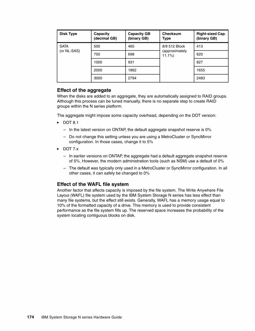
Effect of the aggregateWhen the disks are added to an aggregate, they are automatically assigned to RAID groups. Although this process can be tuned manually, there is no separate step to create RAID groups within the N series platform.
The aggregate might impose some capacity overhead, depending on the DOT version:
� DOT 8.1
– In the latest version on ONTAP, the default aggregate snapshot reserve is 0%
– Do not change this setting unless you are using a MetroCluster or SyncMirror configuration. In those cases, change it to 5%
� DOT 7.x
– In earlier versions on ONTAP, the aggregate had a default aggregate snapshot reserve of 5%. However, the modern administration tools (such as NSM) use a default of 0%
– The default was typically only used in a MetroCluster or SyncMirror configuration. In all other cases, it can safely be changed to 0%
Effect of the WAFL file systemAnother factor that affects capacity is imposed by the file system. The Write Anywhere File Layout (WAFL) file system used by the IBM System Storage N series has less effect than many file systems, but the effect still exists. Generally, WAFL has a memory usage equal to 10% of the formatted capacity of a drive. This memory is used to provide consistent performance as the file system fills up. The reserved space increases the probability of the system locating contiguous blocks on disk.
SATA(or NL-SAS)
500 465 8/9 512 Block(approximately 11.1%)
413
750 698 620
1000 931 827
2000 1862 1655
3000 2794 2483
Disk Type Capacity (decimal GB)
Capacity GB(binary GB)
ChecksumType
Right-sized Cap.(binary GB)
174 IBM System Storage N series Hardware Guide

As a result, the example 2000 GB (decimal) disk drives are down to only a little under 1500 GB (binary) before any user data is put on them. If you take the nine data drives per controller and allocate them to a single large volume, the resulting capacity is approximately 13,400 GB (binary) (Figure 14-1).
Figure 14-1 Example of raw (decimal) to usable (binary) capacity
The example in Figure 14-1 is for a small system. The ratio of usable to raw capacity varies depending on factors such as RAID group size, disk type, and space efficiency features that can be applied later. Examples of these features include thin provisioning, deduplication, compression, and Snapshot backup.
Effect of Snapshot protectionFinally, consider the effect of Snapshot protection on capacity. Snapshot is a built-in capability that keeps space free until it is actually used. However, using Snapshot affects the apparent usable capacity of the storage system. It is common to run a storage system with 20% of space reserved for Snapshot use. To the user, this space seems to be unavailable. The amount allocated for this purpose can be easily adjusted when necessary to a lower or higher value.
Running with this 20% setting further reduces the 13,400 GB usable storage to approximately 10,700 GB (binary). Whether you consider the snapshot reserve as being overhead or just part of the usable capacity depends on your requirements.
To return to reconciling usable storage to raw storage, this example suggests that either 65% or 55% of raw capacity is available for storing user data. The percentage depends on how you classify the snapshot reserve. In general, larger environments tend to result in a higher ratio of raw to usable capacity.
Attention: When introducing the N series gateway in a pre-existing environment, note that the final usable capacity is different from that available on the external disk system before being virtualized.
Chapter 14. Designing an N series solution 175

14.2.2 Other effects of Snapshot
It is important to understand the potential effect of creating and retaining Snapshots, on both the N series controller and any associated servers and applications. Also, the Snapshots need to be coordinated with the attached servers and applications to ensure data integrity.
The effect of Snapshots is determined by these factors:
� N series controller:
– Negligible effect on the performance of the controller: The N series snapshots use a redirect-on-write design. This design avoids most of the performance effect normally associated with Snapshot creation and retention (as seen in traditional copy-on-write snapshots on other platforms).
– Incremental capacity is required to retain any changes: Snapshot technology optimizes storage because only changed blocks are retained. For file access, the change rate is typically in the 1–5% range. For database applications, it might be similar. However, in some cases it might be as high as 100%.
� Server (SAN-attached):
– Minor effect on the performance of the server when the Snapshot is created (to ensure file system and LUN consistency).
– Negligible ongoing effect on performance to retain the Snapshots
� Application (SAN or NAS attached):
– Minor effect on the performance of the application when the snapshot is created (to ensure data consistency). This effect depends on the snapshot frequency. Once per day, or multiple times per day might be acceptable, but more frequent Snapshots can have an unacceptable effect on application performance.
– Negligible ongoing effect on performance to retain the Snapshots
� Workstation (NAS attached):
– No effect on the performance of the workstation. Frequent Snapshots are possible because the NAS file system consistency is managed by the N series controller.
– Negligible ongoing effect on performance to retain the Snapshots
14.2.3 Capacity overhead versus performance
There is considerable commercial pressure to make efficient use of the physical storage media. However, there are also times when using more disk spindles is more efficient.
Consider an example where 100 TB is provisioned on two different arrays:
� 100% raw-to-usable efficiency requires 100 x 1 TB disks, with each disk supporting perhaps 80 IOPS, for a total of 8000 physical IOPS.
� 50% raw-to-usable efficiency requires 200 x 1 TB disks, with each disk supporting perhaps 80 IOPS, for a total of 16,000 physical IOPS.
Obviously this is a simplistic example. Much of the difference might be masked behind the controller’s fast processor and cache memory. But it is important to consider the number of physical disk spindles when designing for performance.
176 IBM System Storage N series Hardware Guide

14.2.4 Processor utilization
Generally, a high processor load on a storage controller is a not, on its own, a good indicator of a performance problem. This is due both to the averaging that occurs on multi-core, multi-processor hardware. Also, the system might be running low-priority housekeeping tasks while otherwise idle (and such tasks are preempted to service client I/O).
One of the benefits of Data ONTAP 8.1 is that it takes better advantage of the modern multi-processor controller hardware.
The optimal initial plan would be for 50% average utilization, with peak periods of 70% processor utilization. In a two-node storage cluster, this configuration allows the cluster to fail-over to a single node with no performance degradation.
If the processors are regularly running at a much higher utilization (for example, 90%), then performance might still be acceptable. However, expect some performance degradation in a fail-over scenario because 90% + 90% adds up to a 180% load on the remaining controller.
14.2.5 Effects of optional featuresA few optional features affect early planning. Most notably, heavy use of the SnapMirror option can use large amounts of processor resources. These resources are directly removed from the pool available for serving user and application data. This process results in what seems to be an overall reduction in performance. SnapMirror can affect available disk I/O bandwidth and network bandwidth as well. Therefore, if heavy, constant use of SnapMirror is planned, adjust these factors accordingly.
14.2.6 Future expansionMany of the resources of the storage system can be expanded dynamically. However, you can make this expansion easier and less disruptive by planning for possible future requirements from the start.
Adding disk drives is one simple example. The disk drives and shelves themselves are all hot-pluggable, and can be added or replaced without service disruption. But if, for example, all available space in a rack is used by completely full disk shelves, how does a disk drive get added?
Where possible, a good practice from the beginning is to try to avoid fully populating disk shelves. It is much more flexible to install a new storage system with two half-full disk shelves attached to it rather than a single full shelf. The added cost is generally minimal, and is quickly recovered the first time additional disks are added.
Similar consideration can be given to allocating network resources. For instance, if a storage system has two available gigabit Ethernet interfaces, it is good practice to install and configure both interfaces from the beginning. Commonly, one interface is configured for actual production use and one as a standby in case of failure. However, it is also possible (given a network environment that supports this) to configure both interfaces to be in use and provide mutual failover protection to each other. This arrangement provides additional insurance because both interfaces are constantly in use. Therefore, you will not find that the standby interface is broken when you need it at the time of failure.
Overall, it is valuable to consider how the environment might change in the future and to engineer in flexibility from the beginning.
Chapter 14. Designing an N series solution 177
14.2.7 Application considerationsDifferent applications and environments put different workloads on the storage system. This section addresses a few considerations that are best addressed early in the planning and installation phases.
Home directories and desktop servingThis is a traditional application for network-attached storage solutions. Because many clients are attached to one or more servers, there is little possibility to effectively plan and model in advance of actual deployment. But a few common sense considerations can help:
� This environment is generally characterized by the use of Network File System (NFS) or Common Internet File System (CIFS) protocols.
� It is generally accessed by using Ethernet with TCP/IP as the primary access mechanism.
� The mix of reading and writing is heavily tipped towards the reading side. Uptime requirements are generally less than those for enterprise application situations, so scheduling downtime for maintenance is not too difficult.
In this environment, the requirements for redundancy and maximum uptime are sometimes reduced. The importance of data writing throughput is also lessened. More important is the protection offered by Snapshot facilities to protect user data and provide for rapid recovery in case of accidental deletion or corruption. For example, email viruses can disrupt this type of environment more readily than an environment that serves applications like Oracle or SAP.
Load balancing in this environment often takes the form of moving specific home directories from one storage system to another, or moving client systems from one subnet to another. Effective prior planning is difficult. The best planning takes into account that the production environment is dynamic, and therefore flexibility is key.
It is especially important in this environment to install with maximum flexibility in mind from the beginning. This environment also tends to use many Snapshot images to maximize the protection offered to the user.
Enterprise applicationsPreviously the domain of direct-attached storage (DAS) architectures, it is becoming much more common to deploy enterprise applications that use SAN or NAS storage systems. These environments have significantly different requirements than the home directory environment. It is common for the emphasis to be on performance, uptime, and backup rather than on flexibility and individual file recovery.
Commonly, these environments use a block protocol such as iSCSI or FCP because they mimic DAS more closely than NAS technologies. However, increasingly the advantages and flexibility provided by NAS solutions have been drawing more attention. Rather than being designed to serve individual files, the configuration focuses on LUNs or the use of files as though they were LUNs. An example would be a database application that uses files for its storage instead of LUNs. At its most fundamental, the database application does not treat I/O to files any differently than it does to LUNs. This configuration allows you to choose the deployment that provides the combination of flexibility and performance required.
Enterprise environments are usually deployed with their storage systems clustered. This configuration minimizes the possibility of a service outage caused by a failure of the storage appliance. In clustered environments, there is always the opportunity to spread workload across at least two active storage systems. Therefore, getting good throughput for the enterprise application is generally not difficult.
178 IBM System Storage N series Hardware Guide

This assumes that the application administrator has a good idea of where the workloads are concentrated in the environment so that beneficial balancing can be accomplished. Clustered environments always have multiple I/O paths available, so it is important to balance the workload across these I/O paths and across server heads.
For mission-critical environments, it is important to plan for the worst-case scenario. That is, running the enterprise when one of the storage systems fails and the remaining single unit must provide the entire load. In most circumstances, the mere fact that the enterprise is running despite a significant failure is viewed as positive. However, but there are situations in which the full performance expectation must be met even after a failure. In this case, the storage systems must be sized accordingly.
Block protocols with iSCSI or FCP are also common. The use of a few files or LUNs to support the enterprise application means that the distribution of the workload is relatively easy to install and predict.
Microsoft ExchangeMicrosoft Exchange has a number of parameters that affect the total storage required of N series. The following are examples of those parameters:
� Number of instances
With Microsoft Exchange, you can specify how many instances of an email or document are saved. The default is 1. If you elect to save multiple instances, take this into consideration for storage sizing.
� Number of logs kept
Microsoft Exchange uses a 5 MB log size. The data change rate determines the number of logs generated per day for recovery purposes. A highly active Microsoft Exchange server can generate up to 100 logs per day.
� Number of users
This number, along with mailbox limit, user load, and percentage concurrent access, has a significant effect on the sizing.
� Mailbox limit
The mailbox limit usually represents the quota assigned to users for their mailboxes. If you have multiple quotas for separate user groups, this limit represents the average. This average, multiplied by the number of users, determines the initial storage space required for the mailboxes.
� I/O load per user
For a new installation, it is difficult to determine the I/O load per user, but you can estimate the load by grouping the users. Engineering and development tend to have a high workload because of drawings and technical documents. Legal might also have a high workload because of the size of legal documents. Normal staff usage, however, consists of smaller sized I/O, more frequent transaction workloads. Use the following formula to calculate the usage:
IOPS/Mailbox = (average disk transfers/sec) / (number of mailboxes)
� Concurrent users
Typically, an enterprise’s employees do not all work in the same time zone or location. Estimate the number of concurrent users for the peak period, which is usually the time when the most employees have daytime operations.
Chapter 14. Designing an N series solution 179

� Number of storage groups
Because a storage group cannot span N series storage systems, the number of storage groups affects sizing. There is no recommendation on number of storage groups per IBM System Storage N series storage system. However, the number and type of users per storage group helps determine the number of storage groups per storage system.
� Volume type
Are FlexVols or traditional volumes used? The type of volume used affects both performance and capacity.
� Drive type
Earlier, this chapter addressed the storage capacity effect of drive type. For Microsoft Exchange, the drive type and performance characteristics are also significant, especially with a highly used Exchange server. In an active environment, use smaller drives and higher performance characteristics such as RPM and Fibre Channel versus SATA.
� Read-to-write ratio
The typical read-to-write ratio is 70% to 30%.
� Growth rate
Industry estimates place data storage growth rates at 50% or higher. Size for at least two years into the future.
� Deleted mailbox cache space
This is a feature of Microsoft Exchange that must also be sized for storage usage on the N series. Microsoft allows for a time-specified retention of documents even after deletion of a mailbox. You also must size the storage effect of this feature.
14.2.8 Backup serversProtecting and archiving critical corporate data is increasingly important. Deploying servers for this purpose is becoming more common, and these configurations call for their own planning guidelines.
A backup server generally is not designed to deliver high transactional performance. Data center managers rely on the backup server being available to receive the backup streams when they are sent. Often the backup server is an intermediate repository for data before it goes to backup tape and ultimately offsite. But frequently the backup server takes the place of backup tapes.
The write throughput of a backup server is frequently the most important factor to consider in planning. Another important factor is the number of simultaneous backup streams that a single server can handle. The more effective the write throughput and the greater the number of simultaneous threads, the more rapidly backup processes complete. The faster the processes complete, the sooner that production servers are taken out of backup mode and returned to full performance.
Each IBM System Storage N series platform has different capabilities in each of these areas. The planning process must take these characteristics into account to ensure that the backup server is capable of the workload expected.
14.2.9 Backup and recoveryIn addition to backup servers, all storage systems must be backed up. Generally, the goal is to have the backup process occur at a time and in a way that minimizes the effect on overall production. Therefore, many backup processes are scheduled to run during off-hours.
180 IBM System Storage N series Hardware Guide

However, all of these backups run more or less at the same time. Therefore, the greatest I/O load put on the storage environment is frequently during these backup activities, instead of during normal production.
IBM System Storage N series storage systems have a number of backup mechanisms available. With prior planning, you can deploy an environment that provides maximum protection against failure while also optimizing the storage and performance capabilities.
Keep in mind the following issues:
� Storage capacity used by Snapshots
How much extra storage must be available for Snapshots to use?
� Networking bandwidth used by SnapMirror
In addition to the production storage I/O paths, SnapMirror needs bandwidth to duplicate data to the remote server.
� Number of possible simultaneous SnapMirror threads
How many parallel backup operations can be run at the same time before some resource runs out? Resources to consider include processor cycles, network throughput, maximum parallel threads (which is platform-dependent), and the amount of data that requires transfer.
� Frequency of SnapMirror operations
The more frequently data is synchronized, the fewer the number of changes each time. More frequent operations result in background operations running almost all the time.
� Rate at which stored data is modified
Data that does not change much (for example, archive repositories) does not need to be synchronized as often, and each operation takes less time.
� Use and effect of third-party backup facilities (for example, IBM Tivoli Storage Manager)
Each third-party backup tool has its unique I/O effects that must be accounted for.
� Data synchronization requirements of enterprise applications
Certain applications such as IBM DB2®, Oracle, and Microsoft Exchange, must be quiesced and flushed before performing backup operations. This process ensures data consistency of backed-up data images.
14.2.10 Resiliency to failureLike all data processing equipment, storage devices sometimes fail. Most often the failure is of small, uncritical pieces that have redundancy such as disks, networks, fans, and power supplies. These failures generally have only a small effect (usually none at all) on the production environment. But unforeseen problems can cause rare and infrequent outages of entire storage systems. The most common issues are software problems that occur inside the storage system or infrastructure errors (such as DNS or routing tables) that prevent access to the storage system. If a storage system is running but cannot be accessed, the effect on the enterprise is effectively the same as it being out of service.
Designing 100% reliable configurations is difficult, time-consuming, and costly. Generally, strike a compromise that minimizes the likelihood of error while providing a mechanism to get the server back into service as quickly as possible. In other words, accept the fact that failures will occur, but have a plan ready and practiced to recover when they do.
Chapter 14. Designing an N series solution 181
Spare serversSome enterprises keep spare equipment around in case of failure. Generally, this is the most expensive solution and is only practical for the largest enterprises.
An often overlooked similar situation is the installation of new servers. Additional or replacement equipment is always being brought into most data environments. Bringing this equipment in a bit early and using it as spare or test equipment is a good practice. Storage administrators can practice new procedures and configurations, and test new software without having to do so on production equipment.
Local clusteringThe decision to use the high availability features of IBM System Storage N series is determined by availability and service level agreements. These agreements affect the data and applications that run on the IBM System Storage N series storage systems. If it is determined that a Active/Active configuration is needed, it affects sizing. Rather than sizing for all data, applications, and clients serviced by one IBM System Storage N series node, the workload is instead divided over two or more nodes.
Failover performanceAnother aspect of a Active/Active configuration is failover performance. As an example, you have determined that the data, application, or clients require constant availability of the IBM System Storage N series, and use Active/Active configurations. However, you might have sized for normal operations on each node and not failover. So what was originally a normal workload for a single node has now doubled.
You also must consider the service level agreement for response time, data access, and application performance. How long can your customers work within a degraded performance environment? If the answer is not long at all, the initial sizing of each node also must take failover workload into consideration. Because failover operation is infrequent and usually remedied quickly, it is difficult to justify these additional standby resources unless maintaining optimum performance is critical. An example is a product ordering system with the data storage or application on an IBM System Storage N series storage system. Any effect on the ability to place an order affects sales.
Software upgradesIBM regularly releases minor upgrades and patches for the Data ONTAP software. Less frequently there are also major release upgrades, such as version 8.1.
You need to be aware of the new software versions for these reasons:
� Patches address recently corrected software flaws� Minor upgrades will bundle multiple patches together, and might introduce new features� Major upgrades generally introduce significant new features
To remain informed of new software releases, subscribe to the relevant sections at the IBM automatic support notification website at:
https://www.ibm.com/support/mynotifications
Upgrades for Data ONTAP, along with mechanisms for implementing the upgrade are available on the web at:
http://www.ibm.com/storage/support/nas
Be sure that you understand the recommendations from the vendor and the risks. Use all the available protection tools such as Snapshots and mirrors to provide a fallback in case the
182 IBM System Storage N series Hardware Guide

upgrade introduces more problems than it solves. And whenever possible, perform incremental unit tests on an upgrade before putting an upgrade into critical production.
TestingAs storage environments become ever more complex and critical, the need for customer-specific testing increases in importance. Work with your storage vendors to determine an appropriate and cost-effective approach to testing solutions to ensure that your storage configurations are running optimally.
Even more important is that testing of disaster recovery procedures become a regular and ingrained process for everyone involved with storage management.
14.3 SummaryThis chapter provided only a high-level set of guidelines for planning. Consideration of the issues addressed maximizes the likelihood for a successful initial deployment of an IBM System Storage N series storage system. Other sources of specific planning templates exist or are under development. Locate them by using web search queries.
Deploying a network of storage systems is not greatly challenging, and most customers can successfully deploy it themselves by following these guidelines. Because of the simplicity that appliances provide, if a mistake is made in the initial deployment, corrective actions are generally not difficult or overly disruptive. For many years customers have iterated their storage system environments into scalable, reliable, and smooth-running configurations. So getting it correct the first time is not nearly as critical as it was before the introduction of storage appliances.
If storage system planners and architects remember to keep things simple and flexible, success in deploying an IBM System Storage N series system can be expected.
Chapter 14. Designing an N series solution 183

184 IBM System Storage N series Hardware Guide

Part 2 Installation and administration
This part provides guidance and checklists for planning the initial hardware installation and software setup.
To help perform the initial hardware and software setup, it also describes the administrative interfaces:
� Serial console� RLM interface� SSH connections� At a high-level, the GUI interfaces
This part includes the following chapters:
� Preparation and installation� Basic N series administration
Part 2
© Copyright IBM Corp. 2012. All rights reserved. 185

186 IBM System Storage N series Hardware Guide

Chapter 15. Preparation and installation
This chapter addresses the N series System Manager tool. This tool allows you to manage the N series storage system even with limited experience and knowledge of the N series hardware and software features. System Manager helps with basic setup and administration tasks, and can help you manage multiple IBM N series storage systems from a single application.
This chapter includes the following sections:
� Installation prerequisites� Configuration worksheet� Initial hardware setup� Troubleshooting if the system does not boot
15
© Copyright IBM Corp. 2012. All rights reserved. 187

15.1 Installation prerequisites
This section describes, at a high level, some of the planning and prerequisite tasks that need to be completed for a successful N series implementation.
For more information, see the N series Introduction and Planning Guide at:
http://www-304.ibm.com/support/docview.wss?crawler=1&uid=ssg1S7001913
15.1.1 Pre-installation checklist
Before arriving at the customer site, send the customer the relevant system specifications, and a pre-install checklist to complete. This list should contain environmental specifications for N series equipment:
� Storage controller weight, dimensions, and rack units.� Power requirements� Network connectivity
The customer completes the pre-install checklist with all the necessary information about their environment such as host name, IP, DNS, AD, and Network.
Work through this checklist with customer and inform them about the rack and floor space requirements. This process speeds up the installation time because all information has been collected beforehand.
After this process is complete and equipment is delivered to the customer, you can arrange an installation date.
15.1.2 Before arriving on site
Before arriving at the customer site, ensure that you have the following tools and resources:
� Required software and firmware:
– Data ONTAP software (take note of storage platform)
– Latest firmware files:
• Expansion shelf firmware
• Disk firmware
• RLM/BMC firmware
• System firmware
� Appropriate tools and equipment:
– Pallet jack, forklift, or hand truck, depending on the hardware that you receive
– #1 and #2 Phillips head screwdrivers, and a flathead screwdriver for cable adapters
– A method for connecting to the serial console:
• A USB-to-Serial adapter
• Null modem cable (with appropriate connectors)
� Documentation stored locally on your mobile computer such as ONTAP documentation, HW documentation
188 IBM System Storage N series Hardware Guide

� Sufficient people to safely install the equipment into a rack:
– Two or three people are required, depending on the hardware model
– See the specific hardware installation guide for your equipment
15.2 Configuration worksheet
Before powering on your storage system for the first time, use the configuration worksheet (Table 15-1) to gather information for the software setup process.
For more information about completing the configuration worksheet, see the N series Data ONTAP 8.1 7-Mode Software Setup Guide at:
http://www.ibm.com/support/docview.wss?uid=ssg1S7003722
Table 15-1 Configuration worksheet
Type of information Your values
Storage system Host name
Password
Time zone
Storage system location
Language used for multiprotocol storage systems
Administration host Host name
IP address
Interface groups Name of the interface group (such as ig0)
Mode type (single, multi, or LACP)
Load balancing type (IP-based, MAC address based, or round-robin based)
Number of links (number of physical interfaces to include in the interface group)
Link names (physical interface names such as e0, e0a, e5a, or e9b)
IP address for the interface group
Subnet mask (IPv4) or subnet prefix length (IPv6) for interface group
Partner interface group name
Media type for interface group
Chapter 15. Preparation and installation 189

Ethernet interfaces Interface name
IPv4 address
IPv4 subnet mask
IPv6 address
IPv6 subnet prefix length
Partner IP address or interface
Media type (network type)
Are jumbo frames supported?
MTU size for jumbo frames
Flow control
e0M interface (if available) IP address
Network mask
Partner IP address
Flow control
Router (if used) Gateway name
IPv4 address
IPv6 address
HTTP Location of HTTP directory
DNS Domain name
Server address 1
Server address 2
Server address 3
NIS Domain name
Server address 1
Server address 2
Server address 3
Type of information Your values
190 IBM System Storage N series Hardware Guide

CIFS Windows domain
WINS servers (1, 2, 3)
Multiprotocol or NTFS only filer?
Should CIFS create default /etc/passwd and /etc/group files?
Enable NIS group caching?
Hours to update the NIS cache?
CIFS server name (if different from default)
User authentication style:(1) Active Directory domain(2) Windows NT 4 domain (3) Windows Workgroup (4) /etc/passwd or NIS/LDAP
Windows Active Directory domain
Domain name
Time server name/IP address
Windows user name
Windows user password
Local administrator name
Local administrator password
CIFS administrator or group
Active Directory container
BMC MAC address
IP address
Network mask (subnet mask)
Gateway
Mailhost
Type of information Your values
Chapter 15. Preparation and installation 191

15.3 Initial hardware setupThe initial N series hardware setup includes the following steps:
1. Hardware Rack and Stack:
– Storage controllers, disk shelves, and so on
2. Connectivity:
– Storage controller to disk shelves
– Ethernet connectivity
3. ONTAP installation or upgrade (if required)
4. Hardware diagnostic tests
5. Protocol and software license verification/activation
6. Firmware updates:
– Disk (if applicable)
– Shelf (if applicable)
– System
– RLM / BMC
7. Protocol tests and cluster failover tests
RLM MAC address
IPv4 Address
IPv4 Subnet mask
IPv4 Gateway
IPv6 Address
IPv6 Subnet prefix length
IPv6 Gateway
AutoSupport mailhost
AutoSupport recipients
ACP Network interface name
Domain (subnet) for network interface
Netmask (subnet mask) for network interface
Key management server(s)(if using Storage Encryption)
IP address(es)
Key tag name
Type of information Your values
192 IBM System Storage N series Hardware Guide

15.4 Troubleshooting if the system does not boot
This section is an extract from the Data ONTAP 8.1 7-mode software setup guide. For more information about system setup, see the following documentation:
http://www.ibm.com/support/docview.wss?uid=ssg1S7003722
If your system does not boot when you power it on, you can troubleshoot the problem by performing these steps:
1. Look for a description of the problem on the console, and follow any instructions provided.
2. Make sure that all cables and connections are secure.
3. Ensure that power is supplied and is reaching your system from the power source.
4. Make sure that the power supplies on your controller and disk shelves are working.
Table 15-2 Power supply LED status
5. Verify disk shelf compatibility and check the disk shelf IDs.
6. Ensure that the Fibre Channel disk shelf speed is correct. If you have DS14mk2 Fibre Channel and DS14mk4 Fibre Channel shelves mixed in the same loop, set the shelf speed to 2 Gb, regardless of module type.
7. Check disk ownership to ensure that the disks are assigned to the system:
a. Verify that disks are assigned to the system by entering the disk show command.
a. Validate that storage is attached to the system, and verify any changes that you made, by entering disk show -v.
8. Turn off your controller and disk shelves, then turn on the disk shelves. For information about LED responses, check the quick reference card that came with the disk shelf or the hardware guide for your disk shelf.
9. Use the onboard diagnostic tests to check that Fibre Channel disks in the storage system are operating properly:
a. Turn on your system and press Ctrl-C.
b. Enter boot_diags at the LOADER> prompt.
c. Enter fcal in the Diagnostic Monitor program that starts at boot.
d. Enter 73 at the prompt to show all disk drives.
e. Exit the Diagnostic Monitor by entering 99 at the prompt.
f. Enter the exit command to return to LOADER.
g. Start Data ONTAP by entering autoboot at the prompt.
10.Use the onboard diagnostic tests to check that SAS disks in the storage system are operating properly:
a. Enter mb in the Diagnostic Monitor program.
b. Enter 6 to select the SAS test menu.
If the LEDs on a power supply are... Then...
Illuminated Proceed to the next step.
Not illuminated Remove the power supply and reinstall it, making sure that it connects with the backplane.
Chapter 15. Preparation and installation 193

c. Enter 42 to scan and show disks on the selected SAS. Doing so displays the number of SAS disks.
d. Enter 72 to show the attached SAS devices.
e. Exit the Diagnostic Monitor by entering 99 at the prompt.
f. Enter the exit command to return to LOADER.
g. Start Data ONTAP by entering autoboot at the prompt.
11.Try starting your system again.
Table 15-3 Starting the system
If your system... Then...
Starts successfully Proceed to setting up the software.
Does not start successfully Call IBM technical support.
The system might not have the boot image downloaded on the boot device.
194 IBM System Storage N series Hardware Guide

Chapter 16. Basic N series administration
This chapter describes how to accomplish basic administration tasks on IBM System Storage N series storage systems.
This chapter includes the following sections:
� Administration methods� Starting, stopping, and rebooting the storage system
16
© Copyright IBM Corp. 2012. All rights reserved. 195

16.1 Administration methodsThe following methods can be used to administer an N series storage system:
� FilerView interface� Command-line interface� N series System Manager� OnCommand
16.1.1 FilerView interface
Earlier versions on the N series controllers supported a built-in web management interface called FilerView. This interface is still available for systems that are running ONTAP 7.3 or earlier, but was removed in ONTAP 8.1.
To access a pre-8.1 N series through FilerView, open your browser and go to the following URL:
http://<filername or ip-address>/na_admin
To proceed, specify a valid user name and password.
16.1.2 Command-line interface
The CLI can be accessed through Telnet or a Secure Shell (SSH) interface. Use the help command or enter a question mark (?) to obtain an overview of available commands.
Enter help <command> for a brief description of what the command does.
Tip: By default the FilerView interface is unencrypted. Enable the HTTP/S protocol as soon as possible if you plan to use FilerView.
Generally, do not use FilerView. Instead, use either the CLI or OnCommand System Manager to perform administrative tasks
196 IBM System Storage N series Hardware Guide

Enter <command> help for a list of the available options of the specified command as shown in Figure 16-1.
Figure 16-1 The help and ? commands
The manual pages can be accessed by entering the man command. Figure 16-2 provides a detailed description of a command and lists options (man <command>).
Figure 16-2 Results of a man command
Chapter 16. Basic N series administration 197

16.1.3 N series System Manager
System Manager provides setup and management capabilities for SAN and NAS environments from a Microsoft Windows system. You can use System Manager to quickly and efficiently set up storage systems that are in a single node or a high-availability configuration. You can also use System Manager for these tasks:
� Configure all protocols, such as NFS, CIFS, FCP, and iSCSI� Supply provisions for file sharing and applications� Monitor and manage your storage system
System Manager is a stand-alone application, and is run as a Microsoft Management Console (MMC) snap-in.
System Manager has these key features:
� System setup and configuration management
� Protocol management (NFS, CIFS, iSCSI, and FCP)
� Shares/exports management
� Storage management (volumes, aggregates, disks, and qtrees)
Microsoft Windows XP, Vista, Server 2003, and 2008 are the currently supported platforms.
System Manager release 1.1 supports Data ONTAP 7.2.3 and later. The current release is Data ONTAP 8.1 7-mode.
For more information about System Manager, see the IBM NAS support site at:
http://www.ibm.com/storage/support/nas/
16.1.4 OnCommand
OnCommand is an operations manager is an N series solution for managing multiple N series storage systems that provides these features:
� Scalable management, monitoring, and reporting software for enterprise-class environments
� Centralized monitoring and reporting of information for fast problem resolution
� Management policies with custom reporting to capture specific, relevant information to address business needs
� Flexible, hierarchical device grouping to allow monitoring
The cost of OnCommand depends on the product purchased.
16.2 Starting, stopping, and rebooting the storage systemThis section describes boot, shutdown, and halt procedures.
Attention: Reboot and halt should always be planned procedures. Users need to be informed about these tasks in advance to give them enough time to save their changes to avoid loss of data.
198 IBM System Storage N series Hardware Guide

16.2.1 Starting the IBM System Storage N series storage systemThe IBM System Storage N series boot code is on a CompactFlash card. After turning on the system, IBM System Storage N series boots automatically from this card. You can enter an alternative boot mode by pressing Ctrl+C and selecting the boot option.
Example 16-1 shows the boot panel. Press Ctrl+C to display the special boot menu.
Example 16-1 Boot panel
CFE version 1.2.0 based on Broadcom CFE: 1.0.35Copyright (C) 2000,2001,2002,2003 Broadcom Corporation.Portions Copyright (C) 2002,2003 Network Appliance Corporation.
CPU type 0x1040102: 650MHzTotal memory: 0x40000000 bytes (1024MB)
Starting AUTOBOOT press any key to abort...Loading: 0xffffffff80001000/21792 0xffffffff80006520/10431377 Entry at 0xffffffff80001000Starting program at 0xffffffff80001000Press CTRL-C for special boot menu
Example 16-2 shows the boot options. Typically, you boot in normal boot mode.
Example 16-2 Boot menu
1) Normal Boot2) Boot without /etc/rc3) Change Password4) Initialize all disks4a) Same as option 4 but create a flexible root volume5) Maintenance bootSelection (1-5)?
16.2.2 Stopping the IBM System Storage N series storage systemStopping and rebooting the IBM System Storage N series storage system prevents all users from accessing the N series. Before stopping or rebooting the system, ensure that maintenance is possible. Also, inform all users (file access, database user, and others) about the upcoming action so they can save their data.
Attention: Power on the IBM System Storage N series storage system in the following order:
1. Expansion disk shelves2. IBM System Storage N series (base unit)
Tip: For a graceful shutdown of IBM System Storage N series storage systems, use the halt command or FilerView. This process avoids unpredictable problems. Remember to shut down both nodes if an IBM System Storage N series A2x model must be shut down.
Chapter 16. Basic N series administration 199

Common Internet File System (CIFS) services The cifs sessions command reports open sessions to the IBM System Storage N series storage system (Example 16-3).
Example 16-3 List open CIFS sessions
itsosj-n1> cifs sessionsServer Registers as 'ITSO-N1' in workgroup 'WORKGROUP'Root volume language is not set. Use vol lang.WINS Server: 9.1.38.12Using Local Users authentication====================================================PC IP(PC Name) (user) #shares #files9.1.57.45() (ITSO-N1\administrator - root) (using security signatures) 1 09.1.39.107() (ITSO-N1\administrator - root) (using security signatures) 3 0itsosj-n1>
With the IBM System Storage N series storage systems, you can specify which users receive CIFS shutdown messages. By issuing the cifs terminate command, Data ONTAP, by default, sends a message to all open client connections. This setting can be changed by issuing the following command:
options cifs.shutdown_msg_level 0 | 1 | 2
The options are:
0: Never send CIFS shutdown messages.1: Send CIFS messages to clients connected and with open files only.2: Send CIFS messages to all open connections (default).
The cifs terminate command shuts down CIFS, ends CIFS service for a volume, or logs off a single station. The -t option can be used to specify a delay interval in minutes before CIFS stops as shown in Example 16-4.
Example 16-4 The cifs terminate -t command
itsosj-n1> cifs terminate -t 3Total number of connected CIFS users: 1 Total number of open CIFS files: 0Warning: Terminating CIFS service while files are open may cause data loss!!3 minutes left until termination (^C to abort)...2 minutes left until termination (^C to abort)...1 minute left until termination (^C to abort)...
CIFS local server is shutting down...
CIFS local server has shut down...itsosj-n1>
You can even select single workstations for which the CIFS service should stop as shown in Example 16-5.
Example 16-5 The cifs terminate command for a single workstation
itsosj-n1> cifs terminate -t 3 workstation_013 minutes left until termination (^C to abort)...2 minutes left until termination (^C to abort)...1 minute left until termination (^C to abort)...
200 IBM System Storage N series Hardware Guide

itsosj-n1> Thu Sep 8 09:41:43 PDT [itsosj-n1: cifs.terminationNotice:warning]: CIFS: shut down completed: disconnected workstation workstation_01.
itsosj-n1>
When you shut down an N series, there is no need to specify the cifs terminate command. During shutdown, this command is run by the operating system automatically.
Depending on the CIFS message settings, messages such as those shown in Figure 16-3 are displayed on the affected workstations.
Figure 16-3 Shut down messages on CIFS clients
To restart CIFS, issue the cifs restart command as shown in Example 16-6. The N series startup procedure starts the CIFS services automatically.
Example 16-6 The cifs restart command
itsosj-n1> cifs restartCIFS local server is running.itsosj-n1>
You can verify whether CIFS is running by using the cifs sessions command. If CIFS is not running, a message is displayed as shown in Example 16-7.
Example 16-7 Checking whether CIFS is running on the N series
itsosj-n1> cifs sessionsCIFS not running. Use "cifs restart" to restart Use "cifs prefdc" to set preferred DCs Use "cifs testdc" to test WINS and DCs Use "cifs setup" to configureitsosj-n1>
Tip: Workstations running Windows 95/98 or Windows for Workgroups will not see the notification unless they are running WinPopup.
Chapter 16. Basic N series administration 201

Halting the N seriesYou can use the command line or FilerView interface to stop the N series. You can use the halt command on the CLI to perform a graceful shutdown. The -t option causes the system to stop after the number of minutes that you specify (for example, halt -t 5). The halt command stops all services and shuts down the system gracefully to the Common Firmware Environment (CFE) prompt.
File system changes are written to disk, and the nonvolatile random access memory (NVRAM) content is vacated.
Use the serial console because the IP connection will be lost after halting the N series (Example 16-8).
Example 16-8 Halting with the command-line interface (serial console)
CFE version 1.2.0 based on Broadcom CFE: 1.0.35Copyright (C) 2000,2001,2002,2003 Broadcom Corporation.Portions Copyright (C) 2002,2003 Network Appliance Corporation. CPU type 0x1040102: 650MHzTotal memory: 0x40000000 bytes (1024MB)CFE>
Booting the N seriesAs described in 16.2.1, “Starting the IBM System Storage N series storage system” on page 199, the IBM System Storage N series storage systems automatically boots Data ONTAP from a PC Compact Flash card. This card ships with the most current Data ONTAP release. The Compact Flash card contains sufficient space for an upgrade kernel. Use the download command to copy a boot kernel to the Compact Flash card.
The CFE prompt provides several boot options:
boot_ontap Boots the current version of Data ONTAP from the Compact Flash card.
boot_primary Boots the current version of Data ONTAP from the Compact Flash card as the primary kernel (the same kernel as boot_ontap).
boot_backup Boots the backup version of Data ONTAP from the Compact Flash card. The backup release is created during the first software upgrade to preserve the kernel that shipped with the system. It provides a known good release from which you can boot the system if it fails to automatically boot the primary image.
netboot Boots from a Data ONTAP version stored on a remote HTTP or TFTP server. The netboot option enables you to boot an alternative kernel if the Compact Flash card becomes damaged. You can upgrade the boot kernel for several devices from a single server.
To enable netboot, you must configure networking for the IBM System Storage N series storage system using DHCP or static IP address. Place the boot image on a configured server.
For more information about setting up netboot, see the following website:
http://www.ibm.com/storage/support/nas/
Tip: Store a boot image on an http or TFTP server to protect against Compact Flash card corruption.
202 IBM System Storage N series Hardware Guide

Usually you boot the N series after you issue the halt command with the boot_ontap or bye command. These commands end the CFE prompt and restart the N series as shown in Example 16-9.
Example 16-9 Starting the N series at the CFE prompt
CFE>byeCFE version 1.2.0 based on Broadcom CFE: 1.0.35Copyright (C) 2000,2001,2002,2003 Broadcom Corporation.Portions Copyright (C) 2002,2003 Network Appliance Corporation.
CPU type 0x1040102: 650MHzTotal memory: 0x40000000 bytes (1024MB)
Starting AUTOBOOT press any key to abort...Loading: 0xffffffff80001000/21792 0xffffffff80006520/10431377 Entry at 0xffffffff80001000Starting program at 0xffffffff80001000Press CTRL-C for special boot menu.................................................................................................................................................................................................................Interconnect based upon M-VIA ERing Support Copyright (c) 1998-2001 Berkeley Lab http://www.nersc.gov/research/FTG/viaWed Aug 31 19:00:46 GMT [cf.nm.nicTransitionUp:info]: Interconnect link 0 is UPWed Aug 31 19:00:46 GMT [cf.nm.nicTransitionDown:warning]: Interconnect link 0 is DOWN Data ONTAP Release 7.1H1: Mon Aug 15 16:02:45 PDT 2005 (IBM)Copyright (c) 1992-2005 Network Appliance, Inc.Starting boot on Wed Aug 31 19:00:45 GMT 2005Wed Aug 31 19:00:51 GMT [diskown.isEnabled:info]: software ownership has been enabled for this systemWed Aug 31 19:00:56 GMT [raid.cksum.replay.summary:info]: Replayed 0 checksum blocks.Wed Aug 31 19:00:56 GMT [raid.stripe.replay.summary:info]: Replayed 0 stripes.Wed Aug 31 19:00:57 GMT [localhost: cf.fm.launch:info]: Launching cluster monitorWed Aug 31 19:00:57 GMT [localhost: cf.fm.notkoverClusterDisable:warning]: Cluster monitor: cluster takeover disabled (restart)add net 127.0.0.0: gateway 127.0.0.1DBG: Failed to get partner serial number from VTICDBG: Set filer.serialnum to: 310070722Wed Aug 31 19:00:58 GMT [rc:notice]: The system was down for 71 secondsWed Aug 31 12:01:00 PDT [itsosj-n1: dfu.firmwareUpToDate:info]: Firmware is up-to-date on all disk drivesWed Aug 31 12:01:00 PDT [ltm_services:info]: Ethernet e0a: Link upadd net default: gateway 192.186.101.57: network unreachableWed Aug 31 12:01:02 PDT [rc:ALERT]: timed: time daemon startedWed Aug 31 12:01:03 PDT [itsosj-n1: mgr.boot.disk_done:info]: Data ONTAP Release 7.1H1 boot complete. Last disk update written at Wed Aug 31 11:59:46 PDT 2005Wed Aug 31 12:01:03 PDT [itsosj-n1: mgr.boot.reason_ok:notice]: System rebooted.
Password:
itsosj-n1> Wed Aug 31 12:01:20 PDT [console_login_mgr:info]: root logged in from consoleitsosj-n1>
Depending on the CIFS Message settings and Microsoft Windows Client settings, you might receive messages on your CIFS client about the shutdown. These messages are shown in Figure 16-3 on page 201.
Chapter 16. Basic N series administration 203

16.2.3 Rebooting the systemThe System Storage N series systems can be rebooted from the command line or from the NSM interface.
Rebooting from the CLI halts the N series and then restarts it as shown in Example 16-10.
Example 16-10 Rebooting from the command-line interface
[root@itso3775 node1]# reboot
Broadcast message from root (pts/2) (Thu Sep 8 13:23:47 2005):
The system is going down for reboot NOW!
Network File System (NFS) clients can maintain use of a file over a halt or reboot because NFS is a stateless protocol. CIFS, FCP, and iSCSI clients behave differently. Therefore, use the -t option to allow users time before the shutdown to save their work.
Depending on the shutdown message settings, CIFS clients might receive messages such as those shown in Figure 16-3 on page 201.
204 IBM System Storage N series Hardware Guide

Part 3 Client hardware integration
This part addresses the functions and installation of the host utility kit software. It also describes how to configure a client system to SAN boot from an N series, and provides a high-level description of host multipathing on the N series platform.
This part includes the following chapters:
� Host Utilities Kits� Boot from SAN� Host multipathing� Designing for nondisruptive upgrades� Hardware and software upgrades
Part 3
© Copyright IBM Corp. 2012. All rights reserved. 205

206 IBM System Storage N series Hardware Guide

Chapter 17. Host Utilities Kits
This chapter provides an overview of the purpose, contents, and functions of Host Utilities Kits (HUKs) for IBM N series storage systems. It addresses why HUKs are an important part of any successful N series implementation, and the connection protocols supported. It also provides a detailed example of a Windows HUK installation.
This chapter includes the following sections:
� What Host Utilities Kits are� The components of a Host Utilities Kit� Functions provided by Host Utilities� Windows installation example� Setting up LUNs
17
© Copyright IBM Corp. 2012. All rights reserved. 207

17.1 What Host Utilities Kits are
Host Utilities Kits are a set of software programs and documentation that enable you to connect host servers to IBM N series storage systems.
The N series Host Utilities enable connection and support from host computers to IBM N series storage systems that run Data ONTAP. Data ONTAP can be licensed for Fibre Channel, iSCSI, or Fibre Channel over Ethernet (FCoE).
The Host Utilities consist of program files that retrieve important information about the storage systems and servers connected to the SAN. The storage systems include both N series and other storage devices. The Host Utilities also contain scripts that configure important settings on your host computer during installation. The scripts can be run manually on the host computer at a later time to restore these configuration settings.
The HUK is retained in a software package that corresponds to the operating system on your host computer. Each software package for a supported operating system contains a single compressed file for each supported release of the Host Utilities. Select the appropriate release of the Host Utilities for your host computer. You can then use the compressed file to install the Host Utilities software on your host computer as explained in the Host Utilities release's installation and setup guide.
Installation of N series Host Utilities is required for hosts that are attached to N series and other storage array to ensure that IBM configuration requirements are met.
17.2 The components of a Host Utilities Kit
This section provides a high-level, functional discussion of Host Utility components.
17.2.1 What is included in the Host Utilities Kit
The following items are included in a HUK:
� An installation program that sets required parameters on the host computer and on certain host bus adapters (HBAs)
� A fileset for providing Multipath I/O (MPIO) on the host operating environment
� Scripts and utilities for gathering specifications about your configuration
� Scripts for optimizing disk timeouts to achieve maximum read/write performance
These functions that can be expected from all Host Utilities packages. Additional components and utilities can be included, depending on the host operating environment and connectivity.
17.2.2 Current supported operating environments
IBM N series provides a SAN Host Utilities kit for every supported OS. This is a set of data collection applications and configuration scripts. These include SCSI and path timeout values, and path retry counts. Tools to improve the supportability of the host in an IBM N series SAN environment are included. These functions include gathering host configuration and logs and viewing the details of all IBM N series presented LUNs.
208 IBM System Storage N series Hardware Guide

HUKs are available that support the following programs:
� AIX with Fibre Channel Protocol (FCP) and iSCSI
� Linux with FCP/iSCSI
� HP-UX with FCP/iSCSI
� Solaris Platform Edition (SPARC and x86) with FCP/iSCSI
� VMWare ESX with FCP/iSCSI
� Windows with FCP/iSCSI
17.3 Functions provided by Host Utilities
This section addresses the main functions of the Host Utilities.
17.3.1 Host configuration
On some operating systems such as Microsoft Windows and VMware ESX, the Host Utilities alter the SCSI and path timeout values and HBA parameters. These timeouts are modified to make sure of the best performance and to handle storage system events. Host Utilities make sure that hosts correctly handle the behavior of the IBM N series storage system. On other operating systems such as those based on Linux and UNIX, timeout parameters need to be modified manually. For more information, see the Host Utilities Setup Guide.
17.3.2 IBM N series controller and LUN configuration
Host Utilities also include a tool called sanlun, which is a host-based utility that helps you configure IBM N series controllers and LUNs. The sanlun tool bridges the namespace between host and storage controller, collecting and reporting storage controller LUN information. It then correlates this information with the host device filename or equivalent entity. This process assists with debugging SAN configuration issues. The sanlun utility is available in all operating systems except Windows.
17.4 Windows installation example
The following section provides an example of what is involved in installing the HUK onto Windows and configuring your system to work with that software.
17.4.1 Installing and configuring Host Utilities
You must perform the following high-level steps to install and configure your HUK:
1. Verify your host and storage system configuration.
2. Confirm that your storage system is set up.
3. Configure the Fibre Channel HBAs and switches.
4. Check the media type setting of the Fibre Channel target ports.
5. Install an iSCSI software initiator or HBA.
6. Configure iSCSI options and security.
Chapter 17. Host Utilities Kits 209

7. Configure a multipathing solution.
8. Install Veritas Storage Foundation.
9. Install the Host Utilities.
10.Install SnapDrive for Windows.
17.4.2 Preparation
Before you install the Host Utilities, verify that the Host Utilities version supports your host and storage system configuration.
Verifying your host and storage system configurationThe Interoperability Matrix lists all supported configurations. Individual computer models are not listed. Windows hosts are qualified based on their processor chips.
http://www.ibm.com/systems/storage/network/interophome.html
The following configuration items must be verified:
1. Windows host processor architecture2. Windows operating system version, service pack level, and required hotfixes3. HBA model and firmware version4. Fibre Channel switch model and firmware version5. iSCSI initiator6. Multipathing software7. Veritas Storage Foundation for Windows software8. Data ONTAP version and cfmode setting9. Option software such as SnapDrive for Windows
Installing Windows hotfixesObtain and install the required Windows hotfixes for your version of Windows. Required hotfixes are listed in the Interoperability Matrix.
Some of the hotfixes require a reboot of your Windows host. You can wait to reboot the host until after you install or upgrade the Host Utilities. When you run the installer for the Windows Host Utilities, it lists any missing hotfixes. You must add the required hotfixes before the installer can complete the installation process.
Use the Interoperability Matrix to determine which hotfixes are required for your version of Windows, then download hotfixes from the Microsoft download site at:
http://www.microsoft.com/downloads/search.aspx?displaylang=en
Enter the hotfix number in the search box and click the Search icon.
Confirming your storage system configurationMake sure that your storage system is properly cabled and the Fibre Channel and iSCSI services are licensed and started.
Remember: If you add a Windows 2008 R2 host to a failover cluster after installing the Host Utilities, run the Repair option of the Host Utilities installation program. This process sets the required ClusSvcHangTimeout parameter.
210 IBM System Storage N series Hardware Guide

Add the iSCSI or FCP license, and start the target service. The Fibre Channel and iSCSI protocols are licensed features of Data ONTAP software. If you need to purchase a license, contact your IBM or sales partner representative.
Next, verify your cabling. See the FC and iSCSI Configuration Guide for detailed cabling and configuration information at:
http://www.ibm.com/storage/support/nas/
Configuring Fibre Channel HBAs and switchesInstall and configure one or more supported Fibre Channel HBAs for Fibre Channel connections to the storage system.
1. Install one or more supported Fibre Channel HBAs according to the instructions provided by the HBA vendor.
2. Obtain the supported HBA drivers and management utilities, and install them according to the instructions provided by the HBA vendor.
3. Connect the HBAs to your Fibre Channel switches or directly to the storage system.
4. Create zones on the Fibre Channel switch according to your Fibre Channel switch documentation.
Checking the media type of Fibre Channel portsThe media type of the storage system FC target ports must be configured for the type of connection between the host and storage system.
The default media type setting of “auto” is for fabric (switched) connections. If you are connecting the host’s HBA ports directly to the storage system, change the media setting of the target ports to “loop”. This task applies to Data ONTAP operating in 7-Mode.
To display the current setting of the storage system’s target ports, enter the following command at a storage system command prompt:
fcp show adapter -v
The current media type setting is displayed.
To change the setting of a target port to “loop” for direct connections, enter the following commands at a storage system command prompt:
fcp config adapter downfcp config adapter mediatype loopfcp config adapter up
adapter is the storage system adapter directly connected to the host.
Configuring iSCSI initiators and HBAsFor configurations that use iSCSI, you must either download and install an iSCSI software initiator, install an iSCSI HBA, or both
An iSCSI software initiator uses the Windows host processor for most processing and Ethernet network interface cards (NICs) or TCP/IP offload engine (TOE) cards for network
Attention: The Windows Host Utilities installer sets the required Fibre Channel HBA settings. Do not change HBA settings manually.
Chapter 17. Host Utilities Kits 211

connectivity. An iSCSI HBA offloads most iSCSI processing to the HBA card, which also provides network connectivity.
The iSCSI software initiator typically provides excellent performance. In fact, an iSCSI software initiator provides better performance than an iSCSI HBA in most configurations. The iSCSI initiator software for Windows is available from Microsoft for no additional charge. In some cases, you can even SAN boot a host with an iSCSI software initiator and a supported NIC.
iSCSI HBAs are best used for SAN booting. An iSCSI HBA implements SAN booting just like a Fibre Channel HBA. When booting from an iSCSI HBA, use an iSCSI software initiator to access your data LUNs.
Select the appropriate iSCSI software initiator for your host configuration. Table 17-1 lists operating systems and their iSCSI software initiator options.
Table 17-1 iSCSI initiator instructions
Installing multipath I/O softwareYou must have multipathing set up if your Windows host has more than one path to the storage system.
The MPIO software presents a single disk to the operating system for all paths, and a device-specific module (DSM) manages path failover. Without MPIO software, the operating system might see each path as a separate disk, which can lead to data corruption.
Operating System
Instructions
Windows Server 2003
Download and install the iSCSI software initiator.
Windows Server 2008
The iSCSI initiator is built into the operating system. The iSCSI Initiator Properties dialog is available from Administrative Tools.
Windows Server 2008 R2
The iSCSI initiator is built into the operating system. The iSCSI Initiator Properties dialog is available from Administrative Tools.
Windows XP guest systems on Hyper-V
For guest systems on Hyper-V virtual machines that access storage directly (not as a virtual hard disk mapped to the parent system), download and install the iSCSI software initiator. You cannot select the Microsoft MPIO Multipathing Support for iSCSI option. Microsoft does not support MPIO with Windows XP. A Windows XP iSCSI connection to IBM N series storage is supported only on Hyper-V virtual machines.
Windows Vista guest systems on Hyper-V
For guest systems on Hyper-V virtual machines that access storage directly (not as a virtual hard disk mapped to the parent system), the iSCSI initiator is built into the operating system. The iSCSI Initiator Properties dialog is available from Administrative Tools. A Windows Vista iSCSI connection to IBM N series storage is supported only on Hyper-V virtual machines.
SUSE Linux Enterprise Server guest systems on Hyper-V
For guest systems on Hyper-V virtual machines that access storage directly (not as a virtual hard disk mapped to the parent system), use an iSCSI initiator solution. This solution must be on a Hyper-V guest that is supported for stand-alone hardware. A supported version of Linux Host Utilities is required.
Linux guest systems on Virtual Server 2005
For guest systems on Virtual Server 2005 virtual machines that access storage directly (not as a virtual hard disk mapped to the parent system), use an iSCSI initiator solution. This solution must be on a Virtual Server 2005 guest that is supported for stand-alone hardware. A supported version of Linux Host Utilities is required.
212 IBM System Storage N series Hardware Guide

On a Windows system, there are two main components to any MPIO solution: A DSM and the Windows MPIO components.
Install a supported DSM before you install the Windows Host Utilities. Select from the following choices:
� The Data ONTAP DSM for Windows MPIO� The Veritas DMP DSM � The Microsoft iSCSI DSM (part of the iSCSI initiator package)� The Microsoft msdsm (included with Windows Server 2008 and Windows Server 2008 R2)
MPIO is supported for Windows Server 2003, Windows Server 2008, and Windows Server 2008 R2 systems. MPIO is not supported for Windows XP and Windows Vista running in a Hyper- V virtual machine.
When you select MPIO support, the Windows Host Utilities installs the Microsoft MPIO components on Windows Server 2003. Or it enables the included MPIO feature of Windows Server 2008 and Windows Server 2008 R2.
17.4.3 Running the Host Utilities installation program
The installation program installs the Host Utilities package, and sets the Windows registry and HBA settings.
You must specify whether to include multipathing support when you install the Windows Host Utilities software package. You can also run a quiet (unattended) installation from a Windows command prompt.
Select MPIO if you have more than one path from the Windows host or virtual machine to the storage system. MPIO is required with Veritas Storage Foundation for Windows. Select no MPIO only if you are using a single path to the storage system.
Installing the Host Utilities interactivelyTo install the Host Utilities software package interactively, run the Host Utilities installation program and follow the prompts. Perform these steps:
1. Check the publication matrix page for important alerts, news, interoperability details, and other information about the product before beginning the installation.
2. Obtain the product software by inserting the Host Utilities CD-ROM into your host system or by downloading the software as follows:
a. Go to the IBM NAS support website.
b. Sign in with your IBM ID and password. If you do not have an IBM ID or password, click the Register link, follow the online instructions, and then sign in. Use the same process if you are adding new N series systems and serial numbers to an existing registration.
Attention: The MPIO selection is not available for Windows XP and Windows Vista systems. Multipath I/O is not supported on these guest operating systems. For Hyper-V guests, raw (passthru) disks are not displayed in the guest OS if you choose multipathing support. You can either use raw disks, or you can use MPIO, but not both in the guest OS.
To install the Host Utilities software package interactively, run the Host Utilities installation program and follow the prompts.
Chapter 17. Host Utilities Kits 213

c. Select the N series software you want to download, and then select the Download view.
d. Use the Software Packages link on the website presented, and follow the online instructions to download the software.
3. Run the executable file, and follow the instructions on the window.
4. Reboot the Windows host when prompted.
Installing the Host Utilities from the command lineYou can perform a quiet (unattended) installation of the Host Utilities by entering the commands at a Windows command prompt. Enter the following command at a Windows command prompt:
msiexec /i installer.msi /quietMULTIPATHING={0 | 1}[INSTALLDIR=inst_path]
where:
� installer is the name of the .msi file for your processor architecture.
� MULTIPATHING specifies whether MPIO support is installed. Allowed values are 0 for no, and 1 for yes.
� inst_path is the path where the Host Utilities files are installed. The default path is C:\Program Files\IBM\Windows Host Utilities\.
17.4.4 Host configuration settings
You need to collect some host configuration settings as part of the installation process. The Host Utilities installer modifies other host settings based on your installation choices.
Fibre Channel and iSCSI identifiersThe storage system identifies hosts that are allowed to access LUNs. The hosts are identified based on the Fibre Channel worldwide port names (WWPNs) or iSCSI initiator node name on the host.
Each Fibre Channel port has its own WWPN. A host has a single iSCSI node name for all iSCSI ports. You need these identifiers when manually creating initiator groups (igroups) on the storage system.
The storage system also has WWPNs and an iSCSI node name, but you do not need them to configure the host.
Recording the WWPNRecord the worldwide port names of all Fibre Channel ports that connect to the storage system. Each HBA port has its own WWPN. For a dual-port HBA, you need to record two values; for a quad-port HBA, record four values.
The WWPN looks like the following example:
WWPN: 10:00:00:00:c9:73:5b:90
Tip: The Windows Host Utilities installer checks for required Windows hotfixes. If it detects a missing hotfix, it displays an error. Download and install the requested hotfixes, then restart the installer.
214 IBM System Storage N series Hardware Guide

For Windows Server 2008 or Windows Server 2008 R2, use the Windows Storage Explorer application to display the WWPNs. For Windows Server 2003, use the Microsoft fcinfo.exe program.
You can instead use the HBA manufacturer's management software if it is installed on the Windows host. Examples include HBAnyware for Emulex HBAs and SANsurfer for QLogic HBAs.
If the system is SAN booted and not yet running an operating system, or the HBA management software is not available, obtain the WWPNs by using the boot BIOS.
Recording the iSCSI initiator node nameRecord the iSCSI initiator node name from the iSCSI Initiator program on the Windows host.
For Windows Server 2008, Windows Server 2008 R2, and Windows Vista, click Start > Administrative Tools > iSCSI Initiator. For Windows Server 2003 and Windows XP, click Start > All Programs > Microsoft iSCSI Initiator > Microsoft iSCSI Initiator.
The iSCSI Initiator Properties window is displayed. Copy the Initiator Name or Initiator Node Name value to a text file or write it down.
The exact label in the dialog box differs depending on the Windows version. The iSCSI node name looks like this example:
iqn.1991-05.com.microsoft:server3
17.4.5 Overview of settings used by the Host Utilities
The Host Utilities require certain registry and parameter settings to ensure that the Windows host correctly handles the storage system behavior.
The parameters set by Windows Host Utilities affect how the Windows host responds to a delay or loss of data. The particular values are selected to ensure that the Windows host correctly handles events. An example event is the failover of one controller in the storage system to its partner controller.
Fibre Channel and iSCSI HBAs also have parameters that must be set to ensure the best performance and handle storage system events.
The installation program supplied with Windows Host Utilities sets the Windows and Fibre Channel HBA parameters to the supported values. You must manually set iSCSI HBA parameters.
The installer sets different values depending on these factors:
� Whether you specify MPIO support when running the installation program
� Whether you enable the Microsoft DSM on Windows Server 2008 or Windows Server 2008 R2
� Which protocols you select (iSCSI, Fibre Channel, both, or none)
Do not change these values unless directed to do so by technical support.
Host Utilities sets registry values to optimize performance based on your selections during installation, including Windows MPIO, Data ONTAP DSM, or the use of Fibre Channel HBAs.
Chapter 17. Host Utilities Kits 215

On systems that use Fibre Channel, the Host Utilities installer sets the required timeout values for Emulex and QLogic Fibre Channel HBAs. If Data ONTAP DSM for Windows MPIO is detected on the host, the Host Utilities installer does not set any HBA values.
17.5 Setting up LUNs
LUNs are the basic unit of storage in a SAN configuration. The host system uses LUNs as virtual disks.
17.5.1 LUN overview
You can use a LUN the same way you use local disks on the host.
After you create the LUN, you must make it visible to the host. The LUN is then displayed on the Windows host as a disk. You can:
� Format the disk with NTFS. To do so, you must initialize the disk and create a partition. Only basic disks are supported with the native OS stack.
� Use the disk as a raw device. To do so, you must leave the disk offline. Do not initialize or format the disk.
� Configure automatic start services or applications that access the LUNs. You must configure these start services so that they are dependent on the Microsoft iSCSI Initiator service.
You can create LUNs manually, or by running the SnapDrive or System Manager software.
You can access the LUN by using either the Fibre Channel or the iSCSI protocol. The procedure for creating LUNs is the same regardless of which protocol you use. You must create an initiator group (igroup), create the LUN, and then map the LUN to the igroup.
The igroup must be the correct type for the protocol. You cannot use an iSCSI igroup when you are using the Fibre Channel protocol to access the LUN. If you want to access a LUN with both Fibre Channel and iSCSI protocols, you must create two igroups: One Fibre Channel and one iSCSI.
17.5.2 Initiator group overview
Initiator groups specify which hosts can access specified LUNs on the storage system. You can create igroups manually, or use the optional SnapDrive for Windows software, which automatically creates igroups. Initiator groups have these features:
� Initiator groups (igroups) are protocol-specific.
� For Fibre Channel connections, create a Fibre Channel igroup using all WWPNs for the host.
� For iSCSI connections, create an iSCSI igroup using the iSCSI node name of the host.
� For systems that use both FC and iSCSI connections to the same LUN, create two igroups: One for FC and one for iSCSI. Then map the LUN to both igroups.
Tip: If you are using the optional SnapDrive software, use SnapDrive to create LUNs and igroups. For more information, see the documentation for your version of SnapDrive. If you are using the optional System Manager software, see the Online Help for specific steps.
216 IBM System Storage N series Hardware Guide

There are many ways to create and manage initiator groups and LUNs on your storage system. These processes vary depending on your configuration. These topics are covered in detail in the Data ONTAP Block Access Management Guide for iSCSI and Fibre Channel for your version of the Data ONTAP software.
Mapping LUNs to igroupsWhen you map a LUN to an igroup, assign the LUN identifier. You must assign the LUN ID of 0 to any LUN that is used as a boot device. LUNs with IDs other than 0 are not supported as boot devices.
If you map a LUN to both a Fibre Channel igroup and an iSCSI igroup, the LUN has two different LUN identifiers.
17.5.3 About mapping LUNs for Windows clusters
When you use clustered Windows systems, all members of the cluster must be able to access LUNs for shared disks. Map shared LUNs to an igroup for each node in the cluster.
17.5.4 Adding iSCSI targets
To access LUNs when you are using iSCSI, you must add an entry for the storage system by using the Microsoft iSCSI Initiator GUI. To add a target, perform the following steps:
1. Run the Microsoft iSCSI Initiator GUI.
2. On the Discovery tab, create an entry for the storage system.
3. On the Targets tab, log on to the storage system.
4. If you want the LUNs to be persistent across host reboots, select Automatically restore this connection when the system boots when logging on to the target.
5. If you are using MPIO or multiple connections per session, create additional connections to the target as needed.
Enabling the optional MPIO support or multiple-connections-per-session support does not automatically create multiple connections between the host and storage system. You must explicitly create the additional connections.
17.5.5 Accessing LUNs on hosts
This section addresses how to make LUNs on N series storage subsystems accessible to hosts.
Restriction: The Windows operating system recognizes only LUNs with identifiers 0 through 254, regardless of the number of LUNs mapped. Be sure to map your LUNs to numbers in this range.
Requirement: If more than one host is mapped to a LUN, you must run clustering software on the hosts to prevent data corruption.
Chapter 17. Host Utilities Kits 217
Accessing LUNs on hosts that use Veritas Storage FoundationTo enable the host that runs Veritas Storage Foundation to access a LUN, you must make the LUN visible to the host. Perform these steps:
1. Click Start All Programs Symantec Veritas Storage Foundation Veritas Enterprise Administrator.
2. The Select Profile window is displayed. Select a profile and click OK to continue.
3. The Veritas Enterprise Administrator window is displayed. Click Connect to a Host or Domain.
4. The Connect window is displayed. Select a Host from the menu and click Browse to find a host, or enter the host name of the computer and click Connect.
5. The Veritas Enterprise Administrator window with storage objects is displayed. Click Action Rescan.
6. All the disks on the host are rescanned. Select Action Rescan.
7. The latest data is displayed. In the Veritas Enterprise Administrator, with the Disks expanded, verify that the newly created LUNs are visible as disks on the host.
The LUNs are displayed on the Windows host as basic disks under Veritas Enterprise Administrator.
Accessing LUNs on hosts that use the native OS stackTo access a LUN when you are using the native OS stack, you must make the LUN visible to the Windows host. Perform these steps:
1. Right-click My Computer on your desktop and select Manage.
2. Expand Storage and double-click the Disk Management folder.
3. Click Action Rescan Disks.
4. Click Action Refresh.
5. In the Computer Management window, with Storage expanded and the Disk Management folder open, check the lower right pane. Verify that the newly created LUN is visible as a disk on the host.
Overview of initializing and partitioning the diskYou can create one or more basic partitions on the LUN. After you rescan the disks, the LUN is displayed in Disk Management as an Unallocated disk.
If you format the disk as NTFS, be sure to select the Perform a quick format option.
The procedures for initializing disks vary depending on which version of Windows you are running on the host. For more information, see the Windows Disk Management online Help.
218 IBM System Storage N series Hardware Guide

Chapter 18. Boot from SAN
Storage area network (SAN) boot is a technique that allows servers to use an operating system (OS) image installed on external SAN-based storage to boot. The term SAN booting means using a SAN-attached disk, such as a logical unit number (LUN), as a boot device for a SAN host.
Fibre Channel SAN booting does not require support for special SCSI operations. It is no different from any other SCSI disk operation. The host bus adapter (HBA) communicates with the system BIOS, which enables the host to boot from a LUN on the storage system.
This chapter describes in detail the process that you must go through to set up a Fibre Channel Protocol (FCP) SAN boot for your server. This process uses a LUN from an FCP SAN-attached N series storage system. It explains the concept of SAN boot and general prerequisites for using this technique. Implementations on the following operating systems are addressed:
� Windows 2003 Enterprise for System x Servers� Windows 2008 Enterprise Server for System x Servers� System x Servers with Red Hat Enterprise Linux 5.2
This chapter includes the following sections:
� Overview� Configure SAN boot for IBM System x servers� Boot from SAN and other protocols
18
© Copyright IBM Corp. 2012. All rights reserved. 219

18.1 Overview
FCP SAN boot, remote boot, and root boot refer to a configuration where the operating system is installed on a logical drive not resident locally to the server chassis. SAN Boot has the following primary benefits over booting the host OS from local storage:
� The ability to create a Snapshot of the host OS
You can create a Snapshot of the OS before installing a hotfix, service pack, or other risky change to the OS. If it goes bad, you can restore the OS from the copy. For more information about Snapshot technology, see:
http://www.ibm.com/systems/storage/network/software/snapshot/index.html
� Performance
The host is likely to boot significantly faster in a SAN boot configuration because you can put several spindles under the boot volume.
� Fault tolerance
There are multiple disks under the volume in a RAID 4 or RAID-DP configuration.
� The ability to clone FlexVols, creating FlexClone volumes
This host OS cloned LUN can be used for testing purposes. Further information about FlexClone software can be found at:
http://www.ibm.com/systems/storage/network/software/flexvol/index.html
� Interchangeable servers
By allowing boot images to be stored on the SAN, servers are no longer physically bound to their startup configurations. Therefore, if a server fails, you can easily replace it with another generic server. You can then resume operations with the exact same boot image from the SAN. Only some minor reconfiguration is required on the storage system. This quick interchange helps reduce downtime and increases host application availability.
� Provisioning for peak usage
Because the boot image is available on the SAN, it is easy to deploy additional servers to temporarily cope with high workloads.
� Centralized administration
SAN boot enables simpler management of the startup configurations of servers. You do not need to manage boot images at the distributed level at each individual server. Instead, SAN boot allows you to manage and maintain the images at a central location in the SAN. This feature enhances storage personnel productivity and helps to streamline administration.
� Uses the high availability features of SAN storage
SANs and SAN-based storage are typically designed with high availability in mind. SANs can use redundant features in the storage network fabric and RAID controllers to ensure that users do not incur any downtime. Most boot images on local disks or direct-attached storage do not share this protection. Using SAN boot allows boot images to take advantage of the inherent availability built into most SANs. This configuration helps to increase availability and reliability of the boot image, and reduce downtime.
� Efficient disaster recovery process
You can have data (boot image and application data) mirrored over the SAN between a primary site and a recovery site. With this configuration, servers can take over at the secondary site if a disaster occurs on servers at the primary site.
220 IBM System Storage N series Hardware Guide

� Reduce overall cost of servers
Locating server boot images on external SAN storage eliminates the need for a local disk in the server. This configuration helps lower costs and allows SAN boot users to purchase servers at a reduced cost while still maintaining the same functionality. In addition, SAN boot minimizes the IT costs through consolidation, which reduces the use of electricity and floor space, and through more efficient centralized management.
18.2 Configure SAN boot for IBM System x servers
This section provides the configuration steps for System x series server SAN boot from N series.
18.2.1 Configuration limits and preferred configurations
The following are the configuration limits and preferred configurations for SAN boot:
� For Windows and Linux-based operating systems, the boot LUN must be assigned as LUN 0 (zero) when doing storage partitioning.
� Enable the BIOS on only one HBA. Enable the BIOS on the second HBA only if you must reboot the server while the original HBA is used for booting purposes. This configuration can also be used if the cable or the Fibre Channel switch fails. In this scenario, use QLogic Fast!UTIL or Emulex HBAnyware to select the active HBA. Then enable the BIOS, scan the BUS to discover the boot LUN, and assign the worldwide port name (WWPN) and LUN ID to the active HBA. However, when both HBA connections are functional, only one can have its BIOS enabled.
� During the installation of the operating system, have only one path active at a time. No multipathing software is available during the installation of the operating system. The second or alternate path can be activated after the installation of the operating system is complete. You must configure your SAN zoning or remove (disconnect) the HBA cables to leave only one path active.
� This implementation does not make any testing statements about supported configurations. Always see the IBM System Storage N series interoperability matrix for FC and iSCSI SAN, available at:
http://www.ibm.com/systems/storage/network/interophome.html
� In addition, review the supported configuration for your server and operating system.
The infrastructure and equipment used in the examples consists of the hardware and software listed in Table 18-1.
Table 18-1 Hardware and software configuration
Server Operating system
HBA model N series Data ONTAP version
IBM System x3655 (7985)
Windows 2003 Enterprise SP2
QLOGIC QLE2462
N series 5500 (2865-A20)
7.3
Windows 2008 Enterprise Server
QLOGIC QLE2462
N series 5500 (2865-A20)
7.3
Chapter 18. Boot from SAN 221

18.2.2 Preferred practices
These guidelines that help you get the most out of your N series:
� Fibre Channel queue depth: To avoid host queuing, the host queue depths should not exceed the target queue depths on a per-target basis. For more information about target queue depths and system storage controllers, see the FCP Configuration Guide at:
http://www.ibm.com/storage/support/nas/
� Check the appropriate interoperability matrix at the following website for the latest SAN booting requirements for your operating system:
http://www.ibm.com/systems/storage/network/interophome.html
� Volume layout: Volumes containing boot LUNs need to be separated from application data to preserve Snapshot data integrity and prevent Snapshot locking when using LUN clones. Although volumes that contain boot LUNs might not require much physical disk space, give the volume enough spindles so that performance is not bound by disk activity. With Data ONTAP Version 7 and later, volumes with boot LUNs can be created on the same aggregate in which the data volumes are located. This configuration maximizes storage utilization without sacrificing performance.
� RHEL5 can now detect, create, and install to dm-multipath devices during installation. To enable this feature, add the parameter mpath to the kernel boot line. At the initial Linux installation panel, type Linux mpath and press Enter to start the Red Hat installation.
� Windows operating system pagefile placement: For Windows 2003 and 2008 configurations, store the pagesys.sys file on the local disk if you suspect pagefile latency issues. For more information about pagefiles, see this Microsoft topic:
http://support.microsoft.com/default.aspx?scid=kb;EN-US;q305547
The operating system pagefile is where Windows writes seldom-used blocks from memory to disk to free physical memory. This operation is called paging. Placing the pagefile on a SAN device can cause these potential issues:
– If systems share common resources on the SAN, heavy paging operations of one system can affect storage system responsiveness for both operating system and application data for all connected systems. These commons resources include disk spindles, switch bandwidth, and controller processor and cache.
– Depending on the device configuration, paging to a SAN device might be slower than paging to local storage. This issue is unlikely because paging operations benefit from the write cache and multiple disk spindles available from enterprise-class SAN storage systems. These benefits far outweigh the latency induced by a storage networking transport unless the storage is oversubscribed.
– Sensitivity to bus resets can cause systems to become unstable. However, bus resets do not generally affect all systems connected to the SAN. Microsoft has implemented a hierarchical reset handling mechanism within its STORport drivers for Windows Server 2003 to address this behavior.
IBM xSeries® 3850 (8863)
Red Hat Enterprise Linux 5.2
QLOGIC QLA2340
N series 5500 (2865-A20)
7.3
IBM xSeries 225 (8647)
Windows 2003 Enterprise SP2
Emulex LP9802 N series 5500 (2865-A20)
7.3
Server Operating system
HBA model N series Data ONTAP version
222 IBM System Storage N series Hardware Guide

– High latency during pagefile access can cause systems to fail with a STOP message (blue screen) or perform poorly. Carefully monitor the disk array to prevent oversubscription of the storage, which can result in high latency.
– Some administrators concerned about paging performance might opt to keep the pagefile on a local disk while storing the operating system on an N series SAN. There are issues with this configuration as well.
– If the pagefile is moved to a drive other than the boot drive, system, crash memory dumps cannot be written. This can be an issue when trying to debug operating system instability in the environment.
– If the local disk fails and is not mirrored, the system fails and cannot boot until the problem is corrected.
In addition, do not create two pagefiles on devices with different performance profiles, such as a local disk and a SAN device. Attempting to distribute the pagefile in this manner might result in kernel inpage STOP errors.
In general, if the system is paging heavily, performance suffers regardless of whether the pagefile is on a SAN device or local disk. The best way to address this problem is to add more physical memory to the system or correct the condition that is causing severe paging. At the time of publication, the costs of physical memory are such that a small investment can prevent paging and preserve the performance of the environment.
It is also possible to limit the pagefile size or disable it completely to prevent SAN resource contention. If the pagefile is severely restricted or disabled to preserve performance, application instability is likely to result in cases where memory is fully used. Use this option only for servers that have enough physical memory to cover the anticipated maximum requirements of the application.
Microsoft Cluster Services and SCSI port drivers: the Microsoft Cluster Service uses bus-level resets in its operation. It cannot isolate these resets from the boot device. Therefore, installations that use the SCSIport driver with Microsoft Windows 2000 or 2003 must use separate HBAs for the boot device and the shared cluster disks. In deployments where full redundancy is wanted, a minimum of four HBAs are required for MPIO. In Fibre Channel implementations, employ zoning to separate the boot and shared cluster HBAs.
Chapter 18. Boot from SAN 223

Deploy Microsoft Cluster Services on a Windows Server 2003 platform using STORport drivers. With this configuration, both the boot disks and shared cluster disks can be accessed through the same HBA (Figure 18-1). A registry entry is required to enable a single HBA to connect to both shared and non-shared disks in an MSCS environment. For details, see the “Server Clusters: Storage Area Networks - For Windows 2000 and Windows Server 2003” topic at:
http://www.microsoft.com/en-us/download/details.aspx?id=13153
Figure 18-1 Windows Server 2003 platform using STORport drivers
18.2.3 Basics of the boot process
The boot process of the IA32 architecture has not changed significantly since the early days of the personal computer. Before the actual loading of the operating system from disk takes place, a pre-boot process is completed by the host BIOS routines:
1. Power on self test: The BIOS initiates a diagnostic test of all hardware devices for which a routine exists. Devices for which the system BIOS does not have direct knowledge, such as installed HBAs, run their own routines after the system tests complete.
2. Initialize: The BIOS routines clear system memory and processor registers, and initialize all devices.
3. Set the boot device: Although multiple devices can be bootable (the CD, a disk drive, network adapter, storage HBA), only one can be the actual boot device. The BIOS determine the correct boot device order based on each device’s ready status and the stored configuration.
224 IBM System Storage N series Hardware Guide

4. Load the boot sector: The first sector of the boot device, which contains the MBR (Master Boot Record), is loaded. The MBR contains the address of the bootable partition on the disk where the operating system is located.
18.2.4 Configuring SAN booting before installing Windows or Linux systems
To use a LUN as a boot device, perform the following steps:
1. Obtain the WWPN of the initiator HBA installed on the host. The WWPN is required to configure the initiator group on the storage system. Map the LUN to it.
2. Enable and configure BootBIOS on the HBA to use the LUN as a boot device.
3. Configure the PC BIOS boot order to make the LUN the first disk device.
For more information about SAN booting, including restrictions and configuration recommendations, see Support for FCP/iSCSI Host Utilities on Windows at:
https://www-304.ibm.com/systems/support/myview/supportsite.wss/selectproduct?taskind=7&brandind=5000029&familyind=5364556&typeind=0&modelind=0&osind=0&psid=sr&continue.x=1
Fore more infomation about Linux Support for FCP/iSCSI Host Utilities, see:
http://www-304.ibm.com/systems/support/myview/supportsite.wss/selectproduct?taskind=7&brandind=5000029&familyind=5364552&typeind=0&modelind=0&osind=0&psid=sr&continue.x=1
Obtaining the WWPN of the initiator HBABefore creating the LUN on the storage system and mapping it to an igroup, obtain the WWPN of the HBA installed on the host. The WWPN is required when you create the igroup. You can obtain the WWPN by using one of the following tools:
� Emulex BIOS Utility� Qlogic Fast!UTIL
Obtaining the WWPN by using Emulex BIOS UtilityTo obtain the WWPN by using the Emulex BIOS Utility, perform these steps:
1. Reboot the host.
2. Press Alt+E to access the Emulex BIOS Utility.
Prerequisites: After you obtain the WWPN for the HBA, create the LUN to use as a boot device. Map this LUN to an initiator group, and assign it a LUN ID of 0.
Chapter 18. Boot from SAN 225

3. Select the appropriate adapter and press Enter as shown in Figure 18-2.
Figure 18-2 Emulex BIOS Utility
BootBIOS displays the configuration information for the HBA, including the WWPN, as shown in Figure 18-3.
Figure 18-3 Adapter 02 panel
4. Record the WWPN for the HBA.
Obtaining the WWPN by using Qlogic Fast!UTILTo obtain the WWPN by using Qlogic Fast!UTIL, perform these steps:
1. Reboot the host.
2. Press Ctrl+Q to access BootBIOS.
226 IBM System Storage N series Hardware Guide

3. BootBIOS displays a menu of available adapters. Select the appropriate HBA and press Enter as shown in Figure 18-4.
Figure 18-4 Selecting host adapter
4. The Fast!UTIL options are displayed. Select Configuration Settings and press Enter as shown in Figure 18-5.
Figure 18-5 Fast!UTIL Options panel
Chapter 18. Boot from SAN 227

5. Select Adapter Settings and press Enter (Figure 18-6).
Figure 18-6 Configuration Settings panel
The adapter settings are displayed including the WWPN, as shown in Figure 18-7.
Figure 18-7 Enabling host adapter BIOS in Adapter Settings menu
6. Record the WWPN from the Adapter Port Name field.
Enabling and configuring BootBIOS on the HBABootBIOS enables the HBA to access the existing BIOS on Intel 32-bit, Intel Xeon 64-bit, and AMD Opteron 64-bit systems. It also enables you to designate a Fibre Channel drive, such as a storage system LUN, as the host's boot device.
BootBIOS firmware is installed on the HBA that you purchased.
228 IBM System Storage N series Hardware Guide

BootBIOS firmware is disabled by default. To configure SAN booting, you must first enable BootBIOS firmware and then configure it to boot from a SAN disk.
You can enable and configure BootBIOS on the HBA by using one of the following tools:
� Emulex LP6DUTIL.EXE: The default configuration for the Emulex expansion card for x86 BootBIOS in the Universal Boot Code image is not enabled at startup. This configuration disallows access to the BIOS Utility on power up. Otherwise, press Alt+E. In Figure 18-8 the x86 BootBIOS is enabled at startup, so we press Alt+E to access the BIOS Utility.
� Qlogic Fast!UTIL: Enable BootBIOS for Qlogic HBAs by using FastUTIL!.
Enabling and configuring Emulex BootBIOSTo enable BootBIOS, perform these steps:
1. Power on your server and press Alt+L to open the Emulex BIOS Utility.
2. Select the appropriate adapter and press Enter as shown in Figure 18-8.
Figure 18-8 Emulex BIOS Utility
3. Select 2 to configure the adapter’s parameters and press Enter as shown in Figure 18-9.
Figure 18-9 Adapter 02 panel
Requirement: Ensure that you are using the version of firmware required by this FCP Windows Host Utility.
Chapter 18. Boot from SAN 229

4. From the Configure Adapter’s Parameters menu, select 1 to enable the BIOS as shown in Figure 18-10.
Figure 18-10 Configure the adapter’s parameters panel
5. This panel shows the BIOS disabled. Select 1 to enable the BIOS as shown in Figure 18-11.
Figure 18-11 Enable/disable BIOS panel
230 IBM System Storage N series Hardware Guide

The BIOS is now enabled (Figure 18-12).
Figure 18-12 Enable BIOS success panel
6. Press Esc to return to the configure adapter’s parameters menu as shown in Figure 18-13.
Figure 18-13 Configure adapter’s parameters panel
Chapter 18. Boot from SAN 231

7. Press Esc to return to the main configuration menu. You are now ready to configure your boot devices. Select 1 to configure the boot devices as shown in Figure 18-14.
Figure 18-14 Adapter 02 panel
8. The eight boot entries are zero by default. The primary boot device is listed first, it is the first bootable device. Select a boot entry to configure and select 1 as shown in Figure 18-15.
Figure 18-15 Configure boot device panel
Tip: The Emulex adapter supports FC_AL (public and private loop) and fabric point-to-point. During initialization, the adapter determines the appropriate network topology and scans for all possible target devices.
232 IBM System Storage N series Hardware Guide

9. At initialization, Emulex scans for all possible targets or boot devices. If the HBA is attached to a storage array, the storage device is visible. To view the LUNs, select the storage array controller. Figure 18-16 shows two arrays within the entry field. Select 01 and press Enter.
Figure 18-16 Boot device entry field panel
10.A pop-up window requests entry of the starting LUN number to display. Enter 00 to display the first 16 LUNS as shown in Figure 18-17.
Figure 18-17 Starting LUN number panel
Clarification: In target device failover, if the first boot entry fails because of a hardware error, the system can boot from the second bootable entry. If the second boot entry fails, the system boots from the third bootable entry, and so on, up to eight distinct entries. This process provides failover protection by automatically redirecting the boot device without user intervention.
Clarification: In device scanning, the adapter scans the fabric for Fibre Channel devices and lists all the connected devices by DID and WWPN. Information about each device is listed, including starting LUN number, vendor ID, product ID, and product revision level.
Chapter 18. Boot from SAN 233
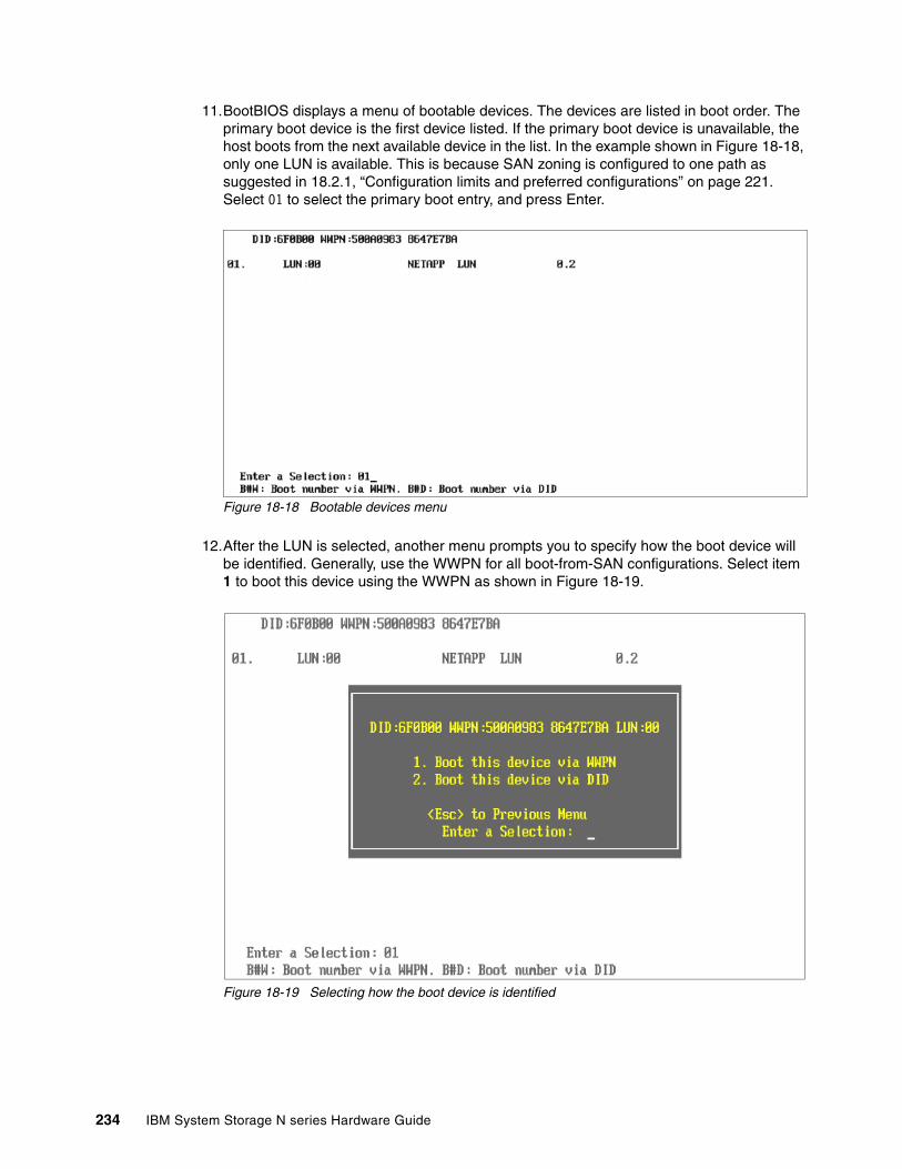
11.BootBIOS displays a menu of bootable devices. The devices are listed in boot order. The primary boot device is the first device listed. If the primary boot device is unavailable, the host boots from the next available device in the list. In the example shown in Figure 18-18, only one LUN is available. This is because SAN zoning is configured to one path as suggested in 18.2.1, “Configuration limits and preferred configurations” on page 221. Select 01 to select the primary boot entry, and press Enter.
Figure 18-18 Bootable devices menu
12.After the LUN is selected, another menu prompts you to specify how the boot device will be identified. Generally, use the WWPN for all boot-from-SAN configurations. Select item 1 to boot this device using the WWPN as shown in Figure 18-19.
Figure 18-19 Selecting how the boot device is identified
234 IBM System Storage N series Hardware Guide

13.After this process is complete, press X to exit and save your configuration as shown in Figure 18-20. Your HBA’s BootBIOS is now configured to boot from a SAN on the attached storage device.
Figure 18-20 Exit Emulex Boot Utility and saved boot device panel
14.Press Y to reboot your system as shown in Figure 18-21.
Figure 18-21 Reboot system confirmation panel
Chapter 18. Boot from SAN 235

Enabling and configuring QLOGIC BootBIOSPerform these steps to configure QLOGIC BootBIOS:
1. Power on or reboot your host.
2. Press Ctrl+Q or Alt+Q to enter the BIOS configuration utility as shown in Figure 18-22.
Figure 18-22 Pressing Ctrl+Q for Fast!UTIL panel
3. The Qlogic Fast!UTIL displays the available adapters, listed in boot order. The primary boot device is the first device listed. If the primary boot device is unavailable, the host boots from the next available device in the list. Select the first Fibre Channel adapter port and press Enter as shown in Figure 18-23.
Figure 18-23 Qlogic Fast!UTIL menu
236 IBM System Storage N series Hardware Guide
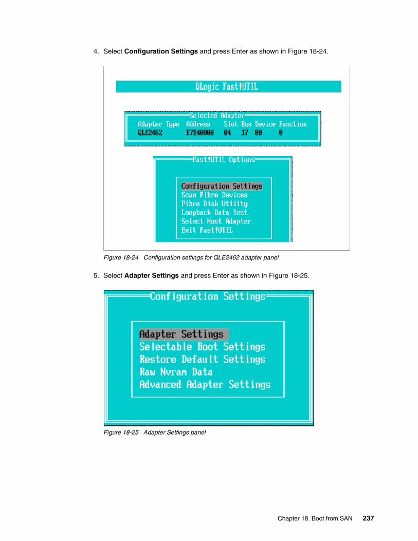
4. Select Configuration Settings and press Enter as shown in Figure 18-24.
Figure 18-24 Configuration settings for QLE2462 adapter panel
5. Select Adapter Settings and press Enter as shown in Figure 18-25.
Figure 18-25 Adapter Settings panel
IBM System Storage™ N series – Unified Storage Solutions
© 2007 IBM Corporation
Chapter 18. Boot from SAN 237

6. Scroll to Host Adapter BIOS as shown in Figure 18-26.
– If this option is disabled, press Enter to enable it.– If this option is enabled, go to the next step.
Figure 18-26 Enabling host adapter BIOS
7. Press Esc to return to the Configuration Settings panel. Scroll to Selectable Boot Settings and press Enter as shown in Figure 18-27.
Figure 18-27 Accessing selectable boot settings
238 IBM System Storage N series Hardware Guide

8. Scroll to Selectable Boot as shown in Figure 18-28.
– If this option is disabled, press Enter to enable it.– If this option is enabled, go to the next step.
Figure 18-28 Enabling selectable boot in Selectable Boot Settings panel
9. Select the entry in the (Primary) Boot Port Name, LUN field, as shown in Figure 18-29, and press Enter.
Figure 18-29 Selecting the (Primary) Boot Port Name
10.The available Fibre Channel devices are displayed as shown in Figure 18-30. Select the boot LUN 0 from the list of devices and press Enter.
Figure 18-30 Select Fibre Channel Device panel
Chapter 18. Boot from SAN 239

11.Press Esc to return to the previous panel. Press Esc again and you are prompted to save the configuration settings as shown in Figure 18-31. Select Save changes and press Enter.
Figure 18-31 Saving the configuration settings
12.The changes are saved and you are returned to the configuration settings. Press Esc and you are prompted to reboot the system as shown in Figure 18-32. Select Reboot system and press Enter.
Figure 18-32 Exiting the Fast!UTIL
Configuring the PC BIOS boot orderIf your host has an internal disk, you must enter BIOS setup to configure the host to boot from the LUN. You must ensure that the internal disk is not bootable through the BIOS boot order.
The BIOS setup program differs depending on the type of PC BIOS that your host is using. This section shows example procedures for the following BIOS setup programs:
� “IBM BIOS” on page 240� “Phoenix BIOS 4 Release 6” on page 242
IBM BIOSThere can be slight differences within the System BIOS configuration and setup utility depending on the server model and BIOS version that are used. Knowledge of BIOS and ROM memory space usage can be required in certain situations. Some older PC architecture
240 IBM System Storage N series Hardware Guide

limits ROM image memory space to 128 K maximum. This limit becomes a concern if you want more devices that require ROM spaced. If you have many HBAs in your server, you might receive a PCI error allocation message during the boot process. To avoid this error, disable the boot options in the HBAs that are not being used for SAN boot installation.
To configure the IBM BIOS setup program, perform these steps:
1. Reboot the host.
2. Press F1 to enter BIOS setup as shown in Figure 18-33.
Figure 18-33 System x BIOS Setup panel
3. Select Start Options as shown in Figure 18-34.
Figure 18-34 Selecting Start Options in Configuration/Setup Utility panel
Chapter 18. Boot from SAN 241

4. Scroll to the PCI Device Boot Priority option and select the slot in which the HBA is installed as shown in Figure 18-35.
Figure 18-35 Selecting PCI Device Boot Priority in Start Options panel
5. Scroll up to Startup Sequence Options and press Enter. Make sure that the Startup Sequence Option is configured as shown in Figure 18-36.
Figure 18-36 Selecting Hard Disk 0 in Startup Sequence Options panel
Phoenix BIOS 4 Release 6To configure Phoenix BIOS to boot from the Emulex HBA, perform these steps:
1. Reboot the host.
2. Press F2 to enter BIOS setup.
3. Navigate to the Boot tab.
242 IBM System Storage N series Hardware Guide

4. The Boot tab lists the boot device order. Ensure that the HBA is configured as the first boot device. Select Hard Drive.
5. Configure the LUN as the first boot device.
18.2.5 Windows 2003 Enterprise SP2 installation
This section describes installation procedures for Windows 2003 Enterprise SP2.
Copying the SAN boot driversWhen you boot from a LUN, you must ensure that the operating system on the LUN has the required HBA driver for booting from a LUN. You must download these drivers from the Qlogic or Emulex website.
During the Windows 2003 installation, you must install the driver as a third-party SCSI array driver from a diskette. To do so, perform the following steps:
1. Download the Emulex or Qlogic driver for Windows 2003:
– For Emulex, download the STOR Miniport driver from:
http://www.emulex.com/downloads.html
– For Qlogic, select the appropriate HBA, click Windows Server 2003, and download the STOR Miniport Microsoft Certified Boot from the SAN Driver Package from:
http://driverdownloads.qlogic.com/QLogicDriverDownloads_UI/default.aspx
2. Copy the driver files to a diskette.
Installing Windows 2003 Enterprise SP2To install Windows 2003 on the LUN, perform these steps:
1. Insert the Windows 2003 CD and reboot the host.
A message displays indicating the HBA BIOS is installed along with the boot LUN as shown in Example 18-1.
Example 18-1 HBA BIOS installation message
LUN: 00 NETAPP LUNBIOS is installed successfully!
2. When prompted, press any key to boot from the CD.
3. When prompted, press F6 to install a third-party SCSI array driver.
4. Insert the HBA driver diskette that you created previously when the following message is displayed:
Setup could not determine the type of one or more mass storage devices installed in your system, or you have chosen to manually specify an adapter.
Tip: If the message does not display, do not continue installing Windows. Check to ensure that the LUN is created and mapped, and that the target HBA is in the correct mode for directly connected hosts. Also, ensure that the WWPN for the HBA is the same WWPN that you entered when creating the igroup.
If the LUN is displayed but the message indicates that the BIOS is not installed, reboot and enable the BIOS.
Chapter 18. Boot from SAN 243

5. Press S to continue.
6. From the list of HBAs, select the supported HBA that you are using and press Enter. The driver for the selected HBA is configured in the Windows operating system.
7. Follow the prompts to set up the Windows operating system. When prompted, set up the Windows operating system in a partition formatted with NTFS.
8. The host system reboots and then prompts you to complete the server setup process as you normally would do. The rest of the Windows installation is the same as a normal installation.
Current limitations to Windows boot from SANThere are a number of advanced scenarios that are not currently possible in Windows boot from SAN environments:
� No shared boot images: Windows servers cannot currently share a boot image. Each server requires its own dedicated LUN to boot.
� Mass deployment of boot images requires Automated Deployment Services (ADS): Windows does not currently support mass distribution of boot images. Although cloning of boot images can help here, Windows does not have the tools for distribution of these images. In enterprise configurations, however, Windows ADS can help.
� Lack of standardized assignment of LUN 0 to controller: Certain vendors’ storage adapters automatically assign logical unit numbers (LUNs). Others require that the storage administrator explicitly define the numbers. With parallel SCSI, the boot LUN is LUN 0 by default.
� Fibre Channel configurations must adhere to SCSI-3 storage standards: In correctly configured arrays, LUN 0 is assigned to the controller (not to a disk device) and is accessible to all servers. This LUN 0 assignment is part of the SCSI-3 standard because many operating systems do not boot unless the controller is assigned as LUN 0. Assigning LUN 0 to the controller allows it to assume the critical role in discovering and reporting a list of all other LUNs available through that adapter. In Windows, these LUNs are reported back to the kernel in response to the SCSI REPORT LUNS command.
Unfortunately, not all vendor storage arrays comply with the standard of assigning LUN 0 to the controller. Failure to comply with that standard means that the boot process might not proceed correctly. In certain cases, even with LUN 0 correctly assigned, the boot LUN cannot be found, and the operating system fails to load. In these cases (without HBA LUN remapping), the kernel finds LUN 0, but might not be successful in enumerating the LUNs correctly.
18.2.6 Windows 2008 Enterprise installation
The Windows 2008 server can be installed in two installations:
� Full installation � Core installation
Full installation supports GUI, and no roles such as print, file, or DHCP are installed by default. Core installation does not support any GUI. It supports only command line and Windows power shell, which is why it does not require higher memory and disk.
Prerequisites: After you successfully install Windows 2003, you must add the remaining WWPN for all additional HBAs to the group and install the FCP Windows Host Utilities.
244 IBM System Storage N series Hardware Guide

A few boot configuration changes were introduced in the Windows 2008 server. The major change is that Boot Configuration Data (BCD) stores contain boot configuration parameters. These parameters control how the operating system is started in Microsoft Windows Server 2008 operating systems. These parameters were previously in the Boot.ini file (in BIOS-based operating systems) or in the nonvolatile RAM (NVRAM) entries (in Extensible Firmware Interface-based operating systems).
You can use the Bcdedit.exe command-line tool to modify the Windows code that runs in the pre-operating system environment by changing entries in the BCD store. Bcdedit.exe is in the \Windows\System32 directory of the Windows 2008 active partition.
BCD was created to provide an improved mechanism for describing boot configuration data. With the development of new firmware models (for example, the Extensible Firmware Interface (EFI)), an extensible and interoperable interface was required to abstract the underlying firmware.
Windows Server 2008 R2 supports the ability to boot from a SAN, which eliminates the need for local hard disks in the individual server computers. In addition, performance for accessing storage on SANs has greatly improved. Figure 18-37 shows how booting from a SAN can dramatically reduce the number of hard disks, decreasing power consumption.
Figure 18-37 Centralizing storage to reduce power consumption
Chapter 18. Boot from SAN 245

To install the Windows Server 2008 full installation option, perform these steps:
1. Insert the appropriate Windows Server 2008 installation media into your DVD drive. Reboot the server as shown in Figure 18-38.
Figure 18-38 Rebooting the server
2. Select an installation language, regional options, and keyboard input, and click Next, as shown in Figure 18-39.
Figure 18-39 Selecting the language to install, regional options, and keyboard input
246 IBM System Storage N series Hardware Guide

3. Click Install now to begin the installation process as shown in Figure 18-40.
Figure 18-40 Selecting Install now
4. Enter the product key and click Next as shown in Figure 18-41.
Figure 18-41 Entering the product key
Chapter 18. Boot from SAN 247

5. Select I accept the license terms and click Next as shown in Figure 18-42.
Figure 18-42 Accepting the license terms
6. Click Custom (advanced) as shown in Figure 18-43.
Figure 18-43 Selecting the Custom installation option
248 IBM System Storage N series Hardware Guide

7. If the window shown in Figure 18-44 does not show any hard disk drives, or if you prefer to install the HBA device driver now, click Load Driver.
Figure 18-44 Where do you want to install Windows? window
8. As shown in Figure 18-45, insert appropriate media that contains the HBA device driver files and click Browse.
Figure 18-45 Load Driver window
9. Click OK Next.
Chapter 18. Boot from SAN 249

10.Click Next again to leave the Windows creates the partition automatically window, or click Drive options (advanced) to create the partition. Then click Next to start the installation process as shown in Figure 18-46.
Figure 18-46 Installing Windows window
11.When Windows Server 2008 Setup has completed installation, the server automatically restarts.
12.After Windows Server 2008 restarts, you are prompted to change the administrator password before you can log on.
13.After you are logged on as the administrator, a configuration wizard window is displayed. Use the wizard for naming and basic networking setup.
14.Use the Microsoft Server 2008 Roles and Features functions to set up the server to your specific needs.
18.2.7 Red Hat Enterprise Linux 5.2 installation
This section shows how to install Red Hat Enterprise Linux 5.2 boot from SAN with an IBM System x server.
Tip: After you successfully install Windows 2008, add the remaining WWPN for all additional HBAs to the igroup, and install the FCP Windows Host Utilities.
Prerequisite: Always check hardware and software, including firmware and operating system compatibility, before you implement SAN boot in different hardware or software environments.
250 IBM System Storage N series Hardware Guide

Linux boot processThis section is an overview of the Linux boot process in an x86 environment. In general, the boot process is as shown in Figure 18-47.
Figure 18-47 Linux boot process
System BIOSThe process starts when you power up or reset your System x. The processor runs the basic input/output system (BIOS) code, which then runs a power-on self-test (POST) to check and initialize the hardware. It then locates a valid device to boot the system.
Boot loaderIf a boot device is found, the BIOS loads the first stage boot loader stored in the master boot record (MBR) into memory. The MBR is the first 512 bytes of the bootable device. This first stage boot loader is then run to locate and load into memory the second stage boot loader. Boot loaders are in two stages because of the limited size of the MBR. In an x86 system, the second stage boot loader can be the Linux Loader (LILO) or the GRand Unified Bootloader (GRUB). After it is loaded, it presents a list of available kernels to boot.
OS kernelAfter a kernel is selected, the second stage boot loader locates the kernel binary and loads into memory the initial RAM disk image. The kernel then checks and configures hardware and peripherals, and extracts the initial RAM disk image into load drivers and modules needed to boot the system. It also mounts the root device.
Continue system startAfter the kernel and its modules are loaded, a high-level system initialization is run by the /sbin/init program. This program is the parent process of all other subsequent start processes. /sbin/init runs /etc/rc.d/rc.sysinit and its corresponding scripts. This process is followed by running /etc/inittab, /etc/rc.d/init.d/functions, and the appropriate rc directory as configured in /etc/inittab. For example, if the default runlevel in /etc/inittab is configured as runlevel 5, /sbin/init runs scripts under the /etc/rc.d/rc5.d/ directory.
Install Red Hat Enterprise Linux 5.2The installation process explained here assumes that the server does not have any special hardware (SCSI card or HBA) that would require a specific Linux driver. If you have a device driver you need to load during the installation process, type Linux dd at the installation boot prompt. Type this before the installation wizard is loaded.
Chapter 18. Boot from SAN 251

The installation process is similar to local disk installation. To set up a Linux SAN boot, perform these steps:
1. Insert the Linux installation CD and reboot the host. During the installation, you are able see the LUN and install the OS on it.
2. Click Next and follow the installation wizard as you normally would do with a local disk installation.
IBM LUNs connected by way of a block protocol (for example, iSCSI, FCP) to Linux hosts using partitions might require special partition alignment for best performance. For more information about this issue, see:
http://www.ibm.com/support/docview.wss?uid=ssg1S1002716&rs=573
18.3 Boot from SAN and other protocols
This section briefly addresses the other protocols that you are able to boot. Implementing them is similar to the boot from SAN with Fibre Channel.
18.3.1 Boot from iSCSI SAN
iSCSI boot is a process where the OS is initialized from a storage disk array across a storage area network (SAN) rather than from the locally attached hard disk drive. Servers equipped with standard Gigabit network adapters are now able to connect to SANs with complete iSCSI functionality, including boot capabilities under Windows. Gigabit network adapters can be configured to perform iSCSI off loading chip technology.
This technology eliminates the high up-front acquisition costs of adding storage networking to a server. It allows IT professionals to avoid having to purchase a server with a separate HBA controller preinstalled. In the past, IT professionals had to purchase separate controllers to perform simultaneous data and storage networking functions. Now you can purchase a server equipped with a standard network adapter capable of iSCSI software boot that is designed to provide both functions in a single network device. However you can still install a iSCSI HBA that will offload certain operations to its own processor. The configuration of these are comparable to the boot from FCP.
18.3.2 Boot from FCoE
Fibre Channel over Ethernet (FCoE) is a protocol designed to seamlessly replace the Fibre Channel physical interface with Ethernet. FCoE protocol specification is designed to use the enhancements in Data Center Bridging (DCB) to support the lossless transport requirement of storage traffic.
Tip: RHEL5 can now detect, create, and install to dm-multipath devices during installation. To enable this feature, add the parameter mpath to the kernel boot line. At the initial Linux installation panel, type linux mpath and press Enter to start the Red Hat installation.
Attention: After you successfully install Red Hat Enterprise Linux 5.2, add the remaining WWPN for all additional HBAs to the igroup, and install the FCP Linux Host Utilities.
252 IBM System Storage N series Hardware Guide

FCoE encapsulates the Fibre Channel frame in an Ethernet packet to enable transporting storage traffic over an Ethernet interface. By transporting the entire Fibre Channel frame in Ethernet packets, FCoE makes sure that no changes are required to Fibre Channel protocol mappings, information units, session management, exchange management, and services.
With FCoE technology, servers that host both HBAs and network adapters reduce their adapter count to a smaller number of converged network adapters (CNAs). CNAs support both TCP/IP networking traffic and Fibre Channel SAN traffic. Combined with native FCoE storage arrays and switches, an end-to-end FCoE solution can be deployed with all the benefits of a converged network in the data center.
FCoE CNAs provide FCoE offload, and support boot from SAN. Configuring it is similar to the boot from SAN with the Fibre Channel protocol.
Chapter 18. Boot from SAN 253

254 IBM System Storage N series Hardware Guide

Chapter 19. Host multipathing
This chapter introduces the concepts of host multipathing. It addresses the installation steps and describes the management interface for the Windows, Linux, and IBM AIX operating systems.
The following topics are covered:
� Overview� Multipathing software options, including ALUA� Installation of IBM Data ONTAP DSM� Managing DSM by using the GUI� Managing DSM by using the CLI� Multiple path I/O support for Red Hat Linux� Multiple path I/O support for Native AIX O/S
This chapter includes the following sections:
� Overview� Multipathing software options
19
© Copyright IBM Corp. 2012. All rights reserved. 255

19.1 Overview
Multipath I/O (MPIO) provides multiple storage paths from hosts (initiators) to their IBM System Storage N series targets. The multiple paths provide redundancy against failures of hardware such as cabling, switches, and adapters. They also provide higher performance thresholds by aggregation or optimum path selection.
Multipathing solutions provide the host-side logic to use the multiple paths of a redundant network to provide highly available and higher bandwidth connectivity between hosts and block level devices. Multipath software has these main objectives:
� Present the OS with a single virtualized path to the storage.
Figure 19-1 includes two scenarios: OS with no multipath management software and OS with multipath management software.
Without multipath management software, the OS believes that it is connected to two different physical storage devices. With multipath management software, the OS correctly interprets that both HBAs are connected to the same storage device.
� Seamlessly recover from a path failure.
Multipath software detects failed paths and recovers from the failure by routing traffic through another available path. The recovery is automatic, usually fast, and transparent to the IT organization. The data ideally remains available at all times.
� Enable load balancing.
Load balancing is the use of multiple data paths between server and storage to provide greater throughput of data than with only one connection. Multipathing software improves throughput by enabling load balancing across multiple paths between server and storage.
Figure 19-1 With and without host multipathing
256 IBM System Storage N series Hardware Guide

When multiple paths to a LUN are available, a consistent method of using those paths needs to be determined. This method is called the load balance policy. There are five standard policies in Windows Server 2008 that apply to multiconnection sessions and MPIO. Other operating systems can implement different load balancing policies.
� Failover only: Only one path is active at a time, and alternate paths are reserved for path failure.
� Round robin: I/O operations are sent down each path in turn.
� Round robin with subset: Some paths are used as in round robin, while the remaining paths act as failover only.
� Least queue depth: I/O is sent down the path with the fewest outstanding I/Os.
� Weighted paths: Each path is given a weight that identifies its priority, with the lowest number having the highest priority.
19.2 Multipathing software options
The multipathing solution can be provided by:
� Third-party vendors:
– Storage vendors provide support for their own storage arrays such as the IBM Data ONTAP DSM for Windows. These solutions are generally specific to the particular vendor’s equipment.
– Independent third-party vendors offer heterogeneous host and storage support such as Symantec and Veritas DMP.
� Operating system vendors as part of the operating system:
– For example, Windows MSDSM, Solaris MPxIO, AIX MPIO, Linux Device-Mapper Multipath, HP-UX PVLinks, VMware ESX Server NMP
19.2.1 Third-party multipathing solution
As mentioned previously, third-party multipathing solutions are provided either by storage vendors or by independent software vendors such as Symantec. The advantage of using multipathing solutions provided by storage vendors is that it provides a unified management interface for all operating systems. This unified interface makes administering a heterogeneous host environment easier. In addition, storage vendors know their array the best, and so the multipathing solution provided by the storage array vendor can provide optimal performance. Conversely, the multipathing solutions provided by storage vendors have the following disadvantages:
� Most of these solutions come with fee-based software licenses, and typically require ongoing license maintenance costs.
� The solutions provided by storage vendors lock the customer into a single storage platform. Some of these solutions do have support for other storage arrays, but there might be long qualification/support delays.
� These solutions usually do not interoperate well with multipathing solutions from other storage vendors that must be installed on the same server.
The multipathing solutions provided by Symantec also require fee-based software licenses. However, these solutions provide support for heterogeneous storage and heterogeneous host OS.
Chapter 19. Host multipathing 257

19.2.2 Native multipathing solution
Native multipathing solutions are packaged as part of the operating system. As of the publication date of this document, Windows, ESX, Linux, HP-UX, Solaris, and AIX provide native multipathing solutions. Native multipathing solutions have these advantages:
� Native multipathing solutions are available for no extra fee. Native multipathing reduces capital expense (can limit the number of redundant servers) and operating expense.
� The availability of multipath support in the server operating systems allows IT installations to adopt a more sensible server-led strategy. This strategy is independent of the storage array vendors. It does not limit you to a single storage array, and so provides freedom of choice and flexibility when selecting a storage vendor.
� Native multipathing provides better interoperability among various vendor storage devices that connect to the same servers. One driver stack and one set of HBAs can communicate with various heterogeneous storage devices simultaneously.
With the advent of SCSI concepts such as asymmetric logical unit access (ALUA), native multipathing solutions have improved. For example, Microsoft provided native Fibre Channel multipathing support only after ALUA became available for Windows.
19.2.3 Asymmetric Logical Unit Access (ALUA)
Asymmetric logical unit access (ALUA) is an industry standard protocol that enables the communication of storage paths and path characteristics between an initiator port and a target port. This communication occurs when the access characteristics of one port might differ from those of another port. A logical unit can be accessed from more than one target port. One target port might provide full performance access to a logical unit. Another target port, particularly on a different physical controller, might provide lower performance access or might support a subset of the available SCSI commands to the same logical unit.
Before inclusion of ALUA in the SCSI standards, multipath providers had to use vendor-specific SCSI commands to figure out the access characteristics of a target port. With the standardization of ALUA, the multipath vendor can use standard SCSI commands to determine the access characteristics. ALUA was implemented in Data ONTAP 7.2.
iSCSI in N series controllers has no secondary path, and because link failover operates differently from Fibre Channel, ALUA is not supported on iSCSI connections.
Certain hosts such as Windows, Solaris, and AIX require the system to rediscover their disks in order for ALUA to be enabled. Therefore, reboot the system after the change is made.
19.2.4 Why ALUA?
Traditionally, IBM has written a plug-in for each SCSI multipathing stack that it interacts with. These plug-ins used vendor-unique SCSI commands to identify a path as Primary or Secondary. By supporting ALUA in conjunction with SCSI multipathing stacks that also support ALUA, support is obtained without writing any new code on the host side.
Data ONTAP implements the implicit ALUA style, not the explicit format. Implicit ALUA makes the target device responsible for all the changes to the target port group states. With implicit access, the device controller manages the states of path connections. In this case, the standard understands that there might be performance differences between the paths to a LUN. Therefore, it includes messages that are specific to a path that change its characteristics, such as changes during failover/giveback.
258 IBM System Storage N series Hardware Guide

With the implicit ALUA style, the host multipathing software can monitor the path states but cannot change them, either automatically or manually. Of the active paths, a path can be specified as preferred (optimized in T10), and as non-preferred (non-optimized). If there are active preferred paths, only those paths receive commands and are load balanced to evenly distribute the commands. If there are no active preferred paths, the active non-preferred paths are used in a round-robin fashion. If there are no active non-preferred paths, the LUN cannot be accessed until the controller activates its standby paths.
Verify that a host supports ALUA before implementing, because otherwise a cluster failover might result in system interruption or data loss. All N series LUNs presented to an individual host must have ALUA enabled. The host's MPIO software expects ALUA to be consistent for all LUNs with the same vendor.
Traditionally, you had to manually identify and select the optimal paths for I/O. Utilities such as dotpaths for AIX are used to set path priorities in environments where ALUA is not supported. Using ALUA, the administrator of the host computer does not need to manually intervene in path management. It is handled automatically. Running MPIO on the host is still required, but no additional host-specific plug-ins are required.
This process allows the host to maximize I/O by using the optimal path consistently and automatically.
ALUA has the following limitations:
� ALUA can only be enabled on FCP initiator groups.
� ALUA is not available on non-clustered storage systems for FCP initiator groups.
� ALUA is not supported for iSCSI initiator groups.
To enable ALUA on existing non-ALUA LUNs, perform these steps:
1. Validate the host OS and the multipathing software as well as the storage controller software support ALUA. For example, ALUA is not supported for VMware ESX until vSphere 4.0. Check with the host OS vendor for supportability.
2. Check the host system for any script that might be managing the paths automatically and disable it.
3. If using SnapDrive, verify that there are no settings that disable the ALUA set in the configuration file.
ALUA is enabled or disabled on the igroup mapped to a LUN on the N series controller. The default ALUA setting in Data ONTAP varies by version and by igroup type. Check the output of the igroup show -v <igroup name> command to confirm the setting.
Enabling ALUA on the igroup activates ALUA.
Tip: Generally, use ALUA on hosts that support ALUA.
Chapter 19. Host multipathing 259

260 IBM System Storage N series Hardware Guide
Part 4 Performing upgrades
This part addresses the design and operational considerations for nondisruptive upgrades on the N series platform. It also provides some high-level example procedures for common hardware and software upgrades.
This part contains the following chapters:
� System NDU� Hardware upgrades
Part 4
© Copyright IBM Corp. 2012. All rights reserved. 261

262 IBM System Storage N series Hardware Guide

Chapter 20. Designing for nondisruptive upgrades
Non Disruptive Upgrade (NDU) began as the process of upgrading Data ONTAP software on the two nodes in an HA pair controller configuration without interrupting I/O to connected client systems. NDU has grown since its inception, and now incorporates the nondisruptive upgrade of system firmware as well.
This chapter covers NDU for the following areas:
� System operating software (Data ONTAP) and firmware (BIOS)� Shelf firmware� Disk firmware� Alternate Control Path (ACP) firmware
The overall objective is to enable upgrade and maintenance of the storage system without affecting the system’s ability to respond to foreground I/O requests. This does not mean that there is no interruption to client I/O. Rather, the I/O interruptions are brief enough so that applications continue to operate without the need for downtime, maintenance, or user notification.
This chapter includes the following sections:
� System NDU� Shelf firmware NDU� Disk firmware NDU� ACP firmware NDU� RLM firmware NDU
20
Note: Upgrade the system software or firmware in the following order:
1. System firmware2. Shelf firmware3. Disk firmware
© Copyright IBM Corp. 2012. All rights reserved. 263
20.1 System NDU
System NDU is a process that takes advantage of HA pair controller technology to minimize client disruption during an upgrade of Data ONTAP or controller firmware.
System NDU entails a series of takeover and giveback operations, These operations allow the partner nodes to transfer the data delivery service while the controllers are upgraded. This process maintains continuous data I/O for clients/hosts.
The controller for each node in the HA pair configuration is connected to both its own storage shelves and the storage shelves of its partner node. Therefore, a single node provides access to all volumes and LUNs, even when the partner node is shut down. This configuration allows each node of HA pair controllers to be upgraded individually to a newer version of Data ONTAP or firmware. It also allows you to transparently perform hardware upgrades and maintenance on the HA pair controller nodes.
Before performing an NDU, create an NDU plan. For more information about developing an NDU plan, see the Data ONTAP 8.1 7-Mode Upgrade and Revert/Downgrade Guide at:
http://www.ibm.com/support/docview.wss?uid=ssg1S7003776
20.1.1 Types of system NDU
There are two types of system NDUs: Major and minor:
� A major version system NDU is an upgrade from one major release of Data ONTAP to another. For example, an upgrade from Data ONTAP 7.2.x to Data ONTAP 7.3.x is considered a major system NDU.
– Major version NDU is supported ONLY when going from one release to the next in sequence. There are occasionally exceptions when deemed necessary to bypass a major release in an upgrade sequence. For example, customers are allowed to nondisruptively upgrade from 7.3 to 8.1 without having to upgrade to 8.0 as an interim step. These exceptions are documented in Table 20-1 on page 265.
� A minor version system NDU is an upgrade within the same release family. For example, an upgrade from Data ONTAP 7.3.1 to Data ONTAP 7.3.2 is considered a minor system NDU. The following are things that constitute a minor version system NDU:
– No version number change to RAID, WAFL, NVLOG, FM, or SANOWN
– No change to NVRAM format
– No change to on-disk format
– Automatic takeover must be possible while the two controllers of the HA pair are running different versions within the same release family
20.1.2 Supported Data ONTAP upgrades
Support for system NDU differs slightly according to the protocols that are in use on the system. The following sections address those different protocols.
Attention: Because of the complexity and individual clients environments, always see the release notes and the upgrade guide available for your new Data ONTAP release before any upgrades.
264 IBM System Storage N series Hardware Guide

Support for NFS environmentsTable 20-1 shows the major and minor upgrades that have NDU support in an NFS environment.
Table 20-1 NDU support for NFS environments
Support for CIFS environmentsSystem NDU is not currently supported for CIFS, NDMP, FTP, or any other protocol that does not have state recovery mechanisms.
Support for FC and iSCSI environmentsTable 20-2 shows the major and minor upgrades that have NDU support in a block storage (Fibre Channel or iSCSI) environment.
Table 20-2 NDU support for block storage environments
Source Data ONTAP version Minor version NDU supported
Major version NDU supported
7.1, 7.1.1 Yes No
7.1.2 (and later) Yes Yes
7.2, 7.2.1, 7.2.2 Yes No
7.2.3 (and later) Yes Yes
7.3 (and later) Yes Yesa
a. Customers upgrading from Data ONTAP 7.3.2 can do major version NDU to Data ONTAP 8.0 and 8.1 releases. This is an exception to the guidelines for major version NDU. Customers running Data ONTAP 7.3 or 7.3.1 must do a minor version NDU to 7.3.2 before upgrading directly to 8.1.
8.0 (and later) Yes Yes
8.1 (and later) Yes Yes
Source Data ONTAP version Minor version NDU supported
Major version NDU supported
7.1, 7.1.1 Yes No
7.1.2 (and later) Yes Yes
7.2, 7.2.1, 7.2.2 Yes No
7.2.3 (and later) Yes Yes
7.3 (and later) Yes Yes
8.0 (and later) Yes Yes
8.1 (and later) Yes Yes
Chapter 20. Designing for nondisruptive upgrades 265

Support for deduplication and compressionYou can perform major and minor nondisruptive upgrades when deduplication and compression are enabled. However, avoid active deduplication processes during the planned takeover or planned giveback:
1. Perform the planned takeover or giveback during a time when deduplication processes are not scheduled to run.
2. Determine whether any deduplication processes are active and, if so, stop them until the planned takeover or giveback is complete.
You can turn the operation off and on by using the sis off and sis on commands. Use the sis status command to determine whether the status of deduplication is Active or Idle. If a deduplication process is running, the status of deduplication is Active.
If there are more than the allowable number of FlexVol volumes with deduplication enabled, sis undo must be run. This command undoes deduplication and brings the number of FlexVol volumes to within the limit for that version of Data ONTAP. The sis undo command can be a time-consuming process, and requires enough available space to store all blocks that are no longer deduplicated. Run the sis undo command on smaller volumes and volumes with the least amount of deduplicated data. This process helps minimize the amount of time required to remove deduplication from the volumes.
For more information about deduplication and compression volume (dense volume) limits for NDU, see 20.1.4, “System NDU software requirements” on page 266.
20.1.3 System NDU hardware requirements
System NDU is supported on any IBM N series storage controller, or gateway, hardware platform that supports the HA pair controller configuration. Both storage controllers must be identical platforms.
Systems must be cabled and configured in an HA pair controller configuration. This configuration includes all InfiniBand interconnect cables, correct NVRAM slot assignments, and appropriate controller-to-shelf cabling, including (as applicable) multipath high-availability storage and SyncMirror configuration options. For more information about cabling and configuration, see the appropriate system configuration guide on the IBM Support site. Also, see the documents in the Data ONTAP information library appropriate to your storage configuration.
20.1.4 System NDU software requirements
Predictable takeover and giveback performance is essential to a successful NDU. It is important not to exceed Data ONTAP configuration limits.
Table 20-3 on page 267 outlines the limits per storage controller for FlexVol, dense volumes, Snapshot copies, LUNs, and vFiler units. These parameters are essential to accurately predict when a planned takeover or planned giveback will complete during the NDU process. The limits are identical for N series controllers and gateways.
These limits are based on the destination version of DATA ONTAP. For example, if the customer has an N7900 HA pair controller configuration installed with Data ONTAP 7.3.3 and wants to do a nondisruptive upgrade to 8.0.1, the number of FlexVol volumes supported per controller is limited to 500.
266 IBM System Storage N series Hardware Guide

Generally, regardless of the system limits, run a system with processor and disk performance utilization no greater than 50% per storage controller.
Table 20-3 Maximum number of FlexVols for NDU
The maximum FlexVol volume limit of 500 per controller matches the native Data ONTAP FlexVol volume limit. Fields that contain N/A in this column indicate platforms that are not supported by Data ONTAP 8.0.
Platform Minor version NDU release family Major version NDU release family
7.2 7.3 8.0 / 8.1 7.3 8.0 / 8.1
N3300 (see note) 100 150 N/A 150 N/A
N3400 N/A 200 200 200 200
N3600 100 150 N/A 150 N/A
N5300 150 150 500 150 500
N6040 150 150 500 150 500
N6060 200 300 500 200 500
N5600 250 300 500 300 500
N6070 250 300 500 300 500
N6210 N/A 300 500 300 500
N6240 N/A 300 500 300 500
N6270 N/A 300 500 300 500
N7600 250 300 500 300 500
N7700 250 300 500 300 500
N7800 250 300 500 300 500
N7900 250 300 500 300 500
N7550 N/A N/A 500 300 500
N7750 N/A N/A 500 300 500
N7950 N/A N/A 500 300 500
Restriction: Major NDU from Data ONTAP 7.2.2L1 to 7.3.1 is not supported on IBM N3300 systems that contain aggregates larger than 8 TB. Therefore, a disruptive upgrade is required. Aggregates larger than 8 TB prevent the system from running a minor version NDU from Data ONTAP 7.2.2L1 to 7.2.x.
Chapter 20. Designing for nondisruptive upgrades 267

Table 20-4 shows the maximum number of dense volumes, snapshot copies, LUNs, and vFiler units that are supported for NDU.
Table 20-4 Maximum limits for NDU
20.1.5 Prerequisites for a system NDU
The following subsections address what needs to be completed before performing a major or minor system NDU.
Reading the latest documentationReview the Data ONTAP Upgrade Guide for the version to which you are upgrading, not the version from which you are upgrading. These documents are available on the IBM Support site.
Verify that the system and hosts (if applicable) fulfill the requirements for upgrade.
Review the release notes for the version of Data ONTAP to which you are upgrading. Release notes are available on the IBM Support site.
Review the list of any known installation or upgrade problems for both the version of Data ONTAP to which you are upgrading, and all host-specific items if your environment uses FCP or iSCSI.
Validating the storage controller system configurationsConfirm that both storage controllers are prepared for the NDU operation. Validate each individual controller’s configuration to identify any issues before upgrading.
Create a detailed upgrade test procedure document and a back-out plan.
Identify any inconsistencies between the two storage controllers within the HA pair controller configuration so that all identified issues can be corrected before beginning the upgrade.
Removing all failed disksFailed disk drives prevent giveback operations and can introduce stack/loop instability throughout the storage system. Remove or replace all failed disk drives before beginning the system NDU operation.
When AutoSupport is enabled, failed drives are detected automatically, and replacement drives are shipped for installation at the administrator's convenience. Generally, enable AutoSupport for all storage systems.
Data ONTAP Dense volumes
Snapshot copies LUNs vFiler units
FC, SAS storage
SATA storage
FC, SAS storage
SATA storage
7.3.x to 8.0 100 500 500 2,000 64 5
7.3.x to 8.0.1 300 12,000 4,000 2,000 64 5
7.3.x to 8.1 300 12,000 4,000 2,000 64 5
8.0 to 8.0.x 300 12,000 4,000 2,000 64 5
8.0.x to 8.1 500 20,000 20,000 2,000 64 5
8.1 to 8.1.x 500 20,000 20,000 2,000 64 5
268 IBM System Storage N series Hardware Guide

Removing all old core filesClear /etc/crash/ of old core files before performing the NDU. Run savecore -l to determine whether there are any cores in memory and, if so, flush them as required.
Upgrading disk and shelf firmwareShelf firmware upgrades must be completed before performing Data ONTAP NDU.
Disk firmware upgrades are automatically performed in the background for all drives starting with Data ONTAP 8.0.2.
For more information about upgrading shelf and disk firmware, see 20.2, “Shelf firmware NDU” on page 270 and 20.3, “Disk firmware NDU” on page 272.
Verifying system loadPerform NDUs only when processor and disk activity are as low as possible. The upgrade process requires one controller to assume the load normally handled by both controllers. By minimizing the system load, you reduce the risk of host I/O requests being delayed or timed out.
Before initiating a Data ONTAP NDU, monitor processor and disk utilization for 30 seconds with the following command at the console of each storage system controller:
sysstat -c 10 -x 3
Avoid having the values in the CPU and Disk Util columns e above 50% for all 10 measurements reported. Make sure that no additional load is added to the storage system until the upgrade completes.
Synchronizing date and timeMake sure that the date and time are synchronized between the two controllers. Although synchronized time is not required, it is important in case an issue arises that requires examining time- and date-based logs from both controllers.
Connecting to the storage controllersUsing serial cables, a console server, and the system's remote LAN module (RLM) or a baseboard management controller (BMC), open a terminal session to the console port of the two storage controllers.
Network connections to the controllers are lost during takeover and giveback operations. Therefore telnet, SSH, and FilerView sessions do not work for the NDU process.
20.1.6 Steps for major version upgrades NDU in NAS and SAN environments
The procedural documentation for running an NDU is in the product documentation on the IBM Support site. See the “Upgrade and Revert Guide” of the product documentation for the destination release of the planned upgrade.
For example, when doing an NDU from Data ONTAP 7.3.3. to 8.1, see the Data ONTAP 8.1 7-Mode Upgrade and Revert/Downgrade Guide at:
http://www.ibm.com/support/docview.wss?uid=ssg1S7003776
Chapter 20. Designing for nondisruptive upgrades 269

System and firmware NDU support for stretch MetroClusterBoth minor and major version NDU is supported in a stretch MetroCluster environment. Stretch MetroCluster is essentially an HA pair configuration, so the same limits and qualifications apply.
System and firmware NDU support for fabric MetroClusterMinor version NDU is supported for fabric MetroCluster environments.
Major version NDU for fabric MetroCluster is supported from Data ONTAP 7.2.4 (and later) to Data ONTAP (7.3.2) and later.
20.1.7 System commands compatibility
cf takeover -f cannot be used across minor releases. The download process requires a clean shutdown of the storage controller for the new kernel image to be installed correctly. If the shutdown is not clean, the system reboots with the old kernel image.
cf takeover -n also cannot be used across minor releases, The cf takeover -n command applies only to major version NDU. It fails if attempted during a minor NDU or normal takeover.
cf giveback -f can be used during system NDU. Running this command might be necessary when long-running operations or operations that cannot be restarted are running on behalf of the partner.
20.2 Shelf firmware NDU
The IBM N series disk shelves incorporate controller modules that support firmware upgrades as a means of providing greater stability or functionality. Because of the need for uninterrupted data I/O access by clients, these firmware updates can, depending on the model of module involved, be performed nondisruptively.
The N series storage controllers, with integrated SAS disk drives, employ internal SAS expander modules that are analogous to controller modules on stand-alone shelves. At the time of writing, these controllers include the N3300, N3600, and N3400 series controllers.
20.2.1 Types of shelf controller module firmware NDUs supported
Shelf controller module firmware NDU is supported or not supported as shown in Table 20-5.
Table 20-5 Shelf firmware NDU support
Shelf module NDU supported?
ESH/ESH2/ESH4 Yes
AT-FC/AT-FC2 No
AT-FCX Yesa
N3000 Yesb
IOM3 (EXN3000) Yes
270 IBM System Storage N series Hardware Guide
20.2.2 Upgrading the shelf firmware
The following sections address how shelf controller module firmware upgrades can occur.
Manual firmware upgradeA manual shelf firmware upgrade before the Data ONTAP NDU operations is the preferred method. Download the most recent firmware from the IBM Support site to the controller's /etc/shelf_fw directory, then issue the storage download shelf command.
Automatic firmware upgradeFor disruptive (non-NDU) Data ONTAP upgrades, shelf firmware is updated automatically on reboot while upgrading Data ONTAP. This process occurs if the firmware on the shelf controller modules is older than the version bundled with the Data ONTAP system files.
Upgrading individual shelf modulesBy default, all shelf modules are upgraded.
For LRC, ESH, ESH2, and ESH4 series modules, you can upgrade a single shelf module or the shelf modules attached to a specific adapter. To do so, use the storage download shelf [adapter_number | adapter_number.shelf_number] command. This command informs the user if the upgrade will disrupt client I/O, and offers an option to cancel the operation.
Systems that use only LRC, ESH, ESH2, or ESH4 shelf modules (in any combination) are not disrupted during the upgrade process. They are not disrupted regardless of whether the upgrade is performed manually or during storage controller reboot.
20.2.3 Upgrading the AT-FCX shelf firmware on live systems
For systems incorporating AT-FC, AT-FC2, or AT-FCX shelf modules, including mixed environments with LRC or ESHx modules, shelf firmware upgrades occur in two steps. All A shelf modules are upgraded first, and then all B shelf modules.
Normal approachThe storage download shelf process requires 5 minutes to download the code to all A shelf modules. During this time, I/O is allowed to occur. When the download completes, all A shelf modules are rebooted. This process incurs up to a 70-second disruption in I/O for the shelf on both controller modules (when running a firmware version before version 37). This disruption affects data access to the shelves regardless of whether multipath is configured.
When the upgrade of the A shelf modules completes, the process repeats for all B modules. It takes 5 minutes to download the code (nondisruptively), followed by up to a 70-second disruption in I/O.
The entire operation incurs two separate pauses of up to 70 seconds in I/O to all attached storage, including Fibre Channel if present in the system. Systems employing multipath HA or
a. AT-FCX modules incur two 70-second pauses in I/O for all storage (Fibre Channel, SATA) attached to the system. AT-FCz NDU functions are available with the release of Data ONTAP 7.3.2 when using AT-FCX firmware version 37 or later.
b. IOM (SAS) modules in a N3000 incur two 40-second pauses in I/O if running firmware versions before 5.0 for all storage (SAS, Fibre Channel, or SATA) attached to the system. For firmware version 5.0 and later, the pauses in I/O are greatly reduced but not completely eliminated.
Chapter 20. Designing for nondisruptive upgrades 271

SyncMirror are also affected. The storage download shelf command is issued only once to perform both A and B shelf module upgrades.
Alternative approachIf your system is configured as multipath HA, the loss of either A or B loops does not affect the ability to serve data. Therefore, by employing another (spare) storage controller, you can upgrade all your AT-FCX modules out of band. You remove them from your production system and put them in your spare system to conduct the upgrade there. The pause in I/O then occurs on the spare (nonproduction) storage controller rather than on the production system.
This approach does not eliminate the risk of latent shelf module failure on the systems in which modules are being swapped in. It also has no effect on the risk of running different shelf controller firmware, even if only for a short time.
20.2.4 Upgrading the AT-FCX shelf firmware during system reboot
This upgrade option is addressed here for technical clarity. Data ONTAP NDU requires all shelf and disk firmware upgrades to occur before a system NDU operation is performed.
In systems incorporating AT-FC, AT-FC2, or AT-FCX shelf modules, including mixed environments with LRC or ESHx modules, shelf firmware upgrade occurs automatically during the boot process. System boot is delayed until the shelf firmware upgrade process completes.
Upgrading all shelf modules entails two downloads of 5 minutes each along with two reboot cycles of up to 70 seconds each. This process must be completed before the system is allowed to boot, and results in a total delay in the boot process of approximately 12 minutes. Upgrading shelf firmware during reboot suspends I/O for the entire 12-minute period for all storage attached to the system, including the partner node in HA pair configurations.
20.3 Disk firmware NDU
Depending on the configuration, the N series allows you to conduct disk firmware upgrades nondisruptively (without affecting client I/O). Disk firmware NDU upgrades target one disk at a time, which reduces the performance effect and results in zero downtime.
20.3.1 Overview of disk firmware NDU
Beginning with Data ONTAP 7.0.1, nondisruptive disk firmware upgrades take place automatically in the background. This process occurs when the disks are members of volumes or aggregates of the following types:
� RAID-DP
� Mirrored RAID-DP (RAID-DP with SyncMirror software)
� Mirrored RAID 4 (RAID 4 with SyncMirror software)
Upgrading disk firmware on systems that contain nonmirrored RAID 4 containers (volumes or aggregates) is disruptive, and can only occur manually or during reboot. In Data ONTAP 7.2 and later, disk firmware updates for RAID 4 aggregates must complete before Data ONTAP can finish booting. Storage system services are not available until the disk firmware update completes.
272 IBM System Storage N series Hardware Guide

The underlying feature that enables disk firmware NDU, called momentary disk offline, is provided by the option raid.background_disk_fw_update.enable. This option is set to On (enabled) by default.
Momentary disk offline is also used as a resiliency feature as part of the error recovery process for abnormally slow or nonresponsive disk drives. Services and data continue to be available throughout the disk firmware upgrade process.
Beginning with Data ONTAP 8.0.2, all drives that are members of RAID-DP or RAID 4 aggregates are upgraded nondisruptively in the background. Still, upgrade all disk firmware before doing a Data ONTAP NDU.
20.3.2 Upgrading the disk firmware non-disruptively
Nondisruptive upgrades are performed by downloading the most recent firmware from the IBM Support site to the controller's /etc/disk_fw directory. Updates start automatically for any disk drives that are eligible for an update. Data ONTAP polls approximately once per minute to detect new firmware in the /etc/disk_fw directory. Firmware must be downloaded to each node in an HA pair configuration. During an automatic download, the firmware is not downloaded to an HA pair partner's disks.
Automatic disk firmware upgradeBackground disk firmware updates do not occur if either of the following conditions is encountered:
� Degraded volumes exist on the storage system
� Disk drives that need a firmware update are present in a volume or plex that is in an offline state
Updates start or resume when these conditions are resolved.
Make sure that the process occurs automatically. Do not manually use the disk_fw_update command. Set systems with large numbers of disks to upgrade automatically overnight. If the option raid.background_disk_fw_update.enable is set to On (enabled), disk firmware upgrade occurs automatically only to disks that can be offlined successfully from active file system RAID groups and from the spare pool.
Firmware updates for disks in RAID 4 volumes are performed disruptively upon controller boot unless the disk firmware is removed from the /etc/disk_fw directory beforehand. RAID 4 volumes can be temporarily (or permanently) upgraded to RAID-DP to automatically enable background firmware updates (excluding gateway models). This operation doubles the RAID group size. It therefore requires sufficient spares to add one double-parity disk drive for each RAID group in a volume. To convert a traditional volume from RAID 4 to RAID-DP, perform these steps:
1. Convert the volume to RAID-DP by running the vol options <volume> raidtype raid_dp command. Wait for double-parity reconstruction to complete.
2. Perform the automatic background disk firmware NDU as usual, followed by the Data ONTAP NDU if necessary.
3. If wanted, convert the volume back to RAID 4 by using the vol options <volume> raidtype raid4 command. This operation takes effect immediately. As a result, the double-parity drive is ejected from the RAID groups, and the RAID group size is halved.
Chapter 20. Designing for nondisruptive upgrades 273

Manual disk firmware upgradeTo upgrade disk firmware manually, you must download the most recent firmware from the IBM Support site to the controller's /etc/disk_fw directory. The disk_fw_update command is used to initiate the disk firmware upgrade. This operation is disruptive to disk drive I/O. It downloads the firmware to both nodes in an HA pair configuration unless software disk ownership is enabled. On systems configured with software disk ownership, the firmware upgrade must be performed separately on each node individually in sequence. Therefore, you must wait for the first node to complete before starting the second.
Disk firmware can be downloaded only when the cluster is enabled and both nodes are able to communicate with each other. Do not perform any takeover or giveback actions until the firmware upgrade is complete. Firmware download cannot be performed while in takeover mode.
Upgrades on RAID 4 traditional volumes and aggregates take disk drives offline until complete, resulting in disruption to data services. Disk firmware upgrades for nonmirrored RAID 4 traditional volumes or aggregates that you did not perform before system NDU must complete disruptively before the new Data ONTAP version can finish booting. Storage system services are not available until the disk firmware upgrade completes. If not updated previously, other disk drives, including spares, are updated after boot by using momentary disk offline.
20.4 ACP firmware NDU
The EXN3000 disk shelves have a built-in component on the shelf module that is an out-of-band control path to assist with resiliency on the shelf itself. This alternate control path (ACP) requires separate firmware than the shelf modules. The ACP firmware update process is an NDU.
20.4.1 Upgrading ACP firmware non-disruptively
Non-disruptive upgrades are performed by downloading the most recent firmware from the IBM Support site to the controller's /etc/acpp_fw directory. Updates start automatically for any eligible ACP. Data ONTAP polls approximately once every 10 minutes to detect new firmware in the /etc/acpp_fw directory. An automatic NDU firmware update can occur from new firmware being downloaded onto either node in the /etc/acpp_fw directory.
The NDU happens automatically. You do not need to use the storage download acp command. The NDU can take 3 - 4 minutes to complete with up to 5 ACP modules running an NDU in parallel.
20.4.2 Upgrading ACP firmware manually
To upgrade ACP firmware manually, you must download the most recent firmware from the IBM Support site to the controller's /etc/acpp_fw directory. Use the storage download acp command to start the ACP firmware upgrade. It downloads the firmware to all ACPs in an active state unless a specific ACP is identified by using the storage download acp command.
As with other firmware downloads, ACP firmware download does not require the cluster to be enabled. ACP firmware download can be run during a takeover in an HA pair.
274 IBM System Storage N series Hardware Guide

20.5 RLM firmware NDU
The RLM is a remote management card that is installed in N6000 and N7000 series controllers. It provides remote platform management capabilities such as remote platform management, remote access, monitoring, troubleshooting, and logging. The RLM is operational regardless of the state of the controller, and is available if the controller has input power. The RLM firmware can be updated by the Data ONTAP command-line interface or the RLM command-line interface. Both procedures are nondisruptive upgrades of the RLM firmware.
Perform nondisruptive upgrades by downloading the latest RLM firmware from the IBM Support site to a web server on a network accessible by the controller. After the firmware is n downloaded, use one of these methods to download the firmware to the RLM:
� From the Data ONTAP command-line interface:
From the controller console, issue the following command to install the firmware:
software install http://web_server_name/path/RLM_FW.zip -f
The installation can take up to 30 minutes to complete. To update the files after installation, use the rlm update –f command.
� From the RLM command-line interface:
Issue the following command to install the firmware:
update http://web_server_ip_address/path/RLM_FW.tar.gz -f
Then reboot the RLM with the rlm reboot command.
Chapter 20. Designing for nondisruptive upgrades 275

276 IBM System Storage N series Hardware Guide

Chapter 21. Hardware and software upgrades
This chapter addresses high-level procedures for some common hardware and software upgrades.
This chapter includes the following sections:
� Hardware upgrades� Software upgrades
21
© Copyright IBM Corp. 2012. All rights reserved. 277
21.1 Hardware upgrades
Many hardware upgrades or additions can be performed non-disruptively:
� Replacing the head (controller), if you are replacing it with the same type, and with the same adapters
� Replacing the system board
� Replacing or adding an NVRAM or NIC, such as upgrading from 2-port to 4-port gigabit Ethernet [GbE], or 1-port to 2-port Fibre Channel
� Replacing the active/active cluster interconnect card where required on older models
21.1.1 Connecting a new disk shelf
A disk shelf can be connected in a number of ways. For example, a DS14 disk shelf can be ‘hot-added’ to an existing loop. Different procedures are required depending on the shelf type.
To add a disk shelf to an existing loop, perform these steps:
1. Set the new shelf’s loop speed to match the existing devices in the target loop.
2. Verify that the disk shelf ID is not already being used in the loop.
3. Connect the new shelf’s two power cords, and power on.
4. Connect the loop cables to the new shelf:
a. Cable from the ‘A Output’ on the last disk shelf in the existing loop, to the ‘A Input’ on the new disk shelf.
b. Cable from the ‘B Output’ on the last disk shelf in the existing loop, to the ‘B Input’ on the new disk shelf.
5. The storage system automatically recognizes the hot-added disk shelf.
To remove a disk shelf from a loop, shut down both controllers and disconnect the shelf. Removing a disk shelf is an offline process.
21.1.2 Adding a PCI adapter
You might be required to install a new expansion adapter to an existing storage controller. You can do this installation by using the NDU process to add additional FC ports, Ethernet ports, iSCSI or FCoE adapters, replacement NVRAM, and so on.
To add a PCI adapter, perform these steps:
1. Follow the normal NDU process to take over one node, upgrade it, and then giveback. Repeat this process for all nodes.
2. Install the new adapter. If you replace the NVRAM adapter, you need to reassign the software disk ownership
The storage system automatically recognizes the new expansion adapter.
Attention: The high-level procedures described in the section are of a generic nature. They are not intended to be your only guide to performing a hardware upgrade.
For more information about procedures that are specific to your environment, see the IBM support site.
278 IBM System Storage N series Hardware Guide
21.1.3 Upgrading a storage controller head
The model of N series controller can be upgraded from without needing to migrate any data (“data in place”).
For example, to replace a N5000 head with a N6000 head, perform these steps:
1. Prepare the old controller:
a. Download and install Data ONTAP to match the version installed on the new controller.
b. Modify the /etc/rc to suit the new controller’s hardware.
c. Disable clustering and shut down.
d. Disconnect the interconnect cables (if any) and the B loop connections on the first shelf in each loop.
e. Transfer any applicable adapters to the new controller head.
f. If not already using software disk ownership, reboot to maintenance mode and enable it now.
2. Configure the new controller:
a. Connect all expansion drawer cables EXCEPT the B loop connections on each head. Also leave the cluster interconnect cables (if any) disconnected.
b. Boot to maintenance mode.
c. Verify that the new controller head sees only the disks on its A loops.
d. Reassign the old controller’s disks to the new controller’s system ID.
e. Delete the old local mailbox disk.
3. Repeat on the partner system:
a. Shut down and power off.
b. Connect the B loop cables and interconnect cables to both controller heads.
c. Reboot to normal mode.
d. Download and install the binary compatible version of ONTAP for the new controller.
e. If required, update the software licenses.
f. Reboot.
g. Enable clustering and test failover/giveback.
h. Decommission the old controller.
21.2 Software upgrades
This section provides an overview of the upgrade process for Data ONTAP 7.3 and 8.1. For more information, see the following documentation:
� Data ONTAP 7.3 Upgrade Guide
http://www.ibm.com/support/docview.wss?uid=ssg1S7002708
� Data ONTAP 8.1 7-Mode Upgrade and Revert/Downgrade Guide
http://www.ibm.com/support/docview.wss?uid=ssg1S7003776
Chapter 21. Hardware and software upgrades 279

21.2.1 Upgrading to Data ONTAP 7.3
To identify the compatible IBM System Storage N series hardware for the currently supported releases of Data ONTAP, see the IBM System Storage N series Data ONTAP Matrix at:
http://www.ibm.com/storage/support/nas
Update the installed N series storage system to the latest Data ONTAP release. Metrics demonstrate reliability over many customer installations and completion of compatibility testing with other products.
Upgrading Data ONTAP software requires several prerequisites, installing system files, and downloading the software to the system CompactFlash. Required procedures can include the following items:
� Update the system board firmware (system firmware).
To determine whether your storage system needs a system firmware update, compare the version of installed system firmware with the latest version available.
� Update the disk firmware.
When you update the storage system software, disk firmware is updated automatically as part of the storage system software update process. A manual update is not necessary unless the new firmware is not compatible with the storage system disks.
� Update the Data ONTAP kernel.
The latest system firmware is included with Data ONTAP update packages for CompactFlash-based storage systems. New disk firmware is sometimes included with Data ONTAP update packages. For more information, see the Data ONTAP Upgrade Guide at:
http://www.ibm.com/storage/support/nas
There are two methods to upgrade storage systems in an Active/Active configuration:
� Nondisruptive
The nondisruptive update method is appropriate when you need to maintain service availability during system updates. When you halt one node and allow takeover, the partner node continues to serve data for the halted node.
� Standard
The standard update method is appropriate when you can schedule downtime for system updates.
Upgrading Data ONTAP for a single node always requires downtime.
Attention: The high-level procedures described in this section are of a generic nature. They are not intended to be your only guide to performing a software upgrade.
For more information about procedures that are specific to your environment, see the IBM support site.
Tip: Review the Data ONTAP Release Notes and IBM System Storage N series Data ONTAP Upgrade Guide for your version of Data ONTAP at:
http://www.ibm.com/storage/support/nas
280 IBM System Storage N series Hardware Guide

21.2.2 Upgrading to Data ONTAP 8.1
Before upgrading to DOT 8.1 7-mode, inspect your system including installed hardware and software. Upgrade all software to the most current release.
Only migrations from 7.3.x to DOT 8.1 7-mode provide the possibility for a non disruptive upgrade (NDU). This upgrade path is the only one that can be reverted without data loss. All other migration paths require a clean installation because the systems are installed from scratch and existing data is erased. Therefore, all data must be backed up.
To organize your upgrade process, follow these high-level steps:
1. Review your current system hardware and licenses.2. Review all necessary documentation.3. Generate an AutoSupport email.4. Obtain the Data ONTAP upgrade image.5. Install the software and download the new version to the CompactFlash card.6. Reboot the system.7. Verify the installation.
Before performing the storage controller NDU, perform the following steps:
1. Validate the high-availability controller configuration.
2. Remove all failed disks to allow giveback operations to succeed.
3. Upgrade the disk and shelf firmware.
4. Verify that system loads are within the acceptable range. The load should be less than 50% on each system.
Table 21-1 shows supported NDU upgrade paths.
Table 21-1 Supported high-availability configuration upgrade paths
Evaluate free space for LUNsBefore upgrading a storage system in a SAN environment, you must ensure that every volume that contains LUNs has at least 1 MB of free space. This space is needed to accommodate changes in the on-disk data structures used by the new version of Data ONTAP.
System requirementsGenerally, DOT8 requires you to use 64-bit hardware. Older 32-bit hardware is not supported. At the time of writing, the following systems and hardware are supported:
� N series: N7900, N7700, N6070, N6060, N6040, N5600, N5300, N3040� Performance acceleration cards (PAM)
Source Release Upgrade Revert NDU
7.2.x 7-mode yes yes no
7.3.x 7-mode yes yes yes
Chapter 21. Hardware and software upgrades 281

Revert considerationsThe N series does not support NDU for the revert process for DOT 8 7-mode. The following restrictions apply to the revert process:
� User data is temporarily offline and unavailable during the revert.
� You must plan when the data is offline to limit the unavailability window and make it fall within the timeout window for the Host attach kits.
� You must disable DOT 8.x 7-mode features before reverting.
� 64-bit aggregates and 64-bit volumes cannot be reverted. Therefore, the data must be migrated.
� You cannot revert while an upgrade is in progress.
� The revert_to command reminds you of the features that need to be disabled to complete the reversion.
� FlexVols must be online during the reversion.
� Space guarantees should be checked after the reversion.
� You must delete any Snapshots made on Data ONTAP 8.0.
� You must reinitialize all SnapVault relationships after the revert because all snapshots associated with Data ONTAP 8.0 are deleted.
� SnapMirror sources must be reverted before SnapMirror destinations are reverted.
� A revert cannot be nondisruptive, so plan for system downtime.
Example 21-1 shows details of the revert_to command.
Example 21-1 revert_to command
TUCSON1> revert_tousage: revert_to [-f] 7.2 (for 7.2 and 7.2.x) revert_to [-f] 7.3 (for 7.3 and 7.3.x)
-f Attempt to force revert.TUCSON1>
You cannot revert while the upgrade is still in progress. Use the command shown in Example 21-2 to check for upgrade processes that are still running.
Example 21-2 WAFL scan status
TUCSON1> priv set advancedWarning: These advanced commands are potentially dangerous; use them only when directed to do so by IBM personnel.TUCSON1*> wafl scan statusVolume vol0: Scan id Type of scan progress 1 active bitmap rearrangement fbn 454 of 1494 w/ max_chain_len 7...
282 IBM System Storage N series Hardware Guide

Example 21-3 shows output from the revert process. First, all 64-bit aggregates were removed, all snapshots were deleted for all volumes and aggregates (the command in Example 21-3) and snapshot schedules were disabled. SnapMirror also had to be disabled. Then the software upgrade command was issued. Finally, the revert_to command was issued. The system rebooted to the firmware level prompt. You are now able to perform a netboot or use the autoboot command.
Example 21-3 The revert process
TUCSON1> snapmirror off...TUCSON1> snap delete -A -a aggr0...TUCSON1> software list727_setup_q.exe732_setup_q.exe8.0RC3_q_image.zipTUCSON1> software update 732_setup_q.exe...TUCSON1> revert_to 7.3...autoboot...TUCSON1> versionData ONTAP Release 7.3.2: Thu Oct 15 04:39:55 PDT 2009 (IBM)TUCSON1>
You can use the netboot option for a fresh installation of the storage system. This installation boots from a Data ONTAP version stored on a remote HTTP or Trivial File Transfer Protocol (TFTP) server.
Perform the following steps for a netboot installation:
1. Upgrade BIOS if necessary:
ifconfig e0c -addr=10.10.123.??? -mask=255.255.255.0 -gw=10.10.123.1ping 10.10.123.45flash tftp://10.10.123.45/folder.(system_type).flash
2. Enter one of the following commands at the boot environment prompt:
– If you are configuring DHCP, enter:
ifconfig e0a -auto
– If you are configuring manual connections, enter:
ifconfig e0a -addr=filer_addr -mask=netmask -gw=gateway -dns=dns_addr -domain=dns_domain
where:
filer_addr is the IP address of the storage system.
netmask is the network mask of the storage system.
gateway is the gateway for the storage system.
dns_addr is the IP address of a name server on your network.
Prerequisites: This procedure assumes that the hardware is functional, and includes a 1 GB CompactFlash card, an RLM card, and a network interface card.
Chapter 21. Hardware and software upgrades 283

dns_domain is the Domain Name System (DNS) domain name.
If you use this optional parameter, you do not need a fully qualified domain name in the netboot server URL. You need only the server’s host name.
3. Set up the boot environment:
set-defaultssetenv ONTAP_NG truesetenv ntap.rlm.gdb 1setenv ntap.init.usebootp falsesetenv ntap.mgwd.autoconf.disable true
Depending on N6xxx or N7xxx, set it to e0c for now. You can set it back to e1a later:
setenv ntap.bsdportname e0fsetenv ntap.bsdportname e0c"a New variable for BR nay be needed."setenv ntap.givebsdmgmtport true #before installing buildsetenv ntap.givebsdmgmtport false #after installing build"FOR 10-MODE"setenv ntap.init.boot_clustered trueifconfig e0c -addr=10.10.123.??? -mask=255.255.255.0 -gw=10.10.123.1ping 10.10.123.45
4. Netboot from the loader prompt:
netboot http://10.10.123.45/home/bootimage/kernel
5. Enter the NFS root path:
10.10.123.45/vol/home/web/bootimage/rootfs.img
The NFS root path is the IP address of an NFS server followed by the export path.
6. Press Ctrl+C to display the Boot menu.
7. Select Software Install (option 7).
8. Enter the URL to install the image:
http://10.10.123.45/bootimage/image.tgz
Update exampleThe test environment was composed of two N6070 storage systems, each with a designated EXN4000 shelf. An upgrade is performed from DOT 7.3.7. If a clean installation is required, DOT 8.1 7-mode also supports the netboot process.
First, review the current system configuration by using the sysconfig -a command. The output is displayed in Example 21-4.
Example 21-4 sysconfig command
N6070A> sysconfig -aData ONTAP Release 7.3.7: Thu May 3 04:32:51 PDT 2012 (IBM)System ID: 0151696979 (N6070A); partner ID: 0151697146 (N6070B)System Serial Number: 2858133001611 (N6070A)System Rev: A1System Storage Configuration: Multi-Path HA System ACP Connectivity: NA slot 0: System Board 2.6 GHz (System Board XV A1)
Tip: The provided URLs are examples only. Replace them with the URLs for your environment.
284 IBM System Storage N series Hardware Guide

Model Name: N6070 Machine Type: IBM-2858-A21 Part Number: 110-00119 Revision: A1 Serial Number: 702035 BIOS version: 4.4.0 Loader version: 1.8 Agent FW version: 3 Processors: 4 Processor ID: 0x40f13 Microcode Version: 0x0 Processor type: Opteron Memory Size: 16384 MB Memory Attributes: Node Interleaving Bank Interleaving Hoisting Chipkill ECC CMOS RAM Status: OK Controller: A Remote LAN Module Status: Online.....
To verify the existing firmware level, use the version -b command as shown in Example 21-5.
Example 21-5 version command
n5500-ctr-tic-1> version -b1:/x86_elf/kernel/primary.krn: OS 7.3.71:/backup/x86_elf/kernel/primary.krn: OS 7.3.6P51:/x86_elf/diag/diag.krn: 5.6.11:/x86_elf/firmware/deux/firmware.img: Firmware 3.1.01:/x86_elf/firmware/SB_XIV/firmware.img: BIOS/NABL Firmware 3.01:/x86_elf/firmware/SB_XIV/bmc.img: BMC Firmware 1.31:/x86_elf/firmware/SB_XVII/firmware.img: BIOS/NABL Firmware 6.11:/x86_elf/firmware/SB_XVII/bmc.img: BMC Firmware 1.3
You can also use the license command to verify what software is licensed on the system. This example cannot be shown because of confidentiality.
Next, review all necessary documentation including the Data ONTAP Upgrade Guide and Data ONTAP Release Notes for the destination version of Data ONTAP. You can obtain these documents from the IBM support website at:
http://www.ibm.com/storage/support/nas
Chapter 21. Hardware and software upgrades 285

The directory /etc/software hosts installable ONTAP releases (Figure 21-1). The installation images have been copied from a Windows client by using the administrative share \\filer_ip\c$.
Figure 21-1 Windows client share
Starting with DOT 8, software images end with .zip and are no longer .exe or .tar files. The software command must be used to install or upgrade DOT 8 versions. At the time of this writing, only DOT 8.1 7-mode was available. Therefore all tasks were performed using this software version. When the system reboots, press CTRL+C to access the first boot menu.
Generally, use the software command. Perform the following steps:
1. Use software get to obtain the Data ONTAP code from an http server. A simple freeware http server is sufficient for smaller environments.
2. Perform a software list to verify that the code is downloaded correctly.
3. Run the software install command with your selected code level.
4. Run the download command.
5. Run reboot to finalize your upgrade.
Upgrade the boot loader of the system by using the update_flash command as shown in Figure 21-2 on page 287.
Requirement: The boot loader must be upgraded. Otherwise, Data ONTAP 8 will not load and the previously installed version will continue to boot.
Attention: Ensure that all firmware is up to date. If you are experiencing long boot times, you can disable the auto update of disk firmware before downloading Data ONTAP by using the following command:
options raid.background_disk_fw_update.enable off
286 IBM System Storage N series Hardware Guide

Figure 21-2 Boot loader
Next, use the autoboot command and perform another reboot if DOT 8 did not load immediately after the flash update.
After the boot process is complete, verify the version by using the version and sysconfig commands as shown in Example 21-6.
Example 21-6 Version and sysconfig post upgrade
N6070A> versionData ONTAP Release 8.1 7-Mode: Wed Apr 25 23:47:02 PDT 2012N6070A> sysconfig Data ONTAP Release 8.1 7-Mode: Wed Apr 25 23:47:02 PDT 2012 System ID: 0151696979 (N6070A); partner ID: 0151697146 (N6070B) System Serial Number: 2858133001611 (N6070A) System Rev: A1 System Storage Configuration: Multi-Path HA System ACP Connectivity: NA slot 0: System Board Processors: 4 Processor type: Opteron Memory Size: 16384 MB Memory Attributes: Node Interleaving Bank Interleaving Hoisting Chipkill ECC Controller: A Remote LAN Module Status: Online....
Chapter 21. Hardware and software upgrades 287

288 IBM System Storage N series Hardware Guide

Part 5 Appendixes
Part 5
© Copyright IBM Corp. 2012. All rights reserved. 289

290 IBM System Storage N series Hardware Guide

Appendix A. Getting started
This appendix provides information to help you document, install, and set up your IBM System Storage N series storage system.
This appendix includes the following sections:
� Preinstallation planning� Start with the hardware� Power on N series� Data ONTAP update� Obtaining the Data ONTAP software from the IBM NAS website� Installing Data ONTAP system files� Downloading Data ONTAP to the storage system� Setting up the network using console� Changing the IP address� Setting up the DNS
A
© Copyright IBM Corp. 2012. All rights reserved. 291

Preinstallation planning Successful installation of the IBM System Storage N series storage system requires careful planning. This section provides information about this preparation.
Collecting documentsN series product documentation is available at:
https://www-947.ibm.com/support/entry/myportal/overview/hardware/system_storage/network_attached_storage_(nas)/
Collect all documents needed for installing new storage systems:
1. N series information requires unregistered users to complete the one-time registration and then log in to the site using their registered IBM Identity with each visit. Detailed step-by-step instructions for N series registration can be downloaded from:
http://www-304.ibm.com/support/docview.wss?uid=ssg1S7003278
2. Prepare the site and requirements of your system. For information about planning for the physical environment where the equipment will operate, see IBM System Storage N series Introduction and Planning Guide, GA32-0543. This planning step includes the physical space, electrical, temperature, humidity, altitude, air flow, service clearance, and similar requirements. Also check this document for rack, power supplies, power requirements, and thermal considerations.
3. Use the hardware guide to install the N series storage system:
– Installation and Setup instructions for N series storage system, GC26-7784– Hardware and Service Guide for N series storage system, GC26-7785
There are separate cabling instructions for single-node and Active/Active configurations.
4. For information about how to set up the N series Data ONTAP, see IBM System Storage N series Data ONTAP Software Setup Guide, GC27-2206. This document describes how to set up and configure new storage systems that run Data ONTAP software.
To ensure interoperability of third-party hardware, software, and the N series storage system, see the appropriate Interoperability Matrix at:
http://www-304.ibm.com/support/docview.wss?uid=ssg1S7003897
Initial worksheet for setting up the nodesFor first-time installation on any of the N series models, Data ONTAP has a series of questions regarding the storage system setup. The worksheets provided here make sure that you have the answers to these questions available before installation.
Further reading: For more information about clustering, see the Cluster Installation and Administration Guide or Active/Active Configuration Guide GC26-7964, for your version of Data ONTAP.
292 IBM System Storage N series Hardware Guide

Table A-1 provides an initial worksheet for setting up the node.
Table A-1 Initial worksheet
Types of information Your values
Storage system Host name If the storage system is licensed for the Network File System (NFS) protocol, the name can be no longer than 32 characters.If the storage system is licensed for the Common Internet File System (CIFS) protocol, the name can be no longer than 15 characters.
Password
Time zone
Storage system location The text that you enter during the storage system setup process is recorded in the SNMP location information. Use a description that identifies where to find your storage system (for example, lab 5, row 7, rack B).
Language used for multiprotocol storage systems
Administration hostA client computer that is allowed to access the storage system through a Telnet client or through the Remote Shell protocol.
Host name
IP address
Virtual interfaces The virtual network interface information must be identical on both storage systems in an Active/Active pair.
Link names (physical interface names such as e0, e0a, e5a, or e9b)
The default is set to no for most installations.
Number of links (number of physical interfaces to include in the vif)
Name of virtual interface (name of vif, such as vif0)
Appendix A. Getting started 293

Ethernet interfaces
IP address
Subnet mask
Partner IP addressIf your storage system is licensed for controller takeover, record the interface name or IP address of the partner that this interface takes over during an Active/Active configuration takeover.
The default is set to no for most installations.
Media type (network type) (100tx-fd, tp-fd, 100tx, tp, auto (10/100/1000)).
The default is set to auto.
Are jumbo frames supported? The default is set to no.
MTU size for jumbo frames.
Flow control (none, receive, send, full) The default is set to full.
E0M Ethernet interface if available
IP address
Subnet mask
Partner IP address The default is set to no for most installations.
Flow control (none, receive, send, full) The default is set to full.
Router (if used) Gateway name
IP address
Would you like to continue setup through Web interface?You do this through the Setup Wizard.
The default is set to no.
DNS Domain name
Server address 1, 2, 3
NIS Domain name
Server address 1, 2, 3
Customer contact
Primary Name
Phone
Alternate phone
Email address or IBM Web ID
Secondary Name
Phone
Alternate phone
Email address or IBM Web ID
294 IBM System Storage N series Hardware Guide

Machine location Business name
Address
City
State
Country code (value must be two uppercase letters)
Postal code
CIFS Windows domain
WINS servers
Multiprotocol or NTFS only storage system
Should CIFS create default etc/passwd and etc/group files?Enter y here if you have a multiprotocol environment. Default UNIX accounts are created that are used when running user mapping. As an alternative to storing this information in a local file, the generic user accounts can be stored in the NIS or LDAP databases. If generic accounts are stored in the local passwd file, mapping of a Windows user to a generic UNIX user and mapping of a generic UNIX user to a Windows user work better than when generic accounts are stored in NIS or LDAP.
NIS group cachingNIS group caching is used when access is requested to data with UNIX security style. UNIX file and directory style permissions of rwxrwxrwx are used to determine access for both Windows and UNIX clients. This security style uses UNIX group information.
Enable?
Hours to update the cache
CIFS server name if different from default
Appendix A. Getting started 295

Start with the hardware See the appropriate installation and setup instructions for your model at:
https://www-947.ibm.com/support/entry/myportal/overview/hardware/system_storage/network_attached_storage_(nas)/
Check the instructions on the document on these steps:
� Unpacking the N series� Rack mounting� Connecting to storage expansions� Power and network cable installations
The IBM System Storage N series come with pre-configured software and hardware, and with no monitor or keyboard for user access. This configuration is commonly termed a headless system. You access the systems and manage the disk resources from a remote console by using a web browser or command line after initial setup. Otherwise, use a serial port.
The ASCII terminal console enables you to monitor the boot process, configure your N series system after it boots, and perform system administration.
User authentication style:
1. Active Directory authentication (Active Directory domains only)
2. Windows NT 4 authentication (Windows NT or Active Directory domains only).
3. Windows workgroup authentication using Storage systems local user accounts
4. etc/password or NIS/LDAP authentication
Windows Active Directory Domain.
Windows Domain Name
Time server names or IP addresses
Windows user name
Windows user password
Local administrator name
Local administrator password
CIFS administrator or groupYou can specify an additional user or group to be added to the storage system's local BUILTIN\Administrators group, thus giving them administrative privileges as well.
296 IBM System Storage N series Hardware Guide

To connect an ASCII terminal console to the N series system, perform these steps:
1. Set the following communications parameters of your system (Table A-2). For example, you can use hyperterminal or PuTTY for Windows users and for Linux users you can use a terminal program like minicom.
Table A-2 Communication parameters
2. Connect the DB-9 null modem cable to the DB-9 to RJ-45 adapter cable
3. Connect the RJ-45 end to the console port on the N series system and the other end to the ASCII terminal.
4. Connect to the ASCII terminal console.
Power on N seriesAfter you connect all power cords to the power sources, perform these steps:
1. Sequentially power on the N series systems by performing these steps:
a. Turn on the power to only the expansion units, making sure that you turn them on within 5 minutes of each other.
b. Turn on the N series storage systems.
2. Initialize Data ONTAP. This step provides information if you want to format all disks on a filer and reinstall Data ONTAP. This step can also be used to troubleshoot when a newly purchased storage system cannot find a root volume (vol0) when trying to boot.
Otherwise, you can skip this step and continue to step 3.
a. Turn on the system.
b. The system begins to boot. At the storage system prompt, enter the following command:
halt
Parameter Setting
Baud 9600
Data bit 8
Parity None
Stop bits 1
Flow control None
Tip: See your terminal documentation for information about changing your ASCII console terminal settings.
Attention: This procedure removes all data from all disks.
Appendix A. Getting started 297

The storage system console then displays the boot environment prompt. The boot environment prompt can be CFE> or LOADER>, depending on your storage system. See Example A-1.
Example A-1 N series halt
n3300a> halt
CIFS local server is shutting down...
CIFS local server has shut down...
Wed May 2 03:00:13 GMT [n3300a: kern.shutdown:notice]: System shut down because : "halt".
AMI BIOS8 Modular BIOSCopyright (C) 1985-2006, American Megatrends, Inc. All Rights Reserved Portions Copyright (C) 2006 Network Appliance, Inc. All Rights Reserved BIOS Version 3.0X11................
Boot Loader version 1.3 Copyright (C) 2000,2001,2002,2003 Broadcom Corporation.Portions Copyright (C) 2002-2006 Network Appliance Inc.
CPU Type: Mobile Intel(R) Celeron(R) CPU 2.20GHzLOADER>
c. When the message Press Ctrl C for special menu is displayed, press Ctrl+C to access the special boot menu. See Example A-2.
Example A-2 Boot menu
LOADER> boot_ontapLoading:...............0x200000/33342524 0x21cc43c/31409732 0x3fc0a80/2557763 0x42311c3/5 Entry at 0x00200000Starting program at 0x00200000cpuid 0x80000000: 0x80000004 0x0 0x0 0x0Press CTRL-C for special boot menuSpecial boot options menu will be available.Wed May 2 03:01:27 GMT [fci.initialization.failed:error]: Initialization failed on Fibre Channel adapter 0a.Wed May 2 03:01:27 GMT [fci.initialization.failed:error]: Initialization failed on Fibre Channel adapter 0b.
Data ONTAP Release 7.2.4L1: Wed Nov 21 06:07:37 PST 2007 (IBM)Copyright (c) 1992-2007 Network Appliance, Inc.Starting boot on Wed May 2 03:01:12 GMT 2007Wed May 2 03:01:28 GMT [nvram.battery.turned.on:info]: The NVRAM battery is turned ON. It is turned OFF during system shutdown.Wed May 2 03:01:31 GMT [diskown.isEnabled:info]: software ownership has been enabled for this system
298 IBM System Storage N series Hardware Guide

d. At the 1-5 special boot menu, choose either option 4 or option 4a. Option 4 creates a RAID 4 traditional volume. Selecting option 4a creates a RAID-DP aggregate with a root FlexVol. The size of the root flexvol is dependant upon platform type. See Example A-3.
Example A-3 Special boot menu
(1) Normal boot.(2) Boot without /etc/rc.(3) Change password.(4) Initialize owned disks (6 disks are owned by this filer).(4a) Same as option 4, but create a flexible root volume.(5) Maintenance mode boot.
Selection (1-5)? 4
e. Answer Y to the next two displayed prompts to zero your disks. See Example A-4.
Example A-4 Initializing disks
Zero disks and install a new file system? yThis will erase all the data on the disks, are you sure? yZeroing disks takes about 45 minutes.Wed May 2 03:01:47 GMT [coredump.spare.none:info]: No sparecore disk was found.................................................................................................................................................................................
f. After the disks are zeroed, the system begins to boot. It stops at the first installation question, which is displayed on the console windows:
Please enter the new hostname [ ]:
See Example A-5.
Example A-5 Initialize complete
Wed May 2 03:32:00 GMT [raid.disk.zero.done:notice]: Disk 0c.00.7 Shelf ? Bay ? [NETAPP X286_S15K5146A15 NQ06] S/N [3LN11RGT0000974325E5] : disk zeroing completeWed May 2 03:32:01 GMT [raid.disk.zero.done:notice]: Disk 0c.00.8 Shelf ? Bay ? [NETAPP X286_S15K5146A15 NQ06] S/N [3LN1322S0000974208ZC] : disk zeroing completeWed May 2 03:32:02 GMT [raid.disk.zero.done:notice]: Disk 0c.00.1 Shelf ? Bay ? [NETAPP X286_S15K5146A15 NQ06] S/N [3LN11G4G00009742TXB2] : disk zeroing completeWed May 2 03:32:02 GMT [raid.disk.zero.done:notice]: Disk 0c.00.9 Shelf ? Bay ? [NETAPP X286_S15K5146A15 NQ06] S/N [3LN11RCB00009742TX02] : disk zeroing completeWed May 2 03:32:09 GMT [raid.disk.zero.done:notice]: Disk 0c.00.10 Shelf ? Bay ? [NETAPP X286_S15K5146A15 NQ06] S/N [3LN1321A0000974209ZM] : disk zeroing completeWed May 2 03:32:10 GMT [raid.disk.zero.done:notice]: Disk 0c.00.11 Shelf ? Bay ? [NETAPP X286_S15K5146A15 NQ06] S/N [3LN120QE00009742TT87] : disk zeroing completeWed May 2 03:32:11 GMT [raid.vol.disk.add.done:notice]: Addition of Disk /vol0/plex0/rg0/0c.00.7 Shelf 0 Bay 7 [NETAPP X286_S15K5146A15 NQ06] S/N [3LN11RGT0000974325E5] to volume vol0 has completed successfullyWed May 2 03:32:11 GMT [raid.vol.disk.add.done:notice]: Addition of Disk /vol0/plex0/rg0/0c.00.1 Shelf 0 Bay 1 [NETAPP X286_S15K5146A15 NQ06] S/N [3LN11G4G00009742TXB2] to volume vol0 has completed successfullyWed May 2 03:32:11 GMT [wafl.vol.add:notice]: Volume vol0 has been added to the system..
Attention: Zeroing disks can take 40 minutes or more to complete. Do not turn off power to the system or interrupt the zeroing process.
Appendix A. Getting started 299

.
.Please enter the new hostname []:
g. Complete the initial setup. See Example A-6 for the initial setup.
h. Install the full operating system. FilerView can be used after the full operating system is installed.
The full installation procedure is similar to the Data ONTAP update procedure. For more information, see “Data ONTAP update” on page 301.
3. The system begins to boot. Complete the initial setup by answering all the installation questions as in the initial worksheet. For more information, see the IBM System Storage Data ONTAP Software Setup Guide, GA32-0530.
See Example A-6 for N3300 setup.
Example A-6 Setup
Please enter the new hostname []: n3000aDo you want to configure virtual network interfaces? [n]: Please enter the IP address for Network Interface e0a []: 9.11.218.246Please enter the netmask for Network Interface e0a [255.0.0.0]: 255.255.255.0Should interface e0a take over a partner IP address during failover? [n]: Please enter media type for e0a {100tx-fd, tp-fd, 100tx, tp, auto (10/100/1000)} [auto]: Please enter flow control for e0a {none, receive, send, full} [full]: Do you want e0a to support jumbo frames? [n]: Please enter the IP address for Network Interface e0b []: Should interface e0b take over a partner IP address during failover? [n]: Would you like to continue setup through the web interface? [n]: Please enter the name or IP address of the default gateway: 9.11.218.1
The administration host is given root access to the filer's/etc files for system administration. To allow /etc root accessto all NFS clients enter RETURN below.
Please enter the name or IP address of the administration host: Where is the filer located? []: TucsonDo you want to run DNS resolver? [n]: Do you want to run NIS client? [n]: This system will send event messages and weekly reports to IBM Technical Support. To disable this feature, enter "options autosupport.support.enable off" within 24 hours. Enabling Autosupport can significantly speed problem determination and resolution should a problem occur on your system.
Press the return key to continue.
The Baseboard Management Controller (BMC) provides remote management capabilitiesincluding console redirection, logging and power control.It also extends autosupport by sending down filer event alerts.
Would you like to configure the BMC [y]: nName of primary contact (Required) []: administratorPhone number of primary contact (Required) []: 1-800-426-4968Alternate phone number of primary contact []: 1-888-7467-426Primary Contact e-mail address or IBM WebID? []: [email protected] of secondary contact []: Phone number of secondary contact []: Alternate phone number of secondary contact []: Secondary Contact e-mail address or IBM WebID? []: Business name (Required) []: itsoBusiness address (Required) []: Rita RoadCity where business resides (Required) []: tucsonState where business resides []: arizona
300 IBM System Storage N series Hardware Guide

2-character country code (Required) []: usPostal code where business resides []:
The root volume currently contains 2 disks; you may add moredisks to it later using the "vol add" or "aggr add" commands.Now apply the appropriate licenses to the system and installthe system files (supplied on the Data ONTAP CD-ROM or downloadedfrom the NOW site) from a UNIX or Windows host. When you arefinished, type "download" to install the boot image and"reboot" to start using the system.
Thu May 3 05:33:10 GMT [n3300a: init_java:warning]: Java disabled: Missing /etc/java/rt131.jar.Thu May 3 05:33:10 GMT [dfu.firmwareUpToDate:info]: Firmware is up-to-date on all disk drivesThu May 3 05:33:13 GMT [n3300a: 10/100/1000/e0a:info]: Ethernet e0a: Link upadd net default: gateway 9.11.218.1Thu May 3 05:33:15 GMT [n3300a: httpd_servlet:warning]: Java Virtual Machine not accessibleThere are 4 spare disks; you may want to use the vol or aggr commandto create new volumes or aggregates or add disks to the existing volume.Thu May 3 05:33:15 GMT [mgr.boot.disk_done:info]: Data ONTAP Release 7.2.5.1 boot complete. Last disk update written at Thu Jan 1 00:00:00 GMT 1970Clustered failover is not licensed.Thu May 3 05:33:15 GMT [cf.fm.unexpectedAdapter:warning]: Warning: clustering is not licensed yet an interconnect adapter was found. NVRAM will be divided into two parts until adapter is removedThu May 3 05:33:15 GMT [cf.fm.unexpectedPartner:warning]: Warning: clustering is not licensed yet the node once had a cluster partnerThu May 3 05:33:16 GMT [mgr.boot.reason_ok:notice]: System rebooted.Thu May 3 05:33:16 GMT [asup.config.minimal.unavailable:warning]: Minimal Autosupports unavailable. Could not read /etc/asup_content.confn3300a> Thu May 3 05:33:18 GMT [n3300a: console_login_mgr:info]: root logged in from console
4. Add software licenses by entering the command:
license add <license>
See Example A-7.
Example A-7 Example NFS license
n3300a> license add XXXXXXXn3300a> Wed May 3 23:19:30 GMT [rc:notice]: nfs licensed
5. Always consider updating firmware and Data ONTAP to the preferred version. For more information, see “Data ONTAP update” on page 301.
6. Do these steps again on the second filer for N series with model A20 or A21.
Data ONTAP updateTo identify the compatible IBM System Storage N series hardware for the currently supported releases of Data ONTAP, see the IBM System Storage N series Data ONTAP Matrix at:
http://www.ibm.com/support/docview.wss?uid=ssg1S7001786
Update the installed N series storage system to the latest Data ONTAP release. Metrics demonstrate reliability over many customer installations and completion of compatibility testing with other products.
Appendix A. Getting started 301
Upgrading Data ONTAP software requires several prerequisites, installing system files, and downloading the software to the system CompactFlash. Required procedures might include the following steps:
� Update the system board firmware (system firmware).
To determine whether your storage system needs a system firmware update, compare the version of installed system firmware with the latest version available.
� Update the disk firmware.
When you update the storage system software, disk firmware is updated automatically as part of the storage system software update process. A manual update is not necessary unless the new firmware is not compatible with the storage system disks.
� Update the Data ONTAP kernel.
The latest system firmware is included with Data ONTAP update packages for CompactFlash-based storage systems. New disk firmware is sometimes included with Data ONTAP update packages. For more information, see the Data ONTAP Upgrade Guide at:
http://www.ibm.com/support/docview.wss?uid=ssg1S7001558
There are two methods to upgrade storage systems in an Active/Active configuration:
� Nondisruptive
The nondisruptive update method is appropriate when you need to maintain service availability during system updates. When you halt one node and allow takeover, the partner node continues to serve data for the halted node.
� Standard
The standard update method is appropriate when you can schedule downtime for system updates.
Upgrading Data ONTAP for a single node always requires downtime.
Obtaining the Data ONTAP software from the IBM NAS websiteTo obtain Data ONTAP, perform these steps:
1. Log in to IBM Support using a registered user account at:
https://www-947.ibm.com/support/entry/myportal/overview/hardware/system_storage/network_attached_storage_%28nas%29/n_series_software/data_ontap
2. Enter a search query for Data ONTAP under Search support and downloads.
Remember: Review the Data ONTAP Release Notes and IBM System Storage N series Data ONTAP Upgrade Guide for your version of Data ONTAP at:
http://www.ibm.com/support/docview.wss?uid=ssg1S7001558
302 IBM System Storage N series Hardware Guide

3. Select the Data ONTAP version.
4. Select the installation kit that you want to download. Check and confirm the license agreement to start downloading the software.
Installing Data ONTAP system filesYou can install Data ONTAP system files from a UNIX client, Windows client, or HTTP server. To install from a Windows client, perform these steps:
1. Set up CIFS on the filer:
a. Add a CIFS license (Example A-8).
Example A-8 CIFS license
n3300a*> license add XXXXXXXRun cifs setup to enable cifs.
b. Set up the CIFS to install Data ONTAP by entering the following command:
cifs setup
See Example A-9.
Example A-9 Basic CIFS setup
n3300a*> cifs setupThis process will enable CIFS access to the filer from a Windows(R) system.Use "?" for help at any prompt and Ctrl-C to exit without committing changes.
Your filer does not have WINS configured and is visible only toclients on the same subnet.
Do you want to make the system visible via WINS? [n]: A filer can be configured for multiprotocol access, or as an NTFS-onlyfiler. Since NFS, DAFS, VLD, FCP, and iSCSI are not licensed on thisfiler, we recommend that you configure this filer as an NTFS-onlyfiler
(1) NTFS-only filer(2) Multiprotocol filerSelection (1-2)? [1]: 1
CIFS requires local /etc/passwd and /etc/group files and default fileswill be created. The default passwd file contains entries for 'root','pcuser', and 'nobody'.
Enter the password for the root user []: Retype the password:
The default name for this CIFS server is 'N3300A'.Would you like to change this name? [n]:
Data ONTAP CIFS services support four styles of user authentication.Choose the one from the list below that best suits your situation.
(1) Active Directory domain authentication (Active Directory domains only)(2) Windows NT 4 domain authentication (Windows NT or Active Directory domains)(3) Windows Workgroup authentication using the filer's local user accounts(4) /etc/passwd and/or NIS/LDAP authenticationSelection (1-4)? [1]: 4What is the name of the Workgroup? [WORKGROUP]: CIFS - Starting SMB protocol...Welcome to the WORKGROUP Windows(R) workgroup
CIFS local server is running.
Appendix A. Getting started 303

n3300a*> cif Wed May 2 04:25:30 GMT [nbt.nbns.registrationComplete:info]: NBT: All CIFS name registrations have completed for the local server.
c. Give share access for C$. This access needs to be set again later for security purposes. Use this command:
cifs access <share> <user|group> <rights>
See Example A-10.
Example A-10 Share CIFS access
n3300a*> cifs access C$ root "Full Control"1 share(s) have been successfully modifiedn3300a*> cifs sharesMount Point Description---- ----------- -----------ETC$ /etc Remote Administration
** priv access only **HOME /vol/vol0/home Default Share
everyone / Full ControlC$ / Remote Administration
root / Full Control
2. Map the system storage to a drive. You must log in as administrator or log in using an account that has full control on the storage system C$ directory.
a. Click Tools Map Network Drive (Figure A-1).
Figure A-1 Map Network Drive
304 IBM System Storage N series Hardware Guide

b. Enter the network mapping address (Figure A-2).
Figure A-2 Mapping address
c. Enter a user name and password to access the storage system (Figure A-3).
Figure A-3 Storage access
Appendix A. Getting started 305

The drive has now been mapped (Figure A-4).
Figure A-4 Drive mapping example
3. Run the Data ONTAP installer:
a. Go to the drive to which you previously downloaded the software (see “Obtaining the Data ONTAP software from the IBM NAS website” on page 302).
b. Double-click the files that you downloaded. A dialog box is displayed as shown in Figure A-5.
Figure A-5 Winzip self-extractor
306 IBM System Storage N series Hardware Guide

c. In the WinZip dialog box, enter the letter of the drive to which you mapped the storage system. For example, if you chose drive Y, replace DRIVE:\ETC with the following path:
Y:\ETC
See Figure A-6.
Figure A-6 Extract path
d. Ensure that the following check boxes are selected:
• Overwrite files without prompting• When done unzipping open
Leave the options as they are.
e. Click Unzip. A window displays the confirmation messages as files are extracted (Figure A-7).
Figure A-7 Extraction finished
f. Run the script installer (Figure A-8).
Figure A-8 Script installer
Appendix A. Getting started 307

g. Check the script output for minimum requirements (Figure A-9).
Figure A-9 Script output
Downloading Data ONTAP to the storage systemThe following steps describe the standard update method for Data ONTAP. For the nondisruptive method on an Active/Active configuration, see the Data ONTAP Upgrade Guide at:
https://www-947.ibm.com/support/entry/myportal/overview/hardware/system_storage/network_attached_storage_%28nas%29/n_series_software/data_ontap
To download Data ONTAP to the storage system, perform these steps:
1. Install Data ONTAP. Type the download command to copy the kernel and firmware data files to the CompactFlash card. The download command provides a status message similar to Example A-11.
Example A-11 Download process
n3300a*> downloaddownload: You can cancel this operation by hitting Ctrl-C in the next 6 seconds.download: Depending on system load, it may take many minutesdownload: to complete this operation. Until it finishes, you willdownload: not be able to use the console.Thu May 3 05:43:50 GMT [download.request:notice]: Operator requested download initiateddownload: Downloading boot deviceVersion 1 ELF86 kernel detected............download: Downloading boot device (Service Area)......n3300a*> Thu May 3 05:49:44 GMT [download.requestDone:notice]: Operator requested download completed
308 IBM System Storage N series Hardware Guide

2. Check whether your system requires a firmware update. At the console of each storage system, enter the following command to compare the installed version of system firmware with the version on the CompactFlash card. To display the version of your current system firmware:
sysconfig -a
See Example A-12.
Example A-12 sysconfig -a
n3300a*> sysconfig -aData ONTAP Release 7.2.5.1: Wed Jun 25 11:01:02 PDT 2008 (IBM)System ID: 0135018677 (n3300a); partner ID: 0135018673 (n3300b)System Serial Number: 2859138306700 (n3300a)System Rev: B0slot 0: System Board 2198 MHz (System Board XIV D0)
Model Name: N3300 Machine Type: IBM-2859-A20 Part Number: 110-00049 Revision: D0 Serial Number: 800949 BIOS version: 3.0 Processors: 1 Processor ID: 0xf29 Microcode Version: 0x2f Memory Size: 896 MB NVMEM Size: 128 MB of Main Memory Used CMOS RAM Status: OK Controller: B...
To display the firmware version on the CompactFlash:
version -b
See Example A-13.
Example A-13 version -b
n3300a*> version -b1:/x86_elf/kernel/primary.krn: OS 7.2.5.11:/backup/x86_elf/kernel/primary.krn: OS 7.2.4L11:/x86_elf/diag/diag.krn: 5.31:/x86_elf/firmware/deux/firmware.img: Firmware 3.1.01:/x86_elf/firmware/SB_XIV/firmware.img: BIOS/NABL Firmware 3.01:/x86_elf/firmware/SB_XIV/bmc.img: BMC Firmware 1.1
3. Compare the two versions and consult Table A-3.
Table A-3 Firmware update requirement
If the version of the newly loaded firmware displayed by the version command is...
Then...
The same as the installed version displayed by sysconfig
Your storage system does not need a system firmware update.
Later than the installed version displayed by sysconfig
Your storage system needs a system firmware update.
Earlier than the installed version displayed by sysconfig
Do not update system firmware.
Appendix A. Getting started 309

4. Shut down the system by using the halt command. After the storage system shuts down, the firmware boot environment prompt is displayed (Example A-14).
Example A-14 Halting process
n3300a*> haltCIFS local server is shutting down...waiting for CIFS shut down (^C aborts)...CIFS local server has shut down...Thu May 3 05:51:54 GMT [kern.shutdown:notice]: System shut down because : "halt".AMI BIOS8 Modular BIOSCopyright (C) 1985-2006, American Megatrends, Inc. All Rights Reserved Portions Copyright (C) 2006 Network Appliance, Inc. All Rights Reserved BIOS Version 3.0................Boot Loader version 1.3 Copyright (C) 2000,2001,2002,2003 Broadcom Corporation.Portions Copyright (C) 2002-2006 Network Appliance Inc.CPU Type: Mobile Intel(R) Celeron(R) CPU 2.20GHzLOADER>
5. From the environmental prompt, you can update your firmware by using the update_flash command.
6. At the firmware environment boot prompt, enter bye to reboot the system. The reboot uses the new software and, if applicable, the new firmware (Example A-15).
Example A-15 Rebooting the system
LOADER> byeAMI BIOS8 Modular BIOSCopyright (C) 1985-2006, American Megatrends, Inc. All Rights Reserved Portions Copyright (C) 2006 Network Appliance, Inc. All Rights Reserved BIOS Version 3.0..................
7. Check the /etc/messages and sysconfig -v outputs to verify that the updates were successful.
Setting up the network using consoleThe easiest way to change network configuration is by using setup command. But the new contents do not take effect until the filer is rebooted. This section addresses how to change the network configuration without rebooting the filer.
Restriction: In Data ONTAP 7.2 and later, disk firmware updates for RAID 4 aggregates must complete before the new Data ONTAP version can finish booting. Storage system services are not available until the disk firmware update completes.
310 IBM System Storage N series Hardware Guide

Changing the IP addressTo change the IP address of a filer, perform these steps:
1. List the contents of the /etc/hosts file to note the N series name and associated IP address. For example, in the following listing, the filer's name is n3300a, its IP address is 9.11.218.146, and it is associated with interface e0a (Example A-16).
Example A-16 List host name
n3300a> rdfile /etc/hosts#Auto-generated by setup Sat May 5 23:06:14 GMT 2007127.0.0.1 localhost9.11.218.146 n3300a n3300a-e0a# 0.0.0.0 n3300a-e0b
2. To change the network IP address, run this command:
ifconfig <interface_name> <new_IP_address> netmask <mask>
See Example A-17.
Example A-17 Changing network IP
n3300a> ifconfig e0a 9.11.218.147 netmask 255.255.255.0n3300a> netstat -inName Mtu Network Address Ipkts Ierrs Opkts Oerrs Collis Queuee0a 1500 9.11.218/24 9.11.218.147 33k 0 13k 0 0 0e0b* 1500 none none 0 0 0 0 0 0lo 8160 127 127.0.0.1 52 0 52 0 0 0
3. If you want this IP address to be persistent after the N series is rebooted, update the /etc/hosts for IP address changes in the associated interface. For netmask and other network parameters, update the /etc/rc. You can modify this file from the N series console, CIFS, or NFS. The example uses a CIFS connection to update these files. See Figure A-10.
Figure A-10 Listing host name from Windows
Prerequisite: You must be connected to the console to use this command. If you are connected by telnet, the connection will be terminated after running the ifconfig command.
Appendix A. Getting started 311

Figure A-11 shows the changes to the /etc/rc file.
Figure A-11 /etc/rc file
Setting up the DNSTo set up DNS, perform these steps:
1. Create/update the file ‘/etc/resolv.conf. Then add/update these entries to the add name server:
nameserver ip_address
See Figure A-12.
Figure A-12 Name server
2. Update/confirm the DNS domain name with the following commands:
– To display the current DNS domain name:
options dns.domainname
– To update the DNS domain name (Example A-18):
options dns.domainname <domain name>
Example A-18 Updating DNS domain name
#---check the dns domainname---n3300a> options dns.domainnamedns.domainname (value might be overwritten in takeover)#---updaten3300a> options dns.domainname itso.tucson.ibm.com
312 IBM System Storage N series Hardware Guide

You are changing option dns.domainname which applies to both members of the cluster in takeover mode.This value must be the same in both cluster members prior to any takeover or giveback, or that next takeover/giveback may not work correctly.Sun May 6 03:41:01 GMT [n3300a: reg.options.cf.change:warning]: Option dns.domainname changed on one cluster node.n3300a> options dns.domainnamedns.domainname itso.tucson.ibm.com (value might be overwritten in takeover)
3. Check that the DNS is already enabled by using the dns info command (Example A-19):
options dns.enable on
Example A-19 Enabling DNS
n3300a> dns infoDNS is disabledn3300a>n3300a>n3300a> options dns.enable onSun May 6 03:50:06 GMT [n3300a: reg.options.overrideRc:warning]: Setting option dns.enable to 'on' conflicts with /etc/rc that sets it to 'off'.** Option dns.enable is being set to "on", but this conflicts** with a line in /etc/rc that sets it to "off".** Options are automatically persistent, but the line in /etc/rc** will override this persistence, so if you want to make this change** persistent, you will need to change (or remove) the line in /etc/rc.You are changing option dns.enable which applies to both members ofthe cluster in takeover mode.This value must be the same in both cluster members prior to any takeoveror giveback, or that next takeover/giveback may not work correctly.Sun May 6 03:50:06 GMT [n3300a: reg.options.cf.change:warning]: Option dns.enable changed on one cluster node.n3300a>n3300a>n3300a> dns infoDNS is enabled
DNS caching is enabled
0 cache hits0 cache misses0 cache entries0 expired entries0 cache replacements
IP Address State Last Polled Avg RTT Calls Errs-------------------------------------------------------------------------------------------------------------9.11.224.114 NO INFO 0 0 09.11.224.130 NO INFO 0 0 0
Default domain: itso.tucson.ibm.comSearch domains: itso.tucson.ibm.com tucson.ibm.com ibm.com
Appendix A. Getting started 313

4. To make this change persistent after filer reboot, update the /etc/rc to ensure that the name server exists as shown in Figure A-13.
Figure A-13 /etc/rc file
314 IBM System Storage N series Hardware Guide

Appendix B. Operating environment
This appendix provides information about the Physical environment and operational environment specifications of N series controller and disk shelves/
This appendix includes the following sections:
� N3000 entry-level systems– N3400– N3220– N3240
� N6000 mid-range systems– N6210– N6240– N6270
� N7000 high-end systems– N7950T
� N series expansion shelves– EXN1000– EXN3000– EXN3500– EXN4000
B
© Copyright IBM Corp. 2012. All rights reserved. 315

N3000 entry-level systems
This section lists N3000 entry-level specifications.
N3400
Physical Specifications IBM System Storage N3400
� Width: 446 mm (17.6 in)
� Depth: 569 mm (22.4 in)
� Height: 88.5 mm (3.5 in)
� Weight: 19.5 kg (43.0 lb) - Model A11
� Weight: 21.5 kg (47.4 lb) - Model A21
� Weight: Add 0.8 kg (1.8 lb) for each SAS drive
� Weight: Add 0.65 kg (1.4 lb) for each SATA drive
Operating Environment
� Temperature:
– Maximum range: 10 - 40 degrees C (50 - 104 degrees F)
– Recommended: 20 - 25 degrees C (68 - 77 degrees F)
– Non-operating: -40 - 70 degrees C (-40 - 158 degrees F)
� Relative humidity:
– Maximum operating range: 20% - 80% (non-condensing)
– Recommended operating range: 40% - 55%
– Non-operating range: 10% - 95% (non-condensing)
– Maximum wet bulb: 28 degrees C
– Maximum altitude: 3050 m (10,000 ft.)
� Wet bulb (caloric value): 853 Btu/hr
� Maximum electrical power: 100-240 V ac, 10-4 A per node, 47-63 Hz
� Nominal electrical power:
– 100 - 120 V ac, 4 A;
– 200 - 240 V ac, 2 A 50-60 Hz
� Noise level:
– 54 dBa @ 1 m @ 23 degrees C
– 7.2 bels @ 1 m @ 23 degrees C
Warning: Operating at extremes of environment can increase failure probability.
316 IBM System Storage N series Hardware Guide

N3220
Physical Specifications IBM System Storage N3220 Model A12/A22
� Width: 44.7 cm (17.61 in.)
� Depth: 61.9 cm (24.4 in.) with cable management arms 54.4 cm (21.4 in.) without cable management arms
� Height: 8.5 cm (3.4 in.)
� Weight: 25.4 kg (56 lb) (two controllers)
Operating Environment
� Temperature:
– Maximum range: 10 - 40 degrees C (50 - 104 degrees F)
– Recommended: 20 - 25 degrees C (68 - 77 degrees F)
– Non-operating: -40 - 70 degrees C (-40 - 158 degrees F)
� Relative humidity:
– Maximum operating range: 20% - 80% (non-condensing)
– Recommended operating range: 40% - 55%
– Non-operating range: 10% - 95% (non-condensing)
– Maximum wet bulb: 29 degrees C
– Maximum altitude: 3050 m (10,000 ft.)
� Wet bulb (caloric value): 2270 Btu/hr
� Maximum electrical power: 100-240 V ac, 8-3 A per node, 50-60 Hz
� Nominal electrical power:
– 100-120 V ac, 16 A;
– 200-240 V ac, 6 A, 50-60 Hz
� Noise level:
– 66 dBa @ 1 m @ 23 degrees C
– 7.2 bels @ 1 m @ 23 degrees C
N3240
Physical Specifications IBM System Storage N3240 Model A14/A24
� Width: 44.9 cm (17.7 in.)
� Depth: 65.7 cm (25.8 in.) with cable management arms65.4 cm (25.7 in.) without cable management arms
� Height: 17.48 cm (6.88 in.)
� Weight: 45.4 kg (100 lb)
Operating Environment
� Temperature:
Warning: Operating at extremes of environment can increase failure probability.
Appendix B. Operating environment 317

– Maximum range: 10 - 40 degrees C (50 - 104 degrees F)
– Recommended: 20 - 25 degrees C (68 - 77 degrees F)
– Non-operating: -40 - 70 degrees C (-40 - 158 degrees F)
� Relative humidity:
– Maximum operating range: 20% - 80% (non-condensing)
– Recommended operating range: 40% - 55%
– Non-operating range: 10% - 95% (non-condensing)
– Maximum wet bulb: 29 degrees C
– Maximum altitude: 3000 m (10,000 ft.)
� Wet bulb (caloric value): 2270 Btu/hr
� Maximum electrical power: 100-240 V ac, 8-3 A per node, 50-60 Hz
� Nominal electrical power:
– 100-120 V ac, 16 A;
– 200-240 V ac, 6 A, 50-60 Hz
� Noise level:
– 66 dBa @ 1 m @ 23 degrees C
– 7.2 bels @ 1 m @ 23 degrees C
N6000 mid-range systems
This section lists N6000 mid-range specifications.
N6210
Physical Specifications IBM System Storage N6240 Models C10, C20, C21, E11, and E21
� Width: 44.7 cm (17.6 in.)
� Depth: 71.3 cm (28.1 in.) with cable management arms65.5 cm (25.8 in.) without cable management arms
� Height: 13 cm (5.12 in.) (times 2 for E21)
Operating environment
� Temperature:
– Maximum range: 10 - 40 degrees C (50 - 104 degrees F)
– Recommended: 20 - 25 degrees C (68 - 77 degrees F)
– Non-operating: -40 - 70 degrees C (-40 - 158 degrees F)
� Relative humidity:
– Maximum operating range: 20% - 80% (non-condensing)
– Recommended operating range: 40% - 55%
Warning: Operating at extremes of environment can increase failure probability.
318 IBM System Storage N series Hardware Guide

– Non-operating range: 10% - 95% (non-condensing)
– Maximum wet bulb: 28 degrees C
– Maximum altitude: 3050 m (10,000 ft.)
� Wet bulb (caloric value): 1553 Btu/hr
� Maximum electrical power: 100-240 V ac, 12-8 A per node, 50-60 Hz
� Nominal electrical power:
– 100-120 V ac, 4.7 A;
– 200-240 V ac, 2.3 A, 50-60 Hz
� Noise level:
– 55.5 dBa @ 1 m @ 23 degrees C
– 7.5 bels @ 1 m @ 23 degrees C
N6240
Physical Specifications IBM System Storage N6240 Models C10, C20, C21, E11, and E21
� Width: 44.7 cm (17.6 in.)
� Depth: 71.3 cm (28.1 in.) with cable management arms65.5 cm (25.8 in.) without cable management arms
� Height: 13 cm (5.12 in.) (times 2 for E21)
Operating environment
� Temperature:
– Maximum range: 10 - 40 degrees C (50 - 104 degrees F)
– Recommended: 20 - 25 degrees C (68 - 77 degrees F)
– Non-operating: -40 - 70 degrees C (-40 - 158 degrees F)
� Relative humidity:
– Maximum operating range: 20% - 80% (non-condensing)
– Recommended operating range: 40% - 55%
– Non-operating range: 10% - 95% (non-condensing)
– Maximum wet bulb: 28 degrees C
– Maximum altitude: 3050 m (10,000 ft.)
� Wet bulb (caloric value): 1553 Btu/hr
� Maximum electrical power: 100-240 V ac, 12-8 A per node, 50-60 Hz
� Nominal electrical power:
– 100-120 V ac, 4.7 A;
– 200-240 V ac, 2.3 A, 50-60 Hz
Warning: Operating at extremes of environment can increase failure probability.
Warning: Operating at extremes of environment can increase failure probability.
Appendix B. Operating environment 319

� Noise level:
– 55.5 dBa @ 1 m @ 23 degrees C
– 7.5 bels @ 1 m @ 23 degrees C
N6270
Physical Specifications N6270 Models C22, E12, and E22
� Width: 44.7 cm (17.6 in.)
� Depth: 71.3 cm (28.1 in.) with cable management arms64.6 cm (25.5 in.) without cable management arms
� Height: 13 cm (5.12 in.) (times 2 for E22)
Operating Environment
� Temperature:
– Maximum range: 10 - 40 degrees C (50 - 104 degrees F)
– Recommended: 20 - 25 degrees C (68 - 77 degrees F)
– Non-operating: -40 - 70 degrees C (-40 - 158 degrees F)
� Relative humidity:
– Maximum operating range: 20% - 80% (non-condensing)
– Recommended operating range: 40% - 55%
– Non-operating range: 10% - 95% (non-condensing)
– Maximum wet bulb: 28 degrees C
– Maximum altitude: 3050 m (10,000 ft.)
� Wet bulb (caloric value): 1847 Btu/hr
� Maximum electrical power: 100-240 V ac, 12-8 A per node, 50-60 Hz
� Nominal electrical power:
– 100-120 V ac, 4.7 A;
– 200-240 V ac, 2.3 A, 50-60 Hz
� Noise level:
– 55.5 dBa @ 1 m @ 23 degrees C
– 7.5 bels @ 1 m @ 23 degrees C
N7000 high-end systems
This section lists N7000 high-end specifications.
Warning: Operating at extremes of environment can increase failure probability.
320 IBM System Storage N series Hardware Guide

N7950T
Physical Specifications IBM System Storage N7950T Model E22
� Width: 44.7 cm (17.6 in.)
� Depth: 74.6 cm (29.4 in.) with cable management arms62.7 cm (24.7 in.) without cable management arms
� Height: 51.8 cm (20.4 in.)
� Weight: 117.2 kg (258.4 lb)
Operating Environment
� Temperature:
– Maximum range: 10 - 40 degrees C (50 - 104 degrees F)
– Recommended: 20 - 25 degrees C (68 - 77 degrees F)
– Non-operating: -40 - 70 degrees C (-40 - 158 degrees F)
� Relative humidity:
– Maximum operating range: 20% - 80% (non-condensing)
– Recommended operating range: 40% - 55%
– Non-operating range: 10% - 95% (non-condensing)
– Maximum wet bulb: 28 degrees C
– Maximum altitude: 3050 m (10,000 ft.)
� Wet bulb (caloric value): 2270 Btu/hr
� Maximum electrical power: 100-240 V ac, 12-7.8 A per node, 50-60 Hz
� Nominal electrical power:
– 100-120 V ac, 6.9 A;
– 200-240 V ac, 3.5 A, 50-60 Hz
� Noise level:
– 66 dBa @ 1 m @ 23 degrees C
– 8.1 bels @ 1 m @ 23 degrees C
N series expansion shelves
This section lists N series expansion shelves specifications.
EXN1000
Because the EXN1000 was withdrawn from the market and is no longer being sold, it is not covered in this book.
Warning: Operating at extremes of environment can increase failure probability.
Appendix B. Operating environment 321

EXN3000
Physical Specifications EXN3000 SAS/SATA expansion unit
� Width: 448.7 mm (17.7 in)
� Depth: 653.5 mm (25.7 in)
� Height: 174.9 mm (6.9 in)
� Weight (minimum configuration): 24 kg (52.8 lb)
� Weight (maximum configuration): 44.6 kg (98.3 lb)
Operating Environment
� Temperature:
– Maximum range: 10 - 40 degrees C (50 - 104 degrees F)
– Recommended: 20 - 25 degrees C (68 - 77 degrees F)
– Non-operating: -40 - 70 degrees C (-40 - 158 degrees F)
� Relative Humidity:
– Maximum operating range: 20% - 80% (non-condensing)
– Recommended operating range: 40% - 55%
– Non-operating range: 10% - 95% (non-condensing)
� Maximum wet bulb: 28 degrees C
� Maximum altitude: 3045 m (10,000 ft.)
� Wet bulb (caloric value):
– 2,201 Btu/hr (fully loaded shelf, SAS drives)
– 1,542 Btu/hr (fully loaded shelf, SATA drives)
� Maximum electrical power: 100 - 240VAC, 16-6 A (8-3A max per inlet)
� Nominal electrical power:
– 100 - 120VAC, 6 A; 200 - 240VAC, 3 A, 50/60 Hz (SAS drives)
– 100 - 120VAC, 4.4 A; 200 - 240VAC, 2.1 A, 50/60 Hz (SATA drives)
� Noise level:
– 5.7 bels @ 1 m @ 23 degrees C (SATA drives) idle
– 6.0 bels @ 1 m @ 23 degrees C (SAS drives) idle
– 6.7 bels @ 1 m @ 23 degrees C (SATA drives) operating
– 7.0 bels @ 1 m @ 23 degrees C (SAS drives) operating
EXN3500
Physical Specifications EXN3500 SAS expansion unit
� Width: 447.2 mm (17.6 in)
� Depth: 542.6 mm (21.4 in)
� Height: 85.3 mm (3.4 in)
Warning: Operating at extremes of environment can increase failure probability.
322 IBM System Storage N series Hardware Guide
� Weight (minimum configuration, 0 HDDs): 17.6 kg (38.9 lb)
� Weight (maximum configuration, 24 HDDs): 22.3 kg (49 lb)
Operating Environment
� Temperature:
– Maximum range: 10 - 40 degrees C (50 - 104 degrees F)
– Recommended: 20 - 25 degrees C (68 - 77 degrees F)
– Non-operating: -40 - 70 degrees C (-40 - 158 degrees F)
� Relative humidity:
– Maximum operating range: 20% - 80% (non-condensing)
– Recommended operating range: 40 - 55%
– Non-operating range: 10% - 95% (non-condensing)
� Maximum wet bulb: 28 degrees C
� Maximum altitude: 3050 m (10,000 ft.)
� Wet bulb (caloric value):
– 1,724 Btu/hr (fully loaded shelf)
� Maximum electrical power: 100 - 240VAC, 12-5.9 A
� Nominal electrical power:
– 100 - 120VAC, 3.6 A;
– 200 - 240VAC 1.9 A, 50/60 Hz
� Noise level: 6.4 bels @ 1 m @ 23 degrees C
EXN4000
Physical Specifications EXN4000 FC expansion unit
� Width: 447 mm (17.6 in)
� Depth: 508 mm (20.0 in)
� Height: 133 mm (2.25 in)
� Weight: 35.8 kg (78.8 lb)
Operating environment
� Temperature:
– Maximum range: 10° - 40° C (50° - 104° F)
– Recommended: 20° - 25° C (68° - 77° F)
– Non-operating: -40° - 65° C (-40° - 149° F)
� Relative humidity: 10 - 90 (percent, non-condensing)
� Wet bulb (caloric value): 1,215 Btu/hr (fully loaded shelf)
� Electrical power: 100-120/200-240 V ac, 7/3.5 A, 50/60 Hz
� Noise level:
Warning: Operating at extremes of environment can increase failure probability.
Appendix B. Operating environment 323

– 49 dBa @ 1 m @ 23 degrees C
– 5 bels @ 1 m @ 23 degrees C
324 IBM System Storage N series Hardware Guide

Appendix C. Useful resources
This appendix provides links to important online resources:
� N series to NetApp model reference� Interoperability matrix
C
© Copyright IBM Corp. 2012. All rights reserved. 325

N series to NetApp model reference
This section provides a matrix of the IBM N series and OEM system types and model numbers.
For the most up-to-date information, see the following websites:
� IBM System Storage N series Machine Types and Models (MTM) Cross Reference
http://www-304.ibm.com/support/docview.wss?uid=ssg1S7001844
� IBM N Series to NetApp Machine type comparison table
http://www.ibm.com/support/techdocs/atsmastr.nsf/WebIndex/TD105042
Interoperability matrix
The IBM System Storage N series Interoperability matrixes help you select the best combination of integrated storage technologies. This information helps reduce expenses, increase efficiency, and expedite storage infrastructure implementation.
The information in the matrixes is intended to aid in the design of high-quality solutions for leading storage platforms. It is also intended to help reduce solution design time. With it, you can identify supported combinations of N series systems with the following items:
� Tape drives and libraries� Storage subsystems and storage management� Middleware and virus protection software� System management software� Other tested independent software vendor (ISV) applications
The interoperability matrix is available at:
http://www-304.ibm.com/support/docview.wss?uid=ssg1S7003897
326 IBM System Storage N series Hardware Guide

Related publications
The publications listed in this section are considered particularly suitable for a more detailed discussion of the topics covered in this book.
IBM Redbooks
The following IBM Redbooks publications provide additional information about the topic in this document. Note that some publications referenced in this list might be available in softcopy only.
� IBM System Storage N series Software Guide, SG24-7129
� IBM System Storage N series MetroCluster, REDP-4259
� IBM N Series Storage Systems in a Microsoft Windows Environment, REDP-4083
� IBM System Storage N series A-SIS Deduplication Deployment and Implementation Guide, REDP-4320
� IBM System Storage N series with FlexShare, REDP-4291
� Managing Unified Storage with IBM System Storage N series Operation Manager, SG24-7734
� Using an IBM System Storage N series with VMware to Facilitate Storage and Server Consolidation, REDP-4211
� Using the IBM System Storage N series with IBM Tivoli Storage Manager, SG24-7243
� IBM System Storage N series and VMware vSphere Storage Best Practices, SG24-7871
� IBM System Storage N series with VMware vSphere 4.1, SG24-7636
� IBM System Storage N series with VMware vSphere 4.1 using Virtual Storage Console 2, REDP-4863
� Introduction to IBM Real-time Compression Appliances, SG24-7953
� Designing an IBM Storage Area Network, SG24-5758
� Introduction to Storage Area Networks, SG24-5470
� IP Storage Networking: IBM NAS and iSCSI Solutions, SG24-6240
� Storage and Network Convergence Using FCoE and iSCSI, SG24-7986
� IBM Data Center Networking: Planning for Virtualization and Cloud Computing, SG24-7928.
� Using the IBM System Storage N series with IBM Tivoli Storage Manager, SG24-7243
You can search for, view, download, or order these documents and other Redbooks, Redpapers, Web Docs, draft and additional materials, at the following website:
ibm.com/redbooks
© Copyright IBM Corp. 2012. All rights reserved. 327

Other publications
These publications are also relevant as further information sources:
� Network-attached storage:
http://www.ibm.com/systems/storage/network/
� IBM support: Documentation:
http://www.ibm.com/support/entry/portal/Documentation
� IBM Storage – Network Attached Storage: Resources:
http://www.ibm.com/systems/storage/network/resources.html
� IBM System Storage N series Machine Types and Models (MTM) Cross Reference:
http://www-304.ibm.com/support/docview.wss?uid=ssg1S7001844
� IBM N Series to NetApp Machine type comparison table:
http://www.ibm.com/support/techdocs/atsmastr.nsf/WebIndex/TD105042
� Interoperability matrix:
http://www-304.ibm.com/support/docview.wss?uid=ssg1S7003897
Online resources
These websites are also relevant as further information sources:
� IBM NAS support website
http://www.ibm.com/storage/support/nas/
� NAS product information
http://www.ibm.com/storage/nas/
� IBM Integrated Technology Services
http://www.ibm.com/planetwide/
Help from IBM
IBM Support and downloads
ibm.com/support
IBM Global Services
ibm.com/services
328 IBM System Storage N series Hardware Guide

Index
Symbols SyncMirror 141“reconstruct” status 143/etc/hosts file 311/etc/rc 314/etc/resolv.conf 312/etc/sanitization.log 166/etc/software 286/sbin/init program 251
Numerics1 GB CompactFlash card 2834 Gbps capability 534 KB block 1354-Gb FC-VI adapter 784-Gbps FC-VI 804-port SAS-HBA controllers 6064-bit aggregates 282–2836500N 1238-Gb FC-VI adapter 788-Gbps FC-VI 80
AACP 20, 66
cabling 66rules 65
connections 65firmware upgraded 274
active/activeconfiguration 69, 73, 82, 103, 182, 280, 302nodes 98pairs 73takeover wizard 94–95
active/passive configuration 81Adapter Port Name field 228Adapter Settings 228administration 195
methods 196aggregate 130, 132, 142, 144
introduction 129Alternative Control Path see ACPALUA 255, 258
enable 259explained 258limitations 259
architecture compatibility 75array 131–132array LUN 71
failure 76ASCII terminal console 296–297ASIC chips 61Asymmetric Logical Unit Access see ALUAasymmetrical configurations 81
© Copyright IBM Corp. 2012. All rights reserved.
asymmetrical standard active/active configuration 81ATA-based 131ATTO 123autoboot command 287Automated Deployment System (ADS) 244automatic failover capability 103AutoSupport email 281
Bbacked-up data images 181back-end operations 98Back-end Switches 79background operations 181backup mechanisms 181backup processes 180backup/recovery 5BIOS 221, 224, 230–231, 283
configuration utility 236routines 224setup 240–242
program 240bit error 131, 133block protocols 179block-level 19Boot Configuration Data (BCD) 245boot device 225, 232boot images 220Boot menu 284boot options 199Boot Port Name 239boot sector 225Boot tab 243boot_backup 202boot_ontap 202boot_primary 202BootBIOS 225–227, 229
firmware 228bundles 9bus resets 222business continuity 101, 103
solutions 105byte patterns 166
CC$ directory 304cabling 59cache management 155campus-level distance 105capacity
density 131per square foot 132
CAT6 65CD-ROM 243centralized administration 220
329

centralized monitoring 198cf 76–77, 80
basic operations 98cf disable command 89cf forcetakeover -d command 78, 104cf giveback command 91, 122cf status command 82, 89–90, 92cf takeover command 89, 91cf_remote 78, 80CFE 202, 298CFE-prompt 89cfo -d command. 119changing network configuration 310checking cluster status 99cifs restart command 201cifs sessions command 200–201cifs terminate command 200–201CLI 196cloned LUN 220cluster
configuration best practices 72, 81status and management 69
cluster failover see cfCluster remote 103Cluster_Remote license 104clustered controllers 20clustering
eliminating single points of failure 86local 182reasons for failover 98
command reboot 82command-line interface see CLICommon Internet File System (CIFS) 76, 198, 303
clients 204license 303message settings 201service 200services 200shutdown messages 200
CompactFlash card 199, 202, 281, 308–309compliance standards 164compression 6configuration worksheet 189consistency point 151controller failover 73core business responsibilities 165core dump 88core installation 244counterpart nodes 69CP 152CPU utilization 177
Ddaisy-chained 61data
access methods 5confidentiality 164drives 133fault tolerance 129–130
data confidentiality 164
Data ONTAP 5–6, 73, 81, 85, 101, 182, 292command-line interface 87disk sanitization feature 163FilerView 87, 92installer 306installing 303
from Windows client 303obtaining 302software 292update 280, 302update procedure 300, 309–310upgrade image 281version 7.2 310version 7G 69version 8.0 282version 8.x 69
Data ONTAP 8supported systems 12
data protection strategies 103data synchronization 181data volume copies 77DB-9 null modem cable 297dedicated interfaces 83–84dedicated network interface 84deduplication 6, 150, 154degraded mode 131DHCP 283diagonal block 138diagonal parity 134, 136, 138
disk 136, 144stripes 136, 143sum 136
diagonal parity stripe 136dialog 307direct-attached storage (DAS) 178direct-attached systems 73disabling takeover 88disaster recovery 103
procedures 183process 220
disk 47disk drive technology 130disk failure event 135disk firmware 272, 280, 302disk pool assignments 76disk sanitization 163
feature 165disk sanitize abort command 168disk sanitize release command 168disk sanitize start command 166
-c option 166disk shelf loops 71disk shelves 47disk structure 149distributed application-based storage 19DNS see Domain Name Service (DNS)Domain Name Service (DNS) 181, 284, 312
domain name 312setup 312–313
DOT 8 286
330 IBM System Storage N series Hardware Guide

DOT 8 7-mode 281DOT 8.0 7-mode features 282double parity 134double-disk failure 134, 137, 143, 145
recovery scenario 129scenario 141
double-parity RAID 134DP 136dparity 142DSM 212dual gigabit Ethernet ports 21
Eefficiency features 10electronic data security 165Emulex 233
BIOS Utility 225, 229LP6DUTIL.EXE 229
encryption 9, 55enterprise environments 178entry-level 13environment specifications 315ESH module 53ESH4 53Exchange server 180exclusive OR 135EXN1000 21EXN2000
loops 53EXN3000 48, 60
cabling 60drives 50shelf 20, 60technical specification 50
EXN3500 50cabling 60drives 53technical specification 53
EXN4000 53–54disk shelves 66–67drives 54FC storage expansion unit 53technical specification 55
expansion units 21, 47ExpressNAV 127external SAN storage 221
Ffabric switch 119
interconnects 120fabric-attached 78Fabric-attached MetroCluster 78–79
configurations 111nodes 79
failover 84, 98, 182connectivity 98disk mismatch 98events 84performance 182
Fast!UTIL 227fault tolerance 70, 132, 220FCoE 208FCP 219
SAN boot 220fcstat device_map 86FC-VI adapter 78FCVI card 32Fibre Channel 4, 76, 105, 108, 208
aggregate 78devices 239media type 211queue depth 222SAN 4SAN booting 219single fabric topologies 73storage 76switches 103
FibreBridge 123administration 127architecture 124cabling 125environmental specifications 128ExpressNAV 127management 127MetroCluster 124ports 125self combinations 124specifications 125
Filerbooting 202halting 202
FilerView 96, 142, 196, 300interface 202
Flash Cache 8, 150, 154algorithm 160function 158module 158
FlexCache 7, 154FlexClone 7, 150FlexScale 157FlexShare 7, 150FlexVols 7, 72, 130, 180, 220forcetakeover command 104Full Disk Encryption 9
GGateway 7, 9gigabit Ethernet interfaces 177giveback 86, 97global hot spare disk 131growth rate 180GUI 244
HHA Configuration Checker 72HA interconnect 71
adapters 76HA pair 69–72, 74, 80–81, 98
Index 331

capability 82configuration 73, 80, 82, 84–85, 88
checker 81interconnect cables 85management 89
controller 64units 81
nodes 81, 88status 69storage system 81
configuration 81types 74
halt command 203hard drive sanitization practices 165hardware overview 5HBA 53, 112
BIOS 243device driver 249
files 249driver 243
floppy disk 243headless system 296health care industry 164heartbeat signal 74heterogeneous unified storage 4high availability (HA) 74
features 220high-end 35high-end value 3high-performance SAS 21home directories 178horizontal row parity 138
solution 136Host Adapter BIOS 238Host Utilities Kit see HUKhot fix 220hot spare disk 145hot spare disks 129, 138, 145–146hot-pluggable 177HTTP 202, 283HUK 207
command line 214components 208defined 208Fibre Channel HBAs and switches 211functionalities 209host configuration 209iSCSI 211LUN configuration 209media type 211multipath I/O software 212parameters used 215supported operating environment 208Windows installation 209
hyperterminal 297
II/O load 179
per user 179I/O sizes 171
IA32 architecture 224IBM 69IBM BIOS setup 241IBM LUN 252IBM System Manager for N series 87IBM System Storage N series 130, 145
data protection with RAID DP 129IBM System Storage N3400 19IBM/Brocade Fibre Channel switches 78–79igroups 216, 225
ALUA 259initial setup 300înitiator group 216install from a Windows client 303installation checklist 188installation planning 292Intel 32-bit 228Interchangeable servers 220interconnect cable 98Interface Group 83internal interconnect 70internal structure 134interoperability matrix 326inter-switch link (ISL) 78IOM 61IOM A circle port 61IOM B circle port 61IOMs 61, 64–65IP address 83, 283
changing 311iSCSI 178, 208, 215
direct-attached topologies 74initiators 211network-attached topologies 74SAN 221target add 217
Jjournaling write 151
KKey Management Interoperability Protocol 56key manager 57
LLAN interfaces 83large RAID group
advantages 133versus smaller 133
latency 171license command 285license type 82licensed protocol 85licensing structure 10Linux
install CD 252SAN boot 252
Linux-based operating systems 221
332 IBM System Storage N series Hardware Guide

load balancing 178local node 73, 86
console 82LUN 70–71, 216, 243
access 217igroup mapping 217number 233setup 216
LUN 0 244
Mmailbox
disks 72limit 179
man command 197management
policies 198mathematical theorems 137MBR 225, 251Metadata 155MetroCluster 7, 31, 78, 101–102
and N series failure 119configuration 78–79, 101fabric-attached 108
cabling 111feature 101Fibre Bridge 123host failure 119interconnect failure 120N62x0 configuration 31N62x0 FCVI card 31overview 102site failure 121site recovery 122stretch 105stretch cabling 107synchronous mirroring with SyncMirror 112SyncMirror 115TI zones 116
Microsoft Cluster Services 223Microsoft Exchange 179
server 179Microsoft Server 2008 “roles and features” functions 250Microsoft Windows Client settings 203Microsoft Windows XP 198mid-range 23mirrored active/active configuration 74mirrored HA pairs 76mirrored volumes 77, 80mirroring process 132mission-critical
applications 101environments 179
MMC 198modern disk architectures 131MPIO 212, 215MS Exchange 179MTTDL 133
formula 134multipath storage 75, 81
multipathing 212, 255I/O 256native solutions 258software 221software options 257third-party solutions 257
multiple disk failures 134multiple I/O paths 179MultiStore 7
NN series
expansion unit failure 119hardware 5registration 292starting the system 199stopping the system 199storage system administration 195System Manager tool 187
N3000 14, 21, 33, 43family hardware specification 19, 21–22hardware 19, 21
N3220 14N3240 16N3300 21, 78
setup 300N3400 19–20N3700 5N5000 5, 80N5600 284N6040 80N6210 27, 80N6240 27N62x0
MetroCluster 31N7000 5N7600 80N7900 281N7950T 37
SFP+ modules 43NDU 21, 263, 281–282
ACP 274CIFS 265compression 266deduplication 266disk firmware 272FC 265hardware requirements 266iSCSI 265limits 266major version 269NFS 265prepare 268RLM 275shelf firmware 270supported 264
NearStore 7NetApp model reference 326netboot 202, 284
server URL 284
Index 333

netmask 311Network File System (NFS) 4, 178
clients 204root path 284server 284
network interface cards (NICs) 76network mask 283network-attached storage
solutions 178networking bandwidth 181NFS see Network File System (NFS)Non Disruptive Update (NDU) see NDUnondisruptive
software upgrades 70update method 280, 302
non-disruptive expansion 4nondistruptive 280, 302nonvolatile memory 70nonvolatile random access memory see NVRAMNTFS 244NVMEM 70NVRAM 70–71, 74, 149–151, 153, 202
adapter 70failure 98operation 152virtualization 153
OOnCommand 7, 198online storage resource 5operating system pagefile 222Operations Manager 87optimum path selection 256overview 4
hardware 5
Ppagefile 223
access 223paging operations 222PAM 158, 281panicked partner 88parallel backup operations 181parallel SCSI 244parity 131parity disk 135partner command 91partner filer 75partner node 70–71, 85–86, 88, 98passive node 81pattern 0x55 166PC BIOS 225PC Compact Flash card 202PCI Device Boot Priority option 242Performance Acceleration Module see Flash CachePhoenix BIOS 242planning
pre-installation 169primary issues 170
worksheets 294–296plex 76–77power on procedure 297–301prefetch data 155prerequisites for installation 188primary boot device 232, 234primary image 202protection tools 182provisioning 220
QQLogic
BootBIOS 236driver 243Fast!UTIL 225, 229, 236
qtrees 198quad-port
Ethernet card 65SAS 60
HBA 60QuickNAV 127
RRAID 129, 131, 133
array 130Double Parity 129group 133–134, 137, 145–146
configurations 134size 133type 142
protection schemes with single-parity using larger disks 131reliability 132technology 131
RAID 1 132mirror 132mirroring 132
RAID 4 129, 134–135, 137, 142–143, 145, 152, 220construct 136group 134, 137, 143horizontal parity 134Horizontal Row Parity 135row parity 144row parity disks 143storage 145traditional volumes 299
RAID-DP 8, 129–130, 133–141, 143–145, 150, 152, 172adding double-parity stripes 136configuration 133construct 134, 136data protection 132double parity 129, 134group 134, 144need for 129, 131operation 141operation summary 141overview 129, 133protection levels 133reconstruction 129, 137
334 IBM System Storage N series Hardware Guide

volume 143random data 166random I/O 171raw capacity 172read caching 150, 153
details 154read-to-write ratio 180reboot 204reconstruct data 132, 135, 137, 141, 146reconstruction 131, 133, 137, 141
times 131recovery site 220recovery time objectives 103Red Hat Enterprise Linux 5.2 250Redbooks website 327
Contact us xvRemote LAN module see RLMremote node 74resiliency to failure 181re-syncing of mirrors 120reversion 282revert_to command 282RHEL5 222RLM 72, 275
firmware 275root volume 104, 146row parity 141
component 134
SSAN 198, 220
boot 219–220, 229boot configuration 220device 222environment 281
SAN-based storage 220sanitization 6, 166
method 165sanitize command 166SAS 19–21, 64
cabling 61connections 60, 64drive bays 21firmware 21HBA 60shelf 62–63
connectivity 64interconnect 61
SATA 78drives 19
scalable storage 4script installer 307SCSI card 251SCSI-3 storage standards 244SCSI-based 131second parity disk 143second stage boot loader 251secondary disk failure 131SecureAdmin 8SED 55
key manager 57overview 55
Self-Encrypting Disk see SEDsequential operations 171sequential reads 155sequential workload 53Serial-Attached SCSI see SASservice clearance 292shared boot images 244shared interfaces 83shared loops 81shared network interface 83shelf firmware 270
upgrade 271shelf technology 48simultaneous backup streams 180simultaneous failure 146simultaneous SnapMirror threads 181single controller 21Single Mailbox Recovery for Exchange see SMBRsingle parity RAID 130single power outage 72single row parity disk 135single storage controller configurations 74single-node 292single-parity 129
RAID 129–132, 134–135solution 130
site disaster 78, 104, 121small RAID group
advantages 133small random reads 155smaller arrays 132SMBR 8SnapDrive 8SnapLock 8SnapManager 8SnapMirror 8, 171
operations 181option 177sources 282
SnapRestore 8recovery 187
Snapshot 9, 175–176, 178, 181, 220data integrity 222facilities 178protection consideration 175technology 176
SnapVault 9relationships 282
software licensing structure 10space guarantees 282spare disk 72
pool 144spare servers 182SPOFs 86standard HA pair 70, 74
configuration 74standard update method 280, 302standby interfaces 83
Index 335

standby network interface 84Startup Sequence options 242STOP errors 223STOR Miniport driver 243storage
controller 143deployment 137efficiency technologies 154environment 5HBA 224I/O paths 181infrastructure 3resources 5system software 280, 302
STORport 224Stretch MetroCluster 77
nodes 77simplified 77
striping 130strong data protection 5switch
bandwidth 222configuration 79
synchronous mirroring 101synchronously mirrored aggregates 104SyncMirror 9, 72, 76, 103, 105, 133
local 115setup 101without MetroCluster 115
syncmirror_local 77–78, 80SyncMirrored plex 115sysconfig -r command 113sysconfig -v outputs 310system board firmware 280, 302system buffer cache 154system crash dumps 223system firmware 280, 302System Manager 93, 96–97, 198
key features 198release 1.1 198
system memory 150System x
machine 251series 221Servers with Red Hat Enterprise Linux 5.2 219
Ttakeover 81, 88, 98
condition 90mode 71–72, 91
takeover/giveback 87TCO 132TCP/IP 178third-party
backup facilities 181backup tool 181disposal 164SCSI array driver 243storage 76
TI zones 116
time zone 179Tivoli Key Lifecycle Manager 9, 57TKLM see Tivoli Key Lifecycle Managertotal cost of ownership (TCO) 132
storage option 133traditional SAN 116traditional volumes 130, 142–143, 145triple disk failure 134troubleshooting 193two disk failure 134
Uuncorrectable bit errors 130unified storage 4, 21update 308update_flash 310update_flash command 286upgrade 263, 278
controller head 279Data ONTAP 279disk shelf 278hardware 278non-disruptive 263PCI adapter 278
usable capacity 172USENIX 137
VVeritas Storage Foundation 218versatile-single integrated architecture 4version -b command 285VIF 72, 83virtual interfaces (VIFs) 81virtual volumes 130vol status command 142volume 133
WWAFL 148–149, 152–153
data objects 148features 148file system 174
impact of 174Windows 2003 243
CD-ROM 243Enterprise for System x Servers 219Enterprise SP2 243installation 243
Windows 2008Enterprise Server for System x Servers 219server 244
Windows operating system 244, 255boot 244domain 72installation 244pagefile 222
Windows Server 2003 243Windows Server 2008
336 IBM System Storage N series Hardware Guide

full installation option 246installation media 246R2 245setup 250
workload mix 170worksheets 294–296Worldwide Port Name (WWPN) see WWPNWrite Anywhere File Layout see WAFLwrite caching 151write workloads 154WWPN 214, 225–226, 228, 234
Xx86 environment 251XOR 136
Index 337

338 IBM System Storage N series Hardware Guide

(0.5” spine)0.475”<
->0.873”
250 <->
459 pages
IBM System
Storage N series Hardware Guide
IBM System
Storage N series Hardw
are Guide
IBM System
Storage N series Hardw
are Guide
IBM System
Storage N series Hardware Guide

IBM System
Storage N series Hardw
are Guide
IBM System
Storage N series Hardw
are Guide


®
SG24-7840-02 ISBN 0738437190
INTERNATIONAL TECHNICALSUPPORTORGANIZATION
BUILDING TECHNICAL INFORMATION BASED ON PRACTICAL EXPERIENCE
IBM Redbooks are developed by the IBM International Technical Support Organization. Experts from IBM, Customers and Partners from around the world create timely technical information based on realistic scenarios. Specific recommendations are provided to help you implement IT solutions more effectively in your environment.
For more information:ibm.com/redbooks
®
IBM System Storage N series Hardware Guide
Select the right N series hardware for your environment
Understand N series unified storage solutions
Take storage efficiency to the next level
This IBM Redbooks publication provides a detailed look at the features, benefits, and capabilities of the IBM System Storage N series hardware offerings.
The IBM System Storage N series systems can help you tackle the challenge of effective data management by using virtualization technology and a unified storage architecture. The N series delivers low- to high-end enterprise storage and data management capabilities with midrange affordability. Built-in serviceability and manageability features help support your efforts to increase reliability; simplify and unify storage infrastructure and maintenance; and deliver exceptional economy.
The IBM System Storage N series systems provide a range of reliable, scalable storage solutions to meet various storage requirements. These capabilities are achieved by using network access protocols such as Network File System (NFS), Common Internet File System (CIFS), HTTP, and iSCSI, and storage area network technologies such as Fibre Channel. Using built-in Redundant Array of Independent Disks (RAID) technologies, all data is protected with options to enhance protection through mirroring, replication, Snapshots, and backup. These storage systems also have simple management interfaces that make installation, administration, and troubleshooting straightforward.
In addition, this book also addresses high-availability solutions including clustering and MetroCluster supporting highest business continuity requirements. MetroCluster is a unique solution that combines array-based clustering with synchronous mirroring to deliver continuous availability.
Back cover
Related Documents