ibm.com/redbooks IBM Converged Switch B32 Jon Tate Shanmuganthan Kumaravel Jose Rodriguez Ruibal Enabling Fibre Channel over Ethernet (FCoE) Implementing Converged Enhanced Ethernet Expanding traditional Ethernet capability

Welcome message from author
This document is posted to help you gain knowledge. Please leave a comment to let me know what you think about it! Share it to your friends and learn new things together.
Transcript

ibm.com/redbooks
IBM Converged Switch B32
Jon TateShanmuganthan Kumaravel
Jose Rodriguez Ruibal
Enabling Fibre Channel over Ethernet (FCoE)
Implementing Converged Enhanced Ethernet
Expanding traditional Ethernet capability
Front cover


IBM Converged Switch B32
April 2011
International Technical Support Organization
SG24-7935-00
© Copyright International Business Machines Corporation 2011. All rights reserved.Note to U.S. Government Users Restricted Rights -- Use, duplication or disclosure restricted by GSA ADPSchedule Contract with IBM Corp.
First Edition (April 2011)
This edition applies to Data Center Fabric Manager v10.1.4 and Fabric Operating System v6.4.x
Note: Before using this information and the product it supports, read the information in “Notices” on page vii.
Contents
Notices . . . . . . . . . . . . . . . . . . . . . . . . . . . . . . . . . . . . . . . . . . . . . . . . . . . . . . viiTrademarks . . . . . . . . . . . . . . . . . . . . . . . . . . . . . . . . . . . . . . . . . . . . . . . . . . . viii
Preface . . . . . . . . . . . . . . . . . . . . . . . . . . . . . . . . . . . . . . . . . . . . . . . . . . . . . . . ixThe team who wrote this book . . . . . . . . . . . . . . . . . . . . . . . . . . . . . . . . . . . . . . ixNow you can become a published author, too! . . . . . . . . . . . . . . . . . . . . . . . . . xiComments welcome. . . . . . . . . . . . . . . . . . . . . . . . . . . . . . . . . . . . . . . . . . . . . . xiStay connected to IBM Redbooks . . . . . . . . . . . . . . . . . . . . . . . . . . . . . . . . . . . xi
Chapter 1. Introduction to converged networking . . . . . . . . . . . . . . . . . . . . 11.1 Converged networking . . . . . . . . . . . . . . . . . . . . . . . . . . . . . . . . . . . . . . . . 2
1.1.1 Introduction . . . . . . . . . . . . . . . . . . . . . . . . . . . . . . . . . . . . . . . . . . . . . 21.1.2 Challenges . . . . . . . . . . . . . . . . . . . . . . . . . . . . . . . . . . . . . . . . . . . . . 4
1.2 What is Converged Enhanced Ethernet . . . . . . . . . . . . . . . . . . . . . . . . . . . 51.2.1 What are the components of a converged network. . . . . . . . . . . . . . . 61.2.2 The 10 Gigabit Enhanced Ethernet. . . . . . . . . . . . . . . . . . . . . . . . . . . 71.2.3 What is FCoE . . . . . . . . . . . . . . . . . . . . . . . . . . . . . . . . . . . . . . . . . . . 8
1.3 Standards . . . . . . . . . . . . . . . . . . . . . . . . . . . . . . . . . . . . . . . . . . . . . . . . . 181.3.1 IEEE - Data Center Bridging . . . . . . . . . . . . . . . . . . . . . . . . . . . . . . . 181.3.2 IEEE - TRILL . . . . . . . . . . . . . . . . . . . . . . . . . . . . . . . . . . . . . . . . . . . 21
1.4 Summary . . . . . . . . . . . . . . . . . . . . . . . . . . . . . . . . . . . . . . . . . . . . . . . . . . 21
Chapter 2. IBM Converged Switch B32 introduction . . . . . . . . . . . . . . . . . 232.1 IBM Converged Switch B32 . . . . . . . . . . . . . . . . . . . . . . . . . . . . . . . . . . . 24
2.1.1 At a glance . . . . . . . . . . . . . . . . . . . . . . . . . . . . . . . . . . . . . . . . . . . . 242.1.2 Overview . . . . . . . . . . . . . . . . . . . . . . . . . . . . . . . . . . . . . . . . . . . . . . 252.1.3 Description . . . . . . . . . . . . . . . . . . . . . . . . . . . . . . . . . . . . . . . . . . . . 252.1.4 Features . . . . . . . . . . . . . . . . . . . . . . . . . . . . . . . . . . . . . . . . . . . . . . 292.1.5 Optional features. . . . . . . . . . . . . . . . . . . . . . . . . . . . . . . . . . . . . . . . 302.1.6 Transceivers . . . . . . . . . . . . . . . . . . . . . . . . . . . . . . . . . . . . . . . . . . . 31
2.2 Hardware. . . . . . . . . . . . . . . . . . . . . . . . . . . . . . . . . . . . . . . . . . . . . . . . . . 312.2.1 Physical and power specifications . . . . . . . . . . . . . . . . . . . . . . . . . . 322.2.2 Cabling and optics. . . . . . . . . . . . . . . . . . . . . . . . . . . . . . . . . . . . . . . 322.2.3 Firmware . . . . . . . . . . . . . . . . . . . . . . . . . . . . . . . . . . . . . . . . . . . . . . 34
2.3 Optional adapters . . . . . . . . . . . . . . . . . . . . . . . . . . . . . . . . . . . . . . . . . . . 342.3.1 Brocade 10 Gbps CNA for IBM System x . . . . . . . . . . . . . . . . . . . . . 352.3.2 QLogic 10 Gbps CNA for IBM System x . . . . . . . . . . . . . . . . . . . . . . 382.3.3 Brocade 8 Gbps Fibre Channel HBA for IBM System x . . . . . . . . . . 42
2.4 Summary . . . . . . . . . . . . . . . . . . . . . . . . . . . . . . . . . . . . . . . . . . . . . . . . . . 44
© Copyright IBM Corp. 2011. All rights reserved. iii
Chapter 3. Deployment considerations and best practices . . . . . . . . . . . 453.1 Deployment considerations . . . . . . . . . . . . . . . . . . . . . . . . . . . . . . . . . . . . 46
3.1.1 Where to deploy? . . . . . . . . . . . . . . . . . . . . . . . . . . . . . . . . . . . . . . . 463.2 Designing your network. . . . . . . . . . . . . . . . . . . . . . . . . . . . . . . . . . . . . . . 49
3.2.1 Logical versus physical topologies . . . . . . . . . . . . . . . . . . . . . . . . . . 493.3 Converged switch use . . . . . . . . . . . . . . . . . . . . . . . . . . . . . . . . . . . . . . . . 50
3.3.1 Use as a traditional switch . . . . . . . . . . . . . . . . . . . . . . . . . . . . . . . . 513.3.2 Use as a 2-in-1 switch. . . . . . . . . . . . . . . . . . . . . . . . . . . . . . . . . . . . 513.3.3 Use as a converged switch . . . . . . . . . . . . . . . . . . . . . . . . . . . . . . . . 53
3.4 Summary . . . . . . . . . . . . . . . . . . . . . . . . . . . . . . . . . . . . . . . . . . . . . . . . . . 55
Chapter 4. IBM Converged Switch B32 installation and configuration . . 574.1 Configuring initial setup . . . . . . . . . . . . . . . . . . . . . . . . . . . . . . . . . . . . . . . 58
4.1.1 Sequence to turn on a switch . . . . . . . . . . . . . . . . . . . . . . . . . . . . . . 584.1.2 The command-line interface initial setup. . . . . . . . . . . . . . . . . . . . . . 594.1.3 Setting the IP address using the serial port . . . . . . . . . . . . . . . . . . . 61
4.2 Configuring the IBM Converged Switch B32 switch . . . . . . . . . . . . . . . . . 644.2.1 CEE Management shell . . . . . . . . . . . . . . . . . . . . . . . . . . . . . . . . . . 644.2.2 Base setup script. . . . . . . . . . . . . . . . . . . . . . . . . . . . . . . . . . . . . . . . 66
4.3 Command descriptions . . . . . . . . . . . . . . . . . . . . . . . . . . . . . . . . . . . . . . . 714.3.1 hostname . . . . . . . . . . . . . . . . . . . . . . . . . . . . . . . . . . . . . . . . . . . . . 714.3.2 no protocol spanning-tree . . . . . . . . . . . . . . . . . . . . . . . . . . . . . . . . . 714.3.3 vlan commands . . . . . . . . . . . . . . . . . . . . . . . . . . . . . . . . . . . . . . . . . 724.3.4 vlan classifier rule . . . . . . . . . . . . . . . . . . . . . . . . . . . . . . . . . . . . . . . 724.3.5 vlan classifier group . . . . . . . . . . . . . . . . . . . . . . . . . . . . . . . . . . . . . 734.3.6 interface vlan. . . . . . . . . . . . . . . . . . . . . . . . . . . . . . . . . . . . . . . . . . . 734.3.7 fcf forward . . . . . . . . . . . . . . . . . . . . . . . . . . . . . . . . . . . . . . . . . . . . . 744.3.8 cee commands . . . . . . . . . . . . . . . . . . . . . . . . . . . . . . . . . . . . . . . . . 744.3.9 interface commands . . . . . . . . . . . . . . . . . . . . . . . . . . . . . . . . . . . . . 764.3.10 protocol commands. . . . . . . . . . . . . . . . . . . . . . . . . . . . . . . . . . . . . 784.3.11 Line commands. . . . . . . . . . . . . . . . . . . . . . . . . . . . . . . . . . . . . . . . 794.3.12 Customizing the base install script . . . . . . . . . . . . . . . . . . . . . . . . . 804.3.13 Configuring a TCP/IP access port . . . . . . . . . . . . . . . . . . . . . . . . . . 804.3.14 Configuring an aggregated trunk port . . . . . . . . . . . . . . . . . . . . . . . 824.3.15 Backing up the CEE configuration . . . . . . . . . . . . . . . . . . . . . . . . . 834.3.16 Restoring the CEE configuration. . . . . . . . . . . . . . . . . . . . . . . . . . . 844.3.17 Backup of config to file in flash . . . . . . . . . . . . . . . . . . . . . . . . . . . . 84
4.4 LLCP link aggregation . . . . . . . . . . . . . . . . . . . . . . . . . . . . . . . . . . . . . . . . 854.4.1 Link aggregation overview . . . . . . . . . . . . . . . . . . . . . . . . . . . . . . . . 864.4.2 LAGs . . . . . . . . . . . . . . . . . . . . . . . . . . . . . . . . . . . . . . . . . . . . . . . . . 864.4.3 LACP. . . . . . . . . . . . . . . . . . . . . . . . . . . . . . . . . . . . . . . . . . . . . . . . . 894.4.4 Dynamic link aggregation . . . . . . . . . . . . . . . . . . . . . . . . . . . . . . . . . 894.4.5 Static link aggregation. . . . . . . . . . . . . . . . . . . . . . . . . . . . . . . . . . . . 89
iv IBM Converged Switch B32

4.4.6 Brocade-proprietary aggregation . . . . . . . . . . . . . . . . . . . . . . . . . . . 894.4.7 LAG distribution process . . . . . . . . . . . . . . . . . . . . . . . . . . . . . . . . . . 904.4.8 LACP configuration guidelines and restrictions. . . . . . . . . . . . . . . . . 904.4.9 Configuring the LACP system priority . . . . . . . . . . . . . . . . . . . . . . . . 924.4.10 Default LACP configuration. . . . . . . . . . . . . . . . . . . . . . . . . . . . . . . 924.4.11 LACP troubleshooting tips. . . . . . . . . . . . . . . . . . . . . . . . . . . . . . . . 94
4.5 VLAN overview . . . . . . . . . . . . . . . . . . . . . . . . . . . . . . . . . . . . . . . . . . . . . 964.5.1 Ingress VLAN filtering . . . . . . . . . . . . . . . . . . . . . . . . . . . . . . . . . . . . 964.5.2 VLAN configuration guidelines and restrictions. . . . . . . . . . . . . . . . . 984.5.3 Default VLAN configuration. . . . . . . . . . . . . . . . . . . . . . . . . . . . . . . . 994.5.4 VLAN configuration procedures . . . . . . . . . . . . . . . . . . . . . . . . . . . . 99
4.6 QoS overview . . . . . . . . . . . . . . . . . . . . . . . . . . . . . . . . . . . . . . . . . . . . . 1014.6.1 Rewriting . . . . . . . . . . . . . . . . . . . . . . . . . . . . . . . . . . . . . . . . . . . . . 1024.6.2 Queueing. . . . . . . . . . . . . . . . . . . . . . . . . . . . . . . . . . . . . . . . . . . . . 1034.6.3 User-priority mapping . . . . . . . . . . . . . . . . . . . . . . . . . . . . . . . . . . . 1034.6.4 Priority mapping commands . . . . . . . . . . . . . . . . . . . . . . . . . . . . . . 1044.6.5 Traffic class mapping . . . . . . . . . . . . . . . . . . . . . . . . . . . . . . . . . . . 1074.6.6 Unicast traffic . . . . . . . . . . . . . . . . . . . . . . . . . . . . . . . . . . . . . . . . . 1074.6.7 Multicast traffic . . . . . . . . . . . . . . . . . . . . . . . . . . . . . . . . . . . . . . . . 1084.6.8 Congestion control . . . . . . . . . . . . . . . . . . . . . . . . . . . . . . . . . . . . . 1104.6.9 Tail drop . . . . . . . . . . . . . . . . . . . . . . . . . . . . . . . . . . . . . . . . . . . . . 1104.6.10 Ethernet pause . . . . . . . . . . . . . . . . . . . . . . . . . . . . . . . . . . . . . . . 1124.6.11 Ethernet Per-Priority Pause . . . . . . . . . . . . . . . . . . . . . . . . . . . . . 1144.6.12 Multicast rate limiting. . . . . . . . . . . . . . . . . . . . . . . . . . . . . . . . . . . 1154.6.13 Scheduling . . . . . . . . . . . . . . . . . . . . . . . . . . . . . . . . . . . . . . . . . . 1164.6.14 Strict priority scheduling . . . . . . . . . . . . . . . . . . . . . . . . . . . . . . . . 1164.6.15 Weighted round robin scheduling . . . . . . . . . . . . . . . . . . . . . . . . . 1174.6.16 Traffic class scheduling policy. . . . . . . . . . . . . . . . . . . . . . . . . . . . 1184.6.17 Multicast queue scheduling. . . . . . . . . . . . . . . . . . . . . . . . . . . . . . 1214.6.18 Converged Enhanced Ethernet. . . . . . . . . . . . . . . . . . . . . . . . . . . 122
4.7 LLDP Discovery Protocol . . . . . . . . . . . . . . . . . . . . . . . . . . . . . . . . . . . . 1244.7.1 Layer 2 topology mapping. . . . . . . . . . . . . . . . . . . . . . . . . . . . . . . . 1254.7.2 DCBX overview . . . . . . . . . . . . . . . . . . . . . . . . . . . . . . . . . . . . . . . . 1274.7.3 DCBX interaction with other vendor devices. . . . . . . . . . . . . . . . . . 1294.7.4 LLDP configuration guidelines and restrictions . . . . . . . . . . . . . . . . 1294.7.5 Default LLDP configuration . . . . . . . . . . . . . . . . . . . . . . . . . . . . . . . 1304.7.6 LLDP configuration procedures. . . . . . . . . . . . . . . . . . . . . . . . . . . . 1314.7.7 LLDP interface-level commands . . . . . . . . . . . . . . . . . . . . . . . . . . . 1344.7.8 Displaying the LLPD configuration . . . . . . . . . . . . . . . . . . . . . . . . . 135
4.8 FCoE configuration guidelines and restrictions . . . . . . . . . . . . . . . . . . . . 1364.8.1 SAN zoning configuration . . . . . . . . . . . . . . . . . . . . . . . . . . . . . . . . 143
Chapter 5. B32 switch management with Web Tools . . . . . . . . . . . . . . . . 145
Contents v
5.1 IBM Converged Switch B32 switch view . . . . . . . . . . . . . . . . . . . . . . . . . 1465.1.1 Displaying switch information . . . . . . . . . . . . . . . . . . . . . . . . . . . . . 1475.1.2 Port information that is unique to FCoE . . . . . . . . . . . . . . . . . . . . . 1485.1.3 Switch Administration panel tabs for FCoE. . . . . . . . . . . . . . . . . . . 1495.1.4 Port Administration panel tabs for FCoE. . . . . . . . . . . . . . . . . . . . . 150
5.2 FCoE configuration tasks . . . . . . . . . . . . . . . . . . . . . . . . . . . . . . . . . . . . 1515.2.1 Quality of Service (QoS) configuration . . . . . . . . . . . . . . . . . . . . . . 1525.2.2 LLDP-DCBX configuration . . . . . . . . . . . . . . . . . . . . . . . . . . . . . . . 1595.2.3 Configuring CEE interfaces. . . . . . . . . . . . . . . . . . . . . . . . . . . . . . . 1645.2.4 Configuring a link aggregation group (LAG) . . . . . . . . . . . . . . . . . . 1675.2.5 Configuring VLANs . . . . . . . . . . . . . . . . . . . . . . . . . . . . . . . . . . . . . 1715.2.6 Configuring FCoE login groups . . . . . . . . . . . . . . . . . . . . . . . . . . . . 176
5.3 Displaying FCoE ports information . . . . . . . . . . . . . . . . . . . . . . . . . . . . . 1795.4 Displaying CEE interface statistics . . . . . . . . . . . . . . . . . . . . . . . . . . . . . 1815.5 Enabling and disabling a CEE interface . . . . . . . . . . . . . . . . . . . . . . . . . 1855.6 Enabling and disabling a LAG . . . . . . . . . . . . . . . . . . . . . . . . . . . . . . . . . 1875.7 Enabling and disabling LLDP . . . . . . . . . . . . . . . . . . . . . . . . . . . . . . . . . 1885.8 Enabling and disabling an FCoE Port . . . . . . . . . . . . . . . . . . . . . . . . . . . 190
Related publications . . . . . . . . . . . . . . . . . . . . . . . . . . . . . . . . . . . . . . . . . . 191IBM Redbooks publications . . . . . . . . . . . . . . . . . . . . . . . . . . . . . . . . . . . . . . 191Other resources . . . . . . . . . . . . . . . . . . . . . . . . . . . . . . . . . . . . . . . . . . . . . . . 191Referenced Web sites . . . . . . . . . . . . . . . . . . . . . . . . . . . . . . . . . . . . . . . . . . 191Help from IBM . . . . . . . . . . . . . . . . . . . . . . . . . . . . . . . . . . . . . . . . . . . . . . . . 192
Index . . . . . . . . . . . . . . . . . . . . . . . . . . . . . . . . . . . . . . . . . . . . . . . . . . . . . . . 195
vi IBM Converged Switch B32

Notices
This information was developed for products and services offered in the U.S.A.
IBM may not offer the products, services, or features discussed in this document in other countries. Consult your local IBM representative for information on the products and services currently available in your area. Any reference to an IBM product, program, or service is not intended to state or imply that only that IBM product, program, or service may be used. Any functionally equivalent product, program, or service that does not infringe any IBM intellectual property right may be used instead. However, it is the user's responsibility to evaluate and verify the operation of any non-IBM product, program, or service.
IBM may have patents or pending patent applications covering subject matter described in this document. The furnishing of this document does not give you any license to these patents. You can send license inquiries, in writing, to: IBM Director of Licensing, IBM Corporation, North Castle Drive, Armonk, NY 10504-1785 U.S.A.
The following paragraph does not apply to the United Kingdom or any other country where such provisions are inconsistent with local law: INTERNATIONAL BUSINESS MACHINES CORPORATION PROVIDES THIS PUBLICATION "AS IS" WITHOUT WARRANTY OF ANY KIND, EITHER EXPRESS OR IMPLIED, INCLUDING, BUT NOT LIMITED TO, THE IMPLIED WARRANTIES OF NON-INFRINGEMENT, MERCHANTABILITY OR FITNESS FOR A PARTICULAR PURPOSE. Some states do not allow disclaimer of express or implied warranties in certain transactions, therefore, this statement may not apply to you.
This information could include technical inaccuracies or typographical errors. Changes are periodically made to the information herein; these changes will be incorporated in new editions of the publication. IBM may make improvements and/or changes in the product(s) and/or the program(s) described in this publication at any time without notice.
Any references in this information to non-IBM Web sites are provided for convenience only and do not in any manner serve as an endorsement of those Web sites. The materials at those Web sites are not part of the materials for this IBM product and use of those Web sites is at your own risk.
IBM may use or distribute any of the information you supply in any way it believes appropriate without incurring any obligation to you.
Information concerning non-IBM products was obtained from the suppliers of those products, their published announcements or other publicly available sources. IBM has not tested those products and cannot confirm the accuracy of performance, compatibility or any other claims related to non-IBM products. Questions on the capabilities of non-IBM products should be addressed to the suppliers of those products.
This information contains examples of data and reports used in daily business operations. To illustrate them as completely as possible, the examples include the names of individuals, companies, brands, and products. All of these names are fictitious and any similarity to the names and addresses used by an actual business enterprise is entirely coincidental.
COPYRIGHT LICENSE:
This information contains sample application programs in source language, which illustrate programming techniques on various operating platforms. You may copy, modify, and distribute these sample programs in any form without payment to IBM, for the purposes of developing, using, marketing or distributing application programs conforming to the application programming interface for the operating platform for which the sample programs are written. These examples have not been thoroughly tested under all conditions. IBM, therefore, cannot guarantee or imply reliability, serviceability, or function of these programs.
© Copyright IBM Corp. 2011. All rights reserved. vii

Trademarks
IBM, the IBM logo, and ibm.com are trademarks or registered trademarks of International Business Machines Corporation in the United States, other countries, or both. These and other IBM trademarked terms are marked on their first occurrence in this information with the appropriate symbol (® or ™), indicating US registered or common law trademarks owned by IBM at the time this information was published. Such trademarks may also be registered or common law trademarks in other countries. A current list of IBM trademarks is available on the Web at http://www.ibm.com/legal/copytrade.shtml
The following terms are trademarks of the International Business Machines Corporation in the United States, other countries, or both:
BladeCenter®FICON®IBM®Power Systems™
Redbooks®Redbooks (logo) ®ServicePac®System p®
System Storage®System x®
The following terms are trademarks of other companies:
Microsoft, Windows, and the Windows logo are trademarks of Microsoft Corporation in the United States, other countries, or both.
UNIX is a registered trademark of The Open Group in the United States and other countries.
Linux is a trademark of Linus Torvalds in the United States, other countries, or both.
Other company, product, or service names may be trademarks or service marks of others.
viii IBM Converged Switch B32

Preface
This IBM® Redbooks® document introduces the IBM Converged Switch B32. This switch supports Fibre Channel over Ethernet (FCoE), Fibre Channel, Converged Enhanced Ethernet (CEE), and traditional Ethernet protocol connectivity for servers and storage. FCoE is a new protocol that can expand Fibre Channel into the Ethernet environment, and it helps to combine and leverage the advantages of two technologies, Fibre Channel protocol and Ethernet.
Features of the IBM Converged Switch B32 include:
� A 32-port multiprotocol switch for server I/O consolidation
� Enterprise-class availability for business continuance
� Improved return on investment and investment protection
� Fabric security for mission-critical information
In the related publication An Introduction to Fibre Channel over Ethernet, and Fibre Channel over Convergence Enhanced Ethernet, REDP-4493 we introduce FCoE and CEE concepts.
The team who wrote this book
This book was produced by a team of specialists from around the world working at the International Technical Support Organization, San Jose Center.
Jon Tate is a Project Manager for IBM System Storage® SAN Solutions at the International Technical Support Organization, San Jose Center. Before joining the ITSO in 1999, he worked in the IBM Technical Support Center, providing Level 2 support for IBM storage products. Jon has 24 years of experience in storage software and management, services, and support, and is both an IBM Certified IT Specialist and an IBM SAN Certified Specialist. He is also the UK Chairman of the Storage Networking Industry Association.
Shanmuganthan Kumaravel is an IBM Technical Services Specialist for the ITD-SSO MR Storage team of IBM India. He has supported SAN and disk products of both IBM and Hewlett Packard since August, 2008. Prior to this he worked for HP product support providing remote support on HP SAN storage products, servers, and operating systems, including HP UNIX® and Linux®.
© Copyright IBM Corp. 2011. All rights reserved. ix

Shan is a Brocade Certified SAN Designer (BCSD), Brocade Certified Fabric Administrator (BCFA) and an HP Certified System Engineer (HPCSE).
Jose Rodriguez Ruibal is the Technical Sales Leader for the IBM System x® Networking team based in Montpellier, France, and covering the southwest Europe region. He has more than 12 years of experience in IT, and has worked for IBM for more than eight years. His experience includes serving as Benchmark Manager in the IBM PSSC Benchmark Center in Montpellier, working as an IT Architect for Nokia while living in Finland for three years and IT Architect and Team Leader for the IBM STG OEM and Next Generation Networks teams in EMEA. Prior to joining IBM, he worked for Red Hat and other consulting firms. He holds an MSC and a BSC in Computer Engineering and Computer Systems from Nebrija University, Madrid. His areas of expertise include business development, strategic OEM alliances, and long-term IT projects in the telecom, media and defense industries; high-level IT architecture and complex solutions design; and Linux and all x86 hardware. Jose has co-authored other Redbooks on Linux solutions, IBM x86 servers, and performance tuning for x86 servers.
Thanks to the following people for their contributions to this project:
Sangam RacherlaLori BideauxInternational Technical Support Organization, San Jose Center
Doris KoniecznyIBM Storage Systems Group
Gareth EdwardsPrevious author
A special thanks to Brocade Communications Systems for their unparalleled support of this residency. We especially thank the following individuals:
Jim BaldygaMansi BotadraYong ChoiSilviano GaonaJason RussoBrian StefflerMarcus ThordalSteven TongBrocade Communications Systems
x IBM Converged Switch B32
Now you can become a published author, too!
Here's an opportunity to spotlight your skills, grow your career, and become a published author—all at the same time! Join an ITSO residency project and help write a book in your area of expertise, while honing your experience using leading-edge technologies. Your efforts will help to increase product acceptance and customer satisfaction, as you expand your network of technical contacts and relationships. Residencies run from two to six weeks in length, and you can participate either in person or as a remote resident working from your home base.
Find out more about the residency program, browse the residency index, and apply online at:
ibm.com/redbooks/residencies.html
Comments welcome
Your comments are important to us!
We want our books to be as helpful as possible. Send us your comments about this book or other IBM Redbooks publications in one of the following ways:
� Use the online Contact us review Redbooks form found at:
ibm.com/redbooks
� Send your comments in an email to:
� Mail your comments to:
IBM Corporation, International Technical Support OrganizationDept. HYTD Mail Station P0992455 South RoadPoughkeepsie, NY 12601-5400
Stay connected to IBM Redbooks
� Find us on Facebook:
http://www.facebook.com/IBMRedbooks
� Follow us on Twitter:
http://twitter.com/ibmredbooks
Preface xi

� Look for us on LinkedIn:
http://www.linkedin.com/groups?home=&gid=2130806
� Explore new Redbooks publications, residencies, and workshops with the IBM Redbooks weekly newsletter:
https://www.redbooks.ibm.com/Redbooks.nsf/subscribe?OpenForm
� Stay current on recent Redbooks publications with RSS Feeds:
http://www.redbooks.ibm.com/rss.html
xii IBM Converged Switch B32

Chapter 1. Introduction to converged networking
Before we delve into detail about the IBM Converged Switch B32 (3758-L32), we are introducing some important converged network concepts. You need to have a clear understanding of the trends in networking and knowledge about the technologies in the future infrastructure. With that in mind, we discuss FC over Ethernet, Data Center Bridging, and other key concepts and protocols in this chapter.
1
© Copyright IBM Corp. 2011. All rights reserved. 1
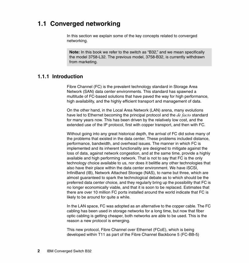
1.1 Converged networking
In this section we explain some of the key concepts related to converged networking.
1.1.1 Introduction
Fibre Channel (FC) is the prevalent technology standard in Storage Area Network (SAN) data center environments. This standard has spawned a multitude of FC-based solutions that have paved the way for high performance, high availability, and the highly efficient transport and management of data.
On the other hand, in the Local Area Network (LAN) arena, many evolutions have led to Ethernet becoming the principal protocol and the de facto standard for many years now. This has been driven by the relatively low cost, and the extended use of the IP protocol, first with copper transport, and then with FC.
Without going into any great historical depth, the arrival of FC did solve many of the problems that existed in the data center. These problems included distance, performance, bandwidth, and overhead issues. The manner in which FC is implemented and its inherent functionality are designed to mitigate against the loss of data, against network congestion, and at the same time, provide a highly available and high performing network. That is not to say that FC is the only technology choice available to us, nor does it belittle any other technologies that also have their place within the data center environment. We have iSCSI, InfiniBand (IB), Network Attached Storage (NAS), to name but three, which are almost guaranteed to spark the technological debate as to which should be the preferred data center choice, and they regularly bring up the possibility that FC is no longer economically viable, and that it is soon to be replaced. Estimates that there are over 10 million FC ports installed around the world indicate that FC is likely to be around for quite a while.
In the LAN space, FC was adopted as an alternative to the copper cable. The FC cabling has been used in storage networks for a long time, but now that fiber optic cabling is getting cheaper, both networks are able to be used. This is the reason a new protocol is emerging.
This new protocol, Fibre Channel over Ethernet (FCoE), which is being developed within T11 as part of the Fibre Channel Backbone 5 (FC-BB-5)
Note: In this book we refer to the switch as “B32,” and we mean specifically the model 3758-L32. The previous model, 3758-B32, is currently withdrawn from marketing.
2 IBM Converged Switch B32
project, is not meant to displace or replace FC, but to complement it. FCoE is an enhancement that expands FC into the Ethernet by combining two leading-edge technologies (FC and the Ethernet) using the same physical transport.
In this book, when we refer to “Enhanced Ethernet,” we are referring to an Ethernet that is full duplex and lossless when transporting Fibre Channel frames. We discuss these terms in greater depth in the sections that follow.
The FC-BB-5 proposalThe original proposal to the T11 technical committee that gave momentum to the creation of the FC-BB-5 standard is:
“This project proposal recommends the development of a set of additional and enhanced mechanisms, services, and protocols to connect Fibre Channel entities over selected non-Fibre Channel protocol infrastructures. Enhancements to Ethernet protocols, such as the Pause mechanism defined in IEEE 802.3-2005, make it possible to define a direct mapping of Fibre Channel over Ethernet (FCoE). This mapping provides several technological benefits over the currently defined Fibre Channel over IP (FCIP) mapping and gives a significant business advantage to Fibre Channel over competing technologies, such as iSCSI, because Fibre Channel provides seamless compatibility with existing storage, drivers, and management tools. The FCoE mapping allows Fibre Channel to be used in Ethernet-based I/O consolidated environments and will be especially useful in both the Data Center and Metro Ethernet environments.
Technical Committee T11: This is the committee within the International Committee for Information Technology Standards (INCITS) responsible for Fibre Channel interfaces. T11 (previously known as X3T9.3) has been producing interface standards for high-performance and mass storage applications since the 1970s.
Is it FCoE or FCoCEE?
FCoE or FCoCEE? Actually, it is both. FCoE is the standard that is driving convergence and the emergence of FC over the Ethernet. However, in and of itself it (FC over Ethernet) will not be enough to allow for fabric convergence. Without question, it is a move in the correct direction but without any enhancements (we will discuss these enhancements later) Ethernet itself does not meet the requirements for data center convergence. FCoCEE is Fibre Channel over Converged Enhanced Ethernet (pronounced eff-see-oh-see), which is enabled by FCoE.
Chapter 1. Introduction to converged networking 3

Included within the scope of this project are functions, such as:
– A direct mapping of Fibre Channel over selected full duplex IEEE 802.3 networks
– Any other item as deemed necessary during the development”
This proposal has now been adopted within the International Committee for Information Technology Standards (INCITS) and is being actively worked on by the Storage technical committee for Fibre Channel Interfaces (T11). You can access the FC-BB-5 project, along with its current status, at:
http://tinyurl.com/3l7u5t
1.1.2 Challenges
Today, many companies are thinking about consolidation and virtualization, if they are not already in the process of migrating. Reducing costs and optimizing utilization of the infrastructure are the forces driving companies to consider consolidation and virtualization. In the same way that server load is consolidated into faster and higher performing machines, networking is now ready to step up to the challenge – especially with the current speeds of the Ethernet and FC, and with 10Gbps or even faster in the near future, the network is ready for consolidation and virtualization.
As we are consolidating storage into SANs and communication networks into LANs and WANs, we face challenges related to the management of the networks and the complexity that we add to have an all-in-one approach. Converged networks enable the use of communication and storage networks over the same physical connection, and we need to address it in the most optimal way.
Specialized networks, like SAN, are great solutions for consolidation, but they increase the cost of ownership and operation of the global infrastructure. This has been one of the approaches used commonly in the past, and it is a valid answer. The problem is that we have to maintain two separate networks, one for storage and another for communications, and generally we require two specialized teams to manage them, effectively doubling the cost of the infrastructure, operations, support, and maintenance. The question is: if we already have an FC network for SAN, can we use it for the communication network as well? In much the same way, can we use an existing high speed LAN for storage?
There are some solutions for this, such as iSCSI or NAS, but they are not optimal, they inherit the problems of the traditional LAN networks, and they will still require separate hardware and software to be able to handle our
4 IBM Converged Switch B32
requirements. These solutions require careful attention or they run the risk of extend existing problems, for example spanning tree, to the storage network.
The converged network solutionConverged networks use the best of both worlds, incorporating standards to consolidate I/O by the use of the FC protocol over Ethernet and enabling the Ethernet to meet the requirements of FC. The main assumptions of the converged network proposal are:
� TCP/IP is the protocol of choice for server connections� FC is the protocol of choice for storage area networks� Ethernet is the transport technology most widely used
By using Ethernet as the base of future networks, we are enabling consolidation and cost reduction in a global infrastructure. But, in order to make it possible, we need to change some aspects of the Ethernet protocol behavior.
The traditional Ethernet is able to accept loss of packets, and requires the sender to resend them when they have not been received. However, this is no longer acceptable on storage networks because we cannot afford to lose even one packet. For this we need a lossless Ethernet. The idea here is not to change Ethernet but to extend it so we can enable features that will let us run TCP/IP and FC with the best of the features from both.
In the next section we discuss these aspects in more detail.
1.2 What is Converged Enhanced Ethernet
As we have stated, the prevalence of FC storage in the world’s data centers cannot be ignored when introducing a new technology. The current FC SAN investment must be protected; this is not negotiable. But, this still does not answer the question, “Why converge?” The appeal of the converged network is that the existing FC infrastructure can be maintained, the management model is the same as the existing FC, fewer components will be required, and therefore, there is less power and cooling necessary, yielding potential energy savings. On the other hand, we can also see it as an opportunity to extend the capabilities of a 10Gb Ethernet network infrastructure.
So before we fully answer our question, let us step back and look at a very simple example of the interfaces and networks that exist today. As we touched upon briefly, data centers and applications can use a variety of interfaces or adapters, for example, Ethernet (Ethernet network interface card (NIC)) and Fibre Channel (Fibre Channel host bus adapter (HBA)).
Chapter 1. Introduction to converged networking 5
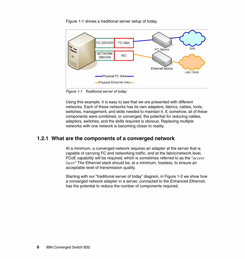
Figure 1-1 shows a traditional server setup of today.
Figure 1-1 Traditional server of today
Using this example, it is easy to see that we are presented with different networks. Each of these networks has its own adapters, fabrics, cables, tools, switches, management, and skills needed to maintain it. If, somehow, all of these components were combined, or converged, the potential for reducing cables, adapters, switches, and the skills required is obvious. Replacing multiple networks with one network is becoming closer to reality.
1.2.1 What are the components of a converged network
At a minimum, a converged network requires an adapter at the server that is capable of carrying FC and networking traffic, and at the fabric/network level, FCoE capability will be required, which is sometimes referred to as the “access layer.” The Ethernet stack should be, at a minimum, lossless, to ensure an acceptable level of transmission quality.
Starting with our “traditional server of today” diagram, in Figure 1-2 we show how a converged network adapter in a server, connected to the Enhanced Ethernet, has the potential to reduce the number of components required.
6 IBM Converged Switch B32

Figure 1-2 Converged Network Adapter
At the server level, we are already starting to see Converged Network Adapters (CNAs), and many of the IBM servers will include these adapters by default. Using a Fibre Channel driver, the CNA functionally represents a traditional Fibre Channel HBA to the server’s operating system. Using NIC or clustering drivers, the CNA functionally represents a traditional networking or clustering device to the server’s operating system. The Fibre Channel traffic is encapsulated into FCoE frames (as we describe in the sections that follow) and these FCoE frames are converged with networking or clustering traffic.
Within the fabric, we already have converged switches, like the L32, that can pass Fibre Channel traffic to the attached SANs and Ethernet traffic to the attached Ethernet network. These switches must be able to support the Enhanced Ethernet. (We discuss these requirements later in this document.)
1.2.2 The 10 Gigabit Enhanced Ethernet
One of the inhibitors to using Ethernet as the base upon which an FCoE/FCoCEE network is built was the bandwidth limitations of the Ethernet protocol. However, with the emergence of 10 Gbps Ethernet (10 GbE), we now have a base on which all FCoE/FCoCEE solutions can be built. This is because with one large pipe, storage is not transported to the exclusion of everything else. The large pipe creates a “superhighway” that allows Voice over IP (VoIP), video, messaging, and storage or other kinds of traffic to travel over a common Ethernet infrastructure. And it only gets better, and faster, with 40 GbE and 100 GbE planned for the future.
The other important item to consider is that the FC network is lossless, whereas the Ethernet is not.
Enhanced Ethernet will include new extensions to the existing Ethernet standard that will eliminate the lossy nature of the Ethernet and make 10 GbE a viable
Chapter 1. Introduction to converged networking 7
storage networking transport. Other enhancements within the Enhanced Ethernet paradigm include:
� Congestion notification� Priority-based flow control� Enhanced transmission selection� Data Center Bridging (DCB) Capability Exchange Protocol
We cover these topics in “IEEE - Data Center Bridging” on page 18, after we have introduced the terminology and concepts that make up the Convergence Enhanced Ethernet.
1.2.3 What is FCoE
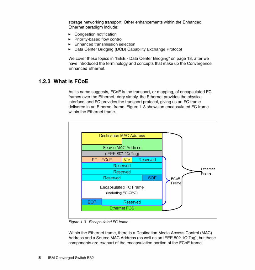
As its name suggests, FCoE is the transport, or mapping, of encapsulated FC frames over the Ethernet. Very simply, the Ethernet provides the physical interface, and FC provides the transport protocol, giving us an FC frame delivered in an Ethernet frame. Figure 1-3 shows an encapsulated FC frame within the Ethernet frame.
Figure 1-3 Encapsulated FC frame
Within the Ethernet frame, there is a Destination Media Access Control (MAC) Address and a Source MAC Address (as well as an IEEE 802.1Q Tag), but these components are not part of the encapsulation portion of the FCoE frame.
8 IBM Converged Switch B32

Of particular note is that the FC frame that is encapsulated contains the original 24 byte header and the payload. The reason that the original FC header is passed is to enable seamless processing of the frame without the requirement for a separate gateway.
Protocol stack changesTo send the packets over the network, changes had to be made to the protocol stack. Figure 1-4 shows the changes made to the stack to accommodate Enhanced Ethernet (you should already familiar with the protocol stack).
Figure 1-4 Protocol stack
The bottom two layers of the FC protocol stack have been replaced with their Ethernet protocol stack equivalents. The FC-BB-5 project group members are tasked with the responsibility for ensuring that the existing FC stack remains unaffected and that the work that has already gone into the existing FC stack is not undermined or lost.
Note that within the FC-BB_E interface is a reference model within FC-BB-5 that defines the mappings for transporting Fibre Channel over Ethernet. Because an Ethernet network can lose frames, it is the extensions to the Ethernet that will allow FCoE to exhibit a lossless and full duplex behavior when carrying Fibre Channel frames.
Chapter 1. Introduction to converged networking 9
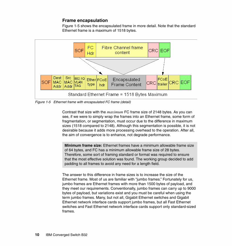
Frame encapsulationFigure 1-5 shows the encapsulated frame in more detail. Note that the standard Ethernet frame is a maximum of 1518 bytes.
Figure 1-5 Ethernet frame with encapsulated FC frame (detail)
Contrast that size with the maximum FC frame size of 2148 bytes. As you can see, if we were to simply wrap the frames into an Ethernet frame, some form of fragmentation, or segmentation, must occur due to the difference in maximum sizes (1518 compared to 2148). Although this segmentation is possible, it is not desirable because it adds more processing overhead to the operation. After all, the aim of convergence is to enhance, not degrade performance.
The answer to this difference in frame sizes is to increase the size of the Ethernet frame. Most of us are familiar with “jumbo frames.” Fortunately for us, jumbo frames are Ethernet frames with more than 1500 bytes of payload, and they meet our requirements. Conventionally, jumbo frames can carry up to 9000 bytes of payload, but variations exist and you must be careful when using the term jumbo frames. Many, but not all, Gigabit Ethernet switches and Gigabit Ethernet network interface cards support jumbo frames, but all Fast Ethernet switches and Fast Ethernet network interface cards support only standard-sized frames.
Minimum frame size: Ethernet frames have a minimum allowable frame size of 64 bytes, and FC has a minimum allowable frame size of 28 bytes. Therefore, some sort of framing standard or format was required to ensure that the most effective solution was found. The working group decided to add padding to all frames to avoid any need for a length field.
10 IBM Converged Switch B32

Although jumbo frames are not a standard, the quickest and simplest option was to require jumbo frame support for every device in the FCoE/FCoCEE network.
“Baby” jumbo frames of approximately 2500 bytes are desirable for the future.
From lossy to losslessStorage requirements are very stringent and it is a given that any new transport mechanism has to be lossless. If Ethernet is to be used, a “new” Ethernet must be built, an Enhanced Ethernet.
Additionally, congestion must be avoided at all costs, and there must be no compromise to the availability that is inherent in the FC data center SAN that exists today. The FC-BB-5 standard will need to take into account that the “lossy” nature of the Ethernet needs to be addressed if it is to gain a foothold in the transport of storage data. We describe several of the key characteristics and points that need addressing in the following sections.
ReliabilityJust as FC does, FCoE must have the ability to guarantee frame delivery, and the physical links must have very low bit error rates (BER) to ensure that, if there is a buffer overflow or any form of congestion, no frames are dropped. Fortunately, both 1 GbE and 10 GbE have a BER requirement that matches that of FC – a 1 in 1012 bit error rate (1 bit in 1,000,000,000,000 bits).
Flow control and avoiding packet lossThe design of FC includes the capability to maintain the speed and efficiency of the data center channel architecture. This entailed the creation of a flow mechanism, which was done using buffer to buffer “credits.” Very briefly, a device cannot send any additional frames until the receiver says that it is acceptable to do so. FC handles this situation very well; Enhanced Ethernet must have the same capability for FCoE to be a viable option.
One of the problems with any Ethernet network is that without an adequate flow control mechanism, when a congestion condition arises, packets can be dropped (lost), which is not acceptable. Flow control similar to the buffer to buffer credit method was needed in the Ethernet network.
What we do find in Ethernet is a flow control PAUSE mechanism that can be used to prevent packet loss. In a similar manner to buffer to buffer credit methods, the flow control PAUSE mechanism will ask a sender to hold off sending any more frames until the receiver’s buffers are cleared. This mechanism is contained in the IEEE 802.3 Annex 31B flow control standard specification. It goes part of the way to ensuring that storage traffic does not suffer frame loss and it attempts to alleviate congestion.
Chapter 1. Introduction to converged networking 11
However, one of the problems with the PAUSE mechanism is that it applies no intelligence to the PAUSE, and arbitrarily pauses all traffic. The IEEE is conscious of this problem and has a number of working groups looking at the issues of congestion management and quality of service (QoS) priority levels to ensure that the most important data gets to its destination first without suffering from any unwarranted congestion.
As the IEEE standard evolves, we can expect to see priority-based flow control that can be selectively applied to different classes of traffic. We discuss flow control and other enhancements later in 1.3.1, “IEEE - Data Center Bridging” on page 18.
AddressingIn an FC network, the links are based on a point-to-point topology. The Ethernet network differs in this respect, because it does not create a point-to-point connection in the same way that FC does. FCoE uses the destination and source MAC addresses (as shown in Figure 1-3 on page 8) to forward a frame to its intended destination.
Addressing schemesThe two addressing schemes of interest are:
� Server-Provided MAC Addresses (SPMA)� Fabric-Provided MAC Addresses (FPMA)
Both of these addressing schemes have been accepted as valid addressing schemes, and it is up to the individual vendor to determine which addressing scheme they choose to implement and support.
Server-Provided MAC AddressesAs its name suggests, an SPMA is a MAC address that is issued in accordance with Ethernet standards and set by the manufacturer at installation.
Fabric-Provided MAC AddressesThe FPMA is a fabric-unique address that is assigned by the fabric. The low-order 24 bits are equivalent to the N_Port ID (FC-ID) assigned during fabric login, and the high-order 24 bits are equal to the FCoE MAC address prefix (FC-MAP) associated with the fabric.
We discuss how these MAC addresses will be used to route frames after we describe the terminology that will be used in the FCoE/FCoCEE data center.
12 IBM Converged Switch B32
FCoE terminologyAs we have stated, FCoE has the ability to transport FC, but unless FCoE is made lossless, it does not meet the behavior requirements that data centers demand of an FC port.
This section explains the terminology used to discuss FCoE concepts and introduces some basic characteristics of FCoE. Where appropriate, we draw parallels with FC to aid you in understanding FCoE.
PortsTo ensure that FCoE ports meet our requirements (that is, FCoE ports behave like FC ports), they need to emulate FC ports and become virtual FC ports. So, using the FC terminology for nodes, ports, and inter-switch links (ISLs), FCoE will have a:
� Port in an Enhanced Ethernet node (ENode), which is a Virtual N_Port (VN_Port)
� Port in an FCoE-capable Ethernet switch, which is a Virtual F_Port (VF_Port)
The FCoE-capable Ethernet switch can also have an:
� ISL port, which is a Virtual E_Port (VE_Port)
From an addressing point of view, each FCoE Virtual Port will have its own MAC address associated with it, whether it has been assigned by SPMA or FPMA.
LinksIn FC, every link between a node port and a switch port is a physical, point-to-point connection. In FCoE, the concept is different. An FCoE node port (VN_Port) has the ability to access more than one FCoE Switch port (VF_Port), based on its MAC address, giving a multitude of paths through the network. Even more impressive is that more than one FCoE node is able to access the same FCoE Switch port.
This capability leads to the concept of virtual links. An FCoE virtual link is an ENode-MAC to FCoE-Switch-port-MAC relationship and is referred to as “virtual link” for brevity.
FCoE-capable Ethernet switch: This switch is capable of supporting the Enhanced Ethernet at a minimum, and one or more of these switches must be configured to support FCoE forwarding functions provided by an FCoE Forwarder (we discuss FCoE Forwarders later), and Fibre Channel fabric services.
Chapter 1. Introduction to converged networking 13

Furthermore, because each virtual port has its own MAC address, the FCoE Virtual Link is created by using the pair of MAC addresses of the two virtual link end points as source and destination MAC addresses.
But what is a virtual link end point? In its simplest form, a virtual link is the logical link created by a VN_Port communicating with a VF_Port, or a VE_Port communicating with a VE_Port. The component that facilitates this logical link is the FCoE Link End Point (FCoE_LEP). Each VN, VF, and VE_Port will have an FCoE_LEP associated with it, and this FCoE_LEP will also perform FC frame encapsulation and decapsulation. Because each virtual port also has a MAC address associated with it, it is easy to see the manner in which virtual link end points can be associated with each other.
Our FC/FCoE switching and interface element has an Ethernet port and the capability to handle, forward, or otherwise cope with FC frames. Within the switch is a component that is called an FCoE Forwarder (FCF). The FCF is an FC switching element and is associated with one or more Enhanced Ethernet MAC addresses. The FCF is the communication bridge between the Enhanced Ethernet and an FC fabric.
Both the ENode and the remote switch can have one or more FCoE_LEPs that are associated with one or more VN or VF and VE_Ports. FCoE_LEPs will reside at or in the ENode and also at or in the FCF.
This means that the virtual link connections allow for any VN_Port to connect to any VF_Port. This connection is in contrast to the FC point-to-point, physical relationship of N_Port to F_Port.
ENode: An FCoE Node (ENode) is an FC node that is associated with one or more Enhanced Ethernet MACs, one or more FCoE Link End Points (FCoE_LEPs), and one or more VN_Ports. Note that each Enhanced Ethernet MAC is coupled with an FCoE Controller. We discuss the function of the FCoE Controller later, but for now it is enough to know that the FCoE_Controller is responsible for the creation of VN_Ports, VF_Ports, VE_Ports, and FCoE_LEPs.
FCoE Forwarder: The FCoE Forwarder is a function that exists in a switch that has Ethernet ports and is responsible for translating the FCoE frames between the Enhanced Ethernet and an FC SAN. On the Enhanced Ethernet side, this function can be within a device, or it can be integrated into an Enhanced Ethernet switch. On the FC SAN side, the native FC ports connect to a Fibre Channel switch.
14 IBM Converged Switch B32
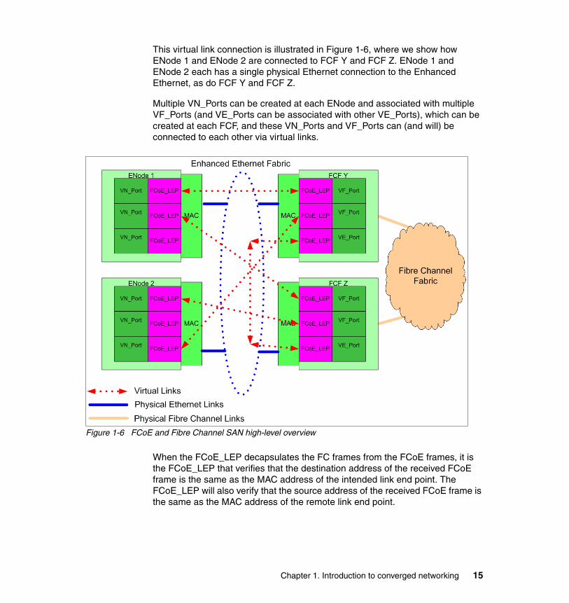
This virtual link connection is illustrated in Figure 1-6, where we show how ENode 1 and ENode 2 are connected to FCF Y and FCF Z. ENode 1 and ENode 2 each has a single physical Ethernet connection to the Enhanced Ethernet, as do FCF Y and FCF Z.
Multiple VN_Ports can be created at each ENode and associated with multiple VF_Ports (and VE_Ports can be associated with other VE_Ports), which can be created at each FCF, and these VN_Ports and VF_Ports can (and will) be connected to each other via virtual links.
Figure 1-6 FCoE and Fibre Channel SAN high-level overview
When the FCoE_LEP decapsulates the FC frames from the FCoE frames, it is the FCoE_LEP that verifies that the destination address of the received FCoE frame is the same as the MAC address of the intended link end point. The FCoE_LEP will also verify that the source address of the received FCoE frame is the same as the MAC address of the remote link end point.
Chapter 1. Introduction to converged networking 15
It is not a requirement that the FCF is connected to a Fibre Channel Fabric. The FCF can be a combined (combo) FC/FCoE switch provided as part of the Enhanced Ethernet Fabric.
Initialization, discovery, and port creationIn much the same way that FC already does, there needs to be a mechanism that discovers new ports, assigns and unassigns MAC addresses, and handles logins and logouts. This process is called the FCoE Initialization Protocol (FIP). Without going into great technical depth, which is not the intent of this paper, the FIP will be used by FCFs to discover other FCFs and to advertise their presence to nodes on the fabric. ENodes will use FIP to log in to the fabric. And it is through FIP that ENodes and FCFs will establish the virtual ports: VN_Ports, VF_Ports, and VE_Ports; and therefore, create FCoE_LEPs.
A functional entity is in control of this process. It is called an FCoE Controller and it is responsible for executing the FIP. The FCoE Controller will be part of, or exist in, an FCF and an ENode.
Connectivity: FIP Link Keep Alive (FKA) is implemented in FCoE because there needs to be a way of detecting whether something has gone wrong in the path between VN_Ports and VF_Ports, and between VE_Ports.
Primarily, FKA enables the VF_Port to discover that the VN_Port is unreachable because the physical link is no longer a reliable indicator of this condition (with FCoE, there might not be a direct connection to the FCF; the path might be through intermediary switches). Timers associated with ENodes and FCFs are able to discover whether a port is sending messages, and also whether the port is still alive and not just inactive. To discover if a port is still alive, periodic messages must be sent, and these messages are sent as unsolicited advertisements.
These messages can be sent from FCF to ENode, and from FCF to FCF. However, because there is no unsolicited advertisement from an ENode to the FCF, a special FKA has been created to let the FCF know that the ENode and its VN_Ports are still alive. No response from the VF_Port is necessary because the VN_Port discovers unreachable VF_Ports by the absence of the periodic advertisements that are multicast from the FCF. An ENode might send periodic FKAs for every MAC address to which it is capable of transmitting or from which it capable of receiving.
16 IBM Converged Switch B32

Figure 1-7 shows how the FCoE Controller can exist in the ENode and the FCF.
Figure 1-7 FCoE Controller
Pathing and routing mechanismsIt is essential that in any FCoE solution implemented, the Ethernet and IP standards, along with the FC standards, are supported for switching, path selection, and routing. The FCoE solution must support the current standards and it must also be in a position to support any enhancements to the standards. In other words, it must have the ability to discern and adapt to FC and FCoE.
FC frames will still be handled by the Fabric Shortest Path Protocol (FSPF). The Spanning Tree Protocol (STP), Etherchannel, and its various versions and intended enhancements (such as TRILL, which we mention next) will be used to move Ethernet frames. Because FC is layered on top of the Ethernet, there is no conflict between the two methods.
Under the auspices of the Internet Engineering Task Force (IETF), there is a working group that is looking at the Transparent Interconnection of Lots of Links (TRILL). The brief description of this group’s goal is to design a solution for shortest-path frame routing in multi-hop IEEE 802.1-compliant Ethernet networks with arbitrary topologies, using an existing link-state routing protocol technology. It is expected that solutions in the future will be able to support this after TRILL is fully approved and ratified. What this means is that in the future, TRILL might be a protocol to watch for moving Ethernet frames around.
In essence, FCoE frames will be moved around by whatever method the Ethernet network uses.
Chapter 1. Introduction to converged networking 17

Usage casesWe see three deployment usage cases for the initial generation of FCoCEE:
� Usage case 1 is a rack upgrade scenario. In this case, an FCoCEE rack is deployed into an existing data center (DC), without changing the data center’s Ethernet or FC infrastructure.
� Usage case 2 is a new Dual-Fabric, data center scenario, where FCoCEE is used within each rack, but at the DC level, there are still two separate fabrics: Ethernet and FC.
� Usage case 3 is a new Converged Fabric, data center scenario, where FC is used at the perimeter of the converged FCoCEE fabric to attach storage, but CEE and FCoCEE switches are used throughout the DC.
All of these usage cases will also enable a lower operational expense by integrating FC and Ethernet fabric management.
1.3 Standards
None of the previous statements will ever become reality if there are no standards to support it. This is why many standardization boards are working together to create the next generation of protocols and standardized extensions to enablethem. In this section we discuss some of them.
1.3.1 IEEE - Data Center Bridging
As we have stated, there are issues to overcome if we are to have a truly lossless Enhanced Ethernet. The IEEE will look at extensions to the Ethernet as part of its Data Center Bridging Task Group.
The Data Center Bridging (DCB) Task Group (TG) is a part of the IEEE 802.1 Working Group, with the charter to provide enhancements to the existing 802.1 bridge specifications to satisfy the requirements of protocols and applications in the data center.
Data centers typically comprise multiple application-specific networks that run on different link layer technologies. The enhancements to the specifications will enable the 802.1 bridges and facilitate a converged network.
The projects that are being managed by the task group are:
� Priority-Based Flow Control (PFC) provides a link level flow control mechanism that can be independently controlled at a priority level and that can selectively pause different classes of traffic. The aim is to ensure zero
18 IBM Converged Switch B32
loss due to congestion in data center bridging networks. The motivation behind this enhancement is to provide a no packet drop behavior, which is required by some data center applications (for example, FC and some IPC traffic). With priority-based flow control, separate flow control mechanisms can be used for different traffic classes.
Flow control comes into play when the network experiences congestion. When congestion occurs, priority-based flow control can be engaged for the lower priority traffic classes where the no packet drop behavior is expected. By selectively pausing these lower priority traffic classes, other high priority traffic and delay-sensitive traffic sharing the same link are not affected, which differs from the current IEEE 802.3x PAUSE?[1]?[3] mechanism where all traffic is affected when PAUSE is enabled. For example, with PFC, if storage traffic has a higher priority than LAN traffic and a large storage transfer causes congestion, PFC can be engaged to pause the storage transfer and let the LAN transfer proceed.
These enhancements are being addressed in the working group 802.1Qbb.
� Enhanced Transmission Selection (ETS) will provide a common management framework for assigning the appropriate and desired bandwidth to different traffic classes. For example, if a class does not use its available bandwidth, the bandwidth can be used by other traffic classes.
Today, IEEE 802.1p defines a strict priority mechanism, where as long as there is higher priority traffic to be transferred, that traffic will take precedence over lower priority traffic. That is, it does not allow bandwidth to be allocated to different traffic priorities. The motivation behind ETS is the recognition that different traffic classes have different queuing requirements and need different resource allocation. ETS is the means to provide traffic differentiation, such that multiple traffic classes can share the same consolidated Ethernet link without impacting each other.
Enhanced Transmission Selection is specified using two configuration tables. The first table maps the priority level as conveyed in IEEE 802.1p bits to Priority Groups, where each Priority Group represents a traffic class, such as LAN, SAN, IPC, and management.
The first table defines whether a Priority Group is lossless or lossy and the type of priority it will use (strict as compared to non-strict). Strict priority scheduling is as defined in IEEE 802.1p, and there is no bandwidth check. For non-strict priority scheduling, the second table specifies the amount of link bandwidth allocated for each Priority Group. How bandwidth is allocated within a group is unspecified. When a group does not fully utilize its bandwidth allocation, the unused bandwidth is given to the other groups. Under an ETS-based scheduler, storage traffic can be managed as a group with configurable bandwidth guarantees to ensure that storage traffic will get its fair share of resources, and storage traffic will be lossless.
Chapter 1. Introduction to converged networking 19
These enhancements are being addressed in the working group 802.1Qaz.
� Data Center Bridging Capabilities Exchange Protocol (DCBCXP) is a discovery and capability exchange protocol that allows Enhanced Ethernet devices to convey and configure their Enhanced Ethernet capabilities with other attached Enhanced Ethernet devices. This protocol will ensure a consistent configuration across the network.
The motivation behind this enhancement is to provide a way for discovering, initializing, and managing CEE compliant components. DCBCXP uses Link Layer Discovery Protocol (LLDP) as defined in IEEE 802.1AB to advertise connectivity and management information between two link peers. It uses DCBX Management Information Base (MIB) to configure and monitor CEE-compliant components.
These enhancements are being addressed in the working group 802.1AB.
There are two additional mechanisms that further enhance convergence of FC with Ethernet, but they are not required for initial deployments. IBM views these additional CEE mechanisms as needed to support FC convergence with Ethernet at the data center level. The two additional mechanisms are:
� Congestion Notification (CN): Provides end-to-end congestion management for protocols that do not already have built-in congestion control mechanisms, which includes FCoE. Whereas mechanisms for congestion notification exist at the IP and TCP level, an enhancement at the Ethernet link level will provide the congestion management capabilities to applications that will exploit CEE but do not use TCP/IP. Link level congestion notification provides a mechanism for detecting congestion and notifying the source to back off the traffic flowing on the congested links. Link level congestion notification will allow a switch to send a signal that other ports need to stop or slow down their transmissions.
Because of the reactive nature of the mechanism, the life of the flow must be much greater than the network latency for congestion notification to be effective, which is useful in controlling unicast traffic in networks with long-lived data flows with respect to their bandwidth-delay product. However, while link level congestion notification might reduce the chance of deadlocks in the network, and packet drops, it is not sufficient to guarantee a no packet drop behavior.
These enhancements are being addressed in the working group 802.1Qau.
� Link level shortest path first-based routing protocol: The routing schemes used in the current Ethernet link layer are inefficient due to the need to strictly avoid loops. This enhancement is intended to provide a mechanism that can provide shortest-path frame routing in multi-hop IEEE 802.1-compliant Ethernet fabrics with arbitrary topologies, using existing link-state routing protocol technology.
20 IBM Converged Switch B32

This effort is currently being pursued in the IETF TRILL working group.
1.3.2 IEEE - TRILL
TRILL stands for Transparent Interconnect of Lots of Links, and is a work in progress from the standardization groups at the IETF and IEEE. The main objective of TRILL is to avoid loops in Ethernet communication, and to do so, instead of using new protocols, like the Spanning Tree or complex configurations and network layouts, this proposal intends to include protocol extensions that will prevent loops happening.
The importance of TRILLThe main objective of TRILL is to provide a frame routing solution to provide shortest-path frame routing for multi-hop environments. This is very important and will certainly have an impact in the future of converged networking, since we will have finally a solution to be able to connect “everyone with everyone” in the network, without the current limits of the technology and avoiding loops.
The solution TRILL proposed is a Layer 2 multi-path alternative to the existing single path and bandwidth limiting Spanning Tree Protocol (STP) that is currently widely use across all the networks.
In addition to the STP solution, the TRILL protocol will provide Layer 2 routing capabilities, needed for the right deployment of DCB/FCoE solutions beyond the local servers that are accessed, and extends it to a larger network. Thus, in the future, large networks with all kind of devices could be connected together without the need to handle loops or worry about routing.
The status of the standard is well advanced, but at the time of this writing it has not yet been widely adopted. The L32 does not support TRILL at this time.
1.4 Summary
At the same time as providing cost reduction benefits, FCoE and FCoCEE will maintain all the services to which the Fibre Channel SAN is accustomed.
Spanning Tree Protocol (STP): The Spanning Tree Protocol is a Layer 2 protocol that prevents loops in a bridged LAN environment. Briefly, the way it works is by creating a virtual tree of the network, and disabling the links on the switches that may potentially provoke loops.
Chapter 1. Introduction to converged networking 21

With the large installed base of FC-based storage in the enterprise data center, a fabric convergence solution that aims to provide a consolidated network for IPC, LAN, and storage traffic needs to allow the users to protect their investment in FC storage. CEE enables fabric convergence by carrying FC traffic over a lossless transmission network, which allows a user to embrace fabric consolidation while retaining full use of the FC storage. Furthermore, features such as traffic differentiation and priority-based flow control in CEE provide value regardless of whether FC Channel storage is used.
Initially, CEE and FCoCEE are expected to play well in the High Performance Computing (HPC) and Analytics market as an alternative to InfiniBand. As FCoCEE matures and meets the performance, reliability, and quality requirements of enterprise clients, we expect CEE will also play well in large enterprises wanting to pursue FC convergence with Ethernet. The usage cases described in this paper can provide a model for how FCoCEE deployment will progress over time.
This evolution with FCoE and FCoCEE makes network consolidation a reality by the combination of Fibre Channel and Ethernet. This network consolidation will still maintain the resiliency, efficiency, and seamlessness of the existing FC-based data center.
IBM is investing heavily in the standards bodies, its technology, and its core competencies to ensure that FCoE preserves and enhances the SAN investment.
In this book you can continue reading about the IBM Converged Switch L32, which enables convergence in your current infrastructure, supports the most advanced CNAs, and offers FC gateway capability.
22 IBM Converged Switch B32
Chapter 2. IBM Converged Switch B32 introduction
The IBM Converged Switch B32 (3758-L32) provides Converged Enhanced Ethernet (CEE) capabilities starting with an entry level solution at 10Gb Ethernet that is upgradeable with a license key. Having servers supply LAN traffic and SAN traffic over a single adapter and cable saves space and power, and reduces the amount of cabling to half of what is traditionally needed when using separate LAN and SAN adapters. If you are familiar with the previous IBM Converged Switch B32, you will notice that this product is the same, but it does not have FC capabilities active by default.
In this chapter we present the features and options of the IBM Converged Switch B32, model L32.
2
© Copyright IBM Corp. 2011. All rights reserved. 23
2.1 IBM Converged Switch B32
In this section we explain what the IBM Converged Switch B32 model L32 is and describe its features and options. Later in this book we demonstrate how it is configured to its operational state.
2.1.1 At a glance
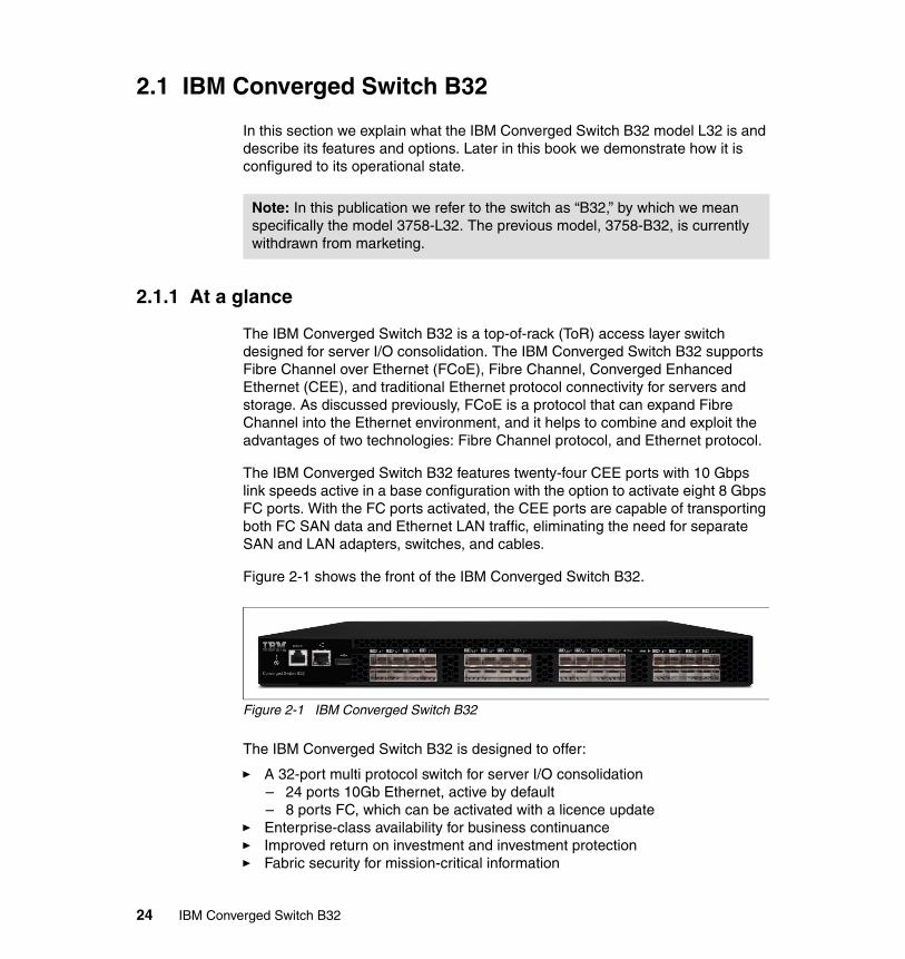
The IBM Converged Switch B32 is a top-of-rack (ToR) access layer switch designed for server I/O consolidation. The IBM Converged Switch B32 supports Fibre Channel over Ethernet (FCoE), Fibre Channel, Converged Enhanced Ethernet (CEE), and traditional Ethernet protocol connectivity for servers and storage. As discussed previously, FCoE is a protocol that can expand Fibre Channel into the Ethernet environment, and it helps to combine and exploit the advantages of two technologies: Fibre Channel protocol, and Ethernet protocol.
The IBM Converged Switch B32 features twenty-four CEE ports with 10 Gbps link speeds active in a base configuration with the option to activate eight 8 Gbps FC ports. With the FC ports activated, the CEE ports are capable of transporting both FC SAN data and Ethernet LAN traffic, eliminating the need for separate SAN and LAN adapters, switches, and cables.
Figure 2-1 shows the front of the IBM Converged Switch B32.
Figure 2-1 IBM Converged Switch B32
The IBM Converged Switch B32 is designed to offer:
� A 32-port multi protocol switch for server I/O consolidation– 24 ports 10Gb Ethernet, active by default– 8 ports FC, which can be activated with a licence update
� Enterprise-class availability for business continuance� Improved return on investment and investment protection� Fabric security for mission-critical information
Note: In this publication we refer to the switch as “B32,” by which we mean specifically the model 3758-L32. The previous model, 3758-B32, is currently withdrawn from marketing.
24 IBM Converged Switch B32
2.1.2 Overview
The IBM Converged Switch B32 is designed to:
� Deliver high performance with a cut-through, non-blocking switch architecture
� Support Fibre Channel over Ethernet (FCoE), Fibre Channel, Converged Enhanced Ethernet (CEE), and traditional Ethernet protocols via a top-of-rack, 1U, multi protocol design
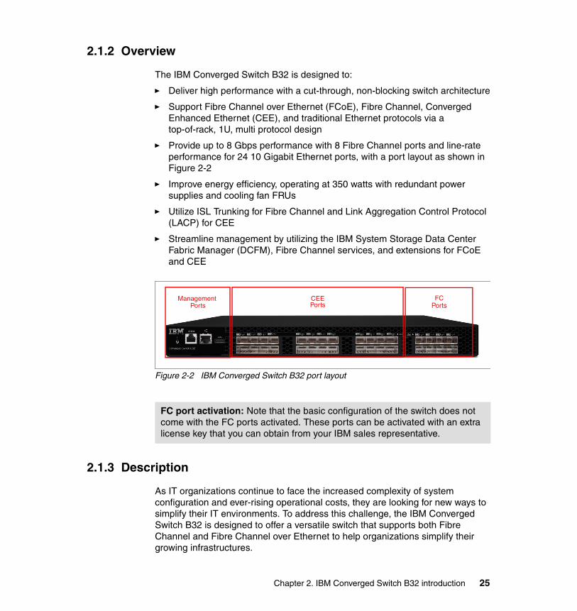
� Provide up to 8 Gbps performance with 8 Fibre Channel ports and line-rate performance for 24 10 Gigabit Ethernet ports, with a port layout as shown in Figure 2-2
� Improve energy efficiency, operating at 350 watts with redundant power supplies and cooling fan FRUs
� Utilize ISL Trunking for Fibre Channel and Link Aggregation Control Protocol (LACP) for CEE
� Streamline management by utilizing the IBM System Storage Data Center Fabric Manager (DCFM), Fibre Channel services, and extensions for FCoE and CEE
Figure 2-2 IBM Converged Switch B32 port layout
2.1.3 Description
As IT organizations continue to face the increased complexity of system configuration and ever-rising operational costs, they are looking for new ways to simplify their IT environments. To address this challenge, the IBM Converged Switch B32 is designed to offer a versatile switch that supports both Fibre Channel and Fibre Channel over Ethernet to help organizations simplify their growing infrastructures.
FC port activation: Note that the basic configuration of the switch does not come with the FC ports activated. These ports can be activated with an extra license key that you can obtain from your IBM sales representative.
Management Ports Ports
CEE FCPorts
Chapter 2. IBM Converged Switch B32 introduction 25

The IBM Converged Switch B32 provides a reliable platform that helps reduce cable clutter, equipment acquisition costs, and operational costs associated with power consumption and cooling. This unique top-of-rack switch features a low-profile 1U form factor and low power consumption (a maximum of 350 watts), leading the way toward a greener data center.
The IBM Converged Switch B32 features 8 Fibre Channel ports along with 24 ports for 10 Gigabit Ethernet. The Fibre Channel ports operate at 8 Gbps, and the 10 Gigabit Ethernet ports support Converged Enhanced Ethernet (CEE), and are capable of transporting both storage and LAN traffic, eliminating the need for separate SAN and LAN adapters.
To support the most data-intensive applications, the IBM Converged Switch B32 is designed to deliver a non-blocking architecture.
The top-of-rack IBM Converged Switch B32 connects to servers through Converged Network Adapters (CNAs). The consolidated SAN and LAN server ports and corresponding cables simplify configuration and cabling in server cabinets to reduce acquisition costs. With fewer components using power or requiring cooling, organizations can save significant operating costs as well.
As shown in Figure 2-3, the IBM Converged Switch B32 is a top-of-rack switch that supports server connectivity into both SANs and LANs.
26 IBM Converged Switch B32
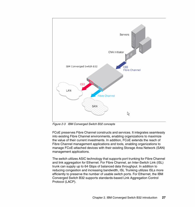
Figure 2-3 IBM Converged Switch B32 concepts
FCoE preserves Fibre Channel constructs and services. It integrates seamlessly into existing Fibre Channel environments, enabling organizations to maximize the value of their current investments. In addition, FCoE extends the reach of Fibre Channel management applications and tools, enabling organizations to manage FCoE-attached devices with their existing Storage Area Network (SAN) management applications.
The switch utilizes ASIC technology that supports port trunking for Fibre Channel and link aggregation for Ethernet. For Fibre Channel, an Inter-Switch Link (ISL) trunk can supply up to 64 Gbps of balanced data throughput. In addition to reducing congestion and increasing bandwidth, ISL Trunking utilizes ISLs more efficiently to preserve the number of usable switch ports. For Ethernet, the IBM Converged Switch B32 supports standards-based Link Aggregation Control Protocol (LACP).
Chapter 2. IBM Converged Switch B32 introduction 27
Additional performance capabilities include 32 virtual channels on each ISL, enabling anti-starvation capabilities at the port level to avoid performance degradation. In addition, exchange-based Dynamic Path Selection (DPS) optimizes fabric-wide performance and load balancing by automatically routing data to the most efficient available path in the fabric. DPS further augments ISL Trunking to provide more effective load balancing in certain configurations.
The IBM Converged Switch B32 provides a reliable foundation for disaster recovery and business continuance by employing enterprise-class availability features such as hot-swappable, redundant, and integrated fan and power supply assemblies.
Combined with a wide range of diagnostic and monitoring functions, these capabilities help ensure highly available SAN environments.
In conjunction with Brocade SAN extension products, the IBM Converged Switch B32 enables servers and storage devices to reside remotely, giving organizations a reliable way to create highly available environments that support the most sophisticated business continuance and disaster recovery initiatives.
The IBM Converged Switch B32 utilizes the same Brocade Fabric Operating System that supports the entire IBM b-type Fibre Channel product family, from fixed port switches to the SAN768B Fabric Backbone. This helps ensure backward compatibility that enables the IBM Converged Switch B32 to seamlessly integrate with existing Fibre Channel environments.
This design also enables forward compatibility among Brocade-based solutions, simplifying maintenance and field upgrades while providing peace of mind for future data center expansion. Moreover, organizations can monitor and manage the IBM Converged Switch B32 with fabric robust management applications such as the IBM Data Center Fabric Manager (DCFM).
By networking Fibre Channel switches and the IBM Converged Switch B32 under a common management platform, Fabric OS simplifies management through standard interfaces and support for third-party management applications. The IBM Converged Switch B32 supports switch management through a command line interface (CLI), web tools, or DCFM, which includes support for FCoE and CEE.
The IBM Converged Switch B32 is designed for the highest level of fabric security to help organizations safeguard their critical information. It utilizes Advanced Zoning as well as advanced port and switch Access Control Lists (ACLs) to simplify administration and significantly increase control over data access. To simplify management access security, the IBM Converged Switch B32 supports Active Directory with LDAP.
28 IBM Converged Switch B32
2.1.4 Features
The IBM Converged Switch B32 includes the following features:
� Eight Fibre Channel universal (E, F, M, and FL) ports: With 1, 2, 4, and 8 Gbps line speed full duplex.
� 24 CEE ports: With 10 Gbps line speed.
� FCoE features: Complete T11 FCoE entity and FCoE bridging. The FCoE translation entity built into the hardware engine provides:
– Detection of Fibre Channel encapsulation and redirection of FCoE fabric login frames
– Encapsulation of Fibre Channel frames in FCoE Ethernet packets
– Extraction of Fibre Channel frames from FCoE Ethernet packets
– Mapping of Fibre Channel destination Virtual Fabrics and destination FC_ID to Ethernet Virtual LAN and destination MAC addresses
– Fabric-Provided MAC Addresses (FPMAs) that enable new Ethernet MAC addresses to be created using the FC_ID assigned by the fabric
� CEE features: Provide the following capabilities:
– Data Center Bridging eXchange (DCBX)
– Priority-based Flow Control (PFC) - IEEE 802.1Qbb
– Enhanced Transmission Selection (ETS) - IEEE 802.1Qaz
� Dynamic Path Selection (DPS): Optimizes fabric-wide performance and load balancing by automatically routing data to the most efficient available path in the fabric.
� Link aggregation: (10 Gigabit Ethernet) Link Aggregation Control Protocol (LACP), Brocade-enhanced and 802.3ad standards-based.
� Maximum frame size: 2112-byte Fibre Channel payload and 9048-byte Ethernet frame.
� Classes of service: Class 2, Class 3, Class F (inter-switch frames).
� Port types FL_Port, F_Port, M_Port (Mirror Port), E_Port: Self-government is based on switch type (U_Port); optional port type control.
� Data traffic types: Fabric switches support unicast, multicast (255 groups), and broadcast.
� Fibre Channel media type: Hot-pluggable, industry-standard Small Form Factor Pluggable (SFP) and SFP+, LC connector; Short-Wave Laser (SWL) and LongWave Laser (LWL); distance depends on fiber optic cable and port speed; supports SFP+ (2 Gbps, 4 Gbps, and 8 Gbps).
Chapter 2. IBM Converged Switch B32 introduction 29
� CEE media type: Hot-pluggable, 10 Gigabit Ethernet SFP+ supports any combination of Short-Reach (SR) and Long-Reach (LR) optical transceivers; copper twinaxial cables of one, three, or five meters.
� Fibre Channel fabric services: Simple Name Server (SNS), Registered State Change Notification (RSCN), NTP, RADIUS, LDAP, Reliable Commit Service (RCS), Dynamic Path Selection (DPS), Enhanced Group Management (EGM), and Web Tools; optional fabric services include Fabric Watch, ISL Trunking, and Advanced Performance Monitoring.
� CEE services: Spanning Tree Protocol (STP, MSTP, RSTP, VLAN Tagging (802.1q)), MAC address learning and aging; native FCoE switching; IEEE 802.3ad Link Aggregation (LACP); access control lists based on VLAN, source, destination address, and port; eight priority levels for quality of service (QoS) and 4k VLANs; Priority-based Flow Control (PFC); Data Center Bridging eXchange (DCBX) Capabilities Exchange; Enhanced Transmission Selection (ETS).
2.1.5 Optional features
The IBM Converged Switch B32 supports SFP and SFP+ optical transceivers. For the Fibre Channel connections, the B32 uses SFP and SFP+ transceivers that support any combination of Short Wavelength (SWL) and Long Wavelength (LWL) optical media. For the CEE connections, the B32 uses SFP+ transceivers that support either optical or active twinaxial copper cables. The optical SFP+ transceivers support both Short Reach (SR) and Long Reach (LR) modules. Twinaxial cables support distances of 1 meter, 3 meters, and 5 meters.
Some of the features require extra optional licensing. These are the ones that will require the optional license:
� FC and Converged Activation: Enables the FC ports and convergence features.
� Frame-based ISL Trunking: Enables up to 8 ports between a pair of switches to be combined into a logical ISL with speeds of up to 64 Gbps (128 Gbps full duplex) for optimal bandwidth utilization and load balancing; exchange-based load balancing across ISLs with DPS (included in Fabric OS).
� Advanced Performance Monitoring: Enables performance monitoring of networked storage resources. This license includes the TopTalkers feature. This feature is applicable only to the FC ports on the B32.
� Fabric Watch: Monitors mission-critical switch operations. Fabric Watch includes Port Fencing capabilities. This feature is applicable only to the FC ports on the B32. In this version of the switch, this feature will be enabled by default when activating the FC and Converged features.
30 IBM Converged Switch B32
The following features are not supported in the current Fabric OS implementations for the B32 switch:
� FICON®
� Adaptive Networking (Ingress Rate Limiting and QoS)
� Hot code load activation
� Integrated routing
� Admin Domains
� Extended fabrics
� Traffic isolation zones
2.1.6 Transceivers
The IBM Converged Switch B32 offers the following SFP optical transceivers:
� 8 Gbps SW (#45W0500) and 10 Km LW (#45W1216) SFP
� 10 Gbps SR (#45W2411) and 10 Gbps LR (#45W2420) SFP+
� Twinaxial Active 1 m (#45W2398), Twinaxial Active 3 m (#45W2408), and Twinaxial Active 5 m (#45W3039)
Transceivers are also available in 8-pack convenience packages:
� 8 Gbps SW (#45W0501) and 10 Km LW (#45W1218) SFP
� 10 Gbps SR (#45W2414) and 10 Gbps LR (#45W2421) SFP+
� Twinaxial Active 1 m (#45W2401), Twinaxial Active 3 m (#45W2409), and Twinaxial Active 5 m (#45W3042)
The Direct attached SFP+ copper (Twinaxial) transceivers are actually cables used to connect to the IBM/Brocade 10 Gb CNA for IBM System x.
The IBM/Brocade 10 Gb CNA for IBM System x is a converged network adaptor used for carrying LAN and SAN traffic to the IBM Converged Switch B32.
2.2 Hardware
In this section we introduce the physical and power specifications of the switch, along with the cables and optic options that connect to it.
Chapter 2. IBM Converged Switch B32 introduction 31

2.2.1 Physical and power specifications
Table 2-1 shows the switch physical and power specifications.
Table 2-1 Physical and power specifications
Port numbering and serial numberThere are two sets of ports in the switch:
� 24 CEE ports, which are numbered from 0 to 23 and support data at the speed of 10GbE
� 8 FC ports, which are numbered from 0 to 7 and support data speeds from 1/2/34/8 Gbps
The switch ID and WWN are available from the pull-out tab, located in the front of the switch, as shown in Figure 2-4.
Figure 2-4 IBM Converged switch B32 port numbering and serial number
2.2.2 Cabling and optics
The B32 switch will only support Brocade branded SFP/SFP+ optical transceivers, available from IBM as options for the switch. For the FC connections, the switch uses transceivers that support any combination of Short Wavelength (SWL) and Long Wavelength (LWL) optical media.
This also applies to the CEE connectors, which support SFP+ optical transceivers with Short Reach (SR) or Long Reach (LR) modules, and also
Weight Dimensions Power consumption
12.97 kg (28.- lb) Width: 42.98 cm (16.9 in)Height:1U/43 cm (1.7 in)Depth: 63,4 cm (25 in)
350 Watts maximum
32 IBM Converged Switch B32

support Twinax cables. The Twinax cables are available in lengths of 1, 3, and 5 meters.
SFP identificationTo determine which SFP modules to use and connect them to the correct ports of the switch, it is important to understand how to identify them. This is done very easily by looking at the sticker of the module.
The FC SFP will be indicated by 1, 2, 4, or 8 G, as shown in Figure 2-5.
Figure 2-5 FC SCP module
The CEE SCP will be indicated by 10GE, as shown in Figure 2-6.
Figure 2-6 CEE SCP module
Chapter 2. IBM Converged Switch B32 introduction 33
2.2.3 Firmware
The IBM Converged Switch B32 requires Fabric OS (FOS) v6.1.2_cee, or later.
The IBM Converged Switch B32 functionality is planned to be included in future versions of the standard Fabric OS. By then, the IBM Converged Switch B32 will be able to use the same FOS that other IBM SAN switch products use.
Upgrading the firmwareThe firmware update process is the same as with other products of the b-type family. The only recommendation we have is to consider upgrading the firmware to the latest available level from IBM when you replace a switch or add a switch to your fabric.
2.3 Optional adapters
In this section, some of the available Converged Network Adapters (CNA) and Fibre Channel Adapters (HBA) are presented. Some of them are available for IBM System x and IBM System p® options. The products might also exist in other versions for different types of servers such as the IBM BladeCenter® line of servers.
Note: Fabric OS v6.1.2_cee1 supports all Converged Network Adapters (CNA) that conform to FC-BB-5 revision 1.0.3. From FOS v6.2 onwards, there is not a specific “cee” version of the firmware for this switch, and all the firmware versions are common for the b-type family. The “cee” variation of the firmware code is no longer used.
Note: The firmware upgrade is disruptive and will disturb traffic flow. For additional details, check the product release notes.
Note: Check the compatibility of your server with the adapters before making your decisions: PCI slots and versions might not be the same from one server to another, and the adapter might not be compatible. For more information on compatibility, check the following IBM website:
http://www-03.ibm.com/systems/info/x86servers/serverproven/compat/us/xseries/lan/matrix.html
34 IBM Converged Switch B32
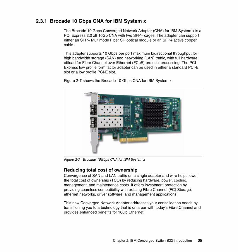
2.3.1 Brocade 10 Gbps CNA for IBM System x
The Brocade 10 Gbps Converged Network Adapter (CNA) for IBM System x is a PCI Express 2.0 x8 10Gb CNA with two SFP+ cages. The adapter can support either an SFP+ Multimode Fiber SR optical module or an SFP+ active copper cable.
This adapter supports 10 Gbps per port maximum bidirectional throughput for high bandwidth storage (SAN) and networking (LAN) traffic, with full hardware offload for Fibre Channel over Ethernet (FCoE) protocol processing. The PCI Express low profile form factor adapter can be used in either a standard PCI-E slot or a low profile PCI-E slot.
Figure 2-7 shows the Brocade 10 Gbps CNA for IBM System x.
Figure 2-7 Brocade 10Gbps CNA for IBM System x
Reducing total cost of ownershipConvergence of SAN and LAN traffic on a single adapter and wire helps lower the total cost of ownership (TCO) by reducing hardware, power, cooling, management, and maintenance costs. It offers investment protection by providing seamless compatibility with existing Fibre Channel (FC) Storage, ethernet networks, driver software, and management applications.
This new Converged Network Adapter addresses your consolidation needs by transitioning you to a technology that is on a par with today's Fibre Channel and provides enhanced benefits for 10Gb Ethernet.
Chapter 2. IBM Converged Switch B32 introduction 35
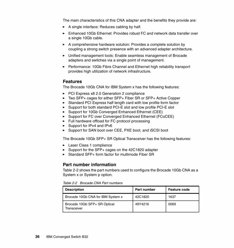
The main characteristics of this CNA adapter and the benefits they provide are:
� A single interface: Reduces cabling by half.
� Enhanced 10Gb Ethernet: Provides robust FC and network data transfer over a single 10Gb cable.
� A comprehensive hardware solution: Provides a complete solution by coupling a strong switch presence with an advanced adapter architecture.
� Unified management tools: Enable seamless management of Brocade adapters and switches via a single point of management.
� Performance: 10Gb Fibre Channel and Ethernet high reliability transport provides high utilization of network infrastructure.
FeaturesThe Brocade 10Gb CNA for IBM System x has the following features:
� PCI Express x8 2.0 Generation 2 compliance� Two SFP+ cages for either SFP+ Fiber SR or SFP+ Active Copper� Standard PCI Express half length card with low profile form factor� Support for both standard PCI-E slot and low profile PCI-E slot� Support for 10Gb Converged Enhanced Ethernet (CEE)� Support for FC over Converged Enhanced Ethernet (FCoCEE)� Full hardware offload for FC protocol processing� Support for IPv4 and IPv6� Support for SAN boot over CEE, PXE boot, and iSCSI boot
The Brocade 10Gb SFP+ SR Optical Transceiver has the following features:
� Laser Class 1 compliance� Support for the SFP+ cages on the 42C1820 adapter� Standard SFP+ form factor for multimode Fiber SR
Part number informationTable 2-2 shows the part numbers used to configure the Brocade 10Gb CNA as a System x or System p option.
Table 2-2 Brocade CNA Part numbers
Description Part number Feature code
Brocade 10Gb CNA for IBM System x 42C1820 1637
Brocade 10Gb SFP+ SR Optical Transceiver
49Y4216 0069
36 IBM Converged Switch B32
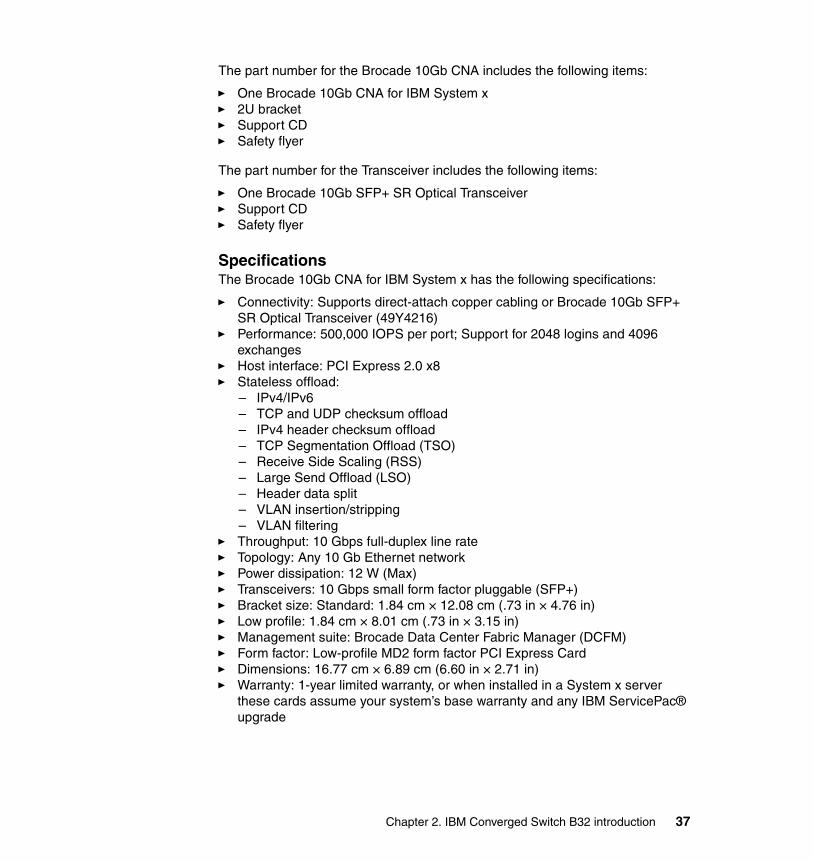
The part number for the Brocade 10Gb CNA includes the following items:
� One Brocade 10Gb CNA for IBM System x� 2U bracket� Support CD� Safety flyer
The part number for the Transceiver includes the following items:
� One Brocade 10Gb SFP+ SR Optical Transceiver� Support CD� Safety flyer
SpecificationsThe Brocade 10Gb CNA for IBM System x has the following specifications:
� Connectivity: Supports direct-attach copper cabling or Brocade 10Gb SFP+ SR Optical Transceiver (49Y4216)
� Performance: 500,000 IOPS per port; Support for 2048 logins and 4096 exchanges
� Host interface: PCI Express 2.0 x8� Stateless offload:
– IPv4/IPv6– TCP and UDP checksum offload– IPv4 header checksum offload– TCP Segmentation Offload (TSO)– Receive Side Scaling (RSS)– Large Send Offload (LSO)– Header data split– VLAN insertion/stripping– VLAN filtering
� Throughput: 10 Gbps full-duplex line rate� Topology: Any 10 Gb Ethernet network� Power dissipation: 12 W (Max)� Transceivers: 10 Gbps small form factor pluggable (SFP+)� Bracket size: Standard: 1.84 cm × 12.08 cm (.73 in × 4.76 in)� Low profile: 1.84 cm × 8.01 cm (.73 in × 3.15 in)� Management suite: Brocade Data Center Fabric Manager (DCFM)� Form factor: Low-profile MD2 form factor PCI Express Card� Dimensions: 16.77 cm × 6.89 cm (6.60 in × 2.71 in)� Warranty: 1-year limited warranty, or when installed in a System x server
these cards assume your system’s base warranty and any IBM ServicePac® upgrade
Chapter 2. IBM Converged Switch B32 introduction 37
2.3.2 QLogic 10 Gbps CNA for IBM System x
The QLogic 10 Gbps CNA for IBM System x (PN 42C1800) is a PCI Express 2.0 x 8 10 Gbps Converged Network Adapter with two SFP+ cages. The adapter can support either SFP+ Multimode Fiber SR optical modules or SFP+ Active Copper cables.
The QLogic 10Gb SFP+ SR Optical Transceiver is offered as an option (PN 49Y4218). The SFP+ Active Copper module comes from the CEE switch supplier supporting attachment to this product.
This adapter supports 10 Gbps per port maximum bidirectional throughput for high bandwidth storage (SAN) and networking (LAN) traffic, with full hardware offload for Fibre Channel (FC) over Ethernet protocol processing. Convergence of SAN and LAN traffic on a single adapter and wire helps lower the total cost of ownership by reducing the hardware, power, cooling, management, and maintenance costs. It offers investment protection by providing seamless compatibility with existing FC storage, Ethernet networks, driver software, and management applications.
The PCI Express low profile form factor adapter can be used in either a standard PCI-E slot or a low profile PCI-E slot. This adapter is supported for all IBM System x modular rack servers, including the latest PCI Express 2.0 Generation 2 servers.
38 IBM Converged Switch B32

Figure 2-8 shows the QLogic 10 Gbps CNA for IBM System x.
Figure 2-8 QLogic 10 Gbps CNA for IBM System x
This new Converged Network Adapter can cost-effectively address your consolidation needs by transitioning you to a technology that is on a par with today's Fibre Channel and provides enhanced benefits for 10 Gb Ethernet.
FeaturesThe QLogic 10 Gb CNA has the following features:
� PCI Express 2.0 compliance� Operates at PCI Express 2.0 x4 or PCI Express 1.1 x8� Transceiver support:
– System x option: Two SFP+ cages for either SFP+ Fiber SR or SFP+ Active Copper
– Power Systems™ feature: Two QLogic 10 Gb SFP+ SR Optical Transceivers standard
� Standard PCI Express half length card with low profile form factor� Support for both standard PCI-E slot and low profile PCI-E slot (System x
option only)� Support for 10 Gb Converged Enhanced Ethernet (CEE)� Support for Fibre Channel over Converged Enhanced Ethernet (FCoCEE)
Chapter 2. IBM Converged Switch B32 introduction 39

� Full hardware offload for FC protocol processing� Support for IPv4 and IPv6� Support for SAN boot over CEE and iSCSI boot
The QLogic 10 Gb SFP+ SR Optical Transceiver has the following features:
� Laser Class 1 compliance� Support for the SFP+ cages on the 42C1800 adapter� Standard SFP+ form factor for multimode Fiber SR
Part number informationTable 2-3 identifies the part numbers used to configure the QLogic CNA as a System x or System p option.
Table 2-3 Qlogic CNA Part numbers
Part number 42C1800 includes the following items:
� One QLogic 10Gb CNA for IBM System x� 2U bracket� Support CD� Safety flyer
Transceiver part number 49Y4218 includes the following items:
� One QLogic 10Gb SFP+ SR Optical Transceiver� Support CD� Safety flyer
Note: There is no support for PXE boot with this CNA.
Description Option part number
Feature code
QLogic 10Gb CNA for IBM System x 42C1800 5751
QLogic 10Gb CNA for IBM Power Systems (Feature 5708, 10 Gb FCoE PCIe Dual Port Adapter)
Not applicable 5708
QLogic 10Gbps SFP+ SR Optical Transceiver
49Y4218 0064
Note: The transceiver is not included with part number 42C1800 or System x feature 5751; however, it is included with Power Systems feature 5708.
40 IBM Converged Switch B32

Ethernet specificationsThe QLogic 10 Gb CNA has the following Ethernet specifications:
� Throughput: 10 Gbps full duplex line rate per port� Topology: Any 10 Gb Ethernet Network� Ethernet Frame: 1500 byte or 9000 byte (Jumbo Frame)� Stateless offload features:
– IP, TCP, and UDP checksum offloads– Large and Giant Send Offload (LSO, GSO)– Receive Side Scaling (RSS)– Header-data split– Interrupt coalescing– NetQueue
� Enhanced Ethernet features:– Priority-based flow control (802.1Qbb rev. 0)– Enhanced transmission selection (802.1Qaz rev. 0)– DCBX protocol (802.1Qaz rev. 0)
� Compliance:– IEEE: 802.3ae (10Gb Ethernet)– 802.1q (VLAN)– 802.3ad (Link Aggregation)– 802.1p (Priority Encoding)– 802.3x (Flow Control)– 802.3ap (KX/KX4)– 802.3ak (CX4)– IEEE 1149.1 (JTAG)– IPv4 Specification (RFC 791)– IPv6 Specification (RFC 2460)– TCP/UDP Specification (RFC 793/768)– ARP Specification (RFC 826)
FCoE specificationsThe QLogic 10Gb CNA has the following FCoE specifications:
� Performance: 250,000 IOPS per port� Logins: Support for 2048 concurrent logins and 2048 active exchanges� Class of service: Class 3� Protocols: FCP (SCSI-FCP), FC-TAPE (FCP-2)� Compliance:
– SCSI-3 Fibre Channel Protocol (SCSI-FCP)– Fibre Channel Tape (FC-TAPE) profile– SCSI Fibre Channel Protocol-2 (FCP-2)– Second Generation FC Generic Services (FC-GS-2)– Third Generation FC Generic Services (FC-GS-3)
Chapter 2. IBM Converged Switch B32 introduction 41
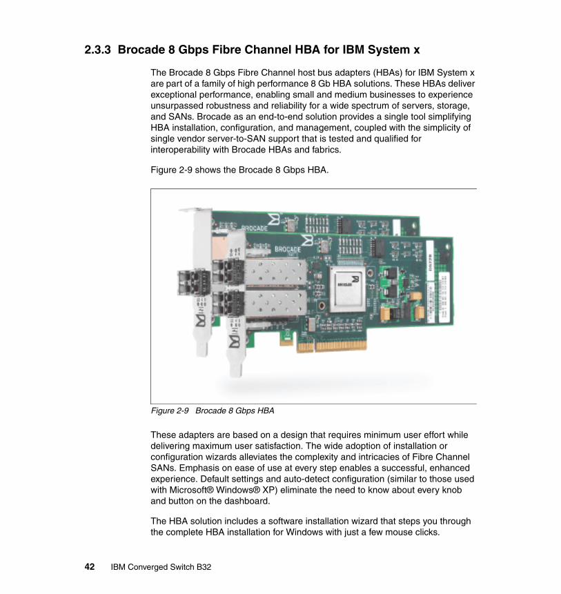
2.3.3 Brocade 8 Gbps Fibre Channel HBA for IBM System x
The Brocade 8 Gbps Fibre Channel host bus adapters (HBAs) for IBM System x are part of a family of high performance 8 Gb HBA solutions. These HBAs deliver exceptional performance, enabling small and medium businesses to experience unsurpassed robustness and reliability for a wide spectrum of servers, storage, and SANs. Brocade as an end-to-end solution provides a single tool simplifying HBA installation, configuration, and management, coupled with the simplicity of single vendor server-to-SAN support that is tested and qualified for interoperability with Brocade HBAs and fabrics.
Figure 2-9 shows the Brocade 8 Gbps HBA.
Figure 2-9 Brocade 8 Gbps HBA
These adapters are based on a design that requires minimum user effort while delivering maximum user satisfaction. The wide adoption of installation or configuration wizards alleviates the complexity and intricacies of Fibre Channel SANs. Emphasis on ease of use at every step enables a successful, enhanced experience. Default settings and auto-detect configuration (similar to those used with Microsoft® Windows® XP) eliminate the need to know about every knob and button on the dashboard.
The HBA solution includes a software installation wizard that steps you through the complete HBA installation for Windows with just a few mouse clicks.
42 IBM Converged Switch B32

In addition, the HBA includes a software utility for Windows and Linux SAN management for these adapters that is tailored specifically for small and medium business users. You can easily monitor and perform any necessary maintenance, including updating firmware.
These adapters broaden the IBM 8 Gb HBA portfolio for System x servers. These additions to the portfolio are offered in both single- and dual-port PCI Express HBAs.
FeaturesThe features of the Brocade 8 Gbps Fibre Channel HBA include:
� 2, 4, or 8 Gbps (auto-negotiation)
� Persistent binding
� 2,048 concurrent logins
� Up to 500,000 IOPS per port at 8 Gbps
� End-to-end SAN solutions using 8 Gb PCIe HBA technology for System x servers
� High performance, highly available SANs
� Easy setup and integration into existing SAN configurations
Table 2-4 Brocade HBA part numbers
Description Type Part number
Brocade 8 Gbps FC HBA Single Port 46M6061
Brocade 8 Gbps FC HBA Dual Port 46M6062
Brocade 8 Gbps SFP SFP 21R9995
Chapter 2. IBM Converged Switch B32 introduction 43

2.4 Summary
In this chapter we have discussed the features, options, and specifications of the IBM Converged Switch B32 product and its capabilities. In the rest of this book we describe how to use the switch by presenting practical scenarios, including a first time installation. We introduce the most used CLI commands and the DCFM GUI tools to configure and use the switch.
The datasheet for the switch can be found at the following website:
ftp://public.dhe.ibm.com/common/ssi/ecm/en/tsd03094usen/TSD03094USEN.PDF
44 IBM Converged Switch B32
Chapter 3. Deployment considerations and best practices
Deployment of the IBM Converged Switch B32 might raise questions about how to best implement your network. In this chapter, we discuss the new capabilities of the switch, some deployment ideas, and also what to consider when deploying or implementing a converged infrastructure in your data center.
3
© Copyright IBM Corp. 2011. All rights reserved. 45

3.1 Deployment considerations
This section covers some of the issues you should consider when planning to deploy an IBM Converged Switch B32 in your network. These topics help you to determine the best model to suit your environment.
3.1.1 Where to deploy?
When deploying network switches in a server room, whether for a LAN and SAN, there are two main ways to physically organize the network: Top of Rack or End of Row. A combination of the two approaches is the most common way to install the switches in a data center.
This section describes the pertinent features of each physical arrangement.
Top of RackAs shown in Figure 3-1 on page 47, Top of Rack configurations are typically deployed to provide the Level 2 network to the elements in a rack. Using the rack as the access unit at a network level simplifies the cabling and deployment.
The basic idea here is to have all the elements of a rack connected to a switch in the top of the rack that will provide the communication capabilities with the rest of the data center. Typically, the Top of Rack switches can be linked together to provide a kind of “virtual chassis,” where all the Top of Rack switches will look like one single, bigger switch or director for the network management team. This simplifies basic access to the network, and enables handling complexity in a different layer of the network, or directly at the core.
OSI Layer 2: The Open Systems Interconnection model defines 7 layers of functionality in network communication. Layer 2, the Data Link layer, provides the means to transfer data between network elements and to detect and possibly correct errors that might occur in the Physical Layer (Layer 1). Basically, it means that this is where we define our VLANs and where the MAC addresses or WWN of our devices are visible in the network.
46 IBM Converged Switch B32
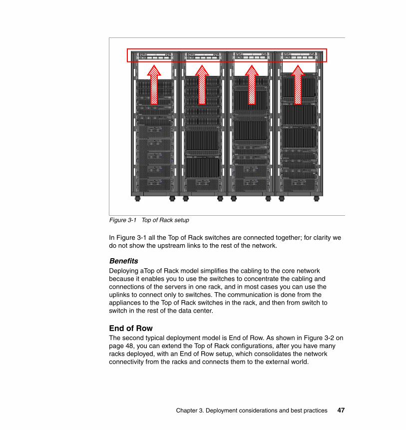
Figure 3-1 Top of Rack setup
In Figure 3-1 all the Top of Rack switches are connected together; for clarity we do not show the upstream links to the rest of the network.
BenefitsDeploying aTop of Rack model simplifies the cabling to the core network because it enables you to use the switches to concentrate the cabling and connections of the servers in one rack, and in most cases you can use the uplinks to connect only to switches. The communication is done from the appliances to the Top of Rack switches in the rack, and then from switch to switch in the rest of the data center.
End of RowThe second typical deployment model is End of Row. As shown in Figure 3-2 on page 48, you can extend the Top of Rack configurations, after you have many racks deployed, with an End of Row setup, which consolidates the network connectivity from the racks and connects them to the external world.
Chapter 3. Deployment considerations and best practices 47
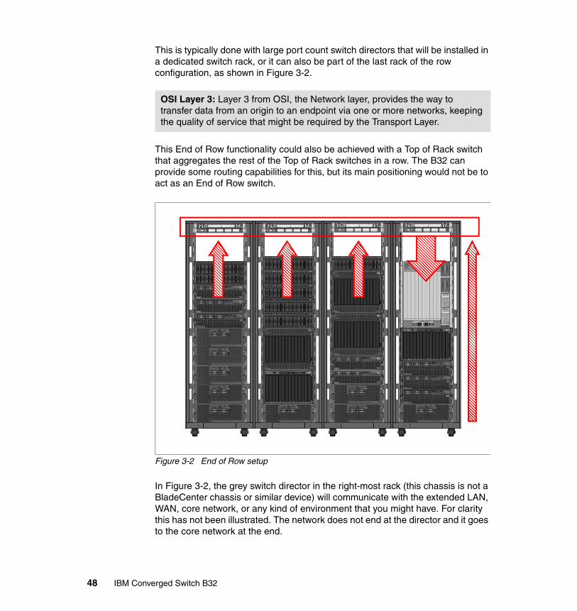
This is typically done with large port count switch directors that will be installed in a dedicated switch rack, or it can also be part of the last rack of the row configuration, as shown in Figure 3-2.
This End of Row functionality could also be achieved with a Top of Rack switch that aggregates the rest of the Top of Rack switches in a row. The B32 can provide some routing capabilities for this, but its main positioning would not be to act as an End of Row switch.
Figure 3-2 End of Row setup
In Figure 3-2, the grey switch director in the right-most rack (this chassis is not a BladeCenter chassis or similar device) will communicate with the extended LAN, WAN, core network, or any kind of environment that you might have. For clarity this has not been illustrated. The network does not end at the director and it goes to the core network at the end.
OSI Layer 3: Layer 3 from OSI, the Network layer, provides the way to transfer data from an origin to an endpoint via one or more networks, keeping the quality of service that might be required by the Transport Layer.
48 IBM Converged Switch B32
The right-most arrow at the top represents the traffic of the local servers in the last rack, which will go to the Top of Rack switch, and then come back to the Director, as the End of Row main switch.
Of course, all the rack-mounted servers can be connected directly to the End of Row director, but this adds extra complexity, increases the cabling, and raises the total cost of the solution because normally the price per port of an End of Row director is much higher than that of the equivalent Top of Rack switch.
BenefitsUsing the end of row model concentrates the uplinks from the rest of the top of rack switches into a single switch, reducing the connections to the core network and thus reducing the complexity to be handled by the core switches. The connections are switch-to-switch at the rack row level, and then switch-to-core in the rest of the data center infrastructure.
3.2 Designing your network
In the remainder of this chapter, we discuss some considerations for designing a new network and provide a few generic examples of how this could be done. These considerations also apply to upgrades to an existing infrastructure.
We assume that the reader is familiar with the differences between logical and physical network topologies, but because this distinction is important we provide a review the basic concepts in this section before getting into network design details.
3.2.1 Logical versus physical topologies
In a traditional network topology, for Ethernet or for FC, the design of the network is based on the physical elements that are available. In other words, you consider the number of network elements that are going to be connected to plan and distribute the network.
Important elements in a traditional network are the number of servers connected, the numbers and types of ports on each server, the kind of cables you are going to use, the type of transceivers, and so on. Then, according to your workload needs and existing or future environment, you decide on the best switches to fulfill those needs.
In a traditional environment, you need as many physical interfaces and physical ports per link as you would like to use. This means, for example, that a server that needs 4 Ethernet ports and 2 FC ports will need at least one card of each
Chapter 3. Deployment considerations and best practices 49
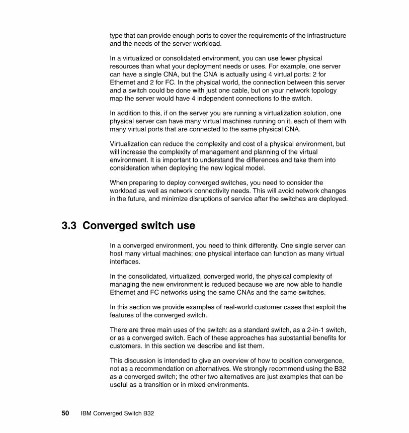
type that can provide enough ports to cover the requirements of the infrastructure and the needs of the server workload.
In a virtualized or consolidated environment, you can use fewer physical resources than what your deployment needs or uses. For example, one server can have a single CNA, but the CNA is actually using 4 virtual ports: 2 for Ethernet and 2 for FC. In the physical world, the connection between this server and a switch could be done with just one cable, but on your network topology map the server would have 4 independent connections to the switch.
In addition to this, if on the server you are running a virtualization solution, one physical server can have many virtual machines running on it, each of them with many virtual ports that are connected to the same physical CNA.
Virtualization can reduce the complexity and cost of a physical environment, but will increase the complexity of management and planning of the virtual environment. It is important to understand the differences and take them into consideration when deploying the new logical model.
When preparing to deploy converged switches, you need to consider the workload as well as network connectivity needs. This will avoid network changes in the future, and minimize disruptions of service after the switches are deployed.
3.3 Converged switch use
In a converged environment, you need to think differently. One single server can host many virtual machines; one physical interface can function as many virtual interfaces.
In the consolidated, virtualized, converged world, the physical complexity of managing the new environment is reduced because we are now able to handle Ethernet and FC networks using the same CNAs and the same switches.
In this section we provide examples of real-world customer cases that exploit the features of the converged switch.
There are three main uses of the switch: as a standard switch, as a 2-in-1 switch, or as a converged switch. Each of these approaches has substantial benefits for customers. In this section we describe and list them.
This discussion is intended to give an overview of how to position convergence, not as a recommendation on alternatives. We strongly recommend using the B32 as a converged switch; the other two alternatives are just examples that can be useful as a transition or in mixed environments.
50 IBM Converged Switch B32

3.3.1 Use as a traditional switch
The B32 can work as a traditional Ethernet switch or FC switch, isolating the communication on both sides. This can enable the use of separate network interfaces for Ethernet and FC, and use each part of the switch as an independent switch itself.
This approach is illustrated in Figure 3-3.
Figure 3-3 Traditional separate networks infrastructure
This approach isolates both networks, but at a high cost because you have to duplicate your investment. For a redundant configuration, two B32 switches configured as standard Ethernet switches and two B32 switches configured as standard FC switches will have to be installed. This does not make a lot of sense, except in a case where you might need a few FC ports or Ethernet connections today, and you are preparing your infrastructure for future design changes. In other words, this can be a good, albeit costly, convergence enablement solution.
3.3.2 Use as a 2-in-1 switch
The use of the B32 as a 2-in-1 switch means using the Ethernet and FC channel components of the switch separately, without using the advantages of
Chapter 3. Deployment considerations and best practices 51
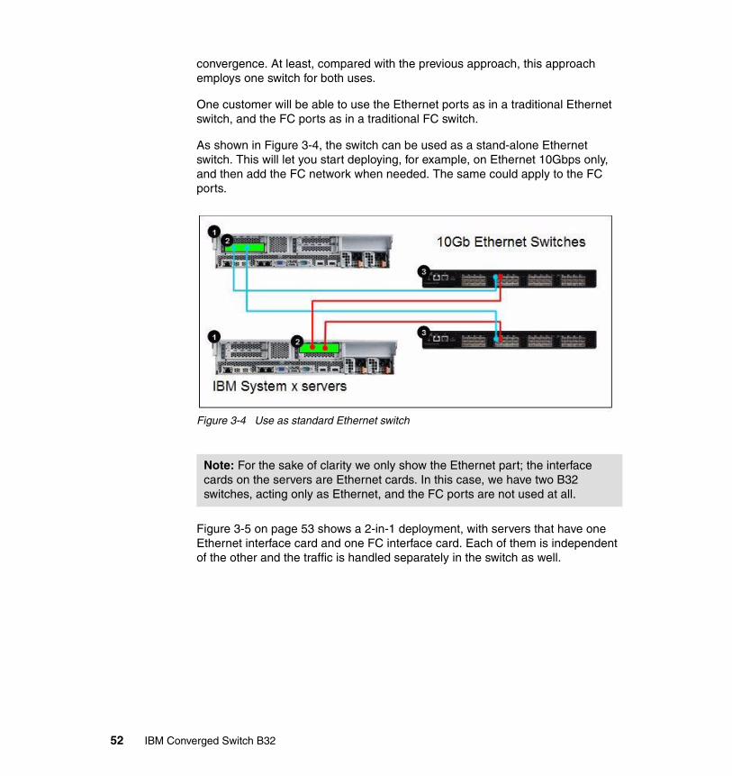
convergence. At least, compared with the previous approach, this approach employs one switch for both uses.
One customer will be able to use the Ethernet ports as in a traditional Ethernet switch, and the FC ports as in a traditional FC switch.
As shown in Figure 3-4, the switch can be used as a stand-alone Ethernet switch. This will let you start deploying, for example, on Ethernet 10Gbps only, and then add the FC network when needed. The same could apply to the FC ports.
Figure 3-4 Use as standard Ethernet switch
Figure 3-5 on page 53 shows a 2-in-1 deployment, with servers that have one Ethernet interface card and one FC interface card. Each of them is independent of the other and the traffic is handled separately in the switch as well.
Note: For the sake of clarity we only show the Ethernet part; the interface cards on the servers are Ethernet cards. In this case, we have two B32 switches, acting only as Ethernet, and the FC ports are not used at all.
52 IBM Converged Switch B32
Figure 3-5 2-in-1 use of the switch
Benefits of this approachThis approach can produce some or all of the following benefits:
� Easy deployment: One physical switch with both kinds of traffic is easier to deploy.
� Rack space reduction: This solution takes up less space.� Reduced switch investment: If you have enough ports with the B32 switch,
there is no need to have separate switches for both kinds of traffic, which reduces the total cost of the deployed infrastructure.
� Reduced licence costs: With fewer ports, licences cost less.� Future proofing: Clients can start today with this solution and use it as a
traditional switch, but in the future enable the converged features and use the latest technology when they are ready.
LimitsThis approach has limitations, the main ones being:
� Limited number of ports: The deployments are limited by the number of physical ports on the switch. In this example there are 32 ports in total, 8 FC and 24 Ethernet.
� Limited availability: At least two switches are needed to provide high availability. This is common to all scenarios.
3.3.3 Use as a converged switch
Figure 3-6 on page 54 illustrates a typical converged deployment scenario. The two servers have converged adapters that are connected directly to the switches. Each CNA has 10 Gbps of bandwidth, two ports, and in this case two switches are used for redundancy. The FC ports of the switch have direct attached connections to the IBM System Storage solution.
Chapter 3. Deployment considerations and best practices 53
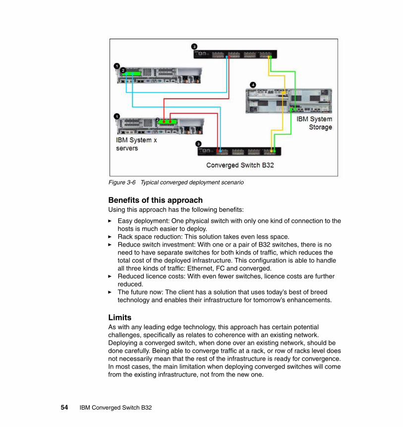
Figure 3-6 Typical converged deployment scenario
Benefits of this approachUsing this approach has the following benefits:
� Easy deployment: One physical switch with only one kind of connection to the hosts is much easier to deploy.
� Rack space reduction: This solution takes even less space.� Reduce switch investment: With one or a pair of B32 switches, there is no
need to have separate switches for both kinds of traffic, which reduces the total cost of the deployed infrastructure. This configuration is able to handle all three kinds of traffic: Ethernet, FC and converged.
� Reduced licence costs: With even fewer switches, licence costs are further reduced.
� The future now: The client has a solution that uses today’s best of breed technology and enables their infrastructure for tomorrow’s enhancements.
LimitsAs with any leading edge technology, this approach has certain potential challenges, specifically as relates to coherence with an existing network. Deploying a converged switch, when done over an existing network, should be done carefully. Being able to converge traffic at a rack, or row of racks level does not necessarily mean that the rest of the infrastructure is ready for convergence. In most cases, the main limitation when deploying converged switches will come from the existing infrastructure, not from the new one.
54 IBM Converged Switch B32

Enabling the CEE capabilities of the switchConfiguration changes are required to enable the CEE capabilities of the switch. The following chapters describe how this is done with step-by-step examples.
3.4 Summary
We discussed where to deploy the switches in the data center, Top of Rack and End of Row approaches, and the differences between logical and physical topologies. We also showed how the B32 can be used as a traditional switch, a 2-in-1 switch, and a converged switch and identified the benefits and limitations of each configuration.
In the following chapters we show how to install the switch and configure it for the first time, and also how to manage it and get it working in a sample environment.
Chapter 3. Deployment considerations and best practices 55

56 IBM Converged Switch B32
Chapter 4. IBM Converged Switch B32 installation and configuration
In this chapter we show the steps to install and configure the IBM Converged Switch B32 using the Command Line Interface.
4
© Copyright IBM Corp. 2011. All rights reserved. 57
4.1 Configuring initial setup
When the IBM Converged Switch B32 is powered up for first time, the system has to be configured for network use. Prior to initial configuration, it must be physically mounted and connected to the appropriate electrical outlets. The amount of planning and preparation that is required for the installation is dependent upon the installation method chosen. For detailed installation instructions, refer to IBM Converged Switch B32 User Guide, GC52-1358-01, which is available at:
http://www-01.ibm.com/support/
After the switch is installed and turned on, some initial configuration parameters must be set. All of the b-type switches require the same initial setup. The fundamental steps have not changed from the earlier switch models.
4.1.1 Sequence to turn on a switch
When you turn on or restart the switch, the following sequence of steps occurs:
1. Early power-on self-test (POST) diagnostics run. POST runs before the Fabric Operating System (Fabric OS) starts.
2. The Fabric OS initializes.
3. The hardware initializes. The switch resets, the internal addresses are assigned, the Ethernet port initializes, the serial port initializes, and the front panel initializes.
4. A full POST runs.
After you install the switch into a rack, and it has passed successfully through the POST tests, you need to perform some basic setup functions.
By connecting to the switch using a terminal emulator, you can see the switch POST tests as they progress. The details of the process to get connected to the console using a serial connection and a terminal emulator are explained in detail in the user guide referenced previously. You will need a serial cable for this. More details on terminal connection can be found on 4.1.3, “Setting the IP address using the serial port” on page 61.
Note: The following steps take a minimum of three minutes to complete.
58 IBM Converged Switch B32

Example 4-1 shows the startup of a switch.
Example 4-1 Switch startup
The system is coming up, please wait...
U-Boot 1.1.3 (Oct 4 2010 - 07:12:17)
CPU: 8548_E, Version: 2.1, (0x80390021)Core: E500, Version: 2.2, (0x80210022)..............Content Removed for clarity..............sys_chip_init: class 0 max 24 Doneethsw_ha_enabled = 0Anvil version 2.2 or higher found.
Fabric OS (switch)
switch console login:
To get to the console login prompt, you must press the Enter key. It is useful to be aware of the standard boot-up sequence for your switch so that, if a problem occurs, it is easy to distinguish between standard and abnormal behavior.
4.1.2 The command-line interface initial setupTo manage the switch from a remote workstation on a network, you have to set the IP address, subnet mask, and gateway address for the Ethernet management interface on the switch.
You can modify these settings using the ipAddrSet command. The default IP address and subnet mask for the switch are 10.77.77.77 and 255.255.255.0.
Note: We recommend that you do not connect the switch to the network until the IP address is correctly set to avoid any conflicts with the default address on the switch.
Chapter 4. IBM Converged Switch B32 installation and configuration 59
For successful implementation, set the following parameters as well:
� Domain ID: For switches to be connected together within a fabric, each switch must have a unique domain ID. The default domain ID for a switch is 1. If two switches are connected through an ISL and if they both have the same Domain ID, they become segmented. You can modify domain IDs using the configure command.
� Switch names: We recommend that you set a switch name to identify different switches within a site. This name is very helpful in identifying easily a switch to which you are connected. Using the switchName command, you can assign your own switch names, which can be up to 15 characters long, must begin with an alpha character, and can include alpha, numeric, and underscore characters.
We describe the steps to configure these settings in the sections that follow.
It takes approximately 15 minutes to configure these settings. The following items are required:
� A SAN switch installed physically and connected to a power source.
� A workstation that has a terminal emulator application. In our examples, we used putty.exe for both serial and telnet connections.
� The serial cable that is provided with the switch for connecting the switch to the workstation. If your workstation does not have a 9-pin serial port, you might require an adapter. We used a USB serial adapter to connect.
� Unused IP address or addresses plus gateway IP address and subnet mask.
� Ethernet cable for connecting the switch to the workstation or to a network that contains the workstation.
� SWL or LWL SFPs and fiber optic cables, twin-ax cables, and ethernet cables as required.
It is important to leave at least 3.28 feet (1 m) of slack for each port cable. This extra length provides room to remove and replace the switch, allows for inadvertent movement of the rack, and helps prevent the cables from being bent to less than the minimum bend radius.
Note: PuTTY is a free and open source terminal emulator that can work as SSH, telnet rlogin, and raw TCP client. It can be obtained from http://www.putty.org.
60 IBM Converged Switch B32
We recommend that you use hook-and-loop straps to secure and to organize fiber optic cables. Do not use tie wraps on fiber optic cables because these wraps are overtightened easily and can damage the optic fibers.
4.1.3 Setting the IP address using the serial port
In this section, we describe the steps necessary to set the IP address using the serial port on the switch.
Follow these steps:
1. Remove the shipping plug from the serial port and insert the serial cable that is provided with the switch.
2. Connect the other end of the serial cable to an RS-232 serial port on the workstation. If you do not have a male DB-9 serial port connector on your workstation, you can use a USB serial adapter.
3. Verify that the switch is on and initialization has completed by confirming that the system and power status LEDs are both on and green.
4. Disable any serial communication programs running on the workstation, such as PDA synchronization.
5. Open a terminal emulator application (such as HyperTerminal or putty.exe on a Windows workstation or TERM in a UNIX environment), and configure as follows:
a. In a Microsoft Windows environment, adjust the following parameters and values if necessary:
• Bits per second: 9600• Databits: 8• Parity: None• Stop bits: 1• Flow control: None
Figure 4-1 on page 62 shows the PuTTY serial connection configuration options.
Tip: The serial cable shipped with the switch is a straight-through cable, not a cross-over cable. We recommend labeling the cable as such to minimize confusion at a later date.
Chapter 4. IBM Converged Switch B32 installation and configuration 61
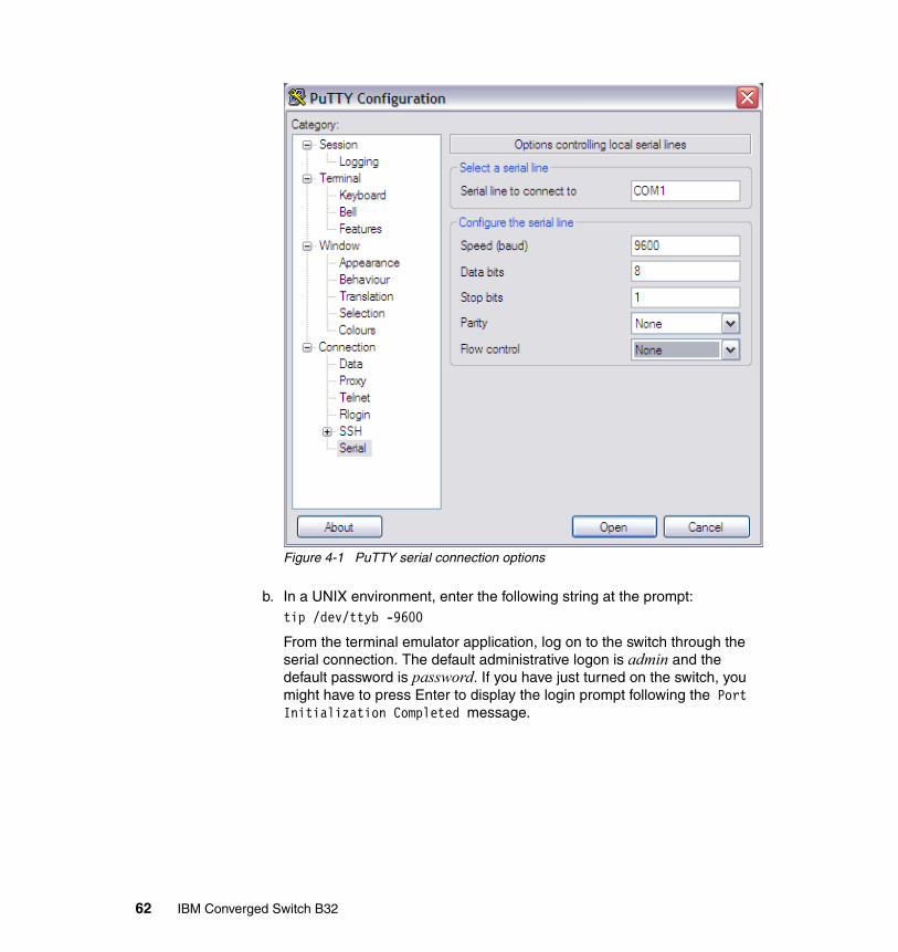
Figure 4-1 PuTTY serial connection options
b. In a UNIX environment, enter the following string at the prompt: tip /dev/ttyb -9600
From the terminal emulator application, log on to the switch through the serial connection. The default administrative logon is admin and the default password is password. If you have just turned on the switch, you might have to press Enter to display the login prompt following the Port Initialization Completed message.
62 IBM Converged Switch B32
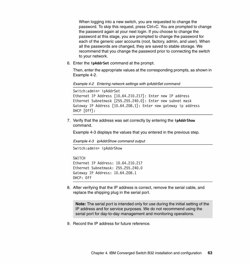
When logging into a new switch, you are requested to change the password. To skip this request, press Ctrl+C. You are prompted to change the password again at your next login. If you choose to change the password at this stage, you are prompted to change the password for each of the generic user accounts (root, factory, admin, and user). When all the passwords are changed, they are saved to stable storage. We recommend that you change the password prior to connecting the switch to your network.
6. Enter the ipAddrSet command at the prompt.
Then, enter the appropriate values at the corresponding prompts, as shown in Example 4-2.
Example 4-2 Entering network settings with ipAddrSet command
Switch:admin> ipAddrSetEthernet IP Address [10.64.210.217]: Enter new IP addressEthernet Subnetmask [255.255.240.0]: Enter new subnet maskGateway IP Address [10.64.208.1]: Enter new gateway ip addressDHCP [Off]:
7. Verify that the address was set correctly by entering the ipAddrShow command.
Example 4-3 displays the values that you entered in the previous step.
Example 4-3 ipAddrShow command output
Switch:admin> ipAddrShow
SWITCHEthernet IP Address: 10.64.210.217Ethernet Subnetmask: 255.255.240.0Gateway IP Address: 10.64.208.1DHCP: Off
8. After verifying that the IP address is correct, remove the serial cable, and replace the shipping plug in the serial port.
9. Record the IP address for future reference.
Note: The serial port is intended only for use during the initial setting of the IP address and for service purposes. We do not recommend using the serial port for day-to-day management and monitoring operations.
Chapter 4. IBM Converged Switch B32 installation and configuration 63

After the IP address is set, you can connect the switch to the managing workstation by Ethernet cable (this can be a direct cross-over connection or through a network) by following these steps:
1. Remove the shipping cover from the Ethernet port.
2. Insert one end of an Ethernet cable in the Ethernet port.
3. Connect the other end of the Ethernet cable to the workstation or to an Ethernet network that contains the workstation.
This concludes the initial setup of the switch.
4.2 Configuring the IBM Converged Switch B32 switch
Configuration of the B32 switch involves:
� CEE network configuration
� SAN Zoning configuration
4.2.1 CEE Management shell
New for the IBM Converged Switch B32 is a separate configurable network switch (the CEE switch) that has to be configured individually by using the CEE Management Shell (cmsh). This shell is accessed by entering the cmsh command from the fabric os prompt as shown in Example 4-4.
Example 4-4 cmsh command
switch:admin> cmshswitch#
This prompt of CEE management shell is in Exec/ Privileged EXEC mode. You can display and change the running config from this mode. Various CMSH modes are available to perform a variety of functions as listed in Table 2-1.
Note: The switch can now be accessed remotely, using Telnet or Web Tools. As a result, it is important to ensure that the switch is not modified simultaneously from any other connections during the remaining steps.
64 IBM Converged Switch B32
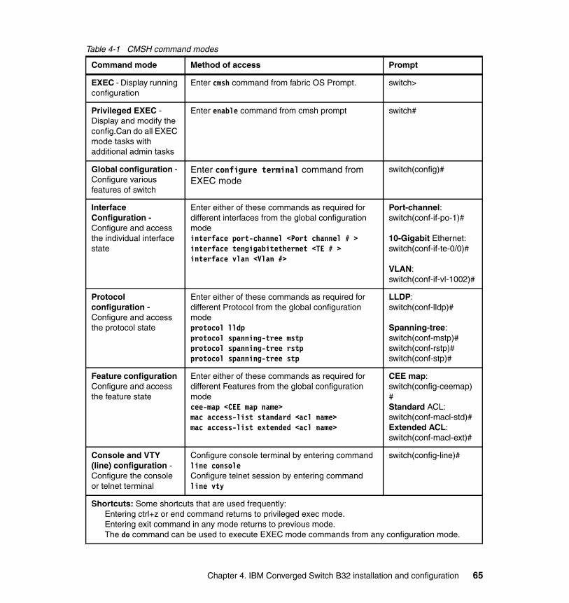
Table 4-1 CMSH command modes
Command mode Method of access Prompt
EXEC - Display running configuration
Enter cmsh command from fabric OS Prompt. switch>
Privileged EXEC - Display and modify the config.Can do all EXEC mode tasks with additional admin tasks
Enter enable command from cmsh prompt switch#
Global configuration - Configure various features of switch
Enter configure terminal command from EXEC mode
switch(config)#
Interface Configuration -Configure and access the individual interface state
Enter either of these commands as required for different interfaces from the global configuration modeinterface port-channel <Port channel # >interface tengigabitethernet <TE # >interface vlan <Vlan #>
Port-channel:switch(conf-if-po-1)#
10-Gigabit Ethernet:switch(conf-if-te-0/0)#
VLAN:switch(conf-if-vl-1002)#
Protocol configuration - Configure and access the protocol state
Enter either of these commands as required for different Protocol from the global configuration modeprotocol lldpprotocol spanning-tree mstpprotocol spanning-tree rstpprotocol spanning-tree stp
LLDP:switch(conf-lldp)#
Spanning-tree:switch(conf-mstp)#switch(conf-rstp)#switch(conf-stp)#
Feature configuration Configure and access the feature state
Enter either of these commands as required for different Features from the global configuration modecee-map <CEE map name>mac access-list standard <acl name>mac access-list extended <acl name>
CEE map:switch(config-ceemap)#Standard ACL:switch(conf-macl-std)#Extended ACL:switch(conf-macl-ext)#
Console and VTY (line) configuration -Configure the console or telnet terminal
Configure console terminal by entering commandline consoleConfigure telnet session by entering commandline vty
switch(config-line)#
Shortcuts: Some shortcuts that are used frequently:Entering ctrl+z or end command returns to privileged exec mode.Entering exit command in any mode returns to previous mode.The do command can be used to execute EXEC mode commands from any configuration mode.
Chapter 4. IBM Converged Switch B32 installation and configuration 65
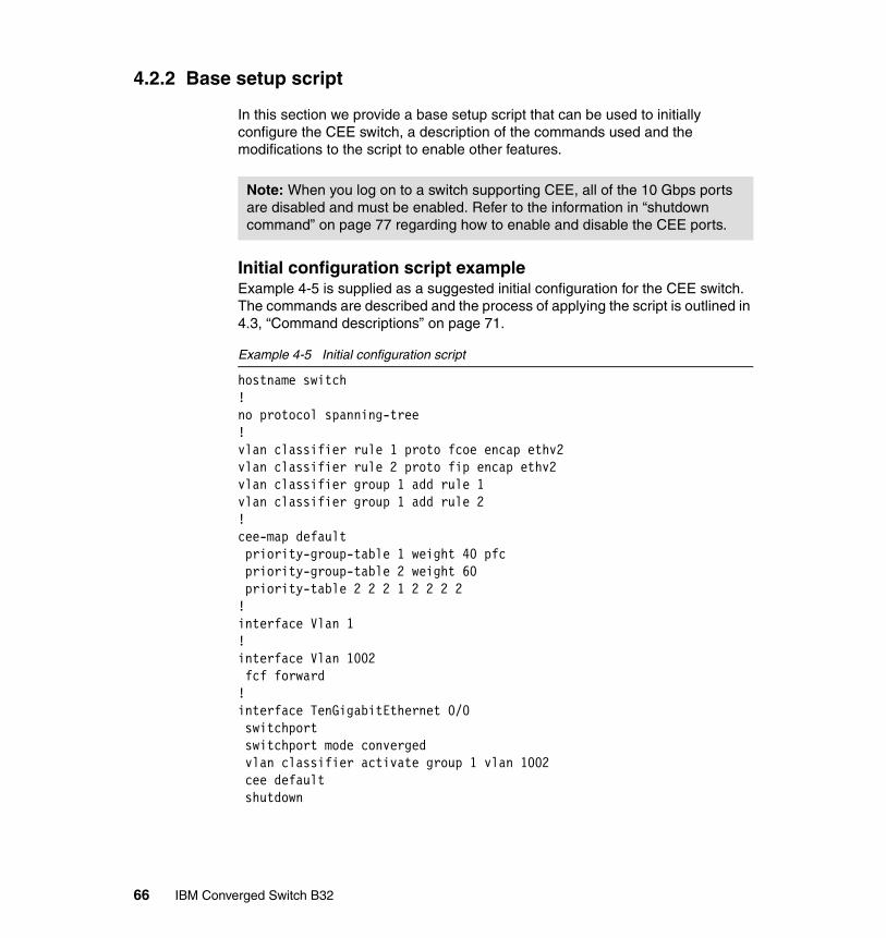
4.2.2 Base setup script
In this section we provide a base setup script that can be used to initially configure the CEE switch, a description of the commands used and the modifications to the script to enable other features.
Initial configuration script example Example 4-5 is supplied as a suggested initial configuration for the CEE switch. The commands are described and the process of applying the script is outlined in 4.3, “Command descriptions” on page 71.
Example 4-5 Initial configuration script
hostname switch!no protocol spanning-tree!vlan classifier rule 1 proto fcoe encap ethv2vlan classifier rule 2 proto fip encap ethv2vlan classifier group 1 add rule 1vlan classifier group 1 add rule 2!cee-map default priority-group-table 1 weight 40 pfc priority-group-table 2 weight 60 priority-table 2 2 2 1 2 2 2 2!interface Vlan 1!interface Vlan 1002 fcf forward!interface TenGigabitEthernet 0/0 switchport switchport mode converged vlan classifier activate group 1 vlan 1002 cee default shutdown
Note: When you log on to a switch supporting CEE, all of the 10 Gbps ports are disabled and must be enabled. Refer to the information in “shutdown command” on page 77 regarding how to enable and disable the CEE ports.
66 IBM Converged Switch B32

!interface TenGigabitEthernet 0/1 switchport switchport mode converged vlan classifier activate group 1 vlan 1002 cee default shutdown!interface TenGigabitEthernet 0/2 switchport switchport mode converged vlan classifier activate group 1 vlan 1002 cee default shutdown!interface TenGigabitEthernet 0/3 switchport switchport mode converged vlan classifier activate group 1 vlan 1002 cee default shutdown!interface TenGigabitEthernet 0/4 switchport switchport mode converged vlan classifier activate group 1 vlan 1002 cee default shutdown!interface TenGigabitEthernet 0/5 switchport switchport mode converged vlan classifier activate group 1 vlan 1002 cee default shutdown!interface TenGigabitEthernet 0/6 switchport switchport mode converged vlan classifier activate group 1 vlan 1002 cee default shutdown!interface TenGigabitEthernet 0/7 switchport
Chapter 4. IBM Converged Switch B32 installation and configuration 67

switchport mode converged vlan classifier activate group 1 vlan 1002 cee default shutdown!interface TenGigabitEthernet 0/8 switchport switchport mode converged vlan classifier activate group 1 vlan 1002 cee default shutdown!interface TenGigabitEthernet 0/9 switchport switchport mode converged vlan classifier activate group 1 vlan 1002 cee default shutdown!interface TenGigabitEthernet 0/10 switchport switchport mode converged vlan classifier activate group 1 vlan 1002 cee default shutdown!interface TenGigabitEthernet 0/11 switchport switchport mode converged vlan classifier activate group 1 vlan 1002 cee default shutdown!interface TenGigabitEthernet 0/12 switchport switchport mode converged vlan classifier activate group 1 vlan 1002 cee default shutdown!interface TenGigabitEthernet 0/13 switchport switchport mode converged vlan classifier activate group 1 vlan 1002 cee default
68 IBM Converged Switch B32

shutdown!interface TenGigabitEthernet 0/14 switchport switchport mode converged vlan classifier activate group 1 vlan 1002 cee default shutdown!interface TenGigabitEthernet 0/15 switchport switchport mode converged vlan classifier activate group 1 vlan 1002 cee default shutdown!interface TenGigabitEthernet 0/16 switchport switchport mode converged vlan classifier activate group 1 vlan 1002 cee default shutdown!interface TenGigabitEthernet 0/17 switchport switchport mode converged vlan classifier activate group 1 vlan 1002 cee default shutdown!interface TenGigabitEthernet 0/18 switchport switchport mode converged vlan classifier activate group 1 vlan 1002 cee default shutdown!interface TenGigabitEthernet 0/19 switchport switchport mode converged vlan classifier activate group 1 vlan 1002 cee default shutdown!interface TenGigabitEthernet 0/20
Chapter 4. IBM Converged Switch B32 installation and configuration 69
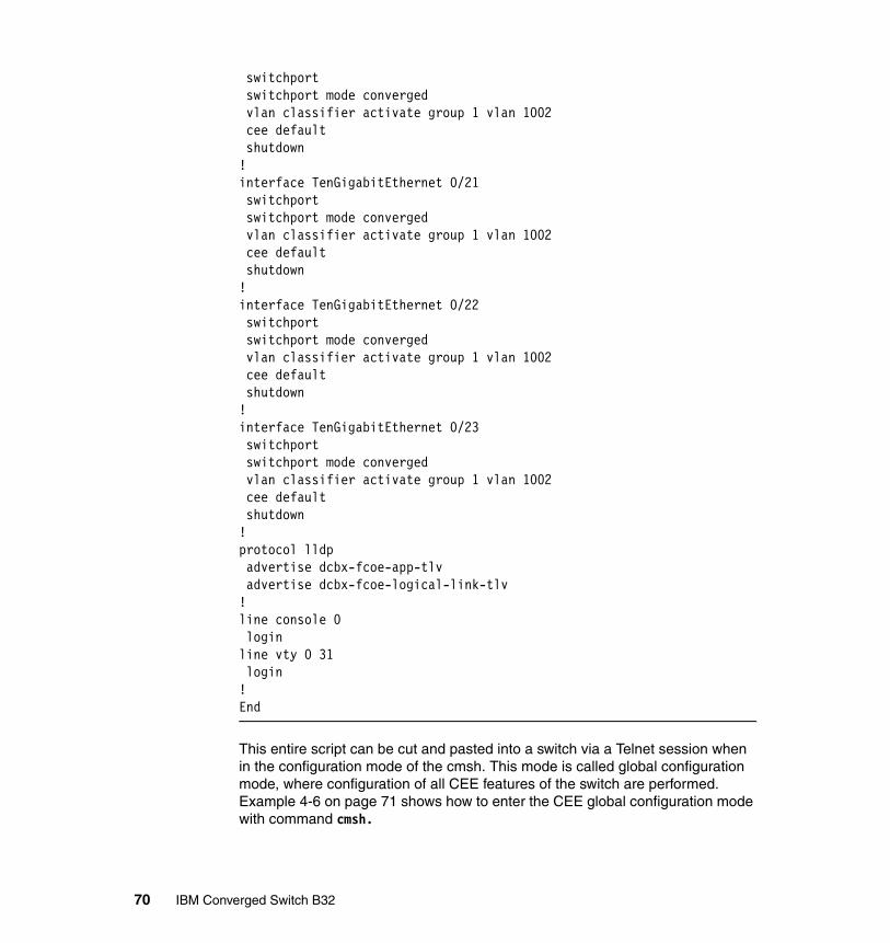
switchport switchport mode converged vlan classifier activate group 1 vlan 1002 cee default shutdown!interface TenGigabitEthernet 0/21 switchport switchport mode converged vlan classifier activate group 1 vlan 1002 cee default shutdown!interface TenGigabitEthernet 0/22 switchport switchport mode converged vlan classifier activate group 1 vlan 1002 cee default shutdown!interface TenGigabitEthernet 0/23 switchport switchport mode converged vlan classifier activate group 1 vlan 1002 cee default shutdown!protocol lldp advertise dcbx-fcoe-app-tlv advertise dcbx-fcoe-logical-link-tlv!line console 0 loginline vty 0 31 login!End
This entire script can be cut and pasted into a switch via a Telnet session when in the configuration mode of the cmsh. This mode is called global configuration mode, where configuration of all CEE features of the switch are performed. Example 4-6 on page 71 shows how to enter the CEE global configuration mode with command cmsh.
70 IBM Converged Switch B32

Example 4-6 Entering configuration mode
switch:admin> cmshswitch#configure terminalEnter configuration commands, one per line. End with CNTL/Z.switch(config)#
4.3 Command descriptions
This section breaks down the sample script and provides a description of the commands used.
4.3.1 hostname
This is the global system name for the switch shown in Example 4-7. If not otherwise specified, Link Layer Discovery Protocol (LLDP) uses this as its System Name value.
Example 4-7 Hostname command
hostname switch
Synopsis: hostname name
Operands:
name Specifies the global system name
4.3.2 no protocol spanning-tree
The no protocol spanning-tree command is used to disable any spanning-tree protocols as shown in Example 4-8.
Example 4-8 no protocol spanning-tree command
no protocol spanning-tree
Synopsis: no protocol spanning-tree
Operands: None
Chapter 4. IBM Converged Switch B32 installation and configuration 71
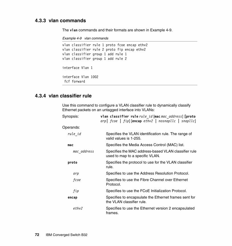
4.3.3 vlan commands
The vlan commands and their formats are shown in Example 4-9.
Example 4-9 vlan commands
vlan classifier rule 1 proto fcoe encap ethv2vlan classifier rule 2 proto fip encap ethv2vlan classifier group 1 add rule 1vlan classifier group 1 add rule 2
interface Vlan 1
interface Vlan 1002 fcf forward
4.3.4 vlan classifier rule
Use this command to configure a VLAN classifier rule to dynamically classify Ethernet packets on an untagged interface into VLANs:
Synopsis: vlan classifier rule rule_id [mac mac_address] [proto arp| fcoe | fip] [encap ethv2 | nosnapllc | snapllc]
Operands:
rule_id Specifies the VLAN identification rule. The range of valid values is 1-255.
mac Specifies the Media Access Control (MAC) list.
mac_address Specifies the MAC address-based VLAN classifier rule used to map to a specific VLAN.
proto Specifies the protocol to use for the VLAN classifier rule.
arp Specifies to use the Address Resolution Protocol.
fcoe Specifies to use the Fibre Channel over Ethernet Protocol.
fip Specifies to use the FCoE Initialization Protocol.
encap Specifies to encapsulate the Ethernet frames sent for the VLAN classifier rule.
ethv2 Specifies to use the Ethernet version 2 encapsulated frames.
72 IBM Converged Switch B32

nosnapllc Specifies to use the Ethernet version 2 non-SNA frames.
snapllc Specifies to use the Ethernet version 2 with SNA frames.
Use the no vlan classifier rule command to delete the VLAN classifier rule specified by the rule_id.
4.3.5 vlan classifier group
Used to add or delete rules to a VLAN classifier group
Synopsis: vlan classifier group number [add rule number| delete rule number]
Operands:
number Specifies the VLAN group number for which rules are to be added or deleted. The range of valid values is 1-16.
add rule number Specifies a rule is to be added. The range of valid values is 1-255. This number corresponds to the rule_id defined in the vlan classifier rule command.
delete rule number Specifies a rule is to be deleted. The range of valid values is 1-256. This number corresponds to the rule_id defined in the vlan classifier rule command.
Use the no vlan classifier group command to delete classifier groups.
4.3.6 interface vlan
Used to configure a VLAN interface.
Synopsis: interface vlan vlan_id
Operands:
vlan_id Specifies the VLAN interface to configure. The range of valid values is 1-3583.
Use the no interface vlan vlan_id command to delete a VLAN interface.
Chapter 4. IBM Converged Switch B32 installation and configuration 73

4.3.7 fcf forward
Use this command to enable FC forwarding on the VLAN interface in order to carry FCoE traffic.
Synopsis: fcf forward
Use the no fcf forward command to disable FCoE on a VLAN interface.
4.3.8 cee commands
Use these commands to create a CEE Map, and then enter the CEE-Map CLI configuration submode for defining the CEE Provisioning Priority Group Table and Priority-to-Priority Group Table as shown in Example 4-10.
Example 4-10 CEE Map with priority coding
cee-map default priority-group-table 1 weight 40 pfc priority-group-table 2 weight 60 priority-table 2 2 2 1 2 2 2 2
cee-map commandSynopsis: cee-map name [precedence number]
Operands:
name Specifies a unique name across all of the CEE maps defined within the system. If the specified CEE map does not exist, then it is created. If the specified CEE map already exists, then it is updated and the new mapping automatically propagates to all interfaces bound to the CEE map.
precedence number Sets the precedence value for controlling the global scheduler policy when there is conflict between multiple CEE maps and non-CEE QoS configurations. The range of valid values is 1-100. The default CEE map precedence value is 1.
Note: VLAN 1—The IBM Converged Switch B32 should not forward FIP frames on VLAN 1 because it is reserved for management traffic only.
Note: Only one FCoE VLAN is supported in Fabric OS.
74 IBM Converged Switch B32

Use the no cee-map name command to delete the specified CEE map. A CEE map can only be deleted if it is not bound to any interface.
priority-group-tableUse this command to configure the bandwidth for each Priority Group, to associate a weight to a Deficit Weighted Round Robin (DWRR) scheduler queue, and to enable the PFC.
Synopsis: priority-group-table pgid [weight weight] [pfc]
Operands:
pgid Specifies the Priority Group ID (PGID) assigned to a priority group. The range of valid values is 0-15. 7 of these for the eight reserved Strict Priority PGIDs.
weight weight Maps a weight to a DWRR scheduler queue. This parameter is only valid for the DWRR Priority Group. The sum of all DWRR Priority Group weight values must equal 100 percent. The range of valid values is 1-100.
pfc Enables the Priority-based Flow Control (PFC) for each priority that gets mapped to the Priority Group.
Use the no priority-group-table pgid command to return the Priority Group to the default values. For the Strict Priority Group, the PGID is still valid, but the PFC is disabled. For the DWRR Priority Group, the PGID is no longer valid and is deleted; the PGID can only be deleted when it is not bound to any Priority-to-Priority Group Table entry.
priority-table commandUse this command to provision the CEE Priority-to-Priority Group Table. This table maps each of the eight ingress Class of Service (CoS) into a Priority Group.
Synopsis: priority-table pgid0 pgid1 pgid2 pgid3 pgid4 pgid5 pgid6 pgid7
Operands:
pgid0 Sets the Priority Group ID for all packets with CoS 0.
pgid1 Sets the Priority Group ID for all packets with CoS 1.
pgid2 Sets the Priority Group ID for all packets with CoS 2.
pgid3 Sets the Priority Group ID for all packets with CoS 3.
pgid4 Sets the Priority Group ID for all packets with CoS 4.
pgid5 Sets the Priority Group ID for all packets with CoS 5.
Chapter 4. IBM Converged Switch B32 installation and configuration 75

pgid6 Sets the Priority Group ID for all packets with CoS 6.
pgid7 Sets the Priority Group ID for all packets with CoS 7.
Use the no priority-table command to return the Priority mapping table to the default values.
4.3.9 interface commands
Use these commands to create or configure an interface as shown in Example 4-11.
Example 4-11 Interface creation
interface TenGigabitEthernet 0/0 switchport switchport mode converged vlan classifier activate group 1 vlan 1002 cee default shutdown
interface commandUse this command to create or enter the interface configuration mode to configure an interface.
Synopsis: interface [port-channel number | tengigabitethernet slot/port | vlan vlan id]
Operands:
tengigabitethernet Configures the specified 10 Gbps Ethernet interface.
slot Specifies a valid slot number.
port Specifies a valid port number.
port-channel number Specifies the port-channel number. The range of valid values is 1-63.
vlan vlan_id Specifies the VLAN number. The range of valid values is 1-3583.
Use the no interface [port-channel number | vlan vlan id] to delete specific port-channels or vlans.
switchport commandPuts the interface to Layer 2 mode and sets the switching characteristics of the Layer 2 interface to the defaults.
76 IBM Converged Switch B32

Synopsis: switchport
Operands: None
To remove an interface from Layer 2 mode use the no switchport command.
switchport mode commandUse this command to set the mode of the Layer 2 interface.
Synopsis: switchport mode {access | trunk | converged}
Operands:
access Sets the Layer 2 interface as access.
trunk Sets the Layer 2 interface as trunk.
converged Sets the Layer 2 interface to converged
vlan classifier activate group commandUse this command to activate a VLAN classifier group for a specified VLAN
Synopsis: vlan classifier activate group number vlan vlan_id
Operands:
number Specifies which VLAN classifier group to activate. The range of valid values is 1-16.
vlan vlan_id Specifies which VLAN interface to activate. The range of valid values is 1-3583.
Use the no vlan classifier activate group command to remove the specified group.
cee commandUse this command to apply a CEE map on an interface.
Synopsis: cee name
Operands:
name Specifies the name of a previously created CEE map. Any existing CEE map must be removed before a new one can be applied. The CEE map applied on an interface should exist on the switch.
shutdown commandUse this command to disable or enable an interface.
Synopsis: shutdown
Chapter 4. IBM Converged Switch B32 installation and configuration 77

Operands: None
Use the no shutdown command to enable an interface that has been disabled
There is also an optional mtu command available for the interface that is used to specify the Maximum Transmission Unit size allowed on the interface. The default value is 2500.
mtu commandUse this command to specify the MTU on the interface.
Synopsis: mtu size
Operands:
size Specifies the size of the Maximum Transmission Unit (MTU) of an interface. The allowed MTU size is 1522-9208.
4.3.10 protocol commands
These are protocol commands.
protocol lldp commandUse this command to enter LLDP configuration mode to be able to make changes to the parameters as shown in Example 4-12.
Example 4-12 Protocol command
protocol lldp advertise dcbx-fcoe-app-tlv advertise dcbx-fcoe-logical-link-tlv
Synopsis: protocol lldp
Operands: None
advertise dcbx-fcoe-app-tlv commandUse this command to advertise application TLVs to ensure interoperability of traffic over DCBX packets. Converged Enhanced Ethernet (CEE) parameters related to FCoE must be negotiated before FCoE traffic can begin on a CEE link. An FCoE application TLV is exchanged over the LLDP protocol, which negotiates information such as FCoE priority, and Priority Flow Control (PFC) pause.
Synopsis: advertise dcbx-fcoe-app-tlv
78 IBM Converged Switch B32

Operands: None
Use the no advertise dcbx-fcoe-app-tlv command to return to the default setting.
advertise dcbx-fcoe-logical-link-tlv commandUse this command to advertise to any attached device the FCoE status of the logical link.
Synopsis: advertise dcbx-fcoe-logical-link-tlv
Operands: None
Use the no advertise dcbx-fcoe-logical-link-tlv command to return to the default setting.
4.3.11 Line commands
The line commands are used to configure the options for the console and virtual terminal sessions as shown in Example 4-13.
Example 4-13 Line commands
line console 0 loginline vty 0 31 login
line consoleUse this command to enter the Line configuration mode, which allows you to configure the console terminal line settings.
Synopsis: line console 0
Operands: None
loginUnder the line console configuration, login is a required configuration command to enable password checking at login.
Synopsis: login
Operands: None
line vtyUse this command to configure the virtual terminal line settings.
Chapter 4. IBM Converged Switch B32 installation and configuration 79

Synopsis: line vty first number last number
Operands:
first number Specifies the first line number. The range of valid values is 0-31.
last number Specifies the last line number. The range of valid values is 0-31.
4.3.12 Customizing the base install script
The sample base installation script configures all the 10 Gigabit Ethernet ports as converged ports. Some of the ports must be reconfigured as TCP/IP ports or aggregated link trunks to enable communications with TCP/IP-only LAN switches. This section covers the additional configuration steps required to achieve this.
4.3.13 Configuring a TCP/IP access port
Table 4-2 shows the commands used to reconfigure a converged port to a TCP/IP access port.
Table 4-2 Converting to Access port
Step Task Command and output
1 Display the current configuration on the desired port.
switch#show running-config interface tengigabitethernet 0/8!interface TenGigabitEthernet 0/8 switchport switchport mode converged switchport converged allowed vlan add 1002 vlan classifier activate group 1 vlan 1002 no shutdown cee default!
2 Enter Global Configuration Mode. switch#configure terminal Enter configuration commands, one per line. End with CNTL/Z.
3 Enter Interface Configuration Mode. switch(config)#interface tengigabitethernet 0/8switch(conf-if-te-0/8)#
4 Change to port to access mode by removing the converged mode.
switch(conf-if-te-0/8)#no switchport convergedswitch(conf-if-te-0/8)#
80 IBM Converged Switch B32

5 Display the configuration of the port to confirm the action was successful.
switch(conf-if-te-0/8)#do sh ru int te 0/8!interface TenGigabitEthernet 0/8 switchport switchport mode access vlan classifier activate group 1 vlan 1002 no shutdown cee default!
6 Remove the vlan classifier. switch(conf-if-te-0/8)#no vlan classifier activate group 1switch(conf-if-te-0/8)#
7 Display the configuration of the port to confirm the action was successful.
switch(conf-if-te-0/8)#do sh ru int te 0/8!interface TenGigabitEthernet 0/8 switchport switchport mode access no shutdown cee default!
8 Remove the CEE mapping. switch(conf-if-te-0/8)#no cee
9 Display the configuration of the port to confirm the action was successful.
switch(conf-if-te-0/8)#do sh ru int te 0/8!interface TenGigabitEthernet 0/8 switchport switchport mode access no shutdown!
10 If the system is not using VLAN1 as the default you need to specify the VLAN associated with this interface (VLAN 20 is used in this example).
switch(conf-if-te-0/8)#switchport access vlan 20
Step Task Command and output
Chapter 4. IBM Converged Switch B32 installation and configuration 81
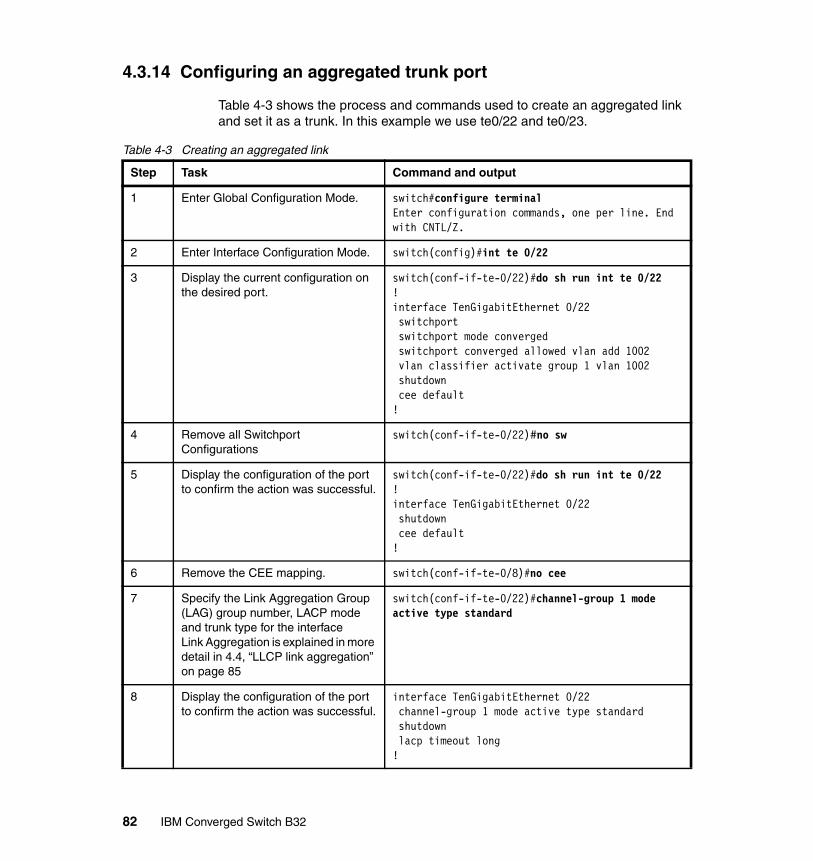
4.3.14 Configuring an aggregated trunk port
Table 4-3 shows the process and commands used to create an aggregated link and set it as a trunk. In this example we use te0/22 and te0/23.
Table 4-3 Creating an aggregated link
Step Task Command and output
1 Enter Global Configuration Mode. switch#configure terminal Enter configuration commands, one per line. End with CNTL/Z.
2 Enter Interface Configuration Mode. switch(config)#int te 0/22
3 Display the current configuration on the desired port.
switch(conf-if-te-0/22)#do sh run int te 0/22!interface TenGigabitEthernet 0/22 switchport switchport mode converged switchport converged allowed vlan add 1002 vlan classifier activate group 1 vlan 1002 shutdown cee default!
4 Remove all Switchport Configurations
switch(conf-if-te-0/22)#no sw
5 Display the configuration of the port to confirm the action was successful.
switch(conf-if-te-0/22)#do sh run int te 0/22!interface TenGigabitEthernet 0/22 shutdown cee default!
6 Remove the CEE mapping. switch(conf-if-te-0/8)#no cee
7 Specify the Link Aggregation Group (LAG) group number, LACP mode and trunk type for the interfaceLink Aggregation is explained in more detail in 4.4, “LLCP link aggregation” on page 85
switch(conf-if-te-0/22)#channel-group 1 mode active type standard
8 Display the configuration of the port to confirm the action was successful.
interface TenGigabitEthernet 0/22 channel-group 1 mode active type standard shutdown lacp timeout long!
82 IBM Converged Switch B32
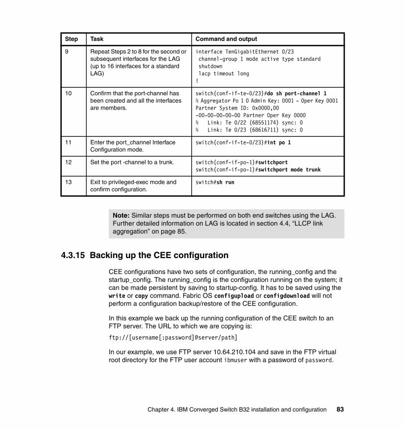
4.3.15 Backing up the CEE configuration
CEE configurations have two sets of configuration, the running_config and the startup_config. The running_config is the configuration running on the system; it can be made persistent by saving to startup-config. It has to be saved using the write or copy command. Fabric OS configupload or configdownload will not perform a configuration backup/restore of the CEE configuration.
In this example we back up the running configuration of the CEE switch to an FTP server. The URL to which we are copying is:
ftp://[username[:password]@server/path]
In our example, we use FTP server 10.64.210.104 and save in the FTP virtual root directory for the FTP user account ibmuser with a password of password.
9 Repeat Steps 2 to 8 for the second or subsequent interfaces for the LAG (up to 16 interfaces for a standard LAG)
interface TenGigabitEthernet 0/23 channel-group 1 mode active type standard shutdown lacp timeout long!
10 Confirm that the port-channel has been created and all the interfaces are members.
switch(conf-if-te-0/23)#do sh port-channel 1% Aggregator Po 1 0 Admin Key: 0001 - Oper Key 0001 Partner System ID: 0x0000,00-00-00-00-00-00 Partner Oper Key 0000% Link: Te 0/22 (68551174) sync: 0% Link: Te 0/23 (68616711) sync: 0
11 Enter the port_channel Interface Configuration mode.
switch(conf-if-te-0/23)#int po 1
12 Set the port -channel to a trunk. switch(conf-if-po-1)#switchportswitch(conf-if-po-1)#switchport mode trunk
13 Exit to privileged-exec mode and confirm configuration.
switch#sh run
Step Task Command and output
Note: Similar steps must be performed on both end switches using the LAG. Further detailed information on LAG is located in section 4.4, “LLCP link aggregation” on page 85.
Chapter 4. IBM Converged Switch B32 installation and configuration 83

First we copy the running-config to startup-config that is stored in flash memory using the write mem command shown in Example 4-14. Next, we back up the configuration to the FTP-server.
Example 4-14 Backing up the configuration
switch:admin> cmshswitch# write memswitch#copy startup-config ftp://ibmuser:[email protected]/IBM_B32_50_config.txtBuilding configuration...switch#endswitch#exit
4.3.16 Restoring the CEE configuration
If you need to restore a previously backed up configuration from an FTP server, Example 4-15 shows how this can be done.
Example 4-15 Restoring a previously saved configuration
switch#copy ftp://ibmuser:[email protected]/IBM_B32_50_config.txt startup-configOverwrite the startup config file (y/n): yBuilding configuration...switch#exitswitch:admin> fastboot
4.3.17 Backup of config to file in flash
CEE configuration can also be copied to a file in switch internal flash memory itself. This can serve as an immediate reference if any config is modified. Either the startup-config or running-config can be copied to a file. Example 4-16 shows the copying of running-config to a file with the name of runconf.1410.
Example 4-16 Copy CEE running-config to file in flash
switch#copy running-config flash://runconf.1410Building configuration...switch#
Note: You must reboot the switch to start with the new startup-config. This will be disruptive to all ports.
84 IBM Converged Switch B32

This backup file can be viewed by using the command show file <filename> and a list of the files in flash can be viewed by using the command dir from exec mode. Example 4-17 shows the listing of files in flash and how to view the file.
Example 4-17 Listing and viewing of files in flash
switch#dirContents of flash:// -rw-r----- 3956 Thu Oct 14 18:33:59 2010 runconf -rw-r----- 3972 Thu Oct 14 18:34:34 2010 startconf -rw-r----- 3953 Thu Oct 14 18:53:34 2010 runconf.1410switch#switch#show file runconf.1410!no protocol spanning-tree!vlan classifier rule 1 proto fcoe encap ethv2vlan classifier rule 2 proto fip encap ethv2vlan classifier group 1 add rule 1vlan classifier group 1 add rule 2!cee-map default priority-group-table 1 weight 40 pfc priority-group-table 2 weight 60 priority-table 2 2 2 1 2 2 2 2!interface Vlan 1!interface Vlan 1002 fcf forward!............................................. Rest of Output Removed for clarity
4.4 LLCP link aggregation
In 4.3.12, “Customizing the base install script” on page 80 we introduced the concept of link aggregation. This topic is discussed in greater detail in this section.
Chapter 4. IBM Converged Switch B32 installation and configuration 85

4.4.1 Link aggregation overview
Link aggregation allows you to bundle multiple physical Ethernet links to form a single logical trunk providing enhanced performance and redundancy. The aggregated trunk is referred to as a Link Aggregation Group (LAG). The LAG is viewed as a single link by connected devices, the spanning tree protocol, IEEE 802.1Q VLANs, and so on. When one physical link in the LAG fails, the other links stay up and there is no disruption to traffic.
To configure links to form a LAG, the physical links must be the same speed and all links must go to the same neighboring device. Link aggregation can be done by manually configuring the LAG or by dynamically configuring the LAG using the IEEE 802.3ad Link Aggregation Control Protocol (LACP).
The benefits of link aggregation are summarized as follows:
� Increased bandwidth. The logical bandwidth can be dynamically changed as the demand changes.
� Increased availability.
� Load sharing.
� Rapid configuration and reconfiguration.
The IBM Converged Switch B32 switch supports the following trunk types:
� Static, standards-based LAG.
� Dynamic, standards-based LAG using LACP.
� Static, Brocade-proprietary LAG.
� Dynamic, Brocade-proprietary LAG using proprietary enhancements to LACP.
4.4.2 LAGs
You can configure a maximum of 24 LAGs with up to 16 links per standard LAG and four links per Brocade-proprietary LAG. Each LAG is associated with an aggregator. The aggregator manages the Ethernet frame collection and distribution functions.
On each port, link aggregation control handles the following functions:
� Maintains configuration information to control port aggregation
� Exchanges configuration information with other devices to form LAGs
Note: The LAG or LAG interface can also be referred to as a port-channel.
86 IBM Converged Switch B32
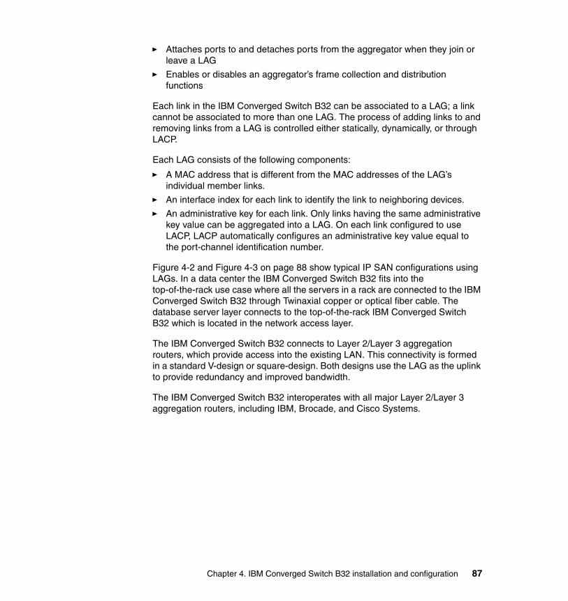
� Attaches ports to and detaches ports from the aggregator when they join or leave a LAG
� Enables or disables an aggregator’s frame collection and distribution functions
Each link in the IBM Converged Switch B32 can be associated to a LAG; a link cannot be associated to more than one LAG. The process of adding links to and removing links from a LAG is controlled either statically, dynamically, or through LACP.
Each LAG consists of the following components:
� A MAC address that is different from the MAC addresses of the LAG’s individual member links.
� An interface index for each link to identify the link to neighboring devices.
� An administrative key for each link. Only links having the same administrative key value can be aggregated into a LAG. On each link configured to use LACP, LACP automatically configures an administrative key value equal to the port-channel identification number.
Figure 4-2 and Figure 4-3 on page 88 show typical IP SAN configurations using LAGs. In a data center the IBM Converged Switch B32 fits into the top-of-the-rack use case where all the servers in a rack are connected to the IBM Converged Switch B32 through Twinaxial copper or optical fiber cable. The database server layer connects to the top-of-the-rack IBM Converged Switch B32 which is located in the network access layer.
The IBM Converged Switch B32 connects to Layer 2/Layer 3 aggregation routers, which provide access into the existing LAN. This connectivity is formed in a standard V-design or square-design. Both designs use the LAG as the uplink to provide redundancy and improved bandwidth.
The IBM Converged Switch B32 interoperates with all major Layer 2/Layer 3 aggregation routers, including IBM, Brocade, and Cisco Systems.
Chapter 4. IBM Converged Switch B32 installation and configuration 87
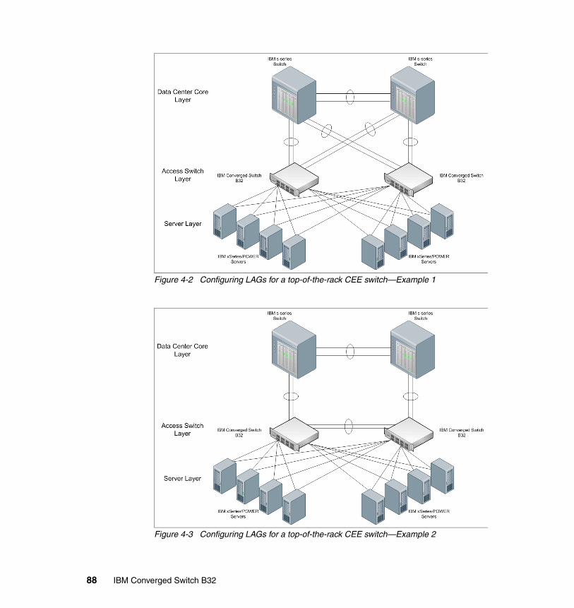
Figure 4-2 Configuring LAGs for a top-of-the-rack CEE switch—Example 1
Figure 4-3 Configuring LAGs for a top-of-the-rack CEE switch—Example 2
88 IBM Converged Switch B32
4.4.3 LACP
LACP is an IEEE 802.3ad standards-based protocol that allows two partner systems to dynamically negotiate attributes of physical links between them to form logical trunks. LACP determines whether a link can be aggregated into a LAG. If a link can be aggregated into a LAG, LACP puts the link into the LAG. All links in a LAG inherit the same administrative characteristics. LACP operates in two modes:
� Passive mode: LACP responds to Link Aggregation Control Protocol Data Units (LACPDUs) initiated by its partner system but does not initiate the LACPDU exchange.
� Active mode: LACP initiates the LACPDU exchange regardless of whether the partner system sends LACPDUs.
4.4.4 Dynamic link aggregation
Dynamic link aggregation uses LACP to negotiate which links can be added and removed from a LAG. Typically, two partner systems sharing multiple physical Ethernet links can aggregate a number of those physical links using LACP. LACP creates a LAG on both partner systems and identifies the LAG by the LAG ID. All links with the same administrative key and all links that are connected to the same partner switch become members of the LAG. LACP continuously exchanges LACPDUs to monitor the health of each member link.
4.4.5 Static link aggregation
In static link aggregation, links are added into a LAG without exchanging LACPDUs between the partner systems. The distribution and collection of frames on static links is determined by the operational status and administrative state of the link.
4.4.6 Brocade-proprietary aggregation
Brocade-proprietary aggregation is similar to standards-based link aggregation but differs in how the traffic is distributed. It also has additional rules that member links must meet before they are aggregated, specifically:
� The most important rule requires that there is not a significant difference in the length of the fiber between the member links, and that all member links are part of the same port-group. The ports that belong to port-group 1, port-group 2, and port-group 3 are te0/0 to te0/7, te0/8 to te0/15, and te0/16 to te0/23, respectively.
� A maximum of four Brocade LAGs can be created per port-group.
Chapter 4. IBM Converged Switch B32 installation and configuration 89
4.4.7 LAG distribution process
The LAG aggregator is associated with the collection and distribution of Ethernet frames. The collection and distribution process is required to guarantee the following operations:
� Inserting and capturing control PDUs.� Restricting the traffic of a given conversation to a specific link.� Load balancing between individual links.� Handling dynamic changes in LAG membership.
4.4.8 LACP configuration guidelines and restrictions
Follow the configuration guidelines and restrictions in this section when configuring LACP.
� Administrative key
An LACP-enabled link is assigned an administrative key, and all local links on the switch that share the same administrative key can potentially be aggregated. A system ID and the administrative key are combined to form a unique identifier for neighboring devices.
� Layer 2 control protocols
Layer 2 control protocols such as Spanning Tree Protocol (STP), Rapid STP (RSTP), and Multiple STP (MSTP) are transparent to the operation of LACP. These protocols see a LAG as a logical interface. When an STP bridged protocol data unit (BPDU) has to be transmitted, the LAG has the responsibility of choosing one of its operationally active member links to transmit it.
� VLANs
– Before being aggregated, links cannot be members of a VLAN.– A VLAN sees a LAG as a logical interface.– All LAG member links are configured with the same VLAN ID.
� QoS
In the Fabric OS version 6.1.2_cee release, QoS commands for a LAG have to be specified on each LAG member link, instead of on the logical LAG interface (port-group). Additionally, the QoS commands specified on each LAG member link must be the same on each link.
Note: This section applies to standards-based and Brocade-proprietary LAG configurations except where specifically noted otherwise.
90 IBM Converged Switch B32

� Brocade-proprietary LAGs only
All LAG member links have to be part of the same port-group.
� Switchport interfaces
Interfaces configured as “switchport” interfaces cannot be aggregated into a LAG. However, a LAG can be configured as a switchport.
� LAG interface statistics and individual link statistics
LAG statistics and individual link statistics comply with standard RMON and MIB2 interface statistics. Cumulative statistics of all the LAG member links are maintained for the LAG. Individual link statistics are also maintained. The statistical counters of a LAG member link start when the link becomes a member of the LAG and stop when the link goes out of the LAG. To retain the history of individual links, individual link statistical counters keep generating individual link statistics even when the link is part of a LAG.
� Active or passive links
IEEE 802.3ad specifies that an LACP-enabled link can be configured as either active or passive. However, if both sides of the link are configured as passive, the LACP protocol is not initiated and the LAG is not formed.
� LACP enables the exchange of the system ID and administrative keys across member links to directly connected neighboring devices. Included in the information exchange are these items:
– Actor port/partner port.– Actor system ID/partner system ID.– Actor administrative key/partner administrative key.– Actor state/partner state: Contained in both actor state and partner state
are LACP activity, LACP timeout, aggregability, synchronization, collecting, and distributing.
� Aggregation considerations
– Essentially, all ports get aggregated if they have:
• The same actor system ID and actor administrative key• The same partner system ID and partner administrative key
– LACP exchanges the aggregator states with its neighbors, which determine the rate at which the LACPDU flows (slow or fast).
– After aggregation, a link can be part of a LAG but does not need to participate in the distribution of traffic.
– When control protocols such as STP, RSTP, and MSTP see the deletion of a LAG or the addition of a new LAG interface, they re-evaluate the topology and determine the port state and port role (root, designated, or blocked) based on BPDUs.
Chapter 4. IBM Converged Switch B32 installation and configuration 91
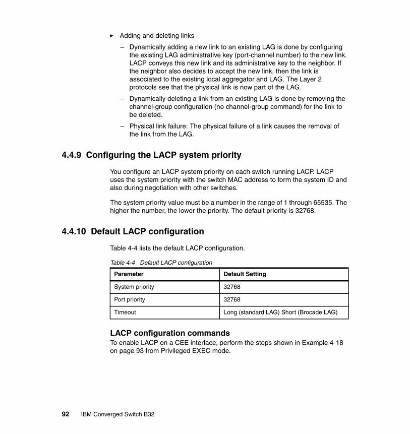
� Adding and deleting links
– Dynamically adding a new link to an existing LAG is done by configuring the existing LAG administrative key (port-channel number) to the new link. LACP conveys this new link and its administrative key to the neighbor. If the neighbor also decides to accept the new link, then the link is associated to the existing local aggregator and LAG. The Layer 2 protocols see that the physical link is now part of the LAG.
– Dynamically deleting a link from an existing LAG is done by removing the channel-group configuration (no channel-group command) for the link to be deleted.
– Physical link failure: The physical failure of a link causes the removal of the link from the LAG.
4.4.9 Configuring the LACP system priority
You configure an LACP system priority on each switch running LACP. LACP uses the system priority with the switch MAC address to form the system ID and also during negotiation with other switches.
The system priority value must be a number in the range of 1 through 65535. The higher the number, the lower the priority. The default priority is 32768.
4.4.10 Default LACP configuration
Table 4-4 lists the default LACP configuration.
Table 4-4 Default LACP configuration
LACP configuration commandsTo enable LACP on a CEE interface, perform the steps shown in Example 4-18 on page 93 from Privileged EXEC mode.
Parameter Default Setting
System priority 32768
Port priority 32768
Timeout Long (standard LAG) Short (Brocade LAG)
92 IBM Converged Switch B32
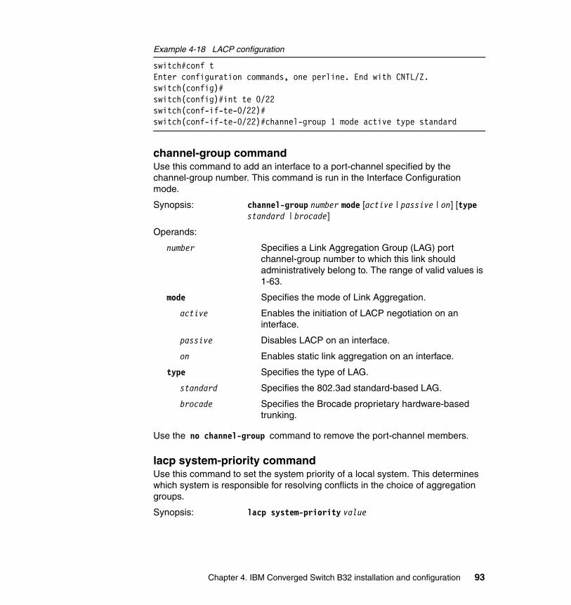
Example 4-18 LACP configuration
switch#conf tEnter configuration commands, one perline. End with CNTL/Z.switch(config)#switch(config)#int te 0/22switch(conf-if-te-0/22)#switch(conf-if-te-0/22)#channel-group 1 mode active type standard
channel-group commandUse this command to add an interface to a port-channel specified by the channel-group number. This command is run in the Interface Configuration mode.
Synopsis: channel-group number mode [active | passive | on] [type standard | brocade]
Operands:
number Specifies a Link Aggregation Group (LAG) port channel-group number to which this link should administratively belong to. The range of valid values is 1-63.
mode Specifies the mode of Link Aggregation.
active Enables the initiation of LACP negotiation on an interface.
passive Disables LACP on an interface.
on Enables static link aggregation on an interface.
type Specifies the type of LAG.
standard Specifies the 802.3ad standard-based LAG.
brocade Specifies the Brocade proprietary hardware-based trunking.
Use the no channel-group command to remove the port-channel members.
lacp system-priority commandUse this command to set the system priority of a local system. This determines which system is responsible for resolving conflicts in the choice of aggregation groups.
Synopsis: lacp system-priority value
Chapter 4. IBM Converged Switch B32 installation and configuration 93

Operands:
value Specifies the value of the LACP system priority. The range of valid values is 1-65535.
Use the no lacp system-priority command to reset the system priority to the default value.
lacp timeout commandUse this command to set the short timeout value for Brocade trunks or to set the long timeout value for standard trunks.
Synopsis: lacp timeout [long | short] value
Operands:
long Specifies a long timeout value.
short Specifies a short timeout value.
value Specifies the number of seconds before invalidating a received Link Aggregation Control Protocol (LACP) data unit (DU).
Use the no lacp timeout command to return to the default value.
4.4.11 LACP troubleshooting tips
To troubleshoot problems with your LACP configuration, use the following troubleshooting tips:
� If a standard IEEE 802.3ad-based dynamic trunk is configured on a link and the link is not able to join the LAG, make sure of the following:
– Both ends of the link are configured as standard for the trunk type.
– Both ends of the link are not configured for passive mode. They must be configured as either active/active, active/passive, or passive/active.
– The port-channel interface is in the administrative “up” state. This can be verified by ensuring that the no shutdown command was entered on the interface on both ends of the link.
– The links that are part of the LAG are connected to the same neighboring switch.
– The system-id of the switches connected by the link is unique. This can be verified by entering the show lacp sys-id command on both switches.
– LACPDUs are being received and transmitted on both ends of the link and that there are no error PDUs. This can be verified by entering the show lacp port-channel-num counters command and looking at the rx and tx
94 IBM Converged Switch B32

statistics. The statistics should be incrementing and should not be at zero or a fixed value.
If the PDU rx count is not incrementing, check the interface for possible CRC errors by entering the show interface link-name command on the neighboring switch. If the PDU tx count is not incrementing, check the operational status of the link by entering the show interface link-name command and verifying that the interface status is “up.”
� If a Brocade-based dynamic trunk is configured on a link and the link is not able to join the LAG, make sure of the following:
– Both ends of the link are configured as Brocade for trunk type.
– Both ends of the link are not configured for passive mode. They must be configured as either active/active, active/passive, or passive/active.
– The port-channel interface is in the administrative “up” state. This can be verified by ensuring that the no shutdown command was entered on the interface on both ends of the link.
– The links that are part of the LAG are connected to the same neighboring switch.
– The system-id of the switches connected by the link is unique. This can be verified by entering the show lacp sys-id command on both switches.
– LACPDUs are being received and transmitted on both ends of the link and there are no error PDUs. This can be verified by entering the show lacp port-channel-num counters command and looking at the rx and tx statistics. The statistics should be incrementing and should not be at zero or a fixed value. If the PDU rx count is not incrementing, check the interface for possible CRC errors by entering the show interface link-name command on the neighboring switch.
– The fiber length of the link has a deskew value of 7 micro-seconds. If it does not, the link will not be able to join the LAG and the following RASLOG message is generated: Deskew calculation failed for link <link-name>. When a link has this problem, the show port port-channel link-name command displays the following message: Mux machine state: Deskew not OK.
� If a Brocade-based static trunk is configured on a link and the link is not able to join the LAG, make sure of the following:
– Both ends of the link are configured as Brocade for trunk type and verify that the mode is “on.”
– The port-channel interface is in the administrative “up” state. This can be verified by ensuring that the no shutdown command was entered on the interface on both ends of the link.
Chapter 4. IBM Converged Switch B32 installation and configuration 95

� If a standards-based static trunk is configured on a link and the link is not able to join the LAG, make sure of the following:
– Both ends of the link are configured as standard for trunk type and verify that the mode is “on.”
– The port-channel interface is in the administrative “up” state. This can be verified by ensuring that the no shutdown command was entered on the interface on both ends of the link.
4.5 VLAN overview
IEEE 802.1Q Virtual LANs (VLANs) provide the capability to overlay the physical network with multiple virtual networks. VLANs allow you to isolate network traffic between virtual networks and reduce the size of administrative and broadcast domains.
A VLAN contains end stations that have a common set of requirements that are independent of physical location. You can group end stations in a VLAN even if they are not physically located in the same LAN segment. VLANs are typically associated with IP subnetworks and all the end stations in a particular IP subnet belong to the same VLAN. Traffic between VLANs must be routed. VLAN membership is configurable on a per interface basis.
The VLAN used for carrying FCoE traffic has to be explicitly designated as the FCoE VLAN. FCoE VLANs are configured through the CEE CLI (see 4.3.7, “fcf forward” on page 74 for details about this command).
4.5.1 Ingress VLAN filtering
A packet arriving at the IBM Converged Switch B32 is associated with either a specific port or with a VLAN, based on whether the packet is tagged or untagged:
� Tagged packets: The port the packet came in on is assigned to a single VLAN or to multiple VLANs depending on the VLAN ID in the frame’s VLAN tag.
� Untagged packets: These are assigned the port VLAN ID (PVID) assigned to the port that the packet came in on.
Note: Currently only one VLAN can be configured as the FCoE VLAN.
96 IBM Converged Switch B32

Figure 4-4 shows the packet processing logic for an incoming packet.
Figure 4-4 Ingress VLAN filtering
Note: Ingress VLAN filtering is enabled by default on all Layer 2 interfaces. This ensures that VLANs are filtered on the incoming port (depending on the user configuration).
Chapter 4. IBM Converged Switch B32 installation and configuration 97

Ingress VLAN filtering is summarized as follows:
� Ingress VLAN filtering is based on port VLAN membership.
� Port VLAN membership is provisioned through the CEE CLI.
� Dynamic VLAN registration is not supported.
� The IBM Converged Switch B32 does VLAN filtering at both the ingress and egress ports.
� The VLAN filtering behavior on logical Layer 2 interfaces such as LAG interfaces is the same as on port interfaces.
� The VLAN filtering database (FDB) determines the forwarding of an incoming packet. VLAN FDB support is summarized as follows:
– The VLAN FDB contains information that helps determine the forwarding of an arriving frame based on MAC address and VLAN ID data. The FDB contains both statically configured data and dynamic data that is learned by the switch.
– Dynamic updating of FDB entries using learning is supported (if the port state permits).
– Dynamic FDB entries are not created for multicast group addresses.
– Dynamic FDB entries are aged out based on the aging time configured per IBM Converged Switch B32. The aging time is between 10 and 1000000 seconds. The default is 300 seconds You can add static MAC address entries specifying a VLAN ID. Static entries are not aged out.
– A static FDB entry overwrites an existing dynamically learned FDB entry and disables learning of the entry going forward.
4.5.2 VLAN configuration guidelines and restrictions
Follow these guidelines and restrictions when configuring VLANs:
� A unique MAC address is assigned per interface.
� One unique MAC address is used as the IBM Converged Switch B32 MAC address and as the Bridge ID in Layer 2 control protocols such as STP.
� In an active topology, MAC addresses can be learned, per VLAN, using Independent VLAN Learning (IVL) or Shared VLAN Learning (SVL). Currently the switch only supports IVL.
� A MAC address ACL always overrides a static MAC address entry. In this case, the MAC address is the forwarding address and the forwarding entry can be overwritten by the ACL.
98 IBM Converged Switch B32

� There is support for a configurable maximum transmission unit (MTU) per CEE interface. For detailed information, see “mtu command” on page 78.
� If a VLAN is designated as an FCoE VLAN, you can enforce permit/deny policies for FCoE traffic on that VLAN.
� There is a configurable default priority per Layer 2 interface (the default priority is 0).
� There is a system-wide default priority for packets that do not contain priority. A default priority per interface is also supported that inherits the global default priority if a user-specified default priority is not specified. For QoS configuration details, see 4.6, “QoS overview” on page 101.
� The IBM Converged Switch B32 supports Ethernet DIX frames and 802.2 LLC SNAP encapsulated frames.
� In addition to the standard protocol-based VLANs, there is an application type classification feature that allows you to create VLAN classification rules that are based on application types. The application type values can specify FCoE or FIP EtherTypes. For detailed information, see 4.3.4, “vlan classifier rule” on page 72.
4.5.3 Default VLAN configuration
Table 4-5 lists the default VLAN configuration.
Table 4-5 Default VLAN configuration
4.5.4 VLAN configuration procedures
Parameter Default setting
default VLAn VLAN 1
Interface VLAN assignment All interfaces assigned to VLAN 1
VLAN state Active
MTU Size 2500 bytes
Note: To see the minimum configuration required to enable FCoE on the IBM Converged Switch B32, refer to “Initial configuration script example” on page 66.
Chapter 4. IBM Converged Switch B32 installation and configuration 99
MTU commandUse this command to specify the size of the Maximum Transmission Unit (MTU) on the interface. By default, all 10 Gbps Ethernet interfaces use a default MTU of 2500.
Synopsis: mtu size
Operands:
size Specifies the size of the Maximum Transmission Unit (MTU) of an interface. The allowed MTU size is 1522-9208.
Completion of VLAN configurationThe remaining steps for the configuration of VLANs have been covered in previous sections and are listed here:
� interface VLAN command:
On an IBM Converged Switch B32, VLANs are treated as logical interfaces from a provisioning point of view. By default, all the CEE ports are assigned to VLAN 1 (VLAN ID equals 1). The vlan_ID value can be 1 through 3583. VLAN IDs 3584 through 4094 are internally-reserved VLAN IDs (see 4.3.6, “interface vlan” on page 73 for details).
� vlan classifier rule command:
You can configure VLAN classifier rules to define specific rules for classifying packets to selected VLANs based on protocol and MAC addresses. VLAN classifier rules (1 through 256) are a set of configurable rules that can be categorized into the following areas:
– 802.1Q protocol-based classifier rules– MAC address-based classifier rules
802.1Q protocol-based VLANs apply only to untagged frames or frames with priority tagging.
With both Ethernet-II and 802.2 SNAP encapsulated frames, the following protocol types are supported:
– Ethernet decimal (0 through 65535)– Address Resolution Protocol (ARP)– Fibre Channel over Ethernet (FCoE)– FCoE Initialization Protocol (FIP)– IP– IP version 6 (IPv6)
Note: Multiple VLAN classifier rules can be applied per interface provided the resulting VLAN IDs are different for the various rules.
100 IBM Converged Switch B32
To configure a protocol-based VLAN classifier rule, perform the steps in 4.3.4, “vlan classifier rule” on page 72.
� vlan classifier group commands:
Sets of rules can be grouped into VLAN classifier groups. VLAN classifier groups (1 through 16) can contain any number of VLAN classifier rules.
To configure a VLAN classifier group and add or delete a VLAN classifier rule, perform the steps in 4.3.5, “vlan classifier group” on page 73.
� vlan classifier activate group command:
To associate a VLAN classifier group to a particular CEE interface, perform the steps in “vlan classifier activate group command” on page 77.
4.6 QoS overview
Quality of Service (QoS) provides you with the capability to control how the traffic is moved from switch to switch. In a network that has different types of traffic with different needs (for example, Class of Service (CoS)), the goal of QoS is to provide each traffic type with a virtual pipe. FCoE uses traffic class mapping, scheduling, and flow control to provide quality of service.
Traffic running through the switches can be classified as either multicast traffic or unicast traffic. Multicast traffic has a single source but multiple destinations. Unicast traffic has a single source with a single destination. With all this traffic going through ingress (incoming) and egress (outgoing) ports, QoS can be set based on egress port and priority level of the CoS.
QoS can also be set on interfaces where the end-station knows how to mark traffic with QoS and it lies with the same trusted interfaces. An untrusted interface is when the end-station is not intelligent and is at the administrative boundaries.
The QoS features described in the following sections are:
� Rewriting:
Rewriting or marking a packet allows for overriding header fields such as priority and VLAN ID.
� Queueing:
Queueing provides temporary storage for packets while waiting for transmission. Queues are selected based on egress port and configured user priority level.
Chapter 4. IBM Converged Switch B32 installation and configuration 101
� Congestion control:
When queues begin filling up and all buffering is exhausted, packets are dropped. This has a detrimental effect on application throughput. Congestion control techniques are used to reduce the risk of queue overruns without adversely affecting network throughput. Congestion control features include IEEE 802.3x Ethernet Pause, Tail Drop, and Brocade proprietary Ethernet Per Priority Pause (PPP).
� Multicast rate limiting:
Many multicast applications cannot be adapted for congestion control techniques and the replication of packets by switching devices can exacerbate this problem. Multicast rate limiting controls packet replication to minimize the impact of multicast traffic.
� Scheduling
When multiple queues are active and contending for output on a common physical port the scheduling algorithm selects the order the queues are serviced. Scheduling algorithms include Strict Priority (SP), Weighted Round Robin (WRR), and Deficit Weighted Round Robin (DWRR) queueing. The scheduler supports a hybrid policy combining SP and WRR/DWRR servicing. Under a hybrid scheduler configuration, the highest priority queues are serviced by SP while lower priority queues share the remaining bandwidth using the WRR service.
� Converged Enhanced Ethernet:
CEE describes an enhanced Ethernet that will enable convergence of various applications in data centers (LAN, SAN, and IPC) onto a single interconnect technology.
4.6.1 Rewriting
Rewriting a packet header field is typically performed by an edge device. Rewriting occurs on packets as they enter or exit a network because the neighboring device is untrusted, unable to mark the packet, or is using a different QoS mapping.
The packet rewriting rules set the Ethernet CoS and VLAN ID fields. Egress Ethernet CoS rewriting is based on the user-priority mapping derived for each packet as described later in the queueing section.
102 IBM Converged Switch B32

4.6.2 Queueing
Queue selection begins by mapping an incoming packet to a configured user priority, then each user-priority mapping is assigned to one of the switch’s eight unicast traffic class queues or one of the four multicast traffic class queues.
There are two type of mapping:
� User-priority mapping� Traffic class mapping
4.6.3 User-priority mapping
There are several ways an incoming packet can be mapped into a user-priority. If the neighboring devices are untrusted or unable to properly set QoS, the interface is considered untrusted and all traffic must be user-priority mapped using explicit policies or the IEEE 802.1Q default-priority mapping is used. If an interface is trusted to have QoS set then the CoS header field can be interpreted.
Default user-priority mappings for untrusted interfacesWhen Layer 2 QoS trust is set to untrusted, the default is to map all Layer 2 switched traffic to the port default user priority value of 0 (best effort), unless configured to a different value.
Table 4-6 presents the Layer 2 QoS untrusted user priority generation table.
Table 4-6 Default priority value of untrusted interfaces
Note: The user priority mapping described in this section applies to both unicast and multicast traffic.
Incoming CoS User priority
0 port <user priority> (default 0)
1 port <user priority> (default 0)
2 port <user priority> (default 0)
3 port <user priority> (default 0)
4 port <user priority> (default 0)
5 port <user priority> (default 0)
6 port <user priority> (default 0)
7 port <user priority> (default 0)
Chapter 4. IBM Converged Switch B32 installation and configuration 103

You can override the default user-priority mapping by applying explicit user-priority mappings.
When neighboring devices are trusted and able to properly set QoS, then Layer 2 QoS trust can be set to CoS and the IEEE 802.1Q default-priority mapping is applied.
Table 4-7 presents the Layer 2 CoS user priority generation table conforming to 802.1Q default mapping. You can override this default user priority table per port if you want to change (mutate) the CoS value.
Table 4-7 IEEE 802.1Q default priority mapping
4.6.4 Priority mapping commands
The following commands are used to configure the priority mapping settings.
qos trust commandUse this command to specify the interface ingress QoS Trust model, which controls user priority mapping of incoming traffic. The untrusted mode overrides all incoming priority markings with the Interface Default CoS. The CoS mode sets the user priority based on the incoming CoS value; if the incoming packet is not priority tagged, then fallback is to the Interface Default CoS value.
Synopsis: qos Trust cos
Operands: None
Note: Non-tagged Ethernet packets are interpreted as incoming CoS 0.
Incoming CoS User priority
0 0
1 1
2 2
3 3
4 4
5 5
6 6
7 7
104 IBM Converged Switch B32

Use the no qos trust command to return the CoS value to the default.
Example 4-19 shows the process of setting the QoS trust on a 10-Gigabit Ethernet interface.
Example 4-19 Setting QoS trust
switch:admin>cmshswitch>enableswitch#conf tEnter configuration commands, one per line. End with CNTL/Z.switch(config)#int te 0/2switch(conf-if-te-0/2)#qos trust cosswitch(conf-if-te-0/2)#exitswitch(config)#exitswitch#
qos cos commandUse this command to specify the interface Default CoS value. When Interface ingress QoS Trust is in the untrusted mode, then the Interface Default CoS value is applied to all ingress traffic for user priority mapping. When the interface ingress QoS Trust is in the CoS mode, then the Interface Default CoS value is applied to all non-priority tagged ingress traffic for user priority mapping.
Synopsis: qos cos value
Operands:
value Specifies the CoS value. The range of valid values is 0-7.
Use the no qos cos command to return the CoS value to the default.
Example 4-20 shows the process of setting an interface default CoS to 3.
Example 4-20 Setting interface default
switch:admin>cmshswitch>enableswitch#conf tEnter configuration commands, one per line. End with CNTL/Z.switch(config)#int te 0/2switch(conf-if-te-0/2)#qos cos 3switch(conf-if-te-0/2)#exitswitch(config)#exitswitch#
Chapter 4. IBM Converged Switch B32 installation and configuration 105

qos map cos-mutationUse this command to create a QoS map for performing CoS-to-CoS Mutation. A CoS-to-CoS mutation takes an inbound CoS value and maps it to an outbound CoS value. The inbound CoS value is the user priority after any interface ingress QoS trust and Interface default CoS policy have been applied. The outbound CoS value is used in selecting Traffic Class and egress packet marking. The default is no CoS-to-CoS Mutation QoS maps defined.
Synopsis: qos map cos-mutation name cos0 cos1 cos2 cos3 cos4 cos5 cos6 cos7
Operands:
name Specifies a unique name across all CoS-to-CoS mutation QoS maps defined within the system. If the named CoS-to-CoS mutation QoS map does not exist, then it is created. If the named CoS-to-CoS mutation QoS map already exists then, it is updated and new mapping is automatically propagated to all interfaces bound to the QoS map.
cos0 Sets the outbound CoS value for all packets with inbound CoS 0.
cos1 Sets the outbound CoS value for all packets with inbound CoS 1.
cos2 Sets the outbound CoS value for all packets with inbound CoS 2
cos3 Sets the outbound CoS value for all packets with inbound CoS 3.
cos4 Sets the outbound CoS value for all packets with inbound CoS 4.
cos5 Sets the outbound CoS value for all packets with inbound CoS 5.
cos6 Sets the outbound CoS value for all packets with inbound CoS 6.
cos7 Sets the outbound CoS value for all packets with inbound CoS 7.
Use the no qos map cos-mutation name command to delete the named CoS-to-CoS mutation QoS map. A QoS map can only be deleted if it is not bound to any interface.
qos cos-mutation commandThis command applies a CoS-to-CoS mutation map on an interface. The qos cos-mutation command is not available if the interface is in CEE Provisioning mode.
Synopsis: qos cos-mutation name
Operands:
name Specifies the name of the CoS mutation map.
Use the no qos cos-mutation command to remove the CoS-to-CoS mutation map.
106 IBM Converged Switch B32
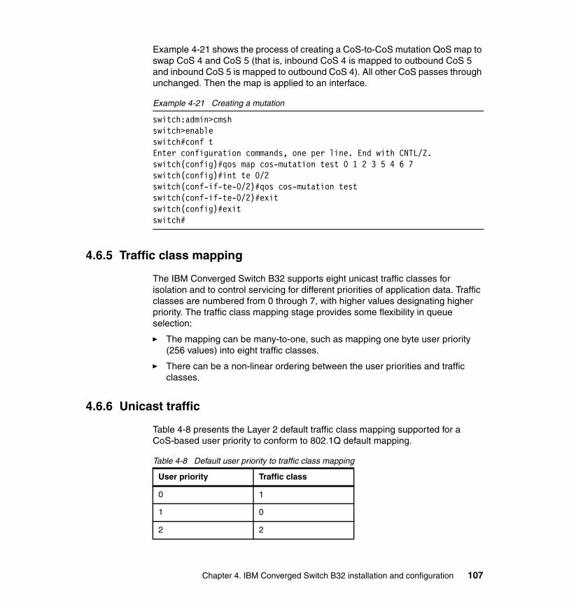
Example 4-21 shows the process of creating a CoS-to-CoS mutation QoS map to swap CoS 4 and CoS 5 (that is, inbound CoS 4 is mapped to outbound CoS 5 and inbound CoS 5 is mapped to outbound CoS 4). All other CoS passes through unchanged. Then the map is applied to an interface.
Example 4-21 Creating a mutation
switch:admin>cmshswitch>enableswitch#conf tEnter configuration commands, one per line. End with CNTL/Z.switch(config)#qos map cos-mutation test 0 1 2 3 5 4 6 7switch(config)#int te 0/2switch(conf-if-te-0/2)#qos cos-mutation testswitch(conf-if-te-0/2)#exitswitch(config)#exitswitch#
4.6.5 Traffic class mapping
The IBM Converged Switch B32 supports eight unicast traffic classes for isolation and to control servicing for different priorities of application data. Traffic classes are numbered from 0 through 7, with higher values designating higher priority. The traffic class mapping stage provides some flexibility in queue selection:
� The mapping can be many-to-one, such as mapping one byte user priority (256 values) into eight traffic classes.
� There can be a non-linear ordering between the user priorities and traffic classes.
4.6.6 Unicast traffic
Table 4-8 presents the Layer 2 default traffic class mapping supported for a CoS-based user priority to conform to 802.1Q default mapping.
Table 4-8 Default user priority to traffic class mapping
User priority Traffic class
0 1
1 0
2 2
Chapter 4. IBM Converged Switch B32 installation and configuration 107
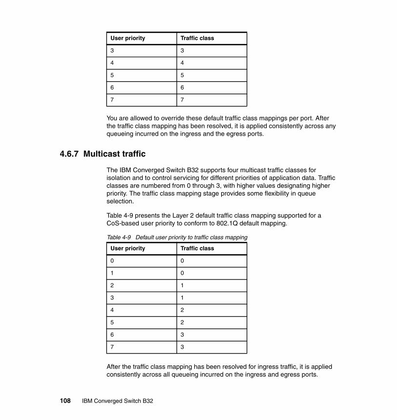
You are allowed to override these default traffic class mappings per port. After the traffic class mapping has been resolved, it is applied consistently across any queueing incurred on the ingress and the egress ports.
4.6.7 Multicast traffic
The IBM Converged Switch B32 supports four multicast traffic classes for isolation and to control servicing for different priorities of application data. Traffic classes are numbered from 0 through 3, with higher values designating higher priority. The traffic class mapping stage provides some flexibility in queue selection.
Table 4-9 presents the Layer 2 default traffic class mapping supported for a CoS-based user priority to conform to 802.1Q default mapping.
Table 4-9 Default user priority to traffic class mapping
After the traffic class mapping has been resolved for ingress traffic, it is applied consistently across all queueing incurred on the ingress and egress ports.
3 3
4 4
5 5
6 6
7 7
User priority Traffic class
User priority Traffic class
0 0
1 0
2 1
3 1
4 2
5 2
6 3
7 3
108 IBM Converged Switch B32
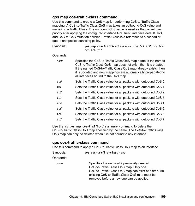
qos map cos-traffic-class commandUse this command to create a QoS map for performing CoS-to-Traffic Class mapping. A CoS-to-Traffic Class QoS map takes an outbound CoS value and maps it to a Traffic Class. The outbound CoS value is used as the packet user priority after applying the configured interface QoS trust, interface default CoS, and CoS-to-CoS mutation policies. Traffic Class is a reference to a scheduler queue and packet servicing policy.
Synopsis: qos map cos-traffic-class name tc0 tc1 tc2 tc3 tc4 tc5 tc6 tc7
Operands:
name Specifies the CoS-to-Traffic Class QoS map name. If the named CoS-to-Traffic Class QoS map does not exist, then it is created. If the named CoS-to-Traffic Class QoS map already exists, then it is updated and new mappings are automatically propagated to all interfaces bound to the QoS map.
tc0 Sets the Traffic Class value for all packets with outbound CoS 0.
tc1 Sets the Traffic Class value for all packets with outbound CoS 1.
tc2 Sets the Traffic Class value for all packets with outbound CoS 2.
tc3 Sets the Traffic Class value for all packets with outbound CoS 3.
tc4 Sets the Traffic Class value for all packets with outbound CoS 4.
tc5 Sets the Traffic Class value for all packets with outbound CoS 5.
tc6 Sets the Traffic Class value for all packets with outbound CoS 6.
tc7 Sets the Traffic Class value for all packets with outbound CoS 7.
Use the no qos map cos-traffic-class name command to delete the CoS-to-Traffic Class QoS map specified by the name. The CoS-to-Traffic Class QoS map can only be deleted when it is not bound to any interface.
qos cos-traffic-class commandUse this command to apply a CoS-to-Traffic Class QoS map to an interface.
Synopsis: qos cos-traffic-class name
Operands:
name Specifies the name of a previously created CoS-to-Traffic Class QoS map. Only one CoS-to-Traffic Class QoS map can exist at a time. An existing CoS-to-Traffic Class QoS map must be removed before a new one can be applied.
Chapter 4. IBM Converged Switch B32 installation and configuration 109

Example 4-22 shows the process of creating CoS-to-Traffic Class QoS Map to map CoS 0 (best effort) to Traffic Class 1 and CoS 1 to below best effort Traffic Class 0, and all other CoS go through unchanged. This mapping matches the default behavior recommended in IEEE 802.1Q for systems supporting 8 Traffic Classes.
Example 4-22 Creating and activating a CoS-to-Traffic Class QoS map
switch:admin>cmshswitch>enableswitch#conf tEnter configuration commands, one per line. End with CNTL/Z.switch(config)#qos map cos-traffic-class test 1 0 2 3 4 5 6 7switch(config)#int te 0/2switch(conf-if-te-0/2)#qos cos-traffic-class testswitch(conf-if-te-0/2)#exitswitch(config)#exitswitch#
4.6.8 Congestion control
The IBM Converged Switch B32 utilizes three types of congestion control:
� Tail drop� Ethernet pause� Ethernet Per-Priority Pause
Queues can begin filling up for a number of reasons, such as oversubscription of a link or back pressure from a downstream device. Sustained, large queue buildups generally indicate congestion in the network and can affect application performance through increased queueing delays and packet loss.
Congestion control covers features that define how the system responds when congestion occurs and active measures taken to prevent the network from entering a congested state.
4.6.9 Tail drop
Tail drop queueing is the most basic form of congestion control. Packets are queued in FIFO order and queue buildup can continue until all buffer memory is exhausted. This is the default behavior when no additional QoS has been configured.
The basic tail drop algorithm does not have any knowledge of multiple priorities and per traffic class drop thresholds can be associated with a queue to address
110 IBM Converged Switch B32

this. When the queue depth breaches a threshold, then any packet arriving with the associated priority value will be dropped.
Figure 4-5 shows how you can use this feature to ensure that lower priority traffic cannot totally consume the full buffer memory. Thresholds can also be used to bound the maximum queueing delay for each traffic class. Additionally, if the sum of the thresholds for a port is set below 100% of the buffer memory, then you can also ensure that a single port does not monopolize the entire shared memory pool.
The tail drop algorithm can be extended to support per priority drop thresholds. When the ingress port CoS queue depth breaches a threshold, then any packet arriving with the associated priority value will be dropped.
Figure 4-5 Queue depth
qos rcv-queue multicast threshold commandUse this command to configure a cap on the maximum queue depth for multicast packet expansion queues. The individual Tail Drop Threshold is specified for each of the four multicast traffic classes. These Tail Drop Thresholds are applied uniformly across the entire system. These queue depths are enforced
Chapter 4. IBM Converged Switch B32 installation and configuration 111

independently by each switch. The default is 64 packets for each multicast Traffic Class.
Synopsis: qos rcv-queue multicast threshold tdt0 tdt1 tdt2 tdt3
Operands:
tdto Sets the Tail Drop Threshold for multicast Traffic Class 0 packet expansion queue in units of packets (pkt). The range of valid values is 0-2047 packets.
tdt1 Sets the Tail Drop Threshold for multicast Traffic Class 1 packet expansion queue in units of packets (pkt). The range of valid values is 0-2047 packets.
tdt2 Sets the Tail Drop Threshold for multicast Traffic Class 2 packet expansion queue in units of packets (pkt). The range of valid values is 0-2047 packets.
tdt3 Sets the Tail Drop Threshold for multicast Traffic Class 3 packet expansion queue in units of packets (pkt). The range of valid values is 0-2047 packets.
Example 4-23 shows how to increase the multicast packet expansion Tail Drop Threshold to 1000 pkt for each multicast Traffic Class
Example 4-23 Example of increasing multicast packet expansion Tail Drop Threshold
switch:admin>cmshswitch>enableswitch#conf tEnter configuration commands, one per line. End with CNTL/Z.switch(config)#qos rcv-queue multicast threshold 1000 1000 1000 1000switch(config)#exit
4.6.10 Ethernet pause
Ethernet Pause is an IEEE 802.3 standard mechanism for back pressuring a neighboring device. Pause messages are sent by utilizing the optional MAC control sublayer. A Pause frame contains a 2-byte pause number, which states the length of the pause in units of 512 bit times. When a device receives a Pause frame, it must stop sending any data on the interface for the specified length of time, after it completes transmission of any frame in progress. You can use this feature to reduce Ethernet packet losses by using a standardized mechanism. However, the Pause mechanism does not have the ability to selectively back pressure data sources multiple hops away, or exert any control per VLAN or per priority, so it is disruptive to all traffic on the link.
112 IBM Converged Switch B32
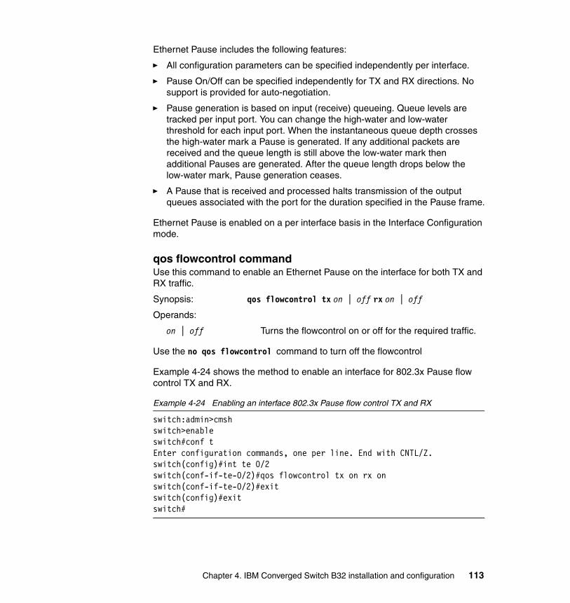
Ethernet Pause includes the following features:
� All configuration parameters can be specified independently per interface.
� Pause On/Off can be specified independently for TX and RX directions. No support is provided for auto-negotiation.
� Pause generation is based on input (receive) queueing. Queue levels are tracked per input port. You can change the high-water and low-water threshold for each input port. When the instantaneous queue depth crosses the high-water mark a Pause is generated. If any additional packets are received and the queue length is still above the low-water mark then additional Pauses are generated. After the queue length drops below the low-water mark, Pause generation ceases.
� A Pause that is received and processed halts transmission of the output queues associated with the port for the duration specified in the Pause frame.
Ethernet Pause is enabled on a per interface basis in the Interface Configuration mode.
qos flowcontrol commandUse this command to enable an Ethernet Pause on the interface for both TX and RX traffic.
Synopsis: qos flowcontrol tx on | off rx on | off
Operands:
on | off Turns the flowcontrol on or off for the required traffic.
Use the no qos flowcontrol command to turn off the flowcontrol
Example 4-24 shows the method to enable an interface for 802.3x Pause flow control TX and RX.
Example 4-24 Enabling an interface 802.3x Pause flow control TX and RX
switch:admin>cmshswitch>enableswitch#conf tEnter configuration commands, one per line. End with CNTL/Z.switch(config)#int te 0/2switch(conf-if-te-0/2)#qos flowcontrol tx on rx onswitch(conf-if-te-0/2)#exitswitch(config)#exitswitch#
Chapter 4. IBM Converged Switch B32 installation and configuration 113

4.6.11 Ethernet Per-Priority Pause
Ethernet Per Priority Pause (PPP) is a basic extension of the Ethernet Pause. The Pause MAC control message is extended with eight 2-byte pause numbers and a bitmask to indicate which values are valid. Each pause number is interpreted identically to the base Pause protocol; however, each is applied to the corresponding Ethernet priority or class level. For example, the Pause number zero applies to priority zero, Pause number one applies to priority one, and so on. This addresses one shortcoming of the Ethernet Pause mechanism, which is disruptive to all traffic on the link. However, it still suffers from the other Ethernet Pause limitations.
Ethernet Per-Priority Pause includes the following features:
� Everything operates exactly as in Ethernet Pause as just described, except that there are 8 high-water and low-water thresholds for each input port. This means that queue levels are tracked per input port plus priority.
� Pause On/Off can be specified independently for TX and RX directions per priority.
� Pause time programmed into Ethernet MAC is a single value covering all priorities.
� Both ends of a link must be configured identically for Ethernet Pause or Ethernet Per Priority Pause because they are incompatible.
qos flowcontrol pfc commandUse this command to enable Ethernet Per Priority Pause on individual priority levels on a specific port.
Synopsis: qos flowcontrol pfc 0-7 tx on | off rx on | off
Operands:
0-7 Selects the Class of Service to apply the flowcontrol.
on | off Turns the flowcontrol on or off for the required traffic.
Use the no qos flowcontrol pfc 0-7 command to turn off the flowcontrol.
Example 4-25 shows the method of enabling 802.3x Pause flow control TX and RX for a CoS on an interface.
Example 4-25 Enabling CoS Pause flow control on an interface
switch:admin>cmshswitch>enableswitch#conf tEnter configuration commands, one per line. End with CNTL/Z.
114 IBM Converged Switch B32

switch(config)#int te 0/2switch(conf-if-te-0/2)#qos flowcontrol pfc 3 tx on rx onswitch(conf-if-te-0/2)#exitswitch(config)#exitswitch#
4.6.12 Multicast rate limiting
Multicast rate limiting provides a mechanism to control multicast packet replication and cap the effect of multicast traffic.
Multicast rate limit is applied to the output of each multicast receive queue. Rate limits apply equally to ingress receive queueing (1st level expansion) and egress receive queueing (2nd level expansion) because the same physical receive queues are utilized. You can set policies to limit the maximum multicast packet rate differently for each traffic class level and cap the total multicast egress rate out of the system.
Multicast rate limiting includes the following features:
� All configuration parameters are applied globally. Multicast rate limits are applied to multicast receive queues as packet replications are placed into the multicast expansion queues. The same physical queues are used for both ingress receive queues and egress receive queues so rate limits are applied to both ingress and egress queueing.
� Four explicit multicast rate limit values are supported, one for each traffic class. The rate limit values represent the maximum multicast expansion rate in packets per second.
qos rcv-queue multicast rate-limit commandUse this command to configures a cap on the maximum rate for multicast packet expansion, for example, packet replication. This rate limit is applied uniformly across the entire system and is enforced independently by each switch. The default burst size is 4096 packets. The default rate value is 3000000 pkt/s.
Synopsis: qos rcv-queue multicast rate-limit rate [burst burst-size]
Operands:
rate Specifies the maximum rate for multicast packet expansion in units of packets per second (pkt/s). This places a cap on the sum of the first level expansion, for example the ingress packets replicated for each egress switch plus the second level expansion, for example
Chapter 4. IBM Converged Switch B32 installation and configuration 115
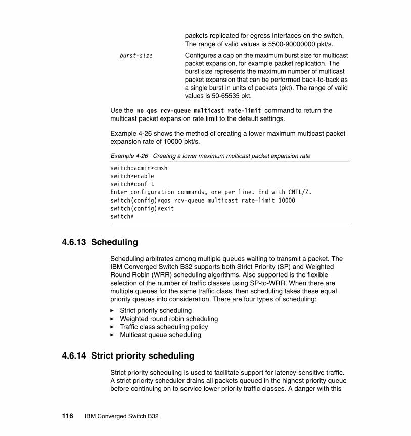
packets replicated for egress interfaces on the switch. The range of valid values is 5500-90000000 pkt/s.
burst-size Configures a cap on the maximum burst size for multicast packet expansion, for example packet replication. The burst size represents the maximum number of multicast packet expansion that can be performed back-to-back as a single burst in units of packets (pkt). The range of valid values is 50-65535 pkt.
Use the no qos rcv-queue multicast rate-limit command to return the multicast packet expansion rate limit to the default settings.
Example 4-26 shows the method of creating a lower maximum multicast packet expansion rate of 10000 pkt/s.
Example 4-26 Creating a lower maximum multicast packet expansion rate
switch:admin>cmshswitch>enableswitch#conf tEnter configuration commands, one per line. End with CNTL/Z.switch(config)#qos rcv-queue multicast rate-limit 10000switch(config)#exitswitch#
4.6.13 Scheduling
Scheduling arbitrates among multiple queues waiting to transmit a packet. The IBM Converged Switch B32 supports both Strict Priority (SP) and Weighted Round Robin (WRR) scheduling algorithms. Also supported is the flexible selection of the number of traffic classes using SP-to-WRR. When there are multiple queues for the same traffic class, then scheduling takes these equal priority queues into consideration. There are four types of scheduling:
� Strict priority scheduling� Weighted round robin scheduling� Traffic class scheduling policy� Multicast queue scheduling
4.6.14 Strict priority scheduling
Strict priority scheduling is used to facilitate support for latency-sensitive traffic. A strict priority scheduler drains all packets queued in the highest priority queue before continuing on to service lower priority traffic classes. A danger with this
116 IBM Converged Switch B32
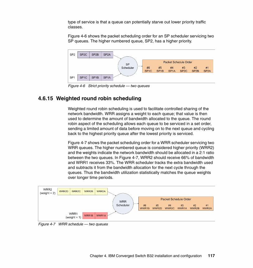
type of service is that a queue can potentially starve out lower priority traffic classes.
Figure 4-6 shows the packet scheduling order for an SP scheduler servicing two SP queues. The higher numbered queue, SP2, has a higher priority.
Figure 4-6 Strict priority schedule — two queues
4.6.15 Weighted round robin scheduling
Weighted round robin scheduling is used to facilitate controlled sharing of the network bandwidth. WRR assigns a weight to each queue; that value is then used to determine the amount of bandwidth allocated to the queue. The round robin aspect of the scheduling allows each queue to be serviced in a set order, sending a limited amount of data before moving on to the next queue and cycling back to the highest priority queue after the lowest priority is serviced.
Figure 4-7 shows the packet scheduling order for a WRR scheduler servicing two WRR queues. The higher numbered queue is considered higher priority (WRR2) and the weights indicate the network bandwidth should be allocated in a 2:1 ratio between the two queues. In Figure 4-7, WRR2 should receive 66% of bandwidth and WRR1 receives 33%. The WRR scheduler tracks the extra bandwidth used and subtracts it from the bandwidth allocation for the next cycle through the queues. Thus the bandwidth utilization statistically matches the queue weights over longer time periods.
Figure 4-7 WRR schedule — two queues
Chapter 4. IBM Converged Switch B32 installation and configuration 117

4.6.16 Traffic class scheduling policy
The traffic classes are numbered from 0 to 7; higher numbered traffic classes are considered higher priority. The IBM Converged Switch B32 provides full flexibility in controlling the number of SP-to-WRR queues. The number of SP queues is specified in N (SP1 through 8), then the highest priority traffic classes are configured for SP service and the remaining 8 are WRR serviced. Table 4-10 shows the set of scheduling configurations supported.
Table 4-10 Supported scheduling configurations
Figure 4-8 shows that extending the packet scheduler to a hybrid SP+WRR system is fairly straightforward. All SP queues are considered strictly higher priority than WRR so they are serviced first. After all SP queues are drained, then the normal WRR scheduling behavior is applied to the non-empty WRR queues.
Figure 4-8 Strict priority and Weighted Round Robin scheduler
qos queue scheduler commandUse this command to configure the Traffic Class packet scheduler policy. Eight Traffic Classes are supported with a configurable number of them being Strict Priority and any remaining ones being serviced DWRR. This Traffic Class packet
Traffic Class SP0 SP1 SP2 SP3 SP4 SP5 SP6 SP7 SP8
7 WRR8 SP1 SP2 SP3 SP4 SP5 SP6 SP7 SP8
6 WRR7 WRR7 SP1 SP2 SP3 SP4 SP5 SP6 SP7
5 WRR6 WRR6 WRR6 SP1 SP2 SP3 SP4 SP5 SP6
4 WRR5 WRR5 WRR5 WRR5 SP1 SP2 SP3 SP4 SP5
3 WRR4 WRR4 WRR4 WRR4 WRR4 SP1 SP2 SP3 SP4
2 WRR3 WRR3 WRR3 WRR3 WRR3 WRR3 SP1 SP2 SP3
1 WRR2 WRR2 WRR2 WRR2 WRR2 WRR2 WRR2 SP1 SP2
0 WRR1 WRR1 WRR1 WRR1 WRR1 WRR1 WRR1 WRR1 SP1
118 IBM Converged Switch B32

scheduler policy is applied uniformly across the entire system. Actual Traffic Class packet scheduling is performed independently by each switch.
Synopsis: qos queue scheduler strict-priority priority number dwrr weight0 weight1 weight2 weight3 weight4 weight5 weight6 weight7
strict-priority Configures the Strict Priority Traffic Class policy. All Strict Priority Traffic Classes are serviced before any DWRR Traffic Classes.
dwrr Configures the DWRR Traffic Class policy. There are a variable number of DWRR weight values accepted that are dependent on the setting of strict priority number. The strict priority number plus the number of DWRR weight values must always sum to eight Traffic Classes.
Operands:
priority number Sets the number of the Strict Priority Traffic Class. These are the strict priority number highest Traffic Class, for example if the strict-priority number is 3, then the Strict Priority Traffic Class are Traffic Classes 7, 6, and 5. The range of valid values is 0-8.
weight0 Sets the DWRR weight for Traffic Class 0 in units of bandwidth percentage left over after servicing all of the Strict Priority Traffic Classes. The sum of all weight values must equal 100 percent. The weight0 value is only valid when the strict priority number is less than 8. The range of valid values is 0-100 percent.
weight1 Sets the DWRR weight for Traffic Class 1 in units of bandwidth percentage left over after servicing all of the Strict Priority Traffic Classes. The sum of all weight values must equal 100 percent. The weight1 value is only valid when the strict priority number is less than 7. The range of valid values is 0-100 percent.
weight2 Sets the DWRR weight for Traffic Class 2 in units of bandwidth percentage left over after servicing all of the Strict Priority Traffic Classes. The sum of all weight values must equal 100 percent. The weight2 value is only valid when the strict priority number is less than 6. The range of valid values is 0-100 percent.
weight3 Sets the DWRR weight for Traffic Class 3 in units of bandwidth percentage left over after servicing all of the Strict Priority Traffic Classes. The sum of all weight values must equal 100 percent. The weight3 value is
Chapter 4. IBM Converged Switch B32 installation and configuration 119

only valid when the strict priority number is less than 5. The range of valid values is 0-100 percent.
weight4 Sets the DWRR weight for Traffic Class 4 in units of bandwidth percentage left over after servicing all of the Strict Priority Traffic Classes. The sum of all weight values must equal 100 percent. The weight4 value is only valid when the strict priority number is less than 4. The range of valid values is 0-100 percent.
weight5 Sets the DWRR weight for Traffic Class 6 in units of bandwidth percentage left over after servicing all of the Strict Priority Traffic Classes. The sum of all weight values must equal 100 percent. The weight5 value is only valid when the strict priority number is less than 3. The range of valid values is 0-100 percent.
weight6 Sets the DWRR weight for Traffic Class 6 in units of bandwidth percentage left over after servicing all of the Strict Priority Traffic Classes. The sum of all weight values must equal 100 percent. The weight6 value is only valid when the strict priority number is less than 2. The range of valid values is 0-100 percent.
weight7 Sets the DWRR weight for Traffic Class 7 in units of bandwidth percentage left over after servicing all of the Strict Priority Traffic Classes. The sum of all weight values must equal 100 percent. The weight7 value is only valid when the strict priority number is less than 1. The range of valid values is 0-100 percent.
Use the no qos queue scheduler command to return the Traffic Class packet scheduler to the default value.
Example 4-27 shows the method of setting the traffic class packet scheduler for 4 Strict Priority Traffic Class and 4 DWRR Traffic Class with Traffic Class 0 getting 10% bandwidth, Traffic Class 1 getting 20% bandwidth, Traffic Class 2 getting 30% bandwidth, and Traffic Class 3 getting 40% bandwidth.
Example 4-27 Setting the traffic class packet scheduler
switch:admin>cmshswitch>enableswitch#conf tEnter configuration commands, one per line. End with CNTL/Z.switch(config)#qos queue scheduler strict-priority 4 dwrr 10 20 30 40switch(config)#exitswitch#
120 IBM Converged Switch B32
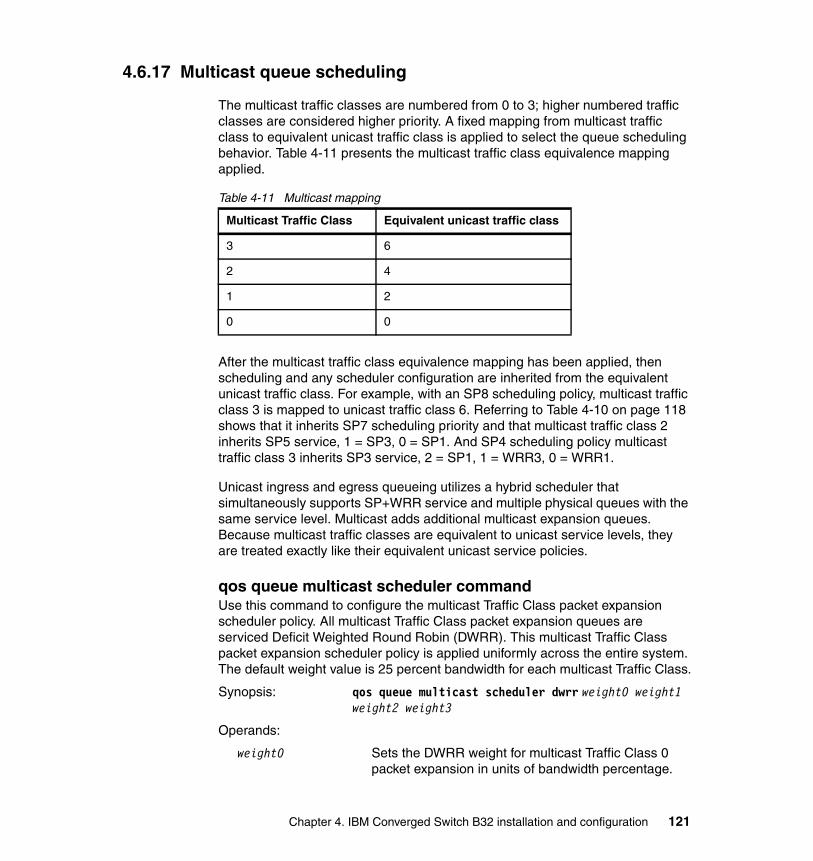
4.6.17 Multicast queue scheduling
The multicast traffic classes are numbered from 0 to 3; higher numbered traffic classes are considered higher priority. A fixed mapping from multicast traffic class to equivalent unicast traffic class is applied to select the queue scheduling behavior. Table 4-11 presents the multicast traffic class equivalence mapping applied.
Table 4-11 Multicast mapping
After the multicast traffic class equivalence mapping has been applied, then scheduling and any scheduler configuration are inherited from the equivalent unicast traffic class. For example, with an SP8 scheduling policy, multicast traffic class 3 is mapped to unicast traffic class 6. Referring to Table 4-10 on page 118 shows that it inherits SP7 scheduling priority and that multicast traffic class 2 inherits SP5 service, 1 = SP3, 0 = SP1. And SP4 scheduling policy multicast traffic class 3 inherits SP3 service, 2 = SP1, 1 = WRR3, 0 = WRR1.
Unicast ingress and egress queueing utilizes a hybrid scheduler that simultaneously supports SP+WRR service and multiple physical queues with the same service level. Multicast adds additional multicast expansion queues. Because multicast traffic classes are equivalent to unicast service levels, they are treated exactly like their equivalent unicast service policies.
qos queue multicast scheduler commandUse this command to configure the multicast Traffic Class packet expansion scheduler policy. All multicast Traffic Class packet expansion queues are serviced Deficit Weighted Round Robin (DWRR). This multicast Traffic Class packet expansion scheduler policy is applied uniformly across the entire system. The default weight value is 25 percent bandwidth for each multicast Traffic Class.
Synopsis: qos queue multicast scheduler dwrr weight0 weight1 weight2 weight3
Operands:
weight0 Sets the DWRR weight for multicast Traffic Class 0 packet expansion in units of bandwidth percentage.
Multicast Traffic Class Equivalent unicast traffic class
3 6
2 4
1 2
0 0
Chapter 4. IBM Converged Switch B32 installation and configuration 121

The sum of all weight values must equal 100 percent. The range of valid values is 0-100.
weight1 Sets the DWRR weight for multicast Traffic Class 1 packet expansion in units of bandwidth percentage. The sum of all weight values must equal 100 percent. The range of valid values is 0-100.
weight2 Sets the DWRR weight for multicast Traffic Class 2 packet expansion in units of bandwidth percentage. The sum of all weight values must equal 100 percent. The range of valid values is 0-100.
weight3 Sets the DWRR weight for multicast Traffic Class 3 packet expansion in units of bandwidth percentage. The sum of all weight values must equal 100 percent. The range of valid values is 0-100.
Example 4-28 shows the method of setting the multicast Traffic Class packet expansion scheduler for Traffic Class 0 getting 10% bandwidth, Traffic Class 1 getting 20% bandwidth, Traffic Class 2 getting 30% bandwidth, and Traffic Class 3 getting 40% bandwidth.
Example 4-28 Setting the multicast Traffic Class packet expansion scheduler
switch:admin>cmshswitch>enableswitch#configure terminalEnter configuration commands, one per line. End with CNTL/Z.switch(config)#qos queue multicast scheduler dwrr 10 20 30 40switch(config)#exitswitch#
4.6.18 Converged Enhanced Ethernet
The CEE QoS covers packet classification, priority and traffic class (queue) mapping, congestion control, and scheduling. Under the CEE Provisioning model all of these features are configured utilizing two configuration tables: Priority Group Table and Priority Table.
CEE Priority Group Table defines each Priority Group ID (PGID) and its scheduling policy (Strict Priority versus DWRR, DWRR weight, relative priority), and partially defines the congestion control (PFC) configuration. There are 16 rows in the CEE Priority Group Table. Table 4-12 presents the default CEE Priority Group Table configuration.
122 IBM Converged Switch B32
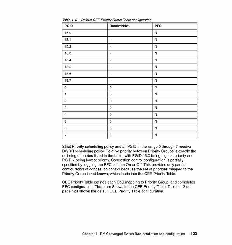
Table 4-12 Default CEE Priority Group Table configuration
Strict Priority scheduling policy and all PGID in the range 0 through 7 receive DWRR scheduling policy. Relative priority between Priority Groups is exactly the ordering of entries listed in the table, with PGID 15.0 being highest priority and PGID 7 being lowest priority. Congestion control configuration is partially specified by toggling the PFC column On or Off. This provides only partial configuration of congestion control because the set of priorities mapped to the Priority Group is not known, which leads into the CEE Priority Table.
CEE Priority Table defines each CoS mapping to Priority Group, and completes PFC configuration. There are 8 rows in the CEE Priority Table. Table 4-13 on page 124 shows the default CEE Priority Table configuration.
PGID Bandwidth% PFC
15.0 - N
15.1 - N
15.2 - N
15.3 - N
15.4 - N
15.5 - N
15.6 - N
15.7 - N
0 0 N
1 0 N
2 0 N
3 0 N
4 0 N
5 0 N
6 0 N
7 0 N
Chapter 4. IBM Converged Switch B32 installation and configuration 123

Table 4-13 Default CEE priority table
PFC configuration is now complete, with the CEE Priority Table defining what CoS map to a PGID and combined with CEE Priority Group Table indicating PFC On or Off for that Priority Group.
For the commands to implement this, see the “cee-map command” on page 74, “priority-group-table” on page 75, and “priority-table command” on page 75.
4.7 LLDP Discovery Protocol
The IEEE 802.1AB Link Layer Discovery Protocol (LLDP) enhances the ability of network management tools to discover and maintain accurate network topologies and simplify LAN troubleshooting in multi-vendor environments. To efficiently and effectively operate the various devices in a LAN you must ensure the correct and valid configuration of the protocols and applications that are enabled on these devices. With Layer 2 networks expanding dramatically, it is difficult for a network administrator to statically monitor and configure each device in the network.
Using LLDP, network devices such as routers and switches advertise information about themselves to other network devices and store the information they discover. Details such as device configuration, device capabilities, and device identification are advertised. LLDP defines the following capabilities:
� A common set of advertisement messages� A protocol for transmitting the advertisements� A method for storing the information contained in received advertisements
CoS PGID
0 15.6
1 15.7
2 15.5
3 15.4
4 15.3
5 15.2
6 15.1
7 15.0
124 IBM Converged Switch B32
LLDP information is transmitted periodically and stored for a finite period. Every time a device receives an LLDP advertisement packet, it stores the information and initializes a timer. If the timer reaches the time to live (TTL) value, the LLDP device deletes the stored information, thereby ensuring that only valid and current LLDP information is stored in network devices and is available to network management systems.
4.7.1 Layer 2 topology mapping
The LLDP protocol lets network management systems accurately discover and model Layer 2 network topologies. As LLDP devices transmit and receive advertisements, the devices store information that they discover about their neighbors. Advertisement data, such as a neighbor’s management address, device type, and port identification is useful in determining what neighboring devices are in the network.
The higher level management tools, such as the IBM DCFM, can query the LLDP information to draw Layer 2 physical topologies. The management tools can continue to query a neighboring device through the device’s management address provided in the LLDP information exchange. As this process is repeated, the complete Layer 2 topology is mapped.
In LLDP the link discovery is achieved through the exchange of link-level information between two link partners. The link-level information is refreshed periodically to reflect any dynamic changes in link-level parameters. The basic format for exchanging information in LLDP is in the form of a type, length, value (TLV) field.
LLDP keeps a database for both local and remote configurations. The LLDP standard currently supports three categories of TLVs. The IBM LLDP implementation adds a proprietary IBM extension TLV set. The four TLV sets are described as follows:
� Basic management TLV set. This set provides information to map the Layer 2 topology and includes the following TLVs:
– Chassis ID TLV: Provides the ID for the switch or router where the port resides. This is a mandatory TLV.
Note: LLDP runs over the data-link layer, which allows two devices running different network layer protocols to learn about each other.
Note: The IBM LLDP implementation supports a one-to-one connection. Each interface has one and only one neighbor.
Chapter 4. IBM Converged Switch B32 installation and configuration 125

– Port description TLV: Provides a description of the port in an alphanumeric format. If the LAN device supports RFC-2863, the port description TLV value equals the “ifDescr” object. This is a mandatory TLV.
– System name TLV: Provides the system-assigned name in an alphanumeric format. If the LAN device supports RFC-3418, the system name TLV value equals the “sysName” object. This is an optional TLV.
– System description TLV: Provides a description of the network entity in an alphanumeric format. This includes system name, hardware version, operating system, and supported networking software. If the LAN device supports RFC-3418, the value equals the “sysDescr” object. This is an optional TLV.
– System capabilities TLV: Indicates the primary functions of the device and whether these functions are enabled in the device. The capabilities are indicated by two octets. The first octet indicates Other, Repeater, Bridge, WLAN AP, Router, Telephone, DOCSIS cable device, and Station, respectively. The second octet is reserved. This is an optional TLV.
– Management address TLV: Indicates the addresses of the local switch. Remote switches can use this address to obtain information related to the local switch. This is an optional TLV.
� IEEE 802.1 organizational TLV set. This set provides information to detect mismatched settings between local and remote devices. A trap or event can be reported after a mismatch is detected. This is an optional TLV. This set includes the following TLVs:
– Port VLANID TLV: Indicates the port VLAN ID (PVID) that is associated with an untagged or priority tagged data frame received on the VLAN port.
– PPVLAN ID TLV: Indicates the port- and protocol--based VLAN ID (PPVID) that is associated with an untagged or priority tagged data frame received on the VLAN port. The TLV supports a “flags” field that indicates whether the port is capable of supporting port- and protocol-based VLANs (PPVLANs) and whether one or more PPVLANs are enabled. The number of PPVLAN ID TLVs in a Link Layer Discovery Protocol Data Unit (LLDPDU) corresponds to the number of the PPVLANs enabled on the port.
– VLAN name TLV: Indicates the assigned name of any VLAN on the device. If the LAN device supports RFC-2674, the value equals the “dot1QVLANStaticName” object. The number of VLAN name TLVs in an LLDPDU corresponds to the number of VLANs enabled on the port.
– Protocol identity TLV: Indicates the set of protocols that are accessible at the device's port. The protocol identity field in the TLV contains a number of octets after the Layer 2 address that can enable the receiving device to recognize the protocol. For example, a device that wishes to advertise the
126 IBM Converged Switch B32
spanning tree protocol includes at least eight octets: 802.3 length (two octets), LLC addresses (two octets), 802.3 control (one octet), protocol ID (two octets), and the protocol version (one octet).
� IEEE 802.3 organizational TLV set. This is an optional TLV set. This set includes the following TLVs:
– MAC/PHY configuration/status TLV: Indicates duplex and bit rate capabilities and the current duplex and bit rate settings of the local interface. It also indicates whether the current settings were configured through auto-negotiation or through manual configuration.
– Power through media dependent interface (MDI) TLV: Indicates the power capabilities of the LAN device.
– Link aggregation TLV: Indicates whether the link (associated with the port on which the LLDPDU is transmitted) can be aggregated. It also indicates whether the link is currently aggregated and provides the aggregated port identifier if the link is aggregated.
– Maximum Ethernet frame size TLV: Indicates the maximum frame size capability of the device’s MAC and PHY implementation.
� IBM extension TLV set. This set is used to identify vendor-specific information. This set includes the following TLVs:
– Link Vendor/Version TLV: Indicates the vendor for the switch, host, or router where the port resides.
– Primitive supported/version TLV: Indicates where the link-level primitives are supported and, if supported, the link-level primitive version.
4.7.2 DCBX overview
Storage traffic requires a lossless communication, which is provided by CEE. The Data Center Bridging (DCB) Capability Exchange Protocol (DCBX) is used to exchange CEE-related parameters with neighbors to achieve more efficient scheduling and a priority-based flow control for link traffic.
DCBX uses LLDP to exchange parameters between two link peers; DCBX is built on the LLDP infrastructure for the exchange of information. DCBX-exchanged parameters are packaged into organizationally specific TLVs. The DCBX protocol requires an acknowledgement from the other side of the link, therefore LLDP is turned on in both transmit and receive directions. DCBX requires version number checking for both control TLVs and feature TLVs.
DCBX interacts with other protocols and features as follows:
� LLDP: LLDP is run in parallel with other Layer 2 protocols such as RSTP and LACP. DCBX is built on the LLDP infrastructure to communicate capabilities
Chapter 4. IBM Converged Switch B32 installation and configuration 127

supported between link partners. The DCBX protocol and feature TLVs are treated as a superset of the LLDP standard.
� QoS management: DCBX capabilities exchanged with a link partner are passed down to the QoS management entity to set up the IBM Converged Switch B32 CEE switch to control the scheduling and priority-based flow control in the hardware.
The DCBX standard is subdivided into two features sets:
� Enhanced Transmission Selection (ETS)� Priority Flow Control (PFC)
Enhanced Transmission Selection (ETS)In a converged network, different traffic types affect the network bandwidth differently. The purpose of ETS is to allocate bandwidth based on the different priority settings of the converged traffic. For example, Inter-process communications (IPC) traffic can use as much bandwidth as needed and there is no bandwidth check; LAN and SAN traffic share the remaining bandwidth.
Table 4-14 shows three traffic groups: IPC, LAN, and SAN. ETS allocates the bandwidth based on traffic type and also assigns a priority to the three traffic types as follows: Priority 7 traffic is mapped to priority group 0, which does not get a bandwidth check; priority 2 and priority 3 are mapped to priority group 1; priorities 6, 5, 4, 1, and 0 are mapped to priority group 2.
The priority settings shown in Table 4-14 are translated to priority groups in the IBM Converged Switch B32.
Table 4-14 ETS priority grouping of IPC, LAN, and SAN traffic
Priority Priority group Bandwidth check
7 0 No
6 2 Yes
5 2 Yes
4 2 Yes
3 1 Yes
2 1 Yes
1 2 Yes
0 2 Yes
128 IBM Converged Switch B32
Priority Flow Control (PFC)With PFC, it is important to provide lossless packet delivery for certain traffic classes while maintaining existing LAN behavior for other traffic classes on the converged link. This differs from the traditional 802.3 PAUSE type of flow control, where the pause affects all traffic on an interface.
PFC is defined by a one-byte bitmap. Each bit position stands for a user priority. If a bit is set, the flow control is enabled in both directions (Rx and Tx).
4.7.3 DCBX interaction with other vendor devices
When the IBM Converged Switch B32 interacts with other vendor devices, the other vendor devices might not have support for the same DCBX version as the IBM Converged Switch B32.
The IBM Converged Switch B32 switch supports two DCBX versions:
� CEE version (1.0.1) – Based on the CEE standard� Pre-CEE version
To accommodate the different DCBX versions, the IBM Converged Switch B32 provides the following options:
� Auto-sense (plug and play):
This is the default. The IBM Converged Switch B32 detects the version used by the link neighbor and automatically switches between the CEE version and the pre-CEE version.
� CEE version:
Forces the use of the CEE version for the link (auto-sense is off).
� Pre-CEE version:
Forces the use of the pre-CEE version for the link (auto-sense is off).
4.7.4 LLDP configuration guidelines and restrictions
Follow the LLDP configuration guidelines and restrictions described in this section when configuring LLDP.
Note: DCBX configuration simply involves configuring DCBX-related TLVs to be advertised. Detailed information is provided in 4.7.6, “LLDP configuration procedures” on page 131.
Chapter 4. IBM Converged Switch B32 installation and configuration 129
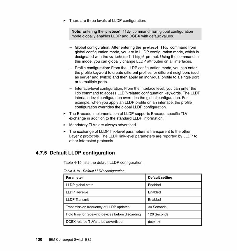
� There are three levels of LLDP configuration:
– Global configuration: After entering the protocol lldp command from global configuration mode, you are in LLDP configuration mode, which is designated with the switch(conf-lldp)# prompt. Using the commands in this mode, you can globally change LLDP attributes on all interfaces.
– Profile configuration: From the LLDP configuration mode, you can enter the profile keyword to create different profiles for different neighbors (such as server and switch) and then apply an individual profile to a single port or to multiple ports.
– Interface-level configuration: From the interface level, you can enter the lldp command to access LLDP-related configuration keywords. The LLDP interface-level configuration overrides the global configuration. For example, when you apply an LLDP profile on an interface, the profile configuration overrides the global LLDP configuration.
� The Brocade implementation of LLDP supports Brocade-specific TLV exchange in addition to the standard LLDP information.
� Mandatory TLVs are always advertised.
� The exchange of LLDP link-level parameters is transparent to the other Layer 2 protocols. The LLDP link-level parameters are reported by LLDP to other interested protocols.
4.7.5 Default LLDP configuration
Table 4-15 lists the default LLDP configuration.
Table 4-15 Default LLDP configuration
Note: Entering the protocol lldp command from global configuration mode globally enables LLDP and DCBX with default values.
Parameter Default setting
LLDP global state Enabled
LLDP Receive Enabled
LLDP Transmit Enabled
Transmission frequency of LLDP updates 30 Seconds
Hold time for receiving devices before discarding 120 Seconds
DCBX related TLV’s to be advertised dcbx-tlv
130 IBM Converged Switch B32

4.7.6 LLDP configuration procedures
You need to configure LLDP with both Global and Interface commands, which are described in this section.
protocol lldp commandUse this command to enter LLDP configuration mode to be able to make changes to the parameters.
Synopsis: protocol lldp
Operands: None
Use the no protocol lldp command to return to the default setting.
After entering the protocol lldp command from global configuration mode, you are in LLDP configuration mode, which is designated with the switch(conf-lldp)# prompt. Using the keywords in this mode, you can set non-default parameter values that apply globally to all interfaces.
system-name commandUse this command to set the global system name specific to LLDP.
Synopsis: system-name name
Operands:
name Specifies a system name for the LLDP. The valid values is a maximum of32 characters.
system-description commandUse this command to set the global system description specific to LLDP.
Synopsis: system-description line
Operands:
line Specifies a description for the LLDP system. The valid value is a maximum of 50 characters.
Use the no system-description command to clear the global LLDP system description.
description commandUse this command to specify a string that contains the description of the LLDP. This description is for network administrative purposes and is not seen by neighboring switches.
Chapter 4. IBM Converged Switch B32 installation and configuration 131

Synopsis: description line
Operands:
line Characters describing the LLDP protocol.
mode commandUse this command to set the LLDP mode on the switch. By default both transmit and receive modes are enabled.
Synopsis: mode tx | rx
Operands:
tx Specifies to enable only the transmit mode.
rx Specifies to enable only the receive mode.
Use the no mode command to return to the default setting.
hello commandUse this command to set the interval between LLDP hello messages. The default is 30 seconds.
Synopsis: hello seconds
Operands:
seconds Sets the Hello transmit interval. The range of valid values is 4-180 seconds.
Use the no hello command to return to the default setting.
multiplier commandUse this command to set the number of consecutive misses of hello messages before LLDP declares the neighbor as dead. The default is 4.
Synopsis: multiplier value
Operands:
value Specifies a multiplier value to use. The range of valid values is 1-10.
Use the no multiplier command to return to the default setting.
advertise dcbx-fcoe-app-tlv commandUse this command to advertise application TLVs to ensure interoperability of traffic over DCBX packets. Converged Enhanced Ethernet (CEE) parameters related to FCoE must be negotiated before FCoE traffic can begin on a CEE link. An FCoE application TLV is exchanged over the LLDP protocol, which
132 IBM Converged Switch B32
negotiates information such as FCoE priority, and Priority Flow Control (PFC) pause.
Synopsis: advertise dcbx-fcoe-app-tlv
Operands: None
Use the no advertise dcbx-fcoe-app-tlv command to return to the default setting.
advertise dcbx-fcoe-logical-link-tlv commandUse this command to advertise to any attached device the FCoE status of the logical link.
Synopsis: advertise dcbx-fcoe-logical-link-tlv
Operands: None
Use the no advertise dcbx-fcoe-logical-link-tlv command to return to the default setting.
advertise dcbx-tlv commandAdvertises to any attached device mandatory Data Center Bridging eXchange protocol (DCBX) Type, Length, Values (TLVs).
Synopsis: advertise dcbx-tlv
Operands: None
Use the no advertise dcbx-tlv command to return to the default setting.
advertise dot1-tlv commandUse this command to advertise to any attached device IEEE 802.1 organizationally specific Type, Length, Value (TLV).
Synopsis: advertise dot1-tlv
Operands: None
Use the no advertise dot1-tlv command to return to the default setting.
advertise dot3-tlv commandUse this command to advertise to any attached device IEEE 802.3 organizationally specific Type, Length, Value (TLV).
Synopsis: advertise dot3-tlv
Operands: None
Use the no advertise dot3-tlv command to return to the default setting.
Chapter 4. IBM Converged Switch B32 installation and configuration 133
advertise optional-tlv commandUse this command to display the following optional TLVs.
Synopsis: advertise optional-tlv [management-address | port-description | system-capabilities | system-description | system-name]
Operands:
management-address Specifies the management address of the system.
port-description Describes the user configured port.
system-capabilities Specifies the capabilities of the system.
system-description Describes the system firmware version and the current image running on the system.
system-name Specifies the name of the system.
Use the no advertise optional-tlv command to return to the default setting.
fcoe-priority-bits commandThe FCoE priority bit setting is a bitmap setting where each bit position stands for a priority. When you set a bit for a particular priority, that priority setting is applied to the FCoE traffic (that is, the incoming FCoE traffic will have that priority).
Synopsis: fcoe-priority-bits value
Operands:
value Specifies the bitmap value. The range of valid values is 0x0-0xff.
The no fcoe-priority-bits command returns to the default setting.
4.7.7 LLDP interface-level commands
There are certain commands that can also be run on a per interface basis. To configure LLDP interface-level command options, perform the following steps from the interface level, that is, the switch(conf-if-te-0/22)# prompt.
lldp fcoe-priority-bits commandThe FCoE priority bit setting is a bitmap setting where each bit position stands for a priority. When you set a bit for a particular priority, that priority setting is applied to the FCoE traffic (that is, the incoming FCoE traffic will have that priority).
134 IBM Converged Switch B32

Synopsis: lldp fcoe-priority-bits value
Operands:
value Specifies the bitmap value. The range of valid values is 0x0-0xff.
The no lldp fcoe-priority-bits command returns to the default setting.
lldp dcbx-version commandUse this command to configure the DCBX version for an interface. For detailed information on these version command keywords, see 4.7.3, “DCBX interaction with other vendor devices” on page 129. The default is auto.
Synopsis: lldp dcbx-version [auto |cee | pre-cee]
Operands:
auto Specifies to auto adjust the DCBX protocol version to accommodate the difference when a switch interacts with different vendors using a different version of the DCBX protocol.
cee Specifies to use the Converged Enhanced Ethernet (CEE) DCBX version.
pre-cee Specifies to use the standard DCBX version, which is the version released prior to the CEE DCBX release.
4.7.8 Displaying the LLPD configuration
From the EXEC mode (that is, the switch# prompt), you can display the LLDP configuration using the show lldp command.
show lldp commandThe show lldp command can be used to show information about the LLDP status of the interfaces, the neighbors, or the LLDP statistics.
Synopsis: show lldp [interface [te slot/port] | neighbors [interface te slot/port detail] | statistics [interface te slot/port]
Operands:
interface
te Specifies a valid 10 Gbps Ethernet interface
slot Specifies a valid slot number.
port Specifies a valid port number.
Chapter 4. IBM Converged Switch B32 installation and configuration 135

neighbors
te Specifies a valid 10 Gbps Ethernet interface
slot Specifies a valid slot number.
port Specifies a valid port number.
statistics
te Specifies a valid 10 Gbps Ethernet interface
slot Specifies a valid slot number.
port Specifies a valid port number.
4.8 FCoE configuration guidelines and restrictions
Follow the FCoE configuration guidelines and restrictions presented in this section when configuring FCoE.
Speed negotiation: The IBM Converged Switch B32 supports auto-negotiated FC link speeds of 2, 4, and 8 Gbps. The Ethernet ports of the IBM Converged Switch B32 do not support auto-negotiation of Ethernet link speeds. The Ethernet ports only support 10-Gigabit Ethernet.
� These features are not supported on the IBM Converged Switch B32 switch:
– Virtual fabrics– Admin Domains– Port-based zoning– QoS zoning– Adaptive networking– FC-SP for the FCoE ports– Interop mode– Access Gateway mode– FC routing– Integrated routing– Hot Code Load (HCL) firmware download– Extended fabrics– FICON
The CEE configuration database is maintained in a file separate from the Fabric OS configuration database. However, note that Fabric OS configuration management remains unchanged:
� FCoE ports are displayed in FC show commands and use the FC port numbering scheme. However, configuration of the FCoE ports through the
136 IBM Converged Switch B32
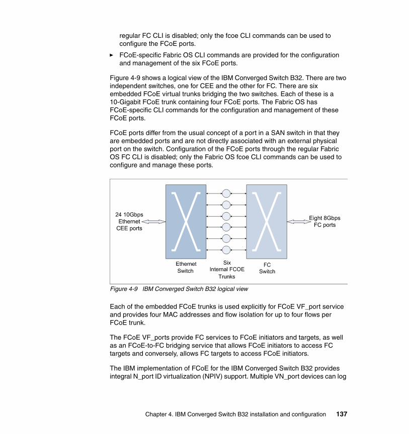
regular FC CLI is disabled; only the fcoe CLI commands can be used to configure the FCoE ports.
� FCoE-specific Fabric OS CLI commands are provided for the configuration and management of the six FCoE ports.
Figure 4-9 shows a logical view of the IBM Converged Switch B32. There are two independent switches, one for CEE and the other for FC. There are six embedded FCoE virtual trunks bridging the two switches. Each of these is a 10-Gigabit FCoE trunk containing four FCoE ports. The Fabric OS has FCoE-specific CLI commands for the configuration and management of these FCoE ports.
FCoE ports differ from the usual concept of a port in a SAN switch in that they are embedded ports and are not directly associated with an external physical port on the switch. Configuration of the FCoE ports through the regular Fabric OS FC CLI is disabled; only the Fabric OS fcoe CLI commands can be used to configure and manage these ports.
Figure 4-9 IBM Converged Switch B32 logical view
Each of the embedded FCoE trunks is used explicitly for FCoE VF_port service and provides four MAC addresses and flow isolation for up to four flows per FCoE trunk.
The FCoE VF_ports provide FC services to FCoE initiators and targets, as well as an FCoE-to-FC bridging service that allows FCoE initiators to access FC targets and conversely, allows FC targets to access FCoE initiators.
The IBM implementation of FCoE for the IBM Converged Switch B32 provides integral N_port ID virtualization (NPIV) support. Multiple VN_port devices can log
Chapter 4. IBM Converged Switch B32 installation and configuration 137
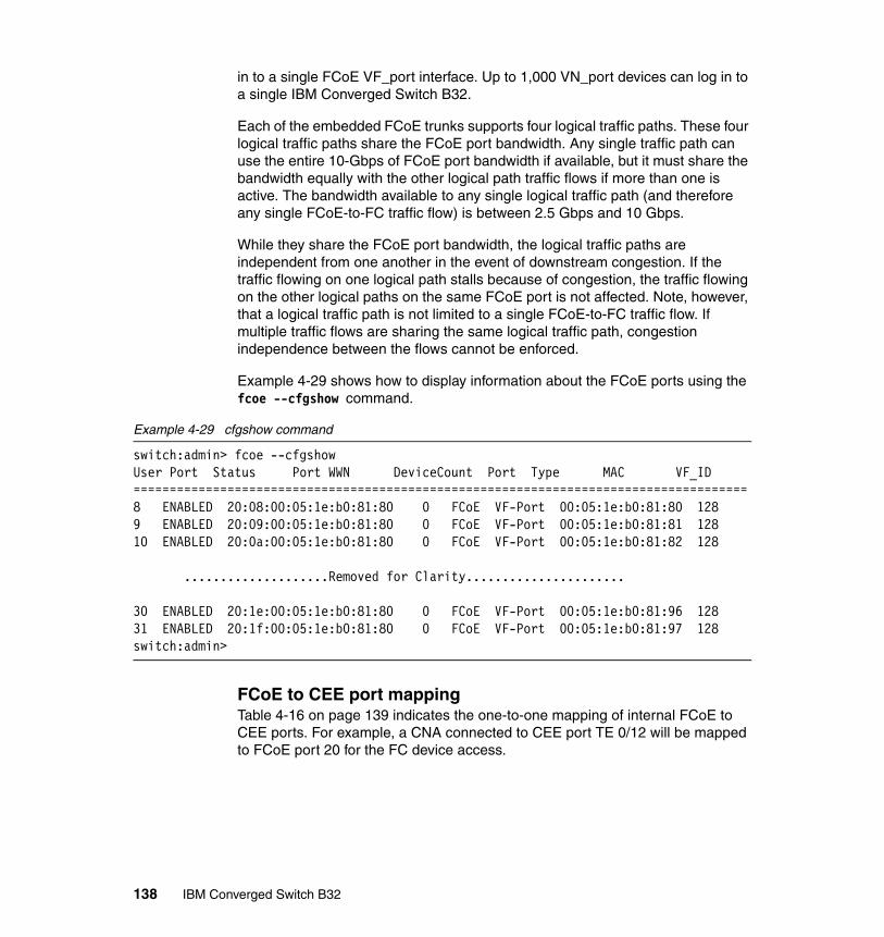
in to a single FCoE VF_port interface. Up to 1,000 VN_port devices can log in to a single IBM Converged Switch B32.
Each of the embedded FCoE trunks supports four logical traffic paths. These four logical traffic paths share the FCoE port bandwidth. Any single traffic path can use the entire 10-Gbps of FCoE port bandwidth if available, but it must share the bandwidth equally with the other logical path traffic flows if more than one is active. The bandwidth available to any single logical traffic path (and therefore any single FCoE-to-FC traffic flow) is between 2.5 Gbps and 10 Gbps.
While they share the FCoE port bandwidth, the logical traffic paths are independent from one another in the event of downstream congestion. If the traffic flowing on one logical path stalls because of congestion, the traffic flowing on the other logical paths on the same FCoE port is not affected. Note, however, that a logical traffic path is not limited to a single FCoE-to-FC traffic flow. If multiple traffic flows are sharing the same logical traffic path, congestion independence between the flows cannot be enforced.
Example 4-29 shows how to display information about the FCoE ports using the fcoe --cfgshow command.
Example 4-29 cfgshow command
switch:admin> fcoe --cfgshowUser Port Status Port WWN DeviceCount Port Type MAC VF_ID=====================================================================================8 ENABLED 20:08:00:05:1e:b0:81:80 0 FCoE VF-Port 00:05:1e:b0:81:80 1289 ENABLED 20:09:00:05:1e:b0:81:80 0 FCoE VF-Port 00:05:1e:b0:81:81 12810 ENABLED 20:0a:00:05:1e:b0:81:80 0 FCoE VF-Port 00:05:1e:b0:81:82 128 ....................Removed for Clarity......................
30 ENABLED 20:1e:00:05:1e:b0:81:80 0 FCoE VF-Port 00:05:1e:b0:81:96 12831 ENABLED 20:1f:00:05:1e:b0:81:80 0 FCoE VF-Port 00:05:1e:b0:81:97 128switch:admin>
FCoE to CEE port mappingTable 4-16 on page 139 indicates the one-to-one mapping of internal FCoE to CEE ports. For example, a CNA connected to CEE port TE 0/12 will be mapped to FCoE port 20 for the FC device access.
138 IBM Converged Switch B32
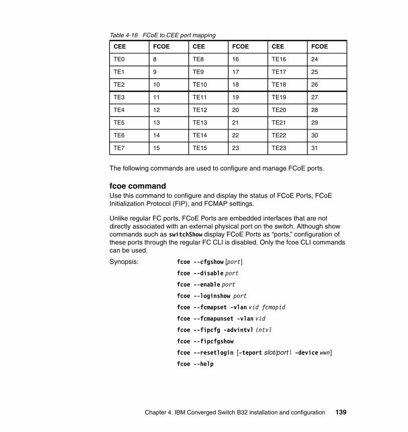
Table 4-16 FCoE to CEE port mapping
The following commands are used to configure and manage FCoE ports.
fcoe commandUse this command to configure and display the status of FCoE Ports, FCoE Initialization Protocol (FIP), and FCMAP settings.
Unlike regular FC ports, FCoE Ports are embedded interfaces that are not directly associated with an external physical port on the switch. Although show commands such as switchShow display FCoE Ports as “ports,” configuration of these ports through the regular FC CLI is disabled. Only the fcoe CLI commands can be used.
Synopsis: fcoe --cfgshow [port]
fcoe --disable port
fcoe --enable port
fcoe --loginshow port
fcoe --fcmapset -vlan vid fcmapid
fcoe --fcmapunset -vlan vid
fcoe --fipcfg -advintvl intvl
fcoe --fipcfgshow
fcoe --resetlogin [-teport slot/port | -device wwn]
fcoe --help
CEE FCOE CEE FCOE CEE FCOE
TE0 8 TE8 16 TE16 24
TE1 9 TE9 17 TE17 25
TE2 10 TE10 18 TE18 26
TE3 11 TE11 19 TE19 27
TE4 12 TE12 20 TE20 28
TE5 13 TE13 21 TE21 29
TE6 14 TE14 22 TE22 30
TE7 15 TE15 23 TE23 31
Chapter 4. IBM Converged Switch B32 installation and configuration 139

Operands: This command has the following operands:
port Specifies the port number. There are six configurable embedded FCoE Ports on the IBM Converged Switch B32, and the valid range for port is 8 to 13. Use switchShow for a list of valid FCoE Ports.
--help Displays command usage.
--cfgshow Displays the configuration of a specified embedded FCoE Port. If a port is not specified, the command displays all port configurations.
--disable Disables the specified FCoE Port.
--enable Enables the specified FCoE Port.
--loginshow Displays information about the devices logged into the specified FCoE Port.
--fcmapset Configures the FCMAP values for Fabric Provided MAC Addresses (FPMA) for the specified VLANs.
-vlan vid Specifies the VLAN for which to set the FCMAP.
fcmapid Specifies the FCMAP to be set.
--fcmapunset Unsets the FCMAP for a specified VLAN. Devices previously logged in are disconnected.
-vlan vid Specifies the VLAN ID for which the FCMAP is unset.
--fipcfg Configures FIP multicast advertisement intervals.
-advintvl intvl Specifies the interval in seconds. The minimum interval value is 0 and the maximum value is 300. A value of 0 cancels the previous advertisement interval value. A value of 1 to 300 is valid for changing the interval.
--fipcfgshow Displays FIP configurations.
--resetlogin Clears the logins that occurred through a front-end port or from a device specified by the Enode’s VN_Port WWN.
-teport slot/port Specifies the slot or port number.
-device wwn Specifies the device WWN.
fcoeLoginCfg commandUse this command to save, abort, or display the current FCoE login configuration, including ongoing transactions and the effective (saved) configuration.
140 IBM Converged Switch B32

Synopsis: fcoelogincfg --show [-switch swwn | -logingroup lgname] [-saved | -mergestatus]
fcoelogincfg --save
fcoelogincfg --transshow
fcoelogincfg --transabort
fcoelogincfg --purge -conflicting [-non-existing]
fcoelogincfg --purge -non-existing [-conflicting]
fcoelogincfg --enable
fcoelogincfg --disable
Operands: This command has the following operands:
--help Displays command usage.
--show Displays the state of the FCoE login configuration including current transactions and effective (saved) configuration.
-switch swwn Displays the login groups for the specified switch.
-logingroup lgname
Displays the login group configuration for the specified login group.
-saved Displays only the effective configuration.
-merge-status Displays the status of the last configuration merge during the last fabric merge. This operand also displays conflicting login groups and login groups for non-existing switches.
--save Saves and applies FCoE login configuration changes as the effective configuration fabric-wide.
--transshow Displays the current configuration transaction in progress fabric-wide.
--transabort Aborts the FCoE login configuration transaction currently in progress.
--purge Purges the specified entries from the effective configuration. Specify one or both of the following operands:
-conflicting Purges all conflicting login groups and conflicting VN_Port mappings from the effective configuration.
-non-existing Purges all login groups for non-existing switches from the effective configuration.
Chapter 4. IBM Converged Switch B32 installation and configuration 141

--enable Enables the FCoE login configuration management on the switch. This allows only configured Enode VN_Ports to log in. Use the fcoeLoginGroup command to configure allowed Enode VN_Ports.
--disable Disables the FCoE login configuration management on the switch. This allows unrestricted login on Enode V_Ports.
fcoeLoginGroupUse this command to create or modify the FCoE login management configuration fabric-wide. You can create or delete a login group and add or remove VN_Port mappings to a login group.
Synopsis: fcoelogingroup --create lgname -self |-switch swwn [-allowall | member; member;…]
fcoelogingroup --delete lgname
fcoelogingroup --add lgname member; member;… [-port port]
fcoelogingroup --remove lgname wwn
fcoelogingroup --rename lgname newlgname
fcoelogingroup --help
Operands: This command has the following operands:
--help Displays command usage.
--create Creates a login group with the specified name and associates it with a specified switch.
lgname Specifies the name of the login group for this switch. The maximum length is a 64-byte string.
-self Specifies the WWN of the current switch. When this operand is specified, the login group is associated with the current switch.
-switch swwn Specifies the WWN of the switch for which to create the login group.
-allowall Allows all VN_Port devices to log in to the switch.
Note: The configuration changes effected by this command are kept in a transaction buffer until you save it using the fabric-wide fcoelogincfg--save command.
142 IBM Converged Switch B32
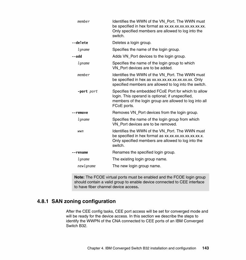
member Identifies the WWN of the VN_Port. The WWN must be specified in hex format as xx.xx.xx.xx.xx.xx.xx.xx. Only specified members are allowed to log into the switch.
--delete Deletes a login group.
lgname Specifies the name of the login group.
--add Adds VN_Port devices to the login group.
lgname Specifies the name of the login group to which VN_Port devices are to be added.
member Identifies the WWN of the VN_Port. The WWN must be specified in hex as xx.xx.xx.xx.xx.xx.xx.xx. Only specified members are allowed to log into the switch.
-port port Specifies the embedded FCoE Port for which to allow login. This operand is optional; if unspecified, members of the login group are allowed to log into all FCoE ports.
--remove Removes VN_Port devices from the login group.
lgname Specifies the name of the login group from which VN_Port devices are to be removed.
wwn Identifies the WWN of the VN_Port. The WWN must be specified in hex format as xx.xx.xx.xx.xx.xx.xx.x. Only specified members are allowed to log into the switch.
--rename Renames the specified login group.
lgname The existing login group name.
newlgname The new login group name.
4.8.1 SAN zoning configuration
After the CEE config tasks, CEE port access will be set for converged mode and will be ready for the device access. In this section we describe the steps to identify the WWPN of the CNA connected to CEE ports of an IBM Converged Switch B32.
Note: The FCOE virtual ports must be enabled and the FCOE login group should contain a valid group to enable device connected to CEE interface to have fiber channel device access.
Chapter 4. IBM Converged Switch B32 installation and configuration 143

Identify the WWPN of CNAFrom the admin prompt of the FOS, execute the command fcoe --loginshow. This displays the devices connected to CEE ports and is shown in Example 4-30.
Example 4-30 FCoE device list
switch:admin> fcoe --loginshow================================================================================Port Te port Device WWN Device MAC Session MAC================================================================================20 Te 0/12 10:00:00:05:1e:af:08:a1 00:05:1e:af:08:a1 0e:fc:00:05:14:0123 Te 0/15 10:00:00:05:1e:af:08:a0 00:05:1e:af:08:a0 0e:fc:00:05:17:01switch:admin>
This port wwpn can be zoned with usual zoning steps to meet the device access requirements.
Note: If the CNA devices are not visible with this command, check the CEE configuration from cmsh and FCOE configuration status. Make sure your CEE and FCoE configuration is valid for the ports. You can check the CEE configuration from cmsh.
144 IBM Converged Switch B32

Chapter 5. B32 switch management with Web Tools
In this chapter, we describe in detail the features of Web Tools that are specific to the IBM Converged Switch B32. The configuration of the FC ports and functions are common to all the FOS-based switches, and are covered in Implementing an IBM/Brocade SAN with 8 Gbps Directors and Switches, SG24-6116.
5
© Copyright IBM Corp. 2011. All rights reserved. 145
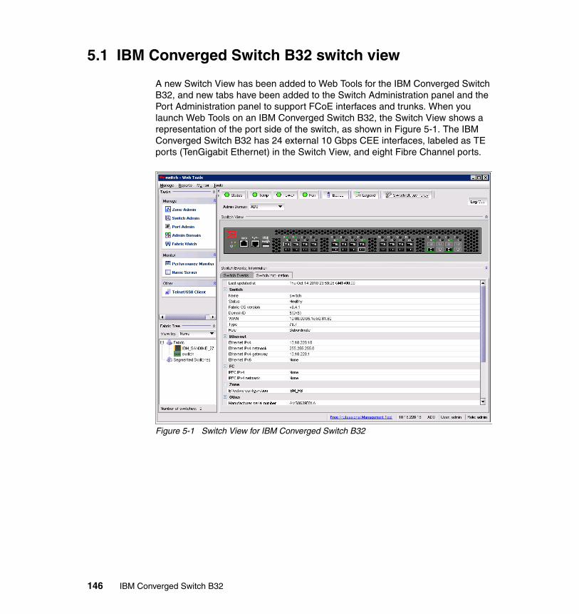
5.1 IBM Converged Switch B32 switch view
A new Switch View has been added to Web Tools for the IBM Converged Switch B32, and new tabs have been added to the Switch Administration panel and the Port Administration panel to support FCoE interfaces and trunks. When you launch Web Tools on an IBM Converged Switch B32, the Switch View shows a representation of the port side of the switch, as shown in Figure 5-1. The IBM Converged Switch B32 has 24 external 10 Gbps CEE interfaces, labeled as TE ports (TenGigabit Ethernet) in the Switch View, and eight Fibre Channel ports.
Figure 5-1 Switch View for IBM Converged Switch B32
146 IBM Converged Switch B32
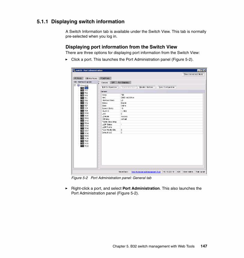
5.1.1 Displaying switch information
A Switch Information tab is available under the Switch View. This tab is normally pre-selected when you log in.
Displaying port information from the Switch ViewThere are three options for displaying port information from the Switch View:
� Click a port. This launches the Port Administration panel (Figure 5-2).
Figure 5-2 Port Administration panel: General tab
� Right-click a port, and select Port Administration. This also launches the Port Administration panel (Figure 5-2).
Chapter 5. B32 switch management with Web Tools 147

� Right-click a port, and select Port Details. A Port Details dialog box is displayed (Figure 5-3). The information displayed is a subset of the information available on the General tab of the Port Administration panel.
Figure 5-3 Port Details
5.1.2 Port information that is unique to FCoE
The General tab of the Port Administration panel shows several parameters that are unique to FCoE interfaces. These parameters are:
� Interface Mode: For this release, the Interface Mode will always be L2.
� VLAN ID: The VLANs that carry traffic on the links attached to this port.
� LAG: The name of the Link Aggregation Group (LAG), with which this port is associated. If no name is present, the port is not associated with any LAG.
� L2 Mode: The value is either Access or Trunk. Access mode allows only one VLAN association, and allows only untagged frames. Trunk mode allows more than one VLAN association, and allows tagged frames.
� CEE Map: The name of a CEE map that was created and associated with the port. If no value is present, it indicates that the default CEE map is being used.
� Traffic Class Map: The name of a traffic class map that was created and associated with the port. If no value is present, it indicates that the default traffic class map is being used.
148 IBM Converged Switch B32

� LLDP Status: Indicates whether LLDP is active or inactive.
� LLDP Profile: The name of an LLDP profile that was created and associated with the port. If no value is present, it indicates that LLDP is not implemented.
� FCoE Priority Bits: Each bit represents a user priority that is associated with FCoE traffic.
� Default CoS: The default Class of Service.
5.1.3 Switch Administration panel tabs for FCoE
The Switch Administration panel includes a CEE tab, shown in Figure 5-4, that is specific to DCE/CEE configuration and management. The CEE tab itself has five tabs that are used for FCoE switch administration, specifically:
� Link Aggregation� VLAN� FCoE Login� QoS� LLDP/DCBX
Figure 5-4 Switch Administration panel with CEE tab and detail tabs highlighted
Chapter 5. B32 switch management with Web Tools 149
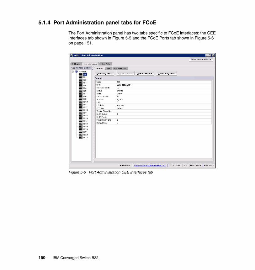
5.1.4 Port Administration panel tabs for FCoE
The Port Administration panel has two tabs specific to FCoE interfaces: the CEE Interfaces tab shown in Figure 5-5 and the FCoE Ports tab shown in Figure 5-6 on page 151.
Figure 5-5 Port Administration CEE Interfaces tab
150 IBM Converged Switch B32

Figure 5-6 Port Administration FCoE ports tab
5.2 FCoE configuration tasks
There are several tasks related to FCoE configuration. Here, we list the high level tasks in suggested order of performance. The following sections provide step-by-step details for each task.
1. Quality of Service (QoS) configuration (optional): If you intend to implement a specific QoS scheme to prioritize data traffic, it is recommended that you finish your QoS configuration before you begin port configuration. QoS values are referenced when you configure ports. See 5.2.1, “Quality of Service (QoS) configuration” on page 152.
2. LLDP-DCBX configuration (optional): If you intend to implement DCBX, it is recommended that you finish LLDP-DCBX configuration before you configure ports. LLDP-DCBX values are referenced when you configure ports. See5.2.2, “LLDP-DCBX configuration” on page 159.
3. CEE interface configuration (mandatory). See 5.2.3, “Configuring CEE interfaces” on page 164.
Chapter 5. B32 switch management with Web Tools 151
4. Link Aggregation Groups (LAG) configuration: Ports must be configured before they can be placed into a LAG. Parameters that are applied individually to ports are applied collectively to LAGs. See 5.2.4, “Configuring a link aggregation group (LAG)” on page 167.
5. VLAN configuration (optional): Port and LAG names are referenced in VLAN configuration, and must be defined before you can successfully complete a VLAN configuration. See 5.2.5, “Configuring VLANs” on page 171.
6. Login group configuration (optional): Login group configuration is not dependent on any of the above configurations. It can be done as a separate task. See 5.2.6, “Configuring FCoE login groups” on page 176.
5.2.1 Quality of Service (QoS) configuration
As a general concept, QoS is a mechanism for classifying and scheduling data traffic based on priority settings. QoS can be used to control traffic congestion, allocate bandwidth, and carry data traffic with a variety of characteristics over a common interface.
Two configuration options are available:
� You can create a CEE map. A CEE map defines priority and priority group tables that support Enhanced Transmission Selection (ETS). ETS allows allocation of bandwidth to different traffic classes. CEE maps also allow you to enable Priority Flow Control (PFC).
� You can create a traffic class map. A traffic class map can be used to map a specific class of traffic to a specific Class of Service (CoS).
Adding a CEE mapA CEE map defines priority and priority group tables that support Enhanced Transmission Selection (ETS). ETS allows bandwidth to be allocated based on priority settings through an exchange of priority group tables.
Follow these steps to create a CEE map:
1. From the Switch Administration panel, make the following tab selections: CEE QoS CEE Map (Figure 5-7).
152 IBM Converged Switch B32

Figure 5-7 QoS tab CEE Map tab
Chapter 5. B32 switch management with Web Tools 153
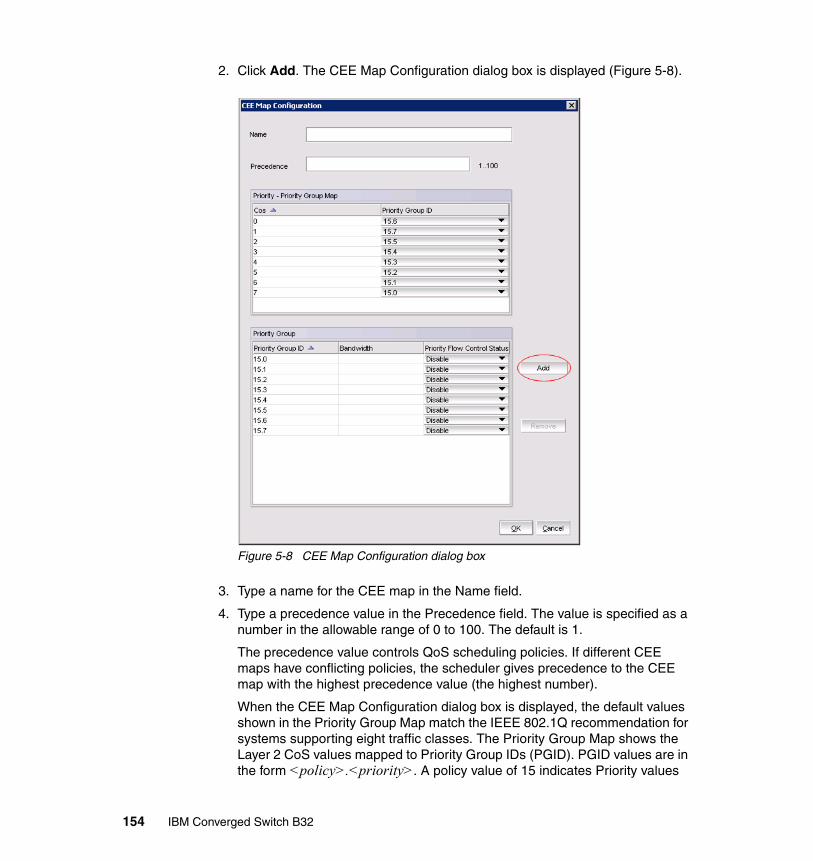
2. Click Add. The CEE Map Configuration dialog box is displayed (Figure 5-8).
Figure 5-8 CEE Map Configuration dialog box
3. Type a name for the CEE map in the Name field.
4. Type a precedence value in the Precedence field. The value is specified as a number in the allowable range of 0 to 100. The default is 1.
The precedence value controls QoS scheduling policies. If different CEE maps have conflicting policies, the scheduler gives precedence to the CEE map with the highest precedence value (the highest number).
When the CEE Map Configuration dialog box is displayed, the default values shown in the Priority Group Map match the IEEE 802.1Q recommendation for systems supporting eight traffic classes. The Priority Group Map shows the Layer 2 CoS values mapped to Priority Group IDs (PGID). PGID values are in the form <policy>.<priority>. A policy value of 15 indicates Priority values
154 IBM Converged Switch B32

run from 0 (highest priority) to 7 (lowest priority). Note that this is contrary to the CoS values, which run from 7 (highest priority) to 0 (lowest priority).
5. Create a new priority group by clicking Add next to the Priority Group table.
An entry is added to the Priority Group table (Figure 5-9). When you add an entry, a PGID is automatically assigned. The PGID is an integer from 0 to 7. The first added entry is given a PGID of 0, and the PGID increments by one for each additional entry created until a PGID of 7 is reached. The new Priority Group can be mapped to different COS by selecting the PGID in each COS in the priority group map table.
Figure 5-9 Adding a Priority Group
6. Edit the Bandwidth entry to indicate the desired percentage of total bandwidth.
Chapter 5. B32 switch management with Web Tools 155
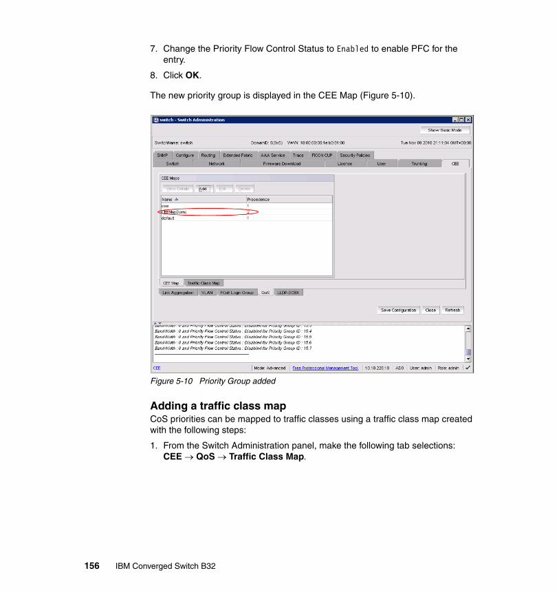
7. Change the Priority Flow Control Status to Enabled to enable PFC for the entry.
8. Click OK.
The new priority group is displayed in the CEE Map (Figure 5-10).
Figure 5-10 Priority Group added
Adding a traffic class mapCoS priorities can be mapped to traffic classes using a traffic class map created with the following steps:
1. From the Switch Administration panel, make the following tab selections: CEE QoS Traffic Class Map.
156 IBM Converged Switch B32
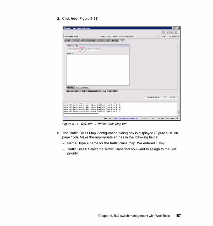
2. Click Add (Figure 5-11).
Figure 5-11 QoS tab Traffic Class Map tab
3. The Traffic Class Map Configuration dialog box is displayed (Figure 5-12 on page 158). Make the appropriate entries in the following fields:
– Name: Type a name for the traffic class map. We entered TCMap.
– Traffic Class: Select the Traffic Class that you want to assign to the CoS priority.
Chapter 5. B32 switch management with Web Tools 157
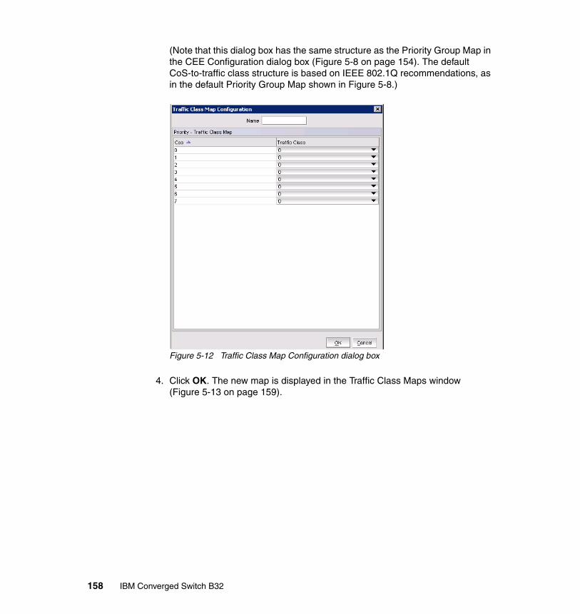
(Note that this dialog box has the same structure as the Priority Group Map in the CEE Configuration dialog box (Figure 5-8 on page 154). The default CoS-to-traffic class structure is based on IEEE 802.1Q recommendations, as in the default Priority Group Map shown in Figure 5-8.)
Figure 5-12 Traffic Class Map Configuration dialog box
4. Click OK. The new map is displayed in the Traffic Class Maps window (Figure 5-13 on page 159).
158 IBM Converged Switch B32
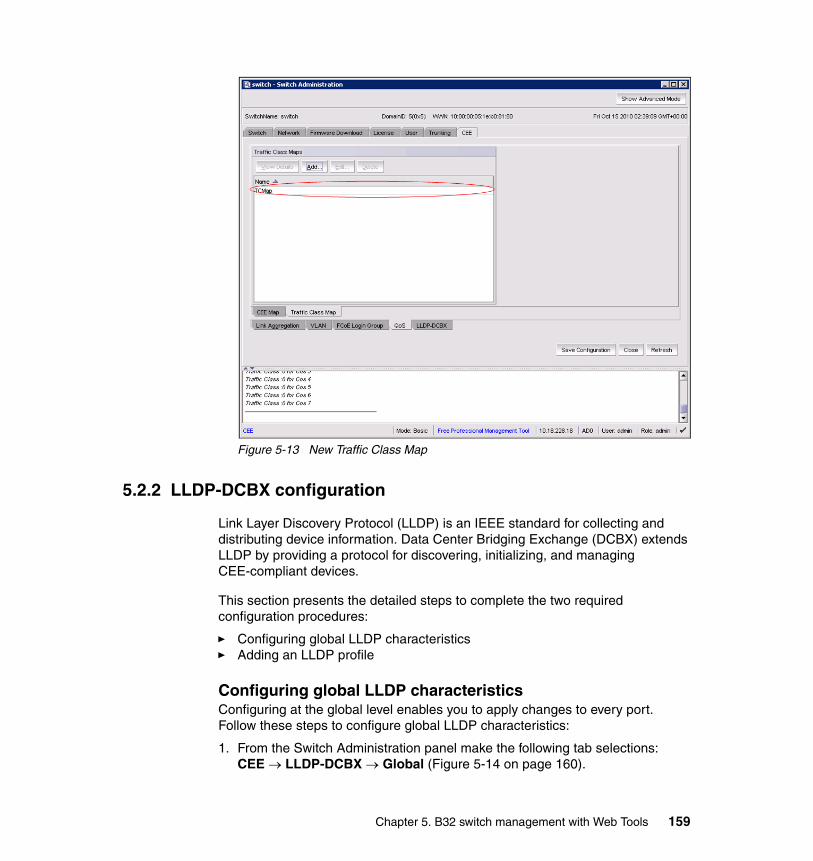
Figure 5-13 New Traffic Class Map
5.2.2 LLDP-DCBX configuration
Link Layer Discovery Protocol (LLDP) is an IEEE standard for collecting and distributing device information. Data Center Bridging Exchange (DCBX) extends LLDP by providing a protocol for discovering, initializing, and managing CEE-compliant devices.
This section presents the detailed steps to complete the two required configuration procedures:
� Configuring global LLDP characteristics� Adding an LLDP profile
Configuring global LLDP characteristicsConfiguring at the global level enables you to apply changes to every port. Follow these steps to configure global LLDP characteristics:
1. From the Switch Administration panel make the following tab selections: CEE LLDP-DCBX Global (Figure 5-14 on page 160).
Chapter 5. B32 switch management with Web Tools 159
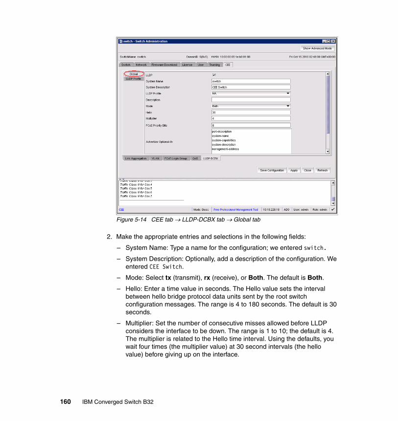
Figure 5-14 CEE tab LLDP-DCBX tab Global tab
2. Make the appropriate entries and selections in the following fields:
– System Name: Type a name for the configuration; we entered switch.
– System Description: Optionally, add a description of the configuration. We entered CEE Switch.
– Mode: Select tx (transmit), rx (receive), or Both. The default is Both.
– Hello: Enter a time value in seconds. The Hello value sets the interval between hello bridge protocol data units sent by the root switch configuration messages. The range is 4 to 180 seconds. The default is 30 seconds.
– Multiplier: Set the number of consecutive misses allowed before LLDP considers the interface to be down. The range is 1 to 10; the default is 4. The multiplier is related to the Hello time interval. Using the defaults, you wait four times (the multiplier value) at 30 second intervals (the hello value) before giving up on the interface.
160 IBM Converged Switch B32

– FC0E Priority Bits: Enter a value that indicates the desired user priority. Each bit represents a user priority associated with FCoE traffic. The range is 0-255. The default is 8.
3. Select the parameters you want to exchange. Note that the term TLV indicates packaging of parameters into a Brocade-specific Type/Length/Value (TLV).
4. Click Apply.
5. Click Save Configuration.
Adding an LLDP profileThe LLDP profile determines LLDP settings per port. Create the LLDP profile using the following steps:
1. From the Switch Administration panel make the following tab selections: CEE LLDP-DCBX LLDP Profile (Figure 5-15).
Figure 5-15 CEE tab LLDP-DCBX tab LLDP Profile tab
Chapter 5. B32 switch management with Web Tools 161

2. Click Add. The LLDP Configuration dialog box is displayed (Figure 5-16).
Figure 5-16 LLDP dialog box
3. Make the appropriate entries and selections in the following fields:
– Name: Type a name for the configuration.
– Description: Optionally, add a description or the configuration.
– Mode: Select tx (transmit), rx (receive), or Both. The default is Both.
– Hello: Enter a time value in seconds. The Hello value sets the interval between hello bridge protocol data units sent by the root switch configuration message. The range is 4 to 180 seconds; the default is 30 seconds.
– Multiplier: Set the number of consecutive misses allowed before LLDP considers the interface to be down. The range is 1 to 10; the default is 4. The multiplier is related to the Hello time interval. Using the defaults, you wait four times (the multiplier value) at 30 second intervals (the hello value) before giving up on the interface.
4. In the Advertise Optional-tlv field, make your selection of TLVs to advertise from the following parameters. Note that the term TLV indicates packaging of parameters into a Brocade-specific Type/Length/Value (TLV).
– system-description: Describes switch or blade characteristics.
– port-description: Describes the configured port.
162 IBM Converged Switch B32
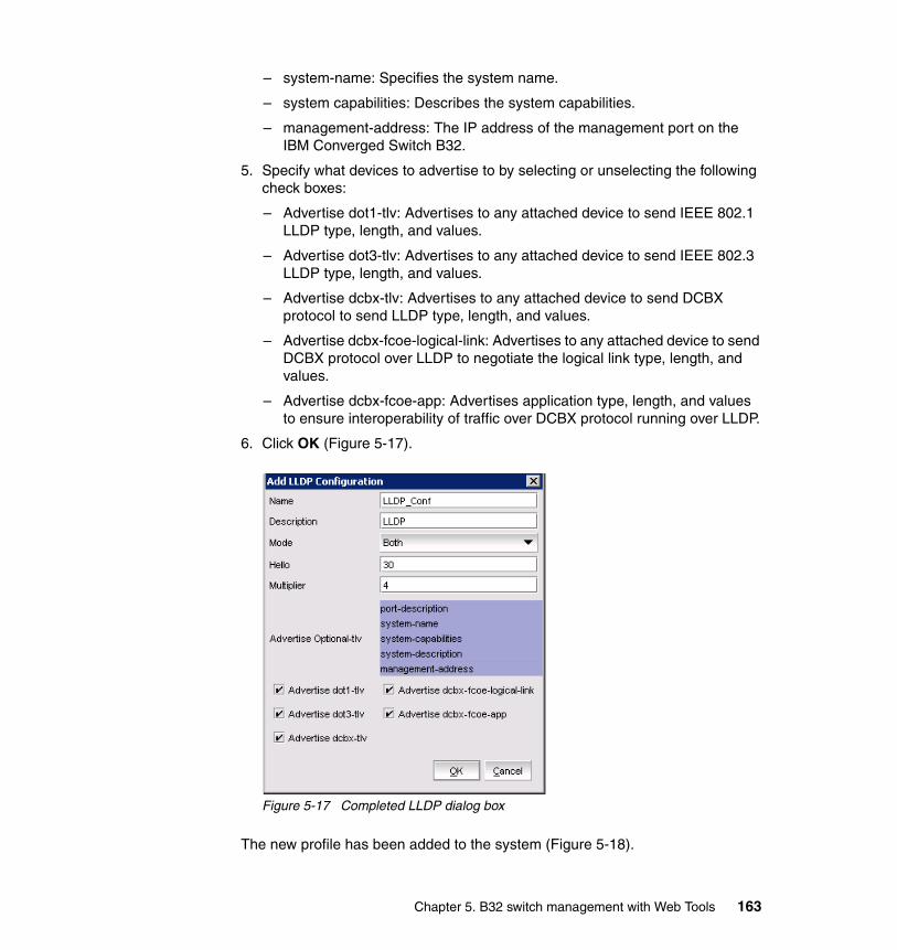
– system-name: Specifies the system name.
– system capabilities: Describes the system capabilities.
– management-address: The IP address of the management port on the IBM Converged Switch B32.
5. Specify what devices to advertise to by selecting or unselecting the following check boxes:
– Advertise dot1-tlv: Advertises to any attached device to send IEEE 802.1 LLDP type, length, and values.
– Advertise dot3-tlv: Advertises to any attached device to send IEEE 802.3 LLDP type, length, and values.
– Advertise dcbx-tlv: Advertises to any attached device to send DCBX protocol to send LLDP type, length, and values.
– Advertise dcbx-fcoe-logical-link: Advertises to any attached device to send DCBX protocol over LLDP to negotiate the logical link type, length, and values.
– Advertise dcbx-fcoe-app: Advertises application type, length, and values to ensure interoperability of traffic over DCBX protocol running over LLDP.
6. Click OK (Figure 5-17).
Figure 5-17 Completed LLDP dialog box
The new profile has been added to the system (Figure 5-18).
Chapter 5. B32 switch management with Web Tools 163
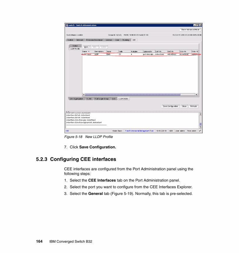
Figure 5-18 New LLDP Profile
7. Click Save Configuration.
5.2.3 Configuring CEE interfaces
CEE interfaces are configured from the Port Administration panel using the following steps:
1. Select the CEE Interfaces tab on the Port Administration panel.
2. Select the port you want to configure from the CEE Interfaces Explorer.
3. Select the General tab (Figure 5-19). Normally, this tab is pre-selected.
164 IBM Converged Switch B32
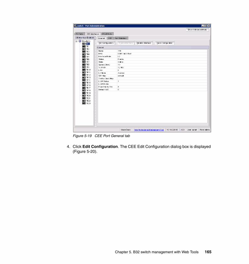
Figure 5-19 CEE Port General tab
4. Click Edit Configuration. The CEE Edit Configuration dialog box is displayed (Figure 5-20).
Chapter 5. B32 switch management with Web Tools 165
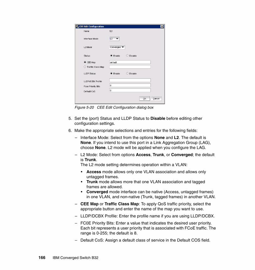
Figure 5-20 CEE Edit Configuration dialog box
5. Set the (port) Status and LLDP Status to Disable before editing other configuration settings.
6. Make the appropriate selections and entries for the following fields:
– Interface Mode: Select from the options None and L2. The default is None. If you intend to use this port in a Link Aggregation Group (LAG), choose None. L2 mode will be applied when you configure the LAG.
– L2 Mode: Select from options Access, Trunk, or Converged; the default is Trunk. The L2 mode setting determines operation within a VLAN:
• Access mode allows only one VLAN association and allows only untagged frames.
• Trunk mode allows more that one VLAN association and tagged frames are allowed.
• Converged mode interface can be native (Access, untagged frames) in one VLAN, and non-native (Trunk, tagged frames) in another VLAN.
– CEE Map or Traffic Class Map: To apply QoS traffic priority, select the appropriate button and enter the name of the map you want to use.
– LLDP/DCBX Profile: Enter the profile name if you are using LLDP/DCBX.
– FC0E Priority Bits: Enter a value that indicates the desired user priority. Each bit represents a user priority that is associated with FCoE traffic. The range is 0-255; the default is 8.
– Default CoS: Assign a default class of service in the Default COS field.
166 IBM Converged Switch B32

7. Click OK.
8. Click Enable for Status and LLDP Status. This can be done at a later time.
5.2.4 Configuring a link aggregation group (LAG)
FCoE ports can be grouped to create a LAG. The LAG is treated as a single interface. Use the following steps to configure a LAG:
1. On the Switch Administration panel make the following tab selections: CEE Link Aggregation (Figure 5-21).
Figure 5-21 CEE tab Link Aggregation tab
2. Click Add.
The LAG Configuration dialog box is displayed (Figure 5-22). Note that only ports you defined with an Interface Mode of None can be LAG Members.
Chapter 5. B32 switch management with Web Tools 167
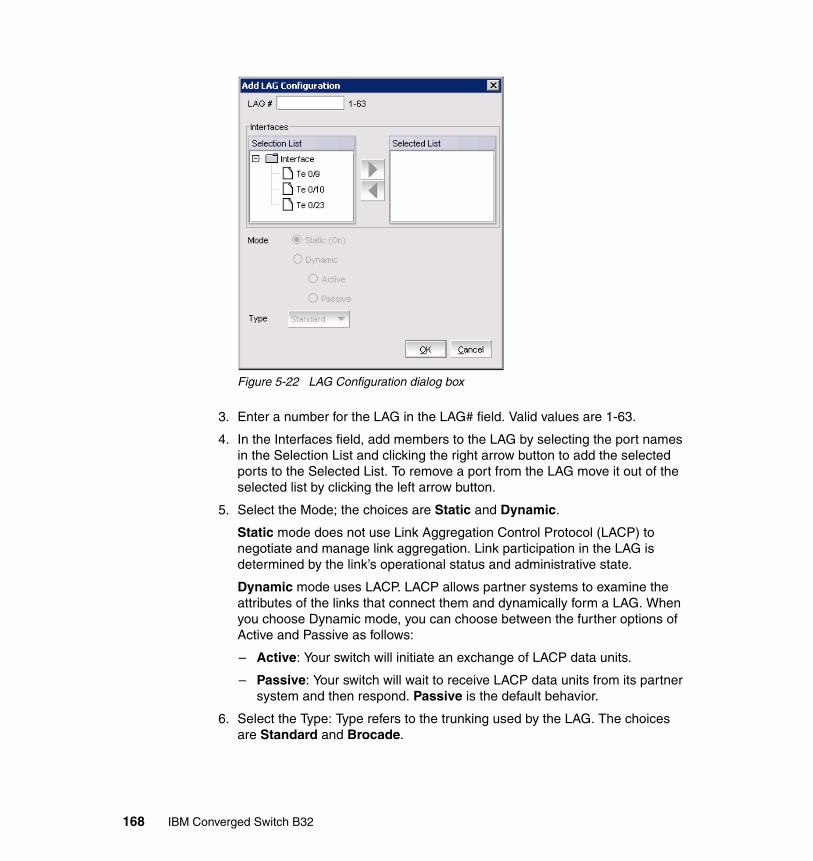
Figure 5-22 LAG Configuration dialog box
3. Enter a number for the LAG in the LAG# field. Valid values are 1-63.
4. In the Interfaces field, add members to the LAG by selecting the port names in the Selection List and clicking the right arrow button to add the selected ports to the Selected List. To remove a port from the LAG move it out of the selected list by clicking the left arrow button.
5. Select the Mode; the choices are Static and Dynamic.
Static mode does not use Link Aggregation Control Protocol (LACP) to negotiate and manage link aggregation. Link participation in the LAG is determined by the link’s operational status and administrative state.
Dynamic mode uses LACP. LACP allows partner systems to examine the attributes of the links that connect them and dynamically form a LAG. When you choose Dynamic mode, you can choose between the further options of Active and Passive as follows:
– Active: Your switch will initiate an exchange of LACP data units.
– Passive: Your switch will wait to receive LACP data units from its partner system and then respond. Passive is the default behavior.
6. Select the Type: Type refers to the trunking used by the LAG. The choices are Standard and Brocade.
168 IBM Converged Switch B32
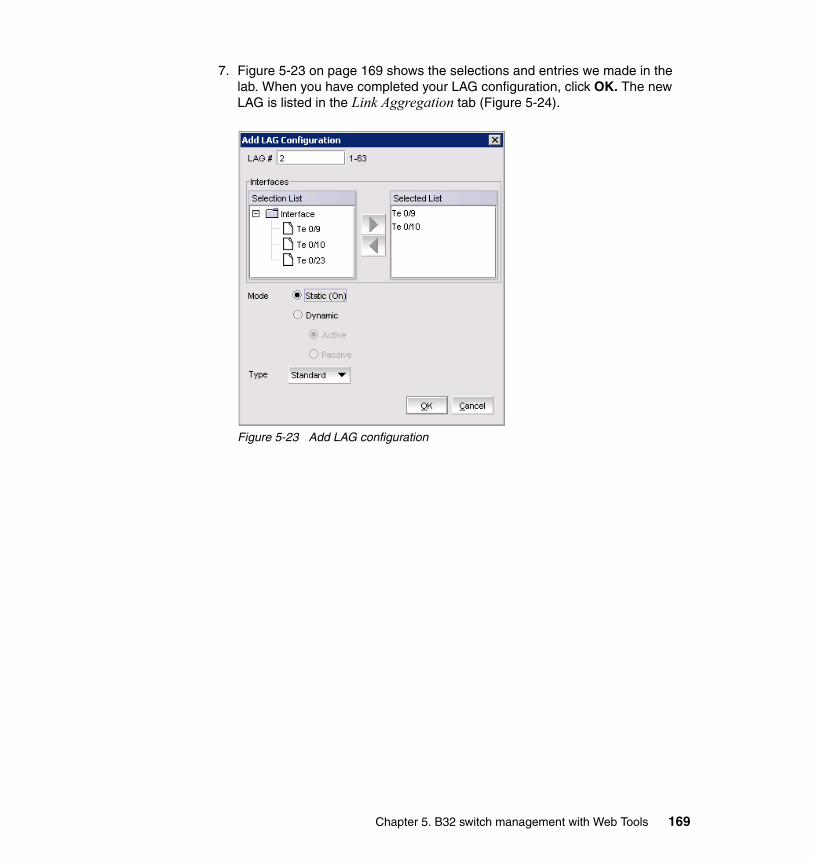
7. Figure 5-23 on page 169 shows the selections and entries we made in the lab. When you have completed your LAG configuration, click OK. The new LAG is listed in the Link Aggregation tab (Figure 5-24).
Figure 5-23 Add LAG configuration
Chapter 5. B32 switch management with Web Tools 169
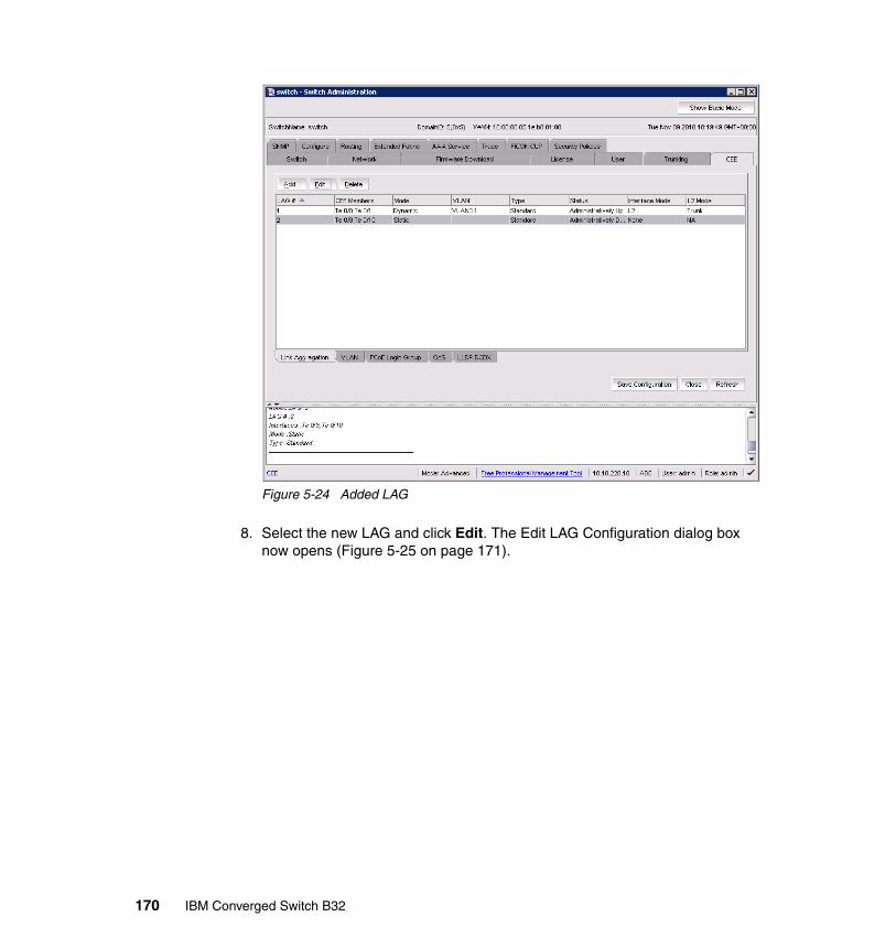
Figure 5-24 Added LAG
8. Select the new LAG and click Edit. The Edit LAG Configuration dialog box now opens (Figure 5-25 on page 171).
170 IBM Converged Switch B32

Figure 5-25 Edit LAG Configuration dialog
9. Make the appropriate selections and entries in the following fields:
– Interface Mode: Select L2.The options are None and L2; the default is None.
– L2 Mode: This setting determines operation within a VLAN:
• Access mode allows only one VLAN association; all frames are untagged.
• Trunk mode allows more that one VLAN association; tagged frames are allowed.
– Status: This is the operational status. The choices are Administratively Up and Administratively Down.
10.Click OK.
5.2.5 Configuring VLANs
The Virtual LAN (VLAN) capability allows multiple virtual LANs within a single physical LAN infrastructure. The physical interface must be configured as L2
Chapter 5. B32 switch management with Web Tools 171
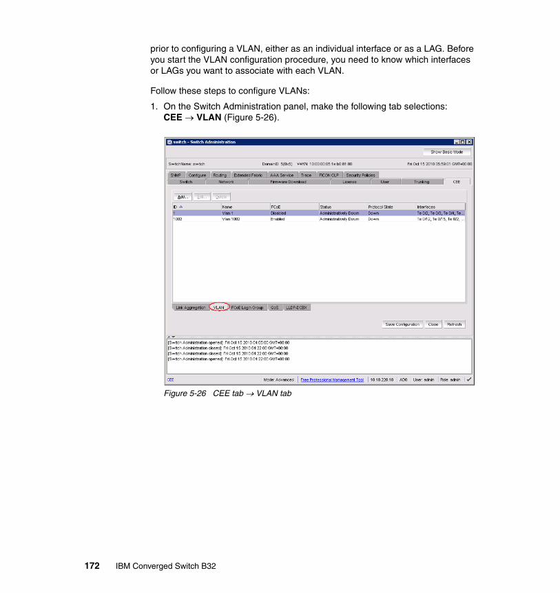
prior to configuring a VLAN, either as an individual interface or as a LAG. Before you start the VLAN configuration procedure, you need to know which interfaces or LAGs you want to associate with each VLAN.
Follow these steps to configure VLANs:
1. On the Switch Administration panel, make the following tab selections: CEE VLAN (Figure 5-26).
Figure 5-26 CEE tab VLAN tab
172 IBM Converged Switch B32
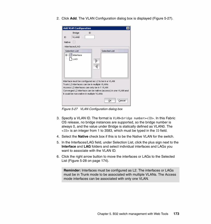
2. Click Add. The VLAN Configuration dialog box is displayed (Figure 5-27).
Figure 5-27 VLAN Configuration dialog box
3. Specify a VLAN ID. The format is VLAN<bridge number><ID>. In this Fabric OS release, no bridge instances are supported, so the bridge number is always 0, and the value under Bridge is statically defined as VLAN0. The <ID> is an integer from 1 to 3583, which must be typed in the ID field.
4. Select the Native check box if this is to be the Native VLAN for the switch.
5. In the Interfaces/LAG field, under Selection List, click the plus sign next to the Interface and LAG folders and select individual interfaces and LAGs you want to associate with the VLAN ID.
6. Click the right arrow button to move the interfaces or LAGs to the Selected List (Figure 5-28 on page 174).
Reminder: Interfaces must be configured as L2. The interfaces or LAGs must be in Trunk mode to be associated with multiple VLANs. The Access mode interfaces can be associated with only one VLAN.
Chapter 5. B32 switch management with Web Tools 173
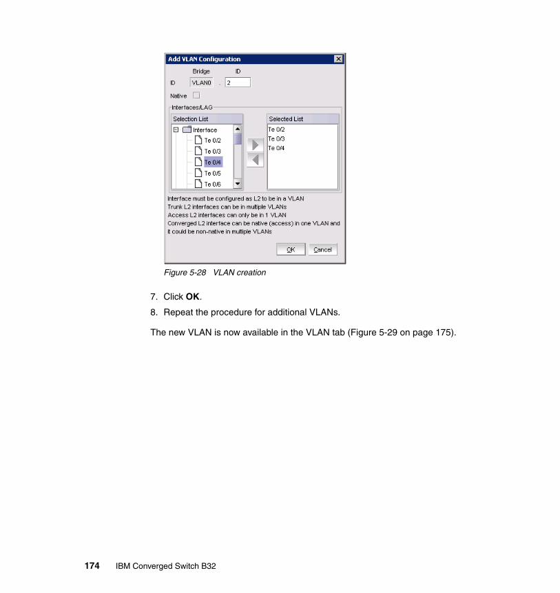
Figure 5-28 VLAN creation
7. Click OK.
8. Repeat the procedure for additional VLANs.
The new VLAN is now available in the VLAN tab (Figure 5-29 on page 175).
174 IBM Converged Switch B32
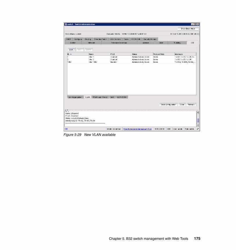
Figure 5-29 New VLAN available
Chapter 5. B32 switch management with Web Tools 175

5.2.6 Configuring FCoE login groups
FCoE login groups control which FCoE switches are allowed to log in to a fabric. Configure the login groups with the following steps:
1. On the Switch Administration panel, make the following tab selections: CEE FCoE Login (Figure 5-30).
Figure 5-30 CEE tab FCoE Login tab
2. Click New. The New Login Group dialog box is displayed (Figure 5-31).
176 IBM Converged Switch B32
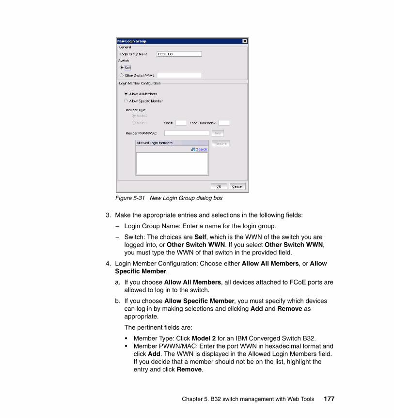
Figure 5-31 New Login Group dialog box
3. Make the appropriate entries and selections in the following fields:
– Login Group Name: Enter a name for the login group.
– Switch: The choices are Self, which is the WWN of the switch you are logged into, or Other Switch WWN. If you select Other Switch WWN, you must type the WWN of that switch in the provided field.
4. Login Member Configuration: Choose either Allow All Members, or Allow Specific Member.
a. If you choose Allow All Members, all devices attached to FCoE ports are allowed to log in to the switch.
b. If you choose Allow Specific Member, you must specify which devices can log in by making selections and clicking Add and Remove as appropriate.
The pertinent fields are:
• Member Type: Click Model 2 for an IBM Converged Switch B32.• Member PWWN/MAC: Enter the port WWN in hexadecimal format and
click Add. The WWN is displayed in the Allowed Login Members field. If you decide that a member should not be on the list, highlight the entry and click Remove.
Chapter 5. B32 switch management with Web Tools 177
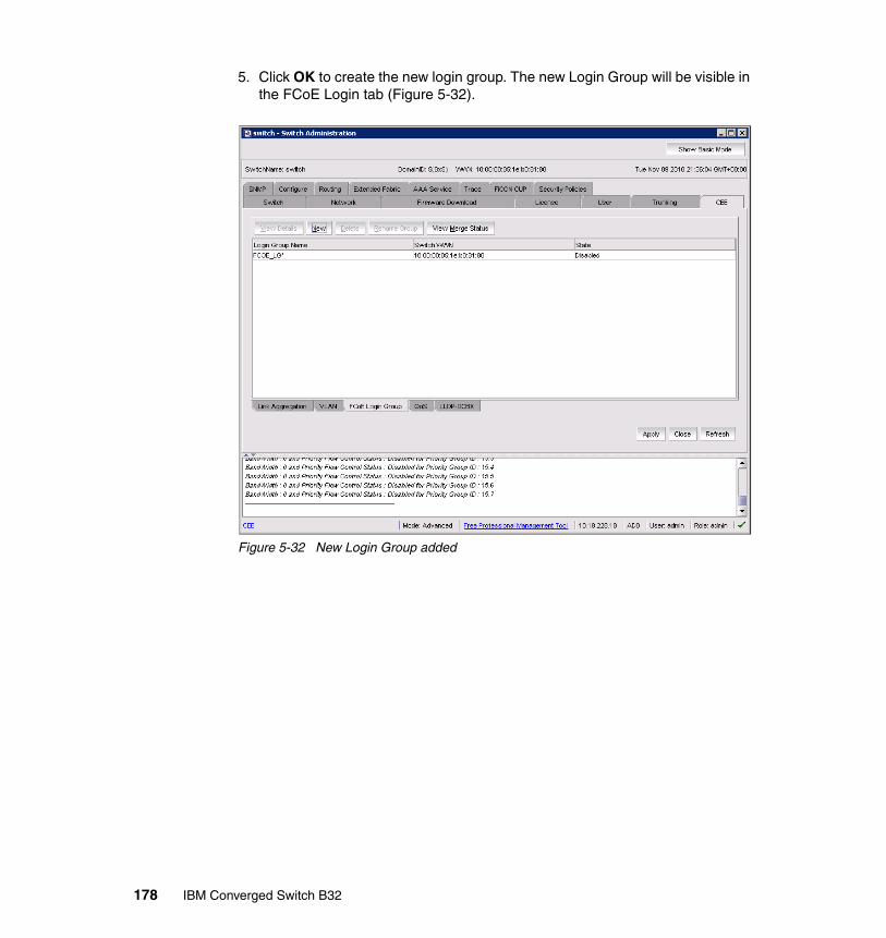
5. Click OK to create the new login group. The new Login Group will be visible in the FCoE Login tab (Figure 5-32).
Figure 5-32 New Login Group added
178 IBM Converged Switch B32

5.3 Displaying FCoE ports information
There are 24 internal FCoE VF ports that bridge FC and Ethernet traffic. You can view FCoE port information using these steps:
1. Select the FCoE Ports tab on the Port Administration panel (Figure 5-33). The initial view shows a summary of all trunks on the switch.
Figure 5-33 FCoE Ports tab: Port Administration panel
2. To view information about a specific port, select the port in the FCoE Ports Explorer window.
Port information is displayed in two tabs. The General tab is pre-selected (Figure 5-34).
Chapter 5. B32 switch management with Web Tools 179

Figure 5-34 FCoE ports: General tab
The Connected Devices tab (Figure 5-35 on page 181) shows information about devices connected to the switch. The following six columns of information are displayed:
� Device WWN: The WWN of the connected device.
� Device MAC: The MAC address of the connected device.
� Connected Peer: The port type on the connected device.
� Is Directly Connected: Indicates whether the device is directly connected to the trunk.
� FCoE Port MAC: The FCoE port MAC address.
� Switch Port: The switch port WWN.
180 IBM Converged Switch B32
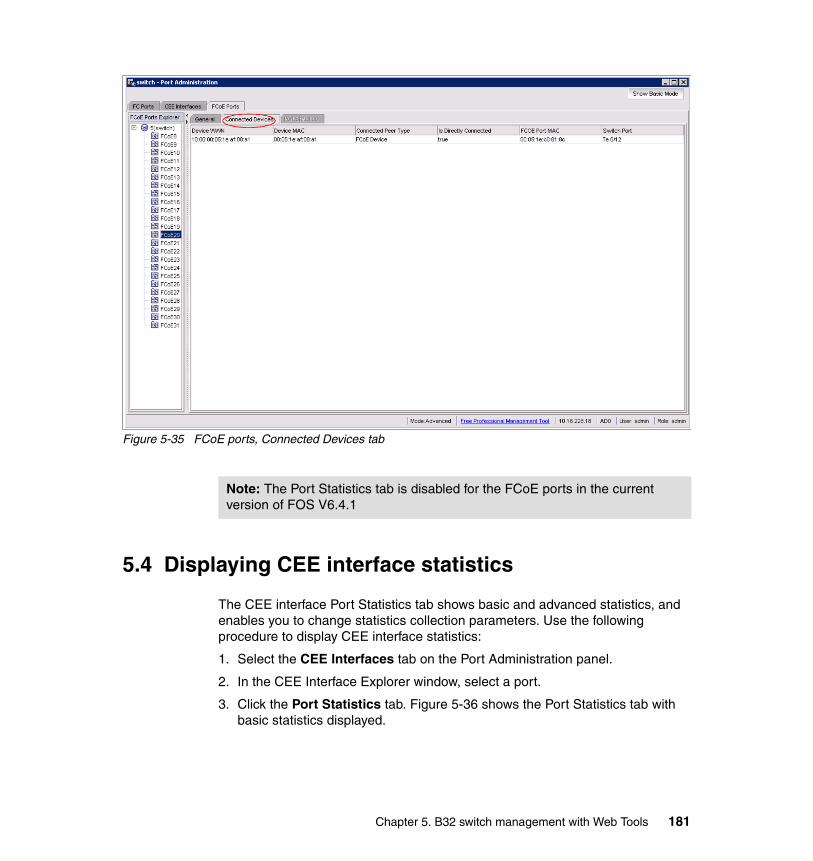
Figure 5-35 FCoE ports, Connected Devices tab
5.4 Displaying CEE interface statistics
The CEE interface Port Statistics tab shows basic and advanced statistics, and enables you to change statistics collection parameters. Use the following procedure to display CEE interface statistics:
1. Select the CEE Interfaces tab on the Port Administration panel.
2. In the CEE Interface Explorer window, select a port.
3. Click the Port Statistics tab. Figure 5-36 shows the Port Statistics tab with basic statistics displayed.
Note: The Port Statistics tab is disabled for the FCoE ports in the current version of FOS V6.4.1
Chapter 5. B32 switch management with Web Tools 181

Figure 5-36 CEE Interfaces, Port Statistics, Basic Mode
The CEE Trunk Statistics Configuration section allows you to do the following tasks:
� Toggle between showing Absolute Values, or Delta Values (values that have changed since the last data collection).
� Clear Counters to refresh data.
� Change the retrieval interval.
182 IBM Converged Switch B32
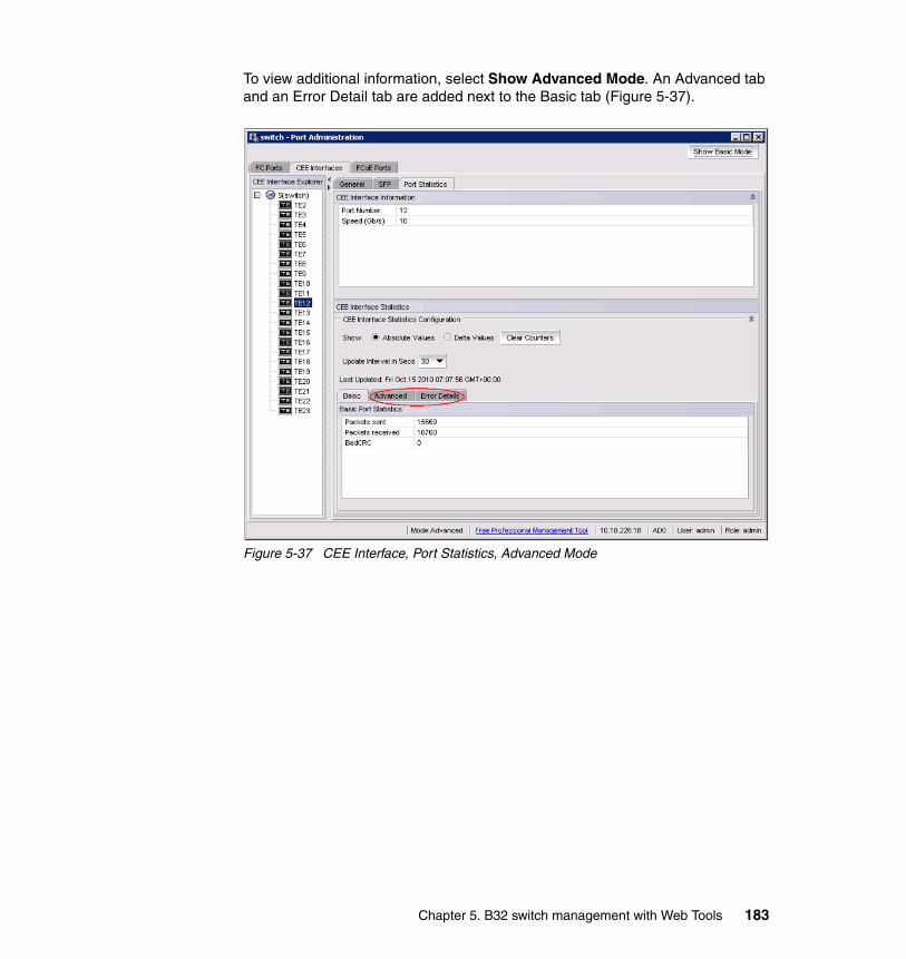
To view additional information, select Show Advanced Mode. An Advanced tab and an Error Detail tab are added next to the Basic tab (Figure 5-37).
Figure 5-37 CEE Interface, Port Statistics, Advanced Mode
Chapter 5. B32 switch management with Web Tools 183
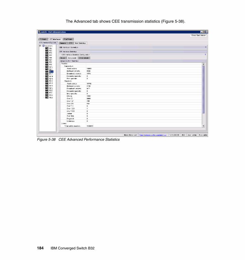
The Advanced tab shows CEE transmission statistics (Figure 5-38).
Figure 5-38 CEE Advanced Performance Statistics
184 IBM Converged Switch B32
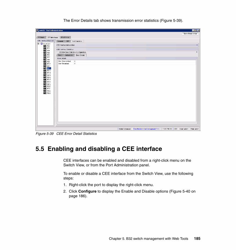
The Error Details tab shows transmission error statistics (Figure 5-39).
Figure 5-39 CEE Error Detail Statistics
5.5 Enabling and disabling a CEE interface
CEE interfaces can be enabled and disabled from a right-click menu on the Switch View, or from the Port Administration panel.
To enable or disable a CEE interface from the Switch View, use the following steps:
1. Right-click the port to display the right-click menu.
2. Click Configure to display the Enable and Disable options (Figure 5-40 on page 186).
Chapter 5. B32 switch management with Web Tools 185

Figure 5-40 Enable/disable a port
To enable or disable a CEE interface from the Port Administration panel, use the following steps:
1. Select the CEE Interfaces tab on the Port Administration panel.
2. In the CEE Interfaces Explorer window, select the port you want to enable or disable.
3. Select the General tab to display the Enable Interface and Disable Interface options. The General tab is normally pre-selected (Figure 5-41).
4. Enable or disable the interface, as desired.
Figure 5-41 CEE Interface Enable/Disable
186 IBM Converged Switch B32

5.6 Enabling and disabling a LAG
To enable or disable a LAG, perform the following steps:
1. From the Switch Administration panel, select the CEE tab.
2. Select the Link Aggregation tab (Figure 5-42).
Figure 5-42 Viewing LAGs
3. Click Edit.
The LAG Configuration dialog box is displayed (Figure 5-43).
4. Change the Status to Administratively Up or Administratively Down.
Chapter 5. B32 switch management with Web Tools 187

Figure 5-43 LAG Configuration dialog box
5.7 Enabling and disabling LLDP
To enable or disable LLDP on a CEE interface, perform the following steps:
1. Select the CEE Interfaces tab on the Port Administration panel.
2. In the CEE Interfaces Explorer window, select the port.
3. Select the General tab.
4. Select Edit Configuration (Figure 5-44).
188 IBM Converged Switch B32
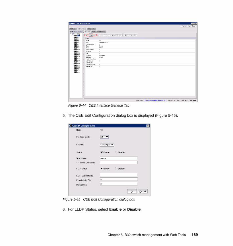
Figure 5-44 CEE Interface General Tab
5. The CEE Edit Configuration dialog box is displayed (Figure 5-45).
Figure 5-45 CEE Edit Configuration dialog box
6. For LLDP Status, select Enable or Disable.
Chapter 5. B32 switch management with Web Tools 189
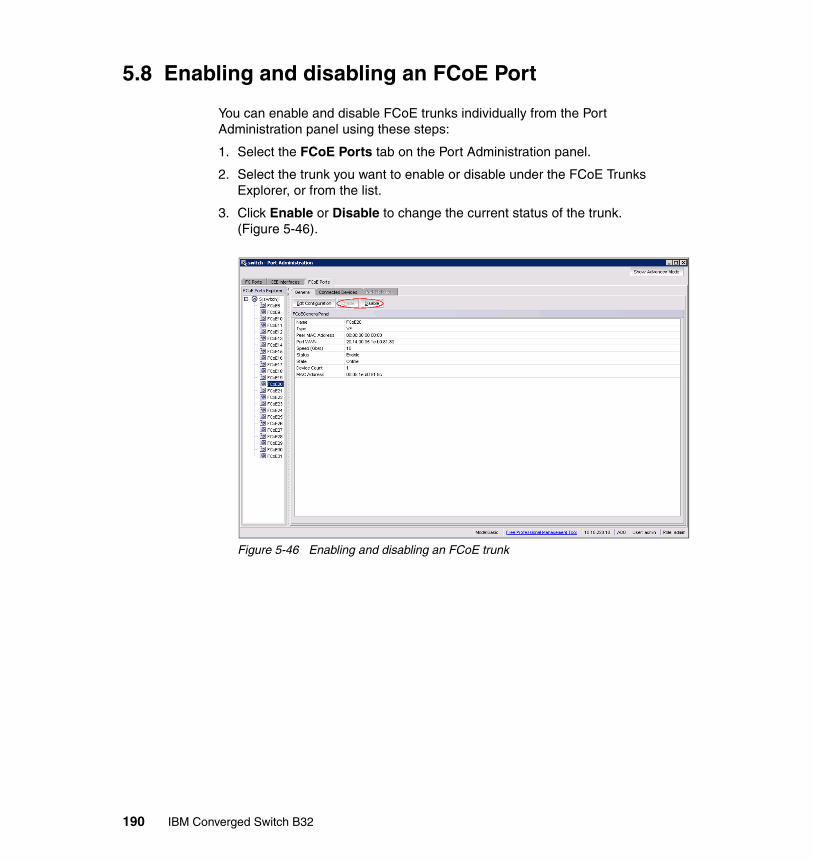
5.8 Enabling and disabling an FCoE Port
You can enable and disable FCoE trunks individually from the Port Administration panel using these steps:
1. Select the FCoE Ports tab on the Port Administration panel.
2. Select the trunk you want to enable or disable under the FCoE Trunks Explorer, or from the list.
3. Click Enable or Disable to change the current status of the trunk. (Figure 5-46).
Figure 5-46 Enabling and disabling an FCoE trunk
190 IBM Converged Switch B32
Related publications
The publications listed in this section are considered particularly suitable for a more detailed discussion of the topics covered in this book.
IBM Redbooks publicationsFor information about ordering these publications, see “Help from IBM” on page 192. Note that several documents referenced here might be available in softcopy only.
� Introduction to Storage Area Networks, SG24-5470
� IBM TotalStorage: SAN Product, Design, and Optimization Guide, SG24-6384
� Implementing an IBM/Brocade SAN with 8 Gbps Directors and Switches, SG24-6116
� Using iSCSI Solutions’ Planning and Implementation, SG24-6291
Other resourcesThese publications are also relevant as further information sources:
� Clark, Tom. IP SANs: An Introduction to iSCSI, iFCP, and FCIP Protocols for Storage Area Network. Addison-Wesley Professional, first edition, December 2001. ISBN 0201752778.
� Judd, Josh. Multiprotocol Routing for SANs. Infinity Publishing, October 2004. ISBN 0741423065.
Referenced Web sitesThese Web sites are also relevant as further information sources:
� IBM TotalStorage hardware, software, and solutions:
http://www.storage.ibm.com
� IBM TotalStorage storage area network:
http://www.storage.ibm.com/snetwork/index.html
© Copyright IBM Corp. 2011. All rights reserved. 191
� Brocade:
http://www.brocade.com
� QLogic:
http://www.qlogic.com
� Emulex:
http://www.emulex.com
� Finisar:
http://www.finisar.com
� Veritas:
http://www.veritas.com
� Tivoli:
http://www.tivoli.com
� JNI:
http://www.Jni.com
� IEEE:
http://www.ieee.org
� Storage Networking Industry Association:
http://www.snia.org
� SCSI Trade Association:
http://www.scsita.org
� Internet Engineering Task Force:
http://www.ietf.org
� American National Standards Institute:
http://www.ansi.org
� Technical Committee T10:
http://www.t10.org
� Technical Committee T11:
http://www.t11.org
Help from IBM
IBM Support and downloads
192 IBM Converged Switch B32

ibm.com/support
IBM Global Services
ibm.com/services
Related publications 193

194 IBM Converged Switch B32

Index
AAccess Control List (ACL) 28, 65, 98Address Resolution Protocol 72, 100addressing 11–13
schemes 12administration 28, 31, 83, 136administrative state 89, 168administrator 124Advanced Performance Monitoring 30aggregate 48, 89application
performance 110application type 99, 163architecture 11, 25, 36ARP 41, 100ASIC 27attributes 89, 130, 168availability 2, 11, 24, 28, 53, 86
Bbackup 83, 85bandwidth 2, 7, 19–21, 27, 30, 38, 53, 75, 86–87, 102, 117, 119–121, 123, 128, 152, 155
management 19utilization 117
BladeCenter 34, 48bridge 14, 18, 160, 162, 173, 179bridging 19, 29, 137broadcast 29, 96buffer 11, 110, 142
credit 11buffer to buffer credit 11business benefits 3business continuance 24, 28
Ccabling 2, 26, 36–37, 47, 49cards 10, 37, 52channels 11, 28, 51, 65, 76, 82–83, 86chassis 46, 48Chassis ID TLV 125Cisco 87
© Copyright IBM Corp. 2011. All rights reserved.
Class of Service 75, 101, 114, 149, 152classes 12, 18–19, 107–108, 111, 116, 118, 152, 154, 156CLI
commands 44, 136clustering 7command line interface (see CLI) 59commands
configure 60switchName 60
configuration changes 141–142configuration options 152configuration parameters 58, 113, 115configuration procedures 99, 131, 172configure command 60configure ports 151congested links 20congestion 2, 11–12, 19, 27, 102, 110, 122–123, 152
control 11, 110congestion control 20, 122core network 48core switches 49cost 2, 5, 21, 35, 38–39, 49–51, 53–54counters 91, 94–95CRC 95cross-over cable 61
Ddata
sharing 117data collection 182data traffic 152DCBX 127design 17, 28, 42, 51, 87diagnostics 28, 58disaster recovery 28discovery 16, 20, 125Domain ID 60domains 96DPS 28–30driver 7, 35, 38Dynamic Path Selection 28–30
195

EE_Port 13, 29egress
port 101, 108source 101traffic 101
encapsulation 8, 10, 14, 29Enhanced Transmission Selection (ETS) 128errors 11, 94–95, 185Ethernet connection 15Ethernet MAC 14, 29, 114ETS 128
FF_Port 13–14, 29fabric
level 28login 12management 18
Fabric Manager 25, 28, 37Fabric OS 28, 30, 34, 58, 136Fabric Watch 30Fast Ethernet 10FC frame 8–10, 14FCIP 3FCP 41FC-SP 136Fibre Channel
frame 29interface 3, 9ports 27, 29protocol 2, 24, 35, 38traffic 7, 35
Fibre Channel over IP 3Fibre Channel ports 25–26Fibre Channel protocol 24Fibre Channel switch 14FICON 31, 136filtering 37, 96–98firmware upgrade 34firmware versions 34FL_Port 29flash 84flash memory 84flow control 11–12, 19, 22, 113–114, 128–129FOS 34, 144–145, 181frame size 10, 127frames 3, 7–10, 29, 72–74, 89, 99, 148, 171
FRUs 25FSPF 17FTP 83–84FTP server 83full duplex 9functions 4, 13, 28, 64, 86, 126, 145
Ggateway 9, 22, 59–60, 63Gigabit Ethernet 10, 25–26, 29–30, 80, 105, 136
Hhardware 4, 29, 31, 35–36, 38, 40, 58, 93, 126, 128HBA 5, 7, 34, 42–43header 9, 37, 101–103high availability 53HyperTerminal 61
IIEEE 3–4, 8, 11–12, 29–30, 41, 86, 89, 91, 94, 154, 158–159, 163IEEE 802.1 17–18, 20, 126, 133IEEE 802.1 organizational TLV 126IEEE 802.3 organizational TLV 127IETF 17, 21INCITS 3–4infrastructure 1, 5, 7, 18, 36, 45, 49, 51, 53, 127, 171initial configuration 66initialization 60–61initiators 137installation 12, 42, 44, 57–58, 80integration 43intelligence 12International Committee for Information Technology Standards 3–4interoperability 42, 78, 132, 163inter-switch links 13, 27IP address 59–61, 63IP address, default 59IP subnet 96IPv4 36–37, 40–41iSCSI 2–4, 36, 40ISL 13, 25, 27–28, 30ISL Trunking 27–28, 30, 60isolation 31, 107–108, 137
196 IBM Converged Switch B32

Llatency 20, 116Layer 2 topology mapping 125link
bandwidth 19Link Aggregation 25, 27, 29–30, 41, 82, 86, 89, 93, 148, 152, 166Link Aggregation TLV 127Link Vendor/Version TLV 127Linux 43load balancing 28–30, 90log 16, 62, 66, 137, 142, 147, 176–177logical interface 90logical ISL 30login 16, 29, 37, 41, 43, 59, 62–63, 70, 79, 140, 176–177login prompt 59loops 20–21LR 30–32
MMAC 8, 12, 15, 29–30, 46, 72, 87, 92, 98, 100, 180MAC address 12–16, 72, 98, 100, 180MAC/PHY configuration/status TLV 127maintenance 4, 28, 35, 38, 43management
costs 35end-to-end 42port 28, 125, 134, 163software 35solutions 42
management address 125, 134management address TLV 126management capabilities 20Management Information Base 20management TLV set 125mapping 3–4, 8–9, 74, 76, 81–82, 101, 103, 108–109, 141–142mask 59–60, 63media 29–30, 32, 127media dependent interface (MDI) TLV 127memory 84, 110messages 16, 62, 95, 112, 114, 124, 132, 160, 162messaging 7metro 3MIB 20migrate 4mode
settings 79monitoring 28, 30, 63MTU 78, 99–100multicast 16, 29, 98, 101–103, 108, 111–112, 115
NN_Port 12–14Name Server 30names 60, 152NAS 2, 4Network Attached Storage, see NAS 2network management 125network settings 63network traffic 96node 13–14, 16
port 13NPIV 137NTP 30numbering scheme 136
OOpen Systems 46OS 28, 30–31, 34, 58–59, 65, 74, 83, 173OS version 90
Ppacket
drop 20, 110loss 11, 110size 115
password 62–63, 79, 83–84path 16–17, 20, 28–29, 83, 138
shortest 17PCI 34–38performance 2–3, 10, 22, 25, 28–30, 42, 86
degradation 28Performance Monitoring 30PFC 129planning 50, 58point-to-point 13–14policy 74, 99, 102–103, 106, 109, 115–116, 121, 154port
adding 92addresses 14, 58
port description TLV 126port information 147–148, 179
Index 197

port layout 25port mapping 138port type 180Port VLANID TLV 126Ports tab 179, 190POST 58Power Systems 39–40PPVLAN ID TLV 126Primitive supported/version TLV 127priority 12, 18–19, 22, 30, 66, 74–76, 78, 149, 152, 154–156Priority Flow Control (PFC) 128priority setting 134problems 2, 4, 11–12, 94profile 26, 35–38, 130, 149, 159, 161, 163, 166provisioning 100PuTTY 60–61PVID 96, 126
QQuality of Service 101, 151–152queue depth 111, 113
RRADIUS 30radius 60rate limiting 102, 115reboot 84recovery 28redundancy 53, 86–87Registered State Change Notification 30relationship 14remote devices 126rename 142–143replication 102, 115requirements
switch 13reset 94restart 58restore 83–84RMON 91role 91routing 17, 20–21, 28–29, 31, 48, 136
capabilities 21RS-232 61RSCN 30rules 73, 89, 99–100, 102running configuration 83
Ssample script 71SAN management 43SAN zoning 143SAN768B 59SCSI 41SCSI-3 41security 24, 28segment 96segmentation 10sequence 58–59serial cable 60–61, 63serial communication programs 61serial connection 62serial number 32serial port 58, 61, 63setup functions, basic 58SFP 29–33sharing 19, 86, 89, 138shutdown 66–69, 76slot 34slot number 76, 135slot/port 76, 135, 139–140SNA 73SNS 30software utility 43spanning tree 5, 86, 127SSH 60stack 6, 9standards 3, 5, 12, 17–18, 27, 29, 86, 89, 96state 91, 112State Change Notification 30statistics 91, 95, 135, 181, 184–185statistics collection 181status 4, 21, 61, 79, 89, 95, 168, 190storage
consolidation 4storage traffic 11, 19, 22subnet 59–60, 63, 96switch
fabric 28switch name 60switch port 13, 180Switch View 146–147, 185Switch WWN 177switched 103switchName command 60synchronization 61, 91System capabilities TLV 126
198 IBM Converged Switch B32

System description TLV 126System name TLV 126
TT11 2, 4, 29TCO 35TCP/IP 5, 20, 80Telnet 64, 70telnet session 65TERM 61terminal emulator application 60–62terminology 8, 12test 42, 58, 107, 110throughput 27, 35, 38, 102timeout value 94tools 3, 6, 27, 36, 44, 124–125topology 12, 37, 41, 49–50, 91, 98total cost of ownership 35traffic
Fibre Channel 7, 35, 38traffic flow 138transceivers 30–32, 37, 39, 49transmission unit 99transport 2–3, 5, 8, 36trap 126troubleshooting 94, 124troubleshooting tips 94trunking 25, 27–28, 30, 93, 168trust 103–105, 109
UU_Port 29unicast 20, 29, 101, 103, 107, 121unique identifier 90UNIX 61–62unused bandwidth 19upgrades 28upgrading 34upstream 47user accounts 63, 83
VVE_Port 13–14virtualization 4, 50, 137VLAN name TLV 126
WWAN 48Web Tools 28, 30, 64, 145–146workload 49–50WWN 32, 46, 138, 140, 142–144, 180WWPN 143
Zzones 31, 144zoning 28, 64, 136, 143–144
Index 199

200 IBM Converged Switch B32

(0.2”spine)0.17”<
->0.473”
90<->
249 pages
IBM Converged Sw
itch B32


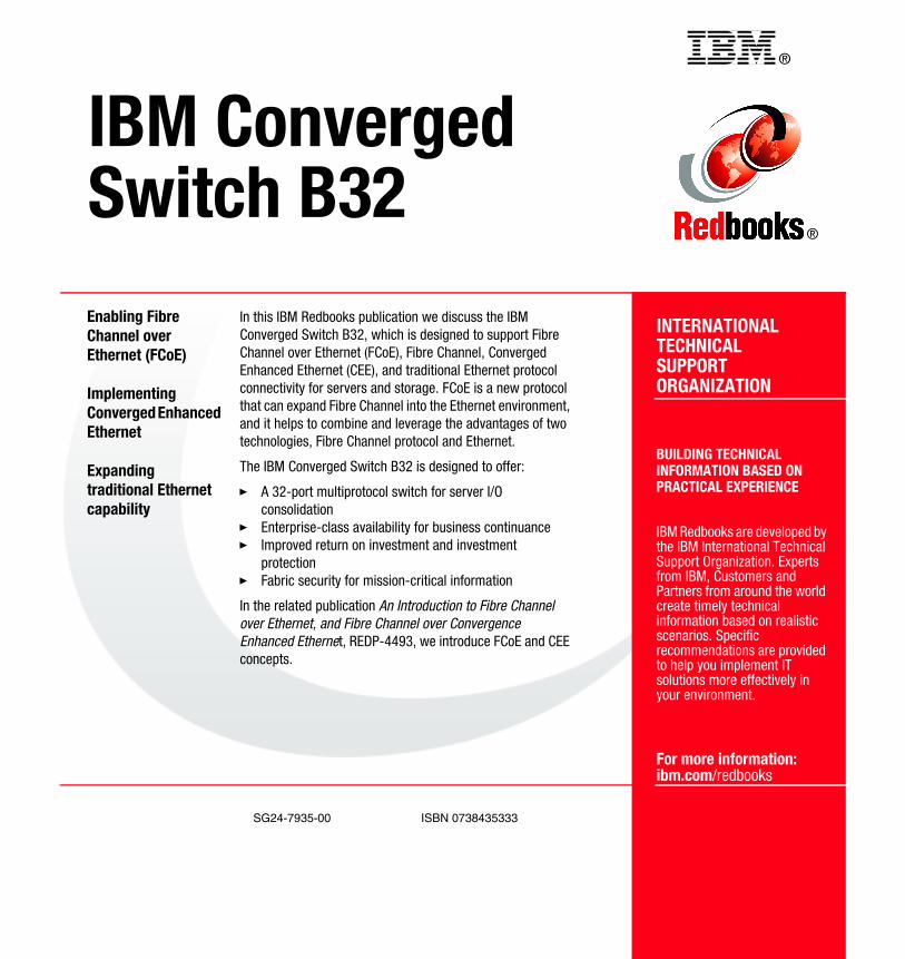
®
SG24-7935-00 ISBN 0738435333
INTERNATIONAL TECHNICALSUPPORTORGANIZATION
BUILDING TECHNICALINFORMATION BASED ONPRACTICAL EXPERIENCE
IBM Redbooks are developed by the IBM International Technical Support Organization. Experts from IBM, Customers and Partners from around the world create timely technical information based on realistic scenarios. Specific recommendations are provided to help you implement IT solutions more effectively in your environment.
For more information:ibm.com/redbooks
®
IBM Converged Switch B32Enabling Fibre Channel over Ethernet (FCoE)
Implementing Converged Enhanced Ethernet
Expanding traditional Ethernet capability
In this IBM Redbooks publication we discuss the IBM Converged Switch B32, which is designed to support Fibre Channel over Ethernet (FCoE), Fibre Channel, Converged Enhanced Ethernet (CEE), and traditional Ethernet protocol connectivity for servers and storage. FCoE is a new protocol that can expand Fibre Channel into the Ethernet environment, and it helps to combine and leverage the advantages of two technologies, Fibre Channel protocol and Ethernet.
The IBM Converged Switch B32 is designed to offer:
� A 32-port multiprotocol switch for server I/O consolidation
� Enterprise-class availability for business continuance� Improved return on investment and investment
protection� Fabric security for mission-critical information
In the related publication An Introduction to Fibre Channel over Ethernet, and Fibre Channel over Convergence Enhanced Ethernet, REDP-4493, we introduce FCoE and CEE concepts.
Back cover
Related Documents