25 th September 2015 Ref: GS6365-1A Nos. 28-30 Dumaresq Street Gordon NSW2072 Geotechnical Investigation Report Page 1 of 19 _______________________________________________________________________________________ © Aargus Pty Ltd GEOTECHNICAL INVESTIGATION REPORT Ibis Hotel Enfield, 626-628 Liverpool Road (Hume Highway) Strathfield South, NSW 2136 Prepared for Iris Capital Report No. GS8219-1A 28 th May 2021

Welcome message from author
This document is posted to help you gain knowledge. Please leave a comment to let me know what you think about it! Share it to your friends and learn new things together.
Transcript
25th September 2015
Ref: GS6365-1A Nos. 28-30 Dumaresq Street Gordon NSW2072
Geotechnical Investigation Report Page 1 of 19
_______________________________________________________________________________________
© Aargus Pty Ltd
GEOTECHNICAL INVESTIGATION
REPORT
Ibis Hotel Enfield,
626-628 Liverpool Road (Hume Highway)
Strathfield South, NSW 2136
Prepared for
Iris Capital
Report No. GS8219-1A
28th May 2021

28th May 2021
Ref: GS8219-1A, Ibis Hotel Enfield, 626-628 Liverpool Road, Strathfield South, NSW 2136
Geotechnical Investigation Report Page 2 of 19
_______________________________________________________________________________________
© Aargus Pty Ltd
CONTROLLED DOCUMENT
DISTRIBUTION AND REVISION REGISTER
Copy No. Custodian Location
_________________________________________________________________________
1 Nick Kariotoglou Aargus (Library)
2 Warren Duarte, Iris Capital GPO Box 5479
Sydney NSW 2001
3 (Electronic) Warren Duarte [email protected]
Note: This register identifies the current custodians of controlled copies of the subject
document.
It is expected that these custodians would be responsible for:
The storage of the document.
Ensuring prompt incorporation of amendments.
Making the document available to pertinent personnel within the organisation.
Encouraging observance of the document by such personnel.
Making the document available for audit.
DOCUMENT HISTORY
Revision No. Issue Date Description
_____________________________________________________________________
0 (GS8219-1A) 28 May 2021 First Issue
Issued By: Shyam Ghimire
28th May 2021
Ref: GS8219-1A, Ibis Hotel Enfield, 626-628 Liverpool Road, Strathfield South, NSW 2136
Geotechnical Investigation Report Page 3 of 19
_______________________________________________________________________________________
© Aargus Pty Ltd
TABLE OF CONTENTS
1. INTRODUCTION .................................................................................... 5
2. AVAILABLE INFORMATION .............................................................. 5
3. SCOPE OF WORK .................................................................................. 5
4. SITE DESCRIPTION ............................................................................... 6
5. PROPOSED DEVELOPMENT .............................................................. 7
6. SUBSURFACE CONDITIONS ............................................................... 7
6.1 Geology ................................................................................................................................................ 7
6.2 Ground Profile .................................................................................................................................... 7
6.3 Groundwater ...................................................................................................................................... 7
7. GEOTECHNICAL ASSESSMENT ........................................................ 8
7.1 General ................................................................................................................................................ 8
7.2 Excavation Conditions ....................................................................................................................... 8
7.3 Vibration Control ............................................................................................................................... 8
7.4 Stability of Excavation ....................................................................................................................... 9
7.5 Earth Pressures ................................................................................................................................ 11
7.6 Subgrade Preparation and Earthworks ......................................................................................... 12
7.7 Foundations ...................................................................................................................................... 13
7.8 Groundwater Management ............................................................................................................. 14
7.9 Laboratory Testing .......................................................................................................................... 15
7.10 Preliminary Site Earthquake Classification .................................................................................. 18
7.11 Further Investigation Recommendations ....................................................................................... 18
8. LIMITATIONS ....................................................................................... 19

28th May 2021
Ref: GS8219-1A, Ibis Hotel Enfield, 626-628 Liverpool Road, Strathfield South, NSW 2136
Geotechnical Investigation Report Page 4 of 19
_______________________________________________________________________________________
© Aargus Pty Ltd
LIST OF TABLES
Table 1: Summary of Subsurface Conditions 7
Table 2: Recommended Maximum Peak Particle Velocity 9
Table 3: Recommended Batter Slopes (Temporary) 9
Table 4: Preliminary Geotechnical Design Parameters for Retaining Walls 11
Table 5: Preliminary Coefficients of Lateral Earth Pressure 11
Table 6: Preliminary Allowable Bond Stress for Temporary Anchors 12
Table 7: Preliminary Geotechnical Foundation Design Capacities 14
Table 8. Results of Atterburg Limit Tests 15
Table 9. Results of CBR/ Compaction Testing 16
Table 10: Results of Electrical Conductivity Tests (Salinity) 16
Table 11: Soil pH, Chloride, Sulphate, Electrical Resistivity Test Results 18
LIST OF APPENDICES
APPENDIX A IMPORTANT INFORMATION ABOUT YOUR GEOTECHNICAL
REPORT
APPENDIX B SITE PLAN (FIGURE 1)
APPENDIX C ENGINEERING BOREHOLE LOGS
APPENDIX D DYNAMIC CONE PENETROMETER TEST RESULTS
APPENDIX E LABORATORY TEST RESULTS
REFERENCES
1. Australian Standard – AS 1726-2017 Geotechnical Site Investigation.
2. Australian Standard – AS 1170.4-2007 Structural Design Actions – Part 4:
Earthquake actions in Australia.
3. Australian Standard – AS3798-2007 Guidelines on Earthworks for Commercial and
Residential Developments.
4. Australian Standard – AS 2870-2011 Residential slabs and footings.
5. Australian Standard – AS 2159-2009 Piling - Design and installation.
6. Pells P.J.N, Mostyn, G. & Walker B.F., “Foundations on Sandstone and Shale in the
Sydney Region”, Australian Geomechanics Journal, 1998.

28th May 2021
Ref: GS8219-1A, Ibis Hotel Enfield, 626-628 Liverpool Road, Strathfield South, NSW 2136
Geotechnical Investigation Report Page 5 of 19
_______________________________________________________________________________________
© Aargus Pty Ltd
1. INTRODUCTION
Aargus Pty Ltd (Aargus) has been commissioned by Warren Duarte of Iris Capital, to carry
out a Geotechnical site investigation at the Ibis Hotel Enfield, at Nos. 626-628 Liverpool
Road (Hume Highway) Strathfield South, NSW 2136. The site investigation was carried
out on Monday 10th May 2021 and was followed by geotechnical interpretation, assessment
and preparation of a geotechnical report.
The purpose of the investigation was to assess the ground conditions and feasibility, from a
geotechnical perspective, of the site for a proposed development, being additions and
extensions to the existing hotel on the site.
This report presents results of the geotechnical site investigation, laboratory testing,
interpretation, and assessment of the site existing geotechnical conditions, as a basis to
provide recommendations for design and construction of ground structures for the
proposed development.
To assist in reading the report, reference should be made to the “Important Information
About Your Geotechnical Report” attached as Appendix A.
2. AVAILABLE INFORMATION
Prior to preparation of this report, the following information was made available to Aargus:
• Formule 1 Motel, Site and Location Plans, by Austin Australia Pty Ltd, Contract
No. AS1144, Sheet No. A10, Issue No. D, date 16/08/96.
• Architectural Plans, by Squillace Architects Interior Designers, Project Ibis Hotels,
Key Planning Controls and Return Brief, Stage Preliminary Investigations (PI),
Section 6 Ibis Budget Enfield, Plan No SK01, dated February 2021.
• First Floor Plan
• Ground Floor Plan
3. SCOPE OF WORK
In accordance with the brief, fieldwork for the geotechnical site investigation was carried
out by an experienced Geotechnical Engineer from Aargus; following in general the
guidelines provided in Australian Standard AS 1726-2017 (Reference 1) and comprised the
following:
• Collection and review of Dial-Before-You-Dig (DBYD) plans;
• A site walkover inspection in order to determine the overall surface conditions and
to identify any relevant site features;
• Service locating using electromagnetic detection equipment to ensure that the
investigation area is free from underground services;
• Machine boring of six (6) boreholes, to between 2.8 and 6.0m below ground level,
to the nominal depth of 6.0m or prior refusal on bedrock and one shallow borehole
for California Bearing Ratio test sampling.
• Dynamic Cone Penetrometer Tests were conducted to assess the in-situ strength of
subsurface soil layers;
28th May 2021
Ref: GS8219-1A, Ibis Hotel Enfield, 626-628 Liverpool Road, Strathfield South, NSW 2136
Geotechnical Investigation Report Page 6 of 19
_______________________________________________________________________________________
© Aargus Pty Ltd
• Representative soil samples from the boreholes for laboratory testing for Atterberg
limits and California Bearing Ratio (CBR) tests;
• Reinstatement of the boreholes with soil cuttings generated from the auger drilling,
and concrete finish at the surface.
The approximate location of the boreholes completed during the geotechnical site
investigation are shown on “Figure 1 - Site Plan” attached in Appendix B.
Boreholes BH1, BH2, BH4, BH5 and BH6 were auger bored to refusal at 2.8m, 2.5m, 5m,
5.6m and 5m, below ground level (bgl) respectively. BH7 was augered to termination
depth of 6.0 m and BH8 was terminated at 2.3m below ground level (for CBR sampling).
BH3 was not bored as a vehicle was parked over the location.
Following completion of the site investigation, laboratory testing was carried out on
selected rock core samples recovered from the borehole, and consisted of:
• Soil Salinity and Aggressivity Testing.
• Plasticity index Testing
• California Bearing Ratio (CBR) Tests
Based on the results of the site investigation and laboratory testing, Aargus carried out
geotechnical interpretation and assessment of the main potential geotechnical issues that
may be associated with the proposed development. A geotechnical report (this report) was
prepared to summarise the results of the geotechnical site investigation and to provide
comments and recommendations relating to:
• Excavation conditions;
• Stability of basement excavation;
• Suitable foundations;
• Allowable bearing pressure (and shaft adhesion for piles);
• Lateral pressure for design of retaining walls;
• Groundwater; and
• Site earthquake classification.
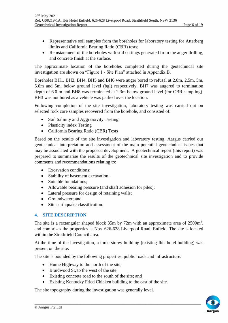
4. SITE DESCRIPTION
The site is a rectangular shaped block 35m by 72m with an approximate area of 2500m2,
and comprises the properties at Nos. 626-628 Liverpool Road, Enfield. The site is located
within the Strathfield Council area.
At the time of the investigation, a three-storey building (existing Ibis hotel building) was
present on the site.
The site is bounded by the following properties, public roads and infrastructure:
• Hume Highway to the north of the site;
• Braidwood St, to the west of the site;
• Existing concrete road to the south of the site; and
• Existing Kentucky Fried Chicken building to the east of the site.
The site topography during the investigation was generally level.

28th May 2021
Ref: GS8219-1A, Ibis Hotel Enfield, 626-628 Liverpool Road, Strathfield South, NSW 2136
Geotechnical Investigation Report Page 7 of 19
_______________________________________________________________________________________
© Aargus Pty Ltd
5. PROPOSED DEVELOPMENT
Based on the information provided by the client, the proposed development comprises the
demolition of the existing buildings on site and the construction of a new two-storey
building (pub with hotel rooms above) with one basement level on the Hume Highway side
of the site, plus a new light industrial building on grade at the rear of the site.
6. SUBSURFACE CONDITIONS
6.1 Geology
Reference to the Sydney 1:100,000 Geological Series Sheet 9130 Edition 1, dated 1983, by
the Geological Survey of New South Wales, Department of Mineral Resources, indicates
the site is located at a geological boundary underlain by Bringelly Shale (Rwb) of the
Wianamatta Group. The Rwb is described as “carbonaceous claystone, laminite, fine to
medium-grained lithic sandstone, rare coal and tuff”.
Assessment of the subsurface materials, discussed in Section 6.2, confirms the published
geology.
It should be noted this geological profile does not take into account any residual soils
derived from in-situ weathering of the bedrock, or the presence of fill that may have been
generated from previous earthworks.
6.2 Ground Profile
The subsoil conditions encountered within the boreholes are summarised in Table 1 and
detailed on the attached Engineering Borehole Logs attached to this report. Reference
should be made to the logs and/or specific test results for design purposes.
Table 1. Summary of Subsurface Conditions
Unit Description BH1
(m)
BH2
(m)
BH4
(m)
BH5
(m)
BH6
(m)
BH7
(m)
BH8
(m)
Pavement Asphalt 0.0-0.1 0.0-0.1 0.0-0.1 0.0-0.1 0.0-0.1 0.0-0.1 0.0-0.1
Fill
Sandy Silty CLAY, brown, red
brown, grey, medium to high
plasticity, with medium brick
gravel. With some coal gravel in
BH7
0.1-2.7 0.1-2.3 0.1-1.5 0.1-4.5 0.1-0.6 0.1-6.0 0.1-2.3
Bedrock1
SHALE, grey, with fine to
medium grained sandstone, pale
brown, extremely to highly
weathered, very low to low
estimated strength.
Inferred Class V Shale (or better).
2.7-2.8 2.3-2.5 1.5-5.0 4.5-5.6 0.6-5.0 - -
1Pells P.J.N, Mostyn G. & Walker B.F. Foundations on Sandstone and Shale in the Sydney Region, Australian
Geomechanics Journal, December 1998 (Reference 6).
6.3 Groundwater
Groundwater was not encountered during augering in the boreholes. Groundwater may be
encountered within the underlying weathered bedrock.

28th May 2021
Ref: GS8219-1A, Ibis Hotel Enfield, 626-628 Liverpool Road, Strathfield South, NSW 2136
Geotechnical Investigation Report Page 8 of 19
_______________________________________________________________________________________
© Aargus Pty Ltd
7. GEOTECHNICAL ASSESSMENT
7.1 General
Consideration needs to be given to specific geotechnical issues including excavation
stability, foundation conditions and temporary shoring. Geotechnical commentary
regarding these geotechnical constraints and recommendations for the proposed
development is presented in the following sections.
7.2 Excavation Conditions
Excavation for the development of the site is expected to be through fill and then into Shale
bedrock of generally very low to low strength, grading to medium strength in places.
Excavation within the soils and extremely low to low strength bedrock is expected to be
readily achieved using a large hydraulic excavator down to the level of medium or stronger
bedrock. However, localised use of rock breaking equipment or ripping may be required
where high strength bands are encountered.
For medium or greater strength rock (if encountered), excavation will require the use of
heavy ripping and/or hydraulic rock hammers. Excavation for foundations or trenches in
this strength sandstone may require the use of hydraulic hammers and possibly a rock saw.
Both noise and vibration will be generated by excavation work within these bedrock
materials.
The rock classification system in Table 1 should not be used to directly assess rock
excavation characteristics. Contractors should refer to the engineering logs, core
photographs and point load tests when assessing the suitability of their excavation
equipment.
7.3 Vibration Control
Where rock hammering is required for excavation through medium strength (or greater)
rock, or other activities that cause vibration, consideration should be given to a vibration
monitoring plan during construction of the proposed development, to monitor the potential
vibration effects on existing buildings within adjoining properties, during excavation,
piling, and from the demolition works.
To ensure vibration levels remain within acceptable levels and to minimise the potential
effects of vibration, if required, excavation into medium strength bedrock or stronger
should be complemented with saw cutting or other appropriate methods prior to
excavation. Rock saw cutting should be carried out using an excavator mounted rock saw,
or similar, so as to minimise transmission of vibrations to any adjoining properties that
may be affected. Hammering is not recommended and should be avoided. However, if
necessary, hammering should be carried out horizontally along bedding planes of (pre-cut)
broken rock blocks or boulders where possible and at the required operational limit to
ensure noise levels are restricted to limits acceptable to adjacent residents.
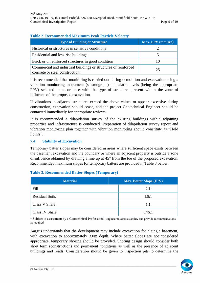
Recommended Maximum Peak Particle Velocity (PPV) for different types of building or
structure is summarised in Table 2. Induced vibrations in structures adjacent to the
excavation should not be exceeded.
28th May 2021
Ref: GS8219-1A, Ibis Hotel Enfield, 626-628 Liverpool Road, Strathfield South, NSW 2136
Geotechnical Investigation Report Page 9 of 19
_______________________________________________________________________________________
© Aargus Pty Ltd
Table 2. Recommended Maximum Peak Particle Velocity
Type of Building or Structure Max. PPV (mm/sec)
Historical or structures in sensitive conditions 2
Residential and low-rise buildings 5
Brick or unreinforced structures in good condition 10
Commercial and industrial buildings or structures of reinforced
concrete or steel construction. 25
It is recommended that monitoring is carried out during demolition and excavation using a
vibration monitoring instrument (seismograph) and alarm levels (being the appropriate
PPV) selected in accordance with the type of structures present within the zone of
influence of the proposed excavation.
If vibrations in adjacent structures exceed the above values or appear excessive during
construction, excavation should cease, and the project Geotechnical Engineer should be
contacted immediately for appropriate reviews.
It is recommended a dilapidation survey of the existing buildings within adjoining
properties and infrastructure is conducted. Preparation of dilapidation survey report and
vibration monitoring plan together with vibration monitoring should constitute as “Hold
Points”.
7.4 Stability of Excavation
Temporary batter slopes may be considered in areas where sufficient space exists between
the basement excavation and the boundary or where an adjacent property is outside a zone
of influence obtained by drawing a line up at 45° from the toe of the proposed excavation.
Recommended maximum slopes for temporary batters are provided in Table 3 below.
Table 3. Recommended Batter Slopes (Temporary)
Material Max. Batter Slope (H:V)
Fill 2:1
Residual Soils 1.5:1
Class V Shale 1:1
Class IV Shale 0.75:1
1 Subject to assessment by a Geotechnical Professional Engineer to assess stability and provide recommendations
as required.
Aargus understands that the development may include excavation for a single basement,
with excavation to approximately 3.0m depth. Where batter slopes are not considered
appropriate, temporary shoring should be provided. Shoring design should consider both
short term (construction) and permanent conditions as well as the presence of adjacent
buildings and roads. Consideration should be given to inspection pits to determine the

28th May 2021
Ref: GS8219-1A, Ibis Hotel Enfield, 626-628 Liverpool Road, Strathfield South, NSW 2136
Geotechnical Investigation Report Page 10 of 19
_______________________________________________________________________________________
© Aargus Pty Ltd
nature and depth of adjacent footings of neighbouring properties and to determine the need
for underpinning to rock prior to excavation.
Based on the ground conditions encountered and the requirements of the proposed
development, consideration may be given to a soldier pile wall solution extending and
socketing to the underlying bedrock, with shotcrete infill panels to support soil. Piles
should be anchored with at least one row of anchors.
Where the retained height is such that tolerable wall movements can be achieved using a
cantilevered wall arrangement (typically less than 2.5m high) or where only one row of
anchors is required (to control lateral deflection), a triangular pressure distribution may be
adopted for derivation of active pressures. Where two or more rows of anchors are required
to support the shoring due to significant retained height or where significant lateral
movements cannot be tolerated (e.g., due to adjacent infrastructure), the shoring/basement
wall should be designed as a braced structure.
If adopted, anchor designs should be based on allowing effective bonding to be developed
behind an ‘active zone’ determined by drawing a line at 45° from the base of the wall to
intersect the ground surface behind the excavated face. It is considered that basement floor
slabs will provide permanent restraint to the retaining walls where these are incorporated
into the permanent works. Anchors are therefore considered to be temporary but depending
on the sensitivity of the adjacent infrastructure, it may be necessary to incorporate the
temporary anchors into the permanent works to control deflections.
Anchor installation beyond the property boundaries will be subject to approval by owners
of adjoining properties, roads and infrastructure. Where an anchorage system is shown to
be impractical, consideration of other temporary support options would be necessary.
These options include the following:
• Temporary solutions such as installation of props associated with staged
excavation; and
• Staged excavations and temporary partial berms in front of walls.
• Top-down construction where floor slabs and beams are constructed at the top of
shoring wall and at floor levels of the upper basement levels prior to excavation
within the basement level underneath the floor slabs.
The design of retaining structures should take into account horizontal pressures due to
surcharge loads from any adjacent infrastructure. The shoring wall and anchors can be
designed using the recommended parameters provided in Section 7.5 below.
A dilapidation survey will be required prior to excavation for the existing buildings within
the adjoining properties and the section of road carriageway and road reserve adjoining the
site.
Detailed construction supervision, monitoring and inspections will be required during
piling and subsequent bulk excavation and should be carried out by an experienced
Geotechnical Engineer, in addition to inspection of the structural elements by the Project
Structural Engineer. The inspections should constitute as “Hold Points”.
28th May 2021
Ref: GS8219-1A, Ibis Hotel Enfield, 626-628 Liverpool Road, Strathfield South, NSW 2136
Geotechnical Investigation Report Page 11 of 19
_______________________________________________________________________________________
© Aargus Pty Ltd
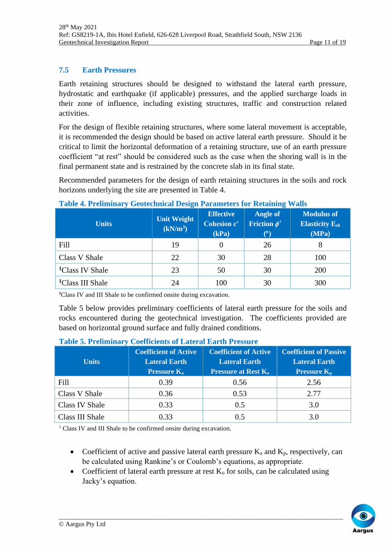
7.5 Earth Pressures
Earth retaining structures should be designed to withstand the lateral earth pressure,
hydrostatic and earthquake (if applicable) pressures, and the applied surcharge loads in
their zone of influence, including existing structures, traffic and construction related
activities.
For the design of flexible retaining structures, where some lateral movement is acceptable,
it is recommended the design should be based on active lateral earth pressure. Should it be
critical to limit the horizontal deformation of a retaining structure, use of an earth pressure
coefficient “at rest” should be considered such as the case when the shoring wall is in the
final permanent state and is restrained by the concrete slab in its final state.
Recommended parameters for the design of earth retaining structures in the soils and rock
horizons underlying the site are presented in Table 4.
Table 4. Preliminary Geotechnical Design Parameters for Retaining Walls
Units Unit Weight
(kN/m3)
Effective
Cohesion c’
(kPa)
Angle of
Friction ′
()
Modulus of
Elasticity Esh
(MPa)
Fill 19 0 26 8
Class V Shale 22 30 28 100
1Class IV Shale 23 50 30 200
1Class III Shale 24 100 30 300
1Class IV and III Shale to be confirmed onsite during excavation.
Table 5 below provides preliminary coefficients of lateral earth pressure for the soils and
rocks encountered during the geotechnical investigation. The coefficients provided are
based on horizontal ground surface and fully drained conditions.
Table 5. Preliminary Coefficients of Lateral Earth Pressure
Units
Coefficient of Active
Lateral Earth
Pressure Ka
Coefficient of Active
Lateral Earth
Pressure at Rest Ko
Coefficient of Passive
Lateral Earth
Pressure Kp
Fill 0.39 0.56 2.56
Class V Shale 0.36 0.53 2.77
Class IV Shale 0.33 0.5 3.0
Class III Shale 0.33 0.5 3.0 1 Class IV and III Shale to be confirmed onsite during excavation.
• Coefficient of active and passive lateral earth pressure Ka and Kp, respectively, can
be calculated using Rankine’s or Coulomb’s equations, as appropriate.
• Coefficient of lateral earth pressure at rest Ko for soils, can be calculated using
Jacky’s equation.

28th May 2021
Ref: GS8219-1A, Ibis Hotel Enfield, 626-628 Liverpool Road, Strathfield South, NSW 2136
Geotechnical Investigation Report Page 12 of 19
_______________________________________________________________________________________
© Aargus Pty Ltd
The coefficients of lateral earth pressure should be verified by the project Structural
Engineer prior to use in the design of retaining walls. Simplified calculations of lateral
active (or at rest) and passive earth pressures can be carried out for cantilever walls using
Rankine’s equation shown below:
𝑃𝑎 = 𝐾 𝛾 𝐻 − 2𝑐√𝐾 For calculation of lateral active or ‘at rest’ earth pressure
𝑃𝑝 = 𝐾𝑝 𝛾 𝐻 + 2𝑐√𝐾𝑝 For calculation of passive earth pressure
For braced retaining walls, a uniform lateral earth pressure should be adopted as follows:
𝑃𝑎 = 0.65 𝐾 𝛾 𝐻 For calculation of active earth pressure
Where;
Pa = Active (or at rest) Earth Pressure (kN/m2)
Pp = Passive Earth Pressure (kN/m2)
= Bulk density (kN/m3)
K = Coefficient of Earth Pressure (Ka or Ko)
Kp = Coefficient of Passive Earth Pressure
H = Retained height (m)
c = Effective Cohesion (kN/m2)
If adopted, temporary anchors will require embedment in bedrock. Preliminary allowable
bond stresses may be adopted for temporary anchors, as detailed in Table 6 below.
Table 6. Preliminary Allowable Bond Stress for Rock Anchors
Units Allowable Bond Stress (kPa)
Class V Shale 60
Class IV Shale 100
Class III Shale 300 1 Class IV and III Shale to be confirmed onsite during excavation.
Anchors should undergo proof testing following installation. The anchors can be designed
for the parameters recommended above providing:
• The bond (socket) length is at least 3.0m; and
• Anchors are proof tested to 1.3 times the design working load specified by the
Structural Engineer, before they are locked off at working load. Anchor testing
should constitute as a “Hold Point”.
7.6 Subgrade Preparation and Earthworks
The following general procedure is provided for site preparation of building platforms and
pavements:
• Strip topsoil and remove any unsuitable material from site.
• Excavate fill, residual soils and rock stockpiling for re-use as engineered fill or
remove to spoil.
• Where clayey soil is exposed at formation level, the exposed surface should be
treated and moisture conditioned to within 2% of optimum moisture content (OMC)

28th May 2021
Ref: GS8219-1A, Ibis Hotel Enfield, 626-628 Liverpool Road, Strathfield South, NSW 2136
Geotechnical Investigation Report Page 13 of 19
_______________________________________________________________________________________
© Aargus Pty Ltd
followed by proof rolling with a smooth drum roller. Soft or loose areas should be
excavated and replaced with approved fill material.
• Where rock is exposed at footing level, it should be free of loose or softened
material.
The suitability of imported materials for filling should be subject to the following criteria:
• The materials should be clean (i.e. free of contaminants, deleterious or organic
material), free of inclusions of >120mm in size; high plasticity material and soft
material be removed and suitably conditioned to meet the design assumptions
where fill material is proposed to be used.
• Material with excessive moisture content should not be used without conditioning.
• The materials should satisfy the Australian Standard AS 3798-2007 (Reference 3).
The final surface levels of all cut and fill areas should be compacted in order to enable the
subgrade to achieve adequate strength for the proposed building platforms.
For the fill construction, the recommended compaction targets should be the following:
• Moisture content of ±2% of OMC (Optimal Moisture Content);
• Minimum density ratio of 98% of the maximum dry density for the building
platforms of the proposed dwellings;
• The loose thickness of layer should not exceed 300mm during the compaction.
Design and construction of earthworks should be carried out in accordance with Australian
Standard AS 3798-2007 (Reference 3). Inspections by the project Geotechnical Engineer
will be required during earthworks, subgrade preparation and proof rolling. The
inspections should constitute as “Hold Points”.
7.7 Foundations
Bulk excavation is mainly likely to expose Fill and Class V Shale rock or better within the
footprint of the proposed development. Suitable footings are likely to comprise a
reinforced concrete raft slab with pad and strip footings to support columns and walls
where suitable bedrock is exposed at bulk excavation level.
It is recommended that all footings be founded on consistent subsurface materials to
minimise the risk of differential settlement. This could be achieved by strip footings where
suitable bedrock is exposed at bulk excavation level and shallow pad or pile foundations
elsewhere. Installation of piles may be required in cases where axial loads on columns and
walls exceed the bearing pressure of the bedrock present at bulk excavation level and
should be socketed into Class III Shale (presence and depth to be confirmed).
Other cases where piles may be required include the need to increase the resistance against
lateral seismic and wind loads. Design of shallow and pile foundations should be carried
out in accordance with Australian Standards AS2870-2011 (Reference 4) and AS2159-
2009 (Reference 5), respectively.
Table 7 provides geotechnical parameters recommended for design of shallow and piled
foundations.

28th May 2021
Ref: GS8219-1A, Ibis Hotel Enfield, 626-628 Liverpool Road, Strathfield South, NSW 2136
Geotechnical Investigation Report Page 14 of 19
_______________________________________________________________________________________
© Aargus Pty Ltd
Table 7. Preliminary Geotechnical Foundation Design Capacities
Unit
Allowable Capacity Values (kPa)
End Bearing
Pressure1
Shaft Adhesion Compression
(Tension)2
Fill N/A3 N/A3
Class V Shale 700 50 (25)
4 Class IV Shale 1000 100 (50)
4 Class III Shale 3500 200 (100) 1 With a minimum embedment depth of 0.5m for deep foundations and 0.4m for shallow foundations. 2 Clean rock socket of roughness of at least R2, ie grooves of depth 1mm to 4mm and width greater than 5mm at spacing of 50mm to 200mm. Shaft Adhesion in Tension is 50% of Compression, applicable to piles only. 3 N/A, Not Applicable, not recommended for the proposed building of this development. 4The actual depth of the underlying Class IV and III Sandstone, if present, should be confirmed during construction if required.
Shaft adhesion may be applied to socketed piles adopted for foundations provided socket
shaft lengths conform to appropriate classes of rock and accepted levels of shaft sidewall
cleanliness and roughness. The rock socket sidewalls should be free of soil and/or crushed
rock to the extent that natural rock is exposed over at least 80% of the socket sidewall.
Shaft adhesion should be reduced or ignored within socket lengths that are smeared and fail
to satisfy cleanliness requirements. Additional attention to cleanliness of socket sidewalls
may be required where presence of clay seams and weathered rock bands is evident over
socket lengths. Where the piles penetrate soils that are susceptible to shrinkage and
swelling, we recommend that the shaft adhesion be ignored in the zone of seasonal
moisture variations due to the potential of shrinkage cracking.
The excavations should be dewatered using conventional sump and pump methods, prior to
concrete pouring if groundwater seepages or surface runoff are encountered within
foundation excavations. Any loose debris and wet soils should also be removed from
excavations.
An experienced Geotechnical Engineer should review footing designs to ensure
compliance with the recommendations in the geotechnical report and assess foundation
excavations to ensure suitable materials of appropriate bearing capacity have been reached.
The presence of water within foundation excavations may negate satisfactory examination
of founding surfaces and certification of founding materials quality. Foundation
inspections should only be undertaken under conditions satisfying WHS requirements.
Verification of the capacity of the shallow and pile foundations by inspections would be
required and inspections should constitute as “Hold Points”.
7.8 Groundwater Management
Groundwater in the form of minor seepage was encountered only in BH7 at a depth of
5.0m. No groundwater was encountered in the other boreholes during the investigation.
Groundwater may be present in fractures in the underlying bedrock.

28th May 2021
Ref: GS8219-1A, Ibis Hotel Enfield, 626-628 Liverpool Road, Strathfield South, NSW 2136
Geotechnical Investigation Report Page 15 of 19
_______________________________________________________________________________________
© Aargus Pty Ltd
Based on observations during the fieldwork, any groundwater is likely to be minor, and
easily controllable with standard sump and pump methods.
7.9 Laboratory Testing
Recovered soil samples from the site were submitted to NATA accredited materials testing
laboratory for testing. The testing comprised:
• Two Atterberg Limits Tests
• One CBR/ Compaction Test
• Two Soil Salinity and Aggressivity Assessment (pH, Chloride Cl- and Sulphates
SO4)
7.9.1 Atterberg Limits Test Results
Atterburg limits and linear shrinkage testing was carried out on disturbed soil samples
recovered from boreholes BH6 and BH8. The results of the tests are presented in Table 6
below and detailed on the attached Laboratory Test Results presented in Appendix E.
Table 1. Results of Atterburg Limit Tests
7.9.2 CBR and Compaction Testing
During the course of the investigation, one bulk sample was obtained from the borehole
BH3, at 0.5-1.5m depth. The sample was tested for determination of the California Bearing
Ratio (CBR) for pavement design purposes, with testing being carried out in Aargus’
NATA accredited laboratory in accordance with Australian Standards AS1289-1998.
Optimum moisture content and Maximum Dry Density tests were performed as part of
CBR testing to determine the moisture content at which maximum dry density could be
achieved during pavement construction.
The results of CBR testing are presented in Table 7 with the laboratory test result sheets
attached in Appendix E.
Borehole ID Depth (m)
Moisture
Content
(%)
Liquid
Limit
(%)
Plastic
Limit
(%)
Plasticity
index
(%)
Linear
Shrinkage
(%)
BH6 0.4-0.7 19.1 65 20 45 14.5
BH8 1.5-1.7 19.1 45 16 29 12.5

28th May 2021
Ref: GS8219-1A, Ibis Hotel Enfield, 626-628 Liverpool Road, Strathfield South, NSW 2136
Geotechnical Investigation Report Page 16 of 19
_______________________________________________________________________________________
© Aargus Pty Ltd
Table 2. Results of CBR/ Compaction Testing
Location Depth
(m) Description
Moisture
Content
(%)
MDD 1 OMC 2 Swell
(%)
CBR
(%)
Linear
Shrinkage
(%)
BH8 0.7-1.7 Silty Clay 17.0 1.77 15.8 0.5 5 12.5
1. Maximum Dry Density (t/m3)
2. Optimum Moisture Content (%)
7.9.3 Exposure Classification for Ground Structures – Soil Salinity & Aggressivity
Assessment
Two soil samples recovered from the boreholes were tested by ALS, a NATA accredited
laboratory. The testing comprised:
• Soil Salinity and Aggressivity testing (pH, Chloride Cl-, Sulphates SO4, electrical
conductivity and moisture content).
Results of the laboratory testing are attached to this report and are summarised in Tables 8
and 9.
Through introduction of a multiplying factor to the test results, as stipulated in the
Department of Natural Resources (DNR) publication “Site Investigations for Urban
Salinity” (2002), the resultant electrical conductivity of saturated extracts (ECe) from the
samples tested ranged from approximately 0.32 dS/m to 0.18 dS/m, as shown in Table 3,
indicating samples of the Residual Clay soils tested to be “Non saline”.
Table 10. Results of Electrical Conductivity Tests (Salinity)
Borehole Depth
(m bgl)
Electrical
Conductivity (dS/m)
Multiplication
Factor a
Electrical Conductivity of
Saturated Extract (dS/m) Soil Type
Ec
ECe
BH1/
DCP1 0.5-0.6 0.046 7 0.32
Residual Heavy
Clay
BH2/
DCP2 0.5-0.6 0.026 7 0.18
Residual Heavy
Clay
“Site Investigations for Urban Salinity” (2002) Saline at >4 dS/m
Non-saline <2 dS/m
Slightly saline 2-4 dS/m
Moderately saline 4-8 dS/m
Very saline 8-16 dS/m
Highly saline >16 dS/m
28th May 2021
Ref: GS8219-1A, Ibis Hotel Enfield, 626-628 Liverpool Road, Strathfield South, NSW 2136
Geotechnical Investigation Report Page 17 of 19
_______________________________________________________________________________________
© Aargus Pty Ltd
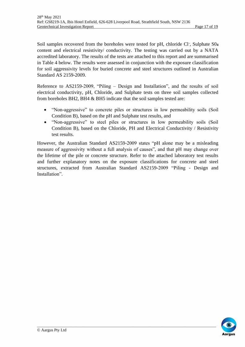
Soil samples recovered from the boreholes were tested for pH, chloride Cl-, Sulphate S04
content and electrical resistivity/ conductivity. The testing was carried out by a NATA
accredited laboratory. The results of the tests are attached to this report and are summarised
in Table 4 below. The results were assessed in conjunction with the exposure classification
for soil aggressivity levels for buried concrete and steel structures outlined in Australian
Standard AS 2159-2009.
Reference to AS2159-2009, “Piling – Design and Installation”, and the results of soil
electrical conductivity, pH, Chloride, and Sulphate tests on three soil samples collected
from boreholes BH2, BH4 & BH5 indicate that the soil samples tested are:
• “Non-aggressive” to concrete piles or structures in low permeability soils (Soil
Condition B), based on the pH and Sulphate test results, and
• “Non-aggressive” to steel piles or structures in low permeability soils (Soil
Condition B), based on the Chloride, PH and Electrical Conductivity / Resistivity
test results.
However, the Australian Standard AS2159-2009 states “pH alone may be a misleading
measure of aggressivity without a full analysis of causes”, and that pH may change over
the lifetime of the pile or concrete structure. Refer to the attached laboratory test results
and further explanatory notes on the exposure classifications for concrete and steel
structures, extracted from Australian Standard AS2159-2009 “Piling - Design and
Installation”.

28th May 2021
Ref: GS8219-1A, Ibis Hotel Enfield, 626-628 Liverpool Road, Strathfield South, NSW 2136
Geotechnical Investigation Report Page 18 of 19
_______________________________________________________________________________________
© Aargus Pty Ltd
Table 11. Soil pH, Chloride, Sulphate, Electrical Resistivity Test Results
Borehole Depth
(m bgl)
MC*
(%) pH
Chloride
(mg/kg)
Sulphate as S04
(mg/kg)
Electrical
Resistivity
(ohm.cm)
BH1 0.5-0.6 21.4 6.2 40 20 21,739
BH2 0.5-0.6 14.7 5.7 20 40 38,461
AS2159-2009
Piling - Design and Installation
Reinforced Concrete Piles
High Permeability Soils
Mild >5.5 - <5000 -
Moderately aggressive 4.5 - 5.5 - 5000 – 10,000 -
Severely aggressive 4.0 - 4.5 - 10,000 – 20,000 -
Very severely <4.0 - >20,000 -
Low Permeability Soils
Non-aggressive > 5.5 - <5000 -
Mild 4.5 - 5.5 - 5000 – 10,000 -
Moderately aggressive 4.0 - 4.5 - 10,000 – 20000 -
Severely aggressive <4.0 - >20,000 -
Steel Piles
High Permeability Soils
Non-aggressive >5.0 <5000 - >5,000
Mild 4.0 - 5.0 5000 – 20,000 - 2,000-5,000
Moderately aggressive 3.0 - 4.0 20,000-50,000 - 1,000-2,000
Severe <3 >50,000 - <1,000
Low Permeability Soils
Non-aggressive >5.0 <5000 - >5,000
Non-aggressive 4.0 - 5.0 5000 – 20,000 - 2,000-5,000
Mild 3.0 - 4.0 20,000-50,000 - 1,000-2,000
Moderately aggressive <3.0 >50,000 - <1,000
Note: MC * = Moisture Content
Note: Electrical Resistivity converted from Electrical Conductivity
7.10 Preliminary Site Earthquake Classification
The results of the site investigation indicate the presence of fill and residual soil extending
to depths between 2.5m and > 6.0m (varying within the site), underlain by residual soils
and very low to low strength Class V Shale or better.
In accordance with Australian Standard AS 1170.4-2007 (Reference 2) the site may be
classified as a “Shallow soil site” (Class Ce) for design of foundations and retaining walls
embedded in the underlying soils and weathered Shale. The Hazard Factor (Z) for Sydney
in accordance with AS 1170.4-2007 is considered to be 0.08.
7.11 Further Investigation Recommendations
The preliminary geotechnical site investigation comprised borehole drilling to a maximum
depth of 6.0m, with most boreholes encountering TC-bit refusal in weathered bedrock
(Class V Shale or better). Borehole BH7 was terminated at the target depth of 6.0m, ending
in Fill.

28th May 2021
Ref: GS8219-1A, Ibis Hotel Enfield, 626-628 Liverpool Road, Strathfield South, NSW 2136
Geotechnical Investigation Report Page 19 of 19
_______________________________________________________________________________________
© Aargus Pty Ltd
Therefore, Aargus recommends further site investigation be carried out to confirm the
actual depth of the rock, and to determine the type and strength of the rock at this site
location for design purposes:
• Machine drilling of at least two boreholes to TC-bit refusal followed by NMLC
coring in bedrock for at least 2m rock coring to establish rock class, allowable
bearing capacities to optimise foundation design.
8. LIMITATIONS
The geotechnical assessment of the subsurface profile and geotechnical conditions within
the proposed development area and the conclusions and recommendations presented in this
report have been based on available information obtained during the work carried out by
Aargus and in the provided documents listed in Section 2 of this report. Inferences about
the nature and continuity of ground conditions away from and beyond the locations of field
exploratory tests are made but cannot be guaranteed.
It is recommended that should ground conditions including subsurface and groundwater
conditions, encountered during construction and excavation vary substantially from those
presented within this report, Aargus Pty Ltd be contacted immediately for further advice
and any necessary review of recommendations. Aargus does not accept any liability for site
conditions not observed or accessible during the time of the inspection.
This report and associated documentation and the information herein have been prepared
solely for the use of Iris Capital and any reliance assumed by third parties on this report
shall be at such parties’ own risk. Any ensuing liability resulting from use of the report by
third parties cannot be transferred to Aargus Pty Ltd, directors or employees.
For and on behalf of
Aargus Pty Ltd
Rafael Furniss
Senior Engineering Geologist
BSc (Applied Geology), Hons, MSc
MAGS, MAIG, ISSMGE
Attachments
➢ Important Information about this Report
➢ Site Location Plan
➢ Borehole Logs
➢ DCP Test Results
➢ Laboratory Test Results

APPENDIX A
______________________________
Information About Geotech Report

IMPORTANT INFORMATION ABOUT YOURGEOTECHNICAL ENGINEERING REPORT
More construction problems are caused by sitesubsurface conditions than any other factor. Astroublesome as subsurface problems can be, theirfrequency and extent have been lessenedconsiderably in recent years, due in largemeasure to programs and publications of ASFE/The Association of Engineering Firms Practicingin the Geosciences.
The following suggestions and observations areoffered to help you reduce the geotechnical-related delays, cost-overruns and other costlyheadaches that can occur during a constructionproject.
A GEOTECHNICAL ENGINEERING
REPORT IS BASED ON A UNIQUE SET
OF PROJECT-SPECIFIC FACTORS
A geotechnical engineering report is based on asubsurface exploration plan designed toincorporate a unique set of project-specificfactors. These typically include the generalnature of the structure involved, its size andconfiguration, the location of the structure on thesite and its orientation, physical concomitantssuch as access roads, parking lots, andunderground utilities, and the level of additionalrisk which the client assumed by virtue oflimitations imposed upon the exploratoryprogram.
To help avoid costly problems, consult thegeotechnical engineer to determine how anyfactors which change subsequent to the date ofthe report may affect its recommendations.
Unless your consulting geotechnical engineerindicates otherwise, your geotechnicalengineering report should NOT be used:
when the nature of the proposed structure ischanged: for example, if an office building willbe erected instead of a parking garage, or if arefrigerated warehouse will be built instead ofan un-refrigerated one,
when the size or configuration of the proposedstructure is altered,
when the location or orientation of the proposedstructure is modified,
when there is a change of ownership, or
for application to an adjacent site.
Geotechnical engineers cannot acceptresponsibility for problems which may develop ifthey are not consulted after factors considered intheir report's development have changed.
Geotechnical reports present the results ofinvestigations carried out for a specific project andusually for a specific phase of the project. Thereport may not be relevant for other phases of theproject, or where project details change.
The advice herein relates only to this project and thescope of works provided by the Client.
Soil and Rock Descriptions are based on AS1726-1993, using visual and tactile assessment except atdiscrete locations where field and/or laboratory testshave been carried out. Refer to the attached termsand symbols sheets for definitions.
MOST GEOTECHNICAL "FINDINGS"
ARE PROFESSIONAL ESTIMATES
Site exploration identifies actual subsurfaceconditions only at those points where samples aretaken, when they are taken. Data derived throughsampling and subsequent laboratory testing areextrapolated by geotechnical engineers who thenrender an opinion about overall subsurfaceconditions, their likely reaction to proposedconstruction activity, and appropriate foundationdesign. Even under optimal circumstances actualconditions may differ from those inferred to exist,because no geotechnical engineer, no matter how
cynthia
Stamp
_______________________________________________________________________________________Page 2 of 3 Important Information About Your Geotechnical Engineering Report
qualified, and no subsurface explorationprogram, no matter how comprehensive, canreveal what is hidden by earth, rock and time.The actual interface between materials maybe far more gradual or abrupt than a reportindicates. Actual conditions in areas notsampled may differ from predictions. Nothingcan be done to prevent the unanticipated, butsteps can be taken to help minimize theirimpact. For this reason, most experiencedowners retain their geotechnical consultantsthrough the construction stage, to identifyvariances, conduct additional tests which maybe needed, and to recommend solutions toproblems encountered on site.
SUBSURFACE CONDITIONS CAN
CHANGE
Subsurface conditions may be modified byconstantly changing natural forces. Because ageotechnical engineering report is based onconditions which existed at the time ofsubsurface exploration, construction decisionsshould not be based on a geotechnicalengineering report whose adequacy may havebeen affected by time. Speak with thegeotechnical consultant to learn if additionaltests are advisable before construction starts.
Construction operations at or adjacent to thesite and natural events such as floods,earthquakes or groundwater fluctuationsmay also affect subsurface conditions, andthus, the continuing adequacy of a geotechnicalreport. The geotechnical engineer should bekept apprised of any such events, and should beconsulted to determine if additional tests arenecessary.
Subsurface conditions can change with timeand can vary between test locations.Construction activities at or adjacent to the siteand natural events such as flood, earthquake orgroundwater fluctuations can also affect thesubsurface conditions.
GEOTECHNICAL SERVICES ARE
PERFORMED FOR SPECIFIC
PURPOSES AND PERSONS
Geotechnical engineers’ reports are prepared to meetthe specific needs of specific individuals. A reportprepared for a consulting civil engineer may not beadequate for a construction contractor, or even someother consulting civil engineer. Unless indicatedotherwise, this report was prepared expressly for theclient involved and expressly for purposes indicatedby the client. Use by any other persons for anypurpose, or by the client for a different purpose, mayresult in problems.No individual other than the client should applythis report for its intended purpose without firstconferring with the geotechnical engineer. Noperson should apply this report for any purposeother than that originally contemplated withoutfirst conferring with the geotechnical engineer.
A GEOTECHNICAL ENGINEERING
REPORT IS SUBJECT TO
MISINTERPRETATION
Costly problems can occur when other designprofessional develop their plans based onmisinterpretations of a geotechnicalengineering report. To help avoid theseproblems, the geotechnical engineer should beretained to work with other appropriate designprofessionals to explain relevant geotechnicalfindings and to review the adequacy of theirplans and specifications relative togeotechnical issues.
The interpretation of the discussion andrecommendations contained in this report are basedon extrapolation/interpretation from data obtained atdiscrete locations. Actual conditions in areas notsampled or investigated may differ from thosepredicted
BORING LOGS SHOULD NOT BE
SEPARATED FROM THE ENGINEERING
REPORT
Final boring logs are developed bygeotechnical engineers based upon theirinterpretation of field logs (assembled by sitepersonnel) and laboratory evaluation of fieldsamples. Only final boring logs customarilyare included in geotechnical engineeringreports. These logs should not under anycircumstances be redrawn for inclusion inarchitectural or other design drawings becausedrafters may commit errors or omissions in the

_______________________________________________________________________________________Page 3 of 3 Important Information About Your Geotechnical Engineering Report
transfer process. Although photographicreproduction eliminates this problem, itdoes nothing to minimize the possibilityof contractors misinterpreting the logsduring bid preparation. When this occurs,delays, disputes and unanticipated costsare the all-too-frequent result.
To minimise the likelihood of boring logmisinterpretation, give contractors readyaccess in the complete geotechnicalengineering report prepared or authorizedfor their use. Those who do not providesuch access may proceed under mistakenimpression that simply disclaimingresponsibility for the accuracy ofsubsurface information always insulatesthem from attendant liability. Providingthe best available information tocontractors helps prevent costlyconstruction problems and the adversarialattitudes which aggravate them todisproportionate scale.READ RESPONSIBILITY
CLAUSES CLOSELY
Because geotechnical engineering is basedextensively on judgment and opinion, it isfar less exact than other designdisciplines. This situation has resulted inwholly unwarranted claims being lodgedagainst geotechnical consultants. To helpprevent this problem, geotechnicalengineers have developed model clausesfor use in written transmittals. These arenot exculpatory clauses designed to foistgeotechnical engineers’ liabilities ontosomeone else. Rather, they are definitiveclauses which identify where geotechnicalengineers' responsibilities begin and end.Their use helps all parties involved rec-ognize their individual responsibilitiesand take appropriate action. Some ofthese definitive clauses are likely toappear in your geotechnical engineeringreport, and you are encouraged to readthem closely. Your geotechnical engineerwill be pleased to give full and frankanswers to your questions.
OTHER STEPS YOU CAN TAKE TO
REDUCE RISK
Your consulting geotechnical engineerwill be pleased to discuss other
techniques which can be employed to mitigaterisk. In addition, ASFE has developed avariety of materials which may be beneficial.Contact ASFE for a complimentary copy of itspublications directory.
FURTHER GENERAL NOTES
Groundwater levels indicated on the logs are takenat the time of measurement and may not reflect theactual groundwater levels at those specific locations.It should be noted that groundwater levels canfluctuate due to seasonal and tidal activities.
This report is subject to copyright and shall not bereproduced either totally or in part without theexpress permission of the Company. Whereinformation from this report is to be included incontract documents or engineering specifications forthe project, the entire report should be included inorder to minimise the likelihood ofmisinterpretation.

APPENDIX B
_______________________________ Site Plan (Figure 1)

Image Source
Aargus ENVIRONMENTAL - ENGINEERING - DRILLING - LABORATORIES - ASBESTOS
Drawn RF
Iris Capital
-Geotechnical Investigation
Ibis Hotel, Hume Highway, Enfield NSW
Figure 1
Checked RF
Title Site Plan Date 17 May 2021
Scale @ A3 NTS Job No GS8219-1A
LEGEND
Borehole Location
Borehole/Piezometer Location
LEGEND
Borehole locations
BH-1
BH-4
BH-2
HUME HIGHWAY)
BH-6
BH-7
BH-8

APPENDIX C
______________________________ Engineering Borehole Logs

Aargus Pty Ltd
Page 1 of 7
GRAPHIC LOG SYMBOLS FOR SOIL AND ROCK
The following information is intended to assist in the interpretation of terms and symbols used in geotechnical borehole logs, test pit logs and
reports issued by or for Aargus Pty Ltd. More detailed information relating to specific test methods is available in the relevant Australian
Standard AS1726-2017.

Aargus Pty Ltd
Page 1 of 7
Soil Description
Description and Classification of Soils for Geotechnical Purposes: Refer to AS1726-2017 (Clause 6.1.6) The following chart (adapted from AS1726-2017, Clause 6.1.6, Table A1) is based on the Unified Soil Classification System (USCS). Table 1
Major Divisions
Particle
size mm
USCS
Group
Symbol
Typical Names
Field classification of sand and gravel
Laboratory Classification
CO
AR
SE
GR
AIN
ED
SO
ILS
(mo
re t
han
65
% o
f so
il e
xcl
udin
g o
ver
size
fra
ctio
n i
s gre
ater
than
0.0
75
mm
)
BOULDERS
COBBLES
GRAVELS
(more than
half of
coarse
fraction is
larger than
2.36 mm)
SANDS
(more than
half of
coarse fraction is
smaller than
2.36 mm)
200
63
coarse
20
medium
6
fine
2.36
coarse
0.6
medium
0.2
fine
0.07
5
% < 0.075 mm
Plasticity
of fine
fraction
Cu =D60
D10
Cu =(𝐷30)
2
(D10)(D
60)
NOTES
GW
Gravel and gravel-sand mixtures, little or no fines
Wide range in grain size and substantial amounts of all intermediate sizes, not enough
fines to bind coarse grains, no dry strength
Use
th
e g
radat
ion c
urv
e o
f m
ater
ial
pas
sing
63 m
m f
or
clas
sifi
cati
on o
f fr
acti
ons
acco
rdin
g t
o t
he
crit
eria
giv
en i
n 'M
ajor
Div
isio
ns'
≤ 5% fines
>4
Between
1 and 3
(1) Identify fines by the method given for fine-
grained soils.
(2) Borderline
classification
s occur when
the
percentage of fines
(fraction
smaller than 0.075 mm
size) is
greater than 5% and less
than 12%.
Borderline classifications
require the
use of SP-SM, GW-
GC.
GP
Gravel and gravel-sand mixtures, little or no fines,
uniform gravels
Predominantly one size or range of sizes with some intermediate sizes missing, not enough
fines to bind coarse grains, no dry strength
≤ 5% fines
Fails to comply with above
GM Gravel-silt mixtures and
gravel-sand-silt mixtures ‘Dirty’ materials with excess of non-plastic
fines, zero to medium dry strength
≥ 12% fines,
fines are
silty
Below 'A'
line or
PI<4
Fines behave
as silt
GC
Gravel-clay mixtures and
gravel-sand-clay mixtures
‘Dirty’ materials with excess of plastic fines,
medium to high dry strength
≥ 12% fines,
fines are clayey
Above
'A' line and PI>7
Fines behave
as clay
SW
Sand and gravel-sand
mixtures, little or no fines
Wide range in grain size and substantial
amounts of all intermediate sizes, not enough fines to bind coarse grains, no dry strength
≤ 5% fines
>6
Between
1 and 3
SP
Sand and gravel-sand
mixtures, little or no fines Predominantly one size or range of sizes with
some intermediate sizes missing, not enough fines to bind coarse grains, no dry strength
≤ 5% fines
Fails to comply with
above
SM Sand-silt mixtures ‘Dirty’ materials with excess of non-plastic
fines, zero to medium dry strength
≥ 12% fines, fines are
silty
Below 'A' line or
PI<4
SC
Sand-clay mixtures ‘Dirty’ materials with excess of plastic fines,
medium to high dry strength ≥ 12% fines, fines are
clayey
Above
'A' line
and PI>7

Aargus Pty Ltd
Page 2 of 7
Classification of fine-grained soils
Major Divisions USCS
Group
Symbol
Typical Names
Field classification of sand and gravel
Laboratory
classification
Dry
Strength
Dilatancy Toughness
% < 0.075 mm
FIN
E G
RA
INE
D S
OIL
S
(mo
re t
han
35%
of
soil
excl
udin
g o
ver
size
fra
ctio
ns
is l
ess
than
0.0
75
mm
)
SILT and CLAY (low to
medium plasticity, %)
(Liquid Limit ≤50%)
ML
Inorganic silt and very fine sand, rock flour, silty
or clayey fine sand or silt
with low plasticity
None to low
Slow to rapid
Low
Below A line
CL
CI
Inorganic clay of low to medium plasticity,
gravelly clay, sandy clay
Medium to
high
None to
slow
Medium
Above A line
OL Organic silts and clays
of low plasticity
Low to
medium
Slow
Low
Below A line
SILT and CLAY (high plasticity)
(Liquid Limit >50%)
MH
Inorganic silts, mic- aceous or diato-maceous fine sands
or silts, elastic silts
Low to
medium
None to
slow
Low to
medium
Below A line
CH Inorganic clays of high plasticity, fat
clays
High to very
high
None
High
Above A line
OH Organic clay of medium to high plasticity,
organic silt
Medium to
high
None to
very slow
Low to
medium
Below A line
HIGHLY
ORGANIC
SOILS
PT
Peat and other highly organic soils
-
-
-
-
Aargus Pty Ltd
Page 3 of 7
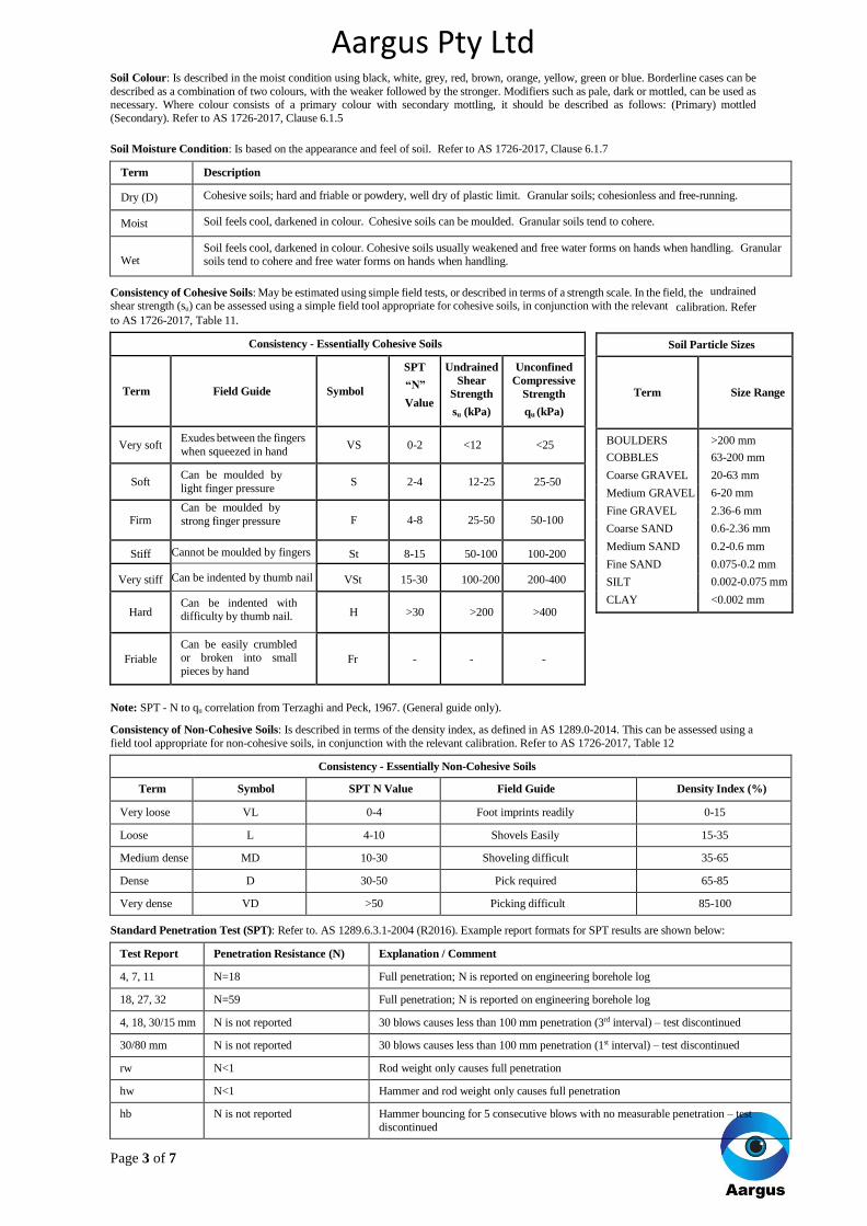
Soil Colour: Is described in the moist condition using black, white, grey, red, brown, orange, yellow, green or blue. Borderline cases can be
described as a combination of two colours, with the weaker followed by the stronger. Modifiers such as pale, dark or mottled, can be used as necessary. Where colour consists of a primary colour with secondary mottling, it should be described as follows: (Primary) mottled
(Secondary). Refer to AS 1726-2017, Clause 6.1.5
Soil Moisture Condition: Is based on the appearance and feel of soil. Refer to AS 1726-2017, Clause 6.1.7
Term Description
Dry (D) Cohesive soils; hard and friable or powdery, well dry of plastic limit. Granular soils; cohesionless and free-running.
Moist Soil feels cool, darkened in colour. Cohesive soils can be moulded. Granular soils tend to cohere.
Wet Soil feels cool, darkened in colour. Cohesive soils usually weakened and free water forms on hands when handling. Granular soils tend to cohere and free water forms on hands when handling.
Consistency of Cohesive Soils: May be estimated using simple field tests, or described in terms of a strength scale. In the field, the undrained
shear strength (su) can be assessed using a simple field tool appropriate for cohesive soils, in conjunction with the relevant calibration. Refer to AS 1726-2017, Table 11.
Note: SPT - N to qu correlation from Terzaghi and Peck, 1967. (General guide only).
Consistency of Non-Cohesive Soils: Is described in terms of the density index, as defined in AS 1289.0-2014. This can be assessed using a
field tool appropriate for non-cohesive soils, in conjunction with the relevant calibration. Refer to AS 1726-2017, Table 12
Consistency - Essentially Non-Cohesive Soils
Term Symbol SPT N Value Field Guide Density Index (%)
Very loose VL 0-4 Foot imprints readily 0-15
Loose L 4-10 Shovels Easily 15-35
Medium dense MD 10-30 Shoveling difficult 35-65
Dense D 30-50 Pick required 65-85
Very dense VD >50 Picking difficult 85-100
Standard Penetration Test (SPT): Refer to. AS 1289.6.3.1-2004 (R2016). Example report formats for SPT results are shown below:
Test Report Penetration Resistance (N) Explanation / Comment
4, 7, 11 N=18 Full penetration; N is reported on engineering borehole log
18, 27, 32 N=59 Full penetration; N is reported on engineering borehole log
4, 18, 30/15 mm N is not reported 30 blows causes less than 100 mm penetration (3rd interval) – test discontinued
30/80 mm N is not reported 30 blows causes less than 100 mm penetration (1st interval) – test discontinued
rw N<1 Rod weight only causes full penetration
hw N<1 Hammer and rod weight only causes full penetration
hb N is not reported Hammer bouncing for 5 consecutive blows with no measurable penetration – test
discontinued
Consistency - Essentially Cohesive Soils
Term Field Guide Symbol
SPT
“N”
Value
Undrained
Shear
Strength
su (kPa)
Unconfined
Compressive
Strength
qu (kPa)
Very soft Exudes between the fingers
when squeezed in hand VS 0-2 <12 <25
Soft Can be moulded by
light finger pressure S 2-4 12-25 25-50
Firm Can be moulded by
strong finger pressure F 4-8 25-50 50-100
Stiff Cannot be moulded by fingers St 8-15 50-100 100-200
Very stiff Can be indented by thumb nail VSt 15-30 100-200 200-400
Hard Can be indented with difficulty by thumb nail. H >30 >200 >400
Friable
Can be easily crumbled or broken into small
pieces by hand Fr - - -
Soil Particle Sizes
Term
Size Range
BOULDERS >200 mm
COBBLES 63-200 mm
Coarse GRAVEL 20-63 mm
Medium GRAVEL 6-20 mm
Fine GRAVEL 2.36-6 mm
Coarse SAND 0.6-2.36 mm
Medium SAND 0.2-0.6 mm
Fine SAND 0.075-0.2 mm
SILT 0.002-0.075 mm
CLAY <0.002 mm

Aargus Pty Ltd
Page 4 of 7
Rock Descriptions Refer to AS 1726-2017 Clause 6.2.3 for the description and classification of rock material composition, including:
(a) Rock name (Table 15, 16, 17, 18)
(b) Grain size
(c) Texture and fabric
(d) Colour (describe as per soil)
(e) Features, inclusion and minor components.
(f) Moisture content
(g) Durability
The condition of a rock material refers to its weathering characteristics, strength characteristics and rock mass properties. Refer to AS 1726-201 7Clause 6.2.4 Tables 19, 20 and 21).
Weathering Condition (Degree of Weathering):
The degree of weathering is a continuum from fresh rock to soil. Boundaries between weathering grades may be abrupt or gradational.
Rock Material Weathering Classification
Weathering Grade Symbol Definition
Residual Soil (Note 1)
RS
Material is weathered to such an extent that it has soil properties. Mass
structure and material texture and fabric of original rock are no longer visible, but the soil has not been significantly transported
Extremely Weathered Rock (Note 2)
XW Material is weathered to such an extent that it has soil properties. Mass
structure and material texture and fabric of original rock are still visible
Highly Weathered Rock (Note 2)
Distinctly Weathered
(Note 2)
HW
DW
The whole of the rock material is discoloured, usually by iron staining or
bleaching to the extent that the colour of the original rock is not
recognizable. Rock strength is significantly changed by weathering. Some primary minerals have weathered to clay minerals. Porosity may be
increased by leaching, or may be decreased due to deposition of weathering
products in pores Moderately Weathered Rock (Note 2)
MW The whole of the rock material is discoloured, usually by iron staining or bleaching to the extent that the colour of the original rock is not recognizable,
but shows little or no change of strength from fresh rock.
Slightly Weathered Rock SW Rock is partially discoloured with staining or bleaching along joints but shows little or no change of strength from fresh rock
Fresh Rock FR Rock shows no sign of decomposition of individual minerals or colour changes.
Notes:
1. Minor variations within broader weathering grade zones will be noted on the engineering borehole logs.
2. Extremely weathered rock is described in terms of soil engineering properties.
3. Weathering may be pervasive throughout the rock mass, or may penetrate inwards from discontinuities to some extent.
4. Where it is not practicable to distinguish between ‘Highly Weathered’ and ‘Moderately Weathered’ rock the term ‘Distinctly Weathered’
may be used. ‘Distinctly Weathered’ is defined as follows: ‘Rock strength usually changed by weathering. The rock may be highly discoloured, usually by iron staining. Porosity may be increased by leaching, or may be decreased due to deposition of weathering products
in pores. There is some change in rock strength.
Strength Condition (Intact Rock Strength):
Strength of Rock Material
(Based on Point Load Strength Index, corrected to 50 mm diameter – Is(50). Field guide used if no tests available. Refer to AS 4133.4.1-2007
(R2016).
Term
Sym
b
o
l
Point Load Index (MPa)
Is(50)
Field Guide to Strength
Extremely Low EL ≤0.03 Easily remoulded by hand to a material with soil properties.
Very Low
VL
>0.0
3
Material crumbles under firm blows with sharp end of pick; can be peeled with knife;
≤0.1 too hard to cut a triaxial sample by hand. Pieces up to 3 cm thick can be broken by
finger pressure.
Low
L
>0.1
Easily scored with a knife; indentations 1 mm to 3 mm show in the specimen with firm
≤0.3 blows of the pick point; has dull sound under hammer. A piece of core 150 mm long by
50 mm diameter may be broken by hand. Sharp edges of core may be friable and
break during handling.

Aargus Pty Ltd
Page 5 of 7
Discontinuity Description: Refer to AS 1726-2017, Table 22.
Note: Describe ‘Zones’ and ‘Coatings’ in terms of composition and thickness (mm).
Discontinuity Spacing: On the geotechnical borehole log, a graphical representation of defect spacing vs depth is shown. This representation takes into account all the natural rock defects occurring within a given depth interval, excluding breaks induced by the drilling / handling of
core. Refer to AS 1726-2017, BS5930-2015.
Defect Spacing Bedding Thickness
(Sedimentary Rock
Stratification) Spacing/Width
(mm)
Descriptor
Symbol
Descriptor Spacing/Width
(mm)
Thinly Laminated < 6
<20 Extremely Close
EC
Thickly Laminated
6 – 20
20 – 60
Very Close
VC
Very Thinly Bedded
20 – 60
60 – 200 Close C Thinly Bedded 60 – 200
200 – 600 Medium M Medium Bedded 200 – 600
600 – 2000 Wide W Thickly Bedded 600 – 2000
2000 – 6000 Very Wide VW Very Thickly Bedded > 2000
>6000 Extremely Wide EW
Medium
M
>0.3 ≤1.0
Readily scored with a knife; broken by hand with difficult
Readily scored with a knife; broken by hand with difficult a piece of core 150 mm long by
50 mm diameter can be y.
High
H
>1 ≤3 A piece of core 150 mm long by 50 mm diameter cannot be broken by hand but can be broken by a pick with a single firm blow; rock rings under hammer.
Very High VH >3 ≤10
H
a
nd
s
pe
c
im
e
n b
r
ea
k
s w
i
th
pick after more than one blow; rock rings under hammer.
Extremely High
EH
>10 Specimen requires many blow rock ring with geological pick to break through intact material;
under hammer
Notes:
1. These terms refer to the strength of the rock material and not to the strength of the rock mass which may be considerably weaker due to
the effect of rock defects.
2. Anisotropy of rock material samples may affect the field assessment of strength.
Anisotropic Fabric
BED Bedding
FOL Foliation
LIN Mineral lineation
Defect Type
LP Lamination Parting
BP Bedding Parting
FP Cleavage / Foliation Parting
J, Js Joint, Joints
SZ Sheared Zone
CZ Crushed Zone
BZ Broken Zone
HFZ Highly Fractured Zone
AZ Alteration Zone
VN Vein
Roughness (e.g. Planar, Smooth is abbreviated Pl / Sm) Class
Stepped (Stp)
Rough or irregular (Ro) I
Smooth (Sm) II
Slickensided (Sl) III
Undulating (Un)
Rough (Ro) IV
Smooth (Sm) V
Slickensided (Sl) VI
Planar (Pl)
Rough (Ro) VII
Smooth (Sm) VIII
Slickensided (Sl) IX
Aperture Infilling
Closed CD No visible coating or infill Clean Cn
Open OP Surfaces discoloured by mineral/s Stain St
Filled FL Visible mineral or soil infill <1mm Veneer Vr
Tight TI Visible mineral or soil infill >1mm Coating Ct
Other
Cly Clay
Fe Iron
Co Coal
Carb Carbonaceous
Sinf Soil Infill Zone
Qz Quartz
CA Calcite
Chl Chlorite
Py Pyrite
Int Intersecting
Inc Incipient
DI Drilling Induced
H Horizontal
V Vertical
Defect Persistence
(areal extent)
Trace length of defect given in metres
Defect Spacing in 3D
Term Description
Blocky Equidimensional
Tabular Thickness much less than
length or width
Columnar Height much greater than
cross section

Aargus Pty Ltd
Page 6 of 7
Symbols
The list below provides an explanation of terms and symbols used on the geotechnical borehole, test pit and penetrometer logs.
Test Results Test Symbols
PI Plasticity Index c′ Effective Cohesion DCP Dynamic Cone Penetrometer
LL Liquid Limit cu Undrained Cohesion SPT Standard Penetration Test
LI Liquidity Index c′R Residual Cohesion CPTu Cone Penetrometer (Piezocone) Test
DD Dry Density ɸ′ Effective Angle of Internal Friction PANDA Variable Energy DCP
WD Wet Density ɸu Undrained Angle of Internal Friction PP Pocket Penetrometer Test
LS
Linear Shrinkage ɸ′R
Residual Angle of Internal Friction
U50 Undisturbed Sample 50 mm (nominal
diameter)
MC
Moisture Content
cv
Coefficient of Consolidation
U100 Undisturbed Sample 100mm (nominal diameter)
OC Organic Content mv Coefficient of Volume Compressibility UCS Uniaxial Compressive Strength
WPI
Weighted
Plasticity Index
cαε
Coefficient of Secondary Compression
Pm
Pressuremeter
Test Results Test Symbols
WLS Weighted Linear Shrinkage
e
Voids Ratio
FSV
Field Shear Vane
DoS Degree of Saturation cv Constant Volume Friction Angle DST Direct Shear Test
APD
Apparent Particle Density
qt / qc
Piezocone Tip Resistance
(corrected / uncorrected)
PR
Penetration Rate
su Undrained Shear Strength qd PANDA Cone Resistance A Point Load Test (axial)
qu
Unconfined
Compressive Strength
Is(50)
Point Load Strength Index
D
Point Load Test (diametral)
R Total Core Recovery RQD Rock Quality Designation L Point Load Test (irregular lump)
Groundwater level on the date shown
28/11/19
Water Inflow
Water Outflow

AD
T
Not
enc
ount
ered
PAVEMENT
FILL
WEATHERED BEDROCK
D(Dry)/
M(Moist)
M
M
D /M
Asphaltic CONCRETE, 100mm.
FILL, Sandy Gravel, fine to coarse grained, pale brown to grey, fine to coarse basaltgravel.
FILL, Sandy Silty Clay, medium to high plasticity, pale brown, grey, with mediumgravel.
Becoming red brown.
SHALE, grey, highly to moderately weathered, low to medium estimated strength.
TC bit refusal at 2.8m.Borehole BH1 terminated at 2.8m
Met
hod
Wat
er
Additional Observations
Moi
stur
e
Con
s./D
ens.
SamplesTests
Remarks
BOREHOLE NUMBER BH1PAGE 1 OF 1
COMPLETED 14/5/21DATE STARTED 14/5/21
DRILLING CONTRACTOR Aargus Pty Ltd
LOGGED BY AS CHECKED BY RF
NOTES Depths to lithogical units and contacts are approximate
HOLE LOCATION See Figure 1 - Site PlanEQUIPMENT Small excavator mounted drilling rig
HOLE SIZE 100
R.L. SURFACE 27.0 DATUM m m AHD
SLOPE 90° BEARING NA
CLIENT Iris Capital
PROJECT NUMBER GS8219-1A
PROJECT NAME Geotechnical Investigation
PROJECT LOCATION Ibis Hotel, Enfield, NSW
BO
RE
HO
LE /
TE
ST
PIT
GS
8219
-1A
EN
FIE
LD B
OR
EH
OLE
LO
GS
.GP
J G
INT
ST
D A
US
TR
ALI
A.G
DT
28/
5/21
Aargus Pty Ltd6 Carter StreetLidcombeTelephone: 1300 137 038Fax: 1300 136 038
RL(m)
26.5
26.0
25.5
25.0
24.5
24.0
23.5
23.0
Depth(m)
0.5
1.0
1.5
2.0
2.5
3.0
3.5
4.0
Cla
ssifi
catio
nS
ymbo
l
Gra
phic
Log
Material Description
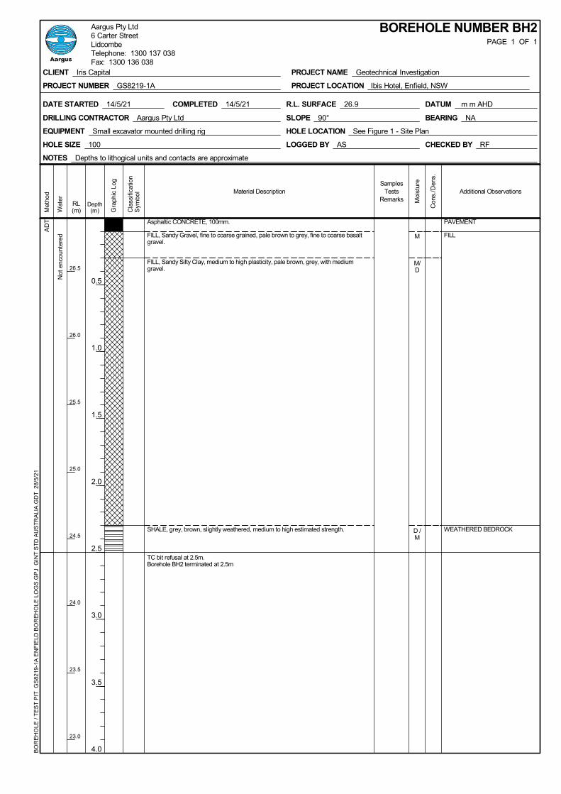
AD
T
Not
enc
ount
ered
PAVEMENT
FILL
WEATHERED BEDROCK
M
M/D
D /M
Asphaltic CONCRETE, 100mm.
FILL, Sandy Gravel, fine to coarse grained, pale brown to grey, fine to coarse basaltgravel.
FILL, Sandy Silty Clay, medium to high plasticity, pale brown, grey, with mediumgravel.
SHALE, grey, brown, slightly weathered, medium to high estimated strength.
TC bit refusal at 2.5m.Borehole BH2 terminated at 2.5m
Met
hod
Wat
er
Additional Observations
Moi
stur
e
Con
s./D
ens.
SamplesTests
Remarks
BOREHOLE NUMBER BH2PAGE 1 OF 1
COMPLETED 14/5/21DATE STARTED 14/5/21
DRILLING CONTRACTOR Aargus Pty Ltd
LOGGED BY AS CHECKED BY RF
NOTES Depths to lithogical units and contacts are approximate
HOLE LOCATION See Figure 1 - Site PlanEQUIPMENT Small excavator mounted drilling rig
HOLE SIZE 100
R.L. SURFACE 26.9 DATUM m m AHD
SLOPE 90° BEARING NA
CLIENT Iris Capital
PROJECT NUMBER GS8219-1A
PROJECT NAME Geotechnical Investigation
PROJECT LOCATION Ibis Hotel, Enfield, NSW
BO
RE
HO
LE /
TE
ST
PIT
GS
8219
-1A
EN
FIE
LD B
OR
EH
OLE
LO
GS
.GP
J G
INT
ST
D A
US
TR
ALI
A.G
DT
28/
5/21
Aargus Pty Ltd6 Carter StreetLidcombeTelephone: 1300 137 038Fax: 1300 136 038
RL(m)
26.5
26.0
25.5
25.0
24.5
24.0
23.5
23.0
Depth(m)
0.5
1.0
1.5
2.0
2.5
3.0
3.5
4.0
Cla
ssifi
catio
nS
ymbo
l
Gra
phic
Log
Material Description

AD
T
Not
enc
ount
ered
PAVEMENT
FILL
WEATHERED BEDROCK
M
D/M
D/M
D/M
D/M
Asphaltic CONCRETE, 100mm.
FILL, Sandy Gravel, fine to coarse grained, pale brown to grey, fine to coarse basaltgravel.
FILL, Sandy Clay, low plasticity, grey, with medium bricks gravel, trace of coarseporcelain.
SHALE, grey, pale brown, extremely weathered, extremely low estimated strength.
Becoming brown, pale brown.
Becoming brown.
Met
hod
Wat
er
Additional Observations
Moi
stur
e
Con
s./D
ens.
SamplesTests
Remarks
BOREHOLE NUMBER BH4PAGE 1 OF 2
COMPLETED 14/5/21DATE STARTED 14/5/21
DRILLING CONTRACTOR Aargus Pty Ltd
LOGGED BY AS CHECKED BY RF
NOTES Depths to lithogical units and contacts are approximate
HOLE LOCATION See Figure 1 - Site PlanEQUIPMENT Small excavator mounted drilling rig
HOLE SIZE 100
R.L. SURFACE 26.6 DATUM m m AHD
SLOPE 90° BEARING NA
CLIENT Iris Capital
PROJECT NUMBER GS8219-1A
PROJECT NAME Geotechnical Investigation
PROJECT LOCATION Ibis Hotel, Enfield, NSW
BO
RE
HO
LE /
TE
ST
PIT
GS
8219
-1A
EN
FIE
LD B
OR
EH
OLE
LO
GS
.GP
J G
INT
ST
D A
US
TR
ALI
A.G
DT
28/
5/21
Aargus Pty Ltd6 Carter StreetLidcombeTelephone: 1300 137 038Fax: 1300 136 038
RL(m)
26.5
26.0
25.5
25.0
24.5
24.0
23.5
23.0
Depth(m)
0.5
1.0
1.5
2.0
2.5
3.0
3.5
4.0
Cla
ssifi
catio
nS
ymbo
l
Gra
phic
Log
Material Description
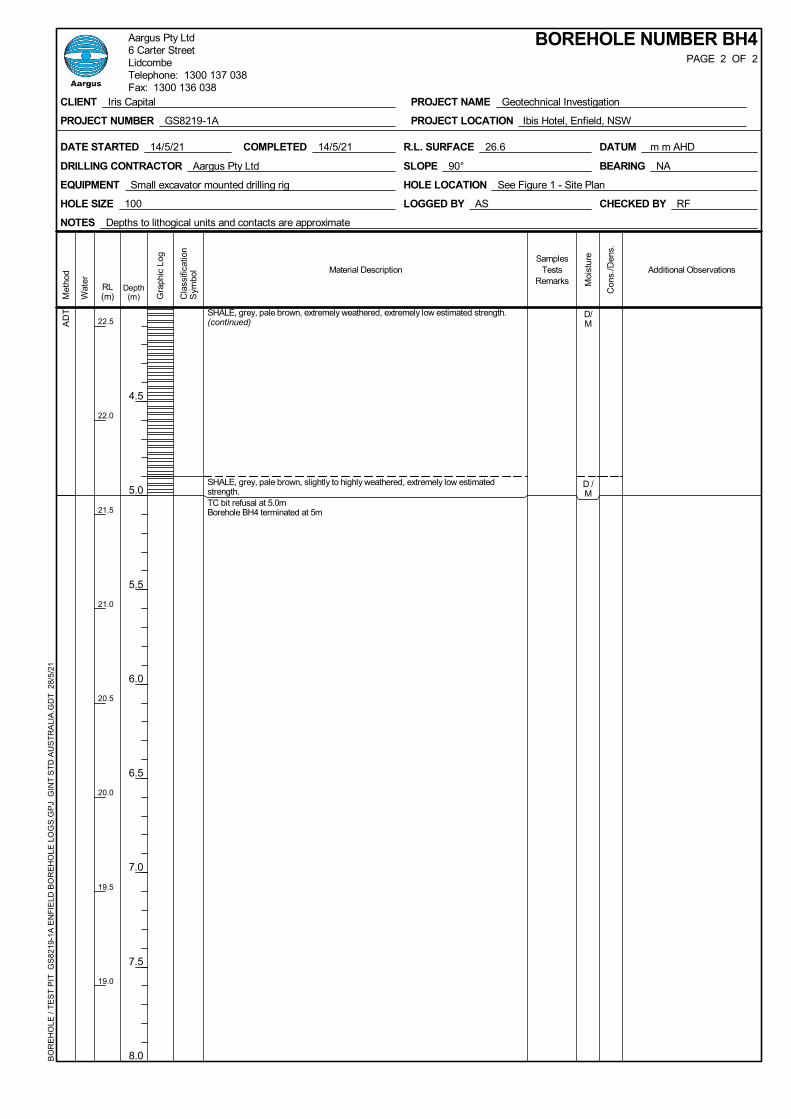
AD
T D/M
D /M
SHALE, grey, pale brown, extremely weathered, extremely low estimated strength.(continued)
SHALE, grey, pale brown, slightly to highly weathered, extremely low estimatedstrength.TC bit refusal at 5.0mBorehole BH4 terminated at 5m
Met
hod
Wat
er
Additional Observations
Moi
stur
e
Con
s./D
ens.
SamplesTests
Remarks
BOREHOLE NUMBER BH4PAGE 2 OF 2
COMPLETED 14/5/21DATE STARTED 14/5/21
DRILLING CONTRACTOR Aargus Pty Ltd
LOGGED BY AS CHECKED BY RF
NOTES Depths to lithogical units and contacts are approximate
HOLE LOCATION See Figure 1 - Site PlanEQUIPMENT Small excavator mounted drilling rig
HOLE SIZE 100
R.L. SURFACE 26.6 DATUM m m AHD
SLOPE 90° BEARING NA
CLIENT Iris Capital
PROJECT NUMBER GS8219-1A
PROJECT NAME Geotechnical Investigation
PROJECT LOCATION Ibis Hotel, Enfield, NSW
BO
RE
HO
LE /
TE
ST
PIT
GS
8219
-1A
EN
FIE
LD B
OR
EH
OLE
LO
GS
.GP
J G
INT
ST
D A
US
TR
ALI
A.G
DT
28/
5/21
Aargus Pty Ltd6 Carter StreetLidcombeTelephone: 1300 137 038Fax: 1300 136 038
RL(m)
22.5
22.0
21.5
21.0
20.5
20.0
19.5
19.0
Depth(m)
4.5
5.0
5.5
6.0
6.5
7.0
7.5
8.0
Cla
ssifi
catio
nS
ymbo
l
Gra
phic
Log
Material Description

AD
T
Not
enc
ount
ered
PAVEMENT
FILLM
M
M
Asphaltic CONCRETE, 100mm.
FILL, Sandy Gravel, fine to coarse grained, pale brown to grey, fine to coarse basaltgravel.FILL, Sandy SIlty Clay, medium to high plasticity, red brown, with medium to coarsebrick gravel.
Becoming dark brown.
Met
hod
Wat
er
Additional Observations
Moi
stur
e
Con
s./D
ens.
SamplesTests
Remarks
BOREHOLE NUMBER BH5PAGE 1 OF 2
COMPLETED 14/5/21DATE STARTED 14/5/21
DRILLING CONTRACTOR Aargus Pty Ltd
LOGGED BY AS CHECKED BY RF
NOTES Depths to lithogical units and contacts are approximate
HOLE LOCATION See Figure 1 - Site PlanEQUIPMENT Small excavator mounted drilling rig
HOLE SIZE 100
R.L. SURFACE 26.8 DATUM m m AHD
SLOPE 90° BEARING NA
CLIENT Iris Capital
PROJECT NUMBER GS8219-1A
PROJECT NAME Geotechnical Investigation
PROJECT LOCATION Ibis Hotel, Enfield, NSW
BO
RE
HO
LE /
TE
ST
PIT
GS
8219
-1A
EN
FIE
LD B
OR
EH
OLE
LO
GS
.GP
J G
INT
ST
D A
US
TR
ALI
A.G
DT
28/
5/21
Aargus Pty Ltd6 Carter StreetLidcombeTelephone: 1300 137 038Fax: 1300 136 038
RL(m)
26.5
26.0
25.5
25.0
24.5
24.0
23.5
23.0
Depth(m)
0.5
1.0
1.5
2.0
2.5
3.0
3.5
4.0
Cla
ssifi
catio
nS
ymbo
l
Gra
phic
Log
Material Description

AD
T
WEATHERED BEDROCK
M
D /M
D /M
FILL, Sandy SIlty Clay, medium to high plasticity, red brown, with medium to coarsebrick gravel. (continued)
SHALE, brown, extremely weathered, extremely low estimated strength.
SHALE, brown, slightly to highly weathered, low to medium estimated strength.
TC bit refusal at 5.6m.Borehole BH5 terminated at 5.6m
Met
hod
Wat
er
Additional Observations
Moi
stur
e
Con
s./D
ens.
SamplesTests
Remarks
BOREHOLE NUMBER BH5PAGE 2 OF 2
COMPLETED 14/5/21DATE STARTED 14/5/21
DRILLING CONTRACTOR Aargus Pty Ltd
LOGGED BY AS CHECKED BY RF
NOTES Depths to lithogical units and contacts are approximate
HOLE LOCATION See Figure 1 - Site PlanEQUIPMENT Small excavator mounted drilling rig
HOLE SIZE 100
R.L. SURFACE 26.8 DATUM m m AHD
SLOPE 90° BEARING NA
CLIENT Iris Capital
PROJECT NUMBER GS8219-1A
PROJECT NAME Geotechnical Investigation
PROJECT LOCATION Ibis Hotel, Enfield, NSW
BO
RE
HO
LE /
TE
ST
PIT
GS
8219
-1A
EN
FIE
LD B
OR
EH
OLE
LO
GS
.GP
J G
INT
ST
D A
US
TR
ALI
A.G
DT
28/
5/21
Aargus Pty Ltd6 Carter StreetLidcombeTelephone: 1300 137 038Fax: 1300 136 038
RL(m)
22.5
22.0
21.5
21.0
20.5
20.0
19.5
19.0
Depth(m)
4.5
5.0
5.5
6.0
6.5
7.0
7.5
8.0
Cla
ssifi
catio
nS
ymbo
l
Gra
phic
Log
Material Description

AD
T
Not
enc
ount
ered
PAVEMENT
FILL
WEATHERED BEDROCK
M
D /M
D /M
D /M
AtterbergLimit
Asphaltic CONCRETE, 100mm.
FILL, Sandy Gravel, fine to coarse grained, pale brown to grey, fine to coarse basaltgravel.
FILL, Sandy Silty Clay, medium to high plasticity, red brown, with medium to coarsebrick gravel.
SHALE, pale brown, extremely weathered, extremely low estimated strength.
Becoming pale grey.
Met
hod
Wat
er
Additional Observations
Moi
stur
e
Con
s./D
ens.
SamplesTests
Remarks
BOREHOLE NUMBER BH6PAGE 1 OF 2
COMPLETED 14/5/21DATE STARTED 14/5/21
DRILLING CONTRACTOR Aargus Pty Ltd
LOGGED BY AS CHECKED BY RF
NOTES Depths to lithogical units and contacts are approximate
HOLE LOCATION See Figure 1 - Site PlanEQUIPMENT Small excavator mounted drilling rig
HOLE SIZE 100
R.L. SURFACE 26.6 DATUM m m AHD
SLOPE 90° BEARING NA
CLIENT Iris Capital
PROJECT NUMBER GS8219-1A
PROJECT NAME Geotechnical Investigation
PROJECT LOCATION Ibis Hotel, Enfield, NSW
BO
RE
HO
LE /
TE
ST
PIT
GS
8219
-1A
EN
FIE
LD B
OR
EH
OLE
LO
GS
.GP
J G
INT
ST
D A
US
TR
ALI
A.G
DT
28/
5/21
Aargus Pty Ltd6 Carter StreetLidcombeTelephone: 1300 137 038Fax: 1300 136 038
RL(m)
26.5
26.0
25.5
25.0
24.5
24.0
23.5
23.0
Depth(m)
0.5
1.0
1.5
2.0
2.5
3.0
3.5
4.0
Cla
ssifi
catio
nS
ymbo
l
Gra
phic
Log
Material Description
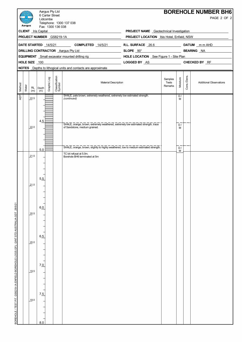
AD
T D /M
D /M
D /M
SHALE, pale brown, extremely weathered, extremely low estimated strength.(continued)
SHALE, orange, brown, extremely weathered, extremely low estimated strength, traceof Sandstone, medium grained.
SHALE, orange, brown, slightly to highly weathered, low to medium estimated strength.
TC bit refusal at 5.0m.Borehole BH6 terminated at 5m
Met
hod
Wat
er
Additional Observations
Moi
stur
e
Con
s./D
ens.
SamplesTests
Remarks
BOREHOLE NUMBER BH6PAGE 2 OF 2
COMPLETED 14/5/21DATE STARTED 14/5/21
DRILLING CONTRACTOR Aargus Pty Ltd
LOGGED BY AS CHECKED BY RF
NOTES Depths to lithogical units and contacts are approximate
HOLE LOCATION See Figure 1 - Site PlanEQUIPMENT Small excavator mounted drilling rig
HOLE SIZE 100
R.L. SURFACE 26.6 DATUM m m AHD
SLOPE 90° BEARING NA
CLIENT Iris Capital
PROJECT NUMBER GS8219-1A
PROJECT NAME Geotechnical Investigation
PROJECT LOCATION Ibis Hotel, Enfield, NSW
BO
RE
HO
LE /
TE
ST
PIT
GS
8219
-1A
EN
FIE
LD B
OR
EH
OLE
LO
GS
.GP
J G
INT
ST
D A
US
TR
ALI
A.G
DT
28/
5/21
Aargus Pty Ltd6 Carter StreetLidcombeTelephone: 1300 137 038Fax: 1300 136 038
RL(m)
22.5
22.0
21.5
21.0
20.5
20.0
19.5
19.0
Depth(m)
4.5
5.0
5.5
6.0
6.5
7.0
7.5
8.0
Cla
ssifi
catio
nS
ymbo
l
Gra
phic
Log
Material Description

AD
T PAVEMENT
FILLM
M
M
Asphaltic CONCRETE, 100mm.
FILL, Sandy Gravel, fine to coarse grained, pale brown to grey, fine to coarse basaltgravel.
FILL, Silty Clay, medium to high plasticity, brown, with basalt gravel and medium tocoarse brick gravel, traces of coarse porcelain gravel.
FILL, Silty Clay, medium to high plasticity, brown, dark grey, with coarse coal and tuff.
Met
hod
Wat
er
Additional Observations
Moi
stur
e
Con
s./D
ens.
SamplesTests
Remarks
BOREHOLE NUMBER BH7PAGE 1 OF 2
COMPLETED 14/5/21DATE STARTED 14/5/21
DRILLING CONTRACTOR Aargus Pty Ltd
LOGGED BY AS CHECKED BY RF
NOTES Depths to lithogical units and contacts are approximate
HOLE LOCATION See Figure 1 - Site PlanEQUIPMENT Small excavator mounted drilling rig
HOLE SIZE 100
R.L. SURFACE 26.8 DATUM m m AHD
SLOPE 90° BEARING NA
CLIENT Iris Capital
PROJECT NUMBER GS8219-1A
PROJECT NAME Geotechnical Investigation
PROJECT LOCATION Ibis Hotel, Enfield, NSW
BO
RE
HO
LE /
TE
ST
PIT
GS
8219
-1A
EN
FIE
LD B
OR
EH
OLE
LO
GS
.GP
J G
INT
ST
D A
US
TR
ALI
A.G
DT
28/
5/21
Aargus Pty Ltd6 Carter StreetLidcombeTelephone: 1300 137 038Fax: 1300 136 038
RL(m)
26.5
26.0
25.5
25.0
24.5
24.0
23.5
23.0
Depth(m)
0.5
1.0
1.5
2.0
2.5
3.0
3.5
4.0
Cla
ssifi
catio
nS
ymbo
l
Gra
phic
Log
Material Description
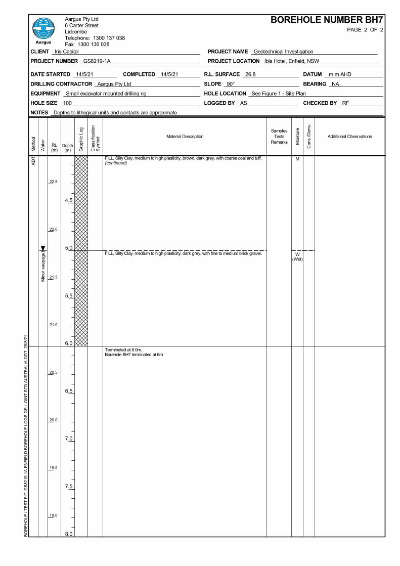
AD
T
Min
or s
eepa
ge
M
W(Wet)
FILL, Silty Clay, medium to high plasticity, brown, dark grey, with coarse coal and tuff.(continued)
FILL, Silty Clay, medium to high plasticity, dark grey, with fine to medium brick gravel.
Terminated at 6.0m.Borehole BH7 terminated at 6m
Met
hod
Wat
er
Additional Observations
Moi
stur
e
Con
s./D
ens.
SamplesTests
Remarks
BOREHOLE NUMBER BH7PAGE 2 OF 2
COMPLETED 14/5/21DATE STARTED 14/5/21
DRILLING CONTRACTOR Aargus Pty Ltd
LOGGED BY AS CHECKED BY RF
NOTES Depths to lithogical units and contacts are approximate
HOLE LOCATION See Figure 1 - Site PlanEQUIPMENT Small excavator mounted drilling rig
HOLE SIZE 100
R.L. SURFACE 26.8 DATUM m m AHD
SLOPE 90° BEARING NA
CLIENT Iris Capital
PROJECT NUMBER GS8219-1A
PROJECT NAME Geotechnical Investigation
PROJECT LOCATION Ibis Hotel, Enfield, NSW
BO
RE
HO
LE /
TE
ST
PIT
GS
8219
-1A
EN
FIE
LD B
OR
EH
OLE
LO
GS
.GP
J G
INT
ST
D A
US
TR
ALI
A.G
DT
28/
5/21
Aargus Pty Ltd6 Carter StreetLidcombeTelephone: 1300 137 038Fax: 1300 136 038
RL(m)
22.5
22.0
21.5
21.0
20.5
20.0
19.5
19.0
Depth(m)
4.5
5.0
5.5
6.0
6.5
7.0
7.5
8.0
Cla
ssifi
catio
nS
ymbo
l
Gra
phic
Log
Material Description

AD
T
Not
enc
ount
ered
PAVEMENT
FILLM
M
CBR
AtterbergLimit
Asphaltic CONCRETE, 100mm.
FILL, Sandy Gravel, medium, basalt, pale brown to grey, fine to medium grained.
FILL, Sandy Silty Clay, high plasticity, dark grey, brown, with fine to medium brickgravel.
Terminated at 2.3m.Borehole BH8 terminated at 2.3m
Met
hod
Wat
er
Additional Observations
Moi
stur
e
Con
s./D
ens.
SamplesTests
Remarks
BOREHOLE NUMBER BH8PAGE 1 OF 1
COMPLETED 14/5/21DATE STARTED 14/5/21
DRILLING CONTRACTOR Aargus Pty Ltd
LOGGED BY AS CHECKED BY RF
NOTES Depths to lithogical units and contacts are approximate
HOLE LOCATION See Figure 1 - Site PlanEQUIPMENT Small excavator mounted
HOLE SIZE 100
R.L. SURFACE 26.8 DATUM m m AHD
SLOPE 90° BEARING NA
CLIENT Iris Capital
PROJECT NUMBER GS8219-1A
PROJECT NAME Geotechnical Investigation
PROJECT LOCATION Ibis Hotel, Enfield, NSW
BO
RE
HO
LE /
TE
ST
PIT
GS
8219
-1A
EN
FIE
LD B
OR
EH
OLE
LO
GS
.GP
J G
INT
ST
D A
US
TR
ALI
A.G
DT
28/
5/21
Aargus Pty Ltd6 Carter StreetLidcombeTelephone: 1300 137 038Fax: 1300 136 038
RL(m)
26.5
26.0
25.5
25.0
24.5
24.0
23.5
23.0
Depth(m)
0.5
1.0
1.5
2.0
2.5
3.0
3.5
4.0
Cla
ssifi
catio
nS
ymbo
l
Gra
phic
Log
Material Description

APPENDIX D
_______________________________ Dynamic Cone Penetrometer Test Results
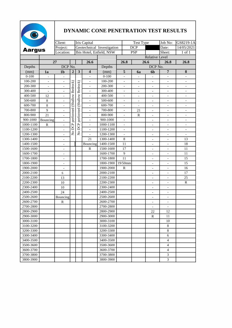
1a 1b 6a 6b
- - - -
- - - -
- - - -
- - - -
12 - - -
8 - - -
8 - - -
9 - 21 -
21 - R -
Bouncing - -
R - -
- -
- -
- -
- -
- -
- -
- -
- -
- -
6 -
13 -
10 -
10 -
24 -
Bouncing -
R -
-
22
R
3700-3800 3700-3800 3
3500-3600 3500-3600 4
3600-3700 3600-3700 4
3300-3400 3300-3400 6
3400-3500 3400-3500 4
-
-
-
-
3100-3200 8
No
DC
P p
erfo
rmed
(S
hal
low
Bed
rock
)
- -
900-1000
- -
- -
Depths
(mm)
0-100
-
500-600
600-700
700-800
-
-
800-900
500-600
100-200 100-200
200-300
300-400
400-500
200-300
300-400
-
-
600-700
700-800
-
-
-
1300-1400
1400-1500
1500-1600
1600-1700
1500-1600
1600-1700
-
-
-
-
-
-
-
900-1000
1000-1100
1100-1200
1200-1300
800-900
-
1000-1100
1700-1800
1800-1900
1900-2000
2400-2500
2500-2600
2000-2100
2100-2200
2200-2300
2300-2400
2600-2700
2700-2800
2800-2900
2900-3000
3800-3900
2600-2700
2700-2800
2800-2900
2900-3000
3000-3100
3100-3200
3200-3300 3200-3300
3800-3900
3000-3100
2500-2600
2000-2100
2100-2200
2200-2300
2300-2400
2400-2500
R
1700-1800
1800-1900
1900-2000
Bouncing
R
21
9 -
-
1100-1200
1200-1300
1300-1400
1400-1500
8
11
- 25
- R
-
18
17 - 11
-
16
- 17
11
11 - 15
19/50mm - 15
-
12
11
-
-
-
3
10
8
Geotechnical Investigation
DCP No. DCP No.
Project:
1 of 1
5 7 82 3 4
Relative Level
27 26.8
DYNAMIC CONE PENETRATION TEST RESULTS
Location: Ibis Hotel, Enfield, NSW
Test Type
PSP Sheet:
- -
Iris CapitalClient: GS8219-1AJob No:
0-100
Depths
(mm)
26.6 26.6 26.8 26.8
-
No
DC
P p
erfo
rmed
(S
hal
low
Bed
rock
)
DCP 14/05/2021Date:
-
-
-- -
400-500
- -
--
-
-
-
- -
13
-
-
-
-
-
-
- -
-
-

APPENDIX E
______________________________ Laboratory Test Results
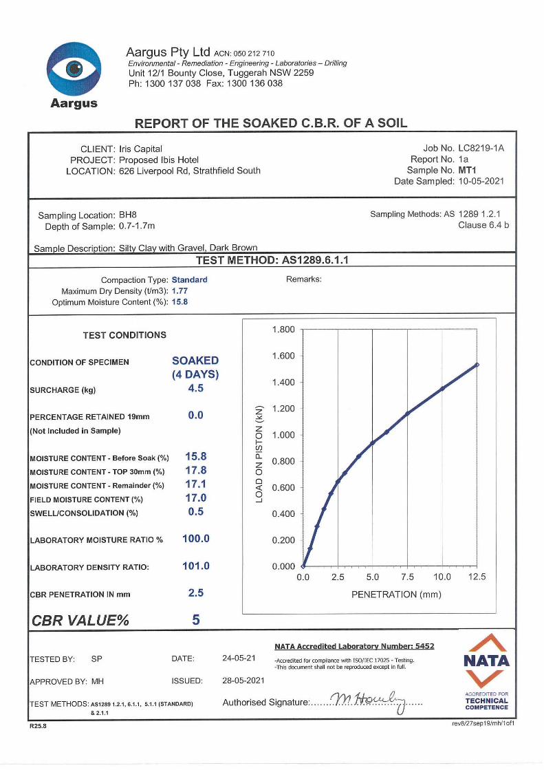


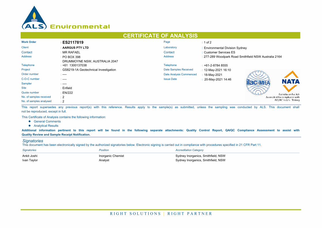
0 0.00 True
Environmental
CERTIFICATE OF ANALYSISWork Order : Page : 1 of 2ES2117819
:: LaboratoryClient AARGUS PTY LTD Environmental Division Sydney
: :ContactContact MR RAFAEL Customer Services ES
:: AddressAddress PO BOX 398
DRUMMOYNE NSW, AUSTRALIA 2047
277-289 Woodpark Road Smithfield NSW Australia 2164
:Telephone +61 1300137038 :Telephone +61-2-8784 8555
:Project GS8219-1A Geotechnical Investigation Date Samples Received : 12-May-2021 16:10
:Order number ---- Date Analysis Commenced : 18-May-2021
:C-O-C number ---- Issue Date : 20-May-2021 14:46
Sampler : ----
Site : Enfield
Quote number : EN/222
2:No. of samples received
2:No. of samples analysed
This report supersedes any previous report(s) with this reference. Results apply to the sample(s) as submitted, unless the sampling was conducted by ALS. This document shall
not be reproduced, except in full.
This Certificate of Analysis contains the following information:
l General Comments
l Analytical Results
Additional information pertinent to this report will be found in the following separate attachments: Quality Control Report, QA/QC Compliance Assessment to assist with
Quality Review and Sample Receipt Notification.
SignatoriesThis document has been electronically signed by the authorized signatories below. Electronic signing is carried out in compliance with procedures specified in 21 CFR Part 11.
Signatories Accreditation CategoryPosition
Ankit Joshi Inorganic Chemist Sydney Inorganics, Smithfield, NSW
Ivan Taylor Analyst Sydney Inorganics, Smithfield, NSW
R I G H T S O L U T I O N S | R I G H T P A R T N E R
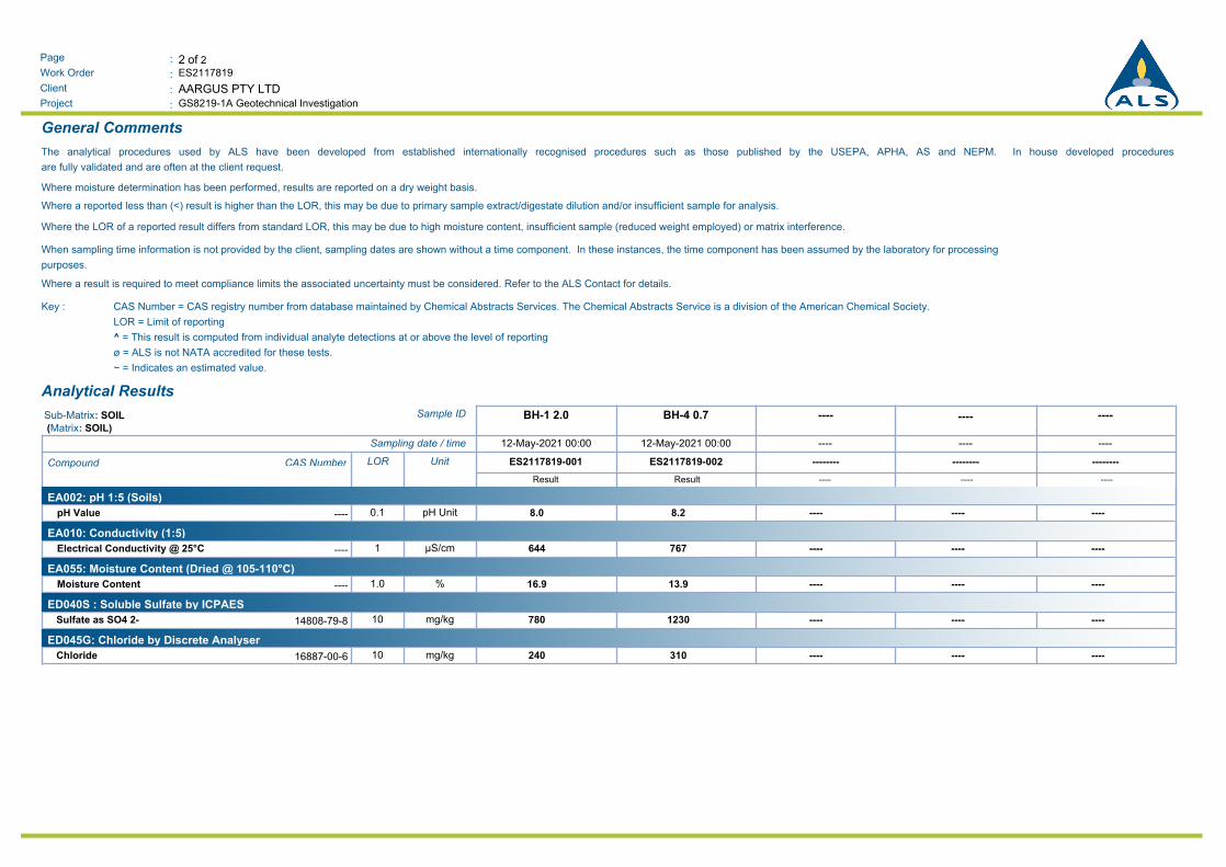
2 of 2:Page
Work Order :
:Client
ES2117819
GS8219-1A Geotechnical Investigation:Project
AARGUS PTY LTD
General Comments
The analytical procedures used by ALS have been developed from established internationally recognised procedures such as those published by the USEPA, APHA, AS and NEPM. In house developed procedures
are fully validated and are often at the client request.
Where moisture determination has been performed, results are reported on a dry weight basis.
Where a reported less than (<) result is higher than the LOR, this may be due to primary sample extract/digestate dilution and/or insufficient sample for analysis.
Where the LOR of a reported result differs from standard LOR, this may be due to high moisture content, insufficient sample (reduced weight employed) or matrix interference.
When sampling time information is not provided by the client, sampling dates are shown without a time component. In these instances, the time component has been assumed by the laboratory for processing
purposes.
Where a result is required to meet compliance limits the associated uncertainty must be considered. Refer to the ALS Contact for details.
CAS Number = CAS registry number from database maintained by Chemical Abstracts Services. The Chemical Abstracts Service is a division of the American Chemical Society.
LOR = Limit of reporting
^ = This result is computed from individual analyte detections at or above the level of reporting
ø = ALS is not NATA accredited for these tests.
~ = Indicates an estimated value.
Key :
Analytical Results
------------BH-4 0.7BH-1 2.0Sample IDSub-Matrix: SOIL
(Matrix: SOIL)
------------12-May-2021 00:0012-May-2021 00:00Sampling date / time
------------------------ES2117819-002ES2117819-001UnitLORCAS NumberCompound
Result Result ---- ---- ----
EA002: pH 1:5 (Soils)
8.0 8.2 ---- ---- ----pH Unit0.1----pH Value
EA010: Conductivity (1:5)
644 767 ---- ---- ----µS/cm1----Electrical Conductivity @ 25°C
EA055: Moisture Content (Dried @ 105-110°C)
16.9 13.9 ---- ---- ----%1.0----Moisture Content
ED040S : Soluble Sulfate by ICPAES
780Sulfate as SO4 2- 1230 ---- ---- ----mg/kg1014808-79-8
ED045G: Chloride by Discrete Analyser
240Chloride 310 ---- ---- ----mg/kg1016887-00-6
Related Documents


