mmerville 2000 Software Engineering, 6th edition. Chapter 20 Slide Defect testing Testing programs to establish the presence of system defects

©Ian Sommerville 2000 Software Engineering, 6th edition. Chapter 20 Slide 1 Defect testing l Testing programs to establish the presence of system defects.
Dec 13, 2015
Welcome message from author
This document is posted to help you gain knowledge. Please leave a comment to let me know what you think about it! Share it to your friends and learn new things together.
Transcript

©Ian Sommerville 2000 Software Engineering, 6th edition. Chapter 20 Slide 1
Defect testing
Testing programs to establish the presence of system defects

©Ian Sommerville 2000 Software Engineering, 6th edition. Chapter 20 Slide 2
Topics covered Defect testing Integration testing Object-oriented testing Testing workbenches

©Ian Sommerville 2000 Software Engineering, 6th edition. Chapter 20 Slide 3
The testing process Component testing
• Testing of individual program components
• Usually the responsibility of the component developer (except sometimes for critical systems)
• Tests are derived from the developer’s experience
Integration testing• Testing of groups of components integrated to create a system
or sub-system
• The responsibility of an independent testing team
• Tests are based on a system specification

©Ian Sommerville 2000 Software Engineering, 6th edition. Chapter 20 Slide 4
Defect testing The goal of defect testing is to discover defects in
programs A successful defect test is a test which causes a
program to behave in an anomalous way Tests show the presence not the absence of
defects

©Ian Sommerville 2000 Software Engineering, 6th edition. Chapter 20 Slide 5
Only exhaustive testing can show a program is free from defects. However, exhaustive testing is impossible
Tests should exercise a system's capabilities rather than its components
Testing old capabilities is more important than testing new capabilities
Testing typical situations is more important than boundary value cases
Testing priorities

©Ian Sommerville 2000 Software Engineering, 6th edition. Chapter 20 Slide 6
Test data Inputs which have been devised to test the system
Test cases Inputs to test the system and the predicted outputs from these inputs if the system operates according to its specification
Test data and test cases

©Ian Sommerville 2000 Software Engineering, 6th edition. Chapter 20 Slide 7
The defect testing process
Design testcases
Prepare testdata
Run programwith test data
Compare resultsto test cases
Testcases
Testdata
Testresults
Testreports

©Ian Sommerville 2000 Software Engineering, 6th edition. Chapter 20 Slide 8
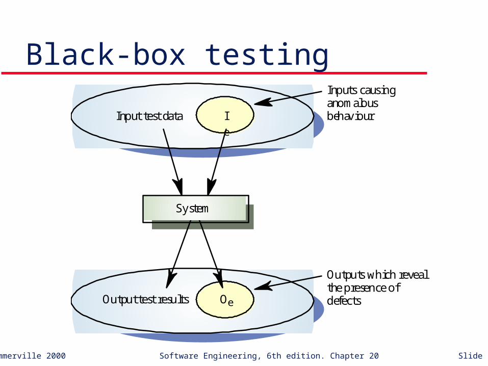
Black-box testing An approach to testing where the program is
considered as a ‘black-box’ The program test cases are based on the system
specification Test planning can begin early in the software
process
©Ian Sommerville 2000 Software Engineering, 6th edition. Chapter 20 Slide 9
Black-box testing
Ie
Input test data
OeOutput test results
System
Inputs causinganomalousbehaviour
Outputs which revealthe presence ofdefects
©Ian Sommerville 2000 Software Engineering, 6th edition. Chapter 20 Slide 10
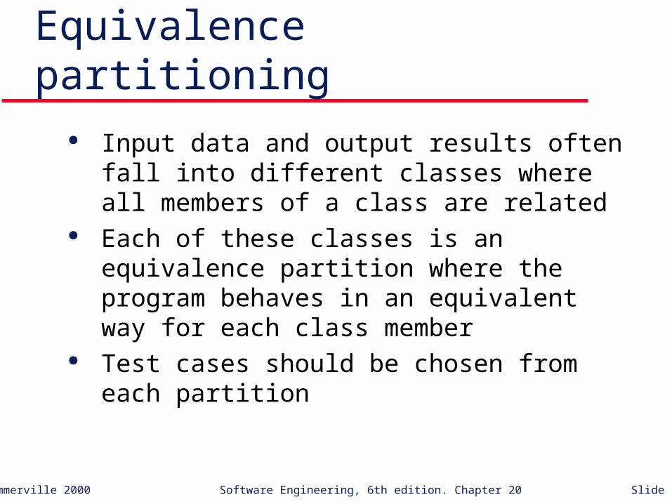
Equivalence partitioning Input data and output results often fall into
different classes where all members of a class are related
Each of these classes is an equivalence partition where the program behaves in an equivalent way for each class member
Test cases should be chosen from each partition

©Ian Sommerville 2000 Software Engineering, 6th edition. Chapter 20 Slide 11
Equivalence partitioning
System
Outputs
Invalid inputs Valid inputs

©Ian Sommerville 2000 Software Engineering, 6th edition. Chapter 20 Slide 12
Partition system inputs and outputs into ‘equivalence sets’• If input is a 5-digit integer between 10,000 and 99,999,
equivalence partitions are <10,000, 10,000-99, 999 and > 10, 000
Choose test cases at the boundary of these sets• 00000, 09999, 10000, 99999, 10001
Equivalence partitioning

©Ian Sommerville 2000 Software Engineering, 6th edition. Chapter 20 Slide 13
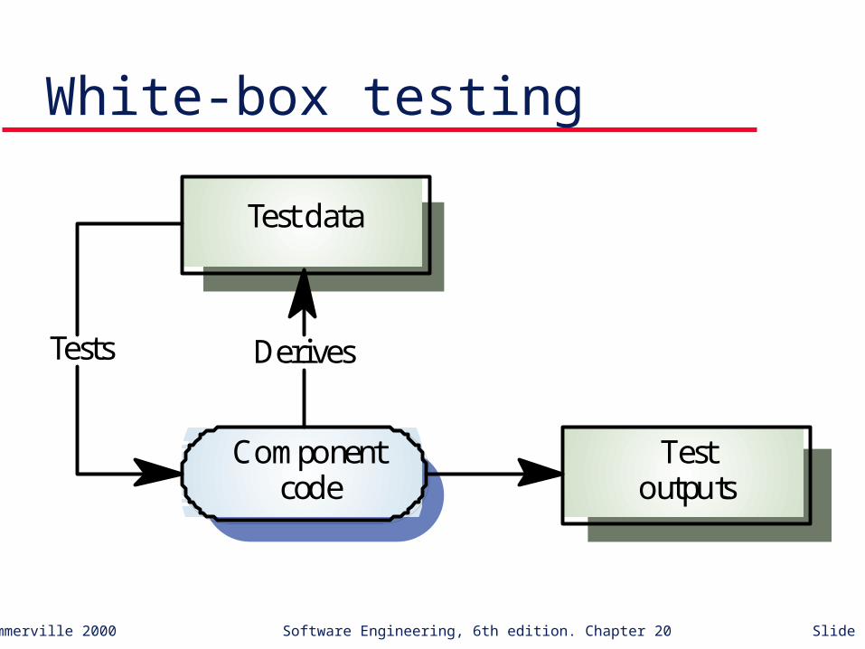
Sometime called white-box testing Derivation of test cases according to program
structure. Knowledge of the program is used to identify additional test cases
Objective is to exercise all program statements (not all path combinations)
Structural testing
©Ian Sommerville 2000 Software Engineering, 6th edition. Chapter 20 Slide 14
White-box testing
Componentcode
Testoutputs
Test data
DerivesTests

©Ian Sommerville 2000 Software Engineering, 6th edition. Chapter 20 Slide 15
Path testing The objective of path testing is to ensure that the
set of test cases is such that each path through the program is executed at least once
The starting point for path testing is a program flow graph that shows nodes representing program decisions and arcs representing the flow of control
Statements with conditions are therefore nodes in the flow graph

©Ian Sommerville 2000 Software Engineering, 6th edition. Chapter 20 Slide 16
Describes the program control flow. Each branch is shown as a separate path and loops are shown by arrows looping back to the loop condition node
Used as a basis for computing the cyclomatic complexity
Cyclomatic complexity = Number of edges - Number of nodes +2
Program flow graphs

©Ian Sommerville 2000 Software Engineering, 6th edition. Chapter 20 Slide 17
The number of tests to test all control statements equals the cyclomatic complexity
Cyclomatic complexity equals number of conditions in a program
Useful if used with care. Does not imply adequacy of testing.
Although all paths are executed, all combinations of paths are not executed
Cyclomatic complexity
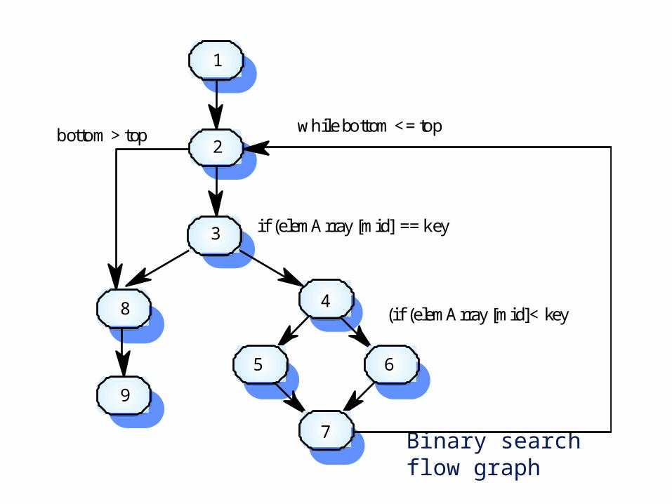
Binary search flow graph
1
2
3
4
65
7
while bottom <= top
if (elemArray [mid] == key
(if (elemArray [mid]< key8
9
bottom > top

©Ian Sommerville 2000 Software Engineering, 6th edition. Chapter 20 Slide 19
1, 2, 3, 8, 9 1, 2, 3, 4, 6, 7, 2 1, 2, 3, 4, 5, 7, 2 1, 2, 3, 4, 6, 7, 2, 8, 9 Test cases should be derived so that all of these
paths are executed A dynamic program analyser may be used to
check that paths have been executed
Independent paths
©Ian Sommerville 2000 Software Engineering, 6th edition. Chapter 20 Slide 20
Integration testing Tests complete systems or subsystems composed
of integrated components Integration testing should be black-box testing
with tests derived from the specification Main difficulty is localising errors Incremental integration testing reduces this
problem

©Ian Sommerville 2000 Software Engineering, 6th edition. Chapter 20 Slide 21
Incremental integration testing
T3
T2
T1
T4
T5
A
B
C
D
T2
T1
T3
T4
A
B
C
T1
T2
T3
A
B
Test sequence1
Test sequence2
Test sequence3
©Ian Sommerville 2000 Software Engineering, 6th edition. Chapter 20 Slide 22
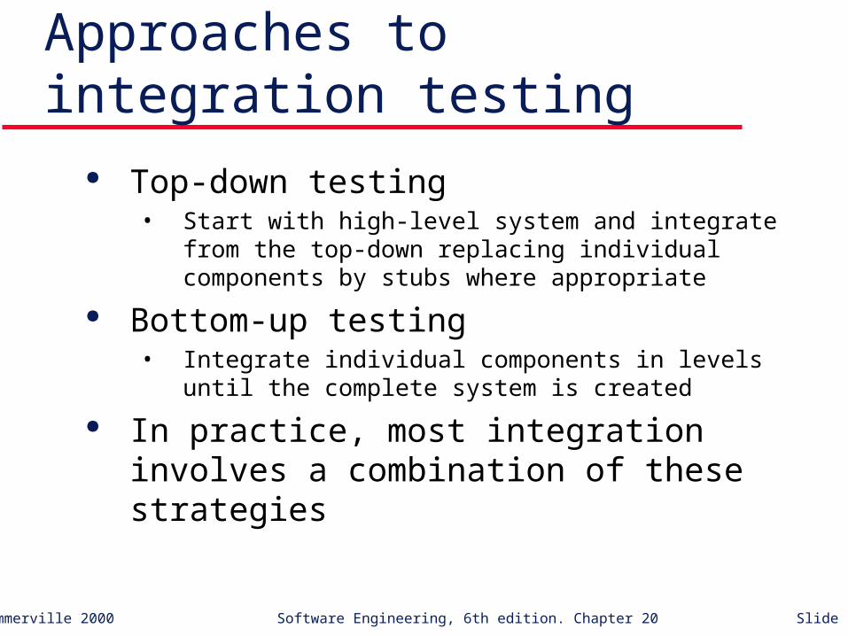
Approaches to integration testing Top-down testing
• Start with high-level system and integrate from the top-down replacing individual components by stubs where appropriate
Bottom-up testing• Integrate individual components in levels until the complete
system is created
In practice, most integration involves a combination of these strategies
©Ian Sommerville 2000 Software Engineering, 6th edition. Chapter 20 Slide 23
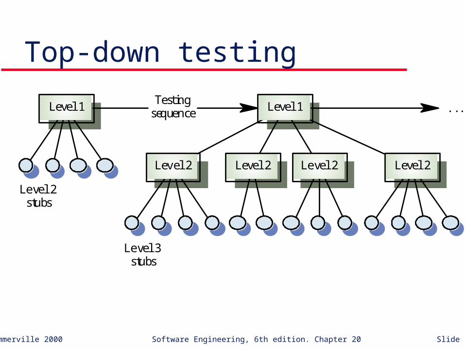
Top-down testing
Level 2Level 2Level 2Level 2
Level 1 Level 1Testing
sequence
Level 2stubs
Level 3stubs
. . .

©Ian Sommerville 2000 Software Engineering, 6th edition. Chapter 20 Slide 24
Bottom-up testing
Level NLevel NLevel NLevel NLevel N
Level N–1 Level N–1Level N–1
Testingsequence
Testdrivers
Testdrivers

©Ian Sommerville 2000 Software Engineering, 6th edition. Chapter 20 Slide 25
Testing approaches Architectural validation
• Top-down integration testing is better at discovering errors in the system architecture
System demonstration• Top-down integration testing allows a limited demonstration at an
early stage in the development
Test implementation• Often easier with bottom-up integration testing
Test observation• Problems with both approaches. Extra code may be required to
observe tests

©Ian Sommerville 2000 Software Engineering, 6th edition. Chapter 20 Slide 26
Takes place when modules or sub-systems are integrated to create larger systems
Objectives are to detect faults due to interface errors or invalid assumptions about interfaces
Particularly important for object-oriented development as objects are defined by their interfaces
Interface testing

©Ian Sommerville 2000 Software Engineering, 6th edition. Chapter 20 Slide 27
Interface testingTestcases
BA
C

©Ian Sommerville 2000 Software Engineering, 6th edition. Chapter 20 Slide 28
Interfaces types Parameter interfaces
• Data passed from one procedure to another
Shared memory interfaces• Block of memory is shared between procedures
Procedural interfaces• Sub-system encapsulates a set of procedures to be called by
other sub-systems
Message passing interfaces• Sub-systems request services from other sub-systems

©Ian Sommerville 2000 Software Engineering, 6th edition. Chapter 20 Slide 29
Interface errors Interface misuse
• A calling component calls another component and makes an error in its use of its interface e.g. parameters in the wrong order
Interface misunderstanding• A calling component embeds assumptions about the behaviour
of the called component which are incorrect
Timing errors• The called and the calling component operate at different speeds
and out-of-date information is accessed
©Ian Sommerville 2000 Software Engineering, 6th edition. Chapter 20 Slide 30
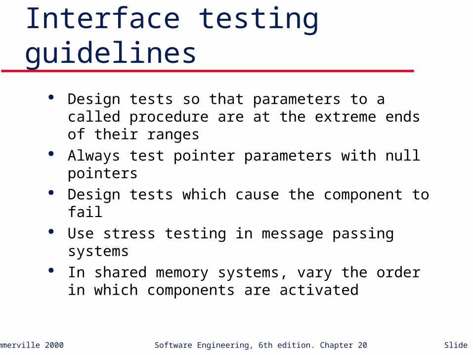
Interface testing guidelines Design tests so that parameters to a called
procedure are at the extreme ends of their ranges Always test pointer parameters with null pointers Design tests which cause the component to fail Use stress testing in message passing systems In shared memory systems, vary the order in
which components are activated
©Ian Sommerville 2000 Software Engineering, 6th edition. Chapter 20 Slide 31
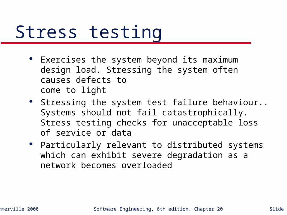
Stress testing Exercises the system beyond its maximum design
load. Stressing the system often causes defects to come to light
Stressing the system test failure behaviour.. Systems should not fail catastrophically. Stress testing checks for unacceptable loss of service or data
Particularly relevant to distributed systems which can exhibit severe degradation as a network becomes overloaded

©Ian Sommerville 2000 Software Engineering, 6th edition. Chapter 20 Slide 32
The components to be tested are object classes that are instantiated as objects
Larger grain than individual functions so approaches to white-box testing have to be extended
No obvious ‘top’ to the system for top-down integration and testing
Object-oriented testing
©Ian Sommerville 2000 Software Engineering, 6th edition. Chapter 20 Slide 33
Testing levels Testing operations associated with objects Testing object classes Testing clusters of cooperating objects Testing the complete OO system

©Ian Sommerville 2000 Software Engineering, 6th edition. Chapter 20 Slide 34
Object class testing Complete test coverage of a class involves
• Testing all operations associated with an object
• Setting and interrogating all object attributes
• Exercising the object in all possible states
Inheritance makes it more difficult to design object class tests as the information to be tested is not localised
©Ian Sommerville 2000 Software Engineering, 6th edition. Chapter 20 Slide 35
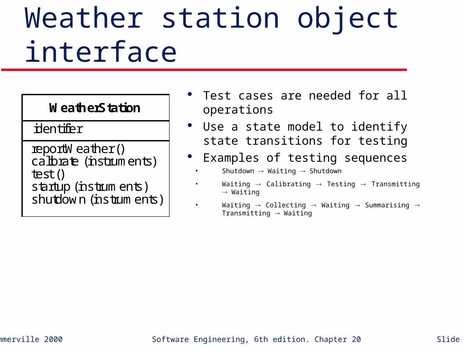
Weather station object interface Test cases are needed for all operations Use a state model to identify state
transitions for testing Examples of testing sequences
• Shutdown Waiting Shutdown
• Waiting Calibrating Testing Transmitting Waiting
• Waiting Collecting Waiting Summarising Transmitting Waiting
identifier
reportWeather ()calibrate (instruments)test ()startup (instruments)shutdown (instruments)
WeatherStation

©Ian Sommerville 2000 Software Engineering, 6th edition. Chapter 20 Slide 36
Object integration Levels of integration are less distinct in object-
oriented systems Cluster testing is concerned with integrating and
testing clusters of cooperating objects Identify clusters using knowledge of the operation
of objects and the system features that are implemented by these clusters

©Ian Sommerville 2000 Software Engineering, 6th edition. Chapter 20 Slide 37
Approaches to cluster testing Use-case or scenario testing
• Testing is based on a user interactions with the system
• Has the advantage that it tests system features as experienced by users
Thread testing• Tests the systems response to events as processing threads
through the system
Object interaction testing• Tests sequences of object interactions that stop when an object
operation does not call on services from another object
©Ian Sommerville 2000 Software Engineering, 6th edition. Chapter 20 Slide 38
Scenario-based testing Identify scenarios from use-cases and supplement
these with interaction diagrams that show the objects involved in the scenario
Consider the scenario in the weather station system where a report is generated

©Ian Sommerville 2000 Software Engineering, 6th edition. Chapter 20 Slide 39
Collect weather data:CommsController
request (report)
acknowledge ()report ()
summarise ()
reply (report)
acknowledge ()
send (report)
:WeatherStation :WeatherData

©Ian Sommerville 2000 Software Engineering, 6th edition. Chapter 20 Slide 40
Weather station testing Thread of methods executed
• CommsController:request WeatherStation:report WeatherData:summarise
Inputs and outputs• Input of report request with associated acknowledge and a final
output of a report
• Can be tested by creating raw data and ensuring that it is summarised properly
• Use the same raw data to test the WeatherData object

©Ian Sommerville 2000 Software Engineering, 6th edition. Chapter 20 Slide 41
Testing workbenches Testing is an expensive process phase. Testing
workbenches provide a range of tools to reduce the time required and total testing costs
Most testing workbenches are open systems because testing needs are organisation-specific
Difficult to integrate with closed design and analysis workbenches

©Ian Sommerville 2000 Software Engineering, 6th edition. Chapter 20 Slide 42
A testing workbench
Dynamicanalyser
Programbeing tested
Testresults
Testpredictions
Filecomparator
Executionreport
Simulator
Sourcecode
Testmanager Test data Oracle
Test datagenerator
Specification
Reportgenerator
Test resultsreport

©Ian Sommerville 2000 Software Engineering, 6th edition. Chapter 20 Slide 43
Tetsing workbench adaptation Scripts may be developed for user interface
simulators and patterns for test data generators Test outputs may have to be prepared manually
for comparison Special-purpose file comparators may be
developed

©Ian Sommerville 2000 Software Engineering, 6th edition. Chapter 20 Slide 44
Key points Test parts of a system which are commonly used
rather than those which are rarely executed Equivalence partitions are sets of test cases where
the program should behave in an equivalent way Black-box testing is based on the system
specification Structural testing identifies test cases which cause
all paths through the program to be executed

©Ian Sommerville 2000 Software Engineering, 6th edition. Chapter 20 Slide 45
Key points Test coverage measures ensure that all statements
have been executed at least once. Interface defects arise because of specification
misreading, misunderstanding, errors or invalid timing assumptions
To test object classes, test all operations, attributes and states
Integrate object-oriented systems around clusters of objects
Related Documents