Ian Bailey Cockcroft Institute/ Lancaster University October 30 th , 2009 Baseline Positron Source Target Experiment Update

Ian Bailey Cockcroft Institute/ Lancaster University October 30 th, 2009 Baseline Positron Source Target Experiment Update.
Dec 18, 2015
Welcome message from author
This document is posted to help you gain knowledge. Please leave a comment to let me know what you think about it! Share it to your friends and learn new things together.
Transcript
Ian Bailey
Cockcroft Institute/ Lancaster University
October 30th, 2009
Baseline Positron Source Target Experiment Update
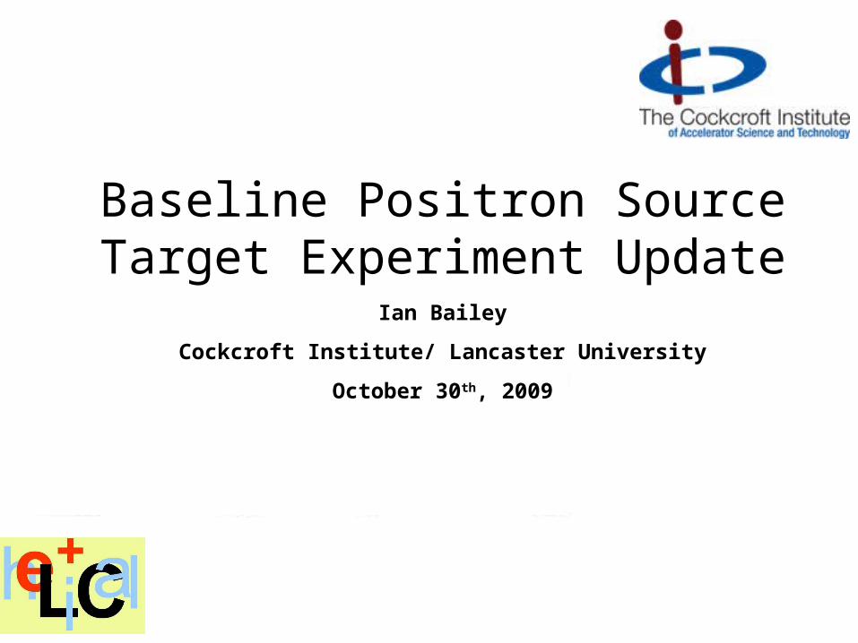
RDR Target Design• Wheel rim speed (100m/s) fixed by thermal load (~8% of photon beam power)
•Rotation reduces pulse energy density (averaged over beam spot) from ~900 J/g to ~24 J/g
•Cooled by internal water-cooling channel
•Wheel diameter (~1m) fixed by radiation damage and capture optics
•Materials fixed by thermal and mechanical properties and pair-production cross-section (Ti6%Al4%V)
•Wheel geometry (~30mm radial width) constrained by eddy currents.
•20cm between target and rf cavity.
•Axial thickness ~0.4 radiation lengths.
T. P
igg
ott, L
LN
L
Drive motor and water union are mounted on opposite ends of through-shaft.
Target documentation will be uploaded to http://www.ippp.dur.ac.uk/LCsources/Target/ and EDMS
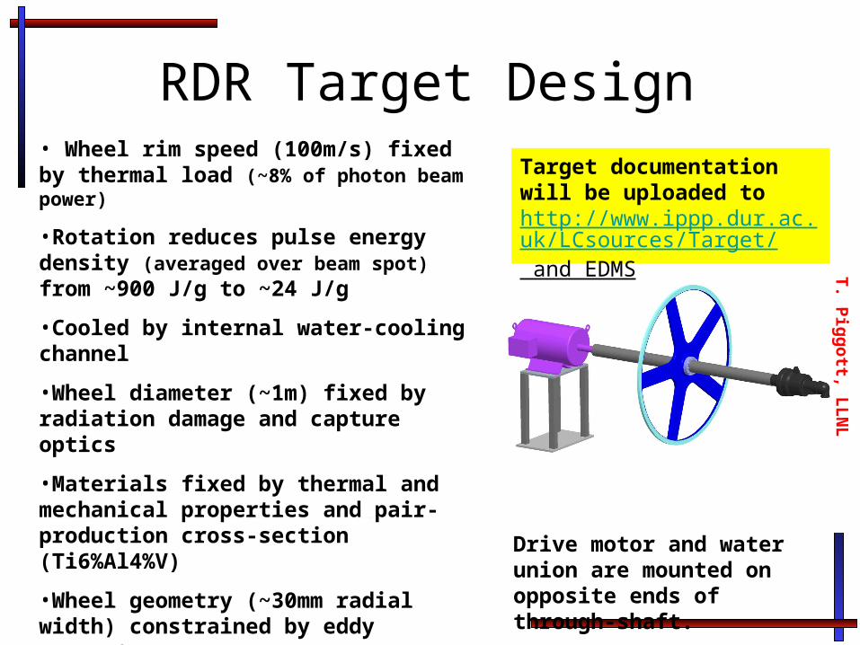
Target Prototype Design Prototype I - eddy current and mechanical stability
Ken
Dav
ies
- D
ares
bury
Lab
orat
ory
Torque transducer
15kW motor
Dipole magnet
mwheel~18kgAccelerometers

Example Torque Data (no magnetic field)
The upper figure shows the measured torque (Nm) as a function of time (s) . The lower figure shows the measured speed over the same period of time.
The torque is sampled at a rate of 2.4kHz. The speed is sampled at a rate of 0.6kHz.
To
rqu
e (N
m)
Sp
eed
(rp
m)

Understanding the Torque DataWithout magnetic field expect average torque given by dark blue line.
Motor controller and structure of motor coils, bearings, etc add oscillations (yellow line)
Magnetic field causes eddy currents to flow in rim (purple line)
Additionally, eddy currents can flow in spokes when they are close to the magnet poles (light blue line).
0
0.5
1
1.5
2
2.5
3
0 0.2 0.4 0.6 0.8 1
Fraction of wheel rotation
To
rqu
e (A
.U.)
Toy model
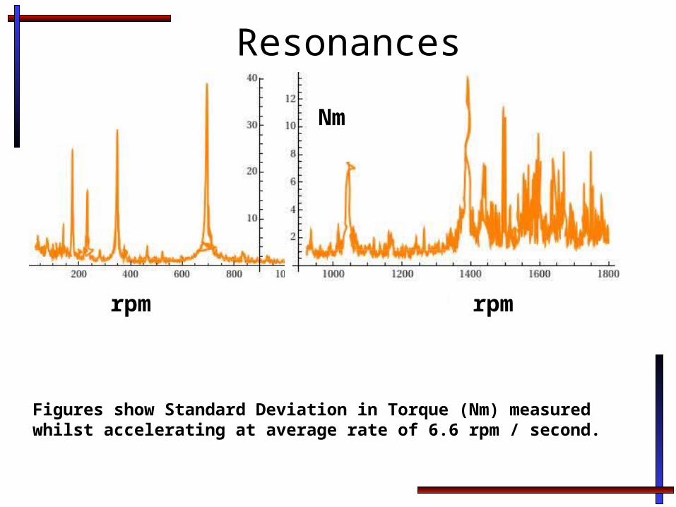
Resonances
Figures show Standard Deviation in Torque (Nm) measured whilst accelerating at average rate of 6.6 rpm / second.
rpm rpm
Nm

Accelerometer Data
B~1.4T
B~0T B~0.9T
0Hz 300Hz-34dB
-25dB
Data obtained from bearing-mounted accelerometer with wheel operating at 800rpm.
Despite auto-scaling of plots, the changes in the power spectrum are clearly visible.
0Hz 300Hz-39.5dB
-24.5dB
0Hz 300Hz-37dB
-21.5dB
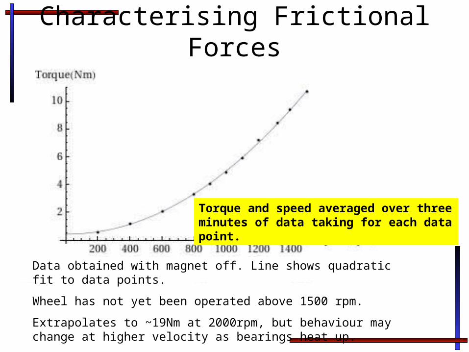
Characterising Frictional Forces
Data obtained with magnet off. Line shows quadratic fit to data points.
Wheel has not yet been operated above 1500 rpm.
Extrapolates to ~19Nm at 2000rpm, but behaviour may change at higher velocity as bearings heat up.
Torque and speed averaged over three minutes of data taking for each data point.
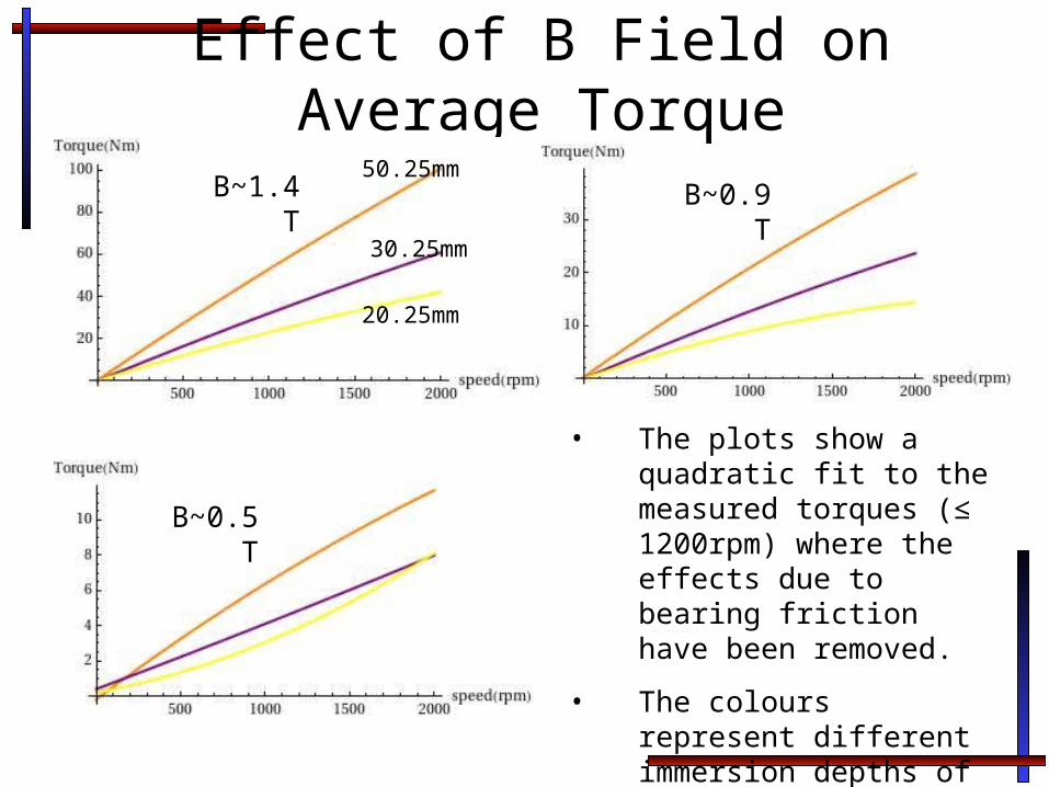
Effect of B Field on Average Torque
B~1.4T B~0.9T
B~0.5T
• The plots show a quadratic fit to the measured torques (≤ 1200rpm) where the effects due to bearing friction have been removed.
• The colours represent different immersion depths of the wheel in the field.
50.25mm
30.25mm
20.25mm
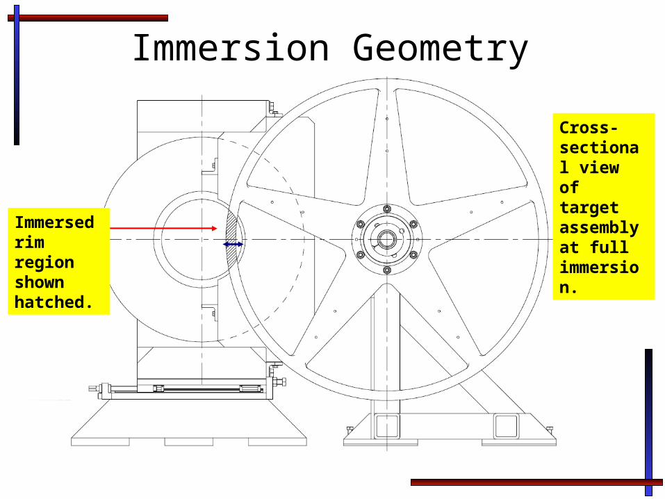
Immersion Geometry
Immersed rim region shown hatched.
Cross-sectional view of target assembly at full immersion.

Current in magnet coils = 50A
0
0.1
0.2
0.3
0.4
0.5
0.6
0.7
0.8
0.9
1
0 10 20 30 40 50 60
Displacement around outer circumference of rim (cm)
B(T
)
50.25mm
50.25mm (2)
40.25mm
40.25mm (2)
30.25mm
30.25mm(2)
20.25mm
20.25mm(2)
Magnetic Field MapsExample of field maps with peak field ~0.9T obtained with Hall probe attached to wheel rim.
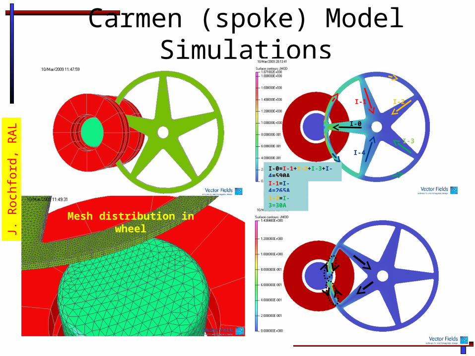
Carmen (spoke) Model Simulations
Mesh distribution in wheel
J. R
ochf
ord,
RA
L
I-1
I-4
I-2
I-3
I-0
I-0=I-1+1-2+I-3+I-4=590AI-1=I-4=265A1-2=I-3=30A

CARMEN Model PredictionRetarding torque for different speeds, Bgap=0.489
-40000
-35000
-30000
-25000
-20000
-15000
-10000
-5000
0
0 10 20 30 40 50 60 70 80 90 100 110 120 130 140 150 160 170 180Angular position (deg)
Torq
ue (N
.mm
)
250rpm
500rpm
1000rpm
1500rpm
2000rpm
J. R
ochf
ord,
RA
L
-5000
0
5000
10000
15000
20000
25000
30000
35000
40000
0 200 400 600 800 1000 1200 1400 1600 1800 2000
Speed (rpm)
To
rqu
e (
Nm
m)
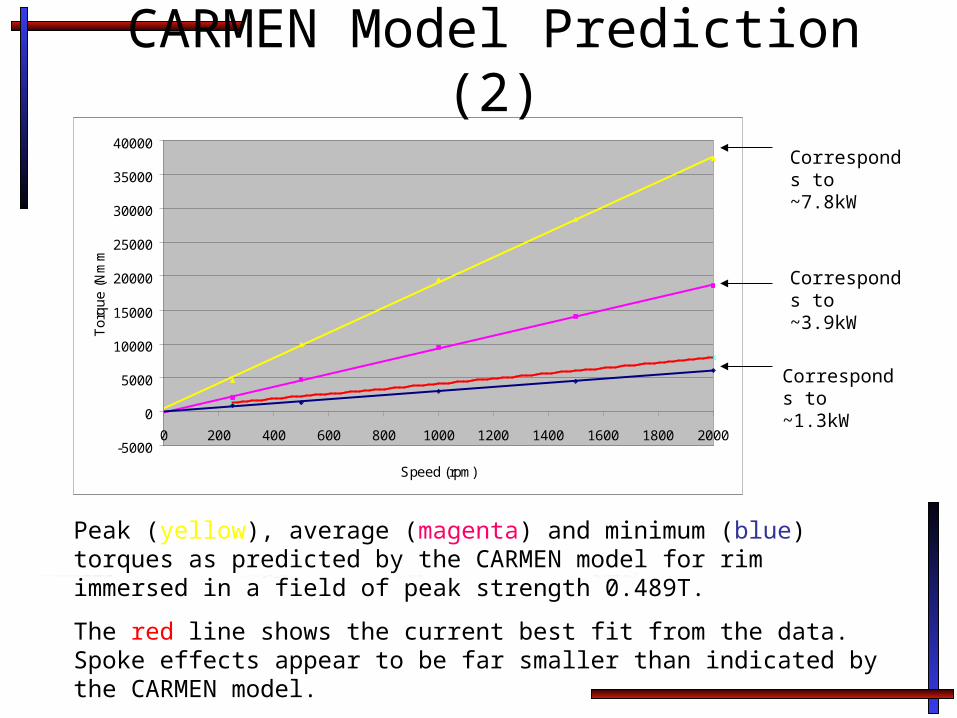
CARMEN Model Prediction (2)
Peak (yellow), average (magenta) and minimum (blue) torques as predicted by the CARMEN model for rim immersed in a field of peak strength 0.489T.
The red line shows the current best fit from the data. Spoke effects appear to be far smaller than indicated by the CARMEN model.
Corresponds to ~7.8kW
Corresponds to ~3.9kW
Corresponds to ~1.3kW

Summary • Prototype complete.
• Data-taking began Nov 08. • Measurements taken for speeds <1800rpm• High speeds vibration and noise (in air)
– Attempting to remove spurious speed measurements with low pass filter
• Extrapolating to 2000rpm suggests wheel will be able to operate in immersed fields ~1T without problems.
• Detailed studies of torque Fourier spectra, etc ongoing
• CARMEN model • Consistent with earlier (rim only) ELECTRA model• In agreement with new LLNL simulation at 10% level• Predicts large effect from spokes• Far smaller effect seen in data
Related Documents