List of models Program controller for operating RCP3 / RCP2 Series actuators. Various control functions are combined into a single unit. Program controller For RCP3/RCP2 Series PSEL Series * 2nd axis specs not applicable to the single-axis model. C Standard Type B Brake B Brake 20P 20 pulse motor-compatible 28P 28 pulse motor-compatible 28SP 28 pulse motor (RCP2-RA3C only) 42P 42 pulse motor-compatible 35P 35 pulse motor-compatible 56P 56 pulse motor-compatible 20P 20 pulse motor-compatible 28P 28 pulse motor-compatible 28SP 28 pulse motor (RCP2-RA3C only) 42P 42 pulse motor-compatible 35P 35 pulse motor-compatible 56P 56 pulse motor-compatible 1 Single-axis model 2 2-axis model I Incremental I Incremental NP PIO NPN (standard) PN PIO PNP DV DeviceNet CC CC-Link PR ProfiBus 0 DC24V 0 No cable 2 2m (standard) 3 3m 5 5m Blank Not used ABU Used 0 C I I * If connecting to RCP2-RA3C/ RGD3C, the motor type is 28SP. * If connecting to RCP2-RA3C/ RGD3C, the motor type is 28SP. Blank Standard H High acceleration type model * If connecting to RCP3-SA4/ SA5/SA6 or RCP2-SA5/SA6, specify "H", for high- acceleration type model. Type Number of Axes Motor Encoder Option Motor Encoder Option I/O Cable Length Power Voltage Simple absolute unit High acceleration type model I/O Type (Specs for 1st axis) (Specs for 2nd axis) Model Type C Program mode Positioner Mode Name External View Description Both the actuator operation and communication with external equipment can be handled by a single controller. When two axes are connected, arc interpolation, path operations, and synchronization can be performed. Up to 1500 positioning points are supported. Push-motion operation and teaching operation are also possible. Position points 1500 points 2 Maximum number of control axes PSEL Controller 557 PSEL Mini Mini PSEP /ASEP PMEC /AMEC ROBO NET ERC2 PCON ACON SCON PSEL ASEL SSEL XSEL Standard Mini Standard Standard Controllers Integrated Controllers Integrated Rod Type Table/Arm /Flat Type Gripper/ Rotary Type Linear Servo Type Cleanroom Type Splash-Proof Controllers Pulse Motor Servo Motor (24V) Servo Motor (200V) Linear Servo Motor Slider Type ELECTROMATE Toll Free Phone (877) SERVO98 Toll Free Fax (877) SERV099 www.electromate.com [email protected] Sold & Serviced By:

Iai psel controller_specsheet
Aug 21, 2015
Welcome message from author
This document is posted to help you gain knowledge. Please leave a comment to let me know what you think about it! Share it to your friends and learn new things together.
Transcript

List of models
Program controller for operating RCP3/ RCP2 Series actuators. Various control functions are combined into a single unit.
Program controller
For RCP3/RCP2 Series
P S E LSeries
* 2nd axis specs not applicable to the single-axis model.
C Standard Type
B Brake B Brake
20P 20 � pulse motor-compatible
28P 28 � pulse motor-compatible
28SP 28 � pulse motor(RCP2-RA3C only)
42P 42 � pulse motor-compatible
35P 35 � pulse motor-compatible
56P 56 � pulse motor-compatible
20P 20 � pulse motor-compatible
28P 28 � pulse motor-compatible
28SP 28 � pulse motor(RCP2-RA3C only)
42P 42 � pulse motor-compatible
35P 35 � pulse motor-compatible
56P 56 � pulse motor-compatible
1 Single-axis model
2 2-axis model
I Incremental I Incremental
NP PIO NPN (standard)
PN PIO PNP
DV DeviceNet
CC CC-Link
PR ProfiBus
0 DC24V
0 No cable
2 2m (standard)
3 3m
5 5m
Blank Not used
ABU Used
0C I I
* If connecting to RCP2-RA3C/ RGD3C, the motor type is 28SP.
* If connecting to RCP2-RA3C/RGD3C, the motor type is 28SP.
Blank Standard
H High acceleration type model
* If connecting to RCP3-SA4/SA5/SA6 or RCP2-SA5/SA6,specify "H", for high-
acceleration type model.
Type Number of Axes Motor Encoder Option Motor Encoder Option
I/O Cable Length
PowerVoltage
Simple absolute unit
High acceleration type model
I/O Type(Specs for 1st axis) (Specs for 2nd axis)
Model
Type C
Program mode Positioner ModeName
External View
Description
Both the actuator operation and communication with external equipment can be handled by a single controller.
When two axes are connected, arc interpolation, path operations, and synchronization can be performed.
Up to 1500 positioning points are supported. Push-motion operation and teaching operation are also possible.
Position points 1500 points
2Maximum number of control axes
PSEL Controller
557 PSEL
Mini
Mini
PSEP/ASEP
PMEC/AMEC
ROBONET
ERC2
PCON
ACON
SCON
PSEL
ASEL
SSEL
XSEL
Standard
Mini
Standard
Standard
ControllersIntegrated
ControllersIntegrated
RodType
Table/Arm/Flat Type
Gripper/Rotary Type
Linear ServoType
Cleanroom Type
Splash-Proof
Controllers
Pulse Motor
Servo Motor (24V)
Servo Motor (200V)
LinearServo Motor
SliderType
ELECTROMATEToll Free Phone (877) SERVO98
Toll Free Fax (877) SERV099www.electromate.com
Sold & Serviced By:

Teaching Pendant (see P565)Model: SEL-T/SEL-TD(Optional)
I/O Flat CableModel: CB-DS-PIO020(Supplied with the controller)For a replacement cable, see P566.
Panel Unit(See P565)Model: PU-1(Optional)
Field Network
Encoder Cable<Model: CB-RCP2-PB���>Standard 1m/3m/5mFor a replacement cable, see P566.
Motor Cable<Model: CB-RCP2-MA���>Standard 1m/3m/5mFor a replacement cable, see P566
PC Software (See P565)Model: IA-101-X-MW (with RS232C cable)
IA-101-X-USB (with USB cable)
System Memory Backup Battery (see P565)Model: AB-5-CS (with case)
AB-5 (stand-alone battery)(Optional)*1
*1 The system memory backup battery is a required feature if you wish to retain data such as flags used in programs even after the power has been shut off.
USB Cable (see P566)Model: CB-SEL-USB030(included w/ IA-101-X-USB PC software)
RS232C CableModel: CB-ST-E1MW050-EB(Supplied with the IA-101-X-MWPC software)
Adapter cable (see P566)Model: CB-SEL-SJ002(Optional)
2m
0.2m
3m 3m
5m
5m
<Model: PS-241 (100V input)><Model: PS-242 (200V input)>(Optional)
DC24V Power Supply(See P471)
PLC
Actuator: RCP2 series
Actuator: RCP3 series
Motor-encoder Integrated Cable<Model: CB-PCS-MPA���>Standard 1m / 3m / 5m(Supplied with the actuator)For a replacement cable, see P566.
<Model: PCON-ABU>(See P545)
Simple Absolute Unit(Optional)
System configuration
PSEL Controller
PSEL 558
Mini
Mini
PSEP/ASEP
PMEC/AMEC
ROBONET
ERC2
PCON
ACON
SCON
PSEL
ASEL
SSEL
XSEL
Standard
Mini
Standard
Standard
ControllersIntegrated
ControllersIntegrated
SliderType
RodType
Table/Arm/Flat Type
Gripper/Rotary Type
Linear ServoType
Cleanroom Type
Splash-Proof
Controllers
Pulse Motor
Servo Motor (24V)
Servo Motor (200V)
LinearServo Motor
ELECTROMATEToll Free Phone (877) SERVO98
Toll Free Fax (877) SERV099www.electromate.com
Sold & Serviced By:
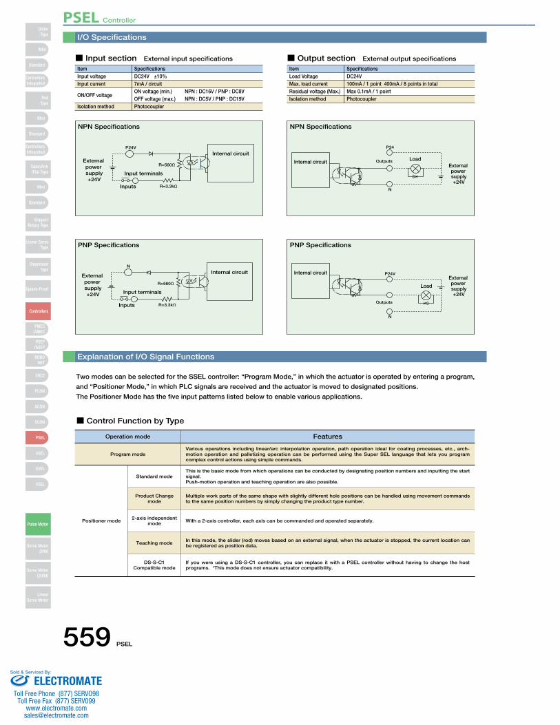
I/O Specifications
Explanation of I/O Signal Functions
Two modes can be selected for the SSEL controller: “Program Mode,” in which the actuator is operated by entering a program,
and “Positioner Mode,” in which PLC signals are received and the actuator is moved to designated positions.
The Positioner Mode has the five input patterns listed below to enable various applications.
■ Control Function by Type
ItemInput voltageInput current
ON/OFF voltage
Isolation method
SpecificationsDC24V ±10%7mA / circuitON voltage (min.) NPN : DC16V / PNP : DC8VOFF voltage (max.) NPN : DC5V / PNP : DC19VPhotocoupler
P24V
R=3.3kΩInputs
R=560ΩExternal power supply+24V
Input terminals
Internal circuit
■ Input section External input specifications
ItemLoad VoltageMax. load current Residual voltage (Max.) Isolation method
SpecificationsDC24V100mA / 1 point 400mA / 8 points in totalMax 0.1mA / 1 pointPhotocoupler
P24
N
OutputsInternal circuit LoadExternal power supply+24V
N
R=3.3kΩInputs
R=560Ω
External power supply+24V Input terminals
Internal circuit P24V
N
Outputs
Internal circuitExternal power supply+24V
Load
■ Output section External output specifications
NPN Specifications NPN Specifications
PNP Specifications PNP Specifications
Operation mode Features
Program mode
Positioner mode
This is the basic mode from which operations can be conducted by designating position numbers and inputting the start signal.Push-motion operation and teaching operation are also possible.
Various operations including linear/arc interpolation operation, path operation ideal for coating processes, etc., arch-motion operation and palletizing operation can be performed using the Super SEL language that lets you program complex control actions using simple commands.
Multiple work parts of the same shape with slightly different hole positions can be handled using movement commands to the same position numbers by simply changing the product type number.
With a 2-axis controller, each axis can be commanded and operated separately.
In this mode, the slider (rod) moves based on an external signal, when the actuator is stopped, the current location can be registered as position data.
Standard mode
Product Change mode
2-axis independent mode
Teaching mode
DS-S-C1Compatible mode
If you were using a DS-S-C1 controller, you can replace it with a PSEL controller without having to change the host programs. *This mode does not ensure actuator compatibility.
PSEL Controller
559 PSEL
Mini
Mini
PSEP/ASEP
PMEC/AMEC
ROBONET
ERC2
PCON
ACON
SCON
PSEL
ASEL
SSEL
XSEL
Standard
Mini
Standard
Standard
ControllersIntegrated
ControllersIntegrated
RodType
Table/Arm/Flat Type
Gripper/Rotary Type
Linear ServoType
Cleanroom Type
Splash-Proof
Controllers
Pulse Motor
Servo Motor (24V)
Servo Motor (200V)
LinearServo Motor
SliderType
ELECTROMATEToll Free Phone (877) SERVO98
Toll Free Fax (877) SERV099www.electromate.com
Sold & Serviced By:

Explanation of I/O Signal Functions
Pin Number Classification
Input
Output
N
24V input Connect 24V.
Program Mode Functions
Resets the system to the same state as when the power is turned on.
Turns off when an alarm occurs. (Contact B)
Turns on when the controller starts up normally and is in an operable state.
Connect 0V.
These outputs can be turned ON/OFF as desired via program instructions.
Starts the program selected by ports 016 to 022.
Waits for external input via program instructions.
Selects the program number to start.
(Input as BCD values to ports 016 to 022)
0V 24
Wiring Diagram
1A P24
1B
2A
2B
3A
3B
4A
4B
5A
5B
6A
6B
7A
7B
8A
8B
9A
9B
10A
10B
11A
11B
12A
12B
13A
13B
14A
14B
15A
15B
16A
16B
17A
17B
016
Port No.
017
018
019
020
021
022
023
000
001
002
003
004
005
006
007
008
009
010
011
012
013
014
015
300
301
302
303
304
305
306
307
Select Program No. 1
Select Program No. 2
Select Program No. 4
Select Program No. 8
Select Program No. 10
Select Program No. 20
Select Program No. 40
CPU reset
Start
General-purpose input
General-purpose input
General-purpose input
General-purpose input
General-purpose input
General-purpose input
General-purpose input
General-purpose input
General-purpose input
General-purpose input
General-purpose input
General-purpose input
General-purpose input
General-purpose input
General-purpose input
Alarm
Ready
General-purpose output
General-purpose output
General-purpose output
General-purpose output
General-purpose output
General-purpose output
0V input
Pin Number
24V input Connect 24V.
PositionerStandard Mode Functions
Resets minor errors. (Severe errors require a restart.)
Turns off when an alarm occurs. (Contact B)
Turns on when the controller starts up normally and is in an operable state.
Turns on when the movement to the destination is complete.
Turns on when the home return operation is complete.
Turns on when servo is ON.
Turns on when a push motion is complete.
Turns on when the system battery runs low (warning level).
Connect 0V.
Starts moving to selected position.
Performs home return.
Switches between Servo ON and OFF.
Performs a push motion.
Pauses the motion when turned OFF, and resumes when turned ON.
Stops the motion when turned OFF. The remaining motion is canceled.
When this signal is turned ON for a 2-axis model, the actuator moves by linear interpolation.
Specifies the position numbers to move to, using ports 007 to 019.
The number can be specified either as BCD or binary.
Specifies the position numbers to move to, using port number 007 to 019.
The number can be specified either as BCD or binary.
0V 24
Wiring Diagram
1A
1B
2A
2B
3A
3B
4A
4B
5A
5B
6A
6B
7A
7B
8A
8B
9A
9B
10A
10B
11A
11B
12A
12B
13A
13B
14A
14B
15A
15B
16A
16B
17A
17B
Position input 10
Position input 11
Position input 12
Position input 13
Error reset
Start
Home return
Servo ON
Push
Pause
Cancel
Interpolation settings
Position input 1
Position input 2
Position input 3
Position input 4
Position input 5
Position input 6
Position input 7
Position input 8
Position input 9
Alarm
Ready
Positioning complete
Home return complete
Servo ON output
Pushing complete
System battery error
0V input
Classification
Input
Output
N
P24016
Port No.
017
018
019
020
021
022
023
000
001
002
003
004
005
006
007
008
009
010
011
012
013
014
015
300
301
302
303
304
305
306
307
Program mode
Positioner mode
Note: This is for NPN. PNP will be different.
Note: This is for NPN. PNP will be different.
PSEL Controller
PSEL 560
Mini
Mini
PSEP/ASEP
PMEC/AMEC
ROBONET
ERC2
PCON
ACON
SCON
PSEL
ASEL
SSEL
XSEL
Standard
Mini
Standard
Standard
ControllersIntegrated
ControllersIntegrated
SliderType
RodType
Table/Arm/Flat Type
Gripper/Rotary Type
Linear ServoType
Cleanroom Type
Splash-Proof
Controllers
Pulse Motor
Servo Motor (24V)
Servo Motor (200V)
LinearServo Motor
ELECTROMATEToll Free Phone (877) SERVO98
Toll Free Fax (877) SERV099www.electromate.com
Sold & Serviced By:

Explanation of I/O Signal Functions
Pin Number
24V input Connect 24V.
Positioner Product Type Change Mode Functions
Connect 0V.
0V 24
Wiring Diagram
1A
Resets minor errors. (Severe errors require a restart.)
Turns off when an alarm occurs. (Contact B)
Turns on when the controller starts up normally and is in an operable state.
Turns on when the movement to the destination is complete.
Turns on when the home return operation is complete.
Turns on when servo is ON.
Turns on when a push motion is complete.
Turns on when the system battery runs low (warning level).
Starts moving to selected position.
Performs home return.
Switches between Servo ON and OFF.
Performs a push motion.
Pauses the motion when turned OFF, and resumes when turned ON.
Stops the motion when turned OFF. The remaining motion is canceled.
When this signal is turned ON for a 2-axis model, the actuator moves by linear interpolation.
Specifies the position numbers to move to, and the product type numbers,
using ports 007 to 022.
The position and product type numbers are assigned by parameter settings.
The number can be specified either as BCD or binary.
Specifies the position numbers to move to, and the product type numbers,
using ports 007 to 022.
The position and product type numbers are assigned by parameter settings.
The number can be specified either as BCD or binary.
1B
2A
2B
3A
3B
4A
4B
5A
5B
6A
6B
7A
7B
8A
8B
9A
9B
10A
10B
11A
11B
12A
12B
13A
13B
14A
14B
15A
15B
16A
16B
17A
17B
Position/Product Type Input 10
Position/Product Type Input 11
Position/Product Type Input 12
Position/Product Type Input 13
Position/Product Type Input 14
Position/Product Type Input 15
Position/Product Type Input 16
Error reset
Start
Home return
Servo ON
Push
Pause
Cancel
Interpolation settings
Position/Product Type Input 1
Position/Product Type Input 2
Position/Product Type Input 3
Position/Product Type Input 4
Position/Product Type Input 5
Position/Product Type Input 6
Position/Product Type Input 7
Position/Product Type Input 8
Position/Product Type Input 9
Alarm
Ready
Positioning complete
Home return complete
Servo ON output
Pushing complete
System battery error
0V input
Classification
Input
Output
N
P24016
Port No.
017
018
019
020
021
022
023
000
001
002
003
004
005
006
007
008
009
010
011
012
013
014
015
300
301
302
303
304
305
306
307
Pin Number
24V input Connect 24V.
Positioner 2-axisIndependent Mode Functions
Connect 0V.
0V 24
Wiring Diagram
1A
Resets minor errors. (Severe errors require a restart.)
Turns off when an alarm occurs. (Contact B)
Turns on when the controller starts up normally and is in an operable state.
Turns on when the movement to the specified position on the 1st axis is complete.
Turns on when home return on the 1st axis is complete.
Turns on when the 1st axis is in a servo ON state.
Turns on when the movement to the specified position on the 2nd axis is complete.
Turns on when home return on the 2nd axis is complete.
Turns on when the 2nd axis is in a servo ON state.
Starts the movement to the selected position number on the 1st axis.
Performs home return on the 1st axis.
Switches between servo ON and OFF for the 1st axis.
Pauses the motion on 1st axis when turned OFF, and resumes when turned ON.
Cancels the movement on the 1st axis.
Starts the movement to the selected position number on the 2nd axis.
Performs home return on the 2nd axis.
Switches between servo ON and OFF for the 2nd axis.
Pauses the motion on 2nd axis when turned OFF, and resumes when turned ON.
Cancels the movement on the 2nd axis.
Specifies the position numbers to move to, using ports 010 to 022.
The position numbers on the 1st and 2nd axes are assigned by
parameter settings.
The number can be specified either as BCD or binary.
Specifies the position numbers to move to, using ports 010 to 022.
The position numbers on the 1st and 2nd axes are assigned by
parameter settings.
The number can be specified either as BCD or binary.
1B
2A
2B
3A
3B
4A
4B
5A
5B
6A
6B
7A
7B
8A
8B
9A
9B
10A
10B
11A
11B
12A
12B
13A
13B
14A
14B
15A
15B
16A
16B
17A
17B
Position input 7
Position input 8
Position input 9
Position input 10
Position input 11
Position input 12
Position input 13
Error reset
Start 1
Home return 1
Servo ON 1
Pause 1
Cancel 1
Start 2
Home return 2
Servo ON 2
Pause 2
Cancel 2
Position input 1
Position input 2
Position input 3
Position input 4
Position input 5
Position input 6
Alarm
Ready
Positioning complete 1
Home return complete 1
Servo ON output 1
Positioning complete 2
Home return complete 2
Servo ON output 2
0V input
Classification
Input
Output
N
P24016
Port No.
017
018
019
020
021
022
023
000
001
002
003
004
005
006
007
008
009
010
011
012
013
014
015
300
301
302
303
304
305
306
307
Positioner, Product-Type Change Mode
Positioner, 2-axis Independent Mode
Note: This is for NPN. PNP will be different.
Note: This is for NPN. PNP will be different.
PSEL Controller
561 PSEL
Mini
Mini
PSEP/ASEP
PMEC/AMEC
ROBONET
ERC2
PCON
ACON
SCON
PSEL
ASEL
SSEL
XSEL
Standard
Mini
Standard
Standard
ControllersIntegrated
ControllersIntegrated
RodType
Table/Arm/Flat Type
Gripper/Rotary Type
Linear ServoType
Cleanroom Type
Splash-Proof
Controllers
Pulse Motor
Servo Motor (24V)
Servo Motor (200V)
LinearServo Motor
SliderType
ELECTROMATEToll Free Phone (877) SERVO98
Toll Free Fax (877) SERV099www.electromate.com
Sold & Serviced By:

Explanation of I/O Signal Functions
Pin Number
24V input Connect 24V.
While the signal is on, the 1st axis is moved in the - (negative) direction.
While the signal is on, the 2nd axis is moved in the + (positive) direction.
While the signal is on, the 2nd axis is moved in the - (negative) direction.
Specifies how much to move during inching.
(Total of the values specified for ports 019 to 022)
PositionerTeaching Mode Functions
Connect 0V.
0V 24
Wiring Diagram
1A
Resets minor errors. (Severe errors require a restart.)
Turns off when an alarm occurs. (Contact B)
While the signal is on, the 1st axis is moved in the + (positive) direction.
Turns on when the controller starts up normally and is in an operable state.
Turns on when the movement to the destination is complete.
Turns on when the home return operation is complete.
Turns on when servo is ON.
Turns on when the system battery runs low (warning level).
Starts moving to selected position.
Switches between Servo ON and OFF.
Pauses the motion when turned OFF, and resumes when turned ON.
Ports 003 to 013 are used to specify the position number to move, and
the position number for inputting the current position.
- When the teaching mode setting on port 014 is in the ON state, the
current value is written to the specified position number.
1B
2A
2B
3A
3B
4A
4B
5A
5B
6A
6B
7A
7B
8A
8B
9A
9B
10A
10B
11A
11B
12A
12B
13A
13B
14A
14B
15A
15B
16A
16B
17A
17B
JOG− on 1st axis
JOG+ on 2nd axis
JOG− on 2nd axis
Specify inching (0.01mm)
Specify inching (0.1mm)
Specify inching (0.5mm)
Specify inching (1mm)
Error reset
Start
Servo ON
Pause
Position input 1
Position input 2
Position input 3
Position input 4
Position input 5
Position input 6
Position input 7
Position input 8
Position input 9
Position input 10
Position input 11
Teaching mode setting
JOG+ on 1st axis
Alarm
Ready
Positioning complete
Home return complete
Servo ON output
System battery error
0V input
Classification
Input
Output
N
P24016
Port No.
017
018
019
020
021
022
023
000
001
002
003
004
005
006
007
008
009
010
011
012
013
014
015
300
301
302
303
304
305
306
307
Pin Number Classification
Input
Output
N
01624V input Connect 24V.
(Same as ports 004 through 015)
Port No.Positioner DS-S-C1
Compatible ModeFunctions
Connect 0V.
0V 24
Wiring Diagram
1A P24
Resets the system to the same state as when the power is turned on.
Turns off when an alarm occurs. (Contact A)
Turns on when the controller starts up normally and is in an operable state.
Turns on when the movement to the destination is complete.
Turns on when the system battery runs low (warning level).
Starts moving to selected position.
Pauses the motion when turned ON, and resumes when turned OFF.
Stops the motion when turned ON. The remaining motion is canceled.
When this signal is turned ON for a 2-axis model, the actuator moves by linear interpolation.
Ports 004 through 016 are used to specify the position number to move.
The numbers are specified as BCD.
1B
2A
2B
3A
3B
4A
4B
5A
5B
6A
6B
7A
7B
8A
8B
9A
9B
10A
10B
11A
11B
12A
12B
13A
13B
14A
14B
15A
15B
16A
16B
17A
17B
017
018
019
020
021
022
023
000
001
002
003
004
005
006
007
008
009
010
011
012
013
014
015
300
301
302
303
304
305
306
307
Position No. 1000
CPU reset
Start
Hold (Pause)
Cancel
Interpolation settings
Position No. 1
Position No. 2
Position No. 4
Position No. 8
Position No. 10
Position No. 20
Position No. 40
Position No. 80
Position No. 100
Position No. 200
Position No. 400
Position No. 800
Alarm
Ready
Positioning complete
System battery error
0V input
Positioner, Teaching Mode
Positioner, DS-S-C1 Compatible Mode
Note: This is for NPN. PNP will be different.
Note: This is for NPN. PNP will be different.
PSEL Controller
PSEL 562
Mini
Mini
PSEP/ASEP
PMEC/AMEC
ROBONET
ERC2
PCON
ACON
SCON
PSEL
ASEL
SSEL
XSEL
Standard
Mini
Standard
Standard
ControllersIntegrated
ControllersIntegrated
SliderType
RodType
Table/Arm/Flat Type
Gripper/Rotary Type
Linear ServoType
Cleanroom Type
Splash-Proof
Controllers
Pulse Motor
Servo Motor (24V)
Servo Motor (200V)
LinearServo Motor
ELECTROMATEToll Free Phone (877) SERVO98
Toll Free Fax (877) SERV099www.electromate.com
Sold & Serviced By:
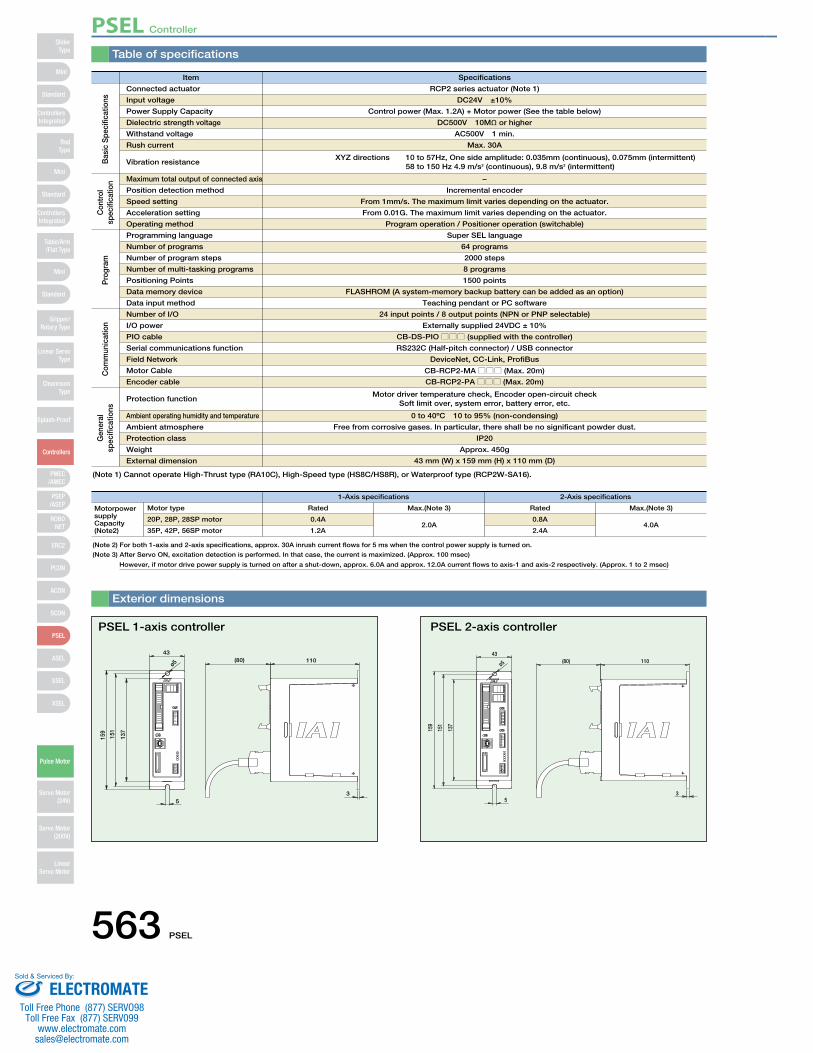
Table of specifications
Item Specifications
1-Axis specifications 2-Axis specifications
Connected actuator
Motor type
Maximum total output of connected axis
Position detection method
Speed setting
Acceleration setting
Operating method
Input voltage
20P, 28P, 28SP motor
Power Supply Capacity
35P, 42P, 56SP motor
Dielectric strength voltage
Withstand voltage
Rush current
Vibration resistance
RCP2 series actuator (Note 1)
Rated Max.(Note 3) Rated Max.(Note 3)
DC24V ±10%
0.4A2.0A
0.8A4.0A
Control power (Max. 1.2A) + Motor power (See the table below)
1.2A 2.4A
DC500V 10MΩ or higher
AC500V 1 min.
Max. 30A
XYZ directions 10 to 57Hz, One side amplitude: 0.035mm (continuous), 0.075mm (intermittent) 58 to 150 Hz 4.9 m/s2 (continuous), 9.8 m/s2 (intermittent)
−
Incremental encoder
From 1mm/s. The maximum limit varies depending on the actuator.
From 0.01G. The maximum limit varies depending on the actuator.
Program operation / Positioner operation (switchable)
(80) 11043
ø5
159
151
137
53
Exterior dimensions
PSEL 1-axis controller
159
151
137
53
43(80) 110
ø5
PSEL 2-axis controller
Bas
ic S
peci
ficat
ions
Con
trol
sp
ecifi
catio
n
Programming language
Number of programs
Number of program steps
Number of multi-tasking programs
Positioning Points
Data memory device
Data input method
Number of I/O
I/O power
PIO cable
Serial communications function
Field Network
Motor Cable
Encoder cable
Protection function
Ambient operating humidity and temperature
Ambient atmosphere
Protection class
Weight
External dimension
Super SEL language
64 programs
2000 steps
8 programs
1500 points
FLASHROM (A system-memory backup battery can be added as an option)
Teaching pendant or PC software
24 input points / 8 output points (NPN or PNP selectable)
Externally supplied 24VDC ± 10%
CB-DS-PIO□□□ (supplied with the controller)
RS232C (Half-pitch connector) / USB connector
DeviceNet, CC-Link, ProfiBus
CB-RCP2-MA□□□ (Max. 20m)
CB-RCP2-PA□□□ (Max. 20m)
Motor driver temperature check, Encoder open-circuit checkSoft limit over, system error, battery error, etc.
0 to 40ºC 10 to 95% (non-condensing)
Free from corrosive gases. In particular, there shall be no significant powder dust.
IP20
Approx. 450g
43 mm (W) x 159 mm (H) x 110 mm (D)
Pro
gram
Com
mun
icat
ion
Gen
eral
sp
ecifi
catio
ns
(Note 1) Cannot operate High-Thrust type (RA10C), High-Speed type (HS8C/HS8R), or Waterproof type (RCP2W-SA16).
(Note 2) For both 1-axis and 2-axis specifications, approx. 30A inrush current flows for 5 ms when the control power supply is turned on.
(Note 3) After Servo ON, excitation detection is performed. In that case, the current is maximized. (Approx. 100 msec)
However, if motor drive power supply is turned on after a shut-down, approx. 6.0A and approx. 12.0A current flows to axis-1 and axis-2 respectively. (Approx. 1 to 2 msec)
Motorpower supply Capacity (Note2)
PSEL Controller
563 PSEL
Mini
Mini
PSEP/ASEP
PMEC/AMEC
ROBONET
ERC2
PCON
ACON
SCON
PSEL
ASEL
SSEL
XSEL
Standard
Mini
Standard
Standard
ControllersIntegrated
ControllersIntegrated
RodType
Table/Arm/Flat Type
Gripper/Rotary Type
Linear ServoType
Cleanroom Type
Splash-Proof
Controllers
Pulse Motor
Servo Motor (24V)
Servo Motor (200V)
LinearServo Motor
SliderType
ELECTROMATEToll Free Phone (877) SERVO98
Toll Free Fax (877) SERV099www.electromate.com
Sold & Serviced By:
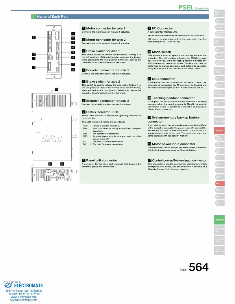
Name of Each Part
13
14
19
1 Motor connector for axis 1 Connects the motor cable of the axis 1 actuator.
8 Panel unit connector A connector for the panel unit (optional) that displays the controller status and error codes.
9 I/O Connector A connector for interface I/Os.
34-pin flat cable connector for DIO (24IN/8OUT) interface.
I/O power is also supplied to the controller via this connector (Pin No. 1 and No. 34).
10 Mode switch This switch is used to specify the running mode of the controller. The left position indicates the MANU (manual operation) mode, while the right position indicates the AUTO (automatic operation) mode. Teaching can only be performed in manual operation, and automatic operation using external I/Os is not possible in the MANU mode.
11 USB connectorA connector for PC connection via USB. If the USB connector is connected, the TP connector is disabled and all communication inputs to the TP connector are cut off.
12 Teaching pendant connectorA half-pitch I/O 26-pin connector that connects a teaching pendant when the running mode is MANU. A special conversion cable is needed to connect a conventional D-sub, 25-pin connector.
14 Motor power input connectorThis connector is used to input the motor power. It consists of a 2-pin, 2-piece connector by Phoenix Contact.
15 Control power/System input connectorThis connector is used to connect the control power input, emergency stop switch, and enable switch. It consists of a Phoenix Contact 6-pin 2-piece connector.
13 System-memory backup battery connectorIf you wish to retain the various data recorded in the SRAM of the controller even after the power is cut off, connect the necessary battery to this connector. This battery is installed externally to the unit. The controller does not come standard with the battery (Option).
2 Motor connector for axis 2 Connects the motor cable of the axis 2 actuator.
4 Encoder connector for axis 1Connect the encoder cable of the axis 1 actuator.
6 Encoder connector for axis 2Connect the encoder cable of the axis 2 actuator.
7 Status indicator LEDsThese LEDs are used to indicate the operating condition of the controller.
The LED status indicators are as follows:
3 Brake switch for axis 1 This switch is used to release the axis brake. Setting it to the left position (RLS side) forcibly releases the brake, while setting it to the right position (NOM side) causes the controller to automatically control the brake.
5 Brake switch for axis 2 This switch is used to release the axis brake. Setting it to the left position (RLS side) forcibly releases the brake, while setting it to the right position (NOM side) causes the controller to automatically control the brake.
PWR : Power is input to controller.RDY : The controller is ready to perform program
operation. ALM : The controller is abnormal. EMG : An emergency stop is actuated and the drive
source is cut off. SV1 : The axis 1 actuator servo is on. SV2 : The axis 2 actuator servo is on.
10
11
12
2
3
4
5
6
8
7
15
PSEL Controller
PSEL 564
Mini
Mini
PSEP/ASEP
PMEC/AMEC
ROBONET
ERC2
PCON
ACON
SCON
PSEL
ASEL
SSEL
XSEL
Standard
Mini
Standard
Standard
ControllersIntegrated
ControllersIntegrated
SliderType
RodType
Table/Arm/Flat Type
Gripper/Rotary Type
Linear ServoType
Cleanroom Type
Splash-Proof
Controllers
Pulse Motor
Servo Motor (24V)
Servo Motor (200V)
LinearServo Motor
ELECTROMATEToll Free Phone (877) SERVO98
Toll Free Fax (877) SERV099www.electromate.com
Sold & Serviced By:

Option
This is a teaching device that provides information on functions such as position input, test runs, and monitoring.
Features
Model
Configuration
SEL-T option
A startup support software for inputting programs/positions, performing test runs, and monitoring. More functions have been added for debugging, and improvements have been made to shorten the start-up time.
Features
Model
Configuration
IA-101-X-MW-J (with RS232C cable + adapter cable)
Specifications
3-position Enable Switch No Yes
Compliant
Item SEL-T-J SEL-TD-J
SEL-T-J
SEL-TD-J
Standard type with adapter cable
Equipped with a deadman switch and adapter cable
Model Description
5m
5m
Adapter cable: CB-SEL-SJ002
0.2m
0.2m
Adapter cable: CB-SEL-SJ002PC Software (CD)
RS232C CableCB-ST-E1MW050-EB
IA-101-X-USB (with USB cable)
3m
Dummy plugDP-3
PC Software (CD)USB cableCB-SEL-USB030
Only versions 7.0.0.0 and later can be used with the PSEL controller.
Note:Model
Configuration
66.6
46.939.0
55.0
89.6
218.
3
110.0Teaching Pendant
PC Software (Windows Only)
• Wall-mounting hook
Model HK-1
• Strap
Model STR-1
ANSI/UL standards
CE mark
DisplayAmbient OperatingTemp./Humidity
Protective structure
Weight
Non-compliant
20 char. × 4 lines
0~40ºC 10~90% RH (non-condensing)
IP54
Approx. 0.4kg (not incl. cable)
Compliant
Panel Unit System Memory Backup BatteryFeatures Display device that shows the error
code from the controller or the currently running program number.
Model PU-1 (Cable length: 3m)
This battery is required when you are using global flags in the program and you want to retain your data even after the power has been turned OFF.
Features
Model AB−5−CS (with case)AB−5 (stand-alone battery)
Dummy Plug
When connecting the PSEL controller to a computer with a USB cable, this plug is inserted in the teaching port to shut off the enable circuit. (Supplied with the PC software IA-101-X-USB)
Features
Model DP-3ø3.2 17
114
43
PSEL Controller
565 PSEL
Mini
Mini
PSEP/ASEP
PMEC/AMEC
ROBONET
ERC2
PCON
ACON
SCON
PSEL
ASEL
SSEL
XSEL
Standard
Mini
Standard
Standard
ControllersIntegrated
ControllersIntegrated
RodType
Table/Arm/Flat Type
Gripper/Rotary Type
Linear ServoType
Cleanroom Type
Splash-Proof
Controllers
Pulse Motor
Servo Motor (24V)
Servo Motor (200V)
LinearServo Motor
SliderType
ELECTROMATEToll Free Phone (877) SERVO98
Toll Free Fax (877) SERV099www.electromate.com
Sold & Serviced By:

A cable for connecting the controller to the USB port to a computer. A controller with no USB port (e.g. XSEL) can be connected to the USB port of a computer by connecting an RS232C cable to the USB cable via a USB adapter. (See PC software IA-101-X-USBMW)
USB Cable Adapter Cable
Features
Model CB-SEL-USB030 (Cable length: 3m)
An adapter cable to connect the D-sub 25-pin connector from the teaching pendant or a PC to the teaching connector (half-pitch) of the PSEL controller.
Features
Model CB-SEL-SJ002 (Cable length: 0.2m)
Spare Parts
Option
A A
I-1318119-3(AMP)
SLP-06V(JST)
Orange Yellow123456
(20)(8)
(Front view)
(15)
L
CN3CN1
(ø8)
(28) (14)
(14)
(20)
(Front view)
Mechanical sideController side
GrayWhiteYellowPink
Orange (Black 1)
VMMBA
VMMB
A1A2A3B1B2B3
VMMAB
VMMB
GrayOrange
Orange (Black 1)Pink
White
Wire Color Signal Pin No. Pin No. WireColorSignal
Model CB-RCP2-MA□□□Motor cable
* Enter the cable length (L) into □□□ . Compatible to a maximum of 20 meters. Ex.: 080 = 8 m
* * The standard cable for the motor cable is the robot cable.
When you need spare parts after purchasing the product, such as when replacing a cable, refer to the list of models below.
PHDR
-16V
S(J
ST)
XMP-
18V
(JST)
Blue (Red 1)
C N 4
C N 2Cable color
Signal PinNo.
Brown Light Gray (Black 1)
Orange (Black 2)
1
L S + L S −B K + B K − E N A E N A E N B E N B
V P S V B B
(N.C)(N.C)(N.C)F.G
E N A E N A E N B E N B
GNDGND
V B B V P S
L S + L S −
B K + B K − F .G
16
Shield wire
Ground wire
Cable color Standard
Cable Robot Cable
Standard Cable Robot Cable
SignalPinNo.
L
CN2
CN4
(5) (8) (13) (15)
(18)
(ø9)
(35)
(25)
WhiteRedGray
BrownGreenPurplePink
YellowOrange
Blue
Ground
Orange (Red 2)Orange (Black 1)Orange (Red 1)Light Gray (Black 1)Light Gray (Red 1)White (Black 1)White (Red 1)
Yellow (Black 1)Pink (Red 1)
Pink (Black 1)
Ground
151413121110987654321
23456789101112131415161718
GreenPurplePink
BlueOrangeYellow
Blue (Red 1)White
RedGray
Ground
Light Gray (Red 1)White (Black 1)White (Red 1)
Pink (Black 1)Pink (Red 1)
Yellow (Black 1)
Orange (Black 2)Orange (Red 2)
Orange (Black 1)Orange (Red 1)
Ground
(Front view) (Front view)
Mechanical sideController side
Model CB-RCP2-PB□□□/CB-RCP2-PB□□□-RBEncoder cable/Encoder robot cable
* Enter the cable length (L) into □□□ . Compatible to a maximum of 20 meters. Ex.: 080 = 8 m
ColorPin No. Wire
Flatcable
crimped
Wire
Flatcable
crimped
ColorPin No.1A Brown 1 9B Gray 2
1B 1A
17B 17A
Flat cable AWG28 (34-core)
2m
No connector
1B2A2B3A3B4A4B5A5B6A6B7A7B8A8B9A
Red 1Orange 1Yellow 1Green 1Blue1
Purple 1Gray 1White 1Black 1Brown-2
Red 2Orange 2Yellow 2Green 2Blue 2
Purple 2
10A10B11A11B12A12B13A13B14A14B15A15B16A16B17A17B
White 2Black 2Brown-3
Red 3Orange 3Yellow 3Green 3Blue 3
Purple 3Gray 3White 3Black 3Brown-4
Red 4Orange 4Yellow 4
Model CB-DS-PIO□□□I/O Flat Cable
* Enter the cable length (L) into □□□ . Compatible to a maximum of 10 meters. Ex.: 080 = 8 m
* The standard cable for the encoder cable is a normal cable. A robot cable can be specified as an option.
L
(15)
(ø12
)
A
Shield
Pink (Red •)Pink (Blue •)White (Red •)White (Blue •)Orange (Red •)Orange (Blue •)
Gray (Red •)Gray (Blue •)
Orange (Blue • Contiguous)Gray (Red • Contiguous)Gray (Blue • Contiguous)
BlackWhiteRed
GreenYellowBrown
B1 A1 A
BK+ 14
(18)
(8)
(20)
(8)
(5)
(30)
(18)
(23)
Signal Pin Number (Wire color) Pin Number Signal
VMM/AB
VMM/B
A2A1B3B2A3
BK−LS+LS−A+A−B+B−NCVPSVCCGNDNCFG
1316151211109876541
B1A2B2A3B3A4B4A5B5A6B6A7B7A8B8A9B9A10B10A11B11
VMM/AB
VMM/BNCNCBK+BK−LS+LS−A+A−B+B−NCVPSVCCGNDNCFG
(Front view) (Front view)
Mechanical sideController side
Model CB-PCS-MPA□□□Motor-Encoder Integrated Cable for RCP3
* Enter the cable length (L) into □□□ . Compatible to a maximum of 20 meters. Ex.: 080 = 8 m
Min. bend radius r = 50 mm or larger (when movable type is used)* Only robot cable is to be used in a cable track.
Min. bend radius r = 84 mm or larger (when movable type is used)
Min. bend radius r = 50 mm or larger (when movable type is used)
PSEL Controller
PSEL 566
Mini
Mini
PSEP/ASEP
PMEC/AMEC
ROBONET
ERC2
PCON
ACON
SCON
PSEL
ASEL
SSEL
XSEL
Standard
Mini
Standard
Standard
ControllersIntegrated
ControllersIntegrated
SliderType
RodType
Table/Arm/Flat Type
Gripper/Rotary Type
Linear ServoType
Cleanroom Type
Splash-Proof
Controllers
Pulse Motor
Servo Motor (24V)
Servo Motor (200V)
LinearServo Motor
ELECTROMATEToll Free Phone (877) SERVO98
Toll Free Fax (877) SERV099www.electromate.com
Sold & Serviced By:
Related Documents