Introducing New, Quasi-Absolute Type LSAS-N15 LSAS-N10 Linear Servo Actuator Quasi-Absolute Type LSAS-N10/N15 ELECTROMATE Toll Free Phone (877) SERVO98 Toll Free Fax (877) SERV099 www.electromate.com [email protected] Sold & Serviced By:

Iai lsas n10_n15_specsheet
Aug 06, 2015
Welcome message from author
This document is posted to help you gain knowledge. Please leave a comment to let me know what you think about it! Share it to your friends and learn new things together.
Transcript
IntroducingNew, Quasi-Absolute Type
LSAS-N15
LSAS-N10
Linear Servo ActuatorQuasi-Absolute Type LSAS-N10/N15
ELECTROMATEToll Free Phone (877) SERVO98
Toll Free Fax (877) SERV099www.electromate.com
Sold & Serviced By:
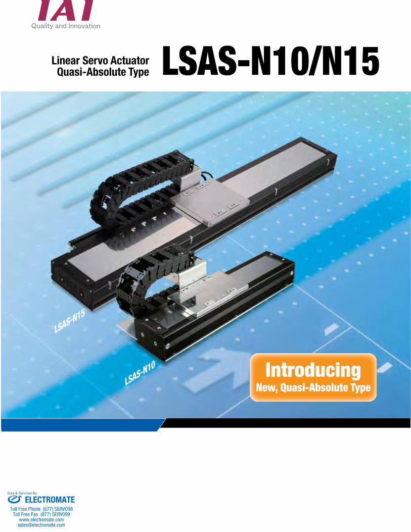
Thrust Maximum payload
Maximum speed
Maximum acceleration/deceleration
N10S 54N 15 kg2500mm/s 3GN15S 86N 20 kg
N15H 125N 30 kg
1 Features
LSA-S6 series (Incremental)
LSA-L15 series (Incremental)
LSA-S8 series (Incremental)
LSA-N10/N15/N19 series (Incremental)LSAS-N10/N15 series (Quasi-Absolute)
LSA-S10 series (Incremental)
LSA-H8 series (Incremental)
LSA-W21 series (Incremental)
Actuator width: 60 mm
Actuator width: 145 mm
Actuator width: N10: 100 mmN15: 150 mmN19: 193 mm
Actuator width: 80 mm Actuator width: 100 mm Actuator width: 80 mm
Actuator width: 210 mm
A quasi-absolute model has been added.
Shaft type Small type
Large typeFlat type Medium type
Introducing a New Type of Absolute Linear Servo Actuator Requiring No Battery
1Newly Developed Quasi-Absolute Encoder
2High Performance 3Wide Variations
The quasi-absolute encoder is a new encoder offering the advantages of both incremental and absolute encoders. When the power is turned on, the actuator moves within a range of approx. 16 mm.
Once the achieved position is confirmed as the current position, the actuator can be moved from that position. (There is no need to move to the home position, resulting in shorter operation recovery times.)
Position data is not stored in the memory, so no absolute battery is needed. (This solves the problem of a dead absolute battery.)
The newly developed flat core helps achieve excellent high-speed performance and high payload.
There are wide variations to choose from, according to your requirements: • Thrust: Standard , High Thrust• Slider: Single , Multi• Stroke: 100 to 4150 mm
Lineup of IAI’s Linear Servo Actuators
ELECTROMATEToll Free Phone (877) SERVO98
Toll Free Fax (877) SERV099www.electromate.com
Sold & Serviced By:

User cable track 15
14
User cable track 40
14
Type Actuator width Slider Stroke Rated
thrustMaximum payload
(horizontal)Maximum
accelerationMaximum
speed
LSAS-N10SS100 mm Standard
Single 100~4100 mm54N 15 kg
3G 2500 mm/s
LSAS-N10SM Multi 100~3900 mm
LSAS-N15SS
150 mm
StandardSingle 150~4150 mm
86N 20 kgLSAS-N15SM Multi 150~3950 mm
LSAS-N15HS High thrust
Single 100~4100 mm125N 30 kg
LSAS-N15HM Multi 150~3850 mm
Installation direction 1 (Standard) Installation direction 2 (Opposite): CT2 Installation direction 3: CT3 Installation direction 4: CT4
Option code CT2 CT3 CT4 US1 US2 US3 US4 UM1 UM2 UM3 UM4Installation direction 2 3 4 1 2 3 4 1 2 3 4User cable track None S type M type
LSAS – N – G – – – T2 – –
Note: Strokes are limited to 3950 on multi-slider models.
(Note 1) The Quasi-Absolute type can be used with SSEL and XSEL-P/Q controllers only.
Cable track selection code (See below.)
10 Actuator width 100 mm15 Actuator width 150 mm
S Single-sliderM Multi-slider
S Standard typeH High thrust type
100S 100W200S 200W
100 100 mm
4150 4150 mm
N NoneS 3 mM 45 mm
X Specified length
T2SSELXSEL-P/Q
LSAS Linear Servo Actuator Serial encoder series
G Quasi-Absolute type (Note 1)
Series Type Encoder model
Corresponding driver output
Stroke Applicable controllers
Cable length
Option
2Code
List of Quasi-Absolute Models
Installation Direction
S type (Code: US) M type (Code: UM)
User Cable Track
Model Specification Items
Cable Track Selection Code
This standard installation direction applies when no direction is specified for the cable track. On single-slider models, a cable track is installed on the side shown below. On multi-slider models, cable tracks are installed on both sides.
A cable track is installed on the side opposite to the standard specification.
The same as the standard specif ication (cable track direction 1), except that the home is on the other side.
The same as the CT2 specification (cable track direction 2), except that the home is on the other side.
*For the external dimensions, refer to the dimension drawing on the page describing each model.
ELECTROMATEToll Free Phone (877) SERVO98
Toll Free Fax (877) SERV099www.electromate.com
Sold & Serviced By:
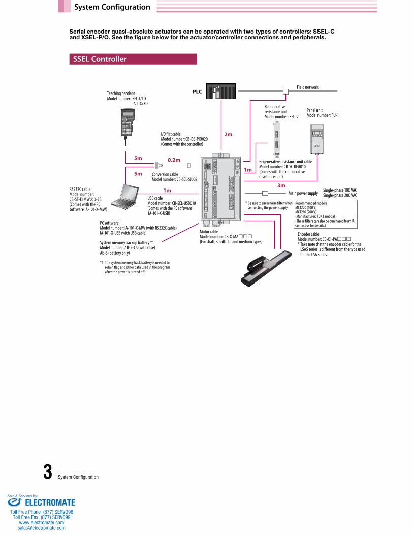
System Configuration
3 System Configuration
Serial encoder quasi-absolute actuators can be operated with two types of controllers: SSEL-C and XSEL-P/Q. See the figure below for the actuator/controller connections and peripherals.
SSEL Controller
PLC
I/O flat cable Model number: CB-DS-PIO020(Comes with the controller)
USB cableModel number: CB-SEL-USB010(Comes with the PC software 1A-101-X-USB)
Regenerative resistance unit cable Model number: CB-SC-REU010(Comes with the regenerative resistance unit)
RS232C cable Model number: CB-ST-E1MW050-EB(Comes with the PC software IA-101-X-MW)
Motor cable Model number: CB-X-MA(For shaft, small, flat and medium types)System memory backup battery *1
Model number: AB-5-CS (with case) AB-5 (battery only)
*1 The system memory back battery is needed to retain flag and other data used in the program after the power is turned off.
Conversion cableModel number: CB-SEL-SJ002
Field network
Main power supply
Panel unitModel number: PU-1
Regenerative resistance unitModel number: REU-2
Teaching pendantModel number: SEL-T/TD
IA-T-X/XD
2m
3m
1m
5m 0.2m
5m
1m Single-phase 100 VACSingle-phase 200 VAC
Encoder cable Model number: CB-X1-PA* Take note that the encoder cable for the
LSAS series is different from the type used for the LSA series.
Recommended modelsMC1220 (100 V) MC1210 (200 V) (Manufacturer: TDK Lambda) (These filters can also be purchased from IAI. Contact us for details.)
* Be sure to use a noise filter when connecting the power supply.
PC software Model number: IA-101-X-MW (with RS232C cable) IA-101-X-USB (with USB cable)
ELECTROMATEToll Free Phone (877) SERVO98
Toll Free Fax (877) SERV099www.electromate.com
Sold & Serviced By:

4System Configuration
XSEL Controller
PLC
Regenerative resistance unit cable Model number: CB-ST-REU010(Comes with the regenerative resistance unit)
Regenerative resistance unitModel number: REU-1
I/O flat cable Model number: CB-X-PIO020(Comes with the controller)
RS232C cable Model number: CB-ST-E1MW050-EB
USB conversion unitModel number: IA-CV-USB
USB cable Model number: CB-SEL-USB010
PC software Model number: IA-101-X-MW (with )
IA-101-X-USBMW (with , and )
•DeviceNet•CC-Link•ProfiBus•Ethernet
Teaching pendantModel number: SEL-T/TD/TG
IA-T-X/XD
5m
2m 1m
1m
5m
5mMotor cable Model number: CB-X-MA(For shaft, small, flat and medium types)
Main power supply Single-phase 200 VAC / Three-phase 200 VAC* Be sure to install filters equivalent to the following when connecting the power supply:
• Noise filter Recommended models Three-phase MC1320 (Manufacturer: TDK Lambda)Single-phase MXB-1220-33 (Manufacturer: TDK Lambda)
• Ring core Recommended model ESD-R-25 (Manufacturer: NEC Tokin) • Clamp filter Recommended models For control power supply ZCAT3035-1330 (Manufacturer: TDK)
For motor power supply RFC-H13 (Manufacturer: Kitagawa Kogyo) • Surge protector Recommended models Three-phase R•A•V-781BXZ-4
Single-phase R•A•V-781BWZ-2A(Manufacturer: Okaya Electric Industries)
Encoder cable Model number: CB-X1-PA* Take note that the encoder cable for
the LSAS series is different from the type used for the LSA series.
ELECTROMATEToll Free Phone (877) SERVO98
Toll Free Fax (877) SERV099www.electromate.com
Sold & Serviced By:

How to Select a Linear Servo Actuator
Selection Method
Model number
Weight of slider (kg)
Traveling resistance Ff (N)
Maximum thrust (N)
N10SS 3.0 5V+16.5 162N
N15SS 4.0 10V+25 See the graph on the right.
N15HS 5.0 17V+30 See the graph on the right.
375 N15HS
275
240
258 N15SS
400
350
300
250
200
150
100
50
00 500 1000 1500 2000 2500
Maximum thrust of N15SS/N15HS
Slider’s travel speed (mm/s)
Mot
or-g
ener
ated
out
put (
N)
ta tr td
t
tc T
V
ta tr td
t
F
FaFf
Fd T
5 How to Select
When selecting a linear servo actuator, the following two conditions must be met.
• The required thrust for acceleration must be no more than the maximum thrustof the linear servo actuator.
• The thrust during continuous operation must be no more than the rated thrustof the linear servo actuator.
Condition Maximum thrustFor the slider to accelerate according to the command, the required thrust for acceleration Fa must be smaller than the maximum thrust of the linear servo actuator. Obtain the required thrust for acceleration (Fa) using the formula below:
Fa = (M + m) • a + Ff M: Weight of the slider (kg) m: Load carried by the slider (kg) a: Commanded acceleration (m/s2) Ff: Traveling resistance (N)
If Fa obtained above is smaller than the maximum thrust of the linear servo actuator, Condition is met.
If the required thrust for acceleration (Fa) exceeds the maximum thrust of the linear servo actuator, the load carried on the slider or acceleration must be reduced. Check the maximum loading mass and maximum acceleration using the formulas below:
The above conditions are explained based on the trapezoid operation pattern.
When the operation pattern graph shown to the left is redrawn with the vertical axis representing thrust…
In the above graph: t: Operating time per cycle (s) tf: Travel time at constant speed (s) ta: Acceleration time (s) td: Deceleration time (s) tc: Settling time (s)
In the above graph: Fa: Required thrust for acceleration (N) Fd: Required thrust for deceleration (N)Ff: Traveling resistance (N)
* V: Slider’s travel speed (m/s) (Under the triangular condition, the attained speed is used.)
Required thrust for acceleration (Fa) Maximum thrust of linear servo actuator
Maximum loading mass m=[(Fa-Ff)/a]-MMaximum acceleration a=(Fa-Ff)/(M+m)
ELECTROMATEToll Free Phone (877) SERVO98
Toll Free Fax (877) SERV099www.electromate.com
Sold & Serviced By:

Trapezoid pattern
Positioning time
Settling time after positioning
Speed mm/s
Acceleration zone
Constant speed zone
Deceleration zone
Times
Triangle pattern
Positioning time
Settling time after positioning
Speed mm/s
Acceleration zone
Deceleration zone
Times
Rated thrust (N)
N10SS 54
N15SS 86
N15HS 125
6How to Select
Condition Thrust during continuous operationThe thrust during continuous operation Ft, calculated by considering the load and duty, must be smaller than the rated thrust of the linear servo actuator. Obtain the thrust during continuous operation using the formula below:
Fa: Required thrust for acceleration (N) Fd: Required thrust for deceleration (N) ta: Acceleration time (s) td: Deceleration time (s) Ff: Traveling resistance (N) t: Operating time per cycle (s) tf: Travel time at constant speed (s)
(t = ta + tf + td + settling time + stationary time)
ta, which represents the acceleration time, is calculated differently depending on whether the operation pattern is the
trapezoid pattern or triangle pattern.
The difference between the trapezoid pattern and triangle pattern is whether the attained speed is greater or smaller than the set speed when the actuator is operated over the distance of its travel at the set speed.
tf represents the travel time at constant speed. Calculate this time by calculating the travel distance at constant speed first. tf = Lc/VLc: Travel distance at constant speed (m) V: Commanded speed (m/s) * Travel distance at constant speed = Travel distance –
Acceleration distance – Deceleration distance Acceleration distance (deceleration distance) = V2/2a
Fd represents the required thrust for deceleration. Calculate this thrust using the formula below: Fd=(M+m)•a–Ff
td represents the deceleration time. If the acceleration and deceleration are the same, td should be the same as the acceleration time. td = V/a V: Speed (m/s) a: Deceleration (m/s2)
t represents the operating time per cycle, corresponding to the sum of the acceleration time (ta), travel time at constant speed (tf), deceleration time (td), settling time (0.15 sec) and stationary time.
If the thrust during continuous operation Ft obtained above is smaller than the rated thrust, Condition is met.
Set speed < Attained speed Trapezoid patternSet speed > Attained speed Triangle pattern
Trapezoid patternta = Vs/aVs: Set speed (m/s) a: Commanded acceleration (m/s2)
Triangle pattern ta = Vt/aVt: Set speed (m/s) a: Commanded acceleration (m/s2)
Ft = Fa2 • ta + Ff2 • tf + Fd2 • tdt
Thrust during continuous operation (Ft) Rated thrust of linear servo actuator
Attained speed (Vmax) = Travel distance (m) x Set acceleration (m/s2)
To calculate the cycle time at which the actuator can be operated continuously, do so using the formula below based on the maximum acceleration obtained according to Condition :
The actuator can be operated if the operating conditions meet both Conditions and above. If either condition cannot be met, reduce the load carried on the slider, lower the acceleration, lower the duty (*) or take other appropriate measure.
* To lower the duty, the ratio of the travel time (acceleration + constant speed + deceleration) to the cycle time must be lowered.
t = Fa2 • ta + Ff2 • tf + Fd2 • tdFt2
ELECTROMATEToll Free Phone (877) SERVO98
Toll Free Fax (877) SERV099www.electromate.com
Sold & Serviced By:

2-ø10 H7, depth 8 2-oblong hole, depth 8 (H)
(A)
(42.5) 175
85E(*3)(*4) Overhang length 65
25 252-ø6 H7, depth 104-M6, depth 1250
42.5
ME MESE5.5 5.5
Home
StrokeL (Stroke+260)
(24) (24)
(80)F
D(50) 50 S type
Section view of user cable track
User cable track (S/M types) (*2)
185 (when installing M)
Detailed view of G
160 (when installing S)
M type2415
(185)10098
Section G
1185
2.711.8
4940
10
Detailed view of H
R5 R5
60
14 19
92.5
(*1)
155
(*1)
1066
3.3
5.8
80
82(R
eam
er pi
tch: ±
0.02)
±0.02
71100
1111
14 19
10 H
7+
0.01
5
0
80
ABx200P
(200)C-M6, depth 12
Series Stroke OptionsCable length
Type Encoder model
Corresponding driver output
Applicable controllers
G: Serial encoder, quasi-absolute type
T2: SSELXSEL-P/-Q
Refer to the option table below.
N: NoneS: 3 mM: 5 mX: Specified length
100S: 100W 100: 100 mm
4100: 4100 mm(every 100 mm)
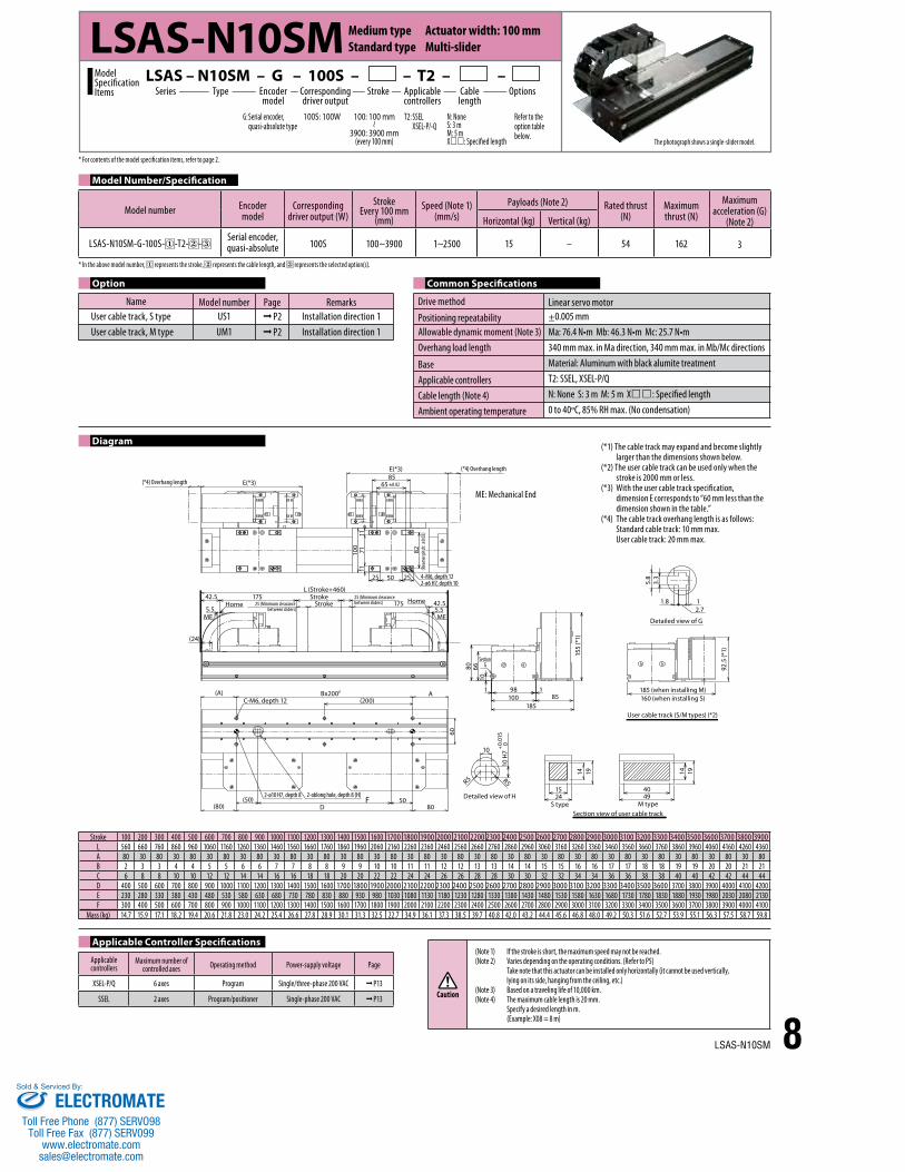
LSAS – N10SS – G – 100S – – T2 – – Model SpecificationItems
LSAS-N10SS Medium type Actuator width: 100 mm Standard type Single-slider
Model Number/Specification
Diagram
Applicable Controller Specifications
Option Common Specifications
Model number Encodermodel
Corresponding driver output (W)
StrokeEvery 100 mm
(mm)Speed (Note 1)
(mm/s)Payloads (Note 2) Rated thrust
(N)Maximum thrust (N)
Maximum acceleration (G)
(Note 2)Horizontal (kg) Vertical (kg)
LSAS-N10SS-G-100S- -T2- -Serial encoder, quasi-absolute 100S 100~4100 1~2500 15 – 54 162 3
Name Model number Page RemarksCable track installation direction CT2~4 P2 Installation direction 2 to 4 User cable track, S type US1~US4 P2 Installation direction 1 to 4 User cable track, M type UM1~UM4 P2 Installation direction 1 to 4
Applicablecontrollers
Maximum number of controlled axes Operating method Power-supply voltage Page
XSEL-P/Q 6 axes Program Single/three-phase 200 VAC P13
SSEL 2 axes Program/positioner Single-phase 200 VAC P13
Drive method Linear servo motorPositioning repeatability ±0.005 mmAllowable dynamic moment (Note 3) Ma: 76.4 N•m Mb: 46.3 N•m Mc: 25.7 N•mOverhang load length 340 mm max. in Ma direction, 340 mm max. in Mb/Mc directions
Base Material: Aluminum with black alumite treatment
Applicable controllers T2: SSEL, XSEL-P/Q
Cable length (Note 4) N: None S: 3 m M: 5 m X: Specified length
Ambient operating temperature 0 to 40°C, 85% RH max. (No condensation)
Stroke 100 200 300 400 500 600 700 800 900 1000 1100 1200 1300 1400 1500 1600 1700 1800 1900 2000 2100 2200 2300 2400 2500 2600 2700 2800 2900 3000 3100 3200 3300 3400 3500 3600 3700 3800 3900 4000 4100L 360 460 560 660 760 860 960 1060 1160 1260 1360 1460 1560 1660 1760 1860 1960 2060 2160 2260 2360 2460 2560 2660 2760 2860 2960 3060 3160 3260 3360 3460 3560 3660 3760 3860 3960 4060 4160 4260 4360A 80 30 80 30 80 30 80 30 80 30 80 30 80 30 80 30 80 30 80 30 80 30 80 30 80 30 80 30 80 30 80 30 80 30 80 30 80 30 80 30 80B 1 2 2 3 3 4 4 5 5 6 6 7 7 8 8 9 9 10 10 11 11 12 12 13 13 14 14 15 15 16 16 17 17 18 18 19 19 20 20 21 21C 4 6 6 8 8 10 10 12 12 14 14 16 16 18 18 20 20 22 22 24 24 26 26 28 28 30 30 32 32 34 34 36 36 38 38 40 40 42 42 44 44D 200 300 400 500 600 700 800 900 1000 1100 1200 1300 1400 1500 1600 1700 1800 1900 2000 2100 2200 2300 2400 2500 2600 2700 2800 2900 3000 3100 3200 3300 3400 3500 3600 3700 3800 3900 4000 4100 4200E 230 280 330 380 430 480 530 580 630 680 73- 780 830 880 930 980 1030 1080 1130 1180 1230 1280 1330 1380 1430 1480 1530 1580 1630 1680 1730 1780 1830 1880 1930 1980 2030 2080 2130 2180 2230F 100 200 300 400 500 600 700 800 900 1000 1100 1200 1300 1400 1500 1600 1700 1800 1900 2000 2100 2200 2300 2400 2500 2600 2700 2800 2900 3000 3100 3200 3300 3400 3500 3600 3700 3800 3900 4000 4100
Mass (kg) 8.0 9.1 10.2 11.3 12.3 13.4 14.5 15.6 16.7 17.8 18.9 19.9 21.0 22.1 23.2 24.3 25.4 26.5 27.5 28.6 29.7 30.8 31.9 33.0 34.1 35.1 36.2 37.3 38.4 39.5 40.6 41.7 42.8 43.8 44.9 46.0 47.1 48.2 49.3 50.4 51.4
Caution
(Note 1) If the stroke is short, the maximum speed may not be reached. (Note 2) Varies depending on the operating conditions. (Refer to P5)
Take note that this actuator can be installed only horizontally (it cannot be used vertically, lying on its side, hanging from the ceiling, etc.)
(Note 3) Based on a traveling life of 10,000 km. (Note 4) The maximum cable length is 20 mm.
Specify a desired length in m. (Example: X08 = 8 m)
7 LSAS-N10SS
* For contents of the model specification items, refer to page 2.
* In the above model number, represents the stroke, represents the cable length, and represents the selected option(s).
ME: Mechanical End SE: Stroke End
(*1) The cable track may expand and become slightly larger than the dimensions shown below. (*2) The user cable track can be used only when the stroke is 2000 mm or less. (*3) With the user cable track specification,
dimension E corresponds to “60 mm less than the dimension shown in the table.” (*4) The cable track overhang length is as follows:
Standard cable track: 10 mm max. User cable track: 20 mm max.
ELECTROMATEToll Free Phone (877) SERVO98
Toll Free Fax (877) SERV099www.electromate.com
Sold & Serviced By:
(*4) Overhang length
(*4) Overhang lengthE(*3)
E(*3)85
65 ±0.02
82(R
eam
er pi
tch: ±
0.02)
71100
1111
25 252-ø6 H7, depth 104-M6, depth 1250
StrokeStroke
L (Stroke+460)175
25 (Minimum clearance between sliders)
25 (Minimum clearance between sliders) 175 42.5
42.5
ME ME
Home Home5.5 5.5
(24)
(A) ABx200P
(200)C-M6, depth 12
60
2-ø10 H7, depth 8 2-oblong hole, depth 8 (H)
(80)F
D(50) 50
80
Detailed view of H
10
R5 R5
10 H
7+
0.01
5
0
S type2415
14 19
Section view of user cable trackM type
4940
14 19
User cable track (S/M types) (*2)
185 (when installing M)160 (when installing S)
92.5
(*1)
Detailed view of G
2.711.8
3.3
5.8
18510098
Section G
1185
155
(*1)
106680
Diagram
Applicable Controller Specifications
Model Number/Specification
Option Common Specifications
Model number Encodermodel
Corresponding driver output (W)
StrokeEvery 100 mm
(mm)Speed (Note 1)
(mm/s)Payloads (Note 2) Rated thrust
(N)Maximum thrust (N)
Maximum acceleration (G)
(Note 2)Horizontal (kg) Vertical (kg)
LSAS-N10SM-G-100S- -T2- -Serial encoder, quasi-absolute 100S 100~3900 1~2500 15 – 54 162 3
Name Model number Page RemarksUser cable track, S type US1 P2 Installation direction 1User cable track, M type UM1 P2 Installation direction 1
Applicablecontrollers
Maximum number of controlled axes Operating method Power-supply voltage Page
XSEL-P/Q 6 axes Program Single/three-phase 200 VAC P13
SSEL 2 axes Program/positioner Single-phase 200 VAC P13
Drive method Linear servo motorPositioning repeatability ±0.005 mmAllowable dynamic moment (Note 3) Ma: 76.4 N•m Mb: 46.3 N•m Mc: 25.7 N•mOverhang load length 340 mm max. in Ma direction, 340 mm max. in Mb/Mc directions
Base Material: Aluminum with black alumite treatment
Applicable controllers T2: SSEL, XSEL-P/Q
Cable length (Note 4) N: None S: 3 m M: 5 m X: Specified length
Ambient operating temperature 0 to 40°C, 85% RH max. (No condensation)
Stroke 100 200 300 400 500 600 700 800 900 1000 1100 1200 1300 1400 1500 1600 1700 1800 1900 2000 2100 2200 2300 2400 2500 2600 2700 2800 2900 3000 3100 3200 3300 3400 3500 3600 3700 3800 3900L 560 660 760 860 960 1060 1160 1260 1360 1460 1560 1660 1760 1860 1960 2060 2160 2260 2360 2460 2560 2660 2760 2860 2960 3060 3160 3260 3360 3460 3560 3660 3760 3860 3960 4060 4160 4260 4360A 80 30 80 30 80 30 80 30 80 30 80 30 80 30 80 30 80 30 80 30 80 30 80 30 80 30 80 30 80 30 80 30 80 30 80 30 80 30 80B 2 3 3 4 4 5 5 6 6 7 7 8 8 9 9 10 10 11 11 12 12 13 13 14 14 15 15 16 16 17 17 18 18 19 19 20 20 21 21C 6 8 8 10 10 12 12 14 14 16 16 18 18 20 20 22 22 24 24 26 26 28 28 30 30 32 32 34 34 36 36 38 38 40 40 42 42 44 44D 400 500 600 700 800 900 1000 1100 1200 1300 1400 1500 1600 1700 1800 1900 2000 2100 2200 2300 2400 2500 2600 2700 2800 2900 3000 3100 3200 3300 3400 3500 3600 3700 3800 3900 4000 4100 4200E 230 280 330 380 430 480 530 580 630 680 730 780 830 880 930 980 1030 1080 1130 1180 1230 1280 1330 1380 1430 1480 1530 1580 1630 1680 1730 1780 1830 1880 1930 1980 2030 2080 2130F 300 400 500 600 700 800 900 1000 1100 1200 1300 1400 1500 1600 1700 1800 1900 2000 2100 2200 2300 2400 2500 2600 2700 2800 2900 3000 3100 3200 3300 3400 3500 3600 3700 3800 3900 4000 4100
Mass (kg) 14.7 15.9 17.1 18.2 19.4 20.6 21.8 23.0 24.2 25.4 26.6 27.8 28.9 30.1 31.3 32.5 22.7 34.9 36.1 37.3 38.5 39.7 40.8 42.0 43.2 44.4 45.6 46.8 48.0 49.2 50.3 51.6 52.7 53.9 55.1 56.3 57.5 58.7 59.8
Caution
(Note 1) If the stroke is short, the maximum speed may not be reached. (Note 2) Varies depending on the operating conditions. (Refer to P5)
Take note that this actuator can be installed only horizontally (it cannot be used vertically, lying on its side, hanging from the ceiling, etc.)
(Note 3) Based on a traveling life of 10,000 km. (Note 4) The maximum cable length is 20 mm.
Specify a desired length in m. (Example: X08 = 8 m)
Series Stroke OptionsCable length
Type Encoder model
Corresponding driver output
Applicable controllers
G: Serial encoder, quasi-absolute type
T2: SSELXSEL-P/-Q
Refer to the option table below.
N: NoneS: 3 mM: 5 mX: Specified length
100S: 100W 100: 100 mm
3900: 3900 mm(every 100 mm)
LSAS – N10SM – G – 100S – – T2 – – Model SpecificationItems
LSAS-N10SM Medium type Actuator width: 100 mm Standard type Multi-slider
The photograph shows a single-slider model.
8LSAS-N10SM
* In the above model number, represents the stroke, represents the cable length, and represents the selected option(s).
* For contents of the model specification items, refer to page 2.
ME: Mechanical End
(*1) The cable track may expand and become slightly larger than the dimensions shown below. (*2) The user cable track can be used only when the stroke is 2000 mm or less. (*3) With the user cable track specification,
dimension E corresponds to “60 mm less than the dimension shown in the table.” (*4) The cable track overhang length is as follows:
Standard cable track: 10 mm max. User cable track: 20 mm max.
ELECTROMATEToll Free Phone (877) SERVO98
Toll Free Fax (877) SERV099www.electromate.com
Sold & Serviced By:
(A)
(*4) Overhang length E(*3)70
50 ±0.02
4-ø6 H7, depth 104-M6, depth 12
Detailed view of G
4.51.5
4.3
7.3
User cable track S/M types
235 (when installing M)210 (when installing S)
88.5
(*1)
(231)150148
Section G
1181
160
(*1)
176380
Detailed view of H
10
R5 R5
10 H
7+
0.01
5
0
S type2415
14 19
Section view of user cable trackM type
4940
14 19
2-ø10 H7, depth 8 2-oblong hole, depth 8 (H)F
D50 50
105105
(Rea
mer
pitch
: ±0.0
2)
40 20 40
147
106
1515
120
190 35
MEHOME5
(28)
ME SE5
(28)
(35) Stroke
L (Stroke+260)
100
ABx200P
(200)C-M6, depth 12
Series Stroke OptionsCable length
Type Encoder model
Corresponding driver output
Applicable controllers
G: Serial encoder, quasi-absolute type
T2: SSELXSEL-P/-Q
Refer to the option table below.
N: NoneS: 3 mM: 5 mX: Specified length
200S: 200W 150: 150 mm
4150: 4150 mm(every 100 mm)
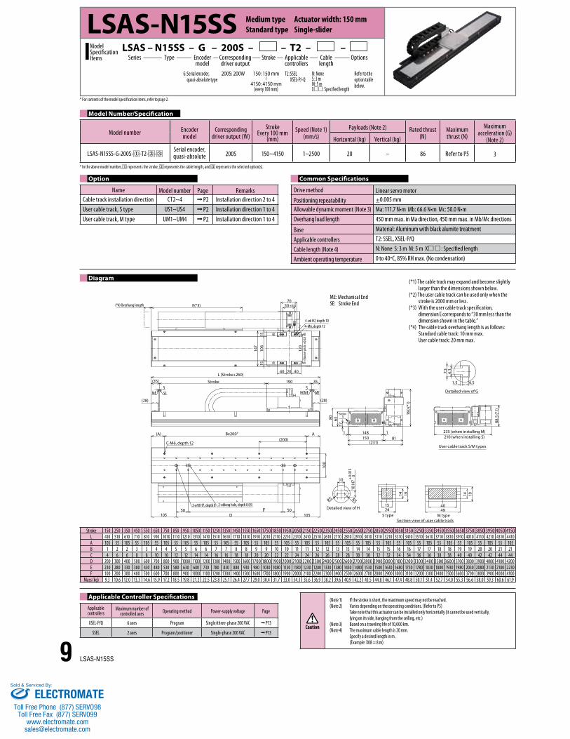
LSAS – N15SS – G – 200S – – T2 – – Model SpecificationItems
LSAS-N15SS Medium type Actuator width: 150 mm Standard type Single-slider
Model Number/Specification
Applicable Controller Specifications
Applicablecontrollers
Maximum number of controlled axes Operating method Power-supply voltage Page
XSEL-P/Q 6 axes Program Single/three-phase 200 VAC P13
SSEL 2 axes Program/positioner Single-phase 200 VAC P13
Stroke 150 250 350 450 550 650 750 850 950 1050 1150 1250 1350 1450 1550 1650 1750 1850 1950 2050 2150 2250 2350 2450 2550 2650 2750 2850 2950 3050 3150 3250 3350 3450 3550 3650 3750 3850 3950 4050 4150L 410 510 610 710 810 910 1010 1110 1210 1310 1410 1510 1610 1710 1810 1910 2010 2110 2210 2310 2410 2510 2610 2710 2810 2910 3010 3110 3210 3310 3410 3510 3610 3710 3810 3910 4010 4110 4210 4310 4410A 105 55 105 55 105 55 105 55 105 55 105 55 105 55 105 55 105 55 105 55 105 55 105 55 105 55 105 55 105 55 105 55 105 55 105 55 105 55 105 55 105B 1 2 2 3 3 4 4 5 5 6 6 7 7 8 8 9 9 10 10 11 11 12 12 13 13 14 14 15 15 16 16 17 17 18 18 19 19 20 20 21 21C 4 6 6 8 8 10 10 12 12 14 14 16 16 18 18 20 20 22 22 24 24 26 26 28 28 30 30 32 32 34 34 36 36 38 38 40 40 42 42 44 44D 200 300 400 500 600 700 800 900 1000 1100 1200 1300 1400 1500 1600 1700 1800 1900 2000 2100 2200 2300 2400 2500 2600 2700 2800 2900 3000 3100 3200 3300 3400 3500 3600 3700 3800 3900 4000 4100 4200E 230 280 330 380 430 480 530 580 630 680 730 780 830 880 930 980 1030 1080 1130 1180 1230 1280 1330 1380 1430 1480 1530 1580 1630 1680 1730 1780 1830 1880 1930 1980 2030 2080 2130 2180 2230F 100 200 300 400 500 600 700 800 900 1000 1100 1200 1300 1400 1500 1600 1700 1800 1900 2000 2100 2200 2300 2400 2500 2600 2700 2800 2900 3000 3100 3200 3300 3400 3500 3600 3700 3800 3900 4000 4100
Mass (kg) 9.3 10.6 12.0 13.3 14.6 15.9 17.2 18.5 19.8 21.2 22.5 23.8 25.1 26.4 27.7 29.0 30.4 31.7 33.0 34.3 35.6 36.9 38.2 39.6 40.9 42.2 43.5 44.8 46.1 47.4 48.8 50.1 51.4 52.7 54.0 55.3 56.6 58.0 59.3 60.6 61.9
Caution
(Note 1) If the stroke is short, the maximum speed may not be reached. (Note 2) Varies depending on the operating conditions. (Refer to P5)
Take note that this actuator can be installed only horizontally (it cannot be used vertically, lying on its side, hanging from the ceiling, etc.)
(Note 3) Based on a traveling life of 10,000 km. (Note 4) The maximum cable length is 20 mm.
Specify a desired length in m. (Example: X08 = 8 m)
Model number Encodermodel
Corresponding driver output (W)
StrokeEvery 100 mm
(mm)Speed (Note 1)
(mm/s)Payloads (Note 2) Rated thrust
(N)Maximum thrust (N)
Maximum acceleration (G)
(Note 2)Horizontal (kg) Vertical (kg)
LSAS-N15SS-G-200S- -T2- -Serial encoder, quasi-absolute 200S 150~4150 1~2500 20 – 86 Refer to P5 3
Drive method Linear servo motorPositioning repeatability ±0.005 mmAllowable dynamic moment (Note 3) Ma: 111.7 N•m Mb: 66.6 N•m Mc: 50.0 N•mOverhang load length 450 mm max. in Ma direction, 450 mm max. in Mb/Mc directions
Base Material: Aluminum with black alumite treatment
Applicable controllers T2: SSEL, XSEL-P/Q
Cable length (Note 4) N: None S: 3 m M: 5 m X: Specified length
Ambient operating temperature 0 to 40°C, 85% RH max. (No condensation)
Common SpecificationsOption
Name Model number Page RemarksCable track installation direction CT2~4 P2 Installation direction 2 to 4 User cable track, S type US1~US4 P2 Installation direction 1 to 4 User cable track, M type UM1~UM4 P2 Installation direction 1 to 4
Diagram
9 LSAS-N15SS
* For contents of the model specification items, refer to page 2.
* In the above model number, represents the stroke, represents the cable length, and represents the selected option(s).
ME: Mechanical End SE: Stroke End
(*1) The cable track may expand and become slightly larger than the dimensions shown below. (*2) The user cable track can be used only when the stroke is 2000 mm or less. (*3) With the user cable track specification,
dimension E corresponds to “30 mm less than the dimension shown in the table.” (*4) The cable track overhang length is as follows:
Standard cable track: 10 mm max. User cable track: 20 mm max.
ELECTROMATEToll Free Phone (877) SERVO98
Toll Free Fax (877) SERV099www.electromate.com
Sold & Serviced By:

(*4) Overhang length(*4) Overhang length
E(*3)E(*3)
70
19019035
5 535
50 ±0.02
147
106
120
1515
(Rea
mer p
itch:
±0.02
)
40 404-ø6 H7, depth 104-M6, depth 1220
ME MEHOME HOME
(28) (28)
(A) ABx200P
(200)C-M6, depth 12
2-ø10 H7, depth 8 2-oblong hole, depth 8 (H)F
D(50) 50
105105
100
Detailed view of H
10
R5 R5
10 H
7+
0.01
5
0
S type2415
14 19
Section view of user cable trackM type
4940
14 19
User cable track S/M types
235 (when installing M)210 (when installing S)
88.5
(*1)
Detailed view of G
4.51.5
4.3
7.3
(231)150148
Section G
1181
160
(*1)
176380
StrokeStroke
L (Stroke+460)
10 (Minimum clearance between sliders)
10 (Minimum clearance between sliders)
Model Number/Specification
Applicable Controller Specifications
Applicablecontrollers
Maximum number of controlled axes Operating method Power-supply voltage Page
XSEL-P/Q 6 axes Program Single/three-phase 200 VAC P13
SSEL 2 axes Program/positioner Single-phase 200 VAC P13Caution
(Note 1) If the stroke is short, the maximum speed may not be reached. (Note 2) Varies depending on the operating conditions. (Refer to P5)
Take note that this actuator can be installed only horizontally (it cannot be used vertically, lying on its side, hanging from the ceiling, etc.)
(Note 3) Based on a traveling life of 10,000 km. (Note 4) The maximum cable length is 20 mm.
Specify a desired length in m. (Example: X08 = 8 m)
Series Stroke OptionsCable length
Type Encoder model
Corresponding driver output
Applicable controllers
G: Serial encoder, quasi-absolute type
T2: SSELXSEL-P/-Q
Refer to the option table below.
N: NoneS: 3 mM: 5 mX: Specified length
200S: 200W 150: 150 mm
3950: 3950 mm(every 100 mm)
LSAS – N15SM – G – 200S – – T2 – – Model SpecificationItems
LSAS-N15SM Medium type Actuator width: 150 mm Standard type Multi-slider
The photograph shows a single-slider model.
Model number Encodermodel
Corresponding driver output (W)
StrokeEvery 100 mm
(mm)Speed (Note 1)
(mm/s)Payloads (Note 2) Rated thrust
(N)Maximum thrust (N)
Maximum acceleration (G)
(Note 2)Horizontal (kg) Vertical (kg)
LSAS-N15SM-G-200S- -T2- -Serial encoder, quasi-absolute 200S 150~3950 1~2500 20 – 86 Refer to P5 3
Name Model number Page RemarksUser cable track, S type US1 P2 Installation direction 1User cable track, M type UM1 P2 Installation direction 1
Drive method Linear servo motorPositioning repeatability ±0.005 mmAllowable dynamic moment (Note 3) Ma: 111.7 N•m Mb: 66.6 N•m Mc: 50.0 N•mOverhang load length 450 mm max. in Ma direction, 450 mm max. in Mb/Mc directions
Base Material: Aluminum with black alumite treatment
Applicable controllers T2: SSEL, XSEL-P/Q
Cable length (Note 4) N: None S: 3 m M: 5 m X: Specified length
Ambient operating temperature 0 to 40°C, 85% RH max. (No condensation)
Diagram
Stroke 150 250 350 450 550 650 750 850 950 1050 1150 1250 1350 1450 1550 1650 1750 1850 1950 2050 2150 2250 2350 2450 2550 2650 2750 2850 2950 3050 3150 3250 3350 3450 3550 3650 3750 3850 3950L 610 710 810 910 1010 1110 1210 1310 1410 1510 1610 1710 1810 1910 2010 2110 2210 2310 2410 2510 2610 2710 2810 2910 3010 3110 3210 3310 3410 3510 3610 3710 3810 3910 4010 4110 4210 4310 4410A 105 55 105 55 105 55 105 55 105 55 105 55 105 55 105 55 105 55 105 55 105 55 105 55 105 55 105 55 105 55 105 55 105 55 105 55 105 55 105B 2 3 3 4 4 5 5 6 6 7 7 8 8 9 9 10 10 11 11 12 12 13 13 14 14 15 15 16 16 17 17 18 18 19 19 20 20 21 21C 6 8 8 10 10 12 12 14 14 16 16 18 18 20 20 22 22 24 24 26 26 28 28 30 30 32 32 34 34 36 36 38 38 40 40 42 42 44 44D 400 500 600 700 800 900 1000 1100 1200 1300 1400 1500 1600 1700 1800 1900 2000 2100 2200 2300 2400 2500 2600 2700 2800 2900 3000 3100 3200 3300 3400 3500 3600 3700 3800 3900 4000 4100 4200E 230 280 330 380 430 480 530 580 630 680 730 780 830 880 930 980 1030 1080 1130 1180 1230 1280 1330 1380 1430 1480 1530 1580 1630 1680 1730 1780 1830 1880 1930 1980 2030 2080 2130F 300 400 500 600 700 800 900 1000 1100 1200 1300 1400 1500 1600 1700 1800 1900 2000 2100 2200 2300 2400 2500 2600 2700 2800 2900 3000 3100 3200 3300 3400 3500 3600 3700 3800 3900 4000 4100
Mass (kg) 16.5 17.9 19.3 20.7 22.1 23.5 25.0 26.4 27.8 29.2 30.7 32.1 33.5 34.9 36.3 37.7 39.1 40.6 42.0 43.4 44.8 46.2 47.6 49.1 50.5 51.9 53.3 54.7 56.2 57.6 59.0 60.4 61.8 63.2 64.6 66.1 67.5 68.9 70.3
10LSAS-N15SM
* For contents of the model specification items, refer to page 2.
Option Common Specifications
* In the above model number, represents the stroke, represents the cable length, and represents the selected option(s).
ME: Mechanical End
(*1) The cable track may expand and become slightly larger than the dimensions shown below. (*2) The user cable track can be used only when the stroke is 2000 mm or less. (*3) With the user cable track specification,
dimension E corresponds to “30 mm less than the dimension shown in the table.” (*4) The cable track overhang length is as follows:
Standard cable track: 10 mm max. User cable track: 20 mm max.
ELECTROMATEToll Free Phone (877) SERVO98
Toll Free Fax (877) SERV099www.electromate.com
Sold & Serviced By:
Section view of user cable trackM type
4940
14 19
S type2415
14 19
Detailed view of H
10
R5 R5
10 H
7+
0.01
5
0
Detailed view of G
4.51.5
4.3
7.3
(231)150148
Section G
1181
160
(*1)
176380
(*4) Overhang length E(*3)70
50 ±0.02
4-ø6 H7, depth 104-M6, depth 12
120
(Rea
mer p
itch:
±0.02
)
40 4020
147
1515
106
StrokeL (Stroke+310)
190 60(60)
(28) (28)
55MEME SE HOME
A
B
(A) Bx200P
C-M6, depth 12 (200)
100
2-ø10 H7, depth 8 2-oblong hole, depth 8 (H)F
D(50) 50
105(105)
User cable track S/M types
235 (when installing M)210 (when installing S)
88.5
(*1)
Series Stroke OptionsCable length
Type Encoder model
Corresponding driver output
Applicable controllers
G: Serial encoder, quasi-absolute type
T2: SSELXSEL-P/-Q
Refer to the option table below.
N: NoneS: 3 mM: 5 mX: Specified length
200S: 200W 100: 100 mm
4100: 4100 mm(every 100 mm)
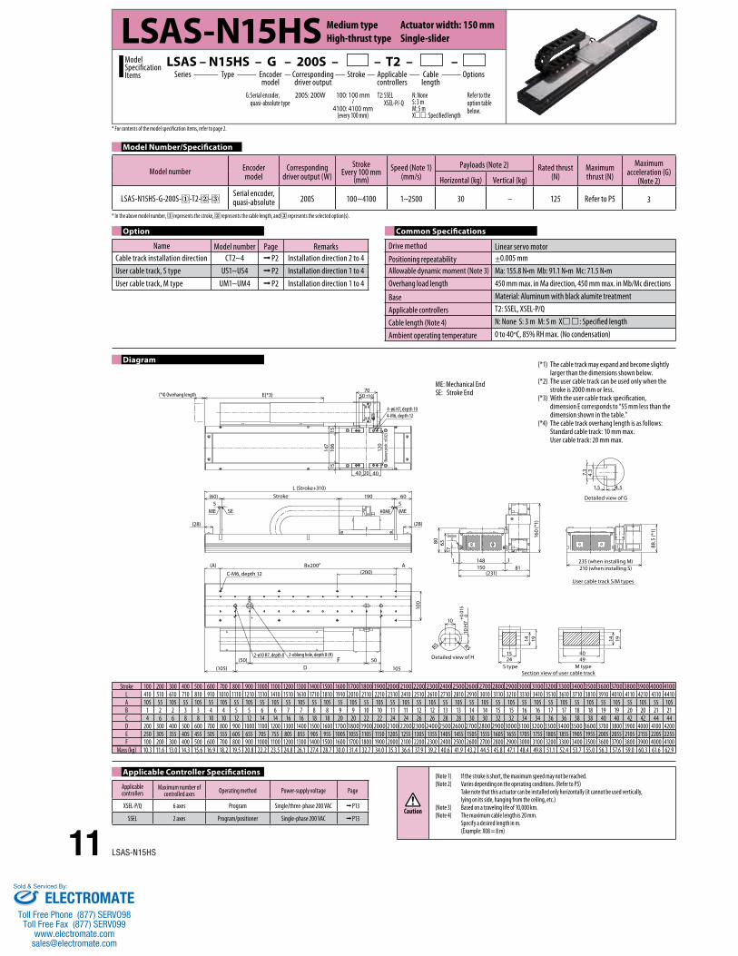
LSAS – N15HS – G – 200S – – T2 – – Model SpecificationItems
LSAS-N15HS Medium type Actuator width: 150 mm High-thrust type Single-slider
Model Number/Specification
Model number Encodermodel
Corresponding driver output (W)
StrokeEvery 100 mm
(mm)Speed (Note 1)
(mm/s)Payloads (Note 2) Rated thrust
(N)Maximum thrust (N)
Maximum acceleration (G)
(Note 2)Horizontal (kg) Vertical (kg)
LSAS-N15HS-G-200S- -T2- -Serial encoder, quasi-absolute 200S 100~4100 1~2500 30 – 125 Refer to P5 3
Drive method Linear servo motorPositioning repeatability ±0.005 mmAllowable dynamic moment (Note 3) Ma: 155.8 N•m Mb: 91.1 N•m Mc: 71.5 N•mOverhang load length 450 mm max. in Ma direction, 450 mm max. in Mb/Mc directions
Base Material: Aluminum with black alumite treatment
Applicable controllers T2: SSEL, XSEL-P/Q
Cable length (Note 4) N: None S: 3 m M: 5 m X: Specified length
Ambient operating temperature 0 to 40°C, 85% RH max. (No condensation)
Common SpecificationsOption
Name Model number Page RemarksCable track installation direction CT2~4 P2 Installation direction 2 to 4 User cable track, S type US1~US4 P2 Installation direction 1 to 4 User cable track, M type UM1~UM4 P2 Installation direction 1 to 4
Diagram
Applicable Controller Specifications
Applicablecontrollers
Maximum number of controlled axes Operating method Power-supply voltage Page
XSEL-P/Q 6 axes Program Single/three-phase 200 VAC P13
SSEL 2 axes Program/positioner Single-phase 200 VAC P13
Stroke 100 200 300 400 500 600 700 800 900 1000 1100 1200 1300 1400 1500 1600 1700 1800 1900 2000 2100 2200 2300 2400 2500 2600 2700 2800 2900 3000 3100 3200 3300 3400 3500 3600 3700 3800 3900 4000 4100L 410 510 610 710 810 910 1010 1110 1210 1310 1410 1510 1610 1710 1810 1910 2010 2110 2210 2310 2410 2510 2610 2710 2810 2910 3010 3110 3210 3310 3410 3510 3610 3710 3810 3910 4010 4110 4210 4310 4410A 105 55 105 55 105 55 105 55 105 55 105 55 105 55 105 55 105 55 105 55 105 55 105 55 105 55 105 55 105 55 105 55 105 55 105 55 105 55 105 55 105B 1 2 2 3 3 4 4 5 5 6 6 7 7 8 8 9 9 10 10 11 11 12 12 13 13 14 14 15 15 16 16 17 17 18 18 19 19 20 20 21 21C 4 6 6 8 8 10 10 12 12 14 14 16 16 18 18 20 20 22 22 24 24 26 26 28 28 30 30 32 32 34 34 36 36 38 38 40 40 42 42 44 44D 200 300 400 500 600 700 800 900 1000 1100 1200 1300 1400 1500 1600 1700 1800 1900 2000 2100 2200 2300 2400 2500 2600 2700 2800 2900 3000 3100 3200 3300 3400 3500 3600 3700 3800 3900 4000 4100 4200E 250 305 355 405 455 505 555 605 655 705 755 805 855 905 955 1005 1055 1105 1150 1205 1255 1305 1355 1405 1455 1505 1555 1605 1655 1705 1755 1805 1855 1905 1955 2005 2055 2105 2155 2205 2255F 100 200 300 400 500 600 700 800 900 1000 1100 1200 1300 1400 1500 1600 1700 1800 1900 2000 2100 2200 2300 2400 2500 2600 2700 2800 2900 3000 3100 3200 3300 3400 3500 3600 3700 3800 3900 4000 4100
Mass (kg) 10.3 11.6 13.0 14.3 15.6 16.9 18.2 19.5 20.8 22.2 23.5 24.8 26.1 27.4 28.7 30.0 31.4 32.7 34.0 35.3 36.6 37.9 39.2 40.6 41.9 43.2 44.5 45.8 47.1 48.4 49.8 51.1 52.4 53.7 55.0 56.3 57.6 59.0 60.3 61.6 62.9
Caution
(Note 1) If the stroke is short, the maximum speed may not be reached. (Note 2) Varies depending on the operating conditions. (Refer to P5)
Take note that this actuator can be installed only horizontally (it cannot be used vertically, lying on its side, hanging from the ceiling, etc.)
(Note 3) Based on a traveling life of 10,000 km. (Note 4) The maximum cable length is 20 mm.
Specify a desired length in m. (Example: X08 = 8 m)
11 LSAS-N15HS
* For contents of the model specification items, refer to page 2.
* In the above model number, represents the stroke, represents the cable length, and represents the selected option(s).
ME: Mechanical End SE: Stroke End
(*1) The cable track may expand and become slightly larger than the dimensions shown below. (*2) The user cable track can be used only when the stroke is 2000 mm or less. (*3) With the user cable track specification,
dimension E corresponds to “55 mm less than the dimension shown in the table.” (*4) The cable track overhang length is as follows:
Standard cable track: 10 mm max. User cable track: 20 mm max.
ELECTROMATEToll Free Phone (877) SERVO98
Toll Free Fax (877) SERV099www.electromate.com
Sold & Serviced By:

Detailed view of G
4.51.5
4.3
7.3
User cable track S/M types
235 (when installing M)210 (when installing S)
88.5
(*1)
(231)150148
Section G
1181
160
(*1)
176380
(*4) Overhang length
(*4) Overhang length
E(*3)
E(*3)70
50 ±0.02
147
106
120
1515
(Rea
mer p
itch:
±0.02
)
40 404-ø6 H7, depth 10
4-M6, depth 1220
190190
606060
60
5 5ME MEHOME HOME
StrokeL (Stroke+560)
(28) (28)
(Minimum clearance between sliders)
(Minimum clearance between sliders)
A(A)(200)
Bx200P
C-M6, depth 12
100
2-ø10 H7, depth 8 2-oblong hole, depth 8 (H)F
D(50) 50
(105)(105)
Detailed view of H
10
R5 R5
10 H
7+
0.01
5
0
S type2415
14 19
Section view of user cable trackM type
4940
14 19
Stroke
Model Number/Specification
Model number Encodermodel
Corresponding driver output (W)
StrokeEvery 100 mm
(mm)Speed (Note 1)
(mm/s)Payloads (Note 2) Rated thrust
(N)Maximum thrust (N)
Maximum acceleration (G)
(Note 2)Horizontal (kg) Vertical (kg)
LSAS-N15HM-G-200S- -T2- -Serial encoder, quasi-absolute 200S 150~3850 1~2500 30 – 125 Refer to P5 3
Drive method Linear servo motorPositioning repeatability ±0.005 mmAllowable dynamic moment (Note 3) Ma: 155.8 N•m Mb: 91.1 N•m Mc: 71.5 N•mOverhang load length 450 mm max. in Ma direction, 450 mm max. in Mb/Mc directions
Base Material: Aluminum with black alumite treatment
Applicable controllers T2: SSEL, XSEL-P/Q
Cable length (Note 4) N: None S: 3 m M: 5 m X: Specified length
Ambient operating temperature 0 to 40°C, 85% RH max. (No condensation)
Common SpecificationsOption
Diagram
Applicable Controller Specifications
Applicablecontrollers
Maximum number of controlled axes Operating method Power-supply voltage Page
XSEL-P/Q 6 axes Program Single/three-phase 200 VAC P13
SSEL 2 axes Program/positioner Single-phase 200 VAC P13Caution
(Note 1) If the stroke is short, the maximum speed may not be reached. (Note 2) Varies depending on the operating conditions. (Refer to P5)
Take note that this actuator can be installed only horizontally (it cannot be used vertically, lying on its side, hanging from the ceiling, etc.)
(Note 3) Based on a traveling life of 10,000 km. (Note 4) The maximum cable length is 20 mm.
Specify a desired length in m. (Example: X08 = 8 m)
Stroke 150 250 350 450 550 650 750 850 950 1050 1150 1250 1350 1450 1550 1650 1750 1850 1950 2050 2150 2250 2350 2450 2550 2650 2750 2850 2950 3050 3150 3250 3350 3450 3550 3650 3750 3850L 710 810 910 1010 1110 1210 1310 1410 1510 1610 1710 1810 1910 2010 2110 2210 2310 2410 2510 2610 2710 2810 2910 3010 3110 3210 3310 3410 3510 3610 3710 3810 3910 4010 4110 4210 4310 4410A 55 105 55 105 55 105 55 105 55 105 55 105 55 105 55 105 55 105 55 105 55 105 55 105 55 105 55 105 55 105 55 105 55 105 55 105 55 105B 3 3 4 4 5 5 6 6 7 7 8 8 9 9 10 10 11 11 12 12 13 13 14 14 15 15 16 16 17 17 18 18 19 19 20 20 21 21C 8 8 10 10 10 12 14 14 16 16 18 18 18 20 22 22 22 24 26 26 28 28 30 30 32 32 34 34 36 36 38 38 38 40 40 42 44 44D 500 600 700 800 900 1000 1100 1200 1300 1400 1500 1600 1700 1800 1900 2000 2100 2200 2300 2400 2500 2600 2700 2800 2900 3000 3100 3200 3300 3400 3500 3600 3700 3800 3900 4000 4100 4200E 255 305 355 405 455 505 555 605 655 705 755 805 855 905 955 1005 1005 1150 1155 1205 1255 1305 1355 1405 1455 1505 1555 1605 1655 1705 1755 1805 1855 1905 1955 2005 2055 2150F 400 500 600 700 700 900 1000 1100 1200 1300 1400 1500 1600 1700 1800 1800 2000 2100 2200 2300 2400 2500 2600 2700 2800 2900 3000 3100 3200 3300 3400 3500 3500 3700 3800 3900 4000 4100
Mass (kg) 19.7 21.1 22.5 23.9 22.1 26.8 28.2 29.6 31.0 32.5 33.9 35.3 36.7 38.1 39.5 40.9 42.3 43.8 45.2 43.4 48.0 49.5 50.9 52.3 53.7 55.1 56.5 57.97 59.4 60.8 62.2 65.0 61.8 66.4 67.9 69.3 70.7 72.1
Series Stroke OptionsCable length
Type Encoder model
Corresponding driver output
Applicable controllers
G: Serial encoder, quasi-absolute type
T2: SSELXSEL-P/-Q
Refer to the option table below.
N: NoneS: 3 mM: 5 mX: Specified length
200S: 200W 150: 150 mm
3850: 3850 mm(every 100 mm)
LSAS – N15HM – G – 200S – – T2 – – Model SpecificationItems
LSAS-N15HM Medium type Actuator width: 150 mm High-thrust type Multi-slider
The photograph shows a single-slider model.
Name Model number Page RemarksUser cable track, S type US1 P2 Installation direction 1User cable track, M type UM1 P2 Installation direction 1
12LSAS-N15HM
* For contents of the model specification items, refer to page 2.
* In the above model number, represents the stroke, represents the cable length, and represents the selected option(s).
ME: Mechanical End
(*1) The cable track may expand and become slightly larger than the dimensions shown below. (*2) The user cable track can be used only when the stroke is 2000 mm or less. (*3) With the user cable track specification,
dimension E corresponds to “55 mm less than the dimension shown in the table.” (*4) The cable track overhang length is as follows:
Standard cable track: 10 mm max. User cable track: 20 mm max.
ELECTROMATEToll Free Phone (877) SERVO98
Toll Free Fax (877) SERV099www.electromate.com
Sold & Serviced By:
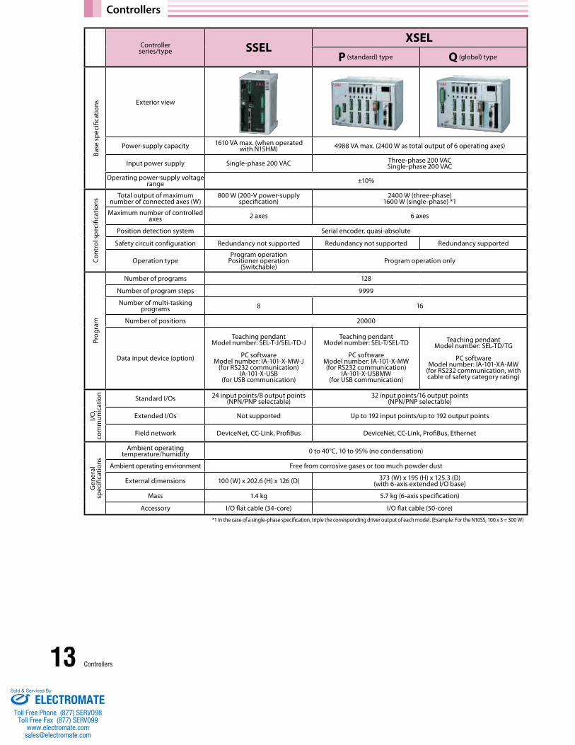
Controllers
Controller series/type SSEL
XSEL
P (standard) type Q (global) type
Exterior view
Power-supply capacity 1610 VA max. (when operated with N15HM) 4988 VA max. (2400 W as total output of 6 operating axes)
Input power supply Single-phase 200 VAC Three-phase 200 VACSingle-phase 200 VAC
Operating power-supply voltage range ±10%
Total output of maximum number of connected axes (W)
800 W (200-V power-supply specification)
2400 W (three-phase) 1600 W (single-phase) *1
Maximum number of controlled axes 2 axes 6 axes
Position detection system Serial encoder, quasi-absolute
Safety circuit configuration Redundancy not supported Redundancy not supported Redundancy supported
Operation type Program operation
Positioner operation (Switchable)
Program operation only
Number of programs 128
Number of program steps 9999
Number of multi-tasking programs 8 16
Number of positions 20000
Data input device (option)
Teaching pendant Model number: SEL-T-J/SEL-TD-J
PC software Model number: IA-101-X-MW-J
(for RS232 communication) IA-101-X-USB
(for USB communication)
Teaching pendant Model number: SEL-T/SEL-TD
PC software Model number: IA-101-X-MW(for RS232 communication)
IA-101-X-USBMW(for USB communication)
Teaching pendant Model number: SEL-TD/TG
PC software Model number: IA-101-XA-MW
(for RS232 communication, with cable of safety category rating)
Standard I/Os 24 input points/8 output points (NPN/PNP selectable)
32 input points/16 output points(NPN/PNP selectable)
Extended I/Os Not supported Up to 192 input points/up to 192 output points
Field network DeviceNet, CC-Link, ProfiBus DeviceNet, CC-Link, ProfiBus, Ethernet
Ambient operating temperature/humidity 0 to 40°C, 10 to 95% (no condensation)
Ambient operating environment Free from corrosive gases or too much powder dust
External dimensions 100 (W) x 202.6 (H) x 126 (D) 373 (W) x 195 (H) x 125.3 (D) (with 6-axis extended I/O base)
Mass 1.4 kg 5.7 kg (6-axis specification)
Accessory I/O flat cable (34-core) I/O flat cable (50-core)
Base
spe
cific
atio
nsCo
ntro
l spe
cific
atio
nsI/O
, co
mm
unic
atio
nG
ener
al
spec
ifica
tions
Prog
ram
13 Controllers
*1 In the case of a single-phase specification, triple the corresponding driver output of each model. (Example: For the N10SS, 100 x 3 = 300 W)
ELECTROMATEToll Free Phone (877) SERVO98
Toll Free Fax (877) SERV099www.electromate.com
Sold & Serviced By:

Controller Options
Maintenance Parts
HorizontalXSEL-P/Q SSEL
0 ~100W ~200W
1 ~600W ~800W
2 ~1200W
3 ~1800W
4 ~2400W
ø5
516.6 126
34
195
186
175
Wiring Color Signal No.
0.75 sq
Green PE 1Red U 2
White V 3Black W 4
No. Signal Color Wiring1 U Red
0.75 sq(Crimped)
2 V White3 W Black4 PE Green
Wiring Signal Color No.
AWG26(Soldered)
– – 10– – 11– E24V 12– OV 13– LS 26– CLEEP 25– OT 24– RSV 23– – 9– – 18– – 19– A+ 1– A- 2– B+ 3– B- 4– Z+ 5– Z- 6
Orange SRD+ 7Green SRD- 8Purple BAT+ 14
Gray BAT- 15Red VCC 16
Black GND 17Blue BKR- 20
Yellow BKR+ 21– – 22
Connect the shield to the hood via a clamp
No. Signal Color Wiring1 BAT+ Purple
AWG26(Crimped)
2 BAT- Gray3 SD Orange4 SD Green5 VCC Red6 GND Black7 FG Ground8 BK- Blue9 BK+ Yellow
14Controllers
Encoder cable
Motor cable
Regenerative Resistance Unit (Option)
Modelnumber CB-X-MA
Modelnumber CB-X1-PA
* indicates the cable length (L). A desired length can be specified up to 30 m. Example) 080 = 8 m
* indicates the cable length (L). A desired length can be specified up to 20 m. Example) 080 = 8 m
❚ Feature This unit converts to heat the regenerative current that generates as the motor decelerates. Confirm the total wattage of the operating actuator on the table below and provide the regenerative resistance if needed.
❚ Model numbers REU-1 (for XSEL)REU-2 (for SSEL)
* Depending on the operating conditions, the required regenerative resistance may be greater than as specified above.
L
(16)
(20)
Mechanical sideController side
(Front view)(Front view)
(10)
4 1
1 4
(41)
(ø9) (2
1)
(18)
(13)
(41) (14)L
1114
13269
(8)
Mechanical sideController side
(Front view)(Front view)
(25)
(37)
Ground wire and braided shield wire
ELECTROMATEToll Free Phone (877) SERVO98
Toll Free Fax (877) SERV099www.electromate.com
Sold & Serviced By:
Related Documents