Dust-proof/Splash-proof Type 493 Dust-proof/Splash-proof Type RCP2W-RA10C RCP2W-SA16C RCP2W-RA4C RCAW-RA3C RCAW/RCS2W-RA4C RCP2W-RA6C RCP4W-SA5C RCP4W-SA6C RCP4W-RA6C RCP4W-SA7C RCP4W-RA7C IP Marking First digit Second digit Protecting against the human body and solid objects Protecting against the intrusion of water * Please contact IAI when using liquids other than water. IP RCP4W RCP2W RCAW RCS2W Dust-proof/Splash-proof Type

Iai 08 rc general_cj0203-2_a_p493-522_dust-proof
Aug 06, 2015
Welcome message from author
This document is posted to help you gain knowledge. Please leave a comment to let me know what you think about it! Share it to your friends and learn new things together.
Transcript

RCP4W ROBO Cylinder RCP4W ROBO CylinderDust-proof/Splash-proof Type
493 Dust-proof/Splash-proof Type
RCP2W-RA10CRCP2W-SA16C RCP2W-RA4C
RCAW-RA3C RCAW/RCS2W-RA4C
RCP2W-RA6C
RCP4W-SA5C RCP4W-SA6C RCP4W-RA6CRCP4W-SA7C RCP4W-RA7C
IP Marking
First digit
Second digit
Protecting against the human body and solid objects
Protecting against the intrusion of water
* Please contact IAI when using liquids other than water.
IP
RCP4WRCP2W
RCAWRCS2W
Dust-proof/Splash-proof Type

RCP4W ROBO Cylinder RCP4W ROBO Cylinder Dust-proof/Splash-proof Type
Dust-proof/Splash-proof Type 494
Mini
Mini
Mini
SliderType
RodType
Table/Arm/Flat Type
Linear ServoType
Gripper/Rotary Type
Clean-room Type
Splash-ProofType
Pulse Motor
Servo Motor (24V)
Servo Motor (200V)
LinearServo Motor
Standard
Standard
Standard
ControllersIntegrated
ControllersIntegrated
RCP4W seriesPulse MotorType
Slider Type Coupled 55mm Width RCP4W-SA5C 49562mm Width RCP4W-SA6C 49777mm Width RCP4W-SA7C 499
Rod Type 65mm Width RCP4W-RA6C 50175mm Width RCP4W-RA7C 503
RCP2W seriesPulse MotorType
Slider Type Coupled 158mm Width RCP2W-SA16C 505Rod Type Coupled 45mm Width RCP2W-RA4C 507
64mm Width RCP2W-RA6C 509High-Thrust Type 100mm Width RCP2W-RA10C 511
Gripper Type Mini Slider Type 42mm Width RCP2W-GRSS 513Mini Lever Type 42mm Width RCP2W-GRLS 515
RCAW series24 Servo Motor Type
Rod Type Coupled ø32mm RCAW-RA3CBuilt-in ø32mm RCAW-RA3D 517Side-Mounted Motor ø32mm RCAW-RA3R
Rod Type Coupled ø37mm RCAW-RA4CBuilt-in ø37mm RCAW-RA4D 519Side-Mounted Motor ø37mm RCAW-RA4R
RCS2W series200V Servo Motor Type
Rod Type Coupled ø37mm RCS2W-RA4CBuilt-in ø37mm RCS2W-RA4D 521Side-Mounted Motor ø37mm RCS2W-RA4R
IP Classes
IP class Description Applicable IAI products
IP67Solid objects Fully protected against the entry of powder
dust into the equipment.
Water Even when the equipment is submerged in water, water does not enter the equipment.
IP65
Solid objects Fully protected against the entry of powder dust into the equipment.
WaterThe equipment receives no harmful effect even when directly hit by water jets from any direction.
IP54
Solid objects Dust that would affect the operation of the equipment does not enter the equipment.
WaterThe equipment receives no harmful effect even when contacted by water splashes from any direction.
IP50Solid objects Dust that would affect the operation of the
equipment does not enter the equipment.
Water The equipment is not protected against water.
Rod typeRCP4W-RA
Slider typeRCP2W-SA16C
Slider typeRCP4W-SA
Slider typeISWA/ISPWA
SCARA robotIX-NNW
Pulse motor rod typeRCP2W-RA4C/RA6C
High-thrust rod typeRCP2W-RA10C
24-V servo motor rod typeRCAW-RA3/RA4200-V servo motor rod typeRCS2W-RA4
Small gripper (dust-proof type)RCP2W-GR

RCP4W ROBO Cylinder RCP4W ROBO Cylinder
495 RCP4W-SA5C
Mini
Mini
Mini
SliderType
RodType
Table/Arm/
Flat Type
Linear ServoType
Gripper/Rotary
Type
Clean-room Type
Splash-ProofType
Pulse Motor
Servo Motor (24V)
Servo Motor (200V)
LinearServo Motor
Standard
Standard
Standard
ControllersIntegrated
ControllersIntegrated
8
6
4
2
00.60.50.40.30.20.10.0
25
15
20
10
5
00.60.50.40.30.20.10.0
44
44
6688
1010
5533 22
11
11
1.21.2
0.50.50.70.7
1.51.5
1.51.51.51.5
22
Lead 5
Lead 10
Lead 5
Lead 10
Lead 5
Lead 10
Lead 5
Lead 10
Diagram of Acceleration/Deceleration vs. Payload [Supported at Both Ends]
Payl
oad
(kg)
Payl
oad
(kg)
Acceleration/deceleration (G) Diagram of Acceleration/Deceleration vs. Payload
[Cantilever]
Acceleration/deceleration (G)
(1) This actuator is designed exclusively for horizontal installation. It cannot be installed vertically. When hanging the actuator from the ceiling or mounting it on the wall, be sure to do so using an optional dedicated bracket.
(2) The payload varies depending on the acceleration/deceleration. The upper limit of acceleration/deceleration is 0.6 G.
(3) The cable joint connector is not splash-proof, so install the connector in a location where it will not come in contact with water.
(4) Refer to the page at right for the air tube length and air flow rate when implementing air purge. (5) See page A-71 for details on push motion.
Actuator Specifications
Item DescriptionDrive system Ball screw ø8 mm, rolled C10Positioning repeatability ±0.02mmLost motion 0.1 mm or lessAllowable static moment
Supported on both ends Ma: 5.9 N•m Mb: 8.4 N•m Mc: 13.7 N•mCantilever Ma: 2.9 N•m Mb: 4.2 N•m Mc: 6.8 N•m
Allowable dynamic moment (*)
Supported on both ends Ma: 3.4 N•m Mb: 4.9 N•m Mc: 8.0 N•mCantilever Ma: 1.7 N•m Mb: 2.5 N•m Mc: 4.0 N•m
Overhang load length
Supported on both ends 125mm or lessCantilever 75mm or less
Protective structure IP65 (with air purge) Ambient operating temperature, humidity 0 to 40°C, 85% RH or less (Non-condensing)
(*) Based on 5,000km of traveling life.
L
L
Ma MaMb Mc Mc
Overhang load lengthDirection of allowable load moment.
35P: Pulse motor, 35 size
I: Incremental* The Simple absolute
encoder is also considered type "I".
P3: PCON-CA
* The RCP4W can be operated only with the PCON-CA
N: None P: 1m S: 3m M: 5mX: Custom lengthR: Robot cable
Lead Stroke Cable length OptionsTypeSA5C
Encoder typeI
Motor type35P
Applicable controllerSeriesRCP4WModel
SpecificationItems
100: 100mm
500: 500mm(50mm pitch increments)
* See page Pre-47 for details on the model descriptions.
P3
See options below.
RCP4W-SA5C ROBO Cylinder, Splash-Proof Slider Type, Actuator Width 55mm, Pulse Motor, Coupled 10 : 10mm 5 : 5mm
�Payload by Acceleration/Deceleration With the RCP4W series, the payload remains the same even when the speed is raised. However, the payload will drop if the acceleration is raised. Check on the table below.
Appendix
P.5
Actuator Specifications
� Lead and Payload � Stroke and Maximum Speed
Code explanation ➀ Stroke ➁ Cable length Options *See page A-71 for details on push motion. (Unit: mm/s)
Stroke 100~500(every 50mm)Lead
10 330
5 165
Model number Lead(mm)
Maximum horizontal payload (kg) Maximum push force
(N)
Positioning repeatability
(mm)Stroke(mm)Supported on both ends Cantilever
RCP4W-SA5C-I-35P-10- ➀ -P3- ➁ - ➂ 10 5 1.5 66.9±0.02 100~500
(every 50mm)RCP4W-SA5C-I-35P-10- ➀ -P3- ➁ - ➂ 5 10 2 147.9
Options
Name Option code See page Standard priceCable exit from the left side face A1 ➝ A-41 —Cable exit from the right side face A3 ➝ A-41 —Additional alumite coating AL ➝ A-42 —Food grade grease (edible grease) GE ➝ A-50 —Non-motor end specification NM ➝ A-52 —Ceiling mount (bracket mounted on the left) HFL ➝ A-51 —Ceiling mount (bracket mounted on the right) HFR ➝ A-51 —Wall mount sideways on the left TFL ➝ A-57 —Wall mount sideways on the right TFR ➝ A-57 —
Stroke
Stroke (mm) Standard price100 —150 —200 —250 —300 —350 —400 —450 —500 —
Type Cable symbol Standard Price
StandardP (1m) —S (3m) —M (5m) —
Special lengthX06 (6m) ~ X10 (10m) —X11 (11m) ~ X15 (15m) —X16 (16m) ~ X20 (20m) —
Robot Cable
R01 (1m) ~ R03 (3m) —R04 (4m) ~ R05 (5m) —R06 (6m) ~ R10 (10m) —R11 (11m) ~ R15 (15m) —R16 (16m) ~ R20 (20m) —
* See page A-59 for cables for maintenance.
Cable Length

RCP4W ROBO Cylinder RCP4W ROBO Cylinder
Mini
Mini
Mini
SliderType
RodType
Table/Arm/Flat Type
Linear ServoType
Gripper/Rotary Type
Clean-room Type
Splash-ProofType
Pulse Motor
Servo Motor (24V)
Servo Motor (200V)
LinearServo Motor
Standard
Standard
Standard
ControllersIntegrated
ControllersIntegrated
Appendix
P.15
200
180
160
140
120
100
80
60
40
20
050 10 15 20 25
Correlation Diagram of Air Tube Length vs. Air Flow Rate
Air tube length (m)
Air
flow
rate
(Nℓ/
min
)
Pressure: 0.3 MPa
Pressure: 0.2 MPaPressure: 0.2 MPa
Pressure: 0.1 MPaPressure: 0.1 MPa
400
350
300
250
200
150
100
50
010 20 30 40 50 60 70 80
Push Force of RCP4W-SA5
Current-limiting value (%)
Push
forc
e (N
)
Lead 5 Lead 5 Lead 10Lead 10
2-M3, depth 3
35 (reamed hole pitch ±0.02)
22.5
55
55 70
4-M4, depth 8
2-ø4H7, depth 47.5357.5
253030
55
(2m)
4-M3, depth 7
Cable joint connector *1
Cable exit from the left side face
Cable exit from the right side face
Mot
or h
eigh
t:56
Air supply port ø6 for air purge
(100 or more)
61
5ME*2
STROKE 50 29 90A
L
257.5357.5
4-M4, depth 6(same on the opposite side)
Home5
1045
ME SE25 (reamed hole pitch ±0.02)
22.5 (from the actuator mounting surface)
2-ø4H7, depth 4(same on the opposite side)
22.5
41
85
7.5
Slider width: 70Bracket width: 67
Actu
ator h
eight
: 63.5
Slide
r heig
ht: 6
5
Reference position for moment o�set *3
BCD
22.52012.5355
75
2-ø4.1, depth 430 (reamed hole pitch ±0.02)
2-ø3H7, depth 58-M3, depth 6
5102010525
45
105070
5
20
2-ø4H7, depth 4 8-M4, through8-ø4.5 hole
75 (reamed hole pitch ±0.02)
(17)
(17)
Cable exit from the left side face
Cable exit from the right side face
Dimensional Drawings
2D CAD2D
CAD
CAD drawings can be downloaded from the website. www.intelligentactuator.com
RCP4W-SA5C 496
Stroke 100 150 200 250 300 350 400 450 500L 385 435 485 535 585 635 685 735 785A 324 374 424 474 524 574 624 674 724B 256.5 306.5 356.5 406.5 456.5 506.5 556.5 606.5 656.5C 221.5 271.5 321.5 371.5 421.5 471.5 521.5 571.5 621.5D 204 254 304 354 404 454 504 554 604
Weight (kg) 2.8 2.9 3.1 3.2 3.4 3.5 3.7 3.8 4.0
�Dimensions and Weight by Stroke
(*1) Connect the motor-encoder integrated cable here. (*2) After homing, the slider moves to the ME, therefore, please watch for any interference with surrounding objects. (*3) Reference position for calculating the moments.
• Theabovecorrelationdiagramassumesanairtubeof6mminouterdiameterand 4mmininnerdiameter.(Ajointof6mminouterdiameterisusedontheactuatorside.)• Usethecorrelationdiagramasareferencetodetermineanappropriatepressureandair tube length in such a way that the air flow rate will become 40 Nℓ/min or more (clean dry air).
* See Page A-9 for the dimensional drawing for the ceiling mount specification. See Page A-10 for the dimensional drawing for the wall mount specification.
�Materials of Main Components Base Extruded aluminum (A6063) Surface treatment: Alumite coating Table Extruded aluminum (A6063) Surface treatment: Alumite coating (excluding machined areas)➂ Mounting bracket (front/rear) Extruded aluminum (A6063) Surface treatment: Alumite coating (excluding machined areas) Side cover Extruded aluminum (A6063) Surface treatment: Alumite coating Motor cover Die-cast aluminum (ADC12) Surface treatment: Alumite coating + Paint Front cover Die-cast aluminum (ADC12) Surface treatment: Alumite coating + Paint Seal Urethane rubber (U) Actuator cable Polyvinyl chloride (PVC) * High flex type cable Air purge joint Polyphenylene sulfide (PPS)
* Alumite coating has been removed in the machined areas of the table and mounting bracket ➂. To add alumite coating to these areas, specify the "Additional alumite coating (code: AL)" option.
Note on Push-motion Operation When performing push-motion operation, make sure the reactive moment generated by the push force does not exceed 80% of the dynamic allowable moment (Ma or Mb) specified in the catalog.
In push-motion operation, the travel speed is fixed at 25 mm/s.
RCP4W series actuators can be operated with the controllers indicated below. Select the type according to your intended application.
Applicable Controllers
* indicates I/O type (NP/PN). * indicates N (NPN specification) or P (PNP specification) symbol * indicates field network specification symbol.
Name Externalview Model number Features Maximum number of
positioning pointsInputpower
Power supply capacity
Standardprice
Reference page
Positioner type PCON-CA-35PI- -2-0 Equipped with a high-output driverPositioner type based on PIO control 512 points
DC24V Refer to P618
—
➝ P607Pulse-train type PCON-CA-35PI-PL--2-0 Equipped with a high-output driverPulse-train input type — —
Field network type PCON-CA-35PI- -0-0 Equipped with a high-output driverSupporting 7 major field networks 768 points —
(Note) These actuators cannot be operated with controllers other than the PCON-CA.

RCP4W ROBO Cylinder RCP4W ROBO Cylinder
497 RCP4W-SA6C
Mini
Mini
Mini
SliderType
RodType
Table/Arm/
Flat Type
Linear ServoType
Gripper/Rotary
Type
Clean-room Type
Splash-ProofType
Pulse Motor
Servo Motor (24V)
Servo Motor (200V)
LinearServo Motor
Standard
Standard
Standard
ControllersIntegrated
ControllersIntegrated
Acceleration/deceleration (G)
8
6
4
2
0
25
15
20
10
5
0
0.60.50.40.30.20.10.0
0.60.50.40.30.20.10.0
1515
1212
99
667.57.57.57.55.55.5
44 33
3.53.5
2.52.52.52.5
1.51.522
33
33
4.54.5
33
4.54.5
Lead6Lead6
Lead6Lead12
Lead6Lead6
Lead12Lead12
Diagram of Acceleration/Deceleration vs. Payload[Supported at Both Ends]
Payl
oad
(kg)
Payl
oad
(kg)
Acceleration/deceleration (G) Diagram of Acceleration/Deceleration vs. Payload
[Cantilever]
(1) This actuator is designed exclusively for horizontal installation. It cannot be installed vertically. When hanging the actuator from the ceiling or mounting it on the wall, be sure to do so using an optional dedicated bracket.
(2) The payload varies depending on the acceleration/deceleration. The upper limit of acceleration/deceleration is 0.6 G.
(3) The cable joint connector is not splash-proof, so install the connector in a location where it will not come in contact with water.
(4) Refer to the page at right for the air tube length and air flow rate when implementing air purge. (5) See page A-71 for details on push motion.
42P: Pulse motor, 42 size
I: Incremental* The Simple absolute
encoder is also considered type "I".
P3: PCON-CA
* The RCP4W can be operated only with the PCON-CA
N: None P: 1m S: 3m M: 5mX: Custom lengthR: Robot cable
Lead Stroke Cable length OptionsTypeSA6C
Encoder typeI
Motor type42P
Applicable controllerSeriesRCP4WModel
SpecificationItems
100: 100mm
600: 600mm(50mm pitch increments)
* See page Pre-47 for details on the model descriptions.
P3
See options below.
RCP4W-SA6C ROBO Cylinder, Splash-Proof Slider Type, Actuator Width 62mm, Pulse Motor, Coupled 12 : 12mm 6 : 6mm
�Payload by Acceleration/Deceleration With the RCP4W series, the payload remains the same even when the speed is raised. However, the payload will drop if the acceleration is raised. Check on the table below.
Appendix
P.5
Actuator Specifications
� Lead and Payload � Stroke and Maximum Speed
Code explanation ➀ Stroke ➁ Cable length Options *See page A-71 for details on push motion. (Unit: mm/s)
Stroke 100~600(every 50mm)Lead
12 400
6 200
Model number Lead(mm)
Maximum horizontal payload (kg) Maximum push force
(N)
Positioning repeatability
(mm)Stroke(mm)Supported on both ends Cantilever
RCP4W-SA6C-I-42P-12- ➀ -P3- ➁ - ➂ 12 7.5 3 82.8±0.02 100~600
(every 50mm)RCP4W-SA6C-I-42P-6- ➀ -P3- ➁ - ➂ 6 15 4.5 179.5
StrokeStroke (mm) Standard price
100 —150 —200 —250 —300 —350 —400 —450 —500 —550 —600 —
Type Cable symbol Standard Price
StandardP (1m) —S (3m) —M (5m) —
Special lengthX06 (6m) ~ X10 (10m) —X11 (11m) ~ X15 (15m) —X16 (16m) ~ X20 (20m) —
Robot Cable
R01 (1m) ~ R03 (3m) —R04 (4m) ~ R05 (5m) —R06 (6m) ~ R10 (10m) —R11 (11m) ~ R15 (15m) —R16 (16m) ~ R20 (20m) —
* See page A-59 for cables for maintenance.
Cable Length
Options
Name Option code See page Standard priceCable exit from the left side face A1 ➝ A-41 —Cable exit from the right side face A3 ➝ A-41 —Additional alumite coating AL ➝ A-42 —Food grade grease (edible grease) GE ➝ A-50 —Non-motor end specification NM ➝ A-52 —Ceiling mount (bracket mounted on the left) HFL ➝ A-51 —Ceiling mount (bracket mounted on the right) HFR ➝ A-51 —Wall mount sideways on the left TFL ➝ A-57 —Wall mount sideways on the right TFR ➝ A-57 —
Actuator Specifications
Item DescriptionDrive system Ball screw ø10 mm, rolled C10Positioning repeatability ±0.02mmLost motion 0.1 mm or lessAllowable static moment
Supported on both ends Ma: 8.5 N•m Mb: 12.2 N•m Mc: 19.9 N•mCantilever Ma: 4.3 N•m Mb: 6.1 N•m Mc: 10.0 N•m
Allowable dynamic moment (*)
Supported on both ends Ma: 4.7 N•m Mb: 6.7 N•m Mc: 11.0 N•mCantilever Ma: 2.4 N•m Mb: 3.4 N•m Mc: 5.5 N•m
Overhang load length
Supported on both ends 150mm or lessCantilever 90mm or less
Protective structure IP65 (with air purge) Ambient operating temperature, humidity 0 to 40°C, 85% RH or less (Non-condensing)
(*) Based on 5,000km of traveling life.
L
L
Ma MaMb Mc Mc
Overhang load lengthDirection of allowable load moment.

RCP4W ROBO Cylinder RCP4W ROBO Cylinder
Mini
Mini
Mini
SliderType
RodType
Table/Arm/Flat Type
Linear ServoType
Gripper/Rotary Type
Clean-room Type
Splash-ProofType
Pulse Motor
Servo Motor (24V)
Servo Motor (200V)
LinearServo Motor
Standard
Standard
Standard
ControllersIntegrated
ControllersIntegrated
Appendix
P.15
RCP4W-SA6C 498
Dimensional Drawings
2D CAD2D
CAD
CAD drawings can be downloaded from the website. www.intelligentactuator.com
200
180
160
140
120
100
80
60
40
20
050 10 15 20 25
Correlation Diagram of Air Tube Length vs. Air Flow Rate
Air tube length (m)
Air
flow
rate
(Nℓ/
min
)
Pressure: 0.3 MPa
Pressure: 0.2 MPaPressure: 0.2 MPa
Pressure: 0.1 MPaPressure: 0.1 MPa
400
350
300
250
200
150
100
50
010 20 30 40 50 60 70 80
Push Force of RCP4W-SA6
Current-limiting value (%)
Push
forc
e (N
)
Lead 5 Lead 6
Lead 10Lead 12
95
9.5
47.5
26.0
512.5
2512.55
BCD35
2022.5
512.5
85
30
5070 10
5
2045
(17)
(17)
5 510 STROKE45 60 29 90
A 61L
ME SE
307.5457.5
ME*2
303030
7.5457.5
5
22.5
55
(2m)62 80
5
45 (reamed hole pitch ±0.02)
2-M3, depth 42-ø5H7, depth 5
4-M5, depth 8
4-M3, depth 8
Cable joint connector *1
Cable exit from the left side face
Cable exit from the right side face
Mot
or h
eigh
t:65
Air supply port ø6 for air purge
(100 or more)
4-M5, depth 8(same on the opposite side)
2-ø5H7, depth 5(same on the opposite side)
2-ø3H7, depth 5
25 (from the actuator mounting surface)
30 (reamed hole pitch ±0.02)Home
8-M4, through8-ø5.5 hole
Cable exit from the left side face
2-ø5H7, depth 5
Cable exit from the right side face
8-M3, depth 6
37 (reamed hole pitch ±0.02)
2-ø5.1, depth 5
Slider width: 80Bracket width: 77
Reference position for moment o�set *3
Actu
ator h
eight
: 73.5
Slid
er h
eigh
t: 75
Stroke 100 150 200 250 300 350 400 450 500 550 600L 395 445 495 545 595 645 695 745 795 845 895A 334 384 434 484 534 584 634 684 734 784 834B 266.5 316.5 366.5 416.5 466.5 516.5 566.5 616.5 666.5 716.5 766.5C 231.5 281.5 331.5 381.5 431.5 481.5 531.5 581.5 631.5 681.5 731.5D 214 264 314 364 414 464 514 564 614 664 714
Weight (kg) 3.9 4.1 4.3 4.5 4.7 4.9 5.1 5.3 5.5 5.8 6.0
�Dimensions and Weight by Stroke
(*1) Connect the motor-encoder integrated cable here. (*2) After homing, the slider moves to the ME, therefore, please watch for any interference with surrounding objects. (*3) Reference position for calculating the moments.
• Theabovecorrelationdiagramassumesanairtubeof6mminouterdiameterand 4mmininnerdiameter.(Ajointof6mminouterdiameterisusedontheactuatorside.)• Usethecorrelationdiagramasareferencetodetermineanappropriatepressureandair tube length in such a way that the air flow rate will become 40 Nℓ/min or more (clean dry air).
Note on Push-motion Operation When performing push-motion operation, make sure the reactive moment generated by the push force does not exceed 80% of the dynamic allowable moment (Ma or Mb) specified in the catalog.
In push-motion operation, the travel speed is fixed at 20 mm/s.
* See Page A-9 for the dimensional drawing for the ceiling mount specification. See Page A-10 for the dimensional drawing for the wall mount specification.
RCP4W series actuators can be operated with the controllers indicated below. Select the type according to your intended application.
Applicable Controllers
* indicates I/O type (NP/PN). * indicates N (NPN specification) or P (PNP specification) symbol * indicates field network specification symbol.
Name Externalview Model number Features Maximum number of
positioning pointsInputpower
Power supply capacity
Standardprice
Reference page
Positioner type PCON-CA-42PI- -2-0 Equipped with a high-output driverPositioner type based on PIO control 512 points
DC24V Refer to P618
—
➝ P607Pulse-train type PCON-CA-42PI-PL--2-0 Equipped with a high-output driverPulse-train input type — —
Field network type PCON-CA-42PI- -0-0 Equipped with a high-output driverSupporting 7 major field networks 768 points —
(Note) These actuators cannot be operated with controllers other than the PCON-CA.
�Materials of Main Components Base Extruded aluminum (A6063) Surface treatment: Alumite coating Table Extruded aluminum (A6063) Surface treatment: Alumite coating (excluding machined areas)➂ Mounting bracket (front/rear) Extruded aluminum (A6063) Surface treatment: Alumite coating (excluding machined areas) Side cover Extruded aluminum (A6063) Surface treatment: Alumite coating Motor cover Die-cast aluminum (ADC12) Surface treatment: Alumite coating + Paint Front cover Die-cast aluminum (ADC12) Surface treatment: Alumite coating + Paint Seal Urethane rubber (U) Actuator cable Polyvinyl chloride (PVC) * High flex type cable Air purge joint Polyphenylene sulfide (PPS)
* Alumite coating has been removed in the machined areas of the table and mounting bracket ➂. To add alumite coating to these areas, specify the "Additional alumite coating (code: AL)" option.

RCP4W ROBO Cylinder RCP4W ROBO Cylinder
499 RCP4W-SA7C
Mini
Mini
Mini
SliderType
RodType
Table/Arm/
Flat Type
Linear ServoType
Gripper/Rotary
Type
Clean-room Type
Splash-ProofType
Pulse Motor
Servo Motor (24V)
Servo Motor (200V)
LinearServo Motor
Standard
Standard
Standard
ControllersIntegrated
ControllersIntegrated
8
6
4
2
0
25
15
20
10
5
0
0.60.50.40.30.20.10.0
0.60.50.40.30.20.10.0
33
44
4444
6688
881010
2020
1616
1212
77
66
55
4.54.5
77
4.54.5
3.53.5
Lead6Lead8
Lead16Lead16
Lead8
Lead16Lead16
Acceleration/deceleration (G)
Diagram of Acceleration/Deceleration vs. Payload[Supported at Both Ends]
Payl
oad
(kg)
Payl
oad
(kg)
Acceleration/deceleration (G) Diagram of Acceleration/Deceleration vs. Payload
[Cantilever]
Actuator Specifications � Lead and Payload � Stroke and Maximum Speed
Code explanation ➀ Stroke ➁ Cable length Options *See page A-71 for details on push motion. (Unit: mm/s)
Stroke 100~700(every 50mm)Lead
16 530
8 265
Model number Lead(mm)
Maximum horizontal payload (kg) Maximum push force
(N)
Positioning repeatability
(mm)Stroke(mm)Supported on both ends Cantilever
RCP4W-SA7C-I-56P-16- ➀ -P3- ➁ - ➂ 16 10 4.5 161.9±0.02 100~700
(every 50mm)RCP4W-SA7C-I-56P-8- ➀ -P3- ➁ - ➂ 8 20 7 337.9
(1) This actuator is designed exclusively for horizontal installation. It cannot be installed vertically. When hanging the actuator from the ceiling or mounting it on the wall, be sure to do so using an optional dedicated bracket.
(2) The payload varies depending on the acceleration/deceleration. The upper limit of acceleration/deceleration is 0.6 G.
(3) The cable joint connector is not splash-proof, so install the connector in a location where it will not come in contact with water.
(4) Refer to the page at right for the air tube length and air flow rate when implementing air purge. (5) See page A-71 for details on push motion.
Actuator Specifications
Item DescriptionDrive system Ball screw ø12 mm, rolled C10Positioning repeatability ±0.02mmLost motion 0.1 mm or lessAllowable static moment
Supported on both ends Ma: 11.7 N•m Mb: 16.6 N•m Mc: 31.8 N•mCantilever Ma: 5.8 N•m Mb: 8.3 N•m Mc: 15.9 N•m
Allowable dynamic moment (*)
Supported on both ends Ma: 6.1 N•m Mb: 8.8 N•m Mc: 16.8 N•mCantilever Ma: 3.1 N•m Mb: 4.4 N•m Mc: 8.4 N•m
Overhang load length
Supported on both ends 175mm or lessCantilever 105mm or less
Protective structure IP65 (with air purge) Ambient operating temperature, humidity 0 to 40°C, 85% RH or less (Non-condensing)
(*) Based on 5,000km of traveling life.L
L
Ma MaMb Mc Mc
Overhang load lengthDirection of allowable load moment.
56P: Pulse motor, 56 size
I: Incremental* The Simple absolute
encoder is also considered type "I".
P3: PCON-CA
* The RCP4W can be operated only with the PCON-CA
N: None P: 1m S: 3m M: 5mX: Custom lengthR: Robot cable
Lead Stroke Cable length OptionsTypeSA7C
Encoder typeI
Motor type56P
Applicable controllerSeriesRCP4WModel
SpecificationItems
100: 100mm
700: 700mm(50mm pitch increments)
* See page Pre-47 for details on the model descriptions.
P3
See options below.
RCP4W-SA7C ROBO Cylinder, Splash-Proof Slider Type, Actuator Width 77mm, Pulse Motor, Coupled 16 : 16mm 8 : 8mm
Cable Length
Type Cable symbol Standard Price
Standard(Robot Cables)
P (1m) —S (3m) —M (5m) —
Special lengthX06 (6m) ~ X10 (10m) —X11 (11m) ~ X15 (15m) —X16 (16m) ~ X20 (20m) —
Robot Cable
R01 (1m) ~ R03 (3m) —R04 (4m) ~ R05 (5m) —R06 (6m) ~ R10 (10m) —R11 (11m) ~ R15 (15m) —R16 (16m) ~ R20 (20m) —
* See page A-59 for cables for maintenance.
�Payload by Acceleration/Deceleration With the RCP4W series, the payload remains the same even when the speed is raised. However, the payload will drop if the acceleration is raised. Check on the table below.
Appendix
P.5
Stroke
Stroke (mm) Standard price100 —150 —200 —250 —300 —350 —400 —450 —500 —550 —600 —650 —700 —
Options
Name Option code See page Standard priceCable exit from the left side face A1 ➝ A-41 —Cable exit from the right side face A3 ➝ A-41 —Additional alumite coating AL ➝ A-42 —Food grade grease (edible grease) GE ➝ A-50 —Non-motor end specification NM ➝ A-52 —Ceiling mount (bracket mounted on the left) HFL ➝ A-51 —Ceiling mount (bracket mounted on the right) HFR ➝ A-51 —Wall mount sideways on the left TFL ➝ A-57 —Wall mount sideways on the right TFR ➝ A-57 —

RCP4W ROBO Cylinder RCP4W ROBO Cylinder
Mini
Mini
Mini
SliderType
RodType
Table/Arm/Flat Type
Linear ServoType
Gripper/Rotary Type
Clean-room Type
Splash-ProofType
Pulse Motor
Servo Motor (24V)
Servo Motor (200V)
LinearServo Motor
Standard
Standard
Standard
ControllersIntegrated
ControllersIntegrated
Appendix
P.15
RCP4W-SA7C 500
Dimensional Drawings
2D CAD2D
CAD
CAD drawings can be downloaded from the website. www.intelligentactuator.com
2-M3, depth 4
110 9.5
53.0
27.5
22.5
55
77 95
357.5557.5 3030
55
(2m)
STROKE105
70 29 9091
45
L
7.5557.535
A
ME SE5
(17)
(17)
5
1070
452050
51530155B
CD
35
20355
12.5
100
22.5
ME*2
Cable exit from the left side face
Cable exit from the right side face
Mot
or h
eight
:72
Air supply port ø6 for air purge
Cable joint connector *1
Cable exit from the left side face
Cable exit from the right side face
4-M3, depth 8
55 (reamed hole pitch ±0.02)
2-ø5H7, depth 54-M5, depth 8
Slider width: 95Bracket width: 92
Actua
tor he
ight: 8
0.5Sli
der h
eight
: 82
27 (from the actuator mounting surface)
35 (reamed hole pitch ±0.02)Home
4-M5, depth 8(same on the opposite side)
2-ø5H7, depth 5(same on the opposite side)
2-ø5.1, depth 52-ø3H7, depth 58-M3, depth 6
52 (reamed hole pitch ±0.02)
2-ø5H7, depth 5
8-M5, through8-ø5.5 hole
(100 or more)
Reference position formoment o�set *3
400
350
300
250
200
150
100
50
010 20 30 40 50 60 70 80
Lead8Lead8
Lead16Lead16
Push Force of RCP4W-SA7
Current-limiting value (%)
Push
forc
e (N
)
200
180
160
140
120
100
80
60
40
20
050 10 15 20 25
Correlation Diagram of Air Tube Length vs. Air Flow Rate
Air tube length (m)
Air
flow
rate
(Nℓ/
min
)
Pressure: 0.3 MPa
Pressure: 0.2 MPaPressure: 0.2 MPa
Pressure: 0.1 MPaPressure: 0.1 MPa
Stroke 100 150 200 250 300 350 400 450 500 550 600 650 700L 435 485 535 585 635 685 735 785 835 885 935 985 1035A 344 394 444 494 544 594 644 694 744 794 844 894 944B 276.5 326.5 376.5 426.5 476.5 526.5 576.5 626.5 676.5 726.5 776.5 826.5 876.5C 241.5 291.5 341.5 391.5 441.5 491.5 541.5 591.5 641.5 691.5 741.5 791.5 841.5D 224 274 324 374 424 474 524 574 624 674 724 774 824
Weight (kg) 5.9 6.2 6.5 6.8 7.1 7.4 7.6 7.9 8.2 8.5 8.8 9.0 9.3
�Dimensions and Weight by Stroke• Theabovecorrelationdiagramassumesanairtubeof6mminouterdiameter and4mmininnerdiameter.(Ajointof6mminouterdiameterisusedonthe actuator side.) • Usethecorrelationdiagramasareferencetodetermineanappropriatepressure and air tube length in such a way that the air flow rate will become 40 Nℓ/min or more (clean dry air).
Note on Push-motion Operation When performing push-motion operation, make sure the reactive moment generated by the push force does not exceed 80% of the dynamic allowable moment (Ma or Mb) specified in the catalog.
In push-motion operation, the travel speed is fixed at 20 mm/s.
RCP4W series actuators can be operated with the controllers indicated below. Select the type according to your intended application.
Applicable Controllers
* indicates I/O type (NP/PN). * indicates N (NPN specification) or P (PNP specification) symbol * indicates field network specification symbol.
Name Externalview Model number Features Maximum number of
positioning pointsInputpower
Power supply capacity
Standardprice
Reference page
Positioner type PCON-CA-56PI- -2-0 Equipped with a high-output driverPositioner type based on PIO control 512 points
DC24V Refer to P618
—
➝ P607Pulse-train type PCON-CA-56PI-PL--2-0 Equipped with a high-output driverPulse-train input type — —
Field network type PCON-CA-56PI- -0-0 Equipped with a high-output driverSupporting 7 major field networks 768 points —
(Note) These actuators cannot be operated with controllers other than the PCON-CA.
�Materials of Main Components Base Extruded aluminum (A6063) Surface treatment: Alumite coating Table Extruded aluminum (A6063) Surface treatment: Alumite coating (excluding machined areas)➂ Mounting bracket (front/rear) Extruded aluminum (A6063) Surface treatment: Alumite coating (excluding machined areas) Side cover Extruded aluminum (A6063) Surface treatment: Alumite coating Motor cover Die-cast aluminum (ADC12) Surface treatment: Alumite coating + Paint Front cover Die-cast aluminum (ADC12) Surface treatment: Alumite coating + Paint Seal Urethane rubber (U) Actuator cable Polyvinyl chloride (PVC) * High flex type cable Air purge joint Polyphenylene sulfide (PPS)
* Alumite coating has been removed in the machined areas of the table and mounting bracket ➂. To add alumite coating to these areas, specify the "Additional alumite coating (code: AL)" option.
(*1) Connect the motor-encoder integrated cable here. (*2) After homing, the slider moves to the ME, therefore, please watch for any interference with surrounding objects. (*3) Reference position for calculating the moments.
* See Page A-9 for the dimensional drawing for the ceiling mount specification. See Page A-10 for the dimensional drawing for the wall mount specification.

RCP4W ROBO Cylinder
501 RCP4W-RA6C
Mini
Mini
Mini
SliderType
RodType
Table/Arm/
Flat Type
Linear ServoType
Gripper/Rotary
Type
Clean-room Type
Splash-ProofType
Pulse Motor
Servo Motor (24V)
Servo Motor (200V)
LinearServo Motor
Standard
Standard
Standard
ControllersIntegrated
ControllersIntegrated
Built-in Guide Mechanism
RCP4W-RA6C Horizontal(Normal condition of use)
RCP4W-RA6C Vertical(Normal condition of use)
Speed (mm/s)
Speed (mm/s)0
35
20
25
30
15
10
500 6004003002001000
Lead 3 (standard speci�cation)Lead 3 (standard speci�cation)
Lead 3 (standard speci�cation)Lead 3 (standard speci�cation)
Lead 3 (standard speci�cation)Lead 3 (standard speci�cation)
The values below are based on operation at 0.3 G.
The values below are based on operation at 0.3 G.
The values below are based on operation at 0.5 G.
The values below are based on operation at 0.5 G.
The values below are based on operation at 0.5 G.
The values below are based on operation at 0.5 G.
The values below are based on operation at 0.3 G.
The values below are based on operation at 0.3 G.
Lead 3 (standard speci�cation)Lead 3 (standard speci�cation)
Lead 6Lead 6
2525
88 88
33 3355 4411 11
2525
77 77
Lead 6Lead 6HorizontalHorizontal
VerticalVertical VerticalVertical
HorizontalHorizontal
Lead 12Lead 12 Lead 12Lead 12
0
10
60
50
40
30
20
6005004003002001000
RCP4W-RA6C Horizontal (Environmental temperature of 5°C or below)
RCP4W-RA6C Vertical (Environmental temperature of 5°C or below)
Speed (mm/s)0
10
60
50
40
30
20
6005004003002001000
Speed (mm/s)
5
0
35
20
25
30
15
10
500 6004003002001000
5
Paylo
ad (k
g)
Paylo
ad (k
g)
Paylo
ad (k
g)
Paylo
ad (k
g)
Lead 3 (High-thrust speci�cation)
Lead 3 (High-thrust speci�cation)
Lead 3 (High-thrust speci�cation)
Lead 3 (High-thrust speci�cation)
Lead 6Lead 6 Lead 6Lead 6Lead 12Lead 12 Lead 12Lead 12
16 16
22 2255 44
Appendix
P.5
� Speed vs. Load Capacity Due to its pulse motor characteristics, the RCP4 series provides lower payload at higher speed. Check the tables below to see if the desired speed and payload can be achieved.
Cable Length
Type Cable symbol Standard Price
StandardP (1m) —S (3m) —M (5m) —
Special lengthX06 (6m) ~ X10 (10m) —X11 (11m) ~ X15 (15m) —X16 (16m) ~ X20 (20m) —
Robot Cable
R01 (1m) ~ R03 (3m) —R04 (4m) ~ R05 (5m) —R06 (6m) ~ R10 (10m) —R11 (11m) ~ R15 (15m) —R16 (16m) ~ R20 (20m) —
* See page A-59 for cables for maintenance.
Stroke
Stroke (mm)Standard price
Standard specification High-thrust specification50 — —
100 — —150 — —200 — —250 — —300 — —350 — —400 — —
Actuator Specifications
� Lead and Payload � Stroke and Maximum Speed
Code explanation ➀ Stroke ➁ Cable length ➂ Options
(Unit: mm/s)
Model number Lead(mm)
Maximum payload (kg) Maximum push
force (N)
Positioning repeatabili-
ty (mm)Stroke (mm)Horizontal
(kg)Vertical
(kg)
Standard specification
RCP4W-RA6C-I-42P-12- 1 -P3- 2 - 3 12 20 3 93
±0.0250 to 400
(Every 50mm)
RCP4W-RA6C-I-42P-6- 1 -P3- 2 - 3 6 40 8 185
RCP4W-RA6C-I-42P-3- 1 -P3- 2 - 3 3 50 16 370
High-thrust specification RCP4W-RA6C-I-42SP-3- 1 -P3- 2 - 3 -B 3 — 30 590
50 (mm) 100 ~ 400(Every 50mm)
12 500[450 <400>]
560 <500>[450 <400>]
6 360 [300]
3 180 [150]
3 <70> [<70>]
StrokeLead
*The values in < > apply when the actuator is used vertically. *The values in [ ] apply when the actuator is used at an
environmental temperature of 5°C or below.
Options
Name Option code Standard priceCable exit from the left side face A1 ➝ A-41 —Cable exit from the right side face A3 ➝ A-41 —Cable exit from the top face AT ➝ A-41 —Brake B ➝ A-42 —With flange FL ➝ A-45 —With foot bracket FT ➝ A-48 —Non-motor side specification NM ➝ A-52 —
42P: Pulse motor, size 42 42SP: High-thrust pulse motor, size 42
I: Incremental P3: PCON-CA N: None P: 1m S: 3m M: 5mX: Custom lengthR: Robot cable
Lead Stroke Cable length OptionsTypeRA6C
Encoder typeI
Motor type42P
Applicable controllerSeriesRCP4WModel
SpecificationItems
50: 50mm
400: 400mm(50mm pitch increments)
* See page Pre-47 for details on the model descriptions.
See Options below.
RCP4W-RA6C ROBO Cylinder, Splash-Proof Rod Type, Actuator Width 65mm, 24V Pulse Motor 12 :12mm 6 : 6mm 3 : 3mm
P3
* If the high-thrust pulse motor is selected, the actuator comes standard with option B (Brake).
(1) The maximum payload is the value when operated horizontally and vertically at 0.3G and 0.5G, respectively. Note that raising the acceleration causes the payload to drop. (Refer to page A-108 for the maximum payload by acceleration.)
(2) The horizontal payload is calculated by assuming that an external guide is also used.
(3) The high-thrust specification is designed exclusively for vertical operation. It comes standard with a brake.
Actuator Specifications
Item DescriptionDrive method Ball screw ø10mm, rolled C10Positioning repeatability ±0.02mmLost motion 0.1mm or lessRod ø22 stainless steel pipe Rod non-rotation accuracy ±0.1 degreesAllowable load/allowable torque at end of rod Refer to the page on the right. Load offset distance at end of rod 100mm or lessProtective structure IP67Ambient operating temperature/ humidity 0 to 40°C, 85% RH or less (Non-condensing)
Load at end of rodOffset distance at end of rod (100mm or less)
RCP4W ROBO Cylinder
Mini
Mini
Mini
SliderType
RodType
Table/Arm/Flat Type
Linear ServoType
Gripper/Rotary Type
Clean-room Type
Splash-ProofType
Pulse Motor
Servo Motor (24V)
Servo Motor (200V)
LinearServo Motor
Standard
Standard
Standard
ControllersIntegrated
ControllersIntegrated
<Cable Exit Direction Option>
Option code: ATExit from the top
Option code: A1Exit from the left side face
Option code: A3Exit from the right side face
22.5 13.5
(47)
(20.5)
13.522.5
(47)
(20.5)
13.5 22.5
(47)
17
4014
68.5
1465
X
8
0.54.37.3 1.
54
Y50
40 AC B×100P
42(T
-slot
dist
ance
)26
+0.0
12 0
5
Detail Y
6 (19.6)M10×1.25
23 4745.5
ME*2ME SEStroke
1731
224
M10×1.25
➅
L
(2m)➀
➁
➂
➄
464-M6, depth 9
Reference plane
Detail view of X at 1:1 (Reference plane and T-slot)
Standard speci�cation: 3 High-thrust speci�cation: 2
304
➂
D-M4, depth 6
2-ø4H7, depth 6.5(from bottom of base)
Oblong hole, depth 6.5 (from bottom base)
Supplied rod end nut
Secure 100 or more
Intake/discharge port(Outer diameter of connection hose: ø6)Standard speci�cation: 3
High-thrust speci�cation: 2
Front housing *4M (Reference plane, e�ective T-slot range)
Cable joint connector *17.5 (Width across �ats) *3
øl41
h7
Outer
diam
eter o
f rod:
ø22
Home
Dimensional Drawings
CAD drawings can be downloaded from the website. www.intelligentactuator.com Appendix
P.15
RCP4W-RA6C 502
*1 Connect the motor-encoder integrated cable here.*2 TherodmovestotheMEduringhomereturn,sopayattentiontopossiblecontactwithsurroundingstructuresandobjects.*3 Theorientationoftheboltvariesfromoneproducttoanother.*4 When installing the actuator using the front housing or flange, make sure the actuator does not receive any external force.
2DCAD
Materials of Key Components 1 Frame Aluminum extrusion material (A6063SS-T5 or equivalent)
with white alumite coating 2 Front bracket Aluminum die-cast 3 Rear cover Aluminum die-cast
4 Rod Stainless steel pipe (SUS304 or equivalent), polished + hard chrome plated
5 Actuator cable Polyvinyl chloride (PVC)6 Intake/exhaust port Polyphenylene sulfide (PPS)
�Dimensions and Weight by Stroke
(*) The dimensions of the high-thrust specification include the brake.
Stroke 50 100 150 200 250 300 350 400
L Without brake 285 335 385 435 485 535 585 635 With brake (*) 346 396 446 496 546 596 646 696
A Without brake 40 40 40 40 40 40 40 40With brake (*) 101 101 101 101 101 101 101 101
B 1 1 2 2 3 3 4 4C 35 85 35 85 35 85 35 85D 6 6 8 8 10 10 12 12
M Without brake 215 265 315 365 415 465 515 565With brake 276 326 376 426 476 526 576 626
Allowable static load at end of rod (N) 65.6 51.2 41.7 34.9 29.8 25.7 22.4 19.7 Allowable dynamic load at end of rod (N)
Load offset 0 mm 32.4 23.6 18.1 14.4 11.6 9.5 7.7 6.2 Load offset 100 mm 25.6 19.7 15.7 12.7 10.4 8.6 7.1 5.7
Allowable static torque at end of rod (N•m) 6.6 5.2 4.3 3.7 3.2 2.8 2.6 2.3 Allowable dynamic torque at end of rod (N•m) 2.6 2.0 1.6 1.3 1.0 0.9 0.7 0.6 Weight
(kg)Without brake 3.1 3.5 3.8 4.2 4.6 5.0 5.4 5.8With brake 3.6 4.0 4.4 4.8 5.2 5.6 6.0 6.4
RCP4W series actuators can be operated with the controllers indicated below. Select the type according to your intended application.
Applicable Controllers
* indicates I/O type (NP/PN). * indicates N (NPN specification) or P (PNP specification) symbol * indicates field network specification symbol. * indicates P (Standard specification) or SP (High-thrust specification) symbol.
Name Externalview Model number Features Maximum number of
positioning pointsInputpower
Power supply capacity
Standardprice
Reference page
Positioner type PCON-CA-42I- -2-0 Equipped with a high-output driverPositioner type based on PIO control 512 points
DC24V Refer to P618
—
➝ P607Pulse-train type PCON-CA-42I-PL--2-0 Equipped with a high-output driverPulse-train input type — —
Field network type PCON-CA-42I- -0-0 Equipped with a high-output driverSupporting 7 major field networks 768 points —
■ Rod Deflection of RCP4W-RA6C (Reference Values)(The graph below plots deflection as measured by installing the actuator vertically and applying a force to the rod from one side.)
2.0
1.8
1.6
1.4
1.2
1.0
0.8
0.6
0.4
0.2
0.0
De�
ectio
n (m
m)
0 10 20 30 40 50Load at end of rod (N)
Home50st100st150st200st250st
300st
350st
400st

RCP4W ROBO Cylinder
503 RCP4W-RA7C
Mini
Mini
Mini
SliderType
RodType
Table/Arm/
Flat Type
Linear ServoType
Gripper/Rotary
Type
Clean-room Type
Splash-ProofType
Pulse Motor
Servo Motor (24V)
Servo Motor (200V)
LinearServo Motor
Standard
Standard
Standard
ControllersIntegrated
ControllersIntegrated
(1) The maximum payload is the value when operated horizontally and vertically at 0.3G and 0.5G, respectively. Note that raising the acceleration causes the payload to drop. (Refer to page A-108 for the maximum payload by acceleration.)
(2) The horizontal payload is calculated by assuming that an external guide is also used.
(3) The high-thrust specification is designed exclusively for vertical operation. It comes standard with a brake.
� Speed vs. Load Capacity Due to its pulse motor characteristics, the RCP4 series provides lower payload at higher speed. Check the tables below to see if the desired speed and payload can be achieved.
Speed (mm/s)
0
20
51015
504540353025
500 6004003002001000
010
60
70
80
50
40
30
20
6005004003002001000
010
60
70
80
50
40
30
20
6005004003002001000
0
20
51015
504540353025
500 6004003002001000
Speed (mm/s)
RCP4W-RA7C Horizontal(Normal condition of use)
RCP4W-RA7C Vertical(Normal condition of use)
RCP4W-RA7C Horizontal(Environmental temperature of 5°C or below)
RCP4W-RA7C Vertical(Environmental temperature of 5°C or below)
HorizontalHorizontal
VerticalVertical VerticalVertical
HorizontalHorizontal
Lead 4 (standard speci�cation)
Lead 4 (standard speci�cation)
The values below are based on operation at 0.3 G.
The values below are based on operation at 0.3 G.
The values below are based on operation at 0.5 G.
The values below are based on operation at 0.5 G.
The values below are based on operation at 0.5 G.
The values below are based on operation at 0.5 G.
The values below are based on operation at 0.3 G.
The values below are based on operation at 0.3 G.
33
77 77
22 2211 11
88 88
33
Paylo
ad (k
g)
Paylo
ad (k
g)
Paylo
ad (k
g)
Paylo
ad (k
g)
Speed (mm/s) Speed (mm/s)
Lead 4 (standard speci�cation)Lead 4 (standard speci�cation)
Lead 4 (standard speci�cation)Lead 4 (standard speci�cation)
Lead 4 (standard speci�cation)Lead 4 (standard speci�cation)
Lead 8Lead 8 Lead 8Lead 8
Lead 16Lead 16
Lead 16Lead 16
Lead 16Lead 16Lead 8Lead 8 Lead 8Lead 8
Lead 16Lead 16
Lead 4 (High-thrust speci�cation)
Lead 4 (High-thrust speci�cation)
Lead 4 (High-thrust speci�cation)
Lead 4 (High-thrust speci�cation)
Appendix
P.5
Built-in Guide Mechanism
I: Incremental 56P: Pulse motor, size 5656SP: High-thrust pulse motor, size 56
P3: PCON-CAP4: PCON-CFA* The PCON-CFA is
designed exclusively for the high-thrust specification.
N: None P: 1m S: 3m M: 5mX: Custom lengthR: Robot cable
Lead Stroke Cable length OptionsTypeRA7C
Encoder typeI
Motor type56P
Applicable controllerSeriesRCP4WModel
SpecificationItems
50: 50mm
500: 500mm(50mm pitch increments)
* See page Pre-47 for details on the model descriptions.
See Options below.
RCP4W-RA7C ROBO Cylinder, Splash-Proof Rod Type, Actuator Width 75mm, 24V Pulse Motor 16 :16mm 8 : 8mm 4 : 4mm
P3
* If the high-thrust pulse motor is selected, the actuator comes standard with option B (Brake).
Actuator Specifications � Lead and Payload � Stroke and Maximum Speed
Code explanation ➀ Stroke ➁ Cable length ➂ Options
(Unit: mm/s)
Model number Lead(mm)
Maximum payload (kg) Maximum push force
(N)
Positioning repeatability
(mm)Stroke (mm)Horizontal
(kg)Vertical
(kg)
Standard specification
RCP4W-RA7C-I-56P-16- 1 -P3- 2 - 3 16 40 7 219
±0.0250 to 500
(Every 50mm)
RCP4W-RA7C-I-56P-8- 1 -P3- 2 - 3 8 50 15 437
RCP4W-RA7C-I-56P-4- 1 -P3- 2 - 3 4 70 25 875
High-thrust specification RCP4W-RA7C-I-56SP-4- 1 -P4- 2 - 3 -B 4 — 45 1030
50 (mm) 100 ~ 500(Every 50mm)
16 500[450 <300>]
560 <400>[450 <300>]
8 340 <280>[300 <250>]
4 170 <140>[150 <125>]
4 <80>[<80>]
StrokeLead
* The values in < > apply when the actuator is used vertically. * The values in [ ] apply when the actuator is used at an environmental temperature of 5°C or below.
Stroke
Stroke (mm)Standard price
Standard specification High-thrust specification50 — —
100 — —150 — —200 — —250 — —300 — —350 — —400 — —450 — —500 — —
Options
Name Option code Standard priceCable exit from the left side face A1 ➝ A-41 —Cable exit from the right side face A3 ➝ A-41 —Cable exit from the top face AT ➝ A-41 —Brake B ➝ A-42 —With flange FL ➝ A-45 —With foot bracket FT ➝ A-48 —Non-motor side specification NM ➝ A-52 —
*The high-thrust specification comes standard with a brake.
Actuator Specifications
Item DescriptionDrive method Ball screw ø10mm, rolled C10Positioning repeatability ±0.02mmLost motion 0.1mm or lessRod ø22 stainless steel pipe Rod non-rotation accuracy ±0.1 degreesAllowable load/allowable torque at end of rod Refer to the page on the right. Load offset distance at end of rod 100mm or lessProtective structure IP67Ambient operating temperature/ humidity 0 to 40°C, 85% RH or less (Non-condensing)
Load at end of rodOffset distance at end of rod (100mm or less)
Cable Length
Type Cable symbol Standard Price
StandardP (1m) —S (3m) —M (5m) —
Special lengthX06 (6m) ~ X10 (10m) —X11 (11m) ~ X15 (15m) —X16 (16m) ~ X20 (20m) —
Robot Cable
R01 (1m) ~ R03 (3m) —R04 (4m) ~ R05 (5m) —R06 (6m) ~ R10 (10m) —R11 (11m) ~ R15 (15m) —R16 (16m) ~ R20 (20m) —
* See page A-59 for cables for maintenance.

RCP4W ROBO Cylinder
Mini
Mini
Mini
SliderType
RodType
Table/Arm/Flat Type
Linear ServoType
Gripper/Rotary Type
Clean-room Type
Splash-ProofType
Pulse Motor
Servo Motor (24V)
Servo Motor (200V)
LinearServo Motor
Standard
Standard
Standard
ControllersIntegrated
ControllersIntegrated
8746
.519
55
1975
X
10
0.55.38.5
2.5
6
ME SE ME*2
5
4+0
.012
0
30.5
42
25 49
L56
21.5
42.5
Y50
45 C B×100P A
49(T
-slot
dist
ance
)31
22
8
M14×1.5
4
Reference plane
Detail view of X at 1:1 (Reference plane and T-slot)
Detail Y
Oblong hole, depth 6.5 (from bottom base)
D-M5, depth 7.52-ø4H7, depth 6.5(from bottom of base)
Front housing *4
4-M8, depth 12
Standard speci�cation: 3 High-thrust speci�cation: 2 Stroke
Home
Standard speci�cation: 3 High-thrust speci�cation: 2 ➂
➁
➃
➀
M (Reference plane, e�ective T-slot range)Secure 100 or more
Intake/discharge port(Outer diameter of connection hose: ø6)
➅
➄
(25.4)
(2m)
Supplied rod end nut
Cable joint connector *1
9.5 (Width across �ats) *3
ø45
h7Ou
ter di
amete
r of ro
d: ø2
5
2.0
1.8
1.6
1.4
1.2
1.0
0.8
0.6
0.4
0.2
0.00 10 20 30 40 50
Load at end of rod (N)
De�
ectio
n (m
m)
Home50st100st150st200st250st300st350st
400st
450st
500st
■ Rod Deflection of RCP4W-RA7C (Reference Values)(The graph below plots deflection as measured by installing the actuator vertically and applying a force to the rod from one side.)
22.5 13.5
〈49〉
〈27〉
13.5 22.5
〈49〉
〈27〉
13.522.5
〈49〉
22.5 13.5
〈49〉
〈27〉
13.5 22.5
〈49〉
〈27〉
13.522.5
〈49〉
<Cable Exit Direction Option>
Option code: ATExit from the top
Option code: A1Exit from the left side face
Option code: A3Exit from the right side face
Dimensional Drawings
CAD drawings can be downloaded from the website. www.intelligentactuator.com Appendix
P.15
RCP4W-RA7C 504
*1 Connect the motor-encoder integrated cable here.*2 TherodmovestotheMEduringhomereturn,sopayattentiontopossiblecontactwithsurroundingstructuresandobjects.*3 Theorientationoftheboltvariesfromoneproducttoanother.*4 When installing the actuator using the front housing or flange, make sure the actuator does not receive any external force.
2DCAD
�Dimensions and Weight by Stroke
(*) The dimensions of the high-thrust specification include the brake.
Stroke 50 100 150 200 250 300 350 400 450 500
L Without brake 344 394 444 494 544 594 644 694 744 794With brake (*) 399 449 499 549 599 649 699 749 799 849
A Without brake 40 40 40 40 40 40 40 40 40 40With brake (*) 95 95 95 95 95 95 95 95 95 95
B 1 1 2 2 3 3 4 4 5 5C 85 135 85 135 85 135 85 135 85 135D 6 6 8 8 10 10 12 12 14 14
M Without brake 270 320 370 420 470 520 570 620 670 720With brake 325 375 425 475 525 575 625 675 725 775
Allowable static load at end of rod (N) 112.7 91.5 76.7 65.7 57.2 50.4 44.8 40.2 36.2 32.7 Allowable dynamic load at end of rod (N)
Load offset 0 mm 49.0 37.4 29.9 24.5 20.4 17.1 14.5 12.3 10.3 8.6 Load offset 100 mm 38.7 31.0 25.5 21.4 18.1 15.4 13.2 11.2 9.5 8.0
Allowable static torque at end of rod (N•m) 11.4 9.3 7.9 6.8 6.0 5.4 4.9 4.5 4.1 3.8 Allowable dynamic torque at end of rod (N•m) 3.9 3.1 2.5 2.1 1.8 1.5 1.3 1.1 1.0 0.8 Weight
(kg)Without brake 5.6 6.1 6.6 7.2 7.7 8.2 8.7 9.2 9.7 10.2With brake 6.4 6.9 7.4 7.9 8.4 9.0 9.5 10.0 10.5 11.0
Materials of Key Components 1 Frame Aluminum extrusion material (A6063SS-T5 or equivalent)
with white alumite coating 2 Front bracket Aluminum die-cast 3 Rear cover Aluminum die-cast
4 Rod Stainless steel pipe (SUS304 or equivalent), polished + hard chrome plated
5 Actuator cable Polyvinyl chloride (PVC)6 Intake/exhaust port Polyphenylene sulfide (PPS)
Applicable ControllerRCP4W series actuators can be operated with the controller indicated below. Select the type according to your intended application.
Name External view Model number Features Maximum number of
positioning pointsInput Power
Power supply capacity
Standard price
Reference page
Positioner type PCON-CA-56PI- -2-0 Equipped with a high-output driver Positioner type based on PIO control 512 points
DC24V Refer to P618
–
Refer to P607Pulse-train type PCON-CA-56PI-PL-2-0 Equipped with a high-output driver Pulse-train
input type — –
Field network type PCON-CA-56PI- -0-0 Equipped with a high-output driver Supporting 7 major field networks 768 points –
Positioner type PCON-CFA-56SPI- -2-0 High-thrust specification Positioner type based on PIO control 512 points
DC24V Refer to P618
–
Refer to P607Pulse-train type PCON-CFA-56SPI-PL-2-0 High-thrust specification
Pulse-train input type — –
Field network type PCON-CFA-56SPI- -0-0 High-thrust specification Supporting 7 major field networks 768 points –
* indicates I/O type (NP/PN). * indicates N (NPN specification) or P (PNP specification) symbol * indicates field network specification symbol.
RCP2W ROBO Cylinder
505 RCP2W-SA16C
Mini
Mini
Mini
SliderType
RodType
Table/Arm/
Flat Type
Linear ServoType
Gripper/Rotary
Type
Clean-room Type
Splash-ProofType
Pulse Motor
Servo Motor (24V)
Servo Motor (200V)
LinearServo Motor
Standard
Standard
Standard
ControllersIntegrated
ControllersIntegrated
Speed (mm/sec)
40
35
30
25
20
15
10
5
00 25 50 75 100 125 150 175 200
Load
Cap
acity
(kg
)
8mm lead
4mm lead
8mm leadAppendix
P.5
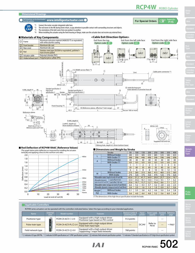
(1) The actuator is limited to being installed horizontally. Please note that it cannot be horizontally wall mounted, vertically mounted, or ceiling mounted. (The same goes for storage.)
(2) When the stroke increases, the maximum speed will drop to prevent the ball screw from reaching the critical rotational speed. Use the actuator specification table below to check the maximum speed at the stroke you desire.
(3) Since the RCP2 series use a pulse motor, the load capacity decreases at high speeds. Check in the Speed vs. Load Capacity graph to see if your desired speed and load capacity are supported.
(4) The load capacity is based on operation at an acceleration of 0.2G. 0.2G is the upper limit for the acceleration.(5) Push motion operation is not supported by this actuator.(6) The cable joint connector is not splash-proof; secure it in a place that is not prone to water spills.
� Speed vs. Load Capacity Due to the characteristics of the pulse motor, the RCP2 series' load capacity decreases at high speeds. In the table below, check if your desired speed and load capacity are supported.
Stroke
Stroke(mm)
Standard priceWithout cover With cover
50 — —100 — —150 — —200 — —250 — —300 — —350 — —400 — —450 — —500 — —550 — —600 — —
Actuator Specifications
� Lead and Payload � Stroke and Maximum Speed
Code explanation ➀ Stroke ➂ Cable length ➃ Options *Push motion operation is not supported by this actuator. (Unit: mm/s)
(Note 1) Please note that the maximum load capacity decreases as the speed increases.
Model number Lead(mm)
Max. Load Capacity (Note 1) Stroke(mm)Horizontal (kg) Vertical (kg)
RCP2W-SA16C-I-86P-8- ➀ -P4- ➁ - ➂ 8 ~25Not Allowed 50~600
(every 50mm)RCP2W-SA16C-I-86P-4- ➀ -P4- ➁ - ➂ 4 ~35
Stroke 50~600(every 50mm)Lead
8 180
4 133
➁Cable Length
Type Cable symbol Standard Price
StandardP (1m) —S (3m) —M (5m) —
Special lengthX06 (6m) ~ X10 (10m) —X11 (11m) ~ X15 (15m) —X16 (16m) ~ X20 (20m) —
Robot Cable
R01 (1m) ~ R03 (3m) —R04 (4m) ~ R05 (5m) —R06 (6m) ~ R10 (10m) —R11 (11m) ~ R15 (15m) —R16 (16m) ~ R20 (20m) —
* See page A-59 for cables for maintenance.
➂OptionsName Option code See page Standard price
With cover CO ➝ A-43 —Non-motor end specification NM ➝ A-52 —
RCP2W-SA16C ROBO Cylinder, Water-Proof Slider Type, Actuator Width 158mm, Pulse Motor, Coupled 86P: Pulse motor, 56 High Output
I: Incremental P4: PCON-CFA N: None P: 1m S: 3m M: 5mX: Custom LengthR: Robot cable
Lead Stroke Cable length OptionsTypeSA16C
Encoder typeI
Motor type86P
Applicable controllerSeriesRCP2WModel
SpecificationItems
50: 50mm
600: 600mm(50mm pitch increments)
* See page Pre-47 for details on the model descriptions.
CO : With cover NM : Non-motor end
8 : 8mm 4 : 4mm
P4
Actuator Specifications
Item DescriptionDrive System Ball screw, ø12mm, rolled C10Positioning repeatability ±0.08mmLost Motion 0.7mm or less Guide ø20 Non-lubricated linear sliding guideAllowable static load moment 20.0N•mAllowable overhang Ma direction 200mm or lessProtective structure IP67Ambient operating temperature/humidity 0 to 40°C, 85% RH max. (Non-condensing)
NoteAdynamicmomentisn'tapplicablefortheSA16Cforstructuralreasons.When an object is to be mounted on the slider, please fix it in a manner so that no moment load is applied in the direction Mb or Mc, and so that the load is distributed evenly.
* Please note that a part of the base plate has changed on the actual product.
RCP2W ROBO Cylinder
Mini
Mini
Mini
SliderType
RodType
Table/Arm/Flat Type
Linear ServoType
Gripper/Rotary Type
Clean-room Type
Splash-ProofType
Pulse Motor
Servo Motor (24V)
Servo Motor (200V)
LinearServo Motor
Standard
Standard
Standard
ControllersIntegrated
ControllersIntegrated
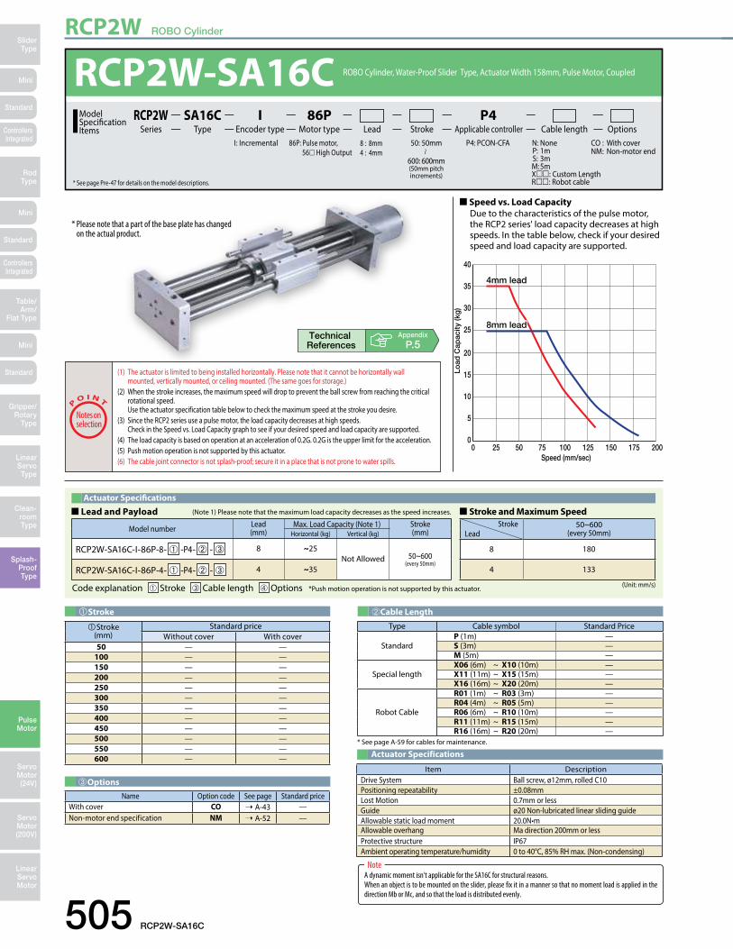
[No Cover]
[With Cover](Optional)
15
20 20
15
ø90
155
(2m)
90130
AB
L
65 654-9 drilled, ø14 counterbore, depth 8.5
2-ø8H7 depth 10
S (Stroke)
Home
3012553 255
130
4-M8 depth 20
105
80
5225
115
100
158
4
Cable jointconnector*1
Actuator cable*3
Base plate(Material: A5052P)
Slider(Material: A6N01S-T15)
Slider rod(Material: SUS304)
Base plate(Material: A5052P)
Guide rod(Material: SUS304)
Cover(Material: SUS304)
Motor cover(Material: SUS304)
SEME ME*2
15
20 20
15
ø90
155
90130
AB
L
65 654-9 drilled, ø14 deep counterbore, depth 8.5
2-ø8H10 depth 10S (Stroke) 3012578
5130
4-M8 depth 20
105
80
774
115
101.
5
166
Home MESEME
4.3±0.2
7.3±0.2
8
6.52
A
Details of A
Dimensional Drawings
2D CAD2D
CADCAD drawings can be downloaded from the website. www.intelligentactuator.com Appendix
P.15
RCP2W-SA16C 506
Stroke 50 100 150 200 250 300 350 400 450 500 550 600L 490 540 590 640 690 740 790 840 890 940 990 1040A 335 385 435 485 535 585 635 685 735 785 835 885B 305 355 405 455 505 555 605 655 705 755 805 855S 50 100 150 200 250 300 350 400 450 500 550 600
Weight without cover (kg) 9 9.4 9.9 10.4 10.9 11.3 11.8 12.3 12.7 13.2 13.7 15.1Weight with cover (kg) 10.5 11.1 11.8 12.5 13.2 13.8 14.6 15.3 15.9 16.6 17.3 18.9
�Dimensions and Weight by Stroke
(*1) Connect the motor and encoder cables here. Please note that the motor cable is the same as the one in the RCP2 series, but that the encoder cable is a dedicated type. *Thecablejointconnector is not splash-proof; therefore, please secure it in a place that is not prone to water spills.
(*2) When homing, the slider moves to the ME; therefore, please watch for any interference with the surrounding objects. ME: Mechanical end SE: Stroke end(*3) Theactuatorcableisnotarobotcable
(flex resistant cable); therefore, please don't use it for movable parts such as in a cable track.
* For the non-motor end model, the dimensions (distance to home) on the motor-side and that on the opposite side are flipped.
The controller for the RCP2W-SA16C type is a dedicated controller.
Applicable Controllers
* indicates I/O type.
Name External view Model number Features Maximum number of positioning points
Input power
Power supply capacity
Standard price
Reference page
Positioner Type PCON-CFA-86PI- -2-0 Positioning is possible
for up to 512 points 512 points DC24V 6A max. — ➝ P607
Note: • Please note that the encoder cable is a dedicated CFA-type cable. (See page A-59.) • Note that a simple absolute unit cannot be used.
RCP2W ROBO Cylinder
507 RCP2W-RA4C
Mini
Mini
Mini
SliderType
RodType
Table/Arm/
Flat Type
Linear ServoType
Gripper/Rotary
Type
Clean-room Type
Splash-ProofType
Pulse Motor
Servo Motor (24V)
Servo Motor (200V)
LinearServo Motor
Standard
Standard
Standard
ControllersIntegrated
ControllersIntegrated
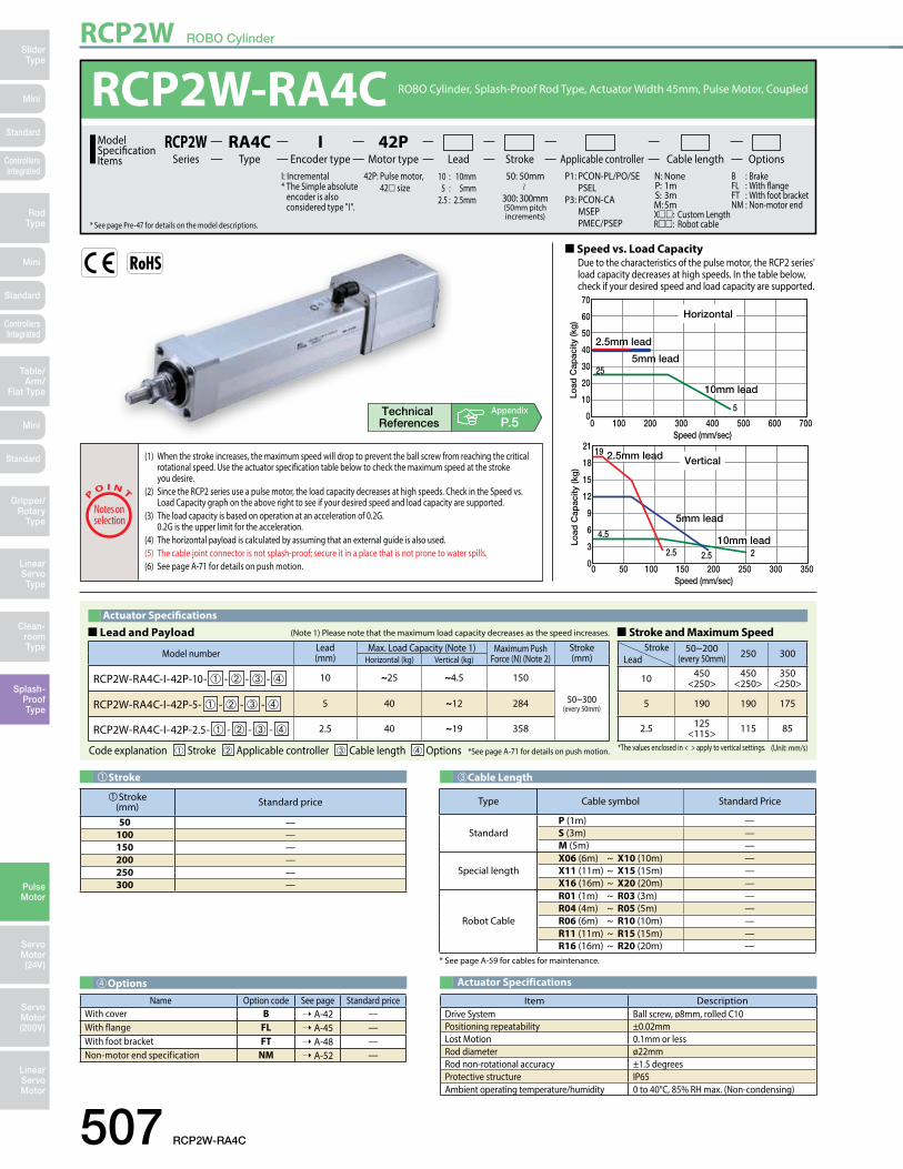
00 100 200
Speed (mm/sec)300 400 500 600 700
10
20
30
40
50
60
70
0 50 100 150 200 250 300 3500
Speed (mm/sec)
3
6
9
12
15
18
21
Vertical
Horizontal
Lead 1010mm lead
2.5mm lead
5mm lead
Lead 10
Lead 2.5
5mm lead
10mm lead
2.5mm lead
25
5
4.5
19
2.5 2.5 2
Load
Cap
acity
(kg
)Lo
ad C
apac
ity (k
g)
00 100 200
Speed (mm/sec)300 400 500 600 700
10
20
30
40
50
60
70
0 50 100 150 200 250 300 3500
Speed (mm/sec)
3
6
9
12
15
18
21
Vertical
Horizontal
Lead 1010mm lead
2.5mm lead
5mm lead
Lead 10
Lead 2.5
5mm lead
10mm lead
2.5mm lead
25
5
4.5
19
2.5 2.5 2
Load
Cap
acity
(kg
)Lo
ad C
apac
ity (k
g)
(1) When the stroke increases, the maximum speed will drop to prevent the ball screw from reaching the critical rotational speed. Use the actuator specification table below to check the maximum speed at the stroke you desire.
(2) Since the RCP2 series use a pulse motor, the load capacity decreases at high speeds. Check in the Speed vs. Load Capacity graph on the above right to see if your desired speed and load capacity are supported.
(3) The load capacity is based on operation at an acceleration of 0.2G. 0.2G is the upper limit for the acceleration.
(4) The horizontal payload is calculated by assuming that an external guide is also used.(5) The cable joint connector is not splash-proof; secure it in a place that is not prone to water spills.(6) See page A-71 for details on push motion.
Stroke
Stroke(mm) Standard price
50 —100 —150 —200 —250 —300 —
Actuator Specifications
Item DescriptionDrive System Ball screw, ø8mm, rolled C10Positioning repeatability ±0.02mmLost Motion 0.1mm or less Rod diameter ø22mmRod non-rotational accuracy ±1.5 degreesProtective structure IP65Ambient operating temperature/humidity 0 to 40°C, 85% RH max. (Non-condensing)
➂Cable Length
Type Cable symbol Standard Price
StandardP (1m) —S (3m) —M (5m) —
Special lengthX06 (6m) ~ X10 (10m) —X11 (11m) ~ X15 (15m) —X16 (16m) ~ X20 (20m) —
Robot Cable
R01 (1m) ~ R03 (3m) —R04 (4m) ~ R05 (5m) —R06 (6m) ~ R10 (10m) —R11 (11m) ~ R15 (15m) —R16 (16m) ~ R20 (20m) —
* See page A-59 for cables for maintenance.
➃OptionsName Option code See page Standard price
With cover B ➝ A-42 —With flange FL ➝ A-45 —With foot bracket FT ➝ A-48 —Non-motor end specification NM ➝ A-52 —
Appendix
P.5
Actuator Specifications
� Lead and Payload
Code explanation ➀ Stroke ➁ Applicable controller ➂ Cable length ➃ Options *See page A-71 for details on push motion.
(Note 1) Please note that the maximum load capacity decreases as the speed increases.
Model number Lead(mm)
Max. Load Capacity (Note 1) Maximum PushForce (N) (Note 2)
Stroke(mm)Horizontal (kg) Vertical (kg)
RCP2W-RA4C-I-42P-10- ➀ - ➁ - ➂ - ➃ 10 ~25 ~4.5 150
50~300(every 50mm)RCP2W-RA4C-I-42P-5- ➀ - ➁ - ➂ - ➃ 5 40 ~12 284
RCP2W-RA4C-I-42P-2.5- ➀ - ➁ - ➂ - ➃ 2.5 40 ~19 358
� Stroke and Maximum Speed
(Unit: mm/s)
Stroke 50~200(every 50mm) 250 300Lead
10 450<250>
450<250>
350<250>
5 190 190 175
2.5 125<115> 115 85
*The values enclosed in < > apply to vertical settings.
RCP2W-RA4C ROBO Cylinder, Splash-Proof Rod Type, Actuator Width 45mm, Pulse Motor, Coupled 42P: Pulse motor, 42 size
I: Incremental* The Simple absolute
encoder is also considered type "I".
P1: PCON-PL/PO/SE PSELP3: PCON-CA MSEP PMEC/PSEP
N: None P: 1m S: 3m M: 5mX: Custom LengthR: Robot cable
Lead Stroke Cable length OptionsTypeRA4C
Encoder typeI
Motor type42P
Applicable controllerSeriesRCP2WModel
SpecificationItems
50: 50mm
300: 300mm(50mm pitch increments)
* See page Pre-47 for details on the model descriptions.
B : Brake FL : With flange FT : With foot bracket NM : Non-motor end
10 : 10mm 5 : 5mm 2.5 : 2.5mm
� Speed vs. Load Capacity Due to the characteristics of the pulse motor, the RCP2 series' load capacity decreases at high speeds. In the table below, check if your desired speed and load capacity are supported.
RCP2W ROBO Cylinder
Mini
Mini
Mini
SliderType
RodType
Table/Arm/Flat Type
Linear ServoType
Gripper/Rotary Type
Clean-room Type
Splash-ProofType
Pulse Motor
Servo Motor (24V)
Servo Motor (200V)
LinearServo Motor
Standard
Standard
Standard
ControllersIntegrated
ControllersIntegrated
Appendix
P.15
Dimensions of Supplied Square Nut for T-slot
(4 nuts provided)Details of A Section
Dimensions of Supplied Nut for Rod TipM4
2.545
361714
492.5
36
6 17
58 90.5
90.5L
242ME*3Home
41
2231.5 2.0
7.5
ST
SEME
(2.3)50
(19.
6)
47 46.5
0.5
0.5
12.5
57
4.3
4.3
24.5
ø38
724
.3
14364947(65.
3)
10.5
1.8
7.3
Brake unit *4
Secure at least 100
Square nut insertion inlet
Actuator cable*5
E�ective T-slot range*4A Sec
4-M8 depth 12
7.5 (width across �ats)*6 Rod
diam
eter
ø22
Intake port*1(360 deg rotatable) Cable joint connector *2
(2m)
M10 X1.25
End bracket (Material: SUS303)Rod (Material: SUS304)
With Brake
M10 X1.25
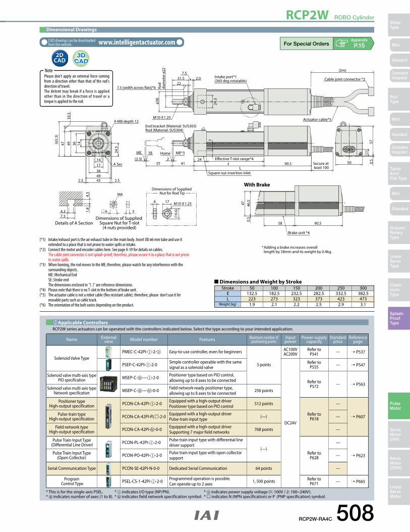
Dimensional Drawings
2D CAD2D
CAD
CAD drawings can be downloaded from the website. www.intelligentactuator.com
RCP2W-RA4C 508
Stroke 50 100 150 200 250 300ℓ 132.5 182.5 232.5 282.5 332.5 382.5L 223 273 323 373 423 473
Weight (kg) 1.9 2.1 2.2 2.5 2.9 3.1
�Dimensions and Weight by Stroke
NotePlease don't apply an external force coming from a direction other than that of the rod's direction of travel.Thedetentmaybreak if a force isappliedother than in the direction of travel or a torque is applied to the rod.
Name Externalview Model number Features Maximum number of
positioning pointsInputpower
Power-supply capacity
Standardprice
Reference page
Solenoid Valve TypePMEC-C-42PI- -2- Easy-to-use controller, even for beginners
3 points
AC100VAC200V
Refer to P541 — ➝ P537
PSEP-C-42PI- -2-0 Simple controller operable with the same signal as a solenoid valve
DC24V
Refer to P555 — ➝ P547
Solenoid valve multi-axis type PIO specification MSEP-C- -~- -2-0 Positioner type based on PIO control,
allowing up to 8 axes to be connected Refer to P572 — ➝ P563
Solenoid valve multi-axis type Network specification MSEP-C- -~- -0-0 Field network-ready positioner type,
allowing up to 8 axes to be connected 256 points
Positioner typeHigh-output specification PCON-CA-42PI- -2-0 Equipped with a high-output driver
Positioner type based on PIO control 512 points
Refer to P618
—
➝ P607Pulse-train typeHigh-output specification PCON-CA-42PI-PL-2-0 Equipped with a high-output driver
Pulse-train input type (—) —
Field network typeHigh-output specification PCON-CA-42PI- -0-0 Equipped with a high-output driver
Supporting 7 major field networks 768 points —
Pulse Train Input Type (Differential Line Driver) PCON-PL-42PI- -2-0 Pulse train input type with differential line
driver support(—)
Refer to P628
—
➝ P623Pulse Train Input Type (Open Collector) PCON-PO-42PI- -2-0 Pulse train input type with open collector
support —
Serial Communication Type PCON-SE-42PI-N-0-0 Dedicated Serial Communication 64 points —
Program Control Type PSEL-CS-1-42PI- -2-0 Programmed operation is possible.
Can operate up to 2 axes 1, 500 points Refer to P671 — ➝ P665
* This is for the single-axis PSEL. * indicates I/O type (NP/PN). * indicates power supply voltage (1: 100V / 2: 100~240V).* indicates number of axes (1 to 8). * indicates field network specification symbol. * indicates N (NPN specification) or P (PNP specification) symbol.
RCP2W series actuators can be operated with the controllers indicated below. Select the type according to your intended application.Applicable Controllers
* Adding a brake increases overall length by 58mm and its weight by 0.4kg.
(*1) Intake/exhaustportistheairexhausttubeinthemainbody.InsertODø6mmtubeanduseit extended to a place that is not prone to water spills or intake.(*2) Connect the motor and encoder cables here. See page A-59 for details on cables. Thecablejointconnectorisnotsplash-proof;therefore,pleasesecureitinaplacethatisnotprone to water spills.(*3) When homing, the rod moves to the ME; therefore, please watch for any interference with the surrounding objects. ME: Mechanical End SE: Stroke end Thedimensionsenclosedin"()"arereferencedimensions. (*4) PleasenotethatthereisnoT-slotinthebottomofbrakeunit. (*5) Theactuatorcableisnotarobotcable(flexresistantcable);therefore,pleasedon'tuseitfor movable parts such as cable track. (*6) Theorientationoftheboltvariesdependingontheproduct.
RCP2W ROBO Cylinder
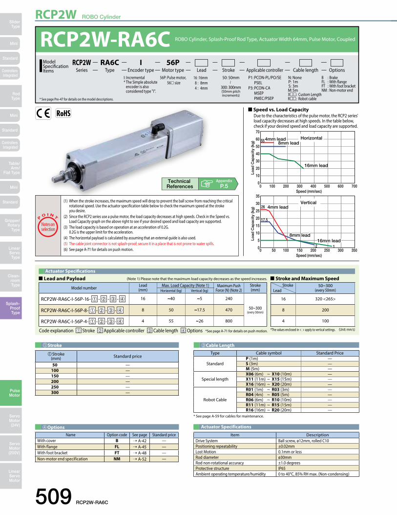
509 RCP2W-RA6C
Mini
Mini
Mini
SliderType
RodType
Table/Arm/
Flat Type
Linear ServoType
Gripper/Rotary
Type
Clean-room Type
Splash-ProofType
Pulse Motor
Servo Motor (24V)
Servo Motor (200V)
LinearServo Motor
Standard
Standard
Standard
ControllersIntegrated
ControllersIntegrated
00 100 200
Speed (mm/sec)300 400 500 600 700
10
20
30
40
50
60
70
0 50 100 150 200 250 300 3500
Speed (mm/sec)
5
10
15
20
25
30
35
Vertical
Horizontal
16mm lead
8mm lead4mm lead
16mm lead
8mm lead4mm lead
8mm lead16mm lead
4mm lead
8mm lead16mm lead
4mm lead
55
2 1
26
17.5Lo
ad C
apac
ity (k
g)
Load
Cap
acity
(kg
)
00 100 200
Speed (mm/sec)300 400 500 600 700
10
20
30
40
50
60
70
0 50 100 150 200 250 300 3500
Speed (mm/sec)
5
10
15
20
25
30
35
Vertical
Horizontal
16mm lead
8mm lead4mm lead
16mm lead
8mm lead4mm lead
8mm lead16mm lead
4mm lead
8mm lead16mm lead
4mm lead
55
2 1
26
17.5
Load
Cap
acity
(kg
)Lo
ad C
apac
ity (k
g)
(1) When the stroke increases, the maximum speed will drop to prevent the ball screw from reaching the critical rotational speed. Use the actuator specification table below to check the maximum speed at the stroke you desire.
(2) Since the RCP2 series use a pulse motor, the load capacity decreases at high speeds. Check in the Speed vs. Load Capacity graph on the above right to see if your desired speed and load capacity are supported.
(3) The load capacity is based on operation at an acceleration of 0.2G. 0.2G is the upper limit for the acceleration.
(4) The horizontal payload is calculated by assuming that an external guide is also used.(5) The cable joint connector is not splash-proof; secure it in a place that is not prone to water spills.(6) See page A-71 for details on push motion.
� Speed vs. Load Capacity Due to the characteristics of the pulse motor, the RCP2 series' load capacity decreases at high speeds. In the table below, check if your desired speed and load capacity are supported.
Stroke
Stroke(mm) Standard price
50 —100 —150 —200 —250 —300 —
Actuator Specifications
� Lead and Payload
Code explanation ➀ Stroke ➁ Applicable controller ➂ Cable length ➃ Options *See page A-71 for details on push motion.
(Note 1) Please note that the maximum load capacity decreases as the speed increases.
Model number Lead(mm)
Max. Load Capacity (Note 1) Maximum PushForce (N) (Note 2)
Stroke(mm)Horizontal (kg) Vertical (kg)
RCP2W-RA6C-I-56P-16- ➀ - ➁ - ➂ - ➃ 16 ~40 ~5 240
50~300(every 50mm)RCP2W-RA6C-I-56P-8- ➀ - ➁ - ➂ - ➃ 8 50 ~17.5 470
RCP2W-RA6C-I-56P-4- ➀ - ➁ - ➂ - ➃ 4 55 ~26 800
Actuator Specifications
Item DescriptionDrive System Ball screw, ø12mm, rolled C10Positioning repeatability ±0.02mmLost Motion 0.1mm or less Rod diameter ø30mmRod non-rotational accuracy ±1.0 degreesProtective structure IP65Ambient operating temperature/humidity 0 to 40°C, 85% RH max. (Non-condensing)
➂Cable Length
Type Cable symbol Standard Price
Standard P (1m) —S (3m) —M (5m) —
Special lengthX06 (6m) ~ X10 (10m) —X11 (11m) ~ X15 (15m) —X16 (16m) ~ X20 (20m) —
Robot Cable
R01 (1m) ~ R03 (3m) —R04 (4m) ~ R05 (5m) —R06 (6m) ~ R10 (10m) —R11 (11m) ~ R15 (15m) —R16 (16m) ~ R20 (20m) —
* See page A-59 for cables for maintenance.
➃OptionsName Option code See page Standard price
With cover B ➝ A-42 —With flange FL ➝ A-45 —With foot bracket FT ➝ A-48 —Non-motor end specification NM ➝ A-52 —
Appendix
P.5
� Stroke and Maximum Speed
(Unit: mm/s)
Stroke 50~300(every 50mm)Lead
16 320 <265>
8 200
4 100
*The values enclosed in < > apply to vertical settings.
RCP2W-RA6C ROBO Cylinder, Splash-Proof Rod Type, Actuator Width 64mm, Pulse Motor, Coupled 56P: Pulse motor, 56 size
I: Incremental* The Simple absolute
encoder is also considered type "I".
P1: PCON-PL/PO/SE PSELP3: PCON-CA MSEP PMEC/PSEP
N: None P: 1m S: 3m M: 5mX: Custom LengthR: Robot cable
Lead Stroke Cable length OptionsTypeRA6C
Encoder typeI
Motor type56P
Applicable controllerSeriesRCP2WModel
SpecificationItems
50: 50mm
300: 300mm(50mm pitch increments)
* See page Pre-47 for details on the model descriptions.
B : Brake FL : With flange FT : With foot bracket NM : Non-motor end
16 : 16mm 8 : 8mm 4 : 4mm

RCP2W ROBO Cylinder
Mini
Mini
Mini
SliderType
RodType
Table/Arm/Flat Type
Linear ServoType
Gripper/Rotary Type
Clean-room Type
Splash-ProofType
Pulse Motor
Servo Motor (24V)
Servo Motor (200V)
LinearServo Motor
Standard
Standard
Standard
ControllersIntegrated
ControllersIntegrated
Appendix
P.15
Dimensions of Supplied Square Nut for T-slot
(4 nuts provided)Details of A Section
Dimensions of Supplied Nut
for Rod TipM14X1.5
M14X1.5
8 22
(25.
4)
M6
5106.5
2 6450
25
19 A Sec. (4.4)
ME SE
ST4
55
10.52.542
30.5
72.5
16 17116
68
116
L
Home ME*3
2
8
32
19506411
(82.
3)
2.6
64
1275
63.5
0.5
10.5
Hex Socket Bolt:4-M5X20
4-M8 depth 15
Brake unit*4
Square nut insertion inlet
E�ective T-slot range*4Secure at least 100
Actuator cable*5
Intake port*1(360 deg rotatable)
Cable joint connector*29.5 (width across �ats)*6
Rod
diam
eter
ø30
ø48
End bracket (Material: SUS303)Rod (Material: SUS304)
With Brake
(2m)
Dimensional Drawings
2D CAD2D
CAD
CAD drawings can be downloaded from the website. www.intelligentactuator.com
RCP2W-RA6C 510
Stroke 50 100 150 200 250 300ℓ 1350 200 250 300 350 400L 266 316 366 416 466 516
Weight (kg) 3.5 4.0 4.5 5.0 5.5 6.0
�Dimensions and Weight by Stroke
Name Externalview Model number Features Maximum number of
positioning pointsInputpower
Power-supply capacity
Standardprice
Reference page
Solenoid Valve TypePMEC-C-56PI- -2- Easy-to-use controller, even for beginners
3 points
AC100VAC200V
Refer to P541 — ➝ P537
PSEP-C-56PI- -2-0 Simple controller operable with the same signal as a solenoid valve
DC24V
Refer to P555 — ➝ P547
Solenoid valve multi-axis type PIO specification MSEP-C- -~- -2-0 Positioner type based on PIO control,
allowing up to 8 axes to be connected Refer to P572 — ➝ P563
Solenoid valve multi-axis type Network specification MSEP-C- -~- -0-0 Field network-ready positioner type,
allowing up to 8 axes to be connected 256 points
Positioner typeHigh-output specification PCON-CA-56PI- -2-0 Equipped with a high-output driver
Positioner type based on PIO control 512 points
Refer to P618
—
➝ P607Pulse-train typeHigh-output specification PCON-CA-56PI-PL-2-0 Equipped with a high-output driver
Pulse-train input type (—) —
Field network typeHigh-output specification PCON-CA-56PI- -0-0 Equipped with a high-output driver
Supporting 7 major field networks 768 points —
Pulse Train Input Type (Differential Line Driver) PCON-PL-56PI- -2-0 Pulse train input type with differential line
driver support(—)
Refer to P628
—
➝ P623Pulse Train Input Type (Open Collector) PCON-PO-56PI- -2-0 Pulse train input type with open collector
support —
Serial Communication Type PCON-SE-56PI-N-0-0 Dedicated Serial Communication 64 points —
Program Control Type PSEL-CS-1-56PI- -2-0 Programmed operation is possible.
Can operate up to 2 axes 1,500 points Refer to P671 — ➝ P665
* This is for the single-axis PSEL. * indicates I/O type (NP/PN). * indicates power supply voltage (1: 100V / 2: 100~240V).* indicates number of axes (1 to 8). * indicates field network specification symbol. * indicates N (NPN specification) or P (PNP specification) symbol.
RCP2W series actuators can be operated with the controllers indicated below. Select the type according to your intended application.Applicable Controllers
* Adding a brake increases overall length by 72.5mm and its weight by 0.9kg.
(*1) Intake/exhaustportistheairexhausttubeinthemainbody.InsertODø6mmtubeanduseit extended to a place that is not prone to water spills or intake.(*2) Connect the motor and encoder cables here. See page A-59 for details on cables. Thecablejointconnectorisnotsplash-proof;therefore,pleasesecureitinaplacethatisnotprone to water spills.(*3) When homing, the rod moves to the ME; therefore, please watch for any interference with the surrounding objects. ME: Mechanical End SE: Stroke end Thedimensionsenclosedin"()"arereferencedimensions. (*4) PleasenotethatthereisnoT-slotinthebottomofbrakeunit. (*5) Theactuatorcableisnotarobotcable(flexresistantcable);therefore,pleasedon'tuseitfor movable parts such as cable track. (*6) Theorientationoftheboltvariesdependingontheproduct.
NotePlease don't apply an external force coming from a direction other than that of the rod's direction of travel.Thedetentmaybreakifaforceisappliedotherthaninthe direction of travel or a torque is applied to the rod.

RCP2W ROBO Cylinder
Mini
Mini
Mini
SliderType
RodType
Table/Arm/
Flat Type
Linear ServoType
Gripper/Rotary
Type
Clean-room Type
Splash-ProofType
Pulse Motor
Servo Motor (24V)
Servo Motor (200V)
LinearServo Motor
Standard
Standard
Standard
ControllersIntegrated
ControllersIntegrated
Speed (mm/s)
Speed (mm/s)
10
100
1000
0 50 100 150 200 250 300
Horizontal
5mm lead
10mm lead
2.5mm lead
5mm lead
5mm lead5mm lead
10mm lead
10mm lead10mm lead
2.5mm lead
2.5mm lead2.5mm lead
1
10
100
1000
0 50 100 150 200
Vertical
300
150
80
15
150
80
3
610
Load
Cap
acity
(kg
)Lo
ad C
apac
ity (k
g)
Speed (mm/s)
Speed (mm/s)
10
100
1000
0 50 100 150 200 250 300
Horizontal
5mm lead
10mm lead
2.5mm lead
5mm lead
5mm lead5mm lead
10mm lead
10mm lead10mm lead
2.5mm lead
2.5mm lead2.5mm lead
1
10
100
1000
0 50 100 150 200
Vertical
300
150
80
15
150
80
3
610
Load
Cap
acity
(kg
)Lo
ad C
apac
ity (k
g)
(1) Minimum speed is set for each lead. (Lead 10: 10mm/s, Lead 5: 5mm/s, Lead 2.5: 1mm/s) Please note that vibration etc. may occur when operated at the minimum speed. (2) Since the RCP2 series use a pulse motor, the load capacity decreases at high speeds. Check the Speed vs.
Load Capacity on the right hand graph to see if your desired speed and load capacity are supported.(3) The load capacity is based on operation at lead 10: 0.04G, lead 5: 0.02G and lead 2.5: 0.01G. These values are the upper limits for the acceleration.
Also, this is when the load capacity is attached to the external guide. The rotation stopper may break if an external force coming from a direction other than that of rod's direction of travel is applied.
(4) The cable joint connector is not splash-proof; secure it in a place that is not prone to water spills.(5) See page A-71 for details on push motion.
� Speed vs. Load Capacity Due to the characteristics of the pulse motor, the RCP2 series' load capacity decreases at high speeds. In the table below, check if your desired speed and load capacity are supported.
511 RCP2W-RA10C
Actuator Specifications
Item DescriptionDrive System Ball screw, rolled C10Positioning repeatability ±0.02mmLost Motion 0.1mm or less Rod diameter ø40mmRod non-rotational accuracy ±1.0 degreesProtective structure IP54Ambient operating temperature/humidity 0 to 40°C, 85% RH max. (Non-condensing)
OptionsName Option code See page Standard price
Connector cable outlet direction changed A1~A3 ➝ A-41 —Brake B ➝ A-42 —With flange FL ➝ A-46 —With foot bracket FT ➝ A-48 —
Appendix
P.5
RCP2W-RA10C 86P: Pulse motor, 86 size
I: Incremental Type
P4: PCON-CFA N: None P: 1m S: 3m M: 5mX: Custom LengthR: Robot cable
Lead Stroke Cable length OptionsTypeRA10C
Encoder typeI
Motor type86P
Applicable controllerSeriesRCP2WModel
SpecificationItems
50: 50mm
300: 300mm(50mm pitch increments)
* See page Pre-47 for details on the model descriptions.
A1~A3 : Connector Cable Cable outlet direction changed B : Brake FL : With flange FT : With foot bracket
P4
10 : 10mm 5 : 5mm 2.5 : 2.5mm
ROBO Cylinder, High-Thrust Dust-Proof Rod Type, Actuator Width 100mm, Pulse Motor, Coupled
Actuator Specifications
� Lead and Payload
Code explanation ➀ Stroke ➁ Cable length ➂ Options *See page A-71 for details on push motion.
(Note 1) Please note that the maximum load capacity decreases as the speed increases.
Model number Lead(mm)
Max. Load Capacity (Note 1) Maximum PushForce (N) (Note 2)
Stroke(mm)Horizontal (kg) Vertical (kg)
RCP2W-RA10C-I-86P-10- ➀ -P4- ➁ - ➂ 10 ~80 ~80 1500
50~300(every 50mm)RCP2W-RA10C-I-86P-5- ➀ -P4- ➁ - ➂ 5 150 ~100 3000
RCP2W-RA10C-I-86P-2.5- ➀ -P4- ➁ - ➂ 2.5 300 ~150 6000
� Stroke and Maximum SpeedStroke 50~300
(every 50mm)Lead
10 250 <167>
5 125
2.5 63
(Unit: mm/s)*The values enclosed in < > apply to vertical settings.
Stroke
Stroke(mm) Standard price
50 —100 —150 —200 —250 —300 —
Type Cable symbol Standard Price
StandardP (1m) —S (3m) —M (5m) —
Special lengthX06 (6m) ~ X10 (10m) —X11 (11m) ~ X15 (15m) —X16 (16m) ~ X20 (20m) —
Robot Cable
R01 (1m) ~ R03 (3m) —R04 (4m) ~ R05 (5m) —R06 (6m) ~ R10 (10m) —R11 (11m) ~ R15 (15m) —R16 (16m) ~ R20 (20m) —
* See page A-59 for cables for maintenance.
Cable Length
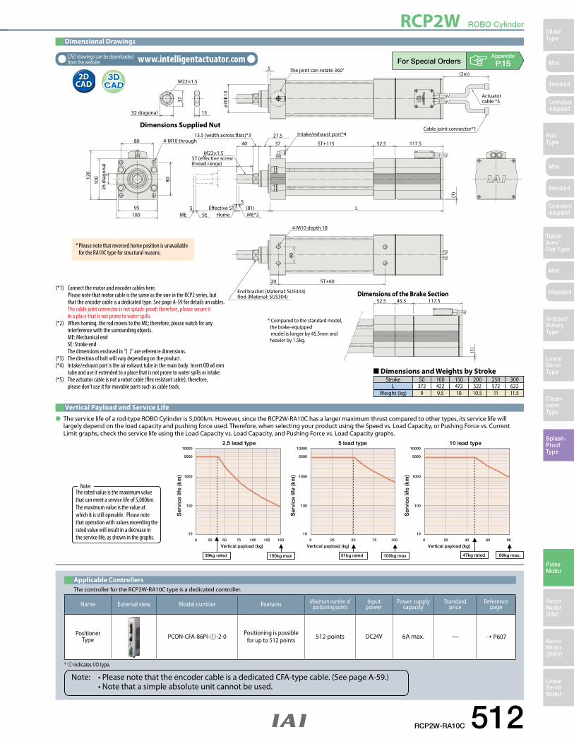
RCP2W ROBO Cylinder
Mini
Mini
Mini
SliderType
RodType
Table/Arm/Flat Type
Linear ServoType
Gripper/Rotary Type
Clean-room Type
Splash-ProofType
Pulse Motor
Servo Motor (24V)
Servo Motor (200V)
LinearServo Motor
Standard
Standard
Standard
ControllersIntegrated
ControllersIntegrated
Appendix
P.15
52.5 45.5 117.5
(1)
Dimensions of the Brake Section
ST+11537
37 (e�ective screw thread range)
26 d
iago
nal
L
117.5
(2m)
52.5
95
80
32 diagonal
M22×1.5
37
13
4-M10 depth 18
End bracket (Material: SUS303)Rod (Material: SUS304)
100
100 Home ME*2ME SE
(1)
ø70h
10
120
4-M10 through 40
M22×1.5
13.5 (width across �ats)*3
5
27.5
Intake/exhaust port*4
5 E�ective ST (81)5
ST+6020
40
80
Dimensions Supplied NutCable joint connector*1
Actuatorcable *5
The joint can rotate 360°
* Compared to the standard model, the brake-equipped model is longer by 45.5mm and heavier by 1.5kg.
10000
5000
1000
100
10
Vertical payload (kg)
2.5 lead type 5 lead type 10 lead type
39kg rated 51kg rated150kg max 100kg max 47kg rated 80kg max.
0 25 50 75 100 125 150
10000
5000
1000
100
10
Vertical payload (kg)0 25 50 75 100
Vertical payload (kg)20 40 60 80
10000
5000
1000
100
10
0
Ser
vice
life
(km
)
Ser
vice
life
(km
)
Ser
vice
life
(km
)
Dimensional Drawings
2D CAD2D
CAD
CAD drawings can be downloaded from the website. www.intelligentactuator.com
RCP2W-RA10C 512
(*1) Connect the motor and encoder cables here. Please note that motor cable is the same as the one in the RCP2 series, but that the encoder cable is a dedicated type. See page A-59 for details on cables. Thecablejointconnectorisnotsplash-proof;therefore,pleasesecureit in a place that is not prone to water spills.(*2) When homing, the rod moves to the ME; therefore, please watch for any interference with the surrounding objects. ME: Mechanical end SE: Stroke end Thedimensionsenclosedin"()"arereferencedimensions.(*3) Thedirectionofboltwillvarydependingontheproduct.(*4) Intake/exhaustportistheairexhausttubeinthemainbody.InsertODø6mm tube and use it extended to a place that is not prone to water spills or intake. (*5) Theactuatorcableisnotarobotcable(flexresistantcable);therefore, please don't use it for movable parts such as cable track.
The controller for the RCP2W-RA10C type is a dedicated controller.
Applicable Controllers
* indicates I/O type.
Name External view Model number Features Maximum number of positioning points
Input power
Power supply capacity
Standard price
Reference page
Positioner Type PCON-CFA-86PI- -2-0 Positioning is possible
for up to 512 points 512 points DC24V 6A max. — ➝ P607
Note: • Please note that the encoder cable is a dedicated CFA-type cable. (See page A-59.) • Note that a simple absolute unit cannot be used.
* Please note that reversed home position is unavailable for the RA10C type for structural reasons.
Theratedvalueisthemaximumvaluethat can meet a service life of 5,000km. Themaximumvalueisthevalueatwhich it is still operable. Please note that operation with values exceeding the rated value will result in a decrease in the service life, as shown in the graphs.
Note:
Vertical Payload and Service Life
● The service life of a rod-type ROBO Cylinder is 5,000km. However, since the RCP2W-RA10C has a larger maximum thrust compared to other types, its service life will largely depend on the load capacity and pushing force used. Therefore, when selecting your product using the Speed vs. Load Capacity, or Pushing Force vs. Current Limit graphs, check the service life using the Load Capacity vs. Load Capacity, and Pushing Force vs. Load Capacity graphs.
■ Dimensions and Weights by StrokeStroke 50 100 150 200 250 300
L 372 422 472 522 572 622Weight (kg) 9 9.5 10 10.5 11 11.5

RCP2W ROBO Cylinder
513 RCP2W-GRSS
Mini
Mini
Mini
SliderType
RodType
Table/Arm/
Flat Type
Linear ServoType
Gripper/Rotary
Type
Clean-room Type
Splash-ProofType
Pulse Motor
Servo Motor (24V)
Servo Motor (200V)
LinearServo Motor
Standard
Standard
Standard
ControllersIntegrated
ControllersIntegrated
L2
L1
Grip
ping
forc
e (N)
Current Limit (% ratio)
00 10 20 30 40 50 60 70
2
4
68
1012
14
16
Appendix
P.5
�Gripping Force Adjustment The gripping (pushing) force can be adjusted freely within the range of current limits of 20% to 70%.
* Operate with the L1 distance up to 40mm.* The gripping force value in the graph below is when both L1 and L2 are at 0 mm. (For gripping force reference per L1 distance, see page A-87.) The gripping force value is the sum of gripping forces of both fingers.
* The gripping force graph above shows the number of references. Please allow margins up to ± 15%.
* Please note that, when gripping (pushing), the speed is fixed at 5mm/s.
(1) The maximum opening/closing speed indicates the operating speed on one side. The relative operating speed is twice this value.
(2) The maximum gripping force is the sum of the gripping forces of both fingers, at a gripping point where there is no offset or overhang distance. The work piece weight that can be actually moved depends on the friction coefficient between the gripper fingers and the work piece, as well as on the shape of the work piece. As a rough guide, a work piece's weight should not exceed 1/10 to 1/20 of the gripping force. (See page A-86 for details.)
(3) The rated acceleration while moving is 0.3G.(4) Please note that the product has no splash-proof function.
➁Cable LengthType Cable symbol Standard price
Standard(Robot Cables)
P (1m) —S (3m) —M (5m) —
Special lengthX06 (6m) ~ X10 (10m) —X11 (11m) ~ X15 (15m) —X16 (16m) ~ X20 (20m) —
* The standard cable is the motor-encoder integrated robot cable.* See page A-59 for cables for maintenance.
➂OptionsName Option code See page Standard price
Non-motor end specification NM ➝ A-52 —Flange bracket FB ➝ A-43 —Shaft bracket SB ➝ A-55 —
Actuator Specifications � Lead and Payload � Stroke and Maximum Speed
Code explanation ➀ Applicable controller ➁ Cable length ➂ Options (Unit: mm/s)
Stroke 8 (mm)Deceleration ratio
30 78
Model numberDeceleration
RatioMaximum Gripping
Force (N)Stroke(mm)
RCP2W-GRSS-I-20P-30-8- ➀ - ➁ - ➂ 30 14(7 per side)
8(4 per side)
Stroke
Stroke (mm) Standard price
8 —
Actuator Specifications
Item DescriptionDrive System Worm gear + helical gear + helical rackPositioning repeatability ±0.01mmBacklash 0.2mm or less per side (constantly pressed out by a spring)Lost motion 0.05mm or less per sideGuide Linear guideAllowable static load moment Ma: 0.5 N·m, Mb: 0.5 N·m, Mc: 1.5 N·mWeight 0.2kgAmbient operating temperature, humidity 0 to 40oC, 85% RH or less (Non-condensing)
RCP2W-GRSS ROBO Cylinder, 2-Finger Gripper, Mini Slider Type, Actuator Width 42mm, Pulse Motor 20P: Pulse motor, 20 size
I: Incremental* The Simple absolute
encoder is also considered type "I".
P1: PCON-PL/PO/SE PSELP3: PCON-CA MSEP PMEC/PSEP
N: None P: 1m S: 3m M: 5mX: Custom Length
Deceleration Ratio Stroke Cable length OptionsTypeGRSS
Encoder typeI
Motor type20P
Applicable controllerSeriesRCP2WModel
SpecificationItems
8: 8mm(4mm per side)
* See page Pre-47 for details on the model descriptions.
NM : Non-motor end FB : Flange bracket SB : Shaft bracket
30: 1/30 deceleration ratio
30 8

RCP2W ROBO Cylinder
Mini
Mini
Mini
SliderType
RodType
Table/Arm/Flat Type
Linear ServoType
Gripper/Rotary Type
Clean-room Type
Splash-ProofType
Pulse Motor
Servo Motor (24V)
Servo Motor (200V)
LinearServo Motor
Standard
Standard
Standard
ControllersIntegrated
ControllersIntegrated
Appendix
P.15
Secu
re a
t lea
st 1
00
Cable jointconnector*1
11+0 −0
.05
94M
AX
22M
IN 1
4
46
178.5
2−3+0.05 0 depth 3
(same as the opposite side)
34
4
4
3+0.05 0 depth 3
8-M3 depth 5(same as the opposite side) 4-M3 depth 5
2-ø3+0.03 0 depth 3
(same as the opposite side) ø3
+0.03 0 depth 3
42
3633
178.5
4
3+0.05 0 depth 3
4-M3 depth 5
ø3+0.03 0 depth 3
24
30
5
ø4
961.5
2.5 6 57.5
2×2-M3(same as the opposite side)
35
17
Dimensional Drawings
2D CAD2D
CAD
CAD drawings can be downloaded from the website. www.intelligentactuator.com
RCP2W-GRSS 514
Name Externalview Model number Features Maximum number of
positioning pointsInputpower
Power-supply capacity
Standardprice
Reference page
Solenoid Valve TypePMEC-C-20PI- -2- Easy-to-use controller, even for beginners
3 points
AC100VAC200V
Refer to P541 — ➝ P537
PSEP-C-20PI- -2-0 Simple controller operable with the same signal as a solenoid valve
DC24V
Refer to P555 — ➝ P547
Solenoid valve multi-axis type PIO specification MSEP-C- -~- -2-0 Positioner type based on PIO control,
allowing up to 8 axes to be connected Refer to P572 — ➝ P563
Solenoid valve multi-axis type Network specification MSEP-C- -~- -0-0 Field network-ready positioner type,
allowing up to 8 axes to be connected 256 points
Positioner typeHigh-output specification PCON-CA-20PI- -2-0 Equipped with a high-output driver
Positioner type based on PIO control 512 points
Refer to P618
—
➝ P607Pulse-train typeHigh-output specification PCON-CA-20PI-PL-2-0 Equipped with a high-output driver
Pulse-train input type (—) —
Field network typeHigh-output specification PCON-CA-20PI- -0-0 Equipped with a high-output driver
Supporting 7 major field networks 768 points —
Pulse Train Input Type (Differential Line Driver) PCON-PL-20PI- -2-0 Pulse train input type with differential line
driver support(—)
Refer to P628
—
➝ P623Pulse Train Input Type (Open Collector) PCON-PO-20PI- -2-0 Pulse train input type with open collector
support —
Serial Communication Type PCON-SE-20PI-N-0-0 Dedicated Serial Communication 64 points —
Program Control Type PSEL-CS-1-20PI- -2-0 Programmed operation is possible.
Can operate up to 2 axes 1,500 points Refer to P671 — ➝ P665
* This is for the single-axis PSEL. * indicates I/O type (NP/PN). * indicates power supply voltage (1: 100V / 2: 100~240V).* indicates number of axes (1 to 8). * indicates field network specification symbol. * indicates N (NPN specification) or P (PNP specification) symbol.
RCP2W series actuators can be operated with the controllers indicated below. Select the type according to your intended application.Applicable Controllers
Weight (kg) 0.2
* Theopeningsideoftheslideristhehomeposition. (*1) Connect the motor-encoder integrated cable here. See page A-59 for details on cables.

RCP2W ROBO Cylinder
515 RCP2W-GRLS
Mini
Mini
Mini
SliderType
RodType
Table/Arm/
Flat Type
Linear ServoType
Gripper/Rotary
Type
Clean-room Type
Splash-ProofType
Pulse Motor
Servo Motor (24V)
Servo Motor (200V)
LinearServo Motor
Standard
Standard
Standard
ControllersIntegrated
ControllersIntegrated
L
Grip
ping
forc
e (N)
Current Limit (% ratio)
00 10 20 30 40 50 60 70
1
2
3
4
5
6
7
(1) The maximum opening/closing speed indicates the operating speed on one side. The relative operating speed is twice this value.
(2) The maximum gripping force is the sum of the gripping forces of both fingers, at a gripping point where there is no offset or overhang distance. The work piece weight that can be actually moved depends on the friction coefficient between the gripper fingers and the work piece, as well as on the shape of the work piece. As a rough guide, a work piece's weight should not exceed 1/10 to 1/20 of the gripping force. (See page A-86 for details.)
(3) The rated acceleration while moving is 0.3G.(4) Please note that the product has no splash-proof function.
Cable LengthType Cable symbol Standard price
Standard(Robot Cables)
P (1m) —S (3m) —M (5m) —
Special lengthX06 (6m) ~ X10 (10m) —X11 (11m) ~ X15 (15m) —X16 (16m) ~ X20 (20m) —
* The standard cable is the motor-encoder integrated robot cable.* See page A-59 for cables for maintenance.
OptionsName Option code See page Standard price
Non-motor end specification NM ➝ A-52 —Flange bracket FB ➝ A-43 —Shaft bracket SB ➝ A-55 —
Actuator Specifications
Item DescriptionDrive System worm gear + helical gear Positioning repeatability ±0.01mmBacklash 1 degree or less per side (constantly pressed out by a spring)Lost motion 0.1 deg (per side) or lessGuide —Allowable static load moment —Weight 0.2kgAmbient operating temperature, humidity 0 to 40oC, 85% RH or less (Non-condensing)
Stroke
Stroke (degrees) Standard price
180 —
� Stroke and Maximum Speed
Code explanation ➀ Applicable controller ➁ Cable length ➂ Options (Unit: degree/s)
Stroke 180 (degrees)Deceleration ratio
30 600
Model number Deceleration Ratio Maximum Gripping Force (N)
Stroke(degrees)
RCP2W-GRLS-I-20P-30-180- ➀ - ➁ - ➂ 30 6.4(3.2 per side)
180(90 per side)
� Lead and PayloadActuator Specifications
�Gripping Force Adjustment The gripping (pushing) force can be adjusted freely within the range of current limits of 20% to 70%.
* The gripping force of the graph below is measured on the top face of the lever. The actual gripping force drops in inverse proportion to the distance from the opening/closing fulcrum. Calculate the effective gripping force using the formula below.
Effective gripping force (GRLS ) = F x 15.5/ (L + 15.5)* In the graph below, the gripping force value is the sum of gripping forces of both fingers.
* The gripping force graph above shows the number of references. Please allow margins up to ± 15%.
* Please note that, when gripping (pushing), the speed is fixed at 5 degrees/s.
Appendix
P.5
RCP2W-GRLS ROBO Cylinder, 2-Finger Gripper, Mini Lever Type, Actuator Width 42mm, Pulse Motor,
30 : 1/30 deceleration ratio
20P: Pulse motor, 20 size
I: Incremental* The Simple absolute
encoder is also considered type "I".
P1: PCON-PL/PO/SE PSELP3: PCON-CA PMEC/PSEP MSEP
N: None P: 1m S: 3m M: 5mX: Custom Length
Deceleration Ratio Stroke Cable length OptionsTypeGRLS
Encoder typeI
Motor type20P
Applicable controllerSeriesRCP2WModel
SpecificationItems
180: 180 degrees
(90 degrees per side)
* See page Pre-47 for details on the model descriptions.
NM: Non-motor endFB: Flange bracketSB: Shaft bracket
30 180
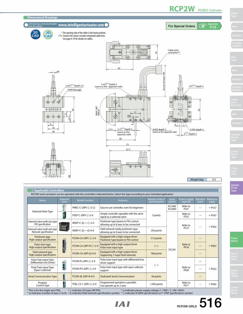
RCP2W ROBO Cylinder
Mini
Mini
Mini
SliderType
RodType
Table/Arm/Flat Type
Linear ServoType
Gripper/Rotary Type
Clean-room Type
Splash-ProofType
Pulse Motor
Servo Motor (24V)
Servo Motor (200V)
LinearServo Motor
Standard
Standard
Standard
ControllersIntegrated
ControllersIntegrated
Appendix
P.15
Secu
re a
t lea
st 1
00
Cable jointconnector*1
15.5
MA
X 18
0°M
IN 0
°
73
9
18 +
0 −0.0
5
34
Depth 3
4
ø4
178.5
4Depth 32-3
(same as the opposite side)
4-M3 depth 5
49
42
2-ø3
3
+0.030 +0.03
0
+0.050
+0.050
+0.030
Depth 3(same as the opposite side) ø3 Depth 3
8-M3 depth 5(same as the opposite side)
45
67.5
24
2-ø4 Depth 2.5
4-M4 through
18
9
36
9
55
35
Dimensional Drawings
2D CAD2D
CAD
CAD drawings can be downloaded from the website. www.intelligentactuator.com
RCP2W-GRLS 516
Name Externalview Model number Features Maximum number of
positioning pointsInputpower
Power-supply capacity
Standardprice
Reference page
Solenoid Valve TypePMEC-C-20PI- -2- Easy-to-use controller, even for beginners
3 points
AC100VAC200V
Refer to P541 — ➝ P537
PSEP-C-20PI- -2-0 Simple controller operable with the same signal as a solenoid valve
DC24V
Refer to P555 — ➝ P547
Solenoid valve multi-axis type PIO specification MSEP-C- -~- -2-0 Positioner type based on PIO control,
allowing up to 8 axes to be connected Refer to P572 — ➝ P563
Solenoid valve multi-axis type Network specification MSEP-C- -~- -0-0 Field network-ready positioner type,
allowing up to 8 axes to be connected 256 points
Positioner typeHigh-output specification PCON-CA-20PI- -2-0 Equipped with a high-output driver
Positioner type based on PIO control 512 points
Refer to P618
—
➝ P607Pulse-train typeHigh-output specification PCON-CA-20PI-PL-2-0 Equipped with a high-output driver
Pulse-train input type (—) —
Field network typeHigh-output specification PCON-CA-20PI- -0-0 Equipped with a high-output driver
Supporting 7 major field networks 768 points —
Pulse Train Input Type (Differential Line Driver) PCON-PL-20PI- -2-0 Pulse train input type with differential line
driver support(—)
Refer to P628
—
➝ P623Pulse Train Input Type (Open Collector) PCON-PO-20PI- -2-0 Pulse train input type with open collector
support —
Serial Communication Type PCON-SE-20PI-N-0-0 Dedicated Serial Communication 64 points —
Program Control Type PSEL-CS-1-20PI- -2-0 Programmed operation is possible.
Can operate up to 2 axes 1,500 points Refer to P671 — ➝ P665
* This is for the single-axis PSEL. * indicates I/O type (NP/PN). * indicates power supply voltage (1: 100V / 2: 100~240V).* indicates number of axes (1 to 8). * indicates field network specification symbol. * indicates N (NPN specification) or P (PNP specification) symbol.
RCP2W series actuators can be operated with the controllers indicated below. Select the type according to your intended application.Applicable Controllers
Weight (kg) 0.2
* Theopeningsideoftheslideristhehomeposition. (*1) Connect the motor-encoder integrated cable here. See page A-59 for details on cables.

RCAW ROBO Cylinder
517 RCAW-RA3C/RA3D/RA3R
Mini
Mini
Mini
SliderType
RodType
Table/Arm/
Flat Type
Linear ServoType
Gripper/Rotary
Type
Clean-room Type
Splash-ProofType
Pulse Motor
Servo Motor (24V)
Servo Motor (200V)
LinearServo Motor
Standard
Standard
Standard
ControllersIntegrated
ControllersIntegrated
AppendixP.5
Actuator Specifications
Item DescriptionDrive System Ball screw, ø8mm, rolled C10Positioning Repeatability ±0.02mmLost Motion 0.1mm or lessBase Material: Aluminum, white alumite treatedRod diameter ø16mmNon-rotating accuracy of rod ±1.0 degProtection structure IP54Ambient operating temperature, humidity 0 to 40oC, 85% RH or less (Non-condensing)
Encoder /Stroke
Stroke (mm)
Standard priceRA3C RA3D RA3R
50 — — —100 — — —150 — — —200 — — —
� Lead and Payload � Stroke and Maximum SpeedActuator Specifications
(Unit: mm/s)
Model number Motor output (W)
Lead(mm)
Max. Load Capacity Ratedthrust (N)
Stroke(mm)Horizontal (kg) Vertical (kg)
RCAW- ➀ -I-20-10- ➁ - ➂ - ➃ - ➄
20
10 4 1.5 36.2
50~200(every 50mm)RCAW- ➀ -I-20-5- ➁ - ➂ - ➃ - ➄ 5 9 3 72.4
RCAW- ➀ -I-20-2.5- ➁ - ➂ - ➃ - ➄ 2.5 18 6.5 144.8
Code explanation ➀ Type ➁ Stroke ➂ Applicable controller ➃ Cable length Options *See page A-71 for details on push motion.
Stroke 50~200(every 50mm)Lead
10 500
5 250
2.5 125
➃Cable Length
Type Cable symbol Standard Price
StandardP (1m) —S (3m) —M (5m) —
Special lengthX06 (6m) ~ X10 (10m) —X11 (11m) ~ X15 (15m) —X16 (16m) ~ X20 (20m) —
Robot Cable
R01 (1m) ~ R03 (3m) —R04 (4m) ~ R05 (5m) —R06 (6m) ~ R10 (10m) —R11 (11m) ~ R15 (15m) —R16 (16m) ~ R20 (20m) —
* See page A-59 for cables for maintenance.
OptionsName Option code See page Standard price
Brake (*1) B ➝ A-42 —Flange bracket FL ➝ A-45 —Foot bracket (front) FT ➝ A-49 —Home sensor (*2) HS ➝ A-50 —Power-saving LA ➝ A-52 —Knuckle joint NJ ➝ A-53 —Non-motor end specification (*2) NM ➝ A-52 —Clevis bracket (*3) QR ➝ A-53 —Rear mounting plate (*3) RP ➝ A-54 —Trunnion bracket (front) (*4) TRF ➝ A-57 —Trunnion bracket (rear) (*4) TRR ➝ A-58 —
(*1) No brake option for RA3D.(*2) The home sensor (HS) cannot be used on the Non-motor end models (NM).(*3) Clevis bracket and rear mounting plate only available for RA3R.(*4) Trunnion bracket (rear) only available for RA3C/RA3D.
(1) When the stroke increases, the maximum will drop to prevent the ball screw from reaching the critical rotational speed. Use the actuator specification table below to check the maximum speed at the stroke you desire.
(2) The load capacity is based on operating the standard and power-saving models at 0.3G (0.2G for 2.5mm lead model). These values are the upper limits for the acceleration.
(3) Please use external guide combination for horizontal load capacity; the value is for when no external force coming from a direction other than that of rod's direction of travel is applied.
(4) The cable joint connector is not splash-proof; secure it in a place that is not prone to water spills.(5) See page A-71 for details on push motion.
RCAW-RA3C/RA3D/RA3R Robo Cylinder, Splash-Proof Rod Type, ø32mm Diameter, 24V Servo Motor, Coupled/Built-In/Side-Mounted Motor Specification
20: 20W Servo motor
Lead Stroke Cable length OptionsType Encoder typeI
Motor type20
Applicable controllerSeriesRCAWModel
SpecificationItems
50: 50mm
200: 200mm(50mm pitch increments)
* See page Pre-47 for details on the model descriptions.
A1: ACON ASEL A3: AMEC ASEP MSEP
I: Incremental* The Simple absolute
encoder is also considered type "I".
N: None P: 1m S: 3m M: 5mX: Custom Length R: Robot Cable
See Options below. 10 : 10mm 5 : 5mm 2.5 : 2.5mm
RA3C: Coupled type RA3D: Built-in RA3R: Side-mounted motor
* Please note that the bellows shape has some change from the photo above.
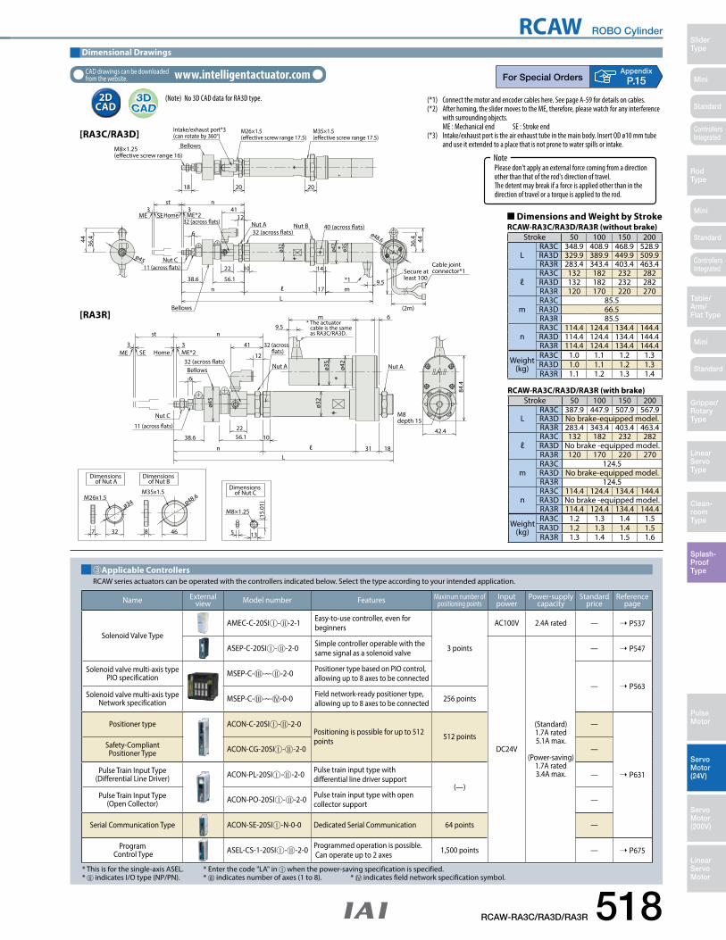
RCAW ROBO Cylinder
Mini
Mini
Mini
SliderType
RodType
Table/Arm/Flat Type
Linear ServoType
Gripper/Rotary Type
Clean-room Type
Splash-ProofType
Pulse Motor
Servo Motor (24V)
Servo Motor (200V)
LinearServo Motor
Standard
Standard
Standard
ControllersIntegrated
ControllersIntegrated
AppendixP.15
M8 depth 15
84.4
42.4
ø48.6
(15.
01)
135468
ø34
327
M26x1.5M35x1.5
M8×1.25
Intake/exhaust port*3(can rotate by 360°)
18 20 20
M8×1.25(e�ective screw range 16)
Bellows
M35×1.5(e�ective screw range 17.5)
M26×1.5 (e�ective screw range 17.5)
6
11 (across �ats)
32 (across �ats) Nut A32 (across �ats)
40 (across �ats)
3st
3n
14
*1
1022
17L
ø42
ø35
ø32
56.138.6
n
4112
m9.5
Nut B
Nut C
Bellows
ME*2HomeSEME
4436
.4
ø48.6
36.444
ø45
ø42
32 (across �ats)
31 18L
ℓ
10
6m
9.5ø3
2
ø45
ø35
Nut A
6
11 (across �ats)
32 (across �ats)Nut A
3
st
3
n
2256.138.6
n
41
12
Nut C
ME*2HomeSEME
Bellows
[RA3C/RA3D]
[RA3R]
Cable jointconnector*1
(2m)
Secure at least 100
* The actuator cable is the same as RA3C/RA3D.
Dimensions of Nut A
Dimensions of Nut B
Dimensions of Nut C
ℓ
Dimensional Drawings
2D CAD2D
CAD
CAD drawings can be downloaded from the website. www.intelligentactuator.com
RCAW-RA3C/RA3D/RA3R 518
RCAW series actuators can be operated with the controllers indicated below. Select the type according to your intended application. ➂Applicable Controllers
Name Externalview Model number Features Maximum number of
positioning pointsInputpower
Power-supply capacity
Standardprice
Reference page
Solenoid Valve Type
AMEC-C-20SI - -2-1 Easy-to-use controller, even for beginners
3 points
AC100V 2.4A rated — ➝ P537
ASEP-C-20SI - -2-0 Simple controller operable with the same signal as a solenoid valve
DC24V
(Standard)1.7A rated5.1A max.
(Power-saving)1.7A rated3.4A max.
— ➝ P547
Solenoid valve multi-axis type PIO specification MSEP-C- -~- -2-0 Positioner type based on PIO control,
allowing up to 8 axes to be connected— ➝ P563
Solenoid valve multi-axis type Network specification MSEP-C- -~- -0-0 Field network-ready positioner type,
allowing up to 8 axes to be connected 256 points
Positioner type ACON-C-20SI - -2-0Positioning is possible for up to 512 points 512 points
—
➝ P631
Safety-Compliant Positioner Type ACON-CG-20SI - -2-0 —
Pulse Train Input Type (Differential Line Driver) ACON-PL-20SI - -2-0 Pulse train input type with
differential line driver support(—)
—
Pulse Train Input Type (Open Collector) ACON-PO-20SI - -2-0 Pulse train input type with open
collector support —
Serial Communication Type ACON-SE-20SI -N-0-0 Dedicated Serial Communication 64 points —
Program Control Type ASEL-CS-1-20SI - -2-0 Programmed operation is possible.
Can operate up to 2 axes 1,500 points — ➝ P675
* This is for the single-axis ASEL. * Enter the code "LA" in when the power-saving specification is specified. * indicates I/O type (NP/PN). * indicates number of axes (1 to 8). * indicates field network specification symbol.
(*1) Connect the motor and encoder cables here. See page A-59 for details on cables.(*2) After homing, the slider moves to the ME, therefore, please watch for any interference with surrounding objects. ME : Mechanical end SE : Stroke end(*3) Intake/exhaust port is the air exhaust tube in the main body. Insert OD ø10 mm tube and use it extended to a place that is not prone to water spills or intake.
(Note) No 3D CAD data for RA3D type.
Stroke 50 100 150 200
LRA3C 348.9 408.9 468.9 528.9 RA3D 329.9 389.9 449.9 509.9RA3R 283.4 343.4 403.4 463.4
ℓRA3C 132 182 232 282 RA3D 132 182 232 282 RA3R 120 170 220 270
mRA3C 85.5RA3D 66.5RA3R 85.5
nRA3C 114.4 124.4 134.4 144.4RA3D 114.4 124.4 134.4 144.4RA3R 114.4 124.4 134.4 144.4
Weight(kg)
RA3C 1.0 1.1 1.2 1.3 RA3D 1.0 1.1 1.2 1.3 RA3R 1.1 1.2 1.3 1.4
�Dimensions and Weight by StrokeRCAW-RA3C/RA3D/RA3R (without brake)
Stroke 50 100 150 200
LRA3C 387.9 447.9 507.9 567.9 RA3D No brake-equipped model.RA3R 283.4 343.4 403.4 463.4
ℓRA3C 132 182 232 282 RA3D No brake -equipped model. RA3R 120 170 220 270
mRA3C 124.5RA3D No brake-equipped model.RA3R 124.5
nRA3C 114.4 124.4 134.4 144.4RA3D No brake -equipped model.RA3R 114.4 124.4 134.4 144.4
Weight(kg)
RA3C 1.2 1.3 1.4 1.5 RA3D 1.2 1.3 1.4 1.5 RA3R 1.3 1.4 1.5 1.6
RCAW-RA3C/RA3D/RA3R (with brake)
NotePlease don't apply an external force coming from a direction other than that of the rod's direction of travel.Thedetentmaybreakifaforceisappliedotherthaninthedirection of travel or a torque is applied to the rod.
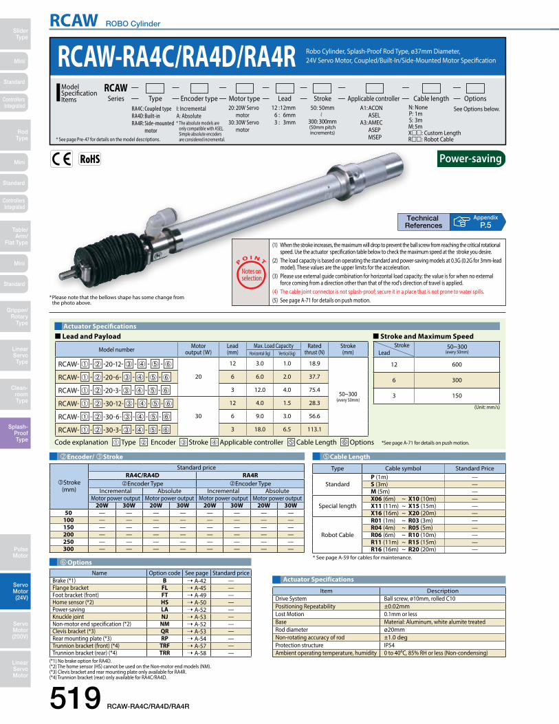
RCAW ROBO Cylinder
519 RCAW-RA4C/RA4D/RA4R
Mini
Mini
Mini
SliderType
RodType
Table/Arm/
Flat Type
Linear ServoType
Gripper/Rotary
Type
Clean-room Type
Splash-ProofType
Pulse Motor
Servo Motor (24V)
Servo Motor (200V)
LinearServo Motor
Standard
Standard
Standard
ControllersIntegrated
ControllersIntegrated
AppendixP.5
Actuator Specifications
Item DescriptionDrive System Ball screw, ø10mm, rolled C10Positioning Repeatability ±0.02mmLost Motion 0.1mm or lessBase Material: Aluminum, white alumite treatedRod diameter ø20mmNon-rotating accuracy of rod ±1.0 degProtection structure IP54Ambient operating temperature, humidity 0 to 40oC, 85% RH or less (Non-condensing)
� Lead and Payload � Stroke and Maximum SpeedActuator Specifications
(Unit: mm/s)
Model number Motor output (W)
Lead(mm)
Max. Load Capacity Ratedthrust (N)
Stroke(mm)Horizontal (kg) Vertical (kg)
RCAW- ➀ - ➁ -20-12- ➂ - ➃ - ➄ - ➅
20
12 3.0 1.0 18.9
50~300(every 50mm)
RCAW- ➀ - ➁ -20-6- ➂ - ➃ - ➄ - ➅ 6 6.0 2.0 37.7
RCAW- ➀ - ➁ -20-3- ➂ - ➃ - ➄ - ➅ 3 12.0 4.0 75.4
RCAW- ➀ - ➁ -30-12- ➂ - ➃ - ➄ - ➅
30
12 4.0 1.5 28.3
RCAW- ➀ - ➁ -30-6- ➂ - ➃ - ➄ - ➅ 6 9.0 3.0 56.6
RCAW- ➀ - ➁ -30-3- ➂ - ➃ - ➄ - ➅ 3 18.0 6.5 113.1
Code explanation ➀ Type ➁ Encoder ➂ Stroke ➃ Applicable controller Cable Length Options *See page A-71 for details on push motion.
Stroke 50~300(every 50mm)Lead
12 600
6 300
3 150
OptionsName Option code See page Standard price
Brake (*1) B ➝ A-42 —Flange bracket FL ➝ A-45 —Foot bracket (front) FT ➝ A-49 —Home sensor (*2) HS ➝ A-50 —Power-saving LA ➝ A-52 —Knuckle joint NJ ➝ A-53 —Non-motor end specification (*2) NM ➝ A-52 —Clevis bracket (*3) QR ➝ A-53 —Rear mounting plate (*3) RP ➝ A-54 —Trunnion bracket (front) (*4) TRF ➝ A-57 —Trunnion bracket (rear) (*4) TRR ➝ A-58 —
(*1) No brake option for RA4D.(*2) The home sensor (HS) cannot be used on the Non-motor end models (NM).(*3) Clevis bracket and rear mounting plate only available for RA4R.(*4) Trunnion bracket (rear) only available for RA4C/RA4D.
(1) When the stroke increases, the maximum will drop to prevent the ball screw from reaching the critical rotational speed. Use the actuator specification table below to check the maximum speed at the stroke you desire.
(2) The load capacity is based on operating the standard and power-saving models at 0.3G (0.2G for 3mm-lead model). These values are the upper limits for the acceleration.
(3) Please use external guide combination for horizontal load capacity; the value is for when no external force coming from a direction other than that of the rod's direction of travel is applied.
(4) The cable joint connector is not splash-proof; secure it in a place that is not prone to water spills.(5) See page A-71 for details on push motion.* Please note that the bellows shape has some change from
the photo above.
Stroke (mm)
Standard priceRA4C/RA4D RA4REncoder Type Encoder Type
Incremental Absolute Incremental AbsoluteMotor power output Motor power output Motor power output Motor power output
20W 30W 20W 30W 20W 30W 20W 30W50 — — — — — — — —
100 — — — — — — — —150 — — — — — — — —200 — — — — — — — —250 — — — — — — — —300 — — — — — — — —
Encoder/ Stroke
Type Cable symbol Standard Price
StandardP (1m) —S (3m) —M (5m) —
Special lengthX06 (6m) ~ X10 (10m) —X11 (11m) ~ X15 (15m) —X16 (16m) ~ X20 (20m) —
Robot Cable
R01 (1m) ~ R03 (3m) —R04 (4m) ~ R05 (5m) —R06 (6m) ~ R10 (10m) —R11 (11m) ~ R15 (15m) —R16 (16m) ~ R20 (20m) —
* See page A-59 for cables for maintenance.
Cable Length
RCAW-RA4C/RA4D/RA4R Robo Cylinder, Splash-Proof Rod Type, ø37mm Diameter, 24V Servo Motor, Coupled/Built-In/Side-Mounted Motor Specification
20: 20W Servo motor 30: 30W Servo motor
Lead Stroke Cable length OptionsType Encoder type Motor type Applicable controllerSeriesRCAWModel
SpecificationItems
50: 50mm
300: 300mm(50mm pitch increments)
* See page Pre-47 for details on the model descriptions.
A1: ACON ASEL A3: AMEC ASEP MSEP
I: Incremental A: Absolute* The absolute models are only compatible with ASEL. Simple absolute encoders are considered incremental.
N: None P: 1m S: 3m M: 5mX: Custom Length R: Robot Cable
See Options below. 12 : 12mm 6 : 6mm 3 : 3mm
RA4C: Coupled type RA4D: Built-in RA4R: Side-mounted motor

RCAW ROBO Cylinder
Mini
Mini
Mini
SliderType
RodType
Table/Arm/Flat Type
Linear ServoType
Gripper/Rotary Type
Clean-room Type
Splash-ProofType
Pulse Motor
Servo Motor (24V)
Servo Motor (200V)
LinearServo Motor
Standard
Standard
Standard
ControllersIntegrated
ControllersIntegrated
[RA4R]
ø52.8
5010
M40×1.5
ø40.2
388
M30×1.5
(19.
6)
176
M10x1.25
Intake/exhaust port*3(can rotate by 360°)
22 22 22
M10×1.25(e�ective screw range 20)
M40×1.5 (e�ective screw range 19.5)M30×1.5 (e�ective screw range 17.5)
Lℓ
ℓ
m
st3 3
38 (across �ats)
Incr
emen
tal ø
42Ab
solu
te ø
48
Incr
emen
tal ø
42Ab
solu
te
ø48
ø50
ø37
7.5
n44
15
9.51619
10n
2258.144.1
14 (across �ats)Nut C
Nut A36 (across �ats)
47 (across �ats)
Nut BME*2
HomeME SE
ø45
4739
.4 4739.4ø52.8
ø37
ø45
ø50
m
36 (across �ats)
Ln
3353
58.144.1 2010
269.5
Nut A
st3 3
38 (across �ats)
7.5
n44
15
22
14 (across �ats)
Nut C
Nut A
ME
Home
ME SE
[RA4C/RA4D]
48
M10 depth 18
50.5
98.5
*The actuator cable is the same as RA3C/RA3D.
Cable jointconnector*1
(2m)
Secure at least100
Dimensions of Nut A
Dimensions of Nut B
Dimensions of Nut C
Dimensional Drawings
2D CAD2D
CAD
CAD drawings can be downloaded from the website. www.intelligentactuator.com Appendix
P.15
RCAW-RA4C/RA4D/RA4R 520
Please don't apply an external force coming from a direction other than that of the rod's direction of travel.Thedetentmaybreakifaforceisappliedother than in the direction of travel or a torque is applied to the rod.
Note:
(*1) Connect the motor and encoder cables here. See page A-59 for details on cables.(*2) After homing, the slider moves to the ME, therefore, please watch for any interference with surrounding objects. ME : Mechanical end SE : Stroke end(*3) Intake/exhaust port is the air exhaust tube in the main body. Insert OD ø10 mm tube and use it extended to a place that is not prone to water spills or intake.
(Note) No 3D CAD data for RA4D type.
Stroke 50 100 150 200 250 300
L
RA4C20W Incremental 345.4 405.4 465.4 525.4 586.4 647.4
Absolute 358.4 418.4 478.4 538.4 599.4 660.4
30W Incremental 360.4 420.4 480.4 540.4 601.4 662.4Absolute 373.4 433.4 493.4 553.4 614.4 675.4
RA4D20W
Incremental 323.4 383.4 443.4 503.4 564.4 625.4Absolute 336.4 396.4 456.4 516.4 577.4 638.4
30W Incremental 338.4 398.4 458.4 518.4 579.4 640.4Absolute 351.4 411.4 471.4 531.4 592.4 653.4
RA4R20W
Incremental 299.9 359.9 419.9 479.9 540.9 601.9Absolute 299.9 359.9 419.9 479.9 540.9 601.9
30W Incremental 299.9 359.9 419.9 479.9 540.9 601.9Absolute 299.9 359.9 419.9 479.9 540.9 601.9
ℓ
RA4C 20W
IncrementalAbsoluteCommon
137 187 237 287 337 38730W 137 187 237 287 337 387
RA4D 20W 137 187 237 287 337 38730W 137 187 237 287 337 387
RA4R 20W 125 175 225 275 325 37530W 125 175 225 275 325 375
m
RA4C20W Incremental 67.5
Absolute 80.5
30W Incremental 82.5Absolute 95.5
RA4D20W Incremental 45.5
Absolute 58.5
30W Incremental 60.5Absolute 73.5
RA4R20W Incremental 67.5
Absolute 80.5
30W Incremental 82.5Absolute 95.5
n
RA4C 20W
IncrementalAbsoluteCommon
121.9 131.9 141.9 151.9 162.9 173.930W 121.9 131.9 141.9 151.9 162.9 173.9
RA4D 20W 121.9 131.9 141.9 151.9 162.9 173.930W 121.9 131.9 141.9 151.9 162.9 173.9
RA4R 20W 121.9 131.9 141.9 151.9 162.9 173.930W 121.9 131.9 141.9 151.9 162.9 173.9
Weight (Kg)
RA4C 20W/30W 1.4 1.5 1.7 1.8 2.0 2.1 RA4D 20W/30W 1.3 1.5 1.6 1.8 1.9 2.1 RA4R 20W/30W 1.5 1.7 1.8 2.0 2.1 2.3
�Dimensions and Weight by StrokeRCAW-RA4C/RA4D/RA4R (without brake)
* Adding a brake increases the RA4C type's overall length by 43mm. Adding a brake also increases the RA4R type's motor portion length by 43mm. However, the overall length does not change because the type is a Side-Mounted type. No brake setting for the RA4D type. Also the weight increases by 0.2kg for all types.
RCAW series actuators can be operated with the controllers indicated below. Select the type according to your intended application.Applicable Controllers
Name Externalview Model number Features Maximum number of
positioning pointsInputpower
Power-supply capacity
Standardprice
Reference page
Solenoid Valve Type
AMEC-C-20I - -2-1 AMEC-C-30I - -2-1
Easy-to-use controller, even for beginners
3 points
AC100V 2.4A rated — ➝ P537
ASEP-C-20I - -2-0ASEP-C-30I - -2-0
Simple controller operable with the same signal as a solenoid valve
DC24V
(Standard)20W
1.3A rated4.4A max.
30W1.3A rated4.4A max.
(Power-saving)20W
1.3A rated2.5A max.
30W1.3A rated2.2A max.
— ➝ P547
Solenoid valve multi-axis type PIO specification MSEP-C- -~- -2-0 Positioner type based on PIO control,
allowing up to 8 axes to be connected— ➝ P563
Solenoid valve multi-axis type Network specification MSEP-C- -~- -0-0 Field network-ready positioner type,
allowing up to 8 axes to be connected 256 points
Positioner type ACON-C-20I - -2-0ACON-C-30I - -2-0 Positioning is possible for up to 512
points 512 points
—
➝ P631
Safety-Compliant Positioner Type
ACON-CG-20I - -2-0ACON-CG-30I - -2-0 —
Pulse Train Input Type (Differential Line Driver)
ACON-PL-20I - -2-0ACON-PL-30I - -2-0
Pulse train input type with differential line driver support
(—)
—
Pulse Train Input Type (Open Collector)
ACON-PO-20I - -2-0ACON-PO-30I - -2-0
Pulse train input type with open collector support —
Serial Communication Type ACON-SE-20I -N-0-0ACON-SE-30I -N-0-0 Dedicated Serial Communication 64 points —
Program Control Type
ASEL-CS-1-20 - -2-0ASEL-CS-1-30 - -2-0
Programmed operation is possible. Can operate up to 2 axes 1,500 points — ➝ P675
* This is for the single-axis ASEL. * indicates encoder type (I: incremental, A: absolute) * Enter the code "LA" in when the power-saving option is specified.* indicates I/O type (NP/PN). * indicates number of axes (1 to 8). * indicates field network specification symbol.

RCS2W ROBO Cylinder
521 RCS2W-RA4C/RA4D/RA4R
Mini
Mini
Mini
SliderType
RodType
Table/Arm/
Flat Type
Linear ServoType
Gripper/Rotary
Type
Clean-room Type
Splash-ProofType
Pulse Motor
Servo Motor (24V)
Servo Motor (200V)
LinearServo Motor
Standard
Standard
Standard
ControllersIntegrated
ControllersIntegrated
� Lead and Payload � Stroke and Maximum SpeedActuator Specifications
(Unit: mm/s)
Model number Motor output (W)
Lead(mm)
Max. Load Capacity Ratedthrust (N)
Stroke(mm)Horizontal (kg) Vertical (kg)
RCS2W- ➀ - ➁ -20-12- ➂ - ➃ - ➄ - ➅
20
12 3.0 1.0 18.9
50~300(every 50mm)
RCS2W- ➀ - ➁ -20-6- ➂ - ➃ - ➄ - ➅ 6 6.0 2.0 37.7
RCS2W- ➀ - ➁ -20-3- ➂ - ➃ - ➄ - ➅ 3 12.0 4.0 75.4
RCS2W- ➀ - ➁ -30-12- ➂ - ➃ - ➄ - ➅
30
12 4.0 1.5 28.3
RCS2W- ➀ - ➁ -30-6- ➂ - ➃ - ➄ - ➅ 6 9.0 3.0 56.6
RCS2W- ➀ - ➁ -30-3- ➂ - ➃ - ➄ - ➅ 3 18.0 6.5 113.1
Code explanation ➀ Type ➁ Encoder ➂ Stroke ➃ Applicable controller Cable Length Options *See page A-71 for details on push motion.
Stroke 50~300(every 50mm)Lead
12 600
6 300
3 150
(1) When the stroke increases, the maximum will drop to prevent the ball screw from reaching the critical rotational speed. Use the actuator specification table below to check the maximum speed at the stroke you desire.
(2) The load capacity is based on operating the standard and power-saving models at 0.3G (0.2G for 3mm-lead model). These values are the upper limits for the acceleration.
(3) Please use external guide combination for horizontal load capacity; the value is for when no external force coming from a direction other than that of the rod's direction of travel is applied.
(4) The cable joint connector is not splash-proof; secure it in a place that is not prone to water spills.(5) See page A-71 for details on push motion.
* Please note that the bellows shape has some change from the photo above.
AppendixP.5
RCS2W-RA4C/RA4D/RA4R Robo Cylinder, Splash-Proof Rod Type, ø37mm Diameter, 200V Servo Motor, Coupled/Built-In/Side-Mounted Motor Specification
20: 20W Servo motor 30: 30W Servo motor
Lead Stroke Cable length OptionsType Encoder type Motor type Applicable controllerSeriesRCS2WModel
SpecificationItems
50: 50mm
300: 300mm(50mm pitch increments)
* See page Pre-47 for details on the model descriptions.
T1: XSEL-J/KT2: SCON MSCON SSEL XSAL-P/Q XSAL-R/S
I: Incremental A: Absolute
N: None P: 1m S: 3m M: 5mX: Custom Length R: Robot Cable
See Options below. 12 : 12mm 6 : 6mm 3 : 3mm
RA4C: Coupled type RA4D: Built-in RA4R: Side-mounted motor
*CE compliance is optional.
Cable Length
Type Cable symbol Standard Price
StandardP (1m) —S (3m) —M (5m) —
Special lengthX06 (6m) ~ X10 (10m) —X11 (11m) ~ X15 (15m) —X16 (16m) ~ X20 (20m) —
Robot Cable
R01 (1m) ~ R03 (3m) —R04 (4m) ~ R05 (5m) —R06 (6m) ~ R10 (10m) —R11 (11m) ~ R15 (15m) —R16 (16m) ~ R20 (20m) —
* See page A-59 for cables for maintenance.OptionsName Option code See page Standard price
Brake (*1) B ➝ A-42 —CE compliance CE ➝ A-42 —Flange bracket FL ➝ A-45 —Foot bracket (front) FT ➝ A-49 —Home sensor (*2) HS ➝ A-50 —Knuckle joint NJ ➝ A-53 —Non-motor end specification (*2) NM ➝ A-52 —Clevis bracket (*3) QR ➝ A-53 —Rear mounting plate (*3) RP ➝ A-54 —Trunnion bracket (front) (*4) TRF ➝ A-57 —Trunnion bracket (rear) (*4) TRR ➝ A-58 —
(*1) No brake option for RA4D.(*2) The home sensor (HS) cannot be used on the Non-motor end models (NM).(*3) Clevis bracket and rear mounting plate only available for RA4R.(*4) Trunnion bracket (rear) only available for RA4C/RA4D.
Encoder & Stroke
Stroke (mm)
Standard priceRA4C/RA4D RA4REncoder Type Encoder Type
Incremental Absolute Incremental AbsoluteMotor power output Motor power output Motor power output Motor power output
20W 30W 20W 30W 20W 30W 20W 30W50 — — — — — — — —
100 — — — — — — — —150 — — — — — — — —200 — — — — — — — —250 — — — — — — — —300 — — — — — — — —
Item DescriptionDrive System Ball screw, ø10mm, rolled C10Positioning Repeatability ±0.02mmLost Motion 0.1mm or lessBase Material: Aluminum, white alumite treatedRod diameter ø20mmNon-rotating accuracy of rod ±1.0 degProtection structure IP54Ambient operating temperature, humidity 0 to 40oC, 85% RH or less (Non-condensing)
Actuator Specifications
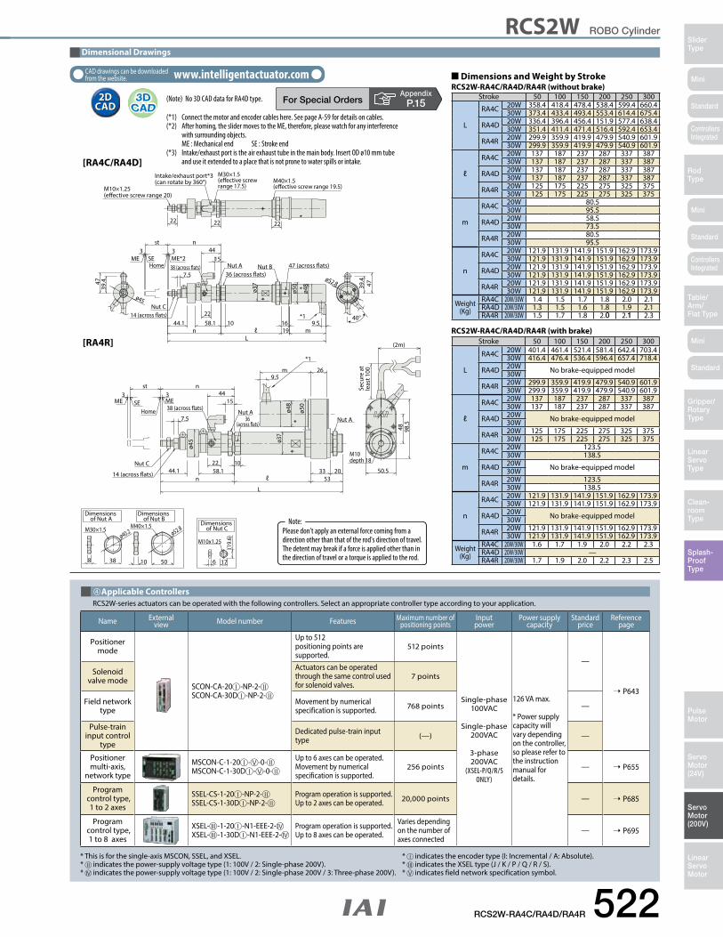
RCS2W ROBO Cylinder
Mini
Mini
Mini
SliderType
RodType
Table/Arm/Flat Type
Linear ServoType
Gripper/Rotary Type
Clean-room Type
Splash-ProofType
Pulse Motor
Servo Motor (24V)
Servo Motor (200V)
LinearServo Motor
Standard
Standard
Standard
ControllersIntegrated
ControllersIntegrated
40°
Dimensions of Nut A
Dimensions of Nut B
Dimensions of Nut C
[RA4R]
ø52.8
5010
M40×1.5
ø40.2
388
M30×1.5
(19.
6)
176
M10x1.25
Intake/exhaust port*3(can rotate by 360°)
22 22 22
M10×1.25(e�ective screw range 20)
M40×1.5 (e�ective screw range 19.5)
M30×1.5 (e�ective screw range 17.5)
Lm
st3 3
38 (across �ats)
ø48
ø50
ø37
7.5
n44
15
9.51619
10n
2258.144.1
14 (across �ats)Nut C
Nut A36 (across �ats)
47 (across �ats)Nut BME*2
HomeME SE
ø45
4739
.4 4739.4ø52.8
ø37
ø45
ø48
ø50
m
36 (across �ats)
L
n33
5358.144.1 20
10
269.5
Nut A
st3 3
38 (across �ats)
7.5
n44
15
22
14 (across �ats)
Nut C
Nut A
ME
Home
ME SE
[RA4C/RA4D]
48
M10 depth 18
50.5
98.5
*1
*1
Secu
re a
t le
ast 1
00
(2m)
ℓ
ℓ
Dimensional Drawings
2D CAD2D
CAD
CAD drawings can be downloaded from the website. www.intelligentactuator.com
RCS2W-RA4C/RA4D/RA4R 522
(*1) Connect the motor and encoder cables here. See page A-59 for details on cables.(*2) After homing, the slider moves to the ME, therefore, please watch for any interference with surrounding objects. ME : Mechanical end SE : Stroke end(*3) Intake/exhaust port is the air exhaust tube in the main body. Insert OD ø10 mm tube and use it extended to a place that is not prone to water spills or intake.
(Note) No 3D CAD data for RA4D type. Stroke 50 100 150 200 250 300
L
RA4C 20W 358.4 418.4 478.4 538.4 599.4 660.430W 373.4 433.4 493.4 553.4 614.4 675.4
RA4D 20W 336.4 396.4 456.4 151.9 577.4 638.430W 351.4 411.4 471.4 516.4 592.4 653.4
RA4R 20W 299.9 359.9 419.9 479.9 540.9 601.930W 299.9 359.9 419.9 479.9 540.9 601.9
ℓ
RA4C 20W 137 187 237 287 337 38730W 137 187 237 287 337 387
RA4D 20W 137 187 237 287 337 38730W 137 187 237 287 337 387
RA4R 20W 125 175 225 275 325 37530W 125 175 225 275 325 375
m
RA4C 20W 80.530W 95.5
RA4D 20W 58.530W 73.5
RA4R 20W 80.530W 95.5
n
RA4C 20W 121.9 131.9 141.9 151.9 162.9 173.930W 121.9 131.9 141.9 151.9 162.9 173.9
RA4D 20W 121.9 131.9 141.9 151.9 162.9 173.930W 121.9 131.9 141.9 151.9 162.9 173.9
RA4R 20W 121.9 131.9 141.9 151.9 162.9 173.930W 121.9 131.9 141.9 151.9 162.9 173.9
Weight (Kg)
RA4C 20W/30W 1.4 1.5 1.7 1.8 2.0 2.1 RA4D 20W/30W 1.3 1.5 1.6 1.8 1.9 2.1 RA4R 20W/30W 1.5 1.7 1.8 2.0 2.1 2.3
�Dimensions and Weight by StrokeRCS2W-RA4C/RA4D/RA4R (without brake)
Stroke 50 100 150 200 250 300
L
RA4C 20W 401.4 461.4 521.4 581.4 642.4 703.430W 416.4 476.4 536.4 596.4 657.4 718.4
RA4D 20W No brake-equipped model30W
RA4R 20W 299.9 359.9 419.9 479.9 540.9 601.930W 299.9 359.9 419.9 479.9 540.9 601.9
ℓ
RA4C 20W 137 187 237 287 337 38730W 137 187 237 287 337 387
RA4D 20W No brake-equipped model30W
RA4R 20W 125 175 225 275 325 37530W 125 175 225 275 325 375
m
RA4C 20W 123.530W 138.5
RA4D 20W No brake-equipped model30W
RA4R 20W 123.530W 138.5
n
RA4C 20W 121.9 131.9 141.9 151.9 162.9 173.930W 121.9 131.9 141.9 151.9 162.9 173.9
RA4D 20W No brake-equipped model30W
RA4R 20W 121.9 131.9 141.9 151.9 162.9 173.930W 121.9 131.9 141.9 151.9 162.9 173.9
Weight (Kg)
RA4C 20W/30W 1.6 1.7 1.9 2.0 2.2 2.3 RA4D 20W/30W —RA4R 20W/30W 1.7 1.9 2.0 2.2 2.3 2.5
RCS2W-RA4C/RA4D/RA4R (with brake)
AppendixP.15
Name Externalview Model number Features Maximum number of
positioning pointsInputpower
Power supply capacity
Standardprice
Reference page
Positioner mode
SCON-CA-20 -NP-2-SCON-CA-30D -NP-2-
Up to 512 positioning points are supported.
512 points
Single-phase 100VAC
Single-phase 200VAC
3-phase 200VAC
(XSEL-P/Q/R/S ONLY)
126 VA max.
* Power supply capacity will vary depending on the controller, so please refer to the instruction manual for details.
—
➝ P643
Solenoid valve mode
Actuators can be operated through the same control used for solenoid valves.
7 points
Field network type
Movement by numerical specification is supported. 768 points —
Pulse-train input control
type
Dedicated pulse-train input type (—) —
Positioner multi-axis,
network type
MSCON-C-1-20 - -0-MSCON-C-1-30D - -0-
Up to 6 axes can be operated. Movement by numerical specification is supported.
256 points — ➝ P655
Program control type,
1 to 2 axes
SSEL-CS-1-20 -NP-2-SSEL-CS-1-30D -NP-2-
Program operation is supported. Up to 2 axes can be operated. 20,000 points — ➝ P685
Program control type,
1 to 8 axes
XSEL- -1-20 -N1-EEE-2-XSEL- -1-30D -N1-EEE-2-
Program operation is supported. Up to 8 axes can be operated.
Varies depending on the number of axes connected
— ➝ P695
RCS2W-series actuators can be operated with the following controllers. Select an appropriate controller type according to your application.Applicable Controllers
* This is for the single-axis MSCON, SSEL, and XSEL. * indicates the encoder type (I: Incremental / A: Absolute).* indicates the power-supply voltage type (1: 100V / 2: Single-phase 200V). * indicates the XSEL type (J / K / P / Q / R / S).* indicates the power-supply voltage type (1: 100V / 2: Single-phase 200V / 3: Three-phase 200V). * indicates field network specification symbol.
Please don't apply an external force coming from a direction other than that of the rod's direction of travel.Thedetentmaybreakifaforceisappliedotherthaninthe direction of travel or a torque is applied to the rod.
Note:
Related Documents