Welcome message from author
This document is posted to help you gain knowledge. Please leave a comment to let me know what you think about it! Share it to your friends and learn new things together.
Transcript

IAEA SAFETY RELATED PUBLICATIONS
IAEA SAFETY STANDARDS
Under the terms of Article III of its Statute, the IAEA is authorized to establish standardsof safety for protection against ionizing radiation and to provide for the application of thesestandards to peaceful nuclear activities.
The regulatory related publications by means of which the IAEA establishes safetystandards and measures are issued in the IAEA Safety Standards Series. This series coversnuclear safety, radiation safety, transport safety and waste safety, and also general safety (thatis, of relevance in two or more of the four areas), and the categories within it are SafetyFundamentals, Safety Requirements and Safety Guides.
Safety Fundamentals (blue lettering) present basic objectives, concepts and principles ofsafety and protection in the development and application of nuclear energy for peacefulpurposes.
Safety Requirements (red lettering) establish the requirements that must be met to ensuresafety. These requirements, which are expressed as ‘shall’ statements, are governed bythe objectives and principles presented in the Safety Fundamentals.
Safety Guides (green lettering) recommend actions, conditions or procedures for meetingsafety requirements. Recommendations in Safety Guides are expressed as ‘should’ state-ments, with the implication that it is necessary to take the measures recommended orequivalent alternative measures to comply with the requirements.
The IAEA’s safety standards are not legally binding on Member States but may beadopted by them, at their own discretion, for use in national regulations in respect of their ownactivities. The standards are binding on the IAEA for application in relation to its own opera-tions and to operations assisted by the IAEA.
Information on the IAEA’s safety standards programme (including editions in languagesother than English) is available at the IAEA Internet site
www.iaea.org/ns/coordinet or on request to the Safety Co-ordination Section, IAEA, P.O. Box 100, A-1400 Vienna,Austria.
OTHER SAFETY RELATED PUBLICATIONS
Under the terms of Articles III and VIII.C of its Statute, the IAEA makes available andfosters the exchange of information relating to peaceful nuclear activities and serves as an inter-mediary among its Member States for this purpose.
Reports on safety and protection in nuclear activities are issued in other series, inparticular the IAEA Safety Reports Series, as informational publications. Safety Reports maydescribe good practices and give practical examples and detailed methods that can be used tomeet safety requirements. They do not establish requirements or make recommendations.
Other IAEA series that include safety related sales publications are the TechnicalReports Series, the Radiological Assessment Reports Series and the INSAG Series. TheIAEA also issues reports on radiological accidents and other special sales publications.Unpriced safety related publications are issued in the TECDOC Series, the Provisional SafetyStandards Series, the Training Course Series, the IAEA Services Series and the ComputerManual Series, and as Practical Radiation Safety and Protection Manuals.

CALIBRATION OF RADIATIONPROTECTION MONITORING
INSTRUMENTS

The following States are Members of the International Atomic Energy Agency:
AFGHANISTANALBANIAALGERIAANGOLAARGENTINAARMENIAAUSTRALIAAUSTRIABANGLADESHBELARUSBELGIUMBENINBOLIVIABOSNIA AND HERZOGOVINABRAZILBULGARIABURKINA FASOCAMBODIACAMEROONCANADACHILECHINACOLOMBIACOSTA RICACOTE D’IVOIRECROATIACUBACYPRUSCZECH REPUBLICDEMOCRATIC REPUBLIC
OF THE CONGODENMARKDOMINICAN REPUBLICECUADOREGYPTEL SALVADORESTONIAETHIOPIAFINLANDFRANCEGABONGEORGIAGERMANYGHANAGREECE
GUATEMALAHAITIHOLY SEEHUNGARYICELANDINDIAINDONESIAIRAN, ISLAMIC REPUBLIC OF IRAQIRELANDISRAELITALYJAMAICAJAPANJORDANKAZAKHSTANKENYAKOREA, REPUBLIC OFKUWAITLATVIALEBANONLIBERIALIBYAN ARAB JAMAHIRIYALIECHTENSTEINLITHUANIALUXEMBOURGMADAGASCARMALAYSIAMALIMALTAMARSHALL ISLANDSMAURITIUSMEXICOMONACOMONGOLIAMOROCCOMYANMARNAMIBIANETHERLANDSNEW ZEALANDNICARAGUANIGERNIGERIANORWAYPAKISTAN
PANAMAPARAGUAYPERUPHILIPPINESPOLANDPORTUGALQATARREPUBLIC OF MOLDOVAROMANIARUSSIAN FEDERATIONSAUDI ARABIASENEGALSIERRA LEONESINGAPORESLOVAKIASLOVENIASOUTH AFRICASPAINSRI LANKASUDANSWEDENSWITZERLANDSYRIAN ARAB REPUBLICTHAILANDTHE FORMER YUGOSLAV
REPUBLIC OF MACEDONIATUNISIATURKEYUGANDAUKRAINEUNITED ARAB EMIRATESUNITED KINGDOM OF
GREAT BRITAIN AND NORTHERN IRELAND
UNITED REPUBLICOF TANZANIA
UNITED STATES OF AMERICAURUGUAYUZBEKISTANVENEZUELAVIET NAMYEMENYUGOSLAVIAZAMBIAZIMBABWE
The Agency’s Statute was approved on 23 October 1956 by the Conference on the Statute of theIAEA held at United Nations Headquarters, New York; it entered into force on 29 July 1957. TheHeadquarters of the Agency are situated in Vienna. Its principal objective is “to accelerate and enlarge thecontribution of atomic energy to peace, health and prosperity throughout the world’’.
© IAEA, 2000
Permission to reproduce or translate the information contained in this publication may beobtained by writing to the International Atomic Energy Agency, Wagramer Strasse 5, P.O. Box 100,A-1400 Vienna, Austria.
Printed by the IAEA in AustriaJanuary 2000
STI/PUB/1074
CALIBRATION OF RADIATIONPROTECTION MONITORING
INSTRUMENTS
SAFETY REPORTS SERIES No. 16
INTERNATIONAL ATOMIC ENERGY AGENCYVIENNA, 2000

VIC Library Cataloguing in Publication Data
Calibration of radiation protection monitoring instruments. — Vienna :International Atomic Energy Agency, 1999.
p. ; 24 cm. — (Safety reports series, ISSN 1020–6450 ; no. 16)STI/PUB/1074ISBN 92–0–100100–2Includes bibliographical references.
1. Radiation—Measurements—Instruments—Calibration. I. InternationalAtomic Energy Agency. II. Series.
VICL 99–00235
FOREWORD
Occupational radiation protection is a major component of the support forradiation safety provided by the International Atomic Energy Agency to its MemberStates. The objective of the IAEA Occupational Protection Programme is to promotean internationally harmonized approach to optimizing occupational radiationprotection through the development and application of guidelines for restrictingradiation exposures in the workplace and for applying current occupational radiationprotection techniques.
Requirements for occupational radiation protection are presented in Appendix Iof the International Basic Safety Standards for Protection against Ionizing Radiationand for the Safety of Radiation Sources (BSS), co-sponsored by the Food andAgriculture Organization of the United Nations (FAO), the IAEA, the InternationalLabour Organization (ILO), the Nuclear Energy Agency of the Organisation forEconomic Co-operation and Development (OECD/NEA), the Pan American HealthOrganization (PAHO) and the World Health Organization (WHO).
Occupational exposure to ionizing radiation can occur in industry, medicalinstitutions, research establishments, universities and nuclear fuel cycle facilities.Adequate radiation protection for workers is an essential requirement for the safe andacceptable use of radiation, radioactive materials and nuclear energy. Guidance on theapplication of the requirements of the BSS to occupational protection is given in threeinterrrelated Safety Guides: Occupational Radiation Protection (RS-G-1.1);Assessment of Occupational Exposure due to External Sources of Radiation (RS-G-1.3); Assessment of Occupational Exposure due to Intakes of Radionuclides(RS-G-1.2).
This Safety Report provides guidance on the establishment and operation ofcalibration facilities for radiation monitoring instruments. It reflects the currentinternationally accepted principles and recommended practices in calibrationprocedures, taking into account of the major changes and developments that haveoccurred over the past decade.
This publication is the result of the efforts of several experts who have providedmaterial and drafted and reviewed the text. The IAEA gratefully acknowledges theassistance of all these contributors. The IAEA officers responsible for the preparationof this report were R. Griffith and R. Ouvrard.
CONTENTS
1. INTRODUCTION . . . . . . . . . . . . . . . . . . . . . . . . . . . . . . . . . . . . . . . . . 1
1.1. Background . . . . . . . . . . . . . . . . . . . . . . . . . . . . . . . . . . . . . . . . . . 11.2. Scope . . . . . . . . . . . . . . . . . . . . . . . . . . . . . . . . . . . . . . . . . . . . . . 11.3. Purpose of calibration . . . . . . . . . . . . . . . . . . . . . . . . . . . . . . . . . . 2
2. TERMINOLOGY, QUANTITIES AND UNITS . . . . . . . . . . . . . . . . . . . 3
2.1. Terminology . . . . . . . . . . . . . . . . . . . . . . . . . . . . . . . . . . . . . . . . . 32.2. Operational quantities and quantities used for the calibration of
surface contamination monitoring equipment . . . . . . . . . . . . . . . . 82.3. Operational quantities and phantoms for dosimeters and
dose rate meters . . . . . . . . . . . . . . . . . . . . . . . . . . . . . . . . . . . . . . 92.4. Other quantities . . . . . . . . . . . . . . . . . . . . . . . . . . . . . . . . . . . . . . . 17
3. FUNDAMENTALS OF CALIBRATION . . . . . . . . . . . . . . . . . . . . . . . . 21
3.1. Calibration and tests . . . . . . . . . . . . . . . . . . . . . . . . . . . . . . . . . . . 213.2. Reference conditions and standard test conditions . . . . . . . . . . . . . 223.3. Traceability . . . . . . . . . . . . . . . . . . . . . . . . . . . . . . . . . . . . . . . . . . 253.4. Determination of the calibration factor and of the response
by a reference instrument . . . . . . . . . . . . . . . . . . . . . . . . . . . . . . . 283.5. Determination of the calibration factor and the response in a
known radiation field (calibration method 4) . . . . . . . . . . . . . . . . . 393.6. Additional considerations for calibrations . . . . . . . . . . . . . . . . . . . 403.7. Intercomparison programmes . . . . . . . . . . . . . . . . . . . . . . . . . . . . 423.8. Records and certificates . . . . . . . . . . . . . . . . . . . . . . . . . . . . . . . . 45
4. CALIBRATION OF PHOTON MEASURING INSTRUMENTS . . . . . . 45
4.1. General . . . . . . . . . . . . . . . . . . . . . . . . . . . . . . . . . . . . . . . . . . . . . 454.2. Conversion coefficients for ISO reference
photon radiations . . . . . . . . . . . . . . . . . . . . . . . . . . . . . . . . . . . . . . 484.3. Reference instruments . . . . . . . . . . . . . . . . . . . . . . . . . . . . . . . . . . 604.4. Measurements of the characteristics and calibration of
radiation fields . . . . . . . . . . . . . . . . . . . . . . . . . . . . . . . . . . . . . . . 654.5. Facilities . . . . . . . . . . . . . . . . . . . . . . . . . . . . . . . . . . . . . . . . . . . . 76
5. CALIBRATION OF BETA MEASURING INSTRUMENTS . . . . . . . . . 82
5.1. Calibration quantities and conversion coefficients . . . . . . . . . . . . . 825.2. Reference beta radiations . . . . . . . . . . . . . . . . . . . . . . . . . . . . . . . 845.3. Reference standards and calibration of radiation fields . . . . . . . . . 885.4. Facilities . . . . . . . . . . . . . . . . . . . . . . . . . . . . . . . . . . . . . . . . . . . . 91
6. CALIBRATION OF NEUTRON MEASURING INSTRUMENTS . . . . . 92
6.1. Calibration quantities and conversion coefficients . . . . . . . . . . . . . 926.2. Reference neutron radiations . . . . . . . . . . . . . . . . . . . . . . . . . . . . . 936.3. Facilities . . . . . . . . . . . . . . . . . . . . . . . . . . . . . . . . . . . . . . . . . . . . 966.4. Reference instruments . . . . . . . . . . . . . . . . . . . . . . . . . . . . . . . . . . 996.5. Radiation fields calibrations . . . . . . . . . . . . . . . . . . . . . . . . . . . . . 1016.6. Additional recommendations for calibrating
survey meters . . . . . . . . . . . . . . . . . . . . . . . . . . . . . . . . . . . . . . . . 107
7. CALIBRATION OF SURFACE CONTAMINATION MONITORINGINSTRUMENTS . . . . . . . . . . . . . . . . . . . . . . . . . . . . . . . . . . . . . . . . . . 108
7.1. General . . . . . . . . . . . . . . . . . . . . . . . . . . . . . . . . . . . . . . . . . . . . . 1087.2. Reference standard sources . . . . . . . . . . . . . . . . . . . . . . . . . . . . . . 1107.3. Instrument calibration procedures . . . . . . . . . . . . . . . . . . . . . . . . . 113
8. MEASUREMENT UNCERTAINTIES . . . . . . . . . . . . . . . . . . . . . . . . . . 115
8.1. Introduction . . . . . . . . . . . . . . . . . . . . . . . . . . . . . . . . . . . . . . . . . 1158.2. General considerations on errors and uncertainties . . . . . . . . . . . . 1158.3. Type ‘A’ standard uncertainties . . . . . . . . . . . . . . . . . . . . . . . . . . . 1178.4. Type ‘B’ standard uncertainties . . . . . . . . . . . . . . . . . . . . . . . . . . . 1188.5. Combined uncertainties and expanded uncertainties . . . . . . . . . . . 1208.6. Propoagation of uncertainties . . . . . . . . . . . . . . . . . . . . . . . . . . . . 1208.7. Definitions . . . . . . . . . . . . . . . . . . . . . . . . . . . . . . . . . . . . . . . . . . 122
APPENDIX I. AN EXAMPLE OF DETERMINING THEOVERALL UNCERTAINTIES FOR THECALIBRATION OF AN INSTRUMENT . . . . . . . . . . . . . . . 125

APPENDIX II. AN EXAMPLE OF DETERMINING THECALIBRATION FACTOR, NI, OF AN AMBIENTDOSE EQUIVALENT RATE METER —CALIBRATION WITH REFERENCE INSTRUMENTWITHOUT MONITOR (CALIBRATION METHOD 1) . . . 129
APPENDIX III: AN EXAMPLE OF DETERMNING THECALIBRATION FACTOR OF A PHOTON MEASURINGINSTRUMENT BY MEANS OF A MONITOR(CALIBRATION METHOD 2) . . . . . . . . . . . . . . . . . . . . . . 132
REFERENCES . . . . . . . . . . . . . . . . . . . . . . . . . . . . . . . . . . . . . . . . . . . . . . 142BIBLIOGRAPHY . . . . . . . . . . . . . . . . . . . . . . . . . . . . . . . . . . . . . . . . . . . . . . 148CONTRIBUTORS TO DRAFTING AND REVIEW . . . . . . . . . . . . . . . . . . . . 153
1
1. INTRODUCTION
1.1. BACKGROUND
Since the publication of Technical Reports Series No. 133 [1] in 1971,considerable progress in standardizing reference radiation fields and calibrationprocedures has been made by the International Organization for Standardization(ISO). In addition, the International Electrotechnical Commission (IEC) has producedmany standards on the performance specifications and type testing of radiationprotection monitoring instruments.
A network of secondary calibration laboratories has been set up by WHO/IAEAin many countries. Although these laboratories were primarily concerned withtherapy standards they are increasingly becoming more concerned with calibratingradiation protection instruments.
The change to SI units in radiation monitoring as well as the introduction ofnew operational quantities in ICRU Reports 39, 43, 47 and 51 [2–5] make itadditionally important that Ref. [1] be revised to reflect all these changes.
In assessing whether a particular radiation monitoring instrument is adequatefor its intended use, and before it is used for the first time, it is important to haveaccess to reliable type test data on this instrument. Often the instrument manufacturerdoes not possess facilities for complete type testing and sometimes even cannotcalibrate the instrument over the complete dose equivalent range with a referenceradiation. There is a tendency for new users of radiation monitoring instrumentationto overestimate the facilities of the manufacturers. Each individual instrument shouldbe calibrated before its first use and then should be recalibrated periodically, usuallyevery 12 to 14 months. In some countries, type test and period calibration are alreadyprescribed legally.
There were examples in the past of inadequate calibration procedures havingcaused large errors in some dose estimates.
1.2. SCOPE
This report is intended to serve those who are establishing or operatingcalibration facilities for radiation monitoring instruments. The sources of radiationand associated apparatus and calibration techniques presented are examples of whatestablished calibration laboratories have deemed adequate. However, these are not to
be considered as the only suitable methods and instruments available for propercalibration. The reader’s attention is drawn to the bibliography for a list of documents,which also covers other calibration techniques.
Because of the multitude of applications for radiation monitoringinstrumentation, e.g. in medicine, radiography or agriculture, it is impossible todescribe the complete calibration of all instruments in one report. However, theconsiderations described here should serve as a basis for calibrating radiationprotection instruments.
In addition to presenting a description of calibration facilities and procedures,this Safety Report includes appropriate definitions and describes appropriate methodsfor the statement of uncertainties in measurements. An example of a calibrationrecord is provided.
1.3. PURPOSE OF CALIBRATION
The primary objectives of calibration are:
(1) To ensure that an instrument is working properly and hence will be suitable forits intended monitoring purpose.
(2) To determine, under a controlled set of standard conditions, the indication of aninstrument as a function of the value of the measurand (the quantity intended tobe measured). This should be done over the complete range of indication of theinstrument.
(3) To adjust the instrument calibration, if possible, so that the overall measurementaccuracy of the instrument is optimized.
This Safety Report describes a comprehensive range of calibration equipmentand techniques. However, the scope of tasks performed by any particular facility willdepend on the types of instrument that must be calibrated, as well as on the conditionsunder which the instruments are likely to be used. The facilities may range from thosewhich perform routine calibration or checks using simple assemblies to highlysophisticated laboratories where detailed energy response characteristics can bedetermined. The more sophisticated of these facilities will have a range of referenceinstruments and reference sources which, in general, will be compared with nationalprimary standards, which may themselves be subject to internationalintercomparison.
2
2. TERMINOLOGY, QUANTITIES AND UNITS
2.1. TERMINOLOGY
Reference instruments
Reference instruments should be secondary standards calibrated with primarystandards by a national primary laboratory or at an acknowledged referencelaboratory which holds appropriate standards. Alternatively, the secondary standards,if they are national standards, may be calibrated by the Bureau International des Poidset Mesures (BIPM) in Paris.
Where the reference instrument is not a secondary standard it should becalibrated against other secondary standards or against tertiary standards which havebeen calibrated against secondary standards.
Reference source
A reference source should be a secondary standard source calibrated withprimary standards by a national primary laboratory or at an acknowledged referencelaboratory which holds appropriate standards. Alternatively, the secondary standardsource, if it is a national standard source, may be calibrated by the BIPM.
Where the reference source is not a secondary standard source it should becalibrated against other secondary standards or against tertiary standards which havebeen calibrated against secondary standards.
Primary standard
A standard with the highest metrological qualities in a specified field. Primarystandards are maintained at national laboratories that (a) perform research for thepurposes of metrology and (b) participate in recognized international inter-comparisons of primary standards laboratories, co-ordinated, for example, by theBIPM.
Secondary standard
A standard whose value is fixed by direct comparison with a primary standardand which is accompanied by a certificate that documents this traceability. Thesecondary standards maintained by the IAEA Secondary Standards Dosimetry
3
Laboratory (SSDL) network laboratories are intended to be recognized by an officialnational decision as the basis for fixing the value, in the country in question, of allother standards of the quantity concerned.
Tertiary standard
A standard whose value is fixed by comparisons with a secondary standard.
National standard
A standard recognized by an official national decision as the basis for fixing thevalue, in a country, of all other standards of the given quantity.
In general, the national standard in a country is also the primary standard.
Measuring instruments
A device intended to make a measurement, alone or in conjunction with otherequipment.
Within this report, measuring instruments are dosimeters, dose rate ordose equivalent ratemeters and monitors, surface contamination meters and moni-tors, etc.
Calibration factor
The calibration factor, N, is defined as the conventional true value of thequantity the instrument is intended to measure (the measurand), H, divided by theindication, M (corrected, if necessary) given by the instrument, i.e.
The calibration factor is normally only quoted for one reference radiation, andthere may not be a unique factor applicable to the whole of an instrument’smeasurement range, in which case the instrument is said to have a non-linearresponse.
The calibration factor N is dimensionless when the indicated value already hasthe same units as the measurand; a perfectly accurate instrument should have acalibration factor of one.
The reciprocal of the calibration factor is equal to the response under referenceconditions. In contrast to the calibration factor which refers to the referenceconditions only, the response is applicable to the conditions prevailing.
NH
M=
4
Response
The response R of a measuring instrument is the quotient of the indication M ofthe instrument and the conventional true value of the measurand.
Note: The type of response should be specified, e.g. ‘fluence response’(response with respect to fluence, Φ):
RΦ = M/Φ
or ‘dose equivalent response’ (response with respect to dose equivalent):
RH = M/H
Note: The response R (with respect to fluence or dose equivalent) usually varieswith the spectral and directional distribution of the incident radiation. It is, therefore,useful to consider the response as a function R(E,Ω) of the energy E of the incidentradiation and of the direction Ω of the incident monodirectional radiation. R(E)describes the ‘energy dependence’ and R(Ω) the ‘angle dependence’ of the response;for the latter, Ω is occasionally expressed by the angle α between the referenceorientation of the instrument and the axis of the incident monodirectional field.
Conventional true value (of a quantity)
The conventional true value of a quantity is the best estimate of the value,determined by a primary or secondary standard or by a reference instrument that hasbeen calibrated against a primary or secondary standard.
Note: A conventional true value is, in general, regarded as sufficiently close tothe true value for the difference to be insignificant for the given purpose.
Conversion coefficient
Two types of conversion coefficient are of importance for this report, thekerma-to-dose equivalent conversion coefficient for photon radiation and the fluence-to-dose equivalent conversion coefficient for neutron radiation:
The kerma-to-dose equivalent conversion coefficient, hk, is the quotient of thedose equivalent, H, and the kerma, Ka, at a point in the radiation field:
hk = H/Ka
The neutron fluence-to-dose equivalent conversion coefficient, hφ, is thequotient of the dose equivalent, H, and the fluence, φ, at a point in the radiation field:
5

hφ = H/φ
Any statement of these conversion coefficients requires the statement of thetype of dose equivalent, e.g. ambient, directional or personal dose equivalent. Theconversion coefficient depends on the spectral (and, for Hp(10), Hp(0.07) andH′(0.07), also on the directional) distribution of the incident radiation. It is, therefore,useful to consider the conversion coefficient as a function of the energy E ofmonoenergetic photons at several angles of incidence. This set of basic data isfrequently called the conversion function.
Relative intrinsic error, I(%)
The relative intrinsic error is defined as the quotient, expressed as a percentage,of the error of the indication, H – M, of a quantity by the conventional true value ofthe measurand, H, when the measuring instrument is subjected to a specifiedreference radiation under specified reference conditions, i.e.
Response time
The time interval between the instant that an instrument is exposed to aradiation source, and the instant that the instrument response reaches 90% of itssteady state value.
Instrument overload
Exposure of an instrument to a radiation field having a dose rate in excess of itsintended upper limit of use.
Reference point of a measuring instrument
The reference point of a measuring instrument is the point to be used in orderto position the instrument at the point of test. The reference point should be markedon the instrument by the manufacturer. If this proves impossible, the reference point
IH M
H100(%) = − ×
6
should be indicated in the accompanying documentation supplied with theinstrument.1
Point of test
The point of test is the point at which the reference point of the instrument isplaced for purposes of calibration or type test and at which the conventionally truevalue of the measurand is known.
Mean energy expended in a gas per ion pair formed, W
The mean energy expended in a gas per ion pair formed, W, is the quotient ofthe initial kinetic energy of a charged particle completely dissipated in the gas and themean number of ion pairs formed.
Unit: 1 joule (J)
W may be expressed in eV (1 eV ≈ 1.602 × 10⁻¹⁹ J).
Half-value layer (air kerma), HVL
The half-value layer (air kerma) (HVL) is the thickness of specified materialattenuating the photon beam to an extent such that the air kerma rate is reduced to onehalf of its original value. In this definition, the contribution of all scattered photonradiation other than any that might initially be present in the beam is thought to beexcluded. This definition is used in this report only in specifying the radiation qualityfor photons under narrow beam conditions. The term half-value layer, in connectionwith broad beam attenuation, which is also used in certain radiation protectionapplications, is not used in this report.
7
1 When calibrating or type testing a personal dosimeter, the dosimeter and therecommended standard test phantom should be regarded as a unit. The reference point of thisunit by convention is the reference point of the dosimeter, and this should be positioned at thepoint of test.
Effective energy, Eeff
The effective energy, Eeff , of radiation comprised of X rays with a range ofenergies is the energy of those monoenergetic X rays the have the same HVL.
Residual maximum energy, Eres
The residual maximum energy, Eres , is the maximum energy of the betaspectrum from all beta decay branches of a radionuclide at the calibration distance.Eres is less than the corresponding Emax as the spectrum is modified by absorption andscattering in the source material itself, the source holder, the source encapsulation andother media between the source and the calibration position.
2.2. OPERATIONAL QUANTITIES AND QUANTITIES USED FOR THECALIBRATION OF SURFACE CONTAMINATION MONITORINGINSTRUMENTS
2.2.1. Activity
The activity, A, of an amount of radioactive nuclide in a particular energy stateat a given time is the quotient of dN and dt, where dN is the expectation value of thenumber of spontaneous nuclear transitions from that energy state in the timeinterval dt:
Unit: s-1. The special name for the unit of activity is becquerel (Bq). 1 Bq = 1 s-1.
2.2.2. Particle flux
The particle flux, N, is the quotient of dN and dt, where dN is the increment ofparticle number in the time interval dt:
Unit: s–1
For radiation protection purposes, the alpha surface flux, Bα, and the betasurface flux, Bß, expressed in reciprocal seconds (s–1) are often of more importancethan the activity expressed in Bq. The numerical values of the particle flux of a source
NdN
dt
AdN
dt=
8

and of its activity are usually different, because of self-absorption, scattering andemission probabilities of the particles.
Although the surface contamination is usually referred to in terms of activityper unit area, As, most instruments can only indicate the flux of alpha or beta particlesemitted from the face of a source — the surface flux Bα or Bß (the ‘surface emissionrate’) [6]. Its unit is s-1.
The numerical values of As, BΙ and Bß are related by the following formulas:
Bα = ΑsPαKα F–1
Bβ = ΑsPβΚβF–1
where Pα and Pß are the alpha and beta emission probabilities (e.g. 0.893for 40K).
Kα and Kß take into account self-absorption in the source and mounting,backscatter from the source, and its mounting and backing material. (Kα and Kß areapproximately 0.5 for thin sources with negligible mounting and backing material.)F is the area of the source.
2.3. OPERATIONAL QUANTITIES AND PHANTOMS FOR DOSIMETERSAND DOSE RATE METERS
2.3.1. General
In 1991, the International Commission on Radiological Protection (ICRP) [7]recommended a revised system of dose limitation, including specification of primarylimiting quantities for radiation protection purposes. The IAEA has incorporated therecommendations of the ICRP in its Basic Safety Standards [8]. The dose limitationsystem is based on the equivalent doses in various organs or tissues, Ht, of anindividual and the weighted sum of the equivalent doses in some tissues and organs— the effective dose, E. These protection quantities are essentially unmeasurable.They must be estimated through the use of quantities that can be measured underoperational conditions — the operational quantities. They are defined under receptorpresent conditions, i.e. in terms of a receptor which is (a) the ICRU sphere for areamonitoring (Section 2.3.2); or (b) the human body for individual monitoring(Section 2.3.3).
Radiation can be characterized as either ‘weakly penetrating’ or ‘stronglypenetrating’, depending on which dose equivalent is closer to its limiting value. Forweakly penetrating radiation, either the dose equivalent in the lens of the eye or thatin the skin is relevant. For strongly penetrating radiation, the effective dose is
9

appropriate. A summary of the operational quantities distinguished according to thepenetration is given in Table I.
Figure 1 illustrates the relationship between the reference radiation fields, thephysical quantities that characterize the dosimetric properties of the reference
10
TABLE I. SUMMARY OF OPERATIONAL QUANTITIES
External radiation Limiting quantityOperational quantity for
area monitoringindividualmonitoring
Strongly penetrating Effective dose H*(10) Hp(10)radiation
Weakly penetrating Skin dose H′(0.07, α) Hp(0.07)radiation
Dose to the lens H′(3, α) Hp(3)of the eye
FIG. 1. Reference radiation fields, physical quantities that characterize the dosimetric
properties of the reference radiation fields, and quantities used for calibrations and type tests.
Physical quantities that characterize the dosimetric properties of the referenceradiation fields:
Fluence, φ(E, ý);tissue kerma, KT ; air kerma, Ka;
absorbed dose to tissue, DT ; absorbed dose to air, Da
Reference radiation fields
Quantities used for calibrations and type testsderived from the physical quantities:
Ambient dose equivalent, H*(d);directional dose equivalent, H'(d, ý);
personal dose equivalent, Hp(d), in a phantomhaving the composition of the ICRU tissue
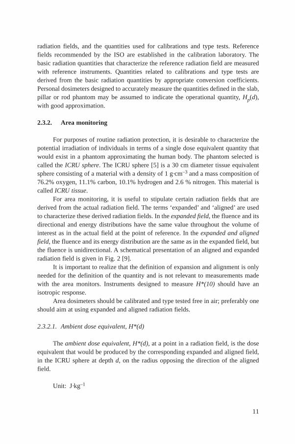
radiation fields, and the quantities used for calibrations and type tests. Referencefields recommended by the ISO are established in the calibration laboratory. Thebasic radiation quantities that characterize the reference radiation field are measuredwith reference instruments. Quantities related to calibrations and type tests arederived from the basic radiation quantities by appropriate conversion coefficients.Personal dosimeters designed to accurately measure the quantities defined in the slab,pillar or rod phantom may be assumed to indicate the operational quantity, Hp(d),with good approximation.
2.3.2. Area monitoring
For purposes of routine radiation protection, it is desirable to characterize thepotential irradiation of individuals in terms of a single dose equivalent quantity thatwould exist in a phantom approximating the human body. The phantom selected iscalled the ICRU sphere. The ICRU sphere [5] is a 30 cm diameter tissue equivalentsphere consisting of a material with a density of 1 g·cm–3 and a mass composition of76.2% oxygen, 11.1% carbon, 10.1% hydrogen and 2.6 % nitrogen. This material iscalled ICRU tissue.
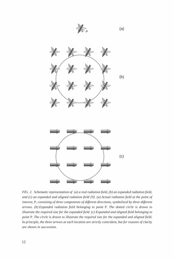
For area monitoring, it is useful to stipulate certain radiation fields that arederived from the actual radiation field. The terms ‘expanded’ and ‘aligned’ are usedto characterize these derived radiation fields. In the expanded field, the fluence and itsdirectional and energy distributions have the same value throughout the volume ofinterest as in the actual field at the point of reference. In the expanded and alignedfield, the fluence and its energy distribution are the same as in the expanded field, butthe fluence is unidirectional. A schematical presentation of an aligned and expandedradiation field is given in Fig. 2 [9].
It is important to realize that the definition of expansion and alignment is onlyneeded for the definition of the quantity and is not relevant to measurements madewith the area monitors. Instruments designed to measure H*(10) should have anisotropic response.
Area dosimeters should be calibrated and type tested free in air; preferably oneshould aim at using expanded and aligned radiation fields.
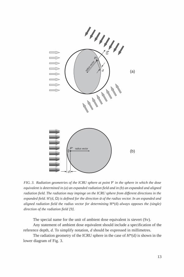
2.3.2.1. Ambient dose equivalent, H*(d)
The ambient dose equivalent, H*(d), at a point in a radiation field, is the doseequivalent that would be produced by the corresponding expanded and aligned field,in the ICRU sphere at depth d, on the radius opposing the direction of the alignedfield.
Unit: J·kg–1
11
12
FIG. 2. Schematic representation of (a) a real radiation field, (b) an expanded radiation field,
and (c) an expanded and aligned radiation field [9]. (a) Actual radiation field at the point of
interest, P, consisting of three components of different directions, symbolized by three different
arrows. (b) Expanded radiation field belonging to point P. The dotted circle is drawn to
illustrate the required size for the expanded field. (c) Expanded and aligned field belonging to
point P. The circle is drawn to illustrate the required size for the expanded and aligned field.
In principle, the three arrows at each location are strictly coincident, but for reasons of clarity
are shown in succession.
P(a)
(b)
(c)
The special name for the unit of ambient dose equivalent is sievert (Sv).Any statement of ambient dose equivalent should include a specification of the
reference depth, d. To simplify notation, d should be expressed in millimetres.The radiation geometry of the ICRU sphere in the case of H*(d) is shown in the
lower diagram of Fig. 3.
13
FIG. 3. Radiation geometries of the ICRU sphere at point P′ in the sphere in which the dose
equivalent is determined in (a) an expanded radiation field and in (b) an expanded and aligned
radiation field. The radiation may impinge on the ICRU sphere from different directions in the
expanded field. H′(d, Ω) is defined for the direction α of the radius vector. In an expanded and
aligned radiation field the radius vector for determining H*(d) always opposes the (single)
direction of the radiation field [9].
(a)
(b)
P'
radiu
s vec
tor
d
Ω
radius vectorP'
d
For strongly penetrating radiation, a depth of 10 mm is currently recommended.The ambient dose equivalent for this depth is then denoted by H*(10). For weaklypenetrating radiation, a depth of 0.07 mm for the skin and 3 mm for the eye areemployed, with analogous notation.
2.3.2.2. Directional dose equivalent, H′(d, Ω)
The directional dose equivalent, H′(d, Ω), at a point in a radiation field, is thedose equivalent that would be produced by the corresponding expanded field, in theICRU sphere at a depth d, on a radius in a specified direction Ω.
Unit: J·kg-1
The special name for the unit of directional dose equivalent is sievert (Sv).Any statement of directional dose equivalent should include a specification of
the reference depth d and the direction Ω. To simplify notation, d should be expressedin millimetres.
The radiation geometry of the ICRU sphere in the case of H′(d, Ω) is shown inthe upper diagram of Fig. 3.
For weakly penetrating radiation, a depth of 0.07 mm for the skin and 3 mm forthe eye are employed. The directional dose equivalent for these depths is then denotedby H′(0.07, Ω) and H′(3, Ω), respectively. In the particular case of a unidirectionalfield, the direction can be specified in terms of the angle α between the radiusopposing the incident field and the specified radius.
2.3.3. Individual monitoring
2.3.3.1. Personal dose equivalent, Hp(d)
The personal dose equivalent, Hp(d), is the dose equivalent in ICRU tissue, atan appropriate depth d below a specified point on the body.
Unit: J·kg–1
The special name for the unit of personal dose equivalent is sievert (Sv).Any statement of personal dose equivalent should include a specification of the
reference depth, d. To simplify notation, d should be expressed in millimetres.For weakly penetrating radiation, a depth of 0.07 mm for the skin and 3 mm for
the eye are employed. The personal dose equivalent for these depths is then denotedby Hp(0.07) and Hp(3), respectively. For strongly penetrating radiation, a depth of10 mm is frequently employed, with analogous notation.
14
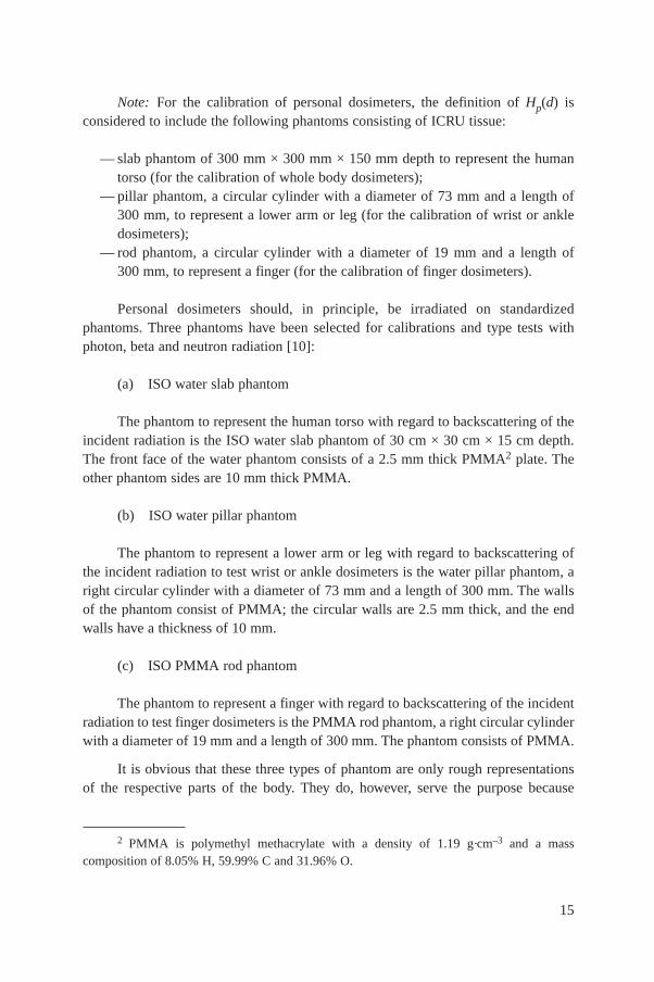
Note: For the calibration of personal dosimeters, the definition of Hp(d) isconsidered to include the following phantoms consisting of ICRU tissue:
— slab phantom of 300 mm × 300 mm × 150 mm depth to represent the humantorso (for the calibration of whole body dosimeters);
— pillar phantom, a circular cylinder with a diameter of 73 mm and a length of300 mm, to represent a lower arm or leg (for the calibration of wrist or ankledosimeters);
— rod phantom, a circular cylinder with a diameter of 19 mm and a length of300 mm, to represent a finger (for the calibration of finger dosimeters).
Personal dosimeters should, in principle, be irradiated on standardizedphantoms. Three phantoms have been selected for calibrations and type tests withphoton, beta and neutron radiation [10]:
(a) ISO water slab phantom
The phantom to represent the human torso with regard to backscattering of theincident radiation is the ISO water slab phantom of 30 cm × 30 cm × 15 cm depth.The front face of the water phantom consists of a 2.5 mm thick PMMA2 plate. Theother phantom sides are 10 mm thick PMMA.
(b) ISO water pillar phantom
The phantom to represent a lower arm or leg with regard to backscattering ofthe incident radiation to test wrist or ankle dosimeters is the water pillar phantom, aright circular cylinder with a diameter of 73 mm and a length of 300 mm. The wallsof the phantom consist of PMMA; the circular walls are 2.5 mm thick, and the endwalls have a thickness of 10 mm.
(c) ISO PMMA rod phantom
The phantom to represent a finger with regard to backscattering of the incidentradiation to test finger dosimeters is the PMMA rod phantom, a right circular cylinderwith a diameter of 19 mm and a length of 300 mm. The phantom consists of PMMA.
It is obvious that these three types of phantom are only rough representationsof the respective parts of the body. They do, however, serve the purpose because
15
2 PMMA is polymethyl methacrylate with a density of 1.19 g·cm–3 and a masscomposition of 8.05% H, 59.99% C and 31.96% O.
— according to the definition of Hp(d), a personal dosimeter should be constructedin such a way that it is sensitive to radiation backscattered from the body; thedifference in backscatter between the standardized phantom and the actual partof the body where the dosimeter is worn is thereby automatically measured;
— the three different shapes of phantom cover the needs of calibrations and typetesting
(1) of whole body dosimeters worn, for example, on the trunk to estimate theeffective dose, and
(2) of wrist or ankle dosimeters and of finger dosimeters to estimate the partialbody doses;
— reference phantoms in which Hp(d) is defined for calibration of personaldosimeters are consistently composed of ICRU tissue and are the same shapesas the phantoms actually used; the conversion coefficients given in thestandards only relate to the reference phantoms;
16
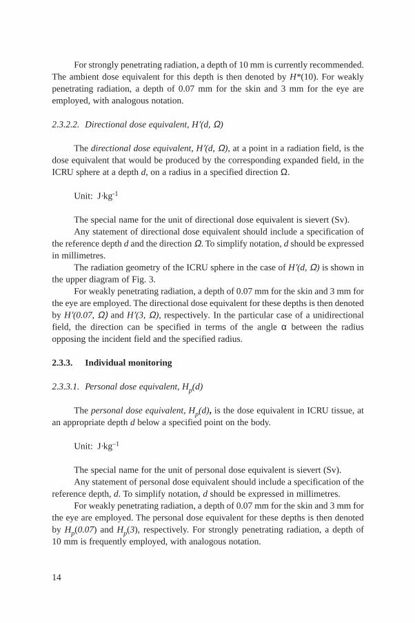
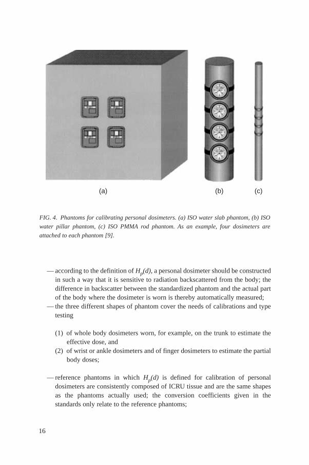
FIG. 4. Phantoms for calibrating personal dosimeters. (a) ISO water slab phantom, (b) ISO
water pillar phantom, (c) ISO PMMA rod phantom. As an example, four dosimeters are
attached to each phantom [9].
(a) (b) (c)
— consistent use of the recommended phantoms makes it possible to compare thecalibrations and type testing at different laboratories.
When these phantoms are used, no correction factors should be applied tocorrect for any differences in backscatter relative to ICRU tissue. A schematic drawingof the phantoms and of examples of attached personal dosimeters is shown in Fig. 4.
Routine calibrations of personal dosimeters may be done, sometimes moresimply, free in air or on a PMMA phantom, and even with a type of radiation otherthan that which the instrument is intended to measure. Such simplifications can bejustified, provided the calibration procedure is checked during the type test so that thedifference in the responses of the dosimeter under both irradiation conditions is thesame for each dosimeter of the same type. Calibration on a phantom should be doneif the dosimeter is very sensitive to the radiation backscattered from the phantom,such as the neutron albedo dosimeter, for example.
2.4. OTHER QUANTITIES
2.4.1. Fluence
The fluence, Φ, is the quotient of dN and da, where dN is the number ofparticles incident on a sphere of cross-sectional area da; thus
Unit: m–2
2.4.2. Energy imparted
The energy imparted, M, by ionizing radiation to matter in a volume is given by
M = Rin – Rout + Σ Q
where
Rin is the radiant energy incident on the volume, i.e. the sum of the energies(excluding rest energies) of all charged and uncharged ionizing particlesentering the volume,
Rout is the radiant energy emerging from the volume, i.e. the sum of theenergies (excluding rest energies) of all charged and uncharged ionizingparticles leaving the volume, and
Φ = dN
da
17

Σ Q is the sum of the rest mass energies of nuclei and elementary particlesin any interactions occurring in the volume (decreases: positive sign;increases: negative sign).
Unit: J
2.4.3. Absorbed dose
The absorbed dose, D, is the quotient of dM and dm, where dM is the meanenergy imparted by ionizing radiation to matter of mass dm, thus
Unit: J·kg-1
The special name for the unit of absorbed dose is gray (Gy).
2.4.4. Absorbed dose rate
The absorbed dose rate, D·, is the quotient of dD and dt, where dD is the
increment of absorbed dose in the time interval dt. Hence,
Unit: J·kg–1·s–1
The special name for the unit of absorbed dose rate is gray per second(Gy·s–1).
2.4.5. Kerma
The kerma, K, is the quotient of dEtr and dm, where dEtr is the sum of the initialkinetic energies of all the charged ionizing particles liberated by uncharged ionizingparticles in a material of mass dm; thus
Unit: J·kg–1
The special name for the unit of kerma is gray (Gy).
dE
dmtr=
DdD
dt
DdM
dm=
18
2.4.6. Kerma rate
The kerma rate, K·, is the quotient of dK and dt, where dK is the increment of
kerma in the time interval dt; thus
Unit: J·kg–1·s–1
The special name for the unit of kerma rate is gray per second (Gy·s–1).
2.4.7. Linear energy transfer
The linear energy transfer or linear collision stopping power, L, of a material,for a charged particle, is the quotient of dE and dl, where dE is the mean energy lostby the particle, due to collisions with electrons, in traversing a distance dl; thus
Unit: J·m–1
E may be expressed in eV, and hence L may be expressed in eV·m–1 or someconvenient submultiple or multiple, such as keV·µm–1.
2.4.8. Lineal energy
The lineal energy, y, is the quotient of M by l_, where M is the energy imparted
to the matter in a volume of interest by an energy deposition event and is the meanchord length in that volume; thus
Unit: J·m–1
M may be expressed in eV, and hence y may be expressed in eV·m–1 or someconvenient submultiple or multiple, such as keV·µm–1.
yM
l
LdE
dl=
KdK
dt
19
An energy deposition event consists of statistically correlated depositions ofenergy as, for example, those by high energy particles and/or their secondaryelectrons.
2.4.9. Distribution of absorbed dose in linear energy transfer
The distribution of absorbed dose in linear energy transfer, DL, is the quotientof dD and dL, where dD is the absorbed dose contributed by primary charged particleswith linear energy transfer between L and L + dL; thus
Unit: m·g–1
2.4.10. Quality factor
The quality factor, Q, at a point in tissue, is given by
where D is the absorbed dose at that point, DL is the distribution of D in linear energytransfer L and Q(L) is the corresponding quality factor at the point of interest. Theintegration is to be performed over the distribution DL, due to all charged particles,excluding their secondary electrons. Q(L) is specified as follows:
1 for L ≤ 10Q(L) = 0.32 L – 2.2 for 10 < L < 100
300/L for L ≤ 100
where L is expressed in keV·µm–1.
2.4.11. Dose equivalent
The dose equivalent, H, is the product of Q and D at a point in tissue, where Dis the absorbed dose and Q is the quality factor at that point; thus
H = QD
Unit: J·kg–1
DQ L D dLL
L
= z1 ( )
DdD
dLL =
20

The special name for the unit of dose equivalent is sievert (Sv).For photons, electrons and muons of all energies H = D is assumed.
2.4.12. Dose equivalent rate
The dose equivalent rate, H, is the quotient of dH by dt, where dH is theincrement of dose equivalent in the time interval dt; thus
Unit: J·kg–1·s–1
The special name for the unit of dose equivalent rate is sievert per second(Sv·s–1).
3. FUNDAMENTALS OF CALIBRATION
3.1. CALIBRATION AND TESTS
Calibration is defined as the quantitative determination, under a controlled setof standard conditions, of the indication given by a radiation measuring instrument asa function of the value of the quantity the instrument is intended to measure.
Tests are measurements intended to confirm that an instrument is functioningcorrectly, and/or the quantitative determination of the variations of the indication ofthe instrument over a range of radiation, electrical and environmental conditions.
Four distinct categories of instrument testing, of which calibration is a part, aregenerally recognized; these are:
(a) Type tests — These tests will normally be carried out by National or SecondaryStandard Laboratories, which may make the information available to theinstrument user. The tests are intended to determine the characteristics of aparticular type or model of a production instrument. They involve extensivetesting over a wide range of quantities that may have a bearing on the result ofa measurement without being the objective of the measurement — the‘influence quantities’. Such influence quantities are energy, angle of incidence,dose or dose rate and radiation type, usually under a variety of environmentalconditions. A type test is normally performed on a prototype or on an
HdH
dt
21

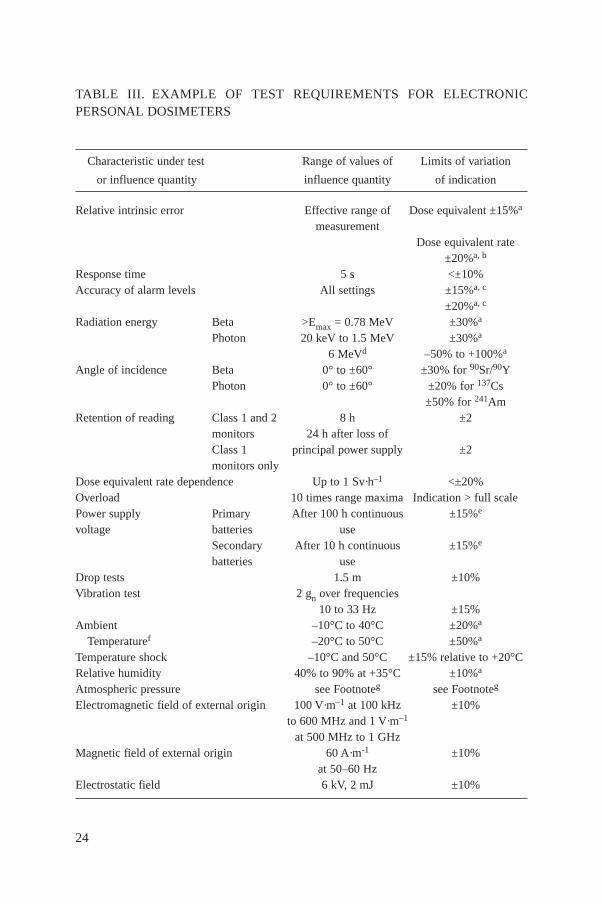
instrument taken at random from a production batch and intended to be typicalof the instrument type.Specific performance requirements for radiation monitoring equipment arespecified in various national and international standards.Examples of some of the International Electrotechnical Commission (IEC)standards on radiation monitoring equipment are listed in Table II.Table III gives, as an example, a summary of the range of testing required in theIEC standard for electron personal dosimeters to measure Hp(10) andHp(0.07, α).
(b) Special calibrations — In some special cases response measurements similar tothose of a type test are necessary in the course of special calibrations. Thesehave to be performed, for example, if the dosimeter or dose ratemeter isoperated under abnormal circumstances or if the routine calibration or typetesting provides insufficient information.
(c) Routine calibrations — These are intended to determine a calibration factorappropriate to the routine application of the dosimeter or dose ratemeter. Aroutine calibration may be of a confirmatory nature when it is either performedto check the calibration carried out by the manufacturer together with adosimeter or dose ratemeter, or to check whether the calibration factor issufficiently stable during the continued long term use of a dosimeter or doseratemeter. When considering the most practical way to perform a routinecalibration, results obtained in a type test may turn out to be helpful, especiallyin selecting the phantom for irradiating personal dosemeters.
(d) Acceptance tests — These are contractual tests carried out on all instruments ofa particular type before being put into service for the first time; they areintended to demonstrate that every instrument in a consignment conforms withits specification.
3.2. REFERENCE CONDITIONS AND STANDARD TEST CONDITIONS
Under reference conditions, all influence quantities and instrument parametershave values (‘reference values’) at which the correction factor for the dependence onthat influence quantity has the value 1.0. The calibration factor is only valid withoutcorrections for reference conditions.
Standard test conditions are the range of values of a set of influence quantitiesunder which a calibration or a determination of the response is carried out.
The deviations of the calibration factor from its value under referenceconditions caused by these deviations should in principle be corrected for. In practice,the uncertainty aimed at serves as a criterion of which influence quantity has to betaken into account by an explicit correction or whether its effect may be incorporated
22

23
TABLE II. EXAMPLES OF IEC STANDARDS ON RADIATION MONITORINGEQUIPMENT
Publication Equipment
Photon and beta monitoring equipment
1018 High range beta and photon dose and dose rate portable instruments foremergency radiation protection purposes
532 Installed dose ratemeters, warning assemblies and monitors for X or gammaradiations of energies between 50 keV and 7 MeV
846 Beta, X and gamma radiation dose equivalent and dose equivalent ratemetersfor use in radiation protection
1017-1 Portable, transportable or installed X or gamma radiation ratemeters for1017-2 environmental monitoring
Part 1: RatemetersPart 2: Integrating assemblies
Personal dosimetry
1283 Direct reading personal dose equivalent and/or dose equivalent rate monitorsfor the measurement of personal dose equivalents Hp(10) and Hp(0.07) for X,gamma and beta radiations
1066 Thermoluminescence dosimetry systems for personal and environmentalmonitoring
Neutron monitoring equipment
1005 Portable neutron ambient dose equivalent ratemeters for use in radiationprotection
1323 Direct reading personal dose equivalent and/or dose equivalent rate monitorsfor neutron radiation
Monitoring of individual radioactive contamination
325 Alpha, beta and alpha–beta contamination meters and monitors504 Hand and/or foot contamination monitors and warning assemblies1098 Installed personnel surface contamination monitoring assemblies for alpha
and beta emitters
Monitoring of airborne radioactive contamination
579 Radioactive aerosol contamination meters and monitors710 Radiation protection equipment for the measuring and monitoring of
airborne tritium1171 Monitoring equipment — Atmospheric radioactive iodines in the environment
24
TABLE III. EXAMPLE OF TEST REQUIREMENTS FOR ELECTRONICPERSONAL DOSIMETERS
Characteristic under test Range of values of Limits of variation
or influence quantity influence quantity of indication
Relative intrinsic error Effective range of Dose equivalent ±15%a
measurementDose equivalent rate
±20%a, b
Response time 5 s <±10%Accuracy of alarm levels All settings ±15%a, c
±20%a, c
Radiation energy Beta >Emax = 0.78 MeV ±30%a
Photon 20 keV to 1.5 MeV ±30%a
6 MeVd –50% to +100%a
Angle of incidence Beta 0° to ±60° ±30% for 90Sr/90YPhoton 0° to ±60° ±20% for 137Cs
±50% for 241AmRetention of reading Class 1 and 2 8 h ±2
monitors 24 h after loss ofClass 1 principal power supply ±2monitors only
Dose equivalent rate dependence Up to 1 Sv·h–1 <±20%Overload 10 times range maxima Indication > full scalePower supply Primary After 100 h continuous ±15%e
voltage batteries useSecondary After 10 h continuous ±15%e
batteries useDrop tests 1.5 m ±10%Vibration test 2 gn over frequencies
10 to 33 Hz ±15%Ambient –10°C to 40°C ±20%a
Temperaturef –20°C to 50°C ±50%a
Temperature shock –10°C and 50°C ±15% relative to +20°CRelative humidity 40% to 90% at +35°C ±10%a
Atmospheric pressure see Footnoteg see Footnoteg
Electromagnetic field of external origin 100 V·m–1 at 100 kHz ±10%to 600 MHz and 1 V·m–1
at 500 MHz to 1 GHzMagnetic field of external origin 60 A·m-1 ±10%
at 50–60 HzElectrostatic field 6 kV, 2 mJ ±10%

into the uncertainty. During type tests, all values of influence quantities not subject ofthe test are fixed within the interval of the standard test conditions. The standard testconditions together with the reference conditions are given in Table IV.
To obtain (corrected) measured values M at standard test conditions, as may beprescribed in the instrument’s instruction manual, it may be necessary, for example,to correct the indicated value M1 for the zero indication M0 and other effectsrepresented by the appropriate correction factors ki:
M = (Mi – M0) Πi
ki
The factor ki is unity for reference conditions.
3.3. TRACEABILITY
Measurements of the radiation characteristics of an instrument made as part ofthe type, acceptance and routine tests need to be traceable to an appropriate nationalstandard. This means that:
(i) each reference instrument used for calibration purposes has itself beencalibrated against a reference instrument of higher quality, up to the level atwhich the higher quality instrument is the accepted national standard;
(ii) the frequency of such calibration, which is dependent on the type, quality,stability, use and environment of the lower quality standard, is such as toestablish reasonable confidence that its value will not move outside the limitsof its specification between successive calibrations;
25
a Of the indication under standard test conditions.b For the lowest decade or scale of the dose equivalent rate, ±30% is applicable.c This error is additional to the uncertainty associated with the determination of the
conventional true dose equivalent rate.d This additional requirement is applicable only to monitors used for measuring doses in the
vicinity of power reactors producing 6 MeV gamma radiation from 16N.e Of the initial indication.f Monitors intended for use in temperate climates. In hotter or colder climates, other limits
may be specified. For monitors intended for operation at very low temperatures, means ofheating the batteries may be provided.
g No general specification. Range of values of influence quantities and limits of variation of indication to be specified if required.
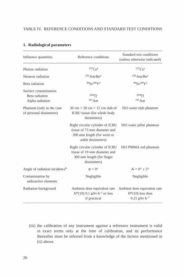
(iii) the calibration of any instrument against a reference instrument is validin exact terms only at the time of calibration, and its performancethereafter must be inferred from a knowledge of the factors mentioned in(ii) above.
26
TABLE IV. REFERENCE CONDITIONS AND STANDARD TEST CONDITIONS
1. Radiological parameters
Influence quantities Reference conditionsStandard test conditions
(unless otherwise indicated)
Photon radiation 137Csa 137Csa
Neutron radiation 241Am/Bea 241Am/Bea
Beta radiation 90Sr/90Ya 90Sr/90Ya
Surface contaminationBeta radiation 204Tl 204TlAlpha radiation 241Am 241Am
Phantom (only in the case 30 cm × 30 cm × 15 cm slab of ISO water slab phantomof personal dosimeters) ICRU tissue (for whole body
dosimeters)
Right circular cylinder of ICRU ISO water pillar phantomtissue of 73 mm diameter and300 mm length (for wrist or
ankle dosimeters)
Right circular cylinder of ICRU ISO PMMA rod phantomtissue of 19 mm diameter and
300 mm length (for fingerdosimeters)
Angle of radiation incidenceb α = 0° Α = 0° ± 5°
Contamination by Negligible Negligibleradioactive elements
Radiation background Ambient dose equivalent rate Ambient dose equivalent rateH*(10) 0.1 µSv·h–1 or less H*(10) less than
if practical 0.25 µSv·h–1
27
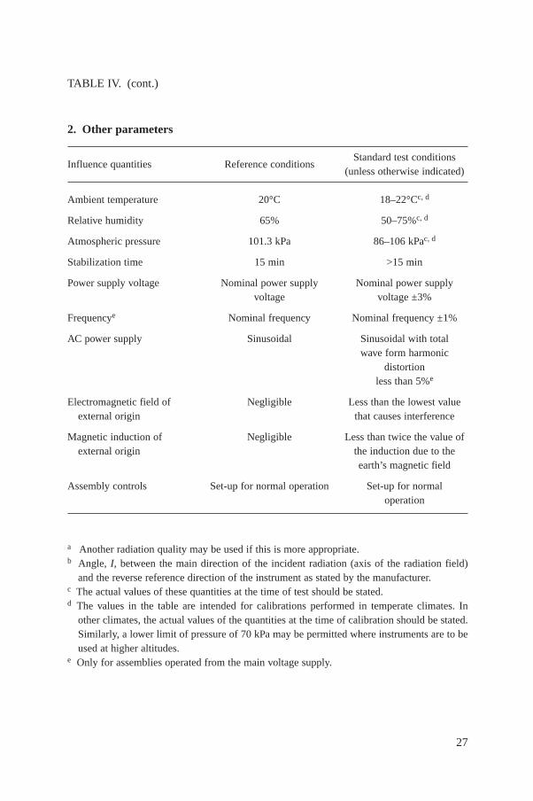
TABLE IV. (cont.)
2. Other parameters
Influence quantities Reference conditionsStandard test conditions
(unless otherwise indicated)
Ambient temperature 20°C 18–22°Cc, d
Relative humidity 65% 50–75%c, d
Atmospheric pressure 101.3 kPa 86–106 kPac, d
Stabilization time 15 min >15 min
Power supply voltage Nominal power supply Nominal power supplyvoltage voltage ±3%
Frequencye Nominal frequency Nominal frequency ±1%
AC power supply Sinusoidal Sinusoidal with totalwave form harmonic
distortionless than 5%e
Electromagnetic field of Negligible Less than the lowest valueexternal origin that causes interference
Magnetic induction of Negligible Less than twice the value ofexternal origin the induction due to the
earth’s magnetic field
Assembly controls Set-up for normal operation Set-up for normaloperation
a Another radiation quality may be used if this is more appropriate.b Angle, I, between the main direction of the incident radiation (axis of the radiation field)
and the reverse reference direction of the instrument as stated by the manufacturer.c The actual values of these quantities at the time of test should be stated.d The values in the table are intended for calibrations performed in temperate climates. In
other climates, the actual values of the quantities at the time of calibration should be stated.Similarly, a lower limit of pressure of 70 kPa may be permitted where instruments are to beused at higher altitudes.
e Only for assemblies operated from the main voltage supply.
3.4. DETERMINATION OF THE CALIBRATION FACTORAND OF THE RESPONSE BY A REFERENCE INSTRUMENT
3.4.1. General
In this report, calibrations are only considered in terms of the operationalquantities for area monitoring, H*(10) and H′(0.07, Ω), and for individualmonitoring, Hp(10) and Hp(0.07). The quantities H′(3, Ω) and Hp(3), listed also inTable I, are used very rarely and are often conservatively estimated by H′(0.07, Ω) andHp(0.07). Therefore they are not dealt with in this report.
In general, reference instruments do not directly indicate the appropriate doseequivalent quantity for calibrations or type tests. Instead, most frequently referenceinstruments are used to characterize the reference radiation fields by othermeasurands such as fluence for neutron radiation and air kerma for photon radiation(Fig. 1). The dose equivalent quantity is derived from these basic radiation quantitiesby appropriate conversion coefficients, h [11].
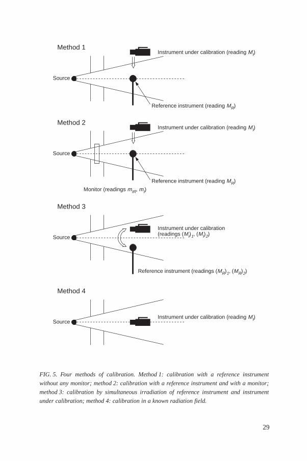
One has to distinguish between four methods of calibration that may be used(Fig. 5). Sections 3.4.2 to 3.4.4 deal with the determination of the calibration factorand of the response by means of a reference instrument; in Section 3.5, it is assumedthat the basic radiation quantity characterizing the field is already known and noreference instrument is needed. If a reference instrument is used (denoted by subscriptR in the following), its calibration factor, NR, given in the calibration certificate, canbe used to determine the conventional true value of the appropriate dose equivalentquantity H by means of the conversion coefficient h for the dose equivalent quantityH and the measured (indicated) value MR of the reference instrument (corrected forreference conditions; see Section 4.3.2):
H = hNR MR
One has to consider two cases:
(a) where the reference instrument indicates the same measurand as the instrumentunder calibration:
h = 1
(b) where the reference instrument indicates a measurand different from that of theinstrument under calibration. Here, the appropriate conversion coefficient, h,should be applied. As an example, conversion coefficients from air kerma Ka toH*(10) and H′(0.07, 0°) are given in Fig. 6 for monoenergetic photons.
28
29
FIG. 5. Four methods of calibration. Method 1: calibration with a reference instrument
without any monitor; method 2: calibration with a reference instrument and with a monitor;
method 3: calibration by simultaneous irradiation of reference instrument and instrument
under calibration; method 4: calibration in a known radiation field.
Instrument under calibration (reading MI)
Reference instrument (reading MR)
Source
Method 1
Instrument under calibration (reading MI)
Reference instrument (reading MR)
Source
Method 2
Instrument under calibration(readings (MI)1, (MI)2)
Reference instrument (readings (MR)1, (MR)2)
Source
Method 3
Instrument under calibration (reading MI)Source
Method 4
Monitor (readings mIR, mI)
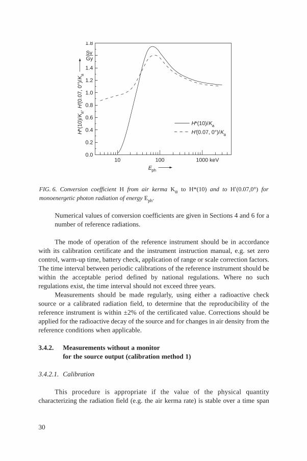
Numerical values of conversion coefficients are given in Sections 4 and 6 for anumber of reference radiations.
The mode of operation of the reference instrument should be in accordancewith its calibration certificate and the instrument instruction manual, e.g. set zerocontrol, warm-up time, battery check, application of range or scale correction factors.The time interval between periodic calibrations of the reference instrument should bewithin the acceptable period defined by national regulations. Where no suchregulations exist, the time interval should not exceed three years.
Measurements should be made regularly, using either a radioactive checksource or a calibrated radiation field, to determine that the reproducibility of thereference instrument is within ±2% of the certificated value. Corrections should beapplied for the radioactive decay of the source and for changes in air density from thereference conditions when applicable.
3.4.2. Measurements without a monitorfor the source output (calibration method 1)
3.4.2.1. Calibration
This procedure is appropriate if the value of the physical quantitycharacterizing the radiation field (e.g. the air kerma rate) is stable over a time span
30
FIG. 6. Conversion coefficient H from air kerma Kα to H*(10) and to H′(0.07,0°) for
monoenergetic photon radiation of energy Eph.
H*(
10)/
Ka,
H'(0
.07,
0°)
/Ka
0.0
0.2
0.4
0.6
0.8
1.0
1.2
1.4
SvGy
1.8
10 100 1000 keV
H*(10)/Ka
H'(0.07, 0°)/Ka
Eph
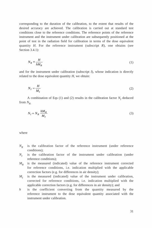
corresponding to the duration of the calibration, to the extent that results of thedesired accuracy are achieved. The calibration is carried out at standard testconditions close to the reference conditions. The reference points of the referenceinstrument and the instrument under calibration are subsequently positioned at thepoint of test in the radiation field for calibration in terms of the dose equivalentquantity H. For the reference instrument (subscript R), one obtains (seeSection 3.4.1):
(1)
and for the instrument under calibration (subscript I), whose indication is directlyrelated to the dose equivalent quantity H, we obtain:
(2)
A combination of Eqs (1) and (2) results in the calibration factor NI deducedfrom NR:
(3)
where
NR is the calibration factor of the reference instrument (under referenceconditions);
NI is the calibration factor of the instrument under calibration (underreference conditions);
MR is the measured (indicated) value of the reference instrument correctedfor reference conditions, i.e. indication multiplied with the applicablecorrection factors (e.g. for differences in air density);
MI is the measured (indicated) value of the instrument under calibration,corrected for reference conditions, i.e. indication multiplied with theapplicable correction factors (e.g. for differences in air density); and
h is the coefficient converting from the quantity measured by thereference instrument to the dose equivalent quantity associated with theinstrument under calibration.
N NhM
MI RR
I
NH
MII
NH
hMRR
=
31
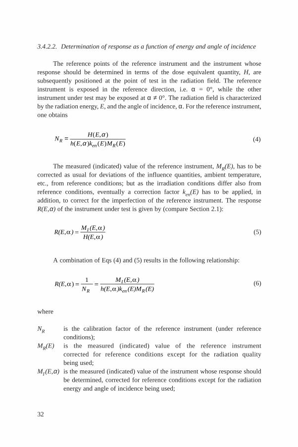
3.4.2.2. Determination of response as a function of energy and angle of incidence
The reference points of the reference instrument and the instrument whoseresponse should be determined in terms of the dose equivalent quantity, H, aresubsequently positioned at the point of test in the radiation field. The referenceinstrument is exposed in the reference direction, i.e. α = 0°, while the otherinstrument under test may be exposed at α ≠ 0°. The radiation field is characterizedby the radiation energy, E, and the angle of incidence, α. For the reference instrument,one obtains
(4)
The measured (indicated) value of the reference instrument, MR(E), has to becorrected as usual for deviations of the influence quantities, ambient temperature,etc., from reference conditions; but as the irradiation conditions differ also fromreference conditions, eventually a correction factor ken(E) has to be applied, inaddition, to correct for the imperfection of the reference instrument. The responseR(E,α) of the instrument under test is given by (compare Section 2.1):
(5)
A combination of Eqs (4) and (5) results in the following relationship:
(6)
where
NR is the calibration factor of the reference instrument (under referenceconditions);
MR(E) is the measured (indicated) value of the reference instrumentcorrected for reference conditions except for the radiation qualitybeing used;
MI (E,α) is the measured (indicated) value of the instrument whose response shouldbe determined, corrected for reference conditions except for the radiation energy and angle of incidence being used;
R(EN
M (E )
h(E )k (E)M (E)R
I
en R, )
,
,
1
R(E )M (E )
H(E )I,
,
,
NH E
h E k E M ERen R
= ( , )
( , ) ( ) ( )
αα
32
h(E,α) is the coefficient converting from the quantity measured by thereference instrument to the dose equivalent quantity for theradiation energy, E, and the angle of incidence, α, being used;
ken(E) is the correction factor to take into account the difference betweenthe responses of the reference chamber at reference conditions and atthe energy where the energy response of the instrument is beingdetermined.
Often the response of the instrument is given as its relative response, r, withrespect to its response under reference conditions:
(7)
where Rr is the response under reference conditions.
Note: The relative response can be a useful quantity for describing the variationof response as a function of photon energy or angle of incidence, as it easilyvisualizes such variation, because of its nature as a ratio.
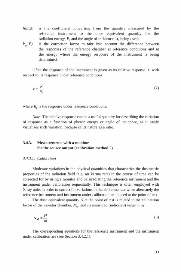
3.4.3. Measurements with a monitorfor the source output (calibration method 2)
3.4.3.1. Calibration
Moderate variations in the physical quantities that characterize the dosimetricproperties of the radiation field (e.g. air kerma rate) in the course of time can becorrected for by using a monitor and by irradiating the reference instrument and theinstrument under calibration sequentially. This technique is often employed withX ray units in order to correct for variations in the air kerma rate when alternately thereference instrument and instrument under calibration are placed at the point of test.
The dose equivalent quantity H at the point of test is related to the calibrationfactor of the monitor chamber, NM, and its measured (indicated) value m by
(8)
The corresponding equations for the reference instrument and the instrumentunder calibration are (see Section 3.4.2.1):
NH
mM =
rR
Rr=
33
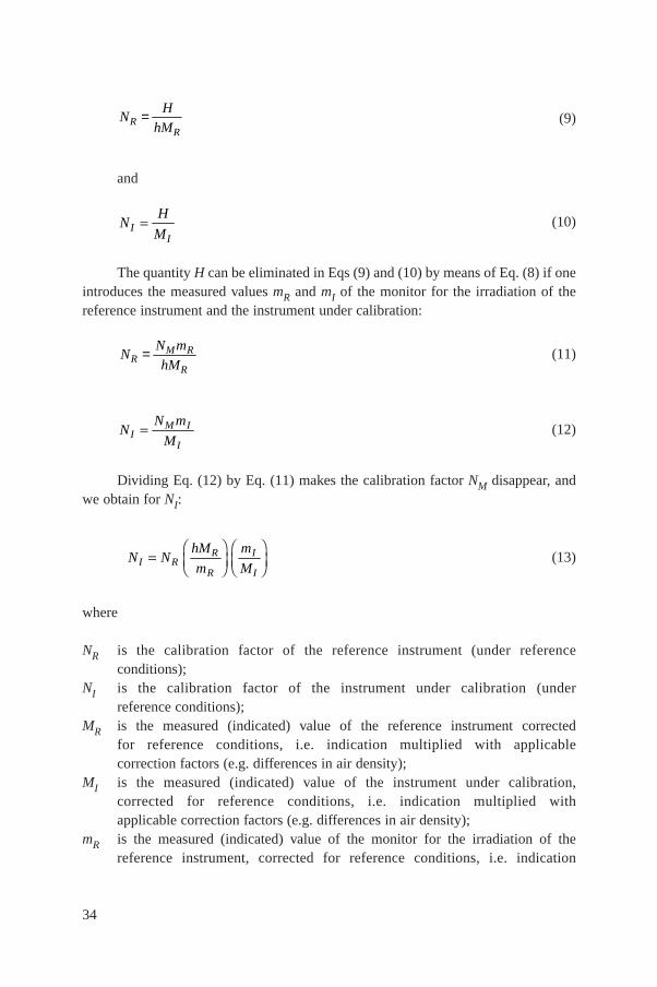
(9)
and
(10)
The quantity H can be eliminated in Eqs (9) and (10) by means of Eq. (8) if oneintroduces the measured values mR and mI of the monitor for the irradiation of thereference instrument and the instrument under calibration:
(11)
(12)
Dividing Eq. (12) by Eq. (11) makes the calibration factor NM disappear, andwe obtain for NI:
(13)
where
NR is the calibration factor of the reference instrument (under referenceconditions);
NI is the calibration factor of the instrument under calibration (underreference conditions);
MR is the measured (indicated) value of the reference instrument corrected for reference conditions, i.e. indication multiplied with applicablecorrection factors (e.g. differences in air density);
MI is the measured (indicated) value of the instrument under calibration,corrected for reference conditions, i.e. indication multiplied withapplicable correction factors (e.g. differences in air density);
mR is the measured (indicated) value of the monitor for the irradiation of thereference instrument, corrected for reference conditions, i.e. indication
N NhM
m
m
MI RR
R
I
I
FHGIKJFHGIKJ
NN m
MIM I
I
NN m
hMRM R
R=
NH
MII
NH
hMRR
=
34
multiplied with applicable correction factors (e.g. differences in airdensity);
mI is the measured (indicated) value of the monitor for the irradiation of theinstrument under calibration, corrected for reference conditions, i.e.indication multiplied with applicable correction factors (e.g. differences inair density);
h is the coefficient converting from the quantity measured by the referenceinstrument to the dose equivalent quantity associated with the instrument under calibration.
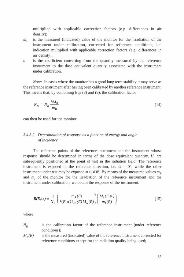
Note: In cases where the monitor has a good long term stability it may serve asthe reference instrument after having been calibrated by another reference instrument.This means that, by combining Eqs (8) and (9), the calibration factor
(14)
can then be used for the monitor.
3.4.3.2. Determination of response as a function of energy and angleof incidence
The reference points of the reference instrument and the instrument whoseresponse should be determined in terms of the dose equivalent quantity, H, aresubsequently positioned at the point of test in the radiation field. The referenceinstrument is exposed in the reference direction, i.e. α = 0°, while the otherinstrument under test may be exposed at α ≠ 0°. By means of the measured values mRand mI of the monitor for the irradiation of the reference instrument and theinstrument under calibration, we obtain the response of the instrument:
(15)
where
NR is the calibration factor of the reference instrument (under referenceconditions);
MR(E) is the measured (indicated) value of the reference instrument corrected forreference conditions except for the radiation quality being used;
R(E )N
m (E)
h(E )k (E) M (E)
M (E, )
m (E)R
R
en R
I
I,
,
FHG
IKJFHG
IKJ
1
N NhM
mM RR
R=
35
MI (E,α) is the measured (indicated) value of the instrument whose response shouldbe determined, corrected for reference conditions except radiation energy and angle of incidence being used;
mR (E) is the measured (indicated) value of the monitor for the irradiation of thereference instrument, corrected for reference conditions except forradiation energy being used;
mI (E) is the measured (indicated) value of the monitor for the irradiation of theinstrument under calibration, corrected for reference conditions except forradiation energy used;
h(E,α) is the coefficient converting from the quantity measured by the referenceinstrument to the dose equivalent quantity for the radiation energy E andthe angle of incidence, α, being used;
ken(E) is the correction factor taking into account the difference between theresponses of the reference chamber at reference conditions and at theenergy where the energy response of the instrument is being determined.
3.4.4. Measurements by simultaneous irradiationof reference instrument and dosimeter (calibration method 3)
3.4.4.1. Calibration
In some cases calibrations may also be performed by simultaneous irradiationof the detectors of the reference instrument and the instrument under test in a field bylocating them symmetrically to the axis of the radiation field at the same distancefrom the source. The distance between the two detectors should be large enough forthe indication of either instrument not to be influenced by the presence of the otherone, to an extent exceeding 2%.
Primarily, this procedure will be applicable to those cases where no phantomis required, i.e. for area monitoring dosimeters. This technique is used particularlyfor reference radiations produced by accelerators or when using uncollimatedsources.
The dose equivalent quantity H at the two symmetrical points of test is relatedto the calibration factor of the reference instrument at point of test No. 1 by (seeSection 3.4.2.1):
(16)
and at point of test No. 2 of the instrument under calibration,
NH
hMRR
FHGIKJ1
36
(17)
To eliminate the influence of the radiation field asymmetry, the measurementsare repeated after exchanging the positions of the two instruments; we obtain
(18)
and
(19)
H1 and H2 can be eliminated by combining Eqs (16) and (19), and Eqs (17) and(18), respectively:
(20)
(21)
Multiplication of Eqs (20) and (21) leads to
(22)
where
NR is the calibration factor of the reference instrument (under referenceconditions);
N NhM
M
hM
MI RR
I
R
I
FHGIKJFHGIKJ1 2
N
N
hM
MI
R
R
I
FHGIKJ 2
N
N
hM
MI
R
R
I
FHGIKJ1
NH
MII
FHGIKJ1
NH
hMRR
FHGIKJ 2
NH
MII
FHGIKJ 2
37

NI is the calibration factor of the instrument under calibration (underreference conditions);
(MR /MI)1 is the measured (indicated) value of the reference instrument divided bythe corresponding value of the instrument under calibration at test pointNo. 1, both corrected for reference conditions, i.e. indication multipliedwith applicable correction factors (e.g. differences in air density);
(MR /MI)2 is the measured (indicated) value of the reference instrument divided bythe corresponding value of the instrument under calibration at test pointNo. 2, both corrected for reference conditions, i.e. indication multipliedwith applicable correction factors (e.g. differences in air density);
h is the coefficient to convert from the quantity measured by the referenceinstrument to the dose equivalent quantity associated with the instrumentunder calibration.
3.4.4.2. Determination of response as a function of energy and angle of incidence
The reference points of the reference instrument and of the instrument whoseresponse should be determined in terms of the dose equivalent quantity, H, arepositioned simultaneously at the two symmetrical points of test in the radiation field.The reference instrument is exposed in the reference direction, i.e. α = 0°, while theother instrument under test may be exposed at α ≠ 0°. We obtain the response of theinstrument:
(23)
where
NR is the calibration factor of the reference instrument (under referenceconditions);
(MI (E,α)/ is the measured (indicated) value of the instrument whose responseMR(E))1 should be determined, divided by the corresponding value of the
reference instrument at test point No. 1, both corrected for referenceconditions except radiation energy and angle of incidence being used;
(MI (E,α)/ is the measured (indicated) value of the instrument whose responseMR(E))2 should be determined, divided by the corresponding value of the
reference instrument at test point No. 2, both corrected for referenceconditions except radiation energy and angle of incidence beingused;
R(E )N h(E )k (E)
M (E
M (E)
M (E
M (E)R en
I
R
I
R,
,
, ) , )
FHG
IKJFHG
IKJ
1
1 2
38
h(E,α) is the coefficient converting from the quantity measured by the referenceinstrument to the dose equivalent quantity for the radiation energy E andthe angle of incidence being used;
ken(E) correction factor taking into account the difference between the responsesof the reference chamber at reference conditions and at the energy wherethe energy response of the instrument is being determined.
3.5. DETERMINATION OF THE CALIBRATION FACTORAND THE RESPONSE IN A KNOWN RADIATION FIELD(CALIBRATION METHOD 4)
3.5.1. Calibration
For a radiation field in which the dose equivalent quantity H of the field at thepoint of test is known, the calibration factor of an instrument NI is obtained by
NI = H / MI (24)
where
NI is the calibration factor of the instrument under calibration (under referenceconditions);
MI is the measured value of the instrument under calibration, corrected forreference conditions, i.e. multiplication by appropriate correction factors(e.g. differences in air density);
H is the conventional true value of the dose equivalent quantity to bemeasured.
3.5.2. Determination of response as a function of energy and angle of incidence
The reference point of the instrument whose response should be determined interms of the dose equivalent quantity, H, is positioned at the point of test in theradiation field. The instrument may be exposed at α ≠ 0°. The response of theinstrument is obtained by
(25)
where
R(E )M (E )
H(E )I,
,
,
39
MI(E,α) is the measured (indicated) value of the instrument whose response shouldbe determined, corrected for reference conditions except radiation energyand angle of incidence being used;
H(E,α) is the dose equivalent quantity for the radiation energy, E, and the angle ofincidence, α, being used.
3.6. ADDITIONAL CONSIDERATIONS FOR CALIBRATIONS
Misplacement of detectorAll distances between the reference source and the instrument should be taken
as the distance between the source and the reference point of the instrument.Misplacement of the detector in the beam by the amount of ∆R in the direction ofthe main beam will lead to a relative error in the measurement of 2∆R/R at a distanceR. Misalignment perpendicular to the beam axis by ∆R causes a relative error of(∆R/R)2.
Instrument and source supports
The supports used for the reference and measuring instruments, and thecalibration source should introduce as little scattered radiation as possible. The effectsof such scattered radiation on the indication of the instruments should be taken intoaccount.
Corrections for decay of radionuclide sources
For calibrations with radiation from radionuclide reference sources with asufficiently long half-life, the determination of the dose equivalent rate with thereference instrument is only necessary once within a comparably long period. Thesource decay with its half-life, t1/2, has to be taken into account with the followingcorrection:
H·(t) = H
·(0) exp (–0.693t/t1/2) (26)
where
H·(t) is the dose equivalent rate after time t, of the measurement H(0);
H· (0) is the dose equivalent rate at time of measurement with the reference instrument.
In applying these corrections, it is important to remember that any radioactiveimpurities will have half-lives that are different from the reference radionuclide. Forexample, a 137Cs source whose half-life is 29.5 years may contain 134Cs with a half-life of 2.1 years.
40
Background radiation
The background reading of the measuring instrument in the absence of anyreference sources should be recorded and corrected for if necessary. For thecalibration of high sensitivity measuring instruments intended to measure dose ratesof the same order of magnitude as the natural background, the corrections to beapplied may depend on the relative contributions of environmental backgroundradiation and the intrinsic background of the instrument. This is a complex matterbeyond the scope of this document; advice is given in Refs [12, 13].
Number of readings required
An adequate number of measurements should be taken to reduce the randomuncertainty (type A) to the appropriate level. Sufficient amounts of time should elapsebetween the individual measurements to ensure that they are statistically independent.
Linearity test
Calibration of the measuring instrument should be carried out on at least onepoint on each measuring range of the instrument or in each decade for an instrumentwith a logarithmic scale or with digital indication. If there are significant differencesin the calibration factors at different measured values, the calibrator should carefullyexamine the data to see whether the measuring instrument is faulty or whether thereis a possibility that an error was made in the calibration itself. If this is not the case itcan be assumed that the instrument is non-linear, and it may be necessary to repeatone or two points of measurement or make more measurements over the range.Alternatively, if the instrument is fitted with calibration controls these should beadjusted to bring the calibration factor nearer to unity and make it more constant overthe ranges or decades.
Overload checks
For certain types of instrument it is important that the overload characteristicsare tested and checks are made to assure that the instrument functions correctly aftersuch a test. Most relevant IEC standards specify the requirements and method of testfor determining the overload characteristics. Usually this involves exposing theinstrument to a dose equivalent rate greater than ten times the maximum value of theupper scale or decade and ensuring that the indication of the instrument is off-scale atthe high end of the scale. This is followed by checking that the instrumentperformance is still within the specification at dose rates within its lowest range ordecade.
41

Response to mixed radiation fields
If a measuring instrument is calibrated in a mixed radiation field (for example,photons accompanying neutrons), the calibration may have to be corrected for theinfluence of the accompanying radiation component.
3.7. INTERCOMPARISON PROGRAMMES
Laboratories are encouraged to participate in national and internationalintercomparisons of monitoring equipment and personal dosimeters to provideindependent checks of their quality assurance. Dosimetry intercomparisons offerparticipating dosimetry services the opportunity to compare the performance of theirsystems with colleagues who use widely different dosimeters and techniques,particularly on the international level. Intercomparisons may provide participantsaccess to radiation fields that they do not have in their own facilities, as well as givingthe opportunity for contact with other dosimetry specialists. This can be particularlyvaluable for those in smaller countries with limited resources and/or dosimetryspecialists. In the following, examples of current intercomparison programmes aregiven.
3.7.1. International environmental dosimeter intercomparison programme
Starting in 1974, the Environmental Measurements Laboratory, US Departmentof Energy, has periodically organized intercomparisons [14]. Sets of environmentaldosimeters in the complete package as used by the participants are exposed underfield conditions for a period of several months under varying climatic and exposureconditions. The organizer determines the nominal exposure by various methods.Additional sets of control dosimeters are exposed under well defined laboratoryconditions. Further details can be obtained from:
Environmental Measurements Laboratory,US Department of Energy,376 Hudson Street,New York, N.Y. 10014,c/o Dr. G. Klemic,Radiation Physics Division,USA
42
3.7.2. Personnel dosimetry intercomparison (neutron dosimetry)
The Oak Ridge National Laboratory organized personnel dosimetryintercomparison programmes including neutron radiation. The irradiations containedmixed neutron/gamma fields from a special reactor for radiation protection physicswith various shieldings. The dosimeters were irradiated on a phantom. The participanthad to specify the evaluated gamma and neutron dose. The radiation field parameterswere specified by the organizing laboratory after the results had been submitted [15].Further details can be obtained from:
Oak Ridge National Laboratory,c/o Dr. James S. Bogard,Building 7710,P.O. Box X,Oak Ridge, Tennessee 37831,USA
3.7.3. European intercomparison of environmental gamma dose ratemeters
This programme was organized during 1984 and 1985 by the EuropeanCommission [16]. It included calibration of the instruments by different techniques aswell as field measurements with the participating instruments at locations where thereare different ratios of cosmic to terrestrial radiation. The energy dependence, thelinearity at very low air kerma rates and the determination of the inherent response ofthe instruments were also investigated.
During the period 1987 to 1989 further intercomparisons were made, and experi-ments were also conducted, investigating the response of instruments to additional expo-sures above normal environmental levels [17–19]. Further details can be obtained from:
Health & Safety Directorate,Commission of the European Communities,Building Jean Monnet,Avenue de Gasperi,L-2920 Luxembourg
3.7.4. IAEA intercomparisons for individual monitoring
The IAEA conducts intercomparisons both at the regional and interregionallevels. Regional programmes provide the opportunity for participants with similar
43

problems and common languages to exchange information and develop co-operativerelationships.
In the period of 1988 to 1991, the IAEA initiated a Co-ordinated ResearchProgram (CRP) on Intercomparison for Individual Monitoring. The programme isintended ultimately to implement an international intercomparison of individualdosimeters that could initiate a regular broad scale performance test programme forthe IAEA Member States. Associated programme objectives include:
— Assistance to monitoring services of Members States, particularly indeveloping countries, in carrying out routine individual monitoring on aninternationally agreed basis and with an assured quality in order to guaranteecomparability of results;
— Test of the applicability of phantom related dose equivalent quantities toindividual monitoring;
— Helping to develop an internationally agreed concept of individual monitoring.
The programme involved exposure of dosimeters from more than 21 dosimetrylaboratories in Member States to photons in the range 15 keV to 1.3 MeV. Theirradiations were provided by three standards laboratories in Austria, the formerGerman Democratic Republic and the United Kingdom [20]. The secondintercomparison in this series was initiated in 1996.
The IAEA has also organized regional intercomparisons in the Asian and LatinAmerican regions. The Asian intercomparisons have been organized through thesupport of the IAEA Regional Co-operation Agreement, which has 17 Member Statesin Asia and Oceania. The first was conducted in the period 1990 to 1992 [21]. Thesecond was initiated in 1995, with completion in 1997. The first IAEAintercomparison in the Latin American region began in 1996, following a similarintercomparison initiated and conducted by the regional participants [22]. Furtherdetails can be obtained from:
International Atomic Energy Agency,Wagramer Strasse 5, P.O.B. 100A-1400 Vienna, Austria
RCA
Radiation Dosimetry Division,Department of Health Physics,Tokai Research Institute,Japan Atomic Energy Research Institute,
44
c/o Dr. Hiroyuki Murakami,Tokai, Ibaraki-Ken 319-11, Japan
LATIN AMERICA
Ente Nacional Regulador Nuclear,Avenida del Libertador 8250,1429 Buenos Aires,Argentina
3.8. RECORDS AND CERTIFICATES
National regulations often specify details and formats of both calibrationrecords and certificates as well as the frequency of calibration and the length of timefor which calibration records should be kept.
The records or certificates should at least include:
(a) Date and place of calibration;(b) Description of instrument, its type and serial number;;(c) Owner of the instrument;(d) Details of reference sources and reference instruments used;(e) Standard test conditions, reference conditions;(f) Results;(g) Name of person carrying out the calibration;(h) Any special observations.
4. CALIBRATION OF PHOTON MEASURINGINSTRUMENTS
4.1. GENERAL
The quantity air kerma should be used for calibrating the reference photonradiation fields and reference instruments. Radiation protection monitoringinstruments should be calibrated in terms of dose equivalent quantities. Areadosimeters or dose ratemeters should be calibrated in terms of the ambient doseequivalent, H*(10), or the directional dose equivalent, H′(0.07), without any phantompresent, i.e. free in air. The calibration of individual dosimeters or dose ratemeters is,
45
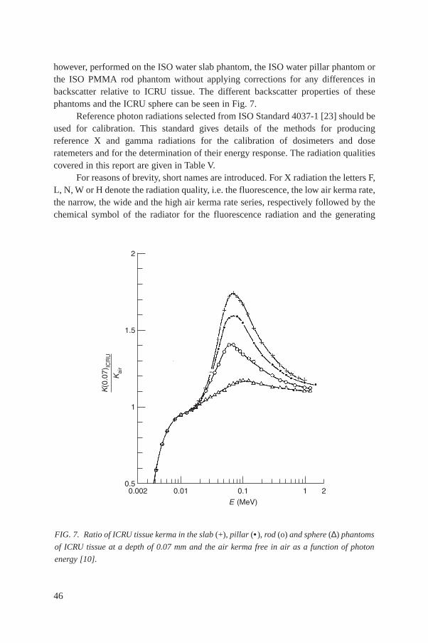
however, performed on the ISO water slab phantom, the ISO water pillar phantom orthe ISO PMMA rod phantom without applying corrections for any differences inbackscatter relative to ICRU tissue. The different backscatter properties of thesephantoms and the ICRU sphere can be seen in Fig. 7.
Reference photon radiations selected from ISO Standard 4037-1 [23] should beused for calibration. This standard gives details of the methods for producingreference X and gamma radiations for the calibration of dosimeters and doseratemeters and for the determination of their energy response. The radiation qualitiescovered in this report are given in Table V.
For reasons of brevity, short names are introduced. For X radiation the letters F,L, N, W or H denote the radiation quality, i.e. the fluorescence, the low air kerma rate,the narrow, the wide and the high air kerma rate series, respectively followed by thechemical symbol of the radiator for the fluorescence radiation and the generating
46
FIG. 7. Ratio of ICRU tissue kerma in the slab (+), pillar (• ), rod (o) and sphere (∆) phantoms
of ICRU tissue at a depth of 0.07 mm and the air kerma free in air as a function of photon
energy [10].
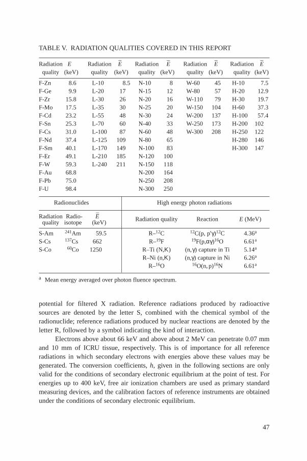
potential for filtered X radiation. Reference radiations produced by radioactivesources are denoted by the letter S, combined with the chemical symbol of theradionuclide; reference radiations produced by nuclear reactions are denoted by theletter R, followed by a symbol indicating the kind of interaction.
Electrons above about 66 keV and above about 2 MeV can penetrate 0.07 mmand 10 mm of ICRU tissue, respectively. This is of importance for all referenceradiations in which secondary electrons with energies above these values may begenerated. The conversion coefficients, h, given in the following sections are onlyvalid for the conditions of secondary electronic equilibrium at the point of test. Forenergies up to 400 keV, free air ionization chambers are used as primary standardmeasuring devices, and the calibration factors of reference instruments are obtainedunder the conditions of secondary electronic equilibrium.
47
TABLE V. RADIATION QUALITIES COVERED IN THIS REPORT
Radiation E Radiation E–
Radiation E–
Radiation E–
Radiation E–
quality (keV) quality (keV) quality (keV) quality (keV) quality (keV)
F-Zn 8.6 L-10 8.5 N-10 8 W-60 45 H-10 7.5F-Ge 9.9 L-20 17 N-15 12 W-80 57 H-20 12.9F-Zr 15.8 L-30 26 N-20 16 W-110 79 H-30 19.7F-Mo 17.5 L-35 30 N-25 20 W-150 104 H-60 37.3F-Cd 23.2 L-55 48 N-30 24 W-200 137 H-100 57.4F-Sn 25.3 L-70 60 N-40 33 W-250 173 H-200 102F-Cs 31.0 L-100 87 N-60 48 W-300 208 H-250 122F-Nd 37.4 L-125 109 N-80 65 H-280 146F-Sm 40.1 L-170 149 N-100 83 H-300 147F-Er 49.1 L-210 185 N-120 100F-W 59.3 L-240 211 N-150 118F-Au 68.8 N-200 164F-Pb 75.0 N-250 208F-U 98.4 N-300 250
Radionuclides High energy photon radiations
Radiation Radio- E–
Radiation quality Reaction E (MeV)quality isotope (keV)
S-Am 241Am 59.5 R–12C 12C(p, p′γ)12C 4.36a
S-Cs 137Cs 662 R–19F 19F(p,αγ)16O 6.61a
S-Co 60Co 1250 R–Ti (N,Κ) (n,γ) capture in Ti 5.14a
R–Ni (n,Κ) (n,γ) capture in Ni 6.26a
R–16O 16O(n, p)16N 6.61a
a Mean energy averaged over photon fluence spectrum.

For higher photon energies, secondary electronic equilibrium is no longerobtained free in air because of the large range of the electrons. For example, the rangeof the maximum energy electron in air which is produced by Compton scattering of60Co photon radiation is about 4 m. The measurement of air kerma is done in primarylaboratories by graphite cavity chambers whose wall thicknesses are sufficient togenerate dose buildup, and thereby secondary electronic equilibrium. This isapplicable to photon energies of up to 6 MeV.
For instruments being calibrated one does not have secondary electronicequilibrium within the sensitive volume of their detectors. In some cases the detectorwindow or encapsulation is not sufficiently thick for dose buildup, one of thepremises for secondary electronic equilibrium. For these instruments one wouldobtain different indications in photon radiation fields having differing electronicequilibrium. By placing a layer in front of the detector which, together with the wallmaterial and the cover of the detector, gives a combined layer of a thickness largerthan the range of the most energetic secondary electrons, one can obtain reproducibleresults. By experience, no additional layers for photon energies below 250 keV arerequired; up to 0.66 MeV, a 1.5 mm thick layer of polymethyl methacrylate (PMMA)is sufficient. For energies up to 1.33 MeV, a 4 mm PMMA layer is sufficient.
For calibrations performed with the ISO reference radiations having energiesabove 1.33 MeV, guidance on the layer thickness required is given in ISO 4037,Parts 2 and 3 [24, 25].
It is only by using these additional layers that calibrations carried out indifferent laboratories can be compared.
The additional PMMA layer should have a 30 cm × 30 cm square cross-sectional area and should be located with its rear side at a distance of 15 cm from thereference point of the dosimeter.
Note: During operational measurements such a calibration does not secure thecorrect measurement of the quantity to be measured in all mixed photon and β fields;additional investigations of the device under test may hence be needed.
4.2. CONVERSION COEFFICIENTS FORISO REFERENCE PHOTON RADIATIONS
4.2.1. X radiation
4.2.1.1. Filtered X rays
Details of the operational conditions required to produce the filteredX radiations as specified in ISO Standard 4037-1 [23] are given in Tables VI, VIII, X,XII and XIV [26]. Tables VII, IX, XI and XIII give the recommended conversion
48
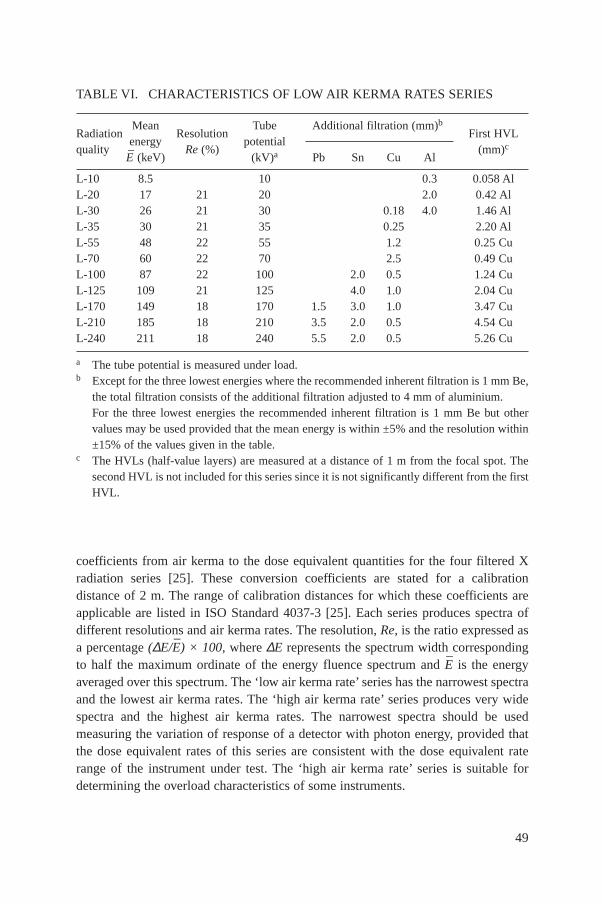
coefficients from air kerma to the dose equivalent quantities for the four filtered Xradiation series [25]. These conversion coefficients are stated for a calibrationdistance of 2 m. The range of calibration distances for which these coefficients areapplicable are listed in ISO Standard 4037-3 [25]. Each series produces spectra ofdifferent resolutions and air kerma rates. The resolution, Re, is the ratio expressed asa percentage (∆E/E
–) × 100, where ∆E represents the spectrum width corresponding
to half the maximum ordinate of the energy fluence spectrum and E–
is the energyaveraged over this spectrum. The ‘low air kerma rate’ series has the narrowest spectraand the lowest air kerma rates. The ‘high air kerma rate’ series produces very widespectra and the highest air kerma rates. The narrowest spectra should be usedmeasuring the variation of response of a detector with photon energy, provided thatthe dose equivalent rates of this series are consistent with the dose equivalent raterange of the instrument under test. The ‘high air kerma rate’ series is suitable fordetermining the overload characteristics of some instruments.
49
TABLE VI. CHARACTERISTICS OF LOW AIR KERMA RATES SERIES
RadiationMean
ResolutionTube Additional filtration (mm)b
First HVLquality
energyRe (%)
potentialPb Sn Cu Al
(mm)cE–
(keV) (kV)a
L-10 8.5 10 0.3 0.058 AlL-20 17 21 20 2.0 0.42 AlL-30 26 21 30 0.18 4.0 1.46 AlL-35 30 21 35 0.25 2.20 AlL-55 48 22 55 1.2 0.25 CuL-70 60 22 70 2.5 0.49 CuL-100 87 22 100 2.0 0.5 1.24 CuL-125 109 21 125 4.0 1.0 2.04 CuL-170 149 18 170 1.5 3.0 1.0 3.47 CuL-210 185 18 210 3.5 2.0 0.5 4.54 CuL-240 211 18 240 5.5 2.0 0.5 5.26 Cu
a The tube potential is measured under load.b Except for the three lowest energies where the recommended inherent filtration is 1 mm Be,
the total filtration consists of the additional filtration adjusted to 4 mm of aluminium.For the three lowest energies the recommended inherent filtration is 1 mm Be but othervalues may be used provided that the mean energy is within ±5% and the resolution within±15% of the values given in the table.
c The HVLs (half-value layers) are measured at a distance of 1 m from the focal spot. Thesecond HVL is not included for this series since it is not significantly different from the firstHVL.

A summary of the spectral data and air kerma rates produced by these series isgiven in Table V. In Section 4.4, an example is given of a calibration set-up forproducing filtered X ray spectra.
For the high air kerma rate series, the quality of the reference radiation isspecified in terms of the X ray tube potential and the first HVL.
Spectra obtained with the reference radiation are published in Ref. [27]. Thisreference also contains information on the measurement of spectra by Ge(Li)detectors. Figure 8 shows a comparison of a measured, unfolded, spectrum for the lowair kerma rate series, having a mean energy of 47.8 keV, and that for a fluorescent Xradiation having a Kα line energy of 49.1 keV [28].
For low photon energies, small differences in the spectral distribution can resultin significant changes in the numerical values of these conversion coefficients as themajority contribution to the air kerma originates from the low energy part of thespectrum, while the majority contribution to H*(10) and Hp(10; I) originates from thehigh energy part of the spectrum. Differences in spectral distribution from oneexperimental arrangement to another may occur as a result of a great number offactors, e.g. anode angle, anode roughening, tungsten evaporated on the tube window,
50
TABLE VII. ISO X RAY REFERENCE RADIATION (LOW AIR KERMA RATESERIES) CONVERSION COEFFICIENTS FOR RADIATION OF NORMALINCIDENCE
Conversion coefficient, h
RadiationMean
Slab phantom Pillar phantom Rod phantomqualitya
energyE–
(keV)
H′(0.07)/Ka H*(10)/Ka
Hp(0.07)/Ka Hp(10)/Ka Hp(0.07)/Ka Hp(0.07)/Ka
(Sv·Gy–1) (Sv·Gy–1)
(Sv·Gy–1) (Sv·Gy–1) (Sv·Gy–1) (Sv·Gy–1)
L-10 8.5 0.93 0.93 0.91 0.91L-20 17 1.01 0.37! 1.00 0.37! 1.00 0.99L-30 26 1.13 0.90! 1.14 0.91! 1.08 1.03L-35 30 1.22 1.08 1.22 1.09 1.17 1.06L-55 48 1.50 1.61 1.57 1.67 1.34 1.11L-70 60 1.59 1.73 1.71 1.87 1.39 1.14L-100 87 1.59 1.69 1.71 1.87 1.37 1.17L-125 109 1.52 1.61 1.64 1.77 1.34 1.17L-170 149 1.42 1.50 1.53 1.62 1.29 1.16L-210 185 1.36 1.42 1.45 1.52 1.26 1.15L-240 211 1.33 1.38 1.42 1.47 1.24 1.15
a With these radiation qualities, care needs to be taken as variations in energy distributionmay have a substantial influence on the numerical values of conversion coefficients.
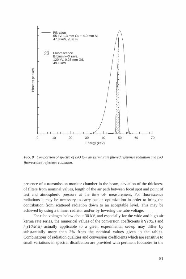
presence of a transmission monitor chamber in the beam, deviation of the thicknessof filters from nominal values, length of the air path between focal spot and point oftest and atmospheric pressure at the time of- measurement. For fluorescenceradiations it may be necessary to carry out an optimization in order to bring thecontribution from scattered radiation down to an acceptable level. This may beachieved by using a thinner radiator and/or by lowering the tube voltage.
For tube voltages below about 30 kV, and especially for the wide and high airkerma rate series, the numerical values of the conversion coefficients h*(10;E) andhp(10;E,α) actually applicable to a given experimental set-up may differ bysubstantially more than 2% from the nominal values given in the tables.Combinations of radiation qualities and conversion coefficients which are sensitive tosmall variations in spectral distribution are provided with pertinent footnotes in the
51
FIG. 8. Comparison of spectra of ISO low air kerma rate filtered reference radiation and ISO
fluorescence reference radiation.
Pho
tons
per
keV
Filtration55 kV, 1.3 mm Cu + 4.0 mm Al,47.8 keV, 20.6 %
FluorescenceErbium k–X rays,120 kV, 0.25 mm Gd,49.1 keV
0 10 20 30 40 50 60 70
Energy (keV)

tables in question. In this case the 2% uncertainty may not be sufficient, and a properestimate of the uncertainty or of a more reliable value of the conversion coefficientmay be required. If a radiation quality listed in Table V is not contained in one of thetables for the conversion coefficients h*(10;E) and hp(10;E), this means that noreliable values may be given.
4.2.1.2. Fluorescent X rays
The fluorescence source of radiation3 has been used by many authors asreference radiation below 100 keV. In Section 4.4, an example is given of a schematic
52
3 Filtered X rays yield as smoother energy dependence than fluorescent X rays. This maybe more realistic from the point of view of operational radiation protecton because at mostworkplaces scattered radiation predominates.
TABLE VIII. CHARACTERISTICS OF NARROW SPECTRUM SERIES
RadiationMean
ResolutionTube Additional filtration (mm)b
First HVL Second HVLquality
energyRe (%)
potentialPb Sn Cu Al
(mm)c (mm)cE–
(keV) (kV)a
N-10 8 28 10 0.1 0.047 Al 0.052 AlN-15 12 33 15 0.5 0.14 Al 0.16 AlN-20 16 34 20 1.0 0.32 Al 0.37 AlN-25 20 33 25 2.0 0.66 Al 0.73 AlN-30 24 32 30 4.0 1.15 Al 1.30 AlN-40 33 30 40 0.21 0.084 Cu 0.091 CuN-60 48 36 60 0.6 0.24 Cu 0.26 CuN-80 65 32 80 2.0 0.58 Cu 0.62 CuN-100 83 28 100 5.0 1.11 Cu 1.17 CuN-120 100 27 120 1.0 5.0 1.71 Cu 1.77 CuN-150 118 37 150 2.5 2.36 Cu 2.47 CuN-200 164 30 200 1.0 3.0 2.0 3.99 Cu 4.05 CuN-250 208 28 250 3.0 2.0 5.19 Cu 5.23 CuN-300 250 27 300 5.0 3.0 6.12 Cu 6.15 Cu
a The tube potential is measured under load.b Except for the five lowest energies, where the recommended inherent filtration is 1 mm Be,
the total filtration consists of the additional filtration plus the inherent filtration adjusted to4 mm aluminium.For these five slowest energies the recommended inherent filtration is 1 mm Be but othervalues may be used provided that the mean energy is within ±5% and the resolution within±15% of the values given in the table.
c The HVLs are measured at a distance of 1 m from the focal spot.
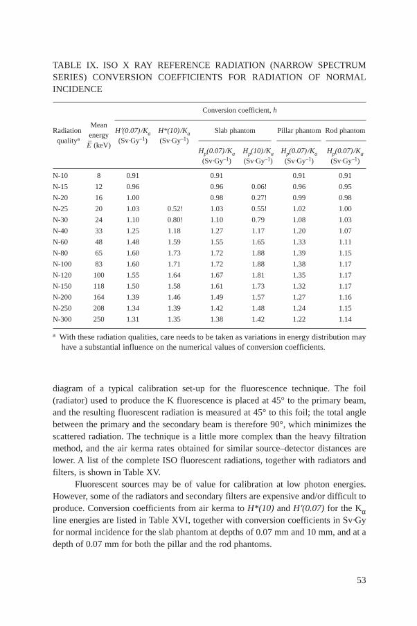
diagram of a typical calibration set-up for the fluorescence technique. The foil(radiator) used to produce the K fluorescence is placed at 45° to the primary beam,and the resulting fluorescent radiation is measured at 45° to this foil; the total anglebetween the primary and the secondary beam is therefore 90°, which minimizes thescattered radiation. The technique is a little more complex than the heavy filtrationmethod, and the air kerma rates obtained for similar source–detector distances arelower. A list of the complete ISO fluorescent radiations, together with radiators andfilters, is shown in Table XV.
Fluorescent sources may be of value for calibration at low photon energies.However, some of the radiators and secondary filters are expensive and/or difficult toproduce. Conversion coefficients from air kerma to H*(10) and H′(0.07) for the Kαline energies are listed in Table XVI, together with conversion coefficients in Sv·Gyfor normal incidence for the slab phantom at depths of 0.07 mm and 10 mm, and at adepth of 0.07 mm for both the pillar and the rod phantoms.
53
TABLE IX. ISO X RAY REFERENCE RADIATION (NARROW SPECTRUMSERIES) CONVERSION COEFFICIENTS FOR RADIATION OF NORMALINCIDENCE
Conversion coefficient, h
RadiationMean
Slab phantom Pillar phantom Rod phantomqualitya
energyE–
(keV)
H′(0.07)/Ka H*(10)/Ka
Hp(0.07)/Ka Hp(10)/Ka Hp(0.07)/Ka Hp(0.07)/Ka
(Sv·Gy–1) (Sv·Gy–1)
(Sv·Gy–1) (Sv·Gy–1) (Sv·Gy–1) (Sv·Gy–1)
N-10 8 0.91 0.91 0.91 0.91
N-15 12 0.96 0.96 0.06! 0.96 0.95
N-20 16 1.00 0.98 0.27! 0.99 0.98
N-25 20 1.03 0.52! 1.03 0.55! 1.02 1.00
N-30 24 1.10 0.80! 1.10 0.79 1.08 1.03
N-40 33 1.25 1.18 1.27 1.17 1.20 1.07
N-60 48 1.48 1.59 1.55 1.65 1.33 1.11
N-80 65 1.60 1.73 1.72 1.88 1.39 1.15
N-100 83 1.60 1.71 1.72 1.88 1.38 1.17
N-120 100 1.55 1.64 1.67 1.81 1.35 1.17
N-150 118 1.50 1.58 1.61 1.73 1.32 1.17
N-200 164 1.39 1.46 1.49 1.57 1.27 1.16
N-250 208 1.34 1.39 1.42 1.48 1.24 1.15
N-300 250 1.31 1.35 1.38 1.42 1.22 1.14
a With these radiation qualities, care needs to be taken as variations in energy distribution mayhave a substantial influence on the numerical values of conversion coefficients.
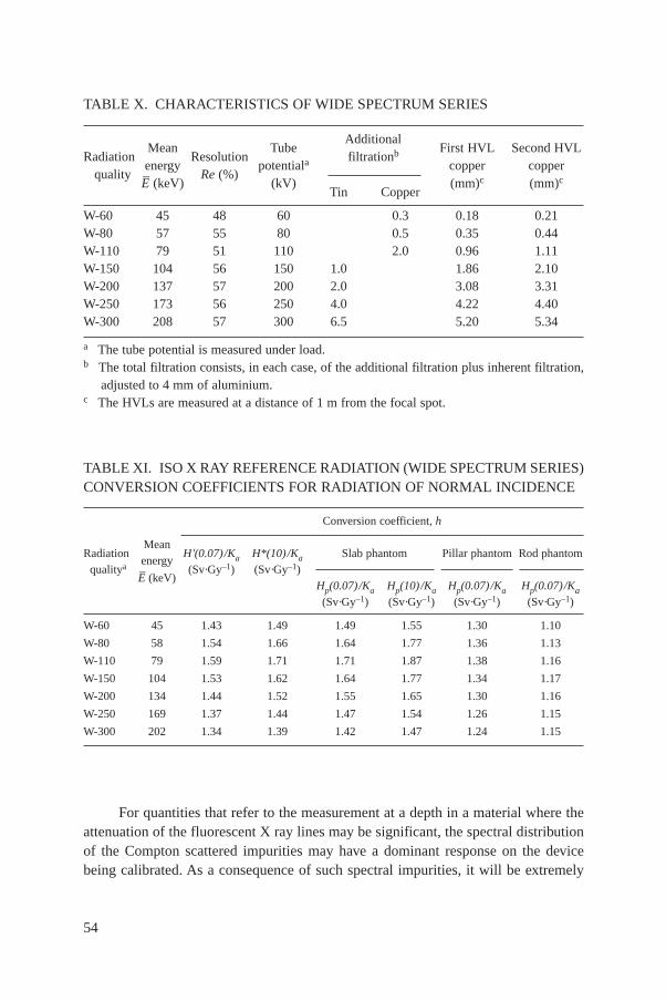
For quantities that refer to the measurement at a depth in a material where theattenuation of the fluorescent X ray lines may be significant, the spectral distributionof the Compton scattered impurities may have a dominant response on the devicebeing calibrated. As a consequence of such spectral impurities, it will be extremely
54
TABLE X. CHARACTERISTICS OF WIDE SPECTRUM SERIES
AdditionalRadiation
MeanResolution
Tubefiltrationb First HVL Second HVL
qualityenergy
Re (%)potentiala copper copper
E– (keV) (kV)
Tin Copper(mm)c (mm)c
W-60 45 48 60 0.3 0.18 0.21W-80 57 55 80 0.5 0.35 0.44W-110 79 51 110 2.0 0.96 1.11W-150 104 56 150 1.0 1.86 2.10W-200 137 57 200 2.0 3.08 3.31W-250 173 56 250 4.0 4.22 4.40W-300 208 57 300 6.5 5.20 5.34
a The tube potential is measured under load.b The total filtration consists, in each case, of the additional filtration plus inherent filtration,
adjusted to 4 mm of aluminium.c The HVLs are measured at a distance of 1 m from the focal spot.
TABLE XI. ISO X RAY REFERENCE RADIATION (WIDE SPECTRUM SERIES)CONVERSION COEFFICIENTS FOR RADIATION OF NORMAL INCIDENCE
Conversion coefficient, h
RadiationMean
Slab phantom Pillar phantom Rod phantomqualitya
energy
E– (keV)
H′(0.07)/Ka H*(10)/Ka
Hp(0.07)/Ka Hp(10)/Ka Hp(0.07)/Ka Hp(0.07)/Ka
(Sv·Gy–1) (Sv·Gy–1)
(Sv·Gy–1) (Sv·Gy–1) (Sv·Gy–1) (Sv·Gy–1)
W-60 45 1.43 1.49 1.49 1.55 1.30 1.10
W-80 58 1.54 1.66 1.64 1.77 1.36 1.13
W-110 79 1.59 1.71 1.71 1.87 1.38 1.16
W-150 104 1.53 1.62 1.64 1.77 1.34 1.17
W-200 134 1.44 1.52 1.55 1.65 1.30 1.16
W-250 169 1.37 1.44 1.47 1.54 1.26 1.15
W-300 202 1.34 1.39 1.42 1.47 1.24 1.15
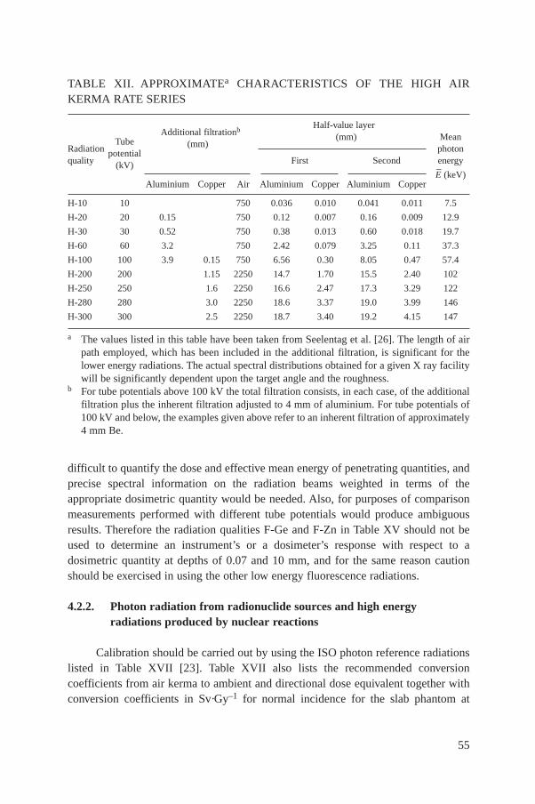
difficult to quantify the dose and effective mean energy of penetrating quantities, andprecise spectral information on the radiation beams weighted in terms of theappropriate dosimetric quantity would be needed. Also, for purposes of comparisonmeasurements performed with different tube potentials would produce ambiguousresults. Therefore the radiation qualities F-Ge and F-Zn in Table XV should not beused to determine an instrument’s or a dosimeter’s response with respect to adosimetric quantity at depths of 0.07 and 10 mm, and for the same reason cautionshould be exercised in using the other low energy fluorescence radiations.
4.2.2. Photon radiation from radionuclide sources and high energyradiations produced by nuclear reactions
Calibration should be carried out by using the ISO photon reference radiationslisted in Table XVII [23]. Table XVII also lists the recommended conversioncoefficients from air kerma to ambient and directional dose equivalent together withconversion coefficients in Sv·Gy–1 for normal incidence for the slab phantom at
55
TABLE XII. APPROXIMATEa CHARACTERISTICS OF THE HIGH AIRKERMA RATE SERIES
Additional filtrationbHalf-value layer
(mm) (mm) Mean
RadiationTube
photonquality
potentialFirst Second energy(kV)
E–
(keV)Aluminium Copper Air Aluminium Copper Aluminium Copper
H-10 10 750 0.036 0.010 0.041 0.011 7.5
H-20 20 0.15 750 0.12 0.007 0.16 0.009 12.9
H-30 30 0.52 750 0.38 0.013 0.60 0.018 19.7
H-60 60 3.2 750 2.42 0.079 3.25 0.11 37.3
H-100 100 3.9 0.15 750 6.56 0.30 8.05 0.47 57.4
H-200 200 1.15 2250 14.7 1.70 15.5 2.40 102
H-250 250 1.6 2250 16.6 2.47 17.3 3.29 122
H-280 280 3.0 2250 18.6 3.37 19.0 3.99 146
H-300 300 2.5 2250 18.7 3.40 19.2 4.15 147
a The values listed in this table have been taken from Seelentag et al. [26]. The length of airpath employed, which has been included in the additional filtration, is significant for thelower energy radiations. The actual spectral distributions obtained for a given X ray facilitywill be significantly dependent upon the target angle and the roughness.
b For tube potentials above 100 kV the total filtration consists, in each case, of the additionalfiltration plus the inherent filtration adjusted to 4 mm of aluminium. For tube potentials of100 kV and below, the examples given above refer to an inherent filtration of approximately4 mm Be.

TABLE XIII. ISO X RAY REFERENCE RADIATION (HIGH AIR KERMA RATESERIES) CONVERSION COEFFICIENTS FOR RADIATION OF NORMALINCIDENCE
Conversion coefficient, h
RadiationMean
Slab phantom Pillar phantom Rod phantomqualitya
energyE–
(keV)
H′(0.07)/Ka H*(10)/Ka
Hp(0.07)/Ka Hp(10)/Ka Hp(0.07)/Ka Hp(0.07)/Ka
(Sv·Gy–1) (Sv·Gy–1)
(Sv·Gy–1) (Sv·Gy–1) (Sv·Gy–1) (Sv·Gy–1)
H-10 7.5 0.89 0.89 0.89 0.89
H-20 12.9 0.96 0.95 0.96 0.95
H-30 19.7 1.02 1.01 0.39! 1.00 0.99
H-60 37.3 1.26 1.15 1.29 1.19 1.20 1.07
H-100 57.4 1.49 1.57 1.58 1.68 1.33 1.12
H-200 102 1.51 1.61 1.62 1.75 1.33 1.16
H-250 122 1.45 1.54 1.56 1.67 1.31 1.16
H-280 146 1.41 1.49 1.51 1.60 1.28 1.16
H-300 147 1.40 1.48 1.51 1.59 1.28 1.16
a With these radiation qualities, care needs to be taken as variations in energy distribution mayhave a substantial influence on the numerical values of conversion coefficients.
TABLE XIV. ISO FILTERED X RADIATIONS
Name of seriesResolution Ratio first HVL/second HVL Typical air kerma ratesa, b
Re (%) (using Cu absorbers) (Gy·h–1)
Low air kerma rate 18–22 1.0 3 × 10⁻⁴ c
Narrow spectrum 27–36 0.75–1.0 10–3 – 10–2 c
Wide spectrum 48–57 0.67–0.98 10–2 – 10–1 c
High air kerma rate not specified 0.64–0.86 10–1–0.5
a At 1 m from the X ray focal spot with the tube operating at 1 mA (distance not applicableto all high air kerma rate series).
b Under conditions of charged particle equilibrium, the value of air kerma is approximatelyequal to the absorbed dose to air.
c At mean energies of less than 30 keV, other values may apply.
depths of 0.07 mm and 10 mm, and at a depth of 0.07 mm for both the pillar and therod phantoms.
Reference radiations in the energy range between 4 MeV and 9 MeV areprovided by ISO because of the 6 MeV photon fields produced by many nuclear
56

power stations and by other nuclear reactor systems as well as for other high energyphoton sources. Further energies are not specified since the variation in response ofmost dosimeters and dose ratemeters with photon energy shows no discontinuitiesover this energy range.
The ISO photon reference radiations are produced by one of the followingreactions:
— de-excitation of 16O in the 19F(p, IK)16O reaction;— de-excitation of 12C;— thermal neutron capture gamma radiation;— decay of 16N.
The facilities required to produce these reference radiations are complex andexpensive so it is not envisaged that many laboratories will wish to use theseradiations. Detailed descriptions of ISO high energy radiations are contained in ISOStandards 4037-1 [23] and 4037-2 [24].
The source should not contain radioactive impurities that contribute morethan 1% to the air kerma rate at the point of test. Table XVIII gives examples ofspecific activities and recommended chemical forms of the specified radioactivenuclides.
ISO has specified recommendations for proper source encapsulation [29]. Thecapsules should have a mass per unit area of 0.2 g·cm–2 for 60Co and 0.5 g·cm–2 for137Cs. For 241Am the capsule should have a mass per unit area of 0.32 g·cm–2 ofstainless steel to attenuate the 26 keV K radiation to less than 1.0% of the 59.5 keVK emission.
At the points of test the air kerma rate due to the radiation scattered by theenvironment, including instrument and support stands, should not exceed 5% of thatdue to the direct radiation. Calibrations can be performed by either using collimatedbeams or uncollimated geometry with the source mounted free in the room, e.g. forroutine calibration of personnel dosimeters (Section 4.4.2).
A second method can be used for both collimated and uncollimated calibrationgeometries. At each point of test, the air kerma rates on the central axis of the beamshould be measured. After correcting for air attenuation, they should be proportional,within ± 5%, to the inverse square of the distance from the centre of the referencesource to the reference point of the detector. It is considered acceptable practice toperform radiation scatter measurements at the closest and furthest test points, as wellas at several intermediate points.
For uncollimated irradiations, a shielded room of at least 4 m × 4 m × 3 m isrequired to ensure that the scattered radiation is kept to less then 5% of the directradiation. The inverse square law tests, described in the previous paragraph, should beused to verify that the scatter is less than 5%.
57
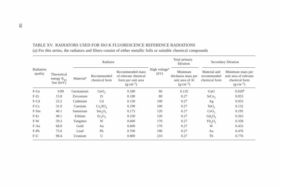
58
TABLE XV. RADIATORS USED FOR ISO K FLUORESCENCE REFERENCE RADIATIONS(a) For this series, the radiators and filters consist of either metallic foils or suitable chemical compounds
RadiatorTotal primary
Secondary filtrationfiltration
Radiation
TheoreticalRecommended mass
High voltageaMinimum Material and Minimum mass perquality
energy Kα1 MaterialaRecommended of relevant chemical
(kV)thickness mass per recommended unit area of relevant
line (keV)chemical form form per unit area unit area of Al chemical form chemical form
(g·cm–2) (g·cm–2) (g·cm–2)
F-Ge 9.89 Germanium GeO2 0.180 60 0.135 GaO 0.020b
F-Zr 15.8 Zirconium Zr 0.180 80 0.27 SrCo3 0.053
F-Cd 23.2 Cadmium Cd 0.150 100 0.27 Ag 0.053
F-Cs 31.0 Caesium Cs2SO4 0.190 100 0.27 TeO2 0.132
F-Sm 40.1 Samarium Sm2O3 0.175 120 0.27 CeO2 0.195
F-Er 49.1 Erbium Er2O3 0.230 120 0.27 Gd2O3 0.263
F-W 59.3 Tungsten W 0.600 170 0.27 Yb2O3 0.358
F-Au 68.8 Gold Au 0.600 170 0.27 W 0.433
F-Pb 75.0 Lead Pb 0.700 190 0.27 Au 0.476
F-U 98.4 Uranium U 0.800 210 0.27 Th 0.776
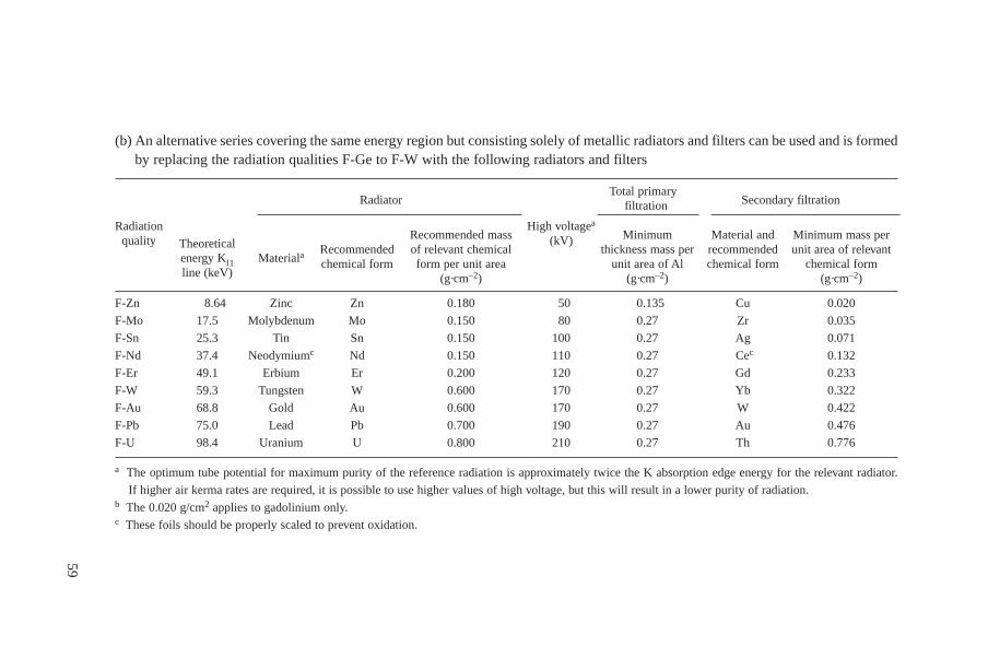
59
(b) An alternative series covering the same energy region but consisting solely of metallic radiators and filters can be used and is formedby replacing the radiation qualities F-Ge to F-W with the following radiators and filters
RadiatorTotal primary
Secondary filtrationfiltration
Radiation
TheoreticalRecommended mass
High voltageaMinimum Material and Minimum mass perquality
energy KΙ1 MaterialaRecommended of relevant chemical
(kV)thickness mass per recommended unit area of relevant
line (keV)chemical form form per unit area unit area of Al chemical form chemical form
(g·cm–2) (g·cm–2) (g·cm–2)
F-Zn 8.64 Zinc Zn 0.180 50 0.135 Cu 0.020
F-Mo 17.5 Molybdenum Mo 0.150 80 0.27 Zr 0.035
F-Sn 25.3 Tin Sn 0.150 100 0.27 Ag 0.071
F-Nd 37.4 Neodymiumc Nd 0.150 110 0.27 Cec 0.132
F-Er 49.1 Erbium Er 0.200 120 0.27 Gd 0.233
F-W 59.3 Tungsten W 0.600 170 0.27 Yb 0.322
F-Au 68.8 Gold Au 0.600 170 0.27 W 0.422
F-Pb 75.0 Lead Pb 0.700 190 0.27 Au 0.476
F-U 98.4 Uranium U 0.800 210 0.27 Th 0.776
a The optimum tube potential for maximum purity of the reference radiation is approximately twice the K absorption edge energy for the relevant radiator.
If higher air kerma rates are required, it is possible to use higher values of high voltage, but this will result in a lower purity of radiation.b The 0.020 g/cm2 applies to gadolinium only.c These foils should be properly scaled to prevent oxidation.

An example of a calibration set-up suitable for personal dosimeters uses acircular arc of a low scatter material (plastics) with 1 m radius for the positioning ofthe dosimeters. This allows simultaneous irradiation of many dosimeters. However,the homogeneity of the air kerma rate around the arc has to be checked. If dosimetersor integrating instruments are being calibrated, the irradiation time should besufficiently long in relation to the transit time of the source. If a shutter is used, theirradiation time should be long enough for the air kerma from the source during thetransit of the shutter to be negligible.
4.3. REFERENCE INSTRUMENTS
4.3.1. Requirements for reference instruments
The reference instrument is normally an ionization chamber and a measuringassembly. In some applications, for example the determination of low kerma rates,
60
TABLE XVI. ISO FLUORESCENCE REFERENCE RADIATION CONVERSIONCOEFFICIENTS FOR RADIATION OF NORMAL INCIDENCE
Theoreti-Conversion coefficient, h
Radiationcal
Slab phantom Pillar phantom Rod phantomqualitya
energyKα line
H′(0.07)/Ka H*(10)/Ka
Hp(0.07)/Ka Hp(10)/Ka Hp(0.07)/Ka Hp(0.07)/Ka(keV)
(Sv·Gy-1) (Sv·Gy-1)
(Sv·Gy–1) (Sv·Gy–1) (Sv·Gy–1) (Sv·Gy–1)
F-Zn 8.64 0.94 0.93 0.93 0.93
F-Ge 9.89 0.95 0.95 0.95 0.95
F-Zr 15.8 1.00 0.32! 0.99 0.32! 0.99 0.98
F-Mo 17.5 1.02 0.44! 1.01 0.44! 1.01 0.99
F-Cd 23.2 1.09 0.80 1.09 0.79 1.08 1.03
F-Sn 25.3 1.13 0.91 1.14 0.89 1.10 1.04
F-Cs 31.0 1.24 1.14 1.25 1.15 1.19 1.06
F-Nd 37.4 1.36 1.39 1.39 1.40 1.27 1.08
F-Sm 40.1 1.41 1.47 1.44 1.49 1.29 1.09
F-Er 49.1 1.52 1.65 1.62 1.75 1.36 1.13
F-W 59.3 1.59 1.74 1.72 1.89 1.39 1.14
F-Au 68.8 1.61 1.75 1.73 1.90 1.39 1.15
F-Pb 75.0 1.61 1.74 1.73 1.90 1.39 1.16
F-U 98.4 1.56 1.65 1.68 1.82 1.35 1.17
a With these radiation qualities, care needs to be taken as variations in energy distributionmay have a substantial influence on the numerical values of conversion coefficients.
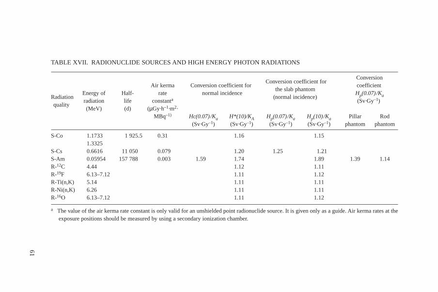
61
TABLE XVII. RADIONUCLIDE SOURCES AND HIGH ENERGY PHOTON RADIATIONS
Conversion coefficient forConversion
Air kerma Conversion coefficient forthe slab phantom
coefficient
RadiationEnergy of Half- rate normal incidence
(normal incidence)Hp(0.07)/Ka
qualityradiation life constanta (Sv·Gy–1)(MeV) (d) (µGy·h–1·m2·
MBq–1) Hc(0.07)/Ka H*(10)/KA Hp(0.07)/Ka Hp(10)/Ka Pillar Rod(Sv·Gy–1) (Sv·Gy–1) (Sv·Gy–1) (Sv·Gy–1) phantom phantom
S-Co 1.1733 1 925.5 0.31 1.16 1.151.3325
S-Cs 0.6616 11 050 0.079 1.20 1.25 1.21S-Am 0.05954 157 788 0.003 1.59 1.74 1.89 1.39 1.14R-12C 4.44 1.12 1.11R-19F 6.13–7.12 1.11 1.12R-Ti(n,K) 5.14 1.11 1.11R-Ni(n,K) 6.26 1.11 1.11R-16O 6.13–7.12 1.11 1.12
a The value of the air kerma rate constant is only valid for an unshielded point radionuclide source. It is given only as a guide. Air kerma rates at theexposure positions should be measured by using a secondary ionization chamber.
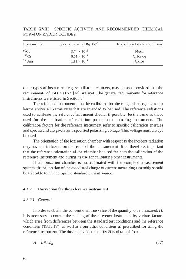
other types of instrument, e.g. scintillation counters, may be used provided that therequirements of ISO 4037-2 [24] are met. The general requirements for referenceinstruments were listed in Section 3.
The reference instrument must be calibrated for the range of energies and airkerma and/or air kerma rates that are intended to be used. The reference radiationsused to calibrate the reference instrument should, if possible, be the same as thoseused for the calibration of radiation protection monitoring instruments. Thecalibration factors for the reference instrument refer to specific calibration energiesand spectra and are given for a specified polarizing voltage. This voltage must alwaysbe used.
The orientation of the ionization chamber with respect to the incident radiationmay have an influence on the result of the measurement. It is, therefore, importantthat the reference orientation of the chamber be used for both the calibration of thereference instrument and during its use for calibrating other instruments.
If an ionization chamber is not calibrated with the complete measurementsystem, the calibration of the associated charge or current measuring assembly shouldbe traceable to an appropriate standard current source.
4.3.2. Correction for the reference instrument
4.3.2.1. General
In order to obtain the conventional true value of the quantity to be measured, H,it is necessary to correct the reading of the reference instrument by various factorswhich arise from differences between the standard test conditions and the referenceconditions (Table IV), as well as from other conditions as prescribed for using thereference instrument. The dose equivalent quantity H is obtained from:
H = hNR MR (27)
62
TABLE XVIII. SPECIFIC ACTIVITY AND RECOMMENDED CHEMICALFORM OF RADIONUCLIDES
Radionuclide Specific activity (Bq· kg–1) Recommended chemical form
60Co 3.7 × 10¹⁵ Metal137Cs 8.51 × 10¹⁴ Chloride241Am 1.11 × 10¹⁴ Oxide
where
h is the conversion coefficient used to obtain the dose equivalent quantity H fromthe physical quantity measured by the reference instrument, in general air kermaor air kerma rate (Section 3.4.1);
NR is the calibration factor of the reference chamber under reference conditions;and
MR is the measured (indicated) value of the reference instrument corrected for reference conditions.
According to Section 3.2, MR can be substituted, and we obtain:
H = hNR(M–
RI – M–
Ro) kprkTkckskr (28)
where
MR1 is the mean value of the indication of the instrument at the time of calibration;MRo is the mean value of the indication of the instrument when the source is
removed (background);kpr is the correction factor for air pressure;kT is the correction factor for temperature;kc is the correction factor for the chamber size (field inhomogeneity over the
chamber volume);ks is the correction factor for scattered radiation; andkr is the correction factor for range or scale, usually contained in the measuring
instrument’s calibration certificate.
The dose equivalent quantity H may be determined for another radiationquantity by means of an additional correction factor, ken, for energy dependence.Values of ken are often supplied with the calibration certificate.
The reference instrument must be calibrated up to the maximum kerma rate tobe measured. If electrical signals have been used to calibrate the higher ranges of themeasuring assembly, a correction for incomplete ion collection of the ionizationchamber assembly is often necessary for these ranges [24]4.
In the following sections, some information on the necessary corrections isgiven.
63
4 It is preferable to calibrate the complete instrument by the use of ionizing radiationsince this method tests the complete measuring system.
4.3.2.2. Zero indication (background)
The leakage current in the absence of any irradiation, other than naturalbackground, should be equivalent to less than ±2% of the maximum indication for themost sensitive scale range of the assembly. For integrating instruments, theaccumulated leakage indication should correspond to less than 2% of the indicationproduced by the reference radiation over the time of measurement. It may benecessary to correct for the effect of leakage currents.
There can be a number of leakage current sources, or errors that produceeffects similar to leakage currents. A fuller description of effects such aspost-irradiation leakage, insulator leakage in the absence of radiation, cablemicrophony and pre-amplifier induced signal is given in Ref. [23]. It should be notedthat in some instruments the signal from the chamber may not indicate leakagecurrents that have a polarity opposite to that produced by ionization within thechamber.
A charge measuring instrument may produce a change of scale indication whenthe setting control is changed from the zero mode to the measurement mode; thischarge may be of either polarity. This effect may be significant in the more sensitivemeasurement ranges. It may be necessary to correct for this effect. It is preferable toexclude this effect by appropriate measurement techniques.
4.3.2.3. Pressure
For an unsealed ionization chamber, the deviation of the actual air pressure pfrom the reference pressure po = 101.3 kPa is corrected by
kpr = po /p (29)
4.3.2.4. Temperature
For an unsealed ionization chamber, the deviation of the actual air tempera-ture T from the reference temperature To = 293.15 K (20°C) has to be corrected forby
kT = T/To (30)
4.3.2.5. Chamber size
The finite size of the chamber may affect the measurement of the radiation atsmall source–chamber distances [30]. For spherical detectors, correction factors aregiven in Ref. [31].
64
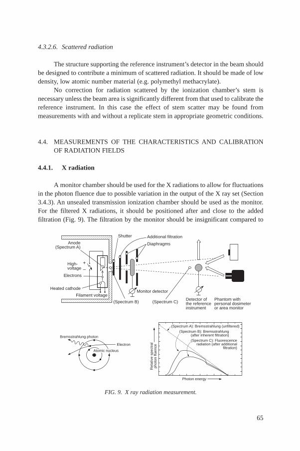
4.3.2.6. Scattered radiation
The structure supporting the reference instrument’s detector in the beam shouldbe designed to contribute a minimum of scattered radiation. It should be made of lowdensity, low atomic number material (e.g. polymethyl methacrylate).
No correction for radiation scattered by the ionization chamber’s stem isnecessary unless the beam area is significantly different from that used to calibrate thereference instrument. In this case the effect of stem scatter may be found frommeasurements with and without a replicate stem in appropriate geometric conditions.
4.4. MEASUREMENTS OF THE CHARACTERISTICS AND CALIBRATIONOF RADIATION FIELDS
4.4.1. X radiation
A monitor chamber should be used for the X radiations to allow for fluctuationsin the photon fluence due to possible variation in the output of the X ray set (Section3.4.3). An unsealed transmission ionization chamber should be used as the monitor.For the filtered X radiations, it should be positioned after and close to the addedfiltration (Fig. 9). The filtration by the monitor should be insignificant compared to
65
FIG. 9. X ray radiation measurement.
Bremsstrahlung photon
Electron
Atomic nucleus
Anode(Spectrum A)
Electrons
(Spectrum B)
Heated cathode
Shutter Additional filtration
Diaphragms
(Spectrum C)
Monitor detector
Detector ofthe referenceinstrument
Phantom withpersonal dosimeteror area monitor
Filament voltage
High-voltage
+–
(Spectrum A): Bremsstrahlung (unfiltered)(Spectrum B): Bremsstrahlung
(after inherent filtration)(Spectrum C): Fluorescence
radiation (after additionalfiltration)
Photon energy
Rel
ativ
e sp
ectr
alph
oton
flue
nce
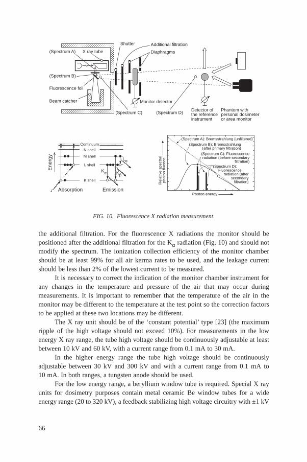
the additional filtration. For the fluorescence X radiations the monitor should bepositioned after the additional filtration for the Kα radiation (Fig. 10) and should notmodify the spectrum. The ionization collection efficiency of the monitor chambershould be at least 99% for all air kerma rates to be used, and the leakage currentshould be less than 2% of the lowest current to be measured.
It is necessary to correct the indication of the monitor chamber instrument forany changes in the temperature and pressure of the air that may occur duringmeasurements. It is important to remember that the temperature of the air in themonitor may be different to the temperature at the test point so the correction factorsto be applied at these two locations may be different.
The X ray unit should be of the ‘constant potential’ type [23] (the maximumripple of the high voltage should not exceed 10%). For measurements in the lowenergy X ray range, the tube high voltage should be continuously adjustable at leastbetween 10 kV and 60 kV, with a current range from 0.1 mA to 30 mA.
In the higher energy range the tube high voltage should be continuouslyadjustable between 30 kV and 300 kV and with a current range from 0.1 mA to10 mA. In both ranges, a tungsten anode should be used.
For the low energy range, a beryllium window tube is required. Special X rayunits for dosimetry purposes contain metal ceramic Be window tubes for a wideenergy range (20 to 320 kV), a feedback stabilizing high voltage circuitry with ±1 kV
66
FIG. 10. Fluorescence X radiation measurement.
(Spectrum A) X ray tube
(Spectrum B)
Fluorescence foil
(Spectrum C)
Beam catcher
Shutter Additional filtration
Diaphragms
(Spectrum D)
Monitor detector
Detector ofthe referenceinstrument
Phantom withpersonal dosimeteror area monitor
N shellContinuum
M shell
L shell
K shell
Ene
rgy
Absorption Emission
Kα
Lα
Kβ
(Spectrum A): Bremsstrahlung (unfiltered)(Spectrum B): Bremsstrahlung
(after primary filtration)(Spectrum C): Fluorescenceradiation (before secondary
filtration)(Spectrum D): Fluorescence radiation (after secondary filtration)
Photon energy
Rel
ativ
e sp
ectr
alph
oton
flue
nce
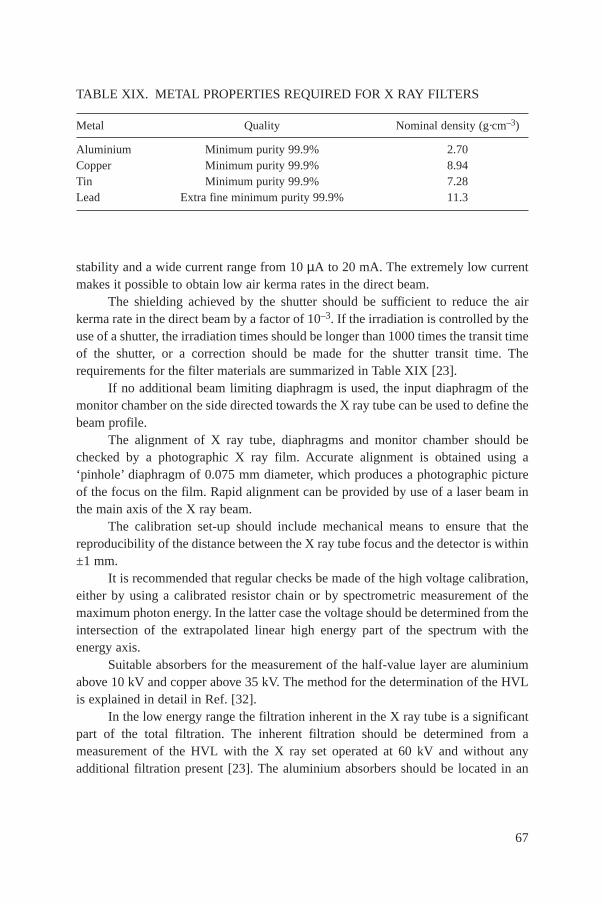
stability and a wide current range from 10 µA to 20 mA. The extremely low currentmakes it possible to obtain low air kerma rates in the direct beam.
The shielding achieved by the shutter should be sufficient to reduce the airkerma rate in the direct beam by a factor of 10–3. If the irradiation is controlled by theuse of a shutter, the irradiation times should be longer than 1000 times the transit timeof the shutter, or a correction should be made for the shutter transit time. Therequirements for the filter materials are summarized in Table XIX [23].
If no additional beam limiting diaphragm is used, the input diaphragm of themonitor chamber on the side directed towards the X ray tube can be used to define thebeam profile.
The alignment of X ray tube, diaphragms and monitor chamber should bechecked by a photographic X ray film. Accurate alignment is obtained using a‘pinhole’ diaphragm of 0.075 mm diameter, which produces a photographic pictureof the focus on the film. Rapid alignment can be provided by use of a laser beam inthe main axis of the X ray beam.
The calibration set-up should include mechanical means to ensure that thereproducibility of the distance between the X ray tube focus and the detector is within±1 mm.
It is recommended that regular checks be made of the high voltage calibration,either by using a calibrated resistor chain or by spectrometric measurement of themaximum photon energy. In the latter case the voltage should be determined from theintersection of the extrapolated linear high energy part of the spectrum with theenergy axis.
Suitable absorbers for the measurement of the half-value layer are aluminiumabove 10 kV and copper above 35 kV. The method for the determination of the HVLis explained in detail in Ref. [32].
In the low energy range the filtration inherent in the X ray tube is a significantpart of the total filtration. The inherent filtration should be determined from ameasurement of the HVL with the X ray set operated at 60 kV and without anyadditional filtration present [23]. The aluminium absorbers should be located in an
67
TABLE XIX. METAL PROPERTIES REQUIRED FOR X RAY FILTERS
Metal Quality Nominal density (g·cm–3)
Aluminium Minimum purity 99.9% 2.70Copper Minimum purity 99.9% 8.94Tin Minimum purity 99.9% 7.28Lead Extra fine minimum purity 99.9% 11.3

equidistant arrangement from the X ray tube focus and the detector. The diameter ofthe beam at the detector position should just be sufficient to irradiate it completelyand uniformly. The distance from the aluminium absorbers to the detector should beat least five times the diameter of the beam at the detector. After plotting theattenuation curve in aluminium, the first HVL must be determined. The value of theinherent filtration can then be determined from the data in Table XX. The resultsshould be rounded to the nearest tenth of a millimetre.
The inherent filtration value, expressed in millimetres of aluminium, varies asa function of the photon energy in a manner which depends upon the constituentelements of the inherent filtration. In the case of filtered X radiation, the valuesdetermined on the basis of Table XX at 60 kV may be used for other high voltagevalues since changes in the inherent filtration, expressed in millimetres of aluminium,are small compared with the added filtration [33].
4.4.2. Photon radiation of radionuclide sources
The reference instrument should be used for the calibration of the radiationfield. A sufficient number of measurements at each point of the test should be made
68
TABLE XX. VARIATION IN HVL AT 60 kV WITH INHERENT FILTRATION(mm ALUMINIUM EQUIVALENT) [33]
First HVL mm of aluminium at 60 kV Inherent filtration mm of aluminium
0.33 0.250.38 0.30.54 0.40.67 0.50.82 0.61.02 0.81.15 1.01.54 1.51.83 22.11 2.52.35 32.56 3.52.75 42.94 4.53.08 53.35 63.56 7
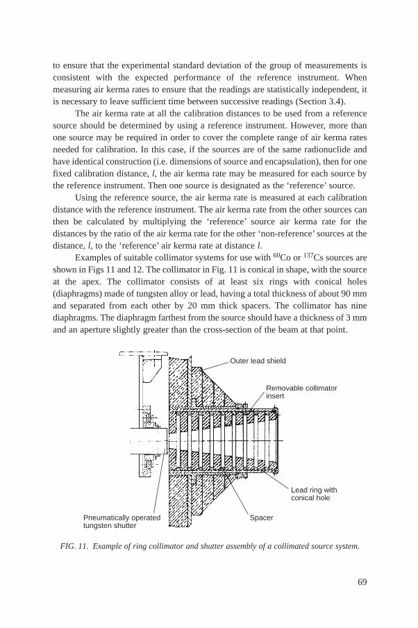
to ensure that the experimental standard deviation of the group of measurements isconsistent with the expected performance of the reference instrument. Whenmeasuring air kerma rates to ensure that the readings are statistically independent, itis necessary to leave sufficient time between successive readings (Section 3.4).
The air kerma rate at all the calibration distances to be used from a referencesource should be determined by using a reference instrument. However, more thanone source may be required in order to cover the complete range of air kerma ratesneeded for calibration. In this case, if the sources are of the same radionuclide andhave identical construction (i.e. dimensions of source and encapsulation), then for onefixed calibration distance, l, the air kerma rate may be measured for each source bythe reference instrument. Then one source is designated as the ‘reference’ source.
Using the reference source, the air kerma rate is measured at each calibrationdistance with the reference instrument. The air kerma rate from the other sources canthen be calculated by multiplying the ‘reference’ source air kerma rate for thedistances by the ratio of the air kerma rate for the other ‘non-reference’ sources at thedistance, l, to the ‘reference’ air kerma rate at distance l.
Examples of suitable collimator systems for use with 60Co or 137Cs sources areshown in Figs 11 and 12. The collimator in Fig. 11 is conical in shape, with the sourceat the apex. The collimator consists of at least six rings with conical holes(diaphragms) made of tungsten alloy or lead, having a total thickness of about 90 mmand separated from each other by 20 mm thick spacers. The collimator has ninediaphragms. The diaphragm farthest from the source should have a thickness of 3 mmand an aperture slightly greater than the cross-section of the beam at that point.
69
FIG. 11. Example of ring collimator and shutter assembly of a collimated source system.
Outer lead shield
Removable collimatorinsert
Lead ring withconical hole
SpacerPneumatically operatedtungsten shutter
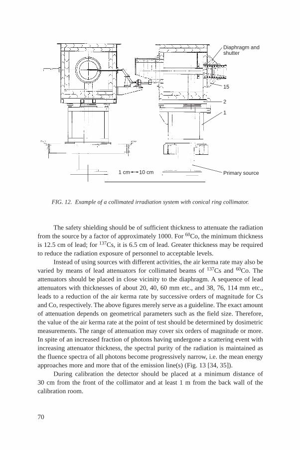
The safety shielding should be of sufficient thickness to attenuate the radiationfrom the source by a factor of approximately 1000. For 60Co, the minimum thicknessis 12.5 cm of lead; for 137Cs, it is 6.5 cm of lead. Greater thickness may be requiredto reduce the radiation exposure of personnel to acceptable levels.
Instead of using sources with different activities, the air kerma rate may also bevaried by means of lead attenuators for collimated beams of 137Cs and 60Co. Theattenuators should be placed in close vicinity to the diaphragm. A sequence of leadattenuators with thicknesses of about 20, 40, 60 mm etc., and 38, 76, 114 mm etc.,leads to a reduction of the air kerma rate by successive orders of magnitude for Csand Co, respectively. The above figures merely serve as a guideline. The exact amountof attenuation depends on geometrical parameters such as the field size. Therefore,the value of the air kerma rate at the point of test should be determined by dosimetricmeasurements. The range of attenuation may cover six orders of magnitude or more.In spite of an increased fraction of photons having undergone a scattering event withincreasing attenuator thickness, the spectral purity of the radiation is maintained asthe fluence spectra of all photons become progressively narrow, i.e. the mean energyapproaches more and more that of the emission line(s) (Fig. 13 [34, 35]).
During calibration the detector should be placed at a minimum distance of30 cm from the front of the collimator and at least 1 m from the back wall of thecalibration room.
70
FIG. 12. Example of a collimated irradiation system with conical ring collimator.
Primary source1 cm
15
2
1
Diaphragm andshutter
10 cm
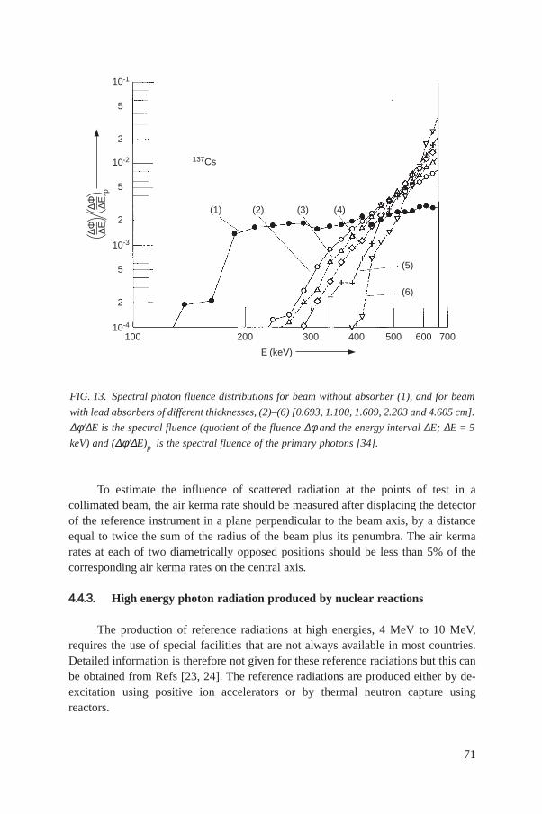
To estimate the influence of scattered radiation at the points of test in acollimated beam, the air kerma rate should be measured after displacing the detectorof the reference instrument in a plane perpendicular to the beam axis, by a distanceequal to twice the sum of the radius of the beam plus its penumbra. The air kermarates at each of two diametrically opposed positions should be less than 5% of thecorresponding air kerma rates on the central axis.
44..44..33. High energy photon radiation produced by nuclear reactions
The production of reference radiations at high energies, 4 MeV to 10 MeV,requires the use of special facilities that are not always available in most countries.Detailed information is therefore not given for these reference radiations but this canbe obtained from Refs [23, 24]. The reference radiations are produced either by de-excitation using positive ion accelerators or by thermal neutron capture usingreactors.
71
FIG. 13. Spectral photon fluence distributions for beam without absorber (1), and for beam
with lead absorbers of different thicknesses, (2)–(6) [0.693, 1.100, 1.609, 2.203 and 4.605 cm].
∆φ/∆E is the spectral fluence (quotient of the fluence ∆φ and the energy interval ∆E; ∆E = 5
keV) and (∆φ/∆E)p is the spectral fluence of the primary photons [34].
(1)
10-4
100
10-3
2
5
10-2
2
5
10-1
2
5p
∆Φ ∆Ε∆Φ ∆Ε
200 300 400 500 600 700
Ε (keV)
(2) (3) (4)
(5)
(6)
137Cs
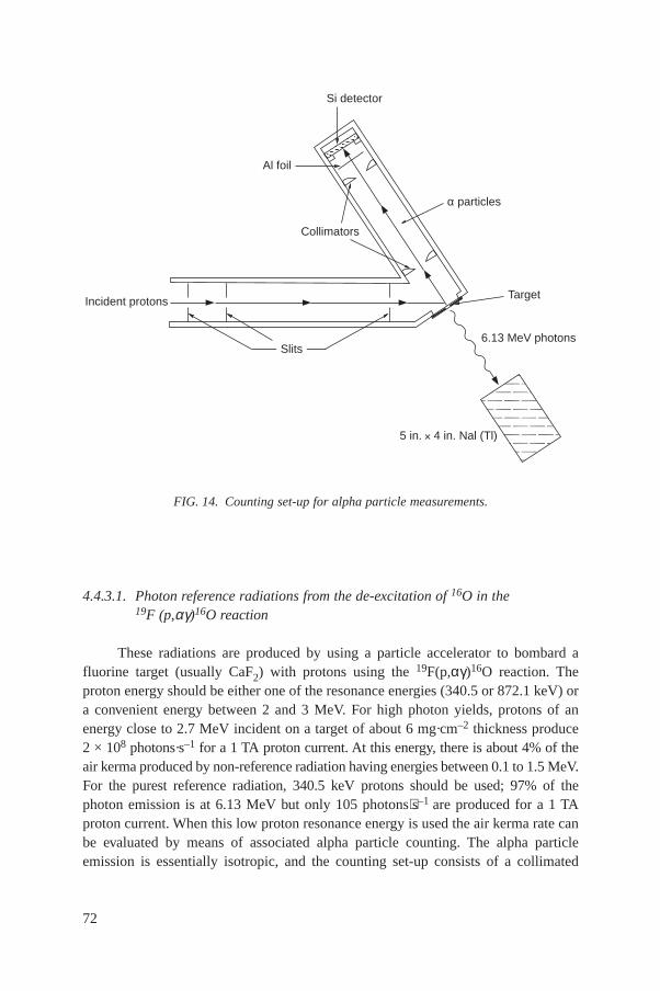
4.4.3.1. Photon reference radiations from the de-excitation of 16O in the19F (p,αγ)16O reaction
These radiations are produced by using a particle accelerator to bombard afluorine target (usually CaF2) with protons using the 19F(p,αγ)16O reaction. Theproton energy should be either one of the resonance energies (340.5 or 872.1 keV) ora convenient energy between 2 and 3 MeV. For high photon yields, protons of anenergy close to 2.7 MeV incident on a target of about 6 mg·cm–2 thickness produce2 × 108 photons·s–1 for a 1 TA proton current. At this energy, there is about 4% of theair kerma produced by non-reference radiation having energies between 0.1 to 1.5 MeV.For the purest reference radiation, 340.5 keV protons should be used; 97% of thephoton emission is at 6.13 MeV but only 105 photons⋅s–1 are produced for a 1 TAproton current. When this low proton resonance energy is used the air kerma rate canbe evaluated by means of associated alpha particle counting. The alpha particleemission is essentially isotropic, and the counting set-up consists of a collimated
72
FIG. 14. Counting set-up for alpha particle measurements.
Si detector
α particles
Target
Collimators
Al foil
Incident protons
Slits6.13 MeV photons
5 in. 4 in. Nal (Tl)

alpha particle detector (e.g. a silicon detector) at the end of a tube mounted oppositethe target of the proton accelerator tube and evacuated to the same pressure(Fig. 14). The air kerma rate at a distance d from the target is given by the followingequation:
(Ka)r = nαEr(µtr/ρ)r (Ωd2)–1 (31)
where nα is the associated particle counting rate, Ω is the solid angle of the collimatorat the alpha particle detector subtended at the centre of the CaF2 target, Er =6.13 MeV and µtr/ρ is the mass energy transfer coefficient for air at energy Er.
4.4.3.2. Photon reference radiations from the de-excitation of 12C
These radiations are produced by using a particle accelerator to bombard a highpurity carbon target with protons, resulting in the lowest excited level of 12C at4.44 MeV, followed by a de-excitation using the 12C(p, p′γ)12C reaction. If naturalcarbon is used as the target there are 3.09 MeV photons and 0.511 MeV photonsproduced by two competing reactions in 13C. For a proton energy of 5.5 MeV anda current of 1 µA at 1 m from the target, an air kerma rate of 85 µGy·h–1 isproduced.
4.4.3.3. Reference radiations produced by the internal neutron capture gammareactions in titanium or nickel
These radiations are produced by the (n,γ) capture reaction in a titanium targetwhich produces 6 MeV photons or a nickel target for 8.5 MeV photons, using areactor as the neutron source. Low energy photons, having energies down to about300 keV, are produced by both of these targets and are reduced or eliminated byappropriate added filtration. Examples of air kerma rates and energies obtained aregiven in Table XXI.
4.4.3.4. Photon reference radiations from the decay of 16N
These reference radiations are produced by activation of water in a reactor coreby fast neutrons using the 16O(n, p)16N reaction. The subsequent ß decay of 16N witha half-life of 7.1 s leads to the excited states of 16O, yielding 6.13 MeV and 7.12 MeVphotons, with relative emission probabilities of 68% and 5%, respectively, and10.4 MeV ß radiation. An air kerma rate of 50 µGy·h–1 per kilogram of water can beproduced at 1 m from water pumped through the reactor core per 1 MW of thermalpower. Low energy photons can also be produced for contaminants in the coolingmedium, e.g. 24Na produces 2.75 MeV and 1.37 MeV photons.
73
4.4.3.5. Contamination of the high energy photon reference radiations
(a) Photons with energies of 0.511 MeV are produced by positron annihilation afterpair production events in the target chamber and in the walls of the calibrationroom and in any filter materials used.
(b) Beta particles are created in the target from nuclear reactions or from secondaryelectrons.
(c) Scattering of reference photons in the target and any nearby material producelower energy photons, which contribute about 1% to the air kerma rate.
4.4.3.6. Dosimetry of high energy photon radiations
The quantity used to characterize the radiation fields at the point of test shouldbe either:
(a) The air kerma rate measured directly with a reference ionization chamber orderived from measurement of the photon fluence or from the emission rate of theassociated alpha particles for the 19F(p,αγ)16O reaction, or
(b) The absorbed dose rate to a specified tissue equivalent material, measured at thedepths of interest in a reference phantom. This can be measured directly by usinga reference ionization chamber calibrated in terms of absorbed dose to tissue orcan be derived indirectly from a measurement of the photon fluence rate or of theair kerma rate.
74
TABLE XXI. CAPTURE GAMMA RADIATIONS: EXAMPLES OF TARGETMATERIALS AND DIMENSIONS, AND ASSOCIATED REFERENCEENERGIES AND AIR KERMA RATES
Target ReferenceAir kerma ratea
energy(Gy·h–1)
Material Dimensions (mm) Mass (kg) Purity (%) (MeV)
Titanium 550 × 100 × 15 3.7 98 6.0 ± 0.5 0.8Nickel 550 × 100 × 10 4.9 98 8.5 ± 0.5 1.2
a Air kerma rate at a distance of 5 m for a thermal neutron fluence rate of 1.5 × 10¹³·s–1.These values are given only as a guide; they were obtained by using beam filtrationcomprising 102 g·cm–2 of polyethylene plus 14 g·cm–2 of aluminium. Different filtrationswill produce different air kerma rates.
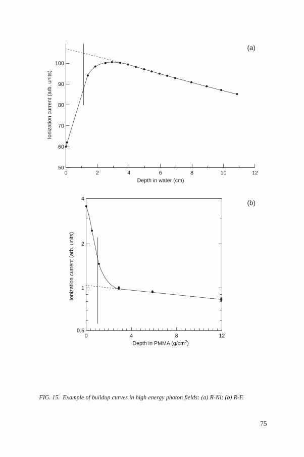
75
FIG. 15. Example of buildup curves in high energy photon fields: (a) R-Ni; (b) R-F.
Ioni
zatio
n cu
rren
t (ar
b. u
nits
)
500
(a)
60
70
80
90
100
2 4 6 8 10 12Depth in water (cm)
Ioni
zatio
n cu
rren
t (ar
b. u
nits
)
0.50
Depth in PMMA (g/cm2)
1
2
4
4 8 12
(b)
4.4.3.7. Calibration of radiation protection instruments in the high energy photonreference radiation fields
At photon energies of 4 to 10 MeV, it is only the strongly penetrating radiationthat contributes to the dose. For measurements of the personal dose equivalent thedepth of 10 mm, Hp(10), is applicable, whilst for area monitoring only the ambientdose equivalent, H*(10), should be measured.
The high energy photon reference radiation fields do, however, have widelydiffering amounts of electron contamination, depending upon the method ofproduction, namely, a collimated or an uncollimated source. This is illustrated inFig. 15, which is a plot of the current of an ionization chamber as a function of thechamber depth in a water phantom for the nickel 9 MeV capture gamma radiation(upper curve) and the corresponding plot in a PMMA phantom for a 6 MeV,19F(p,αγ)16O reference radiation (lower curve). If the radiation field were calibratedcorresponding to a depth of 10 mm (1 g·cm–2), the measured value would be eithertoo low or too high.
To ensure that the correct measurement for the reference photon radiationenergy is obtained and consistent calibrations are made between differentlaboratories, the method to be described in the following section should be used.
4.5. FACILITIES
4.5.1. General
A calibrating laboratory for photon radiation should at least consist of twoseparated irradiation rooms, one for X rays and one for gamma radiation, possiblywith a common measurement and control room. The minimum dimensions of theirradiation rooms should be about 4 m length, 4 m width and 3 m height. If possible,the room should be larger to obtain a sufficient useful range of distances from thesource over which departures for the inverse square law are kept sufficiently small,i.e. ≤ 5%. Sufficient shielding of the irradiation rooms is required. When gammaradiation sources are used concrete walls of about 90 cm thickness with a roof of40 cm concrete will normally be adequate. Additional space should be available forauxiliary laboratories and for a small workshop to be used for electronic testing andrepair facilities.
The facility (Fig. 16), shown only as an example, includes, for gammaradiation, a calibrated collimated beam system with low scatter geometry and anuncollimated irradiation system for simultaneous irradiation of large numbers ofsmall personal dosimeters such as thermoluminescence detectors or photographicfilms. It should be noted that the facility also has a 60Co source and an X ray machinefor therapy level calibrations.
76
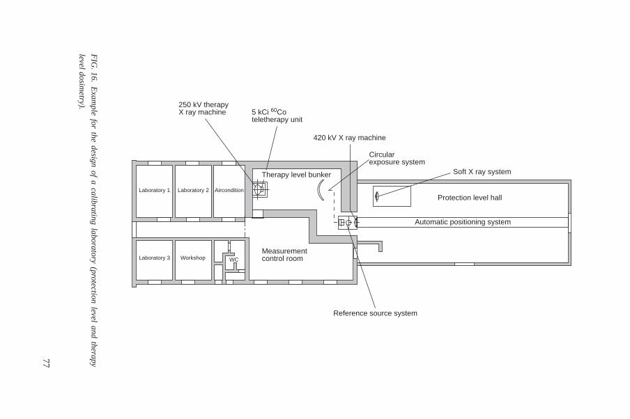
77
FIG
.16.E
xample for the design of a calibrating laboratory (protection level and therapy
level dosimetry).
Automatic positioning system
Protection level hall
Soft X ray system
Laboratory 3 Workshop WC
Laboratory 1 Laboratory 2 Aircondition
250 kV therapyX ray machine 5 kCi 60Co
teletherapy unit
Therapy level bunker
Measurementcontrol room
Circularexposure system
420 kV X ray machine
Reference source system
The irradiation rooms should have suitable track and carriage systems to movethe reference instruments and the measuring instruments to be calibrated accuratelyalong the beam axis. The maximum deviation of the effective point of test from thebeam axis should be less than 1 mm in each direction in the distance range to be used.An aligning instrument, preferably including a laser beam, should be used.
The concrete walls should have special penetrations for cables or other services(according to the services for hot cells [36]) with a cross-section allowing foradditional installations. Air conditioning of the laboratory space to decrease shortterm room temperature and humidity fluctuations may be necessary in manycountries. Adequate electrical mains power supply with regulated voltage is requiredfor the operation of the X ray system and electronic instruments. It should be noted,however, that stabilized transformer supplies may under some circumstancesinfluence the spectrum produced by the X ray set.
4.5.2. Examples of irradiation systems
4.5.2.1. Collimated beam system with ISO ring collimator
A collimated beam system with low scatter geometry using a conical ringcollimator as recommended in ISO 4037-1 [23] should be used. It may consist of anunderground storage container with six gamma ray sources, e.g. 60Co and 137Cs from50 MBq to 1 TBq.
The source is selected for irradiation by rotating a revolving container. It issituated in front of a pneumatically activated tungsten shutter. The opposite side hasan opening in order to reduce 180° backscatter. If the sources are in the storageposition, a mechanical stop can be inserted into the exact position of the source toprovide accurate distance measurement through the ring collimator. The design of thecollimated beam system is shown schematically in Figs 11 and 12 [23]. An exampleof a collimated beam system is presented in Fig. 17.
4.5.2.2. Uncollimated irradiation system
An automated calibration device consisting of a pneumatic rabbit system withcircular irradiation geometry is shown schematically in Fig. 18 and as a photographin Fig. 19 [37, 38].
Four gamma radiation sources, e.g 137Cs with 1 TBq and 0.1 TBq and 60Co with50 GBq and 0.5 GBq activities, are contained in cylindrical rabbits and stored in ashielded revolving container. The selected rabbit is moved through PMMA tubing tothe irradiation position 1 m above floor level. The dosimeters to be calibrated arefixed on the rear side of 3 mm thick PMMA holders providing fast and accuratepositioning, as well as secondary electron equilibrium.
78
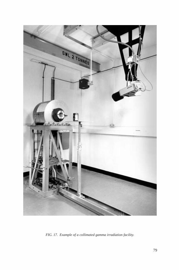
79
FIG. 17. Example of a collimated gamma irradiation facility.
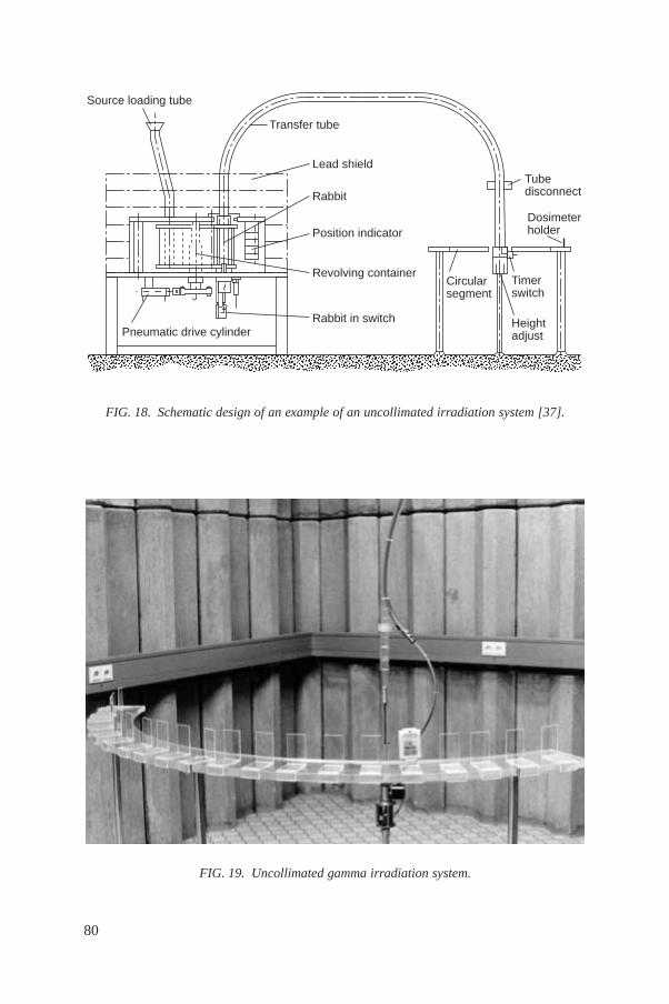
80
FIG. 18. Schematic design of an example of an uncollimated irradiation system [37].
aaaaaaaaaaaaaaaaaaaaSource loading tube
Transfer tube
Lead shield
Rabbit
Position indicator
Revolving container
Rabbit in switchPneumatic drive cylinder
Tubedisconnect
Timerswitch
Heightadjust
Circularsegment
Dosimeterholder
FIG. 19. Uncollimated gamma irradiation system.
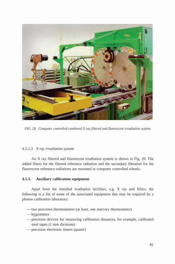
4.5.2.3. X ray irradiation system
An X ray filtered and fluorescent irradiation system is shown in Fig. 20. Theadded filters for the filtered reference radiation and the secondary filtration for thefluorescent reference radiations are mounted in computer controlled wheels.
4.5.3. Auxiliary calibration equipment
Apart from the installed irradiation facilities, e.g. X ray and filters, thefollowing is a list of some of the associated equipment that may be required by aphoton calibration laboratory:
— two precision thermometers (at least, one mercury thermometer)— hygrometer— precision devices for measuring calibration distances, for example, calibrated
steel tapes (1 mm divisions)— precision electronic timers (quartz)
81
FIG. 20. Computer controlled combined X ray filtered and fluorescent irradiation system.
— main power stabilizer— aluminium and copper foils for half-value layer measurements— closed circuit television consisting of controlled camera and monitor— water slab phantom according to ISO specification
— ISO water pillar phantom— ISO PMMA rod phantom
— radiation protection instrumentation:— photon air kerma rate or dose equivalent ratemeters— contamination monitors— personnel alarm dosimeters— area monitors (gamma radiation) to be installed in irradiation rooms with
visual indication of dose rate level (red/green lights) and with remoteindication to be mounted outside the calibration room at the entrance doors(audible alarm indication may also be required).
5. CALIBRATION OF BETA MEASURING INSTRUMENTS
5.1. CALIBRATION QUANTITIES AND CONVERSION COEFFICIENTS
The following two calibration quantities have most often been used up to nowfor calibrating reference standard beta sources:
— Surface absorbed dose rate, Dt(d). The absorbed dose rate to tissue at aspecified depth d on the slab phantom of ICRU tissue.
— Absorbed dose rate free in air, Da. The absorbed dose rate to air underconditions of air scatter only (i.e. for receptor free conditions).
Hp(0.07) in the slab phantom is approximated by H′(0.07), which is calculatedfrom Dt(d) or Da by
H· ′(0.07) = D· t(0.07) (32)
and
H· ′(0.07) = D· aT(0.07) st,a B (33)
where
82
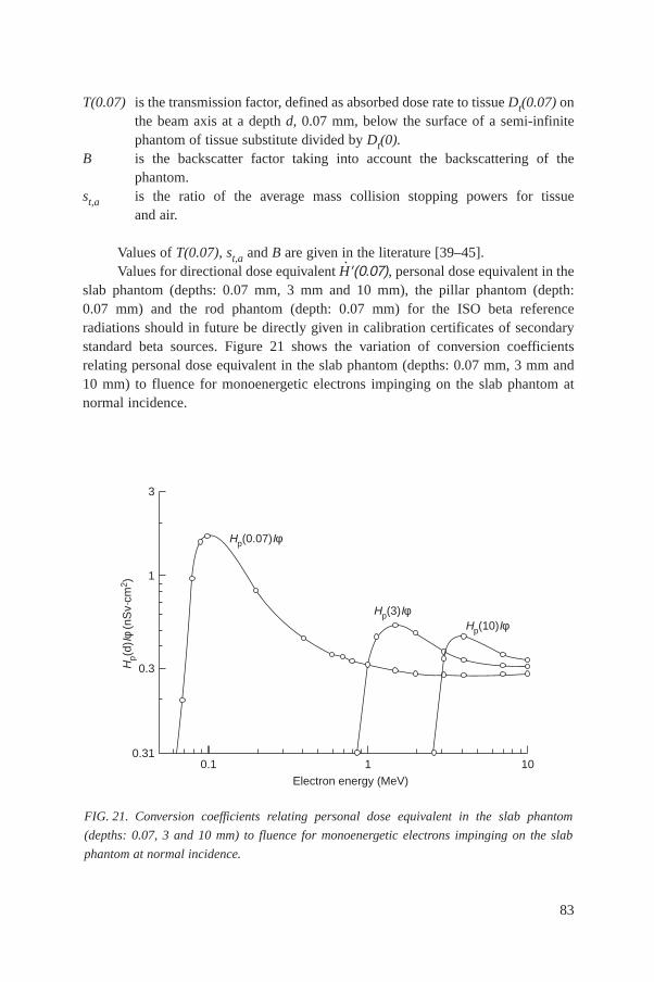
83
T(0.07) is the transmission factor, defined as absorbed dose rate to tissue Dt(0.07) onthe beam axis at a depth d, 0.07 mm, below the surface of a semi-infinitephantom of tissue substitute divided by Dt(0).
B is the backscatter factor taking into account the backscattering of thephantom.
st,a is the ratio of the average mass collision stopping powers for tissueand air.
Values of T(0.07), st,a and B are given in the literature [39–45].Values for directional dose equivalent H
· ′(0.07), personal dose equivalent in theslab phantom (depths: 0.07 mm, 3 mm and 10 mm), the pillar phantom (depth:0.07 mm) and the rod phantom (depth: 0.07 mm) for the ISO beta referenceradiations should in future be directly given in calibration certificates of secondarystandard beta sources. Figure 21 shows the variation of conversion coefficientsrelating personal dose equivalent in the slab phantom (depths: 0.07 mm, 3 mm and10 mm) to fluence for monoenergetic electrons impinging on the slab phantom atnormal incidence.
FIG. 21. Conversion coefficients relating personal dose equivalent in the slab phantom
(depths: 0.07, 3 and 10 mm) to fluence for monoenergetic electrons impinging on the slab
phantom at normal incidence.
0.1
Hp(
d)Iφ
(nS
v·cm
2 )
0.31
0.3
1
3
1 10
Electron energy (MeV)
Hp(0.07)Iφ
Hp(3)IφHp(10)Iφ

5.2. REFERENCE BETA RADIATIONS
The ISO has specified [46] requirements for reference beta radiations producedby radionuclide sources to be used for the calibration of protection level dosimetersand dose ratemeters, and for the determination of their response as a function of betaray energy.
Five beta ray emitting radionuclides are specified; their characteristics are givenin Table XXII. The beta radiation fields produced by all these radionuclides except106Ru + 106Rh are practically free of photon radiation, apart from bremsstrahlunggenerated in the surrounding materials or in the beta ray source itself. 106Ru + 106Rhis used because of its high maximum energy of the beta ray flux density. Only beta
84
TABLE XXII. CHARACTERISTICS OF BETA RAY SOURCES SPECIFIED INISO 6980–1984 [46]
Radionuclides t1/2 (d)a Emax (keV)b Eres (keV)c Photon energies(keV)
14C 2 093 000 156 90
147Pm 957 225 130 K 121 (0.013%)Sm X rays5.6–7.239.5–46.6
204Tl 1381 763 530 Hg X rays9.9–13.868.9–82.5
90Sr + 90Y 10 483 2274 1800 —
106Ru + 106Rh 372.6 3541 2800 106Rh-K, 512 (21%)616/622–(11%doublet)1050 (1.5%)1130 (0.5%)1550 (0.2%)and others
a t1/2 is the half-life.b Emax is the maximum energy of the beta ray flux density of the radionuclide.c Eres is the maximum energy of the beta flux density at the calibration distance which must
at least be attained (residual maximum energy).

ray sources with small self-absorption and thin encapsulation can fulfil the ISOspecifications, since the maximum energy of the beta ray flux density at thecalibration distance Eres (residual maximum energy) must be higher than a specifiedEres value [46].
The last column of Table XXII contains the energies of the principal photonradiations emitted; the emission probability is given in brackets.
Two series of reference radiations are specified by ISO:
— Series 1 reference radiations are produced by beta ray sources used with beamflattening filters designed to give uniform dose rates over a large area at aspecified distance (Fig. 22). As examples of Series 1 reference radiations, TableXXIII gives details of calibration distances and filter construction. Approximatevalues of H
· ′(0.07) divided by the activity A are given in the last column. Theeffect of the beam flattening filters in homogenizing the dose rate of the foursources specified in Table XXIII is demonstrated by the measurements shownin Fig. 23. The remaining asymmetry of the curves is believed to be due to an
85
FIG. 22. Calibration stand with beam flattening filter.
Area of uniformdose rate to be
used for calibration
Beam flat-tening filter
Calibration distance
Support rods forbeam flattening filter
ß source
Jig
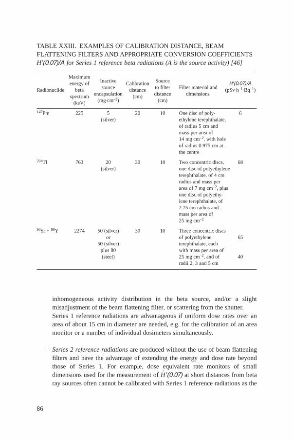
inhomogeneous activity distribution in the beta source, and/or a slightmisadjustment of the beam flattening filter, or scattering from the shutter.Series 1 reference radiations are advantageous if uniform dose rates over anarea of about 15 cm in diameter are needed, e.g. for the calibration of an areamonitor or a number of individual dosimeters simultaneously.
— Series 2 reference radiations are produced without the use of beam flatteningfilters and have the advantage of extending the energy and dose rate beyondthose of Series 1. For example, dose equivalent rate monitors of smalldimensions used for the measurement of H
· ′(0.07) at short distances from betaray sources often cannot be calibrated with Series 1 reference radiations as the
86
TABLE XXIII. EXAMPLES OF CALIBRATION DISTANCE, BEAMFLATTENING FILTERS AND APPROPRIATE CONVERSION COEFFICIENTSH′(0.07)/Α for Series 1 reference beta radiations (A is the source activity) [46]
MaximumInactive Sourceenergy ofsource
Calibrationto filter Filter material and
H′(0.07)/ΑRadionuclide beta
encapsulationdistance
distance dimensions(pSv·h–1·Bq–1)
spectrum(mg·cm–2)
(cm)(cm)(keV)
147Pm 225 5 20 10 One disc of poly- 6(silver) ethylene terephthalate,
of radius 5 cm and mass per area of 14 mg·cm–2, with holeof radius 0.975 cm atthe centre
204Tl 763 20 30 10 Two concentric discs, 68(silver) one disc of polyethylene
terephthalate, of 4 cmradius and mass perarea of 7 mg·cm–2, plusone disc of polyethy-lene terephthalate, of2.75 cm radius andmass per area of25 mg·cm–2
90Sr + 90Y 2274 50 (silver) 30 10 Three concentric discsor of polyethylene 65
50 (silver) terephthalate, eachplus 80 with mass per area of(steel) 25 mg·cm–2, and of 40
radii 2, 3 and 5 cm
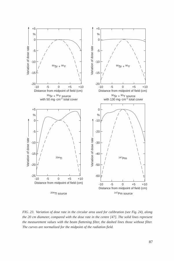
87
Bd
dΩβΩ
=
FIG. 23. Variation of dose rate in the circular area used for calibration (see Fig. 24), along
the 20 cm diameter, compared with the dose rate in the centre [47]. The solid lines represent
the measurement values with the beam flattening filter, the dashed lines those without filter.
The curves are normalized for the midpoint of the radiation field.
-10
204Tl
Var
iatio
n of
dos
e ra
te
-25
-20
-15
-10
-5
0
+5
-5 0 +5 +10Distance from midpoint of field (cm)
%
-10
Var
iatio
n of
dos
e ra
te
-20
-15
-10
-5
0
+5
-5 0 +5 +10
%
-10
Var
iatio
n of
dos
e ra
te
-20
-15
-10
-5
0
+5
-5 0 +5 +10Distance from midpoint of field (cm)
%
90Sr + 90Y90Sr + 90Y
-10
147Pm
Var
iatio
n of
dos
e ra
te
-60
-50
-40
-30
-20
-10
-5 0 +5 +10Distance from midpoint of field (cm)
%
0
90Sr + 90Y sourcewith 130 mg · cm-2 total cover
Distance from midpoint of field (cm)90Sr + 90Y source
with 50 mg · cm-2 total cover
147Pm source204Tl source
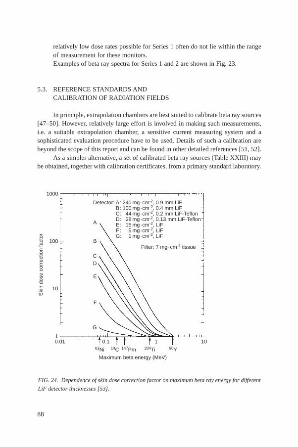
relatively low dose rates possible for Series 1 often do not lie within the rangeof measurement for these monitors.Examples of beta ray spectra for Series 1 and 2 are shown in Fig. 23.
5.3. REFERENCE STANDARDS ANDCALIBRATION OF RADIATION FIELDS
In principle, extrapolation chambers are best suited to calibrate beta ray sources[47–50]. However, relatively large effort is involved in making such measurements,i.e. a suitable extrapolation chamber, a sensitive current measuring system and asophisticated evaluation procedure have to be used. Details of such a calibration arebeyond the scope of this report and can be found in other detailed references [51, 52].
As a simpler alternative, a set of calibrated beta ray sources (Table XXIII) maybe obtained, together with calibration certificates, from a primary standard laboratory.
88
FIG. 24. Dependence of skin dose correction factor on maximum beta ray energy for different
LiF detector thicknesses [53].
63Ni
0.01
Ski
n do
se c
orre
ctio
n fa
ctor
1000
100
10
10.1 1 10
14C 147Pm 204Ti 90Y
Maximum beta energy (MeV)
Detector: A: 240 mg · cm-2, 0.9 mm LiFB: 100 mg · cm-2, 0.4 mm LiFC: 44 mg · cm-2, 0.2 mm LiF-TeflonD: 28 mg · cm-2, 0.13 mm LiF-TeflonE: 15 mg · cm-2, LiFF : 5 mg · cm-2, LiFG: 1 mg · cm-2, LiF
A
B
CD
E
F
G
Filter: 7 mg · cm-2 tissue
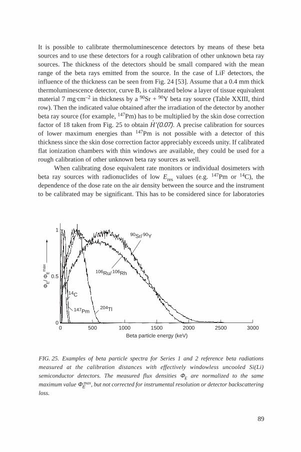
It is possible to calibrate thermoluminescence detectors by means of these betasources and to use these detectors for a rough calibration of other unknown beta raysources. The thickness of the detectors should be small compared with the meanrange of the beta rays emitted from the source. In the case of LiF detectors, theinfluence of the thickness can be seen from Fig. 24 [53]. Assume that a 0.4 mm thickthermoluminescence detector, curve B, is calibrated below a layer of tissue equivalentmaterial 7 mg·cm–2 in thickness by a 90Sr + 90Y beta ray source (Table XXIII, thirdrow). Then the indicated value obtained after the irradiation of the detector by anotherbeta ray source (for example, 147Pm) has to be multiplied by the skin dose correctionfactor of 18 taken from Fig. 25 to obtain H
· ′(0.07). A precise calibration for sourcesof lower maximum energies than 147Pm is not possible with a detector of thisthickness since the skin dose correction factor appreciably exceeds unity. If calibratedflat ionization chambers with thin windows are available, they could be used for arough calibration of other unknown beta ray sources as well.
When calibrating dose equivalent rate monitors or individual dosimeters withbeta ray sources with radionuclides of low Eres values (e.g. 147Pm or 14C), thedependence of the dose rate on the air density between the source and the instrumentto be calibrated may be significant. This has to be considered since for laboratories
89
FIG. 25. Examples of beta particle spectra for Series 1 and 2 reference beta radiations
measured at the calibration distances with effectively windowless uncooled Si(Li)
semiconductor detectors. The measured flux densities ΦE are normalized to the same
maximum value ΦΕmax, but not corrected for instrumental resolution or detector backscattering
loss.
0
90Sr/ 90Y
1
0.5
0
ΦE/ Φ
Em
ax
106Ru/ 106Rh
14C
147Pm204Tl
500 1000 1500 2000 2500 3000
Beta particle energy (keV)
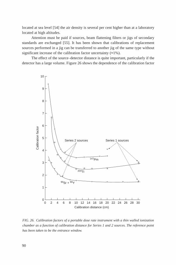
located at sea level [54] the air density is several per cent higher than at a laboratorylocated at high altitudes.
Attention must be paid if sources, beam flattening filters or jigs of secondarystandards are exchanged [55]. It has been shown that calibrations of replacementsources performed in a jig can be transferred to another jig of the same type withoutsignificant increase of the calibration factor uncertainty (≈1%).
The effect of the source–detector distance is quite important, particularly if thedetector has a large volume. Figure 26 shows the dependence of the calibration factor
90
FIG. 26. Calibration factors of a portable dose rate instrument with a thin walled ionization
chamber as a function of calibration distance for Series 1 and 2 sources. The reference point
has been taken to be the entrance window.
0
Series 2 sources
Cal
ibra
tion
fact
or
0
1
2
3
4
5
6
7
8
9
10
2 4 6 8 10 12 14 16 18 20 22 24 26 28 30Calibration distance (cm)
204TI
147Pm
90Sr + 90Y
Series 1 sources
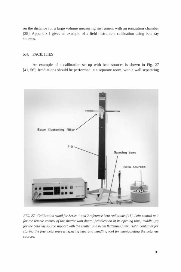
on the distance for a large volume measuring instrument with an ionization chamber[28]. Appendix I gives an example of a field instrument calibration using beta raysources.
5.4. FACILITIES
An example of a calibration set-up with beta sources is shown in Fig. 27[41, 56]. Irradiations should be performed in a separate room, with a wall separating
91
FIG. 27. Calibration stand for Series 1 and 2 reference beta radiations [41]. Left: control unit
for the remote control of the shutter with digital preselection of its opening time; middle: jig
for the beta ray source support with the shutter and beam flattening filter; right: container for
storing the four beta sources; spacing bars and handling tool for manipulating the beta ray
sources.
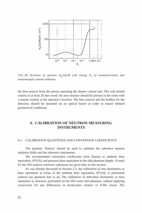
the beta sources from the person operating the shutter control unit. The wall shouldconsist of at least 20 mm wood. An area monitor should be present in the room witha remote readout at the operator’s location. The beta sources and the holders for thedetectors should be mounted on an optical bench in order to ensure definedgeometrical conditions.
6. CALIBRATION OF NEUTRON MEASURINGINSTRUMENTS
6.1. CALIBRATION QUANTITIES AND CONVERSION COEFFICIENTS
The quantity ‘fluence’ should be used to calibrate the reference neutronradiation fields and the reference instruments.
The recommended conversion coefficients from fluence to ambient doseequivalent, H*(10), and personal dose equivalent in the slab phantom (depth: 10 mm)for the ISO neutron reference radiations are given later in this section.
As was already discussed in Section 2.2, the calibration of area dosimeters ordose ratemeters in terms of the ambient dose equivalent, H*(10), is performedwithout any phantom free in air. The calibration of individual dosimeters or doseratemeters is, however, performed on the ISO water slab phantom, without applyingcorrections for any differences in backscatter relative to ICRU tissue. The
92
FIG. 28. Variation of quotient Hp(10)/Φ with energy En of monodirectional and
monoenergetic neutron radiation.
10-6
Hp(
10)/
Φ(p
Sv
· cm
2 )
1000
100
10
En
10-8 10-4 10-2 1 102MeV
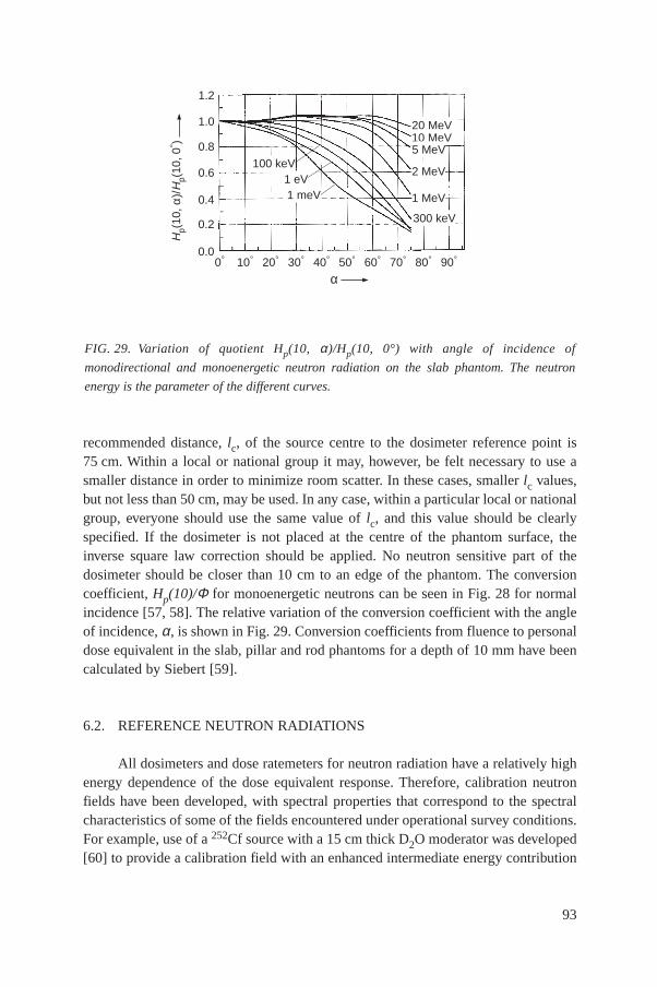
recommended distance, lc, of the source centre to the dosimeter reference point is75 cm. Within a local or national group it may, however, be felt necessary to use asmaller distance in order to minimize room scatter. In these cases, smaller lc values,but not less than 50 cm, may be used. In any case, within a particular local or nationalgroup, everyone should use the same value of lc, and this value should be clearlyspecified. If the dosimeter is not placed at the centre of the phantom surface, theinverse square law correction should be applied. No neutron sensitive part of thedosimeter should be closer than 10 cm to an edge of the phantom. The conversioncoefficient, Hp(10)/Φ for monoenergetic neutrons can be seen in Fig. 28 for normalincidence [57, 58]. The relative variation of the conversion coefficient with the angleof incidence, α, is shown in Fig. 29. Conversion coefficients from fluence to personaldose equivalent in the slab, pillar and rod phantoms for a depth of 10 mm have beencalculated by Siebert [59].
6.2. REFERENCE NEUTRON RADIATIONS
All dosimeters and dose ratemeters for neutron radiation have a relatively highenergy dependence of the dose equivalent response. Therefore, calibration neutronfields have been developed, with spectral properties that correspond to the spectralcharacteristics of some of the fields encountered under operational survey conditions.For example, use of a 252Cf source with a 15 cm thick D2O moderator was developed[60] to provide a calibration field with an enhanced intermediate energy contribution
93
FIG. 29. Variation of quotient Hp(10, α)/Hp(10, 0°) with angle of incidence of
monodirectional and monoenergetic neutron radiation on the slab phantom. The neutron
energy is the parameter of the different curves.
Hp(
10, α
)/H
p(10
, 0° )
0.00° 10° 20° 30° 40° 50° 60° 70° 80° 90°
α
20 MeV10 MeV5 MeV
2 MeV
1 MeV
300 keV
100 keV1 eV1 meV
0.2
0.4
0.6
0.8
1.0
1.2

for calibration of instruments to be used in nuclear power reactors. Althoughduplication of operational spectra is generally not practical in the calibration facility,it is important to be aware of the dependence of the dose equivalent response on theenergy and the direction of incident neutrons. The IAEA has produced twocompilations of neutron spectra and detector energy responses that may be useful foraddressing this question in greater detail [61, 62].
Neutron calibrations can be performed with isotopic sources, reactor neutronsor accelerators. ISO has recommended reference radiations that are suitable forcalibration purposes [63]. These recommendations include details of sourcecharacteristics, such as shape, encapsulation and spectral distribution.
6.2.1. Isotopic sources
Isotopic sources provide the most convenient neutron fields for calibrationpurposes. Neutrons are produced by spontaneous fission (252Cf) or by (α, n) reactions(241Am–Be, 241Am–B, 239Pu–Be, etc.). The fluence rate for isotopic sources iscalculated from the angular source emission rate, BΩ
(34)
where dβ is the number of neutrons per unit time propagating in a specified directionwithin the solid angle dΩ. BΩ is expressed in s–1·sr–1.
The general properties of isotopic sources suggested for routine calibration arepresented in Table XXIV [63]. Spectrum weighted fluence-to-dose-equivalentconversion coefficients for these sources are shown in Table XXV [64].
Neutron source strengths and neutron and photon dose equivalent rate constantsdepend on the source construction. They vary because of scattering and absorption ofneutrons and gamma rays within the source itself and within its encapsulatingmaterial. Emission rates are also affected by radioisotopic impurities in the source.For 252Cf, the specific photon dose equivalent rate depends on the age of the source,because of buildup of fission products. However, the increase is less than 5% in thefirst 20 years. 252Cf sources have a high specific activity and are, therefore,comparatively small. The 241Am–Be(α,n) sources consist of homogeneous,compressed mixtures of 241AmO2 and beryllium.
Calibrations with isotopic sources have the advantages that (1) the sources arephysically small and relatively easy to use, and (2) the source intensity is constant(except for radioactive decay, which is easily determined). The spectra are distributedrather than monoenergetic. As a result, they have limited value for energy responsemeasurements. However, the distribution can be useful in simulating distributed
Bd
dW W= b
94
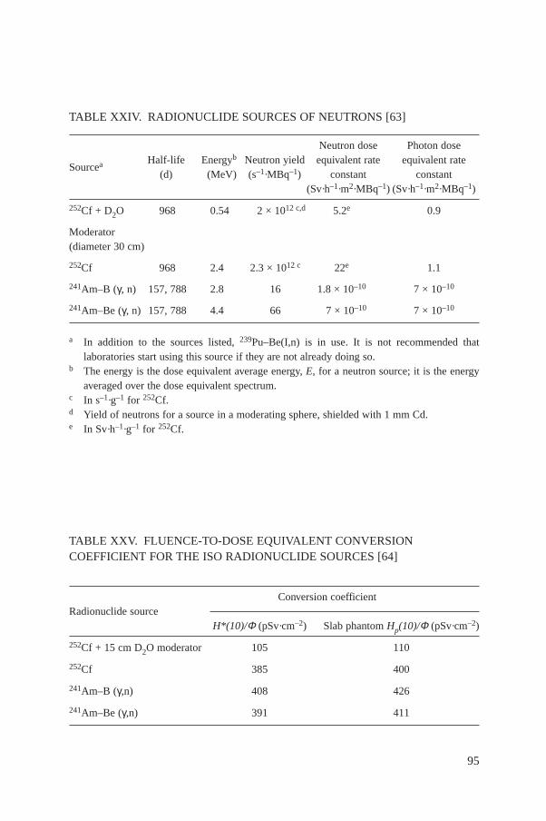
95
TABLE XXIV. RADIONUCLIDE SOURCES OF NEUTRONS [63]
Neutron dose Photon doseHalf-life Energyb Neutron yield equivalent rate equivalent rate
Sourcea(d) (MeV) (s–1·MBq–1) constant constant
(Sv·h–1·m2·MBq–1) (Sv·h–1·m2·MBq–1)
252Cf + D2O 968 0.54 2 × 10¹² c,d 5.2e 0.9
Moderator(diameter 30 cm)
252Cf 968 2.4 2.3 × 10¹² c 22e 1.1
241Am–B (γ, n) 157, 788 2.8 16 1.8 × 10⁻¹⁰ 7 × 10⁻¹⁰
241Am–Be (γ, n) 157, 788 4.4 66 7 × 10⁻¹⁰ 7 × 10⁻¹⁰
a In addition to the sources listed, 239Pu–Be(I,n) is in use. It is not recommended thatlaboratories start using this source if they are not already doing so.
b The energy is the dose equivalent average energy, E, for a neutron source; it is the energyaveraged over the dose equivalent spectrum.
c In s–1·g–1 for 252Cf.d Yield of neutrons for a source in a moderating sphere, shielded with 1 mm Cd.e In Sv·h–1·g–1 for 252Cf.
TABLE XXV. FLUENCE-TO-DOSE EQUIVALENT CONVERSIONCOEFFICIENT FOR THE ISO RADIONUCLIDE SOURCES [64]
Conversion coefficientRadionuclide source
H*(10)/Φ (pSv·cm–2) Slab phantom Hp(10)/Φ (pSv·cm–2)
252Cf + 15 cm D2O moderator 105 110
252Cf 385 400
241Am–B (γ,n) 408 426
241Am–Be (γ,n) 391 411
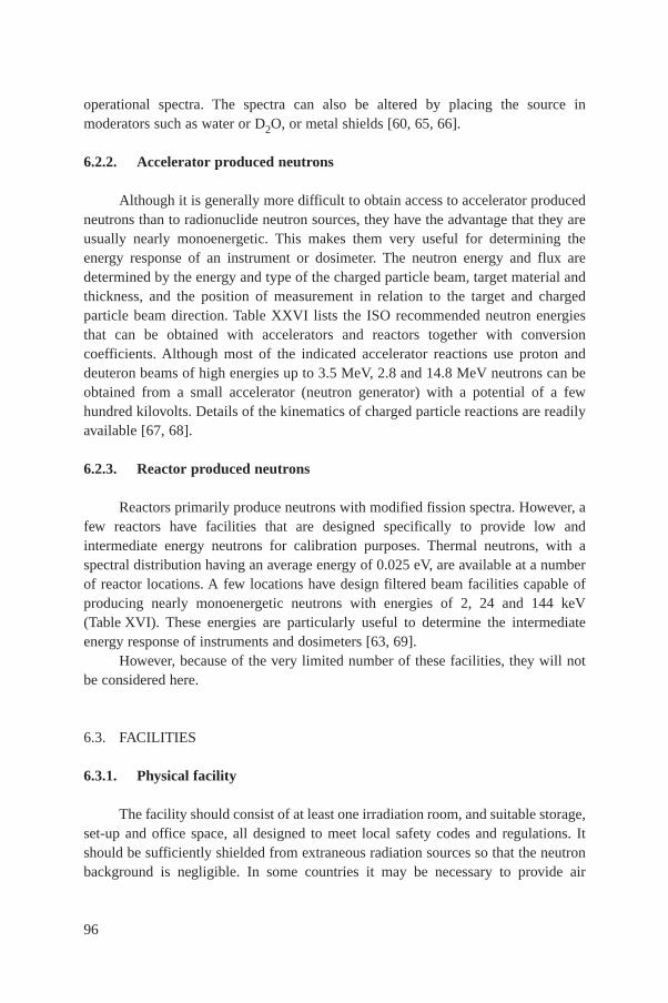
operational spectra. The spectra can also be altered by placing the source inmoderators such as water or D2O, or metal shields [60, 65, 66].
6.2.2. Accelerator produced neutrons
Although it is generally more difficult to obtain access to accelerator producedneutrons than to radionuclide neutron sources, they have the advantage that they areusually nearly monoenergetic. This makes them very useful for determining theenergy response of an instrument or dosimeter. The neutron energy and flux aredetermined by the energy and type of the charged particle beam, target material andthickness, and the position of measurement in relation to the target and chargedparticle beam direction. Table XXVI lists the ISO recommended neutron energiesthat can be obtained with accelerators and reactors together with conversioncoefficients. Although most of the indicated accelerator reactions use proton anddeuteron beams of high energies up to 3.5 MeV, 2.8 and 14.8 MeV neutrons can beobtained from a small accelerator (neutron generator) with a potential of a fewhundred kilovolts. Details of the kinematics of charged particle reactions are readilyavailable [67, 68].
6.2.3. Reactor produced neutrons
Reactors primarily produce neutrons with modified fission spectra. However, afew reactors have facilities that are designed specifically to provide low andintermediate energy neutrons for calibration purposes. Thermal neutrons, with aspectral distribution having an average energy of 0.025 eV, are available at a numberof reactor locations. A few locations have design filtered beam facilities capable ofproducing nearly monoenergetic neutrons with energies of 2, 24 and 144 keV(Table XVI). These energies are particularly useful to determine the intermediateenergy response of instruments and dosimeters [63, 69].
However, because of the very limited number of these facilities, they will notbe considered here.
6.3. FACILITIES
6.3.1. Physical facility
The facility should consist of at least one irradiation room, and suitable storage,set-up and office space, all designed to meet local safety codes and regulations. Itshould be sufficiently shielded from extraneous radiation sources so that the neutronbackground is negligible. In some countries it may be necessary to provide air
96
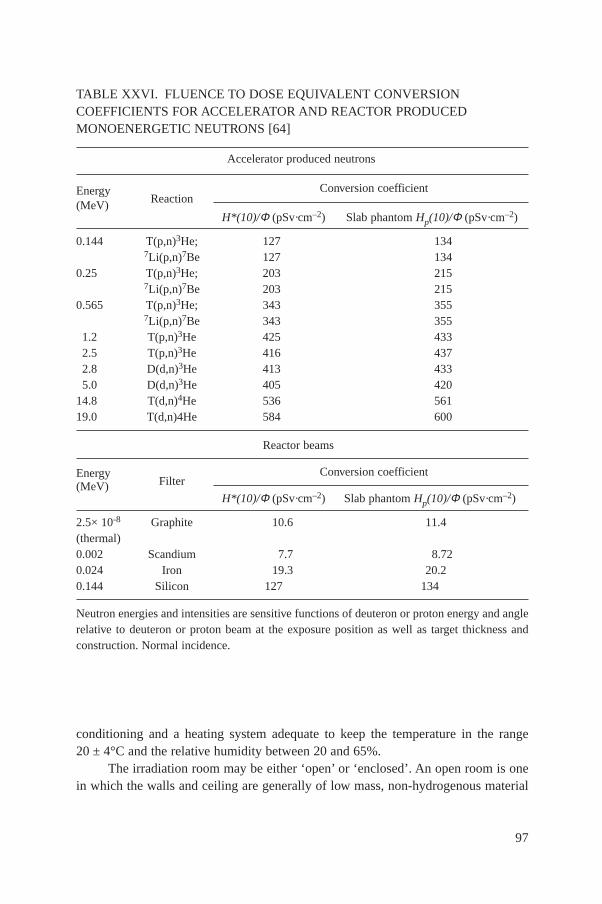
conditioning and a heating system adequate to keep the temperature in the range20 ± 4°C and the relative humidity between 20 and 65%.
The irradiation room may be either ‘open’ or ‘enclosed’. An open room is onein which the walls and ceiling are generally of low mass, non-hydrogenous material
97
TABLE XXVI. FLUENCE TO DOSE EQUIVALENT CONVERSIONCOEFFICIENTS FOR ACCELERATOR AND REACTOR PRODUCEDMONOENERGETIC NEUTRONS [64]
Accelerator produced neutrons
Conversion coefficientEnergyReaction(MeV)
H*(10)/Φ (pSv·cm–2) Slab phantom Hp(10)/Φ (pSv·cm–2)
0.144 T(p,n)3He; 127 1347Li(p,n)7Be 127 134
0.25 T(p,n)3He; 203 2157Li(p,n)7Be 203 215
0.565 T(p,n)3He; 343 3557Li(p,n)7Be 343 355
1.2 T(p,n)3He 425 4332.5 T(p,n)3He 416 4372.8 D(d,n)3He 413 4335.0 D(d,n)3He 405 420
14.8 T(d,n)4He 536 56119.0 T(d,n)4He 584 600
Reactor beams
Conversion coefficientEnergyFilter(MeV)
H*(10)/Φ (pSv·cm–2) Slab phantom Hp(10)/Φ (pSv·cm–2)
2.5× 10⁻⁸ Graphite 10.6 11.4(thermal)0.002 Scandium 7.7 8.720.024 Iron 19.3 20.20.144 Silicon 127 134
Neutron energies and intensities are sensitive functions of deuteron or proton energy and anglerelative to deuteron or proton beam at the exposure position as well as target thickness andconstruction. Normal incidence.

essentially transparent to neutrons. Radiation protection is provided by means of asufficiently large exclusion area. An enclosed room is one in which the walls andceiling are sufficiently massive (usually concrete) to provide adequate shielding. Anenclosed room should be as large as possible to minimize the room scattered neutroncontribution. The smallest inside linear dimensions should be >6 m.
Sources and detectors or phantom arrangements should be placed on suitablelow scatter supports in an open room and should be at least 2 m above the floor. In anenclosed room, the optimum height is in the central plane between the floor and theceiling. In larger laboratories, it may be advisable to erect special lightweightintermediate floors for the calibration arrangement. The source should be positionednear the centre of the room. Special emphasis must be given to minimizing theamount of scatter material near the source. The whole irradiation set-up should, onthe other hand, be sufficiently rigid to assure reproducible alignment of source anddetectors at various source–detector distances.
The data taking area must be completely shielded from the irradiation area.However, it is necessary to have a means of viewing the irradiation set-up, eitherdirectly or by closed circuit television.
6.3.2. Shielding and radiation protection
It is not possible to provide complete guidance on this topic within the scope ofthis document. For many facilities, the largest sources of neutrons will be 252Cfsources, which often exceed emission rates of 5 × 10⁹ neutrons per second. A sourceof this magnitude will require as much as 100 cm of concrete to reduce the doseequivalent rate outside of the source room to acceptable levels. It is also important toconsider the effects of skyshine (air scatter of radiation passing through the roof),since it is often expedient to modify a pre-existing facility, developed for anotherpurpose, as a calibration facility. Such rooms may not have adequate roof shielding.Additional guidance on calibration facility shielding is found in Ref. [70], andspecific technical information for shielding 252Cf is given by Stoddard and Hootman[71]. General texts on radiation shielding, including skyshine, are readily available.
6.3.3. Source storage and transfer
Radionuclide sources must be stored when not in use. Storage is usually a holein the floor or a shielded enclosure on the floor. Figure 30 provides an example of acalibration room. At the US National Institute for Standards and Technology (NIST,formerly NBS), for example, sources are kept in a hole 1.4 m deep and 8 cm indiameter. The hole may be closed with a plastic plug having a lead cap. Otherlaboratories use water filled holes in the floor, water filled boxes on the floor orelaborate shielding arrangements. It must be pointed out, however, that, while water
98
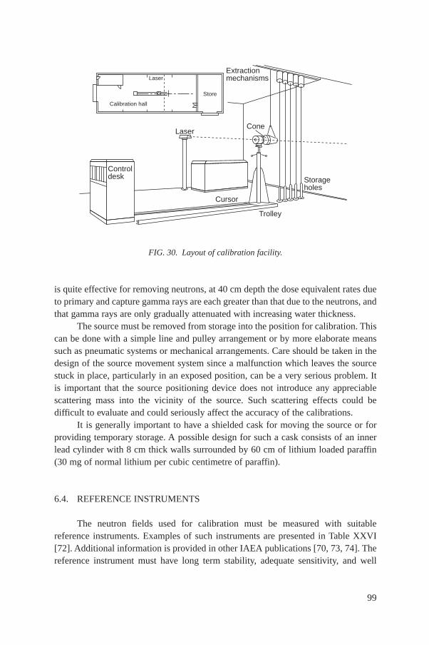
is quite effective for removing neutrons, at 40 cm depth the dose equivalent rates dueto primary and capture gamma rays are each greater than that due to the neutrons, andthat gamma rays are only gradually attenuated with increasing water thickness.
The source must be removed from storage into the position for calibration. Thiscan be done with a simple line and pulley arrangement or by more elaborate meanssuch as pneumatic systems or mechanical arrangements. Care should be taken in thedesign of the source movement system since a malfunction which leaves the sourcestuck in place, particularly in an exposed position, can be a very serious problem. Itis important that the source positioning device does not introduce any appreciablescattering mass into the vicinity of the source. Such scattering effects could bedifficult to evaluate and could seriously affect the accuracy of the calibrations.
It is generally important to have a shielded cask for moving the source or forproviding temporary storage. A possible design for such a cask consists of an innerlead cylinder with 8 cm thick walls surrounded by 60 cm of lithium loaded paraffin(30 mg of normal lithium per cubic centimetre of paraffin).
6.4. REFERENCE INSTRUMENTS
The neutron fields used for calibration must be measured with suitablereference instruments. Examples of such instruments are presented in Table XXVI[72]. Additional information is provided in other IAEA publications [70, 73, 74]. Thereference instrument must have long term stability, adequate sensitivity, and well
99
FIG. 30. Layout of calibration facility.
Extractionmechanisms
Storageholes
Cone
Cursor
Trolley
Laser
Controldesk
Store
Laser
Calibration hall
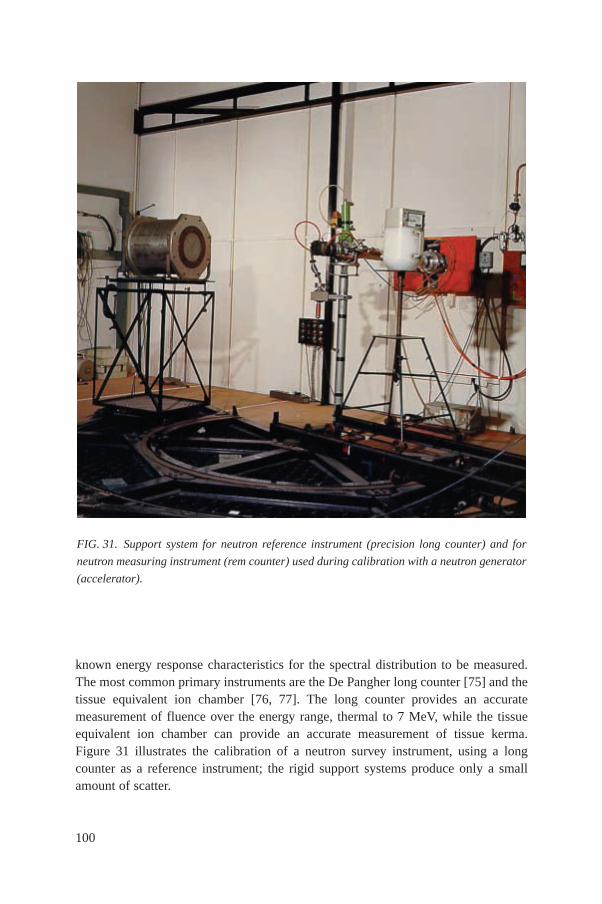
known energy response characteristics for the spectral distribution to be measured.The most common primary instruments are the De Pangher long counter [75] and thetissue equivalent ion chamber [76, 77]. The long counter provides an accuratemeasurement of fluence over the energy range, thermal to 7 MeV, while the tissueequivalent ion chamber can provide an accurate measurement of tissue kerma.Figure 31 illustrates the calibration of a neutron survey instrument, using a longcounter as a reference instrument; the rigid support systems produce only a smallamount of scatter.
100
FIG. 31. Support system for neutron reference instrument (precision long counter) and for
neutron measuring instrument (rem counter) used during calibration with a neutron generator
(accelerator).
For radiation protection purposes, stable instruments designed to determinedose equivalent are also suitable monitors. These include moderated counters such asthe Andersson–Braun cylindrical rem counter [78], the 12 inch spherical moderatedcounter developed by Bonner [79] and the spherical rem counter designed by Leake[80]. Tissue equivalent proportional counters [81, 82] are also designed to determinedose equivalent through measurement of absorbed dose and lineal energy distribution,and may be used as reference instruments.
Since many neutron instruments are sensitive to photons, it is also important tohave gamma monitors that are essentially neutron insensitive. The two most commondetectors for this purpose are energy compensated Geiger–Müller counters [83] andneutron insensitive TLDs, such as TLD 700, enriched in 7Li. Care should be taken inthe use of Geiger–Müller counters to avoid significant activation of the detectormaterial, causing an increase in gamma background. For radiation protection levelcalibrations, however, this is not likely to be a problem.
6.5. RADIATION FIELD CALIBRATIONS
The neutron fluence rate and spectrum should not vary significantly over anarea just sufficient to completely irradiate the instrument being calibrated. If the beamis smaller than the detector, such as those from filtered reactor beam facilities, thebeam may be scanned over the surface of the detector. In the case of individualdosimeters, the phantom is considered part of the detector so that the scan must coveran area of the phantom large enough to simulate uniform irradiation of the phantom.
If the neutron fields are likely to have significant time variation, such as thosefrom an accelerator or neutron generator, an additional monitoring instrument may benecessary to normalize the fluence values from measurement to measurement. Theprimary requirements for such an instrument is that its response be linear with fluencerate, stable, and have adequate sensitivity.
6.5.1. Radionuclide sources
The radionuclide source should be placed at or near the centre of the irradiationroom on a rigid support that gives insignificant scatter. A detailed description of aradionuclide source calibration facility and the calibration procedures used is given inRef. [84].
The neutron source emission rate B should be determined by a measurementthat is directly traceable to a primary standard. The angular source emission rate, BΩ,has to be determined as the emission is rarely isotropic [72].
The unscattered fluence rate, ϕc(l), at the point of test at a distance l from thecentre of the source is then calculated by
101
(35)
Values of FA(l), the correction for air attenuation and scatter, can be calculatedfrom Ref. [72]. The value of ϕc(l) has to be multiplied by the appropriatefluence-to-dose-equivalent conversion coefficient (Table XXV) to obtain the desiredcalibration quantity. The response of the instrument to scattered neutrons must bemeasured using the shadow cone for each calibration distance, l, used (Section 6.5.4).The response of the instrument is then obtained by subtracting the cone measurementfrom a measurement made without the cone present.
Any photon emission associated with the neutron source may influence theresponse of the instrument. This should be checked, and, if necessary, a correctionshould be applied to the calibration.
6.5.2. Accelerator neutrons
When an accelerator is used as the source of neutrons, the neutron fluence atthe point of measurement at distance l from the centre of the target, Φ(θ,l), isdetermined from measurements made by a reference instrument (Table XXVII)[72].
The reference instrument and the measuring instrument requiring calibrationare placed alternately in the same position of test, and their readings are normalizedvia the reading from a monitor instrument. The readings or response of the measuringinstrument and those of the reference instrument should both be corrected for theeffects due to the scattered neutrons, by use of a shadow cone.
Any neutrons scattered from the monitor instrument to the point ofmeasurement will be corrected for by the shadow cone measurement. However, theshadow cone, the measuring instrument or the reference instrument may scatterneutrons into the detector of the monitor instrument and cause its reading to change.If the monitor instrument is insensitive to neutrons (e.g. an associated particlecounting system), such scattered neutrons will not influence its response. Todetermine if the monitor instrument is responding to these scattered neutrons, thecone, the measuring instrument and the reference instrument should be removed andany change in the monitor instrument reading be noted.
As with the radionuclide source calibration, it may be necessary to correct forthe effects of any associated photon radiation produced.
Secondary targets can be produced by the accelerated proton or deuteron beamstriking objects along the flight tube. The effects of such secondary sources ofneutrons should be investigated and corrected for.
j cA
(l)B
F (l)l= W
2
102
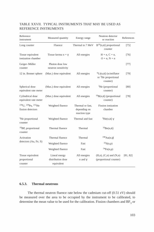
6.5.3. Thermal neutrons
The thermal neutron fluence rate below the cadmium cut-off (0.51 eV) shouldbe measured over the area to be occupied by the instrument to be calibrated, todetermine the mean value to be used for the calibration. Fission chambers and BF3 or
103
TABLE XXVII. TYPICAL INSTRUMENTS THAT MAY BE USED ASREFERENCE INSTRUMENTS
ReferenceMeasured quantity Energy range
Neutron detectorReferences
instrument or reaction
Long counter Fluence Thermal to 7 MeV B10(n,α) proportional [75]counter
Tissue equivalent Tissue kerma n + γ All energies H + n, C + n, [76]ionization chamber O + n, N + n
Geiger–Müller Photon dose low [77]counter neutron sensitivity
12 in. Bonner sphere (Max.) dose equivalent All energies 6Li(n,α) (scintillator [79]or 3He proportional
counter)
Spherical dose (Max.) dose equivalent All energies 3He (proportional [80]equivalent rate meter counter)
Cylindrical dose (Max.) dose equivalent All energies 10B(n,α) (proportional [78]equivalent rate meter counter)
239U, 239Pu, 231He Weighted fluence Thermal or fast, Fission ionizationfission detectors depending on chamber
reaction type
3He proportional Weighted fluence Thermal and fast 3He(n,α) γcounter
10BP, proportional Thermal fluence Thermal 10Be(n,α) counter
Activation Thermal fluence Thermal 198Au(n,γ)detectors (Au, Fe, S)
Weighted fluence Fast 32S(n,p)
Weighted fluence Fast 54Fe(n,p)
Tissue equivalent Lineal energy All energies (H,n), (C,n) and (N,n) [81, 82]
proportional distribution dose n and γ (proportional counter)
counter equivalent

3He proportional counters may be used for this purpose provided that they havebeen calibrated by techniques that are traceable to primary thermal neutronstandards.
The thermal neutron fluence rate may also be determined by measuring theactivation of gold foils. Corrections to the foil measurements should include those forself-shielding, fluence depression and absorption of resonance neutrons in cadmiumas well as those for departures of the neutron cross-section from the 1/v law in the lowenergy region. Traceability may be achieved by sending the activated foils to aprimary laboratory for counting. Alternatively, the foils may be irradiated in a primaryreference thermal neutron calibration facility and returned for calibration of thecounting equipment. Identical foils can then be irradiated in the field to be calibratedand then counted with the foil counting equipment.
With a 1/v detector the ‘conventional’ fluence rate, ϕc = ∫ √––E0/E ϕE (E) dE, is
determined; the cross-section of this detector is taken as that at E0 = 0.0253 eV.Assuming a certain spectral distribution we can calculate the ‘true’ fluence rateϕ = ∫ ϕE (E) dE. For a Maxwellian neutron velocity distribution, ϕm, at a thermo-dynamic temperature of 293.6 K with the energy parameter E0 = 0.0253 eV theconventional true fluence rate ϕc is obtained by multiplying the measuredconventional true flux density by a factor of 1.13. Conversion factors from theMaxwellian fluence-to-dose equivalent are given in Table XXVI.
The gamma radiation field at the point of measurement should be measured sothat its effect on the calibration of the measuring instrument can be corrected for.
A monitoring instrument should be used to detect any variations in the fluencerate with time when using a reactor or an accelerator.
The neutron fluence will be perturbed when the measuring instrument is placedin the field, and corrections may have to be applied for this perturbation, but noperturbation occurs in a thermal neutron beam.
6.5.4. Corrections for neutron scatter
In addition to the direct neutrons from the source, the radiation field used forcalibration includes neutrons that have been scattered from the walls of the room,from support stands and from the surrounding air. The scattered neutrons at thepoint of measurement will have an energy spectrum different from that of the directsource neutrons. Unless the detector of the instrument has a constant energyresponse, its response to scattered neutrons will be different from that to the directneutrons.
It is, therefore, necessary to measure the scatter contribution for all thereference radiations and calibration distances that are to be used, so that the correctionfor their influence on the calibration can be applied. If a reference instrument is used,
104
the influence of scattered neutrons on its response will be different from that on themeasuring instrument to be calibrated, and so both effects will have to be determined.In some special situations the scattered neutrons may be included with direct neutronsin the reference neutron field, i.e.
φ(E)ref = φ(E)direct + φ(E)scatter (36)
Sources of scatter
Neutrons are scattered, in a complex way, from walls, floor and ceiling of theirradiation room, as well as from other objects within the room. Calculations suggestthat, on average, each neutron makes about 2½ traverses of the measurement roombefore being captured by the walls [85]. In most cases, this is the largest contributionto the scattered neutrons at the point of test. It has been shown that, for the ideal caseof a source at the centre of a spherical room, the scattered neutron fluence is uniformand isotopic over the room volume [86].
Air within the irradiation room causes two scattering effects. Air within thedirect path between the detector and the source scatters neutrons away from the pointof measurement. This effect is sometimes called air attenuation or air outscatter. Itsmagnitude is approximately proportional to the distance between the source and thepoint of measurement, and depends on the energy distribution of the neutrons emittedby the source. As a guide for a calibration distance of 100 cm, the attenuation influence is approximately 3% for the 252Cf–D2O moderated source and about 1% for252Cf, 241Am–B and 241Am–Be sources.
Air outside the direct irradiation path can also scatter neutrons into the point oftest. This is called inscatter. As with the outscatter, the magnitude of this effect isproportional to the distance between the source and the point of test. However, theoutscatter and its effect on the calibration will depend on the energy response of theinstrument being calibrated. As a guide for a calibration distance of 100 cm, theincrease in fluence is approximately 2% for 252Cf, 241Am–B and 241Am–Be sourcesand about 2% on the response of many types of detectors. For a 252Cf sourcemoderated by 15 cm of D2O (in a 30 cm diameter sphere), the increase in fluence at100 cm is about 7%, and the increase in response for different types of detectorsvaries between 4 and 6% [72].
It is also necessary to determine the effect of neutrons scattered from supportsused to hold the measuring or reference instrument, and from the support which holdsthe radionuclide source. These effects can be determined through the use of replicatesupport stands placed above the sources or instruments. The difference betweenmeasurements with and without replicate stands is equivalent to the contribution fromthe stands themselves.
105
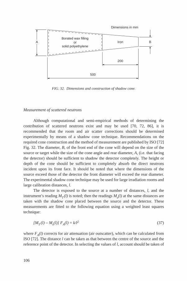
Measurement of scattered neutrons
Although computational and semi-empirical methods of determining thecontribution of scattered neutrons exist and may be used [70, 72, 86], it isrecommended that the room and air scatter corrections should be determinedexperimentally by means of a shadow cone technique. Recommendations on therequired cone construction and the method of measurement are published by ISO [72]Fig. 32. The diameter, B, of the front end of the cone will depend on the size of thesource or target while the size of the cone angle and rear diameter, A, (i.e. that facingthe detector) should be sufficient to shadow the detector completely. The height ordepth of the cone should be sufficient to completely absorb the direct neutronsincident upon its front face. It should be noted that where the dimensions of thesource exceed those of the detector the front diameter will exceed the rear diameter.The experimental shadow cone technique may be used for large irradiation rooms andlarge calibration distances, l.
The detector is exposed to the source at a number of distances, l, and theinstrument’s reading MT (l) is noted; then the readings Ms(l) at the same distances aretaken with the shadow cone placed between the source and the detector. Thesemeasurements are fitted to the following equation using a weighted least squarestechnique:
[MT (l) – Ms(l)] FA(l) = k/l2 (37)
where FA(l) corrects for air attenuation (air outscatter), which can be calculated fromISO [72]. The distance l can be taken as that between the centre of the source and thereference point of the detector. In selecting the values of l, account should be taken of
106
FIG. 32. Dimensions and construction of shadow cone.
Borated wax fillingor
solid polyethyleneIron B
Dimensions in mm
A
500
200
the depth of the cone. As a guide, the minimum distance between the cone rear faceand the detector should be at least equal to the cone’s overall length.
If the distances are measured to the detector’s reference point (or effectivecentre), then
l = r + ae + as (38)
where
r is the distance between the front surface of the source to the front surface of thedetector;
as is the radius of the source (for the reference source 252Cf–D2O, as = 15 cm); and ae is the distance from the front surface of the detector to either the reference point
of the instrument if this has been specified by the manufacturer or to the effectivecentre of the detector.
For spherical detectors, the effective centre should be taken as the geometricalcentre.
For a cylindrically shaped detector irradiated perpendicularly to its axis, theeffective centre should be at the midpoint of this axis. For irradiation parallel to theaxis, the position of the effective centre will be along the axis but will vary with theincident neutron energy.
The position of the effective centre, ae, is obtained from solution of Eq. (37),which will also yield the value of N, the neutron fluence calibration factor.
6.6. ADDITIONAL RECOMMENDATIONS FOR CALIBRATINGSURVEY METERS
The most common neutron survey meters used in radiation protection aremoderator based instruments. These measuring instruments have been designed tomeasure the dose equivalent rate over a range, usually from about 10 µSv·h–1 to50 mSv·h-1, from neutrons having energies from 0.025 eV to about 10 MeV. Detailedinformation on the electrical, mechanical, environmental and radiation specificationsis contained in the IEC Standard for such instruments [87].
The range of fluence rates required to calibrate an instrument over its effectiverange is obtained by either using different radionuclide source strengths, by varyingthe accelerator current or by varying the reactor power, and/or by using differentsource-to-detector distances.
Since the neutron calibration field will also have photon radiation present, testsshould be made to check if the neutron response of the measuring instrument is
107
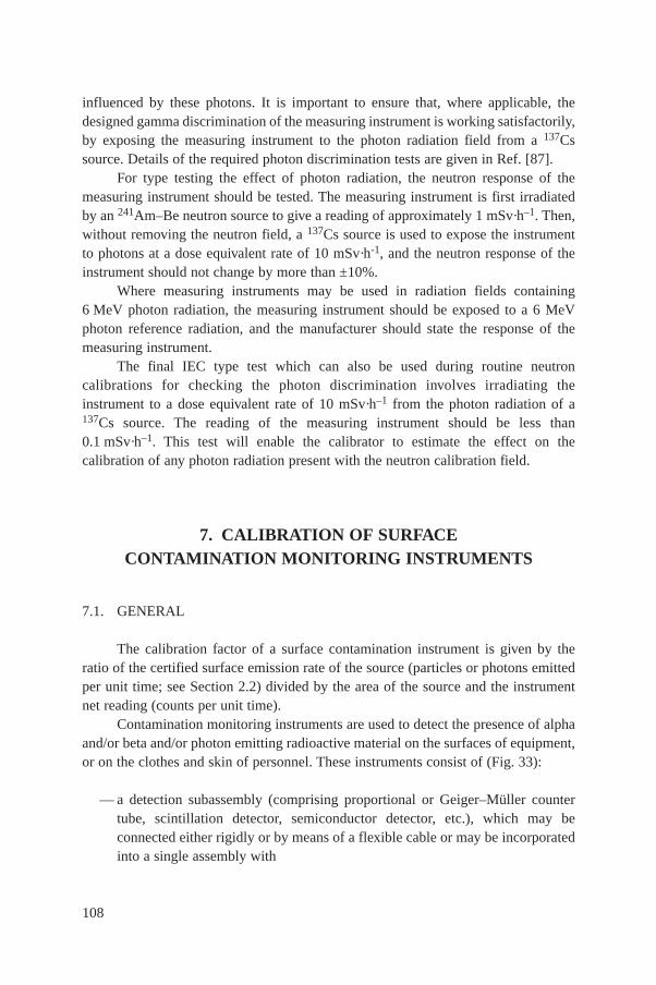
influenced by these photons. It is important to ensure that, where applicable, thedesigned gamma discrimination of the measuring instrument is working satisfactorily,by exposing the measuring instrument to the photon radiation field from a 137Cssource. Details of the required photon discrimination tests are given in Ref. [87].
For type testing the effect of photon radiation, the neutron response of themeasuring instrument should be tested. The measuring instrument is first irradiatedby an 241Am–Be neutron source to give a reading of approximately 1 mSv·h–1. Then,without removing the neutron field, a 137Cs source is used to expose the instrumentto photons at a dose equivalent rate of 10 mSv·h-1, and the neutron response of theinstrument should not change by more than ±10%.
Where measuring instruments may be used in radiation fields containing6 MeV photon radiation, the measuring instrument should be exposed to a 6 MeVphoton reference radiation, and the manufacturer should state the response of themeasuring instrument.
The final IEC type test which can also be used during routine neutroncalibrations for checking the photon discrimination involves irradiating theinstrument to a dose equivalent rate of 10 mSv·h–1 from the photon radiation of a137Cs source. The reading of the measuring instrument should be less than0.1 mSv·h–1. This test will enable the calibrator to estimate the effect on thecalibration of any photon radiation present with the neutron calibration field.
7. CALIBRATION OF SURFACECONTAMINATION MONITORING INSTRUMENTS
7.1. GENERAL
The calibration factor of a surface contamination instrument is given by theratio of the certified surface emission rate of the source (particles or photons emittedper unit time; see Section 2.2) divided by the area of the source and the instrumentnet reading (counts per unit time).
Contamination monitoring instruments are used to detect the presence of alphaand/or beta and/or photon emitting radioactive material on the surfaces of equipment,or on the clothes and skin of personnel. These instruments consist of (Fig. 33):
— a detection subassembly (comprising proportional or Geiger–Müller countertube, scintillation detector, semiconductor detector, etc.), which may beconnected either rigidly or by means of a flexible cable or may be incorporatedinto a single assembly with
108
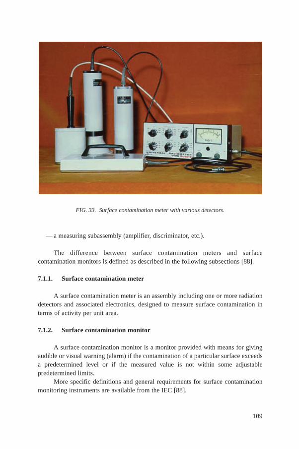
— a measuring subassembly (amplifier, discriminator, etc.).
The difference between surface contamination meters and surfacecontamination monitors is defined as described in the following subsections [88].
7.1.1. Surface contamination meter
A surface contamination meter is an assembly including one or more radiationdetectors and associated electronics, designed to measure surface contamination interms of activity per unit area.
7.1.2. Surface contamination monitor
A surface contamination monitor is a monitor provided with means for givingaudible or visual warning (alarm) if the contamination of a particular surface exceedsa predetermined level or if the measured value is not within some adjustablepredetermined limits.
More specific definitions and general requirements for surface contaminationmonitoring instruments are available from the IEC [88].
109
FIG. 33. Surface contamination meter with various detectors.
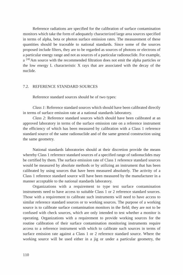
Reference radiations are specified for the calibration of surface contaminationmonitors which take the form of adequately characterized large area sources specifiedin terms of alpha, beta or photon surface emission rates. The measurement of thesequantities should be traceable to national standards. Since some of the sourcesproposed include filters, they are to be regarded as sources of photons or electrons ofa particular energy range and not as sources of a particular radionuclide. For example,a 241Am source with the recommended filtration does not emit the alpha particles orthe low energy L characteristic X rays that are associated with the decay of thenuclide.
7.2. REFERENCE STANDARD SOURCES
Reference standard sources should be of two types:
Class 1: Reference standard sources which should have been calibrated directlyin terms of surface emission rate at a national standards laboratory.
Class 2: Reference standard sources which should have been calibrated at anapproved laboratory in terms of the surface emission rate on a reference instrumentthe efficiency of which has been measured by calibration with a Class 1 referencestandard source of the same radionuclide and of the same general construction usingthe same geometry.
National standards laboratories should at their discretion provide the meanswhereby Class 1 reference standard sources of a specified range of radionuclides maybe certified by them. The surface emission rate of Class 1 reference standard sourceswould be measured by absolute methods or by utilizing an instrument that has beencalibrated by using sources that have been measured absolutely. The activity of aClass 1 reference standard source will have been measured by the manufacturer in amanner acceptable to the national standards laboratory.
Organizations with a requirement to type test surface contaminationinstruments need to have access to suitable Class 1 or 2 reference standard sources.Those with a requirement to calibrate such instruments will need to have access tosimilar reference standard sources or to working sources. The purpose of a workingsource is to calibrate surface contamination monitors in the field; they are not to beconfused with check sources, which are only intended to test whether a monitor isoperating. Organizations with a requirement to provide working sources for theroutine calibration of their surface contamination monitoring instruments requireaccess to a reference instrument with which to calibrate such sources in terms ofsurface emission rate against a Class 1 or 2 reference standard source. Where theworking source will be used either in a jig or under a particular geometry, the
110
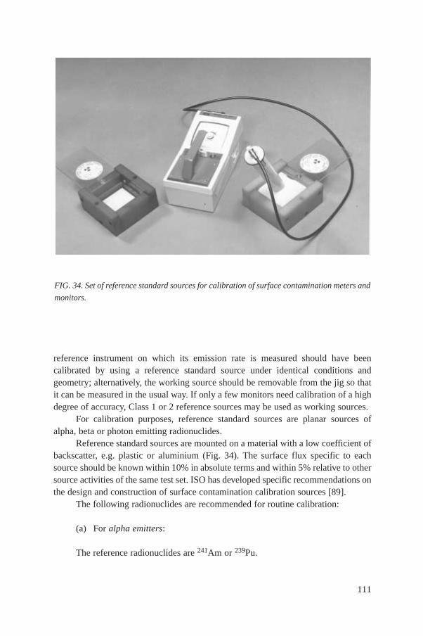
reference instrument on which its emission rate is measured should have beencalibrated by using a reference standard source under identical conditions andgeometry; alternatively, the working source should be removable from the jig so thatit can be measured in the usual way. If only a few monitors need calibration of a highdegree of accuracy, Class 1 or 2 reference sources may be used as working sources.
For calibration purposes, reference standard sources are planar sources ofalpha, beta or photon emitting radionuclides.
Reference standard sources are mounted on a material with a low coefficient ofbackscatter, e.g. plastic or aluminium (Fig. 34). The surface flux specific to eachsource should be known within 10% in absolute terms and within 5% relative to othersource activities of the same test set. ISO has developed specific recommendations onthe design and construction of surface contamination calibration sources [89].
The following radionuclides are recommended for routine calibration:
(a) For alpha emitters:
The reference radionuclides are 241Am or 239Pu.
111
FIG. 34. Set of reference standard sources for calibration of surface contamination meters and
monitors.

(b) For beta emitters:
The reference radionuclide is 204Tl or sometimes 36Cl. If the probe is designedto be used for the measurement of beta particles with a maximum energy of less than250 keV, 14C should be used as the reference.
112
TABLE XXVIII. BETA RADIONUCLIDES FOR TYPE TESTING
Radionuclide Maximum beta energy (keV) Half-life (d)
3H 19 4 49363Ni 66 36 50014C 156 2 093 00035S 167 87.44147Pm 225 957185W 433 75.136Cl 709 1 099.108204Tl 763 1 381210Bi 1162 5.0189Sr 1492 50.590Sr + 90Y 2274 10 483106Ru + 106Rh 3541 373
TABLE XXIX. PHOTON EMITTING SOURCES
Approximate mean photon energyHalf-life (d) (±1%) Radionuclide and filtera
(keV)
5.9 986 55Fe (none)16 3.203 × 10⁴ 238Pu with a 32.5 mg·cm–2
zirconium filter32 5.73 × 10⁹ 129I with a 40.5 mg·cm–2
aluminium filter60 1.57788 × 10⁵ 241Am with a 200 mg·cm–2
stainless steel filter124 270.3 57Co with a 200 mg·cm–2
stainless steel filter
a Mass per unit area tolerance ±10%.
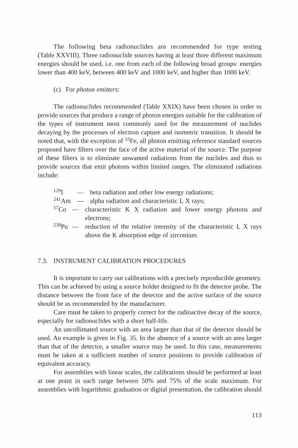
The following beta radionuclides are recommended for type testing(Table XXVIII). Three radionuclide sources having at least three different maximumenergies should be used, i.e. one from each of the following broad groups: energieslower than 400 keV, between 400 keV and 1000 keV, and higher than 1000 keV.
(c) For photon emitters:
The radionuclides recommended (Table XXIX) have been chosen in order toprovide sources that produce a range of photon energies suitable for the calibration ofthe types of instrument most commonly used for the measurement of nuclidesdecaying by the processes of electron capture and isometric transition. It should benoted that, with the exception of 55Fe, all photon emitting reference standard sourcesproposed have filters over the face of the active material of the source. The purposeof these filters is to eliminate unwanted radiations from the nuclides and thus toprovide sources that emit photons within limited ranges. The eliminated radiationsinclude:
129I — beta radiation and other low energy radiations;241Am — alpha radiation and characteristic L X rays;57Co — characteristic K X radiation and lower energy photons and
electrons;238Pu — reduction of the relative intensity of the characteristic L X rays
above the K absorption edge of zirconium.
7.3. INSTRUMENT CALIBRATION PROCEDURES
It is important to carry out calibrations with a precisely reproducible geometry.This can be achieved by using a source holder designed to fit the detector probe. Thedistance between the front face of the detector and the active surface of the sourceshould be as recommended by the manufacturer.
Care must be taken to properly correct for the radioactive decay of the source,especially for radionuclides with a short half-life.
An uncollimated source with an area larger than that of the detector should beused. An example is given in Fig. 35. In the absence of a source with an area largerthan that of the detector, a smaller source may be used. In this case, measurementsmust be taken at a sufficient number of source positions to provide calibration ofequivalent accuracy.
For assemblies with linear scales, the calibrations should be performed at leastat one point in each range between 50% and 75% of the scale maximum. Forassemblies with logarithmic graduation or digital presentation, the calibration should
113
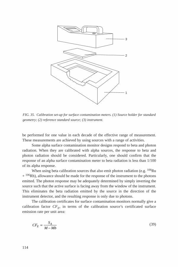
be performed for one value in each decade of the effective range of measurement.These measurements are achieved by using sources with a range of activities.
Some alpha surface contamination monitor designs respond to beta and photonradiation. When they are calibrated with alpha sources, the response to beta andphoton radiation should be considered. Particularly, one should confirm that theresponse of an alpha surface contamination meter to beta radiation is less than 1/100of its alpha response.
When using beta calibration sources that also emit photon radiation (e.g. 106Ru+ 106Rh), allowance should be made for the response of the instrument to the photonsemitted. The photon response may be adequately determined by simply inverting thesource such that the active surface is facing away from the window of the instrument.This eliminates the beta radiation emitted by the source in the direction of theinstrument detector, and the resulting response is only due to photons.
The calibration certificates for surface contamination monitors normally give acalibration factor CFE, in terms of the calibration source’s certificated surfaceemission rate per unit area:
(39)CFS
M MbEA=
-
114
FIG. 35. Calibration set-up for surface contamination meters. (1) Source holder for standard
geometry; (2) reference standard source; (3) instrument.
2
1
3
where SA is the certificated surface emission rate per unit area for the radionuclidesource (in units of s–1· cm–2), M is the monitor count rate (s–1) when exposed to thecalibration source at a specified distance, and Mb is the monitor background countrate (s–1). The calibration distance, from the surface of the source to the detectorwindow, is small and usually chosen to be equal to, or very close to, the distance thatwill be used for subsequent measurements of contaminated surfaces.
Following the calibration of a beta surface contamination meter, checks shouldbe made to ensure that the response of the meter to ambient background iscorrect [90].
8. MEASUREMENT UNCERTAINTIES
8.1. INTRODUCTION
The method used in this report for estimating the uncertainty pertaining to theresult of a measurement is that outlined in BIPM Recommendation INC-1 [91],approved by the Comité international des poids et mesures (CIPM) in 1981. The taskof developing a detailed guide based on this unified approach was transferred to theISO in 1986. This resulted in the issuance, in 1993, of the ISO document entitled‘Guide to the Expression of Uncertainty in Measurement’ [92], which should beconsulted for further details. Readers interested in an elementary presentation of thenew approach can find a summary in Appendix A of IAEA Technical Reports SeriesNo. 277 [93].
8.2. GENERAL CONSIDERATIONS ON ERRORS AND UNCERTAINTIES
Contrary to previous practice, when the terms ‘error’ and ‘uncertainty’ wereused interchangeably, the modern approach, initiated by the CIPM, distinguishesbetween these two concepts. This can probably best be seen from a schematicrepresentation (Fig. 36). It may be useful to distinguish between an ideal and apractical situation. Note that the concepts ‘true value’ and ‘error’ no longer appear inthe practical evaluation.
An error has both a numerical value and a sign. In contrast, the uncertaintyassociated with a measurement is a parameter that characterizes the dispersion of thevalues ‘that could reasonably be attributed to the measurand’ [92]. This parameter isnormally an estimated standard deviation. An uncertainty, therefore, has no knownsign and is usually assumed to be symmetrical. It is a measure of our lack of exact
115
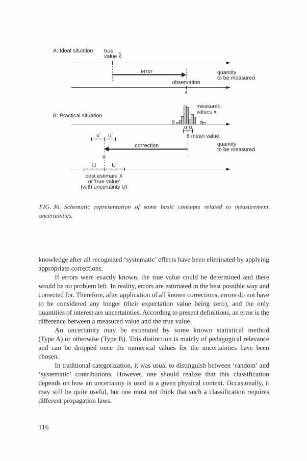
knowledge after all recognized ‘systematic’ effects have been eliminated by applyingappropriate corrections.
If errors were exactly known, the true value could be determined and therewould be no problem left. In reality, errors are estimated in the best possible way andcorrected for. Therefore, after application of all known corrections, errors do not haveto be considered any longer (their expectation value being zero), and the onlyquantities of interest are uncertainties. According to present definitions, an error is thedifference between a measured value and the true value.
An uncertainty may be estimated by some known statistical method(Type A) or otherwise (Type B). This distinction is mainly of pedagogical relevanceand can be dropped once the numerical values for the uncertainties have beenchosen.
In traditional categorization, it was usual to distinguish between ‘random’ and‘systematic’ contributions. However, one should realize that this classificationdepends on how an uncertainty is used in a given physical context. Occasionally, itmay still be quite useful, but one must not think that such a classification requiresdifferent propagation laws.
116
FIG. 36. Schematic representation of some basic concepts related to measurement
uncertainties.
u´ u´
A: Ideal situation
B: Practical situation
^truevalue x
error
observation
x
quantityto be measured
measuredvalues xi
X
U U
best estimate Xof 'true value'
(with uncertainty U)
quantityto be measured
u u
x mean value
correction
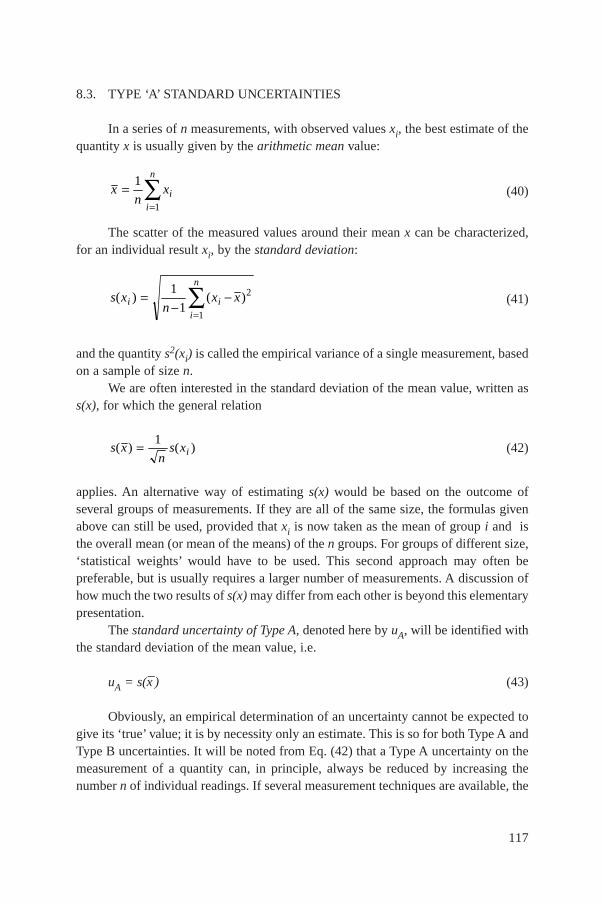
8.3. TYPE ‘A’ STANDARD UNCERTAINTIES
In a series of n measurements, with observed values xi, the best estimate of thequantity x is usually given by the arithmetic mean value:
(40)
The scatter of the measured values around their mean x can be characterized,for an individual result xi, by the standard deviation:
(41)
and the quantity s2(xi) is called the empirical variance of a single measurement, basedon a sample of size n.
We are often interested in the standard deviation of the mean value, written ass(x), for which the general relation
(42)
applies. An alternative way of estimating s(x) would be based on the outcome ofseveral groups of measurements. If they are all of the same size, the formulas givenabove can still be used, provided that xi is now taken as the mean of group i and isthe overall mean (or mean of the means) of the n groups. For groups of different size,‘statistical weights’ would have to be used. This second approach may often bepreferable, but is usually requires a larger number of measurements. A discussion ofhow much the two results of s(x) may differ from each other is beyond this elementarypresentation.
The standard uncertainty of Type A, denoted here by uA, will be identified withthe standard deviation of the mean value, i.e.
uA = s(x–) (43)
Obviously, an empirical determination of an uncertainty cannot be expected togive its ‘true’ value; it is by necessity only an estimate. This is so for both Type A andType B uncertainties. It will be noted from Eq. (42) that a Type A uncertainty on themeasurement of a quantity can, in principle, always be reduced by increasing thenumber n of individual readings. If several measurement techniques are available, the
s xn
s xi( ) ( )= 1
s xn
x xi ii
n
( ) ( )=-
-=Â1
12
1
xn
xii
n
==Â1
1
117
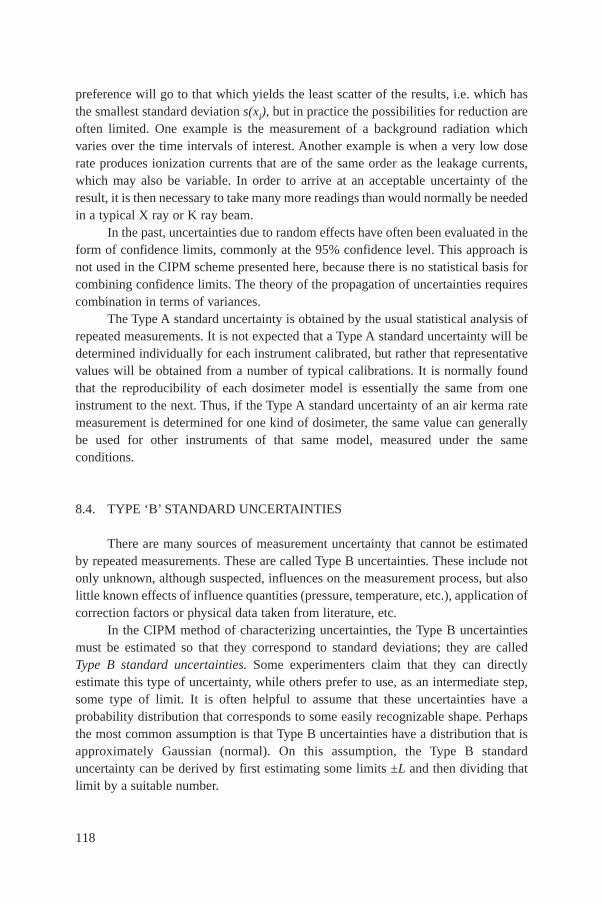
preference will go to that which yields the least scatter of the results, i.e. which hasthe smallest standard deviation s(xi), but in practice the possibilities for reduction areoften limited. One example is the measurement of a background radiation whichvaries over the time intervals of interest. Another example is when a very low doserate produces ionization currents that are of the same order as the leakage currents,which may also be variable. In order to arrive at an acceptable uncertainty of theresult, it is then necessary to take many more readings than would normally be neededin a typical X ray or K ray beam.
In the past, uncertainties due to random effects have often been evaluated in theform of confidence limits, commonly at the 95% confidence level. This approach isnot used in the CIPM scheme presented here, because there is no statistical basis forcombining confidence limits. The theory of the propagation of uncertainties requirescombination in terms of variances.
The Type A standard uncertainty is obtained by the usual statistical analysis ofrepeated measurements. It is not expected that a Type A standard uncertainty will bedetermined individually for each instrument calibrated, but rather that representativevalues will be obtained from a number of typical calibrations. It is normally foundthat the reproducibility of each dosimeter model is essentially the same from oneinstrument to the next. Thus, if the Type A standard uncertainty of an air kerma ratemeasurement is determined for one kind of dosimeter, the same value can generallybe used for other instruments of that same model, measured under the sameconditions.
8.4. TYPE ‘B’ STANDARD UNCERTAINTIES
There are many sources of measurement uncertainty that cannot be estimatedby repeated measurements. These are called Type B uncertainties. These include notonly unknown, although suspected, influences on the measurement process, but alsolittle known effects of influence quantities (pressure, temperature, etc.), application ofcorrection factors or physical data taken from literature, etc.
In the CIPM method of characterizing uncertainties, the Type B uncertaintiesmust be estimated so that they correspond to standard deviations; they are calledType B standard uncertainties. Some experimenters claim that they can directlyestimate this type of uncertainty, while others prefer to use, as an intermediate step,some type of limit. It is often helpful to assume that these uncertainties have aprobability distribution that corresponds to some easily recognizable shape. Perhapsthe most common assumption is that Type B uncertainties have a distribution that isapproximately Gaussian (normal). On this assumption, the Type B standarduncertainty can be derived by first estimating some limits ±L and then dividing thatlimit by a suitable number.
118
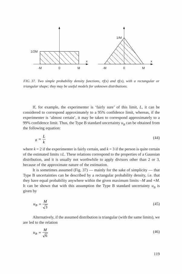
If, for example, the experimenter is ‘fairly sure’ of this limit, L, it can beconsidered to correspond approximately to a 95% confidence limit, whereas, if theexperimenter is ‘almost certain’, it may be taken to correspond approximately to a99% confidence limit. Thus, the Type B standard uncertainty uB can be obtained fromthe following equation:
(44)
where k = 2 if the experimenter is fairly certain, and k = 3 if the person is quite certainof the estimated limits ±L. These relations correspond to the properties of a Gaussiandistribution, and it is usually not worthwhile to apply divisors other than 2 or 3,because of the approximate nature of the estimation.
It is sometimes assumed (Fig. 37) — mainly for the sake of simplicity — thatType B uncertainties can be described by a rectangular probability density, i.e. thatthey have equal probability anywhere within the given maximum limits –M and +M.It can be shown that with this assumption the Type B standard uncertainty uB isgiven by
(45)
Alternatively, if the assumed distribution is triangular (with the same limits), weare led to the relation
(46)uM
B =6
uM
B =3
L
kB =
119
FIG. 37. Two simple probability density functions, rf(x) and tf(x), with a rectangular or
triangular shape; they may be useful models for unknown distributions.
0 M-M
x
1/M
0 M-M
x
1/2M
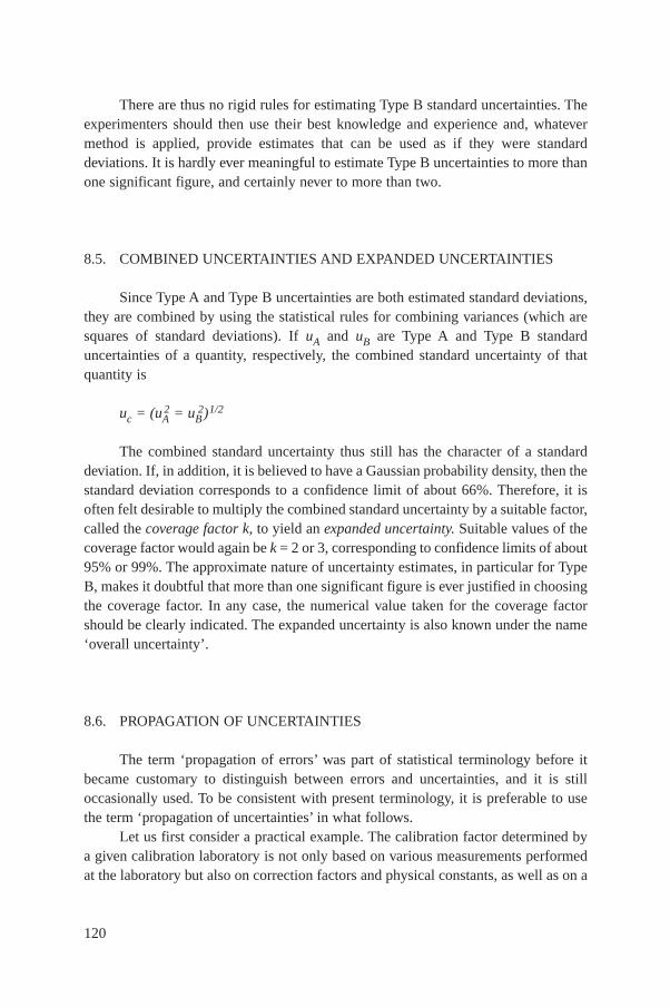
There are thus no rigid rules for estimating Type B standard uncertainties. Theexperimenters should then use their best knowledge and experience and, whatevermethod is applied, provide estimates that can be used as if they were standarddeviations. It is hardly ever meaningful to estimate Type B uncertainties to more thanone significant figure, and certainly never to more than two.
8.5. COMBINED UNCERTAINTIES AND EXPANDED UNCERTAINTIES
Since Type A and Type B uncertainties are both estimated standard deviations,they are combined by using the statistical rules for combining variances (which aresquares of standard deviations). If uA and uB are Type A and Type B standarduncertainties of a quantity, respectively, the combined standard uncertainty of thatquantity is
uc = (uA2 = uB
2)1/2
The combined standard uncertainty thus still has the character of a standarddeviation. If, in addition, it is believed to have a Gaussian probability density, then thestandard deviation corresponds to a confidence limit of about 66%. Therefore, it isoften felt desirable to multiply the combined standard uncertainty by a suitable factor,called the coverage factor k, to yield an expanded uncertainty. Suitable values of thecoverage factor would again be k = 2 or 3, corresponding to confidence limits of about95% or 99%. The approximate nature of uncertainty estimates, in particular for TypeB, makes it doubtful that more than one significant figure is ever justified in choosingthe coverage factor. In any case, the numerical value taken for the coverage factorshould be clearly indicated. The expanded uncertainty is also known under the name‘overall uncertainty’.
8.6. PROPAGATION OF UNCERTAINTIES
The term ‘propagation of errors’ was part of statistical terminology before itbecame customary to distinguish between errors and uncertainties, and it is stilloccasionally used. To be consistent with present terminology, it is preferable to usethe term ‘propagation of uncertainties’ in what follows.
Let us first consider a practical example. The calibration factor determined bya given calibration laboratory is not only based on various measurements performedat the laboratory but also on correction factors and physical constants, as well as on a
120

beam calibration traceable to a secondary laboratory and, ultimately, to a primarylaboratory. All these numerical values contain uncertainties, and they combine to agiven final uncertainty in the calibration factor. This situation can be represented inmore general terms by considering a variable y which is a function f of a number ofvariables a, b, c, ... This can be written in the form
y = f (a, b, c, ...) (48)
It is assumed that all known corrections have already been applied to thevariables and that the remaining uncertainties are small. In many practical cases, theinfluence quantities a, b, ... are independent of each other. Then u(y) can be calculatedby the simple formula
(49)
Two special cases should be mentioned in particular since they are of greatpractical importance and cover most of the usual situations:
If the functional dependence is linear, i.e. for sums (or differences), we have
y = Aa + Bb + Cc + ... (50)
where the coefficients A, B, C, ... are constants and the partial derivatives are simply
... etc. (51)
Then, the uncertainty on y is
u(y) = A2u2(a) + B2u2(b) + C)2)u)2)(c) + ...1/2 (52)
Thus, if independent variables are added (or subtracted), the variances also add.In other words, the uncertainty of the sum is obtained by adding in quadrature the‘weighted’ uncertainties of the independent variables, where the ‘weights’ are thesquares of the coefficients A, B, ... (‘adding in quadrature’ means taking the squareroot of the sum of the squares).
The other special case concerns a product (or ratio) of independent variables.The functional dependence then is
y ∝ aα bβ cγ ... (53)
∂∂
= ∂∂
=f
aA
f
bB, ,
u yf
au a
f
bu b
f
cu c( ) ( ) ( ) ( ) ...@ ∂
∂FHG
IKJ + ∂
∂FHG
IKJ + ∂
∂FHG
IKJ +
RS|T|
UW
22
22
22
121
where the exponents α, β, γ,... are constants. In this case, from Eq. (49) we obtain thefollowing expression for the relative uncertainty on y:
r(y) = I2r2(a) + θ2r2(b) + K2r2(c) + ...½ (54)
where r(a) = u(a)/|a| is the relative uncertainty of a, etc.Thus, for a product (or ratio) of independent variables, the relative weighted
variances add, where the weights are the squares of the exponents α, β ... .A very common case is that of a ratio, y = a/b, where the quantities a and b
contain measurements and correction factors. From Eq. (53), the relative variance ony is equal to the quadratic sum of the relative uncertainties on a and b.
The foregoing discussion applies to Type A, Type B and combined standarduncertainties, all of which are estimated so as to correspond to standard deviations.The rules for propagation of uncertainties also apply to expanded uncertainties,provided that everywhere the same coverage factor k has been used. The uncertaintyon published data is generally in terms of an expanded uncertainty, or someequivalent terminology. This must then be converted into a standard deviation, beforeit is used to calculate an uncertainty. If no coverage factor is stated, it may be assumedto have the value k = 2.
Both Type A and Type B standard uncertainties should be tabulated separately.This will make a possible later change easier to perform.
8.7. DEFINITIONS
8.7.1. Uncertainty of measurement
The limits within which the error of measurement is estimated to lie.
8.7.1.1. Type A standard uncertainty
A quantity estimated, in the ISO [92] method of uncertainty assignment, bystatistical methods.5
122
5 Type A standard uncertainties are stated as standard deviations of means.

8.7.1.2. Type B standard uncertainty
A quantity estimated, in the ISO method of uncertainty assignment, by amethod other than statistical.6
8.7.1.3. Combined standard uncertainty
A quantity obtained, in the ISO method of uncertainty assignment, bycombining in quadrature Type A and Type B standard uncertainties.
8.7.1.4. Coverage factor
A factor, usually denoted by k, by which a standard uncertainty is multiplied. Ifk differs from unity, its value must be stated.
8.7.1.5. Expanded uncertainty
A quantity obtained, in the ISO method of uncertainty assignment, bymultiplying the combined standard uncertainty by a coverage factor k (usually k = 2or 3).
123
6 Type B standard uncertainties are estimated or derived as quantities equivalent tostandard deviations of means.

125
Appendix I
AN EXAMPLE OF DETERMINING THE OVERALLUNCERTAINTIES FOR THE CALIBRATION OF AN INSTRUMENT
• A measuring instrument is going to be calibrated in terms of the directionaldose equivalent rate H¢(0.07) with a beta ray reference source containing theradionuclides 90Sr + 90Y. The reference source has been calibrated on 1 January1992 in a national standard laboratory at a distance of 30 cm. H¢(0.07) is2.13 mSv·h-1. The relative combined uncertainty of the source calibration is1%.
• The measuring instrument is going to be calibrated under the followingconditions:
Date: 20 January 1993Air pressure: p = 95.0 kPaAir temperature: T = 294.5 K
• The calibration factor N (Section 3.2) is obtained from
(I-1)
where
kt corrects for the decay of the source. 385 days have elapsed since the calibrationof the source, and the half-life of 90Sr + 90Y is 10 483 days.
kt = exp –385 ln 2/10483 = 0.975.
kpr corrects for the deviation of the actual air pressure p from the reference pressurep0 = 101.3 kPa.
kpr = p0 /p = 101.3/95.0 = 1.066.
kT corrects for the deviation of the actual air temperature T from the referencetemperature T0 = 293.15 K.
kT = T/T0 = 294.5/293.15 = 1.005.
H k
M M k k kt
pr T d
( . )
( )
0 07
1 0
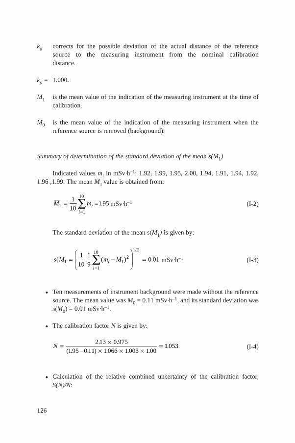
kd corrects for the possible deviation of the actual distance of the referencesource to the measuring instrument from the nominal calibrationdistance.
kd = 1.000.
M1 is the mean value of the indication of the measuring instrument at the time ofcalibration.
M0 is the mean value of the indication of the measuring instrument when thereference source is removed (background).
Summary of determination of the standard deviation of the mean s(M1)
Indicated values mi in mSv·h–1: 1.92, 1.99, 1.95, 2.00, 1.94, 1.91, 1.94, 1.92,1.96 ,1.99. The mean M1 value is obtained from:
mSv·h–1 (I-2)
The standard deviation of the mean s(M1) is given by:
mSv·h–1 (I-3)
• Ten measurements of instrument background were made without the referencesource. The mean value was M0 = 0.11 mSv·h–1, and its standard deviation wass(M0) = 0.01 mSv·h–1.
• The calibration factor N is given by:
(I-4)
• Calculation of the relative combined uncertainty of the calibration factor,S(N)/N:
N
2 13 0 975
1 95 0 11 1 066 1 005 1 001 053
. .
( . . ) . . ..
s M m Mii
( ( ) .1 12
1
10 1/21
10
1
90 01
FHG
IKJ
M mii
11
101
101 95
.
126
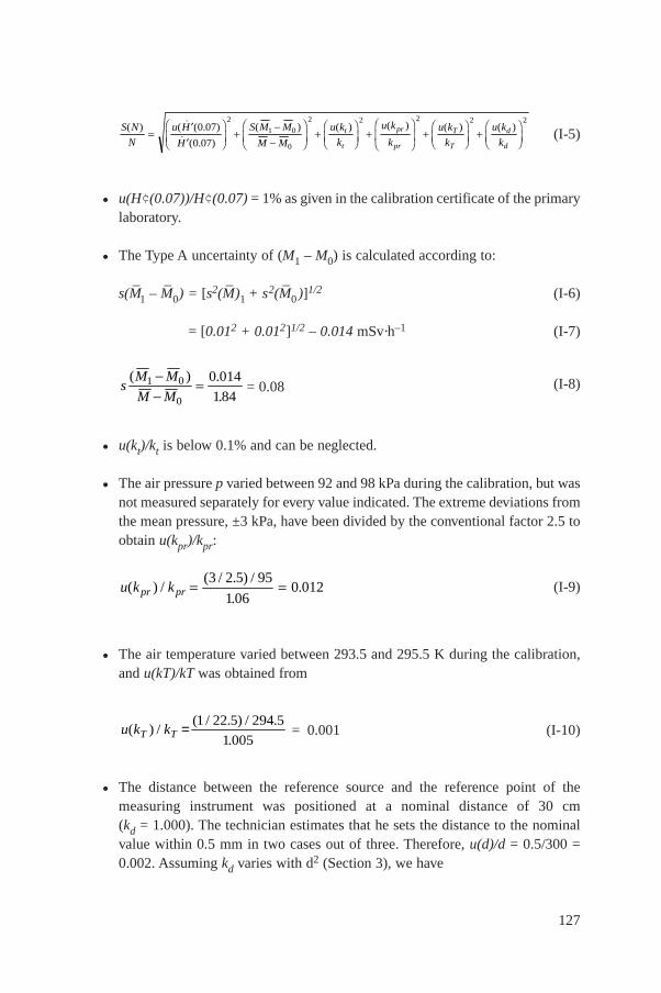
(I-5)
• u(H¢(0.07))/H¢(0.07) = 1% as given in the calibration certificate of the primarylaboratory.
• The Type A uncertainty of (M1 – M0) is calculated according to:
s(M–
1 – M–
0) = [s2(M–
)1 + s2(M–
0 )]1/2 (I-6)
= [0.012 + 0.012]1/2 – 0.014 mSv·h–1 (I-7)
= 0.08 (I-8)
• u(kt)/kt is below 0.1% and can be neglected.
• The air pressure p varied between 92 and 98 kPa during the calibration, but wasnot measured separately for every value indicated. The extreme deviations fromthe mean pressure, ±3 kPa, have been divided by the conventional factor 2.5 toobtain u(kpr)/kpr:
(I-9)
• The air temperature varied between 293.5 and 295.5 K during the calibration,and u(kT)/kT was obtained from
= 0.001 (I-10)
• The distance between the reference source and the reference point of themeasuring instrument was positioned at a nominal distance of 30 cm(kd = 1.000). The technician estimates that he sets the distance to the nominalvalue within 0.5 mm in two cases out of three. Therefore, u(d)/d = 0.5/300 =0.002. Assuming kd varies with d2 (Section 3), we have
u k kT T( ) /( / . ) / .
.= 1 22 5 294 5
1 005
u k kpr pr( ) /( / . ) /
..
3 2 5 95
1 060 012
sM M
M M
( ) .
.1 0
0
0 014
184
S N
N
u H
H
S M M
M M
u k
k
u k
k
u k
k
u k
kt
t
pr
pr
T
T
d
d
( ) ( ( . ( .
( ) ( ) ( ) ( ) ( )
FHG
IKJ
FHG
IKJ
FHGIKJ FHG
IKJ
FHGIKJ FHGIKJ
0 07)
0 07)
2
1 0
0
2 2 2 2 2
127
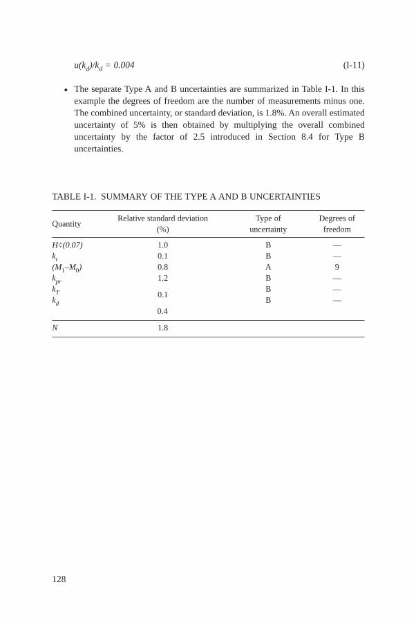
u(kd)/kd = 0.004 (I-11)
• The separate Type A and B uncertainties are summarized in Table I-1. In thisexample the degrees of freedom are the number of measurements minus one.The combined uncertainty, or standard deviation, is 1.8%. An overall estimateduncertainty of 5% is then obtained by multiplying the overall combineduncertainty by the factor of 2.5 introduced in Section 8.4 for Type Buncertainties.
128
TABLE I-1. SUMMARY OF THE TYPE A AND B UNCERTAINTIES
QuantityRelative standard deviation Type of Degrees of
(%) uncertainty freedom
H¢(0.07) 1.0 B —kt 0.1 B —(M1–M0) 0.8 A 9kpr 1.2 B —kT B —kd
0.1B —
0.4
N 1.8
Appendix II
AN EXAMPLE OF DETERMINING THE CALIBRATION FACTOR, NI ,OF AN AMBIENT DOSE EQUIVALENT RATE METER —
CALIBRATION WITH REFERENCE INSTRUMENTWITHOUT MONITOR (CALIBRATION METHOD 1)
(a) Specification of instrument (as stated by the manufacturer in the manual)
— Measurement quantity: ambient dose equivalent rate in mSv·h–1
— Detector: Geiger–Müller counter— Photon energy range: 30 keV to 1.3 MeV— Reference point: cross-point between GM counter axis and line mark— Reference direction: perpendicular to GM counter axis— Warm-up time: 50 s— Measuring range: 1 m Sv·h–1 to 30 m Sv·h–1 (logarithmic scale)
(b) Measurement conditions
— Reference radiation: 137Cs collimated source— Distance from source to point of test: 2.45 m— Environmental conditions: 23°C, 102 kPa, 65% RH— Reference instrument, ionization chamber, unsealed, calibrated at a primary
laboratory with 137Cs— Reference instrument, 137Cs calibration factor, NR = 0.952 (from primary
calibration certificate)— Reference instrument, correction factor for 10 m Gy·h–1 range, kr = 0.992 (from
primary calibration certificate)— Reference instrument warm-up time: 2 min
(c) Procedure for determining conventional time value ofambient dose equivalent rate
Place the ionization chamber, and its appropriate buildup cap, with its referencepoint at the point of test and in its reference orientation relative to the referencesource. Switch the reference instrument on and wait at least two minutes for theinstrument to warm up. Perform the setting-up procedures given in the manufacturer’smanual, e.g. electrical zero test, battery and polarity tests. Switch the instrument to itsappropriate measurement range (0–10 m Gy·h–1) and take the background reading,MRO = 0.04 m G·h–1. Expose the 137Cs source and take ten readings, separated by
129
sufficient time to be independent of each other and exceeding the time constant forthe instrument. Readings, MRI: 8.17, 8.21, 8.22, 8.13, 8.15, 8.23, 8.17, 8.20, 8.19,8.21 m Gy·h–1.
Mean value MRI = 8.19 m Gy·h–1
Standard deviation of the mean = 0.03 m Gy·h–1.
Stop the source exposure and check the background reading: MRO =0.02 m Gy·h–1.
Mean background reading MRO = 0.03 m Gy·h–1.
The conventional true value f of the ambient dose equivalent rate, H, is givenby the following equation (see Section 4.3.2 for identification of symbols):
H·
= h NR (M–
RI – M–
RO) kprKT Kr (II-1)
where h is the conversion coefficient: H*(10)/Ka = 1.20 Sv·Gy–1 (see Table XIV) sothat
H = 1.2. 0.952 (8.19 – 0.03)× 101.3/102 × 296.15 /293.15 × 0.992 = 9.27 µSv·h–1 (II-2)
Remove the standard instrument’s ionization chamber and replace with theinstrument’s GM counter. The GM counter should have its reference point at the pointof test and be in its reference orientation.
(d) Procedure of calibration
— Battery test after warming-up time— Background reading of instrument (without beam): M0 = 0 (as expected in high
measurement range). Note: possible leakage radiation of the source through tothe closed shutter is not part of the background. In this case, the background isdetermined with the source in its safe storage position.
— Radiation source exposed and five readings taken, equilibrium time ofinstrument due to integration has to be shorter than waiting time betweensubsequent readings.
— In this measurement range around 10 m Sv·h–1, the instrument scale is dividedin 0.1 m Sv·h–1 per division below 10 m Sv·h–1 and in 0.2 m Sv·h–1 per divisionabove 10 m Sv·h–1.
— Readings: 9.5, 11.0, 9.0, 9.0, 9.0.
130
— Stop the source exposure and take instrument background reading: M0 = 0.Mean value: M1 = 9.5 m Sv·h–1
Standard deviation of the mean = 0.4 m Sv·h–1
Corrections: according to the manual, no other corrections necessary.The instruments calibration, NI, factor is given by
(II-3)
Note: The same procedures have to be applied if other ambient dose equivalentrates are used for the calibration.
NN M
M
H
MIRh R
I I
.
..
9 27
9 50 98
Sv h
Sv h
1
1
131
132
Appendix III
AN EXAMPLE OF DETERMINING THE CALIBRATION FACTOR OF A PHOTON MEASURING
INSTRUMENT BY MEANS OF A MONITOR(CALIBRATION METHOD 2)
Problem
A measuring instrument with Geiger–Müller tubes as the radiation sensitivedetectors designed to measure the ambient equivalent rate H
·*(10) for photon
radiation in the energy range of 20 to 200 keV shall be calibrated for the radiationquality N-60 (see Table VI of main text) by means of an X ray unit operated with amonitor chamber (see Fig. 7 of main text). A reference instrument with an ionchamber of 30 cm³ chamber volume is available for the calibration. In addition to thecalibration, the energy dependence of the response of the measuring instrument shallbe determined between 30 and 100 keV by using the radiation qualities N-40, N-80and N-120 (see Table VIII of main text).
The calibration factor NR of the air kerma reference chamber is given in acalibration certificate of a national standard laboratory for N-60 by:
NR(N-60) = 1.05E + 09 mGy·C–1
The relative combined standard uncertainty r(NR(N-60)) is stated:
r(NR(N-60)) = 0.7%
TABLE III-1. ENERGY CORRECTION FACTOR ken(E) OF AIR KERMAREFERENCE CHAMBER AND CONVERSION COEFFICIENT h FROM AIRKERMA TO AMBIENT EQUIVALENT RATE H
·*(10) FOR THE RADIATION
QUALITIES USED.
Radiation quality ken(E) h (Sv·Gy–1)
N-40 1.006 1.18N-60 1.000 1.59N-80 1.030 1.73N-120 1.026 1.64
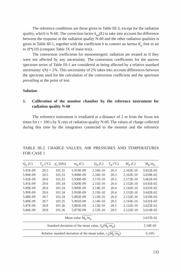
133
TABLE III-2. CHARGE VALUES, AIR PRESSURES AND TEMPERATURESFOR CASE 1
Qm (C) Tm (°C) pa (kPa) mR (C) QR (C) TR (°C) MR (C) MR /mR
5.91E-09 20.5 101.32 5.919E-09 2.16E-10 20.3 2.162E-10 3.652E-025.90E-09 20.5 101.33 5.908E-09 2.16E-10 20.3 2.162E-10 3.659E-025.92E-09 20.6 101.33 5.930E-09 2.17E-10 20.3 2.172E-10 3.662E-025.91E-09 20.6 101.34 5.920E-09 2.15E-10 20.4 2.152E-10 3.635E-025.89E-09 20.6 101.34 5.900E-09 2.14E-10 20.4 2.142E-10 3.631E-025.90E-09 20.6 101.34 5.910E-09 2.15E-10 20.4 2.152E-10 3.642E-025.88E-09 20.7 101.34 5.892E-09 2.13E-10 20.4 2.132E-10 3.619E-025.89E-09 20.7 101.35 5.901E-09 2.14E-10 20.5 2.143E-10 3.631E-025.87E-09 20.8 101.36 5.883E-09 2.13E-10 20.5 2.132E-10 3.625E-025.86E-09 20.8 101.36 5.873E-09 2.12E-10 20.5 2.122E-10 3.614E-02
Mean value MR
—/mR
——3.637E-02
Standard deviation of the mean value, SA(MR
—/mR
——) 5.18E-05
Relative standard deviation of the mean value, rA(MR
—/mR
——) 0.14%
The reference conditions are those given in Table III-3, except for the radiationquality, which is N-60. The correction factor ken(E) to take into account the differencebetween the response at the radiation quality N-60 and the other radiation qualities isgiven in Table III-1, together with the coefficient h to convert air kerma Ka free in airto H*(10) (compare Table IX of main text).
The conversion coefficients for monoenergetic radiation are treated as if theywere not affected by any uncertainty. The conversion coefficients for the narrowspectrum series of Table III-1 are considered as being affected by a relative standarduncertainty r(h) = 2%. This uncertainty of 2% takes into account differences betweenthe spectrum used for the calculation of the conversion coefficient and the spectrumprevailing at the point of test.
Solution
1. Calibration of the monitor chamber by the reference instrument forradiation quality N-60
The reference instrument is irradiated at a distance of 2 m from the focus tentimes for t = 100 s by X rays of radiation quality N-60. The values of charge collectedduring this time by the integrators connected to the monitor and the reference
134
chamber, Qm and QR, are given in Table III-2 together with the air pressure, pa, andthe monitor and the reference chamber temperatures, Tm and TR.
It can be assumed for this example that the air pressure, pa, is the same for themonitor and for the reference chamber. The readings of both the monitor and thereference chamber depend on the air density in the instruments. The measured valuemR of the monitor (corrected for reference conditions) is the charge Qm corrected forreference conditions, (compare Eq. (28) in Section 4.3.2), i.e.:
(III-1)
where Tm is in °C and pa is in kPa.Similarly, we obtain the measured value MR, also corrected for the reference
conditions:
(III-2)
where TR is in °C and pa is in kPa.The quotient MR/mR is calculated in the last column of Table III-2; its mean
value and the standard deviation of the mean are:
MR
—/mR
——= 3.637E – 02; s(MR
—/mR
——) = 5.18E – 05
The standard uncertainty of Type A, here denoted by uA, can be equated withthe standard deviation of the mean in this example (compare Eq. (43) in Section 8.3),i.e.
uA(MR
—/mR
——) = s(MR
—/mR
——) = 5.18E – 0.5
The relative standard uncertainty rA(MR
—/mR
——) is given by
rA(MR
—/mR
——) = s(MR
—/mR
——)/(MR
—/mR
——) = 0.14%
2. Calibration of the measuring instrument by the monitor chamber atradiation quality N-60
The measuring instrument under calibration is irradiated at the same calibrationdistance (2 m) ten times for t = 100 s by X rays of radiation quality N-60. Similarlyas before, the experimentally determined values of charge collected during this timeby the integrator connected to the monitor, Qm , divided by t and multiplied by 36 togive Qm /t in C·h–1 and the readings of the instrument under calibration, MI, are given in Table III-3 together with the air pressure, pa, and the temperatures of the monitor
M Q k k QT
pR R T pr RR
a
27315
29315
1013.
.
.
m Q k k QT
pR m T pr mm
a
27315
29315
1013.
.
.
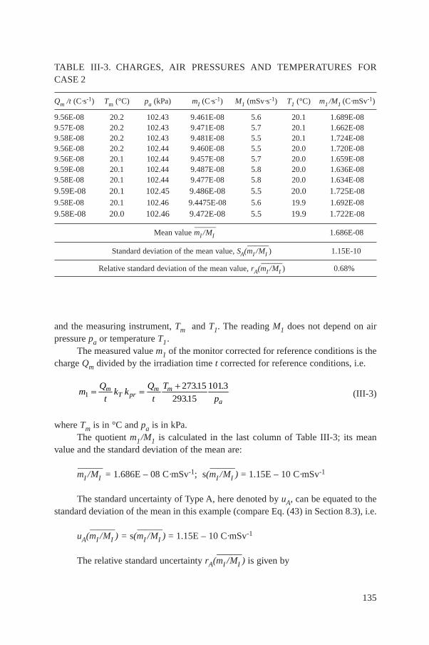
135
TABLE III-3. CHARGES, AIR PRESSURES AND TEMPERATURES FORCASE 2
Qm /t (C·s-1) Tm (°C) pa (kPa) mI (C·s-1) M1 (mSv·s-1) T1 (°C) m1 /M1 (C·mSv-1)
9.56E-08 20.2 102.43 9.461E-08 5.6 20.1 1.689E-089.57E-08 20.2 102.43 9.471E-08 5.7 20.1 1.662E-089.58E-08 20.2 102.43 9.481E-08 5.5 20.1 1.724E-089.56E-08 20.2 102.44 9.460E-08 5.5 20.0 1.720E-089.56E-08 20.1 102.44 9.457E-08 5.7 20.0 1.659E-089.59E-08 20.1 102.44 9.487E-08 5.8 20.0 1.636E-089.58E-08 20.1 102.44 9.477E-08 5.8 20.0 1.634E-08
9.59E-08 20.1 102.45 9.486E-08 5.5 20.0 1.725E-08
9.58E-08 20.1 102.46 9.4475E-08 5.6 19.9 1.692E-08
9.58E-08 20.0 102.46 9.472E-08 5.5 19.9 1.722E-08
Mean value mI
—/MI
——1.686E-08
Standard deviation of the mean value, SA(mI
—/MI
——) 1.15E-10
Relative standard deviation of the mean value, rA(mI
—/MI
——) 0.68%
and the measuring instrument, Tm and T1. The reading M1 does not depend on airpressure pa or temperature T1.
The measured value m1 of the monitor corrected for reference conditions is thecharge Qm divided by the irradiation time t corrected for reference conditions, i.e.
(III-3)
where Tm is in °C and pa is in kPa.The quotient m1/M1 is calculated in the last column of Table III-3; its mean
value and the standard deviation of the mean are:
mI
—/MI
——= 1.686E – 08 C·mSv-1; s(mI
—/MI
——) = 1.15E – 10 C·mSv-1
The standard uncertainty of Type A, here denoted by uA, can be equated to thestandard deviation of the mean in this example (compare Eq. (43) in Section 8.3), i.e.
uA(mI
—/MI
——) = s(mI
—/MI
——) = 1.15E – 10 C·mSv-1
The relative standard uncertainty rA(mI
—/MI
——) is given by
mQ
tk k
Q
t
T
pm
T prm m
a1
27315
29315
1013
.
.
.
136
rA(mI
—/MI
——) = s(mI
—/MI
——)/mI
—/MI
—— = 0.68%
The calibration factor of the instrument (under reference conditions) iscalculated by means of the following equation (see Section 3.4.3.1):
NI = NR h MR
—/mR
—— mI
—/MI
——(III-4)
NR is known from the measurements of the standard laboratory (NR =1.05E + 09 mGy·C–1) and h from Table III-1. Therefore, NI is obtained by:
NI (N-60) = 1.05E + 09 × 1.59 × 3.637E – 02 × 1.686E – 08
NI (N-60) = 1.024
Calculation of the relative combined standard uncertainty
The relative combined standard uncertainty of NI (N-60), r(NI(N-60)) isobtained by the square root of the squares of the relative component standarduncertainties (Section 8.6), i.e. by using Eq. (III-4):
r(NI(N-60)) = r2(NR) + r2(h) + r2(MR
—/mR
——) + r2 (mI
—/MI
——) (III-5)
It has to be considered that, by experience, the measured values MR, mR and mIhave a relative Type B uncertainty of 0.5% due to the performance of the chargemeasuring systems coupled to the monitor chamber and the reference chamber.Therefore, a relative Type B uncertainty of 0.52 + 0.52% has to be considered forMR
—/mR
——, and a relative Type B uncertainty of 0.5% for mI
—/MI
——. The relative component
standard uncertainties contributing to the relative combined standard uncertainty ofNI, r(NI(N-60)), are summarized in Table III-4. One obtains:
r(NI(N-60)) = 2.4%
3. Determination of the response of the measuring instrument
The determination of the response of the measuring instrument as a function ofenergy and angle of incidence, a, is described here only for one energy (N-40) andfor one angle (a = 0°). The determination of the response for other radiation qualitiesand angles of incidence can be done analogously.
The procedure consists of two steps. The first step, the calibration of themonitor chamber, needs not to be repeated for every calibration of a measuring
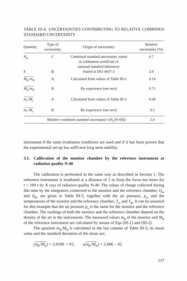
137
instrument if the same irradiation conditions are used and if it has been proven thatthe experimental set-up has sufficient long term stability.
3.1. Calibration of the monitor chamber by the reference instrument at radiation quality N-40
The calibration is performed in the same way as described in Section 1. Thereference instrument is irradiated at a distance of 2 m from the focus ten times fort = 100 s by X rays of radiation quality N-40. The values of charge collected duringthis time by the integrators connected to the monitor and the reference chamber, Qmand QR, are given in Table III-5, together with the air pressure, pa, and thetemperatures of the monitor and the reference chamber, Tm and TR. It can be assumedfor this example that the air pressure pa is the same for the monitor and the referencechamber. The readings of both the monitor and the reference chamber depend on thedensity of the air in the instruments. The measured values mR of the monitor and MRof the reference instrument are calculated by means of Eqs (III-1) and (III-2).
The quotient mR/MR is calculated in the last column of Table III-5; its meanvalue and the standard deviation of the mean are:
(mR
—/MR
——) = 2.010E + 01; s(mR
—/MR
——) = 2.68E – 02
TABLE III-4. UNCERTAINTIES CONTRIBUTING TO RELATIVE COMBINEDSTANDARD UNCERTAINTY
QuantityType of
Origin of uncertaintyRelative
uncertainty uncertainty (%)
NR C Combined standard uncertainty stated 0.7in calibration certificate of
national standard laboratoryh B Stated in ISO 4037-3 2.0
MR
—/mR
——A Calculated from values of Table III-2 0.14
MR
—/mR
——B By experience (see text) 0.71
mI
—/MI
——A Calculated from values of Table III-3 0.68
mI
—/MI
——B By experience (see text) 0.5
Relative combined standard uncertainty r(NI (N-60)) 2.4
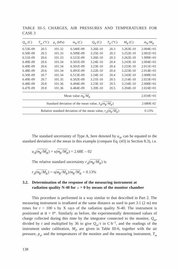
138
The standard uncertainty of Type A, here denoted by uA, can be equated to thestandard deviation of the mean in this example (compare Eq. (43) in Section 8.3), i.e.
uA(mR
—/MR
——) = s(mR
—/MR
——) = 2.68E – 02
The relative standard uncertainty rA(mR
—/MR
——) is
rA(mR
—/MR
——) = s(mR
—/MR
——)/mR
—/MR
——= 0.13%
3.2. Determination of the response of the measuring instrument at radiation quality N-40 for a = 0 by means of the monitor chamber
This procedure is performed in a way similar to that described in Part 2. Themeasuring instrument is irradiated at the same distance as used in part 3.1 (2 m) tentimes for t = 100 s by X rays of the radiation quality N-40. The instrument ispositioned at α = 0°. Similarly as before, the experimentally determined values ofcharge collected during this time by the integrator connected to the monitor, Qm,divided by t and multiplied by 36 to give Qm/t in C·h–1, and the readings of theinstrument under calibration, MI, are given in Table III-6, together with the airpressure, pa, and the temperatures of the monitor and the measuring instrument, Tm
TABLE III-5. CHARGES, AIR PRESSURES AND TEMPERATURES FORCASE 3
Qm (C) Tm (°C) pa (kPa) mR (C) QR (C) TR (°C) MR (C) mR /MR
6.53E-09 20.5 101.32 6.540E-09 3.26E-10 20.3 3.263E-10 2.004E+016.50E-09 20.5 101.33 6.509E-09 3.25E-10 20.3 3.252E-10 2.001E+016.51E-09 20.6 101.33 6.521E-09 3.26E-10 20.3 3.262E-10 1.999E+016.49E-09 20.6 101.34 6.501E-09 3.24E-10 20.4 3.243E-10 2.004E+016.49E-09 20.6 101.34 6.501E-09 3.23E-10 20.4 3.233E-10 2.011E+016.48E-09 20.6 101.34 6.491E-09 3.22E-10 20.4 3.223E-10 2.014E+016.50E-09 20.7 101.34 6.513E-09 3.24E-10 20.4 3.243E-10 2.008E+016.49E-09 20.7 101.35 6.502E-09 3.21E-10 20.5 3.214E-10 2.023E+016.48E-09 20.8 101.36 6.494E-09 3.23E-10 20.5 3.234E-10 2.008E+016.47E-09 20.8 101.36 6.484E-09 3.20E-10 20.5 3.204E-10 2.024E+01
Mean value mR
—/MR
——2.010E+01
Standard deviation of the mean value, SA(mR
—/MR
——) 2.680E-02
Relative standard deviation of the mean value, rA(mR
—/MR
——) 0.13%
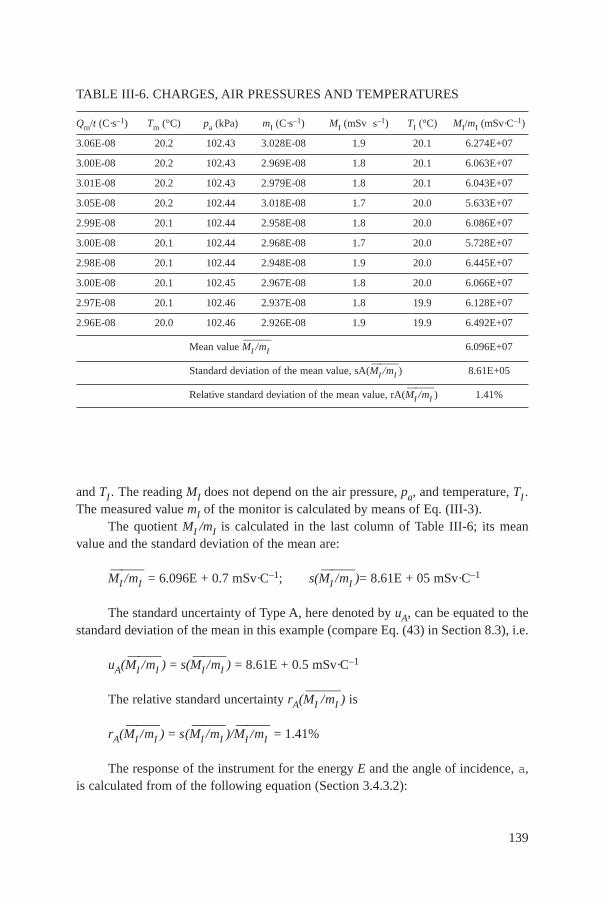
and TI . The reading MI does not depend on the air pressure, pa, and temperature, TI .The measured value mI of the monitor is calculated by means of Eq. (III-3).
The quotient MI /mI is calculated in the last column of Table III-6; its meanvalue and the standard deviation of the mean are:
MI
—/mI
—— = 6.096E + 0.7 mSv·C–1; s(MI
—/mI
——)= 8.61E + 05 mSv·C–1
The standard uncertainty of Type A, here denoted by uA, can be equated to thestandard deviation of the mean in this example (compare Eq. (43) in Section 8.3), i.e.
uA(MI
—/mI
——) = s(MI
—/mI
——) = 8.61E + 0.5 mSv·C–1
The relative standard uncertainty rA(MI
—/mI
——) is
rA(MI
—/mI
——) = s(MI
—/mI
——)/MI
—/mI
——= 1.41%
The response of the instrument for the energy E and the angle of incidence, a,is calculated from of the following equation (Section 3.4.3.2):
139
TABLE III-6. CHARGES, AIR PRESSURES AND TEMPERATURES
Qm/t (C·s–1) Tm (°C) pa (kPa) mI (C·s–1) MI (mSv s–1) TI (°C) MI/mI (mSv·C–1)
3.06E-08 20.2 102.43 3.028E-08 1.9 20.1 6.274E+07
3.00E-08 20.2 102.43 2.969E-08 1.8 20.1 6.063E+07
3.01E-08 20.2 102.43 2.979E-08 1.8 20.1 6.043E+07
3.05E-08 20.2 102.44 3.018E-08 1.7 20.0 5.633E+07
2.99E-08 20.1 102.44 2.958E-08 1.8 20.0 6.086E+07
3.00E-08 20.1 102.44 2.968E-08 1.7 20.0 5.728E+07
2.98E-08 20.1 102.44 2.948E-08 1.9 20.0 6.445E+07
3.00E-08 20.1 102.45 2.967E-08 1.8 20.0 6.066E+07
2.97E-08 20.1 102.46 2.937E-08 1.8 19.9 6.128E+07
2.96E-08 20.0 102.46 2.926E-08 1.9 19.9 6.492E+07
Mean value MI
—/mI
——6.096E+07
Standard deviation of the mean value, sA(MI
—/mI
——) 8.61E+05
Relative standard deviation of the mean value, rA(MI
—/mI
——) 1.41%
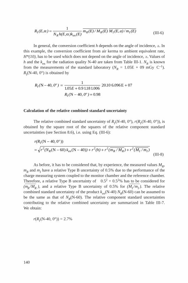
(III-6)
In general, the conversion coefficient h depends on the angle of incidence, a. Inthis example, the conversion coefficient from air kerma to ambient equivalent rate,H*(10), has to be used which does not depend on the angle of incidence, a. Values ofh and the ken for the radiation quality N-40 are taken from Table III-1. NR is knownfrom the measurements of the standard laboratory (NR = 1.05E + 09 mGy C–1).RI(N-40, 0°) is obtained by
Calculation of the relative combined standard uncertainty
The relative combined standard uncertainty of RI(N-40, 0°), r(RI(N-40, 0°)), isobtained by the square root of the squares of the relative component standarduncertainties (see Section 8.6), i.e. using Eq. (III-6):
(III-8)
As before, it has to be considered that, by experience, the measured values MR,mR and mI have a relative Type B uncertainty of 0.5% due to the performance of thecharge measuring system coupled to the monitor chamber and the reference chamber.Therefore, a relative Type B uncertainty of 0.52 + 0.52% has to be considered for (mR
—/MR
——), and a relative Type B uncertainty of 0.5% for (MI
—/mI
——). The relative
combined standard uncertainty of the product ken(N-40) NR(N-60) can be assumed tobe the same as that of NR(N-60). The relative component standard uncertaintiescontributing to the relative combined uncertainty are summarized in Table III-7.We obtain:
r(RI(N-40, 0°)) = 2.7%
r(R
r (N k ) r (h) r (m / M ) r (M / m )
I
2R en
2 2R R
2I I
( , ))
( ) ( )
N
N N
40 0
60 40
R ( , 0 )
R ( , 0 )
I
I
N 40 E
N 40
1
1 05 0 9 1181 00620 10 6 096 07
0 98
. . . .. .
.
E
R (E, )N h(E )k (E)
m (E) / M (E) M (E,a) / m (E)IR en
R R I I
1
,
140

141
TABLE III-7. RELATIVE COMPONENT STANDARD UNCERTAINTIES
QuantityType of
Origin of uncertaintyRelative
uncertainty uncertainty
kenNR(N – 60) C Combined standard uncertainty stated in calibration 0.7%
certificate of national standard laboratory
h B Stated in ISO 4037-3 2.0%
(mR
—/MR
——) A Calculated from values of Table III-5 0.13%
(mR
—/MR
——) B By experience (see text) 0.71%
MI
—/mI
——A Calculated from values of table III-6 1.41%
MI
—/mI
——B By experience (see text) 0.5%
Relative combined standard uncertainty r(RI(N – 40, 0°)) 2.7%

142
REFERENCES
[1] INTERNATIONAL ATOMIC ENERGY AGENCY, Handbook on Calibration ofRadiation Protection Monitoring Instruments, Technical Reports Series No. 133, IAEA,Vienna (1971).
[2] INTERNATIONAL COMMISSION ON RADIATION UNITS AND MEASURE-MENTS, Determination of Dose Equivalents Resulting from External Radiation Sources— Part 1, Rep. ICRU-39, Bethesda, MD (1985).
[3] INTERNATIONAL COMMISSION ON RADIATION UNITS AND MEASURE-
MENTS, Determination of Dose Equivalents from External Radiation Sources — Part 2,
Rep. ICRU-43, Bethesda, MD (1988).[4] INTERNATIONAL COMMISSION ON RADIATION UNITS AND MEASURE-
MENTS, Measurement of Dose Equivalents from External Photon and ElectronRadiations, Rep. ICRU- 47, Bethesda, MD (1992).
[5] INTERNATIONAL COMMISSION ON RADIATION UNITS AND MEASURE-
MENTS, Quantities and Units in Radiation Protection Dosimetry, Rep. ICRU-51,
Bethesda, MD (1993).[6] INTERNATIONAL ORGANIZATION FOR STANDARDIZATION, Reference
Sources for the Calibration of Surface Contamination Monitors — Beta-Emitters(Maximum Beta Energy Greater than 0.15 MeV) and Alpha Emitters, Draft Standard,ISO/DIS 8769, Geneva (1986).
[7] INTERNATIONAL STANDARDS COMMISSION ON RADIOLOGICAL PROTEC-TION, Recommendations of the International Commission on Radiological Protection,Publication 60, Annals of the ICRP 27, Nos 1–3, Pergamon Press, London and New York(1991).
[8] FOOD AND AGRICULTURE ORGANIZATION OF THE UNITED NATIONS,INTERNATIONAL ATOMIC ENERGY AGENCY, INTERNATIONAL LABOURORGANISATION, OECD NUCLEAR ENERGY AGENCY, PAN AMERICANHEALTH ORGANIZATION, WORLD HEALTH ORGANIZATION, InternationalBasic Safety Standards for Protection Against Ionizing Radiation and for the Safety ofRadiation Sources, Safety Series No. 115, IAEA, Vienna (1996).
[9] ALBERTS, W.G., AMBROSI, P., BOEHM, J., DIETZE, G., HOHFIELD, K.,WILL, W., New dose quantities in radiation protection, PTB-Dos-23EN (1995).
[10] ALBERTS, W.G., BOEHM, J., KRAMER, H.M., ILES, W.J., McDONALD, J.,SCHWARTZ, R.B.T., HOMPSON, I.M.G., “International standardization of referenceradiations and calibration procedures for radiation protection instruments”,Strahlenschutz: Physik und Messtechnik, Vol. 1 (KOELZER, W., MAUSHART, R., Eds)(TUV Rheinland Gmbh, Köln (1994) 181–188.
[11] INTERNATIONAL COMMISSION ON RADIOLOGICAL PROTECTION, RadiationProtection, Conversion Coefficients for Use in Radiological Protection Against ExternalRadiation, Publication 74, Pergamon Press, London and New York (1977).
[12] BOTTER-JENSEN, L., NIELSEN, S.P., A multi-laboratory testing of calibrationmethods for environmental dose rate meter, Ris-M-2542 (1985).
143
[13] GIBSON, J.A.B., THOMPSON, I.M.G., SPIERS, F.V., A Guide to the Measurement of
Environmental Gamma-Ray Dose Rate, British Committee on Radiation Units and
Measurements, National Physical Laboratory, Teddington, UK (1994).[14] DE PLANQUE, G., GESELL, T.F., Environmental measurements with
thermoluminescence dosemeter — Trends and issues, Radiat. Prot. Dosim. 17 (1986)193–202.
[15] SWAJA, R.E., WENG, P.S., SIMS, C.S., YEK, S.H., Summary and Analysis of the 1986ORNL Personnel Dosimetry Intercomparison Study, Rep. ORNL-6378, Oak RidgeNational Lab., TN (1987).
[16] COMMISSION OF THE EUROPEAN COMMUNITIES, Intercomparison ofEnvironmental Gamma Dose Rate Meters, A Comprehensive Study of CalibrationMethods and Field Measurements, Part 1, 1984 and 1985 Experiments, Rep. EUR-11665 EN, CEC, Luxembourg (1988).
[17] COMMISSION OF THE EUROPEAN COMMUNITIES, Intercomparison of
Environmental Gamma Dose Rate Meters, A Comprehensive Study of Calibration
Methods and Field Measurements, Part II, 1987 to 1989 Experiments, Rep. EUR-12731
EN, CEC, Luxembourg (1990).[18] THOMPSON, I.M.G., BOTTER-JENSEN, L., LAUTERBACH, U., PESSARA, W.,
SAEZ- VERGARA, J.C., DELGADO, A., The assessment of external photon dose ratein the vicinity of nuclear power stations: An intercomparison of different monitoringsystems, Radiat. Prot. Dosim. 48 (1993) 325–332.
[19] BOTTER-JENSEN, L., THOMPSON, I.M.G., An international intercomparison ofpassive dosemeters, electronic dosemeters and dose rate meters used for environmentalradiation measurements, Radiat. Prot. Dosim. 60 (1995) 201–211.
[20] AMBROSI, P., BUCHHOLZ, G., BOEHM, J., GRIFFITH, R.V., HERRMANN, D.,STRACHOTINSKY, C., Results of the IAEA intercomparison for individualmonitoring, Radiat. Prot. Dosim. 54 (1994) 5–17.
[21] MURAKAMI, H., MINAMI, K., GRIFFITH, R.V., Results of the IAEA/RCA personaldosemeter intercomparison in Asia, Radiat. Prot. Dosim. 54 (1994) 19–23.
[22] DA SILVA, T.A., et al., Intercomparison of personal dosimetry systems for photonradiation in the Latin American region, Radiat. Prot. Dosim. 60 (1995) 249–252.
[23] INTERNATIONAL ORGANIZATION FOR STANDARDIZATION, X and GammaReference Radiations for Calibrating Dose Meters and Dose Rate Meters and forDetermining Their Response as a Function of Photon Energy — Characteristics of theRadiations and their Methods of Production, ISO Standard 4037-1, Geneva (1995).
[24] INTERNATIONAL ORGANIZATION FOR STANDARDIZATION, Reference PhotonRadiations — Dosimetry of X and Gamma Reference Radiations for RadiationProtection over the Energy Range from 8 keV to 1.3 MeV and from 4 MeV to 9 MeV,ISO/DIS 4037-2, Geneva (1995).
[25] INTERNATIONAL ORGANIZATION FOR STANDARDIZATION, Reference PhotonRadiations — Calibration of Area and Personnel Dosemeters and the Determination oftheir Response as a Function of Energy and Angle of Incidence, ISO/DIS 4037-3,Geneva (1995).
[26] SEELANTAG, W.W., PANZER W., DREXLER, G., PLATZ, W., SANTNER, F.,
A Catalogue of Spectra for the Calibration of Dose Meters, Rep. GSF-560, Gesellschaft
für Strahlen- und Umweltforschung, Braunschweig (1979).[27] PEAPLE, L.H.J., BIRCH, R., MARSHALL, M., Measurement of the ISO Series of
Filtered Radiations, Rep. AERE-R-13424, AERE, Harwell (1989).[28] THOMPSON, I.M.G., “International standard reference radiations and their application
to the type testing of dosimetric apparatus”, National and International Standardizationof Radiation Dosimetry (Proc. Symp. Atlanta, 1977), Vol. 1, IAEA, Vienna (1978)343–364.
[29] INTERNATIONAL ORGANIZATION FOR STANDARDIZATION, SealedRadioactive Sources — General, ISO Standard 1677, Geneva (1977).
[30] BOAG, J.W., “Ionization chambers”, Radiation Dosimetry, 2nd edn (ATTIX, F.H.,ROESCH, W.C., Eds), Vol. 2, Academic Press, New York (1966) 2–72.
[31] KOUDO, S., RANDOLPH, M.L., Effect of finite size of ionization chambers onmeasurements of small photon sources, Radiat. Res. 13 (1960) 36–37.
[32] TROUT, E.D., KELLY, J.P., LUKAS, A.C., Determination of half value layer, Am. J.Roentgenol. 85 (1960) 933.
[33] TAYLOR, L.S., Physical Foundations of Radiology, 2nd edn (1958) 227–257.[34] GROSSWENDT, B., ROOS, M., Med. Phys. (1984) 391–394.[35] ROOS, M., GROSSWENDT, B., A simplified method for large-range variations of dose
rate for 137Cs gamma radiation, Radiat. Prot. Dosim. 18 (1987) 147–151.[36] INTERNATIONAL ATOMIC ENERGY AGENCY, Manual on Safety Aspects of the
Design and Equipment of Hot Laboratories, 1981 Edition, Safety Series No. 30, IAEA,Vienna (1981).
[37] DUFTSCHMID, K.E., A fast automated calibration system, Radiat. Prot. Dosim. 6(1984) 94.
[38] DUFTSCHMID, K.E., “The Austrian dosimetry laboratory, national standard androutine calibration centre”, National and International Standardization of RadiationDosimetry (Proc. Symp. Atlanta, 1977), Vol. 1, IAEA, Vienna (1978) 199–210.
[39] BOEHM, J., Eine Referenzstromquelle zur Kalibrierung von Strommessystemen in derDosimetrie mit Ionisationskammern, PTB Mitt. 89 (1979) 237.
[40] HARVEY, J.R., MACFARLANE, B.J., SHIPTON, R.G., THOMPSON, I.M.G.,Conversion of beta-ray dose rates measured in air to dose rates in skin, Phys. Med. Biol.20 (1975) 4.
[41] BOEHM, J., The National Primary standard of the PTB for Realizing the Unit of theAbsorbed Dose Rate to Tissue for Beta Radiation, Rep. PTB-Dos-13, Physikalisch-Technische Bundesanstalt, Braunschweig, Germany (1986).
[42] OWEN, B., The beta calibration of radiation survey instruments at protection levels,Phys. Med. Biol. 17 (1972) 175.
[43] OWEN, B., Factors for converting beta-ray dose rates measured in air to dose rates intissue, Phys. Med. Biol. 18 (1973) 355.
[44] INTERNATIONAL COMMISSION ON RADIOLOGICAL UNITS ANDMEASUREMENTS, Stopping Powers for Electrons and Positrons, Rep. ICRU-7,Bethesda, MD (1984).
144
[45] MURTHY, B.K.S., BOEHM, J., Measurements of backscatter and transmission factors
for beta rays using thermoluminescence dosimeters, Radiat. Prot. Dosim. 2 (1982) 63. [46] INTERNATIONAL ORGANIZATION FOR STANDARDIZATION, Reference Beta
Radiations for Calibrating Dosemeters and Doseratemeters and for Determining theirResponse as a Function of Beta Radiation Energy, ISO Standard 6980 (E), Geneva(1984).
[47] BOEHM, J., Standardization and Calibration in Beta Dosimetry, Rep. NUREG-CP-0050, Nuclear Regulatory Commission, Washington, DC (1984).
[48] BOEHM, J., HILLION, P., SIMOEN, J.P., “Intercomparison of the PTB and LMRIstandards in beta dosimetry”, paper presented at 8th Int. Congr. French Society forRadioprotection, 1976.
[49] HELMSTAEDTER, K., ROTHE, H., KORN, H., Eine verbesserte Volumen-extrapolationskammer und ein Satz neuer Flachionisationskammern als metrologischeBasis des ASMW zur Sicherung richtiger Energiedosismessungen von Betastrahlung inder Praxis, Isotopenpraxis 16 (1980) 393.
[50] BOEHM, J., SCHNEIDER, U., Review of extrapolation chamber measurements of betarays and low energy X-rays, Radiat. Prot. Dosim. 14 (1986) 193.
[51] EHRLICH, M., PRUITT, J.S., SOARES, C.G., Standard Beta-Particle and
Monoenergetic Electron Sources for the Calibration of Beta-radiation Protection
Instrumentation, Rep. NUREG-CR-4266, NBSIR-85-3169, Nuclear Regulatory
Commission, Washington, DC (1985).[52] BOEHM, J., A measuring and calibration system for currents down to 1017,
Atomkernenergie 27 (1976) 139.[53] CHRISTENSEN, P., HERBAUT,Y., MARSHALL, T.O., Personal monitoring for external
sources of beta and low energy photon radiations, Radiat. Prot. Dosim. 18 (1987) 241. [54] PRUITT, J.S., The effect of altitude on beta ray source calibrations, Radiat. Prot. Dosim.
11 (1985) 151.[55] BOEHM, J., Exchange of sources, beam flattening filters and jigs of a secondary
standard for absorbed dose rates of beta radiation, PTB Mitt. 96 (1986) 317. [56] CHRISTENSEN, P., Practical Beta Dosimetry in Radiation Protection, Rep. EUR-7365
EN, CEC, Luxembourg (1982). [57] WAGNER, S.R., NEUTROS GROSSWENDT, B., HARVEY, J R., MILL, A.J.,
SELBACH, H.J., SIEBERT, B.R.L., Unified conversion factors for the new ICRUoperational radiation protection quantities, Radiat. Prot. Dosim. 12 (1985) 231–235.
[58] BRITISH COMMITTEE ON RADIATION UNITS AND MEASUREMENTS, Newquantities in radiation protection and conversion factors, Radiat. Prot. Dosim. 14 (1986)337–343.
[59] SIEBERT, B.R.L., SCHUHMACHER, H., Quality Factors, Ambient and Personal DoseEquivalent for Neutrons, Based on the New ICRU Stopping Power Data for Protons andAlpha Particles, Radiat. Prot. Dosim. 58 (1995) 177–183.
[60] SCHWARTZ, R.B., EISENHAUER, C.M., The design and construction of aDO-moderator 252Cf source for calibrating neutron personnel dosemeters used at nuclearpower reactors, Rep. NUREG-CR-1204, National Bureau of Standards, Washington, CD(1980).
145
[61] INTERNATIONAL ATOMIC ENERGY AGENCY, Compendium of Neutron Spectra in
Criticality Accident Dosimetry, Technical Reports Series No. 180, IAEA, Vienna (1978).[62] INTERNATIONAL ATOMIC ENERGY AGENCY, Compendium of Neutron Spectra
and Detector Responses for Radiation Protection Purposes, Technical Reports SeriesNo. 318, IAEA, Vienna (1990).
[63] INTERNATIONAL STANDARDS ORGANIZATION, Neutron Reference Radiations
for Calibrating Neutron Measuring Devices Used for Radiation Protection Purposes and
for Determining their Response as a Function of Neutron Energy, Draft Standard
ISO/DIS 8529, Part 1: ISO, Geneva (1086).
[64] INTERNATIONAL STANDARDS ORGANIZATION, Reference Neutrons Radiation
Calibration of Area and Personal Dosimeters and the Determination of Their Response
as a Function of Neutron Energy and Angle of Incidence, Draft Standard ISO/DIS 8529,
ISO, Geneva (1996).[65] BLOCK, S., BRYAN, S., PREVO, C., MONTAN, D., Laboratory sources enhanced in
0.53 keV to 200 keV neutrons for instrument evaluation, Health Phys. 13 (1967)1025–1031.
[66] HARVEY, J.R., BOOT, S.J., The calibration of neutron instruments and dosemeters at
intermediate energies, Nucl. Instrum. Methods 148 (1978) 511–520.[67] LISKIEN, H., PAULSEN, A., At. Data Nucl. Data Tables 11 (1973) 585.[68] LISKIEN, H., PAULSEN, A., At. Data Nucl. Data Tables 15 (1975) 57.[69] MILL, S.A., HARVEY, J.R., “Reactor and accelerator based filtered beams”, review
paper presented at IAEA Consultants Meeting on Neutron Source Properties, Debrecen,Hungary, 1980.
[70] INTERNATIONAL ATOMIC ENERGY AGENCY, Guidelines on Calibration ofNeutron Measuring Devices, Technical Reports Series No. 285, IAEA, Vienna (1988).
[71] STODDARD, D.H., HOOTMAN, H.E., 252Cf Shielding Guide, Rep. DP-1246,Savannah River Lab., Aiken, SC (1971).
[72] INTERNATIONAL STANDARDS ORGANIZATION, Procedures for Calibrating andDetermining the Energy Response of Neutron Measuring Devices Used for RadiationProtection, Draft Standard ISO/TC 85/SC2/GT2 N200, ISO, Geneva (1987).
[73] INTERNATIONAL ATOMIC ENERGY AGENCY, Neutron Monitoring for RadiationProtection Purposes (Proc. Symp. Vienna, 1972), 2 vols, IAEA, Vienna (1973).
[74] INTERNATIONAL ATOMIC ENERGY AGENCY, Neutron Monitoring forRadiological Protection, Technical Reports Series No. 252, IAEA, Vienna (1985).
[75] DE PANGHER, J., NICHOLS, L.L., A Precision Long Counter for Measuring FastNeutron Flux Density, Rep. Batelle NWL-260; UC-37 (TID-4500), Pacific NorthwestLaboratory, Richland, WA (1966).
[76] BROESE, J.J., Ion Chambers for Neutron Dosimetry (Proc. Workshop, 1980),Rep. EUR-6782, Academic Publishers, Harwood (1980).
[77] INTERNATIONAL COMMISSION ON RADIATION UNITS AND MEASURE-MENTS, Neutron Dosimetry for Biology and Medicine, Rep. ICRU-26, Bethesda, MD(1977).
[78] ANDERSSON, I.O., BRAUN, J., Nukleonik 6 (1964) 237.
146

[79] BRAMBLETT, R.L., EWING, R.J., BONNER, T.W., A new type of neutron
spectrometer, Nucl. Instrum. Methods 9 (1960) 1–12.[80] LEAKE, J.W., An improved spherical dose-equivalent neutron monitor, Nucl. Instrum.
Methods 63 (1968) 329–332.[81] INTERNATIONAL COMMISSION ON RADIATION UNITS AND MEASURE-
MENTS, Microdosimetry, Rep. ICRU-36, Bethesda, MD (1983).[82] BOOZ, J., EDWARDS, A.A., HARRISON, K.G., Microdosimetric counters in radiation
protection, Radiat. Prot. Dosim. 9 (1984) 423.[83] GULDBAKKE, S., JAHR, R., LESIECKI, H., SCHULERMANN, H., Neutron response
of Geiger–Müller photon dosemeter for neutron energies between 100 keV and 19 MeV,Health Phys. 39 (1980) 963–969.
[84] SCHWARTZ, R.B., Neutron Personnel Dosimetry, National Bureau of StandardsSpecial Publication 250-12 (1987).
[85] EISENHAUER, C.M., SCHWARTZ, R.B., “The effect of room-scattered neutrons onthe calibration of radiation protection instruments”, Neutron Dosimetry in Biology andMedicine (Proc. 4th Symp. Neuherberg, 1981), Vol. 1 (BURGER, G., EBERT, H.G.,Eds), Rep. EUR-7448 EN, CEC, Luxembourg (1981) 421–430.
[86] EISENHAUER, C.M., SCHWARTZ, R.B., JOHNSON, T., Measurement of neutrons
reflected from the surface of a calibration room, Health Phys. 42 (1982) 489–495.[87] INTERNATIONAL ELECTROTECHNICAL COMMISSION, Portable Neutron
Ambient Dose Equivalent Ratemeters for Use in Radiation Protection, IEC Standard1005, Geneva (1990).
[88] INTERNATIONAL ELECTROTECHNICAL COMMISSION, Alpha, Beta andAlpha–Beta Contamination Meters and Monitors, IEC Publication 325, Geneva (1981).
[89] INTERNATIONAL STANDARDS ORGANIZATION, Reference Sources for theCalibration of Surface Contamination Monitors — Electrons of Energy Less than0.15 MeV and Photons of Energy Less than 1.5 MeV, ISO Standard 8769-2, Geneva(1996).
[90] INTERNATIONAL ELECTROTECHNICAL COMMISSION, Installed PersonnelSurface Contamination Monitoring Assemblies for Alpha and Beta Emitters, IECStandard 1098, Geneva (1992).
[91] BUREAU INTERNATIONAL DES POIDS ET MESURES, Recommendation INC-1,Procès-Verbaux, Comité International des Poids et Mesures, Vol. 49 (1981).
[92] INTERNATIONAL STANDARDS ORGANIZATION, Guide to the Expression ofUncertainty in Measurement, ISO, Geneva (1993).
[93] INTERNATIONAL ATOMIC ENERGY AGENCY, Absorbed Dose Determination inPhoton and Electron Beams — An International Code of Practice (2nd edition),Technical Reports Series No. 277, IAEA, Vienna (1997).
147
BIBLIOGRAPHY
ALBERTS, W.G., Response of an albedo neutron dosemeter to 252Cf neutrons on variousphantoms, Radiat. Prot. Dosim. 22 3 (1988) 183.
ALBERTS, W.G., et al., “Standard neutron fields for the calibration of neutron monitors at thePhysikalisch–Technische Bundesanstalt (PTB)”, Advances in Radiation Protection Monitoring(Proc. Symp. Stockholm, 1978), IAEA, Vienna (1979) 625.
ALBERTS, W.G., DIETZ, E., Filtered Neutron Beams of the FMRB – Review and CurrentStatus, Rep. PTB-FMRB-112, Physikalisch–Technische Bundesanstalt, Braunschweig,Germany (1987).
ALBERTS, W.G., SCHWARTZ, R.B., “Comparison of the filtered neutron beams at the NBSand PTB reactors by calibrating a spherical rem meter”, Neutron Dosimetry in Biology andMedicine (Proc. 5th Symp. 1985), EUR-9762 (1985) 629–636.
AMERICAN NATIONAL STANDARDS INSTITUTE, Criteria for Testing PersonnelDosimetry Performance, American National Standard ANSI N13.11, Secretariat: HealthPhysics Society (1981).
AXTON, E.J., Absolute measurement of the neutron flux density in the AERE reactor GLEEP,Reactor Science and Technology, J. Nucl. Energy, Parts A/B 17 (1963) 125–135.
AXTON, E.J., et al., “Progress in the establishment of neutron standards at the NationalPhysical Laboratory”, Neutron Dosimetry in Biology and Medicine (Proc. 4th Symp.Munich-Neuherberg, 1981), Rep. EUR-7448, Vol. 1, CEC, Luxembourg (1981) 395–406.
BÖHM, J., “Standardization and calibration in beta dosimetry, Beta Dosimetry (Proc. Int.Symp. Washington, DC, 1983), Rep. NUREG/CP-0050, Washington, DC (1983).
BÖHM, J., The National Primary Standard of the PTB for Realising the Unit of the AbsorbedDose Rate to Tissue for Beta Radiation, Rep. PTB-Dos-13, Physikalisch–TechnischeBundesanstalt, Braunschweig, Germany (1986).
BÖHM, J., PIESCH, E., REGULLA, D., Neue Messgrössen für Personendosimeter —Ergebnisse des Vergleichsprogramms 1985, Rep. PTB-Dos-14, Physikalisch–TechnischeBundesanstalt, Braunschweig, Germany (1986).
BOOT, S.J., Calibration of reference thermal and epithermal neutron flux densities from theGLEEP reactor at AERE Harwell, Nucl. Instrum. Methods 164 (1979) 513–519.
BOOZ, J., DIETZE, G., Radiation protection quantities for external exposure, Radiat. Prot.Dosim. 12 2 (1985) 227.
BRITISH CALIBRATION SERVICE, Supplementary Criteria for Laboratory Approval,“Calibration of radiological protection level instruments: Neutrons”, BCS 813, BritishCalibration Service (1977) 1–12.
BRITISH COMMITTEE ON RADIATION UNITS AND MEASUREMENTS, New quantityin radiation protection and conversion coefficients, J. Soc. Radiol. Prot. 6 3 (1986).
148
149
BRITISH COMMITTEE ON RADIATION UNITS AND MEASUREMENTS, New
quantities in radiation protection and conversion factors, Radiat. Prot. Dosim. 14 (1986)
337–343.
BUREAU INTERNATIONAL DES POIDS ET MESURES, Le Système International d’Unités(DI), 4th edn (1981);The Quality Factor in Radiation Protection, ICRU Rep-40, Bethesda, MD(1981).
CHAMPLONG, P., et al., “Neutron reference radiations for calibrating neutron measuringdevices used for radiation protection purposes and for determining their response as afunction of neutron energy”, Neutron Dosimetry in Biology and Medicine (Proc. 4thSymp. Munich-Neuherberg, 1981), Rep. EUR-7448, Vol. 1, CEC, Luxembourg (1981)3387–394.
COMMISSION OF THE EUROPEAN COMMUNITIES, Operational Quantities for Use inExternal Radiation Protection Measurements, An Investigation of Concepts and Principles,Rep. EUR-8346 EN, CEC, Luxembourg (1983).
DEBERTIN, K., KOLB, W., LAUTERBACH, U., PESSARA, W., Umweltradioaktivität –Probleme bei Aktivitätsbestimmungen, Rep. PTB-Ra-19, Physikalisch–TechnischeBundesanstalt, Braunschweig, Germany (1987).
DIN 44 801, Oberflächen-Kontaminationsmessgeräte und -monitoren für Alpha-, Beta- undGammastrahlung, Teil 1, Allgemeine Festlegungen, Ausgabe Oktober 1984.
EBERT, P.J., GAINES, J.L., LEIPELT, G.R., Production of monoenergetic X-ray sources ofknown absolute intensity, Nucl. Instrum. Methods 99 (1972) 29–34.
EISENHAUER, C.M., HUNT, J.B., SCHWARTZ, R.B., Calibration techniques for neutronpersonal dosimetry, Radiat. Prot. Dosim. 10 (1985) 43–57.
EISENHAUER, C.M., SCHWARTZ, R.B., McCALL, R.C., Effect of Air Scatter onCalibration of Instruments for Detecting Neutrons, Radiat. Prot. Dosim. 19 (1987) 77–84.
EISENHAUER, C.M., SCHWARTZ, R.B., Review of scattering corrections for calibrations ofneutron instruments, Trans. Am. Nucl. Soc. 55 (1987) 217–218.
GRIFFITH, R., HANKINS, D.E., GAMMAGE, R.B., TOMMASINO, L., Recentdevelopments in personnel neutron dosimeters – A review, Health Phys. 36 (1979) 235.
GROSWENDT, B., BÜERMANN, L., KRAMER, H.M., ZANKL, M., Conversion coefficientsHp (0.07, a) and Hp (10, a) from air kerma to the dose equivalent quantities in the ICRU slab(to be published).
GUIHO, J.P., HILLION, P., OSTROWSKY, A., WAGNER, P., Rep. CEA-R-4643 (1974).
HANKINS, D.E., Phantoms for calibrating albedo neutron dosimeters, Health Phys. 39 (1982)580–584.
HIFFNAR, E.J., PHELPS, M.E., Production of monoenergetic X-rays from 8–87 keV, Phys.Med. Biol. 19 (1974) 19–35.
150
HUNT, J.B., The Calibration and Use of Long Counters for the Accurate Measurement of
Neutron Flux Density, Rep. NPL-RS-5, National Physical Lab., Teddington, UK (1976).
HUNT, J.B., The Calibration of Neutron Sensitive Spherical Devices, Radiat. Prot. Dosim. 8(1984) 239–251.
INTERNATIONAL ATOMIC ENERGY AGENCY, Manual of Dosimetry in Radiotherapy,Technical Reports Series No. 110, IAEA, Vienna (1970).
INTERNATIONAL COMMISSION ON RADIOLOGICAL PROTECTION, Data for Use inProtection against External Radiation, Annals of the ICRP-17, Nos 2/3, Pergamon Press (1987).
INTERNATIONAL COMMISSION ON RADIATION UNITS AND MEASUREMENTS,Conceptual Basis for the Determination of Dose Equivalent, Rep. ICRU-25, Bethesda, MD(1976).
INTERNATIONAL COMMISSION ON RADIATION UNITS AND MEASUREMENTS,Radiation Dosimetry: X Rays Generated at Potentials of 5 to 150 kV, Rep. ICRU-17, Bethesda,MD (1970).
INTERNATIONAL COMMISSION ON RADIATION UNITS AND MEASUREMENTS,Radiation Quantities and Units, Rep. ICRU-19, Bethesda, MD (1971).
INTERNATIONAL COMMISSION ON RADIOLOGICAL PROTECTION, Protectionagainst Ionizing Radiation from External Sources, Publication 21, ICRP (1973).
INTERNATIONAL COMMISSION ON RADIOLOGICAL PROTECTION, Statement andRecommendation of the 1980 Brighton Meeting of the ICRP, Annals of the ICRP 4, Nos 3/4,Pergamon Press, Oxford (1980).
INTERNATIONAL COMMISSION ON RADIOLOGICAL PROTECTION, Statement fromthe 1978 Stockholm Meeting of the ICRP, Annals of the ICRP-2, No. 1, Pergamon Press,Oxford (1979).
INTERNATIONAL ORGANIZATION FOR STANDARDIZATION, General PrinciplesConcerning Quantities, Units and Symbols, Rep. ISO-31/0, Geneva (1981).
KATHREN, R.L., Standard sources for health physics instrument calibration, Health Phys. 29(1975) 143–153.
KATHREN, R.L., RISING, F.L., LARSON, H.V., K-fluorescence, X-rays — A multi-use toolfor health physics, Health Phys. 21 (1971) 285–293.
KLUGE, H., WEISE, K., The neutron energy spectrum of a 241Am–Be(a,n) source andresulting mean fluence to dose equivalent conversion factors, Radiat. Prot. Dosim. 2 (1982)85–93.
LEWIS, V.E., International intercomparison of d+T neutron fluence and energy using niobiumand zirconium activation, Metrologia 20 (1984) 49–53.
LEWIS, V.E., ZIEBA, K.J., A transfer standard for d+T neutron fluence and energy, Nucl.Instrum. Methods 174 (1980) 141–144.
151
LIER, D.W., ISRAEL, H.I., STROM, E., Measurements of Filtered X-Ray Spectrum, Rep. LA-
4878, Los Plasmos Scientific Lab., NM (1972).
NATIONAL COUNCIL ON RADIATION PROTECTION AND MEASUREMENTS,Instrumentation and Monitoring Methods for Radiation Protection, Rep. NCRP-57,Washington, DC (1978).
NATIONAL RADIOLOGICAL PROTECTION BOARD, New Radiation QuantitiesRecommended by ICRU for Practical Use in Radiological Protection: Their Implementationin the United Kingdom, Rep. NRPB-GS5, National Radiological Protection Board, UK(1986).
PEAPLE, L.H.J., BURT, A.K., The Measurement of Spectra from X-Ray Machines, Rep.AERE-R-5687, UKAEA Atomic Energy Research Establishment (1968).
PHYSIKALISCH–TECHNISCHE BUNDESANSTALT, PTB-Prüfregeln, Strahlenschutz-dosimeter für Photonenstrahlung mit Energien zwischen 5 keV und 3 MeV, Vol. 11, PTB,Braunschweig, Germany (1977).
Radiation Protection Quantities for External Exposure (Proc. Sem. Braunschweig, 1985),Radiat. Prot. Dosim. 12 2 (1985).
RYVES, T.B., A new thermal neutron flux convention, Metrologia 5 (1969) 119–124.
RYVES, T.B., PAUL, E.B., The construction and calibration of a standard thermal neutron fluxfacility at NPL, J. Nucl. Energy 22 (1968) 759–775.
SCHRAUBE, A., GRÜNAUER, F., BURGER, G., “Calibration problems and neutronmoderator detectors”, Neutron Monitoring for Radiation Protection Purposes (Proc. Symp.Vienna, 1972), Vol. 2, IAEA, Vienna (1973) 453.
SCHWARTZ, R.B, EISENHAUER, C.M., Procedures for Calibrating Neutron PersonnelDosimeters, Special Publication 633, National Bureau of Standards (1982).
SCHWARTZ, R.B., “Calibration and use of filtered beams”, Neutron Standards and Applications(Proc. Symp. 1977), Special Publication 493, National Bureau of Standards (1977) 250.
SCHWARTZ, R.B., NBS Measurement Service: Neutron Personnel Dosimetry, NBS SpecialPublication 250-1 (1987).
SLAUGHTER, D.R., RUEPPEL, D.W., Calibration of a De Pangher long counter for 3 keV to19 MeV, Nucl. Instrum. Methods 145 (1977) 315.
STORM, E., LIER, D.W., ISRAEL, H.I., Photon sources for instrument calibration, HealthPhys. 26 (1974) 179–189.
TABLES DES RADIONUCLIDES, LMRI, Saclay, France (Supplement to ICRP Publication15, 1978), Bethesda, MD (1986).
THOMPSON, I.M.G., LAVENDER, A., “Calibration of the De Pangher long counter”,Neutron Monitoring for Radiation Protection Purposes (Proc. Symp. Vienna, 1972), Vol. 2,IAEA, Vienna (1973) 465.

WAGNER, S.R., GROSSWENDT, B., HARVEY, J.R., MILL, A.J., SELBACK, H.J.,
SIEBERT, B.R.L., Unified conversion factors for the new ICRU operational radiation
protection quantities, Radiat. Prot. Dosim. 12 (1985) 231–235.
152

CONTRIBUTORS TO DRAFTING AND REVIEW
Böhm, J. Physikalisch-Technische Bundesanstalt,Braunschweig, Germany
Griffith, R. International Atomic Energy Agency
Ouvrard, R. International Atomic Energy Agency
Thompson, I. International Atomic Energy Agency
153
Related Documents