NASA Technical Memorandum 84225 NASA-TM-84225 19820025522 P i A Ground-Simulator Investigationof Helicopter Longitudinal Flying Qualities for Instrument Approach J. V. Lebacqz, R. D. Forrest,.andR. M. Gerdes i September -i982 [IBRP+tnY _OPY +'I i r4_-P ! 61982 _,- J LANGLEY RESEARCH CENTER ' LIBRARY, NASA HAMPTON, VIRGINIA IM/ A National Aeronauticsand Space Administration https://ntrs.nasa.gov/search.jsp?R=19820025522 2018-06-06T10:52:35+00:00Z

Welcome message from author
This document is posted to help you gain knowledge. Please leave a comment to let me know what you think about it! Share it to your friends and learn new things together.
Transcript

NASA TechnicalMemorandum84225
NASA-TM-84225 19820025522P
i
A Ground-SimulatorInvestigationofHelicopter Longitudinal FlyingQualities for Instrument ApproachJ. V. Lebacqz, R. D. Forrest,.andR. M. Gerdes
i
September-i982
[IBRP+tnY_OPY+'I
i r4_-P! 61982_,-J LANGLEY RESEARCH CENTER' LIBRARY, NASA
HAMPTON, VIRGINIA
IM/ ANationalAeronauticsandSpaceAdministration
https://ntrs.nasa.gov/search.jsp?R=19820025522 2018-06-06T10:52:35+00:00Z

)

-. . -;i ' LU~GPU 3 : ~ I Z ~ Q ?URCT I cns W F ~ ? C ! - ' C ~ ~ ~ P ~ " ~ T e the pr oceau r e: -aw: 0:: 1 :::G L Y - anal~sis with the esi;blished i n ~ u t variabiesj o~ t im iza t ion ~f an objective funcZianF and refin& a n a i v s ! ~ f o r design verification.
: E7iTER: 5 I ? RMINASh-TM-84225
D!SPihY 091211 . I I 82N3329Es+ ISSUE 24 PGGE 3293 CATE~OI~Y 8 EFT+: NASG-TH-84225 6-8983 NAS 1 - 1 5: 84225 82!89100 91 PAGES UNCLASS ! F I ED QOCLFIEMT
UTTL: A rrcund-simuia*ior ?nvef?isatisn of I ? e ! i c o ~ t ~ r lonsitudinal i lv i f is . - mrai i t i es f r~r irsslruzent ap~rozch R!!TFI: AfLEIBCiCQZt J. V.; 3fFOREESTt R. F.r CIGERDES, R. 1. FAA: E.fIFAA3
l4o.f.f eZt F iF? dr f.21 i f. 5 CORP: Na t i ona l he:-onau t i cs and Si-?a.ze Admi r? i s t r a 3 it?#. Ariles P,esearcR Cen t e r i
M o f f e t t F i e l d # Caiif. i. MTI S SAP: 't?C GGS!IVr,F: 17131 MR JS: I GHT CHGFGIIETER I ST ! CSPFL I GHT 51 t?ULfiTORSIxGR&lUMD EASED COMTROLP
. - HEL S COPTER PEEFOR8?fi!iCEi5 i f4ST!?UiEf$lT APPRQACH/G LOFG 1 TGD I !JGL STgB IL 1 TY
. - . Cli I MS: / CifNAR T Z STGS I L 1 TY / f"t ICRCZAt'E EGG I %EbdT/ STAT I C STQB l t i TY %A: Author ASS: A srsu~d-s i~t r la t ior ; ex~erirnent ujas coniiucter? t n y intlestisate the d i r e c t ar;d
inieraciive influences gf severai Tcnsitudinal s t a t j c and dvnamic siabi iiiv ~arameters on he; i c ~ ~ t e r flvina sual i t i e s d u r i n g terminal-area o~eratigns ir, instrurrtent c3ndjticsns. Sariations tha t were exarni~ed included f i v e !eveis o f s t a t i c control-~osition s r a d i ~ n i s ransing from
.- , . , ~ - & r , r ,.....-- r 1 - 7 . A r . . ? -..+ i- - r a..- - - . . - - - * - . * , . - -. - I


NASA TechnicalMemorandum84225._
A Ground-SimulatorInvestigationofHelicopterLongitudinalFlyingQualities for Instrument ApproachJ. V. Lebacqz,AmesResearchCenter,Moffett Field,CaliforniaR. D. Forrest,FederalAviationAdministration
AmesResearchCenter,Moffett Field,CaliforniaR. M. Gerdes,AmesResearchCenter,Moffett Field,California
NP ANationalAeronauticsandSpaceAdministration
AmesResearchCenterMoffettField,California94035


A GROUND-SIMULATOR INVESTIGATION OF HELICOPTER
LONGITUDINAL FLYING QUALITIES FOR INSTRUMENT APPROACHES
J. V. Lebacqz, R. D. Forrest, and R. M. Gerdes
Ames Research Center
SUMMARY
A ground-simulatlon experiment was conducted to investigate the direct and
interactive influences of several longitudinal static and dynamic stability param-
eters on helicopter flying qualities during terminal-area operations in instrumentconditions. Variations that were examined included five levels of static control-
position gradients ranging from stable to unstable; two levels of dynamic stability
for the long-period oscillation; two levels of the steady-state pitch-speed gradient;
two levels of angle-of-attack stability and pitch-rate damping; and two levels of
stability and control augmentation. These variations were examined initially in
calm air and then in simulated light-to-moderate turbulence and wind shear. Five
pilots performed a total of 223 evaluations of these parameters for a representativemicrowave landing system precision approach task conducted in a dual-pilot crew-
loading situation. Pilot ratings indicated (I) that the system is clearly adequate
for the IMC approach in calm air for neutral and slightly unstable static control-
position gradients but that adding turbulence causes a significant degradation insystem performance; (2) that high angle-of-attack stability has an adverse effect
because of pitch-to-rate of descent coupling; and C3) that the steady-state pitch-
speed gradient has a minimal influence.
INTRODUCTION
The increase in civil helicopter operations during the past decade has led to
greater emphasis on providing a more fundamental understanding of the aeromechanicsand flight-control requirements of helicopters in the flight regimes of interest.
One such regime is all-weather operations, and in particular terminal-area opera-
tions in instrument meteorological conditions (IMC). As a part of their continuingefforts to provide design and airworthiness information for helicopter IMC flight,
the National Aeronautics and Space Administration (NASA) and the Federal Aviation
Administration (FAA) instituted in 1978 a joint program of analyses, ground simula-
tion, and flight experiments at Ames Research Center. This program is directed at
the following two general goals:
I. Provide analyses and experimental data to support or amplify the Airworthi-
ness Criteria for Helicopter Instrument Flight (ref. i), which are the final proposedappendices to FAR Parts 27 and 29, respectively (refs. 2,3).
2. Provide analyses and experimental data to determine the flying-qualities,
flight-control, and display aspects required for a good helicopter IMC capability,and to relate these aspects to design parameters of the helicopter.

The first four experiments that were conducted in this joint NASA/FAA program
are described in references 4-7. In the first two ground simulation experiments,
the influences of neutral versus stable static control gradients and the require-ments for various levels of stability and control augmentation systems (SCAS) were
examined for a nonprecision very-high-frequency omnidirectional range (VOR) instru-
ment approach task, assuming a dual-pilot crew-loading situation (no auxiliary tasks)and raw-data displays without flight directors. Cooper-Harper pilot ratings (CHPRs)indicated (i) a need for some level of SCAS above the bare airframe to ensure a level
of adequate performance with tolerable workload (CHPR < 6.5)(ref. 4), (2) a require-
ment for attitude augmentation in pitch and roll to obtain a level of satisfactory(CHPR < 3.5) (refs. 4,5), and (3) that neutral longitudinal and lateral static
stabilities were acceptable (ref. 5). In the third ground simulation experiment,
the influences of flight-director display assistance and the effects of representa-tive single-pilot auxiliary tasks on the suitability of the static stabilities andSCAS concepts considered in the first two experiments were examined in relation to
precision MLS instrument approaches (ref. 6). The Cooper-Harper pilot ratings indi-
cated, among other things, that the hypothesized trade-off between control complexity
and display sophistication for equivalent levels of acceptability was evident onlyfor combinations rated as satisfactory (CHPR < 3.5); little average improvement for
control systems rated as only adequate (CHPR < 6.5) was provided by changing thedisplay from raw-data-only to three-axis flight directors. As in the first two
experiments, pitch- and roll-attitude augmentation were required for ratings of
satisfactory and, for the single-pilot case, were effectively required for ratingsbetter than marginally adequate (CHPR < 5.5).
The fourth experiment was conducted, using the variable-stability UH-IHV/STOLAND helicopter, to verify in flight some of the results of the first three
ground-simulation experiments (ref. 7). Neutral and stable longitudinal static sta-
bility, rate-damping and attitude-command SCAS implementation, and raw-data and
three-axis flight directors were examined for a precision MLS approach task with a
dual-pilot crew-loading situation. The results of this experiment corroborated the
conclusions from the ground experiments for these variables: (I) rate-damping aug-
mentation provided an adequate but unsatisfactory system, (2) neutral longitudinal
static stability provided a degraded but still adequate (with rate-damping augmenta-tion) system, (3) attitude augmentation in pitch and roll was required to achieve a
satisfactory system, and (4) three-axls flight directors provided little averageimprovement for the rate-damping system and a small but noticeable improvement withattitude augmentation (ref. 7).
As is indicated by this summary, the major thrust of the first four experiments
was to examine the interactive influences of static stability, SCAS type, flight-
director displays, and crew loading. This focus was determined to some extent by theinitial version of the IFR criteria (ref. 8), as well as industry questions concern-ing them and proposed alternatives (ref. 9). During the 2 years between the time the
experiment reported in reference 4 was conducted and the time the experimentdescribed in this report was conducted, the criteria set forth in reference 8 were
modified and used as the proposed instrument flight rules (IFR) appendix given inreference i. The general goal of this present experiment was to provide data in ¢support of the final versions of the criteria on static and dynamic stability,
thereby bringing to a conclusion this initial sequence of experiments.
To place the parameters selected for investigation in context, the IFR Appendixcriteria dealing with static and dynamic stability from reference 1 are summarized in
table i for normal- and transport-category rotorcraft. The category definitions are

(i) normal--9 passenger seats or fewer and less than 6,000 ib; (2) transport B--9
passenger seats or fewer, over 6,000 ib (with some additional restrictions if over
20,000 ib); and (3) transport A--10 passenger seats or more, all weights. No dif-
ferentiation between transport categories A and B is made for the static and dynamic
criteria, nor is any distinction made between dual-pilot and single-pilot crew load-
ings for transport-category helicopters.
Three points are worth noting about these criteria. First, they are intended toassure minimum safety. It is tacitly understood that an aircraft could be certified
for IFR if one of these criteria is barely met, but it is unlikely that certificationwould be granted if several criteria were only marginally satisfied. Second, no
distinction among longitudinal, lateral, and directional characteristics is made for
dynamic stability, nor is any effort made to limit Interaxis coupling or to prescribe
desirable rapidity of response. In addition, the requirement for a positive longi-:tudinal static-force gradient effectively precludes an unstable aperiodic root longi-
7 tudinally for most realizable situations; as a result, the dynamic criteria relating
to aperiodic roots appear to be overridden by the static criteria for longitudinal
motions. Third, the criteria do not address any SCAS or display requirements as a
function of crew loading in terms of their influences on the flying qualities, nor isthe influence of turbulence explicitly discussed, as it was in the reference 8
proposal.
For this experiment, some aspects of these criteria that were not directly
addressed in the previous experiments were selected for examination. Because of the
importance of glide-slope and airspeed control in terminal-area maneuvers, onlylongitudinal variations were considered. The intent was to have the parameters over-
lap those of the previous experiments in some cases so that collectively the experi-
ments would constitute a data set pertinent to the applicability of these criteria
for constant-speed helicopter IFR terminal-area operations. On this basis, the
primary variables selected for investigation were
i. Longitudinal static stability, as measured by cockpit control-posltion
gradient with speed, with variations from stable to unstable yielding unstable
aperiodic responses
2. Longitudinal long-term (P > i0 sec) oscillations ranging from damped tounstable
3. Longitudinal steady-state pitch-attitude-to-speed gradient ranging from
nearly neutral to highly stable
4. Longitudinal short-termpitch-attitude and angle-of-attack responses to
cyclic and collective inputs
5. Longitudinal stability and control-system implementation rate and attitudecommand
_ 6. Level of turbulence: none and light-to-moderate
Cooper-Harper pilot ratings were obtained from five pilots for several values of each
parameter during the performance of a precision 60-knot IFR approach task, with andwithout simulated turbulence. The Vertical Motion Simulator (VMS) at Ames Research
center was used in conjunction with a generic nine-degree-of-freedom helicopter
mathematical model to implement and examine the experimental configuration.

The remainder of this report is organized as follows. The design and conductof the experiment to address the variables outlined above are described in the next
two sections. Flying qualities results are then presented and discussed, followedby conclusions and recommendations.
The authors wish to express their appreciation to Mr. G. W. Hall, Ames Research
Center, and Lt. Col. R. K. Merrill, U.S. Army, who served as evaluation pilots. In
addition, the authors wish particularly to express their gratitude to Mr. P. L. G.Harper of the Civil Aviation Authority, England_ and Mr. Dennis Tuck of the Federal
Aviation Administration, Southwest Region, who also served as evaluation pilots;
their professionalism and interest greatly enhanced many aspects of the experiment.
DESIGN OF E_ERIMENT
Mathematical Model
The basic mathematical model used to simulate the flight dynamics of the heli-
copters investigated in this experiment was the same nine-degree-of-freedom modelthat was used in the previous ground simulator studies (refs. 4-6). The model
explicitly includes the three-degrees-of-freedom tip-path-plane dynamic equations for
the main rotor (ref. i0) and the slx-degree-of-freedom rigld-body equations. Themain-rotor model includes several major rotor system design parameters, such as
flapping-hinge restraint, flapping-hlnge offset, blade Lock number, and pitch-flap
coupling. Simulation of different rotor systems (e.g., hingeless, articulated, and
teetering) may be accomplished by appropriate combinations of those design param-eters.
The model is structured to permit full state feedback to any of the four con-
trollers (longitudinal and lateral cyclic, collective stick, and directional pedals)
plus control interconnects and gearings. All feedback and control gains may beprogrammed as functions of flight parameters, such as airspeed. This structure
permits the construction of typical SCAS networks; it may also be used as a response-feedback varlable-stability system to modify the basic characteristics of the simu-
lated helicopters.
In the previous experiments, the rotor design and hellcopter geometric param-
eters of the mathematical model were selected and tuned to simulate stability and
control characteristics similar to those of the UH-IH, OH-6A, and BO-105 aircraft,which use teetering-, articulated-, and hingeless-rotor systems, respectively (refs.
4,5). For this experiment, only the generic teetering-rotor aircraft model was used,
as in the reference 6 experiment, to reduce the scope of the study to a manageablelevel. Because the intent of the experiment was to focus upon variations in the
longitudinal degrees of freedom, a lateral-directional SCAS consisting of a high-
gain rate-command-attitude-hold roll channel plus yaw-rate damping and enhanceddirectional weathercock stiffness was implemented for allconflgurations.
Experimental Configurations
For convenience in discussing the experimental configurations, they have been
broken into three groups: (i) high-rate-damping, low-drag-damplng; (2) high-rate-damping, high-drag-damping; and (3) low-rate-damping, low-drag-damping.

Group i: High rate-damping_ low drag-damping configurations--In the high rate-
damping, low drag-damping group a fairly high level of pitch-rate damping (rp = 0.33sec) was incorporated to be consistent with the ra_e SCAS systems investigated in the
experiment of reference 6; this pitch-rate SCAS was held constant for the configura-tions in this group. The variations in longitudinal dynamics and statics that were
considered in this group were achieved by feedback of aircraft states to the longi-tudinal cyclic. Accordingly, the inherent steady-state speed-to-pitch-attitude
relationship (with collective fixed) of the simulation model was unchanged by these
variations. For the basic model, the steady-state attitude-to-speed gradient is
very low (about 0.03°/knot), which considerably aggravates the difficulty of con-
trolling speed. This characteristic was constant for all these configurations.
Four major types of variations were considered in this group (table 2 andAppendix A) and may be summarized as follows:
1. Static control-positlon stability: Variations in the static control-
position stability were achieved by feedback of airspeed to longitudinal cyclic.Five levels were considered: two stable (_I.0 in./15 knot and _0.5 in./15 knot),
one neutral (_0.0 in./15 knot) and two unstable (unstable aperiodic roots) givingtimes-to-double-amplitude of 410.0 sec and _6.0 sec.
2. Angle-of-attack stability: Each of the five levels of static control-
position stability defined in (i) was examined with two levels of angle-of-attack
stability: zero, and a falrly-high stable value to give a "short-period" frequencyof about 2.5 rad/sec with a damping ratio of about 0.8. These variations were
achieved with feedback of the angle of attack to longitudinal cyclic. As can be seen
in table 2, unlike the case with fixed-wing aircraft, the angle-of-attack stabilityvariations had a negligible effect on the static control-position gradients for the
stable and neutral gradient cases; to maintain the aperiodic instability at the
same level, however, somewhat more unstable gradients were required for the twounstable cases.
3. Long-term dynamic stability: The two stable levels of static control-
position stability with both levels of angle-of-attack stability were examined with
two levels of damping of the phugoid or long-term oscillation: stable (_ _ 0.i0),and unstable (tlme-to-double-amplitude of 415.0 sec). These variations were
achieved by feedback of rate-of-change of longitudinal speed (u) to the longitudinal
cyclic. As is evident in table 2, this variation had a negligible effect on thephugoid frequency and a minor effect on the short-term damping.
4. Pitch-attltude augmentation: The five levels of static control-positlon
stability in combination with zero angle-of-attack stability were considered with thepitch-rate SCAS only and also with an attitude-command SCAS. This latter stabiliza-
tion system was achieved by feedback of pitch attitude to the longitudinal cyclic in
addition to the pitch-rate feedback of the rate SCAS; for consistency with theexperiment reported in reference 7, the level of stabilization was selected to pro-vide an undamped natural frequency of about 1.5 rad/sec; it was constant for each of
the five attitude-stabilized configurations. As shown in table 2, this stabilization
- augments the static control-position gradients of the baseline configurations andmodifies the short-term dynamics.
The variations in this group were selected for the following reasons. Withregard to the static control-position stability variations, the neutral and lower
stable levels correspond to those considered for a hingeless-rotor helicopter in the

experiment of reference 5; the higher stable level was added to provide a more
clearly perceptible level of static stability (the resultant phugoid frequency(40.34 rad/sec) is still low enough to remain well separated from the short-term
response dynamics). The unstable level with a 10-see time-to-double-amplitudeaperiodic root was selected to meet barely the normal-category, dual-pilot criteria;the 6-see root level exceeds the criteria but is consistent with earlier examina-
tions of permissible levels of static instability for transport aircraft (ref. ii).
The'zeroangle-of-attack stability case iN effectively equivalent to the
hingeless-rotor configurations examined in the previous experiments; the stable value
was considered to ascertain any beneficial influences of a more "airplane-like"
short-term response, as well as any deleterious influences of the pitch-to-rate-of-descent coupling it introduced. Figure i illustrates this coupling for responses to
a step 1-in. collective input; as can be seen, the stable value of Mw increases thepeak pitch-attitude response by a factor of 5 and the velocity change by a factor of
15, thereby eliminating the uncoupled appearance of the Mw = 0 responses. Because
the achievement of a stable control-position gradient with velocity stability (Mu)in a helicopter tends to increase the frequency of the long-term roots while decreas-
ing their damping, an unstable phugoid was examined that met the normal-categorydual-pilot criteria but did not meet the transport-category criteria; an "unnatural"
feedback of _ was used to vary the stability of this oscillation so that equivalentlevels of instability for different frequencies could be examined (see Appendix B for
description of _ feedback). Finally, even though the difference between a longi-tudinal rate-damping SCAS and pitch-attitude-command SCAS had been examined in the
previous experiments (refs. 4-6), it was repeated here both for consistency among the
experiments and to examine the influence of an effectively neutral stick gradient,
even with attitude augmentation, which arose when the most unstable static configura-tion was attitude augmented.
Group 2: High rate-damping, high drag-damplng confisurations-ln the highrate-damping, high drag-damping configurations (table 3 and Appendix A), the same
variations in static control-posltion gradient (excluding the more stable value),angle-of-attack stability, and pitch-attitude augmentation were considered for an air-
craft with a much higher steady-state pltch-attitude-to-speed gradient. The intent
was to determine if the low attitude-speed gradient of the baseline configurationsexacerbated the speed-control problems occasioned by neutral or unstable stick gradi-
ents, as was suggested in reference 6. This variation was implemented by including
an additional drag force that varied linearly with velocity to add &Xu = -0.i sec-Ito the baseline configuration (Xu _ -0.03 see-l). As a result of this addition, thesteady-state, collective-fixed attitude-speed gradient was increased from 0.03°/knot
to about 0.33°/knot for this group of configurations. A concomitant change in the
power-requlred curve resulted from this implementation: The same torque Was requiredat 60 knots as with the low-gradient baseline configurations, but an increase of
about 12% was required for 80 knots with the modified high gradient; only a 2 percentincrease was required with the baseline configurations.
Group 3: Low rate-dampin$_ low dra$-damping confisurations--The low rate- ?damping, low drag-damping configuration (table 4 and Appendix A) again included the
same variations in static control-position stability, angle-of-attack stability, and
long-term dynamic stability with the baseline low steady-state attitude-speed rela-
tionship, but with no pitch attitude and with reduced pitch-rate feedback. The
intent here was to consider in effect an SCAS failure (in the feedback loops) of the
configurations of the first group (high rate-damplng, low drag-damplng); in

particular, for example, the longitudinal-control sensitivity was not reduced to be
consistent with the reduced pitch-rate damping. The reduced rate feedback yielded an
augmented Mq of -i.0 sec-I at 60 knots, which is only slightly above the unaug-
mented model-value; an augmented value of Mq = -3.0 sec-I was used in the first twoconfiguration groups. It is important to note that these configurations were
designed such that the resulting changes in the short-term dynamics still meet the
IFR criteria given in table i (primarily because the criteria do not specificallyrequire a given rapidity or sensitivity for the short-term responses).
Turbulence Model
Turbulence was included as an experimental variable in addition to the stabilityand control variations of the 43 configurations outlined above (19 in group i, i0 ingroup 2, and 14 in group 3). The. purpose was to determine the influence of atmo-
spheric disturbances on the suitability of those stability and control character-
istics for IFR operations. The wind model was identical to that of reference 6, and
consisted of a 10-knot crosswind which sheared in direction from 49° right to 49 °
left and back to 30° left over a range of 1,200 ft, starting from a range-to-go of
6,600 ft; the intent of this shear was to impose a lateral tracking perturbation in
the middle of the approach to distract attention from the longitudinal tasks. Three
independent Gaussian gusts (u,v,w) were generated through Dryden spectral filters andadded to the wind, with break frequencies of about 0.i rad/sec for u and v and a
range from 0.06 rad/sec to 0.17 rad/sec for w, depending on altitude. The intensi-
ties used in the previous experiments (refs. 5,6) were again implemented: °u = Ov= 3.0 ft/sec, and Ow = 1.5 ft/sec; in addition a higher level with intensities 1.5times greater was available. A more complete description of this turbulence modelis given in references 5 and 12.
CONDUCT OF EXPERIMENT
Equipment
The Vertical Motion Simulator (VMS) ground-based simulation facility at AmesResearch Center was used for this experiment (fig. 2). It includes a complex movable
structure that provides six-degrees-of-freedom motion, including vertical travel of±30 ft to enhance simulation fidelity of longitudinal motions. A visual scene from
a terrain board is presented through the cab window on a color television monitor
with a collimating lens. In this experiment, the approaches were made to a model ofan offshore oil rig, with simulated fog obscuring the visual scene down to an alti-
tude of 350 ft above ground level (AGL); partial clearing began thereafter, followed
by re-fogging at the decision height of 300 ft AGL, thus forcing a missed approach.c
The flight instruments, arranged in a standard "T" for this experiment, wereconventional with the exception of the attitude indicator, which was a 5-in. unit
incorporating heading (through longitudinal lines on the ball), as well as pitch-roll information. Turn-rate-slip information was presented on a separate instrument.
The controls consisted of cyclic stick, collective stick, and directional pedals,with force-feel characteristics provided by programmable electrohydraulic units;
table 5 lists the control throws and gradient and friction forces used for all the
configurations. Force trimming could be accomplished either by a momentary switch on
the cyclic, which simultaneously released the forces on both cyclic axes and the

pedals, or by single-axis rate "beeper" trimmers, which were located on the cyclicstick for the cyclic and on the collective stick for the pedals.
Evaluation Task and Procedure
For this experiment, the simulated aircraft was defined to be a transport-
category dual-pilot helicopter, performing terminal-area operations in instrument
conditions. The specific tasks to be accomplished for each configuration were asfollows:
i. Practice MLS approaches in visual conditions
2. Dual-pilot IMC approach and missed approach
3. Second IMC approach as above, assign Cooper-Harper pilot rating (ref. 13),
and make comments in response to a comment card
The approach elements consisted of MLS azimuth capture at 80 knots and approximately
1,200 ft AGL, a deceleration to 60 knots, capture of a 6° glide slope and tracking at60 knots, and, following the re-fogging at the decision height of 300 ft AGL, execu-
tion of a missed-approach maneuver consisting of a standard-rate turn and a 1,000-
ft/min climb.
During the first half of the experiment, all of the configurations were evalu-ated for these tasks in no turbulence; most of the configurations were then evaluatedin the lower level of turbulence, and a few at the higher level. Neither the order
of the configurations nor any previous ratings assigned was known to the pilots.
Scope
Five pilots participated in this experiment: two from NASA, and one each from
the FAA, the Army, and the Civil Aviation Authority of the United Kingdom. A totalof 223 evaluations were conducted: 138 in no turbulence, 74 in the lighter turbu-
lence level, and ii in the heavier turbulence level.
PILOT RATING RESULTS
Because of the volume of the data, experimental results are discussed here
primarily in terms of averaged pilot ratings. This averaging is done in the interestof simplifying the discussion and highlighting major trends. It is recognized,
however, that the Cooper-Harper scale is ordinal rather than interval (ref. 13), andthat caution must be exercised when a large spread of ratings is averaged; in this
experiment,'a total spread of ±i CHPR was rarely exceeded for a given configuration
among the five pilots. The actual ratings as assigned are given in tables 6 through
ii.
Influence of Long-Term Dynamics
Consider initially the influences of longitudinal control-position gradient andthe concomitant variation in long-term dynamics. The data for configurations with
high pitch-rate damping and low drag damping (group i) are shown in figure 3 as

Cooper-Harper pilot ratings versus the inverse of time-to-half-or-double amplitudeof the long-term oscillation. In no turbulence, very little change in average ratingwith control-posltion stability is evident except for the most unstable level (that
which yields the 6-sec time-to-double aperiodic root), at which point a degradation
of CHPR > i occurs. These results extend those of reference 5 -- in which no signifi-
cant difference between a neutral gradient and a 0.5-in/15 knot gradient was found --to include both a higher level of stability (-i.0 in./15 knot) and a low level ofinstability (T2 = i0 sec).
Pilot comments indicated equivalent types of difficulty in maintaining trim
speed for the neutral and mildly unstable gradients, but noted that, because of good" pitch dynamics and the absence of coupling from other inputs, compensation for this
deficiency was not too difficult. With the higher level of instability (T2 = 6 sec),however, it was noted that speed control required considerable attention to pitch
attitude, with any upsets from other inputs (such as the power change and bank-anglechange for the missed approach) contributing to speed changes in excess of i0 knots.As in the previous experiments, the neutral and stable gradients were rated on
average in the clearly adequate category, but not as satisfactory without improvement;attention to pitch attitude was required for some of the pilots, even with the stablegradient.
The influence of turbulence on the ratings for these configurations is alsoshown in figure 3. As can be seen, the effect of turbulence was minimal with the
highest static gradient, but turbulence degraded the ratings increasingly as the
static gradient decreased to neutral and unstable. The turbulence inputs, therefore,
clearly show the benefit of static control-posltion stability (provided by Mu inthe absence of pitch-attitude or angle-of-attack stability), with speed control in
particular degrading in turbulence for the neutral and unstable configurations; theaverage rating of 5.3 for the neutral static configuration in turbulence is consis-
tent with the results presented in references 5 and 6 (CHPR = 5.8 and 5.5, respec-tively, without the rate-command-attltude-hold lateral SCAS).
A different effect of the long-term dynamics was also considered by artificiallydestabilizing the phugoid root oscillations for the two levels of stable static-
control-posltion gradient; in both cases, the instability corresponds to a time-to-
double-amplitude of about 15 sec. Figures 4 and 5 show the influences of the changefrom stable (_ _ 0.i0) to unstable (T2 = 15 sec) long-term oscillations on the time-
history responses to longitudinal cyclic inputs (fig. 4) and collective inputs
(fig. 5). Note that for the time duration shown for this configuration, the major
dlfference is about 1.5 times as much longitudinal velocity response for either input
with the unstable oscillation. For comparison, the responses to step inputs in bothcontrols for a conflguration with an unstable aperiodic response (T2 = I0 sec, -
unstable gradient) are given in figure 6, where it can be seen that the velocityresponses are similar in magnitude to those with an unstable oscillation over the
time region of interest.
The pilot ratings assigned to the unstable oscillation cases (with Mw = 0) areshown in figure 7. Also shown in figure 7 is the plotting of the pilot ratings forthe same static gradients (from fig. 3) but with stable oscillations, plus the
ratings for the unstable gradient yielding a long-term unstable aperiodic response _with a tlme-to-double amplitude of i0 sec. For these configurations with no turbu,
fence, the average rating was about 0.5 units worse than with the damped long-termoscillation; three of the five pilots indicated difficulty in maintaining speedwithin the desired bounds, although the comments from the other two are similar to

their comments for the damped oscillation. The degrading influence of the unstable
long-term oscillation was more apparent in turbulence, however, with a change in
rating of over one unit compared with that of the stable cases; the pilots notedconsiderable difficulties in both speed and glide-slope steady-state tracking for
these configurations in turbulence. Although the average ratings still fall in the
adequate category, it is possible that the unstable gradient or unstable long-term
dynamic configurations may not produce a sufficient margin from the CHPR = 6.5
boundary in turbulence, and that such characteristics may not be acceptable forcertification.
A final variation involving long-term and steady-state characteristics was the
introduction of artificially high drag damping, Xu. As was discussed, this changeincreased the steady-state collective-fixed attitude-speed gradient to about
0.33°/knot; this gradient was O.03°/knot for the baseline case. A concomitant change
occurs in dy/dV, going from -O.05°/kndt for the baseline cases to -0.34°/knot for
the highdrag cases, thereby producing operation well on the front side of the power-
requited curve. The change in drag damping does not, however, modify the control-position gradient with speed (unless pitch-attitude augmentation is added), so that
this steady-state characteristic is the same as the baseline configurations with
equivalent values of Mu. The pilot ratings for the high-drag cases (Mw = O, highpltch-rate damping) are plotted in figure 8 and compared with the baseline low-drag
data. As can be seen, little change in average rating is evident for the neutral or
stable gradients, with a small improvement for the unstable gradient.
The pilot comments for these configurations demonstrate mixed reactions and
difficulties. One of the pilots consistently rated the high-drag configurations as
better than the low-drag ones, because small speed changes caused fairly significant
rate-of-climb changes as a result of the increased stable dy/dV; hence rate ofclimb could be well controlled using pitch attitude. However, the other pilots noted
that the requirement for large power changes with speed was a detriment, particularly
since the power was still the primary controller for rate-of-descent. As a result,
the required changes for speed led to apparent speed-and-rate-of-descent coupling,
thereby negating any advantages of more precise speed control. Consequently, ingeneral the average ratings for the equivalent high-drag and low-drag configurationswere about the same, both in no turbulence and in light turbulence.
One final note about the data in figure 8: the unstable cases shown have an
unstable aperiodic root with a time-to-double amplitude of i0 sec, but the actual
control-position gradient is more unstable than that of the corresponding low-drag
configurations because of the influence of drag-damping on the low-frequency roots.
The pilot ratings are approximately equivalent to those of the low-drag, lO-sec
instability configurations, indicating that it is the magnitude of this root and no'tthe resulting control-positlon gradient that has the major influence on the pilot
ratings.
Influence of Short-Term Dynamics
As was discussed in the experimental design section, other variations that were ?
considered in this experiment were aimed at modifying primarily the short-term
response characteristics, either independently or in combination with modified long-term characteristics. Consider initially the influences of adding a significant
level of angle-of-attack stability. As noted above, the angle-of-attack stability
had only a minor influence on the control-position gradient but did introddce a
I0

well-damped "airplane-like" short-period mode. It was hypothesized that this char-
acteristic might improve the vernier control of rate-of-descent with pitch attitudefor short-term changes. Pilot comments indicated, _however, that for all these con-
figurations the angle-of-attack stability coupled through pitch attitude to largeinadvertent speed changes when large changes in rate-of-descent were made with the
collective; the greatest difficulty was experienced during the transition to themissed approach.
These characteristics are illustrated in figure 9 -- for the configurations with
the highest stable-control-posltion gradient -- as sketches of the Bode asymptotes for
pltch-attltude response to longitudinal cyclic and collective, respectively. As canbe seen, a considerable amplification of the pitch response to collective (about a
factor of 3 at i rad/sec) is introduced by the angle-of-attack stability over a widefrequency range (0.1 < _ < 3.0); it is this amplification that causes the concomitant
speed variations for collective inputs. The "insidious" nature of this couplingshould be noted, because any hlgh-frequency coupling of collective pitch was elimi- !nated with control cross-gearlngs.
The pilot ratings for some of the configurations with Mw = -0.025 are shown infigure i0 for configurations with low drag damping and high pltch-rate damping; simi-
lar trends were observed with either high drag damping or low pitch-rate damping (see
table 6). As in the Mw = 0 cases, little influence of control-position gradient(or tlme-to-half-or-double amplitude) is evident until the most unstable case
(T2 = 6); the ratings assigned to the Mw = -0.025 cases were between 0.5 and 1.5units worse (higher number) than the Mw = 0 cases. Only three of these configura-tions with the high angle-of-attack stability were considered in turbulence. As
shown in figure i0, the neutral- and unstable-gradlent cases were considered inade-
quate for the task. Pilot comments for these configurations note considerable pitch-
control problems coupling into poor performance of both airspeed and gllde-slope
tracking. Finally, one rating was obtained for a Mw = -0.025 case with an unstablelong-term oscillation (most stable control-positlon gr_dlent, configuration L06u).
It indicates a considerable degradation compared with the damped-oscillation case;
pilot comments indicate difficulty in controlling glide-slope as a major problem.
Figure ii shows the reason for this degradation: the unstable phugoid in combinationwith Mw = -0.025 led to about 50% more speed excitation through the first one-fourth
phugoid cycle than did the stable phugoid (refer to fig. l(b)).
Influence of Stability and Control Augmentation System
A final variation, which affected both short-term and long-term characteristics,was the level of stability and control augmentation. All of the cases discussed so
far had a baseline SCAS consisting of a high level of pltch-rate augmentation
(Mq _ -3.0 sec-l). Two variations were considered, one with low-pitch-rate damping
(Mq = -i.0), approximately the inherent value of the helicopter model), and one withpltch-attitude stabilization added to the high pitch-rate damping. Several of the
pilot ratings are given in figure 12 to indicate trends; all of the data are providedin tables 6-11.
Consider initially the low pltch-rate damping cases. As was noted in the dis-
cussion of the experimental design, these configurations may be considered to repre-sent an SCAS failure of pitch-rate and attitude characteristics, but with the
stable-gradlent (and stable long-term oscillation) configurations still meeting the
static and dynamic criteria of reference i. As shown in figure 12, the ratings insmooth air for these configurations range from adequate (CHPR A 5.5) with stable
ii

statics to marginally inadequate for the neutral and unstable static cases; in turbu-lence the ratings range from marginally adequate (CHPR = 6.2 or 6.3) to clearlyinadequate. The pilot comments uniformly noted the match of pitch sensitivity topitch damping as being much too high, which when coupled with the poor pitch pre-dictability led to extensive pilot compensation being required to perform the tasks.These two short-term characteristics (overly sensitive, poor predictability) over-shadowed to a large extent the variations in the static characteristics. The impor-tant point from a certification aspect, of course, is that the criteria as writtenwere met by these configurations because neither control sensitivity nor short-termresponse predictability characteristics are specifically required.
Finally, the use of pitch-attitude augmentation around the baseline aircraft wasrequired to obtain ratings in the clearly satisfactory category (fig. 12). Thisresult is consistent with those obtained in all the previous experiments _in thisprogram (refs. 4-7). Pilot comments note both good short-term response and long-termstability, with the ability to fly a portion of the approach "hands-off" in smoothair. Although one of the baseline aircraft configurations was sufficiently stati-cally unstable that the stick gradient remained unstable (positive) even after apply-ing the attitude stabilization, it was still rated as satisfactory; again a minimalinfluence of the amount of stick-position stability on the pilot ratings is evidentfor the other configurations.
A significant degradation in average rating was exhibited for the pitch-attitudestabilized configurations in turbulence, with the ratings generally indicating amarginally satisfactory to marginally unsatisfactory suitability for the task inturbulence. The range of ratings is consistent with the dual-pilot results ofreference 7 (average CHPR = 4.0); the pilot comments indicate that the wind shear inazimuth plus the turbulence degraded the lateral tracking performance noticeably forthe configurations. Further, it is possible that the rate-command-attitude-holdlateral control system, in conjunction with an attitude-command longitudinal controlsystem, led to harmony problems; an exploratory look at changing the lateral systemalso to attitude command improved one pilot's ratings from 4-1/2 to 3 in turbulence.Although the baseline rate-damping configuration with the most stable control gradi-ent is not significantly worse than the best of the attitude-stabilized configura-tions, the attltude-stabilized results still confirm the conclusions from the •previous experiments that this type of SCAS is in effect required to obtain ratingsof satisfactory.
CONCLUSIONS
This piloted-simulator experiment was conducted to investigate the influence ofseveral longitudinal stability and control parameters on helicopter flying qualitiesfor terminal-area operations in instrument meteorological conditions. Simulated testconfigurations were evaluated for a precision microwave landing system approach with6° glide slope to an offshore oil rig both in smooth air and in simulated lightturbulence and variable crosswind. The baseline helicopter model was representativeof a medium-weight, teetering-rotor helicopter, with parameter variations of interestbeing achieved through use of a simulated programmable fly-by-wire control system.
Based on the characteristics of the baseline helicopter and the implementationof the parameter variations, the following conclusions may be drawn from the resultsof this experiment.
12

I. Considering the static-gradlent influences with no angle-of-attack or
pitch-attitude stability and without turbulence, very little influence of positiongradient was evident among the values investigated except for the most unstable.
The rating range of 3-1/2 to 4-1/2 for the neutral and 0.5-1n./knot configurations
in smooth air is consistent with ratings assigned to equivalent configurations inprevious experiments; it was shown to exist both for a more stable case (_!.0 in./15
knots) and a slightly unstable case (time-to-double-amplitude of i0 sec for the
aperiodic root). In light turbulence, a clear trend of degrading suitability with
reduced control-position gradient was shown by the pilot ratings, with the moststable case being effectively unchanged from the smooth-air results; however, an
average rating degradation of about 1.0 was shown for the neutral and slightly- unstable gradients. Nevertheless, the slightly unstable (10-sec tlme-to-double-
amplitude), neutral, and stable cases were still rated on average as adequate inlight turbulence. The ratings assigned the neutral and 0.5-in./15-knot configura-
tions in light turbulence were consistent with ratings given similar configurations
in previous experiments. The exclusion of neutral or slightly unstable gradients by
the IFR criteria was not supported by the results of this or the previous experi-ments, if Cooper-Harper ratings indicating adequate performance are the basis foracceptability.
2. The unstable gradient with a 10-sec time-to-double-amplltude aperiodic root
was rated as clearly adequate in smooth air (average ratings = 4.0) and adequate in
light turbulence (average rating = 5.5). The unstable gradient with a 6-sec time-
to-double-amplitude aperiodic root was adequate in smooth air (average rating = 5.5)but marginally inadequate in light turbulence (average rating = 6.2). These results
support the IFR criteria for dual-pilot conditions in terms of allowable aperiodic
roots, although the unstable control-position gradients that led to the aperiodicroots would not be permitted by the criteria.
3. For the stable-gradient cases, unstable long-term oscillations with a time-
to-double-amplitude of 15 sec led to a degradation in pilot ratings of about 1.0 in
light turbulence when compared with stable long-term oscillations. The ratings wereabout the same as those assigned to the slightly unstable gradient case -- that is,
in the adequate category. It is not possible on the basis of these results to verify
the validity of the dual-pilot, normal-category criteria boundary on unstable oscil-lations (time-to-double-amplitude of greater than i0 sec), but the level investi-
gated here, which does meet the criteria, was found to be adequate.
4. Pitch-attitude augmentation was required to achieve average ratings of
satisfactory for the IMC task. No significant influence of control-positlon gradient
was evident on the ratings except the most unstable level. Light turbulence caused
significant degradation in average ratings for the pitch-attitude-augmented configu-
rations: from cl_ar!y satisfact0rY in n_o turbulence to marginally_unsatisfactory in_turbulence. The range of ratings is consistent with ratings given equivalent configu-
rations in previous experiments as is the conclusion regarding the necessity of
pitch-attitude augmentation to achieve a satisfactory capability.
5. The addition of angle-of-attack stability had an insignificant effect on
static control-posltlon stability, and the level used in this experiment introducedundesirable coupling of pitch attitude to rate-of-cllmb. The net result was a degra-
dation in pilot rating of 0.5 to 1.0 unit in smooth air; the degradation rates higher
in light turbulence. As a result, the neutral and slightly unstable-gradient cases
received ratings of inadequate.
13
6. With a stable control-position gradient, configurations with the higherlevel of pitch rate-damping (0.33-sec pitch-attltude response-time constant) and noangle-of-attack or pltch-attitude stability were rated as marginally unsatisfactory;the lower level of pitch damping, used to simulate an SCAS failure (response-timeconstant of 1.0 sec with a corresponding increase in pitch rate for unit controldeflection by a factor of about 3) was used to simulate operation wlth an SCAS fail-ure and resulted in average rating degradations of about 2.0. Configurations withthe lower level of pitch-rate damping were rated marginally inadequate to inadequatein light turbulence.
7. The addition of artificial drag damping had mixed effects: speed controlwith pitch attitude was improved, but speed-power coupling increased also. No netchange in pilot rating resulted.
14

APPENDIX A
CONFIGURATION CHARACTERISTICS
Details regarding the evaluation configurations are given in Tables 12 and 13.
The stability and control derivatives of the configurations are given in first-order form in table 12 for a 60-knot, level-flight condition. The elements of
the matrices include the body-axes stability/control derivatives, plus lumpedgravitational/kinematic terms; in addition, the influence of _ feedback is
included as modified values of these parameters in the manner described in- appendix B.
Table 13 summarizes the longitudinal eigenvalues and transfer-functionnumerators of the evaluation configurations. The notationused to indicate thevalues of the poles and zeroes is:
A(S) characteristic equation
N_ transfer-function numerator of i response to j input
K(S + l/z)(S 2 + 2_wS + w 2) _ K(I/T)(_;w)
15

APPENDIX B
INFLUENCE OF u FEEDBACK
Consider the longitudinal linearized equations of motion in a stability-axiss_;stemfor longitudinal cyclic inputs:
"°" " " " !" 1
"i 0 0 0" u Xu Xw Xq -g cose u X6ES• . O |0 i 0 •0 w = Zu Zw +Uo + Zq -gsineo w + Z6ESI_Es
0 0 I 0 q Mu Mw Mq 0 q 'M_Es[I
o o o 1 _ _ o o 1 o 3. L o I..m
Now let u be fed back through the longitudinal cyclic:
_ES= k-u+u _ESc
Then:
• _•, D 1 i ."i- X6ESk u 0 0 0" u "Xu Xw Xq -go•s0 ° u X6ES
-Z6ESk.u i 0 0 w Zu Zw u• + Zq -gsineo w_ Z6ES
. = q _ + 6ES c-M_Esk'u 0 l 0 q Mu Mw Mq 0 M_E S
0 0 0 i .eJ 0 0 i 0 .8 ] 0
To write this equation in "conventional" first-order state-variable form, we multiplythrough by
-i i"i- X6ES k. 0 0 0"
u 1 - X6E sku 0 0 0
Z6ES uk. i 0 0
-Z6Es u i - X_ESk 6 i 0 0
M6ES k-u-M6ES k- 0 1 0u i - X6ESk. 0 I 0u
0 0 0 i 0 0 0 i
16

The resulting equation is
u Xu Xw Xq -g cos e uo X_ES
w Zu Zw u +_q -gcose +to w £_ES= o o + _ESc
_ _ _ Me q 'iM_ES
o o l o o i owhere
Xi
= i = u,w,q,0,_ES_i i - X6E S ku
zl= zl+ Z_ESkuXi
= Mi + M_Esk ux--i
As can be seen from this equation, the influence of the u feedback is to modify allof the terms in the state and control matrices. Note in particular the addition of^
a "pitch-attltude-stability" from MS, as well as the modified values for Mu and Mw.For this reason, the aircraft characteristics given in appendix A show all deriv-
atives to be different for the stable and unstable long-term oscillation cases.
It is important to recognize that although all of the individual derivatives are
effectively modified by using this type of feedback, the way they are changed rela-tive to each other has different influences on the resulting characteristics than
would individual changes. As a primary example, since the feedback in question isof u, there should be no change in the steady-state gradient of stick position with
velocity; individual feedbacks of u, w, or e all change this gradient, however,
and so it is th'eratios as determined by the equations above that are important.
In particular, it is straightforward to show that
X_E S X -g• W
6-_ SS = _ES _ Z8 (for 8o = 0)
Mu ._Iw _'I0
17

-- Z6ES Zw
s, no influence of u feedback
For the range of u feedback considered in this experiment, the primaryinfluence was therefore on the damping of the long-term roots, with a minor influence _on the frequency and damping of the short-term roots. As an initial approximationto the effect, consider a hovering cubic with feedback having yielded an effectiveM.:U
[sxug]I:][I= = _
-sM6 - Mu s(s-Mq)
The characteristic equation is
s3 + (-Mq - Xu) s2 + (MqXu + gM_) s + gMu = 0
Then the Bairstow approximation is
• gMu
Mq + Xu
therefore,
Mug
(-Mq - Xu) s2 + (Mq Xu + Mq + Xu + gM_) s + gMu = 0
As can be seen, the influence of mu is to change the "phugoid" damping term by
gM_ . gM_
A(m_phi_ph) =-Mq- Xu = -M--_
To the level of accuracy of the approximation, therefore, the feedback has noinfluence on the undamped natural frequency of the oscillating roots in the cubic.This expression was used toestlmate the levels of feedback required, following whichcomputer studies using the full longitudinal equations were conducted to select theexact levels.
18

REFERENCES
i. Rotoreraft Regulatory Review Program Notice No. i; Proposed Rulemaking. Federal
Register, Vol. 45, No. 245, 18 Dec. 1980.
2. Federal Aviation Regulation Part 27 --Airworthiness Standards: Normal Category
Rotorcraft. Federal Aviation Administration, Feb. 1965.
3. Federal Aviation Regulation Part 29 --Airworthiness Standards: Transport
Category Rotorcraft. Federal Aviation Administration, Feb. 1965.
4. Forrest, R. D.; Chen, R. T. N.; Gerdes, R. M., Alderete, T. S., and Gee, D. R.:
Piloted Simulator Investigation of Helicopter Control Systems Effects on
Handling Qualities during Instrument Flight. Paper No. 79-26, 35th Annual
National Forum of the American Helicopter Society. Washington, D.C., May 1979.
5. Lebacqz, J. V., and Forrest, R. D.: A Piloted Simulator Investigation of StaticStability and Stability/Control Augmentation Effects on Helicopter Handling
Qualities for Instrument Approach. Paper No. 80-30, 36th Annual National
Forum of the American Helicopter Society, Washington, D.C., May 1980.
6. Lebacqz, J. V.; Forrest, R. D.; Gerdes, R. M.; and Merrill, R. K.: Investigatio6
of Control, Display, and Crew-Loading Requirements for Helicopter InstrumentApproach. AIAAPaper No. 81-1820, Albuquerque, N.M., Aug. 1981.
7. Lebacqz, J. V.; Weber, J. M.; and Corliss, L. D.: A Flight Investigation of
Static Stability, Control Augmentation, and Flight Director Influences on
Helicopter IFR Handling Qualities. Paper No. 81-25, 37th Annual National
Forum of the American Helicopter Society, New Orleans, La., May 1981.
8. Airworthiness Criteria for Helicopter Instrument Flight. Federal Aviation
Administration draft, 15 Dec. 1978.
9. Airworthiness Criteria for Helicopter Instrument Flight. Helicopter Association
of America revision to FAA proposals 151, 413, submitted at FAA Rotorcraft
Regulatory Review Program, New Orleans, La., 10-14 Dec. 1979.
i0. Chen, R. T. N.: A Simplified Rotor System Mathematical Model for Piloted FlightDynamics Simulation. NASA TM-78575, 1979.
ii. Snyder, C. T.; Fry, E. B.; Drinkwater, F. J. III; Forrest, R. D.; Scott, B. C.;
and Benefield, T. D.: Motion Simulator Study of Longitudinal StabilityRequirements for Large Delta Wing Transport Airplanes during Approach and
Landing with Stability Augmentation Systems Failed. NASA TM X-62,200, 1972.
12. Aiken, E. W.: A Mathematical Representation of an Advanced Helicopter for
Piloted Simulator Investigations of Control System and Display Variations.USAAVRADCOMTM80-A-Z-2, Apr. 1980.
13. Cooper, G. E.; and Harper, R. P., Jr.: The Use of Pilot Rating in theEvaluation of Aircraft Handling Qualities. NASA TN D-5153, 1969.
19

TABLE i.- SUMMARY OF STATIC AND DYNAMIC CRITERIA FROM REFERENCE I
Normal Normal TransportCharacteristic (single pilot) (dual pilot) (single and dual)
i. Trim i. All forces trim to i. Same I. Samezero
2. Static 2. Demonstrate positive 2. Demonstrate positive 2. Same as "Nor-longitudinal force stability ±20 force stability ±20 mal sfngle
knots from trim for knots from trim for pilot"climb, cruise, slow cruise, approachcruise, descent,approach
3. Static 3. Stable directional con- 3. Same 3. Same
lateral/ trol position; no neg-directional ative dihedral apparent
through force or posi-tion
4. Dynamic 4. • Period P < 5 sec: 4. • Period P < 5 sec: 4. Same as "Nor-stability damp to 1/2 amplitude damp to 1/2 ampli- mal single(all axes) in < 1 cycle rude in < 2 cycles pilot"
• Period 5 < P < i0: • Period 5 < P < i0:
damp to 1/2 amplitude damped
in < 2 cycles • Period P > i0 or
• Period i0 < P < 20: aperiodic: doubledamped amplitude > i0 sec
• Period P > 20 or
aperiodic: doubleamplitude > 20 sec
b
20

TABLE 2.- EXPERIMENTAL CONFIGURATIONS: GROUP 1
Group iS: Low Xu, Mq ? -3.0, Stable oscillationsSS: Control position gradient, in/15 kt
(t): s + t [_; _]: (S2 + 2_ _s + _2)
Mw = 0, Me = 0 Mw = -0.025, M% = 0 Mw = 0, Me = 2.25
LOIS L06S LII
Stable
2 (2.92)(1.33)[0.i0;0.34] [0.79;2.46][0.i0;0.27] (1.91)(1.50(0.78)(0.22)
ss = -1.03 ss = -1.05 ss = -1.0s
L02S L07S LI2
Stablei (2.95)(i.33)[0.i0;0.24] [0.79;2.47][0.ii;0.20] (1.72(1.59)(0.98)(0.10)
ss = -0.53 ss= -0.55 ss = -0.5s
L03 L08 LI3
Neutral (3.00)(1.33)[0.17;0.057] [0.79;2.49][0.13;0.057] [0.99;!.61](i.14)(0.011)
SS = -0.03 SS = -0.05 SS = _0.08
L04 L09 LI4
Unstable (3.01)(1.33)(0.07) [0.79;2.49](0.069) [0.99;1.61](i.16)(0.0014)1 (-0.062) (-0.061)
ss=+0.03 ss=+0.053 ss=-O.Ol
L05 LIO LI5
Unstable (3.01)(1.33)(0.12) [0.79;2.49](0.096) [0.99;1.61](i.19)(-0.016)2 (-0.11) (-0.i0)
SS = +0.125 SS = 0.1_8 SS = 0.092
Group IU: Low Xu, Mq = -3.0, unstable oscillations
_L01U L06U
= 0.043 _ = 0.046Stable
2 (3.24)(1.35)[-0.13;0.34] [0.84;2.61][-0.17; 0.28]
ss=-1.03 ss=-1.05
LO2U LOTU= 0.050 o = 0.048
Stable
1 (3.25)(1.35)[-0.21;0.24) [0.83;2.60](-0.24;0.20]
SS = -0.53 SS = -0.55 _
21

TABLE 3.- EXPERIMENTAL CONFIGURATIONS: GROUP 2
Group 2: High Xu, Mq = -3
Mw = O, Me = 0 Mw = -0.25, Me = 0 Mw = O, Me = -2.25,
L16 L20 L24Stable
(3.05)(i.34) [0.20;0.24] [0.80;2.49][0.29;0.196] (1.75)(1.57)(0.96)(0.22)gradient
SS = -0.53 SS = -0.55 SS = -1.23
LI7 L21 L25
Neutral (3.02)(1.33)[0.94;0.06]i [0.79;2.49][0.89;0.04] [0.99;1.62](i.14)(0.12)gradient
SS = -0.03 SS = -0.04 SS = -0.73
LIB L22 L26
Unstable (3.01)(1.33)(0.19) [0.79;2.49](0.17) [0.99;1.61](1.20)(0.085)
2 (-0.075) (-0.063)
SS = +0.125 SS = 0.145 SS = -0.55
LI9
Unstable (3.01)(1.33)(0.18)3 (-0.066)
SS = +0.i0
22

TABLE 4.- EXPERIMENTAL CONFIGURATIONS: GROUP 3
Group 3S: Low Xu, Mq = -I.0 stable oscillations
Mw = 0 Mw = -0.025
L28S L33SStable
2 (0.96)(1.31)[0.i0;0.59] [0.51;1.89][0.i0;0.36]
- SS = -1.03
L29S L34SStable
i (0.98)(1.30)[0.099;0.43] [0.50;1.90][0.13;0.26]
ss= -0.53 ss= -0.53
L30 L35
Neutral (1.09)(1.25)[0.009;0.098) [0.51;1.92][-0.0041;0.075]
L31 L36
Unstable (1.07)(1.26)(0.063)(-0.063)[0.51;1.92](0.073)(-0.069)1
L32 - L37
Unstable (1.05)(1.27)(0.12)(-0.11) [0.51;1.92](0.i0)(-0.ii)3
Group 3U: Low Xu, Mq = -i.0, unstable oscillations
L28U L33U
a = 0.047 _ = 0.050Stable
2 (1.25)(1.25)[-0.086;0.54] [0.55;1.91][-0.14;0.37]
SS = -1.03
L29U L34U
a = 0.045 _ = 0.045
Stable1 (1.23) (1.23)[-0.ii;0.40] [0.54;1.92][-0.17;0.26]
23

TABLE 5.- COCKPIT CONTROLLER CHARACTERISTICS
Characteristic Pitch Roll Yaw Collective
Maximum throw, in ±5.6 ±5.5 ±3.2 i0
Gradient, ib/in 0.5 0.5 3.0 0
Breakout, ib 1.0 1.0 3.0 0
Hysteresis, ib 0.75 0.75 1.6 2a
aAdjustable
24

TABLE 6.- PILOT EVALUATION DATA: GROUP i, L01-LI5 NO TURBULENCE
LOIS L01U L06S L06U LII
3 1/2 (G-II/24) 3 (G-12/I) 4 i/2 (G-17/3) 7 (G-12/5) 2 (G-12/3)
4 1/2 (H-II/26) 6 (H-12/2) 5 1/2 (M-12/5) 2 1/2 (P-12/5)
4 (M-12/2) 3 1/2 (P-12/8) 2 (T-12/9)3 (P-12/5) 4 1/2 (T-12/IO) 2 (H-12/15)
3 1/2 (T-12/9) 4 (M-12/18) 2 (M-12/18)
LII +
2 (e-12/ll)
L02S L02U L07S L07U El2
3 (G-II/24) 3 (G-II/24) 5 1/2 (G-12/I) 2 (G-12/3)
3 (H-II/26) 4 1/2 (M-12/I) 4 (H-12/2) 2 (P-12/ll)5 1/2 (M-12/I) 5 1/2 (H-12/2) 3 i/2 (M-12/5)
3 (P-12/3) 4 1/2 (P-12/3) 5 (P-12/8)
4 (T-12/9) 5 (T-12/9) 5 1/2 (T-12/10)5 (M-12/18)
L03 L08 LI3
5 (G-II/24) 5 i/2 (G-12/I) 3 (G-II/24)
5 1/2 (H-II/26) 5 1/2 (H-12/2) 2 (H-II/26)
4 (M-12/I) 5 (P-12/8) 3 (M-12/I)
4 (P-12/5) 4 (r-12/lO) 2 (T-12/9)3 1/2 (T-12/9) 4 1/2 (M-12/18)
L04 L09 LI4
4 (G-II/24) 6 1/2 (G-12/l) 2 1/2 (G-12/l)
4 (H-II/26) 4 1/2 (M-12/3) 3 (M-12/3)3 1/2 (M-12/3) 5 (P-12/8)4 1/2 (P-12/5) 3 (T-12/10)
4 (T-12/9) 5 (H-12/15)
L05 LI0 LI5
5 1/2 (G-II/24) 6 1/2 (G-12/3) 4 (G-II/24)
6 (H-II/26) 3 (H-II/26)5 (M-12/2) 2 1/2 (M-12/2)
5 (P-12/5) 3 (P-12/8)
6 (T-12/9) 2 (T-12/9)
Note: (I - j/k) = pilot identification and date; Lll+designates attitude commandin roll.
25

TABLE 7.- PILOT EVALUATION DATA: GROUP 2, LI6-L26, NO TURBULENCE
LI6 L20 L24
3 1/2 (G-II/26) 5 (G-12/3) 2 1/2 (G-ii/26)5 (H-12/I) 1 1/2 (H-12/I)3 (M-12/3) 3 1/2 (P-12/8)4 1/2 (P-12/8) 2 (T-12/IO)3 1/2 (T-12/IO)
LI7 L21 L25
3 1/2 (G-11/26) 6 1/2 (G-12/5) 2 (G-i1/26)3 (M-12/3)4 1/2 (P-12/8)4 (T-12/IO)5 i/2 (H-12/15)
LI9 L22 L26
4 (G-II/26) 3 1/2 (M-12/3) 2 (H-12/I)6 (H-12/l) 6 1/2 (G-12/3) 2 1/2 (M-12/3)3 (M-12/3) 2 (G-12/5)5 1/2 (P-12/8) 3 1/2 (P-12/8)2 1/2 (r-12/lO) 2 (T-12/10)4 i/2 (P-12/II) 3 (P-12/10)
LIB
Note: Pilotidentificationin parentheses.
26

TABLE 8.- PILOT EVALUATION DATA: GROUP 3, L28-L37, NO TURBULENCE
L28S L28U L33S L33U
4 (G-II/24) 6 1/2 (H-II/26) 6 1/2 (G-12/3) 5 (G-12/5)5 (H-II/26) 5 (G-12/I)
6 (M-12/2) 6 (P-12/8)
5 1/2 (P-12/5) 6 (T-12/9)6 (T-12/9)
L29U L29u L34S L34U
r 5 (G-12/I) 5 (G-12/4)6 1/2 (H-12/2)
4 (M-12/3)
5 (P-12/8)
7 (T-12/9)
L30 L35
6 (G-12/I) 7 (G-12/3)6 1/2 (H-12/2)
6 (P-12/8)6 (T-12/9
L31 L36
7 (G-12/I) 7 (G-12/5)
6 1/2 (P-12/8)7 (T-12/9)7 (H-12/15)
6 (M-12/18)
L32 L37
6 1/2 (G-II/24)
7 (M-12/2)6 1/2 (H-12/2)
6 (P-12/5)
5 (T-12/9)
Note: Pilot identification in parentheses.
27

TABLE 9.- PILOT EVALUATION DATA: GROUP !, L01-LI5, TURBULENCE
LOIS LOIU L06S L06U LII
5 (P-12/9) 5 1/2 (P-12/16) 2 (H-12/15)
3 (T-12/II) 4 (G-12/17) 3 (M-12/18)
6 HVY (T-12/II) 6 (H-12/19) 4 (M-12/19)HVY
3 (G-12/16) 4 1/2 (P-12/9)
4 1/2 (H-12/16) 3 (T-12/IO)
3 1/2 (M-12/18) 3 (T-12/II)
4 1/2 (T-12/II)HVY
3 (G-12/ll)
4 (P-12/II)
LII+
3 (P-12/II)4 1/2 (P-12/II)HVY
L02S LO2U L07S LI2
5 (P-12/9) 6 (P-12/9) 5 1/2 (G-12/16) 3 1/2 (G-12/15)2 1/2 (T-12/10) 3 (T-12/IO) 5 (H-12/19)
4 (G-12/II) 5 1/2 (G-12/II)
6 (H-12/15) 5 1/2 (H-12/15)
4 (M-12/18) 6 1/2 (M-12/18)
5 HVY (M-12/19) 7 HVY (M-12/19)
L03 L08 LI3
5 1/2 (P-12/9) 7 (6-12/16) 4 1/2 (P-12/10)
4 (r-12/10) 3 1/2 (G-12/15)
5 I/2o(G-12/15) 4 (H-12/19)6 i/2 (M-12/18)
5 (H-12/19)
L04 L09 LI4
' 6 (P-12/9) 7.5 (6-12/16) 3 1/2 (6-12/16)4 (T-12/10)6 (H-12/15)5 1/2 (G-12/15)
6 (M-12/18)
6 HVY (M-12/19)
L05 LI0 LI5
6 1/2 (P-12/9) 5 (P-12/9)4 1/2 (T-12/II) 3 (G-12/16)7 1/2 (T-12/II)HVY 4 1/2 (M-12/187 (G-12/16) 5 HVY (M-12/19)6 (H-12/16)7 (M-12/18)
Notes: Pilot identificationin parentheses;HVY indicateshigher level of turbulence.
28

TABLE i0.- PILOT EVALUATION DATA: LI6-L26, TURBULENCE
LI6 L20 L24
5 (P-12/lO) 4 1/2 (P-12/IO)
5 (G-12/17)
. LI7 L21 L25
5 (e-12/10)
i
LI9 L22 L26
6 (P-12/10) 4 1/2 (P-12/IO)
4 (G-12/17)
LIB
Note: Pilot identification in parentheses.
29

TABLE ii.- PILOT EVALUATION DATA: GROUP 3, L28-L37, TURBULENCE
L28S L28U L33S L33U
7 (P-12/9) 6 1/2 (P-12/IO)
4 1/2 (T-12/II)
6 1/2 (G-12/16)
6 (H-12/16)7 (M-12/18
L29S L29U L34S L34U
6 (P-12/IO) 6 i/2 (G-12/15)6 1/2 (G-12/17)
L30 L35
7 (P-12/10)
L31 L36
7 (P-12/IO)
L32 L37
7 (P-12/9) 9 HVY (T-12/II)' 5 (T-12111)
7 i12 (T-12111)HVY7 1/2 (G-12/16)7 i12 (M-12/18)
30

TABLE 12.- STABILITY AND CONTROL DERIVATIVES: 60 KNOT LEVEL FLIGHT
CONFIGURATION L01U
F MATRIX IS
U W Q THETA V P PHI R
-.7_8E-_1 .14719E-_1 .11876E _2 -.33455E 92 .6958_E-_3 -.93315E _ .17656E-_1 .II861E _1-.19II_E _E -.1319_E _1 .14E69E _3 -.49_97E El -.247#3E-EI -.3_264E El -.3E922E 9_ .83886E-_I
.11497E-01 -.94533E-94 -.31142E 01 .24115E EE .17821E-E4 .15E38E EE .116_7E-93 -.2757_E-D2
.EDB_OE 9E .EE_BE EE .IEOBEE El .EE99BE 09 .EEEB_E OE .EBDBEE 9E .EgE_EE BE .OE_EOE _9-.22521E-El. -.37489E-B2 -.3466BE-El -.!387BE BE -.IIB6BE BE -.tIB46E E2 .22269E 02 -.97517E 92-.8_793E-B2 -.4BI98E-B2 .82694E-B4 -.2BII8E-BI -.21B78E-BI -.!BB42E B2 -.62585E B! .51!B5E BB
.BBBBBE BB .BBBBBE BE .BBBBBE _E .BBBBEE BE .BEBBBE BE .!BBBBE El .BBBBBE BE .38939E-Bl
.I_6B2E-BI -.49112E-B2 .54351E-BI .12995E BE .47332E-B1 -.15BIBE El -.82873E BD -.35396E El
G MATRIX IS
DELTA E DELTA C DELTA A DELTA P
-.19876E BI .55095E BB -.29528E-BZ .3B744E-_I-.56826E Bl -.971_7E _I .51719E-BI .IB_ZIE-B2
.37474E BY .4!B36E-B2 -.I9744E-B4 -.36684E-B2
.BBBBBE BB .BBBBBE BB .BBBBEE BY .BBBBBE BE-.21566E BB -.80156E-B! .16555E El -.11827E B!-.31262E-BI -.38747E-Bl .lB458E El -.29981E 0_
.EBBBBE BB .BBEBBE BB .BBBEBE BY .BEBBEE B_..2BI94E B_ .346geE-B! .13848E BE .8656BE BY

!
TABLE 12.- CONTINUED
CONFIGURATION LOIS
F HATRIX IS
U _ Q THETA V P PHI R
-.64496E-E1 .1356_E-01 .19941E EZ -.3982_E 02 .641EIE-E3 -.85968E _# .16266E-E1 .1_927E 01-.17534E E_ -.13223E _1 .138_20 03 .26213E El -.24859E-E1 -.28163E _1 -.31319E _E -.18312E _E
.10457E-D! .12397E-_3 -.29379E _1 -.25548E 90 .2815_E-_4 .13653E _E ,37817E-_3 .14851E-D1
-.21922E-D1 -.38746E-02 -.13613E EE .147_3E _E -.11_60E 0_ -.11838E _2 .22269E 02 -.97527E 02-.79926E-O2 -.4_3810-_2 -,14625E-01 .213140-_1 -,21_79E-91 -.I_E4EE D2 -.62585E 91 .5_958E EE
._DOE _D ._�H_E 00 .E_009E 90 ._E�_EE EE .90_E_E _ .19DE_E 91 .EO_EE EE .38939E-91
.10942E-B1 -.47935E-02 .149360 OE -.13768E 90 .47337E-E1 -.15085E O1 -.82859E 00 -.353DIE 91
G MATRIX IS
DELTA E DELTA C DELTA A DELTA P
-.18311E BI .50757E _E -.272_3E-92 .283230-91-.52352E 91 -.984080 01 .523840-O1 -.59187E-O2.34523E 00 .122820-O1 -.63578E-O4 -.3212OE-O2.OOOOOE OO .OOOOOE 00 .OOOOOE 00 .OOOOOE 00
-.19868E 00 -.84863E-01 .16555E HI -.11830E 01 .-.288OIE-O1 -.39429E-01 .10459E O1 -.29985E 00
.00_00E 00 .00000E 00 .00000E 00 ._0000E 00
.18604E _O .391_6E-O1 .13846E 00 .86585E 00

TABLE 12.- CONTINUED
CONFIGURATION L02S
l
F MATRIX IS
U W Q THETA V P PHI R
-.37915E-El .13789E-EI .11125E g2 -.31336E 92 .65174E-_3 -.87498E g_ .16571E-_1 .11198E gI-.99561E-_1 -.13216E _1 .13855E _3 .11464E El -.24923E-_1 -.28576E HI -.3126_E E_ -.13981E _
.54537E-_Z .8121_E-_4 -.29724E gl -.15822E 0_ .26533E-g4 .13926E _ .32236E-_3 .II4IZE-_I
-.2_322E-gl -_3852gE-g2 -.11625E gg .91g6gE-g! -.II_6_E gg -.1184_E 92 .22269E g2 -.97525E g2-.63929E-92 -.4_362E-92 -.11731E-9_ .I3292E-EI -,21977E-El -.Ig_41E E2 -.62585E E! .5_987E 8E
.gg_EgE _g ._g_E 9_ .EgEEgE gg .EgEg_E _E .gggg_E gg .IE_E_E 91 .gEEE_E gg .38939E-_1
.l153gE-gl -.48176E-g2 .13977E gg -.85264E-gl .47337E-gl -.15g7gE _1 -.82862E _g -.35319E gl
G MATRIX IS
DELTA E DELTA C DELTA A DELTA P
-.18618E _1 .51599E 9g -.27467E-_2 .28759E-gI _:-.53228E _1 -.98174E gl .52252E-_1 -,44E31E-_2
.351_1E _ .lg699E-gl -.58278E-E4 -.32998E-_2
._g_E _g .g_gO_E 9g ._EgE gO .0090gE Og-.2_201E _g -.83924E-01 .16555E 01 -.11829E gl-.29289E-0! -.39284E-gI .IE458E BI -.29984E BB
.BBgBBE BB .BBBOgE BB .BgBEBE _g .BBEgBE _g
.18916E gg .38244E-BI .13846E _g .86579E BB

TABLE 12.- CONTINUED
CONFIGURATION LO2U
F HATRIX IS
U _ Q THETA V P PHI Ri
!-.49966E-Bt .14898E-_1 .12_2_E B2 -.33858E _2 .7_418E-g3 -.94441E _ .179_4E-_1 .120_2E gl_-.IB828E Bg -.13185E _l .14ll_E _3 -.69623E _1 -.24773E-BI -.39586E gl -.3_879E Og .12472E g_
.60288E-_2 -.I2797E-g3 -.31412E _1 .31716E g_ .16646E-_4 .15252E 0_ .7_977E-_4 -.54396E-_2
.g_g_E _g ._g_gE gg .lg_ggE _l ._g_ggE _g ._ggg_E _ ._ggg_E gg ._O_gE g_ ._E _-.29653E-gl -.37316E-_2 -.19127E-gl -.18253E gg -.11059E B_ -.11847E 02 .22269E 02 -.97516E _2
.64498E-g2 -.4g187E-g2 .23506E-g2 -.26464E-BI -.21076E-_I -.1_42E g2 -.62585E _l .51128E _
._E_E gg .g_gg_E _ .O_gggE B_ ._g_gE g_ ._gg_E _ .Igg_E gI ._gOO_E g_ .38939E-_!
.I]840E-gI -.49393E-g2 .3983_E-_1 .17g91E gg .47332E-gI -.14999E gI -.82875E gE -.3541_E _1
G MATRIX IS
, DELTA E DELTA C DELTA A DELTA P
-.2_II6E BI .55751E g_ -.29677E-gZ .31973E-gl- 57511E g! -.96987E _! .St62gE-_l .22127E-g2
37925E gg .28717E-_2 -.1661gE-g4 ,-.37361E-BZ
i- 21827E Bg -.79419E-gI .16555E _I -.11827E gl ....-.31645E-BI -.38631E-BI .lg458E _I -.2998gE g_
.g_gggE gg .g_gOgE gg .g_g_E _g .gg_OgE gg
.29438E _g .34926E-B[ .13848E gE .86556E EE

r
TABLE 12.- CONTINUED
CONFIGURATION L03
F MATRIX IS
U W Q THETA V p PHI R
-.l_49_E-gl .14_83E-_1 .11366E _2 -.32_17E g2 .66394E-_3 -.893_6E _ .169_8E-gl .11351E _1-.2147gE-EI -.132EBE El .13923E 03 -.79894E EE -.24788E-EI -.2911gE El -.31139E BE -.62_37E-EI
.292E2E-E3 .25341E-g4 -.3EIBgE El -.29936E-gl .23592E-E4 .14281E #g .25838E-E3 .68532E-E2•_gg_E g_ ._Ogg_E g_ .I_E gI .g_ggE g_ ._g_gOE gg ._gE _ ._g_OgE _g ._g_E _g
-.I8621E-BI -.38222E-_2 -.9094gE-_1 .17227E-_1 -.IlE6EE _E -.11842E E2 .22269E _2 -.97523E 92-.47766E-g2 -.40329E-g2 -.79384E-02 .2497EE-B2 -.21079E-EI -.19E41E E2 -.62585E gl .51_25E BE
._EggE _9 -.09_EEE _g .gEgg_E 9E ._EEE_E gg .EEEEgE _E .IEE_EE El .EEEOEE EB .38939E-_1
.12927E-01 -.48478E-_2 Ig621E _E - 16132E-El .47335E-gl 15gSIE El - 82864E _E -.35344E 01
G MATRIX IS
DELTA E DELTA C DELTA A DELTA P
-.19922E _1 .52725E gE -.28357E-EZ .29422E-EI-,54382E _1 -.978_3E gl .52g82E-_l -.27756E-_2
.35863E _ .857_lE-g2 -.42327E-E4 -.34193E-g2 L.:
._E_g_E _ .E_gOE EE .g_gE_E gg .EgEggE _g-.2g638E _ -.8269_E-_1 .16555E gl -.11829E El-.29913E-_1 -.39_95E-_1 .lg458E _I -.29983E _
.EE_E_E gg .g_ggE gG ._9_gDE gg .gggggE gg
.19325E gg .37111E-_I .13847E g_ .86574E g_

TABLE 12.- CONTINUED
CONFIGURATION L04
F MATRIX IS
U W Q THETA V P PHI R
-.66990E-82 .14162E-_1 .11422E _2 -.32176E B2 .41763E-_3 -.89744E _ .16913E-_1 .114_8E gl-.lg66gE-Hl -.132_6E HI .1394_E _3 -.12529E _1 -.24763E-_1 -.29Z35E gl -.31115E g_ -.45763E-gl-.4ZI73E-_3 .IH753E-_4 -.3_286E _1 ._H_E H_ .518_4E-_4 .14364E _ .25548E-B3 .57942E-B2
._g_gE gH .g_gH_E g_ .I_g_gE gI .gggBHE gg .gg_ggE Hg .gggggE _g ._E g_ .B_E _g-.18388E-_1 -.38979E-g2 -.83975E-g! .gggggE gg -.lgg46E gg -.11842E B2 .22269E g2 -.97522E B21.456H3E-H2 -.49274E-_2 -.7_856E-_2 .ggBBgE gg -.18599E-_l -.IE_41E H2 -.62586E gl .51936E gg
.g_g_E gg .g#g_gE gg .gggHgEg_ t gggj_E gg I igggg gE gg .lgggHE gl .gggggE gg .38939E-gl
.131g7E-BI -.48539E-H2 .1H_47E HH ._gg_gE gg .39913E-HI -.15H47E BI -.82866E _g -.3535_E _1
G HATRIX IS
DELTA E DELTA C DELTA A DELTA P
I-.IgII7E HI .52984E gg -.281H4E-g2 .129568E-B|-.54653E gl -.97_7_E gl .52g42E-g! -.23584E-g2 .,
.36941E Bg .8_835E-_2 -.46439E-g4 -.34468E-BZ
.gggggE gH .gH_BHE gg ._BBHE _ .HHgH_E g_-.2H739E gg -.S2439E-Hl .16555E HI -.11828E gl-.39956E-BI -.39_78E-g! .IH458E _1 -.Z9983E _
• I9422E _g .36834E-HI .13847E gg ' .86572E gg

TABLE 12.- CONTINUED
CONFIGURATION L05
F MATRIX IS
U W O THETA V P PHI R
-.19954E-_2 .]4147E-gl .11422E g2 -.32176E _2 .41E75E-B3 -.89747E EE .17926E-_l .II4E7E g!.3113]E-g2 -.132_6E _1 .13940E _3 -.12529E _I -.Z4858E-_! -.29242E 01 -.31133E _E -.45943E-_!
-.1325gE-_2 .13458E-_4 -.3_286E _l ._O_E _g .53697E-g4 .14367E _E .23714E-03 .57934E-_2
-.18984E-_I -.3813_E-_2 -.83952E-gl .ggg_E _g -.lgg46E g_ -.11842E g2 .22269E 02 -.97522E g2-.4283BE-B2 -.48313E-02 -.795E6E-#2 ._gEEEE BE -.185E6E-EI -.I_E4IE g2 -.62585E El .51E34E BE
.Eg_EgE gg • .EE_OOE gE .EOEEOE _g .gOgOEE _g .ggg_gE BE .lgBg_E gI ._gg_BE g_ .38939E-_1
.13331E-_1 -.48557E-B2 .l_g53E'B_ ._ggEBE gg .39915E-g1 -.15_47E gl -.82865E _g -.3535_E _1
G MATRIX IS
DELTA E DELTA C DELTA A DELTA P
-.19117E gt .52986E 9E -.283EIE-E2 .29539E-EI1.54653E E| -.977,7gE El .52842E-EI -.22_12E-92
.36941E 9E ,89776E-_Z -.41254E-g4 -.34459E-B2 _:
.g9_E_E 99 .9_g_E 9g .999EgE g9 .9_gggE 99-.29739E gg -.82431E-91 .16555E 91 -.11828E 91-.39954E-gl -.39975E-91 .19458E gI -.29982E 9g
.g_9_gE 99 .9_99E 99 .ggggOE 9_ .9_g99E 9E.19422E g9 .36639E-g! .13847E gg , .86571E BE

TABLE 12. CONTINUED
CONFIGURATION L06S
F MATRIX IS
U U Q THETA V P PHI R
-.65582E-_1 .1437_E gg .11125E g2 -.31337E #2 .65E79E-g3 -.87497E _# .16527E-01 .11I_9E _1-.17836E gg -.95138E gg .13855E g3 .11448E gl -.24923E-Bt -.28574E _1 -.31241E g_ -.13_76E gB
.I_661E-B! -.24373E-_1 -.29725E #1 -.t5812E gE .26728E-g4 .13926E #g .32828E-g3 .11485E-_1
.BB_OOE Bg .gBgggE _ .I_O_E gI ._gg_E _g ._OE _g .gg_OE 0_ ._00_E _g .g_g_E Og-.22044E-Bl .42291E-_2 -.lI621E gg .91905E-g] -.l[g6gE gg -.[184gE g2 .22269E 02 -.97525E 02
-.8gll6E-g2 .35627E-g2 -.II7IgE-gl .13197E-gl -.21_77E-Bl -.1_41E _2 -.62585E gl .59986E _g.D_BE gg ._ggggE gg ._g_gE gg ._ggg_E gg ._g_g_E g_ .Ig_ggE gI ._g_ggE g_ .38939E-gi.lgi53E-gl .]6492E-g2 .13977E _g , -.85296E-g! .47337E-B! -.]5g7gE gl -.82861E gg -.35319E g[
G HATRIX IS
DELTA E DELTA C DELTA A DELTA P
-.18619E gl .516_2E gg -.27563E-g2 .2875gE-_1-.53227E BI -.98164E gl .52996E-gt -.44g16E-g2
.351_2E Og .lg686E-BI -.55838E-B4 r.32999E-_2.gB_ggE gg ._gg_OE B_ ._ggggE _g .ggg_E g_
-.2g293E gg -.83919E-g! .15555E gl -.11829E g!-.29296E-g[ -.39291E-g] .Jg458E gl -.29984E gg ....
._g_g_E _g ._ggggE gg .gO_E gg .ggg_E _.18915E g_ .38225E-gI .13847E gg .86579E gg

TABLE 12.- CONTINUED
CONFIGURATION L06U
F MATRIX IS
U _ Q THETA V P PHI R
-.73828E-_1 .16176E gE .12524E 92 -.35277E E2 .73263E-_3 -.98397E Eg .18695E-g! .12505E El-.2_193E gg -.B9973E g_ .14254E g3 -.lg12_E _2 -.24689E-_! -.31716E gl -.3_647E g_ .26855E g_
.12ZI6E-_I -.Z7779E-_I -.32362E gl .58474E _E .I]3EIE-_4 .15998E _ -.63596E-_4 -.14929E-_I
._gggEE E_ .EEEEEE EE .]_EEEE g! .EgEEEE EE .EOgEEE Eg .EEEOgE gg ._EE BE ._gEgBE BE-.22939E-g! .61896E-02 .35573E-_1 -.33655E _E -.IIESgE EE -.]1852E 02 .22269E _2 -.9751gE 92-.81414E-g2 .3847_E-E2 .103E1E-_I -.48B_3E-E1 -.21g76E-01 -.10E42E _2 -.62585E 01 .512E6E g_
.EBB_gE gg ._ggEBE 9E ._ggEEE _g .EE_g_E EE .EBEgEE gg .I_E_EE gl ._E_gE gg .38939E-DI1_991E-01 - 18646E-_3 -.l1345E-gl 31519E _0 .47329E-El -.14959E El -.82882E g_ -.35461E gl
G MATRIX IS
DELTA E DELTA C DELTA A DELTA P
-.2096gE El .5B_9IE 9g -.31929E-g2 .32376E-g!-.59920E Hi -.9631gE gI .511H5E-H1 .59363E-g2 '
.39516E gg -.15468E-g2 .95924E-g5 -.39817E-g2
._ggE gg .g_ggOE OE .EEE_EE EE .EgEEOE HE-.22743E gg -.76879E-gl .16555E 01 -.11825E g!-.329BEE-El -.38270E-EI .1_458E gl -.29978E gg
._E_E EE .g_O_gE g_ .EEE_OE gg ._g_g_E gg
.21294E gE .31633E-El .1385gE gg .86543E gg

TABLE 12.- CONTINUED
CONFIGURATION L07S
F MATRIX IS .......
U U O THETA V P PHI R
-.3Bg5gE-gl .144240 gO .111670 O2 -.31455E 02 .658050-03 -.877430 O0 .16579E-01 .11153E O1-.999720-91 -.94993E Eg .13867E _3 .806760 g_ -.24822E-01 -.28671E El -.312420 gE -.11897E OE
.54807E-92 -.24474E-_1 -.29894E E! -.13583E _E .25046E-g4 .13987E gE .31984E-03 .IB6glE-gl
.OB_gBE BE .00_OE B_ .IBEEgE BI , .EEEE_E g_ .E_EOOE BE .EEOBgE BE .EEE_BE BE .O_O_EE BE-.29334E-0_" .42899E-02 -.III71E BE .78165E-01 -.1106_E gE -.11840E 02 .22269E 02 -.97525E 02!-.63949E-92 ..35733E-_2 -.Illg4E-g! .11329E-01 -.21g77E-01 -.10041E 02 -.62585E 01 .5g993E 90
• _EBgBE Bg .BEEgOE BB .BEBBEE _0 .00B0_E gB .008099 BE .IBEB_E 01 .OgEggE BE .38939E-g1.11542E-91 .1596BE-O2 .12645E 00 -.73197E-91 .47338E-B1 -.15967E 01 -.82863E 90 -.35324E O1o
G HATRIX IS
DELTA E DELTA C DELTA A DELTA P
-.18689E 01 .518_9E 90 -.27763E-B2 .Z8906E-0153428E 91 -.98107E B! .52g67E-B1 -.42512E-02 :..35234E BE .193_9E-B1 -.5234BE-94 -.3322BE-92
EEBgEE 0B .BggB_E 90 .BEEB_E BE .BEBEEE BE
2_276E 0g -.83799E-01 .165550 01 -.11829E 0129387E-gl -.39247E-01 .194590 01 -.29984E BEEgBOBE BB .00099E 09 .gggBBE 00 ._OEgE BE18988E 90 .38055E-gl .138470 Bg .86580E BE

TABLE 12.- CONTINUED
CONFIGURATION LO7U
F MATRIX IS
U W O THETA V P PHI R
-.425B6E-E! .]61EBE EE .12471E 92 -.35131E E2 .73494E-B3 -.97996E BE .18516E-El .12456E E1-.11269E BE -.9BI74E BB .1424_E B3 -.97BE7E BI -.246E2E-Bl -.316E2E gI -.3B688E BE .25358E EB
.63191E-BZ -.Z7651E-91 -.32264E El .5571BE BB .IE55BE-B4 .1592EE EE -.45374E-B4 -.13968E-El.B_EEE EE .BEBEEE EE .IBBBEE El ._EEEBE Eg .BBBBEE BE .BB_EEE BE ._EEBEE BE .EBEB_E E_
-.2gBI6E-EI .61184E-BZ .29851E-El -.32E69E EE -.IIE59E EE -.11851E EZ .22269E E2 -.97511E 02-.6464EE-E2 .38383E-E2 .94137E-E2 -.46466E-El -.21E76E-EI -.IEE42E B2 -.62585E El .51198E EE
.BEEEEE E_ .BEEEEE EB .EEBBEE BE .EBEEEE EB .BEEEBE BB .IBEBBE gI .BEBBBE BE .38939E-g!_ .II994E-BI -.I1627E-B3 -.6113BE-E2 .3BBZZE BE .4733BE-El -.14963E BI -.82882E Bg -.35456E El
G HATRIX IS
DELTA E DELTA C DELTA A DELTA P
-.2_872E E! .57863E BE -.31BE7E-B2 .32284E-BI-.59671E El -.96377E BI .51139E-El .54E49E-E2
.39351E BE -.III3EE-E2 .88192E-B5 -.39588E-E2.EBEBEE BE .EEEEEE BE .BBEEEE BE .EEEEEE BE
-.22645E EE -.7714ZE-BI .16555E BI -.11826E El-.32821E-El -.38296E-El .IE459E El -.29979E BB .....
• EEEEEE BE .BBBBBE EE .BEBEEE Eg .BEEBEE EE.212B6E BE .319E4E-E! .1385EE BE .86546E BE

TABLE 12.- CONTINUED
CONFIGURATION L08
F MATRIXIS ................................
U _ O THETA V P PHI R
-.1E438E-EI ,14619E g9 .II31EE H2 -.31869E g2 .66E68E-g3 -.88868E HH .16792E-H1 .11294E H1-.213H7E-_I -.94456E _ .139_8E H3 -.3494ZE H_ -.Z4813E-_l -.28981E _1 -.31145E B_ -.77969E-Hl
.28231E-_3 -.24825E-El -,3_E74E 91 -.59579E-_1 .24365E-94 ,14198E EE .2781HE-_3 .79155E-_2
-.18616E-HI. .44928E-_2 -.g6I_6E-_I .34286E-Hl: -.II_6_E Bg -.11841E B2 .22269E H2 -.975Z3E B2-.47762E-H2 .36928E-g2 -.88223E-_2 .49694E-B2 -.21979E-gl -.Ig_41E _2 -.62585E gl .51gl7E g_
._E _ "._E _H .g_E _. .gH_E H_ .gH_HE B_ .IBH_E HI ._H_gE B_ .38939E-_1
.12922E-HI .14g6_E-H2 .11188E _E -.321_7E-H1 .47336E-HI -.15B56E HI -.82864E gH -.35338E _l
G MATRIX IS
DELTA E DELTA C DELTA A DELTA P
-.18929E _! .52464E gH -.27828E-HZ .29288E-HI-.54117E HI -.979_E gl .51964E-gl -.31889E-BZ
.35687E g_ .gH598E-BZ -.49163E-g4 -.33921E-H2 :!
.g_HHE B_ .HH_E HH .gHH_HE _ ._HH_E H_-.2_537E _ -.82995E-_1 .16555E _l -.11829E H1-.Z9766E-HI -.39151E-_1 .1_458E _1 -.29983E g_
.19232E _H .37372E-_1 .13847E _g .86575E HH
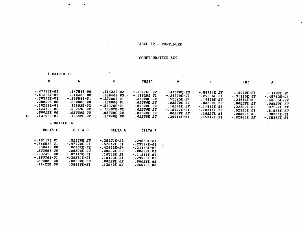
TABLE 12.- CONTINUED
CONFIGURATION L09
F MATRIX IS
U W Q THETA V P PHI R
-.47777E-g2 .14754E gg .11422E _2 : -.32176E B2 .4137gE-g3 -.89751E _# .1697#E-_! .114#7E gl-.51885E-_2 -.94E4_E _ .1394_E _3 -.12529E gl -.24779E-_1 -.29236E _I -.3llI5E _ -.45763E-gt-.78348E-_3 -.25998E-Hl -.3#286E gl ._ggH#E #H .52525E-B4 .14365E #g ,24644E-_3 .58935E-gZ
._g_E _ ._E g_ .I_E gl _ ._E _g ._E _ ._g_E _ ._g_gE g_ ._Eg_E _-.18262E-_1 .465g3E-g2 -.8397gE-g! ._ggg_E _g -.IEE46E gg -.11842E g2 .22269E g2 -.97522E g2-.4447BE-g2 .36259E-_2 -.79892E-_Z ._gg_E _E -.185_7E-gl -.I_4IE _2 -.62585E 91 .51935E gg
.g_g_gE g_ .g_ggE g_ ._EEE _ .gg_gE gg ._ggggE gE .IEgE_E _1 ._BE_E gg .38939E-gI
.13195E-EI .12592E-_2 .IE_46E _ .g_EE _g .39915E-_1 -.15g47E _I -.82866E gg -.3535gE gIG MATRIX IS
DELTA E DELTA C DELTA A DELTA P
-.19117E 81 .52978E _ -.283glE-_2 .29568E-gl-.54653E gI -.9777_E _I .52942E-_l -.23584E-g2 .,
• 36_41E Bg .89932E-B2 -.42832E-g4 -.34468E-_Z ""
-.29742E _g -.82413E-g! .16555E _l -.11828E _l-.3_7_E-_! -.39_61E-g! .]g458E _I -.29983E gg
• B_gBEE gg .Eg_BE BE .BgEEEE g# .BBggEE BE.19422E gg .36836E-El .13848E gg .86572E BE

TABLE 12.- CONTINUED
CONFIGURATIONLIO
F MATRIX IS
U W O THETA V P PHI R
.l1792E-g4 .14754E 8_ .11422E _2 -.32176E g2 .41862E-#3 -.89745E #_ .1697#E-g! .114#8E gl
.849BZE-BZ -.94g43E BB .1394gE B3 : -.12529E gl -.24779E-BI -.29245E gi -.31115E BE -.45943E-B!-.16854E-_Z -.25997E-_l -.3_286E El ._E_EEE EE .51781E-_4 .14365E BE .24618E-_3 .57828E-BZ
.EEBBBE B.gr .EBBBBE BB .IEEEBE BI : .BBBBBE BE .EEBEBE BE .EBEEEE gg .EBBEBE BB .EBEBBE BB-.17959E-gI .46495E-BZ -.8396BE-El .EEBEBE gg -.IEB46E BE -.11842E B2 .22269E E2 -.g7522E B2-.41728E-BZ .36253E-BZ -.7B753E-B2 , .BBBBBE BB -.185BEE-El -.IEB4IE E2 -.62585E B! .51B33E BE
.BBBBBE Bg .EBEBBE BB .BBBBBE'BE .EBBBBE EB .EBBEBE B_ .[BEBEE El .BEEBBE gB .38939E-BI
.13416E-El .12587E-BZ .IBB48E gg , .BBBBEE BB .39915E-EI -.15g47E El -.82865E BB -.3535BE El
G MATRIX IS
DELTA E DELTA C DELTA A DELTA P
-.19116E gl .529B3E BB -.282B2E-B2 : .29568E-BI ._-.54653E BI -.97768E BI .51885E-BI -.23584E-B2
.36g4!E BE .8g835E-B2 -.4395BE-B4 ' -.34466E-g2
.BBBBBE BB .BBBBBE BE .BBBEBE BB .BEBBBE BE-.2B741E BB -.8241ZE-E! .16555E BI -.11828E BI-.3BB63E-B[ -.39E67E-B1 .lB458E BI -.29982E BB
.BBBBBE BE .BBBBBE BE .EBBBBE BB .BBBBBE gg
.19422E BE .36823E-BI .13848E BB .8657gE BE

TABLE 12.- CONTINUED
CONFIGURATION LII
F HATRIX IS
U W Q THETA V P PHI R
-.67339E-51 .141489-9! .114229 92 -.291759 92 .418629-93 -.89745E 99 .169589-91 .114979 91-.18347E 99 -.13296E El .13949E 93 .32953E 92 -.24763E-9! -.29236E 9! -.31997E 99 -.45943E-91
.19992E-8! .1294_E-94 -.392869 91 -.22591E 91 .51691E-94 .14364E 99 .24679E-93 .58963E-92
.99_99E 99 .999_E 09 .1999_E 91 .99999E 99 .9_999E 99 .99999E 99 .99_9E 09 .gEgOBE _9-.2223_E-91 -.38992E-92 -.83974E-9! .761139 99 -.19946E 99 -.11842E 92 .22269E 92 -.97522E 92-.8_381E-_2 -.49287E-_2 -.79834E-92 .68871E _ -.18598E-9! -.19_41E 92 -.62586E El .51_34E _9
.9B_9_E 99 .999_9E _9 .99_9E 99 .99999E _9 ._9_99E _9 .199_9E E1 .9999_E WE .38939E-91
.19327E-91 -.48553E-92 .19948E 99 .S5_llE BE .39913E-9! -.15947E El -.82866E 99 -.35359E 91
G HATRIX IS
DELTA E DELTA C DELTA A DELTA P
-.19117E 91 .52987E 99 -.28391E-92 .29568E-91-.54653E 91 -.97768E 91 .51885E-91 -.23584E-92
.36941E _9 .89758E-92 -.42381E-94 -.34468E-92• BgB99E 99 .99999E 99 .999_9E 99 .99999E 99
-.29749E B_ -.82434E-9! .16555E 91 ! -.11828E 91 .....-.3_9629-9! -,399759-91 .19458E 91 -,29983E 99
• BOO'BE _9 .999_9E 99 ._999E _9 .9999_E WE• 194229 _9 .368359-_! .138489 _9 I .86572E BY

TABLE 12.- CONTINUED
CONFIGURATION LI2
3U ¼ Q _HKTK V p PHI R
".38932E-01 ,14150E-01 ,11422E 02 ",20175E 02 '41370E'03 "'89746E O0 *16913Eq01 "11_7E Ol
*rl_286_--OG -_ i32_6E-_------_139_cE-C3-----r32953E-_2----_-_2t_e3_-`_29_2_5_.-_1------'n-3_-_97_ O0 "'_5943_L'-"0[.5_e2E'02 12511E'04 "'30286E C1 ".22591E 01 .52_35g C4 .1_365E 00 '_5393E'03 '58035E'02-,ocgcoc--_o .ocoooE-oc ,IOQOOEOI------_OO_E-OO---_OOCO_--CO .ooggo_E-oo----_=OOOOO_uo _gggbo_-o_".2C_9_'0I ",38129E'02 "'"3U20_'01 .7611"= 00 "'100 _6t 00 "'11o72_ 02 ,_2269E 02 "'_'_22_ 02"-'&_0--_'C _ "'u'0 "8_ u= u_D3_ 0= --o_ := uu "=u_o_ ul "_0u'_ uc -_ uE OZ "_UJ3_L--oO"
.ocOooEoo .OOOOOEOC .O0000EO0 .O000C_O0 .OO_CO_O0 'toOgg_ Ot .O0_OOEO0 .3893S_'Ot
4
o H_ Rl_-ts
--BELT_ ; DELT_ C D_LTA k _ELTA P
I',1S116E Ol .5_981E O0 "'28399E'02 ,29578E-01_,Sk6_.53E--Ol -;97768E-Ot--.51885E-_OI-------,_3584E_o_
o3_OhOE O0 .80853E-02 -.hO803E-o_ °.3_70E-02
".2CY41E CO ".82_05E'01 .1_555E Ot ,11828E 01_.3C06-tEJ=O_-------,39050E-Ol--.IO_58E--OI-_=._9983E--O0
.OCOCOE O0 ,O0000E O0 ,O0000E oO ,O0000E O0

TABLE 12.- CONTINUED
CONFIGURATION LI3
--p-MATRI-W'--I_
U W Q- TH[I"X V p PHI R-
",1C5_1E'01 ,14154E'01 "11h22E 02 ",20175E 02 "41567E'03 ",89752E O0 'I&902E'01 '114_7E 01
..•_ u_ "._o_'oa "'_?_'o_ ._ DO "'_o_ DO "'_io.2_ o_ ._2_ ,oz -'97s2_ o2;_..T_ u_ -_u _v_ u_ -'u.e6_-c= ._o_'7 _ uu -._8_o_ u_ '_ou_ _ u_ --_586_ u_ "SlO_5E--_T,OCg_O_.O0< .OOg90_ O0 ,O0000E CO ,00000_ O0 .OOOGOEO0 ,I_oooE Ot .60000E O0 '3893SE'O-i
_'-_-_t-_-----_8=_2_2__7E-__5_IF---_-------_399_5___E--_1-----_828&6E_-_-_3535_E-_t -
C __/R-I-X--IB-
"-D_, _ DELTA _ D_LTA _
",19116E 01 ,52983E O0 "'2790BE=02 '29578E'01--_5_653E--bl------=.9776BE-ol------_5_o42E-oI--=_358_E.02.
,360_1E O0 .80814E'02 "'49595E-0_ ",3_6_E=02--,-oeo_ezDo ,O000OE--Oc ;OOoOOE--eO ,O0OOOC---O0_._C_40E oo ",8240_E_01 ,16555E cl -,1182eE 01-.3cO&3E-OI---_39057E Ot_.lo_SSE--Ol-----_,299_3E-O0.
.OCO00E O0 .O0000E O0 ,O0000E O0 ,O000CE O0-._-t___------.36837E-oL--_,i38_BE--OO--_--_B65_2E-O0

TABLE 12.- CONTINUED
CONFIGURATIONLI4
U W O THETA- V P PHI
",67028E'02 14157E'01 '11_22E C2 ='20175E 02 '4137nE=03 "'89751 E O0 ,16958E-01 . ' ,11_8E 01
_1-C660E =0: =! i_ _ 06E-_o 1-----:. 139 _ oE-03-_--_. 32953E-02-------* a_7q 9E = Gi =. _ 923 gE-O 1-------,_ 31115E--O0-------,,* _57 _3E_oT-".421CIE'03 11_77E 04 .30286E O1 .EE591E 01 • ,52570E'0_ ,14365E O0 .24799E-03 ,579bEE'02-,-oc_¢oG_o .oOoQoE--oc •!OOOOE--Ot------_OOOOCE--OO------_OCCOC'--OO.ob_gc_--oo---_oooo_oo------,g_goo_--oo-",183_3£'01 ",380_0E-0_ -,_3_33E-01 ,76113K O0 "'10C_6_ O0 "'11a42 _ 02 ,22269E 02 "'_/022_ 02
"'_: _-- _- "_ --'_ "U-*" 0 _ "_-" :- UU "*_" UA ";OU_I _ U_ __:_r3_ ol T-iu_ _- UU
; .OcOCOE CO, .OOQQOE O0 ,O0000E O0 ,O000cE O0 .COOCOE O0 ,10000_ O1 ._0000£ '00 . '38939E'01--LI-3_OEE'eOI _ "_8_3E'o_--mlOO_7E-oo-----'---_550}OE--oo---'39915E"Ol =:150_7E-01 '-'-=_E867E O0 -_35350F-'--0_
_.v, _ "-''' _ DELTA " DELTA "
",19116E CI '52978E OC "'2_399E=0_ '_9568E=01,.+5k65_E--G_--,L,97770E-Ot--,5_O_2E-OI -+23584E_0_,360_1ECO ,80925E-02 -,41254E-04 -,34466E-02
_C0£ _0 .00009_ OC :O00OOE CO ,00000£ O0
",2C7_9E O0 ",82_16E-01 ,16555E 01 ",11828E Ol.,+3cO.2E--Ot---.,-,--39060E=OI-------_lO_58E--oI--=t29983E--OO
,OCO00E O0 ,O0000E O0 ,O0000E O0 ,O000CE O0--_/9_a3F_._ :.6a_5E=OI.---7----*-_38_TE--OO----_r8657aE-O0

TABLE 12.- CONTINUED
CONFIGURATION LI5
F ;_kTRIX--lE-
O k G THETA V p -PHI R--
.__ ._-_+ .+zX2_c+ -.+o,Z_o2 ._.o_ .._,,_oo ._,-_.o_.,,+o,_o,-_ ._ ==]_=-------_._=cuL-_1--_J9_E-_3-@329_-_-_2----_o_2__29_4_-_1---_sr1_bE-_--_--_;_57_3_1_"*16883E 02 $11677E'04 "'302_8E 01 -.2259iE 01 .52728E 04 $1_367E O0 "25962E'03 058025E'02_9_._ ._. _?_o-------"!_9_-oI-------,_ooo_-0o--------.-?ooo9_oo------,o_-oo .ooooo_-oo----,ooooo_-o_
'l/_=J _ 01 ,_olJ_ 02 "'°3_3_=C1 07611 _ O0 "$10C4b _ 0 °'ts8_2_ 02 +22269E nP -$975"'_''- _" "'u'_ _'. U= -'U'_---O= ,-o .... uU "_'_'- ul ;_OO'l"_ O_ -+-_°'_:'--01"-'--'--_.., _3€'--I]ZT"_'OcQC_ O0 ,O0_QOE OC 'O00_oE CO ,00000[ CO "O00CoE CO '10000E O1 'OOOOOE O0 '38939E'01
_-_-3_g_.6_--_._8_b6E-_2-_o2E-_----_55_1L-__399_5b-_+1_4_E-_1_,o2865E--_-_+353_E-_1-
-'DZLT_ Z _-' "" _- _,'" - DELTA A gELTA P
",15117E C1 ,52982E OC "'28202E'02 ,29539E-01_..54__3E--_I--_-_97778E--Oi--.52042E_ot----,22012E.02
$3_0_1E O0 $BO914E'02 ''_2832E'c4 "$34_5cE-02-_Z _b ,OOeOoE--OC -oooooE _0 .OOOC_E O0
_.2C7_CE O0 -,82428E-01 .16555E C1 ",1182 eE 01-.3CO_.IE-O_-----.39074E-OI---.IO458E--o1-----o,29982E-o000cOGOEO0 ,CO000E O0 °O0000E O0 °OCOOGECO
-_S_22F-.--O__ =26830E'Ol--*I38_TE--oO-----,8657._E-o0

TABLE 12.- CONTINUED
CONFIGURATION LI6
F MATRIX IS ................
U W Q THETA V P PH! R
-.13BgIE g_ .14164E-_1 .11423E g2 -.32176E _2 .676_7E-_3 -.89749E g_ .17926E-_l .l1494E _1!-.19253E _g -.132_6E gI .13940E _3 -.12528E _1 -.24779E-01 -.29235E _1 -.31133E _ -.45763E-_1i .56461E_DZ .lE_O9E-g4 -.3EZB6E _1 ._BE_HE _E .21979E-_4 .14358E 09 .23714E-E3 .57996E-B2
._gg_E gg .gg_ggE _g .IgEEEE gl .g_gB_E gg ._EEggE Og .g_g_gE gg .EEEggE gE .ggg_gE g_-.20415E-g4 -.38992E-g2 -.83995E-g! .gggg_E 9g -.II_60E gg -.11842E g2 .22269E g2 -.97522E _2I-,64g43E-_2 -.4g292E-92 -.79749E-E2 ._BEgEE gg -.2I_7BE-B! -.I_E41E g2 -.62585E El .51936E 9g
._O_E g_ ._ggE 9_ ._9g_OE BE ._8_E g8 .gggggE _E .l_g_E 01 ._9_gE BE .38936E-g!i .lI62_E-EI -.48562E-E2 .lg_4gE gg .gggggE gg .47335E-gl -.15_47E gl -.82866E g_ -.35350E gl
G MATRIX IS
DELTA E DELTA C DELTA A DELTA P
-.19116E ffl .52984E 9E -.75665E-g2 .29676E-_1-.54653E gI -.97773E _! .52356E-_! 1.22_12E-g2
.36941E _0 .8_8_8E-g2 .50632E-g3 -.34522E-g2
.g_BOE BE ._ggOE _g .OEEO_E g_ ._Eg_gE BE-.2974gE gg -.82388E-_! .18464E El -.11829E El-.30957E-g! -.39945E-9! .Ig942E gl -.29984E gg
.19422E _g .3683BE-g! -.12987E-g2 .86576E gg

TABLE 12.- CONTINUED
CONFIGURATION LI7
F MATRIX IS
i U W Q THETA V P PHI R
-.IIB52E 00 .14162E-01 .11422E 02 -.32176E 92 .67411E-93 -.B9750E 00 .16958E-01 .11419E El-.215090-01 -.13207E _1 .13940E 03 -.12528E 01 -.24779E-01 -.29244E El -.31133E 90 -.46664E-01
.30151E-93 .11114E-04 -.302860 Ol .90099E 90 .21979E-94 .14358E 90 .24851E-03 .58097E-92
._00_E 00 .0_909E 99 .199000 01 .00900E 00 .00009E 90 .90099E _0 .00_09E 00 .00000E 00-.186150-91 -.380810-92 -.838740-01 .900990 90 -.11969E 90 -.11842E _2 .22269E 02 -.97522E 92-.477530-02 -.40201E-02 -.70564E-02 .90000E 00 -.21079E-01 -.10041E 02 -.62585E 0! .51034E 00
.E_E_E _ .00000E 90 .0009_E 9E .90900E 90 .00000E 00 .100_0E 01 .90000E 00 .38936E-01_ ,12922E-01 -.48552E-02 .19041E 99 .90990E 90 .47334E-91 -.15947E 01 -.82866E BE -.35350E 91
G HATRIX IS
DELTA E DELTA C DELTA A DELTA P
-.19116E 91 .52986E 99 -.76058E-02 .29686E-91-.54652E El -.97773E 91 .52356E-91 -.22912E-92
.369490 90 .8978_E-02 .51969E-93 -.34529E-92
.990000 09 .09900E 00 .09990E 99 .99909E BE ....-.20740E 09 -.82425E-91 .18464E El -.11829E El-.30051E-01 -.39071E-91 .19942E El -.29984E 99
._O_E _9 .00_9_E 00 .09990E 90 .099_0E 90.194240 00 .36831E-01 -.12835E-0Z .86575E 90

TABLE 12.- CONTINUED
CONFIGURATION LI8
F MATRIX IS
U W O THETA V P PHI R
-.1_188_ 9E .14162E-_1 .11422E _2 -.32176E E2 .67411E-E3 -.89759E E_ o16958E-_1 .II4IgE _1.31288E-_2 -.132_7E _1 .1394_E _3 -.IZ528E _1 -.24779E-_1 -.29244E El -.31133E _ -.46664E-81
-.13251E-_2 .11114E-_4 -.3_286E _1 ._E _ .21979E-_4 .1435BE _ .24851E-_3 .58_97E-_2
-.18068E-9[ -.38EBIE-92 -.83874E-EI .009gEE _H -.IIE68E 9IE -.11842E 02 .22269E 02 -.97522E 92-.42890E-_2 -.4_281E-_2 -.7H564E-_2 ._9_E 9_ -.21_79E-_1 -.I_41E _2 -.62585E 01 .51_34E _
.13318E-_1 -.48552E-_2 .IO_4IE _ ._E_E _ .47334E-_1 -.15_47E _I -.82866E 8_ -.3535_E _I
G MATRIX IS
DELTA E DELTA C DELTA A DELTA P
-.19]16E DI .529_6E 9E -.76E58E-E2 .29686E-_1-.54652E _I -.977_3E _1 .52356E-_1 -.22EIZE-E2 :_
.36_4_E _ .8_78_E-_2 .5196_E-_3 -.3452_E-_2
._E _ ._9_E _ ._E _ ._9_E _-.2_749E 99 -.82425E-91 .18464E 91 -.11829E 91-.3_51E-91 -.39_71E-_! .19942E _I -.29984E 9_
.19424E 9E .36831E-91 -.12835E-E2 .86575E BE

TABLE 12.- CONTINUED
CONFIGURATION LI9
F MATRIX IS
U W Q THETA V P PHI R
-,10369E Og ,14162E-01 ,11422E 92 -,32176E 02 ,67411E-O3 -,89750E OO ,16958E-O1 ,1141OE O1-,182380-O2 -,13207E 01 ,1394OE O3 -,12528E El -.247790-O1 -,29244E 01 -,31133E OO -,46664E-O1-,IB_SE-_Z ,11114E-04 -,30286E 01 ,O00OOE 00 ,219790-O4 . ,14358E O_ ,24851E-_3 ,58097E-O2
.9_009E 99 .09000E 99 .19900E 01 .0009_E 90 .09009E 0E . .00000E 00 .090_0E 09 .00090E 99-,IBI80E-OI -,38081E-O2 -,83874E-0! ,000D9E 00 -,IIO6gE OE : -,11842E 92 ,22269E O2 -,97522E _2-,43809E-O2 -,40281E-O2 -,70564E-92 ,O009OE 90 -,21979E-O! -,1OO41E 92 -,62585E O1 .51034E 99
.90S00E 00 .99000E 00 .09090E 90 .00009E 09 .00000E 00 .10909E 01 .09090E 00 .38936E-_1
.13238E-01 -.48552E-02 .10041E 00 .00000E 9E .47334E-01 -.15047E 01 -.82866E 09 -.35359E 91
G MATRIX IS
DELTA E DELTA C DELTA A DELTA P
-.I9II6E _! .52986E 09 -.76958E-E2 .29686E-0!-,54652E HI -,97773E O1 ,52356E-O! -,22012E-O2
,36040E HE ,80780E-92 ,5106OE-93 -,3452OE-92.00000E 00 .90000E 00 .0_00E 0_ .000_0E 00
-.Z0740E 0_ -.82425E-01 .184640 01 -.118290 El "_-.30051E-01 -,39071E-O! ,19942E HI -,29984E OO.0_000E 90 .000_0E 0_ .00090E 09 .00000E 00,19424E OO ,36831E-O1 -,12835E-9Z ,86575E 00

TABLE 12.- CONTINUED
CONFIGURATION L20
F MATRIX IS
U W Q THETA V P PHI R
-.13BglE _ .14755E g_ .11422E _2 -.32176E _2 .67411E-_3 -.8975_E g_ .16958E-_1 .1141_E _1I-.1_2450 E_ -.94059E _# .1394EE _3 -.125280 0I -.24779E-91 -.29244E 01 -.311330 #_ -.46664E-_!
.56460E-02 -.25_980-EI -.3_286E El .EE_E_E _E .21979E-94 .14358E 0_ .24051E-93 .58E970-9Z
.EEEEEE BE ._9E BE .1_090E 91 ._9_E 90 .EEEE_E _E .g_E_EE 00 ._E_E 99 .0_9EOE _E-.20415E-0L.- .46595E-02 -.83874E-01 .09900E 90 -.11060E EE -.11842E 02 .22269E 92 -.975220 E2_-.64044E-02 .36259E-OZ -.70564E-02 .00000E BE -.21979E-EI -.IBE41E 02 -.62585E O! .51034E OO
.OBEO_E 00 ".00000E 00 .000_0E 00 .00000E 00 .00000E 00 .10000E 01 .00000E 00 .38936E-E!
.11619E-91 .12588E-02 .10041E bE .00000E 00 .47334E-01 -.15047E 01 -.82866E 00 -.35350E 01
G MATRIX IS
DELTA E DELTA C DELTA A DELTA P
,-.I9II6E 01 .52986E 00 -.76058E-02 .29686E-_1-.54652E 01 -.977_E _1 .52356E-0! -.22012E-02 .,
.36_40E 00 .80780E-02 .51060E-03 -,34520E-_2 ""
.00000E 0_ .000000 OW .00W000 WE .WWOWOEOW-.20740E 00 -.82425E-01 .184640 01 -.11829E 01i-.300510-0! -.39_71E-_1 .1W942E O1 -.29984E 00I .000000 00 .90W00E BW .00WEWE OW .00W_WE WE
.19424E BW .36831E-01 -.12835E-02 .86575E OW
€ _ J t

6. • _ O
TABLE 12.- CONTINUED
CONFIGURATION L21
F MATRIX IS
U W Q THETA V P PHI R
-.11D52E 99 .14755E 99 .11422E 92 -.32176E 92 .67411E'93 -.89759E 99 .16958E-91 .11419E 9!-.21599E-91 -.94959E 99 .13949E 93 -.12528E 91 -.24779E-91 -.29244E 91 -.31133E 9E -.46664E-91
.3_1519-93 -.25998E-91 -.39286E El .99999E 99 .21979E-94 .14358E 99 .24851E-93 .58997E-92
.993_9E 99 .99999E 9_ .19999E 91 i .99999E 99 .99999E 99 .99999E 99 .99999E 99 .99999E 99-.18615E-91 .46595E-92 -.83874E-91 .99999E 99 -.11969E E9 -.11842E 92 .22269E 92 -.97522E 92-.47753E-92 .362_9E-92 -.79564E-92 .99999E 99 -.21979E-9! -.19941E 92 -.62585E 91 .51934E 99
.9990_E 99 .999999 99 .99999E 99 .99999E 99 .99999E 99 .19999E 91 .99999E 99 .38936E-H1
.12922E-91 .12588E-92 .19941E 99 .999999 99 .47334E-91 -.15947E 91 -.82866E 99 -.353599 El
G HATRIX IS
DELTA E DELTA C DELTA A DELTA P
-.191169 91 .52986E 99 -.769581-92 .296869-91-.546529 91 -.97773E 91 .523569-91 -.22912E-92
3694_E 99 .89789E-92 .5196_E-93 -.34529E-92i 999999 99 .99999E 9_ ,99999E 99 .99999E 99
29749E 99 -.82425E-91 .18464E El -.118299 91 ....39951E-91 -.39971E-91 .19942E El -.29984E 99
i .99999E 99 .99999E BE .99999E 99 .99999E 9919424E 9_ .36831E-91 -.12835E-92 .86575E 99

TABLE 12.- CONTINUED
i
CONFIGURATION L22
F MATRIX IS
: U U O THETA V P PHI R
-.99953E-91 .14755E EE .11422E _2 ' -.32176E _2 .67411E-_3 -.8975_E EE .16958E-EI .lI419E _1i .B568BE-_2 -.9405_E _ .1394_[ _3 -.12528E _I -.24779E-_1 -.29244E _1 -.31133E _ -.46664E-_1,-.1688_E-_2 -.25_98E-01 -.3_286[ _I ._E_EE _E .21979E-E4 .14358E E_ .'24851E-_3 .58_97E-_2
•:-.17946E-B,I .465E5E-02 -.83874E-E1 .dBdddE Bd -.IIE6BE _B -.11842E _2 .22269E 02 -.97522E d2-.41691E-92 .36259E-_2 -.7D564E-02 .EddddE dd -.21979E-_1 -.IEE41E 92 -.62585E _1 .51d34E 9d
• ddd_E _d ._dd_E 9d ._EdE_E.-_d .EEdd_E BE .B_ddEE _E .l_d_dE _I ._d_E _d .38936E-d!_ .13406E-dl .125BEE-E2 .1_041E dd .#EdEOE Ed .47334E-_1 -.15d47E _1 -.B2B66E _ -.3535_E _1
G MATRIX IS
i DELTA E DELTA C DELTA A DELTA P
I-.IgII6E dl .529B6E 0_ -.76d58E-_2 .29686E-dl
-.54652E Bl -.97_73E _1 .52356E-_1 -.22EI2E-02 ..36_4_E _d .8_78dE-02 .51d6dE-d3 -.3452gE-_2 ".EddddE 0_ ._dB_dE dd ._9d_dE dd ._dddE _B
'-.2d74_E 9d -.82425E-B1 .18464E dl -.11829E 91!-.3_51E-01 -.39E71E-dl .1_942E _1 -.29984E OE
.19424E 9d .36831E-dl -.12835E-_2 .86575E 99

dL • _ •
TABLE 12.- CONTINUED
CONFIGURATION L24
F MATRIX IS
U W Q THETA V P PHI R
-.13891E EE .14162E-_1 .11422E E2 -.2E175E E2 .67411E-O3 -.8975_E EE .16958E-O1 .II41EE BI-.1_245E _ -.132_7E El .1394OE _3 .32954E _2 -.24779E-EI -.29244E _1 -.31133E D_ -.46664E-91
.56460E-OZ .III14E-94 -.39286E O1 -.22591E _1 21979E-O4 .14358E _ .24851E-E3 .58_97E-_2
._E 90 ._E _ .I_OE 91 ._O_E 0_ _EO_E _ ._E _ ._E 0_ ._E _-.2H415E-91 -.38HBIE-O2 -.83874E-HI .76119E HE - IIE6HE HE -.11842E H2 .22269E O2 -.97522E E2-.64944E-02 -.4H28IE-H2 -.7E564E-H2 .68874E H_ - 21E79E-OI -.IHE41E H2 -.62585E O1 .51_34E _
.O_E H0 .HEHgHE HE .H_HHEE 80 .EHHOEE BE EHOEEE _ .IH_HEE _I .EHEDEE E9 .38936E-Hl
.II6IHE-BI -.48552E-E2 .IHE4IE HE .55EHEE HE 47334E-HI -.15H47E HI -.82866E HE -.3535EE HI
G MATRIX IS
DELTA E DELTA C DELTA A DELTA P
-.19116E 01 .52986E OO -.76858E-H2 .29686E-El-.54652E _I -.97773E _1 .52356E-HI -.22HI2E-H2
.36H40E HE .8H78EE-E2 .5IE6EE-H3 -.3452HE-H2
.H_H_HE H_ .HEHH_E HE .HE_EHE HE .H_HHHE EH ---.2_74HE H_ -.82425E-EI .18464E El -.11829E E1-.3HH5IE-EI -.39H71E-HI .IEg42E HI -.29984E EH
._O_E _E .E_HHOE HE .HHHHHE HE .HHOEHE H_
.19424E HB .36831E-HI -.12835E-H2 .86575E EH

TABLE 12.- CONTINUED
CONFIGURATION L25
F MATRIX IS
U W Q THETA V P PHI R
-.11052E HB .14162E-H1 .11422E 92 -.29175E H2 .67411E-_3 -.8975_E BE .16958E-_1 .1141_E BI-.Z15H9E-EI -.13297E HI .13940E 93 .32954E 02 -.24779E-01 -.29244E 01 -.31133E 0_ -.46664E-91i .3H151E-03 .11114E-94 -.39286E El -.22591E 01 .21979E-94 .14358E 99 .24851E-93 .58H97E-BZi .HOEOBE 99 .HH_HHE 99 .190H99 01 .BHH_EE HH .EH990E _9 ._9999E HH .BHHBHE 9H .EBH99E 9H-.IB615E-E! -.389BIE-B2 -.838749-B1 .761199 9H -.11_69E 9H -.11842E 92 .22269E 92 -.g75229 92-.47753E-9Z -.4B2BIE-92 -.79564E-HZ , .6B874E 99 -.21B79E-BI -.19941E B2 -.62585E 91 .51934E BE
.999BBE 09 .BH99HE 99 .BHHEBE 9H ._99HOE OH .H9999E 99 .I_09HE 91 .09_90E HE .38936E-91
.12922E-91 -.48552E-9Z .IHB4IE 99 ' .559H8E OH .47334E-0! -.15947E El -.82866E HH -.3535HE H!
G MATRIX IS
DELTA E DELTA C DELTA A DELTA P
j!-.Ig!!6E 91 .52986E 99 -.76H589-92 .Z9686E-H!
54652E HI -.97773E El .523569-H1 -.22912E-H23604BE BE .8H78_E-92 .51H609-93 -.3452HE-0200009E HH .9BOHBE 9H .9_000E 00 .gHHBHE HH
_-.2_74BE 9H -.82425E-91 .18464E HI -.11829E HI ""I-.3EHSIE-H] -.39971E-91 .1H942E HI ! -.29984E 99
HEEEBE EE .9H900E 09 .99HEOE 90 .EHHHEE OH19424E 9H .36831E-Ht -.12835E-02 .86575E HH

at I t •
TABLE 12.- CONTINUED
CONFIGURATION L26
F MATRIX IS
U W O THETA V P PHI R
-.99953E-91 .14162E-91 .11422E B2 -.29175E 92 .67411E-93 -.89759E 99 .16958E-91 .ll41gE _1.85688E-92 -.13297E El .13949E 93 .32954E 9Z -.24779E-91 - 29244E 91 -.31133E 99 -.46664E-91
-.16889E-gZ .11114E-94 -.39286E El -.22591E 91 .21979E-94 14358E 9g .24851E-g3 .58997E-gZ.99999E 99 .99999E 99 .19999E gl .99999E 99 .99999E 99 99999E 9_ .99999E gg .99999E 99
-.17946E-91 -.38981E-92 -.83874E-91 .76119E 99 -.11969E 99 - 11842E 92 .22269E 92 -.97522E 92-.416919-92 -.49281E-92 -.795649-92 .68874E 99 -.21979E-91 - 19941E 92 -.62585E 91 .51934E _9
.999_99 99 . .99999E gE .99999E 99 .99999E 99 .99999E 99 19999E 91 .999_E 9_ .38936E-91
.13496E-91 -.48552E-92 .1_941E-'99 .55998E 99 .47334E-91 - 15947E 91 -.82866E 99 -.353599 91
G MATRIX IS
DELTA E DELTA C DELTA A DELTA P
1-.191169 91 .52986E 99 -.76958E-9Z .29686E-91-.54652E 91 -.97773E 91 .52356E-91 -.22912E-92
.36949E 9_ .89789E-92 .51969E-93 -.34529E-92 :_
.99999E 99 .999999 99 .99999E 99 .99999E 99-.297499 99 -.82425E-91 .18464E 91 -.11829E 91-.39951E-91 -.39971E-91 .19942E 91 -.29984E 99r .99999E 9g e99999E _9 e99g99E 99 .99999E 99
.19424E 99 .36831E-91 -.12835E-92 .86575E 99

TABLE 12.- CONTINUED
CONFIGURATION L28S
F HATRIX IS
U W Q THETA V P PHI R
-.62711E-B1 .13184E-81 .68952E BE -.29979E _2 .62_59E-_3 -.83594E EE .15786E-91 .1_626E 0117024E 0_ -.13234E _1 .1_881E _3 .50518E _1 -.24925E-_! -.27479E _1 -.31465E Eft -.27_37E _I_IZIE-_I .19518E-_3 -.1_82E _l -.41575E _ .31738E-_4 .13296E _ .46878E-_3 .20537E-_1
21733E-El -.3917_E-02 -.76643E 00 .Z3926E EE -.IIE61E BE -.11836E 02 .22269E 02 -.97531E _279663E-_2 -.4_451E-_2 -.62971E _ .34681E-_1 -.21_8_E-_1 -.I_4_E _2 -.62585E _l .5_9_9E 9__E _ ._09E _ ._OE _ ._ _ ._E _ .1_0E 01 ._E _ .38939E-_198615E-_Z -.475_6E-02 -.38431E _ -.224_41 _ .4734_E-_1 -.151_9E _1 -.82854E 9_ -.3527_E _Io
G MATRIX IS
DELTA E DELTA C DELTA A DELTA P
-.178_6E EI .49349E _ -.26361E-E2 .27514E-_1-.5_998E 91 -.98899E 91 .52439E-91 -.79892E-92
.33579E 99 .14932E-91 -.77146E-94 -,39636E-92
.99909E 09 .99999E 09 .90999E 99 .99999E 99-.19319E 99 -.B6335E-9! .16555E 91 -.11839E 91 ....-.28993E-01 -,3962tE-9! .19458E 91 -,29986E 99
.8909_E 99 .99009E 99 .09990E 90 .90099E 99.18990E 99 .49527E-91 .13846E 99 .86592E 99

,_ F € •
TABLE 12.- CONTINUED
CONFIGURATION L28U
F MATRIX IS
U W Q THETA V P PHI R
-,65818E-_I ,13837E-_1 ,7236BE E9 -,31455E _2 ,65133E-_3 -,87736E EE ,16568E-_I .I1152E _1.-,17913E _E -,13215E _1 ,1_891E _3 ,B_683E _ -,24837E-El -,Z8663E _1 -,31242E _ -,11987E _
.I_7_7E-_1 ,72036E-_4 -.I_147E 91 -,13582E BE ,25942E-_4 ,13987E EO .32134E-_3 ,1_612E-91
-,22_7_E-B3 -,38461E-_2 -.76272E _0 ,78164E-_1 -,1106_E _ -,1184_E E2 .22269E B2 -,97525E B2-.B_ISIE-_2 -,4_349E-_2 -.62_18E _ .II33_E-E1 -,21079E-91 -,1_41E _2 -,62585E EI ,5_992E _E
._B_OE _ ".E_BBEE _B ._BE BE .BOBBLE EB ._OBBE B_ .IBBBBE _1 .BE_BE BE .38939E-_1
.19177E-BI - 4822BE-B2 -.38778E'BE -.73193E-El 47337E-E1 - 15867E Bl -.82862E BE - 35324E #1
G MATRIX IS
DELTA E DELTA C DELTA A DELTA P
-.18688E BI .51794E 0_ -.27667E-E2 .28878E-B1-.5343_E _1 -.98HBE BI .52B66E-_1 -.4_921E-_2
.35233E _ .IB323E-BI -.52524E-B4 -.33285E-g2 "l• B_E OB ._BBE _B ._BBB_E _B .B_B_BE B_
-.2_276E _B -.83683E-_1 .16555E BI -.11829E _l-.29390E-B1 -.39236E-01 .IB458E Bl -.29983E BE.BOBEOE OB .BBEBEE _B .EBBBOE OE .BBBEOE BB.18987E BB .38043E-BI .13847E BB .86578E B_

TABLE 12.- CONTINUEDI
CONFIGURATION L29S
F MATRIX IS
U W O THETA V P PHI R
-.374319-E1 .13699E-91 .71171E 99 . -.39934E 92 .63866E-93 -.86282E 99 .16358E-91 .199689 91-.98249E-91 -.13222E 91 .19888E 93 .22959E 91 -.24868E-91 -.28247E El -.31321E 99 -.17248E 99
.53632E-92 .11526E-93 -.19124E 91 -.23492E 99 .Z81419-94 .13713E 99 .363229-93 .14993E-91
.99999E 99 .99999E 99 .19999E B! .99999E 99 .999_9E 99 .99999E 99 .999_9E 9H .9999_E 99-.29279E-91 -.38698E-92 -.76492E 99 .13467E BE -.11969E BE -.11838E 92 .22269E 92 -.97527E _2
-.63853E-92 -.49387E-92 -.62936E 99 .19521E-91 -.21_79E-91 -.19949E 92 -.62585E 91 .59964E 99.999999 99 ._999E 99 .99999E 99 .99999E 99 .99999E 99. .19999E 91 .99999E _9 .389399-9!.11481E-9! -.48999E-92 -.38656E 99 -.12611E 99 .47336E-91 -.15982E _I -.82859E _9 -.35395E 91
G MATRIX IS
DELTA E DELTA C DELTA A DELTA P
-.18379E 9! .59938E 99 -.27299E-92 .28399E-9!-,52545E 91 -.98362E 91 .52197E-9! -.5458!E-92
.34659E 99 .119479-_1 -.6116!E-94 -.32395E-92
.99999E 99 .99_99E 99 .99999E 99 .99999E 99 ....-.19949E 99 -.84614E-9! .16555E 91 -.11829E 91-.28994E-91 -.39376E-91 .19458E El -.29984E 99
.99999E 99 .99999E 9_ .99999E 99 .99999E 9E
.18672E 99 ,38919E-91 .13846E 99 .86583E 99

TABLE 12.- CONTINUED
CONFIGURATION L29U
F MATRIX IS
U W Q THETA V P PHI R
-.3877BE-El .14U99E-EI .73731E _ -.32047E _2 .66163E-E3 -.89385E BE .16947E-_1 .11362E _I-.I_21_E _ -.132_8E _1 .1_895E _3 -.88524E _ -.248_2E-_1 -.29135E _l -.31152E _ -.59698E-_1
.56170E-_2 .22974E-_4 -.IEI72E El -.24244E-El .2381EE-04 .14298E OE .25229E-_3 .6655_E-E2
._E _ ._EE_E _ .I_E _1 .E_EE_E _E ._E_E _E ._EE_HE _ ._E _ ._E _9-.2E416E-gI -.38167E-92 -.76124E _9 .13952E-91 -.IIE6EE 9E -.11842E 02 .22269E E2 -.97523E 92-.64E65E-EZ -.48310E-E2 -.61996E EE .29223E-02 -.21E79E-EI -.19_41E E2 -.62585E 91 .51E26E 9_
11618E-01 -.485_6E-02 -.38916E-00 - 13E64E-Sl 47334E-01 - 15ES_E El -.82865E E9 35345E 01
G MATRIX IS
DELTA E DELTA C DELTA A DELTA P
-.19E4gE _I .5277_E EE -.28188E-_2 .29411E-_1-.54435E _I -.97838E _I .51917E-01 -.25386E-_2
.35896E _E .849Z6E-02 -.4271_E-_4 -.3423_E-_Z :t
._OE _ ._OOE _E .E_E_E _ .E_OE EE-.2_657E _E -.82627E-_! .16555E gl -.11828E gl-.29944E-_1 -.39988E-_! .l_45BE _I -.29983E gE
.19343E gg .37E48E-g! .13847E gO .86573E Eg

TABLE 12.- CONTINUED
CONFIGURATION L30
u k O THET^ V ,p PR! R--
"oI07_2E'01 :I_154E'01 °74023E O0 ".32176E 02 °_1370E'03 ".897_5E O0 '16992E'01 '11__8E 01=_619E-=Ci -; i=_6E-_-------_8_e-E-_--_--_--x`t25_-L_-_1-----_4_7e3-_'-_--_-_-_29z3eE-_-----_"-_31_t5E-_-----m_*59_3_-_r.3C185E°03 11_3E'0_ o,10178E C1 ,00000_ 00 o=2_35L'04 ,1_364E 00 ,'2_231E-03 " ,57888E-02--rOcOC_£ _0 ,O0000E--OO------,-t-OOOOE ui ,O0000E-OO-------_OOOCOE'-Oo ,u_OOE Ou ,O0000E-Oo ' ,oOObOL:'--O0-.__.,=er.__''tSe30E'o!._,__.._''3810eE'02..... "'76°95E..o0=_O0 ,00000___.O0 _..''10_46E_._00_ _'11842_ 02 .E2269E 02 "'97522E 02
: ,OCgQO_ 00_ ,O0000E OO ,CO000E O0 ,O0000E O0 "OOCO0E O0 ,1o000_ 01 "00000 E O0 I=,38939E-01
-;EL_ _ E DELT_ C ;ELTAA DELTA P
"'19116E 01 ,52986E O0 °'28399E'0_ '29578E'01-'-.6_65L:=E--Ot--_--_97768E--Ot-------t6_O_E:01 =,_358_E-.02
,360_1E O0 ,80767E'02 o,_125_E-0_ -,3_6_E-02
",_0741E O0 ",8_11E'01 ,16555E 01 ",1182SE 01"_.1C068E'0_ ";39061E'0_ 'iO_58E--O_--'-.E9983E--O0
,OCO00E O0 ,O0000E OC 'O0000E O0 ,O0000E O0--_-19_rtF.--G.0 : 36836E_0 _ ,138+8E--0O +9657-aE-.00[0P= 0

• • ! .m
TABLE 12.- CONTINUED
CONFIGURATION L31
F MATRIX IS
U W O THETA V P PHI R
-.81365E-_2 .14165E-_1 .7493EE _B -.32176E E2 .6791BE-_3 -.89745E BE .17926E-Z1 .11497E _1-.14654E-_1 -.13Z_6E _I .1_896E _3 -.12529E _1 -.2485BE-EI -.29242E _1 -.31133E _ -.45763E-_1-.152_1E-03 .1_482E-_4 -.1_178E _1 .O_E _E .23129E-04 .14367E E_ .23714E-_3 .57955E-_2
.99EEEE 9_ .EOBBBE 99 .I_H9_E 91 .999EBE 9E .99EOOE BE .HEEEDE BE ._9BEE 99 .ESBBBE 9S-.I8479E-Hl -.38131E-E2 -.76Eg6E EE .09_E_E OE -.IIE69E 00 -.11842E 02 .22269E 92 -.97522E 92-.46421E-02 -.4_32_E-92 -.61994E EE ._OBEBE BE -.21879E-BI -.IBB41E 82 -.62585E 01 .51033E 9S.BBB_OE B_ "._BBBBE B_ ._B_E B_ .BBBOBE EB ._BB_E BB .IBBBBE Bl ._B_BE B_ .38939E-BI.13043E-BI -.4857BE-_2 -.38948E _ .BOBBBE _ .47335E-_1 -.ISB47E 01 -.82865E EB -.35350E _1
G MATRIX IS
DELTA E DELTA C DELTA A DELTA P
- 19117E BI .52981E OS -.28399E-B2 .29529E-_!- 54652E _1 -.977_BE _l .51885E-E! -.22_12E-B2
36B41E BO .80859E-B2 -.38323E-B4 -.34450E-92DOBBBE 9g .OBOBBE B_ ._BBO_E B_ .B_BBOE B_
- 29743E BO -.82436E-E! .16555E _l -.11828E Hi- 3B_79E-_I -.39_79E-B! .IB458E _! -.29983E B_
._B_BBE B_ .O_BBBE B_ ._BBBBE BE .BOBOEE BB• 19422E 0_ .36825E-01 .13847E 00 .86571E _0

TABLE 12.- CONTINUED
CONFIGURATION L32
F MATRIX IS
U W Q THETA V P PHI R
-.66959E-B2 .14155E-#1 .74921E _E -.32176E _2 .66821E-_3 -.89745E E# .1697#E-_1 .11498E EJ-.IB566E-_t -.132_7E _! .IE896E _3 -.12529E _! -.24795E-_1 -.29244E El -.31133E 0_ -.45943E-_1-.423DEE-_3 .12556E-_4 -.1#178E _1 ._E_BE DE .22971E-E4 .14365E 9E .24644E-_3 .57926E-_2
._D_E_E BE .EEEE_E BE .IHEEOE _1 ._E_E EE .BEEtlE BE .HEBE_E EO .EEEEEE EE. .EHEBEE EE-.18384E-EI -.38EB1E-E2 -.76_98E _E .EO_EBE EE -.I1E6EE EE : -.11842E E2 .22269E E2 -.97522E E2-'.45585E-02 -.4_274E-_2 -.61997E EE ._9_9E E_ -.21_79E-01 -.IEE4IE E2 -.62586E E1 .51E34E EE
._O0_E _ .EEE_EE BE .EEOEEE _E .EEBEEE BE .EE_EEE EE .IE_BEE El .EE_EE EE .38939E-E!
.131_7E-_1 -.48534E-E2 -.38951E EB .EEBHHE BE .47335E-E! -.15E47E El -.82866E BE -.3535EE E1
G HATRIX IS
DELTA E DELTA C DELTA A DELTA P
-.19116E E1 .52988E EE -.28399E-E2 .2957BE-El-,54653E 01 -,9776BE 01 ,52E42E-EI -.23584E-E2
,3604_E BE ,8E74EE-E2 -,41EZ8E-E4 -,34468E-E2._3_E E_ ._EE O_ .EEO_E EE .EE_E_E _
-,2073BE B_ -,82423E-El ,16555E El -,11828E El. """-,3_050E-Et -,39E70E-BI ,IE45BE _1 -,29983E EE
._O_BE EE .OO_BE EE .EEEEOE BE .EEEE_E EE,19421E E9 ,36827E-B] ,13848E EE ,86572E EE

• ii # b
TABLE 12.- CONTINUED
CONFIGURATION L33S
F MATRIX IS
U W Q THETA V P PHI R
-.6644BE-E1 .14559E EH .73_53E _9 -.31751E 92 .66230E-g3 -.88561E gE .16723E-E1 .11256E _1-.18_83E _E -.94596E _ .1_893E _3 -.38217E-_1 -.24883E-_1 -.289_4E 91 -.31179E _ -.888240-_1
,10823E-_1 -.24739E-E1 -.1_159E BI -.8_104E-_1 ,24687E-B4 .14144E _9 .29B70E-B3 .86443E-_2
-.Z2137E-01 .4437BE-02 -.76201E _ .46096E-_I -.II_6EE _0 -.11841E _2 .22269E 02 -.97524E 02-.8_247E-02 .3593gE-_2 -.62_08E _0 .66803E-_2 -.21979E-_1 -.1_41E _2 -.62585E _1 .51_10E _E
.E0�EOE 00 .#00_0E 09 .E_090E B9 .EE_EE 00 .00_9_E _E .1090BE _1 .09090E 09 .38939E-91
.1024_E-91 .14566E-92 -.388470 _9 -.43167E-E1 .47335E-E! -.15059E 01 -.82863E 90 -.35334E El
G MATRIX IS
DELTA E DELTA C DELTA A DELTA P
-.18865E O1 .52284E OO -.2783OE-O2 .ZgI49E-OI-.53930E 01 -.9797_E El .52148E-_I -.331630-02
.35565E 00 .g4_I4E-02 -.49853E-04 -.33715E-0Z ._
.00000E _0 .0_000E 00 .00000E 00 .0000_E 00-.20466E 00 -.83218E-01 .16555E O1 -.11829E 0!-.29660E-01 -.39204E-01 .10458E 01 -.29983E _0
.000_E 00 .00000E _0 .00000E 00 .00_0E 00
.19166E 00 .37534E-01 .13847E 00 .86575E 00

TABLE 12.- CONTINUED
CONFIGURATION L33U
F MATRIX IS ............... • .
' U W O THETA V P PHI R
-.71716E-HI .15716E H_ .78854E _ -.34272E _2 .71489E-_3 -.95594E _ .IBESIE-EI .1215BE _l'-.19592E H_ -.9129HE HH .1HgIHE H3 -.72466E HI -.24732E-_I -.3H914E HI -.3H799E HH .16672E 9H
.IIBIBE-HI -.26glHE-Hl -.IH269E HI .39527E HE .14771E-H4 .1547HE H_ .4H316E-B4 -.82HB2E-B2
.HgHH_E HH .HH_BOE 90 .IBH_E 91 ._HgHHE 99 .gBH_OE _H .gBHBOE BH .99_O_E 9_ .9_990E _-.227B9E-HJ .56914E-HZ -.75571E HH -.22746E HH -.IIH6BE HH -.l184gE H2 .22269E H2 -.97514E H2-.Sl_76E-H2 .37757E-H2 -.61917E H_ -.32964E-HI -.21978E-H1 -.1HH42E 92 -.62585E HI .5lISlE 9_
.H9990E Hg ".H_HHgE H9 .H99HHE HH .H_HHE HH .H_gE _H .IHH99E H1 .H_99HE 9H .38939E-9!
.Iq777E-HI .'2BlBBE-H3 -.39436E°H_ .213HIE HH .4733_E-_1 -.14987E H1 -.82876E HH -.35425E 91
G MATRIX IS
DELTA E DELTA C DELTA A DELTA P
'-.29363E HI .56436E H9 -.3HH49E-H2 .31464E.-HI-.SBZI3E 91 -.96763E 91 .51517E-HI .33HI4E-B2_,
.3839_E H_ .15735E-H2 -.81856E-95 -.38H79E-H2 _'
.Hgg9_E HB .HHgH_E H_ .H_gHHE H_ .HHHHHE HH-.22H92E HH -.78713E-H! .16555E H1 -.11826E HI-.32HI6E-HI -.38552E-H1 .lH458E HI -.29979E HH
._090E B_ .00_E 99 ._00E HO ,H_H_E H_
.2HE88E H_ .33316E-HI .13849E HH .86552E HH
- t€ •

TABLE 12.- CONTINUED
CONFIGURATION L34S
F MATRIX IS
U W Q THETA V P PHI R
-.38166E-El .14464E 99 .72571E EE -.31542E _2 .65217E-_3 -.87979E EE .16647E-91 .11182E _1-.1_927E O_ -.94869E _ .1_892E B3 .55722E _ -.24911E-_1 -.28738E El -.31229E _ -.1_993E _
.5581_E-_2 -.2455_E-O1 -.IEI5_E _1 -.11937E O_ .26521E-_4 .14_34E EE .3_763E-_3 .I_g37E-EI.EEEE_E _E ._E_EE 9_ .IEg_EE El .Eg_EEE 9E ._#EEEE EE ._EDE_E EE .EEEEEE _9 .Eg_E_E g_
-.2935DE-91 .43327E-E2 -.76251E EE .68679E-01 -.II96_E OE -.11849E E2 .22269E 92 -.97525E _2-.63974E-02 .35786E-92 -.62ELSE E9 .99506E-92 -.21977E-El -.IEE41E E2 -.62585E 91 .59999E 9_
._E 00 .E_9_EE EE .#EE#_E EE .EEEEEE OE .EEEEEE 9# .lESSEE El .EEEEOE 9E .38939E-9111555E-91 1554_E-92 -.38798E 9E -.643ZIE-91 .47337E-El - 15964E El -.82861E 0_ -.353Z7E El
G MATRIX IS
DELTA E DELTA C DELTA A DELTA P
-.18741E BI .51937E BB -.27744E-BZ .ZB958E-BI-.53578E B1 -.98_68E El .522BIE-EI -.38629E-EZ
.35332E BE .IBB54E-BI -.51527E-E4 -.33357E-02
.BOB_EE BE .BBBBBE EB .BBBBEE EB .EBBOEE EB ..--.2B329E BB -.83555E-BI .16555E El -.I1829E El-.29453E-El -.39231E-El .IE458E El -.29984E BB._BBE BE .BBOOBE BE .BBBB_E EB .BBBBBE _B.19B39E BE .37899E-BI .13846E EE .86578E BB

TABLE 12.- CONTINUED
CONFIGURATION L34U
F HATRIX IS
U W Q THETA V P PHI R
-.4Eg69E-EI .15526E EE .779EEE BE -.33859E EZ .7EEE6E-E3 -.94439E EE .17869E-EI .IZEE3E El-.IBB29E BE -.gI832E EE .IEBE7E E3 -.6E641E E! -.Z4774E-EI -.3E584E E! -.3EB79E EE .1248EE EE
.6B294E-E2 -.26553E-EI -.IE25!E El .31728E BE .17493E-B4 .15252E BE .77185E-E4 -.54426E-E2
.BEEEEE EE .EEEEEE EE .IEEEEE El .EEEEEE EE .EEEEEE BE .EBEEEE EE .EEEEEE EE .EEEEEE BE_-.2E654E-_.I .54847E-E2 -.75673E EE -.18255E BE -.IIE6EE EE -.11847E E2 .22269E E2 -.97516E E2-.64414E-B2 .37456E-B2 -.61931E EE -.26449E-EI -.21B77E-BI -.IBE42E E2 -.62585E E! .51128E BE
.BEBBBE EE .EBBBBE EB .EEEBBE EE .BBEBBE BY .EEEEBE BE .IBBEEE B! .EEEEBE BE .38939E-El: .II84EE-BI ,475B4E-B3 -.39339E'EE , .17E97E WE .47332E-E[ -.14999E El -.82873E BY -.354lEE EIo
G HATRIX IS
DELTA E DELTA C DELTA A DELTA P
-.2EII7E El .5575BE EE -.29781E-EZ .31E84E-El-.57512E El -.969_7E El .5!6IgE-B! .2ZI58E-E2 ,,
.37927E EE .28642E-E2 -.13121E-E4 -.37365E-B2 "l",EEBBBE EY ,EEEEBE BE. .EEEEEE BE ,EEEEEE BE
-.21821E EE -.79419E-EI .16555E El -.11827E El-.31616E-B! -.38632E-El .IE458E El -.2998EE EE
.BEEEEE EE .EEEEBE BE .EEEEEE WE .EEEEEE EE
.ZB437E EE .34E25E-E! .13848E EE .86557E EE

k •
TABLE 12.- CONTINUED
CONFIGURATION L35
F MATRIX IS
U W Q THETA V P PHI R
-.IE547E-EI .14755E EE .74E27E EE -.32176E E2 .6692EE-#3 -.89746E EE .17_ISE-EI .11497E El-.21524E-BI -.94B39E BB .IBBg6E B3 -.12529E BI -.24873E-Bl -.29246E BI -.31133E BB -.45583E-BI! .3BI76E-B3 -.Z5_98E-B! -.lBI78E BI ._B_BE _B .Z3242E-B4 .14367E _ .Z3843E-B3 .57942E-B2I.BBBBBE BB .BB_BBE BB .IBBBBE BI .BBBBBE BB .BBBBBE BB .BBBBBE BB .BBBBBE BB .BBB_E BE-.18632E-Bt' .46481E-B2 -.76996E BE .BEEEBE BE -.IIB6BE BB -.11842E B2 .22269E B2 -.97522E B2-.47795E-B2 ..3625BE-B2 -.61994E BB .BBBBBE BB -.21B78E-BI -.IWB4IE B2 -.62585E Bl .51B33E gB
.BWBBBE BB .BBWWBE WB .BB_BWE 9B .BBBBWE BB .BBWBWE WB .IBgBBE BI .BBBWBE BB .3893gE-BI
.IZ934E-B! .IZ6BBE-B2 -.38947E BW .BBBWBE WE 47335E-B1 - 15947E BI -.82866E WE -.35350E BI
G HATRIX IS
DELTA E DELTA C DELTA A DELTA P
-.19117E Bl .52982E BB -.283#IE-B2 .29529E-BI-.54653E BI -.9777|E BI .51885E-BI -.22BI2E-B2 ...
.36B41E BB .8BB53E-W2 -.4gI27E-B4 -.3445BE-BZ
.BEBBBE BB .BBWBBE BE .BBBBBE WB .BBBBBE WB-.29742E WE -.82436E-B! .16555E BI -.11828E BI-.3BW65E-B! -.39B76E-W! .IB458E B[ -.29982E BE
.BBWEBE BB .BWBBBE WB .BBBWBE _B .BWEBWE BE• 19423E WE .36834E-B! .13847E BE .86571E WE
- ..... |

/
TABLE 12.- CONTINUED
CONFIGURATION L36
F HATRIX IS
U W Q THETA V P PHI R
-.18861E-gl .14755E gg .7492_E 8g -.32176E g2 .66821E-g3 -.8975gE gg .1697HE-El .II4gSE B!-.2E219E-H! -.94g42E EE .IE896E g3 -.12529E HI -.24795E-HI -.29236E El -.31133E g_ -.45943E-El
.21gBgE-g3 -.Z5E99E-El -.lEI78E El .EEEEEE EE .22971E-E4 .14365E gg .Z4644E-g3 .57934E-gZ.EEgEgE gg .EEEEEE EE .lgEggE El .ggg_gE gg .EEE_EE EE .EEEEEE EE .HgE_E Eg .EEEgEE gg
-.18594E-E_ .46593E-E2 -.76g96E Eg .Eg_EEE gg -.llg6gE BE -.11842E g2 .22269E g2 -.97522E _2-.47494E-EZ .36264E-EZ -.61995E gg .gBgEgE gg -.21g79E-EI -.IEE4IE g2 -.62585E El .51g33E gg
._gE_E gg ".gggggE gg ._ggggE _g ._ggggE gg .E_EEgE BE .Iggg_E gl ._ggg_E gg .38939E-El.12953E-E! .126gIE-E2 -.38949E _g .EEEEEE Eg .47334E-El -.15g47E HI -.82866E gg -.3535gE El
G HATRIX IS
DELTA E DELTA C DELTA A DELTA P
-.19ll6E El .SZ988E EE -.28399E-g2 .2957BE-El-.5465ZE El -.977_8E 91 .52g42E-EI -.23584E-E2
.36g4gE gg .8E738E-_Z -.417E5E-E4 -.34468E-E2
.E_EggE g_ .E_E 9g .E_EE_E gg .gEOrgE EE-.2E74gE HE -.82429E-El .16555E gl -.11828E El-,3Eg55E-EI -.39_7_E-B! .lE458E _l -.Zg983E EE
.gEgggE gg .gggg_E _g ._EB_E Eg .gBgggE gg
.19422E gg .3683HE-g! .13847E gg .86572E gg

TABLE 12.- CONCLUDED
CONFIGURATION L37
F MATRIX IS " ........ _. .
U W Q THETA V P PHI R
i-.28645E-_2 .14754E B_ .74#26E #g -.32176E #2 .66526E-H3 -.89744E ## .16947E-gl .114#8E _131445E-g3 -.9494BE B_ .1_896E _3 -.12529E _l -.24795E-_1 -.29237E _l -.31133E _ -.46844E-_1
_- 11439E-_2 -.25997E-BI -.I_I78E _1 ._gg_E g_ .23152E-_4 .14366E _ .2498_E-B3 .57968E-B2
-.18146E-HI .465_7E-_2 -.76992E gg .ggg_gE _g -.llg6_E gg -.11842E g2 .22269E _2 -.97522E _2.43397E-B2 .3626gE-g2 -.61991E _g .ggg_E #_ -.21979E-_t -.I_g41E g2 -.62585E g! .51_32E gg• BB_E Bg .gggggE gg .g_g_gE Bg .gggg_E gg ._ggBE BB .l_g#gE HI .HBHHHE gg .38939E-HI• 13286E-HI .12588E-H2 -.38946E HH .Hg_HBE HH 47333E-H1 -.15H47E _l -.82866E gg -.3535HE HI
G HATRIX IS
DELTA E DELTA C DELTA A DELTA P
- 191lEE gl .52981E gg -.283glE-H2 .29529E-HI-.54653E HI -.97771E HI .51885E-HI -.Z2HI2E-H2
.36H4HE gg .8H866E-H2 -.4H577E-H4 -.34452E-H2
.HHHHBE HH .HHHHHE _g .HHHHHE _H .HHgHHE B_-.2H74_E HH -.824HHE-HI .16555E HI -.II828E HI ....
-.3BH6IE-H! -.39949E-Hl .]g458E 91 -.29983E Hg.HH_BHE HH .HHHBHE HH .HHHHHE Hg .HHHHHE BE.19421E HH .36847E-HI .13848E gg .86572E gg

TABLE 13.- LONGITUDINAL EIGENVALUES AND TRANSFER FUNCTION NUMERATORS
L01S L03
A(S) (2.93) (1.34) (0.10;0.34) (3.00) (1.34) (0.16;0.056)
N_E S -i. 8(0.15; 2.46) (i.41) -i. 9(0.15 ;2.46) (i.41)
N_E S -5.2 (-6.17) (0;0.06) -5.4 (-6.17) (0.036 ;0.039)
N_ES 0.34 (1.32) (0.009) 0.36 (i.32) (0.0085)
N_C 0.5(3.24) (1.15) (-0.17) 0.53(3.24) (1.15) (-0.17)
N_C -9.84(2.80) (0.07;0.35) -9.78(2.90) (0.11;0.069)
N_C 0.012(1.51)(0.50) 0.008(0.025)(1.52)
LOIU L04
A(S) (3.24) (1.35) (-0.13;0.34) (3.02) (1.34) (0.74) (-0.63)
N_E S -i. 99 (0.15 ;2.45) (i.41)
N_E S -5.7 (-6.17) (0.073;0.053)
NSES 0.37(1.32) (0.045) As per L03
N_C 0.55(3.20)(i.13)(-0.17)
N_C -9.84(3.26) (-0.16;0.34) O.53(3.23) (i.14) (-0.17)
N_C 0.012(0.61) (1.5) 0.008(1.53) (-0.017)
L02S L05
(S) (2.96)(i.34)(0.i0;0.24) (3.01)(i.34)(0.13)(-0.ii)
N6Esu -1.86(0.15;2.46) (1.41)
N_E S -5.3(-6.17)(0.0092;0.052) i_ As per LOB
N_E S 0.35(i. 32) (0.0087) 1N_C 0.52 (3.24) (i.15) (-0.17)
N_C -9.84 (2.84) (0.077;0.25) 0.53 (3.23) (i.14) (-0.17)
N_SC O.012 (i.50) (0.26) O.008 (i.51) (-0.072)
LO2U L06S
A(S) (3.26) (1.35) (-0.21;0.24) (0.79;2.50) (0.10;0.27)
N_E S -2.01(0.15;2.46) (1.41) -1.86(0.15;2.43) (1.32)
N_ES -0.58(_6.17)(0.016;0.050) -5.3(-6.17)(-0.029;0.075)
N_ES 0.38(1.32)(0.0088) 0.35(1.31)(0.0099)
N_C 0.56(3.24) (1.15) (-0.17) 0.52(-i. 71) (0.54;2.99)
N_C -9.7 (3.26) (-0.26 ;0.24) -9.82 (2.89 (0.03 ;0.34)
NSc 0.029 (0.55) (4.77) O.011 (23.ii) (0.035)
74

TABLE 13.- CONTINUED
Lo6U L09
A(S) (0.83; 2.60) (-0.17 ;0.28) (0.79 ;2.52) (0.066) (-0.063)
N_E S -2.1(0.15;2.43) (1.31)
N_E S -6.0(-6.17)(0.34;0.012) _ As per LOS
N_E S 0.40 (i.30) (0.0082)
N_C 0.58(-1.71)(0.54;2.99))
N_C -9.63 (3.55) (-0.29 ;0.33) -9.78 (2.92) (0.098) (-0.086)
- N_C -0.0015 (-173.0) (0.038) 0.008(30.3) (0.0076)
L07S LI0
A(S) (0.79;2.51)(0.11;0.20) (0.79;2.52)(0.10)(-0.10)
N_E S -1.87(0.15;2.43)(1.31)
N_E S -5.3(-6.17)(0.017;0.050)As per L08
N_E S 0.35(1.30)(0.0088)
N_C 0.52(-1.71)(0.54;2.99)
N_C -9.81(2.86)(0.06;0.25) -9.78(2.92)(0.15)(-0.13)
N_C 0.01(23.76)(0.023) 0.008(30.3)(0.0053)
L07U LII
A(S) (0.82;2.60)(-0.24;0.20) (1.97)(1.50)(0.22)(0.72)
N_Esu -2.1(0.15;2.43)(1.31) -1.91(0.15;2.43)(1.42)
N_ES -6.0(0.051;0.039)(6.17) -5.5(-6.17)(0.018;0.076)
N_ES 0.39(1.30)(0.0085) 0.36(1.33)(0.0098)
N_C 0.58(-1.71) (0.54;2.99) 0.53(2.05) (i.62) (0.63)
N_C -9.64(3.47)(-0.36;0.24) -9.78(1.96)(0.22)(0.76)
N_C -0.077(236.0)(0.024) 0.008(1.89)(0.56)
L08 LI2
A(S) (0.79;2.52) (0.15;0.057) (1.83) (1.55) (0.84) (0.i0)u
N_E s -1.9(0.15;2.43)(1.31) 1
° N_Es -5.4(-6.17)(0.066;0.031) As per LIIN_ES 0.36(1.30)(0.0083)
N_C 0.52(-1.71)(0.54;2.99)
N_C -9.79(2.88)(0.18;0.070) -9.78(1.74)(1.13)(0.11)
N_C 0.009(27.0)(0.010) 0.008(1.70)(0.35)
75

TABLE 13.- CONTINUED
LI3 LI7
A(S) (i.64)(i.64)(1.06)(0.013) (3.02)(0.97;0.056)(1.34)
N_ES As per LII As per LI6
jN_C -9.78 (i. 48) (i. 48) (0.015) -9.78 (2.93) (0.87; 0.06 i)
N_C 0.008(1.55)(0.026) 0.008(1.55)(0.13)
LI4 LI8
A(S) (1.64)(1.64)(i.08)(0.0028) (3.01)(0.19)(1.34)(-0.075)
. Es 1
N ESN_ES As per LII As per LI6
N_C -9.78 (1.50)(1.50)(0.0059) -9.78(2.91)(0.19)(-0.074)
N_C 0.008(1.53) (-0.017) 0.008(1.51) (0.031)
LI5 LI9
A(S) (1.63)(1.63)(1.12)(-0.015) (3.01)(1.34)(0.17)(-0.062)
N_ES As per LII As per LI6N_ES
N_C -9.78(1.52)(1.52)(-0.011) -9.78(2.92)(0.18)(-0.061)
N_C 0.008(1.50)(-0.094) 0.008(1.52)(0.051)
LI6 _ L20
_(S) (3.06) (0.19;0.24) (1.34) (0.79;2.53) (0.29;0.20)u
N_E S -i. 91(0.15; 2.46) (i.41) -i.91(i. 31) (0.15 ;2.43)
N_E S -5.47(-6.17) (0.082) (0.019) -5.47(-6.17(0.11) (-0.0043)
N_ES 0.36(1.32)(0.ii) 0.36(1.30)(0.11)
N_C 0.53(3.24)(i.15)('0.17) 0.53(-i.71)(0.54;2.99)
N_C -9.78(2.99) (0.17;0.25) -9.78(2.99) (0.16;0.25)
NSc 0.008(1.71) (0.49) 0.008(30.77) (0.12)
76

TABLE 13.- CONTINUED
L21 L26
A(S) (0.79;2.53)(0.053)(0.053) (1.63)(1.63)(1.12)(0.082)
N' ESN_ES As per L20 As per L16
N_C -9.78(2.93) (0.79 ;0.66) -9.78(1.50) (i.50) (0.082)
. N_C 0.008(30.4)(0.ii) 0.008(i.50)(0.0087)
L22 L28S
A(S) (0.79;2.53)(0.17)(-0.064) (1.30)(1.03(0.10;0.59)
N_ES -1.78(0.18;2.46)(1.40)
N_ES As per L20 -5.1(-6.17)(0.003;0.060)
N_ES 0.34(1.32(0.009)
N_C 0.49(3.94)(0.95;1.32)
N_C -9.78(2.91)(0.20)(-0.088) -9.88(0.032;0.61)(0.88)
N_C 0.008(30.3)(0.11) 0.015(1.39)(0.36)
L24 L28U
A(S) (i.84)(i.53)(0.22)(0.79) (i.27)(i.27)(-0.086;0.54)
u 1N_ES -i. 87(0.18; 2.46) (1.41)
N_ES _As per LI6 -5.3(-6.17)(-0.018;0.069)
N_ES 1 0.35(1.32)(0.0096)
N_C 0.53(2.04)(1.64)(0.63) 0.52(0.39)(0.95;1.31)
N_C -9.78(1.78) (i.02) (0.22) -9.81(i. 15) (-0.14 ;0.55)
N_C 0.008(1.71)(0.49) 0.01(1.64)(0.53)
L25 L29S
A(S) (1.64) (1.64) (1.06) (0.ii) (1.27) (1.07) (0.096;0.42)B
N6ES -1.84(0.18;2.46)(1.40)
" N_ES -5.3(-6.17)(0.023;0.048)
N_ES As per L24 0.35(1.32)(0.0088)
N_C 0.51(0.39)(0.95;i.32)
N_C -9.78(0.99;1.47) (0.12) -9.84(0.037;0.44) (0.88)
N_C 0.008(1.55)(0.13) 0.012(1.44)(0.23)
77

TABLE 13.- CONTINUED
L29U L33S
A(S) (i.26) (I.26) (-0.ii;O.40) (0.52 ;i.91) (0.098 ;0.36)
NTES -i. 90 (i.41) (0.18 ;2.46) -i. 89 (0.18 ;2.43) (i.32)
N_ES -5.4(-6.17)(-0.012;0.063) -5.4(-6.17)(-0.0087;0.065)
N_ES O.36 (I.32) (0.0093) 0.36 (i.31) (0.0094)
N_C 0.53(0.39) (0.95;1.32) 0.52(-2.57) (0.39 ;2.42)
N_C -9.78(1.12) (-0.16;0.41) -9.80(1.19) (-0.17;0.54)
N_C 0.0085 (I.66) (0.33) 0.0094 (26.5) (0.036)
L30 L33U
A(S) (1.21) (1.21) (0.11;0.095) (0.55;1.93) (-0.14;0.40)
N_ES -I. 91(0.17 ;2.46) (i.42) -2.04 (0.18 ;2.43) (i.32)
N_ES -5.5(-6.17) (0.023;0.043) -5.8(-6.18) (-0.020;0.070)
NSES 0.36 (i.33)(0. 0087) 0.38 (i.31) (0.0097)
NTC 0.53(0.39) (0.95;1.31) 0.56(-2.57) (0.39 ;2.42)
N_C -9.78(0.97)(-0.058;0.12) -9.68(1.55)(-0.43;0.50)
NSC 0.0081(1.55)(0.026) 0.0016(166.0)(0.037)
L31 L34S
A(S) (0.079)(-0.064)(1.20)(1.20) (0.51;1.91)(0.13;0.26)u
N6ES _ -i.87(0.18;2.43)(i.32)
N_ES _ As per L30 -5.4(-6.18)(-0.018;0.065)NOES _ 0.35(1.31) (0.0094)
NTC J 0.52(-2.57) (0.39;2.42)
N_ C -9.78 (0.96)(0.057)(-0.050) -9.81(1.04)(-0.064;0.42)
N_C 0.0081(1.54) (-0.0005) 0.01(24.4) (0.023)
L32 L34Um
A(S) (i.20(i.20)(0.13)(-0.ii) (0.54;i.94)(-0.17;0.27)u
N_ES ' -2.0(0.18;2.43)(i.32)
N_ES i,As per 530 -5.8(6.17)(-0.018;0.065)
N_ES _ 0.38(1.31)(0.0094)
N_C J 0.56 (-2.57) (0.39 ;2.42)
N_C 0.53(0.39) (0.95 ;I.32) -9.70 (i.40) (-0.44 ;0.37)
N_SC O.0081(i. 53 (-0.017) 0.003 (90.0) (0.024)
78

TABLE 13.- CONCLUDED
L35
A(S) (0.52;I.93)(0.13;0.075)
N_ES -i.91(0.18;2.43)(i.32)
N_ES -5.5(-6.17)(-0.014;O.059)
N_ES 0.36(i.31)(0.009i)
N_C 0.53(-2.57) (0.39 ;2.42)
N_C -9.78(0.99)(0.0013;0. i0)
. N_C 0.0081(30.0)(0.010)
L36
A(S) (0.52;1.93) (0.012; 0.070)
Nhs 1N_ES As per L35
N_c -9.78(1.0)(0.045;0.077)
N_C 0.0081(30.0)(0.01)
L37
A(S) (0.51;1.93)(0.10)(-0.11)u
N_ES 1N_ES As per L35
N_C_c -9.78(9.17) (-0.17)
N_C 0.0081(30.O)(0.0068)
79

Figure i.- Stable-gradlent responses to 1-in. collective step.
80

AXIS DISPL RATE ACCEL
,r 30 20 32
V 20 !0 24
2.5" 2 16
25" 15 50
22" 15 50
dJ 29" 15 50
ALL NUMBERS . ANO - UNITS: FT; DEG; SEC.
MOTION PERFORMANCE OF VMS• . • "MAXIMUM INDEPENOENT
.... i
/
Figure 2.- Motion Performance of VMS.
81

TURBULENCE
NO TURBULENCE
RANGE { II_AVERAGE 7
STABLE _ I _- UNSTABLE
8 INADEQUATE
6 ADEQUATE
2'4r.3
SATISFACTORYI I I I
.10 .05 0 .05 .10 .15
1/Tv2,sec-1 1FF2,sec-1
Figure 3.- Influence of static position gradient: high Mq, low drag damping, Mw = O.
82

.44
"- -50=
-1 (a_s_ABLEpHuGOtD
.80
3.5
-150_ 2 _ _|ME, sec
_b_UNSTABLEp_UGOIO. 1_02S.co_£_F_u_at_o_
to _°_F_t_d:_a_Lc_cl_LC ste?, _ = 0,
_4F_e _," l_esV°_ses 83

Figure 5.- Responses to collective step, Mw = 0, configuration L02S.
84

'_" "0"<3
I I I I I
=o .15_
"o.07
o"
-.01 t t f I I I
5
-1 = i t t t
-90
<1-180 t i
(a) LONGITUDINALCYCLICSTEP.
_- .02
0 =
oio"-.01 = t t i t t
1.0
€_ -3.5
-8.0 t
-" _ .75=-
<3 I I I I I0 2 4 6 8 10 12
TIME,sec(b) C.OLLEGTIVESTEP.
Figure 6.- Responses to cyclic and collective steps, Mw 0, Unst-_le aperiodic:configuration L04.
..............................
85

• AVERAGE,TURBULENCE• AVERAGE, NO TURBULENCE
STABLE .._-----I---_ UNSTABLE8 -INADEQUATE STABLEGRADIENT =
-0.53 in./15 knots
/!6 .ADEQUATE
_:4 .e ,
SAT,S ACTORY/ \2 STABLEGRADIENT = UNSTABLEGRADIENT
-1.03 in./15 knots I = +0.03 in./15 knots
FROM FIG. 3 FROM FIG. 3! I I I
.10 .05 0 .05 .10 .15
1/Tv=,sec-1 1/T2, sec-1
Figure 7.- Influence of long-term oscillation damping (high Mq, low drag damping,
Mw = o).
• AVERAGE,TURBULENCE•AVERAGE, NO TURBULENCE
9 f LOWXu DATA FROM FIG. 3
STABLE _ _ UNSTABLE8 ""
INADEQUATE
6- ADEQUATE
00 •
SATISFACTORY
2
I I I I -*.10 .05 0 .05 .10 o15
1/'r_ sec-1 1/T2, sec-1
Figure 8.- Influence of high drag damping (Mw = 0, high Mq).
86

% 201-10F Mw=O
oft.-10-20i , = = j
Mw = -0.025,= 2O/ PLUSZEROAT _ =23_= lo
tl 0-lO
o -20• O
-30 -_-- -4( t I _ t
.001 .01 .1 1.0 10.0
_, rad/sec
Figure 9.- Pitch attitude response to longitudinal cyclic and collective for Mw = 0and Mw ---0.025.
O Mw=0• Mw =-0.025, NO TURBULENCE_' Mw =-0.025, TURBULENCE• MW=-0.025, UNSTABLEPHUGOID
STABLE "=_'---I"_" UNSTABLE
STABLEGRADIENT=-1.05 in./15 knots
8 - / INADEQUATEIfBi
i
6
= |_ : I ADEQUATEo,..=4 • •
r
2
SATISFACTORYw
I I I I I.10 .05 0 .05 .10 .15 .20
1/Tvz,s_-I 1]T2, s_-1
Figure i0.- Influence of Mw = -0.025 (low drag damping, high pltch-rate damping).
87

-.01
-.07 i
0 I
I I I I I I
1,0-
"_ -22.g
--46.0 ' I0 2.5 5.0 7.5 10.0 12.5 15.0
TIME, sec
Figure Ii.- Response to collective step, unstable phugold, Mw = -0.025 (low dragdamping, high pitch-rate damping).
• MOST STABLE GRADIENT• NEUTRAL GRADIENT (EXCEPT
PITCH ATTITUDE SCAS)
• MOST UNSTABLE GRADIENT
UNFLAGGED SYMBOLS - NOTURBULENCE
FLAGGED SYMBOLS-MODERATE TURBULENCE
8INADEQUATE
" ADEQUATE•.,-4 ,_
.o .2 •
SATISFACTORY
I I IFAILED BASELINE PITCH-PITCH- PITCH- ATTITUDE-RATE RATE COMMANDDAMPER SCAS SCAS
Figure 12.- Influence of SCAS.88

1. Report No. 2. GovernmentAccessionNo. 3. Recipient'sCatalogNo.NASA TM-84225
4. Title and Subtitle 5. Report Date
A GROUND-SIMULATOR INVESTIGATION OF HELICOPTER LONG- September 1982
ITUDINAL FLYING QUALITIES FOR INSTRUMENT APPROACH 6.P_fo,,i,_Om,nizetionCad,
7. Aurar(s) 8. Perf_mlog Or_nization ReportNo.
A-8983J. V. Lebacqz, R. D. Forrest*, and R. M. Gerdes
10. W_k Unit No.
9. Perf_mingOrgani=tionNameand _m T-6292YNASA Ames ResearchCenter* 11. _rect or Grant _.Moffett Field, CA 94035
13. Ty_ of Report _d Peri_ _v_
12. S_m_ing Agency Namemd Address Technical Memorandum
National Aeronautics and Space AdministrationWashington, D.C. 20546 14.$pon_ri_AgenwCode
115._p_emen_W Not. *FAA, Ames ResearchCenter,MoffettField, CA 94035Point of Contact: J. V. Lebacqz,Ames ResearchCenter,_ 211-2,
l.[offettField,CA 94035. (415)965-5272or FTS 448-5272.
16.A_a_
A ground-simulatlonexperimentwas conductedto investigatethe directand interactiveinfluencesof severallongitudinalstaticand dynamicstabil-ity parameterson helicopterflying qualitlesduringtermlnal-areaoperationsin instrumentconditions. Variationsthatwere examinedincludedfive levelsiofstaticcontrol-positiongradientsrangingfrom stableto unstable;twolevelsof dynamicstabilityfor the long-periodoscillation;two levelsofthe steady-statepitch speedgradient;two levelsof angle-of-attackstabilityand pitch-ratedamping;and two levelsof stabilityand controlaugmentation.These varlationswere examinedinitiallyin calm air and then in simulatedlight-to-moderateturbulenceand wind shear. Five pilots performeda totalof 223 evaluationsof these parametersfor a representativemicrowavelandingsystemprecisionapproachtask conductedin a dual-pilotcrew-loadingsitua-tion. Pilot ratings'indlcated(i) that the systemis clearlyadequateforthe IMC approachin calm air for neutraland slightlyunstablestaticcontrol-positiongradientsbut that addingturbulencecausesa significantdegradationin systemperformance;(2) thathigh angle-of-attackstabilityhas an adverseeffectbecauseof pltch-to-rateof descentcoupling;and (3) that the steady-state pltch-speedgradienthas a minimal influence.
, 17. Key W_ (Suggest_ _ Authm(s)) 18. Di_ibuti_ Statement
Helicopter UnlimitedAirworthiness criteria
Instrument flight Subject Category - 08
19. Security aassif. (of thisreport) 20. SecurityCla_f. (of this page) 21. No. of Pages 22. Price"
Unclassified U_classif_ed ql AN_
"For saleby the NationalTechnicalInformationService,Springfield,Virginia 22161


Related Documents