I n s t a l l a t i o n M a n u a l for TED Pro Commercial A B C TED Pro CT Clamp Commercial Energy Monitor TED Pro CT Clamps Commercial Energy Monitor TED Pro WD Wireless Display for Commercial Energy Monitor TED Pro MTU-HV Commercial Energy Monitor TED Pro MTU-HV Commercial Energy Monitor TED Pro ECC Commercial Energy Monitor TED Pro MTU-HV ECC Commercial Energy Monitor netzerotools.com netzerotools.com netzerotools.com

Welcome message from author
This document is posted to help you gain knowledge. Please leave a comment to let me know what you think about it! Share it to your friends and learn new things together.
Transcript
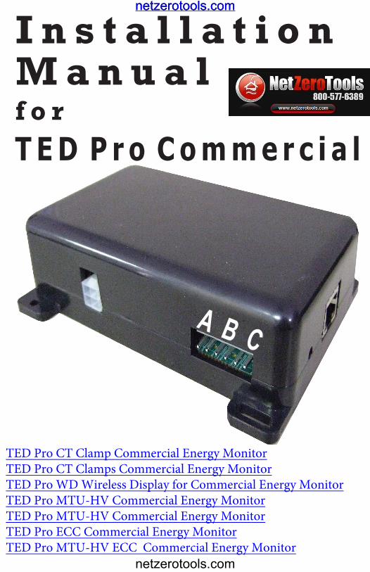
I n s t a l l a t i o n M a n u a l f o rT E D P r o C o m m e r c i a l
A B C
TED Pro CT Clamp Commercial Energy MonitorTED Pro CT Clamps Commercial Energy MonitorTED Pro WD Wireless Display for Commercial Energy MonitorTED Pro MTU-HV Commercial Energy MonitorTED Pro MTU-HV Commercial Energy Monitor TED Pro ECC Commercial Energy MonitorTED Pro MTU-HV ECC Commercial Energy Monitor
netzerotools.com
netzerotools.com
netzerotools.com
Page 2
* * * * * * * * * * * * * * * * * * * * * * * * * * * * * * * * * * * * * * * * * * * * * * * * * * * * * * * * * * * * * * * * * * * * * * * * * * * * * * * * *
* * * * * * * * * * * * * * * * * * * * * * * * * * * * * * * * * * * * * * * * *
TA B L E O F C O N T E N T S
Introduction . . . . . . . . . . . . . . . . . . . . . . . . . . . . . . Page 3Operating Conditions . . . . . . . . . . . . . . . . . . . . . . . Page 3Three phase services . . . . . . . . . . . . . . . . . . . . . . . Page 3Single-phase from 3-phase . . . . . . . . . . .. . . . . . . . Page 4Components . . . . . . . . . . . . . . . . . . . . . . . . . . . . . . Page 5
Safety . . . . . . . . . . . . . . . . . . . . . . . . . . . . . . . . . . Page 6
Installation . . . . . . . . . . . . . . . . . . . . . . . . . . . . . . Page 7
Communication Options . . . . . . . . . . . . . . . . . . Page 15MTU-to-ECC Communication via Ethernet . . . . Page 16ECC Communication via Local Area Network . . Page 17Footprints Software Installation . . . . . . . . . . . . . Page 18
Appendix A1 . . . . . . . . . . . . . . . . . . . . . . . . . . . Page 19Appendix A2 . . . . . . . . . . . . . . . . . . . . . . . . . . . Page 20Appendix A3 . . . . . . . . . . . . . . . . . . . . . . . . . . . Page 21Appendix A4 . . . . . . . . . . . . . . . . . . . . . . . . . . . Page 22Appendix A5 . . . . . . . . . . . . . . . . . . . . . . . . . . . Page 23
PART I
PART II
PART III
PART IV
Appendix
IMPORTANT:The installation of your TED Pro system is a several-step pro-cess. The 1st step is the installation of the MTU-HV. After the MTU-HV is installed, Step 2 is the installation of the ECC, and the last Step ... Footprints software.
If the equipment is used in a manner not specified by the manufacturer, the protection provided by the equipment may be impaired.
netzerotools.com
netzerotools.com

© Copyright 2013 Energy, Inc. All rights reserved www.theenergydetective.com
* * * * * * * * * * * * * * * * * * * * * * * * * * * * * * * * * * * * * * * *
* * * * * * * * * * * * * * * * * * * * * * * * * * * * * * * * * * * * * * * * *
* * * * * * * * * * * * * * * * * * * * * * * * * * * * * * * * * * * * * * * * *Page 3
* * * * * * * * * * * * * * * * * * * * * * * * * * * * * * * * * * * * * * * * *Rev 1.0.13
UseCondition
TemperatureRelative Humidity
AltitudeVoltage
Maximum Power
IndoorDry
10° - 40°C< 80%
3,300M95-265VAC
5W
Indoor/Outdoor Dry /Damp
- 40°C to +50C< 95%3,300M
200-500 VAC4.5W
Display & ECC MTU & CTs
SAFE OPERATING RANGE AND CONDITIONS:
Limitations
Please note the following limitations:• If you have a Single-Phase service, TED Pro Commercial will work. (Use TED Pro Residential
in most cases for a less-costly solution)• If your main circuit breaker or fuse panel is larger than 1200 Amps, TED WILL NOT work.• If you have more than one main circuit breaker or switch you will need to use multiple MTUs.• If your main service circuit conductors (wires) are larger than 1.25 inch diameter, TED WILL
NOT work.• Other TED models and accessories may be available for these applications. Please see
our website for details.
TED MTU 3-PHASE OPERATION
3-Phase Services• TED is designed to work on most 3-phase 50-60HZ electrical services worldwide. TED will work
on 3PH-4W Wye, 3-PH-3W Delta 1 or 3PH-4W Hi-Leg Delta services anywhere where the line-line nominal voltage is between 200VAC and 600VAC. For specific connection drawings for each type of service see Appendix.
• Common 3-Phase Electrical Services around the world include:o 200V 3PH-3W Delta (Japan)o 208Y/120V 3PH-4W Wye (North America)o 240V 3PH-3W Delta (North America)1
PA R T I – I N T R O D U C T I O N
netzerotools.com
netzerotools.com
Page 4
* * * * * * * * * * * * * * * * * * * * * * * * * * * * * * * * * * * * * * * * * * * * * * * * * * * * * * * * * * * * * * * * * * * * * * * * * * * * * * * * *
* * * * * * * * * * * * * * * * * * * * * * * * * * * * * * * * * * * * * * * * *
o 240/120 3PH-4W Hi-Leg Delta (North America)o 380Y/220V 3PH-4W Wye or 380V 3PH-3W Delta (Asia)1
o 400Y/230V3PH-4W Wye or 380V 3PH-3W Delta (Europe)1
o 415Y/240V 3PH-4W Wye or 380V 3PH-3W Delta (UK, Australia/NZ, India)1
o 480Y/277V 3PH-4W Wye or 480V 3-PH-3W Delta (North America)1
o 600/347V 3PH-4W Wye or 600V 3PH-3W Delta (Canada) 1,2
• Service voltages shown above are common systems. There are other configurations. If yours isnot listed and you are not sure, please contact Energy, Inc. Tech Support for assistance.
• TED is only suitable for services of 400 Amps or less, or up to 1200 Amps with parallel 400A feeds(May require optional CT Harness).
• TED is only suitable for services with cables that have a maximum outside diameter of 32mm(1.25”) or 700 MCM Conductors.
1 Delta Services and Wye services where voltage between line-and-neutral exceeds 250V cannot use PLC communication between the MTU and ECC. In these cases the MTU must be mounted outside the electrical panel and Ethernet communication method must be used. The MTU and ECC will need to be connected to the Local Area Network (or connected to each other via Ethernet.)
2 Services with 400A parallel feeds will require the use of a CT harness (Model ADP) and additional sets of CTs (CT301B) for each additional parallel conductor.
4 Normally TED Pro Commercial MTU is provided with 400A current transformers. For small services 200A or less, where space is limited, it is highly recommended that customer use 200A current transformers (Model CT601B). Please specify with order.
Single-Phase ServicesTED Pro Commercial is designed to work on 3-Phase services, however it is possible to configure it for single-phase services. TED Pro Residential (MTU-LV) is recommended for single-phase services and provides a much smaller, more accurate and less costly solution for single-phase services up to 400A. TED Pro Commercial MTU-HV can be configured to work on any single phase service where the line-line nominal voltage or line-to-neutral nominal voltage is between 200VAC and 250VAC. For specific connection drawings for each type of service see the Appendix.
netzerotools.com
netzerotools.com
© Copyright 2013 Energy, Inc. All rights reserved www.theenergydetective.com
* * * * * * * * * * * * * * * * * * * * * * * * * * * * * * * * * * * * * * * *
* * * * * * * * * * * * * * * * * * * * * * * * * * * * * * * * * * * * * * * * *
* * * * * * * * * * * * * * * * * * * * * * * * * * * * * * * * * * * * * * * * *Page 5
* * * * * * * * * * * * * * * * * * * * * * * * * * * * * * * * * * * * * * * * *Rev 1.0.13
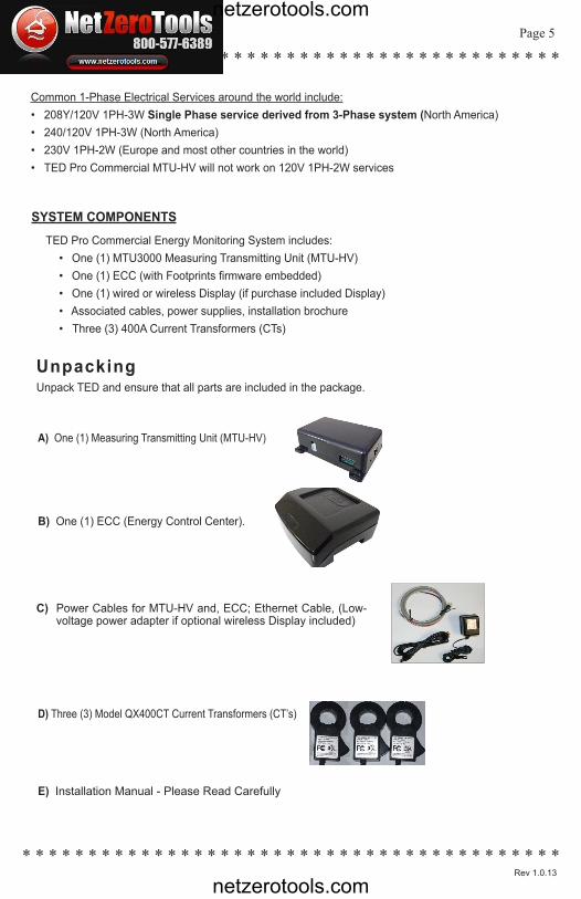
TED Pro Commercial Energy Monitoring System includes:• One (1) MTU3000 Measuring Transmitting Unit (MTU-HV)• One (1) ECC (with Footprints firmware embedded)• One (1) wired or wireless Display (if purchase included Display)• Associated cables, power supplies, installation brochure• Three (3) 400A Current Transformers (CTs)
SYSTEM COMPONENTS
Common 1-Phase Electrical Services around the world include:• 208Y/120V 1PH-3W Single Phase service derived from 3-Phase system (North America)• 240/120V 1PH-3W (North America)• 230V 1PH-2W (Europe and most other countries in the world)• TED Pro Commercial MTU-HV will not work on 120V 1PH-2W services
UnpackingUnpack TED and ensure that all parts are included in the package.
A) One (1) Measuring Transmitting Unit (MTU-HV)
D) Three (3) Model QX400CT Current Transformers (CT’s)
B) One (1) ECC (Energy Control Center).
C) Power Cables for MTU-HV and, ECC; Ethernet Cable, (Low-voltage power adapter if optional wireless Display included)
E) Installation Manual - Please Read Carefully
netzerotools.com
netzerotools.com

Page 6
* * * * * * * * * * * * * * * * * * * * * * * * * * * * * * * * * * * * * * * * * * * * * * * * * * * * * * * * * * * * * * * * * * * * * * * * * * * * * * * * *
* * * * * * * * * * * * * * * * * * * * * * * * * * * * * * * * * * * * * * * * *
PA R T I I – S A F E T Y
THE MTU AND CTs OF THE TED PRO COMMERCIAL sYsTEM MUsT BE INsTALLED BY A LICENsED ELECTRICIAN
This manual provides the steps necessary to safely install the MTU and Current Transformers (CTs). For detailed installation and operation of other components and software, please find it on the TED website: www.theenergydetective.com
Every effort has been made in providing for the safe, secure installation of TED. The installation of TED requires the cover of the main electrical circuit breaker panel to be removed. After the circuit breaker panel cover has been removed, the potential hazard of shock, burn, or even electrocution now exists. Do not attempt to complete this installation unless you are a licensed electrician familiar with the electrical components and operation of the circuit breaker panel. Even when the main circuit breaker has been turned to the “OFF” position, certain areas within the circuit breaker panel may still be electrified. Do not attempt installation unless you know where these electrified areas are.
This symbol will be found throughout the instructions where there is a po-tential for electric shock, burn, or even electrocution. Do not attempt to com-plete the noted section if you are not an electrician, or qualified installer.
WARNING - These servicing instructions are for use by qualified personnel only. To reduce the risk of electric shock, DO NOT perform any servicing other than that contained in these operational instruc-tions unless you are qualified to do so.
WARNING - The MTU must be connected to a switch or circuit breaker in close proximity to the equip-ment and within easy reach of the operator. It must be marked as the disconnecting device for the MTU.
WARNING - If the equipment is used in a manner not specified in these instructions, the protection provided by the equipment may be impaired.
TESTED TO COMPLY WITH FCC STANDARDS
FOR HOME AND OFFICE USE
EnErgy, Inc. ModEl TEd3000 / TEd Pro This device complies with part 15 of the FCC Rules.
Operation is subject to the following two conditions:
(1) This device may not cause harmful interference,
and (2) This device must accept any interference received,
including interference that may cause undesired operations.
FCC Part 15 SubPart BEU/EN 61326-1
netzerotools.com
netzerotools.com
© Copyright 2013 Energy, Inc. All rights reserved www.theenergydetective.com
* * * * * * * * * * * * * * * * * * * * * * * * * * * * * * * * * * * * * * * *
* * * * * * * * * * * * * * * * * * * * * * * * * * * * * * * * * * * * * * * * *
* * * * * * * * * * * * * * * * * * * * * * * * * * * * * * * * * * * * * * * * *Page 7
* * * * * * * * * * * * * * * * * * * * * * * * * * * * * * * * * * * * * * * * *Rev 1.0.13
B E F O R E Y O U S TA R T• Do not begin installation until you have read the “Safety” section of this manual.• Read all instructions before beginning installation.
Estimated Installation Time:Professional Installer: 30 minutes
Equipment Needed:- Flathead screwdriver - small and large- Phillips screwdriver - small and large- Flashlight
QUALIFIED ELECTRICIANS OR PROFESSIONAL INSTALLERS FAMILIAR WITH ALL ASPECTS OF ELECTRICAL WIRING AND THEORY MAY USE THE FOLLOWING INSTRUCTIONS FOR INSTALLATION OF TED PRO COMMERCIAL MTU.
TED will work on single-phase services, however TED Pro Residential will prove to be a smaller and more cost effective solution. For services where there are two-or-more main circuit breaker panels you will need one additional MTU for each main circuit breaker or panel.
For services with Wind/Solar or Standby Generator, an additional MTU will be required to measure GENERATION and NET.
All wiring in the United States must be installed in accordance with the latest adopted edition of the Na-tional Electrical Code (ANSI/NFPA 70, NEC) and state or local requirements. All wiring in Canada must be installed in accordance with the latest adopted edition of the Canadian Electrical Code (CSA C22.2 CEC, Part I) and any provincial or local requirements.
Wiring in other countries and jurisdictions should be done in accordance with the rules and regulations in effect for the installing location. Contact your local power authority or local regulator for more information.
PA R T I I I – I N S TA L L AT I O N
netzerotools.com
netzerotools.com
Page 8
* * * * * * * * * * * * * * * * * * * * * * * * * * * * * * * * * * * * * * * * * * * * * * * * * * * * * * * * * * * * * * * * * * * * * * * * * * * * * * * * *
* * * * * * * * * * * * * * * * * * * * * * * * * * * * * * * * * * * * * * * * *
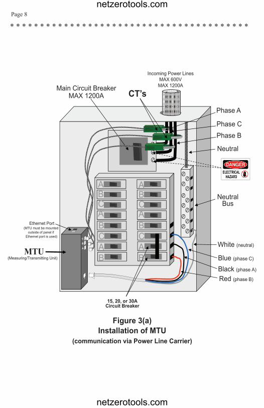
Figure 3(a)Installation of MTU
(communication via Power Line Carrier)
Neutral
Phase C
Phase A
Incoming Power LinesMAX 600VMAX 1200A
White (neutral)
Black (phase A)
NeutralBus
15, 20, or 30ACircuit Breaker
CT’sMain Circuit BreakerMAX 1200A
ABCABCAB
ABCABCAB
Red (phase B)
Phase B
Blue (phase C)MTU
(Measuring/Transmitting Unit)
Ethernet Port(MTU must be mounted
outside of panel ifEthernet port is used)
C
B
A
netzerotools.com
netzerotools.com
© Copyright 2013 Energy, Inc. All rights reserved www.theenergydetective.com
* * * * * * * * * * * * * * * * * * * * * * * * * * * * * * * * * * * * * * * *
* * * * * * * * * * * * * * * * * * * * * * * * * * * * * * * * * * * * * * * * *
* * * * * * * * * * * * * * * * * * * * * * * * * * * * * * * * * * * * * * * * *Page 9
* * * * * * * * * * * * * * * * * * * * * * * * * * * * * * * * * * * * * * * * *Rev 1.0.13
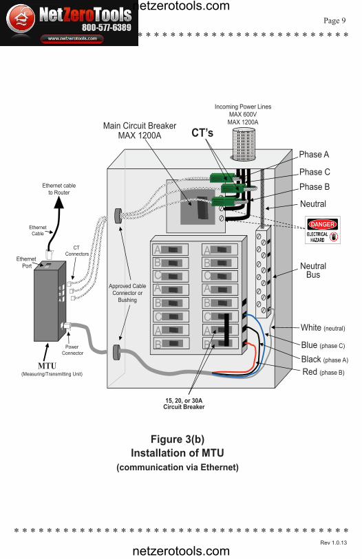
Figure 3(b)Installation of MTU
(communication via Ethernet)
Neutral
Phase C
Phase A
Incoming Power LinesMAX 600VMAX 1200A
White (neutral)
Black (phase A)
NeutralBus
15, 20, or 30ACircuit Breaker
CT’sMain Circuit BreakerMAX 1200A
ABCABCAB
ABCABCAB
Red (phase B)
Phase B
Blue (phase C)MTU
(Measuring/Transmitting Unit)
Ethernet Port(MTU must be mounted
outside of panel ifEthernet port is used)
C
B
A
Neutral
Phase C
Phase A
Incoming Power LinesMAX 600VMAX 1200A
White (neutral)
Black (phase A)
NeutralBus
15, 20, or 30ACircuit Breaker
CT’sMain Circuit BreakerMAX 1200A
ABCABCAB
ABCABCAB
Red (phase B)
Phase B
Blue (phase C)
MTU(Measuring/Transmitting Unit)
EthernetPort
Power Connector
CTConnectors
Approved Cable Connector or
Bushing
Ethernet cableto Router
EthernetCable
CBA
netzerotools.com
netzerotools.com
Page 10
* * * * * * * * * * * * * * * * * * * * * * * * * * * * * * * * * * * * * * * * * * * * * * * * * * * * * * * * * * * * * * * * * * * * * * * * * * * * * * * * *
* * * * * * * * * * * * * * * * * * * * * * * * * * * * * * * * * * * * * * * * *
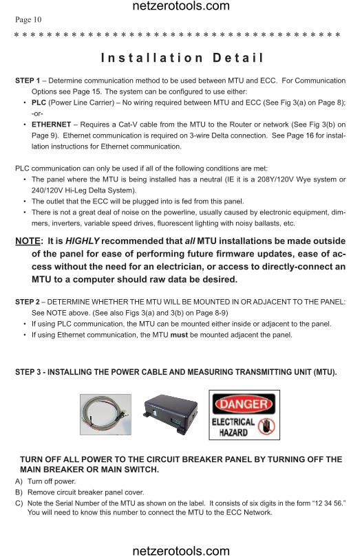
STEP 1 – Determine communication method to be used between MTU and ECC. For Communication Options see Page 15. The system can be configured to use either:
• PLC (Power Line Carrier) – No wiring required between MTU and ECC (See Fig 3(a) on Page 8);-or-
• ETHERNET – Requires a Cat-V cable from the MTU to the Router or network (See Fig 3(b) onPage 9). Ethernet communication is required on 3-wire Delta connection. See Page 16 for instal-lation instructions for Ethernet communication.
PLC communication can only be used if all of the following conditions are met:• The panel where the MTU is being installed has a neutral (IE it is a 208Y/120V Wye system or
240/120V Hi-Leg Delta System).• The outlet that the ECC will be plugged into is fed from this panel.• There is not a great deal of noise on the powerline, usually caused by electronic equipment, dim-
mers, inverters, variable speed drives, fluorescent lighting with noisy ballasts, etc.
NOTE: It is HIGHLY recommended that all MTU installations be made outside of the panel for ease of performing future firmware updates, ease of ac-cess without the need for an electrician, or access to directly-connect an MTU to a computer should raw data be desired.
STEP 2 – DETERMINE WHETHER THE MTU WILL BE MOUNTED IN OR ADJACENT TO THE PANEL: See NOTE above. (See also Figs 3(a) and 3(b) on Page 8-9)
• If using PLC communication, the MTU can be mounted either inside or adjacent to the panel.• If using Ethernet communication, the MTU must be mounted adjacent the panel.
I n s t a l l a t i o n D e t a i l
STEP 3 - INSTALLING THE POWER CABLE AND MEASURING TRANSMITTING UNIT (MTU).
TURN OFF ALL POWER TO THE CIRCUIT BREAKER PANEL BY TURNING OFF THE MAIN BREAKER OR MAIN SWITCH.
A) Turn off power.B) Remove circuit breaker panel cover.C) Note the Serial Number of the MTU as shown on the label. It consists of six digits in the form “12 34 56.”
You will need to know this number to connect the MTU to the ECC Network.
netzerotools.com
netzerotools.com
© Copyright 2013 Energy, Inc. All rights reserved www.theenergydetective.com
* * * * * * * * * * * * * * * * * * * * * * * * * * * * * * * * * * * * * * * *
* * * * * * * * * * * * * * * * * * * * * * * * * * * * * * * * * * * * * * * * *
* * * * * * * * * * * * * * * * * * * * * * * * * * * * * * * * * * * * * * * * *Page 11
* * * * * * * * * * * * * * * * * * * * * * * * * * * * * * * * * * * * * * * * *Rev 1.0.13
D) Connect the black, red and blue wires from the MTU power cord to a spare 15,20 or 30 Amp three-pole circuit breaker in the panel. See Appendix for specific wiring diagrams for your system.
E) If there is no spare circuit breaker, the black/red/blue wires can be attached to any 15, 20 or 30Amp 3-pole circuit breaker in the panel, provided that the circuit breaker is approved for 2 conduc-tors and this is acceptable to the “authority having jurisdiction in the installation location” (it is generallyacceptable); If a 3-pole circuit breaker is not available, then use an approved handle-tie to create one.
NOTE 1: The black, red and blue wires will normally connect to the corresponding 3 phases on the cir-cuit breaker (IE Black wire to Phase A, Red wire to Phase B and Blue wire to phase C). The CT inputs on the MTU are left-to-right: Phase A, Phase B, Phase C (see image on front cover of this booklet) and must be matched to the corresponding wires for proper readings. Some Canadian Standards may have phases marked differently in the panel, this doesn’t matter as long as the MTU power cable wires and CT inputs correspond.
NOTE 2: For optimal PLC Communication, the ECC should be plugged into a circuit on the same phase as the black wire on the MTU power cable. If the ECC cannot be connected to phase A, the black MTU wire may be swapped with the Phase B or Phase C wires, but the corresponding CTs must also be swapped for proper readings.
NOTE 3: For Ethernet Communication, (HTTP post), the circuit to which the ECC is connected does not matter.
F) If the system has a neutral, connect the white wire from the MTU to the neutral bus on the panel.NOTE 4: If there is no neutral, tape or place a wire nut over the conductor and coil neatly.G) Do not connect the Power Cable to the MTU until you have the CTs connected.
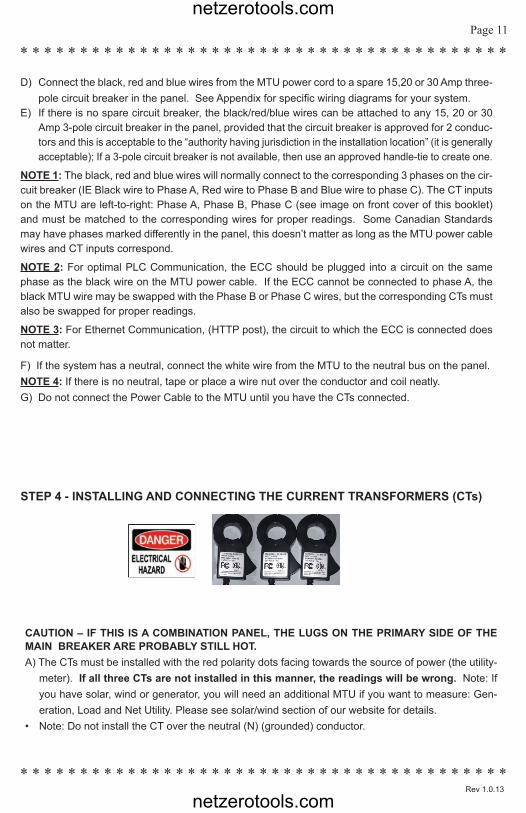
STEP 4 - INSTALLING AND CONNECTING THE CURRENT TRANSFORMERS (CTs)
CAUTION – IF THIS IS A COMBINATION PANEL, THE LUGS ON THE PRIMARY SIDE OF THE MAIN BREAKER ARE PROBABLY STILL HOT.A) The CTs must be installed with the red polarity dots facing towards the source of power (the utility-
meter). If all three CTs are not installed in this manner, the readings will be wrong. Note: If you have solar, wind or generator, you will need an additional MTU if you want to measure: Gen-eration, Load and Net Utility. Please see solar/wind section of our website for details.
• Note: Do not install the CT over the neutral (N) (grounded) conductor.
netzerotools.com
netzerotools.com
Page 12
* * * * * * * * * * * * * * * * * * * * * * * * * * * * * * * * * * * * * * * * * * * * * * * * * * * * * * * * * * * * * * * * * * * * * * * * * * * * * * * * *
* * * * * * * * * * * * * * * * * * * * * * * * * * * * * * * * * * * * * * * * *
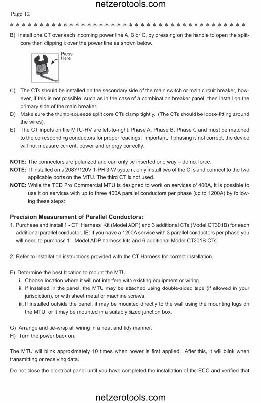
B) Install one CT over each incoming power line A, B or C, by pressing on the handle to open the split-core then clipping it over the power line as shown below.
C) The CTs should be installed on the secondary side of the main switch or main circuit breaker, how-ever, if this is not possible, such as in the case of a combination breaker panel, then install on theprimary side of the main breaker.
D) Make sure the thumb-squeeze split core CTs clamp tightly. (The CTs should be loose-fitting aroundthe wires).
E) The CT inputs on the MTU-HV are left-to-right: Phase A, Phase B, Phase C and must be matchedto the corresponding conductors for proper readings. Important, if phasing is not correct, the devicewill not measure current, power and energy correctly.
NOTE: The connectors are polarized and can only be inserted one way – do not force.NOTE: If installed on a 208Y/120V 1-PH 3-W system, only install two of the CTs and connect to the two
applicable ports on the MTU. The third CT is not used.NOTE: While the TED Pro Commercial MTU is designed to work on services of 400A, it is possible to
use it on services with up to three 400A parallel conductors per phase (up to 1200A) by follow-ing these steps:
Precision Measurement of Parallel Conductors:1. Purchase and install 1 - CT Harness Kit (Model ADP) and 3 additional CTs (Model CT301B) for each
additional parallel conductor. IE: If you have a 1200A service with 3 parallel conductors per phase you will need to purchase 1 - Model ADP harness kits and 6 additional Model CT301B CTs.
2. Refer to installation instructions provided with the CT Harness for correct installation.
F) Determine the best location to mount the MTU.i. Choose location where it will not interfere with existing equipment or wiring.ii. If installed in the panel, the MTU may be attached using double-sided tape (if allowed in your
jurisdiction), or with sheet metal or machine screws.iii. If installed outside the panel, it may be mounted directly to the wall using the mounting lugs on
the MTU, or it may be mounted in a suitably sized junction box.
G) Arrange and tie-wrap all wiring in a neat and tidy manner.H) Turn the power back on.
The MTU will blink approximately 10 times when power is first applied. After this, it will blink when transmitting or receiving data.
Do not close the electrical panel until you have completed the installation of the ECC and verified that
PressHere
netzerotools.com
netzerotools.com
© Copyright 2013 Energy, Inc. All rights reserved www.theenergydetective.com
* * * * * * * * * * * * * * * * * * * * * * * * * * * * * * * * * * * * * * * *
* * * * * * * * * * * * * * * * * * * * * * * * * * * * * * * * * * * * * * * * *
* * * * * * * * * * * * * * * * * * * * * * * * * * * * * * * * * * * * * * * * *Page 13
* * * * * * * * * * * * * * * * * * * * * * * * * * * * * * * * * * * * * * * * *Rev 1.0.13
correct data is being received from the MTU.
Close the Electrical Panel only after you have confirmed the correct operation of TED,
Step 5 – ETHERNET WIRING• Neatly run a CAT-V cable from the MTU to the customer’s router or network location. Be sure to
use plenum-rated cables where required. Neatly route, protect and secure the cable.• Make the connections and plug into MTU and Router.
Step 6 – TESTING THE SYSTEM:EVEN IF THE CUSTOMER CHOOSES TO CONFIGURE THE ECC, DISPLAY AND NETWORK, IT IS EXTREMELY IMPORTANT THAT THE INSTALLING ELECTRICIAN VERIFY CORRECT OPERATION AND MEASUREMENT PRIOR TO LEAVING THE SITE.
ECC CONNECTION• Select an electrical outlet free of other connections and connect ECC power cord. (Must be on
same phase as MTU black power wire.)• Connect provided Ethernet cable from ECC to available port in network router.
TESTING PLC COMMUNICATION• Insure that the left LED on the MTU is blinking orange or green regularly every one or two sec-
onds. This verifies PLC connection. If orange, verify MTU-ID in ECC via EDIT-System Settings.• Insure that the LED on the right side of the ECC is blinking Red/Green. This confirms that the
ECC is sending/receiving data from the MTU.
netzerotools.com
netzerotools.com

Page 14
* * * * * * * * * * * * * * * * * * * * * * * * * * * * * * * * * * * * * * * * * * * * * * * * * * * * * * * * * * * * * * * * * * * * * * * * * * * * * * * * *
* * * * * * * * * * * * * * * * * * * * * * * * * * * * * * * * * * * * * * * * *
TESTING MTU INSTALLATION• The best way to test the system is with all components (MTU, ECC, Display, Computer) connected
and operational.• If this is not possible, the installer can use a laptop or PC to test the system by connecting the MTU
to the laptop/PC with a CAT-V Ethernet patch cable.• See the next section for system connection options which include viewing the real-time information
on the MTU “stats” page.
Step 7 – Refer to Installation Detail on Page 16 for detailed instructions on installing the ECC.
NOTE: For an Ethernet-connected MTU: Connect the ECC per above (refer to TED Installation Utility on Page 18 - item 1). Once the utility has located the TED Pro Commercial on the network, highlight appropriate TED Pro and select “Launch in Browser.” When the TED Pro Commercial user interface opens, select “Post to HTTP” check box. Then carefully type in the IP that the Installation Utility has returned for the TED Pro ECC into the ECC IP field, select Save. (This setting will DISABLE the Power Line Carrier of this MTU.) Refer to Footprints manual or Quick Start Guide to complete ECC setup and test functionality.
netzerotools.com
netzerotools.com
© Copyright 2013 Energy, Inc. All rights reserved www.theenergydetective.com
* * * * * * * * * * * * * * * * * * * * * * * * * * * * * * * * * * * * * * * *
* * * * * * * * * * * * * * * * * * * * * * * * * * * * * * * * * * * * * * * * *
* * * * * * * * * * * * * * * * * * * * * * * * * * * * * * * * * * * * * * * * *Page 15
* * * * * * * * * * * * * * * * * * * * * * * * * * * * * * * * * * * * * * * * *Rev 1.0.13
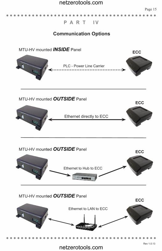
Communication Options
MTU-HV mounted INSIDE Panel ECC
PLC - Power Line Carrier
MTU-HV mounted OUTSIDE PanelECC
Ethernet directly to ECC
MTU-HV mounted OUTSIDE Panel ECC
Ethernet to Hub to ECC
MTU-HV mounted OUTSIDE PanelECC
Ethernet to LAN to ECC
P A R T I V
netzerotools.com
netzerotools.com
Page 16
* * * * * * * * * * * * * * * * * * * * * * * * * * * * * * * * * * * * * * * * * * * * * * * * * * * * * * * * * * * * * * * * * * * * * * * * * * * * * * * * *
* * * * * * * * * * * * * * * * * * * * * * * * * * * * * * * * * * * * * * * * *
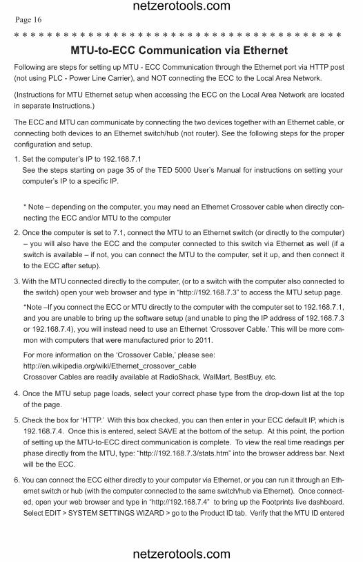
MTU-to-ECC Communication via EthernetFollowing are steps for setting up MTU - ECC Communication through the Ethernet port via HTTP post (not using PLC - Power Line Carrier), and NOT connecting the ECC to the Local Area Network.
(Instructions for MTU Ethernet setup when accessing the ECC on the Local Area Network are located in separate Instructions.)
The ECC and MTU can communicate by connecting the two devices together with an Ethernet cable, or connecting both devices to an Ethernet switch/hub (not router). See the following steps for the proper configuration and setup.
1. Set the computer’s IP to 192.168.7.1See the steps starting on page 35 of the TED 5000 User’s Manual for instructions on setting your computer’s IP to a specific IP.
* Note – depending on the computer, you may need an Ethernet Crossover cable when directly con-necting the ECC and/or MTU to the computer
2. Once the computer is set to 7.1, connect the MTU to an Ethernet switch (or directly to the computer)– you will also have the ECC and the computer connected to this switch via Ethernet as well (if aswitch is available – if not, you can connect the MTU to the computer, set it up, and then connect it to the ECC after setup).
3. With the MTU connected directly to the computer, (or to a switch with the computer also connected tothe switch) open your web browser and type in “http://192.168.7.3” to access the MTU setup page.
*Note –If you connect the ECC or MTU directly to the computer with the computer set to 192.168.7.1,and you are unable to bring up the software setup (and unable to ping the IP address of 192.168.7.3 or 192.168.7.4), you will instead need to use an Ethernet ‘Crossover Cable.’ This will be more com-mon with computers that were manufactured prior to 2011.
For more information on the ‘Crossover Cable,’ please see: http://en.wikipedia.org/wiki/Ethernet_crossover_cableCrossover Cables are readily available at RadioShack, WalMart, BestBuy, etc.
4. Once the MTU setup page loads, select your correct phase type from the drop-down list at the topof the page.
5. Check the box for ‘HTTP.’ With this box checked, you can then enter in your ECC default IP, which is192.168.7.4. Once this is entered, select SAVE at the bottom of the setup. At this point, the portionof setting up the MTU-to-ECC direct communication is complete. To view the real time readings perphase directly from the MTU, type: “http://192.168.7.3/stats.htm” into the browser address bar. Nextwill be the ECC.
6. You can connect the ECC either directly to your computer via Ethernet, or you can run it through an Eth-ernet switch or hub (with the computer connected to the same switch/hub via Ethernet). Once connect-ed, open your web browser and type in “http://192.168.7.4” to bring up the Footprints live dashboard.Select EDIT > SYSTEM SETTINGS WIZARD > go to the Product ID tab. Verify that the MTU ID entered
netzerotools.com
netzerotools.com
© Copyright 2013 Energy, Inc. All rights reserved www.theenergydetective.com
* * * * * * * * * * * * * * * * * * * * * * * * * * * * * * * * * * * * * * * *
* * * * * * * * * * * * * * * * * * * * * * * * * * * * * * * * * * * * * * * * *
* * * * * * * * * * * * * * * * * * * * * * * * * * * * * * * * * * * * * * * * *Page 17
* * * * * * * * * * * * * * * * * * * * * * * * * * * * * * * * * * * * * * * * *Rev 1.0.13
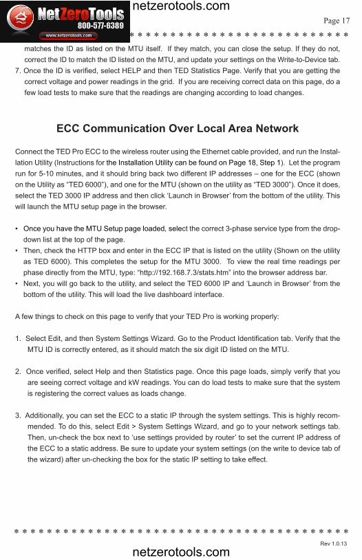
matches the ID as listed on the MTU itself. If they match, you can close the setup. If they do not, correct the ID to match the ID listed on the MTU, and update your settings on the Write-to-Device tab.
7. Once the ID is verified, select HELP and then TED Statistics Page. Verify that you are getting thecorrect voltage and power readings in the grid. If you are receiving correct data on this page, do afew load tests to make sure that the readings are changing according to load changes.
ECC Communication Over Local Area Network
Connect the TED Pro ECC to the wireless router using the Ethernet cable provided, and run the Instal-lation Utility (Instructions for the Installation Utility can be found on Page 18, Step 1). Let the program run for 5-10 minutes, and it should bring back two different IP addresses – one for the ECC (shown on the Utility as “TED 6000”), and one for the MTU (shown on the utility as “TED 3000”). Once it does, select the TED 3000 IP address and then click ‘Launch in Browser’ from the bottom of the utility. This will launch the MTU setup page in the browser.
• Once you have the MTU Setup page loaded, select the correct 3-phase service type from the drop-down list at the top of the page.
• Then, check the HTTP box and enter in the ECC IP that is listed on the utility (Shown on the utilityas TED 6000). This completes the setup for the MTU 3000. To view the real time readings perphase directly from the MTU, type: “http://192.168.7.3/stats.htm” into the browser address bar.
• Next, you will go back to the utility, and select the TED 6000 IP and ‘Launch in Browser’ from thebottom of the utility. This will load the live dashboard interface.
A few things to check on this page to verify that your TED Pro is working properly:
1. Select Edit, and then System Settings Wizard. Go to the Product Identification tab. Verify that theMTU ID is correctly entered, as it should match the six digit ID listed on the MTU.
2. Once verified, select Help and then Statistics page. Once this page loads, simply verify that youare seeing correct voltage and kW readings. You can do load tests to make sure that the systemis registering the correct values as loads change.
3. Additionally, you can set the ECC to a static IP through the system settings. This is highly recom-mended. To do this, select Edit > System Settings Wizard, and go to your network settings tab.Then, un-check the box next to ‘use settings provided by router’ to set the current IP address ofthe ECC to a static address. Be sure to update your system settings (on the write to device tab ofthe wizard) after un-checking the box for the static IP setting to take effect.
netzerotools.com
netzerotools.com

Page 18
* * * * * * * * * * * * * * * * * * * * * * * * * * * * * * * * * * * * * * * * * * * * * * * * * * * * * * * * * * * * * * * * * * * * * * * * * * * * * * * * *
* * * * * * * * * * * * * * * * * * * * * * * * * * * * * * * * * * * * * * * * *
Footprints Software Setup After you have installed your MTU-HV and ECC, follow these instructions to complete your setup:
Installing Footprints Software:
1) Go to the following link and download the TED Pro Installation Utility appropriate for your com-puter (Windows, Mac, or Linux):http://www.theenergydetective.com/downloads-documents
2) Run the Installation UtilityAfter the Utility locates your ECC-IP address, highlight the ECC-line (it may say “TED6000”) select“launch in browser.”
NOTE: After you have selected “Launch in Browser” you will see a grey-screen and “Loading” should appear, followed by the Footprints dashboard. If your computer screen appears to freeze on the grey-colored screen, please clear your cache and relaunch in browser.
Connecting TED to your Computer/Router:
To connect TED to your router, please visit: http://www.theenergydetective.com/router
To connect TED directly to your computer, please visit: http://www.theenergydetective.com/computer
Once you launch TED Footprints, go to the HELP tab, click the User Manual download.
netzerotools.com
netzerotools.com
© Copyright 2013 Energy, Inc. All rights reserved www.theenergydetective.com
* * * * * * * * * * * * * * * * * * * * * * * * * * * * * * * * * * * * * * * *
* * * * * * * * * * * * * * * * * * * * * * * * * * * * * * * * * * * * * * * * *
* * * * * * * * * * * * * * * * * * * * * * * * * * * * * * * * * * * * * * * * *Page 19
* * * * * * * * * * * * * * * * * * * * * * * * * * * * * * * * * * * * * * * * *Rev 1.0.13
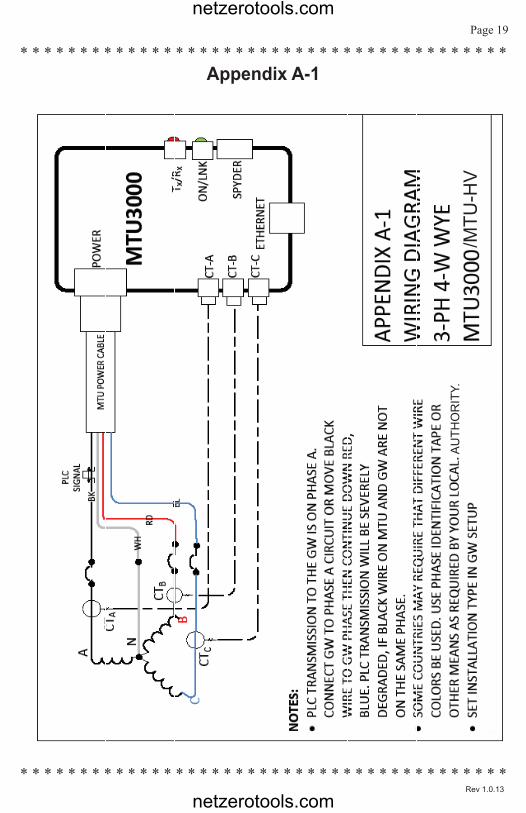
Appendix A-1
AU
THO
RIT
Y./M
TU-H
V
netzerotools.com
netzerotools.com
Page 20
* * * * * * * * * * * * * * * * * * * * * * * * * * * * * * * * * * * * * * * * * * * * * * * * * * * * * * * * * * * * * * * * * * * * * * * * * * * * * * * * *
* * * * * * * * * * * * * * * * * * * * * * * * * * * * * * * * * * * * * * * * *
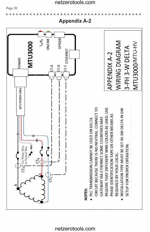
Appendix A-2Ti
e W
hite
Wire
to
Neu
tral B
us
/MTU
-HV
netzerotools.com
netzerotools.com
© Copyright 2013 Energy, Inc. All rights reserved www.theenergydetective.com
* * * * * * * * * * * * * * * * * * * * * * * * * * * * * * * * * * * * * * * *
* * * * * * * * * * * * * * * * * * * * * * * * * * * * * * * * * * * * * * * * *
* * * * * * * * * * * * * * * * * * * * * * * * * * * * * * * * * * * * * * * * *Page 21
* * * * * * * * * * * * * * * * * * * * * * * * * * * * * * * * * * * * * * * * *Rev 1.0.13
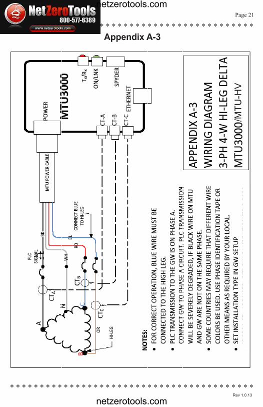
Appendix A-3
/MTU
-HV
netzerotools.com
netzerotools.com
Page 22
* * * * * * * * * * * * * * * * * * * * * * * * * * * * * * * * * * * * * * * * * * * * * * * * * * * * * * * * * * * * * * * * * * * * * * * * * * * * * * * * *
* * * * * * * * * * * * * * * * * * * * * * * * * * * * * * * * * * * * * * * * *
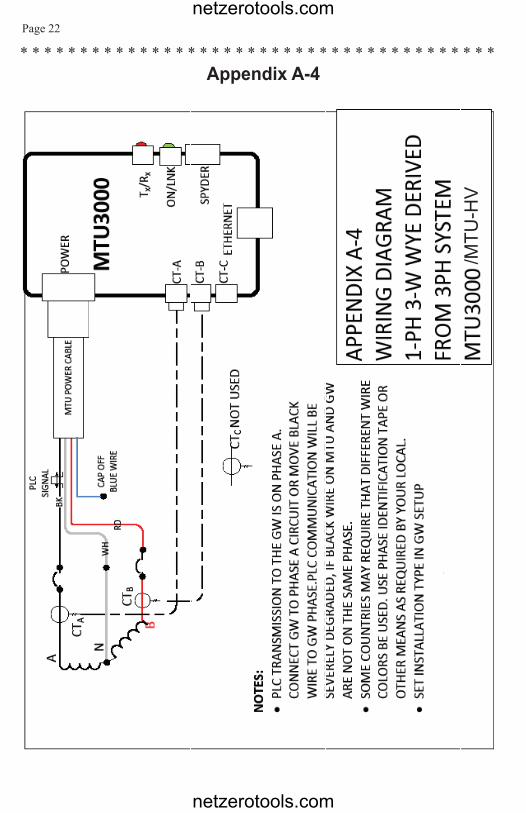
Appendix A-4
/MTU
-HV
netzerotools.com
netzerotools.com
© Copyright 2013 Energy, Inc. All rights reserved www.theenergydetective.com
* * * * * * * * * * * * * * * * * * * * * * * * * * * * * * * * * * * * * * * *
* * * * * * * * * * * * * * * * * * * * * * * * * * * * * * * * * * * * * * * * *
* * * * * * * * * * * * * * * * * * * * * * * * * * * * * * * * * * * * * * * * *Page 23
* * * * * * * * * * * * * * * * * * * * * * * * * * * * * * * * * * * * * * * * *Rev 1.0.13
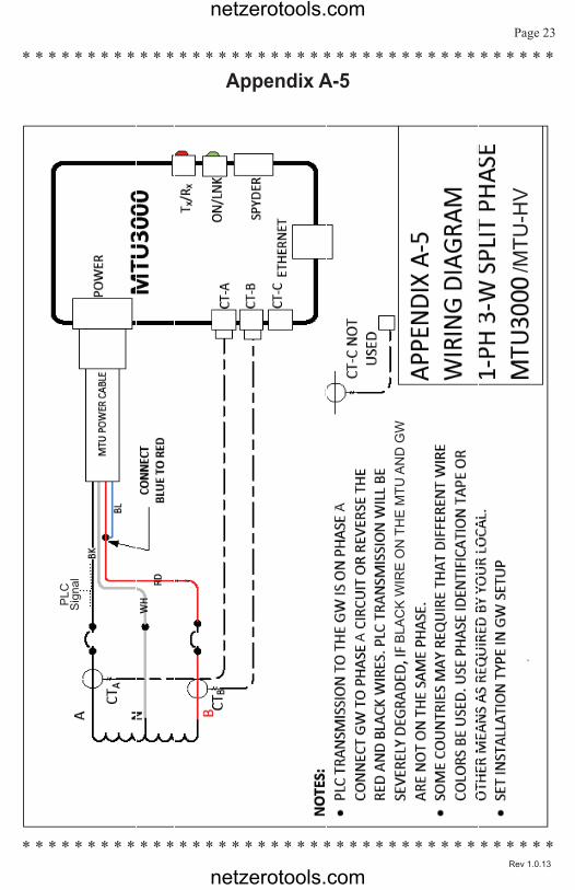
Appendix A-5
AA
PLC
Sig
nal
BLA
CK
WIR
E O
N T
HE
MTU
AN
D G
W
/MTU
-HV
netzerotools.com
netzerotools.com

ENERGY INC.
netzerotools.com
netzerotools.com
Related Documents