I-MATIC CONTROLLER FLOW METERING SYSTEM Installation and User Guide APRIL 2006 I-MATIC Version 1A Auper Electronic Controls Inc

Welcome message from author
This document is posted to help you gain knowledge. Please leave a comment to let me know what you think about it! Share it to your friends and learn new things together.
Transcript

I-MATIC CONTROLLER FLOW METERING SYSTEM Installation and User Guide
APRIL 2006 I-MATIC Version 1A Auper Electronic Controls Inc
I-Matic Portion Controller Installation Guide I50660-E
For more information on Auper products, please visit our web site at www.auper.com Page 1
Content 2
2
I-MATIC PORTION CONTROL SYSTEM 3
GENERAL INFORMATION 3
Caracteristics 3
POWER SOURCE 4
FLOW METERS 4
SOFT DRINK AND JUICE 5 PRE-MIX 5 POST-MIX 5
INSTALLING THE TAILPIECES 5
FOBS 5
TEED BEER LINES: 5
INSTALLATION OF THE FLOW METERS 6
DRAFT BEER AND WINE 6
SOFT DRINK 6
CARBONATED WATER: 6
SYRUPS: 6
CONNECTING THE FLOW METERS TO SERIAL COLLECTOR 7
CONNECTING THE SERIAL COLLECTOR TO THE I-MATIC CONTROLLER 7
INSTALLING THE IMATIC BEER FAUCETS 8
TESTING THE FLOW METER CONNECTIONS 8
CALIBRATING THE IMATIC SYSTEM 9
CALIBRATION: (KEY ON PROG.) 9
PROGRAMMING MODES (POS DISABLED) 10
INTERFACE PROGRAMMING MODE (POS ENABLED) 12
TIME OUT DELAY: 12
OPERATION ( KEY ON "RUN" ) 13
TROUBLE SHOOTING FOAMY DRAFT BEER 14
I-Matic Portion Controller Installation Guide I50660-E
For more information on Auper products, please visit our web site at www.auper.com Page 2
WARRANTY
Auper Electronic Controls Inc warrants that this product is in good working condition, according to its
specifications at the time of the shipment, for a period of one (1) year from the date of purchase.
Should the product, in Auper Electronic Controls opinion, malfunction within the warranty period,
Auper Electronic Controls Inc will repair or replace the product without charge.
Any replaced part becomes the property of Auper Electronic Controls Inc. This warranty does not
apply to the software component of a product or a product which has been damaged due to an
accident, misuse, abuse, improper installation, usage not in accordance with product specifications
and instructions, natural or personal disaster or unauthorized alterations, repairs or modifications.
LIMITATIONS
All warranty for this product, expressed or implied, are limited to one year from the date of purchase
and no warranty, expressed or implied, will apply after that period.
No warranties for this product expressed or implied will apply to any person who purchases the
product in used condition.
The liability of Auper Electronic Controls Inc with respect to any defective product will be limited to
the repair or replacement of such product.
In no event shall Auper Electronic Controls Inc be responsible or liable for any damages arising
(a) from the use of the product;
(b) from the loss of use, revenue or profit of the product; or
(c) as a result of any event, circumstances, action or abuse beyond the control of Auper Electronic Controls Inc ; whether such damage be direct, indirect, consequential, special or otherwise and whether such damages are incurred by the person to whom this warranty extends or a third part
I-Matic Portion Controller Installation Guide I50660-E
For more information on Auper products, please visit our web site at www.auper.com Page 3
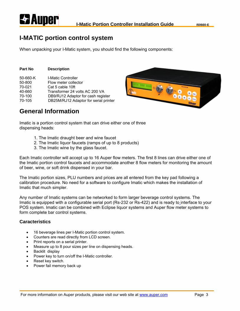
I-MATIC portion control system When unpacking your I-Matic system, you should find the following components: Part No Description 50-660-K I-Matic Controller 50-800 Flow meter collector 70-021 Cat 5 cable 10ft 40-660 Transformer 24 volts AC 200 VA 70-100 DB9/RJ12 Adaptor for cash register 70-105 DB25M/RJ12 Adaptor for serial printer
General Information Imatic is a portion control system that can drive either one of three dispensing heads: 1. The Imatic draught beer and wine faucet 2. The Imatic liquor faucets (ramps of up to 8 products) 3. The Imatic wine by the glass faucet. Each Imatic controller will accept up to 16 Auper flow meters. The first 8 lines can drive either one of the Imatic portion control faucets and accommodate another 8 flow meters for monitoring the amount of beer, wine, or soft drink dispensed in your bar. The Imatic portion sizes, PLU numbers and prices are all entered from the key pad following a calibration procedure. No need for a software to configure Imatic which makes the installation of Imatic that much simpler. Any number of Imatic systems can be networked to form larger beverage control systems. The Imatic is equipped with a configurable serial port (Rs-232 or Rs-422) and is ready to interface to your POS system. Imatic can be combined with Eclipse liquor systems and Auper flow meter systems to form complete bar control systems. Caracteristics
• 16 beverage lines per I-Matic portion control system. • Counters are read directly from LCD screen. • Print reports on a serial printer. • Measure up to 8 pour sizes per line on dispensing heads. • Backlit display • Power key to turn on/off the I-Matic controller. • Reset key switch. • Power fail memory back up
I-Matic Portion Controller Installation Guide I50660-E
For more information on Auper products, please visit our web site at www.auper.com Page 4
Power source The I-Matic controller is powered by a 24 volts @ 200VA transformer. Each system must have its own separate power source. It is recommended to use a “clean” electrical outlet. If you feel that your I-Matic may be exposed to extreme electrical power fluctuations or spikes, you may want to use a UPS system. UPS stands for “Uninterruptible Power Supply”. The UPS is equipped with proper power surge protection and a battery back up. It could be used for other equipment as well. In case of power failure, your system will remain ON for a while on battery power. UPS systems are available at office supply stores.
Customer Support AUPER provides telephone support for all its products, available Monday to Friday from 9 Am to 5 pm (Eastern Standard Time), except on Holidays. If you have any questions regarding your new I-Matic Controller, don’t hesitate to call the AUPER technical support help desk at 1-800-861-1620.
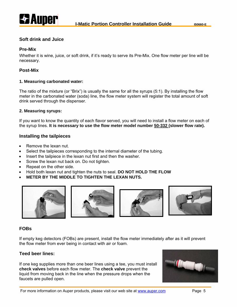
Flow Meters John Guest fitting are available for 3/8” and ½’’ external diameter tubing. DO NOT HOLD THE FLOW METER BY THE MIDDLE TO TIGHTEN THE JG FITTINGS. Tailpieces: • Use stainless steel tailpieces for carbonated water, syrups and wine. • Use chrome plated tailpieces for draft beer. • Hand tighten the plastic nuts at room temperature. When the washers are cold, sealing the adaptors may be difficult. Caution: Install the flow meter at least 30 cm (12 inches) from transformers, blowing fans or motors. These devices emit a magnetic field (60Hz), which can be picked up by the flow meter. If the counter moves without any liquid being dispensed, move the flow meter away from the source.
I-Matic Portion Controller Installation Guide I50660-E
For more information on Auper products, please visit our web site at www.auper.com Page 5
Soft drink and Juice
Pre-Mix Whether it is wine, juice, or soft drink, if it’s ready to serve its Pre-Mix. One flow meter per line will be necessary.
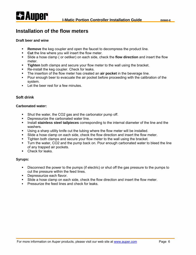
Post-Mix 1. Measuring carbonated water: The ratio of the mixture (or “Brix”) is usually the same for all the syrups (5:1). By installing the flow meter in the carbonated water (soda) line, the flow meter system will register the total amount of soft drink served through the dispenser. 2. Measuring syrups: If you want to know the quantity of each flavor served, you will need to install a flow meter on each of the syrup lines. It is necessary to use the flow meter model number 50-332 (slower flow rate). Installing the tailpieces • Remove the lexan nut. • Select the tailpieces corresponding to the internal diameter of the tubing. • Insert the tailpiece in the lexan nut first and then the washer. • Screw the lexan nut back on. Do not tighten. • Repeat on the other side. • Hold both lexan nut and tighten the nuts to seal. DO NOT HOLD THE FLOW • METER BY THE MIDDLE TO TIGHTEN THE LEXAN NUTS.
FOBs If empty keg detectors (FOBs) are present, install the flow meter immediately after as it will prevent the flow meter from ever being in contact with air or foam. Teed beer lines: If one keg supplies more than one beer lines using a tee, you must install check valves before each flow meter. The check valve prevent the liquid from moving back in the line when the pressure drops when the faucets are pulled open.
I-Matic Portion Controller Installation Guide I50660-E
For more information on Auper products, please visit our web site at www.auper.com Page 6
Installation of the flow meters Draft beer and wine
Remove the keg coupler and open the faucet to decompress the product line. Cut the line where you will insert the flow meter. Slide a hose clamp ( or oetiker) on each side, check the flow direction and insert the flow
meter. Tighten both clamps and secure your flow meter to the wall using the bracket. Re-install the keg coupler. Check for leaks. The insertion of the flow meter has created an air pocket in the beverage line. Pour enough beer to evacuate the air pocket before proceeding with the calibration of the
system. Let the beer rest for a few minutes.
Soft drink Carbonated water:
Shut the water, the CO2 gas and the carbonator pump off. Depressurize the carbonated water line. Install stainless steel tailpieces corresponding to the internal diameter of the line and the
washers. Using a sharp utility knife cut the tubing where the flow meter will be installed. Slide a hose clamp on each side, check the flow direction and insert the flow meter. Tighten both clamps and secure your flow meter to the wall using the bracket. Turn the water, CO2 and the pump back on. Pour enough carbonated water to bleed the line
of any trapped air pockets. Check for leaks.
Syrups:
Disconnect the power to the pumps (if electric) or shut off the gas pressure to the pumps to cut the pressure within the feed lines.
Depressurize each flavor. Slide a hose clamp on each side, check the flow direction and insert the flow meter. Pressurize the feed lines and check for leaks.
I-Matic Portion Controller Installation Guide I50660-E
For more information on Auper products, please visit our web site at www.auper.com Page 7
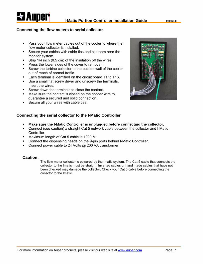
Connecting the flow meters to serial collector
Pass your flow meter cables out of the cooler to where the flow meter collector is installed.
Secure your cables with cable ties and cut them near the monitor system.
Strip 1/4 inch (0.5 cm) of the insulation off the wires. Press the lower sides of the cover to remove it. Screw the turbine collector to the outside wall of the cooler
out of reach of normal traffic. Each terminal is identified on the circuit board T1 to T16. Use a small flat screw driver and unscrew the terminals.
Insert the wires. Screw down the terminals to close the contact. Make sure the contact is closed on the copper wire to
guarantee a secured and solid connection. Secure all your wires with cable ties.
Connecting the serial collector to the I-Matic Controller
Make sure the I-Matic Controller is unplugged before connecting the collector. Connect (see caution) a straight Cat 5 network cable between the collector and I-Matic
Controller. Maximum length of Cat 5 cable is 1000 M. Connect the dispensing heads on the 9-pin ports behind I-Matic Controller. Connect power cable to 24 Volts @ 200 VA transformer.
Caution: The flow meter collector is powered by the Imatic system. The Cat 5 cable that connects the collector to the Imatic must be straight. Inverted cables or hand made cables that have not been checked may damage the collector. Check your Cat 5 cable before connecting the collector to the Imatic.

I-Matic Portion Controller Installation Guide I50660-E
For more information on Auper products, please visit our web site at www.auper.com Page 8
Installing the Imatic beer faucets
The Imatic beer faucets are delivered with a 5 M (15ft cable). The cable is terminated with a 9-pin connector.
You can extend this cable up to 15 M (45ft).
Make sure the Imatic controller is disconnected.
Connect the Imatic faucet cable to the Imatic
controller. The connectors are identified corresponding to the flow meter line numbers. (Line 1 for flow meter 1 on the collector)
Secure the connector screws.
The maximum recommended pressure on the draft
beer keg is 40 PSI. Each faucet is tested at 50 PSI which is the absolute maximum.
Caution: An Imatic dispensing faucet connected to the wrong flow meter will enter the Pause mode a few seconds after you have pressed a pour size button because it does not detect the flow meter pulses. Check you line numbers and brands.
Testing the flow meter connections
Turn the key to PROG on the I-Matic Controller.
The “impulse“ mode is used to verify that the flow meters are connected to the collector.
From left to right, the 16 dots represent lines 1 to 16.
When a flow meter is connected to a line, the corresponding dot is up.
If no flow meter is connected to a line, the corresponding dot is down.
When a flow meter detects liquid flowing though it, the corresponding dot will alternate up
and down.
If a flow meter is installed backward, the corresponding dot will be up but will not alternate
when product is flowing.
Press any of the pour size button to open the beer faucet. Press any button to close it.
Make sure every flow meter registers properly.
I-Matic Portion Controller Installation Guide I50660-E
For more information on Auper products, please visit our web site at www.auper.com Page 9
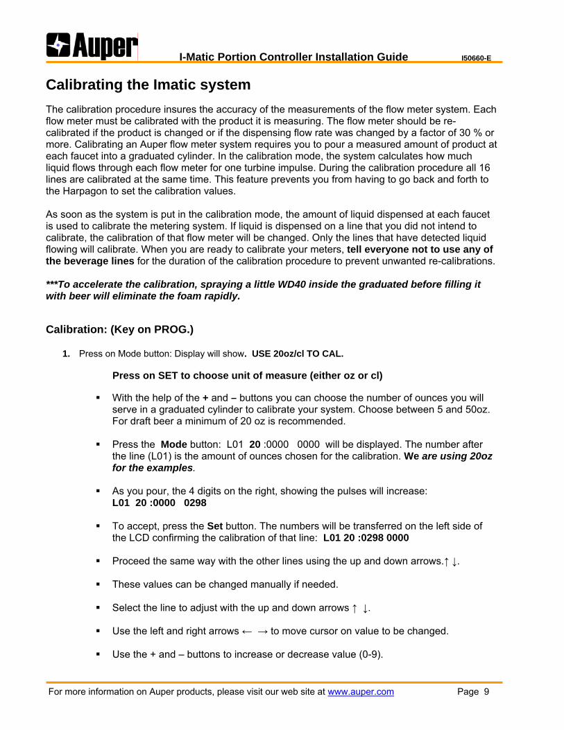
Calibrating the Imatic system The calibration procedure insures the accuracy of the measurements of the flow meter system. Each flow meter must be calibrated with the product it is measuring. The flow meter should be re-calibrated if the product is changed or if the dispensing flow rate was changed by a factor of 30 % or more. Calibrating an Auper flow meter system requires you to pour a measured amount of product at each faucet into a graduated cylinder. In the calibration mode, the system calculates how much liquid flows through each flow meter for one turbine impulse. During the calibration procedure all 16 lines are calibrated at the same time. This feature prevents you from having to go back and forth to the Harpagon to set the calibration values. As soon as the system is put in the calibration mode, the amount of liquid dispensed at each faucet is used to calibrate the metering system. If liquid is dispensed on a line that you did not intend to calibrate, the calibration of that flow meter will be changed. Only the lines that have detected liquid flowing will calibrate. When you are ready to calibrate your meters, tell everyone not to use any of the beverage lines for the duration of the calibration procedure to prevent unwanted re-calibrations. ***To accelerate the calibration, spraying a little WD40 inside the graduated before filling it with beer will eliminate the foam rapidly.
Calibration: (Key on PROG.)
1. Press on Mode button: Display will show. USE 20oz/cl TO CAL.
Press on SET to choose unit of measure (either oz or cl)
With the help of the + and – buttons you can choose the number of ounces you will serve in a graduated cylinder to calibrate your system. Choose between 5 and 50oz. For draft beer a minimum of 20 oz is recommended.
Press the Mode button: L01 20 :0000 0000 will be displayed. The number after
the line (L01) is the amount of ounces chosen for the calibration. We are using 20oz for the examples.
As you pour, the 4 digits on the right, showing the pulses will increase:
L01 20 :0000 0298 To accept, press the Set button. The numbers will be transferred on the left side of
the LCD confirming the calibration of that line: L01 20 :0298 0000 Proceed the same way with the other lines using the up and down arrows.↑ ↓.
These values can be changed manually if needed.
Select the line to adjust with the up and down arrows ↑ ↓.
Use the left and right arrows ← → to move cursor on value to be changed.
Use the + and – buttons to increase or decrease value (0-9).
I-Matic Portion Controller Installation Guide I50660-E
For more information on Auper products, please visit our web site at www.auper.com Page 10
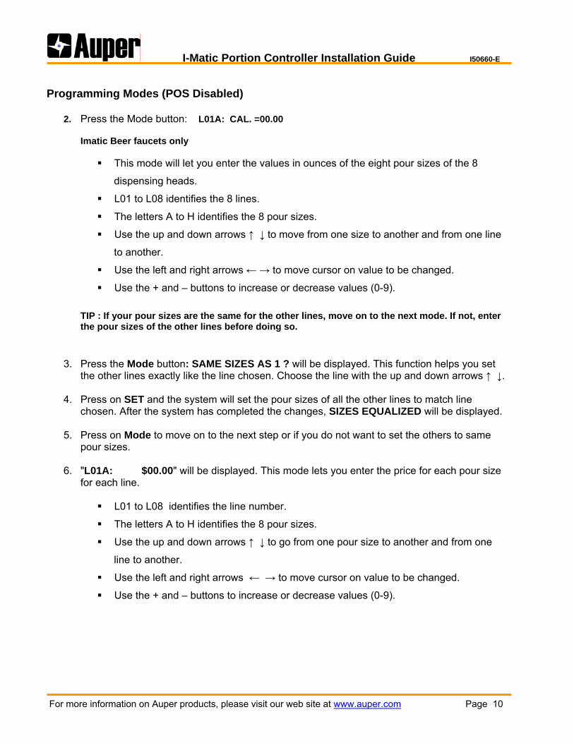
Programming Modes (POS Disabled)
2. Press the Mode button: L01A: CAL. =00.00 Imatic Beer faucets only
This mode will let you enter the values in ounces of the eight pour sizes of the 8
dispensing heads.
L01 to L08 identifies the 8 lines.
The letters A to H identifies the 8 pour sizes.
Use the up and down arrows ↑ ↓ to move from one size to another and from one line
to another.
Use the left and right arrows ← → to move cursor on value to be changed.
Use the + and – buttons to increase or decrease values (0-9). TIP : If your pour sizes are the same for the other lines, move on to the next mode. If not, enter the pour sizes of the other lines before doing so.
3. Press the Mode button: SAME SIZES AS 1 ? will be displayed. This function helps you set the other lines exactly like the line chosen. Choose the line with the up and down arrows ↑ ↓.
4. Press on SET and the system will set the pour sizes of all the other lines to match line
chosen. After the system has completed the changes, SIZES EQUALIZED will be displayed.
5. Press on Mode to move on to the next step or if you do not want to set the others to same pour sizes.
6. "L01A: $00.00" will be displayed. This mode lets you enter the price for each pour size
for each line.
L01 to L08 identifies the line number.
The letters A to H identifies the 8 pour sizes.
Use the up and down arrows ↑ ↓ to go from one pour size to another and from one
line to another.
Use the left and right arrows ← → to move cursor on value to be changed.
Use the + and – buttons to increase or decrease values (0-9).

I-Matic Portion Controller Installation Guide I50660-E
For more information on Auper products, please visit our web site at www.auper.com Page 11
Important Pulse counter and pour size: The first pour size requested after entering a pour size value in the Imatic system will be off by a small amount ( ¼ to ½ oz). This is normal since the pulse counters have been cleared when you entered the new value. Pulse counter: L01A 0005 00020 In normal operation the display will show the line number and size, the pulse counter and the number of sizes served. When you serve a pour size, the pulse counter shows the flow meter activity as product goes through it. When the Imatic reaches the number of flow meter pulses needed for the pour size, it shuts off the faucet. There will always be a number of pulses registered corresponding to the delay needed for the faucet to close and the flow to stop. Calibrating your pour sizes: When setting your pour sizes, use a graduated cylinder. Fill the glass with water or beer to the desired level. Transfer the content of a glass in the cylinder and take note of the amount. Use the graduated to verify all your glass sizes before programming them in the Imatic. You will always be able to revert to these measurements in case of doubts. We recommend that the bar managers be equipped with a graduated cylinder for occasional spot checks.
7. Press on Mode. "RS 01A : 00000" will be displayed. This mode lets you clear the counters of the line selected.
For the dispensing heads (1 to 8), the line and pour size shown is cleared. For lines 9 to 16, the line displayed is cleared. To select the counter to clear, use the left and right arrows ↑ ↓. Press on Set to clear the counter. Lines can all be cleared in the RUN mode. See
OPERATION section.
8. Press on Mode. "POS DISABLED" will be displayed. To interface the I-Matic system to a POS or cash register, press on Set to display "POS ENABLED [ 1 ]".
9. See next section "I-Matic Controller programming mode - POS ENABLED" for more
information. To continue to view other features in this section, please revert back to "POS DISABLED".
10. Press on Mode. "POUR SWITCH OFF" or "POUR SWITCH ON" will be displayed. If your Imatic beer faucets are equipped with the “Pour Switch” option, set mode to "POUR SWITCH ON" by pressing on Set. If your dispensing heads are activated by pressing on the keypad, set to "POUR SWITCH OFF" by pressing on Set button.
11. Press on Mode. "BAUD RATE 9600 " will be displayed. This is to set the baud rate between
your system and POS or cash register. Press on + or – buttons to select baud rate. You have the choice between 3 transmission speeds. 2400, 9600 or 19200.
I-Matic Portion Controller Installation Guide I50660-E
For more information on Auper products, please visit our web site at www.auper.com Page 12
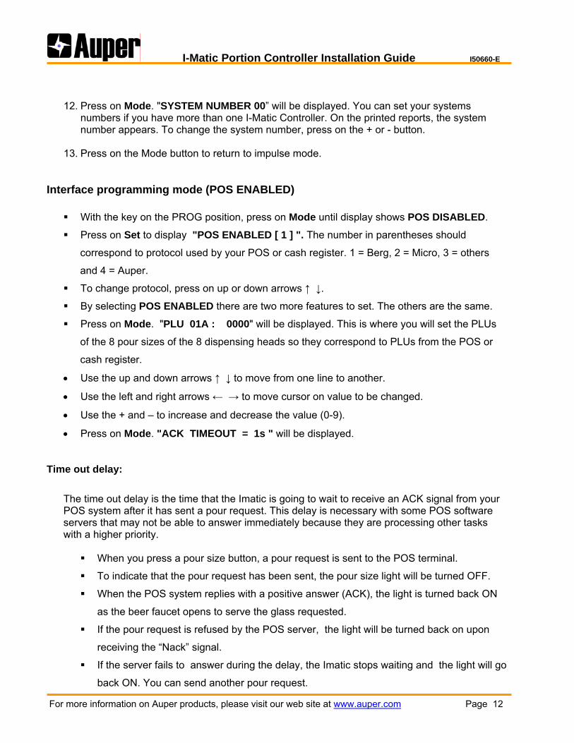
12. Press on Mode. "SYSTEM NUMBER 00” will be displayed. You can set your systems
numbers if you have more than one I-Matic Controller. On the printed reports, the system number appears. To change the system number, press on the + or - button.
13. Press on the Mode button to return to impulse mode.
Interface programming mode (POS ENABLED)
With the key on the PROG position, press on Mode until display shows POS DISABLED.
Press on Set to display "POS ENABLED [ 1 ] ". The number in parentheses should
correspond to protocol used by your POS or cash register. 1 = Berg, 2 = Micro, 3 = others
and 4 = Auper.
To change protocol, press on up or down arrows ↑ ↓.
By selecting POS ENABLED there are two more features to set. The others are the same.
Press on Mode. "PLU 01A : 0000" will be displayed. This is where you will set the PLUs
of the 8 pour sizes of the 8 dispensing heads so they correspond to PLUs from the POS or
cash register.
• Use the up and down arrows ↑ ↓ to move from one line to another.
• Use the left and right arrows ← → to move cursor on value to be changed.
• Use the + and – to increase and decrease the value (0-9).
• Press on Mode. "ACK TIMEOUT = 1s " will be displayed.
Time out delay:
The time out delay is the time that the Imatic is going to wait to receive an ACK signal from your POS system after it has sent a pour request. This delay is necessary with some POS software servers that may not be able to answer immediately because they are processing other tasks with a higher priority.
When you press a pour size button, a pour request is sent to the POS terminal.
To indicate that the pour request has been sent, the pour size light will be turned OFF.
When the POS system replies with a positive answer (ACK), the light is turned back ON
as the beer faucet opens to serve the glass requested.
If the pour request is refused by the POS server, the light will be turned back on upon
receiving the “Nack” signal.
If the server fails to answer during the delay, the Imatic stops waiting and the light will go
back ON. You can send another pour request.

I-Matic Portion Controller Installation Guide I50660-E
For more information on Auper products, please visit our web site at www.auper.com Page 13
OPERATION ( Key on "RUN" ) In operation mode, the key is used to clear counters or to disable counters (Lines cleaning) when lines have to be cleaned.
• Display shows L01A 0000 00000 for lines 1 to 8. Those are counters.
The number of pour sizes dispensed appears on the right ex: L01A 0000 00001 The number of pulses required to count one unit appears on the left of the screen.
• Ex : L01A 0119 00000 therefore if your line was calibrated at 300 pulses (20oz) and your
pour size A is 8 oz, when the system reaches 120 pulses, the pulse counter goes back to zero and one unit is added to the right. Ex : 300 pulses divided by 20 oz = 15 pulses per oz. Therefore 15 pulses X size format A of 8 oz = 120 pulses.
• Display shows L09: .00 for lines 9 to 16. The value is in Oz poured.
• Press on the up and down arrows ↑ ↓ to move from one pour size to another and from one
line to another.
• Press on Mode. PRINT REPORT ? will be displayed. Press on Set to print a report on a serial printer. Mode will change automatically to CLEAR COUNTERS ?
• When CLEAR COUNTERS ? is displayed, turn the key to PROG to clear all lines.
COUNTERS CLEARED will be displayed letting you know that lines have been cleared. If you do not want to clear counters press on Mode.
• LINES CLEANING ? will be displayed. To clean your lines, you need to disable your system.
Turn key to PROG and CLEANING MODE... will be displayed. Use the pour size button to open and close the Imatic faucets manually. Once cleaning completed, turn the key back to RUN.
:
I-Matic Portion Controller Installation Guide I50660-E
For more information on Auper products, please visit our web site at www.auper.com Page 14
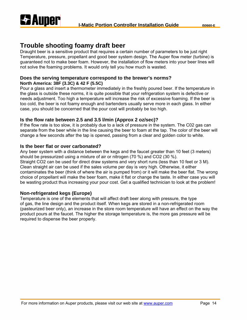
Trouble shooting foamy draft beer Draught beer is a sensitive product that requires a certain number of parameters to be just right Temperature, pressure, propellant and good beer system design. The Auper flow meter (turbine) is guaranteed not to make beer foam. However, the installation of flow meters into your beer lines will not solve the foaming problems. It would only tell you how much is wasted. Does the serving temperature correspond to the brewer’s norms? North America: 38F (3.3C) & 42 F (5.5C) Pour a glass and insert a thermometer immediately in the freshly poured beer. If the temperature in the glass is outside these norms, it is quite possible that your refrigeration system is defective or needs adjustment. Too high a temperature will increase the risk of excessive foaming. If the beer is too cold, the beer is not foamy enough and bartenders usually serve more in each glass. In either case, you should be concerned that the pour cost will probably be too high. Is the flow rate between 2.5 and 3.5 l/min (Approx 2 oz/sec)? If the flow rate is too slow, it is probably due to a lack of pressure in the system. The C02 gas can separate from the beer while in the line causing the beer to foam at the tap. The color of the beer will change a few seconds after the tap is opened, passing from a clear and golden color to white. Is the beer flat or over carbonated? Any beer system with a distance between the kegs and the faucet greater than 10 feet (3 meters) should be pressurized using a mixture of air or nitrogen (70 %) and CO2 (30 %). Straight CO2 can be used for direct draw systems and very short runs (less than 10 feet or 3 M). Clean straight air can be used if the sales volume per day is very high. Otherwise, it either contaminates the beer (think of where the air is pumped from) or it will make the beer flat. The wrong choice of propellant will make the beer foam, make it flat or change the taste. In either case you will be wasting product thus increasing your pour cost. Get a qualified technician to look at the problem! Non-refrigerated kegs (Europe) Temperature is one of the elements that will affect draft beer along with pressure, the type of gas, the line design and the product itself. When kegs are stored in a non-refrigerated room (pasteurized beer only), an increase in the store room temperature will have an effect on the way the product pours at the faucet. The higher the storage temperature is, the more gas pressure will be required to dispense the beer properly.

I-MATIC CONTROLLER
PROGRAMMING AND OPERATING MODE
FLOW CHART FC50660
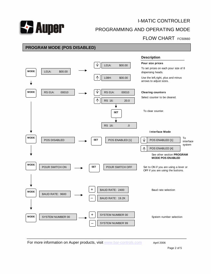
PROGRAM MODE (POS DISABLED)
Impulse Mode
Displays lines connected to a flow meter.
Description
USE 10oz TO CAL. Increase of 5 oz
Calibration
To select oz used for calibration.
L01 10:0000 0000
Calibration
Displays calibration value during calibration.
To accept values of all the lines.(Value on the right is carried over to the left)
L01A: CAL. = 00.00 L01A: CAL. = 00.00
L08H: CAL. = 00.00
Pour Size Mode
Value of each pour size on 8 dispensing heads in oz.
SAME SIZES AS 1 ?
Decrease of 5 oz
L01 10:0000 0150
L16 10:0000 0150
For more information on Auper products, visit www.bar-controls.com April 2006
Page 1of 5
Use the left,right, plus and minus arrows to adjust sizes.
If pour sizes are identical to a line , select that line.
SAME SIZES AS 1 ?
SIZES EQUALIZED
To accept pour sizes on other lines are the same as line chosen.
SAME SIZES AS 8 ?
RUN
PROG
MODE
MODE
MODE
MODE
MODE
+
SET
SET
USE 10Cl TO CAL.
SETPress on set to select unit of measure
PROGRAM MODE (POS DISABLED)
Pour size prices
To set prices on each pour size of 8 dispensing heads.L01A: $00.00
Description
RS 01A: 00010
RS 16: 20.0
Clearing counters
Select counter to be cleared.
POUR SWITCH ON
L01A: $00.00
L08H: $00.00
RS 01A: 00010
To clear counter.
RS 16: .0
POS DISABLED POS ENABLED [1] POS ENABLED [1]
POS ENABLED [4]
To interface system
See other section PROGRAM MODE POS ENABLED
POUR SWITCH OFF Set to ON if you are using a lever or OFF if you are using the buttons.
BAUD RATE: 9600BAUD RATE: 2400
BAUD RATE: 19.2K
Baud rate selection
SYSTEM NUMBER 00SYSTEM NUMBER 00
SYSTEM NUMBER 99
System number selection
Interface Mode
I-MATIC CONTROLLER
PROGRAMMING AND OPERATING MODE
FLOW CHART FC50660
For more information on Auper products, visit www.bar-controls.com April 2006
Page 2 of 5
Use the left,right, plus and minus arrows to adjust sizes.
MODE
MODE
MODE
MODE
MODE
MODE
+
+
SET
SET
SET
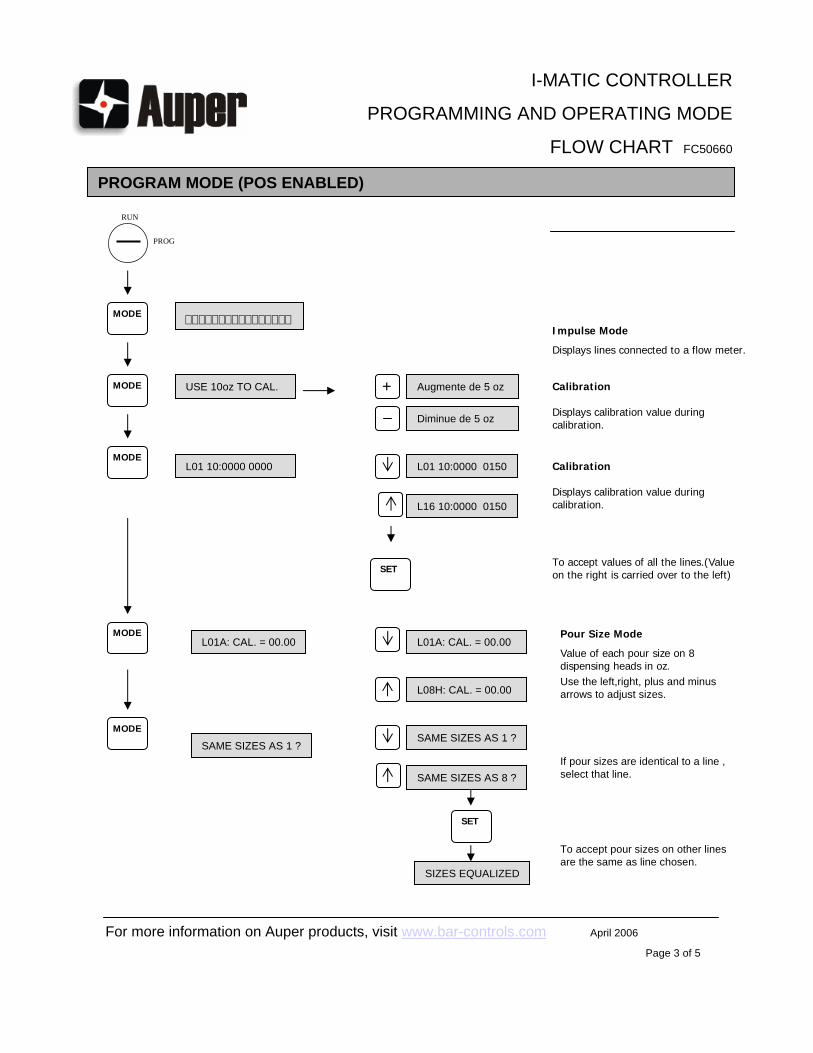
PROGRAM MODE (POS ENABLED)
USE 10oz TO CAL. Augmente de 5 oz
L01 10:0000 0000
Diminue de 5 oz
L01 10:0000 0150
L16 10:0000 0150
L01A: CAL. = 00.00 L01A: CAL. = 00.00
L08H: CAL. = 00.00
SAME SIZES AS 1 ?SAME SIZES AS 1 ?
SIZES EQUALIZED
SAME SIZES AS 8 ?
I-MATIC CONTROLLER
PROGRAMMING AND OPERATING MODE
FLOW CHART FC50660
For more information on Auper products, visit www.bar-controls.com April 2006
Page 3 of 5
Impulse Mode
Displays lines connected to a flow meter.
Calibration
Displays calibration value during calibration.
Calibration
Displays calibration value during calibration.
To accept values of all the lines.(Value on the right is carried over to the left)
Pour Size Mode
Value of each pour size on 8 dispensing heads in oz.Use the left,right, plus and minus arrows to adjust sizes.
If pour sizes are identical to a line , select that line.
To accept pour sizes on other lines are the same as line chosen.
MODE
MODE
MODE
MODE
MODE
RUN
PROG
+
SET
SET
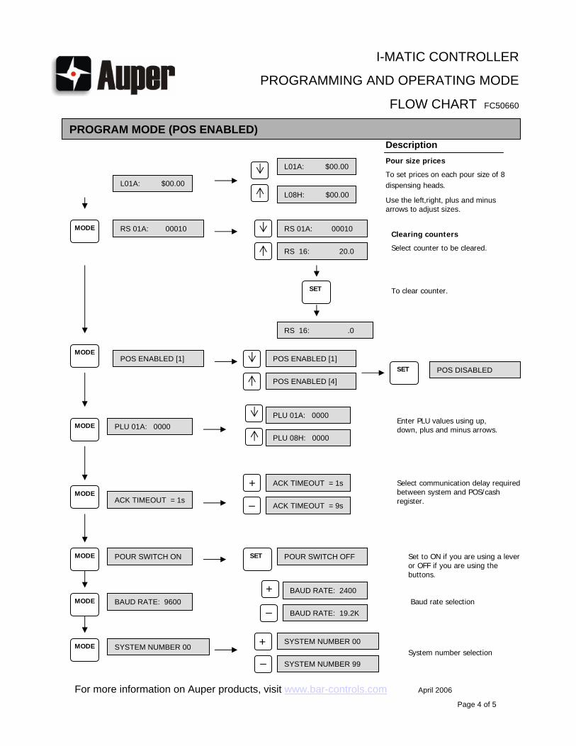
PROGRAM MODE (POS ENABLED)
L01A: $00.00
Description
RS 01A: 00010
RS 16: 20.0
L01A: $00.00
L08H: $00.00
RS 01A: 00010
RS 16: .0
POS ENABLED [1] POS ENABLED [1]POS DISABLED
POS ENABLED [4]
Enter PLU values using up, down, plus and minus arrows.
BAUD RATE: 9600BAUD RATE: 2400
BAUD RATE: 19.2KBaud rate selection
SYSTEM NUMBER 00SYSTEM NUMBER 00
SYSTEM NUMBER 99System number selection
PLU 01A: 0000PLU 01A: 0000
PLU 08H: 0000
ACK TIMEOUT = 1s
ACK TIMEOUT = 1s
ACK TIMEOUT = 9s
Select communication delay required between system and POS/cash register.
POUR SWITCH ON POUR SWITCH OFF
I-MATIC CONTROLLER
PROGRAMMING AND OPERATING MODE
FLOW CHART FC50660
For more information on Auper products, visit www.bar-controls.com April 2006
Page 4 of 5
Pour size prices
To set prices on each pour size of 8 dispensing heads.
Use the left,right, plus and minus arrows to adjust sizes.
Clearing counters
Select counter to be cleared.
To clear counter.
Set to ON if you are using a lever or OFF if you are using the buttons.
MODE
MODE
MODE
MODE
MODE
MODE
MODE
+
+
+
SET
SET
SET

L01A: 0000 00020
L16: .00
Displays counters
To select line to display.
To print a reportPRINT REPORT?
CLEAR COUNTERS ?Turn key to PGRM to clear all counters.
RUN MODE
L01A: 0000 00020
DATA PRINTING…
COUNTERS CLEARED
Turn key back to RUN.LINES CLEANING ?
Turn key to PGRM for line cleaning.CLEANING MODE…
Turn key to RUN once line cleaning completed.
L16: .00
I-MATIC CONTROLLER
PROGRAMMING AND OPERATING MODE
FLOW CHART FC50660
For more information on Auper products, visit www.bar-controls.com April 2006
Page 5 of 5
MODE
MODE
MODE
MODE
RUN
PROG
RUN
PROG
RUN
PROG
PROG
RUN
SET

Auper Electronic Controls Inc. 901 Michelin Street
Laval – Quebec - Canada - H7L 5B6 Phone 450.663.1993 – Fax 450.663.0636
1.800.861.1620 www.bar-controls.com
Related Documents