I INCH-POUND I MIL-S-901D(NAVY) 17 March 1989 SUPERSEDING MIL-S-901C(IUAVY) 15 January 1963 (See 6.8) MILITARY SPECIFICATION SHOCK TESTS, H.I. (HIGH-IMPACT) SHIPBOARD MACHINERY, EQUIPMENT, AND SYSTEMS, REQUIRE~~S FOR This specification is approved for use by the Department of the Navy, and is available for use by all Departments and Agencies of the Department of Defense. 1. SCOPE 1.1 scoDe. This specification covers chock testing requirements for ship board machinery, equipment, SysteM, ●nd structures , excluding submarine pressure huli penetrations, (see 1.2.5). The purpose of these requirements is to varify the ability of shipboard installations to withstand shock loadlngs which may be incurred during wartime service due to the effects of nuclear or conventional weapons. 1.2 Classification. 1.2,1 Test categories. Tests shall be classified in accordance with one of the following test categories, as specified (see 3,1.2 and 6.2.1): Beneficial comments (recommendations, additions, deletions) and any pertinent data which may be of US. in improving this document should be addressed to: Commander, Naval Sea Syutoms Command , SEA 5523, Department of the Navy, Washington. DC 20362- 5103 by using the self-addressed Standardization Decument Improvement Proposal (DD Form 1426) appearing at the and of this .document or by letter . AMSC N4571 AREA ENVR DISTRIBUTION STATEMENT A. Approved for public release; distribution is unlimited.

Welcome message from author
This document is posted to help you gain knowledge. Please leave a comment to let me know what you think about it! Share it to your friends and learn new things together.
Transcript
I INCH-POUND IMIL-S-901D(NAVY)17 March 1989SUPERSEDINGMIL-S-901C(IUAVY)15 January 1963(See 6.8)
MILITARY SPECIFICATION
SHOCK TESTS, H.I. (HIGH-IMPACT) SHIPBOARD MACHINERY,EQUIPMENT, AND SYSTEMS, REQUIRE~~S FOR
This specification is approved for use by the Department of the
Navy, and is available for use by all Departments and Agencies ofthe Department of Defense.
1. SCOPE
1.1 scoDe. This specification covers chock testingrequirements for ship board machinery, equipment, SysteM, ●ndstructures , excluding submarine pressure huli penetrations,(see 1.2.5). The purpose of these requirements is to varify theability of shipboard installations to withstand shock loadlngswhich may be incurred during wartime service due to the effectsof nuclear or conventional weapons.
1.2 Classification.
1.2,1 Test categories. Tests shall be classified inaccordance with one of the following test categories, asspecified (see 3,1.2 and 6.2.1):
Beneficial comments (recommendations, additions, deletions) andany pertinent data which may be of US. in improving thisdocument should be addressed to: Commander, Naval Sea SyutomsCommand , SEA 5523, Department of the Navy, Washington. DC 20362-5103 by using the self-addressed Standardization DecumentImprovement Proposal (DD Form 1426) appearing at the and of this
.document or by letter .
AMSC N4571 AREA ENVR
DISTRIBUTION STATEMENT A. Approved for public release;distribution is unlimited.

MIL-s-9olD(klAvY)
The lightweight test 18 a test performed onLightweight.the lightweight shock machine (8e* figure l).Medium-weiflh~, The medium weight test is a teat performedon the medium weight shock machine (see figure 2) .Heavyweifiht. The heavyweight test i8 a test performed on astandard or large floating shock platform (8ee figures3 and 4).
1.2.2 ck firades . Items to be tested zhall be classifiedin ●ccordance with one of the following gradeo, as specified (See3.1.3 and 6.2):
Grade ~. Grade A itemu are items which ●re ●ssentialto the safety and continued combat capability of th. ship.Grade B Grade B items are items whose operation 18not essential to the safety and combat capability ofthe ship but which could become ● hazard to parsonnol,to grade A items, or to the ship ●s a whole as a resultof exposure to shock.
1.2.3 Equipment Claases. Items to ba tested shall b.classified in accordance with one of the following classes~ ●8specified (see 3.1.4 and 6.2):
Class 1. Class I equipment is defined as that which isrequired to meet these shock requirements without theuse of resilient mountings installed between thoequipment and the ship structure or foundation.
Class IL Class II ●quipment is defined ●m *hat s#hichis required to meet these shock requirements with th.use of resilient mountings installed between theequipment and the ship structure or 8hipboardfoundation.
Class IIL Unless otherwise specified (see3.1.6.3(:)), class III equipment is defined as thatwhich has shipboard application both with and withoutthe use of resilient mountings and 18 thereforerequired to meet both class I ●nd class 11requirements.
1.2.4 Shock test tv~~. Tests shall be classified in accor-dance with one of the following type8. as specified (see 3.1.!Sand6.2):
Type A% A type A test itia test of a principal unit. Thisis the preferred test. Principal units are items which ●rcdirectly supported by the ship structuro or by a foundationwhich is directly attached to the ship structure, and items
2
MIL-S-901D(NAVY)
mounted in piping systems, ducting systems, and similarsystems which are supported by ship structure. The shockresponse of a principal unit is primarily a function of th.rigidity and mass of the item and the shipboard mountingstructure, the shipboard mounting location, and theconfiguration of the item. Such items typically includediesel-generator sets, air conditioning plants,switchboards, radio transmitters, steam generator, missilelaunchers, and valves (if installed in piping which ifJsupported by ship structure).
Type B. A type B test is a test of a subsidiary componont.Subsidiary components ●ro items which are tho major partsof a principal unit. The shock response of tho 8ub8i’diarycomponent is significantly affected by that of theassociated principal unit and all ●ssociated subsidiarycomponents. The shock responses of the ●ssociatedprincipal unit and all associated subsidiary components ●resignificantly affected by that of the 8ub@idiary oomponent.Examples are the diesel engine of a diesel-generator 8et,the electric motor of an air conditioning unit, or thepower supply section of a radio transmitter.
TYne c. A type C test is a test of a subassembly.Subassemblies are items which are a part of a principalunit or a subsidiary component. Tho 8hock response of thesubassembly is significantly affected by that of the●ssociated principal unit or subsidiary component, but theshock response of the principal un~t or subsidiary component .is not significantly affected by the subassembly. Examplesare thermometer~, gauges, meters, relays, and reaistor8.The distinction between subassembly and assembly or part asused herein may be different than that used in variousequipment specifications or other acquisition documents.
1.2.5 Mountinl locati~. Items shall be clarnsified inaccordance with one of the following mounting locations aboard.skJip,●s specified (see 6.2):
Hull mounted. Hull mounted items aro those mounted on:For surface ships. Tho main structural members of theship including structural bulkheads and 8tructuralbulkhead stiffeners below the main deck, and shellplating above the waterline.For s~ Theship including,hullstructural bulkhead
main structural members of theframea , structural bulkheads, andstiffeners.
3

MIL-S-901D(NAVY)
Deck mounted. Deck mounted ite~ are those mounted on:For surface ships. Main deck ●nd ●bovo. ●nd d*cks,platforms, and non-structural bulkheads below tho wtndeck .For Sl&JtN3FillQ&. Decks, platforms, and non-structuralbulkheads.
Shell mounted. Shell mounted ite- ●re thoso mounted on:
For surface ships. The shell plating below the watsrlino.For submarines. The shell plating. (This specificationdoes not cover underwater expLo8ion t~stlng of it~w *ich
pen*trate the submarina pressuro hull (S** l.1~”.$
Wetted-surface . Wetted-surface mounted iteIM ●rethoso mounted:For n-e shim ● External to tho hull ●nd below thewaterline.For submarines. External to the pressure hull.
1.2.6 Mountinfl plane aboar d ship. Items shall b. clmsifiodin ●ccordance with one of the following pianos of mounting aboard#hip, ●s specified (wee 6.2):
BaseFront or faceBackTopCombination. (such ●s base and back)Other
.,1.2.7 Mounting orientation ●board mhi~. Iterasshsll be
classified in accordance with one of the following intendedorientation aboard ship, as specified (see 6.2):
Unrestricted ●s to orientation aboard shipRestricted
Shaft, front, face, principal axis, ●nd so forth,parallel to fore-and-aft axia of ahlpShaft , front, faue, principal mxis, ●nd so forth,perpendicular to fore-tnd-~ft ●xis of ahiPOther
2. APPLICABLE DOCUMENTS
2.1 -(hvernment documents.
4

MIL-S-901D(NAVY)
2.1.1 Specifications and st~ . The followingspecifications and standards form a part of this document to theextent specified herein. Unless otherwise specified. the issues ofthese documents are those listed in the issue of the Department ofDefense Index of Specifications and Standards (DoDISS) andsupplement thereto, cited in the solicitation (see 6.2) .
SPECIFICATIONS
MILITARYMXL-S-1222 - Studs, Bolts, Hex Cap Screws,
and Nuts.MIL-P-15024 - Plates, Tags and Bands for
Identification of Equipment.MIL-P-15024/5 - Plate, Identification.MIL-M-17185A - Mounts, Renili*nt; Oenoral
Specifications and Testn for(Shipboard Application)
MIL-W-21157 - Weldment, Steel, Carbon andLow Alloy (Yield Strength30,000 - 60,000 PSI).
MIL-E-22200/l - Electrodes, Welding, MineralCove~ed, Iron- Powdor, Low-Hydrogen, Medium and HighTensile Steel, As Welded orStrecs-Relieved Weld Appli-cation.
STANDARDS
FEDERAL”
MILITARY
FED-STD-H28
MIL-STD-22MIL-STD-298
(Unless otherwise indicated,
Screw-Thread Standards forFederal Services.
Welded Joint Design.Nondestructive Testing,Welding, Quality Control,Material Control ●ndIdentification and Hi-ShockTest Requirements For NavalShipboard Use.
copies of federal and militaryspecifications, standards, ●nd handbooks ●re available from theNaval Publications and Forms Center, (ATTN: NPODS ), 5801 TaborAvenue , Philadelphia, PA 19120-5099,)
5
MIL-S-901D(NAVY)
2.1.2 Other Government drawin~s. The following otherGovernment drawings form a part of this document to the extentspecified herein. Unless otherwise specified, the issues are thosecited in the solicitation.
DRAWINGS
BUSHIPS 1O-T-2145-L - HI Shock Testing Machine,Lightweight.
BUSHIPS N0807-655947 - HI Shock Testing Machine, Medi~Weight.
BUSHIPS 645-1973904 - Floating Shock Platform, GeneralArrangement and Details.
(Application for copies of NAVSEA drawings should be ●ddressedto: Commanding Officer, Naval Ordnance Station, (Attn: Code 802) ,Louisville, KY 40214.)
2.2 -~ ona. The following documentsform a part of this document to the extent specified herein.Unless otherwise specified, the iaauea of the documents which areDoD adopted shall be those listed in the is-u. of the DoDISS citedin the solicitation. Unless otherwise specified, the Issuca ofdocuments not listed in the DoDISS are the issues of the documentscited in the solicitation (see 6.2) .
AMERICAN NATIONAL STANDARDS INSTITUTE (ANSI)
B46.1 - Surface Texture (Surface Roughness,Waviness and Lay). (DoD adopted)
Y14.5 - Dimensioning and Tolerancing. (DoDadopted)
Y14.6 - Screw Thread Representation. (DoD adopted)
(Application for copies should be addressed to the AmericanNational Standards Institute, Inc. , 1430 Broadway, New York, NY10018.)
AMERICAN WELDING SOCIETY (AWS)
A2.4 - Symbols for Welding ●nd NondestructiveTesting, Including Brazing. (DoD ●dopted)
A3.O - Standard Welding Terms and Definitions,Including Terms for Brazing, Soldering,Thermal Spraying, and Thermal Cutting.(DoD adopted)
6

MIL-S-901D(NAVY)
(Application for copies should be ●ddremaad to the AmeriuanWelding Society, Inc., 55o N.W. LeJeuno Road, P.O. Box 351040,Miami , FL 33135.)
(Non-(30vernment standards and other publtcatione •r~ normallyavailable from the organizations that prepare or distribute thedocuments. These documents also may be availablo in or throughlibraries or other informational services.)
2.3 Order of Precedence. In the event of ● conflict betweenthe text of this document and the references cited herein (exceptfor related associated detail specifications, specification sheetsor MS #tandard8), the text of this dooument takoa preued*nao.Nothing in this document, however, #upar#edes ●pplicable lawsregulations unless a specific exemption has been obtained.
3. REQUIREMENTS
and
3.1 Shock testing requirements . Shock testing roquir*mentsshall be met either by shock testing of the item in accordance with3.1.1 through 3.1.15, or by extension of previously approvod shocktests in accordance with 3.2.
3.1.1 tabli-t of T~ . Requirements uontainedherein are intended to establish general shock test criteria, andto provide a basis for selectlon by the contracting activity orcontractor of detailed shock test requirements (see 6.2) which mustbe tailored to suit the design, function, and ●pplication of thespecific item to be tested.
3.1.1.1 Contractor development of reauire ment~. Whereacquisition requirements are not specified in the contract (see6.2), the contractor shall develop the required information on thebasis of this specification and on the basis of the contractor’sknowledge of the design, function, and intended application of thoitam requiring tesfta. In cases whero information requir.d by thecontractor to permit development of detailed testing requirementsis not available to the contractor, such information @h-n berequested from the contracting ●ctivity or ●cceptance ●uthority.
3.1.1.2 ‘&~roval of rewrementz Whn 8pecified inthe contract or order, detailed test procedures’ for heavyweightshock tests ●nd other acquisition requirements liatod in 6.2 which●re independently developed by the contractor shall b~ prepared(see 6.2.2). When required by the contract or order, fixturedrawings shall be prepared (see 6.2.2) and justification shall beprepared ●s to why the test fixture satisfactorily meets the?equArementrn of this specification (see 6.2.2). Acquisition
7

MIL-S-901D(NAVY)
documents may require that detailed test procodurag and othorinformation required by 6.2 which are independently developed bythe contractor for lightweight and medium weight #hock tests almobe approved by the acceptance authority prior to installing theitem for shock tests (see 6.2.1). Ab8ence of specifiedrequirements for prior approval of such information do@a notprohibit the contractor from submitting #uch Information forapproval prior to testing.
3.1.2 Selection of test category (s.9 1.2.1). Shell mountedand wetted surface mounted items shall be ●ubject to heavyweightshock testing. Other items shall be provon acceptable by eitherlightweight, medium weight, or heavyweight shock testing, providedthat the following limitations ●re complied with:
(a) Liflhtweiflhtshock teat. The total weight supported bythe lightweight shock machine anvil plate (excluding waight ofanvil plate itself but including all structure mid equipment •dd~dto the anvil plate) shall not exceed 550 pounds. Practical sizelimitations shall not be exceeded. Equipment which would normallybe tested on the lightweight shock machine but which is mounted onor incorporates resilient mounts or flexible mounting ●lementawhich have a deflection capability under shock loading of 1-1/2inches or more in any direction shall instead be subject to mediumweight or heavyweight shock testing.
(b) Medium weight shock test. The total weight supportedby the medium weight shock machine anvil table shall not exceed7,400 pounds. Practical size limitations shall not be exceodod.Equipment which would normally be tested on the medium weight 8hockmachine, but which is mounted on or incorporates resilient mountsor flexible mounting elements which have ● deflection capabilityunder shock loading in excess of 3 inches in any direction, shallinstead be subject to heavyweight shock testing.
(c) Heavyweight shock test. Weight ●nd center of gravitylimitations applicable to heavyweight shock testing are shown onfigures 5 and 6. Weight, size, ●nd center of gravity limitationsapplicable to the standard floating shock platform (see figur- S)shall be assymed to apply, unless ●cquisition docum~ntsspecifically state the utilization of the large floating 8bocktplatform (see figure 6) is permitted (See 6.2.1). The ●cceptanceauthority will consider contractor r-quests to utilize the largefloating shock platform in cases where ●cquisition documents do notspecifically prohibit use of this test platform. Contractingactivities or the acceptance authority shall obtain approval fromthe Naval Sea Systems Command (Ship Protection Division) prior tospecifying or permitting shock tests requiring utilization of the
8
MIL-S-901D(NAVY)
large shock platform.
(d) Separately specified limitation8. Acquisitiondocuments may require use of alternate Government-own*d shock te8tvehicles, may upecify the 8hock test cmtegory, or -y imposeadditional limitations upon selection of tbe shock test category(se@ 6.2.1),
3.1.3 Selection of shock Rrade (s6. 1.2.2). Shock gradeshall be as specified (see 6.2). If shock grade is not specifisd,●cceptance of tested items shall be based upon grada A rcquircmmts(ace 3.1.10.1), unless otherwise approved by the ●cceptance●uthority.
3.1.4 1.2.3) . Equipmentclass shall be as specified (s@e 6.2) or, if no cla88 is spoaifiod,shall b. seloctsd to suit tho classes deacribod in 1.2.3.
3.1.5 -k tegt tvCM (s*e 1.2.4) . Shock testtype shall be as specified (see 6.2).
3.1.S.1 WBO A. The type A teat (principal unit test) shallbe required in all cases, except as indicated in 3.1.S.2 ●nd3.1.5.3. The fact that ~ub#idiary components ●nd ●uba#80mbli*8 ofa principal unit have paased type B or C shock test does not affectrequirements for type A testing.
3.1.5.2 ~vDe B. The type B teOt (subsidiary component test)-hall be required in case- where type A testing is not possible due “to hscvyueight shock t*st ●iz. or weight limitations (see 3,1.2(c)●nd 6.2). The fact that subassemblies or ● subsidiary componont
. have pas-cd type C teats does not affect requirements for type Btesting. Type B testing maY also be required by -pacifications (ormay be recommended by the contractor for appreval by the acceptance●uthority) to suit any of the following situations:
(a) In case- whore a subsidiary component (math ●s aeiactric motor) i- ●ssociated with ● widt variety of principalunit8, type B testing of the item may be required by theacquisition @ocumenta for the purpose of providing reasonableaaauranc. that the item will AISO pa8s submeqtwnt type A G@8tS(when tasted as a part of one or more principal unit-) , ●nd tolmprov~ opportunities for #heck test ●xtension.
(b) In cases where a subsidiary component has failed during8hock testing of ● principal unit, repeat shock te-ting of the sub-sidiary component only (by type B te~ting) may b. permitted by theacceptance ●uthority in lieu of repeat to8ting of th* entire
9

MIL-S”901D(MAVY)
principal unit (see 3.1. n(a)).
3,1.5.3 Type C. The type C test (subassembly test) shall beperformed only when specified (see 6.2) or as ●pproved by theacceptance authority. The type C test may be required byspecifications (or recommended by the contractor forconsideration by the acceptance authority) for the same reasons S8indicated in 3.1.5.2. The contractor may also recommendperformance of type C tests in cases whera subassemblies associatedwith a principal unit or subsidiary component are not ●vailable atthe time the principal unit or subsidiary component is scheduledfor shock testing (see 3.1.7.3).
3.1.6 requirements . Items shall be mounted uponshock machines (see figures 1 and 2) or upon floating shockplatforma (see figuvea 3.and 4) for shock testing in kho mannerspecified (see 6.2). Shock machines or floating #hock platform8shall comply with the appropriate Government drawing specified in2.1.2. Paragraphs 3.1.6.1 through 3.1.6.3 provide requirementsapplicable to selection or design of xhock test mounting fixturesby the contracting activity, and provide requirements which shallbe observed by the contractor in the event that the requiredmounting fixture design io not specified by tha aaqut~itiondocuments. Development of shock test mounting requirements by thecontractor will often be necessary, since theao ~equirements arooften contingent upon characteristics of the tested item (such ●ssize, weight, and means of attachment) which ●re not known to thecontracting activity at the time of specification preparation.
3.1.6.1 LiKhtweifiht test fixtures. For lightweight shockteats , items’to be’tustwf #hail mdrmally”be attac?sed “*o the anvilplate of the lightweight uhock machine by means of standardmounting fixtures 4A, 4C, 6D-1, 6D-2, 6E; *T 11-C as shown onfigures 7 through 12. If the required mounting fixture is notspecified, an appropriate standard fixture shall be selected by thecontractor (see 3.1.6.3), or the contractor may recommend the useof a nonstandard fixture which complies with 3.1.6.3 for approvalby the acceptance authority. When the equipment has been mountedfor test upon ● standard fixture, its position upon the fixtureshall not be changed during the course of the teat.
3.1.6.2 ‘Medium weight test fixtures. For medium weight shocktests , items to be tested shall normally be ●ttached to the mediumweight shock machine anvil table by means of the standard mountingfixtures referred to in 3. 1.6.2.1 and 3.1.6.2.2. If the requiredmounting fixtures are not specified, appropriate standard fixturesshall be selected by the contractor (see 3. 1.6.3) , unless useof one or.more nonstandard fixtures which comply with 3.1.6.3 is
10
MIL-S-901D(NAVY)
recommended by the contractor and approved by the ●cceptanceauthority. Note that two different test fixtures shall be selectedfor testing of a given item: one fixture is used to support thetested item on the shock machine in its normal irhipboard mountingattitude (to produce shock loadings in the vertical direction) * anda second fixture is used to support the tested item in an inclinedposition (to produce shock loadings in the athwartship direction).Additional criteria for selection and use of medium weight testfixtures are contained in 3. 1.6.2.1 through 3.1.6.2.3 ●nd in3.1.8.2.
3. 1.6.2.1 Mounting Fixtures for base-mounted items (mediumwei~ht tea ● For the portion of the shock test series which isintended to produce shock loadings in the vertical direction (see3.1.8.2), base-mounted items (items mounted to horizontal surfaces●board ship) shall be attached to the anvil tabla by means @f th~standsrd mounting platform shown on figures 13 ●nd 1*. For tlloportion of the test series which is intended to produce shockloadings in the athwartship direction (see 3.1.6.2.3), base-mountoditems shall be mounted for tests on a standard inclined fixture(see figures 16 and 17) or on a similarly designed nonstandardfixture. To facilitate installation of some items on themedium weight shock machine, items may be inclined 90 degrees -(using a mounting fixture such as shown on !igur* 15).
3. 1.6.2.2 lklountine fixtures for bulkhead mowed items (~~ht t~st). For the portion of the shock test series which isintended to produce eihock loadings in the vertical direction (see3.1.8.2), bulkhead-mounted items (items mounted to verticalsurfaces aboard ship) shall be attached to the anvil table by meansof the standard bulkhead fixture shown on figure 15 or by asimilarly designed, nonstandard fixture. For the portion of thetest series which is intended to simulate shock loadings in theathwartship direction (see 3.1.6,2,3) , bulkhead mounted item shallbe mounted for shock tests in any of the following configurations:
(a) Mount the item in an inclined position upon a standardinclined fixture (figures 16, 17, and 18 showapplicable fixtures) or upon ● similar nonstandardfixture.
(b) If considered practical by tho shock test facillty (andif within the limitations of 3.1.2(b)), mount the itemupon a vertic~l test fixture (such as shown on figure15) and then mount this ●ssembly upon an inclined testfixture of the type shown on figures 16 or 17.
(c) Mount the item horizontally (inclined 90 degrees
11

MIL-S-901D(NA~)
relative to it= shipboard mounting poaitionl won th.standard mounting platform shown on figures 13 ●nd 140Mounting of bulkhead mounted items in this fashion forshock tests is subject to prior approval by theacceptance authority.
3. 1.6.2.3 Special requirements for inclined mount~ . Wheninclined fixtures are used, the item to b. tested shall b. mountedon the fixture such that the item 1s inclined in the same direction●s the item would incline aboard ship if th~ ship were to rollabout its fore-and-aft ●xis (see 6.2). If tho item ia to booriented in differsnt directions aboard ship, the item •h~l~ bemounted and tested in two different incl$ncd orientations tosimulate shock loadings in both principal borizont-1 directions.(If the inclined fixture zhown on figuro 18 is us~d, it is notnecessary to test the item in two different inclined ori*ntation8.)Inclined fixtures shall incline tho test-d item at loaat 30 degxwosrelative to the normal (shipboard) mounting position.
3.1.6.3 ~aaifln and 89 Iection of test fixtures. The followingrequirements ●pply to aelaction of standard test fixtures in csseswhere none is specified, to design of nonstandard fiXtUrOS forlightweight and msdium weight tests, and to d-sign of heavyweightteat fixtures:
(a) Except as indicated by 3.1.6.3(c), PrinciPal unitsshall be mounted for testing in ● manner whichdynamically simulates the most sevare (normally, thestiffest) mounting condition likely to be ●neounteredAn the ackual shipboard in8taAAatiOlA.
(b) Subsidiary components and subassemblies shall bemounted in a manner -which simulates the dynamiccharacteristics of the ●ssociated principal unit.If more than one installation is possible, the mostsevere installation shall be implemented.
(c) Standard shock machine mounting fixturoa are intendedto represent hull mounted conditions, ●nd ●re typiaallystiffer than would be required to simulate deck mountedconditions. Use of standard mounting fixtures forteato of deck-mounted items ia acceptable for class Iteats only. Heavyweight toating L@ recommended incases where simulation of deck-mounted conditions i9dealred; such conditions are difficult to Hlmulate onshock machines. Fixtures intended to simulate deck-mounted conditions shall possess fundamental responsefrequencies (with the equipment installed on the
12
MIL-S-901D(NAVY)
fixture) not lower than .25 Hertz (Hz) in each principalshock direction, for ciass I tests, unless otherwisospecified {see 6.2.1). For class II ttata, fixturesintended to simulate deck-mountod conditions shallpossess a fundamental frequency (with the equiPmentinstalled on the fixture) of 12 to 16 Hz in thovertical direction unless otherwise spocifiod(see 6.2.1).
(d) Plastic yielding or cracking ofshock tests shall be considorodotharwise specifically approved●uthority. (Accsptanco of test
test fixtures duringunaccoptabloo unlessby tho ●cceptancefixturo yielding or
cracking by the acceptance authority shall becontingent upon demonstration by the contractor thatsuch yielding or cracking did not roduco the vslidityof tho test.)
(e) Tested items shall be attached to their shock testfixtur-s in accordance with the manufactur.r’sinstallation deaw~ngs. This method of mounting shallreflect the intended shipboard instalha$on. Clazs IIand class III equipments shall ibe munt.d fo?tests upon the same type ●nd ●rrangement ‘of resilientmountings (including snubbers) ae will b. used tosupport the equipment aboard ship. Note: Shocktesting of class 111 items in the rigidly mountedconfiguration solely to qualify the items for mountingin both rigidly and re@ili@ntlY mountod configurations$nay be permlttod by spplisabla acqui’si~ion douumemt#.Permission to do so Is subjeut to the provision thatthe resilient mounts, subbasa, hold-down means, -dother components unique to the resiliently mountadinstallation are selected, designed, Or shock tested tosuit separately invoked shock requirements (see 102.3and 6.2.1).
(f) Te#t fixtures for hull-mounted heavyweight test item8shall be attached directly to tho standard floatingshock platform inns bottom structure (se. filjlUX$e3) orto transverse or longitudinal hull stiff~nera of thelarge floating Shock platform (see figure 4) ●nd shallbe designed in ●ccordance with 3.1.6.3(a).
(g) Mounting fixtures for wetted-surface mounted itemsshall be ●ttached to the underside of ● floating shockplatform. The mounting fixture shall be ●rranged suchth?t the tested item $8 expoced. to the di,roct ●xplosion
13
MIL-S-901D(MAVY)
pressure wave during test. The test fixture shall belocated so aa to ❑inimize (insofar ●s practical) thehorizontal distance between tha tostod it-m ●nd thoside of the floating shock platform which faues the●xplosive chargo during the most sever. teat shot.
(h) Unless otherwise specified (s-e 6.2.1), tb. standardfloating shock platform -hall be utilized for shocktesting of wetted-surface mounted transducer. Wettedportions of the transducer face shall be positioned ●ta horizontal standoff distanca no greatsr than 21 feetfrom the ●xplostivo charge during the mo8t sovore testand no less than 3 feet below the unde~sida of thafloating shock platform.
(i) Shell mounted items shall b. ●ttach-d dir.ctly to thostandard floating shock platform inno~ bottomstructure.
(j) Acquisition doc~-nta may 8peCify ●dditionalrcquLrement8 powtai.nlng to seloution ef standard testfixtures or to the required d.sign of nonstandardfixtur*W (see 6.2.1).
(k) Where hold-down bolts for test items are specified tobe torqued to specific value= in the ship installationsthe hold-down bolts shall ba torqued to tbeso values inthe shock test installation (see 3.1.8.6 and 0.2).
Kl”) “Bblt’ing””u&M‘tb k~ctam “itexittti’lih~Wltoek t@#% fixturesor foundations shall conform to MIL-S-12fZ2.
3.1.7 Simulation of items during shock teste.
3.1.7.1 Silnulation of shinboard connections ● In eases wherepipiag, zway braces, drive @hafts, control linkages, or similaritems or structures will be connected to the shock tested item inthe shipboard installation, characteristiu8 of the eonnoution whichcould significantly influence shock damago potontlal shail berepmsent~d during the shock t~st. Specific requirements forsimulation of mhipboa~d connections during shock te8t8 shall be ● sspecified (see 6.2) or,if not sjxci.fied, ●hall be developed by thecontractor on the basis of the following and for ●cceptance●uthority ●pproval.
(•> Rigid dummy massez may be used to simulate inertial●ffectz of the connected itsm. D- mas8e6 shall b.●t~achod w tbe tgstgd item by the #Areainema”as will
14
MIL-S-901D(NAVY)
(b)
(c)
be used aboard ship to attach the ●ctual connocteditern. Dummy masses shall not be fabricated frombrittle materia18 such as cast Iron. The weight Ofdummy masses shall normally be equal to the static loadexerted upon the tested item aboard ship due to theweight of the connected item. For simulation ofextended and relatively flexible connected items Suchas piping, use of dummy masses ●qual in weight to theweight of the first 5 feet or first 10 diameters(whichever is of greater weight) of the connected itemwill be considered acceptable, unless otherwisespecified (see 6.2.1). For purposes of simulatingpiping loads, the weight of containod fluid #hail b.represented in addition to piping weight. Acquisitiondocuments may invoke specific requirements for thoweight or design of dummy masses to be used duringtests (see 6.2.1).
In cases where tested items will derive ● substantialdegree of support from relatively rigid shipboardconnections (such that the connections affectivelyserve as secondary foundations) , the restrainingeffects of these connections shall be si!nulated duringthe shock test.
For shock tests of resiliently mounted items,connections between the resiliently mounted item andother (separately mounted) items shall be representedduring the shock test if shock-induced relative motion ‘between the resiliently mounted item and the connscteditem could result in damage to the tested item or tothe connection.
3.1.7.2 Simulation of subsidiary components. All subsidiarycomponents which comprise a principal unit shall be shock testedwith tho principal unit unless the acceptance ●uthorityspecifically permits simulation of one or moro (but not ●ll) of agroup of identical subsidiary components which are Installedon a common subbase (see 6.2.1) . Dummy maxses used for simulatingsubsidiary components shall possess the same weight, cmter-of-gravity, ●nd means of attachment ●a.the actual subsidiarycomponent.
3.1.7.3 Simulation of subassemblies. Th~ requirements of3.1.7.2 also apply to simulation of subassemblies during type A ortype B tests. Requests for permission to simulate subs~aemblissduring type A or type B tests will ‘be considered”by ths acceptanceauthority in caseal where subassemblies associated with a principal
15
MIL-S-901D(NAVY)
unit or subsidiary component are not ●vailable at the time theprincipal unit or subsidiary unit is ucheduled to be tasted.Subassemblies which ●re not tested with their ●ssociated principalunit or subsidiary component shall be subjsct to type C testing(see 3.1.5.3).
3.1,8 Conduct of shock tests. Shock tssts shall be conductedin accordance with 3.1.8.1 through 3.1.8.6 and with the ●cceptedshock test procedures required by tho data ordering document (#*e6.2.2). In order to assure consistent shock hard~nlmg, contracting●ctivities or acceptance authoritic8 shall not specify or permitvariation from the basic shock test parameters of 3.1.8.1 through3.1.8.3 which define the severity of the shock test. In the •v~ntthat modification .of these basic shock test parameters i8 required,approval of the modification shall be obtained from the Naval S*aSystems Command.
3.1.8.1 Lightweight shock test. For all ittma subject tolightweight shock testing, three blows ●t hammer heights of 1, 3,and 5 feet shall be applied psrallel to each of three mutuallyperpendicular axes of the item being testsd. This i8 ●ccomplishedby attaching the test item by fixtures to ●n snvil plate andstriking the ●nvil plate by top, back, ●nd side blows. Thesequence of the testing may be varied ●t the discretion of thecontracting activity and the contractor. In some cases, it may bemore beneficial to conduct a l-foot test in each of thethree mutually perpendicular axes, followed by the 3-foot tests andthen the 5-foot tests. The above series of nine blows shall beconducted for each operating condition to be represented duringshock test. Operating conditions to be repreaentod duringlightw*igbt shock tests shall be as specified ($ee 6.2). If thisinformation is not specified, the contractor shall select operatingconditions to be represented during tests in accordance with3.1.8.4. Separate items may be substituted for each additional setof nine blows, if desired by the contractor.
3.1.8.2 test. For ●ll items 8ubJect tomedium weight shock tcating, a minimum of six blows [of threegroups of two blows each) #hail be ●pplied. For ●ach group, th.height of the hammer, number of blows, ●nd ●nvil table travel Shallbe ●s shown in table I. One blow of ●ach group shall be conductedwith the tested item mounted in its normal attitude (to simulateshipboard shock loadings in the vertical direction) . The otherblow of each group shall be conductod with the tested item mountedin the inclined position (to simulate shipboard shock locdings inthe athwartship direction). In cases where the tested itam isrequired to be mounted in two different Inclinsd orientations tosuit 3.1.6.2.3, three blows per group (nine blows total) shall
16

MIL-S-901D(NAVY)
be required to test the item in all of its mounting orientations.Additional groups of blows may be required to permit testing of theitem in all of its normal operating modes (see 3.1.S.4). Operatingconditions to be represented during any particular group or groupsof blows shall be as specified (see 6.2) . If thig Information isnot specified, the contractor shall select operating conditions tobe represented during tests in accordance with 3.1.8.4. Separateitem8 may be substituted for items which have been exposed to six(or more) medium weight shock test blows subject to approval of theacceptance authority.
TABLE I. Test schedule for medium weifiht shock machine.
Group number I II 111Number of blows 2 2 2 1
Anvil table travel, inches 3 3 1.5
Total weight on anvil table Height of hammer dro#(pounds)’ feet)
v
Under 1,000 0.75 1.75 1.751,000 - 2,000. 1.0 2.0 2.02,000 - 3,000 1.25 2.25 2.253,000 - 3,500 1.5 2.5 2.53,500 - 4,000 1.?5 2.75 2.754,000 - 4,200 ‘2.0 3.0 3.04,200 - 4,400 2.0 : 3.25 3.254,400 - 4,600 2.0 3.5 3.54,600 - 4,800 2.25 3.75 3.754,800 - 5,000 2.25 4.0 4.05,000 - 5,200 2.5 4.5 4.55,200 - 5“,400 2.5 5.0 5.05,400 - 5,600 2.5 5.5 5.55,600 - 6,200 2.75 5.5 5.56,200 - 6,800 3.0 5.5 5.56,800 - 7,400 3.25 5.5 5.5
x Total weight on anvil table isplus weight of al-lmounting fixtures.
= Tha height of hammer drop shallexisting markings on the scale of themade for the added anvil table travelII.
3.1.8.3 Heavyweight shock test.
the gum of equipment weight
be measured by means of themachine , no corrections beingfor the blows of groups I and
The heavyweight shock testseries consigts of four shots, with teat conditions aa indicated bytable II. Additional test shots at standoff distances greater than
17

MIL-S-901D(!JAVY)
shot 1 standoff may be required by specifications (ace 6.2.1) , ormay be conduct-d ●t the contractor’s option in cases wher~ it isdesired to evaluate performance of t“heteatod item ●t lowshock leveis before commencing the standard t*8t series. Operatingconditions to be represented during each shot shall be as specified(ace 8.2). If this information is not specified, the contractorshall select operating conditions to be represented during tests inaccordance with 3.1.8,4.
TABLE II. Test achedule for heavvweifiht shock tent~ .
Standard floating Large floating
Depth of exploslve chargebelow water surface (forall shots) 24 feet 20 feet
Explosive charge weight!composition 60 lbs/HBX-l 300 lbs/HBX-l
Shot direction:
Shot 1 Fore-and-aft Fore-and-aft
Shots 2, 3, and 4 Athwartship Athwartship
Standoff2:
Shot 1 40 feet 110 feet
Shot 2 30 feet 00 feet
Shot 3 25 feet 65 feet
Shot 4 20 feet 50 feet
1 For the fore-and-aft direction shot? the explosive charge 8hallbe located relatlve to the floating shock platform So ●s torepresent an underwater explosion occurring off the bow or sternof the ship in which the equipment 1s to be Installed (see 6.2).Athwartship shots shall be oriented to represent explosions abeamof the ship.
2 Refers to the horizontal distance between the explosive chargecenterline and the near side of the floating shock platform.
18

MIL-S-901D(NAVY)
3.1.8.4 tion of ea~nt during shock teats . Iternsshall be shock tested in each of the operating conditions #pccifledin (6.2). If operating conditions required for tests ●re notBpecified, the contractor shall select operating conditions to berepresented during tests based upon the following requirements:
(a)
(b)
(c)
(d)
Grade A items shall be tested while oporating in each oftheir normal operation modes, positions, or conditions.For example, motors shall be tested whila running at ratedspeed and at standstill, contractor ●hall be tested inopen ●nd closed positions, ●nd ●quipmant shall be ta8ted●t rated pressure and, if applicable, ●nergized atvoltagea, current, and load conditions which will ●id indetecting intermittent ●quipment peoblems. Equipmentshall be tested at tho temperature indicated in 6.2.Unless otherwise specified (see 6.2), test MaY beconducted at the prevailing ambient temperature of theshock test facility. For emergency or standby ●quipment,the normal operating mode shall consider the equipment tobe operating. Grade B items shall be oporated duringshock tests only if operation during exposure to shocksignificantly increases the potential for shock damage ofa type which would violate acceptance criteria (8ee3.1.10.2).
For items with many possible normal operating modes.positions, or conditions, representative operatingconditions which are judged most critical from ● Shockstandpoint shall be represented during shock tests.Unl@eis otherwise specified (see 6.2), no more than thothree most significant operating conditions need berepresented during shock tests.
For medium weight tests, the normal operating mode shallbe represented during group I and III blows, and othermodes of operation shall be represented during group 11blows. (If three operating modes are to be represented,two series of group 11 blows shall be required.)
For heavyweight tests, the normal operating mode shall berepresented during shots 1 and 4 (see 3.1.8.3). The nextmost-likely operating mode shall bt represented duringshot 3, ●nd the least likel-y operating modt during shot 2.The acceptance authority shall specify or ●pproveselection of heavyweight test operating modes to berepresented (see 3.1.1, 3.1.1.2, and 3.1.8.3).

MIL-S-901D(NAVY)
(e) Where operation of items during tests as rsquired ●bove isnot practical due to test facility limitation, thorequired operating conditions shall be aimulatect to themaximum extent practical. Acquisition documents mayindicate requirements for partial simulation of ●ctualshipboard operating conditions in such cases (see 6.2.1).Simulation of operating conditions, if other than asspecifically permitted in acquisition documents, shall besubject to ●cceptance authority approval.
3.1.8.5 ~oni$orin~ of Ims dur$n~ t- . Performance oftested items shall be monitored during shock tests to the ●xtontnecessary to verify compliance with shock test ●cceptance criteria(see 3.1.10). Acquisition documents may indicate requirements formonitoring of items during shock tests (see 6.2). Instrumentationis not generally required, but in order to monitor performance,instrumentation may be required for any particular test asspecified in the acquisition documents.
3.1.8.6 co~tie during s~ teatu. Exposedbolting, screws, and similar exposed fasteners associated with thetested item may be tightened before each test blow or shot only ●snecessary to compensate for loosening due to seating-in of matingsurfaces , as demonstrated by suitable pre- and post- shockmeasurements . If it cannot be demonstrated (e.g., by bolt lengthmeasurement) that fasteners have not yielded, the faateners shallnot be retightened and subsequent shock blows and performance testsshall be conducted with the fasteners in the as-found condition.See 3.1.6.3(k) for torquing requirements for test item hold-downbolts. Torques for applicable bolting shall be measuredand recorded following each shock test blow or shot. Excessiveyielding or loosening of fasteners shall be considered as aviolation of shock test acceptance criteria. Yielding or looseningof fasteners and yielding or cracking of structural members orcomponent parts shall be reported in shock teat reports when suchreports are required by the contract or order (see 6.2.2) .
3.1.9 Post-shock test functional testing ●nd inspection.After completion of shock tests, grade A and B items shall be giventests ●nd inspections in accordance with 3.1.9.1 and 3.1.9.2 todafiermine if specified shock test acceptance criteria (se. 3.3.10)have been satisfied. Detailed requirements for functional te8tingand inspection of tested items shall be as specified for theparticular item (see 6.2). If these requirements have not beenspecified, the contractor shall develop functional testing andinspection criteria based upon the requirements of 3.1.9.1 and3.1.9.2 (see 6.2.2).
20

MIL-S-901D(BIAVY)
3.1.9.1 Functional te8ting. Post-#hock test functionaltesting ia required for grade A items only. When practicable,functional testing at the teat site is desired to ●void diaputearegarding possibility of additional damage during shipment. Iffunctional testing at the test site is considered feaaible ●nd i8desired, this shall be specified in the ●cquisition documonts.Unlea8 otherwise approved by the acceptance authority, functionalperformance testing shall be accomplished prior to disassembly Orrepair of the item, and shall be ●ccompllshod prior to installationof the item in’the ship. ‘In genera”l,‘funetlonal’poFforMnce testsshall include, but not necessarily be limited to, checking theinput-output of the component or equipment, $ta opar=tingtemperatures (bearing, coil windings) , and cyclic t@8ta. asappropriate to determine compliance with acceptance criteria (so.3.1.10). Hydraulic, pneumatic, ●nd fluid aystema equipment *hallbe hydrostatically teated to demonstrate str~ngth’and to taat forleaks , if not previously checked during shock testing. El*atrieal●quipment shall be tested for shorts to detect broskdown ofInsulation.
3*1.9.2 ~. All shock teated grade A items shall bediaaaaembled and inspected for breakage. deformation, andmisalignment. Where cracking would be a cauae for rejection, areashighly stressed during shock teats shall be checked for cracksusing dye ponetrant, magnetic particle. or other teat8.Dimensions of critical tolerance areas shall be checked.Inspection of grade B equipment for purpo8e8 of determiningcompliance with shock test acceptance criteria shall be limited tothe extent required to reveal the existence of any condition that‘could create a hazard (see 3. 1.10.2 and 6.6.6).
3.1.10 Shock teat accep tance criteria.
3. 1.10.1 ~. Grade A items shall withstand shockteats conducted in accordance with this Specification withoutunacceptable effect”upon performance and without creating ● hazard(aefe6.6.6). If applicable apecificationa do not define shock teatacceptance criteria (ace 6.2) , the contractor shall develop thesecriteria in accordance with the following:
(a) For ●ach performance criterion specified for the itemby tho ●pplicable military specification o? purahaseorder, a corresponding shock test ●cceptance criterionshall be developed which Andicatos tho degree, if any,of degradation of performance allowable ●a a result ofexposure to shock. Allowed degradation ofperformance shall be limited to that which will haveno unacceptable effect upon performance of the item,
21
MIL-S-901D(NAVY)
(b)
either by itself or in combination with other forsuof allowed degradation.
Each shock test acceptance criterion shall beidentified with requirements to monitor the itemduring shock te8t8 and post test functional tests orinspections ●s required to verify complt~nce with theacceptance criterion (see 6.2) . Monitoringrequirements should distinguish bstween acceptancecriteria which can bc satisfied by inspoutionimmediately following each blow (e.g., trip throttlevalves and quick closing valves remain open-pressurized component remain leak tight) and criteriafor which monitoring must be continuow th~oughout theshock motion (e.g. , there shall be no Intermittentshort circuits and open circuits in ●lectricalequipment, no abnormal output of control, governorregulating equipment) .
(c) Shock test acceptance criteria shall be ●xpressedprimarily in terms of performance parameter which canbe readily evaluated during or after shock tests.Minor physical damage to the tested item, such assmall cracks, minor yielding of structure, OUt-Of-tolerance clearances, and similar damage shall not because for shock test disapproval unless #uch damagecauses unacceptable impairment of ●quipmentperformance, results in a hazard, or results insubstantially shortened equipment useful life.
(d) Momentary malfunction of any grade A item shall beconsidered acceptable only if it is automaticallyself-correcting and only if no consequent derangement,maloperation, or compromise of the grade A capabilityis caused by the momentary malfunction. For momentarymalfunctions to be considered ●cceptable, the intsndoduse of the component must be known ●nd the #bock teetreport must include a description of any momentarymalfunctions encountered during testing and therationale demonstrating that these malfunctions ●reacceptable for the xntended u8e. Acceptance criteriafor likely momentary malfunctions, where known inadvance of shock testing, shall be included in theshock teat procedure. Acceptance criteria formom~ntary malfunctions shall be consistent both withthe intended use of the component and with anyinformation provided by acquisition documentsregarding momentary malfunctions under shock.
22

MIL-S-901D(NAVY)
(See 6.4(t) for examples of acceptable versusunacceptable momentary malfunctions.)
(e) Shock test acceptance of grade A equipments shall notbe contingent upon the ability of the item to satisfYnoise and vibration standards after ●xposure to shockunless otherwise specified (see 6.2.1).
(f) Shock test acceptance criteria contained in3.1.10.2(a), (b), and (c) ●re also applicable to gradeA items.
3.1. 10.2 ade B it-. Grade B items shall withstand shocktests conducted in accordance with this specification withoutcreating a hazard (see 6.6.6) to personnel or to grade A equipment.Unleag otherwise specified (see 6.2) the following shock te8tacceptance criteria shall apply to grade B items:
(a)
(b)
(c)
The shock tested item, portions thereof, OP thecontents thereof shall not come ●drift du- to exposureto shock. Exceptions to this criterion, which chalibe approved by the acceptance authority on ● caaebasis, will be acceptable in cases where it can bedemonstrated that the weight, shape, ●nd all othercharacteristics of the item which has come ●drift ●resuch as to preclude a significant impact threat topersonnel or adjacent grade A itenw.
Injurious, flammable, radioactive, acidic, caustic, orotherwise hazardous liquids, sollds or gases shall notbe released as a result of exp~sure of the tested itemto shock. Exceptions to this criterion, which shallbe approved by the acceptance authority on a casebasis, will be considered in cases where it can bedemonstrated that the nmture, location, rate, o~ totalpossibl* ●mount of leakago is such ●s to prsventdevelopment of a significant threat to grade Asystems, personnel, or to the ship as ● whole. Inaddition, and for purposes of this criterion, anyfluid whose operating temperature 18 ●bove 150degrees Fahrenheit (F) or below OF shall be consideredhazardous. Fluids at any temperature shall beregarded as hazardous if they might cause anelectrical sho~t,.
Tested items shall not demonstrate ● potential forfire hazards. Any evidence of electrical shorts,release of flame, smoke or sparks rnhall be caune for
23

MIL-S-901D(NAVY)
rejection of the tested item, unless otharwisespecifically approved by the ●cceptance authority on ●
case baaia.
(d) It is not required that grade B items be operableafter shock testing.
3.1.10.2.1 SupDlemental grade B acceptance criteri~ Grade Bshock test acceptance criteria,
.in addition to those listed above,
may be specified if necessary to Suit specific or unusualapplications (see 6.2) .
3.1.11 Resollltion of shoek test failure~ ● In cases whcroshock testing causes damage or malfunctions which violato 8hocktest acceptance criteria, the contractor shall perform rep~at shocktests in accordance with the following to resolve the failure:
(a)
(b)
(c)
In cases where corrective denign modifications wouldbe confined to subsidiary components or subassembliesof the tested item, the contractor may recommend, foracceptance ●uthority approval, that only the affectedsubsidiary components or affected subassemblies besubject to repeat testing. Acceptance ●uthorityapproval to proceed in this manner will be contingentupon demonstration by the contractor that Such testscan be conducted in a manner which realisticallyrepresents conditions and loadings experienced by theaffected subsidiary component or subassembly duringthe original shock test, and that modifications madeto the affected subsidiary component or subassemblieswill not serve to reduce the shock resistance of thoseportions of the originally tested item which are notsubject to repeat testing. In order to permitconvenient retesting of the item, if retesting isrequired by the acceptance ●uthority, resolutions ofacceptability of the proposed procedure shall beaccomplished, if possible, before removal of thetested item from the test facility.
In case8 where repeat textlng in ●ccordance with3. 1011(a) is not considered ●ppropriate forlightweight or medium weight te#ts, the lightweightor medium weight test series shall be repeated toverify the adequacy of corrective designmodifications.
In cases where repeat testing in accordance with3.1. n(a) is not considered appropriate for
24

MIL-S-901D{NAVY)
heavyweight tests, the following criteria shall applyto repeat testing to verify tho ●dequacy of correctivedesign modifications: “
(1) Shot 1 shall be repeated before continuing thetest series if damage in violation of acceptancecriteria is discovered after any shot of the testseries.
(2) Shot 4 shall be repeated if damage in vioiation ofacceptance criteria occurs during that shot.Damage occurring during shots 2 or 3 ●nddiscovered prior to the conduct of shot 4 will notnecessitate repeat of shots 2 and 3, unlega thedamage is related to operating conditionsrepresented only during those shots.Damage in violation of acceptanc~ criteria shallbe corrected before proceeding to the next shotof the test series unless otherwise approved bythe acceptance authority.
(3) In cases where shock test damage in violation ofacceptance crlter~a ia not discovered until post-test teardown or until conduct of peat-testoperational tests, shot 1 and shot 4 shall berepeated. If the damage is possibly related tooperating modes represented only during shots 2and 3, these shots shall also be repeated.
(4) Selection of heavyweight test shots to berepeated, and procedures for such tests, shall berecommended by the contractor and approved by theacceptance authority prior to performing therepeat tests.
3.1.12 Shnck test renortinR. When required by the contract+3?order, shock test reports for all items shock tested inaccordance with this specification shall be prepared (see 6.2.2) .
3.1.13 ce of s~ck tested it- ● The format shown ontigure 19 sha~l be used by the acceptance authority to convey shocktest approval information to the contractor. The information shownon figure 19 shall be forwarded by the approval authority to allparties which received copies of the shock test report,
3.1.14 Disposition of shock tested items. Upon completion ofshock test activities, shock tested grade A items shall normally bedelivered for use aboard ship after reconditioning and
25

MIL-S-901D(IJAVY)
refurbishment as n~cossary to ●ssurs complianc~ with ●ll applicablepre-dclivory requirements. Applicable ●cquisition documents mayspecify gpecific requirements for supplemental pre-d~livery testingor examination of all shock tested items, or may require disposalof the tested item in the manner specified (see 6.2.1). Shocktested valves mhall not be installed in any ship ●m sea valves orhull penetrations. Shock tested resilient mountings shall not beinstalled in any ship.
3.1.15 e of Qover-t-owned Xllock tast facilitl ●s, Unlessotherwise specified by the contracting ●ctivity (see 6.2.1) , shockteats #hall be conducted at commercial to8t facilities. If aGovernment facility is requested, a request shall be prepared (see6.2.2).
3.2 Extengion of Dreviou8 shock tm8t ●DProvala. In easesuharc ●cquisition documents require that the item being ●cquiredcomply with the shock te#ting requirements of this specification,this requirement may be satisfied by demonstrating that previouslyconducted and approved shock tests apply to the item being ●cquiredand provide a basi= for acceptance of the item. Requirementsapplicable to extension of previous #hock test approvale ●recontained in 3.2.1 through 3.2.2.1.
3-2.1 ~. General criteria applicable to shock testextension shall be as follows:
(a) Shock test extension policies apply to items identicalor similar to previously shock tested and approveditems , and to items identical to those previouslyapproved on the basis of shock test ●xtension.
(b) Lightweight and heavyweight shock teats previouslyconducted and approved in accordance with previousissues of this specification may be cited as ● baaisfor shock test extension, irrespective of differcncasbetween this issue and previous iaauas of thisspecification.
(c) Medium weight shock tests previously conducted ●ndapproved in accordance with previous issues of this
“ specification may be cited as ● basis for shsck t-at●xtension irreapectiv.e of d.iffer*nces between thisissue and previous issues of this 8p8c4ficatien,, withthe exception that previous shock testing shall haveincluded (or been supplemented by) testing in twodirections as required by 3.1.8.2. Inclined testsperformed on the fixture shown on figure 18 or similar
26

MIL-S-901D(NAVY)
(d)
(e)
(f)
(g)
(h)
double-angle fixture will be accepted in lieu of twoseparate inclined tests (see 3.1.6.2.3).
Shock test extensions applicable to principal unitsshall be based primarily upon previous t88t8 ofsimilar or identical principal units; it shall not beacceptable to base shock test extension~ of principalunits solely upon previous tests of subsidiarycomponents or subassemblies. Similarly, shock teatextensions applicable to subsidiary components shallnot be based solely upon previous shock test ofassemblies .
Design or service differences (if any) b*tween the newitem and the originally tested ●nd approved Atemashall be limited in scope and ●xtent 8ucb that theeffect of these differences upon shock resistance canbe accurately ●valuated on ●n ●ngineering baais. Inall cases where differences exi8t between new Itemsand previously approved items, it shall be shown thatthe new items possess equal or greater shockresistance than the originally tested items.
Damage, malfunction, or degradation of performancenoted in the shock test report for tho previouslytested item, if accepted without corrective ●ction oraccepted with corrective action unconfirmed byPetesting, shall be specifically evaluated foracceptability in the new item or new application.
The new item shall be shown to be no more susceptibleto shock-induced malfunctions than the originallyshock teste’d and approved item. Only malfunctionswhich would lead to violation of shock test acceptancecriteria need be aonaidered. Such malfunctions could,for ●xample, include shock induced actuation oflatches, switches, relays, circuit breakers, or●larms.
The shipboard mounting location, orientation, anddynamic characteristics intended for the new item
-shall be no more severe from a shock standpoint thanthe mounting location, orientation and dynamiccharacterist~cs represented during the original shocktest. The shock test extension criteria contained intable III shall be applied to determine theacceptability of new shipboard mounting locations andorientations.
07
M1L-S-901D(NAVY)
(i) Class II equipment test approvals shall not beextended to cover ciass I applications. Unlessotherwise specified (see 6.2.1), class I ●quipmentshock test approvals shall not be extended to coverclass II applications, except ●8 noted in 3.1.6.3(e).
(j) In cases where subsidiary components or subassemblieswhich were not represented during the original shocktests are added to the new item, or in cases wher~ newsubsidiary components or subassemblies are substitutedfor those represented during the original 8hock test,evidence shall be provided to show that the newsubsidiary components or subassemblies ●s’. Incompliance with the other requirements of thisspecification.
(k) The overall eff’ect upon shock resistance of ●dding orsubstituting subsidiary components or subassemblies asdescribed in 3.2. l(j) shall be ●valuated. Forinstance, if a new subassembly h~avier than the onerepresented during previous 6hock testing of aprincipal unit 1s to be substituted, the effect ofthis added weight upon the shock re8i8tance of the newprincipal unit shall bs evaluated in accordance with3.2. l(a) through 3.2.1(P).
(1) Shock test extension of an item produced by a givenmanufacturer shall not be based upon previous shocktesting of an Item produced by a differentmanufacturer except where specifically allowed for●build-to-print- type acquisitions (see 6.2.1).
(m) Items previously shock tested and approved on thebasis of grade B requirements shall not be extended tograde A applications, unless it can be demonstratedthat the previous test and @ubsequent in8pection8demonstrated compliance with grade A requirements inall respects. Previous shock tests of grade A itemsmay be cited a- a basis for extension to grade Bapplications .
(n) In order for a previous shock test extension approvalto be cited as a ba8ig for further extension to new
●pplications , the following criteria shall be met:
(1) The new item and the item previously approved onthe basis of a shock test extension shall beidentical In design.
28
MIL-S-901D(NAVY)
(2) If the original extension approval was based uponmedium weight shock testing, the requirements of3.2.1(c) shall apply.
(3) New applications of the item shall be no moredemanding or 8evere from a shock standpoint thanapplications .cauer.ed by. the original shmsk .t*stextension approval; the criteria presented in3.2,1(f), 3.2. l(h), 3.2. l(i), and 3.2.1(1) #hallapply to comparisons of new ●nd originalapplications .
(o) In cases where brittle materials (&ny material with anelongation capability of less than 10 percent) must beutilized in the new item in areas where fracture wouldvxolate shock test acceptance criteria, it shall beshown that these materials posse8s equal or betterfracture toughness than those in correspondinglocations of the originally approved item, and thatshock loading of parts composed of such materials inthe new item w1ll be no more severe than experiencedduring shock tests by corresponding parts of theoriginally approved item.
(p) Applicable acquisition documents may containadditional requirements applicable to 6hock testextension of specific items (see 6.2.1).
3.2.2 tes t exwon reau ests. When appropriate (see3.2.1) or when required by the contract or order, requests forapproval of items on the basis of shock teat eactenslon shall beprepared (see 6.2.2).
3.2.2.1 Acceptance of shock test ~on reaues ts. Theformat shown on figure 19 shall be used to convey #hock testextension approval information to the contractor. The informationshown on figure 19 shall be forwarded to ●ll parties which receivedcopias of the shock test extension request.
3.3 ~ and drawinfi marking..
29

}lIL-S-901D(NAVY)
TABLE III. Mountinq lixnitations for shock test extension. 1
Shock Test fixtures Acceptable Acceptablecategory of used during new shipboard new shipboardoriginal original mounting mountingshock test 2 shock test locations 4 orientations 5
Standard 3 Hull, deck All
LightweightNonstandard 3 Deck 6
Standard 3 null, deckMedium weight 7
Nonstandard 3 Deck 6
Deck-type Deck(see 3.1.6.3(c))
Hull-type Deck(see 3.1.6.3(f))
Heavyweight
Shell-type Deck, hull(see 3.1.6.3(iB
Wetted-surfacetype
(see 3.6.l.(g) Wetted-surfaceand 3.1.6.3(h))
7
1Acceptable new shipboard mounting plane (see 1.2.6 same as
~ represented during he original test.s See 1.2.1.Standard test fixtures are those identified as such by 3.1.6.1,3.1.6.2.1, and 3.1.6.2.2. Other test fixtures are nonstandard.
~ See 1.2.5.~ See 1.2.7.
Hull mounted locations will be also acceptable unless thenonstandard fixture was specifically designed to simulate deck-
~ type conditions.Same as represented during the original test.
30

MIL-S-QOID(NAVY)
3.3.1 DrawlnUs. When the contract or order specifiespreparation or updating of drawings asaocibted with equipment forwhich this specification IS invoked, then the Government willr~quirc that the information specified in 3.3.1.1 through 3.3.1.4be incorporated on an appropriate drawing, preferably tho gen.ralassembly drawing, asia part of the required preparation or updatetask .
3.3.1.1 For iternsaDDr oved on the baa is of shock t~ .Tha following information shall be added on the assembly draw~ngs:
(a) Shock test category (see 1.2.1).(b) Shock grade (see 1.2.2).(c) Equipment class (see 1.2.3).(d) Shock test type (see 1.2.4).(e) Mounting location aboard ship (see 1.2.!5).(f) Mounting plane aboard ship (sac 1.2.6).(g) Mounting orientation aboard ship (see 1.2.7).(h) Applicable shock test report.(i) Approval letter reference.
,.
3.3.1.2 For items apDroved by extensi on of nrevioun shocktest ap~rovals . The following information shall be ●ddgd on thoassembly drawings:
(a)(b)(c)(d)(e)(f)(g)(h)
(i)
Shock test category (see 1.2.1).Shock grade (see 1.2.2).Equipment class (see 1.2.3).Shock test type (see 1.2.4).Mounting location aboard ship (see 1.2.5).Mounting pl”ane aboard ship (see 1.2.6).Mounting orientation aboard ship (see 1.2.7).Applicable shock test report on which extension isbased.Extension approval letter reference.
343.1.3 ~. If limitations have been placed uponapplication of the item by the letter approving the shock test orthe shock test extension, these limitations shall ●lso be noted onthe ●ssembly drawings of the items.
3.3.1.4 ‘Resilient mountinds. Resilient mountings used duringthe shock tests of the item shall also be specifically identi~iedin the drawing notes (see 3.4) . “
3.4 t reauirinfl~lient mountin$ s. Whenuse of resilient mountings between equipment and ship structure (orfoundation) is required for class 11 or class III equipment, the
31

MIL-S-901D(IUAVY)
National Stock Number (or commercial deg~gnator if no NationalStock Number is applicable) of the required mounting shall beindicated on the equipment. The marking shall be accomplishedby a separate identification plate conforming to MIL-P-15024 ●ndMIL-P-15024/5. This marking shall read as follows:
“MOunung No. (or comme~ciai designator) ,,
only must be used to mount this equipment. “
4. QUALITY ASSURANCE PROVISIONS
4.1 ~ibilitv for ~ecti~ . Unless otherwise8pecified in the contract or purchase order, the contractor isresponsible for the performance of ●ll inspection requirements(examinations and tests) as specified herein. Except as otherwisespecified in the contract or purchase order, the contractor may usehis own or any other facilities suitable for the performance of theinspection requirements specified herein, unless disapproved by theGovernment . The Government reserves the right to perform any ofthe inspections set forth in the specification where suchinspections ape deemed necessary to ensure supplies and servicesconform to prescribed requirements.
4.1.1 litv for co~ . All items shall meetall requirements of sections 3 and 5. The inspection set forth inthis specification shall become a part of the contractor’s overallinspection system or quallty program. The absence of anyinspection requirements in the 8peciflcation shall not relievethe contractor of the responsibility of ●nsuring that ●ll productsor supplies submitted to the Government for acceptance comply withall requirements of the contract. Sampling inspection, au part ofmanufacturing operations, is an acceptable practice to ascertainconformance to requirements, however, this does not ●uthorizeaubmiasion of known defective material, either indicated or actual,nor does it commit the (government to accept defective material.
4.2 ock test f~ . Shock tests performed inaccordance with thisispecification shall be conductod at anapproved shock testing facility. A listing of approved shocktesting facilities may be abtained’ from the ?kvsl Sea Sy8temsCommand (Ship Protection Division). Shock machines or floatingshock platforms not referred to in this listing shall be ingpectedby the designated Government representative (see 6.6.9) andcertified by the test ●gency and the designated i30vernmentrepresentative to the Naval Sea Systems Command (Ship ProtectionDivision) to be constructed and installed in accordance with thedrawings referenced herein prior to acceptance of items shockt)%gtedat these fac~~itiea.
32
MIL-s-901 D(NAvY)
4.3 Number of items reauirin~ testq. Shock test ●pprovalshall be based upon shock testing of a single item unless otherwisospecified (see 6.2.1). Acquisition documents may require periodicshock testing of items from different manufacturing lots,particularly when the shock resistance of such items i8unusually sensitive to minor variations in workmanship orconat~uction.
4.4 mock test revert witness and certification●~ 6.6. ). When specified in tho contract
or order, performing activities shall certify ●nd preparainformation (ace 6.2.2). This information shall SISO be certifiedby the designated Government representative in ●ccordance with thefollowing (see 6.6.9):
(a) FOXI heavyweight teat8, the designated Governmentrepresentative shall witness the shock test, th.actual post-test inspection and functional tests, andshall certify reported shock test, post-testinspection. and functional test information.
(b) For lightweight and medium weight tests, tlmdesignated Government representative shall certifyreported shock test, post-test in~Pection* ●ndfunctional testing information, when ~peeified in thecontract or order (see 6.2.2) and whenever the shocktests , associated shock test inspections, orfunctional tests are witnessed by a Governmentrepresentative. Unless otherwise specified (see6.2.1), the Government representative is not requiredto witness light-weight or medium weight shock tests,associated post-test inspections, or functional tests.(Guidance for Government rapresentatlves: It igexpected, at a minimum, that designated Governmentrepresentative will witness #hock tests, associatedshock test inspections, and functional tests on ●
sampling basis at ●ll activities performing under agiven contract. Tests and inspections of relativelycomplex or high-value items should notmally bewitnessed. )
(c) @hen specified in the contract or order, thecontractor shall prepare ●dvance notice of shock testand post-test inspection schedules, ●8 neuessmry, (see6.2.2) to permit the designated Government represen-tative to make arrangements for witnessing theseevents .
33
MIL-S-901D(NAVY)
s. PACKAGING
This section is not applicable to this specification.
6. NOTES
(This section contains information of ● general or explanatorynature that may be helpful, but is not mandatory.)
6.1 Intended u~e. This specification covers shock tests u80dto verify the ability of shipboard machinsry, cqulpment, systems,and structural to with stand shock loading- which may b. incurredduring wartime service due to the effects of nuclear orconventional weapons.
6.1.1 Limitations. This specification is very general in itscoverage since it is applicable to all shipboard items which aresubject to these shock testing requirements. Accordingly, thisspecification does not provide the complete, detailed shock teatrequirements which are applicable to any specific itam (see 3.1.1) .In-the event that acquisition documents-do not specify alldetailed requirements needed to define an acceptable chock test,the contractor must develop these requirements as required by3.1.1.1 herein.
6.2 Uislti on recyuirements. Acquisition documents mustspecify the
(a)
(b)
(c)
(d)
(e)
(f)
($)
following:
Title, number , and date of this specification.
Issue of DoDISS to be cited in the solicitation, andrequired, the specific issue of individual documentsreferenced (see 2.11 .
Applicable shock grade (see 1.2.2 and 3.1.3).
Equipment class (see 1.2.3 and 3.1.4).
Shock te8t type (see 1.2.4, 3.1.S, ●nd 3.1.5.3)type B tests are required because the principaltoo large or too heavy to permit shock testing,d68cribe how the principal unit shall bs broken
. Ifunita180down
into shock-testable groups of subsidiary components(s*e 3.1.2(c) ●nd 3.1.5.2).
Equipment mounting location aboard ship (see 1.2.5).
Equipment mounting plane aboard ship (see 1.2.6).
34

MIL-S-901D(NAVY)
(h)
(i)
(j)
(k)
(1)
(m)
6.2.1data or anyacquisition
Equipment mounting orientation3.1.6.2.3, and 3.1.8.3).
aboard ship (see 1.2.7,
Method of mounting items for tests. Designatestandard test fixtures to be uged (see 3.1.6) ordescribe the design of the required test fixture (see3.1.8.3). Deline requirements, if any, for torquingof hold-down bolts (see 3.1.6.3(k)).
Method of simulating shipboard connections (see3.1.7.1).
Modes or conditions of equipment operation to berepresented during tests (energized, de-energized (orboth) , pressurized, rated speed, temperatures, orother operating conditions) . For lightweight shocktest , state the operating condition to be representedduring each of the series of nine blows (see 3.1.8.1and 3.1.8.4). For medium weight shock te6ts, statethe operating mode to be represented during group Iand 111 blows, and the operating mode or modes to berepresented during group II blows (see 3.1.8.2 ●nd3.1.8.4). For heavyweight shock tests, state theoperating mode to be represented during each test shot(see 3.1.8.3 and 3.1.8.4).
Shock test acceptance criteria and associated post-test functional testing and inspection requirements.In ●ucordanea with 3.1.10.1, define minimum ●cc~ptableperformance of grade A items during ●nd followingshock tests, such as extant of momentary malfunctionif permitted and degree of permanent functionalimpairment allowed. State requirements applicable toimportant characteristics such ●s alignment,dielectric strength, and pre#sure-tight integrity.Furnish supplemental grade B ●cceptance criteria ifapplicable (see 3.1.10.2 and 3.1.10.2.1). Idantifyrequirements for monitoring ●quipment during tests andfor functional testing and inspection after tests (see3.1.8.5, 3.1.9, and 3.1. 10. l(b)) ●s required todemonstrate compliance with acceptance cri’toria.
Acceptance authority or authorities (see 6.6.3).
Supplemental ordering dat~. The following orderingportion thereof may be specified in addition to therequirements of 6.2 in cases where the contracting
35

MIL-S-901D(NAVY)
requirements of this specification. Unless othorwisc spocificd,the contractor is not required to develop supplemental orderingdata for acceptance authority approval if such data is notfurnished by
(a)
(b)
(c)
(d)
(e)
(f)
(g)
(h)
(i)
(j)
(k)
applicable purchase documents.
Shock test category or limitation upon selection ofshock test category (see 1.2.1, 3.1.2, ●nd 3.1.2(d)).
Requirements for acceptance ●uthority ●pproval ofacquisition requirements of 6.2 devolop~d by thocontractor for lightweight or medium weight shocktests (see 3.1.1.2).
Permission or requirements to utilize the largefloating shock platform or other (kovarnment-ownedshock test facilities (see 3.1,2(c), 3.1.6.3(h), and3.1.15).
Additional requirements for selection of standard testfixtures or for design of non-8tandard test fixturesby the contractor, including specific criteria tosimulate shipboard mounting conditions (see 3.1.6.3(c)and 3.1.6.3(j)).
Permission to tahock test class III items in therigidly mounted configuration only (see 3.1.6.3(e)).
Specific requirements for weight or design of dummymasses (see 3.1.7. l(a)).
Permission or requirements to simulate one or more ofa group of identical subsidiary components orsubassemblies (see 3.1.7.2 and 3.1.7.3).
Requirements for heavyweight shock test 8hot8 atstandoffs greater than shot 1 standoff (ace 3.1.8.3) .
Specific requirements for partial 8imulation ofoperating conditions during shock tests in a~aes whereit is not practical to fully 8imulate shipboardoperating conditions (see 3.1.8.4(e)).
Additional limitationrn.upon allowable loosening offasteners (see 3.1.8.61.
Special post-shock test noise and vibration criteria(see 3.1. 10.l(e)).
36
MIL-S-901D(NAVY)
(1)
(m)
(n)
(o)
(p)
(q)
(r)
(s)
(t)
(u)
6.2.2
Requirements Ior supplemental pre-aellvery te=tlng orexamination of shock tested items (see 3.1.14).
Requirements for disposition of shock tested items(see 3.1.14).
Use of alternate Government owned shock test vehicles(Bee 3.1.2(d)).
Additional criteria applicable to achock test extension(see 3.2. l(g), 3.2. l(h), 3.2,1(i), 3.2. l.(kl, 3.2.1(1)and 3.2. l(p)).
Requirements for marking of drawings when differentthan specified in 3.3.1.
Number of articles requiring tests when different thanspecified in 4.3.
Requirements for witnessing of lightweight or mediumweight shock tests or associated post-test inspections(see 4.4(b)).
Requirements for additional distribution of high-impact shock test procedures (see 6.3(a)) .
Requirements for additional distribution of shock testreportu (see 6.3(b)).
Requirements for additional distribution of shock testextension requests (see 6.3(d)) .
eration of data reauiremen ts, The following data~equirements should be considered when this specification imapplied on a contract. The applicable Data Item Descriptions(DID’s) should be reviewed in conjunction with the specificacquisition to ensure that only es~ential data ●reraqua#ted/provided and that the DID’s are tailored to reflect therequirements of the specific ●cquisition. To .nsure correctcontractual application of the data requirements, a Contract DataRequirements List (DD Form 1423) mutt be pnepaxwd to obtain thedata, except where DOD FAR Supplement 27.475-1 exempts therequirement for a DD Form 1423.
3?
MIL-S-901D(NAVY)
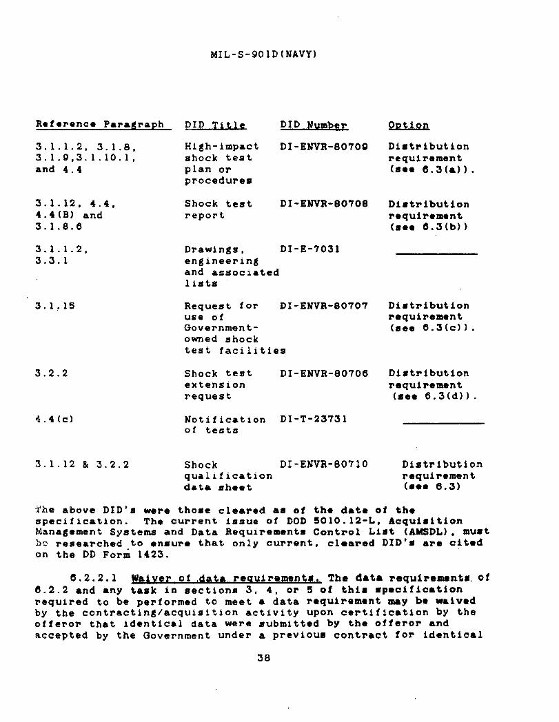
Reference Paragraph
3.1.1.2, 3.1.8,3.1.9,3.1.10.1,and 4.4
3.1.12, 4.4,4.4(B) and3.1.8.6
3.1.1.2,3.3.1
3.1.15
3.2.2
4.4(c)
DID Title DID Number
High-impact DI-ENVR-80709shock testplan orprocedures
Shock test DI-ENVR-80708report
Drawings, DX-E-7031engineeringand assoc~atedlists
Request for DI-ENVR-80707use ofGovernment-owned shocktest facilities
Shock test DI-ENVR-80706extensionrequest
Notification DI-T-23731of tests
3.1.12 & 3.2.2 Shock DI-ENvR-eo710qualificationdata sheet
oDtion
Distributionrequirement(808 6.3(a)).
Distributionrequirement(see 6.3(b))
Distributionrequirement(see 6.3(c)).
Distributionrequirement(see 6.3(d)).
Distributionrequirement(se- 6.3)
‘the above DID’s were those cleared as of the date of thespecification. The current issue of DOD 5010. 12-L, AcquisitionManagement Systems and Data Requirements Control List (AMSDL), mustba researched to ensure that only current, cleared DID’8 are c+tedon the DD Form 1423.
6.2.2.1 The data requirenwnlm of6.2.2 and any task in sections 3, 4, or 5 of this specificationrequired to be performed to meet a data requirement may be waivedby the contracting/acquisition activity upon certification by theofferor that identical data were submitted by the offeror andaccepted by the Government under a previous contract for identical
38
MIL-S-901D(NAVY)
item acquired to this specification. This does not apply to#pecific data which may be required for each contract regardless ofwhether an identical item has been supplied previou=JY (forexample, test reports) .
6.2.2.2 Shock qualification. Section 3.3.1 specifies shockqualification information which is to be incorporated on ● suitableequipment drawing if the contract or order requires development ormodification of such a drawing. The data requirement toinclude this information should be incorporated by the acquisitionactivity au part of the requirement for the drawing concerned.
6.3 Bid/contract requirements. The following information isprovided as guidance concerning requirements to be included in bidsor in the contract for the distribution by the contractor of datarequired by this specification:
(a) Distribution of shock test procedures should beaccomplished as follows:
(1) Acceptance authority: Two copies unless otherwisespecified (see 6.2.1).
(2) Contracting activity: One copy, if contractingactivity is not identical to tbe acceptanceauthority (see 6.2.1).
(3) Manufacturers of Items to be tested: In caseswhere the contractor is not the manufacturer ofprincipal units or subsidiary components to betested , or is not the manufacturer of asubassembly which is to undergo type C testing,these manufacturers shall be furnished a COPY ofthe shock test procedures for information.Distribution of shock test procedures tomanufacturers of subassemblies which comprisesubsidiary components or principal units to betested may be required (see 6.2.1).
(4) Naval Sea Systems Command (Ship ProtectionDivision) , Washington, DC 20362-5101: One copyfor information and one microfiche copy for data8torage.
(5) Supervisor of Shipbuilding, Conversion and Repair,USN, Brooklyn, NY 11251: One copy for review andone microfiche copy for data storage.
39

MIL-S-901D(NAVY)
(6) Naval Ship Systems Engineering Station (Code045B) , Philadelphia, PA 19112: One copy forinformation and one microfiche copy for datastorage.
(7) Performing shock test facility: One copy forinformation.
(8) Other: As specified (see 6.2.1).
(b) Distribution of shock test report8 #hould b.accomplished ●s follows:
(1) Acceptance authority: TWO coPies unless otherwisespecified (see 6.2.1). In cases where a localrepresentative of the acceptance authority hascertified shock test or post-shock testinformation, a copy of the report shall also beforwarded to that representative.
(2) Contracting activity: One copy, if thecontracting activity is not identical to theacceptance authority (see 6.2.1).
(3) Manufacturer of tested items: In cases where thecontractor is not the manufacturer of testedprincipal units or subsidiary CO~pOnent%, or is
not the manufacturer of a subassembly which hasundargone type C testing, these manufacturersshall be furnished a copy of the test report forinformation. Distribution of shock test report8 tomanufacturers of subassemblies which comprisetested subsidiary components or principal unitsmay be required (see 6.2.1) .
(4) Naval Sea Systems Command (Ship ProtectionDivision) , Washington, DC 20362-5101: One copyfor information and one microfiche copy for datastorage.
(5) Supervisor of Shipbuilding, Conversion and Repair,USN, Brooklyn, MY 11251: On. copy for review ●ndone microfiche copy for data storage.
(6) Naval Ship Systems Engineering Station (Code045B) , Philadelphia, PA 19112: One copy forinformation and one microfiche copy for data8torage.
40
MIL-S-!301D(NAVY)
(c)
(d)
(-1) Yerlormlng shock test Xaclllty: One copy forinformation.
(8) Other: As specified (see 6.2.1).
Distribution of requests for use of (30vernment-ownedheavyweight shock test facilities should be forwardedvia the acceptance authority to the Naval Sea SystemsCommand (Ship Protection Division). Distribution ofrequests for use of Government-owned lightweight andmedium weight shock test facilities should beforwarded to the test facility with an informationcopy to the acceptance authority. DI-ENVR-80’707applies.
Distribution of shock test extension requests shouldbe
(1)
(2)
(3)
(4)
(5)
(6)
(7)
accomplished as follows:
Acceptance authority: Two copies unless otherwisespecified (see 6.2.1).
Contracting activity: One copy, unless otherwisespecified (see 6.2.1).
Manufacturers of items subject to shock testextension approval : In cases where the contractoris not the manufacturer of the item which 1Ssubject to shock test extension approval t them&ufacturer shall be furnished a copy of theshock test extension request for information.
Naval Sea Systems Command (Ship ProtectionDivision), Washington, DC 20362-5101: One copyfor information and one microfiche copY for datastorage.
Supervisor of Shipbuilding, Conversion and RePair,USN, Brooklyn, Ny 11251: One copy for review andone microfiche copy for data storage.
Naval Ship Systems E~ginee~ing Station (Code045B) , Philadelphia, PA 19112: One copy forinformation and one microfiche copy for datastorage.
Other: As specified (see 6.2.1).
41

MIL- S-901 D(NAVY)
6.4 General information. The following information isprovided as guidance for designers and others responsible forfulfilling the provisions of this specification:
(a) All items will exhibit some deflection during exposureto shock; nothing is “rigid” , except in a relativeaanae . ,
(b) To account for relative deflection betwen componentsduring shock loadings, the degigner 8hould ●ndeavor tobuild maximum tolerance for relative motion betweencomponent parts into his design. Examples of relativemotion-tolerant design are:
(1)
(2)
(3)
(4)
(5)
(6)
(7)
(8)
Maximized clearances between rotating andnonrotating parts,
Design such that momentary impact between rotatingand nonrotating parts will not significantlyaffect equipment performance.
Provision of sufficient slack in wiring to preventpull-out or breaking of wires during shockexcursions .
Stiffened or braced structure and avoidance ofdesigns and structural arrangements (such ascantilevered elements) which tend to deflectexcessively.
Provision of ample clearance between seParatelY-mounted components or equipments to prevent shock-induced impact.
Design of control systems such that shock-inducedrelative motions do not cause significant falgesignals to be introduced into control 8y8temlogic.
Design of systems utilizing limit switches onsafety tripout devices such that shock-inducedrelative motions will not caune inadvertent 8hock-induced shutdown of vital ●quipment.
Uge of flexible shaft couplings, flexiblewaveguide sections, and flexible tubing or pipingloops where necessary to accommodate relativemotion.
42

MIL-s-9olD(l’JAvY)
(c)
(d)
(9) Avoidance of requirements to rigidly connect ltem8to two elements of ship structure which coulddeflect relative to ●ach other during shockloadings.
Desirable material properties for shock r*~istantdesign are high yield strength, high ductility (atleast 10 percent elongation) , high fracture toughnes8,and , in some caaes, low density (to reduca inertialforces) . Undesirable material prop@rtiat ●e.brittleness, low impact resistance, high nilductil$tytransition temperature, and high notch sensitivity.Cast iron and cast aluminum have proven generallyunsatisfactory when used in strength memb8rs in shockresistant ●pplications. Us. of these materials ●sstrength members in shock r@#lStant ●pplications -Ybe prohibited by separately invoked specifications.
In general, ample cFos8-8ection8 should be provided inpotentially highly-stressed ●reas, ●nd factors causingstress concentration, such ●s notches or suddenchanges of cross-section, should be avoid*d.Structural continuity should be ●chieved wheneverpractical, with aim of distributing shock-inducedstreagea throughout structure8 in ● reasonablyuniform manner.
(e) Well-constructed positive securing means such ashinges or shafts with bearings should be utilizedinstead of knife-edge pivots in the design of supportof moving parts of mechanisms such ●s voltageregulators and relays.
(f) Levers , linkages, and other moving parts of mechanismsshould be dynamically balanced (either individually oron a Systcm basis) whenever practioal in order toreduce the likelihood of shock- induced malfunction.This criterion is particularly applicabl* to ite-such aa circuit breakers, rotary solenoids, relaYssgovernor systems or other control systems, ●ndemergency shut down systems.
(g) Cantilevered mounting of equipments or component8should bo ●voided; ●xperience indieat*= that thismethod of mounting commonly leads te excessivedeflection, high stresses, ●nd conseqtnntly to shocktest failures and shipboard vibration problems.
43
MXL-S-901D(NAVY)
(h) Friction cannot b- depended upon as a meana formaintaining the relative position of alignment-sensitive components during ●xposure to shock,regardless of the apparent static holding power of thsfrictional connection. Positive locating and holdingmeans such as fitted bolts or rsbbett~d joints aihouldbe utiiized in alignment critical application.Positive means should al-o lm used for securingtapered dowels and similar items in liQu of relyingupon friction alone as ● meens for zecuring Suchdevices. Positive locking devices should be used toprevent wires, circuit boards, etc., from looseningfrom connections.
(i) Electronic cabinets and other items which are designedto facilitate quick maintenance ●cce-- or removal musthave positive, shock resi-tant means for latching,secure closure, lock-in, or support when in theirnormal operating position. Such latching or lockingdevices should be quickly and ●aaily oporated and@hould not require special tools. For ●xample, use ofone or two single-turn positive latches to ●ecure anelectronics cabinet drawer sliding as-embly is thepreferred approach; use of ten capscrews toaccomplish the same function 1S discouraged.
(j) Where bolts (including cap -crews, machine screws, andstud-) are installed in clearance holes, the clearanceshould be minimized to cause proper sharing of bolt-hear loads and to reduce the ●dverse effect- ofimpacting due to load reversals under shock. Thefollowing clearance criteria are recommended (and maybe invoked as a requirement by applicablespecifications) :
Itfominalbolt diameter diamete~ of hole
3/4 inch ●nd smaller Nominal bolt diameter plu8l\32 inch
Larger than 3/4 inch Nominal bolt diamater plus1/16 inch.
(k) Where alignment must be maintained, fitted bolts orother positive methods should be u-cd. Nearly allbolted joints tend to 100-en undar shock. Proper boltdesign, aufflcient pre-stress, &nd adequate finighingand sizing of joint surface- can eliminate or reducethis tendency. For joints employing O-rings or other
44

b!IL-S-901D(IUAVY)
types of gaskets, proper bolt pr~-stressing is●ssential to prevent the flanges from momentarilyparting under shock with possible displacement of thegasket due to the internal hydrostatic toroes.
(1) In general, where required by 8epar&tely invokedspecifications, bolts should be tightened (pre-stressed) to ● maximum valua con-i-tent with thoallowable stress, the sffscts of combinod loadg, andoperating conditions. Lock nuts may help to preservethe initial pre-stressing and will normally ●s#ist inminimizing the possibility of ●dditional damage inthe event the joint does become loose following 8hockloadinga. Except for very light items such as gaugas,mounting bolts less than 1/2 inch in diameter shouldnot be used because of the inherent risk of overstressing during Initial or subsequent tightming.Reduced shank or hollow bolts Increass th- capability “of the bolt to absorb energy: however, in order tomaintain tight and unseparated joints, it 18preferable in almost every case of bolted jointdesign to transmit energy rather than attempt toabsorb it.
(m) When possible, locate welded joints away from highlystressed areas. The effects of stress reversalsshould be considered in joint selection. Forinstance, welds loaded only in compression undernormal conditions will experience both tensile andcompressive loadings in the shock environment. Welddesign should make ●llowance for uorrosi.ons difficultyin welding, discontinuities and other factors whichtend to reduce weldment strength. The effact of heaton the material as a result of welding, especially foraluminum and similar materials. should be determinedand allowed for. In general, 100 percent afficientjoint designs should be used to develop strengthneeded to resist shock loadings. The ability toperform weld inspections satisfactorily should beconsidered in the design of joints. Experienceindicates that a seemingly dispropo~tionat.humber of shock test failures havm bqen caused byimproper selection of welding procedures or by lackoti effective production quality, cantrol An this ●rea.
(n) Threaded pipe and fittings should be avoided. Wherethreaded connections cannot be avoided, flexibilityshould be provided to minimize the load on the
45

MIL-S-901D(NAVY)
threada. Flexibility should b- provided in pipingruns between different components or whcra they sreattached to structures that can hav~ relativt movomontunder shuck. ‘J’h8inertial ●ffocts of pApimg can b.large, and sufficient support should be provided so asnot to over-stress or elastically deform the equipmentor associated valvo8 or fittings ●xcessiv~ly. Shockteat requirements for piping system compon~nts forNaval shipboard use aro spocifiod in MIL-STD-798.
(0) Subject to limitations which may b- separatelyspecified, shock mounts may b- smployad, ba80d on ●
definite need, and only after ● careful roviaw of thedesign indicates that it is not othar wiso feasible tomeet the shock requirements. Whero ● nead for shockprotection is established, the mount characteristicsshould be determined based on ● knowl~dge of theparticular shock environment ●nd the dynamic natureof the equipment. Mounts must ●lso be compatible withother shipboard environments #uch as vibration andservice conditions and, ●s such, may be separatelyrequired to meet the requiramenta of MIL-M-17185.
(p) Most resilient mountings intmded primarily to serveas noise or vibration isolating devices pes8e8s non-linear characteristics, and the load mitigatingproperties under normal environmental loadings oftenchange radically with the large amplitudes and highrates of loading encountered in the shock environment.Mount deflection under shock, especially for basemountad equipment, should be constderod whomspecifying the clearances around the equipment and inthe design of waveguide, piping, and 8imilar
continuous systems. All mountings should have apositive, mechanical captive feature in their design.Resilient mounts originally designed for the purposeof mitigating shipboard or equipment noise orvibration do not necessarily pomsess good shockmitigation properties, ●nd on many occasions haveproven detrimental in the -hock environment owing tohard bottoming of the mounts Or due to the“introduction of re~onance problems which in ●ffectcause the mounting system to ●mplify shock motions.For theme reaaana, and because r~sili-nt mountingsystems necessarily demand weight, space (clearance) ,and maintenance requirements in excess ofcorresponding rigidly mounted arrangements, theapplication of resilient nibunt8 is commonly
46

MIL-S-901D(NAVY)
restricted by applicable specifications.(q) Design of items for resistance to the adv.rse effects
of vibration will normally ●l-o enhance shockresistance. It is particularly Important in bothshock and vibration-rernistant applications to avoidstructural resonance between SIMS1l co~Ponenta andlarge masses in the #same (attached) gystem, and to usepouitive securing meana for the item and its
components . Shock-induced vibratory amplitudes andassociated absolute displacements are normally muchgreater than those aggociatsd with normal vibrationenvironments.
(r) It 6hould not be +automatioally agawd by the designerthat standard-line equipment sw$t bc redesigned inorder to satisfy the requirements of thisspecification. Standard-line (or commercial) itemshave often passed the shock tests required by thisspecification because:
(1) The item tested was originally de@igned towithst~d high operat%ng load$ c~nternal presgureltensile or torsional loada, etc.) and thus isinherently resistant to shock loadings also.
(2) The item will remain functional degpite minorshock-induced distortion of structural members orinternal partg. (Grade A shock test acceptancecriteria ●re normally keyed to the ability oftested itsma @ fuctian proper~yduring ●nd+f%er exposure to shock, rather than to thephysical condition of items following shocktests) .
(3) Separately invoked or self-imposed requirementsintended to provide resistance against shockloadings caused by handling or shipping of itemshave caused ruggedness to be built into thedesign.
(s) Information concerning shock test devices and testedequipment response is available from Naval ResearchLaboratory, Strvcturml In,togrity Bnanch, Washington.DC 20375. Additional information concerning theconstruction and characteristics of floating shockplatforms is available from Undwwater ExplosionsResearch Division, David Tayler Remearch Centsr,Portsmouth, VA 23709.
47

J$IL-S-901D(NAVY)
(t) Design provisions to limit the extent or effect ofmomentary malfunctions under ~hock (e.g. , redundantcontacts) will depend to some extent on the design ofthe system in which a component is intended to beused. Examples of momentary malfunction (see3.1.10. l(d)) and the considerations affecting theiracceptability include the following:
(1)
(2)
(3)
(4)
Loss of suction: Acceptable for bulk liquidtransfer pumps, bilge stripping pumps, fire pumps,lube oil pumps, and similar pumps, provided thatthe interrupted pressure or flow from the pumpreturns to normal without manual actions andresumes quickly enough to avoid wiped bearings,upset of fluid control systems, etc. This samemalfunction is unacceptable for items such ascontrol oil pumps where falling control oilpressure causes a manual-reset trip valve toclose, fuel oil pumps where the interruption maybe long enough to extinguish burner flames, pumpswhere manual action to reprirae the suction or stopthe pump is necessary to prevent pump damage, andin similar cases.
Lifting of relief valvea: Acceptable if the valvereseats without ●ssistance with normal systempressure maintained at the inlet piping to thevalve, provided no hazard is created by valveeffluent. Unacceptable if the valve fails toreseat without assistance, if effluent could cauaea hazard, or if the valve is tested with equipmentincapable of sustaining a prolonged (severalseconds) normal lift and re~eat of the valve.
Interruption of instrument reading: Acceptablefor basic gauges whose readings ●re takenmanually, provided no manual protective action orautomatic securing of the ●quipment would resultfrom the interrupted reading. Unacceptable forinstruments monitored by automatic controlsystems where loss of instrument reading, falsereading, or loss of sensor signal cauaes anautomatic protective actifm.
Governor/regulator control signal fluctuation:Acceptable only if the specified characteristicsof the equipment being controlled are known andthe fluctuation of oontrol signal can be shown to
48

MIL-S-901D(NAVY)
.
result in a change in the parameters of theequipment being controlled that is small enough tobe acceptable. Unacceptable if the control signalfluctuation results in controlled ●quipmentparameters outside the acceptable range (e.g.,excessive or inadequate speed, frequency, voltage,pressure, etc. , resulting in damage or interruptedoperation of the controlled item or downstreamequipment dependent on tha output of thecontrolled item).
(5) Contact bounce, trip, or change of state: Contactbounce in relay, switch, or circuit breakercontacts is ●cceptable only as defined by theapplicable acquisition documents. Shock-inducedbounce of contaatm not d-signed for opening orcAosing under load (e.g., dimconnsct devices) isunacceptable. Shock-induced tripping of grad. Acircuit breakers or chango of state of grade Aswitches is unacceptable. If no requirements forcontact bounce are set forth in applicableacquisition documents, than bounce-open of closedcontacts is acceptable only if self-correcting ●ndbrief enough that no impairment of downstreamequipment results, while bounce-closad of opencontacts is unacceptable.
(6) Loss of program or data: LOEIS of program orstored data is unacceptable. Momentary Iosa ofdata being received or transmitted is ●cceptableprovided it in automatically detected ●ndcorrected without significant impact oncommunications link capacity or on controlledfunctions dependent on the transmitted data.
6.5 ~nt aDpro va~. The ●ttention ofthose responsible for the preparation of acquisition documents isinvited to the items listed below which, in all cases, ~equireapproval of the Government (Command, Agency, Activity, or itadaaignated representative) . To minimize requirement- for separate;30vernmant approval action, contract ordering data should includeinformation related to the items listed below, whensver possible.Note that additional requirements for Government approval ofinformation related to shock testing may be ●dded to the contractordering data if deemed necessary.
(a) Ordering data for heavyweight tests when independentlydeveloped by the contractor (see 3.1.1.21.
49

MIL-S-901D(MAVY)
(b)
(c)
(d)
(e)
(f)
(g)
(h)
(i)
(j)
(k)
(1)
(m)
(n)
(o)
Ordering data for lightweight ●nd medium weight shocktests when independently developed by the contractor,when required by 6.2.1” or when ~ubraitted by thecontractor (se- 3.1.1.2).
Permission to utilize the large floating shockplatform (see 3.1.2(c)).
Permission to accept tasted items based upon gradsrequirements , if shock grade is not speclfiod (ace3.1.3).
Permission to perform type B teat when recommendedthe contractor (see 3.1.5.2).
Permission for repeat shock testing of subsidiarycomponents or subassemblies only (see 3.1.5.2(b),3.1.5.3, and 3.1.ll(a)).
Permission to perform type C test (se* 3.1.3.3).
Permission to use nonstandard test fixtures forlightweight teats (see 3.1.6.1).
B
by
Permission to us. nonstandard mount$ng fixtures formedium weight tests (see 3.1.6.2).
Permission to mount bulkhead-mounted items upon thestandard mounting platform, inclined ninety degreesrelative to the shipboard mounting po81tion, forawdium weight atiwar.tabip direction teats (ace3.1.6.2.2(c)).
Acceptance of test fixtuw yielding or cracking duringshock tests (see 3.1.6.3(d)).
Permission to simulate one or more of ● group ofidentical subsidiary components in the test of ●
principal unit (ace 3.i.’?.2].
Permission to simul~te 8uba8eemblies during type A ●nd“El teuts (see 3.1.7.3).
ApprovmL of modification of the basic shock t~s.tparameters (see 3.1.8).
Approval to substitute sepa~ate items for items whichhave been exposed to six (or more} medium might shock
50

MIL-S-901D(NAVY)
(p)
(q)
(r)
(s)
(t)
(u)
(v)
(w)
Approval of selection of heavyweight test operatingmodes (see 3.1.8.4(d)). NOTE : This informationshould normally be included in the heavyweight testordering data referred to in 6.5(a) .
Approval of functional performance testing to beaccomplished after disassembly or repair of the item(see 3.1.9.1).
Approval of exceptions to standard shock testacceptance criteria (see 3.1.10.2(a), 3.1. 10.2(bl, and3.1. 1O.2(C)).
Permission to proceed to next shot of the heavyweighttest series without correction of damage in violationof acceptance criteria [see 3.1.11(C) (2)).
Selection of heavyweight test shots to be repeated andprocedures for such tests (see 3.1.11(c) (4)1.
Approval of shock test reports (see 3.1.12 and 3.1.13)and DI-ENVR-80707.
Permission to utilize Government-owned shock testfacilities (see 3.1.15).
Permission for shock test extension of an itemproduced by a given manufacturer to be based uponp~evious shock testing of an item produced by adifferent manufacturer for “build-to-prinft” typeacquisitions (see 3.2.1(1)).
6.6 Definitions. Definitions of terms umed herein are asindicated in 6.6.1 through 6.6.9.
6.6.1 Item. Item is defined as a complete and definable unitor a component of machinery, equipment, system, or Structur-. AnI?,smcan be a principal unit, subsidiary component, or subassembly..,IJIit+am can also be a group of units or a system.
.
6.6.2 ~vstem. System is defined as an arrangement o?combination o’f $’tems,’all ~f which are nwcessary topwfomn aspecific operational function or functions (such as a -inpropulsion system, a refrigeration system, fire controlsystem, or hydraulic system) .
51

MIL-S-901D(NAVY)
6.6.3 Acceptance authority. Acceptance authority la definedas the Government activity (or its designated Qovernmontrepresentative) having approval authority whora approval of ●ctionsor re8ulta is required herein, and having the responsibility andauthority to determine contractor compliance with therequirements of this specification. The ●cceptance authority foreach contract or order will be as specified (see 6.2). Differsntacceptance authorities may be specified for the various ●pprovalactions required herein for a single contract or order.
6.6.4 Contracting activity. Contracting ●ctivity im defined●s the ●ctivity having authority and responsibility to initiatepu~chase orders, agreements, or documents for acquisition ofservices, materials, or items.
6.6=5 ~. Contractor is defined ● s ● party who hasentered into a formal agreement to provide the services, materials,or items specified herein.
6.6.6of shock it
(a)
(b)
(c)
(d)
(e)
Hazard. An item constitutes a ‘hazard” if, as resultis possible for it, or a portion of it, to:
Strike and injure personnel operating or manning gradeA equipment.
Strike and cause significant impairment or malfunctionof grade A items or systems.
Cause an electrical short (as ● result of internaldamage or as a result of coming adrift and striking anelectrical conductor) in any electrical syskom whichis no,t protected by grade A circuit breakers.
Cause an electrical short which could possibly resultin loss of electrical power to ● grade A system, causefunctional impairment of a grade A system, or causeignition of flammable or explosive materials.
Cause release of injurious, flammable, radioactive,acidic, caustic, or othorwiso hazardoua liqulds,solids, or gases, exoept where it can be demonstrated‘that the nature, loaation, rate. or total possibleamount of leakage is such as to prevent development ofa significant threat to grade A sy8tems, personnel, orto the ship as a whole. Any fluid whose operatingtemperature ig ●bove 150”F or below O°F should beconsidered hazardoua. Fluid@ ●t ●ny temperatureshould be regarded aa hazardous if th~y might cause an
52

MIL-S-~OID(lIIAVY)
electrical short.
(f) Affect electrical, hydraulic, wat~r, or any othtraervicesi required by a grade A system to the extentthat significant impairment OF malfunction of thegrade A system might result. Examples of adverseeffects: unacceptable variation or unacueptablcreduction of pressure, flow rate, or voltaga; Isakageof a fluid from a non-vital system which could quicklydeprive a grada A system of ‘that”wquirod flui-d.
6.6.7 Witness. Witness is defined ●s the obsorver (orobservance) of a shock test procedure, post-test inspection, orfunctional test. It does not imply acceptance of the ●dequacy orthe results of the procedures, tests, or inspections.
6.6.8 Certification. Certification is dotined mverification of the accuracy of reported information of shocktests , post-test inspections, and functional teata. It does notimply acceptance of the adequacy or results of the procedures,tests , or inspections. The term is also defined ●s the veri-fication that a shock test machine or floating shock platform isconstructed and installed in accordance with the drawingsreferenced herein.
6.6.9 Designated Government representative. DesignatedGovernment representative is defined as a representative of theGovernment agency specified in the acquisition document to witnessor certify shock test procedures, post-test inspections orfunctional tests. The term is also defined as tho representativeof the Government agency specified by the Naval Sea SystemsCommand to inspect shock test machines or floating shock platformsor to certify them”to be constructed and installed in accordancewith drawings referenced herein.
6.6.10 Beviewer’s signature. This handwritten signature onfigure 19 is the reviewer’s individual verification andcertification of the following facts: (1) that this ●pproval actionis based on prsonai review of the subject test report or testextension request; (2) that this review has considered ●ll shockapproval criteria and shock guidance provided by this document,other acquisition documents, current shock policy instructions, andthe reviewer’s past experience ●nd knowledge; and (3) that theremarka and limitations shown on figure 19 include statements orreferences to (a) any shortcomings in ●quipm,nt performancediscovered during shock testing, and (b) the ●xtent, if ●ny, tOwhich testing could not be made fully representative of shipboardoperating conditions.
53
MIL-S-901 D(MAVY)
6.7 subject term (kev word) liati~,
Dock mountad ●quipmentHeavyweight shock te8tHull mounted equipmentLightweight shock teatMedium weight shock testPrincipal unitShell mounted equipmentShockSubassemblySubsidiary componentWetted-surface mountad
6.8 Chanfles from Drevious issue. A8terisks are not used inthis revision to identify changes with rcsp~ct te the previousissue due to the ●xtensiveness of the changes.
Review activities: Preparing activity:Navy - AS, EC, MC, OS Navy - SH
(Project ENVR-MO1O)
54
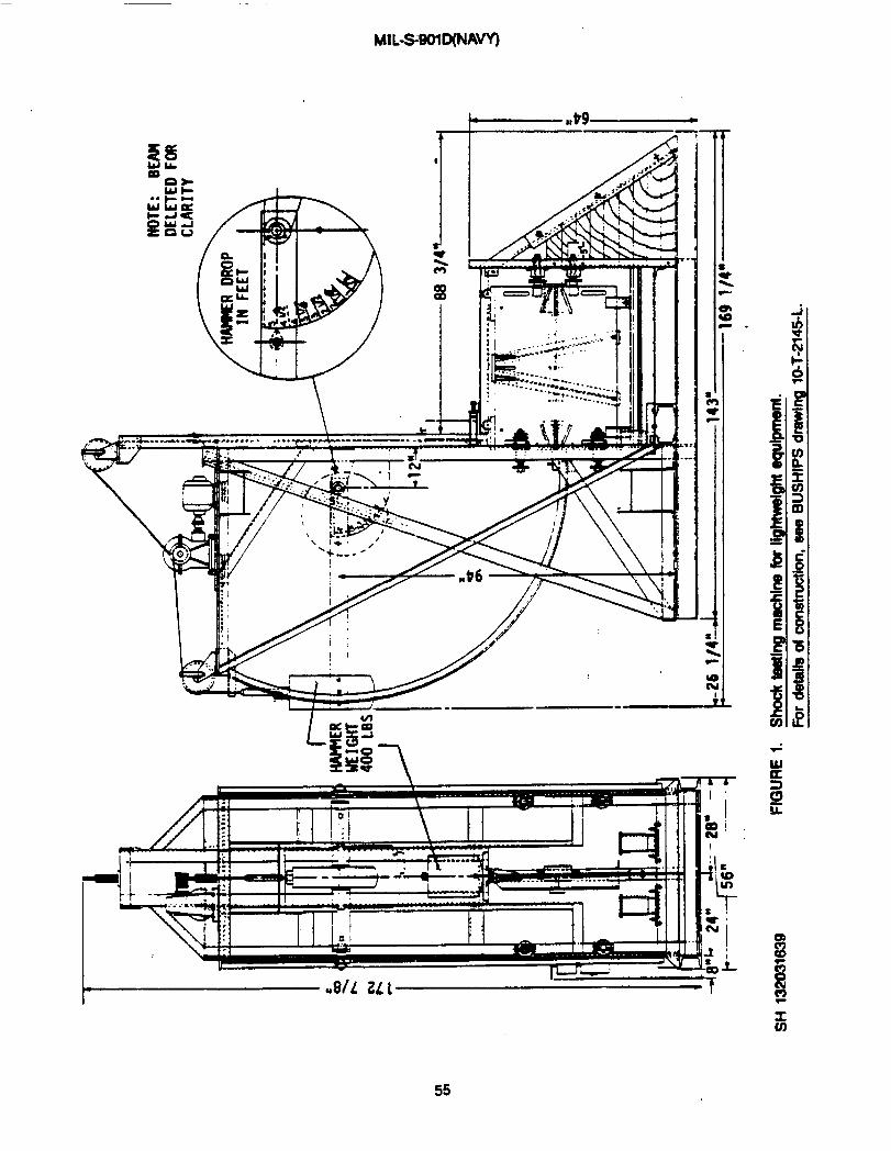
MIL-WOIIXWW)
\ -,\ * t
. . . . . . . .. —-
.
,
.
~. —- .—
55

MlL-&WID(NAVY)
——-————.
.
w w.-J% A/./ /’ ”...
L~g~~-a ...83 “ .,
,. *.,
L_., .\ J..,.. .. . .. ... ... .
‘ ;~● . . . . .. .. .
v v v
ed

MIL-&901D(NAVY)
i
I
+
I
xco
57
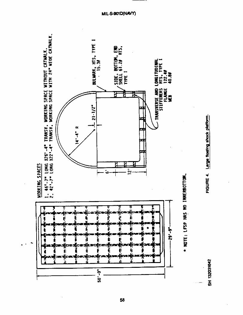
MIL-WOID(NAn
?s”
—. xu)
58
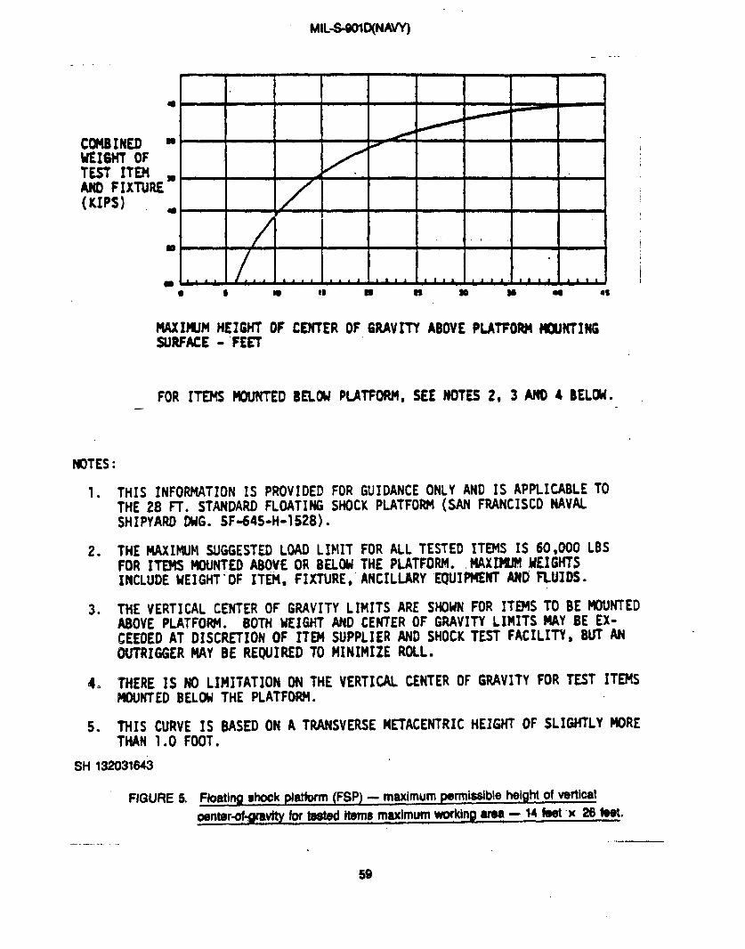
MIL-S-9CMD(NAVY)
..- .... . .
I I I I I I I I I 1m
COf481KD “UE16HT OFTEST ITEHANO FIXTURE”(UPS) -
,
Is w C9 & M a ●$
—
?K)TES:
1.
2*
3*
● 9 *
NAXIWM HEIGHT OFSURFACE- FEET
FOR ITEMS WNIW
CENTER OF GRAVITY ABOVE PLATFORM HWTING
SEW PIJWOW, SEE NOTES 2, 3 AND 4 BELOU.
THIS INFORMATIONIS PROVIDEDFOR GUIDANCE ONLY AND IS APPLICABLE TOTHE 28 FT. STANDARD FLOATING SHOCK PLATFOIM (SAN FRANCISCO NAVALSHIPYARD DUG. SF-645-H-1528) .
.
THE tWIMUM SUGGESTEDLOADLIMIT FOR ALL TESTED ITEMS IS 60,000 LBSFOR ITEMS MOUNTED A80VE OR BELW THE PLATFOW. MAXIJ’M ifEIGHSINCLUDE UEIGHT “OF ITEM, fImRE, ANCILLARYEWI~~ MD ~uJDs-
THE VERTICAL CENTER OF GRAVITY LIMITS ARE SHOW FOR ITEMS TO BE K)WTEDABOVE PLATFORM. BOTH lfEIGHT AND CENTER OF GRAVITY L1PU7S MAY BE EX-CEEDED AT DISCIWXON OF ITEM SUPPLIER AND SHOCK TEST FACILITY, BUT ANOUTRIGGER MAY 8E REQUIRED TO MINIMIZE ROLL.
THERE IS NO LIMITATION ON THE VERTICAL CENTER OF GRAVITY FOR TEST ITEMSMOUNTED BELW THE PLATFORH.
THIS CURVE IS BASED ON A TRANSVERSE METACENTRIC HEIGHT OF SL!GWLY MIRETHAN 1.0 FOOT.
5.
SH 13ZD31643
FIGURE 5.
——.. .
Ftoatiw shock platform(FSP) - maximum wmiable heig~ of ~~~~1
Oentard-gnww for bWeci items maximum working area -14 fad x 26 feat
.—
59

MIL-8-WID(NAW
———— .—. ... . ..—. — —..
UE16HT OFTESTITEMANDFIXTURE-KIPS
1.
2>.
2.
3.
4.
5.
so “
100
150 “ 9
250 “ -
350 - 0400
.
U&xuxwll HE16HT OF
FOR ITE?!S MUNTED
NOTES :
CENTEHF*RAVITY AOOVE tw w FRAME FLANUSm
BELW PLATFORM, SEE MOTES 2, 3 ANO 4 BELOU.
THIS INFORMATION IS PROVIDED FOR GUIDANCE ONLY AND IS APPLICABLE TOTHE LARGE FLOATING SHOCK PLATFORM ( SAN FRANCISCO NAVAL SHIPYARDWG. H-81898-SF-645-H1644) .
THE MAXIIWH SUGGESTED LOAD LIMIT FOR ALL TESTED ITEMS IS 400,000 WFOR ITEMS NOUNTED ABOVE OR BELOU THE PLATFORM. MAXIMUM WE16HTS IN-CLUDE UEIGHT OF ITEM, FIXTURE, ANCILLARY EQUIPNENT AND FLUIDS.
THE VERTICAL CENTER OF GRAVITY LIMITS ARE SWUN FOR ITEP6 TO BEtMXfNTED ABOVE PLATFORM. B(Yftf WEIGHT AND CENTER OF 6RAVITY LIMITSMAY BE EXCEEDED AT DISCRETION OF ITEM SUPPLIER AND SWCK TEST FACILITY.
THERE IS ~ LIMITATION ON THE VERTICAL CENTER OF &RAVITY FOR TEST ITEMSNOUNTED BELOW THE PLATFOfU14.
THIS CURVE IS BASED ON A TRANSVERSE M~ACENTRIC HEIGHT OF 2.0 FEET.
“ FIGURE 6. Wge floating shock plafform (LFSP) – maximum pofmisslbkheight of vertical wntwofgra vlty for t6sted hswm.
60
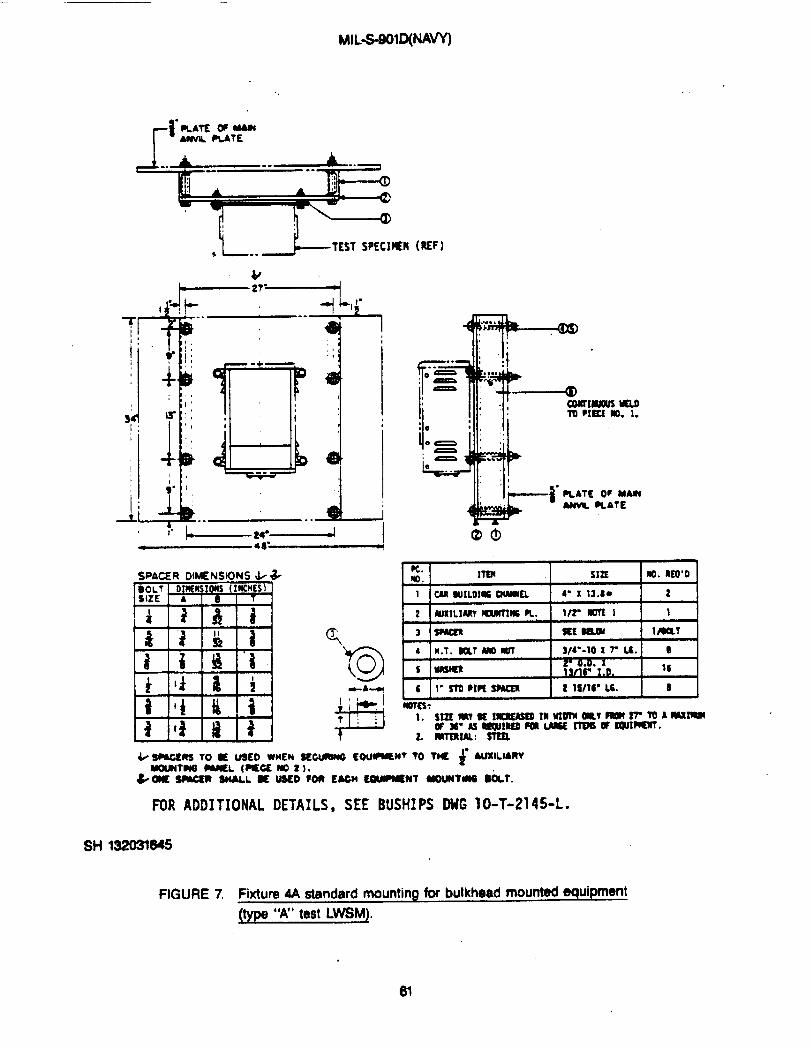
MILS901D(NAW
rpLATE OF MAINAWL RATE
L.__LT~sT‘PECIKN(UF)
I
I
.,,.,
q,
-+—
i: .
-.
&k..’ -.”
u.lm. Im SIZE
11 CM WILD11S6-EL I b“ x 13.BB
2 Nlxll.lm Iwmw m. 1/2” m I
3 SMKR SEi w4
m.RSO’DI2 I
---i
1
1mLT
4 I(. T. ml m Ixlrl w--so x r L6. s
s UAsm2“00 . . I
* unr I.D. 16
I 6 1- STDW2SW2R 1 2 lS/t6” L6. I B IWCS:
FOR ADDITIONAL DETAILS, SEE BUSHIPS OMG 10-T-2145-L.
FIGURE 7. Fixture 4A standard mounting tor bulkhead mounted equipment
(time W’ test LWSML
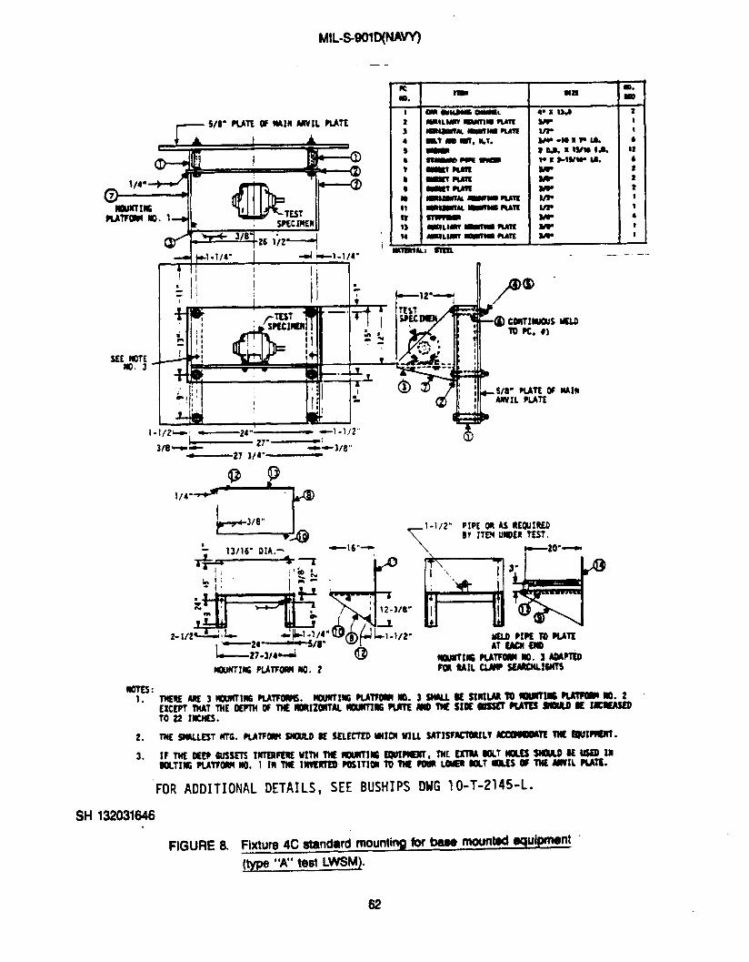
MIL-S9WD(WW
—-
S/8= PLATEW IMIR M IL MTX
J14~
mmmWmm m. 1
# -1/4” 4 +-1.1/4.I
I 4I “ I !i,1
12’I I nJo(x) “
P’$,, I I1-1/2-4 ‘— z4”— 41-1/2”
27.—’ $?lfn-u- --lIR,,-,--
—27 314“- -’-
ImEs:1.
2.
3.
FOR ADDITIONALDETAILS, SEE BUSHIPS lM 10-T-2145-L.
S1-1132031646
FIGURE 8. Fixture4C standard mounting for base mounted aqul~nt
(m “A” test LWSM].
62
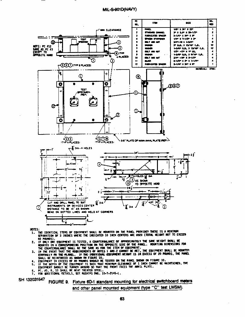
MIL-S-901D(NA~
@&fP8fvcss,w -y
I1I
I
I
Wm Sm
4
rT-
. .Mmlut xsxrl
ot$7AucE 10 u 10” As Smoww
9EU0 * OOTTCO L-i% A@ WSLD A7 CORMSRS
~.l.
3.
4.
5.
6.7*
--------WLL SE REINFOiCEii Ai-SUOtNI ~ F16uRE10.YIUl=ul la EXCESSOF ~ POIMM 910Ulh K TESTSOON TNEMNEL SNOW ON HUE 10.IF THE OEPTNOF TNE EWIFtCNT IS SUCHTMATUIWIUJN CLEMMCE ff 1 1~ HT = ~l~Alm,X)LIIPKwT WOULII SE TURMEIIARWNDSO THAT TnE FRO#TFACES‘TW ANVIL PLATE.W. 15, 8, ]0 SMALLRE HEAT TREATEDSTEEL.PM SOOITt~K fKTAN.S. SEE RUSHIPSOUG. 1O-T-2!4S-L .
w 132031WFIGURE 9. Fixture 60-1 standard mounting for electrical switchboard meters
and other panel mounted equipment (type “C” teat LWSM),

.-—
MILS-90’!-
mn:snP-Fc83sacdm
/1— .-.-
1 “-~1 // v’1 \? ~
— . .‘-hliTm-Ii: STEEL——-. ._ ._. —..-——--
%r’”m”
SH 132031648
“FIGURE10.
.
-[
I
3.4.
..-.—---SUAFACETWAM-ti .~tL mm.PC. 9s, 8* 10 X.S2 mAT mm.FOR MOITI- ~AILS, = ~~ ~“ IeT-Me=*
—.. - .—.. ---
w

MIL-WOID(NAVY)
.- ,,_ I mm 1
aL-- IML-WSSM)
1 ,
mA I A
2s mTam w-lo I P B mn.wm)
--- .r . I .- hn n lIU*W1 d la 1 msn. ,—w.w— r -,-.-.” .- ..- .- 1
.—J
? $TU WE m ‘-,w,m“, [ 1
s pwmc m @ m 1 I U.t. mu 1n l!.!%!.. 1 s I - I
.
8
.
;;
I
YCSTi
WPOMznt;
- yrly
.-l’F’-
Wao
77 t
FOR 4DD1TIONAL DETAILS$ SEE BUStJJES DWG 19-T-2145-L.
SH 132031649
FIGURE 11. Fixture 6E standard mounting for controller components
JContactors, relays, resistors, etc.) (type “C” teat LWSMJ
-n
65

—. —.
. .
MILS901O(NAW
—.—. .- - -— ——
1
1*
.- —.. -------- ---
,
---.~. ------- ------- -— .----—-.
,●
.
J,
a-.
T
t-----% “● I
‘k
II
.,Y.-..-“d
a-e
.
66

MIL-S-$OlD(f4Am
\
/
.
Ud -,---- -. ------ -----.- ----.-- .,
.I
II
mu
\
$----
[
x
x
m“5
ii
f!m
x(n
67
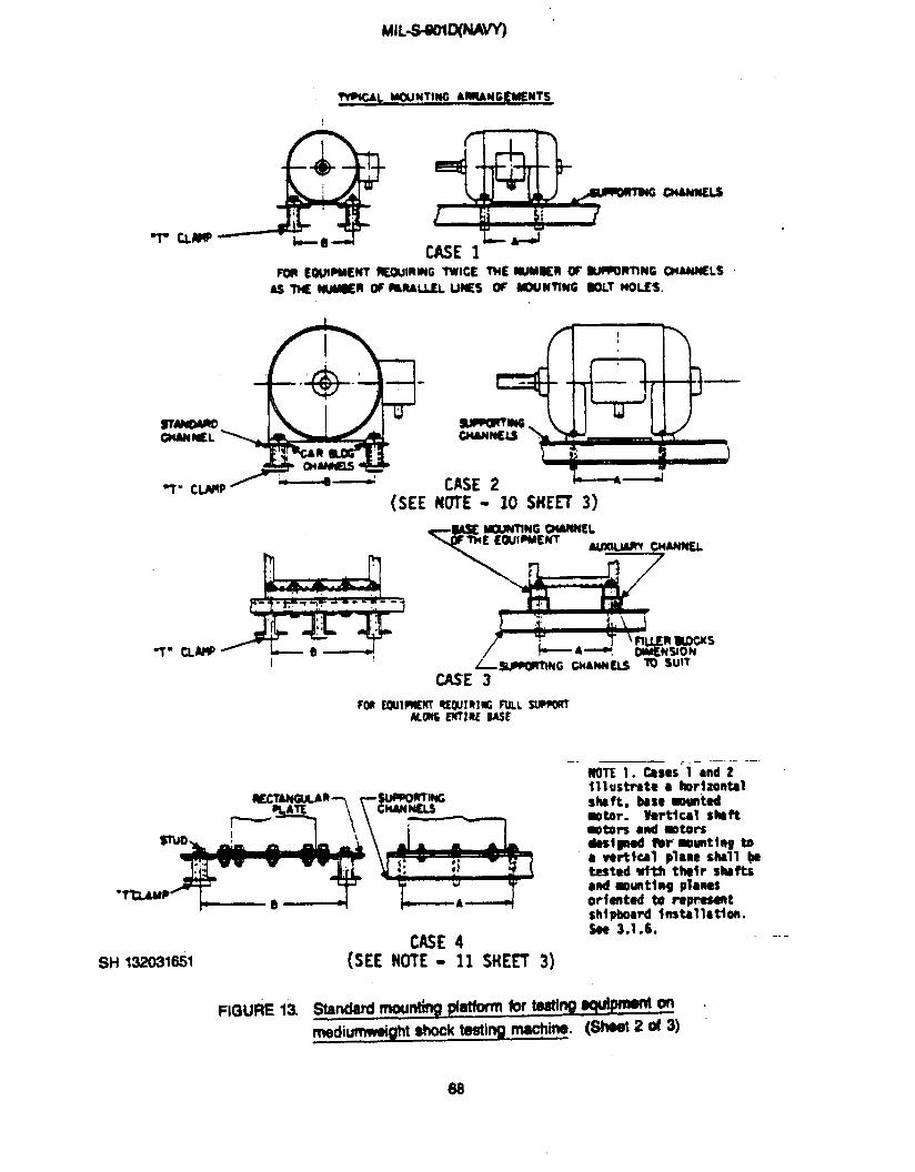
MIL-S-OLMM “
~ UNTING ARRANGtMSNTS
T CLMP I.-ACASE 1
CASE 2 imm\d
NOTE - 10 SttEEl 3)
-T’ CLMPI
SH 132031651
FIGURE 13
(SEE
+A+
CASE 4NOTE - 11 SHEET 3)
,. _ —.— .—NOTE 1. Ceseslmd Z111 ustrste c lw,fzontel
Shsft, bese Wuntedmotor. Vertical Shft-*I’S ●nd inters4estpOd Wr’ WUnttltg tos vertfml plme shell @testedwith thdr shefts●nd umntlmg planesor fented & re~tshf@merd Imtillatfen.
See 3.1.6, .—.-
Standard rncxnh$ @ atforfn fur te8thg ~ on
rnedi-ght shock testi ng machine. (Sh@ 2 d 3)
68
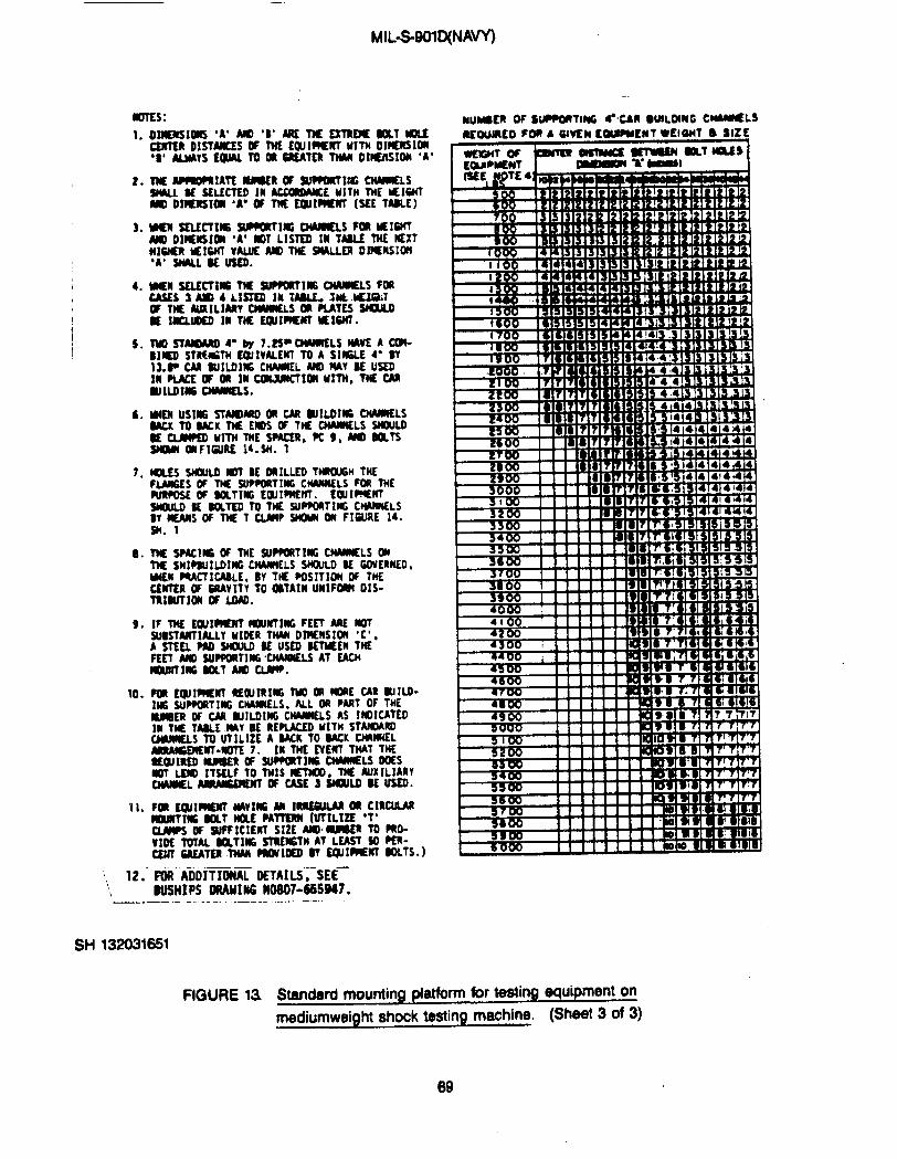
MIL-S-9D1D(NAW
ImEs :
1.
2.
3.
I 4.
b.
7.
9.
!0 ,
11,
“, 12.
OS14UKIOIIS ‘A’ M ‘B’ ARE ~ ~ S&l WLECESTSRDISTWUw TMEEaJI-NTMITMOlmlslm“S4 ALMAYSE@AL TO @ SREATERTWII DIENSfON 4A’
M APmoPAxATE nsuER w supporting ~sSMLL SE SELECTEDIM ~E MSTMTM UIGHTm Dl~SIWI “AO OF THE EW1_ (SEE TASLE)
m sELEcTIm 3uFwRTl)G awMELs Fm MEISMTMl DIHENSIOM ‘A’ S01 LISTEO N TAALE W KXTMHER##V&V& M THE 9WLLER DIWRSIOI
.
*M SELrcmc TnE SUPPORT]* OwvKLs FORCASES 3-4 LI$SEO Ill TASLt* Ilk -$1OF T)E AUXILIARY ~S m PINES WSE lKLmEo III TM E@mwn Mlsm.
TuO sT- 4“ by 7.3S-CIWMELS IWE A CWmm STKMNH w IVALOIT ~ A SI=LE ~- W13.- CM WILOIK CHAHL M M4~ BE USSDla Pi&E W OR M Cmammal Mm, W CMaJtLDIlls clwaELs.
MIEN US1N6 ST~MO OR CAR UkOIIG OWWELSSACKTO SACk TM EMOSWTWCHAMELSWMSE Cm WITH THE SPACER,PC $, ~ SOLTSSNam aFIwRE 14-W. 1
@LES WOULD IIOT BE ORILLEO -H THEfWKES OF TM SU~TIffi CMUNELS FOR THERrRPOSEOF mTIIG EWIWE~. EOJl=~SMOULOSESOLIEOTOTW SUP~TI*CMNUIELS~@fAINFY HE TCl&lPSHO UNONF16URE 14.
.
THE SWIM W THE SU~TIM CMWIELS 0TM SHIPWILDIW CWIMELS S*LD SE WERWD,WEU FQACTICASLE,By M $OSITION W THECENTERW WVITV TO OSTAIN UMIF= OIS-TR1SUTIONOF LOAD.
lF TM EOU1=W~NYIIICFEET ARE NOTSUK7ANTMLLY MIOER TWI OIMWSIOM ‘t’ ,A SEEL PM MLO SE USEOSETUEENTHEFE~ ~ SUPPORTINGtnAWIELS Al EACHMOUWTIWCSOLT M ~.
FORE@lWIENY REWIRItG TUO ~ ~E CAR RIILO-IHG SUPFORTIUGCNAMELS, ML OR PSAT OF THE-ER OF CAR UIILDMG CIWUIELS AS !IOICATEDM W TASLE MY SE REPLACEO MITH STAMOAROCIMIELS TO UTILIZE A SACKTO SACK CMNMELAR&NGEWMT-WOTE7. INTHE EVEWTTHAT THESEQIIREO UMDER Cf SUFPWIW CWWELS WESWY w ITSELF TO TMIS m, ~ mxlLIARyCrWUIEL~~CASES~~MU~.
—.F@ ADDITIONALUEWLS”;-sEE—BUSHIPSORAHIffiKM07-6B5947.
—..—- .——... .—..— -. .-. .. —-
SH 132031651
4
-+
4
t48W 11AaM It
t-+
FIGURE 13 $tanderd mounting # atform for testing equipment on
mediumweight shock testing machine. (Sheet 3 of 3)
69

MIL-WOID(NAW)
STD.
1-]/4” !ik?9 TAP PC. 4- l-l
1-3/4”4 yl;)~Pcsi*2 b!-2-”.
Q i /SEE~t I. . . .
?-3/8= ~ 2- 3/0-
STO . ol-EL~ l/8”— ~ 2-lts.,9/16”. .
- SiL7z,.,,’”-&,- .
.,J I +?$:,$ - 1-1/2”● I
L-..1
sH 132031652
7-QAm oIm4sIo14s
thlk;t~
‘- 1-1/161 1-1/2-, 1- I Z- 1
.TAP ?C. 16 - 7/8- * 9
m-2:-2&r-.
1/4.
3,
IW#css 146 15 1S/16- DIA.
‘E
7,
FIGURE 14. Section detdk of atandad mounting plaW’m b t@n9 mui~nton meditsmweight shock testing machine. (SW 1 of 3)
--
70
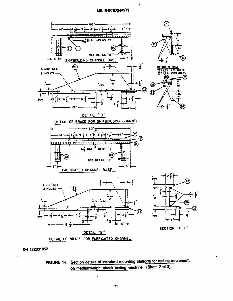
1-’-14” 4~+9~4” F9&4+-14”4
- - .$> ,...—. . . ------ -I ---..* -- 7
-10 MmcsI I
+ 5-~ SHIPBUILDING CHANNEL BASE + ‘- +
I-l/IS= DIA. Q21
DETAIL “D”
DE TAIL OF BRACE FOR SHIP8UILDM CHANNEL
!-----------
I
I -@
1-+ - SEE OETNL ● E-1
-ls”~ 4+5 °i8-FABRICATED CHANNEL BASE
1-1/16= DIA. i“- - ‘i-
SE~Tl(JfU ‘“F-F ‘0
DETAIL “E”
DE TAIL OF BRACE FOR FABRICATED CHANNEL
SH 132031652
.
FIGURE 14. Swtion datails of standard mounting platform for tasting equipment
on nwdiumweight shock testing machine. (ShtWt 2 of 3)
71

MIL-S-901D(t#W)
NOTES :
—.. ..- .
PG.ITEM SIZE (INCHES)
I SHIPBUILDING CHANNEL 7 X22.7*
I 2 ICAR8UILDING cwwrw 4X13E*
3 IC4AMP 12=X2 I/2=x4 3/4”, -— —4 j BLCKK l“x13!/4°x5~”
S ] PAD V2”X3A=X2 1/2”1
6 ] PAD I/z=x 1=% 2-
7 i HEXAGON HEAD BOLT I U4”-7 X 4 IM’LG
6 ] WASHER I I ~/8= 1.0, X 2 ~“0.D
9 ISPAGER 12’ X4= XA#R
10 HEXAGON HEAD BOLT * 1/2”- 13 X A/R
II WASHER 9/16= I.D. X 1°o.D.
12 HEXA~ HEAD NUT 1/2°-13m —
13 ICLAMP lSee Ffq 14 Sht 114 1STANOARD CMANNE L I 4= X 7.2@
Is CLAMP j13M=xlw4” x43/a=
16 BLOCK ]l. xl l/4=x4 3M=
17 PAD I 1/2= x 3/4”x I 3j4=
I 1/2” x 1= XIV4”
19 ] HEXAGON HEAD BOLT*
20 WASHER Is/Is” Lo. x I w. 0.0.
21 GUSSET 1/2° x 5 1/4= x Ii= -
22 PLATE 3/4° X49 x 13=
23 GUSSET 1/2” x5 1/2° X12 w=
24 PLATE 7/ox 4=X 12 V4.
25 PLAt E 7/6= X 2 W2” X 60°
E26
27
20
29
30
31
I PLATE *“X6= XC0.
PLATE 7/6= x 4- X60=
ICLAMP See Ficj 14 Sht 1CL AMP See Fi q 14 Sht 1CLAMP See Fig 14 Sht 1CLAMP~ 1t
MATERIAL SNALL BE STEEL
*Heat treated steel
I. TOP FLANGE OF PC. NO I SHALL BE BURNED OR WT OFF 70 A WIOTtl OF I 3/4=
2. PC. NOS. 3 AND 4 SHALL SE SHAPED TO FIT INNER SURFACES ~ PC. NOS. I AND 2RESPECTIVELY. (SEE NOTE $ )
3. PC. ~S. b AND IS SHALL BE SHAPED TO FIT INNER SURFACES OF PC. NOS. 4 MD U
RESPECTIVELY . ( SEE NOTE 5)
4.USE OF EITMR PC ~. I OR THE FABRICATED O+ANNEL, SECT~ “F -F= OF Fk *2
IS OPTK)NAL DEPENDENT UPON AVAILABILITY * MATERIAL m EASE OF FABRtCATIDN.
s ff THE FABRIcATEO OUNNEL, SECTION . F - F 9 IS USED, w. NOS. 3 ANDIS 2HOULD a2
SHA_ TO FIT THE INNER SURFACE OF T= FABRICATED -EL, SECTION ● F - F ●,
RATHER THAN PC. NO 1. PC. NOS. 6 AND 18 SHALL EACH BE SHIFTED INWARD 3/4 ‘.
6. USE oF BACK TO BACK SWP’ORT ING CHANNELS WHICH ARE PERMANENTLY WELDEDTOGETHER AT THE ENOS RATHER THAN BOLTEO TOGETHER, K OPTIONAL.
SH 132031652 ‘oR ‘DDITIONAL DETAILS s SEE BUSHI ps ~G N0807-655947
FIGURE 14. Section details of etsmdard mounting plstforrn for testing eqdpmant
on mecfiumweight shock testing machine. (Shad 3 of 3)

MIL-S-90WNAW
(TW2- ?)
3
(l’VP)
k ‘“~1-! l-1/2=(Tw)—w-
UIAIElllAL: STEELWEIGHT: 1088 tbs.
FOR ADDITIONAL
St-l 132031653
FIGURE 15.
DETAILS, SEE BUSHIPSDWGN0807-655947 o
Standard mounting fixture for teeting bulk-d ~uti
qulprna nt on mediumweim ehook taatlng maohine.
,
,-
i
?s

I
4]]—2?’—~1-lm~—46”—S* 1)49
—ss”
— 60”
(OWE
Su6w2
I
SH 132031654
FIGURE 16. 30 degree mounting fixture tor testing baaa mounted equipment on
mediumweight shock testing machine. (Sheet 1 of 2)
..
74 ‘

MIL-S-901~~
.— .— . . ---- .. —__.
b
WcE SIZE NATERIALm. Bd%tn
,1 1X4X70 Im 3010 2 *2 1/2 x 9-1/2 x 12-1/2 I z
3 1/2 X 8 X I>V2 2,4 l/2 x 8 X l&l/2 2,5 1/2x 8 x 24-1/2 2
A
6 U2 X8X29 2
7 l/2X14X36 2,8 1X26X60 2
9 v2 x22x% 2,10 1/2 x 7 x 6-ltz 4 2
Y
11 3/4x60x41 I& Mlo 212 3/4x60x60 61fl 113 l/2xsx27 HRS 101O 2
Yr!UTERIAL:STEELWIWT OF FIXTURE (BOTH PIECES)MOO~
NOTES:
1.
2.
3.
4.
5.
6.
7.
8.
9.
10.
THISFI~RE, WHEN USED, REPLACES THE SHIPBUILDING OR FABRICATEDCHANNELS9MUN OH F16URES 13 AND 14. EQJIPnENTANDSU-IN6 WJNELSME HWNEOTOTIIISFIXTUREASSnOUNONFIGURE 13.THIS FIXIVRE *Y DE USED 70 TESTBULKHEAD MOWED Ef$JI~M7 AT 30 W6REEINCLINATIMBY ADDING BULKHEAD FIXTURE SHOWN ON FIGUREM. SEE F16URE18FORALTERNATE M 0E6REE MOIJNT1H6 PUT’FWI FOR 6ULXHEA0 SLJPPORTIWEQLIIPMEI14T.PULL? ANNEAL ASS~Lr AfiER MELDING.
FINISM MCH INE A~ER ANNEALING.
PIECE MO. 12 IS NOT A PART OF THE FIXTURE. 11 IS A TEMPLATE HAYING A MmE .PA~ERN IDENTICALTO TNEHI SHOCK TEST MCHINE PLATFCXM. LWATE ALL 1-1/16IKH DIANETER HOLES FRON SWCK mCHINE PLATFORM.
ALL MELDS TO BE 1/2 IRCH COP4PLETELY AROUND EACH EDGE.
TWO-INCH DIAME7ER HOLE SHALL BE TORCH CUT A~ER WELDING. THE HOLE SHALL BELOCATEO WARTHECENTEROF 6RAVITV.
ALL EDBESANDCORNERS SMALL BEBROKEN SUITABLE FOR HANDLIJ16.
PANALLEI.ISN 3NALL BE MINTAINED AT SURFACES “B’ MD ED6ES “Ag UITHIH1/32INCH.FOR ADDITIONAL BETAILS , SEE BUSHI PS DMG N0807-655947.
SH 132031W
FIGURE 16. 30 ~ fee mounting fixture for testing betm mOUM Wi- On
mediumweight shock testing machine, (Sheet 2 of 2)
75

MIL-WOID(M~
n
●
76
xcl)
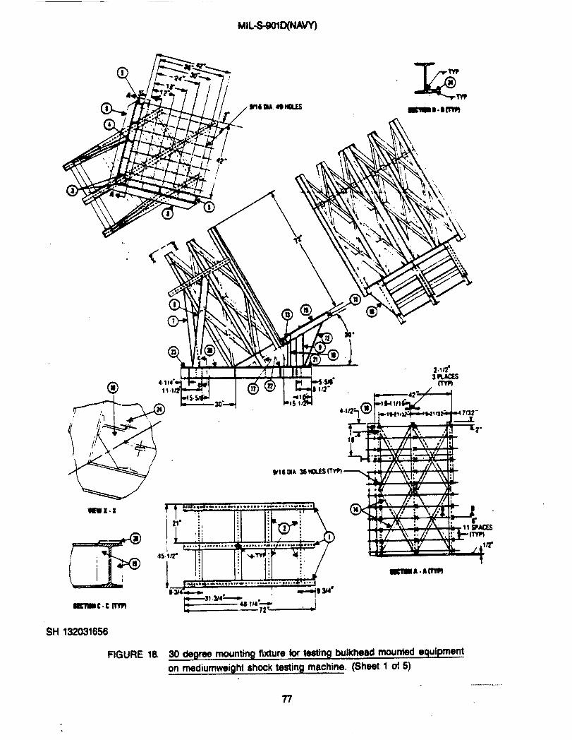
MIL-SWID(NA~
“&Tw
24
w?
-B.ofm
L?l% tM1/11or44r7 a ~,”,,~
-x. x ?y --,.. ..0. - . .-. -- . . . . . . . . ...”......”.=-. .
,. I I 1.1. . I 04!!M. : ,. B.
3WXS.-. . .. .... .. ...?.
I ~1+“’~;~~(,, ‘“ “ “ y.*e. ..*....-. . . . . . . . . . . . . . . . . . .,, -.—
E=-’’,,,- , J
SH 132031656
FIGURE la 30 degree mounting fixture for testing bulkhead mounted equipment
on mediumweight shook testing machine. (Sheet 1 of 5)
.—
?7

MIL-S@lO(NAW
LISTOF !411TERIAL
SH 132031656
—
mat I SIZE 1-. mm Imm tnmss R20%20
6.0 X 3-1/2X ~0.25 m 3
,OJ ga x I ~, I 2 I
141 M-zwll
1 I
c... i I i
I I
-. I‘tu 121
-14s 111“1s0!21
1—
1 1 1
s *SW ;“
64,
km
4A7 lM2M 0:
8 1
9 H=om18x
:; 17-1/2 1
20 &oEM 4o:&*-.’8 ‘ ‘ -w’ ‘
11 T-B2MLo x.-.
*W 1
13 r-em 20=2M 2
14 -EL
“’in J,l‘5-$hsauuZT33
I M J WE j S/8 X 42 42 I 11 1 1 I
.19 ST1FFU2R 3/8 X )-5/8 s-1/2 24
20 w 3/8 x 3tn 14-3/4 z
21 m 3/8 x 3.0 30-3/4 2
22 PM 3/8 x 300 blfi !I
23 PAo 3/2x&o 6 2i <
UEIGHT OF FIXTURE: 1733 POUNDSMATERIAL : STEEL
.-
FIWRE la 30 C@roe mounting fixture for -ng bulkhead ~ 4K@pm@nt
on modiunnk’eifjht @hockt9srinQ mdtirm. (shlBd 9 d q

.MIL-S401D(NA”
NOTES :
10
2.
3.
4.
5.
6.
7.
8.
9.
10.
11.
12.
UNLESS OTHERUISESPECIFIEDHEREINOR IN THEINDIVIDUALEQUIPMENT SPECIFICATIDN , SURFACE ROUGHNESS, AS ROLLEDOR DRAUN, PUNCH CUT OR MACHINED SHALL HAVE A 250 FINISHANO SHALL BE IN ACCORDANCEUITH ANSI 846.1.
THREADS SHALL BE IN ACCORDANCE MITH FED-STD-H28 AND ANSI Y14.6.
UNLESS OTHERHISE SPECIFIEDHEREIN OR IN THE INDIVIDUALEQUIPMENT SPECIFICATION, ALL FILLET UELDS SHALL BEl/4-INCH.
NACHINEO SURFACES SHALL NOT BE PAINTED.
FABRICATION PROCEMJRESAND INSPECTION STANDARDS FORWELDING SHAIL BE IN ACCORDANCE WITH CLASS 1 W MIL-U-21 157. UELD SHALL BE THE HANUAL SHIELDED ARCPROCESSUSINGWELDIHG ELECTRODE TYPE 7018 OF HIL-E-22200/1 .
STRESS RELIEF SHALL BE AT 1175° * 25°F F~ A RINXMUHOF 3 HOURS, THEN THE FURNACE SHALL BE COOLED.
WELDING SYHBOLS SHALL BE AS SPECIFIED IN AUS A2.4.
HELDING TERMS AND DEFINITIONS SHALLBE IN ACCORDANCEWITH AWS A3. O.
UIEl#~-JOINT DESIGNS SHALL BE AS SPECIFIED IN HIL--,
DIMENSIONS AND TOLERANCES SHALL BE AS SPECIFIED INANSI ?14;5.
THIS FIXTURE IS ATTACHED TO THE ANVIL PLATE OF THENW BY MEANS OF SUPPORTS AND CLAMPS SHWN ON SHEETS4AND5.FOR ADDITIONAL DETAILS, SEE BUSHIPSDWG N0807-655947.
SH 132031B56
I
FIGURE 13. 30defj reemounthgfixture fortestingbulkhead mwntedaq uipment
on madiurnweight chock teeting machine. (Sheet 3 of 5)
73

●✌
�� ✎�
MlLS901qNAVY)
.
/
P-i.*
- .Jb-*a
‘T;:
+4
!aT--
R.
‘*m
‘*111IllIll
Ill
IllIll
Ill
, Ill
Ill
Ill
111
Ill‘ Ill
IllIllIll
o Ill
“wI
u
.
‘*
t“ +@111- 1
Ill11P ‘Ill -J ●
~>
w
I
b

“go
1
I
-R.
Ia /
8’.—. — -
‘LwJ‘mh
.—. — .
●
E.“
%-“.!CUr
F-S
3 - “ ..’- ●u
mu)
-
4
*
s%in
.
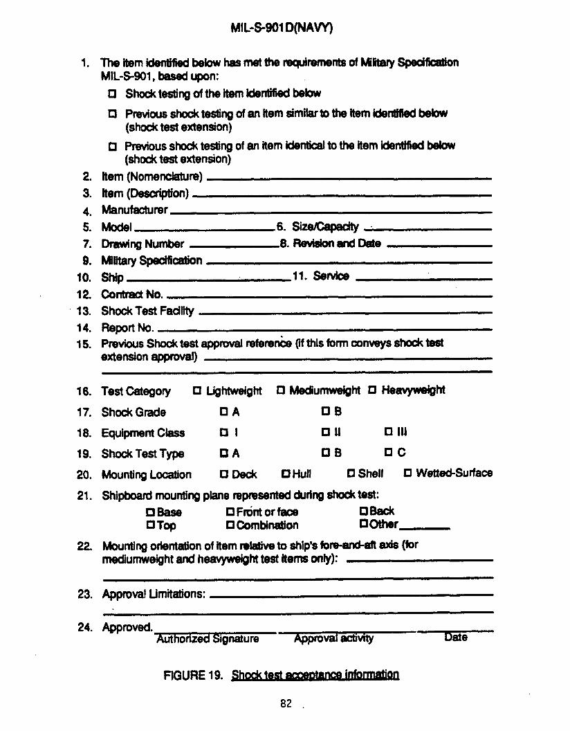
1.
2.
3.
4.5.
7.
9.
100
12
13.
14.
15.
16.
17.
18.
19.
20.
21.
22.
23.
24.
MtL-S-901D(NAVY)
Thehm~below hasmet Wf@reme~of Miiitary~on
MiL-S-901, btwd upon:
o
n
o
Shocktestingof the item identithd below
Ptious shook testing of an item aifnilafto the Item identified bebw
(shocktest extension)
Previousshockteslingof an item kbtioal to the itemWmtiiied below(shocktest extension)
Item (Nomenclature)
hem (Desori@on)Manufacturer
Model 6. SizeCapa&y
Dmwing Number 8. Revidonand DateMilitary Specification
w 11. Sertb
contract No.ShockTest Faoffity
Previous shock test approval referenke (ifthisformoonveysshocktestextensionapproval)
Test &tqOfy o U@tuveighto Mediulllwdght ❑ I+wyw#ght
Shock Grade CIA UB
Equipment CIass H I tl II n Ill
ShookTest Type O A ❑ B DC
MountingLocation Cl Deok D l-lull ❑ Shell O
shipboardmountingplane represented Cmng -test:
oBase D Ftint orfam oBaok•l Top O Combination 00ther_
Wetted-Surface
Mouting orientatkmof item dative to ship’sbm-amkft axis (forrnediumweightand heavyweighttest items only):
Approval limitations:
Approved.
FIGURE 19. ~● .
82 .

UNCLASSIFIED
-.. ,.w ,,. . .
UNCLASSIFIED
●
Related Documents