AD-A277 562 NUMERICAL SIMULATION OF LATERAL THRUSTERS IN HYPERSONIC FLOW OVER A BICONIC BODY BY T. HSIEH AND A. B. WARDLAW, JR. SYSTEMS RESEARCH AND TECHNOLOGY DEPARTMENT 8 MARCH 1994 I I Approved for public release; distribution is unlimited. 94-09694 -I II---- ------- D I HI I ii-- 111-- -- NAVAL SURFACE WARFARE CENTER DAHLGREN DIVISION oWHITE OAK DETACHMENT DAHr SpdD.g Silverd 2UM3-S,

Welcome message from author
This document is posted to help you gain knowledge. Please leave a comment to let me know what you think about it! Share it to your friends and learn new things together.
Transcript

AD-A277 562
NUMERICAL SIMULATION OF LATERAL THRUSTERSIN HYPERSONIC FLOW OVER A BICONIC BODY
BY T. HSIEH AND A. B. WARDLAW, JR.
SYSTEMS RESEARCH AND TECHNOLOGY DEPARTMENT
8 MARCH 1994 I I
Approved for public release; distribution is unlimited.
94-09694
-I II---- -------D I HI I ii-- 111-- --NAVAL SURFACE WARFARE CENTER
DAHLGREN DIVISION oWHITE OAK DETACHMENT
DAHr SpdD.g Silverd 2UM3-S,
NSWCDD/TR-93/138
NUMERICAL SIMULATION OF LATERAL THRUSTERSIN HYPERSONIC FLOW OVER A BICONIC BODY
BY T. HSIEH AND A. B. WARDLAW, JR.SYSTEMS RESEARCH AND TECHNOLOGY DEPARTMENT
8 MARCH 1994
Approved for public release; distribution is unlimited.
NAVAL SURFACE WARFARE CENTERDAHLGREN DIVISION * WHITE OAK DETACHMENT
Silver Spring, Maryland 20903-5640
NSWCDD/TR-93/138
FOREWORD
The lateral thrusters and the shock layer on the THAAD missile are studied throughnumerical simulation using a Navier-Stokes code. This report describes the simulation,presents the computed flow field and indicates the conditions under which jet flow is trappedupstream of the jet.
This report was sponsored by the Naval Surface Warfare Center, Dahlgren Division,ATBM Program Office under the direction of Pete Stafford. The aerothermal group coor-dinator was Frank Moore.
Approved by:
GEORGE LONGHead, Missile Program Office
aoeaston ?or
Unnnn:IIcodr 01
Di•' " 4,. bu.•t i on/-By .--..
ilii •.1~,j11•;,lt~r gode S__cpaudio
spr,4

NSWCDD/TR-93/138
ABSTRACT
A Navier-Stokes simulation of lateral thrusters on a biconic body in hypersonic flow ispresented. Due to simplifications arising from symmetry, cruciform thrusters were consideredfirst. A grid convergence was conducted to evaluate computational accuracy. This wasfollowed by the computation of three different jet exit conditions and an assessment ofthe flow field changes produced by each. Of particular concern was the possibility ofentrapment of streamlines from the jet in a recirculation region upstream of the jet. Thefinal case considered was a single jet thrusting from a biconic body at zero incidence at M= 9.7. These results were compared to experimental surface pressures. A description of thecomplicated interacting flow fields featuring multiple separation and attachment lines/regionsis also presented.
iii/iv

NSWCDD/TR-93/138
CONTENTS
Chapter Page
1 INTRODUCTION ............................. 1
2 NUMERICAL PROCEDURES ..................... 2
3 CONVERGENCE OF SOLUTION .................... 4
4 THE INFLUENCE OF THE JETPARAMETERS ON THE SHOCK LAYER .............. 6
5 SINGLE JET ................................ 7COMPARISON WITH EXPERIMENT .............. 7FLOW STRUCTURE ...................... 8LIFT AUGMENTATION ......................... 9
6 SUMMARY AND CONCLUDING REMARKS ............... 10
7 REFERENCES .............................. 30
DISTRIBUTION ................................... (1)
V
NSWCDD/TR-93/138
ILLUSTRATIONS
Figure Page
1 COMPUTATIONAL DOMAIN AND GRID FOR SYMMETRIC JETS 11
2 COMPARISON OF SURFACE PRESSURE USING THREE GRIDS 12
3 THREE DIMENSIONAL STREAMLINES FOR JETS I, I,AN D III ......... .......................... 13
4 COMPUTATIONAL DOMAIN AND GRID FOR SINGLE JET .... 14
5 APPROXIMATION FOR ROUND JET EXIT GEOMETRY ..... 14
6 COMPARISON OF SURFACE PRESSURE WITHOUT JET .... 15
7 COMPARISON OF SURFACE PRESSURE WITH JET ....... 16
8 STREAMLINES FOR THE JET FLOW FIELD ON THESYMMETRY PLANE AND BODY SURFACE ............... 24
9 DETAILS OF THE SURFACE ANDSYMMETRY PLANE STREAMLINES ................. 25
10 SKETCH OF THE STREAMLINE STRUCTURE ON THESURFACE AND SYMMETRY PLANE ................... 26
11 DETAIL SKETCH OF FLOW STRUCTURE AND PLOTS OFSTREAMLINES NEAR THE JET ................... 27
12 MACH CONTOURS ON THE SYMMETRY PLANE ....... 28
vi

NSWCDD/TR-93/138
TABLE
Table Page
1 THREE JET EXIT CONDITIONS .................. 29
vii/viii

NSWCDD/TR-93/138
CHAPTER 1
INTRODUC.TION
The interaction of a lateral thruster and the surrounding flow field falls into the thecategory of jet interaction. This topic has also been the subject of research for decadesin connection with combustion mixing1 and more recently in conjunction with high speedaerodynamics control.2-10 The typical jet interaction flow field is complex; it is characterizedby shock/shock interactions, shock/boundary layer interactions, three-dimensional turbulentmixing, high temperature combustion and large regions of flow separation. The separationregions may contain numerous vortices which interact in an inherently unsteady manner.Currently, limited information is available concerning this type of flow field. This is a result,at least in part, of the difficulty in providing sufficient instrumentation to measure such aflow field and the expense of wind tunnel testing. Accordingly, a sufficient jet interactiondata base is not currently available to support engineering design.
Recent reports describing the use of Navier-Stokes models for solving the equations withturbulence and chemistry models4-41 show encouraging results in predicting the jet interactionflow field. However, there are notable discrepancies between calculation and experiment.Measurements in Reference 6 indicate that the presence of the relatively small jet causesa pressure rise on the opposite side of the body. The numerical simulation reported herefailed to predict this pressure rise. Later, in Reference 9, McDonough et al. using the sameNavier-Stokes solver, computed such a pressure rise to some extent, but did not achieve afinal solution.
The purpose of the present work is threefold: (1) to predict the aero/fluid-dynamics ofa hypersonic biconic body with lateral thrusters, (2) to assess the accuracy of the numericalsimulation by comparing the computation with experiments and (3) to predict the features ofthe jet induced circulation region; its extent and to assess the possibility of jets streamlineentrainment. These goals are accomplished with the Navier-Stokes solver (CFL3D), whichinitially is applied to an axisymmetric vehicle with four jet located in a cruciform arrangement.The symmetry exhibited by this configuration reduces the computational requirements andfacilites a mesh convergence study. This is followed by an examination of the influenceof different jet conditions on the flow field. Finally, the CFL3D code is applied to thesingle jet problem of Reference 6. The study is concluded by examining the details of theseparation region.

NSWCDD/TR-93/138
CHAPTER 2
NUMERICAL PROCEDURES
The flow is assumed to be a nonreacting, perfect gas (air) and the boundary layer istaken to be laminar. The Navier-Stokes (N-S) solver used in this study is the CFL3D12- 13
code. The governing equations are the single/double thin layer approximations to the three-dimensional, time-dependent, compressible N-S equations, written in generalized coordinates(1, (j, () and conservation form as follows:
a (Q) +a(F) + '9(0 " 9 H-H 1
where Q=(J- 1)(p, pu, pv, pw, e)T, F, G, H are the inviscid flux vectors and the subscriptv stands for the corresponding viscous flux vectors (see Reference 12 for G, and H,),J=a(ý, 77, C)/1(x, y, z), p is the density, e is the total energy, and u,v,w are the x,y,z Cartesianvelocity components. The equation of state for an ideal gas is used to define the pressurep=(-f-l)[e-p(u2+v2+w2)/2], where -y is the ratio of specific heats. Stokes hypothesis forbulk viscosity and Sutherland's law for molecular viscosity are used to close the system.
The flux difference splitting scheme of Roe 14 is chosen for all the generalized fluxesF, G, and H. For example, the flux difference in the ý-direction at the ith cell for F is splitinto forward and backward contributions,
(,VF/Ok)i= Fi + l-F. (2)
2 - I 2
where qe denotes state variables on cell interfaces and A = OF/OQ is the averaged valueat cell interface. Definition for other symbols in Equations (3) may be found in Reference12. The diffusion terms are treated using a central difference. The linearized, backward-timeapproximation in delta form is used for the time differencing. When treated with the spatiallyfactored scheme, the three dimensional equations are solved by a series of sweeps throughthe three directions as follows:
-+ ( 9)] AQ* -L(Qn) (4)
-I + OQ b q - (5)
Jit aiQ aQJ kJA
2

NSWCDD/TR-93/138
I + b a Q = (6)J~t (aQJ~t
Qf = Qn +AQ (7)
where -L(Q") is the discrete representation of the spatial derivative terms in Equation (1)evaluated at time level n. The algorithm is written in delta form so that the steady-statesolution is independent of the time step At. The implicit spatial derivatives for the convectiveand pressure terms are first order accurate. This leads to a block tridiagonal solution. Secondorder accurate upwind-biased spatial differencing is maintained for the residual calculationproducing a second order steady state solution. Successful experiences in the application ofCFL3D code to the prediction of the flow field about a body of revolution at high incidencein supersonic speed have been reported.15
3

NSWCDD/TR-93/138
CHAPTER 3
CONVERGENCE OF SOLUTION
The following biconic model was picked for these tests:
forecone half-angle of 150aftcone half-angle of 2.10diameter at the biconic juncture of 23.5 cmbase diameter of 30. cmnose radius of 2.2 cmtotal length of 1.264 m
Figure 1 provides the biconic body and the grid in the meridian plane. The three-dimensionalgrid was obtained by rotating the 2D-grid with respect to the body axis. In order to facilitatenumerical modeling, a fully symmetric problem of four equally spaced jets was simulated,which reduced the problem to a quarter of the flow field/body. Actually only one eighthof the flow field/body was needed for the fully symmetry problem. However, to facilitatecomputations of a two-jet case, the quarter model was chosen.
Boundary conditions are explicitly implemented. On the body surface, no-slip, no-penetration, and isothermal wall conditions are imposed. For the singular axis, a continuationof cell center flow variables is imposed. At the far-field inflow boundary, the free-streamcondition holds. At the outflow plane, an extrapolation of flow quantities is implemented.The flow is assumed to be symmetrical with respect to the pitching and yawing planes wherethe jets are located, so only a quarter of the crossflow plane needs to be computed.
The computer program was modified to treat the jet interaction problem by changing thebody boundary condition to allow inflow at the jet location. The inflow jet properties arecharacterized by specifying constant velocity, density, and pressure over the jet exit area.Compi:tation for the body without the jets in operation was carried out first with the initialconditions of uniform free stream everywhere except at solid boundaries where' u = v = w= 0 was applied. The calculation was continued with the jets turn on and ternUniLc-d when
a converged solution was obtained.
A grid convergence study was carried out for Jet III of Table 1 at a free stream Machnumber of 6.5. The jet exit was a 5.1 cm square extending from x = 0.511 m to 0.562 m. Thegrid sequence consisted of the following meshes: 65x25x49, 97x37x73 and 129x49x97. Herethe three dimensions refer to the axial, circumferential and radial directions respectively. Thefinest mesh, grid III, is illustrated in Figure 1. Figure 2a and 2b show the surface pressurecoefficient, Cp, along the meridian plane at the circumferential angles of / = 01 and 450for all three grids. Here the /3 = 450 plane coincides with the symmetry plane for the
4

NSWCDD/TR-93/138
computation domain. Good convergence characteristics are achieved for x< 0.38m and x>0.84m. The remaining region includes the recirculation region in front of the jet and thereattachment region. Discrepancies between the results achieved on the different meshes arevisible, particularly for Grid I. These results indicate that a fine grid is needed to resolve theflow in the recirculation region. It appears desirable to used at least the mesh density of GridII in this region. The computational results also indicated that the flow in the recirculationregion may be unsteady, but the fluctuating quantities appear to be relatively small.
NSWCDD/TR-93/138
CHAPTER 4
THE INFLUENCE OF THE JETPARAMETERS ON THE SHOCK LAYER
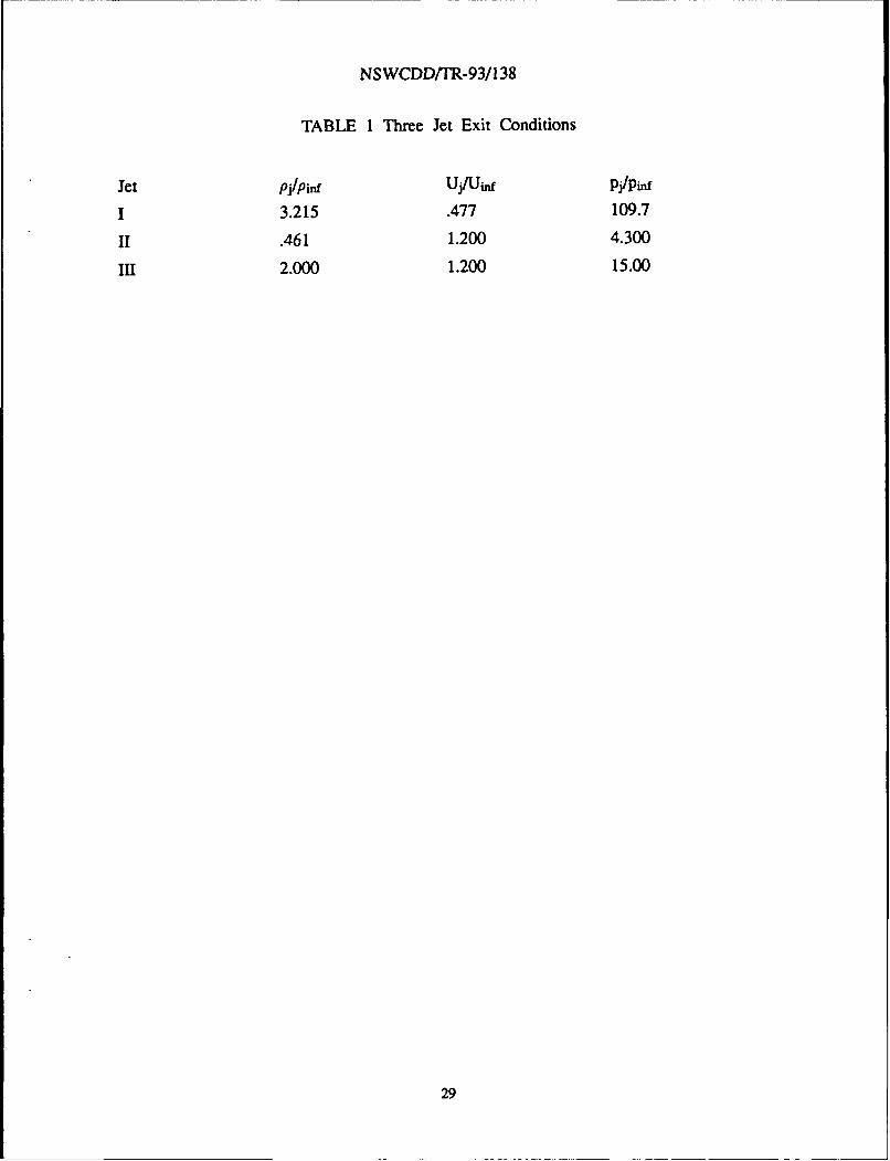
Calculations were completed on a 97x37x49 mesh for the three different jets shown inTable 1. The exit conditions for jets I and II were derived assuming a fixed thrust. Jet Isatisfied this constraint with a high exit pressure, high exit density and low exit velocitywhiie jet II employed a high exit velocity, low exit density and low exit pressure. Jet IIIwas obtained by arbitrarily varying the density and pressure of Jet II.
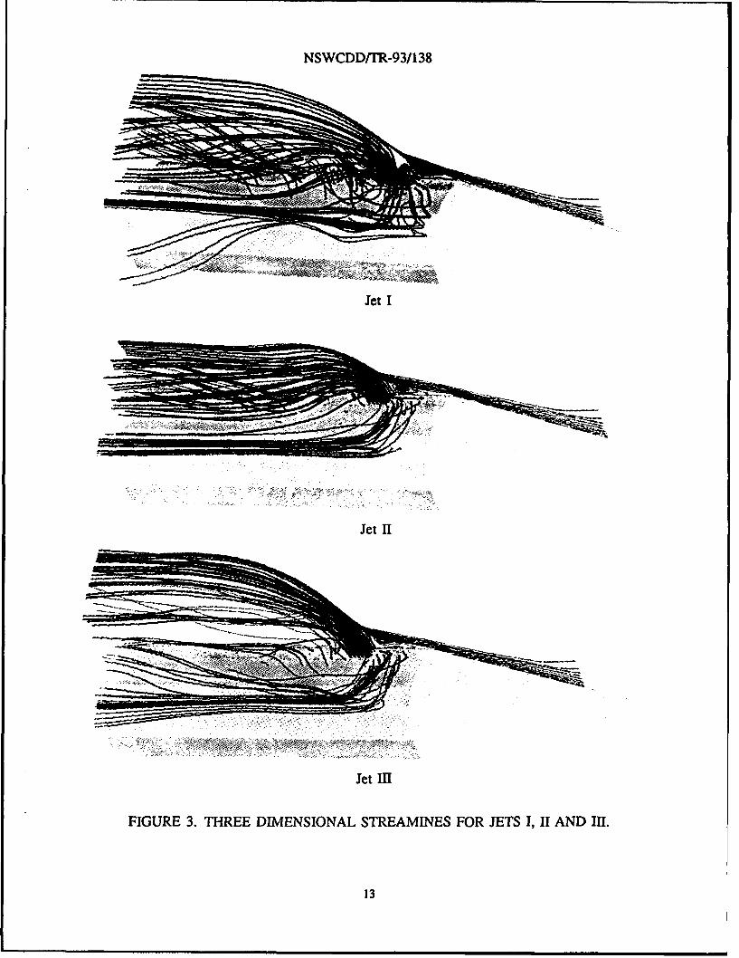
The solutions for jets I, II and Im illustrate the influence of jet exit conditions on shocklayer flow field structures. Of particular interest is entrapment of the jet streamlines in therecirculating zone ahead of the jet. Particulates in the jet exhaust may then be deposited onthe body surface. If an antenna window is located beneath the recirculation window, thesedeposits may obscure the window and impair its operation. Traces of streamlines in the jet-shock layer flow field are shown in Figures 3a, 3b, 3c, where the red streamlines originatefrom the jet and the blue lines in the free stream. These streamline traces demonstrated thatin the case of jet I with the lower jet exit velocity and higher jet exit pressure, streamlinesoriginating from the jet were trapped in the recirculation region ahead of the jet and thatthe recirculation region extended all the way to the biconic cone juncture. Such entrapmentdid not occur for jets II and III which featured the higher jet exit velocity and lower jetexit pressure. Also jet III displaced the shock farther from the body than jet II. Thus ingeneral it appears that increasing the jet exit density and pressure disrupts the flow field toa greater extent.
6

NSWCDDYTR-93/138
CHAPTER 5
SINGLE JET
COMPARISON WITH EXPERIMENT
Further assessment of the numerical simulation was conducted by comparing calculationsand experiments in the case of a body with a single jet. Here the the model was a biconicwith a forecone half-angle of 10.40 and aftcone half-angle of 60. The base diameter, biconicjuncture diameter and nose radius were 21cm , 10.4 cm, and .84 cm respectively. Thisconfiguration was tested at a free stream Mach number of 9.7 and angle of attack of zerodegrees. Surface pressure measurements were taken over the entire body.6'9 The jet waslocated at the upper symmetry plane, circumferential angle / = 0', and axial station of x= 0.417 m. The jet nozzle was oriented normal to the model centerline and had a throatdiameter of 1 cm., exit diameter of 1.42 cm (measured normal to the nozzle center linewhere it intersects the vehicle surface), and a divergent conical section with a half-angle of15'. The test conditions are:
Free stream Mach number - 9.7Free stream dynamic pressure = 5.05 lb/in2
Free stream static pressure = 0.076 lb/in2
Free stream static temperature = 1100 RJet stagnation pressure = 155 lb/in2
Jet stagnation temperature = 5400 R
The resulting Reynolds number is 3 x 10⁶/ft. The free-stream and the jet gasses were nitrogen,-y = 1.4, while the majority of the boundary layer was laminar.16
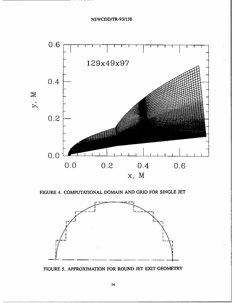
The jet exit conditions were obtained from a one-dimensional nozzle analysis based ona total pressure and temperature of: Pj/pinf = 72.7, Uj/Oinf = 0.358 (Mj = 2.2), and Pj/Pinf =181. Figure 4 shows the meridian plane of the mesh used in the numerical simulation whichconsisted of 129x49x97 grid points. In the circumferential direction, the jet was coveredby six equal width cells with a span of slightly less than 1V. Progressing circumferentiallytowards the opposite side of the model, the circumferential spacing was gradually increasedto a maximum 5.62*. However, grid points were constrained to coincide with the locationat which experimental data was taken in order to facilitate comparison between numericalsolution and experiment. The circular jet was approximated in a stair-step fashion by therectangular surface mesh used in the computation as shown in Figure 5 with a resulting errorin area of less than 1 percent.
7
NSWCDD/TR-93/138
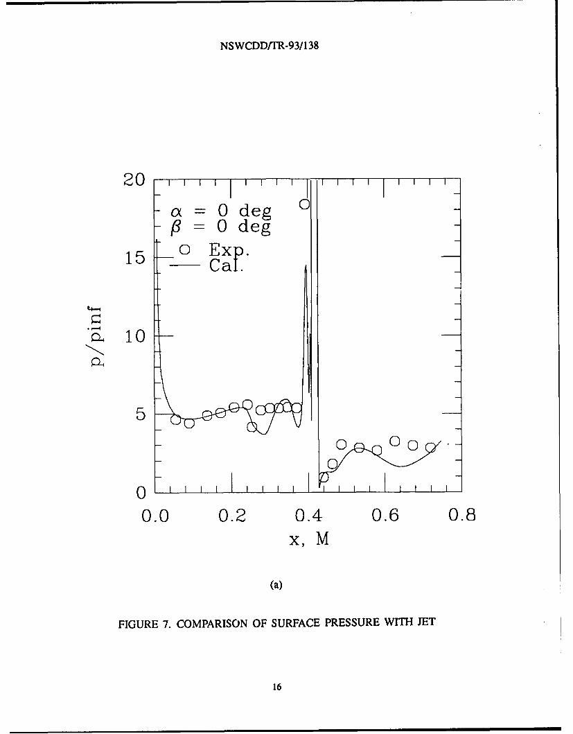
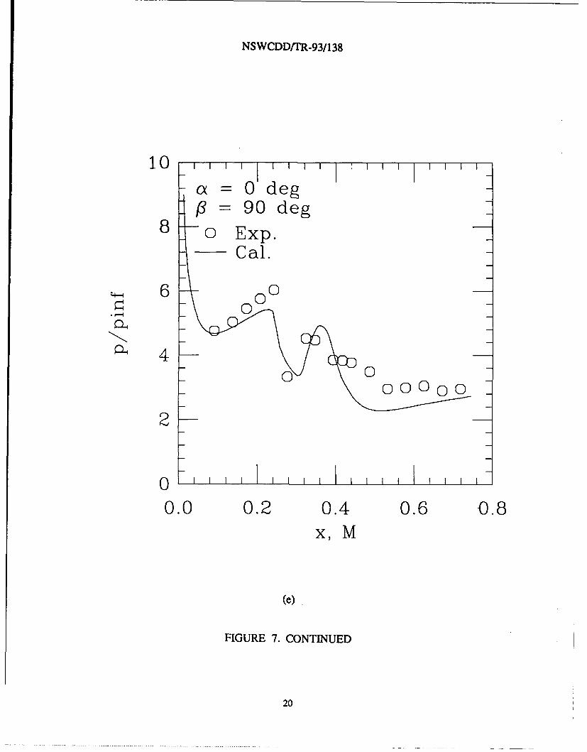
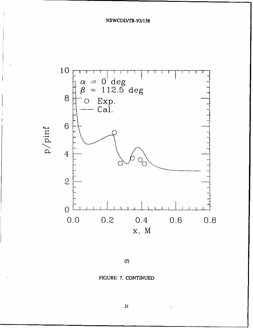
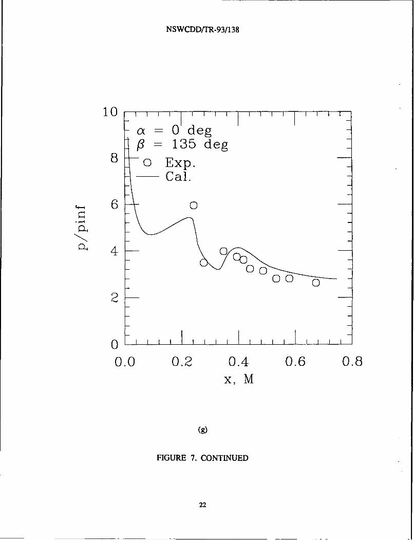
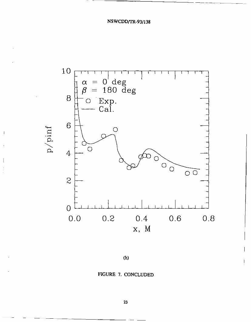
The comparison between the calculated and measured surface pressure without the jetis shown in Figure 6. Good agreement is obtained with a maximum difference of less than10 percent. Similar comparisons with the jet on are provided in Figures 7a to 7h for -- =
00, 22.50, 450, 62.50, 90', 112.50, 1350, and 1800, respectively. The general trend of themeasured pressure distribution from # = 0' to 1800 is well predicteded by the numericalsolution. Of particular interest is the measured pressure rise at P = 1800 and x = 0.4 which iswell predicted. This pressure rise is caused by a local thickening of boundary layer which isa result of flow separation induced by jet which is located on the opposite side of the model.
FLOW STRUCTURE
Select body surface and the flow field streamlines are shown in Figures 8 and 9. InFigure 8, the jet streamlines (red) both on and off the symmetry plane escape entrapmentin the separation region ahead of the jet. A few jet streamlines move laterally, but mostremain part of a cohesive stream which is washed down stream. Figure 8 clearly showsthe separation lines (convergence of surface streamlines) and attachment lines (divergence ofsurface streamlines) on the body surface. This is also illustrated in Figures 9a and 9b whichprovides views of the body from two different roll orientations. Here jet streamline tracesare limited to the pitch plane and the recirculation region can be seen to extend upstreamof the jet by about seven jet diameters ( see Figure 9a). In Figure 9b, there is an increaseof the boundary layer thickness at the location where the first separation line approaches thesymmetry plane, but a flow reversal is not evident here. The location of the surface pressurerise shown in plot of Figure 7h matches this point at which the boundary layer thickens.
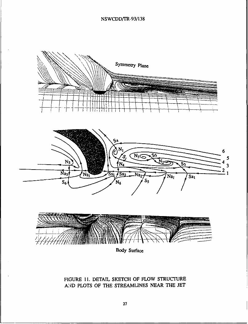
The lateral jet interactive flow field is analyzed using a topological description which isconstructed from streamline traces. The definitive features in this type of model are nodesand saddle singularities, as is described in Reference 17. A topological diagram of the surfaceand jet side pitch plane is given in Figure 10 which indicates the four separation lines, SL1 toSL 4 and two attachment lines AL, and AL 2. An enlargement of the region containing the jetand its associated recirculation region is shown in Figure 11. This figure includes labels forthe singular points and the streamlines originating upstream of this region. Here N designatesa node, S a saddle, and the subscripts a and s are fixed to surface singularities to denoteattachment or separation. In Figure 11, the oncoming flow is divided into 6 layers, whichare separated by the lines labeled 1 to 6 . Layer 6 extends outward from line 6, layer 5 isenclosed by lines 5 and 6 and in general layer n in enclosed by lines n and n+l. From Figure11 it is evident that layer 6 includes fluid which passes outside of the jet and recirculationregion. The fluid contained in layer 5 goes into spiral node N1 while that in layers 4 and 2goes into the spiral node N2. Similarly, the fluid in layer 3 goes into the spiral node N3 andthat in layer 1 ends up at the saddle attachment point Sal. Saddle points are located betweenthe nodal pairs of (NI, N2), (N3, N2), and (N2, Sal). The nodal point N4 which is locatedupstream of the jet and very near the surface, feeds both the nodal attachment points Na1 andNa2 and the saddle attachment point Sa2. Just in front of the jet, there is a saddle separationpoint Ss, on the body surface. Behind the jet, the flow structure is much simpler. Nodal
8

NSWCDD/TR-93/138
point N5 , which is similar in type to N4 and exhibits only outwards flowing streamlines, feedsbody surface point Na 3. An additional separation node, Nsl, is located right behind the jet.
Detail streamline traces do not reveal horseshoe vortices around the jet. The vortices N1 ,N2 , and N3 only remain intact for a distance of about one jet radius away from the symmetryplane and then quickly break apart. A color contour plot of the Mach number distributionin the symmetry plane is shown in Figure 12. The bow shock created by the body and thejet compares well with the Schlieren photograph given in Reference 6. The thickness of theshock layer on the jet side of the body, at the base of the model, is about 3.5 times that onthe opposite side of the body. Low Mach number regions can be identified by the dark bluecolor and they occur near the boundary layer, the recirculation region and behind the jet.
LIFT AUGMENTATION
The lift augmentation due to lateral jets is important in engineering applications. In windtunnel testing, the augmented lift is computedis as follows:
(Lift augmentation) = (jet on, flow on lift )- (jet off, flow on lift)- (jet on, flow off lift)
In numerical simulation, the corresponding lift augmentation is defined,
(Lift augmentation) = (jet on, flow on lift)- (jet off, flow on)
The (jet on, flow off lift) is not necessary in the simulated results since the computed lift isobtained by integrating the surface pressure, without including the jet thrust. Normally thelift augmentation is small at zero incidence and become significant as incidence increases.18
In this report, only zero incidence was investigated and the jet exit was relatively small, thelift augmentation was small, about 1.5 percent of the jet thrust.
9

NSWCDDITR-93/138
CHAPTER 6
SUMMARY AND CONCLUSIONS
A Navier-Stokes simulation of lateral thrusters on a biconic body in laminar, hypersonicflow is presented. The thruster is characterized by specifying a constant velocity, density,and pressure over the jet exit area. The computed flow field contains the appropriate featuresincluding a recirculation region in front of the jet. Three points were considered in detail bythe study: the influence of mesh size, the effect of varying the jet properties and a detailedcomparison of calculation and experiment.
A grid convergence study was performed for a configuration with four cruciform thrusterslocated on a biconic body at zero incidence and M = 6.5. A detailed comparison of surfacepressures indicates good convergence properties except in the vicinity of the recirculationregion. Here a very fine mesh is necessary to capture the vortical and shock structureswhich occur.
Three jets with different exit velocities, densities and pressures have been studied andresults can be summarized as follows: (1) for a given thrust, the jet with the lower velocityand higher pressure penetrates the farthest into the shock layer; (2) jet streamlines may betrapped in the jet created upstream recirculation zone; and (3) incieasing the density andpressure of the jet will increase the jet penetration.
Comparison with experiment was carried out by considering a single lateral jet on abiconic body at M = 9.7 and zero incidence. Good agreement was obtained between themeasured and calculated surface pressure. This includes correctly predicting a pressure riseon the side of the body opposite to the jet which had been missed or partially missed byothers. 6'9 For this case, jet streamline entrapment in the recirculation region did not occur.However, the computed separation region extended seven diameters upstream of the jet.On body surface, four separation lines and two attachment lines could be identified. Thecomputed flow field was also analyzed from the topological point of view by constructingsingular points from the streamline patterns. In the jet side of the pitch plane numerous saddlepoints and nodal points were detected, including a saddle attachment type point which hasrecently been identified in Reference 19.
This study has laid the ground work for the use of Navier-Stokes solvers in predictinglateral thrust preformance. The current work provides proof of principle for the use of suchtechniques in the analysis of wind tunnel models where the jet and ambient gasses are ofthe same type. Extension to the case of different jet-ambient gasses appears be be easilywithin reach. However, computations for a jet with reacting products represents a moreformidable task.
10

NSWCDDITR-93/138
1.0 129 x 49 x 97
0.5
0.00.0 0.5 1.0
X, M
FIGURE 1. COMPUTATIONAL DOMAIN AND GRIDS FOR SYMMETRIC JETS
I1

NSWCDD/TR-93/1 38
0.6
0.4
0.2
0.0
-0.2 I
1 29x49x97- -- 97x37x73
0.2 --- 65x25x49
0xý'
0.0
0.0 0.5 1.0X, M
FIGURE 2. COMPARISON OF SURFACE PRESSURE USING THREE GRIDS
12
NSWCDD)TR-93/138
Jet I
Jet II
Jet Ill1
FIGURE 3. THREE DIMENSIONAL STREAMINES FOR JETS I, 11 AND Ill.
13
NSWCDD/TR-93/138
0.6 l
129x49x97
0.4
0.2
0.00.0 0.2 0.4 0.6
X, M
FIGURE 4. COMPUTATIONAL DOMAIN AND GRID FOR SINGLE JET
FIGURE 5. APPROXIMATION FOR ROUND JET EXIT GEOMETRY
14

NSWCDD/TR-93/138
1 0 i I I I I i I I I i I I ,
a = deg, No Jet
8 Exp. Cal. #l,deg0 00 -- 90[] 180
6
4
L1
2
0 L I I I I I i I I I I I
0.0 0.2 0.4 0.6 0.8X, M
FIGURE 6. COMPARISON OF SURFACE PRESSURE WITHOUT JET
15
NSWCDD/TR-93/138
20
a o deg 0- tdeg
15 0 E
010
0 0000
0.0 0.2 0.4 0.6 0.8X, M
(a)
FIGURE 7. COMPARISON OF SURFACE PRESSURE WITH JET
16

NSWCDD/TR-93/138
i 0 1 1 I I I 1 1 1 1 1 1 1 1 1 1 1
a = 0 deg3= 22.5 deg
8 o Exp.
-_- Cal.
6 00
4 0
2
0jI " " I I , , I I, , ,
0.0 0.2 0.4 0.6 0.8x, M
(b)
FIGURE 7. CONTINUED
17

NSWCDDfTR-93/138
10I I I
a 0 degf3-45 deg
8 o Exp.Cal.
6 0
4- 0
00S4
2
00.0 0.2 0.4 0.6 0.8
X, M
(c)
FIGURE 7. CONTINUED
18

NSWCDD/TR-93/138
10
0( = 0 deg= 62.5 deg
8 o Exp.Cal.
_ 6
. 400
10
2
00.0 0.2 0.4 0.6 0.8
X, M
(d)
FIGURE 7. CONTINUED
19
NSWCDD/TR-93/138
10c 0 deg
=- 90 deg8 0 Exp.
Cal.
6 00S~0
400
00000
2
0.0 0.2 0.4 0.6 0.8
(e)
FIGURE 7. CONTINUED
20
... ~ ~ ~ (e .... ..
NSWCDD/TR-93/138
10
S 0i degp 112.5 deg
8 0 Exp.Cal.
6
4 0
2
00.0 0.2 0.4 0.6 0.8
x, M
FIGURE 7. CONTINUED
21
NSWCDD/TR-93/138
1 0 , i I I I I I
-• - degS-z 135 deg
8 o Exp.Cal.
6 O
4 _
2
00.0 0.2 0.4 0.6 0.8
X, M
(g)
FIGURE 7. CONTINUED
22
NSWCDDrTR-93/138
1 0 '1''''1' 'cx = 0 deg
= 180 deg8 0Exp.
Cal.
6 0
40
002
0 1 L 1 I i I I I I 1 .1
0.0 0.2 0.4 0.6 0.8X, M
(h)
FIGURE 7. CONCLUDED
23

NSWCDD/TR-93/138
I'
FIGURE 8. STREAMLINES FOR THE JET FLOW FIELDON THE SYMMETRY PLANE AND THE BODY SURFACE
24

NSWCDD,'TR-93/1 38
II
00
FIGURE 9. DETAILS OF THE THE SURFACEAND SYMMETRY PLANE STREAMLINES
25

NSWCDD/TR-93/138
FIGURE 10. SKETCH OF THE STREAMLINE STRUCTURE
ON THE SURFACE AND SYMMETRY PLANE
26
NSWCDD/TR-93/1 38
5
1 .8
Body Surface
FIGURE 11. DETAIL SKETCH OF FLOW STRUCTURE
AND PLOTS OF THE STREAMLINES NEAR THE JET
27

NSWCDD/TR-93/1 38
LUJ
z .. 0L MLc m.,ci
FIGURE 12. MACH CONTOURS ON THE SYMMETRY PLANE
28
NSWCDDfTR-93/I 38
TABLE 1 Three Jet Exit Conditions
Jet Pj/PinI UpIinf Pj/Pinf
1 3.215 .477 109.7
1I .461 1.200 4.300
II2.000 1.200 15.00
29

NSWCDD/TR-93/138
CHAPTER 7
REFERENCES
1. Schetz, J. A., "Injection and Mixing in Turbulent Flow" Progress in Astronautics andAeronautics, Vol. 68, AIAA Publications, 1980.
2. Zukoski, E. E. and Spaid, F. W., "Secondary Injection of Gases into a SupersonicStream," AIAA J., Vol. 2, October 1964, pp. 1689-96.
3. Prats, B.D., Hill, J.A.F., Metzger, M.A., and Harvey, D.W., "High Altitude ManeuverControl Tests in the NSWC Hypervelocity Wind Tunnel," AIAA Paper 84-0616, March,1984.
4. Shang, J.S., McMaster, D.L., Scaggs, N., and Buck, M., "Interaction of Jet in HypersonicCross Stream," AIAA Paper 87-0055, Jan. 1987, also AIAA J., vol. 27, March 1989,pp. 323,329.
5. McMaster, D.L., Shang, J.S., and Golbitz, W.C., "Supersonic, Transverse Jet from aRotating Ogive Cylinder in a Hypersonic Flow," AIAA Paper 87-1441, June 1987.
6. Yeneriz, M.A., Davis, J.C., Cooper, G.K., and Harvey, D.W., "Comparison of Calculationand Experiment for a Lateral Jet from a Hypersonic Biconic Vehicle," AIAA Paper89-2548, July 1989
7. McDonough, J.M. and Catton, I., "Calculation of a Lateral Jet in a Hypersonic Cross-Flow," AIAA Paper 89-2549, July 1989.
8. Chamberlain, R.R., "Calculation of Three Dimensional Jet Interaction Flowfields," AIAAPaper 90-2099.
9. McDonough, J.M., Weatherly, D.C., and Catton, I., "Further Studies of Supersonic JetInteraction with a Hypersonic Crossflow," AIAA Paper 90-2101, July 1990.
10. Yeneriz, M.A., Davis, J.C., and Harvey, D.W., "Comparison of Calculation and Exper-iment for a Lateral Jet from a Hypersonic Biconic Vehicle, Part II: Effect of Angle ofAttack," AIAA Paper 90-2104, July 1990.
11. Walters, R.W., Slack, D.C., Cinnella, P., Applebaum, M.P., and Frost, C., "A User'sGuide to GASP," Virginia Polytechnic Institute and State University, Dept. of Aerospaceand Ocean Engineering, Nov 1990.
12. Thomas, J.L., Taylor, S.L., and Anderson, W.K., "Navier-Stokes Computations ofVortical Flows Over Low Aspect Ratio Wings," AIAA paper 87-0207, Jan. 1987.
13. Thomas, J.L., Walters, R.W., Reu, T., Ghaffini, S., Weston R.P., and Duckering, J.M.,"Patched Grid Algorithm for Complex Configurations Directed Toward F-18 Aircraft,"AIAA Paper 89-0121, Jan. 1989.
14. Roe, P.L.," Approximate Riemann Solvers, Parameter Vectors, and Difference Schemes,"J. Comp. Phys., 43, 1981, pp 357-372.
30
NSWCDD/TR-93/138
15. Hsieh, T., Wardlaw, A.B. Jr., and Birch, T.J., "Vortical Flows About a Long Ogive-Cylinder at M=3.5 and a=18*," AIAA Paper 91-1808, June 1991.
16. Harvey, D.W., private communication.17. Lighthill, M.J., "Boundary Layers and Separation," Laminar Boundary Layer, edited by
L. Rosenhead, Oxford Uni. Press, Oxford England, UK 1963.18. Chan, S. C., Rogers, R. P., Edwards, G. L., and Brooks, W. B., "Integrated Jet
Interactions and Comparison to Force and Momement Measurements for a ThrusterAltitude Controlled Missile," AIAA Paper 93-3522, Aug. 1993.
19. Hung, C.M., Sung, C.H. and Chen C.L., "Computation of Saddle Point of Attachment,"AIAA Journal, Vol. 30, No. 6, June 1992, pp 1 56 1- 15 6 9 .
31

NSWCDDfrR-93/138
I)ISTRI BUTION
Copies Coies
DoD ACTIVITIES (CONUS) INTERNALDEFENSE TECHINICAL INFORMATION E231 2
CENTER E232 3CAMERON STATION R44 (T IISIEII) 10ALEXANDRIA VA 22304-6145 12 R44 (A WARDLAW) 10
NON-I)ol) ACTIVITIESATTN GIFT&EXCHIANGEI)IV 4LIBRARY OF CONGRESSWASHINGTON DC 20540
CENTER FOR NAVAL ANALYSES4401 FORD AVEALEXANDRIA VA 22302-0268 1
(1)

REPORT DOCUMENTATION PAGE I A8Nao.704-0188
Public reportin burden for this collection of information * estimated to avelaga 1 hour per teeponae. Ifidudifig the tiae for mviiten initftisuruu. ,eaidsun **Mtin datasource,, gather"n and maintaineng the data needed. and completing and reie-wing the collection at iriformatior Sen coasmewn regardin this burden itatiuate at an otheraspect of this collection of iunformation. mdluding suggestiont for reducing this burden, to Winhingion Ifeadquarten lenrica, Directorate for information Operatior. adRepom IsI IS laffenors Dawn Highway. Suite 1204, Arlington. VA 22202-4302. and to the office of Management endl Sudget. Paperwo" Reduction Prolect (070441"L)Weauhngton. OC 20o0.
1. AGENCY USE ONLY (Leavie blank) 2. REPORT DATE 3. REPORT TYPE AND DATES COVERED
18 Marchl1994 1 _ _ _ _ _ _ _ _ _
4. TITLE AND SUBTITLE S. FUNDING NUMBERSNumerical Simulation of Lateral Thrusters om Hypersonic FlowOver a Biconic Body'O. AUTHOR(S)
T. llsieh and A. B. Wardlaw, Jr.
7. PERFORMING ORGANIZATION NAME(S) AND ADDRESS( ES) 6.PERFORMING ORGANIZATIONREPORT NUMBER
Naval Surface Warfare CenterDahigren Division, White Oak Detachment NSWCDDITR-93/13810901 New Hampshire AvenueSilver Spring, MD 20903-5640
9. SPONSORING/MONITORING AGENCY NAME(S) AND ADDRESS(ES) 10. SPONSORINGIMONITORINGAGENCY REPORT NUMBER
11. SUPPLEMENTARY NOTES
12a. DISTRIBUTION/AVAILABIUITY STATEMENT 12b. DISTRIBUTION CODE
Approved for public release; distribution is unlimited.
13I ABSTRACT (Maximum 200 words)
A Navier-Stokes simulation of lateral thrusters on a biconic body in hypersonic flow is presented.IDue to simplifications arising from symmetry, cruciform thrusters were considered first. A gridconvergence was conducted to evaluate computational accuracy. This was followed by the computation ofthree different jet exit conditions and an assessment of the flow field changes produced by each. Ofparticular concern was the possibility of entrapment of streamlines from the jet in a recirculation regionupstream of the jet. The final case considered was a single jet thrusting from a biconic body at zeroincidence at M = 9.7. These results were compared to experimental surface pressures. A description ofthe complicated interacting flow fields featuring multiple separation and attachment lines/regions is alsopresented
14. SUBJECT TERMS 15. NUMBER OF PAGES
Biconic Body Hypersonic Flow 1.PIECD
17. SECURITY CLASSIFICATION 18. SECURITY CLASSIFICATION 19. SECURITY CLASSIFICATiON 20. UMITATION OF
Proscribed by ANSI Std. Z39-1621150102
Related Documents