ii DESIGN AND DEVELOPMENT OF MINI VACUUM TUBE TESLA COIL (VTTC) MOHD SHAH SOFFIAN BIN SOLAH This report is submitted in partial fulfillment of the requirements for the award of Bachelor of Electronics Engineering (Industrial Electronics) With Honours Faculty of Electronic and Computer Engineering Universiti Teknikal Malaysia Melaka April 2009

Welcome message from author
This document is posted to help you gain knowledge. Please leave a comment to let me know what you think about it! Share it to your friends and learn new things together.
Transcript

ii
DESIGN AND DEVELOPMENT OF MINI VACUUM TUBE TESLA COIL (VTTC)
MOHD SHAH SOFFIAN BIN SOLAH
This report is submitted in partial fulfillment of the requirements for the award of
Bachelor of Electronics Engineering (Industrial Electronics) With Honours
Faculty of Electronic and Computer Engineering
Universiti Teknikal Malaysia Melaka
April 2009
iii
“I hereby declare that this report is the result of my own work except for quotes as cited
in the references”
Signature :……………………………………
Author :MOHD SHAH SOFFIAN BIN SOLAH
Date :30th
APRIL 2009

iv
“I hereby declare that I have read this report and in my opinion this report is sufficient in
terms of the scope and quality for the award of Bachelor of Electronic Engineering
(Industrial Electronic) With Honours.”
Signature :………………………………
Supervisor’s Name : MR ZULKARNAIN BIN ZAINUDIN
Date :30th
APRIL 2008

v
Especially for my beloved father and mother, my siblings and family.

vi
ACKNOWLEDGEMENT
Alhamdulillah, thanks to Allah because of his blessing, I manage to finish this
“Projek Sarjana Muda” in a good condition and sharp on time. I also would like to take
this opportunity to give appreciation especially to my beloved father and mother because
of their support and understanding in helping me to finish this project, then this
appreciation goes to my honorable lecturer’s which is Mr Zulkarnain Bin Zainudin
because of his guidelines and sharing some useful advice in order to help me to give the
best effort and commitment to finish this project. Finally, I would like to thanks to all
my lovely friend and other persons who always help and give support to me along
accomplished this PSM .Lots of thanks to them and hopefully Allah will pay their
kindness.
vii
ABSTRACT
This project was carried out to develop a Mini Vacuum Tesla Coil (VTTC) using high
voltage transformer transformer based on the DC high voltage conservation with input
range 8000VDc. A Tesla Coil is a specially designed transformer, technically termed an
"air-core resonant transformer". It consists of a primary winding, with relatively few
turns, and a secondary winding with hundreds, or even thousands, of turns. As with all
transformers, the primary and secondary windings are physically arranged so that
electrical energy may be transferred between them by transformer action - a changing
current flowing in one winding induces a changing voltage in the other. The Tesla
transformer is an electrical device capable of developing high potentials ranging from a
few hundreds of kilovolts up to several megavolts; the voltage is produced as AC, with a
typical frequency of 50 - 400 kHz This project is done by using special electronic parts
which is 4000V 30MA current ltd open core transformer and .01 MFD 10KVAC
polypropylene high current pulse capacitors..It will cause a gas discharge lamp, to glow
up to a distance of several feet from the unit. The high voltage output coil terminal can
actually be touched with a piece of metal held securely in the demonstrator’s hand,
creating quite a conversation piece. Three element is going to be analyzed in this project
are the voltage regulator circuit, arc sparking and the analysis of the transformer output.

viii
ABSTRAK
Projek ini adalah untuk projek Mini Vacuum Tube Tesla Coil (VTTC)
menggunakan alat ubah pengeluar tinggi dengan kuasa masukan 8000VDc.Tesla Coil
adalah menggunakan alat ubah yang istimewa, juga di panggil alat ubah teras udara
.Ianya mengandungi gelung pertama alat ubah dan gelung kedua alat ubah yang mana
akan mengandungi seratus atau beribu gelung. Gelung pertama akan menghasilkan
merangsang voltan kepeda gelung kedua untuk menghasilkan voltan yang
tinggi.Perubahan arus yang melalui gelung akan juga merangsang kepada terhasilnya
voltan tinggi.Transformer Tesla Coil adalah satu alat elektrik yang boleh mengasilkan
voltan tinggi dari ratusan kilovolt dan akan meninggi ke megavolt.Voltage tersebut akan
menghasilkan voltan AC dengan frekuensi biasa iaitu 50-400 kHz.Projek ini berjaya di
siapkan dengan menggunakan 4000V 30MA arus ltd teras terbuka alat ubah, dan .01
MFD 10KVAC polypropylene kapasitor arus tinggi.Projek ini akan menyebabkan
pengeluaran cas dengan jarak beberapa kaki.Voltan tinggi dapat di sentuh dengan
menggunakan besi atau pengalir elektrik tetapi dengan mengambil kira aspek
keselamatan yang tinggi.Terdapat 3 elemen akan di kaji iaitu litar mengawal boleh
ubah,keluaran kilat dan keluaran alat ubah.
ix
CONTENTS
CHAPTER TITLE PAGES
PROJECT TITLE i
DECLARATION iii
DEDICATION v
ACKNOWLEDMENT vi
ABSTRACT vii
CONTENTS ix
LIST OF TABLE xii
LIST OF FIGURES xiii
LIST OF ABBREVIATION xv
LIST OF APPENDICES xvi
I INTRODUCTION
1.1 Introduction of the Project 1
1.2 Objectives 1
1.3 Problem Statement 2
1.4 Scope 2
1.5 Methodology 3
II LITERATURE REVIEW
2.1 Oscillators 5
x
2.2 Applications 6
2.3 Building a Mini Tesla Coil 7
2.4 Baseboard 9
2.5 Capacitor 9
2.6 Spark Gap 9
2.7 Primary Coil 10
2.8 Secondary Coil 11
2.9 Toroid 12
2.10 Tuning 12
2.11 Flyback Transformer Used To Produce High Voltage 13
2.12 How it works 14
2.13 Practical Considerations 15
2.14 Construction 15
III METHODOLOGY
3.1 Introduction 17
3.2 Design Power Supply 12v, 10 ampere 18
3.3 Design Mini Vacuum Tube Tesla Coil 22
3.3.1 Brief theory of Operation 22
3.3.2 Circuit Description Schematic 23
3.3.3 Description of Major Components 24
3.3.3.1 A- LSl Secondary Coil 24
3.3.3.2 B- Output Terminal 25
3.3.3.3 C-LP1-Primary Coil 25
3.3.3.4 D-Coupling 26
3.3.3.5 E- SPK- Spark Gap Switch 26
3.3.3.6 F-C3-Primary Capacitor 26
3.3.3.7 G Chk1-Rf Choke 27
3.3.4 Assembly Step 27
3.3.5 Test Steps 38

xi
3.3.6 Special Steps 39
IV RESULT & DISCUSSION
4.1 Result 44
4.1.1 Secondary Tesla Coil 44
4.1.2 Complete Model of Tesla Coil 46
4.2 The Arc Spark 49
V DISCUSSION AND CONCLUSION
5.1 Discussion 50
5.2 Electrical Reception 51
5.3 In Fiction 54
5.4 Tesla Coil Effect 56
5.5 Conclusion 56
REFERENCES 58

xii
LIST OF TABLE
NO TITLE PAGES
3.3 Component List for Power Supply 21
3.1 Electrical Parts 41
3.2 Sub Assemblies 41
3.3 Fabrication 42
3.4 Hardware 43

xiii
LIST OF FIGURES
NO TITLE PAGES
2.3 Coil Schematics 7
2.4 Finished Coil 7
2.5 The Oscillator Circuit 8
2.6 Flyback Transformer 14
3.1 Flow Chart Project Methodologies 17
3.2 Power Supply Circuit 20
3.3 Tesla Coil Schematic 23
3.4 Plans Schematic 28
3.5 Assemble Secondary Coil 29
3.6 Assemble Chokes 30
3.7 Fabricate the top and bottom base section 31
3.8 Fabricate plastics parts 32
3.9 Fabricate parts for sparks switch 33
3.9.1 Fabricate metal parts 34
3.9.2 Assemble primary coil section 35
3.9.3 Assemble Base Bottom Wiring Circuit 37
4.1 Secondary Tesla Coil 44
4.2 Toroid 45
4.3 Primary Coil of Tesla Coil 46
4.4 Complete Tesla Coil 46
4.5 Complete Model of Tesla Coil left view 47
4.6 Complete Model of Tesla Coil from right view 47

xiv
4.7 Spark Gap of Tesla Coil 48
4.8 Pictures of Tesla Coil Operation 49
xv
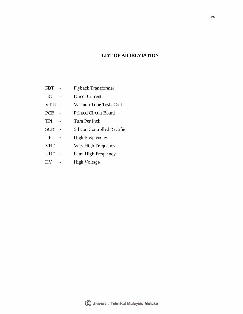
LIST OF ABBREVIATION
FBT - Flyback Transformer
DC - Direct Current
VTTC - Vacuum Tube Tesla Coil
PCB - Printed Circuit Board
TPI - Turn Per Inch
SCR - Silicon Controlled Rectifier
HF - High Frequencies
VHF - Very High Frequency
UHF - Ultra High Frequency
HV - High Voltage

xvi
LIST OF APPENDICES
NO TITLE PAGES
A Transistor 2N3055 Datasheet 59
B Flyback Trasformer Datasheet 65

1
CHAPTER I
INTRODUCTION
1.1 Introduction of the project
A Tesla coil is a high frequency resonant transformer. It differs from a
conventional transformer in that the voltage and current relationships between the
primary winding and secondary winding are independent of the winding turn’s ratios. A
working apparatus basically consists of secondary and primary coil. It is obvious that the
primary circuit is dominant, and turning the primary circuit via taps along the primary
coil alters the frequency accordingly, however this relative fine-tuning of the primary
circuit to the secondary is mandatory for proper operation. Force driving the secondary
coil will produce hot spot and an interwinding breakdown along with other negative
result. This mini Tesla Coil was originally designed to run using project basically to
design the circuit for Wind source can be an excellent complement of electric power
requirement.
1.2 Objectives
1.2.1 To study and develop a high voltage DC up to 30KV by using Neon (high
voltage) transformer
1.2.2 To produce arc using high voltage at the safe condition
1.2.3 To analyzed the arc sparking
1.2.4 To Design and Develop a Tesla Coil by using Neon (high voltage)
transformer.

2
1.3 Problem Statement
Nowadays, so many type of Tesla Coil develop by others that use high voltage to
produces arc (spark).The different with my project is develop Tesla Coil using basic
application to produce arc (spark) by using Neon (high voltage) transformer.
1.4 Scope
This project is to develop Mini Vacuum Tube Tesla Coil by using Neon (high
voltage) transformer to produced high voltage; low ampere from voltage input voltage
240AC and analyzed the output voltage and current from the arcs that Tesla Coil
produced.
1.5 Methodology
Firstly, search a literature review to collect more information about this project.
The literature review will take journal, report, internet and books as it reference. To
design a Mini Vacuum Tube Tesla Coil (VTTC), the theory and all application about
Tesla Coil circuit has been studies and understanding. Make a research about circuit
theory and the characteristic of each component to redesign the Tesla Coil circuit. Later,
some literature review will used to compare this project with previous experiment and
related project for this title.
Then, the circuit of Tesla Coil has been design by refer the literature review have
found. To design the circuit, make sure the Neon (high voltage) transformer and all
component will use is more suitable for Tesla Coil circuit to generate a high voltage.
The design circuit will be simulated using the Pspice and Multisim software. The output
voltage is measured and the calculated of the voltage is very important because it will

3
determine the sum of component and stage that the circuit required to get the right
output voltage.
After the design is successful, the circuit will be constructed on strip board.
Make sure all connection of component at strip board is right. Then, check the circuit
output voltage by using the multimeter and the value is compared with simulation output
value. Then, the circuit has been constructed on PCB board. All connection in circuit is
confirmed right before the soldering process. For last inspection, test the hardware if
function or not. If not function, the circuit will be troubleshooting. If the circuit already
functions, the model has been designed.

4
CHAPTER II
Literature review
A Tesla coil is a type of resonant transformer circuit invented by Serbian-
American scientist Nikola Tesla around 1891. It is generally used to generate very high
voltage, low current, and high frequency alternating current. A Tesla coil consists of
two, or sometimes three, coupled resonant electric circuits. A Tesla coil is difficult to
define, as Nikola Tesla experimented with a large variety of coils and configurations.
Tesla used these coils to conduct innovative experiments in electrical lighting,
fluorescence, x-rays, high frequency alternating current phenomena, electrotherapy, and
wireless power for electric power transmission.
Early Tesla coil designs usually employed a high voltage power source, one or
more high voltage capacitor, and a spark gap to excite the primary side of the Tesla coil
system with periodic bursts of high frequency current. Later and higher power coil
designs had the primary and secondary circuits tuned so that they resonated at the same
frequency (typically, between 25 kHz and 2 MHz). These larger Tesla coil designs are
used to create long electrical discharges.
Tesla coil circuits were used commercially in spark gap radio transmitters for
wireless telegraphy until the 1920, and in electrotherapy and quack medical devices such
as violet ray. Today their main use is entertainment and educational displays. Tesla coils
are built by many high-voltage enthusiasts, research institutions, science museums and
independent experimenters. Modified Tesla coils are widely used as igniters for high

5
power gas discharge lamps, common examples being the mercury vapor and sodium
types used for street lighting. Although electronic igniters are available, Tesla's original
spark gap design is much cheaper and has proven extremely reliable. A Tesla coil,
named for its inventor Nikola Tesla, is a high-voltage resonant transformer that can be
used to produce long electrical discharges.
To investigate the electrical realm of high-frequency and high-voltage, Tesla
invented an apparatus that pushed the limits of electrical understanding. None of the
circuit's typical components were unknown at the time, but its design and operation
together achieved unique results not the least because of Tesla's masterful refinements in
construction of key elements, most particularly of a special transformer, or coil, which is
at the heart of the circuit's performance.
Such a device first appeared in Tesla's US patent No. 454,622 (1891), for use in
new, more efficient lighting systems. In its basic form, the circuit calls for a power
supply, a large capacitor, the coil (transformer) itself, and adjustable spark-gap
electrodes.
2.1 Oscillators
Capacitors (or condensers) and inductors (or coils) are, electrically speaking,
somewhat opposite in operation. Whereas current builds quickly in a capacitor as it
charges up, voltage lags. In an inductor, voltage is felt immediately, while current is
retarded as it works against the magnetic field its own passage builds in the coil. If a coil
and condenser are sized and selected to act with exactly opposite timing with voltage
peaking in the coil just as it reaches a minimum in the capacitor then the circuit may
never reach an electrically quiet, stable state. A bit like the sloshing of water back and
forth in a tub, current and voltage can be made to chase each other back and forth, from
end to end of the circuit.

6
To set his oscillator "ringing" Tesla employed sudden discharges, sparks, across
an adjustable gap between two electrodes. Voltage on a capacitor builds until it reaches a
level at which air in the gap breaks down as an insulator. (Precision screws set the gap
clearance, so that a larger or smaller gap selects a larger or smaller breakdown voltage.)
The initial impulse is very powerful all the energy stored over several microseconds is
released in a rush, and that impulse is itself transformed to a somewhat higher voltage in
passing from the primary coil windings to those of its secondary. This, of course,
completes but a single cycle in the circuit's operation. The air gap restores itself as an
insulator, and the capacitor begins to charge until it reaches a breakdown value once
again. The whole process can repeat itself many thousand times per second.
The transformer's secondary is rather special, too, designed by Tesla to react
quickly to a sudden energy spike and, most importantly, to concentrate voltage at one
end as a standing wave. Its length is calculated so that wave crests, as they reach the end
and are reflected back, meet and exactly reinforce the waves behind them. The net effect
is a wave, a voltage peak, which appears to stand still.
2.2 Applications
If, as happened in practice, Tesla made an antenna of the high-voltage end of his
secondary, it became a powerful radio transmitter. In fact, in the early decades of radio,
most practicable radios utilized Tesla coils in their transmission antennas. Tesla himself
used larger or smaller versions of his invention to investigate fluorescence, x-rays, radio,
wireless power, biological effects, and even the electromagnetic nature of the earth and
its atmosphere.
Today, high-voltage labs often operate such devices, and amateur enthusiasts
around the world build smaller ones to create arcing, streaming electrical displays it is
not difficult to reach a quarter million volts. One of the very first particle accelerator
designs, by Rolf Wideroe in 1928, generated its high voltage in a Tesla coil.) The coil

7
has become a commonplace in electronics, used to supply high voltage to the front of
television picture tubes, in a form known as the flyback transformer.
2.3 Building a Mini Tesla Coil
This mini Tesla Coil was originally designed to run using a previously built high
voltage flyback circuit as a power supply. The circuit provided about 45watts at about
10kV. This means that there are limits to the size of arc that can be produced. My coil is
capable of 4" arcs. Such a small coil provides a great talking point, and is small enough
to be easily portable. Another point is that it is cheap to build.
Figure 2.3 Coil Schematic
Figure 2.4 Finished Coil

8
Figure 2.5 The oscillator circuit
D1 may be either an EHT rectifier stick from a tv or a string of lower voltage
diodes for example 15 x 1N4007s. If you use a string of lower voltage diodes, they must
all be of the same type. Despite what is often said in textbooks, don't use equalizing
resistors across the diodes, modern diodes don't need them, and if one fails then too
much stress will be placed on the diodes with spectacular results. Although the supply is
shown as 12V, up to 18 is ok, but you will need to use a 25V smoothing capacitor rather
than the 16V one. This circuit will draw 3-5A, depending on several factors but chiefly
the current taken from the secondary (HT) winding. The 2N3055s need heat-sinks of a
good size. The primary coil needs to be wound with thick insulated wire, 18swg is about
right.
9
2.4 Baseboard
Various materials can be used for the baseboard, provided that they are good
insulators. The coil shown in the picture used varnished MDF. A good alternative would
be acrylic sheet or polycarbonate.
2.5 Capacitor
The capacitor used in this particular coil needed a value of approximately 5nF at
about 10-15kV, since used it with 8.3nF with appropriate adjustments to the primary coil
tapping. There are various ways of obtaining these values. Whilst many coilers would
use a string of higher value capacitors in series, it used an alternative approach initially,
building my own from double sided printed circuit board. For the 8.3nF capacitor used
an MMC, consisting of 12 x 100nF 1k5V rated Philips capacitors. If you go this route,
then it is essential that you use the correct type of capacitors, namely foil polypropylene
capacitors rated at the appropriate voltage and of the appropriate construction for high
discharge rates. A number of sites have details of the construction of MMCs, read what
they have to say before going this way, it will save you a lot of time, effort, money and
frustration. Other approaches include making rolled polythene or salt water capacitors.
Both these latter approaches can be messy, and they end up with very bulky
components. Bleeder resistors should be placed across capacitors, these need to be high
voltage types, they also need to be of high value, for example for an MMC 10M across
each capacitor.
2.6 Spark Gap
Various types of spark gap have been used, the simplest being a static gap
consisting of two mild steel brackets with brass bolts forming the actual gap. The
preferred gap and the one shown in the picture is a multiple gap of the RQ type. No
Related Documents