Welcome message from author
This document is posted to help you gain knowledge. Please leave a comment to let me know what you think about it! Share it to your friends and learn new things together.
Transcript

LIBRARYOF THE
MASSACHUSETTSAGRICULTURAL
COLLEGE
No._34330 DATEL-a.^LL
SOURCE^^--ITX-.
t"*>< S
1 677
152
v.l
\
DATE DUE
This book may be kept out
TWO WEEKSonly, and is subject to a fine of TWOCENTS a day thereafter. It will be due on
the dav indicated below.


v.\
^riW^**WW7C^y«tVI
^^^^^^^•^
TL
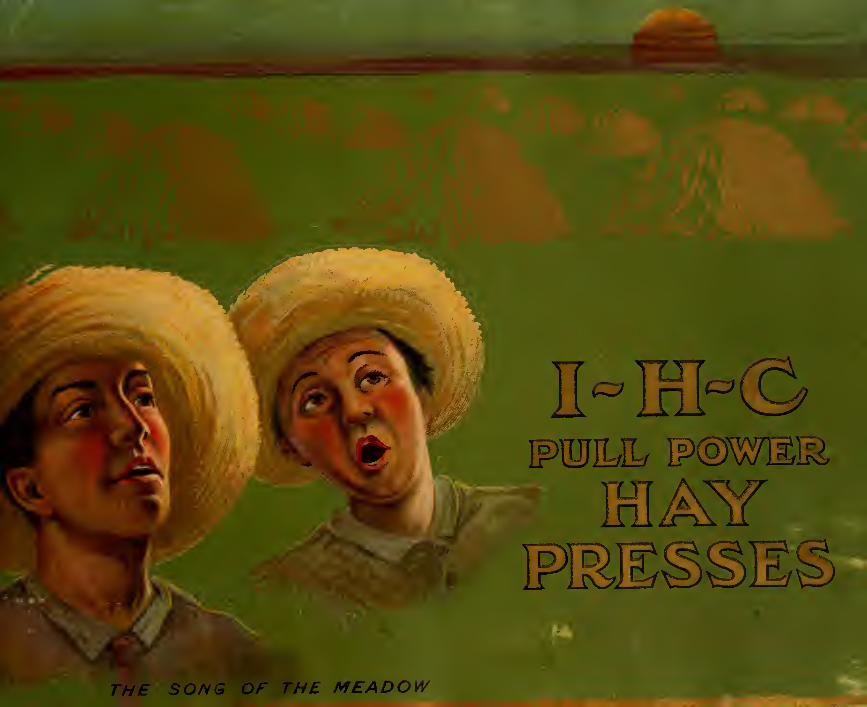
THE SONG OF THE MEADOW

y
<M
In the I H C hay presses, those highly desirable points—capacity,
strength, light draft, simplicity, and convenience — have beendeveloped to a remarkable degree.
These hay presses are of thoroughly good construction and meri-
torious design. They have been designed to meet the requirements
of the farmer who wishes to bale his own hay, and they also provethe most profitable press for the custom baler.
The material and workmanship entering into the construction of
I H C hay presses are the best procurable.
I H C hay presses are neat, compact machines, the strength anddurability of which have been proved by the best of service.
They are very economical, as they require the minimum amountof power and help—two points that will be appreciated by everypress user.
International Harvester Company of America
CHICAGO ( INCORPORATED) USAADV. 115-A
34330
n m mmJV/
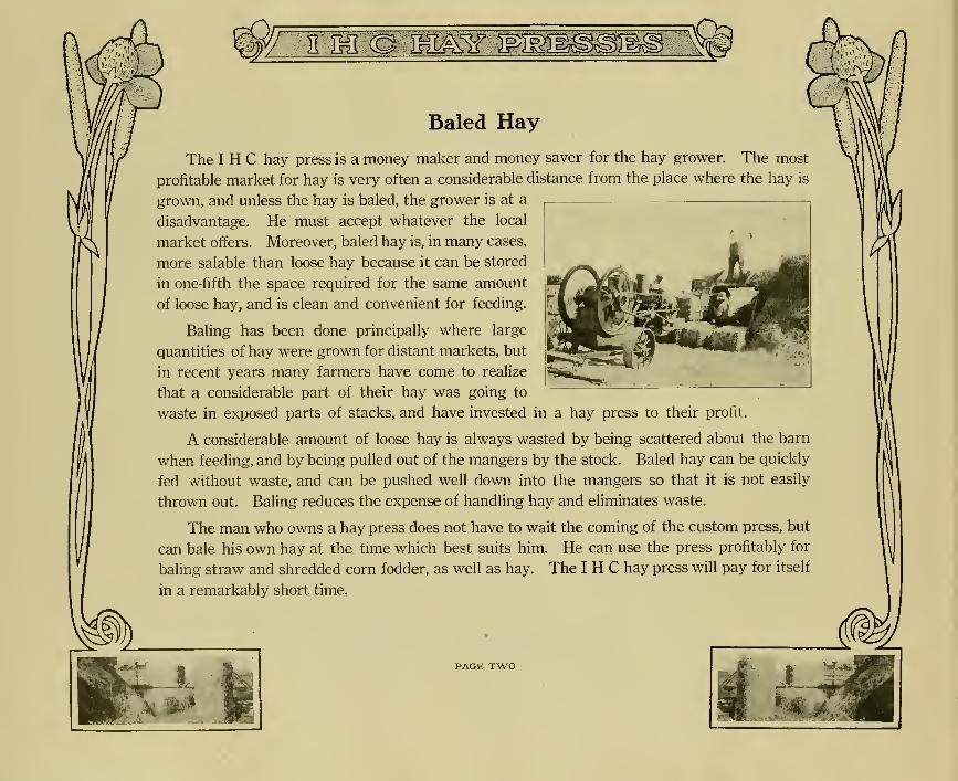
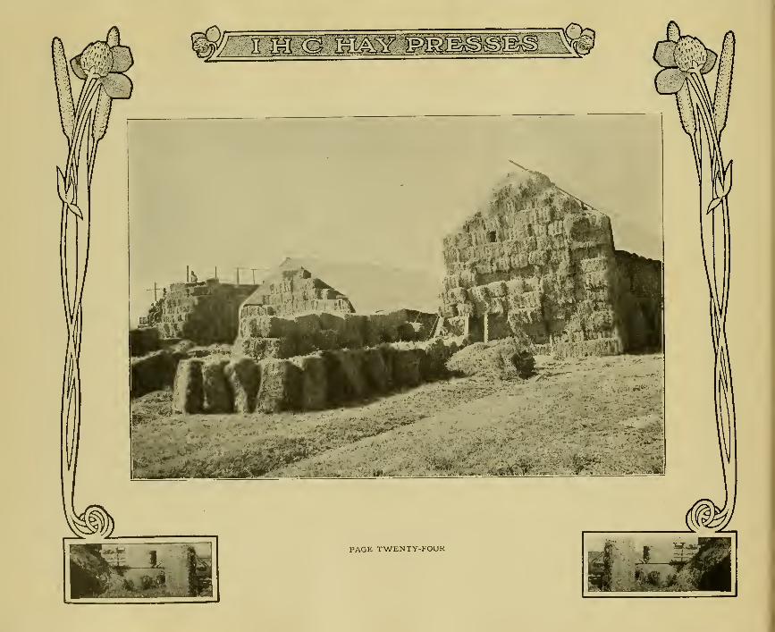
Baled Hay
The I H C hay press is a money maker and money saver for the hay grower. The most
profitable market for hay is very often a considerable distance from the place where the hay is
grown, and unless the hay is baled, the grower is at a
disadvantage. He must accept whatever the local
market offers. Moreover, baled hay is, in many cases,
more salable than loose hay because it can be stored
in one-fifth the space required for the same amount
of loose hay, and is clean and convenient for feeding.
Baling has been done principally where large
quantities of hay were grown for distant markets, but
in recent years many farmers have come to realize
that a considerable part of their hay was going to
waste in exposed parts of stacks, and have invested in a hay press to their profit.
A considerable amount of loose hay is always wasted by being scattered about the barn
when feeding, and by being pulled out of the mangers by the stock. Baled hay can be quickly
fed without waste, and can be pushed well down into the mangers so that it is not easily
thrown out. Baling reduces the expense of handling hay and eliminates waste.
The man who owns a hay press does not have to wait the coming of the custom press, but
can bale his own hay at the time which best suits him. He can use the press profitably for
baling straw and shredded corn fodder, as well as hay. The I H C hay press will pay for itself
in a remarkably short time.
I
PAGE TWO
TH
v
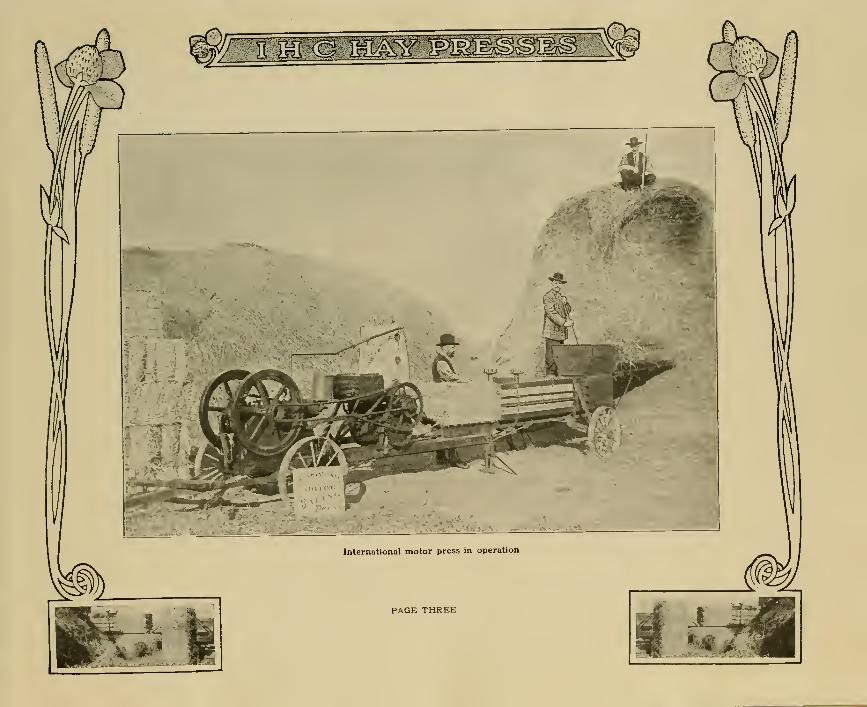
International motor press in operation
PAGE THREE
iiM-m : ££§?', Wg£
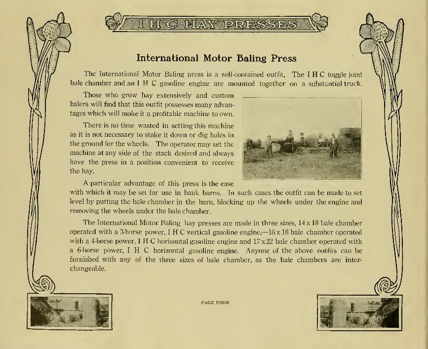
International Motor Baling Press
The International Motor Baling press is a self-contained outfit. The I H C toggle joint
bale chamber and an I H C gasoline engine are mounted together on a substantial truck.
Those who grow hay extensively and custom
balers will find that this outfit possesses many advan-
tages which will make it a profitable machine to own.
There is no time wasted in setting this machine
as it is not necessary to stake it down or dig holes in
the ground for the wheels. The operator may set the
machine at any side of the stack desired and always
have the press in a position convenient to receive
the hay.
A particular advantage of this press is the ease
with which it may be set for use in bank barns. In such cases the outfit can be made to set
level by putting the bale chamber in the barn, blocking up the wheels under the engine and
removing the wheels under the bale chamber.
The International Motor Baling hay presses are made in three sizes, 14 x 18 bale chamber
operated with a 3-horse power, I H C vertical gasoline engine,—16 x 18 bale chamber operated
with a 4-horse power, I H C horizontal gasoline engine and 17x22 bale chamber operated with
a 6-horse power, I H C horizontal gasoline engine. Anyone of the above outfits can be
furnished with any of the three sizes of bale chamber, as the bale chambers are inter-
changeable.
A PAGE FOUR
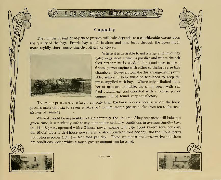
Capacity
The number of tons of hay these presses will bale depends to a considerable extent upon
the quality of the hay. Prairie hay which is short and fine, feeds through the press much
more rapidly than coarse timothy, alfalfa, or clover.
Where it is desirable to get a large amount of hay
baled in as short a time as possible and where the self
feed attachment is used, it is a good plan to use a
6-horse power engine with either of the large size bale
chambers. However, to make this arrangement profit-
able, sufficient help must be furnished to keep the
press supplied with hay. Where only a limited num-
ber of men are available, the small press with self
feed attachment and operated with a 4-horse power
engine will be found very satisfactory.
The motor presses have a larger capacity than the horse presses because where the horse
presses make only six to seven strokes per minute, motor presses make from ten to fourteen
strokes per minute.
While it would be impossible to state definitely the amount of hay any press will bale in a
given time, it is perfectly safe to say that under ordinary conditions in average timothy hay,
the 14 x 18 press operated with a 3-horse power engine will bale about twelve tons per day,
the 16x18 press with 4-horse power engine about fourteen tons per day, and the 17x22 press
with 6-horse power engine sixteen tons per day. These estimates are conservative and there
are conditions under which a much greater amount can be baled.
M.!
JL
H
PAGE FIVE

«wm^Power Jack
The power jack used on International motor
presses is entirely different in construction from
that used on any other press. It insures the
strongest and steadiest action to be found in any
press. The gears which drive the plunger rack
are fitted with a compensating gear to take up
any play or wear that might occur in the teeth.
An even pull on both sides of the jack is insured
by this gear and it also increases durability as it
eliminates the possibility of breakage. Theplunger rack is held in place against the drive
gear by two case-hardened steel rollers, one
above, and one below the gear. These rollers
prevent any jarring or pounding on the gear, conse-
quently, reduce wear and danger of breakage.
By referring to the
View ofjack with
one side removed.showing the
plunger rack onthe return stroke
View of the jack
with one side
and sprocket
removed, show-ing the plunger
rack at the
end of forward
stroke
accompanying illustra-
tion, it will be seen that the plunger rack moves completely
around the drive gear. This gives the return stroke of the
plunger just as positive action as the forward stroke, and
eliminates the danger of breakage which would result if the
plunger was thrown back suddenly by the rebound of the hay.
A heavy drive chain is used to transmit
power from the engine to the power jack.
The tension of this chain can always be prop-
erly regulated by an adjustable idler which is
attached to the power bed between the engine
and the power jack.
PAGE SIX
mIV
KM(ammsr :wm
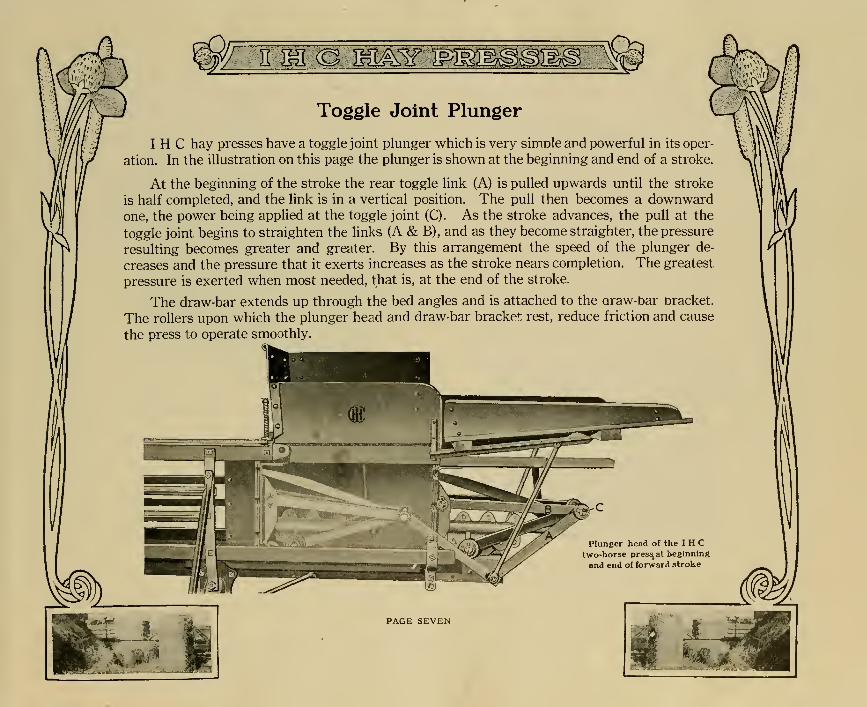
Toggle Joint Plunger
I H C hay presses have a toggle joint plunger which is very simple and powerful in its oper-
ation. In the illustration on this page the plunger is shown at the beginning and end of a stroke.
At the beginning of the stroke the rear toggle link (A) is pulled upwards until the stroke
is half completed, and the link is in a vertical position. The pull then becomes a downwardone, the power being applied at the toggle joint (C). As the stroke advances, the pull at the
toggle joint begins to straighten the links (A & B), and as they become straighter, the pressure
resulting becomes greater and greater. By this arrangement the speed of the plunger de-
creases and the pressure that it exerts increases as the stroke nears completion. The greatest
pressure is exerted when most needed, that is, at the end of the stroke.
The draw-bar extends up through the bed angles and is attached to the araw-bar bracket.
The rollers upon which the plunger head and draw-bar bracket rest, reduce friction and cause
the press to operate smoothly.
Eȣ
Plunger head of the I H Ctwo-horse press^at beginning
and end of forward stroke
PAGE SEVEN
JL
ff
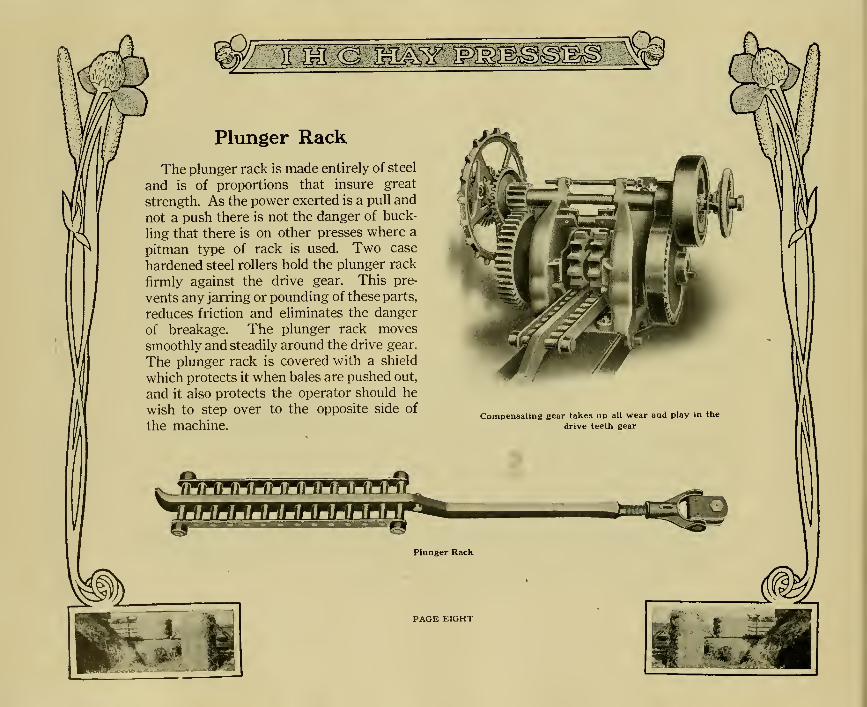
Plunger Rack
The plunger rack is made entirely of steel
and is of proportions that insure great
strength. As the power exerted is a pull and
not a push there is not the danger of buck-
ling that there is on other presses where a
pitman type of rack is used. Two case
hardened steel rollers hold the plunger rack
firmly against the drive gear. This pre-
vents any jarring or pounding of these parts,
reduces friction and eliminates the danger
of breakage. The plunger rack moves
smoothly and steadily around the drive gear.
The plunger rack is covered with a shield
which protects it when bales are pushed out,
and it also protects the operator should he
wish to step over to the opposite side of
the machine.
.1
Plunger Rack
PAGE EIGHT

Roller TuckerPosition of roller
tucker when plungeris at its forward
stroke. Note the hayprotrudes over
the apron
The importance of neat and attrac-
tive bales has not been overlooked in
designing I H C hay presses. The
loose ends of the charge always drop
back over the end of the apron and
will cause rough looking bales unless
they are folded down and held in place
by the next charge. I H C hay presses
are equipped with a roller tucker
which folds down all straggling ends
of hay and insures good looking bales.
When the plunger is withdrawn from the for-
ward stroke, the roller tucker forces the loose
straggling ends of hay down into
the bale chamber against the last
charge and the next charge holds
them there. The springs which
operate the roller tucker are ad-
justable.
Another advantge the roller
tucker gives these presses, is that
by folding down the straggling
ends of hay, the bale chamber is
always kept clear for the incoming
charge, and the hay is prevented
from lapping over the head block.
PAGE NINE
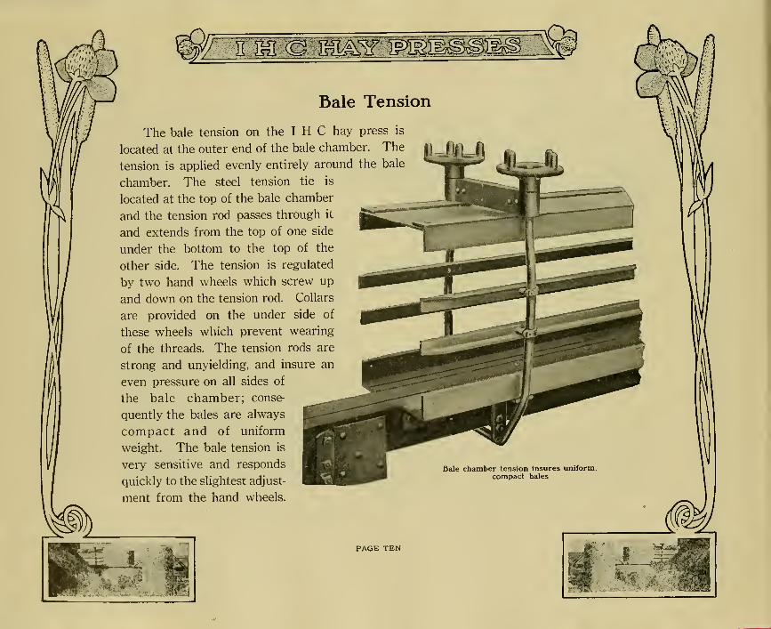
'fSS^SSBale Tension
The bale tension on the I H C hay press is
located at the outer end of the bale chamber,
tension is applied evenly entirely around th
chamber. The steel tension tie is
located at the top of the bale chamber
and the tension rod passes through it
and extends from the top of one side
under the bottom to the top of the
other side. The tension is regulated
by two hand wheels which screw up
and down on the tension rod. Collars
are provided on the under side of
these wheels which prevent wearing
of the threads. The tension rods are
strong and unyielding, and insure an
even pressure on all sides of
the bale chamber; conse-
quently the bales are always
compact and of uniform
weight. The bale tension is
very sensitive and responds
quickly to the slightest adjust-
ment from the hand wheels.
PAGE TEN
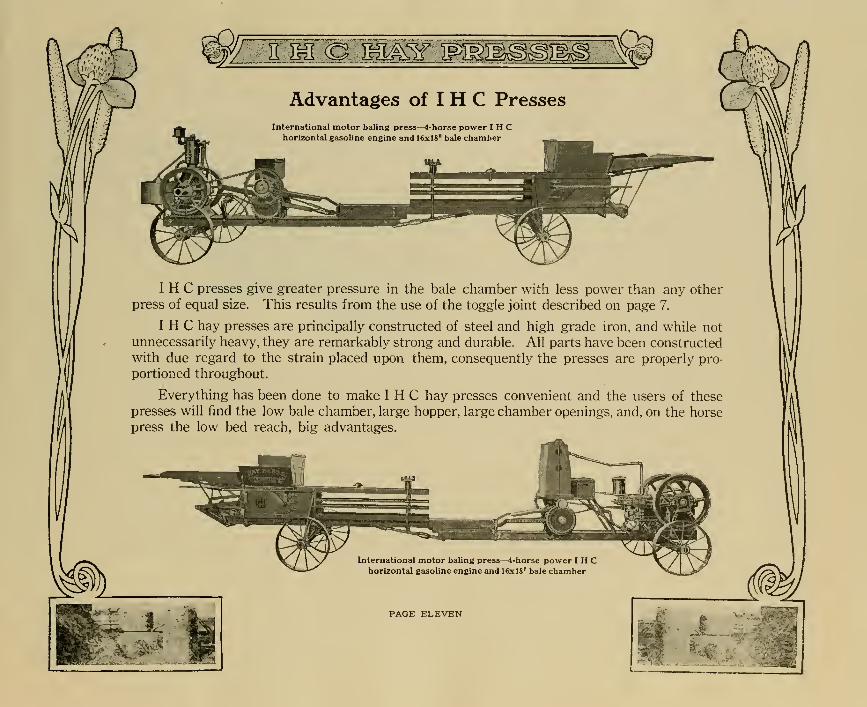
Advantages of I H C Presses
International motor baling press—4-horse power I H Chorizontal gasoline engine and 16x18" bale chamber
I H C presses give greater pressure in the bale chamber with less power than any other
press of equal size. This results from the use of the toggle joint described on page 7.
I H C hay presses are principally constructed of steel and high grade iron, and while not
unnecessarily heavy, they are remarkably strong and durable. All parts have been constructed
with due regard to the strain placed upon them, consequently the presses are properly pro-
portioned throughout.
Everything has been done to make I H C hay presses convenient and the users of these
presses will find the low bale chamber, large hopper, large chamber openings, and, on the horse
press the low bed reach, big advantages.
A
International motor baling press—4-horse power I H Chorizontal gasoline engine and 16x18" bale chamber
PAGE ELEVEN
J&- .1

^mw<^mw :mMffrYi
Self-Feed Attachment
The self-feed attachment for International motor baling presses
increases the capacity of the press as it insures more rapid feeding.
The self-feed never misses and is ad-
justed to feed as rapidly as the plunger
head works. With this self-feed at-
tachment, a condensing hopper andblock setter are furnished. The feed
arms are placed at the rear of the press
just above the toggle links. Thesefeed arms are raised well out of the wayto allow a large charge to be pitched
into the condensing hopper. The illus-
tration on this page shows the self-feed
at the beginning of a stroke. Thisfeeder is operated by means of rollers
and cams. The rollers are attachedto each of the rear toggle links. These rollers run in cams that force the feed arms into thehopper. The feed arms are counterbalanced by coil springs that are attached to the cams.
The condensing hopper is operated from the plunger and condenses the charge under thefeed arms before they descend.
The block setter is located just back of the hopper opening and within convenient reachof the operator. A new block can be placed in the block setter immediately after the previousblock has been dropped or whenever convenient, and when ready the operator pulls the lever
forward which places the block above the feed chamber, from where it drops into the bale
chamber in front of the plunger head. A safety device prevents the block from beingdelivered at the wrong time. The feed table can be placed on either side of the press.
Self-feed attachment in position for
the charge
PAGE TWELVE
The Engine
A regular 3, 4, or 6-horse power I H C gasoline engine is used with I H C motor presses.
When the baling season is over the bale chamber can be detached, and the engine has all the
advantages of a regular portable engine. A pulley is furnished which can be attached in
place of the drive chain sprocket on the engine. The buyer of an I H C motor press not only
gets an excellent bale chamber but also a gasoline engine that in points of simplicity, economy,
and efficiency is unsurpassed. These engines may be used for sawing wood, pumping water,
running feed grinders, small shellers, bone cutters, and for many other purposes, to which an
engine of their size is adaptable on the farm, in mills, and in shops.
All engines are regularly furnished with batteries, but on special order, at a slight addi-
tional cost, a magneto or auto sparker may be had.
Mounting
The power plant of I H C motor presses is self contained ; that is, the engine, cooling tower,
and gasoline tank, are mounted on a substantial metal truck. Two extra wheels and an axle
are furnished which can be attached to the rear end of the power bed when it is detached from
the bale chamber.
The front axle and the extra axle for the rear wheels are angle steel. The power bed,
which is made of four inch timber, is strongly reinforced by 4x4" angles of heavy steel on
each side.
As before stated, the bale chambers are interchangeable and any one of the three power
plants may be used with any of the different bale chambers. However, it is not advisable to
order a 3-horse power engine with a 17x22" bale chamber unless the work to be done is very
light. In many cases it is a good plan to order the 6-horse power engine as it has a wider range
of adaptability, and may be used for so many purposes that it will be a profitable investment.
•<^
V
PAGE THIRTEEN

•m
I H C 2-Horse Pull Power Hay Press
The I H C 2-horse pull power hay press meets the demand for a press of medium size
and light draft. This press has many points of simplicity and convenience found in no other
press, and, with less power and help, will bale as much or more hay than any other press of
equal size.
It is the pull power combined with the I H C toggle joint and compound leverage that
makes it possible with an I H C pull power press to do more work with less strain on the team,
than with any other press. The toggle joint plunger used on this press is the same as that
used on International motor presses.
This press is made with three sizes of bale chamber: 14 x 18", 16 x 18", and 17 x 22". It will
form bales weighing from 90 to 150 pounds. It is difficult to state any definite amount this press
will bale, as the capacity depends largely upon the quality of the material being baled, the skill
of the operator, and the speed of the team. Under ordinary conditions a 14 x 18 press will bale
from 8 to 10 tons of timothy hay in a day of 10 hours ; a 16 x 18, 10 to 12 tons, and the 17 x 22,
12 to 15 tons. There are conditions where this press will bale considerably more than the
estimates here given.
It is a comparatively easy matter with an I H C hay press to make bales weighing from
100 pounds to 120 pounds in from 6 to 10 feeds, as the large hopper and feed opening allow
large charges to be put in and the opening into the bale chamber is correspondingly large.
This press telescopes into a short space for transporting, which makes it very easy and
convenient to handle in going over roads.
I H C two-horse pull power hay press telescoped
for transportation
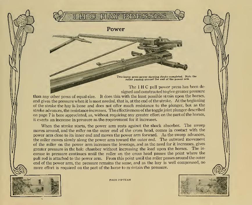
Power
Two-horse press power showing stroke completed. Note the
roller passing around the end of the power arm
The I H C pull power press has been de-
signed and constructed to give greater pressure
than any other press of equal size. It does this with the least possible strain upon the horses,
and gives the pressure when it is most needed, that is, at the end of the stroke. At the beginning
of the stroke the hay is loose and does not offer much resistance to the plunger, but as the
stroke advances, the resistance increases. The effectiveness of the toggle joint plunger described
on page 7 is here appreciated, as, without requiring any greater effort on the part of the horses,
it exerts an increase in pressure as the requirement for it increases.
When the stroke starts, the power arm rests against the shock absorber. The sweep
moves around, and the roller on the outer end of the cross head, comes in contact with the
power arm close to its inner end and moves the power arm forward. As the sweep advances,
the roller moves slowly along the power arm toward the outer end. The outward movement
of the roller on the power arm increases the leverage, and as the need for it increases, gives
greater pressure in the bale chamber without increasing the load upon the horses. The in-
crease in pressure continues until the roller on the cross head passes the point where the
pull rod is attached to the power arm. From this point until the roller passes around the outer
end of the power arm, the pressure remains the same, and as the hay is well compressed, no
more effort is required on the part of the horse to maintain the pressure.
PAGE FIFTEEN
sswmei wm
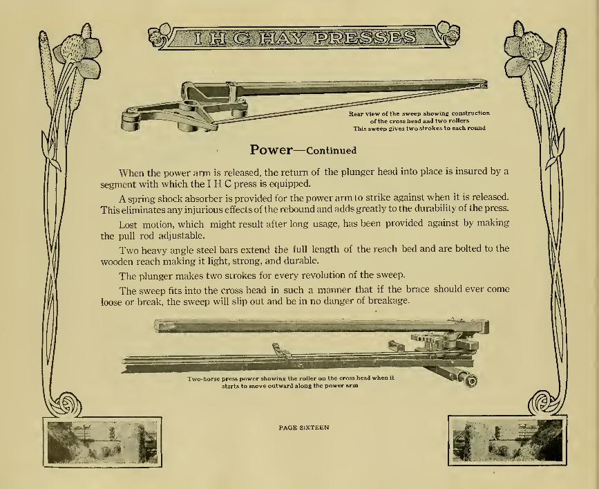
Rear view of the sweep showing construction
of the cross head and two rollers
This sweep gives two strokes to each round
Power—Continued
When the power arm is released, the return of the plunger head into place is insured by a
segment with which the I H C press is equipped.
A spring shock absorber is provided for the power arm to strike against when it is released.
This eliminates any injurious effects of the rebound and adds greatly to the durability of the press.
Lost motion, which might result after long usage, has been provided against by making
the pull rod adjustable.
Two heavy angle steel bars extend the full length of the reach bed and are bolted to the
wooden reach making it light, strong, and durable.
The plunger makes two strokes for every revolution of the sweep.
The sweep fits into the cross head in such a manner that if the brace should ever come
loose or break, the sweep will slip out and be in no danger of breakage.
Two-horse press power showing the roller on the cross head when it
starts to move outward along the power arm
PAGE SIXTEEN
g£W 1PW
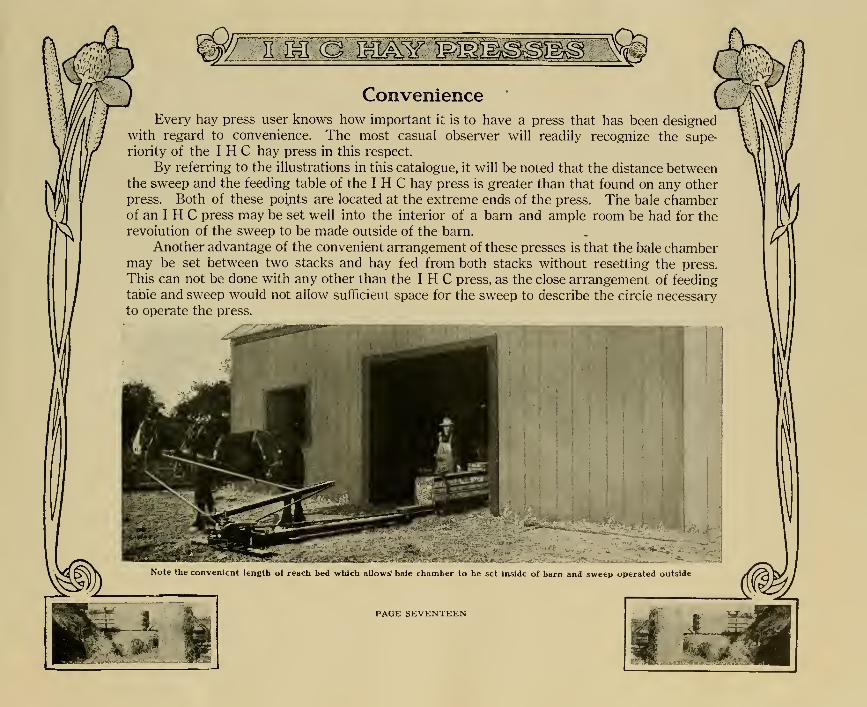
ConvenienceEvery hay press user knows how important it is to have a press that has been designed
with regard to convenience. The most casual observer will readily recognize the supe-
riority of the I H C hay press in this respect.
By referring to the illustrations in this catalogue, it will be noted that the distance betweenthe sweep and the feeding table of the I H C hay press is greater than that found on any other
press. Both of these points are located at the extreme ends of the press. The bale chamberof an I H C press may be set well into the interior of a barn and ample room be had for the
revolution of the sweep to be made outside of the barn.
Another advantage of the convenient arrangement of these presses is that the bale chambermay be set between two stacks and hay fed from both stacks without resetting the press.
This can not be done with any other than the I H C press, as the close arrangement of feeding
table and sweep would not allow sufficient space for the sweep to describe the circle necessaryto operate the press.
Note the convenient length oi reach bed which allow;,' bale chamber to be set inside of barn and sweep operated outside
PAGE SEVENTEEN
JLSM

Convenience—Continued
The reach bed of the I H C press is about 4 inches high and is very narrow. This con-
struction gives the I H C press the lowest and shortest step-over found on any hay press. Whenoperating presses that have a high step-over, the horses will generally slow down, hesitate, and
often stumble at this point which is annoying to the men, wearing on the horses, and slackens
the speed of the press. The lowness and narrowness of the I H C reach bed enables the
horses to walk over it without the least trouble. Simply compare this reach bed with anyother, and its advantages will be readily appreciated.
Furthermore, the power construction of the I H C press is such that when the horses reach
the step-over, they are pulling practically no load. One stroke has been completed before they
reach the step-over and the load of the next stroke does not begin until the low, narrow step-
over has been passed.
The bale chamber on all I H C presses is very low and it is an easy matter to reach
across and tie the bale. This saves time and trouble as, in tying the bale, it is not necessary to
go around the bale chamber to the opposite side.
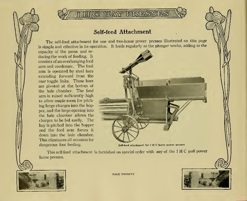
Self-feed Attachment
The self-feed attachment for one and two-horse power presses illustrated on this page
is simple and effective in its operation. It feeds regularly as the plunger works, adding to the
capacity of the press and re-
ducing the work of feeding. It
consists of an overhanging feed
arm and condenser. The feed
arm is operated by steel bars
extending forward from the
rear toggle links. These bars
are pivoted at the bottom of
the bale chamber. The feed
arm is raised sufficiently high
to allow ample room for pitch-
ing large charges into the hop-
per, and the large opening into
the bale chamber allows the
charges to be fed easily. The
hay is pitched into the hopper
and the feed arm forces it
down into the bale chamber.
This eliminates all occasion for
dangerOUS foot feeding. Self-feed attachment for I H C horse power presses
This self-feed attachment is furnished on special order with any of the I H C pull power
horse presses.
PAGE TWENTY

B&
I H C One-Horse Pull Power Hay Press
The I H C one-horse pull power hay press has all the features of the I H C two-horse pull
power hay press, except that it is a smaller and lighter machine. It proves a very satisfactory
press for the farmer who wishes to bale his own hay. With this press he can bale his hay at
a time when it is most convenient, and with a small amount of help. If he wishes he can do
a little custom baling for his neighbors, and in this way make enough to pay for the press in a
very short time.
This press has a 14x18 bale chamber, and makes bales weighing from fifty to ninety
pounds. The bales may be tied with two or three wires. Under average conditions this press
will bale from six to eight tons of hay per day.
The bale chamber has a large opening allowing the feeder to put large charges into the
chamber. A steel hopper is provided with an extension top on one side and front. The plat-
I H C one-horse power hay press
mounted on trucks

form upon which the feeder stands can be placed on either side of the press.
The one-horse press is equipped with trucks only on special order. When mounted on
trucks the presses can be telescoped, which makes it convenient for transporting over roads
and through fields.
Power
The power construction of this press is the same as the two-horse pull power press. The
toggle joint plunger and compound leverage which gives the two-horse press its great com-
pressing power are also used on the one-horse press. Because of this construction greater
pressure is exerted in the bale chamber of this one-horse press than with any other press of
equal size, and with less strain on the horse.
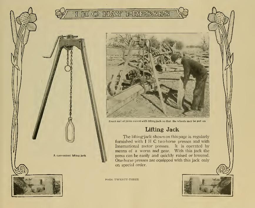
The lifting"jack shown on this page is regularly
furnished with I H C two-horse presses and with
International motor presses. It is operated bymeans of a worm and gear. With this jack the
press can be easily and quickly raised or lowered.
One-horse presses are equipped with this jack only
on special order.
PAGE TWENTY THREE

W^PV^OTV^^v^^BiV"^^**^^
(MIPMRT ©IF MflEMffi(incorporated)
HAVES LITMO CC BUFFALO NY USA


Related Documents