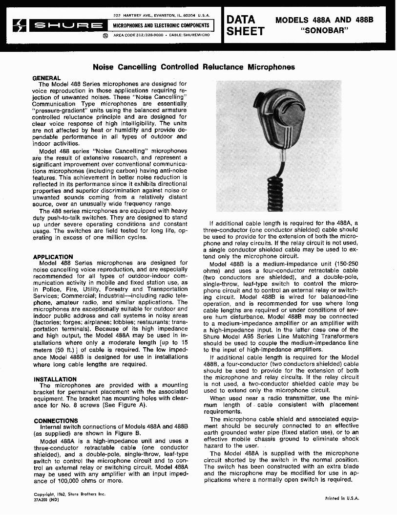
Noise Cancelling Controlled Reluctance Microphones GENERAL The Model 488 Series microphones are designed for 222 HARTREY AVE.. EVANSTON. I L. 60204 U.S A. @ AREA CODE 31z/3~~-9000 . CABLE: SHUREMICRO voice reproduction in those applications requiring re- jection of unwanted noises. These "Noise Cancelling" Communication Type microphones are essentially "pressure-gradient" units using the balanced armature controlled reluctance principle and are designed for clear voice response of high intelligibility. The units are not affected by heat or humidity and provide de- pendable performance in all types of outdoor and indoor activities. DATA MODELS 488~ AND 488~ SHEET "SONOBAR" Model 488 series "Noise Cancelling" microphones are the result of extensive research, and represent a significant improvement over conventional communica- tions microphones (including carbon) having anti-noise features. This achievement in better noise reduction is reflected in its performance since it exhibits directional properties and superior discrimination against noise or unwanted sounds coming from a relatively distant source, over an unusually wide frequency range. The 488 series microphones are equipped with heavy duty push-to-talk switches. They are designed to stand up under severe operating conditions and constant usage. The switches are field tested for long life, op- erating in excess of one million cycles. APPLICATION Model 488 Series microphones are designed for noise cancelling voice reproduction, and are especially recommended for all types of outdoor-indoor com- munication activity in mobile and fixed station use, as in Police, Fire, Utility, Forestry and Transportation Services; Commercial; Industrial-including radio tele- phone, amateur radio, and similar applications. The microphones are exceptionally suitable for outdoor and indoor public address and call systems in noisy areas (factories; forges; airplanes; lobbies; restaurants; trans- portation terminals). Because of its high impedance and high output, the Model 488A may be used in in- stallations where only a moderate length [up to 15 meters (50 ft.) 1 of cable is required. The low imped- ance Model 4888 is designed for use in installations where long cable lengths are required. INSTALLATION The microphones are provided with a mounting bracket for permanent placement with the associated equipment. The bracket has mounting holes with clear- ance for No. 8 screws (See Figure A). CONNECTIONS Internal switch connections of Models 488A and 488B (as supplied) are shown in Figure B. Model 488A is a high-impedance unit and uses a three-conductor retractable cable (one conductor shielded), and a double-pole, single-throw, leaf-type switch to control the microphone circuit and to con- trol an external relay or switching circuit. Model 488A may be used with any amplifier with an input imped- ance of 100,000 ohms or more. If additional cable length is required for the 488A, a three-conductor (one conductor shielded) cable should be used to provide for the extension of both the micro- phone and relay circuits. If the relay circuit is not used, a single conductor shielded cable may be used to ex- tend only the microphone circuit. Model 488B is a medium-impedance unit (150-250 ohms) and uses a four-conductor retractable cable (two conductors are shielded), and a double-pole, single-throw, leaf-type switch to control the micro- phone circuit and to control an external relay or switch- ing circuit. Model 4888 is wired for balanced-line operation, and is recommended for use where long cable lengths are required or under conditions of sev- ere hum disturbance. Model 488B may be connected to a medium-impedance amplifier or an amplifier with a high-impedance input. In the latter case one of the Shure Model A95 Series Line Matching Transformers should be used to couple the medium-impedance line to the input of high-impedance amplifiers. If additional cable length is required for the Model 488B, a four-conductor (two conductors shielded) cable should be used to provide for the extension of both the microphone and relay circuits. If the relay circuit is not used, a two-conductor shielded cable may be used to extend only the microphone circuit. When used near a radio transmitter, use the mini- mum length of cable consistent with placement requirements. The microphone cable shield and associated equip- ment should be securely connected to an effective earth grounded water pipe (fixed station use), or to an effective mobile chassis ground to eliminate shock hazard to the user. The Model 488A is supplied with the microphone circuit shorted by the switch in the normal position. The switch has been constructed with an extra blade and the microphone may be modified for use in ap- plications where a normally open switch is required. Copyright, 1962, Shure Brothers Inc. 27A200 (ND) Printed in U.S.A.

Welcome message from author
This document is posted to help you gain knowledge. Please leave a comment to let me know what you think about it! Share it to your friends and learn new things together.
Transcript
Noise Cancelling Controlled Reluctance Microphones GENERAL
The Model 488 Series microphones are designed for
2 2 2 HARTREY AVE.. EVANSTON. I L. 6 0 2 0 4 U.S A.
@ AREA CODE 3 1 z / 3 ~ ~ - 9 0 0 0 . CABLE: SHUREMICRO
voice reproduction in those applications requiring re- jection of unwanted noises. These "Noise Cancelling" Communication Type microphones are essentially "pressure-gradient" units using the balanced armature controlled reluctance principle and are designed for clear voice response of high intelligibility. The units are not affected by heat or humidity and provide de- pendable performance in all types of outdoor and indoor activities.
DATA MODELS 4 8 8 ~ AND 4 8 8 ~ SHEET "SONOBAR"
Model 488 series "Noise Cancelling" microphones are the result of extensive research, and represent a significant improvement over conventional communica- tions microphones (including carbon) having anti-noise features. This achievement in better noise reduction is reflected in its performance since it exhibits directional properties and superior discrimination against noise or unwanted sounds coming from a relatively distant source, over an unusually wide frequency range.
The 488 series microphones are equipped with heavy duty push-to-talk switches. They are designed to stand up under severe operating conditions and constant usage. The switches are field tested for long life, op- erating in excess of one million cycles.
APPLICATION Model 488 Series microphones are designed for
noise cancelling voice reproduction, and are especially recommended for all types of outdoor-indoor com- munication activity in mobile and fixed station use, as in Police, Fire, Utility, Forestry and Transportation Services; Commercial; Industrial-including radio tele- phone, amateur radio, and similar applications. The microphones are exceptionally suitable for outdoor and indoor public address and call systems in noisy areas (factories; forges; airplanes; lobbies; restaurants; trans- portation terminals). Because of its high impedance and high output, the Model 488A may be used in in- stallations where only a moderate length [up to 15 meters (50 ft.) 1 of cable is required. The low imped- ance Model 4888 is designed for use in installations where long cable lengths are required.
INSTALLATION The microphones are provided with a mounting
bracket for permanent placement with the associated equipment. The bracket has mounting holes with clear- ance for No. 8 screws (See Figure A).
CONNECTIONS Internal switch connections of Models 488A and 488B
(as supplied) are shown in Figure B. Model 488A is a high-impedance unit and uses a
three-conductor retractable cable (one conductor shielded), and a double-pole, single-throw, leaf-type switch to control the microphone circuit and to con- trol an external relay or switching circuit. Model 488A may be used with any amplifier with an input imped- ance of 100,000 ohms or more.
If additional cable length is required for the 488A, a three-conductor (one conductor shielded) cable should be used to provide for the extension of both the micro- phone and relay circuits. If the relay circuit is not used, a single conductor shielded cable may be used to ex- tend only the microphone circuit.
Model 488B is a medium-impedance unit (150-250 ohms) and uses a four-conductor retractable cable (two conductors are shielded), and a double-pole, single-throw, leaf-type switch to control the micro- phone circuit and to control an external relay or switch- ing circuit. Model 4888 is wired for balanced-line operation, and is recommended for use where long cable lengths are required or under conditions of sev- ere hum disturbance. Model 488B may be connected to a medium-impedance amplifier or an amplifier with a high-impedance input. In the latter case one of the Shure Model A95 Series Line Matching Transformers should be used to couple the medium-impedance line to the input of high-impedance amplifiers.
If additional cable length is required for the Model 488B, a four-conductor (two conductors shielded) cable should be used to provide for the extension of both the microphone and relay circuits. If the relay circuit is not used, a two-conductor shielded cable may be used to extend only the microphone circuit.
When used near a radio transmitter, use the mini- mum length of cable consistent with placement requirements.
The microphone cable shield and associated equip- ment should be securely connected to an effective earth grounded water pipe (fixed station use), or to an effective mobile chassis ground to eliminate shock hazard to the user.
The Model 488A is supplied with the microphone circuit shorted by the switch in the normal position. The switch has been constructed with an extra blade and the microphone may be modified for use in ap- plications where a normally open switch is required.
Copyright, 1962, Shure Brothers Inc. 27A200 (ND) Printed in U.S.A.
ACOUSTIC CONSIDERATIONS A. To modify the 488A for a normally open microphone switch, proceed as follows: 1. Remove the three #5-40 round head screws
from the back of the microphone case. (Caution: the microphone cartridge is spring loaded, and care must be taken to hold the two halves of the microphone case firmly together).
2. Separate the case front and back and remove switch button. See Figure C.
3. Remove the #5-40 round head switch mounting screw and lock washer, holding the switch assembly in the case back.
4. Disconnect or clip the white cable lead from the switch solder lug.
5. Strip the insulation from the white lead ap- proximately 6 mm (VI in.) and solder to unused lug at the bottom end of the switch.
NOTE: In certain instances, if switch sequence is critical, it may be necessary to remove the effect of the shorted switch on the cartridge. This can be done by insulating the shorting contacts with a piece of "spaghetti" tubing or a piece of insulating tape. 6. Re-assemble the switch in the case back, using
screw and lock washer removed previously. 7. Replace switch button in case back. Also be cer-
tain that the cartridge-shield retaining springs are in the proper position.
8. Place case back on case front and firmly press cases together. Fasten with the three #5-40 screws and washers previously removed.
The Model 4888 is supplied with the microphone circuit opened by the switch in the normal position of the switch. The microphone may be modified for use in applications requiring the microphone circuit to be shorted in the normal position of the switch. B. To modify the 4888 for normally closed microphone
switch, proceed as follows: 1. Remove the three #5-40 round head screws
from the back of the microphone case. (Caution: the microphone cartridge is spring loaded and care must be taken to hold the two halves of the microphone case firmly together).
2. Separate the case front and back and remove switch button. See Figure C.
3. Remove the #5-40 round head switch mounting screw and lock washer, holding the switch as- sembly in the case back.
4. Disconnect or clip the white cable lead from the switch solder lug.
5. Strip the insulation from the white lead approx- imately 6 mm (1/4 in.) and solder this white lead to the switch blade next to the blade with the green lead connections. This is the blade that the switch button pushes against. The outside solder lug may be bent out of the way to aid soldering.
6. Re-assemble the switch in the case back using screw and lock washer removed previously.
7. Replace switch button in case back. Also be certain that the cartridge shield retaining springs are in the proper position.
8. Place case back on case frogt and firmly press cases together; fasten with the three #5-40 screws and washers previously removed.
The important characteristics contributing to the total noise reduction of the 488 Series Microphones are shaped frequency response, directionality and distance and direction discrimination.
The acoustical elements are arranged to optimize performance in the frequency range of 200 to 4000 Hz. The results achieved are the elimination of all sounds outside of the desired frequency range and proper con- trol of those sounds within the desired range.
The 488 microphones reject noise through their in- herent directional properties and discriminate against unwanted sounds arriving from a distance in favor of sounds arriving from a near source.
The microphones operate on the pressure-gradient principle and have two sound entry ports, spaced a small distance apart.
In order to obtain the best noise cancelling perform- ance with the Model 488 Series, the microphone must be used as "close talking." The lips should be as close to the microphone grille as comfort will permit, with a distance of approximately 6 mm to 25 mm ('/4 in. to 1 in.) providing the greatest discrimination between the voice sounds and background noise.
No special precautions beyond ordinary care are necessary in operation of the 488 Series microphones. They will operate very satisfactorily under all ordinary conditions of humidity, heat, and cold. Dropping the microphones or other severe mechanical shocks should be avoided.
SPECIFICATIONS Frequency Response:
200 - 4000 HZ Output Level (at 1000 Hz):
Model 488A Open Circuit Voltage . . . . . . - 17.0 dB* (.141V) EIA Microphone Rating
Gm (Sensitivity) . . . . . . . . - 147.0 dB***
Model 4888 Open Circuit Voltage . . . . . . - 37.0 dB* (.014V) Power Level (into 200 ohms) - 56.0 dB* * EIA Microphone Rating
Gm (Sensitivity) . . . . . . . . - 148.5 dB* * *O dB = 1 volt per 100 microbars
"'0 dB = 1 milliwatt with 10 microbars ***Reference, EIA Standard SE-105, August, 1949.
Microbar = one dyne per square centimeter. Measurements at 9.5 mm (% in.) from sound source.
Recommended Load Impedance: Model 488A . . . . . . . . . . . . . . .100,000 ohms or more Model 4888 . . . . . . . . . . . . . . . . . . . .I50 to 250 ohms
Cables: Attached, recoils to 0.3m (1 ft) extends to 1.5m (5 ft)
Case: High impact gray "Armo-Dur"
Dimensions: See Figure D
Net Weight: 340 grams (3/4 Ib)
Shipping Weight: 510 grams (1 'YE Ib)
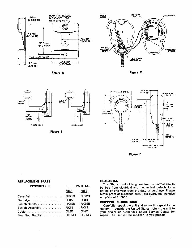
- 9.1 mm MOUNTING HOLES,
(23/64 IN.) CLEARANCE FOR No. 8 SCREWS 7
T - 9.5 mm
(3/8 IN.)
Figure A
MODEL 488A MODEL 488 8
Figure B
REPLACEMENT PARTS
DESCRIPTION
. . . . . . . . . . . . . . . . . . . . Case Set Cartridge . . . . . . . . . . . . . . . . . . . .
. . . . . . . . . . . . . . . . Switch Button Switch Assembly . . . . . . . . . . . . . Cable . . . . . . . . . . . . . . . . . . . . . . . Mounting Bracket . . . . . . . . . . . .
SHURE PART NO.
488A - 4888 - RK2lC RK22C R88A R88B RK3SB RK3SB RK7S RK7S C12C C14C RK6MB RK6MB
SWITCH MU-METAL SHIELD\ ,-OARTRIDCE BUTTON -i
w
Figure C
7.9 mm (5/16 IN.) (7116 IN.)
Figure D
GUARANTEE This Shure product is guaranteed in normal use to
be free from electrical and mechanical defects for a period of one year from the date of purchase. Please retain proof of purchase date. This guarantee includes all parts and labor.
SHIPPING INSTRUCTIONS Carefully repack the unit and return it prepaid to the
factory. If outside the United States, return the unit to your dealer or Authorized Shure Service Center for repair. The unit will be returned to you prepaid.

Related Documents