INSTRUCTION MANUAL VECTOR INVERTER plus RUN DOC. NO HHIS-WZ-PK-008 (02) Accredited by the RvA ISO 9001/ISO 14001/OHSAS 18001(N/A) REGISTERED FIRM DNV Certification B.V., THE NETHERLANDS

Hyundai N100 Manual
Oct 09, 2014
Welcome message from author
This document is posted to help you gain knowledge. Please leave a comment to let me know what you think about it! Share it to your friends and learn new things together.
Transcript

INSTRUCTION MANUALVECTOR INVERTER
plusRUN
DOC. NO HHIS-WZ-PK-008 (02)
Accreditedby the RvA
ISO 9001/ISO 14001/OHSAS 18001(N/A)
REGISTERED FIRMDNV Certification B.V., THE NETHERLANDS

CONTENTS
1. Safety Message
2. Receiving and Checking
3. General Specifications
4. External dimensional diagrams and
Identifying the parts
5. Mounting
6. Wiring
7. Operation
8. Using Intelligent Input Terminals
9. Function List
10. Protective functions
11. Trouble shooting Tips
12. Maintenance and Inspection
13. Option
Page
plus

1. Safety Messages
For the best results with the N100 Series inverter,carefully read this manual and all of the warning labelsattached to the inverter before installing and operating it, andfollow the instructions exactly. Keep this manual handy forquick reference.
plus
Definitions and Symbols
A safety instruction(message) includes a hazard alert symboland a signal word, DANGER or CAUTION. Each signalword has the following meaning:
This symbol is the "Safety Alert Symbol." It occurs witheither of two signal words : DANGER or CAUTION, asdescribed below
Indicates a potentially hazardous situationwhich, if not avoided, can result in serious injury or death.
Indicates a potentially hazardous situationwhich, if not avoided, can result in minor to moderate injury,or serious damage to the product. The situation described inthe may, if not avoided, lead to serious results.Important safety measures are described in CAUTION (aswell as DANGER), so be sure to observe them.
Notes indicate an area or subject of special merit,emphasizing either the product's capabilities or commonerrors in operation or maintenance.
DANGER :
CAUTION :
CAUTION
NOTE :
plus

Some drawings in this manual are shown with the protective or
shields removed in order to describe detail with more clarity.
Make sure all covers and shields are replaced before operating
this product.
This manual may be modified when necessary because of the
improvement of the product, modification, or changes in
specifications.
To order a copy of this manual, or if your copy has been
damaged or lost, contact your representative.
Hyundai is not responsible for any modification of the product
made by the user, since that will void the guarantee.
CAUTION
plus

Index to Dangers and Cautions in This Manual
Installation-cautions for Mounting Procedures
Be sure to install the unit on flame-resistantmaterial such as a steel plate.Otherwise, there is the danger of fire.
Be sure not to place any flammable materialsnear the inverter.Otherwise, there is the danger of fire.
Be sure not to let the foreign matter enter ventopenings in the inverter housing, such as wireclippings, spatter from welding, metal shavings, dust, etc.Otherwise, there is the danger of fire.
Be sure to install the inverter in a place which canbear the weight according to the specifications in the text.Otherwise, it may fall and cause injury to personnel.
Be sure to install the unit on a perpendicular wallwhich is not subject to vibration.Otherwise, it may fall and cause injury to personnel.
Be sure not to install or operate an inverter whichis damaged or has missing parts.Otherwise, it may cause injury to personnel.
Lift the cabinet by the cooling fin. When moving theunit, never lift by the plastic case or the terminal covers.Otherwise, the main unit may be dropped causing damageto the unit.
When mounting units in an enclosure, install a fan orother cooling device to keep the intake air temperaturebelow 40 .
5-1
5-1
5-1
5-1
5-1
5-1
CAUTION
5-1
5-1
plus

Be sure to maintain the specified clearance
area around the inverter and to provide adequate
ventilation.
Otherwise, the inverter may overheat and cause eguipment
damage or fire.
Be sure to install the inverter in a well-ventilated
room which does not have direct exposure to
sunlight, a tendency for high temperature, high
humidity of dew condensation, high levels of dust,
corrosive gas, explosive gas, inflammable gas,
grinding-fluid mist, salt damage, etc.
Otherwise, there is the danger of fire.
5-2
5-2
CAUTION
plus

DANGER
Wiring-Dangers for Electrical Practices and WireSpecifications
Be sure to connect grounding terminal.Otherwise, there is a danger of electric shock and/or fire.
Wiring work shall be carried out only by qualifiedpersonnel.Otherwise, there is a danger of electric shock and/or fire.
Implement wiring after checking that the powersupply is off. You may incur electric shock and/or fire.
Do not connect wiring to an inverter or operate aninverter that is not mounted according the instructionsgiven in this manual.Otherwise, there is a danger of electric shock and/orinjury to personnel.
When wiring the emergency stop circuit, check thewiring thoroughly before operation.Otherwise, it may cause injury to personnel.
For 400V class, make sure to ground the supplyneutral.Otherwise, there is a danger of electric shock.
6-2
6-2
6-2
6-2
6-2
6-2
plus

Wiring-Cautions for Electrical Practices
Be sure that the input voltage matches the inverter
specifications:
Single-phase 200 to 230 V 50/60Hz
Be sure not to input a single phase to a three-phase
only type inverter.
Otherwise, there is the danger of fire.
Be sure not to connect an AC power supply to the
output terminals(U.V.W).
Otherwise, there is the danger of injury and/or fire.
Do not Run/Stop operation by switching ON/OFF
electromagnetic contactors on the primary or secondary
sides of the inverter.
Otherwise, there is the danger of fire.
To connect a braking resistor, follow the procedures
described in this manual.
Otherwise, there is the danger of fire.
Three-phase 200 to 230V 50/60Hz
Three-phase 380 to 460V 50/60Hz
Otherwise, there is the danger of injury and/or fire .
6-1
6-1
6-1
6-1
6-1
CAUTION
plus

Fasten the screws with the specified fastening
torque. Check for any loosening of screws.
Otherwise, there is the danger of fire.
Be sure to install a fuse in the wire for each phase
of the main power supply to the inverter.
Otherwise, there is the danger of fire.
Do not perform a withstand voltage test of the
inverter.
Otherwise, it may cause semi-conductor elements
to be damaged.
To connect a braking resistor, braking resistor unit
or braking unit, follow the procedures in this manual.
Improper connection may cause a fire.
Do not connect or disconnect wires or connectors
while power is applied to the circuit.
Otherwise, it may cause injury to personnel.
6-1
6-1
6-1
6-1
6-1
CAUTION
plus

Dangers for Operations and Monitoring
Be sure to turn on the input power supply afterclosing the front case. While being energized, besure not to open the front case.Otherwise, there is the danger of electric shock and/or fire.
Be sure not to operate the switches with wet hands.Otherwise, there is the danger of electric shock.
While the inverter is energized, be sure not to touchthe inverter terminals even when the motor is stopped.Otherwise, there is the danger of electric shock.
If the Retry Mode is selected, the motor maysuddenly restart during the trip stop. Do not approachthe machine(be sure to design the machine so that safety forpersonnel is secure even if it restarts.)Otherwise, it may cause injury to personnel and/or fire.
If the power supply is cut off for a short period oftime, the inverter may restart operation after the powersupply recovers if the command to operate is active.If a restart may pose danger to personnel, so be sure to usea lock out circuit so that it will not restart after power recovery.Otherwise, it may cause injury to personnel.
The Stop Key is effective only when the stop functionis enabled. Be sure to prepare emergency stop keyseparately.Otherwise, it may cause injury to personnel.
DANGER
7-1
7-1
7-1
7-1
7-1
7-1
plus

After the operation command is given, if the
alarm reset is conducted, it will restart suddenly.
Be sure to set the alarm reset after verifying the
operation command is off.
Otherwise, it may cause injury to personnel.
Be sure not to touch the inside of the energized
inverter or to put any conductive object into it.
Otherwise, there is a danger of electric shock and/of fire.
DANGER
7-1
7-1
plus

Cautions for Operations and Monitoring
The heat sink fins will have a high temperature.Be careful not to touch them.Otherwise, there is the danger of getting burned.
Install a holding brake separately if necessary.Otherwise, there is the danger of accident.
Check the direction of the motor, any abnormalmotor vibrations or noise.Otherwise, there is the danger of equipment damage.
The operation of the inverter can be easily changedfrom low speed to high speed. Be sure check thecapability and limitation of the motor and machinebefore operating the inverter.
If you operate a motor at a frequency higher thanthe inverter standard default setting (60Hz), be sureto check the motor and machine specifications withthe respective manufacturer. Only operate the motor atelevated frequencies after getting their approval.Otherwise, there is the danger of equipment damage.
All the constants of the inverter have been presetat the factory.Otherwise, there is the danger of equipment damage.
CAUTION
7-2
7-2
7-2
7-2
7-2
7-2
plus

Dangers and cautions for TroubleshootingInspection and Maintenance
Wait at least five(5) minutes after turning off theinput power supply before performing maintenanceor an inspection.Otherwise, there is the danger of electric shock.
Make sure that only qualified personnel willperform maintenance, inspection, and part replacement.(Before starting to work, remove any metallic objects fromyour person(wrist watch, bracelet, etc.) Be sure to use tools withinsulated handles.Otherwise, there is a danger of electric shock and/or injury topersonnel.
Never touch high-voltage terminals in the inverter.Otherwise, there is a danger of electric shock.
The control PC board employs CMOS ICDo not touch the CMOS elements.They are easily damaged by static electricity.
Do not connect or disconnect wires, connectors, orcooling fan while power is applied to the circuit.Otherwise, it may cause injury to personnel.
S.
Never modify the product.Otherwise, there is a danger of electric shock and/or injury topersonnel.
DANGER
DANGER
Dangers for using
12-1
12-1
12-1
12-1
12-1
plus
WARNING DISPLAY
WARNING
DANGERRisk of electric shock.Before opening the cover, wait at least 5minutes until DC bus capacitors discharge.Ensure proper earth connection.Refer to the user's manual before installationand operation.
A warning label is displayed on the terminal cover of the inverter,
as shown in the figure.
Follow these instructions when handling the inverter.
plus

Do not Run/Stop operation by switching on/off electromagnetic
contactors (Mc0, Mc1) on the primary or secondary sides of theinverter.Operate the inverter by Run/Stop commanding [FW/RV].
Inverter
Motor Terminal Surge Voltage Suppression Filter (for the
400V class)
In a system using an inverter with the voltage control PWM system, a
voltage surge caused by the cable constants such as the cable length
(especially when the distance between the motor and inverter is 10m or
more) and cabling method may occur at the motor terminals. A
dedicated filter of the 400V class for suppressing this voltage surge is
available. Be sure to install a filter in this situation.
Input power disconnection
This inverter is not able to protect input power disconnection.
Be careful to connect the wires.
plus

In the cases below involving a general-purpose inverter, a large
peak current flows on the power supply side, sometimes destroying theconverter module.The unbalance factor of the power supply is 3% or higher.The power supply capacity is at least 10 times greater than the invertercapacity(and the power supply capacity, 500kVA or more).Abrupt power supply changes are expected.some examples) Several inverters are interconnected with a short bus.
An installed leading capacitor opens and closes.
RC Value of the thermal Relay is 1.1 times greater than the
motor rated current. Also, RC Value is adjustable to the wiringdistance, but contacts us in this case.
Do not connect and disconnect the power supply more than
1/5(number / minute)There is the danger of inverter damage.
When the EEPROM error E 08 occurs, be sure to confirm the
setting values again.
plus

Inverter Specifications Label
Before installing and wiring, check the following(1) Check the unit for physical damage that may have occurred
during shipping(2) Verify that the package contains one inverter and one manual
after packing the N100 inverter.(3) Verify that the specifications on the labels match your purchase
order
plus
Model : N100 -015LFplus
Power : 1.5kW/2HP
Input : 50Hz/60Hz 200 230V 3Ph
Output : 0.5-400Hz 200 230V 3ph 7.0A−
HYUNDAI
MFG NO :
052)230-8445/6Customer Service Center
HEAVY INDUSTRIES CO., LTD.
Inverter model number
Motor capacity for this model
Power Input Rating: frequency,voltage, phase
Output Rating: Frequency,voltage, phase current
Manufacturing codes:Lot number, date, etc.
Model Number convention
The model number for a specific inverter contains useful informationabout its operating characteristics. Refer to the model number legendbelow:
015 H F
022: 2.2kW
004: 0.4kW007: 0.75kW015: 1.5kW
N100plus
Series name
Directive type :E: CE directive, blank : UL directive
Configuration typeF:operator pannel equipped
Input voltage:S: single phase 200V classL: three-phase only 200V classH: three-phase 400V class
Maximum applicable motor capacity(4P, kW)
2. Receiving and checking
If any part of N100 is missing or damaged, call for service immediatelyplus
2-1
-
037: 3.7kW
N100 INSTRUCTION MANUALplus

3. N100 Inverter Standard Specifiations.plus
Model-specific tables for 200V and 400V class inverters
The following two tables are specific to N100 inverters for the200V and 400V class model groups. The table on page 3-3 givesthe general specifications that apply to both voltage class groups.Footnotes for all specifications tables are on the next page.
plus
Item 200V Class Specifications
Model N100 seriesplus
Applicable motor size *2kW
HP
Rated capacity(200V)kVA
Rated input voltage
Rated output voltage *3
Rated output current(A)
Starting torque(with sensorless vector
control selected)
Dynamic brakingapprox. % torque,short time stop *5
without resistor,from 50/60Hz
with resistor
DC braking
Weight (kg)
N100-004SF
plusN100-004LF
plusN100-007SF
plusN100-007LF
plusN100-015LF
plusN100-015SF
plusN100-022LF
plusN100-037LF
plus
0.4 0.40.75 0.751.5 1.5 2.2 3.7
1/2 1/21 12 2 3 5
1.1 1.11.9 1.93.0 3.0 4.2 6.1
Single-phase200 to 230V 10%,
50/60 Hz 5%
There-phase (3-wires)200 to 230V 10%,
50/60 Hz 5%
3-phase 200 to 230V (corresponding to input voltage)
3.0 3.05.0 5.0 7.07.0 11.0 17.0
200% or more
approximately100%
approximately150%
Variable operating frequency, time and braking force
1.21.2 1.21.2 1.51.5 1.5 2.0
approximately20 40%
approximately100%
3-1
N100 INSTRUCTION MANUALplus

Item 400V Class Specifications
Applicable motorsize *2
kW
HP
Rated capacity(200V)kVA
Rated input voltage
Rated output voltage *3
Rated output current(A)
Dynamic brakingapprox. % torque,short time stop *5
without resistor,from 50/60Hz
with resistor
DC braking
Weight(kg)
N100-004HF
plusN100-007HF
plusN100-015HF
plusN100-022HF
plusN100-037HF
plus
0.4 0.75 1.5 2.2 3.7
1/2 1 2 3 5
1.1 1.9 3.0 4.2 6.1
3-phase : 380 to 460V 10%,50/60Hz 5%
3-phase 380 to 460V (corresponding to input voltage)
1.8 3.4 4.8 7.2 9.2
200% or more
approximately100%
approximately100%
Variable operating frequency, time and braking force
1.2 1.5 1.5 2.0 2.0
approximately20 40%
approximately100%
Model N100 seriesplus
Starting torque(with sensorless vector
control selected)
3-2
N100 INSTRUCTION MANUALplus
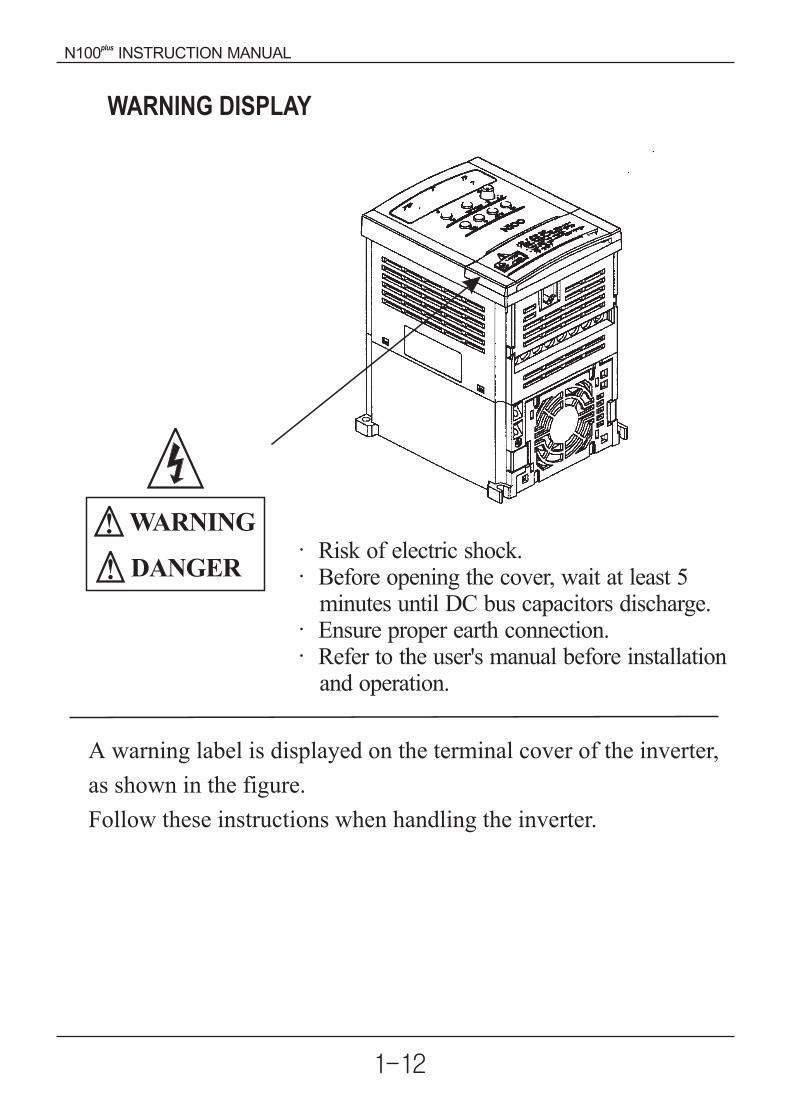
General Specifications
The following table applies to all N100 inverters.plus
Item General Specifications
Frequency settingresolution
Protective housing *1 Enclosed type(IP20)
Space vector PWM control
Digital command : 0.01% of the maximum frequencyAnalog command : 0.1% of the maximum frequency
Digital : 0.01Hz(100Hz and less), 0.1Hz(100Hz or more)
Analog : Max. Setting frequency / 500(DC 5V input),max. setting frequency / 1000(DC 10V, 4 20mA)
0.01 to 400Hz
Control method
Output frequency range *4
Frequency accuracy
Overload current rating
Acceleration/decelerationtime
Operator panel
Operator panel
Potentiometer
External signal
External signal
Intelligent inputterminal
Volt./ Freq. Characteristic
Freq-setting
FWD/REVRun
Input
signal
Any base freguency setting possible between 0Hzand 400Hz.V/F control (constant torque, reduced torque).
150%, 60 seconds
0.1 to 3000sec., (linear accel. / decel. s-curve,u-curve), second accel. / decel. setting available
Up and Down keys / Value settings
Analog setting via potentiometer.
1W, 1 to 2 variable resistorDC 0 5VDC 0 10V, 4 20mA(Input Impedonce 10 )
Run/Stop(Forward/Reverse run change by command)
Forward run/stop, Reverse run/stop set by terminalassignment (NC/NO)
FW(forward run command), RV(reverse runcommand), CF1 CF4(multistage speed setting),JG(jog command), 2CH(2-stage accel./decel.command), FRS(free run stop command),EXT(external trip), USP (unattended startup),SFT(soft lock), AT(analog current input selectsignal), RS(reset), SET(2nd setting selection)
3-3
N100 INSTRUCTION MANUALplus

Intelligent outputterminal
Frequency monitor
Alarm output contact
Ambient temperature
Vibration
Ambient humidity
Storage temperature
Location
Options
Other functions
Protective function
Outp
ut
signal
Oper
atin
gE
nvir
onm
ent
RUN(run status signal), FA1 (frequency arrivalsignal), FA2 (setting Frequency arrival signal),OL(overload advance notice signal), OD(PID errordeviation signal), AL(alarm signal)
Analog meter (DC0 10V full scale, Max. 1mA)Analog output frequency, Analog output current andAnalog output voltage signals selectable.OFF for inverter alarm(normally closed contactoutput) (Transition to ON for alarm)/Intelligentoutput Terminal
Remote operator unit, cable for operator, brakingunit, braking resistor, AC reactor, DC reactor,noise filter.
Altitude 1,000m or less, indoors(no corrosive gassesor dust)
5.9m/s (0.6G), 10 to 55Hz(conforms to the testmethod specified in JIS C0911)
2
90% RH or less (no condensing)
-20 60 (short-term temperature duringtransport)
-10 to 50 (If ambient temperature exceed 40 ,reduce the carrier frequency to 2.1kHz or less andthe rated current to 80% or less)
Over-current, over-voltage, under-voltage, overload,extreme high/low temperature, ground faultdetection, internal communication error, externaltrip, EEPROM error, USP error, instantaneouspower failure, output short-circuit detection.
AVR function, curved accel./decel. profile, upper andlower limiters, 16-stage speed profile, fine adjustmentof start frequency, carrier frequency change (0.5 to16Khz), frequency jump, gain and bias setting, processjogging, electronic thermal level adjustment, retryfunction, trip history monitor, 2nd setting selection,auto tuning, V/f characteristic selection, automatictorque boost, frequency coversion display, USPfunction
Item General Specifications
3-4
N100 INSTRUCTION MANUALplus

Footnotes for the preceding tables :
1. The protection method conforms to JEM 1030.
2. The applicable motor refers to HYUNDAI standard 3-phase motor
(4-pole). To use other motors, care must be taken to prevent the rated
motor current(50/60Hz) from exceeding the rated output current of the
inverter.
3. The output voltage decreases as the main supply voltage decreases
(except for use of the AVR function). In any case, the output voltage
cannot exceed the input power supply voltage.
4. To operate the motor beyond 50/60Hz, consult the motor mamanufacturer
about the maximum allowable rotation speed.
5. The braking torque via capacitive feedback is the average decelection
torque at the shortest deceleration (stopping from 50/60Hz as indicated).
It is not continuous regenerative braking torque. And, the average
deceleration torque varies with motor loss. This value decreases when
operating beyond 50 Hz. If a large regenerative torque is required, the
optional regenerative braking resistor should be used.
6. Control method setting A31 to 2 (sensorless vector control) Selected,
set carrier frequency setting b11 more than 2.1kHz.
3-5
N100 INSTRUCTION MANUALplus
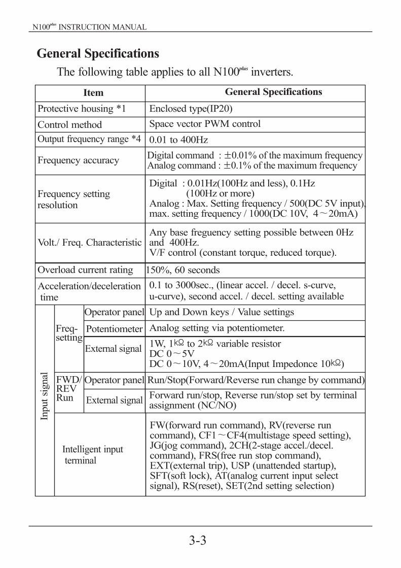
4. External Dimension Diagrams and Identifying the parts
Main Physical Features
Control key
Display part
Front cover
Terminal cover(Note)
Communicationport
Main circuitterminal
Cooling fan
Fan cover
Ground Terminal
Mounting hole
Removing terminal cover :
Use a hand and press on the terminal cover surface to remove it.
Control wiring can be possible by removing terminal cover.
Note) Do not press excessive pressure.
Otherwise, the cover may be damaged.
4-1
N100 INSTRUCTION MANUALplus

Front cover
Bolt
Wiringcover
Use a screwdriver to loosen the Bolt on the front cover.Notice the wiring cover that lifts out to allow full access to the terminals forwiring.
After removing terminal cover, locate the recessed retention screw on the leftside main front panel.Use a small screwdriver to loosen the screw, swing the door around to theleft to reveal the internal components of the drive.
4-2
N100 INSTRUCTION MANUALplus
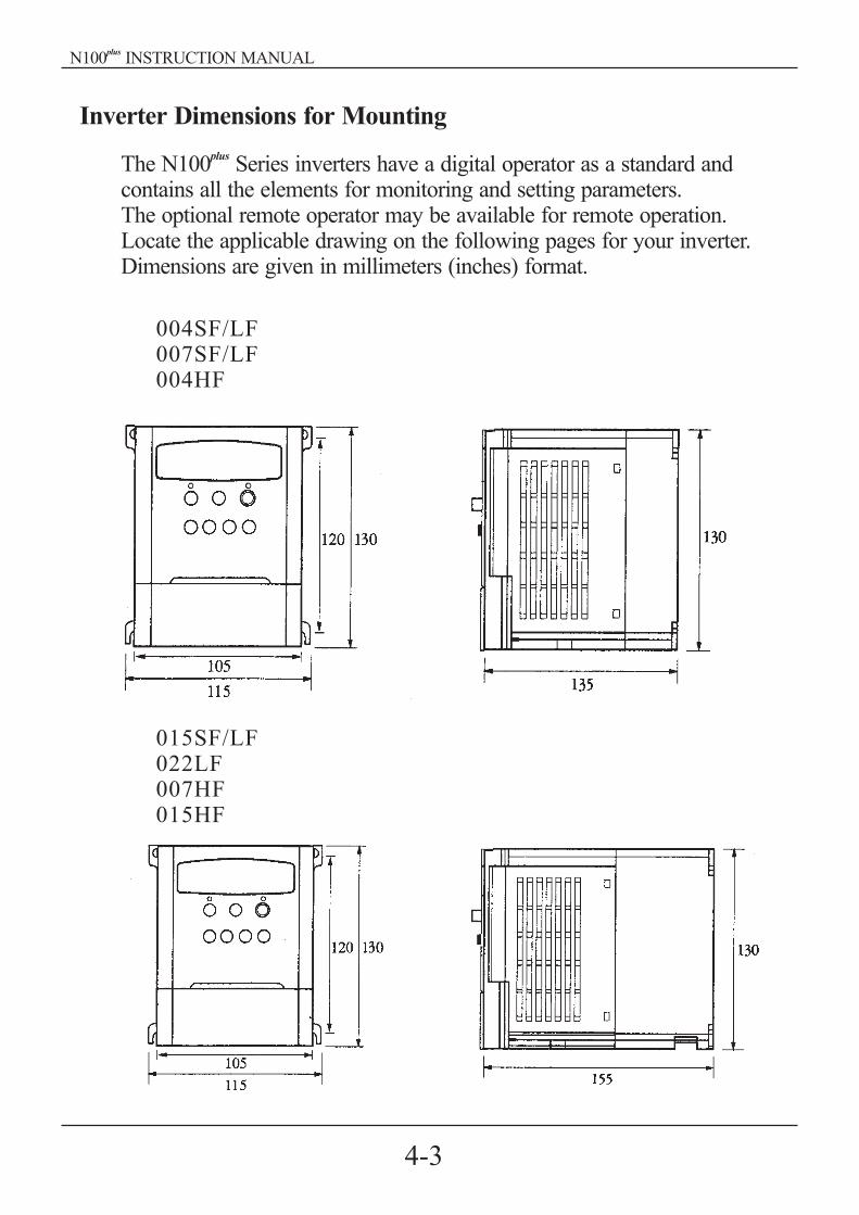
Inverter Dimensions for Mounting
The N100 Series inverters have a digital operator as a standard andcontains all the elements for monitoring and setting parameters.The optional remote operator may be available for remote operation.Locate the applicable drawing on the following pages for your inverter.Dimensions are given in millimeters (inches) format.
plus
004SF/LF007SF/LF004HF
015SF/LF022LF007HF015HF
4-3
N100 INSTRUCTION MANUALplus

Installation dimension(mm)(W H. )
Installation dimension(mm)(W H. )
Installation dimension(mm)(W H. )
037LF022HF037HF
TYPE
004LF
007LF
015LF
022LF
037LF
3-phase200Vclass
115 130 135
115 130 155
150 130 155
105 120,M4
140 120,M4
TYPE
004HF
007HF
015HF
022HF
037HF
3-phase400Vclass
115 130 135
115 130 155
150 130 155
105 120,M4
140 120,M4
TYPEExternal dimension(mm)
(W H D)
External dimension(mm)(W H D)
External dimension(mm)(W H D)
004SF
007SF1-phase200Vclass
115 130 135
115 130 155
105 120,M4
015SF
Dimension table by the capacity
4-4
N100 INSTRUCTION MANUALplus
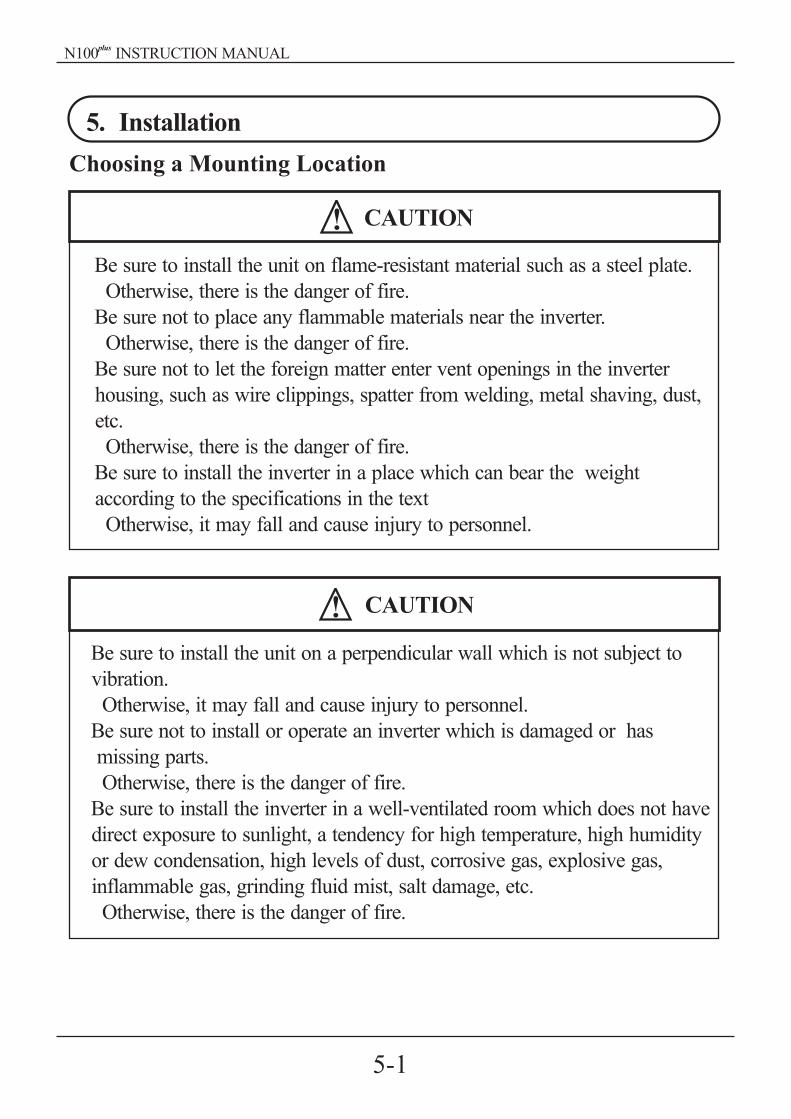
5. Installation
Choosing a Mounting Location
Be sure to install the unit on flame-resistant material such as a steel plate.
Otherwise, there is the danger of fire.
Be sure not to place any flammable materials near the inverter.
Otherwise, there is the danger of fire.
Be sure not to let the foreign matter enter vent openings in the inverter
housing, such as wire clippings, spatter from welding, metal shaving, dust,
etc.
Otherwise, there is the danger of fire.
Be sure to install the inverter in a place which can bear the weight
according to the specifications in the text
Otherwise, it may fall and cause injury to personnel.
CAUTION
CAUTION
Be sure to install the unit on a perpendicular wall which is not subject to
vibration.
Otherwise, it may fall and cause injury to personnel.
Be sure not to install or operate an inverter which is damaged or has
missing parts.
Otherwise, there is the danger of fire.
Be sure to install the inverter in a well-ventilated room which does not have
direct exposure to sunlight, a tendency for high temperature, high humidity
or dew condensation, high levels of dust, corrosive gas, explosive gas,
inflammable gas, grinding fluid mist, salt damage, etc.
Otherwise, there is the danger of fire.
5-1
N100 INSTRUCTION MANUALplus

To summarize the cautions messages-You will need to find a solid, non-flammable, vertical surface that is a relaticely clean and any envirnment. Inorder to ensure enough room for air circulation around the inverter to aid incooling, maintain the specified clearance around the inverter specified in thediagram.
Before proceeding to the wiring section, it's good time to temporarilycover the inverter's ventilation openings. It will prevent harmful debris such aswire clippings and metal shavings from entering the inverter during installation
The ambient temperature must be in the range of-10 to 40 . If the rangewill be up to 50 , you will need to set the carrier frequency to 2kHz or lessand derate the output current to 80% or less.
10cmminimum
10cmminimum
12cmminimum
8cmminimum
Air flow
Wall
CAUTION
CAUTION
Solid, nonflammable, vertical surface
5-2
N100 INSTRUCTION MANUALplus

6.Wiring
Be sure to ground the unit.Otherwise, there is a danger of electric shock and/or fire.
Wiring work shall be carried out only by qualified personnel.Otherwise, there is a danger of electric shock and/or fire.
Implement wiring after checking that the power supply is off.You may incur electric shock and/or fire.
Do not connect wiring to an inverter or operate an inverter that is not mountedaccording the instructions given in this manual.Otherwise, there is a danger of electric shock and/or injury to personnel.
Be sure to that input voltage matches the inverter specifications.Otherwise, there is a danger of electric fire and/or injury to personnel.
Be sure not to connect an AC power supply to the output terminals.Otherwise, there is a danger of electric fire and/or injury to personnel.
Be sure not to connect a resistor to the DC-link terminal(P, PB).Otherwise, there is a danger of fire
Remarks for using earth leakage circuit breakers in the main supply.Otherwise, there is a danger of fire.
For motor leads, earth leakage breakers and electromagnetic contactors, besure to size these components properly.Otherwise, there is a danger of fire.
Do not RUN/STOP operation by switching ON/OFF electromagneticcontactors on the primary or secondary sides of the inverter.Otherwise, there is a danger of fire.
Fasten the screws with the specified fastening torque.Otherwise, there is a danger of fire.
DANGER
CAUTION
6-1
N100 INSTRUCTION MANUALplus

6.1 Wiring the main circuit
Ex)N100 -004LFplus
UTSR V WP RB
You will connect main circuit terminal wiring to the input of the inverter.For wiring, open the front cover and wiring cover.
Power supplyMotor
MotorMotor
Inverter
ThermalRelay
ThermalRelay
Always connect the power input terminals R, S, and T to the power supply.Be sure to install thermal relay individually when one inverter operatesseveral motors.Never connect P, RB, to R, S, T, or U, V, W.Otherwise, there is the danger of equipment damage.
6-2
N100 INSTRUCTION MANUALplus

NOTE1) Install mechanically interlocked switches Mc1 and Mc2 in case ofexchange by using commercial power supply and inverter.
NOTE2)
NOTE3)
Install an earth leakage breaker(or MCCB) on the power supply sideof the inverter. If the wiring distance between inverter and motor(10m and more) is long, the thermal relay may be incorrectly operatedon the effect of high-frequency noise. Install the AC reactor on theinverter output side or use the current sensor.
Make sure to ground the ground terminal according to the local
grounding code. Never ground the N100 inverter in common withwelding machines, motors, or other electrical equipment.
When several inverters are used side by side, ground each unit as shown inexamples. Do not the ground wires.
plus
MCCB
Mc0
R
S
T
U
V
W
Mc1
Mc2Powersupply
Inverter
Motor
POOR GOOD
InverterInverter
InverterInverter
InverterInverter
Ground bolt
6-3
N100 INSTRUCTION MANUALplus

6.2 Wiring the control circuit
CM1 6 5 4 3 2 1 P24 H O OI L FM CM2 12 11
control circuit terminal
Example of control circuit terminal
CM1 6 5 4 3 2 1 P24 H O OI L FM 12 11CM2
RY RY
1 2
27 VDC50 max
1
2
3V.R
Input
com
mon
Res
et
2-s
tage
spee
d
Mult
i-sp
eed2
Mult
i-sp
eed1
Rev
erse
com
man
d
Forw
ard
com
man
dE
xter
nal
pow
ersu
pply
for
inpu
tsi
gnal
Frequency meterFrequencycommand
FA1FA2
Note1) When an output intelligent terminal is used, be sure to install a surgeabsorbing diode in parallel with relay. Otherwise, the surge voltage createdwhen the relay goes ON or OFF may damage the output intelligent terminalcircuit.
Fre
quen
cyar
riva
lsi
gnal
Run
6-4
N100 INSTRUCTION MANUALplus

²
(R,S,T,U,V,W,P,PB )
Signal input line
(CM1,6,5,4,3,2,1,P24,H,O,OI,L, FM,CM2,12,11)
Use a twisted and shielded wire for the signal line, and cut the shielded
covering as shown in the diagram below. Make sure that the length of the
signal line is 20 meters or less
When the frequency setting signal is turned on and off with a contact, use
a relay which will not cause contact malfunctions, even with the extremely
weak currents and voltages.
Use relays which do not have contact defects at 24 V DC, 3mA for the
other terminals.
Separate the main circuit wiring from the relay control circuit wiring.
If they must cross, be sure that they cross at a right angle.
Do not short circuit the terminals H-L of the control circuit.
Note2)
Note3)
Note4)
Note5)
Note6)
Note7) Do not short circuit the terminals H-OI of the control circuit.
Insulate
No grounding necessary
Connect to the common terminal[CM1] and [L] of the inverter
Right angle
Seterate by 10cm or more
Main circuit power line
6-5
N100 INSTRUCTION MANUALplus

6.3 Connecting to PLCs
PLC
DC24V
6
6
P24
5
5
4
4 3
3
2
2
1
1
P24
CM1(D)
AL0AL1
AL2
MCCB
R
S
T
U
V
W
P
RB
N100 Inverter
S
COM
diode
motor
Note 1) In order to use terminal CM1, install the reverse prevention Diode D
brakingresistor
Alarm outputcontact
6-6
N100 INSTRUCTION MANUALplus

MotorOutput(kw)
Wiring Applicable equipment
04
0.75
1.5
2.2
3.7
PowerLines
SignalLines
(Note5)
(Note6)
(Note7)
(Note8)
0.14-
0.75
Shielded
wire
Leakage braker(MCCB)
Magnetic contactor(MC)
HBS-33(5AT)
HBS-33(15AT)
HBS-33(10AT)
HBS-33(10AT)
HBS-33(5AT)
HMC 10W
HMC 10W
HMC 20W
6.4 Application wiring apparatus & options
Determination of wire and Fuse size
HMC 10W
HMC 20W
HMC 10W
N100 -037HFplus
N100 -037LFplus
N100 -022HFplus
N100 -022LFplus
N100 -015HFplus
N100 -015LFplus
N100 -015SFplus
N100 -007HFplus
N100 -007LFplus
N100 -007SFplus
N100 -004HFplus
N100 -004LFplus
N100 -004SFplus
1.25
1.25
2.0
1.25
2.0
1.25
3.5
2.0
HBS-33(10AT)
HBS-33(15AT)
HBS-33(20AT)
HBS-33(30AT)
Application
Inverter Model
6-7
N100 INSTRUCTION MANUALplus

Motoroutput(kw)
Inverter model
(N100 Series)plus
Wiring
Power lines Signal lines
Applicable equipment
Fuse(class J) rated 600V
0.4
0.75
1.5
2.2
3.7
0.4
0.75
1.5
2.2
3.7
N100 -004LFplus
N100 -004HFplus
N100 -007LFplus
N100 -007HFplus
N100 -015LFplus
N100 -015HFplus
N100 -022LFplus
N100 -022HFplus
N100 -037LFplus
N100 -037HFplus
10A
5A
15A
20A
30A
5A
15A
10A
0.14
0.75shieldedwire
0.14
0.75shieldedwire
1.25
2.0
3.5
1.25
2.0
N100 -004SFplus
N100 -007SFplus
N100 -015SFplus
Name Function
R S T
U V W
P
RB
Thermalrelay
T1 T2 T3
L1 L2 L3
Inverter
Standard Apparatus(3-phase input reference)
Option
Electroma-gnetic contact
Fuse
Motor
Power supply
<Note>Field wiring connection must be made by a UL listed and CSA certified, closed-loopterminal connector sized for the wire gauge involved. Connector must be fixed usingthe crimp tool specified by the connector manufacturer.Be sure to consider the capacity of the circuit breaker to be used.Be sure to use bigger wires for power lines if the distance exceeds 20m.Use 0.75mm wire for the alarm signal wire.
2
Input-side AC reactorfor harmonic
suppression/powercoordination/power
improvement
EMI filter
Output-side noisefilter
AC reactor forvibration
reduction/thermalrelay malfunction
prevention
This is useful when harmonic suppression measuresmust be taken. when the main power voltage unbalancerate exceeds 3% and the main power capacity exceeds500kVA, or when a sudden power voltage variationoccurs. It also helps to improve the power factor.
Reduces the conductive noise on the main power wiresgenerated from the main power supply. Connect to theinverter primary side(input side).
This is installed between the inverter and the motor toreduce noise radiated from the main the control powerwiring. It is useful for reducing radio-wave disturbancein a radio or TV set and for preventing malfunctionof measuring instruments or sensors.
Vibration may increases when driving a general-purposemotor with an inverter as compared with operation oncommercial power. Connecting this reactor between theinverter and the motor allows reduction of motor pulsa-tion. When the wirung between the inverter and themotor is 10m or more, inserting the reactor preventsthermal relay malfunction caused by harmonics resultingfrom incerter switching. A current sensor can be usedinstead of the thermal relay
6-8
N100 INSTRUCTION MANUALplus

Note 1) The applicable equipment is for HYUNDAI standard four polesquirrel cage motor.
2) Be sure to consider the capacity of the circuit breaker to be used.) Be sure to use larger wire for power lines if the distance exceeds 20m.) Be sure to use an grounding wire same size of power line or similar.) Use 0.75mm wire for the alarm signal terminal.) Use 0.5
2
NoteNote 3Note 4Note 5Note 6 mm wire for the control curcyit terminal.
Classify the detective current of the earth leakage breaker depending on thetotal distance between the inverter and the motor.
Note1) When using CV wire and metal tube the leakage current is around30mA/km.
Note2) The leakage current becomes eight times because IV wires have ahigh dielectric constant. Therefore, use an one class earth leakagebreaker according to the above table.
2
Length
100m and less
300m and less
800m and less
Detective current(mA)
30
100
200
6-9
N100 INSTRUCTION MANUALplus

6.5 Terminal array & Terminal function
(1) Terminal array
<Main circuit>
<Control circuit>
Main circuit terminal Model Screw Width(mm)
R S T RB U V WP
CASE
N100
004SF
015SF
004LF
037LF
004HF
037HF
plus
M4 11
N100
004SF
015SF
004LF
037LF
004HF
037HF
plus
Control
M2
Alarm
M3
Control
Alarm
:
3.5
:
5.08
Control circuit terminal Model Screwdiameter
Width(mm)
CM1 6 5 4 3 2 1 P24 H O OI L FMCM212 11 AL0AL1AL2
* Use the "-"type skew driver
6-10
N100 INSTRUCTION MANUALplus

R S T P RB U V W
Powersupply
M
Terminalsymbol
Terminalname
Main powersupply input
Connect the inputpower supply 220V,440V
Connect the MOTOR
Connect the brakingresistor(option)
Connect the Die-casting(to prevent electricshock and reduce noise)
Inverteroutput
Externalresistorconnection
Ground
R, S, T
U, V, W
RB, P
Function
(2) Terminal Function
Main circuit Terminal
Control circuit TerminalTerminalsymbol Terminal name Terminal functionSignal
P24
6
5
4
3
2
1
CM1
FM
CM1
Inputsignal
Monitorsignal
Power terminal for input signals
Forward run command(FW), Reverse run
command(RV), multi-speed commands1-4
(CF1-4), 2-stage accel/decel (2CH),
Reset(RS), second control function setting
(SET), terminal software lock(SFT),
unattended start protection(USP),
current input selection(AT), jogging
operation(JG), External trip(EXT)
Common terminal for input or monitorsignal
Output frequency meter, output currentmeter, output voltage meter
Common terminal for input or monitorsignal
24VDC 10%,35mA
Analog frequencymeter
contact input :Close : ON
(operating)Open : OFF
(stop)
minimum ONTIME :12ms
or more
6-11
N100 INSTRUCTION MANUALplus

C 15 C 06
C 07 C 12
AL0 AL1 AL2
Alarm output signals :at normal status, power off
: AL0-AL2 (closed)at abnormal status
: AL0-AL1(closed)
NOTE1)
NOTE2)
NOTE3)
NOTE4)
The USP function prevents the automatic startup immediately afterpowerup.The reset terminal can be used in the normally open(NO)contact state.The contact can be inverted by using the parameter toThe intelligent output terminal has several functions which you canassign individually to three physical logic outputs.The output terminal [11][12] is the normally open(NO) contact.The contact logic can be inverted by using the parameter
H
O
OI
L
11
12
CM2
AL2
Frequ-encycomm-andsignal
Outputsignal
Trip al-armoutputsignal
Power supply for frequency setting
Voltage frequency command signal
Current frequency command signal
Common terminal for frequency command
Intelligent output terminal:run status signal(RUN), frequency arrivalsignal(FA1) set frequency arrival signal(FA2), overload advance notice signal(OL),PID error deviation signal(OD), alarmsignal(AL)
Common terminal for output signal
0 5VDC
0 5VDC(standard),0 10VDC, inputimpedance 10
4 20mA, input impedance250
Contact rating:AC 250V 2.5A
(resistor load)0.2A
(inductor load)DC 30V 3.0A
(resistor load)0.7A(inductor load)
Control circuit Terminal
Terminalsymbol Terminal name Terminal functionSignal
6-12
N100 INSTRUCTION MANUALplus

DANGER
7. Operation
Be sure to turn on the input power supply after closing the front case.While being energized, be sure not to open the front case.Otherwise, there is the danger of electric shock
Be sure not to operate the switches with wet hands.Otherwise, there is the danger of electric shock.
While the inverter is energized, be sure not to touch the inverter terminalseven when the motor is stopped.Otherwise, there is the danger of electric shock.
If the Retry Mode is selected, the motor may suddenly restart during the tripstop. Do not approach the machine(be sure to design the machine so thatsafety for personnel is secure even if it restarts).Otherwise, it may cause injury to personnel.
If the power supply is cut off for a short period of time, the inverter mayrestart operation after the power supply recovers if the command to operateis active. If a restart may pose danger to personnel, so be sure to use alock-out circuit so that it will not restart after power recovery.Otherwise, it may cause injury to personnel.
The stop key is effective only when the stop function is enabled. Be sure toenable the key sepatately from the emergency stop.Otherwise, it may cause injury to personnel.
Arter the operation command is given, if the alarm reset is conducted, it willrestart suddenly. Be sure to set the alarm reset after verifying the operationcommand is off.Otherwise, it may cause injury to personnel.
Be sure not to touch the inside of the energized inverter or to put anyconductive object into it.
Otherwise, there is a danger of electric shock and/or fire.
N100 INSTRUCTION MANUALplus

CAUTION
The heat sink fins will have a high temperature. Be careful not to touchthem.Otherwise is the danger of getting burned.
The operation of the inverter can be easily changed from low speed to highspeed. Be sure check the capability and limitations of the motor and machinebefore operating the inverter.Otherwise, there is the danger of injury.
If you operate a motor at a frequency higher than the inverter standarddefault setting 60Hz, be sure to check the motor and machine specificationswith the respective manufacturer.Otherwise, there is the danger of equipment damage.
Install a holding brake separately if necessary.Otherwise, there is the danger of accident.
Check the direction of the motor, abnormal motor vibrations, and noise.Otherwise, there is the danger of equipment damage.
7.1 Before the powerup test
Prior to the test run, check the following(1) Make sure that the power lines (R, S and T) and output terminals
(U, V and W)are connected correctly.Otherwise, there is a danger of inverter damage
(2)Make sure that there are no mistakes in the signal line connectionsOtherwise, it may be incorrect operation of the inverter.
(3) Make sure that the inverter earth terminal is grounded.Otherwise, there is a danger of electric shock.
(4) Make sure that terminals other than those specified are not grounded.Otherwise, it may be incorrect operation of the inverter.
(5) Make sure that there are no short-circuits caused by stay pieces ofwire, solderless terminals or other objects left from wiring work.Also, make sure that no tools have been left behind.Otherwise, there is a danger of inverter breakage.
(6) Make sure that the output wires are not short-circuited of grounded.Otherwise. there is a danger of inverter damage.
N100 INSTRUCTION MANUALplus

7.2 Powerup test
The following instructions apply to the power up test.The operation from the standard operator Frequency setting, Run andstop command are controlled as follows :Frequency setting select the potentiometer STOP/RUN : select theRUN and STOP key
MCCB
RST
UVWP
RB
123456CM1P24H00ILFM
11
12
CM2
AL2
AL1
AL0
400V class
3-phase 380 460V, 50/60Hz
200V class
3-phase 200 230V , 50/60Hz
200V class
1-phase 200 230V, 50/60Hz
MotorPowersupply
Regenerativebraking resistor
}Alarm output :(AT normal status,power off : AL0-AL2 :ONAT abnormal status
: AL0-AL1 :ON
Ground
ACTION (Digital operator control)
(1) Turn On the power supply by turning ON MCCB.
The [POWER] LED will illuminate.
(2) After checking that the potentiometer Enable LED is ON, set the frequency
by rotating the potentiometer.
(3) After checking that the RUN Enable LED is ON, press the key.
(4) The inverter starts running [RUN] LED is ON.
(5) Monitor the output frequency in the monitor mode
(6) Press the key to stop the motor rotation.
RUN
d 01STOP
RESET
N100 INSTRUCTION MANUALplus

Check the following before and during the powerup test.
CAUTION
Is the direction of the motor correct?Otherwise, there is the danger of equipment damage.
Were there any abnormal motor vibrations or noise?Otherwise, there is the danger of equipment damage.
1. Did the inverter trip during acceleration or deceleration?2. Were the rpm and frequency meter readings as expected?
If the over current or over voltage trip is occurred of the power uptest, set the acceleration or deceleration time longer.
NOTE1)
Factory setting
Maximum frequency : 60Hz
Rotation direction : forward run
N100 INSTRUCTION MANUALplus

Output freguencyForward
Reverse
SWF
SWR
ON OFF
ON
OFF
OFFOFF
SWR
RV2
SWF
FW
1CM1
56 4 3 2 L1
RS 2CHCF2 CF1 RV FW
CM1
Frequency(Hz)
[4-Stage speed]
Switch
ON
RV
FW
CF2
CF1
ON ON
ON ON ON ON
EXT(10)
USP(11)
SFT(12)
AT(13)RS(14)
Default Terminalsetting
1 : FW
2 : RV
3 : CF1
4 : CF2
5 : 2CH
6 : RS
Terminal
Terminal
Terminal
Terminal
Terminal
Terminal
8. Using intelligent terminals
8.1 Intelligent terminal lists
Terminalsymbol
Description
Inte
llig
ent I
nput
Ter
min
al(1
6)
FW(0)
RV(1)
CF1(2)
CF2(3)
CF3(4)
CF4(5)
JG(6)
SET(7)
2CH(8)
FRS(9)
ForwardRUN/STOPterminal
ReverseRUN/STOPterminal
SWF SwitchON (closed):Forward runOFF(open): stop
SWR SwitchON (closed):Reverse
runOFF(open): stop
1
2
3
4
Multi-speedfrequencycommandingterminal
Jogging Jogging operation
Second controlfunction
You may change the setting value when only one inverterconnects two motors(output frequency setting, acceleration/deceleration time setting, manual torque boost setting, electr-onic thermal setting, motor capacity setting, control method)
2-stage acceler-ation/deceleration
The acceleration or deceleration time is possible to changeconsidering the system.
Free-run stop
External trip
Unattended startprevention
Current inputselection
Reset
Terminal soft-ware lock
The inverter stops the output and the motor enters the free-run state.(coasting)
It is possible to enter the external trip state.
Restart prevention when the power is turned on in the RUNstate.The data of all the parameters and functions except the outputfrequency is locked.
The [AT] terminal selects whether the inverter uses the voltage[O] or current [OI] input terminals for external frequency control.
If the inverter is in Trip Mode, the reset cancels the Trip Mode.
When SWF and SWR commands are active at the sametime, the inverter stops
0-speed
3-speed2-speed
1-speed
Terminal name
N100 INSTRUCTION MANUALplus

H 0 0I L
0~10VDCinput impedance
10
H 0 0I L
4~20input impedance
250
H 0 0I L
(1 ~ 2 )0 5VDC
VRO
Frequency monitorAnalog output frequency monitor/ analog output current monitor/analog output voltage monitor
Fre
quen
cyco
mm
andin
g
H
0
0I
L
FMMonitorterminal
Terminalsymbol
Description
CM1
P24
Signal sourcefor input
External powersupply terminalfor input
Common terminal for intelligent input terminals.
External power connection terminal for intelligent inputterminals.
Frequencycommandpowerterminal
Frequencycommandcommonterminal
Frequencycommandingterminal(currentcommand)
Frequencycommandingterminal(voltagecommanding)
The External frequency voltage commanding is 0 to 5VDCas a standard.When the input voltage is 0 to 10VDC, use the parameterA65
Note1) If the [AT] option is not assigned to any intelligentinput terminal, then inverter use the algebraic sumof both the voltage and current input for thefrequency command.
2) If you use either the voltage or current analog input,make sure that the [AT] function is allocated to anintelligent input terminal.
Terminal name
N100 INSTRUCTION MANUALplus

RY
CM2 12 11
Terminalsymbol
Description
Frequency
arrival
signal
Run signal
Overloadadvancenotice signal
PID control errordeviation signal
Alarm signal
Commonterminal
Alarm
terminals
Frequency arrival [FA1][FA2] signals is indicatedwhen the output frequency accelerates anddecelerates to arrive at a constant frequency.
When the [RUN] signal is selected, the inverteroutputs a signal on that terminal when it is inthe RUN mode.
When the output current exceeds a preset value,the [OL] terminal signal turns on.
When the PID loop error magnitude thepreset value, the [OD] terminal signalturns on.
The inverter alarm signal is active when a faulthas occurred.
Common terminal for intelligent output terminal
At normal status, power off(initial setting value)
: Al0 - AL1(closed)
At abnormal status : AL0 - AL2(closed)
Contact rating : 250V AC 2.5A(resistor 1oad) 0.2A(inductor load)
30V DC 3.0A(resistor 1oad) 0.7A(inductor load)
(minimum 100V AC 10mA, 5V DC 100mA)
FA1(1)
FA2(2)
RUN(0)
OL(3)
OD(4)
AL(5)
Inte
llig
ent
outp
utte
rmin
al(1
1,12
)
CM 2
AL 0
AL 1
AL 2
Output terminalspecificationopen-collectoroutput27V DC max50 max
FA1 FA2
Frequency
F01 set value
TimeON atconstantfrequency
Frequency
Thresholds
Time
C22C21
ON at targetfrequency
Terminal name
N100 INSTRUCTION MANUALplus
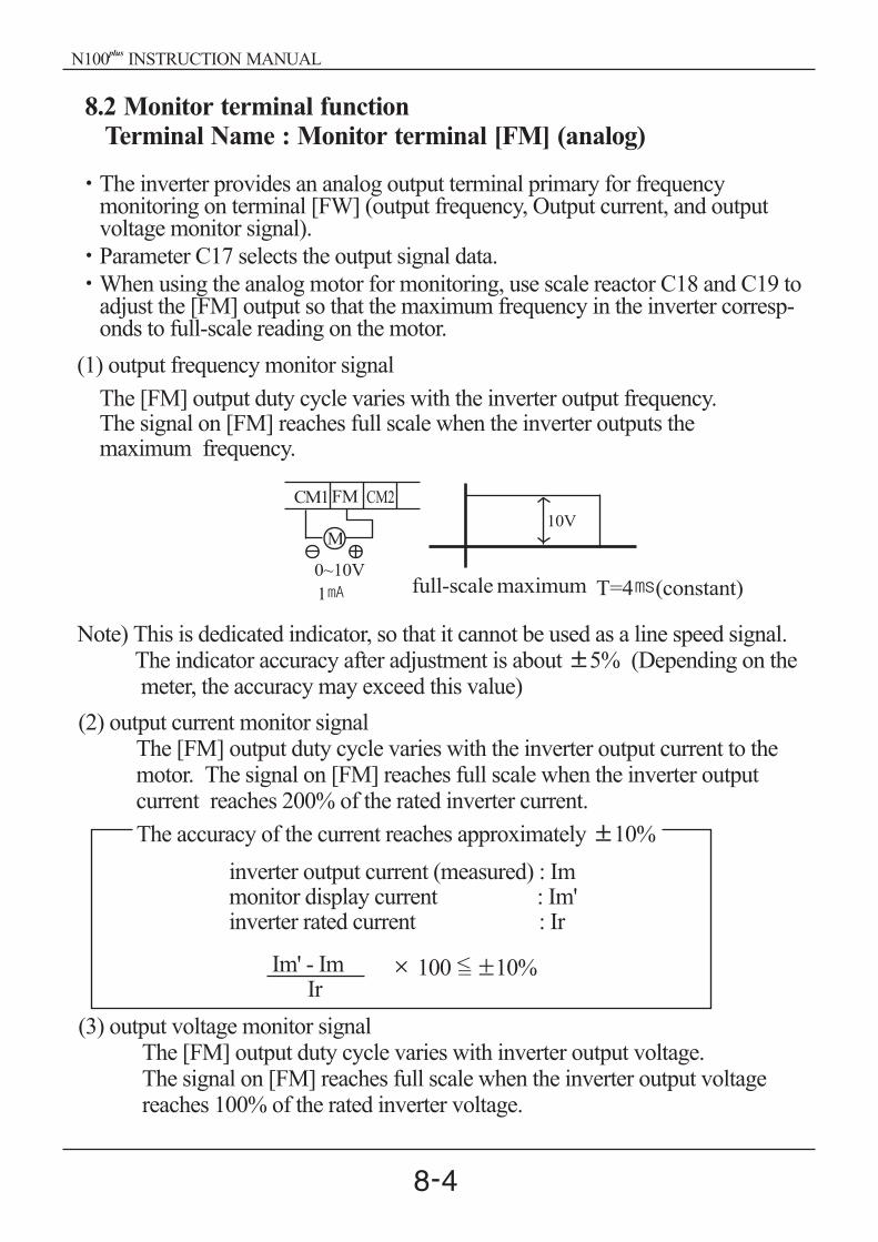
8.2 Monitor terminal functionTerminal Name : Monitor terminal [FM] (analog)
The inverter provides an analog output terminal primary for frequencymonitoring on terminal [FW] (output frequency, Output current, and outputvoltage monitor signal).
Parameter C17 selects the output signal data.
and C19 toadjust the [FM] output so that the maximum frequency in the inverter corresp-onds to full-scale reading on the motor.
When using the analog motor for monitoring, use scale reactor C18
(1) output frequency monitor signal
The [FM] output duty cycle varies with the inverter output frequency.The signal on [FM] reaches full scale when the inverter outputs themaximum frequency.
Note) This is dedicated indicator, so that it cannot be used as a line speed signal.The indicator accuracy after adjustment is about 5% (Depending on themeter, the accuracy may exceed this value)
(2) output current monitor signalThe [FM] output duty cycle varies with the inverter output current to themotor. The signal on [FM] reaches full scale when the inverter outputcurrent reaches 200% of the rated inverter current.
(3) output voltage monitor signalThe [FM] output duty cycle varies with inverter output voltage.The signal on [FM] reaches full scale when the inverter output voltagereaches 100% of the rated inverter voltage.
The accuracy of the current reaches approximately 10%
inverter output current (measured) : Immonitor display current : Im'inverter rated current : Ir
Im' - ImIr
100 =< 10%
10VM
0~10V
1 full-scale maximum T=4 (constant)
CM1FM CM2
N100 INSTRUCTION MANUALplus

1
A 02
8.3 Intelligent Input Terminal FunctionForward Run/Stop[FW] and Reverse Run/Stop Command[RV]
When you input the Run command via the terminal [FW], the inverter executesthe Forward Run command (high) or Stop command(low).
When you input the Run command via the terminal [RV], the inverter executesthe Reverse Run command(high) or Stop command(low).
OptionCode
TerminalSymbol Function Name State Description
0
1
FW
RV
Forward Run/Stop
Reverse Run/Stop
ON
OFF
ON
OFF
Inverter is in Run Mode, motorruns forward
Inverter is in Run Mode, motor stop
Inverter is in Run Mode, motorruns reverseInverter is in Run Mode, motorruns stop
Valid for inputs:Required setting
C01,C02,C03,C04,C05,C06
A02=01
Notes:When the Forward Run and ReverseRun commands are active at the sametime, the inverter enters the Stop Mode.
When a terminal associated with either[FW] or [RV] function is configured fornormally closed, the motor starts rot-ation when that terminal is discon-nected or otherwise has no inputvoltage. Set the parameter to
Example:
DANGER : If the power is turned on and the Run command is alreadyactive, the motor starts rotation and is dangerous! Before turning power on,confirm that Run command is not active.
CM1 6 5 4 3 2 1 P24
RV FW
SWR SWF
N100 INSTRUCTION MANUALplus

Speed 15
Speed 14
Speed 13
Speed 12
Speed 11
Speed 10
Speed 9
Speed 8
Speed 7
Speed 6
Speed 5
Speed 4
Speed 3
Speed 2
Speed 1
Speed 0
Multi-speedControl circuit terminal
SW5 SW4 SW3 SW2
OFF
OFF
OFF
OFF
OFF
OFF
OFF
OFF
OFF
OFF
OFF
OFF
OFF
OFF
OFF
OFF
OFF
OFF
OFF
OFF
OFF
OFF
OFF
OFF
OFF
OFF
OFF
OFF
OFF
OFF
OFF
OFF
ON
ON
ON
ON
ON
ON
ON
ON
ON
ON
ON
ON
ON
ON
ON
ON
ON
ON
ON
ON
ON
ON
ON
ON
ON
ON
ON
ON
ON
ON
ON
ON
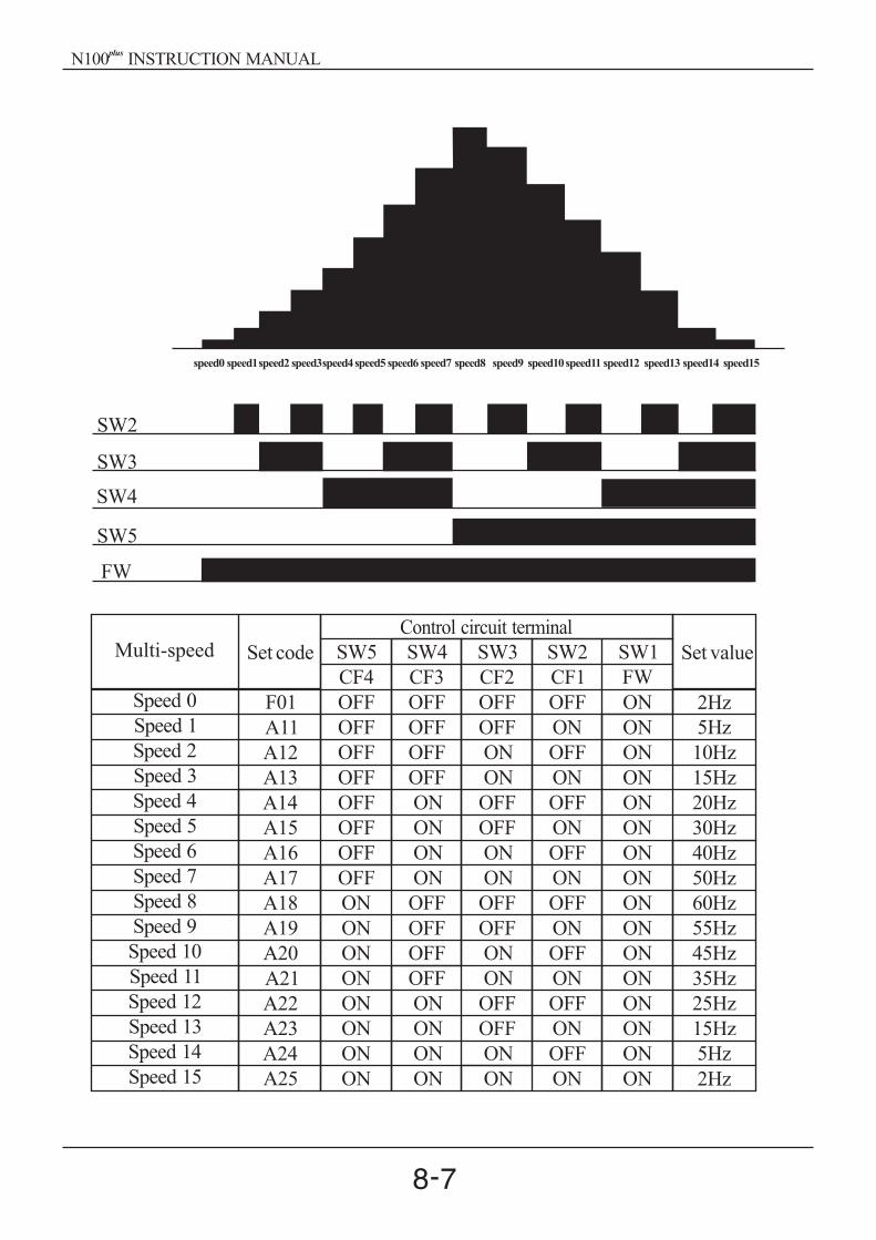
Multi-Speed Select [CF1][CF2][CF3][CF4]
The inverter provides storage parameters for up to 16 different targetfrequencies (speeds) that the motor output uses for steady-state runcondition.These speeds are accessible through programming four of the intelligentterminals as binary-encoded inputs CF1 to CF4 per the table . These can beany of the six inputs, and in any order.You can use fewer inputs if you need eight or less speeds.
When choosing a subset of speeds to use, always start at the top of the table,and with the least-significant bit: CF1, CF2, etc.Note :
NOTE : Speed 0 is set by the parameter value.F 01
N100 INSTRUCTION MANUALplus
speed0 speed1speed2 speed3speed4speed5 speed6 speed7 speed8 speed9 speed10speed11 speed12 speed13 speed14 speed15
SW2
SW3
SW4
SW5
FW
Set code
F01
A11
A12
A13
A14
A15
A16
A17
A18
A19
A20
A21
A22
A23
A24
A25
SW5
CF4
OFF
OFF
OFF
OFF
OFF
OFF
OFF
OFF
ON
ON
ON
ON
ON
ON
ON
ON
SW4
CF3
OFF
OFF
OFF
OFF
ON
ON
ON
ON
OFF
OFF
OFF
OFF
ON
ON
ON
ON
SW3
CF2
OFF
OFF
ON
ON
OFF
OFF
ON
ON
OFF
OFF
ON
ON
OFF
OFF
ON
ON
SW2
CF1
OFF
ON
OFF
ON
OFF
ON
OFF
ON
OFF
ON
OFF
ON
OFF
ON
OFF
ON
SW1
FW
ON
ON
ON
ON
ON
ON
ON
ON
ON
ON
ON
ON
ON
ON
ON
ON
Set value
2Hz
5Hz
10Hz
15Hz
20Hz
30Hz
40Hz
50Hz
60Hz
55Hz
45Hz
35Hz
25Hz
15Hz
5Hz
2HzSpeed 15
Speed 14
Speed 13
Speed 12
Speed 11
Speed 10
Speed 9
Speed 8
Speed 7
Speed 6
Speed 5
Speed 4
Speed 3
Speed 2
Speed 1
Speed 0
Multi-speedControl circuit terminal
N100 INSTRUCTION MANUALplus
CF4 CF3 CF2 CF1 FW
CM1 6 5 4 3 2 1 P24
SW6 SW5 SW4 SW3 SW2 SW1
STR
A 11
F 01
F 01
C 01 C 06
F 01
FUNC
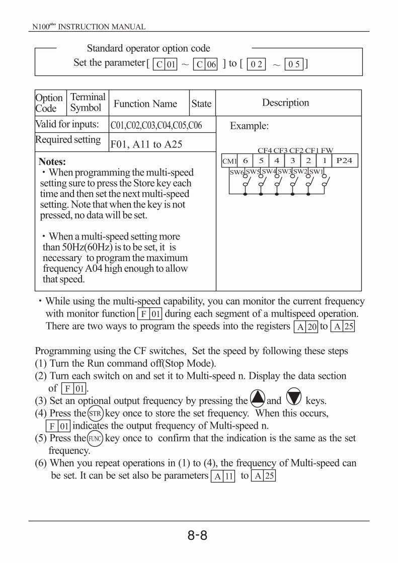
OptionCode
TerminalSymbol Function Name State Description
Valid for inputs:
Required setting
C01,C02,C03,C04,C05,C06
F01, A11 to A25
Notes:When programming the multi-speed
setting sure to press the Store key eachtime and then set the next multi-speedsetting. Note that when the key is notpressed, no data will be set.
When a multi-speed setting morethan 50Hz(60Hz) is to be set, it isnecessary to program the maximumfrequency A04 high enough to allowthat speed.
Example:
While using the multi-speed capability, you can monitor the current frequency
with monitor function during each segment of a multispeed operation.
There are two ways to program the speeds into the registers to
Programming using the CF switches, Set the speed by following these steps
(1) Turn the Run command off(Stop Mode).
(2) Turn each switch on and set it to Multi-speed n. Display the data section
of .
(3) Set an optional output frequency by pressing the and keys.
(4) Press the key once to store the set frequency. When this occurs,
indicates the output frequency of Multi-speed n.
(5) Press the key once to confirm that the indication is the same as the set
frequency.
(6) When you repeat operations in (1) to (4), the frequency of Multi-speed can
be set. It can be set also be parameters to A 25
A 20 A 25
0 2 0 5
Standard operator option code
Set the parameter[ ] to [ ]
N100 INSTRUCTION MANUALplus

A 26
A 021
A 26
A 27
[JG]terminal
[FW,RV](Run)
A
A
27
27
Motorspeed Jog decel type
time
Jogging Command [JG]
When the terminal [JG] is turned on andthe Run command is issued, the inverteroutputs the programmed jog frequencyto the motor. Use a switch betweenterminals [CM1] and [P24] to activatethe JG frequency.The frequency for the jogging operation isset by parameter .Set the value (terminal mode) in (Run command)Since jogging does not use an acceleration ramp, we recommendsetting the jogging frequency in to 5Hz or less to prevent tripping.
The type of deceleration used to end a motor jog is selectable byprogramming function The options are:
0 : Free-run stop (coasting)1 : Deceleration (normal level) and stop2 : DC braking and stop
OptionCode
TerminalSymbol Function Name
InputState
Description
6 JG Jogging ON
OFF
Inverter is in Run Mode, output tomotor runs at jog parameterfrequency.
Inverter is in Stop Mode.
Valid for inputs:
Required setting
C01,C02,C03,C04,C05,C06
A02, A26, A27
Notes:No jogging operation is performed when
the set value of jogging frequency A26 issmaller than the start frequency B10 or thevalue is 0Hz.
Be sure to stop the motor when switchingthe function [JG] on or off.
Example:
CM1 6 5 4 3 2 1 P24
JG FW
0:Free-run stop1:Deceleration stop2:DC braking stop
N100 INSTRUCTION MANUALplus

CM1 6 5 4 3 2 1 P24
SET RV FW
Second Control Function [SET]
If you assign the [SET] function to a logic terminal, the inverter will displaythe Sxx numbered parameters, allowing you to edit the second motorparameters. These parameters store an alternate set of motor characteristicparameters. When the terminal [SET] is turned on, the inverter will use thesecond set of parameters to generate the frequency output to the motor.When changing the state of the [SET] input terminal, first confirm the inverteris in the Stop Mode, and the motor is not rotating.When the switch between the set terminals [SET] and [CM1] is on, theinverter operates per the second set of parameters.When the terminal is turned off, the output function returns to the originalsettings(first set of motor parameters.)
OptionCode
TerminalSymbol Function Name
InputState
Description
7 SET Set 2nd Motor
ON
OFF
Causes the inverter to use the 2ndset of motor parameters forgenerating the frequency output tomotorCauses the inverter to use the 1st(main) set of motor parametersfor heating the frequencyoutput to motor
Valid for inputs:
Required setting
C01,C02,C03,C04,C05,C06
(none)
Notes:
If the terminal is turned off while the motor
is running, the inverter continues to gener-
ate the frequency output using the 2nd set
of parameters until the motor is stopped.
Example:
N100 INSTRUCTION MANUALplus
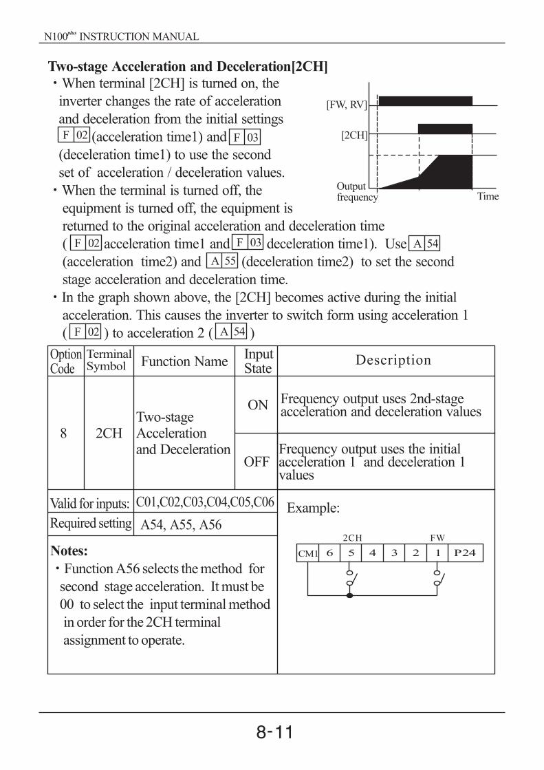
F 02 F 03
F 02
F 02
F 03 A 54
A 54
A 55
CM1 6 5 4 3 2 1 P24
2CH FW
Outputfrequency Time
[FW, RV]
[2CH]
Two-stage Acceleration and Deceleration[2CH]
acceleration time1) and
(deceleration time1) to use the second
set of acceleration / deceleration values.
When the terminal is turned off, the
equipment is turned off, the equipment is
returned to the original acceleration and deceleration time
( acceleration time1 and deceleration time1). Use
(acceleration time2) and (deceleration time2) to set the second
stage acceleration and deceleration time.
In the graph shown above, the [2CH] becomes active during the initial
acceleration. This causes the inverter to switch form using acceleration 1
( ) to acceleration 2 ( )
When terminal [2CH] is turned on, the
inverter changes the rate of acceleration
and deceleration from the initial settings
(
OptionCode
TerminalSymbol Function Name
InputState
Description
8 2CHTwo-stageAccelerationand Deceleration
ON
OFF
Frequency output uses 2nd-stageacceleration and deceleration values
Frequency output uses the initialacceleration 1 and deceleration 1values
Valid for inputs:
Required setting
C01,C02,C03,C04,C05,C06
A54, A55, A56
Notes:
Function A56 selects the method for
second stage acceleration. It must be
00 to select the input terminal method
in order for the 2CH terminal
assignment to operate.
Example:
N100 INSTRUCTION MANUALplus

B 16
CM1 6 5 4 3 2 1 P24
FRS FW
Free-run stop [FRS]
When the terminal [FRS] is turned on, the inverter stops the output and the
motor enters the free-run state (coasting). If terminal [FRS] is turned off, the
output resumes sending power to the motor if the Run command is still active.
The free-run stop feature works with other parameters to provide flexibility in
stopping and starting motor rotation.
In the figure below, parameter selects whether the inverter resumes
operation form 0Hz (left graph) or the current motor rotation speed (right
graph) when the [FRS] terminal turns off. The application determines which
is the best setting. Parameter specifies a delay time before resuming
operation from a free-run stop. To disable this feature, use a zero delay time.B 03
[FW,RV] [FW,RV]
[FRS] [FRS]
Motor speed Motor speed0Hz start
b 03( wait time)
OptionCode
TerminalSymbol Function Name
InputState
Description
9 FRS Free-run StopON
OFF
Causes output to turn off, allowingmotor to free run (coast) to stop
Output operates normally, socontorolled deceleration stopsmotor
Valid for inputs:
Required setting
C01,C02,C03,C04,C05,C06
B03, b16, C07 to C12
Notes:
When you want the [FRS] terminal to be
active low(normally closed logic), change
the setting (C07 to C12) which corresponds
to the input (C01 to C06) that is assigned
the [FRS] function
Example:
N100 INSTRUCTION MANUALplus

E 12
start[EXT] terminal
Motor revolution speed
[RS] terminal
Alarm output terminal
RUN command [FW, RV]
CM1 6 5 4 3 2 1 P24
EXT FW
External Trip [EXT]
When the terminal [EXT] is turned on, the inverter enters the trip state, indicates
error code , and stop the output. This is a general purpose interrupt type
feature, and the meaning of the error depends on what you connect to the
[EXT] terminal. When the switch between the set terminals [EXT] and [CM1]
is turned on, the equipment enters the trip state. Even when the switch to
state. You must reset the
inverter or cycle power to clear the error, returning the inverter to the Stop
Mode.
[EXT] is turned off, the inverter remains in the trip
OptionCode
TerminalSymbol Function Name Input
StateDescription
10 EXT External Trip
ON
OFF
When assigned input transitionsOff to On, inverter latches tripevent and displays E12
No trip event for On to Off, anyrecorded trip events remain inhistory until Reset.
Valid for inputs:
Required setting
C01,C02,C03,C04,C05,C06
(none)
Notes:If the USP (Unattended Start Protection)
feature is in use, the inverter will notautomatically restart after cancelling theEXT trip event. In that case, it mustreceive enter Run command(off-to-on transition)
Example:
N100 INSTRUCTION MANUALplus
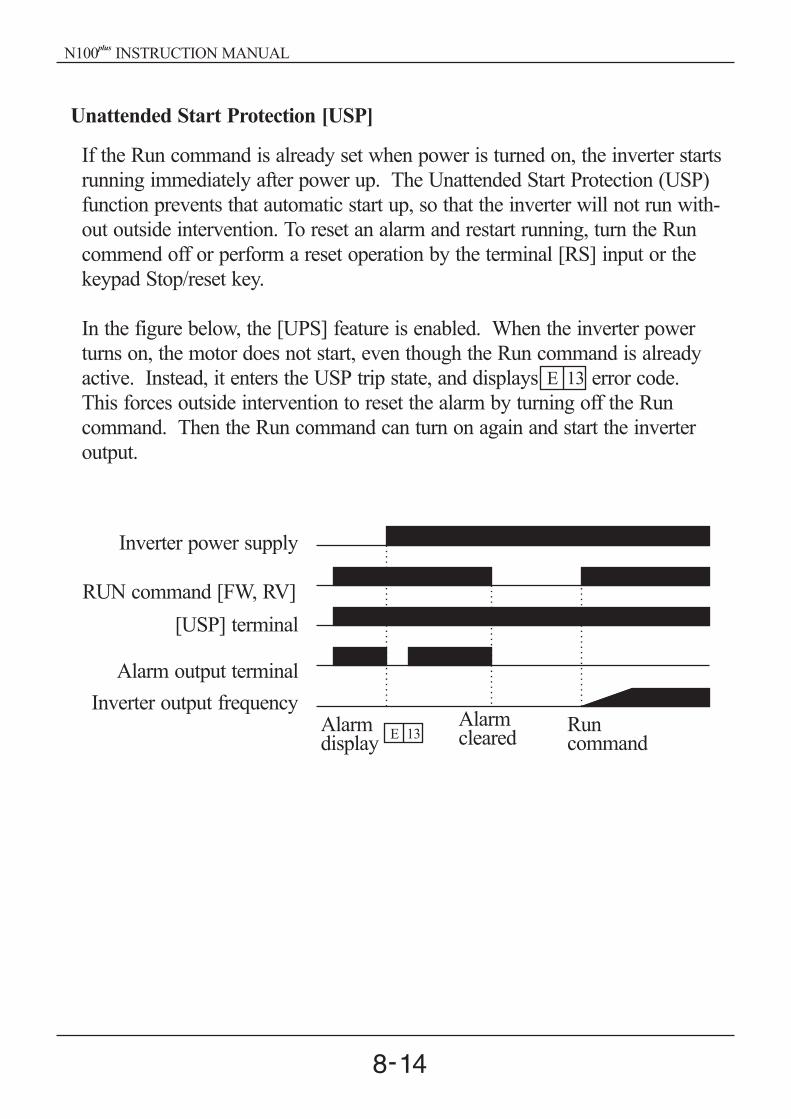
Unattended Start Protection [USP]
If the Run command is already set when power is turned on, the inverter starts
running immediately after power up. The Unattended Start Protection (USP)
function prevents that automatic start up, so that the inverter will not run with-
out outside intervention. To reset an alarm and restart running, turn the Run
commend off or perform a reset operation by the terminal [RS] input or the
keypad Stop/reset key.
In the figure below, the [UPS] feature is enabled. When the inverter power
turns on, the motor does not start, even though the Run command is already
active. Instead, it enters the USP trip state, and displays error code.
This forces outside intervention to reset the alarm by turning off the Run
command. Then the Run command can turn on again and start the inverter
output.
E 13
RUN command [FW, RV]
[USP] terminal
Alarm output terminal
Inverter output frequency
Inverter power supply
E 13Alarmdisplay
Alarmcleared
Runcommand
N100 INSTRUCTION MANUALplus

CM1 6 5 4 3 2 1 P24
USP FW
OptionCode
TerminalSymbol Function Name
InputState
11 USPUnattended SartProtection
ON
OFF
On power up, the inverter will notresume a Run command (mostly
used in the Us)
Valid for inputs:
Required setting
C01,C02,C03,C04,C05,C06
(none)
Notes:Note that when a USP error occurs andit is canceled by a reset from a [RS]terminal input, the inverter restartsrunning immediately.Even when the trip state is canceled byturning the terminal [RS] on and off afteran under voltage protection E09 occurs,the USP function will be performed.When the running command is activeimmediately after the power is turned on,a USP error will occur. When this functionis used, wait for at least three seconds afterthe power up to generate a Run command.
Example:
On power up, the inverter will notresume a Run command that wasactive before power loss
Description
N100 INSTRUCTION MANUALplus
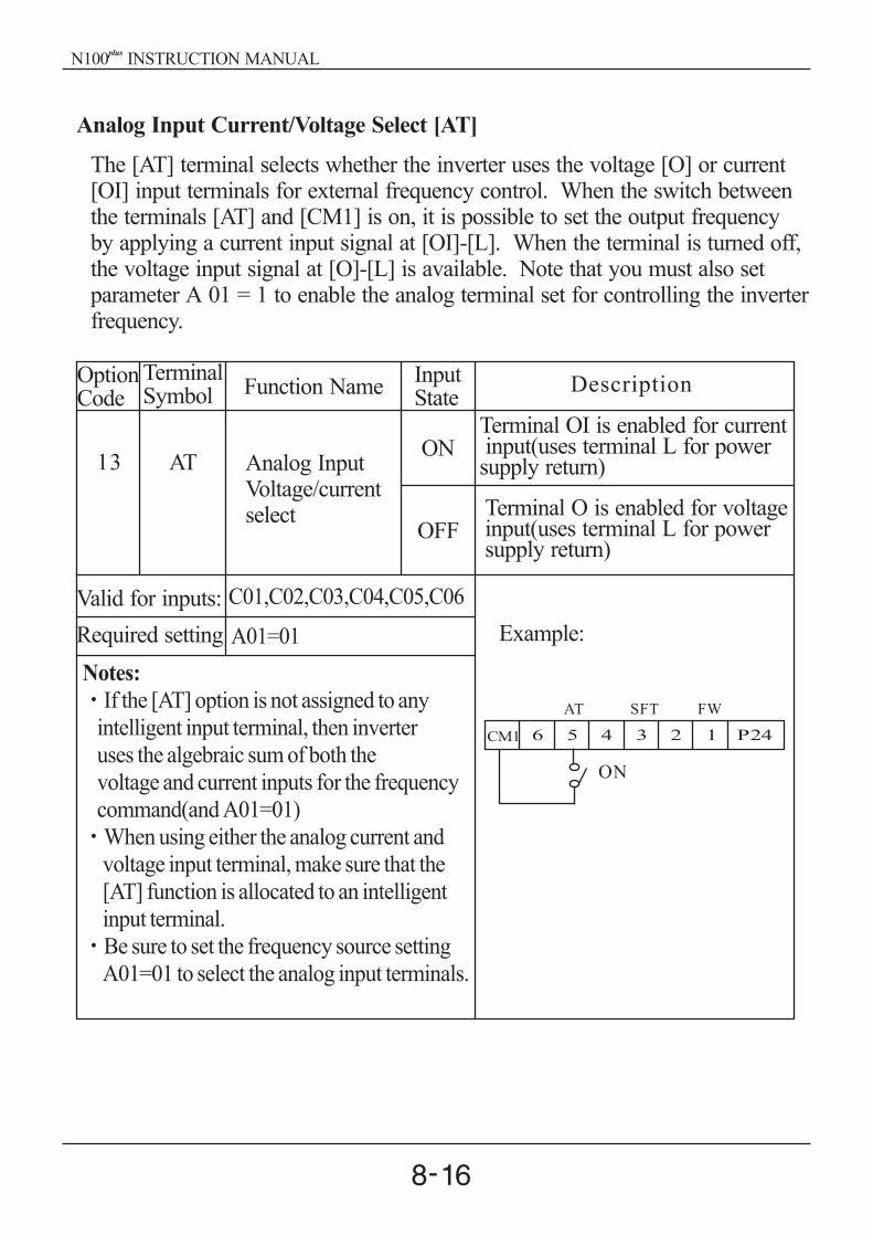
CM1 6 5 4 3 2 1 P24
AT SFT FW
ON
Analog Input Current/Voltage Select [AT]
The [AT] terminal selects whether the inverter uses the voltage [O] or current[OI] input terminals for external frequency control. When the switch betweenthe terminals [AT] and [CM1] is on, it is possible to set the output frequencyby applying a current input signal at [OI]-[L]. When the terminal is turned off,the voltage input signal at [O]-[L] is available. Note that you must also setparameter A 01 = 1 to enable the analog terminal set for controlling the inverterfrequency.
OptionCode
TerminalSymbol Function Name
InputState
Description
13 AT Analog InputVoltage/currentselect
ON
OFF
Terminal OI is enabled for currentinput(uses terminal L for power
supply return)
Terminal O is enabled for voltageinput(uses terminal L for powersupply return)
Valid for inputs:
Required setting
C01,C02,C03,C04,C05,C06
A01=01
Notes:
If the [AT] option is not assigned to any
intelligent input terminal, then inverter
uses the algebraic sum of both the
voltage and current inputs for the frequency
command(and A01=01)
When using either the analog current and
voltage input terminal, make sure that the
[AT] function is allocated to an intelligent
input terminal.
Be sure to set the frequency source setting
A01=01 to select the analog input terminals.
Example:
N100 INSTRUCTION MANUALplus

CM1 6 5 4 3 2 1 P24
RS
OptionCode
TerminalSymbol Function Name Input
StateDescription
14 RS Reset InverterON
OFF
The motor output is turned off, theTrip Mode is cleared(if it exists),and power up reset is applied
Normal power-on operation
Valid for inputs:
Required setting
C01,C02,C03,C04,C05,C06(none)
Notes:When the control terminal [RS] input is already
at power up for more than 4 seconds, the displayof the digital operator is E60. However, theinverter has no error.To clear the digital operator error, turn off the terminal [RS] input and press stop/ reset button of the operator.When the [RS] terminal is turned off from on, the Reset command is active.The stop/reset key of the digital operator is valid only when an alarm occurs.Only the normally open contact [NO] can be set for a terminal configured with the [RS]function. The terminal cannot be used in the normally closed contact [NC] state.Even when power is turned off or on, the function of the terminal is the same as that of thereset terminal.The Stop/Reset key on the inverter is only operational for a few seconds after inverterpower up when a hand-held remote operator is connected to the inverter.If the [RS] terminal is turned on while the motor is running, the motor will befree running(coasting)
Example:
approx.30
12 min
Alarm output
[RS]terminal
Reset Inverter [RS]
The [RS] terminal causes the inverter toexecute the reset operation. If the inverteris in Trip Mode, the reset cancels the Tripstate. When the switch between the setterminals [RS] and [CM1] is turned on andoff, the inverter executes the reset operation.The input timing requirement for [RST] needs a 12 ms pulse width or greater.The alarm output will be cleared within 30 ms after the onset of the Reset
command.
After the Reset command is given and the alarm reset occurs, the motor willrestart suddenly if the Run command is already active. Be sure to set thealarm reset after verifying that the Run command is off to prevent injury topersonnel.
DANGER
N100 INSTRUCTION MANUALplus
CM1 6 5 4 3 2 1 P24
SFT FW
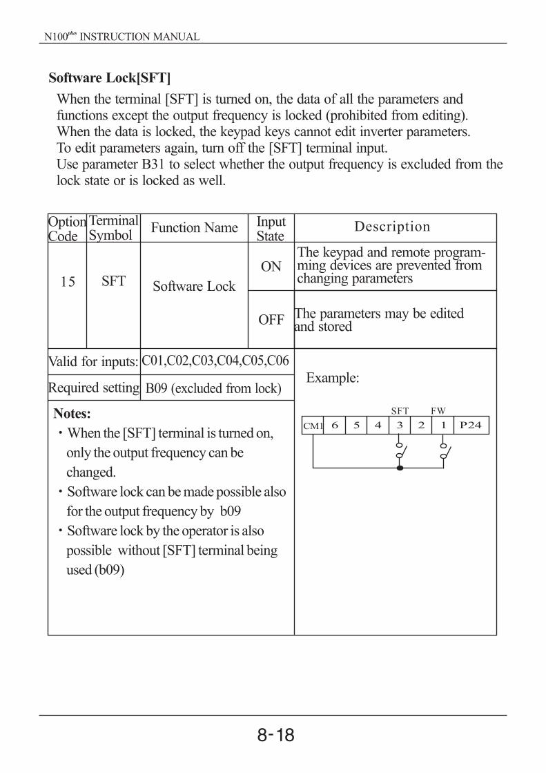
Software Lock[SFT]
When the terminal [SFT] is turned on, the data of all the parameters andfunctions except the output frequency is locked (prohibited from editing).When the data is locked, the keypad keys cannot edit inverter parameters.To edit parameters again, turn off the [SFT] terminal input.Use parameter B31 to select whether the output frequency is excluded from thelock state or is locked as well.
OptionCode
TerminalSymbol
Function Name InputState
Description
15 SFT Software Lock
ON
OFF
The keypad and remote program-ming devices are prevented fromchanging parameters
Valid for inputs:
Required setting
C01,C02,C03,C04,C05,C06
B09 (excluded from lock)
Notes:
When the [SFT] terminal is turned on,
only the output frequency can be
changed.
Software lock can be made possible also
for the output frequency by b09
Software lock by the operator is also
possible without [SFT] terminal being
used (b09)
Example:
The parameters may be editedand stored
N100 INSTRUCTION MANUALplus

(Initial setting is a-contact [NO])
Frequency Arrival Signal [FA1]/[FA2]
Frequency Arrival [FA1] and [FA2] signals indicate when the output frequencyaccelerates or decelerates to arrive at a constant frequency. Refer to the figurebelow. Frequency Arrival [FA1](upper graph) turns on when the outputfrequency gets within 0.5Hz below or 1.5Hz above the target constantfrequency.The timing is modified by a small 60ms delay. Note the active low nature ofthe signal, due to the open collector output.
Frequency Arrival [FA2] (lower graph) uses thresholds for acceleration anddeceleration to provide more timing flexibility than [FA1].Parameter C21 sets the arrival frequency threshold for acceleration, andparameter C22 sets the thresholds for deceleration. This signal also is activelow and has a 60ms delay after the frequency thresholds are crossed.
FA1
signal
60 60
ON ON
1.5
F 010.50.5
F 01
1.5
Outputfrequency
Hz set value
set value
1.5
60
FA2
signal
0.5
ON
C 21
C 22
Outputfrequency
Hz
set valueThresholds
8.4 Using intellingent output terminals
set value
N100 INSTRUCTION MANUALplus

CM2 12
50 max
DC 27Vmax
Open collector output
Fa1/ FA2
11
OptionCode
TerminalSymbol Function Name
InputState
Description
1 FA1Frequency arrivaltype 1 signal
Frequency arrivaltype 2 signal
ON
OFF
when output to motor is at theset frequency
Valid for inputs:
Required setting
C13, C14, C21, C22
(none)
Notes:At the time of acceleration, an arrival signal at
a frequency between the set frequency -0.5Hzto +1.5Hz is turned on.At the time of deceleration, an arrival signal at
a frequency between the set frequency +0.5Hzto -1.5Hz is turned on.The delay time of the output signal is 60ms
(nominal).
Example:
when output to motor is off,or in any acceleration ordeceleration ramp
2 FA2
ON
OFF
when output to motor is at orabove the set frequency theholds for, even if in accelerationor deceleration ramps
when output to motor is off,or during acceleration or decel-eration before the respectivethresholds are crossed
RY
N100 INSTRUCTION MANUALplus

RY
CM2 12 11
50 max
DC 27Vmax
Open collector output
Run Signal [RUN]
When the [RUN] signal is selected as an intelligent output terminal, the inverteroutputs a signal on that terminal when it is in the Run Mode. The output logicis active low, and is the open collector type (switch to ground)
OptionCode
TerminalSymbol Function Name
InputState
Description
0 RUN Run signalON
OFF
when inverter is in Run Mode
Valid for inputs:
Required setting
C13, C14
(none)
Notes:
The inverter outputs the [RUN] signal
whenever the inverter output exceeds the
start frequency . The start frequency is the
initial inverter output frequency when it
turns on.
Example:
when inverter Stop Mode
NOTE : The example circuit in the table above drives a relay coil. Note the useof a diode to prevent the negative-going turn-off spike generated by the coil
from damaging the inverter's output transistor.
ON
DC braking
ON
Motorspeed
Runsignal
Runcommand
FW[RV]
RUN
N100 INSTRUCTION MANUALplus

RY
OL
CM2 12 11
50 max
DC 27Vmax
Open collector output
Current
set value
C 20
OLsignal
Power running
Regeneration
Overload Advance Notice Signal [OL]
When the output current exceeds apreset value, the [OL] terminal signalturns on. The parameter C20 sets theoverload threshold. The overloaddetection circuit operates duringpowered motor operation and duringregenerative braking. The output circuitsuse open-collector transistors, and areactive low.
OptionCode
TerminalSymbol Function Name
InputState
Description
3 OLOverload advancenotice signal
ON
OFF
when output current is more thanthe set threshold for the overloadsignal
Valid for inputs:
Required setting
C13, C14, C20
C23
Notes:
The default value is 100%. To change the
level from the default, set C20 (overload
level).
The accuracy of this function is the same as
the function of the output current monitor
on the [FM] terminal
Example:
when output current is less thanthe set threshold for the overloadsignal
N100 INSTRUCTION MANUALplus

RY
OD
CM2 12 11
50 max
DC 27Vmax
Open collector output
Output Deviation for PID Control [OD]
The PID loop error is defined as the
magnitude(absolute value) of the
difference between the Set point
(target value) and the process Variable
(actual value). When the error magnitude
exceeds the press value for C23, the [OD]
terminal signal turns on. Refer to the PID
loop operation.
Current
set value
C 23
ODsignal
Process variable
Setpoint
OptionCode
TerminalSymbol Function Name
InputState
Description
4 ODOutput deviationfor PID control
ON
OFF
when PID error is more than theset threshold for the deviationsignal
Valid for inputs:
Required setting
C13, C14, C23
C23
Notes:
The default difference value is set to 10%.
To change the value, change parameter
C23 (deviation level).
Example:
when PID error is less than theset threshold for the deviationsignal
NOTE : The example circuit in the table above drives a relay coil. Note the useof a diode to prevent the negative-going turn-off spike generated by the coilfrom damaging the inverter's output transistor.
N100 INSTRUCTION MANUALplus

RY
AL
CM2 12 11
50 max
DC 27Vmax
Open collector output
Alarm Signal output [AL]
The Inverter alarm signal is active when a fault has occurred and it is in theTrip Mode. When the fault is cleared the alarm signal becomes inactive.We must make a distinction between the alarm signal [AL] and the alarm relaycontacts AL0, AL1and AL2. The signal [AL] is a logic function which youcan assign to the open collector output terminals 11, or 12, or the relay outputs.The most common (and default) use of the relay is for [AL], thus the labelingof its terminals.
OptionCode
TerminalSymbol
Function Name InputState
Description
5 AL Alarm signalON
OFF
When an alarm signal has occurredand has not been cleared
Valid for inputs:
Required setting
11, 12, AL0-AL2
C13, C14,C15,C16
Notes:When the alarm output is set to normallyclosed [NC], a time delay occurs until thecontact is closed when the power is turnedon. Therefore, when the alarm contact out-put is to be used, set a delay of about 2seconds when the power is turned on.Terminals 11 and 12 are open collector out-puts, so the electric specification of [AL] isdifferent from the contact output terminals AL0, AL1, AL2.The logic sequence of terminals 11 and 12 is the same as AL0-AL2.See the description of AL1, AL2 and AL0.When the inverter power supply is turned off, the alarm signal output is validas long as the external control circuit has power.The signal output has the delay time(300ms nominal) from the fault alarmoutput.Output terminal 11 is a contact a.In case of contact b, set up C15.Output terminal 12 is a contact a.In case of contact b, set up C16.
Example:
When no alarm has occurred sincethe last clearing of alarm(s)
N100 INSTRUCTION MANUALplus

AL0 AL1 AL2 AL0 AL1 AL2
AL0-AL1 AL0-AL2
ON
ON
OFF
Contact a (Initial setting)
During normal running
or power is turned offwhen an alarm occurs
The alarm output terminals are connected as shown below by default, or afterinitialization. The contact logic can be inverted by using the parameter settingC16. The relay contacts normally contact a.Convention uses "normal' to mean the inverter has power and is in Run or StopMode. The relay contacts switch to the opposite position when it is Trip Modeor when input power is off.
contact
Contact a(initialsetting)
Power Run State
Normal
Trip
Open
Open
Open
Closed
Closed
Closed
8.5 Alarm Terminal Function
Alarm Terminal [AL1, AL2- AL0)
Contact specification
AC 250V, 2.5A(Resistor load), 0.2A(Inductive load)
DC 30V, 3.0A(Resistor load), 0.7A(Inductive load)
Maximum Minimum
AC 100V, 10mA
DC 5V, 100mA
N100 INSTRUCTION MANUALplus
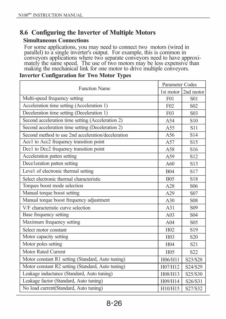
8.6 Configuring the Inverter of Multiple Motors
Simultaneous ConnectionsFor some applications, you may need to connect two motors (wired inparallel) to a single inverter's output. For example, this is common inconveyors applications where two separate conveyors need to have approxi-mately the same speed. The use of two motors may be less expensive thanmaking the mechanical link for one motor to drive multiple conveyors.
Inverter Configuration for Two Motor Types
Second acceleration time setting (Acceleration 2)
Second acceleration time setting (Deceleration 2)
Second method to use 2nd acceleration/deceleration
Acc1 to Acc2 frequency transition point
Acceleration patten setting
Dcc1 to Dcc2 frequency transition point
Dece1eration patten setting
Leve1 of electronic thermal setting
Select electronic thermal characteristic
Torques boost mode selection
Manual torque boost setting
Manual torque boost frequency adjustment
V/F characteristic curve selection
Base frequency setting
Maximum frequency setting
Select motor constant
Motor capacity setting
Motor poles setting
Motor Rated Current
Motor constant R1 setting (Standard, Auto tuning)
Motor constant R2 setting (Standard, Auto tuning)
Leakage inductance (Standard, Auto tuning)
Leakage factor (Standard, Auto tuning)
No load current(Standard, Auto tuning)
1st motor 2nd motor
Multi-speed frequency setting
Acceleration time setting (Acceleration 1)
Deceleration time setting (Deceleration 1)
Function NameParameter Codes
F01 S01
S02
S03
S10
S11
S14
S15
S12
S16
S13
S17
S18
S06
S07
S08
S09
S04
S05
S19
S20
S21
S22
S23/S28
S24/S29
S25/S30
S26/S31
S27/S32
F02
F03
A54
A55
A56
A57
A59
A58
A60
B04
B05
A28
A29
A30
A31
A03
A04
H02
H03
H04
H05
H06/H11
H07/H12
H08/H13
H09/H14
H10/H15
N100 INSTRUCTION MANUALplus

8.7 Sensorless Vector Control
Function description
The N100 inverter has a built-in auto-tuning algorithm. The N100inverter can be possible to do high-starting torque and high-precision operation.Also, the settings have a second set of parameters for a second motor.The required torque characteristic or speed control characteristic may not bemaintained in case that the inverter capacity is move than twice the capacity ofthe motor in use .
Select the parameter A31 to 2 ( sensorless vector control).Parameter H03 and H04 select motor capacity and poles (4-poles).Parameter H02 selects which data(standard data, auto-tuning data) of motorconstants you want the inverter to use.
plusplus
Function setting method
N100 INSTRUCTION MANUALplus

8.8 Auto-tuning
Function description
The auto-tuning procedure automatically sets the motor parameter related to
sensorless vector control. Since sensorless vector control needs motor
parameter, the standard motor parameters have been set at the factory.
Therefore, when an inverter exclusive-use motor is used or when a motor of
any other manufacture is drive, the motor parameter is detected by auto-tuning
because the parameters are not matched.
Follow the steps below to auto-tune the inverter, finally set the parameter H01.
F02, F03 setting : Set the time the range that over-current or over-voltage trip
event not occurs.
Set the same as setting F02.
H03 setting : Set the motor rating.
0 4 : 004LF 037LF
5 9 : 004HF 037HF
H04 setting : set the motor poles
A01 setting : set the frequency command source to 0 (potentiometer)
A03 setting : set the base frequency(60Hz)
F01 setting : set the operation frequency except 0hz (by the potentiometer)
A53 setting : select output voltage for motor.
A33 setting : set DC braking setting to 0(disable).
H01 setting : select the auto-tuning mode (1).
After setting above parameters, press the RUN key on the standard operator.
Function setting
{ }
N100 INSTRUCTION MANUALplus

Auto-tuning method
AC excitation (no rotation)
DC excitation
Motor accelerates to 80% of
base frequency, the stops.
(no rotation)
End display
auto-tuning process completed:
auto-tuning process failed :
Motor connection
Auto-tuning modeselection H01=1
Run command ON
Motor parameter setting
Parameter settingcompleted, stop
Note) The motor parameter of N100 is standard data of HYUNDAIstandard 4-poles motor. At the sensorless vector control when usingdifferent poles motor, operates by using auto-tuning data as a motorparameter.
plus
N100 INSTRUCTION MANUALplus

Setting Method
(1) Digital panel
No
H01
H02
H03
H04
H06/H11
H07/H12
H09/H14
H08/H13
Name
auto-tuningmode selection
motor datasetting
motor capacity
motor poles
motor resistorR1
motor resistorR2
Transientinductance
Motorinductance
Setting range
0/1
0/1
2/4/6/8
0.001-30.00
0.001-20.00
0.01-999.9
0.01-100.0
0.1-100.0
Description
0 : auto-tuning OFF1 : auto-tuning ON
0 : standard data1 : auto-tuning data
Unit : pole
:Unit
:Unit
Unit : mH
Unit : mH
0 90 4 : 004LF 037LF5 9 : 004HF 037HF
Unit : A
The data of H11 to H15 is auto-turning data.
H10/H15No-loadcurrent
N100 INSTRUCTION MANUALplus

Remark
1. If satisfactory performance through auto-tuning cannot be fully obtained,please adjust the motor constants for the observed symptoms according to thetable below.
2. If the inverter capacity is more than twice the capacity of the motor in use,the inverter may not achieve its full performance specifications.
3. Running multiple motor under sensorless vector control is not available.4. When DC braking is enabled, the motor constant will not be accurately set.
Therefore, disable DC braking before starting the auto-tuning procedure.5. The motor will rotate up to 80% of base frequency : make sure that accele-
ration or deceleration is not operated. If then, decrease the manual torqueboost setting value.
6. Be sure if motor is in standstill before you carry out an auto-tuning.Auto-tuning data carried out when motor is still running may be not correct.
7. If the auto-tuning procedure is interrupted by the stop command, the auto-tuning constants may be stored in the inverter. It will be necessary to storethe inverters factory defaults setting.
Poweredrunning
(status with aaccelerating
torque)
When low frequency(a few Hz) torque isinsufficient.
H06/H11/S23/S28
Slowly increase the motor constantR1 in relation to auto-tuning datawithin 1 to 1.2 times R1.
Slowly increase the motor constantR1 in relation to auto-tuning datawithin 1 to 1.2 times R1.
Slowly increase the motor constantR2 in relation to auto-tuning datawithin 1 to 1.2 times R2.
Slowly increase the motor constantIO in relation to auto-tuning datawithin 1 to 1.2 times IO.
Slowly increase the motor constantIO in relation to auto-tuning datawithin 1 to 1.2 times IO.
Slowly decrease the motor constantR2 in relation to auto-tuning datawithin 0.8 to 1 times R2.
Decrease the carrier frequency.
Regeneration(status with adecelerating
torque)
When low frequency(a few Hz) torque
is insufficient.
When over currentprote ction is operatedat injection of load
When the speeddeviation is positive
When the speeddeviation is negative.
H07/H12/S24/S29
H07/H12/S24/S29
H10/H15/S27/S32
H06/H11/S23/S28
H10/H15/S27/S23
b11
Operationstatus
Symptom Adjustment Parameter
N100 INSTRUCTION MANUALplus

9. Operating the inverter
9.1 Identifying the parts
9.2 Operation procedure
Display part (LED display)This part display frequency,motor current, motorrotation speed, alarm history,and setting value.
POWER LEDOn when the controlpowerinput to inverteris on
FUNCTION keyThis key is used forchanging parameterand command
(Example that the frequency is set from potentiometer to the standard operator and theequipment starts running)
PRG LEDThis LED is on when theinverter is ready forparameter editing.
RUN LEDon when the inverteroutputs the PWM
voltage and operatingcommand is ready
RUN keyPress this key to run themotor. The Run enableLED must be terminaloperation UP/ DOWN key
This key is used tochange data andincrease of decreasethe frequency.
STORE KEYPress the store key to write thedata and setting value to thememory
Potentiometerset the inverter outputfrequency.(be operatedonly when the ramp isON)
Hz/A LEDDisplay units Hertz/AmpereLEDs.
STOP/RESET keyThis key is use for stopping the motor or resettingerrors. (When either operator or terminal is selected,this key works. If the extension function b 15 is used,this function is void)
Display afterpower isturned on
060.0
F 01F 01 01 60.0
0.0 F 01F 01
01 A --A --
A--
A 01A 01
A 01A 01
0
chage the frequencycommand by keyoperation from thepotentiometer
set the frequencyto 60Hz
frequency monitor
MotorOperation
Oper-ationstart
press the keyonce
press the keyonce
press the key9 times
press the key
press the keyonce
press the keyonce press the key twice
press the keyfour times
press the keyfour times
Hz
store thedata
display transition
FUNC
FUNC
FUNC
FUNC
FUNC
FUNC
STR
RUN
STR store the data
0.0
N100 INSTRUCTION MANUALplus

9.3 Key Description
or
[UP/DOWN key] The key are used to select the command and
change the data
output frequency monitor
output current monitor
output voltage monitor
rotation direction monitor
output frequency setting
acceleration time 1 setting
PID control feedbackvalue monitor
deceleration time 1 setting
input terminal statusmonitoroutput terminal statusmonitoroutput scalefactor monitor
frequency
power comsumptionmonitoroperating timeaccumulation monitorreal operating time monitor
rotation direction setting
[RUN key] This key starts the run.
The set value of determines a forward run or a reverse run.
[STOP/RESET key] This key stops the run
When a trip occurs, this key becomes the reset key.
basis setting functions
fine tuning functions
terminal setting functions
seceond motor settingfunctionsseceond motor settingfunctions
[FUNCTION key] This key allows the selection of commandsand memorises parameters. When the key ispressed once in the state of, the extensionfunction code selection state is set.
5 8 . 0
5 7 . 9
0 1
0 8
0 2
0 9
1 01 0
1 11 1
1 21 2
1 31 3
0 3
F 0 1F 0 1
1 41 4
0 4
F 0 2F 0 2
1 51 5
0 5
F 0 3F 0 3
1 61 6
0 6
F 0 4F 0 4
1 71 7
0 7
F 0 4F 0 4
A - -A - -
b - -b - -
C - -
S - -S - -
H - -H - -
5 8 . 1
F 2F 2 F 2F 2
DC link votage monitor
trip monitor
trip history 1 monitor
trip history 2 monitor
trip history 3 monitor
trip count
N100N100 INSTRUCTION MANUALplus

9.4 Expanded function mode navigational map
Using the / key to enter the expanded function mode, select expanded
function command NO. in and mode.
Expanded functionsetting
storedataand return to theexpanded
command (setting data is disabled)
do not storedataand return to theexpanded
command (setting data is disabled)
Display description:
When the inverter is turned on, theoutput frequency monitor display appears.
expanded function command NO.
A- -
A - -A - - A 0 1A 0 1
A 0 2A 0 2
A 6 5A 6 5 0 4 0
b - - C - - S - - H - -
expanded functiondata
N100 INSTRUCTION MANUALplus

Parameter Monitoring Functions
Func-code Name Description
d01
d02
d03
d04
d05
d06
d07
d08
Output frequencymonitor
Output current monitor
Output voltage monitor
Rotation directionmonitor
PID feedback monitor
Intelligent input terminalstatus
Intelligent outputterminal status
Scaled output frequencymonitor
Real-time display of output frequency tomotor, from 0.00 to 400.0 Hz, "Hz" LED ON
Real-time display of output current to motor,from 0.0 to 99.9A, "A" LED ON.
Real-time display of output voltage to motor
Three different indications:"F"..... Forward Run" "... Stop"r"...... Reverse Run
Displays the scaled PID process variable(feedback) value (A50 is scale factor)
Displays the state of the intelligent inputterminals:
ON
OFF
6 5 4 3 2 1
Terminal numbers
Displays the state of the intelligent outputterminals:
ON
OFFAL 12 11
Terminal numbers
Displays the output frequency scaled by theconstant in b14.Scale factor(b14) x freguency data
Function List
N100 INSTRUCTION MANUALplus

d09
d10
d11
d12
d13
d14
d15
d16
d17
Power consumptionmonitor
Operating timeaccumulationmonitor(hour)
Real operating timemonitor (minute)
DC link voltage
Trip event monitor
Trip history 1 monitor
Trip history 2 monitor
Trip history 3 monitor
Trip count
Displays the power consumption at inverterstarting (W)
Inverter operating accumulation time(0 9999)
Inverter real operating time (0 59)
Displays the inverter DC link voltage(V)
Displays the current trip eventDisplay method
Alarm reasonpress the UP key
Output frequency at alarm eventpress the UP/DOWN key
Output current at alarm eventpress the UP/DOWN key
DC link voltage at alarm eventpress the FUNC key
"d13" display
No trip event
Displays the previous first trip event
Displays the previous secound trip event
Displays the previous third trip event
Displays the trip accumulation count
Func-code Name Description
N100 INSTRUCTION MANUALplus

Outputfrequency
setting
Basic Function Mode
F01
F02
F03
F04
A--
b--
C--
Accelerationtime1 setting
Decelerationtime 1 setting
Rotation dire-ction setting
Extended fun-ction of A groupsettingExtended func-tion of b groupsettingExtended func-tion of C groupsetting
Standard default target frequency thatdetermines constant motor that deter-mines constant motor speed. setting rangeis 0.00 to 400.0Hz(1) frequency setting from UP/DOWN
key of digital operator.(2) Multi-step speed
By combining frequency referenceand intelligent input terminal ON/OFF, up to 16 step of speed can be set.
(3) Remote operator (NOP), controlterminal input (O-L, OI-L).
Frequency reference by the localpotentiometer can be monitored.
Standard default acceleration,setting range is 0.1 to 3000sec.
0.1 999.9 ----- by 0.1sec1000 3000 ----- by 1sec
Standard default deceleration, 2nd motor.0.1 999.9 ----- by 0.1sec1000 3000 ----- by 1sec
Two options: select codes:0... Forward run1... Reverse run
Basic setting functionssetting range : A01 A65
Fine tuning functionsSetting range :b01 b17
Terminal setting functionsSetting range :C01 C23
volumesettingvalue
10.0sec
10.0sec
0
-
-
-
-
S--
H--
Extended func-tion of S groupsetting
Extended func-tion of H groupsetting
Seond motor setting functionsSetting range :S01 S32
Sensorless vector setting functionsSetting range :H01 H15
-
-
-
-
minimumsetting range
minimumsetting range
Note) If you set the carrier frequency less than 2kHz, acceleration / decelerationtime delays approximately 500msec.
--
Func-code Name Description Defaults
Run-timeEdit
N100 INSTRUCTION MANUALplus

V100%
0
(A04)
BaseFrequency
(A03)
MaximumFrequency
A06
A05
A07 A08 10VOV20mA4mA
Frequency
Analog Input
Expanded Function Mode of A Group
Basic parameter settings
Func-code Name Description
Frequencycommanding(Multi-speedcommandingmethod)
Defaults
A01
A02
A03
A04
Runcommanding
Base frequencysetting
Maximumfrequencysetting
Four options: select codes:0.... Keypad potentiometer1.... Control terminal input2.... Standard operator3.... Remote operator(communication)
Four options: select codes:0.... Standard operator1.... Control terminal input2.... Remote operator(communication)
0
0
60.00HzSettable from the base frequency [A03]up to 400Hz in units of 0.1 Hz.
Settable from 0 to maximum frequencyin units of 0.01Hz
Analog Input Settings
Externalfrequencysetting start
Externalfrequencysetting end
A05
A06End frequency provided when analoginput is 10V(20mA) can be set in unitsof 0.01Hz. setting range is 0 to 400Hz
0.00Hz
0.00Hz
Start frequency provided when analoginput is 0V (4mA) can be set inunits of 0.01Hz setting range is 0 to400 Hz
60.00Hz
Run-timeEdit
N100 INSTRUCTION MANUALplus

Func-code Name Description
Externalfrequencystart rate setting
Externalfrequencyend rate setting
Externalfrequencysampling setting
Defaults
A07
A08
A10
The starting point(offset) for the activeanalog input range(0 10V, 4mA 20mA)setting range is 0 to 100% in units of 0.1%
The ending point(offset) for the activeanalog input range(0 10V, 4mA 20mA)setting range is 0 to 100% in units of 0.1%
Range n = 1 to 8, where n = number ofsamples for average
0.0%
0
100.0%
4Samples
4V4mA
Frequency
Analog input
A06
A05
A07 A0810V20mA
A09=1
A09=0
Two options: select codes:
0.... start at start frequency1.... start at 0Hz
Multi-speed Frequncy Setting
Multi-speedfrequencysetting
Joggingfrequencysetting
Jogging stopoperationselection
A11
A25
A26
A27
Defines limited speed for jog,range is 0.5 to 10.00Hz in units of 0.01Hz.The jogging frequency is provided safetyduring manual operation.
Define how end of jog stops the motor:three options:0.... Free-run stop1.... Deceleration stop(depending on
deceleration time)2.... DC braking stop(necessarg to set
DC braking)
0.50Hz
0
speed1:5Hzspeed2:10Hzspeed3:15Hzspeed4:20Hzspeed5:30Hzspeed6:40Hzspeed7:50Hzspeed8:60Hzetc. 0Hz
Defines the first speed of a multi-speed profile, range is 0 to 400Hz inunits of 0.01Hz.Setting range is 1-speed(A11) to15-speed(A25).Speed0:volume setting value
Run-timeEdit
Externalfrequency startpattern setting
A09
N100 INSTRUCTION MANUALplus

V
0
100%
frequency
Reducedtorque
Constanttorque
V/F Characteristics
Func-code
Name Description
Torque boostmode selection
Manual torqueboost setting
Manual torqueboost frequencysetting
V/Fcharacteristiccurve selection
V/F gain setting
Defaults
A28
A29
A30
A31
A32
Sets the frequency of the V/F breakpointA in graph for torque boost
0
10.0%
100.0%
0
Two options: 0.... Manual torque boost1.... Automatic torque boost
Two available V/F curves: three selectcodes:0... Constant torque1... Reduced torque(reduction of the 1.7th
power)2... Sensorless vector control
A32
V100%
20%
0 frequency
Sets output voltage gain of the inverterfrom 20 to 100%
Can boost starting torque between 0 and100% above normal V/F curve, from 0 to1/2 base frequencyBe aware that excessive torgue boost cancause motor damage and inverter trip.
V
06.0Hz 30.0Hz
=60.0Hz
A29=5.0
A30=10.0%
100%
A
frequency
base frequency
0% 100% : A30
Run-timeEdit
5.0%
N100 INSTRUCTION MANUALplus

A 35 A 37
Running Free run DC braking
0
+
-
time
The delay from the end of Run commandto start of DC braking (motor free runsuntil DC braking begins).Setting range is 0.0 to 5.0sec in units of0.1set.
DC Braking Settings
Func-code Name Description
DC brakingtime setting
DefaultsRun-timeEdit
A33
A34
A35
A36
A37
0
0.50Hz
0.0sec
10.0%
Sets two options for DC braking0.... Disable1.... EnableThe frequency at which DC brakingoccurs, range is 0.0 to 10.0 Hz in unitsof 0.01Hz
Applied level of DC braking force,settable from 0 to 50% in units of 0.1%
Sets the duration for DC braking, rangeis 0.0 to 10.0 seconds in units of 0.1sec.
DC brakingfrequencysetting
DC brakingoutput delaytime setting
DC brakingforce setting
DC brakingfunction selection
Frequency-related Functions
A38
A39
A40A42A44
0.00Hz
0.00Hz
Sets a limit on output frequency greaterthan zero. Range is 0.00 to 400.0Hz inunits of 0.01Hz
Frequencylower limitsetting
Jump(center)frequencysetting
Frequencyupperlimit setting
Up to 3 output frequencies can be definedfor the output to jump past to avoid motorresonances(center frequency) range is0.00 to 400.0Hz in units of 0.01Hz.
A38
A39
Output frequency
Upperlimit
Settable range
Frequency command
Lowerlimit
Sets a limit on output frequency less thanthe maximum frequency(A04). Range is0.00 to 400.0Hz in units of 0.01Hz.
0.0sec
0.00Hz
N100 INSTRUCTION MANUALplus

A40A41
0.00Hz
Jump(hysteresis)frequency widthsetting
Defines the distance from the centerfrequency at which the jump aroundoccurs. Range is 0.00 to 10.00Hz inunits of 0.01Hz
A41A43A45
PID Control(Note1)
A46
A47
A48
A49
0
10.0%
10.0sec
0.0sec
Proportional gain has a range of 0.1to 100 in units of 0.1.
PID P(proportional)gain setting
PID I (integral)gain setting
PID D(deriva-tive) gain setting
PID Functionselection
Integral time constant has a range of0.0 to 100.0 seconds in units of 0.1
Enables PID function, two option codes:0.... PID control disable1.... PID control enable
Derivative gain has a range of 0.0 to100 .0 seconds in units of 0.1
Automatic Voltage Regulation (AVR) Function
A52
A53
0
220/380V
200V class inverter settings:.... 200/220/230/240
400V class inverter settings:.... 380/400/415/440/460
The AVR feature keeps the inverteroutput waveform at a relatively constantamplitude during power input fluctuations
Motor inputvoltage setting
AVR functionselection
Automatic (output) voltage regulation,selects from three type of AVR funct-ions, three option codes:0... Constant ON1...2... OFF during deceleration
Constant OFF
A50
A51
100
0
PID scale factorsetting
Feed-backmethod setting
PID scale factor (multiplier),range of 0.1 to 1000 in units of 0.1
Selects source of PID, option codes:0.... "OI" terminal(current in put)1.... "O" terminal(voltage in put)
Func-code Name Description Defaults
Run-timeEdit
N100 INSTRUCTION MANUALplus

S-curve
LinearU-curve
Target freq.
Second Acceleration and Deceleration Functions
A54
A55
10.0sec
10.0secSecond decelera-tion time setting
Second accelera-tion time setting
Duration of 2nd segment of acceleration,range is 0.1 to 3000 sec.Second acceleration can be set by the[2CH] terminal input or frequenytransition setting
Duration of 2nd segment of deceleration,motor, range is 0.1 to 3000 sec.Second acceleration can be set by the[2CH] terminal input or frequenytransition setting
A56
Two stageacce1/dece1switchingmethodselection
A57 0.00HzAcc1 to Acc2frequencytransition point
Output frequency at which Accel 1switches to Acce1 2, range is 0.00 to400.0Hz in units of 0.01Hz.
frequency acc1 acc2
2CHtime
Two options for switching from 1st to 2ndaccel/decel:0.... 2CH input from terminal1.... transition frequency
Output frequency at which Decel 1switches to Dece1 2, range is 0.00 to400.0Hz in units of 0.01Hz.
A58Decl to Dec2frequencytransition point
0.00Hz
0
0Decelerationcurve setting
Accelerationcurve selection
Set the characteristic curve of dec1and dec2, two options:0... linear, 1... S-curve, 2... U-curve
Set the characteristic curve of Acc1 andAcc2, two options:
0... linear, 1... S-curve, 2... U-curveA59
A60
Func-code Name Description Defaults
Run-timeEdit
Func-code Name Description Defaults
Run-timeEdit
0
N100 INSTRUCTION MANUALplus

A65 0
0.0
0
Input voltage
offset setting
Input current
offset setting
Input voltage
Gain setting
Input current
Gain setting
External voltage
input frequency
selection
100.0
100.0
Set the input power supply for external
voltage input frequency
0:5V input
1:10V input
Set the voltage offset for external analog
signal input input signal adjustment
Set the voltage gain for external analog
signal input signal adjustment
Set the current offset for external analog
signal input signal adjustment
Set the current gain for external analog
signal input signal adjustment
A61
A63
A62
A64
Func-code Name Description Defaults
Run-timeEdit
Func-code Name Description Defaults
N100 INSTRUCTION MANUALplus

Note 1) PID feedback control
The PID(Proportional, Integral, Differential) control functions can apply tocontrolling of fan, the air (water) amount of pump, etc., as well as controllingof pressure within a fixed value.
Set the reference signal according to the frequency setting method or the internallevel.Set the feedback signal according to the analog voltage input (0 to 10V) or analogcurrent input (4 to 20mA).If both input signal (target value and feedback value) set the same terminal,PID control is not available.To use analog current [OI-L] for the target value, set the [AT] terminal to ON.
If the response is not stabilized in a PID control operation, adjust the gains asfollows according to the symptom of the inverter.The change of controlled variable is slow even when the target value is changed.
Increase P gain [A47]The change of controlled variable is fast, but not stable.
[Input method of target value signal and feedback signal]
[PID gain adjustment]
Decrease P gain[A47]It is difficult to make the target value match with the controlled variable.
Decrease I gain [A48]Both the target value and the controlled variable are not stable.
Increase I gain [A48]The response is slow even when the P gain is increased.
Increase D gain[A49]The response is not stabilized due to oscillation even when the P gain is increased.
Decrease D gain[A49]
The figure below is a more detailed diagram of the PID control.
Target valueoperatormulti-speed
Volumeanalog votage inputanalog current input
A50
A50 F01
PA47
IA48
DA49
+ - +
++
Feedback value
analog votage inputanalog current input
analog iputsetting
A05-A08A50 monitor
d05
Frequency setting
N100 INSTRUCTION MANUALplus

Expanded Function mode of B Group
Restart Mode
b01
b02
b03
0
1.0sec
1.0sec
Allowableinstantaneouspower failuretime setting
Reclosing standby afterinstantaneouspower failurerecovered
Selection ofrestart mode
Select inverter restart method, four optioncodes:0.... Alarm output after trip, no automatic
restart1.... Restart at 0Hz2.... Resume operation after frequency
matching3.... Resume previous freq. after freq.
matching, then decelerate to stop anddisplay trip info.
Restart trip is overcurrent, overvoltageand under voltage.Overcurrent and over voltage trip restartup to 3 times, under voltage trip restartup to 10time.
The amount of time a power input undervoltage can occur without tripping thepower failure alarm. Range is 0.3 to 1.0sec. If under-voltage exists longer thanthis time, the inverter trips, even if therestart mode is selected.
Time delay after under-voltage conditiongoes away, before the inverter runs motoragain. Range is 0.3 to 3.0 seconds.
b02 b03
Input power
Motor speed
failure
Func-code Name Description Defaults
Run-timeEdit
Func-code Name Description
N100 INSTRUCTION MANUALplus
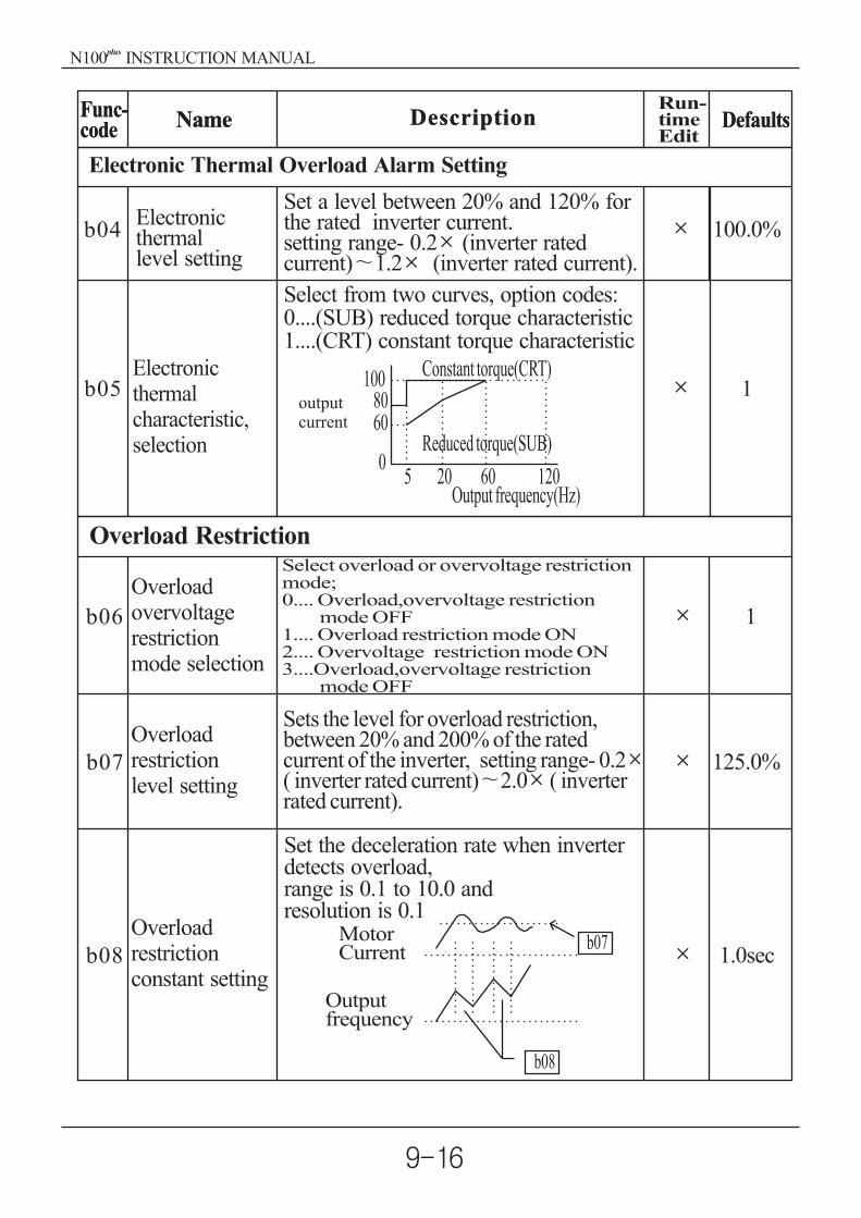
Overload Restriction
b06
b07
b08
1
125.0%
1.0sec
Overloadrestrictionlevel setting
Overloadrestrictionconstant setting
Overloadovervoltagerestrictionmode selection
Select overload or overvoltage restrictionmode;0.... O
1....2....
verload,overvoltage restrictionmode OFFOverload restriction mode ONOvervoltage restriction mode ON
3....Overload,overvoltage restrictionmode OFF
Sets the level for overload restriction,between 20% and 200% of the ratedcurrent of the inverter, setting range- 0.2( inverter rated current) 2.0 ( inverterrated current).
Set the deceleration rate when inverterdetects overload,range is 0.1 to 10.0 andresolution is 0.1
b07
b08
MotorCurrent
Outputfrequency
b04
b05
100.0%
1Electronicthermalcharacteristic,selection
Electronicthermallevel setting
Set a level between 20% and 120% forthe rated inverter current.setting range- 0.2 (inverter ratedcurrent) 1.2 (inverter rated current).
Electronic Thermal Overload Alarm Setting
Select from two curves, option codes:0....(SUB) reduced torque characteristic1....(CRT) constant torque characteristic
1008060
05 20 60 120
Constant torque(CRT)
Reduced torque(SUB)
Output frequency(Hz)
outputcurrent
Func-code Name Description Defaults
Run-timeEdit
Func-code Name Description Defaults
N100 INSTRUCTION MANUALplus

Other Function
b10
b14
b13
b11
b15
b12
b16
0.50Hz
1.00
5.0kHz
0
0
0
Carrier frequ-ency setting
STOP keyvalidity duringterminal operation
Initializationmode(parametersor trip history)
Resume onFRS cancel-lation mode
Start frequencyadjustment
Frequency scalarconversion factor
Country codefor initalization
Sets the starting frequency for the inverteroutput, range is 0.50 to 10.00Hz in unitsof 0.01Hz
Specify a constant to scale the displayedfrequency for [d08] monitor, range is0.01 to 99.9 in units of 0.01
Sets the PWM carrier frequency, rangeis 0.5 to 16.0kHz in units of 0.1kHz.
Select whether the STOP key on the keypad is enabled, two option codes:0.... stop enabled1.... stop disabled
Select the type of initialization to occur,two option codes:0.... Trip history clear1.... Parameter initialization
Select how the inverter resumes opera-tion when the free-run stop (FRS) iscancelled, two options:0... Restart from 0Hz1.... Restart from frequency detected from
real speed of motor
Select default parameter values for cou-ntry on initialization, three options,option codes:0.... Korea version1.... Europe version2.... US version
0
o
b09 0Software lockmode selection
Software Lock Mode
Prevents parameter changes, in fouroptions, option codes:0.... All parameters except b09 are locked
when SFT from terminal is on1.... All parameters except b09 and out-
put frequency F01 are locked whenSFT from terminal is ON
2.... All parameters except b09 are locked3.... All parameters except b09 and output
frequency F01 setting are locked
b17Communicationnumber
Sets the communication number forcommunication, range is 1 to 32 1
Func-code Name Description Defaults
Run-timeEdit
Func-code Name Description Defaults
N100 INSTRUCTION MANUALplus
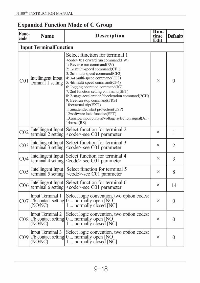
Input TerminalFunction
C01
C05
C04
C08
C02
C06
C03
C07
0
8
1
14
2
0
Intellingent Inputterminal 1 setting
Select function for terminal 1<code> 0: Forward run command(FW)1: Reverse run command(RV)2: 1 multi-speed command(CF1)3
st
: 2 multi-speed command(CF2)4: 3 multi-speed command(CF3)5: 4 multi-speed command(CF4)6: Jogging operation command(JG)7: 2nd function setting command(SET)8: 2-stage acceleration/deceleration command(2CH)9: free-run stop command(FRS)10:external trip(EXT)11:unattended start protection(USP)12:software lock function(SFT)13.analog input current/voltage selection signal(AT)14:reset(RS)
nd
rd
th
Select function for terminal 2<code>-see C01 parameter
Select function for terminal 3<code>-see C01 parameter
Select function for terminal 4<code>-see C01 parameter
Select function for terminal 5<code>-see C01 parameter
Select function for terminal 6<code>-see C01 parameter
Select logic convention, two option codes:0.... normally open [NO]1.... normally closed [NC]
Select logic convention, two option codes:0.... normally open [NO]1.... normally closed [NC]
Select logic convention, two option codes:0.... normally open [NO]1.... normally closed [NC]
3
0
Expanded Function Mode of C Group
Intellingent Inputterminal 2 setting
Intellingent Inputterminal 3 setting
Intellingent Inputterminal 4 setting
Intellingent Inputterminal 5 setting
Intellingent Inputterminal 6 setting
Input Terminal 1a/b contact setting(NO/NC)
Input Terminal 2a/b contact setting(NO/NC)
Input Terminal 3a/b contact setting(NO/NC)
C09 0
Func-code Name Description Defaults
Run-timeEdit
Func-code Name Description Defaults
N100 INSTRUCTION MANUALplus

C13
C17
C16
C14
C15
1
0
0
0
Intellingentoutputterminal 11setting
Select function for terminal 11<code>0... RUN(Run signal)1.... FA1(Frequency arrival signal:
command arrival)2.... FA2(Frequency arrival signal:
setting frequency or more)3.... OL(Overload advance notice
signal)4.... OD(Output deviation for PID
control)5.... AL(Alarm signal)
Select function for terminal 12, 6code.
Select function for terminal FM,3 options0.... output frequency monitor1.... output current monitor2.... output voltage monitor
Select logic convention, two optioncodes:0.... normally open [NO]1.... normally closed [NC]
Select logic convention, two optioncodes:0.... normally open [NO]1.... normally closed [NC]
0
Output Terminal Function
Intellingentoutput terminal12 setting
Montor signalselection
Output Terminal 11a/b contact setting
Output Terminal 12a/b contact setting
Select logic convention, two option codes:0.... normally open [NO]1.... normally closed [NC]
Select logic convention, two option codes:0.... normally open [NO]1.... normally closed [NC]
Select logic convention, two option codes:0.... normally open [NO]1.... normally closed [NC]
Input Terminal 4a/b contact setting(NO/NC)
Input Terminal 5a/b contact setting(NO/NC)
Input Terminal 6a/b contact setting(NO/NC)
C10
C11
C12
0
0
0
Func-code Name Description Defaults
Run-timeEdit
Func-code Name Description Defaults
N100 INSTRUCTION MANUALplus

C18
C19
C20
C21
C22
C23
100.0%
0.0%
100%
0.00Hz
10.0%
Range is 0(45%) to 250(220%),resolution is 1
Range is -3.0 to 10.0%resolution is 0.1
Sets the frequency arrival setting thres-hold for the output frequency duringdeceleration, setting range is 0.00 to400.0Hz resolution is 0.01Hz
Output Terminal state setting
Output Terminal related function
Analog metergain adjustment
Analog meteroffset adjustment
Overloadadvancenotice signallevel setting
Accelerationarrival signalfrequencysetting
Decelerationarrival signalfrequencysetting
PID deviationlevel setting
Sets the overload signal level between50% and 200% resolution is 0.1%.0.5x(Inverter rated current) 2.0x(Inverter rated current)
C20Motor current
Over loadsignal output
Sets the frequency arrival setting thres-hold for the output frequency duringacceleration.Setting range is 0.0 to A04, resolution is0.01Hz output
frequency
freguencyArrival signal
C21C22
Sets the allowable PID loop error mag-nitude. Setting range is 0.0 to 100%,resolution is 0.01%
Feedback valueTarget value
C23PID contrnl
Deviationsignal
0.00Hz
Func-code Name Description Defaults
Run-timeEdit
Func-code Name Description Defaults
N100 INSTRUCTION MANUALplus

S01
2nd control,Multi-speedfrequencysetting
Range is 0.0 to 400Hz in units of 0.01Hz(It is enabled by the frequency demanding inthe standard operator)
0speed:60.00Hz
S02
S03
2nd control ,Accelerationtime
2nd control,Decelerationtime
Range is 0.1 3,000secminimum setting unit
0.1 999.9 ----- by 0.1sec1000 3000 ----- by1sec
Range is 0.1 3,000secmininmum setting unit
0.1 999.9 ----- by 0.1sec1000 3000 ----- by 1sec
10.0sec
10.0sec
S04Range is 0 to SO5 (second control maximumfrequency) in units of 0.1Hz
60.00Hz
S05
2nd control,Basefrequency
2nd control,manual torqueboost setting
2nd control,V/fcharacteristiccurve selection
2nd control,manual torqueboost frequencyadjustment
2nd control,maximumfrequency
Range is S04( )to 400.00Hz in units of 0.1Hz.
second control base frequency 60.00Hz
S062nd control,torque boostmode selection
Twoselections,optioncodes:0---manual torqueboost1---automatictorqueboost
0
S07
Set the manual torque boost voltage. Adjustthe motor torque by boosting the output voltageabove the normal V/F ratio. Be aware thatexcessive torque boost can cause motor damageand inverter trip.
5.0%
S08The boost is applied from 0 to 50% the basefrequency.
10.0%
S09 0
set the V/F characteristics0 --- constant torque1 --- reduced torpue
(the 1.7th power)2 --- sensorless vector control
V100%
constant torquereducedtorpue
0
Func-code Name Description Defaults
Run-timeEdit
Func-code Name Description
Expanded function mode of S group
N100 INSTRUCTION MANUALplus

S10
2nd control,
acceleration
time 2 setting
2nd control,
acceleration
pattem setting
Range is 0.1 to 999.9sec in units of 0.1sec,
1000 3000sec in units of 1 sec. Secondacceleration can be set by the [2CH] terminalinput or frequency transition setting
Range is 0.1 to 999.9sec in units of 0.1sec,
1000 3000sec in units of 1 sec. Secondacceleration can be set by the [2CH] terminalinput or frequency transition setting
10.00sec
S11
S14
2nd control,decelerationtime 2 setting
2nd control,decelerationpattem setting
2nd control,
2-stage
Accel./decel.
transition
method setting
10.00sec
S15
Output frequency at which Acc1 switches to
Acc2, range is 0.0 to 400.0Hz in units of
0.01Hz
Output frequency at which Dcc1 switches to
Dcc2, range is 0.0 to 400.0Hz in units of
0.01Hz
Set a level between 20% to 120% for the ratedinverter currentsetting range : 0.2*(inverter ratedcurrent)
1.2*( )inverter ratedcurrent
0.00Hz
0.00Hz
100.0%
S16
2nd control,accelerationtransitionfrequency setting
2nd control,decelerationtransitionfrequencysetting
2nd control,electronicthermal levelsetting
S17
Set the characteristic curve of Acc 1 andAcc2, three options.0:linear, 1:S-curve, 2:U-curve
S12
S13
0
Set the characteristic curve of Dec 1 andDec2, three options.0:linear, 1:S-curve, 2:U-curve
0
Func-code Name Description Defaults
Run-timeEdit
Func-code Name Description Defaults
0 --terminal(2CH), 1 -- transition frequency
frequencyAcc1 Acc2
time2CH
0
N100 INSTRUCTION MANUALplus

0 9(0 4 : 004LF 037LF,5 9 : 004HF 037HF )
S20
S21
2nd control, motorcapacity selection
2nd control, motorpoles selection
2nd control, motorrated currentselection
2nd control, motorconstant R1
2nd control, motorconstant R2
2nd control, motorconstant L
2nd motor controlleakage factor
4
S23
S24
S25
S26
S27
setting range: 0.001 -30.00
setting range: 0.001 -20.00
setting range: 0.1 -999.9mH
setting range: 0.01 -100.0mH
setting range: 0.1 -100.0A2nd motorconstant IO
2/4/6/8
S22The setting depend on the motorcapacity
-
-
-
-
-
-
-
Considering on the overload, the electronic
thermal protects against the motor from
overheating
0 ---- SUB, 1 ---- CRT
2nd control,Electronicthermalcharacteristicsetting
S18
S19
2nd controlmotorconstantsetting
0 : standard motor constants
1 : auto tune data0
1
Func-code Name Description DefaultsFunc-code Name Description
Run-timeEdit
N100 INSTRUCTION MANUALplus

S28
S29
S30
S31
S32
setting range 0.001 -30.00
setting range 0.001 -20.00
setting range 0.1 -999.9mH
setting range 0.01 -100.0mH
setting range 0.1 -100.0A
2nd motorconstant R1auto-tuning data
2nd motorconstant R2auto-tuning data
2nd motorconstant Lauto-tuning data
2nd motor constantleakage factorauto-tuning data
2nd motorconstant IOauto-tuning data
-
-
-
-
-
Func-code Name Description DefaultsFunc-code Name Description Defaults
Run-timeEdit
N100 INSTRUCTION MANUALplus
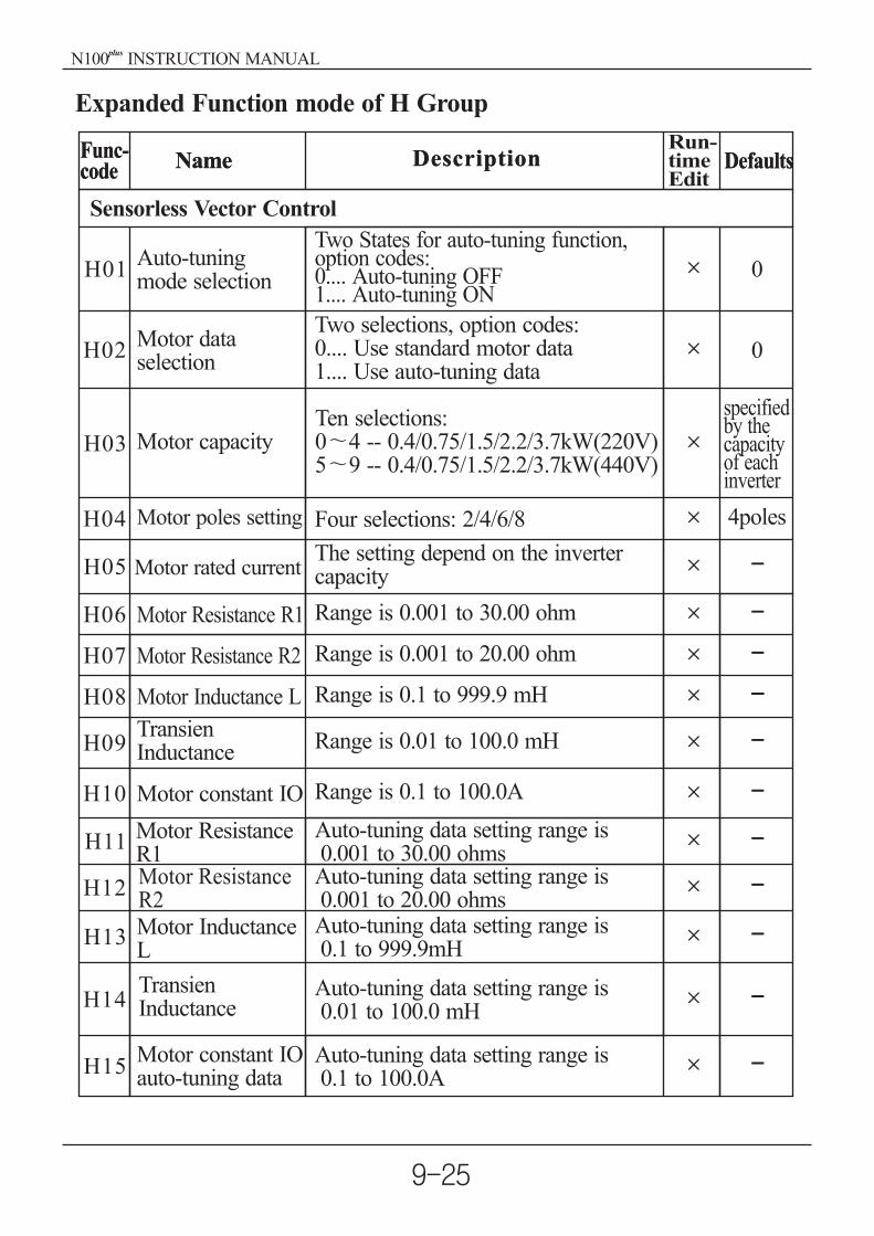
H01
H02
H03
H04
H05
H06
H07
H08
H12
H09
H13
H10
H14
H11
H15
0
0
specifiedby thecapacityof eachinverter
4poles
Two States for auto-tuning function,option codes:0.... Auto-tuning OFF1.... Auto-tuning ON
Two selections, option codes:0.... Use standard motor data1.... Use auto-tuning data
Range is 0.1 to 100.0A
Auto-tuning data setting range is0.001 to 30.00 ohmsAuto-tuning data setting range is0.001 to 20.00 ohmsAuto-tuning data setting range is0.1 to 999.9mH
Auto-tuning data setting range is0.01 to 100.0 mH
Auto-tuning data setting range is0.1 to 100.0A
Sensorless Vector Control
Auto-tuningmode selection
Motor dataselection
Motor capacity
Motor poles setting
Motor rated current
Motor Resistance R1
Motor R2Resistance
Motor Inductance L
MotorR2
Resistance
Motor InductanceL
Motor constant IO
Motor ResistanceR1
Motor constant IOauto-tuning data
TransienInductance
TransienInductance
Ten selections:0 4 -- 0.4/0.75/1.5/2.2/3.7kW(220V)5 9 -- 0.4/0.75/1.5/2.2/3.7kW(440V)
Four selections: 2/4/6/8
The setting depend on the invertercapacity
Range is 0.001 to 30.00 ohm
Range is 0.001 to 20.00 ohm
Range is 0.1 to 999.9 mH
Range is 0.01 to 100.0 mH
Expanded Function mode of H Group
-
-
-
--
-
-
-
-
-
-
-
Func-code Name Description DefaultsFunc-code Name Description Defaults
Run-timeEdit
N100 INSTRUCTION MANUALplus

10. Protective function
The various functions are provided for the protection of the inverter itself, butthey may also protection function when the inverter breaks down.
Overcurrentprotection
Overload protection(Electronic thermal)Regenerative
Over voltageprotection
Communicationerror
Under-voltageprotection
Outputshort-circuit
USP error
Name Cause(s) ErrorCode
When the inverter output current exceeds the ratedcurrent by more than approximately 200% duringthe motor locked or reduced in speed. Protectioncircuit activates, halting inverter output.
When the inverter output current causes the motorto overload, the electronic thermal trip in theinverter cuts off the inverter output.
If regenerative energy from the motor or the mainpower supply voltage is high, the protective circuitactivates to cut off the inverter output when thevoltage of DC link exceeds the specification
The inverter output is cut off when communicationin the inverter has an error to external noise,excessive temperature rise, or other factor
When the input voltage receives by the inverterdecreases, the control circuit does not functionnormally. When the input voltage is below the spe-cification, the inverter output is cut off.
The inverter output was short-circuited. This con-dition causes excessive current for the inverter, sothe inverter output is turned off.
The USP error is indicated when the power isturned on with the inverter in RUN state. (Enabledwhen the USP function selected)
The inverter output is cut off when EEPROM inthe inverter has an error due to external noise, exc-essive temperature rise, or other factor
When the external equipment or unit has an error,the inverter receives the corresponding signal andcuts off the output.
Ground fault is detected between the inverter out-put section and the motor when the power is turnedon, to protect the inverter.
When the temperature in the main circuit increasesdue to cooling fan stop, the inverter output is cutoff.(only for the model type with cooling fan)
E04
E05
E07
E60
E34
E13
E08
E12
E14
E21
E09
EEPROM error
External trip
Ground faultprotection
Temperature trip
N100 INSTRUCTION MANUALplus

Other display
Contents
It is displayed when initialization of data is processing
(It is not displayed when initialization of history is
processing.)
It is displayed when Copy function is operated by the remote
operator.
There is no data available
(Trip history, PID feedback data)
Display
The auto-tuning operation terminates normally.
copy
N100 INSTRUCTION MANUALplus

11. Troubleshooting Tips
Themotorwill
not run.
The inverteroutputs U,Vand W arenot supplyingvoltage.
Inverteroutputs U,V,W are supply-ing voltage.
Symptom/condition Probable Cause Countermeasure
Is the frequency commandsource A01 parameter settingcorrect?Is the Run command sourceA02 parameter settingcorrect?
Is power being supplied toterminals R, S and T ? Ifso, the power lamp shouldbe on.
Is there an error codedisplayed?E
Make sure the parameterA01setting correct?Make sure the parameterA02setting correct?
Check terminals R, S andT then U, V, and WTurn on the power supplyor check fuses.
Are the signals to the intelli-gent input terminals correct?Is the Run Command active?Is the[FW] terminal (or [RV]connected to CM1(via switch,etc.)
Has the frequency settingfor F01 been set greater thanzero?Are the control circuit term-inals H, O, and L connectedto the potentiometer?
Is the motor load too heavy?Is the motor locked?
Reduce load, and test themotor independently.
Is the RS(reset) functionor FRS(free-run stop)function on?
Turn off the command(s)
Set the parameter for F01to a safe, non-zero value.If the potentiometer is thefrequency setting surce,verify voltage at"O" 0V
Verify the terminal functionsfor C01-C06 are correct.Turn on Run CommandSupply 24V to [FW] or [RV]terminal, if configured.(Terminal mode selection)
Press the Func key anddetermine the error type.Then clear the error(Reset).
N100 INSTRUCTION MANUALplus
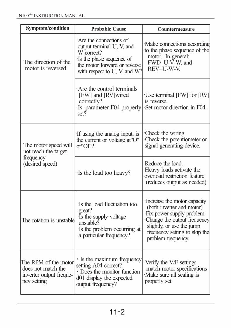
Symptom/condition
The motor speed willnot reach the targetfrequency(desired speed)
The rotation is unstable
The RPM of the motordoes not match theinverter output freque-ncy setting
Probable Cause Countermeasure
If using the analog input, isthe current or voltage at"O"or"OI"?
Check the wiringCheck the potentiometer orsignal generating device.
Reduce the load.Heavy loads activate theoverload restriction feature(reduces output as needed)
Increase the motor capacity(both inverter and motor)Fix power supply problem.Change the output frequencyslightly, or use the jumpfrequency setting to skip theproblem frequency.
Verify the V/F settingsmatch motor specificationsMake sure all scaling isproperly set
Is the load too heavy?
Is the load fluctuation toogreat?Is the supply voltageunstable?Is the problem occurring ata particular frequency?
Is the maximum frequencysetting A04 correct?
Does the monitor functiond01 display the expectedoutput frequency?
The direction of themotor is reversed
Are the connections ofoutput terminal U, V, andW correct?Is the phase sequence ofthe motor forward or reversewith respect to U, V, and W?
Are the control terminals[FW] and [RV]wiredcorrectly?Is parameter F04 properlyset?
Use terminal [FW] for [RV]is reverse.Set motor direction in F04.
Make connections accordingto the phase sequence of themotor. In general:FWD=U-V-W, andREV=U-W-V.
N100 INSTRUCTION MANUALplus

Symptom/condition Probable Cause Countermeasure
Inverterdata isnotcorrect
A param-eter willnot changeafter anedit (reve-rts to oldsetting)
The frequencysetting will notchange.Run/Stopdoes notoperate.
No downloadshave occurred.
True forcertainparameters
True for allparameters
Edit the data and press thestore key once
Wait six seconds or morebefore turning power offafter editing data.
Make sure the setting modeof [A01], [A02] is changed
Put inverter in stop mode(press the stop/reset key)Then edit the parameter.
Change the state of the SFTinput, and check the b09parameter (b09=0)Turn the switch off
Was power turned off aftera parameter edit but beforepressing the store key?
Edits to data are permanentlystored at power down. Wasthe time from power off topower on less than sixseconds?
Was the standard operatormode and terminal modechanged correctly?
Is the inverter in run mode?some parameters cannot beedited during run mode
If you're using the[SET]intelligent input selection[b09] is the [SFT]Is switch 4(located on theback of the remote operatorcopy unit) on?
Precautions for data setting
When changing any set data and pressing key to store the data, keep theequipment un-operated for 6 seconds or more after the selected method isexecuted. When any key is pressed, or the reset operation is performed, or thepower is turned off within 6 seconds, correct data may not be set.
STR
N100 INSTRUCTION MANUALplus

Wait at least five(5) minutes after turning off the input power supply before
performing maintenance of an inspection. Otherwise, there is the danger of
electric shock.
Make sure that only qualified personnel will perform maintenance, inspec-
tion, and part replacement. (Before starting to work, remove any metallic
objects from your person(wristwatch, bracelet, etc.)) Be sure to use tools with
insulated handles. Otherwise, there is a danger of electric shock and/or injury
to personnel.
12.1 General Precautions and Notes
Always keep the unit clean so that dust of other foreign matter does not
enter the inverter.
Take special care in regard to breaking wires of making connection
mistakes.
Firmly connect terminals and connectors.
Keep electronic equipment away from moisture and oil. Dust, steel filings
and other foreign matter can damage insulation, causing unexpected accid-
ents, so take special care.
When removing connectors, never pull the wires(wires for the cooling fan
and logic P.C. board.) Otherwise, there is danger of fire due to wire brea-
kage and/or injury to personnel.
12. Maintenance and Inspection
Please read following safety messages before troubleshooting or performingmaintenance on the inverter and motor system.
DANGER
N100 INSTRUCTION MANUALplus

R S T P RB U WV
Megar
12.2 Inspection Items
This chapter provides instructions or checklists for these inspection items:
Daily inspection
Periodic inspection(approximately once a year)
Insulation resistance test(approximately once two years)
Conduct the insulation resistance test by short circuiting the terminals as
shown below.
Spare parts
We recommend that you stock spare parts to reduce down time, which include:
Part description SymbolQuanity
Used SpareNote
Cooling fan
Case
FAN 1
1
1
1
015SF015LF 037LF007HF 037HF
Front caseCaseBottom cover
Never test the withstand voltage on the inverter. The inverter has a surge
protector between the main circuit terminals and the chassis ground.
N100 INSTRUCTION MANUALplus

Monthly and Yearly Inspection ChartO
ver
all
Terminal block
MonthYear
Thermometer,hygrometer
Item InspectedInspectionCyelc Inspection
Method
Mai
nci
rcuit
Controlcircuit
Display
Extremetemperatures& humidityAbnormalvibrationnoise
Check for...
Ambientenvironment
Major devices
Power supplyinsulation
Mounting
GroundInsulation
Components
Housing
Smoothingcapacitor
Relay(s)
Resistors
Cooling fan
Overall
Capacitor
LEDs
Voltagetolerance
Adequateresistance
No loosescrews
Overheating
Dirt, dust
Secureconnections
Leakingswelling
Chattering
Cracks ordiscoloring
Noise
Dust
No odor,discoloringcorrosionNo leaks ordeformation
Legibility
Visual and aural
Digital volt meter,measure betweeninverter terminalsR, S, T
Digital volt meter,GND to terminals
Torque wrench
Thermal trip events
Visual
Visual
Visual
Visual
Visual
Visual
Visual
Aural
Power down,manually rotate
Criteria
Ambient temperaturebetween -10 to 40 ,non-condensing
Stable environment forelectronic controls
200V class:200 to 230V 50/60Hz400V class:380 to 460V 50/60Hz500V class Megohmmeter
M3: 0.5 0.6NmM4:M5: 1
0.98 1.3Nm.5. 2.0Nm
No abnormalities
No trip events
Vacuum dust and dirt
No abnormalities
No abnormalities
Undistorted appearance
Single click whenswitching On or Off
Use Ohm meter to checkbraking resistors
Rotation must be smooth
Vacuum to clean
All LED segments work
Note1:Note2:
The life of a capacitor is affected by the ambient temperature,The inverter must be cleaned periodically. If dust accumulates on the fanand heat sink, it can cause overheating of the inverter.
N100 INSTRUCTION MANUALplus
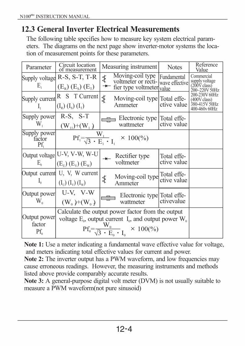
R-S, S-T, T-R
(E ) (E ) (E )R S T
U-V, V-W, W-U
(E ) (E ) (E )U V W
R S T Current
(I ) (I ) (I )R S T
U, V, W current
(I ) (I ) (I )U V W
R-S, S-T
(W )+(W )11 1 2
U-V, V-W
(W )+(W )0 1 0 2
Commercialsupplyvoltage(200Vclass)200~220V50Hz200-230V60Hz(400Vclass)380-415V50Hz400-460v60Hz
Pf = 100(%)0 3 E I0 0
W0
Pf = 100(%)1 3 E I1 1
W1
12.3 General Inverter Electrical MeasurementsThe following table specifies how to measure key system electrical param-eters. The diagrams on the next page show inverter-motor systems the loca-tion of measurement points for these parameters.
Parameter Circuit locationof measurement Measuring instrument Notes Reference
ValueMoving-coil typevoltmeter or recti-fier type voltmeter
Rectifier typevoltmeter
Moving-coil typeAmmeter
Moving-coil typeAmmeter
Electronic typewattmeter
Electronic typewattmeter
Calculate the output power factor from the outputvoltage , output current , and output powerE I W0 0 0
Supply voltageE1
Output voltageE0
Supply currentI1
OutputI0
current
Supply powerW1
OutputW0
power
Supply powerfactor
Pf1
Output
Pf0
powerfactor
Fundamentalwave effectivevalue
Total effe-ctive value
Total effe-ctive value
Total effe-ctive value
Total effe-ctive value
Total effe-ctivevalue
Note 1:
Note 2:
Use a meter indicating a fundamental wave effective value for voltage,and meters indicating total effective values for current and power.
The inverter output has a PWM waveform, and low frequencies maycause erroneous readings. However, the measuring instruments and methodslisted above provide comparably accurate results.Note 3: A general-purpose digital volt meter (DVM) is not usually suitable tomeasure a PWM waveform(not pure sinusoid)
N100 INSTRUCTION MANUALplus

R IR
ER W11
IU
W11
R U
V
W
S
T
W12
IW
IV
W12
ET
ES
IS
IT
S
T
EW-U
EV-W
EU-V
U
V
W
Motor
INVERTER
PowerSupply
The figures below show measurement locations for voltage, current, and powermeasurements listed in the table on the previous page. The voltage to bemeasured is the fundamental wave effective voltage. The power to be measuredis the total effective power.
Three-phase measurement diagram
N100 INSTRUCTION MANUALplus

13.1 Dynamic Braking Resistor Table
1
1
2
2
3
3
Motorcapacity(kW)
Motorcapacity(kW)
200V class
200V class
400V class
400V class
R(resistorvalue)
R(resistorvalue)
R(resistorvalue)
R(resistorvalue)
WATTAGE
WATTAGE
WATTAGE
WATTAGE
1.5 KW
2.2 KW
3.7 KW
1.5 KW
2.2 KW
3.7 KW
50 ohm
50 ohm
35 ohm
50 ohm
35 ohm
35 ohm
0.2 KW
0.3 KW
0.6 KW
0.3 KW
0.6 KW
1.2 KW
180 ohm
100 ohm
100 ohm
180 ohm
100 ohm
100 ohm
0.3 KW
0.3 KW
0.6 KW
0.3 KW
0.6 KW
0.6 KW
13. Option
For the running motor
For the up/down motor
N100 INSTRUCTION MANUALplus

13.2 Remote operator (NOP 100)
Using remote operator specified cable, remote operator controls the inverter
parameter setting and run command.
Because NOP100 contains READ/COPY function, it can be possible to
transmit and store the data of inverter, which is set in advance.
Specification
Item Description
Model Name
External Dimension
Keypad
Communication Method
Function
Connection Cable
NOP 100
135mm(H) 75mm(L) 19mm(D)
LCD
LEDDisplay
2Line 16Characteristic
Forward Run, Reverse Run, Mode change display
12 Key (UP/DOWN method)
RS485 (Modular connect method)
Abnormal status store count: 6 times
Built-in READ/COPY function
1.5 , 3mm
N100 INSTRUCTION MANUALplus

REMOTE OPERATOR
75
13
5
READREMT COPY
FUNCMON STR
FWD REV STOP
N100 INSTRUCTION MANUALplus
NOP
External DiagramUnit : mm
Remote Operator(NOP100 )plus

13.3 Input-side and Output-side AC reactorE
xte
rnal
Dia
gra
mC
on
nec
tion
Dia
gra
m
N100 INSTRUCTION MANUALplus

This is useful when harmonic suppression measures must be taken, when the
main power voltage Unbalance rate exceeds 3% and the main power capacity
exceeds 500KVA, or when a sudden power voltage variation occurs, It also
helps to improve the power factor.
ACL L I - 2.5
L:3- phase 200V
H:3- phase 400V
ACL L I - 2.5
L:3- phase 200V
H:3- phase 400V Input-sideInput-side
Inverter output capacity (KVA)Inverter output capacity (KVA)
Input - side AC reactor
Vibration may increase when driving a general purpose motor with an inverteras compared with commercial power operation. Connecting this reactor betweenthe inverter and the motor allows reduction of motor pulsation. When the cablebetween the inverter and the motor is 10m or more inserting the reactor preventsthermal relay malfunction caused by harmonics resulting from inverter switching.A current sensor can be used instead of the thermal relay.
Output-side reactor
ACL L - 2.5
L:3- phase 200V
H:3- phase 400V
Inverter output capacity (KVA)
ACL L - 2.5
L:3- phase 200V
H:3- phase 400V
Inverter output capacity (KVA)
N100 INSTRUCTION MANUALplus
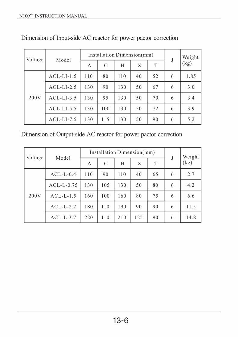
Voltage
Voltage
200V
Model
Model
Installation Dimension(mm)
Installation Dimension(mm)
JWeight(kg)
Weight(kg)
ACL-LI-1.5
ACL-LI-2.5
ACL-LI-3.5
ACL-LI-5.5
ACL-LI-7.5
110
130
130
130
130
80
90 130 50 3.0
3.4
3.9
5.2
95 130 50
100 130 50
115 130 50
110 40 6
6
6
6
6
1.85
A C H X T
67
70
72
90
52
200V
J
ACL-L-0.4
ACL-L-0.75
ACL-L-1.5
ACL-L-2.2
ACL-L-3.7
110
130
160
180
220
90
105 130 50 4.2
6.6
11.5
14.8
100 160 80
110 190 90
110 210 125
110 40 6
6
6
6
6
2.7
A C H X T
80
75
90
90
65
Dimension of Input-side AC reactor for power pactor correction
Dimension of Output-side AC reactor for power pactor correction
N100 INSTRUCTION MANUALplus

In ve rte rNo is e Filte r
P o we r S up p ly MC CB Mo to r
As S ho rt a s
p o s s ib le
L1
L2
L3
M
R
S
T
U
V
W
PE
Line
L1
L2
L3
PE
Loa d
L1
L2
L3
M
R
S
T
U
V
W
PE
Line
L1
L2
L3
PE
Loa d
200V
400V
P3B2020-HD
P3B4012-HD
20A
12A
250V
450V
210 140 45
210 140 45
Connection of the noise filter
Outlook of the noise filter
Specification of the noise filter
Class (W H D)External DimensionRated VoltageRated CurrentModel
13.4 Noise filter
Install a noise filter as shown in figure below. The noise filter must be installedas close as possible to the inverter and its wiring distance minimized. In addition,the primary and secondary wirings of the noise filter must not be close to eachother or cross each other
Reduces the conductive noise on the main power wires generated from the mainpower supply. Connect to the inverter primary side (input side).
N100 INSTRUCTION MANUALplus

The communication between inverter and external controller is doing by
RS485 using modular connector in cling to inverter controller.
14. RS485 Communication
Functioncode
Minimum MaximumInitialValue
Unit Description
b 17
A 01
A 02
1
0
0
32
3
2
1
0
0
-
-
-
Setting the communication number
3: Communication
2: Digital operator
Item
Interface
Communication method
Communication speed
Communication code
Data bits
Parity
Stop bit
Starting method
Wait time
Connection type
Error check
RS485
Half duplex
9600
Binary code
8
No.
1
External request
10 1000ms
1 : N (Max32)
Frame / CRC / CMD /
MAXREQ / parameter
Fixing
Inverter is only slave part.
Communication number is
selected at b17
Fixing
Fixing
Fixing
Description Remark
- Relation code -
- Communication formula -
N100 INSTRUCTION MANUALplus

1 2 3 4 5 6 7 8
RS485 port specification
Pin number Description
1
2
3
4
5
6
7
8
Transmit/Receive side+
Transmit/Receive-side
24V
24V GND
Communication sequence
The communication sequence is as follows:
Frame start : Frame start is recognized by signal line data transmitted.
Frame completion : Frame completion is recognized by no data during
correspond 4, 5-character time.
Frame 1: Transmit from external controller to inverter.
Frame 2: Indication reflects from inverter to external controller.
Externalcontroller
Inverter
wait time
Frame 2
Frame 1
N100 INSTRUCTION MANUALplus

Communication frame type and form
External controller transmit frame
Inverter response frame
Communicationnumber
Communicationnumber
Command
Parameter
Parameternumber
CRC Hi
Number Command Parameter Parameter Count CRC Hi CRC Lo
CRC Lo
Description
Description
Data size Specifications
Specifications
InverterCommunicationnumber
Frame type
Parameter
Request parameternumber
1 byte
1 byte
1 byte Higher 8bit of 16bit CRC
Higher 8bit of 16bit CRC
Lower 8bit of 16bit CRC
Lower 8bit of 16bit CRC
1 byte
2 byte
2 byte
1 32
0 06
1 byte : Group
2 byte : Index
st
nd
1 byte : 0 00
2 byte : N(0 01 0 08)
st
nd
-
-
CRC HiData N CRC LoCommunication
numberOrder
Bytenumber
Data 1
1 byte
1 byte
1 byte
1 byte
1 byte
2 byte
2 byte
1 32
0 06
-
-
CRC Hi
Data N
CRC Lo
Command
Byte Number
Data 1
Data size
InverterCommunicationnumber
Frame type
Data Byte number
Parameter 1
Parameter N
Request parameter number 2
Parameter value
Nth parameter value
Frame Size = 5+Request parameter number 2
N100 INSTRUCTION MANUALplus

External transmit frame
Inverter response frame
Communicationnumber
Communication number
Command
Parameter
Data
CRC Hi
Order Parameter Data CRC Hi CRC Lo
CRC Lo
Description Data size Specifications
Target InverterCommunicationnumber
Frame type
Parameter
Data
1 byte
1 byte
1 byte Higher 8bit of 16bit CRC
Lower 8bit of 16bit CRC1 byte
2 byte
2 byte
1 32
0 03
1 byte : Group
2 byte : Index (Note1)
st
nd
Setting value(Note 2)
-
-
Communication number Order Parameter Data CRC Hi CRC Lo
Communicationnumber
Command
Parameter
Data
CRC Hi
CRC Lo
Description Data size Specifications
Target InverterCommunicationnumber
Frame type
Parameter
Data
1 byte
1 byte
1 byte Higher 8bit of 16bit CRC
Lower 8bit of 16bit CRC1 byte
2 byte
2 byte
1 32
0 03
1 byte : Group
2 byte : Index (Note1)
st
nd
Setting value is response(Note 4)
-
-
N100 INSTRUCTION MANUALplus

(Note1) Parameter setting
Basic parameter
1 byte : Each group is setting.
2 byte : Parameter number setting.
Ex) The case of A60 parameter reading or writing
st
nd
1 byte : 0 03
2 byte : 0 3C
Trip information
Trip information is 4 parameter.(output frequency, output current, DC link
voltage at trip occurs)
Trip information items
st
nd
Group Group
d C
F S
A H
d
1 bytest
1 tripst
2 bytend
2 tripnd
0 01 0 05
0 02 0 06
0 03 0 07
0 04
Tripinformation
Previousfirst trip
Previoussecond trip
Previousthird trip
Trip count
0 01 0 01 0 01 0 01 0 01
0 0D 0 11 0 15 0 19 0 1D
Trip data
1
2
3
4
5
6
Trip data
7
8
9
10
11
12
Trip contents
Over current trip
Over voltage trip
Under voltage trip
Arm short trip
Reserved
Inverter over heat trip
Trip contents
Electric thermal trip
Outside trip
EEROM trouble
Communication trouble
USP trip
GF trip
N100 INSTRUCTION MANUALplus

(Note2) Data value setting
Data value is transmitted except decimal point.
Ex1) Output frequency
Ex2) acc/dec time
Note3) Special parameter
Run command
parameter
1 byte : 0 00
2 byte : 0 02
setting data
1 byte
2 byte
Bit0 : Forward command
Bit1 : Reverse command
Bit2 : Reset command
st
nd
st
nd
Parameter value Conversion hexadecimal
60.00Hz1 byte : 0 17
2 byte : 0 70
st
nd
Communication data
6000
Parameter value Conversion hexadecimal
10.00sec1 byte : 0 00
2 byte : 0 64
st
nd
Communication data
100
Bit7
Reserved
Bit6 Bit5 Bit4 Bit3 Bit2 Bit1 Bit0
Bit7
Reserved
Bit6 Bit5 Bit4 Bit3 Bit2 Bit1 Bit0
RST REV RWD
N100 INSTRUCTION MANUALplus

Frequency command
Parameter
1 byte : 0 00
2 byte : 0 04
setting data
output frequency *100
Ex) the case of output frequency command is 60.00Hz
Data 6000 transmit
1 byte : 0 17
2 byte : 0 70
The step of CRC generation is as follows:
1. All of 16-bit register is 1.0 ffff
2. The exclusive OR of 16-bit register and 8-bit register.
3. Shift right side 1bit 16-bit register
4. If the result of step 3 is 1, exclusive OR 16-bit register and 0xa001.
5. Execute 8 times step 3 and step 4.
6. Execute step 2 6 until data completion.
7. Exchange the step 6 result of higher 8bit and lower 8bit.
Ex)
The case of D01 output frequency reading.
st
nd
st
nd
16bit CRC generation
Byte 1 Byte 2 Byte 3 Byte 4 Byte 6 Byte 7
Commun-icationnumber
Command Parameter Parameter number
0 01 0 03 0 01 0 01 0 00 0 01
N100 INSTRUCTION MANUALplus
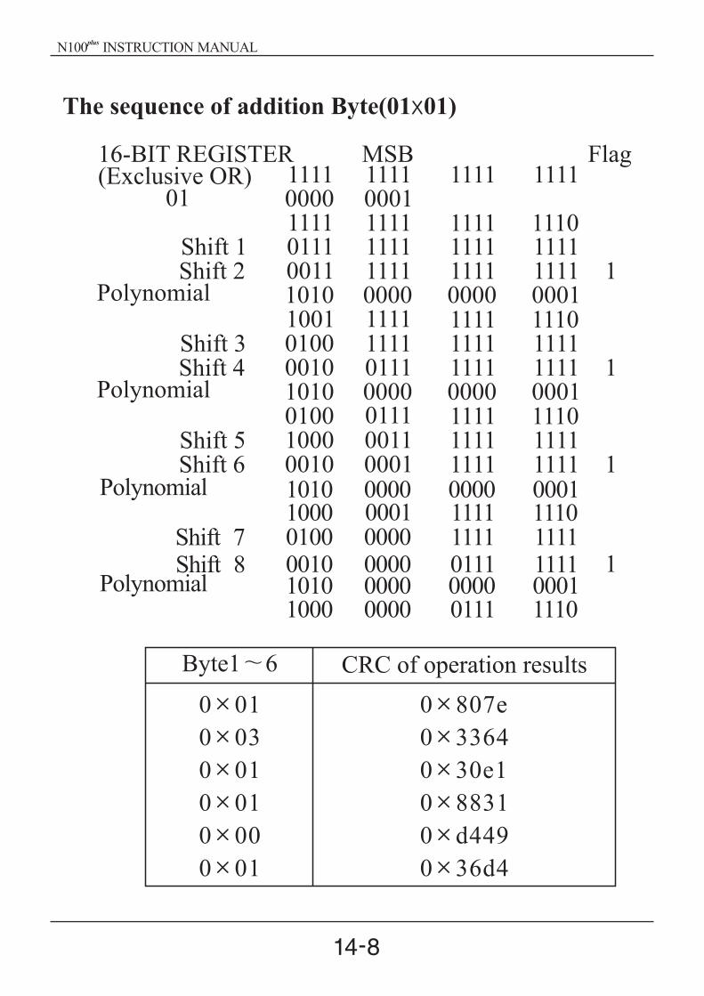
Byte1 6 CRC of operation results
0 01
0 03
0 01
0 01
0 00
0 01
0 807e
0 3364
0 30e1
0 8831
0 d449
0 36d4
Polynomial
Polynomial
Shift 7Shift 8
1010 0000 0000 00011000 0001 1111 11100100 0000 1111 11110010 0000 0111 1111 11010 0000 0000 00011000 0000 0111 1110
1111 1111 1111 11110000 00011111 1111 1111 11100111 1111 1111 11110011 1111 1111 1111 11010 0000 0000 00011001 1111 1111 11100100 1111 1111 11110010 0111 1111 1111 11010 0000 0000 0001
10000111 1111 111001000011 1111 1111
0010 0001 1111 1111 1
16-BIT
The sequence of addition Byte(01 01)
REGISTER MSB Flag(Exclusive OR)
01
Shift 1Shift 2
Polynomial
Shift 3Shift 4
Polynomial
Shift 5Shift 6
N100 INSTRUCTION MANUALplus
Related Documents