HYUNDAI-MAN B&W DIESEL ENGINE INSTRUCTION BOOK

Welcome message from author
This document is posted to help you gain knowledge. Please leave a comment to let me know what you think about it! Share it to your friends and learn new things together.
Transcript
HYUNDAI-MAN B&W DIESEL ENGINE INSTRUCTION BOOK
INSTRUCTIONS I-MAN B&W DIESEL E COMPONENTS NO. 1
(CODE BOOK)!
-"s ;-.. *'..
:*. '-- -
' \
This book must in no case be wholly or partially copied and published or passed to unauthorized persons without the permission of HYUNDAI HEAVY INDUSTRIES CO., LTD. ENGINE & MACHINERY DIVISION.
^'iite*'''
\ t e » ^
^0(^^.
Instructions for Main Engine
Type S50MC-C
This book forms part of a set of books consisting of three volumes entitled:
Vol. I OPERATION Vol.11 MAINTENANCE Vol. Ill COMPONENTS AND DESCRIPTIONS
The purpose of these books is to provide general guidance on operation and maintenance and to describe the constructional features of a standard version of the above engine type. Deviations may be found in a specific plant. In addition, the books can be used for reference purposes, for instance in correspondance and when ordering spare parts.
It is essential that the following data is stated in spare parts orders as it is used by us to ensure the supply of the correct parts for the individual engines:
1. Name of vessel 2. Engine No. built by 3. Plate No. 4. Part No. 5. Quantity required (and description)
Examble: M/S Nybo - 7730 B&W - 90201 - 00 - 059 10 off (piston ring)
Furthermore, to ensure optimum. efficiency, reliability and lifetime of the engine and its components, only original spare parts should be used.
The designation 'D' used in texts and illustrations refers to the information given on the data-''**^ sheets inserted in the respective books
As reliable and economical operation of the diesel engines is conditional on correct operation and maintenance, it is essential that the engine-room personnel is fully acquainted with the contents of this book.
This book is subject to copyright protection. The book must not, either wholly or partly, be copied, reproduced, made public or in any other way made available to a third party without the written consent of this effect from MAN B&W Diesel A/S.
HYUNDAI HEAVY INDUSTRIES CO., LTD ENGINE & MACHINERY DIVISION 1, Cheonha-Dong, Ulsan, Korea
Telephone: (052)230-7411 Telex: HHI EMD K53815.52191
Telefax:(052)230-7210
CONTENTS
A. EXPLANATION & CODE BOOK CYLINDER COVER PISTON WITH ROD AND STUFFING BOX CYLINDER LINER AND CYLINDER LUBRICATION CROSSHEAD WITH CONNECTING ROD CRANKSHAFT, THRUST BEARING AND TURNING GEAR MECHANICAL CONTROL GEAR STARTING AIR COMPONENTS EXHAUST VALVE FUEL OIL SYSTEM TURBOCHARGER SYSTEM SAFETY EQUIPMENT ASSEMBLY OF LARGE PARTS GENERAL TOOLS
B. OVERSEAS NETWORK

A. EXPLANATION & CODE BOOK

INDEX CYLINDER COVER 901 PISTON WITH ROD AND STUFFING BOX 902 CYLINDER LINER AND CYLINDER LUBRICATION 903 CROSSHEAD WITH CONNECTING ROD 904 CRANKSHAFT, THRUST BEARING AND TURNING GEAR 905 MECHANICAL CONTROL GEAR 906 STARTING AIR COMPONENTS 907 EXHAUST VALVE 908 FUEL OIL SYSTEM 909 TURBOCHARGER SYSTEM 910 SAFETY EQUIPMENT 911 ASSEMBLY OF LARGE PARTS 912

CYLINDER COVER
901

901.01-46
Cylinder Cover
General
The cylinder cover is made of steel and has a central bore for the exhaust valve, which is attached by means of four studs. The cover furthermore has bores for the fuel valves, which are mounted with tubular spacers and nuts. Other bores have been provided for starting valve, starting air inlet, safety valve and indicator cock.
A cooling jacket is mounted on the lower part of the cylinder cover, whereby a cooling water space is formed.
Another cooling water space is formed around the exhaust valve seat, when the exhaust valve is installed. These two spaces communicate through a large number of oblique/radial cooling bores in the cover.
The water is supplied from the cooling jacket surrounding the cylinder liner and passes through water transitions to the cooling jacket surrounding the cylinder cover and, further on, through the cooling bores, to the space around the exhaust valve seat.
From here the water is discharged to the main cooling water outlet pipe.
The cylinder cover is tightened against the top of the cylinder liner by means of nuts and long studs fitted in the cylinder frame. The nuts are tightened by means of hydraulic jacks.
Sealing between the cylinder cover and cylinder liner is obtained by means of a sealing ring, made of mild steel.
Xid*'
HYUNDAI
MAN B&W Cylinder Cover Plate 90101-104
S50MC-C
D-D E-O-F
'«*se#*^
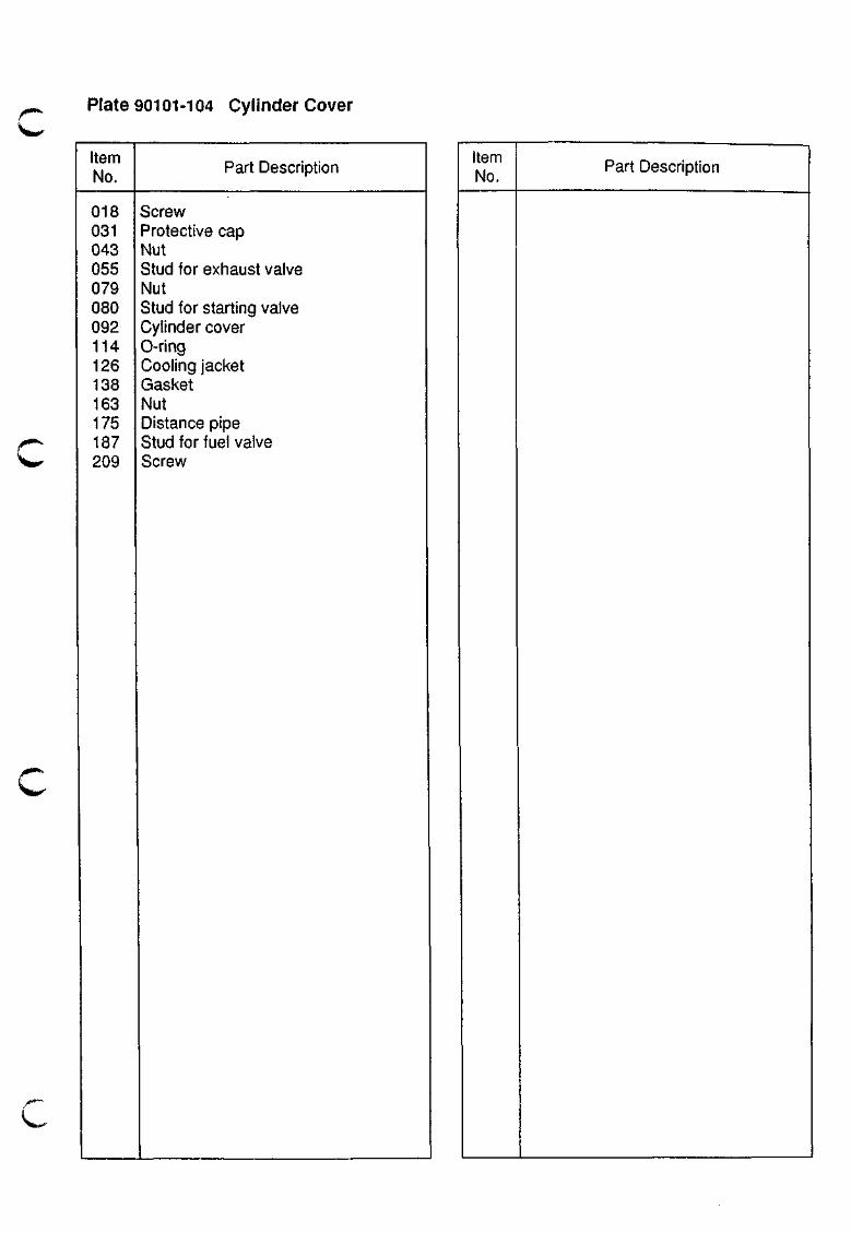
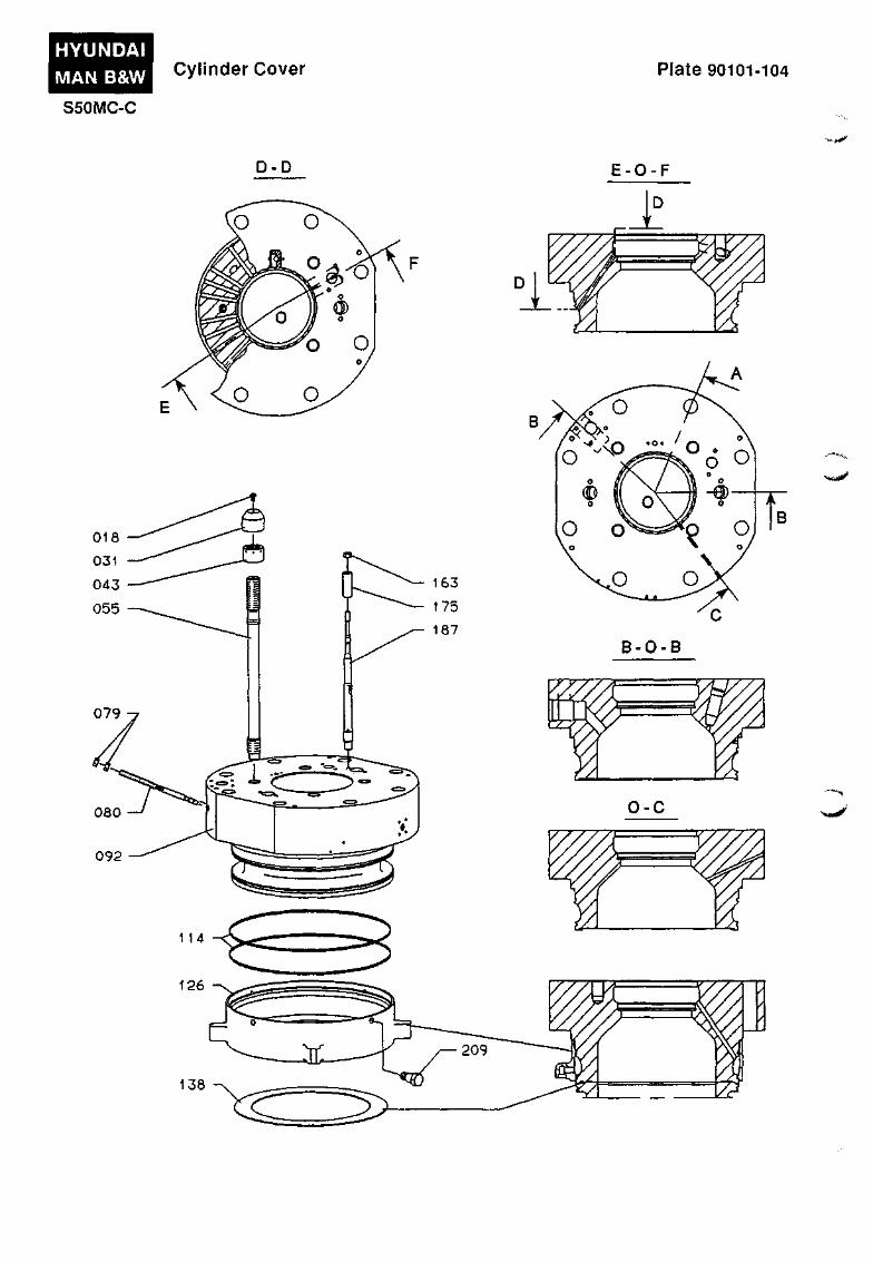
Plate 90101-104 Cylinder Cover
Item No.
018 031 043 055 079 080 092 114 126 138 163 175 187 209
Part Description
Screw Protective cap Nut Stud for exhaust valve Nut Stud for starting valve Cylinder cover 0-ring Cooling jacket Gasket Nut Distance pipe Stud for fuel valve Screw
Item No.
Part Description
Xteia^
PISTON WITH ROD AND STUFFING BOX
902

902.01-65
v.. Piston with Rod and Stuffing Box
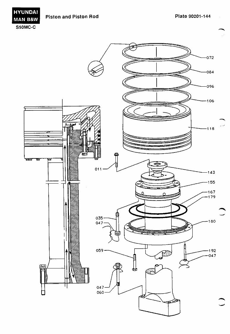
Piston and Piston Rod
Plate 90201
The piston consists of two main parts:
• Piston Crown
• Piston Skirt
The piston crown is tightened to the upper end of the piston rod by means of screws. The screws are locked with locking wire.
The piston skirt is tightened to the piston crown by means of flanged screws. The screws are locked with locking wire.
The piston crown is provided with chromium-plated grooves for four piston rings. The two uppermost rings have increased height.
Piston ring No. 1 is a Controlled-Pressure Relief ring (CPR). CPR rings may have been coated on the external surface. Handle with care, as impact may cause the coating to crack and peel off.
The piston rings oblique cuts:
Nos. 2, 3 and 4 have
- piston ring No. 3, has right-hand cut,
and
- piston rings Nos. 2 and 4, have left-hand cuts.
At the top, the piston crown has a groove for the fitting of lifting tools.
The piston rod has a through-going bore for the cooling oil pipe, which is secured to the piston rod top by means of flanged screws.
Cooling oil is supplied through a telescopic pipe connection on the crosshead and passed through a bore in the piston rod foot and, through the cooling oil pipe in the piston rod, to the piston crown.
The oil is passed on through a number of bores in the thrust part of the piston crown and to the space around the cooling oil pipe in the piston rod.
From the bore in the piston rod foot, the oil is led through the crosshead to a discharge spout and to a slotted pipe inside the engine frame as well as through a control device for checking the flow and temperature.
The piston rod foot rests on a face cut-out in the crosshead pin and is guided by a pipe in the crosshead.
A shim is inserted between the piston rod and the crosshead. The thickness of the shim is calculated for each engine, in order to match the actual engine layout.
The rod is fastened to the crosshead pin by means of four screws. The screws are locked with locking wire.
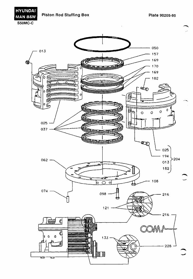
Piston Rod Stuffing Box
The bore for the piston rod in the bottom of the scavenge air box is fitted with a piston rod stuffing box, which is designed to prevent the lubricating oil in the crankcase from being drawn up into the scavenge air space.
The stuffing box also prevents scavenge air (in the scavenge air space) from leaking into the crankcase.
The stuffing box is mounted on a flange which is bolted to the bottom of the scavenge air space.
The stuffing box is removed together with the piston rod during piston inspection, but can also be dismantled for inspection in the crankcase while the piston remains mounted in the engine.
The stuffing box housing consists of two parts, which are bolted together.
902.02-65
The housing is provided with seven machined ring grooves:
- The uppermost groove is provided with a four-part scraper ring with oblique edges, which serves to prevent sludge from the scavenge box from being drawn down to the other rings.
Furthermore, an eight-part sealing ring is located below the scraper ring to prevent scavenge air from passing downwards along the piston rod.
The scraper ring and the sealing ring are guided by two cylindrical pins.
- The next two ring grooves are each provided with a four-part sealing ring and an eight-part sealing ring below. The rings are guided by two cylindrical pins.
- The four lowermost ring grooves are fitted with three-part scraper rings which scrape the lubricating oil off the piston rod.
Each of the three parts consists of a base ring with two machined grooves, each containing a pressed-in lamella, with a scraping edge facing the piston rod.
From the three lowermost grooves, the oil is returned to the crankcase, through bores in the stuffing box housing.
Through bores in the housing and a pipe, the uppermost scraper ring groove communicates with a control funnel on the outside of the engine.
This funnel provides a means of checking that the sealing rings and scraper rings are functioning correctly:
Gaps at the end of the ring segments ensure that the rings will bear against the piston rod even in worn condition.
- Blow-by of air indicates defective sealing rings, while excessive oil indicates defective scraper rings.
The parts are held in place round the piston rod by means of helical springs, which are located in machined grooves on the outside of the scraper rings and sealing rings.
HYUNDAI MAN B&W
S50MC-C
Piston and Piston Rod Plate 90201-144
Plate 90201-144 Piston and Piston Rod
Item No.
Part Description
011 035 047 059 060 072 084 096 106 118 143 155 167 179 180 192
Screw Screw Locking wire Screw Screw Piston ring, no.1 Piston ring, no.2 Piston ring, no.3 Piston ring, no.4 Piston crown Cooling oil pipe Piston rod D-ring D-ring Piston skirt Screw
Item No.
Part Description
HYUNDAI MAN B&W S50MC-C
Piston Rod Stuf f ing Box Plate 90205-95
„..^^^
)>204
Plate 90205-95 Piston Rod Stuffing Box
Item No.
013 025 037 050 062 074 098 108 121 133 157 169 170 182 194 204 216 228
>««»'
Part Description
Nut Stuffing box liousing in 2/2 Scraper ring 0-ring Flange Guide pin Screw Screw Spring pin Lamella for scraper ring Top scraper ring Pack sealing ring Cover sealing ring Screw Fitted bolt Stuffing box housing, complete Spring Spring
Item No. Part Description
CYLINDER LINER AND CYLINDER LUBRICATION
903

903.01-62
Cylinder Liner and Cylinder Lubrication
^ • ^ ^
Z*"* \ n ^
\ B * .
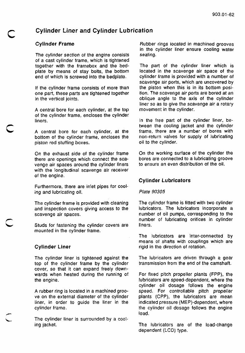
Cylinder Frame
The cylinder section of the engine consists of a cast cylinder frame, which is tightened together with the framebox and the bedplate by means of stay bolts, the bottom end of which is screwed into the bedplate.
If the cylinder frame consists of more than one part, these parts are tightened together in the vertical joints.
A central bore for each cylinder, at the top of the cylinder frame, encloses the cylinder liners.
A central bore for each cylinder, at the bottom of the cylinder frame, encloses the piston rod stuffing boxes.
On the exhaust side of the cylinder frame there are openings which connect the scavenge air spaces around the cylinder liners with the longitudinal scavenge air receiver of the engine.
Furthermore, there are inlet pipes for cooling and lubricating oil.
The cylinder frame is provided with cleaning and inspection covers giving access to the scavenge air spaces.
Studs for fastening the cylinder covers are mounted in the cylinder frame.
Cylinder Liner
The cylinder liner is tightened against the top of the cylinder frame by the cylinder cover, so that it can expand freely downwards when heated during the running of the engine.
A rubber ring is located in a machined groove on the external diameter of the cylinder liner, in order to guide the liner in the cylinder frame.
The cylinder liner is surrounded by a cooling jacket.
Rubber rings located in machined grooves in the cylinder liner ensure cooling water sealing.
The part of the cylinder liner which is located in the scavenge air space of the cylinder frame is provided with a number of scavenge air ports, which are uncovered by the piston when this is in its bottom position. The scavenge air ports are bored at an oblique angle to the axis of the cylinder liner so as to give the scavenge air a rotary movement in the cylinder.
In the free part of the cylinder liner, between the cooling jacket and the cylinder frame, there are a number of bores with non-return valves for supply of lubricating oil to the cylinder.
On the working surface of the cylinder the bores are connected to a lubricating groove to ensure an even distribution of the oil.
Cylinder Lubricators
Plate 90305
The cylinder frame is fitted with two cylinder lubricators. The lubricators incorporate a number of oil pumps, corresponding to the number of lubricating orifices in cylinder liners.
The lubricators are inter-connected by means of shafts with couplings which are rigid in the direction of rotation.
The lubricators are driven through a gear transmission from the end of the camshaft.
For fixed pitch propeller plants (FPP), the lubricators are speed-dependent, where the cylinder oil dosage follows the engine speed. For controllable pitch propeller plants (CPP), the lubricators are mean indicated pressure (MEP)-dependent, where the cylinder oil dosage follows the engine load.
The lubricators are of the load-change dependent (LCD) type.
903.02-62
^^^m^
For engines fitted with a Woodward governor, the LCD lubricators are controlled by an electronic unit, which monitors the position of the fuel regulating shaft.
For engines fitted with an electronic governor, the LCD lubricators are controlled directly by the governor.
The LCD lubricators can operate in two nnodes:
• LCD mode: The lubricators supply the pre-set extra amount of cylinder oil during STARTING, manoeuvring and sudden load changes. This reduces the liner wear rate.
• Fixed-position mode: The lubricators supply the pre-set extra amount of cylinder oil per revolution continuously.
Regarding the cylinder lubricators proper, reference is made to the special instruction manuals supplied.
See also Vol. I, OPERATION Chapter 707.
v.-
HYUNDAI MAN B&W Cylinder Frame Plate 90301-112
S50MC-C
" • ^
^^1^%.
••t^y
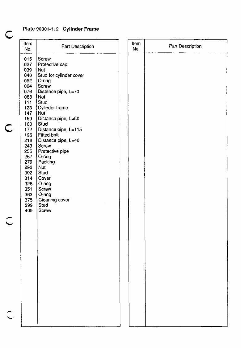
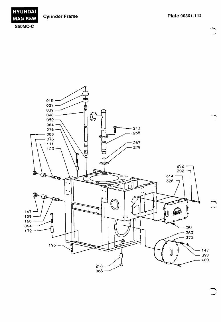
c Plate 90301-112 Cylinder Frame
Item No.
015 027 039 040 052 064 076 088 111 123 147 159 160 172 196 218 243 255 267 279 292 302 314 326 351 363 375 399 409
Part Description
Screw Protective cap Nut Stud for cylinder cover 0-ring Screw Distance pipe, L=70 Nut Stud Cylinder frame Nut Distance pipe, L=50 Stud Distance pipe, L=115 Fitted bolt Distance pipe, L=40 Screw Protective pipe 0-ring Packing Nut Stud Cover 0-ring Screw 0-ring Cleaning cover Stud Screw
Item No.
Part Description
' ^ • i * '
HYUNDAI
MAN B&W
S50MC-C
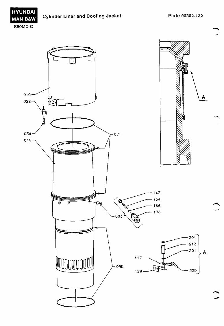
Cylinder Liner and Cooling Jacket Plate 90302-122
• " ' ^ ' ^
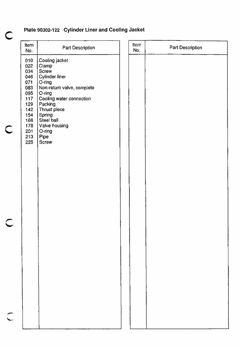
Plate 90302-122 Cylinder Liner and Cooling Jacket
\t0>'
Item No.
010 022 034 046 071 083 095 117 129 142 154 166 178 201 213 225
Part Description
Cooling jacket Clamp Screw Cylinder liner 0-ring Non-return valve, complete 0-ring Cooling water connection Packing Thrust piece Spring Steel ball Valve housing 0-ring Pipe Screw
Item No.
Part Description
V ,
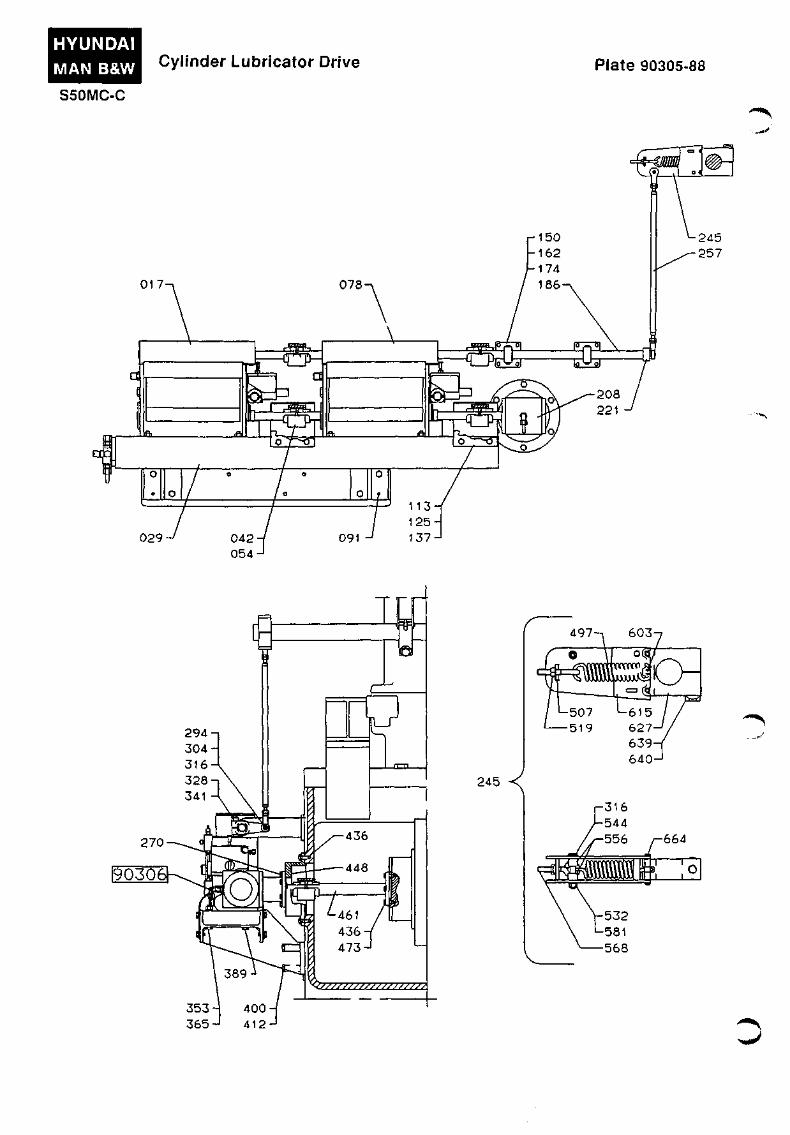
HYUNDAI MAN B&W Cylinder Lubricator Drive Plate 90305-88
S50MC-C
270-
90306
^
tei
7//////////////////^
497-n 603
245 <
. .^..'J^
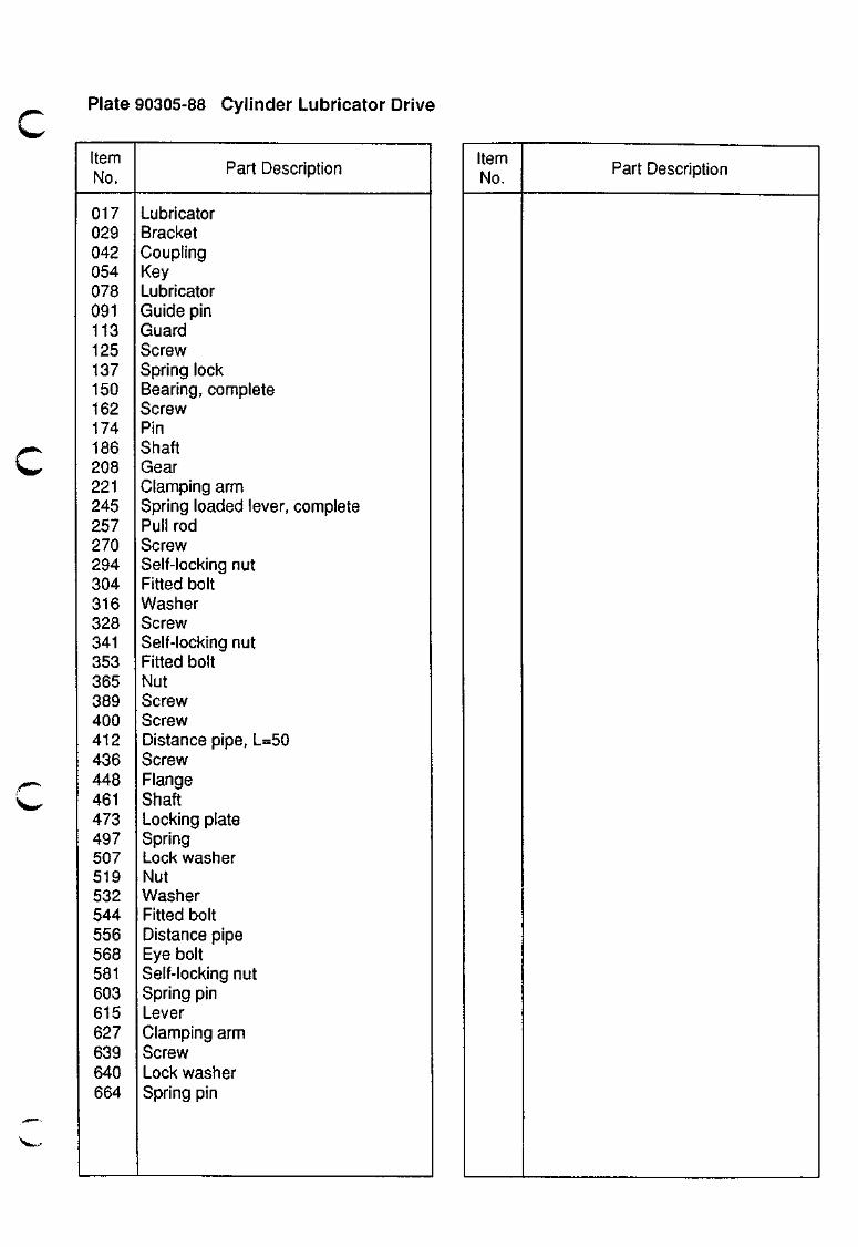
Plate 90305-88 Cylinder Lubricator Drive
Item No.
017 029 042 054 078 091 113 125 137 150 162 174 186 208 221 245 257 270 294 304 316 328 341 353 365 389 400 412 436 448 461 473 497 507 519 532 544 556 568 581 603 615 627 639 640 664
Part Description
Lubricator Bracket Coupling Key Lubricator Guide pin Guard Screw Spring lock Bearing, complete Screw Pin Shaft Gear Clamping arm Spring loaded lever, complete Pull rod Screw Self-locking nut Fitted bolt Washer Screw Self-locking nut Fitted bolt Nut Screw Screw Distance pipe, L=50 Screw Flange Shaft Locking plate Spring Lock washer Nut Washer Fitted bolt Distance pipe Eye bolt Self-locking nut Spring pin Lever Clamping arm Screw Lock washer Spring pin
Item No.
Part Description
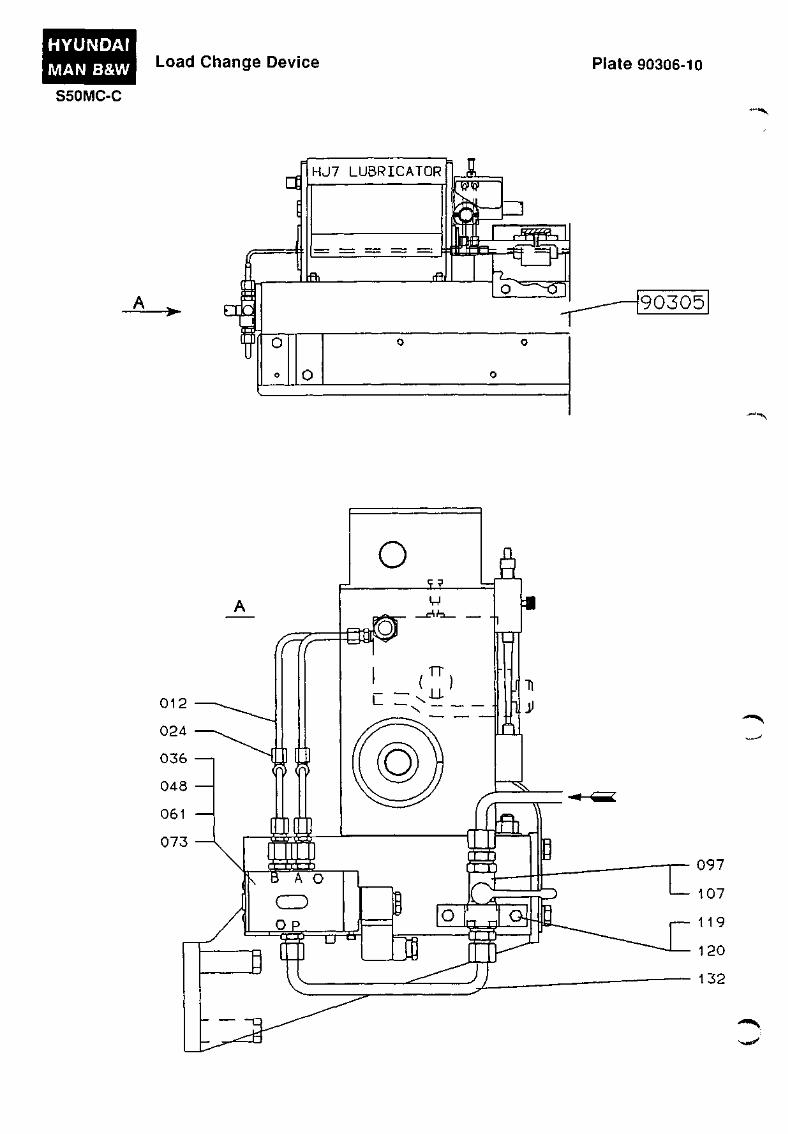
HYUNDAI MAN B&W Load Change Device Plate 90306-10
S50MC-C
a HJ7 LUBRICATOR
ia_
w » ^
•\^00'
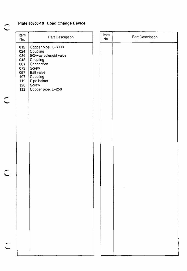
Plate 90306-10 Load Change Device
Item No.
Part Description
012 024 036 048 061 073 097 107 119 120 132
Copper pipe, 1=3300 Coupling 5/2-way solenoid valve Coupling Connection Screw Ball valve Coupling Pipe holder Screw Copper pipe, L=250
Item No.
Part Description

CROSSHEAD WITH CONNECTING ROD
904

904.01-54
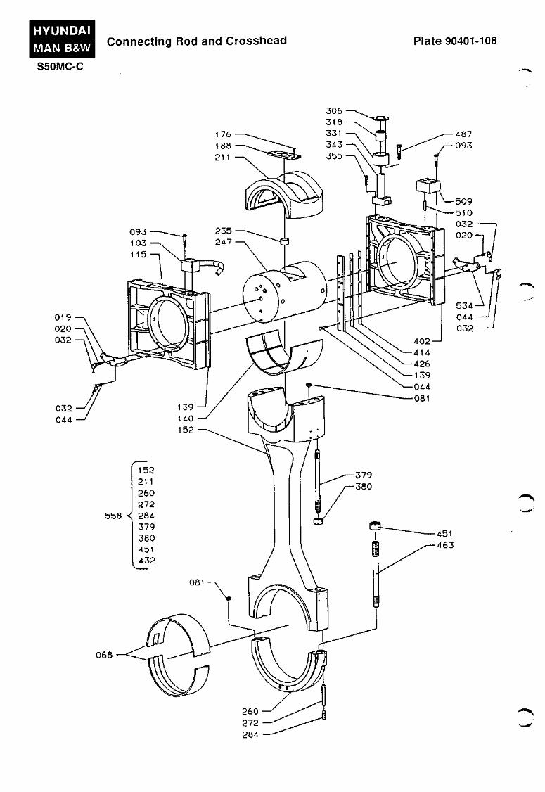
c Crosshead with Connecting Rod
The crosshead is provided with two guide shoes fitted floating on the crosshead ends.
The centre part of the crosshead is housed in the crosshead bearing.
The crosshead bearing cap is provided with a cut-out enabling the piston rod to be assembled with the crosshead journal.
The crosshead bearing is equipped with two lower bearing steel shells, which are lined with tin-aluminium. Furthermore, the lower shells have an overlayer coating of lead, tin and copper, and a flash-layer of tin. See also Vol. I, OPERATION, Chapter 708.
There is no upper bearing shell, as white metal has been applied directly onto the inner diameter of the crosshead bearing cap.
The piston rod foot rests on the crosshead, and is guided by a guide ring in the cross-head.
A shim is inserted between the piston rod and the crosshead. The thickness of the shim is calculated for each engine, in order to match the actual engine layout.
The piston rod is fastened to the crosshead by means of four screws, which are locked with locking wire.
The telescopic pipe, which supplies lubricating and cooling oil to the crosshead, crankpin and piston, is mounted on top of one of the guide shoes.
The guide shoe is also fitted with a counterweight in order to balance the weight of the telescopic pipe.
The outlet pipe for piston cooling oil is mounted on top of the other guide shoe. The outlet pipe slides within a slotted pipe inside the engine framebox, and from there the oil is led through a control device for each cylinder for the purpose of checking the temperature and flow before the oil is passed on to the lube oil tank.
The crosshead block is provided with bores for distributing the oil supplied through the telescopic pipe, partly as cooling oil for the piston, partly as lubricating oil for the crosshead bearing and guide shoes and -through a bore in the connecting rod - for lubricating the crankpin bearing.
The two sliding faces of the guide shoes are lined with cast-on white metal.
The crosshead is guided by crosshead guides in the engine framebox and properly secured against displacement by guide strips fastened to the guide shoes.
The crosshead pin and guide shoes are tightened together by means of plates and screws, located at the lower part of the pin.
The crosshead bearing is assembled by means of four studs and nuts. The nuts are tightened by means of hydraulic tools.
The crankpin bearing is fitted with bearing shells lined with tin-aluminium and a flash-layer of tin, and assembled by means of two studs and nuts. The nuts are tightened by means of hydraulic tools.
Both the crosshead bearing shells and the crankpin bearing shells are retained in position by means of screws fitted in the bearing housings.
Furthermore, the bearing assemblies are guided into position by guide pins.
HYUNDAI MAN B&W
S50MC-C
Connecting Rod and Crosshead Plate 90401-106
.,..»^
032 044
Ste^
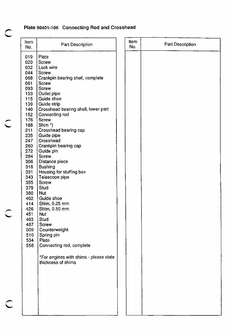
Plate 90401-106 Connecting Rod and Crosshead
Item No.
019 020 032 044 068 081 093 103 115 139 140 152 176 188 211 235 247 260 272 284 306 318 331 343 355 379 380 402 414 426 451 463 487 509 510 534 558
Part Description
Tmii-"
Plate Screw Lock wire Screw Crankpin bearing shell, complete Screw Screw Outlet pipe Guide shoe Guide strip Crosshead bearing shell, lower part Connecting rod Screw Shim *) Crosshead bearing cap Guide pipe Crosshead Crankpin bearing cap Guide pin Screw Distance piece Bushing Housing for stuffing box Telescope pipe Screw Stud Nut Guide shoe Shim, 0.25 mm Shim, 0.50 mm Nut Stud Screw Counterweight Spring pin Plate Connecting rod, complete
*For engines with shims - please state thickness of shims
Item No. Part Description

CRANKSHAFT, THRUST BEARING AND TURNING GEAR
905


905.01-51
Crankshaft, Thrust Bearing and Turning Gear
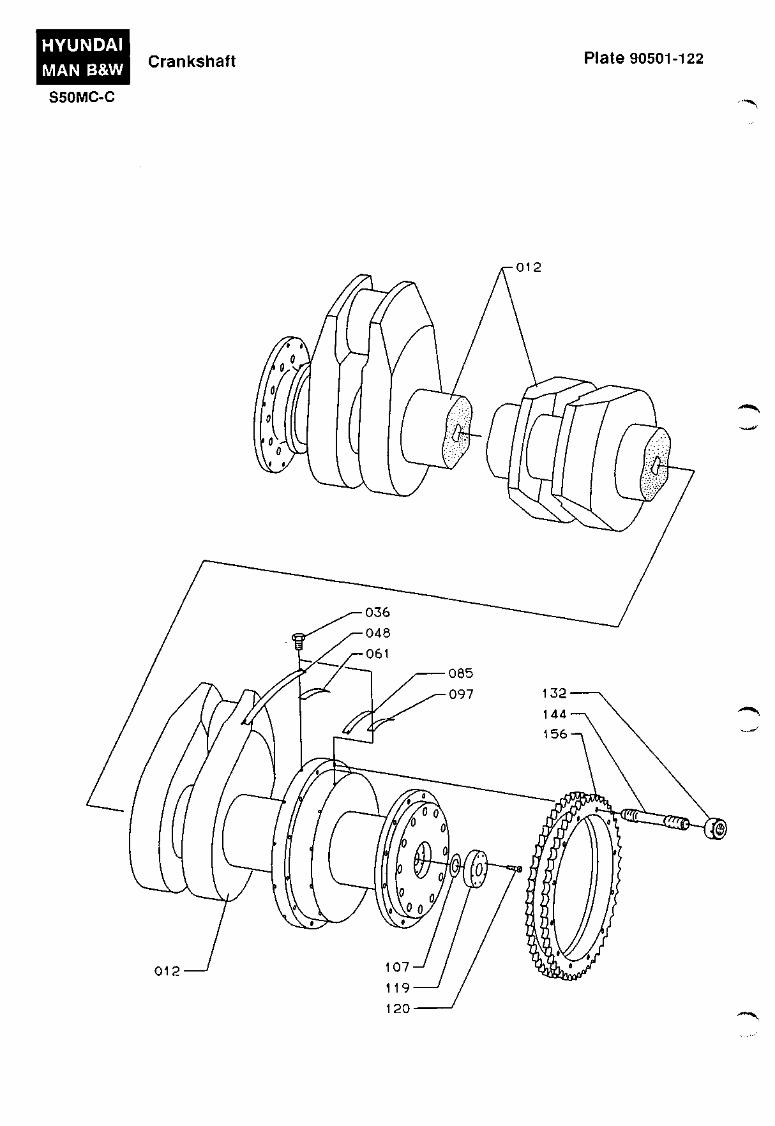
Crankshaft
Plate 90501
The crankshaft is semi-built, i.e. the parts are either shrunk or welded together.
The main bearings are lubricated via a main lubricating oil pipe that branches off to the individual bearings, whereas oil for lubricating the crankpin bearings is supplied from the crossheads through bores in the connecting rods.
At the aftmost end of the crankshaft a turning wheel and a thrust collar for the thrust bearing is fitted.
The chainwheel for the camshaft drive is fitted on the thrust collar.
At the foremost end of the crankshaft, a tuning wheel, a torsional vibration damper and a chain wheel drive for the 2nd order moment compensator may be installed.
Axial Vibration Damper
In order to counteract heavy axial vibrations, and any resultant adverse forces and vibrations, the engine is provided with an axial vibration damper on the foremost end of the crankshaft, see Plate 91211.
The damper consists of a 'piston' and a slit-type housing located in front of the foremost main bearing. The 'piston' is made as an integrated collar on the foremost main bearing journal, and the housing is mounted on the foremost main bearing support.
The axial movement is damped due to the 'restrictions' incorporated in the bores which interconnect the oil-filled chambers on the two sides of the 'piston'.
Lubricating oil is supplied to both sides of the 'piston' from the main system.
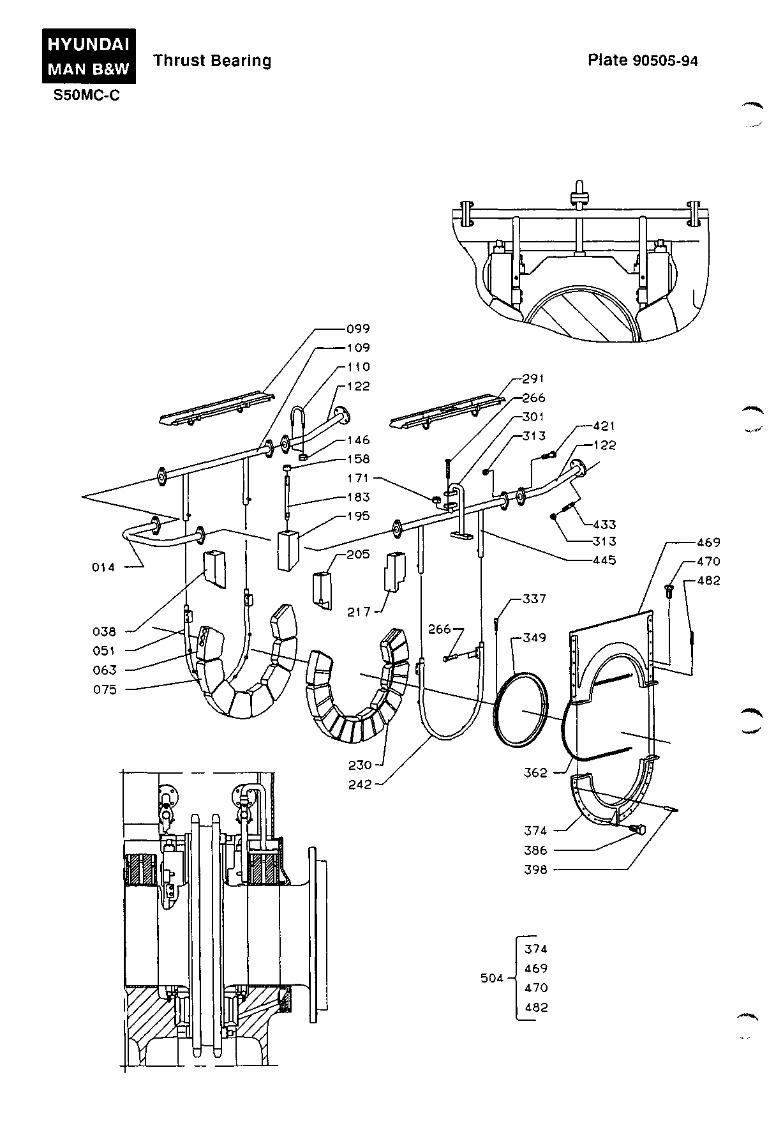
Tlirust Bearing
Plate 90505
The thrust bearing serves the purpose of transmitting the axial thrust of the propeller through propeller shaft and intermediate shafts to the ship's hull.
The thrust bearing is incorporated in the aftermost part of the engine bedplate.
The crankshaft is provided with a thrust collar which transmits the thrust to a number of segments mounted in a thrust shoe on either side of the thrust collar.
The thrust shoes rest on surfaces in the thrust bearing housing and are held in place by means of four stoppers. The segments have white metal cast on the wearing faces against the thrust collar. See also Vol. I, OPERATION, Chapter 708.
The thrust bearing is lubricated from the pressure lubrication system of the engine. The oil is supplied between the segments through spray pipes and spray nozzles.
The thrust bearing is provided with alarm, slow-down, and shut-down devices for low lube oil pressure and high segment temperature. See also Vol. I, OPERATION. Chapter 701.
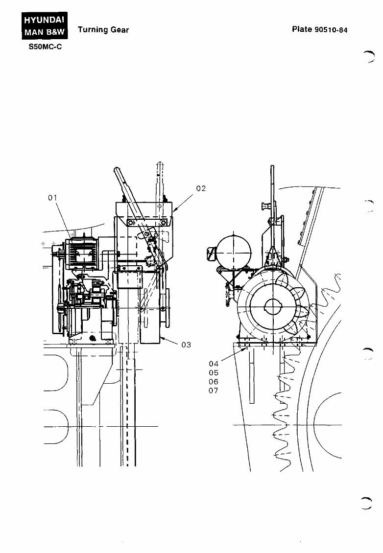
Turning Gear
Plate 90510
The turning gear is attached to the engine bedplate and is driven by an electric motor incorporating a disc brake.
Through a belt drive and a planetary gearing, the motor drives a horizontal shaft equipped with a gear wheel which can be axially displaced by means of a hand wheel, so as to engage with the turning wheel of the engine.
905.02-51
i^"^
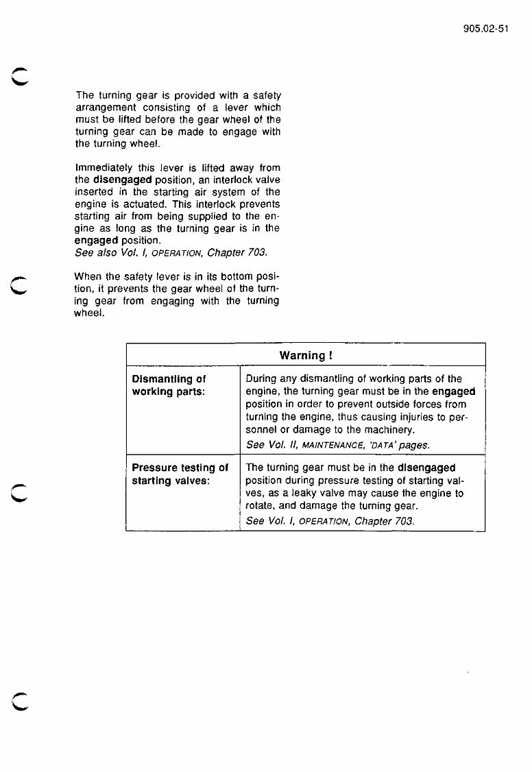
The turning gear is provided with a safety arrangement consisting of a lever which must be lifted before the gear wheel of the turning gear can be made to engage with the turning wheel.
Immediately this lever is lifted away from the disengaged position, an interlock valve inserted in the starting air system of the engine is actuated. This interlock prevents starting air from being supplied to the engine as long as the turning gear is in the engaged position. See also Vol. I, OPERATION, Chapter 703.
When the safety lever is in its bottom position, it prevents the gear wheel of the turning gear from engaging with the turning wheel.
Warning !
Dismantling of worlcing parts:
Pressure testing of starting vaives:
During any dismantling of working parts of the engine, the turning gear must be in the engaged position in order to prevent outside forces from turning the engine, thus causing injuries to personnel or damage to the machinery. See Vol. II, MAINTENANCE, 'DATA'pages.
The turning gear must be in the disengaged position during pressure testing of starting valves, as a leaky valve may cause the engine to rotate, and damage the turning gear. See Vol. 1, OPERATION, Chapter 703.
if^
HYUNDAI MAN B&W Crankshaft Plate 90501-122
S50MC-C • - • ^
012
120
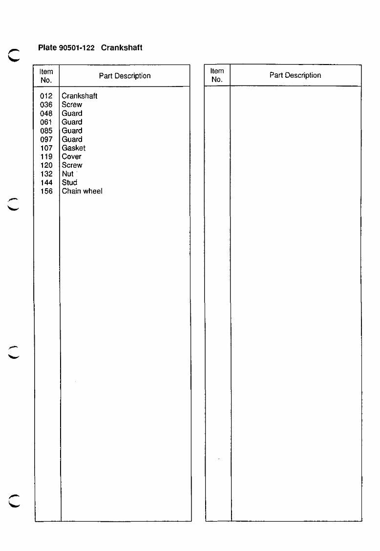
if^^ Plate 90501-122 Crankshaft
Item No.
012 036 048 061 085 097 107 119 120 132 144 156
Part Description
Crankshaft Screw Guard Guard Guard Guard Gasket Cover Screw Nut Stud Chain wheel
\»»'
Item No.
Part Description
508 <
< 018 031 043 067 080 092 102 163
175 209 222 234 354 366 391
283
cn o
O I
o
> -<
\i 0) 3
(Q (D
3 <D 3
-n o - m 3 Q.
Q) (D CO o tn o lO I ro to
) K) )
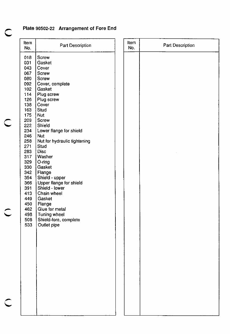
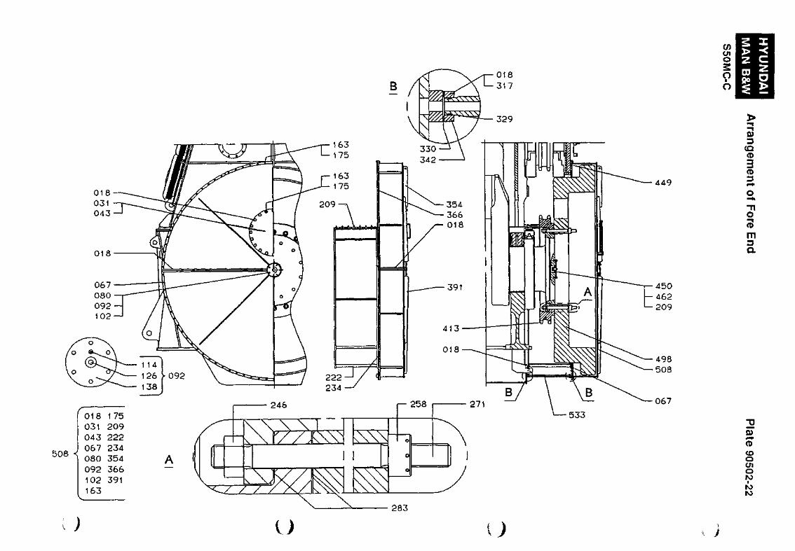
Plate 90502-22 Arrangement of Fore End
Item No.
018 031 043 067 080 092 102 114 126 138 163 175 209 222 234 246 258 271 283 317 329 330 342 354 366 391 413 449 450 462 498 508 533
Part Description
Screw Gasket Cover Screw Screw Cover, complete Gasket Plug screw Plug screw Cover Stud Nut Screw Shield Lower flange for shield Nut Nut for hydraulic tightening Stud Disc Washer 0-ring Gasket Flange Shield - upper Upper flange for shield Shield - lower Chain wheel Gasket Flange Glue for metal Tuning wheel Shield-fore, complete Outlet pipe
Item No.
Part Description
HYUNDAI MAN B&W
S50MC-C
Thrust Bearing Plate 90505-94
- < - " ^

c Plate 90505-94 Thrust Bearing
Item No.
014 038 051 063 075 099 109 110 122 146 158 171 183 195 205 217 230 242 266 291 301 313 337 349 362 374 386 398 421 433 445 469 470 482 504
Part Description
Lub.oil pipe Segment stopper Spray pipe Segment witli sensor pockets Segment "Ahead" Cover Lub.oil pipe Clamp Lub.oil pipe Self-locking nut Nut Self-locking nut Stud Segment stopper Segment stopper Segment stopper Segment "Astern" Spray pipe Screw Cover Lub.oil pipe Self-locking nut Screw Oil throw ring Spring Housing, lower half Screw Guide pin Screw Stud Lub.oil pipe Housing, upper half Screw Guide pin Scraper ring housing, complete
Item No.
Part Description
HYUNDAI
MAN B&W
S50MC-C
Turning Gear Plate 90510-84
02
-^
f^' Plate 90510-84 Turning Gear
Item No.
01 02 03 04 05 06 07
Part Description
Planet gear Disengaging device Pin Bolt Distance pipe Distance pipe Nut
Item No.
Part Description
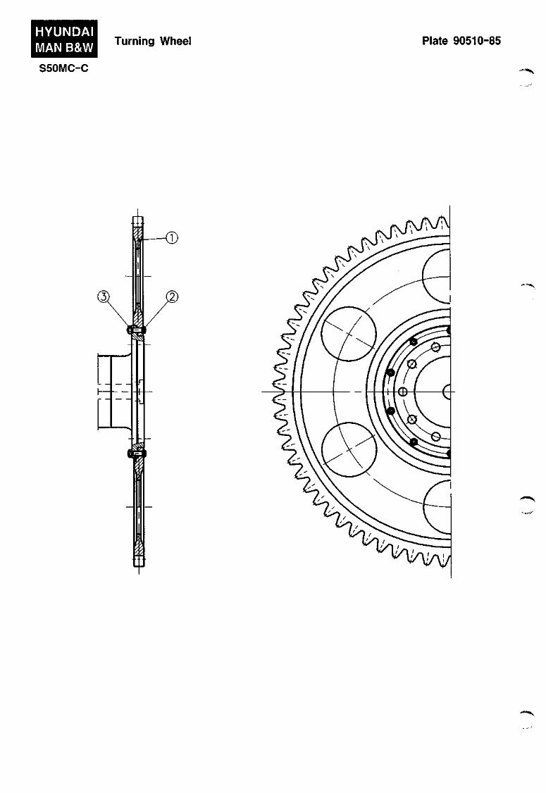
HYUNDAI MAN B&W Turning Wheel Plate 90510-85
S50MC-C • " - ^
Plate 90510-85 Turning Wheel
Item No.
01 02 03
Part Description
Turning wheel Fitted bolt Nut
Item No.
Part Description
MECHANICAL CONTROL GEAR
906

906.01-72
f^
j ( # * * ^
VMC
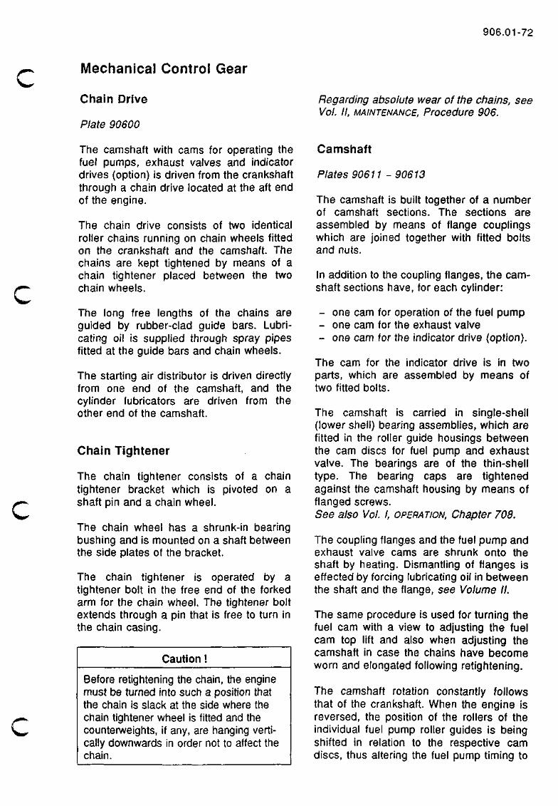
Mechanical Control Gear
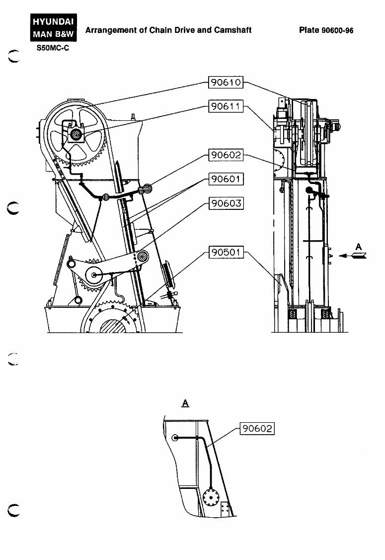
Chain Drive
Plate 90600
The camshaft with cams for operating the fuel pumps, exhaust valves and indicator drives (option) is driven from the crankshaft through a chain drive located at the aft end of the engine.
The chain drive consists of two identical roller chains running on chain wheels fitted on the crankshaft and the camshaft. The chains are kept tightened by means of a chain tightener placed between the two chain wheels.
The long free lengths of the chains are guided by rubber-clad guide bars. Lubricating oil is supplied through spray pipes fitted at the guide bars and chain wheels.
The starting air distributor is driven directly from one end of the camshaft, and the cylinder lubricators are driven from the other end of the camshaft.
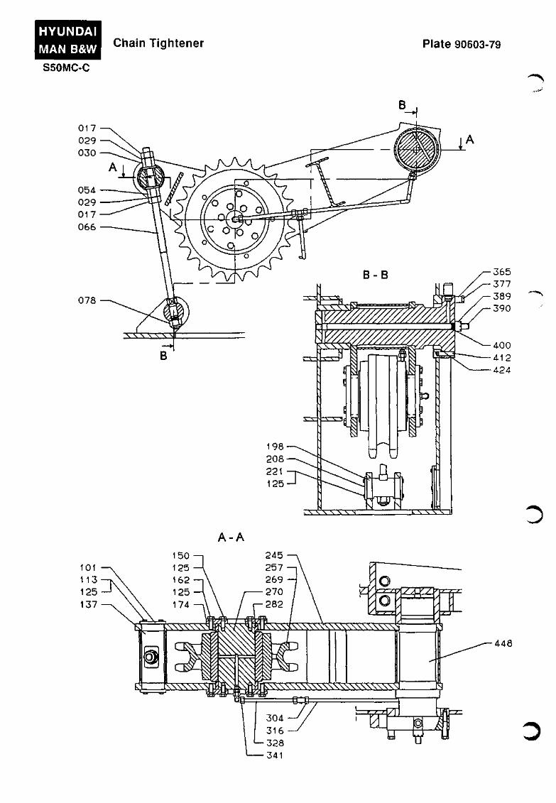
Chain Tightener
The chain tightener consists of a chain tightener bracket which is pivoted on a shaft pin and a chain wheel.
The chain wheel has a shrunk-in bearing bushing and is mounted on a shaft between the side plates of the bracket.
The chain tightener is operated by a tightener bolt in the free end of the forked arm for the chain wheel. The tightener bolt extends through a pin that is free to turn in the chain casing.
f^
Caution !
Before retightening the chain, the engine must be turned into such a position that the chain is slack at the side where the chain tightener wheel is fitted and the counterweights, if any, are hanging vertically downwards in order not to affect the chain.
Regarding absolute wear of the chains, see Vol. II, MAINTENANCE, Procedure 906.
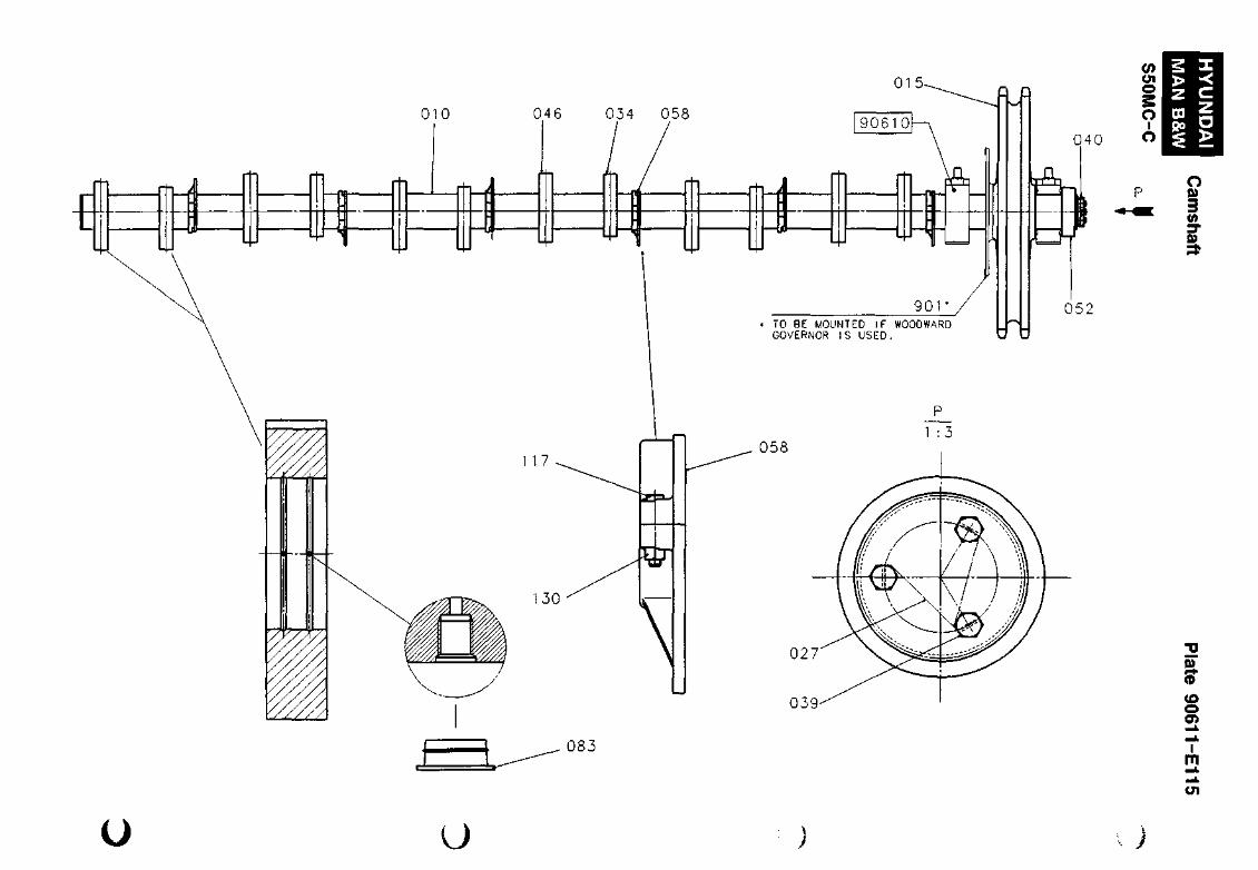
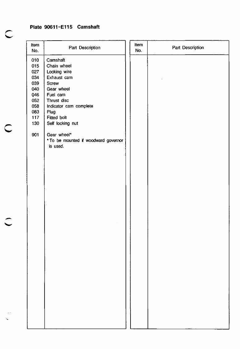
Camshaft
Plates 90611 -90613
The camshaft is built together of a number of camshaft sections. The sections are assembled by means of flange couplings which are joined together with fitted bolts and nuts.
In addition to the coupling flanges, the camshaft sections have, for each cylinder:
- one cam for operation of the fuel pump - one cam for the exhaust valve - one cam for the indicator drive (option).
The cam for the indicator drive is in two parts, which are assembled by means of two fitted bolts.
The camshaft is carried in single-shell (lower shell) bearing assemblies, which are fitted in the roller guide housings between the cam discs for fuel pump and exhaust valve. The bearings are of the thin-shell type. The bearing caps are tightened against the camshaft housing by means of flanged screws. See also Vol. I, OPERATION, Chapter 708.
The coupling flanges and the fuel pump and exhaust valve cams are shrunk onto the shaft by heating. Dismantling of flanges is effected by forcing lubricating oil in between the shaft and the flange, see Volume II.
The same procedure is used for turning the fuel cam with a view to adjusting the fuel cam top lift and also when adjusting the camshaft in case the chains have become worn and elongated following retightening.
The camshaft rotation constantly follows that of the crankshaft. When the engine is reversed, the position of the rollers of the individual fuel pump roller guides is being shifted in relation to the respective cam discs, thus altering the fuel pump timing to
906.02-72
' ^ ^
suit the new direction of rotation. See Chapter 909.
After the engine has been testrun, the camshaft parts and the cylinder frame will be provided with pin gauge marks, and the necessary pin gauges are delivered together with the engine, enabling the camshaft timing to be checked and readjusted if the parts have been dismantled.
The pin gauges are marked with:
• engine type
• engine number
• point of application
• the distance in mm between the measuring points.
Furthermore, the length of the pin gauges is indicated in the relevant section of the maintenance book (Volume II) for the plant.
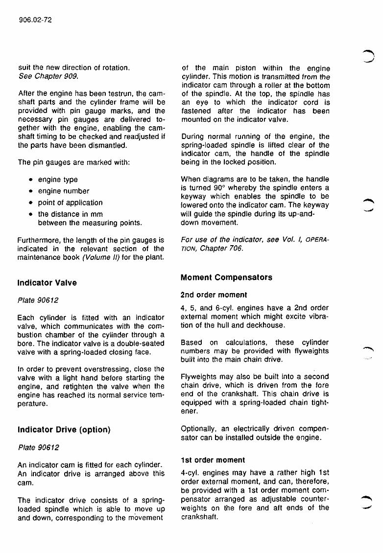
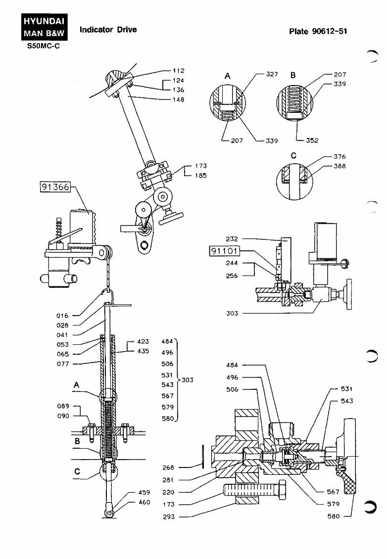
of the main piston within the engine cylinder. This motion is transmitted from the indicator cam through a roller at the bottom of the spindle. At the top, the spindle has an eye to which the indicator cord is fastened after the indicator has been mounted on the indicator valve.
During normal running of the engine, the spring-loaded spindle is lifted clear of the indicator cam, the handle of the spindle being in the locked position.
When diagrams are to be taken, the handle is turned 90° whereby the spindle enters a keyway which enables the spindle to be lowered onto the indicator cam. The keyway will guide the spindle during its up-and-down movement.
For use of the indicator, see Vol. I, OPERATION, Chapter 706.
Indicator Valve
Plate 90612
Each cylinder is fitted with an indicator valve, which communicates with the combustion chamber of the cylinder through a bore. The indicator valve is a double-seated valve with a spring-loaded closing face.
In order to prevent overstressing, close the valve with a light hand before starting the engine, and retighten the valve when the engine has reached its normal service temperature.
Moment Compensators
2nd order moment
4, 5, and 6-cyl. engines have a 2nd order external moment which might excite vibration of the hull and deckhouse.
Based on calculations, these cylinder numbers may be provided with flyweights built into the main chain drive.
Flyweights may also be built into a second chain drive, which is driven from the fore end of the crankshaft. This chain drive is equipped with a spring-loaded chain tightener.
Indicator Drive (option)
Plate 90612
An indicator cam is fitted for each cylinder. An indicator drive is arranged above this cam.
The indicator drive consists of a spring-loaded spindle which is able to move up and down, corresponding to the movement
Optionally, an electrically driven compensator can be installed outside the engine.
1st order moment
4-cyl. engines may have a rather high 1st order external moment, and can, therefore, be provided with a 1st order moment compensator arranged as adjustable counterweights on the fore and aft ends of the crankshaft.
906.03-72
Alternatively, the 1st order moment compensator can be arranged in the main chain drive.
This moment compensator consists of a (new) chain-tightener wheel with an incorporated counterweight and a counterweight rotating with the cranl<shaft.
If the chain drives for the above compensators have been dismantled, the flyweights must be positioned correctly in relation to the crankshaft of the engine.
See the instruction booli, Vol. II, MAINTENANCE.
Incorrectly fitted moment compensators may excite heavy vibrations.
Load Transmitter
A load transmitter may be mounted on the fuel regulating shaft to give a remote indication of the fuel pump index.
^ I I M ^
HYUNDAI MAN B&W
S50MC-C
Arrangement of Chain Drive and Camshaft Plate 90600-96
90610
9061 1
90602
90601
90603
90501
W^
HYUNDAI MAN B&W
S50MC-C
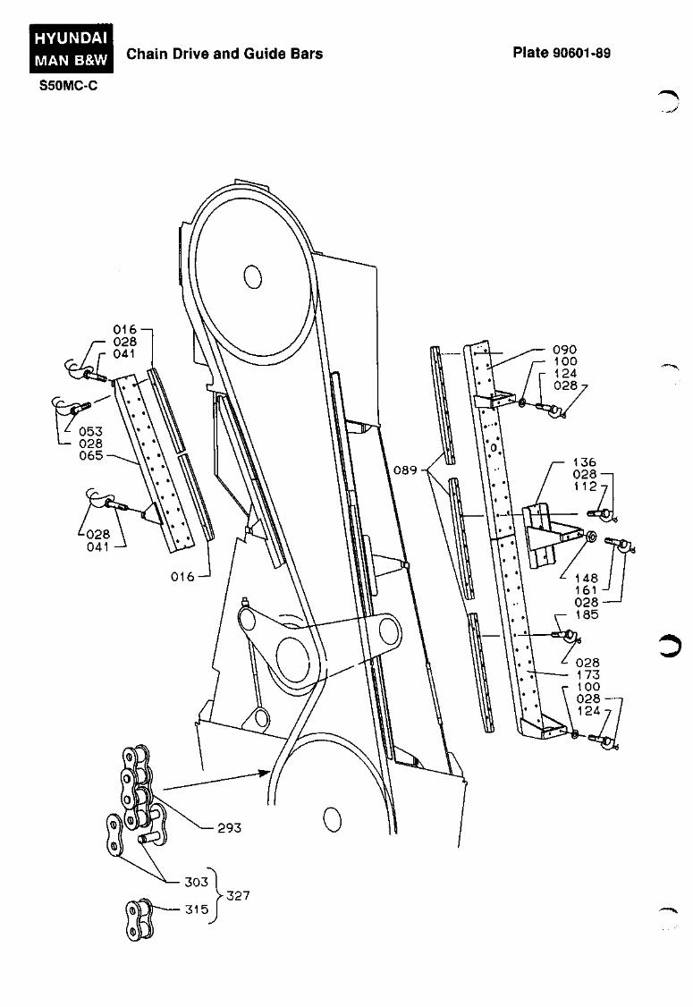
Cliain Drive and Guide Bars Plate 90601-89
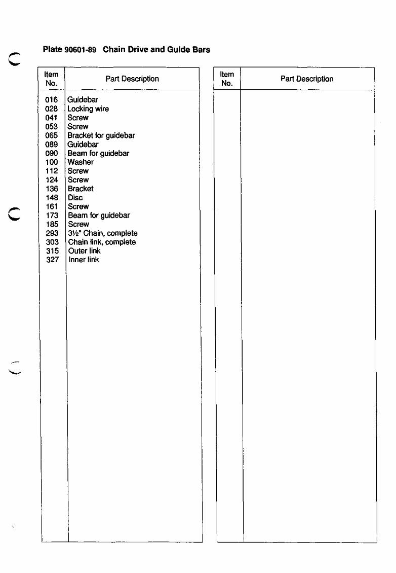
Plate 90601-89 Chain Drive and Guide Bars
C
Item No.
016 028 041 053 065 089 090 100 112 124 136 148 161 173 185 293 303 315 327
Part Description
Guidebar Locking wire Screw Screw Bracket for guidebar Guidebar Beam for guidebar Washer Screw Screw Bracket Disc Screw Beam for guidebar Screw 31/2" Chain, complete Chain link, complete Outer link Inner link
Item No. Part Description
HYUNDAI
MAN B&W
S50MC-C
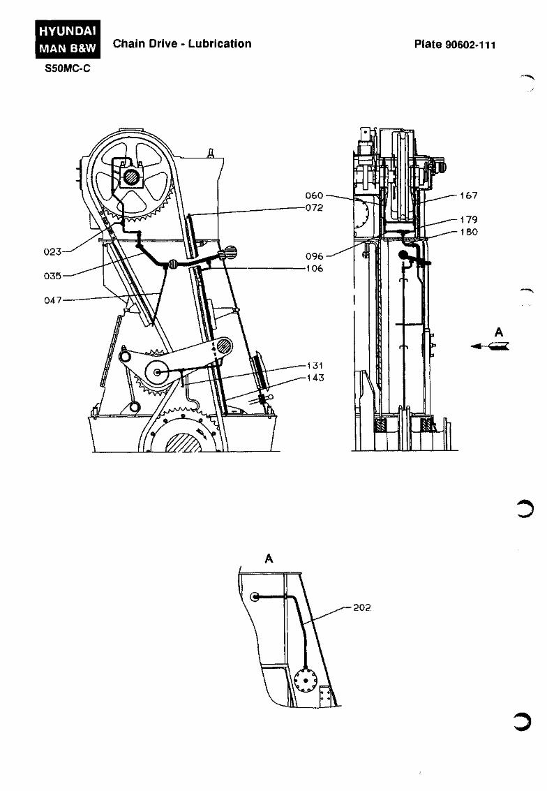
Chain Drive - Lubrication Plate 90602-111
202
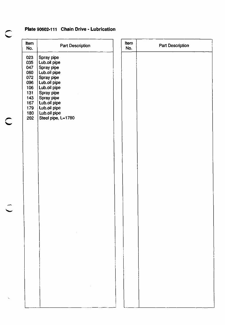
Plate 90602-111 Chain Drive - Lubrication
'WK'
Item No.
023 035 047 060 072 096 106 131 143 167 179 180 202
Part Description
Spray pipe Lub.oil pipe Spray pipe Lub.oii pipe Spray pipe Lub.oil pipe Lub.oil pipe Spray pipe Spray pipe Lub.oil pipe Lub.oil pipe Lub.oil pipe Steel pipe, L= 1780
Item No.
Part Description
HYUNDAI
MAN B&W
S50MC-C
Chain Tightener Plate 90603-79
A - A
448
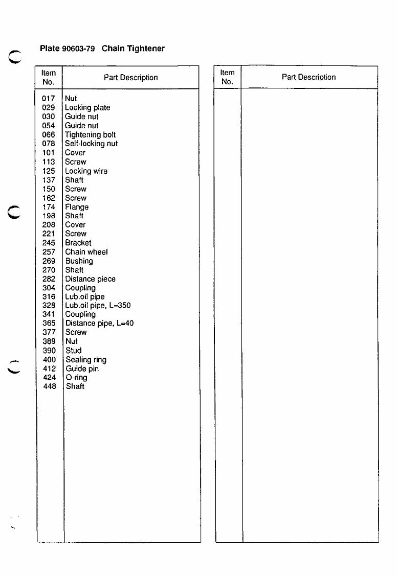
c Plate 90603-79 Chain Tightener
Item No.
017 029 030 054 066 078 101 113 125 137 150 162 174 198 208 221 245 257 269 270 282 304 316 328 341 365 377 389 390 400 412 424 448
Part Description
Nut Locking plate Guide nut Guide nut Tightening bolt Self-locking nut Cover Screw Locking wire Shaft Screw Screw Flange Shaft Cover Screw Bracket Chain wheel Bushing Shaft Distance piece Coupling Lub.oil pipe Lub.oil pipe, L=350 Coupling Distance pipe, L=40 Screw Nut Stud Sealing ring Guide pin 0-ring Shaft
Item No.
Part Description
HYUNDAI
MAN B&W
S50MC-C
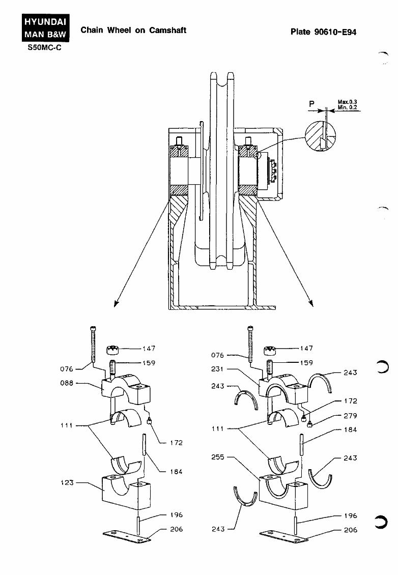
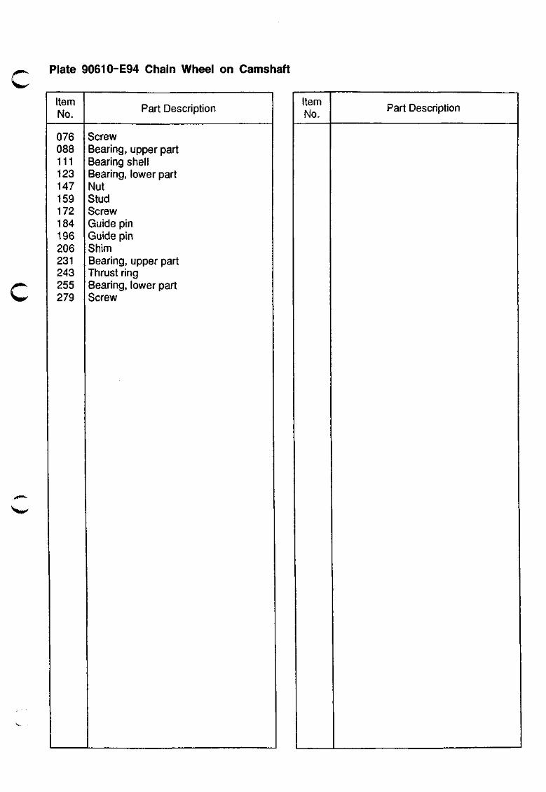
Chain Wheel on Camshaft Plate 90610-E94
M M
Max.0.3 Min. 0.2
^ • i ' J * ^
3 ^•••'m^'^
^ f e i w ^
Plate 90610-E94 Chain Wheel on Camshaft
Item No.
076 088 111 123 147 159 172 184 196 206 231 243 255 279
Part Description
Screw Bearing, upper part Bearing shell Bearing, lower part Nut Stud Screw Guide pin Guide pin Shim Bearing, upper part Thrust ring Bearing, lower part Screw
Item No.
Part Description
015-
'\
. TO BE MOUNTED IF WOODWARD GOVERNOR IS USED.
040
052
0) o s o I
O
> :5 z c
li o 0)
3 (A 3" Q)
7t
083
027
039-^"'^
1 :
r /TV I w\
3
/ ' ^ 11 \/ 11 ^y •D
0) CO
o
1 m
en
O u J
ff^^
Plate 90611-E115 Camshaft
W<^
Item No.
010 015 027 034 039 040 046 052 058 083 117 130
901
Part Description
Camshaft Cfiain wheel Locking wire Exhaust cam Screw Gear wheel Fuel cam Thrust disc Indicator cam complete Plug Fitted bolt Self locking nut
Gear wheel* *To be mounted if woodward governor is used.
Item No.
Part Description
HYUNDAI MAN B&W Indicator Drive Plate 90612-51
SSOMC-C
- • %
'•-mvH^
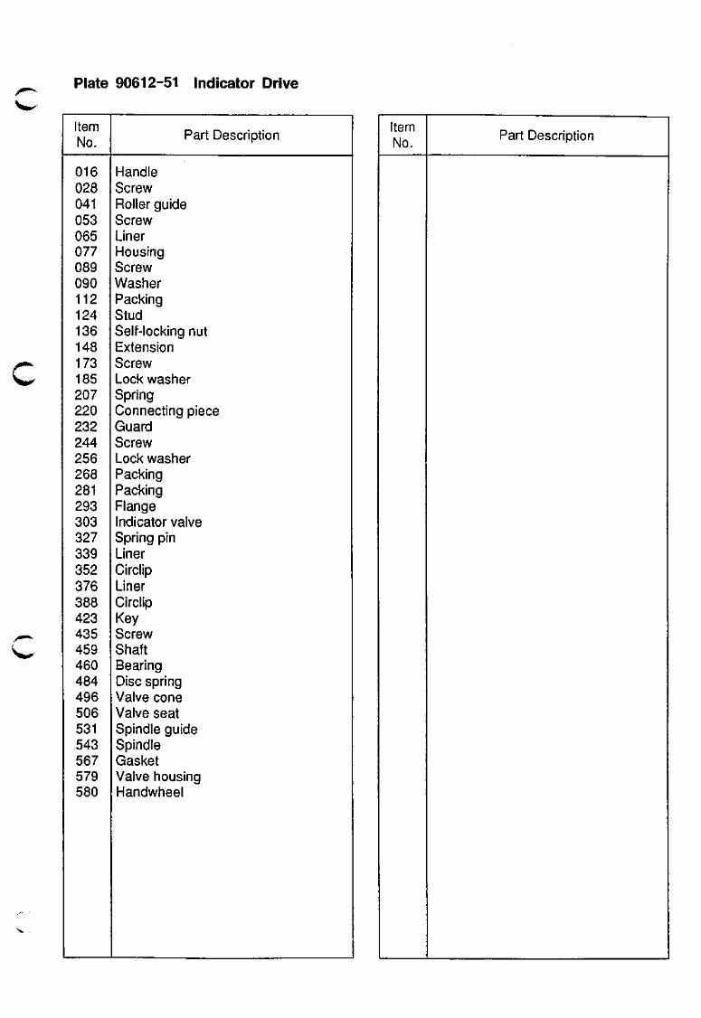
Plate 90612-51 Indicator Drive
Item No.
016 028 041 053 065 077 089 090 112 124 136 148 173 185 207 220 232 244 256 268 281 293 303 327 339 352 376 388 423 435 459 460 484 496 506 531 543 567 579 580
Part Description
Handle Screw Roller guide Screw Liner Housing Screw Washer Packing Stud Self-locking nut Extension Screw Lock washer Spring Connecting piece Guard Screw Lock washer Packing Packing Flange Indicator valve Spring pin Liner Circlip Liner Circlip Key Screw Shaft Bearing Disc spring Valve cone Valve seat Spindle guide Spindle Gasket Valve housing Handwheel
Item No.
Part Description
HYUNDAI MAN B&W S50MC-C
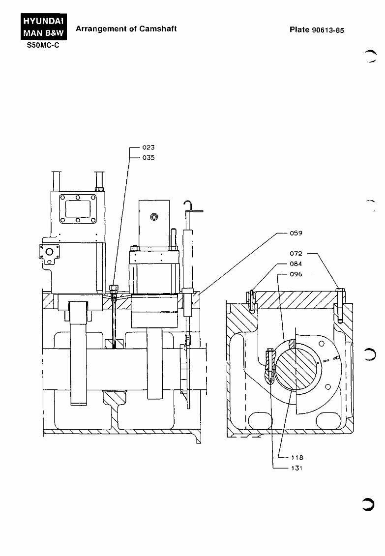
Arrangement of Camshaft Plate 90613-85
Mt (5 o SI
lo o oj
1 o
o j
Q"
vq
^
^
\ X \ \ \ \ V 'X-A \ \ V V \ \ \ \ j ^
059
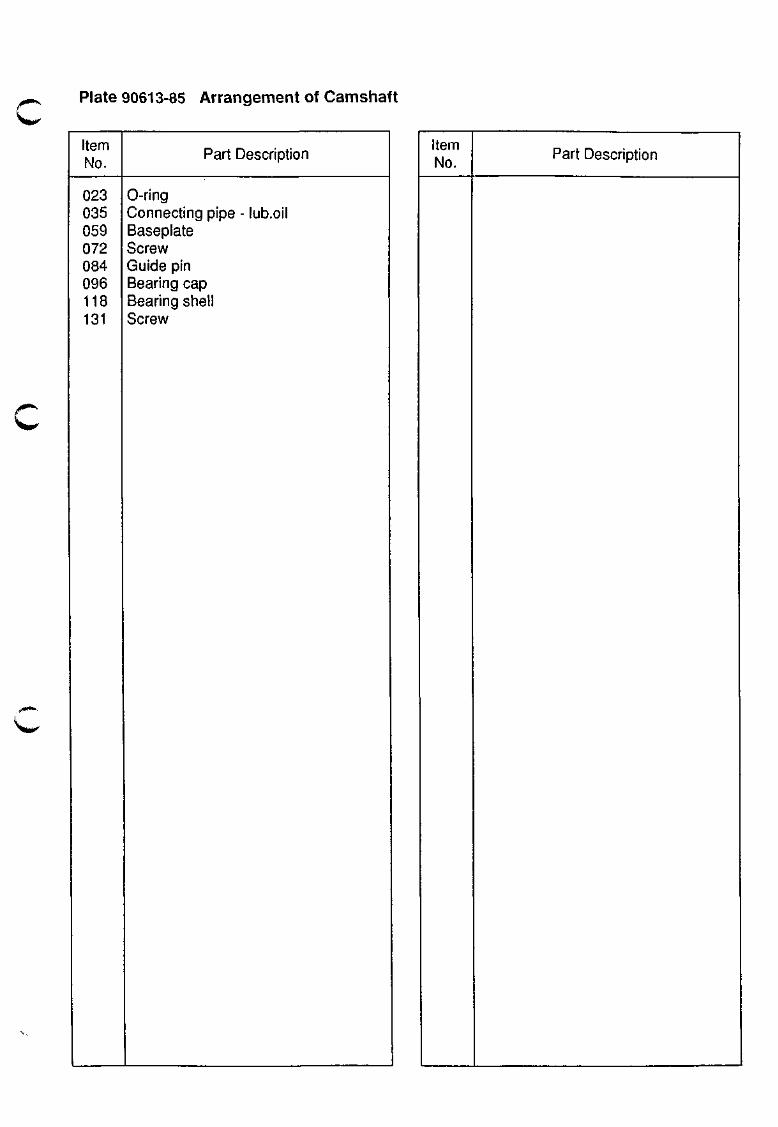
Plate 90613-85 Arrangement of Camshaft
%^lj^
Item No.
023 035 059 072 084 096 118 131
Part Description
0-ring Connecting pipe - lub.oil Baseplate Screw Guide pin Bearing cap Bearing shell Screw
Item No.
Part Description
MAX STOP
144
* TO BE MOUNTED IF NORCONTROL DGS8800E GOVERNOR IS USED.
CO
O
o
i % >
f o
O o <
IS
o
2 0) (D (O O O) en I
m o
. J )
m^^^
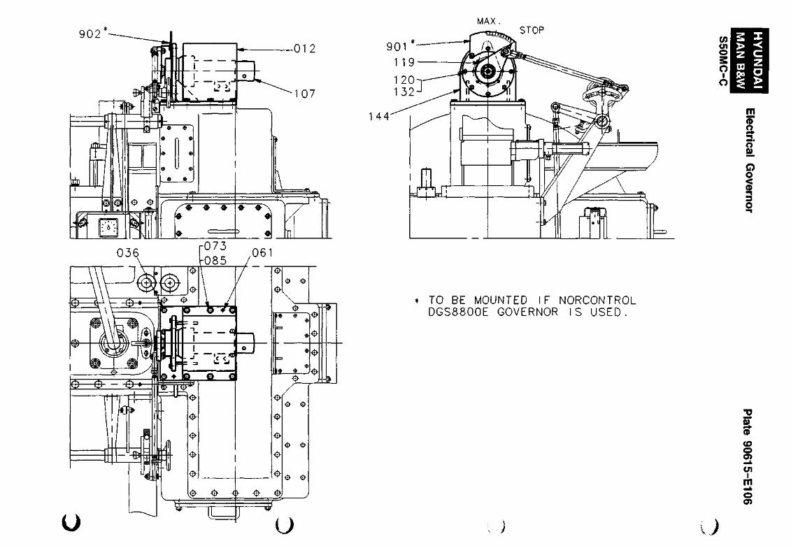
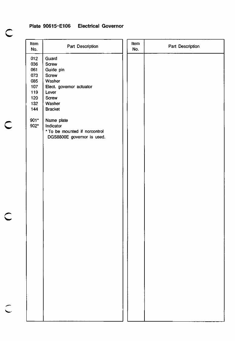
Plate 90615-E106 Electrical Governor
Item No.
r^
012 036 061 073 085 107 119 120 132 144
901* 902*
Part Description
Guard Screw Guide pin Screw Wasfier Elect, governor actuator Lever Screw Wasiier Bracket
Name plate Indicator *To be mounted if norcontrol DGS8800E governor is used.
Item No.
Part Description
HYUNDAI MAN B&W
Regulating Shaft Plate 90618-E106
S50MC-C
• - * * * ^
„*«*%.
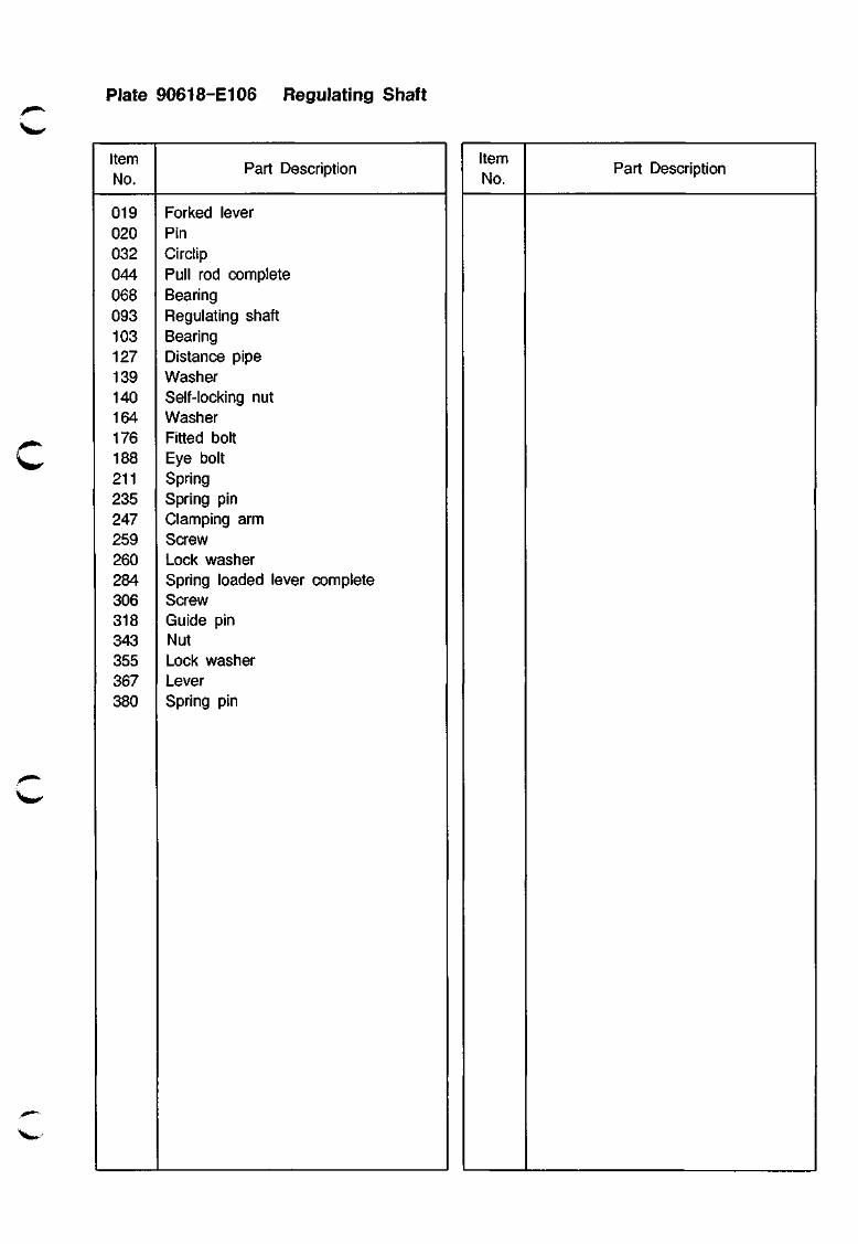
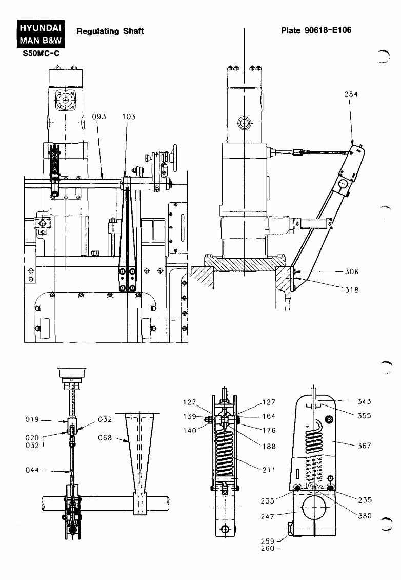
Plate 90618-E106 Regulating Shaft
Item No.
019 020 032 044 068 093 103 127 139 140 164 176 188 211 235 247 259 260 284 306 318 343 355 367 380
Part Description
Forked lever Pin Circlip Pull rod complete Bearing Regulating shaft Bearing Distance pipe Washer Self-locking nut Washer Fitted bolt Eye bolt Spring Spring pin Clamping arm Screw Lock washer Spring loaded lever complete Screw Guide pin Nut Lock washer Lever Spring pin
Item No.
Part Description

FOR 1ST CYLINDER VIEW FROM A
ffth cm.
909 910
902
w o Ol O
z c
li
•0 c 3 •a
H - fl> 3 W
3
a> 3 (O (D
3 (D 3
Q)
O (O o 00
m o
I) i)
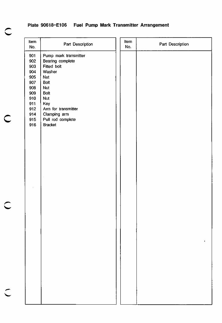
Plate 90618-E106 Fuel Pump Mark Transmitter Arrangement
Item No.
901 902 903 904 905 907 908 909 910 911 912 914 915 916
\ » ^
Part Description
Pump mark transmitter Bearing complete Fitted bolt Washer Nut Bolt Nut Bolt Nut Key Arm for transmitter Clamping arm Pull rod complete Bracket
Item No.
Part Description
HYUNDAI MAN B&W S50MC-C
Emergency Console Plate 90620-66
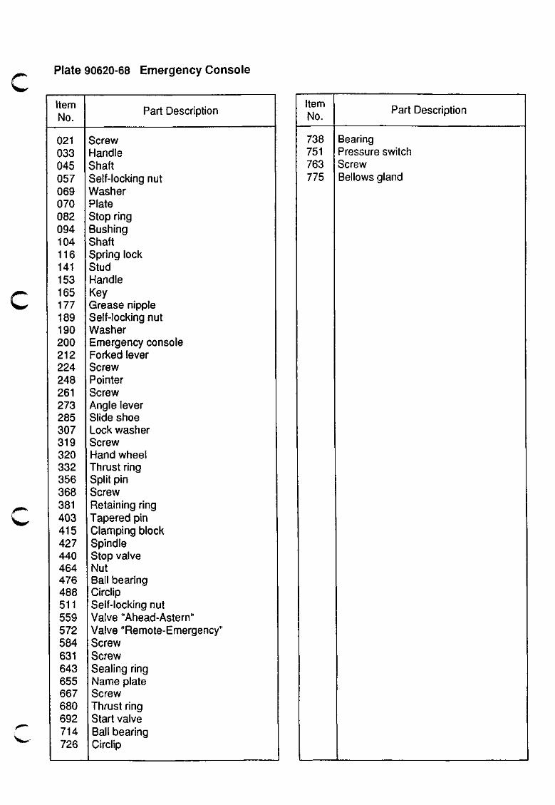
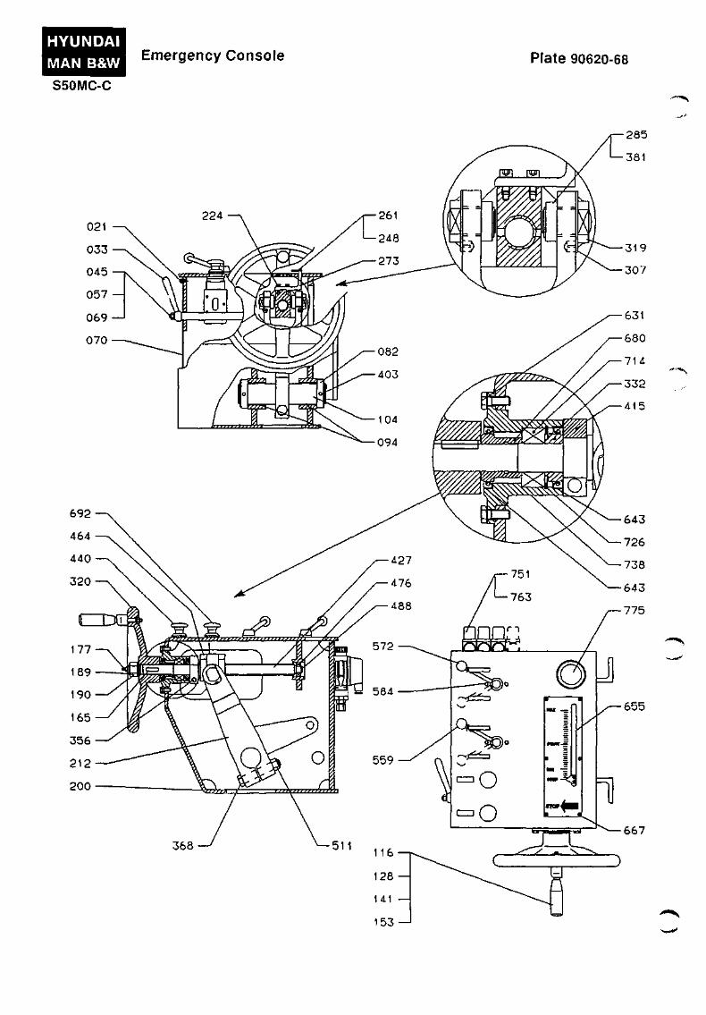
Plate 90620-68 Emergency Console
Item No.
021 033 045 057 069 070 062 094 104 116 141 153 165 177 189 190 200 212 224 248 261 273 285 307 319 320 332 356 368 381 403 415 427 440 464 476 488 511 559 572 584 631 643 655 667 680 692 714 726
Part Description
Screw Handle Shaft Self-locking nut Washier Plate Stop ring Bushing Shaft Spring lock Stud Handle Key Grease nipple Self-locking nut Washer Emergency console Forked lever Screw Pointer Screw Angle lever Slide shoe Lock washer Screw Hand wheel Thrust ring Split pin Screw Retaining ring Tapered pin Clamping block Spindle Stop valve Nut Bail bearing Circlip Self-locking nut Valve "Ahead-Astern" Valve "Remote-Emergency" Screw Screw Sealing ring Name plate Screw Thrust ring Start valve Ball bearing Circlip
Item No.
738 751 763 775
Part Description
Bearing Pressure switch Screw Bellows gland
HYUNDAI MAN B&W
S50MC-C
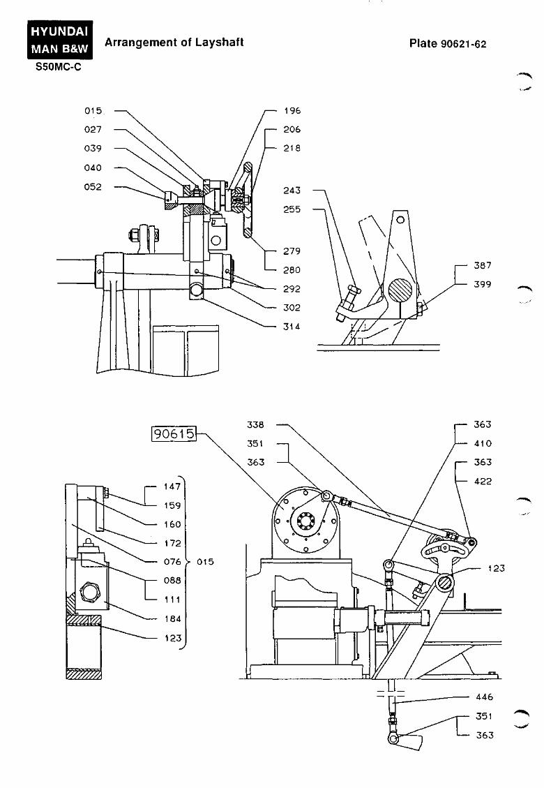
Arrangement of Layshaft Plate 90621-62
--"•"N.
•^,,-»»'
387
399
123
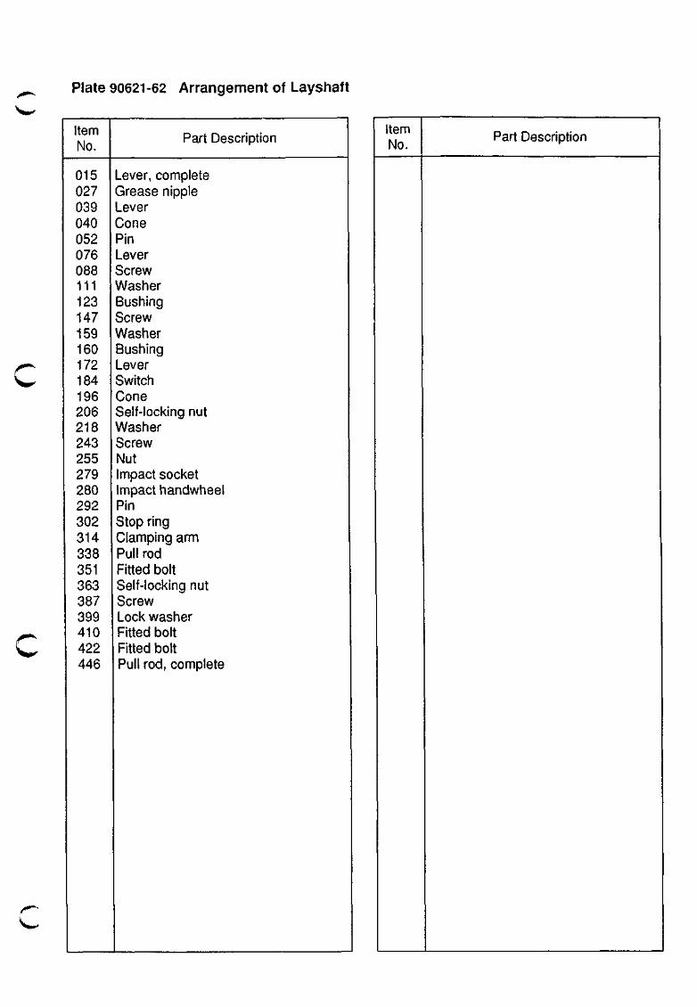
Plate 90621-62 Arrangement of Layshaft
Item No.
015 027 039 040 052 076 088 111 123 147 159 160 172 184 196 206 218 243 255 279 280 292 302 314 338 351 363 387 399 410 422 446
Part Description
Lever, complete Grease nipple Lever Cone Pin Lever Screw Washer Bushing Screw Washer Bushing Lever Switch Cone Self-locking nut Washer Screw Nut Impact socket Impact handwheel Pin Stop ring Clamping arm Pull rod Fitted bolt Self-locking nut Screw Lock washer Fitted bolt Fitted bolt Pull rod, complete
Item No.
Part Description

STARTING AIR COMPONENTS
907

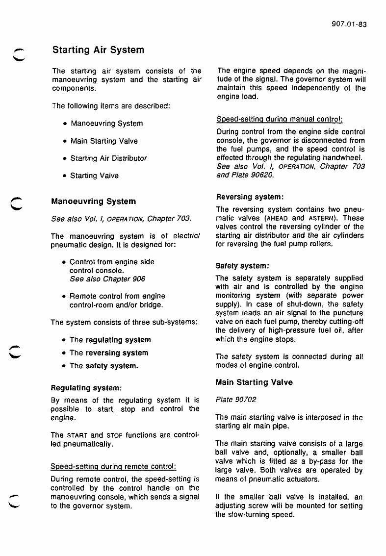
Starting Air System
907.01-83
The starting air system consists of the manoeuvring system and the starting air components.
The following items are described:
• Manoeuvring System
• Main Starting Valve
• Starting Air Distributor
• Starting Valve
The engine speed depends on the magnitude of the signal. The governor system will maintain this speed independently of the engine load.
Speed-setting during manual control:
During control from the engine side control console, the governor is disconnected from the fuel pumps, and the speed control is effected through the regulating handwheel. See also Vol. I, OPERATION, Chapter 703 and Plate 90620.
c
.^^"^
Manoeuvring System
See also Vol. I, OPERATION, Chapter 703.
The manoeuvring system is of electric/ pneumatic design. It is designed for:
• Control from engine side control console. See also Chapter 906
• Remote control from engine control-room and/or bridge.
The system consists of three sub-systems:
• The regulating system
• The reversing system
• The safety system.
Regulating system:
By means of the regulating system it is possible to start, stop and control the engine.
The START and STOP functions are controlled pneumatically.
Speed-settinq during remote control:
During remote control, the speed-setting is controlled by the control handle on the manoeuvring console, which sends a signal to the governor system.
Reversing system:
The reversing system contains two pneumatic valves (AHEAD and ASTERN). These valves control the reversing cylinder of the starting air distributor and the air cylinders for reversing the fuel pump rollers.
Safety system:
The safety system is separately supplied with air and is controlled by the engine monitoring system (with separate power supply). In case of shut-down, the safety system leads an air signal to the puncture valve on each fuel pump, thereby cutting-off the delivery of high-pressure fuel oil, after which the engine stops.
The safety system is connected during all modes of engine control.
IVIain Starting Valve
Plate 90702
The main starting valve is interposed in the starting air main pipe.
The main starting valve consists of a large ball valve and, optionally, a smaller ball valve which is fitted as a by-pass for the large valve. Both valves are operated by means of pneumatic actuators.
If the smaller ball valve is installed, an adjusting screw will be mounted for setting the slow-turning speed.
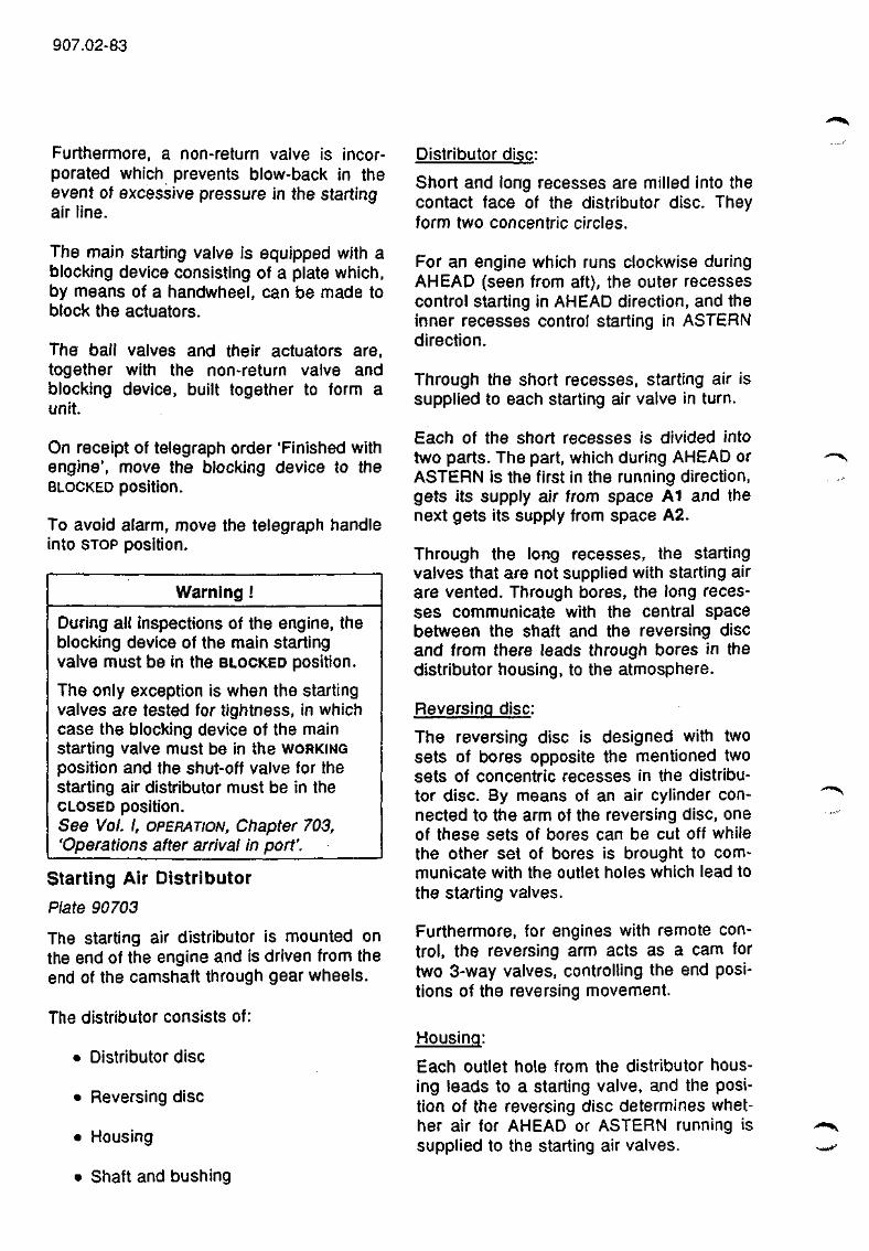
907.02-83
Furthermore, a non-return valve is incorporated which prevents blow-back in the event of excessive pressure in the starting air line.
The main starting valve is equipped with a blocking device consisting of a plate which, by means of a handwheel, can be made to block the actuators.
The ball valves and their actuators are, together with the non-return valve and blocking device, built together to form a unit.
On receipt of telegraph order 'Finished with engine", move the blocking device to the BLOCKED position.
To avoid alarm, move the telegraph handle into STOP position.
Warning
During all inspections of the engine, the blocking device of the main starting valve must be in the BLOCKED position.
The only exception is when the starting valves are tested for tightness, in which case the blocking device of the main starting valve must be in the WORKING position and the shut-off valve for the starting air distributor must be in the CLOSED position. See Vol. I, OPERATION, Chapter 703, 'Operations after arrival in port'.
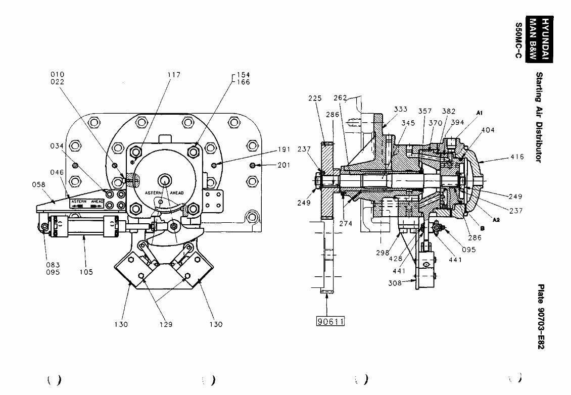
Starting Air Distributor
Plate 90703
The starting air distributor is mounted on the end of the engine and is driven from the end of the camshaft through gear wheels.
The distributor consists of:
• Distributor disc
• Reversing disc
• Housing
• Shaft and bushing
Distributor disc:
Short and long recesses are milled into the contact face of the distributor disc. They form two concentric circles.
For an engine which runs clockwise during AHEAD (seen from aft), the outer recesses control starting in AHEAD direction, and the inner recesses control starting in ASTERN direction.
Through the short recesses, starting air is supplied to each starting air valve in turn.
Each of the short recesses is divided into two parts. The part, which during AHEAD or ASTERN is the first in the running direction, gets its supply air from space A1 and the next gets its supply from space A2.
Through the long recesses, the starting valves that are not supplied with starting air are vented. Through bores, the long recesses communicate with the central space between the shaft and the reversing disc and from there leads through bores in the distributor housing, to the atmosphere.
Reversing disc:
The reversing disc is designed with two sets of bores opposite the mentioned two sets of concentric recesses in the distributor disc. By means of an air cylinder connected to the arm of the reversing disc, one of these sets of bores can be cut off while the other set of bores is brought to communicate with the outlet holes which lead to the starting valves.
Furthermore, for engines with remote control, the reversing arm acts as a cam for two 3-way valves, controlling the end positions of the reversing movement.
Housing:
Each outlet hole from the distributor housing leads to a starting valve, and the position of the reversing disc determines whether air for AHEAD or ASTERN running is supplied to the starting air valves.
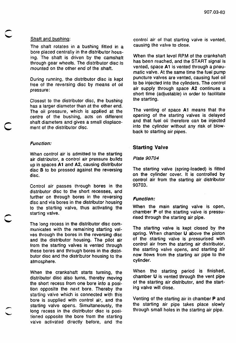
907.03-83
Shaft and bushing:
The shaft rotates In a bushing fitted in a bore placed centrally In the distributor housing. The shaft is driven by the camshaft through gear wheels. The distributor disc is mounted on the other end of the shaft.
During running, the distributor disc is kept free of the reversing disc by means of oil pressure:
Closest to the distributor disc, the bushing has a larger diameter than at the other end. The oil pressure, which is applied at the centre of the bushing, acts on different shaft diameters and gives a small displacement of the distributor disc.
control air of that starting valve is vented, causing the valve to close.
When the start level RPf\/l of the crankshaft has been reached, and the START signal is vented, space A1 is vented through a pneumatic valve. At the same time the fuel pump puncture valves are vented, causing fuel oil to be injected into the cylinders. The control air supply through space A2 continues a short time (adjustable) in order to facilitate the starting.
The venting of space A1 means that the opening of the starting valves is delayed and that fuel oil therefore can be injected into the cylinder without any risk of blow-back to starting air pipes.
Function:
When control air is admitted to the starting air distributor, a control air pressure builds up in spaces A1 and A2, causing distributor disc B to be pressed against the reversing disc.
Control air passes through bores in the distributor disc to the short recesses, and further on through bores in the reversing disc and via bores in the distributor housing to the starting valve, thus activating the starting valve.
The long recess in the distributor disc communicates with the remaining starting valves through the bores in the reversing disc and the distributor housing. The pilot air from the starting valves is vented through these bores and through bores in the distributor disc and the distributor housing to the atmosphere.
When the crankshaft starts turning, the distributor disc also turns, thereby moving the short recess from one bore into a position opposite the next bore. Thereby the starting valve which is connected with this bore is supplied with control air, and the starting valve opens. Simultaneously, the long recess in the distributor disc is positioned opposite the bore from the starting valve activated directly before, and the
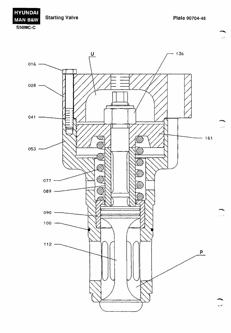
Starting Valve
Plate 90704
The starting valve (spring-loaded) is fitted on the cylinder cover. It is controlled by control air from the starting air distributor 90703.
Function:
When the main starting valve is open, chamber P of the starting valve is pressurised through the starting air pipe.
The starting valve is kept closed by the spring. When chamber U above the piston of the starting valve is pressurised with control air from the starting air distributor, the starting valve opens, and starting air now flows from the starting air pipe to the cylinder.
When the starting period is finished, chamber U is vented through the vent pipe of the starting air distributor, and the starting valve will close.
Venting of the starting air in chamber P and the starting air pipe takes place slowly through small holes in the starting air pipe.
HYUNDAI
MAN B&W
S50MC-C
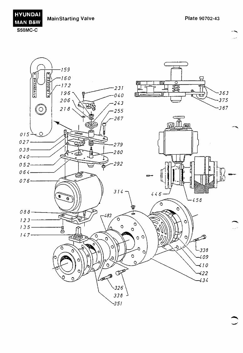
MainStarting Valve Plate 90702-43
-351
• • • « •
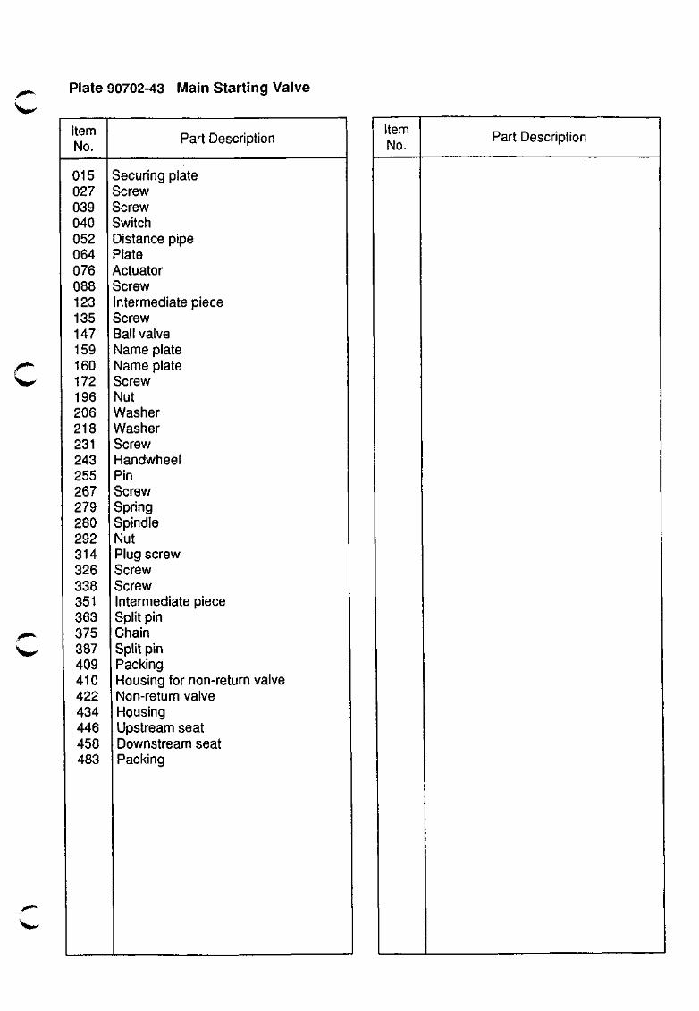
Plate 90702-43 Main Starting Valve
Item No.
015 027 039 040 052 064 076 088 123 135 147 159 160 172 196 206 218 231 243 255 267 279 280 292 314 326 338 351 363 375 387 409 410 422 434 446 458 483
Part Description
Securing plate Screw Screw Switch Distance pipe Plate Actuator Screw Intermediate piece Screw Ball valve Name plate Name plate Screw Nut Washer Washer Screw Handwheel Pin Screw Spring Spindle Nut Plug screw Screw Screw Intermediate piece Split pin Chain Split pin Packing Housing for non-return valve Non-return valve Housing Upstream seat Downstream seat Packing
Item No.
Part Description
(/) en o
o o
S z > -<
li
^^^ 357 382
130 129 130
416
9061 II
0)
3-. 5' (a
o
or c o
•V 0) (D
(O O
o
m 00
ro
i ) ) )
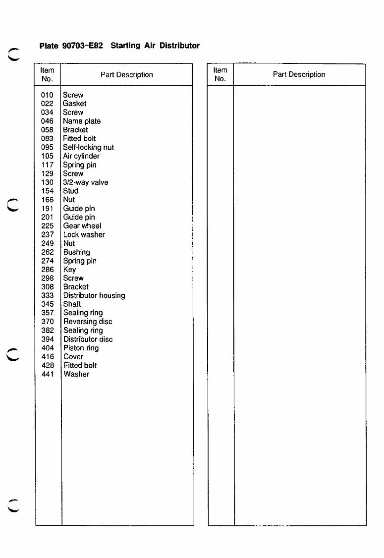
Plate 90703-E82 Starting Air Distributor
Item No.
010 022 034 046 058 083 095 105 117 129 130 154 166 191 201 225 237 249 262 274 286 298 308 333 345 357 370 382 394 404 416 428 441
Part Description
Screw Gasket Screw Name plate Bracket Fitted bolt Self-locking nut Air cylinder Spring pin Screw 3/2-way valve Stud Nut Guide pin Guide pin Gearwheel Lock washer Nut Bushing Spring pin Key Screw Bracket Distributor housing Shaft Sealing ring Reversing disc Sealing ring Distributor disc Piston ring Cover Fitted bolt Washer
Item No.
Part Description
HYUNDAI MAN B&W SSOMC-C
Starting Valve Plate 90704-46
016
028
041
053
161
>«**«h^
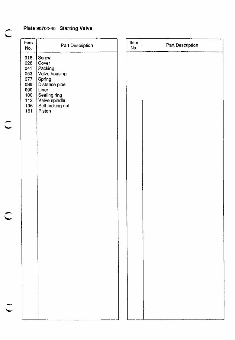
Plate 90704-46 starting Valve
Item No.
016 028 041 053 077 089 090 100 112 136 161
Part Description
Screw Cover Packing Valve housing Spring Distance pipe Liner Sealing ring Valve spindle Self-locking nut Piston
Item No.
Part Description
EXHAUST VALVE
908
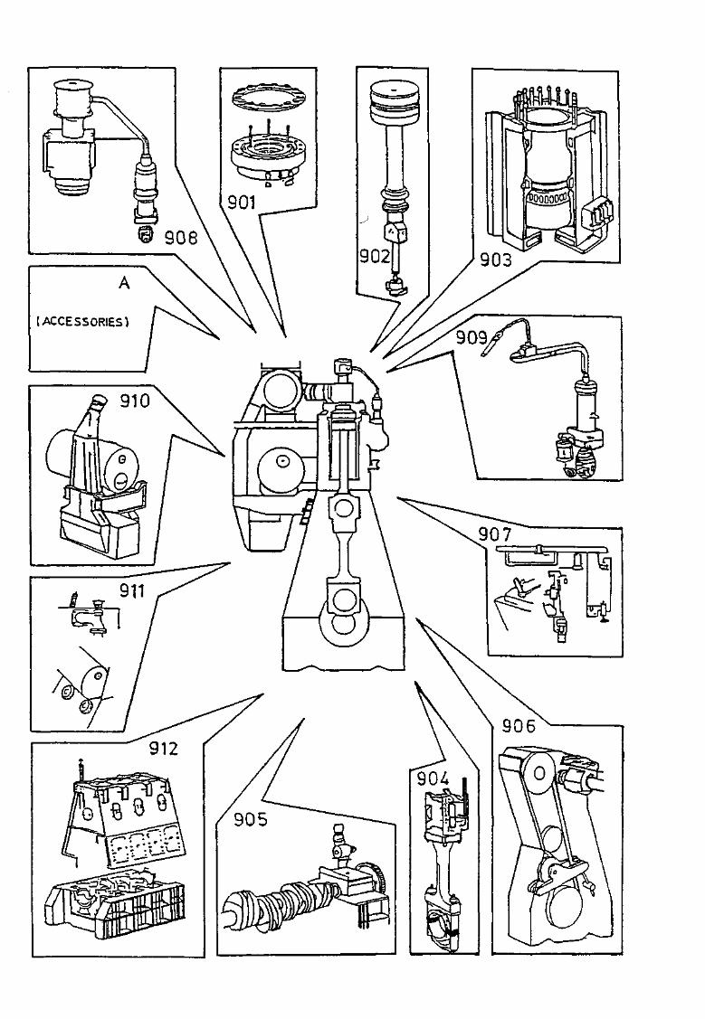
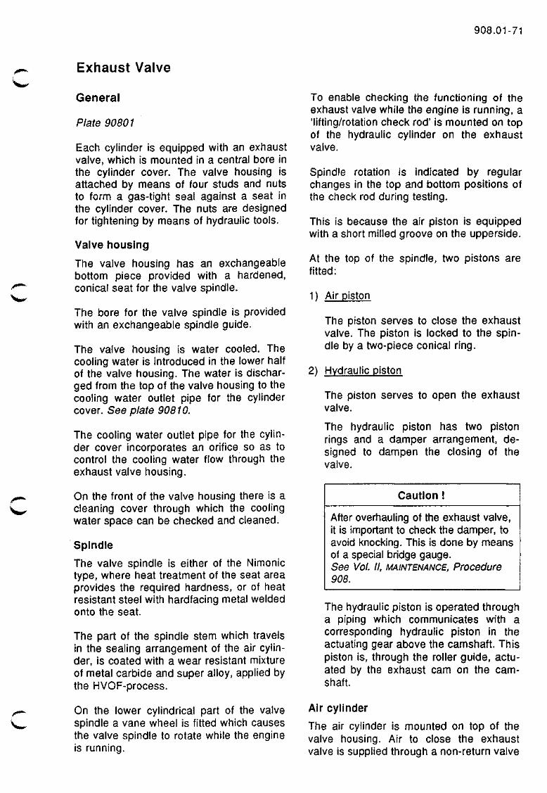
Exhaust Valve
908.01-71
General
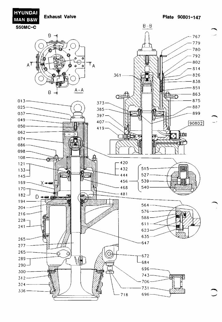
Plate 90801
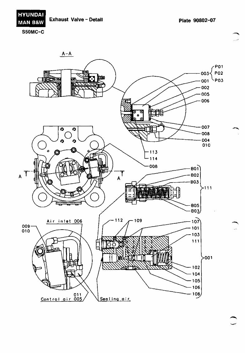
Each cylinder is equipped with an exhaust valve, which is mounted in a central bore in the cylinder cover. The valve housing is attached by means of four studs and nuts to form a gas-tight seal against a seat in the cylinder cover. The nuts are designed for tightening by means of hydraulic tools.
Valve housing
The valve housing has an exchangeable bottom piece provided with a hardened, conical seat for the valve spindle.
The bore for the valve spindle is provided with an exchangeable spindle guide.
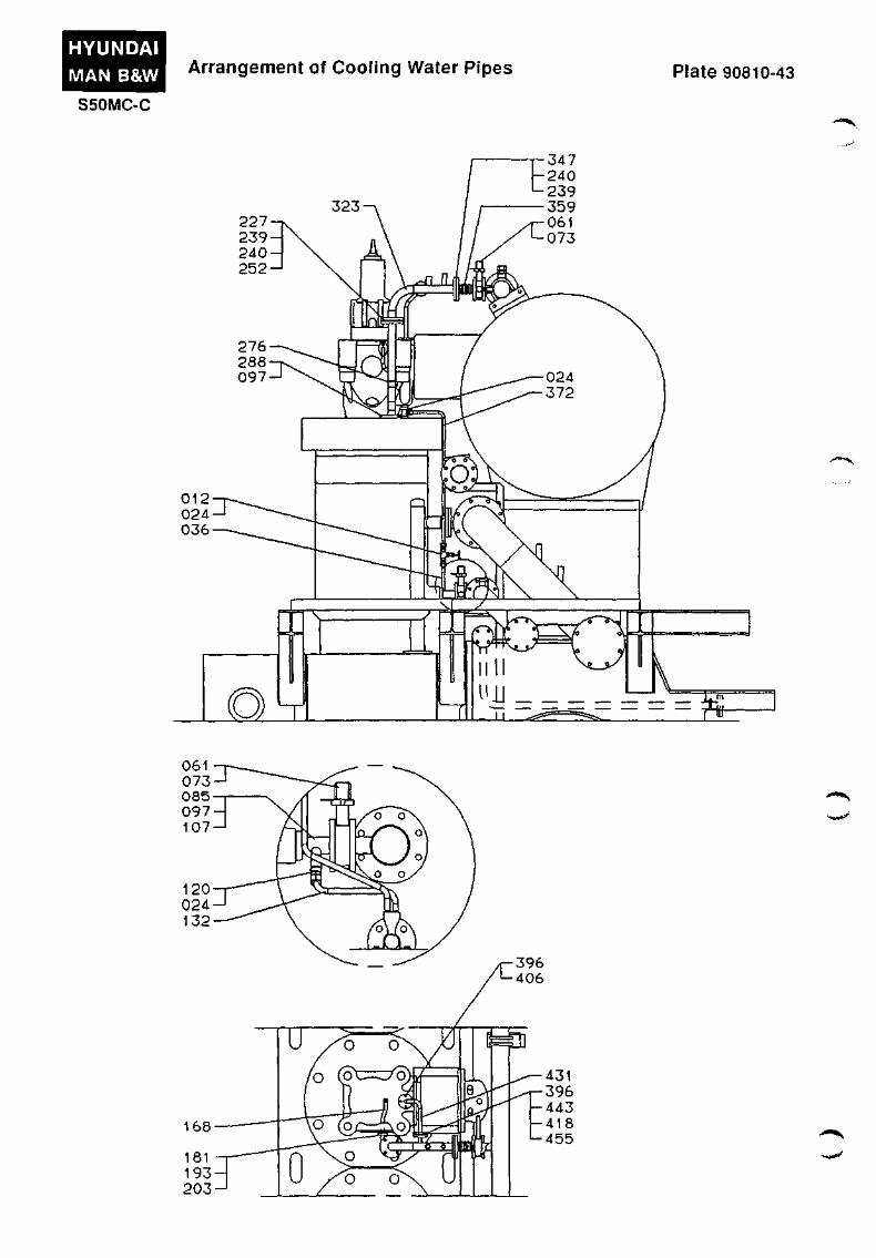
The valve housing is water cooled. The cooling water is introduced in the lower half of the valve housing. The water is discharged from the top of the valve housing to the cooling water outlet pipe for the cylinder cover. See plate 90810.
The cooling water outlet pipe for the cylinder cover incorporates an orifice so as to control the cooling water flow through the exhaust valve housing.
On the front of the valve housing there is a cleaning cover through which the cooling water space can be checked and cleaned.
Spindle
The valve spindle is either of the Nimonic type, where heat treatment of the seat area provides the required hardness, or of heat resistant steel with hardfacing metal welded onto the seat.
The part of the spindle stem which travels in the sealing arrangement of the air cylinder, is coated with a wear resistant mixture of metal carbide and super alloy, applied by the HVOF-process.
On the lower cylindrical part of the valve spindle a vane wheel is fitted which causes the valve spindle to rotate while the engine is running.
To enable checking the functioning of the exhaust valve while the engine is running, a 'lifting/rotation check rod' is mounted on top of the hydraulic cylinder on the exhaust valve.
Spindle rotation is indicated by regular changes in the top and bottom positions of the check rod during testing.
This is because the air piston is equipped with a short milled groove on the upperside.
At the top of the spindle, two pistons are fitted:
1) Air piston
The piston serves to close the exhaust valve. The piston is locked to the spindle by a two-piece conical ring.
2) Hydraulic piston
The piston serves to open the exhaust valve.
The hydraulic piston has two piston rings and a damper arrangement, designed to dampen the closing of the valve.
Caution !
After overhauling of the exhaust valve, it is important to check the damper, to avoid knocking. This is done by means of a special bridge gauge. See Vol. II, MAINTENANCE, Procedure 908.
The hydraulic piston is operated through a piping which communicates with a corresponding hydraulic piston in the actuating gear above the camshaft. This piston is, through the roller guide, actuated by the exhaust cam on the camshaft.
Air cylinder
The air cylinder is mounted on top of the valve housing. Air to close the exhaust valve is supplied through a non-return valve
908.02-71
and a bore in the sealing air control unit and through a curved pipe to the space below the piston.
Two sealing rings are mounted in the bottom of the air cylinder housing. A drain hole D between these rings reveals when the sealing is not sufficient.
A safety valve is mounted in the bottom of the cylinder.
Hydraulic cylinder
The hydraulic cylinder is mounted on the air cylinder on top of the exhaust valve housing by means of studs and nuts.
The exhaust valve is opened by the valve spindle being pressed down by the hydraulic piston in the hydraulic cylinder.
An orifice designed for deaerating the oil system is fitted below the lifting eye bolt at the top of the cylinder.
Oil which escapes through this orifice is led through a duct to the space around the air cylinder and is drained off through a bore X, together with leakage oil from the piston.
Sealing air
Plates 90801 -90802
A sealing air arrangement is fitted around the spindle shaft under the bottom of the air cylinder.
The sealing air is supplied from the air cylinder and introduced below the sealing rings via a sealing air control unit and an orifice pipe.
The sealing air will prevent the exhaust gas and particles from penetrating upwards and wear-out the running surfaces and polluting the pneumatic system of the valve gear.
The oil mist content in the air from the air cylinder improves the service condition of the sealing rings.
The sealing air control unit contains a valve which automatically cuts off the air flow when the engine is in FINISHED WITH ENGINE
status, and a filter housing.
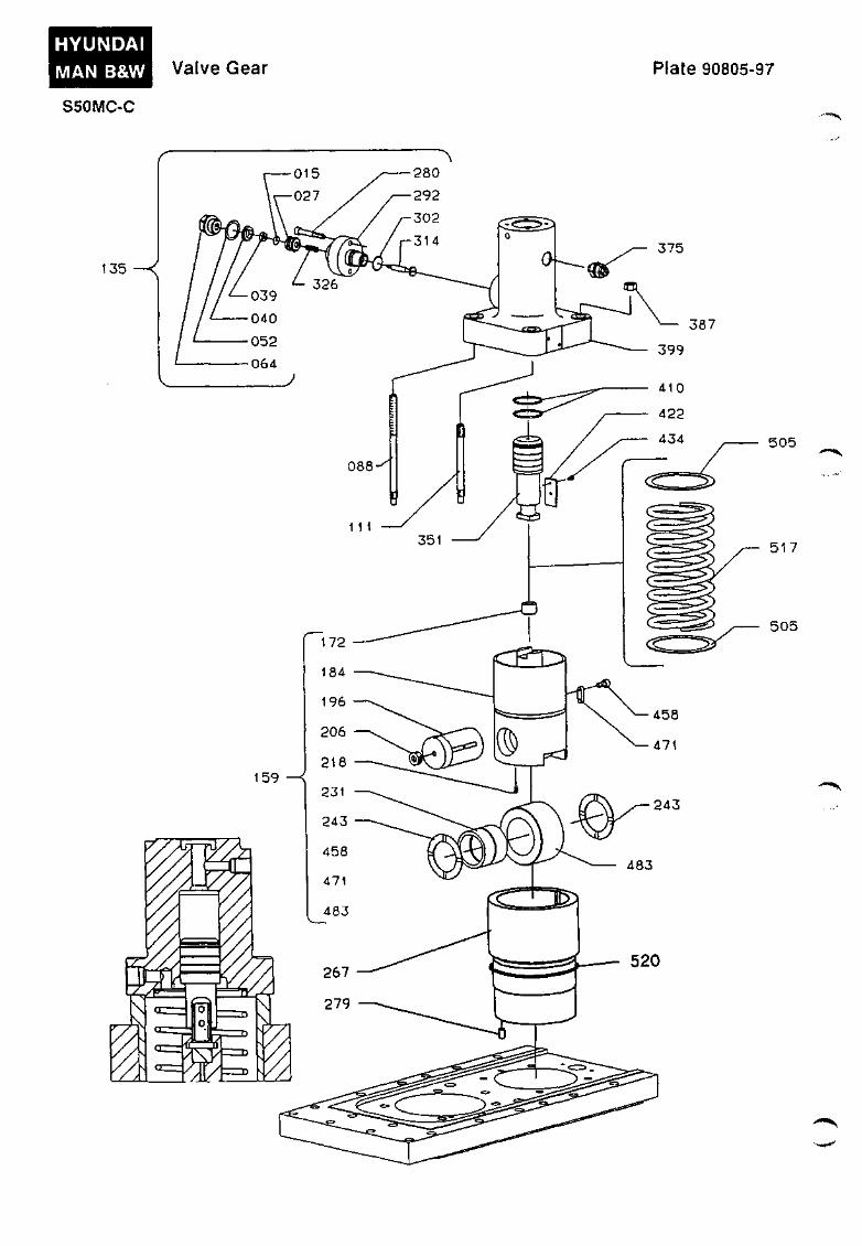
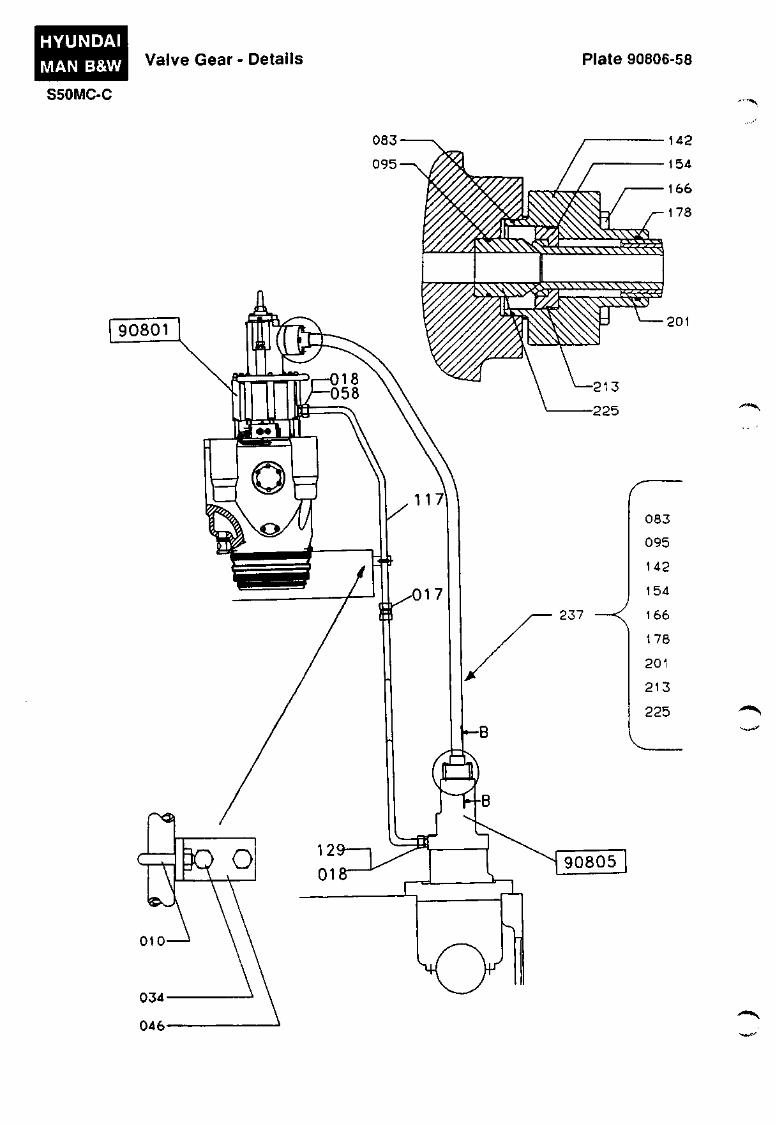
Hydraulic Valve Actuating Gear
Plates 90805 - 90806
The exhaust valve is actuated by a cam on the camshaft through a hydraulic transmission.
A roller guide is kept in contact with the cam by the action of a helical spring which is fixed between the roller guide and the hydraulic cylinder so that the roller of the roller guide will follow the cam on the camshaft.
The hydraulic cylinder is attached to the camshaft housing by four studs, two of which are long enough to permit the spring of the roller guide to be gradually relieved during dismantling of the components.
The roller guide is prevented from turning by means of a key and a keyway.
A piston, which is enclosed in the hydraulic cylinder, rests on a thrust piece in the neck of the roller guide and is locked to the roller guide by a bayonet joint.
The hydraulic cylinder on the camshaft housing is connected to the hydraulic cylinder on the exhaust valve by means of a high-pressure pipe.
Oil is supplied from the lubricating oil system through a non-return valve in the top of the hydraulic cylinder.
Leakage oil from the hydraulic cylinder on the exhaust valve is drained through a pipe connection to the baseplate of the hydraulic cylinder on the camshaft housing. From there the oil is drained off through a bore to the camshaft housing.
A special tool is delivered, which is able to retain the roller guide in its top position and thus put the exhaust valve out of action. See Vol. II, MAINTENANCE, Procedure 908.
'•mt^
908.03-71
Another special tool is delivered, which is able to retain the exhaust valve spindle in the open position. See Vol. II, MAINTENANCE, Procedure 908.
HYUNDAI
MAN B&W
S50MC-C
Exhaust Valve Plate 90801-147
B-B
""^""^
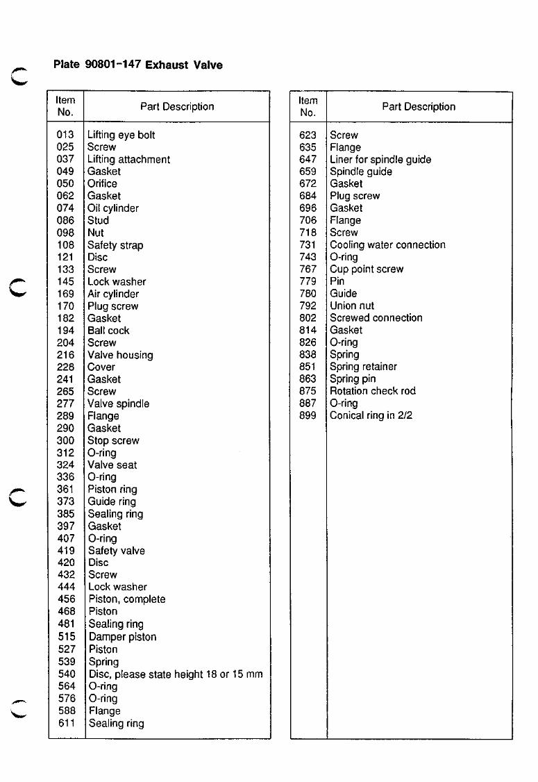
Plate 90801-147 Exhaust Valve
Item No.
013 025 037 049 050 062 074 086 098 108 121 133 145 169 170 182 194 204 216 228 241 265 277 289 290 300 312 324 336 361 373 385 397 407 419 420 432 444 456 468 481 515 527 539 540 564 576 588 611
Part Description
Lifting eye bolt Screw Lifting attacliment Gasket Orifice Gasket Oil cylinder Stud Nut Safety strap Disc Screw Lock washer Air cylinder Plug screw Gasket Ball cock Screw Valve housing Cover Gasket Screw Valve spindle Flange Gasket Stop screw 0-ring Valve seat 0-ring Piston ring Guide ring Sealing ring Gasket 0-ring Safety valve Disc Screw Lock washer Piston, complete Piston Sealing ring Damper piston Piston Spring Disc, please state height 18 or 15 mm 0-ring 0-ring Flange Sealing ring
Item No.
623 635 647 659 672 684 696 706 718 731 743 767 779 780 792 802 814 826 838 851 863 875 887 899
Part Description
Screw Flange Liner for spindle guide Spindle guide Gasket Plug screw Gasket Flange Screw Cooling water connection 0-ring Cup point screw Pin Guide Union nut Screwed connection Gasket 0-ring Spring Spring retainer Spring pin Rotation check rod 0-ring Conical ring in 2/2
HYUNDAI
MAN B&W Exhaust Valve - Detail Plate 90802-07
S50MC-C
A-A
^ P O l
003< P02
001 ^ P 0 3
> i n
>ooi
,...tmt)^
O i l Cont r o I a i r 005
""s.
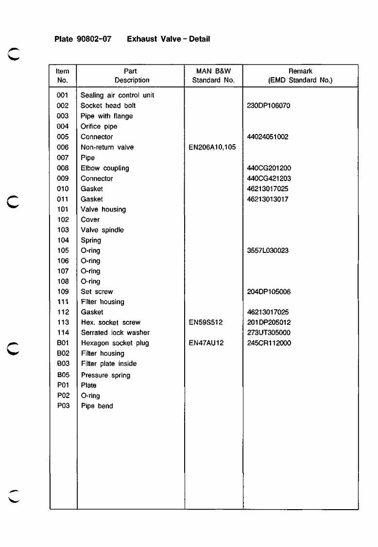
Plate 90802-07 Exhaust Valve - Detail
Item No.
001
002 003
004
005
006
007
008
009
010
011 101 102
103 104
105
106 107 108 109 111
112 113 114
B01
B02 B03
805 P01
P02 P03
Part Description
Sealing air control unit
Socket head bolt Pipe with flange
Orifice pipe
Connector
Non-return valve
Pipe
Elbow coupling
Connector
Gasket Gasket Valve housing Cover
Valve spindle Spring
0-ring 0-ring 0-ring O-ring
Set screw Filter housing
Gasket Hex. socket screw Serrated lock washer
Hexagon socket plug
Filter housing Filter plate inside
Pressure spring Plate
0-ring Pipe bend
MAN B&W Standard No.
EN206A10,105
EN59S512
EN47AU12
Remark (EMD Standard No.)
230DP106070
44024051002
440CG201200
440CG421203
46213017025
46213013017
3557L030023
204DP105006
46213017025 201DP205012
273UT305000
245CR112000
HYUNDAI MAN B&W Valve Gear Plate 90805-97
S50MC-C . • ' ' • * - ^
135
505
517
5 0 5
J^""*^
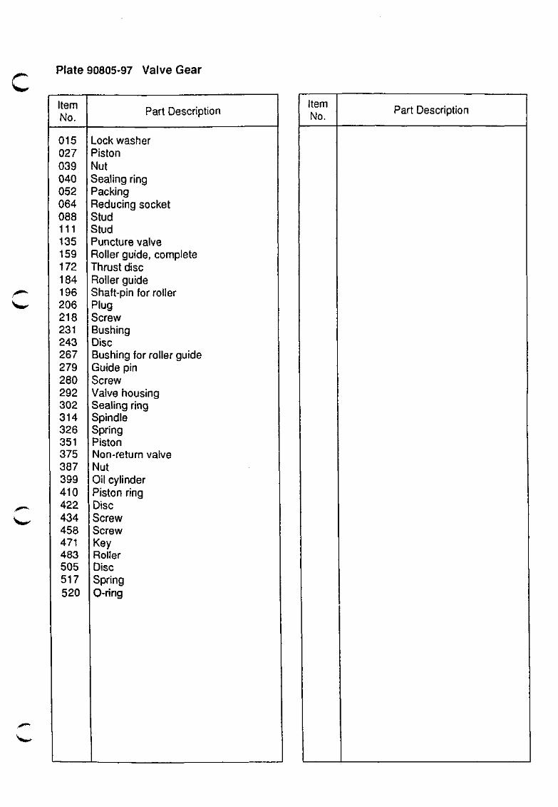
\^^ Plate 90805-97 Valve Gear
Item No.
015 027 039 040 052 064 088 111 135 159 172 184 196 206 218 231 243 267 279 280 292 302 314 326 351 375 387 399 410 422 434 458 471 483 505 517 520
Part Description
Lock washer Piston Nut Sealing ring Packing Reducing socket Stud Stud Puncture valve Roller guide, complete Thrust disc Roller guide Shaft-pin for roller Plug Screw Bushing Disc Bushing for roller guide Guide pin Screw Valve housing Sealing ring Spindle Spring Piston Non-return valve Nut Oil cylinder Piston ring Disc Screw Screw Key Roller Disc Spring 0-ring
Item No. Part Description
\ ^
HYUNDAI MAN B&W
S50MC-C
Valve Gear - Details Plate 90806-58
• " • ^
Plate 90806-58 Valve Gear - Details
/ • " * •
Item No.
010 017 018 034 046 058 083 095 117 129 142 154 166 178 201 213 225 237
Part Description
U-bolt Connector Gasket Screw Support Coupling Sealing ring Sealing ring Pipe, L=2160 Coupling Thrust flange Sleeve in 2/2 Screw 0-ring High-pressure pipe Spring ring Intermediate piece High-pressure pipe, complete
Item No. Part Description
HYUNDAI
MAN B&W Arrangement of Cooling Water Pipes Plate 90810-43
S50MC-C
347
012 024 036
--*~^
• • - i * ^
Plate 90810-43 Arrangement of Cooling Water Pipes
Item No.
012 024 036 061 073 085 097 107 120 132 168 181 193 203 227 239 240 252 276 288 323 347 359 372 396 406 418 431 443 455
Part Description
Valve Coupling Pipe Butterfly valve Screw Pipe Screw Packing Ball valve Drain pipe Pipe (inside valve housing) Packing Screw Screw Screw Nut Packing Orifice plate Cooling pipe Packing Cooling pipe Screw Compensator Pipe Packing Screw Screw Cooling pipe Orifice plate Nut
Item No. Part Description
FUEL OIL SYSTEM
909

Fuel Oil System
909.01-95
^^0*^.
^\^
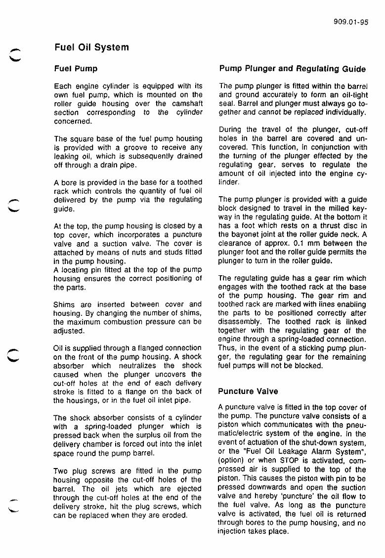
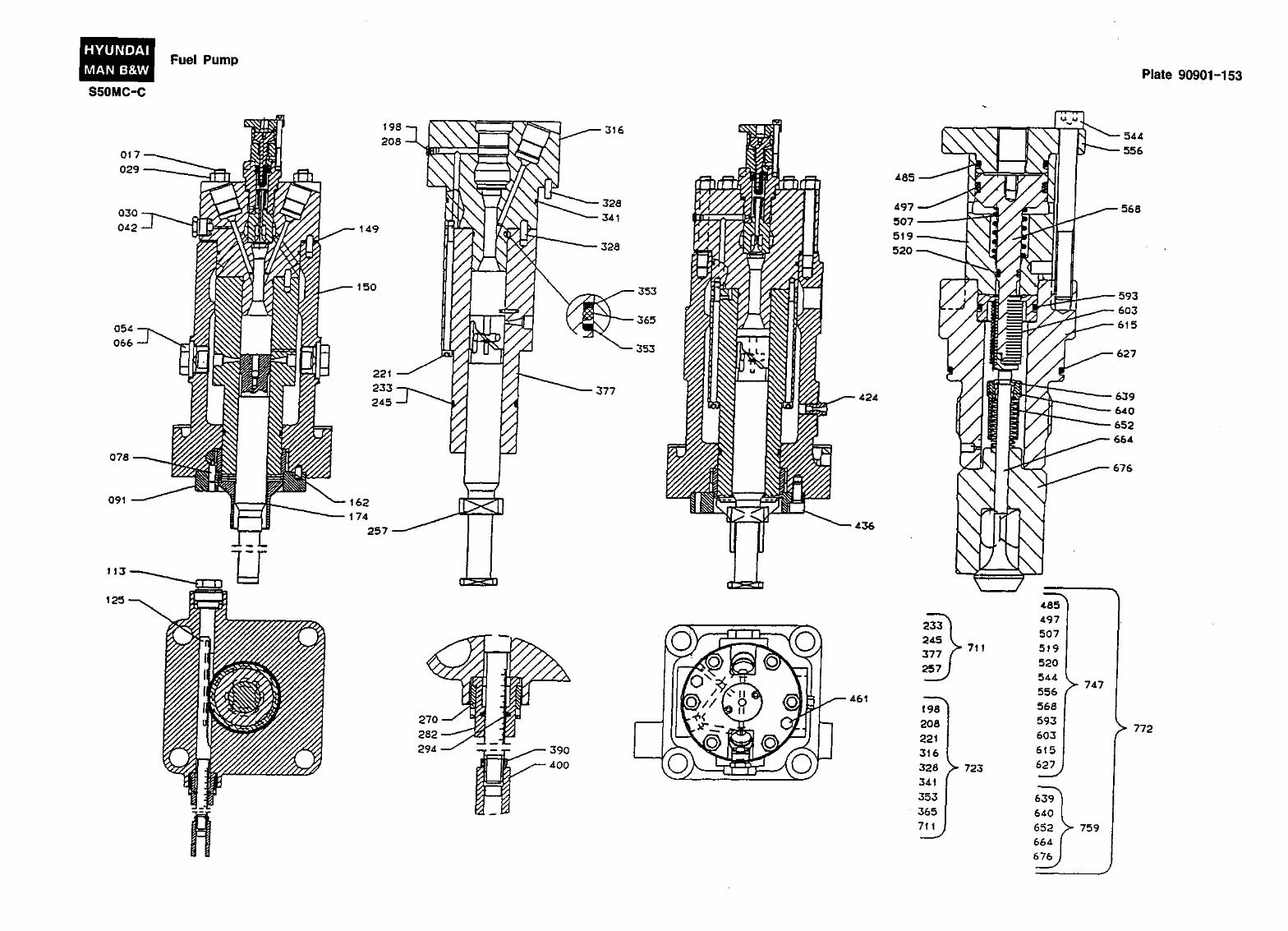
Fuel Pump
Each engine cylinder is equipped with its own fuel pump, which is mounted on the roller guide housing over the camshaft section corresponding to the cylinder concerned.
The square base of the fuel pump housing is provided with a groove to receive any leaking oil, which is subsequently drained off through a drain pipe.
A bore is provided in the base for a toothed rack which controls the quantity of fuel oil delivered by the pump via the regulating guide.
At the top, the pump housing is closed by a top cover, which incorporates a puncture valve and a suction valve. The cover is attached by means of nuts and studs fitted in the pump housing. A locating pin fitted at the top of the pump housing ensures the correct positioning of the parts.
Shims are inserted between cover and housing. By changing the number of shims, the maximum combustion pressure can be adjusted.
Oil is supplied through a flanged connection on the front of the pump housing. A shock absorber which neutralizes the shock caused when the plunger uncovers the cut-off holes at the end of each delivery stroke is fitted to a flange on the back of the housings, or in the fuel oil inlet pipe.
The shock absorber consists of a cylinder with a spring-loaded plunger which is pressed back when the surplus oil from the delivery chamber is forced out into the inlet space round the pump barrel.
Two plug screws are fitted in the pump housing opposite the cut-off holes of the barrel. The oil jets which are ejected through the cut-off holes at the end of the delivery stroke, hit the plug screws, which can be replaced when they are eroded.
Pump Plunger and Regulating Guide
The pump plunger is fitted within the barrel and ground accurately to form an oil-tight seal. Barrel and plunger must always go together and cannot be replaced individually.
During the travel of the plunger, cut-off holes in the barrel are covered and uncovered. This function, in conjunction with the turning of the plunger effected by the regulating gear, serves to regulate the amount of oil injected into the engine cylinder.
The pump plunger is provided with a guide block designed to travel in the milled key-way in the regulating guide. At the bottom it has a foot which rests on a thrust disc in the bayonet joint at the roller guide neck. A clearance of approx. 0.1 mm between the plunger foot and the roller guide permits the plunger to turn in the roller guide.
The regulating guide has a gear rim which engages with the toothed rack at the base of the pump housing. The gear rim and toothed rack are marked with lines enabling the parts to be positioned correctly after disassembly. The toothed rack is linked together with the regulating gear of the engine through a spring-loaded connection. Thus, in the event of a sticking pump plunger, the regulating gear for the remaining fuel pumps will not be blocked.
Puncture Valve
A puncture valve is fitted in the top cover of the pump. The puncture valve consists of a piston which communicates with the pneumatic/electric system of the engine. In the event of actuation of the shut-down system, or the "Fuel Oil Leakage Alarm System", (option) or when STOP is activated, compressed air is supplied to the top of the piston. This causes the piston with pin to be pressed downwards and open the suction valve and hereby 'puncture' the oil flow to the fuel valve. As long as the puncture valve is activated, the fuel oil is returned through bores to the pump housing, and no injection takes place.
909.02-95
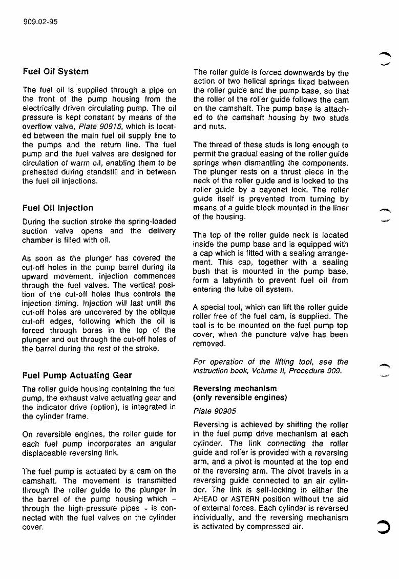
Fuel Oil System
The fuel oil is supplied through a pipe on the front of the pump housing from the electrically driven circulating pump. The oil pressure is kept constant by means of the overflow valve, Plate 90915, which is located between the main fuel oil supply line to the pumps and the return line. The fuel pump and the fuel valves are designed for circulation of warm oil, enabling them to be preheated during standstill and in between the fuel oil injections.
Fuel Oil Injection
During the suction stroke the spring-loaded suction valve opens and the delivery chamber is filled with oil.
As soon as the plunger has covered the cut-off holes in the pump barrel during its upward movement, injection commences through the fuel valves. The vertical position of the cut-off holes thus controls the injection timing. Injection will last until the cut-off holes are uncovered by the oblique cut-off edges, following which the oil is forced through bores in the top of the plunger and out through the cut-off holes of the barrel during the rest of the stroke.
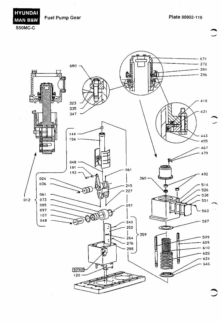
Fuel Pump Actuating Gear
The roller guide housing containing the fuel pump, the exhaust valve actuating gear and the indicator drive (option), is integrated in the cylinder frame.
On reversible engines, the roller guide for each fuel pump incorporates an angular displaceable reversing link.
The fuel pump is actuated by a cam on the camshaft. The movement is transmitted through the roller guide to the plunger in the barrel of the pump housing which -through the high-pressure pipes - is connected with the fuel valves on the cylinder cover.
The roller guide is forced downwards by the action of two helical springs fixed between the roller guide and the pump base, so that the roller of the roller guide follows the cam on the camshaft. The pump base is attached to the camshaft housing by two studs and nuts.
The thread of these studs is long enough to permit the gradual easing of the roller guide springs when dismantling the components. The plunger rests on a thrust piece in the neck of the roller guide and is locked to the roller guide by a bayonet lock. The roller guide itself is prevented from turning by means of a guide block mounted in the liner of the housing.
The top of the roller guide neck is located inside the pump base and is equipped with a cap which is fitted with a sealing arrangement. This cap, together with a sealing bush that is mounted in the pump base, form a labyrinth to prevent fuel oil from entering the lube oil system.
A special tool, which can lift the roller guide roller free of the fuel cam, is supplied. The tool is to be mounted on the fuel pump top cover, when the puncture valve has been removed.
For operation of the lifting tool, see the instruction book, Volume II, Procedure 909.
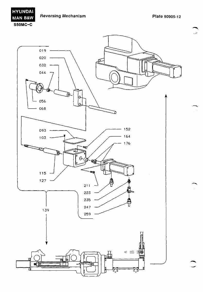
Reversing mechanism (only reversible engines)
Plate 90905
Reversing is achieved by shifting the roller in the fuel pump drive mechanism at each cylinder. The link connecting the roller guide and roller is provided with a reversing arm, and a pivot is mounted at the top end of the reversing arm. The pivot travels in a reversing guide connected to an air cylinder. The link is self-locking in either the AHEAD or ASTERN position without the aid of external forces. Each cylinder is reversed individually, and the reversing mechanism is activated by compressed air.
909.03-95
/ " ^
c
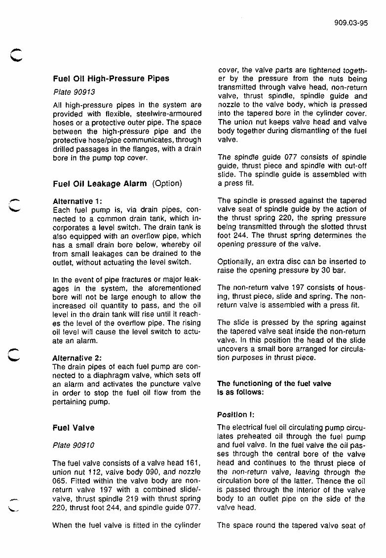
Fuel Oil High-Pressure Pipes
Plate 90913
All high-pressure pipes in the system are provided with flexible, steelwire-armoured hoses or a protective outer pipe. The space between the high-pressure pipe and the protective hose/pipe communicates, through drilled passages in the flanges, with a drain bore in the pump top cover.
Fuel Oil Leakage Alarm (Option)
Alternative 1 : Each fuel pump is, via drain pipes, connected to a common drain tank, which incorporates a level switch. The drain tank is also equipped with an overflow pipe, which has a small drain bore below, whereby oil from small leakages can be drained to the outlet, without actuating the level switch.
In the event of pipe fractures or major leakages in the system, the aforementioned bore will not be large enough to allow the increased oil quantity to pass, and the oil level in the drain tank will rise until it reaches the level of the overflow pipe. The rising oil level will cause the level switch to actuate an alarm.
Alternative 2: The drain pipes of each fuel pump are connected to a diaphragm valve, which sets off an alarm and activates the puncture valve in order to stop the fuel oil flow from the pertaining pump.
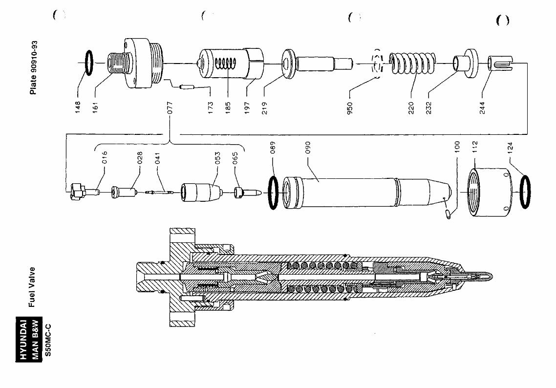
Fuel Valve
Plate 90910
The fuel valve consists of a valve head 161, union nut 112, valve body 090, and nozzle 065. Fitted within the valve body are nonreturn valve 197 with a combined slide/-valve, thrust spindle 219 with thrust spring 220, thrust foot 244, and spindle guide 077.
cover, the valve parts are tightened together by the pressure from the nuts being transmitted through valve head, non-return valve, thrust spindle, spindle guide and nozzle to the valve body, which is pressed into the tapered bore in the cylinder cover. The union nut keeps valve head and valve body together during dismantling of the fuel valve.
The spindle guide 077 consists of spindle guide, thrust piece and spindle with cut-off slide. The spindle guide is assembled with a press fit.
The spindle is pressed against the tapered valve seat of spindle guide by the action of the thrust spring 220, the spring pressure being transmitted through the slotted thrust foot 244. The thrust spring determines the opening pressure of the valve.
Optionally, an extra disc can be inserted to raise the opening pressure by 30 bar.
The non-return valve 197 consists of housing, thrust piece, slide and spring. The nonreturn valve is assembled with a press fit.
The slide is pressed by the spring against the tapered valve seat inside the non-return valve. In this position the head of the slide uncovers a small bore arranged for circulation purposes in thrust piece.
The functioning of the fuel valve is as follows:
Position I:
The electrical fuel oil circulating pump circulates preheated oil through the fuel pump and fuel valve. In the fuel valve the oil passes through the central bore of the valve head and continues to the thrust piece of the non-return valve, leaving through the circulation bore of the latter. Thence the oil is passed through the interior of the valve body to an outlet pipe on the side of the valve head.
When the fuel valve is fitted in the cylinder The space round the tapered valve seat of
909.04-95
the spindle is also filled with oil, but the circulating pump pressure is insufficient to overcome the force of the spring and lift the spindle.
If, for some reason, valve spindle 028/041 should not close during engine standstill, then the closed spindle in the non-return valve will prevent the circulating pump from pressing oil through the nozzle, and thus obviate the risk of the engine cylinder being filled with oil.
Position II:
When, at the beginning of the delivery stroke, the pressure has risen to about 10 bar, the force of the spring in the non-return valve will be overcome and spindle pressed back against the shoulder of thrust piece.
Position III:
When the spindle in the non-return valve is pressed upwards, the circulation bore of the thrust piece is closed, and the oil passes the seat of the spindle and enters the space round valve spindle seat in spindle guide. When the pressure has risen to the preset opening value of the fuel valve, the spindle is lifted, and oil is forced through the nozzle into the engine cylinder.
At the termination of the delivery stroke, first the valve spindle and then the spindle in the non-return valve will be pressed against their respective seats, the injection of fuel stops, and oil is again circulated through the valve (position I).
. r f j i i * * ^
HYUNDAI MAN B&W
S50MC-C
Fuel Pump Plate 90901-153
4.24.
436
461
772
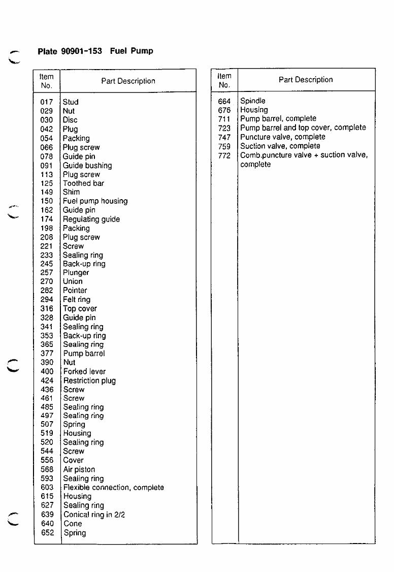
Plate 90901-153 Fuel Pump W^
Item No.
017 029 030 042 054 066 078 091 113 125 149 150 162 174 198 208 221 233 245 257 270 282 294 316 328 341 353 365 377 390 400 424 436 461 485 497 507 519 520 544 556 568 593 603 615 627 639 640 652
Part Description
Stud Nut Disc Plug Packing Plug screw Guide pin Guide bushing Plug screw Toothed bar Shim Fuel pump housing Guide pin Regulating guide Packing Plug screw Screw Sealing ring Back-up ring Plunger Union Pointer Felt ring Top cover Guide pin Sealing ring Back-up ring Sealing ring Pump barrel Nut Forked lever Restriction plug Screw Screw Sealing ring Sealing ring Spring Housing Sealing ring Screw Cover Air piston Sealing ring Flexible connection, complete Housing Sealing ring Conical ring in 2/2 Cone Spring
Item No.
664 676 711 723 747 759 772
Part Description
Spindle Housing Pump barrel, complete Pump barrel and top cover, complete Puncture valve, complete Suction valve, complete Comb.puncture valve + suction valve. complete
HYUNDAI MAN B&W
S50MC-C
Fuel Pump Gear Plate 90902-116
'*%.
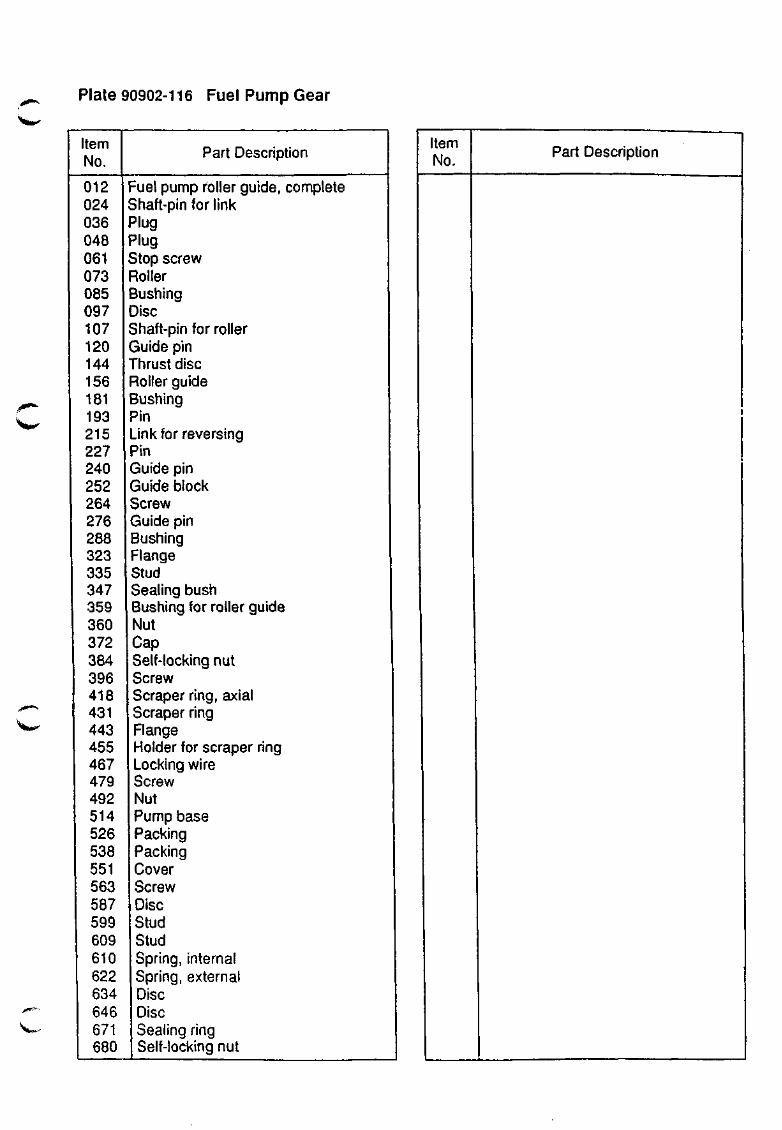
Plate 90902-116 Fuel Pump Gear
'*<te«i»'
Item No.
Part Description
012 024 036 048 061 073 085 097 107 120 144 156 181 193 215 227 240 252 264 276 288 323 335 347 359 360 372 384 396 418 431 443 455 467 479 492 514 526 538 551 563 587 599 609 610 622 634 646 671 680
Fuel pump roller guide, complete Shaft-pin for link Plug Plug Stop screw Roller Bushing Disc Shaft-pin for roller Guide pin Thrust disc Roller guide Bushing Pin Link for reversing Pin Guide pin Guide block Screw Guide pin Bushing Flange Stud Sealing bush Bushing for roller guide Nut Cap Self-locking nut Screw Scraper ring, axial Scraper ring Flange Holder for scraper ring Locking wire Screw Nut Pump base Packing Packing Cover Screw Disc Stud Stud Spring, internal Spring, external Disc Disc Sealing ring Self-locking nut
Item No. Part Description
HYUNDAI
MAN B&W
S50MC-C
Reversing Meciianism Plate 90905-12
* ^ * f ^ " ^ t ^
. , ' < « ' ^ ^
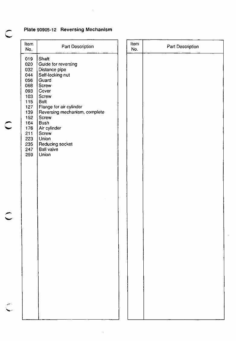
Plate 90905-12 Reversing Meclianism
Item No.
019 020 032 044 056 068 093 103 115 127 139 152 164 176 211 223 235 247 259
^ ^ M l t i ^
Part Description
Shaft Guide for reversing Distance pipe Self-locking nut Guard Screw Cover Screw Bolt Flange for air cylinder Reversing mechanism, complete Screw Bush Air cylinder Screw Union Reducing socket Ball valve Union
Item No.
Part Description
f / f ( )
CO
CD O O)
(U va
QL
LWWN
_> CO
>
3 U.
11 ^1
o •
o o in CO
kWWN
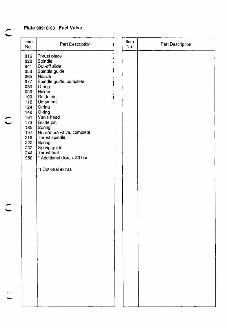
Plate 90910-93 Fuel Valve
Item No.
016 028 041 053 065 077 089 090 100 112 124 148 161 173 185 197 219 220 232 244 950
Part Description
Thrust piece Spindle Cut-off slide Spindle guide Nozzle Spindle guide, complete 0-ring Holder Guide pin Union nut 0-ring 0-ring Valve head Guide pin Spring Non-return valve, complete Thrust spindle Spring Spring guide Thrust foot * Additional disc, + 30 bar
*) Optional extras
Item No.
Part Description
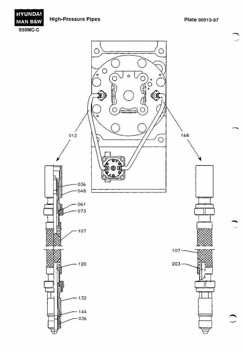
HYUNDAI MAN B&W
S50iVIC-C
High-Pressure Pipes Plate 90913-97
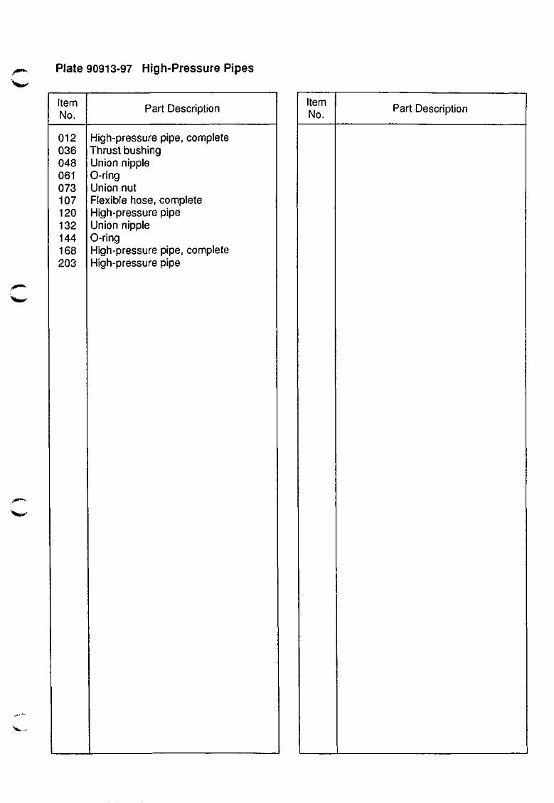
rffiW"*! Plate 90913-97 High-Pressure Pipes
Item No.
012 036 048 061 073 107 120 132 144 168 203
Part Description
High-pressure pipe, complete Thrust bushing Union nipple 0-ring Union nut Flexible hose, complete High-pressure pipe Union nipple 0-ring High-pressure pipe, complete High-pressure pipe
Item No. Part Description
v.-
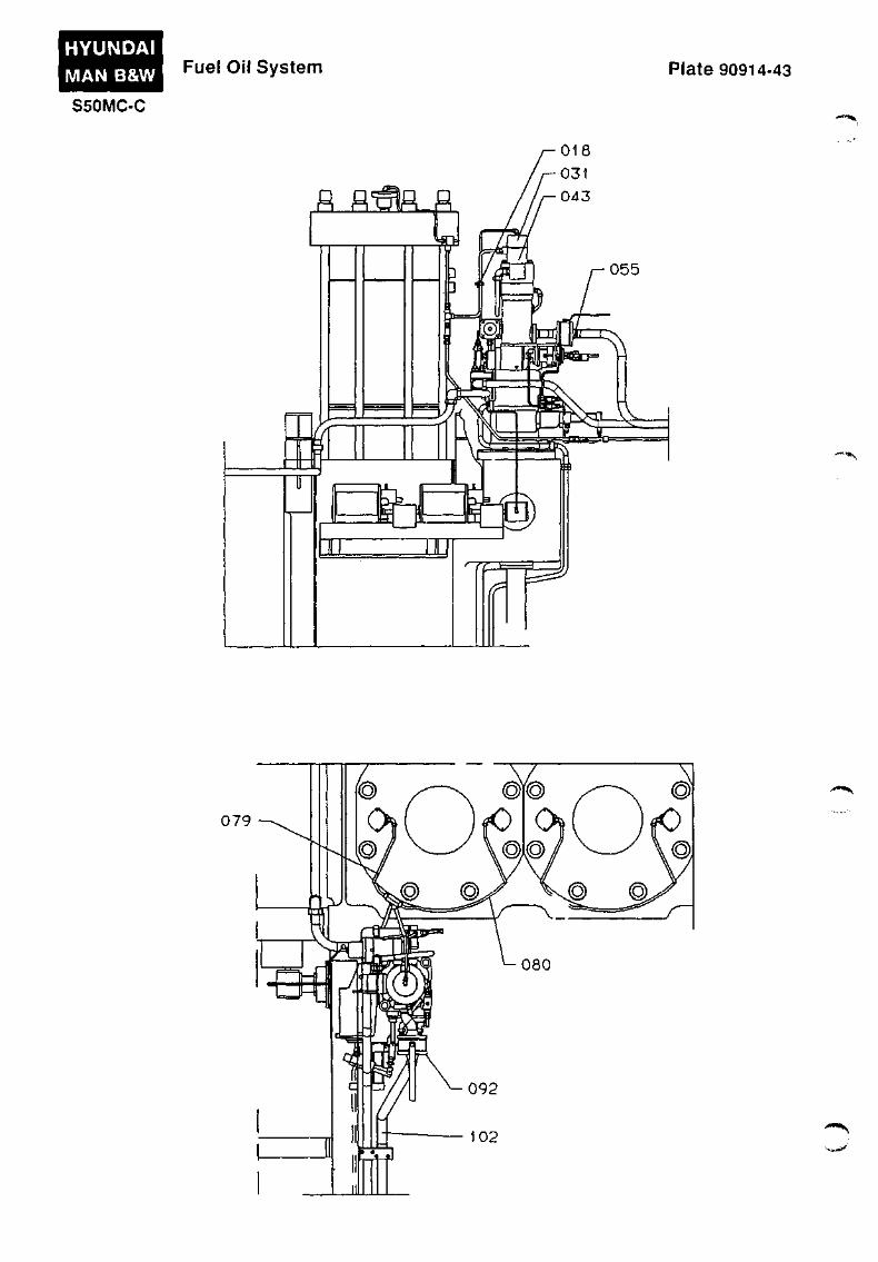
HYUNDAI
MAN B&W
S50MC-C
Fuel Oil System Plate 90914-43
079
• X s , ^

Plate 90914-43 Fuel Oil System
Item No.
018 031 043 055 079 080 092 102
Part Description
Return oil pipe, L=350 Control air pipe, L=900 Pipe, L=650 Fuel oil inlet pipe Return oil pipe, L=600 Return oil pipe, L=1050 Ball valve Fuel oil inlet pipe
'^ifciW
Item No.
Part Description
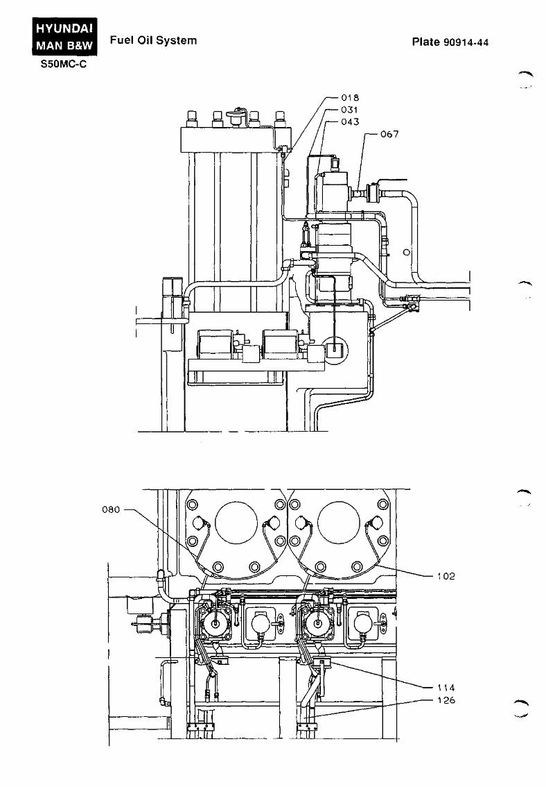
HYUNDAI MAN B&W
S50MC-C
Fuel Oil System Plate 90914-44
R R^R R
080
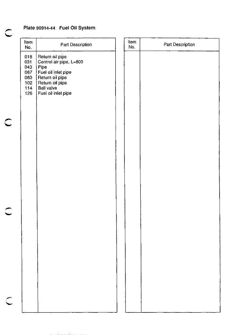
Plate 90914-44 Fuel Oil System
Item No.
018 031 043 067 080 102 114 126
f^
Part Description
Return oil pipe Control air pipe, L= Pipe Fuel oil inlet pipe Return oil pipe Return oil pipe Ball valve Fuel oil inlet pipe
:800
Item No.
Part Description
, » * " » • •

HYUNDAI MAN B&W Fuel Oil System - Details Plate 90915-24
S50MC-C - ' » l » « * ^
013 025 037
- ••
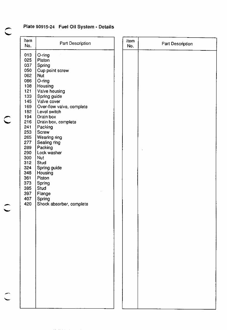
c Plate 90915-24 Fuel Oil System - Details
Item No.
013 025 037 050 062 086 108 121 133 145 169 182 194 216 241 253 265 277 289 290 300 312 324 348 361 373 385 397 407 420
Part Description
0-ring Piston Spring Cup point screw Nut 0-ring Housing Valve housing Spring guide Valve cover Over-flow valve, complete Level switch Drain box Drain box, complete Packing Screw Wearing ring Sealing ring Packing Lock washer Nut Stud Spring guide Housing Piston Spring Stud Flange Spring Shock absorber, complete
Item No. Part Description
TURBOCHARGER SYSTEM
910
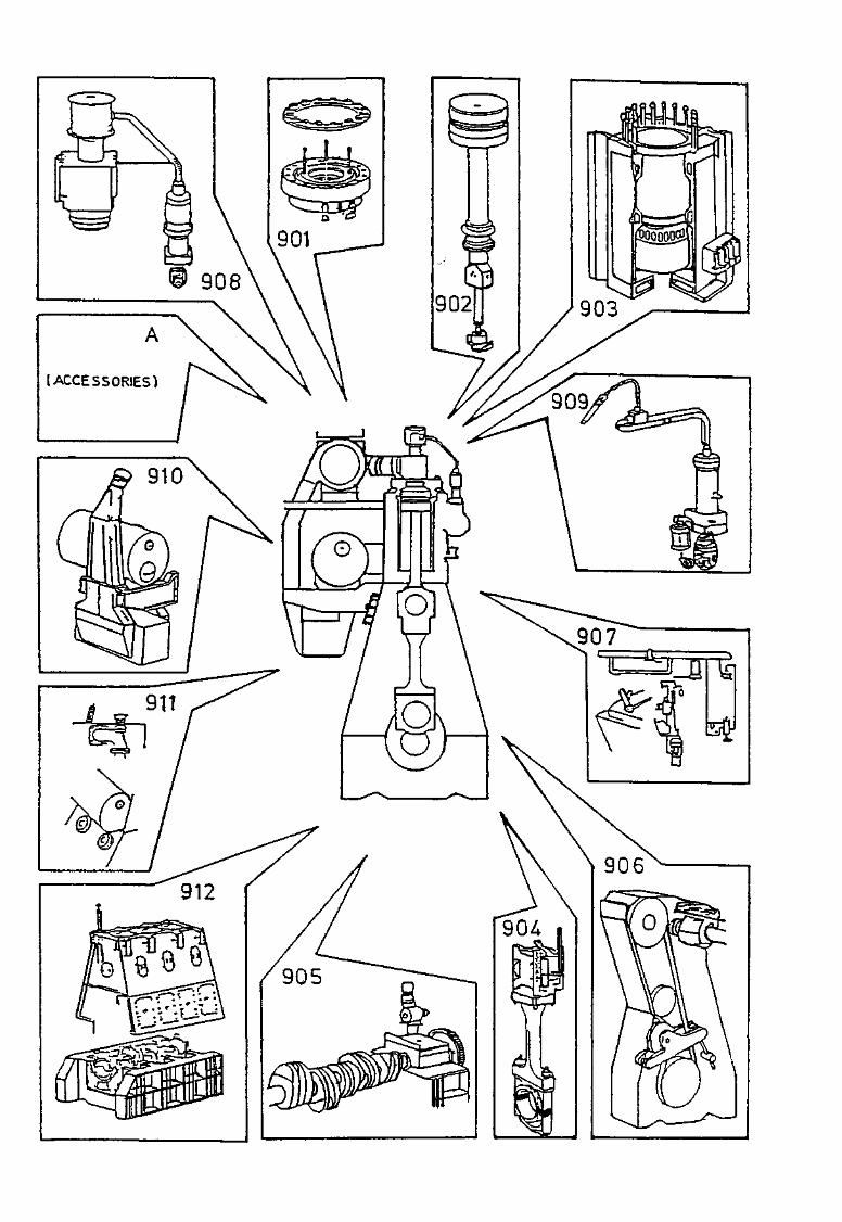
910.01-55
j « « « ^
Air System of Engine (Regarding the turbocharger, see the producer's special instructions)
The engine is supplied with scavenge air from one turbocharger mounted at the aft end of the engine.
Alternatively, one or two turbochargers may be located on the exhaust side.
The engine exhaust gas drives the turbine wheel of the turbocharger and, through a common shaft, the turbine wheel drives the compressor wheel.
The compressor draws air from the engine room, through the air filters. From the compressor outlet, the air passes through the charging air pipe to the charging air cooler {Plate 91005) where the air is cooled down.
The charging air pipe, with compensator, is insulated and can be clad internally with a sound-absorbing material.
The air cooler is designed to separate condensate from the air. See also 'Charging Air Cooler' in this Chapter.
The air is pressed into the scavenge air receiver through non-return valves mounted in the air cooler housing after the water mist catcher. The non-return valves (flap valves) open by pressure from the turbocharger.
From the scavenge air receiver, the air flows to the cylinder through the scavenge air ports when the piston is in the bottom position. When the exhaust valves open, the exhaust gas is pressed into a common exhaust gas receiver {Plate 91003), from where the gas drives the turbine of the turbocharger with an even and steady pressure.
Scavenge Air Receiver
Plate 91001
The scavenge air receiver is a container having a large volume. The receiver is bolted on to the cylinder frame.
Scavenge air is collected in the receiver after the air has passed through the cooler, the water mist catcher and the non-return valves.
The receiver and the cylinder frame communicate through circular openings.
The two auxiliary blowers are placed at the aft end of the air cooler housing. The suction side of the auxiliary blowers is connected to the space before the non-return valves in the air cooler housing. The discharge side is connected to the scavenge air receiver via a non-return valve, in order to prevent reversed air flow. See also item, "Non-return valves", further on.
The scavenge air receiver is provided with man-hole covers and also a safety valve {Plate 91103).
Running with Auxiliary Biowers
During starting of the engine, and when the engine is running at low load the turbocharger is not able to supply enough air for the engine process. In these cases a pressure switch will automatically start the auxiliary blowers.
When the auxiliary blowers are operating, they draw air from the engine room through the turbocharger's air filter and compressor side.
This enables the turbocharger to maintain a reasonable number of revolutions during starting and at low load.
The air passes through the charging air pipe, the charging air cooler, and the water mist catcher, to the suction side of the blowers. From the blowers, the air is discharged to the scavenge air receiver via non-return valves.
The non-return valves fitted in the air cooler housing are now closed due to partial vacuum and gravitation acting on the valve flaps.
910.02-55
A lack of air supply will occur if the nonreturn valves do not close.
Non-Return Valves
it is of the utmost importance that the nonreturn valves of the auxiliary blowers always function correctly and move easily. This can be checked by moving the valves manually, e.g. in connection with the regular scavenge port inspections.
The non-return valves protect the blowers and engine during:
• Starting the auxiliary blowers
• Running with auxiliary blowers.
Starting the auxiliary blowers:
1) Owing to the relatively high starting current, the blowers start in sequence, with 6-10 seconds in between.
The non-return valve of the blower that has not yet started must be in the closed position to prevent the blower from rotating backwards. Otherwise, there is a risk of burning out the electric motor when it starts.
2) If an auxiliary blower fails to start, the non-return valve must be in the closed position. Otherwise, the operating blower will not be able to draw fresh air in through the turbocharger and air cooler. This is due to differences in the air flow resistance.
Running with auxiliary blowers:
In the event of failure of an auxiliary blower during running, the non-return valve must close to ensure the continued supply of fresh air to the engine. See 'Starting the auxiliary blowers', Item 2, above.
Exhaust Gas Receiver
Plate 91003
From the exhaust valves, the exhaust gas is led to the exhaust gas receiver where the pulsatory pressure from the individual exhaust valves is equalized and led to the turbocharger at a constant pressure.
The exhaust gas receiver is fastened to the seating by flexible supports. Compensators are inserted between the receiver and the exhaust valves, and between the receiver and the turbocharger.
Inside the exhaust gas receiver, a protective grating is mounted before the turbocharger.
For quick mounting and dismounting of the joints between the receiver and the exhaust valves, clamping rings are used to hold the parts together. The exhaust gas receiver and the exhaust pipe are insulated.
The exhaust receiver may be provided with by-pass flanges for:
• Emergency running without turbo-chargers
• Improvement of fuel consumption at part load
• Turbo Compound system (TCS).
Charging Air Cooler
Plate 91005
The charging air cooler insert is of the block type. It is mounted in a housing which is welded up of steel plates.
The cooler housing is provided with inspection covers.
The air cooler housing has been prepared for cleaning of the cooler insert without removing it. This is achieved by means of a built-in spray-arrangement. See also Vol. II, MAINTENANCE, Chapter 910. ^•'.m*^

910.03-55
The cooler is designed with an air reversing chamber which has a water mist catcher incorporated. The water mist catcher is built up of a number of lamellas which separate the condensation water from the scavenge air during the passage of the air flow.
The separated water is collected in the bottom of the cooler housing from where it is removed by a drain system.
Caution !
It is important to check that the drain functions correctly, as otherwise water droplets may enter the cylinders. See Vol. I, OPERATION, Chapter 706, 'Cleaning of Turbochargers and Air Coolers'.
An alarm device for high water level in the drain system is installed.
El. Panels for Auxiliary Blower
See special instructions supplied by the engine builder.
\m^
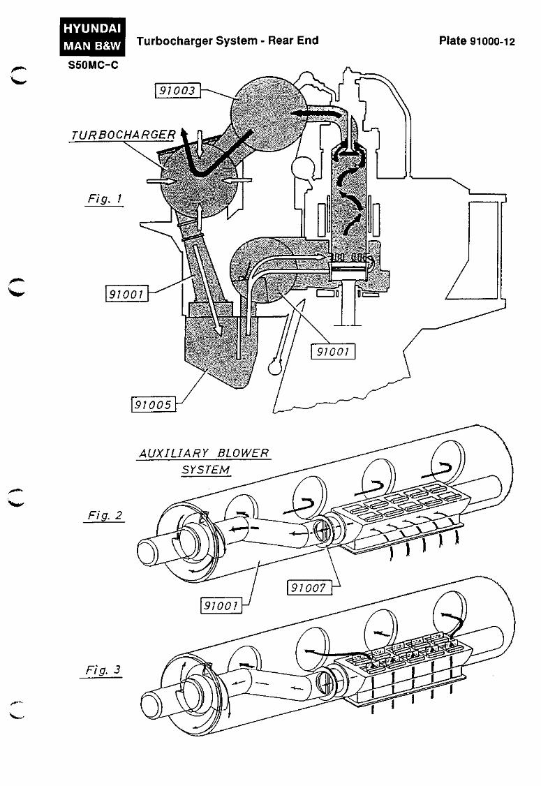
HYUNDAI
MAN B&W Turbocharger System - Rear End Plate 91000-12
S50MC-C
91003
TURBOCHARGER
-""-
v '
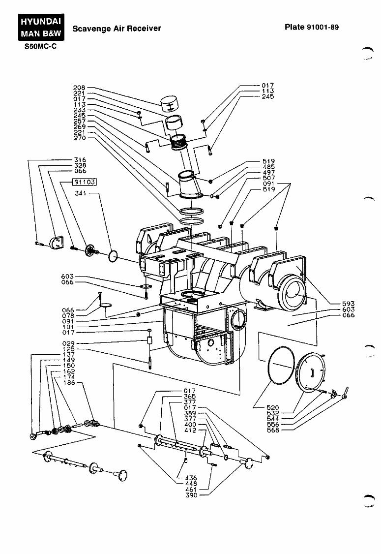
HYUNDAI MAN B&W S50MC-C
Scavenge Air Receiver Plate 91001-89
.-***
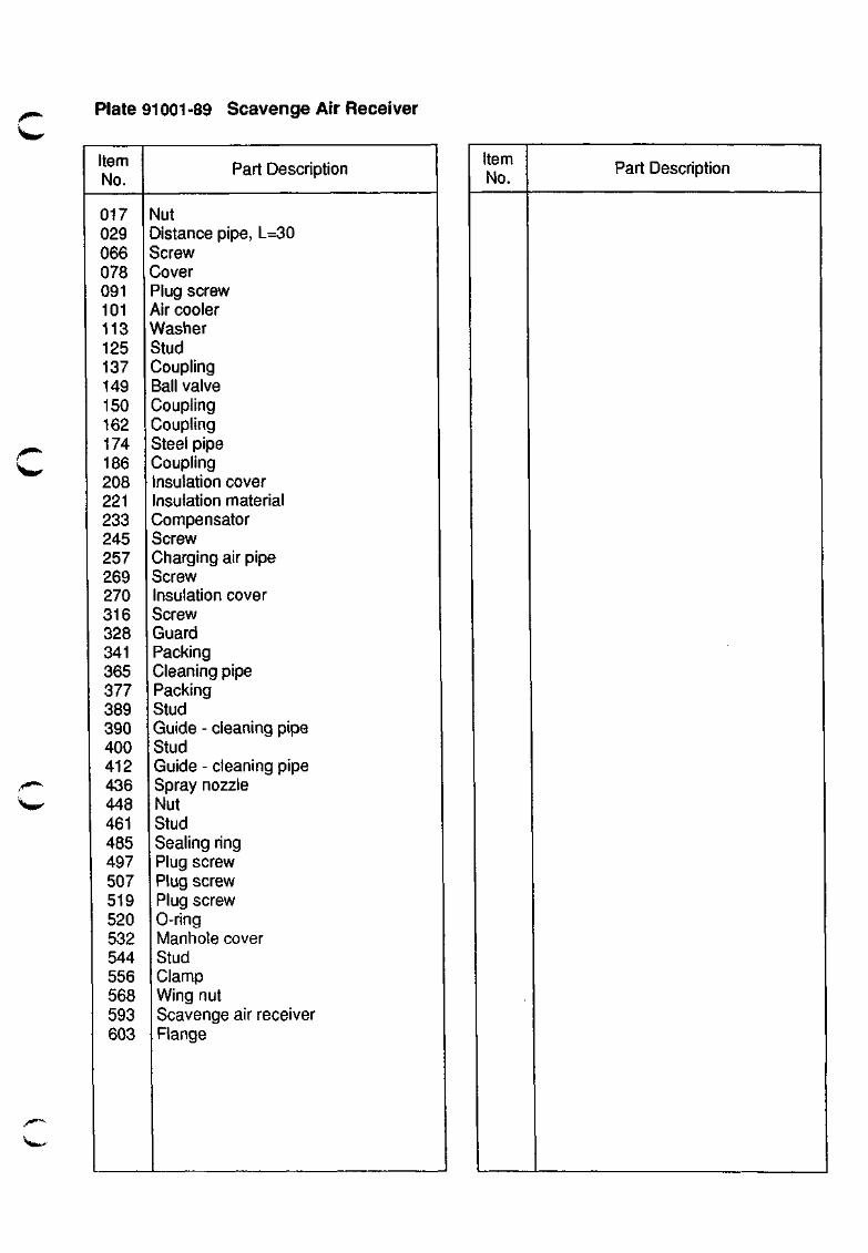
Plate 91001 -89 Scavenge Air Receiver
Item No.
jl0^i^
017 029 066 078 091 101 113 125 137 149 150 162 174 186 208 221 233 245 257 269 270 316 328 341 365 377 389 390 400 412 436 448 461 485 497 507 519 520 532 544 556 568 593 603
Part Description
Nut Distance pipe, L=30 Screw Cover Plug screw Air cooler Washer Stud Coupling Bail valve Coupling Coupling Steel pipe Coupling Insulation cover Insulation material Compensator Screw Charging air pipe Screw Insulation cover Screw Guard Packing Cleaning pipe Packing Stud Guide - cleaning pipe Stud Guide - cleaning pipe Spray nozzle Nut Stud Sealing ring Plug screw Plug screw Plug screw 0-ring Manhole cover Stud Clamp Wing nut Scavenge air receiver Flange
Item No.
Part Description
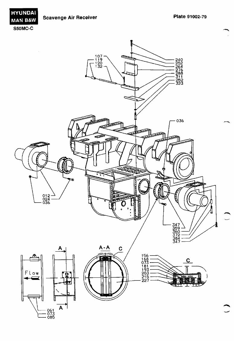
HYUNDAI
MAN B&W
S50MC-C
Scavenge Air Receiver Plate 91002-79
240 252 264 276 288 311 252 323
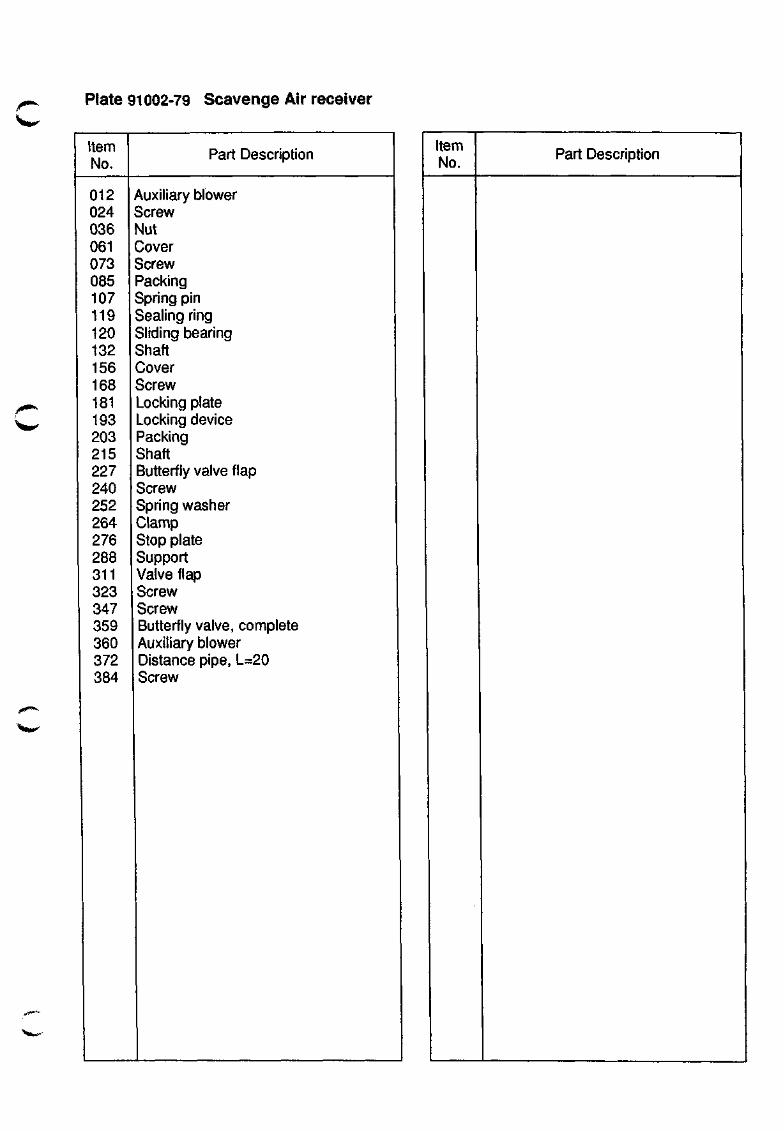
Plate 91002-79 Scavenge Air receiver
Item No.
Part Description
012 024 036 061 073 085 107 119 120 132 156 168 181 193 203 215 227 240 252 264 276 288 311 323 347 359 360 372 384
Auxiliary blower Screw Nut Cover Screw Packing Spring pin Sealing ring Sliding bearing Shaft Cover Screw Locking plate Locking device Packing Shaft Butterfly valve flap Screw Spring washer Clamp Stop plate Support Valve flap Screw Screw Butterfly valve, complete Auxiliary blower Distance pipe, L=20 Screw
Item No.
Part Description
"^rtw
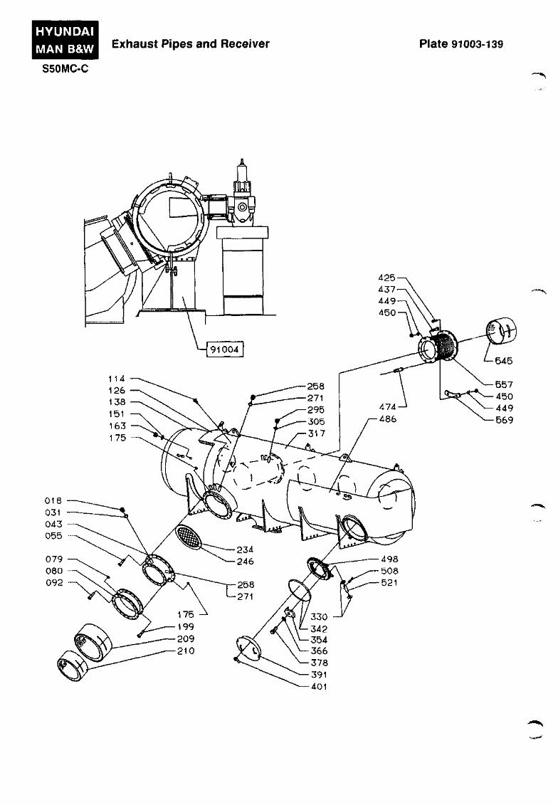
HYUNDAI MAN B&W
S50MC-C
Exhaust Pipes and Receiver Plate 91003-139
*»%^^
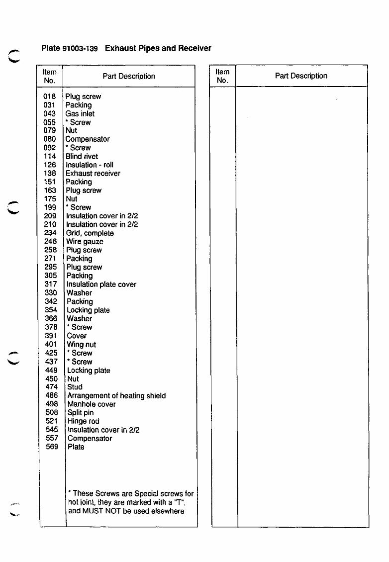
Plate 91003-139 Exhaust Pipes and Receiver
Item No.
\mi>^
' % » - •
018 031 043 055 079 080 092 114 126 138 151 163 175 199 209 210 234 246 258 271 295 305 317 330 342 354 366 378 391 401 425 437 449 450 474 486 498 508 521 545 557 569
Part Description
Plug screw Packing Gas inlet * Screw Nut Compensator * Screw Blind rivet Insulation - roll Exhaust receiver Packing Plug screw Nut * Screw Insulation cover in 2/2 Insulation cover in 2/2 Grid, complete Wire gauze Plug screw Packing Plug screw Packing Insulation plate cover Washer Packing Locking plate Washer * Screw Cover Wing nut * Screw * Screw Locking plate Nut Stud Arrangement of heating shield Manhole cover Split pin Hinge rod Insulation cover in 2/2 Compensator Plate
Item No.
Part Description
* These Screws are Special screws for hot ioint, they are marked with a "T", and MUST NOT be used elsewhere
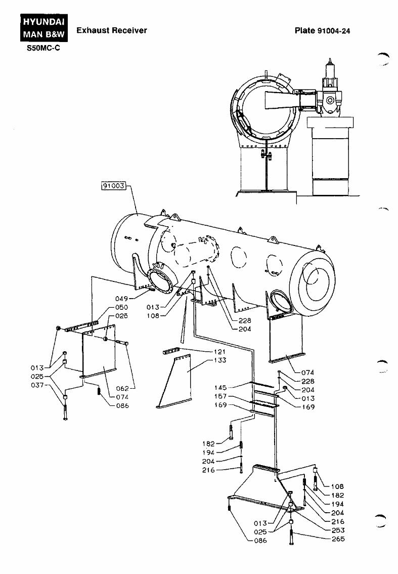
HYUNDAI
MAN B&W
S50MC-C
Exhaust Receiver Plate 91004-24
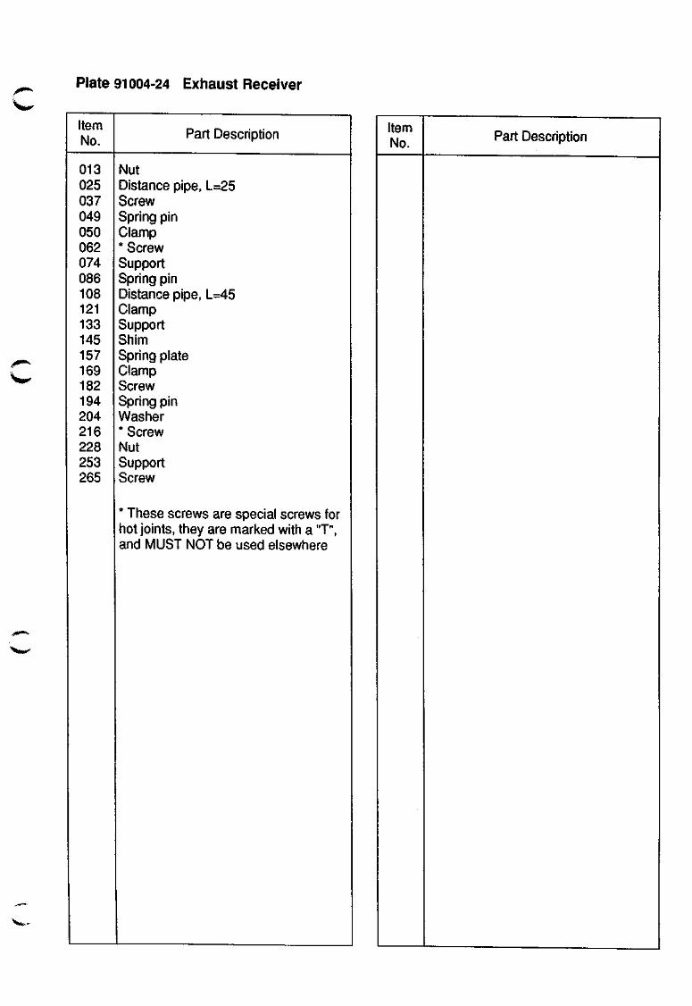
Plate 91004-24 Exhaust Receiver
Item No.
if^
013 025 037 049 050 062 074 086 108 121 133 145 157 169 182 194 204 216 228 253 265
Part Description
Nut Distance pipe, L=25 Screw Spring pin Clamp * Screw Support Spring pin Distance pipe, L=45 Clamp Support Shim Spring plate Clamp Screw Spring pin Washer * Screw Nut Support Screw
* These screws are special screws for hot joints, they are marked with a "T", and MUST NOT be used elsewhere
Item No. Part Description
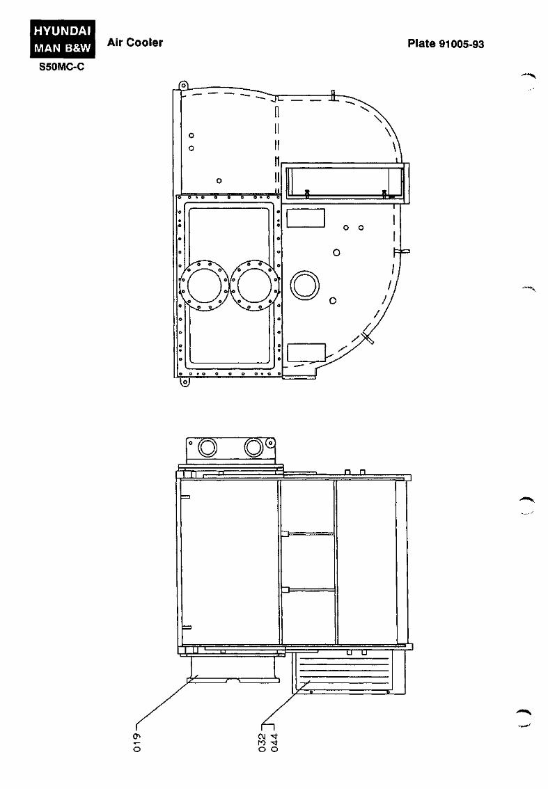
HYUNDAI
MAN B&W Air Cooler Plate 91005-93
S50MC-C
Jsi-
'"" ^ v
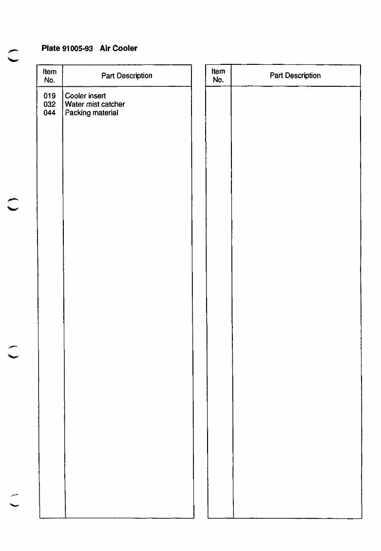
Plate 91005-93 Air Cooler
Item No.
019 032 044
Part Description
Cooler insert Water mist catcher Packing material
Item No.
Part Description
^**m^-

SAFETY EQUIPMENT
911

911.01-16
^f^ Safety Equipment
Safety Valves - Relief Valves
Each cylinder cover is provided with a spring-loaded safety valve which is set to open at a pressure somewhat higher than the maximum firing pressure in the cylinder.
On the exhaust side of the engine a number of spring-loaded relief valves are fitted, which will open in the event of an excessive pressure arising in the crankcase, for instance as a result of the ignition of oil vapour.
Regarding how to:
• avoid evaporation of the lubricating oil,
• detect the oil mist using an 'Oil Mist Detector'.
see Vol. I. OPERATION, Chapter 704.
Warning !
Do not stand near crankcase doors or relief valves - nor in corridors near doors to the engine room casing in the event of an alarm for:
a) oil mist b) high lube oil temperature c) no piston cooling oil flow, or d) scavenge box fire
Alarms b, c and d should be considered as pre-warnings of a possible increasing oil mist level.
See also our Service Letter SL97-348/ERO.
Each starting valve inlet pipe is provided with a safety cap. The safety cap consists of a bursting disc enclosed by a perforated cylinder and a perforated cover in order to protect any bystanders, in the event of a burst.
The cover is provided with a check plate, which shows if the bursting disc has been damaged.
Safety Cap In Starting Air Line
If the bursting disc of the safety cap Is damaged due to excessive pressure in the starting air line, overhaul or replace the starting valve which caused the burst, and mount a new disc.
If a new disc is not available immediately, turn the cover in relation to the cylinder, in order to reduce the leakage of starting air.
Note!
Mount a new bursting disc and return the cover to the open position at the first opportunity.
The scavenge air receiver is fitted with a safety valve which is set to open should the pressure in the scavenge air receiver exceed a value somewhat higher than the normal scavenge air pressure of the engine.
In some cases it may be necessary to open the valve manually, see Vol. I, Chapter 704, "Turbocharger Surging".
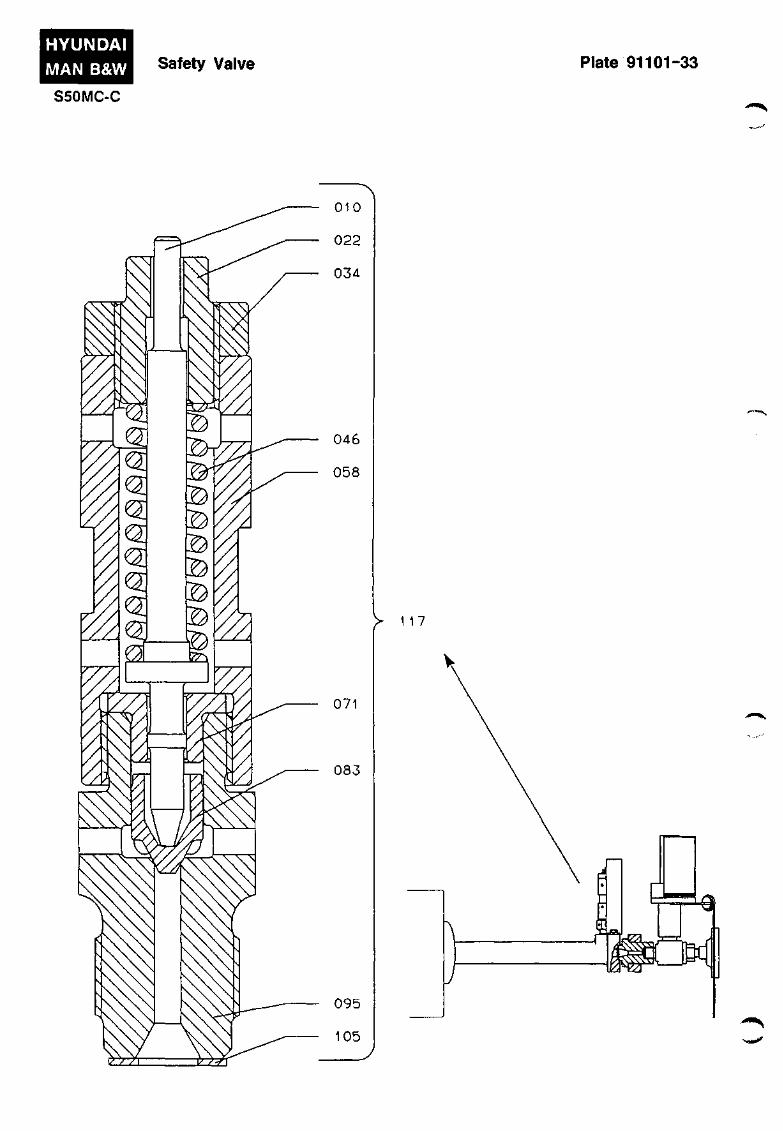
HYUNDAI
MAN B&W
S50MC-C
Safety Valve Plate 91101-33
> 117
-•»s
,:
i
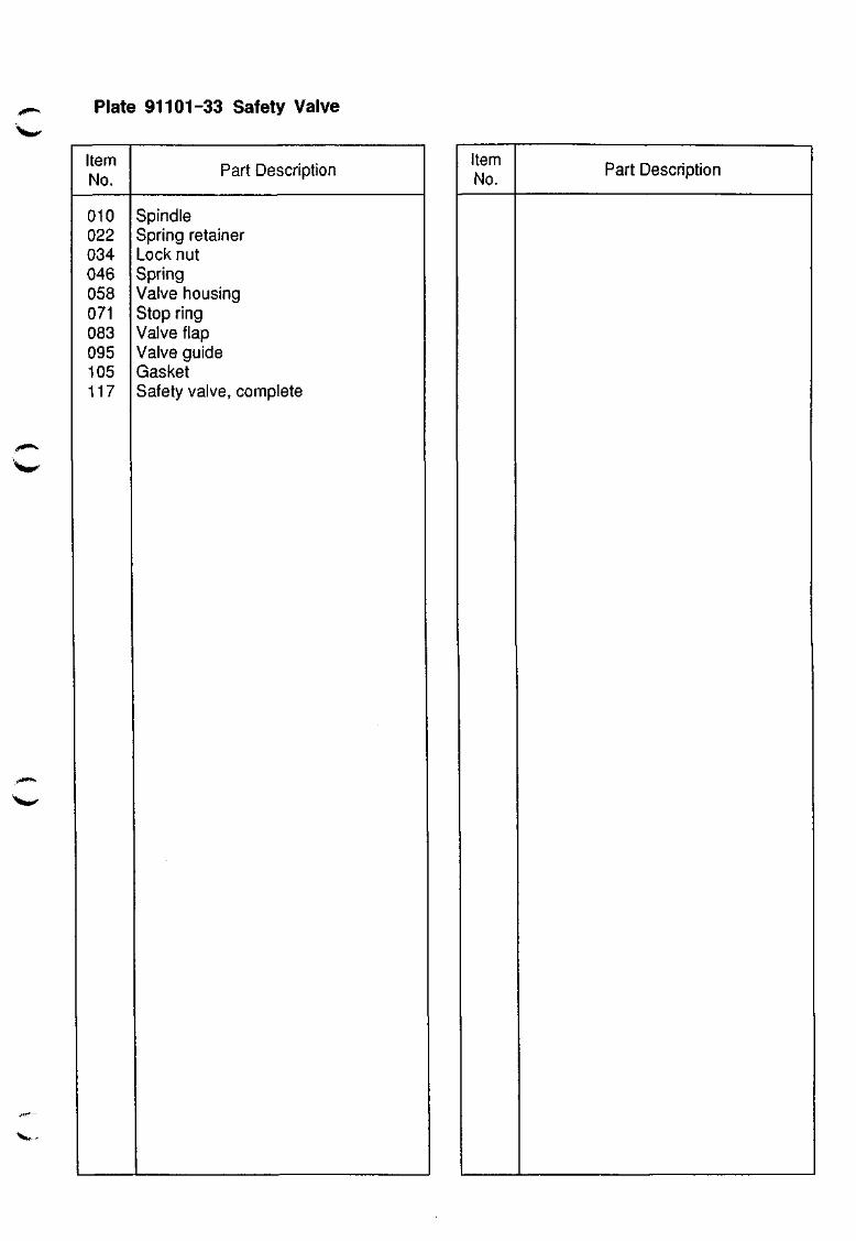
Plate 91101-33 Safety Valve
Item No.
010 022 034 046 058 071 083 095 105 117
^ I M I M ^
Part Description
Spindle Spring retainer Lock nut Spring Valve housing Stop ring Valve flap Valve guide Gasket Safety valve, complete
Item No.
Part Description
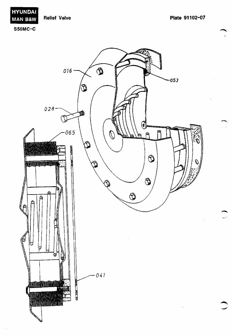
HYUNDAI
MAN B&W Relief Valve Plate 91102-07
S50MC-C ,-«^
,,-*i*««St

Plate 91102-07 Relief Valve
Item No.
016
028
041
053
065
Part Description
Relief valve
Screw
Gasket
0-ring
Flame arrester
Please state type of relief
valve, when ordering spare
parts.
MAN B&W Standard No.
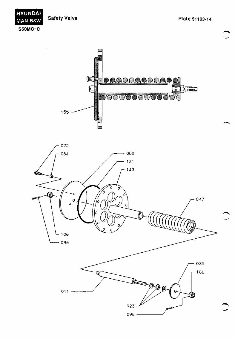
HYUNDAI
MAN B&W Safety Valve Plate 91103-14
S50MC-C ,.*«*'«^
155
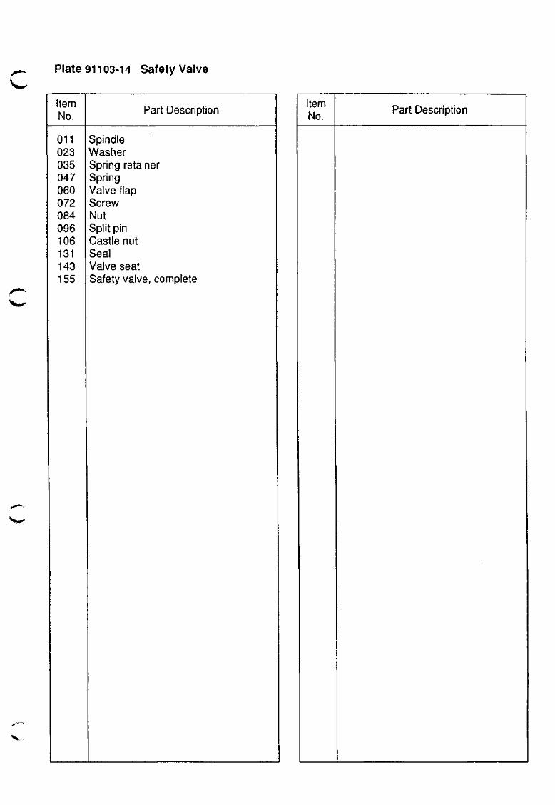
Plate 91103-14 Safety Valve
Item No.
Oil 023 035 047 060 072 084 096 106 131 143 155
Part Description
Spindle Washer Spring retainer Spring Valve flap Screw Nut Split pin Castle nut Seal Valve seat Safety valve, complete
Item No.
Part Description
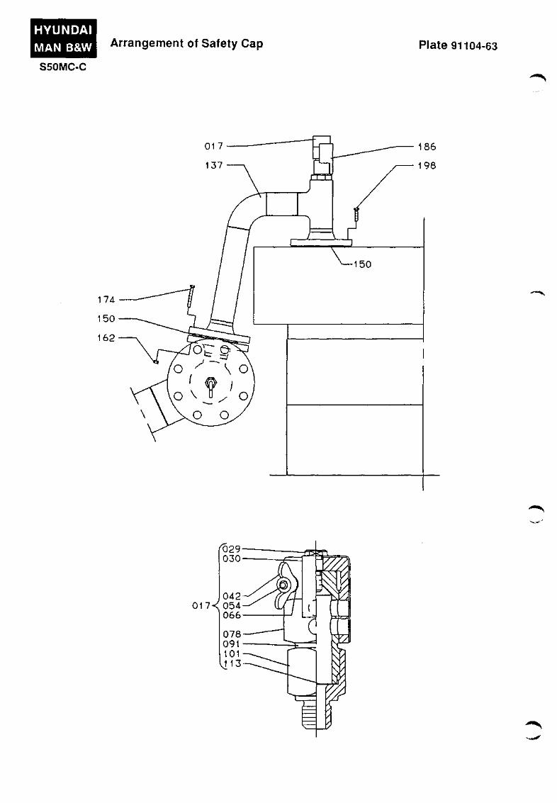
HYUNDAI MAN B&W
S50MC-C
Arrangement of Safety Cap Plate 91104-63
^29 030
042 017< 054
066
078 091 101 VJ13
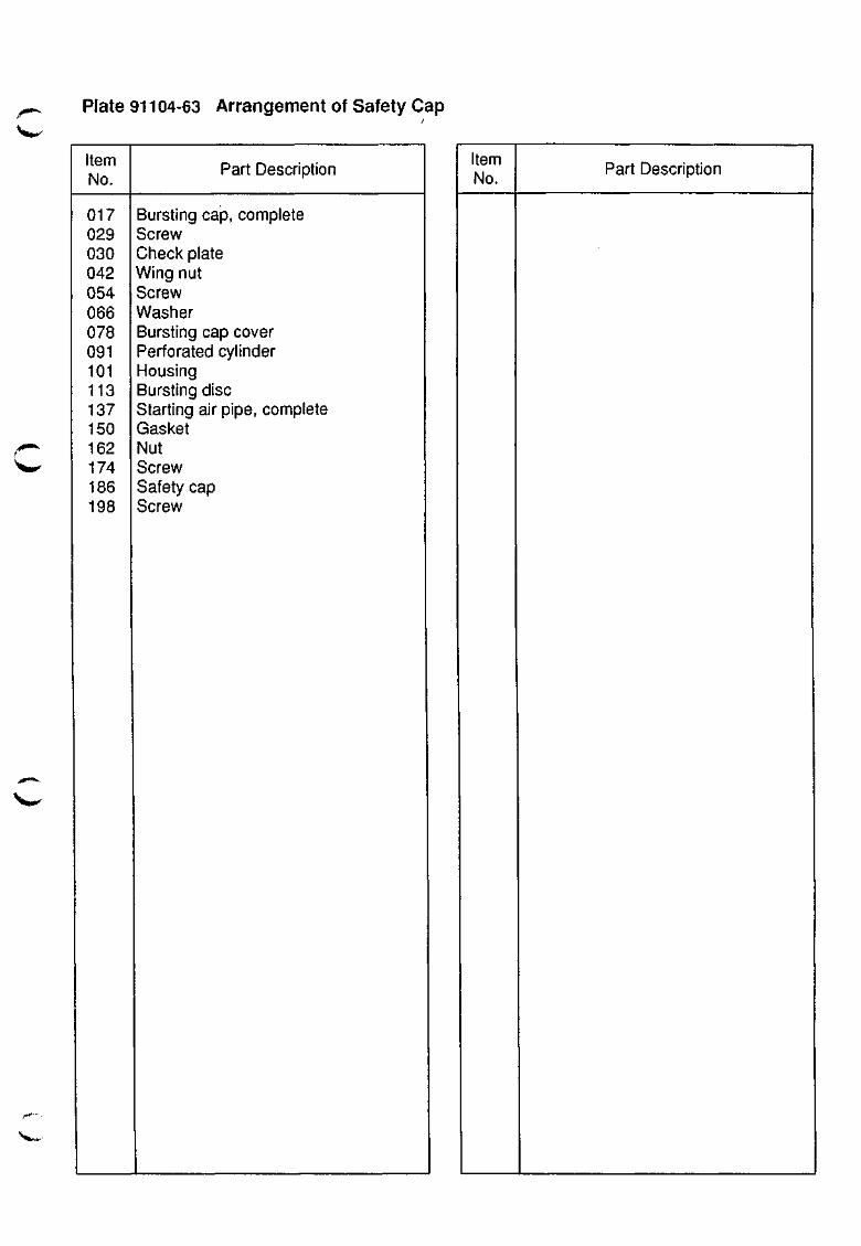
Plate 91104-63 Arrangement of Safety Cap
item No.
017 029 030 042 054 066 078 091 101 113 137 150 162 174 186 198
Part Description
Bursting cap, complete Screw Check plate Wing nut Screw Washer Bursting cap cover Perforated cylinder Housing Bursting disc Starting air pipe, complete Gasket Nut Screw Safety cap Screw
Item No.
Part Description

ASSEMBLY OF LARGE PARTS
912

912.01-58
Assembly of Large Parts
Bedplate, Framebox, etc.
The bedplate is made in one section, consisting of two welded, longitudinal girders and a number of cross girders which support the main bearings. The main bearings, which are of the thin-shell type, consist of steel shells, lined with tin-aluminium and coated with a tin-flash layer. See also Vol. I, OPERATION, Chapter 708.
Each main bearing has one main bearing cap which is secured by four studs and nuts, designed for tightening by means of hydraulic tools.
The aft end of the bedplate incorporates the thrust bearing as well as the chain drive. See also Chapter 905.
At the foremost end of the bedplate, an axial vibration damper is fitted. (Plate 91211). Regarding the design and functioning of the axial vibration damper. See Chapter 905.
A framebox is bolted on to the top of the bedplate. Like the bedplate, the framebox consists of one section with the chain drive located at the aft end. Together, the bedplate and the framebox constitute the crankcase of the engine.
The framebox is fitted with steel-plate doors for access to the crossheads and to the main and crankpin bearings.
The bedplate, the framebox, and the cylinder frame, which rests on top of the framebox, are tightened together to form one unit by means of stay bolts, the bottom of which is screwed into the bedplate.
For each cylinder, the framebox is equipped with a slotted pipe in which the piston cooling oil outlet pipe fitted to the cross-head is able to travel. From the slotted pipe the cooling oil is, through an outlet pipe, led to the oil tray of the bedplate.
Equipment for local checking of the cooling oil temperature and flow, and for temperature and flow alarms, is installed in
conjunction with the outlet pipe. See also Vol. I, OPERATION. Chapter 701.
The bedplate of the engine is positioned on either epoxy or cast iron supporting chocks and bolted to the engine seating in the ship by means of long holding-down bolts, which are equipped with distance tubes of cast iron.
Plate 91215 shows the holding-down bolts, which have spherical washers and nuts with spherical contact face on the lower end of the bolts. The contact faces of the topplate for the spherical washers must be plane.
The engine is secured in the athwartship direction by a number of side chocks fitted in both sides in way of a bedplate cross-girder. The side-chock liners are tapered 1:100 and are fitted from the aft end at both sides of the engine.
The side-chock liners are secured in their correct position by means of inside-hexagon screws.
The engine is secured in the fore-and-aft direction by one end chock with one end-chock bolt with spherical washer at the aft end of each of the two longitudinal girders of the bedplate. The end-chock liners have a 1:100 taper and are fitted from above.
Regarding the engine seating for the specific engine, see the supplier's special instructions.
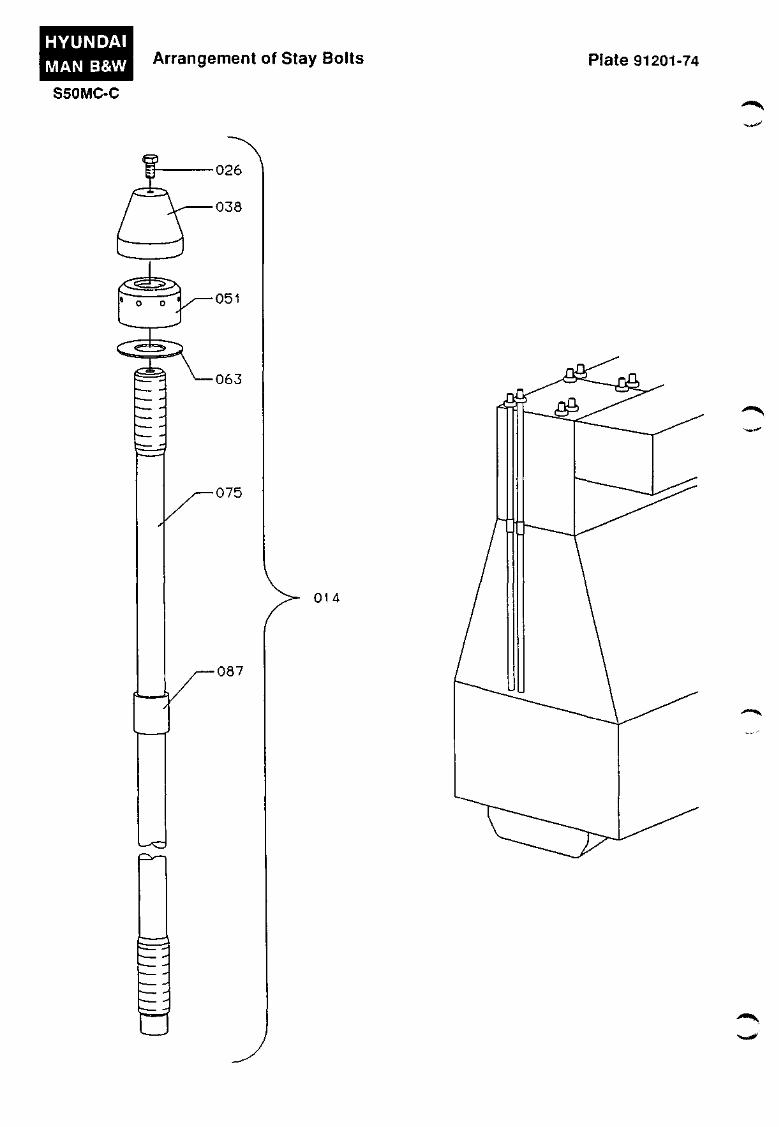
HYUNDAI MAN B&W Arrangement of Stay Bolts Plate 91201-74
S50MC-C
026
038
/ < ^ - > N . / — 0 5 1
•063
•075
•087
•
014
4 « ^
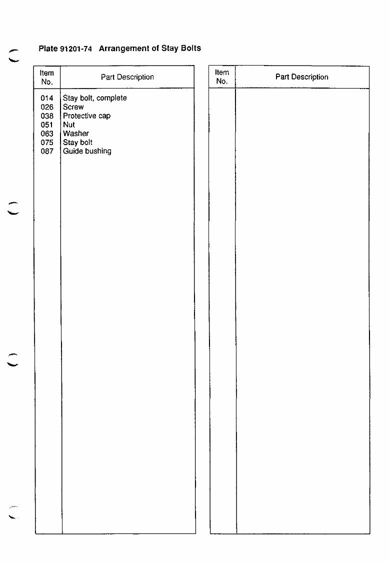
Plate 91201-74 Arrangement of Stay Bolts
item No.
014 026 038 051 063 075 087
Part Description
Stay bolt, complete Screw Protective cap Nut Washer Stay bolt Guide bushing
Item No.
Part Description
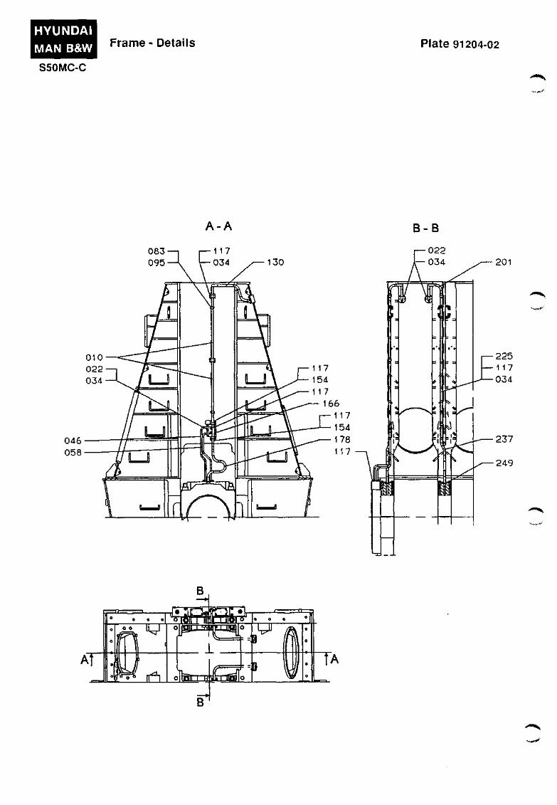
HYUNDAI MAN B&W
S50MC-C
Frame - Details Plate 91204-02
A-A B-B
AT
B
0 0 O
T ^
J^
§»sg 1
o o a
;B ^
'llnlD—UA-LJBIO I
TA
B
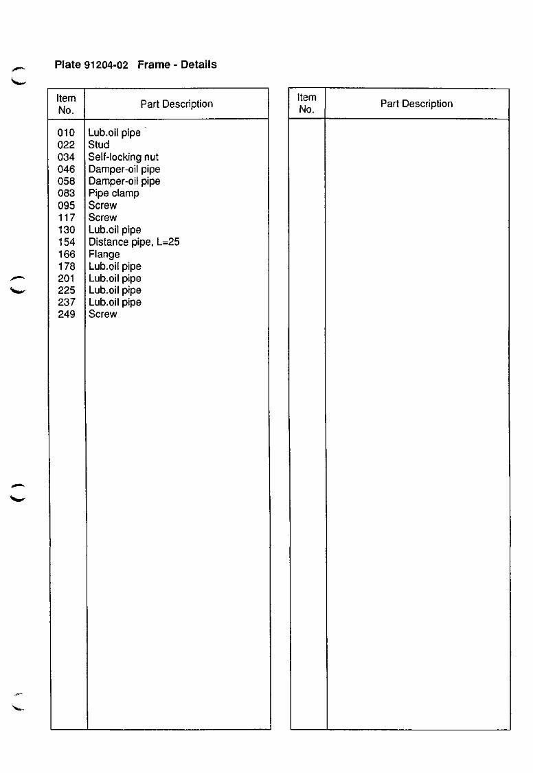
Plate 91204-02 Frame - Details
Item No.
010 022 034 046 058 083 095 117 130 154 166 178 201 225 237 249
Part Description
Lub.oil pipe Stud Self-locking nut Damper-oil pipe Damper-oil pipe Pipe clamp Screw Screw Lub.oil pipe Distance pipe, L=25 Flange Lub.oil pipe Lub.oil pipe Lub.oil pipe Lub.oil pipe Screw
Item No.
Part Description
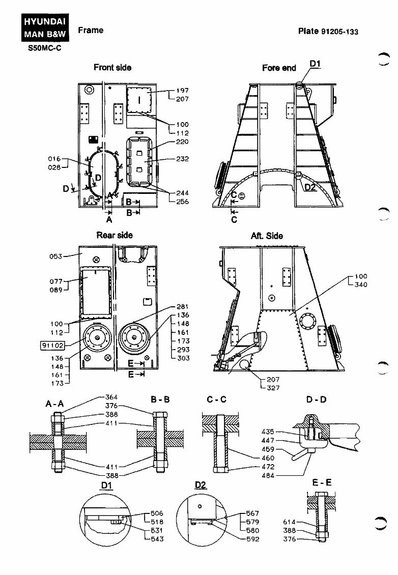
HYUNDAI MAN B&W
S50MC-C
Frame Plate 91205-133
Front side Fore end
Rear side Aft. Side
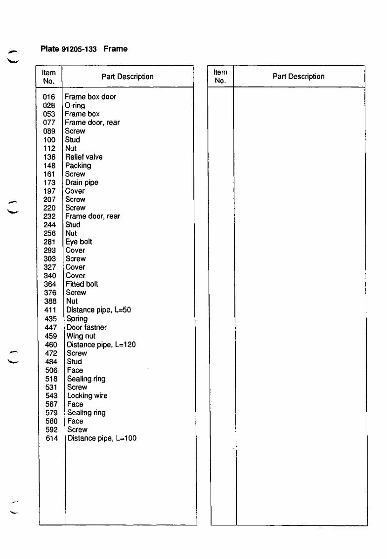
Plate 91205-133 Frame
Item No.
Part Description
^^^^
016 028 053 077 089 100 112 136 148 161 173 197 207 220 232 244 256 281 293 303 327 340 364 376 388 411 435 447 459 460 472 484 506 518 531 543 567 579 580 592 614
Frame box door 0-ring Frame box Frame door, rear Screw Stud Nut Relief valve Packing Screw Drain pipe Cover Screw Screw Frame door, rear Stud Nut Eye bolt Cover Screw Cover Cover Fitted bolt Screw Nut Distance pipe, L=50 Spring Door fastner Wing nut Distance pipe, L=120 Screw Stud Face Sealing ring Screw Locking wire Face Sealing ring Face Screw Distance pipe, L=100
Item No.
Part Description
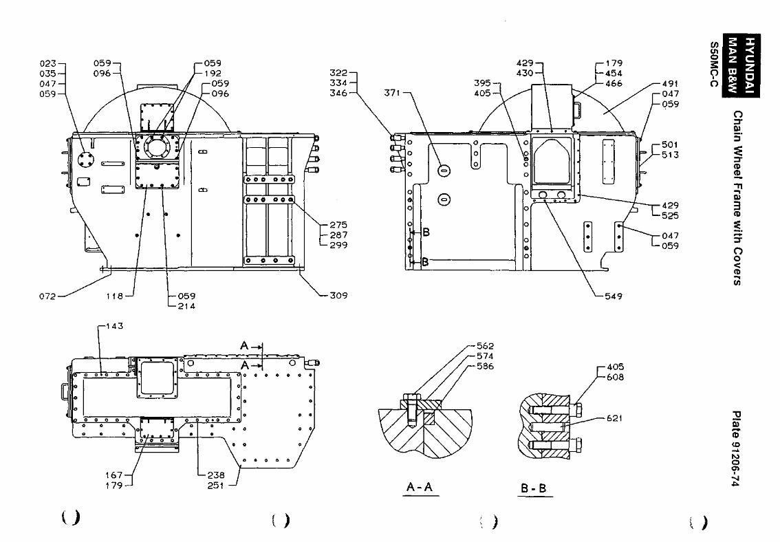
491 047 059
501 513
429 525
047 059
to en o S
6
S z > <
^ ^ • • • ^
li o
5"
(D £. -n
3
5 o o <
072
-143
( ) )
A-A B-B
u>
CO
O O I
)
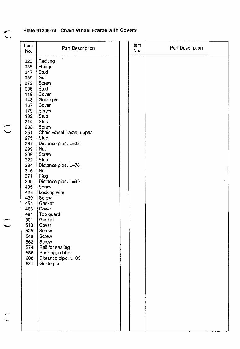
Plate 91206-74 Chain Wheel Frame with Covers
Item No.
023 035 047 059 072 096 118 143 167 179 192 214 238 251 275 287 299 309 322 334 346 371 395 405 429 430 454 466 491 501 513 525 549 562 574 586 608 621
Part Description
Packing Flange Stud Nut Screw Stud Cover Guide pin Cover Screw Stud Stud Screw Chain wheel frame, upper Stud Distance pipe, L=25 Nut Screw Stud Distance pipe, L=70 Nut Plug Distance pipe, L=90 Screw Locking wire Screw Gasket Cover Top guard Gasket Cover Screw Screw Screw Rail for sealing Packing, rubber Distance pipe, L=35 Guide pin
Item No.
Part Description
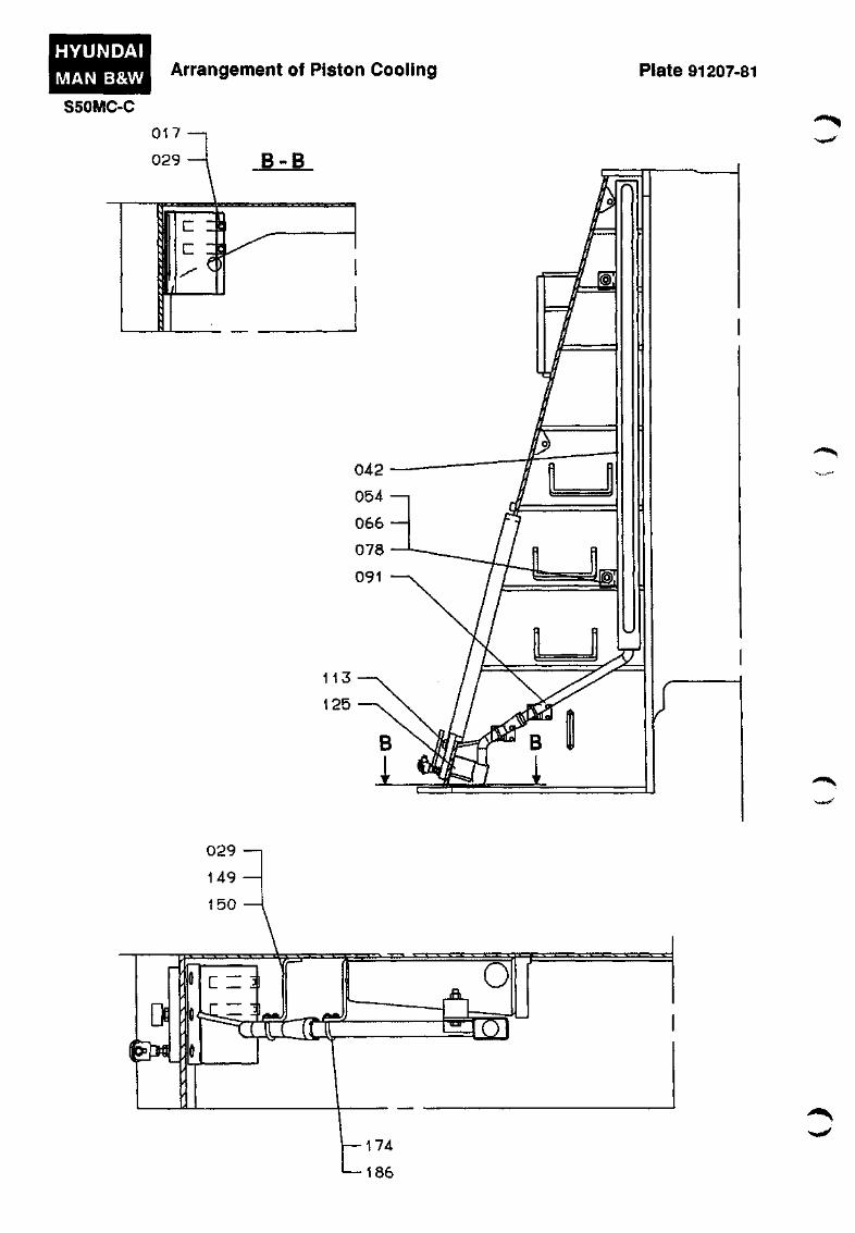
HYUNDAI
MAN B&W
S50MC-C
Arrangement of Piston Cooling Plate 91207-81

Plate 91207-81 Arrangement of Piston Cooling
Item No.
017 029 042 054 066 078 091 113 125 149 150 174 186
'"*•»»»'
Part Description
Screw Locking wire Slotted pipe Screw Self-locking nut Washer Drain pipe Sight glass Drain box Bracket Screw Clamp Self-locking nut
Item No.
Part Description
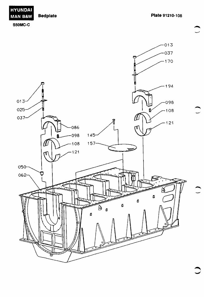
HYUNDAI
MAN B&W Bedplate Plate 91210-108
S50MC-C
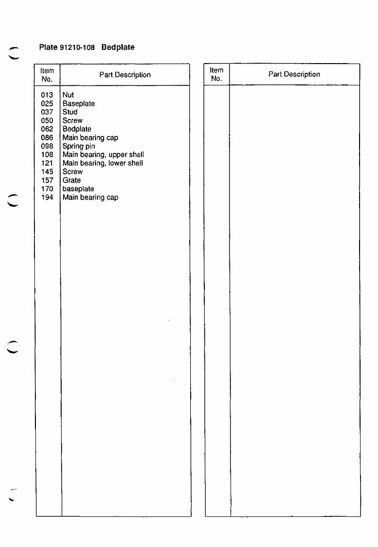
Plate 91210-108 Bedplate
Item No.
013 025 037 050 062 086 098 108 121 145 157 170 194
Part Description
Nut Baseplate Stud Screw Bedplate Main bearing cap Spring pin Main bearing, upper shell Main bearing, lower shell Screw Grate baseplate Main bearing cap
Item No.
Part Description
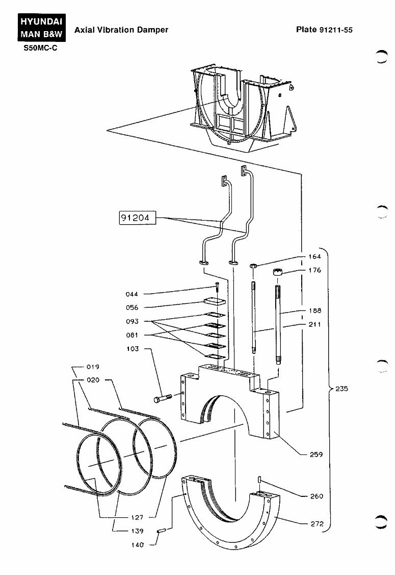
HYUNDAI MAN B&W
S50MC-C
Axial Vibration Damper Plate 91211-55
>235
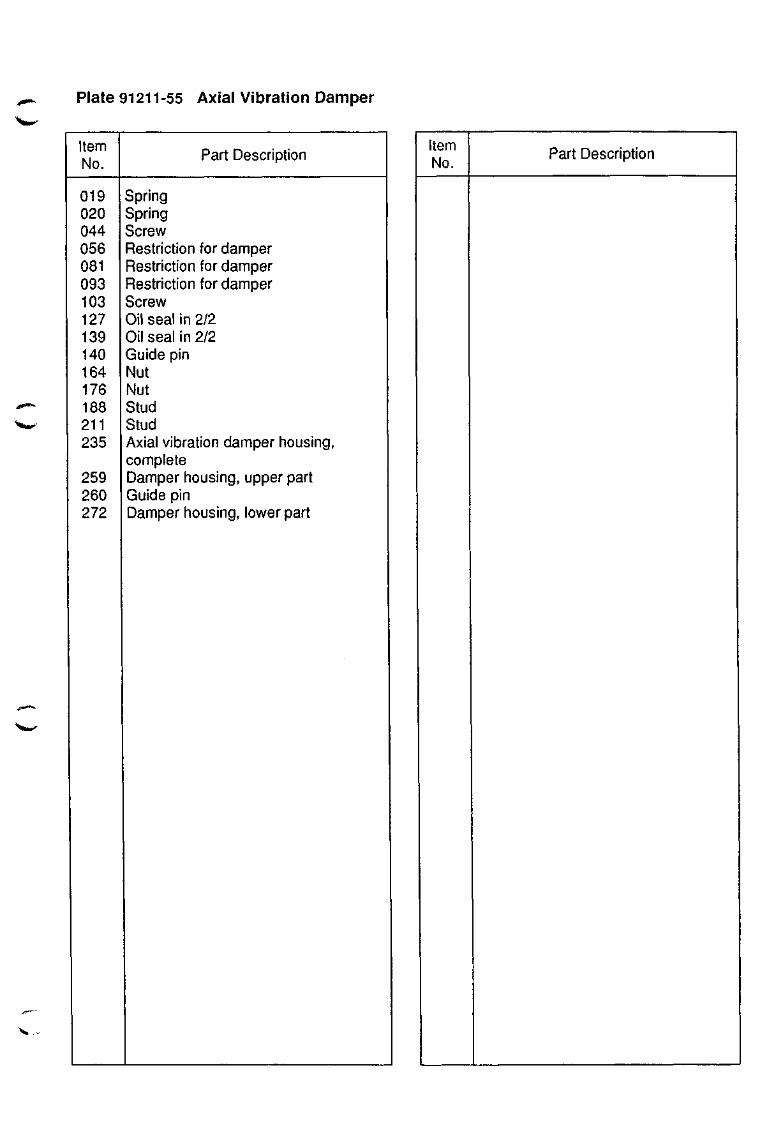
Plate 91211-55 Axial Vibration Damper '%«^
Item No.
019 020 044 056 081 093 103 127 139 140 164 176 168 211 235
259 260 272
Part Description
Spring Spring Screw Restriction for damper Restriction for damper Restriction for damper Screw Oil seal in 2/2 Oil seal in 2/2 Guide pin Nut Nut Stud Stud Axial vibration damper housing, complete Damper housing, upper part Guide pin Damper housing, lower part
Item No.
Part Description
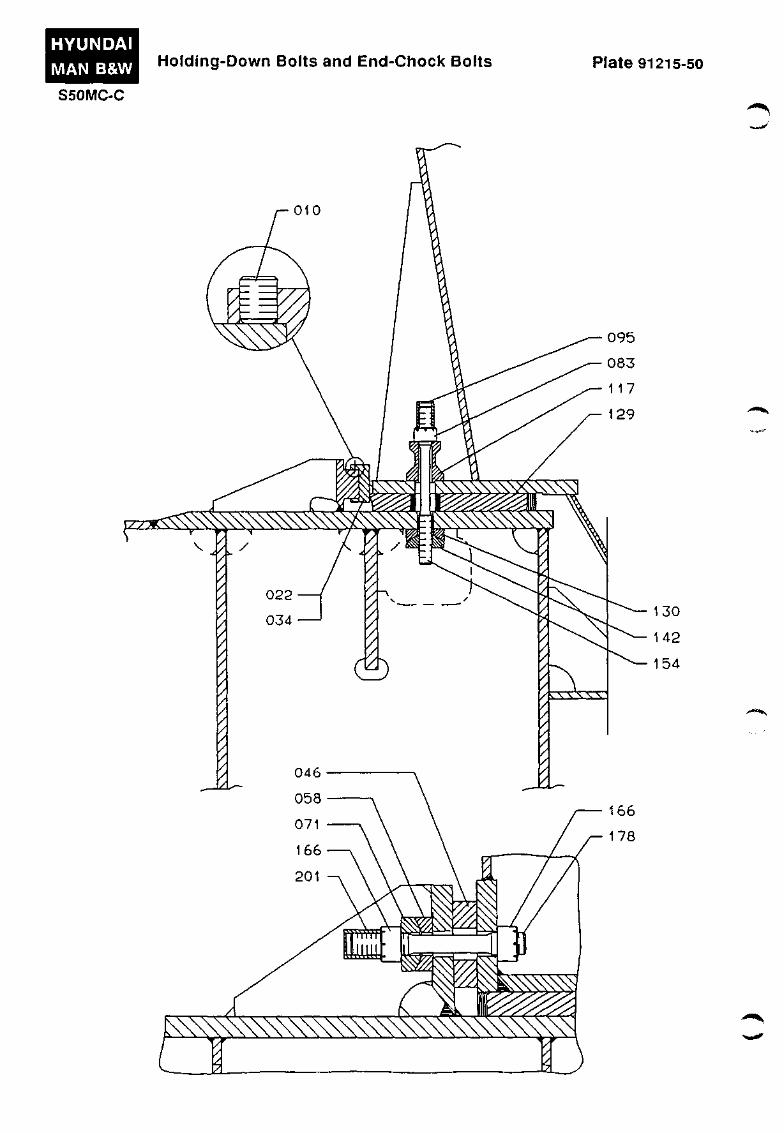
HYUNDAI
MAN B&W
S50MC-C
Holding-Down Bolts and End-Chock Bolts Plate 91215-50
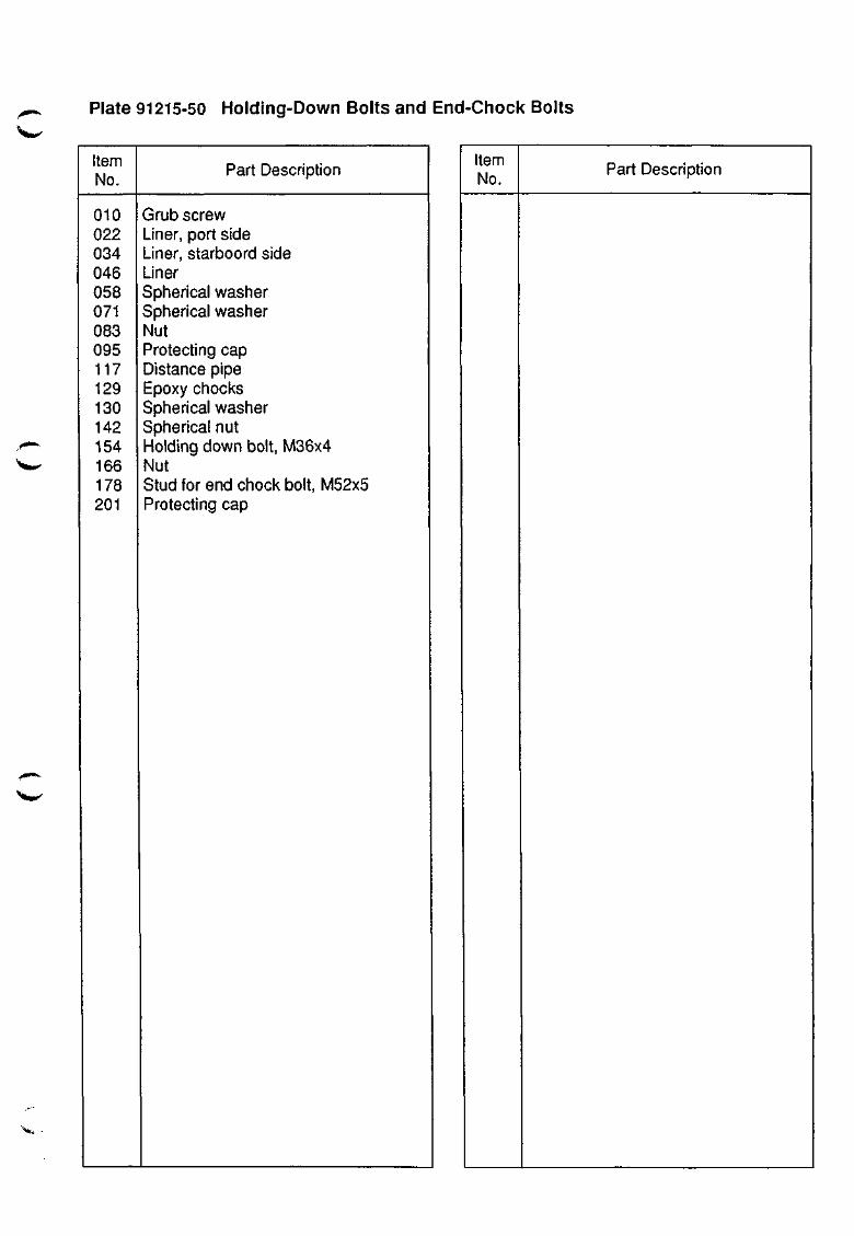
Plate 91215-50 Holding-Down Bolts and End-Chock Bolts
Item No.
010 022 034 046 058 071 083 095 117 129 130 142 154 166 178 201
X»^
Part Description
Grub screw Liner, port side Liner, starboord side Liner Spherical washer Spherical washer Nut Protecting cap Distance pipe Epoxy chocks Spherical washer Spherical nut Holding down bolt, M36x4 Nut Stud for end chock bolt, M52x5 Protecting cap
Item No.
Part Description
x,,
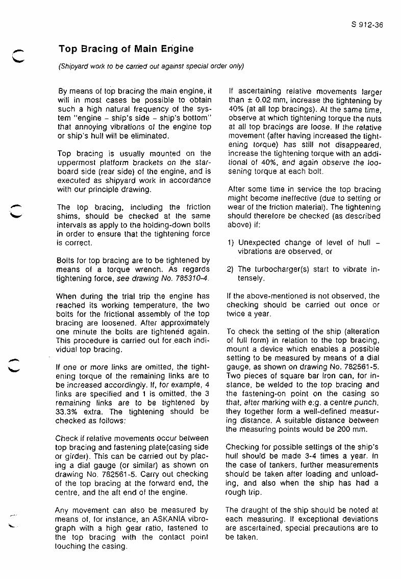
S 912-36
Top Bracing of Main Engine
(Shipyard work to be carried out against special order only)
By means of top bracing the main engine, it will in most cases be possible to obtain such a high natural frequency of the system "engine - ship's side - ship's bottom" that annoying vibrations of the engine top or ship's hull will be eliminated.
Top bracing is usually mounted on the uppermost platform brackets on the starboard side (rear side) of the engine, and is executed as shipyard work in accordance with our principle drawing.
The top bracing, including the friction shims, should be checked at the same intervals as apply to the holding-down bolts in order to ensure that the tightening force is correct.
Bolts for top bracing are to be tightened by means of a torque wrench. As regards tightening force, see drawing No. 785310-4.
When during the trial trip the engine has reached its working temperature, the two bolts for the frictional assembly of the top bracing are loosened. After approximately one minute the bolts are tightened again. This procedure is carried out for.each individual top bracing.
If one or more links are omitted, the tightening torque of the remaining links are to be increased accordingly. If, for example, 4 links are specified and 1 is omitted, the 3 remaining links are to be tightened by 33.3% extra. The tightening should be checked as follows:
Check if relative movements occur between top bracing and fastening plate(casing side or girder). This can be carried out by placing a dial gauge (or similar) as shown on drawing No. 782561-5. Carry out checking of the top bracing at the forward end, the centre, and the aft end of the engine.
Any movement can also be measured by means of, for instance, an ASKANIA vibro-graph with a high gear ratio, fastened to the top bracing with the contact point touching the casing.
If ascertaining relative movements larger than ± 0.02 mm, increase the tightening by 40% (at all top bracings). At the same time, observe at which tightening torque the nuts at all top bracings are loose. If the relative movement (after having increased the tightening torque) has still not disappeared, increase the tightening torque with an additional of 40%, and again observe the loosening torque at each bolt.
After some time in service the top bracing might become ineffective (due to setting or wear of the friction material). The tightening should therefore be checked (as described above) if:
1) Unexpected change of level of hull -vibrations are observed, or
2) The turbocharger(s) start to vibrate intensely.
If the above-mentioned is not observed, the checking should be carried out once or twice a year.
To check the setting of the ship (alteration of full form) in relation to the top bracing, mount a device which enables a possible setting to be measured by means of a dial gauge, as shown on drawing No. 782561-5. Two pieces of square bar iron can, for instance, be welded to the top bracing and the fastening-on point on the casing so that, after marking with e:g. a centre punch, they together form a well-defined measuring distance. A suitable distance between the measuring points would be 200 mm.
Checking for possible settings of the ship's hull should be made 3-4 times a year. In the case of tankers, further measurements should be taken after loading and unloading, and also when the ship has had a rough trip.
The draught of the ship should be noted at each measuring. If exceptional deviations are ascertained, special precautions are to be taken.
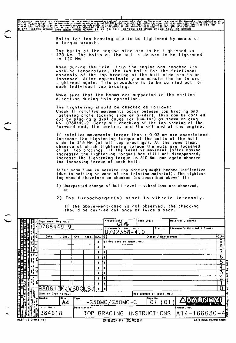
Thi i drOBinq. logvlhar > i th i l a ^wppIcaanla, ia Ih* propartr «' HHI-CUO end lub jac l lo eepyrighl pratact ion. The • o t a r i o l i« placid ot lh« di ipotol e( Ihf r t e l p i t n l • e l v l y (at hia o*n uaa, and on<r lor Iho nontiloclura. rapotr or uaa oa or ig inol HHI-EyO producla. according to eontrael or olhar a r i l t a n ograaaMnl haraon aitK HHI-EW). Tha Motar io l aiual not, aitliar «tioll|r or p o r t l y , ba copiad, raproduead, iMda public or in onjr olttor ooy noda ovoilobla to ony Ibirad porty • i tbout llta a r l t t an eonaant to liia a l tact froai HH|-CI4>, Tba notar ia l Muat not ba tronalarrad or hondad ovar to ooy tn i rd por ly , nailKar d i rac i nor by aueeaaaion to IKa rigltta ol tba racipiant .
01 Egg gcisaasi HI;;QI5S SAISI ssigoi oisgi wawji s£. nn. sa aaiu. oisgaati ¥11 H'-iaa H3<imi satu gg •aauo.
\ m ^ Bo I t s for top b r a c i n g a t o r q u e w r e n c h .
ore to be tig h t e n e d by m e a n s of
The b o l t s at the e n g i n e s i d e 4 7 0 Nm. The bo I ts at the huI to 120 Nm.
are to be t i g h t e n e d to side are to be tightened
When d u r i n g the triol trip the engine hos reached its w o r k i n g t e m p e r a t u r e , the two bolts for the frictionol a s s e m b l y of the top b r a c i n g at the hull side ore to be loosened^. After a p p r o x i m a t e l y one minu t e the bolts are tightened agoin . This p r o c e d u r e is each individual top b r o c i n g .
to be carried ou t for
Moke sure that the b e o m s are supported d i r e c t i o n during this o p e r a t i o n .
i n t h e ve r t i CO I
The t i g h t e n i n g s h o u l d be c h e c k e d as f o l l o w s : Check i f r e l a t i v e movements o c c u r between t op b r a c i n g and f a s t e n i n g p l a t e ( c a s i n g s i d e o r g i r d e r ) . T h i s can be c a r r i e d ou t by p l a c i n g o d i a l gouge ( o r s i m i l a r ) as shown on d r w g . No. 0 7 8 8 4 4 9 - 9 . C a r r y o u t c h e c k i n g of the t o p b r a c i n g ot the f o r w a r d e n d , t h e c e n t r e , a n d t h e o f t e n d o f t h e e n g i n e .
I f r e l a t i v e movements l o r g e r t h a n + 0 . 0 2 mm o r e a s c e r t a i n e d , i n c r e a s e t h e t i g h t e n i n g t o r q u e a t t he b o l t s a t t h e h u l l s i d e t o 215 Nm ( a t a l l t o p b r a c i n g s ) . At t h e some t i m e , o b s e r v e a t w h i c h t i g h t e n i n g t o r q u e t h e n u t s o r e l oosened a t a l l t op b r a c i n g s . I f t he r e l a t i v e movement ( a f t e r hav i ng i n c r e o s e d the t i g h t e n i n g t o r q u e ) has s t i l l no t d i s o p p e o r e d , i n c r e a s e the t i g h t e n i n g t o r q u e t o 310 Nm, and a g a i n observe t h e l o o s e n i n g t o r q u e a t each b o l t .
A f t e r some t ime in (due to se11 i ng o r ing s h o u l d t h e r e f o r e be checked
s e r v i c e top b r a c i n g might become i n e f f e c t i v e wear of the f r i c t i o n m a t e r i a l ) . The t i g h t e n -
(as d e s c r i b e d above) i f :
1) Unexpected change of hu l or
l e v e l - v i b r o t i o n s o re obse rved .
2 ) T h e t u r b o c h a r g e r ( s ) s t a r t t o v i b r a t e i n t e n s e l y
I f t h e a b o v e - m e n t i o n e d i s n o t o b s e r v e d , t h e c h e c k i n g s h o u l d be c a r r i e d o u t o n c e o r t w i c e o y e a r .
Supplamsnt Dwg n o . :
0788449-9 Dote Oes. Chk. Appd. A .C . E
980813KJWSDCLSJ * *
Projec t ion:
< 9 # Moss ( k g ) :
Licensor'! Ident. no.:
0792358-4 .0 O i s t .
Moteriol / Blank:
Licansor't Moteriol / Blonk:
Chonge / Replocement
R*placad by Idant. No.:
C.No
8 7
0 Similor Drowing No.: |Replacem«nt of Ident. No.:
S i z e :
A4 I n r o . N o . ;
384618
Typ«:
L-S50MC/S50MC-C | 01 ( 01 ) Poga No.:
Dascr i pt i on:
TOP BRACING INSTRUCTIONS
A D] l i j in t . No . :
A 1 4 - 1 6 6 6 3 0 - 4 H S E F - k 2 1 0 - 0 1 3 [ R 1 ) sfasgs(7) eni'ws ? A4(2IOninii297nn)=IlS«
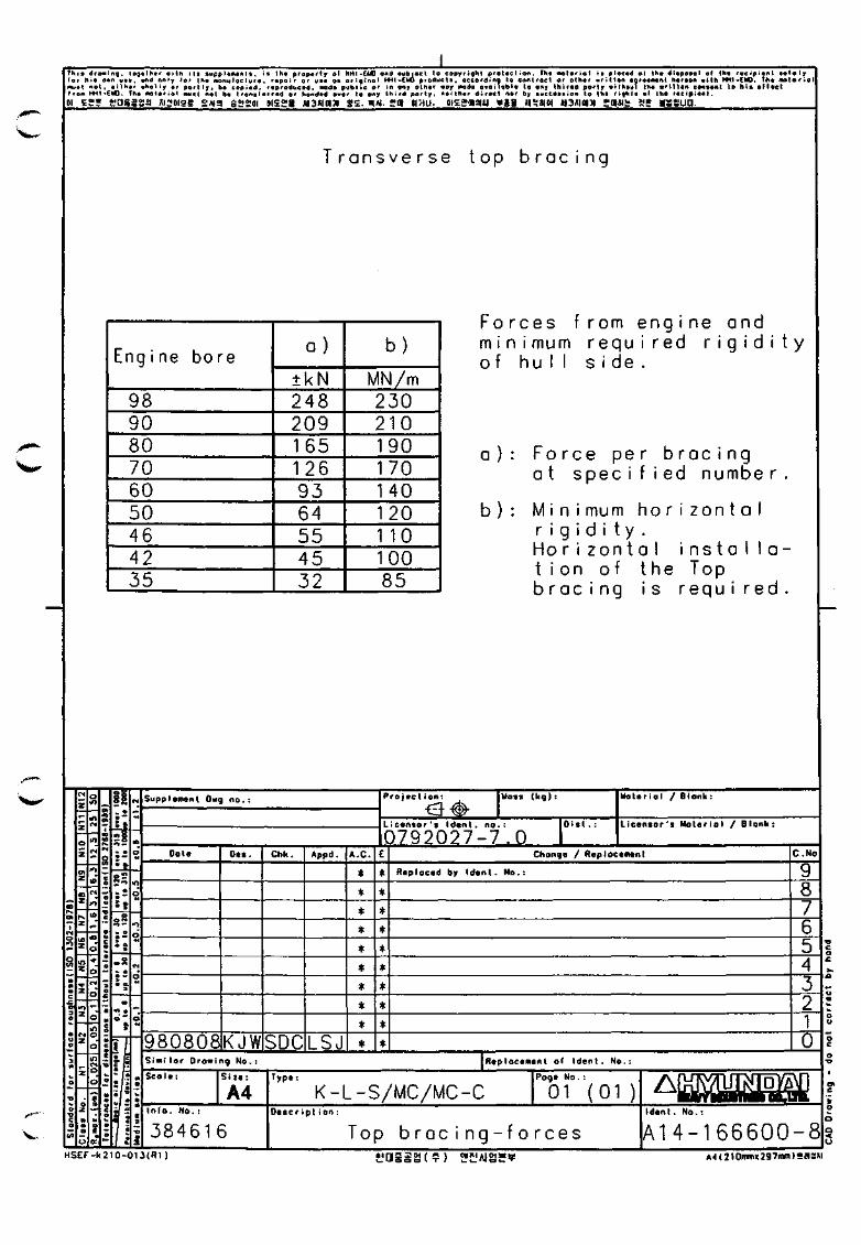
Thtt droMing, (o^tthvr aith itt auppltManti, is th« prap«r(r ol HHI-CIC ond •ubivcl to copyright prsticlion. Fh* Molariol <• placed ol IK« diapoial of lh« racipicnl tolaly for hi* o«n ua*. and only lor irta Moituloclura, rapoir or uaa o* original H H I - C W producta, according lo controct or other aritttn agraaiMnt haraon with H H I - C M ) . Tha nolario must not. aithar Bholly or parity, ba copiad, raproducad. maiSm public or in ony othar «oy gda owoilobla to ony Ihjrad porty aithotit tha written eoneeni to hie e M « e l froM HHI-ElA. Th* MOtariol nuel rtet ba tronelerred or hondtd over lo ony third porty, nailhar direct nor by auccaeaion to tha rights ol the recipient.
01 Egg *'as5aa Ai:;i)ige SAISI s£.'goi oisgg waxiciJi g£. nfi. ga smu. oi£gasi« ¥gg iisjaoi H3«ioia yasi^ gg •asuo.
T r a n s v e r s e t o p b r a c i n g
Eng i ne bore
98 90 80 70 60 50 46 42 35
a )
±kN 248 209 165 126 93 64 55 45 32
b)
MN/m 230 210 190 170 140 120 1 10 100 85
F o r c e s f r o m e n g i n e and m i n i m u m r e q u i r e d r i g i d i t y o f h u l l s i d e .
a ) : F o r c e p e r b rac i ng a t s p e c i f i ed numbe r
b ) : M i n i m u m h o r i z o n t a l r i g i d i t y . H o r i z o n t a l i n s t a l l o t i o n o f t h e Top b r a c i n g i s r e q u i r e d
v..
Supplament Owg n o . :
Dale Chk. Appd. A.C. E
980808KJWSDCISJ * •
ProjBct i I I o n I Mass (kg):
Li censor's Idsnt. no.:
0792027-7.0 Oist .
Moter iol / Blank:
L icensor 's Mo le r io l / B lonk:
Change / Replocement
Replaced by I d e n t . No.
S imi lor Growing N o . :
S c o t t : Si ze :
A4 I n f o . N o . :
3 8 4 6 1 6
Type:
C.No
8
0 Replocsmenl of I d e n t . No. :
K-L-S/MC/MC-C Page No . :
01 (01 ) Descr ipt i o n :
Top b r o c i n g - f 0 r o e s
A: I d i n l . No . :
A14-166600-8 H S E F - k 2 1 0 - 0 1 3 ( R 1 ) t 'asgS(?) 2I.'Alg*9 A4(210iTni«297mii)saS«l
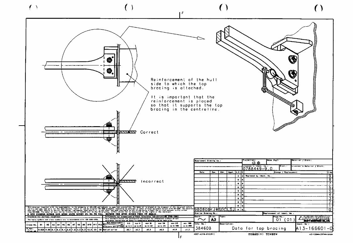
( ) ( ) ( )
R e i n f o r c e m e n t of t he hu s i d e t o w h i c h t h e t o p b r a c i n g i s a t t o c h e d .
I t i s i mpo r t o n t t h a t t h e r e i n f o r c e m e n t i s p l o c e d so t h a t i t s u p p o r t s t h e t o p b r a c i n g i n t h e c e n t r e l i n e .
'm^MM^^ks.:^^-^-• ;K.;S%:;:;: ::r.r'/:::l'::: i;:::.:;:;:: ::'£-!:;:Hi;\::':!::|!::fr"'*^**'"'*''"" w Egg tfoaagg wgpiga sua aiisw iisgi •amoiJi ge. i « . en «>tu. otEgami ¥ » nsfimi nawiw ;•«& ag aBSUQ
Bi>c«t ^at d i f m l B W i w/ lhout tot»f«nc« I n d i c a t lon i ISO 2 7 H - < 8 1 9 I
u p p l t M t n l Ornwinq n o .
Otita Oca. Crih. Appd. A . C . E
98Q8Q8rKJWlSDdLSJ
Projvct ion;
Licinior't Idcnl. no,
Q7S§449-9,Q
U a t C ' a l / B lon l i :
L i c a n a o r - a Met t
Chanqa / Raplocamant
RaplDcad by t d a n i . N« .
Slmi ta r Crowing No, l R t p l a c a « « n l a l I d a n t , No.
Stortdofd far muifaet rau^hnaaa
I ISO 1301-1I7«.
• ' ° ' " ' " *
' • " " " " t"""i ia . MoH.iwoiuraMfnt
w i a t i b l a daviet l a m
tiadiua aar iaa
' •" - " . '""" *""'" »r,d h> «.CM
S i l a :
A3
384608 D«*Cr i p l i o n ;
Poga N o . ;
01 (01
Da to f o r t o p b r ac i ng
A l
A13-166601-0 H 5 E F - k 2 1 0 - D 1 2 ( R I ] !'n55a<?) 2i'A(2S¥ &3(420innii297inm)S«£U
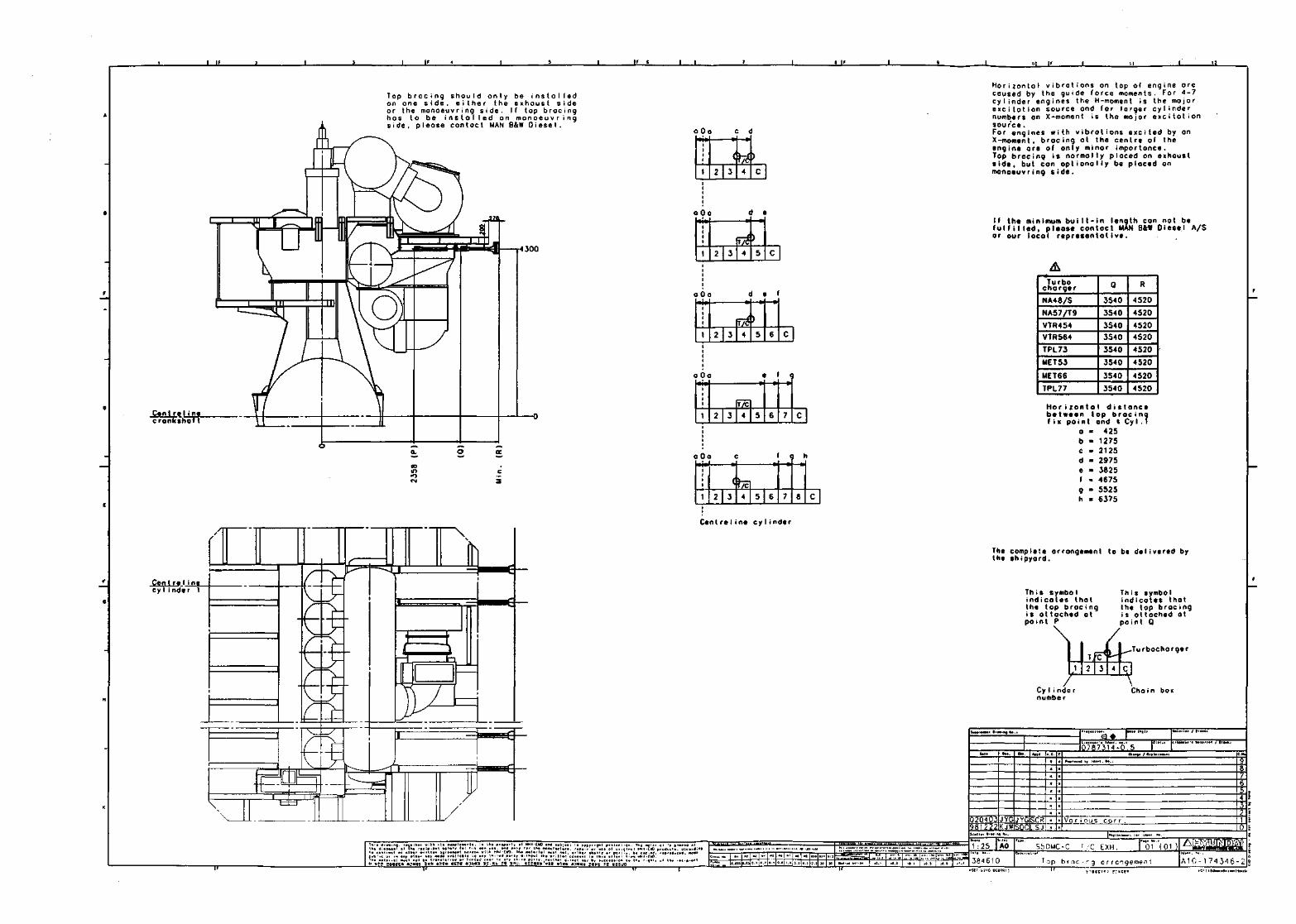
_l_lf L. _«_U_
Top bracing should only be instolled on one side, either the exhaust side or the manoeuvring side. If top bracing has to be installed on manoeuvring side, pleose contoct MAN 6&W Diesel.
4300
Cent re l ine cronksliaTT
Cent re I ine cy I i nder 1
\
fK
\ _
a Oo c d -H4-W
> 2 3 4 C Ml
a Oo _ •
I 1 1 1
1 2 3
^ /
T/* 4
>
5 c
o Do _ l _
1
r
1 2 3
/ J/t 4
^
) 5 6 C
0 Oa
\ ) ( t
1 2 3 VC 4 5 6 7 C
0 Oa f g h
1 1 1 1
1 <^^
2 3 4 5 6 7 8 C
Centreline cylinder
Horizontal vibrations on top o( engine ore caused by the guide force moments. For 4-7 cylinder engines the H-moment is the mojor excitation source and for larger cylinder numbers on X-moment is the major excitation source . For engines with vibrotions excited by on X-moment, brocing at the centre of the engine are of only minor importance. Top bracing is normolly placed on exhoust side, but con optionally be ploced on manoeuvring side.
If the minimum built-in length con not be fulfilled, please contoct MAN B&W Diesel A/S or our locol representotive.
A Turbo charger
NA48/S
NA57/T9
VTR454
VTRS64
TPL73
MET53
MET66
TPL77
0
3540
3540
3540
3540
3540
3540
3540
3540
R
4520
4520
4520
4520
4520
4520
4520
4520
H o r i z o n t a l d i s t a n c e between top b r a c i n g f i x point end t C y I . f
- 425 - 1275 = 2125 - 2975 - 3825 - 4675 - 5525 = 6375
The complete arrangement to be delivered by the shipyard.
This symbol indicates that the top bracing is ottoched at point P
CyIi nde r numbe r
This symbol indicates that the top bracing is ottoched ot point Q
Turbochorger
Chain box
I 5?g !;Q6iea MJMEt SMa ittv wsgl Mama ! tisfiaii ^11 m
020403JYGJYGSCR 9ai222lKjwsnni s.i
g » 0 7 8 7 3 1 4 - 0 . 5
Vo r i O'js CO r r •
1:25 AO
J84610 HSEF-1.310 009(B:
S50MC-C T c EXH. 01 (01 )
^ o p b t o c ' ^ g o r r c n g e m e n t •~TT r,B.= i . , rr..=r.
At£ A 1 C - 1 7 4 3 4 6 -
11 esmmeaiininisfixu

c
B. OVERSEAS NETWORK
c
c
c
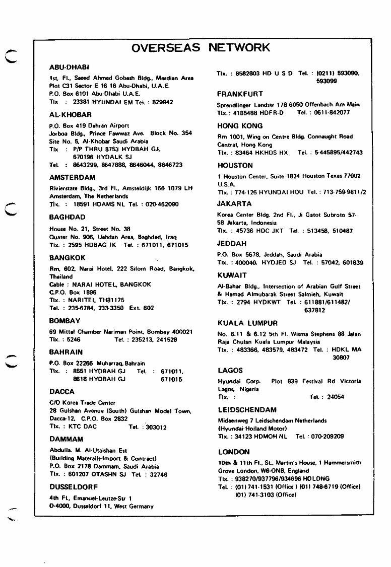
OVERSEAS NETWORK
ABU-DHABI 1st Fl., Saeed Ahmed Gobash BIdg., Merdlan Area Plot C31 Sector E 16 16 Abu-Dhabi, U.A.E. P.O. Box 6101 Abu Dhabi U.A.E. Tlx : 23381 HYUNDAI EM Tel. : 829942
AL-KHOBAR P.O. Box 419 Dahran Airport Jorboa BIdg., Prince Fawwaz Ave. Block No. 354 Site No. 5, Al-Khobar Saudi Arabia Tlx : P/P THRU 8753 HYDBAH GJ,
670196 HYDALK SJ Tel. : 8643299, 8647888, 8646044, 8646723
AMSTERDAM
Rivierstate BIdg., 3rd Fl., Amsteldijk 166 1079 LH Amsterdam, The Netherlands Tl«<. : 18591 HDAMS NL Tel. : 020-462090
BAGHDAD
House No. 21, Street No. 38 Quater No. 906, Uehdah Area, Baghdad, Iraq Tlx. : 2595 HDBAG IK Tel. : 671011, 671015
BANGKOK Rm, 602, Narai Hotel, 222 Silom Road, Bangkok, Thailand Cable : NARAI HOTEL, BANGKOK CP.O. Box 1896 Tlx. : NARITEL TH81175 Tel. : 23S6784, 233-3350 Ext. 602
BOMBAY 69 Mittal Chamber Nariman Point Bombay 40C021 Tlx. : 5246 Tel. : 235213, 241528
BAHRAIN P.O. Box 22266 Muharraq, Bahrain Tlx. : 8551 HYDBAH GJ Tel.
8618 HYDBAH GJ 671011, 671015
DACCA C/O Korea Trade Center 28 Gulshan Avenue (South) Gulshan Model Town, Dacca-12, C.P.O. Box 2832 Tlx. : KTC DAC Tel. : 303012
DAMMAM Abdulla. M. Al-Utaishan Est (Building Materails-lmport & Contract) P.O. Box 2178 Dammam, Saudi Arabia Tlx. : 601207 OTASHN SJ Tel. : 32746
DUSSELDORF 4th Fl., Emanuel-Leutze-Str 1 D-4000, Dusseldorf 11, West Germany
Tlx. : 8582803 HD U S D Tel. : (0211) 593090, 593099
FRANKFURT Sprendlinger Landstr 178 6050 Offenbach Am Main Tlx.: 4185488 HDFR-D Tel. : 0611-842077
HONG KONG Rm 1001, Wing on Centre BIdg. Connaught Road Central, Hong Kong Tlx. : 83464 HKHDS HX Tel. : ^445895/442743
HOUSTON 1 Houston Center, Suite 1824 Houston Texas 77002 U.S. A. Tlx. : 774-126 HYUNDAI HOU Tel. : 713-759-9811/2
JAKARTA Korea Center BIdg. 2nd Fl., Ji Gatot Subroto 57-58 Jakarta, Indonesia Tlx. : 45736 HDC JKT Tel. : 513458, 510487
JEDDAH
P.O. Box 5678, Jeddah, Saudi Arabia Tlx. : 400040, HYDJED SJ Tel. : 57042, 601839
KUWAIT AhBahar BIdg., Intersection of Arabian Gulf Street & Hamad Almubarak Street Salmieh, Kuwait Tix. : 2794 HYDKWT Tel. : 611881/611482/
637812
KUALA LUMPUR No. 6.11 & 6.12 5th Fl. Wisma Stephens 88 Jalan Raja Chulan Kuala Lumpur Malaysia Tlx. : 483366, 483579, 483472 Tel. : HDKL MA
30807
LAGOS Hyundai Corp. Plot 839 Festival Rd Victoria Lagos, Nigeria Tlx. : Tel. : 24054
LEIDSCHENDAM Midaenweg 7 Leidschendam Netherlands (Hyundai-Holland Motor) Tlx. : 34123 HDMOH NL Tel. : 070-209209
LONDON 10th & 11th Fl., St, Martin's House, 1 Hammersmith Grove London, W6-0NB, England Tlx. : 938270/937796/934696 HDLDNG Tel. : (01)741-1531 (Office) (01) 748-6719 (Office)
(01) 741-3103 (Office)
LOS ANGELES Hyundai Corp. L/A Office 19401 S. Main St. Gardena, Ca 90248 U.S.A. Tlx. : 910-346-7780/HDAMERICA Tel. : 213 538-9120/1 213-770-2972, 213-770-2975
MANILA
401 Sarmiento BIdg., Ayala Avenue, Makati Metro Manila, Philippiness Cable : HDCORPMNLA Tlx. : 45841 HDMNL PM Tel. : 871480
MIAMI Suite No. 355,2801 Ponce De Leon Boulevard Coral Gables. Florida 33134 U.aA. Miami Tlx. : 515779 HYUNDAI CGBL Tel : 305-446-0144/305-446 0145
MILANO Via Sporting Milasole No.2, El 20090, Noverasco Di Opera Milano ttay
NAIROBI P.O. Box 68149 NAIROBI
NEW JERSEY Polygon Plaza 3rd Floor, 2050 Center Ave. Fort Lee, N.J. 07024, U.S.A. Tlx.: 252109 HDNJ UR Tel. : 201-592-7766
NEW YORK One Penn Plaza, Suite 360 250 West 34th Street, Nevj York, N.Y. 10001 U.S.A. Tlx.: 235531 HSHI UR
125425 HYUNDAI NYK Tel.: 212 695-7810,
212 793-0605, 212-446-7914
PARIS Tour Maine Montparnasse 33 Avenue Du Maine, 75755 Paris Cedex 15, France Tlx. : 203639 F HD PARIS Tel. : 538-6776, 538 6841
QATAR (DOHA) P.O. Box 3441 Doha State of Qatar Hyundai Corp. Tlx. : 4039 HYDOAT DH Tel. : 326192
RIYADH P. 0 . Box 2761. Riyadh Saudi Arabia. Tlx. : 200197 HYDRYD SJ Tel. : 64739, 69694
SAN FRANCISCO 300 Montagomery Street, Suite 460 San Francisco, Calif, 94104 U.S.A. Tlx. : 278778 HDSFO UR Tel. : 415-956-4908/9
SANTIAGO Huertanos 1022, of, 1009, FONO 88160 Santiago Chilo, P.O. Box Casilla 3304 Tlx. : SGO 451 HYUNDAI Tel.
SEATTLE
88160
Hyundai Corporation Fourth N, Blanchard BIdg., Suite 270 Seattle, Washington 98121 USA. Tlx. : 329476 HYUNDAI SEA Tel. : 206 682 1698/9
SINGAPORE Suite 2403, 24th Fl., Ocean BIdg., Collyer Quay. Singapore 1 Tlx. : RS 21923 HYUNDAI Tel. : 982460,
221937
TAIWAN Chia Hsin BIdg., Rm, 507, 96 Chung Shan N Road Section 2 Taipei Taiwan 104 Tlx. : 27704 HDCTWN
TOKYO 8th Fl., Yurakucho Denki BIdg., 1-7-1, Yurakucho, Chiyoda-Ku, Tokyo, Japan 100 Cable : ROKATLAS TOKYO Tlx. : J28548 HDT, 2226343 HD SHTK, 2523639
HD SHTK Tel. : 03-211 0851/5
TORONTO Suite 3030 Hudson s Bay, Center 2 Bloor Street East, Toronto Ontario M4 Ml 48 Canada Cable : MOOGONG TORONTO Tlx. : 06-22949 HDCORP TOR Tel : (416) 923-7752, (416) 923 7803
HYUNDAI HEAVY INDUSTRIES CO., LTD. ENGINE & MACHINERY DIVISION
Head Office
1, Cheonha-Dong, Ulsan, Korea Tel.: Ulsan (32) 4141, (33) 4141 Telex: HHI EMD K53815. 52191
Related Documents