Advanced Technology - Powerful Operation

Welcome message from author
This document is posted to help you gain knowledge. Please leave a comment to let me know what you think about it! Share it to your friends and learn new things together.
Transcript
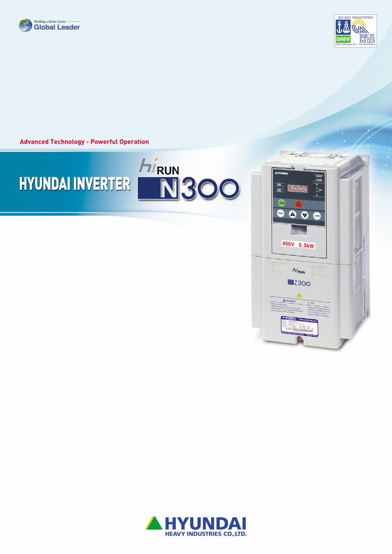
Advanced Technology - Powerful Operation
Powerful Operation, Easy Maintenance
Hyundai Inverter‐Powerful high torque performance has been
accomplished using advanced sensorless vector control.
Powerful operation is possible for two motors at the
same time.
Auto-tuning to perform sensorless vector control can
now be easily done both on-line and off-line.
Versatile functions encompass more applications.
Field replacement of cooling fans and DC bus capacitors
can be accomplished in a fraction of the time.
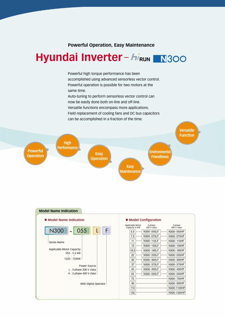
Model Name Indication
Series Name
Applicable Motor Capacity055 : 5.5 kW
1320 : 132kW
Power SourceL : 3-phase 200 V classH : 3-phase 400 V class
With Digital Operator
~ ~
■Model Configuration■Model Name Indication
N300 - L F055
PowerfulOperation
HighPerformance
EasyOperation
EasyMaintenance
EnvironmentalFriendliness
VersatileFunction
▶
▶
▶
▶
▶
▶
Applicable MotorCapacity in kW
3-phase200 V class
3-phase 400 V class
CONTENTS
Features 4
Standard Specifications 8
Dimensions 10
Operation and Programming 14
Function List 16
Terminals 25
Protective Functions 27
Connecting Diagram 28
Connecting to PLC 29
Wiring and Options 30
Torque Characteristics 36
Temperature Derating Characteristics 37
For Correct Operation 38
We build a better future!
Features
� 4
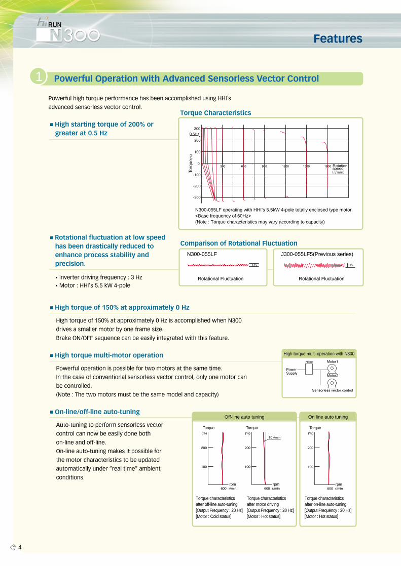
Powerful high torque performance has been accomplished using HHI`s
advanced sensorless vector control.
■High starting torque of 200% or greater at 0.5 Hz
■Rotational fluctuation at low speed has been drastically reduced to enhance process stability and precision.
■High torque of 150% at approximately 0 Hz
High torque of 150% at approximately 0 Hz is accomplished when N300
drives a smaller motor by one frame size.
Brake ON/OFF sequence can be easily integrated with this feature.
■High torque multi-motor operation
Powerful operation is possible for two motors at the same time.
In the case of conventional sensorless vector control, only one motor can
be controlled.
(Note : The two motors must be the same model and capacity)
■On-line/off-line auto-tuning
Auto-tuning to perform sensorless vector
control can now be easily done both
on-line and off-line.
On-line auto-tuning makes it possible for
the motor characteristics to be updated
automatically under “real time” ambient
conditions.
1 Powerful Operation with Advanced Sensorless Vector Control
N300-055LF operating with HHI’s 5.5kW 4-pole totally enclosed type motor.<Base frequency of 60Hz>(Note : Torque characteristics may vary according to capacity)
N300-055LF
Rotational Fluctuation Rotational Fluctuation�Inverter driving frequency : 3 Hz�Motor : HHI’s 5.5 kW 4-pole
J300-055LF5(Previous series)
Off-line auto tuning On line auto tuning
Torque characteristicsafter off-line auto-tuning[Output Frequency : 20 Hz][Motor : Cold status]
Torque characteristics after motor driving[Output Frequency : 20 Hz][Motor : Hot status]
Torque characteristics after on-line auto-tuning[Output Frequency : 20 Hz][Motor : Hot status]
Torque Characteristics
Comparison of Rotational Fluctuation
High torque multi-operation with N300
5 �
■Third motor constants setting
Constants for up to three motors can be set.
This function is useful for controlling (multi-
axis)motors via changeover.
■Fan ON/OFF selection
The cooling fan operates while the inverter is
running, and stops when the inverter stops.
This feature provides longer cooling fan life, and
eliminates fan noise while the inverter is idle.
■PID operation
Helps simplify the system and save initial cost no
need for external PID controller.
Useful for such applications as droop control.
■Deceleration and stop at power failure
N300 decelerates and stops the motor using
regenerative energy from the motor even though
the power is not supplied. Especially critical in some
textile processes.
■UP/DOWN function
Up/down function fine-tunes output frequency.
Convenient for a test-run.
■Frequency scaling conversion
Display the output frequency scaled by the
conversion factor for “line”/process speed.
■3-Wire function
“Seal-in”start signal without an external device.
■P∙PI control selection
Provides stable control for carrier or trolley (material
handling)operations.
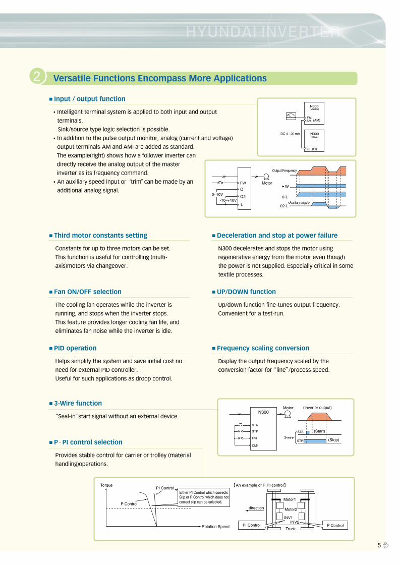
■Input / output function
�Intelligent terminal system is applied to both input and output
terminals.
Sink/source type logic selection is possible.
�In addition to the pulse output monitor, analog (current and voltage)
output terminals-AM and AMI are added as standard.
The example(right) shows how a follower inverter can
directly receive the analog output of the master
inverter as its frequency command.
�An auxiliary speed input or ‘trim”can be made by an
additional analog signal.
2 Versatile Functions Encompass More Applications
Features
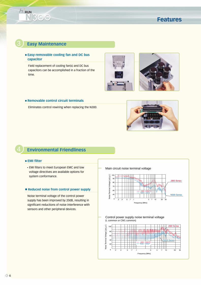
■Easy-removable cooling fan and DC buscapacitor
Field replacement of cooling fan(s) and DC bus
capacitors can be accomplished in a fraction of the
time.
■Removable control circuit terminals
Eliminates control rewiring when replacing the N300.
3 Easy Maintenance
4
■EMI filter
�EMI filters to meet European EMC and low
voltage directives are available options for
system conformance.
■Reduced noise from control power supply
Noise terminal voltage of the control power
supply has been improved by 20dB, resulting in
significant reductions of noise interference with
sensors and other peripheral devices.
4 Environmental Friendliness
Main circuit noise terminal voltage
� 6
Control power supply noise terminal voltage(L common or CM1 common)
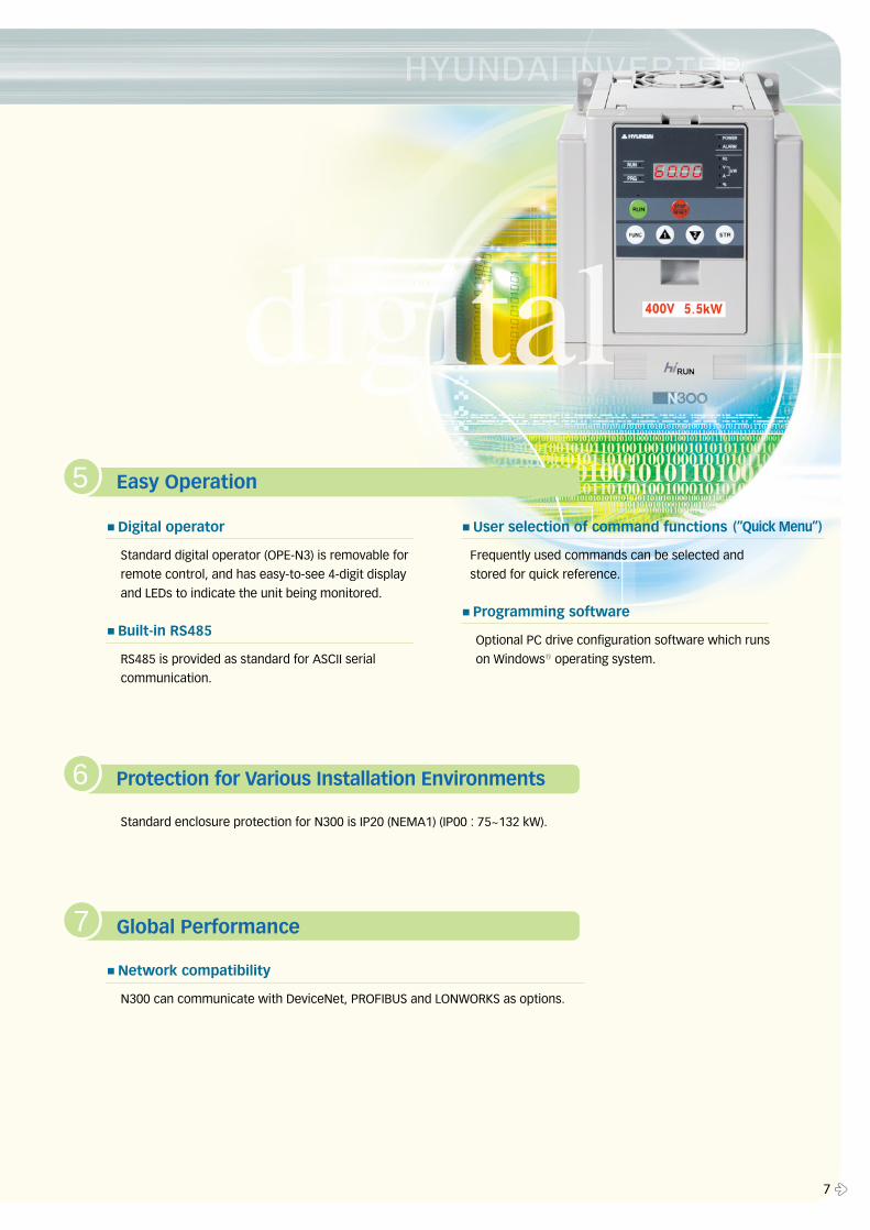
■Digital operator
Standard digital operator (OPE-N3) is removable for
remote control, and has easy-to-see 4-digit display
and LEDs to indicate the unit being monitored.
■Built-in RS485
RS485 is provided as standard for ASCII serial
communication.
■User selection of command functions
Frequently used commands can be selected and
stored for quick reference.
■Programming software
Optional PC drive configuration software which runs
on Windows� operating system.
Standard enclosure protection for N300 is IP20 (NEMA1) (IP00 : 75~132 kW).
■Network compatibility
N300 can communicate with DeviceNet, PROFIBUS and LONWORKS as options.
5 Easy Operation
6 Protection for Various Installation Environments
7 Global Performance
7 �
(“Quick Menu”)
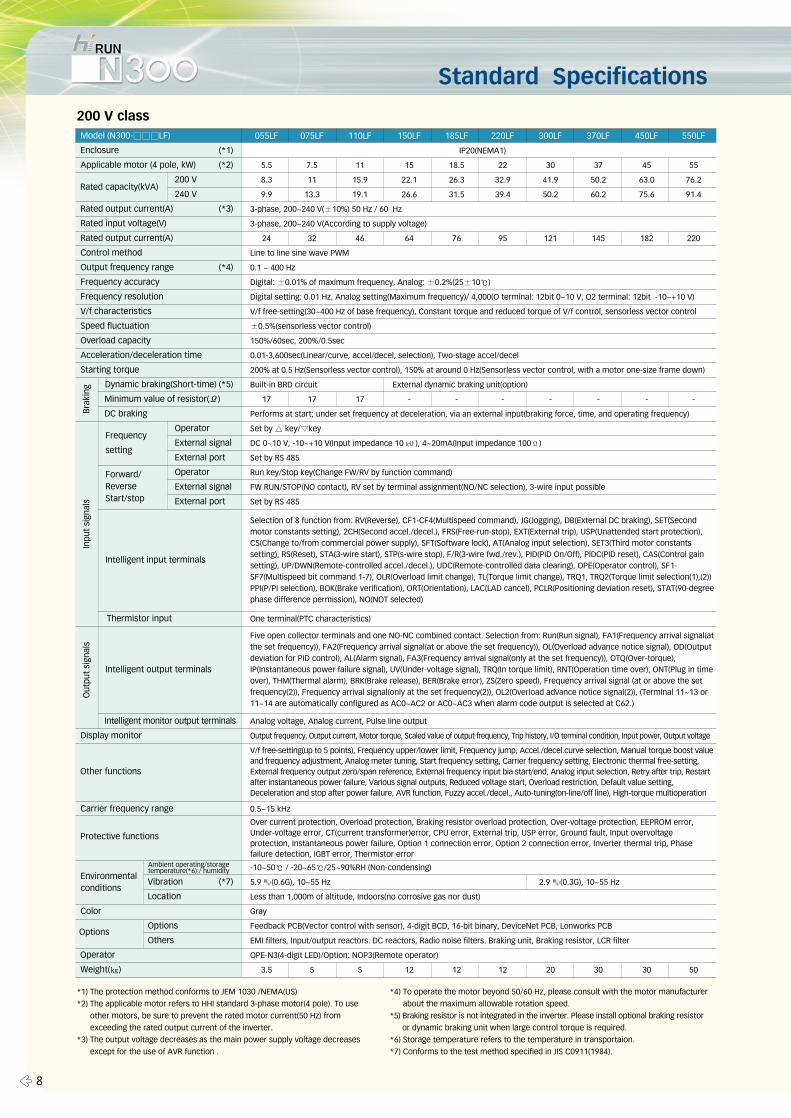
Standard Specifications
200 V class
*1) The protection method conforms to JEM 1030 /NEMA(US)
*2) The applicable motor refers to HHI standard 3-phase motor(4 pole). To use
other motors, be sure to prevent the rated motor current(50 Hz) from
exceeding the rated output current of the inverter.
*3) The output voltage decreases as the main power supply voltage decreases
except for the use of AVR function .
*4) To operate the motor beyond 50/60 Hz, please consult with the motor manufacturer
about the maximum allowable rotation speed.
*5) Braking resistor is not integrated in the inverter. Please install optional braking resistor
or dynamic braking unit when large control torque is required.
*6) Storage temperature refers to the temperature in transportaion.
*7) Conforms to the test method specified in JIS C0911(1984).
Model (N300-���LF)
Enclosure (*1)
Applicable motor (4 pole, kW) (*2)
200 V
240 V
Rated output current(A) (*3)
Rated input voltage(V)
Rated output current(A)
Control method
Output frequency range (*4)
Frequency accuracy
Frequency resolution
V/f characteristics
Speed fluctuation
Overload capacity
Acceleration/deceleration time
Starting torque
Dynamic braking(Short-time) (*5)
Minimum value of resistor(Ω)
DC braking
Operator
External signal
External port
Operator
External signal
External port
Thermistor input
Intelligent monitor output terminals
Display monitor
Carrier frequency range
Vibration (*7)
Location
Color
Options
Others
Weight(㎏)
055LF 075LF 110LF 150LF 185LF 220LF 300LF 370LF 450LF 550LF
IP20(NEMA1)
5.5 7.5 11 15 18.5 22 30 37 45 55
8.3 11 15.9 22.1 26.3 32.9 41.9 50.2 63.0 76.2
9.9 13.3 19.1 26.6 31.5 39.4 50.2 60.2 75.6 91.4
3-phase, 200~240 V(±10%) 50 Hz / 60 Hz
3-phase, 200~240 V(According to supply voltage)
24 32 46 64 76 95 121 145 182 220
Line to line sine wave PWM
0.1 ~ 400 Hz
Digital: ±0.01% of maximum frequency, Analog: ±0.2%(25±10℃)
Digital setting: 0.01 Hz, Analog setting(Maximum frequency)/ 4,000(O terminal: 12bit 0~10 V, O2 terminal: 12bit -10~+10 V)
V/f free-setting(30~400 Hz of base frequency), Constant torque and reduced torque of V/f control, sensorless vector control
±0.5%(sensorless vector control)
150%/60sec, 200%/0.5sec
0.01-3,600sec(Linear/curve, accel/decel, selection), Two-stage accel/decel
200% at 0.5 Hz(Sensorless vector control), 150% at around 0 Hz(Sensorless vector control, with a motor one-size frame down)
Built-in BRD circuit External dynamic braking unit(option)
17 17 17 - - - - - - -
Performs at start; under set frequency at deceleration, via an external input(braking force, time, and operating frequency)
Set by △ key/▽key
DC 0~10 V, -10~+10 V(Input impedance 10 kΪ), 4~20mA(Input impedance 100Ϊ)
Set by RS 485
Run key/Stop key(Change FW/RV by function command)
FW RUN/STOP(NO contact), RV set by terminal assignment(NO/NC selection), 3-wire input possible
Set by RS 485
One terminal(PTC characteristics)
Analog voltage, Analog current, Pulse line output
Output frequency, Output current, Motor torque, Scaled value of output frequency, Trip history, I/O terminal condition, Input power, Output voltage
0.5~15 kHz
-10~50℃ / -20~65℃/25~90%RH (Non-condensing)
5.9 ㎨(0.6G), 10~55 Hz 2.9 ㎨(0.3G), 10~55 Hz
Less than 1,000m of altitude, Indoors(no corrosive gas nor dust)
Gray
Feedback PCB(Vector control with sensor), 4-digit BCD, 16-bit binary, DeviceNet PCB, Lonworks PCB
EMI filters, Input/output reactors. DC reactors, Radio noise filters. Braking unit, Braking resistor, LCR filter
OPE-N3(4-digit LED)/Option: NOP3(Remote operator)
3.5 5 5 12 12 12 20 30 30 50
Selection of 8 function from: RV(Reverse), CF1-CF4(Multispeed command), JG(Jogging), DB(External DC braking), SET(Secondmotor constants setting), 2CH(Second accel./decel.), FRS(Free-run-stop), EXT(External trip), USP(Unattended start protection),CS(Change to/from commercial power supply), SFT(Software lock), AT(Analog input selection), SET3(Third motor constantssetting), RS(Reset), STA(3-wire start), STP(s-wire stop), F/R(3-wire fwd./rev.), PID(PID On/Off), PIDC(PID reset), CAS(Control gainsetting), UP/DWN(Remote-controlled accel./decel.), UDC(Remote-controlled data clearing), OPE(Operator control), SF1-SF7(Multispeed bit command 1-7), OLR(Overload limit change), TL(Torque limit change), TRQ1, TRQ2(Torque limit selection(1),(2))PPI(P/PI selection), BOK(Brake verification), ORT(Orientation), LAC(LAD cancel), PCLR(Positioning deviation reset), STAT(90-degreephase difference permission), NO(NOT selected)
Five open collector terminals and one NO-NC combined contact. Selection from: Run(Run signal), FA1(Frequency arrival signal(atthe set frequency)), FA2(Frequency arrival signal(at or above the set frequency)), OL(Overload advance notice signal), OD(Outputdeviation for PID control), AL(Alarm signal), FA3(Frequency arrival signal(only at the set frequency)), OTQ(Over-torque),IP(Instantaneous power failure signal), UV(Under-voltage signal), TRQ(In torque limit), RNT(Operation time over), ONT(Plug in timeover), THM(Thermal alarm), BRK(Brake release), BER(Brake error), ZS(Zero speed), Frequency arrival signal (at or above the setfrequency(2)), Frequency arrival signal(only at the set frequency(2)), OL2(Overload advance notice signal(2)), (Terminal 11~13 or11~14 are automatically configured as AC0~AC2 or AC0~AC3 when alarm code output is selected at C62.)
V/f free-setting(up to 5 points), Frequency upper/lower limit, Frequency jump, Accel./decel.curve selection, Manual torque boost valueand frequency adjustment, Analog meter tuning, Start frequency setting, Carrier frequency setting, Electronic thermal free-setting,External frequency output zero/span reference, External frequency input bia start/end, Analog input selection, Retry after trip, Restartafter instantaneous power failure, Various signal outputs, Reduced voltage start, Overload restriction, Default value setting,Deceleration and stop after power failure, AVR function, Fuzzy accel./decel., Auto-tuning(on-line/off line), High-torque multioperation
Over current protection, Overload protection, Braking resistor overload protection, Over-voltage protection, EEPROM error,Under-voltage error, CT(current transformer)error, CPU error, External trip, USP error, Ground fault, Input overvoltageprotection, Instantaneous power failure, Option 1 connection error, Option 2 connection error, Inverter thermal trip, Phasefailure detection, IGBT error, Thermistor error
Inpu
t si
gnal
sO
utpu
t si
gnal
sB
raki
ng
Environmentalconditions
Options
Frequency
setting
Forward/ReverseStart/stop
Intelligent input terminals
Intelligent output terminals
Other functions
Protective functions
Rated capacity(kVA)
Operator
� 8
Ambient operating/storagetemperature(*6) / humidity
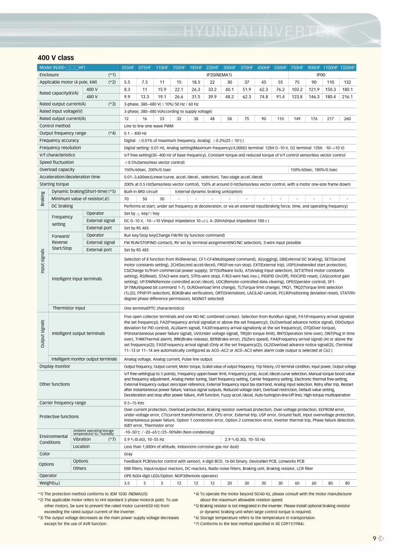
400 V class
9 �
*1) The protection method conforms to JEM 1030 /NEMA(US)
*2) The applicable motor refers to HHI standard 3-phase motor(4 pole). To use
other motors, be sure to prevent the rated motor current(50 Hz) from
exceeding the rated output current of the inverter.
*3) The output voltage decreases as the main power supply voltage decreases
except for the use of AVR function .
*4) To operate the motor beyond 50/60 Hz, please consult with the motor manufacturer
about the maximum allowable rotation speed.
*5) Braking resistor is not integrated in the inverter. Please install optional braking resistor
or dynamic braking unit when large control torque is required.
*6) Storage temperature refers to the temperature in transportaion.
*7) Conforms to the test method specified in JIS C0911(1984).
Model (N300-���HF)
Enclosure (*1)
Applicable motor (4 pole, kW) (*2)
400 V
480 V
Rated output current(A) (*3)
Rated input voltage(V)
Rated output current(A)
Control method
Output frequency range (*4)
Frequency accuracy
Frequency resolution
V/f characteristics
Speed fluctuation
Overload capacity
Acceleration/deceleration time
Starting torque
Dynamic braking(Short-time) (*5)
Minimum value of resistor(Ω)
DC braking
Operator
External signal
External port
Operator
External signal
External port
Thermistor input
Intelligent monitor output terminals
Display monitor
Carrier frequency range
Vibration (*7)
Location
Color
Options
Others
Weight(㎏)
075HF 110HF 150HF 185HF 220HF 300HF 370HF 450HF 550HF 750HF 900HF 1100HF 1320HF
IP20(NEMA1) IP00
5.5 7.5 11 15 18.5 22 30 37 45 55 75 90 110 132
8.3 11 15.9 22.1 26.3 33.2 40.1 51.9 62.3 76.2 103.2 121.9 150.3 180.1
9.9 13.3 19.1 26.6 31.5 39.9 48.2 62.3 74.8 91.4 123.8 146.3 180.4 216.1
3-phase, 380~480 V(±10%) 50 Hz / 60 Hz
3-phase, 380~480 V(According to supply voltage)
12 16 23 32 38 48 58 75 90 110 149 176 217 260
Line to line sine wave PWM
0.1 ~ 400 Hz
Digital: ±0.01% of maximum frequency, Analog: ±0.2%(25±10℃)
Digital setting: 0.01 Hz, Analog setting(Maximum frequency)/4,000(O terminal: 12bit 0~10 V, O2 terminal: 12bit -10~+10 V)
V/f free-setting(30~400 Hz of base frequency), Constant torque and reduced torque of V/f control sensorless vector control
±0.5%(Sensorless vector control)
150%/60sec, 200%/0.5sec 150%/60sec, 180%/0.5sec
0.01~3,600sec(Linear/curve, accel./decel., selection), Two-stage accel./decel.
200% at 0.5 Hz(Sensorless vector control), 150% at around 0 Hz(Sensorless vector control, with a motor one-size frame down)
Built-in BRD circuit External dynamic braking unit(option)
70 50 50 - - - - - - - - - - -
Performs at start; under set frequency at deceleration, or via an external input(braking force, time, and operating frequency)
Set by △ key/▽key
DC 0~10 V, -10~+10 V(Input impedance 10 kΪ), 4~20mA(Input impedance 100Ϊ)
Set by RS 485
Run key/Stop key(Change FW/RV by function command)
FW RUN/STOP(NO contact), RV set by terminal assignment(NO/NC selection), 3-wire input possible
Set by RS 485
One terminal(PTC characteristics)
Analog voltage, Analog current, Pulse line output
Output frequency, Output current, Motor torque, Scaled value of output frequency, Trip history, I/O terminal condition, Input power, Output voltage
0.5~15 kHz
-10~50℃ / -20~65℃/25~90%RH (Non-condensing)
5.9 ㎨(0.6G), 10~55 Hz 2.9 ㎨(0.3G), 10~55 Hz
Less than 1,000m of altitude, Indoors(no corrosive gas nor dust)
Gray
Feedback PCB(Vector control with sensor), 4-digit BCD, 16-bit binary, DeviceNet PCB, Lonworks PCB
EMI filters, Input/output reactors, DC reactors, Radio noise filters, Braking unit, Braking resistor, LCR filter
OPE-N3(4-digit LED)/Option: NOP3(Remote operator)
3.5 5 5 12 12 12 20 30 30 30 60 60 80 80
055HF
Selection of 8 function from RV(Reverse), CF1-CF4(Multispeed command), JG(Jogging), DB(External DC braking), SET(Secondmotor constants setting), 2CH(Second accel/decel), FRS(Free-run-stop), EXT(External trip), USP(Unattended start protection),CS(Change to/from commercial power supply), SFT(Software lock), AT(Analog input selection), SET3(Third motor constantssetting), RS(Reset), STA(3-wire start), STP(s-wire stop), F/R(3-wire fwd./rev.), PID(PID On/Off), PIDC(PID reset), CAS(control gainsetting), UP/DWN(Remote-controlled accel./decel), UDC(Remote-controlled data clearing), OPE(Operator control), SF1-SF7(Multispeed bit command 1-7), OLR(Overload limit change), TL(Torque limit change), TRQ1, TRQ2(Torque limit selection(1),(2)), PPI(P/PI selection), BOK(Brake verification), ORT(Orientation), LAC(LAD cancel), PCLR(Positioning deviation reset), STAT(90-degree phase difference permission), NO(NOT selected)
Five open collector terminals and one NO-NC combined contact. Selection from Run(Run signal), FA1(Frequency arrival signal(atthe set frequency)), FA2(Frequency arrival signal(at or above the set frequency)), OL(Overload advance notice signal), OD(Outputdeviation for PID control), AL(Alarm signal), FA3(Frequency arrival signal(only at the set frequency)), OTQ(Over-torque),IP(Instantaneous power failure signal), UV(Under-voltage signal), TRQ(In torque limit), RNT(Operation time over), ONT(Plug in timeover), THM(Thermal alarm), BRK(Brake release), BER(Brake error), ZS(Zero speed), FA4(Frequency arrival signal) (At or above theset frequency(2)), FA5(Frequency arrival signal) (Only at the set frequency(2)), OL2(Overload advance notice signal(2)), (Terminal11~13 or 11~14 are automatically configured as AC0~AC2 or AC0~AC3 when alarm code output is selected at C62.)
V/f free-setting(up to 5 points), Frequency upper/lower limit, Frequency jump, Accel./decel.curve selection, Manual torque boost valueand frequency adjustment, Analog meter tuning, Start frequency setting, Carrier frequency setting, Electronic thermal free-setting,External frequency output zero/span reference, External frequency input bia start/end, Analog input selection, Retry after trip, Restartafter instantaneous power failure, Various signal outputs, Reduced voltage start, Overload restriction, Default value setting,Deceleration and stop after power failure, AVR function, Fuzzy accel./decel, Auto-tuning(on-line/off line), High-torque multioperation
Over current protection, Overload protection, Braking resistor overload protection, Over-voltage protection, EEPROM error,under-voltage error, CT(current transformer)error, CPU error, External trip, USP error, Ground fault, Input overvoltage protection,Instantaneous power failure, Option 1 connection error, Option 2 connection error, Inverter thermal trip, Phase failure detection,IGBT error, Thermistor error
Inpu
t si
gnal
sO
utpu
t si
gnal
sB
raki
ng
EnvironmentalConditions
Options
Frequency
setting
Forward/ReverseStart/Stop
Intelligent input terminals
Intelligent output terminals
Other functions
Protective functions
Rated capacity(kVA)
Operator
Ambient operating/storagetemperature(*6) / humidity
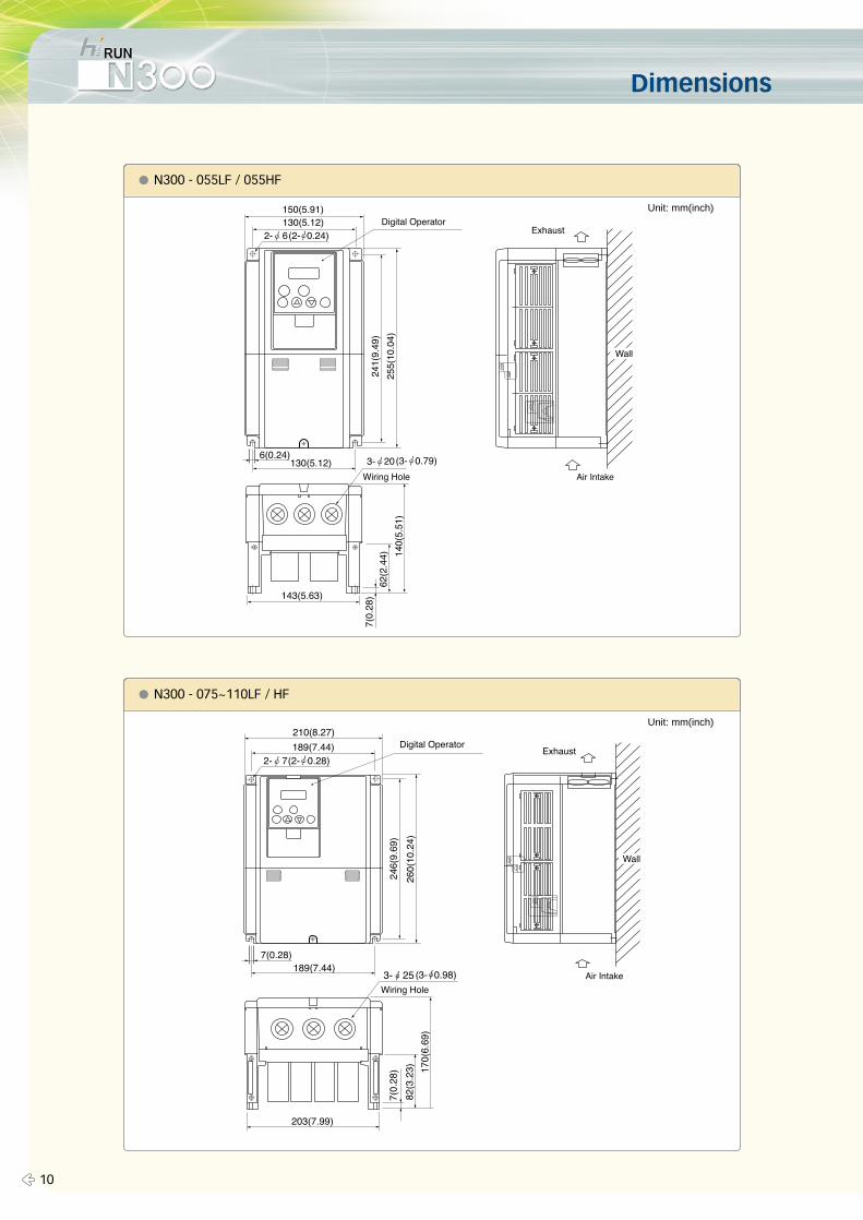
Dimensions
� 10
� N300 - 055LF / 055HF
� N300 - 075~110LF / HF
Unit: mm(inch)
Unit: mm(inch)
11 �
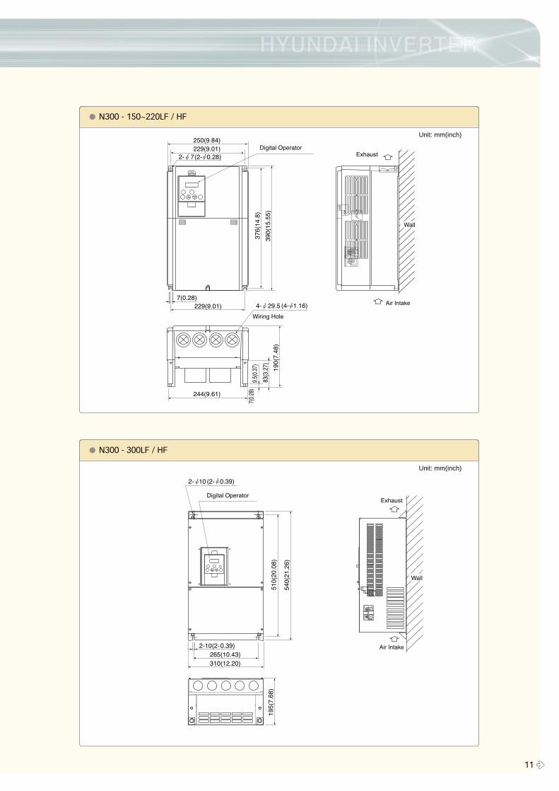
� N300 - 150~220LF / HF
� N300 - 300LF / HF
Unit: mm(inch)
Unit: mm(inch)
Dimensions
� 12
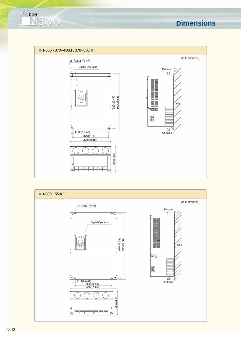
� N300 - 370~450LF, 370~550HF
� N300 - 550LF
Unit: mm(inch)
Unit: mm(inch)
13 �
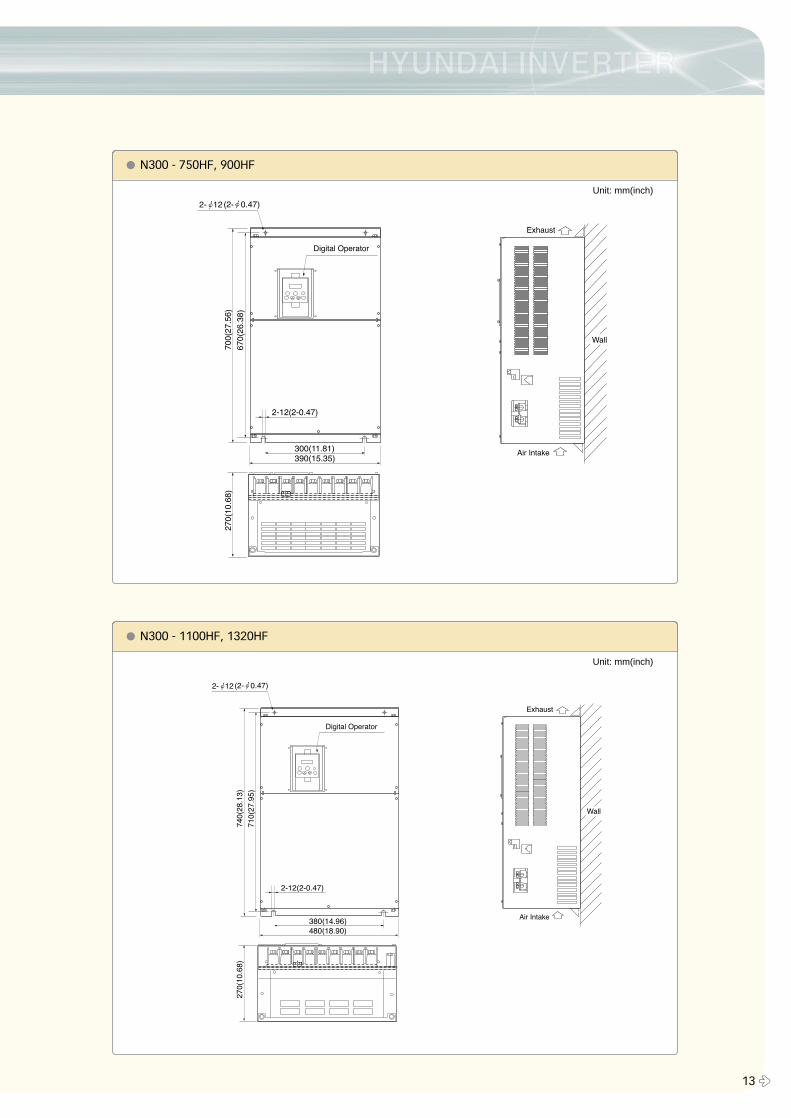
� N300 - 750HF, 900HF
� N300 - 1100HF, 1320HF
Unit: mm(inch)
Unit: mm(inch)
Operation and Programming
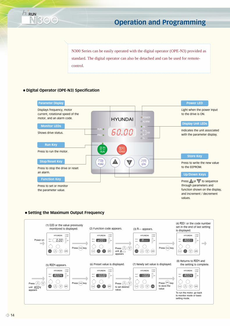
N300 Series can be easily operated with the digital operator (OPE-N3) provided as
standard. The digital operator can also be detached and can be used for remote-
control.
■Digital Operator (OPE-N3) Specification
■Setting the Maximum Output Frequency
Parameter Display
Displays frequency, motorcurrent, rotational speed of themotor, and an alarm code.
Power LED
Light when the power Inputto the drive is ON.
Display Unit LEDs
Indicates the unit associatedwith the parameter display.
Monitor LEDs
Shows drive status.
Store Key
Press to write the new valueto the EEPROM.
Up/Down Keys
Press or to sequencethrough parameters andfunction shown on the display,and increment / decrementvalues.
Run Key
Press to run the motor.
Function Key
Press to set or monitor the parameter value.
Stop/Reset Key
Press to stop the drive or resetan alarm.
(1) 0.00 or the value previouslymonitored is displayed.
(5) a004 appears. (6) Preset value is displayed. (7) Newly set value is displayed.(8) Returns to a004 and
the setting is complete.
(2) Function code appears. (3) a--- appears.
(4) a001 or the code numberset in the end of last settingis displayed.
� 14
▲1 ▼2
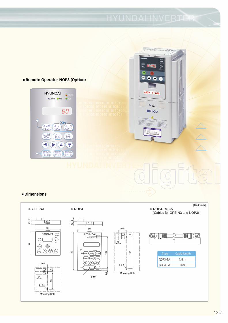
■Remote Operator NOP3 (Option)
■Dimensions
� OPE-N3 � NOP3 � NOP3-1A, 3A(Cables for OPE-N3 and NOP3)
NOP3-1A 1.5 m
NOP3-3A 3 m
Type Cable length
15 �
[Unit: mm]
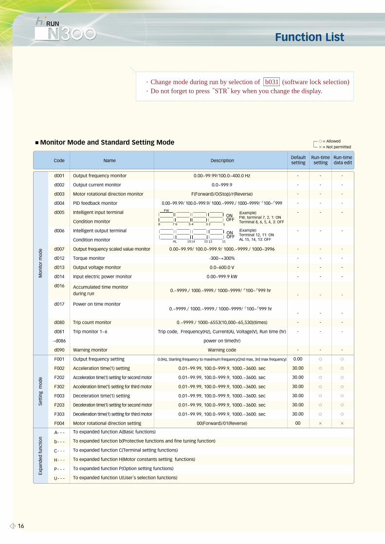
Function List
∙Change mode during run by selection of b031 (software lock selection)∙Do not forget to press “STR”key when you change the display.
- - -
- - -
- - -
- - -
- - -
- - -
- - -
- - -
- - -
- - -
- - -
- - -
- - -
- - -
- - -
0.00 ○ ○
30.00 ○ ○
30.00 ○ ○
30.00 ○ ○
30.00 ○ ○
30.00 ○ ○
30.00 ○ ○
00 × ×
d001
d002
d003
d004
d005
d006
d007
d012
d013
d014
d016
d017
d080
d081
~d086
d090
F001
F002
F202
F302
F003
F203
F303
F004
A- - -
b- - -
C- - -
H- - -
P- - -
U- - -
■Monitor Mode and Standard Setting Mode
Code Name DescriptionRun-timedata edit
Run-timesetting
Defaultsetting
Mon
itor
mod
eSe
ttin
g m
ode
Expa
nded
func
tion
FW
ONOFF
8 7 6 5 4 3 2 1
ONOFF
AL 1514 13 12 11
� 16
Output frequency monitor
Output current monitor
Motor rotational direction monitor
PID feedback monitor
Intelligent input terminal
Condition monitor
Intelligent output terminal
Condition monitor
Output frequency scaled value monitor
Torque monitor
Output voltage monitor
Input electric power monitor
Power on time monitor
Trip count monitor
Trip monitor 1~6
Warning monitor
Output frequency setting
Acceleration time(1) setting
Acceleration time(1) setting for second motor
Acceleration time(1) setting for third motor
Deceleration time(1) setting
Deceleration time(1) setting for second motor
Deceleration time(1) setting for third motor
Motor rotational direction setting
To expanded function A(Basic functions)
To expanded function b(Protective functions and fine tuning function)
To expanded function C(Terminal setting functions)
To expanded function H(Motor constants setting functions)
To expanded function P(Option setting functions)
To expanded function U(User`s selection functions)
0.00~99.99/100.0~400.0 Hz
0.0~999.9
F(Forward)/O(Stop)/r(Reverse)
0.00~99.99/ 100.0~999.9/ 1000.~9999./ 1000~9999/ 「100~「999
0.00~99.99/ 100.0~999.9/ 1000.~9999./ 1000~3996
-300~+300%
0.0~600.0 V
0.00~999.9 kW
0.~9999./ 1000~6553(10,000~65,530)(times)
Trip code, Frequency(Hz), Current(A), Voltage(V), Run time (hr)
power on time(hr)
Warning code
0.0Hz, Starting frequency to maximum frequency(2nd max, 3rd max frequency)
0.01~99.99, 100.0~999.9, 1000.~3600. sec
0.01~99.99, 100.0~999.9, 1000.~3600. sec
0.01~99.99, 100.0~999.9, 1000.~3600. sec
0.01~99.99, 100.0~999.9, 1000.~3600. sec
0.01~99.99, 100.0~999.9, 1000.~3600. sec
0.01~99.99, 100.0~999.9, 1000.~3600. sec
00(Forward)/01(Reverse)
Accumulated time monitor during run
(Example)FW, terminal 7, 2, 1: ONTerminal 8, 6, 5, 4, 3: OFF
(Example)Terminal 12, 11: ONAL 15, 14, 13: OFF
○= Allowed
×= Not permitted
0.~9999./ 1000.~9999./ 1000~9999/ 「100~「999 hr
0.~9999./ 1000.~9999./ 1000~9999/ 「100~「999 hr
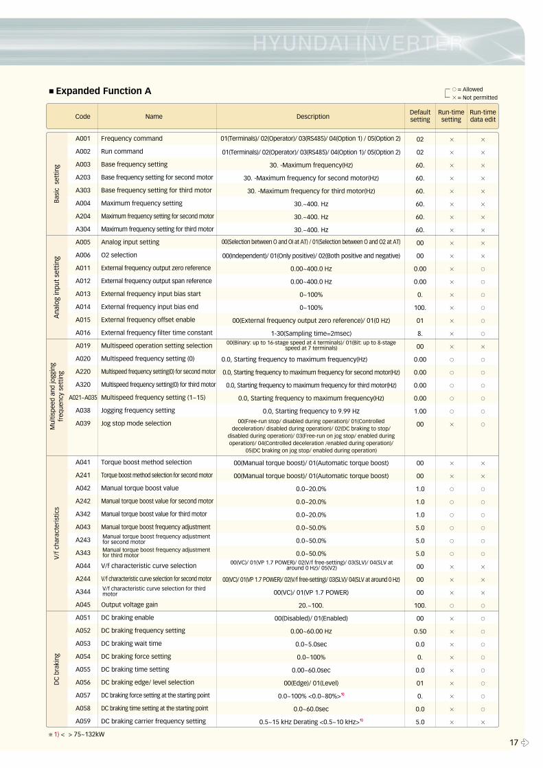
■Expanded Function A
02 × ×
02 × ×
60. × ×
60. × ×
60. × ×
60. × ×
60. × ×
60. × ×
00 × ×
00 × ×
0.00 × ○
0.00 × ○
0. × ○
100. × ○
01 × ○
8. × ○
00 × ×
0.00 ○ ○
0.00 ○ ○
0.00 ○ ○
0.00 ○ ○
1.00 ○ ○
00 × ○
00 × ×
00 × ×
1.0 ○ ○
1.0 ○ ○
1.0 ○ ○
5.0 ○ ○
5.0 ○ ○
5.0 ○ ○
00 × ×
00 × ×
00 × ×
100. ○ ○
00 × ○
0.50 × ○
0.0 × ○
0. × ○
0.0 × ○
01 × ○
0. × ○
0.0 × ○
5.0 × ×
A001
A002
A003
A203
A303
A004
A204
A304
A005
A006
A011
A012
A013
A014
A015
A016
A019
A020
A220
A320
A021~A035
A038
A039
A041
A241
A042
A242
A342
A043
A243
A343
A044
A244
A344
A045
A051
A052
A053
A054
A055
A056
A057
A058
A059
Code Name DescriptionRun-timedata edit
Defaultsetting
Run-timesetting
Bas
ic s
ettin
gA
nalo
g in
put
sett
ing
Mul
tispe
ed a
nd jo
ggin
gfr
eque
ncy
sett
ing
V/f
cha
ract
eris
tics
DC
bra
king
17 �
Frequency command
Run command
Base frequency setting
Base frequency setting for second motor
Base frequency setting for third motor
Maximum frequency setting
Maximum frequency setting for second motor
Maximum frequency setting for third motor
Analog input setting
O2 selection
External frequency output zero reference
External frequency output span reference
External frequency input bias start
External frequency input bias end
External frequency offset enable
External frequency filter time constant
Multispeed operation setting selection
Multispeed frequency setting (0)
Multispeed frequency setting(0) for second motor
Multispeed frequency setting(0) for third motor
Multispeed frequency setting (1~15)
Jogging frequency setting
Jog stop mode selection
Torque boost method selection
Torque boost method selection for second motor
Manual torque boost value
Manual torque boost value for second motor
Manual torque boost value for third motor
Manual torque boost frequency adjustment
V/f characteristic curve selection
V/f characteristic curve selection for second motor
Output voltage gain
DC braking enable
DC braking frequency setting
DC braking wait time
DC braking force setting
DC braking time setting
DC braking edge/ level selection
DC braking force setting at the starting point
DC braking time setting at the starting point
DC braking carrier frequency setting
01(Terminals)/ 02(Operator)/ 03(RS485)/ 04(Option 1)/ 05(Option 2)
30. -Maximum frequency(Hz)
30. -Maximum frequency for second motor(Hz)
30. -Maximum frequency for third motor(Hz)
30.~400. Hz
30.~400. Hz
30.~400. Hz
00(Independent)/ 01(Only positive)/ 02(Both positive and negative)
0.00~400.0 Hz
0.00~400.0 Hz
0~100%
0~100%
00(External frequency output zero reference)/ 01(0 Hz)
1-30(Sampling time=2msec)
0.0, Starting frequency to maximum frequency(Hz)
0.0, Starting frequency to maximum frequency for second motor(Hz)
0.0, Starting frequency to maximum frequency for third motor(Hz)
0.0, Starting frequency to maximum frequency(Hz)
0.0, Starting frequency to 9.99 Hz
00(Manual torque boost)/ 01(Automatic torque boost)
00(Manual torque boost)/ 01(Automatic torque boost)
0.0~20.0%
0.0~20.0%
0.0~20.0%
0.0~50.0%
0.0~50.0%
0.0~50.0%
00(VC)/ 01(VP 1.7 POWER)/ 02(V/f free-setting)/ 03(SLV)/ 04(SLV at around 0 Hz)
00(VC)/ 01(VP 1.7 POWER)
20.~100.
00(Disabled)/ 01(Enabled)
0.00~60.00 Hz
0.0~5.0sec
0.0~100%
0.00~60.0sec
00(Edge)/ 01(Level)
0.0~100% <0.0~80%>1)
0.0~60.0sec
0.5~15 kHz Derating <0.5~10 kHz>1)
01(Terminals)/ 02(Operator)/ 03(RS485)/ 04(Option 1) / 05(Option 2)
00(Binary: up to 16-stage speed at 4 terminals)/ 01(Bit: up to 8-stagespeed at 7 terminals)
00(VC)/ 01(VP 1.7 POWER)/ 02(V/f free-setting)/ 03(SLV)/ 04(SLV ataround 0 Hz)/ 05(V2)
00(Free-run stop/ disabled during operation)/ 01(Controlleddeceleration/ disabled during operation)/ 02(DC braking to stop/
disabled during operation)/ 03(Free-run on jog stop/ enabled duringoperation)/ 04(Controlled deceleration /enabled during operation)/
05(DC braking on jog stop/ enabled during operation)
00(Selection between O and OI at AT) / 01(Selection between O and O2 at AT)
Manual torque boost frequency adjustmentfor third motor
Manual torque boost frequency adjustmentfor second motor
V/f characteristic curve selection for thirdmotor
○= Allowed
×= Not permitted
※1) < > 75~132kW
� 18
Function List
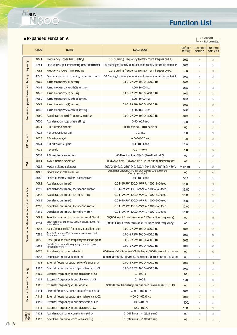
■Expanded Function A
0.00 × ○
0.00 × ○
0.0 × ○
0.00 × ○
0.00 × ○
0.50 × ○
0.00 × ○
0.50 × ○
0.00 × ○
0.50 × ○
0.00 × ○
0.0 × ○
00 × ○
1.0 ○ ○
1.0 ○ ○
0.0 ○ ○
1.0 × ○
00 × ○
02 × ×
200/ 400 × ×
00 × ×
50.0 ○ ○
15.00 ○ ○
15.00 ○ ○
15.00 ○ ○
15.00 ○ ○
15.00 ○ ○
15.00 ○ ○
00 × ×
00 × ×
0.00 × ×
0.00 × ×
0.00 × ×
0.00 × ×
00 × ×
00 × ×
0.00 × ○
0.00 × ○
20. × ○
100. × ○
01 × ○
0.00 × ○
0.00 × ○
-100. × ○
100. × ○
02 × ○
02 × ○
A061
A261
A062
A262
A063
A064
A065
A066
A067
A068
A069
A070
A071
A072
A073
A074
A075
A076
A081
A082
A085
A086
A092
A292
A392
A093
A293
A393
A094
A294
A095
A295
A096
A296
A097
A098
A101
A102
A103
A104
A105
A111
A112
A113
A114
A131
A132
Code Name Description
Freq
uenc
y up
per/
low
er li
mit
& ju
mp
freq
uenc
yPI
D c
ontr
olA
VR
Ope
ratio
n m
ode
and
acce
l./ d
ecel
. fun
ctio
nEx
tern
al f
requ
ency
tun
ing
Acc
el./
de
cel.
Run-timedata edit
Defaultsetting
Run-timesetting
Frequency upper limit setting
Frequency upper limit setting for second motor
Frequency lower limit setting
Frequency lower limit setting for second motor
Jump frequency(1) setting
Jump frequency width(1) setting
Jump frequency(2) setting
Jump frequency width(2) setting
Jump frequency(3) setting
Jump frequency width(3) setting
Acceleration hold frequency setting
Acceleration stop time setting
PID function enable
PID proportional gain
PID integral gain
PID differential gain
PID scale
PID feedback selection
AVR function selection
Motor voltage selection
Operation mode selection
Optimal energy savings capture rate
Acceleration time(2)
Acceleration time(2) for second motor
Acceleration time(2) for third motor
Deceleration time(2)
Deceleration time(2) for second motor
Deceleration time(2) for third motor
Selection method to use second accel./decel.
Accel.(1) to accel.(2) frequency transition point
Decel.(1) to decel.(2) frequency transition point
Acceleration curve selection
Deceleration curve selection
External frequency output zero reference at OI
External frequency output span reference at OI
External frequency input bias start at OI
External frequency input bias end at OI
External frequency offset enable
External frequency output zero reference at O2
External frequency output span reference at O2
External frequency input bias start at O2
External frequency input bias end at O2
Acceleration curve constants setting
Deceleration curve constants setting
0.0, Starting frequency to maximum frequency(Hz)
0.0, Starting frequency to maximum frequency for second motor(Hz)
0.0, Starting frequency to maximum frequency(Hz)
0.0, Starting frequency to maximum frequency for second motor(Hz)
0.00~99.99/ 100.0~400.0 Hz
0.00~10.00 Hz
0.00~99.99/ 100.0~400.0 Hz
0.00~10.00 Hz
0.00~99.99/ 100.0~400.0 Hz
0.00~10.00 Hz
0.00~99.99/ 100.0~400.0 Hz
0.00~60.0sec
00(Disabled) / 01(Enabled)
0.2~5.0
0.0~3600.0sec
0.0~100.0sec
0.01~99.99
00(Feedback at OI)/ 01(Feedback at O)
00(Always on)/01(Always off)/ 02(Off during deceleration)
200/ 215/ 220/ 230/ 240, 380/ 400/ 415/ 440/ 460/ 480 V
0.0~100.0sec
0.01~99.99/ 100.0~999.9/ 1000~3600sec
0.01~99.99/ 100.0~999.9/ 1000~3600sec
0.01~99.99/ 100.0~999.9/ 1000~3600sec
0.01~99.99/ 100.0~999.9/ 1000~3600sec
0.01~99.99/ 100.0~999.9/ 1000~3600sec
0.01~99.99/ 100.0~999.9/ 1000~3600sec
00(2CH input from terminal)/ 01(Transition frequency)
00(2CH input from terminal)/ 01(Transition frequency)
0.00~99.99/ 100.0~400.0 Hz
0.00~99.99/ 100.0~400.0 Hz
0.00~99.99/ 100.0~400.0 Hz
0.00~99.99/ 100.0~400.0 Hz
00(Linear)/ 01(S-curve)/ 02(U-shape)/ 03(Reserved U-shape)
00(Linear)/ 01(S-curve)/ 02(U-shape)/ 03(Reserved U-shape)
0.00~99.99/ 100.0~400.0 Hz
0.00~99.99/ 100.0~400.0 Hz
0.~100.%
0.~100.%
00(External frequency output zero reference)/ 01(0 Hz)
-400.0~400.0 Hz
-400.0~400.0 Hz
-100.~100.%
-100.~100.%
01(Minimum)~10(Extreme)
01(Minimum)~10(Extreme)
00(Normal operation)/ 01(Energy-saving operation)/ 02(Fuzzy operation)
Selection method to use second accel./decel. forsecond motor
Accel.(1) to accel.(2) frequency transition pointfor second motor
Decel.(1) to decel.(2) frequency transition pointfor second motor
○= Allowed
×= Not permitted
19 �
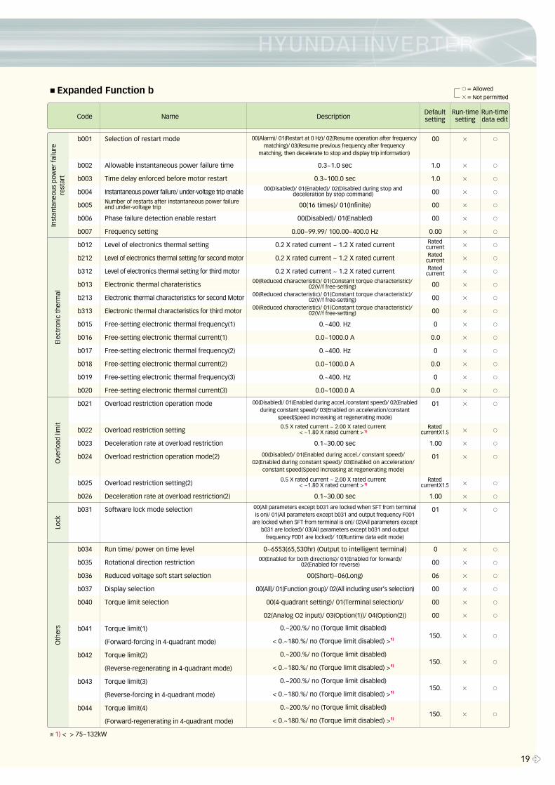
■Expanded Function b
b001
b002
b003
b004
b005
b006
b007
b012
b212
b312
b013
b213
b313
b015
b016
b017
b018
b019
b020
b021
b022
b023
b024
b025
b026
b031
b034
b035
b036
b037
b040
b041
b042
b043
b044
00 × ○
1.0 × ○
1.0 × ○
00 × ○
00 × ○
00 × ○
0.00 × ○
× ○
× ○
× ○
00 × ○
00 × ○
00 × ○
0 × ○
0.0 × ○
0 × ○
0.0 × ○
0 × ○
0.0 × ○
01 × ○
× ○
1.00 × ○
01 × ○
× ○
1.00 × ○
01 × ○
0 × ○
00 × ○
06 × ○
00 × ○
00 × ○
00 × ○
Code Name Description
Inst
anta
neou
s po
wer
failu
rere
star
tEl
ectr
onic
the
rmal
Ove
rloa
d lim
itLo
ckO
ther
s
Run-timedata edit
Defaultsetting
Run-timesetting
Selection of restart mode
Allowable instantaneous power failure time
Time delay enforced before motor restart
Instantaneous power failure/ under-voltage trip enable
Phase failure detection enable restart
Frequency setting
Level of electronics thermal setting
Level of electronics thermal setting for second motor
Level of electronics thermal setting for third motor
Electronic thermal charateristics
Electronic thermal characteristics for second Motor
Electronic thermal characteristics for third motor
Free-setting electronic thermal frequency(1)
Free-setting electronic thermal current(1)
Free-setting electronic thermal frequency(2)
Free-setting electronic thermal current(2)
Free-setting electronic thermal frequency(3)
Free-setting electronic thermal current(3)
Overload restriction operation mode
Overload restriction setting
Deceleration rate at overload restriction
Overload restriction operation mode(2)
Overload restriction setting(2)
Deceleration rate at overload restriction(2)
Software lock mode selection
Run time/ power on time level
Rotational direction restriction
Reduced voltage soft start selection
Display selection
Torque limit selection
Torque limit(1)
(Forward-forcing in 4-quadrant mode)
Torque limit(2)
(Reverse-regenerating in 4-quadrant mode)
Torque limit(3)
(Reverse-forcing in 4-quadrant mode)
Torque limit(4)
(Forward-regenerating in 4-quadrant mode)
0.3~1.0 sec
0.3~100.0 sec
00(16 times)/ 01(Infinite)
00(Disabled)/ 01(Enabled)
0.00~99.99/ 100.00~400.0 Hz
0.2 X rated current ~ 1.2 X rated current
0.2 X rated current ~ 1.2 X rated current
0.2 X rated current ~ 1.2 X rated current
0.~400. Hz
0.0~1000.0 A
0.~400. Hz
0.0~1000.0 A
0.~400. Hz
0.0~1000.0 A
0.1~30.00 sec
0.1~30.00 sec
0~6553(65,530hr) (Output to intelligent terminal)
00(Short)~06(Long)
00(All)/ 01(Function group)/ 02(All including user’s selection)
00(4-quadrant setting)/ 01(Terminal selection)/
02(Analog O2 input)/ 03(Option(1))/ 04(Option(2))
RatedcurrentRated
currentRated
current
RatedcurrentX1.5
0.5 X rated current ~ 2.00 X rated current < ~1.80 X rated current > 1)
0.5 X rated current ~ 2.00 X rated current < ~1.80 X rated current > 1)
RatedcurrentX1.5
00(Alarm)/ 01(Restart at 0 Hz)/ 02(Resume operation after frequencymatching)/ 03(Resume previous frequency after frequency
matching, then decelerate to stop and display trip information)
00(Disabled)/ 01(Enabled during accel./constant speed)/ 02(Enabledduring constant speed)/ 03(Enabled on acceleration/constant
speed(Speed increasing at regenerating mode)
00(Enabled for both directions)/ 01(Enabled for forward)/02(Enabled for reverse)
00(Disabled)/ 01(Enabled during accel./ constant speed)/02(Enabled during constant speed)/ 03(Enabled on acceleration/
constant speed(Speed increasing at regenerating mode)
00(All parameters except b031 are locked when SFT from terminalis on)/ 01(All parameters except b031 and output frequency F001
are locked when SFT from terminal is on)/ 02(All parameters exceptb031 are locked)/ 03(All parameters except b031 and output
frequency F001 are locked)/ 10(Runtime data edit mode)
00(Reduced characteristic)/ 01(Constant torque characteristic)/02(V/f free-setting)
00(Reduced characteristic)/ 01(Constant torque characteristic)/02(V/f free-setting)
00(Reduced characteristic)/ 01(Constant torque characteristic)/02(V/f free-setting)
Number of restarts after instantaneous power failureand under-voltage trip
00(Disabled)/ 01(Enabled)/ 02(Disabled during stop anddeceleration by stop command)
○= Allowed
×= Not permitted
0.~200.%/ no (Torque limit disabled)
< 0.~180.%/ no (Torque limit disabled) >1)
0.~200.%/ no (Torque limit disabled)
< 0.~180.%/ no (Torque limit disabled) >1)
0.~200.%/ no (Torque limit disabled)
< 0.~180.%/ no (Torque limit disabled) >1)
0.~200.%/ no (Torque limit disabled)
< 0.~180.%/ no (Torque limit disabled) >1)
150. × ○
150. × ○
150. × ○
150. × ○
※1) < > 75~132kW
� 20
Function List
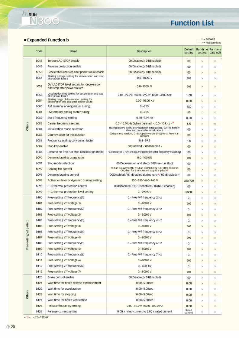
■Expanded Function b
00 × ○
00 × ○
00 × ×
0.0 × ×
1.00 × ×
0.00 × ×
180 ○ ○
60 ○ ○
0.50 × ○
5.0 × ×
00 × ×
00 × ×
1.0 ○ ○
00 × ○
00 × ○
0.0 × ○
00 × ×
00 × ×
00 × ○
360/720 × ○
00 × ○
3000. × ○
0. × ×
0.0 × ×
0. × ×
0.0 × ×
0. × ×
0.0 × ×
0. × ×
0.0 × ×
0. × ×
0.0 × ×
0. × ×
0.0 × ×
0. × ×
0.0 × ×
00 × ○
0.00 × ○
0.00 × ○
0.00 × ○
0.00 × ○
0.00 × ○
× ○
b045
b046
b050
b051
b053
b054
b080
b081
b082
b083
b084
b085
b086
b087
b088
b090
b091
b092
b095
b096
b098
b099
b100
b101
b102
b103
b104
b105
b106
b107
b108
b109
b110
b111
b112
b113
b120
b121
b122
b123
b124
b125
b126
Code Name Description
Oth
ers
Free
-set
ting
V/f
pat
tern
Oth
ers
Run-timedata edit
Defaultsetting
Run-timesetting
Torque LAD-STOP enable
Reverse protection enable
Deceleration and stop after power failure enable
AM terminal analog meter tuning
FM terminal analog meter tuning
Start frequency setting
Carrier frequency setting
Initialization mode selection
Country code for initialization
Frequency scaling conversion factor
Stop key enable
Resume on free-run stop cancellation mode
Dynamic braking usage ratio
Stop mode selection
Cooling fan control
Dynamic braking control
Activation level of dynamic braking setting
PTC thermal protection control
PTC thermal protection level setting
Free-setting V/f frequency(1)
Free-setting V/f voltage(1)
Free-setting V/f frequency(2)
Free-setting V/f voltage(2)
Free-setting V/f frequency(3)
Free-setting V/f voltage(3)
Free-setting V/f frequency(4)
Free-setting V/f voltage(4)
Free-setting V/f frequency(5)
Free-setting V/f voltage(5)
Free-setting V/f frequency(6)
Free-setting V/f voltage(6)
Free-setting V/f frequency(7)
Free-setting V/f voltage(7)
Brake control enable
Wait time for brake release establishment
Wait time for acceleration
Wait time for stopping
Wait time for brake verification
Release frequency setting
Release current setting
00(Disabled)/ 01(Enabled)
00(Disabled)/ 01(Enabled)
00(Disabled)/ 01(Enabled)
0.0~1000. V
0.01~99.99/ 100.0~999.9/ 1000.~3600.sec
0.00~10.00 Hz
0.~255.
0.~255.
0.10~9.99 Hz
0.5~15.0 kHz (When derated) < 0.5~10 kHz >1)
0.1~99.9
00(Enabled )/ 01(Disabled )
00(Restart at 0 Hz)/ 01(Resume operation after frequency matching)
0.0~100.0%
00(Deceleration and stop)/ 01(Free-run stop)
00(Disabled)/ 01<Enabled during run>1)/ 02<Enabled> 1)
330~380/ 660~760 V
00(Disabled)/ 01(PTC enabled)/ 02(NTC enabled)
0.~9999.Ϊ
0.~Free V/f frequency 2 Hz
0.~800.0 V
0.~Free V/f frequency 3 Hz
0.~800.0 V
0.~Free V/f frequency 4 Hz
0.~800.0 V
0.~Free V/f frequency 5 Hz
0.~800.0 V
0.~Free V/f frequency 6 Hz
0.~800.0 V
0.~Free V/f frequency 7 Hz
0.~800.0 V
0.~400. Hz
0.~800.0 V
00(Disabled)/ 01(Enabled)
0.00~5.00sec
0.00~5.00sec
0.00~5.00sec
0.00~5.00sec
0.00~99.99/ 100.0~400.0 Hz
0.00 x rated current to 2.00 x rated current Ratedcurrent
Starting voltage setting for deceleration and stopafter power failure
Deceleration time setting for deceleration and stopafter power failureStarting range of deceleration setting fordeceleration and stop after power failure
00(Trip history clear)/ 01(Parameter initialization)/ 02(Trip historyclear and parameter initialization)
00(Japanese version)/ 01(European version)/ 02(North Americanversion)
00(Fan is always ON)/ 01<Fan is ON during run, after power isON, then for 5 minutes on stop is implied>1)
○= Allowed
×= Not permitted
OV-LADSTOP level setting for decelerationand stop after power failure
b052 0.0~1000. V 0.0 × ×
※1) < > 75~132kW
21 �
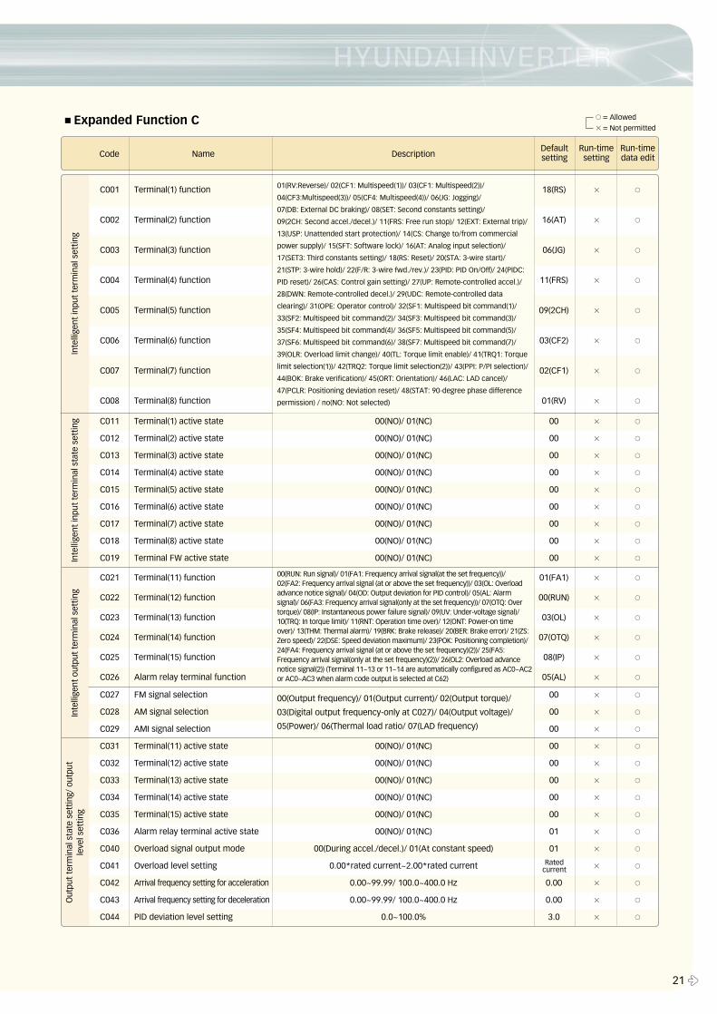
■Expanded Function C
C011 Terminal(1) active state 00(NO)/ 01(NC) 00 × ○
C012 Terminal(2) active state 00(NO)/ 01(NC) 00 × ○
C013 Terminal(3) active state 00(NO)/ 01(NC) 00 × ○
C014 Terminal(4) active state 00(NO)/ 01(NC) 00 × ○
C015 Terminal(5) active state 00(NO)/ 01(NC) 00 × ○
C016 Terminal(6) active state 00(NO)/ 01(NC) 00 × ○
C017 Terminal(7) active state 00(NO)/ 01(NC) 00 × ○
C018 Terminal(8) active state 00(NO)/ 01(NC) 00 × ○
C019 Terminal FW active state 00(NO)/ 01(NC) 00 × ○
C027 FM signal selection 00 × ○
C028 AM signal selection 00 × ○
C029 AMI signal selection 00 × ○
C031 Terminal(11) active state 00(NO)/ 01(NC) 00 × ○
C032 Terminal(12) active state 00(NO)/ 01(NC) 00 × ○
C033 Terminal(13) active state 00(NO)/ 01(NC) 00 × ○
C034 Terminal(14) active state 00(NO)/ 01(NC) 00 × ○
C035 Terminal(15) active state 00(NO)/ 01(NC) 00 × ○
C036 Alarm relay terminal active state 00(NO)/ 01(NC) 01 × ○
C040 Overload signal output mode 00(During accel./decel.)/ 01(At constant speed) 01 × ○
C041 Overload level setting 0.00*rated current~2.00*rated current × ○
C042 Arrival frequency setting for acceleration 0.00~99.99/ 100.0~400.0 Hz 0.00 × ○
C043 Arrival frequency setting for deceleration 0.00~99.99/ 100.0~400.0 Hz 0.00 × ○
C044 PID deviation level setting 0.0~100.0% 3.0 × ○
C001 Terminal(1) function 18(RS) × ○
C002 Terminal(2) function 16(AT) × ○
C003 Terminal(3) function 06(JG) × ○
C004 Terminal(4) function 11(FRS) × ○
C005 Terminal(5) function 09(2CH) × ○
C006 Terminal(6) function 03(CF2) × ○
C007 Terminal(7) function 02(CF1) × ○
C008 Terminal(8) function 01(RV) × ○
C021 Terminal(11) function 01(FA1) × ○
C022 Terminal(12) function 00(RUN) × ○
C023 Terminal(13) function 03(OL) × ○
C024 Terminal(14) function 07(OTQ) × ○
C025 Terminal(15) function 08(IP) × ○
C026 Alarm relay terminal function 05(AL) × ○
Code Name Description
Inte
llige
nt in
put
term
inal
set
ting
Inte
llige
nt in
put
term
inal
sta
te s
ettin
gIn
telli
gent
out
put
term
inal
set
ting
Out
put
term
inal
sta
te s
ettin
g/ o
utpu
tle
vel s
ettin
g
01(RV:Reverse)/ 02(CF1: Multispeed(1))/ 03(CF1: Multispeed(2))/
04(CF3:Multispeed(3))/ 05(CF4: Multispeed(4))/ 06(JG: Jogging)/
07(DB: External DC braking)/ 08(SET: Second constants setting)/
09(2CH: Second accel./decel.)/ 11(FRS: Free run stop)/ 12(EXT: External trip)/
13(USP: Unattended start protection)/ 14(CS: Change to/from commercial
power supply)/ 15(SFT: Software lock)/ 16(AT: Analog input selection)/
17(SET3: Third constants setting)/ 18(RS: Reset)/ 20(STA: 3-wire start)/
21(STP: 3-wire hold)/ 22(F/R: 3-wire fwd./rev.)/ 23(PID: PID On/Off)/ 24(PIDC:
PID reset)/ 26(CAS: Control gain setting)/ 27(UP: Remote-controlled accel.)/
28(DWN: Remote-controlled decel.)/ 29(UDC: Remote-controlled data
clearing)/ 31(OPE: Operator control)/ 32(SF1: Multispeed bit command(1)/
33(SF2: Multispeed bit command(2)/ 34(SF3: Multispeed bit command(3)/
35(SF4: Multispeed bit command(4)/ 36(SF5: Multispeed bit command(5)/
37(SF6: Multispeed bit command(6)/ 38(SF7: Multispeed bit command(7)/
39(OLR: Overload limit change)/ 40(TL: Torque limit enable)/ 41(TRQ1: Torque
limit selection(1))/ 42(TRQ2: Torque limit selection(2))/ 43(PPI: P/PI selection)/
44(BOK: Brake verification)/ 45(ORT: Orientation)/ 46(LAC: LAD cancel)/
47(PCLR: Positioning deviation reset)/ 48(STAT: 90-degree phase difference
permission) / no(NO: Not selected)
00(RUN: Run signal)/ 01(FA1: Frequency arrival signal(at the set frequency))/ 02(FA2: Frequency arrival signal (at or above the set frequency))/ 03(OL: Overloadadvance notice signal)/ 04(OD: Output deviation for PID control)/ 05(AL: Alarmsignal)/ 06(FA3: Frequency arrival signal(only at the set frequency))/ 07(OTQ: Overtorque)/ 08(IP: Instantaneous power failure signal)/ 09(UV: Under-voltage signal)/10(TRQ: In torque limit)/ 11(RNT: Operation time over)/ 12(ONT: Power-on timeover)/ 13(THM: Thermal alarm)/ 19(BRK: Brake release)/ 20(BER: Brake error)/ 21(ZS:Zero speed)/ 22(DSE: Speed deviation maximum)/ 23(POK: Positioning completion)/24(FA4: Frequency arrival signal (at or above the set frequency)(2))/ 25(FA5:Frequency arrival signal(only at the set frequency)(2))/ 26(OL2: Overload advancenotice signal(2)) (Terminal 11~13 or 11~14 are automatically configured as AC0~AC2or AC0~AC3 when alarm code output is selected at C62)
00(Output frequency)/ 01(Output current)/ 02(Output torque)/
03(Digital output frequency-only at C027)/ 04(Output voltage)/
05(Power)/ 06(Thermal load ratio/ 07(LAD frequency)
Run-timedata edit
Defaultsetting
Run-timesetting
Ratedcurrent
○= Allowed
×= Not permitted
Function List
� 22
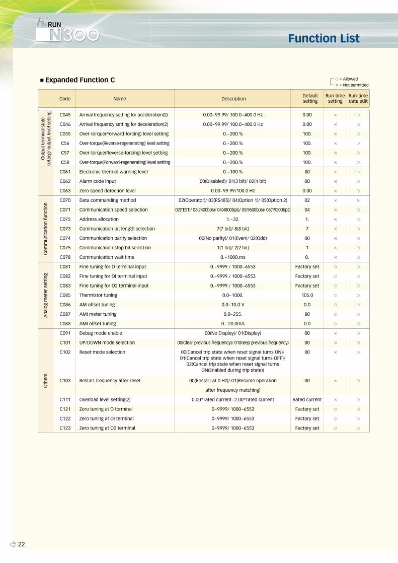
■Expanded Function C
C045 Arrival frequency setting for acceleration(2) 0.00~99.99/ 100.0~400.0 Hz 0.00 × ○
C046 Arrival frequency setting for deceleration(2) 0.00~99.99/ 100.0~400.0 Hz 0.00 × ○
C055 Over-torque(Forward-forcing) level setting 0.~200.% 100. × ○
C56 Over-torque(Reverse-regenerating) level setting 0.~200.% 100. × ○
C57 Over-torque(Reverse-forcing) level setting 0.~200.% 100. × ○
C58 Over-torque(Forward-regenerating) level setting 0.~200.% 100. × ○
C061 Electronic thermal warning level 0.~100.% 80 × ○
C062 Alarm code input 00(Disabled)/ 01(3 bit)/ 02(4 bit) 00 × ○
C063 Zero speed detection level 0.00~99.99/100.0 Hz 0.00 × ○
C070 Data commanding method 02(Operator)/ 03(RS485)/ 04(Option 1)/ 05(Option 2) 02 × ×
C071 Communication speed selection 02(TEST)/ 03(2400bps)/ 04(4800bps)/ 05(9600bps)/ 06(19200bps) 04 × ○
C072 Address allocation 1.~32. 1. × ○
C073 Communication bit length selection 7(7 bit)/ 8(8 bit) 7 × ○
C074 Communication parity selection 00(No parity)/ 01(Even)/ 02(Odd) 00 × ○
C075 Communication stop bit selection 1(1 bit)/ 2(2 bit) 1 × ○
C078 Communication wait time 0.~1000.ms 0. × ○
C081 Fine tuning for O terminal input 0.~9999./ 1000~6553 Factory set ○ ○
C082 Fine tuning for OI terminal input 0.~9999./ 1000~6553 Factory set ○ ○
C083 Fine tuning for O2 terminal input 0.~9999./ 1000~6553 Factory set ○ ○
C085 Thermistor tuning 0.0~1000. 105.0 ○ ○
C086 AM offset tuning 0.0~10.0 V 0.0 ○ ○
C087 AMI meter tuning 0.0~255. 80 ○ ○
C088 AMI offset tuning 0.~20.0mA 0.0 ○ ○
C091 Debug mode enable 00(No Display)/ 01(Display) 00 × ○
C101 UP/DOWN mode selection 00(Clear previous frequency)/ 01(Keep previous frequency) 00 × ○
C102 Reset mode selection 00 × ○
C103 Restart frequency after reset 00(Restart at 0 Hz)/ 01(Resume operation 00 × ○
after frequency matching)
C111 Overload level setting(2) 0.00*rated current~2.00*rated current Rated current × ○
C121 Zero tuning at O terminal 0~9999/ 1000~6553 Factory set ○ ○
C122 Zero tuning at OI terminal 0~9999/ 1000~6553 Factory set ○ ○
C123 Zero tuning at O2 terminal 0~9999/ 1000~6553 Factory set ○ ○
Code Name Description
Com
mun
icat
ion
func
tion
Ana
log
met
er s
ettin
gO
ther
s
00(Cancel trip state when reset signal turns ON)/01(Cancel trip state when reset signal turns OFF)/
02(Cancel trip state when reset signal turnsON(Enabled during trip state))
Run-timedata edit
Defaultsetting
Run-timesetting
Out
put t
erm
inal
sta
tese
ttin
g/ o
utpu
t lev
el s
ettin
g
○= Allowed
×= Not permitted
23 �
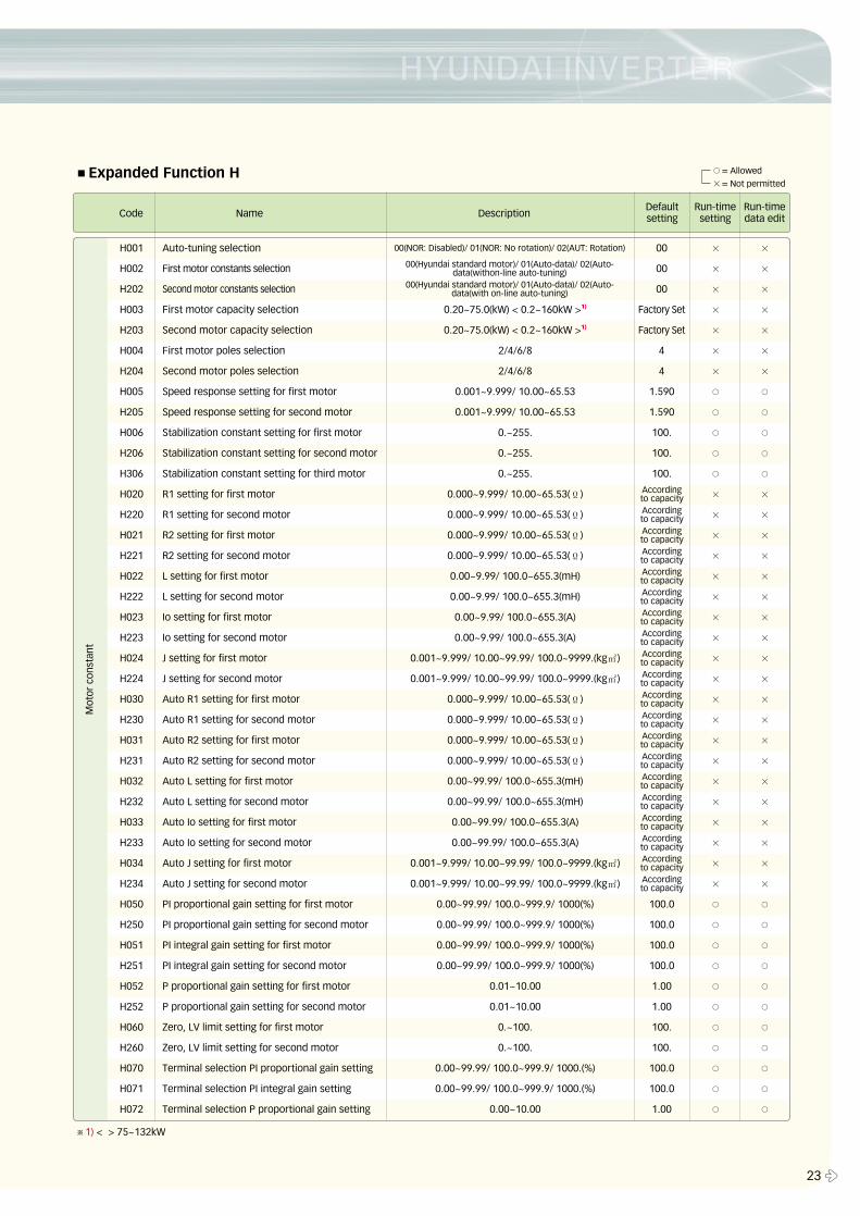
■Expanded Function H
H001 Auto-tuning selection 00 × ×
H002 First motor constants selection 00 × ×
H202 Second motor constants selection 00 × ×
H003 First motor capacity selection 0.20~75.0(kW) < 0.2~160kW >1) Factory Set × ×
H203 Second motor capacity selection 0.20~75.0(kW) < 0.2~160kW >1) Factory Set × ×
H004 First motor poles selection 2/4/6/8 4 × ×
H204 Second motor poles selection 2/4/6/8 4 × ×
H005 Speed response setting for first motor 0.001~9.999/ 10.00~65.53 1.590 ○ ○
H205 Speed response setting for second motor 0.001~9.999/ 10.00~65.53 1.590 ○ ○
H006 Stabilization constant setting for first motor 0.~255. 100. ○ ○
H206 Stabilization constant setting for second motor 0.~255. 100. ○ ○
H306 Stabilization constant setting for third motor 0.~255. 100. ○ ○
H020 R1 setting for first motor 0.000~9.999/ 10.00~65.53(Ϊ) × ×
H220 R1 setting for second motor 0.000~9.999/ 10.00~65.53(Ϊ) × ×
H021 R2 setting for first motor 0.000~9.999/ 10.00~65.53(Ϊ) × ×
H221 R2 setting for second motor 0.000~9.999/ 10.00~65.53(Ϊ) × ×
H022 L setting for first motor 0.00~9.99/ 100.0~655.3(mH) × ×
H222 L setting for second motor 0.00~9.99/ 100.0~655.3(mH) × ×
H023 Io setting for first motor 0.00~9.99/ 100.0~655.3(A) × ×
H223 Io setting for second motor 0.00~9.99/ 100.0~655.3(A) × ×
H024 J setting for first motor 0.001~9.999/ 10.00~99.99/ 100.0~9999.(kg㎡) × ×
H224 J setting for second motor 0.001~9.999/ 10.00~99.99/ 100.0~9999.(kg㎡) × ×
H030 Auto R1 setting for first motor 0.000~9.999/ 10.00~65.53(Ϊ) × ×
H230 Auto R1 setting for second motor 0.000~9.999/ 10.00~65.53(Ϊ) × ×
H031 Auto R2 setting for first motor 0.000~9.999/ 10.00~65.53(Ϊ) × ×
H231 Auto R2 setting for second motor 0.000~9.999/ 10.00~65.53(Ϊ) × ×
H032 Auto L setting for first motor 0.00~99.99/ 100.0~655.3(mH) × ×
H232 Auto L setting for second motor 0.00~99.99/ 100.0~655.3(mH) × ×
H033 Auto Io setting for first motor 0.00~99.99/ 100.0~655.3(A) × ×
H233 Auto Io setting for second motor 0.00~99.99/ 100.0~655.3(A) × ×
H034 Auto J setting for first motor 0.001~9.999/ 10.00~99.99/ 100.0~9999.(kg㎡) × ×
H234 Auto J setting for second motor 0.001~9.999/ 10.00~99.99/ 100.0~9999.(kg㎡) × ×
H050 PI proportional gain setting for first motor 0.00~99.99/ 100.0~999.9/ 1000(%) 100.0 ○ ○
H250 PI proportional gain setting for second motor 0.00~99.99/ 100.0~999.9/ 1000(%) 100.0 ○ ○
H051 PI integral gain setting for first motor 0.00~99.99/ 100.0~999.9/ 1000(%) 100.0 ○ ○
H251 PI integral gain setting for second motor 0.00~99.99/ 100.0~999.9/ 1000(%) 100.0 ○ ○
H052 P proportional gain setting for first motor 0.01~10.00 1.00 ○ ○
H252 P proportional gain setting for second motor 0.01~10.00 1.00 ○ ○
H060 Zero, LV limit setting for first motor 0.~100. 100. ○ ○
H260 Zero, LV limit setting for second motor 0.~100. 100. ○ ○
H070 Terminal selection PI proportional gain setting 0.00~99.99/ 100.0~999.9/ 1000.(%) 100.0 ○ ○
H071 Terminal selection PI integral gain setting 0.00~99.99/ 100.0~999.9/ 1000.(%) 100.0 ○ ○
H072 Terminal selection P proportional gain setting 0.00~10.00 1.00 ○ ○
Code Name Description
Mot
or c
onst
ant
Run-timedata edit
Defaultsetting
Run-timesetting
According to capacityAccording to capacityAccording to capacityAccording to capacityAccording to capacityAccording to capacityAccording to capacityAccording to capacityAccording to capacityAccording to capacityAccording to capacityAccording to capacityAccording to capacityAccording to capacityAccording to capacityAccording to capacityAccording to capacityAccording to capacityAccording to capacityAccording to capacity
00(NOR: Disabled)/ 01(NOR: No rotation)/ 02(AUT: Rotation)
00(Hyundai standard motor)/ 01(Auto-data)/ 02(Auto-data(withon-line auto-tuning)
00(Hyundai standard motor)/ 01(Auto-data)/ 02(Auto-data(with on-line auto-tuning)
○= Allowed
×= Not permitted
※1) < > 75~132kW
Function List
� 24
Opt
ion
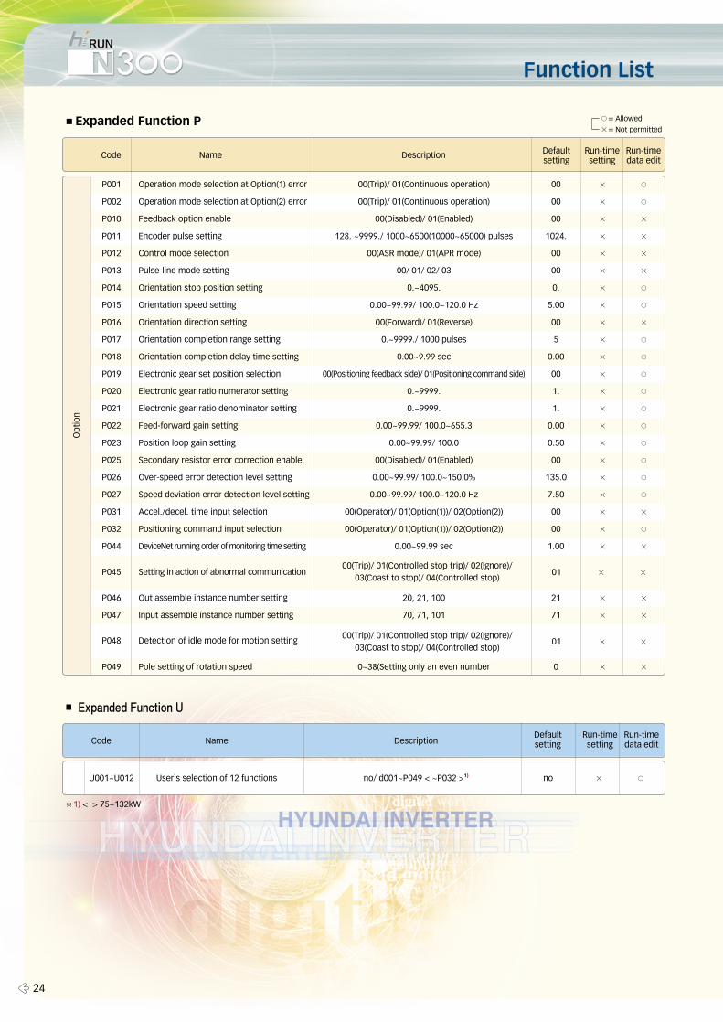
■Expanded Function P
P001 Operation mode selection at Option(1) error 00(Trip)/ 01(Continuous operation) 00 × ○
P002 Operation mode selection at Option(2) error 00(Trip)/ 01(Continuous operation) 00 × ○
P010 Feedback option enable 00(Disabled)/ 01(Enabled) 00 × ×
P011 Encoder pulse setting 128. ~9999./ 1000~6500(10000~65000) pulses 1024. × ×
P012 Control mode selection 00(ASR mode)/ 01(APR mode) 00 × ×
P013 Pulse-line mode setting 00/ 01/ 02/ 03 00 × ×
P014 Orientation stop position setting 0.~4095. 0. × ○
P015 Orientation speed setting 0.00~99.99/ 100.0~120.0 Hz 5.00 × ○
P016 Orientation direction setting 00(Forward)/ 01(Reverse) 00 × ×
P017 Orientation completion range setting 0.~9999./ 1000 pulses 5 × ○
P018 Orientation completion delay time setting 0.00~9.99 sec 0.00 × ○
P019 Electronic gear set position selection 00(Positioning feedback side)/ 01(Positioning command side) 00 × ○
P020 Electronic gear ratio numerator setting 0.~9999. 1. × ○
P021 Electronic gear ratio denominator setting 0.~9999. 1. × ○
P022 Feed-forward gain setting 0.00~99.99/ 100.0~655.3 0.00 × ○
P023 Position loop gain setting 0.00~99.99/ 100.0 0.50 × ○
P025 Secondary resistor error correction enable 00(Disabled)/ 01(Enabled) 00 × ○
P026 Over-speed error detection level setting 0.00~99.99/ 100.0~150.0% 135.0 × ○
P027 Speed deviation error detection level setting 0.00~99.99/ 100.0~120.0 Hz 7.50 × ○
P031 Accel./decel. time input selection 00(Operator)/ 01(Option(1))/ 02(Option(2)) 00 × ×
P032 Positioning command input selection 00(Operator)/ 01(Option(1))/ 02(Option(2)) 00 × ○
P044 DeviceNet running order of monitoring time setting 0.00~99.99 sec 1.00 × ×
P046 Out assemble instance number setting 20, 21, 100 21 × ×
P047 Input assemble instance number setting 70, 71, 101 71 × ×
P049 Pole setting of rotation speed 0~38(Setting only an even number 0 × ×
Code Name Description
■ Expanded Function U
U001~U012 User`s selection of 12 functions no/ d001~P049 < ~P032 >1) no × ○
Code Name Description
Run-timedata edit
Defaultsetting
Run-timesetting
Run-timedata edit
Defaultsetting
Run-timesetting
00(Trip)/ 01(Controlled stop trip)/ 02(Ignore)/ 03(Coast to stop)/ 04(Controlled stop)
00(Trip)/ 01(Controlled stop trip)/ 02(Ignore)/ 03(Coast to stop)/ 04(Controlled stop)
01 × ×
01 × ×
Detection of idle mode for motion setting
Setting in action of abnormal communication
P048
P045
○= Allowed
×= Not permitted
※1) < > 75~132kW
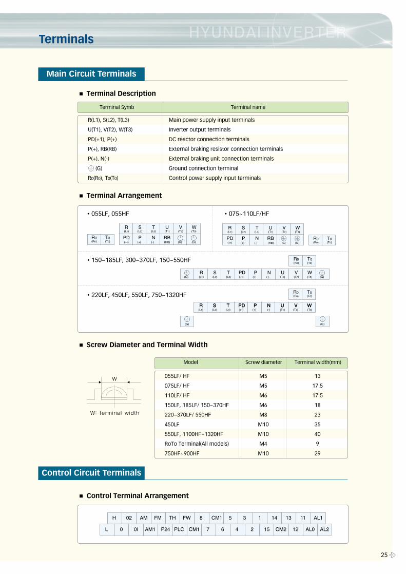
Terminals
25 �
055LF/ HF M5 13
075LF/ HF M5 17.5
110LF/ HF M6 17.5
150LF, 185LF/ 150~370HF M6 18
220~370LF/ 550HF M8 23
450LF M10 35
550LF, 1100HF~1320HF M10 40
RoTo Terminal(All models) M4 9
750HF~900HF M10 29
Model Screw diameter Terminal width(mm)
R(L1), S(L2), T(L3) Main power supply input terminals
U(T1), V(T2), W(T3) Inverter output terminals
PD(+1), P(+) DC reactor connection terminals
P(+), RB(RB) External braking resistor connection terminals
P(+), N(-) External braking unit connection terminals
(G) Ground connection terminal
R0(R0), T0(T0) Control power supply input terminals
Terminal Symb Terminal name
■ Terminal Description
■ Terminal Arrangement
■ Screw Diameter and Terminal Width
■ Control Terminal Arrangement
�055LF, 055HF
�150~185LF, 300~370LF, 150~550HF
�075~110LF/HF
�220LF, 450LF, 550LF, 750~1320HF
Main Circuit Terminals
Control Circuit Terminals
Terminals
� 26
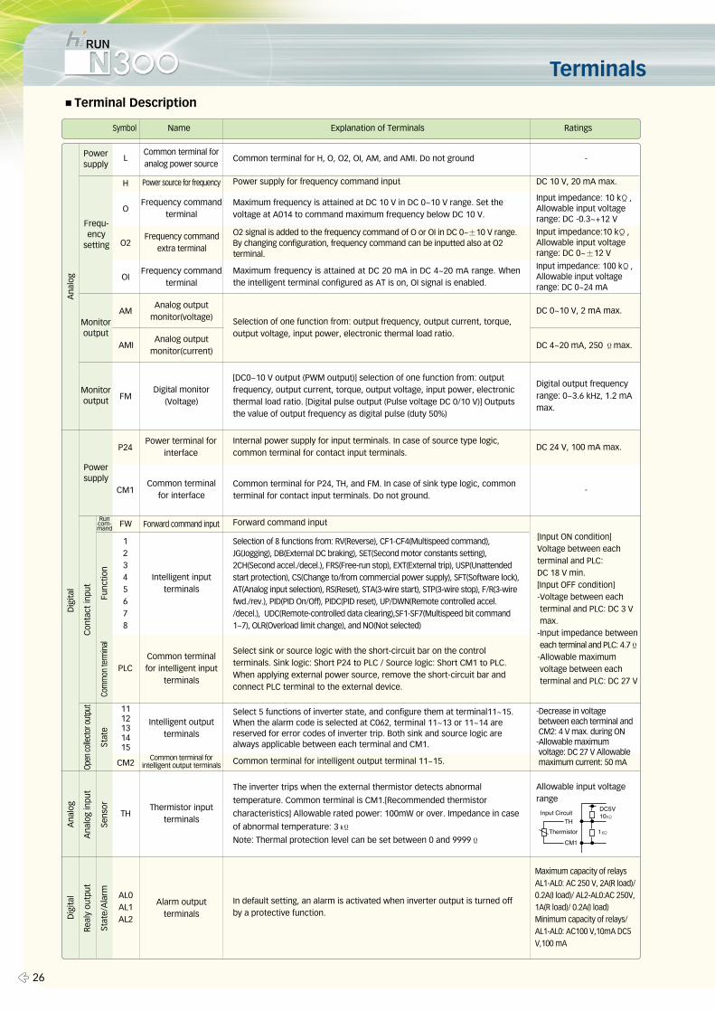
Symbol Name Explanation of Terminals Ratings
L
H
O
O2
OI
AM
AMI
FM
P24
CM1
PLC
CM2
TH
AL0AL1AL2
1112131415
FW
12345678
Common terminal foranalog power source
Frequency commandterminal
Frequency commandterminal
Analog outputmonitor(voltage)
Analog outputmonitor(current)
Power terminal forinterface
Common terminalfor interface
Intelligent inputterminals
Common terminalfor intelligent input
terminals
Common terminal forintelligent output terminals
Intelligent outputterminals
Thermistor inputterminals
Alarm outputterminals
Forward command input
Digital monitor(Voltage)
Frequency commandextra terminal
Power source for frequency Power supply for frequency command input
Forward command input
Common terminal for intelligent output terminal 11~15.
DC 10 V, 20 mA max.
The inverter trips when the external thermistor detects abnormal
temperature. Common terminal is CM1.[Recommended thermistor
characteristics] Allowable rated power: 100mW or over. Impedance in case
of abnormal temperature: 3 kΪ
Note: Thermal protection level can be set between 0 and 9999Ϊ
In default setting, an alarm is activated when inverter output is turned offby a protective function.
Ana
log
Dig
ital
Con
tact
inpu
t
Func
tion
Com
mon
term
inal
Open
col
lect
or o
utpu
t
Stat
e
Ana
log
inpu
t
Sens
or
Real
y ou
tput
Stat
e/A
larm
Ana
log
Dig
ital
Powersupply
Frequ-ency
setting
Monitoroutput
Monitoroutput
Powersupply
Runcom-mand
■Terminal Description
Common terminal for H, O, O2, OI, AM, and AMI. Do not ground -
Input impedance: 10 kΪ,Allowable input voltagerange: DC -0.3~+12 V
Input impedance:10 kΪ,Allowable input voltagerange: DC 0~±12 V
Input impedance: 100 kΪ,Allowable input voltagerange: DC 0~24 mA
DC 0~10 V, 2 mA max.
DC 4~20 mA, 250 Ϊmax.
Digital output frequencyrange: 0~3.6 kHz, 1.2 mAmax.
DC 24 V, 100 mA max.
-
[Input ON condition]Voltage between eachterminal and PLC: DC 18 V min.[Input OFF condition] -Voltage between eachterminal and PLC: DC 3 Vmax.
-Input impedance betweeneach terminal and PLC: 4.7Ϊ
-Allowable maximumvoltage between eachterminal and PLC: DC 27 V
-Decrease in voltagebetween each terminal andCM2: 4 V max. during ON
-Allowable maximumvoltage: DC 27 V Allowablemaximum current: 50 mA
Allowable input voltagerange
Maximum capacity of relays AL1-AL0: AC 250 V, 2A(R load)/0.2A(I load)/ AL2-AL0:AC 250V,1A(R load)/ 0.2A(I load) Minimum capacity of relays/AL1-AL0: AC100 V,10mA DC5V,100 mA
Maximum frequency is attained at DC 10 V in DC 0~10 V range. Set thevoltage at A014 to command maximum frequency below DC 10 V.
O2 signal is added to the frequency command of O or OI in DC 0~±10 V range.By changing configuration, frequency command can be inputted also at O2terminal.
Maximum frequency is attained at DC 20 mA in DC 4~20 mA range. Whenthe intelligent terminal configured as AT is on, OI signal is enabled.
Internal power supply for input terminals. In case of source type logic,common terminal for contact input terminals.
Common terminal for P24, TH, and FM. In case of sink type logic, commonterminal for contact input terminals. Do not ground.
Selection of 8 functions from: RV(Reverse), CF1-CF4(Multispeed command),JG(Jogging), DB(External DC braking), SET(Second motor constants setting),2CH(Second accel./decel.), FRS(Free-run stop), EXT(External trip), USP(Unattendedstart protection), CS(Change to/from commercial power supply), SFT(Software lock),AT(Analog input selection), RS(Reset), STA(3-wire start), STP(3-wire stop), F/R(3-wirefwd./rev.), PID(PID On/Off), PIDC(PID reset), UP/DWN(Remote controlled accel./decel.), UDC(Remote-controlled data clearing),SF1-SF7(Multispeed bit command1~7), OLR(Overload limit change), and NO(Not selected)
Select sink or source logic with the short-circuit bar on the controlterminals. Sink logic: Short P24 to PLC / Source logic: Short CM1 to PLC.When applying external power source, remove the short-circuit bar andconnect PLC terminal to the external device.
Select 5 functions of inverter state, and configure them at terminal11~15.When the alarm code is selected at C062, terminal 11~13 or 11~14 arereserved for error codes of inverter trip. Both sink and source logic arealways applicable between each terminal and CM1.
Selection of one function from: output frequency, output current, torque,output voltage, input power, electronic thermal load ratio.
[DC0~10 V output (PWM output)] selection of one function from: outputfrequency, output current, torque, output voltage, input power, electronicthermal load ratio. [Digital pulse output (Pulse voltage DC 0/10 V)] Outputsthe value of output frequency as digital pulse (duty 50%)
Protective Functions
27 �
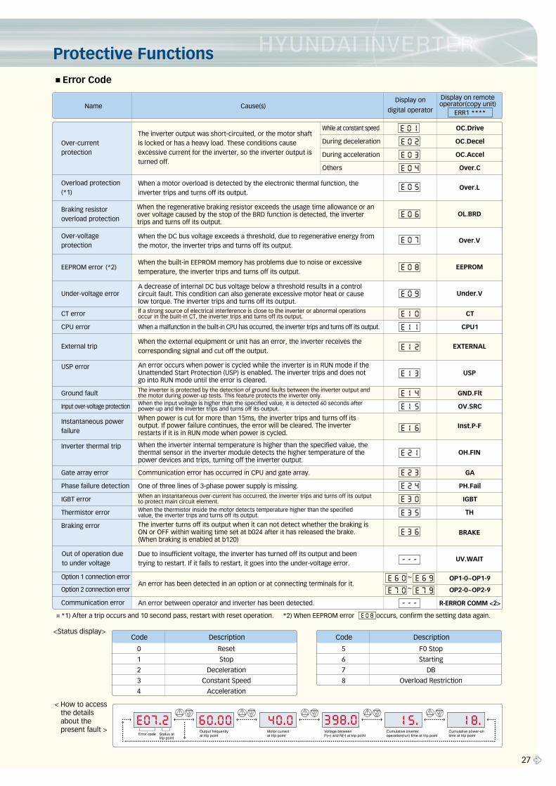
■Error Code
Name Cause(s)
Over-currentprotection
Overload protection(*1)
Braking resistoroverload protection
Over-voltageprotection
EEPROM error (*2)
Under-voltage error
Instantaneous powerfailure
Out of operation dueto under voltage
External trip
OC.Drive
OC.Decel
OC.Accel
Over.C
CT
CPU1
GND.Flt
OV.SRC
GA
PH.Fail
IGBT
OP1-0~OP1-9
OP2-0~OP2-9
R-ERROR COMM <2>
While at constant speed
During deceleration
During acceleration
Others
When a malfunction in the built-in CPU has occurred, the inverter trips and turns off its output.
Communication error has occurred in CPU and gate array.
One of three lines of 3-phase power supply is missing.
CT error
CPU error
USP error
Ground fault
Input over-voltage protection
Inverter thermal trip
Gate array error
Phase failure detection
IGBT error
Thermistor error
Braking error
Option 1 connection error
Option 2 connection error
Communication error
The inverter output was short-circuited, or the motor shaftis locked or has a heavy load. These conditions causeexcessive current for the inverter, so the inverter output isturned off.
When a motor overload is detected by the electronic thermal function, theinverter trips and turns off its output.
When the DC bus voltage exceeds a threshold, due to regenerative energy fromthe motor, the inverter trips and turns off its output.
When the built-in EEPROM memory has problems due to noise or excessivetemperature, the inverter trips and turns off its output.
A decrease of internal DC bus voltage below a threshold results in a controlcircuit fault. This condition can also generate excessive motor heat or causelow torque. The inverter trips and turns off its output.
When the external equipment or unit has an error, the inverter receives thecorresponding signal and cut off the output.
An error occurs when power is cycled while the inverter is in RUN mode if theUnattended Start Protection (USP) is enabled. The inverter trips and does notgo into RUN mode until the error is cleared.
An error has been detected in an option or at connecting terminals for it.
An error between operator and inverter has been detected.
The inverter turns off its output when it can not detect whether the braking isON or OFF within waiting time set at b024 after it has released the brake.(When braking is enabled at b120)
Due to insufficient voltage, the inverter has turned off its output and beentrying to restart. If it fails to restart, it goes into the under-voltage error.
When power is cut for more than 15ms, the inverter trips and turns off itsoutput. If power failure continues, the error will be cleared. The inverterrestarts if it is in RUN mode when power is cycled.
When the inverter internal temperature is higher than the specified value, thethermal sensor in the inverter module detects the higher temperature of thepower devices and trips, turning off the inverter output.
When the thermistor inside the motor detects temperature higher than the specifiedvalue, the inverter trips and turns off its output.
When the regenerative braking resistor exceeds the usage time allowance or anover voltage caused by the stop of the BRD function is detected, the invertertrips and turns off its output.
Over.L
Display on
digital operator
Display on remoteoperator(copy unit)
OL.BRD
Over.V
EEPROM
Under.V
EXTERNAL
USP
Inst.P-F
OH.FIN
BRAKE
UV.WAIT
TH
ERR1 ****
0 Reset
1 Stop
2 Deceleration
3 Constant Speed
4 Acceleration
Code Description
5 F0 Stop
6 Starting
7 DB
8 Overload Restriction
Code Description
※*1) After a trip occurs and 10 second pass, restart with reset operation. *2) When EEPROM error occurs, confirm the setting data again.
<Status display>
< How to accessthe detailsabout thepresent fault >
E 0 8
E 0 2
E 0 3
E 0 4
E 0 5
E 0 6
E 0 7
E 0 8
E 0 9
E 1 0
E 1 1
E 1 2
E 1 3
E 1 4
E 1 5
E 1 6
E 2 1
E 2 3
E 2 4
E 3 0
E 3 5
E 3 6
E 6 0E 7 0
E 6 9E 7 9
~
~
- - -
- - -
E 0 1
If a strong source of electrical interference is close to the inverter or abnormal operationsoccur in the built-in CT, the inverter trips and turns off its output.
The inverter is protected by the detection of ground faults between the inverter output andthe motor during power-up tests. This feature protects the inverter only.When the input voltage is higher than the specified value, it is detected 60 seconds afterpower-up and the inverter trips and turns off its output.
When an instantaneous over-current has occurred, the inverter trips and turns off its outputto protect main circuit element.
� 28
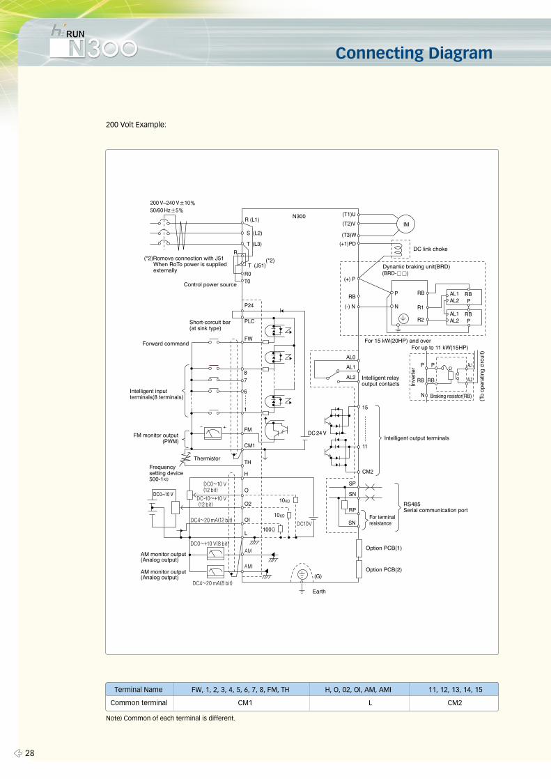
Terminal Name FW, 1, 2, 3, 4, 5, 6, 7, 8, FM, TH H, O, 02, OI, AM, AMI 11, 12, 13, 14, 15
Common terminal CM1 L CM2
Connecting Diagram
200 Volt Example:
Note) Common of each terminal is different.
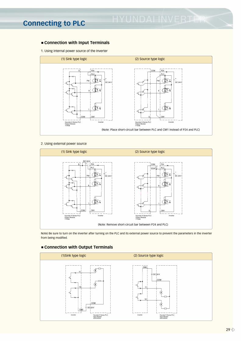
Connecting to PLC
29 �
■Connection with Input Terminals
■Connection with Output Terminals
1. Using internal power source of the Inverter
(1) Sink type logic (2) Source type logic
(Note: Place short-circuit bar between PLC and CM1 instead of P24 and PLC)
2. Using external power source
(1) Sink type logic (2) Source type logic
Note) Be sure to turn on the inverter after turning on the PLC and its external power source to prevent the parameters in the inverter
from being modified.
(Note: Remove short-circuit bar between P24 and PLC)
(1)Sink type logic (2) Source type logic
� 30
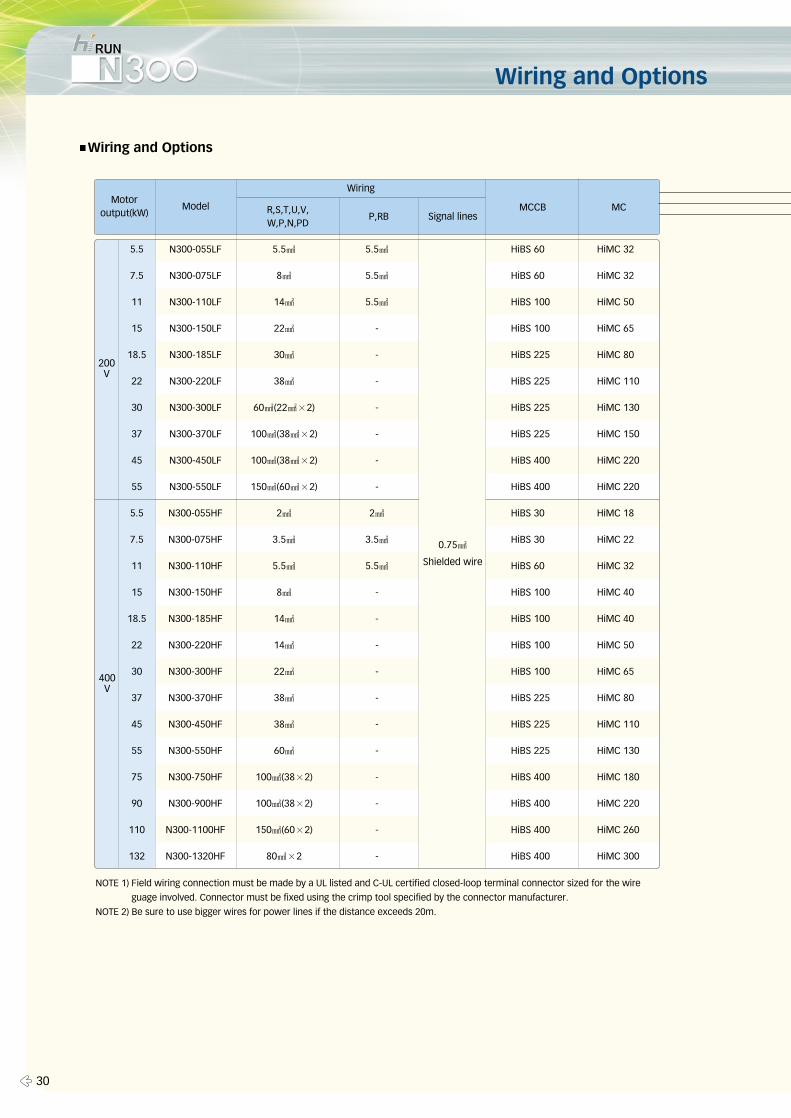
Wiring and Options
■Wiring and Options
5.5 N300-055LF 5.5㎟ 5.5㎟ HiBS 60 HiMC 32
7.5 N300-075LF 8㎟ 5.5㎟ HiBS 60 HiMC 32
11 N300-110LF 14㎟ 5.5㎟ HiBS 100 HiMC 50
15 N300-150LF 22㎟ - HiBS 100 HiMC 65
18.5 N300-185LF 30㎟ - HiBS 225 HiMC 80
22 N300-220LF 38㎟ - HiBS 225 HiMC 110
30 N300-300LF 60㎟(22㎟×2) - HiBS 225 HiMC 130
37 N300-370LF 100㎟(38㎟×2) - HiBS 225 HiMC 150
45 N300-450LF 100㎟(38㎟×2) - HiBS 400 HiMC 220
55 N300-550LF 150㎟(60㎟×2) - HiBS 400 HiMC 220
5.5 N300-055HF 2㎟ 2㎟ HiBS 30 HiMC 18
7.5 N300-075HF 3.5㎟ 3.5㎟ HiBS 30 HiMC 22
11 N300-110HF 5.5㎟ 5.5㎟ HiBS 60 HiMC 32
15 N300-150HF 8㎟ - HiBS 100 HiMC 40
18.5 N300-185HF 14㎟ - HiBS 100 HiMC 40
22 N300-220HF 14㎟ - HiBS 100 HiMC 50
30 N300-300HF 22㎟ - HiBS 100 HiMC 65
37 N300-370HF 38㎟ - HiBS 225 HiMC 80
45 N300-450HF 38㎟ - HiBS 225 HiMC 110
55 N300-550HF 60㎟ - HiBS 225 HiMC 130
75 N300-750HF 100㎟(38×2) - HiBS 400 HiMC 180
90 N300-900HF 100㎟(38×2) - HiBS 400 HiMC 220
110 N300-1100HF 150㎟(60×2) - HiBS 400 HiMC 260
132 N300-1320HF 80㎟×2 - HiBS 400 HiMC 300
200V
400V
Motor output(kW)
Model
Wiring
R,S,T,U,V,W,P,N,PD
P,RB Signal linesMCCB MC
NOTE 1) Field wiring connection must be made by a UL listed and C-UL certified closed-loop terminal connector sized for the wire
guage involved. Connector must be fixed using the crimp tool specified by the connector manufacturer.
NOTE 2) Be sure to use bigger wires for power lines if the distance exceeds 20m.
0.75㎟
Shielded wire
31 �
◀
◀
◀
◀
◀
◀
◀
◀
◀
◀
◀
◀
◀
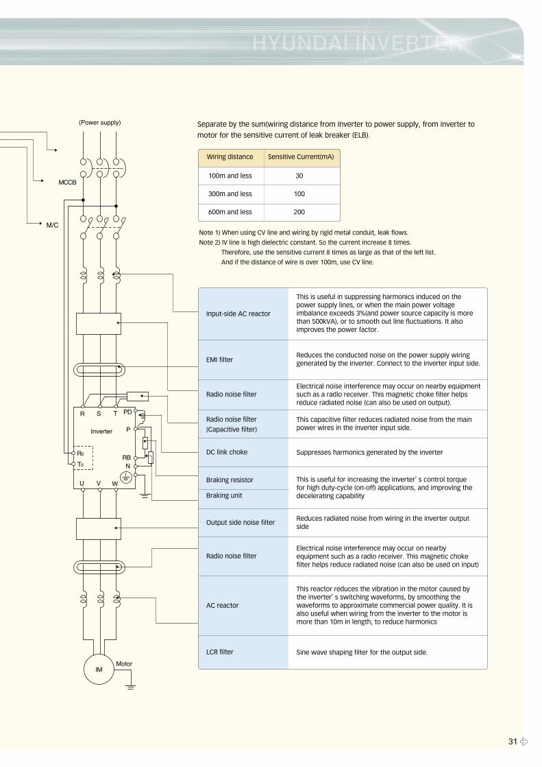
Input-side AC reactor
EMI filter
Radio noise filter
Radio noise filter
(Capacitive filter)
DC link choke
Braking resistor
Braking unit
Output side noise filter
Radio noise filter
AC reactor
LCR filter
This is useful in suppressing harmonics induced on thepower supply lines, or when the main power voltageimbalance exceeds 3%(and power source capacity is morethan 500kVA), or to smooth out line fluctuations. It alsoimproves the power factor.
Reduces the conducted noise on the power supply wiringgenerated by the inverter. Connect to the inverter input side.
Electrical noise interference may occur on nearby equipmentsuch as a radio receiver. This magnetic choke filter helpsreduce radiated noise (can also be used on output).
This capacitive filter reduces radiated noise from the mainpower wires in the inverter input side.
Suppresses harmonics generated by the inverter
This is useful for increasing the inverter’s control torquefor high duty-cycle (on-off) applications, and improving thedecelerating capability
Reduces radiated noise from wiring in the inverter outputside
Electrical noise interference may occur on nearbyequipment such as a radio receiver. This magnetic chokefilter helps reduce radiated noise (can also be used on input)
This reactor reduces the vibration in the motor caused bythe inverter’s switching waveforms, by smoothing thewaveforms to approximate commercial power quality. It isalso useful when wiring from the inverter to the motor ismore than 10m in length, to reduce harmonics
Sine wave shaping filter for the output side.
Separate by the sum(wiring distance from Inverter to power supply, from inverter to
motor for the sensitive current of leak breaker (ELB).
Note 1) When using CV line and wiring by rigid metal conduit, leak flows.
Note 2) IV line is high dielectric constant. So the current increase 8 times.
Therefore, use the sensitive current 8 times as large as that of the left list.
And if the distance of wire is over 100m, use CV line.
100m and less 30
300m and less 100
600m and less 200
Wiring distance Sensitive Current(mA)
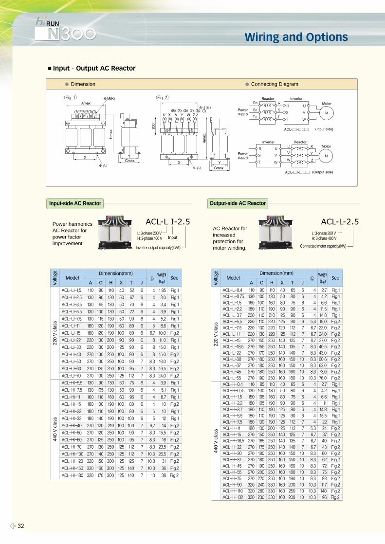
Wiring and Options
� 32
■Input∙Output AC Reactor
A C H X T JVolta
ge
ModelDimension(mm)
ⓚWeight(㎏)
See
ACL-L-0.4 110 90 110 40 65 6 4 2.7 Fig.1
ACL-L-0.75 130 105 130 50 80 6 4 4.2 Fig.1
ACL-L-1.5 160 100 160 80 75 6 4 6.6 Fig.1
ACL-L-2.2 180 110 190 90 90 6 4 11.5 Fig.1
ACL-L-3.7 220 110 210 125 90 6 4 14.8 Fig.1
ACL-L-5.5 220 110 220 125 90 6 5.3 15.0 Fig.2
ACL-L-7.5 220 130 220 120 112 7 6.7 22.0 Fig.2
ACL-L-11 220 130 220 125 112 7 6.7 24.0 Fig.2
ACL-L-15 270 155 250 140 125 7 6.7 37.0 Fig.2
ACL-L-18.5 270 155 250 140 135 7 8.3 40.5 Fig.2
ACL-L-22 270 170 250 140 140 7 8.3 43.0 Fig.2
ACL-L-30 270 180 250 160 150 10 8.3 60.6 Fig.2
ACL-L-37 270 180 250 160 150 10 8.3 62.0 Fig.2
ACL-L-45 270 180 250 160 160 10 8.3 73.0 Fig.2
ACL-L-55 270 190 250 160 180 10 10.3 76.0 Fig.2
ACL-H-0.4 110 85 110 40 65 6 4 2.7 Fig.1
ACL-H-0.75 130 100 130 50 80 6 4 4.2 Fig.1
ACL-H-1.5 150 105 160 80 75 6 4 6.6 Fig.1
ACL-H-2.2 180 105 190 90 90 6 4 11 Fig.1
ACL-H-3.7 180 110 190 125 90 6 4 14.8 Fig.1
ACL-H-5.5 180 110 190 125 90 6 4 15.5 Fig.1
ACL-H-7.5 180 130 190 125 112 7 4 22 Fig.1
ACL-H-11 180 130 200 125 112 7 5.3 24 Fig.2
ACL-H-15 270 150 250 140 125 7 6.7 37 Fig.2
ACL-H-18.5 270 165 250 140 135 7 6.7 40 Fig.2
ACL-H-22 270 175 250 140 140 7 6.7 43 Fig.2
ACL-H-30 270 180 250 160 150 10 8.3 60 Fig.2
ACL-H-37 270 180 250 160 150 10 8.3 62 Fig.2
ACL-H-45 270 190 250 160 160 10 8.3 72 Fig.2
ACL-H-55 270 200 250 160 180 10 8.3 75 Fig.2
ACL-H-75 270 220 250 160 190 10 8.3 93 Fig.2
ACL-H-90 320 240 330 160 200 10 10.3 117 Fig.2
ACL-H-110 320 280 330 160 250 10 10.3 140 Fig.2
ACL-H-132 320 230 330 160 200 10 10.3 96 Fig.2
A C H X T JModel
Dimension(mm)ⓚ
Weight(㎏)
See
ACL-L-2.5L: 3-phase 200 VH: 3-phase 400 V
Connected motor capacity(kW)
� Dimension � Connecting Diagram
(Fig.1) (Fig.2)
ACL-L I-2.5L: 3-phase 200 VH: 3-phase 400 V Input
Inverter output capacity(kVA)
Input-side AC Reactor Output-side AC Reactor
ACL-LI-1.5 110 80 110 40 52 6 4 1.85 Fig.1
ACL-LI-2.5 130 90 130 50 67 6 4 3.0 Fig.1
ACL-LI-3.5 130 95 130 50 70 6 4 3.4 Fig.1
ACL-LI-5.5 130 100 130 50 72 6 4 3.9 Fig.1
ACL-LI-7.5 130 115 130 50 90 6 4 5.2 Fig.1
ACL-LI-11 180 120 190 60 80 6 5 8.6 Fig.1
ACL-LI-15 180 120 190 100 80 6 6.7 10.0 Fig.2
ACL-LI-22 220 130 200 90 90 6 8 11.0 Fig.1
ACL-LI-33 220 130 200 125 90 6 8 15.0 Fig.1
ACL-LI-40 270 130 250 100 90 6 8 15.0 Fig.2
ACL-LI-50 270 130 250 100 90 7 8.3 16.0 Fig.2
ACL-LI-60 270 135 250 100 95 7 8.3 16.5 Fig.2
ACL-LI-70 270 130 250 125 112 7 8.3 24.0 Fig.2
ACL-HI-5.5 130 90 130 50 75 6 4 3.9 Fig.1
ACL-HI-7.5 130 105 130 50 90 6 4 5.1 Fig.1
ACL-HI-11 160 110 160 60 95 6 4 8.7 Fig.1
ACL-HI-15 180 100 190 100 80 6 4 10 Fig.2
ACL-HI-22 180 110 190 100 80 6 5 10 Fig.1
ACL-HI-33 180 140 190 100 100 6 5 12 Fig.1
ACL-HI-40 270 120 210 100 100 7 6.7 14 Fig.2
ACL-HI-50 270 120 250 100 90 7 8.3 15.5 Fig.2
ACL-HI-60 270 125 250 100 95 7 8.3 16 Fig.2
ACL-HI-70 270 130 250 125 112 7 8.3 23.5 Fig.2
ACL-HI-100 270 140 250 125 112 7 10.3 26.5 Fig.2
ACL-HI-120 320 150 300 125 125 7 10.3 31 Fig.2
ACL-HI-150 320 160 300 125 140 7 10.3 36 Fig.2
ACL-HI-180 320 170 300 125 140 7 13 38 Fig.2
Power harmonicsAC Reactor forpower factorimprovement
AC Reactor forincreased protection for motor winding.
220
V c
lass
440
V c
lass
Volta
ge22
0 V
cla
ss44
0 V
cla
ss
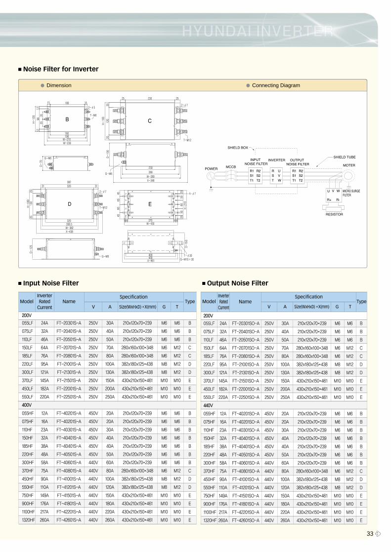
33 �
■Noise Filter for Inverter
� Dimension � Connecting Diagram
■Input Noise Filter ■Output Noise Filter
ModelInverterRated
CurrentName Type
220000VV
055LF 24A FT-20301S-A 250V 30A 210x120x70�239 M6 M6 B
075LF 32A FT-20401S-A 250V 40A 210x120x70�239 M6 M6 B
110LF 46A FT-20501S-A 250V 50A 210x120x70�239 M6 M6 B
150LF 64A FT-20701S-A 250V 70A 280x160x100�348 M6 M12 C
185LF 76A FT-20801S-A 250V 80A 280x160x100�348 M6 M12 C
220LF 95A FT-21001S-A 250V 100A 382x180x125�438 M8 M12 D
300LF 121A FT-21301S-A 250V 130A 382x180x125�438 M8 M12 D
370LF 145A FT-21501S-A 250V 150A 430x210x150�461 M10 M10 E
450LF 182A FT-22001S-A 250V 200A 430x210x150�461 M10 M10 E
550LF 220A FT-22501S-A 250V 250A 430x210x150�461 M10 M10 E
440000VV
055HF 12A FT-40201S-A 450V 20A 210x120x70�239 M6 M6 B
075HF 16A FT-40201S-A 450V 20A 210x120x70�239 M6 M6 B
110HF 23A FT-40301S-A 450V 30A 210x120x70�239 M6 M6 B
150HF 32A FT-40401S-A 450V 40A 210x120x70�239 M6 M6 B
185HF 38A FT-40401S-A 450V 40A 210x120x70�239 M6 M6 B
220HF 48A FT-40501S-A 450V 50A 210x120x70�239 M6 M6 B
300HF 58A FT-40601S-A 440V 60A 210x120x70�239 M6 M6 B
370HF 75A FT-40801S-A 440V 80A 280x160x100�348 M6 M12 C
450HF 90A FT-41001S-A 440V 100A 382x180x125�438 M8 M12 D
550HF 110A FT-41201S-A 440V 120A 382x180x125�438 M8 M12 D
750HF 149A FT-41501S-A 440V 150A 430x210x150�461 M10 M10 E
900HF 176A FT-41801S-A 440V 180A 430x210x150�461 M10 M10 E
1100HF 217A FT-42201S-A 440V 220A 430x210x150�461 M10 M10 E
1320HF 260A FT-42601S-A 440V 260A 430x210x150�461 M10 M10 E
Specification
V A Size(WxHxD) �X(mm) G TModel Type
220000VV
055LF 24A FT-20301SO-A 250V 30A 210x120x70�239 M6 M6 B
075LF 32A FT-20401SO-A 250V 40A 210x120x70�239 M6 M6 B
110LF 46A FT-20501SO-A 250V 50A 210x120x70�239 M6 M6 B
150LF 64A FT-20701SO-A 250V 70A 280x160x100�348 M6 M12 C
185LF 76A FT-20801SO-A 250V 80A 280x160x100�348 M6 M12 C
220LF 95A FT-21001SO-A 250V 100A 382x180x125�438 M8 M12 D
300LF 121A FT-21301SO-A 250V 130A 382x180x125�438 M8 M12 D
370LF 145A FT-21501SO-A 250V 150A 430x210x150�461 M10 M10 E
450LF 182A FT-22001SO-A 250V 200A 430x210x150�461 M10 M10 E
550LF 220A FT-22501SO-A 250V 250A 430x210x150�461 M10 M10 E
444400VV
055HF 12A FT-40201SO-A 450V 20A 210x120x70�239 M6 M6 B
075HF 16A FT-40201SO-A 450V 20A 210x120x70�239 M6 M6 B
110HF 23A FT-40301SO-A 450V 30A 210x120x70�239 M6 M6 B
150HF 32A FT-40401SO-A 450V 40A 210x120x70�239 M6 M6 B
185HF 38A FT-40401SO-A 450V 40A 210x120x70�239 M6 M6 B
220HF 48A FT-40501SO-A 450V 50A 210x120x70�239 M6 M6 B
300HF 58A FT-40601SO-A 440V 60A 210x120x70�239 M6 M6 B
370HF 75A FT-40801SO-A 440V 80A 280x160x100�348 M6 M12 C
450HF 90A FT-41001SO-A 440V 100A 382x180x125�438 M8 M12 D
550HF 110A FT-41201SO-A 440V 120A 382x180x125�438 M8 M12 D
750HF 149A FT-41501SO-A 440V 150A 430x210x150�461 M10 M10 E
900HF 176A FT-41801SO-A 440V 180A 430x210x150�461 M10 M10 E
1100HF 217A FT-42201SO-A 440V 220A 430x210x150�461 M10 M10 E
1320HF 260A FT-42601SO-A 440V 260A 430x210x150�461 M10 M10 E
SpecificationInverterRated
CurrentName
V A Size(WxHxD) �X(mm) G T
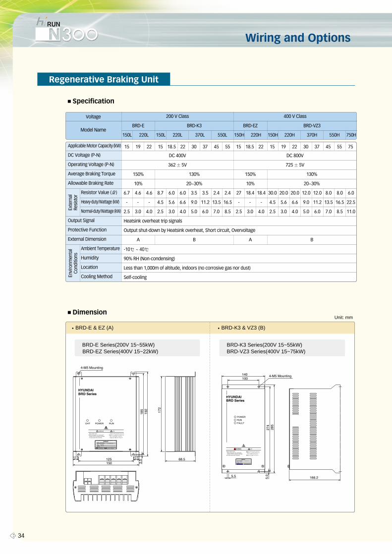
� 34
Wiring and Options
■Specification
Regenerative Braking Unit
■Dimension
Exte
rnal
Resi
stor
Envi
ronm
enta
lCo
nditi
ons
Voltage
Model Name
200 V Class
DC 400V
362±5V
Heatsink overheat trip signals
Output shut-down by Heatsink overheat, Short circuit, Overvoltage
-10℃ ~ 40℃
90% RH (Non-condensing)
Less than 1,000m of altitude, indoors (no corrosive gas nor dust)
Self-cooling
150%
10%
A AB B
150%
10%
130%
20~30%
130%
20~30%
DC 800V
725±5V
BRD-E
150L 150L 370L 550L 150H 220H 150H 750H220H 550H370H220L 220L
15 19 22 15 18.5 22 30 37 45 55
6.7 4.6 4.6 8.7 6.0 6.0 3.5 3.5 2.4 2.4
- - - 4.5 5.6 6.6 9.0 11.2 13.5 16.5
2.5 3.0 4.0 2.5 3.0 4.0 5.0 6.0 7.0 8.5
27 18.4 18.4 30.0 20.0 20.0 12.0 12.0 8.0 8.0 6.0
- - - 4.5 5.6 6.6 9.0 11.2 13.5 16.5 22.5
2.5 3.0 4.0 2.5 3.0 4.0 5.0 6.0 7.0 8.5 11.0
15 18.5 22 15 19 22 30 37 45 55 75
BRD-EZ BRD-VZ3BRD-K3
400 V Class
Applicable Motor Capacity (kW)
DC Voltage (P-N)
Operating Voltage (P-N)
Average Braking Torque
Allowable Braking Rate
Resistor Value (Ω)
Heavy-duty/Wattage (kW)
Normal-duty/Wattage (kW)
Output Signal
Protective Function
External Dimension
Ambient Temperature
Humidity
Location
Cooling Method
�BRD-E & EZ (A) �BRD-K3 & VZ3 (B)
BRD-E Series(200V 15~55kW)BRD-EZ Series(400V 15~22kW)
BRD-K3 Series(200V 15~55kW)BRD-VZ3 Series(400V 15~75kW)
Unit: mm
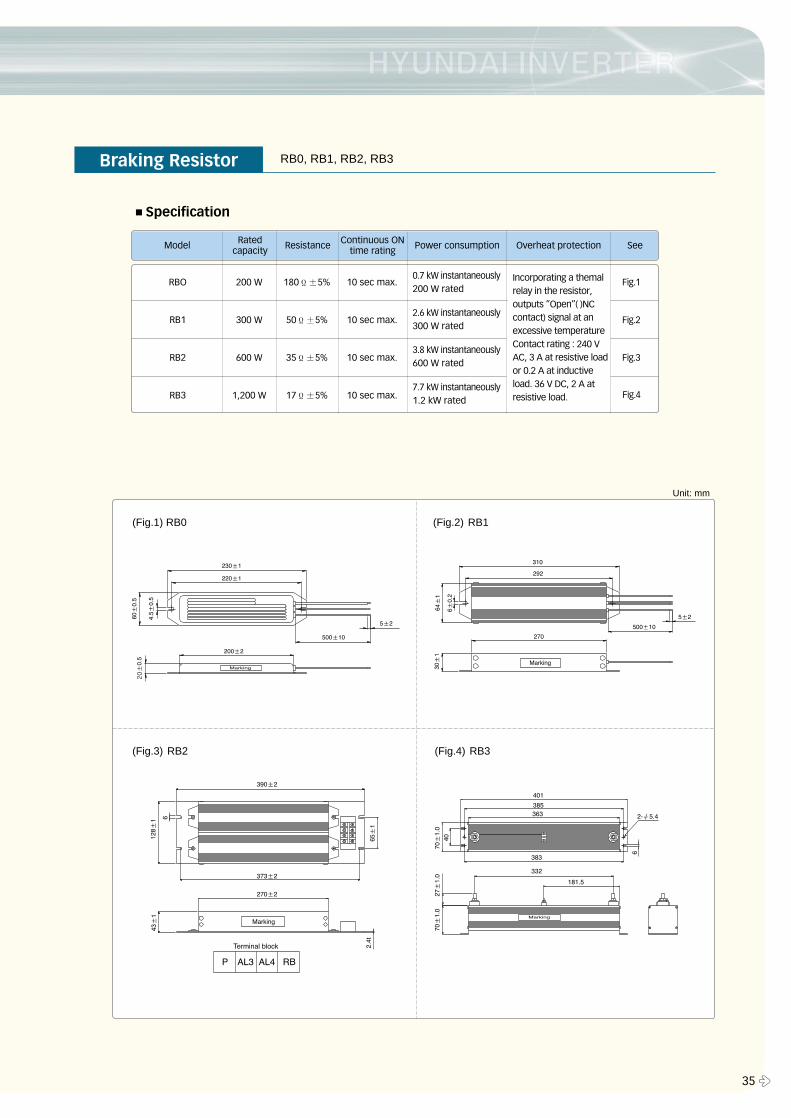
35 �
■Specification
Model Ratedcapacity Resistance Continuous ON
time rating Power consumption Overheat protection See
200 W 180Ϊ±5% 10 sec max. Fig.1
300 W 50Ϊ±5% 10 sec max. Fig.2
600 W 35Ϊ±5% 10 sec max. Fig.3
1,200 W 17Ϊ±5% 10 sec max.
0.7 kW instantaneously200 W rated
Incorporating a themalrelay in the resistor,outputs ”Open”( )NCcontact) signal at anexcessive temperatureContact rating : 240 VAC, 3 A at resistive loador 0.2 A at inductiveload. 36 V DC, 2 A atresistive load.
2.6 kW instantaneously300 W rated
3.8 kW instantaneously600 W rated
7.7 kW instantaneously1.2 kW rated
Fig.4
(Fig.1) RB0 (Fig.2) RB1
(Fig.3) RB2 (Fig.4) RB3
Braking Resistor RB0, RB1, RB2, RB3
RBO
RB1
RB2
RB3
Unit: mm
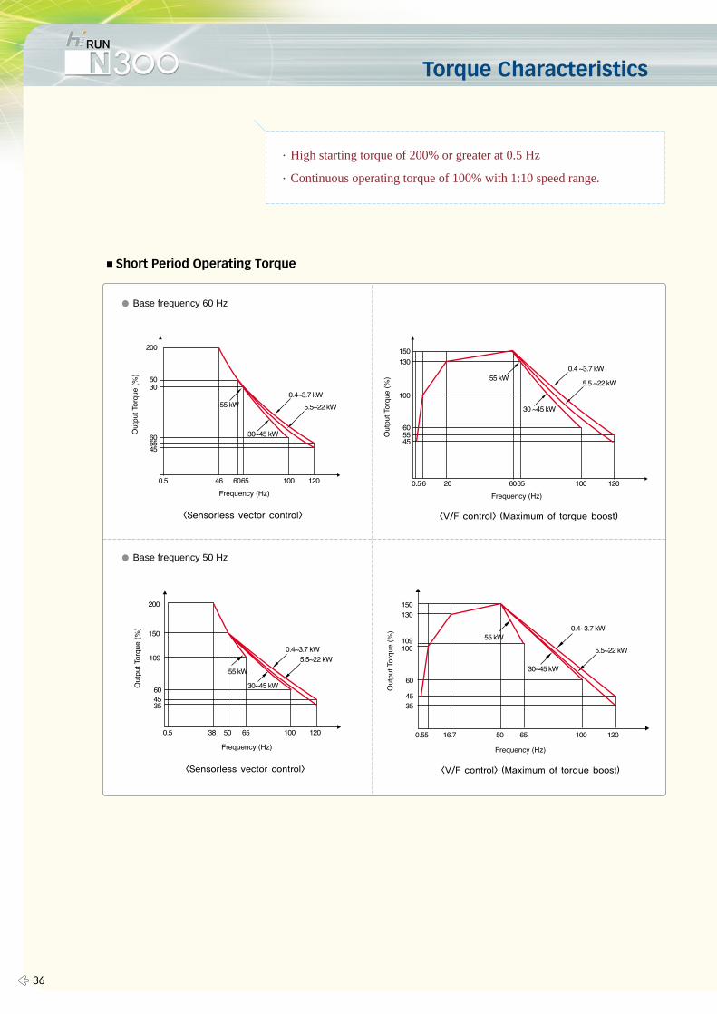
Torque Characteristics
� 36
∙High starting torque of 200% or greater at 0.5 Hz
∙Continuous operating torque of 100% with 1:10 speed range.
■Short Period Operating Torque
� Base frequency 50 Hz
� Base frequency 60 Hz
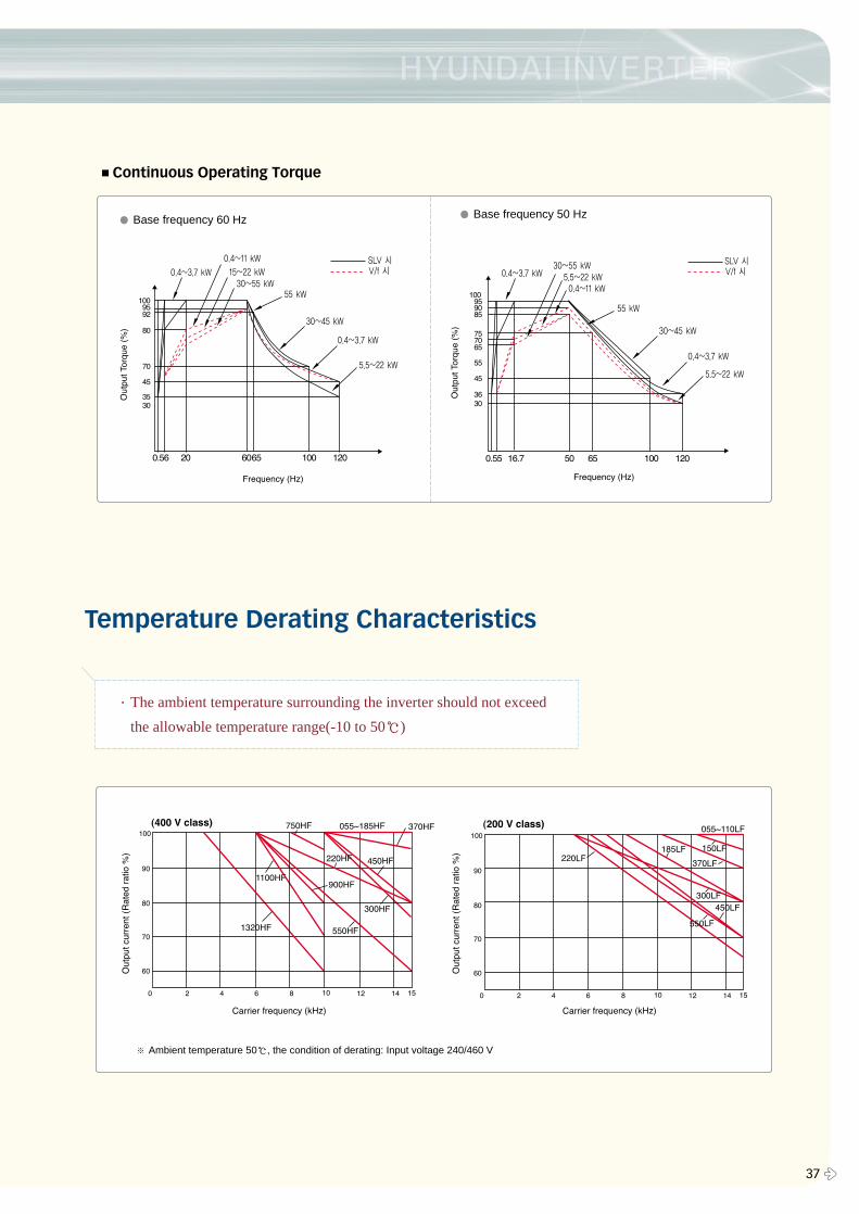
37 �
■Continuous Operating Torque
� Base frequency 60 Hz � Base frequency 50 Hz
Temperature Derating Characteristics
∙The ambient temperature surrounding the inverter should not exceed
the allowable temperature range(-10 to 50℃)
※ Ambient temperature 50℃, the condition of derating: Input voltage 240/460 V
For Correct Operation
� 38
■Application to Motors: Application to General-purpose Motors
Operating frequency
Torque characteristics
Motor loss andtemperature increase
Noise
Vibration
Power transmissionmechanism
■Application to Motors: Application to Special Motors
Gear motor
Brake-equipped motor
Pole-change motor
Submersible motor
Explosion-proof motor
Single-phase motor
Synchronous (MS) motor High-speed(HFM) motor
■Notes on Use: Drive
Run or stop of the inverter must be done with the keys on the operator panel or through the control circuit terminal. Do notoperate by installing a electromagnetic contactor (Mg) in the main circuit.
When the protective function is operating or the power supply stops, the motor enters the free run stop state. When anemergency stop is required or when the motor should be kept stopped, use of a mechanical brake should be considered.
A max. 400Hz can be selected on the N300 series. However, a two-pole motor can attain up to approx. 24,000 rpm, which isextremely dangerous. Therefore, carefully make selection and settings by checking the mechanical strength of the motor andconnected machines. Consult the motor manufacturer when it is necessary to drive a standard(general-purpose) motor above 60Hz. A full line of high-speed motors is available from Hyundai.
Run/ Stop
Emergency motor stop
High-frequency run
■Application to Motors: Application to the 400 V-class Motor
A system applying a voltage-type PWM inverter with IGBT may have surge voltage at the motor terminals resulting from the cable constants including the cablelength and the cable laying method. Depending on the surge current magnification, the motor coil insulation may be degraded. In particular, when a 400 V classmotor is used, a longer cable is used, and critical loss can occur, take the following countermeasures:(1) install the LCR filter between the inverter and themotor,(2) install the AC reactor between the inverter and the motor, or (3) enhance the insulation of the motor coil.
The overspeed endurance of a general-purpose motor is 120% of the rated speed for 2 minutes (JIS C4,004). For operation at higherthan 60Hz, it is required to examine the allowable torque of the motor, useful life of bearings, noise, vibration, etc. In this case, besure to consult the motor manufacturer as the maximum allowable rpm differs depending on the motor capacity, etc.
The torque characteristics of driving a general-purpose motor with an inverter differ from those of driving it using commercialpower (starting torque decreases in particular). Carefully check the load torque characteristic of a connected machine and thedriving torque characteristic of the motor.
An inverter-driven general-purpose motor heats up quickly at lower speeds. Consequently, the continuous torque level (output) willdecrease at lower motor speeds. Carefully check the torque characteristics vs speed range requirments.
When run by an inverter, a general-purpose motor generates noise slightly greater than with commercial power.
When run by an inverter at variable speeds, the motor may generate vibration, especially because of (a) unbalance of the rotorincluding a connected machine, or (b) resonance caused by the natural vibration frequency of a mechanical system. Particularly,be careful of (b) when operating at variable speeds a machine previously fitted with a constant speed motor. Vibration can beminimized by (1) avoiding resonance points using the frequency jump function of the inverter, (2) using a tire-shaped coupling, or(3) placing a rubber shock absorber beneath the motor base.
Under continued, low-speed operation, oil lubrication can deteriorate in a power transmission mechanism with an oil type gear box(gear motor) or reducer. Check with the motor manufacturer for the permissible range of continuous speed. To operate at morethan 60 Hz, confirm the machine’s ability to withstand the centrifugal force generated.
The allowable rotation range of continuous drive varies depending on the lubrication method or motor manufacturer.(Particularly incase of oil lubrication, pay attention to the low frequency range.)
For use of a brake-equipped motor, be sure to connect the braking power supply from the primary side of the inverter.
There are different kinds of pole-change motors (constant output characteristic type, constant torque characteristic type, etc.), withdifferent rated current values. In motor selection, check the maximum allowable current for each motor of a different pole count. Atthe time of pole change, be sure to stop the motor. Also see: Application to the 400 V class motor.
The rated current of a submersible motor is significantly larger than that of the general-purpose motor. In inverter selection, be sureto check the rated current of the motor.
Inverter drive is not suitable for a safety-enhanced explosion-proof type motor. The inverter should be used in combination with apressure-proof and explosion-proof type of motor.* Explosion-proof verification is not available for N300 series.
In most cases, the synchronous (MS) motor and the high-speed (HFM) motor are designed and manufactured to meet thespecifications suitable for a connected machine. As to proper inverter selection, consult the manufacturer.
A single-phase motor is not suitable for variable-speed operation by an inverter drive. Therefore, use a three-phase motor.
�Before use, be sure to read through the Instruction Manual to insure proper use of the inverter. �Note that the inverter requires electrical wiring; a trained specialist should carry out the wiring.�The inverter in this catalog is designed for general industrial applications. For special applications in fields such as aircraft, nuclear power, transport
vehicles, clinics, and underwater equipment, please consult with us in advance.�For application in a facility where human life is involved or serious losses may occur, make sure to provide safety devices to avoid a serious accident. �The inverter is intended for use with a three-phase AC motor. For use with a load other than this, please consult with us.
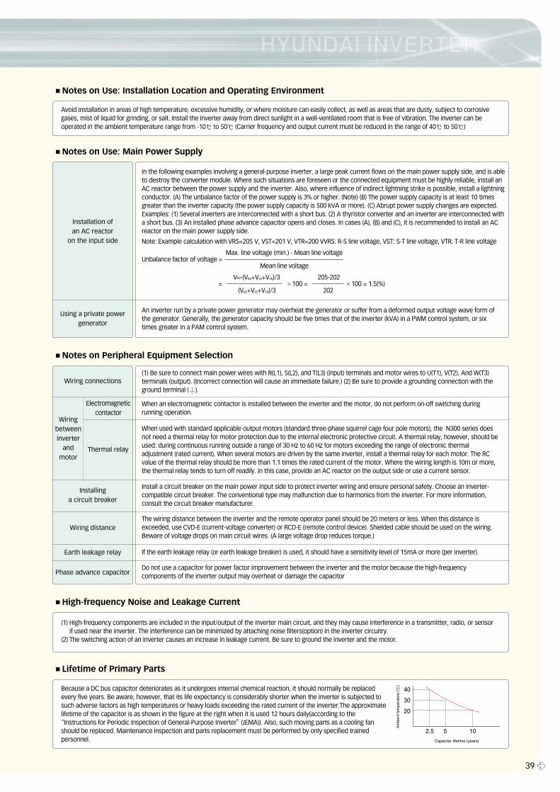
39 �
■Notes on Use: Main Power Supply
In the following examples involving a general-purpose inverter, a large peak current flows on the main power supply side, and is ableto destroy the converter module. Where such situations are foreseen or the connected equipment must be highly reliable, install anAC reactor between the power supply and the inverter. Also, where influence of indirect lightning strike is possible, install a lightningconductor. (A) The unbalance factor of the power supply is 3% or higher. (Note) (B) The power supply capacity is at least 10 timesgreater than the inverter capacity (the power supply capacity is 500 kVA or more). (C) Abrupt power supply changes are expected.Examples: (1) Several inverters are interconnected with a short bus. (2) A thyristor converter and an inverter are interconnected witha short bus. (3) An installed phase advance capacitor opens and closes. In cases (A), (B) and (C), it is recommended to install an ACreactor on the main power supply side.
Note: Example calculation with VRS=205 V, VST=201 V, VTR=200 VVRS: R-S line voltage, VST: S-T line voltage, VTR: T-R line voltage
Max. line voltage (min.) - Mean line voltageUnbalance factor of voltage =
Mean line voltage
VRS-(VRS+VST+VTR)/3 205-202= ×100 = ×100 = 1.5(%)
(VRS+VST+VTR)/3 202
An inverter run by a private power generator may overheat the generator or suffer from a deformed output voltage wave form ofthe generator. Generally, the generator capacity should be five times that of the inverter (kVA) in a PWM control system, or sixtimes greater in a PAM control system.
Installation of an AC reactor
on the input side
Using a private powergenerator
■High-frequency Noise and Leakage Current
(1) High-frequency components are included in the input/output of the inverter main circuit, and they may cause interference in a transmitter, radio, or sensorif used near the inverter. The interference can be minimized by attaching noise filters(option) in the inverter circuitry.
(2) The switching action of an inverter causes an increase in leakage current. Be sure to ground the inverter and the motor.
■Lifetime of Primary Parts
Because a DC bus capacitor deteriorates as it undergoes internal chemical reaction, it should normally be replacedevery five years. Be aware, however, that its life expectancy is considerably shorter when the inverter is subjected tosuch adverse factors as high temperatures or heavy loads exceeding the rated current of the inverter.The approximatelifetime of the capacitor is as shown in the figure at the right when it is used 12 hours daily(according to the
“Instructions for Periodic Inspection of General-Purpose Inverter”(JEMA)). Also, such moving parts as a cooling fanshould be replaced. Maintenance inspection and parts replacement must be performed by only specified trainedpersonnel.
■Notes on Peripheral Equipment Selection
(1) Be sure to connect main power wires with R(L1), S(L2), and T(L3) (input) terminals and motor wires to U(T1), V(T2), And W(T3)terminals (output). (Incorrect connection will cause an immediate failure.) (2) Be sure to provide a grounding connection with theground terminal ( ).
When an electromagnetic contactor is installed between the inverter and the motor, do not perform on-off switching duringrunning operation.
When used with standard applicable output motors (standard three-phase squirrel cage four pole motors), the N300 series doesnot need a thermal relay for motor protection due to the internal electronic protective circuit. A thermal relay, however, should beused: during continuous running outside a range of 30 Hz to 60 Hz for motors exceeding the range of electronic thermaladjustment (rated current). When several motors are driven by the same inverter, install a thermal relay for each motor. The RCvalue of the thermal relay should be more than 1.1 times the rated current of the motor. Where the wiring length is 10m or more,the thermal relay tends to turn off readily. In this case, provide an AC reactor on the output side or use a current sensor.
Install a circuit breaker on the main power input side to protect inverter wiring and ensure personal safety. Choose an inverter-compatible circuit breaker. The conventional type may malfunction due to harmonics from the inverter. For more information,consult the circuit breaker manufacturer.
The wiring distance between the inverter and the remote operator panel should be 20 meters or less. When this distance isexceeded, use CVD-E (current-voltage converter) or RCD-E (remote control device). Shielded cable should be used on the wiring.Beware of voltage drops on main circuit wires. (A large voltage drop reduces torque.)
If the earth leakage relay (or earth leakage breaker) is used, it should have a sensitivity level of 15mA or more (per inverter).
Do not use a capacitor for power factor improvement between the inverter and the motor because the high-frequencycomponents of the inverter output may overheat or damage the capacitor
Wiring connections
Wiring distance
Earth leakage relay
Electromagnetic contactor
Thermal relay
Phase advance capacitor
Installing a circuit breaker
Wiringbetweeninverter
andmotor
■Notes on Use: Installation Location and Operating Environment
Avoid installation in areas of high temperature, excessive humidity, or where moisture can easily collect, as well as areas that are dusty, subject to corrosivegases, mist of liquid for grinding, or salt. Install the inverter away from direct sunlight in a well-ventilated room that is free of vibration. The inverter can beoperated in the ambient temperature range from -10℃ to 50℃ (Carrier frequency and output current must be reduced in the range of 40℃ to 50℃)
Related Documents