Hytera PD41X Patrol Management System Installation and Configuration Guide Documentation Version: 01 Release Date: 03-2015

Welcome message from author
This document is posted to help you gain knowledge. Please leave a comment to let me know what you think about it! Share it to your friends and learn new things together.
Transcript
Hytera
PD41X Patrol Management System
Installation and Configuration Guide
Documentation Version: 01
Release Date: 03-2015

Copyright Information
Hytera is the trademark or registered trademark of Hytera Communications Corporation Limited (the
Company) in PRC and/or other countries or areas. The Company retains the ownership of its trademarks
and product names. All other trademarks and/or product names that may be used in this manual are
properties of their respective owners.
The product described in this manual may include the Company’s computer programs stored in memory
or other media. Laws in PRC and/or other countries or areas protect the exclusive rights of the Company
with respect to its computer programs. The purchase of this product shall not be deemed to grant, either
directly or by implication, any rights to the purchaser regarding the Company’s computer programs. Any
of the Company’s computer programs may not be copied, modified, distributed, decompiled, or
reverse-engineered in any manner without the prior written consent of the Company.
Disclaimer
Hytera Communications Corporation Limited (the Company) endeavors to achieve the accuracy and
completeness of this manual, but no warranty of accuracy or reliability is given. All the specifications and
designs are subject to change without notice due to continuous technology development. No part of this
manual may be copied, modified, translated, or distributed in any manner without the express written
permission of us.
We do not guarantee, for any particular purpose, the accuracy, validity, timeliness, legitimacy or
completeness of the Third Party products and contents involved in this manual.
If you have any suggestions or would like to learn more details, please visit our website at:
http://www.hytera.com.
Installation and Configuration Guide Contents
i
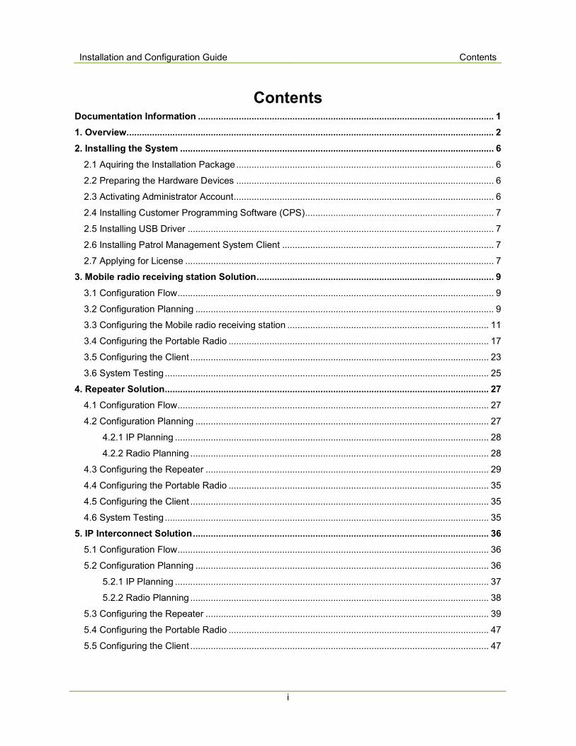
Contents Documentation Information .................................................................................................................... 1
1. Overview ................................................................................................................................................ 2
2. Installing the System ........................................................................................................................... 6
2.1 Aquiring the Installation Package ..................................................................................................... 6
2.2 Preparing the Hardware Devices ..................................................................................................... 6
2.3 Activating Administrator Account ...................................................................................................... 6
2.4 Installing Customer Programming Software (CPS) .......................................................................... 7
2.5 Installing USB Driver ........................................................................................................................ 7
2.6 Installing Patrol Management System Client ................................................................................... 7
2.7 Applying for License ......................................................................................................................... 7
3. Mobile radio receiving station Solution ............................................................................................. 9
3.1 Configuration Flow ............................................................................................................................ 9
3.2 Configuration Planning ..................................................................................................................... 9
3.3 Configuring the Mobile radio receiving station ............................................................................... 11
3.4 Configuring the Portable Radio ...................................................................................................... 17
3.5 Configuring the Client ..................................................................................................................... 23
3.6 System Testing ............................................................................................................................... 25
4. Repeater Solution ............................................................................................................................... 27
4.1 Configuration Flow .......................................................................................................................... 27
4.2 Configuration Planning ................................................................................................................... 27
4.2.1 IP Planning ........................................................................................................................... 28
4.2.2 Radio Planning ..................................................................................................................... 28
4.3 Configuring the Repeater ............................................................................................................... 29
4.4 Configuring the Portable Radio ...................................................................................................... 35
4.5 Configuring the Client ..................................................................................................................... 35
4.6 System Testing ............................................................................................................................... 35
5. IP Interconnect Solution .................................................................................................................... 36
5.1 Configuration Flow .......................................................................................................................... 36
5.2 Configuration Planning ................................................................................................................... 36
5.2.1 IP Planning ........................................................................................................................... 37
5.2.2 Radio Planning ..................................................................................................................... 38
5.3 Configuring the Repeater ............................................................................................................... 39
5.4 Configuring the Portable Radio ...................................................................................................... 47
5.5 Configuring the Client ..................................................................................................................... 47
Contents Installation and Configuration Guide
ii
5.6 System Testing ............................................................................................................................... 47
Installation and Configuration Guide Documentation Information
1
Documentation Information
This section describes the conventions and revision history of this document.
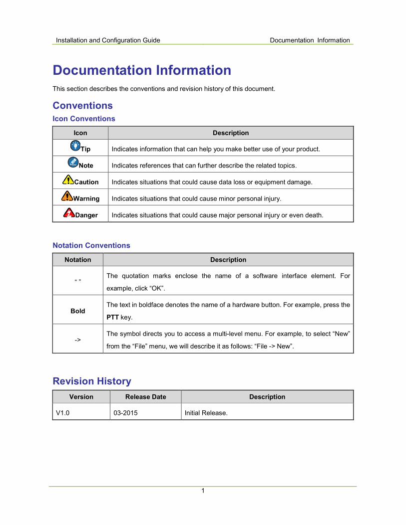
Conventions
Icon Conventions
Icon Description
Tip Indicates information that can help you make better use of your product.
Note Indicates references that can further describe the related topics.
Caution Indicates situations that could cause data loss or equipment damage.
Warning Indicates situations that could cause minor personal injury.
Danger Indicates situations that could cause major personal injury or even death.
Notation Conventions
Notation Description
“ ” The quotation marks enclose the name of a software interface element. For
example, click “OK”.
Bold The text in boldface denotes the name of a hardware button. For example, press the
PTT key.
-> The symbol directs you to access a multi-level menu. For example, to select “New”
from the “File” menu, we will describe it as follows: “File -> New”.
Revision History
Version Release Date Description
V1.0 03-2015 Initial Release.
Error! Use the Home tab to apply 标题标题标题标题 1 to
the text that you want to appear here. Installation and Configuration Guide
2
1. Overview With the diversified and complex development of the urban buildings, the security activity needs to be
upgraded continuously. Thus, it becomes more and more important for guard tour system to ensure
security and carry out comprehensive patrolling. In the past, patrolling is relatively dull and lack of
effective monitoring, patroller might become careless and unconcerned. Under such cases,
uncompleted patrolling may cause property loss to the residents and buildings.
Hytera Patrol Management System can provide you with effective monitoring on patrollers. Patrol
Management System can be used in fields such as security patrolling, fire-fighting patrolling, inspection
patrolling, equipment inspection and pipeline inspection, and can improve the management quality of
these fields effectively.
Electronic Patrol is a Radio Frequency Identification (RFID) technology which is used to manage the
patrolling scientifically and normatively. Patrol Management System has integrated Electronic Patrol
technology. When the patroller reaches the Patrol Checkpoint and swipes, the patrol radio can
automatically detect and save the information of the Patrol Checkpoint. Then, the patrol radio will upload
the patrol data to the Patrol Management System client, even via IP network. Regular and fixed-point
patrolling can help you to be well-informed of patrolling status and to manage the patrollers effectively,
so as to prevent possible accidents and problems.
Patrol Management System can achieve more applications via DMR mobile radio receiving stations or
repeaters. The Patrol Management System consists of a client, repeaters or mobile radio receiving
stations, Patroller ID cards, Patrol Checkpoints, PD41X portable radios, etc. Therefore, the system can
satisfy different kinds of patrolling deployment requirements.
� Client: The client is used to check the patrolling status and manage the patrollers conveniently and
effectively. Currently, the system can only support one client.
� Repeaters: Repeaters receive the patrolling information sent by the portable radios and send the
information to the client via data cable or IP network. Finally, repeaters send the ACK information
back to the portable radios.
� Mobile radio receiving stations: Mobile radio receiving stations receive the patrolling information sent
by the portable radios and send the information to the client via data cable. Finally, mobile radio
receiving stations send the ACK information back to the portable radios.
� Patroller ID card: Patroller ID card is used to identify the ID of patrollers.
Installation and Configuration Guide Error! Use the Home tab to apply 标题标题标题标题 1 t
o the text that you want to appear here.
3
� Patrol Checkpoints: Patrol Checkpoints are allocated along the patrolling route for patrolling
information collection.
� Portable radios: PD41X portable radios are used to collect patrolling information.
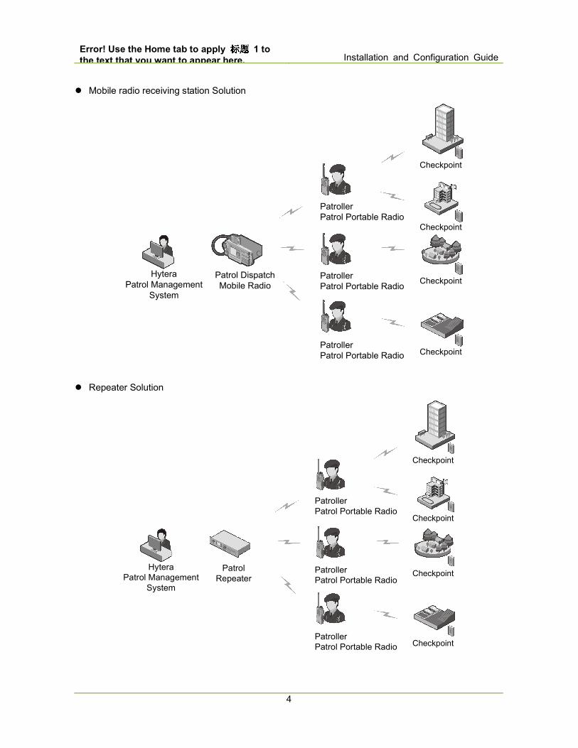
Currently, the available deployment solutions are listed below. The repeaters or mobile radio receiving
stations work independently and access the Patrol Management System via data cable or IP network.
After connecting to the Patrol Management System client, the repeaters or mobile radio receiving
stations can transfer patrolling information to the system.
Error! Use the Home tab to apply 标题标题标题标题 1 to
the text that you want to appear here. Installation and Configuration Guide
4
� Mobile radio receiving station Solution
Hytera
Patrol Management
System
Patrol Dispatch
Mobile Radio
Patroller
Patrol Portable Radio
Patroller
Patrol Portable Radio
Patroller
Patrol Portable Radio
Checkpoint
Checkpoint
Checkpoint
Checkpoint
� Repeater Solution
Hytera
Patrol Management
System
Patrol
Repeater
Patroller
Patrol Portable Radio
Patroller
Patrol Portable Radio
Patroller
Patrol Portable Radio
Checkpoint
Checkpoint
Checkpoint
Checkpoint

Installation and Configuration Guide Error! Use the Home tab to apply 标题标题标题标题 1 t
o the text that you want to appear here.
5
� IP Interconnect Solution

Error! Use the Home tab to apply 标题标题标题标题 1 to
the text that you want to appear here. Installation and Configuration Guide
6
2. Installing the System
2.1 Acquiring the Installation Package
The Company may provide the software installation package in any of the following ways:
� Software installation package: Hytera PD41X Patrol Management System V1.0. ××. ××××.en.rar. “××.
××××” are subject to the content of actual installation package.
� Download the software installation package from www.hytera.com (Download path: Downloads ->
Driver & Software -> PD41X)
2.2 Preparing the Hardware Devices
Device Requirements
Client Computer
� CUP: Dual-core CPU, with a clock speed of 2.0GHz and above
� Free Disk Space: 500M and above
� Memory: 2.0G and above
� Operating System: Windows XP sp3 and above, Windows 7 sp1 and
above, supporting 32-bit and 64-bit operating systems
� Network Interface Card: 100M and above
Mobile radio
receiving
station/Repeater
Mobile radio receiving station: V6.05.07.005 and above DMR firmware version.
Repeater: V7.00.09.005 and above DMR firmware version.
Portable radios V1.02.10.001 and above firmware version.
2.3 Activating Administrator Account
In Windows 7 operating system, the administrator right is disabled by default. Patrol Management
System installation and configuration need to use the Administrator account. To activate the
Administrator account, do as follows:
Step 1 Go to the folder “C:\Windows\System32”.
Step 2 Find the file “cmd.exe”.
Step 3 Right-click the file and select “Run as administrator” to enter the relevant window.
Step 4 Enter “net user administrator /active:yes” in the command line.
Installation and Configuration Guide Error! Use the Home tab to apply 标题标题标题标题 1 t
o the text that you want to appear here.
7
Step 5 Log off the current account after executing the command successfully.
Step 6 Log in the Administrator account and enter the system to install and configure the Patrol
Management System.
2.4 Installing Customer Programming Software (CPS)
Mobile radio receiving station CPS must be V6.05.07.005 and above version; portable radio CPS must
be V1.02.10.001 and above version; repeater CPS must be V7.00.09.005 and above version. Please
refer to the corresponding software operation manual for detailed installation procedures.
2.5 Installing USB Driver
Patrol Management System requires the USB driver software “DMR-USBdriverinstaller” to be
V3.01.01.005 and above version. Please refer to the corresponding software operation manual for
detailed installation procedures.
2.6 Installing Patrol Management System Client
The installation package of Patrol Management System client is a portable applicatioin. After unzipping
the installation package, you can double-click “Patrol.exe” to run the client. If you have any questions
during installation, please refer to the corresponding installation instructions along with the installation
package.
2.7 Applying for License
License is one-to-one corresponding to the computer machine code and it is necessary for the proper
operation of Patrol Management System client.
If not authorized by the Company, the Patrol Management System client can only operate for sixty days.
When sixty-day period expires, the client will be unusable without activation.
You can log in the system using the administrator account and go to “Settings -> Software Information”,
click the information in red to prompt the dialog below. Copy the verification code and send it to your
dealer to obtain the activation code. After the Activation Code is filled in, click the “Activate” button to
activate the client for proper operation.

Error! Use the Home tab to apply 标题标题标题标题 1 to
the text that you want to appear here. Installation and Configuration Guide
8

Installation and Configuration Guide Error! Use the Home tab to apply 标题标题标题标题 1 t
o the text that you want to appear here.
9
3. Mobile radio receiving station Solution
3.1 Configuration Flow
Patrol Management System configuration flow of mobile radio receiving station Solution is as shown
below.
Caution
The following configuration must be operated in the administrator account; otherwise, certain
configurations may fail to work.
Start
Configuring Dispatch
Mobile Radio
Configuring Portable
Radio
Configuring Client
End
Configuration Planning
System Testing
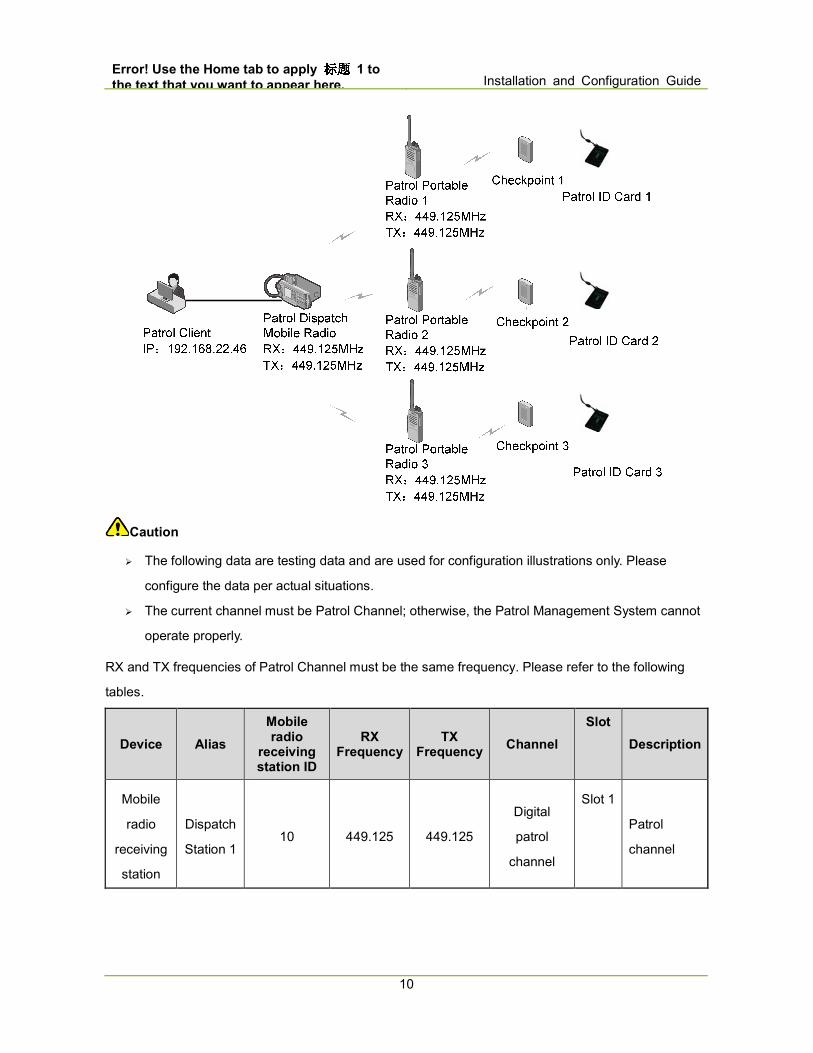
3.2 Configuration Planning
The design case of Mobile radio receiving station Solution is as shown in the figure below.
Error! Use the Home tab to apply 标题标题标题标题 1 to
the text that you want to appear here. Installation and Configuration Guide
10
Caution
� The following data are testing data and are used for configuration illustrations only. Please
configure the data per actual situations. � The current channel must be Patrol Channel; otherwise, the Patrol Management System cannot
operate properly.
RX and TX frequencies of Patrol Channel must be the same frequency. Please refer to the following
tables.
Device Alias
Mobile radio
receiving station ID
RX Frequency
TX Frequency
Channel
Slot
Description
Mobile
radio
receiving
station
Dispatch
Station 1 10 449.125 449.125
Digital
patrol
channel
Slot 1
Patrol
channel
Installation and Configuration Guide Error! Use the Home tab to apply 标题标题标题标题 1 t
o the text that you want to appear here.
11
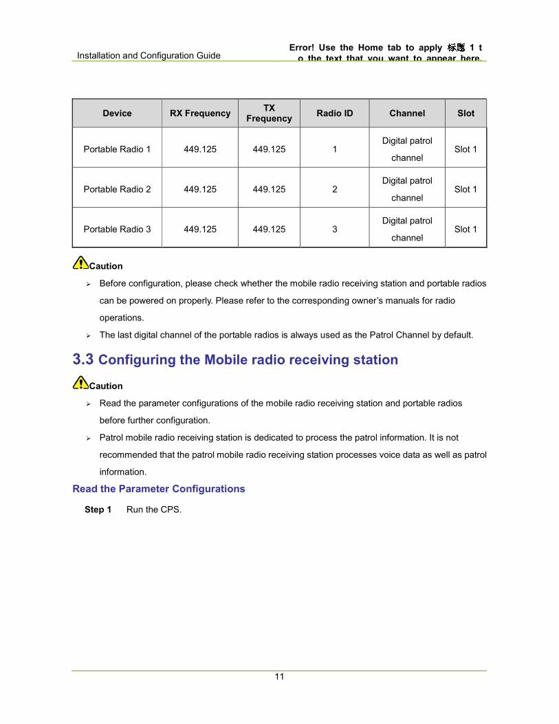
Device RX Frequency TX
Frequency Radio ID Channel Slot
Portable Radio 1 449.125 449.125 1 Digital patrol
channel Slot 1
Portable Radio 2 449.125 449.125 2 Digital patrol
channel Slot 1
Portable Radio 3 449.125 449.125 3 Digital patrol
channel Slot 1
Caution
� Before configuration, please check whether the mobile radio receiving station and portable radios
can be powered on properly. Please refer to the corresponding owner’s manuals for radio
operations.
� The last digital channel of the portable radios is always used as the Patrol Channel by default.
3.3 Configuring the Mobile radio receiving station
Caution
� Read the parameter configurations of the mobile radio receiving station and portable radios
before further configuration.
� Patrol mobile radio receiving station is dedicated to process the patrol information. It is not
recommended that the patrol mobile radio receiving station processes voice data as well as patrol
information.
Read the Parameter Configurations
Step 1 Run the CPS.

Error! Use the Home tab to apply 标题标题标题标题 1 to
the text that you want to appear here. Installation and Configuration Guide
12
Step 2 Click to select the appropriate USB port and click “OK”.
If the CPS does not prompt the window shown below, you need to install the USB driver
“DMR-USBdriverinstaller” first. Restart the CPS when the installation is completed. Please refer
to Digital USB Driver Installation Guide R5.5.pdf for installation guides.

Installation and Configuration Guide Error! Use the Home tab to apply 标题标题标题标题 1 t
o the text that you want to appear here.
13
Step 3 In the “Read window”, click “OK” to read the parameter configurations of the mobile radio
receiving station. After successful reading, click “OK” to finish.
Forward To PC
Step 1 Go to “Conventional -> General Setting -> Network” from the left navigation tree of CPS.
Step 2 Select Forward To PC in Radio to PC Network interface.
Digital Channel
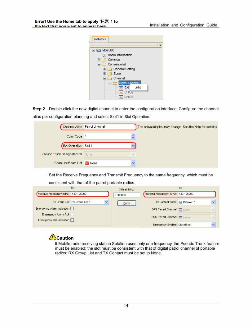
Step 1 Go to “Conventional -> Channel -> Digital Channel” from the left navigation tree of CPS,
right click Digital Channel and select Add to add a new digital channel.
Error! Use the Home tab to apply 标题标题标题标题 1 to
the text that you want to appear here. Installation and Configuration Guide
14
Step 2 Double-click the new digital channel to enter the configuration interface. Configure the channel
alias per configuration planning and select Slot1 in Slot Operation.
Set the Receive Frequency and Transmit Frequency to the same frequency, which must be
consistent with that of the patrol portable radios.
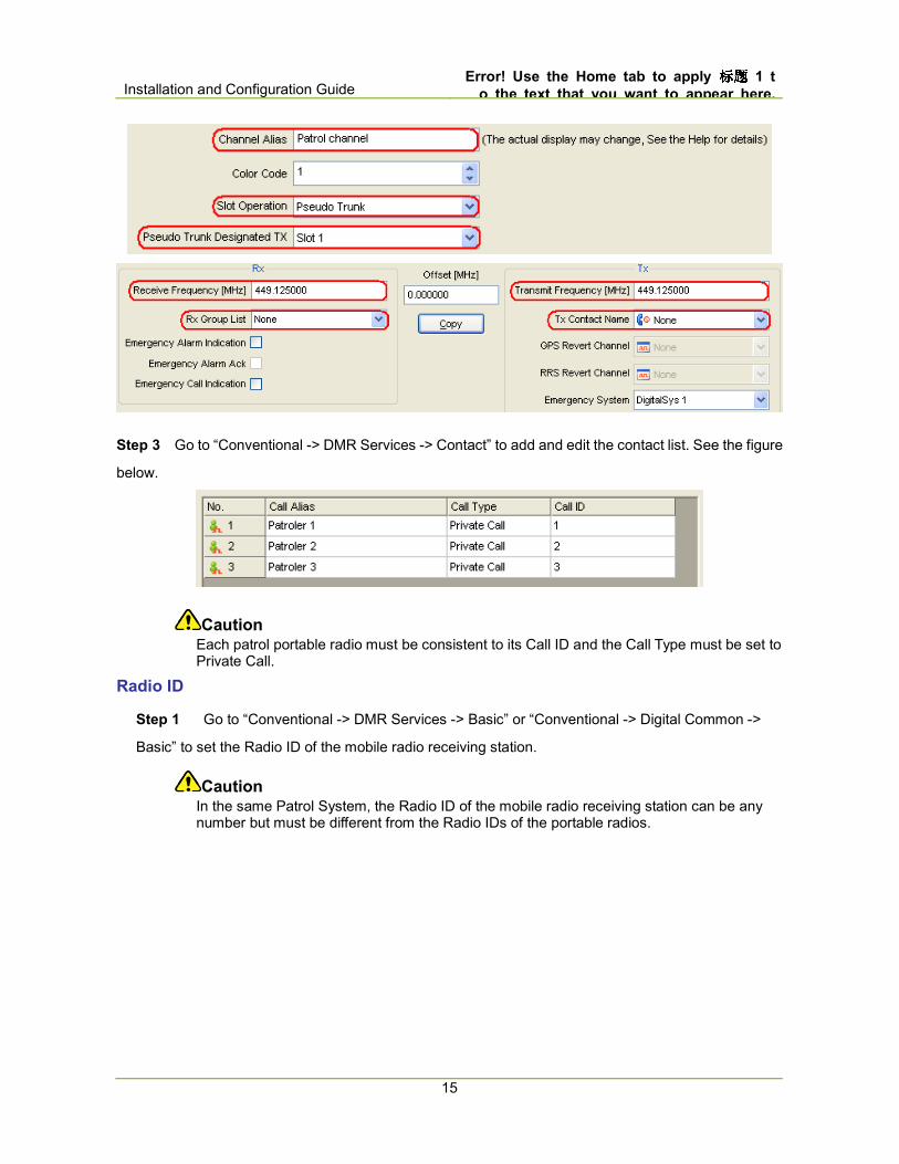
Caution If Mobile radio receiving station Solution uses only one frequency, the Pseudo Trunk feature must be enabled; the slot must be consistent with that of digital patrol channel of portable radios; RX Group List and TX Contact must be set to None.
Installation and Configuration Guide Error! Use the Home tab to apply 标题标题标题标题 1 t
o the text that you want to appear here.
15
Step 3 Go to “Conventional -> DMR Services -> Contact” to add and edit the contact list. See the figure
below.
Caution Each patrol portable radio must be consistent to its Call ID and the Call Type must be set to Private Call.
Radio ID
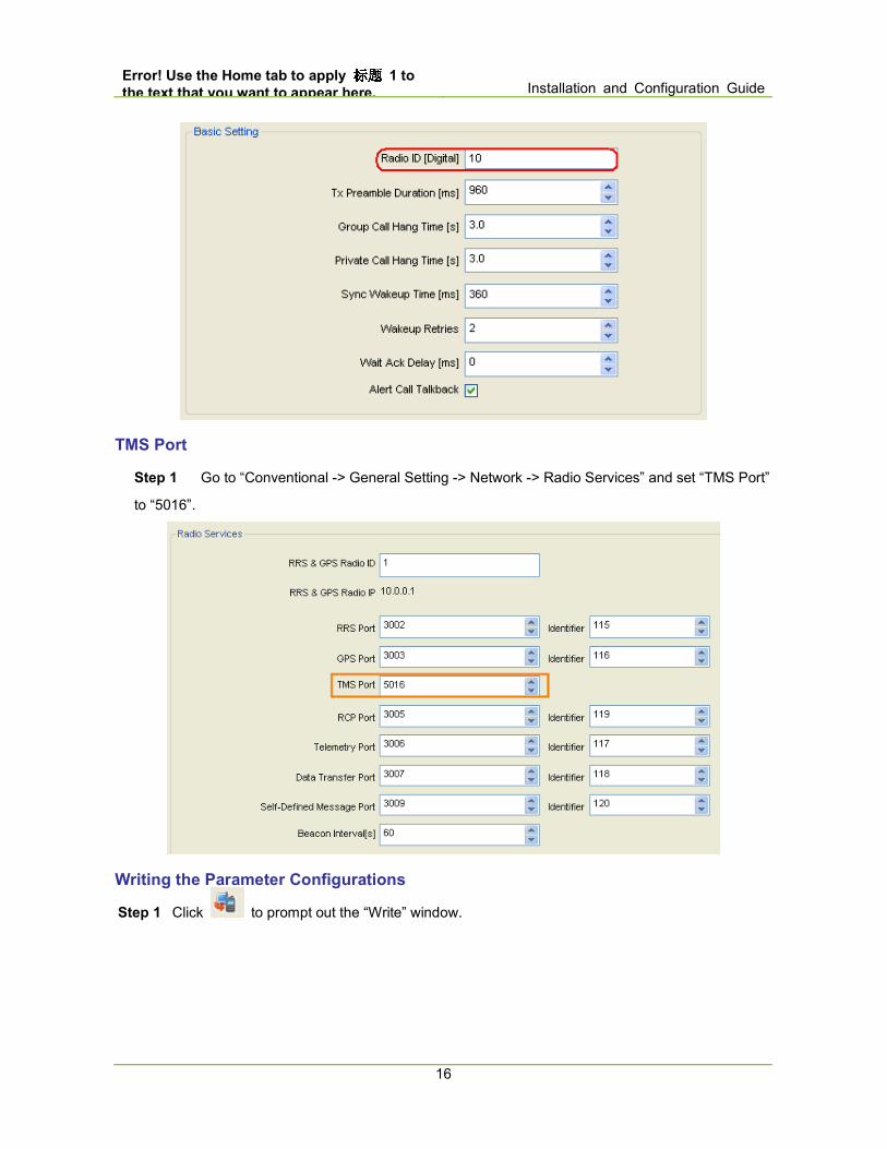
Step 1 Go to “Conventional -> DMR Services -> Basic” or “Conventional -> Digital Common ->
Basic” to set the Radio ID of the mobile radio receiving station.
Caution In the same Patrol System, the Radio ID of the mobile radio receiving station can be any number but must be different from the Radio IDs of the portable radios.
Error! Use the Home tab to apply 标题标题标题标题 1 to
the text that you want to appear here. Installation and Configuration Guide
16
TMS Port
Step 1 Go to “Conventional -> General Setting -> Network -> Radio Services” and set “TMS Port”
to “5016”.
Writing the Parameter Configurations
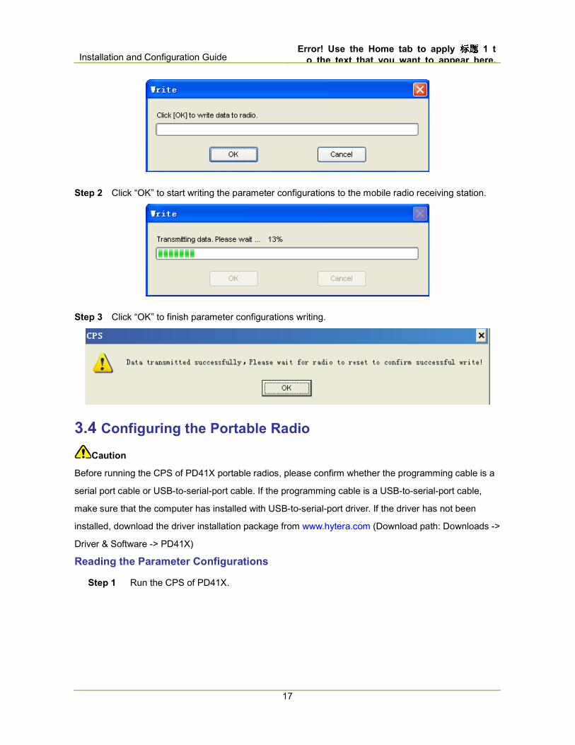
Step 1 Click to prompt out the “Write” window.
Installation and Configuration Guide Error! Use the Home tab to apply 标题标题标题标题 1 t
o the text that you want to appear here.
17
Step 2 Click “OK” to start writing the parameter configurations to the mobile radio receiving station.
Step 3 Click “OK” to finish parameter configurations writing.
3.4 Configuring the Portable Radio
Caution
Before running the CPS of PD41X portable radios, please confirm whether the programming cable is a
serial port cable or USB-to-serial-port cable. If the programming cable is a USB-to-serial-port cable,
make sure that the computer has installed with USB-to-serial-port driver. If the driver has not been
installed, download the driver installation package from www.hytera.com (Download path: Downloads ->
Driver & Software -> PD41X) Reading the Parameter Configurations
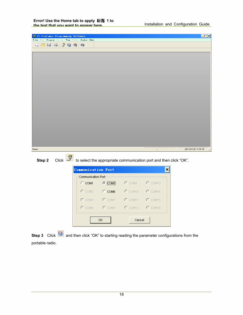
Step 1 Run the CPS of PD41X.
Error! Use the Home tab to apply 标题标题标题标题 1 to
the text that you want to appear here. Installation and Configuration Guide
18
Step 2 Click to select the appropriate communication port and then click “OK”.
Step 3 Click and then click “OK” to starting reading the parameter configurations from the
portable radio.
Installation and Configuration Guide Error! Use the Home tab to apply 标题标题标题标题 1 t
o the text that you want to appear here.
19
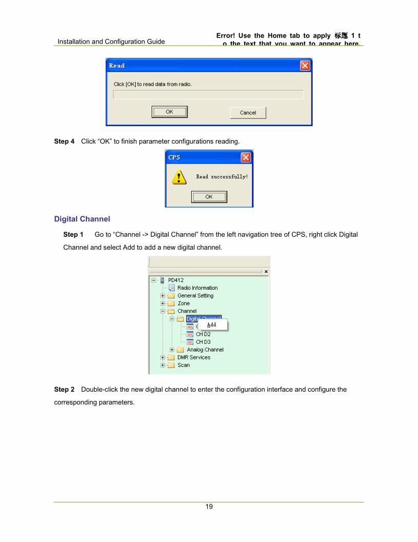
Step 4 Click “OK” to finish parameter configurations reading.
Digital Channel
Step 1 Go to “Channel -> Digital Channel” from the left navigation tree of CPS, right click Digital
Channel and select Add to add a new digital channel.
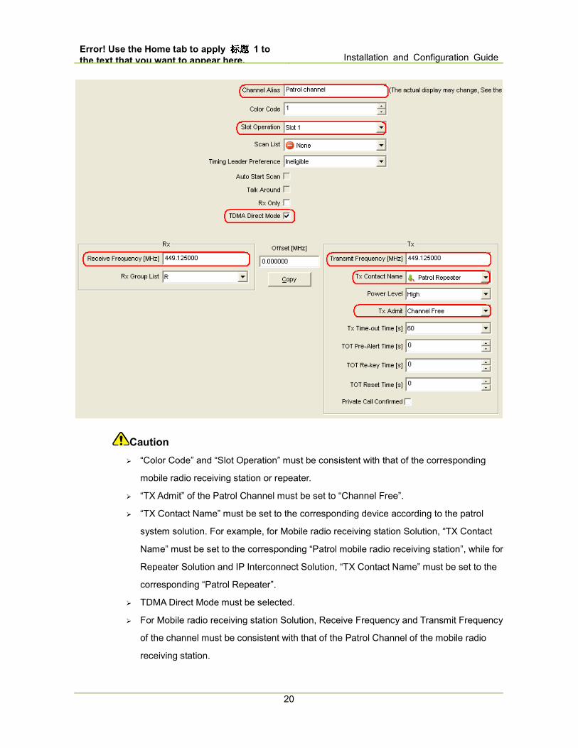
Step 2 Double-click the new digital channel to enter the configuration interface and configure the
corresponding parameters.
Error! Use the Home tab to apply 标题标题标题标题 1 to
the text that you want to appear here. Installation and Configuration Guide
20
Caution
� “Color Code” and “Slot Operation” must be consistent with that of the corresponding
mobile radio receiving station or repeater.
� “TX Admit” of the Patrol Channel must be set to “Channel Free”.
� “TX Contact Name” must be set to the corresponding device according to the patrol
system solution. For example, for Mobile radio receiving station Solution, “TX Contact
Name” must be set to the corresponding “Patrol mobile radio receiving station”, while for
Repeater Solution and IP Interconnect Solution, “TX Contact Name” must be set to the
corresponding “Patrol Repeater”.
� TDMA Direct Mode must be selected.
� For Mobile radio receiving station Solution, Receive Frequency and Transmit Frequency
of the channel must be consistent with that of the Patrol Channel of the mobile radio
receiving station.
Installation and Configuration Guide Error! Use the Home tab to apply 标题标题标题标题 1 t
o the text that you want to appear here.
21
� For Repeater Solution, Receive Frequency and Transmit Frequency of the portable radio
channel must match that of the repeater patrol channel. That is to say, Receive
Frequency must be consistent with Transmit Frequency of the repeater patrol channel
while Transmit Frequency must be consistent with Receive Frequency of the repeater
patrol channel. � For Repeater Solution, the voice service and patrolling service share the same
frequency. To ensure the stability of the system, the voice service and patrolling service
must use different slots. For example, the patrolling service uses slot 1 while the voice
service uses slot 2.
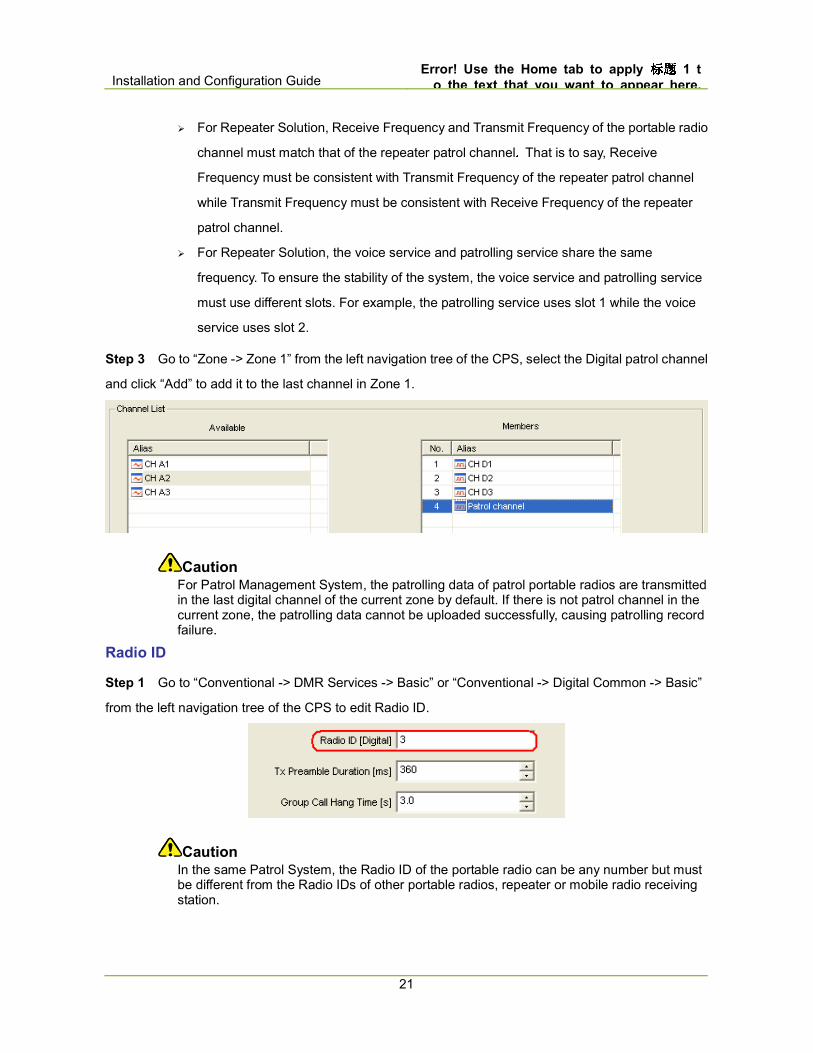
Step 3 Go to “Zone -> Zone 1” from the left navigation tree of the CPS, select the Digital patrol channel
and click “Add” to add it to the last channel in Zone 1.
Caution For Patrol Management System, the patrolling data of patrol portable radios are transmitted in the last digital channel of the current zone by default. If there is not patrol channel in the current zone, the patrolling data cannot be uploaded successfully, causing patrolling record failure.
Radio ID
Step 1 Go to “Conventional -> DMR Services -> Basic” or “Conventional -> Digital Common -> Basic”
from the left navigation tree of the CPS to edit Radio ID.
Caution In the same Patrol System, the Radio ID of the portable radio can be any number but must be different from the Radio IDs of other portable radios, repeater or mobile radio receiving station.
Error! Use the Home tab to apply 标题标题标题标题 1 to
the text that you want to appear here. Installation and Configuration Guide
22
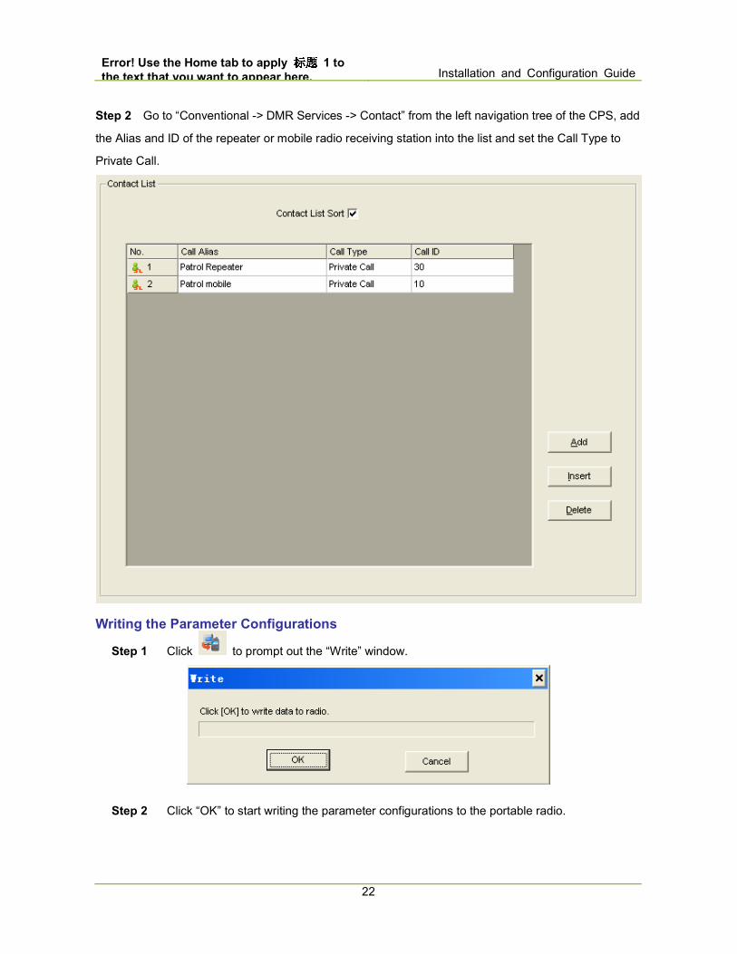
Step 2 Go to “Conventional -> DMR Services -> Contact” from the left navigation tree of the CPS, add
the Alias and ID of the repeater or mobile radio receiving station into the list and set the Call Type to
Private Call.
Writing the Parameter Configurations
Step 1 Click to prompt out the “Write” window.
Step 2 Click “OK” to start writing the parameter configurations to the portable radio.
Installation and Configuration Guide Error! Use the Home tab to apply 标题标题标题标题 1 t
o the text that you want to appear here.
23
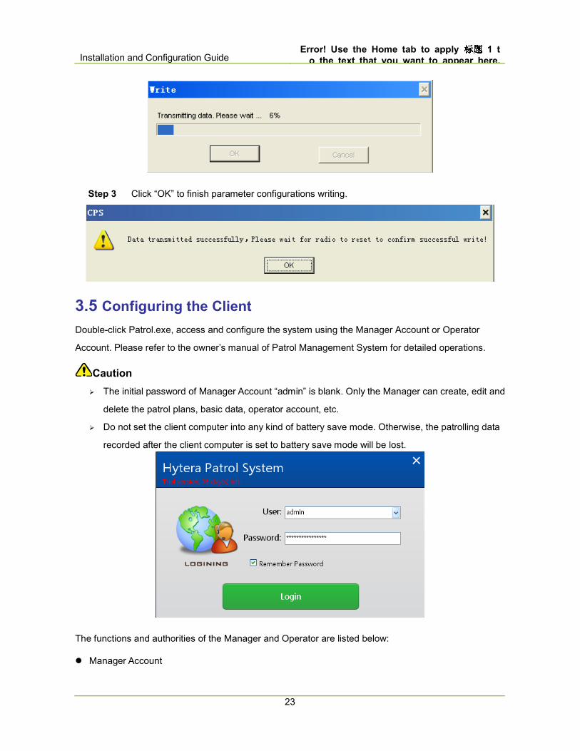
Step 3 Click “OK” to finish parameter configurations writing.
3.5 Configuring the Client
Double-click Patrol.exe, access and configure the system using the Manager Account or Operator
Account. Please refer to the owner’s manual of Patrol Management System for detailed operations.
Caution
� The initial password of Manager Account “admin” is blank. Only the Manager can create, edit and
delete the patrol plans, basic data, operator account, etc.
� Do not set the client computer into any kind of battery save mode. Otherwise, the patrolling data
recorded after the client computer is set to battery save mode will be lost.
The functions and authorities of the Manager and Operator are listed below:
� Manager Account
Error! Use the Home tab to apply 标题标题标题标题 1 to
the text that you want to appear here. Installation and Configuration Guide
24
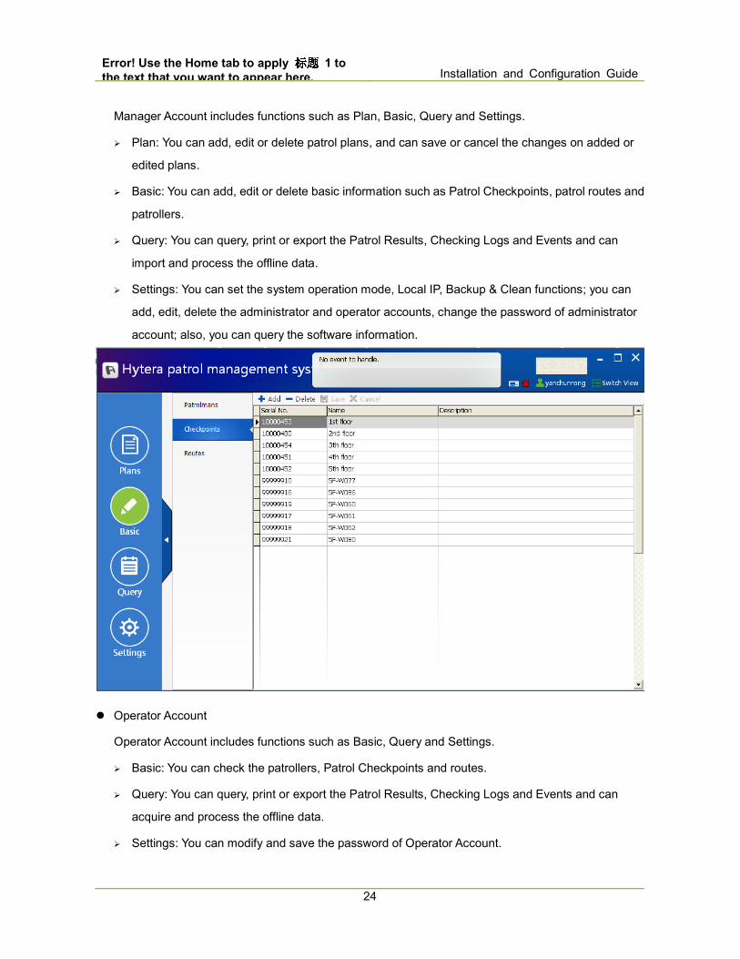
Manager Account includes functions such as Plan, Basic, Query and Settings.
� Plan: You can add, edit or delete patrol plans, and can save or cancel the changes on added or
edited plans.
� Basic: You can add, edit or delete basic information such as Patrol Checkpoints, patrol routes and
patrollers.
� Query: You can query, print or export the Patrol Results, Checking Logs and Events and can
import and process the offline data.
� Settings: You can set the system operation mode, Local IP, Backup & Clean functions; you can
add, edit, delete the administrator and operator accounts, change the password of administrator
account; also, you can query the software information.
� Operator Account
Operator Account includes functions such as Basic, Query and Settings.
� Basic: You can check the patrollers, Patrol Checkpoints and routes.
� Query: You can query, print or export the Patrol Results, Checking Logs and Events and can
acquire and process the offline data.
� Settings: You can modify and save the password of Operator Account.
Installation and Configuration Guide Error! Use the Home tab to apply 标题标题标题标题 1 t
o the text that you want to appear here.
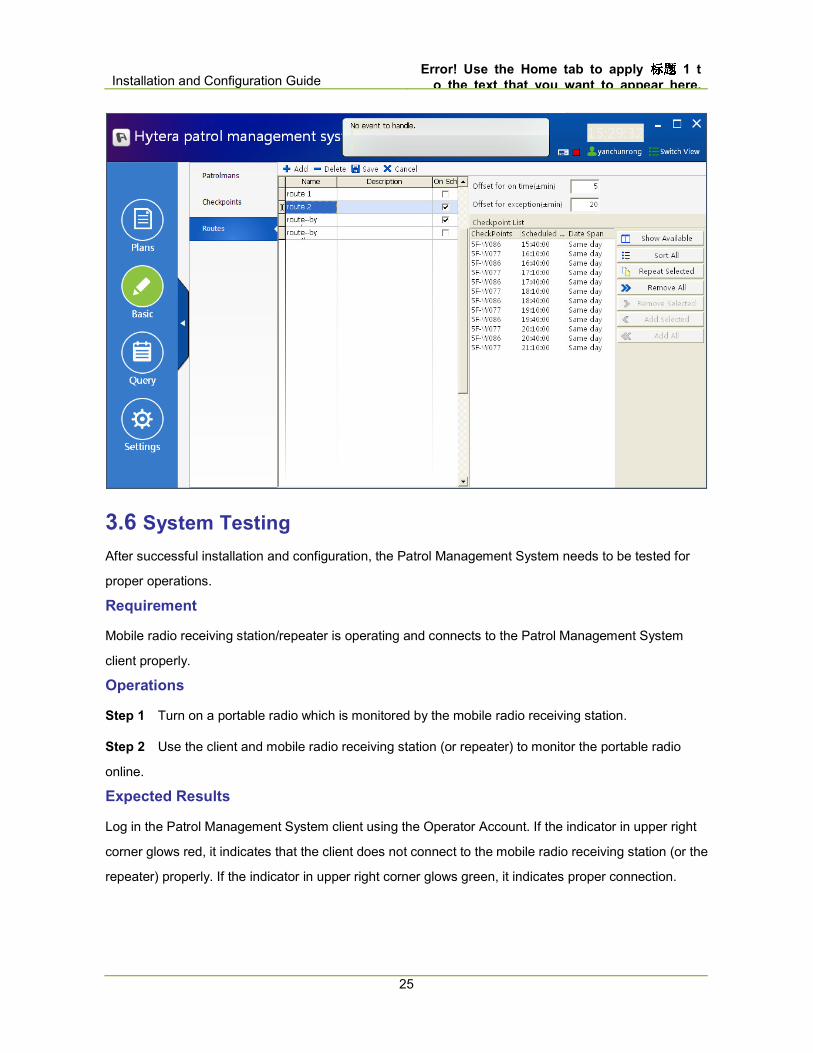
25
3.6 System Testing
After successful installation and configuration, the Patrol Management System needs to be tested for
proper operations.
Requirement
Mobile radio receiving station/repeater is operating and connects to the Patrol Management System
client properly.
Operations
Step 1 Turn on a portable radio which is monitored by the mobile radio receiving station.
Step 2 Use the client and mobile radio receiving station (or repeater) to monitor the portable radio
online.
Expected Results
Log in the Patrol Management System client using the Operator Account. If the indicator in upper right
corner glows red, it indicates that the client does not connect to the mobile radio receiving station (or the
repeater) properly. If the indicator in upper right corner glows green, it indicates proper connection.
Error! Use the Home tab to apply 标题标题标题标题 1 to
the text that you want to appear here. Installation and Configuration Guide
26
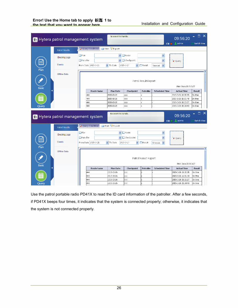
Use the patrol portable radio PD41X to read the ID card information of the patroller. After a few seconds,
if PD41X beeps four times, it indicates that the system is connected properly; otherwise, it indicates that
the system is not connected properly.

Installation and Configuration Guide Error! Use the Home tab to apply 标题标题标题标题 1 t
o the text that you want to appear here.
27
4. Repeater Solution
4.1 Configuration Flow
Patrol Management System configuration flow of Repeater Solution is as shown below.
Caution
The following configuration must be operated in the administrator account; otherwise, certain
configurations may fail to work.
Start
Configuring Repeater
Configuring Portable
Radio
Configuring Client
End
Configuration Planning
System Testing
4.2 Configuration Planning
The design case of Repeater Solution is as shown in the figure below.
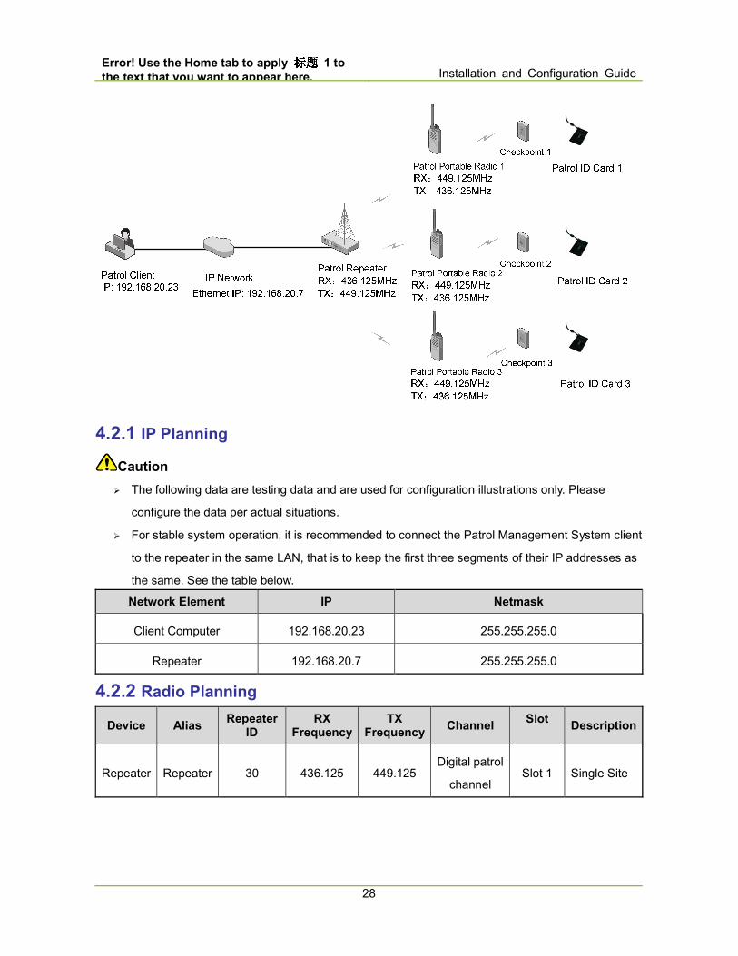
Error! Use the Home tab to apply 标题标题标题标题 1 to
the text that you want to appear here. Installation and Configuration Guide
28
4.2.1 IP Planning
Caution
� The following data are testing data and are used for configuration illustrations only. Please
configure the data per actual situations.
� For stable system operation, it is recommended to connect the Patrol Management System client
to the repeater in the same LAN, that is to keep the first three segments of their IP addresses as
the same. See the table below.
Network Element IP Netmask
Client Computer 192.168.20.23 255.255.255.0
Repeater 192.168.20.7 255.255.255.0
4.2.2 Radio Planning
Device Alias Repeater
ID RX
Frequency TX
Frequency Channel
Slot Description
Repeater Repeater 30 436.125 449.125 Digital patrol
channel Slot 1 Single Site
Installation and Configuration Guide Error! Use the Home tab to apply 标题标题标题标题 1 t
o the text that you want to appear here.
29
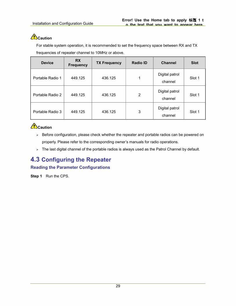
Caution
For stable system operation, it is recommended to set the frequency space between RX and TX
frequencies of repeater channel to 10MHz or above.
Device RX
Frequency TX Frequency Radio ID Channel Slot
Portable Radio 1 449.125 436.125 1 Digital patrol
channel Slot 1
Portable Radio 2 449.125 436.125 2 Digital patrol
channel Slot 1
Portable Radio 3 449.125 436.125 3 Digital patrol
channel Slot 1
Caution
� Before configuration, please check whether the repeater and portable radios can be powered on
properly. Please refer to the corresponding owner’s manuals for radio operations.
� The last digital channel of the portable radios is always used as the Patrol Channel by default.
4.3 Configuring the Repeater
Reading the Parameter Configurations
Step 1 Run the CPS.

Error! Use the Home tab to apply 标题标题标题标题 1 to
the text that you want to appear here. Installation and Configuration Guide
30
Step 2 Click to select the appropriate USB port and click “OK”.
If the CPS does not prompt the window shown below, you need to install the USB driver
“DMR-USBdriverinstaller” first. Restart the CPS when the installation is completed. Please refer
to Digital USB Driver Installation Guide R5.5.pdf for installation guides.
Installation and Configuration Guide Error! Use the Home tab to apply 标题标题标题标题 1 t
o the text that you want to appear here.
31
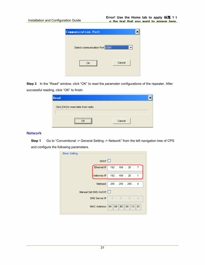
Step 3 In the “Read” window, click “OK” to read the parameter configurations of the repeater. After
successful reading, click “OK” to finish.
Network
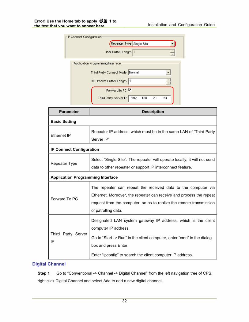
Step 1 Go to “Conventional -> General Setting -> Network” from the left navigation tree of CPS
and configure the following parameters.
Error! Use the Home tab to apply 标题标题标题标题 1 to
the text that you want to appear here. Installation and Configuration Guide
32
Parameter Description
Basic Setting
Ethernet IP Repeater IP address, which must be in the same LAN of “Third Party
Server IP”.
IP Connect Configuration
Repeater Type Select “Single Site”. The repeater will operate locally; it will not send
data to other repeater or support IP interconnect feature.
Application Programming Interface
Forward To PC
The repeater can repeat the received data to the computer via
Ethernet. Moreover, the repeater can receive and process the repeat
request from the computer, so as to realize the remote transmission
of patrolling data.
Third Party Server
IP
Designated LAN system gateway IP address, which is the client
computer IP address.
Go to “Start -> Run” in the client computer, enter “cmd” in the dialog
box and press Enter.
Enter “ipconfig” to search the client computer IP address.
Digital Channel
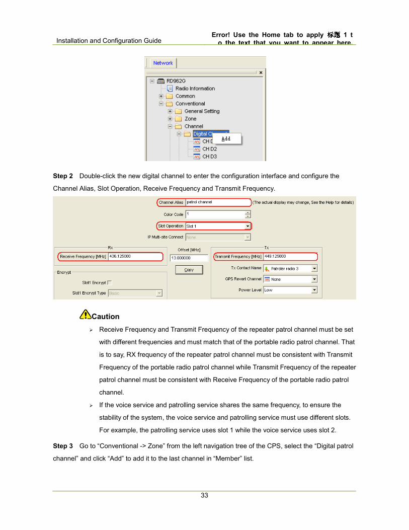
Step 1 Go to “Conventional -> Channel -> Digital Channel” from the left navigation tree of CPS,
right click Digital Channel and select Add to add a new digital channel.
Installation and Configuration Guide Error! Use the Home tab to apply 标题标题标题标题 1 t
o the text that you want to appear here.
33
Step 2 Double-click the new digital channel to enter the configuration interface and configure the
Channel Alias, Slot Operation, Receive Frequency and Transmit Frequency.
Caution
� Receive Frequency and Transmit Frequency of the repeater patrol channel must be set
with different frequencies and must match that of the portable radio patrol channel. That
is to say, RX frequency of the repeater patrol channel must be consistent with Transmit
Frequency of the portable radio patrol channel while Transmit Frequency of the repeater
patrol channel must be consistent with Receive Frequency of the portable radio patrol
channel.
� If the voice service and patrolling service shares the same frequency, to ensure the
stability of the system, the voice service and patrolling service must use different slots.
For example, the patrolling service uses slot 1 while the voice service uses slot 2.
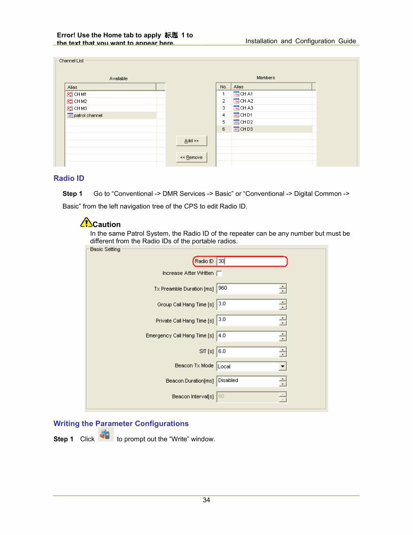
Step 3 Go to “Conventional -> Zone” from the left navigation tree of the CPS, select the “Digital patrol
channel” and click “Add” to add it to the last channel in “Member” list.
Error! Use the Home tab to apply 标题标题标题标题 1 to
the text that you want to appear here. Installation and Configuration Guide
34
Radio ID
Step 1 Go to “Conventional -> DMR Services -> Basic” or “Conventional -> Digital Common ->
Basic” from the left navigation tree of the CPS to edit Radio ID.
Caution In the same Patrol System, the Radio ID of the repeater can be any number but must be different from the Radio IDs of the portable radios.
Writing the Parameter Configurations
Step 1 Click to prompt out the “Write” window.

Installation and Configuration Guide Error! Use the Home tab to apply 标题标题标题标题 1 t
o the text that you want to appear here.
35
Step 2 Click “OK” to start writing the parameter configurations to the repeater.
Step 3 Click “OK” to finish parameter configurations writing.
4.4 Configuring the Portable Radio
This chapter is the same as the mobile radio receiving station. Please refer to 3.4 Configuring the
Portable Radio
for details.
4.5 Configuring the Client
This chapter is the same as the mobile radio receiving station. Please refer to 3.5 Configuring the Client
for details.
4.6 System Testing
This chapter is the same as the mobile radio receiving station. Please refer to 3.6 System Testing
for details.

Error! Use the Home tab to apply 标题标题标题标题 1 to
the text that you want to appear here. Installation and Configuration Guide
36
5. IP Interconnect Solution
5.1 Configuration Flow
Patrol Management System configuration flow of IP Interconnect Solution is as shown below.
Caution
The following configuration must be operated in the administrator account; otherwise, certain
configurations may fail to work.
5.2 Configuration Planning
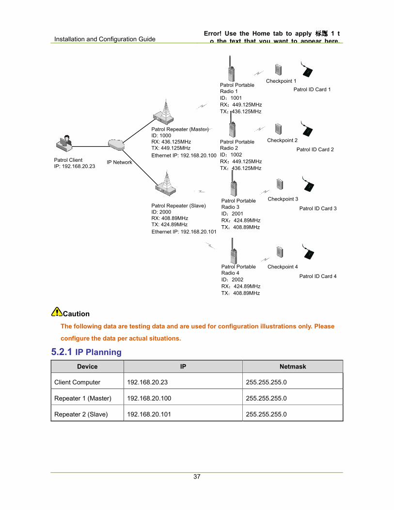
The design case of IP Interconnect Solution is as shown in the figure below.
Installation and Configuration Guide Error! Use the Home tab to apply 标题标题标题标题 1 t
o the text that you want to appear here.
37
Patrol Client
IP: 192.168.20.23
Patrol Repeater (Master)
ID: 1000
RX: 436.125MHz
TX: 449.125MHz
Patrol Portable
Radio 1
ID:1001
RX:449.125MHz
TX:436.125MHz
Patrol Portable
Radio 2
ID:1002
RX:449.125MHz
TX:436.125MHz
Patrol Portable
Radio 3
ID:2001
RX:424.89MHz
TX:408.89MHz
Checkpoint 1
Checkpoint 2
Checkpoint 3
Patrol ID Card 1
Patrol ID Card 2
Patrol ID Card 3
IP Network
Ethernet IP: 192.168.20.100
Patrol Portable
Radio 4
ID:2002
RX:424.89MHz
TX:408.89MHz
Checkpoint 4
Patrol ID Card 4
Patrol Repeater (Slave)
ID: 2000
RX: 408.89MHz
TX: 424.89MHz
Ethernet IP: 192.168.20.101
Caution
The following data are testing data and are used for configuration illustrations only. Please
configure the data per actual situations.
5.2.1 IP Planning
Device IP Netmask
Client Computer 192.168.20.23 255.255.255.0
Repeater 1 (Master) 192.168.20.100 255.255.255.0
Repeater 2 (Slave) 192.168.20.101 255.255.255.0
Error! Use the Home tab to apply 标题标题标题标题 1 to
the text that you want to appear here. Installation and Configuration Guide
38
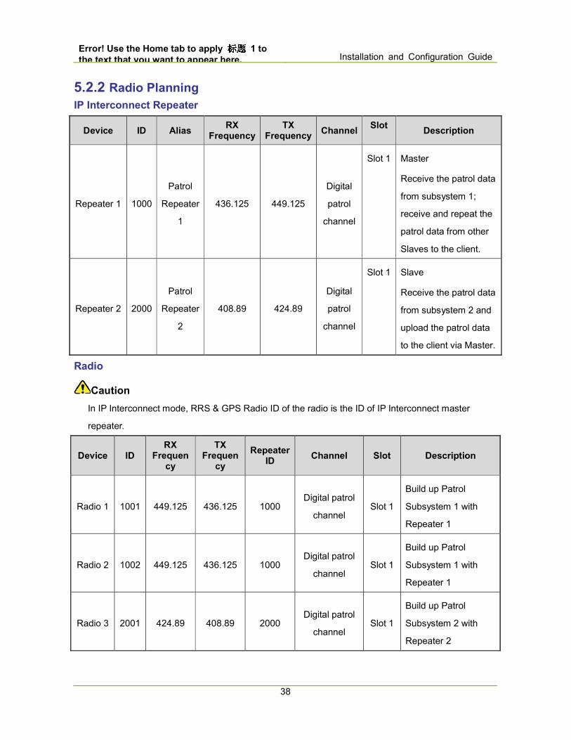
5.2.2 Radio Planning
IP Interconnect Repeater
Device ID Alias RX
Frequency TX
Frequency Channel
Slot Description
Repeater 1 1000
Patrol
Repeater
1
436.125 449.125
Digital
patrol
channel
Slot 1 Master
Receive the patrol data
from subsystem 1;
receive and repeat the
patrol data from other
Slaves to the client.
Repeater 2 2000
Patrol
Repeater
2
408.89 424.89
Digital
patrol
channel
Slot 1 Slave
Receive the patrol data
from subsystem 2 and
upload the patrol data
to the client via Master.
Radio
Caution
In IP Interconnect mode, RRS & GPS Radio ID of the radio is the ID of IP Interconnect master
repeater.
Device ID RX
Frequency
TX Frequen
cy
Repeater ID
Channel Slot Description
Radio 1 1001 449.125 436.125 1000 Digital patrol
channel Slot 1
Build up Patrol
Subsystem 1 with
Repeater 1
Radio 2 1002 449.125 436.125 1000 Digital patrol
channel Slot 1
Build up Patrol
Subsystem 1 with
Repeater 1
Radio 3 2001 424.89 408.89 2000 Digital patrol
channel Slot 1
Build up Patrol
Subsystem 2 with
Repeater 2
Installation and Configuration Guide Error! Use the Home tab to apply 标题标题标题标题 1 t
o the text that you want to appear here.
39
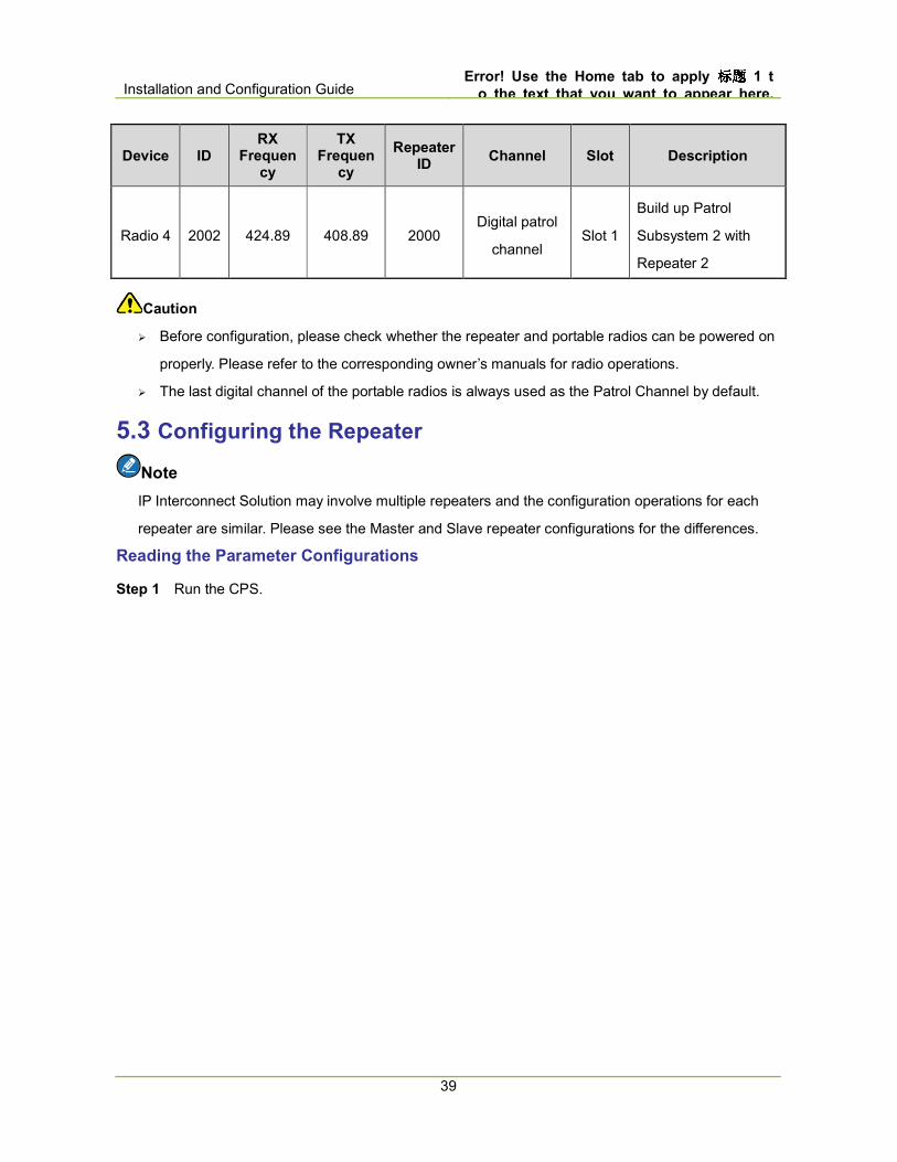
Device ID RX
Frequency
TX Frequen
cy
Repeater ID
Channel Slot Description
Radio 4 2002 424.89 408.89 2000 Digital patrol
channel Slot 1
Build up Patrol
Subsystem 2 with
Repeater 2
Caution
� Before configuration, please check whether the repeater and portable radios can be powered on
properly. Please refer to the corresponding owner’s manuals for radio operations.
� The last digital channel of the portable radios is always used as the Patrol Channel by default.
5.3 Configuring the Repeater
Note
IP Interconnect Solution may involve multiple repeaters and the configuration operations for each
repeater are similar. Please see the Master and Slave repeater configurations for the differences.
Reading the Parameter Configurations
Step 1 Run the CPS.
Error! Use the Home tab to apply 标题标题标题标题 1 to
the text that you want to appear here. Installation and Configuration Guide
40
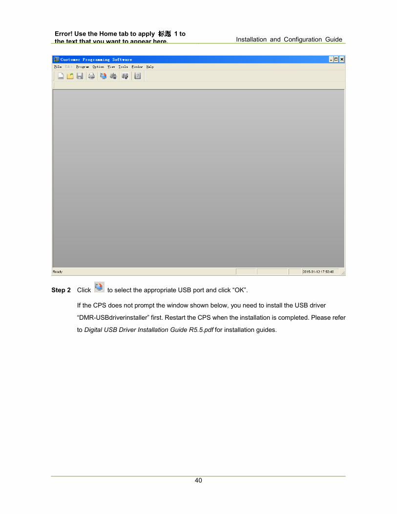
Step 2 Click to select the appropriate USB port and click “OK”.
If the CPS does not prompt the window shown below, you need to install the USB driver
“DMR-USBdriverinstaller” first. Restart the CPS when the installation is completed. Please refer
to Digital USB Driver Installation Guide R5.5.pdf for installation guides.

Installation and Configuration Guide Error! Use the Home tab to apply 标题标题标题标题 1 t
o the text that you want to appear here.
41
Step 3 In the Read window, click “OK” to read the parameter configurations of the repeater. After
successful reading, click “OK” to finish.
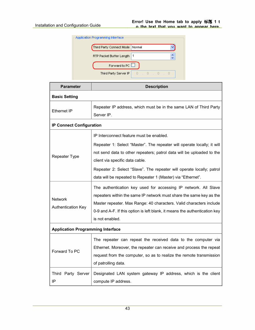
Network
Step 1 Go to “Conventional -> General Setting -> Network” from the left navigation tree of CPS
and configure the following parameters.
� Repeater 1 (Master)

Error! Use the Home tab to apply 标题标题标题标题 1 to
the text that you want to appear here. Installation and Configuration Guide
42
� Repeater 2 (Slave)
Installation and Configuration Guide Error! Use the Home tab to apply 标题标题标题标题 1 t
o the text that you want to appear here.
43
Parameter Description
Basic Setting
Ethernet IP Repeater IP address, which must be in the same LAN of Third Party
Server IP.
IP Connect Configuration
Repeater Type
IP Interconnect feature must be enabled.
Repeater 1: Select “Master”. The repeater will operate locally; it will
not send data to other repeaters; patrol data will be uploaded to the
client via specific data cable.
Repeater 2: Select “Slave”. The repeater will operate locally; patrol
data will be repeated to Repeater 1 (Master) via “Ethernet”.
Network
Authentication Key
The authentication key used for accessing IP network. All Slave
repeaters within the same IP network must share the same key as the
Master repeater. Max Range: 40 characters. Valid characters include
0-9 and A-F. If this option is left blank, it means the authentication key
is not enabled.
Application Programming Interface
Forward To PC
The repeater can repeat the received data to the computer via
Ethernet. Moreover, the repeater can receive and process the repeat
request from the computer, so as to realize the remote transmission
of patrolling data.
Third Party Server
IP
Designated LAN system gateway IP address, which is the client
compute IP address.

Error! Use the Home tab to apply 标题标题标题标题 1 to
the text that you want to appear here. Installation and Configuration Guide
44
Digital Channel
Step 1 Go to “Conventional -> Channel -> Digital Channel” from the left navigation tree of CPS,
right click Digital Channel and select Add to add a new digital channel.
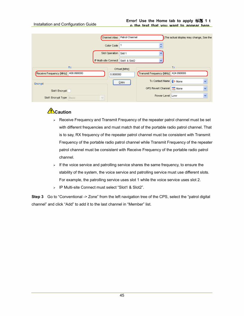
Step 2 Double-click the new digital channel to enter the configuration interface and configure the
Channel Alias, Slot Operation, Receive Frequency and Transmit Frequency.
� Repeater 1 (Master)
� Repeater 2 (Slave)
Installation and Configuration Guide Error! Use the Home tab to apply 标题标题标题标题 1 t
o the text that you want to appear here.
45
Caution
� Receive Frequency and Transmit Frequency of the repeater patrol channel must be set
with different frequencies and must match that of the portable radio patrol channel. That
is to say, RX frequency of the repeater patrol channel must be consistent with Transmit
Frequency of the portable radio patrol channel while Transmit Frequency of the repeater
patrol channel must be consistent with Receive Frequency of the portable radio patrol
channel.
� If the voice service and patrolling service shares the same frequency, to ensure the
stability of the system, the voice service and patrolling service must use different slots.
For example, the patrolling service uses slot 1 while the voice service uses slot 2.
� IP Multi-site Connect must select “Slot1 & Slot2”.
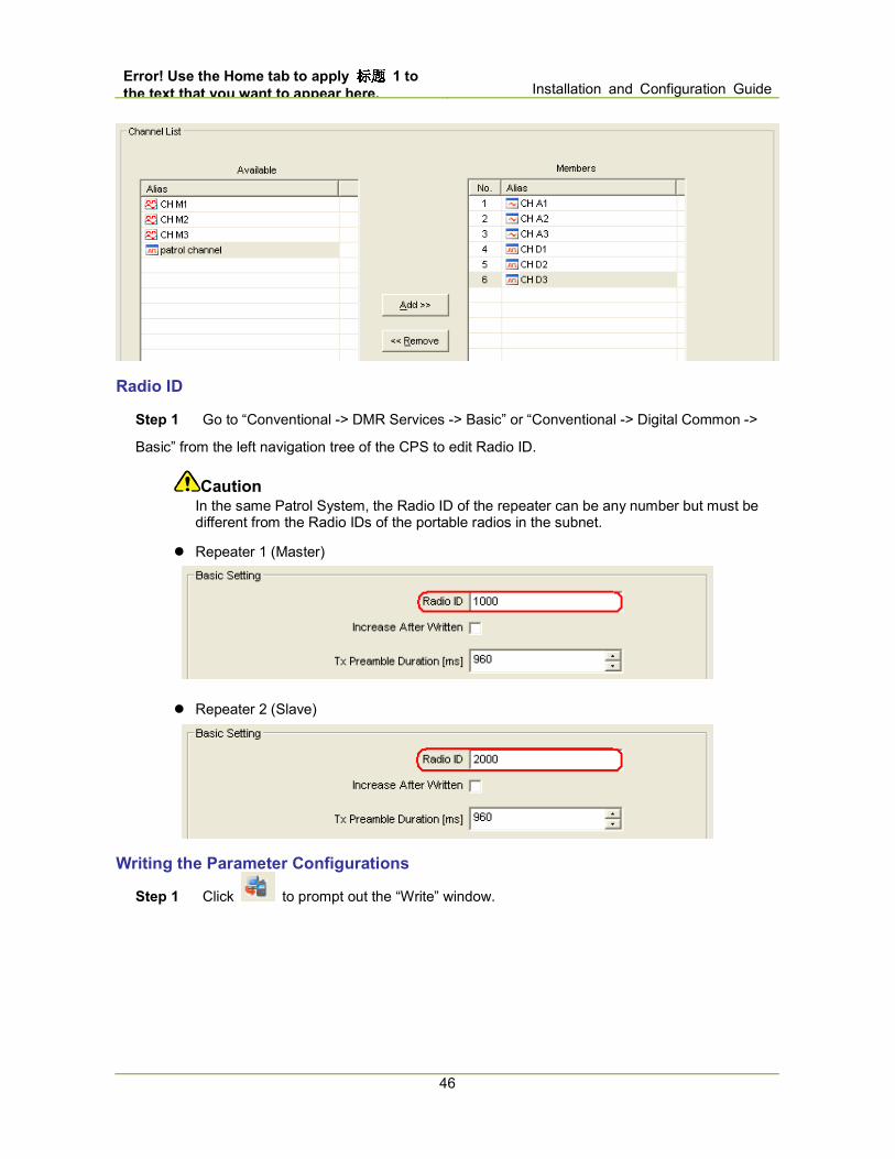
Step 3 Go to “Conventional -> Zone” from the left navigation tree of the CPS, select the “patrol digital
channel” and click “Add” to add it to the last channel in “Member” list.
Error! Use the Home tab to apply 标题标题标题标题 1 to
the text that you want to appear here. Installation and Configuration Guide
46
Radio ID
Step 1 Go to “Conventional -> DMR Services -> Basic” or “Conventional -> Digital Common ->
Basic” from the left navigation tree of the CPS to edit Radio ID.
Caution In the same Patrol System, the Radio ID of the repeater can be any number but must be different from the Radio IDs of the portable radios in the subnet.
� Repeater 1 (Master)
� Repeater 2 (Slave)
Writing the Parameter Configurations
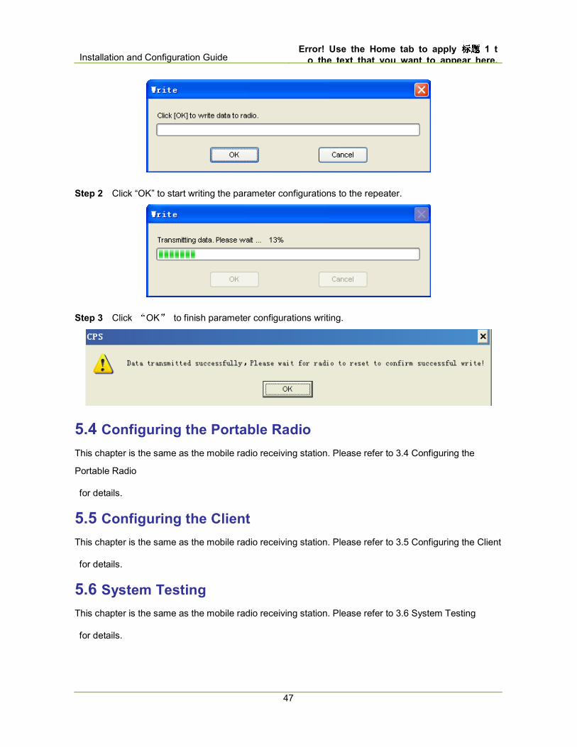
Step 1 Click to prompt out the “Write” window.
Installation and Configuration Guide Error! Use the Home tab to apply 标题标题标题标题 1 t
o the text that you want to appear here.
47
Step 2 Click “OK” to start writing the parameter configurations to the repeater.
Step 3 Click “OK” to finish parameter configurations writing.
5.4 Configuring the Portable Radio
This chapter is the same as the mobile radio receiving station. Please refer to 3.4 Configuring the
Portable Radio
for details.
5.5 Configuring the Client
This chapter is the same as the mobile radio receiving station. Please refer to 3.5 Configuring the Client
for details.
5.6 System Testing
This chapter is the same as the mobile radio receiving station. Please refer to 3.6 System Testing
for details.
Related Documents