HYPERSONIC BOUNDARY LAYER FLOW AROUND A SHARP CORNER Thesis by Andreas Puhl In Partial Fulfillment of the Requirements For the Degree of Aeronautical Engineer California Institute of Technology Pasadena, California June, 1965

Welcome message from author
This document is posted to help you gain knowledge. Please leave a comment to let me know what you think about it! Share it to your friends and learn new things together.
Transcript

HYPERSONIC BOUNDARY LAYER FLOW
AROUND A SHARP CORNER
Thes is by
Andreas Puhl
In P a r t i a l Fulfillment of the Requirements
F o r the Degree of
Aeronautical Engineer
California Institute of Technology
Pasadena, California
June, 1965

ACKNOWLEDGMENTS
The author fee ls a deep sense of grat i tude t o P ro fes so r
Toshi Kubota who suggested and supervised the present experiment
and, through his broad understanding, contributed significantly to
the completion of this research . F o r scientific guidance, personal
encouragement and many stimulating discussions arousing and
cultivating the au thor ' s interest , s incere thanks a r e especially
due to P ro fes so r Les te r Lees. The author a l s o wishes t o express
his gratitude to: Mrs . T r u u s van Harreveld for her invaluable
contribution i n reducing the data mos t carefully and conscientiously,
Mrs. Virginia Conner fo r her able and efficient typing and preparing
of the manuscript , the staff of the GALCIT hyper sonic wind tunnels
under Mr. P. Baloga and especially Mess r s . S. Roman, J. Van Dijk,
G. Van Halewyn and H. Mazurowski for the i r ass i s tance in conduct-
ing the wind tunnel tes t s , and the staff of the Aeronautic s Machine
Shop under G. Carlson, especially Mes s r s. H. McDonald and
6. Baetz for the i r skill in constructing the t e s t equipment.
This investigation was c a r r i e d out under the sponsorship and
with the financial support of the U. S . Army Research Office and the
Advanced Re s e a r c h P ro jec t s Agency, Contract No. DA-3 1- 124-
ARO(D)-33. This r e s e a r c h contract is a par t of Pro jec t DEFENDER
sponsored by the Advanced Research Pro jec ts Agency.

iii
ABSTRACT
An experimental investigation was conducted in the GALCIT
Mach 8 hypersonic wind tunnel, in o r d e r t o study the behavior of an
axisynzmetric hyper sonic laminar boundary l aye r flow undergoing a
rapid expansion a t the juncture of a cone-cylinder body of revolution
a t z e r o angle of yaw. Major emphasis was placed on the acquisition
of detailed da ta nea r the corner where ex t r eme changes in the flow
propert ies w e r e expected. All t e s t s w e r e c a r r i e d out f o r two dif-
ferent r e s e r v o i r p r e s s u r e s but equal total tempera ture . The basic
measurements consis t of the model surface p r e s s u r e and the pitot
p res su re covering the en t i re flow field of interest . These informa-
t ions with ce r t a in assumptions were sufficient to construct the flow
field.
The surface p r e s s u r e distribution is i n total disagreement
with the potential theory f r o m three boundary layer thickne s se s
upstream of the co rne r to about fifteen boundary layer thicknesses
downstream. The expansion i s not concentrated near the corner
but extended over the above-mentioned region which is about one
and a half cylinder radi i long. The p r e s s u r e immediately down-
s t r eam of the c o r n e r is about seven-tenths of the p r e s s u r e on the -
cone, in cons t ras t to the two-tenths as predicted by the potential
theory.

TABLE O F CONTENTS
PART TITLE
Acknowledgments
Abstract
Table of Contents
Lis t of F i g u r e s
Lis t of Symbols
I. INTRODUCTION
II. EXPERIMENTAL APPARATUS AND PROCEDURES
PAGE
i i
i i i
iv
v
vii
1
4
11. 1. Fac i l i t ies
II. 2. Model
11.3. P r e s s u r e Measurements
11.4. Flow Visualization
III. DATA REDUCTION
111. 1. Pitot P r e s s u r e
111.2. Boundary Layer Edge
111. 3. Mach Number and VeLocit y
III. 4. Inviscid Flow
IV. RESULTS
IV. 1. Surface P r e s s u r e
IV. 2. Inviscid Flow Field
IV. 3. Velocity Prof i les
IV. 4. Flow Field in Boundary Layer
V. CONCLUSION
REFERENCES

LIST O F FIGURES
NUMBER PAGE
1 Model Installation in Leg 2 - GALCIT Hypersonic Wind Tunnel 30
2 Drive Mechanism for Pitot Probe 3 1
3 Cone- Cylinder Model 32
4 Schematic Diagram of the Tes t Setup 33
5 Surface P r e s s u r e Distributions 34-36
6 Irnpace P r e s s u r e Profi les 37-46
7 Total P r e s s u r e Prof i les
8 Mach Number Profi les
9 Velocity Prof i les 67-76
10 Static P r e s s u r e Prof i les 77-84
11 Static P r e s s u r e Variation Due to Probe- Body Interference 85
12 Boundary Layer Velocity Prof i les Near Sharp Corner 86-87
13 (Dimensional) Boundary Layer Velocity Prof i les Downstream of Sharp Corner 88-89
14 Boundary Layer Velocity Profi les Downstream of Sharp Corne r 90-91
15 Boundary Layer Velocity Profi les " F a r f ' Down- s t r e a m of Sharp Corner 92-93
16 Total Head Profi les Upstream and Downstream of Sharp Corner 94
17 Flow Field Downstream of Sharp Cone-Cylinder Junc t ur e 95-96
18 Boundary Layer Flow Field Downstream of Sharp Cone- Cylinder Juncture 9 7-98

LIST OF FIGURES (Cont'd)
NUMBER PAGE
19 Flow Field Near a Sharp Cone- Cylinder Juncture . 99- 100
2 0 Total P r e s s u r e Variation Along St ream Lines in Viscous Layer Near Cone- Cylinder Juncture 101 - 102
2 1 Schlieren Photograph of Flow Near Sha rp Cone- C ylinde r Junc tur e 103

LIST O F SYMBOLS
sound speed, ,/zYRT' (ft. / sec. )
c r i t i ca l sound speed (ft. /sec. )
specific heat a t constant p r e s s u r e and constant volume, respect ively
Chapman- Rube s in factor, @ d " m
77%- functions of K
hyper sonic s imi lar i ty parameter , M 8 00
coefficient of the rma l conductivity of g a s
total wetted length of cone
Mach number, v /a
p r e s s u r e
pitot p r e s s u r e
Prandt l number of gas, Cplr/k
G a s constant per unit m a s s
rad ius of cylinder (in. ) .
Reynolds number per unit length (in. - I )
distance along cylinder f rom corne r downstream (in. )
distance along cone f r o m corner ups t ream (in. )
t empera ture (OF relative o r O R absolute)
velocity (ft. /sec. )
wetted dis tance along body f r o m apex (in. )
coordinate no rmal to body surface
ra t io of specific heats,
boundary layer thickness (in. ), a s defined i n P a r t IV. 4
boundary layer displacement thickne s s (in. )

viii
LIST OF SYMBOLS (Cont'd)
cone semi-ver tex angle
ord inary coefficient of viscosity
kinematic viscosity
m a s s density
h personic boundary layer interaction parameter , /mx h13
Subscripts
inviscid quantity a t cone surface
quantity a t the boundary layer edge
quantity a t the surface
quantity at r e se rvo i r conditions
r e f e r r e d to wetted length f r o m apex
quantity a t surface with probe position
quantity a t the boundary layer edge, a s defined in P a r t IV. 4
quantity ahead of normal shock of probe
quantity in the undisturbed flow

I. INTRODUCTION
F o r smooth bodies in slightly viscous flows the theory of
boundary layer is well established. The basic assumption i n the
theory i s that the s t reamwise variations in the flow a r e small compared
to the t r ansve r se gradients in the boundary layer . This assumption
breaks down near a s h a r p leading edge, the t ra i l ing edge of a thin
plate and a s h a r p corner . Many pract ical shapes have a sha rp
corner such a s the junction of a cone-cylinder, the ridge on a
double-wedge airfoil , and the corner a t the bluff base of a finite
cone o r wedge.
It has been observed a t subsonic and low supersonic speeds
that the p resesce of a s h a r p co rne r is felt a few boundary 'Layer
thicknesses upstream in the layer and often the flow sepa ra te s and
reat taches downstream of the corner . Not many extensi ve inves-
tigations have been c a r r i e d out on th is problem either experimentally
o r theoretically because of the difficulties involved and part ly because
of a limited extent of the corner influence in those speed ranges. At
hypersonic speeds, however, the boundary l a y e r s a r e much thicker
compared to those a t low speeds. Also the effects of the boundary
layer on the external flow a r e m o r e pronounced, and often these
must be taken into account in determining the flow in the boundary
layer itself. Thus the co rne r problem can no longer be ignored,
and the present investigation i s a imed toward obtaining experimental
data on the interaction of hypersonic laminar boundary layer with an
expansion caused by a surface slope discontinuity.
* Numbers in parentheses denote re ferences a t the end of the text.

2
Only a limited number of experiments has been c a r r i e d out
on this problem in the past. Murthy and ~ a r n m i t ' ' ) investigated
experimentally the interaction of a turbulent boundary layer with
Prandtl-Meyer expansion a t M = 1.88. They found that the p res -
su re downstream of the corner was initially appreciably higher than
the simple wave theory predicted but gradually approached the
Prandtl-Meyer value about five boundary layer thicknesses down-
s t ream. They c a r r i e d out a charac ter i s t ic calculation for a rota-
tional flow, neglecting the subsonic portion of the init ial profile in
the boundary layer , which agreed qualitatively with the p r e s s u r e
measurements . Sternberg ( 2 ) a t BRL and la te r Zakkay, Tani, Toba
and Mus (3' 4, a t PIBAL studied the flow around a s h a r p convex corner
using a cone- cylinder a t super sonic speeds. They were in te res t ed
mainly in the surface t empera tu res and heat t r ans fe r s , and only a
v e r y l imited amount of fluid dynamical data was obtained. Apparently
in these experiments the boundary l a y e r s were so thin that the su r -
face p r e s s u r e s downstream of the co rne r were in fa i r ly c lose agsee-
ment w i t h the potential theory predictions.
~ a k k a ~ ' ~ ' proposed a flow model attributed to Antonio F e r r i ,
in which the flow over the co rne r within a distance on the order of
the boundary-layer thickness i s divided into th ree par t s ; an inviscid
supersonic layer , an inviscid sublayer and a viscous sublayer adja-
cent to the wall. The flow in the supersonic layer may be analyzed
by the charac ter i s t ic method, and the inviscid sublayer i s t rea ted
as a one-dimensional flow with the assumption' that the p r e s s u r e is

constant a c r o s s the layer . The viscous sublayer i s analyzed by
usual boundary layer techniques, which i s c a r r i e d out in Ref. 3
( 6 ) using a s e r i e s expansion technique suggested by Goldstein and
G'iirtler. * Zakkay et a1 did not c a r r y out the inviscid analyses. In
a recent paper by ~ e i n b a u m ' ~ ' the inviscid rotational super sonic
flow was analyzed, and i t was pointed out that the boundary l aye r
in a region of l a rge wall curva ture can cause la rge depar ture f r o m
the Prandtl-Meyer theory a t hypersonic Mach numbers .
In o rde r to fi l l t h e void of experimental data, the present
investigation was undertaken to m e a s u r e the surface p r e s s u r e dis-
tributions and the pitot p r e s s u r e distributions in the boundary layer
on a cone-cylinder at Mach number 8. F r o m these measuremen t s
the flow field near the co rne r was constructed t o provide a basis
Tor fur ther theoret ical r e s e a r c h on this subject and to augment the
understanding of the phenomena which have eluded t h e ~ r e t i ~ a l de-
scription.
* See, fo r example, Schlichting: Boundary Layer Theory, pp. 158- 159.

11. EXPERIMENTAL APPARATUS AND PROCEDURES
11. 1. Wind Tunnel
The experiment was conducted in the GALCIT 7s' ' X 72"
Hyper sonic Wind Tunnel, Leg No. 2, a t a nominal Mach number of
8. The tunnel is of a continuously operating closed- c i rcu i t type,
with a i r a s the working medium. It i s installed with a symmetr ical ,
flexible-plate nozzle which w a s contoured t o yield uniform flow con-
ditions in the t e s t section. In o r d e r t o avoid liquefaction, the a i r
was heated to 900°F by means of a nichrome-wire heater enclosed
in the supply section ups t ream of the nozzle.
The r e s e r v o i r p r e s s u r e was measured with a Tate-Energy
nitrogen- balanced gage and could be controlled within f 0. 05 psi.
The r e se rvo i r t empera tu re was measured by means of a thermo-
couple located between heater and nozzle and recorded with a n
accuracy of 0.3$.
The f r e e - s t r e a m impact p r e s s u r e w a s recorded with an un-
cer tainty of fO. 03 psi, s o that an accuracy of the Mach number of
f0. 01 resulted.
All t e s t s were c a r r i e d out under steady- s ta te conditions.
Since the tunnel was of the closed-circui t continuously operating
type, sufficient t ime was available to establ ish t h e r m a l and dynam-
ica l equilibrium. No heating o r cooling of the model w a s considered,
so that the data presented in th is repor t a r e for the adiabatic or
no-heat t ransfer case.

The model was kept a t z e r o angle of incidence. T e s t s were
conducted under the following two flow conditions:
A*, M = 7.87 00
ptoo = 264. 3 p. s. i. a.
Ttco = 90O0F.
re^= .49 x 10 6 - - -
B., M = 7.81 00
Ptco = 132.3 p. s.i.a.
Ttoo = 900°F.
R e ~ o o = .257 x
The t e s t section flow was considered uniform over a length
of the 'longitudinal body dimension.
11. 2. Model
The model i s a 10' semi-angle c i r cu la r cone with a cylindrical
afterbody, providing a 10' turning angle around the shoulder. The
dimensions of the s ta in less s tee l model used in the present t e s t s a r e
given in F igure 3 . The frontal a r e a of the cone-cylinder configuration
was l imited to a s ize that would allow the tunnel flow to s tar t .
An optical compara tor examination of the cone showed that the
des i red angle of 10' was within the to le rances shown. The diameter
of the apex was measured and found t o be sufficiently sma l l (Re = ood
100 and 50, respectively) not to invalidate the theoret ical assumption
of a pointed body.

On the model 17 p ressure orif ices with a diameter of 0.0 1 in.
were located a s shown in Figure 3 . F o r the purpose of aligning the
model to the f r e e s t ream flow, four additional orif ices with a diameter
of 0. 02 in. were installed a t 90' intervals around the circumference.
The positions of the surface pressure orifices with respect to the
corner were checked both microscopically and mechanically and found
to be accurate within f O . 00 1 in. To eliminate mutual interference and
a lso for ease of construction, the orifices in the shoulder region had
to be distributed in a sp i ra l form around the body.
11.3. Pre s su re Measurements - In o rder to a s su r e accurate positioning of the probe with re -
spect to the model, after the proper reservoir temperature and r e se r -
voir pressure of the tunnel was reached, sufficient t ime was allowed
(ca. 10 minutes) to permit the instruments in the tes t section to come
to thermal equilibrium.
The four static pressure orifices drilled symmetrically at a
radial c r o s s section of the cone (X/L = 0.68) a r e provided for the
alignment purpose. To account for small flow angle changes mainly
due to a slight dependence of the test section flow on the tunnel stag-
nation conditions, the model supports were adjusted until the p ressures
a t the diametrical locations were equalized.
The model surface p ressures were measured by means of a
bank of Silicone-oil U-tube manometer s, with the reference pressure
maintained at 5 to 10 microns-Hg. The surface p ressures were r e -
corded in almost every run, and several t imes the accuracy of the
pressure reading s was checked by using a Silicone- oil micromano-
meter .
The pitot pressure measurements were obtained by using a
flattened pitot probe. The outer dimensions of i t s forward face were
0. 04 by 0. 004 inches, thus having an aspect ratio of 10. The frontal
height corresponded to about 4$ of the average boundary layer thick-
ness. The probe orifice dimensions were 0.0286 by 0.002 inches,
which limited the t r ave r s e speed to 1/6 inch per hour in the boundary
layer. To provide stiffness the probe was reinforced with a thin
plate with a sharp leading edge and attached to a holder of $ in. outer
diameter. (The drive mechanism of the pitot probe i s presented in
Figure 2. )
By means of a drive mechanism mounted at the top of the
tunnel, the pitot probe was t raversed through the flow field perpen-
dicular to the surface of the body. Downstream of the shoulder the
attitude of the total head probe with respect to the local streamline
direction has been maintained a t an estimated mean value of the
local s t reamline tangents, to minimize the e r r o r caused by the
misalignment of the probe and the flow. The probe position was
accurate to f O . 002 in.
The pitot pressure was converted into an electr ic signal by
means of a p ressure transducer, amplified and plotted against the
probe position on an XY -recorder . Figure 4 shows schematically
the recording set-up. The p ressure transducer was a Statham
PA 208 TC-5-350, which measures absolute p ressure up t o 5 psi.

The direct cu r ren t used t o excite the p r e s s u r e t ransducer was pro-
vided by a Video Instruments, Model SR 200 E, D. C. power supply,
and i t s output w a s adjusted to 5 volts f 1 millivolt, measured by means
of a digital voltmeter, Kintel 501B. The excitation voltage was mea-
sured before, during and af te r every run, and i t was found that af ter
t he power supply had reached constant operational t empera tu re the
voltage was maintained constant during the run.
The s tat ic calibration of the t ransducer against a liquid U-tube
manometer yielded a calibration factor of 323. 2 microvol t s per volt
per c m Hg a t room tempera tu re data given by factory: 328. 9 mic ro -
volts [open c i rcu i t ] per volt pe r c m Hg. Previous tes t s on the lin-
earity, resolution, and repeatabili ty of the same t ransducer indicated
a satisfactory behaviour over the whole p r e s s u r e range involved in
th is experiment. The deviation of the output did not exceed f O . 15% of
the maximum pitot p res su re measured f o r the highest supply p res su re
used in this experiment. Thereafter the significance of the data was
limited by the accuracy of the data plotter.
A Sandborn 1500-860s DC amplifier was used to amplify the
t ransducer s ignals by the factor of 100 and 50 for r e s e r v o i r p r e s s u r e s
of 118 and 250 p. s.i.g. , respectively. A Moseley Model 2 S Autograf
XY-Recorder was used to r eco rd the amplified p r e s s u r e signal a s a
function of no rmal distance f rom body surface.
11.4. Flow Visualization
In o r d e r to supplement the p r e s s u r e measurements , Schlieren
photographs w e r e made for two f ree- s t r e a m Reynolds numbers.

Because of the axi- symmetr ic charac ter of the flow, the Schlieren
effect in the field between the shock and the body w a s understandably
weak. As a re su l t of the increased density variation a t higher supply
p r e s s u r e s the photographs taken at p = 250 p.s.i.g. and Ttm= 9 0 0 ' ~ tco
gave best resolution of the shock wave, the boundary layer edge and
the expansion fan. A Schlieren photograph taken under th i s condition
is shown in F i g u r e 2 1.

111. DATA REDUCTION
111. 1. Pitot P r e s s u r e
Near the wall in the boundary layer the p ressure measured
by the probe i s not equal to the total p ressure of the s treamline aligned
with the probe centerline. The difference comes f rom th ree principal
causes. The f i r s t is that the boundary layer flow is distorted by the
disturbance of the probe. This i s minimized by the use of a small
probe, though, t o the author 's knowledge, no quantitative data a r e
available for this. The second cause i s the fact that, when a probe
i s placed in a shear flow, the stagnation streamline i s not aligned
with the probe axis because of the unsyrnmetry, and the effective
center of the total p ressure is displaced toward the region of higher
velocity. The correct ion given by Young and Maas ( 8 ) fo r a n in-
compressible subsonic fluid is
where 6 is the displacement, dl and d the internal and external dia-
m e t e r s of the probe. This correct ion was obtained with a circular
probe in tl e wake of an airfoil. On the other hand, the experiments
of Davie s ' 9' in laminar boundary l aye r s a t super sonic speeds
showed the displacement in the opposite sense when the probe diameter
i s one-half of the boundary layer thickness o r larger . However, in
the author 's opinion, th is was probably due to the distortion of the
flow caused by the presence of a large probe. In supersonic flow,
Johanne son and Mair ( showed the displacement effect practically
vanished in a wake for M = 1. 96 for probes with the external diameter

twice a s large as the wake half-width. The third cause i s the low
Reynolds number effect. (11, 12913) When the probe Reynolds number
based on the local flow propert ies i s lower than 200 o r so, the total
p ressure measured by the probe i s l a r g e r than the total p ressure
computed by the inviscid flow relation, since the effects of viscosity
a r e no longer negligible.
In the present experiments the displacement effect i s ex-
pected t o be smal l (the order of . O O P inch), iudging f rom the data of
references ( 8) and ( 10 ) - An attempt was made in the present ex-
periments to co r rec t for the effects of the flow distortion and the
viscosity by comparing the velocity profile computed f rom the pitot
p ressure data and the theoretical profile on the cone surface away
f rom the shoulder. The comparison was ca r r i ed out for the two
Reynolds number s of the experiment, and the total p r e s s u r e correction
curve was devised a s a function of the distance f rom the surface nor-
malized by the boundary layer thickne s s and the Reynolds number,
which was used a t a l l other stations. The correct ion was found to be
negligible in the supersonic portion of the boundary layer.
111.2, Boundary Layer Edge - The boundary layer edge may be determined f rom the pitot
p ressure profiles taken on the conical part of the model, since the
pitot pressure i s nearly constant outside the boundary layer . Simi-
larly, the edge could be defined f rom the pitot p ressure curves for
downstream of the shoulder. But around the shoulder the pitot pres-
su re profiles do not show the distinguishable boundary layer edge

since the pitot probe t r a v e r s e s a strong inviscid expansion region
af te r i t has emerged f r o m the viscous layer. (The t h r e e fami l ies
of total head t r a c e s a r e shown i n F igure 16. ) A different method of
finding the boundary layer edge i s therefore necessary, and the fol-
lowing procedure was used to define the boundary layer edge consist-
ently along the whole range of interest . Assuming constant static
p r e s s u r e a c r o s s the boundary layer , the local total p r e s s u r e was
computed (Fig. 7). In regions where the boundary l aye r edge could
be defined f r o m the pitot p r e s s u r e profiles, the total p r e s s u r e a t the
edge of the viscous layer was found to be constant within the experi-
mental accuracy. Hence, in the region around the shoulder the
boundary l aye r edge was defined as the point a t which the compated
total p res su re was equal to the total p r e s s u r e a t the edge as deter-
mined above. The r e su l t s were shown in F igures 17 through 19.
111. 3 , Velocitv and Mach Number Prof i les
On the assumption of constant static p r e s s u r e and total
tempera ture a c r o s s the boundary layer, the Mach number and the
velocity were computed f rom pitot p res su re measuremen t s and the
surface p r e s s u r e readings.
The assumption of constant s ta t ic p r e s s u r e cannot be valid
in the immediate neighborhood of the co rne r because of not negligible
s t reamline curva ture and accompanying p r e s s u r e gradients perpen-
dicular to the s t reaml ines of the o rde r of p v2/r, where r is the
rad ius of curvature. The p r e s s u r e gradients m a y be determined by
an i terat ive procedure. However, th i s has not been c a r r i e d out in

the present work, i n view of the inaccuracy in experimentally de ter -
mined s t reaml ine shapes.
The f i r s t station downstream of the shoulder for which the
above assumption has been made was about one-half boundary layer
thicknesses away f rom the corner . Judging f r o m the calculation of
the static p r e s s u r e in the inviscid flow a s descr ibed in P a r t 111. 4. the
t r ansve r se p r e s s u r e gradients m a y not be negligible near the boundary
layer edge, but i t is expected that the p r e s s u r e gradients decay rapidly
in the boundary layer because of the fas t dec rease of velocity and den-
sity in the boundary layer . It i s thus concluded that the velocity and
Mach number profi les of the f i r s t two to three stations just downstream
of the corner a r e in e r r o r only near the boundary layer edge. At fur-
t he r downstream stations with decreasing s t reaml ine curvature,
Prandt l ' s assumption of constant p r e s s u r e a c r o s s the boundary layer
is believed to be ve ry reasonable.
The velocity profiles were calculated w i t h the a s s m p t i o n of
constant stagnation tempera ture in the ent i re flow field. Since g rea t
difficulties a r e anticipated in carrying out hot wi re measuremen t s
under the present t e s t conditions, no experimental determinat ion of
the tempera ture distribution in the boundary layer was attempted.
111.4. Invi scid Flow
The total head surveys for each station w e r e extended beyond
the boundary layer edge a c r o s s the inviscid region through the shock
wave into the f r e e s t ream.
In portions of the inviscid region, where the flow is unaffected
by the expansion fan originating f r o m the shoulder, the pitot p res su re

profiles show a gradual decrease in p with distance f rom the model. t
This total pressure gradient in the t ransversa l direction i s attributed
to the increasing Mach number in this region associated with the non-
uniform nature of the potential flow over a cone.
The static p ressure in the inviscid region of the expansion
fan was computed using the pitot p ressure profiles and an estimated
total pressure, which was assumed constant throughout.
The latter approximation requires closer scrutiny with regard
to the changes in total pressure caused by a slight curvature of the
shock resulting from the boundary layer interaction. But, judging by
the straightness of the shock in the region where measurements were
carr ied out, no significant entropy gradient a aeros s the inviscid region
near the shoulder a r e expected. The total pressure was obtained from
the pitot p ressure a t the boundary layer edge fa r downstream and up-
s t ream of the corner and f rom the corresponding surface p ressures
(assuming constant static pressure a c ro s s the viscous layer).
IV. RESULTS
IV. 1. Surface P r e s s u r e
Near the cone cylinder juncture the spacing of the orifice
distribution in axial direct ion was kept sufficiently sma l l i n o rde r t o
resolve the p r e s s u r e distribution a s accurately as possible. Because
of very high gradients a t the c o r n e r the measured p r e s s u r e s were
subject t o the e r r o r due t o the finite d iameter of the or i f ices . The
d iameter was 0. 01 in. , over which distance a p res su re m a y change
as much as 0. 2 of p a t the station with the maximum p r e s s u r e g ra - 00
dient. The sca t te r a t this station was l a rges t but did not exceed 3. 5$.
The degree of resolution for the r e s t of the stations was considered
satisfactory. Since i t was pract ical ly imp0 ssible to read the p res su re
a t the co rne r itself, the fairing of the p r e s s u r e curve over the region
f 0.02 inches f r o m the c o r n e r i s somewhat ambiguous. No p res su re
measuremen t s were conducted nea r the ver tex of the cone since the
present work was mainly concerned with the investigation of the flow
in the region of the cone cylinder juncture.
The experimentally found distributions of s ta t ic p r e s s u r e
along the model surface a r e shown in F igures 5a through 5 y . F o r
comparison the p r e s s u r e distributions for inviscid flow and the weak
interaction a r e included.
The inviscid-flow p r e s s u r e for the conical par t of the model
w a s obtained by interpolation of the Kopal tables as presented in
Reference 14. Since the axially- symmetr ic flow around the shoulder
of the present body of revolution is locally a two-dimensional Prandtl-
Meyer expansion, the conditions just downstr e a m of the cone- cylinder

juncture could be obtained f r o m c h a r t s for two-dimensional flow. The
surface p r e s s u r e fur ther downstream of the shoulder could be obtained
by the method of cha rac te r i s t i c s in axially- symmetr ic flow as given
in Procedure LA of Reference 15(Isenberg) and were smoothly faired
to the p r e s s u r e gradient which was calculated fo r the conditions just
downstream of the cone-cylinder juncture using a n approximate pro-
cedure outlined in Reference 16 (Hakkinen).
The boundary-layer induced p res su re on the cone w a s com-
puted on the bas is of Lees ' weak interaction theory, applicable for
laminar hyper sonic flow on a n infinite cone, excluding the strong inter-
action region 'near ' the tip. With the introduction of the hyper sonic
viscous interact ion parameter
where
the induced p r e s s u r e i s given by t h e following algebraic relat ion
The functions F 1 (K) and 2(K) were taken f rom Ref. 18. In the present
c a s e the hyper sonic s imilar i ty pa ramete r was K = 1.37. The Chapman-
Rubesin factor, C, was calculated using Sutherland's formula and the
tempera ture for a n insulated body. F o r the present case, C = 0. 75. 00
The surface p r e s s u r e s were plotted in two ways: fir st, t he
measured p r e s s u r e over f r e e - s t r e a m static p r e s s u r e as a function
of the dis tances ups t ream and downstream of the shoulder where the
dis tances w e r e non-dimensionalized using the radius R of the cylinder

and, second, the same p ressure rat io ve r sus ( s /L) ,/- down-
s t r eam and (-;/L) d T o O upstream of the shoulder, respectively.
L i s the total wetted length of the cone.
According to potential theory the static p ressure along the
cone remains constant until the flow expands around the corner r e -
sulting in a sudden p ressure d rop to some minimum value just behind
the shoulder. Fur the r downstream it approaches the f ree - s t r eam
static p ressure asymptotically. A qualitative comparison of the mea-
sured p r e s s u r e distribution with the inviscid one yields the following
significant r e sult s:
a. The expansion a t the cone-cylinder juncture does have an
upstream effect resulting in significant p ressure changes
within the influence region of 3 to 4 t imes the local boundary
layer thickness. The p ressure disturbance propagates
upstream in the subsonic part of the boundary layer.
b. The p ressure distribution is not discontinuous at the corner
f rom the potential theory and shows a n obvious smoothing
influence of the viscous layer to the flow around a sha rp
corner .
c. Downstream of the corner the surface p ressure is much
higher than the potential theory prediction. The p ressure
drop a t the corner is only one-third of the p r e s s u r e drop
predicted by the Prandtl-Meyer expansion for the inviscid
Mach number a t the cone surface and the expansion angle
a t the corner . The pressure , then, approaches gradually
the f r e e s t r eam value over a distance of s o m e twenty boundary
layer thicknesses.

The following tentative flow model i s proposed to explain the
above observations. The boundary layer flow undergoes a rapid ex-
pansion near the corner . In the main part of the layer the change is
so rapid in the s t reamwise direct ion that the expansion is isentropic.
The viscous effects, however, cannot be neglected everywhere, and
near the surface we must a s sume a viscous sublayer where no s l ip
condition is applied a t the wall.
In the inviscid layer , wherein the viscous effects may be
neglected, the t r a n s v e r s e p r e s s u r e gradient may not be neglected.
Then, in the region near the corner , the ma jo r par t of the p r e s s u r e
variation i s obtained f r o m the expansion of inviscid, non-uniform,
rotational, flow. The solution of this problem is not an easy task,
because the flow is subsonic in some pa r t s and supersonic in other.
Some indication of the plausibility of th is model is provided f rom the
observation that the surface p r e s s u r e in the region nea r the corner
a g r e e s fair ly well with the charac ter i s t ic solution for rotational flow
in the supersonic region. * F u r t h e r downstream the computed p res -
su re fal ls below the measured p res su re , indicating that the viscous
effect must be taken into account not only in the viscous sublayer but
a l s o in the outer layer away f r o m the co rne r .
Plotting the surface p r e s s u r e distribution against the distance
normalized by d-% (Fig. 5 y ) shows that i t sca les with the boundary
layer thickness.
* The numer ica l solution based on the charac ter i s t ic method for rotational flow was kindly furnished by Dr. J. T. Lee at the TRW Space Technology Laboratory. The body contour used in the calcula- tion was the experimentally determined s t reaml ine with slightly super - sonic init ial speed, and s o was the init ial velocity profile ahead of the corner .

IV. 2 . Inviscid Flow Field
It is a well known fact that the supersonic flow past a conical
body will have constant physical proper t ies along straight l ines emi-
nating f r o m the ve r t ex of the cone. In hypersonic flow, however, not
the ent i re field f r o m the body surface to the shock c a n be t rea ted as a
conical flow, since the strong boundary layer displacement effect
f o r m s a new "effective" body shape giving r i s e to considerable changes
of the inviscid region. Because of the strong interaction the shock
near the t i p is considerably curved and thus the flow c e a s e s to be
conical.
It is, nevertheless , believed that m o s t of the s t reaml ines
crossing the ma in portion of the curved par t of the shock a r e contained
in the viscous layer by the t ime they reach the corner .
F i g u r e s 17 's show the i soba r s in the inviscid flow region com-
puted f rom the pitot p res su res . The measured pitot p r e s s u r e d is t r i -
butions were found to define quite distinctly the ups t ream boundary of
the expansion fan. It i s s t raight a s f a r as can be determined experi-
mentally and seen t o in te rsec t the boundary layer edge direct ly above
the corner (Fig. 19). In the boundary layer ahead of the corner , if we
take the beginning of the expansion a t the point where the surface p res -
s u r e s t a r t s decreasing (about two boundary-layer thicknesses ahead of
the co rne r ) and t r a c e the Mach waves f r o m th i s point in the super sonic
portion, i t a l s o in t e r sec t s t h e boundary layer edge direct ly above the
corner , giving some support to the flow model proposed i n the previous
section.

In F igure 10 s tat ic p res su re profiles a r e shdwn f o r different
stations downstream of the corner . The p r e s s u r e var iat ion i n the
inviscid region i s represented as a dashed line. The par t which i s
continued into the viscous layer has obviously no validity due to the
rapid total p r e s s u r e change there. On the other hand, the constant
p r e s s u r e approximation in the viscous layer is not quite co r rec t
everywhere in the layer. Near the outer edge the re will be an appre-
ciable gradient, and the actual p r e s s u r e distribution m a y look like
the curve labelled "probable distribution. " In fact, f r o m the t rans-
v e r s e momentum equation in the boundary layer we should expect a n
appreciable p r e s s u r e gradient nea r the outer edge. F r o m the mornen-
turn equation
ap av ay = - P U x
aV + (viscous t e r m s ) - P V a y
Introducing the following dimensionless var iab les
- - x = X/L, y = y/6
- - u = u/ue, v = v/(6 ue/L) - - P = P/P,, P = P/P, .
we obtain
a? L t- (viscous t e r m s ) b2 ~e 1.
Hence, unless M ~ S / L - 0, aF/ay will not vanish. However, dynami-
cally the p r e s s u r e gradient i s s t i l l negligible when b/L + 0, since the
proper normalization quantity i s the dynamic pr e s s u r e, not the static
' pressure , when the dynamic effect is considered. The above relation
shows a l so that the p r e s s u r e gradient d e c r e a s e s rapidly toward the
surface because 7 approaches z e r o and the o r d e r of magnitude of 'i; becomes away f rom the edge.

IV. 3. Velocity Profiles
In Figures 9a through 9j velocity profiles for severa l stations
a r e shown both in corrected and uncorrected form. The technique to
correc t the original data i s described in Pa r t 111. 1. The velocity was
non-dimensionalized by dividing the value a t the boundary layer edge
defined in P a r t 111. 2.
The fact that self-similar profiles could be expected up-
s t ream of the shoulder unaffected by the expansion prompted the
normalized plot using the squar e-root of the f ree- s t r eam Reynolds
number based on the wetted distance of the particular location from
the apex of the cone. Figures 9a and 9b, representing stations on the
cone, of which the la t ter one l ies just upstream of the expansion fn-
fluence, show the similari ty a s predicted by theory.
Even though downstream of the corner J K loses i t s sig-
nificance a s a s imilari ty parameter, the same non- dimensionalization
of the velocity profiles a s indicated above has been employed for al l
stations consistently.
The profiles cease to be similar after the flow has undergone
the expansion near the corner . The profiles show no resemblance to
the ones in the undisturbed region on the cone.
The strong favorable pressure gradient downstream of the
corner accelerates the flow near the wall more than the flow away
from the wall; namely, the velocity profile becomes fuller. This be-
havior i s consistently more apparent at the lower Reynolds number.
No quantitative theoretical comparison can be made because of lack
of solutions t o the boundary layer equations appropriate t o the present
flow characteris t ics .

In F i g u r e s 14a and 14P normalized velocity profi les down-
s t r e a m of the c o r n e r a r e plotted v e r s u s 7/6. This plot d isp lays
c lear ly the t rend of the profile variation with the distance f r o m the
shoulder. A strong acce lera t ion of the flow in the inner region of
the boundary layer per s i s t s up t o about S/R = 0. 5. About eight local
boundary l aye r th icknesses downstream of the co rne r the p r e s s u r e
gradient decayed sufficiently, resulting in a decreased velocity g ra -
dient a t the wall.
In F i g u r e s 15a and 15P th ree "far" downstream stations being
about 1 to 2 boundary layer th icknesses apar t f r o m each o ther show
very little change in their charac ter . The profiles a lmost coincide
and may thus be called quasi self- s imilar . The fact that the flow
takes long dis tances in recovering to the init ial Blasius- like profile
af ter it has undergone an interaction with a n expansion fan may be
attributed to the slow p rocess of diffusion, spreading into the par t
of the boundary l aye r of higher Mach number. This tendency of the
flow seems to a f f i rm the ea r l i e r mentioned flow model containing a
strongly viscous sublayer with i t s origin a t the corner .
Through the presentation of the velocity profiles in dimen-
sional fo rm ( F i g u r e s 13a and 13p), it i s intended to display the change
of the profiles both near the surface and close to the boundary layer
edge for subsequent locations downstream of the cone- cylinde r junc-
ture . Strong changes in the charac ter of the cu rves a r e - a s expected - m o r e pronounced nea r the shoulder, and become l e s s fur ther down-
s t ream, away f rom the dis turbance region. F o r the l a s t t h r e e stations
the surface p r e s s u r e gradient i s a lmost zero.

In F igures 12a and 12P velocity profiles upstream and down-
s t r e a m of the corner a r e presented in o rde r to bring to light the
severe difference in their character . Even for a "far" downstream
station the velocity does not recover to the Blasius form. A m o r e
pronounced deviation a t the s a m e stations i s to be expected for lower
reservoi r p r e s s u r e s since the lfrelaxation" distance af ter the expan-
sion will cer tainly be proportional to some power of the boundary
layer thickness.
Using one of the flow conditions of the present test , the Crocco
solution of the compressible boundary layer equations fo r a flat plate
was computed for the purpose of comparing with the experimental
curves. In Fig. 12a it i s shown that the theoretical resul t compares
favorably with the s imilar profile measured on the cone.
IV.4. F lowFie ld inBoundaryLayer
An attempt w a s made to construct f rom the measurements
the complete flow field of the boundary layer near the cone-cylinder
juncture, in o r d e r t o shed some light on theoretical analyses. Fig-
u r e s 19a and 19p show a resulting picture of the longitudinal section
of the boundary layer flow field in the region of about one boundary
layer thickness upstream and four boundary layer thicknesses down-
s t ream of the corner . In this representation, the y-coordinate has
not been stretched in o rde r t o avoid the distortion. The plot contains
seven s t reamlines and an equal number of constant Mach lines. The
boundary layer edge and the initial expansion wave have been included
for the completeness of the picture.

The s t reaml ines were chosen such that a t the station
S - = 0. 1397 they in tersec t the constant Mach lines. This a r r ange - R
ment has the advantage of indicating strikingly the smal le st velocity
changes the flow experiences during the co rne r expansion.
Most of the accelerat ion p rocess occur s in a range of about
one and a half boundary layer thicknesses downstream of the corner .
The re the s t reaml ines tend t o turn by a higher angle than the turning
angle of the solid boundary. This behavior is m o r e pronounced for
s t reaml ines nea r the wall. At this t i m e i t is not cer ta in whether th i s
is the c o r r e c t picture of the flow o r the e r r o r introduced by the in-
accurac ies in the measuremen t s and data reduction procedures .
Following s t s e a l i n e s i t is observed that the velocity keeps
increasing to about four boundary layer thicknesses in the subsonic
par t and to about s ix boundary l aye r thicknesses downstream of the
shoulder nea r the edge of the boundary layer . Fur the r downstream
no significant velocity change occur s in the outer region indicating
a minor importance of the shea r fo rces in this part. Below the
M = 2. 5 line, however, the par t ic les on s t reaml ines gradually dec rease
their velocity while traveling downstream. This dec rease i s m o r e
pronounced in the region near the wall. Such a behavior is consistent
with the idea of viscous sublayer near the wall. F igures 20a and 2Op
exhibit the changes of total p r e s s u r e along the s t reaml ines near the
corner . The total p r e s s u r e was non-dimensionalized by the total
p r e s s u r e s corresponding to the part icular s t reaml ines a t the station
- - S/R = 1.85. Since the boundary layer thickness plays a n im-
portant ro le as a scaling parameter , the value of 6 a t the corner has

been used to normalize the longitudinal distance along s t r eamline s.
La rge changes in total p r e s s u r e occur along s t reaml ines
close to the body surface when passing over the shoulder. The
s t reamline in the subsonic portion suffers a total p r e s s u r e lo s s of
about 50% of the re ference total p res su re over a dis tance of five
boundary layer thicknesses. Along the s t reaml ines in the outer par t
of the boundary layer the to ta l -pressure gradient near the shoulder
is not l a r g e r than in any other region.
F igure 18 shows the flow field fur ther downstream and
demonst ra tes the rapid growth of the boundary l aye r in the region
extending f r o m the corner to th ree boundary l aye r thicknes se s down-
s t ream.
It s e e m s noteworthy that near the corner the subsonic layer
amounts to 25% and 20s of the corresponding boundary l aye r thickness
6 - 1 for the f r e e - s t r e a m Reynolds numbers 0. 1042 X 10 in and 0.05314
- 1 x 1 0 ' ~ in , respectively, indicating that the subsonic portion is by no
means negligible a t leas t for the insulated wall.

V. CONCLUSIONS
F r o m the resul t s obtained in the present study the following
conclusions may be drawn regarding the hypersonic boundary layer
around a sha rp expansion corner :
1. The surface p r e s s u r e distribution bears no resemblance to
the inviscid p ressure distribution predicted by simple wave theory.
I t s behavior can be partially explained by the mechanism of isentropic
expansion of the rotational flow in the boundary layer.
2 . The Prandtl-Meyer expansion fan in the external flow i s not
centered at the corner . At the boundary layer edge i t i s spread over
severa l boundary layer thicknesses.
3. A rapid thickening of the viscous layer is observed about one
boundary layer thickness downstream of the shoulder.
4. The velocity gradient near the body surface downstream of the
corner becomes large, indicating a layer of increased shear near the
surface. Recovery to Blasius profiles downstream of the shoulder
requi res a distance of many boundary layer thicknesses.
In the present investigation a few assumptions were made in
the data reduction some of which a r e in contradiction with the experi-
mental observations. In order to obtain m o r e reliable resul ts , the
following refinements a r e recommended:
1. A systematic study be made on the disturbance caused by the
pitot probe and the necessary correct ions for the pitot p ressure readings
in the boundary layer near the solid wall.

2 7
2. The tempera ture distributions be measured in the boundary
layer.
3. A variation of the s tat ic p r e s s u r e be included in the data
reduction especially nea r the corner . It is an a lmost impossible
t a sk to m e a s u r e direct ly the p r e s s u r e distribution i n the layer , and
perhaps an i te ra t ive technique can be used for estimating the s tat ic
p r e s s u r e gradients .
The present study suggests fu r the r inyestigations on the
effects of (1) the variation of the corner expansion angle; ( 2 ) surface
cooling; (3 ) rounding-off the corner , and extensions to the two-
dimensional flows and the f r ee - expansions suck as backward facing
s teps and bluff bases.

REFERENCES
1. Murthy, K. R. A. : "Investigation of the Interaction of a Turbulent Boundary Layer with Prandt l-Meyer Expansion F a n s a t M = 1.88," Princeton Univ., Dept. of Aero. Engrg., Report 403, November 1957. .
2. Sternberg, J. : "The Transi t ion F r o m a Turbulent t o a Laminar Boundary Layer , I ' Ball ist ic Resea rch Laborator ies , Aberdeen Proving Ground, Report No. 906, May 1954.
3. Zakkay, V. and T. Tani: "Theoretical and Experimental Inves- tigation of the Laminar Heat Transfer Downstream of a Sharp Corner , " Polytechnic Inst. of Brooklyn, Dept. of Aerospace Engrg. and Appl. Mech., PIBAL Rept. No. 708, ~ c t o b e r 1961.
4. Zakkay, V., Toba, K. and Kuo, T. J. : "Laminar, Transitional, and Turbulent Heat Trans fe r a f te r a Sharp Convex Corner , " AIAAJour . , Vol. 2, No. 8, pp. 1389-1395, Aug. 1964.
5. Zakkay, V. : "Heat Trans fe r a t a Corner , " Jour . of the Aero. Space Sci., Vol. 27, No. 2, pp. 157-158, Feb. 1960.
6. Goldstein, S. : "Concerning Some Solutions of the Boundary Laye r Equations in Hydrodynamic s, I f Proceeding s of the Cambridge Philosophical Society, Vol. 25, P a r t I, pp. 1-30, 1930.
7. Weinba~rn , S. : "The Rapid Expansion of a Supersonic Shear Flow, I ' Avco-Everett Research Report 204, Jan. 1965.
8. Young, A. D. and Maas, J. N. : "The Behavior of a Pitot Tube in a T r a n s v e r s e Total P r e s s u r e Gradient, " Aeronautical Resea rch Council, London, Rep. and Mem. No. 1770, 1936.
9. Davies, F. V. : "Some Effects of Pitot Size on the Measurement of Boundary Layer s in Super sonic Flow, " Royal Aircraf t Establishment, Farnborough, Tech. Note No. AERO. 2179, Aug. 1952.
10. Johannsen, N. H. and Mair, W. A. : "Experiments with Large Pitot Tube i n - a Narrow Supersonic Wake," Jour. of Aero- nautical Sciences, Vol. 19, No. 11, pp. 785- 787, Nov. 1952.
11. Sherman, F. S. : "New Experiments on Impac t -P ressu re Inter- pretat ion i n Supersonic and Subsonic Raref ied Air Stream, " NACA TN 2995, 1953.

12. Matthews, M. L. : "An Experimental Investigation of Viscous Effects on Static and Impact P r e s s u r e P robes in Hyper sonic Flow. GALCIT Hypersonic Research Pro jec t Memo No. 44, June 1958.
13. Potter, J. L, and Bailey, B. : " P r e s s u r e s in the Stagnation Regions of Blunt Bodies in the Viscous-Layer to Merged- Layer Regimes of Rarefied Flow, " von Karman Gas dynam- i c s Facili ty, ARO, Inc., Technical Documentary Report NO. AEDC-TDR-63-168, Sept. 1963.
14. Sims, J. L. : "Tables for Super sonic Flow Around Right Ci rcular Cones a t Z e r o Angle of Attack, ' I NASA SP- 3004, 1964.
15. Isenberg, J. S. : "The Method of Charac ter i s t ics in Compressible Flow, " P a r t I. Steady Supersonic Flow. Air Mater ia l Com- mand Technical Report No. F -TR- 11 73A-ND, December 1947.
16. Hakkinen, R. J. : "Further Re su1t.s on Supersonic Flow Near Convex Corners , " Douglas Report SM-35992, March 22, 1960.
17. Hakkinen, R. J. : "Supersonic Flow Two-Dimensional. and Axially- Symmetr ic Convex Corne r s an'd Curvature Discon- t inuities, I ' Douglas Report No. SM- 27747, July 15, 1958.
18. Probstein, R. F. : "Interacting Hyper sonic Laminar Boundary Layer Flow Over a Cone, " Technical Report A F 2798/1, Div. of Engrg., Brown Univ., Providence, R. I., March 1955.

Figure 1. Model Insta l la t ion in Leg2-GALCIT Hypersonic Wind Tunnel

Figure 2 . D r i v e Meshonism for Pi $ o t Probe

0 0 0 0 L o " ? " ? " ?

I------ 1
TRANSDUCER
HYPERSONIC WIND TUNNEL
FIG.4. SCHEMATIC DIAGRAM OF THE TEST SETUP


FIG. 5P. SURFACE PRESSURE D l STRl BUTION


F 16.6~1. IMPACT PRESSURE PROFILES AT- S = 1.5 IN.


0 UNCORRECTED CORRECTED (NEAR WALL)
FIG. 7a. TOTAL PRESSURE PROF1 LES AT - 3 = I .% 1 N.

FIG. 7b. TOTAL PRESSURE PROF1 LES AT -T = , 15 IN.

FiG.7c, TOTAL PRESSURE PROFILES AT s =.0766 IN.

FIG. 7d. TOTAL PRESSURE PROFILES AT s = ,I 132 IN.

FIG.7e.TOTAL PRESSURE PROFILES AT s =.2317lN.

0 4 8 12 16 20 FlG.7f. TOTAL PRESSURE PROFILES AT s = 317 IN,

FIG. 79. TOTAL PRESSURE PROFILES AT s = .497 IN.

FIG. 7%. TOTAL PRESSURE PROFILES AT s = 1.225 IN

. FIG.7i. TOTAL PRESSURE PROFILES AT s=1.48 IN.

0 4 8 12 16 20 24
FIG. 7j. TOTAL PRESSURE PROFILES AT s = 1.68 IN.

0 .2 .4 .8 1 .O
' FIG. 8a. MACH NUMBER PROFILES AT--"s 1.5 IN.

FIG. 8b. MACH NUMBER PROF1 L E S AT-T = .I5 IN,

FIG. 8c. MACH NUMBER PROFILES AT s =.0766 IN.

,2 -4 .6 1 .o
FIG, 8d. MACH NUMBER PROFILES AT s=.1132 IN.

F16.8e. MACH NUMBER PROF1 LES AT s =,2317 IN.

20
CORRECTED (NEAR WALL)
A UNCORRECTED 16 --- CORRECTED (NEAR WALL)
12
8
4
0 0 .2 .6 .8 1 .O
FIG. 8f. MACH NUMBER PROFILES AT s = .317 IN.

FIG. 89. MACH NUMBER PROF1 LES AT' s = ,497' IN.

FIG. 8h. MACH NUMBER PROFILES A4 s = 1.225 I N

FIG. Bi. MACH NUMBER PROFILES AT s = 1 .4 8 IN.

FIG. 8j. MACH NUMBER PROFILES AT s = 1.68 IN.

FIG.9a.VELOCiTY PROFILES AT-S=1.5 IN.

F1Ga9b. VELOCITY PROFILES AT-'S =.151N

FIG.9c.VELOClTY PROFILES AT s=.0"P611N,
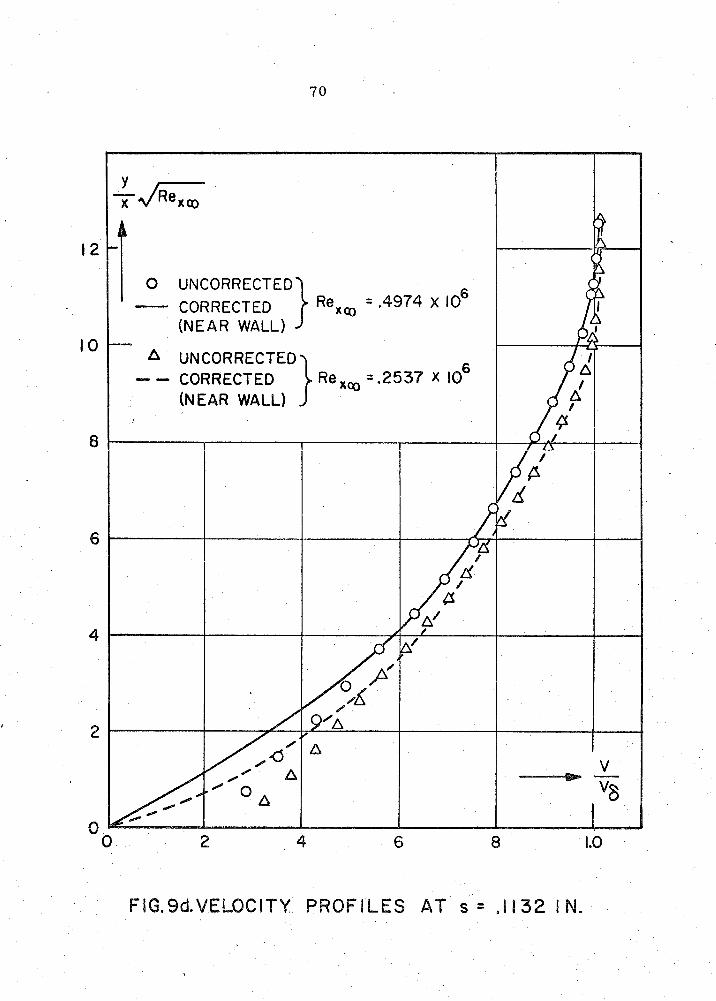
FIG.9d.VELOCITY PROFILES AT s = .I 132 I N.

0 UNCORRECTED _I___ CORRECTED )Rexm z.5097 X I0
(NEAR WALL)
UNCORRECTED -- CORRECTED } =.2597 x lo6 (NEAR WALL)

0 UNCORRECTED ___I) CORRECTED (NEAR WALL)
UNCORRECTED , --- CORRECTED (NEAR WALL)
FIG.Sf. VELOCITY PROFILES AT s = .3 17 IN.

0 UNCORRECTED - CORRECTED
0 .2 .8 1 .O

-CORRECTED
A UNCORRECTED
FIG.9h.VELOCITY PROFILES AT s = 1.225 IN.

FIG. 9 i. VELOCITY PROFILES A T s = I . 4 48 IN.

0 UNCORRECTED
A UNCORRECTED
FIG. 9 j VELOCITY PROFILES AT s = 1.68 IN.


FIG. IOdpe STATIC PRESSURE PROF1 L E AT S = . l 132 IN.


FIG. I0 fa STATIC PRESSURE PROFILE AT S = .317 IN.

FIG. IOfg. STNIC PRESSURE PROFILE AT s = ,317 IN.


FIG. logp. STATIC PRESSURE PROFILES AT ~ ~ 4 9 7 IN,


FIG. 12a, BOUNDARY LAYER VELOCITY PROFILES NEAR SHARP CONE- C Y L I N D E R JUNCTURE AT M,=7.87

FIG.1WBOUNDARY LAYER VELOCITY PROFILES NEAR SHARP CONE-CYLINDER JUNCTURE AT Mrn'7.8 1


FIG 13P.BOUNDARY L A Y E R V E L O C l T Y PROF1 L E S D O W N S T R E A M O F SHARP CONE-CYLINDER - J U N C T U R E A T Ma 17.81

FIG. 1 4 ~ . BOUNDARY LAYER VELOCITY PROFILES DOWNSTREAM O F SHARP CONE-CY L INDER JUNCTURE A T Mrn.7.87

FIG. 146- BOUNDARY LAYER VELOCITY PROFILES DOWNSTREAM OF SHARP CONE-CVLI NDER JUNCTURE A T Ma=7.81

FIG. ISa.VEbOCI TY PROF1 LES '"FAR" "DOWNSTREAM OF SHARP CORNER AT Ma. 7.87

FIG 15P. V E L O C I T Y PROF1 LES "FAR" DOWNSTREAM O F SHARP CORNER A T M r n z 7 . 8 1


. FIG.17a. FLOW DOWNSTREAM O F S H A R P CONE- CYLINDER JUNCTURE AT Mrn'7.87

FIG.17P. FLOW DOWNSTREAM OF SHARP CONE- CYLINDER JUNCTURE AT Mrnz7.81

FIG. 18a. FLOW DOWNSTREAM OF SHARP CONE-CYLI NDER JUNCTURE AT M, = 7.87

JUNCTURE, AT M m = 7.81


FIG. 20P. TOTAL PRESSURE VARIATION ALONG STREAM LINES IN VISCOUS LAYER NEAR CONE-CYLINDER JUNCTURE AT M, = 7.81

Figure 2 1 . Schl i e ren Photograph sf Flow Around Sharp Cone -Cy l inder
Juncture f o r ReR,= .Of3445 x lo6 and M, = 7.87
Related Documents