Hyper-light Architecture: Composite Tower for Hong Kong 3effrey Tsui Bachelor of Science in Civil Engineering Columbia University, New York, NY 1997 Submitted to the Department of Architecture in partial fulfillment of the requirements for the degree of Master of Architecture at the Massachusetts Institute of Technology, February 2001. signature of authose Jeffrey Tsui Department of Architecture January 19, 2001 Peter Testa' Associate Professor of Architecture Thesis Supervisor acgeI4ed byf I Roy Strickland Principal Research Scientist in Architecture Chairman, Departme ate Students 0F TECHNOLOGY I JUL 2 4 2001 V ROTCi. UIBRARIES RTC © 2001 JEFFREY TS I. All rights reserved. The author hereby grants to MIT permission to reproduce and to distribute publicly paper and electronic copies of this thesis document in whole or in part.

Welcome message from author
This document is posted to help you gain knowledge. Please leave a comment to let me know what you think about it! Share it to your friends and learn new things together.
Transcript
Hyper-light Architecture:Composite Tower for Hong Kong
3effrey Tsui
Bachelor of Science in Civil EngineeringColumbia University, New York, NY 1997
Submitted to the Department of Architecture in partialfulfillment of the requirements for the degree of Master ofArchitecture at the Massachusetts Institute of Technology,February 2001.
signature of authose
Jeffrey TsuiDepartment of ArchitectureJanuary 19, 2001
Peter Testa'Associate Professor of ArchitectureThesis Supervisor
acgeI4ed byf I
Roy StricklandPrincipal Research Scientist in ArchitectureChairman, Departme ate Students
0F TECHNOLOGY I
JUL 2 4 2001 V
ROTCi.UIBRARIES RTC
© 2001 JEFFREY TS I. All rights reserved.The author hereby grants to MIT permission to reproduce andto distribute publicly paper and electronic copies of this thesisdocument in whole or in part.

thesis supervisor:
Peter TestaAssociate Professor of Architecture, MIT
thesis readers:
William 3. MitchellDean, School of Architecture and PlanningProfessor of Architecture and Media Arts and Sciences, MIT
Takehiko Nagakura21 Associate Professor of Design and Computation, MIT
3. Kimo GriggsLecturer in Architecture, GSD, Harvard
thesis consultants:
Shi-Chang WoohAssociate Professor of Civil and Environmental Engineering, MIT
3ohn E. FernandezAssistant Professor of Building Technology, MIT
Natalia CardelinoLecturer in Building Technology, MITProject Structural Engineering, Ove Arup and Partners, Boston

LU.UJ cover image 13
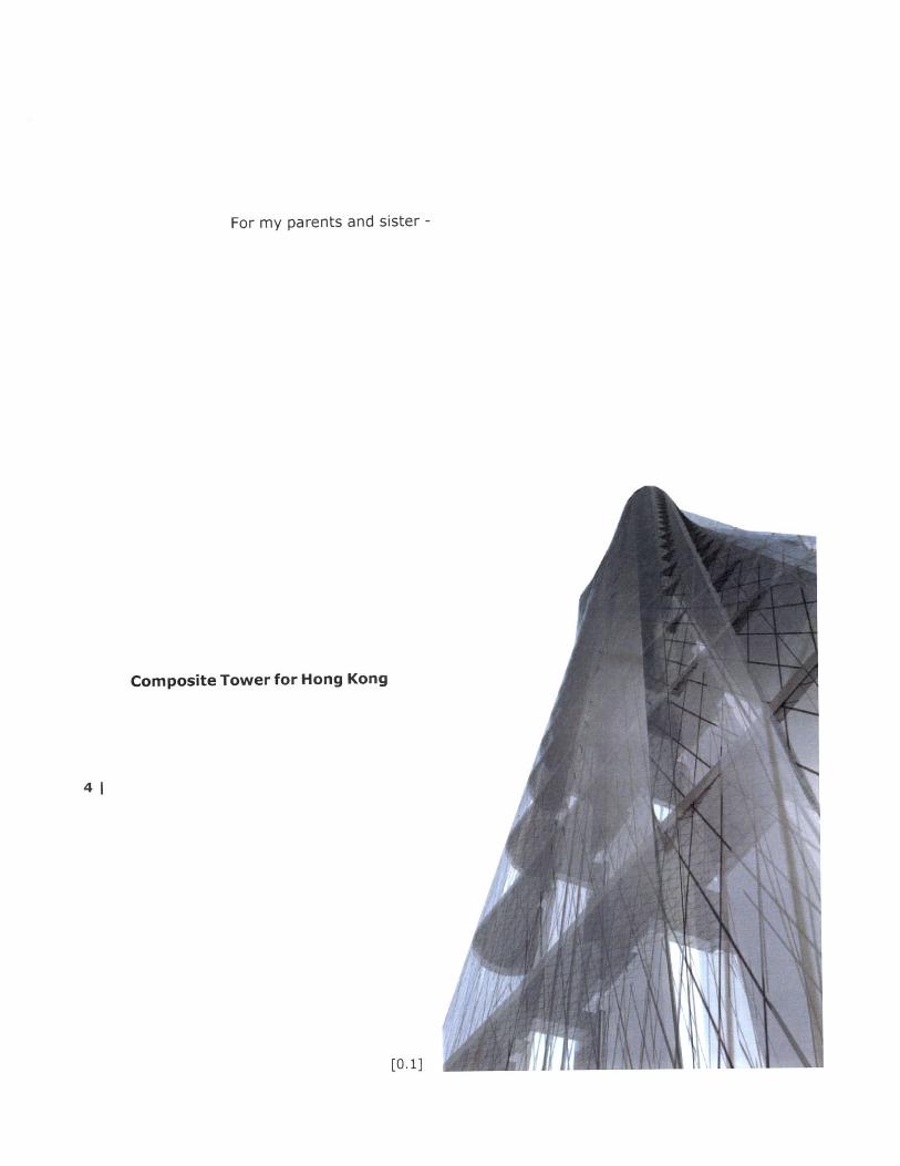
For my parents and sister -
Composite Tower for Hong Kong
41
[0.1]
Hyper-light Architecture:Composite Tower for Hong Kong
Jeffrey Tsui
Bachelor of Science in Civil EngineeringColumbia University, New York, NY 1997
Submitted to the Department of Architecture in partialfulfillment of the requirements for the degree of Master ofArchitecture at the Massachusetts Institute of Technology,February 2001.
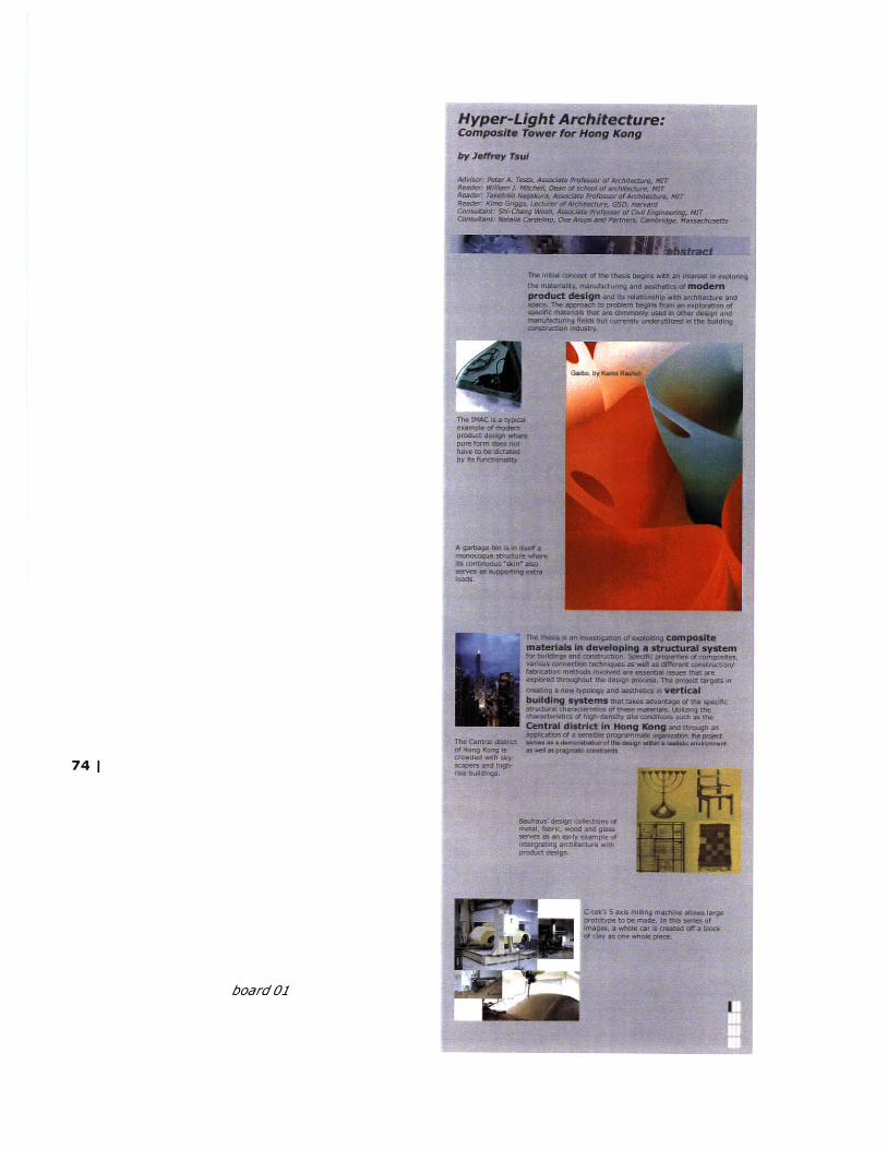
The initial concept of the thesis begins with an interest inunderstanding the materials, manufacturing and aesthetics ofmodern product design and its relationship with architectureand space. The approach to the problem begins with anexploration of specific materials that are commonly used inother design and manufacturing fields but that are currentlyunderutilized in the building construction industry.
The thesis is an investigation of exploiting composite materialsin developing a structural system for buildings and construction.Specific properties of composites, various connectiontechniques as well as different construction/fabrication methodsinvolved are essential issues that are explored throughout thedesign process. The project targets at creating a new typologyand aesthetics in vertical building systems that takesadvantage of the specific structural characteristics of thesematerials. Utilizing the characteristics of high-density siteconditions such as the Central district in Hong Kong and | 5through an application of a sensible programmatic organization,the project serves as a demonstration of the design within arealistic environment as well as within pragmatic constraints.
The outline of the thesis is as follows:1. Research and investigation of materials2. Site analysis and background information3. Design requirements, criteria and decision-making4. Models for experimentation and illustration of design ideas5. Presentation materials
thesis supervisor:Peter TestaAssociate Professor of Architecture, MIT

contents
title pagesupervisor / readers / consultantscover imageoverview
acknowledgements
abstract
introductionbackgroundcase studies
6 research
compositesfabricationapplications
site
Central, Hong Kongthe "escalator"
design
concept 39scenarios 45program 46diagrams 47
models 49
exploratory models 51presentation models 56digital visualizations 61presentation renderings 65
presentation 69
overview 71materials 72boards (reduced from 12" x 36") 74
conclusion 90
bibliography 94
image credits 98
resources
37
102

acknowlegdements
I would like to thank my advisor Peter Testa and DevynWeiser, who have guided me through the three and a halfyears of architecture at MIT. Your teachings and adviceshave prepared me well for all kinds of future career paths.
To my committee:Thank you for all your perceptions and various kinds ofexpertise through each step of the project. It would nothave come such a long way without your constant supportsand encouragements.
Mike Orwat - for spending time teaching me aboutcomposites, and helping me make my composite models atthe NDE lab
John Fernandez - for your great insights and advices on theproject
Betty Lou - for all your enthusiasm and faith on the project!
Michael Fox - for spending so much time on the animation.
Ryan - Without you, this project would never havehappened. Thanks for all the patience and inspirations forthe past couple of years. It's been all good.
Louie - for always being critical and keeping me on my toes
8| Jessica - for a really "bad-ass" layout
Rolando - for constant inspirations and encouragements,and telling me "not to be afraid"
Sean - for lending me local information and materials ofHong Kong
Edwin and Joe - for helping me out so much in the lastcouple of days of production, and also setting up the finalpresentation
Manin - for climbing up the ladder and hanging up the toppanels at the AVT
Larry from www. carb. com and www. strongwe. com - forsending me really nice free samples

[1.0]
[introduction]
[background]
[case studies]
[1.1]
£ [1.3]
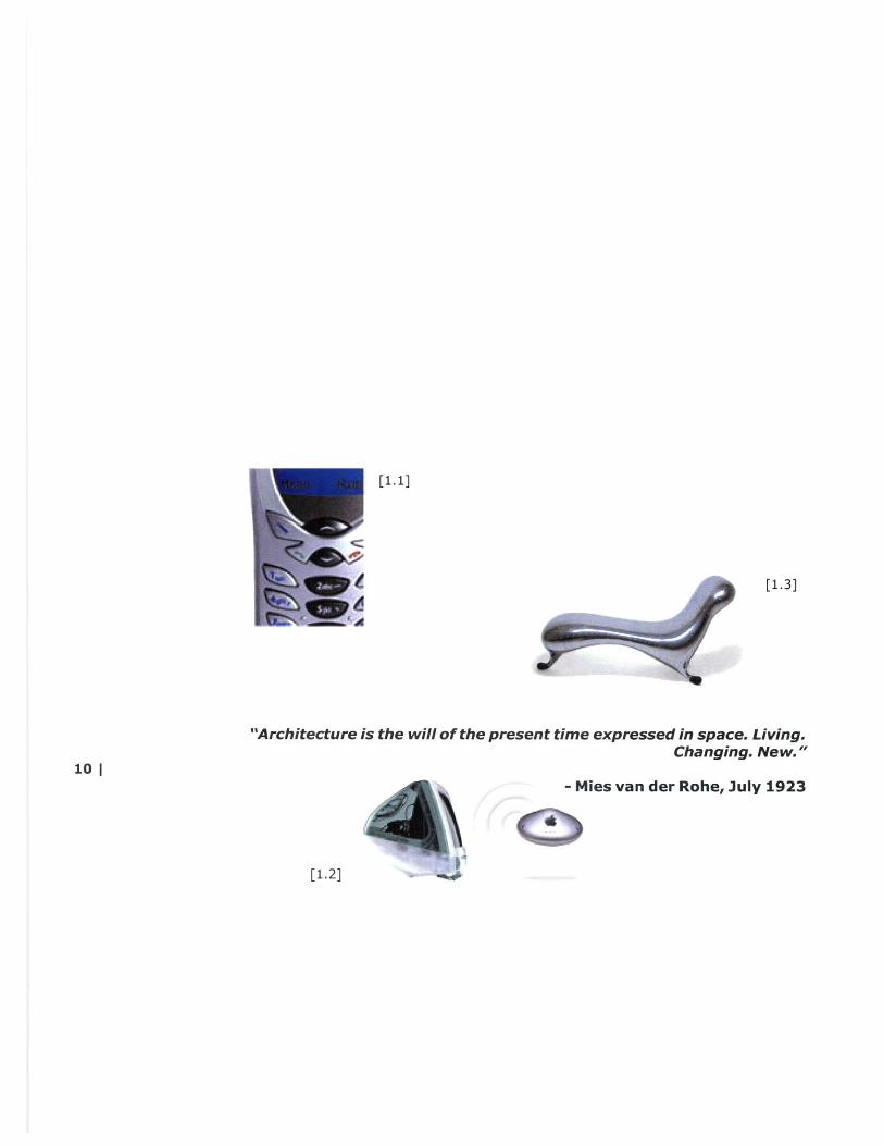
"Architecture is the will of the present time expressed in space. Living.Changing. New."
10 |- Mies van der Rohe, July 1923
[1.2]
introduction
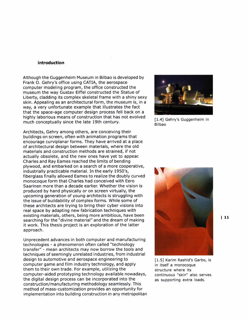
Although the Guggenheim Museum in Bilbao is developed byFrank 0. Gehry's office using CATIA, the aerospacecomputer modeling program, the office constructed themuseum the way Gustav Eiffel constructed the Statue ofLiberty, cladding its complex skeletal frame with a shiny sexyskin. Appealing as an architectural form, the museum is, in away, a very unfortunate example that illustrates the factthat the space-age computer design process fell back on ahighly laborious means of construction that has not evolvedmuch conceptually since the late 19th century.
Architects, Gehry among others, are conceiving theirbuildings on screen, often with animation programs thatencourage curviplanar forms. They have arrived at a placeof architectural design between materials, where the oldmaterials and construction methods are strained, if notactually obsolete, and the new ones have yet to appear.Charles and Ray Eames reached the limits of bendingplywood, and embarked on a search of a more cooperative,industrially practicable material. In the early 1950's,fiberglass finally allowed Eames to realize the doubly curvedmonocoque form that Charles had conceived with EeroSaarinen more than a decade earlier. Whether the vision isproduced by hand physically or on screen virtually, theupcoming generation of young architects is struggling withthe issue of buildability of complex forms. While some ofthese architects are trying to bring their cyber visions intoreal space by adapting new fabrication techniques withexisting materials, others, being more ambitious, have beensearching for the "divine material" and the dream of makingit work. This thesis project is an exploration of the latterapproach.
Unprecedent advances in both computer and manufacturingtechnologies - a phenomenon often called "technologytransfer" - mean architects may now borrow the tools andtechniques of seemingly unrelated industries, from industrialdesign to automotive and aerospace engineering tocomputer game and film industry technology, and applythem to their own trade. For example, utilizing thecomputer-aided prototyping technology available nowadays,the digital design process can be incorporated into theconstruction/manufacturing methodology seamlessly. Thismethod of mass-customization provides an opportunity forimplementation into building construction in any metropolitan
[1.4] Gehry's Guggenheim inBilbao
| 11
[1.5] Karim Rashid's Garbo, isin itself a monocoquestructure where itscontinuous "skin" also servesas supporting extra loads.
cities worldwide, where issues of efficiency and convenienceare critical.
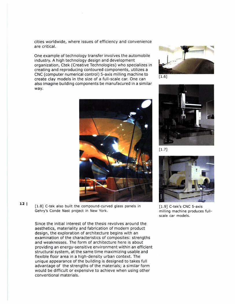
One example of technology transfer involves the automobileindustry. A high technology design and developmentorganization, Ctek (Creative Technologies) who specializes increating and reproducing contoured components, utilizes aCNC (computer numerical control) 5-axis milling machine tocreate clay models in the size of a full-scale car. One canalso imagine building components be manufacured in a similarway.
[1.8] C-tek also built the compound-curved glass panels inGehry's Conde Nast project in New York.
Since the initial interest of the thesis revolves around theaesthetics, materiality and fabrication of modern productdesign, the exploration of architecture begins with anexamination of the characteristics of composites: strengthsand weaknesses. The form of architecture here is aboutproviding an energy-sensitive environment within an efficientstructural system, at the same time maximizing usable andflexible floor area in a high-density urban context. Theunique appearance of the building is designed to takes fulladvantage of the strengths of the materials; a similar formwould be difficult or expensive to achieve when using otherconventional materials.
[1.9] C-tek's CNC 5-axismilling machine produces full-scale car models.
L±.oJ
[1.7]
12 |

[1.10] Richard Dewhurst andProportion's organic 'TheShell Series' is made withfiberglass.
The project aims at providing a mixed-use environment for our lifestyle that constantlydemands adaptability and efficiency in the Central district of Hong Kong. Issues of flexibilityand changing needs are addressed through the spatial organization of the public and privatesector of the program. In the public domain, a combination of different programmaticelements, such as retail and recreational spaces, is included, while in the private domain, amodern typology of housing, hotel and workspace prototypes is incorporated.
background
The architectural philosophy of the Bauhaus and WalterGropius in the 19th century changed the way people at thetime thought of building and construction. It is moreefficient to build with the method of mass-production ofparts that can be assembled on site. There is no doubt thatthe Industrial Revolution facilitated this idea into reality, butthe Industrial Revolution also had an impact on theaesthetics of architecture that was produced: it madearchitecture look like machines. With computer-aided designand manufacturing technology, similar idea could beimplemented more efficiently with a new sense ofaesthetics. Industrial design, for example, has utilized muchof the CAD/CAM technologies in its design andmanufacturing and has created objects that are organic andseamless. Modern architectural design and detailing, forinstance, could also benefit from these technologicaladvances.
[1.11]metal,glass
Bauhaus workshop:fabric, wood and
The project of this thesis will take place in the downtown district of a metropolitan city,Hong Kong, even though the project could have significant implications on downtown areasof other metropolitan cities such as Tokyo, London, or New York. Because of their inheritcharacteristics, such as high land value, pollution, traffic conditions and fast-paced humanactivities, these cities require very careful manipulations of spaces in the design of thearchitecture. As a result, the choice of material, the method of construction, and theorganization of spaces are the main focuses throughout the design process of the thesisproject.
1 13
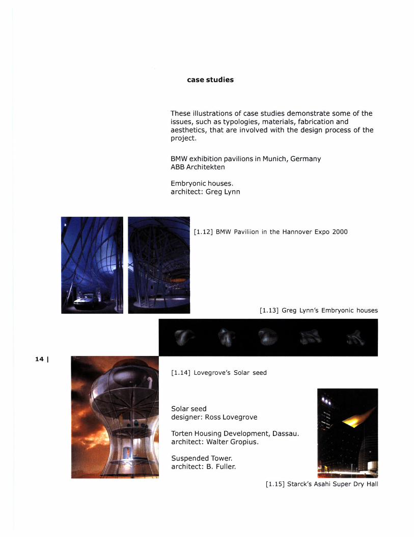
case studies
These illustrations of case studies demonstrate some of theissues, such as typologies, materials, fabrication andaesthetics, that are involved with the design process of theproject.
BMW exhibition pavilions in Munich, GermanyABB Architekten
Embryonic houses.architect: Greg Lynn
[1.12] BMW Pavililon in the Hannover Expo 2000
[1.13] Greg Lynn's Embryonic houses
14 1
[1.14] Lovegrove's Solar seed
Solar seeddesigner: Ross Lovegrove
Torten Housing Development, Dassau.architect: Walter Gropius.
Suspended Tower.architect: B. Fuller.
[1.15] Starck's Asahi Super Dry Hall
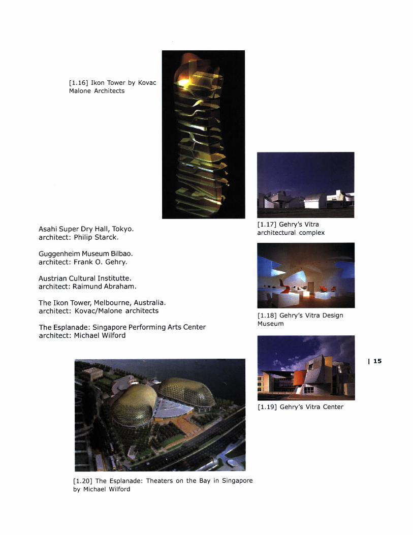
[1.16] Ikon Tower by KovacMalone Architects
Asahi Super Dry Hall, Tokyo.architect: Philip Starck.
Guggenheim Museum Bilbao.architect: Frank 0. Gehry.
Austrian Cultural Institutte.architect: Raimund Abraham.
The Ikon Tower, Melbourne, Australia.architect: Kovac/Malone architects
The Esplanade: Singapore Performing Arts Centerarchitect: Michael Wilford
[1.17] Gehry's Vitraarchitectural complex
[1.18] Gehry's Vitra DesignMuseum
I 15
[1.19] Gehry's Vitra Center
[1.20] The Esplanade: Theaters on the Bay in Singaporeby Michael Wilford
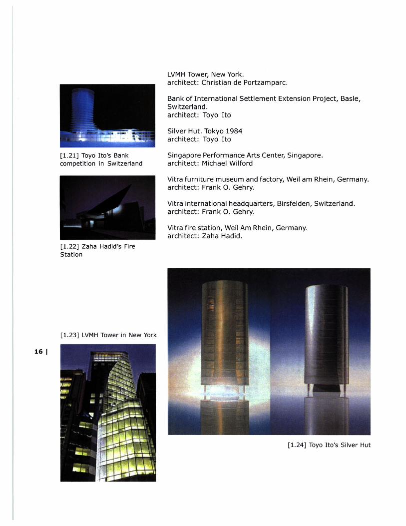
[1.21] Toyo Ito's Bankcompetition in Switzerland
[1.22] Zaha Hadid's FireStation
[1.23] LVMH Tower in New York
LVMH Tower, New York.architect: Christian de Portzamparc.
Bank of International Settlement Extension Project, Basle,Switzerland.architect: Toyo Ito
Silver Hut. Tokyo 1984architect: Toyo Ito
Singapore Performance Arts Center, Singapore.architect: Michael Wilford
Vitra furniture museum and factory, Weil am Rhein, Germany.architect: Frank 0. Gehry.
Vitra international headquarters, Birsfelden, Switzerland.architect: Frank 0. Gehry.
Vitra fire station, Weil Am Rhein, Germany.architect: Zaha Hadid.
16 |
[1.24] Toyo Ito's Silver Hut

-17[2.0]
[composites]
[fabrication ]
[applications]

"When a driver walks away from a crashlike this, he can thank the high strength,lightweight carbon fiber composite thatforms his cocoon."
18 |[2.1]
composites
The term composite refers to a homogeneous material madeup of two individual components whose combined physicalstrength exceeds the properties of either of themindividually.
Different types of composites include:1. timber/wood composite2. reinforced concrete3. fiber-reinforced plastic
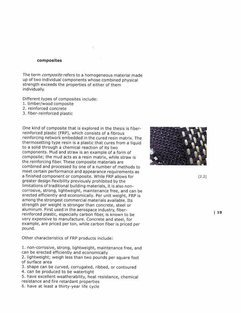
One kind of composite that is explored in the thesis is fiber-reinforced plastic (FRP), which consists of a fibrousreinforcing network embedded in the cured resin matrix. Thethermosetting type resin is a plastic that cures from a liquidto a solid through a chemical reaction of its twocomponents. Mud and straw is an example of a form ofcomposite; the mud acts as a resin matrix, while straw isthe reinforcing fiber. These composite materials arecombined and processed by one of a number of methods tomeet certain performance and appearance requirements asa finished component or composite. While FRP allows for [2.2]greater design flexibility previously prohibited by thelimitations of traditional building materials, it is also non-corrosive, strong, lightweight, maintenance free, and can beerected efficiently and economically. Per unit weight, FRP isamong the strongest commercial materials available. Itsstrength per weight is stronger than concrete, steel oraluminum. First used in the aerospace industry, fiber- I 9reinforced plastic, especially carbon fiber, is known to bevery expensive to manufacture. Concrete and steel, forexample, are priced per ton, while carbon fiber is priced perpound.
Other characteristics of FRP products include:
1. non-corrosive, strong, lightweight, maintenance free, andcan be erected efficiently and economically2. lightweight; weigh less than two pounds per square footof surface area3. shape can be curved, corrugated, ribbed, or contoured4. can be produced to be watertight5. have excellent weatherability, heat resistance, chemicalresistance and fire retardant properties6. have at least a thirty-year life cycle

The physical properties of composites are fiber dominant.This means that when resin and fiber are combined, theirperformance remains most like the individual fiber properties.For example, it is not satisfactory to merely average thetensile strengths of fabric and resin to determine thestrength of a panel. Test data shows that the fibrousreinforcement is the component carrying the majority of theload. For this reason, fabric selection is critical whendesigning composite structures.
The average fabricator has a choice of three types ofreinforcing materials with which to construct a material.These are fiberglass, carbon fiber, and Kevlar*. All threehave their attributes and short-comings, and are available innumerous forms and styles.
The most widely accepted and least expensivereinforcement is fiberglass. It has been used successfully inmany applications since the 1950's, and much is knownabout its properties. It is relatively lightweight, hasmoderate tensile and compressive strength, is tolerant ofboth damage and cyclical loading, and is easy to handle andmachine.
Carbon fiber is a modern reinforcement characterized byextremely low weight, high tensile strength, and high stiff-ness. The material handles easily and can be molded muchlike fiberglass. However, some advanced techniques arenecessary to achieve the maximum properties of this mate-rial. Carbon fiber is also the most expensive of the reinforc-ing fibers. This fact often limits its use to parts needingselective reinforcement or high stiffness with the leastweight.
Kevlar, the most common aramid type fiber, offers a thirdreinforcement option. Kevlar exhibits the lowest density ofany fiber reinforcement, high tensile strength for its weight,and superior toughness. It is priced favorably between
20 | fiberglass and carbon fiber. Kevlar is puncture and abrasionresistant, making it the reinforcement of choice for canoes,kayaks, and leading edges of airfoils. On the down side,Kevlar is difficult to cut and machine during part fabrication.A pair of sharp scissors should be dedicated solely to
[2.3] Different fiberreinforcements producescomposite with differentstrengths.
glass/Kevlar Kevlar/carboncarbon/carbon

cutting Kevlar. It also has a low service temperature andpoor compressive properties. It is possible to combine Kevlarwith other materials creating a hybrid laminate tocompensate for the shortcomings.
The following is a chart comparing the relative properties of reinforcing fabrics.
The legend is as follows: P=Poor, F=Fair, G=Good, E=Excellent
Fiberglass Carbon Kevlar
Density P E ETensile Strength F E GCompressive Strength G E PStiffness F F GFatigue Resistance G-E G EAbrasion Resistance F F ESanding / Machining E E PConductivity P E PHeat Resistance E E FMositure Resistance G G FResin Compatibility E E FCost E P F
Metals have for many years regarded as the only materialsof construction where maximum mechanical properties arerequired. However, their capabilities have reached the stagewhere further marked increase in performance is not likely tobe achieved. Since the demands for technological progress,particularly in aircraft and aerospace, are unlikely to befulfilled by metals alone, a search for alternative types ofconstructional material has been under way for some time.The concept of using composites containing fibers ofexceptional strength or stiffness is not new, but it is only in 21the last decade or so that suitable materials have becomeavailable, and from the chart above, carbon fiber is themost promising.
As for this project, the types of composites that are utilizedincludes the following:
a. composite reinforced and wrapped concrete columnb. carbon fiber woven cablesc. pultruded structural mesh (for skin)d. composite reinforced concrete slabs
[2.4]
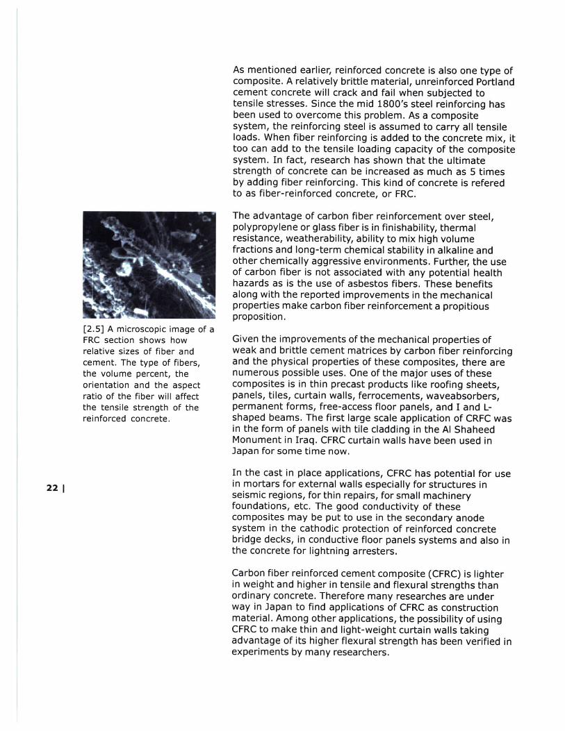
[2.5] A microscopic image of aFRC section shows howrelative sizes of fiber andcement. The type of fibers,the volume percent, theorientation and the aspectratio of the fiber will affectthe tensile strength of thereinforced concrete.
22 |
As mentioned earlier, reinforced concrete is also one type ofcomposite. A relatively brittle material, unreinforced Portlandcement concrete will crack and fail when subjected totensile stresses. Since the mid 1800's steel reinforcing hasbeen used to overcome this problem. As a compositesystem, the reinforcing steel is assumed to carry all tensileloads. When fiber reinforcing is added to the concrete mix, ittoo can add to the tensile loading capacity of the compositesystem. In fact, research has shown that the ultimatestrength of concrete can be increased as much as 5 timesby adding fiber reinforcing. This kind of concrete is referedto as fiber-reinforced concrete, or FRC.
The advantage of carbon fiber reinforcement over steel,polypropylene or glass fiber is in finishability, thermalresistance, weatherability, ability to mix high volumefractions and long-term chemical stability in alkaline andother chemically aggressive environments. Further, the useof carbon fiber is not associated with any potential healthhazards as is the use of asbestos fibers. These benefitsalong with the reported improvements in the mechanicalproperties make carbon fiber reinforcement a propitiousproposition.
Given the improvements of the mechanical properties ofweak and brittle cement matrices by carbon fiber reinforcingand the physical properties of these composites, there arenumerous possible uses. One of the major uses of thesecomposites is in thin precast products like roofing sheets,panels, tiles, curtain walls, ferrocements, waveabsorbers,permanent forms, free-access floor panels, and I and L-shaped beams. The first large scale application of CRFC wasin the form of panels with tile cladding in the Al ShaheedMonument in Iraq. CFRC curtain walls have been used inJapan for some time now.
In the cast in place applications, CFRC has potential for usein mortars for external walls especially for structures inseismic regions, for thin repairs, for small machineryfoundations, etc. The good conductivity of thesecomposites may be put to use in the secondary anodesystem in the cathodic protection of reinforced concretebridge decks, in conductive floor panels systems and also inthe concrete for lightning arresters.
Carbon fiber reinforced cement composite (CFRC) is lighterin weight and higher in tensile and flexural strengths thanordinary concrete. Therefore many researches are underway in Japan to find applications of CFRC as constructionmaterial. Among other applications, the possibility of usingCFRC to make thin and light-weight curtain walls takingadvantage of its higher flexural strength has been verified inexperiments by many researchers.
A similar idea is also proposed for the thesis. A carbon fiber cellular mesh structure,fabricated for each floor slab, is attached to the fiber-reinforcement from the concrete toproduce a donut-form cell. More details will be explained in later chapters.
fabrication
MOLDING:Molding is the process of constructing a part within a mold.Typically, precut reinforcement is placed one layer at a timeinto the mold and saturated with resin. When the part hasachieved the desired thickness and orientation, it is left tocure. When it is demolded, it will have the exact shape ofthe mold surface.
LAMINATING:Laminating originally referred to applying a thin protectivecoating of resin and reinforcement over a surface such aswood. The term's use has broadened to include virtually anyfinished composite part, molded or otherwise. A currentexample would be: "The part tested was a 10-ply vacuumbagged laminate."
CASTING :Casting refers to pouring a large mass of resin into a cavity.The cavity can be a mold when casting parts, or it can bethe backside filler for a tool when making the mold itself.Specialized casting resins are necessary which generate lessheat during their cure and thus create less distortion in thefinal part. Fibrous fillers can be added as needed tostrengthen the casting.
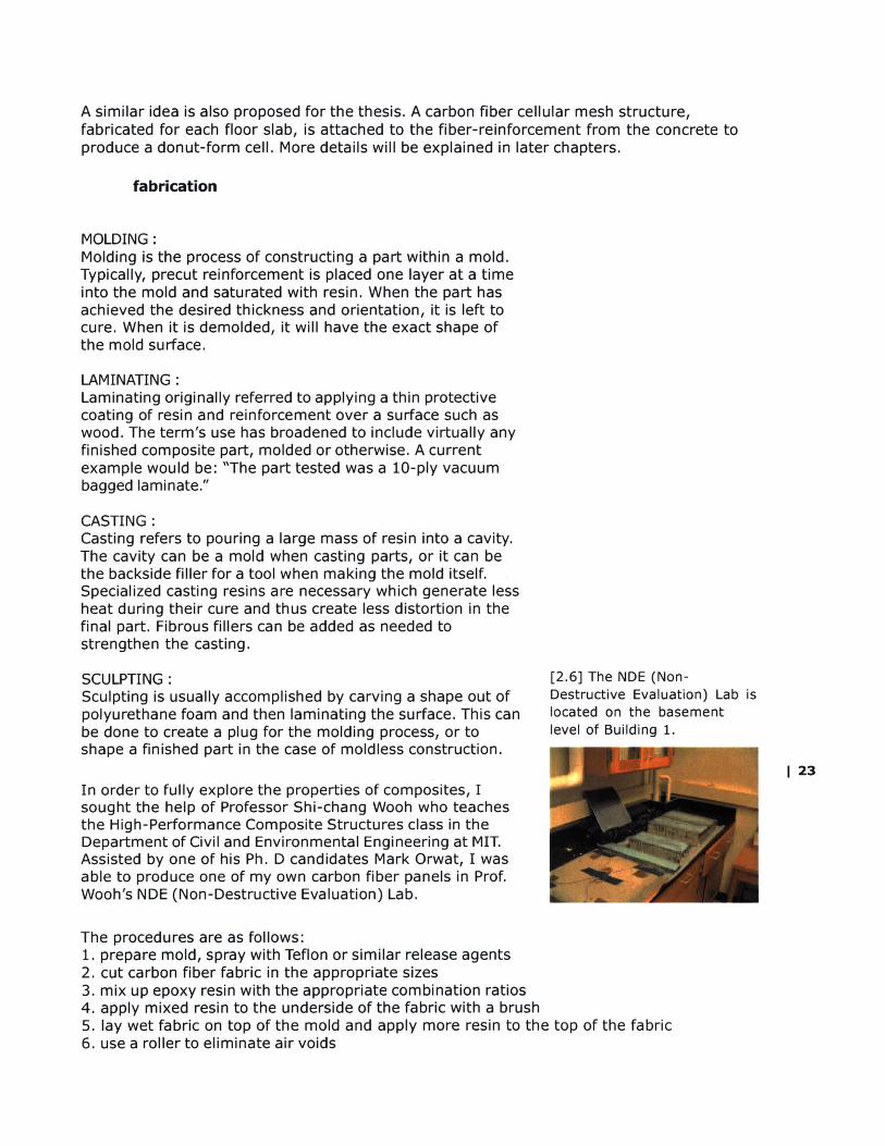
SCULPTING : [2.6] The NDE (Non-Sculpting is usually accomplished by carving a shape out of Destructive Evaluation) Lab ispolyurethane foam and then laminating the surface. This can located on the basementbe done to create a plug for the molding process, or to level of Building 1.shape a finished part in the case of moldless construction.
I23In order to fully explore the properties of composites, Isought the help of Professor Shi-chang Wooh who teachesthe High-Performance Composite Structures class in theDepartment of Civil and Environmental Engineering at MIT.Assisted by one of his Ph. D candidates Mark Orwat, I wasable to produce one of my own carbon fiber panels in Prof.Wooh's NDE (Non-Destructive Evaluation) Lab.
The procedures are as follows:1. prepare mold, spray with Teflon or similar release agents2. cut carbon fiber fabric in the appropriate sizes3. mix up epoxy resin with the appropriate combination ratios4. apply mixed resin to the underside of the fabric with a brush5. lay wet fabric on top of the mold and apply more resin to the top of the fabric6. use a roller to eliminate air voids
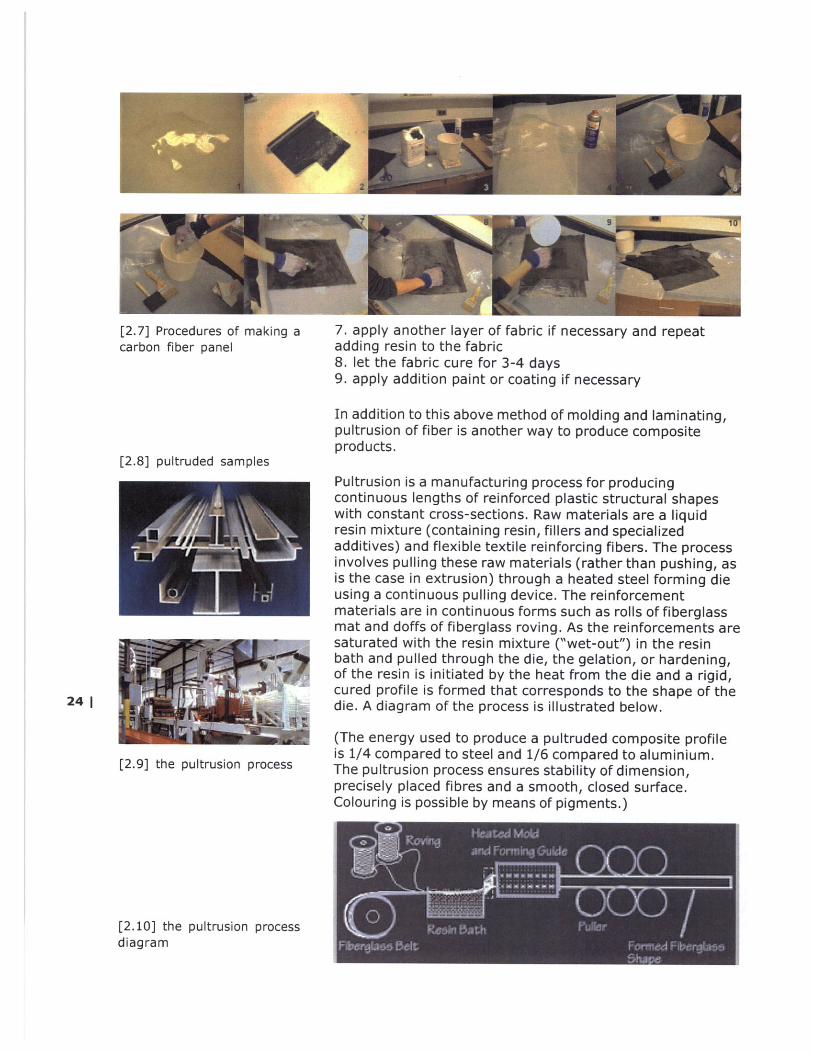
[2.7] Procedures of making a 7. apply another layer of fabric if necessary and repeatcarbon fiber panel adding resin to the fabric
8. let the fabric cure for 3-4 days9. apply addition paint or coating if necessary
In addition to this above method of molding and laminating,pultrusion of fiber is another way to produce compositeproducts.
[2.8] pultruded samplesPultrusion is a manufacturing process for producingcontinuous lengths of reinforced plastic structural shapeswith constant cross-sections. Raw materials are a liquidresin mixture (containing resin, fillers and specializedadditives) and flexible textile reinforcing fibers. The processinvolves pulling these raw materials (rather than pushing, asis the case in extrusion) through a heated steel forming dieusing a continuous pulling device. The reinforcementmaterials are in continuous forms such as rolls of fiberglassmat and doffs of fiberglass roving. As the reinforcements aresaturated with the resin mixture ("wet-out") in the resinbath and pulled through the die, the gelation, or hardening,of the resin is initiated by the heat from the die and a rigid,cured profile is formed that corresponds to the shape of thedie. A diagram of the process is illustrated below.
(The energy used to produce a pultruded composite profileis 1/4 compared to steel and 1/6 compared to aluminium.The pultrusion process ensures stability of dimension,precisely placed fibres and a smooth, closed surface.Colouring is possible by means of pigments.)
[2.10] the pultrusion processdiagram
applications
For more than twenty years, most of fiber production has been used in the aircraft andaerospace industries, where its relatively high cost can be justified by saving in weight.These industries are able to show that the fiber composite materials are cost-effective inselected areas, which accounts for the high level of interest being shown. However,nowadays, the material is become very common for other applications.
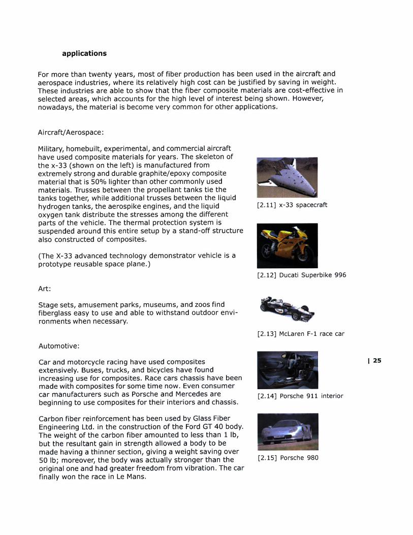
Aircraft/Aerospace:
Military, homebuilt, experimental, and commercial aircrafthave used composite materials for years. The skeleton ofthe x-33 (shown on the left) is manufactured fromextremely strong and durable graphite/epoxy compositematerial that is 50% lighter than other commonly usedmaterials. Trusses between the propellant tanks tie thetanks together, while additional trusses between the liquidhydrogen tanks, the aerospike engines, and the liquidoxygen tank distribute the stresses among the differentparts of the vehicle. The thermal protection system issuspended around this entire setup by a stand-off structurealso constructed of composites.
(The X-33 advanced technology demonstrator vehicle is aprototype reusable space plane.)
[2.11] x-33 spacecraft
[2.12] Ducati Superbike 996
Art:
Stage sets, amusement parks, museums, and zoos findfiberglass easy to use and able to withstand outdoor envi-ronments when necessary.
[2.13] McLaren F-1 race car
Automotive:
Car and motorcycle racing have used compositesextensively. Buses, trucks, and bicycles have foundincreasing use for composites. Race cars chassis have beenmade with composites for some time now. Even consumercar manufacturers such as Porsche and Mercedes arebeginning to use composites for their interiors and chassis.
Carbon fiber reinforcement has been used by Glass FiberEngineering Ltd. in the construction of the Ford GT 40 body.The weight of the carbon fiber amounted to less than 1 lb,but the resultant gain in strength allowed a body to bemade having a thinner section, giving a weight saving over50 lb; moreover, the body was actually stronger than theoriginal one and had greater freedom from vibration. The carfinally won the race in Le Mans.
1 25
[2.14] Porsche 911 interior
[2.15] Porsche 980
Industrial:
[2.16] Quicksilver racecraft
The unique corrosion resistance, strength-to-weight, elec-trical conductivity, and formability of composites lend them-selves to an increasing variety of industrial applications.
Marine:
Boats, jet skis, paddles, canoes, kayaks, and buoys are awide variety of examples where the ability to withstandprolonged exposure to water, salt, gasoline, chlorine, andultraviolet light is critical.
Radio Control:
Radio controlled aircraft, boats, and cars use compositesextensively to obtain the critical reduction of weight.
Sports Equipment:
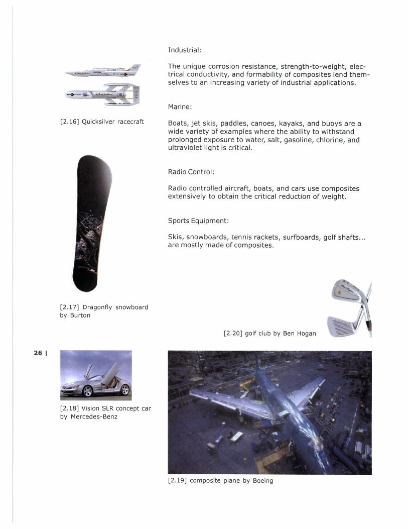
Skis, snowboards, tennis rackets, surfboards, golf shafts...are mostly made of composites.
[2.17] Dragonfly snowboardby Burton
[2.20] golf club by Ben Hogan
26 |
[2.18] Vision SLR concept carby Mercedes-Benz
[2.19] composite plane by Boeing

| 27
[3.0]
[Central, Hong Kong]
[the "escalator" ]
28 1
[3.2]
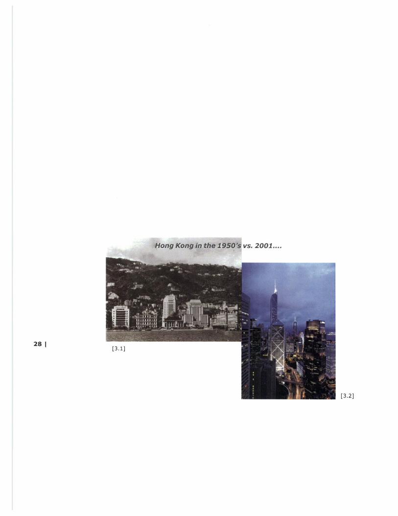
Central, Hong Kong
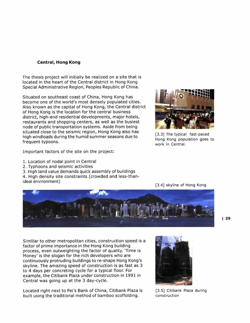
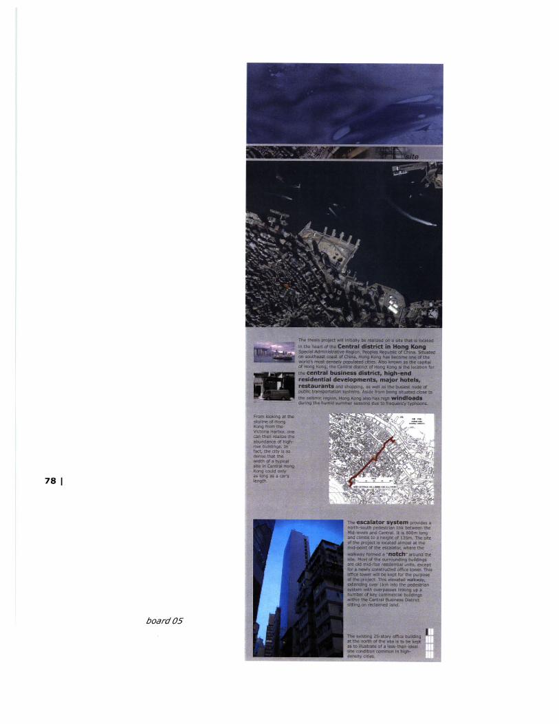
The thesis project will initially be realized on a site that islocated in the heart of the Central district in Hong KongSpecial Administrative Region, Peoples Republic of China.
Situated on southeast coast of China, Hong Kong hasbecome one of the world's most densely populated cities.Also known as the capital of Hong Kong, the Central districtof Hong Kong is the location for the central businessdistrict, high-end residential developments, major hotels,restaurants and shopping centers, as well as the busiestnode of public transportation systems. Aside from beingsituated close to the seismic region, Hong Kong also hashigh windloads during the humid summer seasons due tofrequent typoons.
[3.3] The typical fast-pacedHong Kong population goes towork in Central.
Important factors of the site on the project:
1. Location of nodal point in Central2. Typhoons and seismic activities3. High land value demands quick assembly of buildings4. High density site constraints (crowded and less-than-ideal environment)
Simlilar to other metropolitan cities, construction speed is afactor of prime importance in the Hong Kong buildingprocess, even outweighting the factor of quality. 'Time isMoney' is the slogan for the rich developers who arecontinuously protruding buildings to re-shape Hong Kong'sskyline. The amazing speed of construction is as fast as 3to 4 days per concreting cycle for a typical floor. Forexample, the Citibank Plaza under construction in 1991 inCentral was going up at the 3 day-cycle.
Located right next to Pei's Bank of China, Citibank Plaza isbuilt using the traditional method of bamboo scoffolding.
[3.4] skyline of Hong Kong
[3.5] Citibank Plaza duringconstruction
| 29
left: [3.7] The city is so densethat the width of a typical sitein Central is only as long asthe length of a minivan.right: [3.8] Looking down atthe Victoria Harbor from thepeak, one can then realizethe abundance of high-risebuildings.
[3.8] Bank ofChina duringconstruction
A review of the high land cost would explain the emphasison time. For example, the particular site of around 670square meters in Wanchai for the tallest office building wasacquired at a government auction on 25th January 1989 ata price of HK$ 3,350,000,000.00 or HK$ 5,000,000.00 persquare meter site area. (approximately US$ 60,000 persquare feet) The interest alone on the land cost around HK$918,000.00 (or US$ 118,000) per day at the prime rate of10%. This would give enough pressure to produce a fast-track building (at 4 day-cycle per floor).
Due to the high land cost, developers and architects haveconstantly worked their way through legal restrictions(basically the Building Ordinance) to fish for possibledevelopable areas.
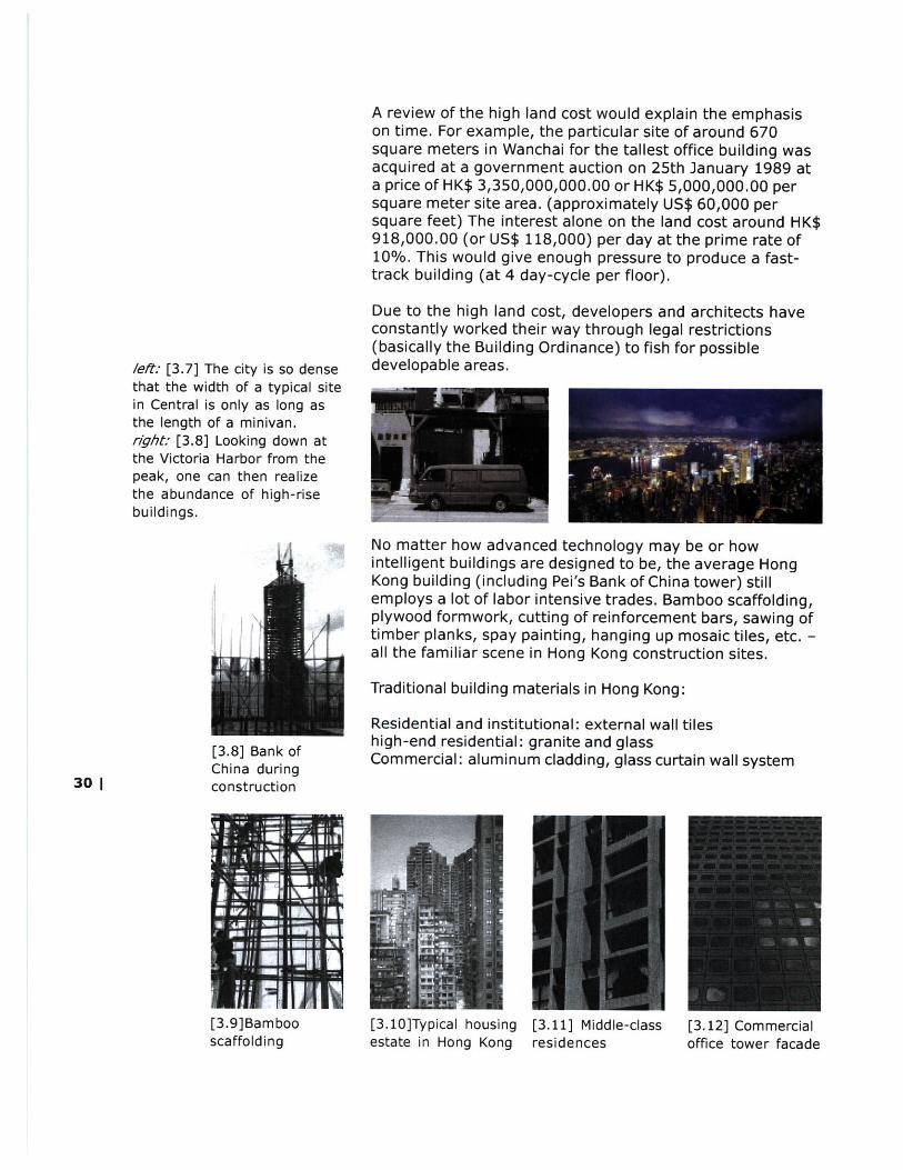
No matter how advanced technology may be or howintelligent buildings are designed to be, the average HongKong building (including Pei's Bank of China tower) stillemploys a lot of labor intensive trades. Bamboo scaffolding,plywood formwork, cutting of reinforcement bars, sawing oftimber planks, spay painting, hanging up mosaic tiles, etc. -all the familiar scene in Hong Kong construction sites.
Traditional building materials in Hong Kong:
Residential and institutional: external wall tileshigh-end residential: granite and glassCommercial: aluminum cladding, glass curtain wall system
[3.9]Bambooscaffolding
[3.10]Typical housingestate in Hong Kong
[3.11] Middle-classresidences
[3.12] Commercialoffice tower facade
30 |

[3.13] aerial photograph of the site
Located on the northern part of Hong Kong island, the siteof the project (colored in orange in above aerial photograph)is located at the corner of Hollywood Road and LydhurstStreet in Central. I 31
PMtTAE $aTE cmatAmES ANo M4W RATIU
Ht behi efss _!om409 WM 60 60amC% GM C6 Puig ka ,k*C6
A . . A a C A a C A I CIe iie sut e ee iei die ir 4F ie .* 4i
7Nd a5ife Us0 3- ;'L 4.A2 100 100 M 5 1
Owr3 mbi s 0"W61Iu AU 67 R 36 43 4J 9 17 47 "4 5,
DIa sa e am saaffaN1 a 3 a at 39 " 4.! is 95 5 &T V
OWr2MbhatMmia0Maf IQ :W o 4 &A $4 Id 2 92 U R A TAGur34 maxnaMida|7 49 5 4A 43 13 9 g t 5 u1
Ov27mbarozt.ailN ft $d | 4A ± $.2 M 5 17 k% 0 V2
0W*miPab4IP I0 itS N 03 3 J 1 7 30 r. Id $ *t
Omwam.s w i0 U.- do i 44 47 Li &3 &S 13 77-5 M M I"
OA$r stan ineesagb &3 a * e 725 73 11.0 .
W QmmuegIdS 1 42 63 71 7 44 4J TO I.$ Q 10"
OWwmin uminiu4I 34 M om Y. 30 423 5 I E
[3.14] Building Ordinance
According to the BuildingOrdinance, it is categorizedas a class C site within zone1; means a corner site thatabuts on streets none ofwhich is less than 4.5 mwide in the most developedarea that has minimumparking requirement. Openarea for a "Class C" site isrequired to be not less than1/4 of roof-over area ofbuilding.
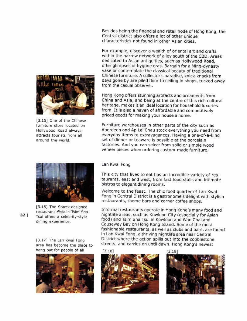
[3.15] One of the Chinesefurniture store located onHollywood Road alwaysattracts tourists from allaround the world.
[3.16] The Starck-designedrestaurant Fe//x in Tsim Sha
32 | Tsui offers a celebrity-styledining experience.
[3.17] The Lan Kwai Fongarea has become the place tohang out for people of all
Besides being the financial and retail node of Hong Kong, theCentral district also offers a lot of other uniquecharacteristics not found in other Asian cities.
For example, discover a wealth of oriental art and craftswithin the narrow network of alley south of the CBD. Areasdedicated to Asian antiquities, such as Hollywood Road,offer glimpses of bygone eras. Bargain for a Ming-dynastyvase or contemplate the classical beauty of traditionalChinese furniture. A collector's paradise, knick-knacks fromdays gone by are piled floor to ceiling in shops, tucked awayfrom the casual observer.
Hong Kong offers stunning artifacts and ornaments fromChina and Asia, and being at the centre of this rich culturalheritage, makes it an ideal location for household luxuriesfrom. It is also a haven of affordable and competitivelypriced goods for making your house a home.
Furniture warehouses in other parts of the city such asAberdeen and Ap Lei Chau stock everything you need fromeveryday items to extravagances. Having a one-of-a-kindset of dinner or teaware is possible at the porcelainfactories. And you can select from solid or simple woodveneer pieces when ordering custom-made furniture.
Lan Kwai Fong
This city that lives to eat has an incredible variety of res-taurants, east and west, from fast food stalls and intimatebistros to elegant dining rooms.Welcome to the feast. The chic food quarter of Lan KwaiFong in Central District is a gastronome's delight with stylishrestaurants, theme bars and corner coffee shops.
Informal restaurants operate in Hong Kong's many food andnightlife areas, such as Kowloon City (especially for Asianfood) and Tsim Sha Tsui in Kowloon and Wan Chai andCauseway Bay on Hong Kong Island. Some of the mostfashionable restaurants, as well as clubs and bars, are foundin Lan Kwai Fong, a thriving nightlife area near CentralDistrict where the action spills out into the cobblestonestreets, and carries on until dawn. Hong Kong's newest[3.18] [3.19]

| 33
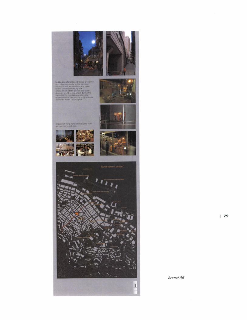
[3.20] site plan of the Central district

[3.21] The elevated walkwayis stretched around theeastern boundary of the site,thus providing an opportunityfor multiply entry/exit pointsat different levels.
34 1
dining area is SoHo (South of Hollywood Road), a rapidlygrowing center of Asian and Western restaurants just aboveLan Kwai Fong.
Hollywood Road
Hong Kong's SoHo ("South of Hollywood Road" aroundStaunton and Elgin streets) joins other international capitalsin offering a compact, fashionable area of bars andrestaurants. Once a warren of shophouses, the streetsaround Hong Kong's Central-Mid-Levels Escalator (theworld's longest outdoor escalator) now boast some of thecity's best and most intimate dining spots. Cheerful exteriorsopen into small speciality restaurants where you can savourdishes from the Himalayas to the Louisiana bayou, and fromMalaysia to the Mediterranean.
Then make your way to Hollywood Road, the hub of Chineseantique shops in central Hong Kong, where dealers arewilling to haggle and generally sell items for less than theauctioneers.
Hollywood Road in Central is the heart of Hong Kong'sthriving antiques quarter. Collectors flock here from all overthe world to hob-nob with knowledgeable dealers and toattend the biannual Christie's and Sotheby's auctions. Thereis plenty of choice, too, for those on a budget andenergetic enough to rummage through the small stalls anddark stores crammed chock full of curios and crafts. Many ofthem are located in and around Upper Lascar Row, or CatStreet about half way along Hollywood Road.
From the rare items offered by Christie's and Sotheby's tothe naive charm of Chinese folk painting, Hong Kong is anexciting place for all sorts of art. Befitting its reputation asa meeting point for East and West, the art-scene is dynamicand varied.
It is precisely this combination of mixed-use environments atthis location that enables a communal gathering as well as aprivate apartment complexes to operate. While part of thepodium levels provide spaces for retail, restaurants andpublic access, the tower on top houses more privateactivites. A sculptural form of the tower could then bedesirable in order to demonstrate itself as a nodal point andallow for interactions that are appropriate for a high-densitysite like this.
[3.22] Alleys only for pedestrian access are very common in theCentral District. This image illustrates the close proximitybetween the elevated walkway and a nearby office tower.
[3.23] map of the "escalator"
[3.24] The elevated walkwaystretches into the CBD.
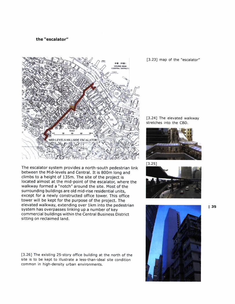
The escalator system provides a north-south pedestrian linkbetween the Mid-levels and Central. It is 800m long andclimbs to a height of 135m. The site of the project islocated almost at the mid-point of the escalator, where thewalkway formed a "notch" around the site. Most of thesurrounding buildings are old mid-rise residential units,except for a newly constructed office tower. This officetower will be kept for the purpose of the project. Theelevated walkway, extending over 1km into the pedestriansystem has overpasses linking up a number of keycommercial buildings within the Central Business Districtsitting on reclaimed land.
[3.26] The existing 25-story office building at the north of thesite is to be kept to illustrate a less-than-ideal site conditioncommon in high-density urban environments.
[3.25]
| 35
the "escalator"

[3.27] Surroundingapartments and stores arewithin very close proximity tothe elevated walkway.
36 1
[3.29]
The site of the project intersects at the mid point of theescalator (shown in red in the previous map). Existingapartments and stores are within very close proximity to theelevated structure and are visible to any passersby. Issuesconcerning the private and public domain are thus criticalwhen one organizes various programmatic elements withinthe complex.
[3.28]

| 37
[4.0]
[concept ]
[program ]
[diagram]

"A modern designer must besensitive to attitudes tomaterials, resource use,
ecology, usefulness, beauty,craft and technology, if he orshe is to respond to the taskwith an intelligent solution."
- Ross Lovegrove
[4.1]
38 |IM [4.2]
[4.3]

concept
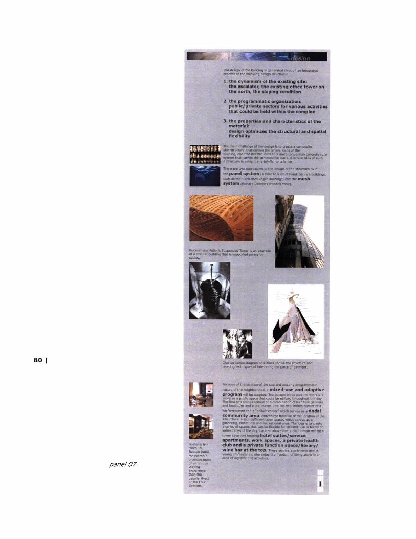
The design of the building is generated through anintegrated process of the following design directions:
1. the dynamism of the existing site:the escalator, the existing office tower on the north, thesloping condition
2. the programmatic organization:public/private sectors for various activities that could beheld within the complex
3. the properties and characteristics of the material:design optimizes the structural and spatial flexibility
From the research of composites, it is understood that inorder to utilize the material effectively, one should take fulladvantage of its tensile strength. However, one should alsokeep in mind that composites have very little or nocompressive strength. A realistic way to approach theproblem is to introduce a combination of tensile andcompressive structural members to carry all the necessaryloads. In this case, some kind of a concrete core structureis indispensable. The composite materials can then be usedin the skin to carry any tensile loads.
The main challenge of the design is therefore to create acomposite structural skin that carries the tensile loads ofthe building, and transfer the loads to a more conventionconcrete core system that carries the compressive loads. Asimilar idea of such a structure is evident in a jellyfish or alantern, where a outer skin element transfers all the forcesto the central core to maintain rigidity.
Option 1: Panel system
The first approach to the design of the structural skin is thepanel system. As seen in most of Frank Gehry's buildings,curved curtain wall systems arranged in panels arecommonly applied onto the building facades. The officetower for the Dutch insurance company, NationalNederlanden in Prague, or commonly known as the "Fred andGinger" building, uses curved glass panels on the facade togive the sculptural quality to the building.
[4.4] Japanese lantern
| 39
[4.5] jellyfish
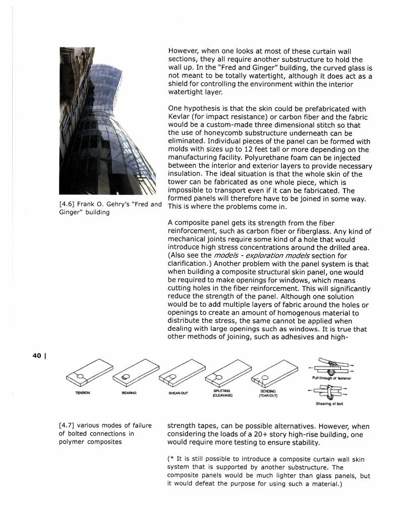
However, when one looks at most of these curtain wallsections, they all require another substructure to hold thewall up. In the "Fred and Ginger" building, the curved glass isnot meant to be totally watertight, although it does act as ashield for controlling the environment within the interiorwatertight layer.
One hypothesis is that the skin could be prefabricated withKevlar (for impact resistance) or carbon fiber and the fabricwould be a custom-made three dimensional stitch so thatthe use of honeycomb substructure underneath can beeliminated. Individual pieces of the panel can be formed withmolds with sizes up to 12 feet tall or more depending on themanufacturing facility. Polyurethane foam can be injectedbetween the interior and exterior layers to provide necessaryinsulation. The ideal situation is that the whole skin of thetower can be fabricated as one whole piece, which isimpossible to transport even if it can be fabricated. Theformed panels will therefore have to be joined in some way.
[4.6] Frank 0. Gehry's "Fred and This is where the problems come in.Ginger" building
A composite panel gets its strength from the fiberreinforcement, such as carbon fiber or fiberglass. Any kind ofmechanical joints require some kind of a hole that wouldintroduce high stress concentrations around the drilled area.(Also see the models - exploration models section forclarification.) Another problem with the panel system is thatwhen building a composite structural skin panel, one wouldbe required to make openings for windows, which meanscutting holes in the fiber reinforcement. This will significantlyreduce the strength of the panel. Although one solutionwould be to add multiple layers of fabric around the holes oropenings to create an amount of homogenous material todistribute the stress, the same cannot be applied whendealing with large openings such as windows. It is true thatother methods of joining, such as adhesives and high-
401
[4.7] various modes of failure strength tapes, can be possible alternatives. However, whenof bolted connections in considering the loads of a 20+ story high-rise building, onepolymer composites would require more testing to ensure stability.
(* It is still possible to introduce a composite curtain wall skinsystem that is supported by another substructure. Thecomposite panels would be much lighter than glass panels, butit would defeat the purpose for using such a material.)
Option 2: Mesh System
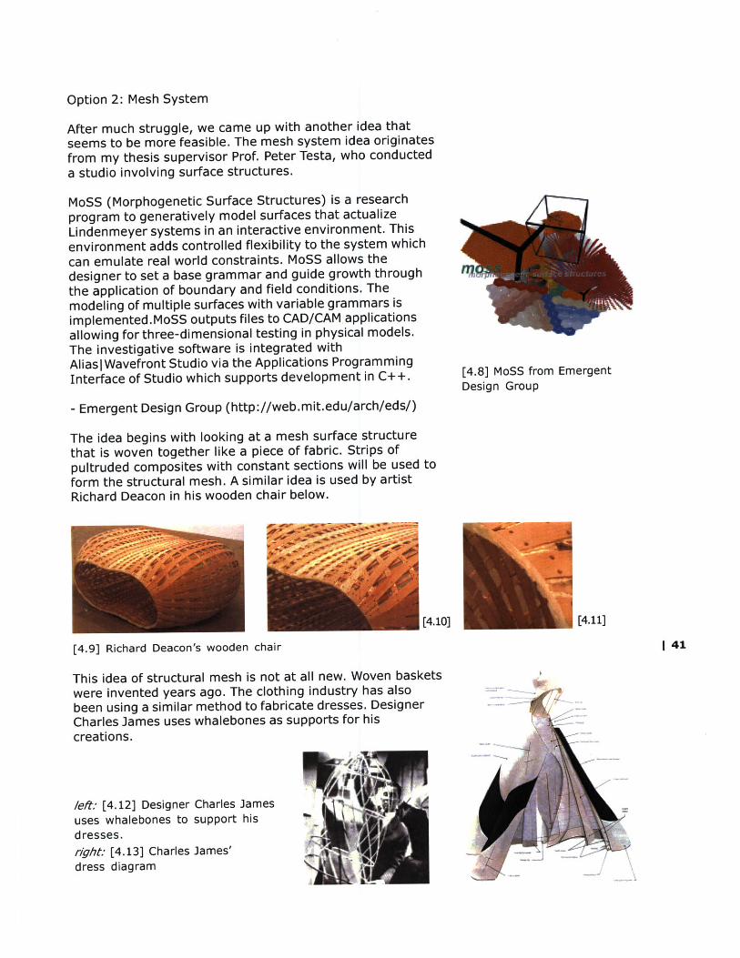
After much struggle, we came up with another idea thatseems to be more feasible. The mesh system idea originatesfrom my thesis supervisor Prof. Peter Testa, who conducteda studio involving surface structures.
MoSS (Morphogenetic Surface Structures) is a researchprogram to generatively model surfaces that actualizeLindenmeyer systems in an interactive environment. Thisenvironment adds controlled flexibility to the system whichcan emulate real world constraints. MoSS allows thedesigner to set a base grammar and guide growth throughthe application of boundary and field conditions. Themodeling of multiple surfaces with variable grammars isimplemented.MoSS outputs files to CAD/CAM applicationsallowing for three-dimensional testing in physical models.The investigative software is integrated withAlias|Wavefront Studio via the Applications ProgrammingInterface of Studio which supports development in C++.
- Emergent Design Group (http://web.mit.edu/arch/eds/)
The idea begins with looking at a mesh surface structurethat is woven together like a piece of fabric. Strips ofpultruded composites with constant sections will be used toform the structural mesh. A similar idea is used by artistRichard Deacon in his wooden chair below.
[4.10]
[4.9] Richard Deacon's wooden chair
This idea of structural mesh is not at all new. Woven basketswere invented years ago. The clothing industry has alsobeen using a similar method to fabricate dresses. DesignerCharles James uses whalebones as supports for hiscreations.
[4.8] MoSS from EmergentDesign Group
[4.11]
1 41
left: [4.12] Designer Charles Jamesuses whalebones to support hisdresses.r/ght: [4.13] Charles James'dress diagram

A few of the problems that are encountered with the panelsystem are solved with the mesh idea. First of all, openingsin the skin becomes natural. Depending on the density of thestructural mesh, the voids of the mesh can be simple beinterpreted as openings. Nothing needs to be drilled or cut.Depending on the strength of the pultruded sections, andthe distribution of loads acting on the tower, strips can belayered and the density of the mesh can vary accordingly.
In order for the composite mesh skin to perform structurally,it would need to be acting in tension. The idea is that all thedead loads of the building, i.e. the floor slabs, will be hungfrom the mesh and carbon fiber woven cables. The loads willthen be transferred from the mesh and cables. Each floorslab has its own set of supporting cables connected to thecores as to prevent failure of the whole structure. Theconcrete cores will then take over the loads. Cellular meshstructure for each floor slab helps to retain rigidity of eachfloor cell.
[4.14] R. Buckminster Fuller'ssuspension tower ideaillustrates a symmetrical formthat optimizes structureefficiency.
42 | [4.15] [4.16] structural diagram
The components of the structural system includes (seemodels - presentaton renderngs section for more details):
1. Concrete core with composite reinforcements2. Mushroom columns3. Steel cage "cap"4. Transverse slab5. Interior cables6. Exterior cables7. Interior cellular mesh8. Exterior cellular mesh
The construction sequence involved in this mesh system is also very different fromconvention constructions. Since all the floors are hung from the cores, the building isconstructed from the top down.
It would be ideal if the whole length of each pultruded stripbe fabricated as one continuous piece. However, that wouldbe impossible for a 300 feet tall building (i.e. 600 feet longstrip). At some point, a strip will need to be joined toanother strip. The connection between strips of pultrudedcomposites can be laminated or tied, similar to the idea ofbamboo scaffolding using in traditional Hong Kongconstruction.
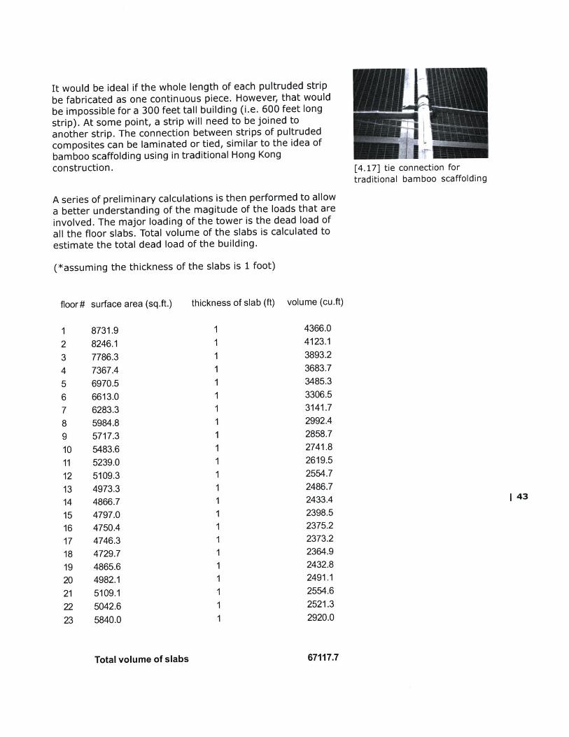
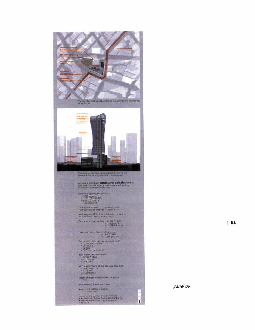
A series of preliminary calculations is then performed to allowa better understanding of the magitude of the loads that areinvolved. The major loading of the tower is the dead load ofall the floor slabs. Total volume of the slabs is calculated toestimate the total dead load of the building.
(*assuming the thickness of the slabs is 1 foot)
[4.17] tie connection fortraditional bamboo scaffolding
floor# surface area (sq.ft.) thickness of slab (ft) volume (cu.ft)
8731.98246.17786.37367.46970.56613.06283.35984.85717.35483.65239.05109.34973.34866.74797.04750.44746.34729.74865.64982.15109.15042.65840.0
Total volume of slabs
4366.04123.13893.23683.73485.33306.53141.72992.42858.72741.82619.52554.72486.72433.42398.52375.22373.22364.92432.82491.12554.62521.32920.0
67117.7
1 43

Using the above calculations of the total volume of the floorslabs, the density of the tensile composite members canthen be estimated.
Density of lightweight concrete:= 1750 kg/cu. m= 1750 *(2.2/39.373)= 0.06310 lb/cu. in.= 109.0 lb/cu. ft.
Total volume of slabs = 68120 cu. ft.Total surface area of tower = 80210 sq. ft.
(* assuming only 20% of the total surface area is to becovered with the structural mesh)
Total area of mesh surface
Density of carbon fiber
Total weight of the exterior
Total weight of all floor slab
= 80210 * (0.20)= 16040 sq. ft.= 27720000 sq. in.
= 1.8 g/cu. cm.= 1.8 / (2.543)= 0.1098 g/cu. in.
structural mesh= 27720000 * 0.1098= 3045000 g= 6699 lb= 3.35 tons (negligible)
s= 67120 * 109.0= 7320000 lb= 3660 tons
With a safety factor of 2.0, the total dead load= 3660 tons * 2.0= 7316 tons= 14600000 lbs
Tensile strength of carbon
Load required
Area
fiber composite= 330 ksi
= Strength * Area
= 14600000 / 330000= 44.3 sq. in.
Assuming the number of vertical tensile members to be 24per floor, each member will have a minimum cross-sectionalarea of 1.85 sq. in. (which is not much at all!)
44 1

scenarios
"Shopping will never die because it is a social th1ing."- Rem Koolhaas. Wallpaper, July 2000
Best known for its tax-free shopping environment, HongKong is crowded with all kinds of retailing business. With theemergence of e-commerce, however, the shoppingexperience will definitely be going through some changes.One major setback of the e-retailing business is the deliveryof goods. The good thing about shopping on the web is thatone can browse, shop place orders and pay online twenty-four hours a day - quick and convenient. One will not needto wait in line, wait for the salesperson or wait for the storeto open. However, after placing an order, one will then haveto wait a few days for the product to be delivered.
The project therefore proposes a new type of shoppingexperience that happens within the complex. Located rightat the nodal in the Central district of Hong Kong, the publicpodium levels not only provide the usual stores, but also atwenty-four hours "delivery center" which stores the thingsthat one buys from the stores or the Internet. Thecustomers have the options to have the goods delivered totheir homes, or to be picked up by themselves - on theirway to work or homes - any time of the day. The followscenarios illustrate a few examples of how it works.
Scenario 01: Shopping stillBanks, travel agencies and estate agents will probablydisappear. Instead, there will be an emergence of a mix ofshops ranging from mega-store extravaganzas to localcorner stores where you will have a personal account. [4.18] Pacific Place - a shopping
arcade near CentralScenario 02: EntertainmentYou will go to your local electronic store, not to buyhardware, but to listen to CDs', watch DVDs' in the theaterroom and enjoy the surround-sound system.
Scenario 03: Retaining privacyYour delivery center will hold a personal refrigerated locker,accessed by code. You will be able to order any goods andpick them up any time you like.
[4.19] Temporary stores onScenario 04: Trying it on the cobblestone street inTry on the clothes, light the candles and lounge on the Centralpillows, then place your order and leave free of awkwardpaper bags.
Scenario 05: Picking up deliveriesYour grocery store will be your personal assistant, picking upyour dry-cleaning and returning it with your food delivery.

Scenario 06: Chilling out
Hanging out in the coffee lounge will become a vital part ofour day. We will be people-watching and gossiping. The highstreet will be a traffic-free zone, with bars and sandwichshops that never close.
program
Because of the location of the site and existingprogrammatic nature of the neighborhood, a mixed-use,adaptive program will be adopted. The bottom four podiumlevels will serve as a public space that could be utilizedthroughout the day. The first two stories consist of acombination of furniture galleries and boutiques and a tealounge. The top two stories consist of a bar/restaurant anda "delivery center" which serves as a nodal community area.There are also sufficient open spaces which serves as agathering, communal and recreational area. The idea is to
[4.20] create a series of spaces that can be flexible for efficient
use at various times of the day. Located above the publicdomain will be a tower structure housing hotel suites/serviceapartments, work spaces, a private health club and aprivate function room that can be converted into a library/wine bar. These service apartments aim at youngprofessionals who enjoy the freedom of living alone in anarea of nightlife and activities while at the same time
[4.2 1] staying close to work by any means of public transportation.
The recreational:
Stores will no longer keep their products on the premises toany significant degree. Instead, they become places ofentertainment, decorated more like fun palaces than oldemporia - places where you go to be coddled and cosied, totry on clothes and play around with gadgets and tuck into
[4.22] free sushi or a couple of cups of java while you figure outwhat you really think looks fabulous. Stores like Sony in NewYork and the Niketown in Chicago already have more touriststhan they have shoppers. These tourists come to gawk andplay and try out visions of fashion, sport or, in Sony's her-metically sealed bedroom of fun, gadgetry. At stores like thisin the New High Street, after you've selected your pur-chases, you simply leave. It is up to the shop to get themto you.
Boston's 61-room 15 Beacon Service apartments:hotel, for example, providesmore of an unique experience The emergence of boutique hotels as opposed to large-scalethan the usual Hyatt or the hotels has recently introduced a new way of temporaryFour Seasons. living when staying abroad. While these hotels offer more of
unique accommodations within their individually-styled
rooms, the scale of these hotels also facilitate bettermanagement and thus provides visitors with more personalservices. For example, the Mercer Hotel in downtown NewYork and the 15 Beacon Hotel in Boston offer very differentexperiences than the Hyatt or the Four Seasons. On theother hand, the required site for one of these small-scaleboutique hotels is more accommodating than a large-scalehotel when situated in an ultra-urban environment. With asmaller site, the location can thus be more ideal for thesehotels. Targeting young entrepreneurs and professionals,these rooms can also provide an ideal, long-term livingenvironment. While parking is not a requirement, thelocation and the services provided at these apartmentsoffer both convenience and high quality of living.
Workspaces:
With the booming of the information-technology and com-puting industries, smaller, rented, short-term cubicles as wellas larger meeting spaces provided with high-end computerhardware, network and Internet connections are constantlyin demand. The workspaces in the complex will providesmall-scale businesses or individuals with the convenienceand flexibility to work efficiently.
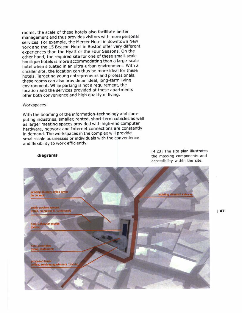
,, m [4.23] The site plan illustratesdiagrams the massing components and
accessibility within the site.
I 47
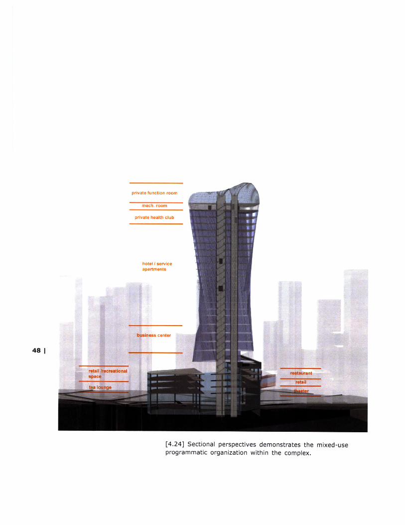
private function room
mech. room
private health club
hotel Y serviceapartments
business center
48 |
retail Aereatlo nai tostaurantretail
[4.24] Sectional perspectives demonstrates the mixed-useprogrammatic organization within the complex.

I 49[5.0]
[exploratory models ]
[presentation models ]
[digital visualizations ]
[presentation renderings]
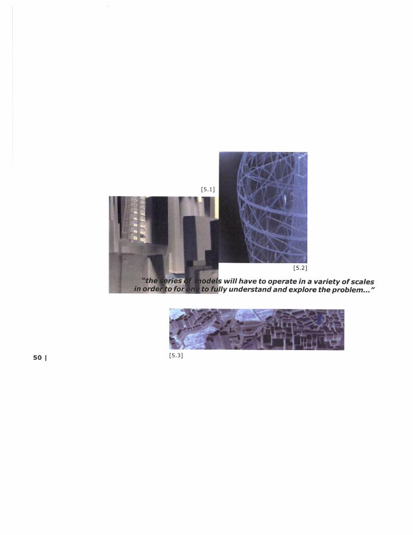
will have to operate in a variety of scalesy understand and explore the problem..."
[5.3]50 I
Since there has never ever been a building constructedusing fiber-reinforced plastics as structural elements, theexploration of the thesis project relies much on theconstruction of exploratory models and digital visualizations.
The physical models shown in this section are organized inchronological order. Various materials, such as chipboard,plexiglass, acrylic blocks, wood, canvas, brass tubes andstainless steel wires, etc. are explored in order to achievethe goals of each investigation. The techniques involved arealso very diverse. The heatgun is used with plexiglass tocreate compound-curved surfaces, while the Stratasys 3Dprinter FDM2000is used to produce complex solid phyiscalmodels which would be very difficult to produce using othermethods or materials. At the same time, iterations ofsurface structures are generated quickly and evaluated indigital form. Moreover, since each floor plate of the towervaries in elevation, each had to be cut by the lasercutter toensure accuracy. This is precisely why digital models andphysical models are developed simultaneously. One can't livewithout the other.
The section is divided into four categories. Each shows thevarious stages of design developments in both physical anddigital models.
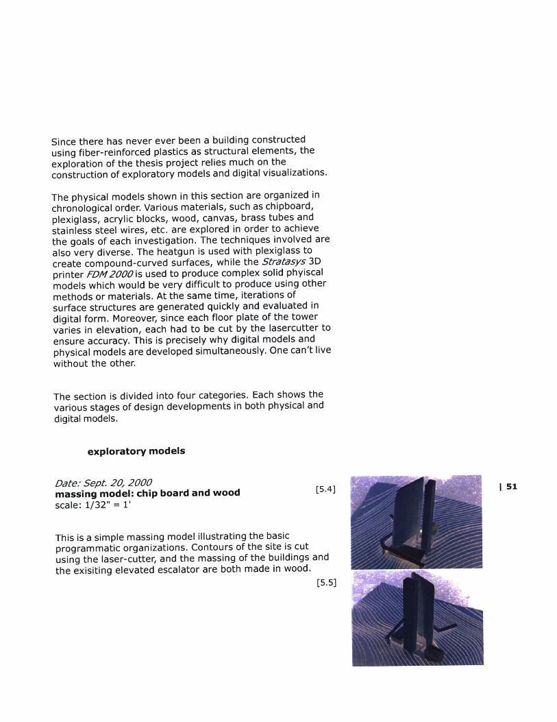
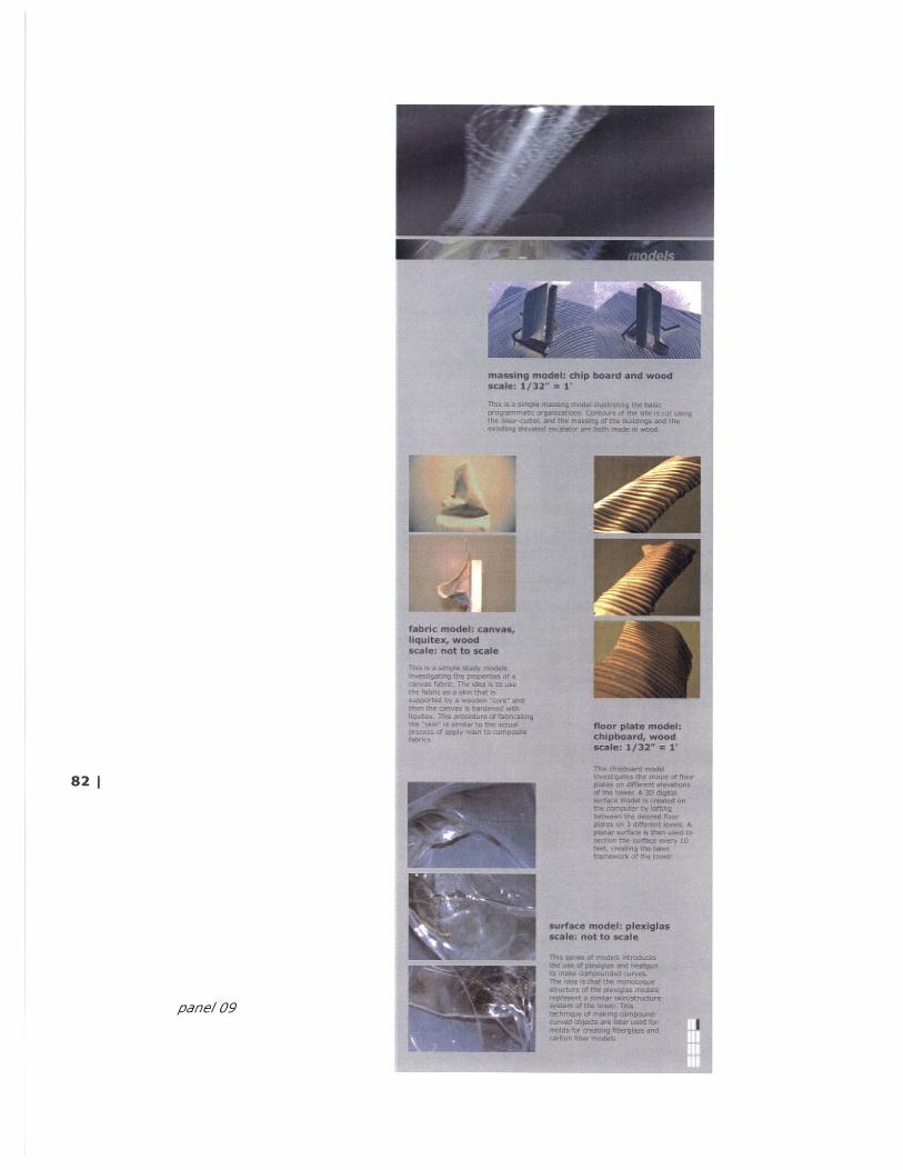
exploratory models
Date: Sept. 20, 2000massing model: chip board and wood [5.4] I 51scale: 1/32" = 1'
This is a simple massing model illustrating the basicprogrammatic organizations. Contours of the site is cutusing the laser-cutter, and the massing of the buildings andthe exisiting elevated escalator are both made in wood.
[5.5]

Date: September 24, 2000
fabric model: canvas, liquitex, woodscale: not to scale
This is a simple study model investigating the properties of acanvas fabric. The idea is to use the fabric as a skin that issupported by a wooden "core" and then the canvas ishardened with liquitex. This procedure of fabricating the"skin" is similar to the actual process of applying resin tocomposite fabrics.
L5.8J [5.9] [5.10]Date: Oct 7, 2000
floor plate model: chipboard, woodscale: 1/32" = 1'
This chipboard model investigates the shape of floor plates on different elevations of thetower. A 3D digital surface model is created first by lofting between the desired floor plateson two different levels. A planar surface is then used to section the surface every 10 feet,creating the profiles for all the floors of the tower for the lasercutting.
52 1
[5.11]
[5.12]
Date: Oct. 8, 2000
surface model 01: plexiglassscale: no scale
This series of models introduces the use of plexiglass glassand heatgun to make compounded curves. The idea is thatthe monocoque structure of the plexiglass models representa simliar skin/structure system of the tower. This techniqueof making compound-curved objects are later used for moldsfor creating fiberglass and carbon fiber models.
[5.6
[5.7
[5.13:
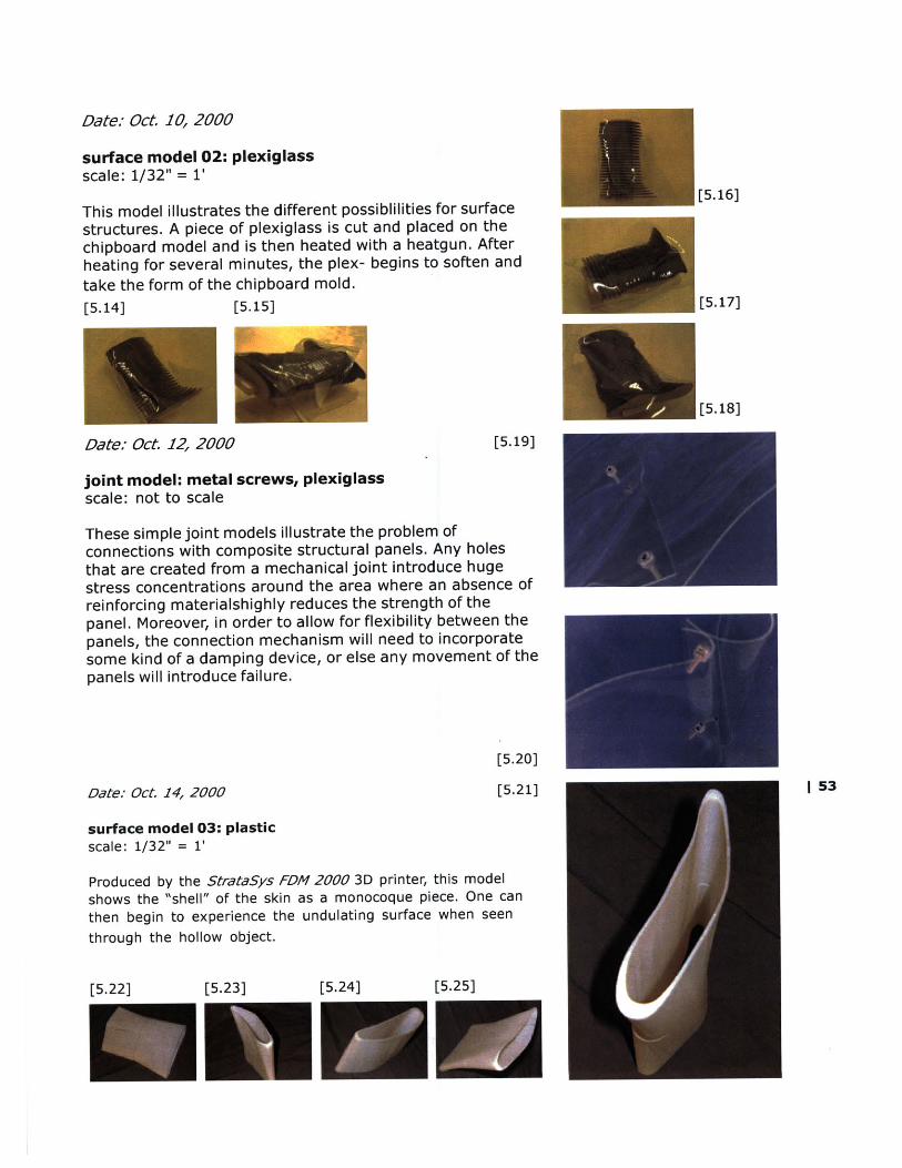
Date: Oct. 10, 2000
surface model 02: plexiglassscale: 1/32" = 1'
This model illustrates the different possiblilities for surface [5.16]
structures. A piece of plexiglass is cut and placed on thechipboard model and is then heated with a heatgun. Afterheating for several minutes, the plex- begins to soften andtake the form of the chipboard mold.[5.14] [5.15] [5.17]
[5.18]
Date: Oct 12, 2000 [5.19]
joint model: metal screws, plexiglassscale: not to scale
These simple joint models illustrate the problem ofconnections with composite structural panels. Any holesthat are created from a mechanical joint introduce hugestress concentrations around the area where an absence ofreinforcing materialshighly reduces the strength of thepanel. Moreover, in order to allow for flexibility between thepanels, the connection mechanism will need to incorporatesome kind of a damping device, or else any movement of thepanels will introduce failure.
[5.20]
Date: Oct. 14, 2000 [5.21] | 53
surface model 03: plasticscale: 1/32" = 1'
Produced by the StrataSys FDM 2000 3D printer, this modelshows the "shell" of the skin as a monocoque piece. One canthen begin to experience the undulating surface when seenthrough the hollow object.
[5.22] [5.23] [5.24] [5.25]

Date: Oct. 27, 2000
tower models: chipboard, woodscale: 1/32" = 1'
These models illustrates the different ideas about the form-making process of the tower. Different configuration of thecore as well as compound curved surfaces are explored. Aslimmer form of the tower seems to give a better visual ideaof the undulating surface.
Lb..1JDate: Oct. 28, 2000 [5.29] [5.30]
This model is built upon the tower form studies and structural strips are added to bring outthe compound-curved skin surface. The floor slabs could be seen as ribs supported by thecore and the vertical and diagonal strips are the substructure for the skin to rest on. Thecombination of the wooden strips and the horizontal plane also suggest a grid system of howthe skin panels are shaped.
[5.32]
Date: Nov. 8, 2000
composite model 01: fiberglass, epoxy, plexiglass mold[5.33] scale: no scale
Created in the NDE (Non-Destructive Evaluation) Lab, thefirst of the composite models illustrates the moldingpossibility for the panel skin surface. The model has only onelayer of fiberglass. The hole shows the location of the
[5.34] absence of the fiberglass fabric (only the epoxy resin).
[5.26]
[5.27]
[5.28]
tower structure model: chipboard, woodscale: 1/32" = 1'
54 1
[5.35]
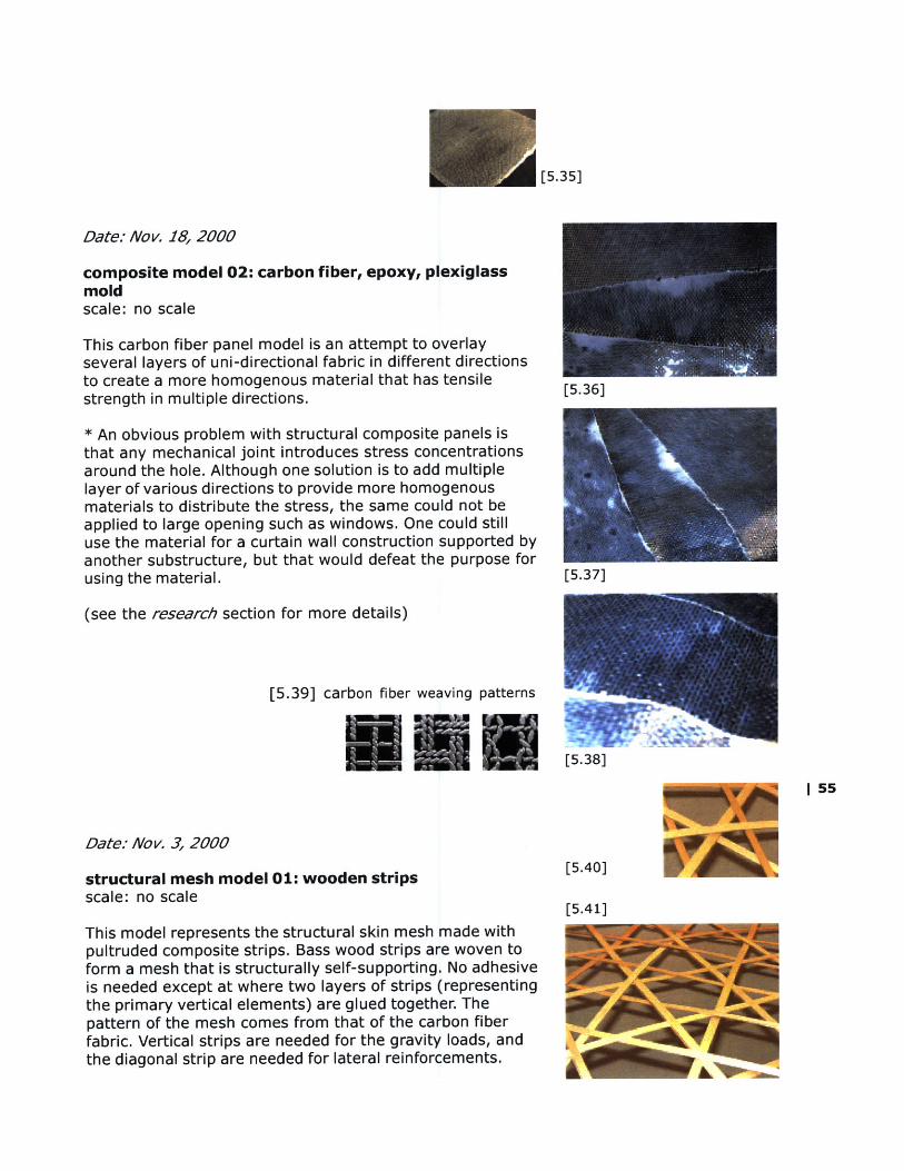
Date: Nov. 18, 2000
composite model 02: carbon fiber, epoxy, plexiglassmoldscale: no scale
This carbon fiber panel model is an attempt to overlayseveral layers of uni-directional fabric in different directionsto create a more homogenous material that has tensile [5.36]strength in multiple directions.
* An obvious problem with structural composite panels isthat any mechanical joint introduces stress concentrationsaround the hole. Although one solution is to add multiplelayer of various directions to provide more homogenousmaterials to distribute the stress, the same could not beapplied to large opening such as windows. One could stilluse the material for a curtain wall construction supported byanother substructure, but that would defeat the purpose forusing the material. [5.37]
(see the research section for more details)
[5.39] carbon fiber weaving patterns
[5.38] WI 55
Date: Nov. 3, 2000
structural mesh model 01: wooden strips [5.40]scale: no scale
[5.41]This model represents the structural skin mesh made withpultruded composite strips. Bass wood strips are woven toform a mesh that is structurally self-supporting. No adhesiveis needed except at where two layers of strips (representingthe primary vertical elements) are glued together. Thepattern of the mesh comes from that of the carbon fiberfabric. Vertical strips are needed for the gravity loads, andthe diagonal strip are needed for lateral reinforcements.A
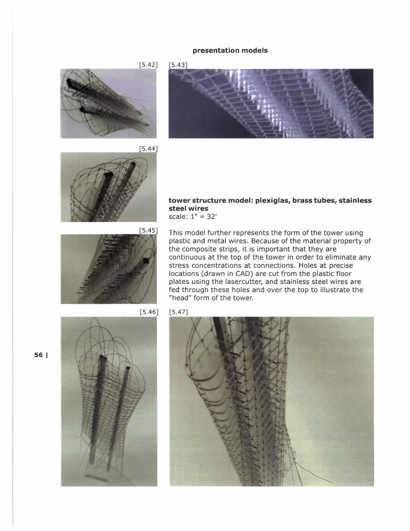
presentation models
[5.421 [5.431
rS.441
tower structuresteel wiresscale: 1" = 32'
model: plexiglas, brass tubes, stainless
rs 41i1 This model further represents the form of the tower usingplastic and metal wires. Because of the material property ofthe composite strips, it is important that they arecontinuous at the top of the tower in order to eliminate anystress concentrations at connections. Holes at preciselocations (drawn in CAD) are cut from the plastic floorplates using the lasercutter, and stainless steel wires arefed through these holes and over the top to illustrate the"head" form of the tower.
r5.461 [5.471
56 |

[5.50]
[5.51]L5.4 'J
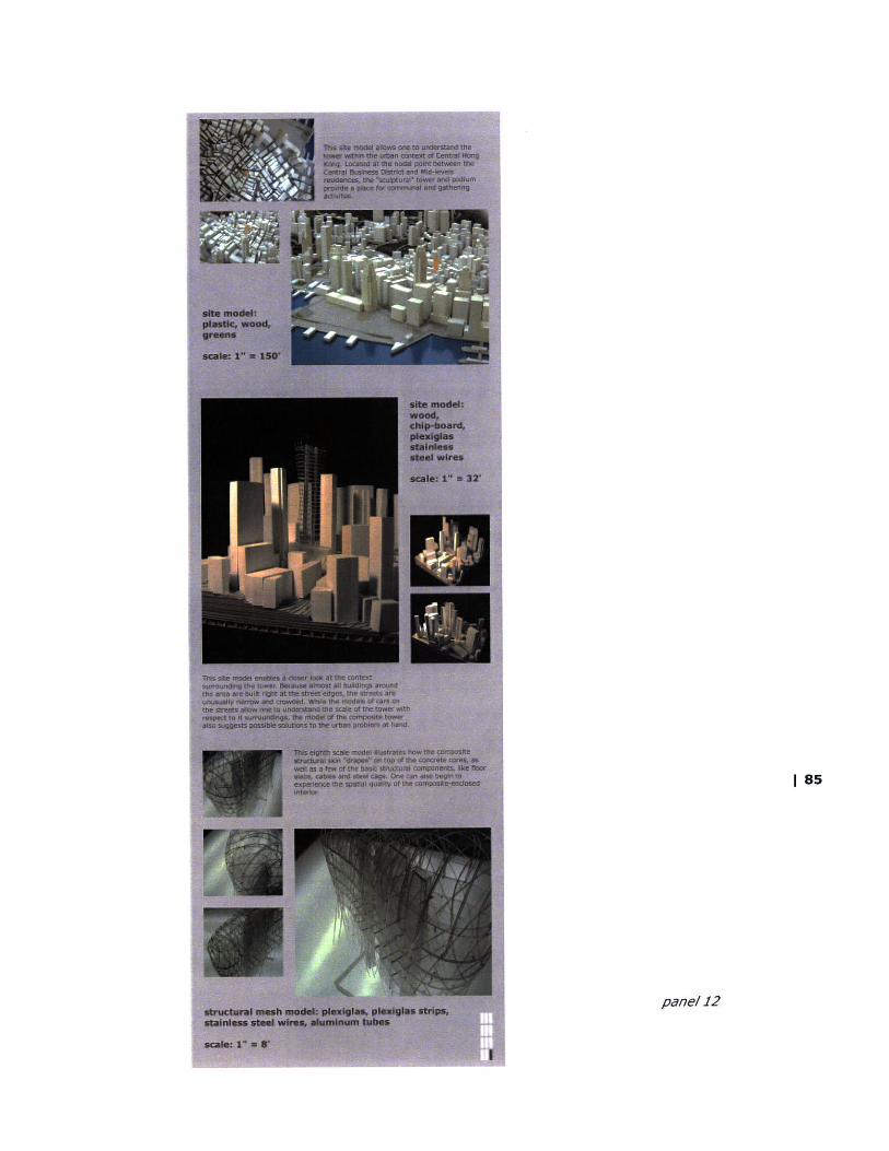
site model: wood, chip-board, plexiglas, stainless steel | 57wiresscale: 1" = 32'
This site model enables a closer look at the contextsurrounding the tower. Because almost all buildings aroundthe area are built right at the street edges, the streets areunusually narrow and crowded. While the models of cars onthe streets allow one to understand the scale of the towerwith respect to it surroundings, the model of the compositetower also suggests possible solutions to the urban problemat hand.
[5.52]
[5.56]
[5.47]
58 |
[5.54] [5.57]
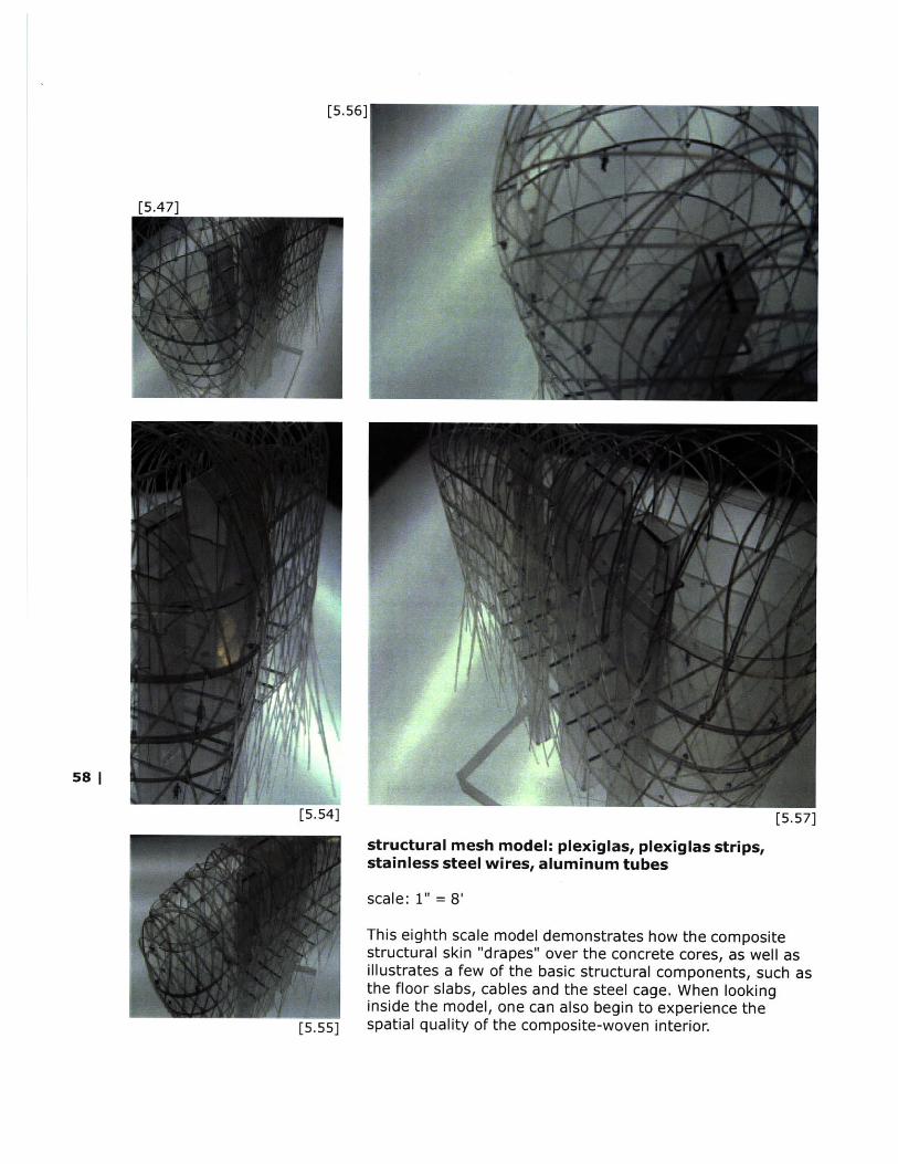
structural mesh model: plexiglas, plexiglas strips,stainless steel wires, aluminum tubes
scale: 1" = 8'
This eighth scale model demonstrates how the compositestructural skin "drapes" over the concrete cores, as well asillustrates a few of the basic structural components, such asthe floor slabs, cables and the steel cage. When lookinginside the model, one can also begin to experience the
[5.55] spatial quality of the composite-woven interior.
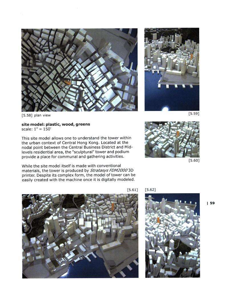
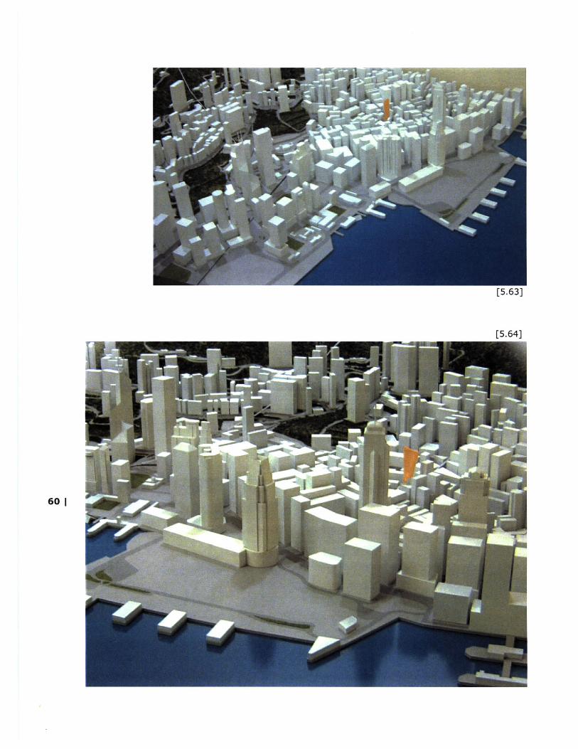
[5.58] plan view [5.59]
site model: plastic, wood, greensscale: 1" = 150'
This site model allows one to understand the tower withinthe urban context of Central Hong Kong. Located at thenodal point between the Central Business District and Mid-levels residential area, the "sculptural" tower and podiumprovide a place for communal and gathering activities.
While the site model itself is made with conventionalmaterials, the tower is produced by Stratasys FDM2000 3Dprinter. Despite its complex form, the model of tower can beeasily created with the machine once it is digitally modeled.
[5.60]
[5.61] [5.62]
1 59
[5.63]
[5.641
60 1
digital visualizations
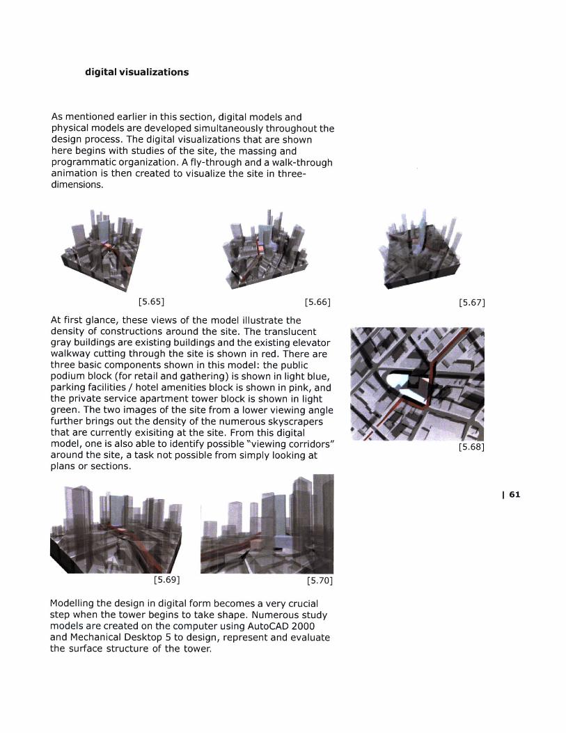
As mentioned earlier in this section, digital models andphysical models are developed simultaneously throughout thedesign process. The digital visualizations that are shownhere begins with studies of the site, the massing andprogrammatic organization. A fly-through and a walk-throughanimation is then created to visualize the site in three-dimensions.
[5.65] [5.66] [5.67]
At first glance, these views of the model illustrate thedensity of constructions around the site. The translucentgray buildings are existing buildings and the existing elevatorwalkway cutting through the site is shown in red. There arethree basic components shown in this model: the publicpodium block (for retail and gathering) is shown in light blue,parking facilities / hotel amenities block is shown in pink, andthe private service apartment tower block is shown in lightgreen. The two images of the site from a lower viewing anglefurther brings out the density of the numerous skyscrapersthat are currently exisiting at the site. From this digitalmodel, one is also able to identify possible "viewing corridors"around the site, a task not possible from simply looking atplans or sections.
|61
[5.69] [5.70]
Modelling the design in digital form becomes a very crucialstep when the tower begins to take shape. Numerous studymodels are created on the computer using AutoCAD 2000and Mechanical Desktop 5 to design, represent and evaluatethe surface structure of the tower.

These digital iterations demonstrate the form-making processof the tower. Each study model is rendered in severaldifferent views, with or without the site context, in order forit to be evaluated. As mentioned earlier, the phyiscal modelof the tower is modelled first in digital form, and then theshapes of the floor slabs are cut using the lasercutter.
The process of making the tower surface (in MechanicalDesktop 5) is as follows (from left to right):
[5.80] floor shapes
1. two splines of the desired forms of the floor plates aredrawn and then offset to the full height of the tower2. using the loft-u command, create the continuous surfacebetween the two splines3. create a solid from the surface using the surface/solidsubstraction command4. using the planar surface, section the solid every floorheight (e.g. 12 feet)5. extrude each sectioned lines to create slabs
[5.71]
[5.72]
[5.73]
[5.74]
[5.75]
[5.76]
62 |
[5.77]
[5.78]
[5.79]
[5.83][5.82]
[5.84]
[5.85
[5.86
[5.87
IiII
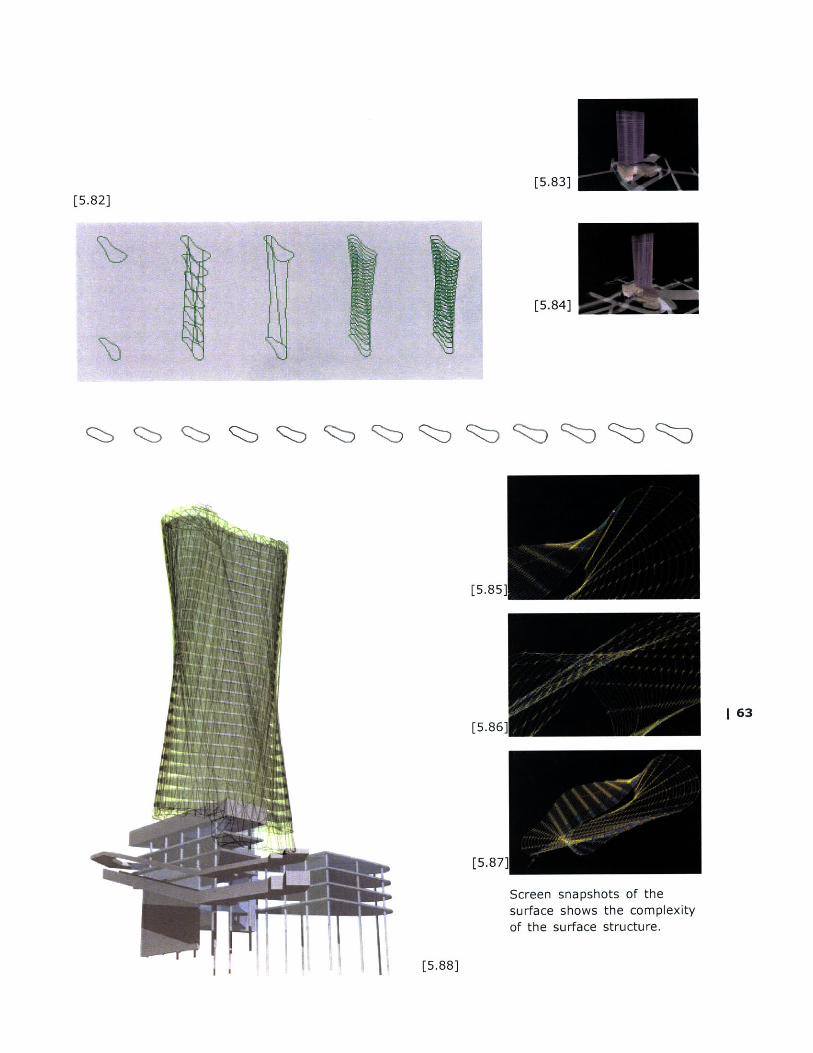
Screen snapshots of thesurface shows the complexityof the surface structure.I jI
[5.88]
1 63

The digital model also allows one to explore the shape aswell as the materiality of the "head" piece of the tower.
[5.89]
64 |
[5.90
presentation renderings
Although the design idea is based on a very simple understanding of structures, the buildingsystem of the composite tower is not as straight-forward. A comprehension of the variousstructural components of the tower is therefore a fundamental requirement for one'sunderstanding of the whole system.
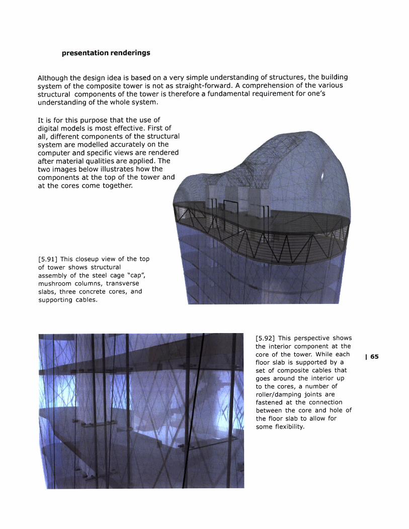
It is for this purpose that the use ofdigital models is most effective. First ofall, different components of the structuralsystem are modelled accurately on thecomputer and specific views are renderedafter material qualities are applied. Thetwo images below illustrates how thecomponents at the top of the tower andat the cores come together.
[5.91] This closeup view of the topof tower shows structuralassembly of the steel cage "cap",mushroom columns, transverseslabs, three concrete cores, andsupporting cables.
[5.92] This perspective showsthe interior component at thecore of the tower. While each | 65floor slab is supported by aset of composite cables thatgoes around the interior upto the cores, a number ofroller/damping joints arefastened at the connectionbetween the core and hole ofthe floor slab to allow forsome flexibility.
2 3 4 5
[5.93]
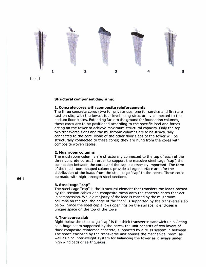
Structural component diagrams:
1. Concrete cores with composite reinforcementsThe three concrete cores (two for private use, one for service and fire) arecast on site, with the lowest four level being structurally connected to thepodium floor plates. Extending far into the ground for foundation columns,these cores are to be positioned according to the specific load and forcesacting on the tower to achieve maximum structural capacity. Only the toptwo transverse slabs and the mushroom columns are to be structurallyconnected to the core. None of the other floor slabs of the tower will bestructurally connected to these cores; they are hung from the cores withcomposite woven cables.
2. Mushroom columnsThe mushroom columns are structurally connected to the top of each of thethree concrete cores. In order to support the massive steel cage "cap", theconnection between the cores and the cap is extremely important. The formof the mushroom-shaped columns provide a larger surface area for thedistribution of the loads from the steel cage "cap" to the cores. These could
66 | be made with high-strength steel sections.
3. Steel cage "cap"The steel cage "cap" is the structural element that transfers the loads carriedby the tension cables and composite mesh onto the concrete cores that actin compression. While a majority of the load is carried by the mushroomcolumns on the top, the edge of the "cap" is supported by the transverse slabbelow. Since the steel cap allows openings on the surface, it encloses aunique space on the top of the tower.
4. Transverse slabRight below the steel cage "cap" is the thick transverse sandwich unit. Actingas a huge beam supported by the cores, the unit consists of two layers ofthick composite reinforced concrete, supported by a truss system in between.The space enclosed by the transverse unit houses the mechanical room, aswell as a counter-weight system for balancing the tower as it sways underhigh windloads or earthquakes.
.. ....... .. ..... .....
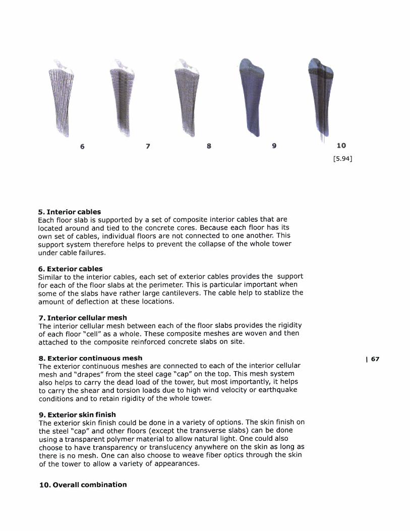
6 7 8 9 10
[5.94]
5. Interior cablesEach floor slab is supported by a set of composite interior cables that arelocated around and tied to the concrete cores. Because each floor has itsown set of cables, individual floors are not connected to one another. Thissupport system therefore helps to prevent the collapse of the whole towerunder cable failures.
6. Exterior cablesSimilar to the interior cables, each set of exterior cables provides the supportfor each of the floor slabs at the perimeter. This is particular important whensome of the slabs have rather large cantilevers. The cable help to stablize theamount of deflection at these locations.
7. Interior cellular meshThe interior cellular mesh between each of the floor slabs provides the rigidityof each floor "cell" as a whole. These composite meshes are woven and thenattached to the composite reinforced concrete slabs on site.
8. Exterior continuous mesh I 67The exterior continuous meshes are connected to each of the interior cellularmesh and "drapes" from the steel cage "cap" on the top. This mesh systemalso helps to carry the dead load of the tower, but most importantly, it helpsto carry the shear and torsion loads due to high wind velocity or earthquakeconditions and to retain rigidity of the whole tower.
9. Exterior skin finishThe exterior skin finish could be done in a variety of options. The skin finish onthe steel "cap" and other floors (except the transverse slabs) can be doneusing a transparent polymer material to allow natural light. One could alsochoose to have transparency or translucency anywhere on the skin as long asthere is no mesh. One can also choose to weave fiber optics through the skinof the tower to allow a variety of appearances.
10. Overall combination

[5.95] The three-quarters view ofthe composite tower displays theskin as a combination of structuralefficiency and pure form.
68 |
|69
[6.0]
[overview]
[materials]
[boards ]

[6.3]
"a Mardi Gras...?"
70 [6.2]

overview
Date:
Friday, December 19, 2000
Time:
1630 hrs
Location:
Advanced Visual Theatre (AVT) 7-431
Participants:
Peter TestaAssociate Professor of Architecture, MIT
William J. MitchellDean, School of Architecture and PlanningProfessor of Architecture and Media Arts and Sciences, MIT
Takehiko NagakuraAssociate Professor of Design and Computation, MIT
J. Kimo GriggsLecturer in Architecture, GSD, Harvard
Shi-Chang WoohAssociate Professor of Civil and Environmental Engineering, MIT
Brian CarterChair, Dept. of Architecture, Univ. of Michigan
Tony McLaughlinBuro Happold, New York
Blanca LleoArchitect, Madrid
Alan ShortDean, Faculty of Art and Design, DeMontfort University

materials:
website presentation
presentation boards [ 01 - 16 ]
site model scale: 1" = 150'
site model scale: 1" = 32'
detail model scale: 1" = 8'
study models include:surface studiestower iterationsjoint explorationscarbon fiber and fiberglass panels
material samples include:reinforcement fabric samplespultruded section samples
1 59
72 | 2 6 103 7 1
board index

N I ~
-
II I-
4
I;ZN
9K
44%

|75
board 02

Q ru
'IC

| 77
board 04
0%
I 79
board 06
80
panel 07
Aw
-Age.
Nt
4
lb
co A
NII
tw
3
"of
11f
PP

1 83
panel 10

co 4;h
lb
IN
I no
w-
AL
,
41
, 01
k2 1
In
(0
J~
i
!M
L
d

I
7. Entur~a mcahIwmma
7v# L riamlnlmss r vt,
aA. l ~tirumbnmast j
IkO~w f tt tp smlooad ho tower
86 1
panel 13

ilo
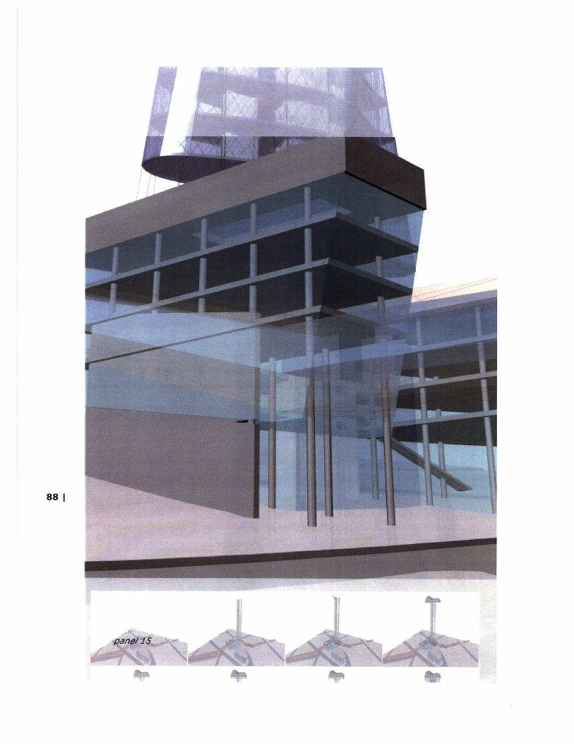
88|
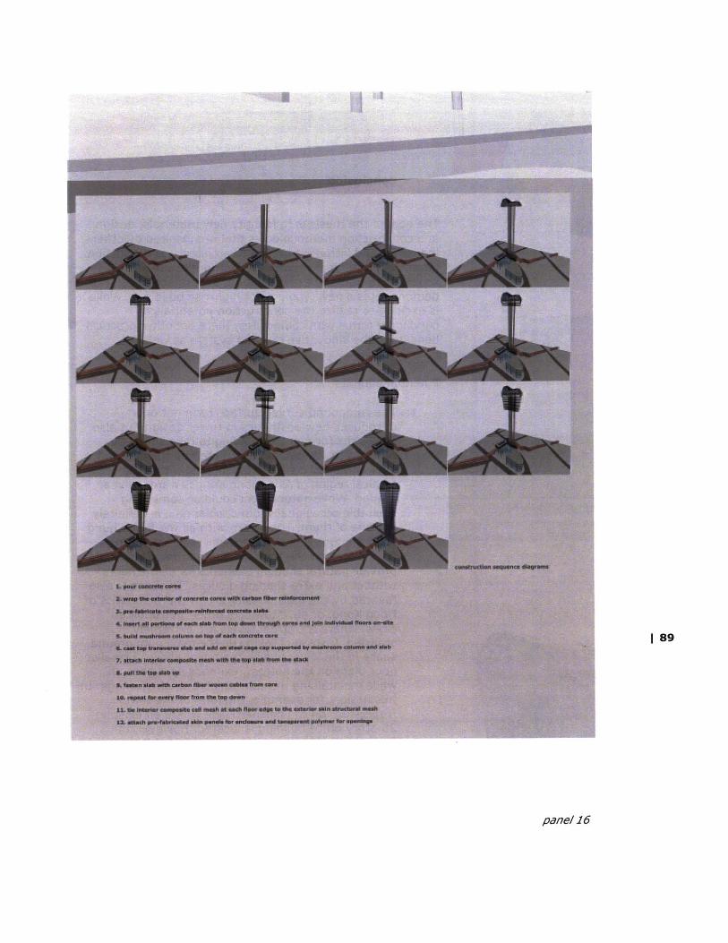
1 89
panel 16
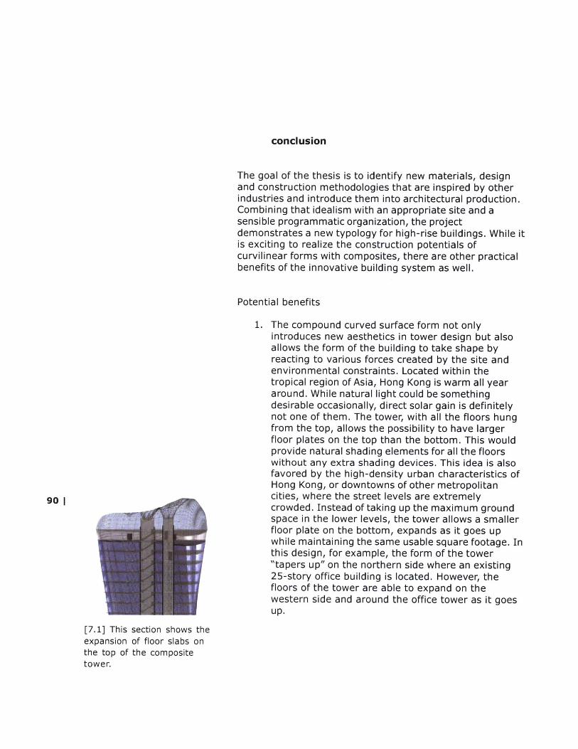
conclusion
The goal of the thesis is to identify new materials, designand construction methodologies that are inspired by otherindustries and introduce them into architectural production.Combining that idealism with an appropriate site and asensible programmatic organization, the projectdemonstrates a new typology for high-rise buildings. While itis exciting to realize the construction potentials ofcurvilinear forms with composites, there are other practicalbenefits of the innovative building system as well.
Potential benefits
1. The compound curved surface form not onlyintroduces new aesthetics in tower design but alsoallows the form of the building to take shape byreacting to various forces created by the site andenvironmental constraints. Located within thetropical region of Asia, Hong Kong is warm all yeararound. While natural light could be somethingdesirable occasionally, direct solar gain is definitelynot one of them. The tower, with all the floors hungfrom the top, allows the possibility to have largerfloor plates on the top than the bottom. This wouldprovide natural shading elements for all the floorswithout any extra shading devices. This idea is alsofavored by the high-density urban characteristics ofHong Kong, or downtowns of other metropolitan
90 Icities, where the street levels are extremelycrowded. Instead of taking up the maximum groundspace in the lower levels, the tower allows a smallerfloor plate on the bottom, expands as it goes upwhile maintaining the same usable square footage. Inthis design, for example, the form of the tower"tapers up" on the northern side where an existing25-story office building is located. However, thefloors of the tower are able to expand on thewestern side and around the office tower as it goesup.
[7.1] This section shows theexpansion of floor slabs onthe top of the compositetower.
2. The form of the tower is also more structurallyefficient for high wind loads and seismic activities.The idea is that the rigid cores are planted deeplyinto the foundation, while all the floors are hung fromthe top. Therefore they are flexible enough not tocollapse during earthquakes. Moreover, the compositetower is the strongest at the top, as opposed to aconvention tower where the top is always theweakest and is subjected to deflections. Since windload increases exponentially with respect to height,this structural system is very effective in locationswith high wind loads such as Hong Kong.
3. While much of the dead load of the tower is carriedby the tensile, fiber-woven cables, the exteriorcomposite structural mesh doubles up to resist theshear and torsion. This enables the interior spaces tobe free of columns and shear walls, thus allowingunlimited flexibility for different uses.
4. Most of the components are pre-fabricated. Inaddition, because the composites are so much lightercompared to conventional materials, the assemblytime required on-site could be reduced. As mentionedearlier in the site section, a day's interest for a sitein any major city could be a large sum of money. Adeveloper could save millions of dollars if the con-struction time is cut down by half.
Although the project has succeeded in developingfundamental way of approaching the architecturalhigh-rise construction, there are a few key issuesnot been fully tackled due to time constraints.
a newdesign ofthat have
1. connections
Because there is not a precedent for such a buildingsystem, conventional connections and details are notbe applicable in this design. One therefore needs tolook at other manufacturing industries and techniquesin order to rethink how these details could be resolved.Prof. John Fernandez from the Department of BuildingTechnology, recommended that one direction ofapproaching the problem is to look at the membranestructures, especially the temporary constructions builtfor the Hannover Expo 2000. Japanese architect,Shigeru Ban, among others, utilized innovative methodsfor constructing tensile structures. Clues can then bedrawn from some of these details involving fabricconnections.
[7.2] Shigeru Ban's famouspaper tube structure at theHannover Expo 2000.
1 91
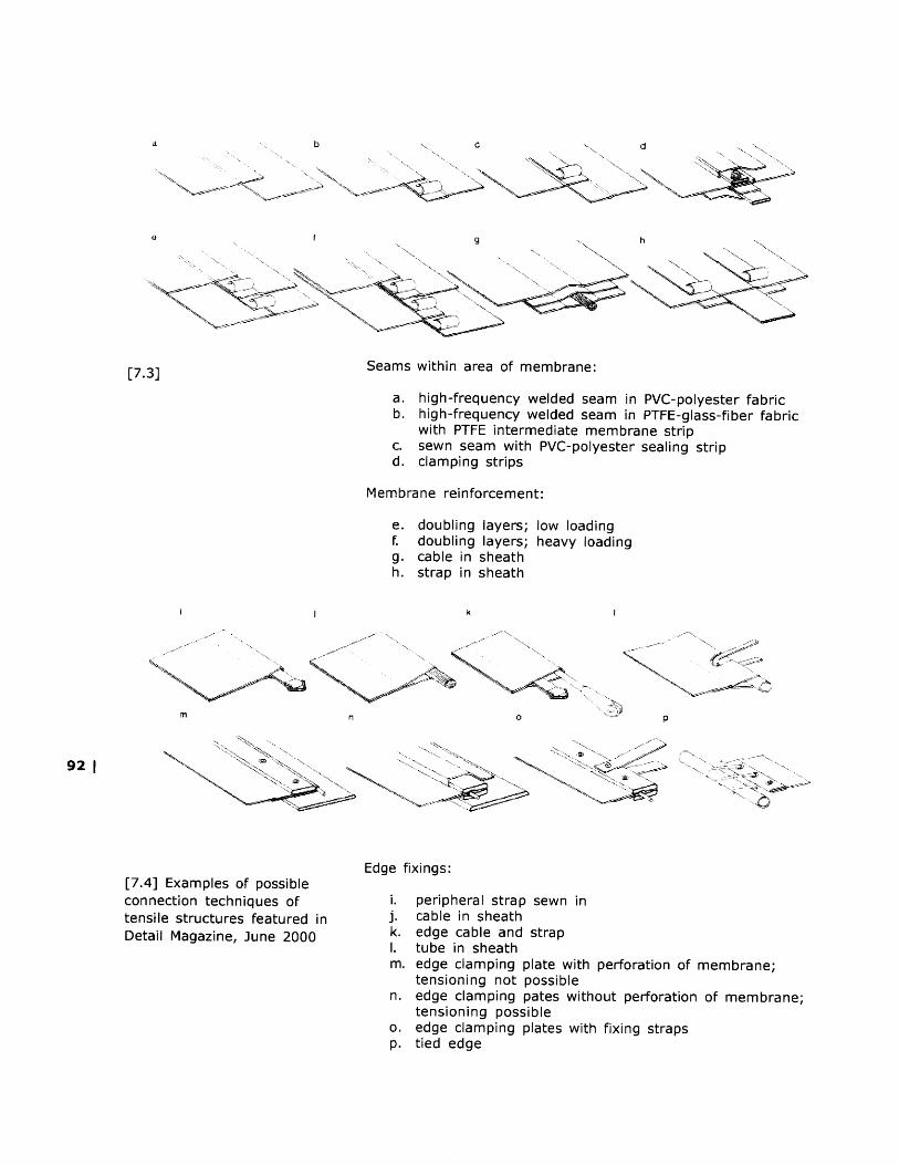
[7.3] Seams within area of membrane:
a. high-frequency welded seam in PVC-polyester fabricb. high-frequency welded seam in PTFE-glass-fiber fabric
with PTFE intermediate membrane stripc. sewn seam with PVC-polyester sealing stripd. clamping strips
Membrane reinforcement:
doubling layers; low loadingdoubling layers; heavy loadingcable in sheathstrap in sheath
A~r'~ a->
~N
< 1N
-~
p
'_i
* A-
[7.4] Examples of possibleconnection techniques oftensile structures featured inDetail Magazine, June 2000
Edge fixings:
i. peripheral strap sewn inj. cable in sheathk. edge cable and strapI. tube in sheathm. edge clamping plate with perforation of membrane;
tensioning not possiblen. edge clamping pates without perforation of membrane;
tensioning possibleo. edge clamping plates with fixing strapsp. tied edge
92 |N
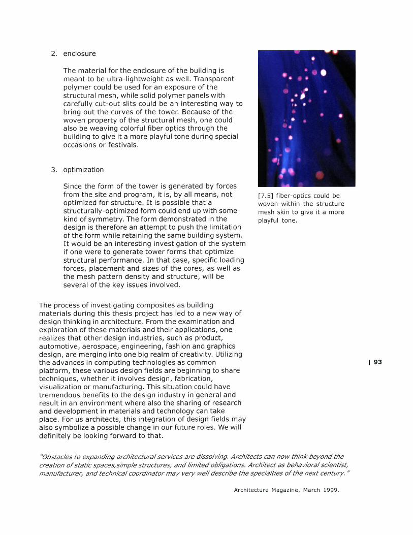
2. enclosure
The material for the enclosure of the building ismeant to be ultra-lightweight as well. Transparentpolymer could be used for an exposure of thestructural mesh, while solid polymer panels withcarefully cut-out slits could be an interesting way tobring out the curves of the tower. Because of thewoven property of the structural mesh, one couldalso be weaving colorful fiber optics through thebuilding to give it a more playful tone during specialoccasions or festivals.
3. optimization
Since the form of the tower is generated by forcesfrom the site and program, it is, by all means, notoptimized for structure. It is possible that astructurally-optimized form could end up with somekind of symmetry. The form demonstrated in thedesign is therefore an attempt to push the limitationof the form while retaining the same building system.It would be an interesting investigation of the systemif one were to generate tower forms that optimizestructural performance. In that case, specific loadingforces, placement and sizes of the cores, as well asthe mesh pattern density and structure, will beseveral of the key issues involved.
[7.5] fiber-optics could bewoven within the structuremesh skin to give it a moreplayful tone.
The process of investigating composites as buildingmaterials during this thesis project has led to a new way ofdesign thinking in architecture. From the examination andexploration of these materials and their applications, onerealizes that other design industries, such as product,automotive, aerospace, engineering, fashion and graphicsdesign, are merging into one big realm of creativity. Utilizingthe advances in computing technologies as commonplatform, these various design fields are beginning to sharetechniques, whether it involves design, fabrication,visualization or manufacturing. This situation could havetremendous benefits to the design industry in general andresult in an environment where also the sharing of researchand development in materials and technology can takeplace. For us architects, this integration of design fields mayalso symbolize a possible change in our future roles. We willdefinitely be looking forward to that.
"Obstacles to expanding architectural services are dissolving. Architects can now think beyond thecreation of static spaces,simple structures, and I/mited ob/Igations. Architect as behavioral scientist,manufacturer, and technical coordinator may very well describe the specialties of the next century."
Architecture Magazine, March 1999.
1 93
bibliography
books
The Art of Accident.NAI Publishers / V2_Organisatie. Rotterdam, 1998.
Beaudoin, James J.Handbook of Fiber-Reinforced Concrete: Principles, Proper-ties, Developments and ApplicationsNoyes Publications. USA. 1990
Beukers, Adriaan.Lightness: The inevitable renaissance of minimum energystructures010 publishers. Rotterdam. 1998
Building materials and technology in Hong KongAll Arts Limited, Hong Kong. 1991
Coleman, Elizabeth Ann. The Genius of Charles JamesThe Brooklyn Museum. 1982
Daniel, James I.Fiber Reinforced Concrete: Developments and InnovationsAmerican Concrete Institute. USA. 1994
Friedman, Mildred S.Gehry TalksRizzoli Internaional Publications. 1999
94 | Galasso, Francis S.Advance Fibers and CompositesGordon and Breach Science Publishers. 1989
Gill, R. M.Carbon fibers in composite materialsIliffe Books, an imprint of the Butterworth Group. 1972
Hollaway L.Polymer Composites for Civil and Structural EngineeringBlackie Academic and Professional. London. 1990
Hong Kong - City of VisionHinge Marketing Ltd. 1996.
Ito, Toyo.Blurring Architecture.Suemondt-Lugwig-Museum Aachen and Edizioni Charta, Milano. 2000
Krausse, Joachim.Your Private Sky: R. Buckminster FullerLars Muller Publishers. 1999
Lynn, Greg.Animate FormPrinceton Press. 1999
The Product BookBritish Design and Art DirectionA D&AD Mastercraft Series publication. 1999
Starck, PhilippeStarckTaschen America. 2000
Thompson, Jon.Richard DeaconPhaidon Press Limited, London. 1995
periodicals
Automobile magazine, December 2000.FiberArt. p. 112-113
Archis, February 2000.Building a Better Blob. R 126-130
The Architects' Journal, July 12, 1995Advanced construction materials. p.37-38
The Architects' Journal, June 18, 1998 I 95Building with composites. R 37 -38
The Architects' Journal, September 10, 1998Moulding Architecture. P. 60-61
Architectural Record, March 2000.Criticism The Seductive Lvmh Tower. p. 98-10 1
Architecture, March 1999.Learning From the Product Makers. p. 132-134
Detail magazine, June 2000.Hanover Expo 2000. p. 1042-1048
Metropolis, July/August 1994.Bauhaus Workshops. p. 38-45

websites
on designers:
Marc Newsonhttp://www. marc-newson. com
Greg Lynn - F O R Mhttp://www.g/form. com
Kovac Malone architectsh7ttp.//www. comcen. com. au/~kovacmalone/
on context
Hong Kong Tourist Associationhttp./www. hkta. org
Hong Kong Survey and Mapping Officehttp.//www. info.go v. hk//andsd/mapping
15 Beacon Hotel, Bostonhttp://www.xvbeacon. com
on materials and manufacturing
Carbcom - supplier of high-tech laminateshttp.//www. carb. com
CTEK: Creative Technologieshttp://www. ctek-on -ine. com
Strongwell Corporation - pultruded composites manufacturerhttp://www.strongwe. com
96 IAdvanced Composites Inc. - composite manufacturingspecialistshittp://www. advancedcomposites. com
Fiber Glast Development Corporationhttp://wwwflbreglast. com
Glass Incorporated Internationalhttp://www.g/assint. com/
Retail Source - retail design, construction and visualpresentationhttp://www. retai/source. com/informaton/fiberrc/fiber rc. htm/

Mays Concrete Contractorshttp./www. maysconcrete. com/gfrc. htm
on applications
Aegis Handmade Carbon Fiber Bicycleshttp.//www.aegisbicycles.coM
The Boeing Companyh7ttp./www.boeing.com
Burton Snowboard Companyhttp://www.burton.com
Ducati Motorbikeshttp://www.ducati.com
Emergent Design Group, MIThttp:/web. mit. edu/arch/edg
Mercedes-Benz of Americahttp://www.mbusa.coM
McLaren - Official websitehttp://www.mclaren.com
Porschehttp://www.porsche. com
Quicksilver (WSR) Ltd./ttp.//www. quicksiiver-wsr. co. uk
Vectran FiberIhttp://www. vectranfiber. com
VentureStar - reusable space launch vehicehttp.//www. venturestar. com | g97

image credits
All images are credited to the author unless listed below.
[1.1] http.//www.nokla.com
[1.2] http://www.app/e.com
[1.3] http://www. marc-newson. com
[1.4] Gehry Talks
[1.5] The Product Book
[1.6] 7ttp://www. ctek-on-ine. com
[1.7] http./www. ctek-on -line. com
[1.8] /7ttp./www.ctek-on-line.com
[1.9] http./www. ctek-on-line. com
[1.10] Wallpaper magazine, Jan/Feb 2001
[1.11] Metropolis magazine, July/Aug 1994
[1.12] http://www. abb-architekten. com
[1.13] 17ttp./www.g/form. com
98 [1.14] The Product Book
[1.15] Starck
[1.16] http.//www. comcen. com. au/~kovacma/one/
[1.17] http.//www. vitra.com
[1.18] http./www. vitra.corm
[1.19] http://www. vitra. com
[1.20] http://www. esplanade. com. sg
[1.21] Blurring Architecture
[1.22] /7ttp://www. vitra.com

[1.23] Architectural Record, March 2000
[1.24] Blurring Architecture
[2.1] Automobile magazine, December 2000
[2.2] http://www.carb. com
[2.3] http://www.carb. com
[2.4b] http://www.imagebank.com
[2.5] Fiber Reinforced Concrete: Principles,development and applications
[2.8] http://www.strongwe//. com
[2.9] http://www.strongwe/.com
[2.10] http://www.strongwe//. com
[2.11] http://www.venturestar.com
[2.12] http.//www.ducat.com
[2.13] http.//www.mclaren.com
[2.14] http://www.porsche. com
[2.15] http://www.porsche. corn
[2.16] http://www. quicksilver- wsr. co. uk
[2.17] http://www.burton.com
[2.18] 7ttp.://www.rmbusa.com
[2.19] http://www.imagebank.com 99
[3.1] Hong Kong - City of Vision
[3.2] http://www.hkta.org
[3.3] http.//www.hkta. org
[3.4] Hong Kong - City of Vision
[3.5] Hong Kong - City of Vision
[3.6] Hong Kong - City of Vision
[3.7] Building materials and technology in Hong Kong

[3.8] hittp://www. imagebank. com
[3.9] Building materials and technology in HongKong
[3.10] Hong Kong - City of Vision
[3.11] Building materials and technology in HongKong
[3.12] Building materials and technology in HongKong
[3.13] Hong Kong Survey and Mapping Office
[3.14] Architectural Service Department, Hong Kong
[3.15] http://www.hkta.org
[3.16] http://www.hkta. org
[3.17] http://www.hkta.org
[3.18] http://www./hkta.org
[3.23] Hong Kong - City of Vision
[3.24] Hong Kong - City of Vision
[3.25] Hong Kong - City of Vision
[4.4] http://www.imagebank.com
[4.5] http://www.imagebank.com
100 | [4.6] Gehry Talks
[4.7] Polymer Composites for Civil and StructuralEngineering
[4.8] http :1/web. mit. edu/arch/edg
[4.9] Richard Deacon
[4.10] Richard Deacon
[4.11] Richard Deacon
[4.12] The Genius of Charles James
[4.13] The Genius of Charles James
[4.14] Your Private Sky, R. Buckminster Fuller
[4.17] Building materials and technology in HongKong
[4.18] http://www.hkta.org
[4.19] http://www.hikta. org
[4.20] http://www.xvbeacon. com
[4.21] http://www.xvbeacon. com
[4.22] http.//www.xvbeacon. com
[6.1] photo taken by Devyn Weiser
[6.2] photo taken by Devyn Weiser
[6.3] photo taken by Devyn Weiser
[7.4] Detail Magazine
[7.5] Detail Magazine
1 101

resources
hardware:
Dell Precision Workstation 420Dual 1-Ghz Pentium III processors512 mb of RDRAM36 gig Hard drive
Fujifilm Finepix 4700 Digital CameraWith 32mb smart media card
software:
Autodesk AutoCAD 2000Autodesk Mechanical Desktop 5Kinetix 3D Studio Max Release 3.0Adobe Photoshop 5.5Adobe Pagemaker 6.5Rhinoeros 1.0Quickslice 6Macromedia Dreamweaver 3
102 |
Related Documents