Installation Manual and Operating Instructions Continuous Flow Gas Water Heaters (External Models) HydroPower TF250-8G(10H)/ TF325-8G(13H)/ TF400-8G(16H) 8 716 473 071 (2015/04) AU Read installation manual prior to installation of this unit! Read user manual before putting this unit in operation! Observe the warnings in the manuals! The installation room must fulfill the ventilation requirements! Installation by an authorised person only!

Welcome message from author
This document is posted to help you gain knowledge. Please leave a comment to let me know what you think about it! Share it to your friends and learn new things together.
Transcript

Installation Manual and Operating Instructions
Read installation manual prior to installation of this unit!Read user manual before putting this unit in operation!
Observe the warnings in the manuals!The installation room must fulfill the ventilation requirements!
Installation by an authorised person only!
Continuous Flow Gas Water Heaters (External Models)
HydroPower
TF250-8G(10H)/ TF325-8G(13H)/ TF400-8G(16H)8 71
6 47
3 07
1 (2
015/
04) A
U
2 | Table of contents
Table of contents
1 Safety information and symbols . . . . . . . . . . . . . . . . 31.1 Key to symbols . . . . . . . . . . . . . . . . . . . . . . . 31.2 Safety information . . . . . . . . . . . . . . . . . . . . . 3
2 Technical Characteristics and Dimensions . . . . . . . 42.1 General Description . . . . . . . . . . . . . . . . . . . 42.2 Explanation of Model Code . . . . . . . . . . . . . . 42.3 Package contents . . . . . . . . . . . . . . . . . . . . . 42.4 Product overview . . . . . . . . . . . . . . . . . . . . . 42.5 Description of the Hot Water Unit . . . . . . . . 42.6 Dimensions . . . . . . . . . . . . . . . . . . . . . . . . . . 62.7 Electrical scheme . . . . . . . . . . . . . . . . . . . . . 72.8 Technical characteristics . . . . . . . . . . . . . . . 7
3 Regulations . . . . . . . . . . . . . . . . . . . . . . . . . . . . . . . . . . 8
4 Installation . . . . . . . . . . . . . . . . . . . . . . . . . . . . . . . . . . 84.1 Important information . . . . . . . . . . . . . . . . . . 94.2 Requirements of the installation location . 104.3 Hot Water Unit mounting . . . . . . . . . . . . . . 114.4 Water connection . . . . . . . . . . . . . . . . . . . . 124.5 Gas connection . . . . . . . . . . . . . . . . . . . . . . 124.6 Testing . . . . . . . . . . . . . . . . . . . . . . . . . . . . . 12
5 Commissioning . . . . . . . . . . . . . . . . . . . . . . . . . . . . . . 125.1 Before starting up the heater . . . . . . . . . . . 125.2 Remove the front cover . . . . . . . . . . . . . . . . 125.3 Inlet pressure adjustment . . . . . . . . . . . . . . 135.4 Burner pressure adjustment . . . . . . . . . . . . 135.5 Conversion to a different type of gas . . . . . 14
6 Operating instructions . . . . . . . . . . . . . . . . . . . . . . . 146.1 Consumer gas adjustment . . . . . . . . . . . . . 146.2 Consumer temperature/flow adjustment . 14
7 Maintenance . . . . . . . . . . . . . . . . . . . . . . . . . . . . . . . . 15
8 Troubleshooting . . . . . . . . . . . . . . . . . . . . . . . . . . . . . 168.1 Problem/cause/solution . . . . . . . . . . . . . . . 16
9 Environmental protection . . . . . . . . . . . . . . . . . . . . 17
10 Water quality . . . . . . . . . . . . . . . . . . . . . . . . . . . . . . . 18
11 Warranty details . . . . . . . . . . . . . . . . . . . . . . . . . . . . 19
8 716 473 071 (2015/04) HydroPower
Safety information and symbols | 3
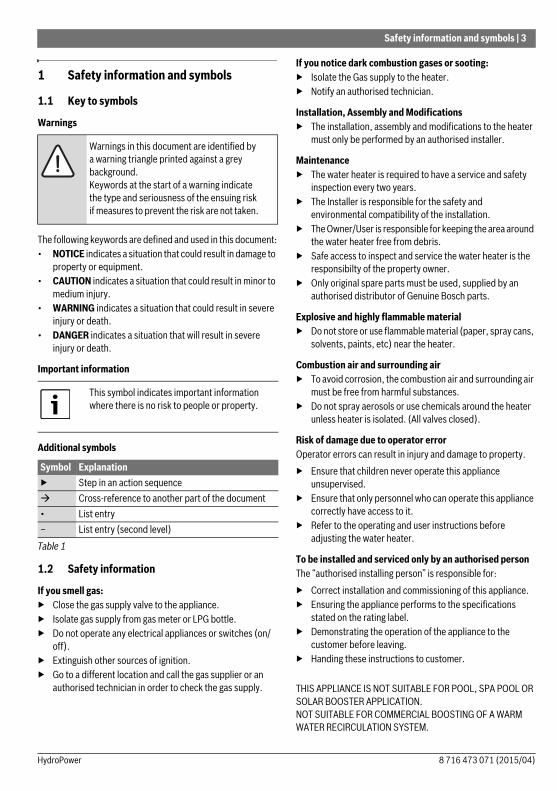
1 Safety information and symbols
1.1 Key to symbols
Warnings
The following keywords are defined and used in this document:• NOTICE indicates a situation that could result in damage to
property or equipment.• CAUTION indicates a situation that could result in minor to
medium injury.• WARNING indicates a situation that could result in severe
injury or death.• DANGER indicates a situation that will result in severe
injury or death.
Important information
Additional symbols
1.2 Safety information
If you smell gas:▶ Close the gas supply valve to the appliance.▶ Isolate gas supply from gas meter or LPG bottle.▶ Do not operate any electrical appliances or switches (on/
off).▶ Extinguish other sources of ignition.▶ Go to a different location and call the gas supplier or an
authorised technician in order to check the gas supply.
If you notice dark combustion gases or sooting:▶ Isolate the Gas supply to the heater.▶ Notify an authorised technician.
Installation, Assembly and Modifications▶ The installation, assembly and modifications to the heater
must only be performed by an authorised installer.
Maintenance▶ The water heater is required to have a service and safety
inspection every two years.▶ The Installer is responsible for the safety and
environmental compatibility of the installation.▶ The Owner/User is responsible for keeping the area around
the water heater free from debris.▶ Safe access to inspect and service the water heater is the
responsibilty of the property owner.▶ Only original spare parts must be used, supplied by an
authorised distributor of Genuine Bosch parts.
Explosive and highly flammable material▶ Do not store or use flammable material (paper, spray cans,
solvents, paints, etc) near the heater.
Combustion air and surrounding air▶ To avoid corrosion, the combustion air and surrounding air
must be free from harmful substances.▶ Do not spray aerosols or use chemicals around the heater
unless heater is isolated. (All valves closed).
Risk of damage due to operator errorOperator errors can result in injury and damage to property.▶ Ensure that children never operate this appliance
unsupervised.▶ Ensure that only personnel who can operate this appliance
correctly have access to it.▶ Refer to the operating and user instructions before
adjusting the water heater.
To be installed and serviced only by an authorised personThe “authorised installing person” is responsible for:▶ Correct installation and commissioning of this appliance.▶ Ensuring the appliance performs to the specifications
stated on the rating label.▶ Demonstrating the operation of the appliance to the
customer before leaving.▶ Handing these instructions to customer.
THIS APPLIANCE IS NOT SUITABLE FOR POOL, SPA POOL OR SOLAR BOOSTER APPLICATION.NOT SUITABLE FOR COMMERCIAL BOOSTING OF A WARM WATER RECIRCULATION SYSTEM.
Warnings in this document are identified by a warning triangle printed against a grey background.Keywords at the start of a warning indicate the type and seriousness of the ensuing risk if measures to prevent the risk are not taken.
This symbol indicates important information where there is no risk to people or property.
Symbol Explanation▶ Step in an action sequence Cross-reference to another part of the document• List entry– List entry (second level)
Table 1
8 716 473 071 (2015/04)HydroPower

4 | Technical Characteristics and Dimensions
2 Technical Characteristics and Dimensions
2.1 General Description
2.2 Explanation of Model Code
2.3 Package contents• Gas hot water unit• Documentation
2.4 Product overviewHydroPower Ignition is exclusive to Bosch - it does not require a 240V power supply.• HydroPower uses the energy created by the water flow to
ignite the burner and begin the heating process. The unit only starts when a hot water tap is opened. Once the tap is turned off, the unit turns off.
2.5 Description of the Hot Water Unit• Hot Water Unit for external wall-mounting only• Available in Natural gas or LP gas• Hydrogenerator produces sufficient energy to ignite and
control the heater– Water enters the Hydrogenerator– The turbine spins with water flow– A voltage is generated by the turbine– This voltage causes the ignition control unit to light a
temporary pilot– The water pressure opens the main burner gas valve
and the pilot ignites the main burner, the pilot then goes out
– The water flows through the heat exchanger where it is heated
• Safety devices:
– Flame rod to check for accidental extinction of the burner flame
– Overtemperature switch to prevent overheating.• Water filter on the inlet water supply
EconomicalOnly heating water when required, the Bosch range is extremely economical to run.
VersatileLPG models are particularly popular in country areas, where Natural Gas is not available.
Low Temperature AreasIn areas where the atmospheric temperature may drop to 0 °C for brief periods, the installation of an EXOGEL valve (part number H707 060 151) will minimise the possibility of damage to the appliance if the water freezes.
Fig. 1 EXOGEL valve
[1] Hot water[2] Cold water[3] EXOGEL valve
Models Bosch Hydropower TF250/325/400Category CONTINUOUS FLOWType GAS - EXTERNAL INSTALLATION
Table 2
TF (Top Flue) 250 (10 litres/min @ 25 °C Rise)
G (Hydrogenerator)
TF (Top Flue) 325 (13 litres/min @ 25 °C Rise)
G (Hydrogenerator)
TF (Top Flue) 400 (16 litres/min @ 25 °C Rise)
G (Hydrogenerator)
Table 3
NOTICE: This water heater MUST NOT be installed in areas where the temperature remains below 0 °C for extended periods.
8 716 473 071 (2015/04) HydroPower
Technical Characteristics and Dimensions | 5
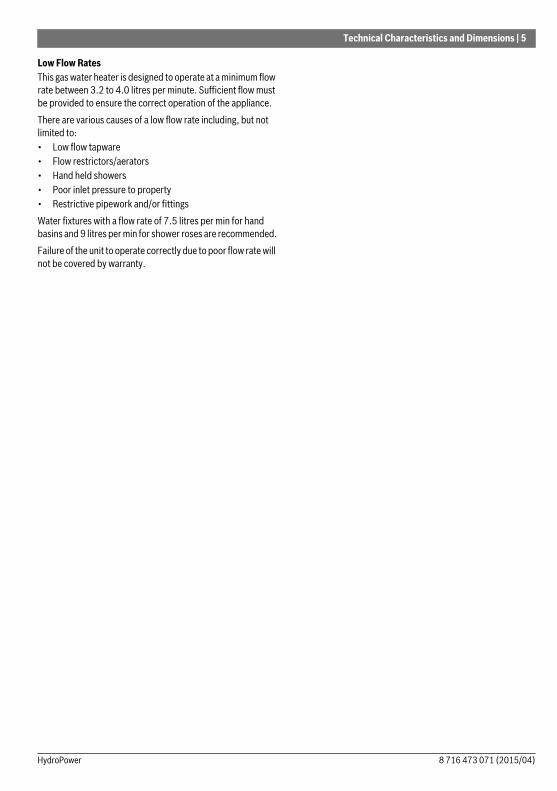
Low Flow RatesThis gas water heater is designed to operate at a minimum flow rate between 3.2 to 4.0 litres per minute. Sufficient flow must be provided to ensure the correct operation of the appliance.There are various causes of a low flow rate including, but not limited to:• Low flow tapware• Flow restrictors/aerators• Hand held showers• Poor inlet pressure to property• Restrictive pipework and/or fittingsWater fixtures with a flow rate of 7.5 litres per min for hand basins and 9 litres per min for shower roses are recommended.Failure of the unit to operate correctly due to poor flow rate will not be covered by warranty.
8 716 473 071 (2015/04)HydroPower
6 | Technical Characteristics and Dimensions
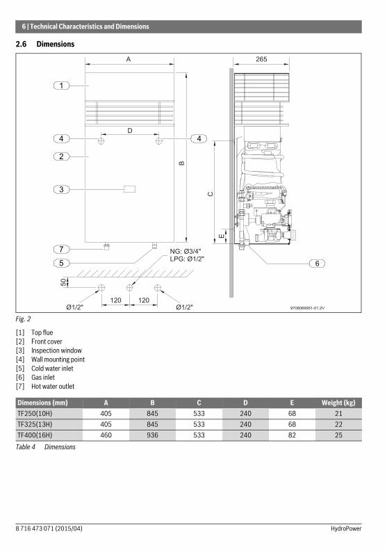
2.6 Dimensions
Fig. 2
[1] Top flue[2] Front cover[3] Inspection window[4] Wall mounting point[5] Cold water inlet[6] Gas inlet[7] Hot water outlet
265
B
9708069951-01.2V
A
C
E
2
D
3
6
1
50
120120
Ø1/2" Ø1/2"
NG: Ø3/4"
LPG: Ø1/2"
4 4
7
5
Dimensions (mm) A B C D E Weight (kg)TF250(10H) 405 845 533 240 68 21TF325(13H) 405 845 533 240 68 22TF400(16H) 460 936 533 240 82 25
Table 4 Dimensions
8 716 473 071 (2015/04) HydroPower

Technical Characteristics and Dimensions | 7
2.7 Electrical scheme
Fig. 3
[1] Main Solenoid Valve[2] Diaphragm Switch[3] Pilot Solenoid Valve[4] Ionisation electrode (Flame Rod)[5] Ignition electrode (Spark Electrode)
[6] Temperature limiter[7] Hydrogenerator[8] LED (green)[9] LED (red)
2.8 Technical characteristics
4 5
3
1
2
9
6
8
S HV
9708069951-11.1V7
Technical characteristics Units TF250H / 10H TF325H / 13H TF400H / 16HGas ConsumptionNominal Gas Consumption MJ/h 79 104 130Supply pressure flowingNatural gas (When operating) kPa 1.13 1.13 1.13LP gas (When operating) kPa 2.75 2.75 2.75Number of injectors 12 14 18Water dataMaximum permissible pressure (Static) kPa 800 800 800Temperature selector in fully clockwise positionTemperature rise (Above incoming water temperature) °C 50 50 50Water flow range (Litres per minute) l/min 3.2 to 5 3.2 to 6.5 3.2 to 8Minimum operating water pressure kPa 30 40 50Minimum constant water pressure for minimum flow kPa 60 100 130
Table 5
8 716 473 071 (2015/04)HydroPower

8 | Regulations
3 RegulationsAll local by-laws and regulations pertaining to installation and use of gas appliances must be observed.This appliance must be installed in accordance with the manufacturers installation instructions, AS/NZS5601, AS/NZS3500 and all Local Building & Gas fitting regulations.This appliance must not be installed indoors or in an enclosed space. This appliance is approved for outdoor installation only. Do not install this appliance with any modification or alteration.Failure to install this appliance in accordance with these installation instructions will void the warranty and may create an unsafe situation.
4 Installation
Fig. 4 Heat shield
Temperature selector in fully anti-clockwise positionTemperature rise (Above incoming water temperature) °C 25 25 25Water flow range (Litres per minute) l/min 4 to 10 4 to 13 4 to 16Minimum operating water pressure kPa 45 45 45Minimum constant water pressure for maximum flow kPa 100 140 170
Technical characteristics Units TF250H / 10H TF325H / 13H TF400H / 16H
Table 5
DANGER: This appliance must not be installed indoors or in an enclosed space in accordance with AS/NZS5601.
DANGER: Explosion Risk!▶ Always turn off the gas valve before
carrying out any work on components which carry gas.
DANGER: Appliance malfunction!This appliance must be installed with no obstructions to air entry openings at the front, rear, side, or top.▶ Periodic checking of openings to ensure
no blockage or obstruction of the air openings from plants, debris, or insects must be carried out.
NOTICE: Property damage!If the appliance is to be installed on a combustible surface:▶ Use a heat shield as per AS/NZS5601 -
accessory 9 708 061 400.ZG1 ( Fig. 4).
The installation and the initial startup are to be carried out only by an authorised person.
Not suitable for pool, spa pool, or solar booster application.Not suitable for commercial boosting of a warm water recirculation system.
This appliance should only be installed in applications where incoming cold water temperature does not exceed 40 °C.
400 m
m
850 mm
230 m
m
=
9708069951-12.1V
=
8 716 473 071 (2015/04) HydroPower

Installation | 9
4.1 Important information▶ Determine most suitable location for the appliance. Install
only on an external wall as close as possible to the most frequently used hot water outlet. If the unit is to be installed on a combustible surface, use a heat shield. (part number 9708 061 400.ZG1). Allow a minimum air gap of 10mm between the flue and the heat shield.
▶ Ensure the mounting structure is capable of supporting the weight of the appliance once installed. Secure the appliance to the wall using fixings suitable for the weight of the appliance and the wall material.
▶ As the water temperature at the outlet may exceed 50 °C, a temperature limiting device (such as a tempering valve) must be fitted to pipework feeding sanitary fixtures used for the purpose of personal hygiene as per AS3498.
▶ Install gas and water isolation valves as close as possible to the heater. Only use gate valve or full flow ball valve (fixed mechanism type) for cold water.
▶ Check the cold water supply pressure to ensure it meets the required supply pressure for the appliance. ( table 5).
▶ If the inlet water pressure exceeds 800 kPa, a pressure limiting valve (500 kPa) MUST be fitted. The preferable location for the pressure limiting valve is at the water meter.
▶ Where the pressure limiting valve is less than 3 metres from the hot water unit, it must be fitted in conjunction with a cold water expansion valve (700 kPa), between the water heater and the pressure limiting valve.
▶ Failure to comply with this requirement may void the warranty.
▶ Refer to AS/NZS5601 for the relevant gas pipe sizing.▶ After finishing the gas piping system, the pipes must be
thoroughly purged and leak tested. This test must be performed with the gas isolation valve of the appliance closed.
▶ Ensure the gas pressure and flow through the regulator are appropriate for the consumption of the heater (à table 5).Refer to AS/NZS5601 and AS3500.1 for the relevant pipe size.
Note: Incorrect pipe sizing or gas supply pressure may cause the appliance to underperform. Service calls for incorrect pipe sizing and/or gas pressure, will NOT be covered under warranty.
Minimum water supply pressure must meet the requirements set out in table 5. Water fixtures with a flow rate of 7.5 litres per min for hand basins and 9 litres per min for shower roses are recommended.
To reduce the chance of corrosion, installation in a marine environment should be avoided. Premature corrosion due to the installation environment would not be covered by warranty.
All gas appliances require adequate air intake to ensure correct combustion. Insects and dirt ingress may affect combustion causing sooting. If you notice sooting from the flue outlet the unit would require servicing. Pest and dirt ingress is not covered by the manufacturers warranty.
8 716 473 071 (2015/04)HydroPower

10 | Installation
4.2 Requirements of the installation location• Comply with the specific instructions for each State.• Install the appliance in an outdoor location where it will not
be exposed to temperatures below zero.• Install the appliance in accordance with the minimum
installation clearances indicated in Fig. 5, according to AS5601.
• The gas heater must not be installed over a heat source.• Do not obstruct the openings at top, bottom and rear of
appliance.• Maximum of 2 meters from the ground to the base of the
appliance.• Top and bottom areas must be clear from any obstacles at
least 30 cm.
Fig. 5 Minimum clearances (use as a guide only, always refer to AS/NZS5601)
[D] Openable Door[T] Flue terminal[M] Gas meter[I] Mechanical air inlet[P] Electricity meter or fuse box[W] Openable window
c
j
j
d
a
n
be f
h
g
k W
T M
T
I
P
D
9708069951-14.2V
8 716 473 071 (2015/04) HydroPower
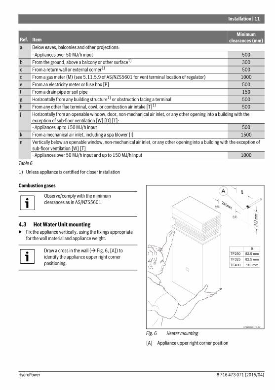
Installation | 11
Combustion gases
4.3 Hot Water Unit mounting▶ Fix the appliance vertically, using the fixings appropriate
for the wall material and appliance weight.
Fig. 6 Heater mounting
[A] Appliance upper right corner position
Ref. ItemMinimum
clearances (mm)a Below eaves, balconies and other projections:
- Appliances over 50 MJ/h input 500b From the ground, above a balcony or other surface1)
1) Unless appliance is certified for closer installation
300c From a return wall or external corner1) 500d From a gas meter (M) (see 5.11.5.9 of AS/NZS5601 for vent terminal location of regulator) 1000e From an electricity meter or fuse box [P] 500f From a drain pipe or soil pipe 150g Horizontally from any building structure1) or obstruction facing a terminal 500h From any other flue terminal, cowl, or combustion air intake [T]1) 500j Horizontally from an openable window, door, non-mechanical air inlet, or any other opening into a building with the
exception of sub-floor ventilation [W] [D] [T]:- Appliances up to 150 MJ/h input 500
k From a mechanical air inlet, including a spa blower [I] 1500n Vertically below an openable window, non-mechanical air inlet, or any other opening into a building with the exception of
sub-floor ventilation [W] [T]- Appliances over 50 MJ/h input and up to 150 MJ/h input 1000
Table 6
Observe/comply with the minimum clearances as in AS/NZS5601.
Draw a cross in the wall ( Fig. 6, [A]) to identify the appliance upper right corner positioning.
8 716 473 071 (2015/04)HydroPower

12 | Commissioning
4.4 Water connectionPurge the water pipes before connection, because the presence of dirt may reduce the flow and, in extreme cases, cause a blockage.▶ Identify the cold water pipe and the hot water pipe, so as to
avoid any possible cross-connection.▶ Check and ensure water filter cleanness.
Fig. 7 Water connection
[A] Hot Water Outlet[B] Cold Water Inlet
4.5 Gas connection
Gas regulatorThe appliance is supplied with a gas pressure regulator already installed. A regulator must be fitted to LPG cylinders to supply
the correct pressure to the appliance regulator. The gas pressures require setting upon installation.
4.6 Testing▶ Turn on the gas and water valves and check all connections
for leaks. If all connections are sound then follow procedures set out in Section 5 for adjustment of Gas Pressures to complete appliance commissioning.
5 Commissioning
5.1 Before starting up the heater
5.2 Remove the front cover▶ Loosen the two knurled screws located on the rear side of
the front panel.
Fig. 8 Front cover removal
CAUTION: Never rest the gas heater on the water or gas connections.
CAUTION: Isolating valve on the water inlet line must be a Gate or ¼ turn full flow Ball Valve. A Stop Valve, Duo Valve or Non-Return Valve must not be fitted.
DANGER: If local regulations are not followed, a fire or explosion could result causing property damage, personal injury, or loss of life.
Size gas supply as per AS/NZS5601.Incorrect gas pipe sizing will not be covered by the warranty.
▶ Open all water and gas isolation valves.▶ Purge the pipes.
CAUTION: ▶ Initial startup must be performed by an
authorised gas fitter who will provide the customer with all the necessary information for optimum operation of the gas heater.
970806995-08.2V
8 716 473 071 (2015/04) HydroPower

Commissioning | 13
5.3 Inlet pressure adjustment
Gas pressure adjustment (commissioning) MUST be carried out upon installation. ▶ Check the gas indicated on the rating plate and front cover
label is the same as the gas to which the heater is connected.
▶ Loosen the pressure test point screw on the left hand side of the gas valve (Fig. 10, [A]) and attach a manometer.
Static Pressures should be greater than or equal to the figures in table 7.Adjust the appliance regulator to achieve the figures in table 7 with the unit operating and all hot water taps open for full water flow through the unit. If the operating inlet pressure cannot be achieved there may be an issue with the gas supply meter (NG), cylinder regulator (LPG), or pipe sizing (Ref AS/NZS5601). This must be resolved before proceeding. ▶ Remove manometer and tighten test point screw.
5.4 Burner pressure adjustment▶ Loosen the burner test point captive screw ( Fig. 9 [D]).▶ Connect a manometer to the burner pressure measuring
point.
Fig. 9 Burner pressure measurement point
Maximum gas flow adjustment▶ Turn on the water heater with the gas control slide set to the
Right (maximum gas flow).▶ Ensure the water control knob is fully open (anticlockwise).▶ Adjust appliance regulator to the maximum burner
pressure figure on the rating plate (See table 8 below).▶ Turn the water control knob fully clockwise and check that
the burner pressure does not exceed the maximum.
Minimum gas flow adjustment▶ With the heater operating, move the gas selector to the Left
(minimum gas position).▶ Ensure the water control knob is fully closed (clockwise).▶ Open various hot water taps.▶ Using the adjusting screw (Fig. 11, [B]) to adjust the gas
pressure to the values indicated in table 9.▶ Close the hot water taps.
DANGER: The following procedures must only be performed by a qualified technician.
Measurements should be made with unit operating with all hot water taps opened to achieve maximum water flow through the unit.If possible all other gas appliances (ducted heating etc.) should be operating at the same time.
Natural gas LP gas
Inlet Pressure (kPa)
TF250/10H1.13 2.75TF325/13H
TF400/16HTable 7 Inlet pressure
Natural gas LP gas
Max. Burner Pressure (kPa)
TF250/10H 0.89 2.60TF325/13H 0.84 2.60TF400/16H 0.78 2.60
Table 8 Maximum burner pressure
D9708069951-9.1V
8 716 473 071 (2015/04)HydroPower
14 | Operating instructions
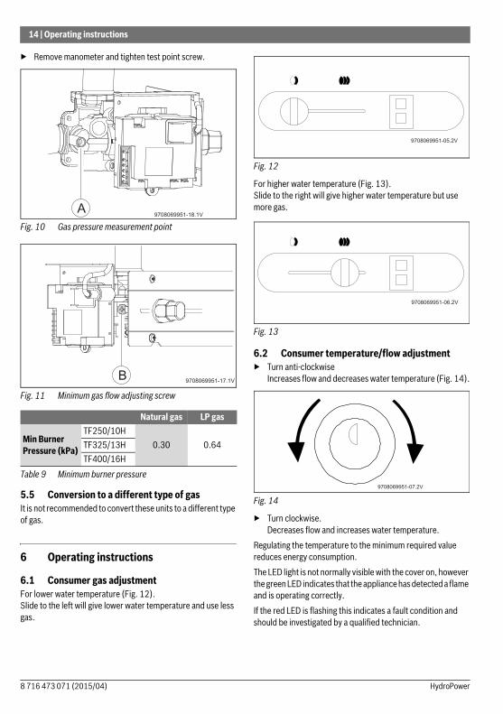
▶ Remove manometer and tighten test point screw.
Fig. 10 Gas pressure measurement point
Fig. 11 Minimum gas flow adjusting screw
5.5 Conversion to a different type of gasIt is not recommended to convert these units to a different type of gas.
6 Operating instructions
6.1 Consumer gas adjustmentFor lower water temperature (Fig. 12).Slide to the left will give lower water temperature and use less gas.
Fig. 12
For higher water temperature (Fig. 13).Slide to the right will give higher water temperature but use more gas.
Fig. 13
6.2 Consumer temperature/flow adjustment▶ Turn anti-clockwise
Increases flow and decreases water temperature (Fig. 14).
Fig. 14
▶ Turn clockwise.Decreases flow and increases water temperature.
Regulating the temperature to the minimum required value reduces energy consumption.The LED light is not normally visible with the cover on, however the green LED indicates that the appliance has detected a flame and is operating correctly.If the red LED is flashing this indicates a fault condition and should be investigated by a qualified technician.
Natural gas LP gas
Min Burner Pressure (kPa)
TF250/10H0.30 0.64TF325/13H
TF400/16HTable 9 Minimum burner pressure
9708069951-18.1VA
9708069951-17.1VB
8 716 473 071 (2015/04) HydroPower
Maintenance | 15
7 MaintenanceTo ensure ongoing performance and safety, we require the appliance be serviced every two years.
▶ Your appliance should only be attended by a Bosch authorised service agent.
▶ Only use original replacement parts.
DANGER: Failure to perform maintenance procedures can lead to appliance malfunction, errors, service calls and loss of manufacturers warranty.
Maintenance must only be performed by a qualified technician. Maintenance information is contained in a service manual available to licenced technicians upon request from Bosch.
8 716 473 071 (2015/04)HydroPower
16 | Troubleshooting
8 Troubleshooting
8.1 Problem/cause/solutionAssembly, maintenance, and repairs must be performed by qualified technicians only. The following chart offers possible solutions to problems.In most instances it is advisable to have a technician attend and inspect the appliance.Some further trouble shooting advice may be found at http://www.bosch-climate.com.au
Problem Cause SolutionFluctuation in hot water temperature. Insufficient flow through the hot water
unit.
Tapware does not give sufficient flow (section 2.5, Low Flow Rates).
Increase water flow by opening multiple hot taps.If fluctuation ceases then check for blockages, aerators dirty etc.
Change tapware to meet requirements.
Unit not working. (No Hot Water). Locked out due to failure to ignite.The ignition will lock out after 20 seconds if a flame is not established.
Turn off all hot water taps and retry.If unit still does not work - isolate valves at unit for 20 seconds. Open valves and retry.If unit still fails to ignite refer to qualified technician.
Unit not working after change in Gas Supply (Maintenance work on Mains or change of LPG cylinders).
Air in gas lines. Turn on hot water tap inside house.Isolate water valve at unit for 20 seconds. Open valve and check if unit lights.Repeat this operation 3-4 times, if unit still fails to ignite call your Gas Retailer or a qualified technician.
Not hot enough. Insufficient Natural Gas supply.
Consumer gas and water controls.
Gas Cylinders may be empty / undersized (45kg cylinders recommended for LPG).
Requires a service technician to inspect and test gas supply pressures / recommission.
Adjust gas and water controls.
Smell of gas. Gas leak. Isolate Gas supply to hot water unit/premises.
Call your Gas Retailer or a qualified technician.
Temperature too hot in Summer. Incoming water temperature has increased with the ambient temperature and Gas control is on hot position (Fully right).
Adjust Water and Gas controls at the unit to achieve desired temperature.
Temperature too cold in Winter. Incoming water temperature has decreased with the ambient temperature.Gas control is on warm position (Fully Left).
Adjust Water and Gas controls at the unit to achieve desired temperature.
Table 10
8 716 473 071 (2015/04) HydroPower
Environmental protection | 17
9 Environmental protectionEnvironmental protection is a basic company strategy of Bosch. The quality of our products, profitability and environmental protection are equal-ranking goals for us. Laws and regulations concerning environmental protection are strictly observed. We use the best possible technology and materials, under economic considerations, to protect the environment.
PackagingWe participate in the recycling program of the respective country to ensure optimal recycling. All of our packaging materials are environmental-friendly and can be recycled.
Old appliancesOld appliances contain valuable materials that should be recycled.
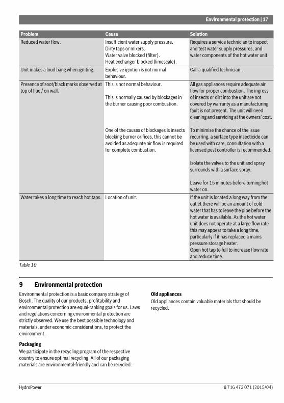
Reduced water flow. Insufficient water supply pressure.Dirty taps or mixers.Water valve blocked (filter). Heat exchanger blocked (limescale).
Requires a service technician to inspect and test water supply pressures, and water components of the hot water unit.
Unit makes a loud bang when igniting. Explosive ignition is not normal behaviour.
Call a qualified technician.
Presence of soot/black marks observed at top of flue / on wall.
This is not normal behaviour.
This is normally caused by blockages in the burner causing poor combustion.
One of the causes of blockages is insects blocking burner orifices, this cannot be avoided as adequate air flow is required for complete combustion.
All gas appliances require adequate air flow for proper combustion. The ingress of insects or dirt into the unit are not covered by warranty as a manufacturing fault is not present. The unit will need cleaning and servicing at the owners’ cost.
To minimise the chance of the issue recurring, a surface type insecticide can be used with care, consultation with a licensed pest controller is recommended.
Isolate the valves to the unit and spray surrounds with a surface spray.
Leave for 15 minutes before turning hot water on.
Water takes a long time to reach hot taps. Location of unit. If the unit is located a long way from the outlet there will be an amount of cold water that has to leave the pipe before the hot water is available. As the hot water unit does not operate at a large flow rate this may appear to take a long time, particularly if it has replaced a mains pressure storage heater.Open hot tap to full to increase flow rate and reduce time.
Problem Cause Solution
Table 10
8 716 473 071 (2015/04)HydroPower
18 | Water quality
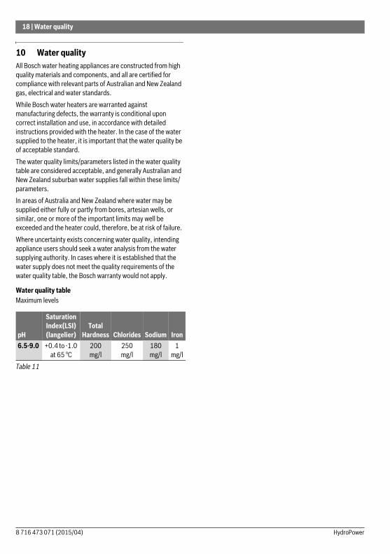
10 Water quality All Bosch water heating appliances are constructed from high quality materials and components, and all are certified for compliance with relevant parts of Australian and New Zealand gas, electrical and water standards.While Bosch water heaters are warranted against manufacturing defects, the warranty is conditional upon correct installation and use, in accordance with detailed instructions provided with the heater. In the case of the water supplied to the heater, it is important that the water quality be of acceptable standard.The water quality limits/parameters listed in the water quality table are considered acceptable, and generally Australian and New Zealand suburban water supplies fall within these limits/parameters.In areas of Australia and New Zealand where water may be supplied either fully or partly from bores, artesian wells, or similar, one or more of the important limits may well be exceeded and the heater could, therefore, be at risk of failure.Where uncertainty exists concerning water quality, intending appliance users should seek a water analysis from the water supplying authority. In cases where it is established that the water supply does not meet the quality requirements of the water quality table, the Bosch warranty would not apply.
Water quality tableMaximum levels
pH
SaturationIndex(LSI)(langelier)
Total Hardness Chlorides Sodium Iron
6.5-9.0 +0.4 to -1.0 at 65 °C
200 mg/l
250 mg/l
180 mg/l
1 mg/l
Table 11
8 716 473 071 (2015/04) HydroPower
Warranty details | 19
11 Warranty detailsRobert Bosch (Australia) Pty Ltd
Thermotechnology Division
Voluntary Repair or Replacement WarrantyAll Bosch products are carefully checked, tested and certified to Australian and New Zealand standards.
Important Note: Mandatory Australian Consumer Law statementIf you have purchased your product in Australia, you should be aware that:This warranty is provided in addition to other rights and remedies held by a consumer at law. Our goods come with guarantees that cannot be excluded under the Australian Consumer Law. You are entitled to a replacement or refund for a major failure and for compensation for any other reasonably foreseeable loss or damage. You are also entitled to have the goods repaired or replaced if the goods fail to be of acceptable quality and the failure does not amount to a major failure.
Important Note: New Zealand lawIf you have purchased your product in New Zealand, you should be aware that:This warranty is supplemental to any other rights and remedies you have under the Consumer Guarantees Act 1993 NZ, unless your purchase is made for commercial purposes, in which case Bosch excludes all consumer guarantees implied in the Consumer Guarantees Act 1993 NZ in respect of your product.
WarrantyBosch warrants, at its option, to repair or replace your water heater or relevant part thereof (Product) if such Product are faulty or defective in manufacture or materials during the warranty period specified below.The warranty period commences on the date of purchase. If the date of original purchase cannot be determined, then the warranty period will commence six (6) months after the date of manufacture stamped on the Product. Bosch may require evidence to verify the date of purchase.This warranty only covers repair or replacement of defective Product (including labour costs where indicated). It does not cover:• any costs incurred by the end user in normal or scheduled maintenance of the Product; or• subject to any law to the contrary, any damage to property, personal injury, direct or indirect loss, consequential losses or other
expenses arising from breach of this warranty. Any end user concerned with this exclusion should consider the "Important Note: Mandatory Australian Consumer Law statement” above
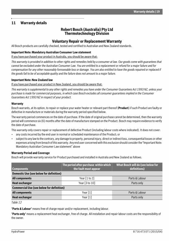
Warranty Period and CoverageBosch will provide warranty service for Product purchased and installed in Australia and New Zealand as follows.
"Parts & Labour" means free of charge repair and/or replacement, including labour."Parts only" means a replacement heat exchanger, free of charge. All installation and repair labour costs are the responsibility of the owner.
ComponentsThe period after purchase within which
the fault must appearWhat Bosch will do (see below for
definitions)Domestic Use (see below for definition)All components Year [1 to 2] Parts & LabourHeat exchanger Year [3 to 10] Parts onlyCommercial Use (see below for definition)All components Year [1] Parts & LabourHeat exchanger Year [1] Parts only
Table 12
8 716 473 071 (2015/04)HydroPower

20 | Warranty details
"Domestic use" warranty period applies to Product installed to supply hot water for use by individuals in domestic dwellings. For Product used for all other uses, the commercial use warranty period will apply. This includes, without limitation, installations such as centralised or bulk hot systems, hotels, sporting complexes, caravan parks, laundry facilities, restaurants and cafes.For “Parts only” warranty, the end user will be charged for service call costs and service technician fees in effecting the replacement.For valid claims within "Parts & Labour" warranty periods, the end user will not be charged for costs associated with making a warranty claim, including service call costs, any service technician fees or the cost of replacement parts and freight, provided that:• the Product is located within the usual operating area of an authorised service technician; and• the Product has been installed according to the installation instructions so as to provide adequate service accessIf the Product is not located within the usual operating area of an authorised service technician, the end user will be required to pay the service call costs associated with a service call under this voluntary warranty.Notwithstanding the above, if the Product has not been installed in accordance with the installation instructions in regards to access, or has been otherwise installed in location where service access is difficult, the end user will be required to pay charges associated with the difficult access. This includes, but is not limited to, the removal of walls or doors to gain access and the use of specialised equipment to move the Product or components to safe working levels. Where the Product cannot be safely accessed, Bosch may refuse to service the Product under this voluntary warranty.For invalid claims under this voluntary warranty, the end user will be liable for the costs of making the warranty claim including any service call costs.
Warranty ConditionsThis voluntary warranty is subject to the following conditions:• The Product must have been installed and correctly commissioned by an authorised and licensed installer in compliance with
applicable Australian Plumbing and Gas Standards. Proof may be required of correct commissioning of the Product (such as certificate of compliance). Claims for failures due to incorrect installation or commissioning are not covered under this voluntary warranty and may be rejected by Bosch.
• Where a Product or part thereof is replaced or repaired under this voluntary warranty, the balance of the original voluntary warranty will apply. The replacement Product or part does not carry a new voluntary warranty.
• The Product must have its original serial numbers and rating labels intact.• The warranty does not extend to any Product that have been completely or partially disassembled.• These warranty terms cannot be amended except in writing by an authorised officer of Bosch.• The warranty only applies to Product installed for an end user in Australia or New Zealand and purchased from Bosch or from a
reseller where the Product have been originally sold by Bosch.• Any claim made under this voluntary warranty meets the requirements set out below in the “How to Make a Warranty Claim”
section.
Warranty ExclusionsThis warranty will not apply to a defect or fault to the extent to which it arises:• due to storage, handling or installation of the Product otherwise than in accordance with instructions provided for the Product
by Bosch or without reasonable care, including installation of a Product which is of inappropriate size or type for the intended purpose;
• due to operation, use or maintenance of the Product otherwise than in accordance with instructions provided for the Product by Bosch or without reasonable care, including use of the Product with faulty or unsuitable plumbing, water pressure, power or gas supply;
• due to accidental damage or use of the Product for a purpose or in environmental conditions for which the Product were not designed or sold, or use of the products outside the specified or normal operating ranges for such Product.
• as a result of changes which occur in the condition or operational qualities of the Product due to climate or other environmental influence, foreign material contamination or water entry or as a result of exposure to excessive heat or solvents or because of use of non-potable water or bore water in the Product or damage as result of an Act of Nature including but not limited to storms, fires, floods and lightning strikes;
• from normal wear and tear or when replacement or repair of parts would be part of normal maintenance or service of the Product or where the damage is only to surface coating, varnish or enamel;
8 716 473 071 (2015/04) HydroPower
Warranty details | 21
• as a result of repairs, alterations or modifications to the Product which have been performed by a person who is not suitably qualified and experienced to perform works on the Product; or
• from the use of any spare parts not manufactured, sold or approved by Bosch in connection with the repair or replacement of Product.
This voluntary warranty does not apply to damage that has been caused by continued use of a Product after it is known, or would have been known with regular servicing, it is defective.
Wrong Deliveries and Transit DamageWrong deliveries, incorrect or damaged packing and transit damage claims are not warranty claims. Such cases should be directed to Bosch's Customer Service line in Australia on ph: 1300 307 037 or in New Zealand on ph: 0800 543 352.
How to Make a Warranty ClaimIf a Product fails within the warranty period, the end user must stop using the Product and make a claim as soon as possible, in any event before the end of the Warranty Period (see Deadlines for Submitting Warranty Claims below).To make a warranty claim under this voluntary warranty, call the Bosch Customer Contact Centre (in Australia on ph: 1300 307 037 or in New Zealand on ph: 0800 543 352). Please be ready to provide the model and serial number, date of installation, purchase details and a full description of the problem. Alternatively, for claims in Australia, you can post details of your claim to Robert Bosch (Aust) Pty Ltd, Attn TT Warranty Department, Locked Bag 66, Clayton Sth, Victoria, 3169. Claims received by post will take longer to process and we encourage you to call. Bosch may refer you to one of its Bosch Warranty Authorised Service Dealers.Proof of purchase and purchase date, as well as proof of installation and proper commissioning by a licensed installer, may be required by Bosch or an authorised service technician.All warranty service calls will be conducted by an authorised service technician during normal business hours. Bosch will not accept claims under this voluntary warranty for attendance and repair of the Product by third parties not authorised by Bosch.
Deadlines for Submitting Warranty ClaimsBosch aims to rectify genuine quality problems as a priority. This is generally achieved by investigating why defective products have failed and by introducing immediate corrective action measures to prevent re-occurring warranty failures. It is therefore critical that all warranty claims are promptly submitted to Bosch as soon as the product fails, and in any event before the end of the warranty period.
Product Liability and Product SafetyBosch should be informed immediately about any potential product safety concerns within and outside the warranty period. Bosch is well aware of its product liability and product safety obligations and responsibilities. It is our aim to ensure appropriate product safety standards are met in order to avoid injury, loss and damage caused by defects in any Product.
PrivacyBosch is required to seek personal information from an end user who seeks to make a claim under this warranty.Such personal information may be used by Bosch and/or any authorised service technician (who is authorised to process warranty claims and/or carry out warranty repairs on behalf of Bosch) for the purpose of processing such warranty claim and also for the provision of customer support and further information about Bosch’s products and services (Purpose).If an end user does not wish to provide Bosch and/or its authorised service technician with personal information, Bosch may be unable to process the end user’s warranty claim or to provide the end user with additional customer support, services and information.
Failure to service Product in accordance with recommendations in instruction manuals for Product may result in a warranty claim under this voluntary warranty being rejected by Bosch. Bosch alerts end users that instruction manuals for Product contain specific recommendations for servicing and safety checks to be carried out on Product.
Table 13
8 716 473 071 (2015/04)HydroPower

22 | Warranty details
Bosch is committed to protecting the privacy of personal information and will act in compliance with applicable privacy laws, including the National Privacy Principles under the Australian Privacy Act 1988 (Cth) (as amended) and New Zealand’s Information Privacy Principles described in the Privacy Act 1993 (NZ).Bosch takes security measures in order to protect any personal information collected in the warranty claim process against manipulation, loss, destruction, access by unauthorized persons or unauthorized disclosure.Bosch will not disclose any personal information to third parties other than for the Purpose or except as required by law.An end user has the right to access the personal information Bosch or its authorised service technician hold about them. The end user can request to see, change or modify the personal information held about them, or withdraw consent for its usage, by contacting Bosch at the Bosch Contact Details below.
Bosch Contact DetailsThis warranty is offered by Robert Bosch (Australia) Pty Ltd (ACN 004 315 628) of 1555 Centre Road, Clayton, Victoria 3168. Please call the Customer Contact Centre on 1300 30 70 37 in Australia or 0800 543 352 in New Zealand if you have any queries in relation to this warranty or contact us using the online form at www.bosch-climate.com.au.
8 716 473 071 (2015/04) HydroPower

| 23
Notes
8 716 473 071 (2015/04)HydroPower

Related Documents

![Workshop Hydropower and Fish.pptx [Schreibgeschützt] - Workshop Hydropower and Fish... · Workshop Hydropower and Fish Existing hydropower facilities: ... spawning grounds and shelter](https://static.cupdf.com/doc/110x72/5a8733247f8b9afc5d8da3c5/workshop-hydropower-and-fishpptx-schreibgeschtzt-workshop-hydropower-and-fishworkshop.jpg)