Hydronic 4/5 (Coolant Heaters) Espar Heater Systems P/N 20 2900 81 0121 0E 09.2009 Subject to Change Web Edition Heater Model 12 V Hydronic D4 SC 25 2096 05 25 2257 05 Hydronic B4 SC 20 1824 05 Hydronic D5 SC 25 1920 05 25 2098 05 25 2219 05 FMP OUT 25 2325 05 Hydronic D5 S 25 2031 05 25 2217 05 Hydronic B5 SC 20 1820 05 Hydronic B5 S 20 1793 05 20 1819 05 Heater Model 24 V Hydronic D5 SC 25 2147 05 Hydronic D5 S 25 2146 05 25 2218 05 Technical Description Installation Instructions Operating Instructions Maintenance Instructions Troubleshooting and Repair Instructions Parts Diagrams and List Espar Products, Inc. (800) 387-4800 (905) 670-0960 www.espar.com * Please check Espar’s website at www.espar.com under the Technical Downloads section, for the most current and up-to-date manuals .

Welcome message from author
This document is posted to help you gain knowledge. Please leave a comment to let me know what you think about it! Share it to your friends and learn new things together.
Transcript

Hydronic 4/5 (Coolant Heaters)Espar Heater Systems
P/N 20 2900 81 0121 0E 09.2009 Subject to Change Web Edition
Heater Model 12 V
Hydronic D4 SC 25 2096 0525 2257 05
Hydronic B4 SC 20 1824 05
Hydronic D5 SC 25 1920 0525 2098 05 25 2219 05
FMP OUT 25 2325 05
Hydronic D5 S 25 2031 05 25 2217 05
Hydronic B5 SC 20 1820 05
Hydronic B5 S 20 1793 0520 1819 05
Heater Model 24 V
Hydronic D5 SC 25 2147 05
Hydronic D5 S 25 2146 05
25 2218 05
Technical DescriptionInstallation InstructionsOperating InstructionsMaintenance InstructionsTroubleshooting and Repair InstructionsParts Diagrams and List
Espar Products, Inc.(800) 387-4800(905) 670-0960www.espar.com
*
Please check Espar ’s websi te
at www.espar.com under the
Technical Downloads sect ion,
for the most current and
up-to-date manuals .

2
egaPstnetnoC fo elbaT
Introduction 3........................................................sgninraW retaeH
4 ........................................................noitcudortnI
4........................................................snoitacificepS
Heater Components
Hydronic 4/5 SC, 12 + 24 volt, Diesel ........................................................ 5
Hydronic 5 S, 12 + 24 volt, Diesel + Gas ........................................................ 6
Hydronic 4/5 SC, 12 volt, Gasoline ........................................................ 6
7........................................................snoisnemiD lapicnirP
Installation 7........................................................noitacoL retaeH
Procedures 8........................................................gnitnuoM retaeH
9........................................................ gnibmulP retaeH
01........................................................metsyS leuF
21........................................................snoitcennoC lacirtcelE
31........................................................snoitcennoC ekatnI / tsuahxE
41........................................................snoitpO lortnoC
Heater Operation 51........................................................serudecorP tratS-erP
51........................................................pU-tratS
51........................................................gninnuR
61........................................................ffO gnihctiwS
61........................................................tnempiuqE ytefaS
71........................................................trahC wolF lanoitarepO
Heater Diagnostics 81........................................................scitamehcS
Maintenance / 42........................................................ecnanetniaM cidoireP
Troubleshooting / 42........................................................gnitoohselbuorT cisaB
Repairs Self Diagnostic 42.......................................................gnitoohselbuorT
Troubleshooting Chart ....................................................... 26
Fuel Quantity Test ........................................................ 28
Heater Disassembly / Repair Steps ........................................................ 29
Heater Components Parts Diagram / Scope, Face Lift “SC” Heaters ........................................................ 32
Description & Part #’s, Face Lift “SC” Heaters ........................................................ 33
Parts Diagram / Scope, Face Lift “S” Heaters ........................................................ 40
Description & Part #’s, Face Lift “S” Heaters ........................................................ 41
Parts Diagram / Scope, Early “SC” Heaters ........................................................ 46
Description & Part #’s, Early “SC” Heaters ........................................................ 47
Parts Diagram / Scope, Early “S” Heaters ........................................................ 58
Description & Part #’s, Early “S” Heaters ........................................................ 59
Parts Diagram / Scope, North American Heaters ....................................................... 66
Parts Diagram / Scope, North American Heaters (F/L) ....................................................... 64
Description & Part #’s, North American Heaters ....................................................... 66
Special Notes
Note: Highlight areas requiring special attention or clarification.
Caution: Indicates that personal injury or damage to equipment may occur unless specific guidelines are followed.
Warning: Indicates that serious or fatal injury may result if specific guidelines are not followed.

• Correct installation of this heater is necessary to ensuresafe and proper operation.Read and understand this manual before attempting toinstall the heater. Failure to follow all these instructionscould cause serious or fatal injury.
• Heater must be turned off while re-fueling.
• Do not install heater in enclosed areas where combustiblefumes may be present.
• Do not install heaters in engine compartments of gasolinepowered boats.
• Install the exhaust system so it will maintain a minimumdistance of 50mm (2”) from any flammable or heat sensi-tive material.
• Ensure that the fuel system is intact and there are no leaks.
• Route the heater exhaust so that exhaust fumes cannotenter any passenger compartments.
• If running exhaust components through an enclosed com-partment, ensure that it is vented to the outside.
• The use of Espar coolant heaters requires that the coolantin the system to be heated contain a proper mixture ofwater and antifreeze to prevent coolant from freezing orslushing.
• If the coolant becomes slushy or frozen, the heater’scoolant pump cannot move the coolant causing a blockageof the circulating system. Once this occurs, pressurewill build up rapidly in the heater and the coolant hose willeither burst or blow off at the connection point to theheater.
• This situation could cause engine damage and/or person-al injury. Extreme care should be taken to ensure a propermixture of water and antifreeze is used in the coolant sys-tem.
• Refer to the engine manufacturer’s or coolant manufac-turer’s recommendations for your specific requirements.
Warning To Installer
Warning - Explosion Hazard
Warning - Fire Hazard
Warning - Asphyxiation Hazard
Warning - Safety Hazard on Coolant HeatersUsed With Improper Antifreeze Mixtures
3
Heater Warnings
Introduction
Note: Only one kit from the listed above is needed.
ATTENTION
Operation with bio-diesel
HYDRONIC D4 / D5
HYDRONIC D4 / D5 is not certified for use with bio-diesel.Admixtures of bio-diesel up to a magnitude of approx. 10%.
ATTENTION
Heating at high altitudes
Up to 1500 meters (4920’) - unrestricted heating operation ispossible.Above 1500 meters (4920’) - heating operation is in principlepossible for short periods, e.g. when crossing a mountainpass or during a brief stop. In cases of extended stays , thefuel supply at the fuel metering pump has to be adapted tohigh altitude conditions.
The following high altitude kits are available:
P/N: 24 0221 00 00 00 (Contains high altitude fuel pump)or
P/N: 20 2900 70 00 07 (Contains high altitude compensator,no extra fuel pump needed)
orP/N: 22 1000 33 22 00 (Only works with Hydronic Heatersthathave “H-Kit” on the factory label)
Direct questions to Espar Heater Systems:
This publication was correct at the time of print.However, Espar has a policy of continuous improve-ment and reserves the right to amend any specifica-tions without prior notice.

Introduction
4
Heat output (±10%) 4.3 kW (14,781 BTU/hr) - High 5 kW (17,000 BTU/hr) - High2.4 kW (8,200 BTU/hr) - Low 2.4 kW (8,200 BTU/hr) - Low
12 volt 24 voltCurrent draw (±10%)
4.0 amps High 4.16 amps High 2.08 amps High1.91 amps Low 1.91 amps Low 0.95 amps Low
Fuel consumption (±10%)0.53 l/hr (0.13 US gal/hr) High 0.62 l/hr (0.16 US gal/hr) High0.27 l/hr (0.07 US gal/hr) Low 0.27 l/hr (0.08 US gal/hr) Low
Operating Voltage RangeMinimum Voltage 10.2 V 10.2 V 20.4 VMaximum Voltage 16 V 16 V 32.0 V
Working pressure 2.5 bar (36 psi) 2.5 bar (36 psi)
Ambient operating temperature -40°C to +80°C (-40°F to 176°F) -40°C to +80°C (-40°F to 176°F)
Overheat temperature shutdown (±5%) 105°C (221°F) 105°C (221°F)
Weight 2.9 kg. (6.4 lbs.) 2.9kg. (6.4lbs)
Controls available - Refer to ProductCatalogue
Espar’s Hydronic D4/D5 Heater
Quality engineered to provide a dependable means of heating,the Espar Hydronic 4/5 is a diesel fired coolant heater capableof between
Hydronic 4 - 2.4 kW to 4.3 kW/hr (8,200 to 14,781 BTU/hr).Hydronic 5 - 2.4 kW to 5 kW/hr (8,200 to 17,100 BTU/hr).
This compact coolant heater offers an affordable heating solu-tion to many applications. The Hydronic 4/5 is ideal for pre-heating the engines of trucks, cars, off-road equipment, smalltrucks and boats. It features automatic heat regulation whilebeing fuel and power efficient. Since the heater runs on fueland 12 or 24 volt power, it is able to perform this completelyindependently of the vehicle engine. The unit regulates thecoolant temperature between a low of 75°C (167°F) and a highof 85°C (185°F) by automatically cycling the heater betweenheat levels.
The Hydronic 4/5 can be operated from the vehicle cab by anon/off switch, a pre-select timer or a combination of both.Remote is optional.
A flame sensor, temperature regulating sensor and overheatsensor are among the safety features which makes theHydronic D4/D5 a safe and dependable heating system.
Note: The heater is equipped with a high-voltage cutout as well as a low-voltage cutout.
Specifications Hydronic 4 Hydronic 5
Note: For specifications of gasoline heaters, pleasesee original manual in heater packaging

5
Introduction
Heater Components - Hydronic 4 & 5 SC versions - 12 + 24 Volt - Diesel
1 Combustion air blower wheel2 Electric motor3 Heat exchanger4 Combustion chamber5 Glow pin6 Flame sensor7 Temperature sensor8 Overheat temperature sensor9 Control unit
10 Combustion air tube
11 Exhaust tube12 Fuel-metering pump13 Coolant pump14 Main fuse15 Interface/8-pin connector16 Bleed screw17 Programmable Timer18 Push/Pull switch19 7-day timer
A = Combustion airE = ExhaustF = Fuel supply lineWO = Water OutletWI = Water Inlet18 19
25 2219 0525 2147 0525 2257 05
17

6
Introduction
Heater Components - Hydronic 5 S - 12 & 24 volt versions - Diesel & Gasoline versions
Heater Components - Hydronic 4 & 5 SC - 12 volt version - Gasoline
25 2217 0525 2218 05
20 1820 0520 1824 05
WO
WI
13

7
Introduction and Installation Procedures
* All measurements in millimeters25.4mm = 1”
Principal Dimensions - Hydronic D4/D5 SC
Always mount the heater in a protected area. Eg: storage com-partment, engine compartments, step box or battery box.Espar recommends you use the boxed unit. Boxed heaterscan be mounted by utilizing one of the existing brackets. See following page.
If mounting on frame rail use an optional Espar Inside framebracket to mount to inside of frame rails. Heaters can also bemounted on a cross tray behind the cab and on top of theframe rails.
When mounting the heater adhere to the following conditions:
• Situate the heater below the normal coolant level of the engine.• Guard against excessive road spray.• Keep coolant hoses, fuel lines and electrical wiring as short
as possible.
Caution: Guard the heater against excessive roadspray to avoid internal corrosion.
For Illustration purposes only
Heater Location

15° tovertical
15°
Note: Proper mounting angle of the fuel pump is necessary toallow any air or vapor in the fuel lines to pass through thepump rather than cause a blockage.
8
Installation Procedures
Heater Mounting
Heater bracket
HydronicWater Heater
Heater bracket
Inside framemounting bracket
Inside frame rail
Mount the heater in the heater bracket and secure with hard-ware provided. If heater is not a boxed unit, mount bracketonto inside frame rail bracket. Boxed unit can also be securedto the inside frame bracket or mounted to the Cross FrameMounting Tray.
1 Cross Frame Mounting Tray
2 Hydronic 4/5 box
3 Inside frame mounting bracket
1 Heater bracket
2 HYDRONIC
3 Fastening screw
For “S” and gasoline version heaters which have externalfuel metering pumps:
• Choose a protected mounting location close to the fuelpick-up pipe and heater.
• Using the bracket and rubber mount provided, install fuelpump as shown.
E s p a r H e a t e r S y s t e m s
1
2
3
Hydronic D4 SC boxed unit P/N 25 2822 57 04 55 (CA 2257 55)
Hydronic D5 SC boxed unit P/N 25 2822 19 05 55 (CA 2219 55)
Mounting thru bolt
FMP and bracket assembly

Installation Procedures
Heater Plumbing
The heater is incorporated into the engine’s cooling system forengine preheating.
Follow these guidelines and refer to engine plumbing diagramshown.
• Use existing holes in the engine block (ie. removeblanking plugs when possible). Install fittings into the blockfor pick-up and returns.
• If possible, use 5/8 ball shut off valves minimum to ensurethe system can be isolated from the engine when not in use.
• Provide (3/4”) hose barbs for hose connections.
• Use (3/4”) hoses to ensure adequate coolant flow.
• Keep the pick up and return points as far apart as possibleto ensure good heat distribution.
• Take the coolant from a low point on the engine to reduceaeration in the system.
• Ensure proper direction of coolant flow by taking coolantfrom a high pressure point in the engine and returning it toa low pressure point. (ie. pickup from back of block andreturn to the suction side of the engine's water pump).
• Ensure adequate flow rate through the heater by comparingthe incoming and outgoing coolant temperatures while theheater is running. If the rise in temperature exceeds 10°C(18°F), coolant flow must be increased by modifying theplumbing.
• Ensure the heater and water pump are installed as low aspossible to allow the purging of air. Bleed system via radia-tor or bleed screw located on heater.
Engine Plumbing

Some Hydronic water heaters (2219) typically have the fuelmetering pump mounted inside the unit. This is to reduceinstallation time and to protect the pump from corrosion. Someversions have an external fuel metering pump. Refer to gra-phics for connections and specifications. All parts necessary to do the installation are included in the kitas shown.
10
Installation Procedures
Fuel System
Note: Butt joints and clamps on all connections.
1
2Max. 76cm (2’6”)
Max. 2 M (6’6”)
4
3
5
5
4
3
6
• Route fuel lines from the fuel pick-up pipe to the heater.
• Use only fuel lines provided.
• Other sizes or types of fuel lines may inhibit proper fuel flow.
• Make proper butt joints using clamps and connector piecesas shown.
• Use a sharp utility knife to cut plastic fuel lines to avoid fuelline pinching.
Hydronic Heater
1. Fuel Pick-Up Pipe2. Fuel Pipe Reducer3. 9mm Clamp4. 3.5mm Rubber Connector5. 2.0mm White Plastic Fuel Line6. Fuel Metering Pump7. 1.5m White Plastic Fuel Line
6
Max. 76cm (2’6”)2 4
3
4
34
4
3
3
Max. 2 M (6’6”)
Max. 6 M (19.8’)
1
7
Fuel System Tolerances
Max. 2 M (6.5’)
Fuel Line
“SC” Models25 2219 05and similar
“S” Models25 2217 05and similar
Note: For 25 2219 and similar “SC” Heaters:Fuel line limits must not be exceeded. Ensure that the following conditions are met.Hydronic heater must be within a height of 76cm (2’6”) from the bottom of the fuel pick-up pipe.Fuel-metering pump must be within a total distance of 200 cm (6’6”) from the fuel pick-up pipe.If the above conditions cannot be met, a heater with external fuel metering pump must be used.

11
Installation Procedures
Fuel Pick-Up Pipe Installation (Drill Option)
Note: Drill the two (1/4”) holes first.
Ø 1.0”
9 / 16” 9 / 16”
Ø 1 / 4” (2 HOLES)
Typical standard assembly, if
not using this format please
adhere to specifications on
pg. 10
Note: NPT fittings are available in various sizes(Refer to ESPAR Product Catalogue).
Fuel Pick-up Pipe
Ferrul Nut (Tighten before installing)
Nut
Sheet Metal Washer(raised center to top)
Reinforcing Washer
Holding Tabs
Allow 4" from FuelPick-up to tank bottom.Allow only 1" for flatbottom tanks.
Fuel Tank
FMP bracket
ø 2.5cm (ø1.0”)
ø 0.625 cm (2 Holes)(ø 1/4”)
1.5 cm(9/16”)
1.5 cm(9/16”)
• Choose a protected mounting location close to the pump andheater. A spare fuel sender gauge plate provides an ideal mounting location. If one is not available...
• Drill mounting holes in tank to accommodate pick-up pipe asshown.
• Tighten Ferrule nut to pick-up pipe at desired height.• Cut the fuel pick-up pipe to length. Allow 2-2.5” from bottom of
tank.
• Mount the fuel pick-up pipe as shown.
• Lower the fuel pick-up pipe (with reinforcing washer) into the tankusing the slot created by the two 0.6cm (1/4”) holes.
• Lift the assembly into position through the 2.5cm (1”) hole.
• Assemble the rubber washer, metal cup washer and nut.

-+
B
C
D
A
E
VehicleChassis
12
Installation Procedures
Electrical Connections
Important: Negative battery terminal must always begrounded.If a vehicle is equipped with switch on negative battery wire, install additional 20 A fuse in negative wire of heater’s harness.
A. Main Heater Harness...................................................
B. Power Harness............................................................
C. Switch Harness............................................................
D. * Fuel Metering Pump Harness........................................
E. * Water Pump Harness......................................................
• Connects switch and power harness to the heater harness.( * in some cases power to fuel metering pump).
• 2 core harness (red, brown).• Connect red wire to fuse link and terminal. • Attach ring terminal to vehicle battery (+).• Connect brown wire to vehicle battery (-) using ring terminal
provided.• 20 amp fuse - 12V.
15 amp fuse - 24V.
• 4 core harness (red/yellow, brown, yellow, blue/white).• Run to location of control option. Make terminal connections
at control option. Espar has 2 available switches see con-trol option instructions on following pages.
• 2 core harness (green, green) or (green, brown).• Connect to fuel metering pump using terminals and protec-
tive seals + connector block (no polarity required).
• 2 core harness (black, brown).
Hydronic Heaters
(Multi Functional)7 Day Timer
All parts needed are included with the kit. ( * ) indicates external mounted fuel and or water pump versions of Hydronics.
Caution:To avoid potential short circuitdamage during installation, insert20 amp fuse on power harnessafter all electrical connections arecomplete.
ConnectorBlock
Note: All harnesses should be cut to length.All exposed electrical connections should be coa-ted with protective grease.
Installation Note:Wire must be inserted into fuse holder prior to terminating.

Warning - Fire Hazard
13
Installation Procedures
Exhaust Connection
A 24mm flexible tube exhaust pipe is required for the exhaust.An exhaust clamp is used to secure the exhaust to the theheater. Connect the exhaust as follows:
• Connect the exhaust pipe to the exhaust port on the heaterand attach with clamp provided.
• Run exhaust to an open area to the rear or side of the vehi-cle so that fumes can not build up and enter the passengercompartment or the heater combustion air intake.
• Install exhaust pipe with a slight slope or drill a small hole inthe lowest point to allow water to run out. Any restriction in exhaust will cause operational problems.
• Route the exhaust pipe from the heater using “p” clamps pro-vided.
Route exhaust beyond the skirt of the cab and outside of the frame area. Failure to comply with this warning could result in Carbon Monoxide Poisoning.
Combustion air must be drawn in from the outside. The combus-tion air opening must be kept free at all times.
• Connect the air intake pipe to the intake port on theheater andsecure with clamp provided.
24mm Flexible ExhaustMin 8” (0.4 mtr)Max 78” (2 mtr)
ExhaustClamp
(27mm - 30mm)
End Sleeve
Air Intake HoseMin 8” (0.04 mtr)Max 39” (1 mtr)
(When not mounted ina Protective Box)
Intake Connection
Warning - Asphyxiation Hazard
The exhaust is hot, keep a minimum of 5cm(2”) clearance from any heat sensitive material. Route exhaust so that the exhaust fumescannot enter the passenger compartment.
Caution: Run exhaust so that it cannot be plugged by dirt,water or snow. Ensure the outlet does not faceinto the vehicle slip stream.
Caution: Do not install the intake opening facing the vehicleslipstream. Ensure that the opening cannot becomeclogged with dirt or snow and that any water ente-ring the intake can drain away.

14
Installation Procedures
Control Options
A Programmable Timer, Push/Pull switch or a Multifunction (7Day Timer) are available.
7 Day TimerThe multifunction is capable of multiple start functions withina 7 day period. Other functions include current time displayand AM automatic heater numeric fault code. Display refer toinstructions provided with timer for setting options.
• Mount timer and bracket in a suitable location.
• Connect the switch harness to the connector at the heaterand run the harness to the control location.
• Cut harness to length at the control and install terminals.
• Connect switch harness to timer as shown below.
• Refer to timer instructions for other wiring options.
Option #1: Dash lights to timer - connect wire between dash lights circuit and timer at ter minal #1.
Option #2: Operate heater continuously - connect wire from ignition circuit to terminal #10. See also multifunction (7 day) timer in instruc-tions.
YellowRed
BrownBlue
DIAG
TRS
Yellow
Red
Blue
Brown
1211
109
87
65
43
21
MO123
18:00
P
a) Power from battery “+”.
b) Switch control to the heater.
c) Power from battery “-”.
d) Diagnostic from heater.
Multifunction
a)
b)
c)
d)
Once ignition is successful the following operations take place:
• Heater runs in high heat mode and the temperature is monito-tored at the heat exchanger.
• Once coolant reaches 80°C (176°F) the heater automaticallyswitches to low heat mode and continues to run.
• If coolant temperature drops to 75°C (167°F) the heater willautomatically switch back to high heat mode.
• If the coolant temperature continues to rise, the heater willautomatically switch off once temperature reaches 85°C (185°F).
• The water pump will continue to circulate coolant to allow theheater to monitor engine temperature.
• The heater will automatically re-start once coolant tempera-ture reaches 75°C (167°F).
• The heater continues to run as described above until it is swit-ched off, either manually, automatically by a timer or heater malfunction shutdown.
Note: If the heater should shut down due to flame out while in running mode, it will automatically attempt onerestart. If successful, it will continue to run. If not, itwill shut down completely with a cool-down cycle.
Note: During operation the heater continually senses the input voltage from the batteries. If the input voltage drops to approximately 10.5 volts or rises above 16 volts the heater will automatically shut down with a cool-down cycle, and display a fault code when using a multifunction timer.
15
Heater Operation
Push/Pull Switch
Note: If the heater fails to start the first time it will automa-tically attempt a second start. If unsuccessful, theheater will shut down completely.
Note: On initial start up the heater may require several startattempts to self prime the fuel system.
Upon completion of installation prepare the heater as follows:
• Check all fuel, electrical and plumbing connections.• Refill the engine coolant.• Bleed air from the coolant system by loosening the bleed
screw on top of the heater to allow air to escape.• Loosen rad cap and run engine to allow air to be purged.• Top up engine coolant.
Once switched on the following sequence occurs:
• Control unit does a systems check ( flame sensor, glow pin,motors, temperature sensor, safety thermal sensor and vari-ous other control unit checks).
• Water pump starts circulating coolant fluid.• Combustion air blower comes on.• Glow pin begins to preheat 20-50 secs.• Metering pump starts and combustion air blower speeds up
gradually.• Once ignition takes place the flame sensor alerts the control
unit and the control unit shuts off the glow pin (ignition time:1.5 - 2 minutes).
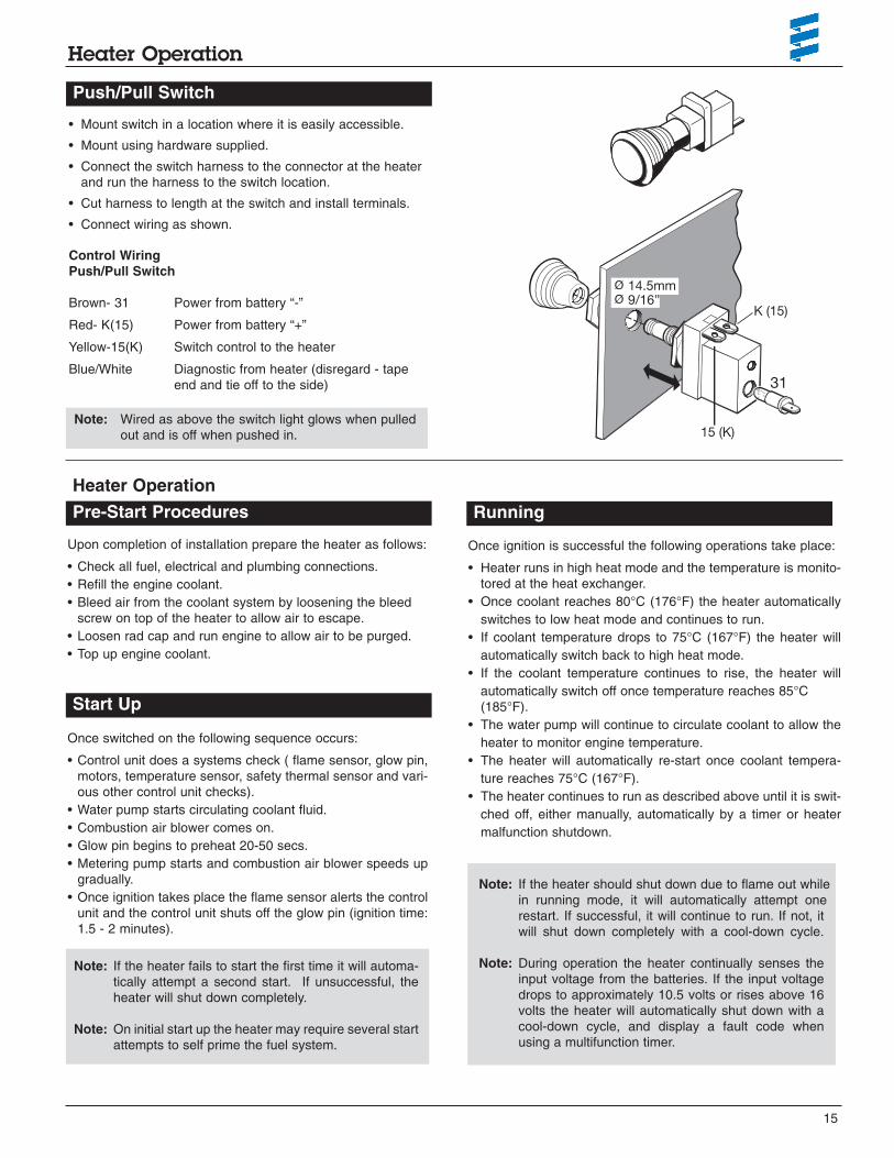
• Mount switch in a location where it is easily accessible.
• Mount using hardware supplied.
• Connect the switch harness to the connector at the heater and run the harness to the switch location.
• Cut harness to length at the switch and install terminals.
• Connect wiring as shown.
14.5mm9/16”
K (15)
15 (K)
31
Note: Wired as above the switch light glows when pulledout and is off when pushed in.
Control WiringPush/Pull Switch
Brown- 31 Power from battery “-”
Red- K(15) Power from battery “+”
Yellow-15(K) Switch control to the heater
Blue/White Diagnostic from heater (disregard - tape end and tie off to the side)
Heater Operation
Start Up
Pre-Start Procedures Running
ØØ

Warning: The heater must be switched off whileany fuel tank on the vehicle is beingfilled. The heater must not be operatedin garages or enclosed areas.
16
Heater Operation
• When the heater is switched off, manually or automatically,it starts a controlled cool down cycle.
• The fuel metering pump stops delivering fuel and the flamegoes out.
• The combustion air blower and water pump continue to runfor 3 minutes to cool down.
• The heater shuts off.
The control unit, temperature sensor, overheat sensor andflame sensor continually monitor heater functions and will shutdown the heater in case of a malfunction.
• The control unit ensures electrical circuits (fuel pump, com-bustion air blower etc.) are complete prior to starting theheater.
• If the heater fails to ignite within 90 seconds of the fuelpump being started, the starting procedure will be repeat-ed. If the heater again fails to ignite after 90 seconds of fuelbeing pumped, a “no start safety shutdown” follows. (Fault#52)
• If the heater flames out during operation, the heater auto-matically attempts to restart. If the heater fails to ignitewithin 90 seconds of fuel delivery, the heater will turn off thefuel pump and complete a cool down and display a F052code. After troubleshooting the problem the heater can bestarted again by switching the heater off and then back onagain.
• Overheating due to lack of water, a restriction or a poorlybled coolant system results in the overheat shutdown(F012). Fuel delivery will cease and an “overheat shutdown” follows. If heater overheats 10 consecutive times, alockout on the control unit will occur. To unlock the controlunit you will need to use the Fault Code Retrieval Device.See following pages for self diagnostics.
• If at any time the voltage drops below 10.5V for 20 sec-onds, or rises above 16.0V for 20 seconds the heater willshut down and display the associated Fault Code.
Switching Off
Safety Equipment

17
Heater Operation
STARTING PHASE RUNNING PHASE SHUT DOWN PHASE
OperatingMode
Time
FuelPump
Glow Pin
Blower
Water Pump
System Check
Pre-heat Pre-heat2nd. attempt
IgnitionAttempt
IgnitionAttempt
2nd. attempt
ControlledHeating
Off
Off
Off
OffOn Off
Off On:
if in stand byOnOnOnOnOn On
OnOnOnOnMomentarily
OnOnOnOn
On
On
On
On OffOff Off
Off Off Off Off OffOnOn On
AfterGlow
CoolDown
Offor
Stand by
1- 3 sec. 40 sec. 20 sec.
40 sec.Up to80 sec.
Up to 80 sec.
If Required High/Low Operation
until switched off manually or automatically
2.5 min.
Note: During the controlled heating cycle, if the coolant temperature exceeds 86°C(187°F) the heater will cycle off.Heater will automatically restart in high mode once coolant temperature reaches 75°C(167°°F)

18
Notes:

19
Heater Diagnostics
Brown
Viol
et
Brow
n
Ligh
tBro
wn
Blac
k
Whi
te
Brow
n
Gre
en
Gre
en Red
Red
Blue
Blue
Brow
n
Blue
12345678910 112 1314
Yello
w
Brow
n
Red
Brow
n
Brow
n
Blue
Blue
/Whi
te
DIA
G
TRS
Yello
w
a)Po
wer
from
batt
ery“
+”.
b)Sw
itch
cont
rolt
ohe
ater
.c)
Pow
erfr
omba
tter
y“-”.
d)D
iagn
ostic
sfr
omhe
ater
.e)
Tove
hicl
edi
mm
ersw
itch
forl
ight
disp
lay.
f)To
vehi
cle
igni
tion
acce
ssor
ies
forc
ontin
uous
oper
atio
nof
heat
er.
121110987654321
4321
1 2 3 4 5 6 7 8
1 2 3 4 5 6 7 8
b)a) d)c) 4321
24
68
13
57
86
42
75
31
3.2.
9
5.1
2.7
Red
Red
Red/
Yello
wRe
d
Brow
n
Red
Brow
n
Blac
k/Re
d
Ligh
tGre
en
Blue
/Whi
te
Blue
Yello
w
Blac
k/W
hite
S1B1
S1B1
B3
2.1
2.12
1.1
1.2
2.2
1.5
1.13
1.12
1357911 1324681012 14
87 87a
85
30
86
M
12
34
B2
B2
M
Ph)
Opt
iona
le)
Opt
iona
lf)
Opt
iona
l
Hydronic D4 SC 12 VoltModel 25 2096 05
Wiring Harness P/N: 20 2900 70 05 03
1.1
Blo
wer
mot
or1.
2G
low
pin
1.5
Ove
rhea
tse
nsor
1.12
Fla
me
sens
or1.
13Te
mpe
ratu
rese
nsor
2.1
Con
trol
unit
2.12
Wat
erP
ump
2.2
Fue
lmet
erin
gpu
mp
2.7
20am
pm
ain
fuse
3.12
Pus
h/P
ulls
witc
h3.
2.9
7da
ytim
er5.
1B
atte
ry
Red
K(1
5)
15(K
)
Yel
low
Bro
wn
31
03.
1.1
Pus
h/P
ulls
witc
h
7da
ytim
er
3.12

20
Heater Diagnostics
M
Opt
iona
l
Brow
nBl
ack
Brow
nVi
olet
Brow
nW
hite
Gre
enG
reen Re
dRe
dBl
ueBl
ueBr
own
Blue
1234567891011 12 13 14
Yello
w
Yello
w
Red
Brow
n
Brow
n
Brow
n
Blue
Blue
/Whi
te
Blac
k/Re
d
DIA
G
TRS
Blue
a)Po
wer
from
batt
ery“
+”.
b)Sw
itch
cont
rolt
ohe
ater
.c)
Pow
erfr
omba
tter
y“-”.
d)D
iagn
ostic
sfr
omhe
ater
.e)
Tove
hicl
edi
mm
ersw
itch
forl
ight
disp
lay.
f)To
vehi
cle
igni
tion
acce
ssor
ies
forc
ontin
uous
oper
atio
nof
heat
er.
121110987654321
4321
1 2 3 4 5 6 7 8
b)a) d)c)
4321
24
68
13
57
86
42
75
31
3.2.
9
5.1
2.7
2.5.
8
Red
Red
Red/
Yello
wRe
d
Brow
n
Red
Brow
n
Blac
k/Re
d
Gre
en
Blue
/Whi
te
Blue
Yello
w
Blac
k/W
hite
S1B1
S1B1
B3
2.1
1.1
2.12
1.2
2.2
1.5
1.13
1.12
1357911 13
87654321
87 87a
85
30
86
12
34
B2 B2
P
246810 12 14
M
h)
Opt
iona
le)
Opt
iona
lf)
Brown
Hydronic D5 SC 12 VoltModel 25 1920 05
Wiring Harness P/N: 202900 70 04 01
1.1
Blo
wer
mot
or1.
2G
low
pin
1.5
Ove
rhea
tse
nsor
1.12
Fla
me
sens
or1.
13Te
mpe
ratu
rese
nsor
2.1
Con
trol
unit
2.12
Wat
erP
ump
2.2
Fue
lmet
erin
gpu
mp
2.5.
8B
low
erlo
ckou
tre
sist
or2.
720
amp
mai
nfu
se3.
12P
ush/
Pul
lsw
itch
3.2.
97
day
timer
5.1
Bat
tery
Red
K(1
5)
15(K
)
Yel
low
Bro
wn
31
03.
1.1
Pus
h/P
ulls
witc
h
7da
ytim
er
3.12

21
Heater Diagnostics
M
1234567891011 12 13 14
B2
P
M
Opt
iona
le)
Opt
iona
l
Opt
iona
l
f)
Red
2.7.
1
Yello
w
Brow
n
Brow
n
Blue
Blue
/Whi
teYe
llow
Red
Red/
Yello
w
Red
Brow
n
4321
b)a) d)c)
4321
Brow
n
Red
Red
DIA
G
TRS
Brown
a)Po
wer
from
batt
ery“
+”.
b)Sw
itch
cont
rolt
ohe
ater
.c)
Pow
erfr
omba
tter
y“-”.
d)D
iagn
ostic
sfr
omhe
ater
.e)
Tove
hicl
edi
mm
ersw
itch
forl
ight
disp
lay.
f)To
vehi
cle
igni
tion
acce
ssor
ies
forc
ontin
uous
oper
atio
nof
heat
er.
121110987654321
3.2.
9
5.1
2.7
Red
Brow
n
Blac
k/Re
d
Gre
en
Blue
/Whi
te
Blue
Yello
w
Blac
k/W
hite
S1B1 1 2 3 4 5 6 7 8
87654321
12
34
Brow
nBl
ack
Brow
nVi
olet
Brow
nW
hite
Gre
enG
reen Re
dRe
dBl
ueBl
ueBr
own
Blue
1.1
2.12
1.2
2.2
1.5
1.13
1.12
h)
S1B1
B3
2.1
B2
24
68
13
57
86
42
75
31
1357911 13
87 87a
85
30
86
246810 12 14
Hydronic D5 SC 12 Volt Model 25 2098 05
25 2219 0525 2257 05
Wiring Harness P/N: 20 2900 70 05 03
Internal FMPNo Blower Relay
1.1
Blo
wer
mot
or1.
2G
low
pin
1.5
Ove
rhea
tse
nsor
1.12
Fla
me
sens
or1.
13Te
mpe
ratu
rese
nsor
2.1
Con
trol
unit
2.12
Wat
erP
ump
2.2
Fue
lmet
erin
gpu
mp
2.7
20am
p/12
Vm
ain
fuse
15am
p/24
Vm
ain
fuse
2.7.
15
amp
fuse
3.12
Pus
h/P
ulls
witc
h3.
2.9
7da
ytim
er5.
1B
atte
ry
Red
K(1
5)
15(K
)
Yel
low
Bro
wn
31
03.
1.1
Pus
h/P
ulls
witc
h
7da
ytim
er
3.12

22
Heater Diagnostics
Opt
iona
le)
Opt
iona
l
Opt
iona
l
f)
Red
2.7.
1
M
Brow
nBl
ack
Brow
nVi
olet
Brow
nW
hite
Gre
enG
reen Re
dRe
dBl
ueBl
ueBr
own
Blue
1234567891011 12 13 14
Yello
w
Brow
n
Brown
Brow
n
Brown
Gre
en
Brow
n
Blue
Blue
/Whi
te
DIA
G
TRS
Yello
wRe
d
a)Po
wer
from
batt
ery“
+”.
b)Sw
itch
cont
rolt
ohe
ater
.c)
Pow
erfr
omba
tter
y“-”.
d)D
iagn
ostic
sfr
omhe
ater
.e)
Tove
hicl
edi
mm
ersw
itch
forl
ight
disp
lay.
f)To
vehi
cle
igni
tion
acce
ssor
ies
forc
ontin
uous
oper
atio
nof
heat
er.
121110987654321
4321
1 2 3 4 5 6 7 8
b)a) d)c)
4321
24
68
13
57
86
42
75
31
3.2.
9
5.1
2.7
2.2
Red
Red
Red/
Yello
w
Red
Brow
n
Red
Brow
n
Blac
k/Re
d
Gre
en
Blue
/Whi
te
Blue
Yello
w
Blac
k/W
hite
S1B1
S1B1
B3
2.1
1.1
2.12
1.2
1.5
1.13
1.12
1357911 13
87654321
87 87a
85
30
86
12
34
B2
B2
P
246810 12 14M
2.2
h)
Hydronic D5 SC 24 Volt Model 25 2147 05
Wiring Harness P/N: 20 2900 70 20 13
External FMPNo Blower Relay
Also applicable to:Hydronic 4 & 5 SC 12 voltGasoline versionsModel 20 1820 05Model 20 1824 05Model 25 2325 05
1.1
Blo
wer
mot
or1.
2G
low
pin
1.5
Ove
rhea
tse
nsor
1.12
Fla
me
sens
or1.
13Te
mpe
ratu
rese
nsor
2.1
Con
trol
unit
2.12
Wat
erP
ump
2.2
Fue
lmet
erin
gpu
mp
2.7
20am
p/12
Vm
ain
fuse
15am
p/24
Vm
ain
fuse
2.7.
15
amp
fuse
3.12
Pus
h/P
ulls
witc
h3.
2.9
7da
ytim
er5.
1B
atte
ry
Red
K(1
5)
15(K
)
Yel
low
Bro
wn
31
03.
1.1
Pus
h/P
ulls
witc
h
7da
ytim
er
3.12

23
Heater Diagnostics
Opt
iona
lBr
own
Blac
kBr
own
Viol
etBr
own
Whi
te
Red
Red
Blue
Blue
Brow
nBl
ue
1234567891011 12 13 14
Yello
w
Brow
n
Brown
Brow
n
Brown
Gre
en
Brow
n
Blue
Red
Blue
/Whi
te
DIA
G
TRS
Yello
w
a)Po
wer
from
batt
ery“
+”.
b)Sw
itch
cont
rolt
ohe
ater
.c)
Pow
erfr
omba
tter
y“-”.
d)D
iagn
ostic
sfr
omhe
ater
.e)
Tove
hicl
edi
mm
ersw
itch
forl
ight
disp
lay.
f)To
vehi
cle
igni
tion
acce
ssor
ies
forc
ontin
uous
oper
atio
nof
heat
er.
121110987654321
4321
1 2 3 4 5 6 7 8
b)a)
e)
d)c)
4321
24
68
13
57
86
42
75
31
3.2.
9
5.1
2.7
2.2
Red
Red
Red
Red/
Yello
w
Red
Brow
n
Red
Brow
n
Brown
Violet
Brown
Black
Blac
k/Re
d
Gre
en
Blue
/Whi
te
Blue
Yello
w
Blac
k/W
hite
S1B1
S1B1
B3
2.1
1.1
1.2
1.5
1.13
1.12
1357911 13
87654321
87 87a
85
30
86
12
34
B2
B2
P
246810 12 14
M
2.12
M
2.7.
1O
ptio
nal
Opt
iona
l
f)
Hydronic 5 S - 12 & 24 volt versionsDiesel & Gasoline versionsModel 20 1793 05 12 voltModel 20 1819 05 12 voltModel 25 2146 05 24 voltModel 25 2217 05 12 voltModel 25 2218 05 24 voltModel 25 2100 05 12 volt
Wiring Harness P/N: 12V 20 2900 70 05 0724V 20 2900 70 05 08
1.1
Blo
wer
mot
or1.
2G
low
pin
1.5
Ove
rhea
tse
nsor
1.12
Fla
me
sens
or1.
13Te
mpe
ratu
rese
nsor
2.1
Con
trol
unit
2.12
Wat
erP
ump
2.2
Fue
lmet
erin
gpu
mp
2.7
20am
p/12
Vm
ain
fuse
15am
p/24
Vm
ain
fuse
2.7.
15
amp
fuse
3.12
Pus
h/P
ulls
witc
h3.
2.9
7da
ytim
er5.
1B
atte
ry
Red
K(1
5)
15(K
)
Yel
low
Bro
wn
31
03.
1.1
Pus
h/P
ulls
witc
h
7da
ytim
er
3.12

The heater is equipped with self diagnostic capability. You canretrieve information on the heaters last 5 faults using the Esparmultifunction timer or Espar’s Fault Code Retrieval Device.
Multifunction
Espar’s multifunction timer has a fault code retrieval devicebuilt into the unit. This function automatically activates if theheater is experiencing problems.
• Fault codes appear on the LCD display screen.• Codes can then be translated from the charts on the
following pages.
Fault Code Retrieval Device
Equipment Face and Controls
Symbols seen on the displayface are as follows:
AF Actual fault.
F1-F5 Up to five stored faults can be accessed. The AF and F1 are the same number.
This sign is displayed when the heater is inoperation.
DIAG The word (Diagnostic) will come on when the diagnostic number is requested.
000 Three digit diagnostic fault code number.
Instructions:
• Connect as shown on following page.• Switch the fault code retrieval device on and wait
10 seconds.• Press the "D" button.• Wait 3-5 seconds for the current fault code to appear
(AF).• To review the previous faults use the arrow buttons
(F1= Most Recent, F5= Oldest).• To erase the faults that are in memory press both "L" keys
at the same time.• See the fault code chart on following pages for code num-
ber descriptions.
24
Maintenance / Troubleshooting / Repair
• Check coolant hoses, clamps, and make sure all valves areopen. Maintain the engine manufacturers recommendedcoolant level and ensure that the heater is properly bled afterservice on or involving the coolant system.
• Visual check of all fuel lines for leaks. Check and if nece-ssary replace fuel filter inserts.
• Visual check of electrical lines and connections for corrosion.• Run your heater at least once a month during the year
(for a minimum of 15 minutes).• Maintain your batteries and all electrical connections in good
condition. With insufficient power the heater will not start.Low and high voltage cutouts will shut the heater down automati-
cally. • Use fuel suitable for the climate (see engine manufacturers
recommendations). Blending used engine oil with diesel fuelis NOT permitted.
• Check the glow pin and replace if necessary.
Basic Troubleshooting
In the event of failure there are several items which should bechecked first before any major troubleshooting is done.
Check:
• Circuit breakers and fuses.
• Electrical lines and connections.
• For interference in combustion air and exhaust pipes.
• That there is fuel in the tank.
• Battery voltage.
L DL
Troubleshooting
Periodic Maintenance Self Diagnostics

25
Maintenance / Troubleshooting / Repair
35
30
25
20
15
10
5
00 20 40 60 80 100 120
3000
2750
2500
2000
2250
1000
1250
1750
1500
750
0-50 0 50 100 150 200 250 300 350 400 450 500 550
Hook Up
• Disconnect the main harness from heater and insert adaptercable harness between them.
• Connect adapter cable to the cable loom of the Fault code retrieval device.
HYDRONIC 5 adapter forFault code retrieval device
P/N 12V 20 2900 70 50 28
Test Values
Resistance
Metering pump approx. 10 Ω for 12 volt heater; approximately 36 Ω for 24 volt heater
Glow Pin approx. 0.9 Ω
Checking the sensors
To check the sensors, measure the resistance at current temperature, see following diagrams:
Temperature sensorOverheating sensor Flame sensor
Temperature (°C) Temperature (°C)
Res
ista
nce
(Koh
ms)
Res
ista
nce
(ohm
s)
R> 2 Ω = open circuitR< 50 Ω = short circuit
R> 3400 Ω = open circuitR< 50 Ω = short circuit
Fault code retrieval deviceP/N 12V 20 2900 70 50 20

000 Normal Operation
010 Overvoltage Check voltage between terminals 1(red) and 2(brown) at connector (B1).
If voltage is > 15 volts then check battery, electrical leads and vehicle
charging system.
011 Under voltage shut down Check voltage between terminals 1(red) and 2(brown) at connector (B1).
If voltage is < 10 volts then check battery, electrical leads and vehicle
charging system.
012 Overheating Check for possible causes of overheat (water circuit), Sensor.
Check overheat switch resistance values. Temperature at temperature
sensor or overheat sensor is greater than 125°C.
014 Possible overheating detected Difference of measured values at temperature sensor >25°C (min. 80°C
(difference evaluation) water temperature and metering pump in operation);
Check temperature sensor and overheating sensor, replace if necessary.
Check values from previous page.
015 Too many overheats Remove cause of over heat. Reset control unit using 7 day timer or
fault code retrieval device to unlock control unit. Permanent overheating
coun- ter reading exceeded. Heating enable only possible by means of diagnos-
tics system (press both “LL” keys simultaneously).
017 Overheating detected Temperature at temperature or overheating sensor > 130 °C,
emergency OFF if Fault Code 012 or 014 not applicable; check water cir-
cuit, check temperature sensor and overheating sensor; replace if nece-
ssary. See graph on previous page.
020 Open circuit - glow pin Check glow pin and electrical leads for continuity, replace if necessary.
021 Short circuit - glow pin Check glow pin and electrical leads for continuity, replace if necessary.
030 Combustion air blower motor Blower impeller or electric motor may be jammed (frozen solid, dirty, etc.)
Fix jam, replace electric motor if necessary.
031 Combustion air blower motor Check lead to combustion air motor for continuity, replace motor if nece-
ssary.
032 Combustion air blower motor short-circuit Check combustion air blower motor (electric motor); replace if neces-
sary. Check power supply (chafed, corroded etc.)
038 Vehicle fan relay control break Check electric lead to relay, fix break, replace relay if necessary
For wiring harness (20 2900 70 04 01) without relay, replace harness.
039 Vehicle fan relay control short circuit Check electric lead to relay, fix break, replace relay if necessary
For wiring harness (20 2900 70 04 01) without relay, replace harness.
041 Water pump break Check supply lead to water pump for continuity, remedy break, replace
water pump if necessary.
042 Water pump short-circuit Check supply lead to water pump for short circuit, check water pump,
re- place water pump if necessary.
047 Short circuit - fuel metering pump Check for wires for short to fuel metering pump. Test fuel metering
pump. Replace if necessary.
26
Maintenance / Troubleshooting / RepairFault Code Fault Description Causes / Repair

27
Maintenance / Troubleshooting / RepairFault Code Fault Description Causes / Repair
048 Open circuit - fuel metering pump Check supply lead to metering pump for continuity, remedy break,
replace if necessary.
050 Too many no start attempts Safety time counter reading exceeded. Reset control unit using 7 day Ti-
mer or fault code retrieval device to unlock control unit.
051 Faulty flame recognition At start, if flame sensor is a above 70°C > 240 seconds; check exhaust
gas and combustion air supply, check flame sensor, replace if necessary.
For flame sensor values see graph on previous page.
052 No start safety time exceeded No flame detected on start attempt. Check fuel delivery and fuel supply,
Check exhaust gas and combustion air ducts.
053 Flame cutout in boost mode Heater has started successfully the flame has extinguished.
Check fuel supply. Check combustion air and exhaust flow.
Check flame sensor resistance value.
Replace flame sensor if necessary.
054 Flame cutout in high mode Heater has started successfully the flame has extinguished.
Check fuel supply. Check combustion air and exhaust flow.
056 Flame cutout in low mode Check flame sensor resistance value.
060 Open circuit - temperature sensor Temperature sensor detects a value beyond it's range.
Check connections. Check sensor resistance values between 11 and 12
at connector B2 > 2 M (if open circuit).
061 Short circuit - external temperature sensor Check connections. Check sensor resistance values between 11 and 12
at connector B2 < 50 Ω (if short circuit).
Temperature sensor values on previous pages.
064 Open circuit - flame sensor Sensor is sensing value outside of range. Check connection leads.
Resistance values between 1 and 2 at connector B2 > 3040 Ω (if open cir-
cuit).
065 Short circuit - flame sensor Check connection leads. Resistance values between 1 and 2 at connec-
tor B2 > 780 Ω (if short circuit). Flame sensor values on page 17.
071 Open circuit - overheat sensor Check connection leads. Resistance values between 9 and 10 at connec-
tor B2 > 2 M Ω (if open circuit).
072 Short circuit - overheat sensor Check connection leads. Resistance values between 9 and 10 at connec-
tor B2 < 50 M Ω (if short circuit).
091 External interference voltage Error in controller from interference voltage from vehicle network possiblecauses: poor batteries, poor battery charges, other interference sources; eliminate interference voltages.
090 Controller defect Control unit malfunction due to interference voltage from vehicle electrical092 -103 system; possible causes low batteries, charges, other sources of interfe-
rence, eliminate interference voltages. Internal faults detected in microprocessor/memory. Replace control unit.Internal failure. Replace control unit.
Faults not shown by the diagnosis system After switching HYDRONIC on, the water pump and vehicle fan start im-HYDRONIC won’t start mediately.
· Remove and check temperature sensor.After switching HYDRONIC on, the vehicle fan starts, functioning “pre-venting” is activated.
· Changeover venting to heating at “heating/venting changeover switch.
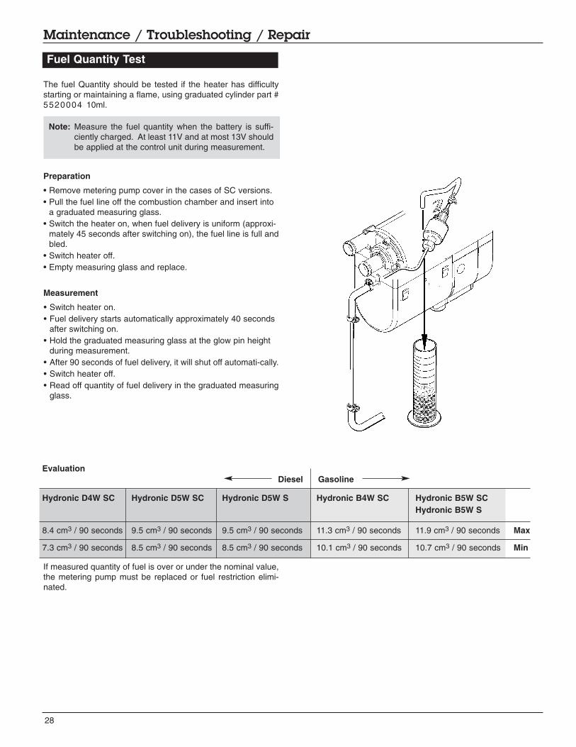
The fuel Quantity should be tested if the heater has difficultystarting or maintaining a flame, using graduated cylinder part #5520004 10ml.
Preparation
• Remove metering pump cover in the cases of SC versions.• Pull the fuel line off the combustion chamber and insert into
a graduated measuring glass.• Switch the heater on, when fuel delivery is uniform (approxi-
mately 45 seconds after switching on), the fuel line is full andbled.
• Switch heater off.• Empty measuring glass and replace.
Measurement
• Switch heater on.• Fuel delivery starts automatically approximately 40 seconds
after switching on.• Hold the graduated measuring glass at the glow pin height
during measurement.• After 90 seconds of fuel delivery, it will shut off automati-cally.• Switch heater off.• Read off quantity of fuel delivery in the graduated measuring
glass.
If measured quantity of fuel is over or under the nominal value,the metering pump must be replaced or fuel restriction elimi-nated.
28
Maintenance / Troubleshooting / Repair
Fuel Quantity Test
Evaluation
Hydronic D4W SC Hydronic D5W SC Hydronic D5W S Hydronic B4W SC Hydronic B5W SCHydronic B5W S
8.4 cm3 / 90 seconds 9.5 cm3 / 90 seconds 9.5 cm3 / 90 seconds 11.3 cm3 / 90 seconds 11.9 cm3 / 90 seconds Max
7.3 cm3 / 90 seconds 8.5 cm3 / 90 seconds 8.5 cm3 / 90 seconds 10.1 cm3 / 90 seconds 10.7 cm3 / 90 seconds Min
Diesel Gasoline
Note: Measure the fuel quantity when the battery is suffi-ciently charged. At least 11V and at most 13V shouldbe applied at the control unit during measurement.

29
Maintenance / Troubleshooting / Repair
Disassembly / Assembly
Repair Steps covered are for the Hydronic 4 & 5 SC versions - other models are similar
1 Cover, metering pump
2 Water pump, assembly
3 Metering pump and bracket
4 Cover, blower
5 Control unit and cover
6 Glow pin
7 Flame sensor
8 Cable harness
9 Electric motor, complete
10 Combustion chamber with flame tube
11 Heat exchanger and jacket
1 Cover, metering pump
2 Water pump assembly. When mounting, place O-ringson connection on water pump housing
3 Metering pump and bracket
4 Cover, blower
5 Control unit and cover
6 Glow pin

30
Maintenance / Troubleshooting / Repair
7 Flame sensor, For removal of tab receptacles, useAMP extractor tool
8 Cable Harness
9 Electric motor, complete
10 Combustion chamber with flame tube
11 Heat exchanger and jacket, Align slot on heatexchanger (arrow) with lug in jacket
31
Maintenance / Troubleshooting / Repair
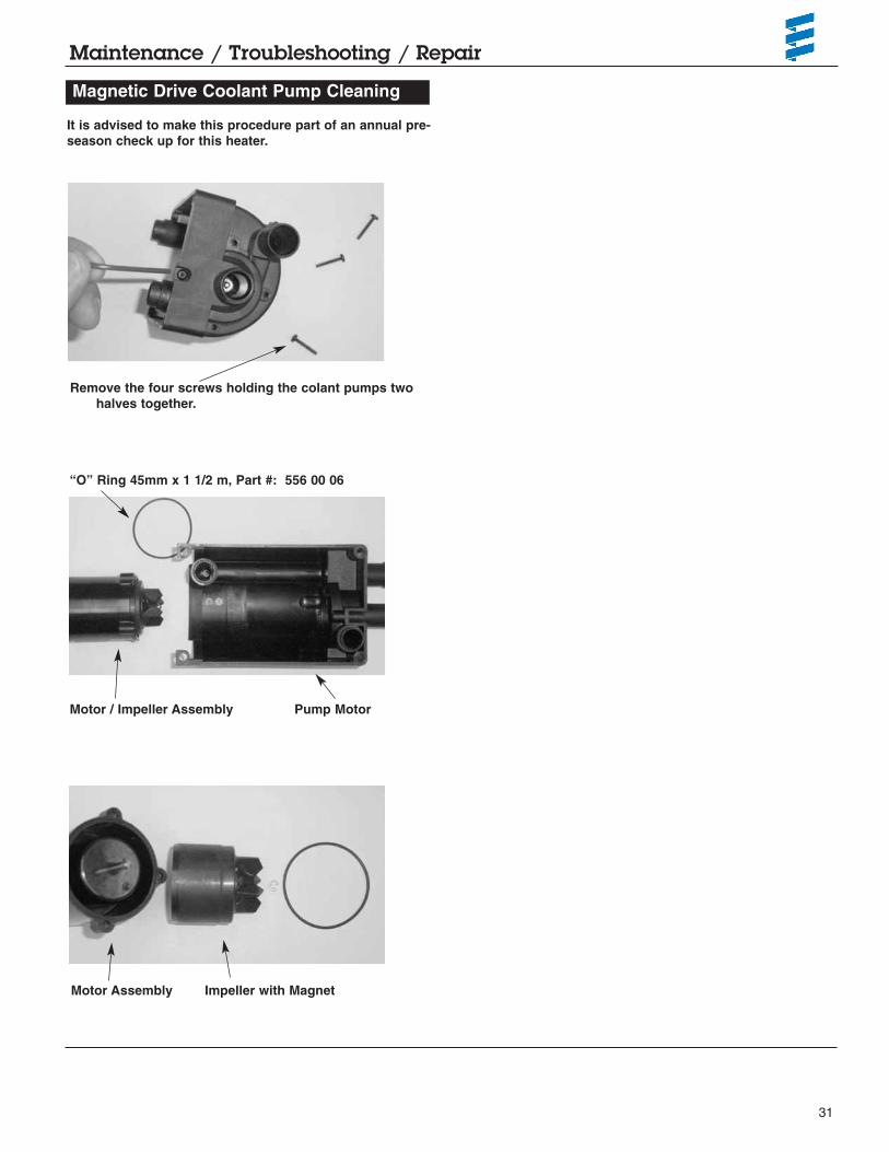
Magnetic Drive Coolant Pump Cleaning
It is advised to make this procedure part of an annual pre-season check up for this heater.
Remove the four screws holding the colant pumps twohalves together.
Motor / Impeller Assembly
“O” Ring 45mm x 1 1/2 m, Part #: 556 00 06
Pump Motor
Motor Assembly Impeller with Magnet

32
1
5
6
7
8
12
13
19
18
21
20
25
29
30
24
26
32
33
3434
36
37
38
39
2
3
35
4
1011
27
9
26
25
23
31
1415
16
17
22
28
28
01
Heater Components Face Lift “SC” Heaters
Parts Diagram - Hydronic 4 / 5 W SC - Face Lift - 12 volt - Diesel & Gasoline versions
Model 20 1824 05Model 25 2257 05Model 20 1820 05
Model 25 2219 05
Model 25 2325 05with external FMP

33
Description & Part #’s
Heater Components Face Lift “SC” Heaters
Ref. No. Description Part Number
HYDRONIC 4 / 5 W SC - Face Lift - 12 volt - Diesel & Gasoline versions
1 Outer casing 25 2149 01 01 01 • • • • •
2 Combustion air blower with cover 20 1819 99 16 00 • • • • •
3 Cover 25 1917 01 00 02 • • • • •
4 Burner 20 1818 10 00 00 • •25 2216 10 00 00 • • •
5 Heat exchanger 25 2149 06 00 01 • • • • •
6 Control unit 22 5201 03 00 02 •22 5201 04 00 06 •22 5201 00 20 04 •22 5201 01 90 02 • •
7 Cover 20 1752 99 01 03 • • • • •
8 Coolant Pump 25 2219 25 00 00 • • • • •
9 Fuel metering pump 22 4504 03 00 00 • •Internal fuel pipe 25 2118 01 00 01 •
Intermediate piece 25 2137 01 00 01 •
10 Integrated fuel filter 20 1312 00 00 06 • • • • •
11 Holder fuel metering pump 25 1917 01 00 07 • •
12 Seal 20 1820 99 00 01 • • • • •
13 O-Ring 74 x 3 mm 320 75 104 • • • • •
14 Glow pin with cable section 25 2106 01 10 00 • • • • •
15 Plug connection 20 1752 01 10 00 • •25 2147 01 14 00 • • •
16 Atomizing Screen with O rings 20 1752 99 01 02 • •25 2121 99 01 13 • • •
17 Holder 20 1752 01 00 04 • •
18 Groomet 20 1752 01 00 02 • •
19 Flame sensor 25 1920 35 00 00 • • • • •
20 Overheat sensor with cable section 25 2147 01 20 00 • •25 2219 01 20 00 • • •
21 Plug kit 14 pin 22 1000 30 10 10 • • • • •
22 Cable section Waterpump 20 1753 01 18 00 • • • • •
23 Spring leaf 25 1922 01 00 05 • • • • •
24 Cover fuel metering pump 20 1752 01 00 03 • •25 1917 01 00 03 • • •
25 O-Ring 14 x 2.6 22 1000 70 00 06 • • • •
26 O-Ring 7 x 2 22 1000 70 00 09 • • • •
27 Hose 25 1917 01 00 11 • •
28 Cable band 209 31 071 • •
29 Screw 25 1917 25 00 12 • • • •
Mod
el#
2522
5705
12v
2522
1905
12v
2018
2005
12v
2018
2405
12v
2523
2505
12v

34
Description & Part #’s
Mod
el#
2522
5705
12v
2018
2405
12v
2522
1905
12v
2018
2005
12v
Ref. No. Description Part Number
30 O-Ring 5 x 1.5 mm Hardware • • • • •
31 Tapite screw M5 x 12 109 10 153 • • • • •
32 Sleeve 25 1917 01 00 05 • • •
33 Sleeve 20 1752 01 00 06 • • •
34 Tapite screw M5 x 35 Torx 109 10 154 • • • • •
35 Tapite screw M5 x 25 Torx 109 10 152 • • • • •
36 Cheese-head screw M5 x 65 Torx 100 10 350 • • • • •
37 Tapite screw M5 x 16 Torx 109 10 151 • • • • •
38 Tapite screw M4 x 10 Torx 109 10 150 • • • • •
39 Counter sunk screw M5 x 12 Torx 102 10 302 • • • • •
Heater Components Face Lift “SC” HeatersHYDRONIC 4 / 5 W SC - Face Lift - 12 volt - Diesel & Gasoline versions
2523
2505
12v

35
Notes:

36
Heater Components Face Lift “SC” Heaters
Parts Diagram - Hydronic 4 / 5 W SC - Face Lift - 12 volt - Diesel & Gasoline versions
6
1
2
3
4
5
78
9
11
11
12/13
17
18
19
20
22
4
4
4
3
38
9
10
10
10
10
10
31
11
11
12/13
23
26
27/28
24 a
24 b
25
21
2930
32
11
11
12/13
12/13
11
11
10
14
16
15
20 a
33
Model 20 1824 05
Model 20 1820 05
Model 25 2219 05
Model 25 2257 05
Model 25 2325 05

37
Description & Part #’s
Ref. No. Description Part Number Mod
el#
2522
5705
12v
2018
2405
12v
2522
1905
12v
2018
2005
12v
01 T-piece 8 x 6 x8 mm 262 31 151 • • • • •
02 T-piece 8 x 4 x8 mm 262 31 155 • • • • •
03 Hose 360 75 350 • • • • •--------------- • •
04 Hose 3.5mm x 3mm 360 75 300 • • • • •--------------- • •
05 Plastic fuel line 2mm 890 31 117 • • • • •
06 Plastic fuel line 1.5mm 890 31 118 • • • • •
07 Plastic fuel line 2mm - Black 890 31 125 • • • • •
08 Hose 7.5mm --------------- • •--------------- • •
09 Supporting sleeve with collar --------------- • • • •
10 Hose clip 11mm 10 2068 01 10 98 • •
11 Hose clip 9mm 10 2068 00 90 98 • • • •
12 Hose clip 14mm 10 2068 01 40 98 • •
13 Hose clip 12mm 10 2068 01 20 98 • • • •
14 Holder 25 2220 80 00 01 • • • •
15 Central screw 100 10 258 • • • •
16 Metal rubber buffer 6 mm 20 1185 00 00 01 • • • •
17 Fuel metering pump 22 4517 04 00 00 • • •
18 Fuel filter 20 1312 00 00 06 • •
19 Holder metering pump 22 1000 50 03 00 • • •
20 Main harness - J.E - Universal w/relay 25 1917 80 10 00 • • •25 1917 80 11 00 • •
20a Main harness ESPAR 20 2900 70 05 02 • •20 2900 70 05 03 • •
21 Connection Kit 22 1000 30 10 21 • • • •
22 Relay 203 00 065 • • • •
23 Cable 22 1000 31 28 00 • • • •
24a Fuse holder, receptable housing 22 1000 31 06 01 • • • •
24b Fuse holder, cover 22 1000 31 06 02 • • • •
25 Fuse 25 A 204 00 089 • • • •20 A 5670055 • • • •5 A 204 00 079 • • • •
26 Terminal 206 52 136 • • • •
27 Terminal 206 52 133 • • • •
28 Terminal 206 52 134 • • • •
29 Eyelet Hardware • • • •
30 Eyelet Hardware • • • • •
31 Cable band 25 1801 80 02 00 • • • • •
32 Combination bracket, fuses and fan relay 22 1000 51 21 00 • • • • •
33 Angle bracket 20 2900 40 01 04 • • • • •
Heater Components Face Lift “SC” HeatersHydronic 4 / 5 W SC - Face Lift - 12 volt - Diesel & Gasoline versions
2523
2505
12v

38
Heater Components Face Lift “SC” Heaters
Parts Diagram - Hydronic 4 / 5 W SC - Face Lift - 12 volt - Diesel & Gasoline versions
3
5
4
12
7
8
10
11
8
8
9
12
1314
14
14
14
14
14
9
6
Model 20 1824 05Model 25 2257 05Model 20 1820 05
Model 25 2219 05
Model 25 2325 05

39
Description & Part #’s
Ref. No. Description Part Number
Heater Components Face Lift “SC” HeatersHydronic 4 / 5 W SC - Face Lift - 12 volt - Diesel & Gasoline versions
1 Flexible air intake hose - 20mm x 1mtr 360 00 099 • • • • •
Double-pipe LW 19, sound damping --------------- • • • • •
2 End cap with bar 25 1688 80 12 01 • • • • •
3 Hose clamp 16 - 32mm 10 2067 01 60 25 • • • • •
4 Exhaust hose - 24mm x 1mtr / with cap 25 1774 80 02 00 • • • • •
5 Exhaust hose 24 mm 360 61 299 • • • • •
6 Exhaust end cap w/bar 25 1729 80 06 00 • • • • •
7 Exhaust silencer 25 1864 81 01 00 • •22 1000 40 09 00 • • •
8 Exhaust clamp 22 1000 50 05 00 • • • • •
9 “P” clamp 28mm 152 09 010 • • • • •
10 Double angle bracket 20 1533 88 00 07 • • • • •
11 Water Hose - Moulded - 18mm 20 1690 81 00 01 • • • • •
12 Water hose union - 18mm 20 1528 88 00 03 • • • • •
13 Water hose union - 18mm - 15mm 20 1645 80 02 01 • • • • •
14 Hose clamp 20 - 32mm 10 2065 02 00 32 • • • • •
2522
5705
12v
2018
2405
12v
2522
1905
12v
2018
2005
12v
Mod
el#
2523
2505
12v

40
Heater Components Face Lift “S” Heaters
Parts Diagram - Hydronic B5 / D5 - 12 & 24 volt - Diesel & Gasoline versions
Model 20 1819 05Model 25 2217 05Model 25 2218 05
1
2
3
28
15
26
1819
32
6
31
29
30
28
8
24
25
27
13
14
5
4
7
17
31
32
32
16
22
20
9*
9
10* 10
11
11
12
21
23
25
01

41
Description & Part #’s
Ref. No. Description Part Number Mod
el#
2018
1905
12V
2522
1805
24V
2522
1705
12V
1 Casing 25 2149 01 01 01 • • •
2 Combustion air blower with cover 20 1819 99 16 00 • •25 2146 99 17 00 •
3 Cover 25 2217 01 00 01 • • •
4 Burner 20 1818 10 00 00 •25 2216 10 00 00 •25 2146 10 00 00 •
5 Heat exchanger 25 2149 06 00 01 • • •
6 Control unit 22 5201 00 20 04 •22 5201 01 90 02 •22 5202 01 10 01 •
7 Cover - heater base 20 1756 99 01 03 • • •
8 Cover 25 2216 01 00 02 • • •
9 Hose barb assly 18mm 25 2216 99 01 06 • • •
10 Hose barb assly - 90° - mm 25 2216 99 01 05 • • •
11 O-Ring 16x2 22 1000 70 00 05 • • •
12 Hose barb locks 25 2216 01 00 10 • • •
13 Gasket / seal set 20 1820 99 00 01 • • •
14 O-Ring - 74x3 22 1000 70 00 02 • • •
15 Glow pin 25 2106 01 10 00 • •25 2107 01 10 00 •
16 Glow plug connection 20 1756 01 10 00 • •25 2121 01 14 00 •
17 Glow pin lining and 2 O-rings 20 1752 99 01 02 •25 2121 99 01 13 • •
18 Flame sensor 25 1920 35 00 00 • • •
19 Holder 20 1752 01 00 04 • • •
20 Over heat sensor with cable 25 2150 01 20 00 • • •
21 Grommet for cable 25 2216 01 17 01 • • •
22 Control unit plug kit 22 1000 30 10 10 • • •
23 Water pump harness 25 2009 01 15 00 • • •
24 Spring 25 1922 01 00 05 • • •
25 O-ring 7 x 2 22 1000 70 00 09 • • •
26 Grommet 20 1756 01 00 04 • • •
27 Taptite screw M5 x 12 torx 109 10 153 • • •
28 Taptite screw M5 x 25 torx 109 10 152 • • •
29 Cheese-head screw M5 x 65 torx 100 10 350 • • •
30 Taptite screw M5 x 16 torx 109 10 151 • • •
31 Taptite Screw M4 x 10 torx 109 10 150 • • •
32 Countersunk screw M5 x 12 torx 102 10 302 • • •
Heater Components Face Lift “S” HeatersHydronic B5 / D5 - 12 & 24 volt - Diesel & Gasoline versions

42
Heater Components Face Lift “S” Heaters
Parts Diagram - Hydronic B5 / D5 - 12 & 24 volt - Diesel & Gasoline versions
Model 20 1819 05Model 25 2217 05Model 25 2218 05
1
9
6
8
2
4
4 / 4a
10
10
10
8
9
7
10
3
155
11
11
12/13
12/13
14
17, 17a
19
20
23
30
24-26
21a
21b29
5
16
18
2827
22
31

43
Description & Part #’s
Ref. No. Description Part Number Mod
el#
2018
1905
12v
2522
1805
24v
2522
1705
12v
Heater Components Face Lift “S” HeatersHydronic B5 / D5 - 12 & 24 volt - Diesel & Gasoline versions
1 T-piece 8 x 6 x 8mm 262 31 151 • • •
2 Fuel pick up pipe 2.0mm - Universal 20 2900 20 20 10 •
3 Fuel filter 25 1226 89 00 37 •
4 Fuel hose 3.5 x 3mm 360 75 300 •
4a Hose ---------------
5 Hose 5 x 3mm 360 75 350 • •--------------- •
6 Plastic fuel line 1.5 mm 890 31 118 • • •Optional 2.0 mm 890 31 117 • • •
7 Plastic fuel line 2 mm 890 31 125 • • •
8 Hose 7.5mm --------------- • • •
9 Supporting sleeve with collar --------------- • • •
10 Clamp 11mm 10 2068 01 10 98 • • •
11 Hose clamp 9mm 10 2068 00 90 98 • • •
12 Hose clamp 14mm 10 2068 01 40 98 • • •
13 Hose clamp 12mm 10 2068 01 20 98 • • •
14 Fuel metering pump 12 V 22 4517 04 00 00 • •24 V 25 1942 45 00 00 •
15 Fuel Basket Filter 20 1312 00 00 06 • • •
16 Holder metering pump 22 1000 50 03 00 • • •
17 Main harness - J.E Universal w/relay 12 V 25 1917 80 10 00 • •24 V 25 2009 80 10 00 •
17a Main harness ESPAR 20 2900 70 05 02 • • •
18 Connector kit 22 1000 30 10 21 • • •
19 Relay 12 V 203 00 065 • •24 V 203 00 066 •
20 Cable 22 1000 31 28 00 • • •
21a Fuse holder, receptacle housing 22 1000 31 06 01 • • •
21b Fuse holder, cover 22 1000 31 06 02 • • •
22 Fuse 25 A 204 00 089 • • •20 A 5670055 • •15 A 5670053 •5 A 204 00 079 • • •
23 Terminal Fe 206 52 136 • • •
24 Terminal Fe 206 00 182 •
25 Terminal Fe 206 52 133 • • •
26 Terminal Fe 206 52 134 • • •
27 Eyelet Hardware • • •
28 Eyelet Hardware • •
29 Cable band 25 1801 80 02 00 • • •
30 Combination bracket, fuses and fan relay 22 1000 51 21 00 • • •

44
Heater Components Face Lift “S” Heaters
Parts Diagram - Hydronic B5 / D5 - 12 & 24 volt - Diesel & Gasoline versions
Model 20 1819 05Model 25 2217 05Model 25 2218 05
41
2
5
6
7
8
99
9
9
11
12
13
14
14
15
10
15
15
15
15
3

45
Description & Part #’s
Ref. No. Description Part Number Mod
el#
2018
1905
12v
2522
1805
24v
2522
1705
12v
1 Bracket 25 2220 80 00 01 • • •
2 Rubber mount 6mm 20 1185 00 00 01 • • •
3 Central screw, M6 x 97 Hex bolt 100 10 258 • • •
4 Flexible air intake hose 360 00 099 • • •
5 End cap with bar 25 1688 80 12 01 • • •
6 Hose clamp 16 - 25mm 10 2067 01 60 25 • • •
7 Exhaust Hose - 24mm x 1mtr with cap 25 1774 80 02 00 • • •
8 Exhaust silencer 24mm 22 1000 40 09 00 • • •
9 Exhaust clamp 22 1000 50 05 00 • • •
10 P clamp 28mm 152 09 010 • • •
11 Double angle bracket 20 1533 88 00 07 • • •
12 Coolant pump 12 V 25 2217 25 00 00 • •24 V 25 2218 25 00 00 •
13 Coolant hose - moulded - 18mm 20 1690 81 00 01 • • •
14 Water hose union - 18mm 20 1528 88 00 03 • • •
15 Hose clip 20 - 32mm 10 2065 02 00 32 • • •
Heater Components Face Lift “S” HeatersHydronic B5 / D5 - 12 & 24 volt - Diesel & Gasoline versions

46
Parts Diagram - Hydronic D4 / D5 - 12 & 24 volt - Diesel & Gasoline versions
1
5
4
6
7
8
10
11
12
13
14
16
17
18
19
25
27
28
29
36
31
24
26
3233
34
3535
37
38
39
40
41
2
3
8
36
21
26
25
19 20
22
23 15
Heater Components Early “SC” Heaters
Model 25 2096 05
Model 25 1920 05
Model 25 2098 05
Model 25 2147 05 24 V
with external fuel pump

47
Description & Part #’s
Ref. No. Description Part Number Mod
el#
2519
2005
12V
2520
9605
12V
2521
4705
24V
2520
9805
12V
1 Casing 25 1917 01 01 01 •25 1920 01 01 01 • •25 1922 01 01 01 •
2 Combustion air blower with cover 25 1922 99 16 00 • •25 2013 99 16 00 •25 2146 99 17 00 •
3 Cover 25 1917 01 00 02 • • •25 2137 01 00 02 •
4 Burner 25 1917 19 00 00 •25 1920 10 00 00 • •25 2146 10 00 00 •
5 Heat exchanger 25 1864 06 00 01 •25 1922 06 00 01 • • •
6 Control unit 25 1917 55 00 01 •22 5201 00 10 01 •22 5201 00 30 01 •22 5202 00 10 03 •
7 Cover 20 1752 99 01 03 • • • •
8 Pump 25 1920 25 00 00 • •25 2118 25 00 00 • •
9 Fuel metering pump 25 1917 45 00 00 •25 1920 45 00 00 • •
10 Integrated fuel filter 20 1312 00 00 06 • • •
11 Holder Fuel metering pump 25 1917 01 00 07 • • •
12 Seal 20 1820 99 00 01 • • • •
13 O-Ring 74 x 33mm 320 75 104 • • • •
14 Glow pin 25 1864 01 10 00 •25 2107 01 10 00 •25 2106 01 10 00 • •
15 Plug connection complete 25 2147 01 13 00 •
16 Holder 20 1752 01 00 04 •
17 Sleeve 20 1752 01 00 02 •
18 Flame sensor 25 1920 35 00 00 • • • •
19 Overheat sensor with cable 25 1920 01 17 00 • • •25 2147 01 20 00 •
20 Plug kit 14 pin 22 1000 30 10 10 • • • •
21 Cable section glow plug 25 1922 01 18 0025 1920 01 18 00 • • • •
22 Cable section Waterpump 20 1752 01 18 0020 1753 01 18 00 • • • •
23 Spring 25 1864 01 00 05 •25 1922 01 00 05 • • •
24 Cover Fuel metering pump 25 1917 01 00 03 • • • •
Heater Components Early “SC” HeatersHydronic D4 / D5 - 12 & 24 volt - Diesel & Gasoline versions

48
Description & Part #’s
Mod
el#
2519
2005
12V
2520
9605
12V
2521
4705
24V
2520
9805
12V
Heater Components Early “SC” Heaters
25 O-Ring 14 x 2.6 22 1000 70 00 06 • • • •
26 O-Ring 7 x 2 22 1000 70 00 09 • • • •
27 Hose 25 1917 01 00 11 • • • •
28 Cable band 209 31 071 • • • •
29 Screw M4 x 10 25 1917 25 00 12 • • • •
30 O-Ring 5x1.5 Din 37714 Hardware • • • •
31 Taptite screw M5 x 12 Torx 109 10 153 • • • •
32 Spring washer 4mm 171 61 001 • • • •
33 Hexagon nut 4mm Din 934-5 110 10 024 • • • •
34 Sleeve 25 1917 01 00 05 • • • •
35 Taptite screw M5 x 35 Torx --------------- • • • •
36 Taptite screw M5 x 25 109 10 152 • • • •
37 Cheese-head screw M5 x 65 Torx 100 10 350 • • • •
38 Taptite screw M5 x 16 Torx 109 10 101 • • • •
39 Taptite screw M4 x 10 Torx 109 10 150 • • • •
40 Countersunk screw M5 x 12 Torx 102 10 302 • • •
41 Sleeve 320 31 120 • • • •
Ref. No. Description Part Number
Hydronic D4 / D5 - 12 & 24 volt - Diesel & Gasoline versions

49
Notes:

50
Heater Components Early “SC” Heaters
Parts Diagram - Hydronic D4 / D5 - 12 & 24 volt - Diesel & Gasoline versions
Model 25 2096 05
Model 25 1920 05
Model 25 2098 05
Model 25 2147 05
with external FMP
6
1
2
3
4
5
89
10
12
13/14
15
16
17
18
19
20 20a
22
4
4
4
3
39
10
16
31
11
11
32
12
13/14
23
26
27/28
24
21
25
2930
12
13/14
13/14
12
11
33

51
Description & Part #’s
Ref. No. Description Part Number 2519
2005
12V
2521
4705
24V
Mod
el#
2520
9605
12V
2520
9805
12V
Heater Components Early “SC” HeatersHydronic D4 / D5 - 12 & 24 volt - Diesel & Gasoline versions
1 T - piece -8-6-8 262 31 151 •
2 T - piece -8-4-8 262 31 155 • • •
3 Hose 5 x 3mm --------------- • • •360 75 350 • • • •
4 Hose 3.5 x 3mm 360 75 300 • • • •
5 Pipe 2.0mm (optional) 890 31 117 • • •
6 Pipe 1.5mm 890 31 118 •
8 Pipe 2mm 890 31 125 •
9 Hose 7.5mm --------------- • • •360 31 070 •
10 Supporting sleeve with collar --------------- • • • •
11 Hose clip 11mm 25 2068 01 10 98 •
12 Hose clip 9mm 10 2068 00 90 98 • • • •
13 Hose clip 14mm 10 2068 01 40 98 • • •
14 Hose clip 12mm 10 2068 01 20 98 • • •
15 Holder 25 1864 80 00 01 • • • •
16 Metal rubber buffer 6mm 20 1185 00 00 01 • • • •
17 Fuel metering pump 24V 25 1942 45 00 00 •
18 Cap sieve 20 1312 00 00 06 •
19 Holder metering pump 22 1000 50 03 00 •
20 Main harness - J.E. universal w/relay 25 1917 80 11 00 • • •25 2009 80 10 00 •
20a Main harness ESPAR 20 2900 70 04 01 •20 2900 70 05 03 • •20 2900 70 05 02 •
21 Connection kit main harness 22 1000 30 10 21 • • • •
22 Relay 203 00 065 • • • •
23 Relay harness 20 1668 80 05 00 • • •22 1000 31 28 00 •
24 Fuse holder Kit 22 1000 31 06 00 • • • •
25 Fuse 25 A 204 00 089 • • • •20 A 5670055 • • • •5 A 204 00 079 • • • •
26 Terminal Fe 206 52 136 • • • •
26 Terminal Fe 206 52 133 • • • •
28 Terminal Fe 206 52 134 • • • •
29 Eyelet Hardware • • • •
30 Eyelet Hardware • • • •

52
Description & Part #’s
Mod
el#
2520
9605
12V
Ref. No. Description Part Number
Heater Components Early “SC” HeatersHydronic D4 / D5 - 12 & 24 volt - Diesel & Gasoline versions
31 Washer 25 1864 80 00 02 • • • •
32 Cable band 25 1801 80 02 00 • • • •
33 Angle bracket 20 2900 40 01 04 • • • •
2519
2005
12V
2521
4705
24V
2520
9805
12V

53
Notes:

54
Heater Components Early “SC” Heaters
Parts Diagram - Hydronic B4 / B5 / D4 / D5 - 12 & 24 volt - Diesel & Gasoline versions
3
5
4
12
7
8
10
11
8
8
9
12
1314
14
14
9
6
Model 25 2096 05
Model 25 1920 05
Model 25 2098 05
Model 25 2147 05with external FMP

55
Ref. No. Description Part Number
Description & Part #’s
1 Flexible air intake hose 360 00 099 • • • •
2 End cap with bar 25 1688 80 12 01 • • • •
3 Hose clamp 16 - 25mm 10 2067 01 60 25 • • • •
4 Exhaust hose - 24mm x 1mtr with cap 25 1774 80 02 00 • • • •
5 Exhaust hose - 24mm 360 61 299 • • • •
6 End cap with bar 25 1729 80 06 00 • • • •
7 Exaust silencer 25 1864 81 01 00 • • • •
8 Exhaust clamp 26mm 152 61 102 • • • •
9 “P” clamp 28mm 152 09 010 • • • •
10 Double angle bracket 20 1533 88 00 07 • • • •
11 Hose - moulded 20mm 25 1917 80 00 01 • • • •
12 Hose union 20mm 20 1534 88 00 01 • • • •
13 Hose union reducer 20-18 mm 20 1645 89 00 06 • • • •
14 Hose clamp 20 - 32mm 10 2065 02 00 32 • • • •
Mod
el#
Heater Components Early “SC” HeatersHydronic D4 / D5 - 12 & 24 volt - Diesel & Gasoline versions
2520
9605
12V
2519
2005
12V
2521
4705
24V
2520
9805
12V

56
Heater Components Early “SC” Heaters
Parts Diagram - Hydronic D4 / D5 - 12 & 24 volt - Diesel & Gasoline versions
1
2
3
55
5
5
5
5
4
6
Model 25 2096 05
Model 25 1920 05
Model 25 2098 05
Model 25 2147 05
with external FMP

57
Description & Part #’s
Ref. No. Description Part Number
1 Thermostat 330 00 123 • • •
2 One way valve 254 00 074 •254 00 070 • • •
3 T - pipe piece Ø 18-18-18 20 1673 80 11 00 •Ø 20-20-20 20 1645 89 10 00 • • •
4 Hose - moulded 20mm 24 0117 80 00 01 •
5 Hose clamp 20 - 32mm 10 2065 02 00 32 • • • •
6 Hose moulded 18mm 24 0132 00 00 01 • • • •
Heater Components Early “SC” HeatersHydronic D4 / D5 - 12 & 24 volt - Diesel & Gasoline versions
Mod
el#
2520
9605
12V
2519
2005
12V
2521
4705
24V
2520
9805
12V

58
Heater Components Early “S” Heaters
Parts Diagram - Hydronic B5 / D5 - 12 & 24 volt - Diesel & Gasoline versions
5
1
10
9
7
4
4a
18
29
29
6
27
26
28
28
2
2914
20
19
22
128
22
25
3
17
6a
6
13
21
30
31
11
Model 20 1793 05Model 25 2031 05
Model 25 2146 05

59
Description & Part #’s
Ref. No. Description Part Number 2017
9305
12v
Mod
el#
2520
3105
12v
2521
4605
24v
Heater Components Early “S” HeatersHydronic B5 / D5 - 12 & 24 volt - Diesel & Gasoline versions
1 Casing 25 1922 01 01 01 • • •
2 Combustion air blower with cover 20 1819 99 16 00 •25 1922 99 16 00 •25 2146 99 17 00 •
3 Cover 20 1756 01 00 03 • •25 1864 01 00 04 •
4 Burner 20 1818 10 00 00 •4a 25 2146 10 00 00 •
25 1922 10 00 00 •
5 Heat exchanger 25 1922 06 00 01 • • •
6 Control unit 22 5201 00 30 02 •22 5201 00 20 04 •22 5202 01 10 01 •
6a Plug kit 22 1000 30 10 10 • • •
7 Cover heater base 20 1756 99 01 03 • • •
8 Cover blower 25 1922 01 00 02 • • •
9 Gasket / seal set 20 1820 99 00 01 • • •
10 O-Ring 74 x 3mm 320 75 104 • • •
11 Glow pin 12 V 25 2106 01 10 00 • •24 V 25 2107 01 10 00 •
12 Lining and 2 O-Rings 20 1752 99 01 02 •
13 Flame sensor 25 1920 35 00 00 • • •
14 Holder 20 1752 01 00 04 • •
17 Over heat / temperature sensors w/cable 25 1942 01 20 00 • •25 2150 01 20 00 •
18 Harness, water pump 25 2009 01 15 00 • • •
19 Spring 25 1922 01 00 05 • • •
20 O-Ring 7 x 2 22 1000 70 00 09 • •
21 Grommet 20 1756 01 00 04 •
22 Taptite screw M5 x 12 Torx 109 10 153 • • •
25 Taptite screw M5 x 25 Torx 109 10 152 •
26 Cheese-head screw M5 x 65 Torx 100 10 350 • • •
27 Taptite screw M5 x 16 Torx 109 10 101 • • •
28 Taptite screw M4 x 10 Torx 109 10 150 • • •
29 Countersunk screw M5 x 12 102 10 302 • • •
30 Plug connection 20 1756 01 10 00 •
31 Plug connection compl. 25 2146 01 13 00 •
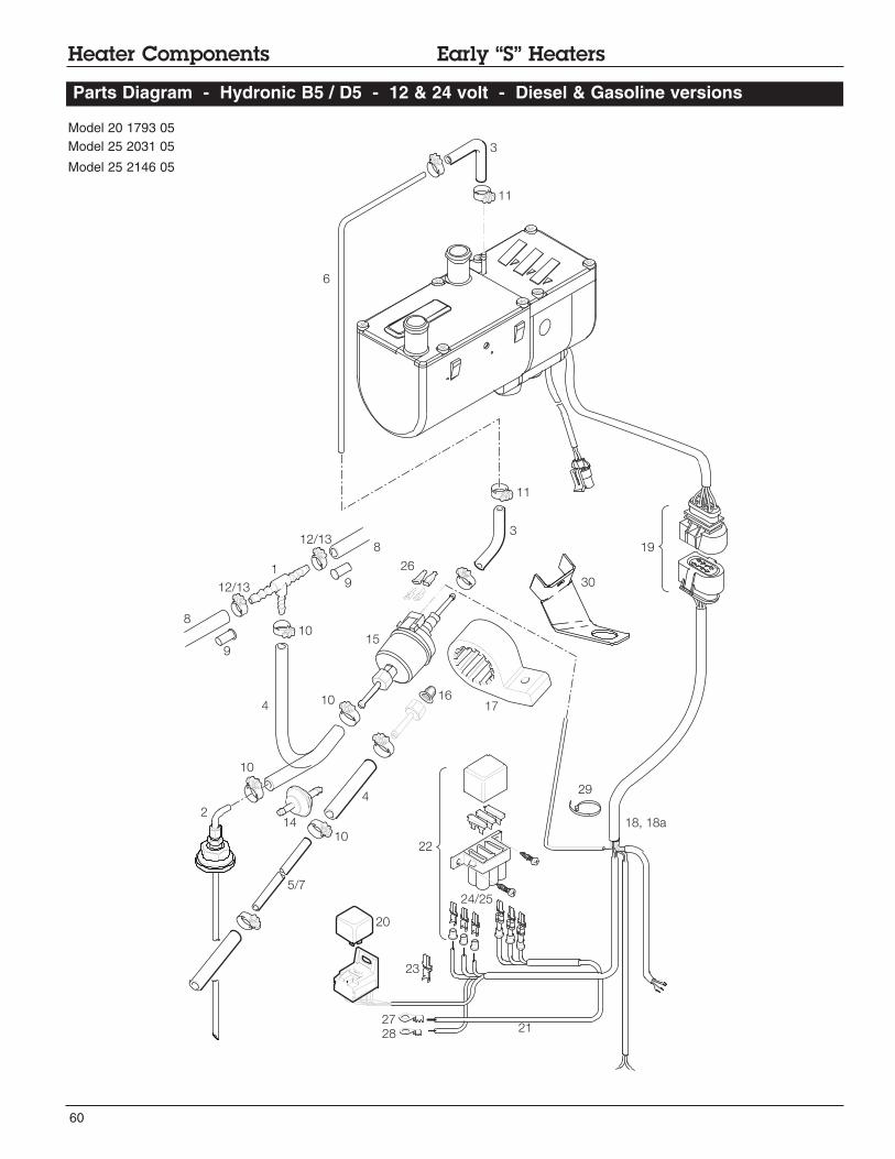
60
Heater Components Early “S” Heaters
Parts Diagram - Hydronic B5 / D5 - 12 & 24 volt - Diesel & Gasoline versions
Model 20 1793 05Model 25 2031 05
Model 25 2146 05
19
11
3
30
6
11
8
12/13 9
12/13
1
8
4
10
10
10
214
10
20
5/7
21
22
15
1617
4
18, 18a
3
9
23
2728
24/25
26
29

61
Description & Part #’s
Mod
el#
1 T-piece 8 x 6 x 8mm 262 31 151 • • • • •
2 Fuel pick up pipe 2.0mm - Universal 20 2900 20 20 10 • •
3 Hose 3.5 x 3mm 360 75 300 • • • • •
4 Hose 5 x 3mm --------------- • •360 75 350 • • •
5 Pipe 2mm (optional) 890 31 117 •
6 Pipe 1.5mm 890 31 118 • • • • •
7 Pipe 2mm 890 31 125 • • • • •
8 Hose 7.5mm 360 31 070 • • • • •
9 Supporting sleeve with collar --------------- • • • • •
10 Hose clip 11mm 10 2068 01 10 98 • • • • •
11 Hose clip 9mm 10 2068 00 90 98 • • • • •
12 Hose clip 14mm 10 2068 01 40 98 • • • • •
13 Double angle bracket 10 2068 01 20 98 • • • • •
14 Fuel filter 25 1226 89 00 37 • •
15 Fuel metering pump 12 V 20 1645 45 00 00 • • • 24 V 25 1942 45 00 00 • •
16 Cap sieve 20 1312 00 00 06 • • • • •
17 Holder metering pump 22 1000 50 03 00 • • • • •
18 Main harness - J.E. universal w/relay 25 1917 80 10 00 • • •
18a Main harness 20 2900 70 05 02 • • • • •
19 Connector kit main harness 22 1000 30 10 21 • • • • •
20 Relay 12 V 203 00 065 • • • 24 V 203 00 066 • •
21 Cable 22 1000 31 28 00 • • • • •
22 Fuse holder kit 22 1000 31 06 00 • • • • •
23 Terminal 206 52 136 • • • • •
24 Terminal 206 52 133 • • • • •
25 Terminal 206 52 134 • • • • •
26 Sleeve 320 31 120 • • • • •
27 Eyelet Hardware • • • • •
28 Eyelet Hardware • • • • •
29 Cable band 25 1801 80 02 00 • • • • •
30 Angle bracket 20 2900 40 01 04 • • • • •
Heater Components Early “S” HeatersHydronic B5 / D5 - 12 & 24 volt - Diesel & Gasoline versions
2017
9305
12v
2520
3105
12v
2521
4605
24v
Ref. No. Description Part Number

62
Heater Components Early “S” Heaters
Parts Diagram - Hydronic B5 / D5 - 12 & 24 volt - Diesel & Gasoline versions
17
18
16
15
19
14
14a
12
6311
20
18
2
1
4
11
5
1310
11
7
89
12
Model 20 1793 05Model 25 2031 05
Model 25 2146 05

63
Description & Part #’s
Ref. No. Description Part Number Mod
el#
1 Bracket 25 1864 80 00 01 • • •
2 Spacer 25 1864 80 00 02 • • •
3 Metal rubber buffer 6mm 20 1185 00 00 01 • • •
4 Air intake hose 360 00 099 • • •
5 End sleeve 25 1688 80 12 01 • • •
6 Hose clamp 16 - 25mm 10 2067 01 60 25 • • •
7 Flexible exhaust w/end cap -1mtr - 24mm 25 1774 80 02 00 • • •
8 Flexible exhaust 24mm 360 61 299 • • •
9 End sleeve w/bar 25 1729 80 06 00 • • •
10 Exhaust silencer 25 1864 81 01 00 • • •
11 Clamp 26mm 152 61 102 • • •
12 Clamp P type 28mm 152 09 010 • • •
13 Holder 20 1533 88 00 07 • • •
14 Pump 12 V 330 00 012 • •
14a Pump 24 V 25 2009 25 00 00 •
15 Hose - moulded - 20mm 25 1917 80 00 01 • • •
16 Hose union 20mm 20 1534 88 00 01 • • •
17 Hose union - reducer 20 - 18 20 1645 89 00 06 • • •
18 Hose clamp 20 - 32mm 10 2065 02 00 32 • • •
19 Pump clamp 22 1000 50 10 00 • •
20 Holder / Bracket with holes 20 1819 80 04 00 • • •
Heater Components Early “S” HeatersHydronic B5 / D5 - 12 & 24 volt - Diesel & Gasoline versions
2017
9305
12v
2520
3105
12v
2521
4605
24v

64
Heater Components North American
Parts Diagram - Hydronic D4 / D5
1
2
3
43
5
711
11
19
17
16
16
16
21
26
27
2015
44
8
8
8
8
8
8
8
8
4547
48
9
9
10
6
11
9
9
1213
14
23
40
22
24
25
32
3130
33
42
43
37
35
36
38
34
18
39
49

65
Heater Components North American
Parts Diagram - Hydronic D4 / D5 - (including Face Lift)
1
2
3
43
5
11
11
19
17
16
16
16
21
26
27
2015
44
8
8
8
8
8
8
8
8
45
46
47
48
9
9
10
6
11
9
9
1213
14
23
40
22
24
2531
41
33
42
43
37
35
36
38
34
18
39
29
28
41
49

66
Mod
el#
2519
2005
12v
2520
9605
12v
2521
4705
24v
2520
9805
12v
1 T-piece, 20mm 20 1673 80 11 00 • • • •
2 Connecting pipe 20mm 20 1534 88 00 01 • • • •
3 Clamp 20mm-32mm 10 2065 02 00 32 • • • •
4 Hose 20mm 25 1917 80 00 01 • • • •
5 1.5m white plastic fuel line 890 31 118 •
6 Fuel line 2mm 890 31 117 • • • •
7 Heater bracket 25 1864 80 00 01 • • • •
8 Hose clamp 9mm 10 2068 00 90 98 • • • •
9 Fuel hose 3.5mm 360 75 300 • • • •
10 Bracket - class 8 truck 20 2900 40 00 85 • • • •
11 Rubber mount 6mm 20 1185 00 00 01 • • • •
12 Pipe clamp 10mm 152 00 139 • • • •
13 Fuel pipe reducer 3.5 - 5mm 25 1888 80 01 02 • • • •
14 Fuel pick up pipe 2.0mm - Universal 20 2900 20 20 10 • • • •
15 Main heater harness 20 2900 70 04 01 •20 2900 70 05 03 • •20 2900 70 20 13 •
16 Exhaust clamp 26mm 152 61 102 • • • •
17 Intake hose clamp 10 2065 02 00 32 • • • •
18 C clamp 28mm 152 09 010 • • • •
19 End sleeve for exhaust 25 1729 80 06 00 • • • •
20 Exhaust hose 360 61 299 • • • •
21 Air intake hose 360 00 099 • • • •
22 Compression fitting 1/4” NPT 20 2900 20 20 44 • • • •3/8” NPT 552 0002 • • • •1/2” NPT 552 0006 • • • •
23 Custom straight pick up pipe w/Ferrule 24” length 20 2900 20 20 02 • • • •
24 Replacement bulb 12V 207 00 005 • • •24V 207 00 006 •
25 Push/pull switch 12V 567 0007 • • •24V 567 0008 •
26 Muffler 24mm 25 1864 81 01 00 • • • •
27 Double angle bracket 20 1533 88 00 07 • • • •
28 Complete bracket kit for 7-day timer 25 1482 70 01 00 • • • •
29 Hex Bolt 100 10 258 • • • •
30 7 day timer bezel 25 1482 70 01 00 • • • •
31 7 day timer 22 1000 30 36 00 • • • •7 day timer with kit (harness & relay) 12 V 20 2900 70 01 35 • • •7 day timer with kit (harness & relay) 24 V 20 2900 70 01 36 •
HYDRONIC 4 / 5 SC - Diesel & Gasoline versionsDescription & Part #’s
Heater Components North American
Ref. No. Description Part Number

67
Description & Part #’s
Mod
el#
2519
2005
12v
2520
9605
12v
2521
4705
24v
2520
9805
12v
32 Bracket for 7 day timer 20 2900 40 01 58 • • • •
33 Fault code retrieval device 20 2900 70 50 20 • • • •
34 Retrieval harness for fault code device 20 2900 70 50 28 • • • •
35 Fuse blade 25 A 204 00 089 • • •20 A 5670055 •
36 Wire awg 12 gage red 5670117 • • • •
37 Main fuse holder 5670051 • • • •
38 Ring terminal 3/8” awg 10-12 5670178 • • • •
39 Fuse link power harness 20 2900 70 51 08 • • •
40 Double pick-up (used with combo kits) 20 2900 20 20 57 • • • •
41 7 day timer bracket and Cosmetic Bezel 25 1482 70 01 00 • • • •
42 Cross frame mounting bracket 20 2900 40 00 28 • • • •
43 Hydronic box Base 25 2800 40 05 02 • • • •Hydronic box Lid 25 2800 40 05 01 • • • •
44 Plug Cables Complete 22 1000 30 10 21 • • • •
45 Fuel metering pump 25 1942 45 00 00 •
46 Boot sleeve 320 31 120 •
47 Fuel metering pump holder 22 1000 50 03 00 •
48 Fuel filter 20 1312 00 00 06 • • • •
49 Angle bracket 20 2900 40 01 04 • • • •
Heater Components North AmericanHYDRONIC 4 / 5 SC - Diesel & Gasoline versions
Ref. No. Description Part Number

A member of the Worldwide Eberspächer Group of Companies
Web Edition - September 2009Subject to changeP/N: 20 2900 81 0121
Espar Products, Inc.(800) 387-4800
(905) 670-0960
www.espar.com
Related Documents