OPERATION, INSTALLATION & MAINTENANCE GUIDE HYDROMETERS WATER METERS

Welcome message from author
This document is posted to help you gain knowledge. Please leave a comment to let me know what you think about it! Share it to your friends and learn new things together.
Transcript

OPERATION, INSTALLATION & MAINTENANCE GUIDE
HYDROMETERS
WATER METERS

This manual is intended for use by the users of this equipment. The information contained herein is the property of Netafim USA and may not be copied, used, or disclosed to others without the manufacturer’s prior written approval.
Users are cautioned that the material contained herein is subject to change by the manufacturer at any time and without prior notice. The material in this manual is intended for informational purposes only.

Table of Contents
INTRODUCTION General Description ............................................................4Water Meter/Registers .........................................................4Hydraulic Valve (Flow Sensor) ...........................................4Specifications and Dimensions ...........................................5Netafim USA Hydrometers with Electrical Output ............7Electrical Output Specifications (Reed Switch Reg.) .........7Electrical Output Specifications (Photo Diode) ...................9Electrical Output Specifications (ER Register) ..................10Transducer Type ................................................................ 11Hydrometer Internal Components .....................................12
INSTALLATIONA. Installation Requirements .............................................13B. Unpacking ....................................................................13C. Pipeline Installation ......................................................13D. Preliminary Steps .........................................................13E. Installing 1 ½” and 2” Models ......................................13F. Installing 3” – 8” Models ..............................................13
CONTROL SYSTEMA. Solenoid Connection ....................................................14B. Electrical Output ..........................................................14
DRAINAGE VALVE .......................................................15
OPERATIONAL TESTINGA. To test water flow and manual operation .....................16B. To test automatic and remote operation .......................16
OPERATIONSA. Manual Operation ........................................................17B. Automatic Operation ....................................................17C. Solenoid Operation .......................................................17
TYPICAL APPLICATIONSPressure Sustaining ...........................................................18Pressure Reducing .............................................................19
TROUBLESHOOTINGA. Leakage from Hydrometer Connection to Pipeline .....20B. No Electrical Output Signal from Hydrometer ............20C. Controller Indicates Water Not Flowing as Instructed .20D. No Indication of Flow on Meter Dial ...........................20E. Controller Indicates Valve Opening Failure .................21F. Controller Indicates Valve Closure Failure ...................21G. Leakage from Valves or Connectors ............................21H. Constant Drainage from Pilot Valve ............................21I. Excess or Insufficient Output Pressure ..........................22
J. Excess or Insufficient Input Pressure ............................22K. Excess or Insufficient Flow Rate .................................22
MAINTENANCE PREPARATION Preliminary Steps ..............................................................23Tools ..................................................................................23
MAINTENANCE 1 ½” – 8” HYDROMETERSHydrometer Removal From Pipeline ................................24Finger Strainer Cleaning and Replacement ......................25Register Assembly Removal and Replacement ................25
MAINTENANCE 1 ½” & 2” HYDROMETERSHydrometer Cover and Base Assemblies ..........................26Diaphragm/Stem Dis-Assembly .......................................27Base and Stem Dis-Assembly ...........................................27Inlet Spider and Strainer ...................................................28
MAINTENANCE 3” & 4” HYDROMETERSHydrometer Dis-Assembly and Re-Assembly ...................29Hydrometer Cover and Base Sub-Assemblies ..................29Diaphragm/Stem Assembly and Base Assembly ..............30Inlet Spider and Strainer ...................................................31
MAINTENANCE 6” HYDROMETERSHydrometer Dis-Assembly and Reinstallation .................32Register .............................................................................32Hydrometer Cover ............................................................32Diaphragm and Upper Stem Bearing ................................33Lower Stem Bearing and Valve Cover ..............................33Impeller and Flow Tube Sub-Assemblies .........................34Inlet Spider ........................................................................34
MAINTENANCE 8” HYDROMETER Hydrometer Dis-Assembly and Re-Assembly ...................35Register .............................................................................35Hydrometer Cover ............................................................35Diaphragm Sub-Assembly ................................................35Diaphragm Sub-Assembly and Dis-Assembly .................36Lower Chamber Disc Sub-Assembly ................................36Stem Sub-Assembly and Valve Cover ..............................37Impellar and Flow Tube Assemblies .................................38Inlet Spider ........................................................................38
SCHEMATICS ................................................................39

4 • Hydrometers Operation and Maintenance Manual
GENERAL DESCRIPTIONA hydrometer combines a hydraulic master valve, water meter and a flow sensor in a single unit. Netafim USA’s Hydrometer is designed for high pressure, remote control irrigation and industrial applications.
Body: HorizontalAvailable Sizes: 1½”, 2”, 3”, 4”, 6” and 8”Operation: For automatic and remote operation in a variety of
applications. Remote operation is possible via an external solenoid valve activated by a remote controller or control center. Flow rate and volume data are electronically transmitted to the remote controller by means of a transducer inserted into the register dial.
WATER METER/REGISTERSREED SWITCH REGISTER GALLON TOTALIZERThe Reed Switch Register has a low frequency pulse output for communicating with control and monitoring equipment. A leak indicator in the center of the dial registers the lowest flow through the meter. Flows are totalled in U.S. Gallons and each dial face indicates the multiplication factor (located directly under the totalizer reading). Three small fractional dials measure quantities smaller than the totalizer reading.
ELECTRONIC (ER) DIGITAL REGISTER GPM RATE OF FLOW WITH GALLON OR ACRE FEET TOTALIZERCombines standard digital register features with dry pulse output capabilities. Clearly displays the rate of flow and volume readings in Gallons or Acre Feet. Mounted inside an IP68 stainless steel glass encapsulated cap. Multi-line digital LCD readout displays 9 digits for Total Volume in U.S. Gallons (U.S.G.) or Acre Feet and 4 digits for Rate of Flow in Gallons per Minute (GPM). It’s programmable to a wide variety of pipe sizes. Register is interchangeable with common tools.
PHOTO DIODE REGISTER GALLON TOTALIZERA sensor combines an IR light source and a light sensitive diode in one package. Signals are created when the light beam created by the IR light is interrupted by a rotating element. The Photo Diode Register includes pulse output (open collector) for communicating with control and monitoring equipment. This register requires a constant supply of DC power. Flows are totalled in U.S. Gallons based on the multiplication factors indicated on the dial face.
Introduction
MULTIPLICATION FACTOR
U.S. GALLONS
FRACTIONAL DIALS
TOTALIZERREADING
OUTPUT
POSITIVE
GROUND
PHOTO DIODE GALLON TOTALIZER
ER REGISTER
TOTALIZER READING (VOLUME)
TOTALIZER READING (FLOW RATE)
REED SWITCHGALLON TOTALIZER
LEAK INDICATOR
MULTIPLICATION FACTOR
U.S. GALLONS
FRACTIONAL DIALS
TOTALIZERREADING
HYDRAULIC VALVE (FLOW SENSOR)The hydrometer contains a hydraulic master valve operated either manually or by remote control. The valve normally remains closed until a command is received to open it. Hydraulic commands are transmitted to the valve via an external solenoid valve. The hydrometer can also be ordered in a Normally Open configuration. In this case the valve is opened until a command is received and the valve closes.

Hydrometers Operation and Maintenance Manual • 5
Specifications and Dimensions
Size 1 ½” 2”
SPECIFICATIONS3” 4” 6” 8”
Maximum Working Pressure (psi) 230 230 230 230 230 230
Minimum Working Pressure (psi) 14 14 14 14 14 14
Regulated Pressure Ratio 1:3 1:3 1:3 1:3 1:3 1:3
Maximum Flow Rate (GPM) 55 95 220 380 860 1500
Minimum Flow Rate (GPM) 4.4 20 53 79 198 357
Accuracy ±2% ±2% ±2% ±2% ±2% ±2%
Size 1 ½” 2”
DIMENSIONS & WEIGHT3” 4” 6” 8”
Length (L) 6 5/16” 6 1/4” 9 9/16” 10 15/16” 19 1/2” 20 11/16”
Width (W) 4 3/4” 4 3/4” 8 1/4” 9 1/16” 14 7/8” 17 3/4”
Height (H) 10 5/16” 13 13/16” 16 15/16” 17 3/4” 25 7/16” 25 5/8”
Weight 4 lbs. 7 lbs. 52 lbs. 65 lbs. 245 lbs. 309 lbs.
W
W L
H
L
H
6 • Hydrometers Operation and Maintenance Manual
Specifications, Cont.
6”
8”
5.0
4.0
3.0
2.0
1.0
0 50 100 150 200 250
1 ½”
2”
3”
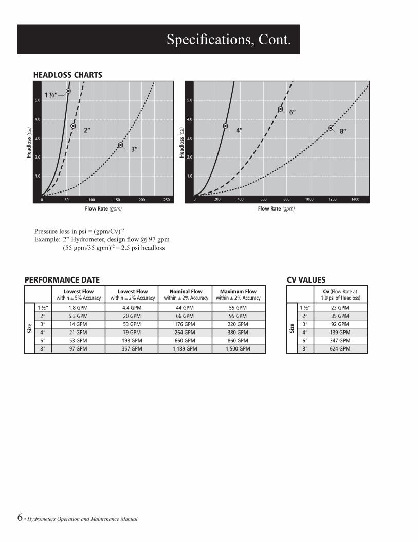
HEADLOSS CHARTS
Hea
dlos
s (p
si)
Hea
dlos
s (p
si)
5.0
4.0
3.0
2.0
1.0
0 200 400 600 800 1000 1200 1400
4”
Flow Rate (gpm)Flow Rate (gpm)
Lowest Flowwithin ± 5% Accuracy
1 ½”
2”
3”
4”
6”
8”
1.8 GPM 4.4 GPM 44 GPM 55 GPM
5.3 GPM 20 GPM 66 GPM 95 GPM
14 GPM 53 GPM 176 GPM 220 GPM
21 GPM 79 GPM 264 GPM 380 GPM
53 GPM 198 GPM 660 GPM 860 GPM
97 GPM 357 GPM 1,189 GPM 1,500 GPM
Lowest Flowwithin ± 2% Accuracy
Size
Nominal Flowwithin ± 2% Accuracy
Maximum Flowwithin ± 2% Accuracy
PERFORMANCE DATECv (Flow Rate at
1.0 psi of Headloss)
1 ½”
2”
3”
4”
6”
8”
23 GPM
35 GPM
92 GPM
139 GPM
347 GPM
624 GPM
Size
CV VALUES
Pressure loss in psi = (gpm/Cv)^2
Example: 2” Hydrometer, design flow @ 97 gpm (55 gpm/35 gpm)^2 = 2.5 psi headloss

Hydrometers Operation and Maintenance Manual • 7
Specifications, Cont.
NETAFIM USA HYDROMETERS WITH ELECTRICAL OUTPUTNetafim USA Hydrometers are equipped with electrical output devices that combine the high reliability of hermetically sealed, magnetically driven registers with a wide variety of electrical output options. Hydrometers (measuring instruments) provide electrical output information about the flow of water. When more than just the traditional register is needed, they also provide the solution for automation and communication with controllers, electronic devices and other water delivery systems.
Netafim USA has four types of transducer outputs available which provide four levels of resolution:
• Reed Switch (RS) Register - low frequency pulse output for functions related primarily to recording volume.
• Electronic (ER) Digital Register - standard frequency pulse output for functions such as rate of flow and recording total volume.
• Photo Diode (PD) Register - standard frequency pulse output (open collector) for functions such as rate of flow and recording total volume.
• Photo Diode (PDH) Register - high frequency pulse (open collector) for functions such as rate of flow and recording total volume.
ELECTRICAL OUTPUT SPECIFICATIONS REED SWITCH (RS) REGISTERThe flow rate is transmitted as periodic electrical pulses are measured by the magnetic pointer in the dial face. The hydrometer is configured to transmit a pulse according to a pre-defined volume interval. The following summarizes the available volume intervals for various hydrometer sizes in either gallons or cubic meters.
• A three pointer register, with a magnet installed on one of the pointers. • Output definition: Volume Output • Output type: RS – Reed Switch and PD – Photo Diode
The sensor is installed in a transparent plastic cover that can be mounted on the register in one of three positions with the pointer facing the magnet. Three values of electrical output are available in 1:10:100 ratios.
ManufacturerRecommended Register Type
RECOMMENDED REGISTERTRANSDUCER OUTPUTS
Baseline Basestation PDH
Hunter ACC 2-Wire PDH
Rain Bird MDC & Maxi RS
Signature All Models RS
Toro Sentinel PDH
TDC 2-Wire PDH
Rainmaster All Models RS (1” to 4”)
PD (6”, 8”)
Tucor Flowmaster
PDH & RK Series
Motorola All Models RS
ControllerModel
ER REGISTERCOMPATIBILITYCOMING SOON

8 • Hydrometers Operation and Maintenance Manual
Specifications, Cont.
Available Outputs(U.S. gallons/pulse) 1 ½” 2”
AVAILABLE INPUT SEQUENCES
3” 4” 6” 8”
1
10
100
1000
Reed Switch (RS) Register Specifications
• Magnet activated.
• Acts as a “dry contact”, uses very little electric power.
• For “Volume” related functions such as data recorders or simple counters.
Electrical Specifications
Maximum Contact Current: 50 mA
Maximum Contact Voltage: 28 VDC
Circuit Diagram Register with Reed Switch Output, Two Wires
HydrometerSize
Gallons/Pulse
REED SWITCH (RS)LOW FREQUENCY PULSE OUTPUTS
Pulse/Gallon K Factor Offset
1½”, 2”, 3”, 4” 1 1 60.00 0
6”, 8” 10 0.1 600.00 0
Reed Switch (RS)
U.S. GALLONS
0 0 0 0 0 0
01
2
3
4
9
8
7
65
01
2
3
4
9
8
7
65
01
2
3
4
9
8
7
65
Pulse per1 USG
Pulse per10 USG
Pulse per100 USG
BM
EXAMPLE for sizes 1½”, 2”, 3”, 4”(standard pulse = 1 g/p)
U.S. GALLONS
0 0 0 0 0 0
01
2
3
4
9
8
7
65
01
2
3
4
9
8
7
65
01
2
3
4
9
8
7
65
Pulse per10 USG
Pulse per100 USG
Pulse per1000 USG
BM
x 1000
EXAMPLE for sizes 6”, 8”(standard pulse = 10 g/p)
For sizes 1½”, 2”, 3”, 4”: If the pointer with the magnet is set in the middle position as shown in the drawing the magnet will make one contact of the reed switch for every 360° rotation - the result is an output of 1 pulse per 10 USG.
For sizes 6”, 8”: If the pointer with the magnet is set in the right position as shown in the drawing the magnet will make one contact of the reed switch for every 360° rotation - the result is an output of 1 pulse per 1000 USG.

Hydrometers Operation and Maintenance Manual • 9
RECOMMENDEDRESISTOR VALUES
Ω W
5 180 0.25
6 220 0.25
9 330 0.25
12 470 0.50
24 1000 1.00
Voltage (V+)Resistor Values
NOTE: Correct polarity of the leads should be checked carefully to prevent damage to the sensor.
Specifications, Cont.
Photo-Diode Electrical Specifications
POSITIVE powers the IR light (yellow wire) Current Min: 15 mA to a maximum of 25 mA DC through a resistor
• Maximum Voltage: 28 VDC
OUTPUT (clear wire) Output – Open collector (Max. Load – 2 mA)
GROUND (bare wire)
Photo-Diode (PD & PDH) Register• Sensor combines an IR light source and a light sensitive
diode in one package.
• Signals are created when the light beam created by the IR light is interrupted by a rotating element.
• Requires a constant supply of DC power.
Circuit DiagramRegister with Photo Diode Output and Wire Leads
Note: Sunlight will interfere with the IR light and may corrupt or interfere with the signal—keep dust cap closed during operation to ensure proper signal output.
10 • Hydrometers Operation and Maintenance Manual
Specifications, Cont.
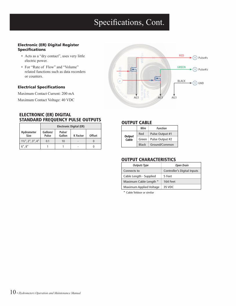
Electronic (ER) Digital Register Specifications
• Acts as a “dry contact”, uses very little electric power.
• For “Rate of Flow” and “Volume” related functions such as data recorders or counters.
Electrical Specifications
Maximum Contact Current: 200 mA
Maximum Contact Voltage: 40 VDC
OutputCable
Wire Function
OUTPUT CABLE
Red
Green
Black
Pulse Output #1
Pulse Output #2
Ground/Common
Outputs Type Open Drain
OUTPUT CHARACTERISTICS
Connects to
Cable Length - Supplied
Maximum Cable Length *
Maximum Applied Voltage
* Cable Teldoor or similar
Controller’s Digital Inputs
5 Feet
164 Feet
35 VDC
HydrometerSize
Gallons/Pulse
ELECTRONIC (ER) DIGITALSTANDARD FREQUENCY PULSE OUTPUTS
Pulse/Gallon K Factor Offset
1½”, 2”, 3”, 4” 0.1 10 - 0
6”, 8” 1 1 - 0
Electronic Digital (ER)
Hydrometers Operation and Maintenance Manual • 11
Transducer Type
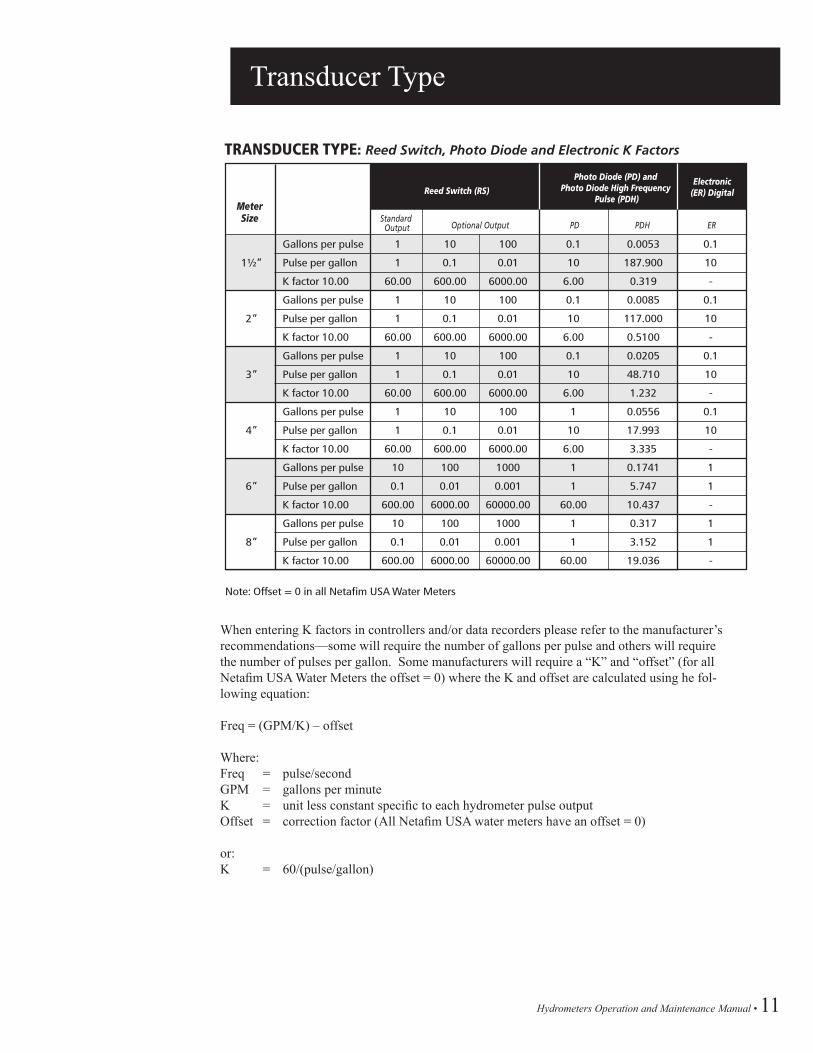
When entering K factors in controllers and/or data recorders please refer to the manufacturer’s recommendations—some will require the number of gallons per pulse and others will require the number of pulses per gallon. Some manufacturers will require a “K” and “offset” (for all Netafim USA Water Meters the offset = 0) where the K and offset are calculated using he fol-lowing equation:
Freq = (GPM/K) – offset
Where:Freq = pulse/secondGPM = gallons per minuteK = unit less constant specific to each hydrometer pulse outputOffset = correction factor (All Netafim USA water meters have an offset = 0)
or:K = 60/(pulse/gallon)
TRANSDUCER TYPE: Reed Switch, Photo Diode and Electronic K Factors
Gallons per pulse 1 10 100 0.1 0.0053 0.1
Pulse per gallon 1 0.1 0.01 10 187.900 10
K factor 10.00 60.00 600.00 6000.00 6.00 0.319 -
Gallons per pulse 1 10 100 0.1 0.0085 0.1
Pulse per gallon 1 0.1 0.01 10 117.000 10
K factor 10.00 60.00 600.00 6000.00 6.00 0.5100 -
Gallons per pulse 1 10 100 0.1 0.0205 0.1
Pulse per gallon 1 0.1 0.01 10 48.710 10
K factor 10.00 60.00 600.00 6000.00 6.00 1.232 -
Gallons per pulse 1 10 100 1 0.0556 0.1
Pulse per gallon 1 0.1 0.01 10 17.993 10
K factor 10.00 60.00 600.00 6000.00 6.00 3.335 -
Gallons per pulse 10 100 1000 1 0.1741 1
Pulse per gallon 0.1 0.01 0.001 1 5.747 1
K factor 10.00 600.00 6000.00 60000.00 60.00 10.437 -
Gallons per pulse 10 100 1000 1 0.317 1
Pulse per gallon 0.1 0.01 0.001 1 3.152 1
K factor 10.00 600.00 6000.00 60000.00 60.00 19.036 -
Standard Output Optional Output PD PDH ER
MeterSize
1½”
2”
3”
4”
6”
8”
Photo Diode (PD) and Photo Diode High Frequency
Pulse (PDH)Reed Switch (RS)
Electronic(ER) Digital
Note: Offset = 0 in all Netafim USA Water Meters

12 • Hydrometers Operation and Maintenance Manual
Hydrometer Internal Components
Hydrometer Internal Components
(Double Chamber Not Available in 6”)
Hydrometers Operation and Maintenance Manual • 13
Installation
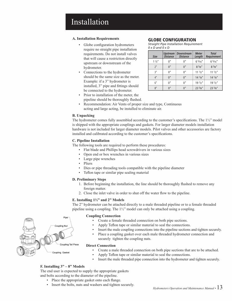
A. Installation Requirements • Globe configuration hydrometers
require no straight pipe installation requirements. Do not install valves that will cause a restriction directly upstream or downstream of the hydrometer.
• Connections to the hydrometer should be the same size as the meter. Example: if a 3” hydrometer is installed, 3” pipe and fittings should be connected to the hydrometer.
• Prior to installation of the meter, the pipeline should be thoroughly flushed.
• Recommendation: Air Vents of proper size and type, Continuous acting and large acting, be installed to eliminate air.
B. UnpackingThe hydrometer comes fully assembled according to the customer’s specifications. The 1½” model is shipped with the appropriate couplings and gaskets. For larger diameter models installation hardware is not included for larger diameter models. Pilot valves and other accessories are factory installed and calibrated according to the customer’s specifications.
C. Pipeline InstallationThe following tools are required to perform these procedures: • Flat blade and Phillips head screwdrivers in various sizes • Open end or box wrenches in various sizes • Large pipe wrenches • Pliers • Dies or pipe threading tools compatible with the pipeline diameter • Teflon tape or similar pipe sealing material
D. Preliminary Steps 1. Before beginning the installation, the line should be thoroughly flushed to remove any
foreign matter. 2. Close the inlet valve in order to shut off the water flow to the pipeline.
E. Installing 1½” and 2” ModelsThe 2” hydrometer can be attached directly to a male threaded pipeline or to a female threaded pipeline using a coupling. The 1½” model can only be attached using a coupling.
Coupling Connection • Create a female threaded connection on both pipe sections. • Apply Teflon tape or similar material to seal the connections. • Insert the male coupling connections into the pipeline sections and tighten securely. • Place a coupling gasket over each male threaded hydrometer connection and
securely tighten the coupling nuts.
Direct Connection • Create a male threaded connection on both pipe sections that are to be attached. • Apply Teflon tape or similar material to seal the connections. • Insert the male threaded pipe connection into the hydrometer and tighten securely.
F. Installing 3” – 8” ModelsThe end user is expected to supply the appropriate gaskets and bolts according to the diameter of the pipeline. • Place the appropriate gasket onto each flange. • Insert the bolts, nuts and washers and tighten securely.
SizeUpstreamDistance
DownstreamDistance
GLOBE CONFIGURATIONStraight Pipe Installation Requirement0 x D and 0 x D
MeterLength
TotalRequirement
1 ½” 0” 0” 6 5/16” 6 5/16”
2” 0” 0” 8 5/8” 8 5/8”
3” 0” 0” 11 1/2” 11 1/2”
4” 0“ 0” 14 1/8“ 14 1/8“
6” 0“ 0” 19 1/2“ 19 1/2“
8” 0” 0” 23 5/8“ 23 5/8“
14 • Hydrometers Operation and Maintenance Manual
Installation, Cont.
CONTROL SYSTEMA. Solenoid ConnectionThe hydrometer receives commands from the controller or control center via an external solenoid valve. The hydrometer may be ordered with a factory installed solenoid valve or connected to an solenoid valve supplied by the user.
To connect to a factory installed solenoid: 1. Connect the electric cable from controller to the attached solenoid valve. Position
the three-way selector in the “Auto” position - in this position the hydrometer will be controlled by the solenoid.
B. Electrical OutputThe hydrometer supplies volume and flow rate data to a controller or to an external measuring device via an electrical connection. A reed switch transducer is factory installed in the register dial. The cable attached to the reed switch transducer attaches to the controller or measuring device.
To connect the hydrometer to the controller or measuring device: 1. Install an appropriate connector onto the bare end of the cable exiting from the reed
switch. Refer to the user manual of the controller or measuring device for details regarding the specific connector type.
2. Connect the cable to the input port of the controller or measuring device. (See pages 7-10 for more details)

Hydrometers Operation and Maintenance Manual • 15
Drainage Valve
DRAINAGE VALVEAt the beginning of the winter it is necessary to drain the water from the pipeline in order to prevent the pipes from bursting. (Please refer to the drawing below)
• Before draining, it is very important to ensure that there is no pressure in the line. • Dissassemble plug (1) • Assemble the drainage ball valve (2) • Assemble elbow (3)
CAUTION: Do not use compressed air to blow out hydrometer.

16 • Hydrometers Operation and Maintenance Manual
Operational Testing
INSTALLATIONBefore the hydrometer is placed into service, you should perform the following tests to verify that it is operating properly:
A. To test water flow and manual operation: • Set 3-Way Selector to the “Open position”. • Turn on the water flow to the hydrometer. • Visually verify that water is flowing downstream from the hydrometer in appropriate
quantities. • Verify that the leak detector, pointers and the totalizer are functioning properly. • Check all hoses, connections, pilot valves, etc. for leakage and repair as necessary. • Set 3-Way Selector to the “Close position”. • Verify that the water flow downstream has stopped.
B. To test automatic and remote operation: • Set 3-Way Selector to the “Auto” position. • Turn on the water flow to hydrometer. • Verify that the hydrometer output is correctly received by the controller or control center. • Use the controller or control center to close the hydrometer. Verify that the water flow
downstream has stopped. • Use the controller software to test operation of the hydrometer under various applications
and conditions such as pressure reducing, pressure sustaining and flow regulation. • Your hydrometer is now ready for routine use.

Hydrometers Operation and Maintenance Manual • 17
Operations
The hydrometer is designed to operate in a variety of automatic and remote control applications. The hydrometer valve is also capable of manual operation and the register dial may be read as an ordinary water meter.
A. Manual OperationThe hydrometer may be manually operated using the 3-Way Selector: • To manually open the valve: Rotate the 3-Way Selector to the “Open” position. • To manually close the valve: Rotate the 3-Way Selector to the “Close” position.
B. Automatic OperationAutomatic operation is made possible by direct hydraulic control from a remote controller or control center. Volume and/or flow data is electronically transmitted to the remote controller by means of a reed switch transducer. The command to open or close the hydrometer valve is transmitted from the controller to a solenoid, which, in turn, transmits a hydraulic command to the hydrometer.
Automatic operation may also be based on a pre-set pressure or flow rate by the use of one or more Pilot Valves. To enable automatic and/or remote operation, rotate the 3-Way Selector to the “Auto” position.
C. Solenoid Operation The hydrometer is always controlled via an external solenoid valve. A “normally open” (NO), high pressure, 3-Way solenoid valve is required for this purpose resulting in a normally closed hydrometer. When a normally closed solenoid is used it will result in a normally open hydrometer. An electric cable connects the controller and the solenoid valve. 8 mm polyethylene tubing runs from the solenoid valve to the “Auto” connection on the 3-Way Selector.
3-Way Selector
Electric Solenoid Specifications• Operation: – Solenoid: 24vac 5.5 watts, 0.23 amps inrush – Manual Override• Construction: Brass• Connections: In/Out NPT Threaded

18 • Hydrometers Operation and Maintenance Manual
Typical Applications
PRESSURE SUSTAININGThe pressure sustaining operation prevents the input pressure from falling below a predetermined value. This application requires a Netafim Pressure Regulating Pilot Valve, or comparable valve. Rotate the adjusting screw atop the pilot valve counterclockwise to increase the desired input pressure and clockwise to reduce the desired input pressure.
Connection Information
The sensor connection runs from the input connector on the hydrometer to the controlled input connector (1) on the pilot valve. The sensor connection also branches off to the “Close” connector on the 3-Way Selector and to the vent connector (4) on the pilot valve.
The command connection runs from solenoid to the “Auto” connector on the 3-Way Selector (via the shuttle valve) and continues on to the pressure controlled input connector (2) on the pilot valve.
The supply connector (3) on the pilot valve serves as a vent. The output connector on the hydrometer is not used.
Hydrometers Operation and Maintenance Manual • 19
Typical Applications, Cont.
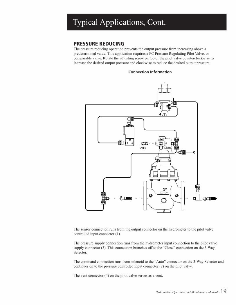
PRESSURE REDUCINGThe pressure reducing operation prevents the output pressure from increasing above a predetermined value. This application requires a PC Pressure Regulating Pilot Valve, or comparable valve. Rotate the adjusting screw on top of the pilot valve counterclockwise to increase the desired output pressure and clockwise to reduce the desired output pressure.
Connection Information
The sensor connection runs from the output connector on the hydrometer to the pilot valve controlled input connector (1).
The pressure supply connection runs from the hydrometer input connection to the pilot valve supply connector (3). This connection branches off to the “Close” connection on the 3-WaySelector.
The command connection runs from solenoid to the “Auto” connector on the 3-Way Selector and continues on to the pressure controlled input connector (2) on the pilot valve.
The vent connector (4) on the pilot valve serves as a vent.

20 • Hydrometers Operation and Maintenance Manual
Troubleshooting
This chapter provides detailed troubleshooting procedures and solutions for a variety of common problems. The procedures described below are general in nature and are presented in a “Quick Reference” style outline format.
We recommend that you perform the steps in order until the specific problem is solved. It may not be necessary to complete all of the steps in a given procedure.
A. Leakage from Hydrometer Connection to Pipeline • Inspect and tighten the couplings or flange bolts. Replace the coupling, bolts and nuts
as necessary. • Apply Teflon tape, or other similar material, to seal the connection. • Inspect and replace gaskets as necessary. • Inspect and clean the orifice and associated gaskets (flow control applications only).
Replace as necessary.
B. No Electrical Output Signal From Hydrometer • Inspect all cables and electrical connections. Repair or replace cables as necessary. • Verify that the reed switch transducer is properly inserted into the register dial. • Verify that the controller is functioning properly. If not, restart the controller and make
certain that your software is properly configured. • Replace the reed switch transducer. • Verify that the flow indicator on the meter dial is rotating.
C. The Controller Indicates Water is Not Flowing as Instructed • Verify that the controller is functioning properly. If not, restart the controller and verify
that your software is properly configured. • Move the 3-Way Selector to the “Open” position. Check to see if the controller shows
water flow. If so, this indicates that the solenoid is not functioning properly. Repair or replace as necessary.
• Verify that the reed switch transducer is properly inserted into the register dial. • Check all electrical connections. Replace cables as necessary. • Verify that the flow indicator on the meter dial is rotating.
D. No Indication of Flow on Meter Dial • Remove the register assembly as described on page 25. Place a small magnet on the
bottom of the register assembly and move it in a circular motion. This should cause the flow indicator to rotate freely. If it does not, replace the register.
• Disassemble the hydrometer as described in Chapter 5. • Clean or replace the strainer (1½” and 2” models only). • Verify that the impeller rotates freely. If it does not, inspect the impeller, impeller shaft
and other related components. Replace as necessary. • Inspect the diaphragm and o-rings. Replace as necessary.

Hydrometers Operation and Maintenance Manual • 21
Troubleshooting, Cont.
E. Controller Indicates Valve Opening Failure • Verify that the 3-Way Selector is in the “Auto” position. If it is not, turn the switch to the
“Auto” position and then check to see if the controller indicates that the valve is open. • Verify that the controller and your software are functioning properly. If not, restart the
controller and make certain that your software is properly configured. • Verify if there is water flow downstream from the hydrometer. If there is not, this indicates
that the valve is indeed closed. • Check the electrical connections as described on page 8. • Check the register as described in the first step on page 5. • Remove the 3-Way Selector. Clean or replace as necessary. • Verify solenoid operation. Repair or replace as necessary. • Disassemble the hydrometer as described in the Maintenance section, pages 23-38. • Clean or replace the strainer (1½” and 2” models only). • Inspect the diaphragm and o-rings. Replace as necessary.
F. Controller Indicates Valve Closure Failure • Verify that the 3-Way Selector is in the “Auto” position. If it is not, turn the switch to the
“Auto” position and then check to see if the controller indicates that the valve is open. • Verify that the controller and your software are functioning properly. If not, restart the
controller and make certain that your software is properly configured. • Move the 3-Way Selector to the “Close” position. Check to see if the controller indicates
that the valve is closed. If so, this indicates that the solenoid is not functioning properly. Repair or replace as necessary.
• Verify if there is water flow downstream from the hydrometer. If there is, this indicates that the valve is indeed open.
• Check the electrical connections as described on page 7. • Check the register as described in the first step on page 4. • Remove the 3-Way Selector. Clean or replace as necessary. • Remove and clean the finger strainer. Replace if necessary. • Disassemble the hydrometer as described in the Maintenance section, pages 22-37. • Inspect the diaphragm, valve cover and o-rings. Replace as necessary.
G. Leakage from Valves or Connectors • Inspect the control hoses, connectors, shuttle valves and adapters. Tighten and replace as
necessary.
H. Constant Drainage from Pilot Valve • Repair or replace the pilot valve.
22 • Hydrometers Operation and Maintenance Manual
Troubleshooting, Cont.
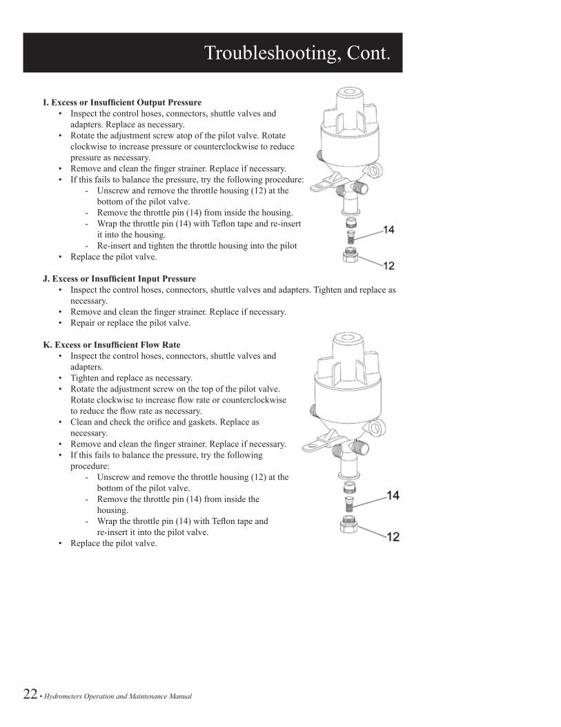
I. Excess or Insufficient Output Pressure • Inspect the control hoses, connectors, shuttle valves and
adapters. Replace as necessary. • Rotate the adjustment screw atop of the pilot valve. Rotate
clockwise to increase pressure or counterclockwise to reduce pressure as necessary.
• Remove and clean the finger strainer. Replace if necessary. • If this fails to balance the pressure, try the following procedure:
- Unscrew and remove the throttle housing (12) at the bottom of the pilot valve.
- Remove the throttle pin (14) from inside the housing.- Wrap the throttle pin (14) with Teflon tape and re-insert
it into the housing.- Re-insert and tighten the throttle housing into the pilot
• Replace the pilot valve.
J. Excess or Insufficient Input Pressure • Inspect the control hoses, connectors, shuttle valves and adapters. Tighten and replace as
necessary. • Remove and clean the finger strainer. Replace if necessary. • Repair or replace the pilot valve.
K. Excess or Insufficient Flow Rate • Inspect the control hoses, connectors, shuttle valves and
adapters. • Tighten and replace as necessary. • Rotate the adjustment screw on the top of the pilot valve.
Rotate clockwise to increase flow rate or counterclockwise to reduce the flow rate as necessary.
• Clean and check the orifice and gaskets. Replace as necessary.
• Remove and clean the finger strainer. Replace if necessary. • If this fails to balance the pressure, try the following
procedure:- Unscrew and remove the throttle housing (12) at the
bottom of the pilot valve.- Remove the throttle pin (14) from inside the
housing.- Wrap the throttle pin (14) with Teflon tape and
re-insert it into the pilot valve. • Replace the pilot valve.

Hydrometers Operation and Maintenance Manual • 23
Maintenance Preparation
The hydrometer requires no routine periodic maintenance. In the unlikely event that the hydrometer fails to operate as expected, please follow the troubleshooting procedures as outlined on pages 20-22. If and when the troubleshooting procedures necessitate the inspection or replacement of internal parts, use the procedures contained in this chapter to perform the required action.
This chapter contains step-by-step instructions for the dis-assembly of the hydrometer as well as the inspection, cleaning and replacement of its component parts.
PRELIMINARY STEPSThe following steps should be undertaken before attempting to remove the hydrometer from the pipeline or performing any repairs: 1. Flush the pipeline to remove impurities and foreign matter. 2. Close the inlet valve in order to shut off the water flow to the pipeline. 3. Drain all water from the hydrometer. 4. Remove the reed switch from the register dial. Gently turn and pull the switch mechanism
up to release it. 5. Disconnect all control hoses from the inlet and outlet connectors. 6. Disconnect all control hoses and shuttle valves from the 3-Way Selector.
TOOLSThe following tools are required to perform these procedures: • Flat blade and Phillips head screwdrivers in various sizes • Socket and open end wrenches in various sizes • Hammer • Large pipe wrench • Special box wrench for removal of the upper spindle bolt – Model Number: 00360-000071 • Special extractor tool for removal of the valve cover – Model Number: 00360-000072 • Teflon tape or similar sealing material • Grease for sealing gaskets and o-rings
IMPORTANT NOTE:Use plumbing grease. DO NOT USE petroleum base grease, it will degrade the o-rings.

24 • Hydrometers Operation and Maintenance Manual
Maintenance 1½” - 8” Hydrometers
HYDROMETER REMOVAL FROM PIPELINEThe hydrometer is designed for easy site repairs. Removal from the pipeline is not required for dis-assembly and most repairs. The following removal instructions are includedin the unlikely event that the hydrometer needs to be disassembled and repaired in the shop.
1½” and 2” ModelsThe 1½” model may only be attached, using a coupling, to a male threaded pipeline.
Coupling Connection• Unscrew the coupling nuts on both sides of the hydrometer counterclockwise.• Slide the coupling nuts away from the hydrometer and remove the hydrometer from the
pipeline. Retain the coupling gaskets.
Direct Connection• If the hydrometer is attached directly to the pipeline, unscrew the pipeline on both sides of the
hydrometer.• Remove the hydrometer from the pipeline.
3” - 8” Models• Unscrew and remove the bolts from the flanged connections on both sides of the hydrometer.• Remove the hydrometer from the pipeline.• Inspect the gaskets and replace as necessary.

Hydrometers Operation and Maintenance Manual • 25
Maintenance 1½” - 8” Hydrometers, Cont.
FINGER STRAINER CLEANING AND REPLACEMENTIt is not necessary to remove the hydrometer from the pipeline or to disassemble it in order to perform this procedure.
To Remove the Finger Strainer: • Locate the inlet connection on the hydrometer body. • Remove the angle nipples and other connection devices. • Turn the nut counter-clockwise to loosen the finger strainer. • Gently pull the finger strainer out. • Clean or replace as necessary.
To Replace the Finger Strainer: • Insert the finger strainer into the inlet connection and turn clockwise to tighten. • Apply Teflon tape or similar material to seal the connections. • Re-install the angle nipples and other connection devices.
REGISTER ASSEMBLY REMOVAL AND REPLACEMENTIt is not necessary to disassemble the hydrometer to perform this procedure.
Removal: • Remove the reed switch transducer (4) from
the register dial. Gently turn and pull the switch (4) upward to release it.
• Close the register cover (1). • Using a large pipe wrench, turn the register
cover assembly (1, 2) counterclockwise until you can remove it from the hydrometer cover (12).
• Remove and set aside the sliding ring (3). • Lift the register assembly (5) out of the
hydrometer body. • Remove the register o-ring (6) and the adapter
ring (7) from the register.
• Inspect and replace as necessary.
Replacement: • Close the register cover (1). • Place the register o-ring (6) around the register assembly. Insert the register assembly into
the adapter ring (7) and place them inside the hydrometer cover (12). • Replace the sliding ring (3) over the register assembly. • Replace the register cover assembly (1, 2) over the register. Turn it clockwise to tighten. • Insert the reed switch (4) into its hole in the register dial. Gently turn the reed switch until
it is fully seated.

26 • Hydrometers Operation and Maintenance Manual
Maintenance 1½” and 2” Models
1½” AND 2” HYDROMETERSThe dis-assembly of the hydrometer is divided into the following assemblies:
• Cover Assembly• Diaphragm/Stem and Base Assemblies• Inlet Spider/Strainer Assembly
Perform only those procedures necessary to inspect and replace parts as directed by the troubleshooting procedures. It is recommended to replace the various o-rings and gaskets during dis-assembly as well as to inspect certain other parts. All gaskets and o-rings must be covered with grease prior to installation.
HYDROMETER COVER AND BASE ASSEMBLIESRemoval • Remove the register assembly as described on page 25.• Loosen and remove the upper bearing bolt (8) using the specially
sized box wrench. Model number: 03640-000071• Remove the upper bearing bolt o-ring (9) from the groove in the
underside of the bolt. Inspect and replace as necessary.• Loosen and remove the six cover screws (10), with the washers.• Lift the base and cover assemblies off of the hydrometer body (21).• Be especially careful not to damage the impeller.• Place the two assemblies upside down. Pull the impeller (30) up
and out.• Some force may be required to free the impeller.• Remove the magnet housing (31) from inside the cover assembly.
The magnet housing was freed from the impeller shaft during the previous step.
• Inspect the impeller and its components for signs of excessive wear or damage.
• Verify that the impeller shaft is straight. Replace as necessary.
Re-assembly• Carefully place the base and cover assemblies over the impeller shaft
(30).• Push the magnet housing (31) down over the top of the impeller shaft (which extends
through the hole in the cover). Tap the magnet housing with a hammer to ensure that it is properly secured to the shaft.
• Place the base and cover assemblies onto the hydrometer body (21).• Replace and tighten the six cover screws (10).• Place the upper bearing bolt o-ring (9) into the groove on the underside of the bolt (8).• Screw in the upper bearing bolt “O” (8) using the specially sized
box wrench.• Replace the register assembly and cover as described on page 25.

Hydrometers Operation and Maintenance Manual • 27
Maintenance 1½” and 2” Models, Cont.
DIAPHRAGM/STEM DIS-ASSEMBLY• Separate the base assembly from the cover (12).• Visually inspect the diaphragm (37), valve cover (32) and stem
assembly (36) for damage or excessive wear. If replacement is needed, continue with the following steps.
• Remove the six screws (39) from the diaphragm retaining ring (38). • Lift the ring off of the diaphragm (37).• Lift the diaphragm (37) off of the stem (36).
BASE AND STEM DIS-ASSEMBLY• Place the base and stem assemblies upside down on a flat surface.• Use the extraction tool to remove the valve cover (32) as follows:
- Slide the lower prongs of the extraction tool under the cover.- Turn the bolt on the extraction tool clockwise until the
extractor seat fits securely into the stem.- Continue turning the bolt until the valve cover slides off
of the stem (36).• Invert the base and pull the stem (36) out of the base (33).• Remove the base o-ring (23) from the underside of the base. Inspect
and replace as necessary.• Remove the stem o-ring (34) from the groove in the hole in the
center of the base. Inspect and replace as necessary.• Remove the diaphragm support ring (35) from the base (33).• Inspect the base (33) for cracks or excessive wear. Replace as
necessary.
WARNINGYou must use the extraction tool to remove the valve cover. Use of any other tool may damage the valve cover and the stem.
Re-assembly • Insert the diaphragm (37) into the grooves on the top of the stem
(36).• Place the diaphragm retaining ring (38) over the diaphragm. Secure
the ring with the six screws (39). Apply Loctite 270 or similar glue to the screws.
• Set the lower diaphragm support ring (35) inside the base (33).• Insert the re-assembled diaphragm and stem assembly into the base.• Push the valve cover (32) up onto the bottom of the diaphragm/stem
subassembly. It should easily snap into place.• Remove and replace the central bushing o-ring (15) at the bottom of
the central bushing (14 not shown), located in the underside of the cover (12).
• Set the cover (12) onto the re-assembled base subassembly. These subassemblies are now ready for reinstallation onto the hydrometer body.
Extraction ToolItem Number:70220-005635

28 • Hydrometers Operation and Maintenance Manual
Maintenance 1½” and 2” Models, Cont.
INLET SPIDER AND STRAINERDis-assembly• Loosen the impeller bushing (29) located atop the inlet
spider screw (24) and bushing (28). Pull the entire inlet spider screw assembly up and out.
• Pull the inlet spider (27) upward and remove it from the hydrometer body (21). Inspect for cracks or excessive wear and replace as necessary.
• Remove and replace the body o-ring (26).• Remove the strainer (25). Clean and inspect for damage or
excessive wear.• Replace as necessary.
Re-assembly• Place the body o-ring (26) in the small flange inside the
hydrometer base.• Place the strainer (25) into the hydrometer base.• Insert the inlet spider into the body so that the end rests on
the top of the strainer and the flange rests over the body o-ring (26).
• Place the inlet spider screw assembly through the holes in the input spider (27) and strainer (25). Use a socket wrench to tighten the impeller bushing (29) atop the assembly.

Hydrometers Operation and Maintenance Manual • 29
Maintenance 3” and 4” Models
HYDROMETER DIS-ASSEMBLY AND RE-ASSEMBLYDis-assembly of the 3” and 4” hydrometer is divided into the following assemblies:• Cover Assembly• Diaphragm/Stem and Base Assemblies• Inlet Spider/Strainer Assembly
Perform only those steps necessary to inspect and replace parts as directed by the troubleshooting procedures. It is recommended to replace the various o-rings and gaskets during dis-assembly as well as to inspect certain other parts. All gaskets and o-rings must be covered with grease prior to installation.
HYDROMETER COVER AND BASE SUB-ASSEMBLIESRemoval• Remove the register subassembly as described on page 24.• Loosen and remove the cover screws (10) along with the washers.• Lift the cover off of the hydrometer body (29). Be especially careful
not to damage the impeller.• Carefully remove the impeller assembly (37) from the hydrometer
body.• Inspect the impeller and its components for signs of excessive wear
or damage. Verify that the impeller shaft is straight. Replace as necessary.
• Inspect the base o-ring (42) for excessive wear or damage. Replace as necessary.
Re-assembly• Insert the impeller (37) into the inlet spider (located inside the
hydrometer base).• Insert the base “O” ring (42) into the groove on the upper body flange.• Carefully place the cover over the impeller shaft (37) and onto the
hydrometer body (29).• Replace and tighten the cover screws (10).• Replace the register subassembly as described on page 24.

30 • Hydrometers Operation and Maintenance Manual
Maintenance 3” and 4” Models, Cont.
DIAPHRAGM/STEM ASSEMBLY AND BASE ASSEMBLYDiaphragm/Stem Dis-assembly• Pull the diaphragm and stem assemblies up and out from the
hydrometer cover (11). The central bushing (13) remains attached to the cover.
• Unscrew and remove the central bushing (13) from the cover (11).• Inspect the upper and lower central bushing o-rings (12,14).
Replace as necessary.• Visually inspect the diaphragm (18), valve cover (39) and stem
(40) for damage or excessive wear. If repair or replacement is required, continue with the following steps.
Diaphragm and Base Dis-assembly• Remove the six screws (16) from the upper diaphragm ring (17).
Lift the upper diaphragm ring off of the diaphragm (18).• Lift the diaphragm off of the lower diaphragm support ring (19)
and the stem (40). The stem remains attached to lower diaphragm support ring.
• Place the stem subassembly upside down on a flat surface.• Use the extraction tool to remove the valve cover (32) as follows:
- Slide the lower prongs of the extraction tool under the valve cover.
- Turn the bolt on the extraction tool clockwise until the extractor seat fits securely into the stem.
- Continue turning the bolt until the valve cover slides off of the stem.
• Visually inspect the base o-ring (20) and replace as necessary.• Visually inspect the stem o-ring (41), located in the groove in the
hole in the center of the base. Replace as necessary.• Inspect the base (21) for cracks or excessive wear. If replacement
is necessary, pull the base off of the stem. Push the replacement base onto the stem as far as it can go.
WARNINGYou must use the extraction tool to remove the valve cover (39). Use of any other tool may damage the valve cover and the stem assembly.
Re-assembly• Insert the diaphragm (18) into the grooves on lower diaphragm support ring (19).• Place the upper diaphragm ring (17) over the diaphragm. Secure it to the lower diaphragm ring (19)
with the six screws (16). Apply Loctite 270 or similar glue to the screws.• Push the base up onto the stem as far as it will go.• Push the valve cover (39) up onto the bottom of the stem. It should easily snap into place.• Insert the re-assembled diaphragm, stem base assemblies into the cover (11).• Replace the impeller assembly into the inlet spider, located inside the hydrometer body.
Extraction ToolItem Number:70220-005635

Hydrometers Operation and Maintenance Manual • 31
Maintenance 3” and 4” Models, Cont.
INLET SPIDER AND STRAINERDis-assembly• Loosen and remove the impeller bushing (36), the inlet
spider bearing nut (35) and the inlet spider bearing washer (34).
• Remove the inlet spider tube (33).• Inspect the inlet spider o-ring (32) and replace as
necessary.
Re-assembly• Replace the inlet spider tube (33)• Replace the inlet spider bearing washer (34) and nut
(35) onto the inlet spider shaft (31) and tighten.• Replace the impeller bushing (36) into the inlet spider
nut (35).

32 • Hydrometers Operation and Maintenance Manual
Maintenance 6” Models
HYDROMETER DIS-ASSEMBLY AND REINSTALLATIONThe dis-assembly of the 6” hydrometer is divided into the following subassemblies:• Register• Hydrometer Cover• Diaphragm and Stem Assemblies• Stem and Valve Seal Assemblies• Impeller and Flow Tube Assemblies• Inlet Spider Assembly
Perform only those procedures necessary to inspect and replace parts as directed by the troubleshooting procedures. It is recommended to replace the various o-rings and gaskets during dis-assembly as well as to inspect certain other parts. All gaskets and o-rings must be covered with grease prior to installation.
REGISTER Dis-assembly• Remove the register assembly as detailed on page 24.• Using a large box wrench, unscrew and remove the upper bearing bolt (8).
Use spacing tool, Model number 00360-000072.• Inspect the upper bearing o-ring (9). Replace as necessary.• Using a screwdriver or a special key, loosen the guide tube nut (10). It is
not necessary to remove the nut.
Re-assembly• Tighten the guide tube nut (10). Use spacing tool, Model number
00360-000072.• Screw the upper bearing bolt (8) back into the cover.• Replace the register assembly.
HYDROMETER COVERDisassembly• Loosen and remove the six cover hex bolts (46) along with their nuts (32)
and washers (33).• Remove the spring (16).• Lift out the guide tube (23).• Inspect and replace as necessary.• Pull the diaphragm/stem assembly out of the hydrometer body. Be careful
not to damage the impeller during removal.
Re-assembly• Carefully replace the diaphragm/stem assembly over the impeller shaft and
into the hydrometer body. Be careful not to damage the impeller.• Place the guide tube (23) over the impeller shaft.• Place the spring (16) over the guide tube (23).• Replace the hex cover bolts (46) together with their washers and nuts.

Hydrometers Operation and Maintenance Manual • 33
Maintenance 6” Models, Cont.
DIAPHRAGM AND UPPER STEM BEARINGDis-assembly• Unscrew and remove the 12 screws (17) and remove the upper
diaphragm ring (18).• Remove the diaphragm (19).• Inspect for cracks or excessive wear and replace as necessary.• Inspect the upper stem wiper (20) and replace as necessary.• Remove the upper stem bearing (21) from inside the stem
(24). Inspect the upper stem bearing (21) along with the upper stem bearing o-ring (22) and the stem o-ring (15). Replace as necessary.
Re-assembly• Replace the upper stem wiper (20) onto the upper stem bearing
(21)• Replace the upper stem bearing (21) into the stem (24).• Place the diaphragm (19) into the grooves on the stem (24).• Place the upper diaphragm ring (18) over the diaphragm and
screw the 12 stem screws (17) into place.
LOWER STEM BEARING AND VALVE COVERDis-assembly• Unscrew and remove the stem lock nut (29).• Pull the valve cover (28) from the stem. Inspect the rubber for
cracks or excessive wear. Replace as necessary.• Inspect the lower valve cover o-ring (26) and replace as
necessary. It is located in a groove inside the valve cover opening.
• Using a screwdriver, remove the lock ring (27) from inside the bottom of the stem (24).
• Inspect the lower stem bearing wiper (20) and the lower stem bearing o-ring (22) and replace as necessary.
• Inspect and replace the lower stem bearing (25) as necessary. Use a pipe wrench to remove it from the stem (24).
• Apply Loctite 270 or similar glue to the threads of the lower stem bearing (25).
• Screw it back into the stem (24).
Re-assembly• Replace the lower stem wiper (20) into the bottom of the stem
(24).• Snap the wiper locking ring (27) into the stem (24).• Push the valve cover (28) onto the lower stem bearing (25).• Apply Loctite 270 or similar glue to the threads of the stem
lock nut (29).• Screw the stem lock nut (29) into the stem (24). Do not over
tighten. Make sure that the valve cover is free to move up and down slightly.

34 • Hydrometers Operation and Maintenance Manual
Maintenance 6” Models, Cont.
IMPELLAR AND FLOW TUBE SUB-ASSEMBLIESDis-assembly• Remove valve seat base (45) from atop the flow tube (41). Be careful not
to damage the impeller shaft. Inspect for excessive wear and replace as necessary.
• Remove the impeller assembly (43). Inspect for cracks or excessive wear and check that the impeller shaft is perfectly straight. Replace if necessary.
• Remove the flow tube (41).• Inspect and replace as necessary.• Inspect the upper and lower flow tube o-rings (40) and replace as
necessary.• Remove the inlet spider assembly (38). Inspect and repair as necessary.
Re-assembly• Replace the inlet spider assembly (38) into the hydrometer body.• Place the lower flow tube o-ring (40) onto the flow tube (41).• Place the upper flow tube o-ring into the valve seat base (45).• Replace the flow tube (41) atop the inlet spider assembly (38) in the
hydrometer body.• Replace the impeller assembly (43) into the flow tube (41) so that the
impeller shaft rests in the lower bearing bushing (39).• Place the valve seat base (45) over the impeller shaft so that it rests atop
the flow tube (41).
INLET SPIDERDis-assembly• Unscrew and remove the cap (35). Inspect and replace as necessary.• Remove the lock nut (36).• Unscrew and remove the lower bearing screw (37) from the inlet spider
(38). Inspect and replace as necessary.• Inspect the inlet spider (38) and the lower bearing bushing (39) and
replace as necessary.
Re-assembly• Screw the lower bearing bushing (37) back into the inlet spider (38).• Replace the lower bearing screw (37) into bottom of the inlet spider.
Tighten approximately eight turns.• Replace the lock nut (36) and the spider cap (35).

Hydrometers Operation and Maintenance Manual • 35
Maintenance 8” Models
HYDROMETER DIS-ASSEMBLY AND RE-ASSEMBLYThe dis-assembly of the 8” hydrometer is divided into the following logical assemblies:• Register• Hydrometer Cover• Diaphragm Sub-assembly• Lower Chamber Disc Sub-assembly• Stem and Valve Cover Sub-assemblies• Impeller and Flow Tube Assemblies• Inlet Spider Assembly
Perform only those procedures necessary to inspect and replace parts as directed by the troubleshooting procedures. It is recommended to replace the various o-rings and gaskets during dis-assembly as well as to inspect certain other parts. All gaskets and o-rings must be covered with grease prior to installation.
REGISTER Dis-assembly• Remove the register assembly as detailed on page 24.• Using a large box wrench, loosen and remove the upper bearing bolt (8).• Remove upper bearing o-ring (9). Inspect and replace as necessary.• Using a screwdriver or a special key, loosen the guide tube nut (10). It is not necessary to
remove the nut.
Re-assembly• Re-tighten the guide tube nut (10).• Replace the upper bearing o-ring (9).• Replace and tighten the upper bearing bolt (8).• Replace the register assembly.
HYDROMETER COVERDisassembly• Loosen and remove the cover hex bolts (12) along with their nuts (61) and washers (14).• Attach a hoist cable or chain to the rings on the hydrometer cover (14). Use the hoist to
lift the cover off of the hydrometer body. Be careful not to damage the impeller shaft.• Lift out the guide tube (20). • Inspect and replace as necessary.• Inspect the cover o-ring (15) and replace as necessary. The o-ring is located on the
underside of the cover in the upper opening.
Re-assembly• Replace the guide tube (20) over the impeller shaft.• Replace the hydrometer cover (24) onto the body.• Replace the cover hex bolts (12) along with their washers (14) and nuts (61).• Tighten the nuts.
DIAPHRAGM SUB-ASSEMBLY Removal of Diaphragm Assembly• Remove all eight screws from the inner circle of screws on the lower diaphragm disc
(25). Four of the screws are ½” length (21) and four are 7∕8” length (24).• Insert the four 7∕8” screws (24) into the holes from which you removed the four ½”
(21) screws and tighten. This will lift the entire diaphragm subassembly off of the stem subassembly.
• Pull the diaphragm subassembly up and remove it from the hydrometer body.• Inspect the diaphragm (23) for cracks or excessive wear. Continue with the following
steps to replace the diaphragm only if necessary.

36 • Hydrometers Operation and Maintenance Manual
Maintenance 8” Model, Cont.
DIAPHRAGM SUB-ASSEMBLY DIS-ASSEMBLYDis-assembly and Re-assembly• Remove the sixteen ½” screws (21) from the upper diaphragm ring (22).• Lift the upper diaphragm ring (22) off of the diaphragm (23).• Lift the diaphragm (23) off of the lower diaphragm disc (25).• Place the replacement diaphragm (23) onto the lower diaphragm disc (25).• Place the upper diaphragm ring (22) over the diaphragm.• Replace and tighten the ½” screws (21) into the upper diaphragm ring.
Replacement in the BodyPerform the preceding steps in the reverse order to reassemble the diaphragm assembly.1. Replace and tighten the four ½” screws (21) and the four 7∕8” screws (24)
into the lower diaphragm disc (25).2. Place the diaphragm assembly over the impeller shaft onto the lower
chamber disc and stem assemblies.
LOWER CHAMBER DISC SUB-ASSEMBLYDis-assemblyThe following steps are performed following removal of the diaphragm sub-assembly as described on page 24.• Remove the six 6 mm screws (33) from the top of the lower chamber disc (27).• Remove the two lower chamber disc locking rings (26).• Temporarily replace the diaphragm subassembly onto the lower chamber
disc (27).• Insert and tighten the four 7∕8” screws (24) into the lower diaphragm disc
(innermost ring) on the diaphragm subassembly, temporarily re-attaching it to the stem.
• Pull upward and lift to remove the diaphragm subassembly, together with the lower chamber disc and stem subassemblies, from the hydrometer body.
• Remove, once again, the four 7∕8” screws (24) and pull the diaphragm subassembly up from the stem.
• Lift the lower chamber disc (27) off of the stem (41).• Inspect the two lower chamber o-rings (28) and (29) on outside of the
lower chamber disc (27). Replace as necessary.• Remove the four ½” screws (21) that fasten the lower chamber ring (35)
to bottom of the lower chamber disc (27) and remove the lower chamber ring.
• Inspect the lower chamber bearing wiper (32). Replace as necessary.• Remove the lower chamber bearing (30) from inside the lower chamber
disc (27). Inspect and replace as necessary.• Inspect the lower chamber bearing o-rings (31 and 34). Replace as
necessary.
Re-assembly• Replace the lower chamber bearing (30) into the lower chamber disc.• Replace the lower chamber bearing ring (35) onto the lower chamber
disc.• Insert and tighten the four ½” screws (21).• Perform the rest of the above steps in the reverse order.

Hydrometers Operation and Maintenance Manual • 37
Maintenance 8” Model, Cont.
STEM SUB-ASSEMBLY AND VALVE COVERFollow this procedure only if it is necessary to replace the stem bearings or the valve cover. Otherwise, skip this section: Dis-assembly and Re-assembly• Inspect the upper stem bearing wiper (36). Replace as necessary.• Remove the upper stem bearing (37) from the stem (41).• Inspect the upper stem bearing o-rings (38,39). Replace as
necessary.• Unscrew and remove the stem locking nut (48), located at the
bottom of the stem subassembly.• Remove the valve cover (47) from the stem. Inspect the rubber for
cracks and excessive wear. Replace as necessary.• Inspect the valve cover o-ring (43) and replace as necessary.• Remove the retaining ring (46) that holds the lower stem bearing
wiper (45) in place. Inspect the lower stem bearing wiper (45) and replace as necessary.
• Inspect the lower stem bearing o-ring (44) and replace as necessary.
• Inspect the lower stem bearing (42) for scratches or wear. Replace as necessary.
• Apply Loctite 270 or similar glue to the threads of the lower stem bearing and screw it into the stem assembly (41).
• Replace the valve cover (47) onto the stem assembly.• Apply Loctite 270 or similar glue to the threads of the stem
locking nut (48) and screw into the stem assembly.• Push the upper stem bearing (37) onto the stem assembly.
38 • Hydrometers Operation and Maintenance Manual
Maintenance 8” Models, Cont.
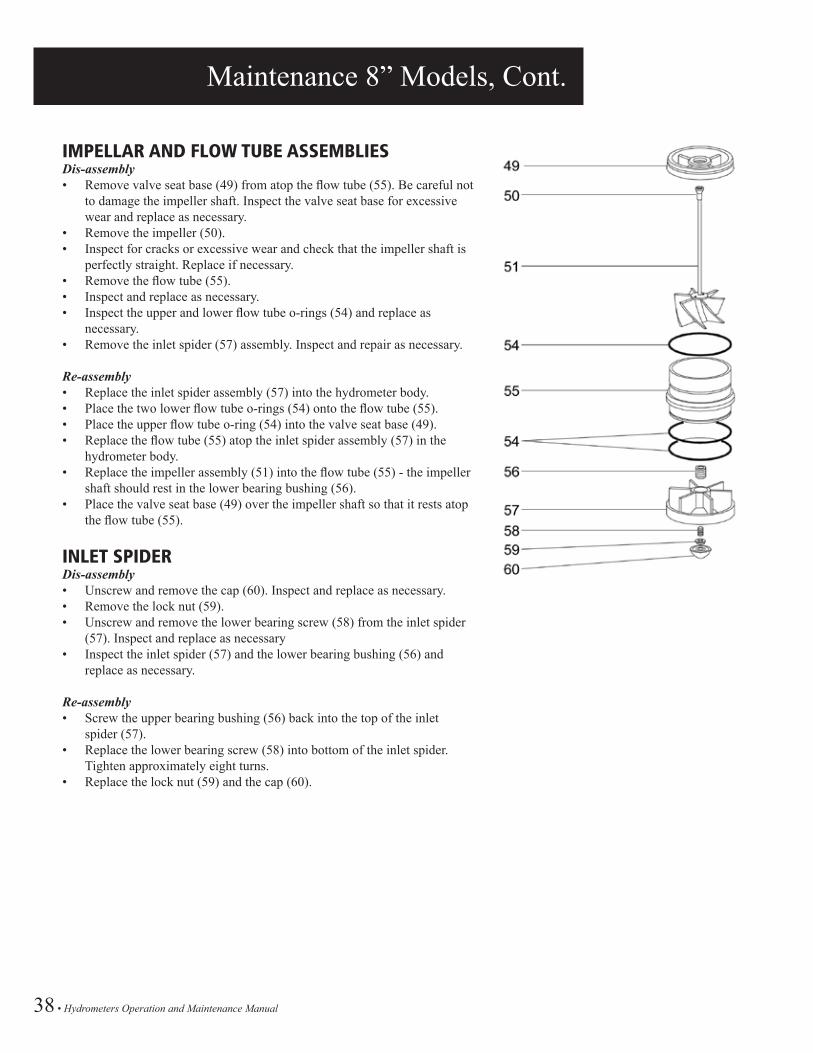
IMPELLAR AND FLOW TUBE ASSEMBLIESDis-assembly• Remove valve seat base (49) from atop the flow tube (55). Be careful not
to damage the impeller shaft. Inspect the valve seat base for excessive wear and replace as necessary.
• Remove the impeller (50).• Inspect for cracks or excessive wear and check that the impeller shaft is
perfectly straight. Replace if necessary.• Remove the flow tube (55).• Inspect and replace as necessary.• Inspect the upper and lower flow tube o-rings (54) and replace as
necessary.• Remove the inlet spider (57) assembly. Inspect and repair as necessary.
Re-assembly• Replace the inlet spider assembly (57) into the hydrometer body.• Place the two lower flow tube o-rings (54) onto the flow tube (55).• Place the upper flow tube o-ring (54) into the valve seat base (49).• Replace the flow tube (55) atop the inlet spider assembly (57) in the
hydrometer body.• Replace the impeller assembly (51) into the flow tube (55) - the impeller
shaft should rest in the lower bearing bushing (56).• Place the valve seat base (49) over the impeller shaft so that it rests atop
the flow tube (55).
INLET SPIDERDis-assembly• Unscrew and remove the cap (60). Inspect and replace as necessary.• Remove the lock nut (59).• Unscrew and remove the lower bearing screw (58) from the inlet spider
(57). Inspect and replace as necessary• Inspect the inlet spider (57) and the lower bearing bushing (56) and
replace as necessary.
Re-assembly• Screw the upper bearing bushing (56) back into the top of the inlet
spider (57).• Replace the lower bearing screw (58) into bottom of the inlet spider.
Tighten approximately eight turns.• Replace the lock nut (59) and the cap (60).
Hydrometers Operation and Maintenance Manual • 39
Schematics
SCHEMATICS TABLE OF CONTENTS
Manual Electric1½”, 2” Hydrometer, Manual Electric Normally Closed, 8mm Tubing .................................. 401½”, 2” Hydrometer, Manual Electric Normally Open, 8mm Tubing ..................................... 413”, 4” Hydrometer, Manual Electric Normally Closed, 8mm Tubing ..................................... 423”, 4” Hydrometer, Manual Electric Normally Open, 8mm Tubing ........................................ 436”, 8” Hydrometer, Manual Electric Normally Closed, 8mm Tubing ..................................... 446”, 8” Hydrometer, Manual Electric Normally Open, 8mm Tubing ....................................... 45
Pressure Reducing, Manual Electric1½”, 2” Hydrometer, Pressure Reducing Manual Electric Normally Closed, 8mm Tubing ... 461½”, 2” Hydrometer, Pressure Reducing Manual Electric Normally Open, 8mm Tubing ...... 473”, 4” Hydrometer, Pressure Reducing Manual Electric Normally Closed, 8mm Tubing ...... 483”, 4” Hydrometer, Pressure Reducing Manual Electric Normally Open, 8mm Tubing ......... 496”, 8” Hydrometer, Pressure Reducing Manual Electric Normally Closed, 8mm Tubing ...... 506”, 8” Hydrometer, Pressure Reducing Manual Electric Normally Open, 8mm Tubing ......... 51

40 • Hydrometers Operation and Maintenance Manual
1½”, 2” HYDROMETER, MANUAL ELECTRIC, NORMALLY CLOSED, 8MM TUBING
V
aria
ble
Fin
ishe
d G
oods
Par
t No.
Par
t No.
LHM
1.5T
G-M
EL-
NC
LHM
2TG
-ME
L-N
C
noitpircseD
tnenopmo
CY
TQ
metIP
art N
o.
1 2 3 4 5 6 7 8 9 10 11 12 13 14 15
Bas
ic H
ydro
met
er 1
.5 a
nd 2
"
BR
AS
S H
EX
NIP
PLE
1/8
"
SO
LEN
OID
3-W
AY
24V
AC
N.O
.
3-W
AY
VA
LVE
1/8
" X 1
/8"
Pla
stic
mal
e 90
-Elb
ow 8
mm
x 1/
8" n
pt
Pla
stic
mal
e br
anch
tee
8mm
x 1/
8" n
pt
Pla
stic
mal
e co
nnec
tor 8
mm
x 1/
8" n
pt
PE
TU
BIN
G 8
MM
BR
AS
S F
ING
ER
FIL
TER
1/4
" X 1
/8"
LHM
xxT
G
55B
216P
2
36S
OLN
O-0
24
62S
V21
/8M
55P
4694
802
55P
4724
802
55P
4684
802
15C
ON
T-8-
I
61S
F25S
B
1 1 1 1 2 1 2 2 1
CLO
SED
OPEN
AU
TO
3
6
8
4
7
7
1
2
5
5
9
21
App
rove
d: P
C
rev
Par
t Num
ber:
LHM
xxT
G-M
EL-
NC
0
Mat
eria
l: A
ST
M 1
020
prep
ared
by
PC
Dat
e: 9
-6-0
8
Sca
le:
1=1
Uni
ts: E
nglis
h [m
etric
]
Qua
ntity
: 1
Sur
face
Fin
ish:
N/A
Hea
t Tre
atm
ent:
N/A
Tole
ranc
es:
MA
NU
AL
ELE
CT
RIC
NC
1.5"
, 2" H
ydro
met
er8M
M P
E T
UB
ING
5470
E H
ome
Ave
.Fr
esno
, CA
937
27T
(888
) 638
-234
6F
(800
) 695
-475
3
61S
F25B

Hydrometers Operation and Maintenance Manual • 41
1½”, 2” HYDROMETER, MANUAL ELECTRIC, NORMALLY OPEN, 8MM TUBING
V
aria
ble
Fin
ishe
d G
oods
Par
t No.
Par
t No.
LHM
1.5T
G-M
EL-
NO
LHM
2TG
-ME
L-N
O
App
rove
d: P
C
rev
Par
t Num
ber:
LHM
xxT
G-M
EL-
NO
0
Mat
eria
l: A
ST
M 1
020
prep
ared
by
PC
Dat
e: 9
-6-0
8
Sca
le:
1=1
Uni
ts: E
nglis
h [m
etric
]
Qua
ntity
: 1
Sur
face
Fin
ish:
N/A
Hea
t Tre
atm
ent:
N/A
Tole
ranc
es:
noitpircseD
tnenopmo
CY
TQ
metIP
art N
o.
1 2 3 4 5 6 7 8 9 10 11 12 13 14 15
Bas
ic H
ydro
met
er 1
.5 a
nd 2
"
BR
AS
S H
EX
NIP
PLE
1/8
"
SO
LEN
OID
3-W
AY
24V
AC
N.C
.
3-W
AY
VA
LVE
1/8
" X 1
/8"
Pla
stic
mal
e 90
-Elb
ow 8
mm
x 1/
8" n
pt
Pla
stic
mal
e br
anch
tee
8mm
x 1/
8" n
pt
Pla
stic
mal
e co
nnec
tor 8
mm
x 1/
8" n
pt
PE
TU
BIN
G 8
MM
BR
AS
S F
ING
ER
FIL
TER
1/4
" X 1
/8"
LHM
xxT
G
55B
216P
2
36S
OLN
C-0
24
62S
V21
/8M
55P
4694
802
55P
4724
802
55P
4684
802
15C
ON
T-8-
I
61S
F25S
B
1 1 1 1 2 1 2 2 1
CLO
SED
OPEN
AU
TO
3
6
8
4
7
7
1
2
5
5
MA
NU
AL
ELE
CT
RIC
NO
1.5"
, 2" H
ydro
met
er8M
M P
E T
UB
ING
9
21
5470
E H
ome
Ave
.Fr
esno
, CA
937
27T
(888
) 638
-234
6F
(800
) 695
-475
3
61S
F25B

42 • Hydrometers Operation and Maintenance Manual
3”, 4” HYDROMETER, MANUAL ELECTRIC, NORMALLY CLOSED, 8MM TUBING
V
aria
ble
Fin
ishe
d G
oods
Par
t No.
Par
t No.
LHM
3FG
-ME
L-N
C
LHM
4FG
-ME
L-N
C
App
rove
d: P
erry
Con
tinen
te
rev
Par
t Num
ber:
LHM
xFG
-ME
L-N
C0
Mat
eria
l: A
ST
M 1
020
prep
ared
by
PC
Dat
e: 9
-6-0
8
Sca
le:
1=1
Uni
ts: E
nglis
h [m
etric
]
Qua
ntity
: 1
Sur
face
Fin
ish:
N/A
Hea
t Tre
atm
ent:
N/A
Tole
ranc
es:
noitpircseD
tnenopmo
CY
TQ
metIP
art N
o.
1 2 3 4 5 6 7 8 9 10 11 12 13 14 15
Bas
ic H
ydro
met
er 3
",4"
BR
AS
S H
EX
NIP
PLE
1/8
"
SO
LEN
OID
3-W
AY
24V
AC
N.O
.
3-W
AY
VA
LVE
1/8
" X 1
/8" M
ALE
PLA
STI
C M
ALE
90-
ELB
OW
8M
M X
1/8
"
PLA
STI
C M
ALE
BR
AN
CH
-TE
E 8
MM
X 1
/8"
PLA
STI
C M
ALE
CO
NN
EC
TOR
8M
M X
1/8
"
PE
TU
BIN
G 8
MM
BR
AS
S F
ING
ER
FIL
TER
1/4
" X 1
/8"
LHM
xFG
55B
216P
2
36S
OLN
O-0
24
62S
V21
/8M
55P
4684
802
55P
4714
802
55P
4684
802
15C
ON
T-8-
I
61S
F25S
B
1 1 1 1 2 1 2 2 1
8
1
5
MA
NU
AL
ELE
CT
RIC
NC
3",4
" Hyd
rom
eter
8mm
tubi
ng
9
CLO
SED
OPEN
AU
TO
3
8
6
8
4
7
7
2
5
21 54
70 E
Hom
e A
ve.
Fres
no, C
A 9
3727
T (8
88) 6
38-2
346
F (8
00) 6
95-4
753
61S
F25B

Hydrometers Operation and Maintenance Manual • 43
3”, 4” HYDROMETER, MANUAL ELECTRIC, NORMALLY OPEN, 8MM TUBING
V
aria
ble
Fin
ishe
d G
oods
Par
t No.
Par
t No.
LHM
3FG
-ME
L-N
O
LHM
4FG
-ME
L-N
O
noitpircseD
tnenopmo
CY
TQ
metIP
art N
o.
1 2 3 4 5 6 7 8 9 10 11 12 13 14 15
Bas
ic H
ydro
met
er 3
",4"
BR
AS
S H
EX
NIP
PLE
1/8
"
SO
LEN
OID
3-W
AY
24V
AC
N.C
.
3-W
AY
VA
LVE
1/8
" X 1
/8" M
ALE
PLA
STI
C M
ALE
90-
ELB
OW
8M
M X
1/8
"
PLA
STI
C M
ALE
BR
AN
CH
-TE
E 8
MM
X 1
/8"
PLA
STI
C M
ALE
CO
NN
EC
TOR
8M
M X
1/8
"
PE
TU
BIN
G 8
MM
BR
AS
S F
ING
ER
FIL
TER
1/4
" X 1
/8"
LHM
xFG
55B
216P
2
36S
OLN
C-0
24
62S
V21
/8M
55P
4684
802
55P
4714
802
55P
4684
802
15C
ON
T-8-
I
61S
F25S
B
1 1 1 1 2 1 2 2 1
8
1
59
CLO
SED
OPEN
AU
TO
3
8
6
8
4
7
7
2
5
21
App
rove
d: P
erry
Con
tinen
te
rev
Par
t Num
ber:
LHM
xFG
-ME
L-N
O0
Mat
eria
l: A
ST
M 1
020
prep
ared
by
PC
Dat
e: 9
-6-0
8
Sca
le:
1=1
Uni
ts: E
nglis
h [m
etric
]
Qua
ntity
: 1
Sur
face
Fin
ish:
N/A
Hea
t Tre
atm
ent:
N/A
Tole
ranc
es:
MA
NU
AL
ELE
CT
RIC
NO
3",4
" Hyd
rom
eter
8mm
tubi
ng
5470
E H
ome
Ave
.Fr
esno
, CA
937
27T
(888
) 638
-234
6F
(800
) 695
-475
3
61S
F25B
44 • Hydrometers Operation and Maintenance Manual
6”, 8” HYDROMETER, MANUAL ELECTRIC, NORMALLY CLOSED, 8MM TUBING
App
rove
d:
rev
PC
6", 8
" Hyd
rom
eter
ME
L- N
C8M
M P
E T
UB
ING
Par
t Num
ber:
LHM
xFG
-ME
L-N
C
Mat
eria
l: A
ST
M 1
020
Eng
r:
Dat
e: 0
9/20
/08
Sca
le:
1=1
Uni
ts: E
nglis
h [m
etric
]
Qua
ntity
: 1
Sur
face
Fin
ish:
N/A
Hea
t Tre
atm
ent:
N/A
Tole
ranc
es:
0
noitpircseD
tnenopmo
CY
TQ
metIP
art N
o.
1 2 3 4 5 6 7 8 9 10 11 12 13 14 15
BA
SIC
6" H
YD
RO
ME
TER
IN-L
INE
FIL
TER
BR
S L
ON
G 1
/4"
PLA
STI
C M
ALE
90-
ELB
OW
8M
M X
1/8
"
BA
LL V
ALV
E B
RA
SS
1/4
"
3-W
AY
VA
LVE
1/4
" X 1
/4" M
ALE
BR
AS
S S
TRE
ET
TEE
1/4
"F X
1/4"
M
PLA
STI
C M
ALE
CO
NN
EC
TOR
8M
M X
1/8
"
PLA
STI
C M
ALE
CO
NN
EC
TOR
8M
M X
1/4
"
BR
AS
S A
DA
PTE
R 1
/4"F
X 1
/4"M
SH
RA
DE
R V
ALVE
BR
AS
S B
US
HIN
G 1
/4"M
X 1
/8"F
BR
AS
S H
EX
NIP
PLE
1/8
"
BR
AS
S A
DA
PTE
R 1
/4"F
X 1
/8"M
MA
LE B
RA
NC
H T
EE
8M
M X
1/4
" NP
T
PE
TU
BIN
G 8
MM
SO
LEN
OID
3-W
AY
24V
AC
N.O
. WIT
H
LHM
6FG
61S
F25L
B55
P46
8480
262
SB
V25
62S
V41
/4M
55B
2225
P4
55P
4684
802
55P
4684
804
55B
222P
4461
AP
S1/
855
B20
9P42
55B
216P
255
B22
2P42
55P
4714
804
15C
ON
T-8-
I
1 1 1 1 1 1 1 2 1 1 2 1 1 1 2 1
LHM
6FG
LHM
8FG
LHM
6FG
-ME
L-N
C
LHM
8FG
-ME
L-N
C
V
aria
ble
Fin
ishe
d G
oods
Par
t No.
Par
t No.
36S
OLN
O-0
2416 17 18 19
1S
OLE
NO
ID 3
-WA
Y 2
4VA
C N
.O.
10
64
211
1
9
13
6
8
11
CLO
SED
OPEN
AU
TO
21
512
3
7
8
11
14
16
15
5470
E H
ome
Ave
.Fr
esno
, CA
937
27T
(888
) 638
-234
6F
(800
) 695
-475
3
61S
F25S
B

Hydrometers Operation and Maintenance Manual • 45
6”, 8” HYDROMETER, MANUAL ELECTRIC, NORMALLY OPEN, 8MM TUBING
App
rove
d:
rev
PC
6", 8
" Hyd
rom
eter
ME
L- N
O8M
M P
E T
UB
ING
Par
t Num
ber:
LHM
xFG
-ME
L-N
O
Mat
eria
l: A
ST
M 1
020
Eng
r:
Dat
e: 0
9/20
/08
Sca
le:
1=1
Uni
ts: E
nglis
h [m
etric
]
Qua
ntity
: 1
Sur
face
Fin
ish:
N/A
Hea
t Tre
atm
ent:
N/A
Tole
ranc
es:
0
noitpircseD
tnenopmo
CY
TQ
metIP
art N
o.
1 2 3 4 5 6 7 8 9 10 11 12 13 14 15
BA
SIC
6" H
YD
RO
ME
TER
IN-L
INE
FIL
TER
BR
S L
ON
G 1
/4"
PLA
STI
C M
ALE
90-
ELB
OW
8M
M X
1/8
"
BA
LL V
ALV
E B
RA
SS
1/4
"
3-W
AY
VA
LVE
1/4
" X 1
/4" M
ALE
BR
AS
S S
TRE
ET
TEE
1/4
"F X
1/4"
M
PLA
STI
C M
ALE
CO
NN
EC
TOR
8M
M X
1/8
"
PLA
STI
C M
ALE
CO
NN
EC
TOR
8M
M X
1/4
"
BR
AS
S A
DA
PTE
R 1
/4"F
X 1
/4"M
SH
RA
DE
R V
ALVE
BR
AS
S B
US
HIN
G 1
/4"M
X 1
/8"F
BR
AS
S H
EX
NIP
PLE
1/8
"
BR
AS
S A
DA
PTE
R 1
/4"F
X 1
/8"M
MA
LE B
RA
NC
H T
EE
8M
M X
1/4
" NP
T
PE
TU
BIN
G 8
MM
SO
LEN
OID
3-W
AY
24V
AC
N.O
. WIT
H
LHM
6FG
61S
F25L
B55
P46
8480
262
SB
V25
62S
V41
/4M
55B
2225
P4
55P
4684
802
55P
4684
804
55B
222P
4461
AP
S1/
855
B20
9P42
55B
216P
255
B22
2P42
55P
4714
804
15C
ON
T-8-
I
1 1 1 1 1 1 1 2 1 1 2 1 1 1 2 1
LHM
6FG
LHM
8FG
LHM
6FG
-ME
L-N
O
LHM
8FG
-ME
L-N
O
V
aria
ble
Fin
ishe
d G
oods
Par
t No.
Par
t No.
36S
OLN
C-0
2416 17 18 19
1S
OLE
NO
ID 3
-WA
Y 2
4VA
C N
.C.
10
64
211
1
9
13
6
8
11
CLO
SED
OPEN
AU
TO
21
512
3
7
8
11
14
16
15
5470
E H
ome
Ave
.Fr
esno
, CA
937
27T
(888
) 638
-234
6F
(800
) 695
-475
3
61S
F25S
B

46 • Hydrometers Operation and Maintenance Manual
1½”, 2” HYDROMETER, PRESSURE REDUCING MANUAL ELECTRIC,NORMALLY CLOSED, 8MM TUBING
V
aria
ble
Fin
ishe
d G
oods
Par
t No.
Par
t No.
LHM
xxTG
LHM
xxTG
-PR
ME
L
noitpircseD
tnenopmo
CY
TQ
metIP
art N
o.
1 2 3 4 5 6 7 8 9 10 11 12 13 14 15
1.5"
'2" H
YD
RO
ME
TER
FLA
NG
ED
GLO
BE
BR
AS
S F
ING
ER
FIL
TER
BA
SIC
PLA
STI
C P
RE
SS
UR
E R
ED
UC
ING
PILO
T
3-W
AY
VA
LVE
1/8
" X 1
/8" M
ALE
PLA
SIC
MA
LE 9
0-E
LBO
W 8
MM
X 1
/8"
PLA
STI
C M
ALE
BR
AN
CH
-TE
E 8
M X
1/8
"
PE
CO
NTR
OL
TUB
E 8
MM
PLA
STI
C M
ALE
CO
NN
EC
TOR
8M
M X
1/8
"
BR
AS
S B
US
HIN
G 1
/4" X
1/8
" F
BR
AS
S S
TRE
ET
TEE
1/4
" X 1/
4"
SH
RA
DE
R V
ALVE
PIL
OT
FITT
ING
X 8
MM
TU
BIN
G
PLA
STI
C M
ALE
CO
NN
EC
TOR
8M
M X
1/4
"
BR
AS
S H
EX
NIP
PLE
1/8
"
SO
LEN
OID
3-W
AY
24
VA
C N
.O.
LHM
1.5,
2TG
61S
F25S
B36
PIL
29-1
17-G
RY
62S
V21
/8M
55P
4694
802
55P
4724
802
15C
ON
T-8-
I55
P46
8480
255
B20
9P42
55B
2225
T461
AP
S1/
836
2423
5309
55P
4684
804
55B
216P
236
SO
LNO
-024
1 1 1 1 1 2 5 2 1 1 1 3 1 1 1
App
rove
d: P
C
rev
1.5"
, 2" H
YD
RO
MET
ER G
LOBE
,P
ress
ure
Red
ucin
g El
ectri
c N
C8m
m tu
bing
Par
t Num
ber:
LHM
xxTG
-PR
ME
L-N
C0
Mat
eria
l: A
ST
M 1
020
Eng
r:
Dat
e: 4
/21/
08
Sca
le:
1=1
Uni
ts: E
nglis
h [m
etric
]
Qua
ntity
: 1
Sur
face
Fin
ish:
N/A
Hea
t Tre
atm
ent:
N/A
Tole
ranc
es:
6
13
3
12
4
Aut
o
14
5
7
815
11
12
10
Clo
se
6
12
21
9
12
8
5470
E H
ome
Ave
.Fr
esno
, CA
937
27T
(888
) 638
-234
6F
(800
) 695
-475
3
61S
F25B
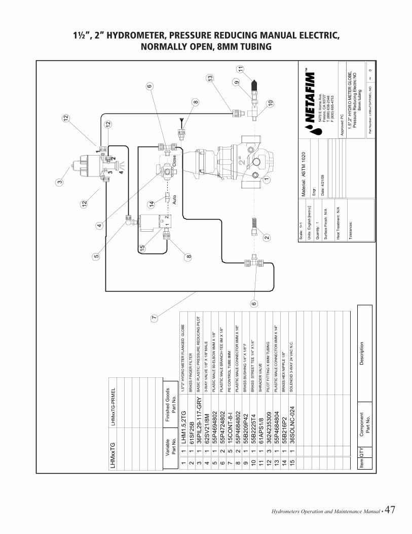
Hydrometers Operation and Maintenance Manual • 47
1½”, 2” HYDROMETER, PRESSURE REDUCING MANUAL ELECTRIC, NORMALLY OPEN, 8MM TUBING
V
aria
ble
Fin
ishe
d G
oods
Par
t No.
Par
t No.
LHM
xxTG
LHM
xxTG
-PR
ME
L
noitpircseD
tnenopmo
CY
TQ
metIP
art N
o.
1 2 3 4 5 6 7 8 9 10 11 12 13 14 15
1.5"
'2" H
YD
RO
ME
TER
FLA
NG
ED
GLO
BE
BR
AS
S F
ING
ER
FIL
TER
BA
SIC
PLA
STI
C P
RE
SS
UR
E R
ED
UC
ING
PILO
T
3-W
AY
VA
LVE
1/8
" X 1
/8" M
ALE
PLA
SIC
MA
LE 9
0-E
LBO
W 8
MM
X 1
/8"
PLA
STI
C M
ALE
BR
AN
CH
-TE
E 8
M X
1/8
"
PE
CO
NTR
OL
TUB
E 8
MM
PLA
STI
C M
ALE
CO
NN
EC
TOR
8M
M X
1/8
"
BR
AS
S B
US
HIN
G 1
/4" X
1/8
" F
BR
AS
S S
TRE
ET
TEE
1/4
" X 1/
4"
SH
RA
DE
R V
ALVE
PIL
OT
FITT
ING
X 8
MM
TU
BIN
G
PLA
STI
C M
ALE
CO
NN
EC
TOR
8M
M X
1/4
"
BR
AS
S H
EX
NIP
PLE
1/8
"
SO
LEN
OID
3-W
AY
24
VA
C N
.C.
LHM
1.5,
2TG
61S
F25S
B36
PIL
29-1
17-G
RY
62S
V21
/8M
55P
4694
802
55P
4724
802
15C
ON
T-8-
I55
P46
8480
255
B20
9P42
55B
2225
T461
AP
S1/
836
2423
5309
55P
4684
804
55B
216P
236
SO
LNC
-024
1 1 1 1 1 2 5 2 1 1 1 3 1 1 1
6
13
3
12
4
Aut
o
14
5
7
8
15
11
12
10
Clo
se
6
12
21
9
12
8
App
rove
d: P
C
rev
1.5"
,2" H
YD
RO
MET
ER G
LOBE
,P
ress
ure
Red
ucin
g El
ectri
c N
O8m
m tu
bing
Par
t Num
ber:
LHM
xxTG
-PR
ME
L-N
O0
Mat
eria
l: A
ST
M 1
020
Eng
r:
Dat
e: 4
/21/
08
Sca
le:
1=1
Uni
ts: E
nglis
h [m
etric
]
Qua
ntity
: 1
Sur
face
Fin
ish:
N/A
Hea
t Tre
atm
ent:
N/A
Tole
ranc
es:
5470
E H
ome
Ave
.Fr
esno
, CA
937
27T
(888
) 638
-234
6F
(800
) 695
-475
3
61S
F25B

48 • Hydrometers Operation and Maintenance Manual
3”, 4” HYDROMETER, PRESSURE REDUCING MANUAL ELECTRIC, NORMALLY CLOSED, 8MM TUBING
6
13
3
12
4
Aut
o
14
5
7
8
15
11
12
10
Clo
se
6
12
21
V
aria
ble
Fin
ishe
d G
oods
Par
t No.
Par
t No.
LHM
3FG
LHM
4FG
LHM
3FG
-PR
ME
L
LHM
4FG
-PR
ME
L
noitpircseD
tnenopmo
CY
TQ
metIP
art N
o.
1 2 3 4 5 6 7 8 9 10 11 12 13 14 15
3"'4
" HY
DR
O M
ETE
R F
LAN
GE
D G
LOB
E
BR
AS
S F
ING
ER
FIL
TER
BA
SIC
PLA
STI
C P
RE
SS
UR
E R
ED
UC
ING
PILO
T
3-W
AY
VA
LVE
1/8
" X 1
/8" M
ALE
PLA
SIC
MA
LE 9
0-E
LBO
W 8
MM
X 1
/8"
PLA
STI
C M
ALE
BR
AN
CH
-TE
E 8
M X
1/8
"
PE
CO
NTR
OL
TUB
E 8
MM
PLA
STI
C M
ALE
CO
NN
EC
TOR
8M
M X
1/8
"
BR
AS
S B
US
HIN
G 1
/4" X
1/8
" F
BR
AS
S S
TRE
ET
TEE
1/4
" X 1/
4"
SH
RA
DE
R V
ALVE
PIL
OT
FITT
ING
X 8
MM
TU
BIN
G
PLA
STI
C M
ALE
CO
NN
EC
TOR
8M
M X
1/4
"
BR
AS
S H
EX
NIP
PLE
1/8
"
SO
LEN
OID
3-W
AY
24
VA
C N
.O.
LHM
3,4F
G61
SF2
5SB
36P
IL29
-117
-GR
Y62
SV
21/8
M55
P46
9480
255
P47
2480
215
CO
NT-
8-I
55P
4684
802
55B
209P
4255
B22
25T4
61A
PS
1/8
3624
2353
0955
P46
8480
455
B21
6P2
36S
OLN
O-0
24
1 1 1 1 1 2 5 2 1 1 1 3 1 1 1
9
12 8
App
rove
d: P
C
rev
3",4
" HY
DR
O M
ETER
GLO
BE,
Pre
ssur
e R
educ
ing
Elec
tric
NC
8mm
tubi
ng
Par
t Num
ber:
LHM
xxFG
-PR
ME
L-N
C0
Mat
eria
l: A
ST
M 1
020
Eng
r:
Dat
e: 4
/21/
08
Sca
le:
1=1
Uni
ts: E
nglis
h [m
etric
]
Qua
ntity
: 1
Sur
face
Fin
ish:
N/A
Hea
t Tre
atm
ent:
N/A
Tole
ranc
es:
5470
E H
ome
Ave
.Fr
esno
, CA
937
27T
(888
) 638
-234
6F
(800
) 695
-475
3
61S
F25B

Hydrometers Operation and Maintenance Manual • 49
3”, 4” HYDROMETER, PRESSURE REDUCING MANUAL ELECTRIC, NORMALLY OPEN, 8MM TUBING
V
aria
ble
Fin
ishe
d G
oods
Par
t No.
Par
t No.
LHM
xxFG
LHM
xxFG
-PR
ME
L
noitpircseD
tnenopmo
CY
TQ
metIP
art N
o.
1 2 3 4 5 6 7 8 9 10 11 12 13 14 15
3",4
" HY
DR
O M
ETE
R F
LAN
GE
D G
LOB
E
BR
AS
S F
ING
ER
FIL
TER
BA
SIC
PLA
STI
C P
RE
SS
UR
E R
ED
UC
ING
PILO
T
3-W
AY
VA
LVE
1/8
" X 1
/8" M
ALE
PLA
SIC
MA
LE 9
0-E
LBO
W 8
MM
X 1
/8"
PLA
STI
C M
ALE
BR
AN
CH
-TE
E 8
M X
1/8
"
PE
CO
NTR
OL
TUB
E 8
MM
PLA
STI
C M
ALE
CO
NN
EC
TOR
8M
M X
1/8
"
BR
AS
S B
US
HIN
G 1
/4" X
1/8
" F
BR
AS
S S
TRE
ET
TEE
1/4
" X 1/
4"
SH
RA
DE
R V
ALVE
PIL
OT
FITT
ING
X 8
MM
TU
BIN
G
PLA
STI
C M
ALE
CO
NN
EC
TOR
8M
M X
1/4
"
BR
AS
S H
EX
NIP
PLE
1/8
"
SO
LEN
OID
3-W
AY
24
VA
C N
.C.
LHM
3,4F
G61
SF2
5SB
36P
IL29
-117
-GR
Y62
SV
21/8
M55
P46
9480
255
P47
2480
215
CO
NT-
8-I
55P
4684
802
55B
209P
4255
B22
25T4
61A
PS
1/8
3624
2353
0955
P46
8480
455
B21
6P2
36SO
LNC
-024
1 1 1 1 1 2 5 2 1 1 1 3 1 1 1
6
13
3
12
4
Aut
o
14
5
7
8
15
11
12
10
Clo
se
6
12
21
9
12 8
App
rove
d: P
C
rev
3",4
"" H
YD
RO
MET
ER G
LOBE
,P
ress
ure
Red
ucin
g El
ectri
c N
O8m
m tu
bing
Par
t Num
ber:
LHM
xxTG
-PR
ME
L-N
O0
Mat
eria
l: A
ST
M 1
020
Eng
r:
Dat
e: 4
/21/
08
Sca
le:
1=1
Uni
ts: E
nglis
h [m
etric
]
Qua
ntity
: 1
Sur
face
Fin
ish:
N/A
Hea
t Tre
atm
ent:
N/A
Tole
ranc
es:
5470
E H
ome
Ave
.Fr
esno
, CA
937
27T
(888
) 638
-234
6F
(800
) 695
-475
3
61S
F25B

50 • Hydrometers Operation and Maintenance Manual
6”, 8” HYDROMETER, PRESSURE REDUCING MANUAL ELECTRIC, NORMALLY CLOSED, 8MM TUBING
App
rove
d: P
C
rev
6", 8
" HY
DR
O M
ETER
GLO
BE,
Pre
ssur
e R
educ
ing
Elec
tric
NC
8mm
tubi
ng
Par
t Num
ber:
LHM
xxFG
-PR
ME
L-N
C0
Mat
eria
l: A
ST
M 1
020
Eng
r:
Dat
e: 4
/21/
08
Sca
le:
1=1
Uni
ts: E
nglis
h [m
etric
]
Qua
ntity
: 1
Sur
face
Fin
ish:
N/A
Hea
t Tre
atm
ent:
N/A
Tole
ranc
es:
V
aria
ble
Fin
ishe
d G
oods
Par
t No.
Par
t No.
LHM
xxFG
LHM
xxFG
-PR
ME
L
noitpircseD
tnenopmo
CY
TQ
metIP
art N
o.
1 2 3 4 5 6 7 8 9 10 11 12 13 14 15
6",8
"" H
YD
RO
ME
TER
FLA
NG
ED
GLO
BE
IN-L
INE
FIL
TER
BR
S L
ON
G 1
/4"
BA
SIC
PLA
STI
C P
RE
SS
UR
E R
ED
UC
ING
PILO
T
3-W
AY
VA
LVE
1/4
" X 1
/4" M
ALE
PLA
SIC
MA
LE 9
0-E
LBO
W 8
MM
X 1
/8"
PLA
STI
C M
ALE
BR
AN
CH
-TE
E 8
M X
1/4
"
PE
CO
NTR
OL
TUB
E 8
MM
PLA
STI
C M
ALE
CO
NN
EC
TOR
8M
M X
1/4
"
BR
AS
S B
US
HIN
G 1
/4" X
1/8
" F
BR
AS
S S
TRE
ET
TEE
1/4
" X 1/
4"
SH
RA
DE
R V
ALVE
PIL
OT
FITT
ING
X 8
MM
TU
BIN
G
PLA
STI
C M
ALE
CO
NN
EC
TOR
8M
M X
1/8
"
BR
AS
S H
EX
NIP
PLE
1/8
"
SO
LEN
OID
3-W
AY
24
VA
C N
.O.
LHM
6,8f
G61
SF2
5LB
36P
IL29
-117
-GR
Y62
SV
41/4
M55
P46
9480
255
P47
1480
415
CO
NT-
8-I
55P
4684
804
55B
209P
4255
B22
25T4
61A
PS
1/8
3624
2353
0955
P46
8480
255
B21
6P2
36S
OLN
O-0
24
1 1 1 1 1 2 5 2 3 2 2 3 1 1 116 17 18
1 2 1
55B
222P
4462
SB
V25
55B
222P
42
BR
AS
S A
DA
PTE
R 1
/4"F
X 1
/4"M
BA
LL V
ALV
E B
RA
SS
1/4
"
BR
AS
S A
DA
PTE
R 1
/4"F
X 1
/8"M
6
13
3
124
Aut
o
14
5
6
8
15
1
Clo
se
12
21
12
176
8
162
99
17
11
11
918
8
5470
E H
ome
Ave
.Fr
esno
, CA
937
27T
(888
) 638
-234
6F
(800
) 695
-475
3
61S
F25S
B
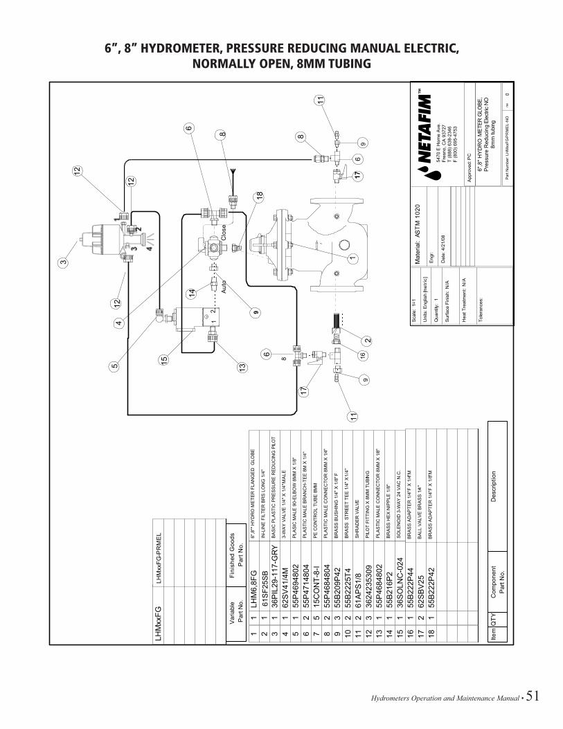
Hydrometers Operation and Maintenance Manual • 51
6”, 8” HYDROMETER, PRESSURE REDUCING MANUAL ELECTRIC, NORMALLY OPEN, 8MM TUBING
App
rove
d: P
C
rev
6",8
" HY
DR
O M
ETER
GLO
BE,
Pre
ssur
e R
educ
ing
Elec
tric
NO
8mm
tubi
ng
Par
t Num
ber:
LHM
xxFG
-PR
ME
L-N
O0
Mat
eria
l: A
ST
M 1
020
Eng
r:
Dat
e: 4
/21/
08
Sca
le:
1=1
Uni
ts: E
nglis
h [m
etric
]
Qua
ntity
: 1
Sur
face
Fin
ish:
N/A
Hea
t Tre
atm
ent:
N/A
Tole
ranc
es:
V
aria
ble
Fin
ishe
d G
oods
Par
t No.
Par
t No.
LHM
xxFG
LHM
xxFG
-PR
ME
L
noitpircseD
tnenopmo
CY
TQ
metIP
art N
o.
1 2 3 4 5 6 7 8 9 10 11 12 13 14 15
6",8
"" H
YD
RO
ME
TER
FLA
NG
ED
GLO
BE
IN-L
INE
FIL
TER
BR
S L
ON
G 1
/4"
BA
SIC
PLA
STI
C P
RE
SS
UR
E R
ED
UC
ING
PILO
T
3-W
AY
VA
LVE
1/4
" X 1
/4" M
ALE
PLA
SIC
MA
LE 9
0-E
LBO
W 8
MM
X 1
/8"
PLA
STI
C M
ALE
BR
AN
CH
-TE
E 8
M X
1/4
"
PE
CO
NTR
OL
TUB
E 8
MM
PLA
STI
C M
ALE
CO
NN
EC
TOR
8M
M X
1/4
"
BR
AS
S B
US
HIN
G 1
/4" X
1/8
" F
BR
AS
S S
TRE
ET
TEE
1/4
" X 1/
4"
SH
RA
DE
R V
ALVE
PIL
OT
FITT
ING
X 8
MM
TU
BIN
G
PLA
STI
C M
ALE
CO
NN
EC
TOR
8M
M X
1/8
"
BR
AS
S H
EX
NIP
PLE
1/8
"
SO
LEN
OID
3-W
AY
24
VA
C N
.C.
LHM
6,8F
G61
SF2
5LB
36P
IL29
-117
-GR
Y62
SV
41/4
M55
P46
9480
255
P47
1480
415
CO
NT-
8-I
55P
4684
804
55B
209P
4255
B22
25T4
61A
PS
1/8
3624
2353
0955
P46
8480
255
B21
6P2
36S
OLN
C-0
24
1 1 1 1 1 2 5 2 3 2 2 3 1 1 116 17 18
1 2 1
55B
222P
4462
SB
V25
55B
222P
42
BR
AS
S A
DA
PTE
R 1
/4"F
X 1
/4"M
BA
LL V
ALV
E B
RA
SS
1/4
"
BR
AS
S A
DA
PTE
R 1
/4"F
X 1
/8"M
6
13
3
124
Aut
o
14
5
6
8
15
1
Clo
se
12
21
12
176
8
162
99
17
11
11
918
8
5470
E H
ome
Ave
.Fr
esno
, CA
937
27T
(888
) 638
-234
6F
(800
) 695
-475
3
61S
F25S
B

52 • Hydrometers Operation and Maintenance Manual
NETAFIM USA5470 E. Home Ave. • Fresno, CA 93727888.638.2346 • 559.453.6800www.netafimusa.com
LSHYDRO-OM 09/16
Related Documents