Hydrokon Pump & Booster Frequency Control Unit User Manual

Welcome message from author
This document is posted to help you gain knowledge. Please leave a comment to let me know what you think about it! Share it to your friends and learn new things together.
Transcript
HydrokonPump & Booster Frequency Control UnitUser Manual
2 3 www.etna.com.tr
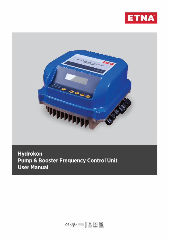
Dear Customer,
Thanks for selecting our product. To use this product correctly, make sure that you read this manual carefully and keep the manual safe together with the warranty card.
Warnings - Specifications 03Supply -Device Connections - Sample Parameter Set 04Setting Parameters 05Driver Connector Descriptions 06Power-Supplied Pump Inverter Connection Diagram 07Control Connections 08Display Descriptions 09 Keypad Descriptions 10Electrical Connections 11Troubleshooting Table 13Building Management System 14Error Codes - Triphase Inverter - Warranty Conditions 15
CONTENTS
2 3 www.etna.com.tr
Warnings
• Cut off the power supplybefore assembling the device.
NOTE: Standard power loss (Watt) = 3% of device power∆T = Temperature difference inthe cabin (°C)3.1 = Specific heat of air at sea level
Min. Operating Temperature = 0°CMax. Operating Temperature = 50°C
• Wait for 5 minutes before opening the cover after the power is cut post-operation (for the discharging of DC capacitors).
If the device is not connected in line with the specified rules, there is always the risk of mild and severe injury, death and material damage. Thus, all settings should be done by expert personnel paying ultimate attention to the security warnings and precautions.
Specifications
• Easy programming • 120% loading for 60 seconds• Operating temperature range between 0°C and 50°C• Ability to set the output frequency (motor speed) using ▲/▼ buttons• Output frequency can be set by 2 digital inputs• Programmable start and stop ramps• High and low voltage protection• Short circuit protection on motor terminals
WARNINGS - SPECIFICATIONS
4 5 www.etna.com.tr
MAINS SUPPLY - DEVICE CONNECTIONS - EXAMPLE PARAMETER SETTING
Mains Supply - Device Connection
• Ensure the power supply voltage and
current are compatible with the device, and there are compatible circuit breakers between the mains and the device.
• Cut off the power on the mainsbefore connecting the device.
• Connect the device by tightening the connectors well without leaving any naked cable or causing short circuits.
Caution! Never use the same cableconduit.
Example Parameter SettingSetting Booster ParametersNote: These settings are for the Master device.
Enter the motor current to the parameter P0007. Enter the operating pressure to the parameter P0009(Ex. 4.0 bar). Enter the maximum pressure of the pump to the parameter P0015. Or set parameter P0018 and exit the program.(Note: After turning off the valve in the delivery part (given that there are no expansion tanks between the valve and the pump), set the autoset parameter.) The device calculates this pressure automatically. There is no need to set the parameter for Slave devices. It would be enough to correctly position the micro switches.
Note: Position the switches while there is no power in the device. The device will set itself according to this position after connecting power.
Enter the differential pressure value of the system to the parameter P0009(∆P, ex. 1bar). Enter the maximum pressure of the pump to the parameter P0015.
4 5 www.etna.com.tr
SETTING PARAMETERS
PART NO.
PARAMETERDEFINITION SETTING RANGE FACTORY SETTING DESCRIPTIONS
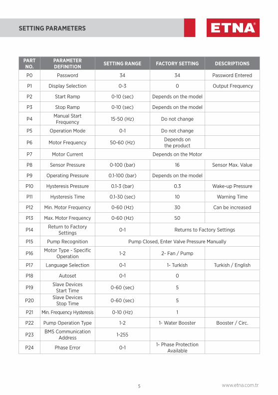
P0 Password 34 34 Password Entered
P1 Display Selection 0-3 0 Output Frequency
P2 Start Ramp 0-10 (sec) Depends on the model
P3 Stop Ramp 0-10 (sec) Depends on the model
P4 Manual StartFrequency 15-50 (Hz) Do not change
P5 Operation Mode 0-1 Do not change
P6 Motor Frequency 50-60 (Hz) Depends onthe product
P7 Motor Current Depends on the Motor
P8 Sensor Pressure 0-100 (bar) 16 Sensor Max. Value
P9 Operating Pressure 0.1-100 (bar) Depends on the model
P10 Hysteresis Pressure 0.1-3 (bar) 0.3 Wake-up Pressure
P11 Hysteresis Time 0.1-30 (sec) 10 Warning Time
P12 Min. Motor Frequency 0-60 (Hz) 30 Can be increased
P13 Max. Motor Frequency 0-60 (Hz) 50
P14 Return to Factory Settings 0-1 Returns to Factory Settings
P15 Pump Recognition Pump Closed, Enter Valve Pressure Manually
P16 Motor Type - Specific Operation 1-2 2- Fan / Pump
P17 Language Selection 0-1 1- Turkish Turkish / English
P18 Autoset 0-1 0
P19 Slave DevicesStart Time 0-60 (sec) 5
P20 Slave DevicesStop Time 0-60 (sec) 5
P21 Min. Frequency Hysteresis 0-10 (Hz) 1
P22 Pump Operation Type 1-2 1- Water Booster Booster / Circ.
P23 BMS Communication Address 1-255
P24 Phase Error 0-1 1- Phase Protection Available
6 7 www.etna.com.tr
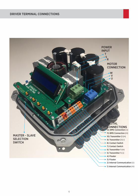
DRIVER TERMINAL CONNECTIONS
MOTORCONNECTION
DIGITALCONNECTIONS
POWER INPUT
MASTER - SLAVESELECTION SWITCH
T
WVU
SR
12) BMS Connection (-)
11) BMS Connection (+)
2) Internal Communication (-)3) Floater
4) Floater
5) Transmitter 1 (-)
9) Transmitter 2 (-)
6) Transmitter 1 (+)
10) Transmitter 2 (+)
7) Contact Switch
8) Contact Switch
1) Internal Communication (+)
6 7 www.etna.com.tr
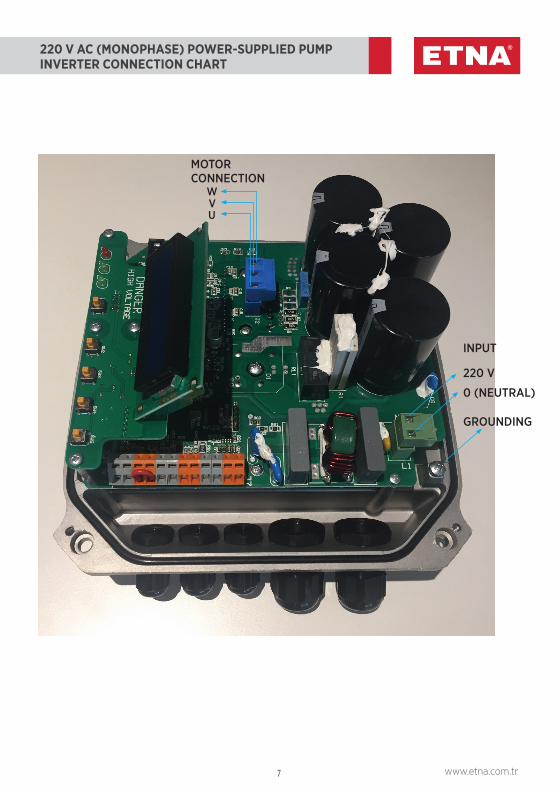
220 V AC (MONOPHASE) POWER-SUPPLIED PUMPINVERTER CONNECTION CHART
VU
MOTORCONNECTION
GROUNDING
INPUT
220 V
0 (NEUTRAL)
W
8 9 www.etna.com.tr
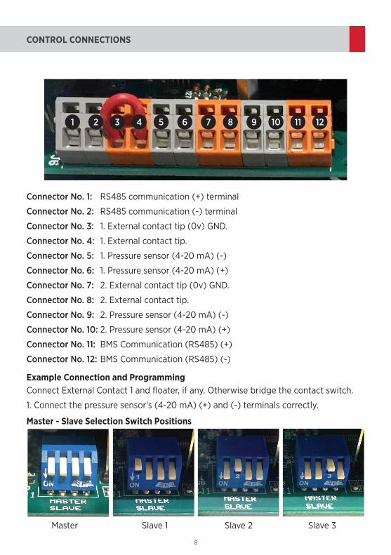
CONTROL CONNECTIONS
Example Connection and Programming
Master - Slave Selection Switch Positions
Connector No. 1: RS485 communication (+) terminal
Connector No. 2: RS485 communication (-) terminal
Connector No. 3: 1. External contact tip (0v) GND.
Connector No. 4: 1. External contact tip.
Connector No. 5: 1. Pressure sensor (4-20 mA) (-)
Connector No. 6: 1. Pressure sensor (4-20 mA) (+)
Connector No. 7: 2. External contact tip (0v) GND.
Connector No. 8: 2. External contact tip.
Connector No. 9: 2. Pressure sensor (4-20 mA) (-)
Connector No. 10: 2. Pressure sensor (4-20 mA) (+)
Connector No. 11: BMS Communication (RS485) (+)
Connector No. 12: BMS Communication (RS485) (-)
Connect External Contact 1 and floater, if any. Otherwise bridge the contact switch.
1. Connect the pressure sensor's (4-20 mA) (+) and (-) terminals correctly.
Master Slave 1 Slave 2 Slave 3
12987654321 10 11
8 9 www.etna.com.tr
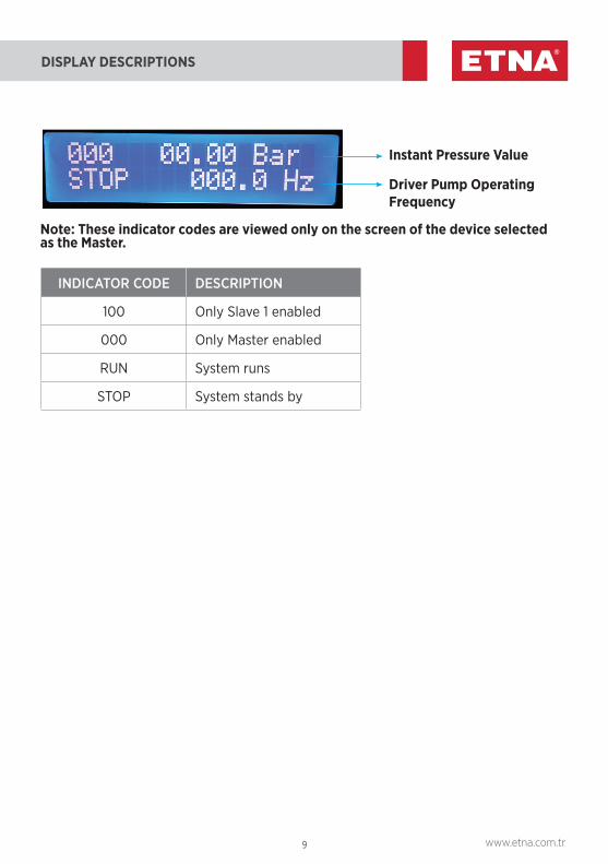
DISPLAY DESCRIPTIONS
Instant Pressure Value
Driver Pump Operating Frequency
Note: These indicator codes are viewed only on the screen of the device selected as the Master.
INDICATOR CODE DESCRIPTION
100 Only Slave 1 enabled
000 Only Master enabled
RUN System runs
STOP System stands by
10 11 www.etna.com.tr
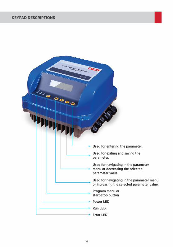
KEYPAD DESCRIPTIONS
Used for entering the parameter.
Used for exiting and saving theparameter.
Used for navigating in the parameter menu or decreasing the selected parameter value.
Used for navigating in the parameter menu or increasing the selected parameter value.
Program menu orstart-stop button
Power LED
Run LED
Error LED
10 11 www.etna.com.tr
ELECTRICAL CONNECTIONS
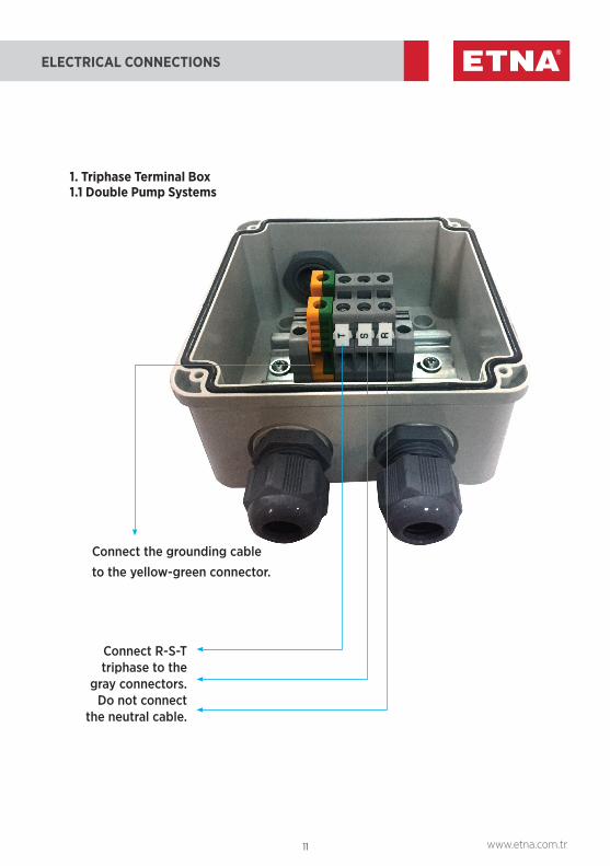
Connect the grounding cable to the yellow-green connector.
Connect R-S-T triphase to the
gray connectors.Do not connect
the neutral cable.
1. Triphase Terminal Box1.1 Double Pump Systems
12 13 www.etna.com.tr
ELECTRICAL CONNECTIONS
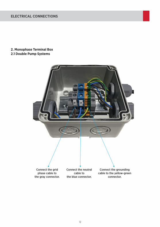
2. Monophase Terminal Box2.1 Double Pump Systems
Connect the grounding cable to the yellow-green
connector.
Connect the grid phase cable to
the gray connector.
Connect the neutral cable to
the blue connector.
12 13 www.etna.com.tr
TROUBLESHOOTING TABLE
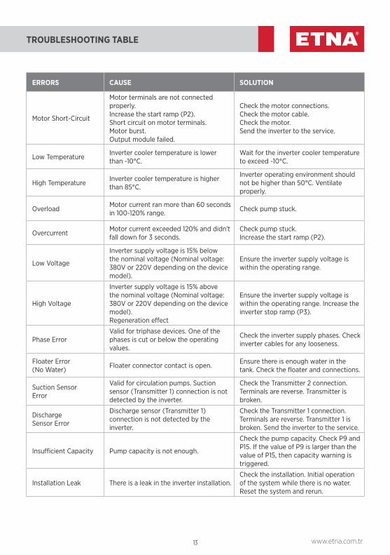
ERRORS CAUSE SOLUTION
Motor Short-Circuit
Motor terminals are not connected properly.Increase the start ramp (P2).Short circuit on motor terminals.Motor burst.Output module failed.
Check the motor connections.Check the motor cable.Check the motor. Send the inverter to the service.
Low Temperature Inverter cooler temperature is lower than -10°C.
Wait for the inverter cooler temperature to exceed -10°C.
High Temperature Inverter cooler temperature is higher than 85°C.
Inverter operating environment should not be higher than 50°C. Ventilate properly.
Overload Motor current ran more than 60 seconds in 100-120% range. Check pump stuck.
Overcurrent Motor current exceeded 120% and didn't fall down for 3 seconds.
Check pump stuck.Increase the start ramp (P2).
Low Voltage
Inverter supply voltage is 15% below the nominal voltage (Nominal voltage: 380V or 220V depending on the device model).
Ensure the inverter supply voltage is within the operating range.
High Voltage
Inverter supply voltage is 15% above the nominal voltage (Nominal voltage: 380V or 220V depending on the device model). Regeneration effect
Ensure the inverter supply voltage is within the operating range. Increase the inverter stop ramp (P3).
Phase ErrorValid for triphase devices. One of the phases is cut or below the operating values.
Check the inverter supply phases. Check inverter cables for any looseness.
Floater Error(No Water) Floater connector contact is open. Ensure there is enough water in the
tank. Check the floater and connections.
Suction SensorError
Valid for circulation pumps. Suction sensor (Transmitter 1) connection is not detected by the inverter.
Check the Transmitter 2 connection. Terminals are reverse. Transmitter is broken.
DischargeSensor Error
Discharge sensor (Transmitter 1)connection is not detected by the inverter.
Check the Transmitter 1 connection. Terminals are reverse. Transmitter 1 is broken. Send the inverter to the service.
Insufficient Capacity Pump capacity is not enough.
Check the pump capacity. Check P9 and P15. If the value of P9 is larger than the value of P15, then capacity warning is triggered.
Installation Leak There is a leak in the inverter installation.Check the installation. Initial operation of the system while there is no water. Reset the system and rerun.
14 15 www.etna.com.tr
BUILDING AUTOMATION SYSTEM
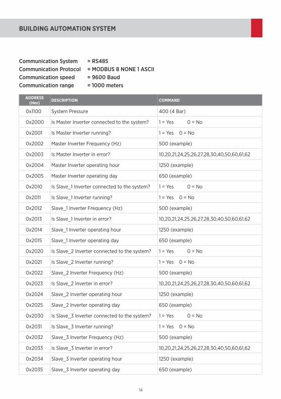
ADDRESS (Hex) DESCRIPTION COMMAND
0x1100 System Pressure 400 (4 Bar)
0x2000 Is Master Inverter connected to the system? 1 = Yes 0 = No
0x2001 Is Master Inverter running? 1 = Yes 0 = No
0x2002 Master Inverter Frequency (Hz) 500 (example)
0x2003 Is Master Inverter in error? 10,20,21,24,25,26,27,28,30,40,50,60,61,62
0x2004 Master Inverter operating hour 1250 (example)
0x2005 Master Inverter operating day 650 (example)
0x2010 Is Slave_1 Inverter connected to the system? 1 = Yes 0 = No
0x2011 Is Slave_1 Inverter running? 1 = Yes 0 = No
0x2012 Slave_1 Inverter Frequency (Hz) 500 (example)
0x2013 Is Slave_1 Inverter in error? 10,20,21,24,25,26,27,28,30,40,50,60,61,62
0x2014 Slave_1 Inverter operating hour 1250 (example)
0x2015 Slave_1 Inverter operating day 650 (example)
0x2020 Is Slave_2 Inverter connected to the system? 1 = Yes 0 = No
0x2021 Is Slave_2 Inverter running? 1 = Yes 0 = No
0x2022 Slave_2 Inverter Frequency (Hz) 500 (example)
0x2023 Is Slave_2 Inverter in error? 10,20,21,24,25,26,27,28,30,40,50,60,61,62
0x2024 Slave_2 Inverter operating hour 1250 (example)
0x2025 Slave_2 Inverter operating day 650 (example)
0x2030 Is Slave_3 Inverter connected to the system? 1 = Yes 0 = No
0x2031 Is Slave_3 Inverter running? 1 = Yes 0 = No
0x2032 Slave_3 Inverter Frequency (Hz) 500 (example)
0x2033 Is Slave_3 Inverter in error? 10,20,21,24,25,26,27,28,30,40,50,60,61,62
0x2034 Slave_3 Inverter operating hour 1250 (example)
0x2035 Slave_3 Inverter operating day 650 (example)
Communication System = RS485 Communication Protocol = MODBUS 8 NONE 1 ASCIICommunication speed = 9600 BaudCommunication range = 1000 meters
14 15 www.etna.com.tr
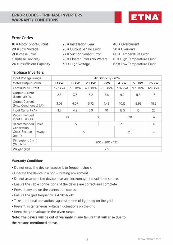
ERROR CODES - TRIPHASE INVERTERSWARRANTY CONDITIONS
Warranty Conditions
• Do not drop the device, expose it to frequent shock.
• Operate the device in a non-vibrating enviroment.
• Do not assemble the device near an electromagnetic radiation source.
• Ensure the cable connections of the device are correct and complete.
• Prevent any arc on the connection cables.
• Ensure the grid frequency is 47Hz-63Hz.
• Take additional precautions against stroke of lightning on the grid.
• Prevent instantaneous voltage fluctuations on the grid.
• Keep the grid voltage in the given range.
Note: The device will be out of warranty in any failure that will arise due to
the reasons mentioned above.
Error Codes
Triphase Inverters
10 = Motor Short-Circuit 20 = Low Voltage21 = Phase Error(Triphase Devices)24 = Insufficient Capacity
25 = Installation Leak26 = Output Sensor Error27 = Suction Sensor Error28 = Floater Error (No Water)30 = High Voltage
40 = Overcurrent50 = Overload60 = Temperature Error61 = High Temperature Error62 = Low Temperature Error
Input Voltage Range AC 380 V +/- 20%Motor Output Power 1.1 kW 1.5 kW 2.2 kW 3 kW 4 kW 5.5 kW 7.5 kWContinuous Output 2.22 kVA 2.91 kVA 4.10 kVA 5.36 kVA 7.26 kVA 9.31 kVA 12.6 kVA
Output Current(Nominal) (A) 2.8 3.7 5.2 6.8 9.2 11.8 17
Output Current(Max. Continuous) (A) 3.08 4.07 5.72 7.48 10.12 12.98 18.5
Input Current (A) 3.7 4.9 5.9 10 12.5 16 25
RecommendedInput Fuse (A) 10 16 20 32
Recommended Connection Cross-Section (mm²)
Inlet 1.5 2.5 4
Outlet 1.5 2.5 4
Dimensions (mm) (WxHxD) 200 x 200 x 127
Weight (Kg) 2.5

Dudullu Organize Sanayi Bölgesi 2. Cadde No: 14 34775 Ümraniye İstanbul / TurkeyTel : +90 216 561 47 74 (Pbx) • Fax : +90 216 561 47 50www.etna.com.tr/en • [email protected] customer service
After-Sales Services
With our more than 35 years of sector experience, 97 service points all
around Turkey, and customer-oriented after-sales approach to service,
we are with you (commissioning, maintenance and repair, spare part
supply).
Related Documents