Published: November 30, 2010 r2010 American Chemical Society 2476 dx.doi.org/10.1021/jp104889a | J. Phys. Chem. C 2011, 115, 2476–2482 ARTICLE pubs/acs/org/JPCC Hydrogen Storage Capacity of Carbon-Foams: Grand Canonical Monte Carlo Simulations Abhishek K. Singh, †,‡,# Jianxin Lu, †,# Rachel S. Aga, § and Boris I. Yakobson* ,† † Department of Mechanical Engineering and Materials Science, Department of Chemistry, and The Richard E. Smalley Institute for Nanoscale Science and Technology, Rice University, Houston, Texas 77005, United States ‡ Materials Research Centre, Indian Institute of Science, Bangalore, India, 560012 § Department of Chemistry, Wright State University, Dayton, Ohio 45435-0001, United States b S Supporting Information ABSTRACT: Hydrogen storage in the three-dimensional carbon foams is analyzed using classical grand canonical Monte Carlo simulations. The calculated storage capacities of the foams meet the material-based DOE targets and are comparable to the capacities of a bundle of well- separated similar diameter open nanotubes. The pore sizes in the foams are optimized for the best hydrogen uptake. The capacity depends sensitively on the C-H 2 interaction potential, and therefore, the results are presented for its “weak” and “strong” choices, to offer the lower and upper bounds for the expected capacities. Furthermore, quantum effects on the effective C-H 2 as well as H 2 -H 2 interaction potentials are considered. We find that the quantum effects noticeably change the adsorption properties of foams and must be accounted for even at room temperature. 1. INTRODUCTION Hydrogen is a source of clean and renewable energy and is considered to be an alternative to fossil fuel. One of the major hurdles to its practical usage is a lack of storage media, which could meet the DOE 2015 targets, 1 i.e., gravimetric g > 5.5 wt % and volumetric v > 40 kg/m 3 (to appreciate the challenge, this is greater than the half-density of liquid hydrogen of 71 kg/m 3 , at 20 K). This has led to an extensive search for materials, which can store hydrogen within a reasonable volume without significant increase in weight. Among the various promising candidates, carbon based nanomaterials have received special attention 2-5 because they are lightweight and have a high surface-to-volume ratio. Additionally, for efficient reversible storage within the achievable temperatures and pressures by existing technology, the adsorption energy should be in the range of 0.01-0.5 eV/H. Owing to their ability to bind hydro- gen both by physisorption and chemisorption, graphitic structures can satisfy the required binding energy criterion. Although carbon nanotubes (CNT) are considered promising for hydrogen storage, 2,6,7 CNT almost always form bundles thereby reducing their hydrogen uptake. The shorter tube-tube distances (3.4 Å) in the bundles hinder the hydrogen molecule from accessing the space between tubes, while the interior is also usually blocked. It has been shown theoretically that a wall-to-wall separation close to 0.8-1.0 nm 8-10 would be best for the hydrogen storage in CNT bundles. 9,11 However, synthesizing and stabilizing bundles with such separation is challenging if at all possible. This is also true for graphene, where layers separated by more than 0.8 nm could store significant amounts of hydrogen; 12-14 yet, such spacing of the layers so far appears unfeasible for experimental realization. In the case of 3D carbon nanoporous materials, it has been shown that a pore size ∼1 nm could be ideal for storage. 11,13,15 There are several 3D carbon foams, 9,10,16-18 both experimen- tally 16,18,19 produced and theoretically 9,10,14,20-22 proposed. However, the experimentally synthesized foams often have very large pore sizes, whereas theoretically discussed foams often lack any suggested way of making them. Recently, we discussed 9 a carbon foam achievable via a known welding technique 20,23,24 from crossed carbon nanotubes. These foams are almost iso- tropic, stable, and mechanically as stiff as steel in all directions. 9 The abundance of pores in these foams makes them ideal for hydrogen storage, whereas their architecture is well-defined and can be designed in a systematic manner. Even if not made di- rectly, such foams can be useful as a representative model system for studying storage in practical nanoporous materials with a usually known recipe and measured surface area but very little data about their atomic makeup (activated carbons, aerogels, and nanoporous and amorphous carbons 19 ). With this in mind, we designed a series of 3D carbon foams using different CNTs, aiming to assess the volumetric and gravi- metric capacities and to find the optimum storage. Grand canon- ical Monte Carlo (GCMC) simulations are used, with the judicious choice of interaction potentials, to estimate the storage capacities under ambient conditions. The storage capacity of such foams is compared with the well-separated CNT bundles. The mass Received: May 27, 2010 Revised: November 8, 2010

Welcome message from author
This document is posted to help you gain knowledge. Please leave a comment to let me know what you think about it! Share it to your friends and learn new things together.
Transcript
Published: November 30, 2010
r 2010 American Chemical Society 2476 dx.doi.org/10.1021/jp104889a | J. Phys. Chem. C 2011, 115, 2476–2482
ARTICLE
pubs/acs/org/JPCC
Hydrogen Storage Capacity of Carbon-Foams: Grand CanonicalMonteCarlo SimulationsAbhishek K. Singh,†,‡,# Jianxin Lu,†,# Rachel S. Aga,§ and Boris I. Yakobson*,†
†Department of Mechanical Engineering and Materials Science, Department of Chemistry, and The Richard E. Smalley Institute forNanoscale Science and Technology, Rice University, Houston, Texas 77005, United States‡Materials Research Centre, Indian Institute of Science, Bangalore, India, 560012§Department of Chemistry, Wright State University, Dayton, Ohio 45435-0001, United States
bS Supporting Information
ABSTRACT: Hydrogen storage in the three-dimensional carbon foams is analyzed using classicalgrand canonical Monte Carlo simulations. The calculated storage capacities of the foams meetthe material-based DOE targets and are comparable to the capacities of a bundle of well-separated similar diameter open nanotubes. The pore sizes in the foams are optimized for thebest hydrogen uptake. The capacity depends sensitively on the C-H2 interaction potential, andtherefore, the results are presented for its “weak” and “strong” choices, to offer the lower andupper bounds for the expected capacities. Furthermore, quantum effects on the effective C-H2
as well as H2-H2 interaction potentials are considered. We find that the quantum effectsnoticeably change the adsorption properties of foams and must be accounted for even at roomtemperature.
1. INTRODUCTION
Hydrogen is a source of clean and renewable energy and isconsidered to be an alternative to fossil fuel. One of the majorhurdles to its practical usage is a lack of storage media, which couldmeet the DOE 2015 targets,1 i.e., gravimetric g > 5.5 wt % andvolumetric v > 40 kg/m3 (to appreciate the challenge, this is greaterthan the half-density of liquid hydrogen of 71 kg/m3, at 20 K). Thishas led to an extensive search for materials, which can storehydrogen within a reasonable volume without significant increasein weight. Among the various promising candidates, carbon basednanomaterials have received special attention2-5 because they arelightweight and have a high surface-to-volume ratio. Additionally, forefficient reversible storage within the achievable temperatures andpressures by existing technology, the adsorption energy should be inthe range of 0.01-0.5 eV/H. Owing to their ability to bind hydro-gen both by physisorption and chemisorption, graphitic structurescan satisfy the required binding energy criterion.
Although carbon nanotubes (CNT) are considered promisingfor hydrogen storage,2,6,7 CNT almost always form bundles therebyreducing their hydrogen uptake. The shorter tube-tube distances(3.4 Å) in the bundles hinder the hydrogenmolecule from accessingthe space between tubes, while the interior is also usually blocked. Ithas been shown theoretically that a wall-to-wall separation closeto 0.8-1.0 nm8-10 would be best for the hydrogen storage inCNT bundles.9,11 However, synthesizing and stabilizing bundleswith such separation is challenging if at all possible. This is alsotrue for graphene, where layers separated bymore than 0.8 nmcouldstore significant amounts of hydrogen;12-14 yet, such spacing of thelayers so far appears unfeasible for experimental realization.
In the case of 3D carbon nanoporous materials, it has beenshown that a pore size ∼1 nm could be ideal for storage.11,13,15
There are several 3D carbon foams,9,10,16-18 both experimen-tally16,18,19 produced and theoretically9,10,14,20-22 proposed.However, the experimentally synthesized foams often have verylarge pore sizes, whereas theoretically discussed foams often lackany suggested way of making them. Recently, we discussed9 acarbon foam achievable via a known welding technique20,23,24
from crossed carbon nanotubes. These foams are almost iso-tropic, stable, and mechanically as stiff as steel in all directions.9
The abundance of pores in these foams makes them ideal forhydrogen storage, whereas their architecture is well-defined andcan be designed in a systematic manner. Even if not made di-rectly, such foams can be useful as a representative model systemfor studying storage in practical nanoporous materials with ausually known recipe and measured surface area but very littledata about their atomic makeup (activated carbons, aerogels, andnanoporous and amorphous carbons19).
With this in mind, we designed a series of 3D carbon foamsusing different CNTs, aiming to assess the volumetric and gravi-metric capacities and to find the optimum storage. Grand canon-icalMonte Carlo (GCMC) simulations are used, with the judiciouschoice of interaction potentials, to estimate the storage capacitiesunder ambient conditions. The storage capacity of such foamsis compared with the well-separated CNT bundles. The mass
Received: May 27, 2010Revised: November 8, 2010
2477 dx.doi.org/10.1021/jp104889a |J. Phys. Chem. C 2011, 115, 2476–2482
The Journal of Physical Chemistry C ARTICLE
densities and pore sizes are optimized for the hydrogen uptake.Due to light weight of H2 and low storage temperature, thequantum effects on the C-H2 as well as H2-H2 interactionpotentials are considered, and their consequences on the storageare evaluated.
2. GENERATION OF FOAM STRUCTURES
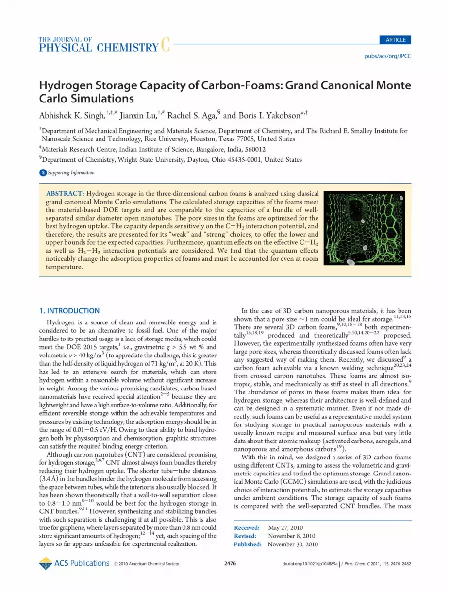
Carbon foams are designed by welding single-wall carbonnanotubes, SWNT.9 In order to obtain a foam, an armchair and azigzag SWNT of similar diameters are chosen as shown inFigure 1a. While the similarities in diameters ensure the uni-formity of foams in x and y directions, the choice of differentchiralities ensures the A-A stacking at the crossing interfacecontact, when in the starting configuration the tubes are placedperpendicular to each other. The facing C-C pairs in the centralpart of the interface are brought to 1-1.5 Å, to the C-C bondlength (that is pressed to each other, to initiate the weldingcoalescence). If the spacing is too large, the connection cannot bebuilt, whereas at too small distances, the tubes fuse very quicklyleading to a nonuniform “fat” neck, which is also undesirable.
As a next step we construct a unit cell of foam via a weldingprocess. In each step, the most energetically preferred bond inthe tube junction is rotated by 90� via Stone-Wales (SW)transformation,25 followed by relaxation of the whole structure.During the relaxation process, the tubes’ edges are fixed to pre-vent them from becoming parallel to each other. The processcontinues until the neck becomes thick and a smoothly curvedjunction is formed. For the optimization process, we use con-jugate gradient method with the Tersoff-Brenner interactionpotential for carbon.26 These calculations are computationallytoo demanding to be handled by quantum mechanical methodssuch as density functional theory based methods. At the sametime, the structural properties obtained from using the Tersoff-Brenner potential agree very well with the DFT results. Snap-shots of welding process are shown in Figure 1a-h.
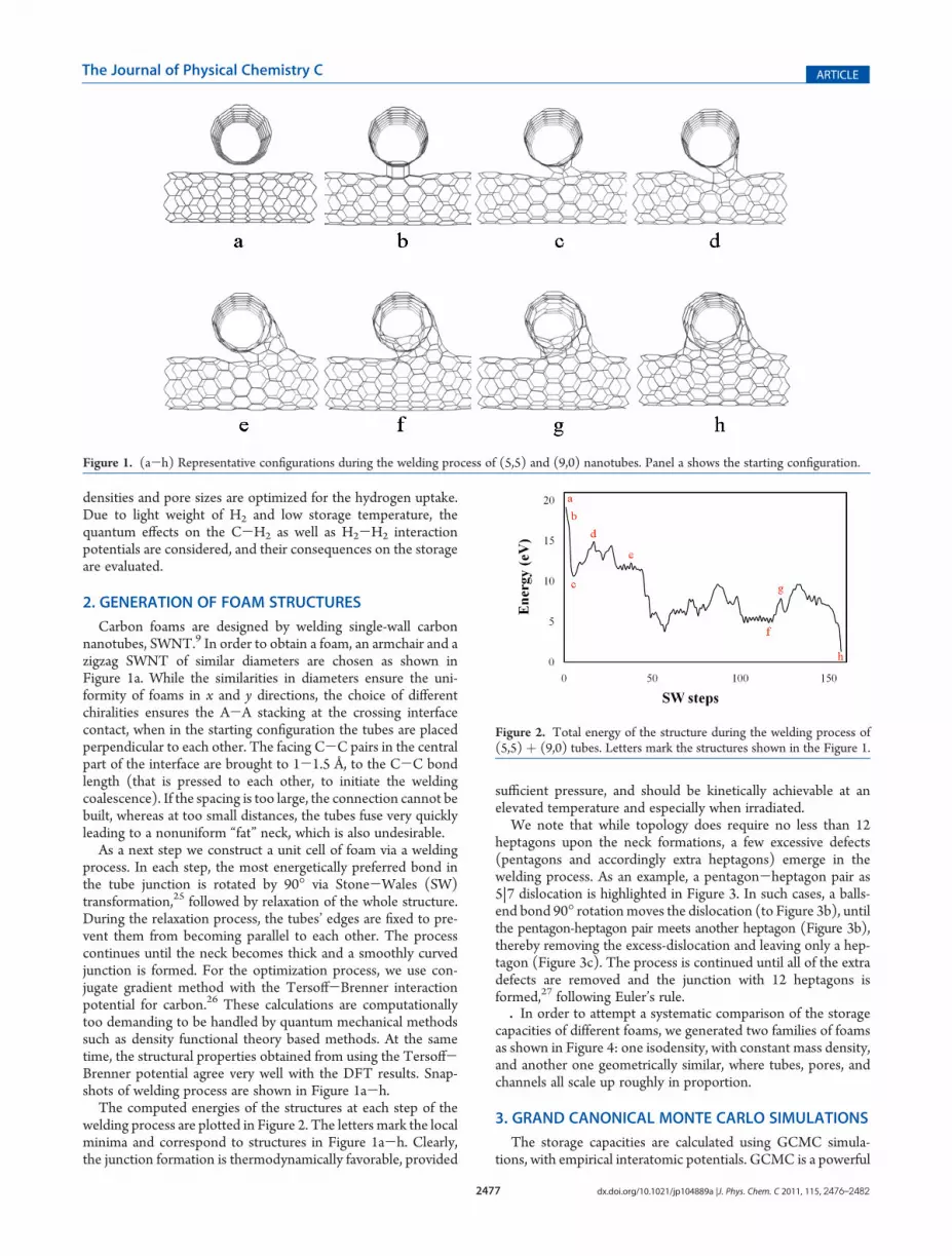
The computed energies of the structures at each step of thewelding process are plotted in Figure 2. The letters mark the localminima and correspond to structures in Figure 1a-h. Clearly,the junction formation is thermodynamically favorable, provided
sufficient pressure, and should be kinetically achievable at anelevated temperature and especially when irradiated.
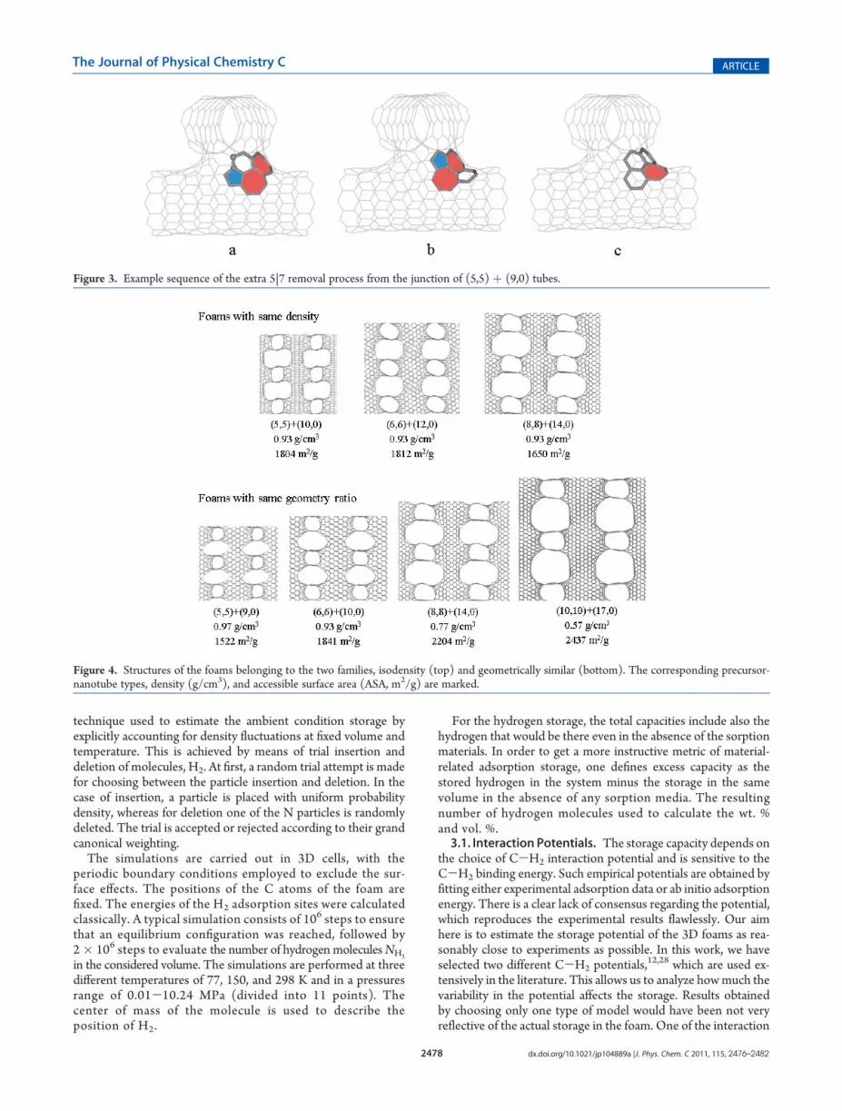
We note that while topology does require no less than 12heptagons upon the neck formations, a few excessive defects(pentagons and accordingly extra heptagons) emerge in thewelding process. As an example, a pentagon-heptagon pair as5|7 dislocation is highlighted in Figure 3. In such cases, a balls-end bond 90� rotationmoves the dislocation (to Figure 3b), untilthe pentagon-heptagon pair meets another heptagon (Figure 3b),thereby removing the excess-dislocation and leaving only a hep-tagon (Figure 3c). The process is continued until all of the extradefects are removed and the junction with 12 heptagons isformed,27 following Euler’s rule.. In order to attempt a systematic comparison of the storage
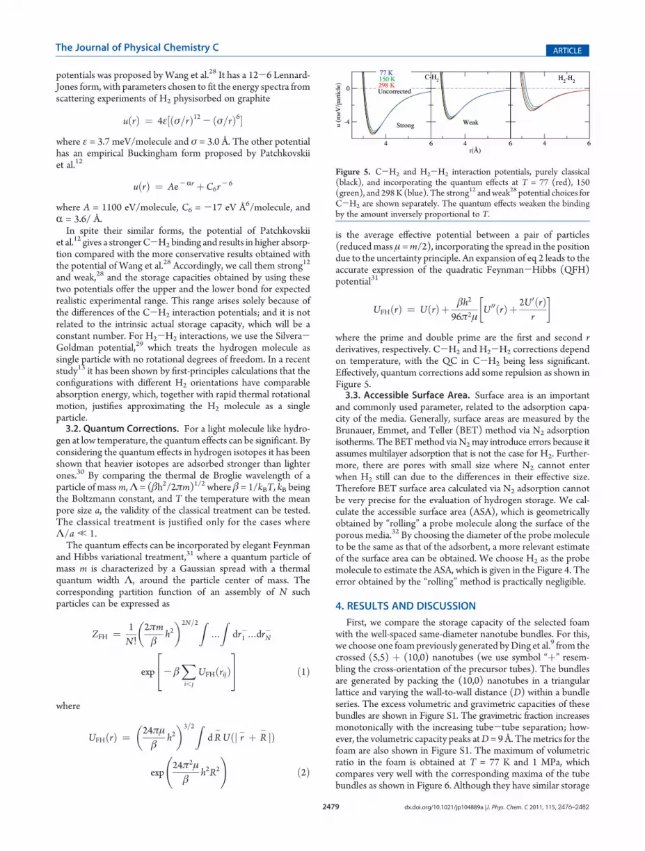
capacities of different foams, we generated two families of foamsas shown in Figure 4: one isodensity, with constant mass density,and another one geometrically similar, where tubes, pores, andchannels all scale up roughly in proportion.
3. GRAND CANONICAL MONTE CARLO SIMULATIONS
The storage capacities are calculated using GCMC simula-tions, with empirical interatomic potentials. GCMC is a powerful
Figure 1. (a-h) Representative configurations during the welding process of (5,5) and (9,0) nanotubes. Panel a shows the starting configuration.
Figure 2. Total energy of the structure during the welding process of(5,5) þ (9,0) tubes. Letters mark the structures shown in the Figure 1.
2478 dx.doi.org/10.1021/jp104889a |J. Phys. Chem. C 2011, 115, 2476–2482
The Journal of Physical Chemistry C ARTICLE
technique used to estimate the ambient condition storage byexplicitly accounting for density fluctuations at fixed volume andtemperature. This is achieved by means of trial insertion anddeletion of molecules, H2. At first, a random trial attempt is madefor choosing between the particle insertion and deletion. In thecase of insertion, a particle is placed with uniform probabilitydensity, whereas for deletion one of the N particles is randomlydeleted. The trial is accepted or rejected according to their grandcanonical weighting.
The simulations are carried out in 3D cells, with theperiodic boundary conditions employed to exclude the sur-face effects. The positions of the C atoms of the foam arefixed. The energies of the H2 adsorption sites were calculatedclassically. A typical simulation consists of 106 steps to ensurethat an equilibrium configuration was reached, followed by2� 106 steps to evaluate the number of hydrogenmoleculesNH2
in the considered volume. The simulations are performed at threedifferent temperatures of 77, 150, and 298 K and in a pressuresrange of 0.01-10.24 MPa (divided into 11 points). Thecenter of mass of the molecule is used to describe theposition of H2.
For the hydrogen storage, the total capacities include also thehydrogen that would be there even in the absence of the sorptionmaterials. In order to get a more instructive metric of material-related adsorption storage, one defines excess capacity as thestored hydrogen in the system minus the storage in the samevolume in the absence of any sorption media. The resultingnumber of hydrogen molecules used to calculate the wt. %and vol. %.3.1. Interaction Potentials. The storage capacity depends on
the choice of C-H2 interaction potential and is sensitive to theC-H2 binding energy. Such empirical potentials are obtained byfitting either experimental adsorption data or ab initio adsorptionenergy. There is a clear lack of consensus regarding the potential,which reproduces the experimental results flawlessly. Our aimhere is to estimate the storage potential of the 3D foams as rea-sonably close to experiments as possible. In this work, we haveselected two different C-H2 potentials,
12,28 which are used ex-tensively in the literature. This allows us to analyze howmuch thevariability in the potential affects the storage. Results obtainedby choosing only one type of model would have been not veryreflective of the actual storage in the foam. One of the interaction
Figure 3. Example sequence of the extra 5|7 removal process from the junction of (5,5) þ (9,0) tubes.
Figure 4. Structures of the foams belonging to the two families, isodensity (top) and geometrically similar (bottom). The corresponding precursor-nanotube types, density (g/cm3), and accessible surface area (ASA, m2/g) are marked.
2479 dx.doi.org/10.1021/jp104889a |J. Phys. Chem. C 2011, 115, 2476–2482
The Journal of Physical Chemistry C ARTICLE
potentials was proposed byWang et al.28 It has a 12-6 Lennard-Jones form, with parameters chosen to fit the energy spectra fromscattering experiments of H2 physisorbed on graphite
uðrÞ ¼ 4ε½ðσ=rÞ12 - ðσ=rÞ6�where ε = 3.7 meV/molecule and σ = 3.0 Å. The other potentialhas an empirical Buckingham form proposed by Patchkovskiiet al.12
uðrÞ ¼ Ae-Rr þC6r- 6
where A = 1100 eV/molecule, C6 = -17 eV Å6/molecule, andR = 3.6/ Å.In spite their similar forms, the potential of Patchkovskii
et al.12 gives a strongerC-H2binding and results in higher absorp-tion compared with the more conservative results obtained withthe potential of Wang et al.28 Accordingly, we call them strong12
and weak,28 and the storage capacities obtained by using thesetwo potentials offer the upper and the lower bond for expectedrealistic experimental range. This range arises solely because ofthe differences of the C-H2 interaction potentials; and it is notrelated to the intrinsic actual storage capacity, which will be aconstant number. For H2-H2 interactions, we use the Silvera-Goldman potential,29 which treats the hydrogen molecule assingle particle with no rotational degrees of freedom. In a recentstudy13 it has been shown by first-principles calculations that theconfigurations with different H2 orientations have comparableabsorption energy, which, together with rapid thermal rotationalmotion, justifies approximating the H2 molecule as a singleparticle.3.2. Quantum Corrections. For a light molecule like hydro-
gen at low temperature, the quantum effects can be significant. Byconsidering the quantum effects in hydrogen isotopes it has beenshown that heavier isotopes are adsorbed stronger than lighterones.30 By comparing the thermal de Broglie wavelength of aparticle of massm,Λ = (βh2/2πm)1/2 where β = 1/kBT, kB beingthe Boltzmann constant, and T the temperature with the meanpore size a, the validity of the classical treatment can be tested.The classical treatment is justified only for the cases whereΛ/a , 1.The quantum effects can be incorporated by elegant Feynman
and Hibbs variational treatment,31 where a quantum particle ofmass m is characterized by a Gaussian spread with a thermalquantum width Λ, around the particle center of mass. Thecorresponding partition function of an assembly of N suchparticles can be expressed as
ZFH ¼ 1N!
2πmβ
h2� �2N=2Z
:::
Zdr�1 :::dr
�N
exp - βXi<j
UFHðrijÞ24
35 ð1Þ
where
UFHðrÞ ¼ 24πμβ
h2� �3=2Z
dR�Uðj r� þ R
� jÞ
exp24π2μ
βh2R2
!ð2Þ
is the average effective potential between a pair of particles(reducedmass μ =m/2), incorporating the spread in the positiondue to the uncertainty principle. An expansion of eq 2 leads to theaccurate expression of the quadratic Feynman-Hibbs (QFH)potential31
UFHðrÞ ¼ UðrÞþ βh2
96π2μU 00ðrÞþ 2U 0ðrÞ
r
� �
where the prime and double prime are the first and second rderivatives, respectively. C-H2 and H2-H2 corrections dependon temperature, with the QC in C-H2 being less significant.Effectively, quantum corrections add some repulsion as shown inFigure 5.3.3. Accessible Surface Area. Surface area is an important
and commonly used parameter, related to the adsorption capa-city of the media. Generally, surface areas are measured by theBrunauer, Emmet, and Teller (BET) method via N2 adsorptionisotherms. The BETmethod via N2may introduce errors because itassumes multilayer adsorption that is not the case for H2. Further-more, there are pores with small size where N2 cannot enterwhen H2 still can due to the differences in their effective size.Therefore BET surface area calculated via N2 adsorption cannotbe very precise for the evaluation of hydrogen storage. We cal-culate the accessible surface area (ASA), which is geometricallyobtained by “rolling” a probe molecule along the surface of theporous media.32 By choosing the diameter of the probe moleculeto be the same as that of the adsorbent, a more relevant estimateof the surface area can be obtained. We choose H2 as the probemolecule to estimate the ASA, which is given in the Figure 4. Theerror obtained by the “rolling” method is practically negligible.
4. RESULTS AND DISCUSSION
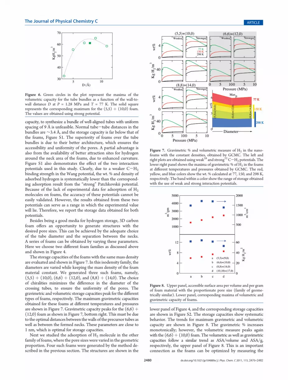
First, we compare the storage capacity of the selected foamwith the well-spaced same-diameter nanotube bundles. For this,we choose one foam previously generated byDing et al.9 from thecrossed (5,5) þ (10,0) nanotubes (we use symbol “þ” resem-bling the cross-orientation of the precursor tubes). The bundlesare generated by packing the (10,0) nanotubes in a triangularlattice and varying the wall-to-wall distance (D) within a bundleseries. The excess volumetric and gravimetric capacities of thesebundles are shown in Figure S1. The gravimetric fraction increasesmonotonically with the increasing tube-tube separation; how-ever, the volumetric capacity peaks atD = 9Å. Themetrics for thefoam are also shown in Figure S1. The maximum of volumetricratio in the foam is obtained at T = 77 K and 1 MPa, whichcompares very well with the corresponding maxima of the tubebundles as shown in Figure 6. Although they have similar storage
Figure 5. C-H2 and H2-H2 interaction potentials, purely classical(black), and incorporating the quantum effects at T = 77 (red), 150(green), and 298K (blue). The strong12 andweak28 potential choices forC-H2 are shown separately. The quantum effects weaken the bindingby the amount inversely proportional to T.
2480 dx.doi.org/10.1021/jp104889a |J. Phys. Chem. C 2011, 115, 2476–2482
The Journal of Physical Chemistry C ARTICLE
capacity, to synthesize a bundle of well-aligned tubes with uniformspacing of 9 Å is unfeasible. Normal tube-tube distances in thebundles are ∼3.4 Å, and the storage capacity is far below that ofthe foams, Figure S1. The superiority of foams over the tubebundles is due to their better architecture, which ensures theaccessibility and uniformity of the pores. A partial advantage isalso from the availability of better attraction sites for hydrogenaround the neck area of the foams, due to enhanced curvature.Figure S1 also demonstrates the effect of the two interactionpotentials used in this study. Clearly, due to a weaker C-H2
binding strength in the Wang potential, the wt. % and density ofadsorbed hydrogen is systematically lower than the correspond-ing adsorption result from the “strong” Patchkovskii potential.Because of the lack of experimental data for adsorption of H2
molecules on foams, the accuracy of these potentials cannot beeasily validated. However, the results obtained from these twopotentials can serve as a range in which the experimental valuewill lie. Therefore, we report the storage data obtained for bothpotentials.
Besides being a good media for hydrogen storage, 3D carbonfoam offers an opportunity to generate structures with thedesired pore sizes. This can be achieved by the adequate choiceof the tube diameter and the separation between the necks.A series of foams can be obtained by varying these parameters.Here we choose two different foam families as discussed aboveand shown in Figure 4.
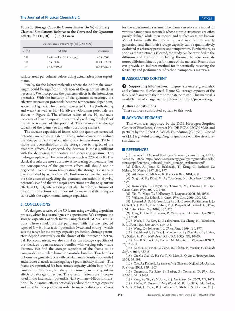
The storage capacities of the foams with the samemass densityare evaluated and shown in Figure 7. In this isodensity family, thediameters are varied while keeping the mass density of the foammaterial constant. We generated three such foams, namely,(5,5) þ (10,0), (6,6) þ (12,0), and (8,8) þ (14,0). The choiceof chiralities minimizes the difference in the diameter of thecrossing tubes, to ensure the uniformity of the pores. Thegravimetric and volumetric storage capacities peak for the differenttypes of foams, respectively. The maximum gravimetric capacitiesobtained for these foams at different temperatures and pressuresare shown in Figure 7. Gravimetric capacity peaks for the (6,6)þ(12,0) foam as shown in Figure 7, bottom right. This must be dueto the optimal distances between thewalls of the precursor tubes aswell as between the formed necks. These parameters are close to1 nm, which is optimal for storage capacities.
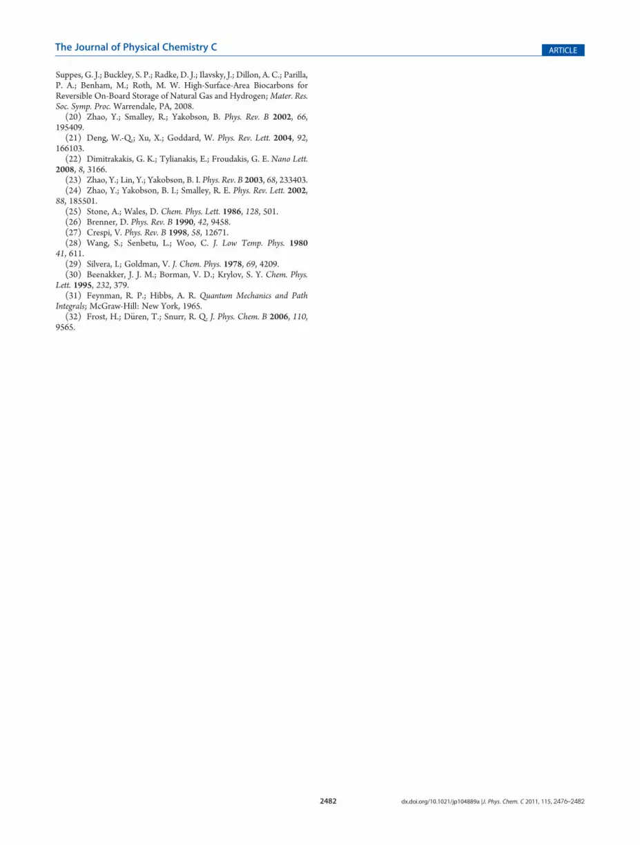
Next we studied the adsorption of H2 molecule in the otherfamily of foams, where the pore sizes were varied in the geometricproportion. Four such foams were generated by the method de-scribed in the previous section. The structures are shown in the
lower panel of Figure 4, and the corresponding storage capacitiesare shown in Figure S2. The storage capacities show systematicbehavior. The trends for maximum gravimetric and volumetriccapacity are shown in Figure 8. The gravimetric % increasesmonotonically; however, the volumetric measure peaks againwith the (6,6)þ (10,0) foam. The volumetric as well as gravimetriccapacities follow a similar trend as ASA/volume and ASA/g,respectively, the upper panel of Figure 8. This is an importantconnection as the foams can be optimized by measuring the
Figure 6. Green circles in the plot represent the maxima of thevolumetric capacity for the tube bundles as a function of the wall-to-wall distance D at P = 1.28 MPa and T = 77 K. The solid squarerepresents the corresponding maximum for the (5,5) þ (10,0) foam.The values are obtained using strong potential.
Figure 7. Gravimetric % and volumetric measure of H2 in the nano-foams with the constant densities, obtained by GCMC. The left andright plots are obtained using weak28 and strong12 C-H2 potentials. Thelower right panel shows the maxima of gravimetric % of H2 in the foamsat different temperatures and pressures obtained by GCMC. The red,yellow, and blue colors show the wt. % calculated at 77, 150, and 298 K,respectively. The band within a color show the range of storage obtainedwith the use of weak and strong interaction potentials.
Figure 8. Upper panel, accessible surface area per volume and per gramof foam material with the proportionate pore size (family of geome-trically similar). Lower panel, corresponding maxima of volumetric andgravimetric capacity of foams.
2481 dx.doi.org/10.1021/jp104889a |J. Phys. Chem. C 2011, 115, 2476–2482
The Journal of Physical Chemistry C ARTICLE
surface areas per volume before doing actual adsorption experi-ments.
Finally, for the lighter molecules where the de Broglie wave-length could be significant, inclusion of the quantum effects isnecessary. We incorporate the quantum effects in the interactionpotentials. With the inclusion of the quantum corrections, theeffective interaction potentials become temperature dependent,as seen in Figure 5. The quantum corrected C-H2 (both strongand weak) as well as H2-H2 Silvera-Goldman potentials areshown in Figure 5. The effective radius of the H2 moleculeincreases at lower temperatures essentially reducing the depth ofthe attractive part of the potential. This reduces the storagecapacity of the foams (or any other adsorbing carrier).
The storage capacities of foams with the quantum correctedpotentials are shown in Table 1. The quantum corrections reducethe storage capacity particularly at low temperatures. Table 1shows the overestimation of the storage due to neglect of thequantum effects. As expected, the decrease is most significantwith the decreasing temperature and increasing pressure. Thehydrogen uptake can be reduced by as much as 22% at 77 K. Theclassical results are more accurate at increasing temperature, butthe consequences of the quantum effects still should not beneglected. Even at room temperature, the storage is classicallyoverestimated by as much as 7%. Furthermore, we also analyzethe sole effect of neglecting the quantum correction in H2-H2
potential. We find that the major corrections are due to quantumeffects in H2-H2 interaction potentials. Therefore, inclusions ofquantum corrections are important to make realistic compar-isons with the experimental storage capacities.
5. CONCLUSIONS
We designed a series of the 3D foams using a welding algorithmprocess, which has its analogues in experiments. We compute thestorage capacities of such foams using classical GCMC simula-tions. These simulations are performed with the two selectedtypes of C-H2 interaction potentials (weak and strong), whichsets the range for the storage capacity prediction. Storage param-eters depend sensitively on the choice of the interaction poten-tial. For comparison, we also simulate the storage capacities ofthe idealized open nanotube bundles with varying tube-tubedistance. We find the storage capacities of the foams to becomparable to similar diameter nanotube bundles. Two familiesof foams are generated, one with constant mass density (isodensity)and another of nearly unvarying shape (geometrically similar). Thefoams are optimized for best storage capacity within both of thefamilies. Furthermore, we study the consequences of quantumeffects on storage capacities. The quantum effects are incorpo-rated in the interaction potentials via Feynman-Hibbs formula-tion. The quantum effects noticeably reduce the storage capacityand must be incorporated in order to make realistic predictions
for the experimental systems. The foams can serve as a model forvarious nanoporous materials whose atomic structures are oftenpoorly defined while their recipes and surface areas are known.Model foams with the desired surface area can be readilygenerated, and then their storage capacity can be quantitativelyevaluated at arbitrary pressure and temperature. Furthermore, assoon as the structure is selected, the study can be extended to thediffusion and transport, including thermal, to also evaluatenonequilibrium, kinetic performance of the material. Foams thuscan provide an indirect method for theoretically assessing thefeasibility and performance of carbon nanoporous materials.
’ASSOCIATED CONTENT
bS Supporting Information. Figure S1: excess gravimetricand volumetric % calculated. Figure S2: storage capacity of thefamily of foams with the proportionate pore size. This material isavailable free of charge via the Internet at http://pubs.acs.org.
Author Contributions#
These authors contributed equally to this work.
’ACKNOWLEDGMENT
This work was supported by the DOE Hydrogen SorptionCenter of Excellence, Contract No. DE-FC36-05GO15080, andpartially by the Robert A. Welch Foundation (C-1590). One ofus (J.L.) is grateful to Feng Ding for guidance with the structuressimulations.
’REFERENCES
(1) Targets for Onboard Hydrogen Storage Systems for Light-DutyVehicles, 2009; http://www1.eere.energy.gov/hydrogenandfuelcells/storage/pdfs/targets_onboard_hydro_storage_explanation.pdf.
(2) Dillon, A.; Jones, K.; Bekkedahl, T.; Kiang, C.; Bethune, D.;Heben, M. Nature 1997, 386, 377.
(3) Atkinson, K.; Michael, R. Fuel Cells Bull. 2001, 4, 9.(4) Singh, A. K.; Ribas, M. A.; Yakobson, B. I. ACS Nano 2009, 3,
1657.(5) Kowalczyk, P.; Holyst, R.; Terrones, M.; Terrones, H. Phys.
Chem. Chem. Phys. 2007, 9, 1786.(6) Yin, Y.; Mays, T.; McEnaney, B. Langmuir 2000, 16, 10521.(7) Williams, K.; Eklund, P. Chem. Phys. Lett. 2000, 320, 352.(8) Leonard, A. D.; Hudson, J. L.; Fan, H.; Booker, R.; Simpson, L. J.;
O’Neill, K. J.; Parilla, P. A.; Heben, M. J.; Pasquali, M.; Kittrell, C.; Tour,J. M. J. Am. Chem. Soc. 2008, 131, 723.
(9) Ding, F.; Lin, Y.; Krasnov, P.; Yakobson, B. J. Chem. Phys. 2007,127, 164703.
(10) Weck, P. F.; Kim, E.; Balakrishnan, N.; Cheng, H.; Yakobson,B. I. Chem. Phys. Lett. 2007, 439, 354.
(11) Wang, Q.; Johnson, J. J. Chem. Phys. 1999, 110, 577.(12) Patchkovskii, S.; Tse, J.; Yurchenko, S.; Zhechkov, L.; Heine,
T.; Seifert, G. Proc. Natl. Acad. Sci. U.S.A. 2005, 102, 10439.(13) Aga, R. S.; Fu, C. L.; Krcmar, M.; Morris, J. R. Phys. Rev. B 2007,
76, 165404.(14) Kuchta, B.; Firlej, L.; Cepel, R.; Pfeifer, P.; Wexler, C. Colloids
Surf., A 2010, 357, 61.(15) Gu, C.; Gao, G.-H.; Yu, Y.-X.; Mao, Z.-Q. Int. J. Hydrogen Ener.
2001, 26, 691.(16) Cao, A.; Dickrell, P.; Sawyer, W.; Ghasemi-Nejhad, M.; Ajayan,
P. Science 2005, 310, 1307.(17) Umemoto, K.; Saito, S.; Berber, S.; Tomanek, D. Phys. Rev.
B 2001, 64, 193409.(18) Yang, Z.; Xia, Y.; Mokaya, R. J. Am. Chem. Soc. 2007, 129, 1673.(19) Pfeifer, P.; Burress, J. W.; Wood, M. B.; Lapilli, C. M.; Barker,
S. A.; S. Pobst, J.; Cepel, R. J.; Wexler, C.; Shah, P. S.; Gordon, M. J.;
Table 1. Storage Capacity Overestimates (in %) of PurelyClassical Simulations Relative to the Corrected for QuantumEffects, for (10,10) þ (17,0) Foam
classical overestimates by (%) (2.56 MPa)
T (K) wt total wt excess
298 2.45 (weak)-3.18 (strong) 4.55-7.01
150 9.35-9.84 10.63-12.89
77 17.47-19.35 19.44-22.34
2482 dx.doi.org/10.1021/jp104889a |J. Phys. Chem. C 2011, 115, 2476–2482
The Journal of Physical Chemistry C ARTICLE
Suppes, G. J.; Buckley, S. P.; Radke, D. J.; Ilavsky, J.; Dillon, A. C.; Parilla,P. A.; Benham, M.; Roth, M. W. High-Surface-Area Biocarbons forReversible On-Board Storage of Natural Gas and Hydrogen;Mater. Res.Soc. Symp. Proc. Warrendale, PA, 2008.(20) Zhao, Y.; Smalley, R.; Yakobson, B. Phys. Rev. B 2002, 66,
195409.(21) Deng, W.-Q.; Xu, X.; Goddard, W. Phys. Rev. Lett. 2004, 92,
166103.(22) Dimitrakakis, G. K.; Tylianakis, E.; Froudakis, G. E. Nano Lett.
2008, 8, 3166.(23) Zhao, Y.; Lin, Y.; Yakobson, B. I. Phys. Rev. B 2003, 68, 233403.(24) Zhao, Y.; Yakobson, B. I.; Smalley, R. E. Phys. Rev. Lett. 2002,
88, 185501.(25) Stone, A.; Wales, D. Chem. Phys. Lett. 1986, 128, 501.(26) Brenner, D. Phys. Rev. B 1990, 42, 9458.(27) Crespi, V. Phys. Rev. B 1998, 58, 12671.(28) Wang, S.; Senbetu, L.; Woo, C. J. Low Temp. Phys. 1980
41, 611.(29) Silvera, I.; Goldman, V. J. Chem. Phys. 1978, 69, 4209.(30) Beenakker, J. J. M.; Borman, V. D.; Krylov, S. Y. Chem. Phys.
Lett. 1995, 232, 379.(31) Feynman, R. P.; Hibbs, A. R. Quantum Mechanics and Path
Integrals; McGraw-Hill: New York, 1965.(32) Frost, H.; D€uren, T.; Snurr, R. Q. J. Phys. Chem. B 2006, 110,
9565.
Related Documents


![Rational Canonical Formbuzzard.ups.edu/...spring...canonical-form-present.pdfIntroductionk[x]-modulesMatrix Representation of Cyclic SubmodulesThe Decomposition TheoremRational Canonical](https://static.cupdf.com/doc/110x72/6021fbf8c9c62f5c255e87f1/rational-canonical-introductionkx-modulesmatrix-representation-of-cyclic-submodulesthe.jpg)