III Hydrogen Production from CO 2 Reforming of Methane over Cobalt-based Catalysts TAN JI SIANG Thesis submitted in partial fulfilment of the requirements for the award of the degree of Bachelor of Chemical Engineering (Gas Technology) Faculty of Chemical & Natural Resources Engineering UNIVERSITI MALAYSIA PAHANG DECEMBER 2014 ©TAN JI SIANG (2014)

Welcome message from author
This document is posted to help you gain knowledge. Please leave a comment to let me know what you think about it! Share it to your friends and learn new things together.
Transcript

III
Hydrogen Production from CO2 Reforming of
Methane over Cobalt-based Catalysts
TAN JI SIANG
Thesis submitted in partial fulfilment of the requirements
for the award of the degree of
Bachelor of Chemical Engineering (Gas Technology)
Faculty of Chemical & Natural Resources Engineering
UNIVERSITI MALAYSIA PAHANG
DECEMBER 2014
©TAN JI SIANG (2014)
VIII
ABSTRACT
Increased concerns on anthropogenic greenhouse gas emissions have renewed interest in
the CO2 (dry) reforming process as an alternative to steam reforming for synthesis gas
production from natural gas. For hydrocarbon dry reforming, where the product stream
H2:CO ratio is less than 3, synfuel production is more amenable and acceptable for
downstream methanol and other oxygenated synthesis. However, dry reforming is
highly endothermic, and suffers from carbon-induced catalyst deactivation. This thesis
therefore investigates and evaluates the performance of methane dry reforming process
at different operation conditions such as reaction temperature and feed composition, and
the effects of loaded metals (Mo and Ni) on alumina-supported Co-based catalyst. Runs
of the methane dry reforming experiment were conducted in a computer-controlled fixe-
bed reactor at different feed compositions and reaction temperature. Both MoO3 and
NiO phases were formed during wetness co-impregnation with a mixture of deionized
water and alumina support as measured in X-ray diffraction. Temperature-programmed
calcination showed that the transformations from MoO3 to CoMoO4 phase and NiO to
NiAl2O4 phase were a 2 step process involving the formation of an oxidation
intermediate form. Calcination of co-impregnated catalysts at 500 0C for 5 h appeared to
be optimal preparation condition for H2 selectivity. Al2O3 support was the best support
to give the highest H2 to CO ratio. Second metal promotion did not alter reaction rate
significantly. However the interaction of loaded metal oxides with the surface
carbonaceous species resulted in substantially reduced carbon deposition on Co-based
catalyst, with Ni providing the greatest coking resistance compared to Mo. A
quantitative relationship between activation energy and feed composition of CO2:CH4
( 1:1, 2:1 and 3:1 ) as well as reaction temperatures (923 K, 953 K and 973 K) was
obtained over bimetallic 5%Ni-10%Co/Al2O3 catalyst which gave the highest value of
H2/CO ratio in the methane dry reforming process. Methane dry reforming activity was
stable with time-on-stream for 4 h.

IX
ABSTRAK
Peningkatan tentang kebimbangan ke atas pengeluaran gas rumah hijau antropogenik
telah menarik semula minat dalam proses pembaharuan (kering) CO2 sebagai alternatif
kepada pembaharuan stim untuk pelahiran sintesis gas daripada gas asli. Bagi
pembaharuan kering hidrokarbon, di mana nisbah aliran produk H2:CO adalah kurang
daripada 3, pengeluaran synfuel adalah lebih sesuai dan diterima untuk hiliran metanol
dan sintesis oksigen lain. Walau bagaimanapun, pembaharuan kering adalah proses
yang sangat endotermik, dan mengalami karbon yang disebabkan penyahaktifan
mangkin. Tesis ini oleh itu akan menyiasat dan menilai prestasi proses pembentukan
semula metana kering pada keadaan operasi yang berbeza seperti suhu tindak balas dan
komposisi makanan, dan kesan-kesan logam dimuatkan (Mo dan Ni) pada pemangkin
alumina yang berasaskan Co. Eksperimen pembaharuan metana kering dijakankan di
sebuah reaktor yg dikawal oleh komputer dalam kalangan komposisi bekalan yang
berbeza dan suhu yang berlain-lainan. Kedua-dua fasa MoO3 dan NIO telah dibentuk
semasa kelembapan bersama dengan campuran air ternyahion dan alumina seperti
bentuk yang diukur dalam pembelauan sinar-X. Pengkalsinan yang berasaskan suhu
yang diprogram menunjukkan bahawa perubahan daripada fasa MoO3 kepada CoMoO4
dan fasa Nio kepada NiAl2O4 adalah satu proses yang melibatkan 2 langkah
pembentukan bentuk perantaraan pengoksidaan. Pengkalsinan pemangkin yang
bersama-impregnated dijalankan dehgn suhu yang sebanyak 500 0C selama 5 jam boleh
dikira sebagai keadaan yang optimum bagi penyediaan dalam pemilihan H2. Al2O3
adalah bahan yang terbaik untuk memberikan nisbah H2 kepada CO yang tertinggi.
Promosi logam kedua tidak mengubah kadar tindak balas dengan ketara.
Walaubagaimanapun interaksi oksida logam dimuatkan dengan permukaan spesies
karbon menyebabkan berlakunya kekurangan pemendapan karbon pada pemangkin
berasaskan-Co, dengan Ni membekal rintangan coking yang paling besar berbanding
dengan Mo. Hubungan kuantitatif antara tenaga pengaktifan dan komposisi bekalan
CO2: CH4 ( 1:1, 2:1 dan 3:1 ) dan juga suhu yang berlainan (923 K, 953 K and 973 K)
telah diperolehi dengan penggunaan pemangkin dwilogam 5%Ni-10%Co / Al2O3 yang
memberikan nilai yang paling tinggi dalam nisbah H2/CO bagi proses pembaharuan
metana kering. Aktiviti pembaharuan metana kering mencapai kestabilan dengan masa-
ke-aliran sebanyak 4 jam.

X
TABLE OF CONTENTS
SUPERVISOR’S DECLARATION ............................................................................... IV
STUDENT’S DECLARATION ...................................................................................... V
DEDICATION ................................................................................................................ VI
ACKNOWLEDGEMENT ............................................................................................. VII
ABSTRACT ................................................................................................................. VIII
ABSTRAK ...................................................................................................................... IX
TABLE OF CONTENTS ................................................................................................. X
LIST OF FIGURES ....................................................................................................... XII
LIST OF TABLES ........................................................................................................ XV
LIST OF ABBREVIATIONS ...................................................................................... XVI
1 INTRODUCTION .................................................................................................... 1
1.1 Motivation and statement of problem ................................................................ 1
1.2 Objectives ........................................................................................................... 3
1.3 Scope of this research ......................................................................................... 3
1.4 Main contribution of this work .......................................................................... 3
1.5 Organisation of this thesis .................................................................................. 4
2 LITERATURE REVIEW ......................................................................................... 9
2.1 Overview ............................................................................................................ 9
2.2 Introduction ........................................................................................................ 9
2.3 Catalytic Steam Reforming ................................................................................ 9
2.4 CO2 Reforming................................................................................................. 10
2.5 Catalytic Partial Oxidation ............................................................................... 11
2.6 Autothermal Reforming ................................................................................... 12
2.7 Reaction Kinetics and Mechanisms ................................................................. 14
2.7.1 CO2 Reforming .......................................................................................... 14
2.7.2 Catalytic Partial Oxidation ........................................................................ 20
2.8 Thermodynamic ............................................................................................... 24
2.9 Typical Catalytic System Used In Reforming of Methane .............................. 28
2.10 Catalyst Deactivation ....................................................................................... 36
2.10.1 Sintering (Aging) ..................................................................................... 37
2.10.2 Coking (Fouling) ...................................................................................... 39
2.10.3 Poisoining ................................................................................................. 42
2.11 Summary .......................................................................................................... 43
3 MATERIALS AND METHODS ............................................................................ 45
3.1 Overview .......................................................................................................... 45
3.2 Introduction ...................................................................................................... 45
3.3 Materials ........................................................................................................... 45
3.3.1 Chemicals .................................................................................................. 45
3.3.2 Gases ......................................................................................................... 46
3.4 Catalyst Preparation ......................................................................................... 47
3.4.1 Pre-treatment of aluminum oxide support, Al2O3 .................................... 48
3.4.2 Preparation of monometallic catalyst, 15 g of 10% Co/Al2O3 .................. 49
3.4.3 Preparation of bimetallic catalyst, 15 g of 5% Ni-10%Co/Al2O3 (or 5%
Mo-10%Co/Al2O3) .................................................................................... 49

XI
3.5 Catalyst Characterisation ................................................................................. 51
3.5.1 Surface Area and Pore Volume ................................................................. 52
3.5.2 Thermogravimetric Analysis ..................................................................... 57
3.5.3 X-Ray Diffraction ..................................................................................... 59
3.6 Reaction Runs ................................................................................................... 60
4 RESULT AND DISCUSSIONS ............................................................................. 63
4.1 Catalyst Characterisation ................................................................................. 63
4.1.1 Physiochemical Properties ........................................................................ 63
4.1.2 X-ray Diffraction Analysis ........................................................................ 63
4.1.3 Thermogravimetric Analyzer (TGA) Study .............................................. 66
4.1.4 Scanning Electron Microscope .................................................................. 70
4.2 Reaction Study ................................................................................................. 72
4.2.1 Effect of promoter .................................................................................... 73
4.2.2 Transient Profiles ...................................................................................... 73
4.2.3 Steady-state Reaction Analysis ................................................................. 76
4.3 Kinetic Modeling ............................................................................................. 78
4.4 Summary .......................................................................................................... 84
5 CONCLUSION AND RECOMMENDATIONS ................................................... 85
5.1 Conclusion........................................................................................................ 85
5.2 Recommendations .............................................................................................. 87
REFRENCES .................................................................................................................. 88
APPENDICES ................................................................................................................ 99
XII
LIST OF FIGURES
Figure 2-1: Malaysia’s dry natural gas production and consumption from year 2000 to
2011 .................................................................................................................... 7
Figure 2-2: Dissociative adsorption of CH4 and subsequent reactions to produce CO and
H2. .................................................................................................................... 15
Figure 2-3: Schematic representation of temperature profile in catalytic partial
oxidation of methane (Prettre, Eichner & Perrin, 1946). .......................................... 20
Figure 2-4: Energy level diagram for the sequence of steps for the direct oxidation of
CH4 on Pt and Rh monolith catalysts (Hickman and Schmidt, 1993). ....................... 22
Figure 2-5: Equilibrium H2:CO ratios at various feed CO2:CH4 ratios and temperatures.
......................................................................................................................... 25
Figure 2-6: Equilibrium composition of (a) H2, and (b) CO at various feed CO2:CH4
ratios and temperatures. ....................................................................................... 25
Figure 2-7: Change in Gibbs free energy for the (a) methane CO2 reforming and partial
oxidation, (b) carbon formation, (c) H2 and CO oxidation, and (d) RWGS reactions at
various temperatures…………………………………………..……………………… 27
Figure 2-8: Promotion effect of oxygen vacancies on a Ni/CeO2 catalyst (Huang et al.,
2005).. ............................................................................................................... 33
Figure 2-9: Schematic diagram for methane dry reforming reaction steps over
bimetallic cluster of Co-Ni (Sinfelt, 1973).. ........................................................... 34
Figure 2-10: Comparison of carbon formation during CH4 dry reforming for
different bimetallic catalysts (Zhang et al, 2007). ................................................... 35
Figure 2-11: Conceptual models for crystallite growth due to sintering: (A) atomic
migration, and (B) crystallite migration (Bartholomew, 2001). ................................ 37
Figure 2-12: Visual illustration for fouling, crystallite encapsulation and pore
plugging of a supported metal catalyst due to carbon deposition (Bartholomew, 2001)…
......................................................................................................................... 39
Figure 2-13: Coke formation and transformation from CO on nickel (Bartholomew,
2001). ................................................................................................................ 40
Figure 2-14: Coke formation and transformation from hydrocarbons on metal
surfaces (Bartholomew, 2001).. ............................................................................ 40
Figure 2-15: Carbon deposition involving dislodgement of metal particle from
support (Snoeck, Froment & Fowles, 1997). .......................................................... 41
Figure 2-16: Influence of strong metal-support interaction on carbon deposition (Huang
et al., 2011 ......................................................................................................... 42
Figure 2-17: Relative steady-state methanation activity profiles for some of the
transition metals as a function of gas phase H2S concentration (Bartholomew, 2001). 43
Figure 3-1: Catalyst preparation flow chart ............................................................ 47
Figure 3-2: Temperature-dependent alumina phases and their surface area. ............... 48
XIII
Figure 3-3: Furnace (CARBOLITE, Model: AAF 11/3).. ........................................ 50
Figure 3-4: Hot plate (JlabTech, model: LMS-3003).. ............................................. 50
Figure 3-5: Oven (MEMMERT GERMANY, model: UFB-500).. ............................ 51
Figure 3-6: Distilled Water Unit (HAMILTON).. ................................................... 51
Figure 3-7: BET device employed in the study. ...................................................... 55
Figure 3-8: Typical adsorption-desorption isotherm profile. .................................... 55
Figure 3-9: Temperature program during oxidation thermogravimetric run. .............. 58
Figure 3-10 TGA (RESEARH INSTRUMENTS, model: TGA Q500) ..................... 58
Figure 3-11: X-ray diffraction as given by Bragg's Law.. ........................................ 60
Figure 3-12: Schematic diagram of the methane dry reforming reaction. ................... 61
Figure 4-1: X-ray diffractograms of : [a] γ -Al2O3, [b]10%Co/Al2O3, [c] 5%Mo-
10%Co/Al2O3, [d] 5%Ni-10%Co/Al2O3 ............................................................... 65
Figure 4-2: Derivative weight profiles of the catalysts during temperature-programmed
calcination. ........................................................................................................ 67
Figure 4-3: Derivative weight profiles of 10%Co/Al2O3 catalyst during temperature-
programmed calcination at different heating rate. ................................................... 68
Figure 4-4: Derivative weight profiles of 5%Mo-10%Co/Al2O3 catalyst during
temperature-programmed calcination at different heating rate.. ................................ 68
Figure 4-5: Derivative weight profiles of 5%Ni-10%Co/Al2O3 catalyst during
temperature-programmed calcination at different heating rate. ................................. 69
Figure 4-6: SEM images of calcined (a) 10%Co/Al2O3; (b) 5%Mo-10%Co/Al2O3; (c)
5%Ni-10%Co/Al2O3. .......................................................................................... 70
Figure 4-7: SEM images of calcined 5%Ni-10%Co/Al2O3 after reforming reaction at
973 K in feed ratio (a) CO2/CH4=1; (b) CO2/CH4=2; (c) CO2/CH4=3. ...................... 71
Figure 4-8: Product H2:CO ratios at T=973 K, = 50.5 kPa and = 50.5 kPa. . 73
Figure 4-9: CH4 conversion profile at T = 973 K with varying feed composition of CO2 /
CH4. .................................................................................................................. 74
Figure 4-10: CO2 conversion profile at T = 973 K with varying feed composition of CO2
/ CH4. ................................................................................................................ 74
Figure 4-11: CH4 conversion profile at constant feed composition of CO2 / CH4=1 with
varying temperatures. .......................................................................................... 75
Figure 4-12: CO2 conversion profile at constant feed composition of CO2 / CH4=1 with
varying temperatures. ...................................................................................................... 75
Figure 4-13: Consumption rate of CH4 and CO2 during methane dry reforming over
bimetallic 5%Ni-10%Co/Al2O3 catalyst.. .............................................................. 76
Figure 4-14: Production rate of H2 and CO during methane dry reforming over
bimetallic 5%Ni-10%Co/Al2O3 catalyst.. .............................................................. 77
Figure 4-15: Product H2:CO ratios for dry reforming at 973 K.. ............................... 78

XIV
Figure 4-16 : Arrhenius parameter study for methane dry reforming at (a) 1 hour. (b) 2
hour. (c) 3 hour. (d) 4 hour.. ................................................................................. 80
Figure 4-17: Overall Arrhenius parameters study for methane dry reforming.. ........... 83

XV
LIST OF TABLES
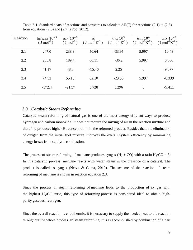
Table 2-1: Standard heats of reactions and constants to calculate ΔH(T) for reactions
(2.1) to (2.5) from equations (2.6) and (2.7), (Foo, 2012) .......................................... 9
Table 2-2: Advantages and Disadvantages of Steam Reforming. .............................. 10
Table 2-3: Advantages and Disadvantages of Catalytic Partial Oxidation. ................. 12
Table 2-4: Advantages and Disadvantages of Autothermal Reforming. ..................... 13
Table 2-5: Summary of some reported kinetic parameters for power law modelling
of the CH4 dry reforming reaction. ....................................... 17
Table 2-6: Kinetic rate expressions. ...................................................................... 18
Table 2-7: List of supported metal catalysts which have been studied for CH4 dry
reforming ........................................................................................................... 29
Table 2-8: Mechanisms of catalyst deactivation (Bartholomew, 2001).. .................... 36
Table 2-9: Hüttig, Tamman and melting temperatures (K) of common compounds in
heterogenous catalysis (Moulijn, van Diepen & Kapteijn, 2001).. ............................ 38
Table 3-1: List of chemicals used for catalyst synthesis. .......................................... 45
Table 3-2: List of gases used.. .............................................................................. 46
Table 4-1: Summary of physisorption data ............................................................ 63
Table 4-2: Comparison of experimental weight drop during calcination with theoretical
values.. .............................................................................................................. 69
Table 4-3: Kinetic parameter estimates for model at (a) 1 hour. (b) 2 hour. (c) 3 hour.
(d) 4 hour ........................................................................................................... 81
Table 4-4: Summary of kinetic parameter estimates for Langmuir-Hinshelwood model.
......................................................................................................................... 83

XVI
LIST OF ABBREVIATIONS
Notation Explanation
am cross-sectional area of adsorbate molecule
Asat quantity of gas adsorbed at saturation
APS active particle size
Biw wall Biot number
CAb bulk gas-phase concentration of component A
CAs concentration of component A on catalyst surface
Cpg specific heat capacity of gas mixture
dp catalyst particle diameter
Deff effective diffusivity
Di density of metal i
Ea activation energy
Fi sample weight fraction of metal i
h heat transfer coefficient
-∆Hads,i heat of adsorption for species i
-∆Hd heat of desorption
-∆Hrxn heat of reaction
kc mass transfer coefficient
kd deactivation coefficient
krxn reaction rate constant
Ki adsorption constant of species i
m0 initial mass
mf final mass
Ma molecular weight of adsorbate
MW molecular weight
na amount of gas adsorbed
nm monolayer capacity of adsorbate
NA Avogadro's number (6.023 × 10²³
molecules/mol)
P system pressure
P0 saturation pressure of absorbate gas at temperature T
Pi partial pressure of species i

XVII
PD percent dispersion
Pr Prandtl number
ri rate of reaction for species i
rk Kelvin radius
R universal gas constant, 8.314 J mol-1
K-1
∆Sads,i change in entropy for adsorption of species i
SA surface area of the sample
Sm metallic surface area
SAi specific area of metal i
Sc Schmidt number
SFi stoichiometric factor of metal i
tads thickness of adsorbed layer
T temperature
Tb bulk gas phase temperature
Ts catalyst surface temperature
Tw tube wall temperature
Tp peak temperature
U superficial gas velocity
vm volume of gas adsorbed for monolayer coverage
Vads volume of gas adsorbed
Vinj volume per injection
Vliq volume of liquid in pores
Vm molar volume
Vna volume not adsorbed
VS volume chemisorbed
XVIII
Greek Explanation
α solid state conversion
β temperature ramping rate
ε bed voidage
γs surface tension of adsorbate at its boiling point
λ wavelength
λp thermal conductivity of catalyst particle
θ diffraction angle
ρb bulk density of catalyst
ρg density of gas

1
1 INTRODUCTION
1.1 Motivation and statement of problem
From the twentieth century till today, world’s energy consumption always is a title which attracts
attention from population over this world. Undeniably, world population growth and the new
out-coming countries’ natural desire to achieve a higher level of economic and quality of life are
some of the main causes of the restless growth in energy demand and in the concurrent increase
in pollution (especially for CO2). Therefore, finding more secure, clean and sustainable energy
sources would be a most prioritize task and successful strategy to reduce the greenhouse gas
emissions and meet the world’s energy need at the same time. Compared to other alternatives,
hydrogen has a large number of advantages.
Hydrogen can be considered as one of the most potential energy in future since it is green,
efficient and environmentally-friendly. Therefore, much more attention has been started paid to
hydrogen production technology in order to ensure the future energy is stable and sustainable
(Fan & Abdullah et al., 2011). In their review paper, J. Gao and Z. Hou (2009) stated that
hydrogen can be produced via methane by technologies such as steam methane reforming,
methane dry reforming and methane partial oxidation. In addition, methane oxidative
CO2 reforming (Oxy-CO2 reforming) was proposed in recent years as an energy efficient manner
to utilize methane resources. However, in our study, methane dry reforming is the only chosen
method to be studied for the hydrogen production based on its high H2/CH4 molar ratio where the
CH4 can be easily found in Malaysia, less coke formation and low energy consumption. The
latter approach can be regarded very useful at remote natural gas fields where containing large
amount of CO2. Compared to reforming with H2O, utilization of CO2 is much more attractive
because it can be employed in areas where water is not available.
Since the rise of hydrogen production techniques, the research and development of the
synthesized catalysts have been paid much more attention today, especially in the performance
and characterization. Therefore, a number of different types of catalysts have been proposed for

2
the production of hydrogen. Awadallah, Aboul-Enein & Aboul-Gheit et al. (2014) reported that
catalytic activities are mostly dependent on their origins, structures and surface areas and found
that the disordered forms of carbon are more catalytically active than the ordered ones after
studied methane decomposition over 30 different forms of carbon catalysts.
Ni-based catalysts are generally used toward hydrogen production owing to their high reaction
activity. However, the Ni-based catalysts are very sensitive to H2S as it could cause a serious
poisoning of the catalysts (Baowei & Yuqin et al., 2014). JL Oliphant & RW Fowler (1978)
illustrated that Ni-based catalysts are limited to less than 0.1 ppm of H2S content for an ideal
performance which is very strict requirement to the feed gas or desulfided samples. Other than
that, carbon deposition will be occurred and formed seriously when the ratio of H2/CO is less
than 3, causing deactivation of Ni-based catalysts (CH Bartholomew, 1980). Thus, all these
obstacles have burden and confine the development of Ni-based catalysts.
Co-based catalysts are widely used in catalytic industry compared to Ni-based catalysts, such as
in the processes of hydrotreating and hydrodesulphurization (HDS), and in the synthesis of
alcohols (Pecoraro & Chianelli, 1981). In 1960s-1970s, Co-based catalysts were used to
improve the heat value of coal gas. Co-based catalysts can be used directly in the dry reforming
reaction without desulfurization. Meanwhile, Mo-based catalyst still can be used and functioning
well with a H2/CO ratio as low as 3 (Baowei & Yuqin et al., 2014). These advantages suggest
that Co-based catalyst owns a good prospect of application compared to Ni-based catalyst.
According to Al-Zeghayer & Sunderland (2005), a deep study on Co, Ni bimetallic component
catalysts were carried out. It has been found that Ni addition can change the structure of Co on
the catalyst surface and increase its resistance to sintering and improve its reaction activity. In
contrast, the current study aims to discover the effect of the different synthesized bimetallic Co-
Ni/Al2O3 catalyst towards the hydrogen production result.

3
1.2 Objectives
The objectives of this research are given below:
To synthesize and evaluate the physicochemical properties of monometallic
10%Co/Al2O3 catalyst, bimetallic 5%Ni-10%Co/Al2O3 catalyst and 5%Mo-10%Co/Al2O3
catalyst.
To evaluate the performance of methane dry reforming reaction at different operation
conditions such as reaction temperature and feed composition.
1.3 Scope of this research
The scopes of this research are summarized as follows:
i) To fabricate the bimetallic catalysts, 5%Ni-10%Co/Al2O3 from Co(NO3)2 and
Ni(NO3)2.6H2O precursors using wet impregnation method.
ii) To characterize the synthesized catalysts by using the following advanced techniques
namely; X-ray Diffraction Measurement (XRD), Brunauer-Emmett-Teller (BET)
surface area measurement, temperature-programmed oxidation (TPO), temperature-
programmed reduction (TPR) and scanning electron microscopy (SEM).
iii) To optimize the operation variable such as CO2/CH4 ratio and temperature for CO2 (or
dry) reforming reaction in order to locate the ideal process settings for highest
performance.
1.4 Main contribution of this work
Carbon dioxide (CO2) has been identified as the most significant greenhouse gas arising from
anthropogenic activities. It is of great importance to reduce anthropogenic CO2 emissions in
order to counteract global warming. One such method, which is presently being extensively
investigated, is the sequestration of CO2 produced by concentrated sources (such as industrial
plants and power stations). However, no one can be sure of the potential influence of CO2 buried
on the ecosystem in the long term. Conversion of CO2 instead of its sequestration is presently
being explored as one potential alternative solution. Production of useful value-added products
(chemicals products, fuels …) by dry reforming of methane appears to be an interesting method.
The dry reforming of methane produces an equimolar synthesis gas (syngas) which is a mixture

4
of hydrogen (H2) and carbon monoxide (CO), from carbon dioxide and methane (CH4),
according to equation below.
CH4 + CO2 → 2CO + 2H2 (1.1)
Undeniably, dry reforming can be viably used as a method of CO2 mitigation for the production
of hydrogen or of synthetic fuels. This work assesses whether monometallic catalyst can be
replaced by bimetallic catalyst and used in dry reforming reaction to give a promising conversion
of syngas from CO2 utilisation. First, a comparison between the monometallic catalystt and
bimetallic catalyst is performed as well as a study of the production of hydrogen from the dry
reforming of methane. Furthermore, a thermodynamic analysis is carried out by the method of
equilibrium constants defining the thermodynamic limit and the optimum conditions.
1.5 Organisation of this thesis
The structure of the reminder of the thesis is outlined as follow:
Chapter 2 provides a description of the applications of catalytic steam reforming, CO2 reforming
and catalytic partial oxidation. A general description on the flow characteristics of the system, as
well as the advantages and disadvantages are presented. This chapter also provides a brief
discussion of different types of catalyst, mentioning their applications and limitations for
reforming process as well as the catalyst deactivation. A summary of the previous experimental
work of CO2 reforming is also presented.
Chapter 3 gives a flow chart of preparing the monometallic catalyst and bimetallic catalyst by
using wetness impregnation method, followed by mixing slurry and lastly drying and calcination
process. In the preparation of bimetallic catalyst section, multiple impregnation technique is
selected instead of co-impregnation in order to ensure the desired compositions of metals are
loaded on the alumina support respectively. The other sections give detailed explanations about
the preparation procedures and precautions.
Chapter 4 is devoted to preliminary work has been done within this semester. In this chapter, the
detailed descriptions about the result of characterization by using advanced technologies are
discussed.
5
2 LITERATURE REVIEW
2.1 Overview
This chapter summarizes a detailed description of current technologies for producing syngas.
The advantages, disadvantages and the challenges for these processes are also discussed.
Furthermore, a detailed literature survey about the physicochemical properties and performance
of noble and non-noble catalysts for methane dry reforming is provide in this chapter.
2.2 Introduction
Today’s energy, which is mainly depends on fossil energy carriers, can in no way be evaluated as
sustainable. Regarding to the progressive industrialization of developing nations and growth in
the world’s population from time to time, especially those countries in Asia as well as South
America, the global demand for energy is expected to continue to escalate in the coming decades
– by more than 50% until 2030, according to the International Energy Agency (IEA) – with
fossil fuels continuing to dominate global energy use (Ball & Wietschel, 2009). At the same time,
a growing number of global consensus that greenhouse gas (GHG) emissions, which continue to
rise, an effective management is required to prevent dangerous anthropogenic interference with
the climate system. Hence, security of supply and climate change represent two major concerns
about the future of the energy sector which give rise to the challenge of finding the best way to
rein in emissions while also providing the energy required to sustain economies. Concerns about
security of energy supply, climate change and local air pollution and rising prices of energy
services are giving a growing influence on the policy making over the world. Subsequently,
syngas production technologies are starting to attract the world’s attentions based on the
requirements mentioned.
Synthesis gas or called as syngas is a mixture of hydrogen and carbon monoxide, which plays an
important role in chemical industries as a key intermediate. It usually used as a feedstock for gas-
to-liquids (GTL) Fisher-Tropsch synthesis to produce liquid hydrocarbon fuels. Undeniably, the
reserves of petroleum and crude oil are depleting from time to time and now becoming a crisis
towards the human being over the world (Hussain & Mazhar et al., 2009).

6
The value chain of the syngas market includes feedstock suppliers, syngas technology licensors,
syngas & derivatives manufacturers, and the end consumers. The feedstock suppliers are the
companies that supply coal, natural gas, petroleum byproducts (heavy oils or petcoke), or
biomass/waste. The syngas technology licensors include companies such as L’Air Liquide
(France), Haldor Topsoe (Denmark), Air Products & Chemicals (U.S.), KBR (U.S.), Siemens
(Germany), MHI (Japan), and Foster Wheeler (Switzerland) among several others. The actual
syngas and derivatives manufacturers are Methanex (Canada), Shell (The Netherlands), Sasol
(South Africa), and several others producing syngas and its derivatives such as methanol,
ammonia, liquid fuels, gaseous fuels, and electricity. The end-users are such as a fertilizer
industry for ammonia.
Syngas can be used for production of various chemicals such as methanol, ammonia, oxo
chemicals, and their individual derivatives such as formaldehyde, urea, butanol, dimethyl ether
(DME), and others. Simultaneously, Fisher Tropsch synthesis (FT–synthesis) can be used for the
production of hydrocarbon fuels such as diesel and gasoline. Power generation can be achieved
through coupling the syngas plant with an IGCC (Integrated Gasification Combined Cycle). Two
or more derivatives can also be produced at the same time, which enables polygeneration. Hence,
chemicals, fuels, or power can be produced depending upon the requirement as well as changes
in the domestic energy markets or global economic conditions.
The major opportunity in the syngas market is removing dependency on conventional natural
resources for the production of chemicals and fuels. Undeniably, gradual depletion of the world's
oil reserves enable a growing recognition of the potential of world natural gas reserves have led
to an increased interest in more efficient utilization of methane (CH4), especially in Malaysia
where rich in natural gas reserves and production. Figure 2-1 shows that the Malaysia’s dry
natural gas production and consumption from year 2000 to 2011 (Eia.gov, 2014).

7
Figure 2-1: Malaysia’s dry natural gas production and consumption from year 2000 to 2011.
Natural gas is a fossil fuel, basically a mixture of light hydrocarbons, found in the basement
of gas accumulations that occur in porous rocks, and may or may not be associated to oil.
Natural gas consists of saturated hydrocarbons, predominantly methane, propane and
butane in lower quantities, among other substances, like inorganic gases as well as some
low levels of contaminants such as nitrogen, carbon dioxide, water and sulfur compounds
(Thomas, 2004). Natural gas currently is one of the best alternatives for the supply of
energy and therefore urgent strategic efforts are necessary to develop alternative sources
and solutions for the frequent energy shortages currently being reported (Schmal, 2005).
Today natural gas is the preferred source for production of syngas, a mixture of hydrogen and
carbon monoxide, from which purified hydrogen can be obtained. There are several different
catalytic processes for producing syngas from natural gas (Armor, 2005).
In fact, the conventional method to produce syngas can be major classified into two, steam
reforming of natural gas and the CO2 (or dry) reforming process. Indeed, CO2 (or dry) reforming
process has attracted significant interest due to increased interest in the effective utilization of
CO2 from the environmental perspective compared to the steam reforming technology. Actually,

8
many natural gas fields contain copious amounts of CO2, natural gas dry reforming may be
readily carried out without pre-separation of CO2 from the natural gas. In some situation,
combination of steam and CO2 reforming may be advantageous. Undeniably, utilization of the
CO2-CH4 reforming reaction is already employed in some industrial processes. However, there is
always a question whether transformation of CH4 and CO2 into other chemicals could have a
significant impact on the concentration of these gases in the atmosphere.
Particularly, the major reactions involved in this chapter are shown in reaction (2.1), accompany
together with some significant side reactions shown in reactions (2.2) to (2.5):
Dry reforming of CH4
CH4 + CO2 2 CO + 2H2 (2.1)
Steam reforming of CH4
CH4 + H2O CO + 3H2 (2.2)
Reverse water-gas shift reaction
CO2 + H2 CO + H2O (2.3)
CH4 dehydration
CH4 C + 2H2 (2.4)
Boudourad reaction
2CO C + CO2 (2.5)
The heats of reaction for reactions (2.1) to (2.5) at temperature, T, may be obtained from
equations (2.6) and (2.7):
( ) ∫
(2.6)
Integration expression:
( )
(2.7)
The constants in equations (2.6) and (2.7) for reactions (2.1) to (2.5) are shown in Table 2.2
below.
9
Table 2-1. Standard heats of reactions and constants to calculate ΔH(T) for reactions (2.1) to (2.5)
from equations (2.6) and (2.7), (Foo, 2012).
Reaction
( J mol
-1 )
( J mol-1
)
( J mol-1
K-1
)
( J mol
-1K
-1 )
( J mol-1
K-1
)
( J mol
-1K
-1 )
2.1 247.0
238.3 50.64 -33.95 5.997 10.48
2.2 205.8
189.4 66.11 -36.2 5.997 0.806
2.3 41.17
48.8 -15.46 2.25 0 9.677
2.4 74.52
55.13 62.10 -23.36 5.997 -8.339
2.5 -172.4
-91.57 5.728 5.296 0 -9.411
2.3 Catalytic Steam Reforming
Catalytic steam reforming of natural gas is one of the most energy efficient ways to produce
hydrogen and carbon monoxide. It does not require the mixing of air in the reaction mixture and
therefore produces higher H2 concentration in the reformed product. Besides that, the elimination
of oxygen from the initial fuel mixture improves the overall system efficiency by minimizing
energy losses from catalytic combustion.
The process of steam reforming of methane produces syngas (H2 + CO) with a ratio H2/CO = 3.
In this catalytic process, methane reacts with water steam in the presence of a catalyst. The
product is called as syngas (Neiva & Gama, 2010). The scheme of the reaction of steam
reforming of methane is shown in reaction equation 2.3.
Since the process of steam reforming of methane leads to the production of syngas with
the highest H2/CO ratio, this type of reforming process is considered ideal to obtain high-
purity gaseous hydrogen.
Since the overall reaction is endothermic, it is necessary to supply the needed heat to the reaction
throughout the whole process. In steam reforming, this is accomplished by combustion of a part
10
of the fuel in a direct-fired or indirectly fired furnace. According to Le Chatelier’s principle,
equilibrium concentrations for reaction are shifted to the right at high temperature and low
pressure. In order to achieve a highly conversion of the methane, a very high temperature and
long residence time at this high temperature is required, meaning that an overall energy loss and
a huge size for the methane reforming reactor. Nevertheless, by using catalysts it is possible to
reduce the temperature necessary for total conversion of the methane to below 1000°C within
considerable short residence time. In Table 2-2, the advantages and disadvantages of steam
reforming are listed.
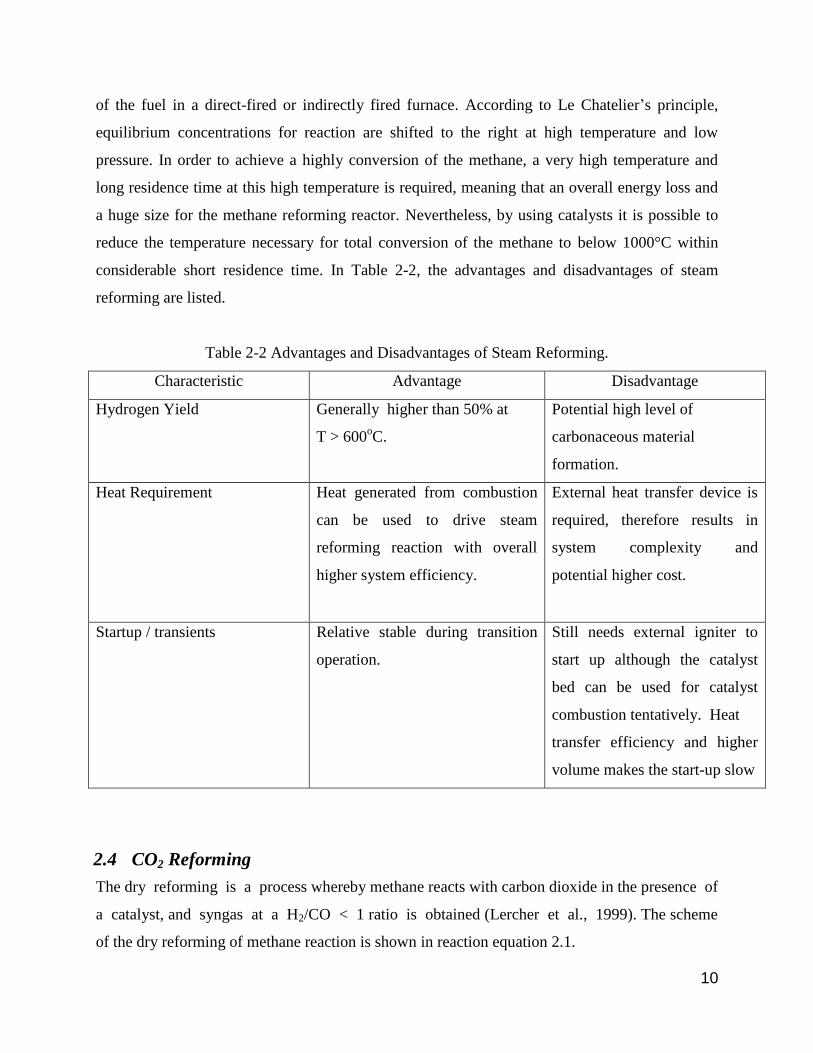
Table 2-2 Advantages and Disadvantages of Steam Reforming.
Characteristic Advantage Disadvantage
Hydrogen Yield Generally higher than 50% at
T > 600oC.
Potential high level of
carbonaceous material
formation.
Heat Requirement Heat generated from combustion
can be used to drive steam
reforming reaction with overall
higher system efficiency.
External heat transfer device is
required, therefore results in
system complexity and
potential higher cost.
Startup / transients Relative stable during transition
operation.
Still needs external igniter to
start up although the catalyst
bed can be used for catalyst
combustion tentatively. Heat
transfer efficiency and higher
volume makes the start-up slow
2.4 CO2 Reforming
The dry reforming is a process whereby methane reacts with carbon dioxide in the presence of
a catalyst, and syngas at a H2/CO < 1 ratio is obtained (Lercher et al., 1999). The scheme
of the dry reforming of methane reaction is shown in reaction equation 2.1.

11
Since the value of the H2/CO ratio obtained in the dry reforming of methane, this process is
considered the ideal type of reforming process when it comes to involve utilisation of the syngas
produced as a raw material for the synthesis of important fuel liquids which require H2 and CO
as raw materials. However, this type of reforming process is very expensive because it is an
endothermic process, meaning it consumes a great amount of energy. The main disadvantage of
dry reforming of methane is the significant production of by-products, typically coke, a
phenomena of catalyst deactivation, that are subsequently deposited on the surface of the
catalyst, impairing its activity in the reaction directly. The occurrence of coking towards a
catalyst contributes to the reduction of its useful life. The large formation of coke occurred in
this process is explained by the presence of CO2 as a reagent. Thus, dry reforming is the unique
process of methane reforming that is affected by two reagents that contain carbon (CH4 and CO2)
(Cheng et al., 2001; Lercher et al., 1999). Edwards and Maitra (2000) reported that there is a
greater potential for carbon formation, primarily due to the lower H/C ratio in the dry reforming
of methane. Furthermore, the lower H2/CO ratio is a preferable feedstock of Fischer-Tropsch
synthesis for long chain hydrocarbon production in petrochemical industries.
The main challenge for the industrial application of dry reforming of methane is most related
towards the development of active catalytic materials. In order to prolong the lifetime of catalyst,
a very low coke formation rate is needed to be achieved, either on the catalysts or reactor’s cold
zones. According to Stagg et al. (1998), carbon formation can be controlled by using a support
that favours the dissociation of CO2 into CO and O whilst, the last species are responsible for the
cleaning of the metallic surface.
2.5 Catalytic Partial Oxidation
The successful results obtained by steam reforming after 1902 was first summarized in 1924 by
Neumann and Jacob and since then the steam reforming become the state-of-art technology for
synthesis gas and hydrogen production (Christian Enger, Lodeng & Holmen, 2008). In 1929,
Liander et al. was the first person suggested that catalytic partial oxidation of methane in
production of synthesis gas.
The partial oxidation of methane is a catalytic process whereby methane reacts directly
with oxygen in the presence of a catalyst, and the product of this reaction is syngas with

12
a good H2/CO ratio (Fathi et al., 2000). The scheme of the partial oxidation of methane is shown
in reaction equation 2.2.
The partial oxidation of methane is an exothermic process and, thus from economic perspective,
it can be considered more economic than the processes of steam reforming or dry reforming,
because, being an exothermic reaction, it requires a lower amount of thermal energy compared to
others. On the other hand, partial oxidation is considered as an expensive process due to
requirement of pure oxygen flow. Generally, reaction times are very short (in milliseconds) and
occur at high temperatures of 850 to 1200 0C. The product mixtures have a lower H2: CO ratio of
2, which is ideal for the Fischer-Tropsch synthesis from synthesis gas (Foo, 2012). The
advantages and disadvantages of catalytic partial oxidation are listed in Table 2-3 below.
Table 2-3 Advantages and Disadvantages of Catalytic Partial Oxidation
Characteristic Advantage Disadvantage
Hydrogen Yield None. Relatively low yield can be
tuned by improving catalyst and
convert some CO back to H2.
Heat Requirement No external heat required. The
system is exothermic.
The heat generated from the
reaction needs to removed or
utilized in the system.
Startup / transients Startup is fast. Transient test is
relatively easy to control.
High temperature
startup/shutdowns may cause
catalyst degradation.
2.6 Autothermal Reforming
The autothermal reforming of methane is a combination of procedures of steam reforming and
partial oxidation. Hence, in the steam reforming there is contact with a flow of gaseous oxygen
Related Documents