Petroleum & Coal ISSN 1337-7027 Available online at www.vurup.sk/petroleum-coal Petroleum & Coal 54 (2) 157-173, 2012 HYDROGEN AND OCTANE BOOSTING THROUGH A NOVEL CONFIGURATION CONSISTS OF ISOTHERMAL AND MEMBRANE NAPHTHA REFORMING REACTORS -A COMPARATIVE STUDY D. Iranshahi, K. Paymooni, A. Goosheneshin, M. R. Rahimpour School of Chemical and Petroleum Engineering, Department of Chemical Engineering, Shiraz University, P.O. Box 71345, Shiraz, Iran, E-mail address: [email protected] Received January 12, 2012, Accepted June 15, 2012 Abstract The increasing demand for hydrogen and high octane gasoline in refineries can be addressed via utilizing alternative configurations for conventional catalytic naphtha reactors (CTR). In this regard, two case studies for a combination of isothermal and tubular membrane reactors are investigated in naphtha reforming process. The isothermal reactors are fabricated as a multi tubular reactor in a furnace. Some key parameters such as aromatic and hydrogen production rates and the aromatic content of reformate are investigated and some guidelines are proposed for the selection of a proper combination according to the desired aim of production. The simultaneous enhancement in products yield due to applying the Pd-Ag membrane layer and a slight temperature drop under an isothermal circumstance are achieved. The modeling results show that the combination of tubular membrane-isothermal-tubular membrane (MIM) reactors is a promising configuration for aromatic and hydrogen enhancement as well as achieving a desired aromatic content of the reformate. Keyword: Octane boosting; In-situ hydrogen removal; Isothermal configuration; Membrane reactor; Hydrogen production; Catalytic naphtha reforming. 1. Introduction The general trend throughout refinery complexes has been to up bring the origin feedstock (crude oil) and produce more products from each barrel of petroleum and to process those products in different ways to meet the specifications for use in modern engines. In fact, an oil refinery incorporates a vast variety of units such as Atmospheric and Vacuum Distillations, Visbreaking, Isomax, Coking, FCC and Catalytic Naphtha Reforming. Among all, catalytic naphtha reforming has a history of 60 years and plays a significant role in the refineries [1] . 1.1. Catalytic naphtha reforming Catalytic naphtha reforming maintains its position as a major process in the petroleum refinery. Catalytic reforming provides a key link between the refining and petrochemical industries through its effective production of aromatic compounds (BTX, i.e. Benzene, Toluene, Xylenes) [2] . More over the naphtha reforming supplies the demanded gasoline and hydrogen [3,4] . This process involves the reconstruction of low-octane hydrocarbons in the naphtha into more valuable high-octane gasoline components without changing the boiling point range [5,6] . Considering the above issues, this process has been under continuous study and evolution by diversity of researchers. Complete lists of such investigations were provided in our previous publications [7-9] . 1.1.1. Naphtha Naphtha and reformate are complex mixtures of paraffins, naphthenes, and aromatics in the C 5 –C 12 range. Most of Naphtha sources is obtained from overhead of main distillation column of refineries, this type of naphta is called strait run naphtha. Other naphtha suppliers such as coker unit, visbreaker unit and fluid catalytic cracking unit (FCC) also produce coker naphtha, visbreaker naphtha and FCC naphtha respectively [10-16] . Naphthas of different origin contain small amounts of additional compounds containing elements such as sulfur and nitrogen. Generally, naphtha constitutes 15-30% of the crude oil. The number of detectable individual compounds in naphthas ranges typically from 100–300,

Welcome message from author
This document is posted to help you gain knowledge. Please leave a comment to let me know what you think about it! Share it to your friends and learn new things together.
Transcript

Petroleum & Coal
ISSN 1337-7027
Available online at www.vurup.sk/petroleum-coal
Petroleum & Coal 54 (2) 157-173, 2012
HYDROGEN AND OCTANE BOOSTING THROUGH A NOVEL CONFIGURATION CONSISTS
OF ISOTHERMAL AND MEMBRANE NAPHTHA REFORMING REACTORS -A COMPARATIVE
STUDY
D. Iranshahi, K. Paymooni, A. Goosheneshin, M. R. Rahimpour
School of Chemical and Petroleum Engineering, Department of Chemical Engineering,
Shiraz University, P.O. Box 71345, Shiraz, Iran, E-mail address: [email protected]
Received January 12, 2012, Accepted June 15, 2012
Abstract
The increasing demand for hydrogen and high octane gasoline in refineries can be addressed via utilizing alternative configurations for conventional catalytic naphtha reactors (CTR). In this regard, two case studies for a combination of isothermal and tubular membrane reactors are investigated in naphtha reforming process. The isothermal reactors are fabricated as a multi tubular reactor in a furnace. Some key parameters such as aromatic and hydrogen production rates and the aromatic content of reformate are investigated and some guidelines are proposed for the selection of a
proper combination according to the desired aim of production. The simultaneous enhancement in products yield due to applying the Pd-Ag membrane layer and a slight temperature drop under an isothermal circumstance are achieved. The modeling results show that the combination of tubular membrane-isothermal-tubular membrane (MIM) reactors is a promising configuration for aromatic
and hydrogen enhancement as well as achieving a desired aromatic content of the reformate.
Keyword: Octane boosting; In-situ hydrogen removal; Isothermal configuration; Membrane reactor; Hydrogen production; Catalytic naphtha reforming.
1. Introduction
The general trend throughout refinery complexes has been to up bring the origin
feedstock (crude oil) and produce more products from each barrel of petroleum and to
process those products in different ways to meet the specifications for use in modern
engines. In fact, an oil refinery incorporates a vast variety of units such as Atmospheric
and Vacuum Distillations, Visbreaking, Isomax, Coking, FCC and Catalytic Naphtha
Reforming. Among all, catalytic naphtha reforming has a history of 60 years and plays a
significant role in the refineries [1].
1.1. Catalytic naphtha reforming
Catalytic naphtha reforming maintains its position as a major process in the petroleum
refinery. Catalytic reforming provides a key link between the refining and petrochemical
industries through its effective production of aromatic compounds (BTX, i.e. Benzene,
Toluene, Xylenes) [2]. More over the naphtha reforming supplies the demanded gasoline
and hydrogen [3,4]. This process involves the reconstruction of low-octane hydrocarbons
in the naphtha into more valuable high-octane gasoline components without changing the
boiling point range [5,6].
Considering the above issues, this process has been under continuous study and evolution
by diversity of researchers. Complete lists of such investigations were provided in our
previous publications [7-9].
1.1.1. Naphtha
Naphtha and reformate are complex mixtures of paraffins, naphthenes, and aromatics
in the C5–C12 range. Most of Naphtha sources is obtained from overhead of main distillation
column of refineries, this type of naphta is called strait run naphtha. Other naphtha
suppliers such as coker unit, visbreaker unit and fluid catalytic cracking unit (FCC) also
produce coker naphtha, visbreaker naphtha and FCC naphtha respectively [10-16]. Naphthas
of different origin contain small amounts of additional compounds containing elements
such as sulfur and nitrogen. Generally, naphtha constitutes 15-30% of the crude oil. The
number of detectable individual compounds in naphthas ranges typically from 100–300,
but these are harsh to follow individually and it is sufficient for the refiner engineers just
to know about the group concentrations of PNA (paraffin, naphthene, aromatic) in order to
evaluate the quality of the final products (research octane number). Usual straight-run
medium naphtha contains 40-70 wt % paraffins, 20-50 wt % naphthenes, 5-20 wt %
aromatics and during the catalytic reforming most of the low octane naphthenes and
paraffines are converted into the high valuable aromatic compounds [5].
1.1.2. Aromatic
The high concentration of aromatics in reformates is a valuable feedstock of benzene,
toluene, and particularly xylenes in the petrochemical usages [5].
Aromatics have the general formula CnH2n-6 and contain one or more polyunsaturated
rings (conjugated double bonds). These benzene rings can have paraffinic side chains or
be coupled with other naphthenic or aromatic rings. The reactivity of the unsaturated
bonds make the C6, C7, and C8 aromatics or BTX (benzene, toluene, xylenes) important
building blocks for the petrochemical industry. Aromatics have high octane numbers
always above 100. Basically, an increase in the octane number of the reformate can best
be obtained by aromatic production. Based on the available evidences throughout the
literature the research octane number (RON) has a linear relation with the weight
fraction of aromatic compounds in the reformate [17-20]. Hence, attempts are made to
enhance the aromatic production rate in the refineries. What is more, the drive to
eliminate the use of MTBE as an oxygenate component in the gasoline pool and the
subsequent lose in the octane number have forced the refineries to replace this lost by
increasing other high octane aromatics [5].
1.1.3. Hydrogen
In addition to high octane gasoline production (or higher aromatic production), a large
quantity of required hydrogen all over the refinery complex is supplied by the reformers.
Hydrogen is mainly used for hydro processing in the refinery. Furthermore, there is a
growing concern about energy supply security owing to the expected increase of global
energy demand. The results of global energy scenarios of IEA’s Energy Technology
Prospective and the WETO H2 scenarios of the European Commission show the emergence of
a considerable hydrogen demand until 2050, provided that very optimistic developments of
hydrogen production and end-use technologies are assumed. Hence, the increasing in
hydrogen demand will eventually lead to a boost in its manufacturing capacity [21]. In
this regard, hydrogen can be nominated as an indispensable source of energy in the
future. Recent progress in fuel cell technology makes it possible to envisage a major role
of hydrogen in the future energy system. Typical hydrogen recovery processes include
pressure-swing adsorption (PSA), membrane separation, especially metal membrane
separation as one of the most cost-effective and promising methods for pure hydrogen
production, and cryogenic separation [4,22-24]. Therefore, some improvements are
observed in both the processing and equipment pieces of the technology as well as the
catalyst component owing to the importance of the catalytic naphtha reforming process
(hydrogen and high octane gasoline production) in the refinery [5] . An extensive literature
review about naphtha reforming can be found in the previous publications [7,8,25,26].
1.2. Membrane reactor
The potential of membranes for gas separation has been known for more than 30
years. The first large-scale commercial application of membrane gas separation was the
separation of hydrogen from nitrogen, methane and argon in ammonia purge gas stream [27]. During this relatively short time, significant development in membrane science has
been come to stage from academic and industrial viewpoints [28-30] and studies are still in
progress. Two groups of polymeric and inorganic membranes are discussed, but majority of
investigations have been concentrated on the inorganic membrane reactors because of
their excellent thermal stability under high reaction temperatures [32]. It is commonly
accepted that using membrane technology in the conventional plants drives toward
greater economic and environmental efficiency [53].
In many hydrogen-related reaction systems, Pd-alloy membranes on a stainless steel
support were used as the hydrogen-permeable membrane [33]. It is also well known that
the use of pure palladium membranes is hindered by transition from the α-phase to the
β-phase at temperatures below 300oC, which depends on the hydrogen concentration in
the metal. This phenomenon leads to distortion of the metal and lattice [34,35].
D. Iranshahi, K. Paymooni, A. Goosheneshin, M. R. Rahimpour/Petroleum & Coal 54(2) 157-173, 2012 158
For endurance enhancement of the commercial Pd membranes, the pd-alloy membranes
such as Pd-Ag, Pd-Cu and Pd-Au is used [36]. Alloying the palladium, especially with silver,
reduces the critical temperature for embitterment and results to an increase in the hydrogen
permeability. Okazaki et al. [37] showed that the durability of Pd-Ag membrane in comparison
to Pd membrane was improved and showed the prevention of lattice expansion by alloying
with more than 20% of silver. In other work, the highest hydrogen permeability was
detected 23wt% of silver [38]. Peters et al. [39] examined the stability of the membranes
by experiments. They studied the hydrogen permeation and the stability of tubular
palladium alloy (Pd-23%Ag) composite membranes at elevated temperatures and pressures.
Briefly, Palladium-based membranes have been used for decades in hydrogen
extraction because of their high permeability and good surface properties and this fact that
palladium, like all metals, is 100% selective for hydrogen transport [40]. The palladium-
copper [41], palladium-silver [42-46] were used for different processes. Rahimpour and
Ghader proposed Pd–Ag membrane and Pd membrane reactors for methanol synthesis [38,47]. Tosti et al. [48] described different configurations of palladium membrane reactors used
for separating ultra pure hydrogen. Nair et al. [49] recently carried out an analysis of
conventional Pd and Pd/Ag membranes. Damen and coworkers model four configurations
of the membrane reactor with Aspen plus to determine its thermodynamic and economic
prospects [50]. These properties cause Pd-based membranes such as Pd-Ag membranes
to be attractive to apply in petrochemical gases.
One apparent opportunity that would seem to match nicely with the current feature of
membrane is the catalytic naphtha reformers in the refineries [27,51]. Membrane can be used
effectively to increase hydrogen production and boost the octane number of the produced
gasoline through this unit.
1.3. Objective
The underlying goal of this study is to investigate the performance of a combination of
isothermal and tubular membrane reactors in naphtha reforming process. Two cases,
Case (I) with one tubular membrane reactor and Case (II) with two tubular membrane
reactors, are investigated in this study and some guidelines are proposed ultimately for
the selection of the most proper combination according to the desired target of production.
Here, M and I represent Membrane tubular and Isothermal reactors, respectively. Since
in the previous study [8], the hydrogen production rate decreased in isothermal configuration,
the combination of isothermal and tubular membrane reactors is proposed as a novel
configuration and a remedy for this undesired phenomenon.
2. Process description
2.1. Conventional tubular reactor (CTR)
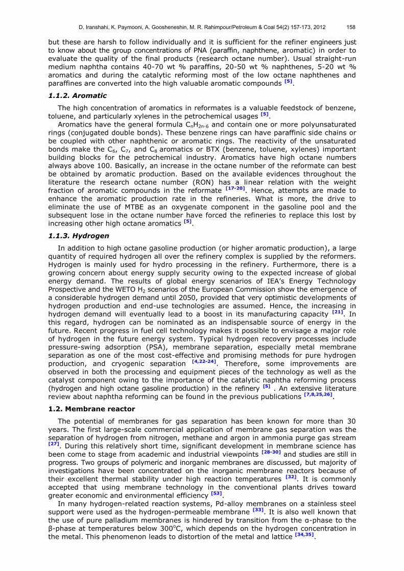
The catalytic naphtha reforming process by CTR configuration has been extensively
discussed in the previous publication [52]. A simplified process diagram for CTR is shown
in Fig.1.
Fee
d t
o t
he
firs
t re
act
or
T=775K
Furnace
T=777K
R-2
R-3
Valve
Flash drum
Stabilizer
P-30
Reboiler
Vapor
Reformate
Condenser
Reflux drum
LPG
Off gasT=777K
R-1
Fresh naphtha feed
Recycled hydrogenHydrogen
Fig.1 A simplified process diagram for CTR.
D. Iranshahi, K. Paymooni, A. Goosheneshin, M. R. Rahimpour/Petroleum & Coal 54(2) 157-173, 2012 159

2.2. A combination of isothermal an tubular membrane reactors
In the isothermal configuration, the reactor is fabricated as a multi tubular reactor inside
a furnace. The furnace consists of the non-reaction section where the inlet naphtha feed
is preheated by parallel tubes and the reaction section where the chemical reactions take
place in a multi tubular reactor which are packed by catalysts. A conceptual design for
multi tubular reactors in a furnace is depicted in Fig.2 (a). Since the temperature is maintained
at 777K by the furnace, reactors operate under an isothermal condition. Cases (I) and
(II) are investigated in this study where the former one is a combination of two isothermal
reactors and one tubular membrane reactor while the latter one is a combination of one
isothermal reactor and two tubular membrane reactors. The Pd-Ag membrane layer is
assisted in tubular reactors to enhance the production rates of main products according
to the thermodynamic equilibrium. Schematic process diagrams for a combination of
isothermal and tubular membrane reactors for MII and MIM combinations are illustrated
in Fig.2 (b)-(c).
Non-Reaction
Zone
Reaction
Zone
Furnace
Inlet
NaphthaProduct
Catalyst
Particle
2a
Fee
d t
o t
he
firs
t re
act
or
T=777K(R-3)
Flash drum
Stabilizer
P-30
Reboiler
Vapor
Reformate
Condenser
Reflux drum
LPG
Off gasT=777K
R-1
Fresh naphtha feed
Recycled hydrogen
Hydrogen
H2
H2
H2
Compressor
Sweep gas
Reach in hydrogen
(R-2)
H-1
Non-reaction
zoneReaction zone
T=775K
Non-reaction
zone
Reaction zone
2b
D. Iranshahi, K. Paymooni, A. Goosheneshin, M. R. Rahimpour/Petroleum & Coal 54(2) 157-173, 2012 160

Fee
d t
o t
he
firs
t re
act
or
T=775K
T=777K
R-3
Flash drum
Stabilizer
P-30
Reboiler
Vapor
Reformate
Condenser
Reflux drum
LPG
Off gasT=777K
R-1
Fresh naphtha feed
Recycled hydrogen
Hydrogen
H2
H2
H2
H2
H2
H2
Compressor
Sweep gas
Reach in hydrogen
(R-2)
H-1
Non-reaction
zoneReaction zone
2c
Fig.2 Schematic process diagram of (a) for multi tubular reactors in a furnace
(b) combination of isothermal and tubular membrane reactors for MII and (c) MIM
3. THE KINETIC OF REACTIONS
In order to verify the feedstock or product qualities, it is often sufficient for the process
engineers to know the PONA (paraffin, olefin, naphthene and aromatic) group concentrations.
Our available process data sheets from three domestic refineries are reported based on
PNA [5,53]. Therefore, a simplified model based on the Smith’s model [54], with four
predominant reactions, is considered to reduce the complexity of naphtha feed. The
related reactions are as follows:
Dehydrogenation of naphthenes to aromatics Naphthenes (CnH2n)↔Aromatics (CnH2n-6)+3H2
2ΔH=71038.06(kj/kmol H )
(1)
Dehydrocyclization of paraffins to naphthenes Naphthenes (CnH2n)+H2↔Paraffins (CnH2n+2)
2ΔH=-36953.33(kj/kmol H ) (2)
Hydro cracking of naphthenes to lower hydrocarbons Naphthenes (CnH2n) + n/3H2→Lighter ends (C1–C5)
2ΔH=-51939.31(kj/kmol H ) (3)
Hydro cracking of paraffins to lower hydrocarbons Paraffins (CnH2n+2) + (n−3)/3H2→Lighter ends (C1–C5)
2ΔH=-56597.54(kj/kmol H ) (4)
The corresponding reactions' rates and their constants have been reported in previous
publications [25].
4. Mathematical modeling, numerical solution and model validation
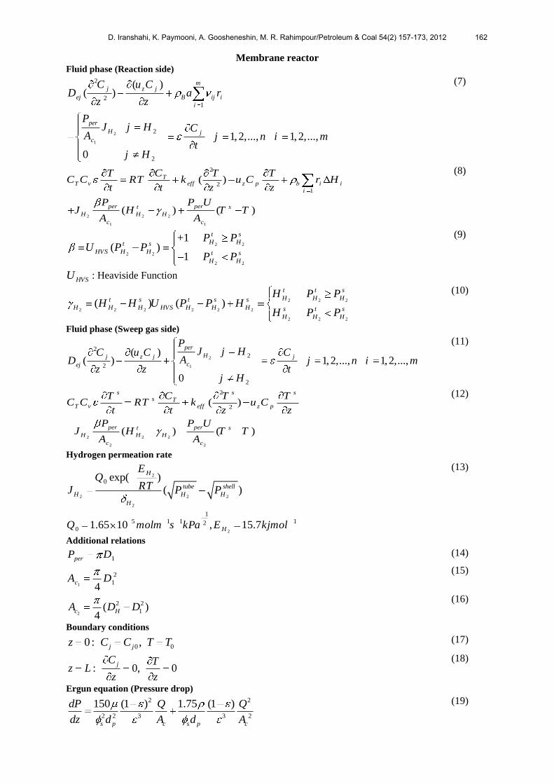
The corresponding mass and energy balance equations as well as the pressure drop
correlation [55] and the Sievert’s law correlation [56] are presented in Table 1. Furthermore,
some useful auxiliary correlations are used in the developed model.
Table 1 Mass and energy balances.
Isothermal reactor 2
21
( )( )
1,2,..., 1,2,...,
mj z j
ej B ij i
i
j
C u CD a r
z z
C j n i m
t
(5)
2
21
( )TT v eff z p b i i
i
CT T TC C RT k u C r H
t t z z
(6)
D. Iranshahi, K. Paymooni, A. Goosheneshin, M. R. Rahimpour/Petroleum & Coal 54(2) 157-173, 2012 161
Membrane reactor Fluid phase (Reaction side)
2
1
2
21
2
2
( )( )
1, 2,..., 1, 2,...,
0
mj z j
ej B ij i
i
per
H j
c
C u CD a r
z z
PJ j H C
A j n i mt
j H
(7)
2 2 2
1 1
2
21
( )
( ) ( )
TT v eff z p b i i
i
per pert s
H H H
c c
CT T TC C RT k u C r H
t t z z
P P UJ H T T
A A
(8)
2 2
2 2
2 2
+1 ( )
1
t s
H Ht s
HVS H H t s
H H
P PU P P
P P
HVSU : Heaviside Function
(9)
2 2 2
2 2 2 2 2 2
2 2 2
( ) ( )
t t s
H H Ht s t s s
H H H HVS H H H s t s
H H H
H P PH H U P P H
H P P
(10)
Fluid phase (Sweep gas side)
2
1
22
2
2
( )( ) 1,2,..., 1,2,...,
0
per
Hj z j j
cej
PJ j HC u C C
AD j n i mz z t
j H
(11)
2 2 2
2 2
2
2( )
( ) ( )
s s ss T
T v eff z p
per pert s
H H H
c c
CT T TC C RT k u C
t t z z
P P UJ H T T
A A
(12)
Hydrogen permeation rate
2
2 2 2
2
0 exp( )
( )
H
tube shell
H H H
H
EQ
RTJ P P
2
1
5 1 1 120 1.65 10 , 15.7HQ molm s kPa E kjmol
(13)
Additional relations
1perP D (14)
1
2
14
cA D (15)
2
2 2
1( )4
c HA D D (16)
Boundary conditions
0 00: ,j jz C C T T (17)
: 0, 0jC T
z Lz z
(18)
Ergun equation (Pressure drop) 2 2
2 2 3 3 2
150 (1 ) 1.75 (1 )
s p c s p c
dP Q Q
dz d A d A
(19)
D. Iranshahi, K. Paymooni, A. Goosheneshin, M. R. Rahimpour/Petroleum & Coal 54(2) 157-173, 2012 162

Steady-state simulation of the reactors is achieved by setting all time variations of
states to zero and also considering fresh catalysts. The set of ODEs (energy and mass
balance equations in tubular reactor) as well as algebraic equations (the auxiliary correlations,
kinetics and thermodynamics of the reaction system) are integrated by a modified
Rosenbrock formula of order two.
A comparison between the achieved results from proposed model and conventional
tubular packed-bed reactors under the steady-state condition has been reported in Table
2. As seen, there is an acceptable agreement between the predicted results and the plant
data. Analyses of the components (paraffin, naphthene and aromatic) are performed by
PONA test apparatus. The PONA test is a GC apparatus which operates with Helium as a
carrier gas. The system is composed of three parts including split injector, temperature
programmed oven and the ionization detector. The analysis time is around one hour and
a half. The components are identified based on the peaks which are appeared by the GC.
In order to detect all the individual compounds, more complex temperature program and
also time are require. For the process engineer, it is often sufficient to know the PONA
group concentration in order to verify the feedstock or product qualities and the least
time-consuming by GC methods. This test is usually taken monthly based on our data
sheets from the domestic refinery [5,53].
Table 2 Comparison between model prediction and plant data for fresh catalyst.
Reactor
No.
Inlet
temperature
(K)
Inlet
pressure
(Kpa)
Catalyst
distribution
(wt %)
Input feedstock
(Mole %)
1 777 3703 20 Paraffin 49.3
2 777 3537 30 Naphthene 36
3 775 3401 50 Aromatic 14.7
Outlet temperature
(K)
Aromatic in reformate
(Mole %)
No. Plant CTR MII MIM plant CTR MII MIM
1 722 727.30 729.82 729.82 − 34.67 34.85 34.84
2 753 750.98 777.00 777.00 − 47.19 54.02 54. 03
3 770 770.53 775.00 772.04 57.70 56.18 63.10 63.66
5. Results and discussion
The modeling results of various combinations are investigated in the following figures
in order to recognize the best configuration for catalytic naphtha reforming process.
5.1. The combination of a tubular membrane reactor and two isothermal
reactors (Case I)
In order to investigate the performance of case (I), the variation of some key parameters
such as aromatic and hydrogen production rates, H2/HC molar ratio, the aromatic content
of reformate are studied along the reactors.
The obtained aromatic compounds from the catalytic reformers are used for adjusting
octane number of gasoline pools. Aromatics are considered to have octane number of more
than 100 [5]. Moreover, aromatics are used as intermediate products for production of
thousands of materials by the petrochemical complexes. On the other hand, the produced
hydrogen from the catalytic naphtha reformers is used for removing sulfur and nitrogen
compounds and producing lighter fuels in the hydrotreating and hydrocracking units [4].
The aromatic and hydrogen production rates along three possible combinations of case (I)
and CTR (also named as TTT here) are depicted in Fig.3 (a)-(b). As seen, the aromatic
production rate increases considerably along IMI in comparison with CTR. Since the
temperature of multi tubular reactors in the isothermal configuration is maintained constant
via furnaces, the reaction rates and consequently the aromatic and hydrogen production
rates by the dehydrogenation reaction (eq.1) increase considerably at higher temperatures.
The aromatic production rate in the outlet of the first reactor in IIM and IMI configurations is
higher than even the outlet aromatic production rate from the second reactor in CTR.
About 82% of total aromatic production is achieved in the first reactor of IIM and IMI.
Although higher aromatic production rate is achieved in IMI (about 800 kg/h compared
with CTR), the hydrogen production rate via MII is superior compared with the other
D. Iranshahi, K. Paymooni, A. Goosheneshin, M. R. Rahimpour/Petroleum & Coal 54(2) 157-173, 2012 163

configurations in Case (I). Providing a heating source (high temperature) for the first
reactor where the naphthene and paraffin concentrations are high proceeds the irreversible
reactions (eq.3 and 4) and turns a portion of produced hydrogen into the light ends. In
MII configuration, lower temperature profile in the tubular membrane reactor than the
isothermal one as well as assisting the membrane layer in the first reactor of MII combination
avoids the unfavorable hydrogen consumption via these two reactions. Consequently,
higher hydrogen yield is achieved in MII. Fig.3 (b) shows that 100% of total hydrogen
production is achieved by applying just one isothermal configuration (the first reactor).
This means a huge saving in the initial cost of investment form neglecting the second and
the third reactors and providing expensive catalyst (Catalyst contains Pt alloy). However,
a cost evaluation between lower hydrogen production (about 9 kmol/h compared with the
CTR) and saving in the operational and initial costs of investment should be considered
before making any decision.
0 0.1 0.2 0.3 0.4 0.5 0.6 0.7 0.8 0.9 10
20
40
60
80
100
120
Mass of catalyst (Dimensionless)
Aro
mati
c p
rod
uct
ion
(k
mole
/hr)
0.98 1
101
101.5
102
102.5
CTR
IIM
IMI
MII
0 0.1 0.2 0.3 0.4 0.5 0.6 0.7 0.8 0.9 10
20
40
60
80
100
120
Mass of catalyst (Dimensionless)
Aro
mati
c p
rod
uct
ion
(k
mole
/hr)
0.98 1
101
101.5
102
102.5
CTR
IIM
IMI
MII
Fig.3 (a) The aromatic and (b) hydrogen production rates along the three possible
configurations of case (I) and CTR
0 0.1 0.2 0.3 0.4 0.5 0.6 0.7 0.8 0.9 14.6
4.8
5
5.2
5.4
5.6
5.8
6
6.2
6.4
Mass of catalyst (Dimensionless)
H2/H
C m
ola
r ra
tio
CTR
IIM
IMI
MII
Fig.4 H2/HC molar ratio along CTR and Case (I)
The H2/HC molar ratio is a key parameter to control the catalyst load and catalyst
deactivation in naphtha reforming process as shown in Fig.4. The catalyst deactivation
decreases considerably at high H2/HC molar ratio however higher aromatic and hydrogen
yield are achieved at low H2/HC molar ratios therefore lower H2/HC molar ratio is preferred
although this is always a trade-off with the catalyst stability [5]. The H2/HC molar ratio
increases gradually along CTR owing to continuous hydrogen production in the reaction
side. Assisting a membrane layer in a tubular reactor extracts the excessive amount of
produced hydrogen from the reaction side and enhances the production rates. It is worth
mentioning that the permeation side pressure is adjusted in tubular membrane reactor in
D. Iranshahi, K. Paymooni, A. Goosheneshin, M. R. Rahimpour/Petroleum & Coal 54(2) 157-173, 2012 164
order to maintain the H2/HC molar ratio above 4.73. Increasing/decreasing trends (the
maximum points) are observed in the reactors of Case (I) owing to applying the Pd-Ag
membrane layers. A remarkable increase in the H2/HC molar ratio along the first and the
second reactors of IIM configuration is due to a large amount of hydrogen production as
well as paraffin consumption in two subsequent isothermal reactors.
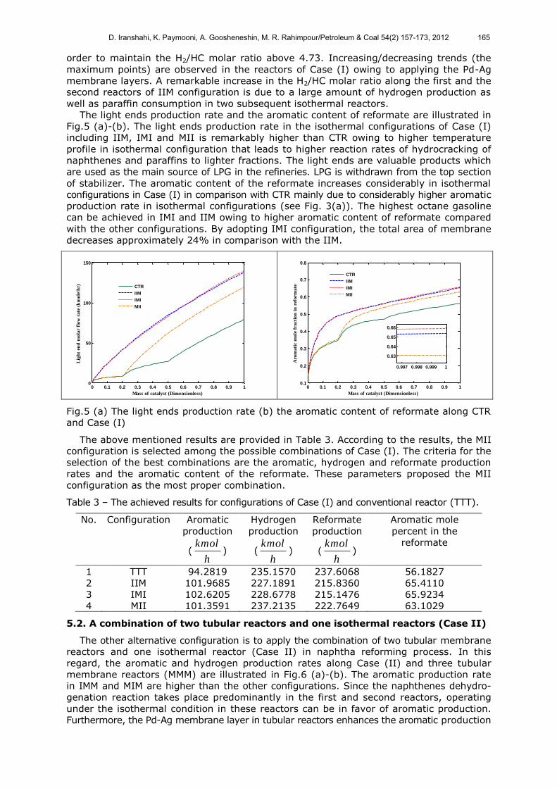
The light ends production rate and the aromatic content of reformate are illustrated in
Fig.5 (a)-(b). The light ends production rate in the isothermal configurations of Case (I)
including IIM, IMI and MII is remarkably higher than CTR owing to higher temperature
profile in isothermal configuration that leads to higher reaction rates of hydrocracking of
naphthenes and paraffins to lighter fractions. The light ends are valuable products which
are used as the main source of LPG in the refineries. LPG is withdrawn from the top section
of stabilizer. The aromatic content of the reformate increases considerably in isothermal
configurations in Case (I) in comparison with CTR mainly due to considerably higher aromatic
production rate in isothermal configurations (see Fig. 3(a)). The highest octane gasoline
can be achieved in IMI and IIM owing to higher aromatic content of reformate compared
with the other configurations. By adopting IMI configuration, the total area of membrane
decreases approximately 24% in comparison with the IIM.
0 0.1 0.2 0.3 0.4 0.5 0.6 0.7 0.8 0.9 10
50
100
150
Mass of catalyst (Dimensionless)
Lig
ht
end
mola
r fl
ow
rate
(k
mole
/hr) CTR
IIM
IMI
MII
0 0.1 0.2 0.3 0.4 0.5 0.6 0.7 0.8 0.9 10.1
0.2
0.3
0.4
0.5
0.6
0.7
0.8
Mass of catalyst (Dimensionless)
Aro
ma
tic
mo
le f
ract
ion
in
ref
orm
ate
0.997 0.998 0.999 1
0.63
0.64
0.65
0.66
CTR
IIM
IMI
MII
Fig.5 (a) The light ends production rate (b) the aromatic content of reformate along CTR
and Case (I)
The above mentioned results are provided in Table 3. According to the results, the MII
configuration is selected among the possible combinations of Case (I). The criteria for the
selection of the best combinations are the aromatic, hydrogen and reformate production
rates and the aromatic content of the reformate. These parameters proposed the MII
configuration as the most proper combination.
Table 3 – The achieved results for configurations of Case (I) and conventional reactor (TTT).
No. Configuration Aromatic
production
(kmol
h)
Hydrogen
production
(kmol
h)
Reformate
production
(kmol
h)
Aromatic mole
percent in the
reformate
1 TTT 94.2819 235.1570 237.6068 56.1827
2 IIM 101.9685 227.1891 215.8360 65.4110
3 IMI 102.6205 228.6778 215.1476 65.9234
4 MII 101.3591 237.2135 222.7649 63.1029
5.2. A combination of two tubular reactors and one isothermal reactors (Case II)
The other alternative configuration is to apply the combination of two tubular membrane
reactors and one isothermal reactor (Case II) in naphtha reforming process. In this
regard, the aromatic and hydrogen production rates along Case (II) and three tubular
membrane reactors (MMM) are illustrated in Fig.6 (a)-(b). The aromatic production rate
in IMM and MIM are higher than the other configurations. Since the naphthenes dehydro-
genation reaction takes place predominantly in the first and second reactors, operating
under the isothermal condition in these reactors can be in favor of aromatic production.
Furthermore, the Pd-Ag membrane layer in tubular reactors enhances the aromatic production
D. Iranshahi, K. Paymooni, A. Goosheneshin, M. R. Rahimpour/Petroleum & Coal 54(2) 157-173, 2012 165

rate. By choosing the MIM configuration, the membrane area reduces to 7.4 m2 compare
with the IMM one.
Since the first reactor in IMM configuration is fabricated inside a furnace (i.e., operating
under isothermal condition), the temperature profile in IMM is higher than the other
combinations and consequently more hydrogen turns into lighter ends according to equations
3 and 4. Therefore, the hydrogen production rate in IMM is the lowest among the other
combinations of Case (II). However, the application of the Pd-Ag membrane layer and
also fabricating the second or the third reactor inside a furnace compensates a decrease
in hydrogen production rate in isothermal configurations.
0 0.1 0.2 0.3 0.4 0.5 0.6 0.7 0.8 0.9 10
20
40
60
80
100
Mass of catalyst (Dimensionless)
Aro
ma
tic
pro
du
ctio
n (
km
ole
/hr)
0.94 0.96 0.98 1
96
98
100
102
IMM
MIM
MMI
MMM
0 0.1 0.2 0.3 0.4 0.5 0.6 0.7 0.8 0.9 10
50
100
150
200
250
Mass of catalyst (Dimensionless)
Hy
dro
gen
pro
du
ctio
n (
km
ole
/hr)
0.992 0.996 1239
240
241
IMM
MIM
MMI
MMM
Fig.6 (a) The aromatic and (b) hydrogen production rates along Case (II) and three tubular
membrane reactors (MMM)
The aromatic content of reformate is expressed in Fig.7. The aromatic content of
reformate in IMM is considerably higher than the other combinations. According to the
reported results in Table 4, MIM configuration is the best combination of Case (II).
0 0.1 0.2 0.3 0.4 0.5 0.6 0.7 0.8 0.9 10.1
0.2
0.3
0.4
0.5
0.6
0.7
0.8
Mass of catalyst (Dimensionless)
Aro
ma
tic
mo
le f
ract
ion
in
ref
orm
ate
0.98 1
0.56
0.6
0.64
0.67
IMM
MIM
MMI
MMM
Fig.7 The aromatic content of reformate along Case (II) and MMM
Table 4 – The achieved results for configurations of Case (II) and membrane reactor (MMM).
No. Configuration Aromatic
production
(kmol
h)
Hydrogen
production
(kmol
h)
Reformate
production
(kmol
h)
The aromatic mole
percent in reformate
1 MMM 97.2053 240.7037 234.4507 58.1859
2 IMM 102.7059 229.3228 215.3892 65.8890
3 MIM 102.2119 239.1858 222.1570 63.6594
4 MMI 98.8211 240.7684 230.7572 59.8175
D. Iranshahi, K. Paymooni, A. Goosheneshin, M. R. Rahimpour/Petroleum & Coal 54(2) 157-173, 2012 166
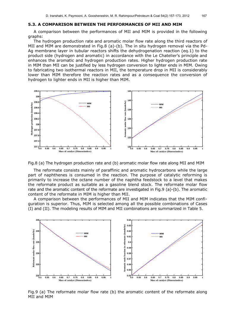
5.3. A COMPARISON BETWEEN THE PERFORMANCES OF MII AND MIM
A comparison between the performances of MII and MIM is provided in the following
graphs:
The hydrogen production rate and aromatic molar flow rate along the third reactors of
MII and MIM are demonstrated in Fig.8 (a)-(b). The in situ hydrogen removal via the Pd-
Ag membrane layer in tubular reactors shifts the dehydrogenation reaction (eq.1) to the
product side (hydrogen and aromatic) in accordance with the Le Chatelier’s principle and
enhances the aromatic and hydrogen production rates. Higher hydrogen production rate
in MIM than MII can be justified by less hydrogen conversion to lighter ends in MIM. Owing
to fabricating two isothermal reactors in MII, the temperature drop in MII is considerably
lower than MIM therefore the reaction rates and as a consequence the conversion of
hydrogen to lighter ends in MII is higher than MIM.
0.5 0.55 0.6 0.65 0.7 0.75 0.8 0.85 0.9 0.95 1237.2
237.4
237.6
237.8
238
238.2
238.4
238.6
238.8
239
239.2
Mass of catalyst (Dimensionless)
Hyd
rogen
pro
du
ctio
n (
km
ole
/hr) MIM
MII
0.5 0.55 0.6 0.65 0.7 0.75 0.8 0.85 0.9 0.95 1130
132
134
136
138
140
142
Mass of catalyst (Dimensionless)
Aro
mati
c m
ola
r fl
ow
rate
(k
mole
/hr)
MIM
MII
Fig.8 (a) The hydrogen production rate and (b) aromatic molar flow rate along MII and MIM
The reformate consists mainly of paraffinic and aromatic hydrocarbons while the large
part of naphthenes is consumed in the reaction. The purpose of catalytic reforming is
primarily to increase the octane number of the naphtha feedstock to a level that makes
the reformate product as suitable as a gasoline blend stock. The reformate molar flow
rate and the aromatic content of the reformate are investigated in Fig.9 (a)-(b). The aromatic
content of the reformate in MIM is higher than MII.
A comparison between the performances of MII and MIM indicates that the MIM confi-
guration is superior. Thus, MIM is selected among all the possible combinations of Cases
(I) and (II). The modeling results of MIM and MII combinations are summarized in Table 5.
0.5 0.55 0.6 0.65 0.7 0.75 0.8 0.85 0.9 0.95 1220
225
230
235
240
245
Mass of catalyst (Dimensionless)
Ref
orm
ate
mo
lar
flo
w r
ate
(k
mo
le/h
r)
MIM
MII
0.5 0.55 0.6 0.65 0.7 0.75 0.8 0.85 0.9 0.95 10.54
0.55
0.56
0.57
0.58
0.59
0.6
0.61
0.62
0.63
0.64
Mass of catalyst (Dimensionless)
Aro
ma
tic
mo
le f
ract
ion
in
ref
orm
ate
(k
mo
le/h
r)
MIM
MII
Fig.9 (a) The reformate molar flow rate (b) the aromatic content of the reformate along
MII and MIM
D. Iranshahi, K. Paymooni, A. Goosheneshin, M. R. Rahimpour/Petroleum & Coal 54(2) 157-173, 2012 167

Table 5 A comparison between the aromatic, hydrogen production rates and the aromatic
content of reformate in the MIM, MII and TTT.
No. Configuration Aromatic
production
(kmol
h)
Hydrogen
production
(kmol
h)
Reformate
production
(kmol
h)
The aromatic mole
percent in reformate
1 TTT 94.2819 235.1570 237.6068 56.1827
2 MIM 102.2119 239.1858 222.1570 63.6594
3 MII 101.3591 237.2135 222.7649 63.1029
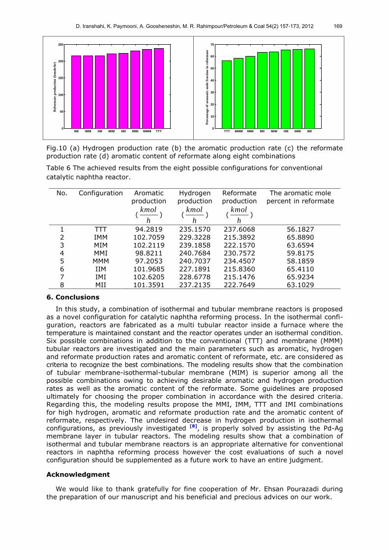
5.4. General guidelines
Some guidelines are provided in this study (Fig.10 (a)-(d)) to select the most proper
combination in accordance with the main desired goal of production.
If the hydrogen production becomes vital as the main goal of naphtha reforming process,
MMI is the best choice among eight proposed combinations (see Fig.10 (a)). Therefore,
MMI configuration can be proposed as a novel configuration for satisfying the increasing
hydrogen demand in refineries for sulfur and nitrogen compounds removal from gasoline
and diesel. Moreover, lighter fuels production can be properly addressed via MMI confi-
guration. This configuration is more reliable to be applied by the process engineers on
account of diminishing the membrane layer area and its maintenance costs in contrast
with the MMM one.
On the other hand, if the aromatic production is the target of naphtha reforming process
to increase the gasoline octane number, the selection can be varied between IMM, IMI
and MIM (see Fig.10 (b)).
TTT (conventional tubular reactor) is obviously the best choice for the reformate production
rate (Fig.10 (c)) because the reformate production rate in isothermal configurations decreases
compared with TTT owing to more conversion of naphthenes and paraffins to lighter ends
(as a result of higher temperature profile).
The purpose of catalytic reforming is primarily to increase the octane number of the naphtha
feedstock to a level that makes the reformate product suitable as a gasoline blend stock.
IMI is definitely the most proper configuration for the purpose of high aromatic content of
reformate according to Fig.10 (d). As high concentration of aromatics in reformates offers
high octane ratings in addition to a rich source of benzene, toluene and particularly xylenes,
IMI configuration can properly address these requirements.
A comparison between the aromatic and hydrogen production rates and the aromatic
content of reformate in eight possible combinations are reported in Table 6. A proper decision
for the selection of the most suitable combination in accordance with the desired and the
state-of-the-art goal of production in the refinery can be made based on the above figures
and Table 6.
IIM IMI IMM TTT MII MIM MMM MMI0
50
100
150
200
250
Hyd
rog
en
pro
du
cti
on
(km
ole
/hr)
TTT MMM MMI MII IIM MIM IMI IMM0
20
40
60
80
100
120
Aro
mati
c p
rod
uct
ion
(k
mole
/hr)
D. Iranshahi, K. Paymooni, A. Goosheneshin, M. R. Rahimpour/Petroleum & Coal 54(2) 157-173, 2012 168
IMI IMM IIM MIM MII MMI MMM TTT0
50
100
150
200
250
Ref
orm
ate
pro
du
ctio
n (
km
ole
/hr)
TTT MMM MMI MII MIM IIM IMM IMI0
10
20
30
40
50
60
70
Per
cen
tag
e o
f a
rom
ati
c m
ole
fra
ctio
n i
n r
efo
rma
te
Fig.10 (a) Hydrogen production rate (b) the aromatic production rate (c) the reformate
production rate (d) aromatic content of reformate along eight combinations
Table 6 The achieved results from the eight possible configurations for conventional
catalytic naphtha reactor.
No. Configuration Aromatic
production
(kmol
h)
Hydrogen
production
(kmol
h)
Reformate
production
(kmol
h)
The aromatic mole
percent in reformate
1 TTT 94.2819 235.1570 237.6068 56.1827
2 IMM 102.7059 229.3228 215.3892 65.8890
3 MIM 102.2119 239.1858 222.1570 63.6594
4 MMI 98.8211 240.7684 230.7572 59.8175
5 MMM 97.2053 240.7037 234.4507 58.1859
6 IIM 101.9685 227.1891 215.8360 65.4110
7 IMI 102.6205 228.6778 215.1476 65.9234
8 MII 101.3591 237.2135 222.7649 63.1029
6. Conclusions
In this study, a combination of isothermal and tubular membrane reactors is proposed
as a novel configuration for catalytic naphtha reforming process. In the isothermal confi-
guration, reactors are fabricated as a multi tubular reactor inside a furnace where the
temperature is maintained constant and the reactor operates under an isothermal condition.
Six possible combinations in addition to the conventional (TTT) and membrane (MMM)
tubular reactors are investigated and the main parameters such as aromatic, hydrogen
and reformate production rates and aromatic content of reformate, etc. are considered as
criteria to recognize the best combinations. The modeling results show that the combination
of tubular membrane-isothermal-tubular membrane (MIM) is superior among all the
possible combinations owing to achieving desirable aromatic and hydrogen production
rates as well as the aromatic content of the reformate. Some guidelines are proposed
ultimately for choosing the proper combination in accordance with the desired criteria.
Regarding this, the modeling results propose the MMI, IMM, TTT and IMI combinations
for high hydrogen, aromatic and reformate production rate and the aromatic content of
reformate, respectively. The undesired decrease in hydrogen production in isothermal
configurations, as previously investigated [8], is properly solved by assisting the Pd-Ag
membrane layer in tubular reactors. The modeling results show that a combination of
isothermal and tubular membrane reactors is an appropriate alternative for conventional
reactors in naphtha reforming process however the cost evaluations of such a novel
configuration should be supplemented as a future work to have an entire judgment.
Acknowledgment
We would like to thank gratefully for fine cooperation of Mr. Ehsan Pourazadi during
the preparation of our manuscript and his beneficial and precious advices on our work.
D. Iranshahi, K. Paymooni, A. Goosheneshin, M. R. Rahimpour/Petroleum & Coal 54(2) 157-173, 2012 169

Nomenclature
Parameter Description, dimension a catalyst activity
A moles of aromatic formed (kmol h-1)
Ac cross-section area of reactor (m2)
C concentration (kmol m-3)
0jC inlet concentration of component j (kmol m-3)
PC specific heat capacity (kJ kmol-1 K-1)
pd particle diameter (m)
eD effective diffusivity (m2s-1)
dE activation energy of catalyst ( J mol-1)
fh heat transfer coefficient (W m-2 K-1)
HC hydrocarbon (kmol h-1)
2H hydrogen (kmol h-1)
i numerator
j numerator
effk effective thermal conductivity (W m-1 s-1)
L length of reactor (m)
m number of reaction
n average carbon number for naphtha
n number of components
Pi partial pressure of i component (kPa)
P total pressure (kPa)
Q volumetric flow rate (m3s-1)
r radius (m)
ri rate of reaction for i reaction (kmol kgcat-1 h-1)
sa specific surface area of catalyst pellet (m2 kg-1)
t time (h)
T temperature of gas phase (K)
refT reference temperature (K)
z reactor length (K)
Greek letters void fraction of catalyst bed
viscosity of gas phase (kg m-1 s-1)
ijv
stoichiometric coefficient of component i in reaction j
b reactor bulk density (kg m-3)
density of gas phase (kg m-3)
H heat of reaction (kJ kmol-1)
s sphericity
Subscripts and Superscript
i numerator for reaction
j numerator for component
n naphthene
p paraffin ss steady state
Abbreviation
FBP final boiling pint (◦C)
IBP initial boiling pint (◦C)
CTR conventional tubular reactor
MMM membrane-membrane-membrane configuration
TBP true boiling point (K)
TTT tubular-tubular-tubular configuration (conventional tubular reactor)
WHSV weight hourly space velocity (h-1)
D. Iranshahi, K. Paymooni, A. Goosheneshin, M. R. Rahimpour/Petroleum & Coal 54(2) 157-173, 2012 170

References
[1] Aitani, A.M. "Catalytic Naphtha Reforming". In "Encyclopedia of Chemical
Processing," Taylor & Francis, (2007). pp. 397-406.
[2] James G, S. "Refinery of the Future". In "The Refinery of the Future," William
Andrew Publishing, Boston, (2011). pp. 315-340.
[3] Kumar, A., G. Gautami, and S. Khanam. "Hydrogen distribution in the refinery
using mathematical modeling". Energy 35(9), 3763-3772 (2010).
[4] Liao, Z., J. Wang, Y. Yang, and G. Rong. "Integrating purifiers in refinery
hydrogen networks: a retrofit case study". Journal of Cleaner Production 18(3),
233-241 (2010).
[5] Antos, G.A., and A.M. Aitani. "Catalytic Naphtha Reforming". 2nd ed. Marcel
Dekker, New York. (2004).
[6] Hu, Y., W. Xu, H. Su, and J. Chu 2004. A dynamic model for naphtha catalytic
reformers. In IEEE International Conference on Control Applications, Taipei. pp.
159-164.
[7] Iranshahi, D., E. Pourazadi, K. Paymooni, A.M. Bahmanpour, M.R. Rahimpour,
and A. Shariati. "Modeling of an axial flow, spherical packed-bed reactor for
naphtha reforming process in the presence of the catalyst deactivation". Int. J.
Hydrogen Energy 35(23), 12784-12799 (2010).
[8] Iranshahi, D., E. Pourazadi, K. Paymooni, and M.R. Rahimpour. "Enhancement
of aromatic production in naphtha reforming process by simultaneous operation
of isothermal and adiabatic reactors". Int. J. Hydrogen Energy 36(3), 2076-
2085 (2011).
[9] Rahimpour, M.R., D. Iranshahi, E. Pourazadi, K. Paymooni, and A.M.
Bahmanpour. "The aromatic enhancement in the axial-flow spherical packed-bed
membrane naphtha reformers in the presence of catalyst deactivation". AlChE
J., (2011).
[10] Anabtawi, J.A., D.S. Redwan, A.M. Al-Jarallah, and A.M. Aitani. "Advances in the
chemistry of catalytic reforming of naphtha". Fuel Sci. Technol. Int. 9(1), 1-23
(1991).
[11] Ball, J.S., G. Dinneen, J. Smith, C. Bailey, and R.V. Meter. "Composition of
Colorado Shale-Oil Naphtha". Industrial & Engineering Chemistry 41(3), 581-
587 (1949).
[12] Berger, C.V., R.F. Denny, and E. Michalko. "Chemistry of HC platforming".
American Chemical Society, Division of Petroleum Chemistry, Preprints 23(3),
(1978).
[13] Fenton Donald, M., H. Hennig, and L. Richardson Ryden. "The Chemistry of
Shale Oil and Its Refined Products". In "Oil Shale, Tar Sands, and Related
Materials," AMERICAN CHEMICAL SOCIETY, (1981). pp. 315-325.
[14] Larraz Mora, R., and R. Arvelo Alvarez. "Catalytic reforming feed
characterisation technique". Oil Gas European Magazine 28(3), 33-35 (2002).
[15] Prestvik, R., K. Moljord, K. Grande, and A. Holmen. "Compositional Analysis of
Naphtha and Reformate". In "Catalytic naphtha reforming," G.A. Antos, and
A.M. Aitani, Eds., Marcel Dekker, New York, (2004). pp. 1-33.
[16] Svetozarova, O.I., S.N. Khadzhiev, E.P. Levashova, G.A. Zubova, I.K.
Romankova, and A.M. Golovenko. "Composition and properties of narrow
naphtha cuts obtained in catalytic cracking of sour or hydrotreated vacuum
distillates". Chem. Technol. Fuels Oils 13(11), 790-793 (1978).
[17] Ali, S.A., J.A. Anabtawi, and K. Alam. "Alternate method to estimate reformate
octane number". Fuel Sci. Technol. Int. 13(5), 545-558 (1995).
[18] Andrade, J.M., S. Muniategui, and D. Prada. "Prediction of clean octane numbers
of catalytic reformed naphthas using FT-m.i.r. and PLS". Fuel 76(11), 1035-
1042 (1997).
[19] Burkhan, O., I.M. Kolesnikov, R.I. Guseinov, and A. Gerbi. "Correlation of the
octane number of the naphtha cut with the aromatic hydrocarbon content".
Chem. Technol. Fuels Oils 43(6), 519-520 (2007).
[20] Lugo, H.J., G. Ragone, and J. Zambrano. "Correlations between octane numbers
and catalytic cracking naphtha composition". Ind. Eng. Chem. Res. 38(5), 2171-
2176 (1999).
[21] Pregger, T., D. Graf, W. Krewitt, C. Sattler, M. Roeb, and S. Möller. "Prospects
D. Iranshahi, K. Paymooni, A. Goosheneshin, M. R. Rahimpour/Petroleum & Coal 54(2) 153-169, 2012 171

of solar thermal hydrogen production processes". Int. J. Hydrogen Energy
34(10), 4256-4267 (2009).
[22] Miltner, A., W. Wukovits, T. Pröll, and A. Friedl. "Renewable hydrogen
production: a technical evaluation based on process simulation". Journal of
Cleaner Production 18, 51-62 (2010).
[23] Urbaniec, K., A. Friedl, D. Huisingh, and P. Claassen. "Hydrogen for a
sustainable global economy". Journal of Cleaner Production 18(0), S1-S3
(2010).
[24] Yang, J., C. Nishimura, and M. Komaki. "Hydrogen permeation of Pd60Cu40
alloy covered V–15Ni composite membrane in mixed gases containing H2S".
Journal of Membrane Science 309(1-2), 246-250 (2008).
[25] Iranshahi, D., A.M. Bahmanpour, E. Pourazadi, and M.R. Rahimpour.
"Mathematical modeling of a multi-stage naphtha reforming process using novel
thermally coupled recuperative reactors to enhance aromatic production". Int. J.
Hydrogen Energy 35(20), 10984-10993 (2010).
[26] Iranshahi, D., M.R. Rahimpour, and A. Asgari. "A novel dynamic radial-flow,
spherical-bed reactor concept for naphtha reforming in the presence of catalyst
deactivation". Int. J. Hydrogen Energy 35(12), 6261-6275 (2010).
[27] Baker, R.W. "Future directions of membrane gas separation technology". Ind.
Eng. Chem. Res. 41(6), 1393-1411 (2002).
[28] Bottino, A., G. Capannelli, and A. Comite. "Catalytic membrane reactors for the
oxidehydrogenation of propane: Eperimental and modelling study". Journal of
Membrane Science 197(1-2), 75-88 (2002).
[29] Brunetti, A., A. Caravella, G. Barbieri, and E. Drioli. "Simulation study of water
gas shift reaction in a membrane reactor". Journal of Membrane Science 306(1-
2), 329-340 (2007).
[30] Criscuoli, A., A. Basile, E. Drioli, and O. Loiacono. "An economic feasibility study
for water gas shift membrane reactor". Journal of Membrane Science 181(1),
21-27 (2001).
[31] Choi, J.S., I.K. Song, and W.Y. Lee. "Performance of double-pipe membrane
reactor comprising heteropolyacid catalyst and polymer membrane for the MTBE
(methyl tert-butyl ether) decomposition". Journal of Membrane Science 166(2),
159-175 (2000).
[32] Sousa, J.M., P. Cruz, and A. Mendes. "Modeling a catalytic polymeric non-porous
membrane reactor". Journal of Membrane Science 181(2), 241-252 (2001).
[33] Lin, Y.M., and M.H. Rei. "Study on the hydrogen production from methanol
steam reforming in supported palladium membrane reactor". Catal. Today 67(1-
3), 77-84 (2001).
[34] Dittmeyer, R., V. Höllein, and K. Daub. "Membrane reactors for hydrogenation
and dehydrogenation processes based on supported palladium". J. Mol. Catal. A:
Chem. 173(1-2), 135-184 (2001).
[35] Shu, J., B.P.A. Grandjean, A. Van Neste, and S. Kaliaguine. "Catalytic palladium-
based membrane reactors. A review". Can. J. Chem. Eng. 69(5), 1036-1060
(1991).
[36] Gobina, E., R. Hughes, D. Monaghan, and D. Arnell. "High-Temperature
Selective Membranes for Hydrogen Separation". Developments in Chemical
Engineering and Mineral Processing 2(2-3), 105-114 (1994).
[37] Okazaki, J., D.A.P. Tanaka, M.A.L. Tanco, Y. Wakui, F. Mizukami, and T.M.
Suzuki. "Hydrogen permeability study of the thin Pd-Ag alloy membranes in the
temperature range across the α-β phase transition". Journal of Membrane
Science 282(1-2), 370-374 (2006).
[38] Rahimpour, M.R., and S. Ghader. "Theoretical investigation of a Pd-membrane
reactor for methanol synthesis". Chem. Eng. Technol. 26(8), 902-907 (2003).
[39] Peters, T.A., M. Stange, H. Klette, and R. Bredesen. "High pressure performance
of thin Pd–23%Ag/stainless steel composite membranes in water gas shift gas
mixtures; influence of dilution, mass transfer and surface effects on the
hydrogen flux". Journal of Membrane Science 316(1-2), 119-127 (2008).
[40] Buxbaum, R.E., and A.B. Kinney. "Hydrogen Transport through Tubular
Membranes of Palladium-Coated Tantalum and Niobium". Industrial &
Engineering Chemistry Research 35(2), 530-537 (1996).
[41] Howard, B.H., R.P. Killmeyer, K.S. Rothenberger, A.V. Cugini, B.D. Morreale,
D. Iranshahi, K. Paymooni, A. Goosheneshin, M. R. Rahimpour/Petroleum & Coal 54(2) 153-169, 2012 172

R.M. Enick, and F. Bustamante. "Hydrogen permeance of palladium-copper alloy
membranes over a wide range of temperatures and pressures". Journal of
Membrane Science 241(2), 207-218 (2004).
[42] Barbieri, G., and F.P. Di Maio. "Simulation of the Methane Steam Re-forming
Process in a Catalytic Pd-Membrane Reactor". Industrial & Engineering
Chemistry Research 36(6), 2121-2127 (1997).
[43] Gobina, E.N., J.S. Oklany, and R. Hughes. "Elimination of ammonia from coal
gasification streams by using a catalytic membrane reactor". Ind. Eng. Chem.
Res. 34(11), 3777-3783 (1995).
[44] Itoh, N. "A membrane reactor using palladium". AlChE J. 33(9), 1576-1578
(1987).
[45] Keuler, J.N., and L. Lorenzen. "Comparing and Modeling the Dehydrogenation of
Ethanol in a Plug-Flow Reactor and a Pd−Ag Membrane Reactor". Industrial &
Engineering Chemistry Research 41(8), 1960-1966 (2002).
[46] Shu, J., B.P.A. Grandjean, and S. Kaliaguine. "Methane steam reforming in
asymmetric Pd- and Pd-Ag/porous SS membrane reactors". Applied Catalysis A:
General 119(2), 305-325 (1994).
[47] Rahimpour, M.R., and S. Ghader. "Enhancement of CO conversion in a novel Pd-
Ag membrane reactor for methanol synthesis". Chemical Engineering and
Processing: Process Intensification 43(9), 1181-1188 (2004).
[48] Tosti, S., A. Basile, L. Bettinali, F. Borgognoni, F. Gallucci, and C. Rizzello.
"Design and process study of Pd membrane reactors". Int. J. Hydrogen Energy
33(19), 5098-5105 (2008).
[49] Nair, B.K.R., J. Choi, and M.P. Harold. "Electroless plating and permeation
features of Pd and Pd/Ag hollow fiber composite membranes". Journal of
Membrane Science 288(1-2), 67-84 (2007).
[50] Sjardin, M., K. Damen, and A. Faaij. "Techno-economic prospects of small-scale
membrane reactors in a future hydrogen-fuelled transportation sector". Energy
31(14), 2523-2555 (2006).
[51] Armor, J.N. "Applications of catalytic inorganic membrane reactors to refinery
products". Journal of Membrane Science 147(2), 217-233 (1998).
[52] Khosravanipour Mostafazadeh, A., M.R. Rahimpour, A. Jahanmiri, and A.K.
Mostafazadeh. "Dynamic simulation and optimization of a dual-type methanol
reactor using genetic algorithms". Chem. Eng. Technol. 31(4), 513-524 (2008).
[53] Domestic Refinery. "Operating Data of Catalytic Reformer Unit" (2005).
[54] Smith, R.B. "Kinetic analysis of naphtha reforming with platinum catalyst".
Chem. Eng. Prog. 55(6), 76-80 (1959).
[55] Ergun, S. "Fluid flow through packed columns". Chem. Eng. Prog. 48, 89-94
(1952).
[56] Abo-Ghander, N.S., J.R. Grace, S.S.E.H. Elnashaie, and C.J. Lim. "Modeling of a
novel membrane reactor to integrate dehydrogenation of ethylbenzene to
styrene with hydrogenation of nitrobenzene to aniline". Chem. Eng. Sci. 63(7),
1817-1826 (2008).
[1] Aitani, A.M. "Catalytic Naphtha Reforming". In "Encyclopedia of Chemical
Processing," Taylor & Francis, (2007). pp. 397-406.
D. Iranshahi, K. Paymooni, A. Goosheneshin, M. R. Rahimpour/Petroleum & Coal 54(2) 153-169, 2012 173
Related Documents


