Hydrogen-fuel-powered bell segments of biomimetic jellyfish This article has been downloaded from IOPscience. Please scroll down to see the full text article. 2012 Smart Mater. Struct. 21 045013 (http://iopscience.iop.org/0964-1726/21/4/045013) Download details: IP Address: 129.110.242.51 The article was downloaded on 21/03/2012 at 15:03 Please note that terms and conditions apply. View the table of contents for this issue, or go to the journal homepage for more Home Search Collections Journals About Contact us My IOPscience

Welcome message from author
This document is posted to help you gain knowledge. Please leave a comment to let me know what you think about it! Share it to your friends and learn new things together.
Transcript

Hydrogen-fuel-powered bell segments of biomimetic jellyfish
This article has been downloaded from IOPscience. Please scroll down to see the full text article.
2012 Smart Mater. Struct. 21 045013
(http://iopscience.iop.org/0964-1726/21/4/045013)
Download details:
IP Address: 129.110.242.51
The article was downloaded on 21/03/2012 at 15:03
Please note that terms and conditions apply.
View the table of contents for this issue, or go to the journal homepage for more
Home Search Collections Journals About Contact us My IOPscience

IOP PUBLISHING SMART MATERIALS AND STRUCTURES
Smart Mater. Struct. 21 (2012) 045013 (17pp) doi:10.1088/0964-1726/21/4/045013
Hydrogen-fuel-powered bell segments ofbiomimetic jellyfish
Yonas Tadesse1,2,3, Alex Villanueva1, Carter Haines2, David Novitski2,Ray Baughman2 and Shashank Priya1
1 Center for Energy Harvesting Materials and Systems (CEHMS), Bio-Inspired Materials and DevicesLaboratory (BMDL), Virginia Tech, Blacksburg, VA 24061, USA2 The Alan G MacDiarmid NanoTech Institute, University of Texas at Dallas, 800 West Campbell Road,Richardson, TX 75080, USA3 Mechanical Engineering Department, University of Texas at Dallas, 800 West Campbell Road,Richardson, TX 75080, USA
E-mail: [email protected]
Received 17 August 2011, in final form 6 February 2012Published 20 March 2012Online at stacks.iop.org/SMS/21/045013
AbstractArtificial muscles powered by a renewable energy source are desired for joint articulation inbio-inspired autonomous systems. In this study, a robotic underwater vehicle, inspired byjellyfish, was designed to be actuated by a chemical fuel source. The fuel-powered musclespresented in this work comprise nano-platinum catalyst-coated multi-wall carbon nanotube(MWCNT) sheets, wrapped on the surface of nickel–titanium (NiTi) shape memory alloy(SMA). As a mixture of oxygen and hydrogen gases makes contact with the platinum, theresulting exothermic reaction activates the nickel–titanium (NiTi)-based SMA. The MWCNTsheets serve as a support for the platinum particles and enhance the heat transfer due to thehigh thermal conductivity between the composite and the SMA. A hydrogen and oxygen fuelsource could potentially provide higher power density than electrical sources. Several vehicledesigns were considered and a peripheral SMA configuration under the robotic bell waschosen as the best arrangement. Constitutive equations combined with thermodynamicmodeling were developed to understand the influence of system parameters that affect theoverall actuation behavior of the fuel-powered SMA. The model is based on the changes inentropy of the hydrogen and oxygen fuel on the composite actuator within a channel. Thespecific heat capacity is the dominant factor controlling the width of the strain for variouspulse widths of fuel delivery. Both theoretical and experimental strains for different diameter(100 and 150 µm) SMA/MWCNT/Pt fuel-powered muscles with dead weight attached at theend exhibited the highest magnitude under 450 ms of fuel delivery within 1.6 mm diameterconduit size. Fuel-powered bell deformation of 13.5% was found to be comparable to that ofelectrically powered (29%) and natural jellyfish (42%).
(Some figures may appear in colour only in the online journal)
1. Introduction
Nanotechnology and biomimetics have enabled the develop-ment of new devices and at the same time improving thefunctionality of existing devices. Biomimetics relies on howclosely one can replicate biological systems with artificialmaterials that ultimately lead to enhanced functionality inengineering systems. Nanotechnology continues to play akey role in the development of novel biomimetic actuation
mechanisms. Recently, emphasis has begun to be placedon bio-inspiration, where one learns the structure–functionrelationship in natural organisms and then develops tech-nology with the objective of surpassing the performanceobserved in nature. One area of focus for bio-inspiredtechnologies has been that of artificial muscles or actuators.High stroke—high stress—low power-consuming artificialmuscles are the most important element in the continueddevelopment of bio-robotics and bio-mechatronics.
10964-1726/12/045013+17$33.00 c© 2012 IOP Publishing Ltd Printed in the UK & the USA
Smart Mater. Struct. 21 (2012) 045013 Y Tadesse et al
There has been continued advances in the area ofartificial muscles [1–3]. Some of the systems that have beeninvestigated include air-powered and pneumatic muscles [3],electrically actuated shape memory alloys [4–7], polymeractuator technologies [2] and carbon nanotube (CNT)actuators [8]. Several geometries and dopant compositionsof polypyrrole actuators have been studied for variousapplications [9–15]. In addition to these electrically poweredactuators, Ebron et al have reported chemically poweredartificial muscles [16], where NiTi shape memory alloy(SMA) wires coated with catalyst platinum particles wereactuated using hydrogen, methanol or formic acid as a fuel. Inthe presence of an oxidant, the NiTi SMA demonstrated highactuation strain (5%) and stress (∼150 MPa). Development offuel-powered SMA actuator systems has been addressed byJun et al [17].
Recently, composite actuator technologies such asbio-inspired shape memory alloy composites (BISMAC) [18]have been employed to achieve the desired actuationfor biomimetic jellyfish applications. Jellyfish have gainedsignificant interest for development of unmanned underseavehicles (UUVs) for monitoring the ocean environment [18,19]. It can be used for surveillance in both military and civilianapplications. Attempts have been made to develop artificialjellyfish using different actuation technologies includingionic polymer metal composite (IPMC) and polypyrrolecomposite (PPy) [20, 21]. In this application, the actuatorneeds to create deformation characteristics similar to that ofnatural jellyfish, resulting in a wake structure that allowsefficient and proficient swimming. Jellyfish are invertebrateswith a relatively simple muscle structure consisting ofradial and circumferential muscles [22–24]. They exist ina multitude of morphologies and exhibit two prominentpropulsion mechanisms, termed ‘rowing’ and ‘jetting’ [25].The advantage of using fuel-powered muscles in artificialjellyfish is the high energy capacity per weight overconventional means. In addition, the fuel-powered technologyhas the following benefits: (1) fuel power actuation is a ‘green’technology that does not need batteries, (2) it has the potentialto regenerate fuel from its surroundings and (3) it has thepotential to develop new components that have access to gasflow or liquid fuels.
The vehicle used in this study is a modified version of theRobojelly described in Villanueva et al [26] and designed tointegrate fuel-powered technology. The bell of the vehicle was16.4 cm diameter and the same geometry as the Aurelia auritamedusa species. This animal consists of a uniform bell whichis almost axisymmetric. The bell is the main part of the body,which is made mostly of mesoglea encased by a skin-likelayer called the epidermis. The subumbrella, referring to theinner part of the bell, houses the circular muscles responsiblefor propulsion. As they contract, the bell closes on itself andejects water to propel the body. The ejected water followsa complex interaction of starting and stopping vortices [27].These vortices have been shown to play a crucial part in theefficiency of the animal’s propulsion mechanism [25]. Aftercontraction, the bell undergoes a relaxation phase where itregains its original shape passively using the elastic energy
stored in the bell structure. In this study, particular attentionwas paid to the bell deformation of the robotic jellyfish.Villanueva et al (2011) [26] have shown that Robojelly isable to achieve a deformation of 29% at the inflection pointwhile the natural animal achieves 42% deformation. Thesedeformations refer to the bell displacement normalized by thecurved length of the bell. Matching the natural deformationis the first step towards replicating the bell dynamics whichwill allow us to meet or exceed the propulsion efficiency andproficiency of the natural animal. The bell configuration usedin this study is a segmented bell with flap configuration. Theflap is a passive membrane that is attached around the activebell segment in order to replicate a similar structure to thatfound in natural jellyfish.
This paper is organized into six sections. Section 1provides the introduction and background to artificial musclebased on a renewable energy source. Section 2 discussesthe theoretical modeling of fuel-powered shape memoryalloys and results from numerical simulation. Section 3describes the synthesis and characterization of fuel-poweredartificial muscle. Section 4 illustrates various designsof artificial jellyfish vehicle and testing under differentenvironmental conditions. Section 5 compares the theoreticaland experimental results and section 6 summarizes the currentstudy.
2. Theoretical study on fuel-powered SMA
2.1. Modeling of fuel-powered SMA
The modeling of the fuel-powered SMA is based on aphenomenological approach and thermodynamic analysis.In our case, the power source is chemical energy and theheat generation is derived based on the entropy equation. Aschematic diagram of the cut-out portion of the fuel-poweredSMA is shown in figure 1.
The chemical reaction of hydrogen and oxygen producingwater and heat (Q) as by-products is given by the balancedchemical equation
H2 +12 O2 → H2O+ Q. (1)
The chemical reaction of hydrogen and oxygen is similarto the chemical reaction in fuel cells. We can consider thesystem as a fuel cell and obtain the heat generated, Q, whichactivates the SMA. The minimum heat generated (heat rise)in a chemical reaction assuming isothermal conditions can bedescribed by the product of the temperature and change inentropy of the reactant and product [29]. Therefore the heatrise can be written as
Q = T(∑
Sreactant −∑
Sproduct
)(2)
where T is the temperature at a given instant, and Sreactantand Sproduct are the entropy of the reactant and products,respectively. The entropy at different pressure (P) andtemperature (T) of the gases assuming ideal gas is given as
S(T,P) = So(T)− R ln(
P
Pref
)(3)
2
Smart Mater. Struct. 21 (2012) 045013 Y Tadesse et al
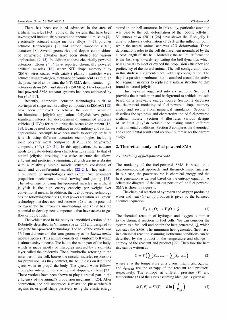
Figure 1. Schematic diagram of the heat transfer in a MWCNT-wrapped SMA composite actuator. (a) Actuator with distinct material and(b) actuator lumped within a control volume shown in green.
where So(T) is the absolute entropy at temperature T andreference pressure Pref (1 atm), and R is the universal gasconstant of 8.3145 (J mol−1 K−1). Therefore, the heat rise inthe reaction of hydrogen and oxygen referencing the balancedequation (1) per mole of the fuel hydrogen can be written as
Q = T(1 mol of H2 ∗ SH2 |T,P +12 mol of O2 ∗ SH2 |T,P
− 1 mol of H2O ∗ SH2O|T,P). (4)
The rate of heat generation is simply the product of mass flowrate and the heat rise:
QT =m
MwQ = nFQ (5)
where m is the mass flow rate of the fuel and Mw is themolecular weight of the fuel. There are several heat losses thatcan be accounted for in the modeling. These losses includeradiation heat loss in the pipe and convection. The mechanismof heat rise in the SMA is due to conduction and convectionbut in this analysis the SMA and MWCNT were considered asa composite material and the material properties were derivedbased upon the rule of mixture of composite materials. Thechange in internal energy of the composite SMA, Pt andMWCNT can be obtained from heat balance as follows:
mccpTs = QT − QL = QT − (Qrad + Qconv1) = Qnet
= Qcond + Qconv2 (6)
where cp is the specific heat capacity of the SMA andMWCNT, mc is the mass of the composite, Ts is thetemperature of the composite, QT is the total heat generateddue to chemical reaction and QL is the total heat loss which isthe sum of Qrad (radiation heat loss) and Qconv1 (convectionheat loss within the channel). The heat rise in the SMA isbasically due to conduction (Qcond) and heat transfer due toconvection (Qconv2) across the Pt–MWCNT layer.
The conduction heat transfer for a one-dimensionalcylindrical surface can be obtained as
qcond = Ak∮−→∇T ·−→dA =
2πkl(Tg − Ts)
ln( r2r1)
(7)
where for a one-dimensional cylindrical surface with radius r1and r2, r2 =
d2 + tc and r1 =
d2 , Tg is the temperature at the
instant the reaction occurs at the surface, Ts is the temperatureof the SMA surface, k is the thermal conductivity of MWCNT,l is the length of SMA, d is the diameter of the SMA andtc is the thickness of the MWCNT and Pt wrapping. Theconvective heat transfer loss in the channel depends on theconvective heat transfer coefficient (h), the surface area of thecomposite (A) and change in temperature:
qconv2 = hA(Tg − Ts). (8)
The radiation heat transfer loss is given by
qrad = εAδ(T4g − T4
w) (9)
where δ is the Stefan–Boltzmann constant(5.6703 × 10⁻⁸ (W m−2 K−4)) and ε is the emissivity of theobject (=1 for a black object). Normal spectral emissivity ofa SWNT forest has been previously studied for a wide rangeof wavelengths between 5 and 12 µm and was found to be0.98 [30].
The overall modeling of the fuel-powered SMA includesthe constitutive relationship of SMA, dynamics and heattransfer. The general one-dimensional governing equationfor a SMA actuator can be obtained from the constitutiverelationship first proposed by Liang and Rogers [31] as
σ − σo = E(ε − εo)+�(ξ − ξo)+ θ(T − To) (10)
where σ , ε, ξ and T represent the stress, strain, fraction ofmartensite and temperature in the SMA actuator, respectively.The subscripts in each symbol represent the initial conditions.Further, E is Young’s modulus, θ is the thermal expansioncoefficient and � is the material transformation coefficientwhich can be obtained from the hysteresis loop of SMA (� =Eεl). The fraction of martensite represents the percentage ofmartensite during transformation. The value ranges between0 and 1 (ξ = 1 for a fully martensitic phase and ξ = 0 for afully austenitic phase). In SMA modeling, the average valueof the modulus of elasticity for austenite and martensite inSMA provides a close approximation to predict the actuator
3

Smart Mater. Struct. 21 (2012) 045013 Y Tadesse et al
response [32, 33]. In fact, the modulus of elasticity of theSMA actuator is dependent on the fraction of martensite andvaries as the internal temperature state changes in time [34].The modulus of elasticity can be written as
E(ξ) = Ea + ξ(Em − Ea) variable modulus, (11a)
E = 0.5(Ea + Em) constant average modulus, (11b)
where Ea and Em are the modulus of elasticity ofaustenite and martensite, respectively. The fraction ofmartensite is one of the characteristic curves (hysteresisloops) of SMA. It is a function of temperature ofthe wire, the transition temperatures and the stress inthe material. Generally, the equation can be obtainedfrom kinetic law. The four characteristic temperatures—martensite start (Ms), martensite finish (Mf), austenitestart (As) and austenite finish (Af)—are dependent onthe stress level. Considering the austenite–martensite andmartensite–austenite transformations as harmonic functionsof cosines, the fraction of martensite with non-zero stress statecan be expressed by (12) [35]
ξM−A =12
{cos
[aA (T − As)−
aA
CAσ
]+ 1
},
martensite to austenite where aA =π
Af − As
(12a)
ξA−M =12
{cos
[aM (T −Mf)−
aM
CMσ
]+ 1
},
austenite to martensite aM =π
Ms −Mf. (12b)
CM and CA are the stress influence coefficients formartensite and austenite. The conditions for the switchingmartensite fraction function are based on the enhancedphenomenological model [36, 37]. These conditions arebasically dependent upon the stress, temperature and the rateform of stress and temperature in the SMA. The condition canbe written as:martensitic phase
if As < T −σ
CA< Af and T −
σ
CA> 0. (13a)
austenitic phase
if Mf < T −σ
CA< Ms and T −
σ
CA< 0. (13b)
The stress influence coefficients, CA and CM, are theslope of stress and transformation temperature [5, 35]. Therate form of the constitutive relationship of the SMA actuatorcan be obtained by taking the first derivative of equation (10)given as
σ = (E)(ε − ε0)+ (E)(ε)+ (�)(ξ − ξ0)
+ (�)(ξ )+ ϑ(T − To)+ ϑ(T). (14)
If the modulus, transformation coefficient and thermal ex-pansion coefficient are assumed to be constant, equation (14)reduces to
σ = (E)(ε)+ (�)(ξ )+ (ϑ)(T). (15)
The rate form of the martensite fraction can be expressed asfollows:
ξM−A = −12
{sin[
aA (T − As)−aA
CAσ
]}×
{(aA)(T)−
aA
CAσ
}(16a)
ξA−M = −12
{sin[
aM(T −Mf)−aM
CMσ
]}×
{(aM)(T)−
aM
CMσ
}. (16b)
The rise in internal temperature of the SMA due to thefuel input can be obtained from equation (6). Rearranging theterms and assuming the actuator as a lumped capacitance, therate of change of temperature is given as
T =1
(mCCcp)(QT − QL). (17)
The specific heat capacity and mass of the actuators aretaken by applying the rule of mixture for composite materials.The specific heat can be expressed as
cp = f cpMWCNT + (1− f )cpSMA (18)
where mC is the mass of the composite actuator (SMA andMWCNT), Ccp is the specific heat capacity of the composite,f = mMWCNT
mTotalis the mass fraction of MWCNT, QT is the total
heat input given by equation (5), QL is the heat losses and Tis the temperature of the wire. The stress, strain, temperatureand fraction of martensite are coupled and cannot be solvedexplicitly. However, the equations can be solved numerically.SimulinkTM block diagrams were created to simultaneouslyobtain the state vector (stress, strain, fraction of martensite,input heat due to chemical reaction and temperature).
Another equation is required to solve the dynamic rela-tionship. The dynamic modeling includes two configurations:(i) when the SMA is lifting a dead weight and (ii) when theSMA is actuating a leaf spring used for the bell segment.To model the bell segment actuation, the SMA is assumedto be attached with a simple spring with stiffness Kst. Thewell-known dynamic equation of motion, assuming damping(c), stiffness (k) and inertial mass (m) with external forceapplied starting from the equilibrium displacement point canbe obtained as
mx+ cx+ kx = Fsma = σAsma (19)
where Asma is the cross-sectional area of the SMA actuator,σ is the stress in the SMA wire and x is the displacementof the tip mass attached to SMA. When the dead weight issuspended at the end of SMA and, if the SMA is not actuated,the wire serves as a spring whose spring constant can bedetermined from the standard spring stiffness of a cord. Thespring stiffness can be obtained from relation = AE
L , whereA is the cross-sectional area of the wire, E is the modulus ofelasticity which is the modulus of martensite (for no externalheat applied) and L is the length of the SMA wire. However,when the SMA is actuated, it provides tension to the wiredue to the stress generated and lifts up the weight attached
4

Smart Mater. Struct. 21 (2012) 045013 Y Tadesse et al
Figure 2. Simulink model of the fuel-powered SMA actuator.
at the end. A stiffness factor kf was used to emphasize orde-emphasize this assumption.
For the bell segment with spring steel embedded withinthe elastomeric substrate, a second-order dynamic equationsimilar to equation (19) can be written. The displacement canbe replaced with rotational angle, the stiffness with torsionalstiffness of the spring and the force with a torque due to theSMA:
Iθ + cθ + ktθ = τsma = σeAsma (20)
where I is the moment of inertia, θ is the rotation angle, kt isthe torsional stiffness, e is the eccentricity of the SMA in thecomposite and τsma is the torque due to the SMA.
To understand the parametric relationship, numericalsimulations were performed. The simulations were performedfor a dead weight attached to the artificial muscle (fuel-powered SMA). Table A.1 (in the appendix) summarizesthe parameters used for the numerical simulation using aSimulink model that utilized the equations presented in thissection.
2.2. Numerical simulation
Numerical simulations were performed to study the variationof various structural and material parameters that affect the
strain response of fuel-powered muscles. As described inthe modeling section, the heat generation is obtained fromthe entropy of the reactant hydrogen and oxygen accountingfor changes in pressure and temperature. In order to reducethe complexity, radiation heat loss was ignored in thenumerical simulation. The factors that affect the performanceare listed in table A.1, namely, martensite start and finishtemperatures, austenite start and finish temperatures, stressinfluence coefficients, heat capacity, density of the SMAand MWCNT, geometrical parameters (length and diameter),fuel properties and fuel inlet conditions (pressure andtemperature). In order to account for the composite properties,the rules of mixtures were applied by obtaining the fractionof MWCNT and calculating the specific heat capacity ofthe composite as described in equation (18). The numericalvalues presented in table A.1 were utilized in a Matlabprogram and a Simulink model. The Matlab program was usedto initiate the Simulink model, to automate the simulationand to obtain the state variables (stress, strain, temperature,heat, transformation temperatures and fraction of martensite).The Simulink model is shown in figure 2. The fuel inputblock provides the type of signals and pulse width ofthe fuel delivery to the heat transfer block with a signalgenerator function or from workspace function. Next, theoutput from the heat transfer block was provided to thephase transformation block which determines the transition
5

Smart Mater. Struct. 21 (2012) 045013 Y Tadesse et al
(a) (b)
(c)
(d)
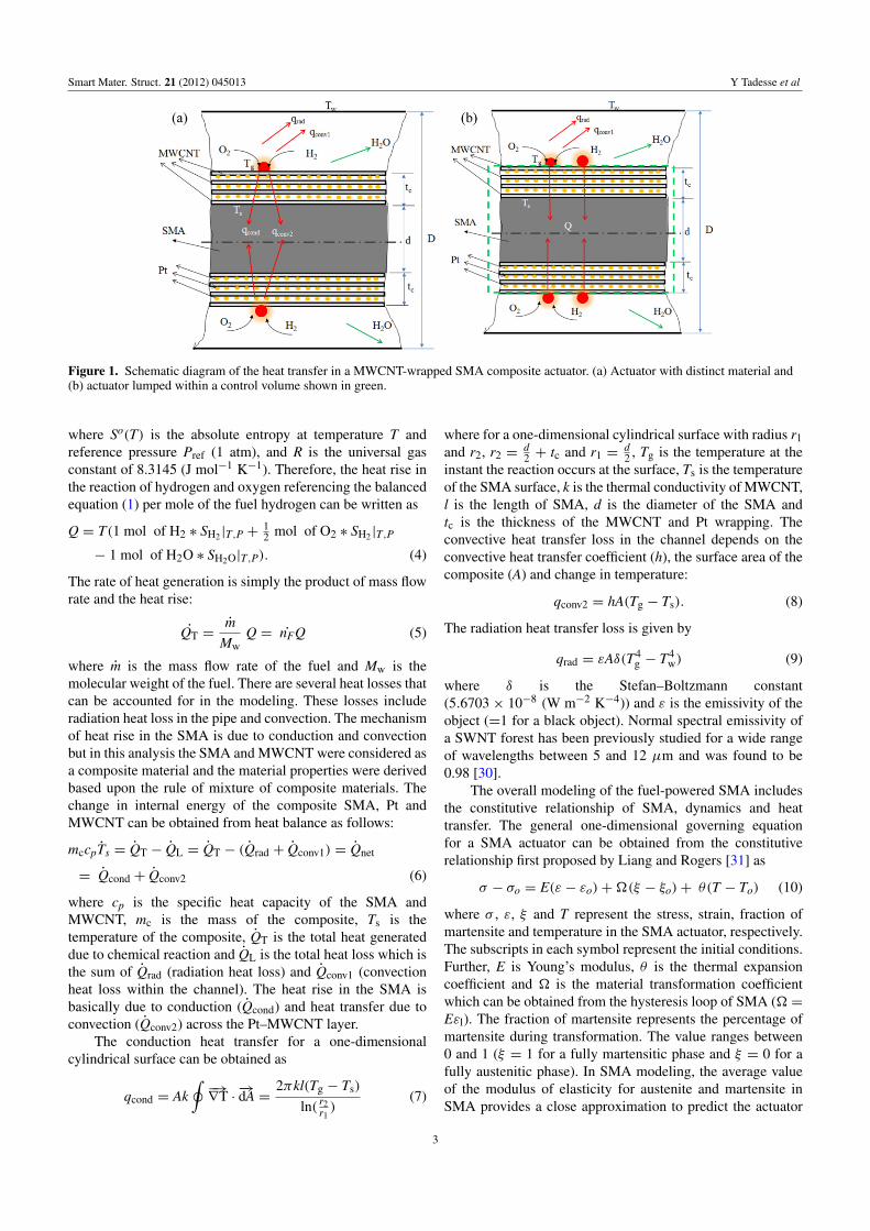
Figure 3. Numerical simulation result of the strain output of fuel-powered muscle with a dead weight attached at the end using values listedin table A.1 and the equations in the modeling section combined with Simulink model: (a) strain at low damping, (b) strain at high damping,(c) strain response for increased heat capacity by a factor of 6 and (d) the variation of maximum strain for variable pulse width of fueldelivery and stiffness factor kf .
temperatures in terms of the stress and temperature changes.At the same time, the output was provided to the constitutiveblock which consists of the constitutive relationship forSMA that outputs the stress rate (shown as σ ). The stressrate (σ ) is integrated to obtain the stress (σ ) and then fedback to the phase transformation block and also to thedynamic block. The output of the dynamic block (strainrate) is connected to a constitutive block with Goto function.It should be noted that the governing relations, describedin the modeling section, are transcendental and switching
functions and can be solved by iteration using initial values.The input pulse width for fuel delivery was varied between200 and 450 ms during the simulation period of 5 s inthe fuel input block. The Simulink model presented here issimilar to the electrically activated SMA described by Tadesseet al [6]. The difference between the Simulink model inelectrically activated SMA and fuel-powered SMA is theaddition of the fuel input block in place of an electricalsource.
6
Smart Mater. Struct. 21 (2012) 045013 Y Tadesse et al
2.3. Simulation results
The numerical simulations were performed using theparameters given in table A.1 (appendix) with a dead weightat the end and various pulse widths of fuel delivery. Theresults of the numerical simulations are shown in figures3(a)–(c). The damping in the system is usually unknown,therefore the damping ratio, ζ was varied (0.1–11) and astiffness coefficient kf was used to vary the contribution ofthe wire as a spring. The numerical simulations show that asmall pulse width of fuel delivery (200 ms) provides a smallerstrain than the higher pulse width (450 ms). This indicatesthat the heat generated did not bring about the changein temperature required to cross the transition temperature.Thus, the transformation of martensite to austenite is notfully complete (partial transformation was encountered).Intuitively, it can be understood that, if the heating is ofshort duration, the heat propagation to the SMA/MWCNTcomposite will be minimal. The decay of the strain is sharpfor the majority of the simulation except at higher dampingas shown in figure 3(b) which remains at remnant strainvalues at the end. As the damping increases the output straindecreases. The specific heat capacity of the composite affectsthe response time significantly. Numerical simulations werecarried out to illustrate this effect and the results are shownin figure 3(d). The heat capacity which was determined byequation (18) was increased six times to account for theuncertainty of the parameter during simulation. From thefigure, it can be seen that the width of the strain outputs isincreased by a factor of 2.5 as compared with figure 3(a).A contour plot of damping value, stiffness factor (kf ) andthe maximum strain obtained at different fuel delivery timesare portrayed in figure 3(d). From this figure, a differenceof 200 ms fuel delivery exhibit relatively large changes inthe maximum strain value change (a difference of 1.5%).A stiffness factor change from 0.4 to 1 also has similarmaximum strain change for most of the fuel delivery time anddamping values. A range of damping values does not have asignificant effect, particularly at low fuel delivery times. Inthe contour plot, the curves with similar colors represent thesame stiffness factor (kf ), whereas various line styles (solid,dashed and dotted lines) represent variable pulse width offuel delivery (pw). For example, a black solid line, blackdashed line and black dotted line correspond to 450, 300 and200 ms of fuel delivery while keeping the stiffness factorconstant at kf = 0.4. The green, blue and red colored curvesrepresent kf = 0.5, 0.8 and 1. The reason for illustratingthis plot is to explain the change in maximum strain fortwo parameters: various fuel deliveries (pw) and the springstiffness factor (kf ) of the actuator. The result is highlydependent on the parameters described in table A.1. However,the simulation results provide insightful information in thedesign and characterization of fuel-powered muscle.
The other state variables obtained from the numericalsimulation are depicted in figure 4 indicating the relationshipof the physical quantities. Figure 4(a) presents the heatgenerated (Q) during the delivery of hydrogen and oxygen atan absolute pressure of 1.212 atm for various pulse widths
of activation. The strain output (ε), fraction of martensite(ξ ), stress (σ ) and temperature (T) are shown as a functionof time in figures 3(a)–(e). In all cases, we can clearly seefuel delivery time playing a key role for the achievable strainmagnitude. In fact, the strain generated is a function ofseveral variables. For example, if the pressure is increased to10 atm, it will not produce any strain because the generatedheat will not propagate to the SMA. The temperature profile(figure 4(e)) is decaying monotonically according to the timeconstant. Figure 4(f) explains the transformation behavior ofmartensite with a hysteresis loop. The loop gets narrow for200 ms fuel delivery than the 450 ms. At the 200 ms delivery,the percentage of martensite transformation is about 60% ascompared to 100% for 450 ms. The temperature profiles aswell as the four transition temperatures of SMA are shownin figure 7(g). In this figure a particular temperature canonly bring about a strain whenever it crosses the transitiontemperature. In figure 7(g) we can see that the temperaturegenerated due to 200 ms and 400 ms pulse of fuel (redcolor and black solid lines, respectively). The transformationtemperatures for each fuel delivery time are also shown.
3. Experimental methods
3.1. Fuel-powered shape memory alloy muscle synthesis
The structure of artificial muscle comprises of commerciallyavailable SMA actuators wrapped with a composite ofMWCNT sheets overlaid with catalytic platinum blackpowder. When hydrogen and oxygen fuel are delivered tothe composite, the platinum catalyst initiates a reaction andthe resulting exothermic heat activates the SMA. Thermalenergy transferred by the chemical reaction causes strain inthe SMA due to the phase transformation. MWCNT has athermal conductivity as high as 150 ± 15 W m−1 K−1 [38]which enhances the heat transfer to SMA. The response timeof this actuator is dependent on the thermodynamic reactionduring injection of fuel and the evacuation in the coolingphase. A schematic diagram of the artificial fuel-poweredmuscle is illustrated in figure 5. The mechanism for drivingthese actuators with hydrogen and oxygen is shown inthis figure. When hydrogen is exposed to finely dividedcatalytic platinum in the presence of oxygen, combustionbecomes thermodynamically favorable. This combustion isused to provide the heat required for SMA to transitionbetween the low temperature martensite phase and the hightemperature austenite phase. An additional benefit of usingpurely hydrogen and oxygen as reactants is that the soleproduct is water.
We have improved upon the previously reporteddesigns [16, 39, 40] by adopting a significantly differentapproach. This involves the usage of MWNT sheets drawnfrom as-grown CNT forests described in detail elsewhere [41,42]. The method utilizes a porous yet mechanically strongnetwork of carbon nanotube bundles to hold finely dividedPt-black catalyst against the SMA wire. A drawing processwas developed to produce CNT wires about 400 mm in lengthby using a semi-automatic lathe that allows radial spinning.When the wire is spinning on the lathe, a thin strip of carbon
7

Smart Mater. Struct. 21 (2012) 045013 Y Tadesse et al
(a) (b)
(c)(d)
(e)(f)
(g)
Figure 4. Numerical simulation result of fuel-powered SMA/MWCNT for various fuel delivery widths: (a) heat input, (b) stress,(c) martensite fraction, (d) strain and (e) temperatures variation in time. (f) Fraction of martensite as a function of temperature and (g) twotypical temperature profiles crossing the boundary of transformation temperatures.
8

Smart Mater. Struct. 21 (2012) 045013 Y Tadesse et al
Figure 5. Schematic diagram of the hydrogen-fuel-powered SMA actuator (dimensions are not to scale).
(a) (b)
(c) (d)
Figure 6. Scanning electron micrographs of the artificial muscles at (a) 200×, (b) 1000× and (c) 5000×. (d) Fabrication of the artificialmuscle.
nanotube bundles draws itself along the wire, wrapping itlike a porous tape. We use this process to our advantage bysupplying a powder of platinum black catalyst that is storedinside this wrapping. Wires made in this fashion have been runfor over 50 000 cycles with little or no degradation in strokeor cycle time. Scanning electron microscopy (SEM) wasutilized to reveal the microstructure of as-synthesized artificialmuscle wires. The results are shown in figure 6 at different
magnifications, revealing that platinum black particles andagglomerations are confined, yet readily accessible, within theconduct CNT mesh. The experiments were repeated severaltimes to confirm the repeatability of all microstructures.
3.2. Characterization
The NiTi wires consisting of Pt-black catalyst wrapped withMWNT sheets were tested to investigate performance under
9

Smart Mater. Struct. 21 (2012) 045013 Y Tadesse et al
(c)
Figure 7. (a) Characteristic of 100 µm diameter and 150 mm long NiTi-wrapped Pt black with MWCNT sheet fuel-powered muscle.(a) Strain generated for various amounts of fuel delivery time under a conduit of 1.5 mm diameter. (b) Schematic diagram of actuation.(c) Energy density of various fuel options that can be used for actuation of the SMA.
various fuel delivery conditions. The actuation of the wire wasmeasured using a digital meter with respect to the time of fueldelivered by using electro-pneumatic valves. As shown in theschematic diagram of figure 7(a), we were able to identifythe characteristics of the actuator by using a conduit sizeof 1.6 mm (1/16 in) inside diameter. After 450 ms of fuelexposure in sheet-wrapped wires, the strain to fuel usage ratiowas found to saturate. These wires are capable of over 2.5%strain per cycle with a full cycle of less than 5 s using passivecooling. Compared to the electrical driving, our techniqueheats the wire from the outside inwards. This is expected
to be the reason for lower strain magnitude since resistiveheating can apply a more even heating profile to the wire.However, there are apparent advantages to our fuel-poweredmuscles. Noting that the energy density of a typical Li-ionbattery is around 1 kJ g−1, which is much lower comparedto that of hydrogen and oxygen gas contained in heavy tanks(5.6 kJ g−1). When using ambient oxygen as fuel, the energydensity is even more favorable. Refueling the system is fasterthan recharging a battery and there is no charge/dischargelifetime for a gas tank as there is in the case of a rechargeablebattery.
10

Smart Mater. Struct. 21 (2012) 045013 Y Tadesse et al
(a) (b)
Figure 8. (a) Centrally actuated design with fuel-powered SMA wires located under the bell and (b) the peripherally actuated design withfuel-powered SMA wires located under the bell. The letters denote the following: A = silicone bell, B = inset of the MWCNT–SMA–Pt,C = MWCNT–SMA–Pt, D = spring steel, E = string, F = structural strut, G = SMA conduit, H = pulleys, I = distributor cap,J = distributor and K = bottom support.
4. Fuel-powered SMA vehicle design and testing
4.1. Vehicle design
Next we describe the method for implementing the MWCNT-based fuel-powered muscle in a jellyfish vehicle. First,a computer-aided design (CAD) model was generated tomimic the Aurelia aurita jellyfish profile that incorporatedthe essential features in using fuel-powered muscle. Variousdesigns were considered to develop the overall systemsuch that the thermodynamic efficiency of the process wasmaximized. The efficiency depends on the rapid transfer ofgenerated heat to the SMA wire and subsequent coolingprocess. The first design was similar to previously developedartificial jellyfish actuated electrically in terms of bothdimension and morphology (Villanueva et al). Eight BISMACactuators surrounded the circumference and each segmentincluded a channel which allowed the flow of hydrogen andoxygen (inlet system), and an exhaust system to remove theburnt fuel out of the tank. The flow was controlled by twosolenoid valves. The mixture of fuel was delivered to eachchannel and the exhaust was collected in a storage tankand finally released to the outside environment. The mainfeatures of this design were: (i) the fuel channel was insidethe silicone-based mesoglea, and (ii) the circular cross sectionof the channel. The major problem was frictional loss ofcatalyst to the silicone wall which limited the performance.The solution to this problem was varying the channel size foroptimum performance. The channel diameter should not belarge because it will limit the heat transferred to the SMAand, at the same time, it should not be small because theentire surface of the actuator will touch the silicone wall,limiting the cooling and deformation [18]. The second designwas based on the notion that, if the channel is designed tohave an elliptical cross-section and the actuator passes througha fixed point in the middle of its length, hence the contact
between the SMA composite and the fuel channel will beminimized. Therefore, during actuation the contact will betangential to the channel and the performance of the actuatorwill not decrease as observed for the circular channel. Themain features of this design were: (i) the attachment of theSMA within the channel at one point and the (ii) the ellipticalsegment geometry. The attachments at the fixed point werefound to increase the relative deformation. This design wasused to evaluate the effect of channel size on actuation ofBISMAC.
Preliminary testing of the BISMAC actuator with theelliptical channel (15 mm× 12 mm outside cross section and150 mm long) was conducted with an electrical power sourceand the deformation obtained for a standard input voltage of27 V m−1 was about 40% transversal deflection. Next, theBISMAC actuator with elliptical channel was tested inside awater tank with sealed connections to prevent the inflow ofwater. For a 5 s period, 40% duty cycle (2 s ON and 3 s OFFtime of fuel delivery), the deformation in water was found tobe 19%. For a 7 s period, 28% duty cycle (2 s ON and 5 sOFF time of fuel delivery), the deformation under water wasfound to be 20%. In both cases, the actuator contracted and theforward and the backward relaxations were not of the samelength. It was noticed that fuel-powered BISMAC actuatorsunder water relaxed faster than in ambient air. This is due tothe increase in heat transfer between the confined surface ofsilicone and water. This in turn suggests that the overall designof fuel-powered jellyfish needs to consider the heat dissipationfactor and the requirement of the cooling mechanism after theactuator is in the relaxing state.
After a number of iterations, two final designs wereconsidered extensively. The schematic diagrams of fuel-powered jellyfish are shown in figures 8(a) and (b). Figure 8(a)is a centrally actuated fuel-powered jellyfish design. In thiscase, the MWCNT–SMA–Pt (C) are kept in a rigid tube (G)secured from the top with the distributor (J and I) and the
11

Smart Mater. Struct. 21 (2012) 045013 Y Tadesse et al
(a)
Figure 9. Fabrication of fuel-powered jellyfish. (a) Computer-aided design of molding set-up, A = cope, B = distributor, C = vehicleinternal support structure, D = drag and E = bottom plate. Parts A and D are the mold used for forming the silicone bell.(b) Hydrogen-fuel-powered Robojelly shown out of water (one fuel pipe is shown). The pins with reflective discs used for deformationtracking can be seen on the bell.
bottom with a support plate (K). Strings (E) are attachedwithin the silicone (A) underneath the spring steel (D). Thegap between the string and the spring is the same as reportedby Villanueva et al [18]. When fuel is injected from the topand passes through the conduit, the actuator deforms, pullingthe strings (E) over the pulley (H). This in turn bends thebell segment during the heating cycle. During the coolingcycle, the spring returns the silicone back to its originalposition. The main features of this design were: (i) one centraltube was required to house all the actuators and (ii) goodsealing for underwater testing. The major concern in this casewas that each bell segment required at least four actuators.This might not be desirable from the cooling point of viewbecause when all are actuated the heat generated will not beremoved in a rapidly, delaying the cyclic response. Thus thedesign was modified with a peripherally actuated structure asshown in figure 8(b). This design was the same as the centralactuation except that each bell segment had fewer actuatorswith their own conduit. The working mechanism is as follows.Injected fuel mixture through the top cap (I) is distributedto each conduit (G) that heats up the SMA due to chemicalreaction. The combusted gases exit through the bottom plate.The conduits (G) are oriented at an angle to the distributor(J) and extend up to the bottom support (K). The rigidity ofthe conduit is maintained by a strut (F) which connects thedistributor and the bottom support. The main features of thisdesign were: (i) each bell segment required 4 SMAs in theconduit, (ii) less time was required to cool and (iii) each bellsegment can be actuated separately by closing the channelinlet.
The peripherally actuated design was modeled in solidmodeling software and the structures were fabricated by usingrapid prototyping. Figure 9(a) illustrates the CAD model of afuel-powered biomimetic jellyfish prototype design followingthe schematic diagram shown in figure 8(b). The fuel modulehas distributor (B), supporting struts (C) and base plate (E).
The distributor has eight nozzles protruded at an angle tothe surface of the distributor. The silicone bell consists ofa two-piece mold, often called cope and drag in castingtechnology. The labeled parts A and D in figure 9(a) are thecope and drag of the mold, respectively. The fuel distributor(B) feeds the fuel mixture to eight pipes in which the actuatorsare anchored at two ends. One end of the actuator is connectedto the bottom plate and the other end to a string. C is thestrut that connects the silicone bell with the bottom plateand its purpose is to provide a rigid support between the topbody of the robot and the bottom plate and it additionallyprovides the connection to the exhaust system. Parts A andD are only used to make the prototype and are removedafter the silicone is cast on the cavity. The prototype wasmade out of a commercial elastomer (Ecoflex 00-10, ReynoldsAdvanced Materials Inc.). First, the spring steel and stringswere assembled on the drag (part A in figure 9(a)) and theelastomer was poured to embed the structures. It is importantto note that the holes made in the distributor might leakthe elastomer and clog the nozzle. Therefore, keeping theelastomeric mixture until it thickens before casting is required.Four BMF100 SMA wires of 110 mm in length were used forone bell segment. During manufacturing the wires must becarefully positioned inside the tubing to avoid contacting theconduit surfaces. Otherwise, any contact would damage theMWCNT coating and reduce deformation. Figure 9(b) is thefinal fuel-powered jellyfish with the silicone bell at the topsupport structure and the artificial muscle in a pipe.
4.2. Vehicle testing and discussion
The deformation experiments were conducted by fixingthe vehicle to a mount and tested in air and underwaterenvironments. The vehicle was clamped at the bottom toprevent it from moving while the bell was allowed to deformfreely. The underwater experiments were done in a water tank
12
Smart Mater. Struct. 21 (2012) 045013 Y Tadesse et al
Air/H2o
(a)(b)
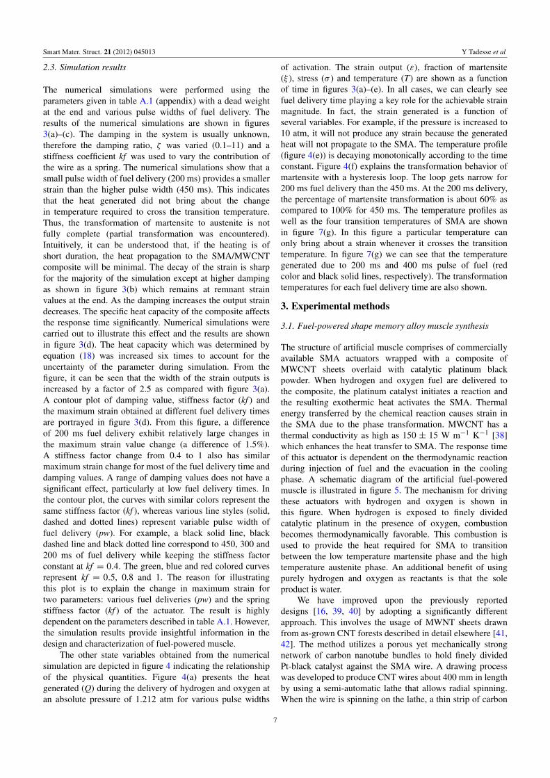
Figure 10. (a) Schematic diagram of the test set-up showing: A = argon gas, B = oxygen gas, C = 5% hydrogen in nitrogen, D = solenoidvalves, E = Robojelly and F = water tank. (b) Bell segment characterization at discrete points on the bell segment.
of 122 cm× 46 cm× 51 cm in size as shown in figure 10(a).A mixture of hydrogen and oxygen was purged by usingsolenoid valves which exited at the bottom after burning inthe conduit. This cycle is the heating cycle. Argon gas wasinjected immediately after the heating cycle to purge outthe remnant gas in the conduit and hence to prevent anyundesired reaction. The hydrogen, oxygen and argon tankswere connected to the vehicle using a pipe with 6 and 3 mmoutside and inside diameters, respectively, and 3 m length.Each gas output was controlled with STC solenoids (SiztoTech Corp., model no. 2P025). The inlet pressure of argon andfuel mixture was 2.5–3.75 Psi as measured right at the outletof the source tank. Actuation for different periods was done bycontrolling the solenoid valve and keeping the same ON time(i.e. 1.5 s ON time and periods of 5, 7 and 10 s). In otherwords, the duty cycle was varied by maintaining the sameheating cycle (30%, 21% and 15% duty cycle). To quantifythe deformation, pins with circular disc were mounted atdifferent locations on the bell segment labeled as in figure 10with letters A–E and tracked with image processing softwaredeveloped in Matlab. The pin heads and shaft at the originaland final deformation were used to calculate the pin basewhich corresponds to the bell surface. Since the pin size isvery small as compared to the bell, the effect of the pin can beignored.
Figures 11(a)–(e) illustrate the characteristic of bellsegment actuation at different locations. Figure 11(a) showsthe deformation behavior at point A, the point attached withthe passive flap. For a 5 s period, the maximum deformationwas 7%: however, this point was not allowed sufficientcooling to return back to its original position for eight cycles.Rather, it oscillates with an amplitude of 2%. For a 7 s periodthe deformation was recovered at 4% and for a 10 s periodthe deformation was fully recovered at 5%. Figure 11(b) isthe deformation behavior of the edge of the bell segment,point B. This point did not return back to its original positionfor a 5 s actuation period. But for 7 and 10 s periods, thereturn amplitude was 2% and 7%, respectively. Figure 11(c)is a deformation characteristic corresponding to point C. Theoverall amplitude for the 5 s period was 3.25% with 0.5%
oscillation. But for 7 and 10 s the amplitude was about 3% andthe return motion was 2% and 2.5%. These results suggest thatthe actuation behavior is typically dependent on the actuationtime and duty cycle. The reason for lower oscillation responseat low period (high frequency) is related to the lower timeconstant of the heat transfer resulting in incomplete cooling.The same behavior was observed at points D and E on thebell segment as shown in figures 11(d) and (e) where thedeformation is below 3% and 1%, respectively.
Next, the characterization was done in water to identifythe practical issues associated with fuel-powered actuation.To this end, the bottom plate of the jellyfish prototype wassecured to a fixed structure under water (figure 12(a)). Then,after making sure that there is no leakage in the prototype, thefuel mixtures were delivered during heating cycles and argongas was used for purging during the cooling cycle. The testingwas conducted at different periods; however, a 10 s periodprovides a full actuation cycle where the bell segment relaxesand contracts completely. Therefore only the 10 s period ispresented here. The characteristic of actuation at the 10 speriod is shown in figure 12(b) and the absolute deformationamplitude for points A, B, C and D were 8.5%, 13.5%, 14%and 0%, respectively. Four locations on the bell were tested inunderwater experiments since the top end of the bell has lessmovement.
The bell in water has a larger deformation than in air.One of the major factors is that water allows the bell to havea greater buoyancy force. This force causes the bell to bemore expanded in the relaxed position. As a result, the SMAwires are fully extended, allowing them to create a greaterdisplacement during contraction. Also, the buoyancy forcehelps the bell regain its original position during relaxation.The electrically activated Robojelly achieves a deformationof 29% in the radial direction [28]. With fuel-powered SMAwe were able to achieve 13.5% deformation at the inflectionpoint. Fuel-powered SMA wires are only expected to deform2–3% as opposed to 4–5% when they are actuated by resistiveheating. This is part of the reason why the contraction doesnot match the deformation of the electrically powered vehicle.Also, the fuel-powered design required the load of the SMA
13

Smart Mater. Struct. 21 (2012) 045013 Y Tadesse et al
(a)(b)
(c) (d)
(e)
Figure 11. Characterization result of the bell segment at various locations in air.
wire to be redirected using a pulley system. The small pulleysresult in force losses due to friction during rotation. Thefuel-powered muscle can potentially achieve a strain of 4–5%for a few cycles, depending on the coating. If there is avariation in coating the NiTi wires, large localized heatingin certain areas will be created. This will result in creepdeformation and limit the life cycle of the actuator. SMAactuation was found to be sensitive to the pressure input ofoxygen and hydrogen, the fuel delivery time and the conduitsize used to house the actuator. The total input pressure andconduit size controlled the gas velocity over the SMA. It wasobserved that a ∼450 ms fuel delivery time within a 1.6 mmconduit size provided maximum strain under a pressure of 2–3psi whereas for 6 mm diameter conduit, a 1.5 s fuel deliverytime provided the maximum strain of the actuator under apressure of 2.5–3.75 psi. These results clearly show that moreheating time is required when a large conduit size is used.Further characterization is required to develop a swimming
biomimetic jellyfish powered by a fuel source where the mainchallenge is placement of the hydrogen source.
5. Comparison of experimental and theoreticalresults of fuel-powered SMA
In this section, we compare the numerical simulations andexperimental results conducted on fuel-powered muscles ofdifferent diameters and lengths. The first comparison wasmade on 150 µm diameter and 100 mm long muscle, andthe second on 100µm diameter and 150 mm long muscle. Thetesting conditions for both were similar during the experimentexcept for the length and diameter of the wire, the deadweight attached, and the mass flow rate. The test parametersfor the simulations and experiments are shown in the captionof each figure and also in the appendix. Figure 13(a) showsthe numerical simulations and experimental result for the150 µm diameter and 100 mm long muscle. The specific heat
14

Smart Mater. Struct. 21 (2012) 045013 Y Tadesse et al
(a)
(b)
Figure 12. (a) Peripherally actuated vehicle seen underwater with deformation tracking pins (A–D). (b) Characteristics of bell segmentdeformation underwater.
(a) (b)
Figure 13. (a) Theoretical and experimental strain of 150 µm diameter and 100 mm length SMA/MWCNT/Pt fuel-powered muscle with a180 g dead weight attached at the end. (b) Theoretical and experimental strains of 100 µm diameter and 150 mm length SMA/MWCNT/Ptfuel-powered muscle with a 200 g dead weight attached at the end.
15

Smart Mater. Struct. 21 (2012) 045013 Y Tadesse et al
capacity determined from the rule of mixture (equation (18))was increased by a certain factor (8× and 6× for the firstand second test, respectively). This was done to account forthe uncertainty in determining the specific heat capacity whichsignificantly affects the width of the strain output at variouspulse widths of fuel delivery. In the simulation, the heatcapacity of the platinum catalysts was not taken into account.Therefore, increasing the heat capacity is a valid argument. Ascan be seen from figure 13(a), the simulation results closelymatch the experimental results for most of the pulse width ofthe fuel delivery. The profile of the strain (magnitude, widthand decay) follows a similar trend for two cycles and thefigure shows the first cycle. Figure 13(b) is the theoretical andexperimental results for the 100 µm diameter and 150 mmlong muscle. Similar to figure 13(a), the strain magnitudesrise up fast at the beginning and return back to the origin,taking a relatively longer time. The strain magnitudes increaseby ∼0.5% for each pulse duration of 200–450 ms similarto the experimental results. The slower response time mightbe due to the thermal mass of the actuator and the remnantheat within the channel during testing. However, the overallresponse time was comparable with the electrically activatedshape memory alloy actuators [5]. The benefit of modelingbased on the physical system is that it provides the influence ofsystem parameters and guides the synthesis of the actuator fora more perfect actuation system to be used in the biomimeticsystem.
6. Summary and conclusion
We report on a hydrogen-fuel-powered artificial jellyfishbell segment. The fuel-powered muscle comprises platinumnanoparticles wrapped with multi-wall carbon nanotube(MWCNT) sheets on the surface of nickel–titanium alloy.A mixture of oxygen and hydrogen produces an exothermicreaction as it encounters the platinum. This reaction activatesthe nickel–titanium (NiTi)-based shape memory alloy actuator(SMA). MWCNT serves as a support for the platinumpowder and enhances the heat transfer due to the highthermal conductivity between the composite and the SMA.Entropy-based modeling of the fuel-powered muscle waspresented and numerical simulations were performed tostudy the characteristics of the actuator. The experimentalcharacterization indicated that the high frequency of actuationdid not return the bell segment to the relaxed state. Theoptimum cyclic condition was found to be 0.1 Hz. Theby-product of the actuation was water vapor, which does notadversely affect the environment. The fuel-powered Robojellywas able to deform 13.5% at the inflection point while theelectrically powered version deformed 29% and the naturalanimal deforms 42%. Limitations in deformation are due toboth the manufacturing technique of the vehicle and in theMWCNT coatings on the SMA.
Acknowledgment
The authors gratefully acknowledge financial support fromthe Office of Naval Research (ONR) through grant no.N000140810654.
Appendix
Table A.1. Numerical simulation parameters.
Parameter Magnitude Unit
Density of SMA ρ = 6.45× 10³ (kg m−3)Length of SMA L = 150× 10−3 a;
100× 10−3 b(m)
Diameter of SMA d = 100× 10−6 a;150× 10−6 b
(m)
Mass of SMA msma = ρπd2L/4 (kg)Cross section of SMA Asma = π
∗d2/4 (m2)Specific heat capacity cpsma = 320 (J kg−1 K−1)Young’s modulus ofaustenite
Da = 75× 109 (Pa)
Young’s modulus ofmartensite
Dm = 28× 109 (Pa)
Austenite starttemperature
As = 88 (◦C)
Austenite finishtemperature
Af = 98 (◦C)
Martensite starttemperature
Ms = 72 (◦C)
Martensite finishtemperature
Mf = 62 (◦C)
Stress influencecoefficient austenite
cA = 10.3 (MPa ◦C−1)
Stress influencecoefficient martensite
cM = 10.3 (MPa ◦C−1)
Density of MWCNT ρmwcnt = 1500 kg m−3
Outside diameter ofMWCNT
Domwcnt =
325× 10−6;205× 10−6 b
(m)
Specific heat capacity ofMWCNT (average fromthree) [43]
cpmwcnt = 609.3 (J kg−1 K−1)
Specific heat capacity ofthe composite
cp = kp∗(f ∗cpmwcnt+
(1− f )cpsma)kp = 6 a, kp = 8 b
(J Kg−1 K−1)
Fuel propertiesAbsolute entropy of H2 SH2 = 130 (kJ kmol−1 K−1)Absolute entropy of O2 SO2 = 205.03 (kJ kmol−1 K−1)Absolute entropy of H2O SH2O = 188.72 (kJ kmol−1 K−1)Molecular weight offuel H2
Mw = 2.016× 10⁻³ (kg mol−1)
Mass flow rate of fuel m = 0.85× 10⁻⁶ a,1.38× 10−6 b
(kg s−1)
Maximum pressure intube (absolute)
P = 1.2125 (atm)
Universal gas constant R = 8.3145 (J mol−1 K−1)Reference pressure Pref = 1 (atm)Initial temperature To = 20 (◦C)Convective heat transfercoefficient (high speedfluid velocity ) [5]
ho = 300, β = 0;h = ho + βT2
(W m−2 C−1)
Mass of dead weight Md = 200× 10−3 a;180× 10−3 b
(kg)
Thermal expansioncoefficient of SMA
Tec = −11× 10−6; (Pa ◦C−1)
Damping ratioζ = C/2
√KM
ζ = variable N s m−1
Fuel delivery pulseperiod
Tp = [200, 250, 300,350 450]
(ms)
a Values used for simulation of 100 µm fuel-powered muscle.b Values used for simulation of 150 µm fuel-powered muscle.
16

Smart Mater. Struct. 21 (2012) 045013 Y Tadesse et al
References
[1] Bar-Cohen Y 2004 Electroactive Polymer (EAP) Actuators asArtificial Muscles : Reality, Potential, and Challenges(Bellingham, WA: SPIE Press)
[2] Mirfakhrai T, Madden J D W and Baughman R H 2007Polymer artificial muscles Mater. Today 10 30–8
[3] Ching-Ping C and Hannaford B 1996 Measurement andmodeling of McKibben pneumatic artificial muscles IEEETrans. Robot. Autom. 12 90–102
[4] Seelecke S and Muller I 2004 Shape memory alloy actuatorsin smart structures: modeling and simulation Appl. Mech.Rev. 57 23–46
[5] Tadesse Y, Thayer N and Priya S 2010 Tailoring the responsetime of shape memory alloy wires through active coolingand pre-stress J. Intell. Mater. Syst. Struct. 21 19–40
[6] Tadesse Y, Hong D and Priya S 2011 Twelve degree offreedom baby humanoid head using shape memory alloyactuators J. Mech. Robot. 3 011008
[7] Garner L J et al 2000 Development of a shape memoryalloy actuated biomimetic vehicle Smart Mater. Struct.9 673
[8] Baughman R H et al 1999 Carbon nanotube actuators Science284 1340–4
[9] Spinks G M et al 2005 Force generation from polypyrroleactuators Smart Mater. Struct. 14 406
[10] Madden J D et al 1999 Encapsulated polypyrrole actuatorsSynth. Met. 105 61–4
[11] Tadesse Y et al 2008 Polypyrrole–polyvinylidene difluoridecomposite stripe and zigzag actuators for use in facialrobotics Smart Mater. Struct. 17 025001
[12] Tadesse Y, Grange R W and Priya S 2009 Synthesis and cyclicforce characterization of helical polypyrrole actuators forartificial facial muscles Smart Mater. Struct. 18 085008
[13] Alici G et al 2006 A methodology towards geometryoptimization of high performance polypyrrole (PPy)actuators Smart Mater. Struct. 15 243
[14] Hara S et al 2006 Tris(trifluoromethylsulfonyl)methide-dopedpolypyrrole as a conducting polymer actuator with largeelectrochemical strain Synth. Met. 156 351–5
[15] Yamamoto T 2010 Molecular assembly and properties ofpolythiophenes NPG Asia Mater. 2 54–60
[16] Ebron V H et al 2006 Fuel-powered artificial muscles Science311 1580–3
[17] Jun H Y et al 2007 Development of a fuel-powered shapememory alloy actuator system: II. Fabrication and testingSmart Mater. Struct. 16 S95
[18] Villanueva A A et al 2010 A bio-inspired shape memory alloycomposite (BISMAC) actuator Smart Mater. Struct.19 025013
[19] Villanueva A et al 2009 Jellyfish inspired unmannedunderwater vehicle EAPAD: Electroactive PolymerActuators and Devices 2009 (March, 2009) (San Diego,CA: SPIE)
[20] Yeom S-W and Oh I-K 2009 A biomimetic jellyfish robotbased on ionic polymer metal composite actuators SmartMater. Struct. 18 085002
[21] Tadesse Y et al 2010 Synthesis and characterization ofpolypyrrole composite actuator for jellyfish unmannedundersea vehicle Proc. SPIE 7642 764222
[22] Gladfelter W B 1972 Structure and function of the locomotorysystem of Polyorchis montereyensis (Cnidaria, Hydrozoa)Helgoland Mar. Res. 23 38–79
[23] Gladfelter W B 1972 Structure and function of the locomotorysystem of the Scyphomedusa Cyanea capillata Mar. Biol.14 150–60
[24] Satterlie R A, Thomas K S and Gray G C 2005 Muscleorganization of the cubozoan jellyfish Tripedaliacystophora conant 1897 Biol. Bull. 209 154–63
[25] Colin S P and Costello J H 2002 Morphology, swimmingperformance and propulsive mode of six co-occurringhydromedusae J. Exp. Biol. 205 427–37
[26] Villanueva A, Smith C and Priya S 2011 Biomimetic roboticjellyfish (Robojelly) using shape memory alloy Biomim.Bioinsp. 6 036004
[27] Dabiri J O et al 2005 Flow patterns generated by oblatemedusan jellyfish: field measurements and laboratoryanalyses J. Exp. Biol. 208 1257–65
[28] Villanueva A et al 2010 Robojelly bell kinematics andresistance feedback control ROBIO: IEEE InternationalConf. on Robotics and Biomimetics 2010
[29] Masters G M 2004 Renewable and Efficient Electric PowerSystems (Hoboken, NJ: Wiley)
[30] Mizuno K et al 2009 A black body absorber from verticallyaligned single-walled carbon nanotubes Proc. Natl Acad.Sci. 106 6044–7
[31] Liang C and Rogers C A 1990 One-dimensionalthermomechanical constitutive relations for shape memorymaterials J. Intell. Mater. Syst. Struct. 1 207–34
[32] Elahinia M H and Ashrafiuon H 2002 Nonlinear control of ashape memory alloy actuated manipulator J. Vib. Acoust.124 566–75
[33] Jayender J et al 2005 Modelling and gain scheduled control ofshape memory alloy actuators CCA 2005: Proc. 2005 IEEEConf. on Control Applications
[34] Zhu S and Zhang Y 2007 A thermomechanical constitutivemodel for superelastic SMA wire with strain-ratedependence Smart Mater. Struct. 16 1696
[35] Leo D J 2007 Engineering Analysis of Smart Material Systems(New York: Wiley)
[36] Elahinia M H and Ahmadian M 2005 An enhanced SMAphenomenological model: I. The shortcomings of theexisting models Smart Mater. Struct. 14 1297
[37] Elahinia M H and Ahmadian M 2005 An enhanced SMAphenomenological model: II. The experimental study SmartMater. Struct. 14 1309
[38] Aliev A E et al 2010 Thermal conductivity of multi-walledcarbon nanotube sheets: radiation losses and quenching ofphonon modes Nanotechnology 21 035709
[39] Seyer D J 2005 Fuel-Powered Artificial Muscles; MechanisticDetails of a Pharmaceutical Process, in Chemistry(Richradson: The University of Texas at Dallas)
[40] Matta-Aoun C 2007 Deposition of catalytic platinum intobucky paper and onto shape memory wires Thesis TheUniversity of Texas at Dallas, Richardson
[41] Zhang M et al 2005 Strong, transparent, multifunctional,carbon nanotube sheets Science 309 1215–9
[42] Lima M D et al 2011 Biscrolling nanotube sheets andfunctional guests into yarns Science 331 51–5
[43] Heo Y J et al 2011 The effect of mesoscopic shape on thermalproperties of multi-walled carbon nanotube mats Curr.Appl. Phys. 11 1144–8
17
Related Documents