3 Hydrodynamic Characteristics of the Main Parts of a Hybrid-Driven Underwater Glider PETREL Wu Jianguo 1 , Zhang Minge 2 and Sun Xiujun 2 1 Shenyang Institute of Automation Chinese Academy of Sciences 2 Tianjin University China 1. Introduction Autonomous Underwater Vehicle (AUV), Remotely Operated Vehicle (ROV) and Autonomous Underwater glider (AUG) are the main autonomous underwater platforms available currently, which play important role in the marine environmental monitering. The relationships between those three types of vehicles were shown in Figure 1. Fig. 1. Underwater Vehicles As a special type of AUV, underwater gliders have many advantages, such as long endurance, low noise and low energy cost. A glider can periodically change its net buoyancy by a hydraulic pump, and utilize the lift from its wings to generate forward motion. The inherent characteristics of a glider can be summarized as buoyancy-driven propulsion, sawtooth pathway, high endurance and slow speed. There exist three legacy gliders named respectively Seaglider, Spray and Slocum [1~6] . In spite that underwater gliders features low level of self noise and high endurance, they also have weaknesses like the lack of maneuverability and the inability to perform a fixed depth or level flight [7] . Driven by a propeller with carried energy source, autonomous underwater vehicles is preprogrammed to carry out an underwater mission without assistance from an operator on the surface. However, they can only cover a relatively short range after each recharge due to the high power consumed for propulsion and generate much more noise than the AUGs because of its propeller and motors [8~10] . The range of AUV’s is restricted by the amount of energy carried on board, can was not more than several hundreds kilometers in general [11] . The performances of the underwater vehicle are compared in Figure 2. www.intechopen.com

Welcome message from author
This document is posted to help you gain knowledge. Please leave a comment to let me know what you think about it! Share it to your friends and learn new things together.
Transcript
3
Hydrodynamic Characteristics of the Main Parts of a Hybrid-Driven Underwater Glider PETREL
Wu Jianguo1, Zhang Minge2 and Sun Xiujun2 1Shenyang Institute of Automation Chinese Academy of Sciences
2Tianjin University China
1. Introduction
Autonomous Underwater Vehicle (AUV), Remotely Operated Vehicle (ROV) and Autonomous Underwater glider (AUG) are the main autonomous underwater platforms available currently, which play important role in the marine environmental monitering. The relationships between those three types of vehicles were shown in Figure 1.
Fig. 1. Underwater Vehicles
As a special type of AUV, underwater gliders have many advantages, such as long endurance, low noise and low energy cost. A glider can periodically change its net buoyancy by a hydraulic pump, and utilize the lift from its wings to generate forward motion. The inherent characteristics of a glider can be summarized as buoyancy-driven propulsion, sawtooth pathway, high endurance and slow speed. There exist three legacy gliders named respectively Seaglider, Spray and Slocum [1~6]. In spite that underwater gliders features low level of self noise and high endurance, they also have weaknesses like the lack of maneuverability and the inability to perform a fixed depth or level flight [7]. Driven by a propeller with carried energy source, autonomous underwater vehicles is preprogrammed to carry out an underwater mission without assistance from an operator on the surface. However, they can only cover a relatively short range after each recharge due to the high power consumed for propulsion and generate much more noise than the AUGs because of its propeller and motors [8~10]. The range of AUV’s is restricted by the amount of energy carried on board, can was not more than several hundreds kilometers in general [11]. The performances of the underwater vehicle are compared in Figure 2.
www.intechopen.com
Autonomous Underwater Vehicles
40
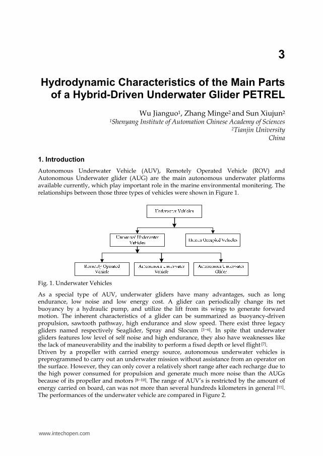
Fig. 2. Performances of three Underwater Vehicles
By combining the advantages of the glider and the propeller-driven AUVs, A hybrid-driven underwater glider PETREL with both buoyancy-driven and propeller-driven systems is developed. Operated in buoyancy-driven mode, the PETREL carries out its mission to collect data in a wide area like a legacy glider. When more exact measurements of a smaller area or level flight are needed, the PETREL will be operated by using the propeller-driven system [5, 7]. This flexible driven glider contributes to have a long range while operated in the buoyancy driven mode like a glider, as well as improve the robust performance to deal with some wicked circumstances by the propeller driven system [7]. Proper hydrodynamic design is important for the improvement of the performance of an underwater vehicle. A bad shape can cause excessive drag, noise, and instability even at low speed. At the initial stage of design, there are two ways to obtain the hydrodynamic data of the underwater vehicle, one is to make model experiment and the other is to use the computational fluid dynamics (CFD). With the development of the computer technology, some accurate simulation analysis of hydrodynamic coefficients have been implemented by using the computational fluid dynamic (CFD) software, instead of by experiments at a much higher cost over the past few years [12-13] . In consideration of the reduced time, lower cost, more flexible and easier optimumal design, the CFD method was used in this article. The fluent Inc.’s (Lebanon,New Hampshire) CFD software FLUENT 6.2 was adopted by this article. This chapter focuses on the hydrodynamic effects of the main parts of a hybrid-driven
underwater glider especially in the glide mode. By analyzing the results of the three main
hydrodynamic parts, the wings, the rudders and the propeller, the characteristics of drag,
glide efficiency and stability will be discussed, and suggestions for altering the HUG’s
design to improve its hydrodynamic performance are proposed.
2. Computational details
2.1 Mathematical model
A criterion for determining of the flow regime of the water when the vehicles moving in it is proposed by Reynolds number [14-15]:
eR vLρ μ=
(1)
Here ρ is the density of water, v is the velocity of vehicle, L is the characteristic length,
μ is the dynamic coefficient of viscosity. The transition point occurred when the Reynolds
No limitationう1kmえ
Several hoursう100kmえ
Several monthsう1000kmえ
ROV
AUV
Time (range)
Man
euv
erab
ilit
y
Low
High
High
Low E
nd
ura
nce
AUG
www.intechopen.com
Hydrodynamic Characteristics of the Main Parts of a Hybrid-Driven Underwater Glider PETREL
41
number is near 610 for the external flow field, which is called critical Reynolds numbers. It
was laminar boundary layer when the 5Re 5 10< × , it was seem as turbulent flow while 6Re 2 10> × . The Reynolds number of the hybrid underwater glider PETREL at two
different steering modes is shown in table 1.
steering mode velocity v / (m/s) Reynolds number
Glider 0.5 1.25×10⁶ AUV 2 5×10⁶
Table 1. The Reynolds number at different steering modes
The turbulence model will be adopted because the Reynolds numbers of the PETREL in two steering modes are all above the critical Reynolds numbers. Computations of drag, lift and moment and flow field are performed for both the model over a range of angles of attack by using the commercially available CFD solver FLUENT6.2. The Reynolds averaged Navier–Stokes equation based on SIMPLAC algorithm and the finite volume method were used by our study. In our study RNG k-ε model was adopted and the second-order modified scheme was applied to discrete the control equations to algebra equations. Assuming that the fluids were continuous and incompressible Newtonian fluids. For the incompressible fluid, the
RNG k ε− transport equations are [12, 16]:
( ) ( )i k eff k k
i j j
kk ku G S
t x x xρ ρ α μ ρε⎛ ⎞∂ ∂ ∂ ∂+ = + − +⎜ ⎟⎜ ⎟∂ ∂ ∂ ∂⎝ ⎠
(2)
2
1 2( ) ( )
i eff k
i j j
u C G C R St x x x k k
ε ε ε ε εε ε ερ ε ρ ε α μ ρ⎛ ⎞∂ ∂ ∂ ∂+ = + − − +⎜ ⎟⎜ ⎟∂ ∂ ∂ ∂⎝ ⎠
(3)
Here kS and Sε are source items, effμ is effective viscosity, kG is turbulence kinetic energy
induced by mean velocity gradient.
' ' j
k i j
i
uG u u
xρ ∂= − ∂
(4)
kσ and εσ is respectively the reversible effect Prandtl number for k and ε .
1 1.42C ε = , 2 1.68C ε =
In the RNG model,a turbulence viscosity differential equation was generated in the non-
dimensional treatment.
2
3
ˆˆd 1.72 d
ˆ 1
k
Cν
ρ ν νεμ ν⎛ ⎞ =⎜ ⎟⎜ ⎟ − +⎝ ⎠
(5)
here, ˆ effμν μ= , 100Cν ≈ . Taking the integral of the(5),the exact description of active
turbulence transport variation with the effective Reynolds number can be acquired, which makes the mode having a better ability to deal with low Reynola number and flow near the wall. For the large Reynola number, the equation(5)can be changed into (3-6).
www.intechopen.com
Autonomous Underwater Vehicles
42
2
t
kCμμ ρ ε=
(6)
Here , 0.0845Cμ = The RNG k ε− model was adopted due to the initial smaller Reynola
number of boundary layer, and the more exact results can be gained by substituting the
differential model into the RNG k ε− model.
2.2 Meshing and boundary conditions
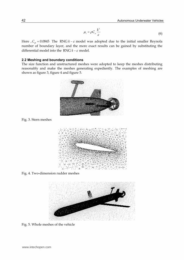
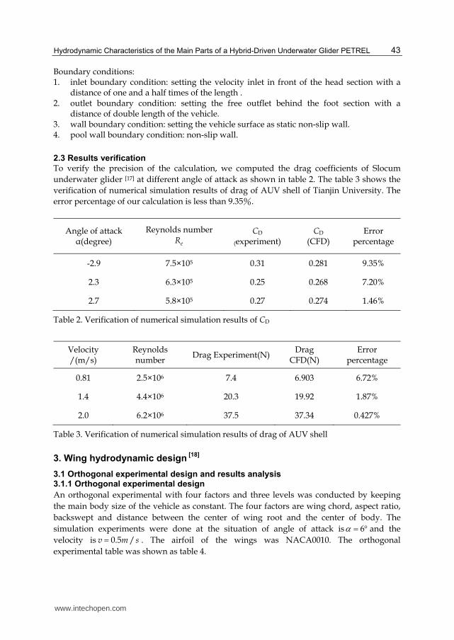
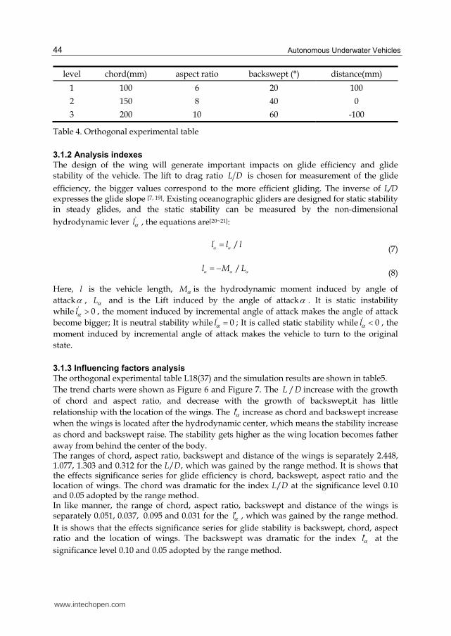
The size function and unstructured meshes were adopted to keep the meshes distributing reasonably and make the meshes generating expediently. The examples of meshing are shown as figure 3, figure 4 and figure 5.
Fig. 3. Stern meshes
Fig. 4. Two-dimension rudder meshes
Fig. 5. Whole meshes of the vehicle
www.intechopen.com
Hydrodynamic Characteristics of the Main Parts of a Hybrid-Driven Underwater Glider PETREL
43
Boundary conditions: 1. inlet boundary condition: setting the velocity inlet in front of the head section with a
distance of one and a half times of the length . 2. outlet boundary condition: setting the free outflet behind the foot section with a
distance of double length of the vehicle. 3. wall boundary condition: setting the vehicle surface as static non-slip wall. 4. pool wall boundary condition: non-slip wall.
2.3 Results verification
To verify the precision of the calculation, we computed the drag coefficients of Slocum
underwater glider [17] at different angle of attack as shown in table 2. The table 3 shows the
verification of numerical simulation results of drag of AUV shell of Tianjin University. The
error percentage of our calculation is less than 9.35%.
Angle of attack α(degree)
Reynolds number
eR CD
(experiment) CD
(CFD) Error
percentage
-2.9 7.5×10⁵ 0.31 0.281 9.35%
2.3 6.3×10⁵ 0.25 0.268 7.20%
2.7 5.8×10⁵ 0.27 0.274 1.46%
Table 2. Verification of numerical simulation results of CD
Velocity /(m/s)
Reynolds number
Drag Experiment(N) Drag
CFD(N) Error
percentage
0.81 2.5×10⁶ 7.4 6.903 6.72%
1.4 4.4×10⁶ 20.3 19.92 1.87%
2.0 6.2×10⁶ 37.5 37.34 0.427%
Table 3. Verification of numerical simulation results of drag of AUV shell
3. Wing hydrodynamic design [18]
3.1 Orthogonal experimental design and results analysis 3.1.1 Orthogonal experimental design
An orthogonal experimental with four factors and three levels was conducted by keeping
the main body size of the vehicle as constant. The four factors are wing chord, aspect ratio,
backswept and distance between the center of wing root and the center of body. The
simulation experiments were done at the situation of angle of attack is 6α = ° and the
velocity is 0.5 /v m s= . The airfoil of the wings was NACA0010. The orthogonal
experimental table was shown as table 4.
www.intechopen.com
Autonomous Underwater Vehicles
44
level chord(mm) aspect ratio backswept (°) distance(mm)
1 100 6 20 100
2 150 8 40 0
3 200 10 60 -100
Table 4. Orthogonal experimental table
3.1.2 Analysis indexes
The design of the wing will generate important impacts on glide efficiency and glide
stability of the vehicle. The lift to drag ratio L D is chosen for measurement of the glide
efficiency, the bigger values correspond to the more efficient gliding. The inverse of L/D expresses the glide slope [7, 19]. Existing oceanographic gliders are designed for static stability in steady glides, and the static stability can be measured by the non-dimensional
hydrodynamic lever 'lα , the equations are[20~21]:
' /l l lα α=
(7)
/l M Lα α α= −
(8)
Here, l is the vehicle length, Mα is the hydrodynamic moment induced by angle of
attackα , Lα and is the Lift induced by the angle of attackα . It is static instability
while ' 0lα > , the moment induced by incremental angle of attack makes the angle of attack
become bigger; It is neutral stability while ' 0lα = ; It is called static stability while ' 0lα < , the
moment induced by incremental angle of attack makes the vehicle to turn to the original
state.
3.1.3 Influencing factors analysis
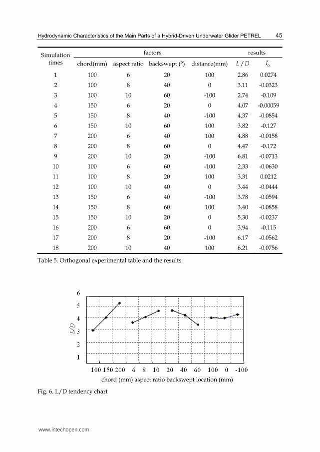
The orthogonal experimental table L18(37) and the simulation results are shown in table5.
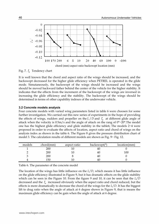
The trend charts were shown as Figure 6 and Figure 7. The /L D increase with the growth
of chord and aspect ratio, and decrease with the growth of backswept,it has little
relationship with the location of the wings. The lα′ increase as chord and backswept increase
when the wings is located after the hydrodynamic center, which means the stability increase
as chord and backswept raise. The stability gets higher as the wing location becomes father
away from behind the center of the body. The ranges of chord, aspect ratio, backswept and distance of the wings is separately 2.448, 1.077, 1.303 and 0.312 for the L/D, which was gained by the range method. It is shows that the effects significance series for glide efficiency is chord, backswept, aspect ratio and the location of wings. The chord was dramatic for the index L/D at the significance level 0.10 and 0.05 adopted by the range method. In like manner, the range of chord, aspect ratio, backswept and distance of the wings is separately 0.051, 0.037, 0.095 and 0.031 for the lα′ , which was gained by the range method.
It is shows that the effects significance series for glide stability is backswept, chord, aspect ratio and the location of wings. The backswept was dramatic for the index lα′ at the
significance level 0.10 and 0.05 adopted by the range method.
www.intechopen.com
Hydrodynamic Characteristics of the Main Parts of a Hybrid-Driven Underwater Glider PETREL
45
Simulation times
factors results
chord(mm) aspect ratio backswept (°) distance(mm) /L D lα′
1 100 6 20 100 2.86 0.0274
2 100 8 40 0 3.11 -0.0323
3 100 10 60 -100 2.74 -0.109
4 150 6 20 0 4.07 -0.00059
5 150 8 40 -100 4.37 -0.0854
6 150 10 60 100 3.82 -0.127
7 200 6 40 100 4.88 -0.0158
8 200 8 60 0 4.47 -0.172
9 200 10 20 -100 6.81 -0.0713
10 100 6 60 -100 2.33 -0.0630
11 100 8 20 100 3.31 0.0212
12 100 10 40 0 3.44 -0.0444
13 150 6 40 -100 3.78 -0.0594
14 150 8 60 100 3.40 -0.0858
15 150 10 20 0 5.30 -0.0237
16 200 6 60 0 3.94 -0.115
17 200 8 20 -100 6.17 -0.0562
18 200 10 40 100 6.21 -0.0756
Table 5. Orthogonal experimental table and the results
Fig. 6. L/D tendency chart
chord (mm) aspect ratio backswept location (mm)
www.intechopen.com
Autonomous Underwater Vehicles
46
Fig. 7. lα′ Tendency chart
It is well known that the chord and aspect ratio of the wings should be increased, and the backswept decreased for the higher glide efficiency when PETREL is operated in the gilde mode. Simutaneously, the backswept of the wings should be increased and the wings should be moved backward father behind the center of the vehicle for the higher stability. It indicates that the effects from the increment of the backswept of the wings are inversed in increasing the glide efficiency and the stability. The backswept of the wings should be determined in terms of other capability indexes of the underwater vehicle.
3.2 Concrete models analysis
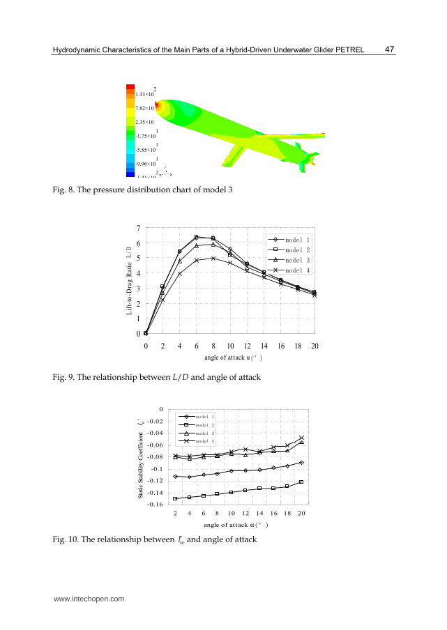
Four concrete models with varied wing parameters listed in table 6 were choosen for some further investigation. We carried out this new series of experiments in the hope of providing the effects of wings, rudders and propeller on the /L D and lα′ at different glide angle of attack when the velocity is 0.5m/s and the angle of attack on the rang of 0°~20°.The model one has the highest glide efficiency and glide stability in the table6; The models 2~4 were proposed in order to evaluate the affects of location, aspect ratio and chord of wings on the analysis index as shown in the table 6. The Figure 8 gives the pressure distribution chart of model 3. The calculation results of different models are shown as Fig. 9~ Fig. 12.
models chord(mm) aspect ratio backswept(°) location(mm)
1 200 10 40 0 2 200 10 40 100 3 200 8 40 0 4 150 10 40 0
Table 6. The parameter of the concrete model
The location of the wings has little influence on the L/D, which means it has little influence on the glide efficiency illustrated in Figure 9, but it has dramatic effects on the glide stability which can be seen in the Figure 10. From the figure 9 and 10, it can be seen that the L/D decreased and the lα′ increased obviously when the aspect ratio and chord reduced, but the effects is more dramatically to decrease the chord of the wings for the L/D. It has the biggest lift to drag ratio when the angle of attack at 6 degree shown in Figure 9, that is means the maximum glide efficiency can be gain when the angle of attack at 6 degree.
chord (mm) aspect ratio backswept location (mm)
www.intechopen.com
Hydrodynamic Characteristics of the Main Parts of a Hybrid-Driven Underwater Glider PETREL
47
Fig. 8. The pressure distribution chart of model 3
0
1
2
3
4
5
6
7
0 2 4 6 8 10 12 14 16 18 20
angle of attack α(°)
Lif
t-to
-Dra
g R
ati
o L/D
model 1
model 2
model 3
model 4
Fig. 9. The relationship between L/D and angle of attack
-0.16
-0.14
-0.12
-0.1
-0.08
-0.06
-0.04
-0.02
0
2 4 6 8 10 12 14 16 18 20
angle of at tack α(°)
Sta
tic
Sta
bility C
oeff
icie
nt lα’
model 1
model 2
model 3
model 4
Fig. 10. The relationship between lα′ and angle of attack
1.33×10²
7.82×101
2.35×10
-1.75×101
-5.85×101
-9.96×101
1 41×102
www.intechopen.com
Autonomous Underwater Vehicles
48
0
0.05
0.1
0.15
0.2
0.25
0.3
0.35
0.4
0 2 4 6 8 10 12 14 16 18 20
angle of attack α(°)
The
dra
g r
atio o
f ru
dder
s an
d p
ropel
ler
model 1
model 2
model 3
model 4
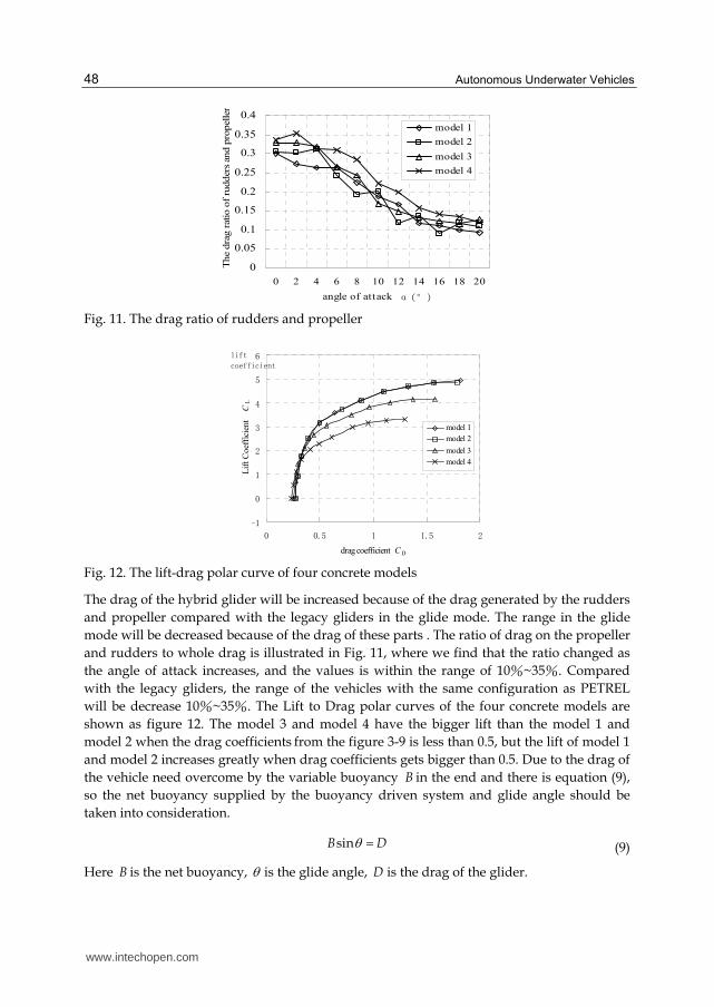
Fig. 11. The drag ratio of rudders and propeller
-1
0
1
2
3
4
5
6
0 0.5 1 1.5 2
drag coefficient CD
Lif
t C
oef
fici
ent
C
L
model 1
model 2
model 3
model 4
lift
coefficient
Fig. 12. The lift-drag polar curve of four concrete models
The drag of the hybrid glider will be increased because of the drag generated by the rudders
and propeller compared with the legacy gliders in the glide mode. The range in the glide
mode will be decreased because of the drag of these parts . The ratio of drag on the propeller
and rudders to whole drag is illustrated in Fig. 11, where we find that the ratio changed as
the angle of attack increases, and the values is within the range of 10%~35%. Compared
with the legacy gliders, the range of the vehicles with the same configuration as PETREL
will be decrease 10%~35%. The Lift to Drag polar curves of the four concrete models are
shown as figure 12. The model 3 and model 4 have the bigger lift than the model 1 and
model 2 when the drag coefficients from the figure 3-9 is less than 0.5, but the lift of model 1
and model 2 increases greatly when drag coefficients gets bigger than 0.5. Due to the drag of
the vehicle need overcome by the variable buoyancy B in the end and there is equation (9),
so the net buoyancy supplied by the buoyancy driven system and glide angle should be
taken into consideration.
sinB Dθ = (9)
Here B is the net buoyancy, θ is the glide angle, D is the drag of the glider.
www.intechopen.com
Hydrodynamic Characteristics of the Main Parts of a Hybrid-Driven Underwater Glider PETREL
49
3.3 Results and discussion
The orthogonal experiment shows that glide efficiency is most significantly influenced by the chord length while stability of the vehicle is most remarkably affected by the sweep angle. Further numerical calculations based on four specific models with the attack angle in the range of 0°-20° indicate that location of the wings mainly affects glide stability but has little influence on glide efficiency. When the vehicle glides at about 6° attack angle it has the maximum ratio of lift to drag. The range of the hybrid glider with the same configuration as PETREL will be decrease 10%~35% compared with the legacy gliders.
4. Rudder hydrodynamic design [22]
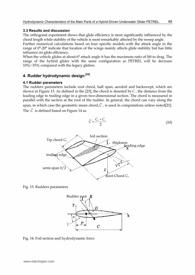
4.1 Rudder parameters The rudders parameters include root chord, half span, aerofoil and backswept, which are shown in Figure 13. As defined in the [23], the chord is denoted by C , the distance from the leading edge to trailing edge in a given two-dimensional section. The chord is measured in parallel with the section at the root of the rudder. In general, the chord can vary along the
span, in which case the geometric mean chord, C , is used in computations unless noted[21].
The C is defined based on Figure 14 as
2t r
C CC
+=
(10)
Fig. 13. Rudders parameters
Fig. 14. Foil section and hydrodynamic force
Rudder post
Tip chord Ct
semi-span b/2
foil section
thickness leading edge
trailing edge
Root Chord Cr
www.intechopen.com
Autonomous Underwater Vehicles
50
The semi-span, denoted by / 2b , measures the distance from the rudder root to tip along the
line perpendicular to the root section. The span, in this work, is twice as long as the root-to-
tip distance for an isolated plan. The hydrodynamic forces including lift and drag acted on
the aerofoil is shown in Figure 14 and can be expressed as
21 2
LL C AVρ=
(11)
21 2
DD C AVρ=
(12)
Here, ρ is the density of the water; LC is the lift coefficient; DC is the drag coefficient; A is
the area of rudder; V is the velocity of water; α is the angle of attack. The rudderpost
location is expressed by P , which is shown in Figure 14.
4.2 Foil section
The geometry of a rudder is mainly defined by the two-dimensional foil section. The symmetrical foil sections are generally used by the underwater vehicles. Many types of the foil sections are proposed by many countries to improve the hydrodynamic performance. The famous foil sections series include NACA series, HEЖ series, ЦАГИ series, and JFS series [21], among which the four-digit NACA sections are most widely used for underwater vehicle rudders in that it provides the higher lift and the lower drag. The four-digit NACA section series is a low velocity foil sections series, and have a bigger radius of leading edge and a plumpy head section, which is suitable for the rudder of underwater vehicles at low velocity. In this work, the four digit NACA00×× section was used, where the ×× denote the thickness-to-chord ratio. The lift coefficient and drag coefficient of the foil sections can be calculated as
L 21 2
LC
V Cρ= (13)
D 21 2
DC
V Cρ= (14)
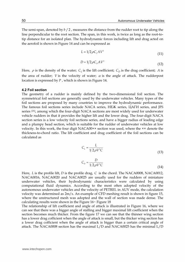
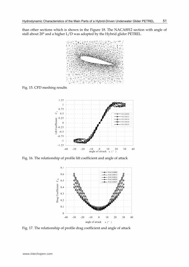
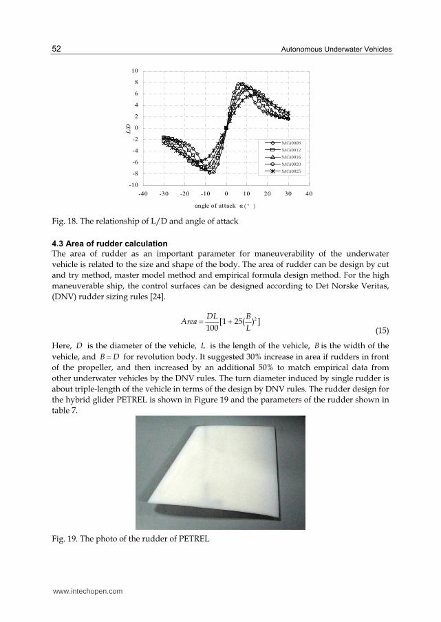
Here, L is the profile lift, D is the profile drag, C is the chord. The NACA0008, NACA0012, NACA0016, NACA0020 and NACA0025 are usually used for the rudders of miniature underwater vehicles, their hydrodynamic characteristics were calculated by using computational fluid dynamics. According to the most often adopted velocity of the autonomous underwater vehicles and the velocity of PETREL in AUV mode, the calculation velocity was determined as 2m/s. An example of CFD meshing result is shown in figure 15, where the unstructured mesh was adopted and the wall of section was made dense. The calculating results were shown in the Figure 16~ Figure 18 The relationship of lift coefficient and angle of attack is illustrated in Figure 16, where we can see that there was a bigger angle of stalling and bigger maximal lift coefficient when the section becomes much thicker. From the figure 17 we can see that the thinner wing section has a lower drag cofficient when the angle of attack is small, but the thicker wing section has a lower drag cofficient when the angle of attack is bigger than a certain critical angle of attack. The NACA0008 section has the maximal L/D and NACA0025 has the minimal L/D
www.intechopen.com
Hydrodynamic Characteristics of the Main Parts of a Hybrid-Driven Underwater Glider PETREL
51
than other sections which is shown in the Figure 18. The NACA0012 section with angle of stall about 20° and a higher L/D was adopted by the Hybrid glider PETREL.
Fig. 15. CFD meshing results
-1.25
-1
-0.75
-0.5
-0.25
0
0.25
0.5
0.75
1
1.25
-40 -30 -20 -10 0 10 20 30 40angle of at t ack
α(°)
Lif
t C
oef
fici
ent C
L
NACA0008
NACA0012
NACA0016
NACA0020
NACA0025
Fig. 16. The relationship of profile lift coefficient and angle of attack
0
0.1
0.2
0.3
0.4
0.5
0.6
0.7
-40 -30 -20 -10 0 10 20 30 40
angle of attack α(°)
Dra
g C
oef
fici
ent C
D
NACA0008
NACA0012
NACA0016NACA0020
NACA0025
Fig. 17. The relationship of profile drag coefficient and angle of attack
www.intechopen.com
Autonomous Underwater Vehicles
52
-10
-8
-6
-4
-2
0
2
4
6
8
10
-40 -30 -20 -10 0 10 20 30 40
angle of at tack α(°)
L/D
NACA0008
NACA0012
NACA0016
NACA0020
NACA0025
Fig. 18. The relationship of L/D and angle of attack
4.3 Area of rudder calculation
The area of rudder as an important parameter for maneuverability of the underwater
vehicle is related to the size and shape of the body. The area of rudder can be design by cut
and try method, master model method and empirical formula design method. For the high
maneuverable ship, the control surfaces can be designed according to Det Norske Veritas,
(DNV) rudder sizing rules [24].
2[1 25( ) ]100
DL BArea
L= +
(15)
Here, D is the diameter of the vehicle, L is the length of the vehicle, B is the width of the
vehicle, and B D= for revolution body. It suggested 30% increase in area if rudders in front
of the propeller, and then increased by an additional 50% to match empirical data from
other underwater vehicles by the DNV rules. The turn diameter induced by single rudder is
about triple-length of the vehicle in terms of the design by DNV rules. The rudder design for
the hybrid glider PETREL is shown in Figure 19 and the parameters of the rudder shown in
table 7.
Fig. 19. The photo of the rudder of PETREL
www.intechopen.com
Hydrodynamic Characteristics of the Main Parts of a Hybrid-Driven Underwater Glider PETREL
53
parameters Tip chord tC Root chord rC Semi-span / 2b section
Value 125mm 200mm 120mm NACA0012
Table 7. The parameters of the rudder
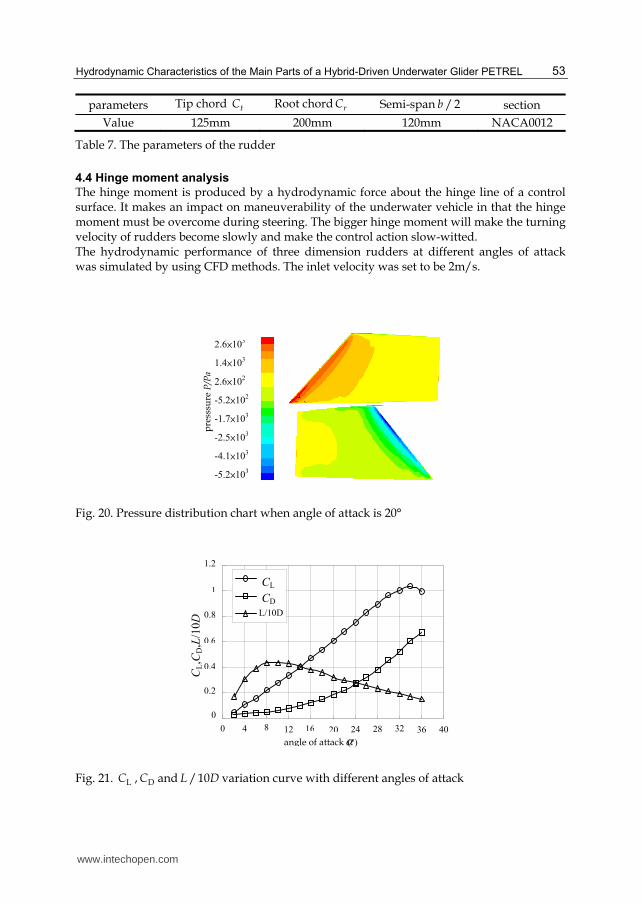
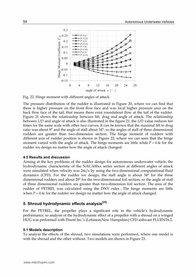
4.4 Hinge moment analysis
The hinge moment is produced by a hydrodynamic force about the hinge line of a control surface. It makes an impact on maneuverability of the underwater vehicle in that the hinge moment must be overcome during steering. The bigger hinge moment will make the turning velocity of rudders become slowly and make the control action slow-witted. The hydrodynamic performance of three dimension rudders at different angles of attack was simulated by using CFD methods. The inlet velocity was set to be 2m/s.
Fig. 20. Pressure distribution chart when angle of attack is 20°
Fig. 21. LC , DC and /10L D variation curve with different angles of attack
0
0.2
0.4
0.6
0.8
1
1.2
0 4 8 12 16 20 24 28 32 36 40
angle of attackα (°)
L/10D
CL
CD
CL,C
D,L
/10D
p
ress
sure
P/P
a
2.6×10³
1.4×10³
2.6×10
2
-5.2×10
2
-1.7×10
3
-2.5×10
3
-4.1×10
3
-5.2×10
3
www.intechopen.com
Autonomous Underwater Vehicles
54
-0.15
-0.1
-0.05
0
0.05
0.1
0.15
0.2
0.25
0.3
0 4 8 12 16 20 24 28
angle of attack α(°)
Hin
ge M
om
en
t C
oeff
icie
nt C
M
P=0.2c
P=0.25cP=0.3c
P=0.35cP=0.4c
P=0.45cP=0.5c
P=0.55c
Fig. 22. Hinge moment with different angles of attack
The pressure distribution of the rudder is illustrated in Figure 20, where we can find that there is higher pressure on the front flow face and was local higher pressure area on the back flow face of the tail, that means there exist roundabout flow at the tail of the rudder. Figure 21 shows the relationship between lift, drag and angle of attack. The relationship between L/D and angle of attack is also illustrated in the figure 21, the L/D value reduces ten times for the same scale with other two curves. It can be known that the maximal lift to drag ratio was about 8° and the angle of stall about 34°, so the angles of stall of three dimensional rudders are greater than two-dimension section. The hinge moment of rudders with different axis of rudder position is shown in Figure 22, where we can seen that the hinge moment varied with the angle of attack. The hinge moments are little while 0.4P c= for the rudder we design no matter how the angle of attack changed.
4.5 Results and discussion
Aiming at the key problems of the rudder design for autonomous underwater vehicle,the hydrodynamic characteristic of the NACA00xx series section at different angles of attack were simulated when velocity was 2m/s by using the two-dimensional computational fluid dynamics (CFD). For the rudder we design, the stall angle is about 34° for the three dimensional rudders and about 20° for the two-dimensional foil section, so the angle of stall of three dimensional rudders are greater than two-dimension foil section. The area of the rudder of PETREL was calculated using the DNV rules;The hinge moments are little
when 0.4P c= for the rudder we design no matter how the angle of attack changed.
5. Shroud hydrodynamic effects analysis[25]
For the PETREL, the propeller plays a significant role in the vehicle’s hydrodynamic performance, so analysis of the hydrodynamic effect of a propeller with a shroud on a winged HUG was performed with Fluent Inc.’s (Lebanon,New Hampshire) CFD software FLUENT6.2.
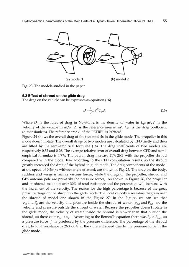
5.1 Models description
To analyze the effects of the shroud, two simulations were performed, where one model is with the shroud and the other without. Two models are shown in Figure 23.
www.intechopen.com
Hydrodynamic Characteristics of the Main Parts of a Hybrid-Driven Underwater Glider PETREL
55
(a) model 1 (b) model 2
Fig. 23. The models studied in the paper
5.2 Effect of shroud on the glide drag
The drag on the vehicle can be expresses as equation (16).
21
2DD V C Aρ= (16)
Where, D is the force of drag in Newton, ρ is the density of water in kg/m³,V is the
velocity of the vehicle in m/s, A is the reference area in m², DC is the drag coefficient
(dimensionless). The reference area A of the PETREL is 0.096m2.
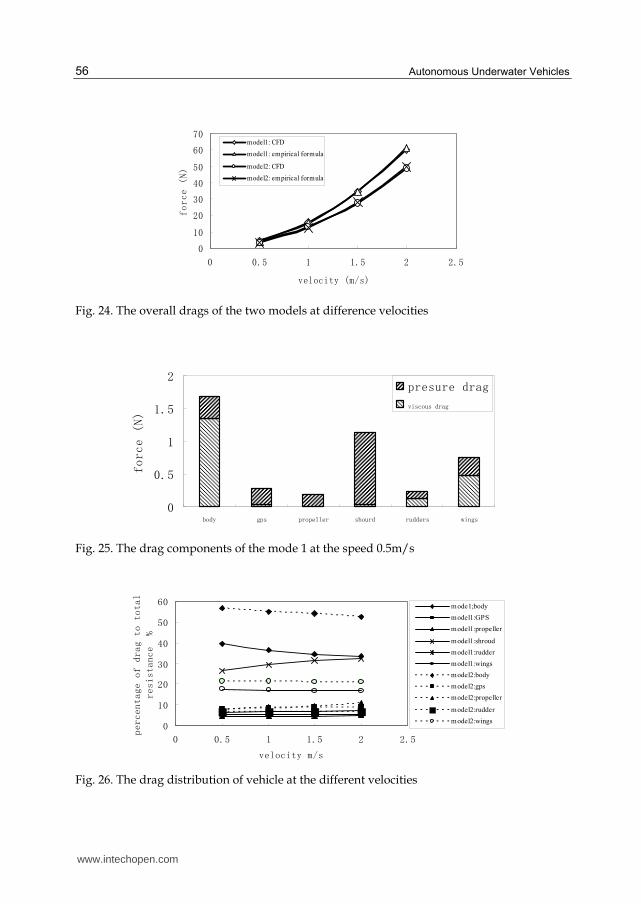
Figure 24 shows the overall drag of the two models in the glide mode. The propeller in this
mode doesn’t rotate. The overall drags of two models are calculated by CFD firstly and then
are fitted by the semi-empirical formulae (16). The drag coefficients of two models are
respectively 0.32 and 0.26. The average relative error of overall drag between CFD and semi-
empirical formulae is 4.7%. The overall drag increase 21%-26% with the propeller shroud
compared with the model two according to the CFD computation results, so the shroud
greatly increased the drag of the hybrid in glide mode. The drag components of the mode1
at the speed of 0.5m/s without angle of attack are shown in Fig. 25. The drag on the body,
rudders and wings is mainly viscous forces, while the drags on the propeller, shroud and
GPS antenna pole are primarily the pressure forces,. As shown in Figure 26, the propeller
and its shroud make up over 30% of total resistance and the percentage will increase with
the increment of the velocity. The reason for the high percentage is because of the great
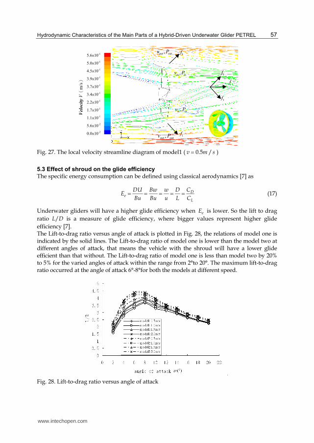
pressure drags on the shroud in the glide mode. The local velocity streamline diagram near
the shroud of model one shown in the Figure 27. In the Figure, we can see that
inv and inP are the velocity and pressure inside the shroud of water, outv and outP are the
velocity and pressure outside the shroud of water. Because the propeller doesn’t rotate in
the glide mode, the velocity of water inside the shroud is slower than that outside the
shroud, so there exits out inv v> . According to the Bernoulli equation there was in outP P> , so
a pressure force f is produced by the pressure difference. The percentage of the shroud
drag to total resistance is 26%-35% at the different speed due to the pressure force in the
glide mode.
www.intechopen.com
Autonomous Underwater Vehicles
56
0
10
20
30
40
50
60
70
0 0.5 1 1.5 2 2.5
velocity (m/s)
force (N)
model1: CFD
model1: empirical formula
model2: CFD
model2: empirical formula
Fig. 24. The overall drags of the two models at difference velocities
0
0.5
1
1.5
2
body gps propeller shourd rudders wings
force (N)
presure drag
viscous drag
Fig. 25. The drag components of the mode 1 at the speed 0.5m/s
0
10
20
30
40
50
60
0 0.5 1 1.5 2 2.5
velocity m/s
percentage of drag to total
resistance %
mode1;body
model1:GPS
model1:propeller
model1:shroud
model1:rudder
model1:wings
model2:body
model2:gps
model2:propeller
model2:rudder
model2:wings
Fig. 26. The drag distribution of vehicle at the different velocities
www.intechopen.com
Hydrodynamic Characteristics of the Main Parts of a Hybrid-Driven Underwater Glider PETREL
57
Fig. 27. The local velocity streamline diagram of model1 ( 0.5 /v m s= )
5.3 Effect of shroud on the glide efficiency
The specific energy consumption can be defined using classical aerodynamics [7] as
De
L
DU Bw w D CE
Bu Bu u L C= = = = = (17)
Underwater gliders will have a higher glide efficiency when eE is lower. So the lift to drag
ratio L/D is a measure of glide efficiency, where bigger values represent higher glide
efficiency [7]. The Lift-to-drag ratio versus angle of attack is plotted in Fig. 28, the relations of model one is indicated by the solid lines. The Lift-to-drag ratio of model one is lower than the model two at different angles of attack, that means the vehicle with the shroud will have a lower glide efficient than that without. The Lift-to-drag ratio of model one is less than model two by 20% to 5% for the varied angles of attack within the range from 2°to 20°. The maximum lift-to-drag ratio occurred at the angle of attack 6°-8°for both the models at different speed.
Fig. 28. Lift-to-drag ratio versus angle of attack
out out,v P
out out,v P
f
in in,v P
in in,v P
1f
1f
1f
1f
5.6×10⁻¹
5.0×10⁻¹
4.5×10⁻¹
3.9×10⁻¹
3.7×10⁻¹
3.4×10⁻¹
2.2×10⁻¹
1.7×10⁻¹
1.1×10⁻¹
5.6×10⁻²
0.0×10⁻²
Velocity
Vm
/s
www.intechopen.com
Autonomous Underwater Vehicles
58
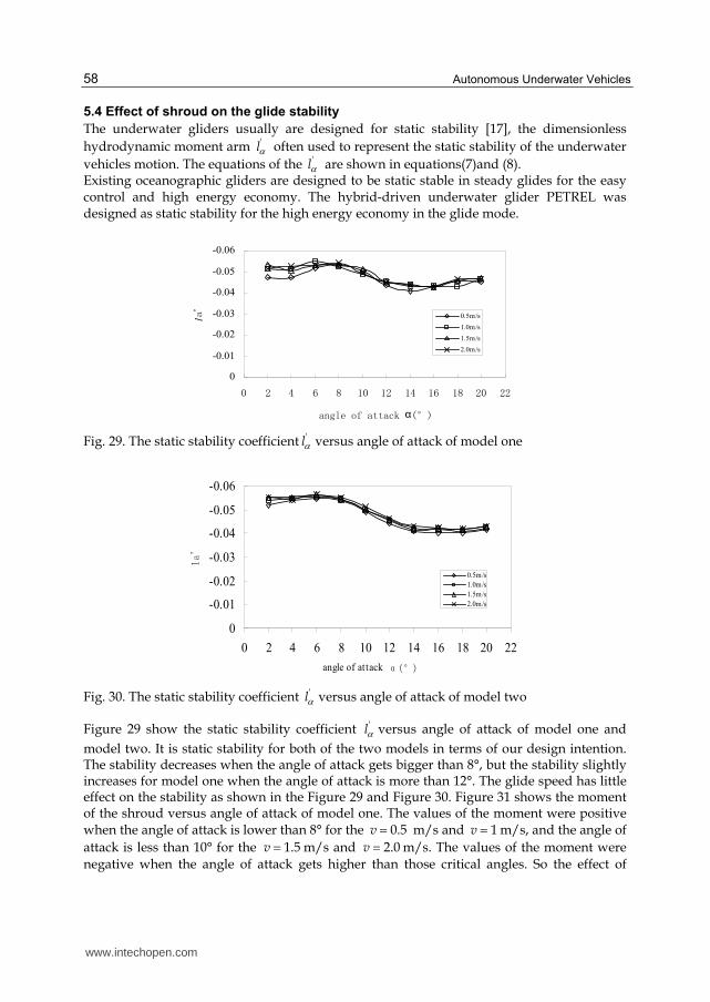
5.4 Effect of shroud on the glide stability
The underwater gliders usually are designed for static stability [17], the dimensionless
hydrodynamic moment arm 'lα often used to represent the static stability of the underwater
vehicles motion. The equations of the 'lα are shown in equations(7)and (8). Existing oceanographic gliders are designed to be static stable in steady glides for the easy control and high energy economy. The hybrid-driven underwater glider PETREL was designed as static stability for the high energy economy in the glide mode.
-0.06
-0.05
-0.04
-0.03
-0.02
-0.01
0
0 2 4 6 8 10 12 14 16 18 20 22
angle of attack α(°)
la'
0.5m/s
1.0m/s
1.5m/s
2.0m/s
Fig. 29. The static stability coefficient 'lα versus angle of attack of model one
-0.06
-0.05
-0.04
-0.03
-0.02
-0.01
0
0 2 4 6 8 10 12 14 16 18 20 22
angle of attack α(°)
la'
0.5m/s
1.0m/s
1.5m/s
2.0m/s
Fig. 30. The static stability coefficient 'lα versus angle of attack of model two
Figure 29 show the static stability coefficient 'lα versus angle of attack of model one and
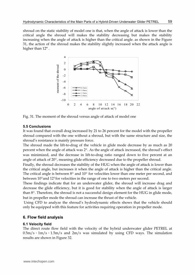
model two. It is static stability for both of the two models in terms of our design intention. The stability decreases when the angle of attack gets bigger than 8°, but the stability slightly increases for model one when the angle of attack is more than 12°. The glide speed has little effect on the stability as shown in the Figure 29 and Figure 30. Figure 31 shows the moment of the shroud versus angle of attack of model one. The values of the moment were positive when the angle of attack is lower than 8° for the 0.5v = m/s and 1v = m/s, and the angle of
attack is less than 10° for the 1.5v = m/s and 2.0v = m/s. The values of the moment were
negative when the angle of attack gets higher than those critical angles. So the effect of
www.intechopen.com
Hydrodynamic Characteristics of the Main Parts of a Hybrid-Driven Underwater Glider PETREL
59
shroud on the static stability of model one is that, when the angle of attack is lower than the critical angle the shroud will makes the stability decreasing but makes the stability increasing when the angle of attack is higher than the critical angle. as shown in the Figure 31, the action of the shroud makes the stability slightly increased when the attack angle is higher than 12° .
-10
-8
-6
-4
-2
0
2
4
0 2 4 6 8 10 12 14 16 18 20 22
angle of attack α(°)
mom
ent of
the
shro
ud
0.5m/s
1.0m/s
1.5m/s
2.0m/s
Fig. 31. The moment of the shroud versus angle of attack of model one
5.5 Conclusions
It was found that overall drag increased by 21 to 26 percent for the model with the propeller
shroud compared with the one without a shroud, but with the same structure and size, the
shroud’s resistance is mainly pressure force.
The shroud made the lift-to-drag of the vehicle in glide mode decrease by as much as 20
percent when the angle of attack was 2º. As the angle of attack increased, the shroud’s effect
was minimized, and the decrease in lift-to-drag ratio ranged down to five percent at an
angle of attack of 20º, meaning glide efficiency decreased due to the propeller shroud.
Finally, the shroud decreases the stability of the HUG when the angle of attack is lower than the critical angle, but increases it when the angle of attack is higher than the critical angle. The critical angle is between 8º and 10º for velocities lower than one meter per second, and
between 10ºand 12ºfor velocities in the range of one to two meters per second.
These findings indicate that for an underwater glider, the shroud will increase drag and
decrease the glide efficiency, but it is good for stability when the angle of attack is larger
than 8º. Therefore, the shroud is not a successful design element for the HUG in glide mode,
but in propeller mode the shroud can increase the thrust of the vehicle.
Using CFD to analyze the shroud’s hydrodynamic effects shows that the vehicle should only be equipped with this feature for activities requiring operation in propeller mode.
6. Flow field analysis
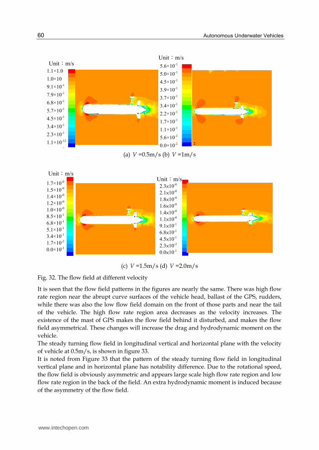
6.1 Velocity field
The direct route flow field with the velocity of the hybrid underwater glider PETREL at 0.5m/s、1m/s、1.5m/s and 2m/s was simulated by using CFD ways. The simulation
results are shown in Figure 32.
www.intechopen.com
Autonomous Underwater Vehicles
60
(a) V =0.5m/s (b) V =1m/s
(c) V =1.5m/s (d) V =2.0m/s
Fig. 32. The flow field at different velocity
It is seen that the flow field patterns in the figures are nearly the same. There was high flow
rate region near the abrupt curve surfaces of the vehicle head, ballast of the GPS, rudders,
while there was also the low flow field domain on the front of those parts and near the tail
of the vehicle. The high flow rate region area decreases as the velocity increases. The
existence of the mast of GPS makes the flow field behind it disturbed, and makes the flow
field asymmetrical. These changes will increase the drag and hydrodynamic moment on the
vehicle.
The steady turning flow field in longitudinal vertical and horizontal plane with the velocity
of vehicle at 0.5m/s, is shown in figure 33.
It is noted from Figure 33 that the pattern of the steady turning flow field in longitudinal
vertical plane and in horizontal plane has notability difference. Due to the rotational speed,
the flow field is obviously asymmetric and appears large scale high flow rate region and low
flow rate region in the back of the field. An extra hydrodynamic moment is induced because
of the asymmetry of the flow field.
2.3×10-0
2.1×10-0
1.8×10-0
1.6×10-0
1.4×10-0
1.1×10-0
9.1×10⁻¹
6.8×10⁻¹
4.5×10⁻¹
2.3×10⁻²
0.0×10⁻¹
Unit:m/s 1.7×10-0
1.5×10-0
1.4×10-0
1.2×10-0
1.0×10-0
8.5×10⁻¹
6.8×10⁻¹
5.1×10⁻¹
3.4×10⁻¹
1.7×10⁻²
0.0×10⁻¹
Unit:m/s
5.6×10⁻¹
5.0×10⁻¹
4.5×10⁻¹
3.9×10⁻¹
3.7×10⁻¹
3.4×10⁻¹
2.2×10⁻¹
1.7×10⁻¹
1.1×10⁻¹
5.6×10⁻²
0.0×10⁻²
Unit:m/s
1.1×1.0
1.0×10
9.1×10⁻¹
7.9×10⁻¹
6.8×10⁻¹
5.7×10⁻¹
4.5×10⁻¹
3.4×10⁻¹
2.3×10⁻¹
1.1×10⁻¹²
2
Unit:m/s
www.intechopen.com
Hydrodynamic Characteristics of the Main Parts of a Hybrid-Driven Underwater Glider PETREL
61
(a) Steady turning in longitudinal vertical plane (b) Steady turning in horizontal plane
Fig. 33. The steady turning flow field
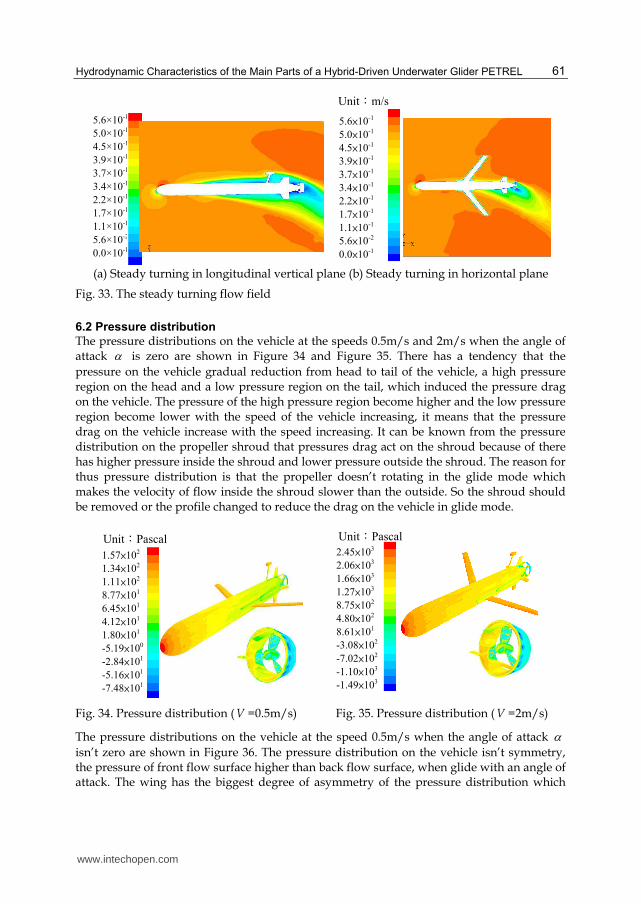
6.2 Pressure distribution
The pressure distributions on the vehicle at the speeds 0.5m/s and 2m/s when the angle of attack α is zero are shown in Figure 34 and Figure 35. There has a tendency that the
pressure on the vehicle gradual reduction from head to tail of the vehicle, a high pressure region on the head and a low pressure region on the tail, which induced the pressure drag on the vehicle. The pressure of the high pressure region become higher and the low pressure region become lower with the speed of the vehicle increasing, it means that the pressure drag on the vehicle increase with the speed increasing. It can be known from the pressure distribution on the propeller shroud that pressures drag act on the shroud because of there has higher pressure inside the shroud and lower pressure outside the shroud. The reason for thus pressure distribution is that the propeller doesn’t rotating in the glide mode which makes the velocity of flow inside the shroud slower than the outside. So the shroud should be removed or the profile changed to reduce the drag on the vehicle in glide mode.
Fig. 34. Pressure distribution (V =0.5m/s) Fig. 35. Pressure distribution (V =2m/s)
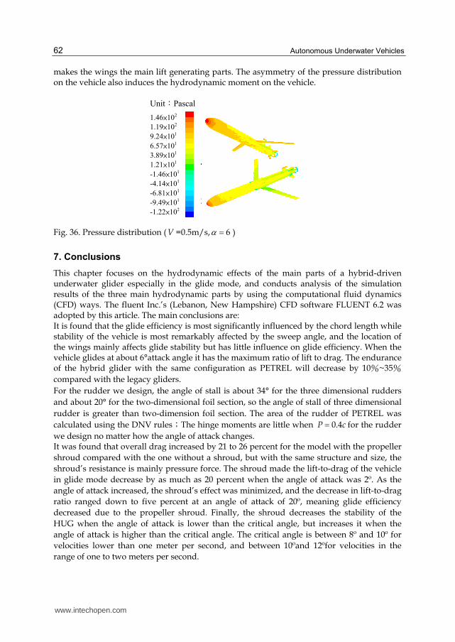
The pressure distributions on the vehicle at the speed 0.5m/s when the angle of attack α
isn’t zero are shown in Figure 36. The pressure distribution on the vehicle isn’t symmetry, the pressure of front flow surface higher than back flow surface, when glide with an angle of attack. The wing has the biggest degree of asymmetry of the pressure distribution which
2.45×10³
2.06×10³
1.66×10³
1.27×10³
8.75×10²
4.80×10²
8.61×101
-3.08×10²
-7.02×10²
-1.10×10³
-1.49×10³
Unit:Pascal
5.6×10⁻¹
5.0×10⁻¹
4.5×10⁻¹
3.9×10⁻¹
3.7×10⁻¹
3.4×10⁻¹
2.2×10⁻¹
1.7×10⁻¹
1.1×10⁻¹
5.6×10⁻²
0.0×10⁻¹
Unit:m/s
1.57×10²
1.34×10²
1.11×10²
8.77×101
6.45×101
4.12×101
1.80×101
-5.19×100
-2.84×101
-5.16×101
-7.48×101
Unit:Pascal
5.6×10⁻¹
5.0×10⁻¹
4.5×10⁻¹
3.9×10⁻¹
3.7×10⁻¹
3.4×10⁻¹
2.2×10⁻¹
1.7×10⁻¹
1.1×10⁻¹
5.6×10⁻²
0.0×10⁻¹
www.intechopen.com
Autonomous Underwater Vehicles
62
makes the wings the main lift generating parts. The asymmetry of the pressure distribution on the vehicle also induces the hydrodynamic moment on the vehicle.
Fig. 36. Pressure distribution (V =0.5m/s, 6α = )
7. Conclusions
This chapter focuses on the hydrodynamic effects of the main parts of a hybrid-driven underwater glider especially in the glide mode, and conducts analysis of the simulation results of the three main hydrodynamic parts by using the computational fluid dynamics (CFD) ways. The fluent Inc.’s (Lebanon, New Hampshire) CFD software FLUENT 6.2 was adopted by this article. The main conclusions are: It is found that the glide efficiency is most significantly influenced by the chord length while stability of the vehicle is most remarkably affected by the sweep angle, and the location of the wings mainly affects glide stability but has little influence on glide efficiency. When the vehicle glides at about 6°attack angle it has the maximum ratio of lift to drag. The endurance of the hybrid glider with the same configuration as PETREL will decrease by 10%~35%
compared with the legacy gliders.
For the rudder we design, the angle of stall is about 34° for the three dimensional rudders
and about 20° for the two-dimensional foil section, so the angle of stall of three dimensional
rudder is greater than two-dimension foil section. The area of the rudder of PETREL was
calculated using the DNV rules;The hinge moments are little when 0.4P c= for the rudder
we design no matter how the angle of attack changes. It was found that overall drag increased by 21 to 26 percent for the model with the propeller
shroud compared with the one without a shroud, but with the same structure and size, the
shroud’s resistance is mainly pressure force. The shroud made the lift-to-drag of the vehicle
in glide mode decrease by as much as 20 percent when the angle of attack was 2º. As the
angle of attack increased, the shroud’s effect was minimized, and the decrease in lift-to-drag
ratio ranged down to five percent at an angle of attack of 20º, meaning glide efficiency
decreased due to the propeller shroud. Finally, the shroud decreases the stability of the
HUG when the angle of attack is lower than the critical angle, but increases it when the
angle of attack is higher than the critical angle. The critical angle is between 8º and 10º for
velocities lower than one meter per second, and between 10ºand 12ºfor velocities in the
range of one to two meters per second.
1.46×10²
1.19×10²
9.24×101
6.57×101
3.89×101
1.21×101
-1.46×101
-4.14×101
-6.81×101
-9.49×101
-1.22×10²
Unit:Pascal
www.intechopen.com
Hydrodynamic Characteristics of the Main Parts of a Hybrid-Driven Underwater Glider PETREL
63
These findings indicate that the shroud of the underwater glider will increase drag, decrease the glide efficiency, but it improves the stability when the angle of attack is larger than 8º.
Therefore, the shroud is not a successful design element for the HUG in glide mode, but it can increase the thrust of the vehicle in propeller mode. Using CFD to analyze the shroud’s hydrodynamic effects shows that the vehicle should only be equipped with this feature for activities requiring operation in propeller mode. Finally, the velocity field, pressure distribution of the hybrid glider PETREL were analyzed, which make us understand how those main parts effect on the hydrodynamic characteristic of the vehicle.
8. References
[1] C. C. Eriksen, T. J. Osse, R. D. Light, T, et al, (2001)“Sea glider: A long range autonomous underwater ve hicle for oceanographic research,” IEEE Journal of Oceanic Engineering, Vol. 26, 2001, pp. 424–436
[2] J. Sherman, R. E. Davis, W. B. Owens, et al , “The autonomous underwater glider “Spray”,” IEEE Journal of Oceanic Engineering, vol.26, 2001, pp. 437–446
[3] D. C. Webb, P. J. Simonetti, C. P. Jones, “SLOCUM, an underwater glider propelled by environmental energy,” IEEE Journal of Oceanic Engineering, vol.26, 2001, pp. 447–452
[4] R. E. Davis, C. C. Eriksen and C. P. Jones, “Autonomous Buoyancy-driven Underwater Gliders,” The Technology and Applications of Autonomous Underwater Vehicles. G.. Griffiths, ed., Taylor and Francis, London, 2002, pp. 37-58
[5] R. Bachmayer, N. E. Leonard, J. Graver, E. Fiorelli, P. Bhatta, D. Paley, “Underwater gliders: Recent development and future applications,” Proc. IEEE International Symposium on Underwater Technology (UT'04), Tapei, Taiwan, 2004, pp.195- 200
[6] D. L. Rudnick, R. E. Davis, C. C. Eriksen, D. M. Fratantoni, and M. J. Perry, “Underwater gliders for ocean research, ” Marine Technology Society Journal, vol. 38, Spring 2004, pp. 48–59
[7] S. A. Jenkins, D. E. Humphreys, J. Sherman, et al. “Underwater glider system study.” Technical Report, Office of Naval Research, 2003
[8] Marthiniussen, Roar ; Vestgård, Karstein ; Klepaker, Rolf Arne ; Strkersen, Nils ,Fuel cell for long-range AUV ,Sea Technology, vol. 38, pp. 69-73
[9] Blidberg, D.Richard ,Solar-powered autonomous undersea vehicles. Sea Technology, vol. 38, pp. 45-51
[10] Ferguson, J , Pope, A.,Butler, B.1, Verrall, R.I.1 ,Theseus AUV-Two record breaking missions, Sea Technology, vol. 40, pp. 65-70
[11] Albert M. Bradley, Michael D. Feezor, Member, IEEE, Hanumant Singh, and F. Yates Sorrell, Power Systems for Autonomous Underwater Vehicles, IEEE JOURNAL OF OCEANIC ENGINEERING, VOL. 26, NO. 4, OCTOBER 2001,pp.526-538
[12] Amit Tyagi*, Debabrata Sen, Calculation of transverse hydrodynamic coefficients using computational fluid dynamic approach, Ocean Engineering 2006 (33),pp. 798–809
[13] Douglas E.H, Correlation and validation of a CFD based hydrodynamic &dynamic model for a towed undersea vehicle, OCEANS, 2001,Vol3, pp.1755-1760
[14] Li Wanping. (2004).Computational fluid dynamics. Huazhong University of Science and Technology Press, 978-7-5609-3214-9. Wuha (in Chinease)
www.intechopen.com
Autonomous Underwater Vehicles
64
[15] Wu Wangyi. (1983).Fluid mechanics (volume I). Higher Education Press, 7301001991,Beijin. (in Chinease).
[16] Wu Ziniu. (2001) .The basic principles of computational fluid dynamics,science
press,7-03-008128-5, Beijin. (in Chinese)
[17] Graver J G. Underwater gliders: dynamics, control and design. The USA: Princeton University, 2005
[18] Wu Jianguo, Chen Chaoyin, Wang Shuxin, et al, Hydrodynamic Characteristics of the Wings of Hybrid-Driven Underwater Glider in Glide Mode, Journal of Tianjin University, 2010,Vol43,No.1,pp.84-89, (in Chinease)
[19] Jenkins S A, Humphreys D E, Sherman J, et al, Alternatives for enhancement of transport economy in underwater gliders, IEEE Proceedings of OCEANS, 2003. 948-950
[20] Wu Baoshan, Xing Fu, Kuang Xiaofeng, et al, Investigation of hydrodynamic characteristics of submarine moving close to the sea bottom with CFD methods, Journal of Ship Mechanics, 2005, Vol.9,No.3,pp. 19-28
[21] Shi Shengda. 1995. Submarine Maneuverability. National Defense Industry Press,
9787118013498,Beijing(in Chinese). [22] Wu Jianguo, Zhang Hongwei, Design and research on the rudder of Mini-type AUV,
ocean technology, 2009,Vol3, No.2, pp.5-8.
[23] P.M.Ostafichuk, AUV hydrodynamics and modeling for improve control, Canada: University of British Columbia, 2004
[24] Timothy Curtis, B.Eng, The design, conatruction, outfitting, and preliminary testing of the C-SCOUT autonomous underwater vehicle (AUV), Canada, Faculty of Engineering and Applied Science Memorial University of Newfoundland, 2001
[25] Jianguo Wu, Chaoying Chen and Shunxin Wang, Hydrodynamic Effects of a shroud Design For a Hybrid-Driven Underwater Glider,Sea Technology,2010, Vol.51, No.6,pp.45-47
www.intechopen.com
Autonomous Underwater VehiclesEdited by Mr. Nuno Cruz
ISBN 978-953-307-432-0Hard cover, 258 pagesPublisher InTechPublished online 17, October, 2011Published in print edition October, 2011
InTech EuropeUniversity Campus STeP Ri Slavka Krautzeka 83/A 51000 Rijeka, Croatia Phone: +385 (51) 770 447 Fax: +385 (51) 686 166www.intechopen.com
InTech ChinaUnit 405, Office Block, Hotel Equatorial Shanghai No.65, Yan An Road (West), Shanghai, 200040, China
Phone: +86-21-62489820 Fax: +86-21-62489821
Autonomous Underwater Vehicles (AUVs) are remarkable machines that revolutionized the process ofgathering ocean data. Their major breakthroughs resulted from successful developments of complementarytechnologies to overcome the challenges associated with autonomous operation in harsh environments. Mostof these advances aimed at reaching new application scenarios and decreasing the cost of ocean datacollection, by reducing ship time and automating the process of data gathering with accurate geo location. Withthe present capabilities, some novel paradigms are already being employed to further exploit the on boardintelligence, by making decisions on line based on real time interpretation of sensor data. This book collects aset of self contained chapters covering different aspects of AUV technology and applications in more detailthan is commonly found in journal and conference papers. They are divided into three main sections,addressing innovative vehicle design, navigation and control techniques, and mission preparation andanalysis. The progress conveyed in these chapters is inspiring, providing glimpses into what might be thefuture for vehicle technology and applications.
How to referenceIn order to correctly reference this scholarly work, feel free to copy and paste the following:
Wu Jianguo, Zhang Minge and Sun Xiujun (2011). Hydrodynamic Characteristics of the Main Parts of a Hybrid-Driven Underwater Glider PETREL, Autonomous Underwater Vehicles, Mr. Nuno Cruz (Ed.), ISBN: 978-953-307-432-0, InTech, Available from: http://www.intechopen.com/books/autonomous-underwater-vehicles/hydrodynamic-characteristics-of-the-main-parts-of-a-hybrid-driven-underwater-glider-petrel

© 2011 The Author(s). Licensee IntechOpen. This is an open access articledistributed under the terms of the Creative Commons Attribution 3.0License, which permits unrestricted use, distribution, and reproduction inany medium, provided the original work is properly cited.
Related Documents