User’s Manual Release 5.0 Copyright 1993-1997 Autoship Systems Corporation Windows is a trademark of Microsoft Corporation AutoCAD is a trademark of Autodesk, Inc. a u t o s h i p Systems Corporation Systems Corporation Suite 312 Tel • (604) 254-4171 611 Alexander Street Fax • (604) 254-5171 Vancouver • B C Internet • http://www.autoship.com V6A 1E1 • Canada

Welcome message from author
This document is posted to help you gain knowledge. Please leave a comment to let me know what you think about it! Share it to your friends and learn new things together.
Transcript
User’s Manual
Release 5.0
Copyright 1993-1997 Autoship Systems CorporationWindows is a trademark of Microsoft CorporationAutoCAD is a trademark of Autodesk, Inc.
a u t o s h i pSystems Corporat ion
Systems CorporationSuite 312 Tel • (604) 254-4171
611 Alexander Street Fax • (604) 254-5171
Vancouver • B C Internet • http://www.autoship.com
V6A 1E1 • Canada
Information contained in this document is subject to change without further notice. No part of thisdocument may be reproduced or transmitted in any form, or by any means, electronic of mechanical, forany purpose, without the express permission of Autoship Systems Corporation.
1997 Autoship Systems Corporation. All right reserved.
Windows is a trademark of Microsoft Corporation. AutoCAD is a trademark of Autodesk Inc. All otherproduct names are trademarks, registered trademarks, or service marks of their respective owners.Autoship Systems Corporation cannot attest to the accuracy of this information. In addition, termssuspected of being trademarks, registered trademarks, or service marks have been appropriatelycapitalized. Use of a term in this book should not be regarded as a validity of any trademark, registeredtrademark, or service mark.
Autoship Systems CorporationSuite 312611 Alexander StreetVancouver, B.C.V6A 1E1Canada
Tel: (604) 254-4171Fax: (604) 254-5171Internet: http//www.autoship.com
Contents
i
Table of ContentsChapter 1: Getting Started 11.0 Introduction................................ ................................ ................ 1
1.0.1 What Autohydro can do for you................................ ............ 21.0.2 Autoship Program Suite ................................ ....................... 3
1.0.2.1 Autohydro................................ ................................ ....... 41.0.2.2 Autopower ................................ ................................ ...... 41.0.2.3 Autobuild ................................ ................................ ........ 41.0.2.4 Autoplate ................................ ................................ ........ 4
1.1 System Requirements................................ ................................ 51.2 Program Installation................................ ................................ ... 61.3 Hardware Lock Installation................................ ......................... 7
1.3.1 General................................ ................................ ................ 71.3.1.1 Description................................ ................................ ..... 71.3.1.2 Precautions................................ ................................ .... 7
1.3.2 Windows 95, Local Station................................ ................... 81.3.3 Windows NT, Local Station................................ .................. 91.3.4 Hardware Lock Installation, Network System..................... 10
1.4 Starting and Exiting Autoship................................ ................... 111.5 Updating Autoship ................................ ................................ ... 11
Chapter 2: About The Program 132.0 Introduction................................ ................................ .............. 132.1 How Autohydro Works................................ ............................. 14
2.1.1 Parts of the Program................................ .......................... 142.1.2 Modelmaker ................................ ................................ ....... 142.1.3 Autohydro ................................ ................................ .......... 152.1.4 Commands................................ ................................ ......... 16
Contents
ii
2.2 Key concepts and terms................................ .......................... 172.2.1 File Types................................ ................................ .......... 172.2.2 Geometry Files ................................ ................................ .. 172.2.3 Data Hierarchy................................ ................................ ... 18
2.2.3.1 Part ................................ ................................ .............. 192.2.3.2 Component ................................ ................................ .. 192.2.3.3 Shape ................................ ................................ .......... 202.2.3.4 Stations and Points................................ ...................... 202.2.3.5 Co-ordinate system................................ ...................... 202.2.3.6 Units................................ ................................ ............. 212.2.3.7 Using files from GHS/BHS ................................ ........... 21
2.2.4 Typical job flow ................................ ................................ .. 22
Chapter 3: A Quick Sailthrough of Autohydro 233.0 Introduction................................ ................................ .............. 233.1 Modelmaker................................ ................................ ............. 24
3.1.1 Start Modelmaker................................ ............................... 253.1.2 Create a part................................ ................................ ...... 253.1.3 Create component 1 ................................ .......................... 253.1.4 Shape component 1................................ ........................... 273.1.5 Create shaped component 2................................ .............. 283.1.6 Join components................................ ................................ 293.1.7 Save the file ................................ ................................ ....... 29
3.2 Autohydro ................................ ................................ ................ 303.2.1. Start Autohydro and find lightship displacement................ 303.2.2 Add deck cargo and find resultant drafts............................ 323.2.3 Generate and print report................................ ................... 33
Chapter 4-Tutorials 354.0 Introduction................................ ................................ .............. 354.1 Tutorial 1: Modelmaker ................................ ............................ 36
4.1.1 Add tanks to the barge................................. ..................... 364.1.2 Create sounding tubes................................. ..................... 434.1.3 Create a deckhouse................................ .......................... 44
Contents
iii
4.2 Tutorial 2: Running Autohydro using menus and screens........ 454.2.1 Find hydrostatics, cross-curves and hull data.................... 454.2.2 Find drafts for a given weight and center of gravity. .......... 46
4.3 Tutorial 3: Modelmaker project using command files................ 484.3.1 Create a barge, LOLLIPOP.GF1................................ ....... 48
4.4 Tutorial 4: Running Autohydro using commands..................... 514.4.1 Obtain basic output from LOLLIPOP.GF1 ......................... 51
4.5 Tutorial 5: Modelling a vessel using Modelmaker commands.. 524.5.1 Load a command file................................ ......................... 524.5.2 Load a second command file................................ ............. 53
4.6 Tutorial 6: How to Produce a Stability Book in Autohydro........ 544.6.1 Load a RUN file................................ ................................ . 54
4.7 Tutorial 7: How to assess damage stability in Autohydro ........ 56
1
Chapter 1Getting Started
1.0 IntroductionUse this manual with your computer on and Autohydro running.
Later in Chapter 1 we will tell you how to install and run Autohydro,but first let’s look at how to use this manual:
To make the best use of this manual, first read the introduction toAutohydro carefully and get a sense of what Autohydro can do foryou and how it works. Then read the short topic on the basicconcepts and terms that you need to understand to work effectivelywith Autohydro. Next, take the guided tour, "A Quick Sailthrough".Then, you can learn and practice other features of the program byrunning through the tutorials given here. You will find it best tofollow the sequence given and not jump ahead or do the tutorials atrandom because we are trying to progress from simple and easytasks to increasingly complex ones.
Autohydro uses some key terms and concepts. There is a shortsection explaining these terms just before the “Quick Sailthrough.”
In addition to this manual, you will find further information in theHelp system provided with the program. For detailed technicalinformation on any features of the program please see theAutohydro Reference Manual.
Chapter 1 – Getting Started
2
1.0.1 What Autohydro can do for you
Autohydro has the capability to analyse the hydrostaticcharacteristics of any kind of vessel under a wide variety ofconditions. It is comprised of two main modules:
Modelmaker, is used to model any vessel, from kayaks tosupertankers, and also buoys, docks, storage tanks, drillingplatforms and anything else that displaces and/or contains fluids.
Autohydro, is used to perform hydrostatic and stabilitycalculations, analyse hydrostatic and stability characteristics forvarious loading conditions including damage, produce graphic andtext for reports such as stability books and tank sounding tables.
Introduction
3
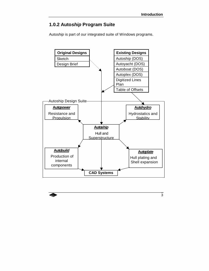
1.0.2 Autoship Program Suite
Autoship is part of our integrated suite of Windows programs.
Original Designs
SketchDesign Brief
Existing DesignsAutoship (DOS)Autoyacht (DOS)Autoboat (DOS)Autoplex (DOS)Digitized LinesPlanTable of Offsets
Autobuild Production of
internalcomponents
Autoplate Hull plating andShell expansion
Autoship
Hull andSuperstructure
Autopower
Resistance andPropulsion
Autohydro
Hydrostatics andStability
CAD Systems
Autoship Design Suite

Chapter 1 – Getting Started
4
1.0.2.1 Autohydro
Use Autohydro to perform hydrostatic and stability calculations forvarious loading conditions including damage, and produce graphicand text for reports such as stability books and tank soundingtables. If Autohydro is installed, you can access it from Autoship byselecting Aux-Autohydro from the Autoship menu bar.
1.0.2.2 Autopower
Use Autopower to perform resistance and power predictioncalculations. If Autopower is installed, you can access it fromAutoship by selecting Aux-Autopower from the Autoship menu bar.
1.0.2.3 Autobuild
Use Autobuild to design and model internal structures.
1.2.0.4 Autoplate
Use Autoplate to perform plate expansions for the vessel youdesigned in Autoship.
Contact us or any of our international dealers for more informationon any of our programs.
System Requirements
5
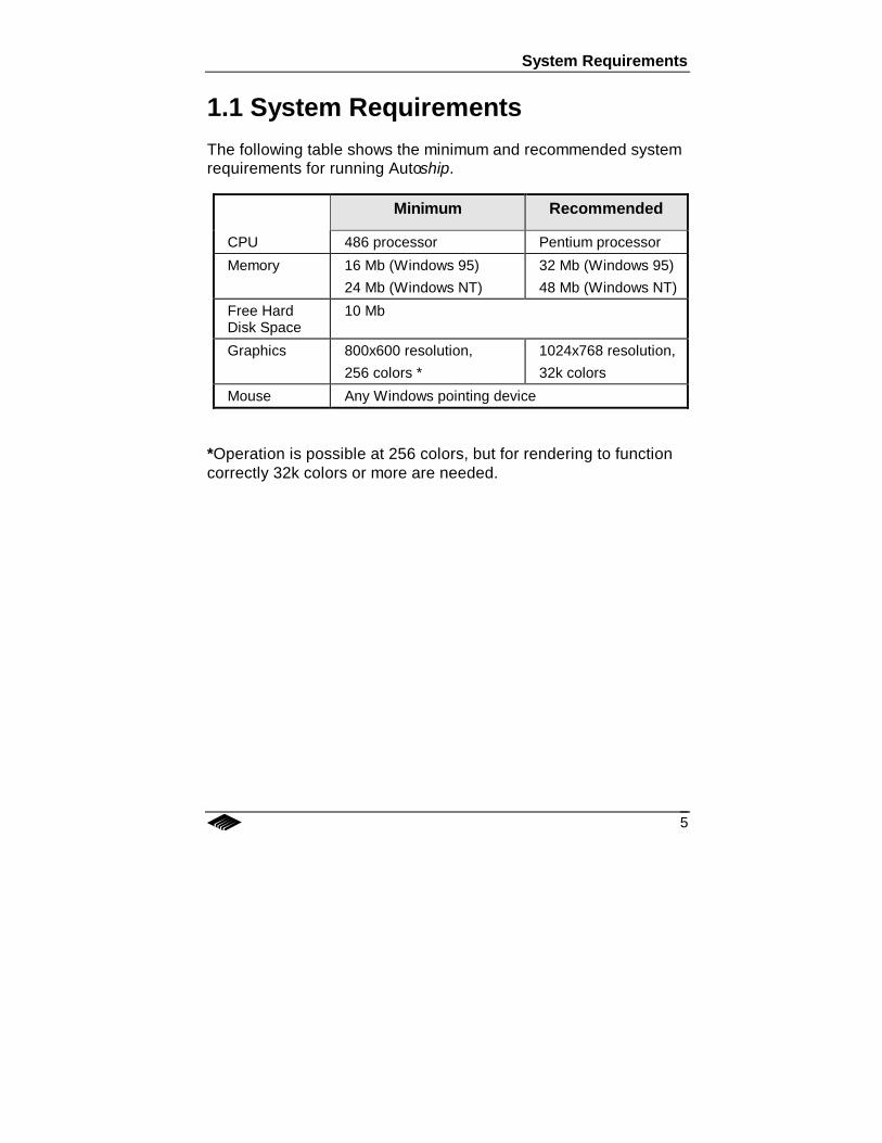
1.1 System RequirementsThe following table shows the minimum and recommended systemrequirements for running Autoship.
Minimum Recommended
CPU 486 processor Pentium processor
Memory 16 Mb (Windows 95)24 Mb (Windows NT)
32 Mb (Windows 95)48 Mb (Windows NT)
Free HardDisk Space
10 Mb
Graphics 800x600 resolution,256 colors *
1024x768 resolution,32k colors
Mouse Any Windows pointing device
*Operation is possible at 256 colors, but for rendering to functioncorrectly 32k colors or more are needed.
Chapter 1 – Getting Started
6
1.2 Program Installation1. First, you need to install the hardware lock onto your
system.
Note: If you do not install the hardware lock, the programwill run in test drive (or “demo”) mode only, and you will notbe able to save, export, or print any of your material orresults. (See “Installing the Hardware Lock” below forhardware lock installation details.)
2. Then, with Windows running:
• If you are installing from a CD, run Setup.exe found on the CD.
• If you are installing from floppy disks, run Setup.exefound on the Authorization disk.
• If you are installing from files on your hard drive, runSetup.exe on your hard drive.
3. Follow the instructions given by the install program.
4. When you get the message that installation is complete,respond by clicking OK.
5. After the installation is complete, you will see theseAutohydro icons on the screen: Autohydro, Modelmaker andPrint Parts
6. To start Autohydro or Modelmaker, click on the appropriateicon or option from Start – Programs – Autoship.
Hardware Lock Installation
7
1.3 Hardware Lock Installation
1.3.1 General
1.3.1.1 Description
A hardware lock is a small electronic device that is installed ontothe parallel port of your computer. (Note: If you have a networkhardware lock, only one lock is used for all computers on thenetwork. See below for details.) You need the hardware lock inorder for Autohydro or Modelmaker to run in normal operatingmode. Otherwise, the program will only run in demo mode. Keepthe lock in a safe place when not in use. As outlined in theLicensing Agreement, you are exclusively responsible for thehardware lock. You may be required to purchase an additionalsoftware license if the hardware lock is lost or stolen.
1.3.1.2 Precautions
• Before beginning the installation, close all running programs.
• Only network locks may be daisy-chained. For a local stationinstallation, a single lock may be configured for all the programsthe user is authorized to use.
• Certain local printers may interfere with the operation of thelock. If this is the case, try a different printer driver, or installanother parallel port.
Chapter 1 – Getting Started
8
1.3.2 Windows 95, Local Station
1. Plug the hardware lock into the parallel port.
2. If you had a printer connected to the same parallel port,plug the printer into the other end of the lock.
3. Install Autohydro as discussed above.
Hardware Lock Installation
9
1.3.3 Windows NT, Local Station
1. If the Autohydro installation program detects a Windows NToperating system, you will be prompted: “Would you like tocopy the NT lock driver files to your computer?” You mustrespond “Yes”, unless you have previously installed the lockdriver. (The NT lock driver is required so your operatingsystem can communicate with the parallel port.) You willthen be asked where you want to copy the NT lock driverfiles to.
2. The Autohydro installation program will indicate aReadme.wri file which contains instructions on how to runthe NT lock driver installation program and will thenterminate to allow you to run the lock driver installation.
3. Follow the instructions contained in the Readme.wri file toinstall the NT lock driver.
4. Re-start the Autohydro installation. This time, when theinstallation program asks if you would like the NT lock driverfiles copied to your computer, respond “No”.
5. Follow the instructions to complete the installation ofAutohydro onto your computer.
Chapter 1 – Getting Started
10
1.3.4 Hardware Lock Installation, Network System
If you have purchased a network lock, you will have received aseparate floppy named “Network Lock Driver”.
1. Connect the network lock onto the parallel port on any oneof the computers in your network.
2. The Network Lock Driver floppy contains 3 directories:
• \DOS (for Windows 3.11)
• \NW (for NetWare)
• \Win32 (for Windows 95 and Windows NT)
Each directory contains a readme.txt file. Follow thedirections appropriate for your operating system.
3. Install Autohydro onto each station on your network fromwhich it will be run, following the installation instructionsabove.
Starting and Exiting Autoship
11
1.4 Starting and Exiting AutoshipTo start Autohydro go to Start – Programs – Autoship and click onthe Autohydro shortcut.
To start Modelmaker go to Start – Programs – Autoship and clickon the Modelmaker shortcut.
To start Print Parts go to Start – Programs – Autoship and click onthe Print Parts shortcut.
The fastest way to get going with Autohydro is to follow our "QuickSailthrough" (chapter 3, this manual), and then to work your waythrough the tutorials starting in chapter 4 of this manual.
For advanced and complex projects, you should take an Autohydrotraining course. Contact Autoship Systems, or your Autoship dealerfor schedules and locations of upcoming courses, or for customisedtraining.
1.5 Updating AutoshipWhen you update Autohydro, the installation procedure is the sameas for a new installation. All necessary program files are updated.No data you have saved will be adversely affected by the update.
12

13
Chapter 2About the Program
2.0 IntroductionChapter 2 introduces the Autohydro and Modelmaker modules. Itdiscusses how the programs work and how to operate them. Sincekey concepts and terminology are discussed, it is important thatnew users read this section.
Chapter 2 – About the Program
14
2.1 How Autohydro Works
2.1.1 Parts of the Program
The Autohydro program is composed of three modules:
• Modelmaker• Autohydro• GF Print
This manual focuses on the first two modules, Modelmaker andAutohydro. Modelmaker is used to create and edit the vesselmodels. Autohydro uses the model produced in Modelmaker tocalculate the hydrostatic characteristics of the vessel. Eachprogram module has its own sets screens, functions andcommands.
A vessel model, or Geometry File (GF) is merely a collection ofgroups of 2D cross sections, and their associated attributes, whichdefine the entire model. Each group or “part” describes a particularpiece of the vessel model, such as the hull or a compartment.
In both Modelmaker and Autohydro you can work using pull-downmenus and/or commands. Simple modelling and calculations byusing the menus is demonstrated in the guided tour ("A QuickSailthrough") provided in this manual while the full set of menusand commands is described in the Reference Manual.
2.1.2 Modelmaker
Modelmaker is used to create and edit the vessel model. The mainscreen displays the model graphically and also shows the co-ordinates of the vertices that make up the model. Various toolsallow you to create and edit the parts and components which definethe model.
How Autohydro Works
15
A model is created by defining parts and their constituentcomponents. The part takes on attributes such as a name, sidefactor (Center, Port or Starboard), class (Displacer, Container orSail), contents and specific gravity. Any number of parts can becreated, but one of them must be named Hull. Without a part calledHull Autohydro cannot process the GF. Next, for each part, youdefine the physical shape, or volume, of the part by creating acomponent, or group of components, and assign further attributes,such as side designation and permeability. Modelmaker suppliesseveral given basic forms, e.g., Box, Cylinder, etc. for which youdefine the extents to build your model. The shape of thecomponent may be modified graphically, or by editing it’s actual co-ordinates. One component may be joined to another componentwithin the part to form a single, complex volume. You can also fit,or trim, components with each other. By repeating this process ofcreating, shaping, joining and fitting you end up with a completemodel of the vessel.
2.1.3 Autohydro
Using the model created in Modelmaker, Autohydro calculatesvarious hydrostatic values for given conditions. You can analysethe model in three distinct ways, or modes:
Given You can find
a. draft, trim, heel weight, center of gravity
b. weight(s) draft, trim, heel
c. waterlines vessel characteristics
Autohydro shows the vessel’s current situation graphically in threedifferent views on the screen, and also as text and values in the“Hydrostatics” window.
Putting together the appropriate sets of instructions allows you toanalyse the model in several different conditions.
Chapter 2 – About the Program
16
Various reports describing the characteristics or stability of thevessel are available by using the appropriate pull down menu orcommand. By assembling the reports in the right order, you canproduce a stability book.
2.1.4 Commands
Both Modelmaker and Autohydro can be controlled either by usingpull down menus or by commands (instructions) issued by the user.
In Modelmaker, commands are grouped together using theprogram’s text editor and saved as a “COMMAND” (.CMD) file. Thecommand file is then run as a batch file and used to the createvessel model. Using commands is a convenient technique formodelling vessels because you can easily change the configurationof the model or correct mistakes just by editing the command fileand re-running it instead of re-creating the model detail by detail asin the interactive mode. Often the best approach to create a modeluses a mixture of the two methods.
You can also use a command file to repeat tasks, for example,when you have to model similar tanks. One tank (or any other part)definition can be copied and pasted to create others.
In Autohydro, you can either group commands as a RUN file usingthe program’s text editor, or type individual commands on thecommand line on the main screen. When run, the RUN file simplyinstructs Autohydro to perform a certain set of calculations uponthe currently loaded vessel model. Often a mixture of singlecommands and running a .RUN file is the best approach toaccomplish a given task.
Key Concepts and Terms
17
2.2 Key concepts and terms
2.2.1 File Types
In addition to Geometry files, each program uses other special fileformats:
Modelmaker
• .CMD (Command): used to create and edit the vessel model.
Autohydro
• .CD (Condition): information for a vessel loading condition.
• .CRI (Criterion): stability criteria to be used for stabilityassessment.
• .LIB (Library): of user-defined macro commands.
• .RUN (Run): a set of commands that Autohydro uses to setconditions and perform calculations.
• .SAV (Save): geometry file and information to reconstruct theloading, criteria, and settings currently in effect.
2.2.2 Geometry Files
A GF (Geometry File) contains all the information about thegeometry of the vessel, represented in detail appropriate forhydrostatic calculations. It describes the volumes of the hull andvarious compartments, their permeabily and the contents andspecific gravity they hold, or displace. Each volume to be modeledconsists of a series of transverse sections, arranged in order frombow to stern. By adjusting the permeability, deductions, such as forbow thrusters can be made. Additionally, volumes which are notconsidered watertight, but are to be used to for wind calculationscan be defined.
Chapter 2 – About the Program
18
Modelmaker and Autohydro will read any GF, including thoseproduced Autoship as well as those created by GHS and BHS.
2.2.3 Data Hierarchy
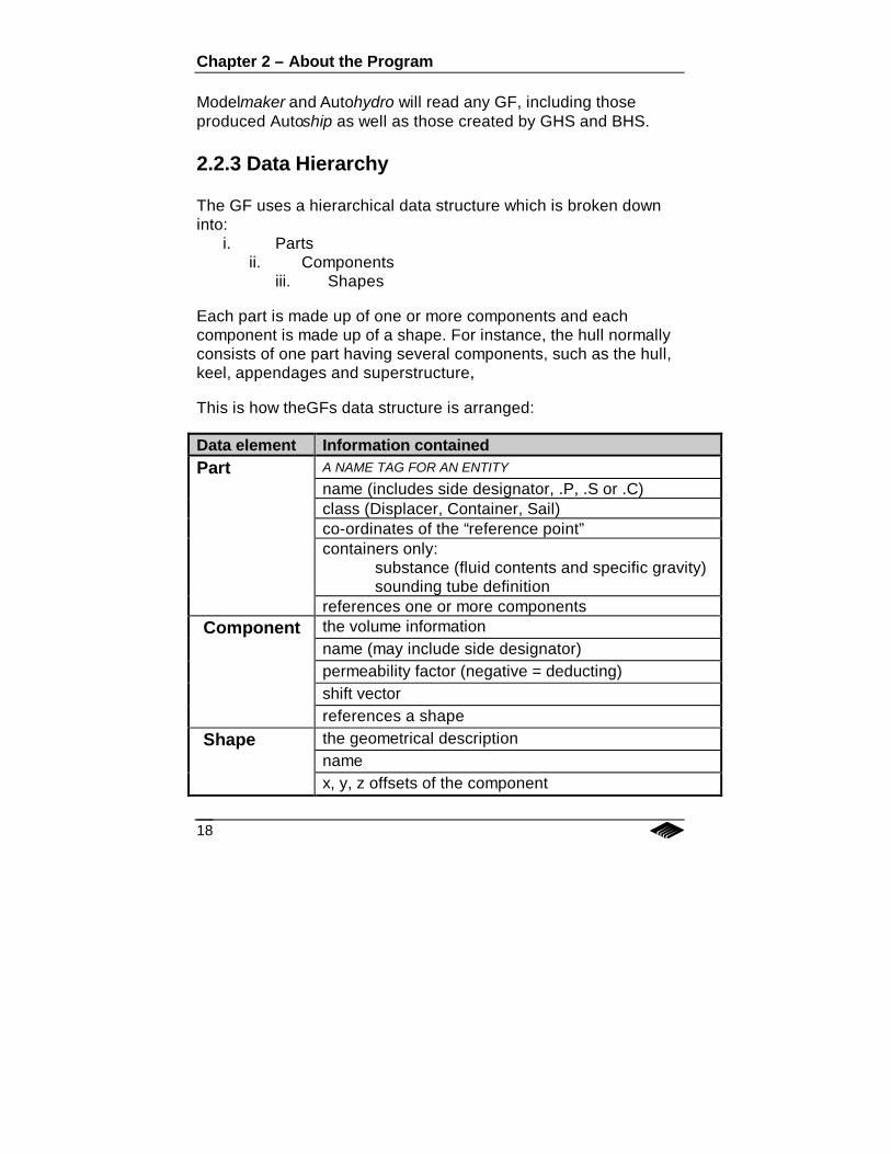
The GF uses a hierarchical data structure which is broken downinto:
i. Partsii. Components
iii. Shapes
Each part is made up of one or more components and eachcomponent is made up of a shape. For instance, the hull normallyconsists of one part having several components, such as the hull,keel, appendages and superstructure,.
This is how theGFs data structure is arranged:
Data element Information containedPart A NAME TAG FOR AN ENTITY
name (includes side designator, .P, .S or .C)class (Displacer, Container, Sail)co-ordinates of the “reference point”containers only:
substance (fluid contents and specific gravity)sounding tube definition
references one or more componentsComponent the volume information
name (may include side designator)permeability factor (negative = deducting)shift vectorreferences a shape
Shape the geometrical descriptionnamex, y, z offsets of the component
Key Concepts and Terms
19
There are two special considerations regarding GFs:
1. Every model has to have a part called HULL.2. Every component must be attached to a part.
2.2.3.1 Part
Each part is identified by a name that is unique within the model.The name also has a side designator: .C for centerline, .P for port,or .S for starboard. Each part is assigned a Contents which has aname and a specific gravity, i.e., Salt Water, 1.025. A part has aclass designation: Displacer, Container or Sail. Displacers displacethe fluid “contents”, Containers contain the fluid “contents”, a Sailpart only produces an area for Wind heeling moments - it does notdisplace or contain a fluid. The part also has a Reference Point - alocation that may be used as a reference when loading the tank, oras the spilling point when the tank type is set to Spilling. Tanks mayalso have a sounding tube definition. Note that a part is only aname tag with attributes and it must reference one or morecomponents to comprise a volume.
While Modelmaker can deal with parts, components and shapes,Autohydro can only access the model at the part level. Therefore, itis important that you define all the volumes you wish to work with,and to group them in a logical fashion.
2.2.3.2 Component
Each component is identified by a name and side designator thatmust be unique within the referencing part. Each component hasan “effectiveness” - i.e. permeability. By default, displacers areassigned 1, containers are assigned .985. Components that arededucted from other parts/components have a negativeeffectiveness. The component refers to one shape by name andgives the shape a specific location on the vessel by means of theshift vector, which by default is 0,0,0.
Chapter 2 – About the Program
20
2.2.3.3 Shape
The shape is identified by a name, which is unique within themodel. It represents a volume in space by a series of 2-dimensionalcross sections. Each section is defined by a longitudinal positionand a series of transverse and vertical co-ordinates. The shapeand has a definite size and orientation but its location is subject tomodification by the referencing component.
Note: Normally, you do not have to deal with shapes because theyare treated by the program as the characteristics of a component.
2.2.3.4 Stations and Points
You will see each component on the screen as a series of 2-dimensional transverse sections. Each station has points locatedon its perimeter. You can change the shape of a station bymodifying the positions of the points.
2.2.3.5 Co-ordinate system
A right-hand co-ordinate system is used. It is aligned with theprincipal axes of the vessel as follows:
Origin: The point at which all three of the model axes cross, (theco-ordinates = 0, 0, 0). It can be located at any positionalong the center plane of the vessel, such as the AP atBaseline, FP at waterline or midships at underside of keel.The first piece of information given to describe the modelultimately establishes the origin, however the origin canbe moved at any later time.
L-axis: The longitudinal, or X axis runs along the length of thevessel. Positive is aft of the origin, negative is forward.The program also recognises A for aft and F for forward.The model may be positioned anywhere longitudinally.
Key Concepts and Terms
21
T-axis: The transverse, or Y axis runs across the vessel. Thetransverse origin is the centerline of the vessel. It ispositive to starboard and negative to port. The programalso recognises S for starboard and P for port. AnyCenterline (.C) components will be automatically mirroredacross the centerline.
Z-axis: The vertical, or Z axis is perpendicular to the vessel'sbaseplane (Z=0). Positive is above the baseplane andnegative is below. The model may be positionedanywhere vertically.
2.2.3.6 Units
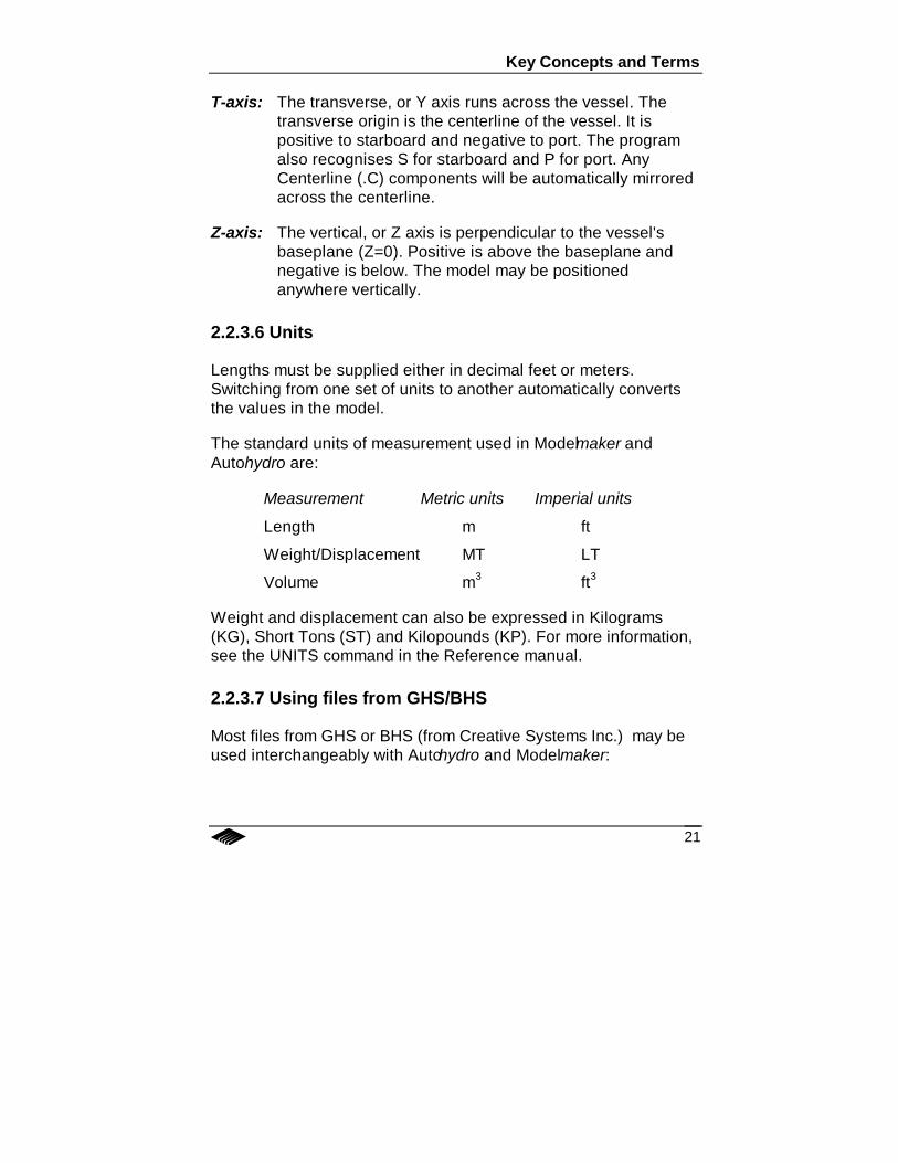
Lengths must be supplied either in decimal feet or meters.Switching from one set of units to another automatically convertsthe values in the model.
The standard units of measurement used in Modelmaker andAutohydro are:
Measurement Metric units Imperial units
Length m ft
Weight/Displacement MT LT
Volume m3 ft3
Weight and displacement can also be expressed in Kilograms(KG), Short Tons (ST) and Kilopounds (KP). For more information,see the UNITS command in the Reference manual.
2.2.3.7 Using files from GHS/BHS
Most files from GHS or BHS (from Creative Systems Inc.) may beused interchangeably with Autohydro and Modelmaker:
Chapter 2 – About the Program
22
• GHS GF's can be read directly by Autohydro orModelmaker.
• GHS Condition files, Criterion files, and Macro files canusually be read directly by Autohydro.
• GHS .RUN files can be read directly by Autohydro.
• Partmaker .RUN files can be read directly by Modelmaker ifyou rename .RUN to .CMD.
Autohydro and Modelmaker cannot read GHS .SAV files or anyother files that represent the environment settings.
Some GHS and Partmaker commands are not essential toAutohydro or Modelmaker but do not affect operation. These non-essential commands are ignored.
2.2.4 Typical job flow
An Autohydro project usually proceeds through three steps:
1. Create a hull using one, or a combination, of these methods:
• Modelmaker menus
• a Modelmaker command file
• digitising offsets in Modelmaker
• an Autoship GF
2. Create internals such as tanks and sounding tubes usingModelmaker.
3. Create appendages such as derricks etc. using Modelmaker.
4. Perform analyses of the model's hydrostatic characteristicsusing Autohydro.
23
Chapter 3A Quick Sailthrough ofAutohydro
3.0 IntroductionThis chapter presents a quick tour of Autohydro. This is what wewill do:
Objectives
i) To use Modelmaker to build a simple barge (40m x 10m x5m) with forward and aft rakes (.5m headlog at fwd and aftends, sloping to the bottom 5m from each end).
ii) To use Autohydro to obtain lightship weight from givendrafts and the operating draft for a load condition with deckcargo.
Chapter 3 – A Quick Sailthrough of Autohydro
24
3.1 Modelmaker
Preview of tasks
Modelmaker
3.1.1 Start Modelmaker3.1.2 Create a hull part3.1.3 Create component 13.1.4 Shape component 13.1.5 Create shaped component 23.1.6 Join components3.1.7 Save the file
Autohydro
3.2.1 Start Autohydro and find lightship displacement3.2.2 Add deck cargo and find resultant drafts3.2.3 Generate and print a report
Get ready! Our co-ordinates will originate from:
Longitudinal "0" at midships
Transverse "0" at center line
Vertical "0" at the lowest point on the flat bottommidships.
Remember the data hierarchy: you will make and edit modelelements in the following order:
Part
Component
Shape
Modelmaker
25
3.1.1 Start Modelmaker
Click on the Modelmaker icon in the Autoship group/folder. WhenModelmaker finishes starting, pick File - New GF. In the dialog thatappears, type a file name, MYBARGE.GF1 for instance, specify adirectory to store it in, then click on OK.
Note: Make a note of the filename and the directory where you arestoring the file.
3.1.2 Create a part
On the top menu bar, click on Options and select Meters.
From the Edit menu select the Part Create/Edit function. In thedialog that appears, under Part Name you will see NEWPARThighlighted. Type HULL over it (it does not matter whether you typein upper or lower case).
Note: You must have a part named HULL. If you don't, the modelwon't work in Autohydro.
For Side, click on the Center radio button. For Class, click on theDisplacer radio button. Click on OK. Now, back at the main screen,nothing shows because there are no components to display yet.
3.1.3 Create component 1
We will create the hull as a combination of two box-shapedcomponents. The first component will be the parallel midshipsection including the aft rake, and we will shape it to form the aftrake. The second component will be the forward rake and, todemonstrate different techniques, we will shape it using a differentmethod. We will then join them together to make a singlecomponent.
Chapter 3 – A Quick Sailthrough of Autohydro
26
From the Edit menu, select the Component Create function. In thedialog that appears, you will see HULL on the left hand side. If it isnot already highlighted, then click on it to highlight it. On the righthand side you will see a list of the basic component shapes, called"primitives", that Modelmaker uses as building blocks.
Click on the Box radio button and then click on Input.
The Create Box dialog will appear. Under Component Name youwill see C1.
Click on the FWD End input box and type 15f (it will show as15.000f).
Click on the AFT End input box and type 20a
Click on the Station Spacing input box and type 2.5 to specify thespace between adjacent stations.
Note: Later, if you find this station spacing too large for fitting partsand components together smoothly, you can change the spacingby adding more stations with the Fill command in the Edit menu.
To the right of OUTBOARD, in the TRANS input box, type 5 to setthe half-breadth.
To the right of TOP, in the VERT input box, type 5 to set the heightof the deck above baseline.
In the Side Factor box click on Center.
Click on OK.
In the Create Component dialog, click on Done to return to themain screen.
A rectangle will now appear on the screen.
Modelmaker
27
Choose Iso (Isometric) from the View menu. This will display thefirst component of the model showing all the stations, with thecurrently selected station (the forward-most one) highlighted inblack and the red cross-shaped cursor highlighting the first vertexof the station.
3.1.4 Shape component 1
We will shape the first component in this way:
Shift through the group of stations from the forward-most station tothe aft-most by pressing F6 until the aft-most station is highlighted.“Location” near the bottom left of the screen will read 20a.
The cursor will show at the bottom-center of the station highlightingthe first vertex of the station. We will change the shape of thissection by moving the two bottom vertices up to from the loweredge of the headlog. To do this, press the up arrow on thekeyboard repeatedly until the 1st vertical cell under Edit Points atthe left of the screen reads 4.5.
Shift the cursor to the next vertex on the station by pressing F4.
Move the cursor up with the up arrow until the 2nd vertical cellunder Edit Points reads 4.5. Hit Enter to update the changes andredraw the view.
Shift to the next station forward by pressing F5.
Shape this station differently (just for practice): type 2.25 in the 1stvertical cell and 2.25 in the 2nd vertical cell and hit Enter to updatethe changes and redraw the view.
Note: If at any time the screen does not show changes that youhave made, click the Redraw button.
Now we will create the second component.
Chapter 3 – A Quick Sailthrough of Autohydro
28
3.1.5 Create shaped component 2
Modelmaker allows you to specify a sloped top, bottom, inboard oroutboard face for a “box” shape. We will use this feature to createthe barges sloped forward rake.
From the Edit menu select the Component Create option. In theCreate Component dialog click on HULL, on Box and then on Input.
In the Create Box dialog you will see C2 for the name of thiscomponent. Type these values:
FWD End 20f
AFT End 15f
Station Spacing 2.5
Outboard Trans 5
Top Vert 5
Click the SLOPING? checkbox for Bottom. This will open up threeadditional input boxes. Input the following values:
Vert 4.5
Long 20f
Vert 0
Long 15f
Make sure that Side Factor is set to Center and then click on OK.Click on Done. If the main screen shows no change, select ViewPart from the View menu to see the entire part.
Note: To scroll through the components of the model, use thespace bar.
Modelmaker
29
3.1.6 Join components
We will now join the two components for a cleaner appearance.
Note that whether a part is made of one component or several,there will be no difference in the resultant calculations.
Select View - View Profile to see the entire model in profile.
From the Edit menu choose Join To. The Join dialog will appear.Under Join Component, pick HULL for part and C2 for component.
Under Component To Join To, pick HULL for part and C1 forcomponent.
Click on the External radio button.
Click on OK.
You will see your complete model without any break betweencomponents.
Note that all reference to the component C2 is gone - it has beenamalgamated with component C1.
3.1.7 Save the file
Choose Save from the File menu.
Chapter 3 – A Quick Sailthrough of Autohydro
30
3.2 Autohydro
3.2.1. Start Autohydro and find lightshipdisplacement
Start Autohydro by clicking on the Autohydro icon in the Autoshipgroup/folder.
When Autohydro has finished starting, click on File - Open, selectthe GF you just created and click on OK. When the GF is finishedloading you should see a representation of your barge.
One of the main ways Autohydro can be used is to have it find thedisplacement and LCG for a given waterline, and assign thatdisplacement and LCG to the lightship weight. We will input twodrafts to define a waterline use this method to determine thelightship weight.
Suppose the lightship drafts are:
1.34m aft (at the forward end of the aft rake, at 15a); and
1.26m fwd (at the aft the of the forward rake, at 15f)
Input these drafts into Autohydro by typing on the command line:
DRAFT 1.34 @ 15a, 1.26 @ 15f <Enter>
Note that the comma is optional and it does not matter whether youtype in upper case or lower case.
Now let’s get Autohydro to find the displacement and longitudinalcenter of gravity (LCG) corresponding to these drafts. On thecommand line, type:
SOLVE WEIGHT LCG <Enter>
Autohydro
31
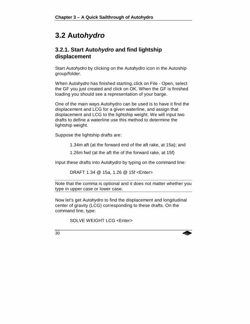
In the Hydrostatic Values window you should now see the followingresults:
Draft status: Aft = 1.35 Mid = 1.30 Fwd = 1.25 m
Lightship: 419.0 MT
Fixed Weight LCG: .194a
Note that the drafts shown are not the drafts you put in. The draftsreported are being measured at the extreme ends of the vessel,while the drafts you input were located closer to midships.
To reset the locations where the drafts are measured, so theymatch your draft mark locations, typing on the command line:
DRAFT "US KEEL" 0 @ 15a, 0 @ 15f <Enter>
Now we know the lightship weight and its LCG. By default, both thetransverse and vertical center of gravity are zero.
Assuming we had calculated the vertical center of gravity to be3.2m above baseline, we can input this value with the command:
VCG 3.2 <Enter>
You may have noticed that when you entered this last commandthe Solve button, in the top left corner of the screen, changed fromgrey to red. The solve button is grey red when the vessel inequilibrium and red when the vessel is not in equilibrium. In thiscase, changing the VCG caused the vessel to go out of equilibrium.
To Autohydro, the vessel is in equilibrium when three conditionsare met:
1. the displacement = the total of all weights (lightship + addedweights + tank loads)
2. the LCB = trimmed LCG (RAt = 0)
3. the TCB = heeled TCG (RAl = 0)
Chapter 3 – A Quick Sailthrough of Autohydro
32
To get Autohydro to calculate a new equilibrium, click on the Solvebutton. After a quick calculation, the Solve button will turn grey, thegraphics window showing the model will be updated and theHydrostatics Values window will show new values.
At this point, Autohydro has a model to work with, has a referenceline for measuring the drafts and knows the vessel's lightshipweight and center of gravity. Now we can add some deck cargoand find the new drafts.
3.2.2 Add deck cargo and find resultant drafts
Autohydro maintains two separate weight categories. One hasfurther sub-categories:
1. Fixed Weight:
i) Lightship Weight
can be set:
• with the WEIGHT command, or
• by specifying drafts or depth and usingthe SOLVE WEIGHT command.
ii) Added Weights
can be input:
• with the ADD command, or
• in a dialog box accessed from the FixedWeight button.
2. Tank Loads
can be specified:
• with the LOAD command, or
• in a dialog box accessed from the TankLoads button.
Autohydro
33
In our barge model we will add two fixed weight items as deckcargo. (If we had defined some tanks in the model, we could haveloaded them with some contents, thus adding liquid weight.)
To add a fixed weight item, click on the Fixed Weight button. In theWeight List dialog that comes up, click on Add and change thelabel New Weight Item#01 to Lumber on deck, set its LCG to 12a,VCG to 6.5, and Weight to 3.
To add the second fixed weight item, click on Add, change NewWeight Item#01 to Forklift on deck, set its LCG to 10f, VCG to 6.1,and Weight to 1.3.
Close the dialog box by clicking on OK and return to the mainAutohydro screen.
Because some variables have been changed the vessel will be outof equilibrium. However, when you exit the Added Weights dialog,Autohydro will automatically find the new equilibrium.
Now we know the total weight and center of gravity of the vesseland cargo, and the resultant drafts. All we need now is to create areport of this condition and print it out.
3.2.3 Generate and print a report
Autohydro has different commands to produce different outputs.The most commonly used (and most general) is Status, whichcreates an overall status report of the current loading condition.
To generate a report, on the command line, type: STATUS, thenclick Enter.
If the Output window is open, it will be filled with an unformattedreport.
To see the formatted report, click on the Report button.
Chapter 3 – A Quick Sailthrough of Autohydro
34
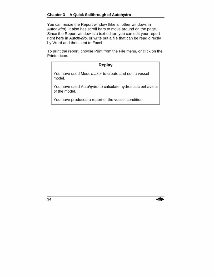
You can resize the Report window (like all other windows inAutohydro). It also has scroll bars to move around on the page.Since the Report window is a text editor, you can edit your reportright here in Autohydro, or write out a file that can be read directlyby Word and then sent to Excel.
To print the report, choose Print from the File menu, or click on thePrinter icon.
Replay
You have used Modelmaker to create and edit a vesselmodel.
You have used Autohydro to calculate hydrostatic behaviourof the model.
You have produced a report of the vessel condition.
35
Chapter 4Tutorials
4.0 IntroductionThis chapter includes seven tutorials. It is suggested that you workthrough each tutorial in the sequence presented, as eachsubsequent tutorial depends upon knowledge gained in theprevious one.
The tutorials are:
Tutorial 1: Modelmaker project using menus and screens
Tutorial 2: Running Autohydro using menus and screens
Tutorial 3: Modelmaker project using command files
Tutorial 4: Autohydro using commands
Tutorial 5: Modeling a vessel using Modelmaker commands
Tutorial 6: How to produce a stability book in Autohydro
Tutorial 7: How to assess damage stability in Autohydro
Chapter 4 – Tutorials
36
4.1 Tutorial 1: Modelmaker projectusing menus and screens
The learning objectives here are:
• to create parts by fitting them to other parts.
• to create a tank part with a recessed portion by joining anumber of components together.
• to create a tank part with a recessed portion by fitting to it atemporary part and then deleting the temporary part.
4.1.1 Add tanks to the barge created in the QuickSailthrough.
We will create 6 tanks: Two void tanks: a Forepeak, and anAftpeak plus four cargo tanks in between, two having a recess ontop.
4.1.1.1 Load MYBARGE.GF1 (or the name you used for yourgeometry file) as created in the Autohydro Sailthrough.
Note: Click on View - ISO to get the best viewing angle.
4.1.1.2 Start by adding more stations to the model so thatModelmaker can fit parts together smoothly.
− From the Edit menu choose Fill− In the Fill station dialog, in the Maximum Station
Spacing field, type .5, and click OK.
This will fill the HULL with more stations and ensure smooth fits.
Tutorial 1
37
4.1.1.3 Create the fwd tank:
Part:(Edit - Part Create/Edit and then Add)
Part name: FOREPEAKSide: CenterClass: ContainerContents: SEA WATER
Component:(Edit - Component Create, select FOREPEAK, click on theBox radio button and then on Input)
FWD: 21fAFT: 14.5fStation spacing: Match Stations to HullOutboard Trans: 6Top Vert: 6Bottom Vert: -1
Note: Observe that the dimensions extend beyond the hull. To getModelmaker to fit, or trim, parts properly, you must specify slightlylarger dimensions for the part that is to be fitted to another part.
4.1.1.4 Fit FOREPEAK to HULL:
− From the Edit menu choose Fit to.− In the Fit Component dialog, under Fit Component,
for Part Name choose FOREPEAK and theappropriate component.
− Under Part or Component to Fit To, for Part Namechoose HULL and the appropriate component.
− Under Type of Fit choose Internal.− Click OK.
Chapter 4 – Tutorials
38
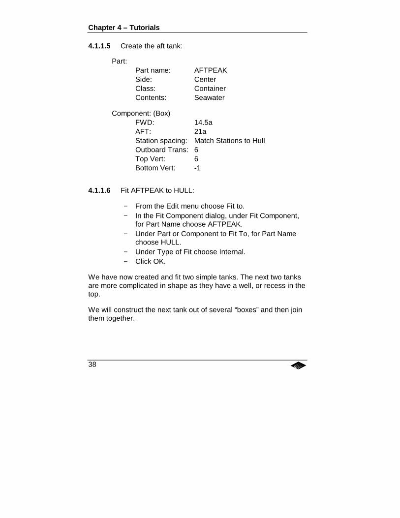
4.1.1.5 Create the aft tank:
Part:Part name: AFTPEAKSide: CenterClass: ContainerContents: Seawater
Component: (Box)FWD: 14.5aAFT: 21aStation spacing: Match Stations to HullOutboard Trans: 6Top Vert: 6Bottom Vert: -1
4.1.1.6 Fit AFTPEAK to HULL:
− From the Edit menu choose Fit to.− In the Fit Component dialog, under Fit Component,
for Part Name choose AFTPEAK.− Under Part or Component to Fit To, for Part Name
choose HULL.− Under Type of Fit choose Internal.− Click OK.
We have now created and fit two simple tanks. The next two tanksare more complicated in shape as they have a well, or recess in thetop.
We will construct the next tank out of several “boxes” and then jointhem together.
Tutorial 1
39
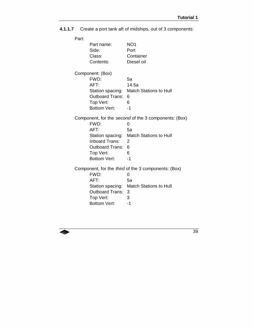
4.1.1.7 Create a port tank aft of midships, out of 3 components:
Part:Part name: NO1Side: PortClass: ContainerContents: Diesel oil
Component: (Box)FWD: 5aAFT: 14.5aStation spacing: Match Stations to HullOutboard Trans: 6Top Vert: 6Bottom Vert: -1
Component, for the second of the 3 components: (Box)FWD: 0AFT: 5aStation spacing: Match Stations to HullInboard Trans: 2Outboard Trans: 6Top Vert: 6Bottom Vert: -1
Component, for the third of the 3 components: (Box)FWD: 0AFT: 5aStation spacing: Match Stations to HullOutboard Trans: 3Top Vert: 3Bottom Vert: -1
Chapter 4 – Tutorials
40
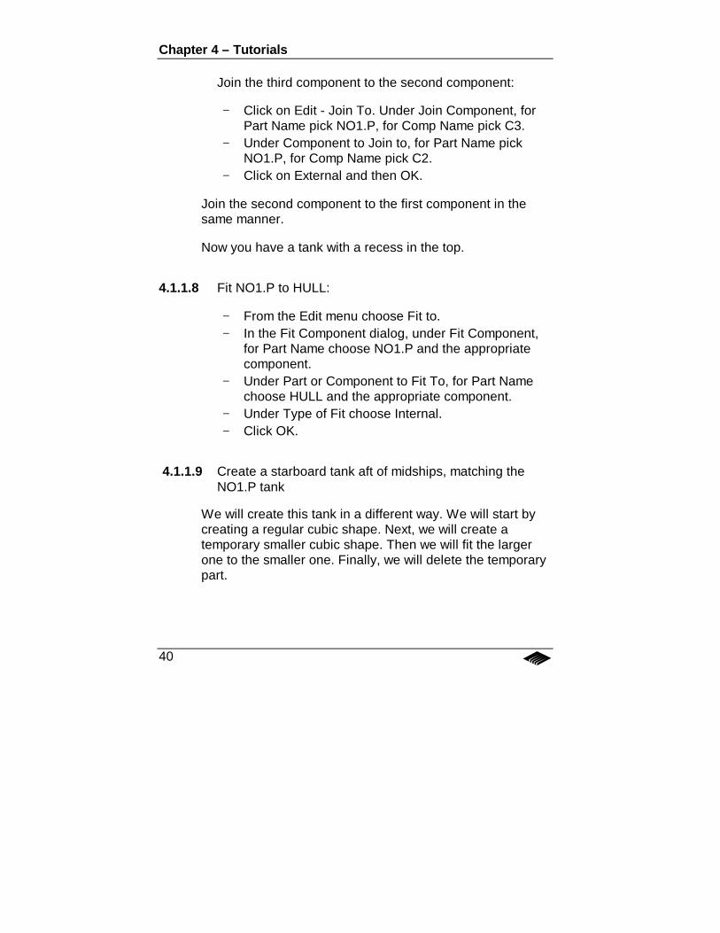
Join the third component to the second component:
− Click on Edit - Join To. Under Join Component, forPart Name pick NO1.P, for Comp Name pick C3.
− Under Component to Join to, for Part Name pickNO1.P, for Comp Name pick C2.
− Click on External and then OK.
Join the second component to the first component in thesame manner.
Now you have a tank with a recess in the top.
4.1.1.8 Fit NO1.P to HULL:
− From the Edit menu choose Fit to.− In the Fit Component dialog, under Fit Component,
for Part Name choose NO1.P and the appropriatecomponent.
− Under Part or Component to Fit To, for Part Namechoose HULL and the appropriate component.
− Under Type of Fit choose Internal.− Click OK.
4.1.1.9 Create a starboard tank aft of midships, matching theNO1.P tank
We will create this tank in a different way. We will start bycreating a regular cubic shape. Next, we will create atemporary smaller cubic shape. Then we will fit the largerone to the smaller one. Finally, we will delete the temporarypart.
Tutorial 1
41
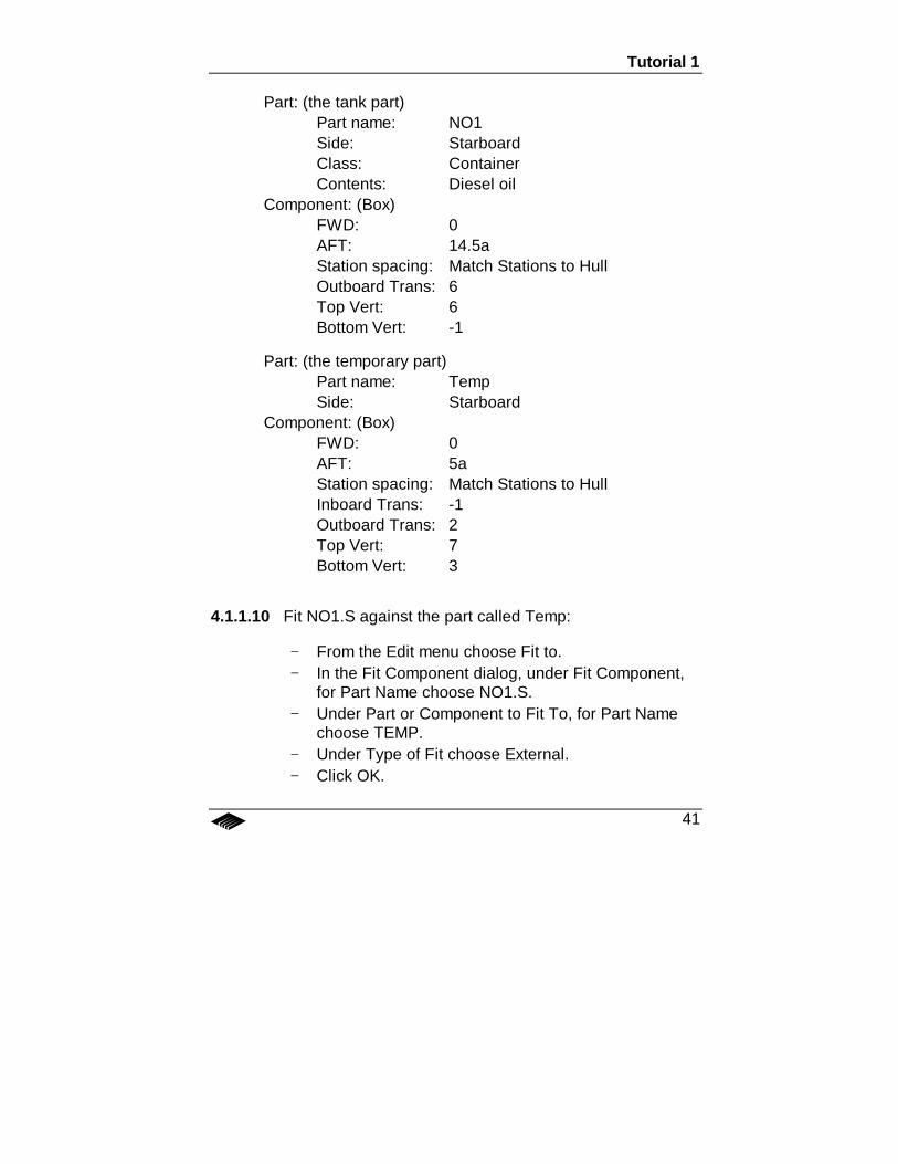
Part: (the tank part)Part name: NO1Side: StarboardClass: ContainerContents: Diesel oil
Component: (Box)FWD: 0AFT: 14.5aStation spacing: Match Stations to HullOutboard Trans: 6Top Vert: 6Bottom Vert: -1
Part: (the temporary part)Part name: TempSide: Starboard
Component: (Box)FWD: 0AFT: 5aStation spacing: Match Stations to HullInboard Trans: -1Outboard Trans: 2Top Vert: 7Bottom Vert: 3
4.1.1.10 Fit NO1.S against the part called Temp:
− From the Edit menu choose Fit to.− In the Fit Component dialog, under Fit Component,
for Part Name choose NO1.S.− Under Part or Component to Fit To, for Part Name
choose TEMP.− Under Type of Fit choose External.− Click OK.
Chapter 4 – Tutorials
42
4.1.1.11 Fit NO1.S to HULL:
− From the Edit menu choose Fit to.− In the Fit Component dialog, under Fit Component,
for Part Name choose NO1.S− Under Part or Component to Fit To, for Part Name
choose HULL− Under Type of Fit choose Internal.− Click OK.
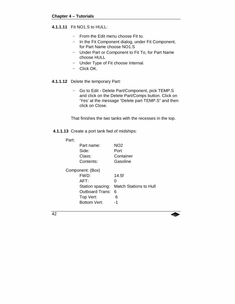
4.1.1.12 Delete the temporary Part:
− Go to Edit - Delete Part/Component, pick TEMP.Sand click on the Delete Part/Comps button. Click on‘Yes’ at the message “Delete part TEMP.S” and thenclick on Close.
That finishes the two tanks with the recesses in the top.
4.1.1.13 Create a port tank fwd of midships:
Part:Part name: NO2Side: PortClass: ContainerContents: Gasoline
Component: (Box)FWD: 14.5fAFT: 0Station spacing: Match Stations to HullOutboard Trans: 6Top Vert: 6Bottom Vert: -1
Tutorial 1
43
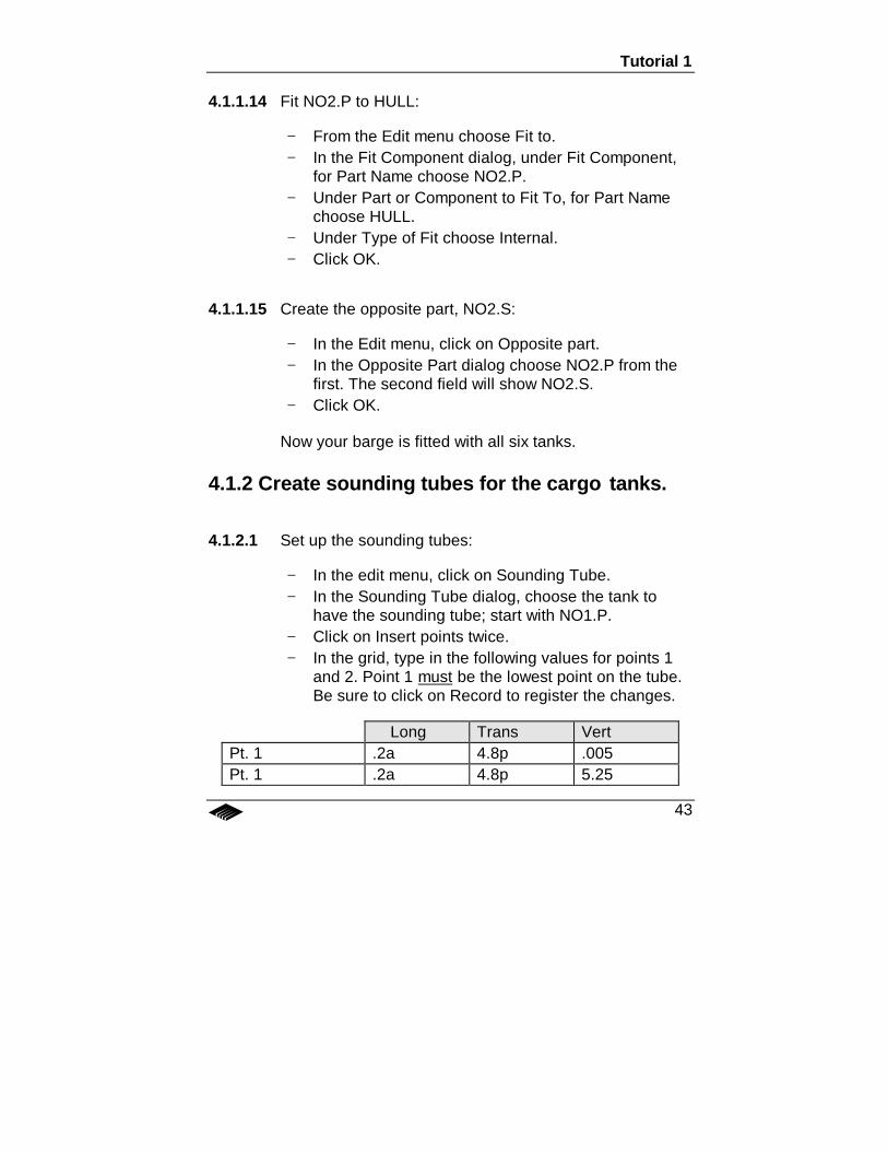
4.1.1.14 Fit NO2.P to HULL:
− From the Edit menu choose Fit to.− In the Fit Component dialog, under Fit Component,
for Part Name choose NO2.P.− Under Part or Component to Fit To, for Part Name
choose HULL.− Under Type of Fit choose Internal.− Click OK.
4.1.1.15 Create the opposite part, NO2.S:
− In the Edit menu, click on Opposite part.− In the Opposite Part dialog choose NO2.P from the
first. The second field will show NO2.S.− Click OK.
Now your barge is fitted with all six tanks.
4.1.2 Create sounding tubes for the cargo tanks.
4.1.2.1 Set up the sounding tubes:
− In the edit menu, click on Sounding Tube.− In the Sounding Tube dialog, choose the tank to
have the sounding tube; start with NO1.P.− Click on Insert points twice.− In the grid, type in the following values for points 1
and 2. Point 1 must be the lowest point on the tube.Be sure to click on Record to register the changes.
Long Trans VertPt. 1 .2a 4.8p .005Pt. 1 .2a 4.8p 5.25
Chapter 4 – Tutorials
44
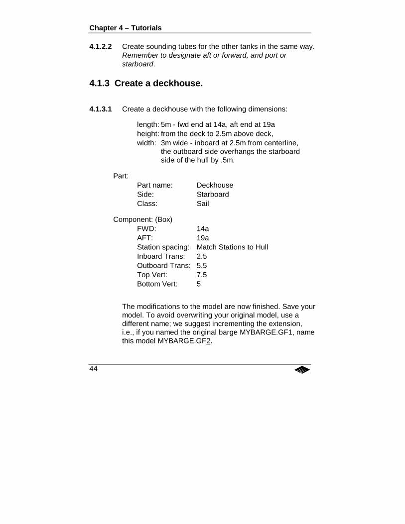
4.1.2.2 Create sounding tubes for the other tanks in the same way.Remember to designate aft or forward, and port orstarboard.
4.1.3 Create a deckhouse.
4.1.3.1 Create a deckhouse with the following dimensions:
length: 5m - fwd end at 14a, aft end at 19aheight: from the deck to 2.5m above deck,width: 3m wide - inboard at 2.5m from centerline,
the outboard side overhangs the starboardside of the hull by .5m.
Part:Part name: DeckhouseSide: StarboardClass: Sail
Component: (Box)FWD: 14aAFT: 19aStation spacing: Match Stations to HullInboard Trans: 2.5Outboard Trans: 5.5Top Vert: 7.5Bottom Vert: 5
The modifications to the model are now finished. Save yourmodel. To avoid overwriting your original model, use adifferent name; we suggest incrementing the extension,i.e., if you named the original barge MYBARGE.GF1, namethis model MYBARGE.GF2.
Tutorial 2
45
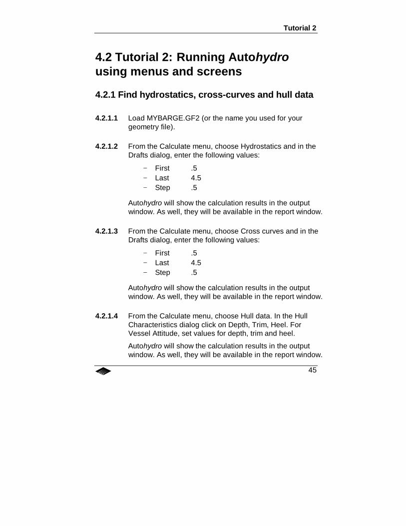
4.2 Tutorial 2: Running Autohydrousing menus and screens
4.2.1 Find hydrostatics, cross-curves and hull data
4.2.1.1 Load MYBARGE.GF2 (or the name you used for yourgeometry file).
4.2.1.2 From the Calculate menu, choose Hydrostatics and in theDrafts dialog, enter the following values:
− First .5− Last 4.5− Step .5
Autohydro will show the calculation results in the outputwindow. As well, they will be available in the report window.
4.2.1.3 From the Calculate menu, choose Cross curves and in theDrafts dialog, enter the following values:
− First .5− Last 4.5− Step .5
Autohydro will show the calculation results in the outputwindow. As well, they will be available in the report window.
4.2.1.4 From the Calculate menu, choose Hull data. In the HullCharacteristics dialog click on Depth, Trim, Heel. ForVessel Attitude, set values for depth, trim and heel.
Autohydro will show the calculation results in the outputwindow. As well, they will be available in the report window.
Chapter 4 – Tutorials
46
4.2.2 Find drafts for a given weight and center ofgravity.
4.2.2.1 On the Command line, type <weight 100 .25a 0 3.6>.Weight is a command telling Autohydro to set the lightshipweight and center to the values that follow; the first value isthe weight, the second is the, the third is tcg, and the fourthis the vcg. Note that the lcg, tcg and vcg are optional, butthey will remain at the default, 0, until changed by someother method.
WEIGHT
Autohydro maintains two weight categories, for use incalculations:
i. Fixed weightii. Liquid weight
Fixed weight
There are two kinds of fixed weight:
i. lightship weight: this is set with the WEIGHTcommand, or found with the SOLVE WEIGHT…command.
ii. the weight of all other fixed items, as set with theADD command.
Liquid weight
The volume of contents in a tank is set either with the LOADcommand or in the Tank List dialog. You can set the loadeither by load fraction, or by weight, or, if sounding tubesare defined, by sounding. Setting or changing one of thesewill update the others in a given tank. You can also changethe tank contents by using the CONTENTS command, or byselecting a fluid from the Fluid list in the Tank List dialogue.
Tutorial 2
47
4.2.2.2 Load tanks: Click on the tank icon and set the loads ofsome of the tanks in the Tank List dialogue. Click on OKwhen you are done.
4.2.2.3 On the command line, type STATUS to generate a reportof the current loading scheme and resultant vesselattitude. View the results in the report window.
4.2.2.4 One the command line, type RA to generate a rightingarm curve for the current loading scheme. View theresults in the report window.
Chapter 4 – Tutorials
48
4.3 Tutorial 3: Modelmaker projectusing command filesThe learning objectives here are:
• to use Modelmaker's text editor to write a .CMD file (a seriesof commands).
• to run the commands to produce a vessel model.
4.3.1 Create a barge, LOLLIPOP.GF1
We will create a barge which has a deckhouse and two deck-mounted cylindrical diesel oil tanks. The hull dimensions are 40mlong, 10m wide, 5m deep, with forward and aft rakes sloping from15f and 15a, respectively, to .5m below deck.
4.3.1.1 Click on CMD on the menu bar. A text editor will appear.
− If the text editor window is not empty, then click on theFiles - New menu option to clear the editor.
− Click any where in the editor window and type CLEAR.The CLEAR command removes any existing geometryfrom Modelmaker’s memory.
Note: Modelmaker cannot create a new part if a part with the samename already exists. Therefore, when re-running a .CMD file it isimportant to remove the previously created set of parts beforecreating new ones.
− Below the CLEAR command, type the following,pressing ENTER after every line: (an explanation ofeach command follows in italics)
Tutorial 3
49
units mt set units to meters and tonnes
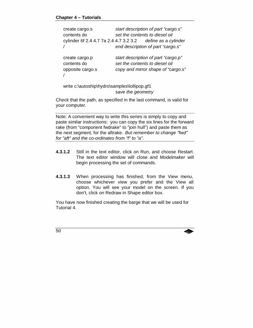
create hull.c start description of part “hull.c”spacing .5 set station spacing at .5m intervalsends 15f 15a define two ends of a box-likecomponenttop 5 define the top of the boxbottom 0 define the bottom of the boxoutboard 5 define the outboard face of the boxcomponent fwdrake describe another component for hullends 20f 15f define the two ends of another boxtop 5 define the top of this boxbottom 0 @ 15f 4.5 @ 20f define a sloping bottomoutboard 5 define the outboard face of this boxjoin hull.c join this component to “hull.c”component aftrake describe another component of“hull.c”ends 15a 20a define the top of this boxtop 5 define the top of this boxbottom 0 @ 15a 4.5 @ 20a define a sloping bottomoutboard 5 define the outboard face of this boxjoin hull.c join this component to hull.c/ end description of part “hull.c”
create deckhouse.c start description of part “deckhouse.c”class sail set to sail rather than containerends 14a 17.5a define two ends of a box-likecomponenttop 8 define the top of the boxbottom 5 define the bottom of the boxoutboard 1.5 define the outboard face of the box/ end description of part “deckhouse.c”
Chapter 4 – Tutorials
50
create cargo.s start description of part “cargo.s”contents do set the contents to diesel oilcylinder 6f 2.4 4.7 7a 2.4 4.7 3.2 3.2 define as a cylinder/ end description of part “cargo.s”
create cargo.p start description of part “cargo.p”contents do set the contents to diesel oilopposite cargo.s copy and mirror shape of “cargo.s”/
write c:\autoship\hydro\samples\lollipop.gf1save the geometry
Check that the path, as specified in the last command, is valid foryour computer.
Note: A convenient way to write this series is simply to copy andpaste similar instructions: you can copy the six lines for the forwardrake (from "component fwdrake" to "join hull") and paste them asthe next segment, for the aftrake. But remember to change "fwd"for "aft" and the co-ordinates from "f" to "a".
4.3.1.2 Still in the text editor, click on Run, and choose Restart.The text editor window will close and Modelmaker willbegin processing the set of commands.
4.3.1.3 When processing has finished, from the View menu,choose whichever view you prefer and the View alloption. You will see your model on the screen. If youdon't, click on Redraw in Shape editor box.
You have now finished creating the barge that we will be used forTutorial 4.
Tutorial 4
51
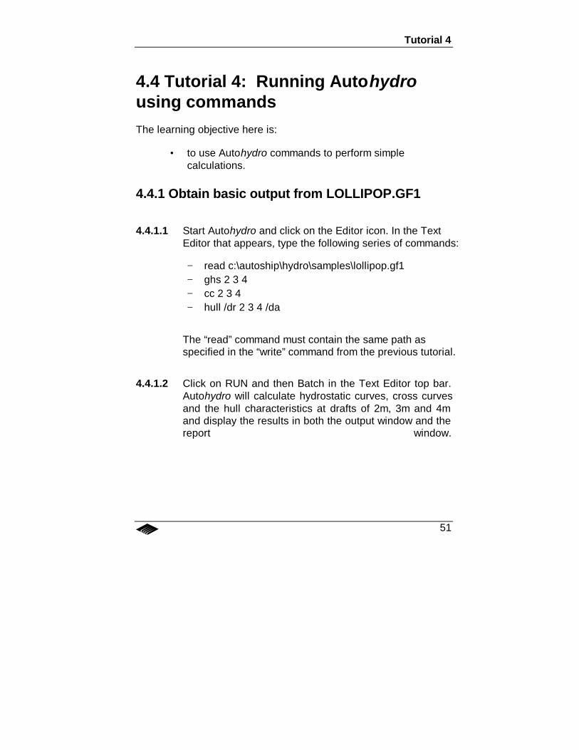
4.4 Tutorial 4: Running Autohydrousing commandsThe learning objective here is:
• to use Autohydro commands to perform simplecalculations.
4.4.1 Obtain basic output from LOLLIPOP.GF1
4.4.1.1 Start Autohydro and click on the Editor icon. In the TextEditor that appears, type the following series of commands:
− read c:\autoship\hydro\samples\lollipop.gf1− ghs 2 3 4− cc 2 3 4− hull /dr 2 3 4 /da
The “read” command must contain the same path asspecified in the “write” command from the previous tutorial.
4.4.1.2 Click on RUN and then Batch in the Text Editor top bar.Autohydro will calculate hydrostatic curves, cross curvesand the hull characteristics at drafts of 2m, 3m and 4mand display the results in both the output window and thereport window.
Chapter 4 – Tutorials
52
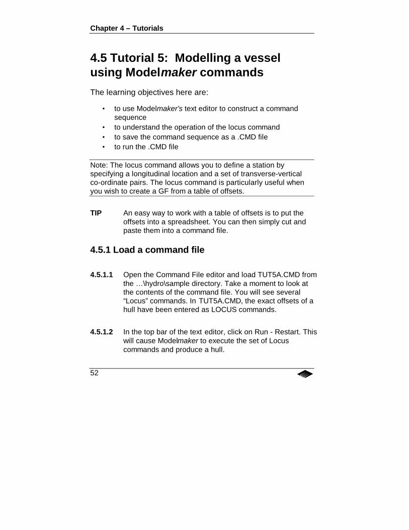
4.5 Tutorial 5: Modelling a vesselusing Modelmaker commandsThe learning objectives here are:
• to use Modelmaker’s text editor to construct a commandsequence
• to understand the operation of the locus command• to save the command sequence as a .CMD file• to run the .CMD file
Note: The locus command allows you to define a station byspecifying a longitudinal location and a set of transverse-verticalco-ordinate pairs. The locus command is particularly useful whenyou wish to create a GF from a table of offsets.
TIP An easy way to work with a table of offsets is to put theoffsets into a spreadsheet. You can then simply cut andpaste them into a command file.
4.5.1 Load a command file
4.5.1.1 Open the Command File editor and load TUT5A.CMD fromthe … \hydro\sample directory. Take a moment to look atthe contents of the command file. You will see several“Locus” commands. In TUT5A.CMD, the exact offsets of ahull have been entered as LOCUS commands.
4.5.1.2 In the top bar of the text editor, click on Run - Restart. Thiswill cause Modelmaker to execute the set of Locuscommands and produce a hull.
Tutorial 5
53
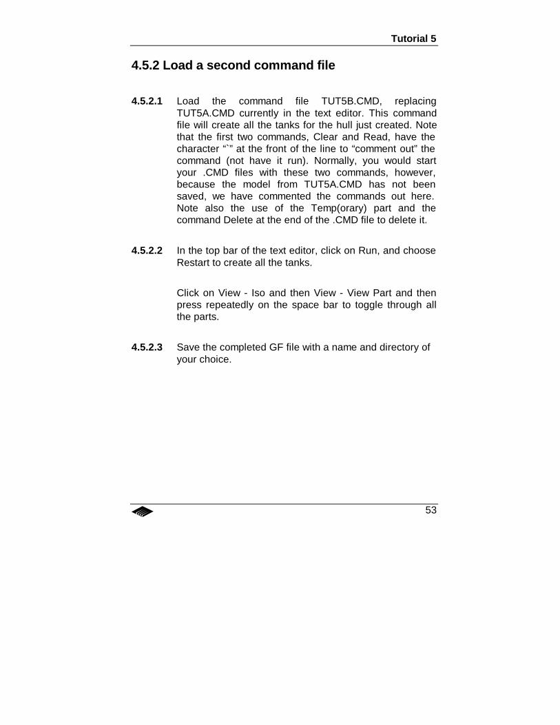
4.5.2 Load a second command file
4.5.2.1 Load the command file TUT5B.CMD, replacingTUT5A.CMD currently in the text editor. This commandfile will create all the tanks for the hull just created. Notethat the first two commands, Clear and Read, have thecharacter “̀” at the front of the line to “comment out” thecommand (not have it run). Normally, you would startyour .CMD files with these two commands, however,because the model from TUT5A.CMD has not beensaved, we have commented the commands out here.Note also the use of the Temp(orary) part and thecommand Delete at the end of the .CMD file to delete it.
4.5.2.2 In the top bar of the text editor, click on Run, and chooseRestart to create all the tanks.
Click on View - Iso and then View - View Part and thenpress repeatedly on the space bar to toggle through allthe parts.
4.5.2.3 Save the completed GF file with a name and directory ofyour choice.
Chapter 4 – Tutorials
54
4.6 Tutorial 6: How to Produce aStability Book in AutohydroThe learning objectives here are:
• to construct a typical sequence of commands for intactstability analysis as follows:
a) Set up limitsb) Specify lightship weight (Alternatively, you can
specify drafts)c) Repeat the following steps for each loading
conditioni. Set up the loading conditionii. Solve for equilibriumiii. Report the results
4.6.1 Load a RUN file
4.6.1.1 In Autohydro, click on Open and load the GF file you justsaved in Modelmaker.
4.6.1.2 Click on the Edit icon to open the run file editor. Load thefile TUT6.RUN by clicking on File - Open and selecting thefile from the ..\hydro\samples directory.
Take a moment to review the contents of this file. It may behelpful to refer to the Reference Manual, or the On-lineHelp system, to understand what the various commandsand parameters will accomplish and why they are used.
Tutorial 6
55
With this run file, we will:
• Set up limits• Specify l/s weight(s)• [Alternatively, you could specify drafts.]• Set up a load condition• Solve for equilibrium.• Report the results• Clear the loads and added weights• Set up a second loading condition• Solve for equilibrium• Report the results
4.6.1.3 Run the RUN file by clicking on Run in the top bar of theeditor. Observe that a Stop sign appears in the top bar ofAutohydro while the calculations are being carried out.When the top sign disappears, the Report Window willopen showing the results. You can either print them out,save them or discard them.
Chapter 4 – Tutorials
56
4.7 Tutorial 7: How to assess damagestability in AutohydroThe learning objectives here are:
• to construct a typical sequence of commands fordamaged stability analysis
4.7.1.1 To be sure that you will start with the program initialisedcorrectly, click on Open and reload the GF file you hadsaved in Modelmaker.
4.7.1.2 Click on the Edit icon to start the Run file editor. Load thefile TUT7.RUN. With this file we will:
• Define limits• Set up lightship• Set up a loading condition• Set up a damage condition• Solve for equilibrium• Report the results• Clear the loads and added weights• Set up a second damage condition• Solve for equilibrium• Report the results
Related Documents