Hydraulic Valve, Pump, Motors (Mechanical Engineering for Mechatronics) Lecture:2 G D Mistry Lecturer SPCE, Visnagar.
Dec 15, 2015
Welcome message from author
This document is posted to help you gain knowledge. Please leave a comment to let me know what you think about it! Share it to your friends and learn new things together.
Transcript
Hydraulic Valve, Pump, Motors(Mechanical Engineering for Mechatronics)
Lecture:2G D MistryLecturerSPCE, Visnagar
3
Hydraulic Valves
• Valves can be divided into three major types:– Pressure Control Valves– Directional Control Valves– Volume Control Valves

4
Pressure Control valves
• Limit system pressure• Reduce pressures• Set pressure at which oil enters a circuit• Unload a pump
5
Pressure Control Valves
• Relief valves• Pressure reducing valves• Pressure sequencing valves• Unloader valves
6
Relief Valves
• The purpose of any relief valve is to protect the hydraulic system and its component parts from excessive pressure or damage.
7
Relief Valves Types
• Direct Acting- open / closed valves• Pilot Operated- controls the main relief
valve
8
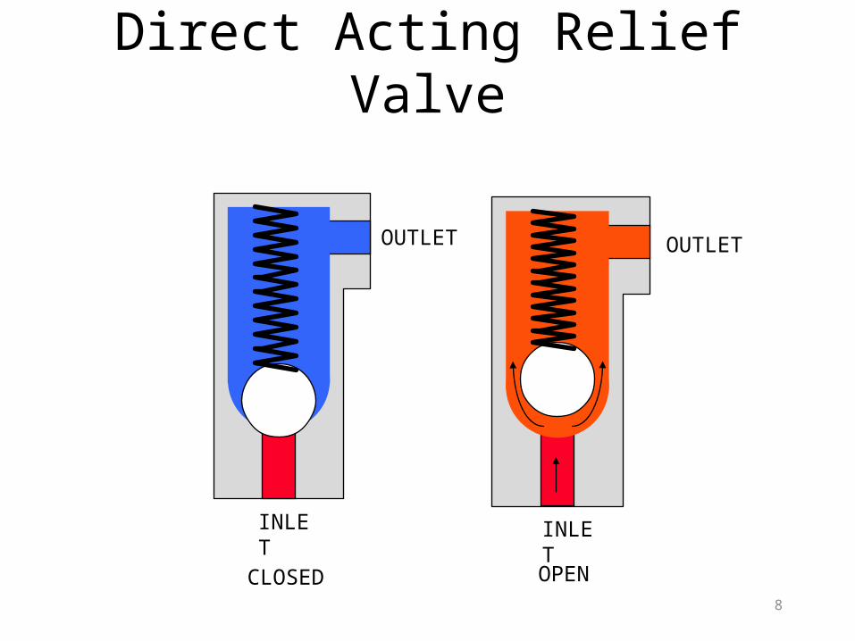
Direct Acting Relief Valve
OUTLET OUTLET
INLET INLET
CLOSED OPEN
9
Direct Acting Relief Valve
• These valves are used mainly where volume is low, and for less frequent operations.
• They have fast response, making them ideal for relieving shock pressure.
• They are often used as safety valves to prevent damage to components.
10
Pilot Operated Relief Valve
• Because these valves don’t start to open until almost full-flow pressure, the efficiency of the system is protected-less oil is released.
• These valves are best for high-pressure, high volume systems.
• Although slower to operate than direct acting valves, the pilot operated relief valve keeps system oil at a more constant pressure while releasing oil
11
Pressure Reducing Valves Types
• Constant reduced pressure valve• Fixed amount reduction valve
12
Constant Reduced Pressure Valves
• They supply a fixed pressure regardless of main circuit pressure. (So long as it is higher)
13
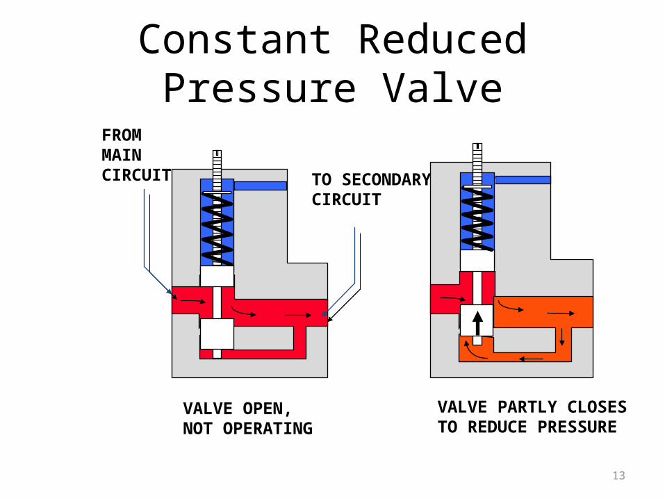
Constant Reduced Pressure Valve
VALVE OPEN, NOT OPERATING
VALVE PARTLY CLOSESTO REDUCE PRESSURE
FROM MAIN CIRCUIT TO
SECONDARY CIRCUIT
14
Fixed Amount Reduction Valves
• They supply a fixed amount of pressure reduction, which means that it varies with the main circuit pressure.
• For example,the valve might be set to give a reduction of 500 PSI. If system pressure was 2000 PSI, the valve would reduce pressure to ________ PSI.
15
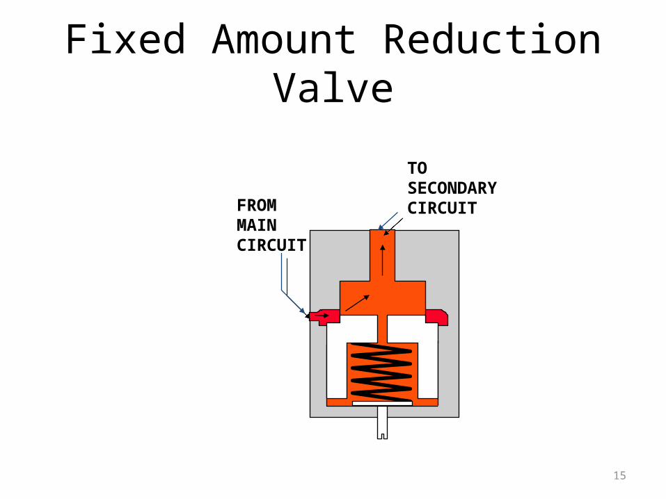
Fixed Amount Reduction Valve
FROMMAINCIRCUIT
TOSECONDARY CIRCUIT
16
Pressure Sequence Valves
• They are used to control the sequence of flow to various branches of a circuit.
• Usually the valves allow flow to a second function only after a first has been fully satisfied.
17
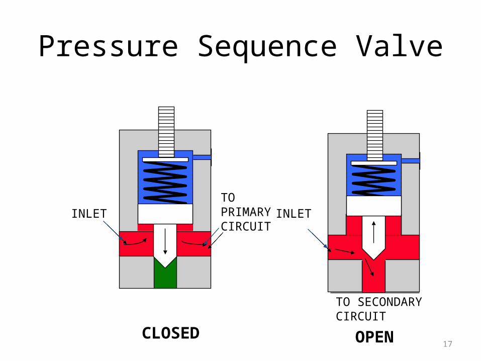
Pressure Sequence Valve
INLETTOPRIMARYCIRCUIT
INLET
TO SECONDARY CIRCUIT
CLOSED OPEN
18
Unloading Valve
• This valve directs pump output oil back to the reservoir at low pressure after system pressure has been reached.
• They may be installed in the pump outlet line with a tee connection.
19
Valve Types
• Pressure control valves• Directional control valves• Volume control valves
20
Directional Control Valves
• Direct the flow of oil in the system• Types of valves
- Check valves- Rotary valves- Spool valves- Pilot controlled poppet valves- Electro-hydraulic valves
21
Check Valves
• One way valves, only allow fluid to flow in one direction
• The valve is open by system pressure • The valve closes when inlet pressure drops• Usually installed in oil line
22
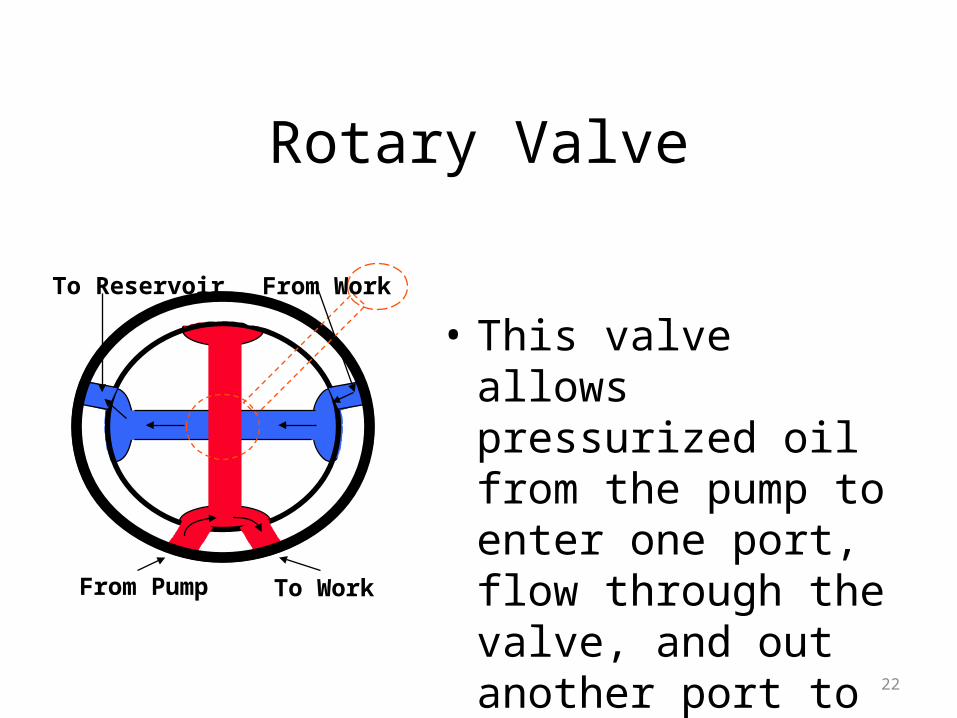
Rotary Valve
• This valve allows pressurized oil from the pump to enter one port, flow through the valve, and out another port to the work
To Reservoir From Work
From Pump To Work
23
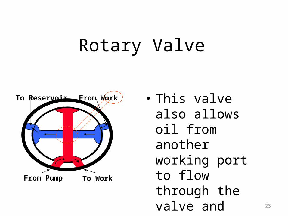
Rotary Valve
• This valve also allows oil from another working port to flow through the valve and return to the reservoir.
To Reservoir From Work
From Pump To Work
24
Rotary Valves
• Used as pilot valves to direct flow to other valves
• Can be modified to operate as two, three, or four way valves
• Done by relocating parts, altering passageways, or adding and removing oil routes
25
Spool Valves
• Most common is open center and closed center
• Directs oil to start, operate, and stop actuating units
• Dirt can cause these valves to stick or work erratically
26
Spool Valves
• open center allows fluid to flow thru the center when in neutral and return to tank
• Closed center stops the flow of oil in neutral• Used as a control valves
27
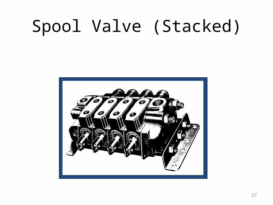
Spool Valve (Stacked)
28
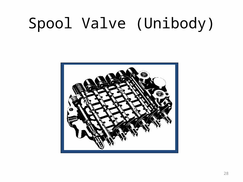
Spool Valve (Unibody)
29
Pilot Controlled Poppet Valves
• May be mounted close to the function it controls
• Eliminates the need for routing hydraulic pipes and hoses over long distances for every control function
• Reduces valve leakage (i.e. cylinder drift)• Adjustable to vary amount of oil flow
30
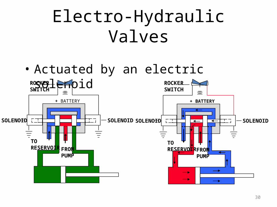
Electro-Hydraulic Valves
• Actuated by an electric solenoid
+ BATTERY
ROCKER SWITCH
SOLENOID SOLENOID
TORESERVOIR FROM
PUMP
+ BATTERY
ROCKER SWITCH
SOLENOID SOLENOID
TORESERVOIR FROM
PUMP
31
Valve Types
• Directional control valves• Pressure control valves• Volume control valves
32
Volume Control Valve Types
• Flow control. • Flow divider.
33
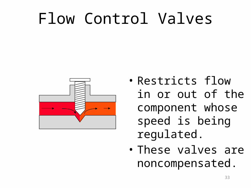
Flow Control Valves
• Restricts flow in or out of the component whose speed is being regulated.
• These valves are noncompensated.
34
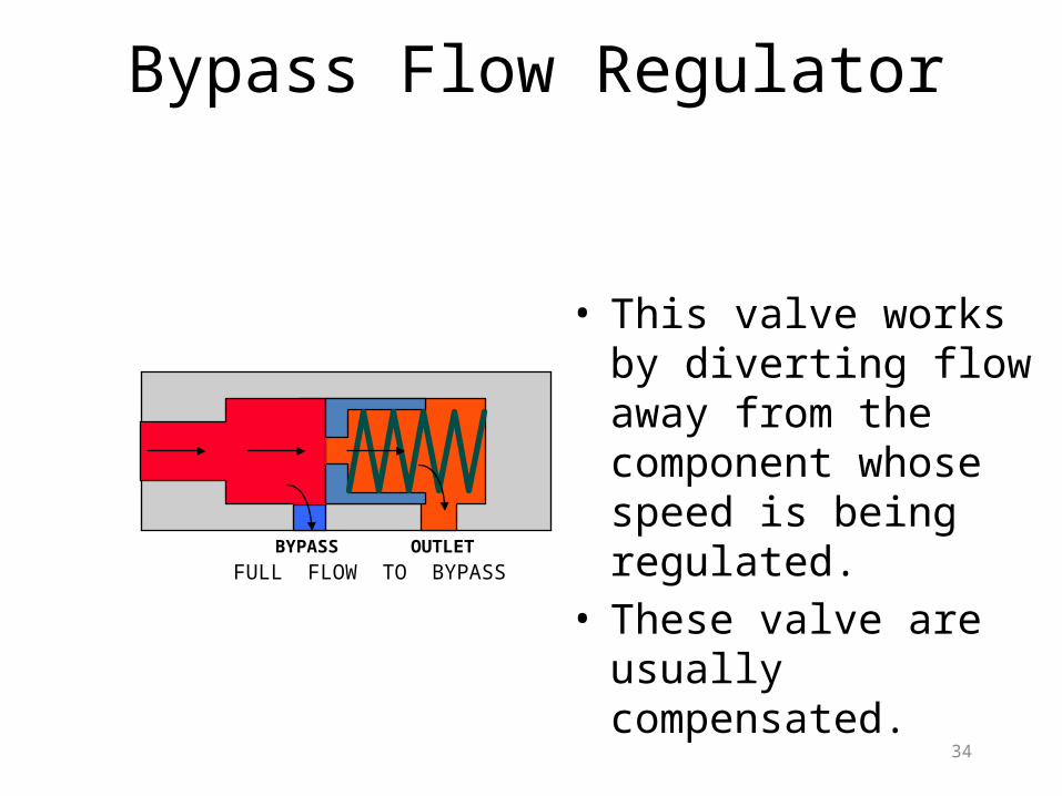
Bypass Flow Regulator
• This valve works by diverting flow away from the component whose speed is being regulated.
• These valve are usually compensated.
BYPASS OUTLETFULL FLOW TO BYPASS
35
Volume Control Valve Types
• Flow control. • Flow divider.
36
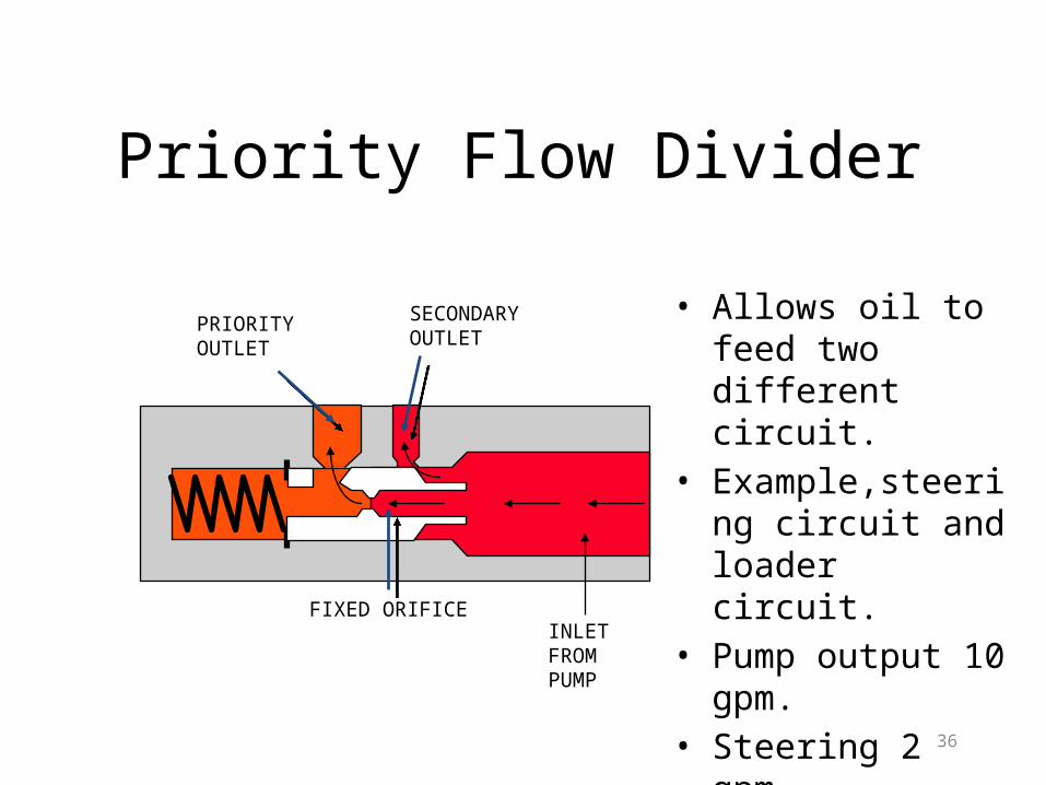
Priority Flow Divider
• Allows oil to feed two different circuit.
• Example,steering circuit and loader circuit.
• Pump output 10 gpm.• Steering 2 gpm.• Loader 8 gpm.
PRIORITY OUTLET
SECONDARY OUTLET
FIXED ORIFICEINLETFROM PUMP
37
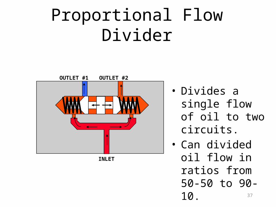
Proportional Flow Divider
OUTLET #1 OUTLET #2
INLET
• Divides a single flow of oil to two circuits.
• Can divided oil flow in ratios from 50-50 to 90-10.
38
Hydraulic Pumps The pump is the heart of the hydraulic system. The pump is the generating force of the hydraulic system, it creates the
flow of fluid which supplies the whole circuit. Pumps convert mechanical energy to hydraulic power
39
Pump Classification
• Two classifications of pumps– Fixed Displacement– Variable Displacement
40
Types Displacement
• Fixed-Moves the same volume of fluid with each cycle
41
Variable Displacement Pumps
• Changing Displacement- this is accomplished by changing the angle of the swashplate.
• Swash Plate Positioning - The position is controlled by one of two ways.
- A small hydraulic cylinder called a “servo” - A spring loaded cylinder called a “pressure
compensator”
42
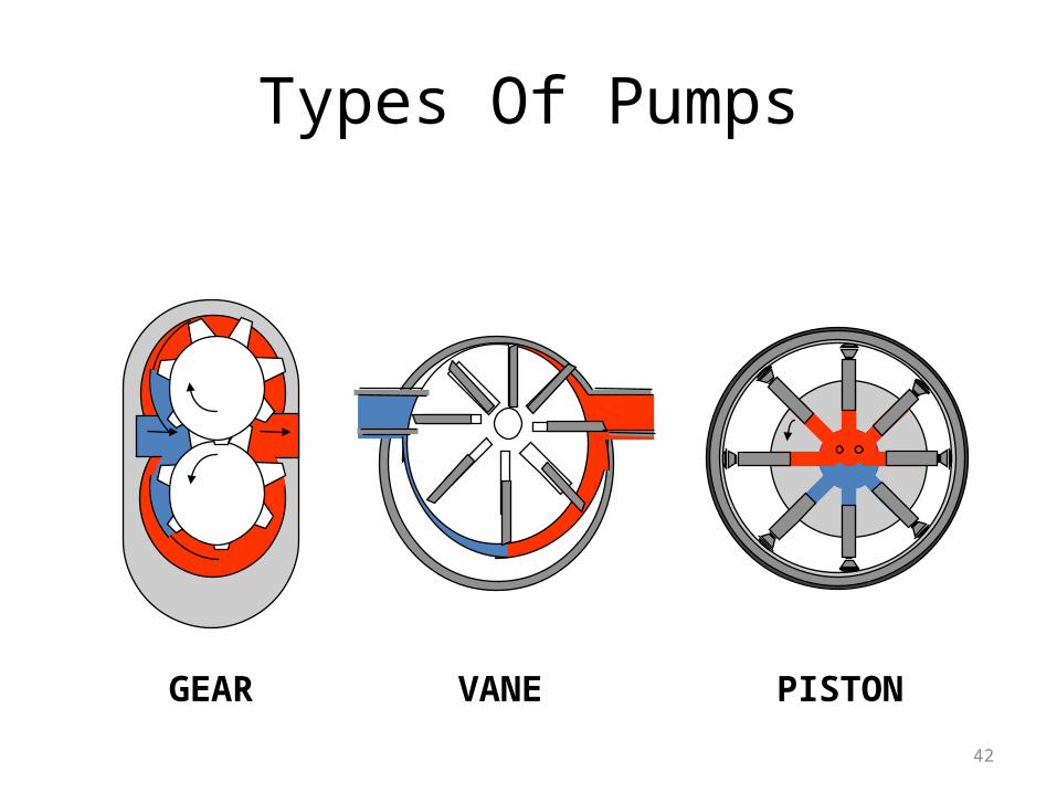
Types Of Pumps
GEAR PISTONVANE
43
Types Of Pumps
• Gear (rotary) – Internal– External
• Vane (centrifugal)– Balanced– Unbalanced
• Piston (reciprocating)– Axial– Radial
44
Gear Pumps
• Simple Design.• Economical.• Fixed Displacement.• Used as charging pumps for larger
system pumps.
45
Gear Pump Side Plates
• Some gear pumps are equipped with pressurized plates on both side of the gears. These plates are used to prevent cavitation. The plates seal tightly when the pump is under a load and relax when there is no load.

46
Internal Gear Pumps
Pump Housing
InletOutlet
Separator(fixed)
Outer RingGear
Internal Gear
• The internal gear is the drive gear, which is meshed with the outer ring gear and traps fluid between the gear teeth on both gears and the separator, which is fixed.
47
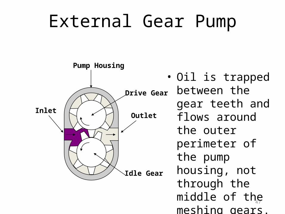
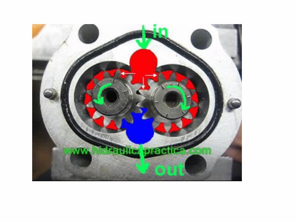
External Gear Pump
• Oil is trapped between the gear teeth and flows around the outer perimeter of the pump housing, not through the middle of the meshing gears.
InletOutlet
Pump Housing
Drive Gear
Idle Gear
48
Gear Pump Advantages
• Most widely used.• Easiest to manufacture.• Produces a large volume of oil for its size.• Tolerant to dirt.• Inexpensive to manufacture.
49
Gear Pump Disadvantages
• Noisier than other types of pumps.• Fixed displacement only.
50
Vane Pumps
• Balanced Vane Pump - Fixed Displacement only. - Equalized force increases bearing life.• Unbalanced Vane Pump - Either Fixed or Variable Displacement. - Frequent bearing failure.
51
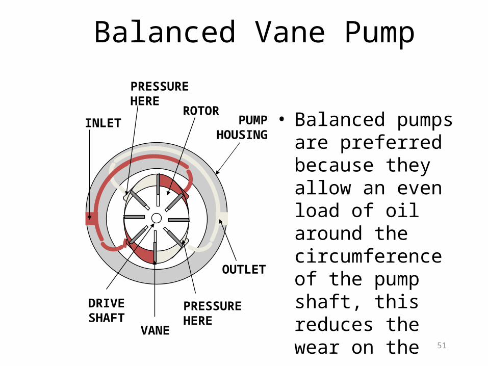
Balanced Vane Pump
PRESSUREHERE
• Balanced pumps are preferred because they allow an even load of oil around the circumference of the pump shaft, this reduces the wear on the pump.
INLETROTOR
OUTLET
PRESSUREHERE
DRIVESHAFT
VANE
PUMP HOUSING
52
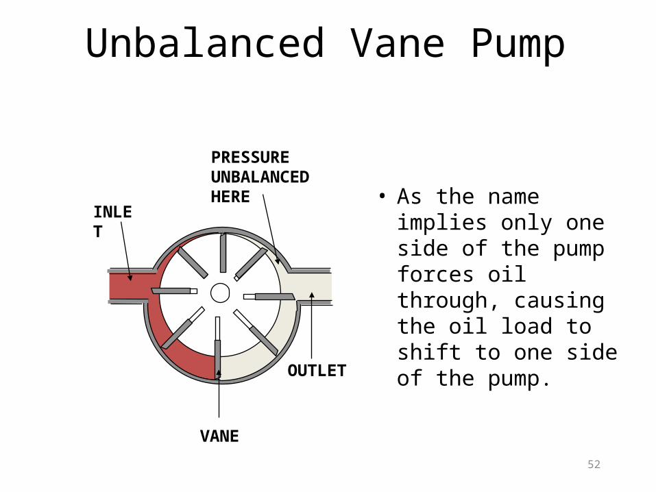
Unbalanced Vane Pump
• As the name implies only one side of the pump forces oil through, causing the oil load to shift to one side of the pump.
INLET
PRESSURE UNBALANCEDHERE
OUTLET
VANE
53
Vane PumpAdvantages
• Quiet.• They are self compensating for wear.
54
Vane PumpsDisadvantages
• Not as tolerable to dirt as gear pumps.• Low volume output.• Low pressure output.
55
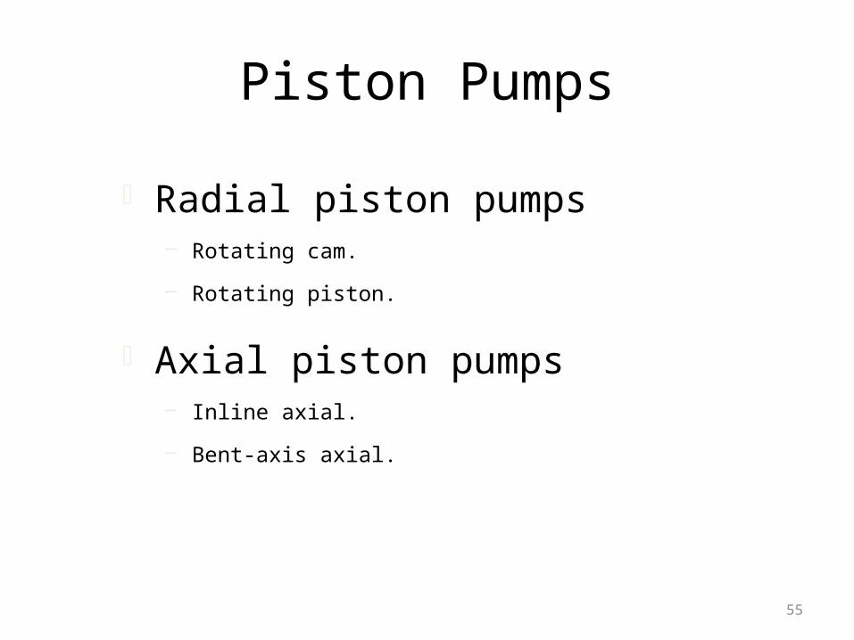
Piston Pumps
Radial piston pumps– Rotating cam.
– Rotating piston.
Axial piston pumps– Inline axial.
– Bent-axis axial.
56
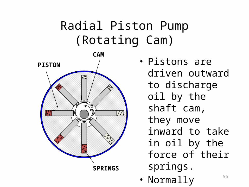
Radial Piston Pump(Rotating Cam)
CAM
PISTON • Pistons are driven outward to discharge oil by the shaft cam, they move inward to take in oil by the force of their springs.
• Normally designed as a 4 or 8 piston model.
SPRINGS
57
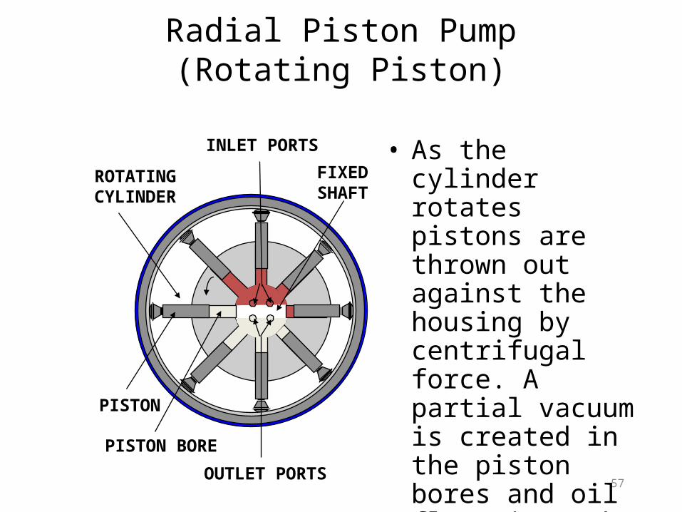
Radial Piston Pump(Rotating Piston)
• As the cylinder rotates pistons are thrown out against the housing by centrifugal force. A partial vacuum is created in the piston bores and oil flows into the inlet ports to fill the bores.
ROTATINGCYLINDER
FIXEDSHAFT
INLET PORTS
OUTLET PORTS
PISTON
PISTON BORE
58
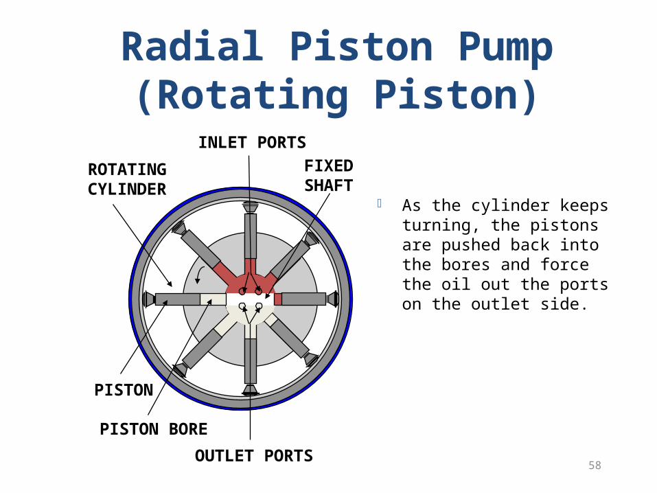
Radial Piston Pump(Rotating Piston)
As the cylinder keeps turning, the pistons are pushed back into the bores and force the oil out the ports on the outlet side.
OUTLET PORTS
ROTATINGCYLINDER
FIXEDSHAFT
INLET PORTS
PISTON
PISTON BORE
59
Axial Piston Pumps
• The axial flow of fluid provides a more compact design and is the second most widely used pump in the industry next to the gear pump.
• Inline axial piston pump.• Bent-axis axial piston pump

60
Axial Piston Pumps(Inline)
• Pump can be variable displacement.
• Swashplate directs the intake and discharge of flow.
• Piston, draws and discharges the fluid.
• Cylinder block, holds the piston and rotates them from inlet to outlet ports.
OUTLET
SWASHPLATE
PISTON
DRIVE SHAFT
INLET
ROTATINGCYLINDERBLOCK
62
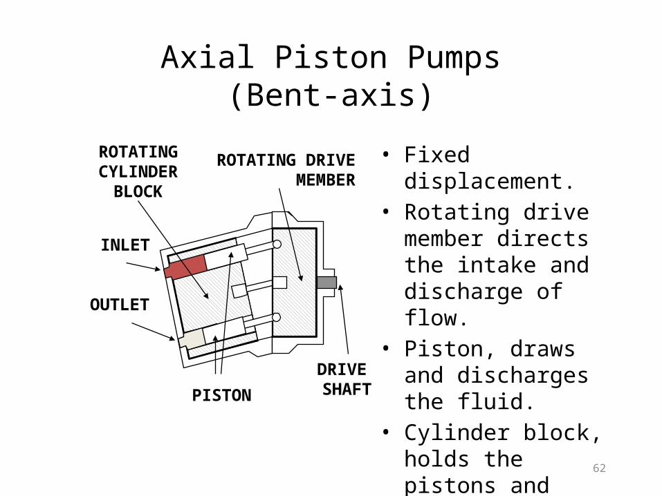
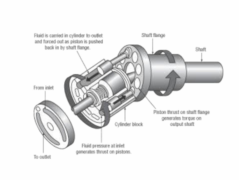
Axial Piston Pumps(Bent-axis)
• Fixed displacement.• Rotating drive member
directs the intake and discharge of flow.
• Piston, draws and discharges the fluid.
• Cylinder block, holds the pistons and rotates them from inlet to outlet ports.
DRIVE SHAFT
INLET
OUTLET
PISTON
ROTATING DRIVE MEMBER
ROTATINGCYLINDER
BLOCK
64
Piston PumpsAdvantages
• Able to withstand high pressure.• Capable of variable displacement.
65
Piston PumpsDisadvantages
• Very low tolerance to dirt.• More difficult to manufacture.• Most expensive to manufacture.
66
Questions
• What are the three types of pumps?- Gear, Piston and Vane
• What will change the displacement of the piston pump?- Angle of the swashplate
• What is the purpose of the side plates in the gear type pump ?- These plates are used to prevent cavitation
67
HYDRAULIC MOTORS
68
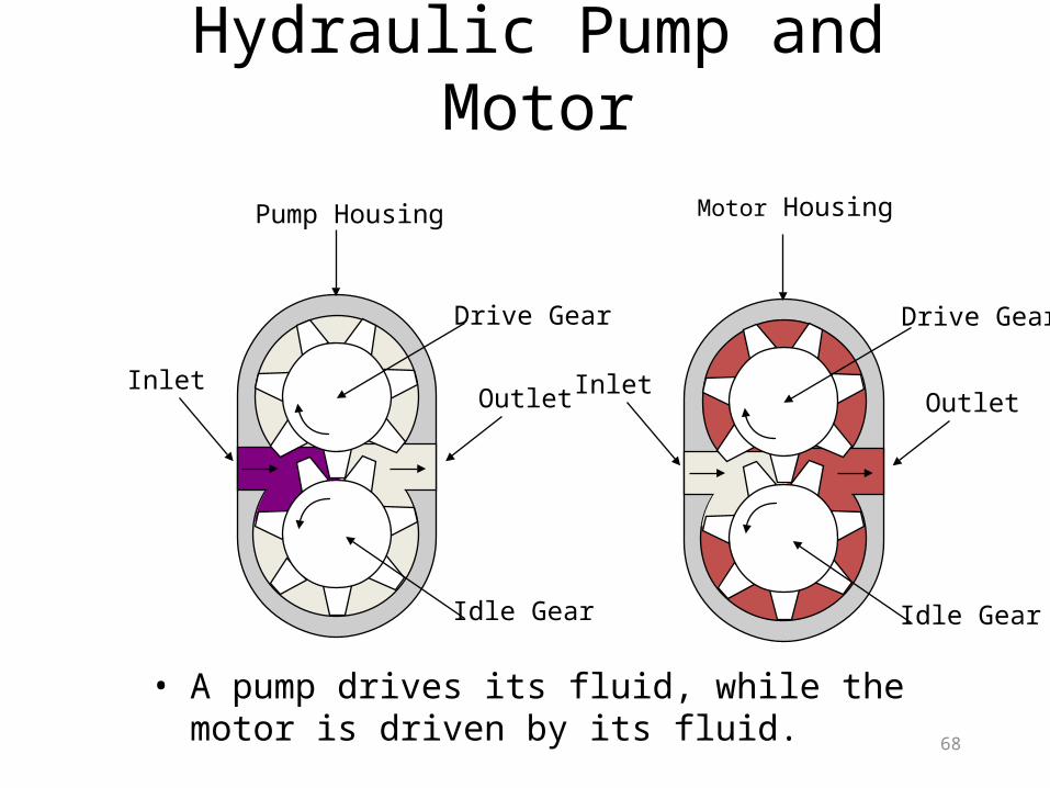
InletOutlet
Pump Housing
Drive Gear
Idle Gear
Hydraulic Pump and Motor
Drive Gear
Motor Housing
InletOutlet
Idle Gear
• A pump drives its fluid, while the motor is driven by its fluid.
70
Hydraulic Motors
• A motor is a rotary actuator that rotates in a full circle.
• The work output of a motor is called torque.• They convert hydraulic energy to
mechanical energy.
71
Hydraulic Motors
• Fixed displacement motors- have variable speed but fixed torque
• Variable displacement motors- have variable speeds and torques
72
Hydraulic Motors (Types)
• Gear motors.• Vane motors.• Piston motors.

Thank You
Related Documents


![UNIT_2 1 DATABASE MANAGEMENT SYSTEM[DBMS] 2620003 [Unit: 2] Prepared By Lavlesh Pandit SPCE MCA, Visnagar.](https://static.cupdf.com/doc/110x72/56649f385503460f94c5526a/unit2-1-database-management-systemdbms-2620003-unit-2-prepared-by-lavlesh.jpg)