Hydraulic Symbols

Hydraulic Symbols. Piping and Tubing Symbols Normal working line Flexible working line Pilot line Drain line Enclosure outline Direction of flow.
Dec 29, 2015
Welcome message from author
This document is posted to help you gain knowledge. Please leave a comment to let me know what you think about it! Share it to your friends and learn new things together.
Transcript

Hydraulic Symbols
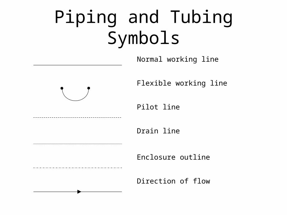
Piping and Tubing Symbols
Normal working line
Flexible working line
Pilot line
Drain line
Enclosure outline
Direction of flow
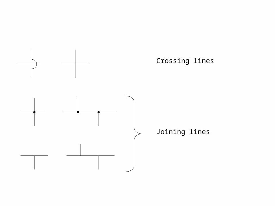
Crossing lines
Joining lines
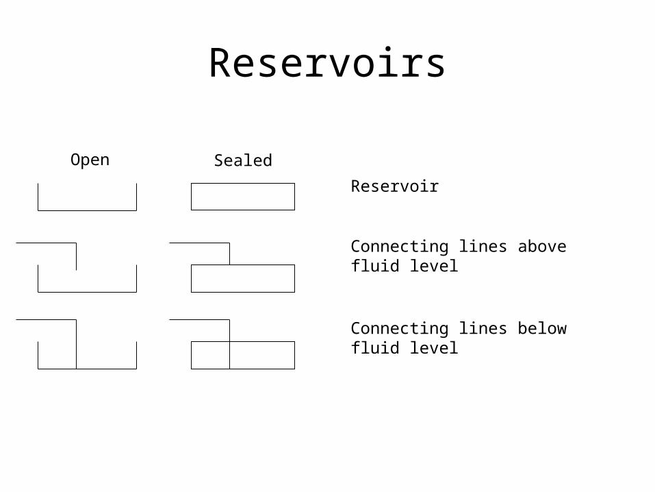
Reservoirs
Reservoir
Connecting lines above fluid level
Connecting lines below fluid level
SealedOpen
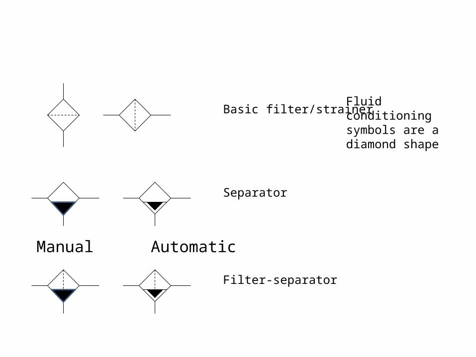
Basic filter/strainer
Separator
Filter-separator
Manual Automatic
Fluid conditioning symbols are a diamond shape
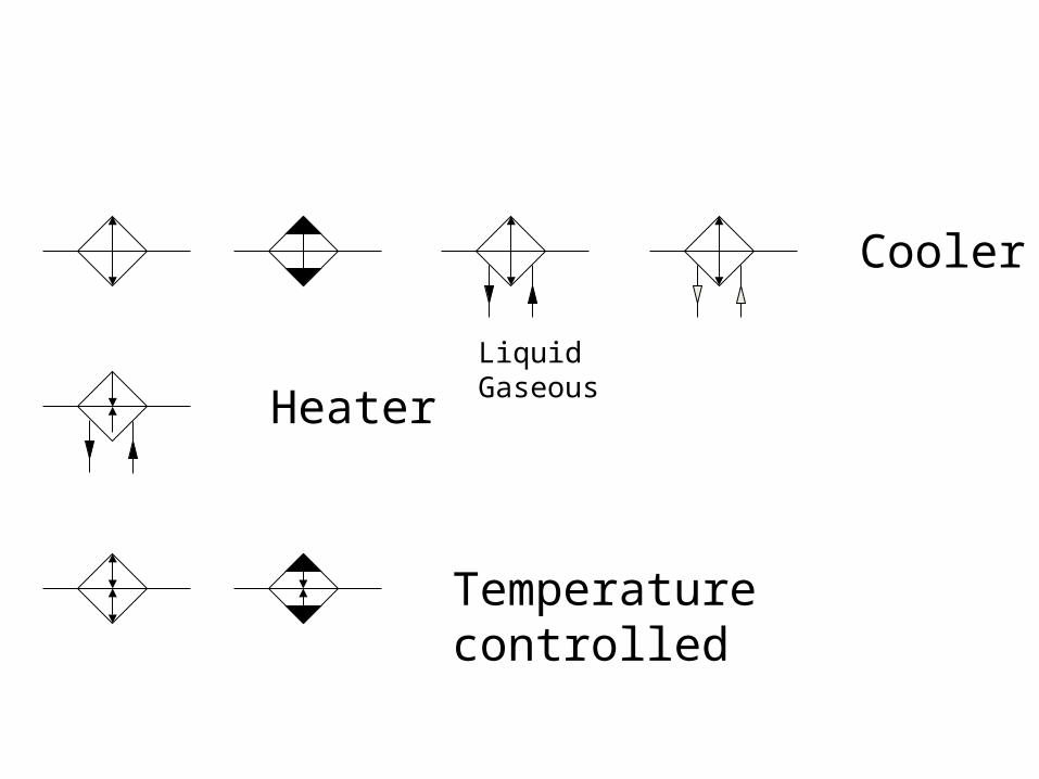
Cooler
Liquid Gaseous
Heater
Temperature controlled
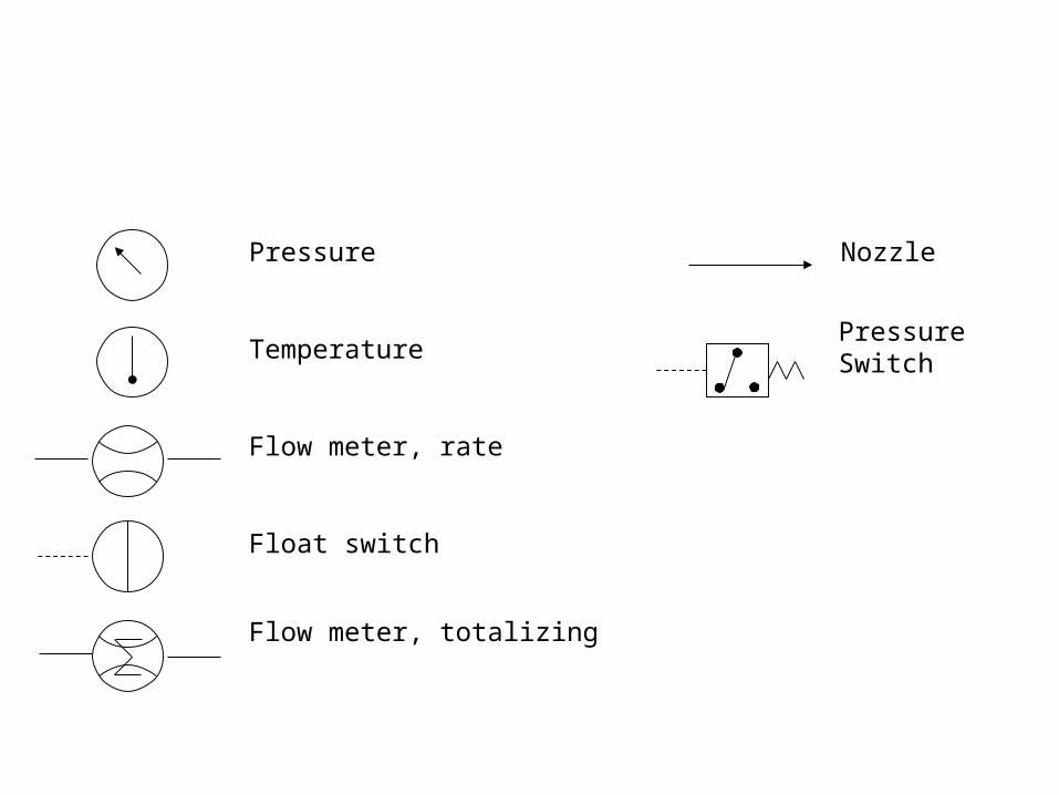
Pressure
Temperature
Flow meter, rate
Flow meter, totalizing
Float switch
Nozzle
Pressure Switch

Pumps
Fixed displacement
Unidirectional Bidirectional
Variable displacement, non-compensated, unidirectional
Variable displacement, non-compensated, bidirectional
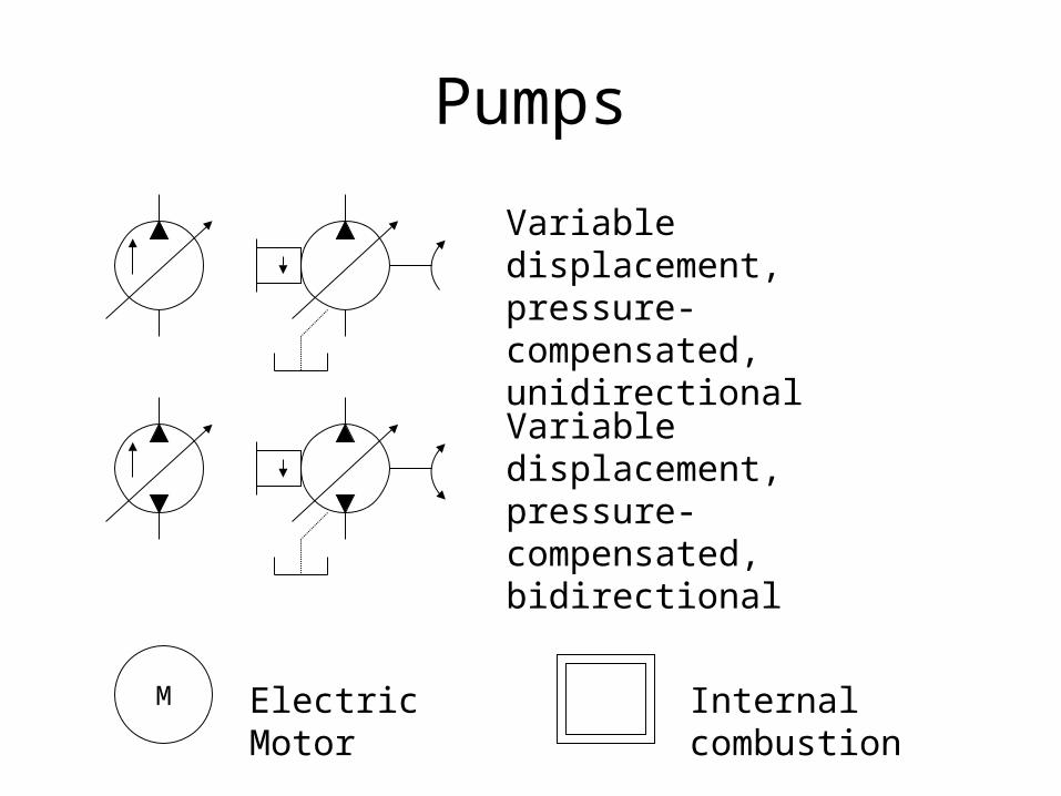
Pumps
Variable displacement, pressure-compensated, unidirectional
Variable displacement, pressure-compensated, bidirectional
M Electric Motor Internal combustion

MotorsFixed displacement, unidirectional
Fixed displacement, bidirectional
Variable displacement, unidirectional
Variable displacement, bidirectional
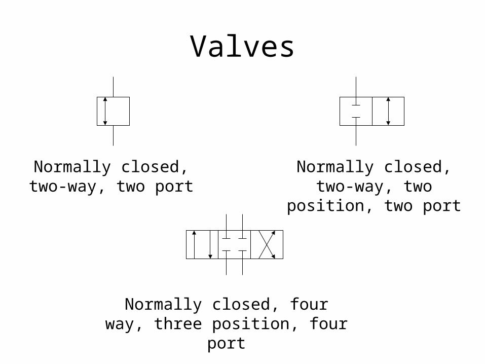
Valves
Normally closed, two-way, two port
Normally closed, two-way, two position, two port
Normally closed, four way, three position, four port
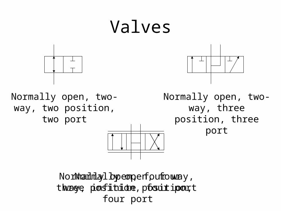
Valves
Normally open, two-way, two position, two port
Normally open, two-way, three position, three port
Normally open, four way, three position, four port
Normally open, four way, infinite position, four port
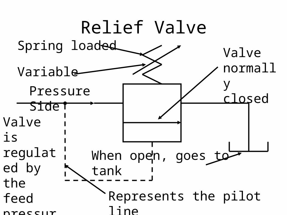
Relief Valve
Represents the pilot line
Pressure Side
Valve normally closed
Spring loaded
Variable
When open, goes to tank
Valve is regulated by the feed pressure
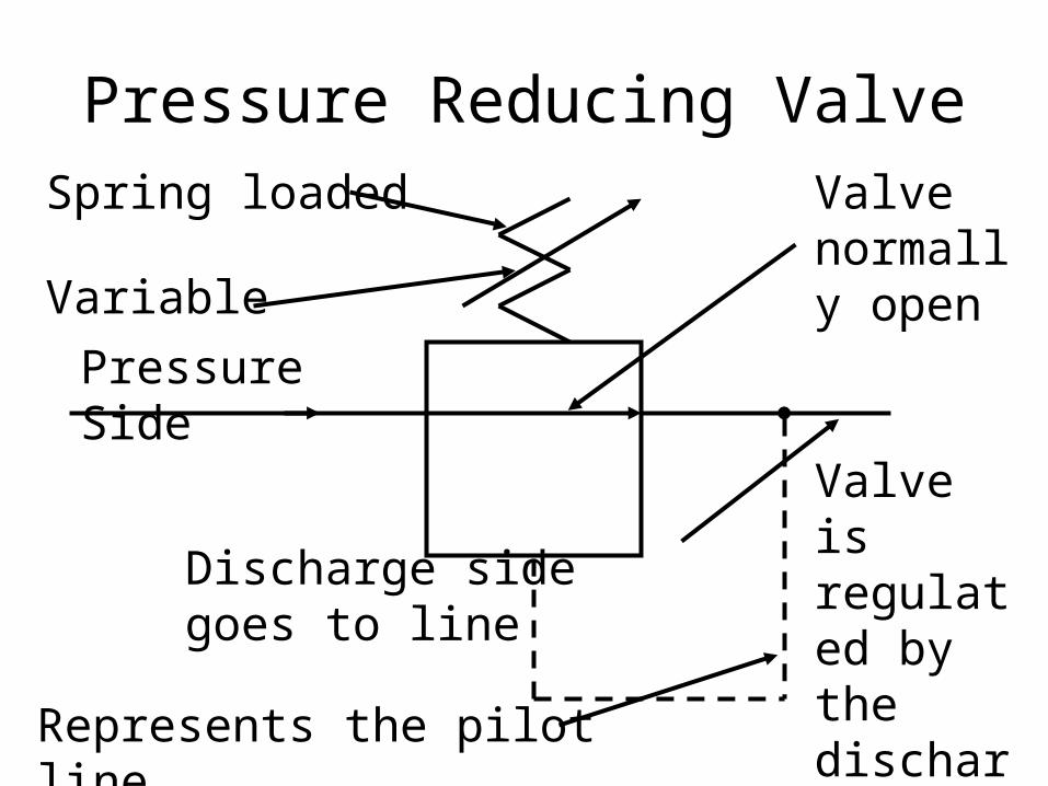
Pressure Reducing Valve
Pressure Side
Represents the pilot line
Valve normally open
Spring loaded
Variable
Discharge side goes to line
Valve is regulated by the discharge pressure

Valves
Relief Valve
Sequencing Valve
Pressure Reducing/Regulating Valve

Valves
Orifice
V Timing logic
Check valve
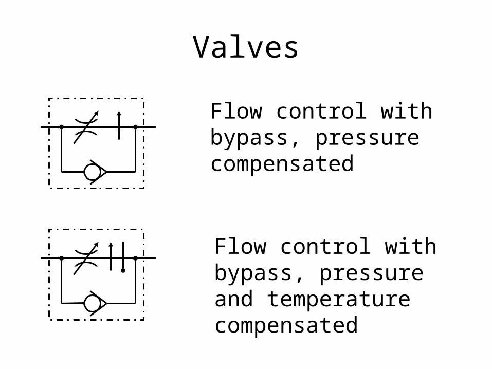
Valves
Flow control with bypass, pressure compensated
Flow control with bypass, pressure and temperature compensated
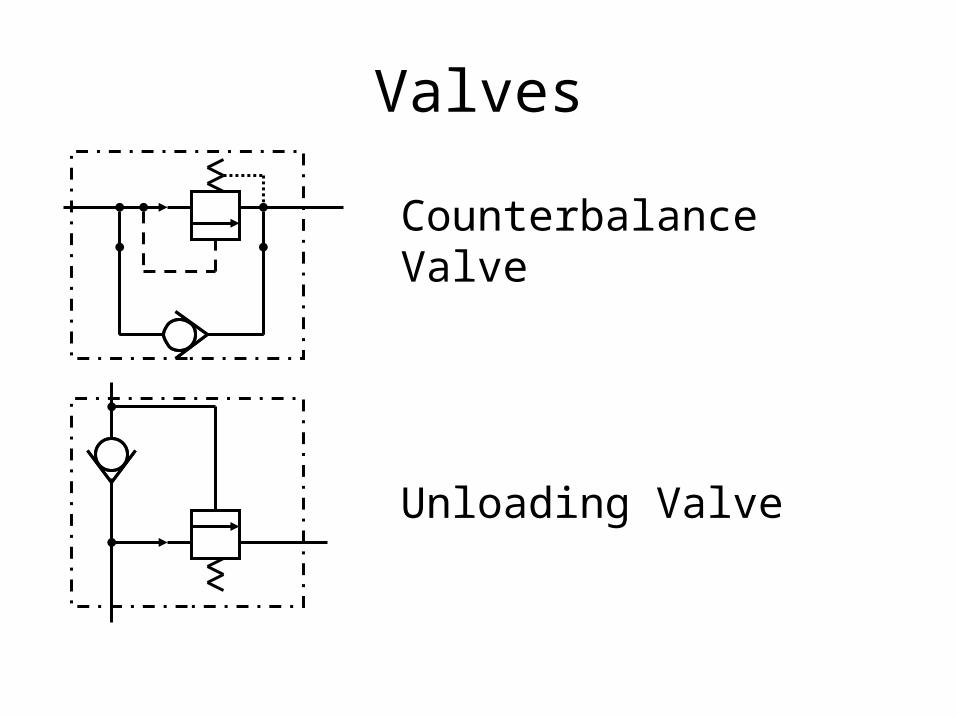
Valves
Counterbalance Valve
Unloading Valve
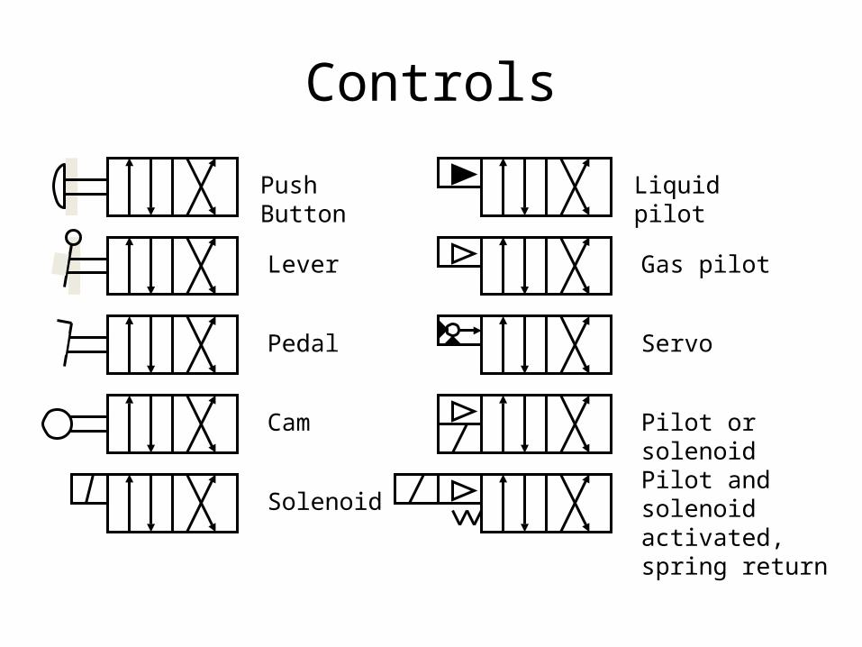
Controls
Push Button
Lever
Pedal
Cam
Solenoid
Liquid pilot
Gas pilot
Servo
Pilot or solenoid
Pilot and solenoid activated, spring return

Cylinders
Single acting
Single acting, spring return
Double acting
Double acting, double rod
Double acting, single cushion
Double acting, Double cushion
Double acting, double adjustable cushion
Telescoping
Ram
Pressure intensifier

This workforce solution was funded by a grant awarded by the U.S. Department of Labor’s Employment and Training Administration. The solution was created by the grantee and does not necessarily reflect the official position of the U.S. Department of Labor. The Department of Labor makes no guarantees, warranties, or assurances of any kind, express or implied, with respect to such information, including any information on linked sites, but not limited to accuracy of the information or its completeness, timeliness, usefulness, adequacy, continued availability or ownership.
This work is licensed under a Creative Commons CC BY 3.0 Unported License. http://creativecommons.org/licenses/by/3.0/
Related Documents