UNESCO-EOLSS SAMPLE CHAPTERS HYDRAULIC STRUCTURES, EQUIPMENT AND WATER DATA ACQUISITION SYSTEMS - Vol. I - Fluid Mechanics - Joseph Hun-wei Lee and James J. Sharp FLUID MECHANICS J. H. W. Lee Department of Civil Engineering, The University of Hong Kong, China J. J. Sharp Faculty of Engineering and Applied Science, Memorial University of Newfoundland, Canada Keywords: fluid mechanics, pressure variations, fluid in motion, types of flow, basic principles, continuity, energy, momentum, hydropower, energy loss, turbines, nozzles, open channel flow. Contents 1. Introduction 2. Pressure Variations and Forces in Fluids at Rest 3. Fluid in Motion: Types of Flow 4. Basic Principles of Fluid Motion: Continuity, Energy, and Momentum 5. Hydropower 6. Energy Loss 7. Turbines and Nozzles 8. Open Channel Flow 9. Concluding Remarks Glossary Bibliography Biographical Sketches Summary Essential concepts of fluid mechanics required to understand the action of hydraulic structures are developed. The fundamentals of pressure variation in a static fluid and the calculation of hydrostatic forces on submerged surfaces are first studied. Continuity, energy, and momentum principles for a fluid flow are then introduced using an essentially one-dimensional approach, followed by discussion of pipe flow, open channel flow, and hydropower. The ideas of flow measurement and conveyance, forces on hydraulic structures, and energy dissipation and abstraction, are illustrated through a number of worked novel application examples related to life support systems, in particular micro-hydropower and sustainable development. The article, which assumes little or no prior knowledge of the subject, offers a quick introduction to basic concepts of “green” fluid mechanics. The reader will gain an understanding of basic calculations for designing an appropriate simple hydroelectric system; other notions covered include ocean energy utilization, the use of hydraulic structures for environmental preservation and protection of human lives from devastating fluid flow forces, and flood risks imposed by dam construction. ©Encyclopedia of Life Support Systems (EOLSS) 29

Welcome message from author
This document is posted to help you gain knowledge. Please leave a comment to let me know what you think about it! Share it to your friends and learn new things together.
Transcript
UNESCO-EOLS
S
SAMPLE C
HAPTERS
HYDRAULIC STRUCTURES, EQUIPMENT AND WATER DATA ACQUISITION SYSTEMS - Vol. I - Fluid Mechanics - Joseph Hun-wei Lee and James J. Sharp
FLUID MECHANICS J. H. W. Lee Department of Civil Engineering, The University of Hong Kong, China J. J. Sharp Faculty of Engineering and Applied Science, Memorial University of Newfoundland, Canada Keywords: fluid mechanics, pressure variations, fluid in motion, types of flow, basic principles, continuity, energy, momentum, hydropower, energy loss, turbines, nozzles, open channel flow. Contents 1. Introduction 2. Pressure Variations and Forces in Fluids at Rest 3. Fluid in Motion: Types of Flow 4. Basic Principles of Fluid Motion: Continuity, Energy, and Momentum 5. Hydropower 6. Energy Loss 7. Turbines and Nozzles 8. Open Channel Flow 9. Concluding Remarks Glossary Bibliography Biographical Sketches Summary Essential concepts of fluid mechanics required to understand the action of hydraulic structures are developed. The fundamentals of pressure variation in a static fluid and the calculation of hydrostatic forces on submerged surfaces are first studied. Continuity, energy, and momentum principles for a fluid flow are then introduced using an essentially one-dimensional approach, followed by discussion of pipe flow, open channel flow, and hydropower. The ideas of flow measurement and conveyance, forces on hydraulic structures, and energy dissipation and abstraction, are illustrated through a number of worked novel application examples related to life support systems, in particular micro-hydropower and sustainable development. The article, which assumes little or no prior knowledge of the subject, offers a quick introduction to basic concepts of “green” fluid mechanics. The reader will gain an understanding of basic calculations for designing an appropriate simple hydroelectric system; other notions covered include ocean energy utilization, the use of hydraulic structures for environmental preservation and protection of human lives from devastating fluid flow forces, and flood risks imposed by dam construction.
©Encyclopedia of Life Support Systems (EOLSS) 29

UNESCO-EOLS
S
SAMPLE C
HAPTERS
HYDRAULIC STRUCTURES, EQUIPMENT AND WATER DATA ACQUISITION SYSTEMS - Vol. I - Fluid Mechanics - Joseph Hun-wei Lee and James J. Sharp
1. Introduction Fluid mechanics deals with the mechanics and behavior of all types of fluids. Some of these fluids may be gases, such as air, while others may be liquids, but even within these two broad categories there may be very different characteristics. For example, some liquids flow easily while others, for example molasses or crude oil, show great resistance to flow. The study of fluid mechanics should take all of these variations into account. However, consistent with the theme, here the coverage is limited to fluid mechanics as it relates to water. The aim is to present the basic fluid mechanical principles required to understand the action of hydraulic structures, and to develop and illustrate their application in life support systems through a number of examples. In particular mini/micro-hydropower and sustainable development was selected as the theme. This is the development of hydroelectricity, a sustainable renewable energy source, on a scale that might be suitable for small villages, or indeed, individual small farms. Mini hydro developments typically require a small dam and reservoir to store water, together with some sort of conveyance system, either a pipe or a channel, to transport the water to a turbine where power is generated. To design such a system it is necessary to have some understanding of flow measurement to determine the magnitude of flow in the river. Forces exerted by the fluid against the dam must be calculated to ensure that the dam will be safe. Flow in pipes and channels must be understood to calculate an appropriate size, and so that the energy loss due to resistance between the pipe or channel and the flowing water can be calculated. Finally, it is necessary to understand the way in which power is abstracted from the flowing water to be able to calculate the power output of any scheme. All of the above topics will be discussed in this article so that, by its conclusion, the reader should have an understanding of the relevant calculations for designing an appropriate, simple, hydroelectric system. Other interesting applications will also be covered. The article has been written for those with little or no prior knowledge of the subject, and assumes only a basic knowledge of mathematics up to first year university level. The fundamental nature of the topic is such that any professionals, teachers or researchers in the area will already be familiar with most of the material covered here although it is hoped that the treatment given will be somewhat different from that found in standard textbooks. 2. Pressure Variations and Forces in Fluids at Rest The basic difference between solids, liquids and gases lies in the relative strength of the intermolecular bonds. In a solid the bonds are strong enough for the material to retain a distinctive shape, while in a liquid the bonding forces are weaker to the extent that a liquid will flow to completely fill the bottom part of any container in which it is placed. The strength of the intermolecular force is even weaker in a gas which will expand to fill any closed container completely. The fact that a solid can maintain a particular shape also makes it possible for different stresses to exist on different planes passing through a single point. Such a condition is not possible in a fluid where the relatively weaker bonds make it impossible for the fluid to resist any shear stress permanently.
©Encyclopedia of Life Support Systems (EOLSS) 30
UNESCO-EOLS
S
SAMPLE C
HAPTERS
HYDRAULIC STRUCTURES, EQUIPMENT AND WATER DATA ACQUISITION SYSTEMS - Vol. I - Fluid Mechanics - Joseph Hun-wei Lee and James J. Sharp
This ensures that the pressure (analogous to stress in a solid) at a point in a fluid is the same in all directions (i.e., the pressure is equal on all planes passing through any particular point). Furthermore, because of the inability of a fluid to resist shear stresses without flowing, the pressure force at any point will always be perpendicular to the surface on which it acts. Of course, this is fairly obvious because any pressure force component parallel to the surface will cause the fluid to flow so as to eliminate that component. In a fluid at rest, the pressure distribution is entirely determined by the body (gravity) force. The change of pressure in the vertical direction can be shown to be:
)1(γ−=dzdp
where p = pressure, z = elevation (positive in the upwards direction), and γ = ρg = specific weight of fluid (ρ = density, g = gravitational acceleration). If the fluid is incompressible and homogenous (constant density, γ = constant), the pressure varies linearly with depth,
( ) )2(00 zzpp −−=− γ where p – p0 is the pressure relative to the reference pressure at z = z0. If the reference level is a free surface open to the atmosphere, then – (z – z0) is the depth below the surface and p – p0 is the difference between the pressure at elevation z and atmospheric pressure; this is called the gage pressure. This is the normal situation for water, which can generally be considered to be incompressible unless the flow conditions are changed very quickly, as in water hammer. The above equation can be rewritten to give the fundamental law of hydrostatics:
=+ zpγ
constant (3)
where γp and z each has the unit of length.
γp is termed the pressure head and z the
elevation head; the sum of the two, zp+
γ, is called the piezometric head. Stated simply,
the piezometric head is the same at all points in a fluid at rest. A point at a higher location (larger z) will have lower pressure so as to keep the piezometric head constant, and vice versa. In static water with a free surface (e.g., a lake or reservoir) the piezometric head relative to any datum will be the difference in elevation between the datum and the free surface. The simple relationship for pressure variation given above is sufficient to allow pressure forces to be calculated. On a vertical rectangular surface, for example a vertical dam wall of depth h, the pressure will vary linearly with depth, with zero pressure at the surface and a pressure of γh at the bottom of the dam (i.e., the pressure profile on the dam is triangular—the “pressure prism”). The total force on the dam will then be given by the average pressure multiplied by the area of the dam. For a dam width of B this
©Encyclopedia of Life Support Systems (EOLSS) 31
UNESCO-EOLS
S
SAMPLE C
HAPTERS
HYDRAULIC STRUCTURES, EQUIPMENT AND WATER DATA ACQUISITION SYSTEMS - Vol. I - Fluid Mechanics - Joseph Hun-wei Lee and James J. Sharp
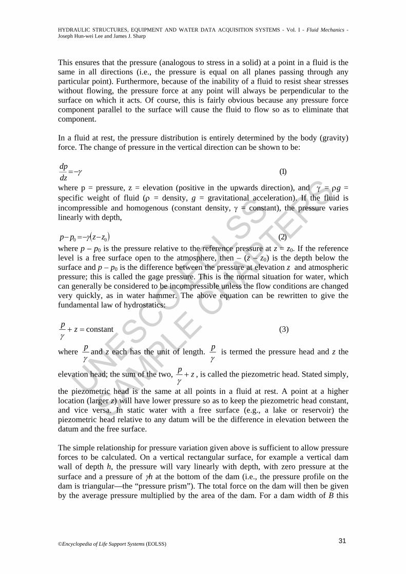
would be .21 2 BhFh γ= This is the only fluid force acting on the dam. It will be
horizontal and will act through the centroid of the pressure distribution, i.e., at a depth of 2h/3. In many cases the surface will be inclined, as shown in Figure 1. Here the dam surface is inclined at angle θ to the horizontal, and the dam must now withstand the combined effects of a horizontal and a vertical force. The horizontal force will be the same as before, while the vertical force Fv is given by the weight of the wedge of water immediately above the dam wall. For the circumstances shown in Figure 1,
.cot21 2 BhWFv θγ== It acts through the centroid of the triangle abc. The total force
on the dam is then the resultant of these two forces, namely .22vh FFR += The
resultant passes through the center of pressure C (the centroid of the elemental pressure forces) at an angle ( hv FF1tan −=φ ) to the horizontal.
Figure 1. Hydrostatic force on a dam
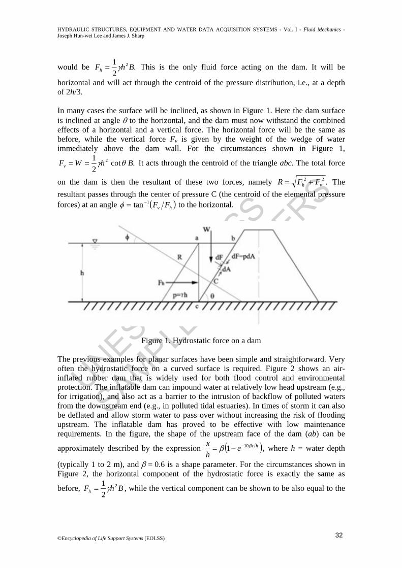
The previous examples for planar surfaces have been simple and straightforward. Very often the hydrostatic force on a curved surface is required. Figure 2 shows an air-inflated rubber dam that is widely used for both flood control and environmental protection. The inflatable dam can impound water at relatively low head upstream (e.g., for irrigation), and also act as a barrier to the intrusion of backflow of polluted waters from the downstream end (e.g., in polluted tidal estuaries). In times of storm it can also be deflated and allow storm water to pass over without increasing the risk of flooding upstream. The inflatable dam has proved to be effective with low maintenance requirements. In the figure, the shape of the upstream face of the dam (ab) can be
approximately described by the expression ( )hzehx ββ 101 −−= , where h = water depth
(typically 1 to 2 m), and β = 0.6 is a shape parameter. For the circumstances shown in Figure 2, the horizontal component of the hydrostatic force is exactly the same as
before, BhFh2
21 γ= , while the vertical component can be shown to be also equal to the
©Encyclopedia of Life Support Systems (EOLSS) 32

UNESCO-EOLS
S
SAMPLE C
HAPTERS
HYDRAULIC STRUCTURES, EQUIPMENT AND WATER DATA ACQUISITION SYSTEMS - Vol. I - Fluid Mechanics - Joseph Hun-wei Lee and James J. Sharp
weight of the water above the dam surface (ab). The latter can be obtained by integration and is equal to . BhFv
21.0 γ≈
Figure 2. An environmentally friendly air-inflated rubber dam
In general, the elemental force dF acting on an elemental area dA is dF = pdA, where p is the local pressure. Since the vectorial components of dF are known, given the pressure (Equation 2) and the orientation of the surface, integration of the elemental forces will give the hydrostatic force for a surface of any shape. For γ = constant, the integration also results in two useful theorems for Fh and Fv: It can be shown that the horizontal and vertical components of the resultant are given by (i) Fh = horizontal force on the projection of the curved surface on the vertical plane; and (ii) Fv = γ × (volume subtended by the surface at the reference pressure level, z = z0). For the case when there is water directly above the surface, the latter reduces to the weight of fluid above the surface. Similarly the line of action or center of gravity of the resultant can be obtained in general by integration. The reader is reminded that (i) pressure acts in all directions; and (ii) the hydrostatic force is a result of the summation of local normal stresses (pressure) acting on the surface in contact with the water.
Figure 3a. A cistern for storing water
©Encyclopedia of Life Support Systems (EOLSS) 33

UNESCO-EOLS
S
SAMPLE C
HAPTERS
HYDRAULIC STRUCTURES, EQUIPMENT AND WATER DATA ACQUISITION SYSTEMS - Vol. I - Fluid Mechanics - Joseph Hun-wei Lee and James J. Sharp
Figure 3b.Pascal vessels and the hydrostatic paradox
Figure 3a shows a 76 m cistern used to store water. It consists of a 5 m diameter lower cylindrical portion narrowing into a 2.5 m diameter upper cylindrical portion by a shoulder, in the form of a conical frustrum 6 m high. Although the weight of the water acts downwards, there are significant upward hydrostatic forces on the slanting sides of the cone (ABCD). The vertical upthrust can be large enough to rupture the base of the pipe (an example was the failure of the Coney Island Standpipe in December 1886). Figure 3b shows vessels of different shapes all with the same base area a and filled to the same depth of water h. It should not come as a surprise that despite different weights of water in the vessels (“Pascal” vessels), the force acting on the base is the same in each vessel, F = γha (this is the Hydrostatic Paradox which puzzled the ancient Greeks). The apparent “paradox” can be readily explained by isolating the fluid mass inside each vessel and considering the pressure force along the sides of the vessel. This discussion of hydrostatics closes with an illustrative “toy example” (Example 1): Example 1: Hydrostatic Force on an Inverted Cone. An inverted hollow perspex cone (base diameter 9 cm, height 10 cm) with an effective density less than that of water is inserted into a 2 cm diameter hole at the bottom of a laboratory tank (Figure 4a). First, the initially empty tank is slowly filled with water from below (Figure 4b). Neglecting friction forces, at what depth h1 will the cone start to float?
Figure 4 (a, b, and c). An inverted cone experiment
After draining all the water in the tank, a second experiment is carried out. However, this time the cone is pressed down lightly against the hole, and the tank is slowly filled with water up to a large depth above the cone so that it will stay in position when left
©Encyclopedia of Life Support Systems (EOLSS) 34

UNESCO-EOLS
S
SAMPLE C
HAPTERS
HYDRAULIC STRUCTURES, EQUIPMENT AND WATER DATA ACQUISITION SYSTEMS - Vol. I - Fluid Mechanics - Joseph Hun-wei Lee and James J. Sharp
alone (Figure 4c). Water is then allowed to discharge very slowly through a side opening. At what depth h2 will the cone pop up from the hole? The interior of the solid perspex cone is made partly hollow, and the mass of the cone is
0.15 kg (volume of cone = hr 2
31π ).
Solution: Consider first the situation when the tank is initially empty and water is added (Figure 4b). At some depth h1, the upward hydrostatic force will exceed the weight and the cone will rise, allowing water to exit through the hole in the base of the tank. This depth can be calculated by considering the force on an elemental strip of height dh at a depth h (Figure 4a). The force is given by the product of the pressure at depth h, i.e., h multiplied by the area of the strip around the surface of the cone, dF = p(πBdh). This can then be integrated from h = 0 to h = h1 to obtain the total force. When the vertical component of this force is equal to the weight the cone will move upwards and open the hole. The mass of the cone, Mc = 150 g. The vertical distance of the cone vertex below the 1 cm radius opening is: ho = 10/4.5 × 1 = 2.2 cm (Figure 4b). The vertical force acting on the surface ab is equal to γ (volume abc); hence:
( ) ( ) ( ) )4(0.10.131
31
12
02
012
1 gMhhhhrgF cv =⎟⎠⎞
⎜⎝⎛ −−+= πππρ
where ρ = 1000 kg/m3, and g = 9.81 m/s2. Noting that r1 = (4.5/10) (h1 + ho), it can be shown that the force balance becomes (with depths in cm):
( ) ( ) ( ) ( ) )5(1500.12.20.13145.0
31
12223
01 =−−+ hhh πππ
The equation can be rearranged into a form convenient for iteration:
( ) )6(27.4646.2 31+= yy where y = h1 + ho. Starting with y = 0, the above equation gives y = h1 + ho = 9.38 cm after three iterations. Hence h1 = 7.2 cm. For the second case (Figure 4c), a quite different situation arises if the cone is held in place while water fills the tank to a depth significantly in excess of the height of the cone. When the cone is released it will remain in place while the water level is lowered, and will continue to remain in place until the depth decreases to some depth h2 which will be greater than h1. These depths are different because the pressure force on the top surface of the cone must be included in the second case but not in the first. The upward force acting on the surface abc can be similarly computed (it is equal to the displaced volume of abc). In addition there is a downward pressure p = γ(h2 – 7.8) acting on the center part of the top surface of the cone, cc. It can be shown then that:
( ) ( )v c vF upward W F downward (7)= +
©Encyclopedia of Life Support Systems (EOLSS) 35

UNESCO-EOLS
S
SAMPLE C
HAPTERS
HYDRAULIC STRUCTURES, EQUIPMENT AND WATER DATA ACQUISITION SYSTEMS - Vol. I - Fluid Mechanics - Joseph Hun-wei Lee and James J. Sharp
or
( ) ( ) ( ) ( ) )8(8.70.18.70.10.1311045.0
31
222
022 −+=⎟
⎠⎞
⎜⎝⎛ ×−−× hWh c γππππγ
This then gives h2 = 19 cm. Now suppose the position of the cone is reversed and it is placed over the hole with its pointed end upwards. It is easy to see that the hole will remain sealed under all conditions. In that position the vertical component of the pressure force always acts down to reinforce the weight and keep the hole closed. 3. Fluid in Motion: Types of Flow Flows may be classified in various ways, but two useful classifications deal with consideration of the flow characteristics with respect to time and with respect to distance along the flow path. Steady flow refers to one in which the flow characteristics are constant everywhere with respect to time, whereas the flow characteristics vary with time in unsteady flows. In reality, all flows are unsteady if looked at over a long enough time period, but much can be learned from a study of steady flows. For example a hydraulic structure on a river might be designed to cope with the maximum flow and the minimum flow. Each could be considered from a steady flow point of view and the way in which the flow changed from one condition to the other might be of little interest. On the other hand, the study of the movement of flood waves or tidal influence in an estuary would certainly have to consider the unsteady nature of the flow. An alternative method of classifying the flow considers the flow characteristics at a particular instant of time and looks at whether there is any change with respect to distance along the flow path. When the flow characteristics (depth, velocity, etc.) are constant along the length of the channel the flow is said to be uniform. This condition occurs when the forces causing (e.g., gravity) and opposing (e.g., friction) flow are in balance. When the forces are not balanced the flow will accelerate or decelerate. The characteristics will then vary along the channel and the flow is said to be gradually or rapidly varied depending on the flow curvature. The flow is then nonuniform even though it is steady. Most natural flows are unsteady and nonuniform. However, many useful calculations can be made by considering steady uniform flows. For example, water supply pipes are designed to cater for the maximum flow and the flow variation throughout the day does not affect the size of pipe needed for the maximum flow. Most pipelines operate with uniform flow because the diameter is constant. The flow in natural channels would be varied but may be approximated as uniform over short distances. In 1883, Professor Osborne Reynolds observed two distinctly different types of flow. These have become known as laminar and turbulent flow. Laminar flow is an orderly flow in which there are no eddies. Particles in the flow follow one another in smooth paths; a dye trace injected into the fluid would follow a fairly straight unbroken line and would not disperse throughout the flow. Flows of viscous oil, malt or molasses would all be cases of laminar flow. These liquids are all viscous, or sticky, liquids. However the flow of any fluid may be laminar if it occurs at small enough scale or small enough velocity. For example the movement of groundwater, which occurs at low velocities
©Encyclopedia of Life Support Systems (EOLSS) 36

UNESCO-EOLS
S
SAMPLE C
HAPTERS
HYDRAULIC STRUCTURES, EQUIPMENT AND WATER DATA ACQUISITION SYSTEMS - Vol. I - Fluid Mechanics - Joseph Hun-wei Lee and James J. Sharp
A Bibliography Anwar H. O. (1967). Inflatable dams. Journal of Hydraulics Division, ASCE 93(3), 99–119. [A classic paper on the mechanics of air-inflated rubber dams.]
Francis J. R. D. and Minton P. (1986). Civil Engineering Hydraulics. Hong Kong: Edward Arnold (Times Asian Editions). [A classic text with excellent treatment of the connection between fluid mechanics and civil engineering hydraulic problems.]
French R. H. (1985). Open Channel Hydraulics. New York: McGraw Hill. [Provides a modern view on various aspects of open channel flow including environmental hydraulics; contains many design examples and practical numerical methods of computing gradually varied flow profiles.]
Henderson F. M. (1966). Open Channel Flow. New York: MacMillan. [Time-tested and thought provoking classic text on free surface flow covering basics as well as advanced topics such as hydraulic transients.]
Hranisavljevic D., Cox R., Dixon J., and Lees S. (1997). Loyalty Road retarding basin: development of a unique energy dissipater. Proceedings of the 3rd International Conference on River Flood Hydraulics, November 1997, Stellenbosch, South Africa (ed. J. Watts), pp. 157–166. Wallingford, UK: Hydraulics Research. [This describes the concept and performance of a novel energy dissipation structure used for a flood control project in Australia.]
Lawson T. B. (1995). Fundamentals of Aquaculture Engineering. New York: Chapman and Hall. [This contains descriptions of hydraulic devices that are useful in aquaculture management, in particular the use of aspirator nozzles to raise the dissolved oxygen level in fish farms.]
Liang N. K., Huang P. A., Li D. J., Chu L. L., and Wu C. L. (1978). Artificial upwelling induced by ocean currents—theory and experiment. Ocean Engineering 5, 83–94. [This and related papers describe a long-term laboratory and field research program to utilize ocean energy in Taiwan’s deep coastal waters.]
Massey B. S. (1989). Mechanics of Fluids (6th Edition). Van Nostrand Reinhold. [A concise and comprehensive fluid mechanics text for both mechanical and civil engineering students.]
Nezu I. and Nakagawa H. (1993). Turbulence in Open-Channel Flows. Rotterdam: Balkema. [A research text containing authoritative measurements of turbulent open channel flows.]
Smith C. D. (1985). Hydraulic Structures. Saskatoon (Canada): University of Saskatchewan. [An excellent monograph on the principles and design of various types of hydraulic structures.]
Subramanya K. (1982). Flow in Open Channels. New Delhi: Tata/McGraw Hill. [Well-written systematic text on open channel flows with good examples and problems.]
Streeter V. L. and Wylie E. B. (1987). Fluid Mechanics. Singapore: McGraw Hill. [Widely-adopted fluid mechanics text, with a good combination of fundamentals and classroom-tested problems.]
©Encyclopedia of Life Support Systems (EOLSS) 60
Guest6
Text Box
Guest6
Text Box
TO ACCESS ALL THE 34 PAGES OF THIS CHAPTER, Visit: http://www.eolss.net/Eolss-sampleAllChapter.aspx

UNESCO-EOLS
S
SAMPLE C
HAPTERS
HYDRAULIC STRUCTURES, EQUIPMENT AND WATER DATA ACQUISITION SYSTEMS - Vol. I - Fluid Mechanics - Joseph Hun-wei Lee and James J. Sharp
Tam P. W. M. (1998). Use of inflatable dams as agricultural weirs in Hong Kong. Journal of Hydraulic Engineering, ASCE 124(12), 1215–1226. [This paper contains a review of inflatable dams in Hong Kong and elsewhere.]
Vennard J. K. and Street R. L. (1975) Elementary Fluid Mechanics. New York: Wiley. [Good fluid mechanics text with emphasis on fundamentals as well as applications to mechanical and civil engineering.] Biographical Sketches Professor Joseph Hun-wei Lee is Redmond Professor of Civil Engineering and also Dean of the Faculty of Engineering of the University of Hong Kong. Professor Lee grew up in Hong Kong and obtained his BSc, MSc, and PhD degrees all from the Massachusetts Institute of Technology in the USA (1969-1977). His research interests lie at the interface between hydraulics/fluid mechanics and environmental engineering and these include all types of hydraulic problems related to the prediction and control of water quality. He has edited five books and published over 100 technical articles in international journals and books. He is an Associate Editor of the ASCE Journal of Hydraulic Engineering, China Ocean Engineering, Water Quality and Ecosystem Modeling, Korea International Journal of Water Engineering Research, and Communications in Nonlinear Science and Numerical Simulation. For his contributions to environmental hydraulics, he was awarded the Alexander von Humboldt Research Fellowship by the German Government in 1991 and the Croucher Foundation Senior Research Fellowship in 1998. He is also Consulting/Advisory Professor of Hohai University and Tongji University.
Over the past two decades, Professor Lee has served as expert advisor on many projects that include the UK Marine Outfall Design Guide, Sydney Deepwater Outfall Modelling Study, Deep Bay Water Quality Regional Control Strategy Study, Hong Kong Strategic Sewage Disposal Scheme, Shanghai Sewage Project, Yuen Long Bypass Floodway Model Study, Tai Hang Tung Flood Storage Scheme, and the European Economic Community Harmful Algal Bloom Expert System (HABES 2001) group research project. He is the Chairman of the Fluid Mechanics section of the International Association for Hydraulic Engineering and Research (IAHR) and Vice-Chairman of the IAHR Asian-Pacific Division. He has also served on the Engineering Panel of the Hong Kong Research Grants Council from 1993 to 1999, and also as the Chairman of the University Grants Committee Research Assessment Exercise (1999) Built Environment Panel. (Homepage: http://www.hku.hk/civil/envhydraulics or http://www.aoe-water.hku.hk/). Jim Sharp has is in possession of the degrees B.Sc., M.Sc., ARCST, Ph.D., and has the Professional Status of P. Eng., C. Eng. He is a Fellow of the Canadian Society for Civil Engineering, the Institution of Civil Engineers (UK) and the Engineering Institute of Canada. He is Professor of Engineering in the Faculty of Engineering and Applied Science at the Memorial University of Newfoundland, Canada, where he was Associate Dean (1992– - 1998) and Chairman of Civil Engineering (1983– - 1991). He has more than thirty years of’ experience in higher education, including positions of academic leadership. His research and teaching interests relate to hydro-technical and environmental engineering. He has published four hydro-technical books and more than one hundred papers and articles on research topics. He acts as a reviewer for scholarly journals and as a consultant for engineering firms in Newfoundland. He has written widely on educational matters and has other academic interests, having published two history books and a number of trade books. In 1991 he was honored by the Canadian Society of Civil Engineers with the Dagenais Award for outstanding contributions to the development and practice of hydro-technical engineering in Canada. In 1993 he received the ASCE Award for the best technical note (Hydraulics) in the previous year, and in 1996 the Newfoundland Association of Professional Engineers and Geo-scientists Award for important and valued contributions to the profession of engineering and to Newfoundland and Labrador. In 1998 he received the James A. Vance Award for outstanding service to the Canadian Society for Civil Engineering, and in 1999 the Award for Research Excellence from the Environmental Protection Agency of China. His experience includes two and a half years of professional work in Africa, and visiting professorships at Universities in Singapore, Hong-Kong, West Malaysia, Sarawak and the United Kingdom. Since 1992 he has been is external advisor and assessor to the Civil Engineering Department at the University of Malaya in Kuala Lumpur, and he is currently also a member of the Editorial Board for the Journal of that University. In 1994 he was made an Honorary Professor of Shandong University of Technology, China. He has worked as an educational consultant in the Philippines where he advised on accreditation procedures and on the development of engineering
©Encyclopedia of Life Support Systems (EOLSS) 61

UNESCO-EOLS
S
SAMPLE C
HAPTERS
HYDRAULIC STRUCTURES, EQUIPMENT AND WATER DATA ACQUISITION SYSTEMS - Vol. I - Fluid Mechanics - Joseph Hun-wei Lee and James J. Sharp
curricula for the country. He has also been involved in the accreditation of Canadian Universities and Government Research Organizations. His current research interests relate to the hydraulics of ocean out-fall structures, a research area funded by the Natural Sciences and Research Council of Canada.
©Encyclopedia of Life Support Systems (EOLSS) 62
Related Documents