121 Hydraulic Snubbers Description Hydraulic snubbers are dynamic linear supports designed to protect piping systems and components by restraining undesirable displacements due to the following: Seismic / earthquake loadings Water Hammer effects Violent thrusts due to safety valve discharges Extreme wind conditions Other similar conditions The snubbers allow free movement during the thermal displacement, but lock up and transfer the energy to the fixed structure when seismic loadings occur; this is achieved by using the snubbers’ sophisticated valve mechanism. Once the disturbance has passed, the device returns to its initial state and enables slow movements once again. In this way the snubber provides temporary additional support to the installation in order to prevent it from entering into resonance and thereby minimising the risk of breaking due to vibrations. Hydraulic Snubbers are used on: Piping Tanks Control Valves Stream Generators Safety Valves Pumps, motors, etc. Snubber selection considerations Dynamic Load At normal loading, check that the snubber is capable of handling dynamic forces during normal operation. Stroke The selected snubber must be able to accommodate the maximum travel between the assembly position and the extreme operation position. Available space Ensure that once the snubber is in place, the expected movements are achievable within the space envelope. An extension adaptor should be included If the space available is larger than the travel capacity of the snubber. Snubber Types Our hydraulic snubbers are available as standard configurations, but large loads and extended travels can be accommodated. In the first instance please email your snubber requirements to [email protected]; we will then provide technical recommendations, generate specific drawings and provide prices / delivery periods.

Welcome message from author
This document is posted to help you gain knowledge. Please leave a comment to let me know what you think about it! Share it to your friends and learn new things together.
Transcript
121
Hydraulic Snubbers
Description Hydraulic snubbers are dynamic linear supports designed to protect piping systems and components by restraining undesirable displacements due to the following:
Seismic / earthquake loadings Water Hammer effects Violent thrusts due to safety valve discharges Extreme wind conditions Other similar conditions
The snubbers allow free movement during the thermal displacement, but lock up and transfer the energy to the fixed structure when seismic loadings occur; this is achieved by using the snubbers’ sophisticated valve mechanism. Once the disturbance has passed, the device returns to its initial state and enables slow movements once again. In this way the snubber provides temporary additional support to the installation in order to prevent it from entering into resonance and thereby minimising the risk of breaking due to vibrations. Hydraulic Snubbers are used on:
Piping Tanks Control Valves Stream Generators Safety Valves Pumps, motors, etc.
Snubber selection considerations Dynamic Load At normal loading, check that the snubber is capable of handling dynamic forces during normal operation. Stroke The selected snubber must be able to accommodate the maximum travel between the assembly position and the extreme operation position. Available space Ensure that once the snubber is in place, the expected movements are achievable within the space envelope. An extension adaptor should be included If the space available is larger than the travel capacity of the snubber. Snubber Types Our hydraulic snubbers are available as standard configurations, but large loads and extended travels can be accommodated. In the first instance please email your snubber requirements to [email protected]; we will then provide technical recommendations, generate specific drawings and provide prices / delivery periods.

122
Dynamic Restraints Index
Description Figure Page
Sway Brace 230 123 Rigid Strut 240 124/125 Yoke Clamp 250 128 Restraint Pipe Clamp 260 126/127 Restraint Pipe Clamp 260A 126/127 Restraint Pipe Clamp 260AH 126/127 Restraint Pipe Clamp 260H 126/127 Rigid Strut Attachment 280 129 Pipe Whip Restraint 290 129 Riser Clamps 300R 130/131 Riser Clamps 301R 130/131 Riser Clamps 302R 130/131
Fig. Page Desc. Pictorial
230 123 Sway Brace
240 124/125 Rigid Strut
250 128 Yoke
Clamp
260/H
126/127 Pipe
Clamp
Fig. Page Desc. Pictorial
260A/AH 126/127Pipe
Clamp
280 129 Rigid Strut Attachment
290 129 Pipe Whip Restraint
300R 301R 302R
130/131Riser Clamp

123
Dynamic Equipment – Fig. 230
Fig.230 – Sway Brace
Size Pipe Size
Preload Kg
Spring Rate Kg
mm
Max Force
Kg
Max Rod Length at Max force M mm
L Pin Ø K
PlateThick
J A
RTOB
C D E F G H Use With Structural
Attachment 1 50-90 23 0.89 90 1500 20 12 12 115 345 42 395 100 25 225 25 Fig.280-15 2 100-200 68 2.68 270 1000 24 12 12 115 360 42 410 120 25 225 25 Fig.280-15 3 225-600 204 8.04 815 1000 24 12 12 115 450 42 500 150 25 280 25 Fig.280-15 4 225-600 400 16.07 1630 1000 30 20 25 168 430 58 500 140 40 270 30 Fig.280-55 5 225-600 614 24.48 2540 1000 36 20 25 168 470 58 555 150 50 312 30 Fig.280-55 6 225-600 820 32.66 3270 1000 36 20 25 168 520 58 605 150 50 362 30 Fig.280-55
Our Spring Sway Brace is recommended for controlling vibration, absorbing shock loading, or restraining the pipe movement due to thermal expansion. The Sway Brace is available in six sizes with a maximum load of 3270 kg. The Sway Brace should be in a neutral position when the pipe is at operating condition, at which time the two spring plates should be in contact with the end plates. Any adjustment required should be undertaken by use of the load coupling. Sizes available: 1 to 6 Preset Loads: 23kg to 820kg Maximum Force: 90kg to 3270kg Features Vibration is dampened with an immediate opposing force thus allowing the pipe to return to its normal position. All units have 75mm travel in either direction. The preloaded spring provides two-way movement Accurate neutral adjustment is assured A wide range of Surface Finishes is available The Sway Brace is shipped ready for installation.
Optional Features Larger sizes can be supplied to suit.
Fig. 230 Material: Carbon Steel Please Specify:- Figure Number: Size: Finish:
124
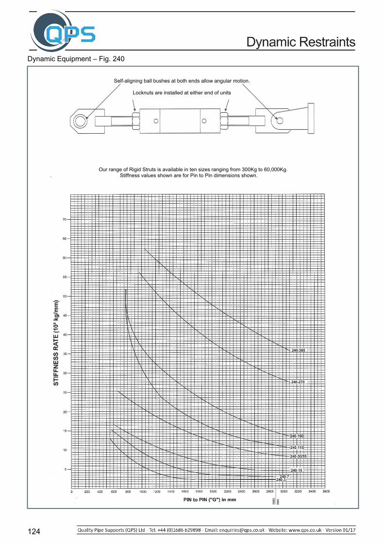
Dynamic Equipment – Fig. 240
Our range of Rigid Struts is available in ten sizes ranging from 300Kg to 60,000Kg.
. Stiffness values shown are for Pin to Pin dimensions shown.
Self-aligning ball bushes at both ends allow angular motion.
Locknuts are installed at either end of units
125
Dynamic Equipment – Fig. 240
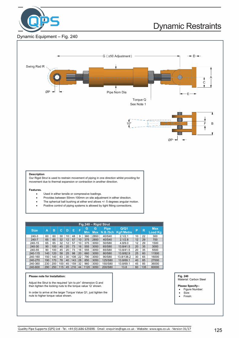
Fig.240 – Rigid Strut
Size A B C D E F G
Min G
Max Pipe
N.B./SchQ/Q1
KgF/MetreP R
Max Load Kg
240-3 60 60 30 10 48 9 360 2850 40/S40 2.1/2.1 10 22 300 240-7 65 65 32 12 57 10 375 2850 40/S40 2.1/2.8 12 29 700 240-15 65 65 32 12 57 10 375 3050 50/S80 4.8/9.0 12 29 1500 240-30 90 100 45 20 73 16 555 3050 65/S80 13.8/41.5 20 35 3000 240-55 90 100 45 20 73 16 555 3050 65/S80 13.8/41.5 20 35 5500
240-115 140 120 58 25 98 20 660 3050 80/S80 13.8/82.9 25 60 11500 240-160 150 140 63 30 108 22 790 3050 90/S80 13.8/138.2 30 65 16000 240-270 190 170 78 40 143 28 850 3050 125/S80 13.8/69.1 40 85 27000 240-360 230 200 100 45 159 32 960 3050 150/S80 13.8/69.1 45 85 36000 240-600 290 250 115 45 216 44 1120 3050 200/S80 13.8 60 135 60000
Fig. 240 Material: Carbon Steel Please Specify:- Figure Number: Size: Finish:
Description Our Rigid Strut is used to restrain movement of piping in one direction whilst providing for movement due to thermal expansion or contraction in another direction.
Features. Used in either tensile or compressive loadings. Provides between 50mm-100mm on site adjustment in either direction. The spherical ball bushing at either end allows +/- 5 degrees angular motion.
Positive control of piping systems is allowed by tight fitting connections.
Please note for Installation: Adjust the Strut to the required “pin to pin” dimension G and then tighten the locking nuts to the torque value ‘Q’ shown. In order to arrive at the larger Torque Value Q1, just tighten the nuts to higher torque value shown.

126
Dynamic Equipment – Fig. 260A/260AH & 260/260H
Fig. 260 & 260A – Restraint Pipe Clamp NPS Pipe O/D A B C D FxT G H
15 21.3 92 32 12 12 30 x 6 110 50 20 26.9 95 38 12 12 30 x 6 113 56 25 33.7 97 44 12 12 30 x 6 115 62 32 42.4 102 46 12 12 30 x 6 120 64 40 48.3 102 49 25 12 30 x 6 120 68 50 60.3 127 54 25 12 30 x 6 149 76 65 76.1 140 67 25 12 45 x 8 162 89 80 88.9 152 76 25 12 45 x 8 175 99 90 101.6 159 82 25 12 45 x 8 181 104100 114.3 165 100 25 16 50 x 10 194 129125 139.7 178 114 25 16 50 x 10 206 142150 168.3 216 135 38 20 65 x 10 254 173175 193.7 230 150 38 20 65 x 10 268 188200 219.1 241 163 38 20 65 x 10 279 201225 244.5 265 180 38 20 65 x 12 303 218250 273 279 192 38 20 65 x 12 317 230300 323.9 305 220 38 20 65 x 12 343 258350 355.6 330 243 51 24 80 x 15 378 291400 406.4 356 273 51 24 80 x 15 403 320450 457.2 381 300 51 24 80 x 15 429 348500 508 406 329 51 24 80 x 20 457 380550 558.8 432 365 51 24 100 x 20 489 422600 610 457 390 51 24 100 x 20 514 447650 660.4 559 431 51 30 130 x 25 622 494700 711.2 585 457 51 30 130 x 25 648 520750 762 610 482 51 30 130 x 25 673 545800 812.8 647 508 51 30 130 x 25 710 571900 914.4 699 560 51 30 130 x 25 762 623
Fig. 260AH & 260H – Restraint Pipe Clamp NPS Pipe O/D A B C D FxT G H 150 168.3 229 143 44 30 100x12 279 193175 193.7 241 158 44 30 110x12 291 208200 219.1 254 172 44 30 110x12 305 223225 244.5 305 198 51 36 100x20 359 258250 273 305 214 51 36 100x20 359 268300 323.9 330 240 51 36 100x20 384 294350 355.6 356 262 57 42 110x20 419 325400 406.4 381 292 57 42 110x25 444 355450 457 406 317 57 42 110x25 469 380500 508 457 353 57 42 130x25 521 417550 558.8 483 393 57 42 150x30 559 469600 610 508 418 57 42 150x30 584 494650 660.4 581 443 57 42 150x30 657 519700 711.2 610 472 57 42 150x30 686 548750 762 635 497 57 42 150x30 711 573800 812.8 661 525 57 42 150x30 737 601900 914.4 711 575 57 42 150x30 787 651

127
Dynamic Equipment – Fig. 260/260H & 260A/260AH
Fig. 260/260H & 260A/260AH - SWL in Kg Material Carbon Steel Alloy Steel
Temperature 340⁰C 400⁰C 510⁰C 538⁰C 566⁰C
NPS Pipe O/D
Clip I/D
Figure Number Figure Number 260 260H 260 260H 260A 260AH 260A 260AH 260A 260AH
15 21.3 23 250 250 210 210 210 20 26.9 28 250 250 210 210 210 25 33.7 36 250 250 210 210 210 32 42.4 44 250 250 210 210 210 40 48.3 50 680 635 635 455 315 50 60.3 62 680 635 635 455 315 65 76.1 80 680 635 635 455 315 80 88.9 92 680 635 635 455 315 90 101.6 106 680 635 635 455 315 100 114.3 118 1135 1000 1045 725 500 125 139.7 144 1135 1000 1045 725 500 150 168.3 172 1270 3630 1135 3220 1180 3310 815 2360 590 1680 175 193.7 198 1270 3630 1135 3220 1180 3310 815 2360 590 1680 200 219.1 224 1270 3630 1135 3220 1180 3310 815 2360 590 1680 225 244.5 248 1450 4990 1315 4445 1360 4535 950 3265 680 2270 250 273 278 1450 4990 1315 4445 1360 4535 950 3265 680 2270 300 323.9 330 1450 4990 1315 4445 1360 4535 950 3265 680 2270 350 355.6 362 1450 5760 1725 5125 1770 5260 1270 3765 910 2720 400 406.4 412 1950 5760 1725 5125 1770 5260 1270 3765 910 2720 450 457 464 1950 5760 1725 5125 1770 5260 1270 3765 910 2720 500 508 516 2495 6805 2220 6805 2270 6185 1450 4810 1135 3400 550 558.8 566 2720 6805 2405 6805 2495 6185 1590 5900 1225 4080 600 610 618 2720 6805 2405 6805 2495 6185 1590 5900 1225 4080 650 660.4 670 3630 6805 3175 6805 3265 6185 2085 5900 1590 4080 700 711.2 721 3630 6805 3175 6805 3265 6185 2085 5900 1590 4080 750 762 773 3630 6805 3175 6805 3265 6185 2085 5900 1590 4080 800 812.8 824 3630 6805 3175 6805 3265 6185 2085 5900 1590 4080 900 914.4 926 3630 6805 3175 6805 3265 6185 2085 5900 1590 4080
Fig. 260/A/AH/H Material: See Note Please Specify:- Figure Number: NPS: Finish:
This range of Pipe Clamps is primarily used with Hydraulic Shock Arrestor and Rigid Strut
dynamic supports.
When selecting, please note that the load rating of the rigid struts and snubbers should not
exceed the SWL of the pipe clamp.
Please consult our Technical Department for advice.
The pin diameters and gap dimension G should
always be specified.
Note: Pin dia. D and gap G will vary depending on whether used in conjunction with a strut or shock arrestor. See component section for details. (Pin & Gap dimensions given are suitable for rigid rod connection) Fig.260 & 260H Material = Carbon Steel Fig.260A & 260AH Material = Alloy Steel Fig.260 & 260H up to 400°C Fig.260A & 260AH above 400°C

128
Dynamic Equipment – Fig. 250
Yoke Clamps
Size D G P T Maximum Load Kg
350°C 510°C 538°C 566°C250-7 20 10 12 25 700 415 195 80 250-15 20 10 12 30 1500 895 420 180 250-55 30 16 20 45 5500 3285 1550 670
250-115 50 20 25 75 11500 6865 3240 1400 250-160 60 22 30 90 16000 9555 4510 1945 250-270 60 28 40 150 27000 16125 7610 3285 250-360 80 32 45 200 36000 21500 10150 4380 250-600 100 44 60 200 60000 35835 16920 7305
Yoke Clamps – Dimension E
NPS Size
250-7 250-15 250-55 250-115 250-160 250-270 250-360 250-60065 125 125 80 150 150 205 90 160 160 210 100 165 165 215 125 180 180 235 150 190 190 245 270 175 220 220 260 285 200 240 240 270 295 225 255 255 285 310 250 270 270 295 320 300 295 295 320 350 385 390 350 310 340 360 405 450 485 485 400 335 360 385 440 455 510 510 450 385 410 470 480 535 535 500 415 440 500 510 585 585 550 435 510 535 555 605 605 600 460 540 565 585 635 635 650 505 565 600 620 670 670 700 550 590 630 650 705 705 750 595 615 660 685 735 735 800 645 690 735 765 765 900 695 735 825 810 810
Yoke Clamp - Materials
ComponentTemp.
Up To 200°C 201°C & Over Yoke Body Carbon Steel Alloy Steel
Saddle Strap Carbon Steel Alloy Steel U-Bolt Alloy Steel Alloy Steel
Load Pin Stainless Steel Stainless Steel
Fig. 250 – available in Carbon Steel Alloy Steel Stainless Steel
Please Specify:- Figure Number: Size: Surface Finish:
Our standard Yoke Clamps are recommended for the support of hot pipework, and where loadings are relatively high. They are used in conjunction with our range of hydraulic shock arrestors and rigid struts.
Please note that load pin dia. P and dimension G are dependent upon whether the clamp is used in conjunction with a rigid strut or a hydraulic shock arrestor.
Note: The Yoke Clamp is designed to
accommodate a 10° cone in relation to the pipe.
Fig.250 – Size 7 to 160 Fig.250 – Size 270 to 600

129
Dynamic Equipment – Fig. 280 & 290
Fig. 280– Rigid Strut Attachment Size A B C D E F G H J T 280-3 60 60 25 10 48 10 22 22 ~ 10 280-7 65 65 30 12 57 12 25 25 ~ 10 280-15 65 65 30 12 57 12 25 25 ~ 10 280-30 90 100 50 20 73 20 34 34 ~ 12 280-55 90 100 50 20 73 20 34 34 ~ 12
280-115 140 120 60 25 98 25 45 45 70 15 280-160 150 140 70 30 108 30 50 50 73 20 280-270 190 170 80 40 143 40 65 65 100 25 280-360 230 200 95 45 159 45 75 75 105 30 280-600 290 250 110 60 216 45 90 90 150 45
Fig. 290 Material: Carbon Steel Please Specify:- Figure Number: NPS: Finish:
Fig 290 Pipe Whip Restraint.
Pipe Whip Restraints are exclusively used in the Nuclear Industry.
The restraints dampen and absorb the kinetic energy of bursting pipes in emergency cases. For this purpose the elongation capacity of the encompassing U-Bolts is used, as they are designed to absorb the
expected dynamic loads.
Features
The restraint absorbs the energy of the moving pipe and has high energy absorption in relation to its size.
The restraint is compact in size. The restraint provides a relatively large normal clearance between
the restraint and pipe to allow for normal thermal movement. Design of restraints can be undertaken to suit clients’ requirements.
Fig. 280 Material: Carbon Steel Please Specify:- Figure Number: Size: Finish:
Type 280 Size 3 to 55 Type 280 Size 115 to 600

130
Dynamic Equipment – Fig.300R, 301R & 302R – Riser Clamps
Stress-Temperature Correction Factors
Design °C Temperature
Material Carbon Steel
2¼ Cr-1 Mo BS 1501 PT2-622
Stainless Steel Grade 316
343 0.80 0.80 0.70 371 0.85 0.80 0.71 399 0.93 0.80 0.71 427 0.80 0.72 454 0.83 0.73 482 0.92 0.75 510 1.10 0.80 538 1.50 0.86 566 2.20 0.99 593 1.20 620 1.80 640 2.30 650 3.00
The total load to be supported must be multiplied by 2 before the Stress Temperature Correction Factor is applied.
Stress Temperature Correction Factor The selection chart is based on a maximum allowable stress in the clamp of 8.50 Kg/mm2; the table of Stress Temperature Correction Factors provides details for the most commonly used materials.
Stress Temperature Correction Factor.
8.50
S. A. Design @ Temperature
Or: Corrected Load = calculated load x Stress Temperature Correction Factor. Example:
Pipe Nominal Bore = 400mm Support Load = 4545Kg Rod Centres (C) = 1100mm Temperature = 510°C Procedure = Stock Material – Alloy Steel 2% Cr 1% Mo. Correction Factor from table STCF = 1.1 Corrected Load = 9090 x 1.1 = 10,000Kg.
Using Charts: 1. Enter lower chart @ rod centres = 1100mm, move horizontally until sloping line 400mm pipe size is intersected. 2. Project this intersection vertically upwards. 3. Enter upper chart @ load = 11000Kg. Move horizontally to the right until the vertical line from (B) is intersected. 4. Read stock size of curve immediately above the (C) intersection.
Fig.300R Fig.302R
Fig.301R
Fig. 300R, 301R & 302R Material: Carbon Steel Please Specify:- Figure Number Nominal Pipe Size Temperature Range Surface Finish
These Riser Clamps are similar to the ones shown in our Ancillary section and should be used together with our dynamic restraints. For selection purposes please ensure that the load rating of the strut / snubber is not greater than the load capacity of the pipe clamp. If the loads are greater then our Yoke Pipe clamp should be used. (Clamp gaps and load pins should always be checked)

131
Dynamic Equipment – Fig.300R, 301R & 302R
Related Documents