190 Hydraulic Shaft Lock ETP BUSHINGS ETP BUSHINGS Hydraulic Shaft Lock ETP BUSHINGS A hydraulic method using the Pascal's principle is employed to connect the shaft and the hub to eliminate all the disadvantages and inconvenience of the key connection. The machining tolerance of the shaft and the hub is just the general fitting tolerance and no special specification is needed. Positioning can be performed freely both in the rotation and shaft directions. Furthermore, a 1-bolt tightening task unique to the hydraulic method significantly reduces man-hours. Eas y and Precise Frictiona l Coupl ing Using t he Pascal's Principle Application Machine tool, pump, molding machine, printing machine, palletizing robot, various jigs and tools Positioning in the shaft and rotation d irections can be per f ormed arbitrarily, and it is easy to mount the device to equipment where accurate sync adjustment is required. You can design so that the device is connected to the shaft from the radial direction to save space. The device contri butes to a compact and lightweight low inertia design. Since the contact pressure on the shaft and hub sides is uniform, high concentricity can be maintained even if the hub's external d iameter is re d uce d . Accor d ing l y, unbalance caused by a centrifugal force can be reduced in applications where the device is used at a high rotation speed. Secure mounting can be performed by just tightening a couple of bolts to the specified torque. * To firmly secure the device with the appropriate contact pressure to the shaft and hub, mount the device so that the shaft and the hub completely contact each other. ■ Easy and Precise Positioning ■ Saving Space ■ High Concentricity ■ Secure and Quick Mounting ou * D e p e n d i n g o n y yo u r l o c a t i o n a n d s u c h , w e m a y el n o t b e a b l e t o s e l l y yo u o u r p r o d u c t s . P l e a s e t c o n t a c t u s fo o r d e t a i l s .

Welcome message from author
This document is posted to help you gain knowledge. Please leave a comment to let me know what you think about it! Share it to your friends and learn new things together.
Transcript
190
Hydraulic Shaft Lock ETP BUSHINGSETP BUSHINGS
Hydraulic Shaft Lock
ETP BUSHINGS
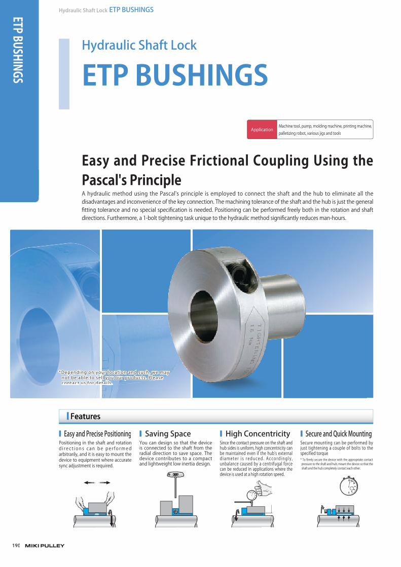
A hydraulic method using the Pascal's principle is employed to connect the shaft and the hub to eliminate all the disadvantages and inconvenience of the key connection. The machining tolerance of the shaft and the hub is just the generalfitting tolerance and no special specification is needed. Positioning can be performed freely both in the rotation and shaft directions. Furthermore, a 1-bolt tightening task unique to the hydraulic method significantly reduces man-hours.
Easy and Precise Frictional Coupling Using the Pascal's Principle
ApplicationMachine tool, pump, molding machine, printing machine,palletizing robot, various jigs and tools
Positioning in the shaft and rotation d i r e c t i on s c an be pe r f o rmedarbitrarily, and it is easy to mount thedevice to equipment where accurate sync adjustment is required.
You can design so that the device is connected to the shaft from theradial direction to save space. The device contributes to a compactand lightweight low inertia design.
Since the contact pressure on the shaft and hub sides is uniform, high concentricity canbe maintained even if the hub's external d i amete r i s r educed . Acco rd ing l y , unbalance caused by a centrifugal forcecan be reduced in applications where thedevice is used at a high rotation speed.
Secure mounting can be performed by just tightening a couple of bolts to thespecified torque.* To firmly secure the device with the appropriate contact pressure to the shaft and hub, mount the device so that the shaft and the hub completely contact each other.
■ Easy and Precise Positioning ■ Saving Space ■ High Concentricity ■ Secure and Quick Mounting
ou*Depending on yyour locat ion and such, we mayelnot be able to sel l yyou our produc ts . Please tcontac t us fofor detai ls .
003_ETPBush_01.indd 190 /2015 6:02:59 PMM4/21/2015 6:02:59 PMM4/21/2015 6:02:594/21/2015 6:02:59 PM

191
191
SERIES
Hydraulic Shaft LockETP BUSHINGS
Mechanical Shaft LockPOSI-LOCK
MODELS
ETP-T
ETP-E
ETP-A
ETP-H
COUPLINGS
ETP BUSHINGS
ELECTROMAGNETIC CLUTCHES & BRAKES
SPEED CHANGERS & REDUCERS
INVERTERS
LINEAR SHAFT DRIVES
TORQUE LIMITERS
ROSTA
Model/Type Main body material Surface finishingApplied shaft
diameter[mm]
Max. rated torque[N・m]
Max. rated thrust[N]
Operating temperature[℃]
Concentricity[mm]
ETP-T SCM415 or an equivalent ー 15 ~ 100 18000 360000 -30 ~ 110 0.006
ETP-T C SCM415 or an equivalent
Electrolessnickel plating 15 ~ 60 3000 99750 -30 ~ 110 0.006
ETP-E SMn420 or anequivalent ー 15 ~ 100 17000 280000 -30 ~ 85 0.02
ETP-E R SUS431 or anequivalent ー 15 ~ 60 3300 90000 -30 ~ 85 0.02
ETP-A SCM415 or an equivalent ー 15 ~ 100 15500 310000 -30 ~ 85 0.05
ETP-A B SCM415 or an equivalent ー 15 ~ 100 15500 310000 -30 ~ 85 0.05
ETP-A C SCM415 or an equivalent
Electrolessnickel plating 15 ~ 50 1426 53000 -30 ~ 85 0.05
ETP-A S SCM415 or an equivalent ー 19 ~ 50 1000 40000 -30 ~ 85 0.05
ETP-A R SUS630 or anequivalent ー 15 ~ 50 1550 62000 -30 ~ 85 0.05
ETP-H SMn420 or anequivalent ー 50 ~ 220 273000 2485000 -40 ~ 150 0.02
Series Tightening method Specifications Lineup
ETP BUSHINGS ETP-T
ETP-T C
ETP-E
ETP-E R
ETP-A
ETP-A B
ETP-A C
ETP-A S
ETP-A R
ETP-H
Standard
Electroless nickel plating
Standard
Stainless
Standard
Hexagon bolt
Simple rustproof
Short
Stainless
High torque
1-bolt high-performance type
1-bolt general-purpose type
Multiple-bolt type
Tapered piston/shim
* Some sizes are fixed with 2 bolts.
miki_Catalog_e.indb 191miki_Catalog_g_e.indb 191 /2015 10:26:46 AMM5/20/2015 10:26:46 AMM5/20/2015 10:26:46 A5/20/2015 10:26:46 AM
192
Hydraulic Shaft Lock ETP BUSHINGSETP BUSHINGS ETP-TETP TECHNO
ETP EXPRESS
ETP-E
Max. rated torque [N・m] 18000
Max. rated thrust [N] 360000
Applied shaft diameter [mm] φ15 ~100
Operating temperature [℃] -30 ~110
Backlash Zero
Concentricity [mm] 0.006
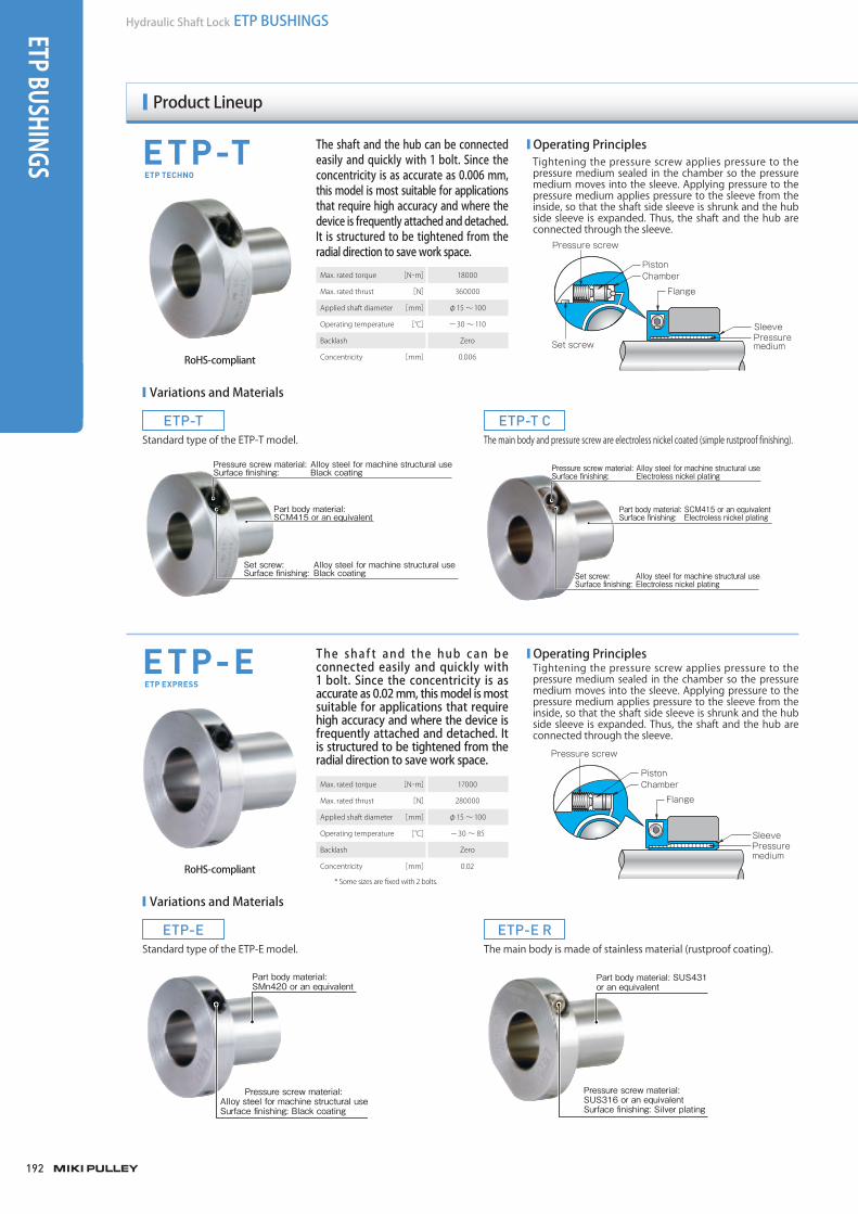
The shaft and the hub can be connected easily and quickly with 1 bolt. Since the concentricity is as accurate as 0.006 mm, this model is most suitable for applications that require high accuracy and where the device is frequently attached and detached. It is structured to be tightened from the radial direction to save work space.
The shaf t and the hub can be connected easily and quickly with 1 bolt. Since the concentricity is as accurate as 0.02 mm, this model is most suitable for applications that require high accuracy and where the device is frequently attached and detached. It is structured to be tightened from the radial direction to save work space.
■ Operating PrinciplesTightening the pressure screw applies pressure to the pressure medium sealed in the chamber so the pressure medium moves into the sleeve. Applying pressure to the pressure medium applies pressure to the sleeve from the inside, so that the shaft side sleeve is shrunk and the hub side sleeve is expanded. Thus, the shaft and the hub are connected through the sleeve.
■ Operating PrinciplesTightening the pressure screw applies pressure to the pressure medium sealed in the chamber so the pressure medium moves into the sleeve. Applying pressure to the pressure medium applies pressure to the sleeve from the inside, so that the shaft side sleeve is shrunk and the hub side sleeve is expanded. Thus, the shaft and the hub are connected through the sleeve.
RoHS-compliant
RoHS-compliant
Pressure medium
Flange
Chamber
Pressure screw
Set screw
Sleeve
Piston
Pressure medium
Flange
Chamber
Pressure screw
Sleeve
PistonMax. rated torque [N・m] 17000
Max. rated thrust [N] 280000
Applied shaft diameter [mm] φ15 ~100
Operating temperature [℃] -30 ~ 85
Backlash Zero
Concentricity [mm] 0.02
Part body material: SCM415 or an equivalentSurface finishing: Electroless nickel plating
Pressure screw material: Alloy steel for machine structural useSurface finishing: Electroless nickel plating
Set screw: Alloy steel for machine structural useSurface finishing: Electroless nickel plating
Part body material: SUS431 or an equivalent
Pressure screw material: SUS316 or an equivalentSurface finishing: Silver plating
ETP-T
ETP-E
ETP-T C
ETP-E R
Standard type of the ETP-T model.
Standard type of the ETP-E model.
The main body and pressure screw are electroless nickel coated (simple rustproof finishing).
The main body is made of stainless material (rustproof coating).
■ Variations and Materials
■ Variations and Materials
Part body material: SCM415 or an equivalent
Pressure screw material: Alloy steel for machine structural useSurface finishing: Black coating
Set screw: Alloy steel for machine structural useSurface finishing: Black coating
Part body material: SMn420 or an equivalent
Pressure screw material: Alloy steel for machine structural useSurface finishing: Black coating
* Some sizes are fixed with 2 bolts.
Product Lineup
miki_Catalog_e.indb 192 5/20/2015 10:26:47 AM

193
193
SERIES
Hydraulic Shaft LockETP BUSHINGS
Mechanical Shaft LockPOSI-LOCK
MODELS
ETP-T
ETP-E
ETP-A
ETP-H
COUPLINGS
ETP BUSHINGS
ELECTROMAGNETIC CLUTCHES & BRAKES
SPEED CHANGERS & REDUCERS
INVERTERS
LINEAR SHAFT DRIVES
TORQUE LIMITERS
ROSTA
Flange material: S45C or an equivalent Surface finishing: Zinc plating
Sleeve material: SCM415 or an equivalentSurface finishing: Electroless nickel plating
Clamping bolt material: Alloy steel for machine structural useSurface finishing: Antirust film coating
ETP-A
ETP-H
Compared to the mechanical connecting element, the number of bolts can be reduced and attachment and detachment can be simplified. The concentricity is 0.05 mm so mounting can be performed with relatively high precision.
The maximum rated torque is very large so this model is suitable for applications where a heavy thrust load is applied.
■ Operating PrincipleThe pressure medium inserted in the sleeve is sealed by a sealing ring. Tightening the clamping bolt compresses the pressure medium mechanically through the flange, piston ring, and sealing ring. Applying pressure to the pressure medium applies pressure to the sleeve from the inside, so that the shaft side sleeve is shrunk and the hub side sleeve is expanded. Thus, the shaft and the hub are connected through the sleeve.
■ Operating PrincipleA hydraulic pressure from the port moves the tapered piston inserted in the sleeve to the shaft direction. The movement of the tapered piston shrinks the shaft side sleeve and expands the hub side sleeve. Thus, the shaft and the hub are connected through the sleeve. The hydraulic pressure just moves the tapered piston and does not apply pressure after the connection. The connecting force is maintained by the wedge effect of the tapered piston.
RoHS-compliant
RoHS-compliant
Flange
Sleeve
Pressure mediumShear ringPiston ring
Clampingbolt
Sleeve
Groove
Tapered pistonPort
Max. rated torque [N・m] 15500
Max. rated thrust [N] 310000
Applied shaft diameter [mm] φ15 ~100
Operating temperature [℃] -30 ~ 85
Backlash Zero
Concentricity [mm] 0.05
Max. rated torque [N・m] 273000
Max. rated thrust [N] 2485000
Applied shaft diameter [mm] φ50 ~220
Operating temperature [℃] -40 ~150
Backlash Zero
Concentricity [mm] 0.02
Flange material: SUS630 or an equivalent
Sleeve material: SUS630 or an equivalent
Clamping bolt material: SUS316 or an equivalent
Plastic plug
Part body material: SMn420 tempered or an equivalent
Steel plug: SCM435 or an equivalent
ETP-A
ETP-A C
ETP-A B
ETP-A R
ETP-A SStandard type of the ETP-A model.
The main body is electroless nickel coated (simple rustproof finishing).
A hexagon bolt is used for the clamping bolt so the device can be mounted even in tight space in the thrust direction.
The main body is made of stainless material (rustproof coating).
A short-sleeve type, which can be mounted to the thin part of the hub.
■ Variations and Materials
Flange material: S45C or an equivalent
Sleeve material: SCM415 or an equivalent
Clamping bolt material: Alloy steel for machine structural useSurface finishing: Black coating
Flange material: S45C or an equivalent
Sleeve material: SCM415 or an equivalent
Clamping bolt material: Alloy steel for machine structural useSurface finishing: Black coating
Flange material: S45C or an equivalent
Sleeve material: SCM415 or an equivalent
Clamping bolt material: Alloy steel for machine structural useSurface finishing: Black coating
ETP CLASSIC
ETP HYLOC
003_ETPBush_01.indd 193 4/21/2015 6:03:02 PM
194
Hydraulic Shaft Lock ETP BUSHINGSETP BUSHINGS
Customization Examples
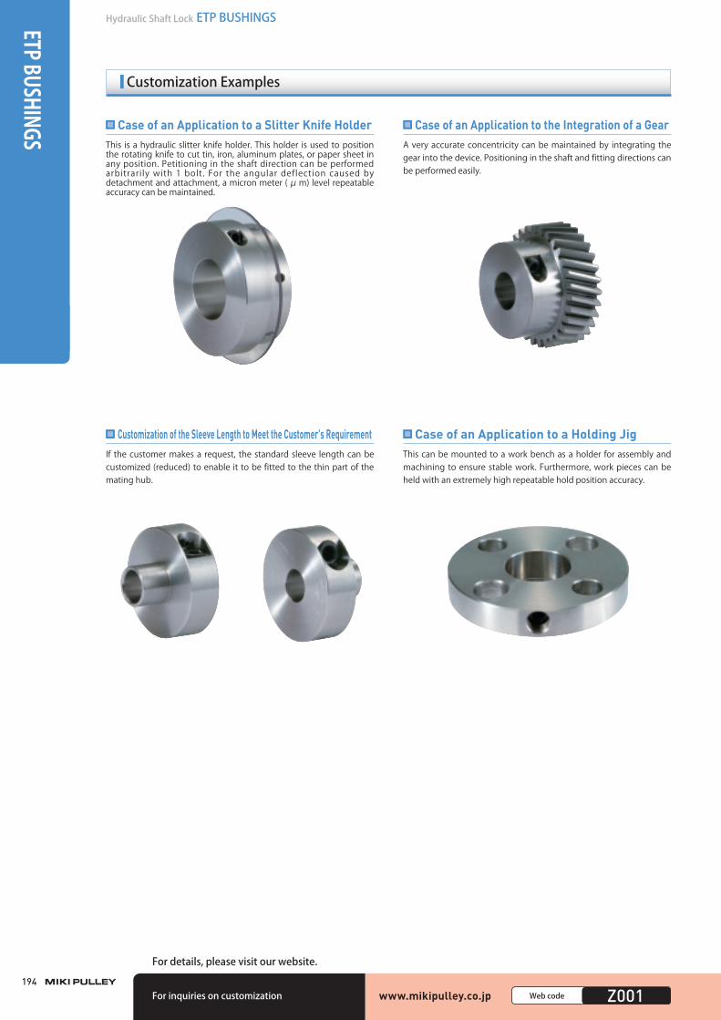
This is a hydraulic slitter knife holder. This holder is used to position the rotating knife to cut tin, iron, aluminum plates, or paper sheet in any position. Petitioning in the shaft direction can be performed arbitrarily with 1 bolt. For the angular deflection caused by detachment and attachment, a micron meter (μm) level repeatable accuracy can be maintained.
Case of an Application to a Slitter Knife HolderA very accurate concentricity can be maintained by integrating the gear into the device. Positioning in the shaft and fitting directions can be performed easily.
Case of an Application to the Integration of a Gear
If the customer makes a request, the standard sleeve length can be customized (reduced) to enable it to be fitted to the thin part of the mating hub.
Customization of the Sleeve Length to Meet the Customer's RequirementThis can be mounted to a work bench as a holder for assembly and machining to ensure stable work. Furthermore, work pieces can be held with an extremely high repeatable hold position accuracy.
Case of an Application to a Holding Jig
www.mikipulley.co.jp 0000Web code Z001For inquiries on customization
For details, please visit our website.
003_ETPBush_01.indd 194 4/21/2015 6:03:03 PM
195
195
SERIES
Hydraulic Shaft LockETP BUSHINGS
Mechanical Shaft LockPOSI-LOCK
MODELS
ETP-T
ETP-E
ETP-A
ETP-H
COUPLINGS
ETP BUSHINGS
ELECTROMAGNETIC CLUTCHES & BRAKES
SPEED CHANGERS & REDUCERS
INVERTERS
LINEAR SHAFT DRIVES
TORQUE LIMITERS
ROSTA
FAQ
Q1 Please let me know about the durability of the ETP bushings.
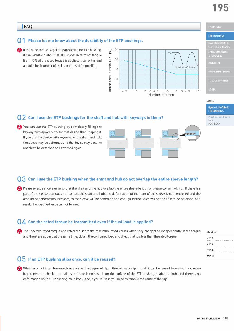
If the rated torque is cyclically applied to the ETP bushing,
it can withstand about 500,000 cycles in terms of fatigue
life. If 75% of the rated torque is applied, it can withstand
an unlimited number of cycles in terms of fatigue life.
A
Q3 Can I use the ETP bushing when the shaft and hub do not overlap the entire sleeve length?
Please select a short sleeve so that the shaft and the hub overlap the entire sleeve length, or please consult with us. If there is a
part of the sleeve that does not contact the shaft and hub, the deformation of that part of the sleeve is not controlled and the
amount of deformation increases, so the sleeve will be deformed and enough friction force will not be able to be obtained. As a
result, the specified value cannot be met.
A
Q4 Can the rated torque be transmitted even if thrust load is applied?
The specified rated torque and rated thrust are the maximum rated values when they are applied independently. If the torque
and thrust are applied at the same time, obtain the combined load and check that it is less than the rated torque.A
Q5 If an ETP bushing slips once, can it be reused?
Whether or not it can be reused depends on the degree of slip. If the degree of slip is small, it can be reused. However, if you reuse
it, you need to check it to make sure there is no scratch on the surface of the ETP bushing, shaft, and hub, and there is no
deformation on the ETP bushing main body. And, if you reuse it, you need to remove the cause of the slip.
A
Q2 Can I use the ETP bushings for the shaft and hub with keyways in them?
You can use the ETP bushing by completely filling the
keyway with epoxy putty for metals and then shaping it.
If you use the device with keyways on the shaft and hub,
the sleeve may be deformed and the device may become
unable to be detached and attached again.
A
Number of times
Rated torque ratio Tk/T [%] 200
150
100
50
4 5 2 3 4 5 2 3 4 5105 106 107
Tk
Number of times
003_ETPBush_01.indd 195 4/21/2015 6:03:04 PM

ETP BUSHINGS
196
Hydraulic Shaft Lock ETP BUSHINGS
ETP-T Models
Model Rated torque [N ・m]
Rated thrust [N]
Rated radial load[N]
Shaft contactpressure
[N/mm2]
Hub contactpressure
[N/mm2]
Tighteningtorque
[N ・m]
Moment of inertia[kg ・m2]
Mass[kg]
ETP-T-15 40 5000 1000 90 70 12 0.09 × 10- 3 0.25
ETP-T-19 90 9000 1000 90 70 12 0.14 × 10- 3 0.31
ETP-T-20 120 12000 2000 90 70 12 0.15 × 10- 3 0.32
ETP-T-24 220 18000 2000 90 70 16 0.40 × 10- 3 0.57
ETP-T-25 290 23000 3000 90 70 16 0.44 × 10- 3 0.60
ETP-T-30 500 33000 4000 90 70 16 0.60 × 10- 3 0.70
ETP-T-35 800 45000 5000 90 70 16 1.00 × 10- 3 1.00
ETP-T-40 1200 60000 6000 90 70 24 1.70 × 10- 3 1.30
ETP-T-50 2000 94000 9000 90 70 24 2.70 × 10- 3 1.70
ETP-T-60 4000 133000 12000 90 70 40 5.00 × 10- 3 2.50
ETP-T-70 6500 18600 13000 90 70 40 8.80 × 10- 3 3.60
ETP-T-75 7800 20800 14000 90 70 40 11.60 × 10- 3 4.20
ETP-T-80 9000 225000 15000 90 70 40 14.37 × 10- 3 4.77
ETP-T-90 13000 288000 17000 90 70 60 24.07 × 10- 3 6.48
ETP-T-100 18000 360000 19000 90 70 80 37.02 × 10- 3 8.41
* The rated torque values are those when the thrust is zero and the rated thrust values are those when the torque is zero.* The rated torque, rated thrust, shaft contact pressure, and hub contact pressure values given are measured values at a temperature of 20℃ .* ETP-T-70, 75, 80, 90, and 100 are made to order.
Specifications
Pressure screw M
LL1
φdφD
φD1
N
R ETP-T- Size
Dimensions
Model d D D1 L L1 R N M
ETP-T-15 15 19 52 25 41 14.5 6 1-M12
ETP-T-19 19 24 58 28 44 18 6 1-M12
ETP-T-20 20 25 59 30 46 19 6 1-M12
ETP-T-24 24 30 71 33 53 23 6 1-M14
ETP-T-25 25 32 73 35 55 23.5 6 1-M14
ETP-T-30 30 38 78 40 60 26.5 6 1-M14
ETP-T-35 35 44 88 45 65 30 6 1-M14
ETP-T-40 40 52 100 55 75 34 8 1-M16
ETP-T-50 50 65 110 60 80 40 8 1-M16
ETP-T-60 60 75 122 70 95 46.5 10 1-M20
ETP-T-70 70 90 138 85 110 52 10 1-M20
ETP-T-75 75 95 146 90 115 56 10 1-M20
ETP-T-80 80 100 154 95 120 58 10 1-M20
ETP-T-90 90 112 170 105 133 64.5 10 1-M22
ETP-T-100 100 125 184 115 145 70 12 1-M24
* The nominal diameter of the pressure screw M is equal to the quantity minus the nominal diameter of the screw threads.
Unit [mm]
How to Place an Order
www.mikipulley.co.jp Web code B001To download CAD data or product catalogs:
* Depend i ng on you r l o c a t i o n and su ch , wemay no t b e ab l e t o s e l l y ou ou r p r o du c t s .P lease contac t us for deta i l s .
003_ETPBush_01.indd 196003_ETPBush_01.indd 196 /2015 6:03:04 PMM4/21/2015 6:03:04 PMM4/21/2015 6:03:044/21/2015 6:03:04 PM
MODELS
ETP-T
ETP-E
ETP-A
ETP-H
SERIES
Hydraulic Shaft LockETP BUSHINGS
Mechanical Shaft LockPOSI-LOCK
COUPLINGS
ETP BUSHINGS
ELECTROMAGNETIC CLUTCHES & BRAKES
SPEED CHANGERS & REDUCERS
INVERTERS
LINEAR SHAFT DRIVES
TORQUE LIMITERS
ROSTA
197
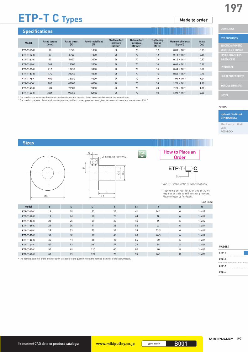
197ETP-T C Types
Model Rated torque [N・m]
Rated thrust [N]
Rated radial load[N]
Shaft contactpressure
[N/mm2]
Hub contact pressure
[N/mm2]
Tightening torque
[N・m]
Moment of inertia[kg・m2]
Mass[kg]
ETP-T-15-C 30 3750 1000 90 70 12 0.09×10⁻³ 0.25
ETP-T-19-C 67 6750 1000 90 70 12 0.14×10⁻³ 0.31
ETP-T-20-C 90 9000 2000 90 70 12 0.15×10⁻³ 0.32
ETP-T-24-C 165 13500 2000 90 70 16 0.40×10⁻³ 0.57
ETP-T-25-C 217 17250 3000 90 70 16 0.44×10⁻³ 0.60
ETP-T-30-C 375 24750 4000 90 70 16 0.60×10⁻³ 0.70
ETP-T-35-C 600 33750 5000 90 70 16 1.00×10⁻³ 1.00
ETP-T-40-C 900 45000 6000 90 70 24 1.70×10⁻³ 1.30
ETP-T-50-C 1500 70500 9000 90 70 24 2.70×10⁻³ 1.70
ETP-T-60-C 3000 99750 12000 90 70 40 5.00×10⁻³ 2.50
* The rated torque values are those when the thrust is zero and the rated thrust values are those when the torque is zero.* The rated torque, rated thrust, shaft contact pressure, and hub contact pressure values given are measured values at a temperature of 20°C.
Made to order
Pressure screw M
LL1
φdφD
φD1
N
R ETP-T- -C
Type (C: Simple antirust specifications)
Size
Model d D D1 L L1 R N M
ETP-T-15-C 15 19 52 25 41 14.5 6 1-M12
ETP-T-19-C 19 24 58 28 44 18 6 1-M12
ETP-T-20-C 20 25 59 30 46 19 6 1-M12
ETP-T-24-C 24 30 71 33 53 23 6 1-M14
ETP-T-25-C 25 32 73 35 55 23.5 6 1-M14
ETP-T-30-C 30 38 78 40 60 26.5 6 1-M14
ETP-T-35-C 35 44 88 45 65 30 6 1-M14
ETP-T-40-C 40 52 100 55 75 34 8 1-M16
ETP-T-50-C 50 65 110 60 80 40 8 1-M16
ETP-T-60-C 60 75 122 70 95 46.5 10 1-M20
* The nominal diameter of the pressure screw M is equal to the quantity minus the nominal diameter of the screw threads.
Unit [mm]
How to Place an Order
Specifications
Sizes
To download CAD data or product catalogs: www.mikipulley.co.jp Web code B001
* Depend ing on you r l o c a t i on and su ch , we may no t b e ab l e to s e l l you ou r p roduc t s . P lease contac t us for deta i l s .
003_ETPBush_01.indd 197003_ETPBush_01.indd 197 /2015 6:03:05 PMM4/21/2015 6:03:05 PMM4/21/2015 6:03:054/21/2015 6:03:05 PM

ETP BUSHINGS
198
Hydraulic Shaft Lock ETP BUSHINGS
■ Service Factor■ Service factor based on the load property: K1
Loadproperty
Constant Vibrations: Small Vibrations: Medium Vibrations: Large
K1 1.0 1.25 1.75 2.25
■Service factor based on the operating temperature: K2
Temperature [°C]
Temperature coefficient: K20.5 1 1.2 1.5
-30
-20
-10
0
10
20
30
40
50
60
70
80
90
100
110ETP-T
ETP-T Models
■ Torque and Thrust CoefficientsIf torque and thrust are applied to ETP-TECHNOat the same t ime, thera ted va lues o f bothdecrease. These valuescan be obtained basedon the coefficients in the figure on the right.
The torque coefficient, Kt, when Kf = 0.61 is about 0.8 based on the figure above.Accordingly, the maximum rated torque, Tmax, in this case is as follows.
The relationship between Kt and Kf can be obtained from the following formula.
Calculation example:When using the ETP-T-30 at 20℃ .Maximum rated torque at 20℃ [T] and thrust (F): T=500 [N・m]and F = 33000 [N]The max imum r a t ed
[ ]
torque, Tmax, when the maximum thrust (Fmax=20000 [N]) is applied can be obtained as follows.
■ Selection Procedure(1) Selection is determined by the used shaft diameter. In general, find
the torque, Ta, applied to the connecting element using the output capacity, P, of the driver and usage rotation speed, n. Next, obtain the thrust, Fa, applied to the connecting element.
Ta: Torque applied to the connecting element [N・m] P: Driver's output [kW]n : Connecting element's rotation speed [minー1] Fa: Thrust applied to the connecting element [N]
Ta [N·m] = 9550 ×n [min-1]P [kW]
(2) Determine the service factor, K1, based on the load property and obtain the corrected torque, Td, and corrected thrust, Fd, applied to the connecting element.
Td: Corrected torque applied to the connecting element [N・m]Fd: Corrected thrust applied to the connecting element [N]K1: Service factor based on the load property
Td = Ta × K1Fd = Fa × K1
(3) Correct the values according to the load property.
Compare the connecting element's rated thrust, F, based on the used diameter with the calculated corrected thrust, Fd.
Calculate the combined load, Mr, and compare the result with the rated torque, T.
Mr: Combined load applied to the connecting element [N・m] d: Shaft diameter [m]
Compare the connecting element's rated torque, T, based on theused diameter with the calculated corrected torque, Td.
1. For the torque alone
2. For the thrust alone
3. If torque and thrust are applied at the same time
T: Connecting element's rated torque [N・m]T ≧ Td
F: Connecting element's rated thrust [N]F ≧ Fd
2dMr = Td2 + (Fd × )2T ≧ Mr
2.Obtain the hollow shaft's maximum internal diameter based on the used hollow shaft material's strength.
(4) Obtain the hub's minimum external diameter and the hollowshaft's maximum internal diameter.
If the hub material's yield stress value is large, make sure the ratio of the hub's minimum external diameter to the hub's internal diameter is more than about 1.3 times to prevent the hub's deformation.
DO: Hub's minimum external diameter [mm]D: Hub's internal diameter [mm]P2: Hub contact pressure [N/mm2]δ0.2N: Hub material's yield stress [N/mm2]
B: Hub length [mm]L: Effective contact length [mm]C: Coefficient
1. Obtain the hub's minimum external diameter based on the used hub material'sstrength.
C = 1 B = LC = 0.8 L < B < 2LC = 0.6 B ≧ 2L
δ 0.2N + CP2
δ 0.2N - CP2DO ≧ D
The shaft contact pressure and hub contact pressure vary depending on the operating temperature. You need to correct these values
p p y p gp p y p
based on the operating temperature. Note that the contact pressure p g pp g p
values were those measured at 20℃ . If the operating temperature p g p pp g p
exceeds 20℃ , obtain the hub's minimum external diameter and thep g pp g p
hollow shaft's maximum internal diameter with the following formulas.
di: Hollow shaft's maximum internal diameter [mm]δ0.2N: Hollow shaft material's yield stress [N/mm2]P1 : Shaft contact pressure [N/mm2]
d: Shaft diameter[mm]
C: Coefficient
C = 0.6 when using a single oneC = 0.8 when using multiple ones
δ 0.2N - 2P1Cδ 0.2N
di ≦ d
(Kt)2+ (Kf)2 = 1
Thrust coefficient (Kf) = Fmax / F × temperature coefficient (K2) = 20000/33000 × 1.0 = 0.61
Tmax = T × K2 × Kt = 500 × 1.0 × 0.8 = 400 [N·m]
Items Checked for Design Purposes
The operating temperature range is from -30℃ to 110℃ .
P1・P2 = contact pressure at 20℃ × temperature coefficient (K 2)
1
0.8
0.5
00 0.5 0.6 1
Torque coefficient: Kt
Thrust coefficient: Kf
003_ETPBush_01.indd 198 4/21/2015 6:03:05 PMM4/21/2015 6:03:05 PM
MODELS
ETP-T
ETP-E
ETP-A
ETP-H
SERIES
Hydraulic Shaft LockETP BUSHINGS
Mechanical Shaft LockPOSI-LOCK
COUPLINGS
ETP BUSHINGS
ELECTROMAGNETIC CLUTCHES & BRAKES
SPEED CHANGERS & REDUCERS
INVERTERS
LINEAR SHAFT DRIVES
TORQUE LIMITERS
ROSTA
199
199
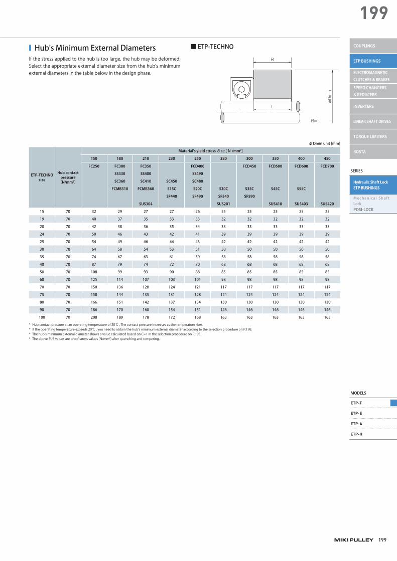
■ Hub's Minimum External DiametersIf the stress applied to the hub is too large, the hub may be deformed. Select the appropriate external diameter size from the hub's minimum external diameters in the table below in the design phase.
ETP-TECHNOsize
Hub contact pressure
[N/mm2]
Material's yield stress δ0.2 [N /mm2]
150 180 210 230 250 280 300 350 400 450
FC250 FC300 FC350 FCD400 FCD450 FCD500 FCD600 FCD700
SS330 SS400 SS490
SC360 SC410 SC450 SC480
FCMB310 FCMB360 S15C S20C S30C S35C S45C S55C
SF440 SF490 SF540 SF590
SUS304 SUS201 SUS410 SUS403 SUS420
15 70 32 29 27 27 26 25 25 25 25 25
19 70 40 37 35 33 33 32 32 32 32 32
20 70 42 38 36 35 34 33 33 33 33 33
24 70 50 46 43 42 41 39 39 39 39 39
25 70 54 49 46 44 43 42 42 42 42 42
30 70 64 58 54 53 51 50 50 50 50 50
35 70 74 67 63 61 59 58 58 58 58 58
40 70 87 79 74 72 70 68 68 68 68 68
50 70 108 99 93 90 88 85 85 85 85 85
60 70 125 114 107 103 101 98 98 98 98 98
70 70 150 136 128 124 121 117 117 117 117 117
75 70 158 144 135 131 128 124 124 124 124 124
80 70 166 151 142 137 134 130 130 130 130 130
90 70 186 170 160 154 151 146 146 146 146 146
100 70 208 189 178 172 168 163 163 163 163 163
* Hub contact pressure at an operating temperature of 20℃ . The contact pressure increases as the temperature rises.* If the operating temperature exceeds 20℃ , you need to obtain the hub's minimum external diameter according to the selection procedure on P.198.* The hub's minimum external diameter shows a value calculated based on C=1 in the selection procedure on P.198.* The above SUS values are proof stress values (N/mm2) after quenching and tempering.
φ Dmin unit [mm]
■ ETP-TECHNO
B
L
B=L
φDmin
miki_Catalog_e.indb 199 5/18/2015 5:18:57 PM

ETP BUSHINGS
200
Hydraulic Shaft Lock ETP BUSHINGS
ETP-T Models
■ Fatigue Caused by Periodically Applied Varying Torque ■ Keyway Shape where the ETP-TECHNO Cannot BeDetached due to a Deformation of the Sleeve
The ETP-TECHNO cannot be used if the shaft and hub have a keyway asshown in the figure below. Note that you can use the ETP-TECHNO forthe shaft and hub with a keyway if you completely fill the keyway withepoxy putty for metals and then shape it.
The following figure shows the fatigue state when a varying static torque, Tk, is applied periodically to the ETP-TECHNO. The vertical axis shows the percentage of the rated torque, T, and the horizontal axis shows the number of periodically applied varying static torque events.If the rated torque, T, is periodically applied to the ETP-TECHNO, it can withstandabout 500,000 events in terms of fatigue life. If 75% of the rated torque, T, is applied, it can withstand an unlimited number of events in terms of fatigue life.
Number of times
Rated torque ratio Tk/T [%] 200
150
100
50
4 5 2 3 4 5 2 3 4 5105 106 107
Tk
Number of times
ModelMounting
shafttolerance
Mountinghub tolerance Surface roughness
ETP-Th8 H7 25S (center line's average
roughness 6.3a) or lessETP-T C
■ Mounting Shaft Tolerance, Mounting Hub Tolerance, and Surface Roughness
Model Operating temperature range [°C]
ETP-T- 30 ~ 110
ETP-T C
■ Operating Temperature Range
Model Concentricity [mm] Balance [g·mm/kg]
ETP-T0.006 50
ETP-T C
■ Concentricity and Balance
■ Number of Attachments and DetachmentsThe number of attachments/detachments only applies if you preventforeign particles from adhering to the pressure screw and make sure oil containing molybdenum-based antifriction material always remainson the pressure screw's surface.In addition, be sure to use a torque wrench and do not use an impact wrench that has large torque fluctuation.
Model No. of attachments/detachments
ETP-T-15 ~ 50 5000
ETP-T-60 ~ 80 3000
ETP-T-90・100 500
■ ETP-T
Model No. of attachments/detachments
ETP-T-15 ~ 50 C 5000
ETP-T-60 C 3000
■ ETP-T C
■ Allowable Range of EdgeThe performance of the ETP-TECHNO is based on the case where the shaft andthe hub have the effect for the entire standard shaft length, Ls, and the entirestandard hub length, Lh, respectively. Accordingly, make sure in the design phase that the shaft and the hub have the effect for the respective entirestandard length. If the length of the shaft and hub is limited due to design reasons, make sure it is less than the dimension S in the figure below. If itexceeds the dimension S, stress concentrates on the sleeve edge and thesleeve is deformed, so there is the possibility that the ETP-TECHNO cannot bedetached.
■ ETP-TECHNO
S
S
Lh
LS
S
ETP-TECHNO size S[mm]
15 5
19 5
20 5
24 5
25 6
30 6
35 6
40 7
50 8
60 9
70 10
75 10
80 10
90 10
100 10
Items Checked for Design Purposes
003_ETPBush_01.indd 200003_ETPBush_01.indd 200 /2015 6:03:06 PMM4/21/2015 6:03:06 PMM4/21/2015 6:03:04/21/2015 6:03:06 PM
MODELS
ETP-T
ETP-E
ETP-A
ETP-H
SERIES
Hydraulic Shaft LockETP BUSHINGS
Mechanical Shaft LockPOSI-LOCK
COUPLINGS
ETP BUSHINGS
ELECTROMAGNETIC CLUTCHES & BRAKES
SPEED CHANGERS & REDUCERS
INVERTERS
LINEAR SHAFT DRIVES
TORQUE LIMITERS
ROSTA
201
201
■ Mounting(1) Wipe the rust, dust, and oil off from the surfaces of the shaft and
hub with a cloth or alcohol solution. In particular, if grease remains, wipe it off completely. If oil remains on the surfaces of the ETP-TECHNO, wipe it off with a cloth, etc.If the oil is wiped off, the friction coefficient basically changes. Never allow oil containing molybdenum-based antifriction material to contact the surface.
(2) Attach the ETP-TECHNO to the hub and mount them to the shaft. If accurate positioning of the shaft and hub is needed, adjust the position of both before tightening the pressure screw.Never tighten the pressure screw before mounting the ETP-TECHNO to the shaft and hub.
(3) Tighten the pressure screw to the specified torque using a torque wrench.
■ Removal (1) Before starting work, ensure safety by making sure no torque and
thrust are applied to the ETP-TECHNO and there is no risk of a fall due to the self-weight of the shaft and hub.The ETP-TECHNO does not have a self-locking mechanism. The connecting force is instantaneously released by loosening the pressure screw.
(2) Loosen the pressure screw until it comes into contact with the set screw. Also, do not remove the pressure screw by removing the set screw.
003_ETPBush_01.indd 201 4/21/2015 6:03:06 PM
ETP BUSHINGS
202
Hydraulic Shaft Lock ETP BUSHINGS
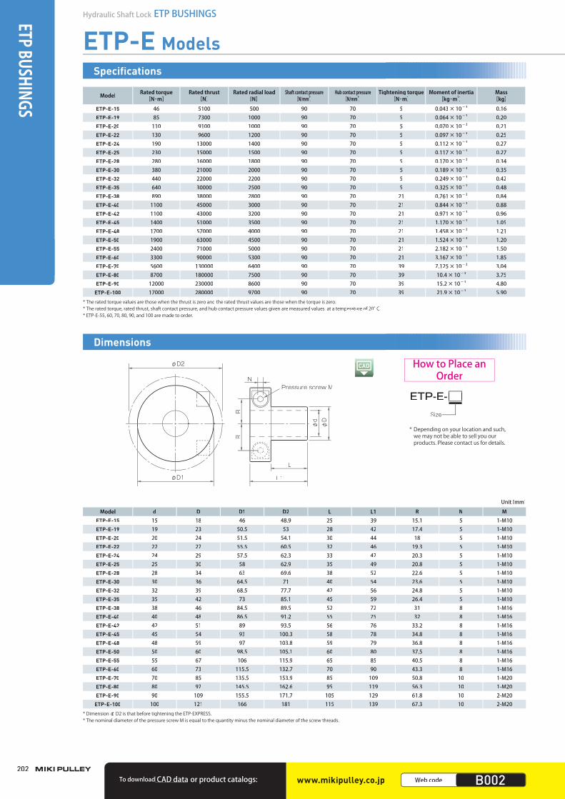
ETP-E Models
Model Rated torque[N・m]
Rated thrust[N]
Rated radial load [N]
Shaft contact pressure [N/mm2]
Hub contact pressure [N/mm2]
Tightening torque[N・m]
Moment of inertia[kg・m2]
Mass[kg]
ETP-E-15 46 5100 500 90 70 5 0.043×10⁻³ 0.16ETP-E-19 85 7300 1000 90 70 5 0.064×10⁻³ 0.20ETP-E-20 110 9100 1000 90 70 5 0.070×10⁻³ 0.21ETP-E-22 130 9600 1200 90 70 5 0.097×10⁻³ 0.25ETP-E-24 190 13000 1400 90 70 5 0.112×10⁻³ 0.27ETP-E-25 230 15000 1500 90 70 5 0.117×10⁻³ 0.27ETP-E-28 280 16000 1800 90 70 5 0.170×10⁻³ 0.34ETP-E-30 380 21000 2000 90 70 5 0.189×10⁻³ 0.35ETP-E-32 440 22000 2200 90 70 5 0.249×10⁻³ 0.42ETP-E-35 640 30000 2500 90 70 5 0.325×10⁻³ 0.48ETP-E-38 890 38000 2800 90 70 21 0.761×10⁻³ 0.84ETP-E-40 1100 45000 3000 90 70 21 0.844×10⁻³ 0.88ETP-E-42 1100 43000 3200 90 70 21 0.971×10⁻³ 0.96ETP-E-45 1400 51000 3500 90 70 21 1.170×10⁻³ 1.05ETP-E-48 1700 57000 4000 90 70 21 1.458×10⁻³ 1.21ETP-E-50 1900 63000 4500 90 70 21 1.524×10⁻³ 1.20ETP-E-55 2400 71000 5000 90 70 21 2.182×10⁻³ 1.50ETP-E-60 3300 90000 5300 90 70 21 3.167×10⁻³ 1.85ETP-E-70 5600 130000 6400 90 70 39 7.125×10⁻³ 3.04ETP-E-80 8700 180000 7500 90 70 39 10.4×10⁻³ 3.75ETP-E-90 12000 230000 8600 90 70 39 15.2×10⁻³ 4.80
ETP-E-100 17000 280000 9700 90 70 39 21.9×10⁻³ 5.90* The rated torque values are those when the thrust is zero and the rated thrust values are those when the torque is zero.* The rated torque, rated thrust, shaft contact pressure, and hub contact pressure values given are measured values at a temperature of 20°C.* ETP-E-55, 60, 70, 80, 90, and 100 are made to order.
Specifications
Unit [mm]
Model d D D1 D2 L L1 R N METP-E-15 15 18 46 48.9 25 39 15.1 5 1-M10ETP-E-19 19 23 50.5 53 28 42 17.4 5 1-M10ETP-E-20 20 24 51.5 54.1 30 44 18 5 1-M10ETP-E-22 22 27 55.5 60.5 32 46 19.3 5 1-M10ETP-E-24 24 29 57.5 62.3 33 47 20.3 5 1-M10ETP-E-25 25 30 58 62.9 35 49 20.8 5 1-M10ETP-E-28 28 34 63 69.6 38 52 22.6 5 1-M10ETP-E-30 30 36 64.5 71 40 54 23.6 5 1-M10ETP-E-32 32 39 68.5 77.7 42 56 24.8 5 1-M10ETP-E-35 35 42 73 85.1 45 59 26.4 5 1-M10ETP-E-38 38 46 84.5 89.5 52 72 31 8 1-M16ETP-E-40 40 48 86.5 91.2 55 75 32 8 1-M16ETP-E-42 42 51 89 93.5 56 76 33.2 8 1-M16ETP-E-45 45 54 93 100.3 58 78 34.8 8 1-M16ETP-E-48 48 59 97 103.8 59 79 36.8 8 1-M16ETP-E-50 50 60 98.5 105.1 60 80 37.5 8 1-M16ETP-E-55 55 67 106 115.9 65 85 40.5 8 1-M16ETP-E-60 60 73 115.5 132.7 70 90 43.3 8 1-M16ETP-E-70 70 85 135.5 153.9 85 109 50.8 10 1-M20ETP-E-80 80 97 145.5 162.6 95 119 56.3 10 1-M20ETP-E-90 90 109 155.5 171.7 105 129 61.8 10 2-M20
ETP-E-100 100 121 166 181 115 139 67.3 10 2-M20* DimensionφD2 is that before tightening the ETP-EXPRESS.* The nominal diameter of the pressure screw M is equal to the quantity minus the nominal diameter of the screw threads.
Pressure screw M
L
L1
φdφD
φD1
N
RR
φD2
ETP-E-Size
Dimensions
How to Place an Order
www.mikipulley.co.jp Web code B002To download CAD data or product catalogs:
* Depending on your location and such, we may not be able to sell you ourproducts. Please contact us for details.
003_ETPBush_01.indd 202003_ETPBush_01.indd 202 /2015 6:03:06 PMM4/21/2015 6:03:06 PMM4/21/2015 6:03:04/21/2015 6:03:06 PM
SERIES
Hydraulic Shaft LockETP BUSHINGS
Mechanical Shaft LockPOSI-LOCK
MODELS
ETP-T
ETP-E
ETP-A
ETP-H
COUPLINGS
ETP BUSHINGS
ELECTROMAGNETIC CLUTCHES & BRAKES
SPEED CHANGERS & REDUCERS
INVERTERS
LINEAR SHAFT DRIVES
TORQUE LIMITERS
ROSTA
203
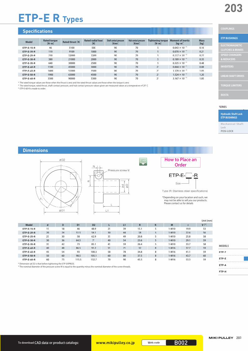
203ETP-E R Types
Model Rated torque[N・m] Rated thrust[N] Rated radial load
[N]Shaft contact pressure
[N/mm2]Hub contact pressure
[N/mm2]Tightening torque
[N・m]Moment of inertia
[kg・m2]Mass[kg]
ETP-E-15-R 46 5100 500 90 70 5 0.043×10⁻³ 0.16ETP-E-20-R 110 9100 1000 90 70 5 0.070×10⁻³ 0.21ETP-E-25-R 230 15000 1500 90 70 5 0.117×10⁻³ 0.27ETP-E-30-R 380 21000 2000 90 70 5 0.189×10⁻³ 0.35ETP-E-35-R 640 30000 2500 90 70 5 0.325×10⁻³ 0.48ETP-E-40-R 1100 45000 3000 90 70 21 0.844×10⁻³ 0.88ETP-E-45-R 1400 51000 3500 90 70 21 1.170×10⁻³ 1.05ETP-E-50-R 1900 63000 4500 90 70 21 1.524×10⁻³ 1.20ETP-E-60-R 3300 90000 5300 90 70 21 3.167×10⁻³ 1.85
* The rated torque values are those when the thrust is zero and the rated thrust values are those when the torque is zero.* The rated torque, rated thrust, shaft contact pressure, and hub contact pressure values given are measured values at a temperature of 20°C.* ETP-E-60-R is made to order.
Specifications
Model d D D1 D2 L L1 R N M r V[°]ETP-E-15-R 15 18 46 48.9 25 39 15.1 5 1-M10 19.9 53ETP-E-20-R 20 24 51.5 54.1 30 44 18 5 1-M10 22.6 56ETP-E-25-R 25 30 58 62.9 35 49 20.8 5 1-M10 25.8 58ETP-E-30-R 30 36 64.5 71 40 54 23.6 5 1-M10 29.1 59ETP-E-35-R 35 42 73 85.1 45 59 26.4 5 1-M10 33.7 58ETP-E-40-R 40 48 86.5 91.2 55 75 32 8 1-M16 37.7 59ETP-E-45-R 45 54 93 100.3 58 78 34.8 8 1-M16 41.1 59ETP-E-50-R 50 60 98.5 105.1 60 80 37.5 8 1-M16 43.7 60ETP-E-60-R 60 73 115.5 132.7 70 90 43.3 8 1-M16 53.3 59
* DimensionφD2 is that before tightening the ETP-EXPRESS.* The nominal diameter of the pressure screw M is equal to the quantity minus the nominal diameter of the screw threads.
Unit [mm]
Pressure screw M
L
L1
φd
φD
N
R
V°
r
φD1
φD2
ETP-E- -R
Type (R: Stainless steel specifications)
Size
Dimensions
How to Place an Order
To download CAD data or product catalogs: www.mikipulley.co.jp Web code B002
*Depending on your location and such, we may not be able to sell you our products.Please contact us for details.
003_ETPBush_01.indd 203003_ETPBush_01.indd 203 /2015 6:03:06 PMM4/21/2015 6:03:06 PMM4/21/2015 6:03:04/21/2015 6:03:06 PM

ETP BUSHINGS
204
Hydraulic Shaft Lock ETP BUSHINGS
ETP-E Models
■ Torque and Thrust CoefficientsI f to rque and th rus t a re applied to the ETP-EXPRESS atthe same t ime, the rated va lues of both decrease .These values can be obtained based on the coefficients inthe figure on the right.
The torque coefficient, Kt, when Kf = 0.6 is about 0.8 based on the above figure.Accordingly, the maximum rated torque, Tmax, in this case is as follows.
The relationship between Kt and Kf can be obtained from thefollowing formula.
Calculation example:When using the ETP-E-30 at 20℃ .
Maximum rated torque, T, and thrust, F,at 20℃ , T = 380 [N・m] andF = 25000 [N]The maximum rated torque, Tmax, when the maximum thrust(Fmax=15000 [N]) is applied can be obtained as follows.
■ Selection Procedure(1) Selection is determined by the used shaft diameter. In general, find the torque, Ta,
applied to the connecting element using the output capacity, P, of the driver and usage rotation speed, n. Next, obtain the thrust, Fa, applied to the connectingelement.
Ta: Torque applied to the connecting element [N・m] P: Driver's output [kW]n : Connecting element's rotation speed [minー1] Fa: Thrust applied to the connecting element [N]
Ta [N·m] = 9550 ×n [min-1]P [kW]
(2) Determine the service factor, K1, based on the load property and obtain the corrected torque, Td, and corrected thrust, Fd, applied to the connecting element.
Td: Corrected torque applied to the connecting element [N・m]Fd: Corrected thrust applied to the connecting element [N]K1: Service factor based on the load property
Td = Ta × K1Fd = Fa × K1
(3) Correct the values according to the load property.
Compare the connecting element's rated torque, T, based on theused diameter with the calculated corrected torque, Td.
1. For the torque alone
Compare the connecting element's rated thrust, F, based on the used diameter with the calculated corrected thrust, Fd.
2. For the thrust alone
Calculate the combined load, Mr, and compare the result with the rated torque, T.3. If torque and thrust are applied at the same time
T: Connecting element's rated torque [N・m]T ≧ Td
F: Connecting element's rated thrust [N]F ≧ Fd
2dMr = Td2 + (Fd × )2T ≧ Mr
C = 1 B = LC = 0.8 L < B < 2LC = 0.6 B ≧ 2L
C = 0.6 when using a single oneC = 0.8 when using multiple ones
Mr: Combined load applied to the connecting element [N・m] d: Shaft diameter [m]
The shaft contact pressure and hub contact pressure varydepending on the operating temperature. You need to correctthese values based on the operating temperature. Note that thecontact pressure values were those measured at 20 ℃ . If theoperating temperature exceeds 20℃ , obtain the hub's minimumexternal diameter and the hollow shaft's maximum internal diameter with the following formulas.
di: Hollow shaft's maximum internal diameter [mm]δ0.2N: Hollow shaft material's yield stress [N/mm2]P1: Shaft contact pressure [N/mm2]
d: Shaft diameter [mm]C: Coefficient
2. Obtain the hollow shaft's maximum internal diameter based on the usedhollow shaft material's strength.
(4) Obtain the hub's minimum external diameter and the hollow shaft's maximum internal diameter.
If the hub material's yield stress value is large, make sure the ratio of the hub's minimum external diameter to the hub's internal diameter is more than about 1.3 times to prevent the hub's deformation.
DO: Hub's minimum external diameter [mm]D: Hub's internal diameter [mm]P2: Hub contact pressure [N/mm2]δ0.2N: Hub material's yield stress [N/mm2]
B: Hub length [mm]L: Effective contact length [mm]C: Coefficient
1. Obtain the hub's minimum external diameter based on the usedhub material'sstrength.
δ 0.2N + CP2
δ 0.2N - CP2DO ≧ D
δ 0.2N - 2P1Cδ 0.2N
di ≦ d
(Kt)2+ (Kf)2 = 1
Thrust coefficient (Kf) = Fmax / F × temperature coefficient (K2) = 15000/25000 × 1.0 = 0.6
Tmax = T × K2 × Kt = 380 × 1.0 × 0.8 = 304 [N·m]
1
0.8
0.5
00 0.5 0.6 1
Torque coefficient: Kt
Thrust coefficient: Kf
Loadproperty
Constant Vibrations: Small Vibrations: Medium Vibrations: Large
K1 1.0 1.25 1.75 2.25
■ Service Factor■ Service factor based on the load property: K1
■ Service factor based on the operating temperature (K2)
Temperature coefficient: K2
Temperature [°C]
0.5 1 1.2 1.5-30
-20
-10
0
10
20
30
40
50
60
70
80
90
100
110
ETP-E
Items Checked for Design Purposes
The operating temperature range is from -30℃ to 85℃ .
P1・P2 = contact pressure at 20℃ × temperature coefficient (K2)
003_ETPBush_01.indd 204003_ETPBush_01.indd 204 /2015 6:03:07 PMM4/21/2015 6:03:07 PMM4/21/2015 6:03:074/21/2015 6:03:07 PM
SERIES
Hydraulic Shaft LockETP BUSHINGS
Mechanical Shaft LockPOSI-LOCK
MODELS
ETP-T
ETP-E
ETP-A
ETP-H
COUPLINGS
ETP BUSHINGS
ELECTROMAGNETIC CLUTCHES & BRAKES
SPEED CHANGERS & REDUCERS
INVERTERS
LINEAR SHAFT DRIVES
TORQUE LIMITERS
ROSTA
205
205
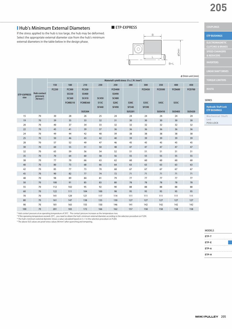
■ Hub's Minimum External DiametersIf the stress applied to the hub is too large, the hub may be deformed. Select the appropriate external diameter size from the hub's minimum external diameters in the table below in the design phase.
■ ETP-EXPRESS
ETP-EXPRESS size
Hub contact pressure
[N/mm2]
Material's yield stress δ0.2 [N /mm2]
150 180 210 230 250 280 300 350 400 450
FC250 FC300 FC350 FCD400 FCD450 FCD500 FCD600 FCD700
SS330 SS400 SS490
SC360 SC410 SC450 SC480
FCMB310 FCMB360 S15C S20C S30C S35C S45C S55C
SF440 SF490 SF540 SF590
SUS304 SUS201 SUS410 SUS403 SUS420
15 70 30 28 26 25 24 24 24 24 24 24
19 70 39 35 33 32 31 30 30 30 30 30
20 70 40 37 34 33 32 32 32 32 32 32
22 70 45 41 39 37 36 36 36 36 36 36
24 70 49 44 42 40 39 38 38 38 38 38
25 70 50 46 43 42 40 39 39 39 39 39
28 70 57 52 49 47 46 45 45 45 45 45
30 70 60 55 51 50 48 47 47 47 47 47
32 70 65 59 56 54 52 51 51 51 51 51
35 70 70 64 60 58 56 55 55 55 55 55
38 70 77 70 66 63 62 60 60 60 60 60
40 70 80 73 68 66 64 63 63 63 63 63
42 70 85 77 73 70 68 67 67 67 67 67
45 70 90 82 77 74 72 71 71 71 71 71
48 70 98 89 84 81 79 77 77 77 77 77
50 70 100 91 85 83 80 78 78 78 78 78
55 70 112 102 95 92 90 88 88 88 88 88
60 70 122 111 104 100 98 95 95 95 95 95
70 70 141 129 121 117 114 111 111 111 111 111
80 70 161 147 138 133 130 127 127 127 127 127
90 70 181 165 155 150 146 141 142 142 142 142
100 70 201 183 172 166 162 157 158 158 158 158
* Hub contact pressure at an operating temperature of 20℃ . The contact pressure increases as the temperature rises.* If the operating temperature exceeds 20℃ , you need to obtain the hub's minimum external diameter according to the selection procedure on P.204.* The hub's minimum external diameter shows a value calculated based on C=1 in the selection procedure on P.204.* The above SUS values are proof stress values (N/mm2) after quenching and tempering.
φ Dmin unit [mm]
B
L
B=L
φDmin
miki_Catalog_e.indb 205 5/18/2015 5:18:59 PM
ETP BUSHINGS
206
Hydraulic Shaft Lock ETP BUSHINGS
ETP-E Models
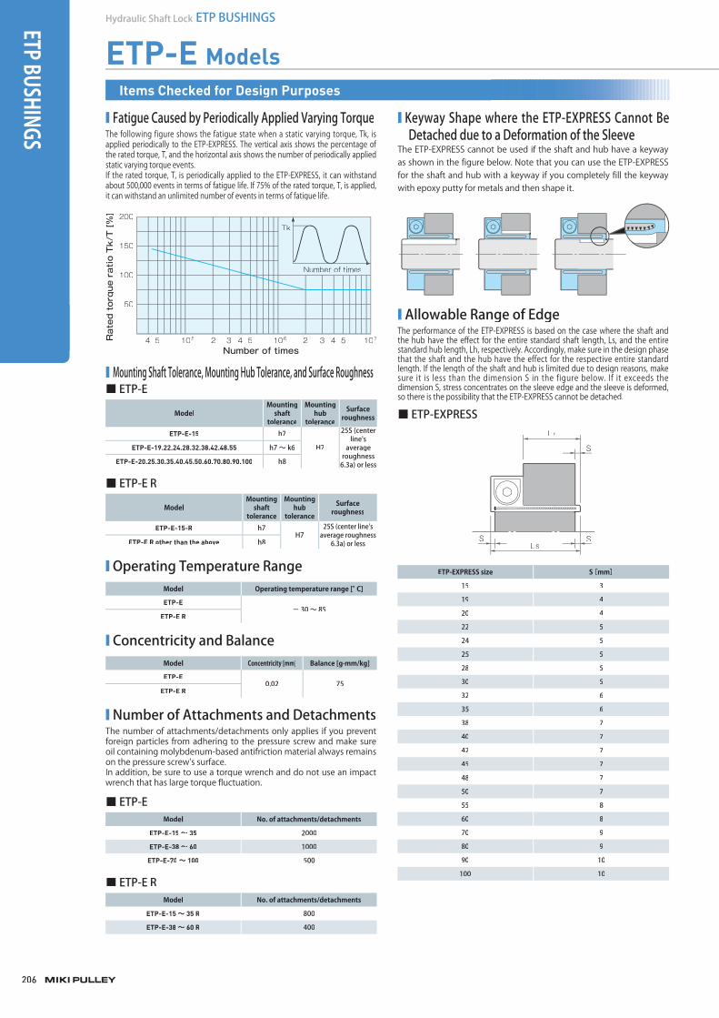
■ Fatigue Caused by Periodically Applied Varying TorqueThe following figure shows the fatigue state when a static varying torque, Tk, isapplied periodically to the ETP-EXPRESS. The vertical axis shows the percentage of the rated torque, T, and the horizontal axis shows the number of periodically appliedstatic varying torque events.If the rated torque, T, is periodically applied to the ETP-EXPRESS, it can withstand about 500,000 events in terms of fatigue life. If 75% of the rated torque, T, is applied, it can withstand an unlimited number of events in terms of fatigue life.
Number of times
Rated torque ratio Tk/T [%] 200
150
100
50
4 5 2 3 4 5 2 3 4 5105 106 107
Tk
Number of times
■ Mounting Shaft Tolerance, Mounting Hub Tolerance, and Surface Roughness
■ Keyway Shape where the ETP-EXPRESS Cannot BeDetached due to a Deformation of the Sleeve
The ETP-EXPRESS cannot be used if the shaft and hub have a keywayas shown in the figure below. Note that you can use the ETP-EXPRESSfor the shaft and hub with a keyway if you completely fill the keywaywith epoxy putty for metals and then shape it.
■ Allowable Range of EdgeThe performance of the ETP-EXPRESS is based on the case where the shaft andthe hub have the effect for the entire standard shaft length, Ls, and the entirestandard hub length, Lh, respectively. Accordingly, make sure in the design phase that the shaft and the hub have the effect for the respective entire standardlength. If the length of the shaft and hub is limited due to design reasons, make sure it is less than the dimension S in the figure below. If it exceeds the dimension S, stress concentrates on the sleeve edge and the sleeve is deformed, so there is the possibility that the ETP-EXPRESS cannot be detached.
■ ETP-EXPRESS
ETP-EXPRESS size S[mm]
15 3
19 4
20 4
22 5
24 5
25 5
28 5
30 5
32 6
35 6
38 7
40 7
42 7
45 7
48 7
50 7
55 8
60 8
70 9
80 9
90 10
100 10
S
S
Lh
LsS
■ ETP-E
ModelMounting
shafttolerance
Mounting hub
tolerance
Surfaceroughness
ETP-E-15 h7
H7
25S (centerline's
averageroughness 6.3a) or less
ETP-E-19.22.24.28.32.38.42.48.55 h7 ~ k6
ETP-E-20.25.30.35.40.45.50.60.70.80.90.100 h8
■ ETP-E R
ModelMounting
shaft tolerance
Mounting hub
tolerance
Surfaceroughness
ETP-E-15-R h7H7
25S (center line'saverage roughness
6.3a) or lessETP-E R other than the above h8
■ ETP-EModel No. of attachments/detachments
ETP-E-15 ~ 35 2000
ETP-E-38 ~ 60 1000
ETP-E-70 ~ 100 500
■ ETP-E RModel No. of attachments/detachments
ETP-E-15 ~ 35 R 800
ETP-E-38 ~ 60 R 400
■ Number of Attachments and DetachmentsThe number of attachments/detachments only applies if you prevent foreign particles from adhering to the pressure screw and make sure oil containing molybdenum-based antifriction material always remains on the pressure screw's surface.In addition, be sure to use a torque wrench and do not use an impactwrench that has large torque fluctuation.
Model Operating temperature range [°C]
ETP-E- 30 ~ 85
ETP-E R
■ Operating Temperature Range
Model Concentricity [mm] Balance [g·mm/kg]
ETP-E0.02 75
ETP-E R
■ Concentricity and Balance
Items Checked for Design Purposes
003_ETPBush_01.indd 206 4/21/2015 6:03:08 PMM4/21/2015 6:03:08 PM
SERIES
Hydraulic Shaft LockETP BUSHINGS
Mechanical Shaft LockPOSI-LOCK
MODELS
ETP-T
ETP-E
ETP-A
ETP-H
COUPLINGS
ETP BUSHINGS
ELECTROMAGNETIC CLUTCHES & BRAKES
SPEED CHANGERS & REDUCERS
INVERTERS
LINEAR SHAFT DRIVES
TORQUE LIMITERS
ROSTA
207
207
■ Mounting(1) Wipe the rust, dust, and oil off from the surface of the shaft and hub
with a cloth or alcohol solution. In particular, if grease remains, wipe it off completely. If oil remains on the surface of the ETP-EXPRESS, wipe it off with a cloth, etc.If the oil is wiped off, the friction coefficient basically changes. Never allow oil containing molybdenum-based antifriction material to contact the surface.
(2) Attach the ETP-EXPRESS to the hub and mount them to the shaft. If accurate positioning of the shaft and hub is needed, adjust the position of both before tightening the pressure screw.Never tighten the pressure screw before mounting the ETP-EXPRESS to the shaft and hub.
(3) Tighten the pressure screw to the specified torque using a torque wrench.
■ Removal (1) Before starting work, ensure safety by making sure no torque and
thrust are applied to the ETP-EXPRESS and there is no risk of a fall due to the self-weight of the shaft and hub.The ETP-EXPRESS does not have a self-locking mechanism. The connecting force is instantaneously released by loosening the pressure screw.
(2) Loosen the pressure screw until the connecting force is released. The pressure screw should only be loosened. Do not remove it.
003_ETPBush_01.indd 207 4/21/2015 6:03:08 PM

208
Hydraulic Shaft Lock ETP BUSHINGSETP BUSHINGS
ETP-A ModelsSpecifications
Model Rated torque[N ・m]
Rated thrust[N]
Shaft contact pressure
[N/mmpp
2]Hub contact pressure
[N/mm2]Tightening
torque[N ・m]
q Moment of inertia [kg ・m2]
Mass[kg]
ETP-A-15 55 7300 90 80 6 0.018 × 10- 3 0.10ETP-A-19 100 10600 90 80 8 0.046 × 10- 3 0.17ETP-A-20 125 12500 90 80 8 0.046 × 10- 3 0.16ETP-A-22 135 12300 90 80 8 0.065 × 10- 3 0.19ETP-A-24 200 16700 90 80 8 0.067 × 10- 3 0.20ETP-A-25 250 20000 90 80 8 0.071 × 10- 3 0.19ETP-A-28 300 21400 90 80 8 0.12 × 10- 3 0.26ETP-A-30 420 28000 90 80 8 0.14 × 10- 3 0.29ETP-A-32 420 26300 90 80 8 0.20 × 10- 3 0.35ETP-A-35 650 37100 90 80 8 0.25 × 10- 3 0.40ETP-A-38 750 39500 90 80 8 0.31 × 10- 3 0.43ETP-A-40 940 47000 90 80 8 0.44 × 10- 3 0.55ETP-A-42 940 44800 90 80 8 0.47 × 10- 3 0.55ETP-A-45 1290 57300 90 80 13 0.69 × 10- 3 0.71ETP-A-48 1570 65400 90 80 13 0.83 × 10- 3 0.78ETP-A-50 1900 76000 90 80 13 1.05 × 10- 3 0.86ETP-A-55 2500 90900 90 80 13 1.43 × 10- 3 1.06ETP-A-60 3400 113000 90 80 13 2.15 × 10- 3 1.37ETP-A-65 3500 108000 90 80 13 3.10 × 10- 3 1.67ETP-A-70 5200 149000 90 80 32 4.08 × 10- 3 2.04ETP-A-75 6300 168000 90 80 32 5.50 × 10- 3 2.42ETP-A-80 8800 220000 90 80 32 8.10 × 10- 3 2.64ETP-A-90 11000 244000 90 80 32 12.2 × 10- 3 3.54
ETP-A-100 15500 310000 90 80 32 19.9 × 10- 3 4.80* The rated torque values are those when the thrust is zero and the rated thrust values are those when the torque is zero.* The rated torque, rated thrust, shaft contact pressure, and hub contact pressure values given are measured values at a temperature of 20°C.* ETP-A-75, 80, 90, and 100 are made to order.
Clamping bolt M
φD1
φd
φD
L3L4
L
L1L2
Model d D D1 L L1 L2 L3 L4 METP-A-15 15 23 37.5 17 28 33 5 5.4 3-M5 × 10ETP-A-19 19 28 45 21 34 39 5.5 6.9 3-M5 × 12ETP-A-20 20 28 45 22 35 40 5.5 6.4 3-M5 × 12ETP-A-22 22 32 49 22 35 40 5.5 6.4 4-M5 × 12ETP-A-24 24 34 49 25 38 43 5.5 6.4 4-M5 × 12ETP-A-25 25 34 49 27 41 46 5.5 6.9 4-M5 × 12ETP-A-28 28 39 55 29 43 48 5.5 6.9 4-M5 × 12ETP-A-30 30 41 57 32 46 51 5.5 6.9 4-M5 × 12ETP-A-32 32 43 60 34 50 55 7 7.4 4-M5 × 14ETP-A-35 35 47 62.5 37 53 58 7 7.4 6-M5 × 14ETP-A-38 38 50 65 41 57 62 7 7.4 6-M5 × 14ETP-A-40 40 53 70 43 60 65 7.5 8.4 6-M5 × 16ETP-A-42 42 55 70 45 62 67 7.5 8.4 6-M5 × 16ETP-A-45 45 59 77 49 66 72 8 8.4 6-M6 × 16ETP-A-48 48 62 80 52 70 76 8 8.4 6-M6 × 16ETP-A-50 50 65 83 53 72 78 8.5 9.4 6-M6 × 18ETP-A-55 55 71 88 58 77 83 9 9.4 8-M6 × 18ETP-A-60 60 77 95 64 85 91 10 10.4 8-M6 × 20ETP-A-65 65 84 102 68 90 96 9.5 10.9 8-M6 × 20ETP-A-70 70 90 113 72 94 102 9.5 10.9 6-M8 × 20ETP-A-75 75 95 118 85 108 116 11 11 6-M8 × 22ETP-A-80 80 100 123 90 114 122 11 11 6-M8 × 22ETP-A-90 90 112 135 100 127 135 12.5 12.5 8-M8 × 25
ETP-A-100 100 125 148 110 139 147 13.5 13 8-M8 × 25* L1 and L2 are dimensions when the ETP-CLASSIC is mounted. These values may vary slightly depending on the fit tolerances of the shaft diameter and internal hub diameter.* The nominal diameter of the clamping bolt M is equal to the quantity minus the nominal diameter of the screw threads times the nominal length.
Unit [mm]
Dimensions
ETP-A-Size
How to Place an Order
* Depending on your location andsuch, we may not be able to sellyou our products. Please contactus for details.
003_ETPBush_01.indd 208003_ETPBush_01.indd 208 /2015 6:03:08 PMM4/21/2015 6:03:08 PMM4/21/2015 6:03:084/21/2015 6:03:08 PM
209
209
SERIES
Hydraulic Shaft LockETP BUSHINGS
Mechanical Shaft LockPOSI-LOCK
MODELS
ETP-T
ETP-E
ETP-A
ETP-H
COUPLINGS
ETP BUSHINGS
ELECTROMAGNETIC CLUTCHES & BRAKES
SPEED CHANGERS & REDUCERS
INVERTERS
LINEAR SHAFT DRIVES
TORQUE LIMITERS
ROSTA
To download CAD data or product catalogs: www.mikipulley.co.jp Web code B003
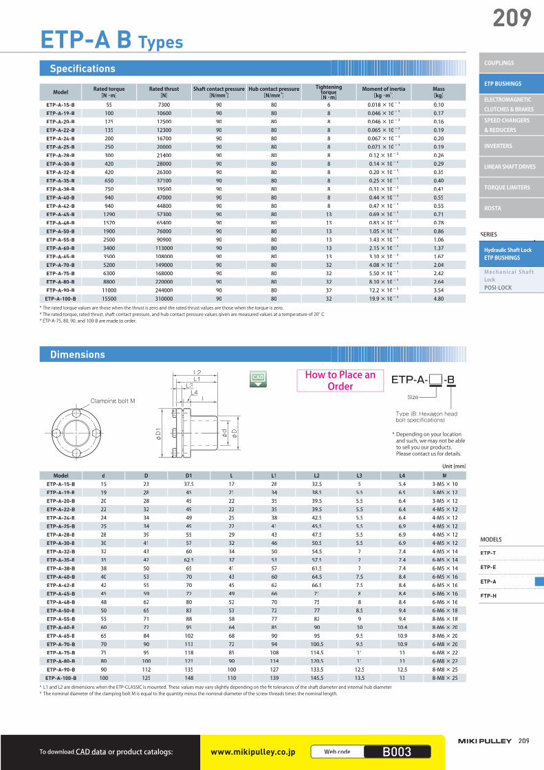
ETP-A B Types
Model Rated torque[N ・m]
Rated thrust[N]
Shaft contact pressure [N/mm2]
Hub contact pressure[N/mm2]
Tighteningtorque
[N ・m]q Moment of inertia
[kg ・m2]Mass[kg]
ETP-A-15-B 55 7300 90 80 6 0.018 × 10- 3 0.10ETP-A-19-B 100 10600 90 80 8 0.046 × 10- 3 0.17ETP-A-20-B 125 12500 90 80 8 0.046 × 10- 3 0.16ETP-A-22-B 135 12300 90 80 8 0.065 × 10- 3 0.19ETP-A-24-B 200 16700 90 80 8 0.067 × 10- 3 0.20ETP-A-25-B 250 20000 90 80 8 0.071 × 10- 3 0.19ETP-A-28-B 300 21400 90 80 8 0.12 × 10- 3 0.26ETP-A-30-B 420 28000 90 80 8 0.14 × 10- 3 0.29ETP-A-32-B 420 26300 90 80 8 0.20 × 10- 3 0.35ETP-A-35-B 650 37100 90 80 8 0.25 × 10- 3 0.40ETP-A-38-B 750 39500 90 80 8 0.31 × 10- 3 0.43ETP-A-40-B 940 47000 90 80 8 0.44 × 10- 3 0.55ETP-A-42-B 940 44800 90 80 8 0.47 × 10- 3 0.55ETP-A-45-B 1290 57300 90 80 13 0.69 × 10- 3 0.71ETP-A-48-B 1570 65400 90 80 13 0.83 × 10- 3 0.78ETP-A-50-B 1900 76000 90 80 13 1.05 × 10- 3 0.86ETP-A-55-B 2500 90900 90 80 13 1.43 × 10- 3 1.06ETP-A-60-B 3400 113000 90 80 13 2.15 × 10- 3 1.37ETP-A-65-B 3500 108000 90 80 13 3.10 × 10- 3 1.67ETP-A-70-B 5200 149000 90 80 32 4.08 × 10- 3 2.04ETP-A-75-B 6300 168000 90 80 32 5.50 × 10- 3 2.42ETP-A-80-B 8800 220000 90 80 32 8.10 × 10- 3 2.64ETP-A-90-B 11000 244000 90 80 32 12.2 × 10- 3 3.54
ETP-A-100-B 15500 310000 90 80 32 19.9 × 10- 3 4.80* The rated torque values are those when the thrust is zero and the rated thrust values are those when the torque is zero.* The rated torque, rated thrust, shaft contact pressure, and hub contact pressure values given are measured values at a temperature of 20°C.* ETP-A-75, 80, 90, and 100-B are made to order.
Specifications
Model d D D1 L L1 L2 L3 L4 METP-A-15-B 15 23 37.5 17 28 32.5 5 5.4 3-M5 × 10ETP-A-19-B 19 28 45 21 34 38.5 5.5 6.9 3-M5 × 12ETP-A-20-B 20 28 45 22 35 39.5 5.5 6.4 3-M5 × 12ETP-A-22-B 22 32 49 22 35 39.5 5.5 6.4 4-M5 × 12ETP-A-24-B 24 34 49 25 38 42.5 5.5 6.4 4-M5 × 12ETP-A-25-B 25 34 49 27 41 45.5 5.5 6.9 4-M5 × 12ETP-A-28-B 28 39 55 29 43 47.5 5.5 6.9 4-M5 × 12ETP-A-30-B 30 41 57 32 46 50.5 5.5 6.9 4-M5 × 12ETP-A-32-B 32 43 60 34 50 54.5 7 7.4 4-M5 × 14ETP-A-35-B 35 47 62.5 37 53 57.5 7 7.4 6-M5 × 14ETP-A-38-B 38 50 65 41 57 61.5 7 7.4 6-M5 × 14ETP-A-40-B 40 53 70 43 60 64.5 7.5 8.4 6-M5 × 16ETP-A-42-B 42 55 70 45 62 66.5 7.5 8.4 6-M5 × 16ETP-A-45-B 45 59 77 49 66 71 8 8.4 6-M6 × 16ETP-A-48-B 48 62 80 52 70 75 8 8.4 6-M6 × 16ETP-A-50-B 50 65 83 53 72 77 8.5 9.4 6-M6 × 18ETP-A-55-B 55 71 88 58 77 82 9 9.4 8-M6 × 18ETP-A-60-B 60 77 95 64 85 90 10 10.4 8-M6 × 20ETP-A-65-B 65 84 102 68 90 95 9.5 10.9 8-M6 × 20ETP-A-70-B 70 90 113 72 94 100.5 9.5 10.9 6-M8 × 20ETP-A-75-B 75 95 118 85 108 114.5 11 11 6-M8 × 22ETP-A-80-B 80 100 123 90 114 120.5 11 11 6-M8 × 22ETP-A-90-B 90 112 135 100 127 133.5 12.5 12.5 8-M8 × 25
ETP-A-100-B 100 125 148 110 139 145.5 13.5 13 8-M8 × 25* L1 and L2 are dimensions when the ETP-CLASSIC is mounted. These values may vary slightly depending on the fit tolerances of the shaft diameter and internal hub diameter.* The nominal diameter of the clamping bolt M is equal to the quantity minus the nominal diameter of the screw threads times the nominal length.
Unit [mm]
Clamping bolt M
φD1
φd
φD
L3L4
L
L1L2
ETP-A- -B
Type (B: Hexagon headbolt specifications)
Size
Dimensions
How to Place an Order
* Depending on your locationand such, we may not be ableto sell you our products.Please contact us for details.
003_ETPBush_01.indd 209003_ETPBush_01.indd 209 /2015 6:03:09 PMM4/21/2015 6:03:09 PMM4/21/2015 6:03:094/21/2015 6:03:09 PM
210
Hydraulic Shaft Lock ETP BUSHINGSETP BUSHINGS
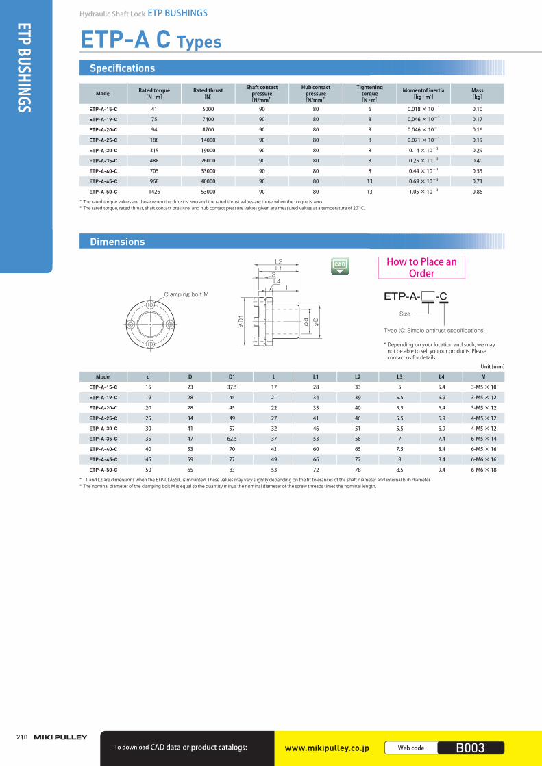
ETP-A C Types
Model Rated torque[N ・m]
Rated thrust[N]
Shaft contact pressure
[N/mm2]
Hub contact pressure
[N/mm2]
Tighteningtorque
[N ・m]
Momentof inertia[kg ・m2]
Mass[kg]
ETP-A-15-C 41 5000 90 80 6 0.018 × 10- 3 0.10
ETP-A-19-C 75 7400 90 80 8 0.046 × 10- 3 0.17
ETP-A-20-C 94 8700 90 80 8 0.046 × 10- 3 0.16
ETP-A-25-C 188 14000 90 80 8 0.071 × 10- 3 0.19
ETP-A-30-C 315 19000 90 80 8 0.14 × 10- 3 0.29
ETP-A-35-C 488 26000 90 80 8 0.25 × 10- 3 0.40
ETP-A-40-C 705 33000 90 80 8 0.44 × 10- 3 0.55
ETP-A-45-C 968 40000 90 80 13 0.69 × 10- 3 0.71
ETP-A-50-C 1426 53000 90 80 13 1.05 × 10- 3 0.86
* The rated torque values are those when the thrust is zero and the rated thrust values are those when the torque is zero.* The rated torque, rated thrust, shaft contact pressure, and hub contact pressure values given are measured values at a temperature of 20°C.
Specifications
Clamping bolt M
φD1
φd
φD
L3L4
L
L1L2
ETP-A- -C
Type (C: Simple antirust specifications)
Size
Model d D D1 L L1 L2 L3 L4 M
ETP-A-15-C 15 23 37.5 17 28 33 5 5.4 3-M5 × 10
ETP-A-19-C 19 28 45 21 34 39 5.5 6.9 3-M5 × 12
ETP-A-20-C 20 28 45 22 35 40 5.5 6.4 3-M5 × 12
ETP-A-25-C 25 34 49 27 41 46 5.5 6.9 4-M5 × 12
ETP-A-30-C 30 41 57 32 46 51 5.5 6.9 4-M5 × 12
ETP-A-35-C 35 47 62.5 37 53 58 7 7.4 6-M5 × 14
ETP-A-40-C 40 53 70 43 60 65 7.5 8.4 6-M5 × 16
ETP-A-45-C 45 59 77 49 66 72 8 8.4 6-M6 × 16
ETP-A-50-C 50 65 83 53 72 78 8.5 9.4 6-M6 × 18
* L1 and L2 are dimensions when the ETP-CLASSIC is mounted. These values may vary slightly depending on the fit tolerances of the shaft diameter and internal hub diameter.* The nominal diameter of the clamping bolt M is equal to the quantity minus the nominal diameter of the screw threads times the nominal length.
Unit [mm]
Dimensions
How to Place an Order
www.mikipulley.co.jp Web code B003To download CAD data or product catalogs:
* Depending on your location and such, we maynot be able to sell you our products. Please contact us for details.
003_ETPBush_01.indd 210003_ETPBush_01.indd 210 /2015 6:03:09 PMM4/21/2015 6:03:09 PMM4/21/2015 6:03:094/21/2015 6:03:09 PM
211
211
SERIES
Hydraulic Shaft LockETP BUSHINGS
Mechanical Shaft LockPOSI-LOCK
MODELS
ETP-T
ETP-E
ETP-A
ETP-H
COUPLINGS
ETP BUSHINGS
ELECTROMAGNETIC CLUTCHES & BRAKES
SPEED CHANGERS & REDUCERS
INVERTERS
LINEAR SHAFT DRIVES
TORQUE LIMITERS
ROSTA
To download CAD data or product catalogs: www.mikipulley.co.jp Web code B003
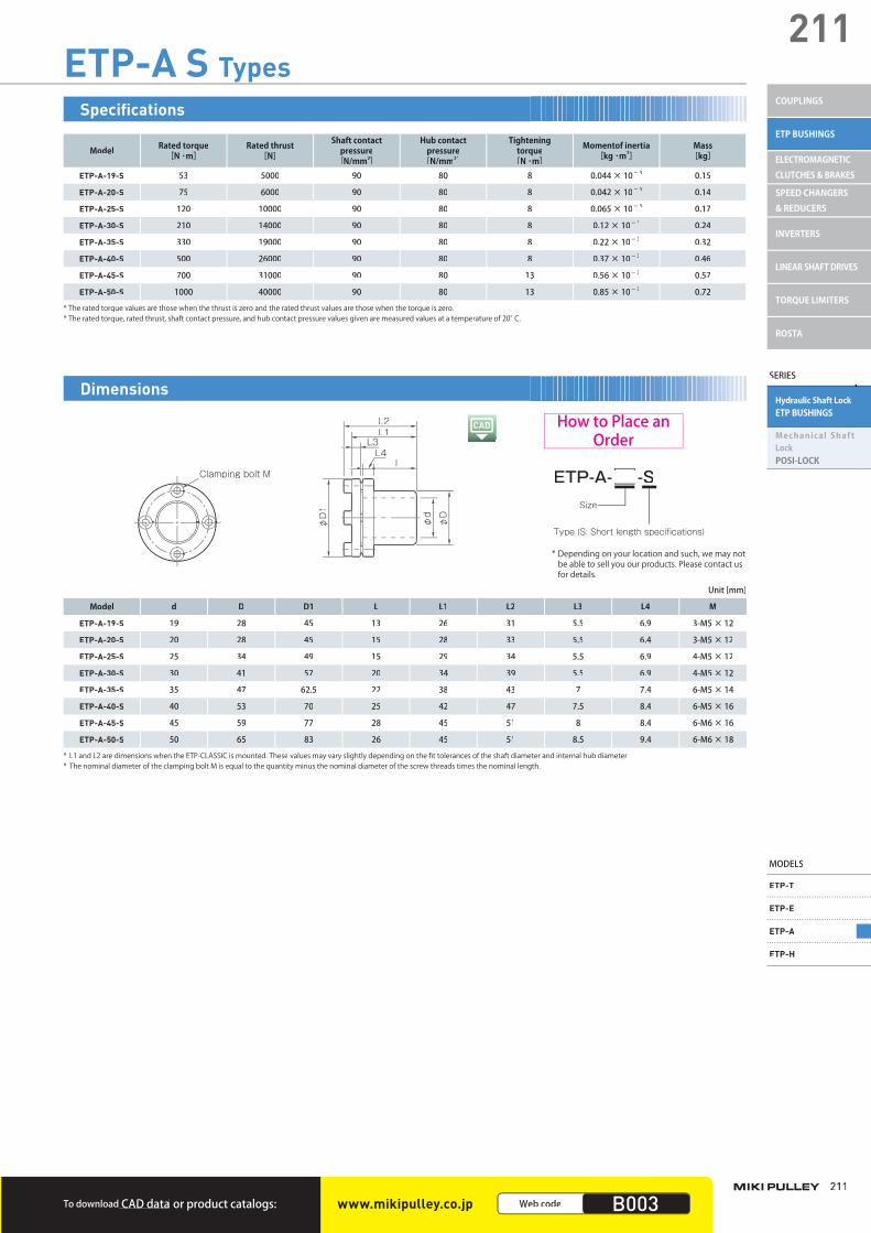
ETP-A S Types
Model Rated torque[N ・m]
Rated thrust[N]
Shaft contact pressure
[N/mm2]
Hub contact pressure
[N/mm2]
Tightening torque
[N ・m]
Momentof inertia[kg ・m2]
Mass[kg]
ETP-A-19-S 53 5000 90 80 8 0.044 × 10- 3 0.15
ETP-A-20-S 75 6000 90 80 8 0.042 × 10- 3 0.14
ETP-A-25-S 120 10000 90 80 8 0.065 × 10- 3 0.17
ETP-A-30-S 210 14000 90 80 8 0.12 × 10- 3 0.24
ETP-A-35-S 330 19000 90 80 8 0.22 × 10- 3 0.32
ETP-A-40-S 500 26000 90 80 8 0.37 × 10- 3 0.46
ETP-A-45-S 700 31000 90 80 13 0.56 × 10- 3 0.57
ETP-A-50-S 1000 40000 90 80 13 0.85 × 10- 3 0.72
* The rated torque values are those when the thrust is zero and the rated thrust values are those when the torque is zero.* The rated torque, rated thrust, shaft contact pressure, and hub contact pressure values given are measured values at a temperature of 20°C.
Specifications
Clamping bolt M
φD1
φd
φD
L3L4
L
L1L2
ETP-A- -S
Type (S: Short length specifications)
Size
Model d D D1 L L1 L2 L3 L4 M
ETP-A-19-S 19 28 45 13 26 31 5.5 6.9 3-M5 × 12
ETP-A-20-S 20 28 45 15 28 33 5.5 6.4 3-M5 × 12
ETP-A-25-S 25 34 49 15 29 34 5.5 6.9 4-M5 × 12
ETP-A-30-S 30 41 57 20 34 39 5.5 6.9 4-M5 × 12
ETP-A-35-S 35 47 62.5 22 38 43 7 7.4 6-M5 × 14
ETP-A-40-S 40 53 70 25 42 47 7.5 8.4 6-M5 × 16
ETP-A-45-S 45 59 77 28 45 51 8 8.4 6-M6 × 16
ETP-A-50-S 50 65 83 26 45 51 8.5 9.4 6-M6 × 18
* L1 and L2 are dimensions when the ETP-CLASSIC is mounted. These values may vary slightly depending on the fit tolerances of the shaft diameter and internal hub diameter.* The nominal diameter of the clamping bolt M is equal to the quantity minus the nominal diameter of the screw threads times the nominal length.
Unit [mm]
Dimensions
How to Place an Order
* Depending on your location and such, we may not be able to sell you our products. Please contact us for details.
003_ETPBush_01.indd 211003_ETPBush_01.indd 211 /2015 6:03:09 PMM4/21/2015 6:03:09 PMM4/21/2015 6:03:094/21/2015 6:03:09 PM
212
Hydraulic Shaft Lock ETP BUSHINGSETP BUSHINGS
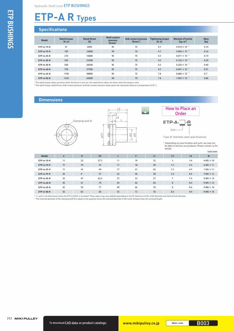
ETP-A R Types
Model Rated torque[N・m]
Rated thrust [N]
Shaft contactpressure
[N/mm2]
Hub contact pressure[N/mm2]
Tightening torque [N・m]
Moment of inertia [kg・m2]
Mass[kg]
ETP-A-15-R 45 6000 90 70 4.5 0.018×10⁻³ 0.10
ETP-A-20-R 100 10000 90 70 4.5 0.046×10⁻³ 0.16
ETP-A-25-R 210 16800 90 70 4.5 0.071×10⁻³ 0.19
ETP-A-30-R 350 23300 90 70 4.5 0.142×10⁻³ 0.29
ETP-A-35-R 500 28500 90 70 4.5 0.250×10⁻³ 0.40
ETP-A-40-R 750 37500 90 70 4.5 0.441×10⁻³ 0.55
ETP-A-45-R 1100 48800 90 70 7.8 0.686×10⁻³ 0.71
ETP-A-50-R 1550 62000 90 70 7.8 1.045×10⁻³ 0.86
* The rated torque values are those when the thrust is zero and the rated thrust values are those when the torque is zero.* The rated torque, rated thrust, shaft contact pressure, and hub contact pressure values given are measured values at a temperature of 20°C.
Specifications
Model d D D1 L L1 L2 L3 L4 M
ETP-A-15-R 15 23 37.5 17 28 32 5 5.4 4-M5×10
ETP-A-20-R 20 28 45 22 36 40 5.5 6.4 5-M5×12
ETP-A-25-R 25 34 49 27 41 45 5.5 6.9 7-M5×12
ETP-A-30-R 30 41 57 32 46 50 5.3 6.9 7-M5×12
ETP-A-35-R 35 47 62.5 37 53 57 7 7.4 9-M5×14
ETP-A-40-R 40 53 70 43 60 64 8 8.4 9-M5×16
ETP-A-45-R 45 59 77 49 66 70 8 8.4 9-M6×16
ETP-A-50-R 50 65 83 53 72 76 8.5 9.4 9-M6×18
* L1 and L2 are dimensions when the ETP-CLASSIC is mounted. These values may vary slightly depending on the fit tolerances of the shaft diameter and internal hub diameter.* The nominal diameter of the clamping bolt M is equal to the quantity minus the nominal diameter of the screw threads times the nominal length.
Unit [mm]
ETP-A- -R
Type (R: Stainless steel specifications)
Size
Clamping bolt M
φD1
φd
φD
L3L4
L
L1L2
Dimensions
How to Place an Order
www.mikipulley.co.jp Web code B003To download CAD data or product catalogs:
* Depending on your location and such, we may notbe able to sell you our products. Please contact us fordetails.
003_ETPBush_01.indd 212 /2015 6:03:10 PMM4/21/2015 6:03:10 PMM4/21/2015 6:03:104/21/2015 6:03:10 PM
213
213
SERIES
Hydraulic Shaft LockETP BUSHINGS
Mechanical Shaft LockPOSI-LOCK
MODELS
ETP-T
ETP-E
ETP-A
ETP-H
COUPLINGS
ETP BUSHINGS
ELECTROMAGNETIC CLUTCHES & BRAKES
SPEED CHANGERS & REDUCERS
INVERTERS
LINEAR SHAFT DRIVES
TORQUE LIMITERS
ROSTA
■ Selection Procedure(1) Selection is determined by the used shaft diameter. In general, find
the torque, Ta, applied to the connecting element using the output y gy g
capacity, P, of the driver and usage rotation speed, n. Next, obtain q pp g g ppp g g
the thrust, Fa, applied to the connecting element.p y g pp y g
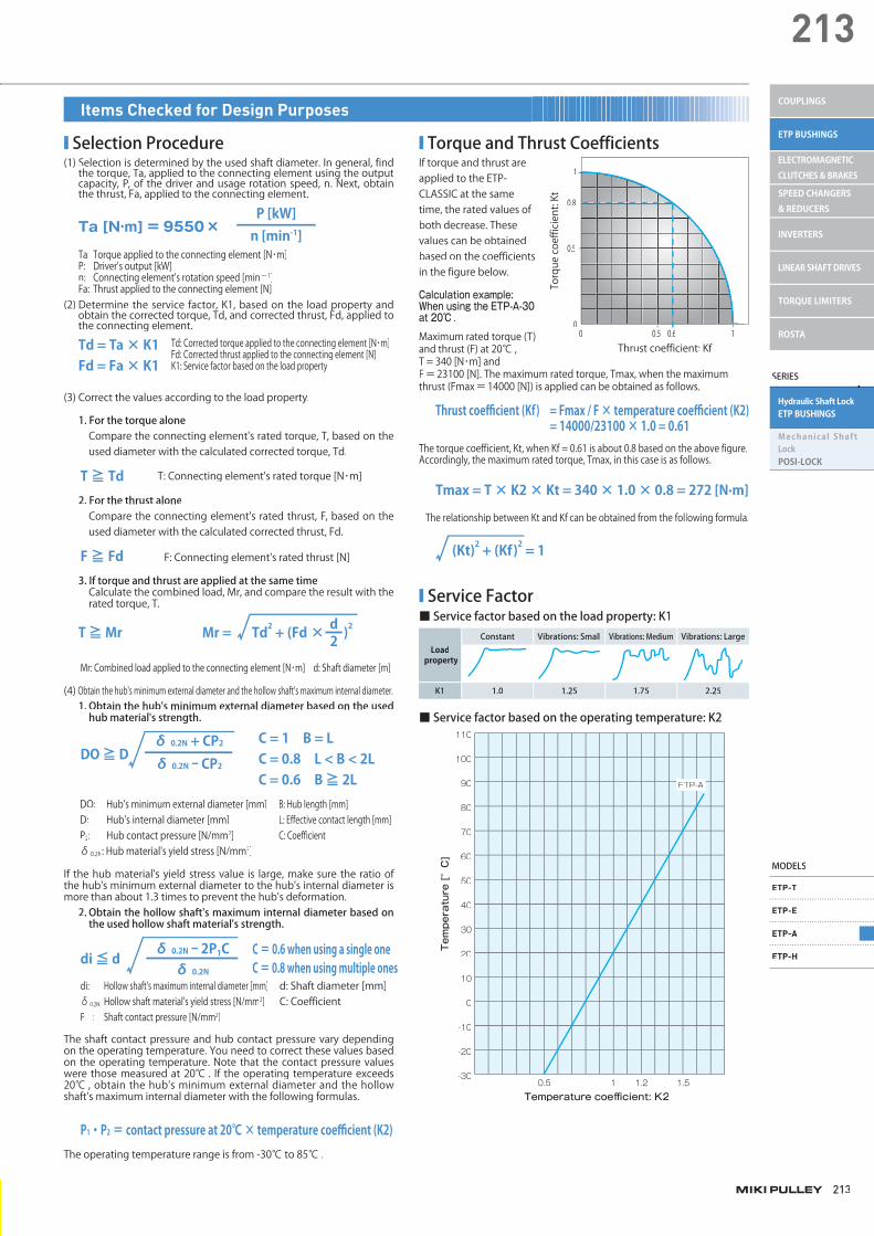
■ Torque and Thrust CoefficientsIf torque and thrust areapplied to the ETP-CLASSIC at the same time, the rated values of both decrease. Thesevalues can be obtainedbased on the coefficients in the figure below.
Calculation example: When using the ETP-A-30 at 20℃ .
Maximum rated torque (T) and thrust (F) at 20℃ , T = 340 [N・m] and F=23100 [N]. The maximum rated torque, Tmax, when the maximum thrust (Fmax=14000 [N]) is applied can be obtained as follows.
Ta [N·m] = 9550× n [min-1]P [kW]
Ta: Torque applied to the connecting element [N・m]P: Driver's output [kW]n: Connecting element's rotation speed [minー 1]Fa: Thrust applied to the connecting element [N]
(2) Determine the service factor, K1, based on the load property and obtain the corrected torque, Td, and corrected thrust, Fd, applied to
p p yp p y
the connecting element.q
Td = Ta × K1Fd = Fa × K1
Td: Corrected torque applied to the connecting element [N・m]Fd: Corrected thrust applied to the connecting element [N]K1: Service factor based on the load property
(3) Correct the values according to the load property.
1. For the torque aloneCompare the connecting element's rated torque, T, based on theused diameter with the calculated corrected torque, Td.
T ≧ Td T: Connecting element's rated torque [N・m]
2. For the thrust aloneCompare the connecting element's rated thrust, F, based on theused diameter with the calculated corrected thrust, Fd.
3. If torque and thrust are applied at the same timeCalculate the combined load, Mr, and compare the result with the rated torque, T.
F ≧ Fd F: Connecting element's rated thrust [N]
2dMr = Td2 + (Fd × )2T ≧ Mr
1
0.8
0.5
00 0.5 0.6 1
Torque coefficient: Kt
Thrust coefficient: Kf
Thrust coefficient (Kf) = Fmax / F × temperature coefficient (K2) = 14000/23100 × 1.0 = 0.61
The torque coefficient, Kt, when Kf = 0.61 is about 0.8 based on the above figure.Accordingly, the maximum rated torque, Tmax, in this case is as follows.
Tmax = T × K2 × Kt = 340 × 1.0 × 0.8 = 272 [N·m]
The relationship between Kt and Kf can be obtained from the following formula.
(Kt)2 + (Kf)2 = 1
■ Service Factor■ Service factor based on the load property: K1
Load property
Constant Vibrations: Small Vibrations: Medium Vibrations: Large
K1 1.0 1.25 1.75 2.25
■ Service factor based on the operating temperature: K2
Temperature [°C]
Temperature coefficient: K20.5 1 1.2 1.5
-30
-20
-10
0
10
20
30
40
50
60
70
80
90
100
110
ETP-A
Items Checked for Design Purposes
Mr: Combined load applied to the connecting element [N・m] d: Shaft diameter [m]
(4) Obtain the hub's minimum external diameter and the hollow shaft's maximum internal diameter.1. Obtain the hub's minimum external diameter based on the used
hub material's strength.
If the hub material's yield stress value is large, make sure the ratio of the hub's minimum external diameter to the hub's internal diameter is more than about 1.3 times to prevent the hub's deformation.
DO: Hub's minimum external diameter [mm]D: Hub's internal diameter [mm]P2: Hub contact pressure [N/mm2]δ0.2N: Hub material's yield stress [N/mm2]
B: Hub length [mm]L: Effective contact length [mm]C: Coefficient
C = 1 B = LC = 0.8 L < B < 2LC = 0.6 B ≧ 2L
δ 0.2N + CP2
δ 0.2N - CP2DO ≧ D
2. Obtain the hollow shaft's maximum internal diameter based onthe used hollow shaft material's strength.
The shaft contact pressure and hub contact pressure vary depending on the operating temperature. You need to correct these values based on the operating temperature. Note that the contact pressure values were those measured at 20℃ . If the operating temperature exceeds 20℃ , obtain the hub's minimum external diameter and the hollowshaft's maximum internal diameter with the following formulas.
C = 0.6 when using a single oneC = 0.8 when using multiple ones
δ 0.2N - 2P1Cδ 0.2N
di ≦ d
P1・P2 = contact pressure at 20℃ × temperature coefficient (K2)
di: Hollow shaft's maximum internal diameter [mm]δ0.2N: Hollow shaft material's yield stress [N/mm2]P1 : Shaft contact pressure [N/mm2]
d: Shaft diameter [mm]C: Coefficient
The operating temperature range is from -30℃ to 85℃ .
003_ETPBush_01.indd 213003_ETPBush_01.indd 213 /2015 6:03:10 PMM4/21/2015 6:03:10 PMM4/21/2015 6:03:104/21/2015 6:03:10 PM

ETP-A Models
■ Hub's Minimum External DiametersIf the stress applied to the hub is too large, the hub may be deformed. Select the appropriate external diameter size from the hub's minimum external diameters in the table below in the design phase.
■ ETP-A, ETP-A B, ETP-A C, ETP-A S
L
B
B=L
φDmin
ETP-AETP-A BETP-A C ETP-A S size
Hub contactpressure
[N/mm2]
Material's yield stress δ0.2 [N /mm2]
150 180 210 230 250 280 300 350 400 450
FC250 FC300SS330 SC360
FCMB310
FC350 SS400 SC410
FCMB360
SUS304
SC450 S15C SF440
FCD400SS490 SC480 S20C SF490
S30CSF540SUS201
FCD450
S35CSF590
FCD500
S45C
SUS410
FCD600
S55C
SUS403
FCD700
SUS420
15 80 42 37 35 33 32 31 31 30 30 30
19 80 51 46 42 41 39 38 37 37 37 37
20 80 51 46 42 41 39 38 37 37 37 37
22 80 58 52 48 46 45 43 42 42 42 42
24 80 62 55 51 49 48 46 45 45 45 45
25 80 62 55 51 49 48 46 45 45 45 45
28 80 71 63 59 56 55 53 52 51 51 51
30 80 75 67 62 59 58 55 54 54 54 54
32 80 78 70 65 62 60 58 57 56 56 56
35 80 86 76 71 68 66 63 62 62 62 62
38 80 91 81 75 72 70 67 66 65 65 65
40 80 96 86 80 77 74 72 70 69 69 69
42 80 100 89 83 79 77 74 73 72 72 72
45 80 107 96 89 85 83 80 78 77 77 77
48 80 113 100 93 90 87 84 82 81 81 81
50 80 118 105 97 94 91 88 86 85 85 85
55 80 129 115 106 102 99 96 94 93 93 93
60 80 140 125 115 111 108 104 102 101 101 101
65 80 153 136 126 121 117 113 111 110 110 110
70 80 164 146 135 130 126 121 119 117 117 117
75 80 173 154 142 137 133 128 125 124 124 124
80 80 182 162 150 144 140 135 132 130 130 130
90 80 203 181 168 161 156 151 148 146 146 146
100 80 227 202 187 180 175 168 165 163 163 163
* Hub contact pressure at an operating temperature of 20℃ . The contact pressure increases as the temperature rises.* If the operating temperature exceeds 20℃ , you need to obtain the hub's minimum external diameter according to the selection procedure on P.213.* The hub's minimum external diameter shows a value calculated based on C=1 in the selection procedure on P.213.* The above SUS values are proof stress values (N/mm2) after quenching and tempering.
ø Dmin, unit [mm]
Items Checked for Design Purposes
214
Hydraulic Shaft Lock ETP BUSHINGSETP BUSHINGS
miki_Catalog_g_e.indb 214 /2015 5:19:01 PMM5/18/2015 5:19:01 PMM5/18/2015 5:19:015/18/2015 5:19:01 PM

■ ETP-A R
L
B
B=L
φDmin
■ Hub's Minimum External DiametersIf the stress applied to the hub is too large, the hub may be deformed. Select the appropriate external diameter size from the hub's minimum external diameters in the table below in the design phase.
ETP-A R size
Hub contact pressure
[N/mm2]
Material's yield stress δ0.2 [N /mm2]
150 180 210 230 250 280 300 350 400 450
FC250 FC300 SS330 SC360
FCMB310
FC350 SS400 SC410
FCMB360
SUS304
SC450 S15C SF440
FCD400 SS490 SC480 S20C SF490
S30C SF540 SUS201
FCD450
S35C SF590
FCD500
S45C
SUS410
FCD600
S55C
SUS403
FCD700
SUS420
15 70 39 35 33 32 31 30 30 30 30 30
20 70 47 43 40 39 38 37 37 37 37 37
25 70 57 52 49 47 46 45 45 45 45 45
30 70 68 62 58 57 55 54 54 54 54 54
35 70 78 71 67 65 63 62 62 62 62 62
40 70 88 80 75 73 71 69 69 69 69 69
45 70 98 89 84 81 79 77 77 77 77 77
50 70 108 98 92 90 87 85 85 85 85 85
* Hub contact pressure at an operating temperature of 20℃ . The contact pressure increases as the temperature rises.* If the operating temperature exceeds 20℃ , you need to obtain the hub's minimum external diameter according to the selection procedure on P.213.* The hub's minimum external diameter shows a value calculated based on C=1 in the selection procedure on P.213.* The above SUS values are proof stress values (N/mm2) after quenching and tempering.
ø Dmin, unit [mm]
215
215
SERIES
Hydraulic Shaft LockETP BUSHINGS
Mechanical Shaft LockPOSI-LOCK
MODELS
ETP-T
ETP-E
ETP-A
ETP-H
COUPLINGS
ETP BUSHINGS
ELECTROMAGNETIC CLUTCHES & BRAKES
SPEED CHANGERS & REDUCERS
INVERTERS
LINEAR SHAFT DRIVES
TORQUE LIMITERS
ROSTA
miki_Catalog_e.indb 215 5/18/2015 5:19:01 PM

ETP-A Models
■ Fatigue Caused by Periodically Applied Varying TorqueThe following figure shows the fatigue state when a static varying torque, Tk, is applied periodically to the ETP-CLASSIC. The vertical axis shows the percentage of the rated torque, T, and the horizontal axis shows the number of periodically applied static varying torque events.
If the rated torque, T, is periodically applied to the ETP-CLASSIC, it can withstand about 500,000 events in terms of fatigue life. If 75% of the rated torque, T, is applied, it can withstand an unlimited number of events interms of fatigue life.
Number of timesRated torque ratio Tk/T [%]
200
150
100
50
4 5 2 3 4 5 2 3 4 50 107
Tk
Number of times
■ Mounting Shaft Tolerance, Mounting HubTolerance, and Surface Roughness
■ Operating Temperature RangeModel Operating temperature range [°C]ETP-A
- 30 ~ 85ETP-A B
ETP-A C
ETP-A S
ETP-A R
■ Concentricity and BalanceModel Concentricity [mm] Balance [g·mm/kg]ETP-A
0.05 100ETP-A B
ETP-A C
ETP-A S
ETP-A R
■ ETP-A
Model Mountingshaft tolerance
Mountinghub tolerance
Surface roughness
ETP-A-15 h7H7
25S (center line'saverage roughness
6.3a) or lessETP-A-19 ~ 100 h8 ~ k6
■ ETP-A B, C
Model Mountingshaft tolerance
Mountinghub tolerance
Surface roughness
ETP-A-15-B・C h7H7
25S (center line'saverage roughness
6.3a) or lessETP-A-19-B・C ~ 100-B・C h8 ~ k6
■ ETP-A R
Model Mountingshaft tolerance
Mountinghub tolerance
Surface roughness
ETP-A-15-R h7H7
25S (center line'saverage roughness
6.3a) or lessETP-A-20-R ~ 50-R h8
■ ETP-A S
Model Mountingshaft tolerance
Mountinghub tolerance
Surface roughness
ETP-A-19-S ~ 50-S h8 ~ k6 H725S (center line's
average roughness6.3a) or less
■ Keyway Shape where the ETP-CLASSIC Cannot Be Detached due to a Deformation of the Sleeve
The ETP-CLASSIC cannot be used if the shaft and hub have a keyway asshown in the figure below. Note that you can use the ETP-CLASSIC forthe shaft and hub with a keyway if you completely fill the keyway withepoxy putty for metals and then shape it.
■ Allowable Range of EdgeThe performance of the ETP-CLASSIC is based on the case where the shaft and the hub have the effect for the entire standard shaft length,Ls, and the entire standard hub length, Lh, respectively. Accordingly, make sure in the design phase that the shaft and the hub have the effect for the respective entire standard length. If the length of the shaft and hub is limited due to design reasons, make sure it is less thanthe dimension S in the figure below. If it exceeds the dimension S,stress concentrates on the sleeve edge and the sleeve is deformed, sothere is the possibility that the ETP-CLASSIC cannot be detached.
■ ETP-CLASSIC
S
S
LhL4
LS
ETP-CLASSIC size S[mm]15 319 3.520 3.522 424 425 3.628 4.530 532 535 5.538 5.540 642 645 6.548 750 755 7.560 865 970 9.575 9.580 9.590 10.5100 12.5
Items Checked for Design Purposes
216
Hydraulic Shaft Lock ETP BUSHINGSETP BUSHINGS
003_ETPBush_01.indd 216 /2015 6:03:11 PMM4/21/2015 6:03:11 PMM4/21/2015 6:03:114/21/2015 6:03:11 PM

■ Mounting ■ Removal (1) Wipe the rust, dust, and oil off from the surface of the shaft and hub
with a cloth or alcohol solution. In particular, if grease remains, wipe it off completely. If oil remains on the surface of the ETP-CLASSIC, wipe it off with a cloth, etc.If the oil is wiped off, the friction coefficient basically changes. Never allow oil containing molybdenum-based antifriction material to contact the surface.
(2) Attach the ETP-CLASSIC to the hub and mount them to the shaft. If accurate positioning of the shaft and hub is needed, adjust the position of both before tightening the clamping bolts.Never tighten the clamping bolts before mounting the ETP-CLASSIC to the shaft and hub.
(3) Gently put a hand on the ETP-CLASSIC and tighten the clamping bolts one by one by a half turn in order of (1), (2), and (3) as shown in the figure. Tighten the clamping bolts for the ETP-CLASSIC to the specified torque using a torque wrench. Do not tighten the clamping bolt to a torque greater than the specified torque and then loosen the clamping bolt to the specified tightening torque. The clamping bolts of the ETP-A-R are made of stainless steel. Stainless steel can gall easily. Slowly tighten the stainless steel bolts to prevent galling.
(1) Before starting work, ensure safety by making sure no torque and thrust are applied to the ETP-CLASSIC and there is no risk of a fall due to the self-weight of the shaft and hub. The ETP-CLASSIC does not have a self-locking mechanism. The connecting force is instantaneously released by loosening the clamping bolts.
(2) The clamping bolts should only be loosened until the connecting force is released. Do not remove them. If for any reason the ETP-CLASSIC cannot be removed, remove all the clamping bolts, flange, and piston ring, and then remove the ETP-CLASSIC using the sleeve's tapped holes as removal screw holes.
(4) When the mounting is finished, check to make sure the spacing between the flange and sleeve is uniform. If the flange and the sleeve are in close contact with each other, the ETP-CLASSIC may not be able to achieve its full performance. In this case, re-check the shaft and hub tolerances and the material.
S 2 S
S 1
|S1 - S2|≦ 0.3 S > 0
217
217
SERIES
Hydraulic Shaft LockETP BUSHINGS
Mechanical Shaft LockPOSI-LOCK
MODELS
ETP-T
ETP-E
ETP-A
ETP-H
COUPLINGS
ETP BUSHINGS
ELECTROMAGNETIC CLUTCHES & BRAKES
SPEED CHANGERS & REDUCERS
INVERTERS
LINEAR SHAFT DRIVES
TORQUE LIMITERS
ROSTA
003_ETPBush_01.indd 217 4/21/2015 6:03:11 PM

218
Hydraulic Shaft Lock ETP BUSHINGS
ETP-H Models
Model
Rated torque [N·m] Rated thrust [N]Moment of
inertia[kg・m2]
Mass[kg]Oil pressure: 60 MPa Oil pressure: 80 MPa Oil pressure: 100 MPa Oil pressure: 60 MPa Oil pressure: 80 MPa Oil pressure: 100 MPa
Shaft tol. h7 Shaft tol. h8 Shaft tol. h7 Shaft tol. h8 Shaft tol. h7 Shaft tol. h8 Shaft tol. h7 Shaft tol. h8 Shaft tol. h7 Shaft tol. h8 Shaft tol. h7 Shaft tol. h8
ETP-H-50 800 800 1600 1400 2600 2400 30000 30000 55000 55000 70000 70000 3.2 × 10⁻³ 2.4
ETP-H-60 1100 1100 3300 3000 4600 4300 60000 60000 100000 100000 130000 130000 5.4 × 10⁻³ 3.1
ETP-H-70 2400 2400 5800 5300 7900 7400 100000 95000 150000 150000 210000 200000 8.7 × 10⁻³ 4.1
ETP-H-80 5600 5300 9000 8400 12100 11500 150000 135000 220000 210000 290000 280000 14 × 10-3 5.4
ETP-H-90 8300 7400 12700 11800 17100 16200 185000 165000 285000 265000 380000 360000 23 × 10-3 7
ETP-H-100 12100 11000 18200 17100 24200 23100 245000 220000 365000 340000 485000 460000 34 × 10-3 8.6
ETP-H-110 16800 15400 24800 23500 32900 31500 305000 280000 450000 430000 595000 570000 51 × 10-3 11
ETP-H-120 22300 20600 32700 31100 43200 41600 370000 345000 545000 520000 720000 690000 76 × 10-3 14
ETP-H-130 27200 24900 40500 38100 53800 51400 420000 385000 620000 590000 825000 790000 110 × 10-3 17
ETP-H-140 35600 32900 52300 49600 68900 66200 510000 470000 750000 710000 985000 945000 150 × 10-3 21
ETP-H-150 44500 41400 65000 61900 85400 82300 595000 550000 870000 825000 1135000 1095000 210 × 10-3 25
ETP-H-160 54800 51200 79500 76000 104000 100000 685000 640000 995000 950000 1305000 1260000 290 × 10-3 30
ETP-H-180 80000 75000 115000 110000 150000 146000 890000 835000 1280000 1220000 1675000 1625000 500 × 10-3 42
ETP-H-200 109000 103000 157000 151000 206000 200000 1090000 1030000 1570000 1510000 2060000 2000000 830 × 10-3 56
ETP-H-220 144000 137000 209000 201000 273000 266000 1310000 1245000 1900000 1830000 2485000 2415000 1300 × 10-3 73
* The maximum rated torque values are those when the thrust is zero and the maximum rated thrust values are those when the torque is zero.
Specifications
Dimensions
Made to order
ETP BUSHINGS
φD1
φd
φD
L1P.C.D.B
ONOFF
2-M, length: 12
L
7
7
ETP-H-Size
How to Place an Order
Model d D D1 L L1 P.C.D.B M
ETP-H-50 50 77 101 57 82 75 M8
ETP-H-60 60 89 113 65 90 86 M8
ETP-H-70 70 102 122 75 100 96 M8
ETP-H-80 80 115 135 85 110 107 M8
ETP-H-90 90 128 148 95 120 124 M12
ETP-H-100 100 140 160 105 130 140 M12
ETP-H-110 110 154 173 115 140 150 M12
ETP-H-120 120 168 186 125 150 160 M12
ETP-H-130 130 182 200 135 160 175 M16
ETP-H-140 140 196 213 145 170 185 M16
ETP-H-150 150 210 227 155 180 195 M16
ETP-H-160 160 224 240 165 190 205 M16
ETP-H-180 180 252 267 185 210 223 M16
ETP-H-200 200 280 293 205 230 247 M16
ETP-H-220 220 308 320 225 250 280 M16
* The port (for connecting the radial thrust hose) is G1/8.
Unit [mm]
www.mikipulley.co.jp Web code B004To download CAD data or product catalogs:
* Depending on your location and such, we may not be able to sell you our products. Please contact us for details.
003_ETPBush_01.indd 218 /2015 6:03:12 PMM4/21/2015 6:03:12 PMM4/21/2015 6:03:124/21/2015 6:03:12 PM
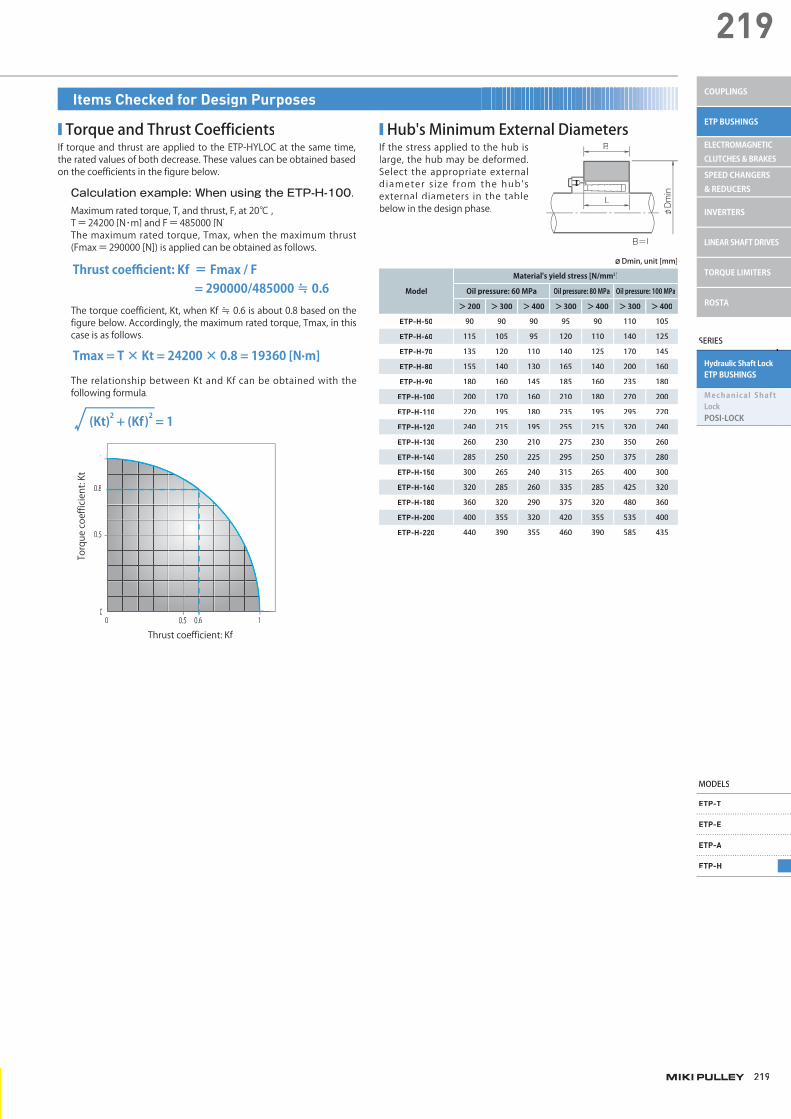
219
219
Calculation example: When using the ETP-H-100.Maximum rated torque, T, and thrust, F, at 20℃ ,T=24200 [N・m] and F=485000 [N]The maximum rated torque, Tmax, when the maximum thrust (Fmax=290000 [N]) is applied can be obtained as follows.
Thrust coefficient: Kf = Fmax / F = 290000/485000 ≒ 0.6The torque coefficient, Kt, when Kf ≒ 0.6 is about 0.8 based on the figure below. Accordingly, the maximum rated torque, Tmax, in thiscase is as follows.
The relationship between Kt and Kf can be obtained with the following formula.
■ Torque and Thrust CoefficientsIf torque and thrust are applied to the ETP-HYLOC at the same time,the rated values of both decrease. These values can be obtained basedon the coefficients in the figure below.
■ Hub's Minimum External DiametersIf the stress applied to the hub islarge, the hub may be deformed.Select the appropriate externaldiameter s ize f rom the hub's external diameters in the table below in the design phase.
(Kt)2 + (Kf)2 = 1
Tmax = T × Kt = 24200 × 0.8 = 19360 [N·m]
1
0.8
0.5
00 0.5 0.6 1
Torque coefficient: Kt
Thrust coefficient: Kf
L
B
B=L
φDmin
Model
Material's yield stress [N/mm2]
Oil pressure: 60 MPa Oil pressure: 80 MPa Oil pressure: 100 MPa
>200 >300 >400 >300 >400 >300 >400
ETP-H-50 90 90 90 95 90 110 105
ETP-H-60 115 105 95 120 110 140 125
ETP-H-70 135 120 110 140 125 170 145
ETP-H-80 155 140 130 165 140 200 160
ETP-H-90 180 160 145 185 160 235 180
ETP-H-100 200 170 160 210 180 270 200
ETP-H-110 220 195 180 235 195 295 220
ETP-H-120 240 215 195 255 215 320 240
ETP-H-130 260 230 210 275 230 350 260
ETP-H-140 285 250 225 295 250 375 280
ETP-H-150 300 265 240 315 265 400 300
ETP-H-160 320 285 260 335 285 425 320
ETP-H-180 360 320 290 375 320 480 360
ETP-H-200 400 355 320 420 355 535 400
ETP-H-220 440 390 355 460 390 585 435
ø Dmin, unit [mm]
Items Checked for Design Purposes
SERIES
Hydraulic Shaft LockETP BUSHINGS
Mechanical Shaft LockPOSI-LOCK
MODELS
ETP-T
ETP-E
ETP-A
ETP-H
COUPLINGS
ETP BUSHINGS
ELECTROMAGNETIC CLUTCHES & BRAKES
SPEED CHANGERS & REDUCERS
INVERTERS
LINEAR SHAFT DRIVES
TORQUE LIMITERS
ROSTA
003_ETPBush_01.indd 219003_ETPBush_01.indd 219 4/21/2015 6:03:12 PMM4/21/2015 6:03:12 PM
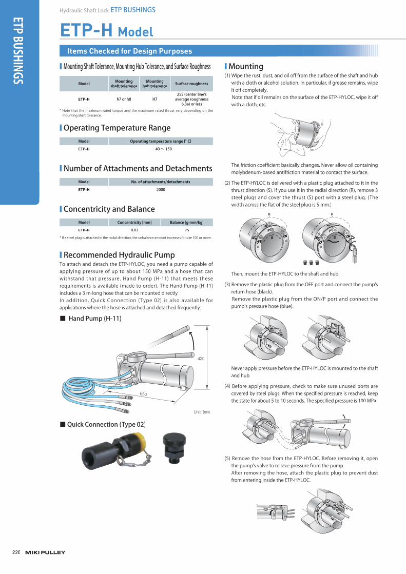
220
Hydraulic Shaft Lock ETP BUSHINGS
ETP-H Model
■ Mounting Shaft Tolerance, Mounting Hub Tolerance, and Surface Roughness
Model Mountingshaft tolerance
Mountinghub tolerance Surface roughness
ETP-H h7 or h8 H725S (center line's
average roughness 6.3a) or less
* Note that the maximum rated torque and the maximum rated thrust vary depending on the mounting shaft tolerance.
■ Operating Temperature RangeModel Operating temperature range [°C]
ETP-H - 40 ~ 150
■ Number of Attachments and DetachmentsModel No. of attachments/detachments
ETP-H 2000
■ Concentricity and BalanceModel Concentricity [mm] Balance [g·mm/kg]
ETP-H 0.02 75
* If a steel plug is attached in the radial direction, the unbalance amount increases for size 100 or more.
■ Mounting(1) Wipe the rust, dust, and oil off from the surface of the shaft and hub
with a cloth or alcohol solution. In particular, if grease remains, wipeit off completely.
Note that if oil remains on the surface of the ETP-HYLOC, wipe it off with a cloth, etc.
The friction coefficient basically changes. Never allow oil containingmolybdenum-based antifriction material to contact the surface.
(2) The ETP-HYLOC is delivered with a plastic plug attached to it in thethrust direction (S). If you use it in the radial direction (R), remove 3 steel plugs and cover the thrust (S) port with a steel plug. (Thewidth across the flat of the steel plug is 5 mm.)
Then, mount the ETP-HYLOC to the shaft and hub.
(3) Remove the plastic plug from the OFF port and connect the pump'sreturn hose (black).
Remove the plastic plug from the ON/P port and connect thepump's pressure hose (blue).
Never apply pressure before the ETP-HYLOC is mounted to the shaftand hub.
(4) Before applying pressure, check to make sure unused ports are covered by steel plugs. When the specified pressure is reached, keepthe state for about 5 to 10 seconds. The specified pressure is 100 MPa.
(5) Remove the hose from the ETP-HYLOC. Before removing it, openthe pump's valve to relieve pressure from the pump.After removing the hose, attach the plastic plug to prevent dustfrom entering inside the ETP-HYLOC.
■ Recommended Hydraulic PumpTo attach and detach the ETP-HYLOC, you need a pump capable of applying pressure of up to about 150 MPa and a hose that canwithstand that pressure. Hand Pump (H-11) that meets theserequirements is available (made to order). The Hand Pump (H-11) includes a 3 m-long hose that can be mounted directly.In addition, Quick Connection (Type 02) is also available for applications where the hose is attached and detached frequently.
■ Hand Pump (H-11)
650
420
Unit: [mm]
■ Quick Connection (Type 02)
Items Checked for Design Purposes
ETP BUSHINGS
003_ETPBush_01.indd 220003_ETPBush_01.indd 220 /2015 6:03:13 PMM4/21/2015 6:03:13 PMM4/21/2015 6:03:134/21/2015 6:03:13 PM
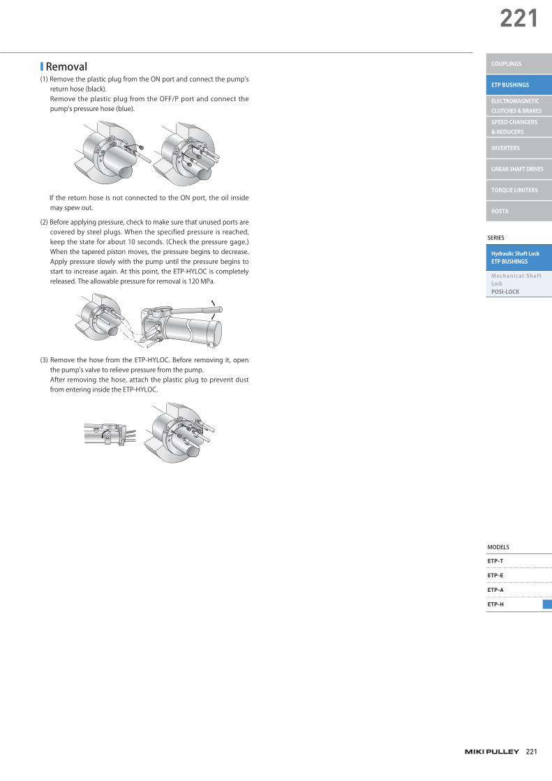
221
221
■ Removal (1) Remove the plastic plug from the ON port and connect the pump's
return hose (black).Remove the plastic plug from the OFF/P port and connect the pump's pressure hose (blue).
If the return hose is not connected to the ON port, the oil inside may spew out.
(2) Before applying pressure, check to make sure that unused ports are covered by steel plugs. When the specified pressure is reached, keep the state for about 10 seconds. (Check the pressure gage.) When the tapered piston moves, the pressure begins to decrease. Apply pressure slowly with the pump until the pressure begins to start to increase again. At this point, the ETP-HYLOC is completely released. The allowable pressure for removal is 120 MPa.
(3) Remove the hose from the ETP-HYLOC. Before removing it, open the pump's valve to relieve pressure from the pump.After removing the hose, attach the plastic plug to prevent dust from entering inside the ETP-HYLOC.
SERIES
Hydraulic Shaft LockETP BUSHINGS
Mechanical Shaft LockPOSI-LOCK
MODELS
ETP-T
ETP-E
ETP-A
ETP-H
COUPLINGS
ETP BUSHINGS
ELECTROMAGNETIC CLUTCHES & BRAKES
SPEED CHANGERS & REDUCERS
INVERTERS
LINEAR SHAFT DRIVES
TORQUE LIMITERS
ROSTA
003_ETPBush_01.indd 221 4/21/2015 6:03:14 PM
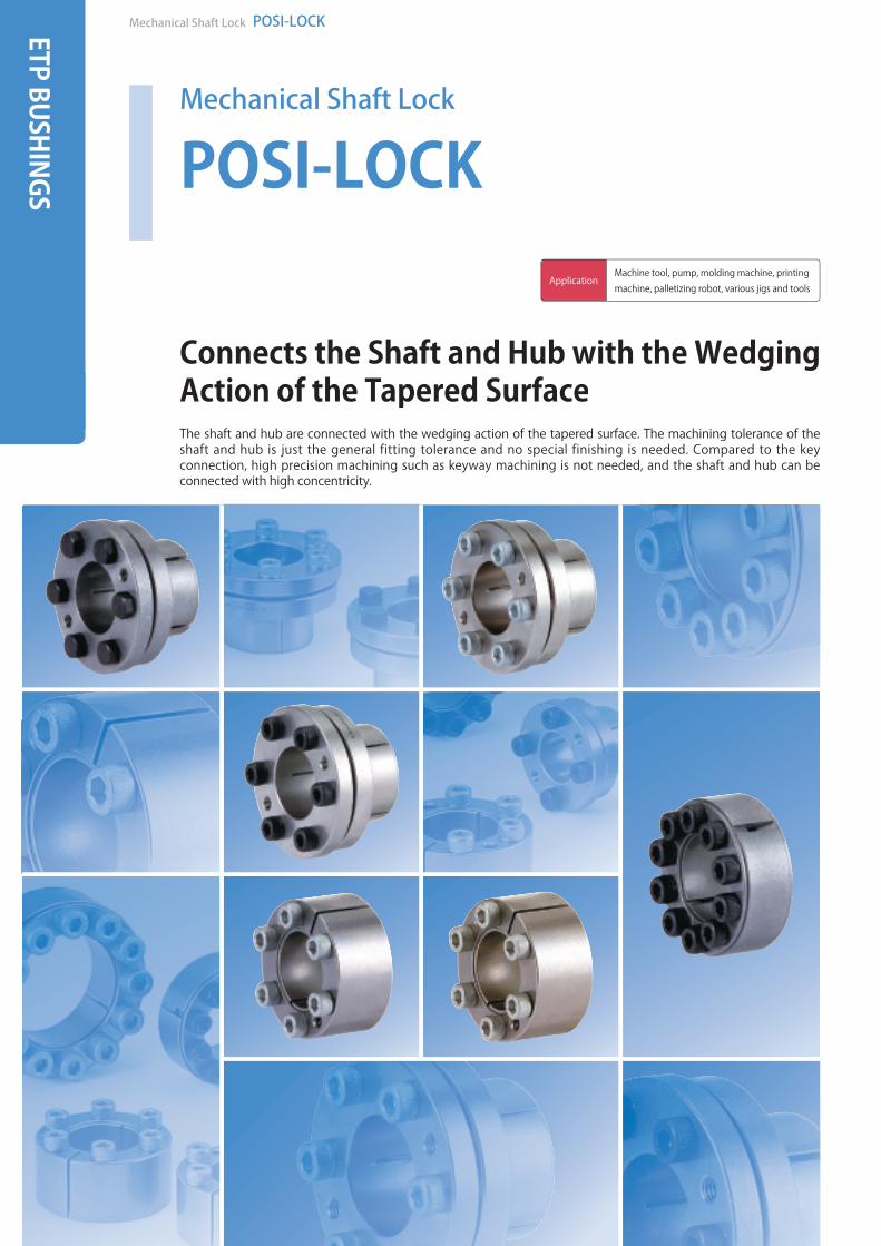
Mechanical Shaft Lock POSI-LOCKETP BUSHINGS
Mechanical Shaft Lock
POSI-LOCK
Connects the Shaft and Hub with the WedgingAction of the Tapered SurfaceThe shaft and hub are connected with the wedging action of the tapered surface. The machining tolerance of the shaft and hub is just the general fitting tolerance and no special finishing is needed. Compared to the key connection, high precision machining such as keyway machining is not needed, and the shaft and hub can be connected with high concentricity.
ApplicationMachine tool, pump, molding machine, printing machine, palletizing robot, various jigs and tools
miki_Catalog_e.indb 222miki_Catalog_g_e.indb 222 /2015 5:19:06 PMM5/18/2015 5:19:06 PMM5/18/2015 5:19:05/18/2015 5:19:06 PM

223
223
SERIES
Hydraulic Shaft LockETP BUSHINGS
Mechanical Shaft LockPOSI-LOCK
MODELS
PSL-K
PSL-G
PSL-D
COUPLINGS
ETP BUSHINGS
ELECTROMAGNETIC CLUTCHES & BRAKES
SPEED CHANGERS & REDUCERS
INVERTERS
LINEAR SHAFT DRIVES
TORQUE LIMITERS
ROSTA
Series Models Specification Lineup
POSI-LOCK PSL-K
PSL-K B
PSL-K C
PSL-K F
PSL-G
PSL-G C
PSL-D
PSL-D C
Standard
Hexagon bolt
Simple rustproof
Stainless steel
Standard
Simple rustproof
Standard
Simple rustproof
Flange model
Third party compatible model
Medium load model
Model/Type Main body material Surface finishingApplied shaft diameter
[mm]Max. rated torque[N・m]
Max. rated thrust[N]
Operating temperature[℃]
PSL-K S45C refined or equivalent ― 6 ~ 42 750 36000 -40 ~ 150
PSL-K B S45C refined or equivalent ― 6 ~ 42 750 36000 -40 ~ 150
PSL-K C S45C refined or equivalent
Electroless nickelplating 6 ~ 42 750 36000 -40 ~ 150
PSL-K F SUS304 or an equivalent ― 6 ~ 35 504 28800 -40 ~ 150
PSL-G S45C refined or equivalent ― 19 ~ 120 13500 225000 -40 ~ 150
PSL-G C S45C refined or equivalent
Electroless nickelplating 19 ~ 60 2810 93600 -40 ~ 150
PSL-D S45C refined or equivalent ― 6 ~ 50 1760 70300 -40 ~ 150
PSL-D C S45C refined or equivalent
Electroless nickelplating 16 ~ 50 1760 70300 -40 ~ 150
003_ETPBush_02.indd 223003_ETPBush_02.indd 223 /2015 3:59:37 PMM4/20/2015 3:59:37 PMM4/20/2015 3:59:374/20/2015 3:59:37 PM

224
Mechanical Shaft Lock POSI-LOCKETP BUSHINGS
Product Lineup
PSL-K■ Operating PrincipleTightening the clamping bolt moves the outer sleeve in the shaft direction. At this point, the wedge action of the tapered surface with the inner sleeve generates a force to press the inner surface of the shaft and hub and this force connects the shaft and hub completely. The groove of the inner sleeve increases the wedge effect so a high transmission torque can be obtained.
Outer sleeve material: S45C tempered or an equivalent
Inner sleeve material: S45C tempered or an equivalent
Clamping bolt material: Alloy steel for machine structural useSurface finishing: Black coating
Outer sleeve material: S45C tempered or an equivalentSurface finishing: Electroless nickel plating
Inner sleeve material: S45C tempered or an equivalentSurface finishing: Electroless nickel plating
Clamping bolt material: Alloy steel for machine structural useSurface finishing: Antirust film coating
Outer sleeve material: SUS304 or an equivalent
Inner sleeve material: SUS304 or an equivalent
Clamping bolt material: SUH660 or an equivalentSurface finishing: Solid film lubricant coating
* A special coating is applied to the clamping bolt to stabilize the shaft force.
PSL-K
PSL-K C
Standard type of the PSL-K model.
The main body is electroless nickel coated (simple rustproof finishing).
A hexagon bolt is used for the clamping bolt so the device can be mounted even in tight space in the thrust direction.
The main body is made of stainless material (rustproof coating).
Max. rated torque [N・m] 750
Max. rated thrust [N] 36000
Applied shaft diameter [mm] 6 ~ 42
Operating temperature [℃] -40 ~150
The sleeve's internal/external diameter ratio is small. The mounting part's diameter as well as the moment of inertia can be reduced. The mechanism is simple and high concentricity can be maintained.
■ Variations and Materials
Clampingbolt
Inner sleeve
Groove
Outersleeve
Detachment screw hole
PSL-K B
PSL-K F
RoHS-compliant
Outer sleeve material: S45C tempered or an equivalent
Inner sleeve material: S45C tempered or an equivalent
Clamping bolt material: Alloy steel for machine structural useSurface finishing: Black coating
003_ETPBush_02.indd 224 4/20/2015 3:59:38 PM
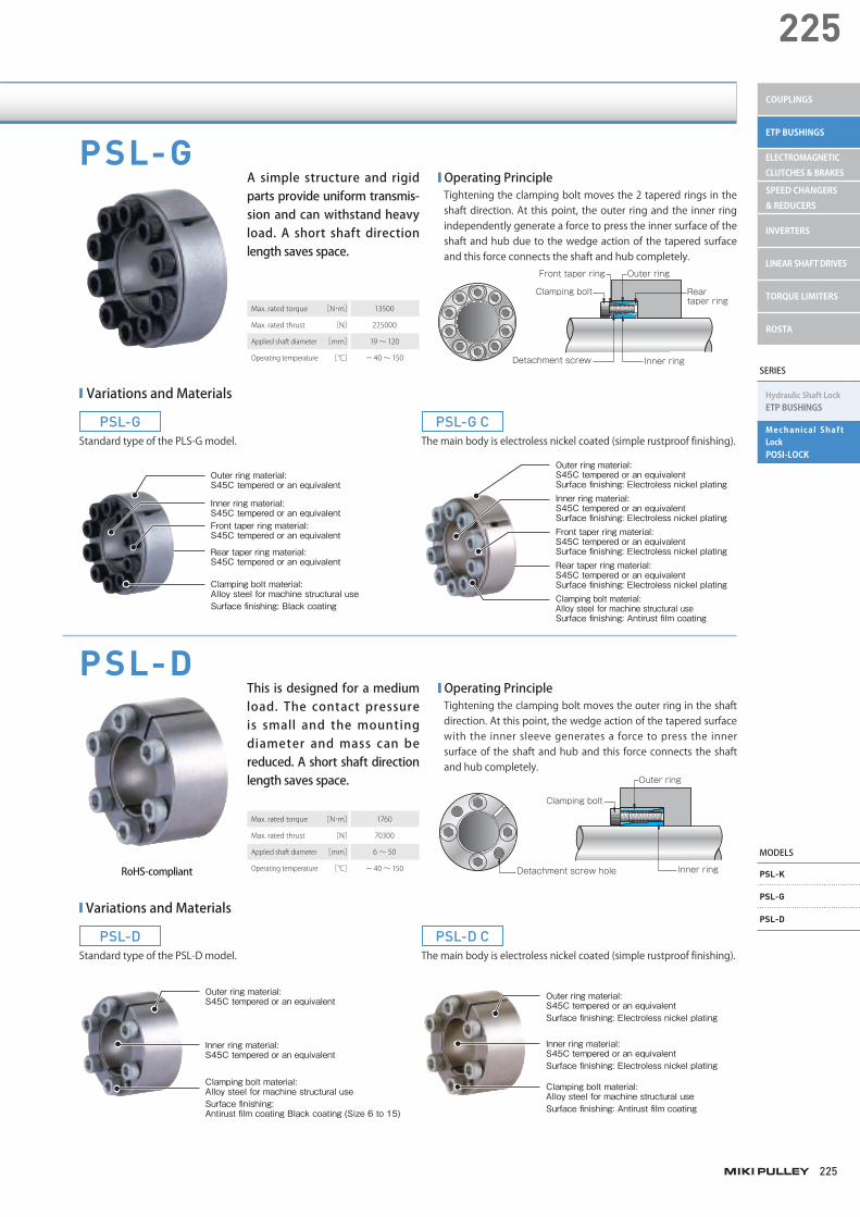
225
225
SERIES
Hydraulic Shaft LockETP BUSHINGS
Mechanical Shaft LockPOSI-LOCK
MODELS
PSL-K
PSL-G
PSL-D
COUPLINGS
ETP BUSHINGS
ELECTROMAGNETIC CLUTCHES & BRAKES
SPEED CHANGERS & REDUCERS
INVERTERS
LINEAR SHAFT DRIVES
TORQUE LIMITERS
ROSTA
PSL-G
PSL-D
■ Operating PrincipleTightening the clamping bolt moves the 2 tapered rings in the shaft direction. At this point, the outer ring and the inner ring independently generate a force to press the inner surface of the shaft and hub due to the wedge action of the tapered surface and this force connects the shaft and hub completely.
■ Operating PrincipleTightening the clamping bolt moves the outer ring in the shaft direction. At this point, the wedge action of the tapered surface with the inner sleeve generates a force to press the inner surface of the shaft and hub and this force connects the shaft and hub completely.
Outer ring material: S45C tempered or an equivalent
Inner ring material: S45C tempered or an equivalent
Clamping bolt material: Alloy steel for machine structural useSurface finishing: Antirust film coating Black coating (Size 6 to 15)
Outer ring material: S45C tempered or an equivalentSurface finishing: Electroless nickel plating
Inner ring material: S45C tempered or an equivalentSurface finishing: Electroless nickel plating
Clamping bolt material: Alloy steel for machine structural useSurface finishing: Antirust film coating
PSL-G
PSL-D
Standard type of the PLS-G model.
Standard type of the PSL-D model.
The main body is electroless nickel coated (simple rustproof finishing).
The main body is electroless nickel coated (simple rustproof finishing).
Outer ring material: S45C tempered or an equivalent
Inner ring material: S45C tempered or an equivalentFront taper ring material: S45C tempered or an equivalent
Rear taper ring material: S45C tempered or an equivalent
Clamping bolt material: Alloy steel for machine structural useSurface finishing: Black coating
Outer ring material: S45C tempered or an equivalentSurface finishing: Electroless nickel platingInner ring material: S45C tempered or an equivalentSurface finishing: Electroless nickel platingFront taper ring material: S45C tempered or an equivalentSurface finishing: Electroless nickel platingRear taper ring material: S45C tempered or an equivalentSurface finishing: Electroless nickel platingClamping bolt material: Alloy steel for machine structural useSurface finishing: Antirust film coating
Max. rated torque [N・m] 13500
Max. rated thrust [N] 225000
Applied shaft diameter [mm] 19 ~120
Operating temperature [℃] -40 ~150
Max. rated torque [N・m] 1760
Max. rated thrust [N] 70300
Applied shaft diameter [mm] 6 ~ 50
Operating temperature [℃] -40 ~150
A simple structure and rigid parts provide uniform transmis-sion and can withstand heavy load. A short shaft direction length saves space.
This is designed for a medium load. The contact pressure is small and the mounting diameter and mass can be reduced. A short shaft direction length saves space.
■ Variations and Materials
■ Variations and Materials
Outer ring
Reartaper ring
Front taper ring
Clamping bolt
Detachment screw Inner ring
Outer ring
Clamping bolt
Inner ringDetachment screw hole
PSL-G C
PSL-D C
RoHS-compliant
003_ETPBush_02.indd 225 4/20/2015 3:59:39 PM
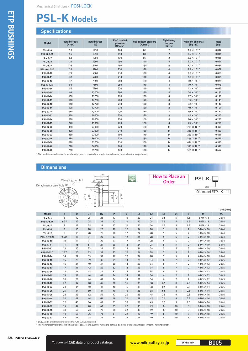
226
Mechanical Shaft Lock POSI-LOCKETP BUSHINGS
PSL-K Models
Model Rated torque[N ・m]
Rated thrust[N]
Shaft contact pressure
[N/mm2]
Hub contact pressure [N/mm2]
Tightening torque
[N ・m]
Moment of inertia [kg ・m2]
Mass[kg]
PSL-K-6 5.9 1950 160 80 2 2.5 × 10- 6 0.037PSL-K-6.35 6.2 1950 150 80 2 2.5 × 10- 6 0.036
PSL-K-7 6.8 1950 130 80 2 2.5 × 10- 6 0.035PSL-K-8 23 5900 290 160 4 5.0 × 10- 6 0.056PSL-K-9 26 5900 260 160 4 5.0 × 10- 6 0.053
PSL-K-9.525 28 5900 250 130 4 7.8 × 10- 6 0.069PSL-K-10 29 5900 230 130 4 7.7 × 10- 6 0.068PSL-K-11 32 5900 210 130 4 7.6 × 10- 6 0.065PSL-K-12 47 7800 260 160 4 10 × 10- 6 0.076
PSL-K-12.7 50 7800 250 140 4 10 × 10- 6 0.073PSL-K-14 55 7800 220 140 4 13 × 10- 6 0.083PSL-K-15 95 12700 290 190 8 24 × 10- 6 0.125PSL-K-16 100 12700 270 180 8 27 × 10- 6 0.130PSL-K-17 110 12700 260 170 8 33 × 10- 6 0.145PSL-K-18 110 12700 240 170 8 32 × 10- 6 0.140PSL-K-19 120 12700 230 160 8 40 × 10- 6 0.155PSL-K-20 130 12700 220 160 8 39 × 10- 6 0.150PSL-K-22 210 19000 250 170 8 65 × 10- 6 0.210PSL-K-24 230 19000 230 160 8 76 × 10- 6 0.220PSL-K-25 240 19000 220 160 8 75 × 10- 6 0.210PSL-K-28 380 27000 220 160 14 203 × 10- 6 0.390PSL-K-30 400 27000 210 150 14 230 × 10- 6 0.400PSL-K-32 430 27000 190 140 14 260 × 10- 6 0.425PSL-K-35 630 36000 210 150 14 366 × 10- 6 0.525PSL-K-38 680 35700 210 160 14 426 × 10- 6 0.580PSL-K-40 720 36000 160 120 14 511 × 10- 6 0.599PSL-K-42 750 35700 170 130 14 561 × 10- 6 0.657
* The rated torque values are those when the thrust is zero and the rated thrust values are those when the torque is zero.
Specifications
Old model ETP - K - □
PSL-K-Size
φD1
φP
φd
φD
φD2
L3 SL1L2
LL4Clamping bolt M1
Detachment screw hole M2
Model d D D1 D2 P L L1 L2 L3 L4 S M1 M2PSL-K-6 6 12 25 23 17 10 20 24 3.5 5 1.5 2-M4 × 8 2-M4
PSL-K-6.35 6.35 12 25 23 17 10 20 24 3.5 5 1.5 2-M4 × 8 2-M4PSL-K-7 7 12 25 23 17 10 20 24 3.5 5 1.5 2-M4 × 8 2-M4PSL-K-8 8 15 28 26 20 12 24 28 5 5 2 3-M4 × 10 3-M4PSL-K-9 9 15 28 26 20 12 24 28 5 5 2 3-M4 × 10 3-M4
PSL-K-9.525 9.525 18 31 29 23 12 24 28 5 5 2 3-M4 × 10 3-M4PSL-K-10 10 18 31 29 23 12 24 28 5 5 2 3-M4 × 10 3-M4PSL-K-11 11 18 31 29 23 12 24 28 5 5 2 3-M4 × 10 3-M4PSL-K-12 12 20 33 31 25 12 24 28 5 5 2 4-M4 × 10 2-M4
PSL-K-12.7 12.7 20 33 31 25 12 24 28 5 5 2 4-M4 × 10 2-M4PSL-K-14 14 22 35 33 27 12 24 28 5 5 2 4-M4 × 10 2-M4PSL-K-15 15 23 39 36 29 14 29 34 6 7 2 4-M5 × 12 2-M5PSL-K-16 16 24 40 37 30 14 29 34 6 7 2 4-M5 × 12 2-M5PSL-K-17 17 26 42 39 32 14 29 34 6 7 2 4-M5 × 12 2-M5PSL-K-18 18 26 42 39 32 14 29 34 6 7 2 4-M5 × 12 2-M5PSL-K-19 19 28 44 41 34 14 29 34 6 7 2 4-M5 × 12 2-M5PSL-K-20 20 28 44 41 34 14 29 34 6 7 2 4-M5 × 12 2-M5PSL-K-22 22 32 48 45 38 16 33 38 6.5 8 2.5 6-M5 × 14 2-M5PSL-K-24 24 34 50 47 40 16 33 38 6.5 8 2.5 6-M5 × 14 2-M5PSL-K-25 25 34 50 47 40 16 33 38 6.5 8 2.5 6-M5 × 14 2-M5PSL-K-28 28 39 62 59 47 20 39 45 7.5 9 2.5 6-M6 × 16 2-M6PSL-K-30 30 41 64 61 49 20 39 45 7.5 9 2.5 6-M6 × 16 2-M6PSL-K-32 32 43 66 63 51 20 39 45 7.5 9 2.5 6-M6 × 16 2-M6PSL-K-35 35 47 70 67 55 22 43 49 8 10 3 8-M6 × 18 2-M6PSL-K-38 38 50 73 70 58 22 43 49 8 10 3 8-M6 × 18 2-M6PSL-K-40 40 53 76 73 61 22 43 49 8 10 3 8-M6 × 18 2-M6PSL-K-42 42 55 78 75 63 22 43 49 8 10 3 8-M6 × 18 2-M6
* L1, L2, and S are dimensions before the POSI-LOCK is mounted.* The nominal diameter of each bolt and tap is equal to the quantity minus the nominal diameter of the screw threads times the nominal length.
Unit [mm]
Dimensions
How to Place an Order
www.mikipulley.co.jp Web code B005To download CAD data or product catalogs:
003_ETPBush_02.indd 226003_ETPBush_02.indd 226 4/20/2015 3:59:39 PMM4/20/2015 3:59:39 PM
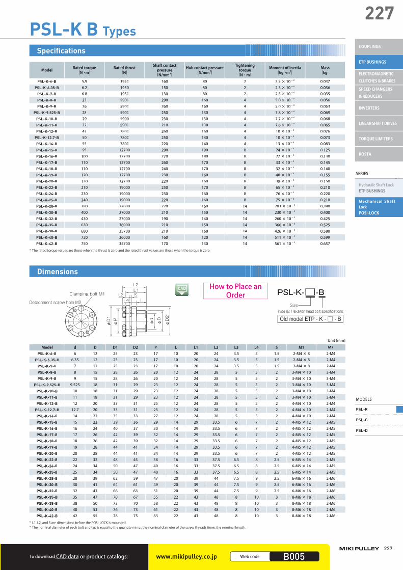
227
227
To download CAD data or product catalogs: www.mikipulley.co.jp Web code B005
MODELS
PSL-K
PSL-G
PSL-D
SERIES
Hydraulic Shaft Lock ETP BUSHINGS
Mechanical Shaft LockPOSI-LOCK
COUPLINGS
ETP BUSHINGS
ELECTROMAGNETIC CLUTCHES & BRAKES
SPEED CHANGERS & REDUCERS
INVERTERS
LINEAR SHAFT DRIVES
TORQUE LIMITERS
ROSTA
PSL-K B Types
Model Rated torque[N ・m]
Rated thrust[N]
Shaft contactpressure
[N/mm2]
Hub contact pressure [N/mm2]
Tightening torque
[N ・ m]
Moment of inertia[kg ・m2]
Mass[kg]
PSL-K-6-B 5.9 1950 160 80 2 2.5 × 10- 6 0.037PSL-K-6.35-B 6.2 1950 150 80 2 2.5 × 10- 6 0.036
PSL-K-7-B 6.8 1950 130 80 2 2.5 × 10- 6 0.035PSL-K-8-B 23 5900 290 160 4 5.0 × 10- 6 0.056PSL-K-9-B 26 5900 260 160 4 5.0 × 10- 6 0.053
PSL-K-9.525-B 28 5900 250 130 4 7.8 × 10- 6 0.069PSL-K-10-B 29 5900 230 130 4 7.7 × 10- 6 0.068PSL-K-11-B 32 5900 210 130 4 7.6 × 10- 6 0.065PSL-K-12-B 47 7800 260 160 4 10 × 10- 6 0.076
PSL-K-12.7-B 50 7800 250 140 4 10 × 10- 6 0.073PSL-K-14-B 55 7800 220 140 4 13 × 10- 6 0.083PSL-K-15-B 95 12700 290 190 8 24 × 10- 6 0.125PSL-K-16-B 100 12700 270 180 8 27 × 10- 6 0.130PSL-K-17-B 110 12700 260 170 8 33 × 10- 6 0.145PSL-K-18-B 110 12700 240 170 8 32 × 10- 6 0.140PSL-K-19-B 120 12700 230 160 8 40 × 10- 6 0.155PSL-K-20-B 130 12700 220 160 8 39 × 10- 6 0.150PSL-K-22-B 210 19000 250 170 8 65 × 10- 6 0.210PSL-K-24-B 230 19000 230 160 8 76 × 10- 6 0.220PSL-K-25-B 240 19000 220 160 8 75 × 10- 6 0.210PSL-K-28-B 380 27000 220 160 14 203 × 10- 6 0.390PSL-K-30-B 400 27000 210 150 14 230 × 10- 6 0.400PSL-K-32-B 430 27000 190 140 14 260 × 10- 6 0.425PSL-K-35-B 630 36000 210 150 14 366 × 10- 6 0.525PSL-K-38-B 680 35700 210 160 14 426 × 10- 6 0.580PSL-K-40-B 720 36000 160 120 14 511 × 10- 6 0.599PSL-K-42-B 750 35700 170 130 14 561 × 10- 6 0.657
* The rated torque values are those when the thrust is zero and the rated thrust values are those when the torque is zero.
Specifications
Type (B: Hexagon head bolt specifications)
Old model ETP - K - □ - B
PSL-K- -BSize
Clamping bolt M1
φD1
φP
φd
φD
φD2
L3 SL1L2
LL4Detachment screw hole M2
Model d D D1 D2 P L L1 L2 L3 L4 S M1 M2PSL-K-6-B 6 12 25 23 17 10 20 24 3.5 5 1.5 2-M4 × 8 2-M4
PSL-K-6.35-B 6.35 12 25 23 17 10 20 24 3.5 5 1.5 2-M4 × 8 2-M4PSL-K-7-B 7 12 25 23 17 10 20 24 3.5 5 1.5 2-M4 × 8 2-M4PSL-K-8-B 8 15 28 26 20 12 24 28 5 5 2 3-M4 × 10 3-M4PSL-K-9-B 9 15 28 26 20 12 24 28 5 5 2 3-M4 × 10 3-M4
PSL-K-9.525-B 9.525 18 31 29 23 12 24 28 5 5 2 3-M4 × 10 3-M4PSL-K-10-B 10 18 31 29 23 12 24 28 5 5 2 3-M4 × 10 3-M4PSL-K-11-B 11 18 31 29 23 12 24 28 5 5 2 3-M4 × 10 3-M4PSL-K-12-B 12 20 33 31 25 12 24 28 5 5 2 4-M4 × 10 2-M4
PSL-K-12.7-B 12.7 20 33 31 25 12 24 28 5 5 2 4-M4 × 10 2-M4PSL-K-14-B 14 22 35 33 27 12 24 28 5 5 2 4-M4 × 10 2-M4PSL-K-15-B 15 23 39 36 29 14 29 33.5 6 7 2 4-M5 × 12 2-M5PSL-K-16-B 16 24 40 37 30 14 29 33.5 6 7 2 4-M5 × 12 2-M5PSL-K-17-B 17 26 42 39 32 14 29 33.5 6 7 2 4-M5 × 12 2-M5PSL-K-18-B 18 26 42 39 32 14 29 33.5 6 7 2 4-M5 × 12 2-M5PSL-K-19-B 19 28 44 41 34 14 29 33.5 6 7 2 4-M5 × 12 2-M5PSL-K-20-B 20 28 44 41 34 14 29 33.5 6 7 2 4-M5 × 12 2-M5PSL-K-22-B 22 32 48 45 38 16 33 37.5 6.5 8 2.5 6-M5 × 14 2-M5PSL-K-24-B 24 34 50 47 40 16 33 37.5 6.5 8 2.5 6-M5 × 14 2-M5PSL-K-25-B 25 34 50 47 40 16 33 37.5 6.5 8 2.5 6-M5 × 14 2-M5PSL-K-28-B 28 39 62 59 47 20 39 44 7.5 9 2.5 6-M6 × 16 2-M6PSL-K-30-B 30 41 64 61 49 20 39 44 7.5 9 2.5 6-M6 × 16 2-M6PSL-K-32-B 32 43 66 63 51 20 39 44 7.5 9 2.5 6-M6 × 16 2-M6PSL-K-35-B 35 47 70 67 55 22 43 48 8 10 3 8-M6 × 18 2-M6PSL-K-38-B 38 50 73 70 58 22 43 48 8 10 3 8-M6 × 18 2-M6PSL-K-40-B 40 53 76 73 61 22 43 48 8 10 3 8-M6 × 18 2-M6PSL-K-42-B 42 55 78 75 63 22 43 48 8 10 3 8-M6 × 18 2-M6
* L1, L2, and S are dimensions before the POSI-LOCK is mounted.* The nominal diameter of each bolt and tap is equal to the quantity minus the nominal diameter of the screw threads times the nominal length.
Unit [mm]
Dimensions
How to Place an Order
003_ETPBush_02.indd 227003_ETPBush_02.indd 227 4/20/2015 3:59:40 PMM4/20/2015 3:59:40 PM
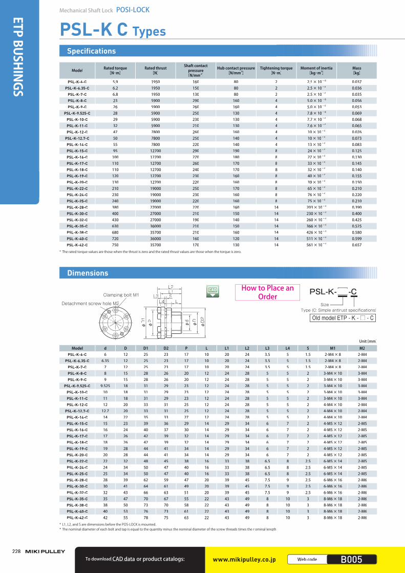
228
Mechanical Shaft Lock POSI-LOCKETP BUSHINGS
PSL-K C Types
Model Rated torque [N・m]
Rated thrust [N]
Shaft contact pressure
[N/mm2]
Hub contact pressure [N/mm2]
Tightening torque [N・m]
Moment of inertia [kg・m2]
Mass [kg]
PSL-K-6-C 5.9 1950 160 80 2 2.5×10⁻⁶ 0.037PSL-K-6.35-C 6.2 1950 150 80 2 2.5×10⁻⁶ 0.036
PSL-K-7-C 6.8 1950 130 80 2 2.5×10⁻⁶ 0.035PSL-K-8-C 23 5900 290 160 4 5.0×10⁻⁶ 0.056PSL-K-9-C 26 5900 260 160 4 5.0×10⁻⁶ 0.053
PSL-K-9.525-C 28 5900 250 130 4 7.8×10⁻⁶ 0.069PSL-K-10-C 29 5900 230 130 4 7.7×10⁻⁶ 0.068PSL-K-11-C 32 5900 210 130 4 7.6×10⁻⁶ 0.065PSL-K-12-C 47 7800 260 160 4 10×10-6 0.076
PSL-K-12.7-C 50 7800 250 140 4 10×10-6 0.073PSL-K-14-C 55 7800 220 140 4 13×10-6 0.083PSL-K-15-C 95 12700 290 190 8 24×10-6 0.125PSL-K-16-C 100 12700 270 180 8 27×10-6 0.130PSL-K-17-C 110 12700 260 170 8 33×10-6 0.145PSL-K-18-C 110 12700 240 170 8 32×10-6 0.140PSL-K-19-C 120 12700 230 160 8 40×10-6 0.155PSL-K-20-C 130 12700 220 160 8 39×10-6 0.150PSL-K-22-C 210 19000 250 170 8 65×10-6 0.210PSL-K-24-C 230 19000 230 160 8 76×10-6 0.220PSL-K-25-C 240 19000 220 160 8 75×10-6 0.210PSL-K-28-C 380 27000 220 160 14 203×10-6 0.390PSL-K-30-C 400 27000 210 150 14 230×10-6 0.400PSL-K-32-C 430 27000 190 140 14 260×10-6 0.425PSL-K-35-C 630 36000 210 150 14 366×10-6 0.525PSL-K-38-C 680 35700 210 160 14 426×10-6 0.580PSL-K-40-C 720 36000 160 120 14 511×10-6 0.599PSL-K-42-C 750 35700 170 130 14 561×10-6 0.657
* The rated torque values are those when the thrust is zero and the rated thrust values are those when the torque is zero.
Specifications
Type (C: Simple antirust specifications)
Old model ETP - K - □ - C
PSL-K- -CSize
φD1
φP
φd
φD
φD2
L3 SL1L2
LL4Clamping bolt M1
Detachment screw hole M2
Model d D D1 D2 P L L1 L2 L3 L4 S M1 M2PSL-K-6-C 6 12 25 23 17 10 20 24 3.5 5 1.5 2-M4×8 2-M4
PSL-K-6.35-C 6.35 12 25 23 17 10 20 24 3.5 5 1.5 2-M4×8 2-M4PSL-K-7-C 7 12 25 23 17 10 20 24 3.5 5 1.5 2-M4×8 2-M4PSL-K-8-C 8 15 28 26 20 12 24 28 5 5 2 3-M4×10 3-M4PSL-K-9-C 9 15 28 26 20 12 24 28 5 5 2 3-M4×10 3-M4
PSL-K-9.525-C 9.525 18 31 29 23 12 24 28 5 5 2 3-M4×10 3-M4PSL-K-10-C 10 18 31 29 23 12 24 28 5 5 2 3-M4×10 3-M4PSL-K-11-C 11 18 31 29 23 12 24 28 5 5 2 3-M4×10 3-M4PSL-K-12-C 12 20 33 31 25 12 24 28 5 5 2 4-M4×10 2-M4
PSL-K-12.7-C 12.7 20 33 31 25 12 24 28 5 5 2 4-M4×10 2-M4PSL-K-14-C 14 22 35 33 27 12 24 28 5 5 2 4-M4×10 2-M4PSL-K-15-C 15 23 39 36 29 14 29 34 6 7 2 4-M5×12 2-M5PSL-K-16-C 16 24 40 37 30 14 29 34 6 7 2 4-M5×12 2-M5PSL-K-17-C 17 26 42 39 32 14 29 34 6 7 2 4-M5×12 2-M5PSL-K-18-C 18 26 42 39 32 14 29 34 6 7 2 4-M5×12 2-M5PSL-K-19-C 19 28 44 41 34 14 29 34 6 7 2 4-M5×12 2-M5PSL-K-20-C 20 28 44 41 34 14 29 34 6 7 2 4-M5×12 2-M5PSL-K-22-C 22 32 48 45 38 16 33 38 6.5 8 2.5 6-M5×14 2-M5PSL-K-24-C 24 34 50 47 40 16 33 38 6.5 8 2.5 6-M5×14 2-M5PSL-K-25-C 25 34 50 47 40 16 33 38 6.5 8 2.5 6-M5×14 2-M5PSL-K-28-C 28 39 62 59 47 20 39 45 7.5 9 2.5 6-M6×16 2-M6PSL-K-30-C 30 41 64 61 49 20 39 45 7.5 9 2.5 6-M6×16 2-M6PSL-K-32-C 32 43 66 63 51 20 39 45 7.5 9 2.5 6-M6×16 2-M6PSL-K-35-C 35 47 70 67 55 22 43 49 8 10 3 8-M6×18 2-M6PSL-K-38-C 38 50 73 70 58 22 43 49 8 10 3 8-M6×18 2-M6PSL-K-40-C 40 53 76 73 61 22 43 49 8 10 3 8-M6×18 2-M6PSL-K-42-C 42 55 78 75 63 22 43 49 8 10 3 8-M6×18 2-M6
* L1, L2, and S are dimensions before the POS-LOCK is mounted.* The nominal diameter of each bolt and tap is equal to the quantity minus the nominal diameter of the screw threads times the nominal length.
Unit [mm]
Dimensions
How to Place an Order
www.mikipulley.co.jp Web code B005To download CAD data or product catalogs:
003_ETPBush_02.indd 228003_ETPBush_02.indd 228 4/20/2015 3:59:40 PMM4/20/2015 3:59:40 PM

229
229
To download CAD data or product catalogs: B005
MODELS
PSL-K
PSL-G
PSL-D
SERIES
Hydraulic Shaft Lock ETP BUSHINGS
Mechanical Shaft LockPOSI-LOCK
COUPLINGS
ETP BUSHINGS
ELECTROMAGNETIC CLUTCHES & BRAKES
SPEED CHANGERS & REDUCERS
INVERTERS
LINEAR SHAFT DRIVES
TORQUE LIMITERS
ROSTA
To download or product catalogs:CAD dataTo download CAD data or product catalogs: www.mikipulley.co.jp Web code B005
PSL-K F Types
Model Rated torque [N・m] Rated thrust (N)
Shaft contact pressure
[N/mm2]
Hub contact pressure[N/mm2]
Tightening torque [N・m]
Moment of inertia [kg・m2]
Mass[kg]
PSL-K-6-F 4.7 1560 120 60 2 2.5×10⁻⁶ 0.037PSL-K-6.35-F 4.9 1560 120 60 2 2.5×10⁻⁶ 0.036
PSL-K-7-F 5.4 1560 100 60 2 2.5×10⁻⁶ 0.035PSL-K-8-F 18 4720 230 120 3.5 5.0×10⁻⁶ 0.056PSL-K-9-F 20 4720 200 120 3.5 5.0×10⁻⁶ 0.053
PSL-K-9.525-F 22 4720 200 100 3.5 7.8×10⁻⁶ 0.069PSL-K-10-F 23 4720 180 100 3.5 7.7×10⁻⁶ 0.068PSL-K-11-F 25 4720 160 100 3.5 7.6×10⁻⁶ 0.065PSL-K-12-F 37 6240 200 120 3.5 10×10-6 0.076
PSL-K-12.7-F 40 6240 200 110 3.5 10×10-6 0.073PSL-K-14-F 44 6240 170 110 3.5 13×10-6 0.083PSL-K-15-F 76 10160 230 150 7 24×10-6 0.125PSL-K-16-F 80 10160 210 140 7 27×10-6 0.130PSL-K-17-F 88 10160 200 130 7 33×10-6 0.145PSL-K-18-F 88 10160 190 130 7 32×10-6 0.140PSL-K-19-F 96 10160 180 120 7 40×10-6 0.155PSL-K-20-F 104 10160 170 120 7 39×10-6 0.150PSL-K-22-F 168 15200 200 130 7 65×10-6 0.210PSL-K-24-F 184 15200 180 120 7 76×10-6 0.220PSL-K-25-F 192 15200 170 120 7 75×10-6 0.210PSL-K-28-F 304 21600 170 120 12 203×10-6 0.390PSL-K-30-F 320 21600 160 120 12 230×10-6 0.400PSL-K-32-F 344 21600 150 110 12 260×10-6 0.425PSL-K-35-F 504 28800 160 120 12 366×10-6 0.525
* The rated torque values are those when the thrust is zero and the rated thrust values are those when the torque is zero.
Specifications
Type (F: Stainless-steel specification)
Old model ETP - K - □ - F
PSL-K- -FSize
φD1
φP
φd
φD
φD2
L3 SL1L2
LL4Clamping bolt M1
Detachment screw hole M2
Model d D D1 D2 P L L1 L2 L3 L4 S M1 M2PSL-K-6-F 6 12 25 23 17 10 20 24 3.5 5 1.5 2-M4×8 2-M4
PSL-K-6.35-F 6.35 12 25 23 17 10 20 24 3.5 5 1.5 2-M4×8 2-M4PSL-K-7-F 7 12 25 23 17 10 20 24 3.5 5 1.5 2-M4×8 2-M4PSL-K-8-F 8 15 28 26 20 12 24 28 5 5 2 3-M4×10 3-M4PSL-K-9-F 9 15 28 26 20 12 24 28 5 5 2 3-M4×10 3-M4
PSL-K-9.525-F 9.525 18 31 29 23 12 24 28 5 5 2 3-M4×10 3-M4PSL-K-10-F 10 18 31 29 23 12 24 28 5 5 2 3-M4×10 3-M4PSL-K-11-F 11 18 31 29 23 12 24 28 5 5 2 3-M4×10 3-M4PSL-K-12-F 12 20 33 31 25 12 24 28 5 5 2 4-M4×10 2-M4
PSL-K-12.7-F 12.7 20 33 31 25 12 24 28 5 5 2 4-M4×10 2-M4PSL-K-14-F 14 22 35 33 27 12 24 28 5 5 2 4-M4×10 2-M4PSL-K-15-F 15 23 39 36 29 14 29 34 6 7 2 4-M5×12 2-M5PSL-K-16-F 16 24 40 37 30 14 29 34 6 7 2 4-M5×12 2-M5PSL-K-17-F 17 26 42 39 32 14 29 34 6 7 2 4-M5×12 2-M5PSL-K-18-F 18 26 42 39 32 14 29 34 6 7 2 4-M5×12 2-M5PSL-K-19-F 19 28 44 41 34 14 29 34 6 7 2 4-M5×12 2-M5PSL-K-20-F 20 28 44 41 34 14 29 34 6 7 2 4-M5×12 2-M5PSL-K-22-F 22 32 48 45 38 16 33 38 6.5 8 2.5 6-M5×14 2-M5PSL-K-24-F 24 34 50 47 40 16 33 38 6.5 8 2.5 6-M5×14 2-M5PSL-K-25-F 25 34 50 47 40 16 33 38 6.5 8 2.5 6-M5×14 2-M5PSL-K-28-F 28 39 62 59 47 20 39 45 7.5 9 2.5 6-M6×16 2-M6PSL-K-30-F 30 41 64 61 49 20 39 45 7.5 9 2.5 6-M6×16 2-M6PSL-K-32-F 32 43 66 63 51 20 39 45 7.5 9 2.5 6-M6×16 2-M6PSL-K-35-F 35 47 70 67 55 22 43 49 8 10 3 8-M6×18 2-M6
* L1, L2, and S are dimensions before the POSI-LOCK is mounted.* The nominal diameter of each bolt and tap is equal to the quantity minus the nominal diameter of the screw threads times the nominal length.
Unit [mm]
Dimensions
How to Place an Order
003_ETPBush_02.indd 229003_ETPBush_02.indd 229 /2015 3:59:41 PMM4/20/2015 3:59:41 PMM4/20/2015 3:59:414/20/2015 3:59:41 PM

230
Mechanical Shaft Lock POSI-LOCKETP BUSHINGS
PSL-G Models
Model Rated torque [N·m]
Rated thrust [N]
Shaft contactpressure
[N/mm2]
Hub contact pressure [N/mm2]
Tightening torque[N·m]
Moment of inertia[kg・m2]
Mass [kg]
PSL-G-19 289 30500 250 101 17 0.70×10⁻⁴ 0.22PSL-G-20 305 30500 238 101 17 0.70×10⁻⁴ 0.21PSL-G-22 335 30500 216 101 17 0.69×10⁻⁴ 0.20PSL-G-24 411 34300 223 107 17 0.89×10⁻⁴ 0.23PSL-G-25 428 34300 214 107 17 0.88×10⁻⁴ 0.22PSL-G-28 533 38100 212 108 17 1.28×10⁻⁴ 0.26PSL-G-30 571 38100 198 108 17 1.25×10⁻⁴ 0.25PSL-G-32 731 45700 223 119 17 1.80×10⁻⁴ 0.30PSL-G-35 800 45700 204 119 17 1.74×10⁻⁴ 0.28PSL-G-38 1020 53500 220 129 17 2.43×10⁻⁴ 0.34PSL-G-40 1070 53500 209 129 17 2.37×10⁻⁴ 0.32PSL-G-42 1680 80200 253 142 41 5.26×10⁻⁴ 0.56PSL-G-45 1800 80200 236 142 41 5.11×10⁻⁴ 0.53PSL-G-48 1920 80200 222 133 41 6.51×10⁻⁴ 0.59PSL-G-50 2010 80200 213 133 41 6.36×10⁻⁴ 0.56PSL-G-55 2570 93600 226 146 41 8.01×10⁻⁴ 0.62PSL-G-60 2810 93600 207 138 41 9.68×10⁻⁴ 0.65PSL-G-65 3090 95000 194 133 41 12.8×10⁻⁴ 0.77PSL-G-70 4800 137000 218 138 82 28.3×10⁻⁴ 1.34PSL-G-75 5160 138000 203 132 82 32.9×10⁻⁴ 1.40PSL-G-80 5510 138000 190 127 82 37.9×10⁻⁴ 1.46PSL-G-85 6500 153000 199 135 82 44.3×10⁻⁴ 1.56PSL-G-90 6880 153000 188 130 82 50.4×10⁻⁴ 1.62PSL-G-95 7940 167000 195 137 82 56.6×10⁻⁴ 1.67
PSL-G-100 10100 202000 205 142 142 91.4×10⁻⁴ 2.36PSL-G-110 11100 202000 187 133 142 113.9×10⁻⁴ 2.53PSL-G-120 13500 225000 190 138 142 142.7×10⁻⁴ 2.74
* The rated torque values are those when the thrust is zero and the rated thrust values are those when the torque is zero.
Specifications
Model d D L ℓ L1 M1 M2PSL-G-19 19 47 20 17 26 8-M6×18 2-M8PSL-G-20 20 47 20 17 26 8-M6×18 2-M8PSL-G-22 22 47 20 17 26 8-M6×18 2-M8PSL-G-24 24 50 20 17 26 8-M6×18 2-M8PSL-G-25 25 50 20 17 26 8-M6×18 2-M8PSL-G-28 28 55 20 17 26 10-M6×18 2-M8PSL-G-30 30 55 20 17 26 10-M6×18 2-M8PSL-G-32 32 60 20 17 26 12-M6×18 2-M8PSL-G-35 35 60 20 17 26 12-M6×18 2-M8PSL-G-38 38 65 20 17 26 14-M6×18 2-M8PSL-G-40 40 65 20 17 26 14-M6×18 2-M8PSL-G-42 42 75 24 20 32 12-M8×22 2-M10PSL-G-45 45 75 24 20 32 12-M8×22 2-M10PSL-G-48 48 80 24 20 32 12-M8×22 2-M10PSL-G-50 50 80 24 20 32 12-M8×22 2-M10PSL-G-55 55 85 24 20 32 14-M8×22 2-M10PSL-G-60 60 90 24 20 32 14-M8×22 2-M10PSL-G-65 65 95 24 20 32 16-M8×22 3-M10PSL-G-70 70 110 28 24 38 14-M10×25 3-M12PSL-G-75 75 115 28 24 38 14-M10×25 3-M12PSL-G-80 80 120 28 24 38 14-M10×25 3-M12PSL-G-85 85 125 28 24 38 16-M10×25 3-M12PSL-G-90 90 130 28 24 38 16-M10×25 3-M12PSL-G-95 95 135 28 24 38 18-M10×25 3-M12
PSL-G-100 100 145 33 26 45 14-M12×30 3-M14PSL-G-110 110 155 33 26 45 14-M12×30 3-M14PSL-G-120 120 165 33 26 45 16-M12×30 3-M14
* L and L1 are dimensions before the POSI-LOCK is mounted.* The nominal diameter of each bolt and tap is equal to the quantity minus the nominal diameter of the screw threads times the nominal length.* Screw hole M2 for removal purpose is indicated with a tool mark for sizes 19 to 60 and indicated by marking the head of the bok lt with paint for sizes 65 or more.
Unit [mm]
Dimensions
Clamping bolt M1
φd φD
LL1
Detachment screw hole M2
Old model ETP - G - □
PSL-G- Size
How to Place an Order
www.mikipulley.co.jp Web code B006To download CAD data or product catalogs:
003_ETPBush_02.indd 230003_ETPBush_02.indd 230 /2015 3:59:41 PMM4/20/2015 3:59:41 PMM4/20/2015 3:59:414/20/2015 3:59:41 PM
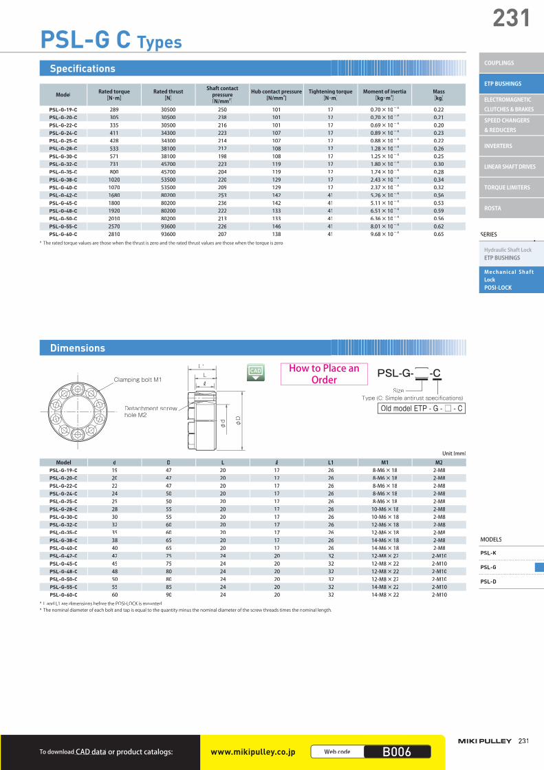
231
231
SERIES
Hydraulic Shaft LockETP BUSHINGS
Mechanical Shaft LockPOSI-LOCK
MODELS
PSL-K
PSL-G
PSL-D
COUPLINGS
ETP BUSHINGS
ELECTROMAGNETIC CLUTCHES & BRAKES
SPEED CHANGERS & REDUCERS
INVERTERS
LINEAR SHAFT DRIVES
TORQUE LIMITERS
ROSTA
To download CAD data or product catalogs: www.mikipulley.co.jp Web code B006
PSL-G C Types
Model Rated torque [N・m]
Rated thrust [N]
Shaft contact pressure
[N/mm2]
Hub contact pressure[N/mm2]
Tightening torque [N・m]
Moment of inertia [kg・m2]
Mass[kg]
PSL-G-19-C 289 30500 250 101 17 0.70×10⁻⁴ 0.22PSL-G-20-C 305 30500 238 101 17 0.70×10⁻⁴ 0.21PSL-G-22-C 335 30500 216 101 17 0.69×10⁻⁴ 0.20PSL-G-24-C 411 34300 223 107 17 0.89×10⁻⁴ 0.23PSL-G-25-C 428 34300 214 107 17 0.88×10⁻⁴ 0.22PSL-G-28-C 533 38100 212 108 17 1.28×10⁻⁴ 0.26PSL-G-30-C 571 38100 198 108 17 1.25×10⁻⁴ 0.25PSL-G-32-C 731 45700 223 119 17 1.80×10⁻⁴ 0.30PSL-G-35-C 800 45700 204 119 17 1.74×10⁻⁴ 0.28PSL-G-38-C 1020 53500 220 129 17 2.43×10⁻⁴ 0.34PSL-G-40-C 1070 53500 209 129 17 2.37×10⁻⁴ 0.32PSL-G-42-C 1680 80200 253 142 41 5.26×10⁻⁴ 0.56PSL-G-45-C 1800 80200 236 142 41 5.11×10⁻⁴ 0.53PSL-G-48-C 1920 80200 222 133 41 6.51×10⁻⁴ 0.59PSL-G-50-C 2010 80200 213 133 41 6.36×10⁻⁴ 0.56PSL-G-55-C 2570 93600 226 146 41 8.01×10⁻⁴ 0.62PSL-G-60-C 2810 93600 207 138 41 9.68×10⁻⁴ 0.65
* The rated torque values are those when the thrust is zero and the rated thrust values are those when the torque is zero.
Specifications
Clamping bolt M1
φd φD
LL1
Detachment screw hole M2
Type (C: Simple antirust specifications)
Old model ETP - G - □ - C
PSL-G- -CSize
Model d D L ℓ L1 M1 M2PSL-G-19-C 19 47 20 17 26 8-M6×18 2-M8PSL-G-20-C 20 47 20 17 26 8-M6×18 2-M8PSL-G-22-C 22 47 20 17 26 8-M6×18 2-M8PSL-G-24-C 24 50 20 17 26 8-M6×18 2-M8PSL-G-25-C 25 50 20 17 26 8-M6×18 2-M8PSL-G-28-C 28 55 20 17 26 10-M6×18 2-M8PSL-G-30-C 30 55 20 17 26 10-M6×18 2-M8PSL-G-32-C 32 60 20 17 26 12-M6×18 2-M8PSL-G-35-C 35 60 20 17 26 12-M6×18 2-M8PSL-G-38-C 38 65 20 17 26 14-M6×18 2-M8PSL-G-40-C 40 65 20 17 26 14-M6×18 2-M8PSL-G-42-C 42 75 24 20 32 12-M8×22 2-M10PSL-G-45-C 45 75 24 20 32 12-M8×22 2-M10PSL-G-48-C 48 80 24 20 32 12-M8×22 2-M10PSL-G-50-C 50 80 24 20 32 12-M8×22 2-M10PSL-G-55-C 55 85 24 20 32 14-M8×22 2-M10PSL-G-60-C 60 90 24 20 32 14-M8×22 2-M10
* L and L1 are dimensions before the POSI-LOCK is mounted.* The nominal diameter of each bolt and tap is equal to the quantity minus the nominal diameter of the screw threads times the nominal length.
Unit [mm]
Dimensions
How to Place an Order
003_ETPBush_02.indd 231003_ETPBush_02.indd 231 /2015 3:59:41 PMM4/20/2015 3:59:41 PMM4/20/2015 3:59:414/20/2015 3:59:41 PM

232
ETP BUSHINGS
Mechanical Shaft Lock POSI-LOCK
PSL-D Models
Model Rated torque[N・m]
Rated thrust[N]
Shaft contact pressure
[N/mm2]
Hub contact pressure [N/mm2]
Tightening torque
[N・m]
Moment of inertia[kg・m2]
Mass[kg]
PSL-D-6 6 2100 150 60 1 0.48×10⁻⁶ 0.012PSL-D-7 8 2100 140 60 1 0.52×10⁻⁶ 0.013PSL-D-8 10 2600 110 50 1 0.77×10⁻⁶ 0.015PSL-D-9 15 3200 130 60 1 1.1×10⁻⁶ 0.020
PSL-D-10 16 3200 110 60 1 1.2×10⁻⁶ 0.019PSL-D-11 17 3200 100 50 1 1.8×10⁻⁶ 0.024PSL-D-12 19 3200 100 50 1 1.7×10⁻⁶ 0.022PSL-D-14 34 4800 100 50 2 4.3×10⁻⁶ 0.039PSL-D-15 36 4800 90 50 2 5.7×10⁻⁶ 0.044PSL-D-16 67 8400 130 60 4 10×10-6 0.068PSL-D-17 70 8400 120 60 4 18×10-6 0.093PSL-D-18 75 8400 110 60 4 17×10-6 0.090PSL-D-19 80 8400 110 60 4 16×10-6 0.085PSL-D-20 140 13600 150 80 8 24×10-6 0.120PSL-D-22 150 13600 140 80 8 29×10-6 0.130PSL-D-24 230 19300 150 80 14 70×10-6 0.220PSL-D-25 240 19300 140 80 14 69×10-6 0.210PSL-D-28 400 28900 190 110 14 86×10-6 0.240PSL-D-30 430 28900 180 100 14 128×10-6 0.270PSL-D-32 460 28900 170 100 14 123×10-6 0.260PSL-D-35 670 38600 160 90 14 215×10-6 0.370PSL-D-38 730 38600 150 90 14 298×10-6 0.420PSL-D-40 770 38600 140 90 14 286×10-6 0.410PSL-D-42 1110 52700 150 80 34 682×10-6 0.700PSL-D-45 1200 52700 140 80 34 609×10-6 0.630PSL-D-48 1690 70300 190 110 34 769×10-6 0.730PSL-D-50 1760 70300 180 110 34 742×10-6 0.710
* The rated torque values are those when the thrust is zero and the rated thrust values are those when the torque is zero.
Specifications
φP
φd
φD
Detachment screw hole M2
Clamping bolt M1
L
L1
Old model ETP - D - □
PSL-D- Size
Model d D P L L1 M1 M2PSL-D-6 6 16 11 11 13.5 3-M2.5×10 2-M2.5PSL-D-7 7 17 12 11 13.5 3-M2.5×10 2-M2.5PSL-D-8 8 18 13 11 13.5 3-M2.5×10 2-M2.5PSL-D-9 9 20 15 13 15.5 4-M2.5×12 2-M2.5
PSL-D-10 10 20 15 13 15.5 4-M2.5×12 2-M2.5PSL-D-11 11 22 17 13 15.5 4-M2.5×12 2-M2.5PSL-D-12 12 22 17 13 15.5 4-M2.5×12 2-M2.5PSL-D-14 14 26 20 17 20 4-M3×16 2-M3PSL-D-15 15 28 21.5 17 20 4-M3×16 2-M3PSL-D-16 16 32 24 17 21 4-M4×16 2-M4PSL-D-17 17 35 27 21 25 4-M4×20 2-M4PSL-D-18 18 35 27 21 25 4-M4×20 2-M4PSL-D-19 19 35 27 21 25 4-M4×20 2-M4PSL-D-20 20 38 29 21 26 4-M5×20 2-M5PSL-D-22 22 40 31 21 26 4-M5×20 2-M5PSL-D-24 24 47 36 26 32 4-M6×25 2-M6PSL-D-25 25 47 36 26 32 4-M6×25 2-M6PSL-D-28 28 50 39 26 32 6-M6×25 2-M6PSL-D-30 30 55 43.5 26 32 6-M6×25 2-M6PSL-D-32 32 55 43.5 26 32 6-M6×25 2-M6PSL-D-35 35 60 47.5 31 37 8-M6×30 2-M6PSL-D-38 38 65 52.5 31 37 8-M6×30 2-M6PSL-D-40 40 65 52.5 31 37 8-M6×30 2-M6PSL-D-42 42 75 60 36 44 6-M8×35 2-M8PSL-D-45 45 75 60 36 44 6-M8×35 2-M8PSL-D-48 48 80 65 36 44 8-M8×35 2-M8PSL-D-50 50 80 65 36 44 8-M8×35 2-M8
* L and L1 are dimensions before the POSI-LOCK is mounted.* The nominal diameter of each bolt and tap is equal to the quantity minus the nominal diameter of the screw threads times the nominal length.
Unit [mm]
Dimensions
How to Place an Order
www.mikipulley.co.jp Web code B007To download CAD data or product catalogs:
003_ETPBush_02.indd 232003_ETPBush_02.indd 232 4/20/2015 3:59:42 PMM4/20/2015 3:59:42 PM

233
233
SERIES
Hydraulic Shaft LockETP BUSHINGS
Mechanical Shaft LockPOSI-LOCK
MODELS
PSL-K
PSL-G
PSL-D
COUPLINGS
ETP BUSHINGS
ELECTROMAGNETIC CLUTCHES & BRAKES
SPEED CHANGERS & REDUCERS
INVERTERS
LINEAR SHAFT DRIVES
TORQUE LIMITERS
ROSTA
To download CAD data or product catalogs: www.mikipulley.co.jp Web code B007
PSL-D C Types
Model Rated torque[N・m]
Rated thrust[N]
Shaft contactpressure
[N/mm2]
Hub contact pressure[N/mm2]
Tighteningtorque
[N・m]
Moment of inertia [kg・m2]
Mass[kg]
PSL-D-16-C 67 8400 130 60 4 10× 10- 6 0.068PSL-D-17-C 70 8400 120 60 4 18× 10- 6 0.093PSL-D-18-C 75 8400 110 60 4 17× 10- 6 0.090PSL-D-19-C 80 8400 110 60 4 16× 10- 6 0.085PSL-D-20-C 140 13600 150 80 8 24× 10- 6 0.120PSL-D-22-C 150 13600 140 80 8 29× 10- 6 0.130PSL-D-24-C 230 19300 150 80 14 70× 10- 6 0.220PSL-D-25-C 240 19300 140 80 14 69× 10- 6 0.210PSL-D-28-C 400 28900 190 110 14 86× 10- 6 0.240PSL-D-30-C 430 28900 180 100 14 128× 10- 6 0.270PSL-D-32-C 460 28900 170 100 14 123× 10- 6 0.260PSL-D-35-C 670 38600 160 90 14 215× 10- 6 0.370PSL-D-38-C 730 38600 150 90 14 298× 10- 6 0.420PSL-D-40-C 770 38600 140 90 14 286× 10- 6 0.410PSL-D-42-C 1110 52700 180 110 34 682× 10- 6 0.700PSL-D-45-C 1200 52700 140 80 34 609× 10- 6 0.630PSL-D-48-C 1690 70300 190 110 34 769× 10- 6 0.730PSL-D-50-C 1760 70300 180 110 34 742× 10- 6 0.710
* The rated torque values are those when the thrust is zero and the rated thrust values are those when the torque is zero.
Specifications
Model d D P L L1 M1 M2PSL-D-16-C 16 32 24 17 21 4-M4×16 2-M4PSL-D-17-C 17 35 27 21 25 4-M4×20 2-M4PSL-D-18-C 18 35 27 21 25 4-M4×20 2-M4PSL-D-19-C 19 35 27 21 25 4-M4×20 2-M4PSL-D-20-C 20 38 29 21 26 4-M5×20 2-M5PSL-D-22-C 22 40 31 21 26 4-M5×20 2-M5PSL-D-24-C 24 47 36 26 32 4-M6×25 2-M6PSL-D-25-C 25 47 36 26 32 4-M6×25 2-M6PSL-D-28-C 28 50 39 26 32 6-M6×25 2-M6PSL-D-30-C 30 55 43.5 26 32 6-M6×25 2-M6PSL-D-32-C 32 55 43.5 26 32 6-M6×25 2-M6PSL-D-35-C 35 60 47.5 31 37 8-M6×30 2-M6PSL-D-38-C 38 65 52.5 31 37 8-M6×30 2-M6PSL-D-40-C 40 65 52.5 31 37 8-M6×30 2-M6PSL-D-42-C 42 75 60 36 44 6-M8×35 2-M8PSL-D-45-C 45 75 60 36 44 6-M8×35 2-M8PSL-D-48-C 48 80 65 36 44 8-M8×35 2-M8PSL-D-50-C 50 80 65 36 44 8-M8×35 2-M8
* L and L1 are dimensions before the POSI-LOCK is mounted.* The nominal diameter of each bolt and tap is equal to the quantity minus the nominal diameter of the screw threads times the nominal length.
Unit [mm]
φP
φd
φD
Detachment screw hole M2
Clamping bolt M1
L
L1
Type (C: Simple antirust specifications)
Old model ETP - D - □ - C
PSL-D- -CSize
Dimensions
How to Place an Order
003_ETPBush_02.indd 233003_ETPBush_02.indd 233 /2015 3:59:42 PMM4/20/2015 3:59:42 PMM4/20/2015 3:59:424/20/2015 3:59:42 PM
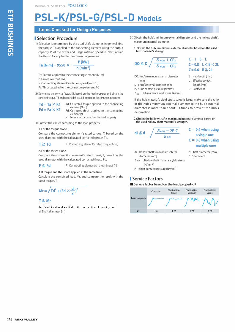
234
Mechanical Shaft Lock POSI-LOCK
PSL-K/PSL-G/PSL-D Models
2dMr = Td2 + (Fd × )2
T ≧ Mr
d: Shaft diameter [m]
■ Selection Procedure(1) Selection is determined by the used shaft diameter. In general, find
the torque, Ta, applied to the connecting element using the output capacity, P, of the driver and usage rotation speed, n. Next, obtain the thrust, Fa, applied to the connecting element.
Ta [N·m] = 9550 ×n [min-1]P [kW]
Ta: Torque applied to the connecting element [N・m]P: Driver's output [kW]n: Connecting element's rotation speed [minー 1]Fa: Thrust applied to the connecting element [N]
(2) Determine the service factor, K1, based on the load property and obtain thecorrected torque, Td, and corrected thrust, Fd, applied to the connecting element.
(3) Correct the values according to the load property.
Td: Corrected torque applied to the connectingelement [N・m]
Fd: Corrected thrust applied to the connectingelement [N]
K1: Service factor based on the load property
Td = Ta × K1Fd = Fa × K1
T ≧ Td T: Connecting element's rated torque [N・m]
F ≧ Fd F: Connecting element's rated thrust [N]
Compare the connecting element's rated torque, T, based on theused diameter with the calculated corrected torque, Td.
1. For the torque alone
Compare the connecting element's rated thrust, F, based on the used diameter with the calculated corrected thrust, Fd.
2. For the thrust alone
Calculate the combined load, Mr, and compare the result with the rated torque, T.
3. If torque and thrust are applied at the same time
(4) Obtain the hub's minimum external diameter and the hollow shaft'smaximum internal diameter.
2.Obtain the hollow shaft's maximum internal diameter based on the used hollow shaft material's strength.
C = 1 B = LC = 0.8 L < B < 2LC = 0.6 B ≧ 2L
δ 0.2N + CP2
δ 0.2N - CP2DO ≧ D
B : Hub length [mm]L : Effective contact
length [mm]C : Coefficient
DO: Hub's minimum external diameter[mm]
D : Hub's internal diameter [mm]P2 : Hub contact pressure [N/mm2]δ0.2N : Hub material's yield stress [N/mm2]
If the hub material's yield stress value is large, make sure the ratioof the hub's minimum external diameter to the hub's internaldiameter is more than about 1.3 times to prevent the hub'sdeformation.
di : Hollow shaft's maximum internal diameter [mm]
δ0.2N : Hollow shaft material's yield stress[N/mm2]
P1 : Shaft contact pressure [N/mm2]
d: Shaft diameter [mm]C: Coefficient
C = 0.6 when using a single one
C = 0.8 when using multiple ones
δ0.2N - 2P1Cδ0.2N
di ≦ d
■ Service Factors■ Service factor based on the load property: K1
Load property
Constant Fluctuation:Small
Fluctuation: Medium
Fluctuation:Large
K1 1.0 1.25 1.75 2.25
1. Obtain the hub's minimum external diameter based on the usedhub material's strength.
Items Checked for Design Purposes
ETP BUSHINGS
003_ETPBush_02.indd 234 /2015 3:59:43 PMM4/20/2015 3:59:43 PMM4/20/2015 3:59:434/20/2015 3:59:43 PM
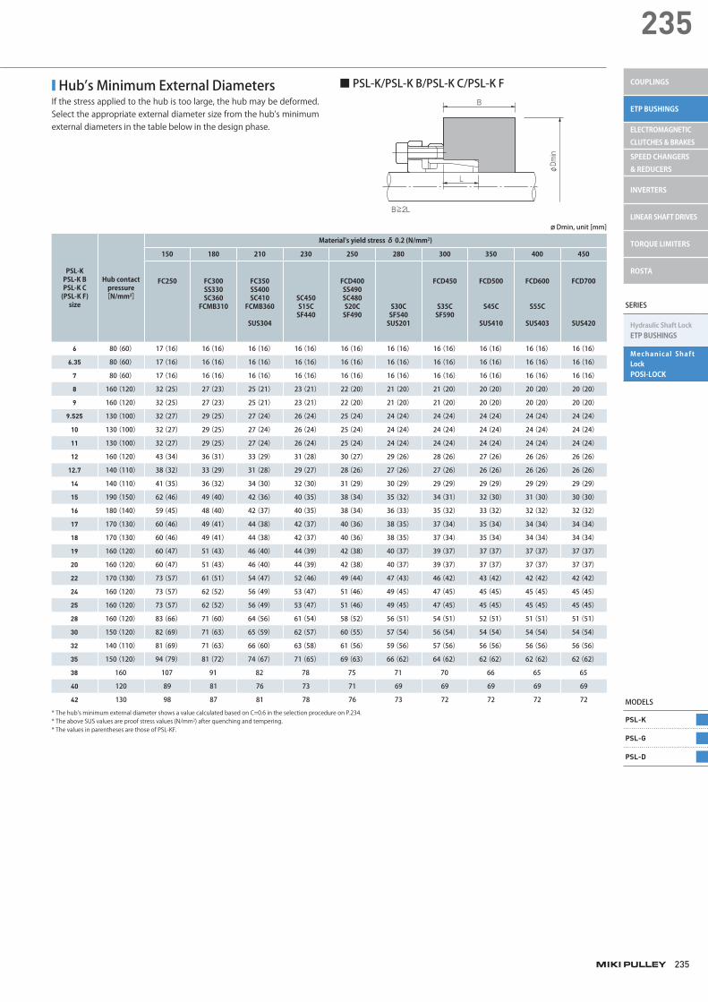
235
235
■ Hub’s Minimum External DiametersIf the stress applied to the hub is too large, the hub may be deformed. Select the appropriate external diameter size from the hub's minimum external diameters in the table below in the design phase.
PSL-K PSL-K B PSL-K C (PSL-K F)
size
Hub contact pressure
[N/mm2]
Material's yield stress δ 0.2 (N/mm2)
150 180 210 230 250 280 300 350 400 450
FC250 FC300 SS330 SC360
FCMB310
FC350 SS400 SC410
FCMB360
SUS304
SC450 S15C SF440
FCD400 SS490 SC480 S20C SF490
S30C SF540 SUS201
FCD450
S35C SF590
FCD500
S45C
SUS410
FCD600
S55C
SUS403
FCD700
SUS420
6 80(60) 17(16) 16(16) 16(16) 16(16) 16(16) 16(16) 16(16) 16(16) 16(16) 16(16)
6.35 80(60) 17(16) 16(16) 16(16) 16(16) 16(16) 16(16) 16(16) 16(16) 16(16) 16(16)
7 80(60) 17(16) 16(16) 16(16) 16(16) 16(16) 16(16) 16(16) 16(16) 16(16) 16(16)
8 160(120) 32(25) 27(23) 25(21) 23(21) 22(20) 21(20) 21(20) 20(20) 20(20) 20(20)
9 160(120) 32(25) 27(23) 25(21) 23(21) 22(20) 21(20) 21(20) 20(20) 20(20) 20(20)
9.525 130(100) 32(27) 29(25) 27(24) 26(24) 25(24) 24(24) 24(24) 24(24) 24(24) 24(24)
10 130(100) 32(27) 29(25) 27(24) 26(24) 25(24) 24(24) 24(24) 24(24) 24(24) 24(24)
11 130(100) 32(27) 29(25) 27(24) 26(24) 25(24) 24(24) 24(24) 24(24) 24(24) 24(24)
12 160(120) 43(34) 36(31) 33(29) 31(28) 30(27) 29(26) 28(26) 27(26) 26(26) 26(26)
12.7 140(110) 38(32) 33(29) 31(28) 29(27) 28(26) 27(26) 27(26) 26(26) 26(26) 26(26)
14 140(110) 41(35) 36(32) 34(30) 32(30) 31(29) 30(29) 29(29) 29(29) 29(29) 29(29)
15 190(150) 62(46) 49(40) 42(36) 40(35) 38(34) 35(32) 34(31) 32(30) 31(30) 30(30)
16 180(140) 59(45) 48(40) 42(37) 40(35) 38(34) 36(33) 35(32) 33(32) 32(32) 32(32)
17 170(130) 60(46) 49(41) 44(38) 42(37) 40(36) 38(35) 37(34) 35(34) 34(34) 34(34)
18 170(130) 60(46) 49(41) 44(38) 42(37) 40(36) 38(35) 37(34) 35(34) 34(34) 34(34)
19 160(120) 60(47) 51(43) 46(40) 44(39) 42(38) 40(37) 39(37) 37(37) 37(37) 37(37)
20 160(120) 60(47) 51(43) 46(40) 44(39) 42(38) 40(37) 39(37) 37(37) 37(37) 37(37)
22 170(130) 73(57) 61(51) 54(47) 52(46) 49(44) 47(43) 46(42) 43(42) 42(42) 42(42)
24 160(120) 73(57) 62(52) 56(49) 53(47) 51(46) 49(45) 47(45) 45(45) 45(45) 45(45)
25 160(120) 73(57) 62(52) 56(49) 53(47) 51(46) 49(45) 47(45) 45(45) 45(45) 45(45)
28 160(120) 83(66) 71(60) 64(56) 61(54) 58(52) 56(51) 54(51) 52(51) 51(51) 51(51)
30 150(120) 82(69) 71(63) 65(59) 62(57) 60(55) 57(54) 56(54) 54(54) 54(54) 54(54)
32 140(110) 81(69) 71(63) 66(60) 63(58) 61(56) 59(56) 57(56) 56(56) 56(56) 56(56)
35 150(120) 94(79) 81(72) 74(67) 71(65) 69(63) 66(62) 64(62) 62(62) 62(62) 62(62)
38 160 107 91 82 78 75 71 70 66 65 65
40 120 89 81 76 73 71 69 69 69 69 69
42 130 98 87 81 78 76 73 72 72 72 72
* The hub's minimum external diameter shows a value calculated based on C=0.6 in the selection procedure on P.234.* The above SUS values are proof stress values (N/mm2) after quenching and tempering.* The values in parentheses are those of PSL-KF.
ø Dmin, unit [mm]
■ PSL-K/PSL-K B/PSL-K C/PSL-K F
L
B
B≧2L
φDmin
SERIES
Hydraulic Shaft LockETP BUSHINGS
Mechanical Shaft LockPOSI-LOCK
MODELS
PSL-K
PSL-G
PSL-D
COUPLINGS
ETP BUSHINGS
ELECTROMAGNETIC CLUTCHES & BRAKES
SPEED CHANGERS & REDUCERS
INVERTERS
LINEAR SHAFT DRIVES
TORQUE LIMITERS
ROSTA
miki_Catalog_e.indb 235 5/18/2015 5:19:13 PM
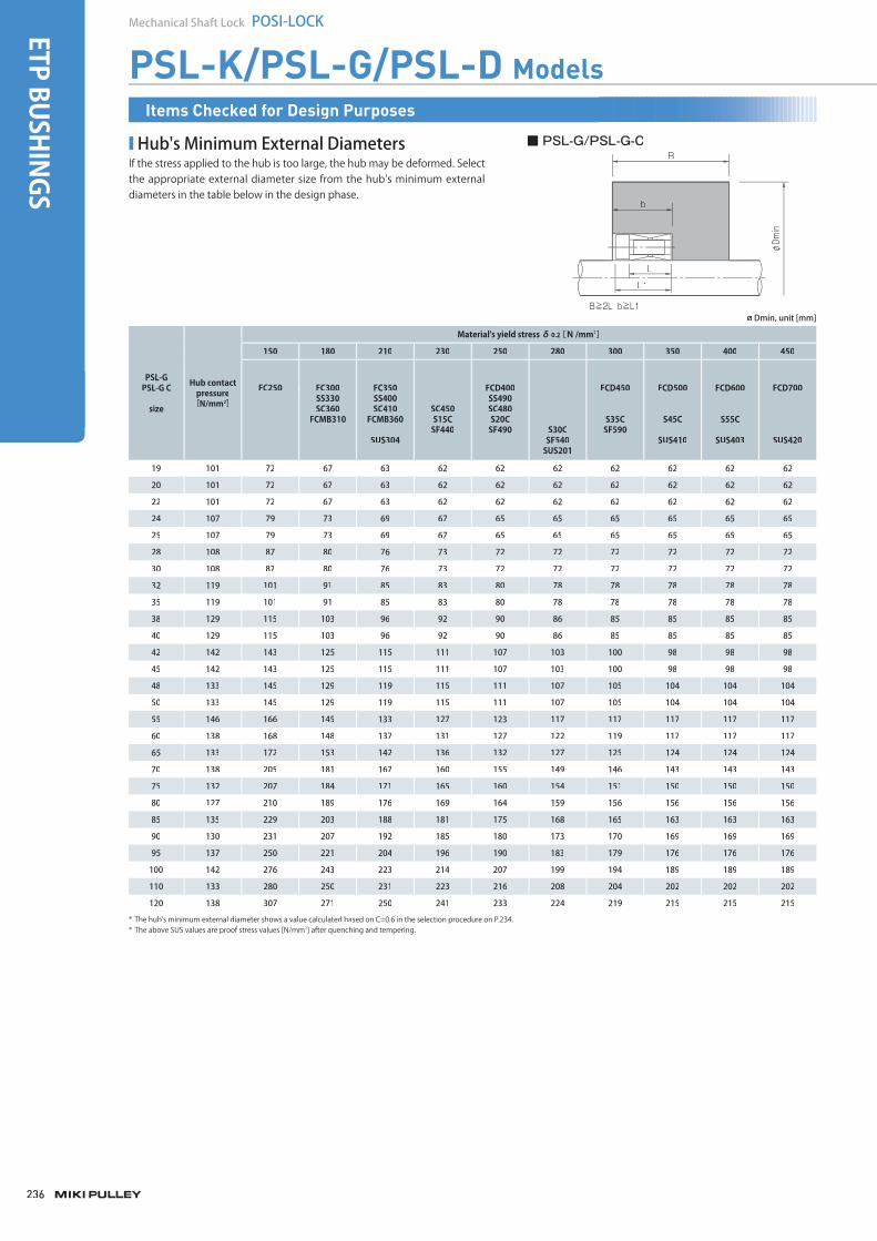
236
Mechanical Shaft Lock POSI-LOCKETP BUSHINGS
■ Hub's Minimum External DiametersIf the stress applied to the hub is too large, the hub may be deformed. Select the appropriate external diameter size from the hub's minimum external diameters in the table below in the design phase.
■ PSL-G/PSL-G-CB
b
L
L1
B≧2L b≧L1
φDmin
PSL-G PSL-G C
size
Hub contact pressure
[N/mm2]
Material's yield stress δ0.2[N/mm2]
150 180 210 230 250 280 300 350 400 450
FC250 FC300SS330SC360
FCMB310
FC350 SS400SC410
FCMB360
SUS304
SC450 S15C SF440
FCD400SS490 SC480 S20CSF490 S30C
SF540 SUS201
FCD450
S35C SF590
FCD500
S45C
SUS410
FCD600
S55C
SUS403
FCD700
SUS420
19 101 72 67 63 62 62 62 62 62 62 62
20 101 72 67 63 62 62 62 62 62 62 62
22 101 72 67 63 62 62 62 62 62 62 62
24 107 79 73 69 67 65 65 65 65 65 65
25 107 79 73 69 67 65 65 65 65 65 65
28 108 87 80 76 73 72 72 72 72 72 72
30 108 87 80 76 73 72 72 72 72 72 72
32 119 101 91 85 83 80 78 78 78 78 78
35 119 101 91 85 83 80 78 78 78 78 78
38 129 115 103 96 92 90 86 85 85 85 85
40 129 115 103 96 92 90 86 85 85 85 85
42 142 143 125 115 111 107 103 100 98 98 98
45 142 143 125 115 111 107 103 100 98 98 98
48 133 145 129 119 115 111 107 105 104 104 104
50 133 145 129 119 115 111 107 105 104 104 104
55 146 166 145 133 127 123 117 117 117 117 117
60 138 168 148 137 131 127 122 119 117 117 117
65 133 172 153 142 136 132 127 125 124 124 124
70 138 205 181 167 160 155 149 146 143 143 143
75 132 207 184 171 165 160 154 151 150 150 150
80 127 210 189 176 169 164 159 156 156 156 156
85 135 229 203 188 181 175 168 165 163 163 163
90 130 231 207 192 185 180 173 170 169 169 169
95 137 250 221 204 196 190 183 179 176 176 176
100 142 276 243 223 214 207 199 194 189 189 189
110 133 280 250 231 223 216 208 204 202 202 202
120 138 307 271 250 241 233 224 219 215 215 215
* The hub's minimum external diameter shows a value calculated based on C=0.6 in the selection procedure on P.234.* The above SUS values are proof stress values [N/mm2] after quenching and tempering.
ø Dmin, unit [mm]
PSL-K/PSL-G/PSL-D ModelsItems Checked for Design Purposes
miki_Catalog_e.indb 236miki_Catalog_g_e.indb 236 /2015 5:19:13 PMM5/18/2015 5:19:13 PMM5/18/2015 5:19:135/18/2015 5:19:13 PM
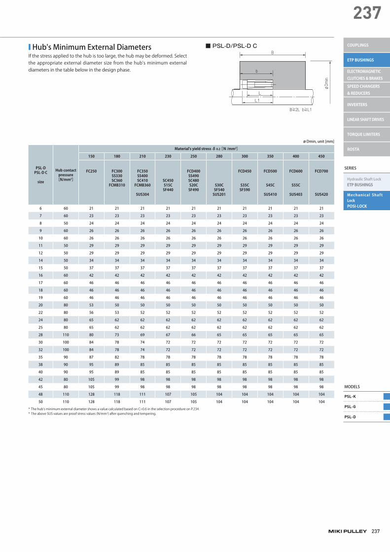
237
237
SERIES
Hydraulic Shaft LockETP BUSHINGS
Mechanical Shaft LockPOSI-LOCK
MODELS
PSL-K
PSL-G
PSL-D
COUPLINGS
ETP BUSHINGS
ELECTROMAGNETIC CLUTCHES & BRAKES
SPEED CHANGERS & REDUCERS
INVERTERS
LINEAR SHAFT DRIVES
TORQUE LIMITERS
ROSTA
■ Hub's Minimum External DiametersIf the stress applied to the hub is too large, the hub may be deformed. Select the appropriate external diameter size from the hub's minimum external diameters in the table below in the design phase.
■ PSL-D/PSL-D C
b
B
L
L1
B≧2L b≧L1
φDmin
PSL-D PSL-D C
size
Hub contact pressure
[N/mm2]
Material's yield stress δ0.2[N/mm2]
150 180 210 230 250 280 300 350 400 450
FC250 FC300 SS330 SC360
FCMB310
FC350 SS400 SC410
FCMB360
SUS304
SC450 S15C SF440
FCD400 SS490 SC480 S20C SF490
S30C SF540 SUS201
FCD450
S35C SF590
FCD500
S45C
SUS410
FCD600
S55C
SUS403
FCD700
SUS420
6 60 21 21 21 21 21 21 21 21 21 21
7 60 23 23 23 23 23 23 23 23 23 23
8 50 24 24 24 24 24 24 24 24 24 24
9 60 26 26 26 26 26 26 26 26 26 26
10 60 26 26 26 26 26 26 26 26 26 26
11 50 29 29 29 29 29 29 29 29 29 29
12 50 29 29 29 29 29 29 29 29 29 29
14 50 34 34 34 34 34 34 34 34 34 34
15 50 37 37 37 37 37 37 37 37 37 37
16 60 42 42 42 42 42 42 42 42 42 42
17 60 46 46 46 46 46 46 46 46 46 46
18 60 46 46 46 46 46 46 46 46 46 46
19 60 46 46 46 46 46 46 46 46 46 46
20 80 53 50 50 50 50 50 50 50 50 50
22 80 56 53 52 52 52 52 52 52 52 52
24 80 65 62 62 62 62 62 62 62 62 62
25 80 65 62 62 62 62 62 62 62 62 62
28 110 80 73 69 67 66 65 65 65 65 65
30 100 84 78 74 72 72 72 72 72 72 72
32 100 84 78 74 72 72 72 72 72 72 72
35 90 87 82 78 78 78 78 78 78 78 78
38 90 95 89 85 85 85 85 85 85 85 85
40 90 95 89 85 85 85 85 85 85 85 85
42 80 105 99 98 98 98 98 98 98 98 98
45 80 105 99 98 98 98 98 98 98 98 98
48 110 128 118 111 107 105 104 104 104 104 104
50 110 128 118 111 107 105 104 104 104 104 104
* The hub's minimum external diameter shows a value calculated based on C=0.6 in the selection procedure on P.234.* The above SUS values are proof stress values (N/mm2) after quenching and tempering.
ø Dmin, unit [mm]
miki_Catalog_e.indb 237 5/18/2015 5:19:13 PM
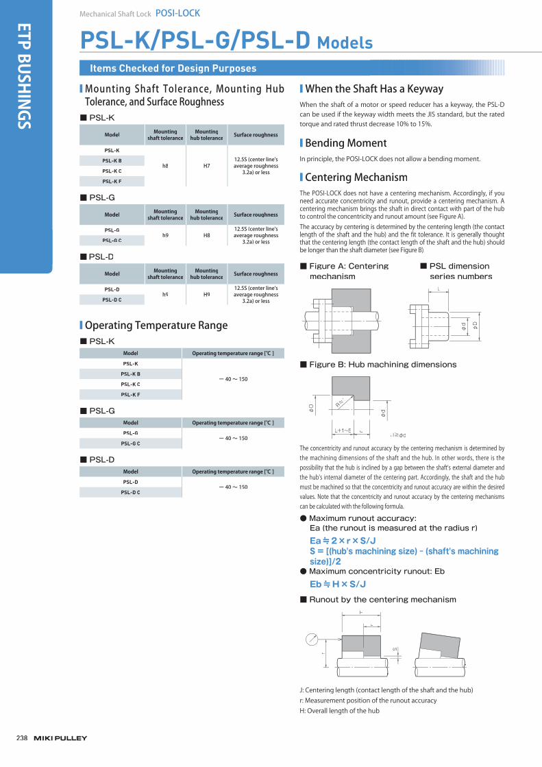
238
Mechanical Shaft Lock POSI-LOCKETP BUSHINGS
PSL-K/PSL-G/PSL-D ModelsItems Checked for Design Purposes
■ Mounting Shaft Tolerance, Mounting Hub Tolerance, and Surface Roughness
Model Mountingshaft tolerance
Mountinghub tolerance Surface roughness
PSL-K
h8 H712.5S (center line's average roughness
3.2a) or less
PSL-K B
PSL-K C
PSL-K F
■ PSL-K
Model Mountingshaft tolerance
Mountinghub tolerance Surface roughness
PSL-Gh9 H8
12.5S (center line's average roughness
3.2a) or lessPSL-G C
■ PSL-G
Model Mountingshaft tolerance
Mountinghub tolerance Surface roughness
PSL-Dh9 H9
12.5S (center line's average roughness
3.2a) or lessPSL-D C
■PSL-D
■ Operating Temperature Range
Model Operating temperature range [℃ ]
PSL-K
ー 40 ~ 150PSL-K B
PSL-K C
PSL-K F
■ PSL-K
Model Operating temperature range [℃ ]
PSL-Gー 40 ~ 150
PSL-G C
■ PSL-G
Model Operating temperature range [℃ ]
PSL-Dー 40 ~ 150
PSL-D C
■ PSL-D
■ When the Shaft Has a KeywayWhen the shaft of a motor or speed reducer has a keyway, the PSL-Dcan be used if the keyway width meets the JIS standard, but the ratedtorque and rated thrust decrease 10% to 15%.
■ Bending MomentIn principle, the POSI-LOCK does not allow a bending moment.
■ Centering MechanismThe POSI-LOCK does not have a centering mechanism. Accordingly, if you need accurate concentricity and runout, provide a centering mechanism. A centering mechanism brings the shaft in direct contact with part of the hubto control the concentricity and runout amount (see Figure A).The accuracy by centering is determined by the centering length (the contact length of the shaft and the hub) and the fit tolerance. It is generally thoughtthat the centering length (the contact length of the shaft and the hub) shouldbe longer than the shaft diameter (see Figure B).
The concentricity and runout accuracy by the centering mechanism is determined bythe machining dimensions of the shaft and the hub. In other words, there is thepossibility that the hub is inclined by a gap between the shaft's external diameter andthe hub's internal diameter of the centering part. Accordingly, the shaft and the hub must be machined so that the concentricity and runout accuracy are within the desiredvalues. Note that the concentricity and runout accuracy by the centering mechanismscan be calculated with the following formula.
L
φD
φd
J≧φd
φD R≒
1
φd
JL+1~5
■ Figure A: Centeringmechanism
■ PSL dimension series numbers
■ Figure B: Hub machining dimensions
H
J
r
S
■ Runout by the centering mechanism
J: Centering length (contact length of the shaft and the hub)r: Measurement position of the runout accuracyH: Overall length of the hub
● Maximum runout accuracy: Ea (the runout is measured at the radius r)
Ea≒2×r×S/JS = [(hub's machining size) - (shaft's machining size)]/2
● Maximum concentricity runout: Eb
Eb≒H×S/J
003_ETPBush_02.indd 238 /2015 3:59:44 PMM4/20/2015 3:59:44 PMM4/20/2015 3:59:444/20/2015 3:59:44 PM

239
239
SERIES
Hydraulic Shaft LockETP BUSHINGS
Mechanical Shaft LockPOSI-LOCK
COUPLINGS
ETP BUSHINGS
ELECTROMAGNETIC CLUTCHES & BRAKES
SPEED CHANGERS & REDUCERS
INVERTERS
LINEAR SHAFT DRIVES
TORQUE LIMITERS
ROSTA
MODELS
PSL-K
PSL-G
PSL-D
■ Standard Dimensions of the Shaft and the Hub
■ Mounting
■ Removal
■ Hub's Movement in the Axial Direction
Items Checked for Design Purposes
Model Nominal standard dimensions Dimensional drawing symbols
PSL-KShaft's standard dimension Ls L1
Hub's standard dimension Lh L
PSL-GShaft's standard dimension Ls ℓ
Hub's standard dimension Lh ℓ
PSL-DShaft's standard dimension Ls L
Hub's standard dimension Lh L
The performance of the POSI-LOCK is based on the case where theshaft and the hub have the effect for the entire standard shaft length (Ls) and the entire standard hub length (Lh), respectively. Accordingly, make sure in the design phase that the shaft and the hub have the effect for the respective entire standard length.
(1) Wipe the rust, dust, and oil completely off the inner surface of the shaft and hub, and apply oil or grease to coat it thinly.
(2) Wipe the rust-proof oil and dirt off the exterior of the POSI-LOCK (the outer sleeve's (ring's) external surface and inner sleeve's (ring's)internal surface). Do not disassemble or wipe any other parts. Neverallow oil containing molybdenum-based antifriction material to contact the surface. If that happens, the friction coefficient basicallychanges.
(3) Mount the POSI-LOCK to the shaft and hub, lightly tighten the clamping bolts so that the parts slightly contact each other, and thenperform positioning.
At this point, never tighten the clamping bolts before mounting thePOSI-LOCK to the shaft and hub.
(4) Tighten the clamping bolts.
・For PSL-K/PSL-DIncrease tightening on diagonally opposed clamping bolts evenly. After that, tighten all the clamping bolts to the specified torque using a torque wrench. Because the PSL-K F clamping bolts are coated with a solid lubricant film, do not apply lubricants such as oil or grease to the clamping bolts when tightening them.
・For PSL-GThe PSL-G has many clamping bolts compared with other POSI-LOCK models, so tighten diagonally opposed clamping bolts evenly about four times to the specified torque. (If you tighten a bolt four times,tighten it so that the torque will increase about 25% every time.)Finally, tighten all the clamping bolts again to the specified torque. Toprevent the bolts from coming loose after tightening them, check thetightening torque again after operating for a certain period of time.f
(1) Before starting work, ensure safety by making sure no torque andthrust are applied to the POSI-LOCK and there is no risk of a fall due tothe self-weight of the shaft and hub. The POSI-LOCK does not have aself-locking mechanism. The connecting force is instantaneously released by loosening the clamping bolts.
(2) Remove it.
・For PSL-K/PSL-D
The PSL-K or PSL-D model may not be removed by loosening the clamping bolts, because it is self-locked depending on the conditions.Never remove it forcibly, because the shaft, hub, and main body maybe damaged. To remove it, first loosen the clamping bolts to open a gap between the flange and the clamping bolt bearing surface. (Abouta 2-mm gap is sufficient.) Then insert a bolt into the threaded hole for removal to release the connection. Normally one removal screw is enough to remove the device. If the device cannot be moved, use twoscrews.
・For PSL-G
After ensuring safety, loosen the clamping bolts. The parts are automatically separated from each other. The PSL-G may not beremoved by loosening the clamping bolts depending on theconditions. Never remove it forcibly, because the shaft, hub, and mainbody may be damaged. If the rear tapering cannot be loosened by loosening the clamping bolts, tap on the heads of the clamping bolts.The spring action of each part moves the rear tapering backward so that it is released. If the front tapering cannot be loosened by loosening the clamping bolts, insert a bolt into the threaded hole forremoval (which is one size larger than the clamping bolt) and tap thebolt head with a hammer. This will enable the front tapering to bereleased.
For the PSL-K and PSL-D models, mount the shaft and hub and thentighten the bolts. The hub will be slightly drawn and moved in the shaft direction. Special attention is required to mount it in the axial direction with high accuracy. However, if the hub is mounted as shownin Figure 1 for the PSL-K, tightening the bolt moves the hub (outersleeve) slightly in the shaft direction. On the other hand, mounting thehub as shown in Figure 2 eliminates the movement in the shaft direction. In this case, the torque, thrust, and contact pressuredecrease to 70% of the specified values.
■ POSI-LOCK standard dimension series numbers
LS
Lh
LS
Lh
LS
Lh
■ PSL-K ■ PSL-G ■ PSL-D
■ Figure 1 ■ Figure 2
003_ETPBush_02.indd 239003_ETPBush_02.indd 239 5/29/2015 9:34:23 AMM5/29/2015 9:34:23 AM
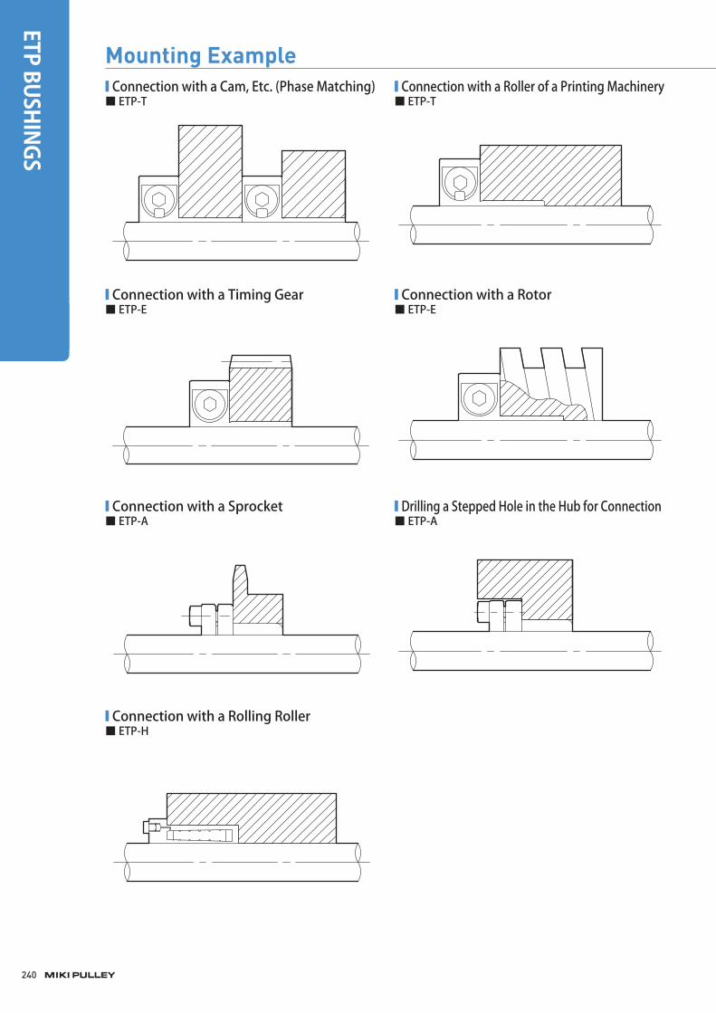
■ Connection with a Cam, Etc. (Phase Matching)
■ Connection with a Timing Gear
■ Connection with a Sprocket
■ Connection with a Rolling Roller
■ Connection with a Roller of a Printing Machinery
■ Connection with a Rotor
■ Drilling a Stepped Hole in the Hub for Connection
■ ETP-T ■ ETP-T
■ ETP-E ■ ETP-E
■ ETP-A ■ ETP-A
■ ETP-H
Mounting Example
240
ETP BUSHINGS
miki_Catalog_e.indb 240 5/20/2015 10:27:11 AM
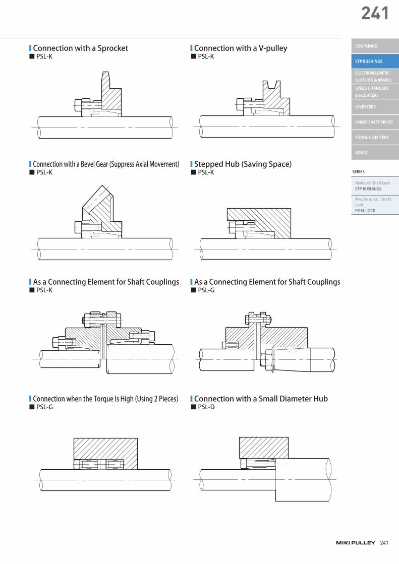
■ Connection with a Sprocket
■ Connection with a Bevel Gear (Suppress Axial Movement)
■ As a Connecting Element for Shaft Couplings
■ Connection when the Torque Is High (Using 2 Pieces)
■ Connection with a V-pulley
■ Stepped Hub (Saving Space)
■ As a Connecting Element for Shaft Couplings
■ Connection with a Small Diameter Hub
■ PSL-K
■ PSL-K
■ PSL-K
■ PSL-G
■ PSL-K
■ PSL-K
■ PSL-G
■ PSL-D
241
241
SERIES
Hydraulic Shaft LockETP BUSHINGS
Mechanical Shaft LockPOSI-LOCK
COUPLINGS
ETP BUSHINGS
ELECTROMAGNETIC CLUTCHES & BRAKES
SPEED CHANGERS & REDUCERS
INVERTERS
LINEAR SHAFT DRIVES
TORQUE LIMITERS
ROSTA
miki_Catalog_e.indb 241 5/20/2015 10:27:12 AM

Torque Wrenches■ ETP-T, ETP-T C
Nominal diameter Tightening torque [N ・m]
Torque wrench (Single-function) Hexagonal head Applicable size
M12 12.0 N230SPCK × 12.0N ・m 230HCK 6mm 15 ~ 20
M14 16.0 N230SPCK × 16.0N ・m 230HCK 6mm 24 ~ 35
M16 24.0 N450SPCK × 24.0N ・m 450HCK 8mm 40 ~ 50
M20 40.0 N450SPCK × 40.0N ・m 450HCK 10mm 60 ~ 80
M22 60.0 N900SPCK × 60.0N ・m 900HCK 10mm 90
M24 80.0 N900SPCK × 80.0N ・m 900HCK 12mm 100
■ ETP-E, ETP-E R
Nominal diameter Tightening torque [N ・m]
Torque wrench (Single-function) Hexagonal head Applicable size
M10 5.0 N 60SPCK × 5.0N ・m 230HCK 5mm 15 ~ 35
M16 21.0 N230SPCK × 21.0N ・m 230HCK 8mm 38 ~ 60
M20 39.0 N450SPCK × 39.0N ・m 450HCK 10mm 70 ~ 100
■ ETP-A, ETP-A C, ETP-A S
Nominal diameter Tightening torque [N ・m]
Torque wrench (Single-function) Hexagonal head Applicable size
M5 6.0 N60SPCK × 6.0N ・m 230HCK 4mm 15
M5 8.0 N120SPCK × 8.0N ・m 230HCK 4mm 19 ~ 42
M6 13.0 N230SPCK × 13.0N ・m 230HCK 5mm 45 ~ 65
M8 32.0 N450SPCK × 32.0N ・m 450HCK 6mm 70 ~ 100
■ ETP-A B
Nominal diameter Tightening torque [N ・m]
Torque wrench (Single-function) Wrench attachment Applicable size
M5 6.0 N60SPCK × 6.0N ・m 230SCK 8mm 15
M5 8.0 N120SPCK × 8.0N ・m 230SCK 8mm 19 ~ 42
M6 13.0 N230SPCK × 13.0N ・m 230SCK 10mm 45 ~ 65
M8 32.0 N450SPCK × 32.0N ・m 450SCK 13mm 70 ~ 100
■ ETP-A R
Nominal diameter Tightening torque [N ・m]
Torque wrench (Single-function) Wrench attachment Applicable size
M5 4.5 N60SPCK × 4.5N ・m 230SCK 8mm 15 ~ 40
M6 7.8 N120SPCK × 7.8N ・m 230SCK 10mm 45 ~ 50
■ Torque Wrench (Single-function) ■ Hexagonal Head■ N-SPCK ■ HCK
■ Torque Wrench (Preset Type) ■ Wrench Attachment■ N-LCK ■ SCK
* The above torque wrench and wrench attachment models are those of Nakamura Mfg. Co., Ltd.
242
ETP BUSHINGS
003_ETPBush_02.indd 242 4/20/2015 3:59:46 PM
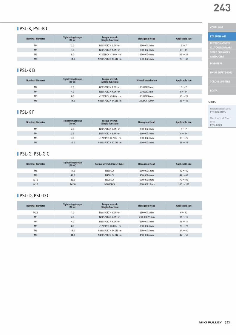
■ PSL-K, PSL-K C
Nominal diameter Tightening torque [N ・m]
Torque wrench (Single-function) Hexagonal head Applicable size
M4 2.0 N60SPCK × 2.0N ・m 230HCK 3mm 6 ~ 7
M4 4.0 N60SPCK × 4.0N ・m 230HCK 3mm 8 ~ 14
M5 8.0 N120SPCK × 8.0N ・m 230HCK 4mm 15 ~ 25
M6 14.0 N230SPCK × 14.0N ・m 230HCK 5mm 28 ~ 42
■ PSL-K B
Nominal diameter Tightening torque [N ・m]
Torque wrench (Single-function) Wrench attachment Applicable size
M4 2.0 N60SPCK × 2.0N ・m 230SCK 7mm 6 ~ 7
M4 4.0 N60SPCK × 4.0N ・m 230SCK 7mm 8 ~ 14
M5 8.0 N120SPCK × 8.0N ・m 230SCK 8mm 15 ~ 25
M6 14.0 N230SPCK × 14.0N ・m 230SCK 10mm 28 ~ 42
■ PSL-K F
Nominal diameter Tightening torque [N ・m]
Torque wrench (Single-function) Hexagonal head Applicable size
M4 2.0 N60SPCK × 2.0N ・m 230HCK 3mm 6 ~ 7
M4 3.5 N60SPCK × 3.5N ・m 230HCK 3mm 8 ~ 14
M5 7.0 N120SPCK × 7.0N ・m 230HCK 4mm 15 ~ 25
M6 12.0 N230SPCK × 12.0N ・m 230HCK 5mm 28 ~ 35
■ PSL-G, PSL-G C
Nominal diameter Tightening torque [N ・m] Torque wrench (Preset type) Hexagonal head Applicable size
M6 17.0 N230LCK 230HCK 5mm 19 ~ 40
M8 41.0 N450LCK 450HCK 6mm 42 ~ 65
M10 82.0 N900LCK 900HCK 8mm 70 ~ 95
M12 142.0 N1800LCK 1800HCK 10mm 100 ~ 120
■ PSL-D, PSL-D C
Nominal diameter Tightening torque [N ・m]
Torque wrench (Single-function) Hexagonal head Applicable size
M2.5 1.0 N60SPCK × 1.0N ・m 230HCK 2mm 6 ~ 12
M3 2.0 N60SPCK × 2.0N ・m 230HCK 2.5mm 14 ~ 15
M4 4.0 N60SPCK × 4.0N ・m 230HCK 3mm 16 ~ 19
M5 8.0 N120SPCK × 8.0N ・m 230HCK 4mm 20 ~ 22
M6 14.0 N230SPCK × 14.0N ・m 230HCK 5mm 24 ~ 40
M8 34.0 N450SPCK × 34.0N ・m 450HCK 6mm 42 ~ 50
243
243
SERIES
Hydraulic Shaft LockETP BUSHINGS
Mechanical Shaft LockPOSI-LOCK
COUPLINGS
ETP BUSHINGS
ELECTROMAGNETIC CLUTCHES & BRAKES
SPEED CHANGERS & REDUCERS
INVERTERS
LINEAR SHAFT DRIVES
TORQUE LIMITERS
ROSTA
003_ETPBush_02.indd 243 4/20/2015 3:59:46 PM
Related Documents